JP7112252B2 - A method for estimating the current and state of charge of a battery pack or cell without directly sensing the current under operating conditions - Google Patents
A method for estimating the current and state of charge of a battery pack or cell without directly sensing the current under operating conditions Download PDFInfo
- Publication number
- JP7112252B2 JP7112252B2 JP2018100345A JP2018100345A JP7112252B2 JP 7112252 B2 JP7112252 B2 JP 7112252B2 JP 2018100345 A JP2018100345 A JP 2018100345A JP 2018100345 A JP2018100345 A JP 2018100345A JP 7112252 B2 JP7112252 B2 JP 7112252B2
- Authority
- JP
- Japan
- Prior art keywords
- cell
- battery pack
- battery
- operating
- current
- Prior art date
- Legal status (The legal status is an assumption and is not a legal conclusion. Google has not performed a legal analysis and makes no representation as to the accuracy of the status listed.)
- Active
Links
Images


Classifications
-
- G—PHYSICS
- G01—MEASURING; TESTING
- G01R—MEASURING ELECTRIC VARIABLES; MEASURING MAGNETIC VARIABLES
- G01R31/00—Arrangements for testing electric properties; Arrangements for locating electric faults; Arrangements for electrical testing characterised by what is being tested not provided for elsewhere
- G01R31/36—Arrangements for testing, measuring or monitoring the electrical condition of accumulators or electric batteries, e.g. capacity or state of charge [SoC]
- G01R31/367—Software therefor, e.g. for battery testing using modelling or look-up tables
-
- G—PHYSICS
- G01—MEASURING; TESTING
- G01R—MEASURING ELECTRIC VARIABLES; MEASURING MAGNETIC VARIABLES
- G01R31/00—Arrangements for testing electric properties; Arrangements for locating electric faults; Arrangements for electrical testing characterised by what is being tested not provided for elsewhere
- G01R31/36—Arrangements for testing, measuring or monitoring the electrical condition of accumulators or electric batteries, e.g. capacity or state of charge [SoC]
- G01R31/374—Arrangements for testing, measuring or monitoring the electrical condition of accumulators or electric batteries, e.g. capacity or state of charge [SoC] with means for correcting the measurement for temperature or ageing
-
- G—PHYSICS
- G01—MEASURING; TESTING
- G01R—MEASURING ELECTRIC VARIABLES; MEASURING MAGNETIC VARIABLES
- G01R31/00—Arrangements for testing electric properties; Arrangements for locating electric faults; Arrangements for electrical testing characterised by what is being tested not provided for elsewhere
- G01R31/36—Arrangements for testing, measuring or monitoring the electrical condition of accumulators or electric batteries, e.g. capacity or state of charge [SoC]
- G01R31/382—Arrangements for monitoring battery or accumulator variables, e.g. SoC
- G01R31/3842—Arrangements for monitoring battery or accumulator variables, e.g. SoC combining voltage and current measurements
-
- G—PHYSICS
- G01—MEASURING; TESTING
- G01R—MEASURING ELECTRIC VARIABLES; MEASURING MAGNETIC VARIABLES
- G01R31/00—Arrangements for testing electric properties; Arrangements for locating electric faults; Arrangements for electrical testing characterised by what is being tested not provided for elsewhere
- G01R31/36—Arrangements for testing, measuring or monitoring the electrical condition of accumulators or electric batteries, e.g. capacity or state of charge [SoC]
- G01R31/392—Determining battery ageing or deterioration, e.g. state of health
-
- G—PHYSICS
- G01—MEASURING; TESTING
- G01R—MEASURING ELECTRIC VARIABLES; MEASURING MAGNETIC VARIABLES
- G01R31/00—Arrangements for testing electric properties; Arrangements for locating electric faults; Arrangements for electrical testing characterised by what is being tested not provided for elsewhere
- G01R31/36—Arrangements for testing, measuring or monitoring the electrical condition of accumulators or electric batteries, e.g. capacity or state of charge [SoC]
- G01R31/382—Arrangements for monitoring battery or accumulator variables, e.g. SoC
- G01R31/3835—Arrangements for monitoring battery or accumulator variables, e.g. SoC involving only voltage measurements
-
- G—PHYSICS
- G01—MEASURING; TESTING
- G01R—MEASURING ELECTRIC VARIABLES; MEASURING MAGNETIC VARIABLES
- G01R31/00—Arrangements for testing electric properties; Arrangements for locating electric faults; Arrangements for electrical testing characterised by what is being tested not provided for elsewhere
- G01R31/36—Arrangements for testing, measuring or monitoring the electrical condition of accumulators or electric batteries, e.g. capacity or state of charge [SoC]
- G01R31/389—Measuring internal impedance, internal conductance or related variables
Description
本発明は、電気器具を制御する、電子方法及びシステムの技術的部門に関連する。 The present invention relates to the technical sector of electronic methods and systems for controlling electrical appliances.
特に、本発明は、動作条件下で電流を直接検知することなく、バッテリ、または自動車のバッテリパックまたは、同様に、バッテリセル(単にセル「cell」としてこの明細書で定義される)の、動作電流及び充電状態を推定する方法に関連する。 In particular, the present invention provides the ability to operate a battery, or battery pack in an automobile, or, similarly, a battery cell (defined herein simply as a cell) without directly sensing current under operating conditions. It relates to methods for estimating current and state of charge.
さらに、本発明は、前記方法を実行する、バッテリパックまたはセル、電流センサを備える必要なく、前記方法の長所によって、動作電流及び充電状態をモニタできる自動車のバッテリパックまたはセルの制御装置に関連する。 Furthermore, the present invention relates to a battery pack or cell control device for a motor vehicle that can monitor operating current and state of charge by virtue of said method without the need to equip the battery pack or cell with a current sensor to carry out said method. .
電気化学的なセル(特に、自動車分野において、電気またはハイブリッド駆動自動車の動作システム及びバッテリという観点において)から構成されるバッテリ、バッテリパックまたはセルの電圧及び電流を知ることは、バッテリ、バッテリパックまたはセルの正しい管理及び制御のとても重要な情報である。 Knowing the voltage and current of a battery, battery pack or cell made up of electrochemical cells (especially in the automotive field, in terms of operating systems and batteries in electric or hybrid powered vehicles) is useful for batteries, battery packs or It is very important information for correct management and control of the cell.
バッテリパックまたはセルの複数のセルの電圧、電流、温度の取得は、セルのパフォーマンス及び耐久性の低下、また、極端な場合、重大な結果として、バッテリパックまたはセルの火災または爆発まで至る、熱暴走「thermal runaway」として知られる現象をもたらす、2次物理化学プロセスのきっかけを避けるように、セルそれ自身の充電状態を知り、バッテリパックまたはセルの正しい管理及び保護するために、必要とされる。 Obtaining the voltage, current, and temperature of multiple cells in a battery pack or cell can result in reduced cell performance and durability, and, in extreme cases, heat, with serious consequences, including fire or explosion of the battery pack or cell. Required to know the state of charge of the cell itself and to properly manage and protect the battery pack or cell so as to avoid triggering secondary physico-chemical processes leading to a phenomenon known as runaway "thermal runaway" .
さらに、いくつかのモジュールまたは全てのバッテリパックまたはセルに共通の、電流を知ることは、セルの充電状態(SOC)を決定するために役立つ。 Additionally, knowing the current, common to some modules or all battery packs or cells, helps determine the state of charge (SOC) of the cells.
共通の背景技術の解決方法において、バッテリまたはセルの電流を知ることは、通常、バッテリパックまたはセルそれ自身に設置された、シャントタイプの物理電流センサまたはホール効果ベースのセンサを使って、そのような電流の直接検知によって得られる。 In common background art solutions, knowing the current of a battery or cell is usually done by using a shunt-type physical current sensor or a Hall effect-based sensor installed in the battery pack or cell itself. obtained by direct sensing of the current.
シャントタイプセンサについて言えば、電流は、バッテリまたはセル電流が循環する既知の値の抵抗の電圧を測定することによって、決定される。 For shunt-type sensors, the current is determined by measuring the voltage across a resistor of known value through which the battery or cell current circulates.
ホール効果ベースのセンサについて言えば、電流は、バッテリまたはセルの電流によって横切られ、電磁場を受ける導体に発生するホール電圧を測定することによって、決定される。 For Hall effect-based sensors, the current is determined by measuring the Hall voltage developed in a conductor traversed by the battery or cell current and subjected to the electromagnetic field.
前述の両方の場合は、バッテリパックそれ自身またはセルの複雑さとコストの増加の不利益を必然的に伴う、複数の電流センサを備える、バッテリパックまたはセルを提供する必要性を想定している。 Both of the foregoing cases envisage the need to provide a battery pack or cell with multiple current sensors, which entails the penalty of increased complexity and cost of the battery pack itself or the cell.
それゆえ、電流センサによって、そのような電流の直接の取得に関わらず、バッテリまたはセルの電流(すなわち、「バッテリまたはセル電流」)を推定する方法を特定する必要が生じる。 Therefore, a need arises to identify a method for estimating battery or cell current (ie, "battery or cell current") by means of a current sensor, regardless of direct acquisition of such current.
このアプローチは、しかしながら、実際に使用できるように十分に正確な電流推定を得るさらなる技術的な問題に遭遇する。実際に、必要とされた正確さは、(例えば5%に相当またはそれより小さい)制限されたパーセンテージの範囲内で推定の誤差を最小化することを提供する。 This approach, however, encounters the additional technical problem of obtaining sufficiently accurate current estimates for practical use. In practice, the required accuracy provides for minimizing the error of the estimation within a limited percentage (e.g. equal to or less than 5%).
そのような正確なバッテリまたはセルの電流の推定を得ることは、実際のバッテリまたはセルの電流が、得られた瞬間において、その瞬間に検知されたバッテリまたはセルの動作電圧に依存するだけでなく、複雑な振る舞いで、バッテリまたはセルの温度と充電状態(今後、その過程及び寿命)にも依存するので、全く容易でない。それゆえ、バッテリまたはセルの電圧及び温度を知ることによって、必要とされる正確さで、バッテリまたはセル電流を得ることができる、単一の分析式はない。 Obtaining such an accurate estimate of battery or cell current not only depends on the moment the actual battery or cell current is obtained, but also on the sensed operating voltage of the battery or cell at that moment. , is not easy at all, as it is a complex behavior and also depends on the temperature and state of charge of the battery or cell (henceforth its process and life). Therefore, by knowing the battery or cell voltage and temperature, there is no single analytical formula that can obtain the battery or cell current with the required accuracy.
さらに、バッテリまたはセル電流と他のバッテリまたはセルの電気的、熱的量の関係は、劣化及び経年劣化にも依存するので、さらに、そのような態様を適切に考慮する推定方法を有する必要性が、さらに感じられる。 Furthermore, since the relationship between battery or cell current and electrical and thermal quantities of other batteries or cells also depends on deterioration and aging, there is a need to have an estimation method that appropriately considers such aspects. is felt even more.
既知の解決法は、この関連で、上記で言及された必要を満足しない。 Known solutions do not satisfy the needs mentioned above in this connection.
前述を参照して、主に自動車応用の分野で、特に電気またはハイブリッドの自動車のバッテリパックとの関連で、バッテリまたはセルの電流及び充電状態を推定し、バッテリまたはセルの電流及び充電状態に関して十分正確な情報を提供する一方で、動作条件下で、バッテリまたはセルの電流を直接取得する必要を避ける方法の必要性が感じられる。 With reference to the foregoing, primarily in the field of automotive applications, and particularly in the context of battery packs in electric or hybrid vehicles, the current and state of charge of a battery or cell is estimated and adequately determined with respect to the current and state of charge of the battery or cell. A need is felt for a method that provides accurate information while avoiding the need to obtain battery or cell current directly under operating conditions.
少なくとも部分的に、背景技術を参照して上記に示される欠点を克服すること、特に考えられる技術部門で感じられる上述の必要を満たすことができるような、電流それ自身の直接の取得を必要とすることなく、バッテリまたはセルの電流及び充電状態を十分に正確に推定することを提供することができる、バッテリパックまたはセルの動作電流及び充電状態を推定する方法を提供することが、本発明の目的である。 Overcoming, at least in part, the shortcomings indicated above with reference to the background art, particularly those requiring a direct acquisition of the electric current itself, such that the above-mentioned needs felt in the considered technical sector can be met. It is an object of the present invention to provide a method of estimating operating current and state of charge of a battery pack or cell that can provide sufficiently accurate estimates of battery or cell current and state of charge without Purpose.
特に、本発明は、シャントまたはホール効果タイプの物理電流センサを用いる必要なく、バッテリまたはセルが電流によって横切られるとき、バッテリまたはセルの端部において電圧のみを測定することによって、バッテリまたはセルの電流を決定する方法を提供することが目的である。それによって、バッテリまたはセルの端部において、電圧を直接測定することのみで、バッテリパックまたはセルを完全に管理することが可能であり、それにより、温度及び経年劣化を含む、異なる変化に応じて、電圧測定とその内部抵抗の特性評価から電流を決定する。 In particular, the present invention measures the current in a battery or cell by measuring only the voltage at the ends of the battery or cell when the battery or cell is traversed by the current, without the need to use a shunt or Hall effect type physical current sensor. The purpose is to provide a method for determining It is thereby possible to fully manage a battery pack or cell by simply measuring the voltage directly at the end of the battery or cell, thereby responding to different changes, including temperature and aging. , to determine the current from voltage measurements and characterization of its internal resistance.
そのような目的は、請求項1による電流を推定する方法で達成される。
Such object is achieved with a method for estimating current according to
そのような方法のさらなる実施形態は、請求項2-15によって定義される。 Further embodiments of such a method are defined by claims 2-15.
請求項16によるバッテリパックまたはセルの充電状態を推定する方法が、本発明の別の目的である。 A method for estimating the state of charge of a battery pack or cell according to claim 16 is another object of the invention.
本発明の目的は、また前述の方法を実行することができる、請求項17で定義される、バッテリパックまたはセルの制御装置及び、請求項18で定義される、電流センサなしで、前述の制御器具によって制御されるバッテリパックまたはセルでもある。 The object of the invention is also a device for controlling a battery pack or cell, defined in claim 17, capable of carrying out the method described above, and without a current sensor, defined in claim 18, the control device described above. It is also a battery pack or cell controlled by the instrument.
本発明による電流を推定する方法及び充電状態を推定する方法、及び関連する制御装置及びバッテリパックまたはセルのさらなる特徴及び利点は、添付した図を参照して、示す及び制限しない実施例を手段として得られる、好ましい実施形態の続く記載から明白になるであろう。 Further features and advantages of the current estimating method and the state of charge estimating method, and the associated controller and battery pack or cell according to the present invention, by way of illustrative and non-limiting example, with reference to the accompanying figures It will become apparent from the ensuing description of the preferred embodiments obtained.
図1-15を参照して、バッテリまたはセルによって分配された動作電流Iを推定する方法が、これから記載される。 A method for estimating the operating current I delivered by a battery or cell will now be described with reference to FIGS. 1-15.
方法は、第1に、バッテリパックまたはセルの特性評価電圧Vm及び特性評価電流Imの測定された時間的傾向に関連する、バッテリパックまたはセルの特性評価データを取得するステップを備える。前記時間的傾向のそれぞれは、複数の特性評価温度値Tkのそれぞれの値に関連付けられる。 The method first comprises obtaining battery pack or cell characterization data relating to measured temporal trends of battery pack or cell characterization voltage Vm and characterization current Im. Each of said temporal trends is associated with a respective value of a plurality of characterization temperature values Tk .
さらにバッテリパックまたはセルの温度及び充電状態SOCに応じた、バッテリパックまたはセルの動作モデルの複数のパラメータPを決定するために前記の特性評価データを処理する方法が提供される。 Further provided is a method of processing the characterization data to determine a plurality of parameters P of a battery pack or cell operating model as a function of battery pack or cell temperature and state of charge SOC.
その後、バッテリパックまたはセルが動作条件下にある間、測定された動作電圧V、測定された動作温度T及び前述の複数のパラメータP(前にバッテリパックまたはセルの温度及び充電状態に応じて決定されたように)に基づいて、前記の動作モデルによって、バッテリパックまたはセルの動作電圧V及び動作温度Tを測定し、バッテリパックまたはセルの動作電流Iを推定する方法が提供される。 Thereafter, while the battery pack or cell is under operating conditions, the measured operating voltage V, the measured operating temperature T and the aforementioned plurality of parameters P (previously determined depending on the temperature and state of charge of the battery pack or cell) ), the operating model provides a method for measuring the operating voltage V and operating temperature T of a battery pack or cell and estimating the operating current I of the battery pack or cell.
動作電流Iは、バッテリパックまたはセルの瞬間的な動作電圧V、瞬間的な温度Tが検知されたとき、バッテリパックまたはセルに流れる瞬間的な電流であることに注目すべきである。そのような動作電流Iは、それゆえ、前記のパラメータT、V及びPに基づいて推定される。 It should be noted that the operating current I is the instantaneous current flowing through the battery pack or cell when the instantaneous operating voltage V and the instantaneous temperature T of the battery pack or cell are sensed. Such an operating current I is therefore estimated based on the parameters T, V and P above.
パラメータPは、次に、すでに上記で記述されたように、下記で記載されるように、バッテリパックまたはセルの温度及び充電状態SOCに基づいて、さらに処理することによって、得られる。 The parameter P is then obtained by further processing based on the temperature and state of charge SOC of the battery pack or cell, as already described above and as described below.
本明細書で記載された方法において、処理するステップは、前記の複数の特性評価温度値Tkのそれぞれの値で処理される、いくつかのステージを備える。 In the method described herein, the processing step comprises several stages processed at respective values of said plurality of characterization temperature values Tk .
特に、処理するステップは、特性評価温度Tkに関連した、特性評価電圧Vm及び特性評価電流Imのそれぞれの時間的傾向に沿った複数の時間観測窓Wiを特定することと、それぞれ特性評価電流Imiと特性評価電圧Vmi値を検知することを含む。 In particular, the processing step includes identifying a plurality of time observation windows W i along respective temporal trends of the characterization voltage Vm and the characterization current Im associated with the characterization temperature T k ; Including sensing current Im i and characterization voltage Vm i values.
それゆえ、それぞれの観測窓Wiにおいて、バッテリパックまたはセルの充電状態SOCiのそれぞれの値を計算する方法が提供される。 Therefore, a method is provided to calculate respective values of the state of charge SOC i of a battery pack or cell in each observation window W i .
さらに、それぞれの観測窓Wiにおいて、パラメータPのそれぞれの名目上の値に応じて、バッテリパックまたはセルの動作モデルによって、それぞれ推定された電圧VABiを計算し、時間観測窓Wiの推定された電圧VABiと特性評価電圧Vmiの差に依存するそれぞれの誤差関数Eiを決定する方法が提供される。 Furthermore, in each observation window W i , depending on the respective nominal value of the parameter P, calculate the respective estimated voltage V ABi by the battery pack or cell operating model, and estimate the time observation window W i A method is provided for determining the respective error function E i that depends on the difference between the measured voltage V ABi and the characterization voltage Vm i .
さらに、それぞれの観測窓Wiにおいて、前記の誤差関数Eiを最小化することによって、バッテリパックまたはセルのモデルの複数のパラメータPのそれぞれの実際の値Piを計算する方法が提供される。 Further, a method is provided for calculating the actual value P i of each of the plurality of parameters P of the model of the battery pack or cell by minimizing said error function E i in each observation window W i . .
最終的に、それぞれの充電状態SOCi及び特性評価温度Tkと観測窓Wiにおいて計算される、パラメータの実際の値Piを関連付けるステップは、バッテリパックまたはセルの温度及び充電状態SOCに応じた、前記の複数のパラメータPを得るために、提供される。 Finally, the step of associating the respective state of charge SOC i and characterization temperature T k with the actual value of the parameter P i calculated in the observation window W i depends on the temperature and state of charge SOC of the battery pack or cell. Also provided for obtaining said plurality of parameters P.
方法の実施形態によると、さらに、それぞれの観測窓Wiにおいて、バッテリパックまたはセルの負荷なし電圧Vociのそれぞれを決定し、観測窓Wiにおいて得られる複数の負荷なし電圧Voci及び充電状態SOCi値に基づいて、バッテリパックまたはセルの負荷なし電圧Voc及び充電状態SOCの関係を定義する、特性評価データを処理する前記のステップが提供される。 According to an embodiment of the method, further determining each of the no-load voltages Voc i of the battery packs or cells in the respective observation windows W i and the plurality of no-load voltages Voc i obtained in the observation windows W i and the state of charge The foregoing step of processing the characterization data is provided to define the relationship between the no-load voltage Voc and the state of charge SOC of the battery pack or cell based on the SOC i values.
そのような場合において、それぞれの観測窓Wiにおいて、パラメータの実際の値Piを計算するステップは、それぞれの負荷なし電圧Voci値及び決定されたバッテリパックまたはセルの負荷なし電圧Voc及び充電状態SOCの関係も考慮する。 In such a case, in each observation window W i , the step of calculating the actual values of the parameters P i is performed by calculating the respective no-load voltage V oc i values and the determined battery pack or cell no-load voltage V oc and charge The state SOC relationship is also considered.
特定の実施形態によると、複数の観測窓Wiを特定するステップは、特性評価電流Imが過渡電流現象の完全な消耗時に、ゼロであり、その結果、負荷なし電圧Vociが特性評価電圧Vmiに対応する、時間窓を特定することを備える。 According to a particular embodiment, the step of identifying the plurality of observation windows W i is such that the characterization current Im is zero at the complete depletion of the transient current event, such that the no-load voltage Voc i is equal to the characterization voltage Vm identifying a time window corresponding to i .
特定の実施形態によると、バッテリパックまたはセルの充電状態の値を計算するステップは、特性評価電流の時間的傾向に基づく、バッテリパックまたはセルの充電状態(SOCi)のそれぞれの値を計算することを備える。 According to a particular embodiment, the step of calculating a state of charge value of the battery pack or cell comprises calculating a respective value of state of charge (SOC i ) of the battery pack or cell based on the temporal trend of the characterizing current. Be prepared.
方法の異なる可能な実施形態によると、バッテリパックまたはセルの異なる動作モデルを使うことができる。 According to different possible embodiments of the method, different operating models of battery packs or cells can be used.
方法の典型的な実施形態によると、バッテリパックまたはセルの動作モデルは、電気回路モデルである。そのような場合において、モデルパラメータは、電気回路パラメータを含む。 According to an exemplary embodiment of the method, the battery pack or cell behavioral model is an electrical circuit model. In such cases, the model parameters include electrical circuit parameters.
図2で示された実施例において、バッテリパックまたはセルの電気回路モデルは、負荷のない電圧Voc発生器、1以上の回路グループの直列に配置されたバッテリまたはセルの内部抵抗R0を備え、それぞれは、回路グループ抵抗及び回路グループ容量の並列を備える。そのような場合において、回路パラメータPの群は、負荷のない電圧Voc、バッテリまたはセルの内部抵抗R0、1以上の回路グループ抵抗R1、R2、及び1以上の回路グループ容量C1、C2を備える。 In the embodiment shown in FIG. 2, the electrical circuit model of a battery pack or cell comprises a voltage Voc generator with no load, the internal resistance R0 of the battery or cell arranged in series in one or more circuit groups, Each comprises a circuit group resistance and a circuit group capacitance in parallel. In such a case, the group of circuit parameters P are the no-load voltage Voc, the battery or cell internal resistance R 0 , one or more circuit group resistances R 1 , R 2 , and one or more circuit group capacitances C 1 , with C2 .
特に図2の実施例は、2次モデル(通常、正確で、同時に、相対的に単一のモデルを有するように使われる)、すなわち2つの回路グループを備えるモデルを示す。そのような場合において、回路パラメータPの群は、バッテリまたはセルの内部抵抗R0及び負荷なし電圧Vocに加えて、第1の回路群抵抗R1、第1の回路群容量C1、第2の回路群抵抗R2、第2の回路群容量C2を備える。 In particular, the embodiment of FIG. 2 shows a quadratic model (usually used to be accurate and at the same time have a relatively single model), ie a model comprising two circuit groups. In such a case, the group of circuit parameters P includes, in addition to the internal resistance R 0 of the battery or cell and the no-load voltage Voc, a first circuit group resistance R 1 , a first circuit group capacitance C 1 , a second circuit group resistance R 2 and a second circuit group capacitance C 2 .
いくつかのパラメータ、偶数の非回路パラメータで特性評価される、他のタイプのモデル、偶数の非回路モデルを使用する方法が提供されることに注目すべきである。 It should be noted that methods are provided that use other types of models, even non-circuit models, characterized by some parameters, even non-circuit parameters.
1つの実施形態において、例えば、バッテリパックまたはセルの動作モデルは、訓練された予測アルゴリズムを備え、パラメータPは、訓練された予測アルゴリズムのパラメータである。そのような場合において、複数のパラメータPを決定するステップは、取得されるバッテリパックまたはセルの特性評価データによる予測アルゴリズムを訓練することを備える。 In one embodiment, for example, a battery pack or cell behavioral model comprises a trained prediction algorithm, and the parameter P is a parameter of the trained prediction algorithm. In such cases, the step of determining the plurality of parameters P comprises training a prediction algorithm with the obtained battery pack or cell characterization data.
例えば、Nパラメータのニューラルネットワークを使用することができる。 For example, an N-parameter neural network can be used.
電気回路モデル(例えば、図2に示されているもの)の実施例に戻ると、モデルパラメータ(Voc、R0、R1、R2、C1、C2)は、充電状態SOCと温度の関数であることに注目すべきである。 Returning to the example of the electrical circuit model (eg, that shown in FIG. 2), the model parameters (Voc, R 0 , R 1 , R 2 , C 1 , C 2 ) are the state of charge SOC and temperature Note that it is a function.
電圧、電流及び温度の関係は、次の式(1)で表される。 The relationship between voltage, current and temperature is represented by the following equation (1).

ここで、電圧VAB(t)は、バッテリセルまたはセルの終端の電圧を示し、I(t)はセルを循環する電流である。 Here, the voltage V AB (t) denotes the voltage at the battery cell or cell terminals and I(t) is the current circulating in the cell.
温度依存は、それぞれ温度に依存する、パラメータ(Voc、R0、R1、R2、C1、C2)に含まれるので、潜在している。 The temperature dependence is implicit as it is included in the parameters (Voc, R 0 , R 1 , R 2 , C 1 , C 2 ), each dependent on temperature.
ジュール効果によって消散した電力とエネルギは、次の式(2)で表される。 The power and energy dissipated by the Joule effect are represented by the following equation (2).

すでに上記で記述されたように、電気パラメータは温度に依存し、さらに、バッテリセルまたはセルの充電状態、特に負荷なし電圧Vocに依存する。 As already mentioned above, the electrical parameter depends on the temperature and also on the battery cell or the state of charge of the cell, in particular on the no-load voltage Voc.
モデルを効果的に使うために、それゆえ、異なる充電状態SOCと温度T値に対するパラメータを特性評価する必要がある。 To use the model effectively, it is therefore necessary to characterize the parameters for different state of charge SOC and temperature T values.
この目的を達成するために、特性評価データを処理するステップを、一般論として、すでに上記で記載されて、提供している。 To this end, the steps of processing the characterization data have already been described and provided in general terms above.
さらなる詳細は、これによって、図2の電気回路モデルが使われている方法の実施形態を参照して、処理するステップに用いられているアルゴリズムに提供されている。 Further details are hereby provided for the algorithms used in the processing step with reference to the embodiment of the method in which the electrical circuit model of FIG. 2 is used.
アルゴリズムを処理するそのような実施例は、図3に図式的に示されている。 Such an embodiment of processing algorithm is shown diagrammatically in FIG.
温度を変えてあらかじめ定義され、設定されたKに対応する、Kの時間的傾向、すなわち電圧及び電流傾向を有すると見なす。k=1に関して、第1の温度は設定され(Tk=T1)、温度T1のバッテリまたはセルで取得される、電圧及び電流の時間的傾向が、選択される。 Suppose we have K temporal trends, ie voltage and current trends, corresponding to a predefined and set K with varying temperature. For k=1, a first temperature is set (T k =T 1 ) and the temporal trends of voltage and current obtained with a battery or cell at temperature T 1 are selected.
電圧と電流の時間的傾向は、例えば、バッテリまたはセルの、「オフライン」で特性を評価するステップで取得される。それゆえ、そのような電圧とそのような電流は、それぞれ上記で定義された、特性評価電圧Vm及び特性評価電流Imに対応する。 Voltage and current trends over time are obtained, for example, in a step of "off-line" characterization of a battery or cell. Such voltage and such current thus correspond respectively to the characterization voltage Vm and the characterization current Im defined above.
特性評価電圧Vmと特性評価電流Imの時間的傾向の実施例は、温度28℃、20アンペアアウア(Ah)チタン酸リチウム(LTO)バッテリセルまたはセルについて言えば、それぞれ、図4A及び4Bに示される。 An example of the temporal trend of the characterization voltage Vm and the characterization current Im is shown in FIGS. 4A and 4B, respectively, for a 20 ampere Auer (Ah) lithium titanate (LTO) battery cell or cells at a temperature of 28° C. be
Vm及びImの前記時間的傾向において、電流がゼロであり、例えば、セルそれ自身の挙動が決定されると考えることができることなど、時間間隔の間、ゼロ値で残る、すなわち、回路モデルの容量C1及びC2がかなり放電された状態で、時間観測窓Wiは、特定される。図4A及び4Bにおいて、観測窓Wiの終わりは、「X」マークによって示される。 In said temporal trend of Vm and Im, the current is zero and remains at zero value during the time interval, e.g. the behavior of the cell itself can be considered determined, i.e. the capacitance of the circuit model With C 1 and C 2 significantly discharged, a time observation window W i is specified. In Figures 4A and 4B, the end of the observation window W i is indicated by an "X" mark.
第1の時間観測窓の拡大が、特性評価電圧Vmに関して、図5Aで、特性評価電流Imに関して、図5Bで示される。 The expansion of the first time observation window is shown in FIG. 5A for characterization voltage Vm and in FIG. 5B for characterization current Im.
次のステージは、測定された電流Imに基づいて、充電状態(SOC)を計算することである。充電状態SOCを、例えば、次の式(4)に基づいて、いわゆる「クーロンカウンタ」技術で、計算することができる。 The next stage is to calculate the state of charge (SOC) based on the measured current Im. The state of charge SOC can be calculated, for example, with the so-called "coulomb counter" technique, based on equation (4) below.

ここで、Qnomは、1クーロンの放電割合で推定された、セルの名目上の容量(示されている実施例において、20Ahの値を有する)である。 where Q nom is the nominal capacity of the cell (having a value of 20 Ah in the example shown) estimated at a discharge rate of 1 coulomb.
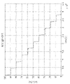
時間の関数として計算されている、充電状態SOCは、図6に示される。 The state of charge SOC, calculated as a function of time, is shown in FIG.
その後、負荷なし電圧Vocも、時間の関数として計算される。この目的を達成するために、観測窓Wiの最初と終わりの点は、電流がゼロであり、それゆえ、容量C1及びC2の端部の電圧が無視できると考慮できる、「変化しない」点であることに注目すべきである。それゆえ、そのような点において、負荷なし電圧Vocは、測定された電圧Vmと一致する。他の点において、負荷なし電圧Vocの計算は、前に推定された充電状態SOCの関数の線形補間として実行されることができる。 The no-load voltage Voc is then also calculated as a function of time. To this end, the points at the beginning and end of the observation window W i have zero current and can therefore be considered to have negligible voltages at the ends of the capacitances C 1 and C 2 , "not changing ” point. At such point, therefore, the no-load voltage Voc coincides with the measured voltage Vm. In other respects, the calculation of the no-load voltage Voc can be performed as a linear interpolation of the previously estimated state of charge SOC function.
時間の関数として計算された負荷なし電圧Vocは、図7に示される。 The calculated no-load voltage Voc as a function of time is shown in FIG.
前記情報に基づいて、負荷なし電圧Vocの関数として充電状態SOC、すなわち、図が図8に示されるSOC=f(Voc)、を計算することが可能である。 Based on said information, it is possible to calculate the state of charge SOC as a function of the no-load voltage Voc, ie SOC=f(Voc), the diagram of which is shown in FIG.
同様に、逆関数を負荷なし電圧Vocを充電状態SOCと結び付けて、すなわち図が図9に示されるVoc=f-1(SOC)で得ることができる。 Similarly, an inverse function can be obtained combining the no-load voltage Voc with the state of charge SOC, ie Voc=f −1 (SOC), the diagram of which is shown in FIG.
VocとSOCの関係を参照して、第iの観測窓Wiが設定された時点で、次の関係が、有効である。 With reference to the relationship between Voc and SOC, the following relationship is valid when the i -th observation window Wi is set.

ここで、下付文字1及び2は、それぞれ時間観測窓の最初及び終わりの点を示す。より小さいΔSOC=SOC2-SOC1はそのような近似関係をより正確にする。
where
現時点で、残っている回路パラメータ(R0、R1、R2、C1、C2)を得ることができる:それぞれの観測窓Wiにおいて、モデルは、それぞれ測定された電流Imiで促され、前記5つの回路パラメータの組み合わせが、測定された電圧Vmとモデルによって推定された電圧VABの誤差を最小化するように、決定される。 We can now obtain the remaining circuit parameters (R 0 , R 1 , R 2 , C 1 , C 2 ): In each observation window W i , the model is prompted with each measured current Im i and a combination of the five circuit parameters is determined to minimize the error between the measured voltage Vm and the voltage VAB estimated by the model.
そのような誤差の最小化プロセスの終わりに、推定された電圧VABは、図10(図のスケールにおいて、2つの電圧は、実際には区別ができない)に示されるように、測定された特性評価電圧Vmを高い精度で、再現する。 At the end of such an error minimization process, the estimated voltage V AB is the measured characteristic To reproduce the evaluation voltage Vm with high accuracy.
特性評価温度Tk(特定の場合において、28℃)についての処理手順の終わりに、モデルのすべてのパラメータは、図11の図に示されるように、充電状態SOCの関数として得られる。 At the end of the procedure for the characterization temperature T k (28° C. in the particular case), all parameters of the model are obtained as a function of the state of charge SOC, as shown in the diagram of FIG.
処理手順は複数の特性評価温度Tkで反復される。理想的には、手順は、いくつもの温度値で実行されることができる。 The procedure is repeated at multiple characterization temperatures Tk . Ideally, the procedure can be performed at any number of temperature values.
全手順の終わりに、それゆえ、バッテリパックまたはセルのモデルの回路パラメータのそれぞれの値は、充電状態SOCの値の関数として、及び異なる動作温度値の関数として入手可能である。 At the end of the whole procedure, the respective values of the circuit parameters of the battery pack or cell model are therefore available as a function of the value of the state of charge SOC and as a function of the different operating temperature values.
処理手順の結果は、「ルックアップテーブル」の形で、集められ、保存することができる。 The results of the procedure can be collected and stored in the form of "lookup tables".
実際には、方法の実施形態によると、処理はさらに電子保存手段(動作条件でバッテリパックまたはセルにアクセス可能な)に、入力として温度と充電状態を受け取り、出力としてパラメータPのそれぞれの値を提供するように構成された、ルックアップテーブルとして、バッテリパックまたはセルの動作モデルのパラメータPを保存するステップを備える。 In fact, according to an embodiment of the method, the processing further receives the temperature and the state of charge as inputs and the respective values of the parameter P as outputs in electronic storage means (accessible to the battery pack or cells under operating conditions). Storing the parameters P of the battery pack or cell operating model as a lookup table, adapted to provide.
そのような場合において、方法の実施形態によると、バッテリパックまたはセルの動作電流を推定するステップは、前記保存されたルックアップテーブルにアクセスするように構成され、入力として、バッテリパックまたはセルに組み込まれたそれぞれのセンサから生じる測定された動作電圧Vと動作温度T値を受け取るように構成された、バッテリパックまたはセルに関連する電子プロセッサによって、実行される。 In such a case, according to a method embodiment, the step of estimating the operating current of the battery pack or cell is configured to access said stored look-up table and, as an input, the battery pack or cell's built-in by an electronic processor associated with the battery pack or cell configured to receive the measured operating voltage V and operating temperature T values resulting from the respective sensors.
本明細書において、バッテリパックまたはセルの特性評価データを取得するステップは、広い意味で、限定されない実施例を手段として、ここから下記で記載される実施形態に記載されているそれらを含む、多くの異なる方法で実行されることができる、前の特性を評価する段階に続いて、そのようなデータを利用可能にするように、理解されるに違いない。 As used herein, the step of obtaining battery pack or cell characterization data is broadly defined, by way of non-limiting example, including those described in the embodiments described here below, as well as many It should be understood that making such data available subsequent to the previous characterization step can be performed in different ways.
方法の可能な実施形態において、バッテリパックまたはセルの特性評価データを取得するステップは、動作条件下でバッテリパックまたはセルを使用する前に、それぞれの特性評価温度Tk値における、バッテリパックまたはセルの特性評価電圧Vm及び特性評価電流Imの時間的傾向を測定することを備える。 In a possible embodiment of the method, the step of obtaining battery pack or cell characterization data includes testing the battery pack or cell at the respective characterization temperature T k value prior to using the battery pack or cell under operating conditions. measuring the temporal trend of the characterization voltage Vm and the characterization current Im of the .
方法の別の可能な実施形態において、バッテリパックまたはセルの特性評価データを取得するステップは、バッテリパックまたはセルの動作条件下で使用する前に、実行される特性を評価する手順で特性評価データを取得することを備える。 In another possible embodiment of the method, the step of obtaining battery pack or cell characterization data is a characterization procedure performed prior to use of the battery pack or cell under operating conditions. provided to obtain
方法のさらなる可能な実施形態において、特性評価データを取得するステップは、バッテリパックまたはセルの入手可能なデータシートから特性評価データを導き出すことを備える。 In a further possible embodiment of the method, obtaining the characterization data comprises deriving the characterization data from available datasheets of the battery pack or cell.
バッテリパックまたはセルの動作モデルのパラメータが、前に記載されたように、バッテリまたはセルの温度と充電状態の両方を考慮して、決定されると、バッテリパックまたはセルの動作電流Iを推定することが可能である。 Once the parameters of the operating model of the battery pack or cell are determined, as previously described, taking into account both the temperature and state of charge of the battery or cell, the operating current I of the battery pack or cell is estimated. It is possible.
これは、例えば、次の方程式(5)に基づいて、なされることができる。 This can be done, for example, based on equation (5) below.

ここで、 here,

反復法の、次のステージ(ステップ:Ts)を離散化することで、次の式が得られる。 By discretizing the next stage (step: T s ) of the iterative method, the following equation is obtained.


ここで、下付文字OLDをつけて、反復法の前のステージTsから得られたI、IR1、IR2、C1、C2、R1及びR2の値が示される。 Here, with the subscript OLD , the values of I, I R1 , I R2 , C 1 , C 2 , R 1 and R 2 obtained from the previous stage T s of the iterative method are indicated.
方法の前に記載された実施形態は、適当な方法で、いかなる動作条件でも、そのような電流を直接検知する必要なく、バッテリパックまたはセルの電流の信頼性のある推定を得るように、バッテリパックまたはセルの充電状態及び動作温度を考慮することができる。 The previously described embodiments of the method provide a battery pack or cell current in a suitable manner to obtain a reliable estimate of battery pack or cell current at any operating condition without the need to directly sense such current. Pack or cell state of charge and operating temperature can be considered.
電流の実際の値からの推定の狂いのさらなる原因は、バッテリまたはセル及びその構成要素の劣化及び/または経年劣化に由来することがかもしれない。 A further source of deviations in estimation from the actual value of current may come from deterioration and/or aging of the battery or cell and its components.
実際には、回路モデルのパラメータが、バッテリまたはセルが新しいか特性を評価することが実行されたときのものである場合有効である。充電状態と温度のそのようなパラメータの依存は、バッテリまたはセルの劣化により、徐々に変化する。それゆえ、厳しく言うと、特性を評価することは、バッテリパックまたはセルがハイブリッドまたは電気自動車に取り付けられた後、これは簡単ではなく、または、実現可能ではないが、周期的に実行されるべきである。 In practice, it is useful if the parameters of the circuit model are as they were when the battery or cell was new or the characterization was performed. The dependence of such parameters on state of charge and temperature changes over time as the battery or cell ages. Therefore, strictly speaking, characterization should be performed periodically after a battery pack or cell is installed in a hybrid or electric vehicle, although this is not easy or feasible. is.
そのような態様に対処し、及び経年劣化及び劣化に関連する要因も考慮して、モデルのパラメータを正しく推定しようとするために、方法のさらなる実施形態は、続くさらなるステップを提供する。 To address such aspects, and to attempt to correctly estimate the parameters of the model, also taking into account factors related to aging and degradation, further embodiments of the method provide further steps to follow.
第1に、バッテリパックまたはセルの熱的モデルが、前述の動作モデルに追加して、定義される。 First, a thermal model of the battery pack or cell is defined in addition to the operational model described above.
その後、少なくとも1つの測定時間間隔(t0-t1)において、消散した電力Peを、バッテリパックまたはバッテリセルの電圧Vと温度Tcの前記間隔(t0-t1)で測定された値に基づいて、及びバッテリパックまたはバッテリセルの前記温度Tcにおいて推定されるパラメータPに基づいて、バッテリパックまたはセルの動作モデルによって推定する。 Thereafter, in at least one measurement time interval (t 0 -t 1 ), the dissipated power P e was measured at said interval (t 0 -t 1 ) of the voltage V and the temperature T c of the battery pack or battery cell. value and based on the parameter P estimated at said temperature Tc of the battery pack or battery cell, estimated by the operating model of the battery pack or cell.
さらに、同じ測定時間間隔(t0-t1)において、消散した熱出力Pdを、バッテリパックまたはバッテリセルの温度Tcの前記値に基づいて、及び前記間隔(t0-t1)で測定された環境温度Te値に基づいて、及びバッテリパックまたはバッテリセルの温度Tcにおいて推定されるパラメータPに基づいて、バッテリパックまたはセルの熱的モデルによって推定する。 Furthermore, in the same measurement time interval (t 0 -t 1 ), the dissipated thermal power P d is calculated based on said value of battery pack or battery cell temperature T c and in said interval (t 0 -t 1 ) Estimated by a thermal model of the battery pack or cell based on the measured ambient temperature T e value and based on the parameter P estimated at the battery pack or battery cell temperature T c .
その後、前に推定された消散した電力Peと消散した熱出力Pdの差ΔPを決定するためのステップを実行する。 A step is then performed to determine the difference ΔP between the previously estimated dissipated power P e and the dissipated thermal power P d .
最終的に、そのような劣化及び/または経年劣化の現象を考慮するために、パラメータPの更新値を得るように、前記推定された差ΔPに基づいてパラメータPを、修正する。 Finally, the parameter P is modified based on the estimated difference ΔP so as to obtain an updated value of the parameter P to take account of such degradation and/or aging phenomena.
方法の実施形態によると、バッテリパックまたはセルの熱的モデルは、それぞれの熱的セルモデルが、熱的セル容量CT、熱的セル抵抗RT、セル温度Tc及び環境温度Teによって特性評価される、1以上の熱的セルモデルから成り立って使われる。 According to a method embodiment, a thermal model of a battery pack or cell, each thermal cell model is characterized by a thermal cell capacity C T , a thermal cell resistance R T , a cell temperature T c and an ambient temperature T e . Used to consist of one or more thermal cell models to be evaluated.
熱的セル容量CT及び熱的セル抵抗RTパラメータは、セル及びバッテリパックまたはセルの特定の形態に特有である。 The thermal cell capacity C T and thermal cell resistance R T parameters are specific to the particular configuration of cells and battery packs or cells.
特に、方法に使われる熱的モデルの実施例は、例えば、図式的に図12に示されるものなど、1次熱的モデルである。 In particular, an example of a thermal model used in the method is a first order thermal model, such as that schematically shown in FIG.
そのような熱的モデルによると、次の関係(6)が有効である。 According to such a thermal model, the following relationship (6) is valid.

ここで、パラメータの意味するものは、すでに上記に記載されている。 Here, what is meant by the parameters has already been described above.
時間間隔(t0-t1)で消散した熱エネルギETは次の式(7)によって計算されることができる。 The thermal energy E T dissipated in the time interval (t 0 -t 1 ) can be calculated by the following equation (7).

現時点で、与えられた時間間隔で消散したエネルギ及び/または熱及び電力を利用可能に有するので、パラメータの値は更新されることができる。 Since we now have available energy and/or heat and power dissipated in a given time interval, the value of the parameter can be updated.
特に、図13のブロック図で示される実施形態によって、モデルパラメータを修正する前記ステップは、前に記載されたように、劣化を除外して決定される値から始まる、内部抵抗R0パラメータの修正を備える。 In particular, according to the embodiment illustrated in the block diagram of FIG. 13, said step of modifying the model parameters consists of modifying the internal resistance R0 parameter starting from the value determined excluding degradation as previously described. Prepare.
この目的を達成するために、修正因子Gが、推定された電力と推定された熱出力の差ΔPに基づいて、決定される。その後、劣化を除外して有効な、バッテリまたはセルの内部抵抗R0値は、バッテリまたはセルの内部抵抗R0の更新された推定を得るために、前記修正因子Gで乗じられる。 To this end, a correction factor G is determined based on the difference ΔP between the estimated power and the estimated heat output. The battery or cell internal resistance R 0 value, valid excluding degradation, is then multiplied by said correction factor G to obtain an updated estimate of the battery or cell internal resistance R 0 .
その後、内部抵抗R0の更新された推定に基づいて、電力Peを再計算し、その後、差ΔPがあらかじめ決められたしきい値未満に減らされるまで、決定することと、乗じることと、再計算する前記ステップを繰り返すステップが提供される。最終的に、前記反復法の終わりにおいて得られる更新された推定は、バッテリまたはセルの内部抵抗R0値として考えられる。 then recalculating the power P e based on the updated estimate of the internal resistance R 0 and then determining and multiplying until the difference ΔP is reduced below a predetermined threshold; A step of repeating the above steps of recalculating is provided. Finally, the updated estimate obtained at the end of the iterative method is taken as the internal resistance R0 value of the battery or cell.
また、劣化及び/または経年劣化の存在するバッテリまたはセルの電気動作パラメータを推定においても、目的とされる方法の代替の実施形態は、動作条件下でバッテリパックまたはセルを使う前に、異なる温度値と使用の時間に応じたバッテリまたはセルの内部抵抗R0の値の変化の特性評価をし、バッテリまたはセルの内部抵抗の特性評価データを保存するステップを備える。 Also in estimating the electrical operating parameters of a battery or cell in the presence of deterioration and/or aging, an alternative embodiment of the method contemplated is to perform different temperature measurements prior to using the battery pack or cell under operating conditions. characterizing changes in the value of the internal resistance R0 of the battery or cell as a function of value and time of use; and storing the characterization data of the internal resistance of the battery or cell.
さらに、方法が、バッテリパックまたはセルの動作条件下で適用されたとき、バッテリまたはセルの内部抵抗R0の修正された値は、バッテリパックまたはセルの実際の使用の経過時間を考慮して、バッテリまたはセルの内部抵抗R0の前記特性評価データによって、用いられる。 Moreover, when the method is applied under the operating conditions of the battery pack or cell, the corrected value of the internal resistance R0 of the battery or cell takes into account the elapsed time of actual use of the battery pack or cell, Used by said characterization data of the internal resistance R0 of the battery or cell.
本発明は、また、バッテリパックまたはセルの充電状態SOCを推定する方法を備える。そのような方法は、上記で記載された実施形態のいずれか1つによって、バッテリパックまたはセルの動作時間に沿って、バッテリパックまたはセルによって分配される動作電流Iを推定するステップを備える。その後、バッテリパックまたはセルの動作開始の瞬間から現在の瞬間まで、動作する、動作電流Iの推定された時間的傾向に基づく、最初の充電状態SOC0からバッテリパックまたはセルの充電状態SOCを推定する方法が提供される。 The invention also comprises a method of estimating the state of charge SOC of a battery pack or cell. Such a method comprises estimating the operating current I distributed by the battery pack or cell along the operating time of the battery pack or cell according to any one of the embodiments described above. then estimate the state of charge SOC of the battery pack or cell from the initial state of charge SOC 0 based on the estimated temporal trend of the operating current I, operating from the moment the battery pack or cell starts operating to the current moment; A method is provided.
特に、実施形態によると、前述の式はこの目的において使われることができる(4)。 In particular, according to embodiments, the above formula can be used for this purpose (4).

そのような方法は、比較が、物理センサによって、取得される電流を測定することによって推定される充電状態SOCImisと、物理電流センサを除外して、この方法に基づいて推定される充電状態SOCIestの間でなされる、図14の実施例を手段として示されるように、3%と同じかそれより低い誤差で、充電状態を正確に推定することができる。 Such a method compares the state of charge SOC Imis estimated by measuring the current obtained by a physical sensor and the state of charge SOC Imis estimated based on this method excluding the physical current sensor. State of charge can be accurately estimated with an error as low as or less than 3%, as shown by way of example in FIG. 14, done during Iest .
図15において、比較は、測定された電流Imisと本発明の方法によって推定されたように推定された電流Iestでなされる。注目されることができるように、5%と同じかそれより低い、高い正確性が得られる。 In FIG. 15 a comparison is made between the measured current I mis and the estimated current I est as estimated by the method of the present invention. As can be noted, high accuracies equal to or less than 5% are obtained.
本発明は、さらに一体化された電流センサを除外しても、バッテリパックまたはセルを制御するように構成されたバッテリパックまたはセル制御装置を備え、装置は、バッテリパックまたはセルの測定された動作電圧V値及びバッテリパックまたはセルの測定された動作温度T値を受け取るように構成されている。 The present invention further comprises a battery pack or cell controller configured to control a battery pack or cell, even excluding an integrated current sensor, wherein the device measures the measured operation of the battery pack or cell. It is configured to receive a voltage V value and a measured operating temperature T value of the battery pack or cell.
装置は、上記に記載された実施形態のいずれかによって、バッテリパックまたはセルの動作電流Iを推定する方法を実行、及び/または上記に記載された実施形態のいずれか1つによって、バッテリパックまたはセルの充電状態SOCを推定する方法を実行するように構成された電子処理手段を備える。 The apparatus performs a method for estimating the operating current I of a battery pack or cell according to any of the above described embodiments and/or according to any one of the above described embodiments a battery pack or It comprises electronic processing means adapted to perform the method of estimating the state of charge SOC of the cell.
本発明は、さらに、一体化された電流センサを備えることなく、動作するように構成されたバッテリパックまたはセルを備える。 The invention further comprises battery packs or cells configured to operate without an integrated current sensor.
バッテリパックまたはセルは、バッテリパックまたはセルの動作電圧Vを検知するように構成された、電圧センサ、バッテリパックまたはセルの動作温度Tを検知するように構成された、温度センサ、前に記載されたものによる制御装置を備える。 The battery pack or cells may include a voltage sensor configured to sense the operating voltage V of the battery pack or cells, a temperature sensor configured to sense the operating temperature T of the battery pack or cells, a temperature sensor as previously described. Equipped with a control device by
注目されることができるように、本発明の目的は、記載された推定する方法によって、そのそれぞれの動作特徴の長所によって、完全に達成される。 As can be remarked, the objects of the invention are fully achieved by the described estimating method by virtue of its respective operating characteristics.
実際には、バッテリまたはセルの電流及びバッテリまたはセルの充電状態を推定する方法は、適切なセンサによって、バッテリまたはセルの電流を直接取得する必要なく、バッテリまたはセルの電圧及び温度のみを「オンライン」での取得(すなわち、バッテリまたはセルは動作条件下である間)に基づく。 In practice, the methods of estimating battery or cell current and battery or cell state of charge rely on a suitable sensor to measure only battery or cell voltage and temperature "on-line" without the need to obtain battery or cell current directly. ” (ie, while the battery or cell is under operating conditions).
これは、さらに、複雑さとコストを減らすことに関して、明らかな利点を導き出すバッテリパックまたはセルから電流センサを排除する(並びに対応する配線、電流信号を取得するハードウェアシステム及び関連のあるソフトウェア管理も排除する)ことが可能である。 This further eliminates the current sensor from the battery pack or cell (as well as the corresponding wiring, the hardware system that acquires the current signal and the associated software management) which yields distinct advantages in terms of reducing complexity and cost. to).
本方法が物理電流センサの存在下で用いられたとしても、電流の追加の間接の推定を得る方法を提供すること、この方法の使用は、ついでの利益として、安全の観点から有益な、合同性または妥当性の推定をする可能性をどちらにせよ提供するであろうことは注目すべきである(ISO26262規格)。 Even if the method is used in the presence of a physical current sensor, providing a way to obtain an additional indirect estimate of the current, the use of this method is, as an incidental benefit, beneficial from a safety point of view. It should be noted that it would either provide the possibility to make an inference of validity or validity (ISO 26262 standard).
さらに、前に詳細に記載されているように、バッテリまたはセルの電流及びバッテリまたはセルの充電状態を推定する方法は、実用的に、効果的に用いられるように、十分正確な推定を得ることができる。特に、記載された方法は、5%より低い誤差でバッテリパックまたはセルを流れる瞬間電流を推定し、3%より低い誤差で充電状態を推定することができる。 Furthermore, as described in detail above, methods for estimating battery or cell current and battery or cell state of charge should yield sufficiently accurate estimates to be effectively used in practice. can be done. In particular, the described method can estimate the instantaneous current through a battery pack or cell with an error of less than 5% and the state of charge with an error of less than 3%.
同様な利点を、前記推定方法を実行する、本発明による制御装置、並びに装置及び制御システムを使って、電流センサのなくてもよい、そのような推定方法から利益を得る、本発明によるバッテリパックまたはセルを参照して特定することができる。 A battery pack according to the invention, benefiting from such an estimation method, which can be without current sensors, using the control device according to the invention and the device and the control system for carrying out said estimation method with similar advantages. Alternatively, it can be specified by referring to the cell.
当業者は、付随する要求を満足するために、続く請求項の範囲から逸脱することなく、上記に記載された電流を推定する方法、充電状態を推定する方法、制御装置及びバッテリパックまたはセルの実施形態の他の機能的な均等物に、要素を改良し、適合し、置き換えることができる。 Those skilled in the art will be able to implement the methods of estimating current, estimating state of charge, controllers and battery packs or cells described above without departing from the scope of the following claims to satisfy the attendant needs. Elements may be modified, adapted, or replaced with other functional equivalents of the embodiments.
可能な実施形態に付属するように記載された特徴のそれぞれは、記載された他の実施形態から独立に達成されることができる。用語「備える」(comprising)は、他の要素またはステップを排除することがなく、用語「1つの」(a)または「1つの」(one)は複数を排除することがないことも留意すべきである。より明確に説明するために、さまざまな部分に適切なハイライトをする要求を許容するので、図はノンスケールで描かれている。 Each of the features described as being associated with possible embodiments can be achieved independently of other described embodiments. It should also be noted that the term "comprising" does not exclude other elements or steps, and the terms "a" or "one" do not exclude a plurality. is. The figures are drawn non-scale to allow for the need to properly highlight the various parts for a more clear illustration.
Claims (17)
-前記バッテリパックまたはセルの特性評価電圧(Vm)及び特性評価電流(Im)の測定された時間的傾向に関連する、前記バッテリパックまたはセルの特性評価データを取得するステップであって、それぞれの時間的傾向は、複数の特性評価温度値(Tk)のそれぞれの値に関連する、特性評価データを取得するステップと、
-前記バッテリパックまたはセルの、温度及び充電状態「state of charge」(SOC)に応じて、前記バッテリパックまたはセルの動作モデルの複数のパラメータ(P)を決定するために前記特性評価データを処理するステップと、
-前記バッテリパックまたはセルが動作条件下にある間に、前記バッテリパックまたはセルの動作電圧(V)及び動作温度(T)を測定するステップと、
-測定された前記動作電圧(V)、測定された前記動作温度(T)及び複数の前記パラメータ(P)に基づく、前記動作モデルによって、前記バッテリパックまたはセルの動作電流(I)を推定するステップと、を備え、
前記処理するステップは、複数の前記特性評価温度値(Tk)のそれぞれの値のために実行される、次のステージ、
-前記特性評価温度値(Tk)に関連する前記特性評価電圧(Vm)及び前記特性評価電流(Im)のそれぞれの時間的傾向に沿って複数の時間観測窓(Wi)を特定し、それぞれの特性評価電流(Imi)及び特性評価電圧(Vmi)値を検知するステップと、
-それぞれの観測窓(Wi)において、前記バッテリパックまたはセルの充電状態(SOCi)のそれぞれの値を計算するステップと、
-それぞれの前記観測窓(Wi)において、前記パラメータ(P)のそれぞれの名目上の値に応じた、前記バッテリパックまたはセルの動作モデルによって、それぞれの推定した電圧(VABi)を計算し、時間観測窓(Wi)の推定された電圧(VABi)と特性評価電圧(Vmi)の間の差に依存するそれぞれの誤差関数(Ei)を決定するステップと、
-それぞれの観測窓(Wi)において、前記誤差関数(Ei)を最小化することによって、前記バッテリパックまたはセルのモデルの複数の前記パラメータ(P)のそれぞれについての実際の値(Pi)を計算するステップと、
-前記バッテリパックまたはセルの温度と充電状態に応じた複数の前記パラメータ(P)を得るために、それぞれの前記充電状態(SOCi)及び前記特性評価温度値(Tk)と、前記観測窓(Wi)において計算される、パラメータの前記実際の値(Pi)を関連付けるステップと、
-前記バッテリパックまたはセルの熱的モデルを定義するステップと、
-少なくとも1つの測定時間間隔において、前記測定時間間隔で測定される前記バッテリパックまたはバッテリセルの前記動作電圧(V)及び前記動作温度(T)の値に基づいて、及び前記バッテリパックまたはバッテリセルの前記動作温度(T)に対応する前記パラメータ(P)に基づいて、前記バッテリパックまたはセルの動作モデルによって、消散した電力(P e )を推定するステップと、
-前記バッテリパックまたは前記バッテリセルの前記動作温度(T)に基づいて、及び環境温度値(T e )に基づいて、ここで両方の温度値は、前記測定時間間隔で測定され、及び前記バッテリパックまたは前記バッテリセルの前記動作温度(T)に対応する前記パラメータ(P)に基づいて、前記バッテリパックまたはセルの熱的モデルによって、消散した熱出力(P d )を推定するステップと、
-推定された、前記消散した電力(P e )と前記消散した熱出力(P d )の差(ΔP)を決定するステップと、
-劣化及び/または経年劣化現象を考慮する前記パラメータ(P)の訂正した値を得るように、前記推定した差(ΔP)によって、前記パラメータを訂正するステップと、を備える方法。 A method of estimating the operating current (I) delivered by a battery pack or cell, comprising:
- obtaining characterization data of said battery pack or cell relating to the measured temporal trend of the characterization voltage (Vm) and characterization current (Im) of said battery pack or cell, each obtaining characterization data wherein the temporal trends are associated with respective values of a plurality of characterization temperature values (T k );
- processing said characterization data to determine a plurality of parameters (P) of an operating model of said battery pack or cell depending on temperature and state of charge (SOC) of said battery pack or cell; and
- measuring the operating voltage (V) and operating temperature (T) of said battery pack or cell while said battery pack or cell is under operating conditions;
- estimating the operating current (I) of the battery pack or cell by means of the operating model based on the measured operating voltage (V), the measured operating temperature (T) and a plurality of the parameters (P); comprising a step and
said processing step being performed for each of a plurality of said characterization temperature values (T k ), in the following stages:
- identifying a plurality of time observation windows (W i ) along the respective temporal trend of the characterization voltage (Vm) and the characterization current (Im) associated with the characterization temperature value (T k ); sensing respective characterization current (Im i ) and characterization voltage (Vm i ) values;
- calculating respective values of the state of charge (SOC i ) of said battery pack or cell in each observation window (W i );
- in each said observation window (W i ), calculating each estimated voltage (V ABi ) by means of an operating model of said battery pack or cell according to each nominal value of said parameter (P); , determining a respective error function (E i ) dependent on the difference between the estimated voltage (V ABi ) and the characterized voltage (Vm i ) of the time observation window (W i );
- in each observation window (W i ) , the actual values (P i ), and
- each said state of charge (SOC i ) and said characterization temperature value (T k ) and said observation window to obtain a plurality of said parameters (P) depending on the temperature and state of charge of said battery pack or cell; associating said actual values (P i ) of parameters calculated at (W i );
- defining a thermal model of said battery pack or cell;
- in at least one measurement time interval, based on the values of said operating voltage (V) and said operating temperature (T) of said battery pack or battery cell measured in said measuring time interval, and said battery pack or battery cell; estimating the power dissipated (P e ) by an operating model of the battery pack or cell based on the parameter (P) corresponding to the operating temperature (T) of
- based on said operating temperature (T) of said battery pack or said battery cell and based on an ambient temperature value (T e ), where both temperature values are measured at said measurement time interval and said battery estimating the dissipated thermal power (P d ) by a thermal model of the battery pack or cell based on the parameter (P) corresponding to the operating temperature (T) of the pack or the battery cell ;
- determining the difference (ΔP) between the estimated power dissipated (P e ) and the thermal power dissipated (P d );
- correcting said parameter by said estimated difference (ΔP) so as to obtain a corrected value of said parameter (P) taking into account degradation and/or aging phenomena .
-それぞれの前記観測窓(Wi)において、前記バッテリパックまたはセルのそれぞれの負荷なし電圧(Voci)値を決定するステップと、
-前記観測窓(Wi)で得られた複数の前記負荷なし電圧(Voci)及び前記充電状態(SOCi)値に基づいて、前記バッテリパックまたはセルの負荷なし電圧(Voc)及び前記充電状態(SOC)の関係を定義するステップと、を備え、
それぞれの前記観測窓(Wi)において、パラメータの前記実際の値(Pi)を計算するステップは、それぞれの前記負荷なし電圧(Voci)値と、前記バッテリパックまたはセルの前記負荷なし電圧(Voc)及び前記充電状態(SOC)の前記関係も考慮する、請求項2に記載の方法。 Furthermore ,
- determining respective no-load voltage (Voc i ) values of said battery packs or cells in each said observation window (W i );
- the no-load voltage (Voc) and the charge of the battery pack or cell based on a plurality of the no-load voltage (Voc i ) and the state of charge (SOC i ) values obtained over the observation window (W i ); defining a state (SOC) relationship;
In each said observation window (W i ), the step of calculating said actual value (P i ) of a parameter comprises: each said no-load voltage (Voc i ) value and said no-load voltage of said battery pack or cell; 3. The method of claim 2, wherein the relationship between (Voc) and the state of charge (SOC) is also considered.
-前記特性評価電流の時間的傾向に基づいて、前記バッテリパックまたはセルの前記充電状態(SOCi)のそれぞれの値を計算する、請求項1乃至4のいずれか1項に記載の方法。 calculating respective values of the state of charge (SOC i ) of the battery pack or cell, comprising:
5. A method according to any one of claims 1 to 4, wherein the respective values of the state of charge (SOC i ) of the battery pack or cell are calculated based on the temporal trend of the characterizing current.
回路パラメータPのグループは、前記負荷なし電圧(Voc)、前記バッテリまたはセルの前記内部抵抗(R0)、1以上の回路グループ抵抗(R1、R2)、及び1以上の回路グループ容量(C1、C2)を備える、請求項2乃至5のいずれか1項に記載の方法。 The electrical circuit model of the battery pack or cell comprises a no load voltage (Voc) generator, an internal resistance (R 0 ) of the battery or cell and one or more circuit groups in series, each with a respective circuit group resistance and with a parallel of the respective circuit group capacitances,
A group of circuit parameters P includes the no -load voltage (Voc), the internal resistance (R 0 ) of the battery or cell, one or more circuit group resistances (R 1 , R 2 ), and one or more circuit group capacitances (R 1 , R 2 ). C1 , C2 ).
前記複数の前記パラメータ(P)を決定するステップは、取得される前記バッテリパックまたはセルの特性評価データによる予測アルゴリズムを訓練するステップを備える、請求項1に記載の方法。 the battery pack or cell behavior model comprises a trained prediction algorithm, the parameter (P) being a parameter of the trained prediction algorithm;
2. The method of claim 1, wherein determining the plurality of parameters (P) comprises training a prediction algorithm with obtained battery pack or cell characterization data.
-動作条件下で前記バッテリパックまたはセルを使う前に、それぞれの前記特性評価温度値(Tk)値において、前記バッテリパックまたはセルの前記特性評価電圧(Vm)の及び前記特性評価電流(Im)の時間的傾向を測定するステップ、または、
-前記バッテリパックまたはセルの動作条件下の使用の前に実行される特性評価手順から前記特性評価データを取得するステップ、を備える請求項1乃至8のいずれか1項に記載の方法。 Obtaining the characterization data of the battery pack or cell comprises:
of the characterized voltage (Vm) and the characterized current (Im) of the battery pack or cell at each of the characterized temperature values (T k ) before using the battery pack or cell under operating conditions; ), or
- obtaining the characterization data from a characterization procedure performed prior to use of the battery pack or cell under operating conditions.
-動作条件下の前記バッテリパックまたはセルを容易に利用できる電気保存手段で、入力として、温度と充電状態値を受け取り、前記パラメータ(P)のそれぞれの値を提供するように構成されたルックアップテーブルとして、前記バッテリパックまたはセルの動作モデルの前記パラメータ(P)を保存するステップ、を備える請求項1乃至9のいずれか1項に記載の方法。 The step of processing further comprises:
- an electrical storage means readily available to said battery pack or cell under operating conditions, receiving as inputs temperature and state of charge values and a lookup adapted to provide respective values of said parameters (P); 10. A method according to any one of the preceding claims, comprising storing the parameters (P) of the battery pack or cell operating model as a table.
それぞれの前記熱的セルモデルは、熱的セル容量(CT)、熱的セル抵抗(RT)、セル温度(Tc)及び環境温度(Te)によって特性評価される、請求項1乃至11のいずれか1項に記載の方法。
1に記載の方法。 the battery pack or cell thermal model comprises one or more thermal cell models;
3. Each of the thermal cell models is characterized by a thermal cell capacity (C T ), a thermal cell resistance (R T ), a cell temperature (T c ) and an ambient temperature (T e ). 12. The method of any one of 11 .
1. The method according to 1.
-電力と熱出力の差(ΔP)により、訂正因子(G)を決定するステップと、
-前記バッテリまたはセルの前記内部抵抗(R0)の更新された推定を得るために、前記訂正因子(G)を、前記内部抵抗(R0)の値に乗じるステップと、
-前記バッテリまたはセルの前記内部抵抗(R0)の更新された推定により、電力(Pe)を再計算するステップと、
-前記差(ΔP)があらかじめ決められたしきい値以下に減るまで、決定するステップ、乗じるステップ、及び再計算するステップを反復するステップと、
-前記反復の終わりに得られた更新された推定を前記バッテリまたはセルの内部抵抗(R0)値と見なすステップと、を備える請求項1乃至12のいずれか1項に記載の方法。 The correcting step includes:
- determining a correction factor (G) by the difference between power and heat output (ΔP);
- multiplying the value of said internal resistance (R 0 ) by said correction factor (G) to obtain an updated estimate of said internal resistance (R 0 ) of said battery or cell;
- recalculating the power (P e ) with an updated estimate of the internal resistance (R 0 ) of the battery or cell;
- repeating the steps of determining, multiplying and recalculating until said difference (ΔP) is reduced below a predetermined threshold;
- taking the updated estimate obtained at the end of said iteration as the internal resistance (R 0 ) value of said battery or cell.
-動作条件下で前記バッテリパックまたはセルを使用する前に、異なる温度値及び使用時間に応じて、前記バッテリまたはセルの前記内部抵抗(R0)の値の変化の特性を評価するステップと、
-前記内部抵抗の前記特性評価データを保存するステップと、
-方法が適用されたとき、前記バッテリパックまたはセルの動作条件下で、前記バッテリパックまたはセルの実際の使用の経過時間を考慮して、前記バッテリまたはセルの前記内部抵抗(R0)の前記特性評価データによって、前記バッテリまたはセルの前記内部抵抗(R0)の訂正値を使用するステップと、を備える請求項6に記載の方法。 moreover,
characterizing the change in the value of the internal resistance (R 0 ) of the battery or cell according to different temperature values and times of use before using the battery pack or cell under operating conditions;
- storing said characterization data of said internal resistance;
- when the method is applied, said internal resistance (R 0 ) of said battery or cell under operating conditions of said battery pack or cell, taking into account the elapsed time of actual use of said battery pack or cell; using a corrected value of the internal resistance (R 0 ) of the battery or cell according to characterization data.
-請求項1乃至14のいずれか1項に記載の、前記バッテリパックまたはセルの動作時間に沿って、前記バッテリパックまたはセルにより分配される前記動作電流(I)を推定するステップと、
-前記バッテリパックまたはセルの動作開始時から現在時まで動作する、前記動作電流(I)の推定された時間的傾向に基づき、初期充電状態(SOC0)から前記バッテリパックまたはセルの前記充電状態(SOC)を推定するステップと、を備える方法。 A method of estimating the state of charge (SOC) of the battery pack or cell, comprising:
- estimating the operating current (I) distributed by the battery pack or cell along the operating time of the battery pack or cell according to any one of claims 1 to 14 ;
- from the initial state of charge (SOC 0 ) to the state of charge of the battery pack or cell, based on the estimated temporal trend of the operating current (I) operating from the start of operation of the battery pack or cell to the present time; estimating (SOC).
装置は、前記バッテリパックまたはセルの測定された動作電圧(V)値と前記バッテリパックまたはセルの測定された動作温度(T)値を受け取るように構成され、
装置は、請求項1乃至14のいずれか1項に記載された、前記バッテリパックまたはセルの前記動作電流(I)を推定する方法を実行する及び/または請求項15に記載された前記バッテリパックまたはセルの前記充電状態(SOC)を推定する方法を実行するように構成された電子処理手段を備える、バッテリパックまたはセル制御装置。 A control device for said battery pack or cell configured to control said battery pack or cell even with the exclusion of an integrated current sensor, comprising:
an apparatus configured to receive a measured operating voltage (V) value of said battery pack or cell and a measured operating temperature (T) value of said battery pack or cell;
A device for performing a method for estimating the operating current (I) of the battery pack or cell as claimed in any one of claims 1 to 14 and/or the battery pack as claimed in claim 15 . or a battery pack or cell controller comprising electronic processing means adapted to perform the method of estimating said state of charge (SOC) of a cell.
前記バッテリパックまたはセルの動作電圧(V)を検知するように構成された、電圧センサと、
前記バッテリパックまたはセルの動作温度(T)を検知するように構成された、温度センサと、
請求項16に記載の制御装置と、を備えるバッテリパックまたはセル。 A battery pack or cell configured to operate without an integrated current sensor,
a voltage sensor configured to sense an operating voltage (V) of the battery pack or cell;
a temperature sensor configured to sense an operating temperature (T) of the battery pack or cell;
17. A battery pack or cell comprising a control device according to claim 16 .
Applications Claiming Priority (2)
| Application Number | Priority Date | Filing Date | Title |
|---|---|---|---|
| IT102017000058171 | 2017-05-29 | ||
| IT102017000058171A IT201700058171A1 (en) | 2017-05-29 | 2017-05-29 | Method of estimating the current and state of charge of a battery pack or cell, without direct current detection in operating conditions |
Publications (3)
| Publication Number | Publication Date |
|---|---|
| JP2019032299A JP2019032299A (en) | 2019-02-28 |
| JP2019032299A5 JP2019032299A5 (en) | 2021-05-27 |
| JP7112252B2 true JP7112252B2 (en) | 2022-08-03 |
Family
ID=60294052
Family Applications (1)
| Application Number | Title | Priority Date | Filing Date |
|---|---|---|---|
| JP2018100345A Active JP7112252B2 (en) | 2017-05-29 | 2018-05-25 | A method for estimating the current and state of charge of a battery pack or cell without directly sensing the current under operating conditions |
Country Status (5)
| Country | Link |
|---|---|
| US (1) | US10649035B2 (en) |
| EP (1) | EP3410139B1 (en) |
| JP (1) | JP7112252B2 (en) |
| CN (1) | CN108931732B (en) |
| IT (1) | IT201700058171A1 (en) |
Families Citing this family (7)
| Publication number | Priority date | Publication date | Assignee | Title |
|---|---|---|---|---|
| CN114325395B (en) * | 2020-09-30 | 2024-01-26 | 北京昇科能源科技有限责任公司 | Battery state determining method and device |
| CN112462282B (en) * | 2020-11-09 | 2022-03-18 | 西南大学 | Method for determining real-time state of charge of battery pack based on mechanism model |
| WO2022116037A1 (en) * | 2020-12-02 | 2022-06-09 | 宁德新能源科技有限公司 | Battery life prediction method and device |
| CN113933725B (en) * | 2021-09-08 | 2023-09-12 | 深圳大学 | Method for determining state of charge of power battery based on data driving |
| CN113777505A (en) * | 2021-09-13 | 2021-12-10 | 深圳创维汽车智能有限公司 | Detection circuit and method for display screen battery |
| CN113884884B (en) * | 2021-10-21 | 2022-07-26 | 山东大学 | Power battery pack fault diagnosis method and system based on correlation |
| CN114264957A (en) * | 2021-12-02 | 2022-04-01 | 东软集团股份有限公司 | Abnormal monomer detection method and related equipment thereof |
Citations (4)
| Publication number | Priority date | Publication date | Assignee | Title |
|---|---|---|---|---|
| JP2009204320A (en) | 2008-02-26 | 2009-09-10 | Nissan Motor Co Ltd | Charge rate estimating device and charge rate estimating method for secondary cell |
| US20090295397A1 (en) | 2008-05-28 | 2009-12-03 | Texas Instruments Incorporated | Systems and Methods for Determining Battery Parameters Following Active Operation of the Battery |
| US20120143585A1 (en) | 2010-12-06 | 2012-06-07 | Yevgen Barsukov | System and method for sensing battery capacity |
| US20160124051A1 (en) | 2014-10-29 | 2016-05-05 | Texas Instruments Incorporated | Battery fuel gauge |
Family Cites Families (7)
| Publication number | Priority date | Publication date | Assignee | Title |
|---|---|---|---|---|
| JP4767558B2 (en) * | 2005-03-07 | 2011-09-07 | 日立ビークルエナジー株式会社 | Power supply state detection device, power supply device, and initial characteristic extraction device used for power supply device |
| US9678164B2 (en) * | 2010-03-23 | 2017-06-13 | Furukawa Electric Co., Ltd. | Battery internal state estimating apparatus and battery internal state estimating method |
| JP6033155B2 (en) * | 2013-03-29 | 2016-11-30 | 日立オートモティブシステムズ株式会社 | Battery control device |
| CN105452889B (en) * | 2013-05-23 | 2018-05-29 | 日立汽车系统株式会社 | Battery control device |
| CN103744030B (en) * | 2014-01-12 | 2016-06-01 | 中国科学院电工研究所 | Battery state-of-health and state-of-charge estimation on line device and evaluation method |
| WO2015188610A1 (en) * | 2014-06-11 | 2015-12-17 | 北京交通大学 | Method and device for estimating state of charge of battery |
| KR102399722B1 (en) * | 2014-12-29 | 2022-05-19 | 삼성전자주식회사 | Method and apparatus for estimating current |
-
2017
- 2017-05-29 IT IT102017000058171A patent/IT201700058171A1/en unknown
-
2018
- 2018-05-22 US US15/985,926 patent/US10649035B2/en active Active
- 2018-05-23 EP EP18173905.3A patent/EP3410139B1/en active Active
- 2018-05-25 JP JP2018100345A patent/JP7112252B2/en active Active
- 2018-05-29 CN CN201810535539.5A patent/CN108931732B/en active Active
Patent Citations (5)
| Publication number | Priority date | Publication date | Assignee | Title |
|---|---|---|---|---|
| JP2009204320A (en) | 2008-02-26 | 2009-09-10 | Nissan Motor Co Ltd | Charge rate estimating device and charge rate estimating method for secondary cell |
| US20090295397A1 (en) | 2008-05-28 | 2009-12-03 | Texas Instruments Incorporated | Systems and Methods for Determining Battery Parameters Following Active Operation of the Battery |
| US20120143585A1 (en) | 2010-12-06 | 2012-06-07 | Yevgen Barsukov | System and method for sensing battery capacity |
| JP2014505863A (en) | 2010-12-06 | 2014-03-06 | 日本テキサス・インスツルメンツ株式会社 | System and method for detecting battery capacity |
| US20160124051A1 (en) | 2014-10-29 | 2016-05-05 | Texas Instruments Incorporated | Battery fuel gauge |
Also Published As
| Publication number | Publication date |
|---|---|
| US10649035B2 (en) | 2020-05-12 |
| US20180340981A1 (en) | 2018-11-29 |
| CN108931732A (en) | 2018-12-04 |
| EP3410139A1 (en) | 2018-12-05 |
| EP3410139B1 (en) | 2019-12-11 |
| IT201700058171A1 (en) | 2018-11-29 |
| JP2019032299A (en) | 2019-02-28 |
| CN108931732B (en) | 2022-06-17 |
Similar Documents
| Publication | Publication Date | Title |
|---|---|---|
| JP7112252B2 (en) | A method for estimating the current and state of charge of a battery pack or cell without directly sensing the current under operating conditions | |
| KR102452548B1 (en) | Apparatus for determination battery degradation, system having the same and method thereof | |
| JP5058814B2 (en) | Battery state and parameter estimation system and method | |
| JP5944291B2 (en) | Battery parameter estimation apparatus and method | |
| Mastali et al. | Battery state of the charge estimation using Kalman filtering | |
| US9537325B2 (en) | Battery state estimation system, battery control system, battery system, and battery state estimation method | |
| US20180246173A1 (en) | Online determination of model parameters of lead acid batteries and computation of soc and soh | |
| Zhao et al. | Lithium-ion battery state of charge estimation with model parameters adaptation using H∞ extended Kalman filter | |
| JP5036662B2 (en) | Secondary battery monitoring device and secondary battery system | |
| JP4511600B2 (en) | Apparatus, method and system for estimating current state and current parameters of electrochemical cell, and recording medium | |
| CN108291944B (en) | Battery management device | |
| KR101989692B1 (en) | Method and System for Diagnosing Battery Aging | |
| JP6495469B2 (en) | Battery parameter estimation | |
| KR101930647B1 (en) | Apparatus and Method for Estimating Capacity of Battery Using Second Order Differential Voltage Curve | |
| US20200292622A1 (en) | An Energy Storage Device Monitoring Technique | |
| JP6450565B2 (en) | Battery parameter estimation device | |
| JP2012047580A (en) | Charging rate estimation device for battery | |
| KR101661578B1 (en) | Battery status estimation method, system and recording medium for performing the method | |
| KR20150019190A (en) | Method of Estimating Battery Stste-Of-Charge and Apparatus therefor the same | |
| JP7016704B2 (en) | Rechargeable battery system | |
| JP2019032299A5 (en) | ||
| CN110673049A (en) | Method for evaluating state of health of battery | |
| Rosca et al. | On-line parameter, state-of-charge and aging estimation of Li-ion batteries | |
| JP2018077199A (en) | Estimation device | |
| WO2006057469A1 (en) | Method and system for joint battery stateand parameter estimation |
Legal Events
| Date | Code | Title | Description |
|---|---|---|---|
| A521 | Request for written amendment filed |
Free format text: JAPANESE INTERMEDIATE CODE: A523 Effective date: 20210416 |
|
| A621 | Written request for application examination |
Free format text: JAPANESE INTERMEDIATE CODE: A621 Effective date: 20210416 |
|
| A977 | Report on retrieval |
Free format text: JAPANESE INTERMEDIATE CODE: A971007 Effective date: 20220316 |
|
| A131 | Notification of reasons for refusal |
Free format text: JAPANESE INTERMEDIATE CODE: A131 Effective date: 20220405 |
|
| A521 | Request for written amendment filed |
Free format text: JAPANESE INTERMEDIATE CODE: A523 Effective date: 20220630 |
|
| TRDD | Decision of grant or rejection written | ||
| A01 | Written decision to grant a patent or to grant a registration (utility model) |
Free format text: JAPANESE INTERMEDIATE CODE: A01 Effective date: 20220719 |
|
| A61 | First payment of annual fees (during grant procedure) |
Free format text: JAPANESE INTERMEDIATE CODE: A61 Effective date: 20220722 |
|
| R150 | Certificate of patent or registration of utility model |
Ref document number: 7112252 Country of ref document: JP Free format text: JAPANESE INTERMEDIATE CODE: R150 |