JP6033155B2 - Battery control device - Google Patents
Battery control device Download PDFInfo
- Publication number
- JP6033155B2 JP6033155B2 JP2013073505A JP2013073505A JP6033155B2 JP 6033155 B2 JP6033155 B2 JP 6033155B2 JP 2013073505 A JP2013073505 A JP 2013073505A JP 2013073505 A JP2013073505 A JP 2013073505A JP 6033155 B2 JP6033155 B2 JP 6033155B2
- Authority
- JP
- Japan
- Prior art keywords
- battery
- ocv
- soc
- unit
- charger
- Prior art date
- Legal status (The legal status is an assumption and is not a legal conclusion. Google has not performed a legal analysis and makes no representation as to the accuracy of the status listed.)
- Active
Links
Images


Classifications
-
- B—PERFORMING OPERATIONS; TRANSPORTING
- B60—VEHICLES IN GENERAL
- B60L—PROPULSION OF ELECTRICALLY-PROPELLED VEHICLES; SUPPLYING ELECTRIC POWER FOR AUXILIARY EQUIPMENT OF ELECTRICALLY-PROPELLED VEHICLES; ELECTRODYNAMIC BRAKE SYSTEMS FOR VEHICLES IN GENERAL; MAGNETIC SUSPENSION OR LEVITATION FOR VEHICLES; MONITORING OPERATING VARIABLES OF ELECTRICALLY-PROPELLED VEHICLES; ELECTRIC SAFETY DEVICES FOR ELECTRICALLY-PROPELLED VEHICLES
- B60L58/00—Methods or circuit arrangements for monitoring or controlling batteries or fuel cells, specially adapted for electric vehicles
- B60L58/10—Methods or circuit arrangements for monitoring or controlling batteries or fuel cells, specially adapted for electric vehicles for monitoring or controlling batteries
- B60L58/12—Methods or circuit arrangements for monitoring or controlling batteries or fuel cells, specially adapted for electric vehicles for monitoring or controlling batteries responding to state of charge [SoC]
-
- B—PERFORMING OPERATIONS; TRANSPORTING
- B60—VEHICLES IN GENERAL
- B60L—PROPULSION OF ELECTRICALLY-PROPELLED VEHICLES; SUPPLYING ELECTRIC POWER FOR AUXILIARY EQUIPMENT OF ELECTRICALLY-PROPELLED VEHICLES; ELECTRODYNAMIC BRAKE SYSTEMS FOR VEHICLES IN GENERAL; MAGNETIC SUSPENSION OR LEVITATION FOR VEHICLES; MONITORING OPERATING VARIABLES OF ELECTRICALLY-PROPELLED VEHICLES; ELECTRIC SAFETY DEVICES FOR ELECTRICALLY-PROPELLED VEHICLES
- B60L3/00—Electric devices on electrically-propelled vehicles for safety purposes; Monitoring operating variables, e.g. speed, deceleration or energy consumption
- B60L3/0023—Detecting, eliminating, remedying or compensating for drive train abnormalities, e.g. failures within the drive train
- B60L3/0046—Detecting, eliminating, remedying or compensating for drive train abnormalities, e.g. failures within the drive train relating to electric energy storage systems, e.g. batteries or capacitors
-
- B—PERFORMING OPERATIONS; TRANSPORTING
- B60—VEHICLES IN GENERAL
- B60L—PROPULSION OF ELECTRICALLY-PROPELLED VEHICLES; SUPPLYING ELECTRIC POWER FOR AUXILIARY EQUIPMENT OF ELECTRICALLY-PROPELLED VEHICLES; ELECTRODYNAMIC BRAKE SYSTEMS FOR VEHICLES IN GENERAL; MAGNETIC SUSPENSION OR LEVITATION FOR VEHICLES; MONITORING OPERATING VARIABLES OF ELECTRICALLY-PROPELLED VEHICLES; ELECTRIC SAFETY DEVICES FOR ELECTRICALLY-PROPELLED VEHICLES
- B60L3/00—Electric devices on electrically-propelled vehicles for safety purposes; Monitoring operating variables, e.g. speed, deceleration or energy consumption
- B60L3/12—Recording operating variables ; Monitoring of operating variables
-
- B—PERFORMING OPERATIONS; TRANSPORTING
- B60—VEHICLES IN GENERAL
- B60L—PROPULSION OF ELECTRICALLY-PROPELLED VEHICLES; SUPPLYING ELECTRIC POWER FOR AUXILIARY EQUIPMENT OF ELECTRICALLY-PROPELLED VEHICLES; ELECTRODYNAMIC BRAKE SYSTEMS FOR VEHICLES IN GENERAL; MAGNETIC SUSPENSION OR LEVITATION FOR VEHICLES; MONITORING OPERATING VARIABLES OF ELECTRICALLY-PROPELLED VEHICLES; ELECTRIC SAFETY DEVICES FOR ELECTRICALLY-PROPELLED VEHICLES
- B60L58/00—Methods or circuit arrangements for monitoring or controlling batteries or fuel cells, specially adapted for electric vehicles
- B60L58/10—Methods or circuit arrangements for monitoring or controlling batteries or fuel cells, specially adapted for electric vehicles for monitoring or controlling batteries
- B60L58/16—Methods or circuit arrangements for monitoring or controlling batteries or fuel cells, specially adapted for electric vehicles for monitoring or controlling batteries responding to battery ageing, e.g. to the number of charging cycles or the state of health [SoH]
-
- B—PERFORMING OPERATIONS; TRANSPORTING
- B60—VEHICLES IN GENERAL
- B60L—PROPULSION OF ELECTRICALLY-PROPELLED VEHICLES; SUPPLYING ELECTRIC POWER FOR AUXILIARY EQUIPMENT OF ELECTRICALLY-PROPELLED VEHICLES; ELECTRODYNAMIC BRAKE SYSTEMS FOR VEHICLES IN GENERAL; MAGNETIC SUSPENSION OR LEVITATION FOR VEHICLES; MONITORING OPERATING VARIABLES OF ELECTRICALLY-PROPELLED VEHICLES; ELECTRIC SAFETY DEVICES FOR ELECTRICALLY-PROPELLED VEHICLES
- B60L58/00—Methods or circuit arrangements for monitoring or controlling batteries or fuel cells, specially adapted for electric vehicles
- B60L58/10—Methods or circuit arrangements for monitoring or controlling batteries or fuel cells, specially adapted for electric vehicles for monitoring or controlling batteries
- B60L58/24—Methods or circuit arrangements for monitoring or controlling batteries or fuel cells, specially adapted for electric vehicles for monitoring or controlling batteries for controlling the temperature of batteries
-
- G—PHYSICS
- G01—MEASURING; TESTING
- G01R—MEASURING ELECTRIC VARIABLES; MEASURING MAGNETIC VARIABLES
- G01R31/00—Arrangements for testing electric properties; Arrangements for locating electric faults; Arrangements for electrical testing characterised by what is being tested not provided for elsewhere
- G01R31/36—Arrangements for testing, measuring or monitoring the electrical condition of accumulators or electric batteries, e.g. capacity or state of charge [SoC]
- G01R31/374—Arrangements for testing, measuring or monitoring the electrical condition of accumulators or electric batteries, e.g. capacity or state of charge [SoC] with means for correcting the measurement for temperature or ageing
-
- G—PHYSICS
- G01—MEASURING; TESTING
- G01R—MEASURING ELECTRIC VARIABLES; MEASURING MAGNETIC VARIABLES
- G01R31/00—Arrangements for testing electric properties; Arrangements for locating electric faults; Arrangements for electrical testing characterised by what is being tested not provided for elsewhere
- G01R31/36—Arrangements for testing, measuring or monitoring the electrical condition of accumulators or electric batteries, e.g. capacity or state of charge [SoC]
- G01R31/382—Arrangements for monitoring battery or accumulator variables, e.g. SoC
- G01R31/3842—Arrangements for monitoring battery or accumulator variables, e.g. SoC combining voltage and current measurements
-
- G—PHYSICS
- G01—MEASURING; TESTING
- G01R—MEASURING ELECTRIC VARIABLES; MEASURING MAGNETIC VARIABLES
- G01R31/00—Arrangements for testing electric properties; Arrangements for locating electric faults; Arrangements for electrical testing characterised by what is being tested not provided for elsewhere
- G01R31/36—Arrangements for testing, measuring or monitoring the electrical condition of accumulators or electric batteries, e.g. capacity or state of charge [SoC]
- G01R31/392—Determining battery ageing or deterioration, e.g. state of health
-
- H—ELECTRICITY
- H01—ELECTRIC ELEMENTS
- H01M—PROCESSES OR MEANS, e.g. BATTERIES, FOR THE DIRECT CONVERSION OF CHEMICAL ENERGY INTO ELECTRICAL ENERGY
- H01M10/00—Secondary cells; Manufacture thereof
- H01M10/42—Methods or arrangements for servicing or maintenance of secondary cells or secondary half-cells
- H01M10/48—Accumulators combined with arrangements for measuring, testing or indicating the condition of cells, e.g. the level or density of the electrolyte
-
- H—ELECTRICITY
- H02—GENERATION; CONVERSION OR DISTRIBUTION OF ELECTRIC POWER
- H02J—CIRCUIT ARRANGEMENTS OR SYSTEMS FOR SUPPLYING OR DISTRIBUTING ELECTRIC POWER; SYSTEMS FOR STORING ELECTRIC ENERGY
- H02J7/00—Circuit arrangements for charging or depolarising batteries or for supplying loads from batteries
- H02J7/0047—Circuit arrangements for charging or depolarising batteries or for supplying loads from batteries with monitoring or indicating devices or circuits
- H02J7/0048—Detection of remaining charge capacity or state of charge [SOC]
-
- H—ELECTRICITY
- H02—GENERATION; CONVERSION OR DISTRIBUTION OF ELECTRIC POWER
- H02J—CIRCUIT ARRANGEMENTS OR SYSTEMS FOR SUPPLYING OR DISTRIBUTING ELECTRIC POWER; SYSTEMS FOR STORING ELECTRIC ENERGY
- H02J7/00—Circuit arrangements for charging or depolarising batteries or for supplying loads from batteries
- H02J7/0047—Circuit arrangements for charging or depolarising batteries or for supplying loads from batteries with monitoring or indicating devices or circuits
- H02J7/005—Detection of state of health [SOH]
-
- H—ELECTRICITY
- H02—GENERATION; CONVERSION OR DISTRIBUTION OF ELECTRIC POWER
- H02J—CIRCUIT ARRANGEMENTS OR SYSTEMS FOR SUPPLYING OR DISTRIBUTING ELECTRIC POWER; SYSTEMS FOR STORING ELECTRIC ENERGY
- H02J7/00—Circuit arrangements for charging or depolarising batteries or for supplying loads from batteries
- H02J7/0069—Charging or discharging for charge maintenance, battery initiation or rejuvenation
-
- B—PERFORMING OPERATIONS; TRANSPORTING
- B60—VEHICLES IN GENERAL
- B60L—PROPULSION OF ELECTRICALLY-PROPELLED VEHICLES; SUPPLYING ELECTRIC POWER FOR AUXILIARY EQUIPMENT OF ELECTRICALLY-PROPELLED VEHICLES; ELECTRODYNAMIC BRAKE SYSTEMS FOR VEHICLES IN GENERAL; MAGNETIC SUSPENSION OR LEVITATION FOR VEHICLES; MONITORING OPERATING VARIABLES OF ELECTRICALLY-PROPELLED VEHICLES; ELECTRIC SAFETY DEVICES FOR ELECTRICALLY-PROPELLED VEHICLES
- B60L2240/00—Control parameters of input or output; Target parameters
- B60L2240/40—Drive Train control parameters
- B60L2240/54—Drive Train control parameters related to batteries
- B60L2240/545—Temperature
-
- B—PERFORMING OPERATIONS; TRANSPORTING
- B60—VEHICLES IN GENERAL
- B60L—PROPULSION OF ELECTRICALLY-PROPELLED VEHICLES; SUPPLYING ELECTRIC POWER FOR AUXILIARY EQUIPMENT OF ELECTRICALLY-PROPELLED VEHICLES; ELECTRODYNAMIC BRAKE SYSTEMS FOR VEHICLES IN GENERAL; MAGNETIC SUSPENSION OR LEVITATION FOR VEHICLES; MONITORING OPERATING VARIABLES OF ELECTRICALLY-PROPELLED VEHICLES; ELECTRIC SAFETY DEVICES FOR ELECTRICALLY-PROPELLED VEHICLES
- B60L2240/00—Control parameters of input or output; Target parameters
- B60L2240/40—Drive Train control parameters
- B60L2240/54—Drive Train control parameters related to batteries
- B60L2240/547—Voltage
-
- B—PERFORMING OPERATIONS; TRANSPORTING
- B60—VEHICLES IN GENERAL
- B60L—PROPULSION OF ELECTRICALLY-PROPELLED VEHICLES; SUPPLYING ELECTRIC POWER FOR AUXILIARY EQUIPMENT OF ELECTRICALLY-PROPELLED VEHICLES; ELECTRODYNAMIC BRAKE SYSTEMS FOR VEHICLES IN GENERAL; MAGNETIC SUSPENSION OR LEVITATION FOR VEHICLES; MONITORING OPERATING VARIABLES OF ELECTRICALLY-PROPELLED VEHICLES; ELECTRIC SAFETY DEVICES FOR ELECTRICALLY-PROPELLED VEHICLES
- B60L2240/00—Control parameters of input or output; Target parameters
- B60L2240/40—Drive Train control parameters
- B60L2240/54—Drive Train control parameters related to batteries
- B60L2240/549—Current
-
- B—PERFORMING OPERATIONS; TRANSPORTING
- B60—VEHICLES IN GENERAL
- B60L—PROPULSION OF ELECTRICALLY-PROPELLED VEHICLES; SUPPLYING ELECTRIC POWER FOR AUXILIARY EQUIPMENT OF ELECTRICALLY-PROPELLED VEHICLES; ELECTRODYNAMIC BRAKE SYSTEMS FOR VEHICLES IN GENERAL; MAGNETIC SUSPENSION OR LEVITATION FOR VEHICLES; MONITORING OPERATING VARIABLES OF ELECTRICALLY-PROPELLED VEHICLES; ELECTRIC SAFETY DEVICES FOR ELECTRICALLY-PROPELLED VEHICLES
- B60L2260/00—Operating Modes
- B60L2260/40—Control modes
- B60L2260/44—Control modes by parameter estimation
-
- G—PHYSICS
- G01—MEASURING; TESTING
- G01R—MEASURING ELECTRIC VARIABLES; MEASURING MAGNETIC VARIABLES
- G01R31/00—Arrangements for testing electric properties; Arrangements for locating electric faults; Arrangements for electrical testing characterised by what is being tested not provided for elsewhere
- G01R31/36—Arrangements for testing, measuring or monitoring the electrical condition of accumulators or electric batteries, e.g. capacity or state of charge [SoC]
- G01R31/367—Software therefor, e.g. for battery testing using modelling or look-up tables
-
- Y—GENERAL TAGGING OF NEW TECHNOLOGICAL DEVELOPMENTS; GENERAL TAGGING OF CROSS-SECTIONAL TECHNOLOGIES SPANNING OVER SEVERAL SECTIONS OF THE IPC; TECHNICAL SUBJECTS COVERED BY FORMER USPC CROSS-REFERENCE ART COLLECTIONS [XRACs] AND DIGESTS
- Y02—TECHNOLOGIES OR APPLICATIONS FOR MITIGATION OR ADAPTATION AGAINST CLIMATE CHANGE
- Y02E—REDUCTION OF GREENHOUSE GAS [GHG] EMISSIONS, RELATED TO ENERGY GENERATION, TRANSMISSION OR DISTRIBUTION
- Y02E60/00—Enabling technologies; Technologies with a potential or indirect contribution to GHG emissions mitigation
- Y02E60/10—Energy storage using batteries
-
- Y—GENERAL TAGGING OF NEW TECHNOLOGICAL DEVELOPMENTS; GENERAL TAGGING OF CROSS-SECTIONAL TECHNOLOGIES SPANNING OVER SEVERAL SECTIONS OF THE IPC; TECHNICAL SUBJECTS COVERED BY FORMER USPC CROSS-REFERENCE ART COLLECTIONS [XRACs] AND DIGESTS
- Y02—TECHNOLOGIES OR APPLICATIONS FOR MITIGATION OR ADAPTATION AGAINST CLIMATE CHANGE
- Y02T—CLIMATE CHANGE MITIGATION TECHNOLOGIES RELATED TO TRANSPORTATION
- Y02T10/00—Road transport of goods or passengers
- Y02T10/60—Other road transportation technologies with climate change mitigation effect
- Y02T10/70—Energy storage systems for electromobility, e.g. batteries
Description
本発明は、電池制御装置に関し、特に電池の充電状態を求める技術に関する。 The present invention relates to a battery control device, and more particularly to a technique for obtaining a charged state of a battery.
電気自動車(EV)、プラグインハイブリッド自動車(PHEV)、ハイブリッド自動車(HEV)に搭載する電池システムは、電池システムを構成する電池を安全に使用し、かつ電池の性能を最大限に引き出すために、電池の電圧、温度、電流を検出し、これらに基づいて電池の充電状態(State Of Charge:SOC)や劣化状態(State Of Health:SOH)などの電池パラメータを演算する電池制御装置を備えている。 Battery systems installed in electric vehicles (EV), plug-in hybrid vehicles (PHEV), and hybrid vehicles (HEV) use the batteries that make up the battery system safely and maximize the performance of the batteries. A battery control device that detects battery voltage, temperature, and current and calculates battery parameters such as a state of charge (SOC) and a state of deterioration (State of Health: SOH) based on the battery voltage, temperature, and current. .
電池のSOCと開回路電圧(Open Circuit Voltage:OCV)との関係や内部抵抗特性などの電池パラメータは、電池のSOHや劣化モードによって様々に変化する。電池パラメータを正確に把握するためには、劣化にともなう電池特性の変化を検知し、電池パラメータを演算する際にその変化を反映させる必要がある。 Battery parameters such as the relationship between the SOC of the battery and the open circuit voltage (Open Circuit Voltage: OCV) and the internal resistance characteristics vary depending on the SOH and the deterioration mode of the battery. In order to accurately grasp the battery parameter, it is necessary to detect a change in the battery characteristics accompanying the deterioration and reflect the change when calculating the battery parameter.
下記特許文献1は、SOCとOCVの対応関係の変化率(dOCV/dSOC)を検出し、電池が劣化する前の変化率と比較することにより、SOCとOCVの対応関係が電池の劣化にともなって変化したことを検知する技術を記載している。
電池は、時間の経過に伴い、経過時間内での電池の保存状態や使用履歴に応じて劣化が進んでいく。電池が劣化したときのSOCとOCVの対応関係は、電池が劣化していないときのものとは異なる特性を有する。電池パラメータはSOCとOCVの対応関係に基づき演算されるため、劣化時に変化したSOCとOCVの対応関係を電池パラメータの演算に反映させる必要がある。上記特許文献1は、電池の劣化を検出する技術については開示しているものの、劣化時に変化したSOCとOCVの対応関係を電池パラメータの演算に反映させる方法については開示していない。
As the time elapses, the battery deteriorates according to the storage state and usage history of the battery within the elapsed time. The correspondence relationship between the SOC and the OCV when the battery is deteriorated has characteristics different from those when the battery is not deteriorated. Since the battery parameter is calculated based on the correspondence relationship between the SOC and the OCV, it is necessary to reflect the correspondence relationship between the SOC and the OCV changed at the time of deterioration in the calculation of the battery parameter. Although the said
本発明は、上記のような課題に鑑みてなされたものであり、電池の劣化にともなってSOCとOCVの対応関係が変化しても、SOCを始めとする電池パラメータを精度よく検知することができる電池制御装置を提供することを目的とする。 The present invention has been made in view of the above problems, and can accurately detect battery parameters such as SOC even if the correspondence between SOC and OCV changes as the battery deteriorates. An object of the present invention is to provide a battery control device that can be used.
本発明に係る電池制御装置は、電池のSOCとOCVの対応関係を記述したマップデータを備え、電池の電圧に基づき、時間の経過に伴って異なるSOCを出力する。 The battery control device according to the present invention includes map data describing the correspondence between the SOC and OCV of the battery, and outputs different SOCs as time passes based on the battery voltage.
本発明に係る電池制御装置によれば、電池の劣化に応じて、OCVとSOCの対応関係を変化させるので、劣化の進行に追随して充電状態を求めることができる。 According to the battery control device of the present invention, since the correspondence relationship between the OCV and the SOC is changed according to the deterioration of the battery, the state of charge can be obtained following the progress of the deterioration.
上記した以外の課題、構成、および効果は、以下の実施形態の説明により明らかになるであろう。 Problems, configurations, and effects other than those described above will become apparent from the following description of embodiments.
以下、本発明の実施形態を図面に基づいて説明する。以下の実施形態では、プラグインハイブリッド自動車(PHEV)の電源を構成する電池システムに対して本発明を適用した場合を例に挙げて説明する。以下に説明する実施形態の構成は、ハイブリッド自動車(HEV)、電気自動車(EV)などの乗用車やハイブリッド鉄道車両といった産業用車両の電源を構成する蓄電装置の蓄電器制御回路にも適用できる。 Hereinafter, embodiments of the present invention will be described with reference to the drawings. In the following embodiments, a case where the present invention is applied to a battery system constituting a power source of a plug-in hybrid vehicle (PHEV) will be described as an example. The configuration of the embodiment described below can also be applied to a power storage device control circuit of a power storage device that constitutes a power supply for an industrial vehicle such as a passenger vehicle such as a hybrid vehicle (HEV) or an electric vehicle (EV) or a hybrid railway vehicle.
以下の実施形態では、リチウムイオン電池を採用した場合を例に挙げて説明するが、他にもニッケル水素電池、鉛電池、電気二重層キャパシタ、ハイブリッドキャパシタなどを用いることもできる。なお、以下の実施形態では単電池を直列に接続して組電池を構成しているが、単電池を並列接続したものを直列接続して組電池を構成してもよいし、直列接続した単電池を並列接続して組電池を構成してもよい。 In the following embodiments, a case where a lithium ion battery is employed will be described as an example. However, a nickel metal hydride battery, a lead battery, an electric double layer capacitor, a hybrid capacitor, and the like can also be used. In the following embodiments, the assembled batteries are configured by connecting the cells in series. However, the assembled batteries may be configured by connecting the cells connected in parallel, or by connecting the cells connected in series. A battery pack may be configured by connecting batteries in parallel.
<実施の形態1:システム構成>
図1は、本発明の実施形態1に係る電池システム100とその周辺の構成を示す図である。電池システム100はリレー300と310を介してインバータ400に接続され、リレー320と330を介して充電器420に接続される。電池システム100は、組電池110、単電池管理部120、電流検知部130、電圧検知部140、組電池制御部150、記憶部180を備える。
<Embodiment 1: System configuration>
FIG. 1 is a diagram showing a configuration of a
組電池110は、複数の単電池111から構成される。単電池管理部120は、単電池111の状態を監視する。電流検知部130は、電池システム100に流れる電流を検知する。電圧検知部140は、組電池110の総電圧を検知する。組電池制御部150は、組電池110の状態を検知し、状態の管理等も行う。
The assembled
組電池制御部150は、単電池管理部120が送信する単電池111の電池電圧や温度、電流検知部130が送信する電池システム100に流れる電流値、電圧検知部140が送信する組電池110の総電圧値を受け取る。組電池制御部150は、受け取った情報をもとに組電池110の状態を検知する。組電池制御部150による状態検知の結果は、単電池管理部120や車両制御部200に送信される。
The assembled
組電池110は、電気エネルギーの蓄積および放出(直流電力の充放電)が可能な複数の単電池111を電気的に直列に接続して構成されている。組電池110を構成する単電池111は、状態の管理・制御を実施する上で、所定の単位数にグループ分けされている。グループ分けされた単電池111は、電気的に直列に接続され、単電池群112a、112bを構成している。単電池群112を構成する単電池111の個数は、全ての単電池群112において同数でもよいし、単電池群112毎に単電池111の個数が異なっていてもよい。
The assembled
単電池管理部120は、組電池110を構成する単電池111の状態を監視する。単電池管理部120は、単電池群112毎に設けられた単電池制御部121を備える。図1では、単電池群112aと112bに対応して、単電池制御部121aと121bが設けられている。単電池制御部121は、単電池群112を構成する単電池111の状態を監視および制御する。
The unit
本実施形態1では、説明を簡略化するために、4個の単電池111を電気的に直列接続して単電池群112aと112bを構成し、単電池群112aと112bをさらに電気的に直列接続して合計8個の単電池111を備える組電池110とした。
In the first embodiment, in order to simplify the description, four
組電池制御部150と単電池管理部120は、フォトカプラに代表される絶縁素子170および信号通信手段160を介して信号を送受信する。絶縁素子170を設けるのは、組電池制御部150と単電池管理部120は、動作電源が異なるためである。すなわち、単電池管理部120は、組電池110から電力をうけて動作するのに対して、組電池制御部150は、車載補機用のバッテリ(例えば14V系バッテリ)を電源として用いている。絶縁素子170は、単電池管理部120を構成する回路基板に実装してもよいし、組電池制御部150を構成する回路基板に実装してもよい。システム構成によっては、絶縁素子170を省略することもできる。
The assembled
組電池制御部150と、単電池管理部120を構成する単電池制御部121aおよび121bとの間の通信手段について説明する。単電池制御部121aおよび121bは、それぞれが監視する単電池群112aおよび112bの電位の高い順にしたがって直列に接続されている。組電池制御部150が単電池管理部120に送信した信号は、絶縁素子170および信号通信手段160を介して単電池制御部121aに入力される。単電池制御部121aの出力は信号通信手段160を介して単電池制御部121bに入力され、最下位の単電池制御部121bの出力は絶縁素子170および信号通信手段160を介して組電池制御部150へと伝送される。本実施形態1では、単電池制御部121aと単電池制御部121bの間は絶縁素子170を介していないが、絶縁素子170を介して信号を送受信することもできる。
A communication unit between the assembled
記憶部180は、組電池110、単電池111、および単電池群112の内部抵抗特性、満充電時の容量、分極特性、劣化特性、個体差情報、SOCとOCVの対応関係などの情報を格納する。尚、本実施形態1では、記憶部180は組電池制御部150または単電池管理部120の外部に設置されている構成としたが、組電池制御部150または単電池管理部120が記憶部を備える構成とし、これに上記情報を格納してもよい。
The
車両制御部200は、組電池制御部150が送信する情報を用いて、リレー300と310を介して電池システム100と接続されるインバータ400を制御する。また、リレー320と330を介して電池システム100に接続される充電器420を制御する。車両走行中には、電池システム100はインバータ400と接続され、組電池110が蓄えているエネルギーを用いて、モータジェネレータ410を駆動する。充電の際には、電池システム100は充電器420と接続され、家庭用の電源または電気スタンドからの電力供給によって充電される。
The
充電器420は、家庭または電気スタンドに代表される外部の電源を用いて組電池110を充電する際に用いられる。本実施形態1では、充電器420は車両制御部200からの指令に基づき充電電圧や充電電流などを制御する構成としているが、組電池制御部150からの指令に基づき制御を実施してもよい。また、充電器420は車両の構成、充電器420の性能、使用目的、外部の電源の設置条件などに応じて車両内部に設置してもよいし、車両の外部に設置することもできる。
The
電池システム100を搭載した車両システムが始動して走行する場合には、車両制御部200の管理のもと、電池システム100はインバータ400に接続され、組電池110が蓄えているエネルギーを用いてモータジェネレータ410を駆動し、回生時はモータジェネレータ410の発電電力により組電池110が充電される。電池システム100を備える車両が家庭用または電気スタンドに代表される外部の電源と接続された際には、車両制御部200が発信する情報に基づき電池システム100と充電器420とが接続され、組電池110が所定の条件になるまで充電される。充電によって組電池110に蓄えられたエネルギーは、次回の車両走行時に利用されるか、車両内外の電装品等を動作させるためにも利用される。さらに必要に応じて、家庭用の電源に代表される外部電源へも放出する場合がある。
When the vehicle system on which the
図2は、単電池制御部121の回路構成を示す図である。単電池制御部121は、電圧検出回路122、制御回路123、信号入出力回路124、温度検知部125を備える。電圧検出回路122は、各単電池111の端子間電圧を測定する。制御回路123は、電圧検出回路122および温度検知部125から測定結果を受け取り、信号入出力回路124を介して組電池制御部150に送信する。なお、単電池制御部121に一般的に実装される、自己放電や消費電流ばらつき等に伴い発生する単電池111間の電圧やSOCばらつきを均等化する回路構成は、周知のものであると判断して記載を省略した。
FIG. 2 is a diagram illustrating a circuit configuration of the unit
図2における単電池制御部121が備える温度検知部125は、単電池群112の温度を測定する機能を有する。温度検知部125は、単電池群112全体として1つの温度を測定し、単電池群112を構成する単電池111の温度代表値としてその温度を取り扱う。温度検知部125が測定した温度は、単電池111、単電池群112、または組電池110の状態を検知するための各種演算に用いられる。図2はこれを前提とするため、単電池制御部121に1つの温度検知部125を設けた。単電池111毎に温度検知部125を設けて単電池111毎に温度を測定し、単電池111毎の温度に基づいて各種演算を実行することもできるが、この場合は温度検知部125の数が多くなる分、単電池制御部121の構成が複雑となる。
The
図2では、簡易的に温度検知部125を示した。実際は温度測定対象に温度センサが設置され、設置した温度センサが温度情報を電圧として出力し、これを測定した結果が制御回路123を介して信号入出力回路124に送信され、信号入出力回路124が単電池制御部121の外に測定結果を出力する。この一連の流れを実現する機能が単電池制御部121に温度検知部125として実装され、温度情報(電圧)の測定には電圧検出回路122を用いることもできる。
In FIG. 2, the
図3は、組電池制御部150の構成図である。組電池制御部150は、OCVカーブ決定部151、電池状態検知部152を備える。組電池制御部150は、単電池管理部120が出力する単電池111の電池電圧と温度の計測値、電流検知部130が出力する電池電流値、電圧検出部140が出力する組電池110の総電圧値、車両制御部200が出力する制御信号が入力される。
FIG. 3 is a configuration diagram of the assembled
電池状態検知部152は、入力された各情報と、記憶部180が記憶している単電池111の内部抵抗、後述の図4で説明するSOCとOCVの対応関係に基づいて、単電池111のSOCやSOHを演算する。演算結果やこれに基づく指令は、単電池管理部120や車両制御部200に出力される。OCVカーブ決定部151の構成については後述の図6で説明する。
The battery
図4は、記憶部180が格納しているSOCとOCVの対応関係の一例を示す図である。電池状態検知部152は、例えば、閉回路電圧CCVからIRドロップとVpを差し引くことでOCVを求め、図4に示すSOCとOCVの対応関係に基づき、求めたOCVからSOCを求める。ただしこのSOCは単電池111の劣化状態に応じて変化するため、後述する手法によって劣化状態に応じた値を改めて求める必要がある。
FIG. 4 is a diagram illustrating an example of a correspondence relationship between the SOC and the OCV stored in the
SOCテーブル181は、単電池111のOCVと、単電池111のSOCとの対応関係をテーブルや関数などの形式で記述したデータである。図5は、SOCテーブル181の構成例を示す図である。SOCテーブル181は、単電池111のOCVと単電池111のSOCとの対応関係を単電池111の温度に応じて記述したデータテーブルとして構成されている。
The SOC table 181 is data describing a correspondence relationship between the OCV of the
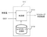
図6は、OCVカーブ決定部151の構成図である。OCVカーブ決定部151は、OCV演算部1511、残容量演算部1512、OCVカーブ判定部1513、OCVカーブ修正部1514を備える。
FIG. 6 is a configuration diagram of the OCV
OCV演算部1511は、単電池111の電流、電圧、温度を入力として、単電池111のOCVを演算する。残容量演算部1512は、電流検知部130が検知した電池電流を積算することにより、単電池111の残容量を演算する。OCVカーブ判定部1513は、OCVと残容量を入力として、後述の図9で説明するSOC−OCVカーブの特性が変化したか否かを判定する。OCVカーブ修正部1514は、SOC−OCVカーブの特性が変化したことをOCVカーブ判定部1513が検知した場合、変化後の特性に対応するSOC−OCVカーブを選択し直して出力する。SOC−OCVカーブは、SOCとOCVの対応関係を温度毎に記述したマップデータとして記述することができる。
The
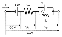
図7は、OCV演算部1511がOCVを演算する手順を説明する図である。単電池111は、図7に例示するような等価回路として表すことができる。すなわち単電池111は、電池の開回路電圧を模擬した直流電源、電極や電解液などの電気抵抗を表すRo、電池の電気化学的な反応に伴う損失分を表すRpとCの並列回路、を直列に接続した回路として表すことができる。電圧検知部140または電圧検出回路122が検知する電圧は、図7におけるCCV(閉回路電圧)に相当する。図7に示す等価回路に電流Iが通電した場合のOCVは、下記式1で表すことができる。
FIG. 7 is a diagram illustrating a procedure for the

RoとRpは、記憶部180にあらかじめ格納しておくデータテーブルに基づき定めることができる。SOHRは、電池の内部抵抗に基づき求めたSOHであり、電池の劣化にともない上昇する電池内部抵抗の上昇率を表しており、以下の式2で定義される。OCV演算部1511は、上記式1を用いてOCVを演算する。式1において、電流Iが0の場合は、右辺第2項は0となり、右辺第3項も通電終了時から所定時間経過後に0となる。つまり、電流Iが0で通電終了から所定時間が経過した後の電圧は、電圧検知部140または電圧検出回路122が検知する電圧はOCVとみなすことができるので、OCVを取得するには好適である。
Ro and Rp can be determined based on a data table stored in the
![]()
![]()
R1(SOC,T)は、現在(劣化後)の単電池111の内部抵抗[Ω]を示す。R0(SOC,T)は、新品時の単電池111の内部抵抗[Ω]を示す。R1(SOC,T)は、例えば、下記式3に示すように、充放電期間中の電流変化(ΔI=I2−I1)と電圧変化(ΔV=V2−V1)の比に基づき算出することができる。
R1 (SOC, T) indicates the internal resistance [Ω] of the current cell 111 (after deterioration). R0 (SOC, T) represents the internal resistance [Ω] of the
![]()
![]()
R0の値は、単電池111のSOCと温度に応じて記述したデータテーブルとしてあらかじめ記憶部180に格納しておくことができ、下記式4にしたがって、充放電期間中のSOCと温度に対応したR0を得ることができる。式3と式4によって得られるR1とR0の値を式2に適用することにより、単電池111のSOHRを求めることができる。
The value of R0 can be stored in advance in the
![]()
![]()
残容量演算部1512は、充放電期間中に電流検知部130が取得した電流値を積算することにより、組電池110または組電池110を構成する各単電池111に蓄えられている残容量を演算する。
The remaining
図8は、OCVカーブ判定部1513の構成図である。OCVカーブ判定部1513は、判定部15131、Q−OCVカーブ記憶部15132を備える。判定部15131は、残容量演算部1512が演算した残容量、OCV演算部1511が演算したOCV、Q−OCVカーブ記憶部15132が格納している残容量とOCVの対応関係を記述したQ−OCVカーブを用いて、SOCとOCVの対応関係が変化しているか否かを判定する。
FIG. 8 is a configuration diagram of the OCV
図9は、Q−OCVカーブ記憶部15132が格納している、残容量とOCVの対応関係を記述したQ−OCVカーブを例示する図である。図9の横軸は残容量Q(Ah)、縦軸はOCV(V)である。
FIG. 9 is a diagram illustrating a Q-OCV curve describing the correspondence between the remaining capacity and the OCV stored in the Q-OCV
電池の劣化が進行すると、SOC−OCVカーブが変化するだけでなく、満充電容量も減少する。このため、残容量とOCVの関係は図9(a)に示すように劣化にともなって変化し、同じ残容量に対応するOCVの値は劣化度に応じて異なる。そこで、あらかじめ劣化状態に応じた残容量とOCVの関係を測定し、それぞれQ−OCVカーブ記憶部15132に記憶しておく。
As the battery deteriorates, not only the SOC-OCV curve changes, but also the full charge capacity decreases. Therefore, the relationship between the remaining capacity and the OCV changes with deterioration as shown in FIG. 9A, and the OCV value corresponding to the same remaining capacity varies depending on the degree of deterioration. Therefore, the relationship between the remaining capacity and the OCV corresponding to the deterioration state is measured in advance and stored in the Q-OCV
図9(b)は、Q−OCVカーブが電池劣化にともなって変化するその他の例を示している。図9(b)の満充電時における値が示すように、満充電容量が同一であってもQ−OCVカーブが異なる特性を示す場合があるので、単に満充電容量が減少していないということのみをもって、SOCとOCVの対応関係が変化していないと判断することはできない。 FIG. 9B shows another example in which the Q-OCV curve changes as the battery deteriorates. As the value at the time of full charge in FIG. 9B shows, even if the full charge capacity is the same, the Q-OCV curve may show different characteristics, so that the full charge capacity does not simply decrease. Therefore, it cannot be determined that the correspondence between the SOC and the OCV has not changed.
図10は、OCVカーブ判定部15131がQ−OCVカーブを特定する手順を説明する図である。OCVカーブ判定部15131は、残容量とOCVの組み合せを複数点取得し、Q−OCVカーブ記憶部15132が格納しているQ−OCVカーブのうちいずれが、取得した残容量とOCVに合致するかを判定する。判定結果は、例えばQ−OCVカーブ記憶部15132が格納しているQ−OCVカーブの識別番号などの形態で、OCVカーブ修正部1514に出力される。
FIG. 10 is a diagram illustrating a procedure for the OCV
図11は、OCVカーブ修正部1514の構成図である。OCVカーブ修正部1514は、OCVカーブ選択部15141とSOC−OCVカーブ記憶部15142を備える。OCVカーブ選択部15141は、OCVカーブ判定部1513の判定結果を受け取り、判定結果に対応するSOC−OCVカーブをSOC−OCVカーブ記憶部15142から選択して出力する。
FIG. 11 is a configuration diagram of the OCV
図12は、SOC−OCVカーブ記憶部15142が格納しているSOC−OCVカーブを例示する図である。SOC−OCVカーブ記憶部15142は、図9で例示したQ−OCVカーブの様々なパターンに対応する複数のSOC−OCVカーブを記憶している。個々のSOC−OCVカーブは、SOCとOCVの対応関係を温度毎に記述したマップデータとして記述することができる。OCVカーブ選択部15141は、判定部15131が出力したQ−OCVカーブの判定結果(例えばQ−OCVカーブの識別番号)に対応するSOC−OCVカーブを選択する。両者の対応関係は、あらかじめ定義しておくものとする。
FIG. 12 is a diagram illustrating an SOC-OCV curve stored in the SOC-OCV
図13は、OCVカーブ決定部151の別構成例を示す図である。組電池110を構成する単電池111においては、個体差によるばらつきや劣化特性のばらつきが生じる。そこで、図13に示すように単電池管理部120が取得する単電池111それぞれの電圧をOCVカーブ決定部151へ入力することにより、単電池111毎にSOCとOCVの対応関係を決定することができる。この場合、Q−OCVカーブ記憶部15132とSOC−OCVカーブ記憶部15142は、個体差によるばらつき情報と関連付けて各データを記憶しておくことが望ましい。
FIG. 13 is a diagram illustrating another configuration example of the OCV
なお、単電池111個々の特性を考慮せず組電池110毎の電池電圧を計測値として用いる場合は、例えば個々の単電池111の両端電圧を合算したものを組電池110の両端電圧として用いればよい。
In addition, when using the battery voltage for each assembled
<実施の形態1:システム動作>
図14は、電池制御システム100の全体動作を説明するフローチャートである。以下図14の各ステップについて説明する。
<Embodiment 1: System operation>
FIG. 14 is a flowchart for explaining the overall operation of the
(図14:ステップS100)
組電池制御部150は、車両が起動したことを示す信号を受信したか否かを判定する。受信した場合はステップS110へ進み、受信していない場合は受信するまで待機する。
(FIG. 14: Step S100)
The assembled
(図14:ステップS110)
OCV演算部1511は、組電池110と負荷が接続される前の無負荷状態における電池電圧、すなわちOCVを取得し、SOCテーブル181を用いてOCVをSOCへ変換する。本ステップにおいて求めるSOCは、以下のステップにおいて修正される暫定的なものであることに留意されたい。
(FIG. 14: Step S110)
The
(図14:ステップS120)
残容量演算部1512は、ステップS110において取得したSOCと電池の満充電容量Qmax(Ah)を用いて、下記式5にしたがって電池の残容量Qを演算する。
(FIG. 14: Step S120)
The remaining
![]()
![]()
(図14:ステップS130)
判定部15131は、Q−OCVカーブの特性が変化しているかどうかを判定するために残容量QとOCVのペアを複数点取得する。本ステップの詳細は後述の図15で改めて説明する。
(FIG. 14: Step S130)
The
(図14:ステップS140)
判定部15131は、ステップS130で取得した残容量QとOCVのペアの個数が所定個数以上に達したか否かを判定する。所定個数以上であればステップS150に進み、所定個数以上に達していない場合はステップS130を繰り返す。
(FIG. 14: Step S140)
The
(図14:ステップS150)
判定部15131は、ステップS130において取得した残容量QとOCVのペアに基づき、Q−OCVカーブの特性が変化したか否かを判定する。変化している場合は、変化後のQ−OCVカーブに対応するSOC−OCVカーブを選択する。本ステップの詳細は後述の図16で改めて説明する。
(FIG. 14: Step S150)
The
図15は、ステップS130の詳細を説明するフローチャートである。以下、図15の各ステップについて説明する。 FIG. 15 is a flowchart for explaining details of step S130. Hereinafter, each step of FIG. 15 will be described.
(図15:ステップS131)
残容量演算部1512は、充放電期間中の電池電流値を積算し、その積算結果をステップS120において算出された残容量Qに加算することにより、複数時点における電池の残容量(Q1〜Qn)を算出する。
(FIG. 15: Step S131)
The remaining
(図15:ステップS132〜S133)
残容量演算部1512は、車両停止信号を受信したか否かを判定する(S132)。受信した場合はステップS131において算出した残容量を記憶部180に格納し(S133)、受信していない場合はステップS131に戻る。
(FIG. 15: Steps S132 to S133)
The remaining
(図15:ステップS132〜S133:補足)
車両が停止した時点において残容量を記憶部180に格納するのは、残容量とペアで取得するOCVを次回、車両起動時に取得するためである。車両が走行している間は電池の電圧(CCV)からOCVを演算する際に電流センサの誤差や図7に示す分極電圧(Vp)のモデリング誤差などにより、OCV演算結果に誤差が生じるためである。次回、車両起動時の安定した条件であればOCVを精度良く取得出来る。このため、本実施例では、車両停止時に記録した残容量と次回起動時に取得した安定したOCVのペアでSOCとOCVの対応関係の変化を検知する構成とした。後述の図17において具体的な動作イメージを例示する。
(FIG. 15: Steps S132 to S133: Supplement)
The reason why the remaining capacity is stored in the
(図15:ステップS134〜S135)
OCV演算部1511は、車両起動信号を受信したか否かを判定する(S134)。受信した場合は無負荷時の電圧すなわちOCVを取得して記憶部180に格納し(S135)、受信していない場合はステップS134に戻る。なお、OCVを記憶部180に格納するとき、ステップS133において記憶部180に格納した残容量とペアにしておく。後述の図17においてペアの具体的なイメージを例示する。
(FIG. 15: Steps S134 to S135)
The
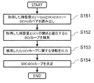
図16は、ステップS150の詳細を説明するフローチャートである。以下、図16の各ステップについて説明する。 FIG. 16 is a flowchart for explaining details of step S150. Hereinafter, each step of FIG. 16 will be described.
(図16:ステップS151〜S152)
判定部15131は、ステップS130において記憶部180に格納された残容量QとOCVのペアを読み出す(S151)。判定部15131は、Q−OCVカーブ記憶部15132が格納しているQ−OCVカーブの中から、ステップS151において読み出した残容量QとOCVのペアに適合するものを検索する(S152)。
(FIG. 16: Steps S151 to S152)
The
(図16:ステップS153)
判定部15131は、ステップS152におけるQ−OCVカーブについての判定結果をOCVカーブ修正部1514へ出力する。この判定結果は、例えばステップS152において特定したQ−OCVカーブの識別番号などでもよいし、当該Q−OCVカーブがどのような条件で計測されたものであるのか(例えば、電池のSOC、温度、使用状況)についての情報でもよい。すなわち、次のステップS154において、当該Q−OCVカーブに対応するSOC−OCVカーブを特定することができる情報であればよい。
(FIG. 16: Step S153)
The
(図16:ステップS154)
OCVカーブ修正部1514は、ステップS153において特定されたQ−OCVカーブに対応するSOC−OCVカーブを、SOC−OCVカーブ記憶部15142から選択する。OCVカーブ修正部1514は、選択したSOC−OCVカーブを修正前のものと置き換える。
(FIG. 16: Step S154)
The OCV
図17は、ステップS130においてOCVカーブ決定部151が残容量QとOCVのペアを取得する際の動作イメージを示す図である。図17は、車両が走行と停止を繰り返し、最後に充電器420によって満充電まで充電する動作パターンを示している。
FIG. 17 is a diagram illustrating an operation image when the OCV
OCVカーブ決定部151は、走行終了時点または充電終了時点における残容量Qと、走行終了から所定時間経過後または充電終了から所定時間経過後のOCVを取得する。電池の劣化は時間経過に応じて進行していくため、SOCとOCVの関係を取得する際に用いる残容量QとOCVのペアは、ある程度の長さを有する期間、例えば1ヶ月の間に取得することが望ましい。
The OCV
なお、図17に示す例においては、OCVを精度よく検知することができるように、車両起動後に電池電圧が安定した時点においてOCVを取得することとしたが、式1にしたがって、通電中においてもOCVを演算し、残容量QとOCVの関係を取得するようにしてもよい。 In the example shown in FIG. 17, the OCV is acquired when the battery voltage is stabilized after the vehicle is started so that the OCV can be accurately detected. The OCV may be calculated to obtain the relationship between the remaining capacity Q and the OCV.
<実施の形態1:まとめ>
以上のように、本実施形態1に係る電池制御装置は、残容量QとOCVの対応関係(Q−OCVカーブ)が変化したことを検知し、変化後のQ−OCVカーブに対応するSOC−OCVカーブを用いる。これにより、電池の劣化に応じて充放電特性が変化しても、SOCを精度よく検知することができる。またこれにより、SOCを用いて演算するSOHなどの電池パラメータについても精度よく演算することができるので、信頼性を確保した電池制御システムを提供することができる。
<Embodiment 1: Summary>
As described above, the battery control device according to the first embodiment detects that the correspondence relationship (Q-OCV curve) between the remaining capacity Q and the OCV has changed, and the SOC- corresponding to the Q-OCV curve after the change. An OCV curve is used. Thereby, even if the charge / discharge characteristics change according to the deterioration of the battery, the SOC can be accurately detected. In addition, as a result, battery parameters such as SOH calculated using the SOC can be calculated with high accuracy, so that a battery control system that ensures reliability can be provided.
<実施の形態2>
実施形態1では、残容量QとOCVの対応関係(Q−OCVカーブ)が変化したことを検知することにより、電池の劣化にともなってSOC−OCVカーブが変化したことを検知することを説明した。電池の劣化にともなって変化するその他の電池パラメータとしては、電池の内部抵抗が考えられる。そこで本発明の実施形態2では、電池の内部抵抗が変化したことを検知することにより、電池の劣化にともなってSOC−OCVカーブが変化したことを検知する構成例を説明する。電池の内部抵抗の変化を検知する構成以外については実施形態1と同様であるため、以下では差異点を中心に説明する。
<Embodiment 2>
In the first embodiment, it has been described that by detecting that the correspondence between the remaining capacity Q and the OCV (Q-OCV curve) has changed, it has been detected that the SOC-OCV curve has changed as the battery has deteriorated. . Another battery parameter that changes as the battery deteriorates is the internal resistance of the battery. Therefore, in Embodiment 2 of the present invention, a configuration example will be described in which it is detected that the SOC-OCV curve has changed due to deterioration of the battery by detecting that the internal resistance of the battery has changed. Since the configuration other than the configuration for detecting the change in the internal resistance of the battery is the same as that of the first embodiment, the following description will focus on the differences.
図18は、本実施形態2におけるOCVカーブ決定部151の構成図である。本実施形態2において、OCVカーブ決定部151は、残容量演算部1512に代えて内部抵抗演算部1515を備える。内部抵抗演算部1515は、例えば式2〜式3で説明したR1(SOC,T)などを用いて、単電池111の内部抵抗を演算する。
FIG. 18 is a configuration diagram of the OCV
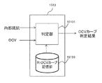
図19は、本実施形態2におけるOCVカーブ判定部1513の構成図である。本実施形態2において、OCVカーブ判定部1513は、Q−OCVカーブ記憶部15132に代えて、R−OCVカーブ記憶部15133を備える。
FIG. 19 is a configuration diagram of the OCV
図20は、R−OCVカーブ記憶部15133が格納している、電池の内部抵抗RとOCVの対応関係を記述したR−OCVカーブを例示する図である。電池の内部抵抗は電池の劣化にともなって変化するので、内部抵抗の変化を検知することにより、電池の劣化を検知することができる。そこでR−OCVカーブ記憶部15133は、複数パターンのR−OCVカーブを格納しておき、判定部15131は実施形態1において残容量Qを用いてQ−OCVカーブを特定した動作と同様に、現在の劣化状態に対応するR−OCVカーブを特定する。OCVカーブ修正部1514は、特定されたR−OCVカーブに対応するSOC−OCVカーブを選択する。
FIG. 20 is a diagram illustrating an R-OCV curve describing the correspondence between the internal resistance R and OCV of the battery stored in the R-OCV
<実施の形態3>
実施形態1においては、次回、車両起動時の安定した無負荷電圧と前回車両停止時に取得した残容量とのペアを取得することとした。SOC−OCVカーブの変化を検知するためには、残容量が少ない点から残容量が大きい点の幅広い範囲の中で略均等になるようにペアを取得するのが望ましい。但し、電池の使われ方は車両のユーザにより様々に異なるため、車両停止時の残容量とOCVとのペアは上記のようにSOC−OCVカーブを取得するのに適した点で取得出来るとは限らない。実施形態2の内部抵抗とOCVとのペアの取得についても同様のことが言える。これに対し、充電器420を用いて充電をしている間は、電池制御装置の側で充電動作を制御することができる。
<Embodiment 3>
In the
そこで本発明の実施形態3では、充電器420を用いて充電をしている間において、実施形態1で説明した動作を実施する構成例を説明する。その他の構成は実施形態1と同様であるため、以下では差異点を中心に説明する。本実施形態3では、実施形態2で説明した動作も同様に実施することができる。
Thus, in the third embodiment of the present invention, a configuration example will be described in which the operation described in the first embodiment is performed while charging is performed using the
図21は、本実施形態3における組電池制御部150の構成図である。本実施形態3において、組電池制御部150は、実施形態1で説明した構成に加えて充電器制御部153を備える。充電器制御部153は、充電器420の動作を制御する。実施形態2で説明した構成においても充電器制御部153が加わることになる。
FIG. 21 is a configuration diagram of the assembled
図22は、充電器制御部153の構成図である。充電器制御部153は、モード判定部1531、メンテナンスモード用制御部1532、通常モード用制御部1533を備える。モード判定部1531は、電池の劣化状態(電池の内部抵抗を用いて演算したSOHRまたは電池の満充電容量を用いて演算したSOHQ)に基づき、後述の図25で例示するメンテナンスモードを実施するか否かを判断する。メンテナンスモードを実施している間はメンテナンスモード用制御部1532が充電器420の動作を制御し、それ以外の通常モードにおいては通常モード用制御部1533が充電器420の動作を制御する。モード切替する理由については後述の図25で説明する。
FIG. 22 is a configuration diagram of the
図23は、充電器制御部153の動作フローチャートである。以下、図23の各ステップについて説明する。尚、以下に示すフローチャートでは、SOHRもしくはSOHQを充電開始前に取得し、記憶部180に記憶されていることを前提とする。
FIG. 23 is an operation flowchart of the
(図23:ステップS300)
充電器制御部153は、充電器に接続されたかどうかを示す充電開始信号を受信したか否かを判定する。受信した場合はステップS310へ進み、受信していない場合は受信するまで待機する。
(FIG. 23: Step S300)
The
(図23:ステップS310)
充電器制御部153は、予め取得した現在のSOHRもしくはSOHQを読み出す。
(FIG. 23: Step S310)
The
(図23:ステップS320)
モード判定部1531は、ステップS310で演算してSOHRとSOHQが、前回SOC−OCVテーブルを選択し直したとき(初回である場合は出荷時)から所定値以上変化したか否か、すなわち電池の劣化が所定値以上進行したか否かを判定する。所定値以上変化している場合はステップS330へ進み、それ以外であればステップS340にスキップする。SOHRとSOHQは、いずれか一方のみを用いてもよい。
(FIG. 23: Step S320)
The
(図23:ステップS330〜S350)
モード判定部1531は、メンテナンスモードを実施すべき旨を指示するメンテナンスモード要求フラグを「1」にセットする(S330)。後述の図24で説明するフローチャートにしたがって充電を実施する(S340)。
(FIG. 23: Steps S330 to S350)
The
図24は、ステップS340の詳細を説明するフローチャートである。以下、図24の各ステップについて説明する。 FIG. 24 is a flowchart illustrating the details of step S340. Hereinafter, each step of FIG. 24 will be described.
(図24:ステップS341)
充電器制御部153は、メンテナンスモード要求フラグが「1」になっているか否かを確認する。「1」になっている場合はステップS342へ進み、それ以外であればステップS346へスキップする。
(FIG. 24: Step S341)
The
(図24:ステップS342)
充電器制御部153は、充電器420によって充電を開始した後、電池電圧が後述の図25で例示する充電一時停止電圧に到達したか否かを判定する。到達していればステップS343へ進み、到達していなければ充電を継続する。
(FIG. 24: Step S342)
The
(図24:ステップS343〜S344)
充電器制御部153は、充電を一時停止し、残容量QとOCVのペアを取得する(S343)。取得した残容量QとOCVのペアが所定個数以上に到達した場合はステップS345へ進み、到達していない場合はステップS342に戻る(S344)。
(FIG. 24: Steps S343 to S344)
The
(図24:ステップS345〜S346)
判定部15131は、ステップS150と同様の手法を用いて、SOC−OCVカーブを選択し直す(S345)。充電器制御部153は充電を再開し、電池電圧が充電終始電圧に到達するまで充電を継続する(S346)。
(FIG. 24: Steps S345 to S346)
The
図25は、ステップS343において充電器制御部153が残容量QとOCVのペアを取得する動作を例示する図である。本実施形態3においては、車両が停止したことに代えて充電器420が充電を停止した時点で残容量QとOCVのペアを取得する。充電器420の動作は充電器制御部153によって制御することができるので、より自由に残容量QとOCVのペアを取得することができる。
FIG. 25 is a diagram illustrating an operation in which the
ただし図25に例示するように、残容量QとOCVのペアを取得するためには充電を一時停止する必要があるので、通常の充電動作と比較して充電時間が長くかかる。そこで、電池劣化が進行していると考えられる時点までは図25の動作を保留しておき、ステップS320において電池劣化が判定された時点で図25の動作を実施する。これにより通常モード時においては充電動作を妨げずにおくことができる。 However, as illustrated in FIG. 25, since it is necessary to temporarily stop charging in order to acquire the pair of the remaining capacity Q and OCV, the charging time is longer than that in the normal charging operation. Therefore, the operation of FIG. 25 is suspended until the time point when the battery deterioration is considered to be progressing, and the operation of FIG. 25 is performed when the battery deterioration is determined in step S320. As a result, the charging operation can be kept without interruption in the normal mode.
<実施の形態3:まとめ>
以上のように、本実施形態3に係る電池制御装置は、電池の劣化状態がある程度進行した時点において充電器制御部153の動作モードを切り替え、残容量QとOCVのペアを取得してSOC−OCVカーブを選択し直す。これにより、車両の走行状態に依拠することなくSOC−OCVカーブをより正確なものに改めることができる。
<Embodiment 3: Summary>
As described above, the battery control device according to the third embodiment switches the operation mode of the
<実施の形態4>
実施形態1〜3では、SOC−OCVカーブ記憶部15142にあらかじめ複数パターンのSOC−OCVカーブを格納しておき、残容量Qまたは内部抵抗Rの劣化度合いに対応するSOC−OCVカーブを選択する手法を説明した。これに代えて、SOC−OCVカーブ記憶部15142には単一のSOC−OCVカーブのみを格納しておき、残容量とOCVの関係に所定値以上のズレがあるのを検知した場合に所定値だけOCVカーブを修正する構成とすることも可能である。
<Embodiment 4>
In the first to third embodiments, a plurality of patterns of SOC-OCV curves are stored in advance in the SOC-OCV
具体的には、SOC−OCVカーブのズレを検知した場合に補正量(例えば、1mVずつ)だけもとのSOC−OCVカーブに加算する。この処理を予め実装してある残容量とOCVの関係との間の差異が十分小さくなるまで繰り返す。但し、SOC−OCVカーブのズレの方向(極性)はSOCに応じて異なる可能性があるため、予めSOC−OCVカーブを調査しておき、補正量を設定する必要がある。 Specifically, when a shift of the SOC-OCV curve is detected, a correction amount (for example, by 1 mV) is added to the original SOC-OCV curve. This process is repeated until the difference between the pre-installed remaining capacity and the OCV relationship is sufficiently small. However, since the direction of deviation (polarity) of the SOC-OCV curve may vary depending on the SOC, it is necessary to investigate the SOC-OCV curve in advance and set the correction amount.
本発明は上記した実施形態に限定されるものではなく、様々な変形例が含まれる。上記実施形態は本発明を分かりやすく説明するために詳細に説明したものであり、必ずしも説明した全ての構成を備えるものに限定されるものではない。また、ある実施形態の構成の一部を他の実施形態の構成に置き換えることもできる。また、ある実施形態の構成に他の実施形態の構成を加えることもできる。また、各実施形態の構成の一部について、他の構成を追加・削除・置換することもできる。 The present invention is not limited to the embodiments described above, and includes various modifications. The above embodiment has been described in detail for easy understanding of the present invention, and is not necessarily limited to the one having all the configurations described. A part of the configuration of one embodiment can be replaced with the configuration of another embodiment. The configuration of another embodiment can be added to the configuration of a certain embodiment. Further, with respect to a part of the configuration of each embodiment, another configuration can be added, deleted, or replaced.
上記各構成、機能、処理部、処理手段等は、それらの一部や全部を、例えば集積回路で設計する等によりハードウェアで実現してもよい。また、上記の各構成、機能等は、プロセッサがそれぞれの機能を実現するプログラムを解釈し、実行することによりソフトウェアで実現してもよい。各機能を実現するプログラム、テーブル、ファイル等の情報は、メモリ、ハードディスク、SSD(Solid State Drive)等の記録装置、ICカード、SDカード、DVD等の記録媒体に格納することができる。 Each of the above-described configurations, functions, processing units, processing means, and the like may be realized in hardware by designing a part or all of them, for example, with an integrated circuit. Each of the above-described configurations, functions, and the like may be realized by software by interpreting and executing a program that realizes each function by the processor. Information such as programs, tables, and files for realizing each function can be stored in a recording device such as a memory, a hard disk, an SSD (Solid State Drive), or a recording medium such as an IC card, an SD card, or a DVD.
100:電池システム、110:組電池、111:単電池、112:単電池群、120:単電池管理部、121:単電池制御部、122:電圧検出回路、123:制御回路、124:信号入出力回路、125:温度検知部、130:電流検知部、140:電圧検知部、150:組電池制御部、151:OCVカーブ決定部、152:電池状態検知部、153:充電器制御部、160:信号通信手段、170:絶縁素子、180:記憶部、200:車両制御部、300〜330:リレー、400:インバータ、410:モータジェネレータ、420:充電器。 100: battery system 110: assembled battery 111: single battery 112: single battery group 120: single battery management unit 121: single battery control unit 122: voltage detection circuit 123: control circuit 124: signal input Output circuit, 125: temperature detection unit, 130: current detection unit, 140: voltage detection unit, 150: assembled battery control unit, 151: OCV curve determination unit, 152: battery state detection unit, 153: charger control unit, 160 : Signal communication means, 170: insulation element, 180: storage unit, 200: vehicle control unit, 300 to 330: relay, 400: inverter, 410: motor generator, 420: charger.
Claims (10)
前記SOC−OCV特性を用いて、前記電池の電圧或いは複数の前記電池が電気的に接続されて構成された組電池の電圧に応じた前記電池或いは前記組電池の充電状態に関する情報を出力する制御部、
を備え、
前記SOC−OCVデータは、前記電池或いは前記組電池の電圧及び前記電池に流れる電流のいずれか一方又は両方に基づいて求められる前記電池或いは前記組電池の状態量と、前記電池或いは前記組電池の開回路電圧との対応関係を示す特性ごとに、前記SOC−OCV特性をそれぞれ記述しており、
前記制御部は、
前記電池或いは前記組電池の電圧及び前記電池に流れる電流のいずれか一方又は両方に基づいて求められた前記電池或いは前記組電池の状態量と、この状態量に対応するように求められた前記電池或いは前記組電池の開回路電圧とを一つのペアとして、このペアを複数取得し、
この取得された複数のペアと、前記電池或いは前記組電池の状態量と開回路電圧との対応関係を示す特性に対応する前記SOC−OCV特性を特定し、
前記特定したSOC−OCV特性に基づき前記電池の充電状態を出力することにより、前記電池或いは前記組電池の電圧が同一でも、時間経過に応じて異なる値の充電状態を出力する、
電池制御装置。 An SOC-OCV characteristic storage unit for storing SOC-OCV data describing SOC-OCV characteristics indicating the correspondence between the open circuit voltage of the battery and the state of charge ;
Control that outputs information on the state of charge of the battery or the assembled battery according to the voltage of the battery or the voltage of the assembled battery configured by electrically connecting a plurality of the batteries using the SOC-OCV characteristic Part ,
With
The SOC-OCV data includes the state quantity of the battery or the assembled battery obtained based on one or both of the voltage of the battery or the assembled battery and the current flowing through the battery, and the battery or the assembled battery. Each SOC-OCV characteristic is described for each characteristic indicating a correspondence relationship with an open circuit voltage.
The controller is
A state quantity of the battery or the assembled battery obtained based on one or both of a voltage of the battery or the assembled battery and a current flowing through the battery, and the battery obtained so as to correspond to the state quantity. Alternatively, the open circuit voltage of the assembled battery is taken as one pair, and a plurality of these pairs are acquired,
The SOC-OCV characteristic corresponding to the characteristic indicating the correspondence relationship between the obtained plurality of pairs and the state quantity of the battery or the assembled battery and the open circuit voltage is specified ,
By outputting the state of charge of the battery based on the specified SOC-OCV characteristics , even if the voltage of the battery or the assembled battery is the same, the state of charge of a different value is output over time.
Battery control device.
前記制御部は、
前記電池の開回路電圧を演算するOCV演算部と、
前記電池に流れる電流を積算し、前記電池の残容量を前記状態量として演算する残容量演算部と、
前記電池の残容量と前記電池の開回路電圧との対応関係を示すQ−OCV特性が記憶されたQ−OCV特性記憶部と、
前記残容量と、この残容量に対応するように求められた前記電池の開回路電圧とを一つのペアとして、このペアを複数取得し、この取得された複数のペアと前記Q−OCV特性との関係に基づいて、前記SOC−OCV特性を、前記電池の劣化状態に対応するように修正する修正部と、を有する、
電池制御装置。 The battery control device according to claim 1,
The controller is
An OCV calculation unit for calculating an open circuit voltage of the battery ;
A remaining capacity calculation unit that integrates the current flowing through the battery and calculates the remaining capacity of the battery as the state quantity;
A Q-OCV characteristic storage unit storing a Q-OCV characteristic indicating a correspondence relationship between the remaining capacity of the battery and the open circuit voltage of the battery;
The remaining capacity and the open circuit voltage of the battery determined to correspond to the remaining capacity are taken as one pair, and a plurality of the pairs are acquired, and the acquired plurality of pairs and the Q-OCV characteristics are obtained. A correction unit that corrects the SOC-OCV characteristic so as to correspond to the deterioration state of the battery based on the relationship of
Battery control device.
前記制御部は、
前記電池の開回路電圧を演算するOCV演算部と、
前記電池の電圧と前記電池に流れる電流とに基づいて、前記電池の内部抵抗を前記状態量として演算する内部抵抗演算部と、
前記電池の内部抵抗と前記電池の開回路電圧との対応関係を示すR−OCV特性が記憶されたR−OCV特性記憶部と、
前記内部抵抗と、この内部抵抗に対応するように求められた前記電池の開回路電圧とを一つのペアとして、このペアを複数取得し、この取得された複数のペアと前記R−OCV特性との関係に基づいて、前記SOC−OCV特性を、前記電池の劣化状態に対応するように修正する修正部と、を有する、
電池制御装置。 The battery control device according to claim 1,
The controller is
An OCV calculation unit for calculating an open circuit voltage of the battery ;
An internal resistance calculator that calculates the internal resistance of the battery as the state quantity based on the voltage of the battery and the current flowing through the battery;
An R-OCV characteristic storage unit storing an R-OCV characteristic indicating a correspondence relationship between the internal resistance of the battery and the open circuit voltage of the battery;
The internal resistance and the open circuit voltage of the battery determined so as to correspond to the internal resistance are taken as one pair, and a plurality of the pairs are acquired. The acquired plurality of pairs and the R-OCV characteristics A correction unit that corrects the SOC-OCV characteristic so as to correspond to the deterioration state of the battery based on the relationship of
Battery control device.
前記制御部は、さらに、前記電池を充電する充電器の動作を制御する充電器制御部を有し、
前記修正部は、前記充電器制御部が前記充電器を動作させて前記電池の充電を実施させている期間において、前記複数のペアを取得する、
電池制御装置。 The battery control device according to claim 2,
The control unit further includes a charger control unit that controls an operation of a charger that charges the battery,
The correction unit acquires the plurality of pairs in a period in which the charger control unit operates the charger to charge the battery.
Battery control device.
前記制御部は、さらに、前記電池を充電する充電器の動作を制御する充電器制御部を有し、
前記修正部は、前記充電器制御部が前記充電器を動作させて前記電池の充電を実施させている期間において、前記複数のペアを取得する、
電池制御装置。 The battery control device according to claim 3, wherein
The control unit further includes a charger control unit that controls an operation of a charger that charges the battery,
The correction unit acquires the plurality of pairs in a period in which the charger control unit operates the charger to charge the battery.
Battery control device.
前記充電器制御部は、前記充電器を動作させて前記電池の充電を実施させている期間において、前記充電器による前記電池の充電動作と、この充電動作を一時的に中断する動作とを繰り返すように、前記充電器の動作を制御しており、
前記修正部は、前記充電器制御部が前記充電動作を一時的に中断させている時点において、前記ペアを取得する、
電池制御装置。 The battery control device according to claim 4 or 5,
The charger control unit repeats a charging operation of the battery by the charger and an operation of temporarily interrupting the charging operation during a period in which the battery is operated to charge the battery. So as to control the operation of the charger,
The correction unit acquires the pair at a time when the charger control unit temporarily interrupts the charging operation.
Battery control device.
前記充電器制御部は、前記電池の劣化状態が所定程度に達したか否かを判定するモード判定部を有し、
前記充電器に前記電池の充電を実施させる前に、前記電池の劣化状態が前記所定程度に達したと前記モード判定部が判定した場合に、前記充電動作と、前記充電動作を一時的に中断する動作とを繰り返すように、前記充電器の動作を制御する、
電池制御装置。 The battery control device according to claim 6,
The charger control unit includes a mode determination unit that determines whether or not a deterioration state of the battery has reached a predetermined level.
The charging operation and the charging operation are temporarily interrupted when the mode determination unit determines that the deterioration state of the battery has reached the predetermined level before causing the charger to charge the battery. Controlling the operation of the charger to repeat the operation of
Battery control device.
前記充電器制御部は、前記電池の劣化状態が前記所定程度に達していないと前記モード判定部が判定した場合に、前記充電動作を一時的に中断する動作を前記充電器にさせない、
電池制御装置。 The battery control device according to claim 7,
The charger control unit does not cause the charger to temporarily stop the charging operation when the mode determination unit determines that the battery deterioration state has not reached the predetermined level.
Battery control device.
前記SOC−OCV特性は前記電池の劣化特性に対応して複数用意されており、
前記修正部は、前記複数のSOC−OCV特性のなかから、前記電池の劣化状態に応じたSOC−OCV特性を選択する、
電池制御装置。 The battery control device according to any one of claims 2 to 8,
A plurality of the SOC-OCV characteristics are prepared corresponding to the deterioration characteristics of the battery,
The correction unit selects an SOC-OCV characteristic according to a deterioration state of the battery from the plurality of SOC-OCV characteristics.
Battery control device.
前記修正部は、前記電池の劣化状態に応じて、前記SOC−OCV特性を所定値補正する、
電池制御装置。 The battery control device according to any one of claims 2 to 8,
The correction unit corrects the SOC-OCV characteristic by a predetermined value according to a deterioration state of the battery.
Battery control device.
Priority Applications (3)
| Application Number | Priority Date | Filing Date | Title |
|---|---|---|---|
| JP2013073505A JP6033155B2 (en) | 2013-03-29 | 2013-03-29 | Battery control device |
| US14/655,371 US9685807B2 (en) | 2013-03-29 | 2014-01-27 | Battery control device |
| PCT/JP2014/051614 WO2014156265A1 (en) | 2013-03-29 | 2014-01-27 | Battery control device |
Applications Claiming Priority (1)
| Application Number | Priority Date | Filing Date | Title |
|---|---|---|---|
| JP2013073505A JP6033155B2 (en) | 2013-03-29 | 2013-03-29 | Battery control device |
Publications (3)
| Publication Number | Publication Date |
|---|---|
| JP2014196985A JP2014196985A (en) | 2014-10-16 |
| JP2014196985A5 JP2014196985A5 (en) | 2015-06-18 |
| JP6033155B2 true JP6033155B2 (en) | 2016-11-30 |
Family
ID=51623267
Family Applications (1)
| Application Number | Title | Priority Date | Filing Date |
|---|---|---|---|
| JP2013073505A Active JP6033155B2 (en) | 2013-03-29 | 2013-03-29 | Battery control device |
Country Status (3)
| Country | Link |
|---|---|
| US (1) | US9685807B2 (en) |
| JP (1) | JP6033155B2 (en) |
| WO (1) | WO2014156265A1 (en) |
Cited By (1)
| Publication number | Priority date | Publication date | Assignee | Title |
|---|---|---|---|---|
| CN107571747A (en) * | 2017-07-07 | 2018-01-12 | 宝沃汽车(中国)有限公司 | SOC smooth control method, device, battery management system and vehicle |
Families Citing this family (55)
| Publication number | Priority date | Publication date | Assignee | Title |
|---|---|---|---|---|
| JP6260812B2 (en) * | 2013-12-05 | 2018-01-17 | パナソニックIpマネジメント株式会社 | Battery remaining capacity estimation device, battery remaining capacity determination method, and battery remaining capacity determination program |
| KR102165937B1 (en) * | 2014-05-30 | 2020-10-14 | 삼성전자주식회사 | Method and apparatus for managing battery |
| KR101619620B1 (en) * | 2014-10-17 | 2016-05-10 | 현대자동차주식회사 | Apparatus and method for calculating state of charge |
| JP6488105B2 (en) | 2014-10-28 | 2019-03-20 | 株式会社東芝 | Storage battery evaluation apparatus and method |
| JP6490414B2 (en) * | 2014-12-05 | 2019-03-27 | 古河電気工業株式会社 | Secondary battery state detection device and secondary battery state detection method |
| JP6548387B2 (en) * | 2014-12-15 | 2019-07-24 | 川崎重工業株式会社 | Method and apparatus for estimating state of charge of secondary battery |
| DE102014226190A1 (en) * | 2014-12-17 | 2016-06-23 | Robert Bosch Gmbh | Test device for checking a battery control unit or a battery and method for testing a battery control unit or a battery |
| CN106324506A (en) * | 2015-06-17 | 2017-01-11 | 炬才微电子(深圳)有限公司 | Embedded equipment battery test method, device and system |
| JP6871912B2 (en) * | 2015-08-19 | 2021-05-19 | エフシーエー フィアット クライスラー オートモーヴィス ブラジル リミターダ | Battery monitoring system and method |
| JP6437403B2 (en) * | 2015-09-09 | 2018-12-12 | 株式会社東芝 | Charge condition control device and battery pack |
| CN107431255A (en) * | 2015-09-15 | 2017-12-01 | 株式会社东芝 | Accumulator control device, control method, program, accumulating system, power system |
| KR20170060499A (en) * | 2015-11-24 | 2017-06-01 | 현대자동차주식회사 | Method for controlling output of battery |
| US10705147B2 (en) * | 2015-12-17 | 2020-07-07 | Rohm Co., Ltd. | Remaining capacity detection circuit of rechargeable battery, electronic apparatus using the same, automobile, and detecting method for state of charge |
| US10176100B1 (en) * | 2015-12-21 | 2019-01-08 | Cadence Design Systems, Inc. | Cache coherency process |
| JP5948518B1 (en) * | 2016-02-04 | 2016-07-06 | 本田技研工業株式会社 | Power storage device, transport device having the power storage device, failure determination method, and failure determination program |
| JP6122164B1 (en) * | 2016-02-04 | 2017-04-26 | 本田技研工業株式会社 | Power storage device, transport device having the power storage device, determination method for determining correlation information between SOC and OCV of storage battery, and program for determining the correlation information |
| JP6700996B2 (en) * | 2016-06-15 | 2020-05-27 | 本田技研工業株式会社 | Battery state estimating device and battery state estimating method |
| JP6326452B2 (en) | 2016-06-15 | 2018-05-16 | 本田技研工業株式会社 | Battery state estimation device and battery state estimation method |
| JP6558313B2 (en) * | 2016-06-29 | 2019-08-14 | トヨタ自動車株式会社 | Vehicle and manufacturing method thereof |
| WO2018012364A1 (en) * | 2016-07-13 | 2018-01-18 | 株式会社 村田製作所 | Battery pack circuit, capacity coefficient detection method, and capacity coefficient detection program |
| US10976370B2 (en) * | 2016-09-29 | 2021-04-13 | Gs Yuasa International Ltd. | SOC estimation device of energy storage device, energy storage apparatus, and SOC estimation method of energy storage device |
| KR102579538B1 (en) * | 2016-10-05 | 2023-09-18 | 삼성전자주식회사 | Method and apparatus for controlling battery charging |
| KR101846913B1 (en) * | 2016-11-01 | 2018-04-09 | 현대자동차 주식회사 | Apparatus and method for controlling charging of battery for hybrid vehicle |
| CN106740594B (en) * | 2016-11-30 | 2019-07-23 | 广州汽车集团股份有限公司 | A kind of vehicle battery electric quantity reminding method, system and automobile gateway |
| JP2018169284A (en) * | 2017-03-30 | 2018-11-01 | 日立オートモティブシステムズ株式会社 | Device and method for controlling storage battery |
| JP6939057B2 (en) * | 2017-04-27 | 2021-09-22 | トヨタ自動車株式会社 | In-vehicle battery system and battery aging estimation method |
| IT201700058171A1 (en) * | 2017-05-29 | 2018-11-29 | Magneti Marelli Spa | Method of estimating the current and state of charge of a battery pack or cell, without direct current detection in operating conditions |
| US11237214B2 (en) * | 2017-07-19 | 2022-02-01 | Gs Yuasa International Ltd. | Estimation device, energy storage apparatus, estimation method, and computer program |
| JP6477959B2 (en) * | 2017-07-19 | 2019-03-06 | 株式会社Gsユアサ | Estimation device, power storage device, estimation method, and computer program |
| JP6794960B2 (en) * | 2017-08-22 | 2020-12-02 | トヨタ自動車株式会社 | Power system |
| KR102182691B1 (en) | 2017-10-20 | 2020-11-24 | 주식회사 엘지화학 | Apparatus and method for estimating resistance of battery |
| KR102239365B1 (en) | 2017-10-20 | 2021-04-09 | 주식회사 엘지화학 | Apparatus for estimating state of charge of battery |
| KR102259967B1 (en) * | 2017-12-18 | 2021-06-02 | 주식회사 엘지에너지솔루션 | Apparatus and method for managing charging of battery |
| KR102525676B1 (en) * | 2018-02-20 | 2023-04-24 | 에스케이온 주식회사 | Battery management system |
| CN110320477B (en) * | 2018-03-30 | 2021-09-03 | 比亚迪股份有限公司 | SOC (State of Charge) calculation method and device of power battery pack and electric automobile |
| EP3690461B1 (en) * | 2018-04-10 | 2022-06-29 | LG Energy Solution, Ltd. | Apparatus and method for diagnosing a battery |
| JP7040284B2 (en) * | 2018-05-23 | 2022-03-23 | トヨタ自動車株式会社 | Deterioration state estimation method, deterioration state estimation device, control method, and control system for secondary batteries |
| JP2020034524A (en) * | 2018-08-31 | 2020-03-05 | 株式会社デンソー | Power supply system |
| JP7174327B2 (en) * | 2018-11-14 | 2022-11-17 | トヨタ自動車株式会社 | Method for determining state of secondary battery |
| CN112771708A (en) * | 2019-01-15 | 2021-05-07 | 五育电池株式会社 | Deterioration degree of storage element, storage battery power level detection device, and storage element management unit |
| JP7346034B2 (en) * | 2019-02-01 | 2023-09-19 | 株式会社東芝 | Storage battery management device and method |
| US11133534B2 (en) * | 2019-02-22 | 2021-09-28 | Aurora Flight Sciences Corporation | Programmable battery pack |
| JP6826152B2 (en) * | 2019-04-26 | 2021-02-03 | 川崎重工業株式会社 | Secondary battery charge status estimation method and estimation device |
| WO2020255196A1 (en) * | 2019-06-17 | 2020-12-24 | 本田技研工業株式会社 | Management device, management method, and program |
| ES2739535B9 (en) * | 2019-12-18 | 2020-12-02 | Garcia Luis Arturo Parres | METHOD AND SYSTEM TO CALCULATE THE ENERGY AVAILABLE IN AN ELECTRIC BATTERY AT ANY TIME IN ITS LIFE. WITHOUT DOWNLOADING IT, AS WELL AS ITS AUTONOMY, CAPACITY. AND LIFE REMAINING |
| JP2021099898A (en) * | 2019-12-19 | 2021-07-01 | 横河電機株式会社 | Secondary battery management device and secondary battery management method |
| US20210270906A1 (en) * | 2020-02-27 | 2021-09-02 | O2Micro, Inc. | Battery management controllers capable of determining estimate of state of charge |
| JP2022067892A (en) | 2020-10-21 | 2022-05-09 | ヤマハ発動機株式会社 | Power source system for vessel and vessel |
| EP4011683A3 (en) * | 2020-10-21 | 2022-08-31 | Yamaha Hatsudoki Kabushiki Kaisha | Marine vessel power supply system, marine vessel and marine vessel power supply method |
| US11621573B2 (en) * | 2020-10-30 | 2023-04-04 | GM Global Technology Operations LLC | Drooping cell detection and state of cell health monitoring |
| WO2022114871A1 (en) * | 2020-11-27 | 2022-06-02 | 주식회사 엘지에너지솔루션 | Battery diagnosis device, battery diagnosis method, battery pack, and vehicle |
| CN112650078B (en) * | 2020-12-14 | 2022-12-09 | 广西玉柴机器股份有限公司 | Hardware-in-loop simulation system for vehicle control unit of pure electric vehicle and extended range electric vehicle |
| JP7235792B2 (en) * | 2021-03-24 | 2023-03-08 | 本田技研工業株式会社 | Capacity deterioration prediction method |
| CN115291123B (en) * | 2022-09-19 | 2023-03-07 | 伏达半导体(合肥)股份有限公司 | Method for characterizing a plurality of battery cells, battery parameter estimation device and method |
| CN117269774B (en) * | 2023-11-20 | 2024-04-12 | 羿动新能源科技有限公司 | Correction method of SOC of power battery |
Family Cites Families (6)
| Publication number | Priority date | Publication date | Assignee | Title |
|---|---|---|---|---|
| JP5373302B2 (en) * | 2008-03-26 | 2013-12-18 | 有限会社オーエイチケー研究所 | Battery evaluation device, battery charger with battery evaluation function, and battery evaluation method |
| JP2010066232A (en) | 2008-09-12 | 2010-03-25 | Toyota Motor Corp | Device for determining degradation of lithium ion battery, vehicle, and method of determining degradation of lithium ion battery |
| EP2527855B1 (en) * | 2010-01-19 | 2019-03-06 | GS Yuasa International Ltd. | Device for measuring state of charge of secondary battery and method for measuring state of charge of secondary battery |
| JP2011151983A (en) * | 2010-01-22 | 2011-08-04 | Panasonic Corp | Soc detection circuit, and battery power supply device |
| JP5419831B2 (en) * | 2010-09-06 | 2014-02-19 | カルソニックカンセイ株式会社 | Battery degradation degree estimation device |
| JP5673470B2 (en) * | 2011-09-21 | 2015-02-18 | 三菱自動車工業株式会社 | Charger |
-
2013
- 2013-03-29 JP JP2013073505A patent/JP6033155B2/en active Active
-
2014
- 2014-01-27 US US14/655,371 patent/US9685807B2/en active Active
- 2014-01-27 WO PCT/JP2014/051614 patent/WO2014156265A1/en active Application Filing
Cited By (2)
| Publication number | Priority date | Publication date | Assignee | Title |
|---|---|---|---|---|
| CN107571747A (en) * | 2017-07-07 | 2018-01-12 | 宝沃汽车(中国)有限公司 | SOC smooth control method, device, battery management system and vehicle |
| CN107571747B (en) * | 2017-07-07 | 2020-06-16 | 北汽福田汽车股份有限公司 | Smooth control method and device of SOC (System on chip), battery management system and vehicle |
Also Published As
| Publication number | Publication date |
|---|---|
| WO2014156265A1 (en) | 2014-10-02 |
| JP2014196985A (en) | 2014-10-16 |
| US20150357852A1 (en) | 2015-12-10 |
| US9685807B2 (en) | 2017-06-20 |
Similar Documents
| Publication | Publication Date | Title |
|---|---|---|
| JP6033155B2 (en) | Battery control device | |
| JP6111275B2 (en) | Battery control device | |
| US11124072B2 (en) | Battery control device and electric motor vehicle system | |
| US9252624B2 (en) | Battery control device and battery system | |
| JP6324248B2 (en) | Battery state detection device, secondary battery system, battery state detection program, battery state detection method | |
| JP5819443B2 (en) | Battery control device, battery system | |
| US10209317B2 (en) | Battery control device for calculating battery deterioration based on internal resistance increase rate | |
| JP5610652B2 (en) | Capacitor control circuit | |
| JP5687340B2 (en) | Battery control device, battery system | |
| JP6084225B2 (en) | Battery control device, secondary battery system | |
| US10686229B2 (en) | Battery state detection device, secondary battery system, program product, and battery state detection method | |
| JP5868499B2 (en) | Battery control device | |
| WO2012169061A1 (en) | Battery control device and battery system | |
| JP6101714B2 (en) | Battery control device, battery system | |
| WO2017056732A1 (en) | Battery control device and battery system | |
| JP2015158412A (en) | secondary battery system | |
| WO2019142550A1 (en) | Secondary battery system | |
| CN113614981A (en) | Battery management device, battery management method, and power storage system | |
| JP5851514B2 (en) | Battery control device, secondary battery system | |
| JPWO2012169061A1 (en) | Battery control device, battery system |
Legal Events
| Date | Code | Title | Description |
|---|---|---|---|
| A711 | Notification of change in applicant |
Free format text: JAPANESE INTERMEDIATE CODE: A712 Effective date: 20140801 |
|
| A521 | Request for written amendment filed |
Free format text: JAPANESE INTERMEDIATE CODE: A821 Effective date: 20140801 |
|
| A521 | Request for written amendment filed |
Free format text: JAPANESE INTERMEDIATE CODE: A523 Effective date: 20150428 |
|
| A621 | Written request for application examination |
Free format text: JAPANESE INTERMEDIATE CODE: A621 Effective date: 20150428 |
|
| A131 | Notification of reasons for refusal |
Free format text: JAPANESE INTERMEDIATE CODE: A131 Effective date: 20160216 |
|
| A521 | Request for written amendment filed |
Free format text: JAPANESE INTERMEDIATE CODE: A523 Effective date: 20160415 |
|
| TRDD | Decision of grant or rejection written | ||
| A01 | Written decision to grant a patent or to grant a registration (utility model) |
Free format text: JAPANESE INTERMEDIATE CODE: A01 Effective date: 20160927 |
|
| A61 | First payment of annual fees (during grant procedure) |
Free format text: JAPANESE INTERMEDIATE CODE: A61 Effective date: 20161025 |
|
| R150 | Certificate of patent or registration of utility model |
Ref document number: 6033155 Country of ref document: JP Free format text: JAPANESE INTERMEDIATE CODE: R150 |
|
| R250 | Receipt of annual fees |
Free format text: JAPANESE INTERMEDIATE CODE: R250 |
|
| S111 | Request for change of ownership or part of ownership |
Free format text: JAPANESE INTERMEDIATE CODE: R313111 |
|
| R350 | Written notification of registration of transfer |
Free format text: JAPANESE INTERMEDIATE CODE: R350 |
|
| R250 | Receipt of annual fees |
Free format text: JAPANESE INTERMEDIATE CODE: R250 |
|
| R250 | Receipt of annual fees |
Free format text: JAPANESE INTERMEDIATE CODE: R250 |
|
| R250 | Receipt of annual fees |
Free format text: JAPANESE INTERMEDIATE CODE: R250 |
|
| R250 | Receipt of annual fees |
Free format text: JAPANESE INTERMEDIATE CODE: R250 |