JP7110706B2 - image forming device - Google Patents
image forming device Download PDFInfo
- Publication number
- JP7110706B2 JP7110706B2 JP2018086708A JP2018086708A JP7110706B2 JP 7110706 B2 JP7110706 B2 JP 7110706B2 JP 2018086708 A JP2018086708 A JP 2018086708A JP 2018086708 A JP2018086708 A JP 2018086708A JP 7110706 B2 JP7110706 B2 JP 7110706B2
- Authority
- JP
- Japan
- Prior art keywords
- light
- toner cartridge
- cartridge
- emitting element
- receiving element
- Prior art date
- Legal status (The legal status is an assumption and is not a legal conclusion. Google has not performed a legal analysis and makes no representation as to the accuracy of the status listed.)
- Active
Links
Images


Landscapes
- Dry Development In Electrophotography (AREA)
- Electrophotography Configuration And Component (AREA)
Description
本発明は、トナーカートリッジを備える画像形成装置に関する。 The present invention relates to an image forming apparatus having a toner cartridge.
従来、着脱可能なトナーカートリッジを備える画像形成装置が知られている。詳細には、従来の画像形成装置において、トナーカートリッジが新品であることを検知するために、トナーカートリッジに検知ギヤが設けられているものが知られている(特許文献1参照)。検知ギヤは、新品のトナーカートリッジが画像形成装置に装着されると、回転する。画像形成装置の光センサが、検知ギヤの回転を検出することで、画像形成装置は、トナーカートリッジが新品であるかを判断している。 2. Description of the Related Art Conventionally, an image forming apparatus having a detachable toner cartridge is known. Specifically, in a conventional image forming apparatus, there is known one in which a detection gear is provided in a toner cartridge in order to detect whether the toner cartridge is new (see Patent Document 1). The detection gear rotates when a new toner cartridge is installed in the image forming apparatus. The optical sensor of the image forming apparatus detects rotation of the detection gear, whereby the image forming apparatus determines whether the toner cartridge is new.
しかしながら、トナーカートリッジは、必ずしも、画像形成装置の正規の位置に装着されるとは限らない。 However, the toner cartridge is not necessarily installed in the proper position of the image forming apparatus.
そこで、本発明は、検知ギヤおよび光センサの機構を利用して、トナーカートリッジが正規の装着位置からずれている可能性を検知可能な画像形成装置を提供することを目的とする。 SUMMARY OF THE INVENTION Accordingly, it is an object of the present invention to provide an image forming apparatus capable of detecting the possibility that a toner cartridge is displaced from its normal mounting position by using a detection gear and an optical sensor mechanism.
前記した目的を達成するため、本発明の画像形成装置は、装置本体と現像カートリッジとトナーカートリッジとを備えている。
装置本体は、発光素子と、発光素子と所定の方向において向かい合う受光素子と、前記所定の方向において発光素子と受光素子の間に配置され、発光素子より受光素子の近くに位置する第1壁であって、所定の方向に貫通し、所定の方向において発光素子と受光素子との間に位置する第1開口を有する第1壁とを有する。
現像カートリッジは、装置本体に対して発光素子と第1壁との間に着脱可能な現像カートリッジであって、前記所定の方向に延びる第1回転軸について回転可能な現像ローラを有する。
トナーカートリッジは、現像カートリッジに着脱可能であり、トナーを収容可能なトナーカートリッジであって、前記所定の方向に貫通した第2開口であって、トナーカートリッジが現像カートリッジに装着された状態において、現像カートリッジが装置本体に装着された場合に、受光素子と発光素子との間に位置する第2開口を有する第2壁と、前記所定の方向に延びる第2回転軸について第1位置から第2位置へ回転可能な検知ギヤであって、検知ギヤが第1位置の場合に検知ギヤは発光素子と受光素子との間に位置せず、検知ギヤが第2位置の場合に、検知ギヤの一部が発光素子と受光素子との間に位置する検知ギヤと、を有する。
画像形成装置は、トナーカートリッジが現像カートリッジに装着されるとき、トナーカートリッジは、トナーカートリッジの端部が現像カートリッジに係合し、現像カートリッジに対してトナーカートリッジの装着を開始する装着開始位置と、現像カートリッジに対してトナーカートリッジの装着が完了した装着完了位置との間で移動が可能であり、トナーカートリッジが現像カートリッジに装着された状態で現像カートリッジが装置本体に装着されたとき、トナーカートリッジが装着完了位置の場合に、第2開口は、受光素子と発光素子との間に位置し、検知ギヤが第1位置の場合に、受光素子は、第1開口および第2開口を介して、発光素子により発された光を受けることができる。
トナーカートリッジは、トナーカートリッジが現像カートリッジに装着された状態で現像カートリッジが装置本体に装着されたとき、トナーカートリッジが装着開始位置と装着完了位置の間の位置であり、且つ、所定の方向から見て、第1開口と第2開口が重ならない位置のときに、発光素子が発した光を遮蔽する遮蔽壁をさらに有する。
To achieve the above object, the image forming apparatus of the present invention comprises an apparatus main body, a developing cartridge and a toner cartridge.
The apparatus body includes a light emitting element, a light receiving element facing the light emitting element in a predetermined direction, and a first wall disposed between the light emitting element and the light receiving element in the predetermined direction and positioned closer to the light receiving element than the light emitting element. and a first wall penetrating in a predetermined direction and having a first opening positioned between the light emitting element and the light receiving element in the predetermined direction.
The developing cartridge is detachable between the light emitting element and the first wall with respect to the apparatus main body, and has a developing roller rotatable about the first rotation shaft extending in the predetermined direction.
The toner cartridge is detachable from the developing cartridge and can contain toner, and has a second opening penetrating in the predetermined direction. a second wall having a second opening positioned between the light receiving element and the light emitting element when the cartridge is attached to the apparatus main body; a detection gear that is rotatable to the first position, the detection gear is not positioned between the light-emitting element and the light-receiving element when the detection gear is at the first position, and is part of the detection gear when the detection gear is at the second position a sensing gear positioned between the light emitting element and the light receiving element.
The image forming apparatus includes an installation start position where, when the toner cartridge is installed in the development cartridge, the end of the toner cartridge is engaged with the development cartridge and installation of the toner cartridge to the development cartridge is started; The toner cartridge can be moved between the installation completion position where the installation of the toner cartridge is completed with respect to the development cartridge. When the detection gear is in the first position, the light receiving element emits light through the first opening and the second opening. Light emitted by the device can be received.
When the toner cartridge is attached to the developing cartridge and the developing cartridge is attached to the apparatus main body, the toner cartridge is positioned between the attachment start position and the attachment completion position, and when viewed from a predetermined direction. and a shielding wall that shields the light emitted from the light emitting element when the first opening and the second opening do not overlap each other.
このような構成によれば、トナーカートリッジが現像カートリッジに装着された状態で現像カートリッジが装置本体に装着されたとき、トナーカートリッジが装着開始位置と装着完了位置の間の位置であり、且つ、所定の方向から見て、第1開口と第2開口が重ならない位置のとき、遮蔽壁は、発光素子が発した光を遮蔽する。このため、検知ギヤが第1位置にあるトナーカートリッジを現像カートリッジに正しく装着しない状態で、現像カートリッジを装置本体に装着した場合に、トナーカートリッジが正規の装着位置からずれている可能性を検知可能である。 According to such a configuration, when the developing cartridge is attached to the apparatus main body in a state in which the toner cartridge is attached to the developing cartridge, the toner cartridge is positioned between the attachment start position and the attachment completion position, and is in a predetermined position. When viewed from the direction of , the shielding wall shields the light emitted by the light emitting element when the first opening and the second opening do not overlap. Therefore, if the toner cartridge is not properly installed in the developing cartridge and the detection gear is in the first position, the possibility of the toner cartridge being displaced from the normal installation position can be detected. is.
前記した画像形成装置において、トナーカートリッジは、トナーを収容するケースと、ケースの外側に設けられ、検知ギヤを覆うギヤカバーと、を有し、遮蔽壁は、ギヤカバーに設けられている構成としてもよい。 In the above-described image forming apparatus, the toner cartridge may have a case containing toner and a gear cover provided outside the case to cover the detection gear, and the shielding wall may be provided in the gear cover. .
これによれば、検知ギヤに近い位置に遮蔽壁を設けることができ、発光素子が発した光を適切に遮蔽しやすい。 According to this, the shielding wall can be provided at a position close to the detection gear, and it is easy to appropriately shield the light emitted from the light emitting element.
前記した画像形成装置において、遮蔽壁は、ギヤカバーから前記所定の方向と交差する方向に延びるリブである構成としてもよい。 In the image forming apparatus described above, the shielding wall may be a rib extending from the gear cover in a direction intersecting with the predetermined direction.
これによれば、遮蔽壁を必要十分な大きさで設けることができる。 According to this, the shielding wall can be provided with a necessary and sufficient size.
前記した画像形成装置において、遮蔽壁は、発光素子よりも受光素子に近い構成としてもよい。 In the image forming apparatus described above, the shielding wall may be closer to the light receiving element than to the light emitting element.
これによれば、遮蔽壁が受光素子よりも発光素子に近い場合に比べて、発光素子から発された光を適切に遮蔽することができる。 According to this, compared with the case where the shielding wall is closer to the light emitting element than the light receiving element, the light emitted from the light emitting element can be appropriately shielded.
前記した画像形成装置において、現像カートリッジは、トナーカートリッジに向かい合う底壁であって、前記所定の方向に延びる底壁と、底壁の前記所定の方向の端部から前記所定の方向に交差する方向に延びる側壁と、底壁から突出する補強リブであって、前記所定の方向に交差する方向に延びる補強リブと、を有する構成において、遮蔽壁の少なくとも一部は、トナーカートリッジが装着完了位置にあるとき、側壁と補強リブの間に位置する構成としてもよい。 In the above-described image forming apparatus, the developing cartridge has a bottom wall facing the toner cartridge, the bottom wall extending in the predetermined direction and the direction intersecting the predetermined direction from the end of the bottom wall in the predetermined direction. and reinforcing ribs projecting from the bottom wall and extending in a direction crossing the predetermined direction. In some cases, it may be configured to be located between the side walls and the reinforcing ribs.
これによれば、発光素子から発された光が装置本体内で反射しても、現像カートリッジの補強リブとトナーカートリッジの遮蔽壁と側壁とが前記所定方向で重なって並ぶので、受光素子まで光が届きにくい。 According to this, even if the light emitted from the light emitting element is reflected inside the main body of the apparatus, the reinforcing rib of the developing cartridge and the shielding wall and side wall of the toner cartridge are aligned in the predetermined direction so that the light reaches the light receiving element. is difficult to reach.
前記した画像形成装置において、現像カートリッジは、トナーカートリッジを装着完了位置にロックするロック部材を有する構成としてもよい。 In the image forming apparatus described above, the developing cartridge may have a lock member for locking the toner cartridge in the installation completion position.
これによれば、トナーカートリッジを装着完了位置に安定して維持することができる。 According to this, the toner cartridge can be stably maintained at the installation completion position.
前記した画像形成装置において、現像カートリッジは、感光体ドラムを有する構成としてもよい。 In the image forming apparatus described above, the developing cartridge may be configured to have a photosensitive drum.
前記した画像形成装置において、装置本体は、制御部をさらに有する構成としてもよい。
検知ギヤは、トナーカートリッジが新品の場合、第1位置に位置し、検知ギヤが回転すると、第1位置から前記第2位置に移動し、現像カートリッジから新品のトナーカートリッジに駆動力が入力されると、第1位置から、第2位置に移動し、現像カートリッジから新品でないトナーカートリッジに駆動力が入力されると、第2位置に位置したまま停止している構成としてもよい。
制御部は、現像カートリッジが装置本体に装着された後において、発光素子に光を発させトナーカートリッジの状態を判定する新品検知制御を実行し、トナーエンプティが判定されている状態において、新品検知制御を実行する場合、受光素子で、発光素子が発した光を検出しない場合には、トナーカートリッジが新品でない、または、トナーカートリッジが正規の装着位置からずれて装着されている、のいずれかであることを表す情報を報知する構成としてもよい。
In the image forming apparatus described above, the apparatus main body may further include a control section.
The detection gear is positioned at the first position when the toner cartridge is new, and when the detection gear rotates, it moves from the first position to the second position, and a driving force is input from the developing cartridge to the new toner cartridge. , the toner cartridge moves from the first position to the second position, and when the driving force is input from the developing cartridge to the toner cartridge that is not new, it may be stopped at the second position.
After the developing cartridge is installed in the apparatus main body, the control unit executes new product detection control for determining the state of the toner cartridge by causing the light emitting element to emit light, and in the state in which the toner cartridge is determined to be empty, the new product detection control. If the light-receiving element does not detect the light emitted by the light-emitting element, it means that the toner cartridge is not new or that the toner cartridge is installed in a position deviated from the normal installation position. It may be configured to notify information indicating that.
これによれば、新品検知制御を実行すると、トナーカートリッジが新品でない、または、トナーカートリッジが正規の装着位置からずれて装着されている、のいずれかであることをユーザが認識することができる。 According to this, when the new product detection control is executed, the user can recognize that the toner cartridge is not new or that the toner cartridge is installed in a position deviated from the normal installation position.
前記した画像形成装置において、制御部は、新品検知制御において、受光素子が、発光素子が発した光を検出した場合、現像カートリッジから前記トナーカートリッジに駆動力を入力した後も、所定時間、受光素子で、発光素子が発した光を受光し続けた場合には、トナーカートリッジが現像カートリッジに装着されていないことを表す情報を報知する構成としてもよい。 In the image forming apparatus described above, in the new article detection control, when the light receiving element detects light emitted by the light emitting element, the light is received for a predetermined period of time even after the driving force is input from the developing cartridge to the toner cartridge. If the element continues to receive the light emitted by the light emitting element, it may be configured to report information indicating that the toner cartridge is not attached to the developing cartridge.
これによれば、トナーカートリッジが現像カートリッジに装着されていないことをユーザが認識することができる。 According to this, the user can recognize that the toner cartridge is not attached to the developing cartridge.
前記した画像形成装置において、制御部は、新品検知制御において、受光素子が、発光素子が発した光を検出した場合、現像カートリッジからトナーカートリッジに駆動力を入力した後に、受光素子で、発光素子が発した光を検出しなくなった場合には、トナーカートリッジが新品であると判断する構成としてもよい。 In the image forming apparatus described above, in the new product detection control, when the light receiving element detects light emitted by the light emitting element, after inputting the driving force from the developing cartridge to the toner cartridge, the light receiving element detects the light emitted by the light emitting element. It may be determined that the toner cartridge is new when the light emitted by is no longer detected.
これによれば、トナーカートリッジが現像カートリッジに装着されていないことをユーザが認識することができる。 According to this, the user can recognize that the toner cartridge is not attached to the developing cartridge.
本発明の画像形成装置によれば、検知ギヤが第1位置にあるトナーカートリッジを現像カートリッジにしっかりと装着しない状態で、現像カートリッジを装置本体に装着した場合に、トナーカートリッジが正規の装着位置からずれている可能性を検知可能である。 According to the image forming apparatus of the present invention, when the toner cartridge whose detection gear is in the first position is not firmly attached to the developing cartridge and the developing cartridge is attached to the apparatus main body, the toner cartridge is displaced from the normal attachment position. Possibility of misalignment can be detected.
次に、本発明の第1実施形態について、図面を参照しながら詳細に説明する。
図1に示すように、モノクロ用のレーザプリンタの画像形成装置1は、装置本体2と、フィーダ部3と、画像形成部4と、制御部10と、を主に備えている。フィーダ部3は、記録シートSを装置本体2内に供給する。画像形成部4は、記録シートSに画像を形成する。
Next, a first embodiment of the invention will be described in detail with reference to the drawings.
As shown in FIG. 1, the monochrome laser printer
装置本体2は、開口23と、カバー24と、開閉センサ10Aと、表示パネル10Bと、を有している。カバー24は、開口23を覆う閉位置と、開口23を開放する開位置と、に回動可能となっている。開閉センサ10Aは、カバー24の開閉状態を検知可能である。表示パネル10Bは、例えば、テキストメッセージを表示可能な液晶ディスプレイである。
The
フィーダ部3は、供給トレイ31と、供給機構32とを備えている。供給トレイ31は、装置本体2の下部に着脱可能に装着される。供給機構32は、供給トレイ31内の記録シートSを画像形成部4に向けて給紙する。
The feeder section 3 includes a
画像形成部4は、スキャナユニット5と、プロセスカートリッジ6と、定着装置7とを備えている。
The
スキャナユニット5は、装置本体2内の上部に設けられ、図示しないレーザ発光部、ポリゴンミラー、レンズおよび反射鏡などを備えている。このスキャナユニット5では、レーザビームを、後述する感光体ドラム81の表面上に走査する。
The
プロセスカートリッジ6は、フィーダ部3とスキャナユニット5との間に装着される。プロセスカートリッジ6は現像カートリッジ8とトナーカートリッジ9とを備えている。トナーカートリッジ9は現像カートリッジ8に着脱可能である。現像カートリッジ8は、トナーカートリッジ9を装着した状態で、プロセスカートリッジ6として開口23から装置本体2に対して着脱可能である。
A
トナーカートリッジ9は、ケース90と、アジテータ91と、オーガ92と、排出口93と、を主に有している。ケース90は、内部にトナーを収容可能である。アジテータ91は、ケース90内のトナーを撹拌可能である。オーガ92は、回転することにより、トナーを、排出口93に向けて搬送可能である。
The
現像カートリッジ8は、筐体80と、感光体ドラム81と、帯電器82と、現像ローラ83と、供給ローラ84と、アジテータ85と、供給口86と、を主に有している。
The developing
筐体80は、内部にトナーを収容可能である。筐体80は、感光体ドラム81、現像ローラ83、供給ローラ84およびアジテータ85を回転可能に支持している。なお、本実施形態においては、現像ローラ83は、所定の方向の一例としての軸方向に延びる第1回転軸X1について回転可能である。供給口86は、トナーカートリッジ9を装着した状態で、トナーカートリッジ9の排出口93に向かい合って配置されている。トナーは、供給口86を介して筐体80内に供給される。筐体80内に供給されたトナーは、アジテータ85に撹拌された後、供給ローラ84によって現像ローラ83に供給されるようになっている。
The
このプロセスカートリッジ6では、感光体ドラム81の表面が、帯電器82により一様に帯電された後、スキャナユニット5からのレーザビームの高速走査により露光される。これにより、露光された部分の電位が下がって、感光体ドラム81の表面に画像データに基づく静電潜像が形成される。
In the
次いで、現像ローラ83が回転することで、現像カートリッジ8内のトナーが感光体ドラム81の静電潜像に供給されて、感光体ドラム81の表面上にトナー像が形成される。その後、感光体ドラム81と転写ローラ81Aの間で記録シートSが搬送されることで、感光体ドラム81の表面に担持されているトナー像が記録シートS上に転写される。
Next, as the developing
定着装置7は、加熱ローラ71と、加圧ローラ72とを備えている。加圧ローラ72は、加熱ローラ71と向かい合って配置される。そして、定着装置7では、記録シートS上に転写されたトナーを、加熱ローラ71と加圧ローラ72との間で記録シートSに熱定着している。
The fixing
なお、定着装置7で熱定着された記録シートSは、定着装置7の下流側に配置される排紙ローラ25に搬送され、この排紙ローラ25から排紙トレイ26上に送り出される。
The recording sheet S heat-fixed by the fixing
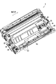
図2に示すように、現像カートリッジ8の筐体80は、底壁8Aと、側壁8Bと、補強リブ87と、溝88と、ロック部材89と、をさらに有している。
As shown in FIG. 2, the
底壁8Aは、トナーカートリッジ9が装着された状態で、トナーカートリッジ9に向かい合っている。底壁8Aは、軸方向に延びている。側壁8Bは、底壁8Aの軸方向の両側の端部から軸方向に交差する方向に延びている。
The
補強リブ87は、底壁8Aからケース90に向けて突出している。補強リブ87は、軸方向に交差する方向に延びている。補強リブ87は、側壁8Bから離間している。補強リブ87は、筐体80の剛性を高めるために補強するリブである。ロック部材89は、軸方向の端部の片側に設けられている。ロック部材89は、トナーカートリッジ9を装着完了位置にロックする部材である。
The reinforcing
図3に示すように、トナーカートリッジ9は、軸方向に延びている。トナーカートリッジ9は、ギヤカバー100をさらに有している。ギヤカバー100は、ケース90の外側に設けられている。詳しくは、ギヤカバー100は、ケース90の軸方向の一端側の側壁94に設けられている。
As shown in FIG. 3, the
図4に示すように、トナーカートリッジ9は、オーガギヤ160と、アジテータギヤ170と、アイドルギヤ180と、検知ギヤ190と、をさらに有している。オーガギヤ160は、オーガ92の一端に設けられている。オーガギヤ160は、オーガ92と一体に回転する。オーガギヤ160は、現像カートリッジ8の図示しないギヤと係合し、現像カートリッジ8のギヤを介して装置本体2から駆動力が入力される。アジテータギヤ170は、アジテータ91の一端に設けられている。アジテータギヤ170は、アジテータ91と一体に回転する。アイドルギヤ180は、オーガギヤ160およびアジテータギヤ170と噛み合っている。検知ギヤ190は、アジテータギヤ170と係合可能な位置に位置している。ギヤカバー100は、オーガギヤ160、アジテータギヤ170、アイドルギヤ180および検知ギヤ190を覆っている。検知ギヤ190は、トナーカートリッジ9が新品であるかを識別するためのギヤである。検知ギヤ190は、新品の場合に、図10(a)の第1位置に位置し、新品でない場合に、図10(b)の第2位置に位置する。
As shown in FIG. 4 , the
図3に戻り、ギヤカバー100は、本体部110と、第1突起120と、第2突起130と、第2壁140と、遮蔽壁150と、有している。
Returning to FIG. 3 , the
第1突起120は、直方体の形状を有している。第1突起120は、本体部110から軸方向に突出している。第1突起120は、軸方向と直交する方向における本体部110の端部に位置している。
The
第2突起130は、本体部110から軸方向に突出している。第2突起130は、ロック部材89と係合してトナーカートリッジ9を現像カートリッジ8にロックするためのものである。
The
第2壁140は、軸方向に交差する壁である。具体的には、第2壁140は、軸方向に直交する。第2壁140は、第2開口141を有している。第2開口141は、軸方向に貫通した孔である。第2開口141は、円形状である。第2壁140は、後述する発光素子13が発する光Lが通過できない。第2開口141は、光Lが通過可能である。
なお、ケース90の側壁94は、第2開口141と向かい合う位置に、第3開口95を有している。本実施形態では、第3開口95は、第2開口141と同じ形状で同じ大きさである。
The
A
遮蔽壁150は、本体部110から軸方向と交差する方向に延びるリブである。具体的に、遮蔽壁150は、本体部110から、筐体80の底壁8Aに向けて突出している。遮蔽壁150は、発光素子13が発する光Lが通過できない。
The shielding
図4に示すように、画像形成装置1の装置本体2は、第1側壁11と、第2側壁12と、発光素子13と、受光素子14と、第1壁15と、をさらに有している。
As shown in FIG. 4, the
第1側壁11と第2側壁12は、軸方向に互いに離れて配置されている。トナーカートリッジ9が装置本体2に装着された状態で、ギヤカバー100は、第1側壁11より第2側壁12の近くに位置する。
The
発光素子13は、第1側壁11に固定されている。受光素子14は、第2側壁12に固定されている。第1壁15は、第2側壁12に固定されている。トナーカートリッジ9が装置本体2に装着された状態で、ギヤカバー100の遮蔽壁150は、発光素子13よりも受光素子14に近い。現像カートリッジ8は、発光素子13と第1壁15との間に装着される。
The
発光素子13は、光Lを発する。受光素子14は、発光素子13と軸方向において向かい合っている。受光素子14は、光Lを検知可能である。
The
第1壁15は、軸方向において発光素子13と受光素子14の間に配置されている。第1壁15は、発光素子13より受光素子14の近くに位置している。第1壁15は、第1開口15Aを有する。
The
第1開口15Aは、軸方向において発光素子13と受光素子14との間に位置している。第1開口15Aは、軸方向に貫通した孔である。第1開口15Aは、円形状である。第1開口15Aは、第2開口141と同じ大きさをしている。第1開口15Aの直径は特に限定されないが、4~8mmが望ましい。
The
第2開口141は、トナーカートリッジ9が現像カートリッジ8に装着された状態において、現像カートリッジ8が装置本体2に装着された場合に、発光素子13と受光素子14との間に位置する。
The
図5に示すように、トナーカートリッジ9の遮蔽壁150の少なくとも一部は、トナーカートリッジ9が装着完了位置にあるとき、現像カートリッジ8の側壁8Bと、現像カートリッジ8の補強リブ87の間に位置する。
As shown in FIG. 5, at least a portion of the shielding
ここで、トナーカートリッジ9の装着方法について説明する。トナーカートリッジ9を現像カートリッジ8に装着するときには、トナーカートリッジ9を図6に示す装着開始位置にセットした後、図7に示す装着完了位置まで移動させる。
Here, a method of mounting the
図6に示すように、装着開始位置は、現像カートリッジ8に対してトナーカートリッジ9の装着を開始する位置である。具体的には、装着開始位置では、トナーカートリッジ9の第1突起120を現像カートリッジ8の溝88に挿入して、トナーカートリッジ9の端部を現像カートリッジ8に係合している。溝88は、第1突起120を軸支可能な円形の断面を有する。装着開始位置において、ロック部材89は、トナーカートリッジ9と接触しておらず、トナーカートリッジ9をロックしていない。
As shown in FIG. 6, the mounting start position is a position where mounting of the
装着開始位置から装着完了位置にするには、トナーカートリッジ9を、第1突起120を中心に約90°回動させて、トナーカートリッジ9を現像カートリッジ8に近づける。
To move from the installation start position to the installation completion position, the
図7に示すように、装着完了位置は、現像カートリッジ8に対してトナーカートリッジ9の装着が完了した位置である。装着完了位置では、ロック部材89は、第2突起130に係合してトナーカートリッジ9を装着完了位置にロックしている。
As shown in FIG. 7, the mounting completion position is a position where the
ここで、ユーザがトナーカートリッジ9を装着開始位置にセットしたあと、装着完了位置に移動させようとした場合に、ユーザの操作が不十分であると、トナーカートリッジ9は、必ずしも装着完了位置まで移動されるとは限らない。例えば、図8、図9に示すように、トナーカートリッジ9は、トナーカートリッジ9が現像カートリッジ8に装着された状態で現像カートリッジ8が装置本体2に装着されたとき、トナーカートリッジ9が装着開始位置と装着完了位置の間の位置(以下の説明では、この位置を「中間位置」という。)となる場合がある。
Here, when the user attempts to move the
図8に示すように、トナーカートリッジ9は、中間位置にあるとき、軸方向から見て、第1開口15Aと第2開口141が重ならない位置(以下の説明では「第1中間位置」という。)となる場合がある。トナーカートリッジ9が第1中間位置にあるときに、遮蔽壁150は、発光素子13が発光した光Lを遮蔽するようになっている。遮蔽壁150は、
As shown in FIG. 8, when the
図9に示すように、トナーカートリッジ9は、中間位置にあるとき、軸方向から見て、第1開口15Aと第2開口141の一部が重なる位置(以下の説明では「第2中間位置」という。)となるときがある。トナーカートリッジ9が第2中間位置にあるときには、発光素子13が発光した光Lは、第1開口15Aと第2開口141が重なる位置を通過する。このとき、通過した光Lが所定量より多ければ、受光素子14が受光可能である。
As shown in FIG. 9, when the
なお、装置本体2は、装置本体2に装着されたトナーカートリッジ9の上に内壁2Aを有している。このため、トナーカートリッジ9は、現像カートリッジ8に不十分に装着された状態で装置本体2に装着されても、少なくとも図8に示す位置までは内壁2Aに押し下げられる。すなわち、トナーカートリッジ9は、装置本体2の中に装着されると、必ず、図8の位置から図7の位置の範囲のいずれかの位置に位置する。
The apparatus
遮蔽壁150は、トナーカートリッジ9が第1中間位置にあるとき、トナーカートリッジ9がいずれの位置であっても、発光素子13が発する光Lが受光素子14に届かないように遮蔽する十分な大きさを有している。
The shielding
次に、新品検知のためのギヤ列の構成について説明する。
検知ギヤ190は、軸方向に延びる第2回転軸X2について、図10(a)に示す第1位置から図10(a)に示す第2位置へ回転可能である。
Next, the configuration of the gear train for new product detection will be described.
The
図10(a)に示すように、検知ギヤ190は、ギヤ部191と、遮蔽板192と、第1リブ193と、第2リブ194と、を有している。また、トナーカートリッジ9は、検知ギヤ190を付勢して第1位置および第2位置において検知ギヤ190を付勢するトーションばね195を有している。さらに、トナーカートリッジ9は、側壁94から突出したストッパ196を有している。ギヤ部191は、検知ギヤ190の回転方向の一部にのみギヤ歯が配置されており、回転方向にギヤ歯が並んで配置されたギヤ歯部191Aと、ギヤ歯が配置されていない欠け歯部191Bとを有する。遮蔽板192は、切欠き192Aを有している。
As shown in FIG. 10( a ), the
トナーカートリッジ9が新品の場合、トーションばね195は、第1リブ193を付勢して検知ギヤ190を回転方向に付勢する。トナーカートリッジ9が新品の場合、この付勢力によりギヤ歯部191Aのギヤ歯がアジテータギヤ170に接触してアジテータギヤ170がギヤ部191と噛み合っている。
When the
検知ギヤ190は、第1位置の場合に、第2開口141に対応する位置に切欠き192Aが位置する。すなわち、検知ギヤ190は、第1位置の場合に、発光素子13と受光素子14との間に位置しない(図4の実線参照)。このため、検知ギヤ190が第1位置の場合に、受光素子14は、第1開口15A、第2開口141および第3開口95を介して、発光素子13により発された光Lを受けることができる。
When the
検知ギヤ190は、第2位置の場合に、第2開口141に遮蔽板192が向かい合う。すなわち、検知ギヤ190は、第2位置の場合に、検知ギヤ190の一部が発光素子13と受光素子14との間に位置する(図4の破線参照)。
When the
検知ギヤ190は、第2位置の場合に、トーションばね195が第2リブ194に接触して検知ギヤ190を回転方向に付勢する。検知ギヤ190は、第1リブ193がストッパ196に接触することで、検知ギヤ190の回転が規制され、図10(b)の姿勢に維持される。検知ギヤ190は、第2位置においてギヤ歯部191Aから離れていることで、アジテータギヤ170が回転しても、回転しないようになっている。
When the
上述したように、トナーカートリッジ9には、現像カートリッジ8からオーガギヤ160に駆動力が入力される。
新品のトナーカートリッジ9が現像カートリッジ8から駆動力を受けると、アジテータギヤ170が回転し、アジテータギヤ170と噛み合っているギヤ部191が回転する。これにより、検知ギヤ190は、第1位置から、第2位置に移動する。その後、検知ギヤ190は、第2位置に停止する。
新品でないトナーカートリッジ9が現像カートリッジ8から駆動力受けると、検知ギヤ190は、第2位置に位置したまま停止している。
As described above, the
When the
When the
制御部10は、図示しないCPU(プロセッサー)、RAM、ROMなどのメモリ、入出力回路などを有し、ROMに記憶されたプログラムやデータなどの出力に基づいて画像形成装置1を制御する。そして、制御部10は、現像カートリッジ8が装置本体2に装着された後において、トナーカートリッジ9の状態を判定する新品検知制御を実行する。
The
制御部10は、トナーエンプティを示すフラグMをメモリに記憶させる。フラグMは、1の場合に、トナーエンプティであることを示し、0の場合に、トナーエンプティでないことを示すこととする。
制御部10は、開閉センサ10Aの状態を検出することで、カバー24の開閉状態を取得する。また、制御部10は、新品検知制御の実行の際に、発光素子13から光Lを発させるとともに、受光素子14での光Lの受光状態を取得する。そして、制御部10は、受光素子14での受光状態に応じ、後に詳述する処理に従ってフラグMを変更する。すなわち、制御部10は、受光素子14の受光状態に従って、トナーエンプティの状態から復帰すべきか否かを判断する。
The
The
ここで、トナーカートリッジ9の状態(新品か否かの状態および装着状態)に応じた、受光素子14の受光パターンについて図11に示すタイムチャートを使って説明する。
Here, the light receiving pattern of the
制御部10は、新品検知制御において、発光素子13により光Lを所定時間発させる(t1~t4)。
制御部10は、受光素子14により光Lを受光した場合に、トナーカートリッジ9に駆動力をONする(t2以降の実線)。
In the new product detection control, the
When the
トナーカートリッジ9が新品の場合、検知ギヤ190は、第1位置に位置するので、発光素子13が光Lを発すると、光Lが第1開口15A、第2開口141および第3開口95を通って受光素子14に達する。現像カートリッジ8から駆動力が入力されることにより検知ギヤ190は、所定角度回転する。そして、切欠き192Aが第2開口141および第3開口95に向かい合う期間だけ(t1~t3)、受光素子14が光Lを受光する。なお、図11においては、受光素子14が光Lを受光しているときをONとして示している。
When the
トナーカートリッジ9が新品でない場合、検知ギヤ190は、第2位置に位置するので、発光素子13が光Lを発しても、遮蔽板192が光Lを遮蔽する。このため、受光素子14は、光Lを受光しない。
When the
トナーカートリッジ9が第1中間位置にある場合、遮蔽壁150は、光Lを遮蔽する。このため、受光素子14は、光Lを受光しない。
The shielding
トナーカートリッジ9が現像カートリッジ8に装着されていない場合、軸方向において第1開口15Aと向かい合う位置には、検知ギヤ190と遮蔽壁150のいずれも存在しない。そのため、受光素子14は、発光素子13が光Lを発している間、常に光Lを受光する(t1~t4)。
When the
次に、制御部10の動作の一例について詳細に説明する。制御部10は、画像形成装置1の電源がONされている間、図12、図13に示す処理を繰り返し実行する。
Next, an example of the operation of the
図12に示すように、制御部10は、印刷ジョブの終了後などの適宜なタイミングにおいてトナーエンプティであるかを判断する(S1)。ステップS1において、制御部10が、トナーエンプティでないと判断した場合には(S1,No)、制御部10は、フラグMを0にし(S4)、本制御を終了する。
As shown in FIG. 12, the
なお、トナーエンプティであるかを判断する方法は、特に限定されない。本実施形態では、制御部10は、使用中のトナーカートリッジ9に対応して記憶しているドットカウントが基準値に達したときにトナーエンプティであると判断する。
Note that the method for determining whether the toner is empty is not particularly limited. In this embodiment, the
ステップS1において、制御部10が、トナーエンプティであると判断した場合(S1,Yes)、制御部10は、フラグMを1とする(S2)。ステップS2の後、制御部10は、ユーザにトナーカートリッジ9を交換するように表示パネル10Bに表示させて報知する(S3)。
In step S1, when the
制御部10は、トナーエンプティを示すフラグMが1である場合には印字を実行しない。フラグMが1である場合には、ユーザが新しいトナーカートリッジ9を装着する必要がある。
The
図13に示す処理において、制御部10は、開閉センサ10Aからカバー24の開閉状態を取得して、カバー24が閉じられたかを判断する(S10)。制御部10は、ステップS10において、制御部10が、カバー24が閉じられていないと判断すると(S10,No)、ステップS11以下の処理を行わない。
In the process shown in FIG. 13, the
ステップS10において、カバー24が閉じられたと判断すると(S10,Yes)、制御部10は、フラグMが1であるかを判断する(S11)。フラグMが1でないと判断した場合には(S11,No)、制御部10は、本制御を終了する。
In step S10, when it is determined that the
ステップS11において、フラグMが1である判断すると(S11,Yes)、制御部10は、所定時間、発光素子13から光Lを発させる(S12)(図では発光素子を発光させている状態をONと示す。)。
In step S11, when it is determined that the flag M is 1 (S11, Yes), the
ステップS12のあと、制御部10は、受光素子14は受光したかを判断する(S13)。ステップS13において、受光素子14が受光しないと判断すると(S13,No)、制御部10は、トナーカートリッジ9が新品でない、または、トナーカートリッジ9が正規の装着位置からずれている、のいずれかであることを表す情報を表示パネル10Bに表示させて報知する(S15)。ステップS15のあと、制御部10は、フラグMを変えることなく本制御を終了する。
After step S12, the
ステップS13において、制御部10は、受光素子14が受光したと判断すると(S13,Yes)、トナーカートリッジ9に駆動を入力する(S14)。
In step S13, when the
ステップS14のあと、制御部10は、受光素子14が受光したかを判断する(S16)。ステップS16において、制御部10は、所定期間の間に受光素子14が受光したと判断すると(S16,Yes)、トナーカートリッジ9が装着されていないことを表示パネル10Bに表示させて報知する(S17)。ステップS17のあと、制御部10は、フラグMを変えることなく本制御を終了する。
After step S14, the
ステップ16において、制御部10は、所定期間の間に受光素子14が受光しないと判断すると(S16,Yes)、トナーカートリッジ9が新品であることを判断したことの動作としてフラグMを0にして(S18)、本制御を終了する。フラグMが0になることで、画像形成装置1は、印刷が可能になる。
In step 16, when the
以上のように構成された画像形成装置1の作用効果について説明する。トナーカートリッジ9が現像カートリッジ8に装着された状態で現像カートリッジ8が装置本体2に装着される場合、トナーカートリッジ9が十分に現像カートリッジ8に装着されず、トナーカートリッジ9が中間位置に位置することがあり得る。
The effects of the
ここで、仮にトナーカートリッジ9が、遮蔽壁150を有さない場合の問題について説明する。図14に示すように、トナーカートリッジ9Bが遮蔽壁150を有していない場合には、第1中間位置のとき、発光素子13が発光した光Lを遮蔽することができない。このとき、発光素子13から発された光Lは、ギヤカバー100の下側を通って、受光素子14に到達しうる(斜線部A1を参照)。そのため、トナーカートリッジ9Bが第1中間位置にある場合には、制御部10は、図13のフローチャートのステップS13においてYesと判断し、トナーカートリッジ9Bに駆動を入力する(S14)。そして、制御部10は、図13のフローチャートのステップS16においてYesと判断する。つまり、制御部10は、新品のトナーカートリッジ9Bが装着されているにもかかわらず、トナーカートリッジ9Bが装着されていないと判定してしまう(S17)。そして、新品のトナーカートリッジ9Bは、現像カートリッジ8に装着されていないと判定されたにもかかわらず、駆動力に従って検知ギヤ190が回転し、検知ギヤ190が第2位置に位置してしまう。そのため、そのトナーカートリッジ9Bが、その後、正しく現像カートリッジ8の装着完了位置に装着されたとしても、制御部10は、そのトナーカートリッジ9Bを新品と判断することができない。
Here, a problem in the case where the
これに対して、本実施形態の画像形成装置1では、トナーカートリッジ9が現像カートリッジ8に装着された状態で現像カートリッジ8が装置本体2に装着されたとき、トナーカートリッジ9が装着開始位置と装着完了位置の間の位置であり、且つ、所定の方向から見て、第1開口15Aと第2開口141が重ならない位置、すなわち、第1中間位置のとき、遮蔽壁150は、発光素子13が発光した光Lを遮蔽する。このため、検知ギヤ190が第1位置にあるトナーカートリッジ9を現像カートリッジ8に正しく装着しない状態で、現像カートリッジ8を装置本体2に装着した場合に、トナーカートリッジ9が正規の装着位置からずれている可能性を検知しうる。
On the other hand, in the
例えば、制御部10は、新品検知制御において、受光素子14で、発光素子13が発光した光Lを検出しない場合には、トナーカートリッジ9が新品でない、または、トナーカートリッジ9が正規の装着位置からずれて装着されている、のいずれかであることを表す情報を報知することができる。これにより、ユーザは、トナーカートリッジ9が新品か否かや、装着状態を確認することができる。
For example, in the new product detection control, if the
また、制御部10は、新品検知制御において、受光素子14が、発光素子13が発光した光Lを検出した場合、トナーカートリッジ9が現像カートリッジ8から駆動力を受けた後も、所定時間、受光素子14が、発光素子13が発光した光Lを受光し続けた場合には、制御部10がユーザに、トナーカートリッジ9が現像カートリッジ8に装着されていないことを表す情報を報知することができる。これにより、ユーザは、トナーカートリッジ9の装着忘れに気付くことができる。
Further, in the new product detection control, when the
ところで、トナーカートリッジ9が新品で、第2中間位置にある場合、(1)受光素子14が受光可能な程度に第1開口15Aと第2開口141が重なっている場合と、(2)受光素子14が受光不能な程度に第1開口15Aと第2開口141がずれている場合とがある。
By the way, when the
(1)受光素子14が受光可能な程度に第1開口15Aと第2開口141が重なっている場合、発光素子13が発した光Lは、第1開口15Aと第2開口141の両方を通って受光素子14に届くので、制御部10は、新品のトナーカートリッジ9が装着完了位置に装着された場合と同様に動作する。すなわち、ユーザは、新品のトナーカートリッジ9を問題無く新品として使用することができる。
(1) When the
(2)受光素子14が受光不能な程度に第1開口15Aと第2開口141がずれている場合、発光素子13が発した光Lは、受光素子14に届かない。そのため、制御部10は、図13のフローチャートのステップS13においてNoと判断し、トナーカートリッジ9が新品でない、または、トナーカートリッジ9が正規の装着位置からずれている、のいずれかであることを表す情報を報知する(S15)。このため、ユーザは、新品のトナーカートリッジ9を装着完了位置に正しく装着しなおせばよい。
(2) When the
すなわち、本実施形態の画像形成装置1によれば、トナーカートリッジ9が新品で、第2中間位置にある場合であったとしても、トナーカートリッジ9が装着されていないと判断されて、トナーカートリッジ9が新品として使用できなくなることを抑制できる。
That is, according to the
また、制御部10は、新品検知制御において、受光素子14が、発光素子13が発光した光Lを検出した場合、トナーカートリッジ9に駆動力を入力する。そして、制御部10は、トナーカートリッジ9が現像カートリッジ8から駆動力を受けた後に、受光素子14が、発光素子13が発光した光Lを検出しなくなった場合には、トナーカートリッジ9が新品であると判断することができる。
In the new product detection control, the
また、遮蔽壁150が、ケース90の外側のギヤカバー100に設けられているので、検知ギヤ190に近い位置に遮蔽壁150を設けることができ、発光素子13が発光した光Lを適切に遮蔽しやすい。
Further, since the shielding
また、遮蔽壁150がギヤカバー100から軸方向と交差する方向に延びるリブであるので、遮蔽壁150を必要十分な大きさで設けることができる。
Further, since the shielding
また、遮蔽壁150が発光素子13よりも受光素子14に近いので、遮蔽壁150が受光素子14よりも発光素子13に近い場合に比べて、適切に光Lを遮蔽することができる。
Further, since the shielding
また、トナーカートリッジ9が装着完了位置にあるとき、遮蔽壁150の少なくとも一部は、側壁8Bと補強リブ87の間に位置する。このため、発光素子13から発光された光Lが装置本体2内で反射しても、現像カートリッジ8の補強リブ87とトナーカートリッジ9の遮蔽壁150と側壁8Bとが軸方向で重なって並ぶので、受光素子14まで光Lが届きにくい。
At least part of the shielding
また、現像カートリッジ8は、トナーカートリッジ9を装着完了位置にロックするロック部材89を有するので、トナーカートリッジ9を装着完了位置に安定して維持することができる。
Further, since the developing
以上、本発明の実施形態について説明したが、本発明は前記実施形態に限定されるものではない。具体的な構成については、本発明の趣旨を逸脱しない範囲で適宜変更が可能である。 Although the embodiments of the present invention have been described above, the present invention is not limited to the above embodiments. The specific configuration can be changed as appropriate without departing from the gist of the present invention.
上述の実施形態では、遮蔽壁150は、ギヤカバー100に設けられたリブであったが、遮蔽壁の位置および形状はこれに限られない。例えば、遮蔽壁は、ケース90に設けられたリブであってもよいし、ケース90の側壁であってもよい。
In the above-described embodiment, shielding
上述の実施形態では、第1開口および第2開口の形状は円形状であったが、第1開口および第2開口は、円形状でなくてもよく、例えば、多角形、楕円、切欠きなどであってもよい。 In the above-described embodiments, the shapes of the first opening and the second opening were circular, but the first opening and the second opening may be non-circular, such as polygonal, elliptical, notched, etc. may be
上述の各実施形態においては、モノクロのレーザプリンタの画像形成装置を例示したが、画像形成装置はカラーの画像形成装置であってもよいし、LEDにより露光するものであってもよいし、コピー機や複合機であってもよい。 In each of the above-described embodiments, the image forming apparatus of a monochrome laser printer was exemplified, but the image forming apparatus may be a color image forming apparatus, an apparatus that exposes with an LED, or a copier. It may be a machine or a multi-function machine.
上述した各実施形態および各変形例の各要素は、任意に組み合わせて実施することが可能である。 Each element of each embodiment and each modification described above can be arbitrarily combined and implemented.
1 画像形成装置
2 装置本体
9 トナーカートリッジ
10 制御部
11 第1側壁
12 第2側壁
13 発光素子
14 受光素子
15 第1壁
15A 第1開口
89 ロック部材
90 ケース
100 ギヤカバー
140 第2壁
141 第2開口
150 遮蔽壁
190 検知ギヤ
REFERENCE SIGNS
Claims (9)
前記装置本体に対して前記発光素子と前記第1壁との間に着脱可能な現像カートリッジであって、前記所定の方向に延びる第1回転軸について回転可能な現像ローラを有する現像カートリッジと、
前記現像カートリッジに着脱可能であり、トナーを収容可能なトナーカートリッジであって、
前記所定の方向に貫通した第2開口であって、前記トナーカートリッジが前記現像カートリッジに装着された状態において、前記現像カートリッジが前記装置本体に装着された場合に、前記受光素子と前記発光素子との間に位置する第2開口を有する第2壁と、
前記所定の方向に延びる第2回転軸について第1位置から第2位置へ回転可能な検知ギヤであって、前記検知ギヤが前記第1位置の場合に前記検知ギヤは前記発光素子と前記受光素子との間に位置せず、前記検知ギヤが前記第2位置の場合に、前記検知ギヤの一部が前記発光素子と前記受光素子との間に位置する検知ギヤと、
を有するトナーカートリッジと、
制御部と、を備え、
前記トナーカートリッジが前記現像カートリッジに装着されるとき、前記トナーカートリッジは、前記トナーカートリッジの端部が前記現像カートリッジに係合し、前記現像カートリッジに対して前記トナーカートリッジの装着を開始する装着開始位置と、前記現像カートリッジに対して前記トナーカートリッジの装着が完了した装着完了位置との間で移動が可能であり、
前記トナーカートリッジが前記現像カートリッジに装着された状態で前記現像カートリッジが前記装置本体に装着されたとき、前記トナーカートリッジが前記装着完了位置の場合に、前記第2開口は、前記受光素子と前記発光素子との間に位置し、前記検知ギヤが前記第1位置の場合に、前記受光素子は、前記第1開口および前記第2開口を介して、前記発光素子により発された光を受けることができる画像形成装置であって、
前記トナーカートリッジは、前記トナーカートリッジが前記現像カートリッジに装着された状態で前記現像カートリッジが前記装置本体に装着されたとき、前記トナーカートリッジが前記装着開始位置と前記装着完了位置の間の位置であり、且つ、前記所定の方向から見て、前記第1開口と前記第2開口が重ならない位置のときに、前記発光素子が発した光を遮蔽する遮蔽壁をさらに有し、
前記検知ギヤは、
前記トナーカートリッジが新品の場合、前記第1位置に位置し、
前記検知ギヤが回転すると、前記第1位置から前記第2位置に移動し、
新品の前記トナーカートリッジが前記現像カートリッジから駆動力を受けると、前記第1位置から、前記第2位置に移動し、
新品でない前記トナーカートリッジが前記現像カートリッジから駆動力を受けると、前記第2位置に位置したまま停止しており、
前記制御部は、
前記現像カートリッジが前記装置本体に装着された後において、前記発光素子に光を発させトナーカートリッジの状態を判定する新品検知制御を実行し、
トナーエンプティが判定されている状態において、前記新品検知制御を実行する場合、前記受光素子で、前記発光素子が発した光を検出しない場合には、前記トナーカートリッジが新品でない、または、トナーカートリッジが正規の装着位置からずれて装着されている、のいずれかであることを表す情報を報知することを特徴とする画像形成装置。 a light-emitting element, a light-receiving element facing the light-emitting element in a predetermined direction, and a first wall disposed between the light-emitting element and the light-receiving element in the predetermined direction and positioned closer to the light-receiving element than the light-emitting element. an apparatus main body having a first wall penetrating in the predetermined direction and having a first opening positioned between the light emitting element and the light receiving element in the predetermined direction;
a developing cartridge detachable between the light emitting element and the first wall with respect to the apparatus main body, the developing cartridge having a developing roller rotatable about a first rotation shaft extending in the predetermined direction;
A toner cartridge that is detachable from the developing cartridge and can contain toner,
The second opening penetrating in the predetermined direction, wherein the light-receiving element and the light-emitting element are aligned when the developing cartridge is attached to the apparatus body in a state in which the toner cartridge is attached to the developing cartridge. a second wall having a second opening located between;
A detection gear rotatable from a first position to a second position about the second rotation shaft extending in the predetermined direction, wherein when the detection gear is at the first position, the detection gear includes the light emitting element and the light receiving element. and a part of the detection gear positioned between the light-emitting element and the light-receiving element when the detection gear is in the second position;
a toner cartridge having
a control unit ;
When the toner cartridge is attached to the developer cartridge, the toner cartridge is in an attachment start position where an end portion of the toner cartridge is engaged with the developer cartridge and attachment of the toner cartridge to the developer cartridge is started. and an installation completion position where installation of the toner cartridge is completed with respect to the development cartridge,
When the developing cartridge is attached to the apparatus main body while the toner cartridge is attached to the developing cartridge, and the toner cartridge is at the attachment completion position, the second opening is formed by the light receiving element and the light emitting element. element, and when the detection gear is in the first position, the light receiving element can receive light emitted by the light emitting element through the first opening and the second opening. An image forming apparatus capable of
The toner cartridge is positioned between the installation start position and the installation completion position when the toner cartridge is installed in the developing cartridge and the developing cartridge is installed in the apparatus main body. and further comprising a shielding wall that shields the light emitted by the light emitting element when the first opening and the second opening do not overlap when viewed from the predetermined direction,
The detection gear is
When the toner cartridge is new, it is positioned at the first position;
When the sensing gear rotates, it moves from the first position to the second position;
When the new toner cartridge receives a driving force from the developing cartridge, it moves from the first position to the second position,
When the toner cartridge, which is not new, receives a driving force from the developing cartridge, it stops at the second position, and
The control unit
after the developing cartridge is attached to the apparatus main body, executing new product detection control for determining the state of the toner cartridge by causing the light emitting element to emit light;
When the new product detection control is executed in a state in which the toner is determined to be empty, if the light receiving element does not detect the light emitted by the light emitting element, the toner cartridge is not new, or the toner cartridge is out of stock. An image forming apparatus that notifies information indicating that the image forming apparatus is mounted at a position deviated from a normal mounting position .
前記遮蔽壁は、前記ギヤカバーに設けられていることを特徴とする請求項1に記載の画像形成装置。 The toner cartridge has a case containing toner, and a gear cover provided outside the case and covering the detection gear,
2. The image forming apparatus according to claim 1, wherein the shielding wall is provided on the gear cover.
前記トナーカートリッジに向かい合う底壁であって、前記所定の方向に延びる底壁と、
前記底壁の前記所定の方向の端部から前記所定の方向に交差する方向に延びる側壁と、
前記底壁から突出する補強リブであって、前記所定の方向に交差する方向に延びる補強リブと、を有し、
前記遮蔽壁の少なくとも一部は、前記トナーカートリッジが前記装着完了位置にあるとき、前記側壁と前記補強リブの間に位置することを特徴とする請求項1から請求項4のいずれか1項に記載の画像形成装置。 The developing cartridge is
a bottom wall facing the toner cartridge and extending in the predetermined direction;
a side wall extending from an end of the bottom wall in the predetermined direction in a direction crossing the predetermined direction;
a reinforcing rib projecting from the bottom wall and extending in a direction intersecting the predetermined direction;
5. The toner cartridge according to any one of claims 1 to 4, wherein at least part of said shielding wall is positioned between said side wall and said reinforcing rib when said toner cartridge is in said completely installed position. The described image forming apparatus.
前記受光素子が、前記発光素子が発した光を検出した場合、前記現像カートリッジから前記トナーカートリッジに駆動力を入力した後も、所定時間、前記受光素子が、前記発光素子が発した光を受光し続けた場合には、前記トナーカートリッジが前記現像カートリッジに装着されていないことを表す情報を報知することを特徴とする請求項1から請求項7のいずれか1項に記載の画像形成装置。 In the new product detection control, the control unit includes:
When the light-receiving element detects the light emitted by the light-emitting element, the light-receiving element receives the light emitted by the light-emitting element for a predetermined time even after the driving force is input from the developing cartridge to the toner cartridge. 8. The image forming apparatus according to any one of claims 1 to 7, wherein information indicating that the toner cartridge is not attached to the developing cartridge is notified when the image forming apparatus continues to do so.
前記受光素子が、前記発光素子が発した光を検出した場合、前記現像カートリッジから前記トナーカートリッジに駆動力を入力した後に、前記受光素子で、前記発光素子が発した光を検出しなくなった場合には、前記トナーカートリッジが新品であると判断することを特徴とする請求項1から請求項8のいずれか1項に記載の画像形成装置。 In the new product detection control, the control unit includes:
When the light-receiving element detects the light emitted by the light-emitting element, and when the light-receiving element stops detecting the light emitted by the light-emitting element after the driving force is input from the developing cartridge to the toner cartridge. 9. The image forming apparatus according to claim 1 , wherein the toner cartridge is determined to be new.
Priority Applications (2)
| Application Number | Priority Date | Filing Date | Title |
|---|---|---|---|
| JP2018086708A JP7110706B2 (en) | 2018-04-27 | 2018-04-27 | image forming device |
| CN201920473118.4U CN209657089U (en) | 2018-04-27 | 2019-04-09 | Image forming apparatus |
Applications Claiming Priority (1)
| Application Number | Priority Date | Filing Date | Title |
|---|---|---|---|
| JP2018086708A JP7110706B2 (en) | 2018-04-27 | 2018-04-27 | image forming device |
Publications (2)
| Publication Number | Publication Date |
|---|---|
| JP2019191476A JP2019191476A (en) | 2019-10-31 |
| JP7110706B2 true JP7110706B2 (en) | 2022-08-02 |
Family
ID=68387749
Family Applications (1)
| Application Number | Title | Priority Date | Filing Date |
|---|---|---|---|
| JP2018086708A Active JP7110706B2 (en) | 2018-04-27 | 2018-04-27 | image forming device |
Country Status (2)
| Country | Link |
|---|---|
| JP (1) | JP7110706B2 (en) |
| CN (1) | CN209657089U (en) |
Families Citing this family (2)
| Publication number | Priority date | Publication date | Assignee | Title |
|---|---|---|---|---|
| JP2022157973A (en) * | 2021-04-01 | 2022-10-14 | ブラザー工業株式会社 | Toner cartridge and drum cartridge |
| CN117724312B (en) * | 2024-02-09 | 2024-04-16 | 珠海市颂洋科技有限公司 | Toner storage and supply device and image forming apparatus |
Citations (3)
| Publication number | Priority date | Publication date | Assignee | Title |
|---|---|---|---|---|
| JP2012226234A (en) | 2011-04-22 | 2012-11-15 | Brother Ind Ltd | Image forming apparatus |
| JP2018031961A (en) | 2016-08-26 | 2018-03-01 | 京セラドキュメントソリューションズ株式会社 | Toner container and image forming apparatus |
| JP2018055065A (en) | 2016-09-30 | 2018-04-05 | ブラザー工業株式会社 | Toner cartridge |
Family Cites Families (2)
| Publication number | Priority date | Publication date | Assignee | Title |
|---|---|---|---|---|
| JP4630166B2 (en) * | 2005-09-27 | 2011-02-09 | 株式会社沖データ | Developer accommodating device, developing device, and image forming apparatus |
| PL3167338T3 (en) * | 2015-09-29 | 2019-04-30 | Brother Ind Ltd | Developer cartridge |
-
2018
- 2018-04-27 JP JP2018086708A patent/JP7110706B2/en active Active
-
2019
- 2019-04-09 CN CN201920473118.4U patent/CN209657089U/en active Active
Patent Citations (3)
| Publication number | Priority date | Publication date | Assignee | Title |
|---|---|---|---|---|
| JP2012226234A (en) | 2011-04-22 | 2012-11-15 | Brother Ind Ltd | Image forming apparatus |
| JP2018031961A (en) | 2016-08-26 | 2018-03-01 | 京セラドキュメントソリューションズ株式会社 | Toner container and image forming apparatus |
| JP2018055065A (en) | 2016-09-30 | 2018-04-05 | ブラザー工業株式会社 | Toner cartridge |
Also Published As
| Publication number | Publication date |
|---|---|
| JP2019191476A (en) | 2019-10-31 |
| CN209657089U (en) | 2019-11-19 |
Similar Documents
| Publication | Publication Date | Title |
|---|---|---|
| JP4867955B2 (en) | Image forming apparatus | |
| US7283773B2 (en) | Toner container, image forming apparatus, and method for identifying toner container | |
| JP2007148285A (en) | Image forming apparatus and developing cartridge | |
| JP2007093931A (en) | Developing cartridge and image forming apparatus | |
| US9594328B2 (en) | Image forming apparatus having cartridge detachably mounted therein | |
| JP6252442B2 (en) | Developer guide device and image forming apparatus having the same | |
| JP7110706B2 (en) | image forming device | |
| US11402782B2 (en) | Image forming apparatus and control method thereof | |
| JP2005099434A (en) | Toner container and image forming apparatus provided with the same | |
| JP2009180984A (en) | Developing cartridge | |
| JP2009244558A (en) | Developing cartridge | |
| JP2012255918A (en) | Powder storage container, and image forming apparatus | |
| JP5945524B2 (en) | Image forming apparatus provided with toner container | |
| JP2013029663A (en) | Image forming apparatus | |
| CN108693640B (en) | Image forming apparatus and abnormality detection method | |
| JP4443590B2 (en) | Toner cartridge and image forming apparatus | |
| JP5040616B2 (en) | Image forming apparatus and cartridge | |
| JP6088367B2 (en) | Toner cartridge and image forming apparatus using the same | |
| JP7404045B2 (en) | Display device, image forming device equipped with display device, and method for manufacturing display device | |
| US10732544B2 (en) | Toner replenishing apparatus with agitation member, developer, and image forming apparatus | |
| JP5652437B2 (en) | Toner supply device and image forming apparatus | |
| JP4328999B2 (en) | Method for detecting attachment of toner container of image forming apparatus | |
| JP7163680B2 (en) | Paper feeding device, image forming device, drawer regulation method | |
| JP4645613B2 (en) | Image forming apparatus | |
| JP3854955B2 (en) | Development unit |
Legal Events
| Date | Code | Title | Description |
|---|---|---|---|
| A621 | Written request for application examination |
Free format text: JAPANESE INTERMEDIATE CODE: A621 Effective date: 20210423 |
|
| A977 | Report on retrieval |
Free format text: JAPANESE INTERMEDIATE CODE: A971007 Effective date: 20220204 |
|
| A131 | Notification of reasons for refusal |
Free format text: JAPANESE INTERMEDIATE CODE: A131 Effective date: 20220215 |
|
| A521 | Request for written amendment filed |
Free format text: JAPANESE INTERMEDIATE CODE: A523 Effective date: 20220408 |
|
| TRDD | Decision of grant or rejection written | ||
| A01 | Written decision to grant a patent or to grant a registration (utility model) |
Free format text: JAPANESE INTERMEDIATE CODE: A01 Effective date: 20220621 |
|
| A61 | First payment of annual fees (during grant procedure) |
Free format text: JAPANESE INTERMEDIATE CODE: A61 Effective date: 20220704 |
|
| R150 | Certificate of patent or registration of utility model |
Ref document number: 7110706 Country of ref document: JP Free format text: JAPANESE INTERMEDIATE CODE: R150 |