JP7106798B2 - Pressurized short-circuit inspection device for detecting pouch-type secondary battery cells with low voltage defects - Google Patents
Pressurized short-circuit inspection device for detecting pouch-type secondary battery cells with low voltage defects Download PDFInfo
- Publication number
- JP7106798B2 JP7106798B2 JP2021535165A JP2021535165A JP7106798B2 JP 7106798 B2 JP7106798 B2 JP 7106798B2 JP 2021535165 A JP2021535165 A JP 2021535165A JP 2021535165 A JP2021535165 A JP 2021535165A JP 7106798 B2 JP7106798 B2 JP 7106798B2
- Authority
- JP
- Japan
- Prior art keywords
- cell
- block
- circuit inspection
- pressurized
- pressurizing
- Prior art date
- Legal status (The legal status is an assumption and is not a legal conclusion. Google has not performed a legal analysis and makes no representation as to the accuracy of the status listed.)
- Active
Links
Images


Classifications
-
- G—PHYSICS
- G01—MEASURING; TESTING
- G01R—MEASURING ELECTRIC VARIABLES; MEASURING MAGNETIC VARIABLES
- G01R31/00—Arrangements for testing electric properties; Arrangements for locating electric faults; Arrangements for electrical testing characterised by what is being tested not provided for elsewhere
- G01R31/36—Arrangements for testing, measuring or monitoring the electrical condition of accumulators or electric batteries, e.g. capacity or state of charge [SoC]
- G01R31/385—Arrangements for measuring battery or accumulator variables
-
- G—PHYSICS
- G01—MEASURING; TESTING
- G01R—MEASURING ELECTRIC VARIABLES; MEASURING MAGNETIC VARIABLES
- G01R31/00—Arrangements for testing electric properties; Arrangements for locating electric faults; Arrangements for electrical testing characterised by what is being tested not provided for elsewhere
- G01R31/50—Testing of electric apparatus, lines, cables or components for short-circuits, continuity, leakage current or incorrect line connections
- G01R31/52—Testing for short-circuits, leakage current or ground faults
-
- H—ELECTRICITY
- H01—ELECTRIC ELEMENTS
- H01M—PROCESSES OR MEANS, e.g. BATTERIES, FOR THE DIRECT CONVERSION OF CHEMICAL ENERGY INTO ELECTRICAL ENERGY
- H01M10/00—Secondary cells; Manufacture thereof
- H01M10/04—Construction or manufacture in general
- H01M10/0481—Compression means other than compression means for stacks of electrodes and separators
-
- H—ELECTRICITY
- H01—ELECTRIC ELEMENTS
- H01M—PROCESSES OR MEANS, e.g. BATTERIES, FOR THE DIRECT CONVERSION OF CHEMICAL ENERGY INTO ELECTRICAL ENERGY
- H01M10/00—Secondary cells; Manufacture thereof
- H01M10/42—Methods or arrangements for servicing or maintenance of secondary cells or secondary half-cells
- H01M10/4285—Testing apparatus
-
- H—ELECTRICITY
- H01—ELECTRIC ELEMENTS
- H01M—PROCESSES OR MEANS, e.g. BATTERIES, FOR THE DIRECT CONVERSION OF CHEMICAL ENERGY INTO ELECTRICAL ENERGY
- H01M50/00—Constructional details or processes of manufacture of the non-active parts of electrochemical cells other than fuel cells, e.g. hybrid cells
- H01M50/10—Primary casings, jackets or wrappings of a single cell or a single battery
- H01M50/102—Primary casings, jackets or wrappings of a single cell or a single battery characterised by their shape or physical structure
- H01M50/105—Pouches or flexible bags
-
- G—PHYSICS
- G01—MEASURING; TESTING
- G01R—MEASURING ELECTRIC VARIABLES; MEASURING MAGNETIC VARIABLES
- G01R31/00—Arrangements for testing electric properties; Arrangements for locating electric faults; Arrangements for electrical testing characterised by what is being tested not provided for elsewhere
- G01R31/36—Arrangements for testing, measuring or monitoring the electrical condition of accumulators or electric batteries, e.g. capacity or state of charge [SoC]
-
- Y—GENERAL TAGGING OF NEW TECHNOLOGICAL DEVELOPMENTS; GENERAL TAGGING OF CROSS-SECTIONAL TECHNOLOGIES SPANNING OVER SEVERAL SECTIONS OF THE IPC; TECHNICAL SUBJECTS COVERED BY FORMER USPC CROSS-REFERENCE ART COLLECTIONS [XRACs] AND DIGESTS
- Y02—TECHNOLOGIES OR APPLICATIONS FOR MITIGATION OR ADAPTATION AGAINST CLIMATE CHANGE
- Y02E—REDUCTION OF GREENHOUSE GAS [GHG] EMISSIONS, RELATED TO ENERGY GENERATION, TRANSMISSION OR DISTRIBUTION
- Y02E60/00—Enabling technologies; Technologies with a potential or indirect contribution to GHG emissions mitigation
- Y02E60/10—Energy storage using batteries
Description
本発明は、低電圧不良の二次電池セルを検出するための装置であって、より詳しくは、パッケージング工程が完了したパウチ型二次電池セルを加圧し電流を印加して低電圧不良セルを検出する加圧短絡検査装置に関する。 The present invention is an apparatus for detecting a low voltage defective secondary battery cell, and more particularly, a pouch-type secondary battery cell that has undergone a packaging process is pressurized and current is applied to detect a low voltage defective cell. It relates to a pressurized short-circuit inspection device that detects
本出願は、2019年9月18日出願の韓国特許出願第10-2019-0114920号に基づく優先権を主張し、該当出願の明細書及び図面に開示された内容は、すべて本出願に組み込まれる。 This application claims priority based on Korean Patent Application No. 10-2019-0114920 filed on September 18, 2019, and all contents disclosed in the specification and drawings of that application are incorporated into this application. .
最近、環境にやさしいエネルギー源として二次電池に対する需要が急増しつつあり、この中でも高いエネルギー密度と作動電位を示し、サイクル寿命が長く、また、自己放電率の低いリチウム二次電池が商用化して広く使用されている。 Recently, the demand for secondary batteries as an environment-friendly energy source is rapidly increasing. Among them, lithium secondary batteries, which exhibit high energy density and operating potential, have a long cycle life and a low self-discharge rate, have been commercialized. Widely used.
リチウム二次電池は、正極活物質及び負極活物質が各々塗布された正極板及び負極板が分離膜を挟んで配置された電極組立体と、電極組立体を電解液と共に密封収納する外装材、即ち、電池ケースを備える。 A lithium secondary battery includes an electrode assembly in which a positive electrode plate and a negative electrode plate coated with a positive active material and a negative active material are respectively disposed with a separation film sandwiched therebetween; That is, it has a battery case.
前記リチウム二次電池を構成する正極/分離膜/負極構造の電極組立体は、構造によってゼリーロール型(巻取り型)、スタック型(積層型)及びこれらの混合形態である積層/折畳み型に分けられる。 The electrode assembly having a positive electrode/separator/negative electrode structure constituting the lithium secondary battery can be classified into a jelly roll type (winding type), a stack type (laminated type), and a laminated/folded type, which is a mixture thereof, depending on the structure. divided.
ゼリーロール型の電極組立体は、集電体に使用される金属ホイルに電極活物質などをコーティングし、乾燥及びプレスした後、所望する幅と長さのバンド形態に裁断し、分離膜を使用して負極と正極とを隔膜した後、螺旋状に巻き取って製造される。ゼリーロール型の電極組立体は、円筒型電池に適する。 A jelly roll type electrode assembly is made by coating a metal foil used as a current collector with an electrode active material, drying and pressing it, then cutting it into a band of a desired width and length, and using a separation membrane. After separating the negative electrode and the positive electrode, it is spirally wound. A jelly roll type electrode assembly is suitable for a cylindrical battery.
スタック型の電極組立体は、複数の正極及び負極単位体を順次に積層した構造であって、角形の形態が容易に得られる。そして、積層/折畳み型の電極組立体は、一定の単位大きさの正極/分離膜/負極構造のフルセル(full cell)または正極/分離膜/負極/分離膜/正極構造のバイセル(bi-cell)を長い長さの連続的な分離膜フィルムを用いて折り畳んで製造される。前記スタック型または積層/折畳み型の電極組立体は、パウチ型二次電池に適する。 A stack-type electrode assembly has a structure in which a plurality of positive and negative electrode units are sequentially stacked, and a rectangular shape can be easily obtained. The stacked/folded electrode assembly may be a full cell having a positive electrode/separator/negative electrode structure or a bi-cell having a positive electrode/separator/negative electrode/separator/cathode structure. ) is folded using a long length of continuous separator film. The stack type or laminated/folded type electrode assembly is suitable for a pouch type secondary battery.
一方、製造済みの二次電池が自己放電率以上の電圧降下挙動を示す不良を低電圧不良といい、これは、電極組立体の組立て過程で、分離膜の破れ、刺されまたは折れなどによる分離膜の欠陷に原因すると把握される。 On the other hand, a defect in which a manufactured secondary battery exhibits a voltage drop behavior higher than the self-discharge rate is called a low voltage defect. It is understood that it is caused by the deficiency of
前記分離膜は、正極板と負極板との物理的接触を防止する電気的な絶縁体の役割を果たす多孔性高分子からなるフィルムである。このような分離膜が絶縁体として本来の機能ができなくなると、漏れ電流が発生することがあり、これは二次電池の発火原因になることもある。 The separator is a porous polymer film that serves as an electrical insulator to prevent physical contact between the positive electrode plate and the negative electrode plate. If the separation membrane cannot perform its original function as an insulator, leakage current may occur, which may cause ignition of the secondary battery.
前記分離膜の欠陥類型の一例として、図1を参照すれば、積層/折畳み型の電極組立体を製造するに際し、グリッパー2を用いて分離膜3とバイセル4を把持し、一方向へ折り畳む折畳み工程を行うが、この際、分離膜3の縁部で分離膜の破れ5がよく発生する。
As an example of the defect type of the separation membrane, refer to FIG. During the process, separation membrane breaks 5 often occur at the edges of the
例えば、折畳み完了後、グリッパー2を取り出す(後進)とき、グリッパー2の応力またはグリッパー2についている異物によって分離膜3の縁部が破れるか、または穴が開くことがある。
For example, when the
その他にも、電極組立体の積層過程で分離膜の角領域が内側へ折られて、当該部分に正極板及び負極板が当てられるか、正極板及び負極板の電極板に電極タブを溶接するときに発生し得るバリー(burr)によって分離膜に穴ができることもある。 In addition, in the stacking process of the electrode assembly, the corner region of the separator is folded inward, and the positive electrode plate and the negative electrode plate are applied to the corner region, or an electrode tab is welded to the electrode plate of the positive electrode plate and the negative electrode plate. Occasionally, burrs that may occur may cause holes in the separation membrane.
従来、上記のような分離膜の欠陥の有無を検出するために、「田」字形状のジグを使用して二次電池セルの胴体を加圧しながらハイポット(hi-pot) テストによって漏れ電流を測定して低電圧不良セルを検出していた。 Conventionally, in order to detect the presence or absence of defects in the separation membrane as described above, leakage current is measured by a hi-pot test while pressurizing the body of the secondary battery cell using a jig shaped like a square. It was measuring and detecting low voltage bad cells.
しかし、現在「田」字形状のジグの場合、セルの胴体を押す圧力が弱くて、分離膜の欠陥部位に正極板及び負極板の一時的な短絡がよく誘導されず、正確な検査が行われていないというのが実情である。したがって、加圧短絡検査に使用可能な装備の開発が必要である。 However, in the case of the jig in the shape of the square square, the pressing pressure on the cell body is weak, and the temporary short circuit between the positive electrode plate and the negative electrode plate is not well induced at the defective part of the separator, so that accurate inspection is not performed. The reality is that it is not. Therefore, it is necessary to develop equipment that can be used for pressurized short-circuit inspection.
一方、二次電池セルの胴体の全面を加圧して、セル内部の気泡除去及び電解液の濡れ性(wetting)を高めるためのセル加圧工程がある。前記セル加圧工程に使用されるジグ加圧装置は、従来の加圧短絡検査装置と異なる圧力範囲で二次電池セルの胴体の全面を押圧するものであって、装備の仕様差によって加圧短絡検査工程とセル加圧工程とは別の装置で行われている。 On the other hand, there is a cell pressurization process to pressurize the entire surface of the body of the secondary battery cell to remove air bubbles inside the cell and improve the wetting of the electrolyte. The jig pressurizing device used in the cell pressurizing process presses the entire surface of the body of the secondary battery cell in a pressure range different from that of the conventional pressurizing short-circuit inspection device. The short-circuit inspection process and the cell pressurization process are performed by separate devices.
したがって、現在、コスト節減及び生産性の向上のために加圧短絡検査工程のみならず、セル加圧工程まで一気に行い得る新規装備の開発がイシューになりつつある。 Therefore, in order to reduce costs and improve productivity, it is becoming an issue to develop new equipment that can perform not only the pressurization short-circuit inspection process but also the cell pressurization process at once.
本発明は、上記の技術的な背景を考慮してなされたものであり、信頼性のある加圧短絡検査工程を実施可能な加圧短絡検査装置を提供することを目的とする。 SUMMARY OF THE INVENTION It is an object of the present invention to provide a pressurized short-circuit inspection apparatus capable of performing a reliable pressurized short-circuit inspection process.
また、本発明は、前記加圧短絡検査装置によって加圧短絡検査工程とセル加圧工程とを統合化することで、コスト節減及び生産性の向上を図ることを他の目的とする。 Another object of the present invention is to reduce costs and improve productivity by integrating the pressurized short-circuit inspection process and the cell pressurization process using the pressurized short-circuit inspection apparatus.
本発明が解決しようとする課題は上述の課題に制限されず、言及されていないさらに他の課題は、下記の発明の説明から当業者に明確に理解されるであろう。 The problems to be solved by the present invention are not limited to the above problems, and still other problems not mentioned will be clearly understood by those skilled in the art from the following description of the invention.
上記の課題を達成するために、本発明の一実施例による加圧短絡検査装置は、二次電池セルを少なくとも一つずつ挿入できるように相互に所定の距離で離隔して配列され、前記離隔距離が調節されるように±X軸方向へ移動可能な圧着プレートと、前記二次電池セルの胴体における予め決められた領域を加圧するセル加圧部と、前記二次電池セルの電極リード部分に接触してテスト電圧を印加する電源供給部と、を備え、前記圧着プレートの各々に±Y軸方向に沿って移動可能に取り付けられる加圧短絡検査組立体と、を含み得る。 In order to achieve the above object, a pressurized short-circuit inspection apparatus according to an embodiment of the present invention is arranged with a predetermined distance from each other so that at least one secondary battery cell can be inserted, and the spaced-apart A crimping plate movable in the ±X-axis direction so as to adjust the distance, a cell pressurizing part that presses a predetermined area in the body of the secondary battery cell, and an electrode lead portion of the secondary battery cell. and a pressurized short circuit test assembly movably mounted on each of the crimping plates along the ±Y-axis direction.
前記セル加圧部は少なくとも一面にボールを備え、前記ボールによって前記二次電池セルの胴体が加圧され得る。 The cell pressing part has a ball on at least one surface, and the body of the secondary battery cell may be pressed by the ball.
前記セル加圧部は、前記圧着プレートの前面と後面に各々重ねられて配置される加圧パッドを含み、前記ボールは前記加圧パッドに部分的に埋設され得る。 The cell pressurizing part may include pressurizing pads arranged to overlap front and rear surfaces of the pressing plate, and the balls may be partially embedded in the pressurizing pads.
前記セル加圧部と前記電源供給部とは、一体で移動可能に設けられ得る。 The cell pressurizing unit and the power supply unit may be integrally provided so as to be movable.
前記セル加圧部は、前記電源供給部に対して±Y軸方向に沿って移動可能に前記電源供給部に連結され得る。 The cell pressure unit may be connected to the power supply unit so as to be movable along ±Y-axis directions with respect to the power supply unit.
前記加圧短絡検査組立体は、前記セル加圧部と前記電源供給部とを一つの胴体として連結する構造強化ブロック部をさらに含み得る。 The pressurized short circuit inspection assembly may further include a structural reinforcement block unit connecting the cell pressurizer and the power supply unit as one body.
前記構造強化ブロック部は、前記セル加圧部と前記電源供給部との上端部を連結し、前記圧着プレートの上端に摺動可能に取り付けられる上部ブロックと、前記セル加圧部と前記電源供給部との下端部を連結し、前記圧着プレートの下端に摺動可能に取り付けられる下部ブロックと、を含み得る。 The structural reinforcement block part connects upper ends of the cell pressurizing part and the power supply part and is slidably attached to an upper end of the crimping plate; a lower block connecting the lower end of the crimp plate and slidably mounted to the lower end of the crimp plate.
前記上部ブロック及び前記下部ブロックは、前記圧着プレートの上端と下端に各々備えられる第1のLMガイドレールに沿って摺動可能に設けられた第1のLMスライダーを含み得る。 The upper block and the lower block may include first LM sliders slidably installed along first LM guide rails respectively provided at upper and lower ends of the compression plate.
前記上部ブロック及び前記下部ブロックは、各々、前記セル加圧部と結合している移動ブロック及び前記電源供給部と結合している固定ブロックを含み、前記移動ブロックは、前記固定ブロックの内外へ引込み及び引出し可能に設けられ得る。 The upper block and the lower block respectively include a moving block coupled with the cell pressurizing part and a fixed block coupled with the power supply part, the moving block retracting into and out of the fixed block. and can be provided to be drawable.
前記固定ブロックは、前記移動ブロックを部分的に内部に収容するシリンダー室を備え、前記シリンダー室と連通する空気注入ホールを外側に備え得る。 The fixed block may have a cylinder chamber partially housing the moving block therein and an air injection hole communicating with the cylinder chamber on the outside.
前記圧着プレートの下部で前記圧着プレートを±X軸方向へ移動可能に支持する支持ユニットをさらに含み得る。 A support unit may be further included below the compression plate to movably support the compression plate in ±X-axis directions.
前記支持ユニットは、前記圧着プレートの配列方向に沿って延び、前記圧着プレートの両端部の下部に配置される支持ブロックと、前記支持ブロックの上端ラインに沿って備えられる第2のLMガイドレールと、前記圧着プレートに各々結合し、前記第2のLMガイドレールに沿ってX軸方向へ摺動可能に設けられる第2のLMスライダーと、を含み得る。 The support unit includes support blocks extending along the arrangement direction of the compression plates and disposed under both ends of the compression plates, and second LM guide rails provided along the upper end line of the support blocks. , and second LM sliders respectively coupled to the crimping plates and provided slidably in the X-axis direction along the second LM guide rails.
本発明の一面によれば、加圧短絡検査組立体が圧着プレートの上端ラインに沿って左右へ移動可能に構成されていることから、一つの装置で加圧短絡検査工程と、その後のエイジング工程の時間短縮のためのセル加圧工程とを連続に行うことができる。 According to one aspect of the present invention, since the pressurized short-circuit inspection assembly is configured to be movable left and right along the upper end line of the crimping plate, a single apparatus can perform the pressurized short-circuit inspection process and the subsequent aging process. , and the cell pressurization step for shortening the time can be performed continuously.
即ち、加圧短絡検査装置によって二つの工程を統合することでタクトタイム(Tact time)の向上及び既存に比べて関連設備構築による費用と空間を節約することができる。 That is, by integrating the two processes using the pressurized short-circuit inspection device, it is possible to improve the tact time and save the cost and space required for constructing related equipment compared to the existing equipment.
本発明の他面によれば、パウチ型二次電池において分離膜の損傷が憂慮される部位を加圧短絡検査組立体で集中的に加圧することで、正極と負極との一時的な短絡状態を有効に誘導し、テスト電圧を印加できるので、加圧短絡検査工程の信頼性を高めることができる。 According to another aspect of the present invention, the temporary short-circuit state between the positive electrode and the negative electrode is detected by concentrating pressure on the portion of the pouch-type secondary battery where the separation membrane is likely to be damaged by the pressure short-circuit inspection assembly. can be effectively induced and the test voltage applied, the reliability of the pressurized short-circuit inspection process can be enhanced.
特に、分離膜損傷の予想部位に対してボールによるポイント加圧で加圧力を増加させることで、検査の正確性を向上させることができる。 In particular, it is possible to improve the accuracy of the inspection by increasing the pressure applied by the ball to the site where separation membrane damage is expected by point pressing.
また、電源供給部に対してセル加圧部の位置を移動させることで、必要に応じて分離膜損傷の調査対象領域を拡大することができる。 Further, by moving the position of the cell pressurizing unit with respect to the power supply unit, it is possible to expand the investigation target region for the separation membrane damage as necessary.
なお、言及していないさらに他の効果は、下記に記載された発明の説明から当業者にとって明確に理解されるであろう。 Still other effects not mentioned will be clearly understood by those skilled in the art from the description of the invention given below.
以下、添付された図面を参照して本発明の望ましい実施例を詳しく説明する。これに先立ち、本明細書及び特許請求の範囲に使われた用語や単語は通常的や辞書的な意味に限定して解釈されてはならず、発明者自らは発明を最善の方法で説明するために用語の概念を適切に定義できるという原則に則して本発明の技術的な思想に応ずる意味及び概念で解釈されねばならない。したがって、本明細書に記載された実施例及び図面に示された構成は、本発明のもっとも望ましい一実施例に過ぎず、本発明の技術的な思想のすべてを代弁するものではないため、本出願の時点においてこれらに代替できる多様な均等物及び変形例があり得ることを理解せねばならない。 Preferred embodiments of the present invention will now be described in detail with reference to the accompanying drawings. Prior to this, the terms and words used in the specification and claims should not be construed as being limited to their ordinary or dictionary meaning, and the inventors themselves should explain their invention in the best possible way. Therefore, it should be interpreted with the meaning and concept according to the technical idea of the present invention according to the principle that the concept of the term can be properly defined. Therefore, the embodiments described in this specification and the configuration shown in the drawings are merely the most desirable embodiments of the present invention, and do not represent all the technical ideas of the present invention. It should be understood that there may be various equivalents and modifications that could be substituted for them at the time of filing.
以下で説明する本発明による加圧短絡検査装置とは、パウチ型二次電池の製造過程で二次電池セルを充放電して活性化するためのフォーメーション工程の前に分離膜損傷による低電圧不良セルを予め検出するための装置を意味する。 The pressurized short-circuit inspection device according to the present invention, which will be described below, is a low voltage defect due to damage to the separation membrane before the formation process for charging and discharging and activating the secondary battery cells in the manufacturing process of the pouch-type secondary battery. It means a device for pre-detecting cells.
また、本発明による加圧短絡検査装置は、詳しくは後述するが、前記低電圧不良セルの検査後、電極組立体の電解液含浸性促進の目的でセル胴体の全面を加圧する工程、即ち、セル加圧工程にも使用できる。 In addition, the pressurized short-circuit inspection apparatus according to the present invention, which will be described later in detail, pressurizes the entire surface of the cell body for the purpose of promoting electrolyte solution impregnation of the electrode assembly after the inspection of the low voltage defective cell, that is, It can also be used in the cell pressurization process.
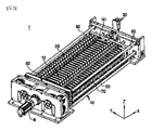
図2は、本発明の一実施例による加圧短絡検査装置の概略的な構成を示す斜視図であり、図3は及び図4は各々、図2の平面図及び側面図である。 FIG. 2 is a perspective view showing a schematic configuration of a pressurized short-circuit inspection apparatus according to an embodiment of the present invention, and FIGS. 3 and 4 are a plan view and a side view of FIG. 2, respectively.
これらの図面を参照すれば、本発明の一実施例による加圧短絡検査装置1は、圧着プレート10、加圧短絡検査組立体20、検査調整ユニット30及び支持ユニット40を含む。
Referring to these drawings, a pressurized short
圧着プレート10は、高い熱と圧力にも変形せず、機械的剛性の高い板状体であって、これらの間にパウチ型二次電池セル6を挟み込み、その両面を加圧するように構成される。前記圧着プレート10は、金属材質のみならず、機械的剛性の高い材質であれば、例えば、強化プラスチック、強化セラミックまたは強化ガラスなどから製作されても差し支えない。
The crimping
圧着プレート10は相互に板面が対向し、各々所定の距離で離隔して一方向(X軸方向)へ配列され、前記離隔距離が狭くなるか、または広くなるように±X軸方向に沿って移動可能である。
The crimping
検査対象の二次電池セル6は、トレイに収納された状態で加圧短絡検査装置1が備えられている作業チャンバに移送され得、セルピックアップ装置(図示せず)によってピックアップされて前記圧着プレート10同士の間の空間Sの中に一つずつ挿入配置され得る。
The
前記二次電池セル6は、圧着プレート10同士の間の空間Sに予め介在されるシート状の中間板(図示せず)によって一定の高さで支えられ得、圧着プレート10によって両面が加圧できる。
The
加圧短絡検査組立体20の主要構成についての説明に先立ち、加圧短絡検査方法について簡略に説明すれば、以下のようである。
Before describing the main structure of the pressurized short-
電極組立体の組立て時、分離膜の損傷可能性が最も大きい部分は、分離膜の両側縁部である(図1参照)。正常の分離膜は、該当の部分を加圧しても正極板と負極板とが分離膜によって遮断されるため相互に接触しないが、損傷した分離膜は、当該部分を加圧したとき、分離膜の損傷部分を通して正極板と負極板とが相互に接触するようになり、短絡が発生し得る。 When assembling the electrode assembly, the most likely parts of the separation membrane to be damaged are the side edges of the separation membrane (see FIG. 1). In a normal separation membrane, even if the corresponding part is pressurized, the positive electrode plate and the negative electrode plate are blocked by the separation membrane and do not come into contact with each other. The positive plate and the negative plate come into contact with each other through the damaged portion of the battery, and a short circuit can occur.
これに着目して、加圧短絡検査工程は、主に分離膜の損傷が頻繁な二次電池セル6の胴体の両側縁部を加圧し、一定のテスト電圧を印加した後に漏れ電流を測定することで良品セルと不良品セルとに区分する方式で行われ得る。
Focusing on this, the pressurized short circuit inspection process mainly presses both side edges of the body of the
前記テスト電圧に到達したとき、良品セルの場合、漏れ電流がほとんどなくて電流が安定化するのに対し、不良セルの場合、加圧状態で短絡が発生するため、テスト電圧を維持するために電流が増加する。この際、分離膜の損傷程度に比例して前記漏れ電流値が増加する様相を示し得る。 When the test voltage is reached, there is almost no leakage current in the case of good cells and the current stabilizes, whereas in the case of bad cells, a short circuit occurs under pressure. current increases. At this time, the leakage current value may increase in proportion to the degree of damage to the separator.
本発明による加圧短絡検査組立体20は、前述したような加圧短絡検査が可能になるように、分離膜の損傷部位、即ち、セル胴体の縁部に集中的に圧力を加えると共にテスト電圧を印加できるように設けられている。
The pressurized short-
前記加圧短絡検査組立体20は、一枚の圧着プレート10当たり二つずつ取り付けられ、相互に対称的に動作し得る。
The pressurized short-
具体的に、図5及び図6を参照すれば、加圧短絡検査組立体20は、圧着プレート10の各々に±Y軸方向に沿って移動可能に取り付けられ、二次電池セル6の胴体の一部を加圧するセル加圧部21と、二次電池セル6の電極リード6a部分に接触してテスト電圧を印加するように設けられた電源供給部22と、を含む。
Specifically, referring to FIGS. 5 and 6, the pressurized short-
前記二次電池セルの胴体の一部は、二次電池セルの組立て過程で分離膜損傷の可能性が最も高い箇所であって、二次電池セル6の胴体で両側縁部であり得る(ここで、前記二次電池セル6の胴体は、二次電池セルの厚さを形成する部分を意味する。)。
A part of the body of the secondary battery cell is a place where the possibility of separation membrane damage is highest in the process of assembling the secondary battery cell, and may be both side edges of the body of the secondary battery cell 6 (here, and the body of the
セル加圧部21は、圧着プレート10の前面と後面に各々重ねられて配置され、その幅がセル胴体の縁部に対応し、上下方向へ長く延びて形成される加圧パッド21aと、前記加圧パッド21aに部分的に埋設される球状のボール21bを含む。
The
前記ボール21bは、例えば、各々ボールホルダー21cにはめ込まれ、前記ボールホルダー21cを、加圧パッド21aに予め形成されている溝に締まりばめ方式で組み立てて加圧パッド21aに備えられ得る。
For example, the
例えば、特定の容量の加圧モーターMを用いて圧着プレート10で二次電池セル6の胴体の全面を加圧すれば、単位面積当たり約5kgf/cm2の圧力が作用するようになるが、セル加圧部21を前記二次電池セルの胴体の縁部に移すと、前記二次電池セル6の胴体の縁部のみが加圧パッド21aによって加圧されるため、当該領域に単位面積当たり約34kgf/cm2の圧力が作用できる。
For example, if the entire surface of the body of the
参考までに、前記単位面積当たり約5kgf/cm2の圧力とは、セル加圧工程において必要な圧力であり、前記単位面積当たり約34kgf/cm2の圧力は、加圧短絡検査時に必要な圧力であり得る。 For reference, the pressure of approx . can be
特に、本発明による加圧パッド21aにはボール21bが備えられており、セル胴体の縁領域がポイント加圧されるため、当該領域の加圧力が面加圧時に比べてさらに増加する。
In particular, since the
また、後述するが、前記加圧パッド21aのボール21bは、正/逆方向へ回転できるように構成することで、セル胴体を加圧した状態でセル加圧部21を電源供給部22に対して±Y軸方向に沿って移動させることができる。
Also, as will be described later, the
電源供給部22は、圧着プレート10の前面と後面に各々重ねられて配置される端子支持台22aと、前記端子支持台22aの少なくともいずれか一つに付着される電圧端子台22bと、を含み、前記セル加圧部21と一体型で設けられ、セル加圧部21と所定の間隔を隔てて共に移動できる。
The
前記電源供給部22は、セル加圧部21が二次電池セル6の胴体の両面に接触するとき、電圧端子台22bが電極リード6aに接触可能な位置に配置され得る。
The
加圧短絡検査組立体20は、セル進入ガイド23及び構造強化ブロック部24をさらに含む。
Pressurized
セル進入ガイド23は、セル加圧部21と電源供給部22の上部に配置され、二次電池セル6が移動して下降できる斜面または曲面形状で設けられ得る。
The
このようなセル進入ガイド23は、セルピックアップ装置(図示せず)によって二次電池セル6をピックアップして二次電池セル6を圧着プレート10同士の間の空間に挿入するとき、前記二次電池セル6が正位置に挿入されるようにガイドする役割を果たす。
When the
構造強化ブロック部24は、セル加圧部21と電源供給部22とを一つの胴体として連結し、セル加圧部21ないし電源供給部22の傾き(tilting)現象を防止する役割と、これらに移動性を提供するための構成要素である。
The structural
前記構造強化ブロック部24は、上部ブロック25及び下部ブロック26を含む。
The structural
前記上部ブロック25は、セル加圧部21と電源供給部22との上端部を連結し、圧着プレート10の上端ラインに沿って摺動するように前記圧着プレート10の上端に取り付けられ得る。
The
前記下部ブロック26は、セル加圧部21と電源供給部22との下端部を連結し、圧着プレート10の下端ラインに沿って摺動するように前記圧着プレート10の下端に取り付けられ得る。
The
より具体的に、図5に示したように、上部ブロック25及び下部ブロック26には、各々第1のLMスライダー27が設けられ得、圧着プレート10の上端ライン及び下端ラインには(図9参照)、前記第1のLMスライダー27の直線移動経路を形成する第1のLMガイドレール11、12が設けられ得る。このような構成によって、上部ブロック25及び下部ブロック26が圧着プレート10に対して±Y軸方向に沿って摺動できる。
More specifically, as shown in FIG. 5, the
このような上部ブロック25及び下部ブロック26によってセル加圧部21と電源供給部22とが連結され、その上端部及び下端部が各々支持されており、前記セル加圧部21と電源供給部22が±X軸または±Y軸方向へ安定的に移動でき、二次電池セルを加圧するときに傾かなくなる。
The
本発明による加圧短絡検査組立体20は、セル加圧部21が電源供給部22に対して±Y軸方向に沿って移動できる。
In the pressurized short-
このために、上部ブロック25及び下部ブロック26は、図5及び図7~図8を参照すれば、各々前記セル加圧部21と結合している移動ブロック25a、26aと、前記電源供給部22と結合している固定ブロック25b、26bと、を含んで構成され得る。
For this purpose, referring to FIGS. 5 and 7 to 8, the
前記移動ブロック25a、26aは、所定の長さを有し、その一端がセル加圧部21に固定され、その他端が固定ブロック25b、26bの内部に挿入されるシャフト形態で設けられ得、前記固定ブロック25b、26bは、移動ブロック25a、26aがその内部を出入りするように内部が空いている空間であるシリンダー室25cと、その外側に前記シリンダー室25cに連通する空気注入ホール25d、25eと、を備え得る。
The moving
例えば、図8において、第1空気注入ホール25dからシリンダー室25cに空気を注入すると、シリンダーの空気圧が正方向(-Y軸方向)に作用して移動ブロック25a、26aが固定ブロック25b、26bの外へ引き出され、第2空気注入ホール25eからシリンダー室25cに空気を注入すると、シリンダーの空気圧が逆方向(+Y軸方向)に作用して移動ブロック25a、26aが固定ブロック25b、26bの中に引き込まれる。即ち、移動ブロック25a、26aは、空気圧によって固定ブロック25b、26bの内外へ往復運動できる。勿論、空気圧の代わりに油圧を使ってもよい。
For example, in FIG. 8, when air is injected into the
本発明の一実施例は、前記移動ブロック25a、26aが空気圧によって作動するように構成したが、空気圧や油圧方式の他にも、前記移動ブロック25a、26aを固定ブロック25b、26bに対して往復運動させ得る作動メカニズムであれば、如何なる方式を適用してもよい。
In one embodiment of the present invention, the moving
上述したような構成及び作動によって、セル加圧部21と電源供給部22との離隔距離が調節可能になることにより、加圧短絡検査組立体20は、加圧短絡検査できるセル胴体の範囲が拡がる。
Due to the configuration and operation as described above, the separation distance between the
即ち、図9のように、加圧短絡検査工程は、セル加圧部21によってセル胴体の縁部を加圧して電源供給部22にテスト電圧を印加し、この際の漏れ電流の量を測定することで不良有無を判別する簡易検査方式と、図10のように、セル加圧部21をセル胴体の縁部とセル胴体の中心領域との間で往復運動させながら漏れ電流の量を測定することで不良有無を判別する拡大検査方式で行われ得る。
That is, as shown in FIG. 9, in the pressurized short-circuit inspection process, the edge of the cell body is pressed by the
前記拡大検査方式において、セル加圧部21は、前記移動ブロック25a、26aとともに往復運動し、加圧パッド21aに複数のボール21bが埋設されているため、往復移動時、セル胴体を転び加圧できる。本実施例は、加圧パッド21aにボール21bを採用したが、前記ボール21bの代わりにローラーを採用してもよい。
In the enlarged inspection method, the
このような拡大検査方式によれば、不良セルとは、セル胴体が転び加圧される間に漏れ電流が測定されるセルである。そして、前記漏れ電流が測定された時点及び加圧パッド21aの位置に基づいて分離膜の損傷位置も予測できる。
According to such a magnified inspection method, a defective cell is a cell whose leakage current is measured while the cell body is overturned and pressurized. Also, the damage position of the separation membrane can be predicted based on the time when the leakage current is measured and the position of the
一方、加圧短絡検査組立体20は、全体が一括的に同時に精密に動ければこそ正しい検査が可能にある。このために、本発明の加圧短絡検査装置1は、加圧短絡検査組立体20を一括的に移動させるために、検査組立体調整ユニット30をさらに含み得る。
On the other hand, the pressurized short-
図2、図3及び図12を共に参照して見れば、前記検査調整ユニット30は、加圧短絡検査装置1のハウジングを形成する後方フレーム36の外側に位置し得、駆動力を提供する調整モーター31と、前記調整モーター31と連結され、垂直方向へ延びて配置される垂直シャフト32、前記垂直シャフト32とかさ歯車によって連結され、水平方向へ延びて配置される水平シャフト33a~33dと、前記水平シャフト33a~33dに左右移動可能に連結される調整LMブロック34a~34dと、を含み得る。
2, 3 and 12 together, the
前記水平シャフト33a~33dは、前記垂直シャフト32を基準で上部領域において左右へ各々延びて配置される第1水平シャフト33a及び第2水平シャフト33bと、前記垂直シャフト32を基準で下部領域において左右へ各々延びて配置される第3水平シャフト33c及び第4水平シャフト33dと、を含む。
The
そして、前記調整LMブロック34a~34dは、前記第1水平シャフト33aに設けられる第1調整LMブロック34aと、前記第2水平シャフト33bに設けられる第2調整LMブロック34bと、前記第3水平シャフト33cに設けられる第3調整LMブロック34cと、前記第4水平シャフト33dに設けられる第4調整LMブロック34dと、を含む。
The adjustment LM blocks 34a to 34d are composed of a first adjustment LM
前記第1及び第2調整LMブロック34a、34bは、加圧短絡検査組立体20の上部ブロック25と、X軸方向へ延びて配置される第1及び第2調整シャフト(図示せず)を介して連結され得、前記第3及び第4調整LMブロック34c、34dは、加圧短絡検査組立体20の下部ブロック26と、X軸方向へ延びて配置される第3及び第4調整シャフト(図示せず)を介して連結され得る。
The first and second adjustment LM blocks 34a and 34b are connected to the
図示していないが、前記第1~第4調整シャフトは、各々一側が第1~第4調整LMブロック34a~34dに対応するように結合し、前記後方フレーム36のガイドホール35を通し、上部ブロック25の胴体または下部ブロック26の胴体に備えられる通孔H1、H2を通すように設けられ得る。
Although not shown, the first to fourth adjustment shafts are coupled to the first to fourth adjustment LM blocks 34a to 34d so that one side thereof corresponds to each of the first to fourth adjustment LM blocks 34a to 34d. The through holes H1 and H2 provided in the body of the
したがって、全ての加圧短絡検査組立体20は、調整モーター31によって左右へ移動するようになる第1~第4調整ブロック34a~34dに連結され、一対一に対応する圧着プレートに対して左右に(±Y軸方向)一括的に移動できる。
Therefore, all pressurized short-
このような検査組立体調整ユニット30によれば、加圧短絡工程の時、前記セル加圧部21が検査対象の二次電池セル6の胴体と対向するようになる第1ポジションへ加圧短絡検査組立体20を一括的に移動させることができ、加圧短絡工程の完了後には、二次電池セル6の胴体と非対向する第2ポジションへ加圧短絡検査組立体20を一括的に移動させることができる。
According to the test
本実施例による加圧短絡検査装置1は、図2、図10、図11及び図13~図14を参照すれば、圧着プレート10の下部で圧着プレート10をX軸方向へ移動可能に支持する支持ユニット40をさらに含み得る。
Referring to FIGS. 2, 10, 11, and 13 to 14, the pressurized short-
前記支持ユニット40は、前記圧着プレート10の配列方向に沿って延び、前記圧着プレート10の両端部の下部に各々配置される一対の支持ブロック41と、前記支持ブロック41の上端ラインに沿って備えられる第2のLMガイドレール43と、圧着プレート10に各々結合し、前記第2のLMガイドレール43に沿って±X軸方向へ摺動するように設けられる連結される第2のLMスライダー45と、から構成され得る。
The
このような構成を有する支持ユニット40によると、圧着プレート10が起立した状態で安定的に±X軸方向へ摺動可能になる。
According to the
また、加圧短絡検査装置1は、圧着プレート10に対して、両サイド領域に X軸方向に沿って延びて配置される支持シャフト50と、前記圧着プレート10の両サイド領域に配置され、前記支持シャフト50が胴体を通過し、前記圧着プレート10と一対一に結合する移動ブロック60と、そして移動ブロック60を相互に連結するリンク部材70と、をさらに含み得る。
In addition, the pressurized short-
各々の前記移動ブロック60は、圧着プレート10の両サイド領域に支持され、支持シャフト50に沿って±X軸方向へ移動できる。移動ブロック60のスムーズな動きのために、移動ブロック60と支持シャフト50とが連結される部分には、軸受が備えられ得る。
Each moving
このような構成によれば、各々の圧着プレート10は、両サイド領域が前記移動ブロック60及び支持シャフト50によって支持されることによって、駆動時、左右方向への傾きが発生しない。また、移動ブロック60は、リンク部材70によって相互に連結されるため、圧着プレート10が相互に一定の間隔を維持して一体で動くことができる。
According to this structure, both side regions of each
また、図2及び図3をさらに参照すれば、本実施例の加圧短絡検査装置1は、前記圧着プレート10を±X軸方向へ押すかまたは引くメイン圧着プレート80と、前記メイン圧着プレート80から前記圧着プレート10に伝達される加圧力を吸収する緩衝ユニット90をさらに含み得る。
Further, referring to FIGS. 2 and 3, the pressurized short-
メイン圧着プレート80は、圧着プレート10の配列方向による前記圧着プレート10のうち最前方に位置した圧着プレート10と一面が対向するように設けられ、メイン圧着プレート80の角領域にTMスクリューシャフト82、83が通過する。
The
前記TMスクリューシャフト82、83は、圧着プレート10の配列方向に沿って延びて配置され、前記TMスクリューシャフト82、83の一端が加圧モーターMによって正逆回転するギアGに連結されていることから、正逆回転できる。
The
メイン圧着プレート80は、このようなTMスクリューシャフト82、83の正逆回転時、前進または後退できる。例えば、前記TMスクリューシャフト82、83を正方向へ回転させると、メイン圧着プレート80が前進しながら圧着プレート10を+X軸方向へ緩衝ユニット90に向けて押すようになる。これによって、メイン圧着プレート80と緩衝ユニット90との間の圧着プレート10同士の間隔が次第に狭められながら二次電池セル6が加圧される。
The
逆に、前記TMスクリューシャフト82、83を逆方向へ回転させると、メイン圧着プレート10、80が後退しながら最前方の圧着プレート10を-X軸方向へ引くようになる。この際、圧着プレート10は、リンク部材70によって相互に連結されていることから、最前方の圧着プレート10のみを引いても全ての圧着プレート10が引かれて-X軸方向へ移動するようになる。
Conversely, when the
一方、前記緩衝ユニット90は、圧着プレート10のうち最後方に位置した圧着プレート10と対向するように設けられる第1緩衝プレート91と、第1緩衝プレート91と弾性部材92とを挟んで相互に対向するように離隔して配置される第2緩衝プレート93と、を含み得る。
On the other hand, the
このような構成の緩衝ユニット90によれば、メイン圧着プレート80によって+X軸方向へ押される圧着プレート10を弾性的に支持でき、圧着プレート10が受ける衝撃を効果的に緩和させることができる。
According to the
前述した本発明の一実施例による加圧短絡検査装置1を使用すると、加圧短絡検査工程とセル加圧工程とを統合することができる。以下では、このような加圧短絡検査装置1の活用方法を簡単に説明する。
By using the pressurized short-
組立て工程の後、不良セルに対する後続工程は、ロス(loss)のみである。そのため、二次電池セル6の組立て工程が完了した直後にすぐ加圧短絡検査工程を施して、不良セルを検出することが望ましい。
After the assembly process, the only subsequent process for defective cells is loss. Therefore, it is desirable to perform the pressurization short-circuit inspection process immediately after the assembly process of the
先ず、加圧短絡検査工程を行うに際し、図9のように、加圧短絡検査組立体20をY軸方向における圧着プレート10の内側へ移動させて第1ポジションに配置する。ここで、前記第1ポジションは、検査対象の二次電池セル6の胴体の両側縁部と加圧パッド21aとが対向する位置を意味する。
First, when performing the pressurized short-circuit inspection process, as shown in FIG. 9, the pressurized short-
その後、加圧モーターMを作動させて二次電池セル6の縁部を約34kgf/cm2の圧力で集中的に加圧してテスト電圧を印加し、漏れ電流が発生するか否かを把握し、不良セルを検出する。
After that, the pressurizing motor M is operated to intensively pressurize the edge of the
上記のような方式で加圧短絡検査工程が完了すると、続いてセル加圧工程を即時に行う。前記セル加圧工程は、二次電池セル6の胴体の全面を加圧して内部の気泡を除去してプレエージング(pre-aging)時間を短縮するための工程である。セル加圧工程を行うと、セル加圧工程を行っていない場合に比べてプレエージングにかかる時間を約1~2日間短縮できるという利点がある。
After the pressurization short-circuit inspection process is completed in the above manner, the cell pressurization process is immediately performed. The cell pressurizing process is a process for pressurizing the entire surface of the body of the
セル加圧工程を行うときは、図11のように加圧短絡検査組立体20をY軸方向における圧着プレート10の外側へ移動させて第2ポジションに配置する。ここで、前記第2ポジションは、加圧短絡検査が終了した二次電池セル6と加圧短絡検査組立体20とが対向しない位置を意味する。
When performing the cell pressurizing process, the pressurized short-
その後、さらに加圧モーターMを作動させ、二次電池セル6の胴体の全面を圧着プレート10で完全に加圧する。ここで、二次電池セル6の胴体の全面を約5kgf/cm2の圧力で予め設定された時間の間に加圧する。
After that, the pressurizing motor M is further operated, and the entire surface of the body of the
以上のように、本実施例による加圧短絡検査装置1によれば、相異なる圧力範囲が必要な加圧短絡検査工程とセル加圧短絡工程とを一つの装置に統合して行うことができるので、タクトタイムが短縮でき、生産設備構築に必要な空間と費用を節減することができる。
As described above, according to the pressurized short-
以上のように、本発明を限定された実施例と図面によって説明したが、本発明はこれに限定されず、本発明が属する技術分野における通常の知識を有する者によって本発明の技術思想と特許請求の範囲の均等範囲内で多様な修正及び変形が可能であることは言うまでもない。 As described above, the present invention has been described with limited examples and drawings, but the present invention is not limited thereto, and the technical ideas and patents of the present invention can be obtained by persons having ordinary knowledge in the technical field to which the present invention belongs. It goes without saying that various modifications and variations are possible within the equivalent scope of the claims.
なお、本明細書において、上、下、左、右、前、後のような方向を示す用語が使用されたが、このような用語は相対的な位置を示し、説明の便宜のためのものであるだけで、対象となる事物の位置や観測者の位置などによって変わり得ることは、当業者にとって自明である。 Although terms indicating directions such as up, down, left, right, front, and rear are used in this specification, such terms indicate relative positions and are for convenience of explanation. It is obvious to a person skilled in the art that it can change depending on the position of the target object, the position of the observer, and the like.
Claims (10)
二次電池セルを少なくとも一つずつ挿入できるように相互に所定の距離で離隔して配列され、前記離隔の距離が調節されるように±X軸方向へ移動可能な圧着プレートと、
前記二次電池セルの胴体における予め決められた領域を加圧するセル加圧部と、前記二次電池セルの電極リード部分に接触してテスト電圧を印加する電源供給部と、を備え、前記圧着プレートの各々に±Y軸方向に沿って移動可能に取り付けられる加圧短絡検査組立体と、を含み、
前記セル加圧部は少なくとも一面にボールを備え、前記ボールによって前記二次電池セルの胴体が加圧される、加圧短絡検査装置。 A pressurized short-circuit inspection device for detecting a pouch-type secondary battery cell with a low voltage defect due to damage to the separation membrane,
compression plates spaced apart from each other by a predetermined distance so that at least one secondary battery cell can be inserted therein, and movable in the ±X-axis direction so as to adjust the distance;
A cell pressurizing unit that pressurizes a predetermined area in the body of the secondary battery cell, and a power supply unit that contacts the electrode lead portion of the secondary battery cell and applies a test voltage, and the crimping a pressurized shorts test assembly movably mounted on each of the plates along the ±Y axis;
The pressurized short-circuit inspection device, wherein the cell pressurizing unit has a ball on at least one surface, and the body of the secondary battery cell is pressurized by the ball.
前記圧着プレートの前面と後面に各々重ねられて配置される加圧パッドを含み、前記ボールは球状であって、前記加圧パッドに部分的に埋設されている、請求項1に記載の加圧短絡検査装置。 The cell pressurizing unit is
The pressurizing device according to claim 1, further comprising pressurizing pads disposed on the front and rear surfaces of the pressurizing plate, respectively, wherein the balls are spherical and partially embedded in the pressurizing pads. Short circuit inspection device.
前記セル加圧部と前記電源供給部とを一つの胴体として連結する構造強化ブロック部をさらに含み、
前記構造強化ブロック部は、
前記セル加圧部と前記電源供給部との上端部を連結し、前記圧着プレートの上端に摺動可能に取り付けられる上部ブロックと、前記セル加圧部と前記電源供給部との下端部を連結し、前記圧着プレートの下端に摺動可能に取り付けられる下部ブロックと、を含む、請求項1から4のいずれか一項に記載の加圧短絡検査装置。 The pressurized short circuit inspection assembly includes:
further comprising a structural reinforcement block unit connecting the cell pressurizing unit and the power supply unit as one body;
The structural reinforcement block part includes:
Upper ends of the cell pressurizing part and the power supply part are connected, and lower ends of the cell pressurizing part and the power supply part are connected to an upper block slidably attached to an upper end of the crimping plate. and a lower block slidably attached to the lower end of the crimp plate.
前記セル加圧部と結合している移動ブロック及び前記電源供給部と結合している固定ブロックを含み、
前記移動ブロックが、前記固定ブロックの内外へ引込み及び引出し可能に設けられる、請求項5または6に記載の加圧短絡検査装置。 The upper block and the lower block each comprise:
a moving block coupled with the cell pressure unit and a fixed block coupled with the power supply unit;
7. The pressurized short-circuit inspection device according to claim 5, wherein said moving block is provided so as to be able to be drawn in and out of said fixed block.
前記圧着プレートの配列方向に沿って延び、前記圧着プレートの両端部の下部に配置される支持ブロックと、
前記支持ブロックの上端ラインに沿って備えられる第2のLMガイドレールと、
前記圧着プレートに各々結合し、前記第2のLMガイドレールに沿ってX軸方向へ摺動可能に設けられる第2のLMスライダーと、を含む、請求項9に記載の加圧短絡検査装置。 The support unit is
a support block extending along the arrangement direction of the compression plates and disposed under both ends of the compression plates;
a second LM guide rail provided along the top line of the support block;
10. The pressurized short circuit inspection device according to claim 9, further comprising a second LM slider coupled to each of said crimping plates and provided slidably along said second LM guide rail in the X-axis direction.
Applications Claiming Priority (3)
| Application Number | Priority Date | Filing Date | Title |
|---|---|---|---|
| KR10-2019-0114920 | 2019-09-18 | ||
| KR1020190114920A KR102509603B1 (en) | 2019-09-18 | 2019-09-18 | Apparatus for detecting a low voltage pouch type secondary battery cell |
| PCT/KR2020/010561 WO2021054605A1 (en) | 2019-09-18 | 2020-08-10 | Pressing short-circuit testing apparatus for detecting low-voltage defective pouch-type secondary battery cell |
Publications (2)
| Publication Number | Publication Date |
|---|---|
| JP2022514578A JP2022514578A (en) | 2022-02-14 |
| JP7106798B2 true JP7106798B2 (en) | 2022-07-27 |
Family
ID=74883829
Family Applications (1)
| Application Number | Title | Priority Date | Filing Date |
|---|---|---|---|
| JP2021535165A Active JP7106798B2 (en) | 2019-09-18 | 2020-08-10 | Pressurized short-circuit inspection device for detecting pouch-type secondary battery cells with low voltage defects |
Country Status (6)
| Country | Link |
|---|---|
| US (1) | US11959974B2 (en) |
| EP (1) | EP3907809B1 (en) |
| JP (1) | JP7106798B2 (en) |
| KR (1) | KR102509603B1 (en) |
| CN (1) | CN113711071B (en) |
| WO (1) | WO2021054605A1 (en) |
Families Citing this family (3)
| Publication number | Priority date | Publication date | Assignee | Title |
|---|---|---|---|---|
| CN113640704B (en) * | 2021-08-10 | 2024-01-30 | 苏州昊建自动化系统有限公司 | Battery leakage current inspection device and inspection method |
| KR20230129881A (en) * | 2022-03-02 | 2023-09-11 | 주식회사 엘지에너지솔루션 | Apparatus and method for performing short-circuit test under pressure for battery-cell |
| CN117706124A (en) * | 2023-04-12 | 2024-03-15 | 徐州宝佳信息科技有限公司 | Battery short circuit testing machine |
Citations (2)
| Publication number | Priority date | Publication date | Assignee | Title |
|---|---|---|---|---|
| JP2005339925A (en) | 2004-05-26 | 2005-12-08 | Toyota Motor Corp | Inspection method of unit cell and assembly method of battery pack |
| JP2015037047A (en) | 2013-08-14 | 2015-02-23 | 日産自動車株式会社 | Method for pressurizing film exterior battery |
Family Cites Families (26)
| Publication number | Priority date | Publication date | Assignee | Title |
|---|---|---|---|---|
| JP3161240B2 (en) * | 1994-08-30 | 2001-04-25 | 三菱マテリアル株式会社 | Thermistor sensor |
| JP3907026B2 (en) * | 1998-06-19 | 2007-04-18 | 津田駒工業株式会社 | Press roll device |
| US8035394B2 (en) | 2007-12-07 | 2011-10-11 | Ntt Docomo, Inc. | Battery testing device and battery testing method |
| JP5060623B2 (en) | 2009-01-19 | 2012-10-31 | パナソニック株式会社 | Battery internal short circuit evaluation device |
| JP5747895B2 (en) * | 2012-11-06 | 2015-07-15 | トヨタ自動車株式会社 | Manufacturing method of battery pack |
| JP5929865B2 (en) * | 2013-10-02 | 2016-06-08 | トヨタ自動車株式会社 | Manufacturing method of secondary battery |
| KR101826894B1 (en) * | 2013-11-04 | 2018-02-07 | 주식회사 엘지화학 | Electrode assembly and apparatus for manufacturing the same |
| KR101778829B1 (en) * | 2013-11-29 | 2017-09-14 | 주식회사 엘지화학 | Short circuit detection device |
| KR101704760B1 (en) | 2014-01-08 | 2017-02-08 | 주식회사 엘지화학 | Pressing tray |
| JP5892182B2 (en) | 2014-01-09 | 2016-03-23 | トヨタ自動車株式会社 | Vehicle power supply |
| KR101790118B1 (en) | 2014-12-05 | 2017-10-25 | 주식회사 엘지화학 | Pressing Device for Checking Defect of Electrode Assembly and Method of Checking the Same |
| KR102088272B1 (en) | 2016-02-26 | 2020-03-12 | 주식회사 엘지화학 | Pressing Device for Battery Cell, Initial Charging and Discharging System for Battery Cell Using the Same, and Method of Initial Charging And Discharging Battery Cell Using the Same |
| KR101861429B1 (en) * | 2016-06-08 | 2018-05-25 | 엘지전자 주식회사 | Battery Pack |
| KR102249896B1 (en) * | 2016-11-08 | 2021-05-07 | 삼성에스디아이 주식회사 | Rechargeable battery module and pack |
| JP2018106930A (en) | 2016-12-27 | 2018-07-05 | 日産自動車株式会社 | Manufacturing method of battery cell and pressure magazine |
| KR20180111122A (en) | 2017-03-31 | 2018-10-11 | (주)이티에스 | Leak inpection system for secondary cell |
| CN108878699B (en) * | 2017-05-15 | 2021-03-09 | 宁德时代新能源科技股份有限公司 | Battery module |
| KR102308856B1 (en) * | 2017-06-19 | 2021-10-01 | 에스케이이노베이션 주식회사 | Zig for evaluating battery cell |
| KR102161028B1 (en) | 2017-07-11 | 2020-10-05 | 주식회사 엘지화학 | Fault test device and fault test method of rechargeable battery |
| CN207181638U (en) * | 2017-08-18 | 2018-04-03 | 深圳鼎阳智能科技有限公司 | A kind of soft package lithium battery fixture for testing formation device |
| KR101866942B1 (en) * | 2017-09-05 | 2018-06-14 | 주식회사 부삼 | Apparatus for testing battery cell |
| CN207280623U (en) * | 2017-10-20 | 2018-04-27 | 深圳市特普生传感有限公司 | A kind of film temperature sensor |
| JP2019109975A (en) * | 2017-12-15 | 2019-07-04 | 日本電気株式会社 | Internal short-circuit test method for battery and internal short-circuit test device |
| KR101949687B1 (en) | 2018-01-25 | 2019-02-19 | 세종기술 주식회사 | Hpc process unit for polima cell |
| CN108508367A (en) * | 2018-03-06 | 2018-09-07 | 天津力神电池股份有限公司 | The detection method of flexible-packed battery pole group short circuit |
| KR102073697B1 (en) | 2019-06-26 | 2020-02-05 | 파워소프트 주식회사 | Plasma pulse power supply |
-
2019
- 2019-09-18 KR KR1020190114920A patent/KR102509603B1/en active IP Right Grant
-
2020
- 2020-08-10 EP EP20866686.7A patent/EP3907809B1/en active Active
- 2020-08-10 US US17/415,473 patent/US11959974B2/en active Active
- 2020-08-10 WO PCT/KR2020/010561 patent/WO2021054605A1/en unknown
- 2020-08-10 JP JP2021535165A patent/JP7106798B2/en active Active
- 2020-08-10 CN CN202080029261.XA patent/CN113711071B/en active Active
Patent Citations (2)
| Publication number | Priority date | Publication date | Assignee | Title |
|---|---|---|---|---|
| JP2005339925A (en) | 2004-05-26 | 2005-12-08 | Toyota Motor Corp | Inspection method of unit cell and assembly method of battery pack |
| JP2015037047A (en) | 2013-08-14 | 2015-02-23 | 日産自動車株式会社 | Method for pressurizing film exterior battery |
Also Published As
| Publication number | Publication date |
|---|---|
| KR20210033328A (en) | 2021-03-26 |
| JP2022514578A (en) | 2022-02-14 |
| WO2021054605A1 (en) | 2021-03-25 |
| KR102509603B1 (en) | 2023-03-10 |
| EP3907809A4 (en) | 2022-04-06 |
| EP3907809B1 (en) | 2024-02-07 |
| EP3907809A1 (en) | 2021-11-10 |
| US20220065948A1 (en) | 2022-03-03 |
| CN113711071B (en) | 2023-09-01 |
| US11959974B2 (en) | 2024-04-16 |
| CN113711071A (en) | 2021-11-26 |
Similar Documents
| Publication | Publication Date | Title |
|---|---|---|
| JP7106798B2 (en) | Pressurized short-circuit inspection device for detecting pouch-type secondary battery cells with low voltage defects | |
| KR102619196B1 (en) | Apparatus for detecting a low voltage pouch type secondary battery cell | |
| KR102395248B1 (en) | Apparatus for detecting a defect of battery separator and Detecting method using the same | |
| KR20200042801A (en) | Formation appartus that can integrate pressure short circuit inspection and activation process | |
| KR102015898B1 (en) | Folding Device for electrode lead Part of Battery Cell | |
| KR101714951B1 (en) | Charging and discharging inspection device and charging and discharging inspection method for thin secondary battery | |
| CN113196537A (en) | Apparatus for manufacturing cell stack of secondary battery | |
| KR20200059618A (en) | Secondary battery production system and method of the same | |
| KR101622437B1 (en) | Press device for jelly roll-secondary battery and Fabricating method of secondary battery using the same | |
| CN111226122B (en) | Simultaneous inspection apparatus for multiple secondary battery cell bags | |
| WO2016017008A1 (en) | Sheet-like-battery test device and sheet-like-battery test method | |
| KR20200059615A (en) | Apparatus for forming a pouch of secondary cell | |
| KR20200059563A (en) | Method for testing pressure short defect by jig pressing | |
| KR20200059614A (en) | Loading apparatus and method of electrode/separator assembly | |
| KR20200059616A (en) | Tab cutting apparatus of secondary cell | |
| KR101800051B1 (en) | Short measuring apparatus of unit cell | |
| KR102620663B1 (en) | Secondary battery cell pressurization test apparatus capable of pressurization pressure correction | |
| KR102043114B1 (en) | Welding guide device for electrode lead of secondary battery cell and welding guide system using the same | |
| KR20190089377A (en) | Stage module and welding apparatus for battery cell connections including the same | |
| KR20220020493A (en) | Apparatus for detecting a defect of battery separator including a plurality of pressing rollers and method for detecting a defect of battery separator using same | |
| KR20230058836A (en) | Welding Part Inspection Device and Welding Part Inspection Method Using the Same | |
| KR20230129881A (en) | Apparatus and method for performing short-circuit test under pressure for battery-cell | |
| JP2023551208A (en) | Electrode tab guide device, electrode tab manufacturing device using the same, and method for manufacturing an electrode assembly | |
| KR20230053187A (en) | Battery cell inspection device and battery cell inspection method | |
| KR20220077252A (en) | Separator damage inspection jig, separator damage inspection device and inspection method thereof |
Legal Events
| Date | Code | Title | Description |
|---|---|---|---|
| A521 | Request for written amendment filed |
Free format text: JAPANESE INTERMEDIATE CODE: A523 Effective date: 20210618 |
|
| A621 | Written request for application examination |
Free format text: JAPANESE INTERMEDIATE CODE: A621 Effective date: 20210618 |
|
| A977 | Report on retrieval |
Free format text: JAPANESE INTERMEDIATE CODE: A971007 Effective date: 20220607 |
|
| TRDD | Decision of grant or rejection written | ||
| A01 | Written decision to grant a patent or to grant a registration (utility model) |
Free format text: JAPANESE INTERMEDIATE CODE: A01 Effective date: 20220614 |
|
| A61 | First payment of annual fees (during grant procedure) |
Free format text: JAPANESE INTERMEDIATE CODE: A61 Effective date: 20220617 |
|
| R150 | Certificate of patent or registration of utility model |
Ref document number: 7106798 Country of ref document: JP Free format text: JAPANESE INTERMEDIATE CODE: R150 |