JP7105582B2 - Determination method, exposure method, exposure apparatus, article manufacturing method and program - Google Patents
Determination method, exposure method, exposure apparatus, article manufacturing method and program Download PDFInfo
- Publication number
- JP7105582B2 JP7105582B2 JP2018043490A JP2018043490A JP7105582B2 JP 7105582 B2 JP7105582 B2 JP 7105582B2 JP 2018043490 A JP2018043490 A JP 2018043490A JP 2018043490 A JP2018043490 A JP 2018043490A JP 7105582 B2 JP7105582 B2 JP 7105582B2
- Authority
- JP
- Japan
- Prior art keywords
- focus position
- level
- optical system
- determining
- projection optical
- Prior art date
- Legal status (The legal status is an assumption and is not a legal conclusion. Google has not performed a legal analysis and makes no representation as to the accuracy of the status listed.)
- Active
Links
Images


Classifications
-
- G—PHYSICS
- G03—PHOTOGRAPHY; CINEMATOGRAPHY; ANALOGOUS TECHNIQUES USING WAVES OTHER THAN OPTICAL WAVES; ELECTROGRAPHY; HOLOGRAPHY
- G03F—PHOTOMECHANICAL PRODUCTION OF TEXTURED OR PATTERNED SURFACES, e.g. FOR PRINTING, FOR PROCESSING OF SEMICONDUCTOR DEVICES; MATERIALS THEREFOR; ORIGINALS THEREFOR; APPARATUS SPECIALLY ADAPTED THEREFOR
- G03F9/00—Registration or positioning of originals, masks, frames, photographic sheets or textured or patterned surfaces, e.g. automatically
- G03F9/70—Registration or positioning of originals, masks, frames, photographic sheets or textured or patterned surfaces, e.g. automatically for microlithography
- G03F9/7003—Alignment type or strategy, e.g. leveling, global alignment
- G03F9/7023—Aligning or positioning in direction perpendicular to substrate surface
- G03F9/7026—Focusing
-
- G—PHYSICS
- G03—PHOTOGRAPHY; CINEMATOGRAPHY; ANALOGOUS TECHNIQUES USING WAVES OTHER THAN OPTICAL WAVES; ELECTROGRAPHY; HOLOGRAPHY
- G03F—PHOTOMECHANICAL PRODUCTION OF TEXTURED OR PATTERNED SURFACES, e.g. FOR PRINTING, FOR PROCESSING OF SEMICONDUCTOR DEVICES; MATERIALS THEREFOR; ORIGINALS THEREFOR; APPARATUS SPECIALLY ADAPTED THEREFOR
- G03F7/00—Photomechanical, e.g. photolithographic, production of textured or patterned surfaces, e.g. printing surfaces; Materials therefor, e.g. comprising photoresists; Apparatus specially adapted therefor
- G03F7/20—Exposure; Apparatus therefor
- G03F7/2002—Exposure; Apparatus therefor with visible light or UV light, through an original having an opaque pattern on a transparent support, e.g. film printing, projection printing; by reflection of visible or UV light from an original such as a printed image
- G03F7/2014—Contact or film exposure of light sensitive plates such as lithographic plates or circuit boards, e.g. in a vacuum frame
-
- G—PHYSICS
- G03—PHOTOGRAPHY; CINEMATOGRAPHY; ANALOGOUS TECHNIQUES USING WAVES OTHER THAN OPTICAL WAVES; ELECTROGRAPHY; HOLOGRAPHY
- G03F—PHOTOMECHANICAL PRODUCTION OF TEXTURED OR PATTERNED SURFACES, e.g. FOR PRINTING, FOR PROCESSING OF SEMICONDUCTOR DEVICES; MATERIALS THEREFOR; ORIGINALS THEREFOR; APPARATUS SPECIALLY ADAPTED THEREFOR
- G03F7/00—Photomechanical, e.g. photolithographic, production of textured or patterned surfaces, e.g. printing surfaces; Materials therefor, e.g. comprising photoresists; Apparatus specially adapted therefor
- G03F7/70—Microphotolithographic exposure; Apparatus therefor
- G03F7/70216—Mask projection systems
- G03F7/70258—Projection system adjustments, e.g. adjustments during exposure or alignment during assembly of projection system
-
- G—PHYSICS
- G03—PHOTOGRAPHY; CINEMATOGRAPHY; ANALOGOUS TECHNIQUES USING WAVES OTHER THAN OPTICAL WAVES; ELECTROGRAPHY; HOLOGRAPHY
- G03F—PHOTOMECHANICAL PRODUCTION OF TEXTURED OR PATTERNED SURFACES, e.g. FOR PRINTING, FOR PROCESSING OF SEMICONDUCTOR DEVICES; MATERIALS THEREFOR; ORIGINALS THEREFOR; APPARATUS SPECIALLY ADAPTED THEREFOR
- G03F7/00—Photomechanical, e.g. photolithographic, production of textured or patterned surfaces, e.g. printing surfaces; Materials therefor, e.g. comprising photoresists; Apparatus specially adapted therefor
- G03F7/70—Microphotolithographic exposure; Apparatus therefor
- G03F7/70216—Mask projection systems
- G03F7/70275—Multiple projection paths, e.g. array of projection systems, microlens projection systems or tandem projection systems
-
- G—PHYSICS
- G03—PHOTOGRAPHY; CINEMATOGRAPHY; ANALOGOUS TECHNIQUES USING WAVES OTHER THAN OPTICAL WAVES; ELECTROGRAPHY; HOLOGRAPHY
- G03F—PHOTOMECHANICAL PRODUCTION OF TEXTURED OR PATTERNED SURFACES, e.g. FOR PRINTING, FOR PROCESSING OF SEMICONDUCTOR DEVICES; MATERIALS THEREFOR; ORIGINALS THEREFOR; APPARATUS SPECIALLY ADAPTED THEREFOR
- G03F7/00—Photomechanical, e.g. photolithographic, production of textured or patterned surfaces, e.g. printing surfaces; Materials therefor, e.g. comprising photoresists; Apparatus specially adapted therefor
- G03F7/70—Microphotolithographic exposure; Apparatus therefor
- G03F7/70216—Mask projection systems
- G03F7/70325—Resolution enhancement techniques not otherwise provided for, e.g. darkfield imaging, interfering beams, spatial frequency multiplication, nearfield lenses or solid immersion lenses
- G03F7/70333—Focus drilling, i.e. increase in depth of focus for exposure by modulating focus during exposure [FLEX]
-
- G—PHYSICS
- G03—PHOTOGRAPHY; CINEMATOGRAPHY; ANALOGOUS TECHNIQUES USING WAVES OTHER THAN OPTICAL WAVES; ELECTROGRAPHY; HOLOGRAPHY
- G03F—PHOTOMECHANICAL PRODUCTION OF TEXTURED OR PATTERNED SURFACES, e.g. FOR PRINTING, FOR PROCESSING OF SEMICONDUCTOR DEVICES; MATERIALS THEREFOR; ORIGINALS THEREFOR; APPARATUS SPECIALLY ADAPTED THEREFOR
- G03F7/00—Photomechanical, e.g. photolithographic, production of textured or patterned surfaces, e.g. printing surfaces; Materials therefor, e.g. comprising photoresists; Apparatus specially adapted therefor
- G03F7/70—Microphotolithographic exposure; Apparatus therefor
- G03F7/70483—Information management; Active and passive control; Testing; Wafer monitoring, e.g. pattern monitoring
- G03F7/70605—Workpiece metrology
- G03F7/70616—Monitoring the printed patterns
- G03F7/70641—Focus
-
- G—PHYSICS
- G03—PHOTOGRAPHY; CINEMATOGRAPHY; ANALOGOUS TECHNIQUES USING WAVES OTHER THAN OPTICAL WAVES; ELECTROGRAPHY; HOLOGRAPHY
- G03F—PHOTOMECHANICAL PRODUCTION OF TEXTURED OR PATTERNED SURFACES, e.g. FOR PRINTING, FOR PROCESSING OF SEMICONDUCTOR DEVICES; MATERIALS THEREFOR; ORIGINALS THEREFOR; APPARATUS SPECIALLY ADAPTED THEREFOR
- G03F7/00—Photomechanical, e.g. photolithographic, production of textured or patterned surfaces, e.g. printing surfaces; Materials therefor, e.g. comprising photoresists; Apparatus specially adapted therefor
- G03F7/70—Microphotolithographic exposure; Apparatus therefor
- G03F7/70691—Handling of masks or workpieces
- G03F7/70775—Position control, e.g. interferometers or encoders for determining the stage position
-
- H—ELECTRICITY
- H01—ELECTRIC ELEMENTS
- H01L—SEMICONDUCTOR DEVICES NOT COVERED BY CLASS H10
- H01L21/00—Processes or apparatus adapted for the manufacture or treatment of semiconductor or solid state devices or of parts thereof
- H01L21/02—Manufacture or treatment of semiconductor devices or of parts thereof
- H01L21/027—Making masks on semiconductor bodies for further photolithographic processing not provided for in group H01L21/18 or H01L21/34
- H01L21/0271—Making masks on semiconductor bodies for further photolithographic processing not provided for in group H01L21/18 or H01L21/34 comprising organic layers
- H01L21/0273—Making masks on semiconductor bodies for further photolithographic processing not provided for in group H01L21/18 or H01L21/34 comprising organic layers characterised by the treatment of photoresist layers
- H01L21/0274—Photolithographic processes
Description
本発明は、決定方法、露光方法、露光装置、物品の製造方法及びプログラムに関する。 The present invention relates to a determination method, an exposure method, an exposure apparatus, an article manufacturing method, and a program.
半導体デバイスやフラットパネルディスプレイ(FPD)などのデバイスは、フォトリソグラフィ工程を経て製造される。フォトリソグラフィ工程は、マスク又はレチクル(原版)のパターンを、レンズやミラーを含む投影光学系を介して、レジスト(感光剤)が塗布されたガラスプレートやウエハなどの基板に投影し、かかる基板を露光する露光工程を含む。 Devices such as semiconductor devices and flat panel displays (FPDs) are manufactured through a photolithography process. In the photolithography process, a pattern of a mask or reticle (original) is projected onto a substrate such as a glass plate or wafer coated with a resist (photosensitive agent) through a projection optical system including lenses and mirrors. It includes an exposure step of exposing.
露光工程では、投影光学系のベストフォーカス位置、即ち、マスクのパターンの像が最も高いコントラストで形成される位置と、基板の表面位置(レジストが塗布された面)とを正確に一致させる必要がある。投影光学系のベストフォーカス位置と基板の表面位置とが一致していないと、マスクのパターンの像にボケが生じ、所望のパターンの像を基板上に形成することができない。 In the exposure process, it is necessary to precisely match the best focus position of the projection optical system, that is, the position where the mask pattern image is formed with the highest contrast, and the surface position of the substrate (surface coated with resist). be. If the best focus position of the projection optical system and the surface position of the substrate do not match, the image of the pattern on the mask will be blurred and the image of the desired pattern cannot be formed on the substrate.
投影光学系のベストフォーカス位置を求める技術に関しては、従来から提案されている(特許文献1参照)。特許文献1に開示された技術では、まず、レジストが塗布された基板のフォーカス位置を初期値に設定した状態において、フォーカス計測用パターンを介して基板を露光する(フォーカス計測用パターンの像を基板上に形成する)。次いで、基板のフォーカス位置を所定のステップ量だけ変更した状態において、フォーカス計測用パターンを介して基板を露光する。このような基板のフォーカス位置の変更と基板の露光とを、基板のフォーカス位置が変更範囲の下限や上限に達するまで繰り返し、基板のフォーカス位置が変更範囲の下限や上限に達したら、基板を現像する。次に、現像後の基板上に形成されたフォーカス計測用パターンに対応するレジスト像(パターン像)の大きさを計測し、最小自乗法を用いてパターン像の大きさをフォーカス位置の関数で近似する。そして、近似関数の最大値から予め定められた値だけ小さい閾値を設定し、かかる閾値と近似関数とが交差する2つの点(フォーカス位置)を求め、2つの点の中間の位置を投影光学系のベストフォーカス位置とする。このように、特許文献1に開示された技術は、理想的な結像状態においては、基板上に形成されるフォーカス計測用パターンに対応するパターン像の大きさのフォーカス位置による変化がベストフォーカス位置に関して対称となることを利用している。これは、像形成に対するデフォーカスの影響は、プラス側、マイナス側でほぼ同じであるからである。
Techniques for obtaining the best focus position of the projection optical system have been proposed in the past (see Patent Document 1). In the technique disclosed in
しかしながら、実際には、基板上に形成されるフォーカス計測用パターンに対応するパターン像の大きさのフォーカス位置による変化がベストフォーカス位置に関して非対称となる場合がある。フォーカス計測用パターンに対応するパターン像は、フォーカス位置ごとに基板上の異なる位置に形成される。従って、基板上の位置に依存してパターン像の大きさを変化させる要因が存在する場合、パターン像の大きさのフォーカス位置による変化がベストフォーカス位置に関して非対称となる。このような要因としては、レジスト膜厚の基板上の位置による差、現像時の現像液の液量や滞留時間の基板上の位置による差、フレア光強度の基板上の位置による差などが挙げられる。また、投影光学系が球面収差などの収差を有している場合にも、パターン像の大きさのフォーカス位置による変化がベストフォーカス位置に関して非対称となる。 However, in practice, there are cases where the change in the size of the pattern image corresponding to the focus measurement pattern formed on the substrate depending on the focus position is asymmetric with respect to the best focus position. A pattern image corresponding to the focus measurement pattern is formed at a different position on the substrate for each focus position. Therefore, when there is a factor that changes the size of the pattern image depending on the position on the substrate, the change in the size of the pattern image depending on the focus position becomes asymmetric with respect to the best focus position. Such factors include the difference in resist film thickness depending on the position on the substrate, the difference in the liquid amount and residence time of the developer during development due to the position on the substrate, and the difference in the intensity of flare light depending on the position on the substrate. be done. Also when the projection optical system has aberration such as spherical aberration, the change in the size of the pattern image depending on the focus position becomes asymmetric with respect to the best focus position.
このような場合には、パターン像の大きさをフォーカス位置の関数で近似して得られる近似関数も非対称な形状となるため、閾値をどこに設定するかに依存して、ベストフォーカス位置が大きく変化してしまう。従って、非対称な形状の近似関数から求まるベストフォーカス位置は、その信頼性が低い(真値との差が大きい)と考えられる。但し、従来技術では、近似関数から求まるベストフォーカス位置の信頼性を定量的に評価することができないため、真値との差が大きいフォーカス位置をベストフォーカス位置としてしまう可能性がある。 In such a case, the approximation function obtained by approximating the size of the pattern image with the function of the focus position also has an asymmetric shape, so the best focus position changes greatly depending on where the threshold is set. Resulting in. Therefore, the best focus position obtained from the asymmetrical approximation function is considered to have low reliability (the difference from the true value is large). However, in the prior art, the reliability of the best focus position obtained from the approximation function cannot be quantitatively evaluated, so there is a possibility that the focus position with a large difference from the true value is set as the best focus position.
本発明は、このような従来技術の課題に鑑みてなされ、投影光学系のベストフォーカス位置を決定するのに有利な決定方法を提供することを例示的目的とする。 SUMMARY OF THE INVENTION It is an exemplary object of the present invention to provide an advantageous determination method for determining the best focus position of a projection optical system.
上記目的を達成するために、本発明の一側面としての決定方法は、マスクのパターンを基板に投影する投影光学系のベストフォーカス位置を決定する決定方法であって、前記投影光学系を介して前記投影光学系の像面側の光軸方向の複数の位置においてそれぞれに転写された、第1計測パターンの線幅の計測値、又は前記第1計測パターンの強度プロファイルと、前記複数の位置のそれぞれとの関係を示す関数を取得する第1工程と、前記関数と第1レベルとが交差する2つの点の中点となる第1フォーカス位置を求める第2工程と、前記関数と前記第1レベルとは異なる第2レベルとが交差する2つの点の中点となる第2フォーカス位置を求める第3工程と、前記関数と前記第1レベルと前記第2レベルとの間の第3レベルとが交差する2つの点の中点となる第3フォーカス位置を求める第4工程と、前記第1フォーカス位置、前記第2フォーカス位置及び前記第3フォーカス位置に基づいて、前記ベストフォーカス位置を決定する第5工程と、を有することを特徴とする。 To achieve the above object, a determination method as one aspect of the present invention is a determination method for determining a best focus position of a projection optical system that projects a pattern of a mask onto a substrate, comprising: measurement values of the line width of the first measurement pattern or the intensity profile of the first measurement pattern , which are respectively transferred at a plurality of positions in the optical axis direction on the image plane side of the projection optical system; a first step of obtaining a function representing a relationship between each of the a third step of obtaining a second focus position that is the midpoint of two points where a second level different from the level intersects; and a third level between the function and the first level and the second level. determining the best focus position based on the first focus position, the second focus position, and the third focus position; and a fifth step.
本発明の更なる目的又はその他の側面は、以下、添付図面を参照して説明される好ましい実施形態によって明らかにされるであろう。 Further objects or other aspects of the present invention will be made clear by preferred embodiments described below with reference to the accompanying drawings.
本発明によれば、例えば、投影光学系のベストフォーカス位置を決定するのに有利な決定方法を提供することができる。 According to the present invention, for example, it is possible to provide an advantageous determination method for determining the best focus position of the projection optical system.
以下、添付図面を参照して、本発明の好適な実施の形態について説明する。なお、各図において、同一の部材については同一の参照番号を付し、重複する説明は省略する。 Preferred embodiments of the present invention will be described below with reference to the accompanying drawings. In addition, in each figure, the same reference numerals are given to the same members, and redundant explanations are omitted.
本発明の一側面として、物体面からの光を像面に結像させる光学系のベストフォーカス位置を決定する決定方法について説明する。本実施形態では、露光装置に用いられる、マスクのパターンを基板に投影する投影光学系のベストフォーカス位置を決定する際に本発明を適用する場合を例に説明する。ここで、投影光学系のベストフォーカス位置とは、マスクのパターンの像が最も高いコントラストで形成される位置である。 As one aspect of the present invention, a determination method for determining the best focus position of an optical system that forms an image of light from an object plane onto an image plane will be described. In this embodiment, an example will be described in which the present invention is applied to determine the best focus position of a projection optical system used in an exposure apparatus for projecting a mask pattern onto a substrate. Here, the best focus position of the projection optical system is the position where the mask pattern image is formed with the highest contrast.
まず、図1を参照して、露光装置100について説明する。図1は、露光装置100の構成を示す概略図である。露光装置100は、半導体デバイスやフラットパネルディスプレイ(FPD)などのデバイスの製造工程であるフォトリソグラフィ工程に用いられるリソグラフィ装置である。露光装置100は、マスクを介して基板を露光して、マスクのパターンを基板に転写する。
First, the
露光装置100は、図1に示すように、照明光学系1と、投影光学系7と、マスクステージ22と、基板ステージ62と、制御部80とを有する。ここでは、水平面をXY平面とし、鉛直方向をZ軸方向とするようにXYZ座標系が定義されている。
The
露光装置100は、光源(不図示)から射出された光を、照明光学系1を介してマスク21に照射し、マスク21のパターンからの光を、投影光学系7を介して基板61に結像させる。基板61には、レジスト(感光剤)が塗布されているため、後工程の現像工程を経ることでマスク21のパターンが基板61に転写される。
The
基板61を露光する際には、マスク21を保持するマスクステージ22と、基板61を保持する基板ステージ62とが同期して±Y方向に走査される。これにより、投影光学系7の投影領域よりも大きいサイズの領域(マスクパターン領域)で基板61を露光することができる。マスクステージ22及び基板ステージ62の走査が終了すると、基板ステージ62をX方向及び/又はY方向に一定量だけステップ移動させて、基板61の別のショット領域を露光する。基板61の全てのショット領域の露光が終了すると、基板61を露光装置100から搬出し、新たな基板を露光装置100に搬入する。
When exposing the
投影光学系7は、本実施形態では、凹面ミラー3と、台形ミラー4と、凸面ミラー5とを含む反射型光学系である。また、投影光学系7は、両側(物体面側及び像面側)にテレセントリックである。換言すれば、投影光学系7から基板61に入射する光の主光線は、物体面側及び像面側の両方において、Z軸と平行である。
The projection
制御部80は、CPUやメモリなどを含む情報処理装置(コンピュータ)で構成され、メモリに格納されたプログラムに従って露光装置100の各部を制御する。制御部80は、露光装置100の各部の動作を制御することで、基板61を露光してマスク21のパターンを基板61に転写する露光処理を行う。また、制御部80は、本実施形態では、投影光学系7のベストフォーカス位置を決定する決定処理を行う処理部としても機能する。但し、かかる決定処理は、必ずしも制御部80で行う必要はなく、露光装置100の外部の情報処理装置で行い、情報処理装置から投影光学系7のベストフォーカス位置を取得するようにしてもよい。
The
投影光学系7を介してマスク21のパターンを基板61に投影する際には、投影光学系7のベストフォーカス位置と、基板61の表面位置(レジストが塗布された面)とを正確に一致させる必要がある。投影光学系7のベストフォーカス位置と基板61の表面位置とが一致していないと、投影光学系7を介して基板上に形成されるマスク21のパターンの像にボケが生じてしまうため、所望のパターンの像を基板上に形成することができない。
When projecting the pattern of the
そこで、本実施形態では、基板61を露光する前に、投影光学系7のベストフォーカス位置を決定する決定処理を行う。決定処理では、まず、投影光学系7に対するテスト基板の光軸方向、即ち、Z軸方向の位置(フォーカス位置)を変更しながら、投影光学系7を介して、計測パターンの像をテスト基板に投影する。そして、現像工程を経てテスト基板に形成された、計測パターンに対応するレジスト像(パターン像)の線幅を計測し、その計測結果に基づいて、投影光学系7のベストフォーカス位置を決定する。このようにして決定された投影光学系7のベストフォーカス位置と基板61の表面位置とを一致させて基板61を露光する。これにより、投影光学系7を介して基板上に形成されるマスク21のパターンの像にボケが生じることなく、所望のパターンの像を基板上に形成することができる。なお、投影光学系7のベストフォーカス位置を決定する決定処理については、後で詳細に説明する。また、本実施形態では、決定処理では、投影光学系7を介して計測パターンの像を投影する対象をテスト基板としているが、テスト基板の代わりに、マスク21のパターンが転写される基板61を用いてもよい。
Therefore, in the present embodiment, determination processing for determining the best focus position of the projection
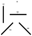
図2は、複数の計測パターンを含む計測パターン群10の一例を示す図である。計測パターン群10は、マスク21に設けられていてもよいし、マスク21とは別のフォーカス計測用マスクに設けられていてもよい。計測パターン群10は、例えば、図2に示すように、パターンの延在する方向が互いに異なる4つの計測パターン101、102、103及び104を含む。計測パターン101乃至104は、それぞれ孤立した単一の線パターンであって、孤立線(アイソ)パターンと呼ばれる。計測パターン101乃至104は、それぞれが延在する方向のパターンに対する投影光学系7のベストフォーカス位置を決定するために用いられる。従って、マスク21に形成されたどの方向のパターンに対して投影光学系7のベストフォーカス位置を決定するのかによって、計測パターン101乃至104のうち用いる計測パターンを決定すればよい。計測パターン101乃至104は、投影光学系7のベストフォーカス位置と基板61の表面位置とが一致している場合に、その像の線幅が最大となるように設計されている。従って、投影光学系7を介して投影光学系7の像面側の光軸方向、即ち、Z軸方向の複数の位置のそれぞれに形成される計測パターン101乃至104の像の線幅を計測することで、投影光学系7のベストフォーカス位置を求めることができる。
FIG. 2 is a diagram showing an example of a
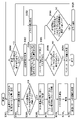
以下、図3を参照して、投影光学系7のベストフォーカス位置を決定する決定処理について詳細に説明する。S302では、テスト基板のフォーカス位置を初期フォーカス位置に設定する。具体的には、レジストが塗布されたテスト基板を基板ステージ62に保持させて、テスト基板のフォーカス位置が初期フォーカス位置となるように基板ステージ62を移動させる。初期フォーカス位置は、例えば、テスト基板をZ軸方向に移動させる範囲(移動範囲)の下限位置(Z座標マイナス側のリミット)又は上限位置(Z座標プラス側のリミット)に設定される。本実施形態では、初期フォーカス位置は、移動範囲の下限位置に設定されているものとする。
A determination process for determining the best focus position of the projection
S304では、投影光学系7を介して計測パターンの像をテスト基板に投影し、テスト基板を露光する。具体的には、図2に示す計測パターン群10が設けられたマスクをマスクステージ22に保持させ、投影光学系7を介して、計測パターン101乃至104のうちの1つの計測パターンの像をテスト基板上に形成する。
In S304, the image of the measurement pattern is projected onto the test substrate via the projection
S306では、テスト基板のフォーカス位置が移動範囲の上限位置に到達したかどうかを判定する。テスト基板のフォーカス位置が移動範囲の上限位置に到達していない場合には、S308に移行する。 In S306, it is determined whether the focus position of the test board has reached the upper limit position of the movement range. If the focus position of the test board has not reached the upper limit position of the movement range, the process proceeds to S308.
S308では、テスト基板をZ軸方向にステップ移動する。具体的には、テスト基板を保持する基板ステージを所定のステップ量だけZ軸方向に移動させる。本実施形態では、初期フォーカス位置が移動範囲の下限位置に設定されているため、テスト基板が上昇するように、基板ステージをZ座標プラス側に移動させる。S302において、初期フォーカス位置が移動範囲の上限位置に設定されている場合には、テスト基板が下降するように、基板ステージをZ座標マイナス側に移動させる。 In S308, the test substrate is stepped in the Z-axis direction. Specifically, the substrate stage holding the test substrate is moved in the Z-axis direction by a predetermined step amount. In this embodiment, since the initial focus position is set to the lower limit position of the movement range, the substrate stage is moved to the positive side of the Z coordinate so that the test substrate is raised. In S302, when the initial focus position is set to the upper limit position of the movement range, the substrate stage is moved to the Z coordinate minus side so that the test substrate descends.
S310では、テスト基板をX軸方向及び/又はY軸方向にステップ移動する。具体的には、テスト基板の未露光領域が露光されるように、テスト基板を保持する基板ステージを所定のステップ量だけX軸方向及び/又はY軸方向に移動させる。 At S310, the test substrate is stepped in the X-axis and/or Y-axis. Specifically, the substrate stage holding the test substrate is moved in the X-axis direction and/or the Y-axis direction by a predetermined step amount so that the unexposed area of the test substrate is exposed.
このように、テスト基板のフォーカス位置が移動範囲の上限位置に到達するまで、S304乃至S310が繰り返される。そして、テスト基板のフォーカス位置が移動範囲の上限位置に到達すると、S306において、S312に移行する。 In this way, S304 to S310 are repeated until the focus position of the test board reaches the upper limit position of the movement range. Then, when the focus position of the test substrate reaches the upper limit position of the movement range, in S306, the process proceeds to S312.
S312では、露光装置100からテスト基板を搬出する。S314では、露光装置100から搬出したテスト基板を現像する。
At S<b>312 , the test substrate is unloaded from the
S316では、顕微鏡を用いて、現像後のテスト基板に形成された、計測パターンに対応するレジスト像、即ち、テスト基板に転写された計測パターンの線幅を計測する。テスト基板のフォーカス位置Fi(i=0,1,2,・・・)に対応する計測パターンの線幅の計測値(計測結果)をLiとする。レジスト像が崩れているなどして計測パターンの線幅が計測できない場合には、そのフォーカス位置Fiに対応する計測パターンの線幅の計測値Liは無効とする。 In S316, a microscope is used to measure the resist image corresponding to the measurement pattern formed on the test substrate after development, that is, the line width of the measurement pattern transferred to the test substrate. Let Li be the measured value (measurement result) of the line width of the measurement pattern corresponding to the focus position Fi (i=0, 1, 2, . . . ) of the test substrate. If the line width of the measurement pattern cannot be measured because the resist image is deformed, the measured value Li of the line width of the measurement pattern corresponding to the focus position Fi is invalidated.
S318では、S316で得られた計測パターンの計測値(有効な計測値)の数が所定数以下(例えば、4つ以下)であるかどうかを判定する。計測パターンの計測値の数が所定数以下である場合には、計測条件に問題があるとして、S320に移行する。S320では、投影光学系7のベストフォーカス位置を決定する決定処理がエラーとなったことを通知(エラー通知)し、S302に移行して、投影光学系7を介して計測パターンの像をテスト基板に投影してテスト基板を露光することからやり直す。一方、計測パターンの計測値の数が所定数以下でない場合には、S322に移行する。
In S318, it is determined whether or not the number of measured values (effective measured values) of the measurement pattern obtained in S316 is equal to or less than a predetermined number (for example, 4 or less). If the number of measured values in the measurement pattern is equal to or less than the predetermined number, it is determined that there is a problem with the measurement conditions, and the process proceeds to S320. In S320, it is notified that the determination process for determining the best focus position of the projection
S322では、S316で得られた計測パターンの計測値Liとテスト基板のフォーカス位置Fiとの関係を示す近似関数を取得する。具体的には、S316で得られた計測パターンの計測値Liを、フォーカス位置の関数として最小自乗法による関数フィッティングを行う。関数フィッティングに用いる関数は、例えば、フォーカス位置の4次の多項式である。なお、本実施形態では、近似関数を例に説明するが、S316で得られた計測パターンの計測値Liとテスト基板のフォーカス位置Fiとの関係を示す関数であればよい。 In S322, an approximation function representing the relationship between the measured value Li of the measurement pattern obtained in S316 and the focus position Fi of the test substrate is acquired. Specifically, the measurement value Li of the measurement pattern obtained in S316 is subjected to function fitting by the method of least squares as a function of the focus position. A function used for function fitting is, for example, a fourth-order polynomial of the focus position. In this embodiment, an approximation function will be described as an example, but any function may be used as long as it indicates the relationship between the measured value Li of the measurement pattern obtained in S316 and the focus position Fi of the test substrate.
S324では、S322で取得された近似関数に基づいて、あるフォーカス範囲内で、近似関数の最大値M及び最大値Mに対応するフォーカス位置FMを求める。 In S324, based on the approximate function obtained in S322, the maximum value M of the approximate function and the focus position FM corresponding to the maximum value M are obtained within a certain focus range.
S326では、S322で取得された近似関数に対して、3つのスライス値T1、T2及びT3を設定して、3つのフォーカス位置F1C、F2C及びF3Cを求める。スライス値T1、T2及びT3は、S322で取得された近似関数に交差するように設定されるスライスレベル(直線)である。 In S326, three slice values T1, T2 and T3 are set for the approximate function obtained in S322 to obtain three focus positions F1C, F2C and F3C. The slice values T1, T2 and T3 are slice levels (straight lines) set to intersect the approximation function obtained in S322.
具体的には、まず、スライス値T3(レベル)を設定し、S322で取得された近似関数とスライス値T3とが交差する2つの点の中点となるフォーカス位置F3Cを求める。ここでは、S322で取得された近似関数とスライス値T3とが交差する2つの点のうち、マイナス側の点をフォーカス位置F3Aとし、プラス側の点をフォーカス位置F3Bとする。そして、フォーカス位置F3A及びF3Bから、その平均であるフォーカス位置F3Cを求める。スライス値T3は、S324で求められた近似関数の最大値Mよりも僅かに小さい値を設定するのが妥当である。例えば、近似関数の最大値Mを基準として、T3=0.90×Mとする。但し、スライス値T3は、近似関数の最大値Mにかかわらず、固定値としてもよい。 Specifically, first, a slice value T3 (level) is set, and a focus position F3C, which is the midpoint between two points where the approximation function obtained in S322 and the slice value T3 intersect, is obtained. Here, of the two points at which the approximation function acquired in S322 and the slice value T3 intersect, the point on the minus side is set as the focus position F3A, and the point on the plus side is set as the focus position F3B. Then, the average focus position F3C is obtained from the focus positions F3A and F3B. It is appropriate to set the slice value T3 to a value slightly smaller than the maximum value M of the approximation function obtained in S324. For example, T3=0.90×M based on the maximum value M of the approximation function. However, the slice value T3 may be a fixed value regardless of the maximum value M of the approximation function.
次いで、スライス値T3とは異なるスライス値T1及びT2を用いて、同様にフォーカス位置を求める。スライス値T1は、スライス値T3よりも一定量大きな値であり、スライス値T2は、スライス値T3よりも一定量小さな値である。例えば、T1=0.95×Mとし、T2=0.85×Mとする。そして、S322で取得された近似関数とスライス値T1とが交差する2つの点の中点となるフォーカス位置F1Cを求める。ここでは、S322で取得された近似関数とスライス値T1とが交差する2つの点のうち、マイナス側の点をフォーカス位置F1Aとし、プラス側の点をフォーカス位置F1Bとする。そして、フォーカス位置F1A及びF1Bから、その平均であるフォーカス位置F1Cを求める。同様に、S322で取得された近似関数とスライス値T2とが交差する2つの点の中点となるフォーカス位置F2Cを求める。ここでは、S322で取得された近似関数とスライス値T2とが交差する2つの点のうち、マイナス側の点をフォーカス位置F2Aとし、プラス側の点をフォーカス位置F2Bとする。そして、フォーカス位置F2A及びF2Bから、その平均であるフォーカス位置F2Cを求める。 Next, using slice values T1 and T2 different from slice value T3, the focus position is obtained in the same manner. The slice value T1 is a value larger than the slice value T3 by a certain amount, and the slice value T2 is a value smaller than the slice value T3 by a certain amount. For example, T1=0.95*M and T2=0.85*M. Then, the focus position F1C, which is the midpoint between the two points where the approximation function acquired in S322 and the slice value T1 intersect, is obtained. Here, of the two points at which the approximation function acquired in S322 and the slice value T1 intersect, the point on the minus side is set as the focus position F1A, and the point on the plus side is set as the focus position F1B. Then, the average focus position F1C is obtained from the focus positions F1A and F1B. Similarly, the focus position F2C, which is the midpoint between the two points where the approximation function acquired in S322 and the slice value T2 intersect, is obtained. Here, of the two points at which the approximation function acquired in S322 and the slice value T2 intersect, the point on the minus side is set as the focus position F2A, and the point on the plus side is set as the focus position F2B. Then, the average focus position F2C is obtained from the focus positions F2A and F2B.
S328では、S326で求めた3つのフォーカス位置F1C、F2C及びF3Cが基準を満たしているかどうかを判定する。S328は、本実施形態では、S326で求めたフォーカス位置F3Cを投影光学系7のベストフォーカス位置として妥当であるか(採用するか)どうかを判定するものである。具体的には、フォーカス位置F3Cとフォーカス位置F1Cとの差分、及び、フォーカス位置F3Cとフォーカス位置F2Cとの差分を求め、これらの差分の絶対値が閾値以下であるか、即ち、以下の式(1)及び式(2)を満たすか判定する。S322で取得された近似関数がフォーカス位置に関して対称な形状であれば、|F1C-F3C|及び|F2C-F3C|の値が小さくなるため、式(1)及び式(2)を満たしやすくなる。一方、S322で取得された近似関数がフォーカス位置に関して非対称な形状であれば、|F1C-F3C|及び|F2C-F3C|の値が大きくなるため、式(1)及び式(2)を満たしにくくなる。 In S328, it is determined whether or not the three focus positions F1C, F2C, and F3C obtained in S326 meet the criteria. In this embodiment, S328 determines whether or not the focus position F3C obtained in S326 is appropriate (adopted) as the best focus position of the projection optical system . Specifically, the difference between the focus position F3C and the focus position F1C and the difference between the focus position F3C and the focus position F2C are obtained, and whether the absolute value of these differences is equal to or less than a threshold, that is, the following formula ( 1) and formula (2) are satisfied. If the approximation function obtained in S322 has a symmetrical shape with respect to the focus position, the values of |F1C-F3C| and |F2C-F3C| become small, so that formulas (1) and (2) are easily satisfied. On the other hand, if the approximation function obtained in S322 has an asymmetrical shape with respect to the focus position, the values of |F1C−F3C| and |F2C−F3C| Become.
|F1C-F3C|≦U ・・・(1)
|F2C-F3C|≦U ・・・(2)
式(1)及び式(2)において、Uは、閾値である。
|F1C-F3C|≦U (1)
|F2C-F3C|≦U (2)
In equations (1) and (2), U is a threshold.
閾値Uは、投影光学系7のベストフォーカス位置を決定する精度に基づいて予め設定しておく必要がある。例えば、投影光学系7のベストフォーカス位置を1μm程度の精度で決定する必要があれば、U=1μmと設定する。
The threshold value U needs to be set in advance based on the accuracy with which the best focus position of the projection
式(1)及び式(2)の両方を満たしている場合には、フォーカス位置F3Cは投影光学系7のベストフォーカス位置として信頼性が高い(真値に近い)と考えられる。従って、フォーカス位置F1C、F2C及びF3Cが基準を満たしていると判定され、S332に移行する。
If both equations (1) and (2) are satisfied, the focus position F3C is considered highly reliable (close to the true value) as the best focus position of the projection
一方、式(1)及び式(2)のいずれか一方又は両方を満たしていない場合には、フォーカス位置F3Cは、スライス値によって大きく変動するということであるため、投影光学系7のベストフォーカス位置として信頼性が低い(真値から遠い)と考えられる。従って、フォーカス位置F1C、F2C及びF3Cが基準を満たしていないと判定され、S330に移行する。 On the other hand, if either one or both of the formulas (1) and (2) are not satisfied, the focus position F3C fluctuates greatly depending on the slice value. is considered to be unreliable (far from the true value). Therefore, it is determined that the focus positions F1C, F2C, and F3C do not meet the criteria, and the process proceeds to S330.
S330では、S322で取得された近似関数とスライス値との交点が1点以下となるか、又は、スライス値が予め設定された変更範囲の限界に達したかどうかを判定する。スライス値が小さくなりすぎると、S322で取得された近似関数とスライス値との交点が1点以下となる場合がある。S322で取得された近似関数とスライス値との交点が1点以下となるか、又は、スライス値が予め設定された変更範囲の限界に達した場合には、S320に移行する。一方、S322で取得された近似関数とスライス値との交点が1点以下ではなく、且つ、スライス値が予め設定された変更範囲の限界に達していない場合には、S332に移行する。 In S330, it is determined whether the intersection of the approximation function acquired in S322 and the slice value is 1 point or less, or whether the slice value has reached the limit of the preset change range. If the slice value becomes too small, the number of intersections between the approximation function obtained in S322 and the slice value may be one or less. If the intersection of the approximation function acquired in S322 and the slice value is 1 point or less, or if the slice value reaches the limit of the preset change range, the process proceeds to S320. On the other hand, if the intersection of the approximation function acquired in S322 and the slice value is not less than 1 point and the slice value has not reached the limit of the preset change range, the process proceeds to S332.
S332では、スライス値T1、T2及びT3を変更する。具体的には、スライス値T1、T2及びT3が小さくなるように、それぞれを所定量だけシフトさせる。例えば、スライス値T3は、T3=0.90×MからT3=0.80×Mに変更する。同様に、スライス値T1は、T1=0.95×MからT1=0.85×Mに変更し、スライス値T2は、T2=0.85×MからT2=0.75×Mに変更する。そして、S326に移行して、3つのフォーカス位置F1C、F2C及びF3Cを再度求める。 At S332, the slice values T1, T2 and T3 are changed. Specifically, each of the slice values T1, T2, and T3 is shifted by a predetermined amount so as to become smaller. For example, the slice value T3 is changed from T3=0.90*M to T3=0.80*M. Similarly, the slice value T1 is changed from T1=0.95×M to T1=0.85×M, and the slice value T2 is changed from T2=0.85×M to T2=0.75×M. . Then, in S326, the three focus positions F1C, F2C and F3C are obtained again.
S334では、投影光学系7のベストフォーカス位置を決定する。本実施形態では、上述したように、フォーカス位置F3Cが投影光学系7のベストフォーカス位置として妥当であるかを判定している。従って、S334に移行した場合には、S326で求めたフォーカス位置F3Cを投影光学系7のベストフォーカス位置として決定(採用)する。
In S334, the best focus position of the projection
図4(a)、図4(b)、図5(a)、図5(b)及び図6を参照して、図3に示す決定処理のS322、S324及びS326、S328、S332及びS334を具体的に説明する。 4(a), 4(b), 5(a), 5(b) and 6, S322, S324 and S326, S328, S332 and S334 of the decision processing shown in FIG. A specific description will be given.
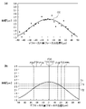
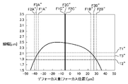
図4(a)は、S322で取得される、S316で得られた計測パターンの計測値Liとテスト基板のフォーカス位置Fiとの関係を示す近似関数CCの一例を示す図である。図4(a)では、縦軸は、計測パターンの計測値Li(線幅)を示し、横軸は、テスト基板のフォーカス位置Fi(投影光学系7のベストフォーカス位置からのデフォーカス量)を示している。また、計測パターンの計測値Liは、約4μmのフォーカスピッチで得られている。 FIG. 4A is a diagram showing an example of the approximation function CC obtained in S322 and indicating the relationship between the measured value Li of the measurement pattern obtained in S316 and the focus position Fi of the test substrate. In FIG. 4A, the vertical axis indicates the measured value Li (line width) of the measurement pattern, and the horizontal axis indicates the focus position Fi of the test substrate (defocus amount from the best focus position of the projection optical system 7). showing. Also, the measured value Li of the measurement pattern is obtained at a focus pitch of about 4 μm.
図4(b)は、図4(a)に示す近似関数CCに対してスライス値T1、T2及びT3を設定することで求められるフォーカス位置F1A、F1B、F1C、F2A、F2B、F2C、F3A、F3B及びF3Cの一例を示す図である。図4(b)では、縦軸は、計測パターンの計測値Li(線幅)を示し、横軸は、テスト基板のフォーカス位置Fi(投影光学系7のベストフォーカス位置からのデフォーカス量)を示している。また、スライス値T1は、T1=0.95×Mとし、スライス値T2は、T2=0.85×Mとし、スライス値T3は、T3=0.90×Mとしている。 FIG. 4B shows focus positions F1A, F1B, F1C, F2A, F2B, F2C, F3A, It is a figure which shows an example of F3B and F3C. In FIG. 4B, the vertical axis indicates the measured value Li (line width) of the measurement pattern, and the horizontal axis indicates the focus position Fi of the test substrate (defocus amount from the best focus position of the projection optical system 7). showing. Also, the slice value T1 is T1=0.95×M, the slice value T2 is T2=0.85×M, and the slice value T3 is T3=0.90×M.
図4(b)を参照するに、フォーカス位置F1C、F2C及びF3Cは、ほぼ同じである。従って、S328において、例えば、閾値UをU=1μmとすると、式(1)及び式(2)を満たす。この場合、S334に移行し、フォーカス位置F3Cを投影光学系7のベストフォーカス位置として決定する。 Referring to FIG. 4B, focus positions F1C, F2C and F3C are substantially the same. Therefore, in S328, for example, if the threshold value U is set to U=1 μm, the formulas (1) and (2) are satisfied. In this case, the process proceeds to S334, and the focus position F3C is determined as the best focus position of the projection optical system .
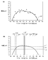
図5(a)は、S322で取得される、S316で得られた計測パターンの計測値Liとテスト基板のフォーカス位置Fiとの関係を示す近似関数CC’の一例を示す図である。図5(a)では、縦軸は、計測パターンの計測値Li(線幅)を示し、横軸は、テスト基板のフォーカス位置Fi(投影光学系7のベストフォーカス位置からのデフォーカス量)を示している。また、計測パターンの計測値Liは、約4μmのフォーカスピッチで得られている。 FIG. 5A is a diagram showing an example of an approximation function CC' obtained in S322 that indicates the relationship between the measured value Li of the measurement pattern obtained in S316 and the focus position Fi of the test substrate. In FIG. 5A, the vertical axis indicates the measured value Li (line width) of the measurement pattern, and the horizontal axis indicates the focus position Fi of the test substrate (defocus amount from the best focus position of the projection optical system 7). showing. Also, the measured value Li of the measurement pattern is obtained at a focus pitch of about 4 μm.
図5(b)は、図5(a)に示す近似関数CC’に対してスライス値T1’、T2’及びT3’を設定することで求められるフォーカス位置F1A’、F1B’、F1C’、F2A’、F2B’、F2C’、F3A’、F3B’及びF3C’の一例を示す図である。図5(b)では、縦軸は、計測パターンの計測値Li(線幅)を示し、横軸は、テスト基板のフォーカス位置Fi(投影光学系7のベストフォーカス位置からのデフォーカス量)を示している。また、スライス値T1’は、T1’=0.95×M’とし、スライス値T2’は、T2’=0.85×M’とし、スライス値T3’は、T3’=0.90×M’としている。M’は、近似関数CC’の最大値である。 FIG. 5(b) shows focus positions F1A′, F1B′, F1C′, and F2A obtained by setting slice values T1′, T2′, and T3′ for the approximation function CC′ shown in FIG. 5(a). It is a figure which shows an example of ', F2B', F2C', F3A', F3B' and F3C'. In FIG. 5B, the vertical axis indicates the measured value Li (line width) of the measurement pattern, and the horizontal axis indicates the focus position Fi of the test substrate (defocus amount from the best focus position of the projection optical system 7). showing. Also, the slice value T1′ is T1′=0.95×M′, the slice value T2′ is T2′=0.85×M′, and the slice value T3′ is T3′=0.90×M '. M' is the maximum value of the approximation function CC'.
図5(b)を参照するに、フォーカス位置F1C’、F2C’及びF3C’間には、差が生じている。従って、S328において、例えば、閾値UをU=1μmとすると、式(1)及び式(2)を満たさない。この場合、S330に移行し、更に、S332に移行すると、スライス値に変更が加えられる。ここでは、スライス値T1’は、スライス値T1’’(=0.85×M’)に変更され、スライス値T2’は、スライス値T2’’(=0.75×M’)に変更され、スライス値T3’は、スライス値T3’’(=0.80×M’)に変更されるものとする。 Referring to FIG. 5B, there is a difference between the focus positions F1C', F2C' and F3C'. Therefore, in S328, for example, if the threshold U is set to U=1 μm, the equations (1) and (2) are not satisfied. In this case, when the process proceeds to S330 and then to S332, the slice value is changed. Here, the slice value T1′ is changed to the slice value T1″ (=0.85×M′), and the slice value T2′ is changed to the slice value T2″ (=0.75×M′). , the slice value T3′ is changed to the slice value T3″ (=0.80×M′).
図6は、図5(a)に示す近似関数CC’に対してスライス値T1’’、T2’’及びT3’’を設定した場合を示している。この場合、フォーカス位置F1A’’、F1B’’、F1C’’、F2A’’、F2B’’、F2C’’、F3A’’、F3B’’及びF3C’’が求まる。図6では、縦軸は、計測パターンの計測値Li(線幅)を示し、横軸は、テスト基板のフォーカス位置Fi(投影光学系7のベストフォーカス位置からのデフォーカス量)を示している。 FIG. 6 shows a case where slice values T1'', T2'' and T3'' are set for the approximation function CC' shown in FIG. 5(a). In this case, focus positions F1A'', F1B'', F1C'', F2A'', F2B'', F2C'', F3A'', F3B'' and F3C'' are obtained. In FIG. 6, the vertical axis indicates the measured value Li (line width) of the measurement pattern, and the horizontal axis indicates the focus position Fi of the test substrate (defocus amount from the best focus position of the projection optical system 7). .
図6を参照するに、フォーカス位置F1C’’、F2C’’及びF3C’’は、ほぼ同じである。従って、S328において、式(1)及び式(2)を満たす。この場合、S334に移行し、フォーカス位置F3C’’を投影光学系7のベストフォーカス位置として決定する。
Referring to FIG. 6, focus positions F1C'', F2C'' and F3C'' are substantially the same. Therefore, in S328, formulas (1) and (2) are satisfied. In this case, the process proceeds to S<b>334 to determine the focus position F<b>3 C″ as the best focus position of the projection
このように、本実施形態では、計測パターンの計測結果とフォーカス位置との関係を示す近似関数から求まるベストフォーカス位置の信頼性を定量的に評価している。従って、近似関数が非対称な形状を有している場合であっても、真値との差が大きいフォーカス位置を投影光学系7のベストフォーカス位置とすることを回避し、真値に近いフォーカス位置を投影光学系7のベストフォーカス位置として決定することができる。換言すれば、本実施形態では、従来技術と比較して、投影光学系7のベストフォーカス位置を高精度に求めることができる。
As described above, in this embodiment, the reliability of the best focus position obtained from the approximation function indicating the relationship between the measurement result of the measurement pattern and the focus position is quantitatively evaluated. Therefore, even when the approximation function has an asymmetrical shape, it is possible to avoid using a focus position with a large difference from the true value as the best focus position of the projection
また、本実施形態における投影光学系7のベストフォーカス位置を決定する決定処理は、図3を参照して説明した手法に限定されず、種々の手法を採用することが可能である。例えば、スライス値T1、T2及びT3の設定は、近似関数の最大値からの割合ではなく、固定値(ベストフォーカス位置の設定値など)からの割合としてもよい。
Further, the determination processing for determining the best focus position of the projection
また、S304乃至S310において、テスト基板のフォーカス位置を変更しながら露光する代わりに、テスト基板を保持している基板ステージ62を、XY平面から一定量傾いた方向に走査しながら露光してもよい。これにより、異なるフォーカス位置での露光を1つのショット領域内に一括して行うことができる。
Further, in S304 to S310, instead of performing exposure while changing the focus position of the test substrate, the
また、S302に戻って、テスト基板への露光をやり直す場合には、同一の計測パターンを再度転写するのではなく、かかる計測パターンと同一の方向に延在し、且つ、異なる線幅を有する計測パターンを転写するようにしてもよい。例えば、現像プロセスなどの要因で計測パターンに対応するレジスト像が正しく形成できていない場合には、より大きい線幅を有する計測パターンを用いることで、計測パターンに対応するレジスト像が正しく形成できる。 Returning to S302, when the exposure to the test substrate is redone, instead of transferring the same measurement pattern again, a measurement pattern extending in the same direction as the measurement pattern and having a different line width is used. A pattern may be transferred. For example, when the resist image corresponding to the measurement pattern cannot be correctly formed due to factors such as the development process, the resist image corresponding to the measurement pattern can be correctly formed by using a measurement pattern having a larger line width.
また、S328において、式(1)及び式(2)の少なくとも一方を満たさない場合に、S330に移行するのではなく、S302に戻って、テスト基板への露光をやり直してもよい。この場合、上述したように、同一の方向に延在し、且つ、異なる線幅を有する計測パターンを用いてもよい。なお、同一の方向に延在し、且つ、異なる線幅を有する別の計測パターンがテスト基板に既に転写されている場合には、露光は不要であるため、S316に移行して、別の計測パターンの線幅を計測すればよい。 Further, in S328, if at least one of the formulas (1) and (2) is not satisfied, instead of proceeding to S330, the process may return to S302 to re-expose the test substrate. In this case, as described above, measurement patterns extending in the same direction and having different line widths may be used. Note that if another measurement pattern extending in the same direction and having a different line width has already been transferred to the test substrate, exposure is not necessary, so the process proceeds to S316 to perform another measurement. The line width of the pattern should be measured.
また、S328において、式(1)及び式(2)に代えて、以下の式(3)を用いてもよい。そして、式(3)を満たしている場合には、S332に移行し、式(3)を満たしていない場合には、S330に移行する。 Also, in S328, the following formula (3) may be used instead of the formulas (1) and (2). Then, if the formula (3) is satisfied, the process proceeds to S332, and if the formula (3) is not satisfied, the process proceeds to S330.
|F1C-F2C|≦U ・・・(3)
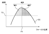
式(3)を用いる場合には、S334において、フォーカス位置F3Cを投影光学系7のベストフォーカス位置としてもよいが、これに限定されるものではない。換言すれば、フォーカス位置F3C以外のフォーカス位置を投影光学系7のベストフォーカス位置とすることも可能である。例えば、フォーカス位置F1Cとフォーカス位置F2Cとの間に位置し、且つ、フォーカス位置F3Cではないフォーカス位置を投影光学系7のベストフォーカス位置としてもよい。具体的には、フォーカス位置F1Cとフォーカス位置F2Cとの中点に対応するフォーカス位置を投影光学系7のベストフォーカス位置としてもよい。また、図7に示すように、近似関数CCとスライス値T3とがなす閉領域400の重心位置F4を求め、重心位置F4に対応するフォーカス位置を投影光学系7のベストフォーカス位置としてもよい。図7に示すように、閉領域400は、近似関数CCと、近似関数CCとスライス値T3とが交差する2つの点を結ぶ線分とによって規定され、重心位置F4を示す直線によって、領域401と領域402とに分割される。重心位置F4は、領域401の面積と領域402の面積とが等しくなるように定められる。
|F1C-F2C|≦U (3)
When formula (3) is used, the focus position F3C may be set as the best focus position of the projection
また、図3では、計測パターンをテスト基板に転写する場合を例に説明した。但し、図8に示すように、基板ステージ62に設けられたセンサ63によって、計測パターンの像の線幅を計測してもよい。センサ63は、投影光学系7を介して、計測パターンの像を検出して、かかる計測パターンの像の線幅を出力(計測)する。また、センサ63は、計測パターンの像の線幅ではなく、計測パターンの像の光強度プロファイル(最大光強度)を計測してもよい。なお、センサ63は、基板ステージ62から独立して構成されていてもよい。
Moreover, in FIG. 3, the case where the measurement pattern is transferred to the test substrate has been described as an example. However, as shown in FIG. 8, a
露光装置100における露光処理(露光方法)について説明する。まず、上述した決定方法によって、投影光学系7のベストフォーカス位置を決定する。次いで、投影光学系7のベストフォーカス位置に基づいて、露光装置100の各部を調整する。具体的には、投影光学系7のベストフォーカス位置と基板61の表面位置とを一致させるように、露光装置100の各部を調整する。かかる調整は、基板ステージ62の位置及び姿勢の少なくとも1つを調整すること、及び、投影光学系7に含まれる光学素子の位置、姿勢及び面形状の少なくとも1つを調整することの少なくとも一方を含む。そして、投影光学系7のベストフォーカス位置と基板61の表面位置とを一致させた状態で、投影光学系7を介して基板61を露光してマスク21のパターンを基板61に転写する。このように、露光装置100では、投影光学系7のベストフォーカス位置と基板61の表面位置とを一致させた状態で露光を行うことができるため、所望のパターンの像を基板上に形成することができる。
An exposure process (exposure method) in the
本発明の実施形態における物品の製造方法は、例えば、デバイス(半導体素子、磁気記憶媒体、液晶表示素子など)、カラーフィルタ、光学部品、MEMSなどの物品を製造するのに好適である。かかる製造方法は、露光装置100を用いて、上述した実施形態の露光方法によって、感光剤が塗布された基板を露光する工程と、露光された感光剤を現像する工程とを含む。また、現像された感光剤のパターンをマスクとして基板に対してエッチング工程やイオン注入工程などを行い、基板上に回路パターンが形成される。これらの露光、現像、エッチングなどの工程を繰り返して、基板上に複数の層からなる回路パターンを形成する。後工程で、回路パターンが形成された基板に対してダイシング(加工)を行い、チップのマウンティング、ボンディング、検査工程を行う。また、かかる製造方法は、他の周知の工程(酸化、成膜、蒸着、ドーピング、平坦化、レジスト剥離など)を含みうる。本実施形態における物品の製造方法は、従来に比べて、物品の性能、品質、生産性及び生産コストの少なくとも1つにおいて有利である。
The method for manufacturing an article according to the embodiment of the present invention is suitable for manufacturing articles such as devices (semiconductor devices, magnetic storage media, liquid crystal display devices, etc.), color filters, optical components, and MEMS. This manufacturing method includes a step of exposing a substrate coated with a photosensitive agent and a step of developing the exposed photosensitive agent by the exposure method of the embodiment described above using the
本発明は、上述の実施形態の1つ以上の機能を実現するプログラムを、ネットワーク又は記憶媒体を介してシステム又は装置に供給し、そのシステム又は装置のコンピュータにおける1つ以上のプロセッサーがプログラムを読出し実行する処理でも実現可能である。また、1つ以上の機能を実現する回路(例えば、ASIC)によっても実現可能である。 The present invention supplies a program that implements one or more functions of the above-described embodiments to a system or device via a network or a storage medium, and one or more processors in the computer of the system or device reads the program. It can also be realized by executing processing. It can also be implemented by a circuit (eg, an ASIC) that implements one or more functions.
以上、本発明の好ましい実施形態について説明したが、本発明はこれらの実施形態に限定されないことはいうまでもなく、その要旨の範囲内で種々の変形及び変更が可能である。 Although the preferred embodiments of the present invention have been described above, it goes without saying that the present invention is not limited to these embodiments, and various modifications and changes are possible within the scope of the gist.
100:露光装置 7:投影光学系 10:計測パターン群 61:基板 80:制御部 101乃至104:計測パターン
100: Exposure device 7: Projection optical system 10: Measurement pattern group 61: Substrate 80:
Claims (27)
前記投影光学系を介して前記投影光学系の像面側の光軸方向の複数の位置においてそれぞれに転写された、第1計測パターンの線幅の計測値、又は前記第1計測パターンの強度プロファイルと、前記複数の位置のそれぞれとの関係を示す関数を取得する第1工程と、
前記関数と第1レベルとが交差する2つの点の中点となる第1フォーカス位置を求める第2工程と、
前記関数と前記第1レベルとは異なる第2レベルとが交差する2つの点の中点となる第2フォーカス位置を求める第3工程と、
前記関数と前記第1レベルと前記第2レベルとの間の第3レベルとが交差する2つの点の中点となる第3フォーカス位置を求める第4工程と、
前記第1フォーカス位置、前記第2フォーカス位置及び前記第3フォーカス位置に基づいて、前記ベストフォーカス位置を決定する第5工程と、
を有することを特徴とする決定方法。 A determination method for determining a best focus position of a projection optical system for projecting a pattern of a mask onto a substrate, comprising:
measured values of the line width of the first measurement pattern or the intensity profile of the first measurement pattern , which are respectively transferred at a plurality of positions in the optical axis direction on the image plane side of the projection optical system via the projection optical system; and a first step of obtaining a function indicating the relationship between each of the plurality of positions;
a second step of finding a first focus position that is the midpoint of two points where the function and the first level intersect;
a third step of determining a second focus position that is the midpoint of two points where the function and a second level different from the first level intersect;
a fourth step of determining a third focus position that is the midpoint of two points where the function and a third level between the first level and the second level intersect;
a fifth step of determining the best focus position based on the first focus position, the second focus position and the third focus position;
A determination method characterized by having
前記投影光学系を介して前記投影光学系の像面側の光軸方向の複数の位置においてそれぞれに転写された第1計測パターンの計測結果と、前記複数の位置のそれぞれとの関係を示す関数を取得する第1工程と、 A function indicating the relationship between the measurement results of the first measurement pattern transferred at a plurality of positions in the optical axis direction on the image plane side of the projection optical system via the projection optical system and each of the plurality of positions. a first step of obtaining
前記関数と第1レベルとが交差する2つの点の中点となる第1フォーカス位置を求める第2工程と、 a second step of finding a first focus position that is the midpoint of two points where the function and the first level intersect;
前記関数と前記第1レベルとは異なる第2レベルとが交差する2つの点の中点となる第2フォーカス位置を求める第3工程と、 a third step of determining a second focus position that is the midpoint of two points where the function and a second level different from the first level intersect;
前記関数と前記第1レベルと前記第2レベルとの間の第3レベルとが交差する2つの点の中点となる第3フォーカス位置を求める第4工程と、 a fourth step of determining a third focus position that is the midpoint of two points where the function and a third level between the first level and the second level intersect;
前記ベストフォーカス位置を決定する第5工程と、 a fifth step of determining the best focus position;
を有し、 has
前記第5工程は、前記第1フォーカス位置と前記第3フォーカス位置との第1差分及び前記第2フォーカス位置と前記第3フォーカス位置との第2差分が閾値より大きい場合に、 In the fifth step, when a first difference between the first focus position and the third focus position and a second difference between the second focus position and the third focus position are larger than a threshold,
前記関数と前記第1レベルを所定量だけシフトさせた第4レベルとが交差する2つの点の中点となる第4フォーカス位置を求める工程と、 determining a fourth focus position that is the midpoint between two points where the function and a fourth level obtained by shifting the first level by a predetermined amount are intersected;
前記関数と前記第2レベルを前記所定量だけシフトさせた第5レベルとが交差する2つの点の中点となる第5フォーカス位置を求める工程と、 determining a fifth focus position that is the midpoint between two points of intersection of the function and a fifth level obtained by shifting the second level by the predetermined amount;
前記関数と前記第3レベルを前記所定量だけシフトさせた第6レベルとが交差する2つの点の中点となる第6フォーカス位置を求める工程と、 determining a sixth focus position that is the midpoint between two points of intersection of the function and a sixth level obtained by shifting the third level by the predetermined amount;
前記第6フォーカス位置、前記第4フォーカス位置と前記第6フォーカス位置との差分、及び、前記第5フォーカス位置と前記第6フォーカス位置との差分に基づいて、前記ベストフォーカス位置を決定する工程と、 determining the best focus position based on the sixth focus position, the difference between the fourth focus position and the sixth focus position, and the difference between the fifth focus position and the sixth focus position; ,
を含むことを特徴とする決定方法。 A determination method comprising:
前記投影光学系を介して前記複数の位置のそれぞれに再度転写された前記第1計測パターンの計測結果と、前記複数の位置のそれぞれとの関係を示す新たな関数を取得する工程と、
前記新たな関数と前記第1レベルとが交差する2つの点の中点となる第7フォーカス位置を求める工程と、
前記新たな関数と前記第2レベルとが交差する2つの点の中点となる第8フォーカス位置を求める工程と、
前記新たな関数と前記第3レベルとが交差する2つの点の中点となる第9フォーカス位置を求める工程と、
前記第9フォーカス位置、前記第7フォーカス位置と前記第9フォーカス位置との差分、及び、前記第8フォーカス位置と前記第9フォーカス位置との差分に基づいて、前記ベストフォーカス位置を決定する工程と、
を含むことを特徴とする請求項2に記載の決定方法。 In the fifth step, when the first difference and the second difference are greater than a threshold,
obtaining a new function indicating the relationship between the measurement result of the first measurement pattern transferred again to each of the plurality of positions via the projection optical system and each of the plurality of positions;
determining a seventh focus position that is the midpoint of two points where the new function and the first level intersect;
determining an eighth focus position that is the midpoint of two points where the new function and the second level intersect;
determining a ninth focus position that is the midpoint of two points where the new function and the third level intersect;
determining the best focus position based on the ninth focus position, the difference between the seventh focus position and the ninth focus position, and the difference between the eighth focus position and the ninth focus position; ,
3. The method of claim 2, comprising:
前記投影光学系を介して前記複数の位置のそれぞれに転写された、前記第1計測パターンと同一の方向に延在し、且つ、前記第1計測パターンの線幅とは異なる線幅を有する第2計測パターンの計測結果と、前記複数の位置のそれぞれとの関係を示す新たな関数を取得する工程と、
前記新たな関数と前記第1レベルとが交差する2つの点の中点となる第10フォーカス位置を求める工程と、
前記新たな関数と前記第2レベルとが交差する2つの点の中点となる第11フォーカス位置を求める工程と、
前記新たな関数と前記第3レベルとが交差する2つの点の中点となる第12フォーカス位置を求める工程と、
前記第12フォーカス位置、前記第10フォーカス位置と前記第12フォーカス位置との差分、及び、前記第11フォーカス位置と前記第12フォーカス位置との差分に基づいて、前記ベストフォーカス位置を決定する工程と、
を含むことを特徴とする請求項2に記載の決定方法。 In the fifth step, when the first difference and the second difference are greater than a threshold,
A first measurement pattern transferred to each of the plurality of positions via the projection optical system, extending in the same direction as the first measurement pattern, and having a line width different from the line width of the first measurement pattern. Acquiring a new function indicating the relationship between the measurement results of two measurement patterns and each of the plurality of positions;
determining a tenth focus position that is the midpoint of two points where the new function and the first level intersect;
determining an eleventh focus position that is the midpoint of two points where the new function and the second level intersect;
determining a twelfth focus position that is the midpoint of two points where the new function and the third level intersect;
determining the best focus position based on the 12th focus position, the difference between the 10th focus position and the 12th focus position, and the difference between the 11th focus position and the 12th focus position; ,
3. The method of claim 2, comprising:
前記投影光学系を介して前記投影光学系の像面側の光軸方向の複数の位置においてそれぞれに転写された、第1計測パターンの線幅の計測値、又は前記第1計測パターンの強度プロファイルと、前記複数の位置のそれぞれとの関係を示す関数を取得する第1工程と、
前記関数と第1レベルとが交差する2つの点の中点となる第1フォーカス位置を求める第2工程と、
前記関数と前記第1レベルとは異なる第2レベルとが交差する2つの点の中点となる第2フォーカス位置を求める第3工程と、
前記第1フォーカス位置と前記第2フォーカス位置とに基づいて、前記ベストフォーカス位置を決定する第4工程と、
を有することを特徴とする決定方法。 A determination method for determining a best focus position of a projection optical system for projecting a pattern of a mask onto a substrate, comprising:
measured values of the line width of the first measurement pattern or the intensity profile of the first measurement pattern, which are respectively transferred at a plurality of positions in the optical axis direction on the image plane side of the projection optical system via the projection optical system; and a first step of obtaining a function indicating the relationship between each of the plurality of positions;
a second step of finding a first focus position that is the midpoint of two points where the function and the first level intersect;
a third step of determining a second focus position that is the midpoint of two points where the function and a second level different from the first level intersect;
a fourth step of determining the best focus position based on the first focus position and the second focus position;
A determination method characterized by having
前記第3レベルは、前記第1レベルと前記第2レベルとの間のレベルであることを特徴とする請求項12に記載の決定方法。 The third focus position is a center-of-gravity position of a closed region defined by the function and a line segment connecting two points where the function and the third level intersect,
13. The method of claim 12 , wherein said third level is a level between said first level and said second level.
前記投影光学系のベストフォーカス位置を決定する第1工程と、
前記第1工程で決定したベストフォーカス位置に基づいて、前記露光装置を調整する第2工程と、
前記第2工程で調整された前記露光装置を用いて前記基板を露光する第3工程と、
を有し、
前記第1工程は、
前記投影光学系を介して前記投影光学系の像面側の光軸方向の複数の位置においてそれぞれに転写された、第1計測パターンの線幅の計測値、又は前記第1計測パターンの強度プロファイルと、前記複数の位置のそれぞれとの関係を示す関数を取得する工程と、
前記関数と第1レベルとが交差する2つの点の中点となる第1フォーカス位置を求める工程と、
前記関数と前記第1レベルとは異なる第2レベルとが交差する2つの点の中点となる第2フォーカス位置を求める工程と、
前記関数と前記第1レベルと前記第2レベルとの間の第3レベルとが交差する2つの点の中点となる第3フォーカス位置を求める工程と、
前記第1フォーカス位置、前記第2フォーカス位置及び前記第3フォーカス位置に基づいて、前記ベストフォーカス位置を決定する工程と、
を含むことを特徴とする露光方法。 An exposure method for exposing a substrate using an exposure apparatus having a projection optical system for projecting a pattern of a mask onto a substrate,
a first step of determining a best focus position of the projection optical system;
a second step of adjusting the exposure device based on the best focus position determined in the first step;
a third step of exposing the substrate using the exposure apparatus adjusted in the second step;
has
The first step is
measured values of the line width of the first measurement pattern or the intensity profile of the first measurement pattern, which are respectively transferred at a plurality of positions in the optical axis direction on the image plane side of the projection optical system via the projection optical system; and obtaining a function indicating the relationship between each of the plurality of positions;
determining a first focus position that is the midpoint of two points where the function and the first level intersect;
determining a second focus position that is the midpoint of two points where the function and a second level different from the first level intersect;
determining a third focus position that is the midpoint of two points where the function and a third level between the first level and the second level intersect;
determining the best focus position based on the first focus position, the second focus position and the third focus position;
An exposure method comprising:
前記投影光学系のベストフォーカス位置を決定する第1工程と、 a first step of determining a best focus position of the projection optical system;
前記第1工程で決定したベストフォーカス位置に基づいて、前記露光装置を調整する第2工程と、 a second step of adjusting the exposure device based on the best focus position determined in the first step;
前記第2工程で調整された前記露光装置を用いて前記基板を露光する第3工程と、 a third step of exposing the substrate using the exposure apparatus adjusted in the second step;
を有し、 has
前記第1工程は、 The first step is
前記投影光学系を介して前記投影光学系の像面側の光軸方向の複数の位置においてそれぞれに転写された第1計測パターンの計測結果と、前記複数の位置のそれぞれとの関係を示す関数を取得する工程と、 A function indicating the relationship between the measurement results of the first measurement pattern transferred at a plurality of positions in the optical axis direction on the image plane side of the projection optical system via the projection optical system and each of the plurality of positions. and obtaining
前記関数と第1レベルとが交差する2つの点の中点となる第1フォーカス位置を求める工程と、 determining a first focus position that is the midpoint of two points where the function and the first level intersect;
前記関数と前記第1レベルとは異なる第2レベルとが交差する2つの点の中点となる第2フォーカス位置を求める工程と、 determining a second focus position that is the midpoint of two points where the function and a second level different from the first level intersect;
前記関数と前記第1レベルと前記第2レベルとの間の第3レベルとが交差する2つの点の中点となる第3フォーカス位置を求める工程と、 determining a third focus position that is the midpoint of two points where the function and a third level between the first level and the second level intersect;
前記第1フォーカス位置と前記第3フォーカス位置との第1差分及び前記第2フォーカス位置と前記第3フォーカス位置との第2差分が閾値より大きい場合に、前記関数と前記第1レベルを所定量だけシフトさせた第4レベルとが交差する2つの点の中点となる第4フォーカス位置を求め、前記関数と前記第2レベルを前記所定量だけシフトさせた第5レベルとが交差する2つの点の中点となる第5フォーカス位置を求め、前記関数と前記第3レベルを前記所定量だけシフトさせた第6レベルとが交差する2つの点の中点となる第6フォーカス位置を求め、前記第6フォーカス位置、前記第4フォーカス位置と前記第6フォーカス位置との差分、及び、前記第5フォーカス位置と前記第6フォーカス位置との差分に基づいて、前記ベストフォーカス位置を決定する工程と、 if a first difference between the first focus position and the third focus position and a second difference between the second focus position and the third focus position are greater than a threshold, the function and the first level are combined by a predetermined amount; A fourth focus position, which is the middle point of two points where the fourth level shifted by Finding a fifth focus position that is the midpoint of the points, finding a sixth focus position that is the midpoint between two points where the function and the sixth level obtained by shifting the third level by the predetermined amount intersect, determining the best focus position based on the sixth focus position, the difference between the fourth focus position and the sixth focus position, and the difference between the fifth focus position and the sixth focus position; ,
を含むことを特徴とする露光方法。 An exposure method comprising:
前記投影光学系のベストフォーカス位置を決定する第1工程と、
前記第1工程で決定したベストフォーカス位置に基づいて、前記露光装置を調整する第2工程と、
前記第2工程で調整された前記露光装置を用いて前記基板を露光する第3工程と、
を有し、
前記第1工程は、
前記投影光学系を介して前記投影光学系の像面側の光軸方向の複数の位置においてそれぞれに転写された、第1計測パターンの線幅の計測値、又は前記第1計測パターンの強度プロファイルと、前記複数の位置のそれぞれとの関係を示す関数を取得する工程と、
前記関数と第1レベルとが交差する2つの点の中点となる第1フォーカス位置を求める工程と、
前記関数と前記第1レベルとは異なる第2レベルとが交差する2つの点の中点となる第2フォーカス位置を求める工程と、
前記第1フォーカス位置と前記第2フォーカス位置とに基づいて、前記ベストフォーカス位置を決定する工程と、
を含むことを特徴とする露光方法。 An exposure method for exposing a substrate using an exposure apparatus having a projection optical system for projecting a pattern of a mask onto a substrate,
a first step of determining a best focus position of the projection optical system;
a second step of adjusting the exposure device based on the best focus position determined in the first step;
a third step of exposing the substrate using the exposure apparatus adjusted in the second step;
has
The first step is
measured values of the line width of the first measurement pattern or the intensity profile of the first measurement pattern, which are respectively transferred at a plurality of positions in the optical axis direction on the image plane side of the projection optical system via the projection optical system; and obtaining a function indicating the relationship between each of the plurality of positions;
determining a first focus position that is the midpoint of two points where the function and the first level intersect;
determining a second focus position that is the midpoint of two points where the function and a second level different from the first level intersect;
determining the best focus position based on the first focus position and the second focus position;
An exposure method comprising:
マスクのパターンを前記基板に投影する投影光学系と、
前記投影光学系のベストフォーカス位置を決定する処理を行う処理部と、
を有し、
前記処理部は、
前記投影光学系を介して前記投影光学系の像面側の光軸方向の複数の位置においてそれぞれに転写された第1計測パターンの線幅の計測値、又は前記第1計測パターンの強度プロファイルと、前記複数の位置のそれぞれとの関係を示す関数を取得し、
前記関数と第1レベルとが交差する2つの点の中点となる第1フォーカス位置を求め、
前記関数と前記第1レベルとは異なる第2レベルとが交差する2つの点の中点となる第2フォーカス位置を求め、
前記関数と前記第1レベルと前記第2レベルとの間の第3レベルとが交差する2つの点の中点となる第3フォーカス位置を求め、
前記第1フォーカス位置、前記第2フォーカス位置及び前記第3フォーカス位置に基づいて、前記ベストフォーカス位置を決定することを特徴とする露光装置。 An exposure apparatus for exposing a substrate,
a projection optical system that projects a mask pattern onto the substrate;
a processing unit that performs processing for determining the best focus position of the projection optical system;
has
The processing unit is
measurement values of the line width of the first measurement pattern transferred via the projection optical system at a plurality of positions in the optical axis direction on the image plane side of the projection optical system, or the intensity profile of the first measurement pattern ; , obtaining a function indicating the relationship with each of the plurality of positions;
Finding a first focus position that is the midpoint between two points where the function and the first level intersect,
Obtaining a second focus position that is the midpoint between two points at which the function and a second level different from the first level intersect;
Finding a third focus position that is the midpoint between two points where the function and a third level between the first level and the second level intersect;
An exposure apparatus, wherein the best focus position is determined based on the first focus position, the second focus position and the third focus position.
マスクのパターンを前記基板に投影する投影光学系と、 a projection optical system that projects a mask pattern onto the substrate;
前記投影光学系のベストフォーカス位置を決定する処理を行う処理部と、 a processing unit that performs processing for determining the best focus position of the projection optical system;
を有し、 has
前記処理部は、 The processing unit is
前記投影光学系を介して前記投影光学系の像面側の光軸方向の複数の位置においてそれぞれに転写された第1計測パターンの計測結果と、前記複数の位置のそれぞれとの関係を示す関数を取得し、 A function indicating the relationship between the measurement results of the first measurement pattern transferred at a plurality of positions in the optical axis direction on the image plane side of the projection optical system via the projection optical system and each of the plurality of positions. and get
前記関数と第1レベルとが交差する2つの点の中点となる第1フォーカス位置を求め、 Finding a first focus position that is the midpoint between two points where the function and the first level intersect,
前記関数と前記第1レベルとは異なる第2レベルとが交差する2つの点の中点となる第2フォーカス位置を求め、 Obtaining a second focus position that is the midpoint between two points at which the function and a second level different from the first level intersect;
前記関数と前記第1レベルと前記第2レベルとの間の第3レベルとが交差する2つの点の中点となる第3フォーカス位置を求め、 Finding a third focus position that is the midpoint between two points where the function and a third level between the first level and the second level intersect;
前記第1フォーカス位置と前記第3フォーカス位置との第1差分及び前記第2フォーカス位置と前記第3フォーカス位置との第2差分が閾値より大きい場合に、前記関数と前記第1レベルを所定量だけシフトさせた第4レベルとが交差する2つの点の中点となる第4フォーカス位置を求め、前記関数と前記第2レベルを前記所定量だけシフトさせた第5レベルとが交差する2つの点の中点となる第5フォーカス位置を求め、前記関数と前記第3レベルを前記所定量だけシフトさせた第6レベルとが交差する2つの点の中点となる第6フォーカス位置を求め、 if a first difference between the first focus position and the third focus position and a second difference between the second focus position and the third focus position are greater than a threshold, the function and the first level are combined by a predetermined amount; A fourth focus position, which is the middle point of two points where the fourth level shifted by Finding a fifth focus position that is the midpoint of the points, finding a sixth focus position that is the midpoint between two points where the function and the sixth level obtained by shifting the third level by the predetermined amount intersect,
前記第6フォーカス位置、前記第4フォーカス位置と前記第6フォーカス位置との差分、及び、前記第5フォーカス位置と前記第6フォーカス位置との差分に基づいて、前記ベストフォーカス位置を決定することを特徴とする露光装置。 Determining the best focus position based on the sixth focus position, the difference between the fourth focus position and the sixth focus position, and the difference between the fifth focus position and the sixth focus position An exposure apparatus characterized by:
マスクのパターンを前記基板に投影する投影光学系と、
前記投影光学系のベストフォーカス位置を決定する処理を行う処理部と、
を有し、
前記処理部は、
前記投影光学系を介して前記投影光学系の像面側の光軸方向の複数の位置においてそれぞれに転写された、第1計測パターンの線幅の計測値、又は前記第1計測パターンの強度プロファイルと、前記複数の位置のそれぞれとの関係を示す関数を取得し、
前記関数と第1レベルとが交差する2つの点の中点となる第1フォーカス位置を求め、
前記関数と前記第1レベルとは異なる第2レベルとが交差する2つの点の中点となる第2フォーカス位置を求め、
前記第1フォーカス位置と前記第2フォーカス位置とに基づいて、前記ベストフォーカス位置を決定することを特徴とする露光装置。 An exposure apparatus for exposing a substrate,
a projection optical system that projects a mask pattern onto the substrate;
a processing unit that performs processing for determining the best focus position of the projection optical system;
has
The processing unit is
measured values of the line width of the first measurement pattern or the intensity profile of the first measurement pattern , which are respectively transferred at a plurality of positions in the optical axis direction on the image plane side of the projection optical system via the projection optical system; and obtain a function indicating the relationship between each of the plurality of positions,
Finding a first focus position that is the midpoint between two points where the function and the first level intersect,
Obtaining a second focus position that is the midpoint between two points at which the function and a second level different from the first level intersect;
An exposure apparatus, wherein the best focus position is determined based on the first focus position and the second focus position.
露光された前記感光剤を現像して前記感光剤のパターンを形成する工程と、
現像された前記感光剤のパターンをもとに前記基板にパターンを形成して、パターンが形成された基板を加工することによって物品を製造する工程と、
を有することを特徴とする物品の製造方法。 exposing a photosensitive agent coated on a substrate using the exposure method according to any one of claims 15 to 20 ;
developing the exposed photosensitive agent to form a pattern of the photosensitive agent;
a step of forming a pattern on the substrate based on the pattern of the developed photosensitive agent, and processing the patterned substrate to manufacture an article;
A method for manufacturing an article, comprising:
Priority Applications (4)
| Application Number | Priority Date | Filing Date | Title |
|---|---|---|---|
| JP2018043490A JP7105582B2 (en) | 2018-03-09 | 2018-03-09 | Determination method, exposure method, exposure apparatus, article manufacturing method and program |
| TW108104887A TWI722386B (en) | 2018-03-09 | 2019-02-14 | Determination method, exposure method, exposure device, article manufacturing method, and storage medium |
| KR1020190023746A KR102493922B1 (en) | 2018-03-09 | 2019-02-28 | Determination method, exposure method, exposure apparatus, method of manufacturing article, and computer program |
| CN201910161927.6A CN110244518B (en) | 2018-03-09 | 2019-03-05 | Determining method, exposure apparatus, article manufacturing method, and storage medium |
Applications Claiming Priority (1)
| Application Number | Priority Date | Filing Date | Title |
|---|---|---|---|
| JP2018043490A JP7105582B2 (en) | 2018-03-09 | 2018-03-09 | Determination method, exposure method, exposure apparatus, article manufacturing method and program |
Publications (3)
| Publication Number | Publication Date |
|---|---|
| JP2019159029A JP2019159029A (en) | 2019-09-19 |
| JP2019159029A5 JP2019159029A5 (en) | 2021-04-22 |
| JP7105582B2 true JP7105582B2 (en) | 2022-07-25 |
Family
ID=67882947
Family Applications (1)
| Application Number | Title | Priority Date | Filing Date |
|---|---|---|---|
| JP2018043490A Active JP7105582B2 (en) | 2018-03-09 | 2018-03-09 | Determination method, exposure method, exposure apparatus, article manufacturing method and program |
Country Status (4)
| Country | Link |
|---|---|
| JP (1) | JP7105582B2 (en) |
| KR (1) | KR102493922B1 (en) |
| CN (1) | CN110244518B (en) |
| TW (1) | TWI722386B (en) |
Families Citing this family (1)
| Publication number | Priority date | Publication date | Assignee | Title |
|---|---|---|---|---|
| US11781214B2 (en) * | 2019-07-30 | 2023-10-10 | Applied Materials, Inc. | Differential capacitive sensors for in-situ film thickness and dielectric constant measurement |
Citations (3)
| Publication number | Priority date | Publication date | Assignee | Title |
|---|---|---|---|---|
| JP2002260986A (en) | 2001-03-02 | 2002-09-13 | Nikon Corp | Method of measuring optical characteristic, method for exposure, and method of manufacturing device |
| JP2003086498A (en) | 2001-09-13 | 2003-03-20 | Canon Inc | Focal point detecting method and system |
| US20030170552A1 (en) | 2000-10-05 | 2003-09-11 | Nikon Corporation | Method of determining exposure conditions, exposure method, device manufacturing method, and storage medium |
Family Cites Families (16)
| Publication number | Priority date | Publication date | Assignee | Title |
|---|---|---|---|---|
| JP3265668B2 (en) * | 1993-01-13 | 2002-03-11 | 株式会社ニコン | How to calculate the best focus position |
| JP3303436B2 (en) * | 1993-05-14 | 2002-07-22 | キヤノン株式会社 | Projection exposure apparatus and method for manufacturing semiconductor element |
| JPH07326563A (en) * | 1994-06-01 | 1995-12-12 | Hitachi Ltd | Exposure condition evaluating pattern, and method and system for evaluating exposure condition using the same |
| JPH0982620A (en) * | 1995-09-20 | 1997-03-28 | Nikon Corp | Method for detection of best focus position |
| AU2003303356A1 (en) * | 2002-12-30 | 2004-07-22 | Koninklijke Philips Electronics N.V. | Determining lithographic parameters to optimise a process window |
| JP4177722B2 (en) * | 2003-07-02 | 2008-11-05 | 株式会社東芝 | Pattern correction method, pattern correction system, mask manufacturing method, semiconductor device manufacturing method, and pattern correction program |
| US7566893B2 (en) * | 2004-06-22 | 2009-07-28 | Nikon Corporation | Best focus detection method, exposure method, and exposure apparatus |
| TWI396225B (en) * | 2004-07-23 | 2013-05-11 | 尼康股份有限公司 | Image surface measuring method, exposuring method, device manufacturing method, and exposuring device |
| KR101346581B1 (en) * | 2006-02-21 | 2014-01-02 | 가부시키가이샤 니콘 | Pattern forming apparatus, pattern forming method, mobile object driving system, mobile body driving method, exposure apparatus, exposure method and device manufacturing method |
| JP2008053618A (en) * | 2006-08-28 | 2008-03-06 | Canon Inc | Exposure apparatus and method therefor, as well as device manufacturing method using exposure apparatus |
| DE102008042356A1 (en) * | 2008-09-25 | 2010-04-08 | Carl Zeiss Smt Ag | Projection exposure system with optimized adjustment option |
| CN102053506A (en) * | 2009-11-05 | 2011-05-11 | 中芯国际集成电路制造(上海)有限公司 | Method for monitoring focusing of exposure machine |
| JP5835968B2 (en) * | 2011-07-05 | 2015-12-24 | キヤノン株式会社 | Determination method, program, and exposure method |
| JP6661371B2 (en) * | 2015-12-25 | 2020-03-11 | キヤノン株式会社 | Evaluation method, exposure method, and article manufacturing method |
| WO2017171880A1 (en) * | 2016-04-01 | 2017-10-05 | Intel Corporation | Systems, methods, and apparatuses for implementing critical dimension (cd) and phase calibration of alternating phase shift masks (apsm) and chromeless phase lithography (cpl) masks for modeling |
| JP6730850B2 (en) * | 2016-06-01 | 2020-07-29 | キヤノン株式会社 | Exposure condition determination method, program, information processing apparatus, exposure apparatus, and article manufacturing method |
-
2018
- 2018-03-09 JP JP2018043490A patent/JP7105582B2/en active Active
-
2019
- 2019-02-14 TW TW108104887A patent/TWI722386B/en active
- 2019-02-28 KR KR1020190023746A patent/KR102493922B1/en active IP Right Grant
- 2019-03-05 CN CN201910161927.6A patent/CN110244518B/en active Active
Patent Citations (3)
| Publication number | Priority date | Publication date | Assignee | Title |
|---|---|---|---|---|
| US20030170552A1 (en) | 2000-10-05 | 2003-09-11 | Nikon Corporation | Method of determining exposure conditions, exposure method, device manufacturing method, and storage medium |
| JP2002260986A (en) | 2001-03-02 | 2002-09-13 | Nikon Corp | Method of measuring optical characteristic, method for exposure, and method of manufacturing device |
| JP2003086498A (en) | 2001-09-13 | 2003-03-20 | Canon Inc | Focal point detecting method and system |
Also Published As
| Publication number | Publication date |
|---|---|
| KR20190106711A (en) | 2019-09-18 |
| TWI722386B (en) | 2021-03-21 |
| JP2019159029A (en) | 2019-09-19 |
| CN110244518B (en) | 2021-07-23 |
| CN110244518A (en) | 2019-09-17 |
| TW201939325A (en) | 2019-10-01 |
| KR102493922B1 (en) | 2023-02-01 |
Similar Documents
| Publication | Publication Date | Title |
|---|---|---|
| KR20080059572A (en) | Optical characteristic measuring method, exposure method, device manufacturing method, inspecting apparatus and measuring method | |
| TW201719299A (en) | Lithographic apparatus and device manufacturing method | |
| KR20100014357A (en) | Measuring method, exposure method, and device fabricating method | |
| CN107450279B (en) | Exposure apparatus, exposure method, and article manufacturing method | |
| JP2018072541A (en) | Pattern formation method, positioning method of substrate, positioning device, pattern formation device and manufacturing method of article | |
| TWI781419B (en) | Detection apparatus, exposure apparatus, and article manufacturing method | |
| JP2008263194A (en) | Exposure apparatus, exposure method, and method for manufacturing electronic device | |
| JPWO2005008754A1 (en) | Flare measurement method, exposure method, and mask for flare measurement | |
| JP2008263193A (en) | Exposure method and manufacturing method for electronic device | |
| US8149385B2 (en) | Alignment unit and exposure apparatus | |
| JP6521637B2 (en) | Measurement apparatus, lithographic apparatus, and method of manufacturing article | |
| TWI409595B (en) | Measuring apparatus, projection exposure apparatus having the same, and device manufacturing method | |
| JP7105582B2 (en) | Determination method, exposure method, exposure apparatus, article manufacturing method and program | |
| JP5662717B2 (en) | Exposure apparatus and device manufacturing method | |
| TW201932906A (en) | Projection optical system, exposure apparatus, and method of manufacturing article capable of correcting magnification and astigmatism with high precision | |
| JP6762746B2 (en) | Exposure equipment and exposure method, and manufacturing method of articles | |
| JP4174324B2 (en) | Exposure method and apparatus | |
| JP2009094256A (en) | Exposure method, exposure device and device manufacturing method | |
| JP3715751B2 (en) | Residual aberration correction plate and projection exposure apparatus using the same | |
| JP2021006893A (en) | Patterning method, patterning device and method for producing article | |
| JP2020177149A (en) | Exposure apparatus and method for manufacturing article | |
| JP2001358059A (en) | Method for evaluating exposure apparatus and exposure apparatus | |
| JP2018116155A (en) | Evaluation method, article manufacturing method and program | |
| JP6501680B2 (en) | EXPOSURE METHOD, EXPOSURE APPARATUS, AND ARTICLE MANUFACTURING METHOD | |
| JP2020095218A (en) | Determination method, exposure method, method for manufacturing article, and program |
Legal Events
| Date | Code | Title | Description |
|---|---|---|---|
| RD01 | Notification of change of attorney |
Free format text: JAPANESE INTERMEDIATE CODE: A7421 Effective date: 20210103 |
|
| A521 | Request for written amendment filed |
Free format text: JAPANESE INTERMEDIATE CODE: A523 Effective date: 20210113 |
|
| A521 | Request for written amendment filed |
Free format text: JAPANESE INTERMEDIATE CODE: A523 Effective date: 20210301 |
|
| A621 | Written request for application examination |
Free format text: JAPANESE INTERMEDIATE CODE: A621 Effective date: 20210301 |
|
| A977 | Report on retrieval |
Free format text: JAPANESE INTERMEDIATE CODE: A971007 Effective date: 20211207 |
|
| A131 | Notification of reasons for refusal |
Free format text: JAPANESE INTERMEDIATE CODE: A131 Effective date: 20211213 |
|
| A521 | Request for written amendment filed |
Free format text: JAPANESE INTERMEDIATE CODE: A523 Effective date: 20220210 |
|
| TRDD | Decision of grant or rejection written | ||
| A01 | Written decision to grant a patent or to grant a registration (utility model) |
Free format text: JAPANESE INTERMEDIATE CODE: A01 Effective date: 20220613 |
|
| A61 | First payment of annual fees (during grant procedure) |
Free format text: JAPANESE INTERMEDIATE CODE: A61 Effective date: 20220712 |
|
| R151 | Written notification of patent or utility model registration |
Ref document number: 7105582 Country of ref document: JP Free format text: JAPANESE INTERMEDIATE CODE: R151 |