JP7103110B2 - Blower for vehicles - Google Patents
Blower for vehicles Download PDFInfo
- Publication number
- JP7103110B2 JP7103110B2 JP2018178195A JP2018178195A JP7103110B2 JP 7103110 B2 JP7103110 B2 JP 7103110B2 JP 2018178195 A JP2018178195 A JP 2018178195A JP 2018178195 A JP2018178195 A JP 2018178195A JP 7103110 B2 JP7103110 B2 JP 7103110B2
- Authority
- JP
- Japan
- Prior art keywords
- air flow
- air
- outlet
- vehicle
- traveling direction
- Prior art date
- Legal status (The legal status is an assumption and is not a legal conclusion. Google has not performed a legal analysis and makes no representation as to the accuracy of the status listed.)
- Active
Links
Images


Classifications
-
- B—PERFORMING OPERATIONS; TRANSPORTING
- B60—VEHICLES IN GENERAL
- B60H—ARRANGEMENTS OF HEATING, COOLING, VENTILATING OR OTHER AIR-TREATING DEVICES SPECIALLY ADAPTED FOR PASSENGER OR GOODS SPACES OF VEHICLES
- B60H1/00—Heating, cooling or ventilating [HVAC] devices
- B60H1/34—Nozzles; Air-diffusers
-
- F—MECHANICAL ENGINEERING; LIGHTING; HEATING; WEAPONS; BLASTING
- F24—HEATING; RANGES; VENTILATING
- F24F—AIR-CONDITIONING; AIR-HUMIDIFICATION; VENTILATION; USE OF AIR CURRENTS FOR SCREENING
- F24F13/00—Details common to, or for air-conditioning, air-humidification, ventilation or use of air currents for screening
- F24F13/02—Ducting arrangements
- F24F13/06—Outlets for directing or distributing air into rooms or spaces, e.g. ceiling air diffuser
-
- F—MECHANICAL ENGINEERING; LIGHTING; HEATING; WEAPONS; BLASTING
- F24—HEATING; RANGES; VENTILATING
- F24F—AIR-CONDITIONING; AIR-HUMIDIFICATION; VENTILATION; USE OF AIR CURRENTS FOR SCREENING
- F24F13/00—Details common to, or for air-conditioning, air-humidification, ventilation or use of air currents for screening
- F24F13/08—Air-flow control members, e.g. louvres, grilles, flaps or guide plates
- F24F13/10—Air-flow control members, e.g. louvres, grilles, flaps or guide plates movable, e.g. dampers
- F24F13/14—Air-flow control members, e.g. louvres, grilles, flaps or guide plates movable, e.g. dampers built up of tilting members, e.g. louvre
Description
本発明は、車両用送風装置に関するものである。 The present invention relates to a vehicle blower.
従来、車両用送風装置では、車室内の天井において前側座席および後側座席の間に配置されて、車室内から吸い込んだ空気流を後側座席の乗員の頭部に向けて吹き出す吹出口が設けられたものがある(例えば、特許文献1参照)。 Conventionally, in a vehicle blower, an outlet is provided which is arranged between the front seat and the rear seat on the ceiling of the vehicle interior and blows out the air flow sucked from the vehicle interior toward the head of the occupant in the rear seat. (See, for example, Patent Document 1).
この車両用送風装置では、軸を中心として回動することで吹出口から吹き出された空気流の向きを調整可能なフラップが吹出口に対して車両進行方向後側に設けられている。 In this vehicle blower, a flap that can adjust the direction of the air flow blown out from the air outlet by rotating around an axis is provided on the rear side of the vehicle traveling direction with respect to the air outlet.
このことにより、フラップの角度を調整することにより、吹出口から吹き出された空気流をフラップの一面によって案内して空気流の流れ方向を調整することができる。 As a result, by adjusting the angle of the flap, the air flow blown out from the outlet can be guided by one surface of the flap to adjust the flow direction of the air flow.
上述の車両用送風装置では、吹出口から吹き出された空気流を前側座席の乗員の後側に送風させるには、フラップの先端側を真下(或いは、車両進行方向前側)に向けるように調整する必要がある。 In the above-mentioned vehicle blower, in order to blow the air flow blown from the air outlet to the rear side of the occupant of the front seat, the tip side of the flap is adjusted to face directly below (or the front side in the vehicle traveling direction). There is a need.
この場合、フラップの一面が車両進行方向前側に向けられるため、吹出口から吹き出された空気流がフラップの一面によって反転されるので、空気流の圧力損失が増大する。このため、騒音が発生したり、前側座席の乗員の後側に到達する風量が少なくなるため、前側座席の乗員へ与える快適性が低下する。 In this case, since one surface of the flap is directed to the front side in the vehicle traveling direction, the air flow blown out from the outlet is reversed by one surface of the flap, so that the pressure loss of the air flow increases. For this reason, noise is generated and the amount of air reaching the rear side of the front seat occupant is reduced, so that the comfort given to the front seat occupant is reduced.
本発明は上記点に鑑みて、乗員に与える快適性を向上するようにした車両用送風装置を提供することを目的とする。 In view of the above points, it is an object of the present invention to provide a vehicle blower that improves the comfort given to the occupant.
上記目的を達成するため、請求項1に記載の発明では、車室内の天井に配置されて、車室内の座席(3)に着座する乗員に対して車両進行方向後側に設けられて車室内にて車両進行方向前側に向けて開口して噴流としての空気流を吹き出す吹出口(41)を備える送風ダクト(12a、12b)と、
車両進行方向前側に向いて形成されている前面(71)と車両進行方向後側に向いて形成されている後面(72)とを備える風向調整部材(70)と、
を備え、
吹出口から吹き出される空気流が当該空気流の周辺から空気流を引き込み、この引き込まれた空気流と吹出口から吹き出される空気流とを乗員の後側に送風し、
吹出口から吹き出される空気流を第1空気流とし、吹出口から吹き出される第1空気流によって当該第1空気流の周辺から引き込んだ空気流を第2空気流とし、吹出口を、第1吹出口としたとき、
送風ダクトは、車室内にて車両進行方向後側に向けて開口して車両進行方向後側に噴流としての空気流を吹き出す第2吹出口(40)を備え、
第2吹出口から吹き出される第3空気流が当該第3空気流の周辺から第4空気流を引き込み、この引き込まれた第4空気流と第2吹出口から吹き出される第3空気流とを送風し、
風向調整部材の後面が第1空気流と第2空気流とを案内し、
風向調整部材の前面が第3空気流と第4空気流とを案内する。
In order to achieve the above object, in the invention according to
A wind direction adjusting member (70) having a front surface (71) formed toward the front side in the vehicle traveling direction and a rear surface (72) formed toward the rear side in the vehicle traveling direction.
With
The air flow blown out from the air outlet draws in the air flow from the periphery of the air flow, and the drawn air flow and the air flow blown out from the air outlet are blown to the rear side of the occupant.
The air flow blown out from the outlet is the first air flow, the air flow drawn from the periphery of the first air flow by the first air flow blown out from the outlet is the second air flow, and the outlet is the second air flow. When 1 outlet is used
The ventilation duct is provided with a second outlet (40) that opens toward the rear side in the vehicle traveling direction in the vehicle interior and blows out an air flow as a jet to the rear side in the vehicle traveling direction.
The third air flow blown out from the second air outlet draws in the fourth air flow from the periphery of the third air flow, and the drawn fourth air flow and the third air flow blown out from the second air outlet Blow,
The rear surface of the wind direction adjusting member guides the first air flow and the second air flow,
The front surface of the wind direction adjusting member guides the third air flow and the fourth air flow.
ここで、説明の便宜上、吹出口から吹き出される空気流を第1空気流とし、第1空気流によってこの第1空気流の周辺から引き込んだ空気流を第2空気流とする。 Here, for convenience of explanation, the air flow blown out from the outlet is referred to as a first air flow, and the air flow drawn from the periphery of the first air flow by the first air flow is referred to as a second air flow.
以上により、請求項1に記載の発明によれば、第1空気流と第2空気流とを乗員の後側に送風させることができる。このため、第1空気流だけを乗員の後側に送風する場合に比べて乗員の後側に到達する風量を増加させることができる。
As described above, according to the invention of
これに加えて、請求項1に記載の発明によれば、吹出口は、座席に着座する乗員に対して車両進行方向後側に設けられて車室内にて車両進行方向前側に向けて開口されている。このため、吹出口から吹き出される空気流を乗員の後側に送風させるために、吹出口から吹き出される空気流をフラップによって反転させる必要がない。したがって、圧力損失の増大に伴う送風量の低下や騒音の発生を未然に防ぐことができる。
In addition to this, according to the invention of
以上により、快適性を向上するようにした車両用送風装置を提供することができる。 As described above, it is possible to provide a vehicle blower with improved comfort.
なお、この欄および特許請求の範囲で記載した各手段の括弧内の符号は、後述する実施形態に記載の具体的手段との対応関係を示すものである。 The reference numerals in parentheses of each means described in this column and in the claims indicate the correspondence with the specific means described in the embodiments described later.
以下、本実施形態における車両用送風装置を図1~図9に基づいて説明する。各図において、前矢印は車両進行方向前側を示し、後矢印は車両進行方向前側を示し、上矢印は車室内の上側を示し、下矢印は車室内の下側を示し、左矢印は車両幅方向左側を示し、右矢印は車両幅方向右側を示している。 Hereinafter, the vehicle blower according to the present embodiment will be described with reference to FIGS. 1 to 9. In each figure, the front arrow indicates the front side in the vehicle traveling direction, the rear arrow indicates the front side in the vehicle traveling direction, the up arrow indicates the upper side in the vehicle interior, the down arrow indicates the lower side in the vehicle interior, and the left arrow indicates the vehicle width. It indicates the left side in the direction, and the right arrow indicates the right side in the vehicle width direction.
本実施形態における車両用送風装置10が適用される自動車1は、座席を車両進行方向に3列備えている。車両用送風装置10は、送風ユニット11および送風ダクト12a、12bを備えている。
The
送風ユニット11および送風ダクト12a、12bは、車室内の天井2に配置されている。送風ユニット11は、車室内の空気を車両進行方向前側から吸い込んで送風ダクト12a、12bへ送風する。送風ユニット11から送風された空気は、送風ダクト12a、12bから車両進行方向前側、或いは後側に向けて吹き出される。
The
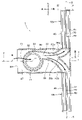
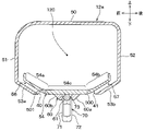
送風ユニット11は、図1に示すように、車室内の車両進行方向において、1列目の座席3の位置辺りに配置されている。送風ユニット11は、図2に示すように車両幅方向(すなわち、左右方向)において車室内空間の中央部に配置されている。
As shown in FIG. 1, the
送風ダクト12a、12bは、図1に示すように、車両進行方向において1列目の座席3と2列目の座席4との間に配置されている。
As shown in FIG. 1, the
送風ダクト12aは、図2に示すように、送風ユニット11に対して車両幅方向右側に配置されている。送風ダクト12bは、送風ユニット11に対して車両幅方向左側に配置されている。
As shown in FIG. 2, the
図3に示すように、送風ユニット11は、ケース20および送風機30を備える。ケース20は、送風機30を収容している。
As shown in FIG. 3, the
ケース20は、ある程度の弾性を有し、強度的にも優れた樹脂(例えば、ポリプロピレン)にて成形されている。ケース20は、略直方体形状を有し、その長辺が車両進行方向と一致し、その短辺が車両幅方向と一致するように配置されている。
The
ケース20のうち車室内前方側の端部には、ケース20の内部に車室内の空気を導入するための吸込口24が開口している。ケース20のうち吸込口24の開口部位には、複数のルーバー21aが形成されている。
At the end of the
ルーバー21aは、吸込口24から吸い込まれる空気の流れを案内するものであり、ケース20の車両進行方向前側から後側に向かうにつれて下側に傾斜する平板状に形成されている。これにより、吸込口24に吸い込まれる車室内空気は、上側から下側に向かって流れる。
The
送風機30は、空気を送風する電動送風機であり、ファン31、電動モータ32、およびスクロールケーシング33を有している。ファン31は、軸線方向一方側から空気を吸い込み、径方向外側に空気を吐出する遠心式多翼ファンである。
The
本実施形態のファン31の軸線方向一方側は、車室内の天地方向下側に一致している。ファン31は、軸線方向他端側(すなわち、車室内の天地方向上側)に取り付けられた電動モータ32によって回転駆動される。ファン31は、その軸線方向が車室内の天地方向と一致するように配置されている。
One side of the
スクロールケーシング33は、ファン31および電動モータ32を収容するとともに、ファン31から流出した空気が通過する流出通路を形成している。スクロールケーシング33は、流出通路の通路断面積が、ファン31の回転方向に向かって徐々に拡大する渦巻き形状に形成されている。
The
スクロールケーシング33のうちファン31の空気吸込部に対応する部位(図3では車室内下側)には、ケース20内の空気を吸い込む空気吸込口36が形成されている。したがって、この空気吸込口36を介して、ファン31に空気が吸い込まれる。
An
ケース20の内部には、送風機30のスクロールケーシング33から吐出された空気が流れる空気通路35が形成されている。
Inside the
空気通路35は、車室内前方側から車両後方側へ延びており、車両後方側の部位が車両左右方向に2つに分岐している。ケース20のうち車両幅方向における側面部には、空気通路35を流れた空気が流出する空気出口36a、36bが形成されている。
The
空気出口36aには送風ダクト12aが接続されている。空気出口36bには送風ダクト12bが接続されている。
A
送風ダクト12a、12bは、中心線T(図2参照)を中心として線対称となるように構成されている。中心線Tは、車両用送風装置10の車両幅方向(すなわち、左右方向)の中心線である。
The
そこで、以下、送風ダクト12aの構造を説明し、送風ダクト12bの構造の説明を省略する。
Therefore, the structure of the
送風ダクト12aは、ケース20の空気出口36aから車両幅方向右側に向かって延びるように形成されている。送風ダクト12aは、ケース20の空気出口36aから流出した空気流を車両幅方向右側に流通させる主空気通路120を形成する角筒状に形成されている。送風ダクト12aは、ある程度の弾性を有し、強度的にも優れた樹脂(例えば、ポリプロピレン)にて成形されている。
The
送風ダクト12aには、車両進行方向後側に開口されて空気流を車両進行方向後側に吹き出す吹出口40と、車両進行方向前側に開口されて空気流を車両進行方向前側に吹き出す吹出口41とが設けられている。
The
ここで、吹出口40、41は、それぞれ、車両幅方向に細長く延びて開口している。吹出口40、41は、一列目の座席3に着座した乗員の頭部よりも車両進行方向後側に配置されている。吹出口41は、吹出口40に対して車両進行方向後側に配置されている第1吹出口である。
Here, the
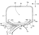
図4に示すように、送風ダクト12aは、断面形状が略矩形状になっている。送風ダクト12aは、上壁部50、前壁部51、後壁部52、下壁部53a、53b、および閉塞壁部54を備えている。
As shown in FIG. 4, the
上壁部50は、車両進行方向に平行に形成されている。上壁部50は、天井2に装着されている。前壁部51は上壁部50に対して車両進行方向前側に配置されて、上下方向に平行に形成されている。下壁部53aは、上壁部50に対して車両進行方向後側に配置されて上下方向に平行に形成されている。
The
下壁部53aは、前壁部51のうち下側端部から車両進行方向後側に向けて形成されている。具体的には、下壁部53aは、上壁部50のうち下側端部から車両進行方向後側に向かうほど下側に進むように水平方向に対して傾斜するように形成されている。
The
下壁部53bは、後壁部52のうち下側端部から車両進行方向前側に向けて形成されている。具体的には、下壁部53bは、後壁部52のうち下側端部から車両進行方向前側に向かうほど下側に進むように水平方向に対して傾斜するように形成されている。下壁部53a、53bの間には、開口部が車両幅方向に亘って形成されている。
The
閉塞壁部54は、薄板状に形成されて、天地方向下側に凸となる湾曲状に形成されている。閉塞壁部54は、下壁部53a、53bの間の開口部を上側から塞ぐように配置されている。
The
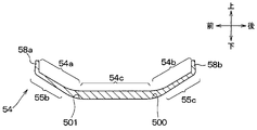
具体的には、閉塞壁部54は、図5に示すように、前側壁部54a、後側壁部54b、および中間壁部54cを備える。前側壁部54a、後側壁部54b、および中間壁部54cは、下側に凸となる湾曲状に形成されている。中間壁部54cは、下壁部53a、53bの間の開口部に配置されている。
Specifically, as shown in FIG. 5, the
前側壁部54aは、図4に示すように、中間壁部54cに対して車両進行方向前側に配置されている。前側壁部54aは、下壁部53aに対して上側において下壁部53aとの間で間隔を開けて配置されている。
As shown in FIG. 4, the front
前側壁部54aは、中間壁部54cから車両進行方向前側に向かうほど上側に進むように形成されている。前側壁部54aのうち最前側端部には、前壁部51との間に間隔を開けて上側に突起する突起部58aが設けられている。
The front
このことにより、前壁部51および下壁部53aと閉塞壁部54の前側壁部54aとの間には、第2空気流路としての吹出空気流路56が形成されている。このため、前壁部51、下壁部53a、および前側壁部54aが、吹出空気流路56を形成する第2空気流路形成部を構成することになる。
As a result, a blown
吹出空気流路56は、車両進行方向後側に進むほど、下側に向かうように形成されている。吹出空気流路56のうち最も車両進行方向後側には、第2吹出口としての吹出口40が形成されている。吹出口40は、車室内において、車両進行方向後側で、かつ下側に向けて開口形成されている。吹出空気流路56は、主空気通路120からの空気流を吹出口40に向けて流通させる空気流路である。
The blown
ここで、吹出空気流路56の空気流路の断面積は、主空気通路120の空気流路の断面積に比べて小さくなっている。吹出空気流路56は、主空気通路120の空気流を昇圧して、この昇圧した空気流を吹出口40から噴流として車室内にて車両進行方向後側に向けて噴出するノズルとして機能する。
Here, the cross-sectional area of the air flow path of the blown
後側壁部54bは、下壁部53bに対して上側において下壁部53bとの間で間隔を開けて配置されている。後側壁部54bは、車両進行方向前側に向かうほど下側に進むように形成されている。
The rear
後側壁部54bのうち最も後側には、後壁部52との間に間隔を開けて上側に突起する突起部58bが設けられている。
On the rearmost side of the rear
このことにより、後壁部52および下壁部53bと閉塞壁部54の後側壁部54bとの間には、第1空気流としての吹出空気流路57が形成されている。このため、後壁部52、下壁部53b、および後側壁部54bが、吹出空気流路57を形成する第1空気流路形成部を構成することになる。
As a result, a blown
吹出空気流路57は、車両進行方向前側に進むほど、下側に向かうように形成されている。吹出空気流路57のうち最も車両進行方向前側には、吹出口41が形成されている。吹出口41は、車両進行方向前側で、かつ下側に向けて開口形成されている。吹出空気流路57は、主空気通路120からの空気流を吹出口41に向けて流通させる空気流路である。
The blown
ここで、吹出空気流路57の空気流路の断面積は、主空気通路120の空気流路の断面積に比べて小さくなっている。吹出空気流路57は、主空気通路120の空気流を昇圧して、この昇圧した空気流を吹出口41にて噴流として車室内にて車両進行方向前側(すなわち、一列目の座席3の乗員の後側)に向けて噴出するノズルとして機能する。
Here, the cross-sectional area of the air flow path of the blown
閉塞壁部54のうち天地方向下側には、図5に示すように、前側傾斜面55b、および後側傾斜面55cを備える。
As shown in FIG. 5, a front
前側傾斜面55bは、閉塞壁部54のうち車両進行方向後側において下側に形成されている壁面である。前側傾斜面55bは、吹出空気流路57に対して上側に形成される第2傾斜上壁部を構成する。前側傾斜面55bは、車両進行方向前側に向かうほど、下側に進むように形成されている。
The front
後側傾斜面55cは、閉塞壁部54のうち車両進行方向前側において下側に形成されている壁面である。後側傾斜面55cは、吹出空気流路56に対して上側に形成される第1傾斜上壁部を構成する。後側傾斜面55cは、車両進行方向後側に向かうほど、下側に進むように形成されている。
The rear
閉塞壁部54のうち天地方向下側のうち吹出口41およびスライドドア60の間には、後述するように、吹出口41からの噴流を引き寄せるコアンダ効果を発揮させるガイド部500を構成する。
As will be described later, a
ガイド部500は、車両進行方向に亘って形成されて、車室内にて下側に向けて露出している壁面を構成する。ガイド部500および後側傾斜面55cは、連続した壁面を構成している。
The
閉塞壁部54のうち天地方向下側のうち吹出口40およびスライドドア60の間には、後述するように、吹出口40からの噴流を引き寄せるコアンダ効果を発揮させるガイド部501を構成する。
As will be described later, a
ガイド部501は、車両進行方向に亘って形成されて、車室内にて下側に向けて露出している壁面を構成する。ガイド部501および前側傾斜面55bは、連続した壁面を構成している。
The
閉塞壁部54の中間壁部54cに対して下側には、スライド調整部としてのスライドドア60が設けられている。スライドドア60は、吹出口40、41の間において、車両進行方向にスライド移動が可能になるように送風ダクト12aの車両幅方向右側端部および左側端部によって支持されている。スライドドア60は、吹出口40、41のうち一方の吹出口を開けて、他方の吹出口を閉じる役割を果たす(図6、図7、図8参照)。
A
スライドドア60は、車両幅方向に延びる長板状に形成されている。スライドドア60のうち車両進行方向後側の端面60aは、車両進行方向前側に向かうほど天地方向下側に進む傾斜状に形成されている。端面60aは、ガイド部500に沿って流れる空気流をフラップ70の後面72に案内する役割を果たす。
スライドドア60のうち車両進行方向前側の端面60bは、車両進行方向後側に向かうほど天地方向下側に進む傾斜状に形成されている。端面60bは、ガイド部501に沿って流れる空気流をフラップ70の前面71に案内する役割を果たす。
The sliding
The
スライドドア60は、車両幅方向に延びる軸線S(図2参照)を中心としてフラップ70が回転自在になるようにフラップ70を支持する。
具体的には、スライドドア60には、2つの軸61が設けられている。図4では、1つの軸61のみを示す。2つの軸61のうち一方側の軸61は、スライドドア60のうち車両幅方向右側側面からから右側に延びるように形成されている。2つの軸61のうち一方側の軸61以外の他方の軸61は、スライドドア60のうち車両幅方向左側側面からから左側に延びるように形成されている。
The sliding
Specifically, the sliding
このことにより、フラップ70は、スライドドア60の軸61に対して回転自在になるように構成されていることになる風向調整部である。フラップ70は、車両幅方向に拡がる板状に形成されてフラップ本体を構成する。
As a result, the
フラップ本体は、車両進行方向に交差し、かつ車両幅方向に交差(例えば、直交)する交差方向に拡がる板状に形成されている。フラップ70のうち交差方向の一方側に、軸線Sが重なるように配置されている。
The flap body is formed in a plate shape that intersects in the vehicle traveling direction and intersects (for example, orthogonally) in the vehicle width direction and extends in the intersecting direction. The axis S is arranged so as to overlap one side of the
フラップ70のうち交差方向の一方側には、2つのフランジ部73(図4参照)が設けられている。図4では、1つのフランジ部73のみを示す。2つのフランジ部73のうち一方のフランジ部73は、2つの軸61のうち一方の軸61を回転自在に支持する。
Two flange portions 73 (see FIG. 4) are provided on one side of the
2つのフランジ部73のうち他方のフランジ部73は、2つの軸61のうち他方の軸61を回転自在に支持する。本実施形態のフラップ70は、自らの交差方向の一方側端部がスライドドア60に対して支持されている片持ちドアである。フラップ70は、車両進行方向前側に向いて形成されている前面71と車両進行方向後側に向いて形成されている後面72とを備える。
The
本実施形態の前面71は、交差方向と車両幅方向に拡がるように形成されている。前面71は、ガイド部501に沿って流れる空気流を案内する役割を果たす。後面72は、交差方向と車両幅方向に拡がるように形成されている。後面72は、ガイド部500に沿って流れる空気流を案内する役割を果たす。
The
フラップ70における2つの軸61を中心とする回転方向の位置が乗員の操作によって設定される。このことにより、吹出口40、41から吹き出される空気流が前面71、後面72によって案内される方向を設定することができる。
The position of the
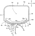
図1に示すように、車室内最前部の計器盤6(インストルメントパネル)の内側には、車両用空調装置の室内空調ユニット7が配置されている。室内空調ユニット7は空調ケース71を有している。空調ケース71は、室内空調ユニット7の外殻を形成するとともに、車室内に向かって送風される室内送風空気の空気通路を形成する。
As shown in FIG. 1, an indoor
空調ケース71内の空気通路の最上流部には、送風機ユニット(図示せず)からの送風空気が流入するようになっている。送風機ユニットは、室内空調ユニット7とともに、計器盤6の内側に配置されている。
Blower air from a blower unit (not shown) flows into the most upstream portion of the air passage in the
送風機ユニットは、内気(車室内空気)と外気(車室外空気)とを切替導入する内外気切替箱と、内外気切替箱に導入された空気を送風する遠心式送風機とを備えている。空調ケース71内の空気通路には蒸発器、ヒータコアおよびエアミックスドア等(いずれも図示せず)が配置されている。蒸発器は、蒸気圧縮式冷凍サイクル(図示せず)を構成する機器の1つであり、冷凍サイクル内の低圧冷媒を蒸発させて吸熱作用を発揮させることで、送風機ユニットからの送風空気を冷却する冷却用熱交換器である。
The blower unit includes an inside / outside air switching box that switches between inside air (vehicle interior air) and outside air (vehicle outside air), and a centrifugal blower that blows the air introduced into the inside / outside air switching box. An evaporator, a heater core, an air mix door, and the like (none of which are shown) are arranged in the air passage in the
ヒータコアは、自動車1のエンジン(図示せず)を冷却するエンジン冷却水(温水)と、蒸発器で冷却された冷風とを熱交換することによって冷風を加熱する加熱用熱交換器である。エアミックスドアは、蒸発器で冷却された冷風とヒータコアで加熱された温風との風量割合を調整することによって、車室内に吹き出される空気の温度を所望温度に調整する温度調整手段である。
The heater core is a heating heat exchanger that heats the cold air by exchanging heat between the engine cooling water (hot water) that cools the engine (not shown) of the
空調ケース71にはフェイス開口部711が開口している。フェイス開口部711には、空気通路を形成するフェイスダクト8の一端部が接続されている。フェイスダクト8の他端部は、計器盤6に設けられたフェイス吹出口9に接続されている。
The
フェイス吹出口9は、空調ケース71で温度調整された空調風を車室内乗員の顔部側(車室内上方側)へ向けて吹き出す。フェイス吹出口9から空調風が吹き出されることによって、車室上方側へ向かう空気流れF(図1参照)が形成される。
The
次に、上記構成における作動を説明する。まず、車両用送風装置10の送風機30が作動すると、送風ユニット11のケース20の前面部に形成された吸込口24から、車室内空気がケース20内に吸い込まれる。
ケース20内に吸い込まれた空気は、矢印F1の如くスクロールケーシング33に吸い込まれてスクロールケーシング33から吐出される。スクロールケーシング33から吐出された空気の一部は、矢印F2aの如く、ケース20内の空気通路35、および空気出口36aを通して送風ダクト12aの主空気通路120に流れる。
Next, the operation in the above configuration will be described. First, when the
The air sucked into the
一方、スクロールケーシング33から吐出された空気流のうち送風ダクト12aに流れる空気流以外の残りの空気流は、矢印F2bの如く、ケース20内の空気通路35および空気出口36bを通して送風ダクト12bの主空気通路120に流れる。
On the other hand, of the air flow discharged from the
例えば、図7に示すように、使用者が操作させてスライドドア60をスライド移動して、送風ダクト12aにおいてスライドドア60が吹出口40を閉じて吹出口41を開けた状態にする。この際に、前面71を上側に向けて、後面72を下側に向けて、フラップ70の先端側を前下側に向けた状態にする。
For example, as shown in FIG. 7, the user operates the
この場合、送風ダクト12aの主空気通路120に流れる空気流は、吹出空気流路57を通して吹出口41に流れる。この際に、主空気通路120からの空気流は、吹出空気流路57で減圧されてこの減圧された空気流は、吹出口41から車室内に排出される際に膨張する。
In this case, the air flow flowing through the
このため、吹出空気流路57内の空気流が吹出口41から噴流として車室内に吹き出される。この噴流は、吹出口41から一列目の座席3の乗員の後側に向けて矢印F3の如く、吹き出される。以下、説明の便宜上、吹出口41から吹き出される空気流を第1空気流とする。
Therefore, the air flow in the blown
ここで、吹出口41から吹き出される第1空気流がこの第1空気流の周囲から矢印F4の如く、第2空気流を引き込む。この際に、吹出口41から吹き出される第1空気流と第1空気流の周囲から引き込まれる第2空気流とがコアンダ効果によってガイド部500に引き寄せられて、ガイド部500およびフラップ70の後面72に沿って流れる。
Here, the first air flow blown out from the
このガイド部500に引き寄せられた第1空気流と第2空気流とがF5の如く、フラップ70の後面72に案内されて前下側に流れる。この流れた空気流は、一列目の座席3に着座した乗員(以下、前側乗員という)の頭部の後側、首元、或いは、前側乗員と一列目の座席3のヘッドレストとの間に送られる。
The first air flow and the second air flow attracted to the
このことにより、吹出口41から吹き出される第1空気流がその周囲から第2空気流を引き寄せることなく、前側乗員に送風される場合に比べて、前側乗員に送風する風量を増大することができる。このため、前側乗員の快適性を向上することができる。
As a result, the amount of air blown to the front occupant can be increased as compared with the case where the first air flow blown out from the
図6に示すように、スライドドア60が吹出口40を閉じて吹出口41を開けた状態にする。この際に、前面71を前側に向けて、後面72を後側に向けて、フラップ70の先端側を真下に向けた状態にする。
As shown in FIG. 6, the sliding
この場合、ガイド部500に沿って流れる第1空気流と第2空気流とがフラップ70の後面72に案内されて真下側に流れる。
In this case, the first air flow and the second air flow flowing along the
図8に示すように、スライドドア60が吹出口41を閉じて吹出口40を開けた状態にする。この際に、前面71を下側に向けて、後面72を上側に向けて、フラップ70の先端側を後下側に向けた状態にする。
As shown in FIG. 8, the sliding
この場合、送風ダクト12aの主空気通路120に流れる空気流は、吹出空気流路56を通して吹出口40に流れる。この際に、主空気通路120からの空気流は、吹出空気流路56で減圧されてこの減圧された空気流は、吹出口40から車室内に排出される際に膨張する。
In this case, the air flow flowing through the
このため、吹出空気流路56内の空気流が吹出口40から噴流として車室内に吹き出される。この噴流は、車両進行方向後側に向けて、矢印F6の如く、吹き出される。以下、説明の便宜上、吹出口40から吹き出される空気流を第3空気流とする。
Therefore, the air flow in the blown
吹出口41からから吹き出される第3空気流がこの第3空気流の周囲から矢印F7の如く、第4空気流を引き込む。この際に、吹出口40から吹き出される第3空気流と第3空気流の周囲から引き込まれる第4空気流とがコアンダ効果によってガイド部501に引き寄せられて、ガイド部501およびフラップ70の前面71に沿って流れる。
The third air flow blown out from the
このガイド部501に引き寄せられ第3空気流と第4空気流とがF8の如く、フラップ70の前面71に案内されて後下側に流れる。この流れた空気流は、二列目の座席4に着座した乗員(以下、後側乗員という)の頭部に送られる。
The third air flow and the fourth air flow are attracted to the
このことにより、吹出口40から吹き出される第3空気流がその周囲から第4空気流を引き込むことなく、後側乗員に送風する場合に比べて、後側乗員に送風する風量を増大することができる。このため、後側乗員の快適性を向上することができる。
As a result, the amount of air blown to the rear occupant is increased as compared with the case where the third air flow blown out from the
さらに、図4に示すように、スライドドア60が吹出口40、41をそれぞれ開けた状態にする。この際に、前面71を前側に向けて、後面72を後側に向けて、フラップ70の先端側を真下に向けた状態にする。
Further, as shown in FIG. 4, the sliding
この場合、ガイド部500に沿って流れる第1空気流と第2空気流とがフラップ70の後面72に案内されて真下側に流れる。
In this case, the first air flow and the second air flow flowing along the
一方、ガイド部501に沿って流れる第3空気流と第4空気流とがフラップ70の前面71に案内されて真下側に流れる。
On the other hand, the third air flow and the fourth air flow flowing along the
ここで、フラップ70における回転方向の位置を乗員の操作によって設定すると、後面72が第1空気流と第2空気流とを案内する方向を任意に設定することができる。これに加えて、前面71が第3空気流と第4空気流とを案内する方向を任意に設定することができる。
Here, if the position of the
また、スクロールケーシング33から送風ダクト12bの主空気通路120に流れた空気流は、送風ダクト12aの場合と同様に、吹出空気流路56、57を通過してから吹出口40、41から噴流として吹き出される。
Further, the air flow flowing from the
ここで、送風ダクト12bの吹出口41からの空気流が一列目の座席3の前側乗員に送風されるメカニズムや送風ダクト12bの吹出口40からの空気流が車両進行方向後側に送風されるメカニズムは、送風ダクト12aの場合と同様である。このため、それらの説明を省略する。
Here, the mechanism in which the air flow from the
以上説明した本実施形態によれば、車両用送風装置10は、車室内の天井2に配置されて、一列目の座席3に着座する前側乗員の頭部に対して車両進行方向後側に配置されている送風ダクト12aを備える。
According to the present embodiment described above, the
送風ダクト12a、12bは、車室内にて車両進行方向前側に向けて開口して空気流を吹き出す吹出口41を備える。送風ダクト12a、12bのうち乗員の頭部に対して車両進行方向後側で、かつ空気吹出口41に対して車両進行方向前側には、車室内にて下側に向けて露出するガイド部500が設けられている。
The
ここで、吹出口41から吹き出される噴流としての第1空気流がこの第1空気流の周囲から第2空気流を引き込む。この第1空気流と第2空気流がコアンダ効果によってガイド部500に引き寄せられてガイド部500に沿って流れる。
Here, the first air flow as a jet blown out from the
このガイド部500に沿って流れる第1空気流と第2空気流とがフラップ70の後面72によって一列目の座席3に着座する前側乗員の後側に流れるように案内される。
The first air flow and the second air flow flowing along the
一方、上述した特許文献1の車両用送風装置では、図9に示すように、吹出口40Aから吹き出された空気流を前側座席の乗員の後側に送風させるには、フラップ70Aの先端側を真下(或いは、車両進行方向前側)に向けるように調整する必要がある。
On the other hand, in the vehicle blower device of
この場合、フラップ70Aの一面が車両進行方向前側に向けられるため、吹出口40Aから吹き出された空気流がフラップ70Aの一面によって反転されるので、空気流の圧力損失が増大する。このため、騒音が発生したり、前側座席の乗員の後側に到達する風量が少なくなるため、一列目の座席3の乗員へ与える快適性が低下する。
In this case, since one surface of the
これに対して、本実施形態によれば、第1空気流と第2空気流とが乗員の後側に送られるため、吹出口41から吹き出される第1空気流が、その周囲から第2空気流を引き込むことなく、乗員の後側に送られる場合に比べて、乗員に到達する送風量を増大させることができる。このため、ファンや電動モータを増大化させることなく、一列目の座席3の乗員の後側に送られる送風量を増大させることができる。
On the other hand, according to the present embodiment, since the first air flow and the second air flow are sent to the rear side of the occupant, the first air flow blown out from the
ここで、吹出口41から吹き出される空気流を一列目の座席3の乗員の後側に送風させるために、吹出口41から吹き出される空気流をフラップによって反転させる必要がない。したがって、圧力損失の増大に伴う送風量の低下や騒音の発生を未然に防ぐことができる。
Here, in order to blow the air flow blown out from the
以上により、一列目の座席3の乗員に与える快適性を向上するようにした車両用送風装置10を提供することができる。
As described above, it is possible to provide the
本実施形態では、スライドドア60が吹出口40、41のうち少なくとも一方を開けることにより、空気流を吹き出す吹出口を切り替えることができる。このため、空気流の流れ方向の選択の自由を向上することができる。
In the present embodiment, the sliding
本実施形態では、コアンダ効果によってガイド部500に沿って流れる第1空気流と第2空気流とをフラップ70の後面72が乗員の後側に向けて流れるように案内する。
In the present embodiment, the Coanda effect guides the first air flow and the second air flow flowing along the
これにより、第1空気流と第2空気流とを円滑に一列目の座席3の乗員の後側に向けて流すことができる。
As a result, the first air flow and the second air flow can be smoothly flowed toward the rear side of the occupants of the
本実施形態では、後側傾斜面55cおよびガイド部500は、連続する壁を構成する。
In the present embodiment, the rear
これにより、吹出口41から吹き出される第1空気流を円滑にガイド部500に沿わせて流すことができる。
As a result, the first air flow blown out from the
本実施形態では、コアンダ効果によってガイド部501に沿って流れる第3空気流と第4空気流とをフラップ70の前面71が2列目の座席4の乗員の前側に向けて流れるように案内する。
In the present embodiment, the Coanda effect guides the third air flow and the fourth air flow flowing along the
これにより、第3空気流と第4空気流とを円滑に2列目の座席4の乗員の前側に向けて流すことができる。
As a result, the third air flow and the fourth air flow can be smoothly flowed toward the front side of the occupant of the
本実施形態では、前側傾斜面55bおよびガイド部501は、連続する壁を構成する。
In this embodiment, the front
これにより、吹出口40から吹き出される第3空気流を円滑にガイド部501に沿わせて流すことができる。
As a result, the third air flow blown out from the
本実施形態では、第1空気流と第2空気流とがフラップ70の後面72によって案内される。このため、フラップ70における回転方向の位置の設定により後面72によって案内される第1空気流と第2空気流とが流れる方向を任意に設定することができる。
In this embodiment, the first air flow and the second air flow are guided by the
本実施形態では、第3空気流と第4空気流とがフラップ70の前面71によって案内される。このため、フラップ70における回転方向の位置の設定により前面71によって案内される第3空気流と第4空気流が流れる方向を任意に設定することができる。
(他の実施形態)
(1)上記実施形態では、車両用送風装置10において送風ダクト12a、12bを設けた例について説明したが、これに代えて、車両用送風装置10において1つの送風ダクトを設けてもよい。
In this embodiment, the third air flow and the fourth air flow are guided by the
(Other embodiments)
(1) In the above embodiment, the example in which the
(2)上記実施形態では、送風ダクト12a、12bにおいて2つの吹出口40、41を設けた例について説明したが、これに代えて、吹出口40を削除して、吹出口41を設けてもよい。
(2) In the above embodiment, an example in which the two
(3)上記実施形態では、送風ダクト12a、12bにおいて吹出口41に対して吹出口40を車両進行方向前側に配置した例について説明した。しかし、これに代えて、送風ダクト12a、12bにおいて吹出口41に対して吹出口40を車両進行方向後側に配置してもよい。
(3) In the above embodiment, an example in which the
或いは、送風ダクト12a、12bにおいて吹出口41に対して吹出口40を車両幅方向に配置してもよい。
Alternatively, the
(4)上記実施形態では、送風ダクト12a、12bにおいて吹出口40を一列目の座席3に着座した乗員に対して車両進行方向後側に配置した例について説明した。しかし、これに代えて、送風ダクト12a、12bにおいて吹出口40を一列目の座席3に着座した乗員に対して車両進行方向前側に配置してもよい。
(4) In the above embodiment, an example in which the
或いは、送風ダクト12a、12bにおいて吹出口40を一列目の座席3に着座した乗員に対して上下方向に重なるように配置してもよい。
Alternatively, in the
(5)上記実施形態では、ファン31によって吸込口24を通して車室内から吸い込んだ空気流を、温度調節することなく、吹出口40、41から車室内に吹き出す例について説明した。
(5) In the above embodiment, an example has been described in which the air flow sucked from the vehicle interior through the
しかし、これに代えて、ファン31によって吸込口24を通して車室内から吸い込んだ空気流を、熱交換器によって温度調節して吹出口40、41から車室内に吹き出すようにしてもよい。
However, instead of this, the air flow sucked from the vehicle interior through the
(6)上記実施形態では、ファン31によって吸込口24を通して車室内から吸い込んだ空気流を、吹出口40、41から車室内に吹き出す例について説明した。
(6) In the above embodiment, an example has been described in which the air flow sucked from the vehicle interior through the
しかし、これに代えて、ファン31によって車室外から吸い込んだ空気流を、吹出口40、41から車室内に吹き出すようにしてもよい。或いは、ファン31によって車室外および車室内のそれぞれから吸い込んだ空気流を、吹出口40、41から車室内に吹き出すようにしてもよい。
However, instead of this, the air flow sucked from the outside of the vehicle interior by the
(7)上記実施形態では、使用者に操作によってスライドドア60をスライド移動する例について説明したが、これに代えて、電動モータによってスライドドア60をスライド移動させてもよい。
(7) In the above embodiment, an example in which the
(8)上記実施形態では、使用者に操作によってフラップ70における回転方向の位置を設定した例について説明したが、これに代えて、電動モータによってフラップ70における回転方向の位置を設定してもよい。
(8) In the above embodiment, an example in which the position in the rotation direction of the
(9)上記実施形態では、送風ユニット11では、車室内の空気を吸込口24から吸い込んで送風ダクト12a、12bの吹出口40、41から吹き出す例について説明した。しかし、これに代えて、車室外の空気を吸込口24から吸い込んで送風ダクト12a、12bの吹出口40、41から吹き出すようにしてもよい。
(9) In the above embodiment, an example has been described in which the
或いは、車室内の空気と車室外の空気とを吸い込んで送風ダクト12a、12bの吹出口40、41から吹き出すようにしてもよい。
Alternatively, the air inside the vehicle interior and the air outside the vehicle interior may be sucked in and blown out from the
(10)上記実施形態では、スライドドア60に2つの軸61を設けた例について説明したが、これに代えて、フラップ70に2つの軸61を設けてもよい。
(10) In the above embodiment , the example in which the
(11)上記実施形態では、フラップ70がスライドドア60に対して支持される例について説明したが、これに代えて、フラップ70が送風ダクト12a、12bに対して支持されるようにしてもよい。
( 11 ) In the above embodiment , the example in which the
この場合、送風ダクト12a(或いは、12b)に2つの軸61を設けてもよい。或いは、フラップ70に2つの軸61を設けてもよい。
In this case, two
(12)上記実施形態では、フラップ70としては、自らの交差方向一方側がスライドドア60の2つの軸61に支持されている片持ちドアを採用した例について説明した。
( 12 ) In the above embodiment , as the
これに代えて、フラップ70としては、自らの交差方向中央がスライドドア60の2つの軸61に支持されるようにしてもよい。
Instead of this, the
(13)なお、本発明は上記した実施形態に限定されるものではなく、特許請求の範囲に記載した範囲内において適宜変更が可能である。また、上記実施形態および他の実施形態は、互いに無関係なものではなく、組み合わせが明らかに不可な場合を除き、適宜組み合わせが可能である。また、上記実施形態および他の実施形態において、実施形態を構成する要素は、特に必須であると明示した場合および原理的に明らかに必須であると考えられる場合等を除き、必ずしも必須のものではないことは言うまでもない。また、上記実施形態および他の実施形態において、実施形態の構成要素の個数、数値、量、範囲等の数値が言及されている場合、特に必須であると明示した場合および原理的に明らかに特定の数に限定される場合等を除き、その特定の数に限定されるものではない。また、上記実施形態および他の実施形態において、構成要素等の形状、位置関係等に言及するときは、特に明示した場合および原理的に特定の形状、位置関係等に限定される場合等を除き、その形状、位置関係等に限定されるものではない。
(まとめ)
上記実施形態、および他の実施形態の一部または全部に記載された第1の観点によれば、車両用送風装置は、車室内の天井に配置されて、車室内の座席に着座する乗員に対して車両進行方向後側に設けられて車室内にて車両進行方向前側に向けて開口して噴流としての空気流を吹き出す吹出口を備える送風ダクトを備える。
( 13 ) The present invention is not limited to the above-described embodiment, and can be appropriately modified within the scope of the claims. Further, the above-described embodiment and other embodiments are not unrelated to each other, and can be appropriately combined unless the combination is clearly impossible. Further, in the above-described embodiment and other embodiments, the elements constituting the embodiment are not necessarily essential except when it is clearly stated that they are essential or when they are clearly considered to be essential in principle. Needless to say, there is no such thing. Further, in the above-described embodiment and other embodiments, when numerical values such as the number, numerical values, quantities, and ranges of the constituent elements of the embodiment are mentioned, when it is clearly specified that it is particularly essential, and when it is clearly specified in principle. It is not limited to the specific number except when it is limited to the number of. Further, in the above-described embodiment and other embodiments, when the shape, positional relationship, etc. of the constituent elements are referred to, except for the case where it is clearly stated and the case where the shape, the positional relationship, etc. are limited in principle. , The shape, the positional relationship, etc. are not limited.
(summary)
According to the first aspect described in the above embodiment and some or all of the other embodiments, the vehicle blower is arranged on the ceiling of the vehicle interior and is used for an occupant seated in a seat in the vehicle interior. On the other hand, it is provided with a ventilation duct provided on the rear side in the vehicle traveling direction and provided in the vehicle interior with an outlet that opens toward the front side in the vehicle traveling direction to blow out an air flow as a jet flow.
吹出口から吹き出される空気流が当該空気流の周辺から空気流を引き込み、この引き込まれた空気流と吹出口から吹き出される空気流とを乗員の後側に送風する。 The air flow blown out from the air outlet draws an air flow from the periphery of the air flow, and the drawn air flow and the air flow blown out from the air outlet are blown to the rear side of the occupant.
第2の観点によれば、吹出口から吹き出される空気流を第1空気流とし、吹出口から吹き出される第1空気流によって当該第1空気流の周辺から引き込んだ空気流を第2空気流とし、吹出口を、第1吹出口とする。 According to the second viewpoint, the air flow blown out from the outlet is the first air flow, and the air flow drawn from the periphery of the first air flow by the first air flow blown out from the outlet is the second air. Let the flow and the air outlet be the first air outlet.
送風ダクトは、車室内にて車両進行方向後側に向けて開口して車両進行方向後側に噴流としての空気流を吹き出す第2吹出口を備える。 The ventilation duct is provided with a second outlet that opens toward the rear side in the vehicle traveling direction in the vehicle interior and blows out an air flow as a jet to the rear side in the vehicle traveling direction.
第2吹出口から吹き出される第3空気流が当該第3空気流の周辺から第4空気流を引き込み、この引き込まれた第4空気流と第2吹出口から吹き出される第3空気流とを送風する。 The third air flow blown out from the second air outlet draws in the fourth air flow from the periphery of the third air flow, and the drawn fourth air flow and the third air flow blown out from the second air outlet To blow air.
これにより、第3空気流と第4空気流とを車両進行方向後側に向けて送風することができる。このため、第3空気流だけを車両進行方向後側に向けて吹き出す場合に比べて、車両進行方向後側に送風する送風量を増大することができる。 As a result, the third air flow and the fourth air flow can be blown toward the rear side in the vehicle traveling direction. Therefore, the amount of air blown to the rear side in the vehicle traveling direction can be increased as compared with the case where only the third air flow is blown toward the rear side in the vehicle traveling direction.
第3の観点によれば、車両進行方向前側に向いて形成されている前面と車両進行方向前側に向いて形成されている後面とを備える風向調整部材を備える。 According to the third aspect, the wind direction adjusting member includes a front surface formed toward the front side in the vehicle traveling direction and a rear surface formed toward the front side in the vehicle traveling direction.
風向調整部材の後面が第1空気流と第2空気流とを案内し、風向調整部材の前面が第3空気流と第4空気流とを案内する。 The rear surface of the wind direction adjusting member guides the first air flow and the second air flow, and the front surface of the wind direction adjusting member guides the third air flow and the fourth air flow.
第4の観点によれば、車両用送風装置は、スライド調整部を備える。第1吹出口は、第2吹出口に対して車両進行方向後側に配置されている。スライド調整部は、第1吹出口および第2吹出口の間において、車両進行方向にスライド移動が可能に構成されている。 According to the fourth aspect, the vehicle blower includes a slide adjusting unit. The first outlet is arranged on the rear side in the vehicle traveling direction with respect to the second outlet. The slide adjusting unit is configured to be able to slide and move in the vehicle traveling direction between the first outlet and the second outlet.
スライド調整部は、スライド移動によって、第1吹出口および第2吹出口のうち一方の吹出口を開けて、他方の吹出口を閉塞する。 The slide adjusting unit opens one of the first outlet and the second outlet by sliding movement, and closes the other outlet.
これにより、第1吹出口および第2吹出口のうち空気流を吹き出す吹出口を選択することができる。 Thereby, the air outlet that blows out the air flow can be selected from the first air outlet and the second air outlet.
第5の観点によれば、風向調整部材は、車両幅方向に延びる軸を中心として回転が可能になるようにスライド調整部に対して支持されている。風向調整部材における回転方向の位置が設定されることにより、後面が案内する方向、および前面が案内する方向をそれぞれ調整する。 According to the fifth aspect, the wind direction adjusting member is supported with respect to the slide adjusting portion so as to be able to rotate about an axis extending in the vehicle width direction. By setting the position of the wind direction adjusting member in the rotation direction, the direction guided by the rear surface and the direction guided by the front surface are adjusted respectively.
これにより、第1空気流と第2空気流が案内される方向と、第3空気流と第4空気流が案内される方向とを調整することができる。 Thereby, the direction in which the first air flow and the second air flow are guided and the direction in which the third air flow and the fourth air flow are guided can be adjusted.
第6の観点によれば、送風ダクトは、第1吹出口に対して車両進行方向後側に配置され、第1吹出口に近づくほど下側に向かうように形成されて第1吹出口に向けて空気流を流通させる空気流路を送風ダクト内部に形成する空気流路形成部を備える。 According to the sixth viewpoint, the ventilation duct is arranged on the rear side in the vehicle traveling direction with respect to the first air outlet, and is formed so as to face downward as it approaches the first air outlet toward the first air outlet. It is provided with an air flow path forming portion for forming an air flow path through which the air flow flows inside the ventilation duct.
空気流路を通過した空気流を第1吹出口から噴流として乗員の後側に吹き出す。 The air flow that has passed through the air flow path is blown out to the rear side of the occupant as a jet from the first outlet.
第7の観点によれば、送風ダクトは、第1吹出口および風向調整部材の間に配置される壁であり、かつ車室内にて下側に向けて露出し、さらに車両進行方向に亘って形成されているガイド部を備える。 According to the seventh aspect, the ventilation duct is a wall arranged between the first air outlet and the wind direction adjusting member, and is exposed downward in the vehicle interior, and further extends in the vehicle traveling direction. It is provided with a formed guide portion.
第1空気流と第2空気流とがガイド部に沿って流れ、このガイド部に沿って流れる第1空気流と第2空気流とを風向調整部材の後面が乗員の後側に向けて流れるように案内する。 The first air flow and the second air flow flow along the guide portion, and the rear surface of the wind direction adjusting member flows toward the rear side of the occupant through the first air flow and the second air flow flowing along the guide portion. I will guide you.
これにより、コアンダ効果によってガイド部に沿って流れる第1空気流と第2空気流とを風向調整部材の後面によって円滑に乗員の後側に向けて流すことができる。 As a result, the first air flow and the second air flow flowing along the guide portion due to the Coanda effect can be smoothly flowed toward the rear side of the occupant by the rear surface of the wind direction adjusting member.
第8の観点によれば、空気流路形成部は、空気流路に対して上側に形成される壁を構成する傾斜上壁部を有し、傾斜上壁部およびガイド部は、連続する壁を構成する。 According to the eighth aspect, the air flow path forming portion has an inclined upper wall portion forming a wall formed above the air flow path, and the inclined upper wall portion and the guide portion are continuous walls. To configure.
これにより、第1吹出口から吹き出される第1空気流を円滑にガイド部に沿わせて流すことができる。 As a result, the first air flow blown out from the first air outlet can be smoothly flowed along the guide portion.
第9の観点によれば、空気流路を第1空気流路とし、空気流路形成部を第1空気流路形成部とする。送風ダクトは、第2吹出口に対して車両進行方向前側に配置され、第2吹出口に近づくほど下側に向かうように形成されて第2吹出口に向けて空気流を流通させる第2空気流路を送風ダクト内部に形成する第2空気流路形成部を備える。 According to the ninth aspect, the air flow path is the first air flow path, and the air flow path forming portion is the first air flow path forming portion. The air duct is arranged on the front side in the vehicle traveling direction with respect to the second air outlet, and is formed so as to go downward as it approaches the second air outlet, and the second air that circulates the air flow toward the second air outlet. A second air flow path forming portion for forming the flow path inside the ventilation duct is provided.
第2空気流路を通過した空気流を第2吹出口から噴流として車室内に吹き出す。 The air flow that has passed through the second air flow path is blown into the vehicle interior as a jet from the second outlet.
第10の観点によれば、ガイド部を第1ガイド部としたとき、送風ダクトは、第2吹出口および風向調整部材の間に配置され、かつ車室内にて下側に向けて露出し、さらに車両進行方向に亘って形成されている第2ガイド部を備える。 According to the tenth viewpoint, when the guide portion is the first guide portion, the ventilation duct is arranged between the second air outlet and the wind direction adjusting member, and is exposed downward in the vehicle interior. Further, a second guide portion formed in the traveling direction of the vehicle is provided.
第3空気流と第4空気流が第2ガイド部に沿って流れ、このガイド部に沿って流れる第3空気流と第4空気流を風向調整部材の前面が案内する。 The third air flow and the fourth air flow flow along the second guide portion, and the front surface of the wind direction adjusting member guides the third air flow and the fourth air flow flowing along the guide portion.
これにより、コアンダ効果によってガイド部に沿って流れる第3空気流と第4空気流とを風向調整部材の前面によって円滑に案内することができる。 As a result, the third air flow and the fourth air flow flowing along the guide portion due to the Coanda effect can be smoothly guided by the front surface of the wind direction adjusting member.
第11の観点によれば、傾斜上壁部を第1傾斜上壁部としたとき、第2空気流路形成部は、第2空気流路に対して上側に形成される壁を構成する第2傾斜上壁部を有する。第2傾斜上壁部および第2ガイド部は、連続する壁を構成する。 According to the eleventh viewpoint, when the inclined upper wall portion is the first inclined upper wall portion, the second air flow path forming portion constitutes a wall formed on the upper side with respect to the second air flow path. It has a two-sloping upper wall. The second inclined upper wall portion and the second guide portion form a continuous wall.
これにより、第2吹出口から吹き出される第3空気流を円滑に第2ガイド部に沿わせて流すことができる。 As a result, the third air flow blown out from the second outlet can be smoothly flowed along the second guide portion.
10 車両用送風装置
11 送風ユニット
12a、12b 送風ダクト
40、41 吹出口
50 上壁部
51 前壁部
52 後壁部
53a、53b 下壁部
54 閉塞壁部
500、501 ガイド部
10 Ventilation device for
Claims (9)
前記車両進行方向前側に向いて形成されている前面(71)と車両進行方向後側に向いて形成されている後面(72)とを備える風向調整部材(70)と、
を備え、
前記吹出口から吹き出される空気流が当該空気流の周辺から空気流を引き込み、この引き込まれた空気流と前記吹出口から吹き出される空気流とを前記乗員の後側に送風し、
前記吹出口から吹き出される空気流を第1空気流とし、前記吹出口から吹き出される第1空気流によって当該第1空気流の周辺から引き込んだ空気流を第2空気流とし、前記吹出口を、第1吹出口としたとき、
前記送風ダクトは、前記車室内にて前記車両進行方向後側に向けて開口して前記車両進行方向後側に噴流としての空気流を吹き出す第2吹出口(40)を備え、
前記第2吹出口から吹き出される第3空気流が当該第3空気流の周辺から第4空気流を引き込み、この引き込まれた第4空気流と前記第2吹出口から吹き出される第3空気流とを送風し、
前記風向調整部材の前記後面が前記第1空気流と前記第2空気流とを案内し、
前記風向調整部材の前記前面が前記第3空気流と前記第4空気流とを案内する車両用送風装置。 It is arranged on the ceiling in the passenger compartment, is provided on the rear side in the vehicle traveling direction with respect to the occupant seated in the seat (3) in the passenger compartment, and opens in the passenger compartment toward the front side in the vehicle traveling direction as a jet flow. Blower ducts (12a, 12b) provided with an outlet (41) for blowing out the air flow of
A wind direction adjusting member (70) including a front surface (71) formed toward the front side in the vehicle traveling direction and a rear surface (72) formed toward the rear side in the vehicle traveling direction.
With
The air flow blown out from the air outlet draws an air flow from the periphery of the air flow, and the drawn air flow and the air flow blown out from the air outlet are blown to the rear side of the occupant.
The air flow blown out from the outlet is referred to as a first air flow, and the air flow drawn from the periphery of the first air flow by the first air flow blown out from the outlet is referred to as a second air flow. When is the first outlet
The ventilation duct is provided with a second outlet (40) that opens toward the rear side in the vehicle traveling direction in the vehicle interior and blows out an air flow as a jet to the rear side in the vehicle traveling direction.
The third air flow blown out from the second air outlet draws in the fourth air flow from the periphery of the third air flow, and the drawn fourth air flow and the third air blown out from the second air outlet. Blow the flow and
The rear surface of the wind direction adjusting member guides the first air flow and the second air flow.
A vehicle blower in which the front surface of the wind direction adjusting member guides the third air flow and the fourth air flow .
前記第1吹出口は、前記第2吹出口に対して前記車両進行方向後側に配置されており、
前記スライド調整部は、前記第1吹出口および前記第2吹出口の間において、車両進行方向にスライド移動が可能に構成されており、
前記スライド調整部は、前記スライド移動によって、前記第1吹出口および前記第2吹出口のうち一方の吹出口を開けて、他方の吹出口を閉塞する請求項1に記載の車両用送風装置。 Equipped with a slide adjustment unit (60)
The first outlet is arranged on the rear side in the vehicle traveling direction with respect to the second outlet.
The slide adjusting unit is configured to be slidable in the vehicle traveling direction between the first outlet and the second outlet.
The vehicle blower according to claim 1 , wherein the slide adjusting unit opens one of the first outlet and the second outlet by the slide movement and closes the other outlet.
前記風向調整部材における回転方向の位置が設定されることにより、前記後面が案内する方向、および前記前面が案内する方向をそれぞれ調整する請求項2に記載の車両用送風装置。 The wind direction adjusting member is supported with respect to the slide adjusting portion so as to be able to rotate about a shaft (61) extending in the vehicle width direction.
The vehicle blower according to claim 2 , wherein the position in the rotation direction of the wind direction adjusting member is set to adjust the direction guided by the rear surface and the direction guided by the front surface, respectively.
前記空気流路を通過した空気流を前記第1吹出口から噴流として前記乗員の後側に吹き出す請求項1ないし3のいずれか1つに記載の車両用送風装置。 The air duct is arranged on the rear side in the vehicle traveling direction with respect to the first air outlet, and is formed so as to move downward as it approaches the first air outlet, and an air flow toward the first air outlet. The air flow path forming portion (54b, 53b) for forming the air flow path (57) through which the air is circulated is provided inside the ventilation duct.
The vehicle blower according to any one of claims 1 to 3 , wherein an air flow passing through the air flow path is blown out from the first outlet as a jet to the rear side of the occupant.
前記第1空気流と前記第2空気流とが前記ガイド部に沿って流れ、この前記ガイド部に沿って流れる前記第1空気流と前記第2空気流とを前記風向調整部材の後面が前記乗員の後側に向けて流れるように案内する請求項4に記載の車両用送風装置。 The air duct is a wall arranged between the first air outlet and the wind direction adjusting member, and is exposed downward in the vehicle interior and is further formed in the vehicle traveling direction. Equipped with a guide section (500)
The first air flow and the second air flow flow along the guide portion, and the rear surface of the wind direction adjusting member connects the first air flow and the second air flow flowing along the guide portion. The vehicle blower according to claim 4 , wherein the air is guided to flow toward the rear side of the occupant.
前記傾斜上壁部および前記ガイド部は、連続する壁を構成する請求項5に記載の車両用送風装置。 The air flow path forming portion has an inclined upper wall portion (55c) forming a wall formed on the upper side of the air flow path.
The vehicle blower according to claim 5 , wherein the inclined upper wall portion and the guide portion form a continuous wall.
前記送風ダクトは、前記第2吹出口に対して車両進行方向前側に配置され、前記第2吹出口に近づくほど下側に向かうように形成されて前記第2吹出口に向けて空気流を流通させる第2空気流路(56)を前記送風ダクト内部に形成する第2空気流路形成部(54a、53a)を備え、
前記第2空気流路を通過した空気流を前記第2吹出口から噴流として前記車室内に吹き出す請求項6に記載の車両用送風装置。 When the air flow path is the first air flow path and the air flow path forming portion is the first air flow path forming portion,
The air duct is arranged on the front side in the vehicle traveling direction with respect to the second air outlet, and is formed so as to go downward as it approaches the second air outlet, and the air flow flows toward the second air outlet. The second air flow path forming portion (54a, 53a) for forming the second air flow path (56) to be made inside the air duct is provided.
The vehicle blower according to claim 6 , wherein the air flow that has passed through the second air flow path is blown into the vehicle interior as a jet from the second outlet.
前記第3空気流と前記第4空気流が前記第2ガイド部に沿って流れ、この前記第2ガイド部に沿って流れる前記第3空気流と前記第4空気流を前記風向調整部材の前記前面が案内する請求項7に記載の車両用送風装置。 When the guide portion is used as the first guide portion, the ventilation duct is arranged between the second air outlet and the wind direction adjusting member, and is exposed downward in the vehicle interior, and the vehicle advances. A second guide portion (501) formed in the direction is provided.
The third air flow and the fourth air flow flow along the second guide portion, and the third air flow and the fourth air flow flowing along the second guide portion are combined with the wind direction adjusting member. The vehicle blower according to claim 7 , which is guided by the front surface.
前記第2空気流路形成部は、前記第2空気流路に対して上側に形成される壁を構成する第2傾斜上壁部(55b)を有し、
前記第2傾斜上壁部および前記第2ガイド部は、連続する壁を構成する請求項8に記載の車両用送風装置。 When the inclined upper wall portion is used as the first inclined upper wall portion,
The second air flow path forming portion has a second inclined upper wall portion (55b) forming a wall formed on the upper side with respect to the second air flow path.
The vehicle blower according to claim 8 , wherein the second inclined upper wall portion and the second guide portion form a continuous wall.
Priority Applications (2)
| Application Number | Priority Date | Filing Date | Title |
|---|---|---|---|
| JP2018178195A JP7103110B2 (en) | 2018-09-24 | 2018-09-24 | Blower for vehicles |
| PCT/JP2019/034969 WO2020066524A1 (en) | 2018-09-24 | 2019-09-05 | Blowing device for vehicle |
Applications Claiming Priority (1)
| Application Number | Priority Date | Filing Date | Title |
|---|---|---|---|
| JP2018178195A JP7103110B2 (en) | 2018-09-24 | 2018-09-24 | Blower for vehicles |
Publications (3)
| Publication Number | Publication Date |
|---|---|
| JP2020049976A JP2020049976A (en) | 2020-04-02 |
| JP2020049976A5 JP2020049976A5 (en) | 2020-10-01 |
| JP7103110B2 true JP7103110B2 (en) | 2022-07-20 |
Family
ID=69952057
Family Applications (1)
| Application Number | Title | Priority Date | Filing Date |
|---|---|---|---|
| JP2018178195A Active JP7103110B2 (en) | 2018-09-24 | 2018-09-24 | Blower for vehicles |
Country Status (2)
| Country | Link |
|---|---|
| JP (1) | JP7103110B2 (en) |
| WO (1) | WO2020066524A1 (en) |
Families Citing this family (1)
| Publication number | Priority date | Publication date | Assignee | Title |
|---|---|---|---|---|
| JP7086493B2 (en) * | 2020-02-28 | 2022-06-20 | ダイハツ工業株式会社 | Vehicle air conditioner |
Citations (6)
| Publication number | Priority date | Publication date | Assignee | Title |
|---|---|---|---|---|
| JP2006218908A (en) | 2005-02-08 | 2006-08-24 | Denso Corp | Air conditioner for cabin of working machine vehicle |
| JP2007203794A (en) | 2006-01-31 | 2007-08-16 | Nippon Plast Co Ltd | Air-conditioner for vehicle |
| JP2011102113A (en) | 2009-10-14 | 2011-05-26 | Howa Kasei Kk | Register |
| WO2013145172A1 (en) | 2012-03-28 | 2013-10-03 | トヨタ自動車株式会社 | Vehicle air-conditioning device |
| WO2014097605A1 (en) | 2012-12-20 | 2014-06-26 | 株式会社デンソー | Blowing device for vehicle |
| JP2018131006A (en) | 2017-02-14 | 2018-08-23 | 株式会社デンソー | Vehicular air conditioner |
-
2018
- 2018-09-24 JP JP2018178195A patent/JP7103110B2/en active Active
-
2019
- 2019-09-05 WO PCT/JP2019/034969 patent/WO2020066524A1/en active Application Filing
Patent Citations (6)
| Publication number | Priority date | Publication date | Assignee | Title |
|---|---|---|---|---|
| JP2006218908A (en) | 2005-02-08 | 2006-08-24 | Denso Corp | Air conditioner for cabin of working machine vehicle |
| JP2007203794A (en) | 2006-01-31 | 2007-08-16 | Nippon Plast Co Ltd | Air-conditioner for vehicle |
| JP2011102113A (en) | 2009-10-14 | 2011-05-26 | Howa Kasei Kk | Register |
| WO2013145172A1 (en) | 2012-03-28 | 2013-10-03 | トヨタ自動車株式会社 | Vehicle air-conditioning device |
| WO2014097605A1 (en) | 2012-12-20 | 2014-06-26 | 株式会社デンソー | Blowing device for vehicle |
| JP2018131006A (en) | 2017-02-14 | 2018-08-23 | 株式会社デンソー | Vehicular air conditioner |
Also Published As
| Publication number | Publication date |
|---|---|
| WO2020066524A1 (en) | 2020-04-02 |
| JP2020049976A (en) | 2020-04-02 |
Similar Documents
| Publication | Publication Date | Title |
|---|---|---|
| JP5569513B2 (en) | Air conditioner for vehicles | |
| JP6197616B2 (en) | Blower for vehicle | |
| JP5706923B2 (en) | Air conditioner for vehicles | |
| JP6101065B2 (en) | Air conditioner for vehicles | |
| US20170129312A1 (en) | Air blowing device | |
| JP2008094251A (en) | Vehicular air conditioner | |
| US20190168566A1 (en) | Air blowout apparatus | |
| JP7103110B2 (en) | Blower for vehicles | |
| JP2004161059A (en) | Air-conditioner for vehicle | |
| JP5711982B2 (en) | Air conditioner for vehicles | |
| JP4178866B2 (en) | Air conditioner for vehicles | |
| WO2014103610A1 (en) | Air conditioning system for vehicle | |
| JP2004338613A (en) | Air conditioner for vehicle | |
| JP4089393B2 (en) | Air conditioner for vehicles | |
| KR102610904B1 (en) | HVAC for electric vehicles | |
| JP4075627B2 (en) | Air conditioner for vehicles | |
| JP4059103B2 (en) | Air conditioner for vehicles | |
| JP4007158B2 (en) | Air conditioner for vehicles | |
| JP2020049977A (en) | Air blowing device | |
| JP2006056451A (en) | Vehicular air-conditioning system | |
| WO2023171503A1 (en) | Vehicular air-conditioning device | |
| JP2005059654A (en) | Air conditioner for vehicle | |
| JP7024545B2 (en) | Vehicle air conditioner | |
| WO2023182220A1 (en) | Vehicle air-conditioning device | |
| JP6783082B2 (en) | Air conditioner unit and vehicle air conditioner |
Legal Events
| Date | Code | Title | Description |
|---|---|---|---|
| A521 | Request for written amendment filed |
Free format text: JAPANESE INTERMEDIATE CODE: A523 Effective date: 20200818 |
|
| A621 | Written request for application examination |
Free format text: JAPANESE INTERMEDIATE CODE: A621 Effective date: 20210525 |
|
| TRDD | Decision of grant or rejection written | ||
| A01 | Written decision to grant a patent or to grant a registration (utility model) |
Free format text: JAPANESE INTERMEDIATE CODE: A01 Effective date: 20220607 |
|
| A61 | First payment of annual fees (during grant procedure) |
Free format text: JAPANESE INTERMEDIATE CODE: A61 Effective date: 20220620 |
|
| R151 | Written notification of patent or utility model registration |
Ref document number: 7103110 Country of ref document: JP Free format text: JAPANESE INTERMEDIATE CODE: R151 |