JP2018131006A - Vehicular air conditioner - Google Patents

Vehicular air conditioner Download PDF

Info

Publication number
JP2018131006A
JP2018131006A JP2017024701A JP2017024701A JP2018131006A JP 2018131006 A JP2018131006 A JP 2018131006A JP 2017024701 A JP2017024701 A JP 2017024701A JP 2017024701 A JP2017024701 A JP 2017024701A JP 2018131006 A JP2018131006 A JP 2018131006A
Authority
JP
Japan
Prior art keywords
seat
air
refrigerant
cooling
target range
Prior art date
Legal status (The legal status is an assumption and is not a legal conclusion. Google has not performed a legal analysis and makes no representation as to the accuracy of the status listed.)
Pending
Application number
JP2017024701A
Other languages
Japanese (ja)
Other versions
JP2018131006A5 (en
Inventor
寛人 矢田
Hiroto Yada
寛人 矢田
川野 茂
Shigeru Kawano
茂 川野
浩司 太田
Koji Ota
浩司 太田
Current Assignee (The listed assignees may be inaccurate. Google has not performed a legal analysis and makes no representation or warranty as to the accuracy of the list.)
Denso Corp
Original Assignee
Denso Corp
Priority date (The priority date is an assumption and is not a legal conclusion. Google has not performed a legal analysis and makes no representation as to the accuracy of the date listed.)
Filing date
Publication date
Application filed by Denso Corp filed Critical Denso Corp
Priority to JP2017024701A priority Critical patent/JP2018131006A/en
Priority to PCT/JP2018/000923 priority patent/WO2018150783A1/en
Publication of JP2018131006A publication Critical patent/JP2018131006A/en
Publication of JP2018131006A5 publication Critical patent/JP2018131006A5/ja
Pending legal-status Critical Current

Links

Images

Classifications

    • AHUMAN NECESSITIES
    • A47FURNITURE; DOMESTIC ARTICLES OR APPLIANCES; COFFEE MILLS; SPICE MILLS; SUCTION CLEANERS IN GENERAL
    • A47CCHAIRS; SOFAS; BEDS
    • A47C7/00Parts, details, or accessories of chairs or stools
    • A47C7/62Accessories for chairs
    • A47C7/72Adaptations for incorporating lamps, radio sets, bars, telephones, ventilation, heating or cooling arrangements or the like
    • A47C7/74Adaptations for incorporating lamps, radio sets, bars, telephones, ventilation, heating or cooling arrangements or the like for ventilation, heating or cooling
    • BPERFORMING OPERATIONS; TRANSPORTING
    • B60VEHICLES IN GENERAL
    • B60HARRANGEMENTS OF HEATING, COOLING, VENTILATING OR OTHER AIR-TREATING DEVICES SPECIALLY ADAPTED FOR PASSENGER OR GOODS SPACES OF VEHICLES
    • B60H1/00Heating, cooling or ventilating [HVAC] devices
    • BPERFORMING OPERATIONS; TRANSPORTING
    • B60VEHICLES IN GENERAL
    • B60HARRANGEMENTS OF HEATING, COOLING, VENTILATING OR OTHER AIR-TREATING DEVICES SPECIALLY ADAPTED FOR PASSENGER OR GOODS SPACES OF VEHICLES
    • B60H1/00Heating, cooling or ventilating [HVAC] devices
    • B60H1/22Heating, cooling or ventilating [HVAC] devices the heat being derived otherwise than from the propulsion plant
    • BPERFORMING OPERATIONS; TRANSPORTING
    • B60VEHICLES IN GENERAL
    • B60HARRANGEMENTS OF HEATING, COOLING, VENTILATING OR OTHER AIR-TREATING DEVICES SPECIALLY ADAPTED FOR PASSENGER OR GOODS SPACES OF VEHICLES
    • B60H1/00Heating, cooling or ventilating [HVAC] devices
    • B60H1/32Cooling devices
    • BPERFORMING OPERATIONS; TRANSPORTING
    • B60VEHICLES IN GENERAL
    • B60HARRANGEMENTS OF HEATING, COOLING, VENTILATING OR OTHER AIR-TREATING DEVICES SPECIALLY ADAPTED FOR PASSENGER OR GOODS SPACES OF VEHICLES
    • B60H1/00Heating, cooling or ventilating [HVAC] devices
    • B60H1/34Nozzles; Air-diffusers
    • BPERFORMING OPERATIONS; TRANSPORTING
    • B60VEHICLES IN GENERAL
    • B60NSEATS SPECIALLY ADAPTED FOR VEHICLES; VEHICLE PASSENGER ACCOMMODATION NOT OTHERWISE PROVIDED FOR
    • B60N2/00Seats specially adapted for vehicles; Arrangement or mounting of seats in vehicles
    • B60N2/56Heating or ventilating devices

Abstract

PROBLEM TO BE SOLVED: To provide a vehicular air conditioner capable of further improving comfort of an occupant by securing a temperature difference between a head part and a leg part of the occupant in a state of keeping his/her head cool and his/her feet warm.SOLUTION: A vehicular air conditioner 1 includes: a seat heating unit 10 disposed in a seat 30; and a cooling unit 50 disposed on a cabin ceiling surface C. The seat heating unit 10 accommodates a vapor compression type refrigeration cycle and an air blower in a casing 20. The seat heating unit 10 supplies warm air WA to a heating target range WS located on a seating surface part 31 of the seat 30 to warm a body trunk portion and a leg portion of an occupant seated on the seat 30. The cooling unit 50 accommodates a vapor compression type refrigeration cycle and an air blower in a casing 60. The cooling unit 50 supplies cold air CA from the cabin ceiling surface C to a cooling target range CS located above the heating target range WS to cool a head portion of the occupant seated on the seat 30.SELECTED DRAWING: Figure 7

Description

本発明は、シートに座った乗員の胴体等を温めつつ、当該乗員の頭部周辺を冷却することのできる車両用空調装置に関する。   The present invention relates to a vehicle air conditioner capable of cooling a passenger's torso or the like sitting on a seat while cooling the periphery of the passenger's head.

従来、車両用空調装置において、空調風の供給モードとして、バイレベルモードを有しているものがある。このような車両用空調装置は、バイレベルモードにおいて、シートに座った乗員の脚部等に対して温風を供給すると同時に、それより低温の空調風を当該乗員の頭部に対して供給している。このように空調風を供給することで、車両用空調装置は、シートに座った乗員を、いわゆる、頭寒足熱の状態とすることができ、乗員の快適性を高めている。   Conventionally, some vehicle air conditioners have a bi-level mode as a supply mode of conditioned air. Such a vehicle air conditioner supplies hot air to the legs of an occupant sitting on a seat in the bi-level mode, and at the same time supplies conditioned air at a lower temperature to the occupant's head. ing. By supplying the conditioned air in this manner, the vehicle air conditioner can bring the occupant sitting on the seat into a so-called head cold foot heat state, thereby improving the comfort of the occupant.

いわゆる、頭寒足熱の状態を実現可能な車両用空調装置に関する発明として、例えば、特許文献1に記載された発明が知られている。特許文献1に記載の車両用空調装置は、車両前側のインストルメントパネル内に配置されており、バイレベルモードでは、フット開口部から温風を乗員の脚部へ送風すると同時に、フェイス開口部から前記温風よりも低温な空調風を乗員の頭部へ送風するように構成されている。当該車両用空調装置は、バイレベルモードで配風することで、乗員の頭部と脚部に温度差をつけて頭寒足熱としており、乗員の快適性を高めている。   For example, the invention described in Patent Document 1 is known as an invention relating to a vehicle air conditioner capable of realizing a so-called cold head heat state. The vehicle air conditioner described in Patent Document 1 is arranged in an instrument panel on the front side of the vehicle, and in the bi-level mode, hot air is blown from the foot opening to the occupant's leg and simultaneously from the face opening. Air conditioned air that is cooler than the warm air is blown to the head of the passenger. The vehicle air conditioner distributes the air in the bi-level mode, thereby providing a temperature difference between the occupant's head and legs to generate a cold head heat, thereby improving the comfort of the occupant.

特開平11−115464号公報JP 11-115464 A

特許文献1の技術では、車室前側のインストルメントパネルに形成されたフェイス開口部から低温の空調風を吹き出すように構成されている為、低温の空調風がシートに座った乗員の頭部へ到達するまでの距離が大きくなってしまっている。又、インストルメントパネルに形成されたフット開口部から乗員の脚部に向けて供給される温風は、乗員へ向かう過程で車室床面によって吹き上がる場合がある。そうすると、フット開口部からの温風が車室床面によって吹き上がることで、フェイス開口部から吹き出される低温の空調風と混ざり合ってしまう場合がある。   In the technology of Patent Document 1, since the low-temperature conditioned air is blown out from the face opening formed in the instrument panel on the front side of the passenger compartment, the low-temperature conditioned air is directed to the head of the passenger sitting on the seat. The distance to reach has increased. Moreover, the warm air supplied toward the passenger | crew's leg part from the foot opening part formed in the instrument panel may blow up by the passenger compartment floor surface in the process which goes to a passenger | crew. If it does so, the warm air from a foot opening part may be mixed with the low-temperature air-conditioning wind which blows off from a face opening part by blowing up with a vehicle compartment floor surface.

この影響によって、乗員の頭部に到達する時点では、フェイス開口部から吹き出された空調風の温度が上昇してしまう。この結果、特許文献1に記載された発明では、シートに座った乗員の頭部と脚部との間の温度差が小さくなってしまい、頭寒足熱による快適性の向上を妨げてしまう場合があった。   Due to this influence, the temperature of the conditioned air blown out from the face opening rises when reaching the head of the occupant. As a result, in the invention described in Patent Document 1, the temperature difference between the head and legs of the occupant sitting on the seat becomes small, and there is a case where improvement in comfort due to head cold foot heat is hindered. .

又、特許文献1に記載された発明では、シートに座った乗員の頭部と、インストルメントパネルのフェイス開口部との間が大きく離れている為、車室床面によって吹き上がった温風の影響を、より強く受けてしまうと考えられる。この場合、乗員の頭部と脚部との間の温度差が更に小さくなってしまい、頭寒足熱の実現を妨げることになる。   Further, in the invention described in Patent Document 1, since the head of the occupant sitting on the seat and the face opening of the instrument panel are far apart, the warm air blown up by the passenger compartment floor It is thought that it will be affected more strongly. In this case, the temperature difference between the occupant's head and legs is further reduced, which hinders the realization of head cold foot heat.

本発明は、この点に鑑みてなされており、頭寒足熱の状態において、乗員の頭部と脚部との温度差を確保して、乗員の快適性をより向上可能な車両用空調装置を提供することを目的とする   The present invention has been made in view of this point, and provides a vehicle air conditioner that can secure a temperature difference between the head and legs of the occupant and can further improve the comfort of the occupant in a state of cold head heat. Aimed at

前記目的を達成するため、請求項1に記載の車両用空調装置は、
車室内において乗員が座るシート(30)に配置され、シートにおける座面部(31)の上方に位置する暖房対象範囲(WS)を暖房するシート暖房ユニット(10)と、
車室における上側部分に配置され、暖房対象範囲の上方に位置する冷房対象範囲(CS)に対して冷風(WA)を供給する冷房ユニット(50)と、を有する。
In order to achieve the object, an air conditioner for a vehicle according to claim 1,
A seat heating unit (10) which is disposed on a seat (30) where an occupant sits in the passenger compartment and heats a heating target range (WS) located above the seat surface portion (31) in the seat;
A cooling unit (50) that is disposed in an upper portion of the passenger compartment and supplies cooling air (WA) to a cooling target range (CS) positioned above the heating target range.

これにより、当該車両用空調装置は、シート暖房ユニットによって、シートの座面部上方の暖房対象範囲を温めつつ、冷房ユニットによって、暖房対象範囲の上方に位置する冷房対象範囲を冷房することができる。暖房対象範囲は、シートの座面部の上方に定義されている為、シートに座った乗員の体幹部分を包含する。冷房対象範囲は、暖房対象範囲の上方に定義されている為、シートに座った乗員の頭部を包含する。従って、当該車両用空調装置は、シートに座った乗員の体幹をシート暖房ユニットで温めつつ、当該乗員の頭部を冷房ユニットで冷却することができ、いわゆる、頭寒足熱の状態を提供することができる。   Thereby, the said vehicle air conditioner can cool the cooling object range located above a heating object range with a cooling unit, heating the heating object range above the seat surface part of a seat with a seat heating unit. Since the heating target range is defined above the seat surface portion of the seat, it includes the trunk portion of the occupant sitting on the seat. Since the cooling target range is defined above the heating target range, it includes the head of the passenger sitting on the seat. Therefore, the vehicle air conditioner can cool the occupant's head with the seat heating unit while cooling the occupant's head with the cooling unit, and can provide a so-called cold head heat state. it can.

又、当該車両用空調装置において、冷房ユニットは車室の上側部分に配置されており、冷房対象範囲から近い位置に位置している為、冷房ユニットから冷房対象範囲に到達するまでに冷風の温度が上昇することを抑制することができる。これにより、当該車両用空調装置によれば、乗員の頭部と体幹部との温度差を確保することができ、乗員の快適性をより向上させることができる。   Moreover, in the said vehicle air conditioner, since the cooling unit is arrange | positioned in the upper part of a compartment, and it is located in the position close | similar to the air_conditioning | cooling object range, it is the temperature of cold air before it reaches the air_conditioning target range from an air conditioning unit Can be prevented from rising. Thereby, according to the said vehicle air conditioner, the temperature difference of a passenger | crew's head and trunk can be ensured, and a passenger | crew's comfort can be improved more.

なお、この欄および特許請求の範囲で記載した各手段の括弧内の符号は、後述する実施態に記載の具体的手段との対応関係を示すものである。   In addition, the code | symbol in the bracket | parenthesis of each means described in this column and the claim shows the correspondence with the specific means as described in the embodiment described later.

第1実施形態に係る車両用空調装置の概略構成を示す説明図である。It is explanatory drawing which shows schematic structure of the vehicle air conditioner which concerns on 1st Embodiment. 第1実施形態に係るシート暖房ユニットの内部構成を示す平面図である。It is a top view which shows the internal structure of the seat heating unit which concerns on 1st Embodiment. 図2におけるIII−III断面を示す断面図である。It is sectional drawing which shows the III-III cross section in FIG. 第1実施形態におけるシートのシートフレームを示す外観斜視図である。It is an external appearance perspective view which shows the seat frame of the sheet | seat in 1st Embodiment. 第1実施形態に係る冷房ユニットの内部構成を示す平面図である。It is a top view which shows the internal structure of the air_conditioning | cooling unit which concerns on 1st Embodiment. 第1実施形態に係る車両用空調装置の制御系を示すブロック図である。It is a block diagram which shows the control system of the vehicle air conditioner which concerns on 1st Embodiment. 第1実施形態に係る車両用空調装置の作動態様を示す説明図である。It is explanatory drawing which shows the operation | movement aspect of the vehicle air conditioner which concerns on 1st Embodiment. 第2実施形態に係る車両用空調装置の概略構成を示す説明図である。It is explanatory drawing which shows schematic structure of the vehicle air conditioner which concerns on 2nd Embodiment. 第2実施形態に係る車両用空調装置の作動態様を示す説明図である。It is explanatory drawing which shows the operation | movement aspect of the vehicle air conditioner which concerns on 2nd Embodiment.

以下、実施形態について図に基づいて説明する。以下の各実施形態相互において、互いに同一もしくは均等である部分には、図中、同一符号を付してある。   Hereinafter, embodiments will be described with reference to the drawings. In the following embodiments, the same or equivalent parts are denoted by the same reference numerals in the drawings.

(第1実施形態)
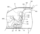
図1に示すように、第1実施形態に係る車両用空調装置1は、車両の車室内を快適な空調環境にする為に配置されており、車室内に配置されたシート30の下部に配置されたシート暖房ユニット10と、車室の天井により構成される車室天井面Cに配置された冷房ユニット50を有して構成されている。
(First embodiment)
As shown in FIG. 1, the vehicle air conditioner 1 according to the first embodiment is disposed to make the vehicle interior of the vehicle a comfortable air conditioning environment, and is disposed below the seat 30 disposed in the vehicle interior. The seat heating unit 10 and the cooling unit 50 disposed on the ceiling surface C of the passenger compartment, which is constituted by the ceiling of the passenger compartment, are configured.

第1実施形態において、シート暖房ユニット10は、シート30の座面部31と車室床面Fとの間の小さなスペースに配置されており、座面部31上方に位置する暖房対象範囲WSに対して適切な温度に調整された温風WAを供給することで、シート30に座った乗員を温める。尚、暖房対象範囲WSは、シート30に座った乗員の体幹部(即ち、胴体)及び脚部が配置される範囲である。   In the first embodiment, the seat heating unit 10 is disposed in a small space between the seat surface portion 31 of the seat 30 and the passenger compartment floor surface F, and with respect to the heating target range WS located above the seat surface portion 31. By supplying warm air WA adjusted to an appropriate temperature, the passenger sitting on the seat 30 is warmed. The heating target range WS is a range in which the trunk (that is, the trunk) and legs of the occupant sitting on the seat 30 are arranged.

そして、シート暖房ユニット10は、蒸気圧縮式の冷凍サイクル11と、送風機16とを、筐体20内部に収容して構成されている。従って、シート暖房ユニット10は、送風機16の作動による送風空気を冷凍サイクル11によって温度調整して、後述するシートフレーム40等を介して、暖房対象範囲WSへ温風WAとして供給することができる。   The seat heating unit 10 is configured by housing a vapor compression refrigeration cycle 11 and a blower 16 in a housing 20. Therefore, the seat heating unit 10 can adjust the temperature of the air blown by the operation of the blower 16 by the refrigeration cycle 11 and supply the air as the hot air WA to the heating target range WS via the seat frame 40 and the like described later.

ここで、シート30は、座面部31と、背もたれ部32と、ヘッドレスト部33とを有しており、車両の車室床面Fに対して車両の前後方向へスライド移動可能に配置されている。座面部31は、乗員が着座する部分であり、その上面に多孔質製のクッション部を有している。背もたれ部32は、座面部31の後端側に配置されており、座面部31に座った乗員の体幹部を後方から支持する。ヘッドレスト部33は、背もたれ部32の上部に配置されており、座面部31に座った乗員の頭部を後方から支持する。   Here, the seat 30 has a seat surface portion 31, a backrest portion 32, and a headrest portion 33, and is arranged so as to be slidable in the vehicle front-rear direction with respect to the vehicle compartment floor surface F of the vehicle. . The seat surface portion 31 is a portion on which an occupant is seated, and has a porous cushion portion on the upper surface thereof. The backrest portion 32 is disposed on the rear end side of the seat surface portion 31 and supports the trunk of the occupant sitting on the seat surface portion 31 from behind. The headrest portion 33 is disposed on the upper portion of the backrest portion 32 and supports the head of an occupant sitting on the seat surface portion 31 from behind.

尚、シート暖房ユニット10は、座面部31の下面に固定されており、シート30と共にスライド可能に配置されている。シート暖房ユニット10は、車載バッテリからの電力供給を受けており、車載バッテリからの電力線は、スライドを許容するように余裕のあるコイル配線で構成されている。   The seat heating unit 10 is fixed to the lower surface of the seat surface portion 31 and is slidably disposed with the seat 30. The seat heating unit 10 is supplied with electric power from the in-vehicle battery, and the power line from the in-vehicle battery is configured by a coil wiring having a margin so as to allow sliding.

車両用空調装置1を構成する冷房ユニット50は、車室の車室天井面Cに対して取り付けられており、暖房対象範囲WSの上方に位置する冷房対象範囲CSに対して適切な温度に調整された冷風CAを供給し、乗員の頭部を冷却する。   The cooling unit 50 that constitutes the vehicle air conditioner 1 is attached to the ceiling surface C of the passenger compartment, and is adjusted to an appropriate temperature for the cooling target range CS located above the heating target range WS. The supplied cool air CA is supplied to cool the occupant's head.

そして、冷房ユニット50は、シート暖房ユニット10と同様に、蒸気圧縮式の冷凍サイクル51と、送風機56とを、筐体60内部に収容して構成されている。従って、冷房ユニット50は、送風機56の作動による送風空気を冷凍サイクル51によって温度調整して、冷風CAとして冷房対象範囲CSへ供給することができる。   The cooling unit 50 is configured by housing a vapor compression refrigeration cycle 51 and a blower 56 in the housing 60 in the same manner as the seat heating unit 10. Therefore, the cooling unit 50 can adjust the temperature of the air blown by the operation of the blower 56 by the refrigeration cycle 51 and supply the air to the cooling target range CS as the cold air CA.

図1に示すように、冷房ユニット50は、車室天井面Cにおいて、ヘッドレスト部33の直上に相当するヘッドレスト上方領域Rよりも後方へ所定距離ずれた位置に配置されている。これにより、冷房ユニット50は、シート30に座った乗員の頭部直上からではなく、やや後方から冷風CAを供給することが可能となる。   As shown in FIG. 1, the cooling unit 50 is disposed at a position shifted a predetermined distance rearward from the headrest upper region R corresponding to the position directly above the headrest portion 33 on the ceiling surface C of the passenger compartment. Accordingly, the cooling unit 50 can supply the cold air CA from slightly behind rather than from just above the head of the passenger sitting on the seat 30.

次に、第1実施形態に係るシート暖房ユニット10の具体的構成について、図2、図3を参照しつつ詳細に説明する。上述したように、第1実施形態に係るシート暖房ユニット10は、座面部31と車室床面Fとの間に配置可能な箱体として構成された筐体20内部に、冷凍サイクル11と送風機16とを収容している。   Next, a specific configuration of the seat heating unit 10 according to the first embodiment will be described in detail with reference to FIGS. 2 and 3. As described above, the seat heating unit 10 according to the first embodiment includes the refrigeration cycle 11 and the blower in the housing 20 configured as a box that can be disposed between the seat surface portion 31 and the passenger compartment floor surface F. 16 is housed.

図2、図3に示すように、冷凍サイクル11は、蒸気圧縮式の冷凍サイクルを構成し、空調対象空間である車室内のシート30周辺(例えば、暖房対象範囲WS)へ送風される送風空気を加熱する機能を果たす。当該冷凍サイクル11は、圧縮機12と、凝縮器13と、膨張弁14と、蒸発器15とを有している。   As shown in FIGS. 2 and 3, the refrigeration cycle 11 constitutes a vapor compression refrigeration cycle, and is blown air that is blown to the vicinity of the seat 30 (for example, the heating target range WS) that is an air conditioning target space. Fulfills the function of heating. The refrigeration cycle 11 includes a compressor 12, a condenser 13, an expansion valve 14, and an evaporator 15.

そして、当該冷凍サイクル11では、冷媒としてHFC系冷媒(具体的には、R134a)を採用しており、高圧側冷媒圧力が冷媒の臨界圧力を超えない蒸気圧縮式の亜臨界冷凍サイクルを構成している。もちろん、冷媒としてHFO系冷媒(例えば、R1234yf)や自然冷媒(例えば、R744)等を採用してもよい。更に、冷媒には圧縮機12を潤滑するための冷凍機油が混入されており、冷凍機油の一部は冷媒とともにサイクルを循環している。   The refrigeration cycle 11 employs an HFC refrigerant (specifically, R134a) as the refrigerant, and constitutes a vapor compression subcritical refrigeration cycle in which the high-pressure side refrigerant pressure does not exceed the critical pressure of the refrigerant. ing. Of course, an HFO refrigerant (for example, R1234yf), a natural refrigerant (for example, R744), or the like may be employed as the refrigerant. Furthermore, the refrigerating machine oil for lubricating the compressor 12 is mixed in the refrigerant, and a part of the refrigerating machine oil circulates in the cycle together with the refrigerant.

図2に示すように、当該シート暖房ユニット10では、送風機16が筐体20内部の中央部分に配置されている。この送風機16は、遠心多翼ファンを電動モータにて駆動する電動送風機である。送風機16は、遠心多翼ファンの回転軸が筐体20の上下方向に一致するように配置されている。従って、送風機16は、筐体20の上下方向に沿って空気を吸い込み、吸い込んだ空気を、軸に対して直交し且つ遠心方向へ送風する。送風機16における遠心多翼ファンの回転数(即ち、送風量)は、後述する空調制御装置70から出力される制御電圧によって制御される。   As shown in FIG. 2, in the seat heating unit 10, the blower 16 is disposed in the central portion inside the housing 20. The blower 16 is an electric blower that drives a centrifugal multiblade fan with an electric motor. The blower 16 is arranged so that the rotation axis of the centrifugal multiblade fan coincides with the vertical direction of the housing 20. Therefore, the blower 16 sucks air along the vertical direction of the housing 20 and blows the sucked air in a direction perpendicular to the axis and in the centrifugal direction. The number of rotations of the centrifugal multiblade fan in the blower 16 (i.e., the amount of blown air) is controlled by a control voltage output from the air conditioning controller 70 described later.

圧縮機12は、冷凍サイクル11において、冷媒を吸入し、圧縮して吐出するものである。圧縮機12は、シート暖房ユニット10の筐体20内に配置されている。圧縮機12は、吐出容量が固定された固定容量型の圧縮機構を電動モータにて駆動する電動圧縮機として構成されている。この圧縮機構としては、スクロール型圧縮機構、ベーン型圧縮機構等の各種圧縮機構を採用することができる。   In the refrigeration cycle 11, the compressor 12 sucks refrigerant, compresses it, and discharges it. The compressor 12 is disposed in the housing 20 of the seat heating unit 10. The compressor 12 is configured as an electric compressor that drives a fixed displacement type compression mechanism with a fixed discharge capacity by an electric motor. As this compression mechanism, various compression mechanisms such as a scroll-type compression mechanism and a vane-type compression mechanism can be employed.

圧縮機12を構成する電動モータは、後述する空調制御装置70から出力される制御信号によって、その作動(即ち、回転数)が制御される。この電動モータとしては、交流モータ、直流モータの何れの形式を採用してもよい。そして、空調制御装置70が電動モータの回転数を制御することによって、圧縮機構の冷媒吐出能力が変更される。   The operation (that is, the number of rotations) of the electric motor constituting the compressor 12 is controlled by a control signal output from an air conditioning control device 70 described later. As this electric motor, either an AC motor or a DC motor may be adopted. And the refrigerant | coolant discharge capability of a compression mechanism is changed because the air-conditioning control apparatus 70 controls the rotation speed of an electric motor.

圧縮機12の吐出口には、凝縮器13の冷媒入口側が接続されている。図2に示すように、凝縮器13は、複数の熱交換器を冷媒管で接続して構成されている。凝縮器13を構成する複数の熱交換器は、筐体20内部において、送風機16の周囲を約180度の範囲にわたって囲むように配置されている。従って、当該凝縮器13は、圧縮機12から吐出された高温高圧の吐出冷媒と、送風機16により送風された送風空気とを熱交換させることで、送風空気を加熱して温風WAにすることができる。即ち、当該凝縮器13は、加熱用熱交換器として作動し、本発明における凝縮器として機能する。   The refrigerant inlet side of the condenser 13 is connected to the discharge port of the compressor 12. As shown in FIG. 2, the condenser 13 is configured by connecting a plurality of heat exchangers with refrigerant pipes. The plurality of heat exchangers constituting the condenser 13 are arranged inside the casing 20 so as to surround the blower 16 over a range of about 180 degrees. Therefore, the condenser 13 heats the blown air to warm air WA by exchanging heat between the high-temperature and high-pressure discharged refrigerant discharged from the compressor 12 and the blown air blown by the blower 16. Can do. That is, the condenser 13 operates as a heat exchanger for heating and functions as a condenser in the present invention.

凝縮器13の冷媒出口側には、膨張弁14が配置されている。当該膨張弁14は、冷媒流路の絞り開度を変更可能に構成されており、凝縮器13から流出した冷媒を減圧させる。膨張弁14は、本発明におけるシート暖房ユニットの減圧部として機能する。   An expansion valve 14 is disposed on the refrigerant outlet side of the condenser 13. The expansion valve 14 is configured to be able to change the throttle opening of the refrigerant flow path, and depressurizes the refrigerant that has flowed out of the condenser 13. The expansion valve 14 functions as a pressure reducing unit of the seat heating unit in the present invention.

尚、第1実施形態に係る減圧部としては、膨張弁14を用いているが、この態様に限定されるものではない。凝縮器13から流出した冷媒を減圧可能であれば、減圧部として、種々の構成を採用することができる。例えば、固定絞りやキャピラリーチューブを本発明の減圧部として採用しても良いし、空調制御装置70の制御信号により絞り開度を制御可能な膨張弁を用いても良い。   In addition, although the expansion valve 14 is used as a pressure reduction part which concerns on 1st Embodiment, it is not limited to this aspect. If the refrigerant flowing out of the condenser 13 can be depressurized, various configurations can be adopted as the depressurization unit. For example, a fixed throttle or a capillary tube may be employed as the pressure reducing unit of the present invention, or an expansion valve capable of controlling the throttle opening degree by a control signal of the air conditioning control device 70 may be used.

膨張弁14の出口側には、蒸発器15の冷媒入口側が接続されている。図2に示すように、蒸発器15は、複数の熱交換器を冷媒管で接続して構成されている。蒸発器15を構成する複数の熱交換器は、筐体20内部において、送風機16の周囲を約180度の範囲にわたって囲むように配置されている。即ち、当該送風機16は、凝縮器13及び蒸発器15によって、その周囲を囲まれている。   The refrigerant inlet side of the evaporator 15 is connected to the outlet side of the expansion valve 14. As shown in FIG. 2, the evaporator 15 is configured by connecting a plurality of heat exchangers with refrigerant pipes. The plurality of heat exchangers constituting the evaporator 15 are arranged inside the housing 20 so as to surround the blower 16 over a range of about 180 degrees. That is, the blower 16 is surrounded by the condenser 13 and the evaporator 15.

当該蒸発器15は、膨張弁14から流出した冷媒と、送風機16により送風された送風空気とを熱交換させ、送風空気から吸熱することができる。即ち、当該蒸発器15は、本発明におけるシート暖房ユニットの蒸発器として機能する。   The evaporator 15 can exchange heat between the refrigerant that has flowed out of the expansion valve 14 and the blown air blown by the blower 16, and can absorb heat from the blown air. That is, the evaporator 15 functions as an evaporator of the seat heating unit in the present invention.

そして、筐体20は、シート30の座面部31と車室床面Fの間のスペースに配置可能なサイズの箱型に形成されており、吸気口21と、複数の第1通気口22及び複数の第2通気口23とを、その上面に有している。   And the housing | casing 20 is formed in the box shape of the size which can be arrange | positioned in the space between the seat surface part 31 of the sheet | seat 30, and the compartment floor surface F, The inlet port 21 and several 1st ventilation port 22 and A plurality of second vent holes 23 are provided on the upper surface.

図2、図3に示すように、吸気口21は、筐体20の上面における中央部分に形成されている。当該吸気口21は、送風機16における遠心多翼ファンの回転軸の直上部分を含むように開口しており、筐体20内部と外部とを連通している。従って、送風機16は、その作動に伴って、吸気口21を介して、筐体20の内部へ車室内の空気を吸い込むことができる。   As shown in FIGS. 2 and 3, the air inlet 21 is formed in the central portion of the upper surface of the housing 20. The intake port 21 is opened so as to include a portion directly above the rotating shaft of the centrifugal multiblade fan in the blower 16, and communicates the inside of the housing 20 with the outside. Therefore, the blower 16 can suck the air in the passenger compartment into the inside of the housing 20 through the intake port 21 in accordance with the operation thereof.

第1通気口22は、筐体20の上面における角部の内、凝縮器13側にあたる2つの角部に開口されており、筐体20内部と外部とを連通している。送風機16による送風空気の一部は、凝縮器13における熱交換により温められた後、温風WAとして第1通気口22から吹き出される。   The first vent 22 is opened at two corners corresponding to the condenser 13 among the corners on the upper surface of the housing 20, and communicates the inside and the outside of the housing 20. A part of the air blown by the blower 16 is heated by heat exchange in the condenser 13 and then blown out from the first vent 22 as hot air WA.

一方、第2通気口23は、筐体20の上面における角部の内、蒸発器15側にあたる2つの角部に開口されており、筐体20内部と外部とを連通している。送風機16による送風空気の他の一部は、蒸発器15における熱交換により冷却された後、第2通気口23から吹き出される。   On the other hand, the second vent opening 23 is opened at two corners corresponding to the evaporator 15 among the corners on the upper surface of the housing 20, and communicates the inside and the outside of the housing 20. Another part of the air blown by the blower 16 is cooled by heat exchange in the evaporator 15 and then blown out from the second vent 23.

従って、第1実施形態に係るシート暖房ユニット10は、図7に示すように、後述するシートフレーム40を介して、冷凍サイクル11によって調整された温風WAを暖房対象範囲WSに対して供給することができ、シート30に座った乗員の体幹部及び脚部を温めることができる。   Therefore, as shown in FIG. 7, the seat heating unit 10 according to the first embodiment supplies the warm air WA adjusted by the refrigeration cycle 11 to the heating target range WS via the seat frame 40 described later. The trunk and legs of the occupant sitting on the seat 30 can be warmed.

続いて、車両の車室内に配置されたシート30の構成について、図面を参照しつつ詳細に説明する。当該シート30は、車両において乗員が座る為に配設されており、座面部31と、背もたれ部32と、ヘッドレスト部33と、シートフレーム40とを有している。当該シート30は、座面部31、背もたれ部32及びヘッドレスト部33の相対的な位置を、シートフレーム40で固定することによって構成されている。   Next, the configuration of the seat 30 disposed in the vehicle interior of the vehicle will be described in detail with reference to the drawings. The seat 30 is disposed for a passenger to sit in the vehicle, and includes a seat surface portion 31, a backrest portion 32, a headrest portion 33, and a seat frame 40. The seat 30 is configured by fixing the relative positions of the seat surface portion 31, the backrest portion 32, and the headrest portion 33 with the seat frame 40.

座面部31は、乗員が着座する部分であり、ウレタン等の多孔質材で構成されたクッション部をその上面に有している。そして、背もたれ部32は、座面部31の後端側に配置されており、座面部31に座った乗員の体幹部を後方から支持する。背もたれ部32の前面には、多孔質製のクッション部が配置されている。当該クッション部は、シート30に乗員が座った場合の衝撃を吸収すると共に、背もたれ部32内部との間の通気性を担保している。   The seat surface portion 31 is a portion on which an occupant sits, and has a cushion portion made of a porous material such as urethane on the upper surface thereof. And the backrest part 32 is arrange | positioned at the rear-end side of the seat surface part 31, and supports the trunk | drum of the passenger | crew who sat on the seat surface part 31 from back. A porous cushion portion is disposed on the front surface of the backrest portion 32. The cushion portion absorbs an impact when an occupant sits on the seat 30 and ensures air permeability between the seat back portion 32 and the inside.

ヘッドレスト部33は、背もたれ部32の上部に配置されており、座面部31に座った乗員の頭部を後方から支持する。ヘッドレスト部33の前面にも、多孔質性のクッション部が配置されており、乗員の頭部が接触した場合の衝撃を吸収する。   The headrest portion 33 is disposed on the upper portion of the backrest portion 32 and supports the head of an occupant sitting on the seat surface portion 31 from behind. A porous cushion portion is also arranged on the front surface of the headrest portion 33 to absorb an impact when the head of the occupant comes into contact.

尚、上述した暖房対象範囲WSは、シート30に座った乗員の体幹部及び脚部が位置する範囲に相当しており、座面部31の上方であり、且つ、背もたれ部32の前方である範囲を含んで定義されている。又、冷房対象範囲CSは、暖房対象範囲WSの上方であり、ヘッドレスト部33の前方に位置しており、シート30に座った乗員の頭部が位置する範囲に相当している。   The heating target range WS described above corresponds to a range in which the trunk and legs of an occupant sitting on the seat 30 are located, and is a range above the seat surface portion 31 and in front of the backrest portion 32. Defined. The cooling target range CS is located above the heating target range WS, in front of the headrest portion 33, and corresponds to a range in which the head of an occupant sitting on the seat 30 is located.

そして、シート30を構成するシートフレーム40は、金属パイプを組み合わせて構成されており、シート30の骨材部として機能すると同時に、シート暖房ユニット10による温風WAの流路としても機能する。   The seat frame 40 constituting the seat 30 is configured by combining metal pipes and functions as an aggregate portion of the seat 30 and also functions as a flow path of the warm air WA by the seat heating unit 10.

図1、図4に示すように、当該シートフレーム40は、第1シートフレーム41と、第2シートフレーム44とによって構成されている。この第1シートフレーム41と第2シートフレーム44とは、図示しない補強部材で連結されており、その相対的な位置関係を維持している。   As shown in FIGS. 1 and 4, the seat frame 40 includes a first seat frame 41 and a second seat frame 44. The first seat frame 41 and the second seat frame 44 are connected by a reinforcing member (not shown) and maintain their relative positional relationship.

第1シートフレーム41は、座面部31のクッション部よりも下方において、座面部31の内部に配置されており、接続部42と、複数の通気孔43とを有している。接続部42は、第1シートフレーム41の端部に形成されており、座面部31の下面から突出するように配置されている。複数の通気孔43は、第1シートフレーム41の上面における複数個所に配置されており、中空状の第1シートフレーム41内部と連通している。   The first seat frame 41 is disposed inside the seat surface portion 31 below the cushion portion of the seat surface portion 31, and has a connection portion 42 and a plurality of vent holes 43. The connection portion 42 is formed at the end of the first seat frame 41 and is disposed so as to protrude from the lower surface of the seat surface portion 31. The plurality of vent holes 43 are disposed at a plurality of locations on the upper surface of the first seat frame 41 and communicate with the interior of the hollow first seat frame 41.

従って、第1実施形態に係るシート暖房ユニット10からの温風WAの一部は、筐体20の第1通気口22から吹き出されると、接続部42を介して、第1シートフレーム41内部に流入する。その後、当該温風WAは、第1シートフレーム41における複数の通気孔43から流出し、座面部31のクッション部を介して、暖房対象範囲WSへ吹き出される。   Therefore, when a part of the warm air WA from the seat heating unit 10 according to the first embodiment is blown out from the first vent 22 of the housing 20, the inside of the first seat frame 41 is connected via the connection portion 42. Flow into. Thereafter, the warm air WA flows out from the plurality of ventilation holes 43 in the first seat frame 41 and is blown out to the heating target range WS through the cushion portion of the seat surface portion 31.

そして、第2シートフレーム44は、背もたれ部32のクッション部よりも後方において、背もたれ部32の内部に配置されており、空調風供給口45と、複数の空調風吹出口46とを有している。空調風供給口45は、第2シートフレーム44の下端部に配置されており、背もたれ部32の下端部から突出している。空調風吹出口46は、第2シートフレーム44の前面側における複数個所に配置されており、それぞれ中空状の第2シートフレーム44の内部と連通している。   And the 2nd seat frame 44 is arrange | positioned inside the backrest part 32 behind the cushion part of the backrest part 32, and has the air-conditioning air supply port 45 and the several air-conditioning air outlet 46. FIG. . The conditioned air supply port 45 is disposed at the lower end of the second seat frame 44 and protrudes from the lower end of the backrest 32. The air-conditioning air outlet 46 is disposed at a plurality of locations on the front side of the second seat frame 44 and communicates with the inside of the hollow second seat frame 44.

従って、第1実施形態に係るシート暖房ユニット10からの温風WAの一部は、第1通気口22から吹き出されると、空調風供給口45から第2シートフレーム44内部に流入する。その後、当該温風WAは、第2シートフレーム44における複数の空調風吹出口46から流出し、背もたれ部32のクッション部を介して、暖房対象範囲WSに吹き出される。   Therefore, a part of the warm air WA from the seat heating unit 10 according to the first embodiment flows into the second seat frame 44 from the conditioned air supply port 45 when blown out from the first ventilation port 22. Thereafter, the warm air WA flows out from the plurality of conditioned air outlets 46 in the second seat frame 44 and is blown out to the heating target range WS through the cushion portion of the backrest portion 32.

次に、第1実施形態に係る車両用空調装置1を構成する冷房ユニット50について、図5を参照しつつ詳細に説明する。尚、図5は、冷房ユニット50を車室天井面Cに取り付けた状態で車室内から見た場合の平面図を示している。   Next, the cooling unit 50 constituting the vehicle air conditioner 1 according to the first embodiment will be described in detail with reference to FIG. FIG. 5 shows a plan view when the cooling unit 50 is viewed from the passenger compartment with the cooling unit 50 attached to the passenger compartment ceiling C.

上述したように、冷房ユニット50は、車用の車室天井面Cに取り付けられており、図1に示すように、ヘッドレスト上方領域Rから後方へ所定距離ずれた位置に配置されている。尚、具体的には、冷房ユニット50の筐体60における中心位置が、ヘッドレスト上方領域Rの中心位置よりも所定距離の分だけ後方に位置している。   As described above, the cooling unit 50 is attached to the vehicle interior ceiling C, and as shown in FIG. Specifically, the center position of the cooling unit 50 in the housing 60 is located behind the center position of the headrest upper region R by a predetermined distance.

図5に示すように、当該冷房ユニット50は、シート暖房ユニット10と同様に、蒸気圧縮式の冷凍サイクル51と、送風機56とを箱体状に形成された筐体20内部に収容している。冷房ユニット50における冷凍サイクル51は、圧縮機52と、放熱器53と、膨張弁54と、吸熱器55とを有しており、空調対象空間である車室内のシート30周辺(例えば、冷房対象範囲CS)へ送風される送風空気を冷却する機能を果たす。   As shown in FIG. 5, like the seat heating unit 10, the cooling unit 50 accommodates a vapor compression refrigeration cycle 51 and a blower 56 in a housing 20 formed in a box shape. . The refrigeration cycle 51 in the cooling unit 50 includes a compressor 52, a radiator 53, an expansion valve 54, and a heat absorber 55, and the vicinity of the seat 30 (for example, an object to be cooled) that is an air conditioning target space. It fulfills the function of cooling the air blown into the range CS).

尚、当該冷凍サイクル51でも、冷媒としてHFC系冷媒(具体的には、R134a)を採用しており、高圧側冷媒圧力が冷媒の臨界圧力を超えない蒸気圧縮式の亜臨界冷凍サイクルを構成している。もちろん、冷媒としてHFO系冷媒(例えば、R1234yf)や自然冷媒(例えば、R744)等を採用してもよい。更に、冷媒には圧縮機52を潤滑するための冷凍機油が混入されており、冷凍機油の一部は冷媒とともにサイクルを循環している。   The refrigeration cycle 51 also employs an HFC-based refrigerant (specifically, R134a) as a refrigerant, and constitutes a vapor compression subcritical refrigeration cycle in which the high-pressure side refrigerant pressure does not exceed the critical pressure of the refrigerant. ing. Of course, an HFO refrigerant (for example, R1234yf), a natural refrigerant (for example, R744), or the like may be employed as the refrigerant. Furthermore, the refrigerant is mixed with refrigerating machine oil for lubricating the compressor 52, and a part of the refrigerating machine oil circulates in the cycle together with the refrigerant.

図5に示すように、当該冷房ユニット50においては、シート暖房ユニット10と同様に、送風機56が筐体20内部の中央部分に配置されている。この送風機56は、遠心多翼ファンを電動モータにて駆動する電動送風機である。従って、送風機56は、筐体60の上下方向に沿って空気を吸い込み、吸い込んだ空気を、軸に対して直交し且つ遠心方向へ送風する。送風機56の送風量は、後述する空調制御装置70から出力される制御電圧によって制御される。   As shown in FIG. 5, in the cooling unit 50, as in the seat heating unit 10, the blower 56 is disposed in the central portion inside the housing 20. The blower 56 is an electric blower that drives a centrifugal multiblade fan with an electric motor. Therefore, the blower 56 sucks air along the vertical direction of the housing 60 and blows the sucked air in a direction perpendicular to the axis and in the centrifugal direction. The amount of air blown by the blower 56 is controlled by a control voltage output from an air conditioning control device 70 described later.

圧縮機52は、冷凍サイクル51において、冷媒を吸入し、圧縮して吐出するものであり、冷房ユニット50の筐体60内に配置されている。圧縮機52は、冷凍サイクル11の圧縮機12と同様に、固定容量型の圧縮機構を電動モータにて駆動する電動圧縮機として構成されている。圧縮機52を構成する電動モータは、後述する空調制御装置70から出力される制御信号によって、その作動(即ち、回転数)が制御される。そして、空調制御装置70が電動モータの回転数を制御することで、圧縮機構の冷媒吐出能力が変更される。   The compressor 52 sucks, compresses and discharges the refrigerant in the refrigeration cycle 51, and is disposed in the housing 60 of the cooling unit 50. Similarly to the compressor 12 of the refrigeration cycle 11, the compressor 52 is configured as an electric compressor that drives a fixed capacity type compression mechanism with an electric motor. The operation (that is, the rotation speed) of the electric motor constituting the compressor 52 is controlled by a control signal output from an air conditioning control device 70 described later. And the refrigerant | coolant discharge capability of a compression mechanism is changed because the air-conditioning control apparatus 70 controls the rotation speed of an electric motor.

圧縮機52の吐出口には、放熱器53の冷媒入口側が接続されている。図5に示すように、放熱器53は、複数の熱交換器を冷媒管で接続して構成されている。放熱器53を構成する複数の熱交換器は、筐体60内部において、送風機56の周囲を約180度の範囲にわたって囲むように配置されている。従って、当該放熱器53は、圧縮機52から吐出された高温高圧の吐出冷媒と、送風機56により送風された送風空気とを熱交換させて、送風空気に放熱することができる。即ち、当該放熱器53は、本発明における放熱器として機能する。   The refrigerant inlet side of the radiator 53 is connected to the discharge port of the compressor 52. As shown in FIG. 5, the radiator 53 is configured by connecting a plurality of heat exchangers with refrigerant pipes. The plurality of heat exchangers constituting the radiator 53 are arranged inside the housing 60 so as to surround the blower 56 over a range of about 180 degrees. Accordingly, the radiator 53 can radiate heat to the blown air by exchanging heat between the high-temperature and high-pressure discharged refrigerant discharged from the compressor 52 and the blown air blown by the blower 56. That is, the radiator 53 functions as a radiator in the present invention.

そして、放熱器53の冷媒出口側には、膨張弁54が配置されている。当該膨張弁54は、冷媒流路の絞り開度を変更可能に構成されており、放熱器53から流出した冷媒を減圧させる。膨張弁54は、本発明における冷房ユニットの減圧部として機能する。   An expansion valve 54 is disposed on the refrigerant outlet side of the radiator 53. The expansion valve 54 is configured to be able to change the throttle opening of the refrigerant flow path, and depressurizes the refrigerant flowing out of the radiator 53. The expansion valve 54 functions as a pressure reducing unit of the cooling unit in the present invention.

尚、冷房ユニットに係る減圧部としては、膨張弁54を用いているが、この態様に限定されるものではない。放熱器53から流出した冷媒を減圧可能であれば、減圧部として、種々の構成を採用することができる。例えば、固定絞りやキャピラリーチューブを本発明に係る冷房ユニットの減圧部として採用しても良い。この構成によれば、冷房ユニット50の総重量を抑制することができる為、車室天井面Cに取り付ける構成を採用する上で有効である。   In addition, although the expansion valve 54 is used as a pressure reduction part which concerns on a cooling unit, it is not limited to this aspect. As long as the refrigerant flowing out of the radiator 53 can be depressurized, various configurations can be adopted as the depressurization unit. For example, a fixed throttle or a capillary tube may be employed as the pressure reducing unit of the cooling unit according to the present invention. According to this configuration, since the total weight of the cooling unit 50 can be suppressed, it is effective in adopting a configuration that attaches to the passenger compartment ceiling surface C.

膨張弁54の出口側には、吸熱器55の冷媒入口側が接続されている。図5に示すように、吸熱器55は、複数の熱交換器を冷媒管で接続して構成されている。吸熱器55を構成する複数の熱交換器は、筐体60内部において、送風機56の周囲を約180度の範囲にわたって囲むように配置されている。即ち、当該送風機56は、放熱器53及び吸熱器55によって、その周囲を囲まれている。   The refrigerant inlet side of the heat absorber 55 is connected to the outlet side of the expansion valve 54. As shown in FIG. 5, the heat absorber 55 is configured by connecting a plurality of heat exchangers with refrigerant pipes. The plurality of heat exchangers constituting the heat absorber 55 are arranged inside the housing 60 so as to surround the periphery of the blower 56 over a range of about 180 degrees. That is, the blower 56 is surrounded by the radiator 53 and the heat absorber 55.

そして、当該吸熱器55は、膨張弁54から流出した冷媒を蒸発させることで、送風機56により送風された送風空気から吸熱させて、当該送風空気を冷却することができ、冷風CAを生成することができる。即ち、吸熱器55は、冷却用熱交換器として作動し、本発明における冷房ユニットの吸熱器として機能する。   And the said heat absorber 55 can absorb the heat from the blowing air ventilated by the air blower 56 by evaporating the refrigerant | coolant which flowed out from the expansion valve 54, can cool the said blowing air, and produces | generates cold wind CA. Can do. That is, the heat absorber 55 operates as a heat exchanger for cooling, and functions as a heat absorber of the cooling unit in the present invention.

冷房ユニット50の筐体60は、シート暖房ユニット10における筐体20と同様に、箱型に形成されており、吸気口61と、複数の第1通気口62と、複数の第2通気口63とを有している。筐体60は、車室天井面Cに取り付けられる為、吸気口61、第1通気口62、第2通気口63は、筐体60の下面(即ち、車室内側を向く面)に形成されている。   The casing 60 of the cooling unit 50 is formed in a box shape like the casing 20 in the seat heating unit 10, and includes an air inlet 61, a plurality of first vent holes 62, and a plurality of second vent holes 63. And have. Since the housing 60 is attached to the vehicle interior ceiling C, the air inlet 61, the first air vent 62, and the second air vent 63 are formed on the lower surface of the housing 60 (that is, the surface facing the vehicle interior side). ing.

図5に示すように、吸気口61は、筐体60の下面の中央部分において、送風機56の回転軸の直上部分を含むように開口している。従って、送風機56は、吸気口61を介して、筐体60の内部へ車室内の空気を吸い込むことができる。   As shown in FIG. 5, the air inlet 61 is open at the central portion of the lower surface of the housing 60 so as to include a portion directly above the rotating shaft of the blower 56. Therefore, the blower 56 can suck the air in the passenger compartment into the housing 60 through the intake port 61.

第1通気口62は、筐体60の下面における角部の内、放熱器53側にあたる2つの角部に開口されており、筐体60内部と外部とを連通している。送風機56による送風空気の一部は、放熱器53を通過した後、第1通気口62から吹き出される。   The first vent 62 is opened at two corners corresponding to the radiator 53 among the corners on the lower surface of the housing 60, and communicates the inside of the housing 60 with the outside. A part of the air blown by the blower 56 is blown out from the first vent 62 after passing through the radiator 53.

一方、第2通気口63は、筐体60の下面における角部の内、吸熱器55側にあたる2つの角部に開口されており、筐体60内部と外部とを連通している。送風機56による送風空気の他の一部は、吸熱器55における熱交換により冷却された後、冷風CAとして第2通気口63から吹き出される。   On the other hand, the second vent 63 is opened at two corners corresponding to the heat absorber 55 in the corners on the lower surface of the housing 60, and communicates the inside of the housing 60 with the outside. The other part of the air blown by the blower 56 is cooled by heat exchange in the heat absorber 55 and then blown out from the second vent 63 as cold air CA.

そして、冷房ユニット50においては、各第2通気口63に対して冷風吹出部64が配置されている。冷風吹出部64は、略中空状に形成されており、内部に複数の風向調整板を回動可能に有している。各冷風吹出部64における風向調整板の向きは、第2通気口63から吹き出された冷風CAが冷房対象範囲CSに到達するように調整されている。つまり、冷風吹出部64は、第2通気口63から吹き出した冷風CAを冷房対象範囲CSに導く機能を果たしている。   In the cooling unit 50, a cold air blowing part 64 is arranged for each second vent 63. The cold air blowing part 64 is formed in a substantially hollow shape, and has a plurality of wind direction adjusting plates rotatably inside. The direction of the wind direction adjusting plate in each cold air blowing section 64 is adjusted so that the cold air CA blown from the second vent 63 reaches the cooling target range CS. That is, the cold air blowing unit 64 has a function of guiding the cold air CA blown from the second vent 63 to the cooling target range CS.

このように構成することで、第1実施形態に係る冷房ユニット50は、図7に示すように、冷凍サイクル51によって調整された冷風CAを冷房対象範囲CSに対して供給することができ、シート30に座った乗員の頭部を冷却することができる。   By configuring in this way, the cooling unit 50 according to the first embodiment can supply the cooling air CA adjusted by the refrigeration cycle 51 to the cooling target range CS as shown in FIG. The head of an occupant sitting at 30 can be cooled.

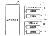
続いて、第1実施形態に係る車両用空調装置1の作動制御を司る制御系について、図6を参照しつつ説明する。車両用空調装置1は、当該車両用空調装置1の構成機器(即ち、シート暖房ユニット10及び冷房ユニット50)の作動を制御する為の空調制御装置70を有している。   Next, a control system that controls operation of the vehicle air conditioner 1 according to the first embodiment will be described with reference to FIG. The vehicle air conditioner 1 includes an air conditioning control device 70 for controlling the operation of the components of the vehicle air conditioner 1 (that is, the seat heating unit 10 and the cooling unit 50).

空調制御装置70は、CPU、ROM及びRAM等を含む周知のマイクロコンピュータとその周辺回路から構成されている。そして、空調制御装置70は、そのROM内に記憶された制御プログラムに基づいて各種演算、処理を行い、シート暖房ユニット10の圧縮機12及び送風機16や、冷房ユニット50の圧縮機52及び送風機56等の空調制御機器の作動を制御する。   The air conditioning control device 70 includes a known microcomputer including a CPU, a ROM, a RAM, and the like and peripheral circuits thereof. The air conditioning control device 70 performs various calculations and processes based on the control program stored in the ROM, and the compressor 12 and the blower 16 of the seat heating unit 10 and the compressor 52 and the blower 56 of the cooling unit 50. Control the operation of air conditioning control equipment.

図6に示すように、空調制御装置70の出力側には、シート暖房ユニット10の圧縮機12と送風機16とが接続されている。従って、当該空調制御装置70は、シート暖房ユニット10に関して、圧縮機12による冷媒吐出性能(例えば、冷媒圧力)や、送風機16による送風性能(例えば、送風量)を状況に応じて調整することができる。即ち、空調制御装置70は、シート暖房ユニット10により生成される温風WAの温度等を調整することができる。   As shown in FIG. 6, the compressor 12 and the blower 16 of the seat heating unit 10 are connected to the output side of the air conditioning control device 70. Therefore, the air conditioning control device 70 can adjust the refrigerant discharge performance (for example, refrigerant pressure) by the compressor 12 and the ventilation performance (for example, the amount of air flow) by the blower 16 according to the situation with respect to the seat heating unit 10. it can. That is, the air conditioning control device 70 can adjust the temperature of the hot air WA generated by the seat heating unit 10 and the like.

又、空調制御装置70の出力側には、冷房ユニット50の圧縮機52と送風機56が接続されている。従って、空調制御装置70は、冷房ユニット50において、圧縮機52による冷媒吐出性能(例えば、冷媒圧力)や、送風機56による送風性能(例えば、送風量)を状況に応じて調整することができる。即ち、冷房ユニット50により生成される冷風CAの温度等を調整することができる。   A compressor 52 and a blower 56 of the cooling unit 50 are connected to the output side of the air conditioning control device 70. Therefore, the air conditioning control device 70 can adjust the refrigerant discharge performance (for example, refrigerant pressure) by the compressor 52 and the ventilation performance (for example, the amount of air flow) by the blower 56 in the cooling unit 50 according to the situation. That is, the temperature of the cold air CA generated by the cooling unit 50 can be adjusted.

次に、第1実施形態に係る車両用空調装置1の作動態様について、図7を参照しつつ詳細に説明する。図7に示す場合、空調制御装置70は、シート暖房ユニット10の作動制御と同時に、冷房ユニット50の作業制御を行う。   Next, the operation | movement aspect of the vehicle air conditioner 1 which concerns on 1st Embodiment is demonstrated in detail, referring FIG. In the case shown in FIG. 7, the air conditioning control device 70 performs work control of the cooling unit 50 simultaneously with operation control of the seat heating unit 10.

先ず、シート暖房ユニット10においては、空調制御装置70は、冷凍サイクル11を構成する圧縮機12及び送風機16の作動を開始する。送風機16の作動を開始すると、車室内の空気が吸気口21から筐体20の内部に吸い込まれる。筐体20内部に吸い込まれた空気は、送風機16の周囲に配置された凝縮器13及び蒸発器15に対して送風される。   First, in the seat heating unit 10, the air conditioning control device 70 starts the operation of the compressor 12 and the blower 16 constituting the refrigeration cycle 11. When the operation of the blower 16 is started, the air in the passenger compartment is sucked into the housing 20 from the air inlet 21. The air sucked into the housing 20 is blown to the condenser 13 and the evaporator 15 arranged around the blower 16.

一方、圧縮機12の作動開始により、圧縮機12は、吸入冷媒を圧縮して、高温高圧のガス冷媒として吐出する。圧縮機12の吐出口には、凝縮器13が接続されている。凝縮器13は、送風機16により送風された空気と熱交換することで、圧縮機12から吐出されたガス冷媒を冷却して凝縮させる。換言すると、凝縮器13は、ガス冷媒の熱を送風空気に対して放熱させて温め、温風WAを生成する。   On the other hand, when the operation of the compressor 12 starts, the compressor 12 compresses the suction refrigerant and discharges it as a high-temperature and high-pressure gas refrigerant. A condenser 13 is connected to the discharge port of the compressor 12. The condenser 13 exchanges heat with the air blown by the blower 16 to cool and condense the gas refrigerant discharged from the compressor 12. In other words, the condenser 13 radiates and heats the heat of the gas refrigerant to the blown air to generate the warm air WA.

凝縮後の冷媒は、凝縮器13の流出口から膨張弁14に流入する。膨張弁14は、液冷媒を気液二相状態に減圧膨張させる。そして、蒸発器15は、膨張弁14を通過した冷媒を蒸発させることで、蒸発器15を通過する送風空気と熱交換させる。蒸発器15から流出した冷媒は、圧縮機12に吸入される。   The condensed refrigerant flows into the expansion valve 14 from the outlet of the condenser 13. The expansion valve 14 decompresses and expands the liquid refrigerant into a gas-liquid two-phase state. The evaporator 15 evaporates the refrigerant that has passed through the expansion valve 14 to exchange heat with the blown air that passes through the evaporator 15. The refrigerant flowing out of the evaporator 15 is sucked into the compressor 12.

このように第1実施形態に係るシート暖房ユニット10では、冷凍サイクル11の凝縮器13と送風空気との間の熱交換によって温風WAが生成される。凝縮器13で生成された温風WAは、第1通気口22から吹き出され、第1シートフレーム41、第2シートフレーム44に供給される。   As described above, in the seat heating unit 10 according to the first embodiment, the hot air WA is generated by heat exchange between the condenser 13 of the refrigeration cycle 11 and the blown air. The hot air WA generated by the condenser 13 is blown out from the first vent 22 and supplied to the first seat frame 41 and the second seat frame 44.

図7に示すように、第1シートフレーム41に吹き込まれた温風WAは、第1シートフレーム41の上面に形成された複数の通気孔43を介して上方へ吹き出される。第1シートフレーム41の上方には、座面部31のクッション部が配置されている。座面部31のクッション部は、ウレタン等の多孔質材で構成されている為、温風WAは、座面部31のクッション部を介して、その上方に位置する暖房対象範囲WSに供給される。つまり、第1実施形態に係るシート暖房ユニット10は、温風WAによって、シート30に座った乗員の脚部を温めることができる。   As shown in FIG. 7, the warm air WA blown into the first seat frame 41 is blown upward through a plurality of vent holes 43 formed on the upper surface of the first seat frame 41. Above the first seat frame 41, a cushion portion of the seat surface portion 31 is disposed. Since the cushion portion of the seat surface portion 31 is made of a porous material such as urethane, the warm air WA is supplied to the heating target range WS located above the cushion portion of the seat surface portion 31. That is, the seat heating unit 10 according to the first embodiment can warm the legs of the occupant sitting on the seat 30 with the warm air WA.

そして、第2シートフレーム44に吹き込まれた温風WAは、第2シートフレーム44の前面に形成された複数の空調風吹出口46を介して前方へ吹き出される。第2シートフレーム44の前方には、背もたれ部32のクッション部が配置されている。背もたれ部32のクッション部は、ウレタン等の多孔質材で構成されている為、温風WAは、背もたれ部32のクッション部を介して、その前方に位置する暖房対象範囲WSに供給される。これにより、当該シート暖房ユニット10は、シート30に座った乗員の体幹部を、背後から吹き出される温風WAによって温めることができる。   The warm air WA blown into the second seat frame 44 is blown forward through a plurality of air-conditioning air outlets 46 formed on the front surface of the second seat frame 44. A cushion portion of the backrest portion 32 is disposed in front of the second seat frame 44. Since the cushion part of the backrest part 32 is comprised with porous materials, such as urethane, the warm air WA is supplied to the heating object range WS located in front of it through the cushion part of the backrest part 32. Thereby, the said seat heating unit 10 can warm the trunk | drum of the passenger | crew who sat on the seat 30 with the warm air WA which blows off from back.

一方、冷房ユニット50については、空調制御装置70は、冷凍サイクル51を構成する圧縮機52及び送風機56の作動を開始する。送風機56の作動を開始すると、車室内の空気が吸気口61から筐体60の内部に吸い込まれる。筐体60内部に吸い込まれた空気は、送風機56の周囲に配置された放熱器53及び吸熱器55に対して送風される。   On the other hand, for the cooling unit 50, the air conditioning control device 70 starts the operation of the compressor 52 and the blower 56 constituting the refrigeration cycle 51. When the operation of the blower 56 is started, the air in the passenger compartment is sucked into the housing 60 from the air inlet 61. The air sucked into the housing 60 is blown to the radiator 53 and the heat absorber 55 arranged around the blower 56.

冷凍サイクル51における圧縮機52の作動開始により、圧縮機52は、吸入冷媒を圧縮して、高温高圧のガス冷媒として吐出する。圧縮機52の吐出口には、放熱器53が接続されている。放熱器53は、送風機56により送風された空気に冷媒の熱を放熱させることで、圧縮機52から吐出されたガス冷媒を冷却して凝縮させる。   When the operation of the compressor 52 in the refrigeration cycle 51 starts, the compressor 52 compresses the suction refrigerant and discharges it as a high-temperature and high-pressure gas refrigerant. A radiator 53 is connected to the discharge port of the compressor 52. The radiator 53 cools and condenses the gas refrigerant discharged from the compressor 52 by radiating the heat of the refrigerant to the air blown by the blower 56.

凝縮後の冷媒は、放熱器53の流出口から膨張弁54に流入する。膨張弁54は、液冷媒を気液二相状態に減圧膨張させる。そして、吸熱器55は、膨張弁54を通過した冷媒を蒸発させることで、吸熱器55を通過する送風空気から吸熱する。即ち、冷房ユニット50は、吸熱器55にて送風空気から吸熱することで、送風空気を冷却して冷風CAを生成する。吸熱器55から流出した冷媒は、圧縮機52に吸入される。   The condensed refrigerant flows into the expansion valve 54 from the outlet of the radiator 53. The expansion valve 54 decompresses and expands the liquid refrigerant into a gas-liquid two-phase state. The heat absorber 55 absorbs heat from the blown air passing through the heat absorber 55 by evaporating the refrigerant that has passed through the expansion valve 54. That is, the cooling unit 50 absorbs heat from the blown air by the heat absorber 55, thereby cooling the blown air and generating the cold air CA. The refrigerant that has flowed out of the heat absorber 55 is sucked into the compressor 52.

このように第1実施形態に係る冷房ユニット50では、冷凍サイクル51の吸熱器55と送風空気との間の熱交換によって冷風CAが生成される。吸熱器55で生成された冷風CAは、第2通気口63及び冷風吹出部64を介して、冷房対象範囲CSに向けて吹き出される。これにより、当該冷房ユニット50は、シート30に座った乗員の頭部を、背後から吹き出される冷風CAによって冷却することができる。   Thus, in the cooling unit 50 according to the first embodiment, the cold air CA is generated by heat exchange between the heat absorber 55 of the refrigeration cycle 51 and the blown air. The cold air CA generated by the heat absorber 55 is blown out toward the cooling target range CS via the second vent 63 and the cold air blowing part 64. Thereby, the cooling unit 50 can cool the head of the passenger sitting on the seat 30 with the cold air CA blown out from behind.

ここで、図1等に示すように、冷房ユニット50は、車室天井面Cにおいて、ヘッドレスト上方領域Rよりも所定距離後方へずれた位置に配置されている。これにより、冷風CAは、車室天井面Cに取り付けられた冷房ユニット50から、冷房ユニット50の前方における斜め下側に位置する冷房対象範囲CSに向かって吹き出される。   Here, as shown in FIG. 1 and the like, the cooling unit 50 is disposed on the ceiling C of the passenger compartment at a position shifted backward by a predetermined distance from the headrest upper region R. Thus, the cool air CA is blown out from the cooling unit 50 attached to the passenger compartment ceiling surface C toward the cooling target range CS located diagonally below the front of the cooling unit 50.

このように冷風CAを供給することで、冷房ユニット50は、乗員の冷感を効率よく高めることのできる首筋や後頭部に対して、集中的に冷風CAを供給することができる。即ち、当該冷房ユニット50によれば、シート30に座った乗員の頭部を効率よく冷却することができる。   By supplying the cold air CA in this manner, the cooling unit 50 can supply the cold air CA in a concentrated manner to the neck and the back of the head that can efficiently increase the cooling sensation of the occupant. That is, according to the cooling unit 50, the head of the passenger sitting on the seat 30 can be efficiently cooled.

図7に示すように、当該車両用空調装置1は、シート暖房ユニット10によって温風WAを供給することで、シート30に座った乗員の体幹部及び脚部を温めると同時に、冷房ユニット50によって冷風CAを供給することで、当該乗員の頭部周辺を冷却することができる。即ち、車両用空調装置1は、シート暖房ユニット10により生成される温風WA及び冷房ユニット50により生成される冷風CAを活用し、シート30に座った乗員を、いわゆる、頭寒足熱とよばれる状態にすることができ、乗員の快適性を向上させることができる。   As shown in FIG. 7, the vehicle air conditioner 1 supplies warm air WA by the seat heating unit 10 to warm the trunk and legs of the occupant sitting on the seat 30, and at the same time, by the cooling unit 50. By supplying the cold air CA, the occupant's head and its surroundings can be cooled. That is, the vehicle air conditioner 1 uses the warm air WA generated by the seat heating unit 10 and the cool air CA generated by the cooling unit 50 to bring the occupant sitting on the seat 30 into a state called head cold foot heat. It is possible to improve passenger comfort.

又、図7に示すように、冷房ユニット50は、車室の上方部分である車室天井面Cに取り付けられている為、シート30に座った乗員の頭部が位置する冷房対象範囲CSまでの距離が、一般にバイレベルモード等で冷風が吹き出されるフェイス開口よりも短い。   Further, as shown in FIG. 7, since the cooling unit 50 is attached to the passenger compartment ceiling surface C, which is the upper part of the passenger compartment, the cooling target range CS where the head of the passenger sitting on the seat 30 is located. Is generally shorter than the face opening through which cold air is blown out in the bi-level mode or the like.

即ち、当該車両用空調装置1によれば、冷房ユニット50から冷房対象範囲CSに供給される冷風CAに対する温風WAの影響を抑えることができ、より低温な状態で冷風CAを冷房対象範囲CSに供給することができる。この結果、当該車両用空調装置1は、温風WAにより温められる乗員の体幹部及び脚部と、冷風CAにより冷却される乗員の頭部との温度差を確保することができ、乗員の快適性をより向上させることができる。   That is, according to the vehicle air conditioner 1, the influence of the warm air WA on the cool air CA supplied from the cooling unit 50 to the cooling target range CS can be suppressed, and the cool air CA is cooled at a lower temperature in the cooling target range CS. Can be supplied to. As a result, the vehicle air conditioner 1 can ensure a temperature difference between the trunk and legs of the occupant that is warmed by the warm air WA and the occupant's head that is cooled by the cold air CA. The sex can be further improved.

ここで、冬季のような低温環境の場合、乗員の快適性を向上させる為には、乗員を温めることが重要となる。しかしながら、乗員の全身を過度に温かな環境においてしまうと、乗員の頭部が温まりすぎ、乗員の脳機能が低下してしまう場合がある。そして、乗員が車両を運転している場合において、頭部の温まりすぎに起因して脳機能が低下すると、集中力の低下を招いたり、危険に対する回避動作が緩慢になったりすることが想定される。   Here, in the case of a low temperature environment such as winter, it is important to warm the occupant in order to improve the comfort of the occupant. However, if the occupant's whole body is placed in an excessively warm environment, the occupant's head may become too warm, and the occupant's brain function may deteriorate. And, when the occupant is driving the vehicle, it is assumed that if the brain function is reduced due to overheating of the head, concentration may be reduced or the avoidance action for danger will be slow. The

この点、当該車両用空調装置1によれば、冷風吹出部64から吹き出された低温な状態を維持した状態で、冷風CAを乗員の頭部周辺に供給することができる為、乗員の頭部の温めすぎを抑制しつつ、シート暖房ユニット10からの温風WAによって乗員の胴体より下方の部分を温めることができる。即ち、車両用空調装置1は、冬季における乗員の快適性を高めると同時に、乗員の脳機能の低下を抑制して安全性を確保することができる。   In this respect, according to the vehicle air conditioner 1, the cold air CA can be supplied around the head of the occupant while maintaining the low temperature state blown out from the cold air blowing section 64. The portion below the occupant's torso can be warmed by the warm air WA from the seat heating unit 10 while suppressing the excessive warming. That is, the vehicle air conditioner 1 can increase the comfort of the passengers in winter, and at the same time, can suppress the deterioration of the brain functions of the passengers and ensure safety.

以上説明したように、第1実施形態に係る車両用空調装置1は、シート30の座面部31上に位置する暖房対象範囲WSを暖房するシート暖房ユニット10と、暖房対象範囲WSの上方に位置する冷房対象範囲CSに冷風CAを供給する冷房ユニット50とを有している。   As described above, the vehicle air conditioner 1 according to the first embodiment is positioned above the heating target range WS and the seat heating unit 10 that heats the heating target range WS located on the seat surface portion 31 of the seat 30. A cooling unit 50 that supplies the cooling air CA to the cooling target range CS.

従って、当該車両用空調装置1は、図7に示すように、シート暖房ユニット10によって、シート30の座面部31上方の暖房対象範囲WSを温めつつ、冷房ユニット50によって、暖房対象範囲WSの上方に位置する冷房対象範囲CSを冷房することができる。暖房対象範囲WSは、シート30の座面部31の上方に定義されている為、シート30に座った乗員の体幹部を包含する。冷房対象範囲CSは、暖房対象範囲WSの上方に定義されている為、シートに座った乗員の頭部を包含する。   Therefore, as shown in FIG. 7, the vehicle air conditioner 1 is configured to warm the heating target range WS above the seat surface portion 31 of the seat 30 by the seat heating unit 10, and to raise the heating target range WS above the heating target range WS by the cooling unit 50. The cooling target range CS located at can be cooled. Since the heating target range WS is defined above the seat surface portion 31 of the seat 30, it includes the trunk of the occupant sitting on the seat 30. Since the cooling target range CS is defined above the heating target range WS, it includes the head of an occupant sitting on the seat.

即ち、当該車両用空調装置1は、シート30に座った乗員の体幹をシート暖房ユニット10で温めつつ、当該乗員の頭部を冷房ユニット50で冷却することができ、いわゆる、頭寒足熱の状態を提供することができる。   That is, the vehicle air conditioner 1 can cool the occupant's head with the cooling unit 50 while warming the occupant's trunk sitting on the seat 30 with the cooling unit 50. Can be provided.

そして、当該車両用空調装置1において、冷房ユニット50は車室の上側部分に配置されており、冷房対象範囲CSから近い位置に位置している。従って、当該車両用空調装置1は、冷房ユニット50から冷房対象範囲CSに到達するまでに、冷風CAの温度が上昇することを抑制することができる。これにより、当該車両用空調装置1によれば、乗員の頭部と体幹部との温度差を充分に確保することができ、乗員の快適性をより向上させることができる。   And in the said vehicle air conditioner 1, the air_conditioning | cooling unit 50 is arrange | positioned in the upper part part of the compartment, and is located in the position near the air_conditioning | cooling object range CS. Therefore, the vehicle air conditioner 1 can suppress the temperature of the cold air CA from rising before reaching the cooling target range CS from the cooling unit 50. Thereby, according to the said vehicle air conditioner 1, the temperature difference of a passenger | crew's head and trunk can fully be ensured, and a passenger | crew's comfort can be improved more.

又、冷房ユニット50は、車室内の上部において、車室天井面Cに取り付けられている為、冷房対象範囲CSに対して充分に近づけることができる。従って、当該車両用空調装置1によれば、冷房ユニット50から冷房対象範囲CSへ到達するまでの間における冷風CAの温度上昇を確実に抑制することができ、頭寒足熱による乗員の快適性を確実に向上させることができる。   Further, since the cooling unit 50 is attached to the ceiling surface C in the upper part of the passenger compartment, the cooling unit 50 can be sufficiently close to the cooling target range CS. Therefore, according to the vehicle air conditioner 1, it is possible to reliably suppress the temperature rise of the cold air CA before reaching the cooling target range CS from the cooling unit 50, and to ensure the comfort of the passenger due to the head cold foot heat. Can be improved.

更に、図1、図7に示すように、当該冷房ユニット50は、車室天井面Cにおいて、シート30のヘッドレスト部33の直上に相当するヘッドレスト上方領域Rから後方にずれた位置に取り付けられている。この結果、冷房ユニット50からの冷風CAは、冷房対象範囲CSに対して斜め上方から供給されることになる。   Further, as shown in FIGS. 1 and 7, the cooling unit 50 is attached to a position shifted rearward from the headrest upper region R corresponding to a position directly above the headrest portion 33 of the seat 30 on the ceiling C of the passenger compartment. Yes. As a result, the cold air CA from the cooling unit 50 is supplied obliquely from above to the cooling target range CS.

即ち、当該冷房ユニット50によれば、冷房対象範囲CS内に位置する乗員の頭部に対して冷風CAを供給する際に、頭頂部よりも冷感を感じさせやすい部分(例えば、後頭部や首筋等)に対して冷風CAを供給することができ、乗員の頭部周辺を効果的に冷却することができる。この結果、当該車両用空調装置1は、乗員の頭部と体幹部との温度差を充分に確保することができ、頭寒足熱による乗員の快適性を効率よく向上させることができる。   That is, according to the cooling unit 50, when the cool air CA is supplied to the head of an occupant located within the cooling target range CS, a portion that is more chilly than the top of the head (for example, the back of the head or the neck) Etc.) can be supplied with the cold air CA, and the area around the head of the passenger can be effectively cooled. As a result, the vehicle air conditioner 1 can sufficiently ensure a temperature difference between the head and the trunk of the occupant, and can efficiently improve the comfort of the occupant due to the cold head heat.

又、第1実施形態に係る車両用空調装置1においては、冷房ユニット50は、図5に示すように、蒸気圧縮式の冷凍サイクル51と、送風機56とを筐体60内部に収容して構成されている。冷房ユニット50における冷凍サイクル51は、圧縮機52と、放熱器53と、膨張弁54と、吸熱器55とを有している。   Further, in the vehicle air conditioner 1 according to the first embodiment, the cooling unit 50 is configured by housing a vapor compression refrigeration cycle 51 and a blower 56 inside the housing 60 as shown in FIG. Has been. The refrigeration cycle 51 in the cooling unit 50 includes a compressor 52, a radiator 53, an expansion valve 54, and a heat absorber 55.

従って、当該冷房ユニット50は、送風機56の作動によって送風される送風空気を、冷凍サイクル51の吸熱器55での熱交換によって冷却して、冷風CAを確実に生成することができる。そして、当該冷房ユニット50は、この冷風CAを冷房対象範囲CSに供給することで、シート30に座った乗員の頭部周辺を冷却することができ、当該乗員の頭部と体幹部等との温度差を充分に確保することができる。   Therefore, the cooling unit 50 can cool the blown air blown by the operation of the blower 56 by heat exchange in the heat absorber 55 of the refrigeration cycle 51, and can reliably generate the cold air CA. And the said cooling unit 50 can cool the passenger | crew's head periphery sitting on the sheet | seat 30 by supplying this cooling wind CA to the cooling object range CS, and the said passenger | crew's head, trunk, etc. A sufficient temperature difference can be secured.

そして、第1実施形態に係る車両用空調装置1において、シート暖房ユニット10は、図2、図3に示すように、蒸気圧縮式の冷凍サイクル11と、送風機16とを筐体20の内部に収容して構成されている。シート暖房ユニット10における冷凍サイクル11は、圧縮機12と、凝縮器13と、膨張弁14と、蒸発器15とを有している。   In the vehicle air conditioner 1 according to the first embodiment, the seat heating unit 10 includes a vapor compression refrigeration cycle 11 and a blower 16 inside the housing 20 as shown in FIGS. 2 and 3. Contained and configured. The refrigeration cycle 11 in the seat heating unit 10 includes a compressor 12, a condenser 13, an expansion valve 14, and an evaporator 15.

従って、当該シート暖房ユニット10は、送風機56の作動によって送風される送風空気を、冷凍サイクル11の凝縮器13における熱交換によって加熱して、温風WAを確実に生成することができる。当該シート暖房ユニット10は、この温風WAを暖房対象範囲WSに供給することで、シート30に座った乗員の体幹部及び脚部周辺を温めることができ、当該乗員の頭部と体幹部等との温度差を充分に確保することができる。   Therefore, the seat heating unit 10 can reliably generate the warm air WA by heating the blown air blown by the operation of the blower 56 by heat exchange in the condenser 13 of the refrigeration cycle 11. The seat heating unit 10 can warm the trunk and legs around the occupant sitting on the seat 30 by supplying the warm air WA to the heating target range WS, and the occupant's head and trunk etc. A sufficient temperature difference can be secured.

(第2実施形態)
続いて、上述した第1実施形態とは異なる第2実施形態について、図面を参照しつつ説明する。第2実施形態に係る車両用空調装置1は、第1実施形態と同様に、シート30の座面部31上に位置する暖房対象範囲WSを暖房するシート暖房ユニット10と、暖房対象範囲WSの上方に位置する冷房対象範囲CSに冷風CAを供給する冷房ユニット50とを有している。
(Second Embodiment)
Next, a second embodiment different from the first embodiment described above will be described with reference to the drawings. The vehicle air conditioner 1 according to the second embodiment is similar to the first embodiment in that the seat heating unit 10 that heats the heating target range WS located on the seat portion 31 of the seat 30 and the heating target range WS above. And a cooling unit 50 for supplying the cooling air CA to the cooling target range CS located at the same position.

第2実施形態に係る車両用空調装置1では、シート暖房ユニット10の構成が第1実施形態と相違しており、その他の基本的な構成は、第1実施形態と同様である。従って、以下の説明において、第1実施形態と同じ符号は、同一の構成を示すものであって、先行する説明を参照する。   In the vehicle air conditioner 1 according to the second embodiment, the configuration of the seat heating unit 10 is different from that of the first embodiment, and other basic configurations are the same as those of the first embodiment. Accordingly, in the following description, the same reference numerals as those in the first embodiment indicate the same configuration, and the preceding description is referred to.

先ず、第2実施形態に係る車両用空調装置1の概略構成について、図8、図9を参照しつつ説明する。上述したように、当該車両用空調装置1は、第1実施形態と同様に、シート暖房ユニット10と、冷房ユニット50とを有している。   First, a schematic configuration of the vehicle air conditioner 1 according to the second embodiment will be described with reference to FIGS. 8 and 9. As described above, the vehicle air conditioner 1 includes the seat heating unit 10 and the cooling unit 50 as in the first embodiment.

第2実施形態に係る冷房ユニット50は、第1実施形態と同様に、車室天井面Cにおいて、ヘッドレスト上方領域Rから所定距離後方にずれた位置に取り付けられており、蒸気圧縮式の冷凍サイクル51と、送風機56とを筐体60内に収容している。冷凍サイクル51は、圧縮機52と、放熱器53と、膨張弁54と、吸熱器55とを有している。   As in the first embodiment, the cooling unit 50 according to the second embodiment is mounted on the ceiling surface C of the passenger compartment at a position shifted backward from the headrest upper region R by a predetermined distance, and is a vapor compression refrigeration cycle. 51 and the blower 56 are accommodated in the housing 60. The refrigeration cycle 51 includes a compressor 52, a radiator 53, an expansion valve 54, and a heat absorber 55.

当該冷房ユニット50は、空調制御装置70により圧縮機52及び送風機56の作動を制御することで、冷凍サイクル51の吸熱器55と送風空気との間の熱交換によって冷風CAを生成することができる。そして、当該冷房ユニット50は、冷風吹出部64等を介して、生成した冷風CAを冷房対象範囲CSに供給することができ、シート30に座った乗員の頭部を冷却することができる。   The cooling unit 50 can generate the cold air CA by heat exchange between the heat absorber 55 of the refrigeration cycle 51 and the blown air by controlling the operation of the compressor 52 and the blower 56 by the air conditioning control device 70. . And the said cooling unit 50 can supply the produced | generated cold wind CA to the cooling object range CS via the cold wind blowing part 64 grade | etc., And can cool the head of the passenger | crew who seated on the seat | 30.

一方、第2実施形態に係るシート暖房ユニット10は、図7、図8に示すように、下部シートヒータ25と、上部シートヒータ26とを有して構成されている。下部シートヒータ25は、シート30における座面部31の上面側に配置されている。下部シートヒータ25は、高い熱伝導率を有する材料によって薄板状に構成されており、電力供給を受けることによって発熱する。即ち、下部シートヒータ25は、暖房対象範囲WSに対して座面部31側から温熱Hを供給するように構成されており、シート30に座った乗員の脚部を温める。   On the other hand, the seat heating unit 10 according to the second embodiment includes a lower seat heater 25 and an upper seat heater 26 as shown in FIGS. The lower seat heater 25 is disposed on the upper surface side of the seat surface portion 31 in the seat 30. The lower sheet heater 25 is configured in a thin plate shape with a material having high thermal conductivity, and generates heat when receiving power supply. That is, the lower seat heater 25 is configured to supply the heat H from the seat surface portion 31 side to the heating target range WS, and warms the legs of the occupant sitting on the seat 30.

又、当該下部シートヒータ25は、その上部を覆うように緩衝材を有している。この緩衝材は、座面部31上面と下部シートヒータ25の間に配置されており、シート30に座った乗員が座面部31に接触した際の柔軟な感触を担保している。   The lower seat heater 25 has a cushioning material so as to cover the upper part thereof. The cushioning material is disposed between the upper surface of the seat surface portion 31 and the lower seat heater 25, and ensures a flexible feel when an occupant sitting on the seat 30 contacts the seat surface portion 31.

そして、上部シートヒータ26は、シート30における背もたれ部32の前面側に配置されている。当該上部シートヒータ26は、下部シートヒータ25と同様に、高い熱伝導率を有する材料によって薄板状に構成されており、電力供給を受けることによって発熱する。即ち、上部シートヒータ26は、暖房対象範囲WSに対して背もたれ部32側から温熱Hを供給するように構成されており、シート30に座った乗員の体幹部を温める。   The upper seat heater 26 is disposed on the front side of the backrest 32 in the seat 30. Similar to the lower seat heater 25, the upper seat heater 26 is configured in a thin plate shape with a material having high thermal conductivity, and generates heat when supplied with electric power. That is, the upper seat heater 26 is configured to supply the heat H from the backrest 32 side to the heating target range WS, and warms the trunk of the occupant sitting on the seat 30.

そして、当該上部シートヒータ26は、その前面側を覆うように緩衝材を有している。この緩衝材は、背もたれ部32の前面と上部シートヒータ26の間に配置されており、シート30に座った乗員が背もたれ部32に接触した際の柔軟な感触を担保している。   And the said upper sheet | seat heater 26 has a shock absorbing material so that the front side may be covered. The cushioning material is disposed between the front surface of the backrest portion 32 and the upper seat heater 26, and ensures a flexible feel when an occupant sitting on the seat 30 contacts the backrest portion 32.

このように、第2実施形態に係るシート暖房ユニット10によれば、下部シートヒータ25及び上部シートヒータ26からの温熱Hによって、シート30に座った乗員の体幹部及び脚部を温めることができる。   Thus, according to the seat heating unit 10 according to the second embodiment, the trunk and legs of the occupant sitting on the seat 30 can be warmed by the heat H from the lower seat heater 25 and the upper seat heater 26. .

尚、図示は省略するが、第2実施形態においては、空調制御装置70の出力側には、第1実施形態におけるシート暖房ユニット10の圧縮機12及び送風機16に代えて、第2実施形態に係るシート暖房ユニット10を構成する下部シートヒータ25及び上部シートヒータ26が接続されている。   In addition, although illustration is abbreviate | omitted, in 2nd Embodiment, it replaces with the compressor 12 and the air blower 16 of the seat heating unit 10 in 1st Embodiment on the output side of the air-conditioning control apparatus 70, and is in 2nd Embodiment. A lower seat heater 25 and an upper seat heater 26 constituting the seat heating unit 10 are connected.

従って、第2実施形態に係る車両用空調装置1において、空調制御装置70は、下部シートヒータ25及び上部シートヒータ26の作動を制御することができる。即ち、第2実施形態においては、空調制御装置70は、下部シートヒータ25及び上部シートヒータ26の作動の有無や、下部シートヒータ25及び上部シートヒータ26から供給される温熱Hの熱量等を制御することができる。   Therefore, in the vehicle air conditioner 1 according to the second embodiment, the air conditioning control device 70 can control the operations of the lower seat heater 25 and the upper seat heater 26. In other words, in the second embodiment, the air conditioning control device 70 controls whether the lower seat heater 25 and the upper seat heater 26 are operated, the amount of heat H supplied from the lower seat heater 25 and the upper seat heater 26, and the like. can do.

続いて、第2実施形態に係る車両用空調装置1の作動態様について、図9を参照しつつ詳細に説明する。図9に示す場合、空調制御装置70は、シート暖房ユニット10の作動制御と同時に、冷房ユニット50の作業制御を行う。   Then, the operation | movement aspect of the vehicle air conditioner 1 which concerns on 2nd Embodiment is demonstrated in detail, referring FIG. In the case shown in FIG. 9, the air conditioning control device 70 performs work control of the cooling unit 50 simultaneously with the operation control of the seat heating unit 10.

先ず、シート暖房ユニット10においては、空調制御装置70は、下部シートヒータ25及び上部シートヒータ26に対する電力供給を開始する。これにより、下部シートヒータ25及び上部シートヒータ26は、それぞれ温熱Hを発生させる。   First, in the seat heating unit 10, the air conditioning control device 70 starts supplying power to the lower seat heater 25 and the upper seat heater 26. Thereby, the lower seat heater 25 and the upper seat heater 26 generate the heat H, respectively.

下部シートヒータ25は、シート30の座面部31側から暖房対象範囲WSへ温熱Hを供給し、シート30に座った乗員の脚部を温める。上部シートヒータ26は、シート30の背もたれ部32側から暖房対象範囲WSへ温熱Hを供給し、シート30に座った乗員の体幹部を温める。   The lower seat heater 25 supplies the heat H to the heating target range WS from the seat surface portion 31 side of the seat 30 to warm the legs of the occupant sitting on the seat 30. The upper seat heater 26 supplies the heat H to the heating target range WS from the backrest 32 side of the seat 30 to warm the trunk of the occupant sitting on the seat 30.

冷房ユニット50に対しては、空調制御装置70は、第1実施形態と同様に、冷凍サイクル51を構成する圧縮機52及び送風機56の作動を開始する。これにより、冷房ユニット50では、第1実施形態と同様に、冷凍サイクル51の吸熱器55と送風空気との間の熱交換によって冷風CAが生成される。吸熱器55で生成された冷風CAは、第2通気口63及び冷風吹出部64を介して、冷房対象範囲CSに向けて吹き出される。即ち、第2実施形態に係る冷房ユニット50は、第1実施形態と同様に、シート30に座った乗員の頭部を、背後から吹き出される冷風CAによって冷却することができる。   For the cooling unit 50, the air conditioning control device 70 starts the operation of the compressor 52 and the blower 56 constituting the refrigeration cycle 51, as in the first embodiment. Thereby, in the cooling unit 50, the cold wind CA is produced | generated by the heat exchange between the heat absorber 55 of the refrigerating cycle 51, and blowing air similarly to 1st Embodiment. The cold air CA generated by the heat absorber 55 is blown out toward the cooling target range CS via the second vent 63 and the cold air blowing part 64. That is, the cooling unit 50 according to the second embodiment can cool the head of the occupant sitting on the seat 30 with the cold air CA blown from behind, as in the first embodiment.

ここで、図8に示すように、第2実施形態に係る冷房ユニット50も、車室天井面Cにおいて、ヘッドレスト上方領域Rよりも所定距離後方へずれた位置に配置されている。これにより、冷風CAは、車室天井面Cに取り付けられた冷房ユニット50から、冷房ユニット50の前方における斜め下側に位置する冷房対象範囲CSに向かって吹き出される。このように冷風CAを供給することで、冷房ユニット50は、乗員の冷感を効率よく高めることのできる首筋や後頭部に対して集中的に冷風CAを供給することができる。即ち、当該冷房ユニット50によれば、シート30に座った乗員の頭部を効率よく冷却することができる。   Here, as shown in FIG. 8, the cooling unit 50 according to the second embodiment is also arranged at a position shifted backward by a predetermined distance from the headrest upper region R on the passenger compartment ceiling surface C. Thus, the cool air CA is blown out from the cooling unit 50 attached to the passenger compartment ceiling surface C toward the cooling target range CS located diagonally below the front of the cooling unit 50. By supplying the cold air CA in this way, the cooling unit 50 can supply the cold air CA in a concentrated manner to the neck and the back of the head that can efficiently increase the cooling sensation of the passenger. That is, according to the cooling unit 50, the head of the passenger sitting on the seat 30 can be efficiently cooled.

図9に示すように、第2実施形態に係る車両用空調装置1は、シート暖房ユニット10によって温熱Hを供給することで、シート30に座った乗員の胴体より下方の部分を温めると同時に、冷房ユニット50によって冷風CAを供給することで、当該乗員の頭部周辺を低温環境におくことができる。即ち、車両用空調装置1は、シート暖房ユニット10により生成される温熱H及び冷房ユニット50により生成される冷風CAを活用して、シート30に座った乗員を、いわゆる、頭寒足熱とよばれる状態にすることができ、乗員の快適性を向上させることができる。   As shown in FIG. 9, the vehicle air conditioner 1 according to the second embodiment warms a portion below the torso of the occupant sitting on the seat 30 by supplying the heat H by the seat heating unit 10. By supplying the cold air CA by the cooling unit 50, the occupant's head periphery can be placed in a low temperature environment. That is, the vehicle air conditioner 1 uses the warm heat H generated by the seat heating unit 10 and the cold air CA generated by the cooling unit 50 to bring the occupant sitting on the seat 30 into a so-called head cold foot heat. It is possible to improve passenger comfort.

又、図9に示すように、冷房ユニット50は、車室の上方部分である車室天井面Cに取り付けられている為、シート30に座った乗員の頭部が位置する冷房対象範囲CSまでの距離が、一般にバイレベルモード等で冷風が吹き出されるフェイス開口よりも短い。   Further, as shown in FIG. 9, since the cooling unit 50 is attached to the passenger compartment ceiling surface C, which is the upper part of the passenger compartment, up to the target cooling area CS where the head of the passenger sitting on the seat 30 is located. Is generally shorter than the face opening through which cold air is blown out in the bi-level mode or the like.

即ち、第2実施形態に係る車両用空調装置1によれば、冷房ユニット50から冷房対象範囲CSに供給される冷風CAに対する温風WAの影響を小さくすることができ、より低温な状態で冷風CAを冷房対象範囲CSに供給することができる。この結果、当該車両用空調装置1は、温風WAにより温められる乗員の体幹部及び脚部と、冷風CAにより冷却される乗員の頭部との温度差を確保することができる為、乗員の快適性をより向上させることができる。   That is, according to the vehicle air conditioner 1 according to the second embodiment, the influence of the warm air WA on the cool air CA supplied from the cooling unit 50 to the cooling target range CS can be reduced, and the cool air can be cooled at a lower temperature. CA can be supplied to the cooling target range CS. As a result, the vehicle air conditioner 1 can ensure the temperature difference between the trunk and legs of the occupant heated by the warm air WA and the occupant's head cooled by the cold air CA. Comfort can be further improved.

ここで、冬季のような低温環境の場合、乗員の快適性を向上させる為には、乗員を温めることが重要となる。しかしながら、乗員の全身を過度に温かな環境においてしまうと、乗員の頭部が温まりすぎ、乗員の脳機能が低下してしまう場合がある。そして、乗員が車両を運転している場合において、頭部の温まりすぎに起因して脳機能が低下すると、集中力の低下を招いたり、危険に対する回避動作が緩慢になったりすることが想定される。   Here, in the case of a low temperature environment such as winter, it is important to warm the occupant in order to improve the comfort of the occupant. However, if the occupant's whole body is placed in an excessively warm environment, the occupant's head may become too warm, and the occupant's brain function may deteriorate. And, when the occupant is driving the vehicle, it is assumed that if the brain function is reduced due to overheating of the head, concentration may be reduced or the avoidance action for danger will be slow. The

この点、当該車両用空調装置1によれば、冷風吹出部64から吹き出された状態を維持した状態で、冷風CAを乗員の頭部周辺に供給することができる為、乗員の頭部の温めすぎを抑制しつつ、シート暖房ユニット10からの温風WAによって乗員の体幹部より下方を温めることができる。即ち、車両用空調装置1は、冬季における乗員の快適性を高めると同時に、乗員の脳機能の低下を抑制して安全性を確保することができる。   In this regard, according to the vehicle air conditioner 1, since the cold air CA can be supplied around the head of the occupant while maintaining the state of being blown out from the cold air outlet 64, the occupant's head is warmed. It is possible to warm the lower part of the trunk of the occupant by the warm air WA from the seat heating unit 10 while suppressing the excess. That is, the vehicle air conditioner 1 can increase the comfort of the passengers in winter, and at the same time, can suppress the deterioration of the brain functions of the passengers and ensure safety.

以上説明したように、第2実施形態に係る車両用空調装置1は、シート30の座面部31上に位置する暖房対象範囲WSを暖房するシート暖房ユニット10と、暖房対象範囲WSの上方に位置する冷房対象範囲CSに冷風CAを供給する冷房ユニット50とを有している。   As described above, the vehicle air conditioner 1 according to the second embodiment is positioned above the heating target range WS and the seat heating unit 10 that heats the heating target range WS located on the seat surface portion 31 of the seat 30. A cooling unit 50 that supplies the cooling air CA to the cooling target range CS.

従って、当該車両用空調装置1は、図9に示すように、シート暖房ユニット10によって、シート30の座面部31上方の暖房対象範囲WSを温めつつ、冷房ユニット50によって、暖房対象範囲WSの上方に位置する冷房対象範囲CSを冷房することができる。即ち、当該車両用空調装置1は、シート30に座った乗員の体幹をシート暖房ユニット10で温めつつ、当該乗員の頭部を冷房ユニット50で冷却することができ、いわゆる、頭寒足熱の状態を提供することができる。   Accordingly, as shown in FIG. 9, the vehicle air conditioner 1 is configured to warm the heating target range WS above the seat surface portion 31 of the seat 30 by the seat heating unit 10, while the heating unit 50 is above the heating target range WS. The cooling target range CS located at can be cooled. That is, the vehicle air conditioner 1 can cool the occupant's head with the cooling unit 50 while warming the occupant's trunk sitting on the seat 30 with the cooling unit 50. Can be provided.

そして、第2実施形態に係る車両用空調装置1において、冷房ユニット50は車室の上側部分に配置されており、冷房対象範囲CSから近い位置に位置している。従って、当該車両用空調装置1は、冷房ユニット50から冷房対象範囲CSに到達するまでに、冷風CAの温度が上昇することを抑制することができる。これにより、当該車両用空調装置1によれば、乗員の頭部と体幹部との温度差を充分に確保することができ、乗員の快適性をより向上させることができる。   And in the vehicle air conditioner 1 which concerns on 2nd Embodiment, the air_conditioning | cooling unit 50 is arrange | positioned in the upper part part of the compartment, and is located in the position near the air_conditioning | cooling object range CS. Therefore, the vehicle air conditioner 1 can suppress the temperature of the cold air CA from rising before reaching the cooling target range CS from the cooling unit 50. Thereby, according to the said vehicle air conditioner 1, the temperature difference of a passenger | crew's head and trunk can fully be ensured, and a passenger | crew's comfort can be improved more.

又、第2実施形態においても、冷房ユニット50は、車室内の上部において、車室天井面Cに取り付けられている。従って、当該車両用空調装置1によれば、冷房ユニット50から冷房対象範囲CSへ到達するまでの間における冷風CAの温度上昇を確実に抑制することができ、頭寒足熱による乗員の快適性を確実に向上させることができる。   Also in the second embodiment, the cooling unit 50 is attached to the vehicle interior ceiling surface C in the upper part of the vehicle interior. Therefore, according to the vehicle air conditioner 1, it is possible to reliably suppress the temperature rise of the cold air CA before reaching the cooling target range CS from the cooling unit 50, and to ensure the comfort of the passenger due to the head cold foot heat. Can be improved.

又、第2実施形態に係る冷房ユニット50は、車室天井面Cにおいて、ヘッドレスト上方領域Rから後方にずれた位置に配置されている。従って、当該冷房ユニット50によれば、冷房対象範囲CS内に位置する乗員の頭部に対して冷風CAを供給する際に、頭頂部よりも冷感を感じさせやすい部分(例えば、後頭部や首筋等)に対して冷風CAを供給することができ、乗員の頭部周辺を効果的に冷却することができる。この結果、当該車両用空調装置1は、乗員の頭部と体幹部との温度差を充分に確保することができ、頭寒足熱による乗員の快適性を効率よく向上させることができる。   Further, the cooling unit 50 according to the second embodiment is disposed at a position shifted rearward from the headrest upper region R on the passenger compartment ceiling surface C. Therefore, according to the cooling unit 50, when the cool air CA is supplied to the head of an occupant located within the cooling target range CS, a portion that is more chilly than the top of the head (for example, the back of the head or the neck) Etc.) can be supplied with the cold air CA, and the area around the head of the passenger can be effectively cooled. As a result, the vehicle air conditioner 1 can sufficiently ensure a temperature difference between the head and the trunk of the occupant, and can efficiently improve the comfort of the occupant due to the cold head heat.

又、第2実施形態に係る車両用空調装置1においては、冷房ユニット50は、第1実施形態と同様に、蒸気圧縮式の冷凍サイクル51と、送風機56とを筐体60内部に収容して構成されている。冷房ユニット50における冷凍サイクル51は、圧縮機52と、放熱器53と、膨張弁54と、吸熱器55とを有している。   Moreover, in the vehicle air conditioner 1 according to the second embodiment, the cooling unit 50 accommodates the vapor compression refrigeration cycle 51 and the blower 56 in the housing 60 as in the first embodiment. It is configured. The refrigeration cycle 51 in the cooling unit 50 includes a compressor 52, a radiator 53, an expansion valve 54, and a heat absorber 55.

従って、当該冷房ユニット50は、送風機56の作動によって送風される送風空気を、冷凍サイクル51の吸熱器55での熱交換によって冷却して、冷風CAを確実に生成することができる。そして、当該冷房ユニット50は、この冷風CAを冷房対象範囲CSに供給することで、シート30に座った乗員の頭部周辺を冷却することができ、当該乗員の頭部と体幹部等との温度差を充分に確保することができる。   Therefore, the cooling unit 50 can cool the blown air blown by the operation of the blower 56 by heat exchange in the heat absorber 55 of the refrigeration cycle 51, and can reliably generate the cold air CA. And the said cooling unit 50 can cool the passenger | crew's head periphery sitting on the sheet | seat 30 by supplying this cooling wind CA to the cooling object range CS, and the said passenger | crew's head, trunk, etc. A sufficient temperature difference can be secured.

第2実施形態に係る車両用空調装置1において、シート暖房ユニット10は、図8、図9に示すように、下部シートヒータ25と、上部シートヒータ26とを有する簡易な構成で構成されている。下部シートヒータ25は、シート30の座面部31に配置され、上部シートヒータ26は、シート30の背もたれ部32に配置されている。そして、下部シートヒータ25及び上部シートヒータ26は、それぞれ電力供給を受けることで、温熱Hを発生させる。   In the vehicle air conditioner 1 according to the second embodiment, the seat heating unit 10 is configured with a simple configuration having a lower seat heater 25 and an upper seat heater 26, as shown in FIGS. . The lower seat heater 25 is disposed on the seat surface portion 31 of the seat 30, and the upper seat heater 26 is disposed on the backrest portion 32 of the seat 30. And the lower seat heater 25 and the upper seat heater 26 generate the heat H by receiving electric power supply, respectively.

従って、当該シート暖房ユニット10は、下部シートヒータ25及び上部シートヒータ26に対して電力供給を行うことで温熱Hを発生させることができる。第2実施形態におけるシート暖房ユニット10は、この温熱Hを暖房対象範囲WSに供給することで、シート30に座った乗員の体幹部及び脚部周辺を確実に温めることができ、当該乗員の頭部と体幹部等との温度差を充分に確保することができる。   Therefore, the seat heating unit 10 can generate the heat H by supplying power to the lower seat heater 25 and the upper seat heater 26. The seat heating unit 10 according to the second embodiment can reliably warm the periphery of the trunk and legs of the occupant sitting on the seat 30 by supplying the heat H to the heating target range WS. A sufficient temperature difference between the body and the trunk can be secured.

(他の実施形態)
以上、実施形態に基づき本発明を説明したが、本発明は上述した実施形態に何ら限定されるものではない。即ち、本発明の趣旨を逸脱しない範囲内で種々の改良変更が可能である。例えば、上述した各実施形態を適宜組み合わせても良い。又、上述した実施形態を、例えば、以下のように種々変形することも可能である。
(Other embodiments)
As mentioned above, although this invention was demonstrated based on embodiment, this invention is not limited to embodiment mentioned above at all. That is, various improvements and modifications can be made without departing from the spirit of the present invention. For example, you may combine each embodiment mentioned above suitably. The above-described embodiment can be variously modified as follows, for example.

(1)上述した実施形態では、冷房ユニット50は、蒸気圧縮式の冷凍サイクルによって送風空気を冷却して冷風CAを生成していたが、この態様に限定されるものではない。本発明における冷房ユニットは、冷風を生成可能であればよく、送風空気の冷却方法は適宜変更することができる。   (1) In the above-described embodiment, the cooling unit 50 cools the blown air by the vapor compression refrigeration cycle to generate the cold air CA, but is not limited to this mode. The cooling unit in the present invention only needs to be able to generate cold air, and the cooling method of the blown air can be changed as appropriate.

例えば、冷房ユニット50として、ペルチェ素子を用いて送風空気を冷却し、冷風CAを生成する態様を採用しても良い。ここで、ペルチェ素子は、二種類の金属又は金属と半導体とを接続して構成された板状の半導体素子である。ペルチェ素子は、二種類の金属の接合部に直流電流を流すと、ペルチェ効果を起こすように構成されている。ペルチェ効果とは、二種類の金属の接合部に直流電流を流した場合、一方の金属から他方へ熱が移動して、一方の面で吸熱を起こすと同時に、他方の面で発熱を起こす効果である。   For example, the cooling unit 50 may employ a mode in which the blast air is cooled using a Peltier element to generate the cold air CA. Here, the Peltier element is a plate-like semiconductor element configured by connecting two kinds of metals or a metal and a semiconductor. The Peltier element is configured to cause a Peltier effect when a direct current is passed through a joint between two kinds of metals. The Peltier effect is the effect of heat transfer from one metal to the other when a direct current is passed through the junction of two types of metal, causing heat absorption on one side and at the same time generating heat on the other side. It is.

従って、ペルチェ素子の接合部に直流電流を流した場合に、その一面側において生じる吸熱を利用して、送風機56による送風空気を冷却してもよい。この場合においては、ペルチェ素子の吸熱面側に、伝熱性に優れる金属(具体的には、アルミニウム、銅等)で板状に形成された複数のフィンを有する伝熱部材を接触させた状態で取り付けてもよい。この伝熱部材を用いることで、ペルチェ素子による吸熱効率を向上させることができるからである。   Therefore, when a direct current is passed through the joint portion of the Peltier element, the air blown by the blower 56 may be cooled using the heat absorption generated on the one surface side. In this case, in a state in which a heat transfer member having a plurality of fins formed in a plate shape with a metal (specifically, aluminum, copper, etc.) having excellent heat transfer property is in contact with the heat absorption surface side of the Peltier element. It may be attached. It is because the heat absorption efficiency by the Peltier element can be improved by using this heat transfer member.

(2)又、上述した第1実施形態においては、シート暖房ユニット10は、蒸気圧縮式の冷凍サイクル11を用いて送風空気を温め、温風WAを生成していたが、この態様に限定されるものではない。本発明におけるシート暖房ユニットは、暖房対象範囲を温めることができればよく、例えば、送風空気を温めて温風WAを生成する方法を適宜変更することができる。   (2) In the first embodiment described above, the seat heating unit 10 warms the blown air using the vapor compression refrigeration cycle 11 to generate the warm air WA, but is limited to this mode. It is not something. The seat heating unit in the present invention only needs to be able to warm the heating target range. For example, the method of warming the blown air and generating the warm air WA can be changed as appropriate.

例えば、シート暖房ユニット10として、ペルチェ素子を用いて送風空気を温め、温風WAを生成する態様を採用しても良い。ペルチェ素子の接合部に直流電流を流した場合には、吸熱面の裏面は放熱する為、その放熱を利用して送風機56による送風空気を温めてもよい。この場合においては、ペルチェ素子の放熱面側に、上述した伝熱部材を接触させた状態で取り付けてもよい。この伝熱部材を用いることで、ペルチェ素子による放熱効率を向上させることができるからである。   For example, the seat heating unit 10 may employ a mode in which the blast air is heated using a Peltier element to generate the warm air WA. When a direct current is passed through the junction of the Peltier elements, the back surface of the heat absorbing surface dissipates heat, so the air blown by the blower 56 may be warmed using the heat dissipation. In this case, you may attach in the state which contacted the heat-transfer member mentioned above to the thermal radiation surface side of the Peltier device. It is because the heat dissipation efficiency by a Peltier device can be improved by using this heat transfer member.

(3)そして、上述した実施形態においては、冷房ユニット50は、車室天井面Cに取り付けた態様であったが、この態様に限定されるものではない。本発明における冷房ユニットは、車室における上側部分に配置されていればよく、例えば、シート30のヘッドレスト部33に配置されていても良い。このヘッドレスト部33に冷房ユニット50を配置する場合においては、冷房ユニット50は、ペルチェ素子の吸熱を用いて冷却される接触部を更に有しており、当該接触部を乗員の頭部近傍(例えば、乗員の首筋)に接触させて冷却してもよい。   (3) In the above-described embodiment, the cooling unit 50 is mounted on the vehicle interior ceiling C. However, the present invention is not limited to this mode. The cooling unit in the present invention may be disposed in the upper portion of the passenger compartment, and may be disposed in the headrest portion 33 of the seat 30, for example. In the case where the cooling unit 50 is disposed on the headrest portion 33, the cooling unit 50 further includes a contact portion that is cooled by using the heat absorption of the Peltier element, and the contact portion is disposed in the vicinity of the occupant's head (for example, It may be cooled by bringing it into contact with the neck of the passenger).

(4)更に、上述した各実施形態においては、冷房ユニット50は、車室天井面Cにおいて、ヘッドレスト上方領域Rから後方に所定距離ずれた位置に配置されていたが、この態様に限定されるものではない。例えば、車室天井面Cにおいて、ヘッドレスト上方領域Rから前方に所定距離ずれた位置に冷房ユニットを配置してもよい。   (4) Furthermore, in each embodiment mentioned above, the cooling unit 50 was arrange | positioned in the vehicle interior ceiling surface C in the position shifted | deviated the predetermined distance back from the headrest upper area | region R, However, It is limited to this aspect. It is not a thing. For example, the cooling unit may be arranged at a position shifted a predetermined distance forward from the headrest upper region R on the passenger compartment ceiling surface C.

この構成によれば、シート30に座った乗員の前側上方から、斜め下方に位置する冷房対象範囲CSに対して冷風CAを供給することができる。この場合、冷風CAは、乗員の顔や首などの皮膚に吹き付けられる。従って、この構成によれば、乗員の頭上から頭頂部に向けて冷風CAを供給する場合に比べて、乗員の頭部における冷感を効果的に高めることができる。   According to this configuration, the cold air CA can be supplied from the front upper side of the occupant sitting on the seat 30 to the cooling target range CS located obliquely below. In this case, the cold air CA is blown onto the skin of the passenger's face and neck. Therefore, according to this configuration, it is possible to effectively enhance the cooling sensation in the occupant's head as compared with the case where the cold air CA is supplied from the occupant's head toward the top of the head.

1 車両用空調装置
10 シート暖房ユニット
30 シート
31 座面部
50 冷房ユニット
C 車室天井面
WA 温風
WS 暖房対象範囲
CA 冷風
CS 冷房対象範囲
DESCRIPTION OF SYMBOLS 1 Vehicle air conditioner 10 Seat heating unit 30 Seat 31 Seat surface part 50 Cooling unit C Cabin ceiling surface WA Warm air WS Heating target range CA Cold wind CS Cooling target range

Claims (6)

車室内において乗員が座るシート(30)に配置され、前記シートにおける座面部(31)の上方に位置する暖房対象範囲(WS)を暖房するシート暖房ユニット(10)と、
前記車室における上側部分に配置され、前記暖房対象範囲の上方に位置する冷房対象範囲(CS)に対して冷風(WA)を供給する冷房ユニット(50)と、を有する車両用空調装置。
A seat heating unit (10) which is disposed on a seat (30) where an occupant sits in the passenger compartment, and which heats a heating target range (WS) located above the seat surface portion (31) in the seat;
An air conditioner for a vehicle, comprising: a cooling unit (50) that is disposed in an upper portion of the vehicle compartment and supplies cold air (WA) to a cooling target range (CS) positioned above the heating target range.
前記冷房ユニットは、前記車室における天井(C)に配置され、前記冷房対象範囲に対して冷風を供給している請求項1に記載の車両用空調装置。   The said air conditioning unit is a vehicle air conditioner of Claim 1 which is arrange | positioned at the ceiling (C) in the said vehicle interior, and supplies the cool air with respect to the said cooling object range. 前記シートは、当該シートにおける背もたれ部(32)の上側部分において、前記冷房対象範囲に隣接するように配置されるヘッドレスト部(33)を有し、
前記冷房ユニットは、前記車室の天井において、前記ヘッドレスト部の直上から前記シートの前後方向の何れかに一方向へずれた位置に配置されている請求項2に記載の車両用空調装置。
The seat has a headrest portion (33) disposed so as to be adjacent to the cooling target range in an upper portion of the backrest portion (32) in the seat,
3. The vehicle air conditioner according to claim 2, wherein the cooling unit is disposed at a position shifted in one direction in any one of the front and rear directions of the seat from directly above the headrest portion on the ceiling of the passenger compartment.
前記冷房ユニットは、
冷媒を圧縮して吐出する圧縮機(52)と、前記圧縮機から吐出された冷媒を放熱させる放熱器(53)と、前記放熱器から流出した冷媒を減圧させる減圧部(54)と、前記減圧部にて減圧された冷媒を蒸発させて吸熱する吸熱器(55)とを有する冷凍サイクル(51)と、
前記冷媒との熱交換の対象である空気を送風する送風機(56)と、を筐体(60)の内部に有し、
前記吸熱器における冷媒との熱交換により冷却された冷風を、前記冷房対象範囲に供給する請求項1ないし3の何れか1つに記載の車両用空調装置。
The cooling unit is
A compressor (52) that compresses and discharges the refrigerant, a radiator (53) that radiates heat from the refrigerant discharged from the compressor, a decompression section (54) that depressurizes the refrigerant flowing out of the radiator, A refrigeration cycle (51) having a heat absorber (55) that evaporates and absorbs the refrigerant decompressed in the decompression unit;
A blower (56) for blowing air that is an object of heat exchange with the refrigerant, inside the housing (60),
The vehicle air conditioner according to any one of claims 1 to 3, wherein cold air cooled by heat exchange with the refrigerant in the heat absorber is supplied to the cooling target range.
前記シート暖房ユニットは、
冷媒を圧縮して吐出する圧縮機(12)と、前記圧縮機から吐出された冷媒を放熱させる凝縮器(13)と、前記凝縮器から流出した冷媒を減圧させる減圧部(14)と、前記減圧部にて減圧された冷媒を蒸発させる蒸発器(15)とを有する冷凍サイクル(11)と、
前記冷媒との熱交換の対象である空気を送風する送風機(16)と、を筐体(20)の内部に有し、
前記凝縮器における冷媒との熱交換により温められた温風(WA)を、前記暖房対象範囲に供給する請求項1ないし4の何れか1つに記載の車両用空調装置。
The seat heating unit is:
A compressor (12) that compresses and discharges the refrigerant, a condenser (13) that dissipates heat from the refrigerant discharged from the compressor, a decompression section (14) that decompresses the refrigerant that has flowed out of the condenser, A refrigeration cycle (11) having an evaporator (15) for evaporating the refrigerant decompressed in the decompression unit;
A fan (16) for blowing air that is a target of heat exchange with the refrigerant, inside the housing (20),
The vehicle air conditioner according to any one of claims 1 to 4, wherein warm air (WA) heated by heat exchange with the refrigerant in the condenser is supplied to the heating target range.
前記シート暖房ユニットは、
前記シートにおける前記暖房対象範囲側に配置され、通電に伴って前記暖房対象範囲を温める為の熱を発するシートヒータ(25、26)を有している請求項1ないし4の何れか1つに記載の車両用空調装置。
The seat heating unit is:
It has a seat heater (25, 26) which is arranged in the heating object range side in the seat and emits heat for heating the heating object range with energization. The vehicle air conditioner described.
JP2017024701A 2017-02-14 2017-02-14 Vehicular air conditioner Pending JP2018131006A (en)

Priority Applications (2)

Application Number Priority Date Filing Date Title
JP2017024701A JP2018131006A (en) 2017-02-14 2017-02-14 Vehicular air conditioner
PCT/JP2018/000923 WO2018150783A1 (en) 2017-02-14 2018-01-16 Air conditioning device for vehicles

Applications Claiming Priority (1)

Application Number Priority Date Filing Date Title
JP2017024701A JP2018131006A (en) 2017-02-14 2017-02-14 Vehicular air conditioner

Publications (2)

Publication Number Publication Date
JP2018131006A true JP2018131006A (en) 2018-08-23
JP2018131006A5 JP2018131006A5 (en) 2019-02-28

Family

ID=63170563

Family Applications (1)

Application Number Title Priority Date Filing Date
JP2017024701A Pending JP2018131006A (en) 2017-02-14 2017-02-14 Vehicular air conditioner

Country Status (2)

Country Link
JP (1) JP2018131006A (en)
WO (1) WO2018150783A1 (en)

Cited By (2)

* Cited by examiner, † Cited by third party
Publication number Priority date Publication date Assignee Title
WO2020066524A1 (en) * 2018-09-24 2020-04-02 株式会社デンソー Blowing device for vehicle
JP2020131743A (en) * 2019-02-13 2020-08-31 三菱重工業株式会社 On-vehicle air conditioner and method of controlling on-vehicle air conditioner

Citations (8)

* Cited by examiner, † Cited by third party
Publication number Priority date Publication date Assignee Title
JPS55129807U (en) * 1979-03-12 1980-09-13
JPS5635407U (en) * 1979-08-28 1981-04-06
JPS5783011U (en) * 1980-11-10 1982-05-22
JPH03129513U (en) * 1990-04-11 1991-12-26
JPH11334352A (en) * 1998-05-26 1999-12-07 Hitachi Constr Mach Co Ltd Gab equipped with air conditioner for construction machine
JP2001171340A (en) * 1999-12-17 2001-06-26 Iseki & Co Ltd Air conditioner for moving vehicle
JP2006131106A (en) * 2004-11-05 2006-05-25 Denso Corp Air-conditioner for vehicle
JP2015016825A (en) * 2013-07-12 2015-01-29 本田技研工業株式会社 Vehicle air conditioner device

Family Cites Families (1)

* Cited by examiner, † Cited by third party
Publication number Priority date Publication date Assignee Title
JP2011195078A (en) * 2010-03-23 2011-10-06 Toyota Industries Corp Vehicle air conditioner

Patent Citations (8)

* Cited by examiner, † Cited by third party
Publication number Priority date Publication date Assignee Title
JPS55129807U (en) * 1979-03-12 1980-09-13
JPS5635407U (en) * 1979-08-28 1981-04-06
JPS5783011U (en) * 1980-11-10 1982-05-22
JPH03129513U (en) * 1990-04-11 1991-12-26
JPH11334352A (en) * 1998-05-26 1999-12-07 Hitachi Constr Mach Co Ltd Gab equipped with air conditioner for construction machine
JP2001171340A (en) * 1999-12-17 2001-06-26 Iseki & Co Ltd Air conditioner for moving vehicle
JP2006131106A (en) * 2004-11-05 2006-05-25 Denso Corp Air-conditioner for vehicle
JP2015016825A (en) * 2013-07-12 2015-01-29 本田技研工業株式会社 Vehicle air conditioner device

Cited By (4)

* Cited by examiner, † Cited by third party
Publication number Priority date Publication date Assignee Title
WO2020066524A1 (en) * 2018-09-24 2020-04-02 株式会社デンソー Blowing device for vehicle
JP2020049976A (en) * 2018-09-24 2020-04-02 株式会社デンソー Vehicle blowing device
JP7103110B2 (en) 2018-09-24 2022-07-20 株式会社デンソー Blower for vehicles
JP2020131743A (en) * 2019-02-13 2020-08-31 三菱重工業株式会社 On-vehicle air conditioner and method of controlling on-vehicle air conditioner

Also Published As

Publication number Publication date
WO2018150783A1 (en) 2018-08-23

Similar Documents

Publication Publication Date Title
US11325441B2 (en) Seat air conditioner
JP6439476B2 (en) Seat air conditioner
JP7284799B2 (en) Vehicle compartment microclimate system
JP2019006373A (en) Seat air-conditioning device
JP7059783B2 (en) Air conditioning system for passenger compartment
US11511651B2 (en) Vehicular air conditioner
JP2007126047A (en) Seat air conditioning device for vehicle
JP2018131005A5 (en)
JP6658570B2 (en) Seat air conditioner
US10850652B2 (en) Air conditioning device for vehicle seat
JP2018131094A (en) Vehicular air conditioner
WO2018150783A1 (en) Air conditioning device for vehicles
JP2019006198A (en) Seat air-conditioning system
JP6078575B2 (en) Air conditioner device for vehicles
CN106494181B (en) Vehicle HVAC system with auxiliary coolant loop
JP2018131006A5 (en)
JP7309324B2 (en) vehicle air conditioning system
WO2018235551A1 (en) Seat air-conditioning device
JP6975585B2 (en) Vehicle air conditioner
JP2008049984A (en) Vehicular air conditioner
JP2021069928A (en) Hot-cold stimulation system
CN110234525A (en) Air conditioner for vehicles
JP2009280038A (en) Air-conditioning device for vehicle
JP2002225552A (en) Air-conditioning unit for vehicle
KR20140067593A (en) Apparatus for storage of vehicle

Legal Events

Date Code Title Description
A521 Request for written amendment filed

Free format text: JAPANESE INTERMEDIATE CODE: A523

Effective date: 20190114

A621 Written request for application examination

Free format text: JAPANESE INTERMEDIATE CODE: A621

Effective date: 20190206

A131 Notification of reasons for refusal

Free format text: JAPANESE INTERMEDIATE CODE: A131

Effective date: 20200218

A02 Decision of refusal

Free format text: JAPANESE INTERMEDIATE CODE: A02

Effective date: 20200901