JP6658570B2 - Seat air conditioner - Google Patents
Seat air conditioner Download PDFInfo
- Publication number
- JP6658570B2 JP6658570B2 JP2017010520A JP2017010520A JP6658570B2 JP 6658570 B2 JP6658570 B2 JP 6658570B2 JP 2017010520 A JP2017010520 A JP 2017010520A JP 2017010520 A JP2017010520 A JP 2017010520A JP 6658570 B2 JP6658570 B2 JP 6658570B2
- Authority
- JP
- Japan
- Prior art keywords
- air
- seat
- housing
- blower
- ventilation opening
- Prior art date
- Legal status (The legal status is an assumption and is not a legal conclusion. Google has not performed a legal analysis and makes no representation as to the accuracy of the status listed.)
- Expired - Fee Related
Links
- 238000009423 ventilation Methods 0.000 claims description 139
- 239000003507 refrigerant Substances 0.000 claims description 46
- 238000007664 blowing Methods 0.000 claims description 12
- 230000006837 decompression Effects 0.000 claims description 7
- 238000007599 discharging Methods 0.000 claims description 4
- 238000001704 evaporation Methods 0.000 claims description 4
- 230000035699 permeability Effects 0.000 claims description 3
- 238000004378 air conditioning Methods 0.000 description 61
- 230000001143 conditioned effect Effects 0.000 description 51
- 210000002414 leg Anatomy 0.000 description 40
- 238000005057 refrigeration Methods 0.000 description 36
- 239000000428 dust Substances 0.000 description 25
- 230000007246 mechanism Effects 0.000 description 15
- 230000006835 compression Effects 0.000 description 11
- 238000007906 compression Methods 0.000 description 11
- 238000001816 cooling Methods 0.000 description 5
- 230000007423 decrease Effects 0.000 description 5
- 230000005855 radiation Effects 0.000 description 4
- 230000002542 deteriorative effect Effects 0.000 description 2
- 238000010438 heat treatment Methods 0.000 description 2
- 239000011148 porous material Substances 0.000 description 2
- 239000010726 refrigerant oil Substances 0.000 description 2
- JOYRKODLDBILNP-UHFFFAOYSA-N Ethyl urethane Chemical compound CCOC(N)=O JOYRKODLDBILNP-UHFFFAOYSA-N 0.000 description 1
- 238000009825 accumulation Methods 0.000 description 1
- 230000008859 change Effects 0.000 description 1
- 238000006073 displacement reaction Methods 0.000 description 1
- 230000000694 effects Effects 0.000 description 1
- 230000005484 gravity Effects 0.000 description 1
- 230000001050 lubricating effect Effects 0.000 description 1
- 239000002184 metal Substances 0.000 description 1
- 230000004048 modification Effects 0.000 description 1
- 238000012986 modification Methods 0.000 description 1
- 230000003014 reinforcing effect Effects 0.000 description 1
- 230000035939 shock Effects 0.000 description 1
- 210000000689 upper leg Anatomy 0.000 description 1
Images


Classifications
-
- B—PERFORMING OPERATIONS; TRANSPORTING
- B60—VEHICLES IN GENERAL
- B60N—SEATS SPECIALLY ADAPTED FOR VEHICLES; VEHICLE PASSENGER ACCOMMODATION NOT OTHERWISE PROVIDED FOR
- B60N2/00—Seats specially adapted for vehicles; Arrangement or mounting of seats in vehicles
- B60N2/56—Heating or ventilating devices
- B60N2/5678—Heating or ventilating devices characterised by electrical systems
-
- A—HUMAN NECESSITIES
- A47—FURNITURE; DOMESTIC ARTICLES OR APPLIANCES; COFFEE MILLS; SPICE MILLS; SUCTION CLEANERS IN GENERAL
- A47C—CHAIRS; SOFAS; BEDS
- A47C7/00—Parts, details, or accessories of chairs or stools
- A47C7/62—Accessories for chairs
- A47C7/72—Adaptations for incorporating lamps, radio sets, bars, telephones, ventilation, heating or cooling arrangements or the like
- A47C7/74—Adaptations for incorporating lamps, radio sets, bars, telephones, ventilation, heating or cooling arrangements or the like for ventilation, heating or cooling
-
- B—PERFORMING OPERATIONS; TRANSPORTING
- B60—VEHICLES IN GENERAL
- B60H—ARRANGEMENTS OF HEATING, COOLING, VENTILATING OR OTHER AIR-TREATING DEVICES SPECIALLY ADAPTED FOR PASSENGER OR GOODS SPACES OF VEHICLES
- B60H1/00—Heating, cooling or ventilating [HVAC] devices
-
- B—PERFORMING OPERATIONS; TRANSPORTING
- B60—VEHICLES IN GENERAL
- B60H—ARRANGEMENTS OF HEATING, COOLING, VENTILATING OR OTHER AIR-TREATING DEVICES SPECIALLY ADAPTED FOR PASSENGER OR GOODS SPACES OF VEHICLES
- B60H1/00—Heating, cooling or ventilating [HVAC] devices
- B60H1/32—Cooling devices
-
- B—PERFORMING OPERATIONS; TRANSPORTING
- B60—VEHICLES IN GENERAL
- B60N—SEATS SPECIALLY ADAPTED FOR VEHICLES; VEHICLE PASSENGER ACCOMMODATION NOT OTHERWISE PROVIDED FOR
- B60N2/00—Seats specially adapted for vehicles; Arrangement or mounting of seats in vehicles
- B60N2/56—Heating or ventilating devices
- B60N2/5607—Heating or ventilating devices characterised by convection
- B60N2/5621—Heating or ventilating devices characterised by convection by air
- B60N2/5635—Heating or ventilating devices characterised by convection by air coming from the passenger compartment
-
- B—PERFORMING OPERATIONS; TRANSPORTING
- B60—VEHICLES IN GENERAL
- B60N—SEATS SPECIALLY ADAPTED FOR VEHICLES; VEHICLE PASSENGER ACCOMMODATION NOT OTHERWISE PROVIDED FOR
- B60N2/00—Seats specially adapted for vehicles; Arrangement or mounting of seats in vehicles
- B60N2/56—Heating or ventilating devices
- B60N2/5607—Heating or ventilating devices characterised by convection
- B60N2/5621—Heating or ventilating devices characterised by convection by air
- B60N2/5657—Heating or ventilating devices characterised by convection by air blown towards the seat surface
Description
本発明は、シートに対して空調空気を供給するシート空調装置に関する。 The present invention relates to a seat air conditioner that supplies conditioned air to a seat.
従来、シートに着座した乗員に快適な温度環境を提供する為に、様々なシート空調装置が開発されている。このシート空調装置に関する発明として、特許文献1に記載された発明が知られている。
Conventionally, various seat air conditioners have been developed in order to provide a comfortable temperature environment for an occupant seated in a seat. As an invention related to the seat air conditioner, an invention described in
この特許文献1に記載されたシート空調装置は、シートの座面部と床の間に配置されており、蒸気圧縮式の冷凍サイクルを筐体内部に備えている。当該シート空調装置は、冷凍サイクルによる温度調整を施した空調空気をシートに対して送風することで、シートに着座した乗員の快適性を高めている。
The seat air conditioner described in
特許文献1に記載されたシート空調装置においては、空調空気を送風する為には、冷凍サイクルによる温度調整の対象となる空気を吸い込む必要がある。ここで、特許文献1のシート空調装置の場合、空気の吸込口が、シート空調装置の筐体における下面に形成されており、床面に対向するように配置されている。
In the seat air conditioner described in
この特許文献1の構成では、吹込口がシート空調装置の筐体下面に形成され、床面と対向している為、この吸込口から日射等により暖められた床面近傍の空気を吸い込んでしまう場合がある。この場合、吸込空気温度が上昇することで、冷凍サイクルによる冷却の後で、乗員に対して吹出される温度も上昇してしまうことになり、シート空調装置における冷房性能を低下させてしまう。
In the configuration of
又、この構成の場合、吸込口から空気を吸い込む際に、床面上の塵芥や埃が一緒に吸い込まれる虞がある。吸い込まれた埃等は、シート空調装置内部に堆積して冷凍サイクルにおける熱交換を阻害する場合があり、シート空調装置の空調性能を著しく低下させてしまう。 In addition, in the case of this configuration, when air is sucked from the suction port, there is a possibility that dust and dust on the floor surface may be sucked together. The sucked dust and the like may accumulate inside the seat air conditioner and hinder heat exchange in the refrigeration cycle, which significantly lowers the air conditioning performance of the seat air conditioner.
本発明は、これらの点に鑑みてなされており、シートの座面部よりも下方に配置されるシート空調装置に関し、空気の吸込みに関連する空調性能の低下を抑制可能なシート空調装置を提供することを目的とする。 The present invention has been made in view of these points, and relates to a seat air conditioner that is arranged below a seat surface of a seat, and provides a seat air conditioner that can suppress a decrease in air conditioning performance related to air suction. The purpose is to:
前記目的を達成するため、請求項1に記載のシート空調装置は、
車室内のシート(50)における座面部(51)の下方で車室床面(F)の上方に形成される空間に配置された筐体(10)と、
冷媒を圧縮して吐出する圧縮機(3)と、
圧縮機から吐出された冷媒を放熱させる凝縮器(4)と、
凝縮器から流出した冷媒を減圧させる減圧部(5)と、
減圧部にて減圧された冷媒を蒸発させる蒸発器(6)と、
冷媒との熱交換の対象である空気を送風する送風機(7)と、を筐体の内部に有し、
送風機は、筐体の上面に形成された通気開口(11)を介して、空気を吸い込み可能に構成されており、
更に、筐体の内部と外部とを連通する通気口(12、13)と、
通気口に対して一端が接続され、送風機の作動により空気が流れるダクト部材(17、18、21、22)と、
通気開口に対して一端が接続されると共に、他端が前記座面部の下面に対して連結されており、空気が流れる接続部材(16)と、を有し、
ダクト部材の他端は、シートの側面に対して隣接して配置され、
送風機は、筐体外部から空気を吸い込む際に、座面部及び接続部材を介して、通気開口から空気を吸い込み、当該空気を通気口及びダクト部材を介して吹き出す。
又、請求項4に記載のシート空調装置は、
車室内のシート(50)における座面部(51)の下方で車室床面(F)の上方に形成される空間に配置された筐体(10)と、
冷媒を圧縮して吐出する圧縮機(3)と、
圧縮機から吐出された冷媒を放熱させる凝縮器(4)と、
凝縮器から流出した冷媒を減圧させる減圧部(5)と、
減圧部にて減圧された冷媒を蒸発させる蒸発器(6)と、
冷媒との熱交換の対象である空気を送風する送風機(7)と、を筐体の内部に有し、
送風機は、筐体の上面に形成された通気開口(11)を介して、空気を吸い込み可能に構成されており、
更に、筐体の内部と外部とを連通する通気口(12、13)と、
通気口に対して一端が接続され、送風機の作動により空気が流れる筒状部材(17、18、53)と、
通気開口に対して一端が接続されると共に、他端が座面部の下面に対して連結されており、空気が流れる接続部材(16)と、を有し、
筒状部材は、通気性を有するシートの内部と連通し、
送風機は、筐体外部から空気を吸い込む際に、座面部及び接続部材を介して、通気開口から空気を吸い込み、当該空気を通気口、筒状部材及びシートを介して吹き出す。
To achieve the above object, the seat air conditioner according to
A housing (10) disposed in a space formed below the seat surface (51) of the seat (50) in the vehicle interior and above the vehicle floor (F);
A compressor (3) for compressing and discharging the refrigerant;
A condenser (4) for radiating heat of the refrigerant discharged from the compressor;
A decompression unit (5) for decompressing the refrigerant flowing out of the condenser;
An evaporator (6) for evaporating the refrigerant decompressed by the decompression unit,
A blower (7) for blowing air that is a target of heat exchange with the refrigerant, inside the housing,
The blower is configured to be able to suck air through a ventilation opening (11) formed on the upper surface of the housing ,
Further, vents (12, 13) for communicating between the inside and the outside of the housing,
A duct member (17, 18, 21, 22) having one end connected to the ventilation port and through which air flows by operation of the blower;
A connection member (16) having one end connected to the ventilation opening and the other end connected to the lower surface of the seat surface portion, and through which air flows;
The other end of the duct member is disposed adjacent to the side of the seat,
When sucking air from outside the housing, the blower sucks air from the ventilation opening through the seat surface and the connection member, and blows out the air through the ventilation hole and the duct member.
The seat air conditioner according to
A housing (10) disposed in a space formed below the seat surface (51) of the seat (50) in the vehicle interior and above the vehicle floor (F);
A compressor (3) for compressing and discharging the refrigerant;
A condenser (4) for radiating heat of the refrigerant discharged from the compressor;
A decompression unit (5) for decompressing the refrigerant flowing out of the condenser;
An evaporator (6) for evaporating the refrigerant decompressed by the decompression unit,
A blower (7) for blowing air that is a target of heat exchange with the refrigerant, inside the housing,
The blower is configured to be able to suck air through a ventilation opening (11) formed on the upper surface of the housing,
Further, vents (12, 13) for communicating between the inside and the outside of the housing,
A tubular member (17, 18, 53), one end of which is connected to the ventilation port and through which air flows by operation of the blower;
A connection member having one end connected to the ventilation opening and the other end connected to the lower surface of the seating surface portion, and through which air flows;
The tubular member communicates with the inside of the air-permeable sheet,
When sucking air from outside the housing, the blower sucks air from the ventilation opening through the seat surface and the connection member, and blows out the air through the ventilation hole, the tubular member, and the sheet.
これにより、このシート空調装置によれば、空調運転に際して送風機を作動させた場合には、車室床面から離れている筐体上面よりも上方側の空気を吸い込み、空調風を送出することができる。つまり、当該シート空調装置は、日射等によって暖められた車室床面近傍の空気を吸い込むことを抑制することができ、シート空調装置における冷房性能の低下を抑制することができる。 Thereby, according to this seat air-conditioning apparatus, when the blower is operated during the air-conditioning operation, the air above the upper surface of the housing, which is separated from the floor of the passenger compartment, is sucked in, and the conditioned air is sent out. it can. That is, the seat air conditioner can suppress the suction of the air near the floor of the passenger compartment warmed by solar radiation or the like, and can suppress a decrease in the cooling performance of the seat air conditioner.
又、送風機の作動に伴う空気の吸込みに際して、車室床面上の埃等の吸込みを抑制することができる為、当該シート空調装置は、埃等の堆積に起因する冷凍サイクルの空調性能の低下を抑制すると共に、埃等に起因する故障を防止することができる。 Further, when air is sucked in due to the operation of the blower, it is possible to suppress the suction of dust and the like on the floor of the passenger compartment. Therefore, the seat air conditioner reduces the air conditioning performance of the refrigeration cycle due to the accumulation of dust and the like. And a failure caused by dust or the like can be prevented.
なお、この欄および特許請求の範囲で記載した各手段の括弧内の符号は、後述する実施態に記載の具体的手段との対応関係を示すものである。 In addition, reference numerals in parentheses of each means described in this section and in the claims indicate the correspondence with specific means described in the embodiments described later.
以下、実施形態について図に基づいて説明する。以下の各実施形態相互において、互いに同一もしくは均等である部分には、図中、同一符号を付してある。 Hereinafter, embodiments will be described with reference to the drawings. In the following embodiments, the same or equivalent parts are denoted by the same reference numerals in the drawings.
(第1実施形態)
第1実施形態に係るシート空調装置1は、バッテリの電力で走行する電気自動車の空調に適用されている。図1、図2に示すように、シート空調装置1は、この電気自動車のシート50の座面部51と車室床面Fとの間の小さなスペースに配置されており、温度調整された空気による空気流れAを作り出すことで、シート50に座った乗員の快適性を高めている。
(1st Embodiment)
The seat air-
シート空調装置1は、筐体10内部に、蒸気圧縮式の冷凍サイクル2と、送風機7とを収容して構成されている。従って、シート空調装置1は、送風機7の作動による送風空気を冷凍サイクル2によって温度調整し、シート50に座った乗員に対してシート50及びメインダクト21、脚部用ダクト23を介して、空調風として供給することができる。
The
尚、シート50は、座面部51と、背もたれ部52とを有しており、車両の車室床面Fに対して、車両の前後方向へスライド移動可能に配置されている。又、シート空調装置1は、座面部51の下面に固定されており、シート50と共にスライド可能に配置されている。シート空調装置1は、車載バッテリからの電力供給を受けており、車載バッテリからの電力線は、スライドを許容するように余裕のあるコイル配線で構成されている。
The
第1実施形態に係るシート空調装置1の概略構成について、図3、図4を参照しつつ詳細に説明する。上述したように、第1実施形態に係るシート空調装置1は、シート50の座面部51と車室床面Fとの間に配置される。
A schematic configuration of the
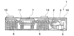
図3、図4に示すように、シート空調装置1は、座面部51と車室床面Fとの間に配置可能な箱体として構成された筐体10内部に、冷凍サイクル2と送風機7とを収容している。
As shown in FIGS. 3 and 4, the
冷凍サイクル2は、蒸気圧縮式の冷凍サイクルを構成し、空調対象空間である車室内のシート50周辺へ送風される送風空気を冷却或いは加熱する機能を果たす。当該冷凍サイクル2は、圧縮機3と、凝縮器4と、膨張弁5と、蒸発器6とを有している。
The
そして、当該冷凍サイクル2では、冷媒としてHFC系冷媒(具体的には、R134a)を採用しており、高圧側冷媒圧力が冷媒の臨界圧力を超えない蒸気圧縮式の亜臨界冷凍サイクルを構成している。もちろん、冷媒としてHFO系冷媒(例えば、R1234yf)や自然冷媒(例えば、R744)等を採用してもよい。更に、冷媒には圧縮機3を潤滑するための冷凍機油が混入されており、冷凍機油の一部は冷媒とともにサイクルを循環している。
The
図3に示すように、当該シート空調装置1では、送風機7が筐体10内部の中央部分に配置されている。この送風機7は、遠心多翼ファンを電動モータにて駆動する電動送風機である。送風機7は、遠心多翼ファンの回転軸が筐体10の上下方向に一致するように配置されている。従って、送風機7は、筐体10の上下方向に沿って空気を吸い込み、吸い込んだ空気を、軸に対して直交し、且つ、遠心方向へ送風する。送風機7における遠心多翼ファンの回転数(送風量)は、図示しない空調制御装置から出力される制御電圧によって制御される。
As shown in FIG. 3, in the
圧縮機3は、冷凍サイクル2において、冷媒を吸入し、圧縮して吐出するものである。圧縮機3は、シート空調装置1の筐体10内に配置されている。圧縮機3は、吐出容量が固定された固定容量型の圧縮機構を電動モータにて駆動する電動圧縮機として構成されている。この圧縮機構としては、スクロール型圧縮機構、ベーン型圧縮機構等の各種圧縮機構を採用することができる。
The
圧縮機3を構成する電動モータは、図示しない空調制御装置から出力される制御信号によって、その作動(回転数)が制御される。この電動モータとしては、交流モータ、直流モータの何れの形式を採用してもよい。そして、空調制御装置が電動モータの回転数を制御することによって、圧縮機構の冷媒吐出能力が変更される。
The operation (rotation speed) of the electric motor constituting the
圧縮機3の吐出口には、凝縮器4の冷媒入口側が接続されている。図3に示すように、凝縮器4は、筐体10内部において、送風機7の周囲を約180度の範囲にわたって囲むように配置された複数の熱交換器を冷媒管で接続して構成されている。従って、当該凝縮器4は、圧縮機3から吐出された高温高圧の吐出冷媒と、送風機7により送風された送風空気とを熱交換させることができ、送風空気を加熱することができる。即ち、凝縮器4は、加熱用熱交換器として機能する。
A refrigerant inlet side of the
凝縮器4の冷媒出口側には、膨張弁5が配置されている。当該膨張弁5は、冷媒流路の絞り開度を変更可能に構成されており、凝縮器4から流出した冷媒を減圧させる。膨張弁5は、本発明における減圧部として機能する。
An
尚、第1実施形態に係る減圧部としては、膨張弁5を用いているが、この態様に限定されるものではない。凝縮器4から流出した冷媒を減圧可能であれば、減圧部として、種々の構成を採用することができる。例えば、固定絞りやキャピラリーチューブを本発明の減圧部として採用しても良いし、空調制御装置の制御信号により絞り開度を制御可能な膨張弁を用いても良い。
Although the
膨張弁5の出口側には、蒸発器6の冷媒入口側が接続されている。図3に示すように、蒸発器6は、筐体10内部において、送風機7の周囲を約180度の範囲にわたって囲むように配置された複数の熱交換器を冷媒管で接続して構成されている。即ち、送風機7は、凝縮器4及び蒸発器6によって、その周囲を囲まれている。従って、当該蒸発器6は、膨張弁5から流出した冷媒と、送風機7により送風された送風空気とを熱交換させることができ、送風空気を冷却することができる。即ち、蒸発器6は、冷却用熱交換器として機能する。
The outlet side of the
そして、筐体10は、シート50の座面部51と車室床面Fの間のスペースに配置可能なサイズの箱型に形成されており、中央通気開口11と、複数の第1通気開口12及び複数の第2通気開口13とを、その上面に有している。
The
図3、図4に示すように、中央通気開口11は、筐体10の上面における中央部分に形成されており、送風機7における遠心多翼ファンの回転軸の直上部分を含むように開口している。当該中央通気開口11は、筐体10内部と外部とを連通しており、本発明における通気開口として機能する。従って、送風機7は、その作動に伴って、中央通気開口11を介して、筐体10の内部へ車室内の空気を吸い込むことができる。
As shown in FIGS. 3 and 4, the
第1通気開口12は、筐体10の上面における角部の内、凝縮器4側にあたる2つの角部に開口されており、筐体10内部と外部とを連通している。送風機7による送風空気の一部は、凝縮器4における熱交換により暖められた後、第1通気開口12から吹き出される。第1通気開口12は、本発明における通気口の一例である。
The
一方、第2通気開口13は、筐体10の上面における角部の内、蒸発器6側にあたる2つの角部に開口されており、筐体10内部と外部とを連通している。送風機7による送風空気の他の一部は、蒸発器6における熱交換により冷却された後、第2通気開口13から吹き出される。第2通気開口13も、本発明における通気口の一例である。
On the other hand, the second ventilation opening 13 is opened at two corners on the
第1実施形態において、中央通気開口11には、中央接続部材16が取り付けられている。中央接続部材16は、中空状に形成されており、シート50における座面部51の下面に接続されている。
In the first embodiment, a
ここで、シート50の座面部51は、その上部に、ウレタン等の多孔質材で構成されたクッション部を有しており、その弾力性によって、乗員との接触により発生する衝撃を緩和している。そして、座面部51は、この多孔質材からなるクッション部によって通気性を有している。
Here, the
従って、当該シート空調装置1は、中央通気開口11及び中央接続部材16を介して、通気性を有する座面部51の上方の空間との間で、空気を移動させることができ、座面部51上方の空間から吸気することができる。即ち、中央接続部材16は、本発明における接続部材の一例である。
Accordingly, the seat air-
そして、第1通気開口12には、中空状の第1接続部材17が取り付けられており、第2通気開口13には、中空状の第2接続部材18が取り付けられている。第1接続部材17、第2接続部材18は、それぞれ、座面部51内部に配置された図示しない空強風供給機構部を介して、後述するシートフレーム53の空調風供給口58や、後述するメインダクト21、脚部用ダクト23の端部と接続されている。
A first
従って、図6、図7に示すように、シート空調装置1は、第2シートフレーム57の各空調風吹出口59や、メインダクト21のメイン通風口22、及び脚部用ダクト23の脚部通風口24から、冷凍サイクル2によって調整された空調風を、シート50に座った乗員に対して供給することができる。即ち、第1接続部材17及び第2接続部材18は、本発明におけるダクト部材の一部として機能すると共に、本発明における筒状部材の一部として機能する。
Accordingly, as shown in FIGS. 6 and 7, the seat air-
図1、図2に示すように、シート50の両側面には、メインダクト21と、脚部用ダクト23とがそれぞれ配置されている。メインダクト21は、扁平な中空状に形成されており、シート50の側面に沿って、背もたれ部52中段まで伸びている。
As shown in FIGS. 1 and 2, a
メインダクト21の一端部は、背もたれ部52の中段に位置しており、メイン通風口22を有している。メイン通風口22は、メインダクト21内部と連通しており、シート50の側面に隣接する位置で、幅方向内側へやや湾曲するように形成されている。そして、メインダクト21の他端部は、図示しない空強風供給機構部を介して、第1接続部材17及び第1通気開口12、第2接続部材18及び第2通気開口13と接続されている。
One end of the
従って、シート空調装置1によって調整された空調風の一部は、メイン通風口22を介して、シート50に座った乗員に対して供給される。メイン通風口22が背もたれ部52の中段において幅方向やや内側に湾曲している為、シート空調装置1は、シート50に座った乗員の体幹部分に対して、より効率良く空調風を供給することができる。
Therefore, a part of the conditioned air adjusted by the
又、脚部用ダクト23は、中空状に形成されており、シート50の座面部51における側面に沿って伸びた後、上方に曲がっている。脚部用ダクト23の一端部は、座面部51の上面によりもやや上方に位置し脚部通風口24を有している。脚部通風口24は、シート50の側面に隣接する位置で、幅方向内側へやや湾曲するように形成されている。一方、脚部用ダクト23の他端部は、図示しない空強風供給機構部を介して、第1接続部材17及び第1通気開口12、第2接続部材18及び第2通気開口13と接続されている。
Further, the
従って、シート空調装置1によって調整された空調風の一部は、脚部通風口24を介して、シート50に座った乗員の脚部に対して供給される。脚部通風口24が座面部51上面よりも上方の位置において幅方向やや内側に湾曲している為、シート空調装置1は、シート50に座った乗員の太腿等の脚部に対して、より効率良く空調風を供給することができる。
Therefore, a part of the conditioned air adjusted by the
次に、シート50の構成について、図面を参照しつつ詳細に説明する。シート50は、電気自動車において乗員が座る為に配設されており、座面部51と、背もたれ部52と、シートフレーム53とを有している。座面部51は、乗員が着座する部分であり、その上面に多孔質製のクッション部を有している。
Next, the configuration of the
そして、背もたれ部52は、座面部51に座った乗員を背後から支持する部分を構成しており、その前面に多孔質製のクッション部を有している。そして、シート50は、座面部51及び背もたれ部52を、シートフレーム53で相対的な位置を固定することによって構成されている。
And the
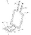
シートフレーム53は、金属パイプを組み合わせて構成されており、シート50の骨材部として機能すると同時に、シート空調装置1による空気の流路としても機能する。図5に示すように、シートフレーム53は、第1シートフレーム54と、第2シートフレーム57とによって構成されている。この第1シートフレーム54と第2シートフレーム57とは、図示しない補強部材で連結されており、その相対的な位置関係を維持している。
The
第1シートフレーム54は、座面部51のクッション部よりも下方において、座面部51の内部に配置されており、接続部55と、複数の通気孔56とを有している。接続部55は、第1シートフレーム54の端部に形成されており、座面部51の下面から突出するように配置されている。この接続部55には、中央接続部材16の端部が接続される。
The
複数の通気孔56は、第1シートフレーム54の上面における複数個所に配置されており、中空状の第1シートフレーム54内部と連通している。従って、第1実施形態に係るシート空調装置1は、座面部51の上方の空気を、座面部51のクッション部、第1シートフレーム54、中央接続部材16、中央通気開口11を介して、筐体10の内部へ吸い込むことができる。
The plurality of ventilation holes 56 are arranged at a plurality of locations on the upper surface of the
第2シートフレーム57は、背もたれ部52のクッション部よりも後方において、背もたれ部52の内部に配置されており、空調風供給口58と、複数の空調風吹出口59とを有している。空調風供給口58は、背もたれ部52の下端部に配置されており、図示しない空強風供給機構部を介して、第1接続部材17、第2接続部材18に接続されている。
The
図5に示すように、空調風吹出口59は、第2シートフレーム57の前面側における複数個所に配置されており、それぞれ中空状の第2シートフレーム57の内部と連通している。従って、第1実施形態に係るシート空調装置1は、第1通気開口12を介して吹き出される温風や第2通気開口13を介して吹き出される冷風等の空調風を、第1接続部材17、第2接続部材18、図示しない空強風供給機構部、第2シートフレーム57、背もたれ部52のクッション部を介して、車室内に吹き出させることができる。
As shown in FIG. 5, the air-
又、座面部51及び背もたれ部52のクッション部は、多孔質である為、シート空調装置1による空気の流れによって、座面部51、背もたれ部52におけるクッション部の温度調整をすることができる。
Further, since the cushion portions of the
次に、第1実施形態に係るシート空調装置1による空気流れAについて、図6、図7を参照しつつ詳細に説明する。尚、図6、図7において、矢印で示す空気流れAは、第1実施形態における代表的な空気の流れを示しており、この流れに限定されるものではない。
Next, the air flow A by the
上述したように、第1実施形態に係るシート空調装置1において、送風機7を作動させて遠心多翼ファンを回転させると、遠心多翼ファンの回転軸に沿って、空気が吸い込まれる。従って、シート空調装置1では、筐体10の上面に形成された中央通気開口11を介して、その上方にある空気が吸い込まれていく。
As described above, in the seat air-
中央通気開口11には、中央接続部材16を介して、第1シートフレーム54の接続部55が連結されている。更に、第1シートフレーム54は、シート50における座面部51のクッション部の下方に配置されており、複数の通気孔56を有している。従って、当該シート空調装置1は、座面部51のクッション部、第1シートフレーム54を介して、座面部51の上方の空気を筐体10の内部に吸い込むことができる。
The
筐体10の内部に吸い込まれた空気は、送風機7の遠心方向に送風され、凝縮器4や蒸発器6において冷媒と熱交換される。これにより、送風機7から送風される空気は、凝縮器4又は蒸発器6によって加熱又は冷却され、空調風として第1通気開口12、第2通気開口13から吹き出される。
The air sucked into the
図6、図7に矢印で示すように、空調風の空気流れAは、第1通気開口12、第2通気開口13等から筐体10外部へ吹き出されると、図示しない空強風供給機構部を介して、メインダクト21、脚部用ダクト23の内部を流れる。この時、空調風の一部は、当該空強風供給機構部を介して、第2シートフレーム57の内部へ供給される。
As shown by arrows in FIGS. 6 and 7, when the airflow A of the conditioned air is blown out of the
メインダクト21を流れた空調風は、背もたれ部52の左右両側に位置するメイン通風口22から前方斜め上方向に吹き出される。又、各メイン通風口22は、背もたれ部52の左右両側において、それぞれシート50の幅方向内側へ曲がっている。従って、空調風は、シート50に座っている乗員の体幹部分に向かって吹き出される。
The conditioned air flowing through the
又、脚部用ダクト23を流れた空調風は、座面部51の左右両側に位置する脚部通風口24から前方斜め上方向に吹き出される。そして、脚部通風口24は、座面部51の左右両側において、シート50の幅方向内側へ曲がっている。従って、空調風は、シート50に座っている乗員の脚部に向かって吹き出される。
The conditioned air that has flowed through the
一方、第2シートフレーム57を流れた空調風は、第2シートフレーム57に形成された各空調風供給口58から、背もたれ部52のクッション部を介して、シート50の前方に向かって吹き出される。
On the other hand, the conditioned air flowing through the
従って、第1実施形態に係るシート空調装置1によれば、シート50の前方側における一定の範囲に対して、空調風を供給することができる。この空調風が供給される範囲は、シート50に座った乗員が位置する範囲に相当する。即ち、当該シート空調装置1によれば、空調風を供給することによって、シート50に座った乗員の快適性を効率よく高めることができる。
Therefore, according to the
そして、図6、図7に示すように、空調風が吹き出されるシートの前面における一定の範囲は、シート50における座面部51の上方に位置する。上述したように、第1実施形態に係るシート空調装置1は、送風機7の作動によって、座面部51の上方の空気を、座面部51のクッション部等を介して、中央通気開口11から筐体10内部へと吸い込む。従って、第1実施形態に係るシート空調装置1によれば、シート空調装置1と、シート50に座った乗員が存在する空間の間を循環する空気流れAをつくりだすことができる。
As shown in FIGS. 6 and 7, a certain range on the front surface of the seat from which the conditioned air is blown out is located above the
ここで、第1実施形態に係るシート空調装置1において、空調風として冷風を供給する場合について考察する。上述したように、シート空調装置1では、中央通気開口11から吸い込んだ空気を、蒸発器6で冷媒と熱交換することで冷却し、冷風として第2通気開口13から筐体10外部へ吹き出している。
Here, in the seat air-
この場合において、蒸発器6における熱交換対象である空気の温度が高いと、蒸発器6での熱交換後の空気の温度も高くなってしまう。この為、冷風を供給することで、シート50に座った乗員の快適性を高める上では、中央通気開口11から吸い込まれる空気の温度が重要となる。
In this case, if the temperature of the air to be heat-exchanged in the
上述したように、第1実施形態に係るシート空調装置1において、蒸発器6での熱交換の対象となる空気は、中央通気開口11から吸い込まれた座面部51上方の空気である。この座面部51上方の空気は、車室床面F近傍の空気よりも日射等の影響を受けにくく、車室床面F近傍の空気よりも低い温度を示す。
As described above, in the seat air-
従って、第1実施形態に係るシート空調装置1によれば、車室床面F近傍の空気よりも低い温度の空気を、座面部51上方から吸い込むことができるので、車室床面F近傍の空気を吸い込んで蒸発器6で熱交換させる場合に比べて、蒸発器6での熱交換後による冷風の温度を低くすることができ、冷風送風時における効率の向上を図ることができる。
Therefore, according to the
又、車室床面Fには、重力等の影響により必然的に塵や埃が堆積していることが想定される。そうすると、仮に、シート空調装置1が車室床面F近傍の空気を吸い込む構成であるとすると、シート空調装置1は、送風機7の作動に伴う空気の吸込みに伴って、塵や埃も筐体10内部に吸い込んでしまう。
It is also assumed that dust and dirt are inevitably deposited on the vehicle floor F due to the influence of gravity and the like. Then, assuming that the seat air-
この場合、筐体10内部に吸い込まれた塵や埃は、送風機7等の故障要因となったり、凝縮器4や蒸発器6における通風抵抗となり、冷媒との熱交換効率を低下させたりすることが考えられる。
In this case, dust or dirt sucked into the inside of the
この点、第1実施形態に係るシート空調装置1は、図6、図7に示すように、筐体10の上面に形成された中央通気開口11を介して、座面部51の上方の空気を吸い込むように構成されている為、車室床面Fに堆積している塵や埃等を吸い込むことはない。即ち、シート空調装置1は、筐体10内に吸い込まれた埃等に起因する冷凍サイクルの空調性能の低下を抑制すると共に、埃等に起因する故障を防止することができる。
In this regard, as shown in FIGS. 6 and 7, the seat air-
更に、第1実施形態に係るシート空調装置1によれば、図6、図7に示すように、シート空調装置1と、シート50に座った乗員が存在する空間の間を循環する空気流れAをつくりだすことができる。この循環する空気流れAによれば、シート50に座った乗員が存在する空間に吹き出した冷風の一部が、座面部51のクッション部、中央通気開口11を介して、シート空調装置1における筐体10内部に吸い込まれることになる。
Further, according to the
これにより、シート空調装置1によれば、少なくとも冷風として吹き出された空気の一部を、蒸発器6における熱交換対象である空気として利用することができる。即ち、シート空調装置1によれば、蒸発器6における熱交換対象の空気の温度を低下させることができ、冷風送風時における空調性能の向上を図ることができる。
Thus, according to the seat air-
以上説明したように、第1実施形態に係るシート空調装置1は、シート50の座面部51と車室床面Fとの間のスペースに配置された筐体10内部に、冷凍サイクル2と送風機7を収容している。当該シート空調装置1は、送風機7によって送風される空気を、冷凍サイクル2で温度調整して送風することで、シート50に座った乗員の快適性を高めている。
As described above, the
この第1実施形態に係るシート空調装置1によれば、冷凍サイクル2による空調風として送風される空気は、筐体10の上面に形成された中央通気開口11を介して吸い込まれた空気を用いて生成される。中央通気開口11は、筐体10の上面に形成されている為、筐体10の上面よりも上方の空気を吸い込むように構成されている。
According to the seat air-
従って、第1実施形態に係るシート空調装置1によれば、日射等の影響を受けやすい車室床面F近傍の空気ではなく、筐体10上面よりも上方の空気を用いて、冷凍サイクル2による空調を行うことができるので、シート空調装置1における空調性能を高めることができる。
Therefore, according to the seat air-
又、車室床面F近傍の空気を筐体10内部に吸い込む構成の場合、車室床面Fに堆積している塵や埃も吸い込んでしまう場合がある。この点、当該シート空調装置1によれば、筐体10上面に形成された中央通気開口11を介して、空気を吸い込んでいる為、車室床面F近傍の空気を吸い込む場合に比べて、塵や埃の吸い込みを抑制することができる。これにより、シート空調装置1は、埃等に起因する冷凍サイクルの空調性能の低下を抑制すると共に、埃等に起因するシート空調装置1の故障を防止できる。
Moreover, in the case of a configuration in which air near the vehicle floor F is sucked into the inside of the
そして、当該シート空調装置1においては、中央通気開口11に対して、中央接続部材16が取り付けられており、当該中央接続部材16は、シート50を構成する座面部51内部に配置された第1シートフレーム54の接続部55に接続されている。第1シートフレーム54は、座面部51内部において、通気性を有するクッション部の下方に配置されており、複数の通気孔56を有している。
In the
従って、当該シート空調装置1は、送風機7の作動により、中央通気開口11から空気を吸い込む際に、中央接続部材16、第1シートフレーム54及び座面部51のクッション部を介して、座面部51の上方の空気を吸い込むことができる。座面部51の上方の空気は、車室床面Fに対して、筐体10上面よりも更に上方に位置し、日射等の影響が小さい為、より低温であり、塵や埃も少ない。
Therefore, when air is sucked from the
この結果、当該シート空調装置1によれば、座面部51等を介して、中央通気開口11から空気を吸い込むことで、より空調性能を向上させることができ、塵や埃に起因する故障の発生や空調性能の低下を防止できる。
As a result, according to the seat air-
そして、当該シート空調装置1においては、第1通気開口12、第2通気開口13が筐体10の上面に形成されており、メインダクト21及び脚部用ダクト23に接続されている。図6、図7に示すように、メインダクト21のメイン通風口22、脚部用ダクト23の脚部通風口24は、それぞれシート50の側面部に配置されており、シート50に乗員が座る部分に対して、空調風を吹き出すように構成されている。
In the
従って、当該シート空調装置1によれば、冷凍サイクル2により調整された空調風を、シート50に座っている乗員に対して効率よく供給することができ、快適な環境を効率よく実現することができる。
Therefore, according to the
そして、図6、図7に示すように、シート空調装置1では、空調風は、メインダクト21のメイン通風口22や、脚部用ダクト23の脚部通風口24から、シート50の前方部分に吹き出される。シート50の前面部分の空気は、座面部51のクッション部、第1シートフレーム54等を介して、中央通気開口11から筐体10内部に吸い込まれる。
As shown in FIGS. 6 and 7, in the seat air-
即ち、当該シート空調装置1は、シート空調装置1と、シート50の前面部分とを経由する空気流れAをつくりだすことができ、この空気流れAを循環させることができる。これにより、シート空調装置1は、冷風供給時におけるシート空調装置1の空調性能を高めることができる。
That is, the
又、第1通気開口12、第2通気開口13は、第1接続部材17、第2接続部材18を介して、第2シートフレーム57に接続されている。図5に示すように、第2シートフレーム57は、複数の空調風吹出口59を有しており、背もたれ部52内部において、通気性を有するクッション部の後方に配置されている。
The
従って、当該シート空調装置1は、背もたれ部52のクッション部を介して、冷凍サイクル2により調整された空調風を供給することができ、シート50に座った乗員に快適な環境を提供することができる。
Therefore, the
そして、当該シート空調装置1では、空調風は、第2シートフレーム57における複数の空調風吹出口59から、背もたれ部52のクッション部を介して、シート50の前方部分に吹き出される。シート50の前面部分の空気は、座面部51のクッション部、第1シートフレーム54等を介して、中央通気開口11から筐体10内部に吸い込まれる。
In the
即ち、当該シート空調装置1は、背もたれ部52のクッション部から吹き出された空調風も含めて、シート空調装置1と、シート50の前面部分とを経由する空気流れAをつくりだすことができ、この空気流れAを循環させることができる。これにより、シート空調装置1は、冷風供給時におけるシート空調装置1の空調性能を高めることができる。
That is, the
(第2実施形態)
続いて、上述した第1実施形態とは異なる第2実施形態について、図面を参照しつつ説明する。第2実施形態に係るシート空調装置1は、第1実施形態と同様に、バッテリの電力で走行する電気自動車の空調に適用されている。そして、以下の説明において、第1実施形態と同じ符号は、同一の構成を示すものであって、先行する説明を参照する。
(2nd Embodiment)
Next, a second embodiment different from the above-described first embodiment will be described with reference to the drawings. The
図8、図9に示すように、第2実施形態におけるシート空調装置1は、第1実施形態と同様に、電気自動車のシート50の座面部51と車室床面Fとの間の小さなスペースに配置されており、シート50を介した空気流れAを作り出すことで、シート50に座った乗員の快適性を高めている。
As shown in FIGS. 8 and 9, the
そして、当該シート空調装置1は、第1実施形態と同様に、蒸気圧縮式の冷凍サイクル2と、遠心多翼ファンを用いた送風機7とを、箱体状に形成された筐体10の内部に収容している。冷凍サイクル2は、圧縮機3と、凝縮器4と、膨張弁5と、蒸発器6とを冷媒管で接続して構成されている。
The
第2実施形態に係るシート空調装置1における筐体10内部の配置は、第1実施形態と同様であり、冷凍サイクル2の構成装置及び送風機7は、図3、図4に示す配置で収容されている。
The arrangement inside the
又、第2実施形態に係る筐体10の上面には、第1実施形態と同様に、中央通気開口11と、第1通気開口12と、第2通気開口13とが形成されている。第1通気開口12及び第2通気開口13には、第1実施形態と同様に、第1接続部材17及び第2接続部材18が取り付けられている。第1接続部材17及び第2接続部材18は、図示しない空強風供給機構部を介して、メインダクト21、脚部用ダクト23及び第2シートフレーム57に接続されている。
In addition, a
ここで、第2実施形態においては、中央通気開口11には、第1実施形態における中央接続部材16は接続されていない。従って、中央通気開口11は、シート50の座面部51の下面と、筐体10上面との間の空間に対して連通している。従って、第2実施形態においては、筐体10上面と座面部51の間の空気が、送風機7の作動に伴って筐体10内部に吸い込まれる。
Here, in the second embodiment, the
尚、第2実施形態におけるメインダクト21、脚部用ダクト23の構成や、シート50の構成については、第1実施形態と同様である為、再度の説明は省略する。
Note that the configuration of the
続いて、第2実施形態に係るシート空調装置1による空気流れAについて、図8、図9を参照しつつ詳細に説明する。尚、図8、図9においても、矢印で示す空気流れAは、第2実施形態における代表的な空気の流れを示しており、この流れに限定されるものではない。
Subsequently, the air flow A by the
第2実施形態に係るシート空調装置1において、送風機7を作動させて遠心多翼ファンを回転させると、遠心多翼ファンの回転軸に沿って空気が吸い込まれる。従って、シート空調装置1では、筐体10の上面に形成された中央通気開口11を介して、筐体10上面と座面部51の間にある空気が筐体10の内部に吸い込まれていく。
In the
筐体10の内部に吸い込まれた空気は、送風機7の遠心方向に送風され、凝縮器4や蒸発器6において冷媒と熱交換される。これにより、送風機7から送風される空気は、凝縮器4又は蒸発器6によって加熱又は冷却され、空調風として第1通気開口12、第2通気開口13から吹き出される。
The air sucked into the
図8、図9に矢印で示すように、空調風の空気流れAは、第1通気開口12、第2通気開口13等から筐体10外部へ吹き出されると、図示しない空強風供給機構部を介して、メインダクト21、脚部用ダクト23の内部を流れる。この時、空調風の一部は、当該空強風供給機構部を介して、第2シートフレーム57の内部へ供給される。
As shown by the arrows in FIGS. 8 and 9, when the airflow A of the conditioned air is blown out of the
メインダクト21を流れた空調風は、背もたれ部52の左右両側に位置するメイン通風口22から前方斜め上方向に吹き出される。又、各メイン通風口22は、背もたれ部52の左右両側において、それぞれシート50の幅方向内側へ曲がっている。従って、第2実施形態においても、空調風は、シート50に座っている乗員の体幹部分に向かって吹き出される。
The conditioned air flowing through the
又、第2実施形態においても、脚部用ダクト23を流れた空調風は、座面部51の左右両側に位置する脚部通風口24から前方斜め上方向に吹き出される。そして、脚部通風口24は、座面部51の左右両側において、シート50の幅方向内側へ曲がっている。従って、空調風は、シート50に座っている乗員の脚部に向かって吹き出される。
Also in the second embodiment, the conditioned air flowing through the
一方、第2シートフレーム57を流れた空調風は、第2シートフレーム57の各空調風供給口58から、背もたれ部52のクッション部を介して、シート50の前方に向かって吹き出される。
On the other hand, the conditioned air that has flowed through the
従って、第2実施形態に係るシート空調装置1によれば、シート50の前方側の空間に対して、空調風を供給することができる。即ち、当該シート空調装置1によれば、空調風を供給することによって、シート50に座った乗員の快適性を効率よく高めることができる。
Therefore, according to the
第2実施形態においては、シート50の前方側の空間に吹き出された空調風は、シート50に座った乗員に直接供給されるだけではなく、当該シート50周辺の空調としても機能する。即ち、第2実施形態に係るシート空調装置1は、第1実施形態よりも低い割合ではあるが、冷凍サイクル2により温度調整された空調風を、筐体10上面と座面部51との間のスペースを介して、中央通気開口11から再び筐体10内部に吸い込むことができる。
In the second embodiment, the conditioned air blown into the space on the front side of the
従って、当該シート空調装置1は、第1実施形態と同様に、冷風として吹き出された空気の一部を、蒸発器6における熱交換対象である空気として利用することができる。即ち、シート空調装置1によれば、蒸発器6における熱交換対象の空気の温度を低下させることができ、冷風送風時における空調性能の向上を図ることができる。
Therefore, the
以上説明したように、第2実施形態に係るシート空調装置1は、シート50の座面部51と車室床面Fとの間のスペースに配置された筐体10内部に、冷凍サイクル2と送風機7を収容している。当該シート空調装置1は、送風機7によって送風される空気を、冷凍サイクル2で温度調整して送風することで、シート50に座った乗員の快適性を高めている。
As described above, the
この第2実施形態に係るシート空調装置1によれば、第1実施形態と同様に、冷凍サイクル2による空調風として送風される空気は、筐体10の上面に形成された中央通気開口11を介して吸い込まれた空気を用いて生成される。中央通気開口11は、筐体10の上面に形成されている為、筐体10の上面よりも上方の空気を吸い込むように構成されている。
According to the
従って、第2実施形態に係るシート空調装置1によれば、日射等の影響を受けやすい車室床面F近傍空気ではなく、筐体10上面よりも上方の空気を用いて、冷凍サイクル2による空調を行うことができる。これにより、第2実施形態に係るシート空調装置1は、空調風を生成する為の空気の所在を限定することで、その空調性能を高めることができる。
Therefore, according to the
又、第2実施形態においては、中央通気開口11を介して、筐体10上面と座面部51の間の空気を吸い込んでいる為、車室床面F近傍の空気を吸い込む場合に比べて、塵や埃の吸い込みを抑制することができる。これにより、シート空調装置1は、埃等に起因する冷凍サイクルの空調性能の低下を抑制すると共に、埃等に起因するシート空調装置1の故障を防止できる。
Further, in the second embodiment, since the air between the upper surface of the
又、第2実施形態に係るシート空調装置1によれば、冷凍サイクル2により調整された空調風を、メインダクト21、脚部用ダクト23を介して、シート50に座っている乗員に対して効率よく供給することができる。そして、当該シート空調装置1は、第1実施形態と同様に、冷凍サイクル2により調整されて空調風を、第2シートフレーム57及び背もたれ部52のクッション部を介して、シート50に座っている乗員に効率よく供給することができる。即ち、第2実施形態に係るシート空調装置1は、第1実施形態と同様に、シート50に座っている乗員が快適な環境を効率よく実現することができる。
Further, according to the
又、第2実施形態に係るシート空調装置1において、メインダクト21、脚部用ダクト23、第2シートフレーム57等を介して吹き出された空調風は、シート50に座っている乗員のみならず、シート50の周辺の空調としても機能する。
Further, in the
従って、第2実施形態に係るシート空調装置1は、冷凍サイクル2によって調整された空調風の一部を、筐体10上面と座面部51との間のスペースを介して、中央通気開口11から筐体10の内部に吸い込むことができる。これにより、当該シート空調装置1は、冷風供給時におけるシート空調装置1の空調性能を高めることができる。
Therefore, the seat air-
(他の実施形態)
以上、実施形態に基づき本発明を説明したが、本発明は上述した実施形態に何ら限定されるものではない。即ち、本発明の趣旨を逸脱しない範囲内で種々の改良変更が可能である。例えば、上述した各実施形態を適宜組み合わせても良い。又、上述した実施形態を、例えば、以下のように種々変形することも可能である。
(Other embodiments)
As described above, the present invention has been described based on the embodiments, but the present invention is not limited to the above-described embodiments. That is, various modifications can be made without departing from the spirit of the present invention. For example, the above-described embodiments may be appropriately combined. Further, the above-described embodiment can be variously modified as follows, for example.
(1)上述した各実施形態では、筐体10の上面に形成された中央通気開口11を、筐体10の内部に空気を吸い込む為の開口部としていたが、この態様に限定されるものではない。例えば、この中央通気開口11に加えて、筐体10の側面に補助通気開口を形成して、当該補助通気開口から、筐体10外部の空気を内部へ吸い込むように構成することも可能である。この場合に、補助通気開口は、筐体10の側面における上側部分に形成されていることが望ましい。車室床面F近傍の空気や埃等を、できるだけ筐体10内部に吸い込まないようにする為である。
(1) In each of the embodiments described above, the
(2)又、上述した各実施形態においては、送風機7を、遠心多翼ファンを用いた送風機としていたが、送風機7の形式は、これに限定されるものではない。例えば、送風機7として、軸流式送風機、斜流式送風機、貫流式送風機を採用することも可能である。
(2) Further, in each of the above-described embodiments, the
(3)更に、シート空調装置1の送風機7の作動に伴う空気流れAも、中央通気開口11から吸い込み、第1通気開口12、第2通気開口13を介して、筐体10外部へ吹き出す態様を実現可能であれば、この空気流れAのみに限定されるものではない。即ち、上述した実施形態における空気流れAとは、逆向きの空気流れを実現可能な構成とすることも可能である。
(3) A mode in which the air flow A accompanying the operation of the
具体的には、メインダクト21、脚部用ダクト23から、第1通気開口12、第2通気開口13を介して吸込み、中央通気開口11から吹き出すように構成することも可能である。例えば、送風機7を軸流式送風機に変更して、筐体10の底面における中央部分に整流部材を配置する。この場合の整流部材は、軸流式送風機による空気流れを、羽根車の回転軸方向と水平方向との間で変換する機能を有する。
Specifically, it is also possible to adopt a configuration in which the air is sucked from the
このように構成して、軸流式送風機の回転方向を、中央通気開口11から空気を吸い込む場合と逆方向にすれば、中央通気開口11を介して吸い込む場合と、第1通気開口12等から吸い込む場合との両者を実現することができる。
With such a configuration, if the rotation direction of the axial-flow type blower is set to the opposite direction to the case where air is sucked from the
この場合においても、メインダクト21のメイン通風口22及び、脚部用ダクト23の脚部通風口24は、座面部51よりも上方に位置する為、埃等を吸い込むことなく、日射等により暖められた車室床面F近傍の空気の影響を抑制できる。
Also in this case, the
(4)そして、上述した実施形態におけるメインダクト21におけるメイン通風口22の配置、脚部用ダクト23における脚部通風口24の配置は、あくまでも一例であり、これに限定されるものではない。メインダクト21のメイン通風口22や、脚部用ダクト23の脚部通風口24は、シート50の側面部に位置していればよく、その具体的な配置を適宜変更することができる。
(4) The arrangement of the
(5)又、上述した第1実施形態においては、シート空調装置1は、座面部51の上方に位置する空気を中央通気開口11から吸い込む際に、座面部51のクッション部、第1シートフレーム54を介して吸い込んでいたが、この態様に限定されるものではない。
(5) In the above-described first embodiment, the seat air-
例えば、座面部51上方で且つ背もたれ部52の前方の空気を、背もたれ部52のクッション部、第2シートフレーム57を介して、中央通気開口11から筐体10内部に吸い込むように構成しても良い。具体的には、中央接続部材16と第2シートフレーム57を接続すれば、この態様を実現することができる。更に、第1シートフレーム54を介した流れと、第2シートフレーム57を介した流れを併用して、当該空気を筐体10内部に吸い込むように構成することも可能である。
For example, a configuration may be adopted in which air above the
(6)そして、上述した実施形態においては、シート50の座面部51における下面に対して、シート空調装置1を固定することによって、シート空調装置1をシート50と共に車両の前後方向へスライド移動可能に配置していたが、この態様に限定されるものではない。
(6) In the above-described embodiment, the
例えば、シート空調装置1の筐体10を車室床面Fの所定位置に固定しておき、伸縮自在な筒状に形成された中央接続部材16、第1接続部材17、第2接続部材18で、筐体10の中央通気開口11、第1通気開口12、第2通気開口13と、シート50側と接続するように構成しても良い。この場合における中央接続部材16等は、例えば、蛇腹状に形成されたフレキシブルダクトにより構成することができる。
For example, the
1 シート空調装置
3 圧縮機
4 凝縮器
5 膨張弁
6 蒸発器
7 送風機
10 筐体
11 中央通気開口
51 座面部
F 車室床面
DESCRIPTION OF
Claims (4)
冷媒を圧縮して吐出する圧縮機(3)と、
前記圧縮機から吐出された冷媒を放熱させる凝縮器(4)と、
前記凝縮器から流出した冷媒を減圧させる減圧部(5)と、
前記減圧部にて減圧された冷媒を蒸発させる蒸発器(6)と、
前記冷媒との熱交換の対象である空気を送風する送風機(7)と、を前記筐体の内部に有し、
前記送風機は、前記筐体の上面に形成された通気開口(11)を介して、前記空気を吸い込み可能に構成されており、
更に、前記筐体の内部と外部とを連通する通気口(12、13)と、
前記通気口に対して一端が接続され、前記送風機の作動により前記空気が流れるダクト部材(17、18、21、22)と、
前記通気開口に対して一端が接続されると共に、他端が前記座面部の下面に対して連結されており、前記空気が流れる接続部材(16)と、を有し、
前記ダクト部材の他端は、前記シートの側面に対して隣接して配置され、
前記送風機は、前記筐体外部から空気を吸い込む際に、前記座面部及び前記接続部材を介して、前記通気開口から前記空気を吸い込み、当該空気を前記通気口及び前記ダクト部材を介して吹き出すシート空調装置。 A housing (10) disposed in a space formed below the seat surface (51) of the seat (50) in the vehicle interior and above the vehicle floor (F);
A compressor (3) for compressing and discharging the refrigerant;
A condenser (4) for radiating heat of the refrigerant discharged from the compressor;
A pressure reducing unit (5) for reducing the pressure of the refrigerant flowing out of the condenser;
An evaporator (6) for evaporating the refrigerant decompressed by the decompression unit;
A blower (7) for blowing air to be subjected to heat exchange with the refrigerant, inside the housing,
The blower is configured to be able to suck the air through a ventilation opening (11) formed on an upper surface of the housing ,
A vent (12, 13) for communicating the inside and the outside of the housing;
A duct member (17, 18, 21, 22) having one end connected to the ventilation port and through which the air flows by operation of the blower;
A connection member having one end connected to the ventilation opening and the other end connected to the lower surface of the seating surface portion, through which the air flows;
The other end of the duct member is disposed adjacent to a side surface of the seat,
The air blower, when sucking air from the outside of the housing, through the seat surface and the connection member, sucks the air from the ventilation opening, and blows the air through the ventilation hole and the duct member. Air conditioner.
前記通気口に対して一端が接続され、前記送風機の作動により前記空気が流れる筒状部材(17、18、53)と、を有しており、
前記筒状部材は、通気性を有する前記シートの内部と連通している請求項1に記載のシート空調装置。 Vents (12, 13) for communicating between the inside and the outside of the housing;
A cylindrical member (17, 18, 53), one end of which is connected to the vent, and through which the air flows by operation of the blower;
The seat air conditioner according to claim 1, wherein the tubular member communicates with the inside of the seat having air permeability.
冷媒を圧縮して吐出する圧縮機(3)と、
前記圧縮機から吐出された冷媒を放熱させる凝縮器(4)と、
前記凝縮器から流出した冷媒を減圧させる減圧部(5)と、
前記減圧部にて減圧された冷媒を蒸発させる蒸発器(6)と、
前記冷媒との熱交換の対象である空気を送風する送風機(7)と、を前記筐体の内部に有し、
前記送風機は、前記筐体の上面に形成された通気開口(11)を介して、前記空気を吸い込み可能に構成されており、
更に、前記筐体の内部と外部とを連通する通気口(12、13)と、
前記通気口に対して一端が接続され、前記送風機の作動により前記空気が流れる筒状部材(17、18、53)と、
前記通気開口に対して一端が接続されると共に、他端が前記座面部の下面に対して連結されており、前記空気が流れる接続部材(16)と、を有し、
前記筒状部材は、通気性を有する前記シートの内部と連通し、
前記送風機は、前記筐体外部から空気を吸い込む際に、前記座面部及び前記接続部材を介して、前記通気開口から前記空気を吸い込み、当該空気を前記通気口、前記筒状部材及び前記シートを介して吹き出すシート空調装置。 A housing (10) disposed in a space formed below the seat surface (51) of the seat (50) in the vehicle interior and above the vehicle floor (F);
A compressor (3) for compressing and discharging the refrigerant;
A condenser (4) for radiating the refrigerant discharged from the compressor,
A pressure reducing unit (5) for reducing the pressure of the refrigerant flowing out of the condenser;
An evaporator (6) for evaporating the refrigerant decompressed by the decompression unit;
A blower (7) for blowing air to be subjected to heat exchange with the refrigerant, inside the housing,
The blower is configured to be able to suck the air through a ventilation opening (11) formed on an upper surface of the housing,
A vent (12, 13) for communicating the inside and the outside of the housing;
A tubular member (17, 18, 53), one end of which is connected to the vent, through which the air flows by operation of the blower;
A connection member having one end connected to the ventilation opening and the other end connected to the lower surface of the seating surface portion, through which the air flows;
The tubular member communicates with the inside of the sheet having air permeability,
The air blower, when sucking air from outside the housing, sucks the air from the ventilation opening through the seat surface and the connection member, and sends the air to the ventilation port, the tubular member, and the sheet. Seat air conditioner blowing out through .
Priority Applications (5)
| Application Number | Priority Date | Filing Date | Title |
|---|---|---|---|
| JP2017010520A JP6658570B2 (en) | 2017-01-24 | 2017-01-24 | Seat air conditioner |
| DE112017006907.6T DE112017006907T5 (en) | 2017-01-24 | 2017-12-12 | Seat air conditioning |
| PCT/JP2017/044462 WO2018139080A1 (en) | 2017-01-24 | 2017-12-12 | Seat air-conditioning device |
| CN201780081600.7A CN110121440B (en) | 2017-01-24 | 2017-12-12 | Air conditioning device for seat |
| US16/439,890 US11091075B2 (en) | 2017-01-24 | 2019-06-13 | Seat air conditioner |
Applications Claiming Priority (1)
| Application Number | Priority Date | Filing Date | Title |
|---|---|---|---|
| JP2017010520A JP6658570B2 (en) | 2017-01-24 | 2017-01-24 | Seat air conditioner |
Publications (3)
| Publication Number | Publication Date |
|---|---|
| JP2018118588A JP2018118588A (en) | 2018-08-02 |
| JP2018118588A5 JP2018118588A5 (en) | 2019-02-21 |
| JP6658570B2 true JP6658570B2 (en) | 2020-03-04 |
Family
ID=62978959
Family Applications (1)
| Application Number | Title | Priority Date | Filing Date |
|---|---|---|---|
| JP2017010520A Expired - Fee Related JP6658570B2 (en) | 2017-01-24 | 2017-01-24 | Seat air conditioner |
Country Status (5)
| Country | Link |
|---|---|
| US (1) | US11091075B2 (en) |
| JP (1) | JP6658570B2 (en) |
| CN (1) | CN110121440B (en) |
| DE (1) | DE112017006907T5 (en) |
| WO (1) | WO2018139080A1 (en) |
Families Citing this family (5)
| Publication number | Priority date | Publication date | Assignee | Title |
|---|---|---|---|---|
| JP6772879B2 (en) * | 2017-02-14 | 2020-10-21 | 株式会社デンソー | Seat air conditioner |
| JP6658679B2 (en) * | 2017-06-20 | 2020-03-04 | 株式会社デンソー | Seat air conditioner |
| JP6766762B2 (en) * | 2017-06-22 | 2020-10-14 | 株式会社デンソー | Seat air conditioning system |
| US10773615B2 (en) * | 2018-05-03 | 2020-09-15 | Ford Global Technologies, Llc | Vehicle seating assembly with ventilated cooling |
| JP7059783B2 (en) * | 2018-05-07 | 2022-04-26 | 株式会社デンソー | Air conditioning system for passenger compartment |
Family Cites Families (17)
| Publication number | Priority date | Publication date | Assignee | Title |
|---|---|---|---|---|
| JPS5344841U (en) * | 1976-09-21 | 1978-04-17 | ||
| CN2076939U (en) * | 1990-08-03 | 1991-05-15 | 郭长青 | Automobile tempering chair cushion |
| JP3301109B2 (en) * | 1991-11-14 | 2002-07-15 | 株式会社デンソー | Air conditioning system for seats |
| US5275017A (en) * | 1992-07-22 | 1994-01-04 | Clardy Manufacturing, Inc. | Condenser apparatus |
| US5626387A (en) * | 1995-02-27 | 1997-05-06 | Yeh; Ching-Hsiu | Cushion with cooling stubs |
| SE504942C2 (en) * | 1995-09-14 | 1997-06-02 | Walinov Ab | Device for ventilating a vehicle seat |
| JP3633777B2 (en) * | 1997-06-03 | 2005-03-30 | 株式会社デンソー | Vehicle seat air conditioner |
| US6105667A (en) * | 1998-03-12 | 2000-08-22 | Denso Corporation | Air conditioning apparatus for vehicle seat |
| CN1285288A (en) * | 1999-08-23 | 2001-02-28 | 圣州企业股份有限公司 | Implement for blowing cold/hot air in car |
| JP2005348997A (en) * | 2004-06-11 | 2005-12-22 | Matsushita Electric Ind Co Ltd | Seat device for vehicle |
| DE112006000384T5 (en) * | 2005-02-17 | 2008-01-03 | W.E.T. Automotive Systems Ag | Active ventilation systems for vehicle seats |
| KR100868961B1 (en) * | 2007-11-02 | 2008-11-17 | 한국델파이주식회사 | Air conditioner for vehicle |
| JP2011121461A (en) * | 2009-12-10 | 2011-06-23 | Sanden Corp | Vehicular air conditioner |
| US20120013153A1 (en) * | 2010-07-16 | 2012-01-19 | Southern Taiwan University Of Technology | Air-conditioned chair |
| US9975394B2 (en) * | 2011-12-23 | 2018-05-22 | Faurecia Automotive Seating, Llc | Airflow management system for vehicle seat |
| JP6439476B2 (en) * | 2015-02-09 | 2018-12-19 | 株式会社デンソー | Seat air conditioner |
| JP2017010520A (en) | 2015-06-25 | 2017-01-12 | パナソニックIpマネジメント株式会社 | Agent control method, agent control device, and multiagent system |
-
2017
- 2017-01-24 JP JP2017010520A patent/JP6658570B2/en not_active Expired - Fee Related
- 2017-12-12 CN CN201780081600.7A patent/CN110121440B/en active Active
- 2017-12-12 DE DE112017006907.6T patent/DE112017006907T5/en not_active Withdrawn
- 2017-12-12 WO PCT/JP2017/044462 patent/WO2018139080A1/en active Application Filing
-
2019
- 2019-06-13 US US16/439,890 patent/US11091075B2/en active Active
Also Published As
| Publication number | Publication date |
|---|---|
| WO2018139080A1 (en) | 2018-08-02 |
| US11091075B2 (en) | 2021-08-17 |
| CN110121440B (en) | 2022-03-15 |
| US20190291614A1 (en) | 2019-09-26 |
| DE112017006907T5 (en) | 2019-10-02 |
| CN110121440A (en) | 2019-08-13 |
| JP2018118588A (en) | 2018-08-02 |
Similar Documents
| Publication | Publication Date | Title |
|---|---|---|
| JP6658570B2 (en) | Seat air conditioner | |
| US11325441B2 (en) | Seat air conditioner | |
| JP2019006373A (en) | Seat air-conditioning device | |
| JP6197616B2 (en) | Blower for vehicle | |
| JP7059783B2 (en) | Air conditioning system for passenger compartment | |
| US11338642B2 (en) | Vehicle cabin air conditioning system | |
| JP6699632B2 (en) | Vehicle air conditioner | |
| JP2016137846A (en) | Seat and seat blower apparatus | |
| JP2019006198A (en) | Seat air-conditioning system | |
| WO2018150783A1 (en) | Air conditioning device for vehicles | |
| WO2018235551A1 (en) | Seat air-conditioning device | |
| JP2018177190A (en) | Vehicle air conditioner | |
| KR20200119522A (en) | Armrest console and vehicle including the same | |
| JP7147228B2 (en) | Air conditioner | |
| JP7159856B2 (en) | Air conditioner | |
| JP7129297B2 (en) | vehicle air conditioner | |
| WO2020066383A1 (en) | Vehicle air conditioning device | |
| JP7025824B2 (en) | Vehicle air conditioner | |
| WO2018186125A1 (en) | Air conditioner for vehicle | |
| JP2020037308A (en) | Vehicular air-conditioning system | |
| JP2019142412A (en) | Vehicle air conditioner | |
| JP2001150939A (en) | Air conditioner for vehicle |
Legal Events
| Date | Code | Title | Description |
|---|---|---|---|
| A521 | Request for written amendment filed |
Free format text: JAPANESE INTERMEDIATE CODE: A523 Effective date: 20190108 |
|
| A621 | Written request for application examination |
Free format text: JAPANESE INTERMEDIATE CODE: A621 Effective date: 20190117 |
|
| TRDD | Decision of grant or rejection written | ||
| A01 | Written decision to grant a patent or to grant a registration (utility model) |
Free format text: JAPANESE INTERMEDIATE CODE: A01 Effective date: 20200107 |
|
| A61 | First payment of annual fees (during grant procedure) |
Free format text: JAPANESE INTERMEDIATE CODE: A61 Effective date: 20200120 |
|
| R151 | Written notification of patent or utility model registration |
Ref document number: 6658570 Country of ref document: JP Free format text: JAPANESE INTERMEDIATE CODE: R151 |
|
| LAPS | Cancellation because of no payment of annual fees |