JP7101618B2 - Lure lock adapter - Google Patents

Lure lock adapter Download PDF

Info

Publication number
JP7101618B2
JP7101618B2 JP2018532722A JP2018532722A JP7101618B2 JP 7101618 B2 JP7101618 B2 JP 7101618B2 JP 2018532722 A JP2018532722 A JP 2018532722A JP 2018532722 A JP2018532722 A JP 2018532722A JP 7101618 B2 JP7101618 B2 JP 7101618B2
Authority
JP
Japan
Prior art keywords
luer lock
housing portion
housing
rotation
respect
Prior art date
Legal status (The legal status is an assumption and is not a legal conclusion. Google has not performed a legal analysis and makes no representation as to the accuracy of the status listed.)
Active
Application number
JP2018532722A
Other languages
Japanese (ja)
Other versions
JP2019502458A (en
Inventor
シェメシュ,エリ
Original Assignee
シンプリヴィア ヘルスケア リミテッド
Priority date (The priority date is an assumption and is not a legal conclusion. Google has not performed a legal analysis and makes no representation as to the accuracy of the date listed.)
Filing date
Publication date
Application filed by シンプリヴィア ヘルスケア リミテッド filed Critical シンプリヴィア ヘルスケア リミテッド
Publication of JP2019502458A publication Critical patent/JP2019502458A/en
Application granted granted Critical
Publication of JP7101618B2 publication Critical patent/JP7101618B2/en
Active legal-status Critical Current
Anticipated expiration legal-status Critical

Links

Images

Classifications

    • AHUMAN NECESSITIES
    • A61MEDICAL OR VETERINARY SCIENCE; HYGIENE
    • A61MDEVICES FOR INTRODUCING MEDIA INTO, OR ONTO, THE BODY; DEVICES FOR TRANSDUCING BODY MEDIA OR FOR TAKING MEDIA FROM THE BODY; DEVICES FOR PRODUCING OR ENDING SLEEP OR STUPOR
    • A61M39/00Tubes, tube connectors, tube couplings, valves, access sites or the like, specially adapted for medical use
    • A61M39/10Tube connectors; Tube couplings
    • A61M39/1011Locking means for securing connection; Additional tamper safeties
    • AHUMAN NECESSITIES
    • A61MEDICAL OR VETERINARY SCIENCE; HYGIENE
    • A61JCONTAINERS SPECIALLY ADAPTED FOR MEDICAL OR PHARMACEUTICAL PURPOSES; DEVICES OR METHODS SPECIALLY ADAPTED FOR BRINGING PHARMACEUTICAL PRODUCTS INTO PARTICULAR PHYSICAL OR ADMINISTERING FORMS; DEVICES FOR ADMINISTERING FOOD OR MEDICINES ORALLY; BABY COMFORTERS; DEVICES FOR RECEIVING SPITTLE
    • A61J1/00Containers specially adapted for medical or pharmaceutical purposes
    • A61J1/14Details; Accessories therefor
    • A61J1/20Arrangements for transferring or mixing fluids, e.g. from vial to syringe
    • AHUMAN NECESSITIES
    • A61MEDICAL OR VETERINARY SCIENCE; HYGIENE
    • A61MDEVICES FOR INTRODUCING MEDIA INTO, OR ONTO, THE BODY; DEVICES FOR TRANSDUCING BODY MEDIA OR FOR TAKING MEDIA FROM THE BODY; DEVICES FOR PRODUCING OR ENDING SLEEP OR STUPOR
    • A61M39/00Tubes, tube connectors, tube couplings, valves, access sites or the like, specially adapted for medical use
    • A61M39/10Tube connectors; Tube couplings
    • A61M2039/1027Quick-acting type connectors
    • AHUMAN NECESSITIES
    • A61MEDICAL OR VETERINARY SCIENCE; HYGIENE
    • A61MDEVICES FOR INTRODUCING MEDIA INTO, OR ONTO, THE BODY; DEVICES FOR TRANSDUCING BODY MEDIA OR FOR TAKING MEDIA FROM THE BODY; DEVICES FOR PRODUCING OR ENDING SLEEP OR STUPOR
    • A61M39/00Tubes, tube connectors, tube couplings, valves, access sites or the like, specially adapted for medical use
    • A61M39/10Tube connectors; Tube couplings
    • A61M2039/1033Swivel nut connectors, e.g. threaded connectors, bayonet-connectors
    • AHUMAN NECESSITIES
    • A61MEDICAL OR VETERINARY SCIENCE; HYGIENE
    • A61MDEVICES FOR INTRODUCING MEDIA INTO, OR ONTO, THE BODY; DEVICES FOR TRANSDUCING BODY MEDIA OR FOR TAKING MEDIA FROM THE BODY; DEVICES FOR PRODUCING OR ENDING SLEEP OR STUPOR
    • A61M39/00Tubes, tube connectors, tube couplings, valves, access sites or the like, specially adapted for medical use
    • A61M39/10Tube connectors; Tube couplings
    • A61M2039/1066Tube connectors; Tube couplings having protection means, e.g. sliding sleeve to protect connector itself, shrouds to protect a needle present in the connector, protective housing, isolating sheath
    • AHUMAN NECESSITIES
    • A61MEDICAL OR VETERINARY SCIENCE; HYGIENE
    • A61MDEVICES FOR INTRODUCING MEDIA INTO, OR ONTO, THE BODY; DEVICES FOR TRANSDUCING BODY MEDIA OR FOR TAKING MEDIA FROM THE BODY; DEVICES FOR PRODUCING OR ENDING SLEEP OR STUPOR
    • A61M39/00Tubes, tube connectors, tube couplings, valves, access sites or the like, specially adapted for medical use
    • A61M39/10Tube connectors; Tube couplings
    • A61M2039/1077Adapters, e.g. couplings adapting a connector to one or several other connectors

Description

本発明は、一般に医療用コネクタに関し、より詳細にはルアーロックアダプタに関する。 The present invention relates generally to medical connectors, and more particularly to luer lock adapters.

様々な種類のルアーロックアダプタが当技術分野で既知である。 Various types of luer lock adapters are known in the art.

本発明は、改良されたルアーロックアダプタを提供することを目的とする。 It is an object of the present invention to provide an improved luer lock adapter.

そこで、本発明の好ましい実施形態にしたがって、ルアーロックアダプタであって、軸を画定するハウジングと、ねじ切りを有する内部ルアーロック要素であって、ルアーロック要素のハウジングに対して時計回りである第1の回転方向での軸周りの回転を可能にし、ルアーロック要素のハウジングに対する、第1の回転方向と反対の第2の回転方向での軸周りの回転を制限するように、ハウジングの内方に配置され、ハウジングに対して軸周りに回転するためにハウジングに回転可能に取り付けられた該内部ルアーロック要素と、内部ルアーロック要素と螺合するように構成される外部ルアーロック要素と、を備え、そのことにより、ハウジングの内方に内部ルアーロック要素を配置することによって、時計回りである第1の回転方向の、前記ハウジングに対する前記内部ルアーロック要素の回転を制限する内部ルアーロック要素への手動アクセスが妨げられ、ルアーロックアダプタは、ポートに繋がるように構成され、内部ルアーロック要素は、メスルアーコネクタ部をその後ろ向き端部にさらに備えるハブ要素を備え、ハブ要素は、2重歯付き周方向中間部を備える、ルアーロックアダプタが提供される。 Therefore, according to a preferred embodiment of the present invention, there is a first luer lock adapter, a housing defining an axis, and an internal luer lock element having threading, which is counterclockwise with respect to the housing of the luer lock element. Inside the housing to allow rotation around the axis in one direction of rotation and limit rotation around the axis in the second direction of rotation opposite to the first direction of rotation with respect to the housing of the luer lock element. An internal luer lock element rotatably attached to the housing to rotate about an axis relative to the housing, and an external luer lock element configured to screw into the internal luer lock element. Provided, thereby, by disposing the internal luer lock element inside the housing, the internal luer lock element restricts the rotation of the internal luer lock element with respect to the housing in the first counterclockwise direction of rotation . Manual access to is blocked, the luer lock adapter is configured to connect to the port, the internal luer lock element features a hub element further with a mess luer connector at its rearward end, and the hub element is double. A luer lock adapter with a toothed circumferential middle is provided.

本発明の好ましい実施形態によれば、内部ルアーロック要素の第2の回転方向の回転は制限されるので、外部ルアーロック要素は、内部ルアーロック要素との螺合において外部ルアーロック要素を第2の回転方向に回転させることにより、内部ルアーロック要素に摩擦螺合して螺合係止され得、外部ルアーロック要素の内部ルアーロック要素への係止後、内部ルアーロック要素の第1の回転方向の回転は制限されないので、かつ、外部ルアーロック要素が第1の回転方向に回転されたとき、外部ルアーロック要素と内部ルアーロック要素の摩擦係合により、内部ルアーロック要素は外部ルアーロック要素と一緒に第1の回転方向に回転するので、外部ルアーロック要素は、外部ルアーロック要素を第1の回転方向に回転させることによって内部ルアーロック要素から螺合解除され得ない。 According to a preferred embodiment of the present invention, the rotation of the inner luer lock element in the second rotation direction is restricted, so that the outer luer lock element is a second lure lock element in screwing with the inner luer lock element. By rotating in the direction of rotation of, it can be screw-locked by frictionally screwing to the internal luer lock element, and after the external luer lock element is locked to the internal lure lock element , the first rotation of the internal lure lock element. The rotation in the direction is not restricted, and when the external luer lock element is rotated in the first rotation direction, the internal luer lock element becomes the external lure lock element due to the frictional engagement between the external lure lock element and the internal lure lock element. Since it rotates in the first rotation direction together with, the external luer lock element cannot be unscrewed from the internal luer lock element by rotating the external luer lock element in the first rotation direction.

好ましくは、ハウジングは、ポート接続端部を画定する前方ハウジング部およびルアー接続端部を画定する後方ハウジング部を含む。さらに、前方ハウジング部および後方ハウジング部は、相対的な軸方向移動およびそれらの間の軸に対する相対的な方位角方向移動の両方を妨げるように、互いに固定的に装着される。 Preferably, the housing includes a front housing portion defining a port connection end and a rear housing portion defining a luer connection end. Further, the front housing portion and the rear housing portion are fixedly mounted to each other so as to prevent both relative axial movement and relative azimuth movement with respect to the axis between them.

本発明の好ましい実施形態によれば、ルアーロックアダプタはまた、前方ハウジング部内に配置されたセプタムハウジング部も含む。さらに、ルアーロックアダプタはまた、セプタムハウジングを、内部ルアーロック要素に対して前方に付勢する圧縮ばねも含む。 According to a preferred embodiment of the invention, the luer lock adapter also includes a septum housing portion disposed within the front housing portion. In addition, the luer lock adapter also includes a compression spring that urges the septum housing forward against the internal luer lock element.

好ましくは、内部ルアーロック要素は、その後ろ向き端部にメスルアーコネクタ部を含むハブ要素を含む。さらに、ハブ要素は、その前向き端部に、針取付け部を含み、尖端を有する針は、ポート接続がない場合は針の尖端がセプタムハウジング内に位置するように、針取付け部に取り付けられ、軸に沿って前方ハウジング部内に軸方向前方に延在する。 Preferably, the internal luer lock element comprises a hub element including a female luer connector portion at its rearward end. In addition, the hub element includes a needle attachment at its forward end, and the needle with a tip is attached to the needle attachment so that the tip of the needle is located within the septum housing if there is no port connection. Extends axially forward in the anterior housing along the axis.

本発明の好ましい実施形態によれば、ハウジングおよび内部ルアーロック要素はそれぞれ、内部ルアーロック要素のハウジングに対する第1の回転方向の軸周りの自在な回転を可能にし、内部ルアーロック要素のハウジングに対する第2の回転方向の回転を制限するように協働する歯止め型部分を含む。さらに、歯止め型部分は、ハウジングに形成された少なくとも1つの歯付き縁および内部ルアーロック要素に形成された少なくとも1つの歯付き縁を含み、内部ルアーロック要素に形成された少なくとも1つの歯付き縁は、内部ルアーロック要素とハウジングの第2の回転方向の軸周りの相対的回転を制限することにおいて、ハウジングに形成された少なくとも1つの歯付き縁と協働するように配置されている。 According to a preferred embodiment of the invention, the housing and the internal lure lock element, respectively, allow free rotation about the axis of the first rotational direction of the internal lure lock element with respect to the housing and the inner lure lock element with respect to the housing. Includes a pawl-type portion that cooperates to limit rotation in the direction of rotation of 2. Further, the pawl portion comprises at least one toothed edge formed on the housing and at least one toothed edge formed on the internal luer lock element and at least one toothed edge formed on the internal luer lock element. Is arranged to cooperate with at least one toothed edge formed on the housing in limiting the relative rotation of the internal luer lock element and the housing around the axis of the second rotation direction.

好ましくは、内部ルアーロック要素に形成された少なくとも1つの歯付き縁およびハウジングに形成された少なくとも1つの歯付き縁はそれぞれ、単一の歯付き縁を含む。代替として、内部ルアーロック要素に形成された少なくとも1つの歯付き縁およびハウジングに形成された少なくとも1つの歯付き縁はそれぞれ、一対の歯付き縁を含む。 Preferably, the at least one toothed edge formed on the internal luer lock element and the at least one toothed edge formed on the housing each include a single toothed edge. Alternatively, each of the at least one toothed edge formed on the internal luer lock element and the at least one toothed edge formed on the housing comprises a pair of toothed edges.

本発明の好ましい実施形態によれば、内部ルアーロック要素は、第1の相対軸方向位置と第2の相対軸方向位置の間でハウジングに対して軸に沿って軸方向に変位可能であり、ハウジングに形成された少なくとも1つの歯付き縁および内部ルアーロック要素に形成された少なくとも1つの歯付き縁は、内部ルアーロック要素が第1の相対軸方向位置および第2の相対軸方向位置のいずれかにあるとき、内部ルアーロック要素とハウジングの第2の回転方向の軸周りの相対的回転を制限することにおいて協働する。さらに、ハウジングに形成された少なくとも1つの歯付き縁および内部ルアーロック要素に形成された少なくとも1つの歯付き縁は、内部ルアーロック要素が第1の相対軸方向位置および第2の相対軸方向位置の間のかつそれらを含む、ハウジングに対して任意の位置にあるとき、内部ルアーロック要素とハウジングの第1の回転方向の軸周りの相対的回転を可能にすることにおいて協働する。 According to a preferred embodiment of the invention, the internal lure lock element is axially displaceable along an axis with respect to the housing between a first relative axial position and a second relative axial position. The at least one toothed edge formed on the housing and the at least one toothed edge formed on the internal lure lock element are either in the first relative axial position or the second relative axial position of the internal lure lock element. When in the air, it cooperates in limiting the relative rotation of the internal lure lock element and the housing around the axis of the second rotation direction. Further, at least one toothed edge formed on the housing and at least one toothed edge formed on the internal luer lock element, the internal luer lock element has a first relative axial position and a second relative axial position. Cooperate in allowing relative rotation of the internal luer lock element and the housing around the axis of the first rotational direction when in any position with respect to the housing, including and between them.

好ましくは、歯止め型部分は、内部ルアーロック要素とハウジングの第2の回転方向の軸周りの相対的回転を制限するために、ハウジングおよび内部ルアーロック要素の少なくとも1つに形成された少なくとも1つの半径方向に延在する歯と、ハウジングおよび内部ルアーロック要素のもう1つに形成された少なくとも1つの凹部とを含む。さらに、少なくとも1つの半径方向に延在する歯はハウジングに形成され、少なくとも1つの凹部は内部ルアーロック要素に形成される。
Preferably, the pawl portion is formed on at least one of the housing and the internal luer lock element in order to limit the relative rotation of the internal luer lock element and the housing around the axis of the second rotation direction. Includes radially extending teeth and at least one recess formed in the housing and another of the internal luer lock elements. Further, at least one radial extending tooth is formed in the housing and at least one recess is formed in the internal luer lock element.

本発明は、図面と併せて以下の詳細な説明からより完全に理解かつ認識されよう。 The present invention will be more fully understood and recognized from the following detailed description in conjunction with the drawings.

本発明の好ましい実施形態により構成され動作するルアーロックアダプタの簡略化された第1の側面図である。FIG. 3 is a simplified first side view of a luer lock adapter configured and operating according to a preferred embodiment of the present invention. 本発明の好ましい実施形態により構成され動作するルアーロックアダプタの簡略化された第2の側面図である。FIG. 2 is a simplified second side view of a luer lock adapter configured and operating according to a preferred embodiment of the present invention. 本発明の好ましい実施形態により構成され動作するルアーロックアダプタの簡略化された第1の端面図である。FIG. 3 is a simplified first end view of a luer lock adapter configured and operating according to a preferred embodiment of the present invention. 本発明の好ましい実施形態により構成され動作するルアーロックアダプタの簡略化された第2の端面図である。FIG. 2 is a simplified second end view of a luer lock adapter configured and operating according to a preferred embodiment of the present invention. 図1Dの線IE-IEに沿った、本発明の好ましい実施形態により構成され動作するルアーロックアダプタの簡略化された断面図である。FIG. 6 is a simplified cross-sectional view of a luer lock adapter configured and operating according to a preferred embodiment of the invention, along line IE-IE in FIG. 1D. 図1A~1Eのルアーロックアダプタの簡略化された分解図である。It is a simplified exploded view of the lure lock adapter of FIGS. 1A-1E. 図1A~2のルアーロックアダプタの前方ハウジング部の形成部の簡略化された第1の側面図である。It is a simplified first side view of the formation part of the front housing part of the lure lock adapter of FIGS. 1A-2. 図1A~2のルアーロックアダプタの前方ハウジング部の形成部の簡略化された第2の側面図である。It is a simplified second side view of the formation part of the front housing part of the lure lock adapter of FIGS. 1A-2. 図1A~2のルアーロックアダプタの前方ハウジング部の形成部の簡略化されたルアー接続端部の斜視端面図である。It is the perspective end view of the simplified lure connection end part of the formation part of the front housing part of the lure lock adapter of FIGS. 1A-2. 図3Cの線IIID-IIIDに沿った、図1A~2のルアーロックアダプタの前方ハウジング部の形成部の簡略化された断面図である。It is a simplified sectional view of the formation part of the front housing part of the luer lock adapter of FIGS. 1A-2 along the line IIID-IIID of FIG. 3C. 図1A~2のルアーロックアダプタの形成部である前方セプタムの簡略化された説明図である。It is a simplified explanatory view of the front septum which is the forming part of the luer lock adapter of FIGS. 1A-2. 図1A~2のルアーロックアダプタの形成部である前方セプタムの簡略化された説明図である。It is a simplified explanatory view of the front septum which is the forming part of the luer lock adapter of FIGS. 1A-2. 図1A~2のルアーロックアダプタのセプタムハウジング部の形成部の簡略化された第1の側面図である。It is a simplified first side view of the formation part of the septum housing part of the lure lock adapter of FIGS. 1A-2. 図1A~2のルアーロックアダプタのセプタムハウジング部の形成部の簡略化された第2の側面図である。It is a simplified second side view of the formation part of the septum housing part of the lure lock adapter of FIGS. 1A-2. 図1A~2のルアーロックアダプタのセプタムハウジング部の形成部の簡略化された端面図である。It is a simplified end view of the formation part of the septum housing part of the lure lock adapter of FIGS. 1A-2. 図5Aの線VD-VDに沿った、図1A~2のルアーロックアダプタのセプタムハウジング部の形成部の簡略化された断面図である。5 is a simplified cross-sectional view of the forming portion of the septum housing portion of the luer lock adapters of FIGS. 1A and 1A along the line VD-VD of FIG. 5A. 図1A~2のルアーロックアダプタのハブ要素の形成部の簡略化された第1の側面図である。It is a simplified first side view of the formation part of the hub element of the lure lock adapter of FIGS. 1A-2. 図1A~2のルアーロックアダプタのハブ要素の形成部の簡略化された第2の側面図である。It is a simplified second side view of the formation part of the hub element of the lure lock adapter of FIGS. 1A-2. 図1A~2のルアーロックアダプタのハブ要素の形成部の簡略化された第1の斜視端面図である。It is a simplified first perspective end view of the formation part of the hub element of the lure lock adapter of FIGS. 1A-2. 図1A~2のルアーロックアダプタのハブ要素の形成部の簡略化された第2の斜視端面図である。It is a simplified second perspective end view of the formation part of the hub element of the lure lock adapter of FIGS. 1A-2. 図6Cの線VIE-VIEに沿った、図1A~2のルアーロックアダプタのハブ要素の形成部の簡略化された断面図である。It is a simplified sectional view of the formation part of the hub element of the luer lock adapter of FIGS. 1A-2 along the line VIE-VIE of FIG. 6C. 図1A~2のルアーロックアダプタの後方ハウジング部の形成部の簡略化された第1の斜視端面図である。It is a simplified first perspective end view of the formation part of the rear housing part of the lure lock adapter of FIGS. 1A-2. 図1A~2のルアーロックアダプタの後方ハウジング部の形成部の簡略化された第2の斜視端面図である。It is a simplified second perspective end view of the formation part of the rear housing part of the lure lock adapter of FIGS. 1A-2. 図7Aの線VIIC-VIICに沿った、図1A~2のルアーロックアダプタの後方ハウジング部の形成部の簡略化された断面図である。FIG. 6 is a simplified cross-sectional view of the forming portion of the rear housing portion of the luer lock adapters of FIGS. 1A and 1A along the line VIIC-VIIC of FIG. 7A. 図1A~7Cのルアーロックアダプタの、従来のルアーロックシリンジに対する第1の動作方位における簡略化された図である。1A-7C is a simplified view of the luer lock adapter in a first operating orientation with respect to a conventional luer lock syringe. 図1A~7Cのルアーロックアダプタの、従来のルアーロックシリンジに対する第2の動作方位における簡略化された図である。It is a simplified view of the lure lock adapter of FIGS. 1A-7C in the second operating direction with respect to the conventional luer lock syringe. 図1A~7Cのルアーロックアダプタの、従来のルアーロックシリンジに対する第3の動作方位における簡略化された図である。It is a simplified view of the lure lock adapter of FIGS. 1A-7C in the third operating direction with respect to the conventional luer lock syringe. 図1A~7Cのルアーロックアダプタの、従来のルアーロックシリンジに対する第4の動作方位における簡略化された図である。It is a simplified view of the lure lock adapter of FIGS. 1A-7C in the fourth operating direction with respect to the conventional luer lock syringe. 図1A~7Cのルアーロックアダプタの、従来のルアーロックシリンジに対する第5の動作方位における簡略化された図である。It is a simplified view of the lure lock adapter of FIGS. 1A-7C in the fifth operating direction with respect to the conventional luer lock syringe. 図1A~7Cのルアーロックアダプタの、従来のルアーロックシリンジに対する第6の動作方位における簡略化された図である。It is a simplified view of the lure lock adapter of FIGS. 1A-7C in the sixth operating direction with respect to the conventional luer lock syringe. 図1A~7Cのルアーロックアダプタの、従来のルアーロックシリンジに対する第7の動作方位における簡略化された図である。It is a simplified view of the lure lock adapter of FIGS. 1A-7C in the seventh operating direction with respect to the conventional luer lock syringe. 図1A~7Cのルアーロックアダプタの、従来のルアーロックコネクタに対する第1の動作方位における簡略化された図である。1A-7C is a simplified view of the luer lock adapter in the first operating orientation with respect to the conventional luer lock connector. 図1A~7Cのルアーロックアダプタの、従来のルアーロックコネクタに対する第2の動作方位における簡略化された図である。It is a simplified figure in the 2nd operating direction with respect to the conventional luer lock connector of the luer lock adapter of FIGS. 1A-7C. 図1A~7Cのルアーロックアダプタの、従来のルアーロックコネクタに対する第3の動作方位における簡略化された図である。It is a simplified view of the lure lock adapter of FIGS. 1A-7C in the third operating direction with respect to the conventional luer lock connector. 図1A~7Cのルアーロックアダプタの、従来のルアーロックコネクタに対する第4の動作方位における簡略化された図である。It is a simplified figure in the 4th operating direction with respect to the conventional luer lock connector of the luer lock adapter of FIGS. 1A-7C. 図1A~7Cのルアーロックアダプタの、従来のルアーロックコネクタに対する第5の動作方位における簡略化された図である。It is a simplified view of the lure lock adapter of FIGS. 1A-7C in the fifth operating direction with respect to the conventional luer lock connector. 図1A~7Cのルアーロックアダプタの、従来のルアーロックコネクタに対する第6の動作方位における簡略化された図である。It is a simplified view of the lure lock adapter of FIGS. 1A-7C in the sixth operating direction with respect to the conventional luer lock connector. 図1A~7Cのルアーロックアダプタの、従来のルアーロックコネクタに対する第7の動作方位における簡略化された図である。It is a simplified view of the lure lock adapter of FIGS. 1A-7C in the seventh operating direction with respect to the conventional luer lock connector. 本発明の別の好ましい実施形態により構成され動作するルアーロックアダプタの簡略化された第1の側面図である。FIG. 3 is a simplified first side view of a luer lock adapter configured and operating according to another preferred embodiment of the present invention. 本発明の別の好ましい実施形態により構成され動作するルアーロックアダプタの簡略化された第2の側面図である。FIG. 2 is a simplified second side view of a luer lock adapter configured and operating according to another preferred embodiment of the present invention. 本発明の別の好ましい実施形態により構成され動作するルアーロックアダプタの簡略化された斜視図である。FIG. 3 is a simplified perspective view of a luer lock adapter configured and operating according to another preferred embodiment of the present invention. 本発明の別の好ましい実施形態により構成され動作するルアーロックアダプタの簡略化された第1の端面図である。FIG. 3 is a simplified first end view of a luer lock adapter configured and operating according to another preferred embodiment of the present invention. 本発明の別の好ましい実施形態により構成され動作するルアーロックアダプタの簡略化された第2の端面図である。FIG. 2 is a simplified second end view of a luer lock adapter configured and operating according to another preferred embodiment of the present invention. 図10Eの線XF-XFに沿った、本発明の別の好ましい実施形態により構成され動作するルアーロックアダプタの簡略化された断面図である。10E is a simplified cross-sectional view of a luer lock adapter configured and operating according to another preferred embodiment of the invention, along line XF-XF of FIG. 10E. 図10A~10Fのルアーロックアダプタの簡略化された分解図である。It is a simplified exploded view of the lure lock adapter of FIGS. 10A-10F. 図10A~11のルアーロックアダプタの前方ハウジング部の形成部の簡略化された第1の側面図である。It is a simplified first side view of the formation part of the front housing part of the lure lock adapter of FIGS. 10A-11. 図10A~11のルアーロックアダプタの前方ハウジング部の形成部の簡略化された第2の側面図である。It is a simplified second side view of the formation part of the front housing part of the lure lock adapter of FIGS. 10A-11. 図10A~11のルアーロックアダプタの前方ハウジング部の形成部の簡略化されたルアー接続端部の斜視端面図である。It is the perspective end view of the simplified lure connection end portion of the formation portion of the front housing portion of the lure lock adapter of FIGS. 10A-11. 図12Cの線XIID-XIIDに沿った、図10A~11のルアーロックアダプタの前方ハウジング部の形成部の簡略化された断面図である。It is a simplified sectional view of the formation part of the front housing part of the luer lock adapter of FIGS. 10A-11 along the line XIID-XIID of FIG. 12C. 図12Cの線XIIE-XIIEに沿った、図10A~11のルアーロックアダプタの前方ハウジング部の形成部の簡略化された断面図である。It is a simplified sectional view of the formation part of the front housing part of the luer lock adapter of FIGS. 10A-11 along the line XIIE-XIIE of FIG. 12C. 図12Cの線XIIF-XIIFに沿った、図10A~11のルアーロックアダプタの前方ハウジング部の形成部の簡略化された断面図である。It is a simplified sectional view of the formation part of the front housing part of the luer lock adapter of FIGS. 10A-11 along the line XIIF-XIIF of FIG. 12C. 図10A~11のルアーロックアダプタのセプタムハウジング部の形成部の簡略化された後ろ向き斜視図である。10A-11 is a simplified rearward perspective view of a forming portion of a septum housing portion of the luer lock adapter. 図10A~11のルアーロックアダプタのセプタムハウジング部の形成部の簡略化された前向き斜視図である。It is a simplified forward perspective view of the forming part of the septum housing part of the luer lock adapter of FIGS. 10A-11. 図10A~11のルアーロックアダプタのセプタムハウジング部の形成部の簡略化された側面図である。It is a simplified side view of the formation part of the septum housing part of the lure lock adapter of FIGS. 10A-11. 図10A~11のルアーロックアダプタのセプタムハウジング部の形成部の簡略化された前向き端面図である。It is a simplified forward end view of the formation part of the septum housing part of the lure lock adapter of FIGS. 10A-11. 図13Aの線XIIIE-XIIIEに沿った、図10A~11のルアーロックアダプタのセプタムハウジング部の形成部の簡略化された断面図である。It is a simplified sectional view of the formation part of the septum housing part of the luer lock adapter of FIGS. 10A-11 along the line XIIIE-XIIIE of FIG. 13A. 図10A~11のルアーロックアダプタのハブ要素の形成部の簡略化された第1の側面図である。It is a simplified first side view of the formation part of the hub element of the luer lock adapter of FIGS. 10A-11. 図10A~11のルアーロックアダプタのハブ要素の形成部の簡略化された第2の側面図である。It is a simplified second side view of the formation part of the hub element of the lure lock adapter of FIGS. 10A-11. 図10A~11のルアーロックアダプタのハブ要素の形成部の簡略化された第1の斜視端面図である。It is a simplified first perspective end view of the formation part of the hub element of the lure lock adapter of FIGS. 10A-11. 図10A~11のルアーロックアダプタのハブ要素の形成部の簡略化された第2の斜視端面図である。It is a simplified second perspective end view of the formation part of the hub element of the lure lock adapter of FIGS. 10A-11. 図14Cの線XIVE-XIVEに沿った、図10A~11のルアーロックアダプタのハブ要素の形成部の簡略化された断面図である。It is a simplified sectional view of the formation part of the hub element of the luer lock adapter of FIGS. 10A-11 along the line XIVE-XIVE of FIG. 14C. 図10A~11のルアーロックアダプタの後方ハウジング部の形成部の簡略化された第1の斜視端面図である。10A-11 is a simplified first perspective end view of a forming portion of a rear housing portion of the luer lock adapter. 図10A~11のルアーロックアダプタの後方ハウジング部の形成部の簡略化された第2の斜視端面図である。10A-11 is a simplified second perspective end view of the forming portion of the rear housing portion of the luer lock adapter. 図10A~11のルアーロックアダプタの後方ハウジング部の形成部の簡略化された断面図である。It is a simplified sectional view of the formation part of the rear housing part of the lure lock adapter of FIGS. 10A-11. 図10A~16Cのルアーロックアダプタの、従来のルアーロックシリンジに対する第1の動作方位における簡略化された図である。10A-16C are simplified views of the luer lock adapter in a first operating orientation with respect to a conventional luer lock syringe. 図10A~16Cのルアーロックアダプタの、従来のルアーロックシリンジに対する第2の動作方位における簡略化された図である。10A-16C are simplified views of the luer lock adapter in a second operating orientation with respect to a conventional luer lock syringe. 図10A~16Cのルアーロックアダプタの、従来のルアーロックシリンジに対する第3の動作方位における簡略化された図である。10A-16C are simplified views of the luer lock adapter in a third operating orientation with respect to a conventional luer lock syringe. 図10A~16Cのルアーロックアダプタの、従来のルアーロックシリンジに対する第4の動作方位における簡略化された図である。10A-16C are simplified views of the luer lock adapter in a fourth operating orientation with respect to a conventional luer lock syringe. 図10A~16Cのルアーロックアダプタの、従来のルアーロックシリンジに対する第5の動作方位における簡略化された図である。10A-16C is a simplified view of the luer lock adapter in the fifth operating orientation with respect to a conventional luer lock syringe. 図10A~16Cのルアーロックアダプタの、従来のルアーロックシリンジに対する第6の動作方位における簡略化された図である。It is a simplified view of the lure lock adapter of FIGS. 10A to 16C in the sixth operating direction with respect to the conventional luer lock syringe. 図10A~15Cのルアーロックアダプタの、従来のルアーロックコネクタに対する第1の動作方位における簡略化された図である。10A-15C is a simplified view of the luer lock adapter in the first operating orientation with respect to the conventional luer lock connector. 図10A~15Cのルアーロックアダプタの、従来のルアーロックコネクタに対する第2の動作方位における簡略化された図である。10A-15C is a simplified view of the luer lock adapter in the second operating orientation with respect to the conventional luer lock connector. 図10A~15Cのルアーロックアダプタの、従来のルアーロックコネクタに対する第3の動作方位における簡略化された図である。10A-15C is a simplified view of the luer lock adapter in a third operating orientation with respect to a conventional luer lock connector. 図10A~15Cのルアーロックアダプタの、従来のルアーロックコネクタに対する第4の動作方位における簡略化された図である。10A-15C is a simplified view of the luer lock adapter in the fourth operating orientation with respect to the conventional luer lock connector. 図10A~15Cのルアーロックアダプタの、従来のルアーロックコネクタに対する第5の動作方位における簡略化された図である。10A-15C is a simplified view of the luer lock adapter in the fifth operating orientation with respect to the conventional luer lock connector. 図10A~15Cのルアーロックアダプタの、従来のルアーロックコネクタに対する第6の動作方位における簡略化された図である。10A-15C is a simplified view of the luer lock adapter in the sixth operating orientation with respect to the conventional luer lock connector. 本発明の別の好ましい実施形態により構成され動作するルアーロックアダプタの簡略化された第1の側面図である。FIG. 3 is a simplified first side view of a luer lock adapter configured and operating according to another preferred embodiment of the present invention. 本発明の別の好ましい実施形態により構成され動作するルアーロックアダプタの簡略化された第2の側面図である。FIG. 2 is a simplified second side view of a luer lock adapter configured and operating according to another preferred embodiment of the present invention. 本発明の別の好ましい実施形態により構成され動作するルアーロックアダプタの簡略化された第1の端面図である。FIG. 3 is a simplified first end view of a luer lock adapter configured and operating according to another preferred embodiment of the present invention. 本発明の別の好ましい実施形態により構成され動作するルアーロックアダプタの簡略化された第2の端面図である。FIG. 2 is a simplified second end view of a luer lock adapter configured and operating according to another preferred embodiment of the present invention. 図18Dの線XVIIIE-XVIIIEに沿った、本発明の別の好ましい実施形態により構成され動作するルアーロックアダプタの簡略化された断面図である。FIG. 18D is a simplified cross-sectional view of a luer lock adapter configured and operating according to another preferred embodiment of the invention, along line XVIIIE-XVIIIE of FIG. 図18A~18Eのルアーロックアダプタの簡略化された分解図である。It is a simplified exploded view of the lure lock adapter of FIGS. 18A-18E. 図18A~19のルアーロックアダプタの前方ハウジング部の形成部の簡略化された第1の側面図である。It is a simplified first side view of the formation part of the front housing part of the lure lock adapter of FIGS. 18A-19. 図18A~19のルアーロックアダプタの前方ハウジング部の形成部の簡略化された第2の側面図である。It is the simplified 2nd side view of the formation part of the front housing part of the lure lock adapter of FIGS. 18A-19. 図18A~19のルアーロックアダプタの前方ハウジング部の形成部の簡略化されたルアー接続端部の斜視端面図である。It is the perspective end view of the simplified lure connection end part of the formation part of the front housing part of the lure lock adapter of FIGS. 18A-19. 図20Cの線XXD-XXDに沿った、図18A~19のルアーロックアダプタの前方ハウジング部の形成部の簡略化された断面図である。20C is a simplified cross-sectional view of the formation portion of the front housing portion of the luer lock adapter of FIGS. 18A-19 along the line XXD-XXD of FIG. 20C. 図18A~19のルアーロックアダプタの形成部である前方セプタムの簡略化された説明図である。It is a simplified explanatory view of the front septum which is the forming part of the luer lock adapter of FIGS. 18A-19. 図18A~19のルアーロックアダプタの形成部である前方セプタムの簡略化された説明図である。It is a simplified explanatory view of the front septum which is the forming part of the luer lock adapter of FIGS. 18A-19. 図18A~19のルアーロックアダプタのセプタムハウジング部の形成部の簡略化された第1の側面図である。It is a simplified first side view of the formation part of the septum housing part of the lure lock adapter of FIGS. 18A-19. 図18A~19のルアーロックアダプタのセプタムハウジング部の形成部の簡略化された第2の側面図である。It is the simplified 2nd side view of the forming part of the septum housing part of the lure lock adapter of FIGS. 18A-19. 図18A~19のルアーロックアダプタのセプタムハウジング部の形成部の簡略化された端面図である。It is a simplified end view of the formation part of the septum housing part of the lure lock adapter of FIGS. 18A-19. 図22Aの線XXIID-XXIIDに沿った、図18A~19のルアーロックアダプタのセプタムハウジング部の形成部の簡略化された断面図である。22A is a simplified cross-sectional view of the forming portion of the septum housing portion of the luer lock adapter of FIGS. 18A-19 along the line XXIID-XXIID of FIG. 22A. 図18A~19のルアーロックアダプタのハブ要素の形成部の簡略化された第1の側面図である。It is a simplified first side view of the formation part of the hub element of the luer lock adapter of FIGS. 18A-19. 図18A~19のルアーロックアダプタのハブ要素の形成部の簡略化された第2の側面図である。It is a simplified second side view of the formation part of the hub element of the lure lock adapter of FIGS. 18A-19. 図18A~19のルアーロックアダプタのハブ要素の形成部の簡略化された第1の斜視端面図である。It is a simplified first perspective end view of the formation part of the hub element of the lure lock adapter of FIGS. 18A-19. 図18A~19のルアーロックアダプタのハブ要素の形成部の簡略化された第2の斜視端面図である。It is a simplified second perspective end view of the formation part of the hub element of the lure lock adapter of FIGS. 18A-19. 図23Cの線XXIIIE-XXIIIEに沿った、図18A~19のルアーロックアダプタのハブ要素の形成部の簡略化された断面図である。It is a simplified sectional view of the formation part of the hub element of the luer lock adapter of FIGS. 18A-19 along the line XXIIIE-XXIIIE of FIG. 23C. 図18Eの線XXIIIF-XXIIIFに沿った、図18A~19のルアーロックアダプタのハブ要素と後方ハウジング部の、4つの異なる回転方位における相対的位置決めの簡略化された断面図である。It is a simplified sectional view of the hub element and the rear housing part of the luer lock adapter of FIGS. 18A-19 along the line XXIIIF-XXIIIF of FIG. 18E in four different rotational orientations. 図18Eの線XXIIIF-XXIIIFに沿った、図18A~19のルアーロックアダプタのハブ要素と後方ハウジング部の、4つの異なる回転方位における相対的位置決めの簡略化された断面図である。It is a simplified sectional view of the hub element and the rear housing part of the luer lock adapter of FIGS. 18A-19 along the line XXIIIF-XXIIIF of FIG. 18E in four different rotational orientations. 図18Eの線XXIIIF-XXIIIFに沿った、図18A~19のルアーロックアダプタのハブ要素と後方ハウジング部の、4つの異なる回転方位における相対的位置決めの簡略化された断面図である。It is a simplified sectional view of the hub element and the rear housing part of the luer lock adapter of FIGS. 18A-19 along the line XXIIIF-XXIIIF of FIG. 18E in four different rotational orientations. 図18Eの線XXIIIF-XXIIIFに沿った、図18A~19のルアーロックアダプタのハブ要素と後方ハウジング部の、4つの異なる回転方位における相対的位置決めの簡略化された断面図である。It is a simplified sectional view of the hub element and the rear housing part of the luer lock adapter of FIGS. 18A-19 along the line XXIIIF-XXIIIF of FIG. 18E in four different rotational orientations. 図18A~19のルアーロックアダプタの後方ハウジング部の形成部の簡略化された斜視端面図である。It is a simplified perspective end view of the formation part of the rear housing part of the lure lock adapter of FIGS. 18A-19. 図18A~19のルアーロックアダプタの後方ハウジング部の形成部の簡略化された切り取り斜視端面図である。It is a simplified cut-out perspective end view of the formation part of the rear housing part of the lure lock adapter of FIGS. 18A-19. 図18A~19のルアーロックアダプタの後方ハウジング部の形成部の簡略化された断面図である。It is a simplified sectional view of the formation part of the rear housing part of the lure lock adapter of FIGS. 18A-19. 図18A~24Cのルアーロックアダプタの、従来のルアーロックシリンダに対する第1の動作方位における簡略化された図である。It is a simplified view of the lure lock adapter of FIGS. 18A to 24C in the first operating direction with respect to the conventional luer lock cylinder. 図18A~24Cのルアーロックアダプタの、従来のルアーロックシリンダに対する第2の動作方位における簡略化された図である。It is a simplified view of the lure lock adapter of FIGS. 18A to 24C in the second operating direction with respect to the conventional luer lock cylinder. 図18A~24Cのルアーロックアダプタの、従来のルアーロックシリンダに対する第3の動作方位における簡略化された図である。It is a simplified view of the lure lock adapter of FIGS. 18A to 24C in the third operating direction with respect to the conventional luer lock cylinder. 図18A~24Cのルアーロックアダプタの、従来のルアーロックシリンダに対する第4の動作方位における簡略化された図である。It is a simplified view of the lure lock adapter of FIGS. 18A to 24C in the 4th operating direction with respect to the conventional luer lock cylinder. 図18A~24Cのルアーロックアダプタの、従来のルアーロックシリンダに対する第5の動作方位における簡略化された図である。It is a simplified view of the lure lock adapter of FIGS. 18A to 24C in the fifth operating direction with respect to the conventional luer lock cylinder. 図18A~24Cのルアーロックアダプタの、従来のルアーロックシリンダに対する第6の動作方位における簡略化された図である。It is a simplified view of the lure lock adapter of FIGS. 18A to 24C in the sixth operating direction with respect to the conventional luer lock cylinder. 図1A~7Cのルアーロックアダプタの、従来のルアーロックコネクタに対する第1の動作方位における簡略化された図である。1A-7C is a simplified view of the luer lock adapter in the first operating orientation with respect to the conventional luer lock connector. 図1A~7Cのルアーロックアダプタの、従来のルアーロックコネクタに対する第2の動作方位における簡略化された図である。It is a simplified figure in the 2nd operating direction with respect to the conventional luer lock connector of the luer lock adapter of FIGS. 1A-7C. 図1A~7Cのルアーロックアダプタの、従来のルアーロックコネクタに対する第3の動作方位における簡略化された図である。It is a simplified view of the lure lock adapter of FIGS. 1A-7C in the third operating direction with respect to the conventional luer lock connector. 図1A~7Cのルアーロックアダプタの、従来のルアーロックコネクタに対する第4の動作方位における簡略化された図である。It is a simplified figure in the 4th operating direction with respect to the conventional luer lock connector of the luer lock adapter of FIGS. 1A-7C. 図1A~7Cのルアーロックアダプタの、従来のルアーロックコネクタに対する第5の動作方位における簡略化された図である。It is a simplified view of the lure lock adapter of FIGS. 1A-7C in the fifth operating direction with respect to the conventional luer lock connector. 図1A~7Cのルアーロックアダプタの、従来のルアーロックコネクタに対する第6の動作方位における簡略化された図である。It is a simplified view of the lure lock adapter of FIGS. 1A-7C in the sixth operating direction with respect to the conventional luer lock connector. 本発明のさらに別の好ましい実施形態により構成され動作するルアーロックアダプタの簡略化された第1の側面図である。FIG. 3 is a simplified first side view of a luer lock adapter configured and operating according to yet another preferred embodiment of the present invention. 本発明のさらに別の好ましい実施形態により構成され動作するルアーロックアダプタの簡略化された第2の側面図である。FIG. 2 is a simplified second side view of a luer lock adapter configured and operating according to yet another preferred embodiment of the present invention. 本発明のさらに別の好ましい実施形態により構成され動作するルアーロックアダプタの簡略化された第1の端面図である。FIG. 3 is a simplified first end view of a luer lock adapter configured and operating according to yet another preferred embodiment of the present invention. 本発明のさらに別の好ましい実施形態により構成され動作するルアーロックアダプタの簡略化された第2の端面図である。FIG. 2 is a simplified second end view of a luer lock adapter configured and operating according to yet another preferred embodiment of the present invention. 図27Dの線XXVIIE-XXVIIEに沿った、本発明のさらに別の好ましい実施形態により構成され動作するルアーロックアダプタの簡略化された断面図である。FIG. 27D is a simplified cross-sectional view of a luer lock adapter configured and operating according to yet another preferred embodiment of the invention, along line XXVIIE-XXVIIE of FIG. 27D. 図27A~27Eのルアーロックアダプタの簡略化された分解図である。It is a simplified exploded view of the lure lock adapter of FIGS. 27A-27E. 図27A~28のルアーロックアダプタの前方ハウジング部の形成部の簡略化された第1の側面図である。It is a simplified first side view of the formation part of the front housing part of the lure lock adapter of FIGS. 27A-28. 図27A~28のルアーロックアダプタの前方ハウジング部の形成部の簡略化された第2の側面図である。It is a simplified second side view of the formation part of the front housing part of the lure lock adapter of FIGS. 27A-28. 図27A~28のルアーロックアダプタの前方ハウジング部の形成部の簡略化されたルアー接続端部の斜視端面図である。It is the perspective end view of the simplified lure connection end part of the formation part of the front housing part of the lure lock adapter of FIGS. 27A-28. 図29Cの線XXIXD-XXIXDに沿った、図27A~28のルアーロックアダプタの前方ハウジング部の形成部の簡略化された断面図である。It is a simplified sectional view of the formation part of the front housing part of the luer lock adapter of FIGS. 27A-28 along the line XXIXD-XXIXD of FIG. 29C. 図27A~28のルアーロックアダプタのセプタムハウジング部の形成部の簡略化された後ろ向き斜視図である。27A-28 is a simplified rearward perspective view of the forming portion of the septum housing portion of the luer lock adapter. 図27A~28のルアーロックアダプタのセプタムハウジング部の形成部の簡略化された前向き斜視図である。It is a simplified forward perspective view of the formation part of the septum housing part of the lure lock adapter of FIGS. 27A-28. 図27A~28のルアーロックアダプタのセプタムハウジング部の形成部の簡略化された側面図である。It is a simplified side view of the formation part of the septum housing part of the lure lock adapter of FIGS. 27A-28. 図30Aの線XXXD-XXXDに沿った、図27A~28のルアーロックアダプタのセプタムハウジング部の形成部の簡略化された前向き端面図である。It is a simplified forward end view of the formation part of the septum housing part of the luer lock adapter of FIGS. 27A-28 along the line XXXD-XXXD of FIG. 30A. 図27A~28のルアーロックアダプタのセプタムハウジング部の形成部の簡略化された断面図である。It is a simplified sectional view of the formation part of the septum housing part of the lure lock adapter of FIGS. 27A-28. 図27A~28のルアーロックアダプタのハブ要素の形成部の簡略化された第1の側面図である。It is a simplified first side view of the formation part of the hub element of the lure lock adapter of FIGS. 27A-28. 図27A~28のルアーロックアダプタのハブ要素の形成部の簡略化された第2の側面図である。It is a simplified second side view of the formation part of the hub element of the lure lock adapter of FIGS. 27A-28. 図27A~28のルアーロックアダプタのハブ要素の形成部の簡略化された第1の斜視端面図である。It is a simplified first perspective end view of the formation part of the hub element of the lure lock adapter of FIGS. 27A-28. 図27A~28のルアーロックアダプタのハブ要素の形成部の簡略化された第2の斜視端面図である。It is a simplified second perspective end view of the formation part of the hub element of the lure lock adapter of FIGS. 27A-28. 図31Cの線XXXIE-XXXIEに沿った、図27A~28のルアーロックアダプタのハブ要素の形成部の簡略化された断面図である。It is a simplified sectional view of the formation part of the hub element of the luer lock adapter of FIGS. 27A-28 along the line XXXIE-XXXIE of FIG. 31C. 図27Eの線XXXIF-XXXIFに沿った、図27A~28のルアーロックアダプタのハブ要素と後方ハウジング部の、4つの異なる回転方位における相対的位置決めの簡略化された断面図である。FIG. 27 is a simplified cross-sectional view of the hub element and rear housing portion of the luer lock adapters of FIGS. 27A-28 along the line XXXIF-XXXIF of FIG. 27E in four different rotational orientations. 図27Eの線XXXIF-XXXIFに沿った、図27A~28のルアーロックアダプタのハブ要素と後方ハウジング部の、4つの異なる回転方位における相対的位置決めの簡略化された断面図である。FIG. 27 is a simplified cross-sectional view of the hub element and rear housing portion of the luer lock adapters of FIGS. 27A-28 along the line XXXIF-XXXIF of FIG. 27E in four different rotational orientations. 図27Eの線XXXIF-XXXIFに沿った、図27A~28のルアーロックアダプタのハブ要素と後方ハウジング部の、4つの異なる回転方位における相対的位置決めの簡略化された断面図である。FIG. 27 is a simplified cross-sectional view of the hub element and rear housing portion of the luer lock adapters of FIGS. 27A-28 along the line XXXIF-XXXIF of FIG. 27E in four different rotational orientations. 図27Eの線XXXIF-XXXIFに沿った、図27A~28のルアーロックアダプタのハブ要素と後方ハウジング部の、4つの異なる回転方位における相対的位置決めの簡略化された断面図である。FIG. 27 is a simplified cross-sectional view of the hub element and rear housing portion of the luer lock adapters of FIGS. 27A-28 along the line XXXIF-XXXIF of FIG. 27E in four different rotational orientations. 図27A~28のルアーロックアダプタの後方ハウジング部の形成部の簡略化された斜視端面図である。It is a simplified perspective end view of the formation part of the rear housing part of the lure lock adapter of FIGS. 27A-28. 図27A~28のルアーロックアダプタの後方ハウジング部の形成部の簡略化された切り取り斜視端面図である。It is a simplified cut-out perspective end view of the formation part of the rear housing part of the lure lock adapter of FIGS. 27A-28. 図27A~28のルアーロックアダプタの後方ハウジング部の形成部の簡略化された断面図である。It is a simplified sectional view of the formation part of the rear housing part of the lure lock adapter of FIGS. 27A-28. 図18A~24Cのルアーロックアダプタの、従来のルアーロックシリンジに対する第1の動作方位における簡略化された図である。18A-24C is a simplified view of the luer lock adapter in a first operating orientation with respect to a conventional luer lock syringe. 図18A~24Cのルアーロックアダプタの、従来のルアーロックシリンジに対する第2の動作方位における簡略化された図である。18A-24C is a simplified view of the luer lock adapter in a second operating orientation with respect to a conventional luer lock syringe. 図18A~24Cのルアーロックアダプタの、従来のルアーロックシリンジに対する第3の動作方位における簡略化された図である。18A-24C is a simplified view of the luer lock adapter in a third operating orientation with respect to a conventional luer lock syringe. 図18A~24Cのルアーロックアダプタの、従来のルアーロックシリンジに対する第4の動作方位における簡略化された図である。18A-24C is a simplified view of the luer lock adapter in the fourth operating orientation with respect to a conventional luer lock syringe. 図18A~24Cのルアーロックアダプタの、従来のルアーロックシリンジに対する第5の動作方位における簡略化された図である。It is a simplified view of the lure lock adapter of FIGS. 18A to 24C in the fifth operating direction with respect to the conventional luer lock syringe. 図18A~24Cのルアーロックアダプタの、従来のルアーロックシリンジに対する第6の動作方位における簡略化された図である。It is a simplified view of the lure lock adapter of FIGS. 18A-24C in the sixth operating direction with respect to the conventional luer lock syringe. 図1A~7Cのルアーロックアダプタの、従来のルアーロックコネクタに対する第1の動作方位における簡略化された図である。1A-7C is a simplified view of the luer lock adapter in the first operating orientation with respect to the conventional luer lock connector. 図1A~7Cのルアーロックアダプタの、従来のルアーロックコネクタに対する第2の動作方位における簡略化された図である。It is a simplified figure in the 2nd operating direction with respect to the conventional luer lock connector of the luer lock adapter of FIGS. 1A-7C. 図1A~7Cのルアーロックアダプタの、従来のルアーロックコネクタに対する第3の動作方位における簡略化された図である。It is a simplified view of the lure lock adapter of FIGS. 1A-7C in the third operating direction with respect to the conventional luer lock connector. 図1A~7Cのルアーロックアダプタの、従来のルアーロックコネクタに対する第4の動作方位における簡略化された図である。It is a simplified figure in the 4th operating direction with respect to the conventional luer lock connector of the luer lock adapter of FIGS. 1A-7C. 図1A~7Cのルアーロックアダプタの、従来のルアーロックコネクタに対する第5の動作方位における簡略化された図である。It is a simplified view of the lure lock adapter of FIGS. 1A-7C in the fifth operating direction with respect to the conventional luer lock connector. 図1A~7Cのルアーロックアダプタの、従来のルアーロックコネクタに対する第6の動作方位における簡略化された図である。It is a simplified view of the lure lock adapter of FIGS. 1A-7C in the sixth operating direction with respect to the conventional luer lock connector.

本発明の好ましい実施形態により構成され動作するルアーロックアダプタの簡略化されたそれぞれ第1の側面図、第2の側面図、第1の端面図、第2の端面図および図1Dの線IE-IEに沿った断面図である図1A、1B、1C、1Dおよび1E、ならびに図1A~1Eのルアーロックアダプタの簡略化された分解図である図2をここで参照する。 Simplified first side view, second side view, first end view, second end view and line IE- of FIG. 1D, respectively, of a luer lock adapter configured and operating according to a preferred embodiment of the present invention. 1A, 1B, 1C, 1D and 1E, which are cross-sectional views along the IE, and FIG. 2, which is a simplified exploded view of the luer lock adapters of FIGS. 1A-1E, are referred to herein.

図1A~1Eおよび図2で把握されるように、長手軸101に概ね沿って延在しルアー接続端部102およびポート接続端部104を有するルアーロックアダプタ100が提供される。メスルアー接続端部102が示されているが、ルアー接続端部は、任意の適切なルアー接続端部であってもよい。特定のポート接続端部104が示されているが、ポート接続端部104は、任意の適切なポート接続端部104であってもよい。ポート接続部の様々な例が、本明細書によってその内容が参照により援用される出願者/譲受人米国特許第8,122,923号に記載される。ルアーロックアダプタ100は、前方ハウジング部110および後方ハウジング部120を含むことが好ましく、それらは相対的な軸方向移動およびそれらの間の軸101周りの相対的な方位角方向移動の両方を妨げるように互いに固定的にスナップフィットされるのが好ましい。代替として、前方ハウジング部110および後方ハウジング部120は、単一の統合ユニットとして形成されてもよい。図1Aで、前向き方向は左を向いている。 As can be seen in FIGS. 1A-1E and 2, a luer lock adapter 100 is provided that extends substantially along the longitudinal axis 101 and has a luer connection end 102 and a port connection end 104. Although the mesh luer connection end 102 is shown, the luer connection end may be any suitable luer connection end. Although a particular port connection end 104 is shown, the port connection end 104 may be any suitable port connection end 104. Various examples of port connections are described in Applicant / Assignee US Pat. No. 8,122,923, the contents of which are incorporated by reference herein. The luer lock adapter 100 preferably includes a front housing portion 110 and a rear housing portion 120 so that they interfere with both relative axial movement and relative azimuth movement around the axis 101 between them. It is preferable that they are snap-fitted to each other in a fixed manner. Alternatively, the front housing portion 110 and the rear housing portion 120 may be formed as a single integrated unit. In FIG. 1A, the forward direction is to the left.

前方ハウジング部110内にセプタムハウジング部130が配置され、セプタムハウジング部130に、好ましくはセプタムハウジング部130の前縁および後縁の超音波カシメによりセプタムハウジング部130に保持される前方セプタム132および後方セプタム134が固定的に取り付けられる。 The septum housing portion 130 is arranged in the front housing portion 110, and the front septum 132 and the rear are held by the septum housing portion 130, preferably by ultrasonic caulking of the leading and trailing edges of the septum housing portion 130. The septum 134 is fixedly attached.

後方ハウジング部120内に、その後ろ向き端部でメスルアーコネクタ部142を画定し、その前向き端部で針取付け部144を画定するハブ要素140が配置される。針取付け部144に取り付けられた針146は、ポート接続端部104でポート接続がない場合は針146の尖端150が後方セプタム134と前方セプタム132の間でセプタムハウジング130内に位置するように、長手軸101に沿って前方ハウジング部110内に軸方向前方に延在する。圧縮ばね152は、セプタムハウジング130を、ハブ要素140および針146に対して前方に付勢する。圧縮ばね152は、ハブ要素140の前向き面153とセプタムハウジング130の後ろ向き面154の間に収まる。 In the rear housing portion 120, a hub element 140 that defines the female luer connector portion 142 at its rear facing end and defines the needle mounting portion 144 at its front facing end is arranged. The needle 146 attached to the needle attachment portion 144 is such that the tip 150 of the needle 146 is located within the septum housing 130 between the rear septum 134 and the anterior septum 132 if there is no port connection at the port connection end 104. Along the longitudinal axis 101, it extends axially forward in the front housing portion 110. The compression spring 152 urges the septum housing 130 forward against the hub element 140 and the needle 146. The compression spring 152 fits between the forward facing surface 153 of the hub element 140 and the backward facing surface 154 of the septum housing 130.

本発明の実施形態の特定の特徴は、ここでは軸101である軸を画定する、ここではハウジング部110および120であるハウジングと、ここではハブ要素140である内部ルアーロック要素であって、ルアーロック要素のハウジングに対する第1の回転方向での軸周りの回転を可能にし、ルアーロック要素のハウジングに対する、第1の回転方向と反対の第2の回転方向での軸周りの回転を制限するように、ハウジングの内方に配置され、ハウジングに対して軸周りに回転するためにハウジングに回転可能に取り付けられた該内部ルアーロック要素とを含み、そのことにより、ハウジングの内方に内部ルアーロック要素を配置することによって、第1の回転方向のその回転を制限する内部ルアーロック要素への手動アクセスが妨げられる、ここではルアーロックアダプタ100であるルアーロックアダプタが提供されることである。 A particular feature of the embodiments of the present invention is a luer that defines an axis, here an axis 101, here the housings 110 and 120, and here an internal luer lock element which is a hub element 140. Allows rotation around the axis in the first rotation direction with respect to the housing of the lock element, and limits rotation about the axis with respect to the housing of the luer lock element in the second rotation direction opposite to the first rotation direction. Includes the internal luer lock element located inside the housing and rotatably attached to the housing to rotate about an axis relative to the housing, thereby including an internal luer lock inside the housing. Placing the element prevents manual access to an internal luer lock element that limits its rotation in the first direction of rotation, where a luer lock adapter 100 is provided.

図1A~図2のルアーロックアダプタの形成部である前方ハウジング部110の簡略化されたそれぞれ第1の側面図、第2の側面図、ルアー接続端部斜視図および断面図である図3A、3B、3Cおよび3Dをここでさらに参照する。 3A, which is a simplified first side view, second side view, luer connection end perspective view, and cross-sectional view of the front housing portion 110, which is the forming portion of the luer lock adapter of FIGS. 1A to 2, respectively. 3B, 3C and 3D are further referenced here.

図3A~3Dで把握されるように、前方ハウジング部110は、前方円周リム202と、一対の逆方向を向いたポートコネクタ係合部206が隣接して取り付けられた一対の反対側切り欠き部204とを有する概ね円柱状の主部200を備える。 As can be seen in FIGS. 3A-3D, the front housing portion 110 has a pair of opposite cutouts to which a front circumferential rim 202 and a pair of oppositely oriented port connector engaging portions 206 are attached adjacently. A substantially columnar main portion 200 having a portion 204 is provided.

ポートコネクタ係合部206はそれぞれ、格納式ポートコネクタ係合歯210に連結するリブ付き指係合面208を含むことが好ましい。ポートコネクタ係合部206はそれぞれ、対応する切り欠き部204にまで及ぶ屈曲性のある取付けアーチ212によって主部200に屈曲可能に取り付けられる。係合面208を手で押すことによりポートコネクタ係合歯210は格納され、したがって、両方のポートコネクタ係合部206の係合面208を同時に手で押すとポートコネクタ(図示せず)を円筒主部200の内部から係合解除することが可能になる。 Each port connector engaging portion 206 preferably includes a ribbed finger engaging surface 208 that connects to the retractable port connector engaging teeth 210. Each of the port connector engaging portions 206 is flexibly attached to the main portion 200 by a flexible mounting arch 212 extending to the corresponding notch 204. The port connector engaging teeth 210 are retracted by manually pushing the engaging surface 208, and therefore the port connector (not shown) is cylindrical when the engaging surface 208 of both port connector engaging portions 206 is manually pushed at the same time. It becomes possible to disengage from the inside of the main portion 200.

図3Dで明確に把握されるように、主部200の反対側内部面はそれぞれ、セプタムハウジング130の前方ハウジング部110に対する前方変位を制限する前方止め画定壁面214を有するセプタムハウジングガイド用凹部213を画定する。 As is clearly grasped in FIG. 3D, each of the opposite inner surfaces of the main portion 200 has a delimitation housing guide recess 213 having a front stop demarcation wall surface 214 that limits the forward displacement of the delimitation housing 130 with respect to the front housing portion 110. Delimit.

図3Cで特に明確に把握されるように、前方ハウジング部110は、通常全部で4個の複数の歯216が形成された後ろ向き歯付き縁215を含み、該歯はそれぞれ、前向きの視点で、後ろ向き部分円周面217、後ろ向きかつ時計回り向きの傾斜面218および軸方向に延在している反時計回り向きの係止面219を含む。 As is particularly clearly grasped in FIG. 3C, the anterior housing portion 110 typically includes a rear-facing toothed edge 215 in which a total of four teeth 216 are formed, each of which has a forward-looking perspective. Includes a rearward portion circumferential surface 217, a rearward and clockwise tilted surface 218, and an axially extending counterclockwise locking surface 219.

主部200の半径方向外方面220上で後ろ向き歯付き縁215に隣接して、複数の相互に離間している周方向長尺突起221が在る。 On the radial outer side 220 of the main portion 200, adjacent to the posterior toothed edge 215, there are a plurality of mutually spaced circumferential elongated protrusions 221.

図3Dで把握されるように、好ましくは両側に一対の複数の突起222は、ルアーロックアダプタ100の中空ポート接続端部104の内向き周方向壁面223の両側に在る。 As can be seen in FIG. 3D, a pair of protrusions 222, preferably on both sides, are located on both sides of the inward circumferential wall 223 of the hollow port connection end 104 of the luer lock adapter 100.

前方セプタム132の簡略化された説明図である図4Aおよび4B、ならびにセプタムハウジング部130の図の簡略化されたそれぞれ第1の側面図、第2の側面図、端面図および図5Aの線VD-VDに沿った断面図である図5A、5B、5Cおよび5Dをここでさらに参照する。 Simplified explanatory views of the front septum 132, FIGS. 4A and 4B, and the simplified first side view, second side view, end view and line VD of FIG. 5A, respectively. -FIGS. 5A, 5B, 5C and 5D, which are cross-sectional views along the VD, are further referenced herein.

図4A~5Dで把握されるように、セプタムハウジング部130は、それぞれ前方セプタム132および後方セプタム134を収容するそれぞれ前方凹部226および後方凹部227につながる概ね円形のそれぞれ前方開口224および後方開口225を有する概ね円筒状の要素である。開口針収容チャネル228は、前方凹部226と後方凹部227の間で軸101に沿って長手方向に延在する。 As can be seen in FIGS. 4A-5D, the septum housing portion 130 has a generally circular front opening 224 and rear opening 225 connected to the front recess 226 and the rear recess 227, respectively, which accommodate the front septum 132 and the rear septum 134, respectively. It is a substantially cylindrical element that has. The opening needle accommodating channel 228 extends longitudinally along the axis 101 between the anterior recess 226 and the posterior recess 227.

図4Aおよび4Bで特に把握されるように、前方セプタム132は、好ましくは、ポリイソプレンなどのポリマーで形成された一体形成要素であり、セプタムハウジング部130の前方凹部226に収まり後方を向いた前方セプタム面232を画定することが好ましい相対的に太い後方円筒部230、および後方円筒部230の前方に延在し、好ましくはセプタムハウジング部130の前方開口224を通ってその前方に延在し、前方を向いた前方セプタム面236を画定する相対的に細い円筒部234を含む。後方セプタム134は、好ましくは、ポリイソプレンなどのポリマーで形成された一体形成要素であり、円盤状の扁平円筒構成を有し、セプタムハウジング部130の後方凹部227に収まる。 As specifically illustrated in FIGS. 4A and 4B, the anterior delimiter 132 is preferably an integral forming element made of a polymer such as polyisoprene, which fits into the anterior recess 226 of the septum housing portion 130 and faces rearward. It extends in front of the relatively thick rear cylindrical portion 230, which preferably defines the delimitation surface 232, and preferably in front of it through the anterior opening 224 of the septum housing portion 130. Includes a relatively thin cylindrical portion 234 defining an anterior septum surface 236 facing forward. The rear septum 134 is preferably an integral forming element made of a polymer such as polyisoprene, has a disk-shaped flat cylindrical structure, and fits in the rear recess 227 of the septum housing portion 130.

ここで具体的に、セプタムハウジング部130を示す図5A~5Dに戻ると、セプタムハウジング部130は、半径方向外方に突出する周方向帯240が形成された概ね円筒状の外面238を有することが把握される。一対の細い突起242は、セプタムハウジングガイド用凹部213および前方止め画定壁面214と係合し、したがって前方ハウジング部110内でのセプタムハウジング部130の前方変位を制限し、セプタムハウジング部130の軸101周りの方位角方向の回転を妨げるために、セプタムハウジング部130の周方向帯240から半径方向外方に延在する。 Specifically, returning to FIGS. 5A to 5D showing the septum housing portion 130, the septum housing portion 130 has a substantially cylindrical outer surface 238 in which a circumferential band 240 projecting outward in the radial direction is formed. Is grasped. The pair of narrow protrusions 242 engage the septum housing guide recess 213 and the front stop demarcation wall 214, thus limiting the forward displacement of the septum housing 130 within the front housing 110 and the shaft 101 of the septum housing 130. It extends radially outward from the circumferential band 240 of the septum housing portion 130 to prevent rotation in the circumferential azimuth direction.

ハブ要素140の図の簡略化されたそれぞれ第1の側面図、第2の側面図、第1の斜視端面図、第2の斜視端面図および図6Cの線VIE-VIEに沿った断面図である図6A、図6B、図6C、図6Dおよび図6Eをここで参照する。本明細書中で上述したように、ハブ要素140は、後ろ向き端部でメスルアーコネクタ部142を、前向き端部で針取付け部144を画定する。 Simplified first side view, second side view, first perspective end view, second perspective end view and cross-sectional view along line VIE-VIE of FIG. 6C, respectively, of the figure of hub element 140. Some FIGS. 6A, 6B, 6C, 6D and 6E are referred to herein. As described above herein, the hub element 140 defines the female luer connector portion 142 at the rearward end and the needle attachment portion 144 at the forward end.

メスルアーコネクタ部142と針取付け部144の中間に、2重歯付き周方向中間部250が配置される。歯付き周方向中間部250は、外向き円柱面部252を含むことが好ましい。 A circumferential intermediate portion 250 with double teeth is arranged between the female lure connector portion 142 and the needle mounting portion 144. The toothed circumferential intermediate portion 250 preferably includes an outward cylindrical surface portion 252.

外向き円柱面部252の前方に、通常全部で4個の複数の歯258が形成された前向き歯付き縁256を有する前向き歯付き部254があり、該歯はそれぞれ、前向きの視点で、前向きかつ時計回り向きの傾斜面260および軸方向に延在している時計回り向きの係止面262を含む。 In front of the outward cylindrical surface portion 252 is a forward-facing toothed portion 254 having a forward-facing toothed edge 256, usually formed with a total of four teeth 258, each of which is forward-facing and forward-looking from a forward-looking perspective. Includes a clockwise tilted surface 260 and an axially extending clockwise locking surface 262.

歯258の構成は、シリンジまたは他の要素(図示せず)のオスルアーコネクタが、前向きの視点で、時計回りの回転方向でメスルアーコネクタ部142にねじ込まれたとき、シリンジを前述の時計回り方向に回転させることを続けると、ハブ要素140の前述の時計回り方向の対応する回転が生じ、時計回り向きの軸方向かつ半径方向を向いた係止面262が、前方ハウジング部110の後ろ向き歯付き縁215の歯216の対応する反時計回り向きの軸方向かつ半径方向を向いた係止面219に係止係合するようなものである。前述の時計回りの回転方向は、図6A~6Eでは矢印270で示される。 The configuration of the teeth 258 is such that when the Osluer connector of the syringe or other element (not shown) is screwed into the Mesluar connector portion 142 in a clockwise rotational direction from a forward perspective, the syringe is screwed clockwise as described above. Continued rotation in the direction results in the corresponding clockwise rotation of the hub element 140, with the locking surface 262 pointing clockwise axially and radially to the rearward teeth of the anterior housing portion 110. It is like locking engagement with the corresponding counterclockwise axial and radial locking surfaces 219 of the teeth 216 of the rim 215. The above-mentioned clockwise rotation direction is indicated by an arrow 270 in FIGS. 6A to 6E.

外向き円柱面部252の後方に、通常全部で4個の複数の歯278が形成された後ろ向き歯付き面276を有する後ろ向き歯付き部274があり、該歯はそれぞれ、後ろ向きかつ時計回り向きの傾斜面280および時計回り向きの軸方向かつ半径方向を向いた係止面282を含む。 Behind the outward cylindrical surface portion 252 is a backward toothed portion 274 having a posterior toothed surface 276, usually formed with a total of four teeth 278, each of which is tilted backward and clockwise. Includes a surface 280 and a locking surface 282 oriented clockwise, axially and radially.

後方ハウジング部120の簡略化された第1の斜視端面図、第2の斜視端面図および断面図である図7A、7Bおよび7Cをここでさらに参照する。 7A, 7B and 7C, which are simplified first perspective end views, second perspective end views and cross-sectional views of the rear housing portion 120, are further referenced herein.

図2および7A~7Cで把握されるように、後方ハウジング部120は、軸101に沿って配置され前方端部300、後方端部302および円柱外向き面304を有する全体的に円柱状の要素であることが好ましい。前方ハウジング部110の対応する突起221をスナップフィット係合で受け、それによって前方ハウジング部110と後方ハウジング部120の間に軸方向の係止および方位角方向の係止の両方を提供する複数の方位角方向に相互に離間している周方向凹部308が内向き面306に形成される。 As can be seen in FIGS. 2 and 7A-7C, the rear housing portion 120 is an overall cylindrical element arranged along the axis 101 and having a front end portion 300, a rear end portion 302 and a cylindrical outward facing surface 304. Is preferable. A plurality of snap-fit engagements that receive the corresponding projections 221 of the anterior housing portion 110, thereby providing both axial and azimuthic locking between the anterior housing portion 110 and the rear housing portion 120. Circumferential recesses 308 that are spaced apart from each other in the azimuth direction are formed on the inward facing surface 306.

前向き面322および後ろ向き面324を有する内方を向いたフランジ320は、前方端部300と後方端部302の中間にあり、内向き面306の半径方向内方に延在する。前向き面322は、好ましくは全部で4個以上の歯付き凹部330の方位角方向配列とともに形成されることが好ましく、該凹部はそれぞれ、前向きかつ時計回り向きの傾斜面332および軸方向を向いた反時計回り向きの係止面334を含む。 The inward facing flange 320 having the forward facing surface 322 and the backward facing surface 324 lies between the front end portion 300 and the rear end portion 302 and extends radially inward of the inward facing surface 306. The forward facing surface 322 is preferably formed with an azimuthal arrangement of a total of four or more toothed recesses 330, the recesses each facing a forward and clockwise inclined surface 332 and an axial direction, respectively. Includes a locking surface 334 in the counterclockwise direction.

前方ハウジング部110と後方ハウジング部120の間の前述の軸方向のかつ方位角方向の係止により、ハブ要素140は、後方ハウジング部120の前向き面322と圧縮ばね152の間に保持され、このことにより、ハブ要素140は前向き面322に付勢され、したがって、ハブ要素140の歯278は、凹部330に係止係合し、歯278の時計回り向きの軸方向かつ半径方向を向いた係止面282は、軸方向を向いた反時計回り向きの係止面334に係止係合し、それによって、ハブ要素140の後方ハウジング部120に対する前向きの視点で、反時計回りの回転を可能にするが、ハブ要素140の後方ハウジング部120に対する前向きの視点で、時計回りの回転を妨げるようにする。 The hub element 140 is held between the forward facing surface 322 of the rear housing portion 120 and the compression spring 152 by the aforementioned axial and azimuth locking between the front housing portion 110 and the rear housing portion 120. Thereby, the hub element 140 is urged to the forward facing surface 322, so that the teeth 278 of the hub element 140 engage in locking engagement with the recess 330 and engage in a clockwise axial and radial orientation of the teeth 278. The stop surface 282 engages with an axially counterclockwise locking surface 334, which allows counterclockwise rotation from a forward perspective with respect to the rear housing portion 120 of the hub element 140. However, it is intended to prevent clockwise rotation from a forward perspective with respect to the rear housing portion 120 of the hub element 140.

歯278の構成は、シリンジまたは他の要素(図示せず)のオスルアーコネクタが、矢印340で示す軸101に沿って前方を向いた軸力を加えることなしに、矢印270で示す時計回りの回転方向でメスルアーコネクタ部142にねじ込まれたとき、シリンジを前述の時計回り方向に回転させることを続けると、矢印270で示すハブ要素140の前述の時計回りの方向の対応する回転は生じず、シリンジのハブ140との密な係合を可能にするようなものである。この構成はまた、ユーザが、矢印342(図8A~8D)で示す反時計回りの方向にオスルアーコネクタを回転させることによってオスルアーコネクタを外そうと試みたとき、ハブ140はシリンジと一緒に軸101周りを回転し、それによってシリンジのハブ140からの係合解除を妨げるようなものでもある。 The tooth 278 configuration is clockwise, indicated by arrow 270, without the male lure connector of the syringe or other element (not shown) applying an axial force pointing forward along axis 101, indicated by arrow 340. When the syringe is screwed into the messuler connector portion 142 in the direction of rotation, if the syringe is continuously rotated in the above-mentioned clockwise direction, the corresponding rotation in the above-mentioned clockwise direction of the hub element 140 indicated by the arrow 270 does not occur. , It is like allowing a tight engagement of the syringe with the hub 140. This configuration also causes the hub 140 to accompany the syringe when the user attempts to disconnect the osluer connector by rotating the osluer connector in the counterclockwise direction indicated by arrows 342 (FIGS. 8A-8D). It also rotates around the shaft 101, thereby preventing the syringe from disengaging from the hub 140.

図1A~7Cのルアーロックアダプタの、従来のルアーロックシリンジに対するそれぞれ第1の動作方位、第2の動作方位、第3の動作方位、第4の動作方位、第5の動作方位、第6の動作方位および第7の動作方位における簡略化された図である図8A、8B、8C、8D、8E、8Fおよび8Gをここで参照する。 The first operating direction, the second operating direction, the third operating direction, the fourth operating direction, the fifth operating direction, and the sixth operating direction of the luer lock adapters of FIGS. 1A to 7C with respect to the conventional luer lock syringe, respectively. References are made herein to FIGS. 8A, 8B, 8C, 8D, 8E, 8F and 8G, which are simplified views of the operating orientation and the seventh operating orientation.

図8Aは、図1A~7Cのルアーロックアダプタ100に接続されようとするオスルアーコネクタ402を有する従来のルアーロックシリンジ400を示す。ルアーロックシリンジ400がルアーロックアダプタ100へ係合される前、圧縮ばね152の圧縮作用は、ハブ要素140を後方ハウジング部120のフランジ320の前向き面322に付勢し、したがって、ハブ要素140の歯278は、凹部330に係止係合し、歯278の時計回り向きの軸方向かつ半径方向を向いた係止面282は、軸方向を向いた反時計回り向きの係止面334に係止係合し、それによって、矢印342で表されるハブ要素140の後方ハウジング部120に対する前向きの視点で、反時計回りの回転は可能になるが、矢印270で表されるハブ要素140の後方ハウジング部120に対する前向きの視点で、時計回りの回転は妨げられる。前方ハウジング部110の後ろ向き歯付き縁215とハブ要素140の前向き歯付き縁256の間の文字Aで示される通常約1.8mmである軸方向間隔は、通常約0.7mmである軸方向に延在している時計回り向きの係止面262の軸方向の大きさより大きく、したがって、ハブ要素140と前方ハウジング部110のいずれの回転方向においても相互回転が制限されないことに留意されたい。矢印270で示すハブ要素140の前方ハウジング部110に対する時計回り方向の回転はそれでも、後方ハウジング部120が前方ハウジング部110に固定されているということにより妨げられることが理解される。 FIG. 8A shows a conventional luer lock syringe 400 having a male luer connector 402 attempted to be connected to the luer lock adapter 100 of FIGS. 1A-7C. Before the luer lock syringe 400 is engaged with the lure lock adapter 100, the compressive action of the compression spring 152 urges the hub element 140 to the forward facing surface 322 of the flange 320 of the rear housing portion 120, thus of the hub element 140. The teeth 278 are locked and engaged with the recess 330, and the clockwise and radial locking surface 282 of the teeth 278 engages with the axially counterclockwise locking surface 334. Stop-engaged, thereby allowing counterclockwise rotation from a forward perspective with respect to the rear housing portion 120 of the hub element 140 represented by arrow 342, but rearward of the hub element 140 represented by arrow 270. From a forward perspective with respect to the housing portion 120, clockwise rotation is hindered. The axial spacing, typically about 1.8 mm, indicated by letter A between the posterior toothed edge 215 of the anterior housing portion 110 and the forward toothed edge 256 of the hub element 140, is typically about 0.7 mm in the axial direction. It should be noted that it is greater than the axial magnitude of the extending clockwise locking surface 262 and is therefore not restricted to mutual rotation in either direction of rotation of the hub element 140 and the front housing portion 110. It is understood that the clockwise rotation of the hub element 140 with respect to the front housing portion 110 indicated by the arrow 270 is still hindered by the rear housing portion 120 being fixed to the front housing portion 110.

後方ハウジング部120の前向き面322とハブ要素140の276の後ろ向き歯付き面の間の軸方向間隔は文字Bで示されることにさらに留意されたい。図8Aに示された方位では、圧縮ばね152の圧縮作用は、ハブ要素140を、軸方向間隔Bがゼロになるように、後方ハウジング部120のフランジ320の前向き面322に付勢する。 Further note that the axial spacing between the forward facing surface 322 of the rear housing portion 120 and the rear facing toothed surface of the hub element 140 276 is indicated by letter B. In the orientation shown in FIG. 8A, the compressive action of the compression spring 152 urges the hub element 140 to the forward surface 322 of the flange 320 of the rear housing portion 120 so that the axial spacing B is zero.

文字Cで示される後方ハウジング部120の前向き面322と前方ハウジング部110の後ろ向き歯付き縁215の間の軸方向間隔は、本明細書中で上述したように、前方ハウジング部110と後方ハウジング部120のスナップフィット係合により通常約5.4mmと一定を保ち、前方ハウジング部110と後方ハウジング部120の間に軸方向のかつ方位角方向の係止を提供することが理解される。さらに、軸方向間隔Aと軸方向間隔Bの合計は、本明細書中で上述したように、前方ハウジング部110と後方ハウジング部120のスナップフィット係合により一定を保ち、前方ハウジング部110と後方ハウジング部120の間に軸方向のかつ方位角方向の係止を提供する。 The axial spacing between the forward facing surface 322 of the rear housing portion 120 and the posterior toothed edge 215 of the anterior housing portion 110, as indicated by the letter C, is the anterior housing portion 110 and the rear housing portion 110, as described herein above. It is understood that the snap-fit engagement of 120 usually remains constant at about 5.4 mm and provides axial and azimuth locking between the front housing portion 110 and the rear housing portion 120. Further, the sum of the axial spacing A and the axial spacing B is kept constant by the snap-fit engagement between the front housing portion 110 and the rear housing portion 120 as described above in the present specification, and the front housing portion 110 and the rear are kept constant. Axial and azimuth locking is provided between the housing portions 120.

図8Bは、オスルアーコネクタ402がメスルアーコネクタ部142とその後ろ向き端部で接触係合するような、矢印410で示すようなシリンジ400のルアーロックアダプタ100に対する軸101に沿った初期前方軸方向変位を示す。後方ハウジング部120とハブ要素140の歯278の係止係合は、図8Aを参照して本明細書中で上述されたものと変わらない。後ろ向き歯付き縁215と前向き歯付き縁256の間の軸方向間隔Aおよび後方ハウジング部120の前向き面322とハブ要素140の276の後ろ向き歯付き面の間の軸方向間隔Bは、図8Aを参照して本明細書中で上述されたものと変わらないことに留意されたい。 FIG. 8B shows the initial anterior axial direction along axis 101 of the syringe 400 with respect to the luer lock adapter 100 of the syringe 400 as indicated by arrow 410, where the male luer connector 402 is in contact engagement with the female luer connector portion 142 at its rearward end. Shows the displacement. The locking engagement of the teeth 278 of the rear housing portion 120 and the hub element 140 is the same as described above herein with reference to FIG. 8A. Axial spacing A between the posterior toothed edge 215 and the anterior toothed edge 256 and axial spacing B between the anterior surface 322 of the rear housing portion 120 and the posterior toothed surface of the hub element 140 276 are shown in FIG. 8A. It should be noted that reference is not different from that described above herein.

図8Cは、オスルアーコネクタ402がハブ要素140のメスルアーコネクタ部142と完全螺合摩擦係合するような、シリンジ400のルアーロックアダプタ100に対する軸101周りの時計回りの回転を示す。この回転は、軸101に沿ったさらなる前方軸力を加えることなしに行われる。この完全螺合係合は、後方ハウジング部120に対する時計回りの回転に対して、ハブ要素140の回転の上記係止をすることによって可能になる。後ろ向き歯付き縁215と前向き歯付き縁256の間の軸方向間隔Aおよび後方ハウジング部120の前向き面322とハブ要素140の276の後ろ向き歯付き面の間の軸方向間隔Bは、図8Aおよび8Bを参照して本明細書中で上述されたものと変わらないことに留意されたい。 FIG. 8C shows a clockwise rotation of the syringe 400 with respect to the luer lock adapter 100 with respect to the axis 101 such that the male luer connector 402 is fully screwed and frictionally engaged with the female luer connector portion 142 of the hub element 140. This rotation is performed without applying additional forward axial force along the axis 101. This fully screwed engagement is made possible by the above locking of the rotation of the hub element 140 with respect to the clockwise rotation with respect to the rear housing portion 120. The axial spacing A between the posterior toothed edge 215 and the forward toothed edge 256 and the axial spacing B between the forward surface 322 of the rear housing section 120 and the posterior toothed surface of the hub element 140 276 are shown in FIGS. 8A and It should be noted that with reference to 8B, it is not different from that described above herein.

図8Dは、オスルアーコネクタ402をハブ要素140のメスルアーコネクタ部142から係合解除しようとする試みにおいて、シリンジ400の、ルアーロックアダプタ100の後方ハウジング部120に対する軸101周りの反時計回りの回転を示す。この試みは、オスルアーコネクタ402とハブ要素140のメスルアーコネクタ部142の摩擦係合により、かつ、後ろ向き歯付き縁215と前向き歯付き縁256の間の通常約1.0mmである軸方向間隔Aは、軸方向に延在している時計周り向きの係止面262の通常約0.7mmである軸方向の大きさより大きく、したがって、ハブ要素140と前方ハウジング部110の反時計周り方向の相互回転は制限されないので、ハブ要素140はルアーロックアダプタ100の残りの部分に対して反時計回りに回転自在であることにより、成功しない。図8Dの軸方向間隔Aは、図8A~8Cの軸方向間隔Aより小さいが、それでも、軸方向に延在している時計周り向きの係止面262の軸方向の大きさより大きいことが理解される。 FIG. 8D shows counterclockwise about the axis 101 of the syringe 400 with respect to the rear housing portion 120 of the luer lock adapter 100 in an attempt to disengage the male luer connector 402 from the female luer connector portion 142 of the hub element 140. Shows rotation. This attempt is by frictional engagement between the male luer connector 402 and the messuler connector portion 142 of the hub element 140, and the axial spacing is typically about 1.0 mm between the backward toothed edge 215 and the forward toothed edge 256. A is larger than the axial size of the axially extending locking surface 262, which is usually about 0.7 mm, and is therefore counterclockwise of the hub element 140 and the front housing portion 110. Since mutual rotation is not restricted, the hub element 140 is unsuccessful because it is rotatable counterclockwise with respect to the rest of the luer lock adapter 100. It is understood that the axial spacing A in FIGS. 8D is smaller than the axial spacing A in FIGS. 8A-8C, but is still larger than the axial magnitude of the clockwise locking surface 262 extending axially. Will be done.

後方ハウジング部120に対するハブ要素140の反時計回りの回転により、通常0~0.8mmの間で変化する、後方ハウジング部120の前向き面322とハブ要素140の276の後ろ向き歯付き面の軸方向間隔Bは、図8A~8Cに示す軸方向間隔Aから図8Dに示す軸方向Aへの減少に対応して、図8A~8Cに示す軸方向間隔Bから通常約0.8mmに増加していることも理解される。 Axial orientation of the forward facing surface 322 of the rear housing portion 120 and the backward toothed surface of the hub element 140, which normally varies between 0 and 0.8 mm due to the counterclockwise rotation of the hub element 140 with respect to the rear housing portion 120. The spacing B increases from the axial spacing B shown in FIGS. 8A-8C to typically about 0.8 mm in response to the decrease from the axial spacing A shown in FIGS. 8A-8C to the axial A shown in FIG. 8D. It is also understood that there is.

図8Eおよび8Fは、図8Cに示された段階の代替を示す。図8Eは、オスルアーコネクタ402がハブ要素140のメスルアーコネクタ部142と完全螺合摩擦係合するような、矢印270で示すようなシリンジ400のルアーロックアダプタ100に対する軸101周りの時計回りの回転を示す。図8Cと区別して、ここでこの回転は、矢印340で示すような軸101に沿ったさらなる前方軸力を加えて行われる。 8E and 8F show alternatives to the stages shown in FIG. 8C. FIG. 8E shows clockwise about axis 101 with respect to the luer lock adapter 100 of the syringe 400 as indicated by arrow 270, such that the male luer connector 402 is fully screwed and frictionally engaged with the female luer connector portion 142 of the hub element 140. Shows rotation. Distinguished from FIG. 8C, this rotation is performed here with additional forward axial force along axis 101 as indicated by arrow 340.

この前方軸力により、後ろ向き歯付き縁215と前向き歯付き縁256の間の軸方向間隔Aは、軸方向に延在している時計周り向きの通常約0.7mmである係止面262の軸方向の大きさより小さくなり、したがって、ハブ要素140の前方ハウジング部110に対する時計回りの回転が制限される。 Due to this anterior axial force, the axial spacing A between the posterior toothed edge 215 and the anterior toothed edge 256 is on the locking surface 262, which extends axially and is usually about 0.7 mm clockwise. It is smaller than the axial magnitude and thus limits the clockwise rotation of the hub element 140 with respect to the anterior housing portion 110.

図8Eは、矢印270および340で示すようなシリンジ400の時計回りの回転と軸力の供給との組み合わせによる、オスルアーコネクタ402とメスルアーコネクタ部142の部分的な螺合摩擦係合を示す。図8Eに示す段階で、通常約0.3mmの軸方向間隔Aは、通常約1.5mmの軸方向Bより小さいことが理解される。 FIG. 8E shows the partial screw friction engagement between the male luer connector 402 and the female luer connector portion 142 due to the combination of clockwise rotation of the syringe 400 and supply of axial force as shown by arrows 270 and 340. .. At the stage shown in FIG. 8E, it is understood that the axial spacing A, which is usually about 0.3 mm, is usually smaller than the axial B, which is about 1.5 mm.

図8Fは、矢印270および340で示すようなシリンジ400のさらなる時計回りの回転と軸力の供給との組み合わせによる、オスルアーコネクタ402とメスルアーコネクタ部142の完全螺合摩擦係合を示す。図8Fに示す段階で、軸方向間隔Aは通常0mmであり、軸方向間隔Bは通常約1.8mmであることが理解される。 FIG. 8F shows the fully screwed friction engagement between the male luer connector 402 and the female luer connector portion 142 by a combination of additional clockwise rotation of the syringe 400 and supply of axial force as shown by arrows 270 and 340. At the stage shown in FIG. 8F, it is understood that the axial spacing A is usually 0 mm and the axial spacing B is usually about 1.8 mm.

図8Gは、オスルアーコネクタ402をハブ要素140のメスルアーコネクタ部142から係合解除しようとする試みにおいて、矢印342および340で示すようなシリンジ400の、ルアーロックアダプタ100の後方ハウジング部120に対する軸101周りの反時計周りの回転と軸力の供給との組み合わせを示す。この試みは、オスルアーコネクタ402とハブ要素140のメスルアーコネクタ部142の摩擦係合により、かつ、通常全部で4個の複数の歯258が形成されたハブ要素140の前向き歯付き縁256であって、該歯はそれぞれ前方ハウジング部110に対する反時計回りの回転において前向きかつ時計回り向きの傾斜面260を含むものである該歯付き縁256が、通常全部で4個の複数の歯216が形成された後ろ向き歯付き縁215であって、該歯がそれぞれ後ろ向きの部分円周面217および後ろ向きかつ時計回り向きの傾斜面218を含むものである該歯付き縁215上を摺動し、したがって、ハブ要素140の前方ハウジング部110に対する反時計回り方向の回転は制限されないので、ハブ要素140はルアーロックアダプタ100の残りの部分に対して反時計回りに回転自在であることにより、成功しない。 FIG. 8G shows the syringe 400 as shown by arrows 342 and 340 with respect to the rear housing portion 120 of the luer lock adapter 100 in an attempt to disengage the male luer connector 402 from the female luer connector portion 142 of the hub element 140. The combination of the counterclockwise rotation around the axis 101 and the supply of the axial force is shown. This attempt was made by frictional engagement between the male lure connector 402 and the messuler connector portion 142 of the hub element 140, and at the forward toothed edge 256 of the hub element 140, usually with a total of four plurality of teeth 258 formed. There, the toothed edges 256, each of which comprises a forward and clockwise tilted surface 260 in a counterclockwise rotation with respect to the anterior housing portion 110, usually have a total of four plurality of teeth 216 formed. A posterior toothed edge 215 that slides on the toothed edge 215, where the teeth each include a posterior partial circumferential surface 217 and a posterior and clockwise tilted surface 218, thus the hub element 140. Since the counterclockwise rotation of the front housing portion 110 is not restricted, the hub element 140 is unsuccessful because it is rotatable counterclockwise with respect to the rest of the luer lock adapter 100.

ハブ要素140の後方ハウジング部120に対する反時計回りの回転により、後方ハウジング部120の前向き面322とハブ要素140の276の後ろ向き歯付き面の間の軸方向間隔Bは、通常1.1~1.8mmの間で変化することも理解される。 Due to the counterclockwise rotation of the hub element 140 with respect to the rear housing portion 120, the axial spacing B between the forward facing surface 322 of the rear housing portion 120 and the backward toothed surface of the hub element 140 276 is usually 1.1 to 1. It is also understood that it varies between 8.8 mm.

図1A~7Cのルアーロックアダプタの、従来のルアーロックコネクタに対するそれぞれ第1の動作方位、第2の動作方位、第3の動作方位、第4の動作方位、第5の動作方位、第6の動作方位および第7の動作方位における簡略化された図である図9A、9B、9C、9D、9E、9Fおよび9Gをここで参照する。 The first operating direction, the second operating direction, the third operating direction, the fourth operating direction, the fifth operating direction, and the sixth operating direction of the lure lock adapters of FIGS. 1A to 7C with respect to the conventional lure lock connector, respectively. References are made herein to FIGS. 9A, 9B, 9C, 9D, 9E, 9F and 9G, which are simplified views of the operating orientation and the seventh operating orientation.

図9Aは、図1A~7Cのルアーロックアダプタ100に接続されようとするオスルアーコネクタ422を有する従来のルアーロックコネクタ420を示す。ルアーロックコネクタ420がルアーロックアダプタ100へ係合される前、圧縮ばね152の圧縮作用は、ハブ要素140を後方ハウジング部120のフランジ320の前向き面322に付勢し、したがって、ハブ要素140の歯278は凹部330に係止係合し、歯278の時計回り向きの軸方向かつ半径方向を向いた係止面282は、軸方向を向いた反時計周り向きの係止面334に係止係合し、それによって、矢印342で表されるハブ要素140の後方ハウジング部120に対する前向きの視点で、反時計回りの回転は可能になるが、矢印270で表されるハブ要素140の後方ハウジング部120に対する前向きの視点で、時計回りの回転は妨げられる。前方ハウジング部110の後ろ向き歯付き縁215とハブ要素140の前向き歯付き縁256の間の文字Aで示される通常約1.8mmである軸方向間隔は、軸方向に延在している時計回り向きの係止面262の通常約0.7mmである軸方向の大きさより大きく、したがって、ハブ要素140と前方ハウジング部110のいずれの回転方向においても相互回転が制限されないことに留意されたい。矢印270で示すハブ要素140の前方ハウジング部110に対する時計回りの方向の回転は、それでも、後方ハウジング部120が前方ハウジング部110に固定されていることにより妨げられることが理解される。 FIG. 9A shows a conventional luer lock connector 420 having a male luer connector 422 to be connected to the luer lock adapter 100 of FIGS. 1A-7C. Before the luer lock connector 420 is engaged with the luer lock adapter 100, the compressive action of the compression spring 152 urges the hub element 140 to the forward facing surface 322 of the flange 320 of the rear housing section 120, thus of the hub element 140. The teeth 278 are locked and engaged with the recess 330, and the clockwise and radial locking surface 282 of the teeth 278 is locked to the axially counterclockwise locking surface 334. Engagement, thereby allowing counterclockwise rotation from a forward perspective with respect to the rear housing portion 120 of the hub element 140 represented by arrow 342, but the rear housing of the hub element 140 represented by arrow 270. From a positive point of view with respect to the unit 120, clockwise rotation is hindered. The axial spacing, typically about 1.8 mm, indicated by the letter A between the posterior toothed edge 215 of the anterior housing portion 110 and the forward toothed edge 256 of the hub element 140, extends axially clockwise. It should be noted that the orientation locking surface 262 is larger than the axial magnitude, which is typically about 0.7 mm, and therefore mutual rotation is not restricted in either direction of rotation of the hub element 140 and the anterior housing portion 110. It is understood that the clockwise rotation of the hub element 140 with respect to the front housing portion 110 indicated by the arrow 270 is still hindered by the rear housing portion 120 being fixed to the front housing portion 110.

後方ハウジング部120の前向き面322とハブ要素140の276の後ろ向き歯付き面の間の軸方向間隔は文字Bで示されることにさらに留意されたい。図8Aに示された方位では、圧縮ばね152の圧縮作用は、ハブ要素140を、軸方向間隔Bがゼロになるように、後方ハウジング部120のフランジ320の前向き面322に付勢する。 Further note that the axial spacing between the forward facing surface 322 of the rear housing portion 120 and the rear facing toothed surface of the hub element 140 276 is indicated by letter B. In the orientation shown in FIG. 8A, the compressive action of the compression spring 152 urges the hub element 140 to the forward surface 322 of the flange 320 of the rear housing portion 120 so that the axial spacing B is zero.

文字Cで示される後方ハウジング部120の前向き面322と前方ハウジング部110の後ろ向き歯付き縁215の間の軸方向間隔は、本明細書中で上述したように、前方ハウジング部110と後方ハウジング部120のスナップフィット係合により通常約5.4mmと一定を保ち、前方ハウジング部110と後方ハウジング部120の間に軸方向のかつ方位角方向の係止を提供することが理解される。さらに、軸方向間隔Aと軸方向間隔Bの合計は、本明細書中で上述したように、前方ハウジング部110と後方ハウジング部120のスナップフィット係合により一定を保ち、前方ハウジング部110と後方ハウジング部120の間に軸方向のかつ方位角方向の係止を提供する。 The axial spacing between the forward facing surface 322 of the rear housing portion 120 and the posterior toothed edge 215 of the anterior housing portion 110, as indicated by the letter C, is the anterior housing portion 110 and the rear housing portion 110, as described herein above. It is understood that the snap-fit engagement of 120 usually remains constant at about 5.4 mm and provides axial and azimuth locking between the front housing portion 110 and the rear housing portion 120. Further, the sum of the axial spacing A and the axial spacing B is kept constant by the snap-fit engagement between the front housing portion 110 and the rear housing portion 120 as described above in the present specification, and the front housing portion 110 and the rear are kept constant. Axial and azimuth locking is provided between the housing portions 120.

図9Bは、オスルアーコネクタ422がメスルアーコネクタ部142とその後ろ向き端部で接触係合するような、矢印430で示すようなルアーロックコネクタ420のルアーロックアダプタ100に対する軸101に沿った初期前方軸方向変位を示す。後方ハウジング部120とハブ要素140の歯278の係止係合は、図9Aを参照して本明細書中で上述されたものと変わらない。後ろ向き歯付き縁215と前向き歯付き縁256の間の軸方向間隔Aおよび後方ハウジング部120の前向き面322とハブ要素140の276の後ろ向き歯付き面の間の軸方向間隔Bは、図9Aを参照して本明細書中で上述されたものと変わらないことに留意されたい。 FIG. 9B shows the initial anterior along axis 101 of the luer lock connector 420 with respect to the luer lock adapter 100 as indicated by arrow 430, such that the male luer connector 422 is in contact engagement with the female luer connector portion 142 at its rearward end. Shows the axial displacement. The locking engagement between the rear housing portion 120 and the teeth 278 of the hub element 140 is not different from that described herein with reference to FIG. 9A. Axial spacing A between the posterior toothed edge 215 and the anterior toothed edge 256 and axial spacing B between the anterior surface 322 of the rear housing portion 120 and the posterior toothed surface of the hub element 140 276 are shown in FIG. 9A. It should be noted that reference is not different from that described above herein.

図9Cは、オスルアーコネクタ422がハブ要素140のメスルアーコネクタ部142と完全螺合摩擦係合するような、ルアーロックコネクタ420のルアーロックアダプタ100に対する軸101周りの時計回りの回転を示す。この回転は、軸101に沿ったさらなる前方軸力を加えることなしに行われる。この完全螺合係合は、後方ハウジング部120に対する時計回りの回転に対して、ハブ要素140の回転の上記係止をすることによって可能になる。後ろ向き歯付き縁215と前向き歯付き縁256の間の軸方向間隔Aおよび後方ハウジング部120の前向き面322とハブ要素140の276の後ろ向き歯付き面の間の軸方向間隔Bは、図9Aおよび9Bを参照して本明細書中で上述されたものと変わらないことに留意されたい。 FIG. 9C shows the clockwise rotation of the luer lock connector 420 with respect to the luer lock adapter 100 such that the male luer connector 422 is fully screwed and frictionally engaged with the female luer connector portion 142 of the hub element 140. This rotation is performed without applying additional forward axial force along the axis 101. This fully screwed engagement is made possible by the above locking of the rotation of the hub element 140 with respect to the clockwise rotation with respect to the rear housing portion 120. Axial spacing A between the posterior toothed edge 215 and the anterior toothed edge 256 and axial spacing B between the anterior surface 322 of the rear housing section 120 and the posterior toothed surface of the hub element 140 276 are shown in FIGS. 9A and 9A. It should be noted that with reference to 9B, it is not different from that described above herein.

図9Dは、オスルアーコネクタ422をハブ要素140のメスルアーコネクタ部142から係合解除しようとする試みにおいて、ルアーロックコネクタ420の、ルアーロックアダプタ100の後方ハウジング部120に対する軸101周りの反時計回りの回転を示す。この試みは、オスルアーコネクタ422とハブ要素140のメスルアーコネクタ部142の摩擦係合により、かつ、後ろ向き歯付き縁215と前向き歯付き縁256の間の通常約1.0mmである軸方向間隔Aが、軸方向に延在している時計周り向きの係止面262の通常約0.7mmである軸方向の大きさより大きく、したがって、ハブ要素140と前方ハウジング部110の反時計周り方向の相互回転は制限されないので、ハブ要素140はルアーロックアダプタ100の残りの部分に対して反時計回りに回転自在であることにより、成功しない。図9Dの軸方向間隔aは図9A~9Cの軸方向間隔Aより小さいが、それでも、軸方向に延在している時計周り向きの係止面262の軸方向の大きさより大きいことが理解される。 FIG. 9D shows the luer lock connector 420 counterclockwise around the axis 101 with respect to the rear housing portion 120 of the luer lock adapter 100 in an attempt to disengage the male luer connector 422 from the female luer connector portion 142 of the hub element 140. Shows the rotation around. This attempt is by frictional engagement between the male luer connector 422 and the messuler connector portion 142 of the hub element 140, and the axial spacing is typically about 1.0 mm between the rear facing edge 215 and the forward toothed edge 256. A is greater than the axial size of the axially extending locking surface 262, which is typically about 0.7 mm, and is therefore counterclockwise of the hub element 140 and the front housing portion 110. Since mutual rotation is not restricted, the hub element 140 is unsuccessful because it is rotatable counterclockwise with respect to the rest of the luer lock adapter 100. It is understood that the axial spacing a in FIGS. 9D is smaller than the axial spacing A in FIGS. 9A-9C, but is still larger than the axial magnitude of the clockwise locking surface 262 extending axially. To.

ハブ要素140の後方ハウジング部120に対する反時計回りの回転により、通常0~0.8mmの間で変化する、後方ハウジング部120の前向き面322とハブ要素140の276の後ろ向き歯付き面の間の軸方向間隔Bは、図9A~9Cに示す軸方向間隔Aから図9Dに示す軸方向Aへの減少に対応して、図9A~9Cに示す軸方向間隔Bから通常約0.8mmに増加していることも理解される。 A counterclockwise rotation of the hub element 140 with respect to the rear housing portion 120 usually varies between 0 and 0.8 mm between the forward facing surface 322 of the rear housing portion 120 and the rear facing toothed surface of the hub element 140 276. The axial spacing B usually increases from the axial spacing B shown in FIGS. 9A-9C to about 0.8 mm in response to the decrease from the axial spacing A shown in FIGS. 9A-9C to the axial spacing A shown in FIG. 9D. It is also understood that you are doing.

図9Eおよび9Fは、図9Cに示された段階の代替を示す。図9Eは、オスルアーコネクタ422がハブ要素104のメスルアーコネクタ部142と完全螺合摩擦係合するような、矢印270によって示すようなルアーロックコネクタ420のルアーロックアダプタ100に対する軸101周りの時計回りの回転を示す。図9Cと区別して、ここでこの回転は、矢印340によって示すような軸101に沿ったさらなる前方軸力を加えて行われる。 9E and 9F show alternatives to the stages shown in FIG. 9C. FIG. 9E shows a clock around axis 101 with respect to the luer lock adapter 100 of the luer lock connector 420 as indicated by arrow 270, such that the male luer connector 422 is fully screwed and frictionally engaged with the female luer connector portion 142 of the hub element 104. Shows the rotation around. Distinguished from FIG. 9C, this rotation is performed here with additional forward axial force along axis 101 as indicated by arrow 340.

この前方軸力により、後ろ向き歯付き縁215と前向き歯付き縁256の間の軸方向間隔Aは、軸方向に延在している時計周り向きの係止面262の通常約0.7mmである軸方向の大きさより小さくなり、したがって、ハブ要素140の前方ハウジング部110に対する時計回りの回転は制限される。 Due to this forward axial force, the axial spacing A between the backward toothed edge 215 and the forward toothed edge 256 is typically about 0.7 mm of the clockwise locking surface 262 extending axially. It is smaller than the axial magnitude and therefore the clockwise rotation of the hub element 140 with respect to the anterior housing portion 110 is limited.

図9Eは、矢印270および340で示すようなルアーロックコネクタ420の時計回りの回転と軸力の供給の組み合わせによる、オスルアーコネクタ422とメスルアーコネクタ部142の部分的な螺合摩擦係合を示す。図9Eに示す段階で、通常約0.3mmの軸方向間隔Aは、通常約1.5mmの軸方向Bより小さいことが理解される。 FIG. 9E shows the partial screw friction engagement between the male luer connector 422 and the mesh luer connector portion 142 due to the combination of clockwise rotation of the luer lock connector 420 and supply of axial force as shown by arrows 270 and 340. show. At the stage shown in FIG. 9E, it is understood that the axial spacing A, which is usually about 0.3 mm, is smaller than the axial B, which is usually about 1.5 mm.

図9Fは、矢印270および340で示すようなルアーロックコネクタ420のさらなる時計回りの回転と軸力の供給の組み合わせによる、オスルアーコネクタ422とメスルアーコネクタ部142の完全螺合摩擦係合を示す。図9Fに示す段階で、軸方向間隔Aは通常0mmであり、軸方向Bは通常約1.8mmであることが理解される。 FIG. 9F shows the complete screw friction engagement between the male luer connector 422 and the mess luer connector portion 142 by a combination of further clockwise rotation of the luer lock connector 420 and supply of axial force as indicated by arrows 270 and 340. .. At the stage shown in FIG. 9F, it is understood that the axial spacing A is usually 0 mm and the axial B is usually about 1.8 mm.

図9Gは、オスルアーコネクタ422をハブ要素140のメスルアーコネクタ部142から係合解除しようとする試みにおいて、矢印342および340で示すような、ルアーロックコネクタ420の、ルアーロックアダプタ100の後方ハウジング部120に対する軸101周りの反時計周りの回転と軸力の供給の組み合わせを示す。この試みは、オスルアーコネクタ422とハブ要素140のメスルアーコネクタ部142の摩擦係合により、かつ、通常全部で4個の複数の歯258が形成されたハブ要素140の前向き歯付き縁256であって、該歯はそれぞれ前方ハウジング部110に対する反時計回りの回転において前向きかつ時計回り向きの傾斜面260を含むものである該歯付き縁256が、通常全部で4個の複数の歯216が形成された後ろ向き歯付き縁215であって、該歯はそれぞれ後ろ向きの部分円周面217および後ろ向きかつ時計回り向きの傾斜面218を含むものである該歯付き縁215上を摺動し、したがって、ハブ要素140の前方ハウジング部110に対する反時計回りの方向の回転は制限されないので、ハブ要素140はルアーロックアダプタ100の残りの部分に対して反時計回りに回転自在であることにより、成功しない。 FIG. 9G shows the rear housing of the luer lock adapter 100 of the luer lock connector 420, as indicated by arrows 342 and 340, in an attempt to disengage the male luer connector 422 from the female luer connector portion 142 of the hub element 140. The combination of the counterclockwise rotation around the axis 101 and the supply of the axial force with respect to the unit 120 is shown. This attempt was made by frictional engagement between the male lure connector 422 and the messuler connector portion 142 of the hub element 140, and with the forward toothed edge 256 of the hub element 140, usually with a total of four plurality of teeth 258 formed. There, the toothed edges 256, each of which comprises a forward and clockwise tilted surface 260 in a counterclockwise rotation with respect to the anterior housing portion 110, usually have a total of four plurality of teeth 216 formed. A posterior toothed edge 215 that slides on the toothed edge 215, each of which comprises a posterior partial circumferential surface 217 and a posterior and clockwise tilted surface 218, thus the hub element 140. Since rotation in the counterclockwise direction with respect to the front housing portion 110 is not restricted, the hub element 140 is unsuccessful because it is rotatable counterclockwise with respect to the rest of the luer lock adapter 100.

ハブ要素140の後方ハウジング部120に対する反時計回りの回転により、後方ハウジング部120の前向き面322とハブ要素140の276の後ろ向き歯付き面の間の軸方向間隔Bは、通常1.1~1.8mmの間で変化することも理解される。 Due to the counterclockwise rotation of the hub element 140 with respect to the rear housing portion 120, the axial spacing B between the forward facing surface 322 of the rear housing portion 120 and the backward toothed surface of the hub element 140 276 is usually 1.1 to 1. It is also understood that it varies between 8.8 mm.

本発明の別の好ましい実施形態により構成され動作するルアーロックアダプタの簡略化されたそれぞれ第1の側面図、第2の側面図、斜視図、第1の端面部、第2の端面図および図10Eの線XF-XFに沿った断面図である図10A、10B、10C、10D、10Eおよび10F、ならびに図10A~10Fのルアーロックアダプタの簡略化された分解図である図11をここで参照する。 Simplified first side view, second side view, perspective view, first end face portion, second end face view and view of a luer lock adapter configured and operating according to another preferred embodiment of the present invention. See here 10A, 10B, 10C, 10D, 10E and 10F, which are cross-sectional views along line XF-XF of 10E, and FIG. 11, which is a simplified exploded view of the luer lock adapters of FIGS. 10A-10F. do.

図10A~10Fおよび11で把握されるように、長手軸501に概ね沿って延在しルアー接続端部502およびポート接続端部504を有するルアーロックアダプタ500が提供される。ルアーロックアダプタ500は、前方ハウジング部510および後方ハウジング部520を含むことが好ましく、それらは相対的な軸方向移動およびそれらの間の軸501周りの相対的な方位角方向移動の両方を妨げるように互いに固定的にスナップフィットされるのが好ましい。代替として、前方ハウジング部510および後方ハウジング部520は、単一の統合ユニットとして形成されてもよい。図10Aで、前向き方向は左を向いている。 As can be seen in FIGS. 10A-10F and 11, a luer lock adapter 500 is provided that extends approximately along a longitudinal axis 501 and has a luer connection end 502 and a port connection end 504. The luer lock adapter 500 preferably includes a front housing portion 510 and a rear housing portion 520 so that they interfere with both relative axial movement and relative azimuth movement around the axis 501 between them. It is preferable that they are snap-fitted to each other in a fixed manner. Alternatively, the front housing portion 510 and the rear housing portion 520 may be formed as a single integrated unit. In FIG. 10A, the forward direction is to the left.

前方ハウジング部510内に、前方セプタム532および後方セプタム534を含むセプタムハウジング組立体530が配置され、前方セプタム532および後方セプタム534は、好ましくはセプタム取付け部536の前縁および後縁の超音波カシメによりセプタム取付け部536に固定的かつ封止的に保持される。セプタムハウジング組立体530は、それぞれが前方係合部539を含む複数のセプタムハウジング取付け脚部538を含むことが好ましく、該セプタムハウジング取付け脚部538は通常、セプタム取付け部536にスナップ取付けされる。 Within the anterior housing portion 510, a septum housing assembly 530 including an anterior septum 532 and a posterior septum 534 is disposed, the anterior septum 532 and the posterior septum 534 are preferably ultrasonic caulking of the leading and trailing edges of the septum mounting portion 536. It is fixedly and sealedly held by the septum mounting portion 536. The septum housing assembly 530 preferably includes a plurality of septum housing mounting legs 538, each including a front engaging portion 539, the septum housing mounting legs 538 usually snap-mounted to the septum mounting portion 536.

後方ハウジング部520内に、その後ろ向き端部でメスルアーコネクタ部542を、その前向き端部で針取付け部544を画定するハブ要素540が配置される。針取付け部544に取り付けられた針546は、ポート接続端部504でポート接続がない場合は針546の尖端550が後方セプタム534と前方セプタム532の間でセプタムハウジング530内に位置するように、長手軸501に沿って前方ハウジング部510内に軸方向前方に延在する。図1A~9Gの実施形態とは異なり、圧縮ばねは提供されておらず、セプタムハウジング530は、セプタムハウジング取付け脚部538を介して前方ハウジング部510に軸方向に摺動可能に取り付けられる。 In the rear housing portion 520, a hub element 540 that defines a female luer connector portion 542 at its rear facing end and a needle mounting portion 544 at its front facing end is arranged. The needle 546 attached to the needle attachment 544 is such that the tip 550 of the needle 546 is located within the septum housing 530 between the rear septum 534 and the anterior septum 532 if there is no port connection at the port connection end 504. Along the longitudinal axis 501, it extends axially forward in the front housing portion 510. Unlike the embodiments of FIGS. 1A-9G, compression springs are not provided and the septum housing 530 is axially slidably mounted to the front housing portion 510 via the septum housing mounting legs 538.

本発明の実施形態の特定の特徴は、ここでは軸501である軸を画定する、ここではハウジング部510および520であるハウジングと、ここではハブ要素540である内部ルアーロック要素であって、ルアーロック要素のハウジングに対する第1の回転方向での軸周りの回転を可能にし、ルアーロック要素のハウジングに対する、第1の回転方向と反対の第2の回転方向での軸周りの回転を制限するように、ハウジングの内方に配置され、ハウジングに対して軸周りに回転するためにハウジングに回転可能に取り付けられた該内部ルアーロック要素とを含み、そのことにより、ハウジングの内方に内部ルアーロック要素を配置することによって、第1の回転方向のその回転を制限する内部ルアーロック要素への手動アクセスが妨げられる、ここではルアーロックアダプタ500であるルアーロックアダプタが提供されることである。 Specific features of the embodiments of the present invention are the housing, here the housing portions 510 and 520, which defines the axis which is the axis 501, and the internal luer lock element which is the hub element 540 here, the luer. Allows rotation around the axis in the first rotation direction with respect to the housing of the lock element, and limits rotation about the axis with respect to the housing of the luer lock element in the second rotation direction opposite to the first rotation direction. Includes the internal luer lock element located inside the housing and rotatably attached to the housing to rotate about an axis relative to the housing, thereby including an internal luer lock inside the housing. Placing the element prevents manual access to an internal luer lock element that limits its rotation in the first direction of rotation, where a lure lock adapter 500, a luer lock adapter 500, is provided.

図10A~11のルアーロックアダプタの前方ハウジング部の形成部の簡略化されたそれぞれ第1の側面図、第2の側面図、ルアー接続端部の斜視図、ならびに図12Cのそれぞれの線XIID-XIID、XIIE-XIIEおよびXIIF-XIIFに沿った断面図である図12A、図12B、図12C、図12D、図12Eおよび図12Fをここでさらに参照する。 Simplified first side view, second side view, perspective view of luer connection end, and each line XIID- 12A, 12B, 12C, 12D, 12E and 12F, which are cross-sectional views along XIID, XIIE-XIE and XIIF-XIIF, are further referenced herein.

図12A~12Fで把握されるように、前方ハウジング部510は、前方円周リム602と、一対の逆方向を向いたポートコネクタ係合部606が隣接して取り付けられた一対の反対側切り欠き部604とを有する概ね円柱状の主部600を備える。 As can be seen in FIGS. 12A-12F, the front housing portion 510 has a pair of opposite cutouts to which a front circumferential rim 602 and a pair of oppositely oriented port connector engagement portions 606 are attached adjacently. A substantially columnar main portion 600 having a portion 604 is provided.

ポートコネクタ係合部606はそれぞれ、格納式ポートコネクタ係合歯610に連結するリブ付き指係合面608を含むことが好ましい。ポートコネクタ係合部606はそれぞれ、対応する切り欠き部604にまで及ぶ屈曲性のある取付けアーチ612によって主部600に屈曲可能に取り付けられる。係合面608を手で押すことによりポートコネクタ係合歯610は格納され、したがって、両方のポートコネクタ係合部606の係合面608を同時に手で押すとポートコネクタ(図示せず)を円筒主部600の内部から係合解除することが可能になる。 Each port connector engaging portion 606 preferably includes a ribbed finger engaging surface 608 that connects to the retractable port connector engaging teeth 610. Each port connector engagement portion 606 is flexibly attached to the main portion 600 by a flexible mounting arch 612 that extends to the corresponding notch 604. The port connector engaging teeth 610 are retracted by manually pushing the engaging surface 608, and thus the port connector (not shown) is cylindrical when the engaging surfaces 608 of both port connector engaging portions 606 are manually pushed. It becomes possible to disengage from the inside of the main portion 600.

図12Dで明確に把握されるように、主部600の反対側内部面はそれぞれ、セプタムハウジング530の前方ハウジング部510に対する前方変位を制限する前方止め画定壁面614を有するセプタムハウジングガイド用凹部613を画定する。 As is clearly grasped in FIG. 12D, each of the opposite inner surfaces of the main portion 600 has a septum housing guide recess 613 having a front stop demarcation wall surface 614 that limits the forward displacement of the delimitation housing 530 with respect to the front housing portion 510. Delimit.

図12Cで特に明確に把握されるように、前方ハウジング部510は、通常全部で4個の複数の歯616が形成された後ろ向き歯付き縁615を含み、該歯はそれぞれ、前向きの視点で、後ろ向きの部分円周面617、後ろ向きかつ時計回り向きの傾斜面618および軸方向に延在している反時計回り向きの係止面619を含む。 As is particularly clearly grasped in FIG. 12C, the anterior housing portion 510 includes a rear-facing toothed edge 615, typically formed with a total of four plurality of teeth 616, each of which has a forward-looking perspective. Includes a rearward partial circumferential surface 617, a backward and clockwise tilted surface 618, and an axially extending counterclockwise locking surface 619.

主部600の半径方向外方面620上で後ろ向き歯付き縁615に隣接して、複数の相互に離間している周方向長尺突起621が在る。 On the radial outward 620 of the main portion 600, adjacent to the posterior toothed edge 615, there are a plurality of mutually spaced circumferential elongated protrusions 621.

図12D~12Fで把握されるように、前方ハウジング部510の内向き周方向壁面623の前方に、複数の凹部624が提供され、複数の凹部624はそれぞれ、内向き周方向壁面623に対して半径方向外方に配置されかつその前方に在る内向き壁面を有する。凹部624は、先細の肩部626によって内向き周方向壁面623からそれぞれ分離される。 As can be seen in FIGS. 12D-12F, a plurality of recesses 624 are provided in front of the inward circumferential wall 623 of the front housing portion 510, and the plurality of recesses 624 are respectively relative to the inward circumferential wall 623. It has an inward facing wall that is located radially outward and in front of it. The recess 624 is separated from the inward peripheral wall surface 623 by a tapered shoulder portion 626, respectively.

セプタムハウジング取付け脚部538の前方係合部539は、ポート接続端部504が例えばバイアルアダプタなどのポートアダプタによって係合されないとき、対応する凹部624に収まることが理解される。ポートアダプタとポート接続端部504が係合すると、通常、前方係合部539は、凹部624の外へ半径方向内方かつ後方に、それぞれの先細の肩部626を超えて押し進められ、内向き周方向壁面623と係合される。 It is understood that the front engaging portion 539 of the septum housing mounting leg 538 fits into the corresponding recess 624 when the port connecting end 504 is not engaged by a port adapter such as a vial adapter. When the port adapter and the port connection end 504 engage, the anterior engaging portion 539 is typically pushed radially inward and backward out of the recess 624 over the respective tapered shoulders 626 and inward. Engage with the circumferential wall 623.

図10A~11のルアーロックアダプタのセプタムハウジング組立体の形成部の簡略化されたそれぞれ後ろ向き斜視図、前向き斜視図、側面図、前向き端面図、および図13Aの線XIIIE-XIIIEに沿った断面図である図13A、13B、13C、13Dおよび13Eをここで参照する。 Simplified rear-view, forward-view, side-view, front-end end-view, and cross-sectional views along lines XIIIE-XIIIE of FIGS. 13A, respectively, with simplified rear-facing perspectives, forward-facing perspective views, side views, and forward-facing perspective views of the formation of the septum housing assembly of the luer lock adapters of FIGS. 10A-11. 13A, 13B, 13C, 13D and 13E are referred to herein.

上述のように、セプタムハウジング組立体530は、好ましくはセプタム取付け部536の前縁および後縁の超音波カシメによりセプタム取付け部536に固定的にかつ封止的に保持される前方セプタム532および後方セプタム534を含む。セプタムハウジング組立体530は、それぞれが前方係合部539を含む複数のセプタムハウジング取付け脚部538を含むことが好ましく、該セプタムハウジング取付け脚部538は通常、セプタム取付け部536にスナップ取付けされる。 As mentioned above, the septum housing assembly 530 preferably has an anterior septum 532 and a rear septum 532 that is fixedly and sealedly held to the septum mount 536 by ultrasonic caulking of the leading and trailing edges of the septum mounting 536. Includes septum 534. The septum housing assembly 530 preferably includes a plurality of septum housing mounting legs 538, each including a front engaging portion 539, the septum housing mounting legs 538 usually snap-mounted to the septum mounting portion 536.

図13A~13Eで把握されるように、セプタムハウジング組立体530は、それぞれ前方セプタム532および後方セプタム534を収容するそれぞれ前方凹部629および後方凹部630につながる概ね円形のそれぞれ前方開口627および後方開口628を有する概ね円筒状の要素である。開口針収容チャネル640は、前方凹部629と後方凹部630の間で軸501に沿って長手方向に延在する。 As can be seen in FIGS. 13A-13E, the septum housing assembly 530 has a generally circular anterior opening 627 and a rear opening 628 that connect to the anterior recess 629 and the posterior recess 630, respectively, accommodating the anterior septum 532 and the posterior septum 534, respectively. It is a substantially cylindrical element having. The opening needle accommodating channel 640 extends longitudinally along the shaft 501 between the anterior recess 629 and the posterior recess 630.

図13A~13Eで特に把握されるように、前方セプタム532は、好ましくは、ポリイソプレンなどのポリマーで形成された一体形成要素であり、セプタム取付け部536の前方凹部629に収まり後方を向いた前方セプタム面642を画定することが好ましい相対的に太い後方円筒部641、および後方円筒部641の前方に延在し、好ましくはセプタムハウジング組立体530の前方開口627を通ってその前方に延在し前方を向いた前方セプタム面646を画定する相対的に細い円筒部644を含む。後方セプタム534は、好ましくは、ポリイソプレンなどのポリマーで形成された一体形成要素であり、円盤状の扁平円筒構成を有し、セプタムハウジング組立体530の後方凹部630に収まる。 As specifically grasped in FIGS. 13A-13E, the anterior septum 532 is preferably an integral forming element made of a polymer such as polyisoprene, which fits into the anterior recess 629 of the septum mounting portion 536 and faces rearward. Extending anteriorly to the relatively thick rear cylindrical portion 641 and the rear cylindrical portion 641 preferably defining the delimitation surface 642, preferably extending anteriorly through the anterior opening 627 of the delimitation housing assembly 530. Includes a relatively thin cylindrical portion 644 defining an anterior septum surface 646 facing forward. The rear septum 534 is preferably an integral forming element made of a polymer such as polyisoprene, has a disc-shaped flat cylindrical configuration, and fits into the rear recess 630 of the septum housing assembly 530.

セプタム取付け部536は、セプタムハウジング取付け脚部538がそこから前方に延在する半径方向外方に突出する周方向帯648がスナップ取付けされたまたは固定された概ね円筒状の外面647を有することが把握される。一対の細い突起649は、セプタムハウジングガイド用凹部613および前方止め画定壁面614と係合し、したがって、セプタムハウジング組立体530の前方ハウジング部510内の前方変位を制限し、セプタムハウジング部530の軸501周りの方位角方向の回転を妨げるために、周方向帯648から半径方向外方に延在する。 The septum mounting portion 536 may have a generally cylindrical outer surface 647 to which a circumferential band 648 snapped or secured with a radially outwardly projecting septum housing mounting leg 538 extending forward from it. Be grasped. The pair of narrow protrusions 649 engages the septum housing guide recess 613 and the front stop demarcation wall 614, thus limiting the forward displacement of the delimitation housing assembly 530 within the front housing portion 510 and the axis of the septum housing portion 530. It extends radially outward from the circumferential band 648 to prevent azimuthal rotation around 501.

図10A~11のルアーロックアダプタのハブ要素540の形成部の簡略されたそれぞれ第1の側面図、第2の側面図、第1の斜視端面図、第2の斜視端面図、および図14Cの線XIVE-XIVEに沿った断面図である図14A、14B、14C、14Dおよび14Eをここで参照する。本明細書中で上述したように、ハブ要素540は、後ろ向き端部でメスルアーコネクタ部542を、前向き端部で針取付け部544を画定する。 10A-11, simplified first side view, second side view, first perspective end view, second perspective end view, and FIG. 14C, respectively, of the forming portion of the hub element 540 of the luer lock adapter. 14A, 14B, 14C, 14D and 14E, which are cross-sectional views along the line XIVE-XIVE, are referred to herein. As described above herein, the hub element 540 defines a female luer connector portion 542 at the rearward end and a needle attachment portion 544 at the forward end.

メスルアーコネクタ部542および針取付け部544の中間に、2重歯付き周方向中間部650が配置される。歯付き周方向中間部650は、外向き円柱面部652を含むことが好ましい。 A circumferential intermediate portion 650 with double teeth is arranged between the female lure connector portion 542 and the needle mounting portion 544. The toothed circumferential intermediate portion 650 preferably includes an outward cylindrical surface portion 652.

外向き円柱面部652の前方に、通常全部で4個の複数の歯658が形成された前向き歯付き縁656を有する前向き歯付き部654があり、該歯はそれぞれ、前向きの視点で、前向きかつ時計回り向きの傾斜面660および軸方向に延在している時計回り向きの係止面662を含む。 In front of the outward cylindrical surface portion 652 is a forward-facing toothed portion 654 having a forward-facing toothed edge 656, usually formed with a total of four teeth 658, each of which is forward-facing and forward-looking with a forward-looking perspective. Includes a clockwise tilted surface 660 and an axially extending clockwise locking surface 662.

歯658の構成は、シリンジまたは他の要素(図示せず)のオスルアーコネクタが前向きの視点で、時計回りの回転方向でメスルアーコネクタ部542にねじ込まれたとき、シリンジを前述の時計回り方向に回転させることを続けると、ハブ要素540の前述の時計回りの方向の対応する回転が生じ、時計回り向きの軸方向かつ半径方向を向いた係止面662は、前方ハウジング部510の後ろ向き歯付き縁615の歯616の対応する反時計回り向きの軸方向かつ半径方向を向いた係止面619に係止係合するようなものである。前述の時計回りの回転方向は、図14A~14Eにおいて矢印670で示される。 The configuration of the teeth 658 is such that when the Osluer connector of the syringe or other element (not shown) is screwed into the Mesluar connector portion 542 in a clockwise rotational direction from a forward perspective, the syringe is screwed into the aforementioned clockwise direction. Continued rotation to the corresponding clockwise rotation of the hub element 540, with the clockwise axial and radial locking surface 662 being the rearward facing teeth of the anterior housing portion 510. It is like locking engagement with the corresponding counterclockwise axial and radial locking surfaces 619 of the teeth 616 of the rim 615. The aforementioned clockwise rotation direction is indicated by arrow 670 in FIGS. 14A-14E.

外向き円柱面部652の後方に、通常全部で4個の複数の歯678が形成された後ろ向き歯付き面676を有する後ろ向き歯付き部674があり、該歯はそれぞれ、後ろ向きかつ時計回り向きの傾斜面680および時計回り向きの軸方向かつ半径方向を向いた係止面682を含む。 Behind the outward cylindrical surface portion 652 is a backward toothed portion 674 having a posterior toothed surface 676, typically formed with a total of four teeth 678, each of which is tilted backward and clockwise. Includes a surface 680 and an axially and radially oriented locking surface 682 in the clockwise direction.

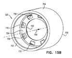
後方ハウジング部520の簡略化された第1の斜視端面図、第2の斜視端面図および断面図である図15A、15Bおよび15Cをここでさらに参照する。 15A, 15B and 15C, which are simplified first perspective end views, second perspective end views and cross-sectional views of the rear housing portion 520, are further referenced herein.

図11および15A~15Cで把握されるように、後方ハウジング部520は、軸501に沿って配置され、前方端部700、後方端部702および円柱外向き面704を有する全体的に円柱状の要素であることが好ましい。前方ハウジング部510の対応する突起621をスナップフィット係合で受け、それにより前方ハウジング部510と後方ハウジング部520の間に軸方向の係止および方位角方向の係止の両方を提供する複数の方位角方向に相互に離間している周方向凹部708が内向き面706に形成される。 As can be seen in FIGS. 11 and 15A-15C, the rear housing portion 520 is arranged along the shaft 501 and is generally columnar with a front end 700, a rear end 702 and a cylindrical outward surface 704. It is preferably an element. A plurality of snap-fit engagements that receive the corresponding projections 621 of the anterior housing portion 510, thereby providing both axial and azimuthic locking between the anterior housing portion 510 and the rear housing portion 520. Circumferential recesses 708 that are spaced apart from each other in the azimuth direction are formed on the inward facing surface 706.

前向き面722および後ろ向き面724を有する内方を向いたフランジ720は、前方端部700と後方端部702の中 間にあり、内向き面706の半径方向内方に延在する。前向き面722は、好ましくは全部で4個以上の歯付き凹部730の方位角方向配列とともに形成されることが好ましく、該凹部はそれぞれ、前向きかつ時計回り向きの傾斜面732および軸方向を向いた反時計回り向きの係止面734を含む。 The inward-facing flange 720 with the forward-facing surface 722 and the rear-facing surface 724 lies between the front end 700 and the rear-end 702 and extends radially inward of the inward surface 706. The forward facing surface 722 is preferably formed with an azimuthal arrangement of a total of four or more toothed recesses 730, the recesses each facing a forward and clockwise inclined surface 732 and axially oriented. Includes a locking surface 734 in the counterclockwise direction.

歯658の構成は、シリンジまたは他の要素(図示せず)のオスルアーコネクタが矢印670で示される時計回りの回転方向でメスルアーコネクタ部542にねじ込まれ、矢印740で示される軸501に沿った前方を向いた軸力が加えられたとき、シリンジを前述の時計回り方向に回転させることを続けると、矢印670で示すハブ要素540の前述の時計回り方向の対応する回転は生じず、シリンジとハブ540の密な係合が可能になるようなものである。この構成はまた、ユーザが、オスルアーコネクタを矢印742(図16A~16D)で示すような反時計回り方向に回転させることによりオスルアーコネクタを外そうと試みたとき、ハブ540はシリンジと一緒に軸501周りを回転し、それによってシリンジがハブ540から係合解除されることを妨げるようなものでもある。 The configuration of the teeth 658 is such that the male luer connector of the syringe or other element (not shown) is screwed into the messuler connector portion 542 in the clockwise direction indicated by arrow 670 and along the axis 501 indicated by arrow 740. Continuing to rotate the syringe in the clockwise direction as described above when an axial force directed forward is applied does not result in the corresponding clockwise rotation of the hub element 540 indicated by arrow 670 and the syringe. And the hub 540 are such that tight engagement is possible. This configuration also includes the hub 540 with the syringe when the user attempts to disconnect the male luer connector by rotating the male luer connector counterclockwise as indicated by arrows 742 (FIGS. 16A-16D). It also rotates around the shaft 501, thereby preventing the syringe from being disengaged from the hub 540.

図10A~15Cのルアーロックアダプタの、従来のルアーロックシリンジに対するそれぞれ第1の動作方位、第2の動作方位、第3の動作方位、第4の動作方位、第5の動作方位および第6の動作方位における簡略化された図である図16A、16B、16C、16D、16Eおよび16Fをここで参照する。 The first operating orientation, the second operating orientation, the third operating orientation, the fourth operating orientation, the fifth operating orientation, and the sixth operating orientation of the luer lock adapters of FIGS. 10A to 15C with respect to the conventional luer lock syringe, respectively. 16A, 16B, 16C, 16D, 16E and 16F, which are simplified diagrams in the operating direction, are referred to here.

図16Aは、図10A~15Cのルアーロックアダプタ500に接続されようとするオスルアーコネクタ802を有する従来のルアーロックシリンジ800を示す。 FIG. 16A shows a conventional luer lock syringe 800 having a male luer connector 802 to be connected to the luer lock adapter 500 of FIGS. 10A-15C.

図1A~9Gの実施形態では、ルアーロックシリンジ400がルアーロックアダプタ100へ係合される前、圧縮ばね152の圧縮作用は、ハブ要素140を後方ハウジング部120のフランジ320の前向き面322に付勢し、したがって、ハブ要素140の歯278は、凹部330に係止係合し、歯278の時計回り向きの軸方向かつ半径方向を向いた係止面282は、軸方向を向いた反時計回り向きの係止面334に係止係合し、それによって、矢印342で表されるハブ要素140の後方ハウジング部120に対する前向きの視点で、反時計回りの回転は可能になるが、矢印270で表されるハブ要素140の後方ハウジング部120に対する前向きの視点で、時計回りの回転は妨げられることに留意されたい。 In the embodiments of FIGS. 1A-9G, before the luer lock syringe 400 is engaged with the luer lock adapter 100, the compressive action of the compression spring 152 attaches the hub element 140 to the forward facing surface 322 of the flange 320 of the rear housing portion 120. Therefore, the teeth 278 of the hub element 140 are locked and engaged with the recess 330, and the clockwise and radially oriented locking surface 282 of the teeth 278 is an axially counterclockwise. Locking engagement with the clockwise locking surface 334, which allows counterclockwise rotation from a forward perspective with respect to the rear housing portion 120 of the hub element 140 represented by arrow 342, but arrow 270. Note that clockwise rotation is hindered from a forward perspective with respect to the rear housing portion 120 of the hub element 140 represented by.

図10A~16Fの実施形態では、圧縮ばねは提供されておらず、したがって、ルアーロックシリンジ800がルアーロックアダプタ500に係合される前、ハブ要素540は、後方ハウジング部520のフランジ720の前向き面722に付勢されず、したがって、ハブ要素540の歯678は、凹部730に必ずしも、通常は係止係合せず、歯678の時計回り向きの軸方向かつ半径方向を向いた係止面682は、軸方向を向いた反時計回り向きの係止面734に必ずしも、通常は係止係合せず、それによって、矢印742で表されるハブ要素540の後方ハウジング部520に対する前向きの視点で、反時計周りの回転は可能になるが、矢印670で表されるハブ要素540の後方ハウジング部520に対する前向きの視点で、時計回りの回転も通常可能になる。 In the embodiments of FIGS. 10A-16F, compression springs are not provided and therefore, before the luer lock syringe 800 is engaged with the luer lock adapter 500, the hub element 540 faces forward to the flange 720 of the rear housing portion 520. The tooth 678 of the hub element 540 is not necessarily urged to the surface 722 and therefore does not necessarily engage with the recess 730 in a normally locking manner, and the clockwise axial and radial locking surface 682 of the tooth 678. Does not necessarily lock-engage to the axially counterclockwise locking surface 734, thereby, in a forward view to the rear housing portion 520 of the hub element 540 represented by arrow 742. Although counterclockwise rotation is possible, clockwise rotation is also normally possible from a forward perspective with respect to the rear housing portion 520 of the hub element 540 represented by arrow 670.

前方ハウジング部510の後ろ向き歯付き縁615とハブ要素540の前向き歯付き縁656の間の文字Aで示される軸方向間隔は、軸方向に延在している時計回り向きの係止面662の軸方向の大きさより大きくてもよく、または、大きくなくてもよく、したがって、ハブ要素540と前方ハウジング部510のいずれの回転方向においても相互回転が制限されてもよく、または制限されなくてもよいことに留意されたい。図16Aに示す例示された実施形態では、軸方向間隔Aは、通常、0.7mm~1.0mmの間にあり、後方ハウジング部520の前向き面722とハブ要素540の676の後ろ向き歯付き面の間の文字Bで示される軸方向間隔は、通常、0.8mm~1.1mmの間にある。 The axial spacing indicated by letter A between the backward toothed edge 615 of the anterior housing portion 510 and the forward toothed edge 656 of the hub element 540 is an axially extending clockwise locking surface 662. It may or may not be larger than the axial magnitude, and thus mutual rotation may or may not be restricted in either direction of rotation of the hub element 540 and the front housing portion 510. Please note that it is good. In the exemplary embodiment shown in FIG. 16A, the axial spacing A is typically between 0.7 mm and 1.0 mm, with the forward facing surface 722 of the rear housing portion 520 and the backward toothed surface of 676 of the hub element 540. The axial spacing indicated by the letter B between them is usually between 0.8 mm and 1.1 mm.

後方ハウジング部520の前向き面722と前方ハウジング部510の後ろ向き歯付き縁615の間の文字Cで示される軸方向間隔は、本明細書中で上述したように、前方ハウジング部510と後方ハウジング部520のスナップフィット係合により、通常約5.4mmと一定を保ち、前方ハウジング部510と後方ハウジング部520の間に軸方向のかつ方位角方向の係止を提供することが理解される。さらに、軸方向間隔Aと軸方向間隔Bの合計は、本明細書中で上述したように、前方ハウジング部510と後方ハウジング部520のスナップフィット係合により通常約1.8mmと一定を保ち、前方ハウジング部510と後方ハウジング部520の間に軸方向のかつ方位角方向の係止を提供する。 The axial spacing, represented by letter C, between the forward facing surface 722 of the rear housing portion 520 and the posterior toothed edge 615 of the anterior housing portion 510 is the anterior housing portion 510 and the rear housing portion as described above herein. It is understood that the snap-fit engagement of the 520 usually remains constant at about 5.4 mm and provides axial and azimuth locking between the front housing portion 510 and the rear housing portion 520. Further, the sum of the axial spacing A and the axial spacing B is usually kept constant at about 1.8 mm due to the snap-fit engagement between the front housing portion 510 and the rear housing portion 520, as described above in the present specification. Axial and azimuth locking is provided between the front housing portion 510 and the rear housing portion 520.

図16Bは、オスルアーコネクタ802がメスルアーコネクタ部542にその後ろ向き端部で接触係合するような、シリンジ800のルアーロックアダプタ500に対する軸501に沿った初期前方軸方向変位を示す。接触係合により、ハブ要素540は、ハブ要素540の歯658が、ハブ要素540の回転を止めシリンジ800がハブ要素540に対して回転することを可能にする、歯616の傾斜面618との接触係合をするまで、矢印810で示すように後方ハウジング部520に対して前方に押される。 FIG. 16B shows the initial anterior axial displacement of the syringe 800 with respect to the luer lock adapter 500 such that the male luer connector 802 is in contact with the female luer connector portion 542 at its rearward end. By contact engagement, the hub element 540 is with the inclined surface 618 of the teeth 616, which allows the teeth 658 of the hub element 540 to stop the rotation of the hub element 540 and allow the syringe 800 to rotate with respect to the hub element 540. It is pushed forward with respect to the rear housing portion 520 as indicated by arrow 810 until contact engagement is made.

図16Bに示す例示された実施形態では、軸方向間隔Aは、軸方向に延在している時計回り向きの係止面662の約0.7mmである軸方向の大きさより小さく、軸方向間隔Bは、1.1mmより大きく、これは通常約0.8mmである時計回り向きの軸方向かつ半径方向を向いた係止面682の軸方向の大きさより大きい。 In the exemplary embodiment shown in FIG. 16B, the axial spacing A is smaller than the axial magnitude of about 0.7 mm of the clockwise locking surface 662 extending axially and the axial spacing. B is greater than 1.1 mm, which is greater than the axial magnitude of the locking surface 682 in the clockwise and radial directions, which is usually about 0.8 mm.

図16Cは、オスルアーコネクタ802がハブ要素540のメスルアーコネクタ部542と部分的に螺合摩擦係合するような、矢印670で示すようなシリンジ800のルアーロックアダプタ500に対する軸501周りの時計回りの回転を示す。この回転は、矢印740で示すような軸501に沿ったさらなる前方軸力を加えて行われる。 FIG. 16C shows a clock around a shaft 501 with respect to the luer lock adapter 500 of the syringe 800 as indicated by arrow 670, such that the male luer connector 802 is partially screwed and frictionally engaged with the female luer connector portion 542 of the hub element 540. Shows the rotation around. This rotation is performed by applying additional forward axial force along the axis 501 as indicated by arrow 740.

図16Cに示す例示された実施形態では、ハブ要素540の、前方ハウジング部510および後方ハウジング部520に対する図16Bに示す位置からの時計回りの回転により、約0.4mmである図16Cに示す軸方向間隔Aは、図16Bに示す軸方向間隔Aより小さく、約1.4mmである図16Cに示す軸方向間隔Bは、図16Bに示す軸方向間隔Bより大きい。 In the exemplary embodiment shown in FIG. 16C, the axis shown in FIG. 16C is about 0.4 mm due to clockwise rotation of the hub element 540 with respect to the front housing portion 510 and the rear housing portion 520 from the position shown in FIG. 16B. The directional spacing A is smaller than the axial spacing A shown in FIG. 16B, and the axial spacing B shown in FIG. 16C, which is about 1.4 mm, is larger than the axial spacing B shown in FIG. 16B.

図16Dは、オスルアーコネクタ802がハブ要素540のメスルアーコネクタ部542と完全螺合摩擦係合するような、シリンジ800のルアーロックアダプタ500に対する軸510周りの時計回りの回転を示す。この回転は、矢印740で示すような軸501に沿ったさらなる前方軸力を加えて行われる。 FIG. 16D shows the clockwise rotation of the syringe 800 with respect to the luer lock adapter 500 about a shaft 510 such that the male luer connector 802 is fully screwed and frictionally engaged with the female luer connector portion 542 of the hub element 540. This rotation is performed by applying additional forward axial force along the axis 501 as indicated by arrow 740.

この前方軸力により、前方ハウジング部510の後ろ向き歯付き縁615はハブ要素540の前向き歯付き縁656に係止係合し、圧縮ばねが存在しなくても、ハブ要素540の前方ハウジング部510に対するさらなる時計回りの回転を妨げ、軸方向間隔Aはゼロに減少し、軸方向間隔Bは約1.8mmに増加する。 Due to this forward axial force, the backward toothed edge 615 of the front housing portion 510 is locked and engaged with the forward toothed edge 656 of the hub element 540, and the front housing portion 510 of the hub element 540 is engaged even in the absence of the compression spring. Preventing further clockwise rotation with respect to, the axial spacing A decreases to zero and the axial spacing B increases to about 1.8 mm.

図16Eは、オスルアーコネクタ802をハブ要素540のメスルアーコネクタ部542から係合解除しようとする試みにおいて、矢印742および740で示すようなシリンジ800の、ルアーロックアダプタ500の後方ハウジング部520に対する軸501周りの反時計回りの回転と前方を向いた軸力の供給の組み合わせを示す。この試みは、オスルアーコネクタ802とハブ要素540のメスルアーコネクタ部542の摩擦係合により、かつ、通常全部で4個の複数の歯658が形成されたハブ要素540の前向き歯付き縁656であって、該歯はそれぞれ前方ハウジング部510に対する反時計回り回転において前向きかつ時計回り向きの傾斜面660を含むものである該歯付き縁656が、通常全部で4個の複数の歯616が形成された後ろ向き歯付き縁615であって、該歯はそれぞれ後ろ向きの部分的に円周状の面617および後ろ向きかつ時計回り向きの傾斜面618を含むものである該歯付き縁615上を摺動し、したがって、ハブ要素540の前方ハウジング部510に対する反時計回り方向の回転は制限されないので、ハブ要素540はルアーロックアダプタ500の残りの部分に対して反時計回りに回転自在であることにより、成功しない。 FIG. 16E shows the syringe 800 as shown by arrows 742 and 740 with respect to the rear housing portion 520 of the luer lock adapter 500 in an attempt to disengage the male luer connector 802 from the female luer connector portion 542 of the hub element 540. The combination of the counterclockwise rotation around the shaft 501 and the supply of the axial force facing forward is shown. This attempt was made by frictional engagement between the male luer connector 802 and the messuler connector portion 542 of the hub element 540, and at the forward toothed edge 656 of the hub element 540, usually with a total of four plurality of teeth 658 formed. There, the toothed edges 656, each of which comprises a forward and clockwise tilted surface 660 in counterclockwise rotation with respect to the anterior housing portion 510, typically have a total of four plurality of teeth 616 formed. A posterior toothed rim 615 that slides on the toothed rim 615, each of which comprises a partially circumferential surface 617 facing backwards and an inclined surface 618 facing backwards and clockwise. Since the rotation of the hub element 540 in the counterclockwise direction with respect to the front housing portion 510 is not restricted, the hub element 540 is unsuccessful because it is rotatable counterclockwise with respect to the rest of the luer lock adapter 500.

図16Eに示す例示された実施形態では、ハブ要素540の前方ハウジング部510および後方ハウジング部520に対する図16Dに示す位置からの反時計回りの回転により、軸方向間隔Aは、約0.7mmである軸方向に延在している時計回り向きの係止面662の軸方向の大きさと略等しく、軸方向間隔Bは、約1.1mmである。 In the exemplary embodiment shown in FIG. 16E, the axial spacing A is about 0.7 mm due to counterclockwise rotation from the position shown in FIG. 16D with respect to the front housing portion 510 and the rear housing portion 520 of the hub element 540. It is substantially equal to the axial size of the clockwise locking surface 662 extending in a certain axial direction, and the axial spacing B is about 1.1 mm.

図16Fは、オスルアーコネクタ802をハブ要素540のメスルアーコネクタ部542から係合解除しようとする試みにおいて、矢印742および820で示すような、シリンジ800の、ルアーロックアダプタ500の後方ハウジング部520に対する軸501周りの反時計周りの回転と後方を向いた軸力の供給の組み合わせを示す。この試みは、オスルアーコネクタ802とハブ要素540のメスルアーコネクタ部542の摩擦係合により、かつ、通常全部で4個の複数の歯678が形成されたハブ要素540の後ろ向き歯付き縁674であって、該歯はそれぞれ後方ハウジング部520に対する反時計回り回転における後ろ向きかつ時計回り向きの傾斜面680を含むものである該歯付き縁674が、通常全部で4個の複数の歯付き凹部730が形成された前向き面722であって、該歯付き凹部はそれぞれ前向きかつ時計回り向きの傾斜面732および軸方向を向いた反時計回り向きの係止面734を含むものである該前向き面722上を摺動し、したがって、ハブ要素540の前方ハウジング部510に対する反時計回り方向の回転は制限されないので、ハブ要素540はルアーロックアダプタ500の残りの部分に対して反時計回りに回転自在であることにより、成功しない。 FIG. 16F shows the rear housing portion 520 of the luer lock adapter 500 of the syringe 800, as indicated by arrows 742 and 820, in an attempt to disengage the male luer connector 802 from the female luer connector portion 542 of the hub element 540. The combination of the counterclockwise rotation around the axis 501 and the supply of the axial force facing backward is shown. This attempt was made by frictional engagement between the male luer connector 802 and the messuler connector portion 542 of the hub element 540, and at the rear-facing toothed edge 674 of the hub element 540, usually with a total of four plurality of teeth 678 formed. The toothed edges 674, each of which comprises a backward and clockwise tilted surface 680 in counterclockwise rotation with respect to the rear housing portion 520, are usually formed by a total of four toothed recesses 730. A front-facing surface 722 that slides on the forward-facing surface 722, each of which comprises a forward-facing and clockwise inclined surface 732 and an axially counterclockwise locking surface 734. Thus, since the rotation of the hub element 540 in the counterclockwise direction with respect to the front housing portion 510 is not restricted, the hub element 540 is rotatable counterclockwise with respect to the rest of the luer lock adapter 500. Not successful.

図16Fに示す例示された実施形態では、矢印820で示す後方を向いた軸力と、ハブ要素540の前方ハウジング部510および後方ハウジング部520に対する図16Dに示した位置からの反時計周りの回転の組み合わせにより、軸方向間隔Aは、約1.0mmであり、軸方向間隔Bは、時計回り向きの軸方向かつ半径方向を向いた係止面682の約0.8mmである軸方向の大きさと略等しい。 In the exemplary embodiment shown in FIG. 16F, the backward axial force indicated by arrow 820 and the counterclockwise rotation of the hub element 540 with respect to the front housing portion 510 and the rear housing portion 520 from the position shown in FIG. 16D. The axial spacing A is about 1.0 mm, and the axial spacing B is the axial magnitude of about 0.8 mm of the locking surface 682 clockwise and radially oriented. Is almost equal to.

図10A~15Cのルアーロックアダプタの、従来のルアーロックシリンジに対するそれぞれ第1の動作方位、第2の動作方位、第3の動作方位、第4の動作方位、第5の動作方位および第6の動作方位の簡略化された図である図17A、17B、17C、17D、17Eおよび17Fをここで参照する。 The first operating orientation, the second operating orientation, the third operating orientation, the fourth operating orientation, the fifth operating orientation, and the sixth operating orientation of the luer lock adapters of FIGS. 10A to 15C with respect to the conventional luer lock syringe, respectively. 17A, 17B, 17C, 17D, 17E and 17F, which are simplified views of the operating direction, are referred to here.

図17Aは、図10A~15Cのルアーロックアダプタ500に接続されようとするオスルアーコネクタ902を有する従来のルアーロックコネクタ900を示す。 FIG. 17A shows a conventional luer lock connector 900 having a male luer connector 902 that is to be connected to the luer lock adapter 500 of FIGS. 10A-15C.

図1A~9Gの実施形態では、ルアーロックコネクタ420がルアーロックアダプタ100へ係合される前、圧縮ばね152の圧縮作用は、ハブ要素140を後方ハウジング部120のフランジ320の前向き面322に付勢し、したがって、ハブ要素140の歯278は、凹部330に係止係合し、歯278の時計回り向きの軸方向かつ半径方向を向いた係止面282は、軸方向を向いた反時計回り向きの係止面334に係止係合し、それによって、矢印342で表されるハブ要素140の後方ハウジング部120に対する前向きの視点で、反時計回りの回転は可能になるが、矢印270で表されるハブ要素140の後方ハウジング部120に対する前向きの視点で、時計回りの回転は妨げられることに留意されたい。 In the embodiments of FIGS. 1A-9G, before the luer lock connector 420 is engaged with the luer lock adapter 100, the compressive action of the compression spring 152 attaches the hub element 140 to the forward facing surface 322 of the flange 320 of the rear housing portion 120. Therefore, the teeth 278 of the hub element 140 are locked and engaged with the recess 330, and the clockwise and radially oriented locking surface 282 of the teeth 278 is an axially counterclockwise. Locking engagement with the clockwise locking surface 334, which allows counterclockwise rotation from a forward perspective with respect to the rear housing portion 120 of the hub element 140 represented by arrow 342, but arrow 270. Note that clockwise rotation is hindered from a forward perspective with respect to the rear housing portion 120 of the hub element 140 represented by.

図10A~17Fの実施形態では、圧縮ばねは提供されておらず、したがって、ルアーロックコネクタ900がルアーロックアダプタ500へ係合される前、ハブ要素540は、後方ハウジング部520のフランジ720の前向き面722に付勢されず、したがって、ハブ要素540の歯678は、凹部730に必ずしも、通常は係止係合せず、歯678の時計回り向きの軸方向かつ半径方向を向いた係止面682は、軸方向を向いた反時計回り向きの係止面734に必ずしも、通常は係止係合せず、それによって、矢印742で表されるハブ要素540の後方ハウジング部520に対する前向きの視点で、反時計周りの回転は可能になるが、矢印670で表されるハブ要素540の後方ハウジング部520に対する前向きの視点で、時計回りの回転も通常可能になる。 In embodiments of FIGS. 10A-17F, compression springs are not provided and therefore, before the luer lock connector 900 is engaged with the luer lock adapter 500, the hub element 540 faces forward to the flange 720 of the rear housing portion 520. The tooth 678 of the hub element 540 is not necessarily urged to the surface 722 and therefore does not necessarily engage with the recess 730 in a normally locking manner, and the clockwise axial and radial locking surface 682 of the tooth 678. Does not necessarily lock-engage to the axially counterclockwise locking surface 734, thereby, in a forward view to the rear housing portion 520 of the hub element 540 represented by arrow 742. Although counterclockwise rotation is possible, clockwise rotation is also normally possible from a forward perspective with respect to the rear housing portion 520 of the hub element 540 represented by arrow 670.

前方ハウジング部510の後ろ向き歯付き縁615とハブ要素540の前向き歯付き縁656の間の文字Aで示された軸方向間隔は、軸方向に延在している時計回り向きの係止面662の軸方向の大きさより大きくてもよく、または、大きくなくてもよく、したがって、ハブ要素540と前方ハウジング部510のいずれの回転方向においても相互回転は制限されてもよく、または制限されなくてもよいことに留意されたい。図17Aに示す例示された実施形態では、軸方向間隔Aは、通常約0.7mm~1.0mmの間にあり、後方ハウジング部520の前向き面722とハブ要素540の676の後ろ向き歯付き面の間の文字Bで示された軸方向間隔は、通常0.8mm~1.1mmの間にある。 The axial spacing indicated by letter A between the backward toothed edge 615 of the anterior housing portion 510 and the forward toothed edge 656 of the hub element 540 is an axially extending clockwise locking surface 662. May or may not be larger than the axial magnitude of, and thus mutual rotation may or may not be restricted in either direction of rotation of the hub element 540 and the front housing portion 510. Please note that it is also good. In the exemplary embodiment shown in FIG. 17A, the axial spacing A is typically between about 0.7 mm and 1.0 mm, with the forward facing surface 722 of the rear housing portion 520 and the backward toothed surface of 676 of the hub element 540. The axial spacing indicated by the letter B between them is usually between 0.8 mm and 1.1 mm.

文字Cによって示される後方ハウジング部520の前向き面722と前方ハウジング部510の後ろ向き歯付き縁615の間の軸方向間隔は、本明細書中で上述したように、前方ハウジング部510と後方ハウジング部520のスナップフィット係合により通常約5.4mmと一定を保ち、前方ハウジング部510と後方ハウジング部520の間に軸方向のかつ方位角方向の係止を提供することが理解される。さらに、軸方向間隔Aと軸方向間隔Bの合計は、本明細書内で上述したように、前方ハウジング部510と後方ハウジング部520のスナップフィット係合により、通常約1.8mmと一定を保ち、前方ハウジング部510と後方ハウジング部520の間に軸方向のかつ方位角方向の係止を提供する。 The axial spacing between the forward facing surface 722 of the rear housing portion 520 and the posterior toothed edge 615 of the anterior housing portion 510, as indicated by the letter C, is the anterior housing portion 510 and the rear housing portion, as described herein above. It is understood that the snap-fit engagement of the 520 usually remains constant at about 5.4 mm and provides axial and azimuth locking between the front housing portion 510 and the rear housing portion 520. Further, the sum of the axial spacing A and the axial spacing B is usually kept constant at about 1.8 mm due to the snap-fit engagement between the front housing portion 510 and the rear housing portion 520, as described above in the present specification. Provides axial and azimuth locking between the front housing portion 510 and the rear housing portion 520.

図17Bは、オスルアーコネクタ902がメスルアーコネクタ部542にその後ろ向き端部で接触係合するような、ルアーロックコネクタ900のルアーロックアダプタ500に対する軸501に沿った初期前方軸方向変位を示す。接触係合により、ハブ要素540は、ハブ要素540の歯658が、ハブ要素540の回転を止めルアーロックコネクタ900がハブ要素540に対して回転することを可能にする、歯616の傾斜面618との接触係合をするまで、矢印910で示すように後方ハウジング部520に対して前方に押される。 FIG. 17B shows the initial forward axial displacement of the luer lock connector 900 with respect to the luer lock adapter 500 such that the male luer connector 902 is in contact engagement with the female luer connector portion 542 at its rearward end. By contact engagement, the hub element 540 allows the tooth 658 of the hub element 540 to stop the rotation of the hub element 540 and allow the luer lock connector 900 to rotate relative to the hub element 540. It is pushed forward with respect to the rear housing portion 520 as shown by the arrow 910 until it engages in contact with.

図17Bに示す例示された実施形態では、軸方向間隔Aは、約0.7mmである軸方向に延在している時計回り向きの係止面662の軸方向の大きさより小さく、軸方向間隔Bは、1.1mmより大きく、これは、通常約0.8mmである時計回り向きの軸方向かつ半径向を向いた係止面682の軸方向の大きさより大きい。 In the exemplary embodiment shown in FIG. 17B, the axial spacing A is smaller than the axial magnitude of the clockwise locking surface 662 extending axially, which is about 0.7 mm, and the axial spacing. B is greater than 1.1 mm, which is greater than the axial magnitude of the locking surface 682 in the clockwise and radial directions, which is usually about 0.8 mm.

図17Cは、オスルアーコネクタ902がハブ要素540のメスルアーコネクタ部542と部分的に螺合摩擦係合するような、矢印670で示すようなルアーロックコネクタ900のルアーロックアダプタ500に対する軸501周りの時計回りの回転を示す。この回転は、矢印740で示すような軸501に沿ったさらなる前方軸力を加えて行われる。 FIG. 17C shows around the shaft 501 of the luer lock connector 900 with respect to the luer lock adapter 500 as indicated by arrow 670, such that the male luer connector 902 is partially screwed and frictionally engaged with the female luer connector portion 542 of the hub element 540. Shows the clockwise rotation of. This rotation is performed by applying additional forward axial force along the axis 501 as indicated by arrow 740.

図17Cに示す例示された実施形態では、ハブ要素540の前方ハウジング部510および後方ハウジング部520に対する図17Bに示す位置からの時計回りの回転により、約0.4mmである図17Cに示す軸方向間隔Aは、図17Bに示す軸方向間隔Aより小さく、約1.4mmである図17Cに示す軸方向間隔Bは、図17Bに示す軸方向間隔Bより大きい。 In the exemplary embodiment shown in FIG. 17C, the axial direction shown in FIG. 17C is about 0.4 mm due to clockwise rotation from the position shown in FIG. 17B with respect to the front housing portion 510 and the rear housing portion 520 of the hub element 540. The spacing A is smaller than the axial spacing A shown in FIG. 17B, and the axial spacing B shown in FIG. 17C, which is about 1.4 mm, is larger than the axial spacing B shown in FIG. 17B.

図17Dは、オスルアーコネクタ902がハブ要素540のメスルアーコネクタ部542と完全螺合摩擦係合するような、ルアーロックコネクタ900のルアーロックアダプタ500に対する軸501周りの時計回りの回転を示す。この回転は、矢印740で示すような軸501に沿ったさらなる前方軸力を加えて行われる。 FIG. 17D shows the clockwise rotation of the luer lock connector 900 with respect to the luer lock adapter 500 such that the male luer connector 902 is fully screwed and frictionally engaged with the female luer connector portion 542 of the hub element 540. This rotation is performed by applying additional forward axial force along the axis 501 as indicated by arrow 740.

この前方軸力により、前方ハウジング部510の後ろ向き歯付き縁615は、ハブ要素540の前向き歯付き縁656に係止係合し、圧縮ばねが存在しなくてもハブ要素540の前方ハウジング部510に対するさらなる時計回りの回転は妨げられ、軸方向間隔Aはゼロに減少し、軸方向間隔Bは約1.8mmに増加する。 Due to this forward axial force, the rear facing toothed edge 615 of the front housing portion 510 is locked and engaged with the forward toothed edge 656 of the hub element 540, and the front housing portion 510 of the hub element 540 is engaged even in the absence of the compression spring. Further clockwise rotation with respect to is impeded, the axial spacing A decreases to zero, and the axial spacing B increases to about 1.8 mm.

図17Eは、オスルアーコネクタ902をハブ要素540のメスルアーコネクタ部542から係合解除しようとする試みにおいて、矢印742および740で示すような、ルアーロックコネクタ900の、ルアーロックアダプタ500の後方ハウジング部520に対する軸501周りの反時計回りの回転と前方を向いた軸力の供給の組み合わせを示す。この試みは、オスルアーコネクタ902とハブ要素540のメスルアーコネクタ部542の摩擦係合により、かつ、通常全部で4個の複数の歯658が形成されたハブ要素540の前向き歯付き縁656であって、該歯はそれぞれ前方ハウジング部510に対する反時計回り回転において前向きかつ時計回り向きの傾斜面660を含むものである該歯付き縁656が、通常全部で4個の複数の歯616が形成された後ろ向き歯付き縁615であって、該歯はそれぞれ後ろ向きの部分円周面617および後ろ向きかつ時計回り向きの傾斜面618を含むものである該歯付き縁615上を摺動し、したがって、ハブ要素540の前方ハウジング部510に対する反時計回り方向の回転は制限されないので、ハブ要素540はルアーロックアダプタ500の残りの部分に対して反時計回りに回転自在であることにより、成功しない。 FIG. 17E shows the rear housing of the luer lock adapter 500 of the luer lock connector 900, as indicated by arrows 742 and 740, in an attempt to disengage the male luer connector 902 from the female luer connector portion 542 of the hub element 540. The combination of the counterclockwise rotation around the shaft 501 with respect to the unit 520 and the supply of the axial force facing forward is shown. This attempt was made by frictional engagement between the male luer connector 902 and the messuler connector portion 542 of the hub element 540, and at the forward toothed edge 656 of the hub element 540, usually with a total of four plurality of teeth 658 formed. There, the toothed edges 656, each of which comprises a forward and clockwise tilted surface 660 in counterclockwise rotation with respect to the anterior housing portion 510, typically have a total of four plurality of teeth 616 formed. A posterior toothed edge 615 that slides on the toothed edge 615, each of which comprises a posterior partial circumferential surface 617 and a posterior and clockwise tilted surface 618, thus of the hub element 540. Since the counterclockwise rotation with respect to the front housing portion 510 is not restricted, the hub element 540 is unsuccessful because it is rotatable counterclockwise with respect to the rest of the luer lock adapter 500.

図17Eに示す例示された実施形態では、ハブ要素540の前方ハウジング部510および後方ハウジング部520に対する図17Dに示す位置からの反時計回りの回転により、軸方向間隔Aは、約0.7mmである軸方向に延在している時計回り向きの係止面662の軸方向の大きさと略等しく、軸方向間隔Bは、約1.1mmである。 In the exemplary embodiment shown in FIG. 17E, the axial spacing A is about 0.7 mm due to counterclockwise rotation from the position shown in FIG. 17D with respect to the front housing portion 510 and the rear housing portion 520 of the hub element 540. It is substantially equal to the axial size of the clockwise locking surface 662 extending in a certain axial direction, and the axial spacing B is about 1.1 mm.

図17Fは、オスルアーコネクタ902をハブ要素540のメスルアーコネクタ部542から係合解除しようとする試みにおいて、ルアーロックコネクタ900の、ルアーロックアダプタ500の後方ハウジング部520に対する軸501周りの反時計回りの回転と後方を向いた軸力の供給の組み合わせを示す。この試みは、オスルアーコネクタ902とハブ要素540のメスルアーコネクタ部542の摩擦係合により、かつ、通常全部で4個の複数の歯678が形成されたハブ要素540の前向き歯付き縁674であって、該歯はそれぞれ後方ハウジング部520に対する反時計回り回転における後ろ向きかつ時計回り向きの傾斜面680を含むものである該歯付き縁674が、通常全部で4個の複数の歯付き凹部730が形成された前向き面722であって、該歯付き凹部はそれぞれ前向きかつ時計回り向きの傾斜面732および軸方向を向いた反時計回り向きの係止面734を含むものである該前向き面722上を摺動し、したがって、ハブ要素540の前方ハウジング部510に対する反時計回り方向の回転は制限されないので、ハブ要素540はルアーロックアダプタ500の残りの部分に対して反時計回りに回転自在であることにより、成功しない。 FIG. 17F shows the counterclockwise around the shaft 501 of the luer lock connector 900 with respect to the rear housing portion 520 of the luer lock adapter 500 in an attempt to disengage the male luer connector 902 from the female luer connector portion 542 of the hub element 540. The combination of the rotation around and the supply of the axial force facing backward is shown. This attempt was made by frictional engagement between the male luer connector 902 and the messuler connector portion 542 of the hub element 540, and at the forward toothed edge 674 of the hub element 540, usually with a total of four plurality of teeth 678 formed. The toothed edges 674, each of which comprises a backward and clockwise tilted surface 680 in counterclockwise rotation with respect to the rear housing portion 520, are usually formed by a total of four toothed recesses 730. A front-facing surface 722 that slides on the forward-facing surface 722, each of which comprises a forward-facing and clockwise inclined surface 732 and an axially counterclockwise locking surface 734. Thus, since the rotation of the hub element 540 in the counterclockwise direction with respect to the front housing portion 510 is not restricted, the hub element 540 is rotatable counterclockwise with respect to the rest of the luer lock adapter 500. Not successful.

図17Fに示す例示された実施形態では、矢印820で示す後方を向いた軸力とハブ要素540の前方ハウジング部510および後方ハウジング部520に対する図17Dに示す位置からの反時計回りの回転の組み合わせにより、軸方向間隔Aは、約1.0mmであり、軸方向間隔Bは、時計回り向きの軸方向かつ半径方向を向いた係止面682の約0.8mmである軸方向の大きさと略等しい。 In the exemplary embodiment shown in FIG. 17F, a combination of the backward axial force indicated by arrow 820 and the counterclockwise rotation of the hub element 540 with respect to the front housing portion 510 and the rear housing portion 520 from the position shown in FIG. 17D. As a result, the axial spacing A is about 1.0 mm, and the axial spacing B is approximately 0.8 mm of the locking surface 682 clockwise and radially oriented. equal.

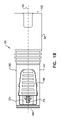
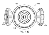
本発明の好ましい実施形態により構成され動作するルアーロックアダプタの簡略化されたそれぞれ第1の側面図、第2の側面図、第1の端面図、第2の端面図および図18Dの線XVIIIE-XVIIIEに沿った断面図である図18A、18B、18C、18Dおよび18E、ならびに図18A~18Eのルアーロックアダプタの簡略化された分解図である図19をここで参照する。 Simplified first side view, second side view, first end view, second end view and line XVIIIE- of FIG. 18D, respectively, of a luer lock adapter configured and operating according to a preferred embodiment of the present invention. 18A, 18B, 18C, 18D and 18E are cross-sectional views along XVIIIE, and 19 is a simplified exploded view of the luer lock adapters of FIGS. 18A-18E.

図18A~18Eおよび19で把握されるように、長手軸1001に概ね沿って延在しルアー接続端部1002およびポート接続端部1004を有するルアーロックアダプタ1000が提供される。メスルアー接続端部1002が示されているが、ルアー接続端部は、任意の適切なルアー接続端部であってもよい。特定のポート接続端部1004が示されているが、ポート接続端部1004は、任意の適切なポート接続端部1004であってもよい。 As illustrated in FIGS. 18A-18E and 19, a luer lock adapter 1000 is provided that extends substantially along the longitudinal axis 1001 and has a luer connection end 1002 and a port connection end 1004. Although the mesh luer connection end 1002 is shown, the luer connection end may be any suitable luer connection end. Although a particular port connection end 1004 is shown, the port connection end 1004 may be any suitable port connection end 1004.

ルアーロックアダプタ1000は、前方ハウジング部1010および後方ハウジング部1020を含むことが好ましく、それらは、相対的な軸方向移動およびそれらの間の軸1001周りの相対的な方位角方向移動の両方を妨げるように互いに固定的にスナップフィットされるのが好ましい。代替として、前方ハウジング部1010および後方ハウジング部1020は、単一の統合ユニットとして形成されてもよい。図18Aで、前向き方向は左を向いている。 The luer lock adapter 1000 preferably includes a front housing portion 1010 and a rear housing portion 1020, which prevent both relative axial movement and relative azimuth movement around the axis 1001 between them. It is preferable that they are snap-fitted to each other in a fixed manner. Alternatively, the front housing section 1010 and the rear housing section 1020 may be formed as a single integrated unit. In FIG. 18A, the forward direction is to the left.

前方ハウジング部1010内にセプタムハウジング部1030が配置され、セプタムハウジング部1030に、好ましくはセプタムハウジング部1030の前縁および後縁の超音波カシメによりセプタムハウジング部1030に保持される前方セプタム1032および後方セプタム1034が固定的に取り付けられる。 The septum housing portion 1030 is arranged in the front housing portion 1010, and the front septum 1032 and the rear septum 1032 are held by the septum housing portion 1030, preferably by ultrasonic caulking of the front and rear edges of the septum housing portion 1030. The housing 1034 is fixedly attached.

後方ハウジング部1020内に、その後ろ向き端部でメスルアーコネクタ部1042を画定しその前向き端部で針取付け部1044を画定するハブ要素1040が配置される。針取付け部1044に取り付けられた針1046は、ポート接続端部1004でポート接続がない場合は針1046の尖端1050が後方セプタム1034と前方セプタム1032の間でセプタムハウジング1030内に位置するように、長手軸1001に沿って前方ハウジング部1010内に軸方向前方に延在する。圧縮ばね1052は、セプタムハウジング1030を、ハブ要素1040および針1046に対して前方に付勢する。圧縮ばね1052は、ハブ要素1040の前向き面1053とセプタムハウジング1030の後ろ向き面1054の間に収まる。 In the rear housing portion 1020, a hub element 1040 is arranged, which defines a female luer connector portion 1042 at its rear facing end and a needle mounting portion 1044 at its front facing end. The needle 1046 attached to the needle attachment portion 1044 is such that the tip 1050 of the needle 1046 is located within the septum housing 1030 between the rear septum 1034 and the anterior septum 1032 if there is no port connection at the port connection end 1004. Along the longitudinal axis 1001, it extends axially forward within the anterior housing portion 1010. The compression spring 1052 urges the septum housing 1030 forward with respect to the hub element 1040 and the needle 1046. The compression spring 1052 fits between the forward facing surface 1053 of the hub element 1040 and the backward facing surface 1054 of the septum housing 1030.

本発明の実施形態の特定の特徴は、ここでは軸1001である軸を画定する、ここではハウジング部1010および1020であるハウジングと、ここではハブ要素1040である内部ルアーロック要素であって、ルアーロック要素のハウジングに対する第1の回転方向での軸周りの回転を可能にし、ルアーロック要素のハウジングに対する、第1の回転方向と反対の第2の回転方向での軸周りの回転を制限するように、ハウジングの内方に配置され、ハウジングに対して軸周りに回転するためにハウジングに回転可能に取り付けられた該内部ルアーロック要素とを含み、そのことにより、ハウジングの内方に内部ルアーロック要素を配置することによって、第1の回転方向のその回転を制限する内部ルアーロック要素への手動アクセスが妨げられる、ここではルアーロックアダプタ1000であるルアーロックアダプタが提供されることである。 Specific features of the embodiments of the present invention are the housing, here the housing portions 1010 and 1020, which define the axis which is the axis 1001, and the internal luer lock element which is the hub element 1040 here, the luer. Allows rotation around the axis in the first rotation direction with respect to the housing of the lock element, and limits rotation about the axis with respect to the housing of the luer lock element in the second rotation direction opposite to the first rotation direction. Includes the internal luer lock element located inside the housing and rotatably attached to the housing to rotate about an axis relative to the housing, thereby including an internal luer lock inside the housing. Placing the element prevents manual access to an internal luer lock element that limits its rotation in the first direction of rotation, where a luer lock adapter 1000 is provided.

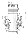
図18A~19のルアーロックアダプタの形成部である前方ハウジング部1010の簡略化されたそれぞれ第1の側面図、第2の側面図、ルアー接続端部の斜視図および断面図である図20A、20B、20Cおよび20Dをここでさらに参照する。 20A, which is a simplified first side view, second side view, perspective view and cross-sectional view of the luer connection end, respectively, of the front housing portion 1010 which is the forming portion of the luer lock adapter of FIGS. 18A-19. 20B, 20C and 20D are further referenced here.

図20A~20Dで把握されるように、前方ハウジング部1010は、前方円周リム1102と、一対の逆方向を向いたポートコネクタ係合部1106が隣接して取り付けられた一対の反対側切り欠き部1104とを有する概ね円柱状の主部1100を備える。 As can be seen in FIGS. 20A-20D, the front housing portion 1010 has a pair of opposite cutouts to which a front circumferential rim 1102 and a pair of oppositely oriented port connector engaging portions 1106 are attached adjacently. It comprises a substantially columnar main portion 1100 having a portion 1104.

ポートコネクタ係合部1106はそれぞれ、格納式ポートコネクタ係合歯1110に連結するリブ付き指係合面1108を含むことが好ましい。ポートコネクタ係合部1106はそれぞれ、対応する切り欠き部1104にまで及ぶ屈曲性のある取付けアーチ1112によって主部1100に屈曲可能に取り付けられる。係合面1108を手で押すことによりポートコネクタ係合歯1110は格納され、したがって、両方のポートコネクタ係合部1106の係合面1108を同時に手で押すとポートコネクタ(図示せず)を円筒主部1100の内部から係合解除することが可能になる。 Each port connector engaging portion 1106 preferably includes a ribbed finger engaging surface 1108 that connects to the retractable port connector engaging teeth 1110. Each port connector engaging portion 1106 is flexibly attached to the main portion 1100 by a flexible mounting arch 1112 extending to the corresponding notch 1104. The port connector engaging teeth 1110 are retracted by manually pushing the engaging surface 1108, and thus the port connector (not shown) is cylindrical when the engaging surface 1108 of both port connector engaging portions 1106 is manually pushed. It becomes possible to disengage from the inside of the main portion 1100.

図20Dで明確に把握されるように、主部1100の反対側内部面はそれぞれ、セプタムハウジング1030の前方ハウジング部1010に対する前方変位を制限する前方止め画定壁面1114を有するセプタムハウジングガイド用凹部1113を画定する。 As is clearly grasped in FIG. 20D, each of the opposite inner surfaces of the main portion 1100 has a septum housing guide recess 1113 having a front stop demarcation wall surface 1114 that limits the forward displacement of the septum housing 1030 with respect to the front housing portion 1010. Delimit.

図20Cで特に明確に把握されるように、前方ハウジング部1010は、後ろ向き縁1115を含む。主部1100の半径方向外方面1120上で後ろ向き縁1115に隣接して、複数の相互に離間している周方向長尺突起1121が在る。 As is particularly clearly grasped in FIG. 20C, the front housing portion 1010 includes a rear facing edge 1115. On the radial outer direction 1120 of the main portion 1100, adjacent to the rearward edge 1115, there are a plurality of mutually spaced circumferential elongated protrusions 1121.

図20Dで把握されるように、好ましくは両側に一対の複数の突起1122は、ルアーロックアダプタ1100の中空ポート接続端部1004の内向き周方向壁面1123の両側に在る。 As can be seen in FIG. 20D, a pair of protrusions 1122 are preferably located on both sides of the inward circumferential wall surface 1123 of the hollow port connection end 1004 of the luer lock adapter 1100.

前方セプタム1032の簡略化された説明図である図21Aおよび21B、ならびにセプタムハウジング部1030の図の簡略化されたそれぞれ第1の側面図、第2の側面図、端面図および図22Aの線XXIID-XXIIDに沿った断面図である図22A、22B、22Cおよび22Dをここでさらに参照する。 Lines XXIID of FIGS. 21A and 21B, which are simplified explanatory views of the front septum 1032, and the first side view, the second side view, the end view, and 22A, respectively, which are simplified views of the septum housing portion 1030. -FIGS. 22A, 22B, 22C and 22D, which are cross-sectional views along XXIID, are further referenced herein.

図21A~22Dで把握されるように、セプタムハウジング部1030は、それぞれ前方セプタム1032および後方セプタム1034を収容するそれぞれ前方凹部1126および後方凹部1127につながる概ね円形のそれぞれ前方開口1124および後方開口1125を有する概ね円筒状の要素である。開口針収容チャネル1128は、前方凹部1126と後方凹部1127の間で軸1001に沿って長手方向に延在する。 As can be seen in FIGS. 21A-22D, the septum housing section 1030 has approximately circular front openings 1124 and rear openings 1125 that connect to the anterior recesses 1126 and rear recesses 1127, respectively, that accommodate the anterior septum 1032 and the rear septum 1034, respectively. It is a substantially cylindrical element. The opening needle accommodating channel 1128 extends longitudinally along the axis 1001 between the anterior recess 1126 and the posterior recess 1127.

図21Aおよび21Bで特に把握されるように、前方セプタム1032は、好ましくは、ポリイソプレンなどのポリマーで形成された一体形成要素であり、セプタムハウジング部1030の前方凹部1126に取り付けられ後方を向いた前方セプタム面1132を画定することが好ましい相対的に太い後方円筒部1130、および後方円筒部1130の前方に延在し好ましくはセプタムハウジング部1030の前方開口1124を通ってその前方に延在し前方を向いた前方セプタム面1136を画定する相対的に細い円筒部1134を含む。後方セプタム1034は、好ましくは、ポリイソプレンなどのポリマーで形成された一体形成要素であり、円盤状の扁平円筒構成を有し、セプタムハウジング部1030の後方凹部1127に収まる。 As specifically illustrated in FIGS. 21A and 21B, the anterior septum 1032 is preferably an integral forming element made of a polymer such as polyisoprene, attached to the anterior recess 1126 of the septum housing portion 1030 and facing backwards. Extending anteriorly to the relatively thick posterior cylindrical portion 1130, which preferably defines the anterior septum surface 1132, and preferably anteriorly extending anteriorly through the anterior opening 1124 of the septum housing portion 1030. Includes a relatively thin cylindrical portion 1134 defining an anterior septum surface 1136 facing. The posterior septum 1034 is preferably an integral forming element formed of a polymer such as polyisoprene, has a disc-shaped flat cylindrical configuration, and fits into the posterior recess 1127 of the septum housing portion 1030.

ここで具体的に、セプタムハウジング部1030を示す図22A~22Dに戻ると、セプタムハウジング部1030は、半径方向外方に突出した周方向帯1140が形成された概ね円筒状の外面1138を有することが把握される。一対の細い突起1142は、セプタムハウジングガイド用凹部1113および前方止め画定壁面1114と係合ししたがってセプタムハウジング部1030の前方ハウジング部1010内での前方変位を制限しセプタムハウジング部1030の軸1001周りの方位角方向の回転を妨げるために、セプタムハウジング1030の周方向帯1140から半径方向外方に延在する。 Specifically, returning to FIGS. 22A to 22D showing the septum housing portion 1030, the septum housing portion 1030 has a substantially cylindrical outer surface 1138 in which a circumferential band 1140 protruding outward in the radial direction is formed. Is grasped. The pair of narrow protrusions 1142 engage with the septum housing guide recess 1113 and the front stop demarcation wall surface 1114 to limit the forward displacement of the septum housing portion 1030 within the front housing portion 1010 and around the shaft 1001 of the septum housing portion 1030. It extends radially outward from the circumferential band 1140 of the septum housing 1030 to prevent rotation in the azimuth direction.

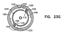
ハブ要素1040の図の簡略化されたそれぞれ第1の側面図、第2の側面図、第1の斜視端面図、第2の斜視端面図および図23Cの線XXIIIE-XXIIIEに沿った断面図である図23A、23B、23C、23Dおよび23Eをここで参照する。本明細書中で上述したように、ハブ要素1040は、後ろ向き端部でメスルアーコネクタ部1042を画定し、前向き端部で針取付け部1044を画定する。 Simplified first side view, second side view, first perspective end view, second perspective end view and cross-sectional view along line XXIIIE-XXIIIE of FIG. 23C, respectively, of the figure of hub element 1040. Some FIGS. 23A, 23B, 23C, 23D and 23E are referred to herein. As described above herein, the hub element 1040 defines the female luer connector portion 1042 at the rear facing end and the needle mounting portion 1044 at the forward facing end.

メスルアーコネクタ部1042と針取付け部1044の中間に、半径方向歯付き円周中間部1150が配置される。半径方向歯付き円周中間部1150は、一対の概ね反対側の周方向隙間1154によって分離された一対の概ね反対側の外向きの円柱面部1152を含むことが好ましい。 A circumferential middle portion 1150 with radial teeth is arranged between the mesh luer connector portion 1042 and the needle mounting portion 1044. The radial middle portion 1150 with teeth preferably includes a pair of substantially opposite outwardly facing cylindrical surface portions 1152 separated by a pair of substantially opposite circumferential gaps 1154.

それぞれの隙間1154内に周方向にかつ外向きの円柱面部1152の周方向縁1156から半径方向外方に延在するのは、好ましくは均等に周方向に離間している一対の片持ち歯付きアーム1160であり、片持ち歯付きアーム1160はそれぞれ、概ね円周状のアーム部1162および歯部1164を含む。 It is preferably with a pair of cantilever teeth that extend radially outward from the circumferential edge 1156 of the circumferential and outward cylindrical surface portion 1152 within each gap 1154, preferably evenly spaced circumferentially apart. The arm 1160, the cantilevered arm 1160, includes a generally circumferential arm portion 1162 and a tooth portion 1164, respectively.

歯部1164は、前向き面1166および面1166に平行である後ろ向き面1168、面1166および1168に垂直に延在することが好ましい周方向かつ半径方向外方の傾斜面1170、半径方向外向きの係合面1174、および時計回り向きの半径方向を向いた係止面1176を含むことが好ましい。 The tooth portion 1164 has a circumferential and radially outwardly inclined surface 1170, radially outwardly engaged, preferably extending perpendicularly to the posterior facing surfaces 1168, surfaces 1166 and 1168 parallel to the forward facing surface 1166 and the surface 1166. It preferably includes a mating surface 1174 and a locking surface 1176 facing clockwise in the radial direction.

半径方向歯付き円周中間部1150の前方に、前向き面1180、外向き円筒縁面1182および後ろ向き面1184を有する前向きフランジ1178が在る。 In front of the radial middle portion 1150, there is a forward flange 1178 with a forward surface 1180, an outward cylindrical edge surface 1182 and a backward surface 1184.

後方ハウジング部1020の簡略化された斜視端面図、切り取り斜視端面図および断面図である図24A、24Bおよび24Cをここでさらに参照する。 Simplified perspective end views, cut perspective end views and cross-sectional views of the rear housing portion 1020 are further referenced herein by FIGS. 24A, 24B and 24C.

図19および24A~24Cで把握されるように、後方ハウジング部1020は、軸1001に沿って配置され、前方端部1200、後方端部1202、円柱外向き面1204、および円柱内向き面1206を有する全体的に円柱状の要素であることが好ましい。前向き面1222および後ろ向き面1224を有する内方を向いたフランジ1220は、前方端部1200と後方端部1202の中間にあり、内向き面1206の半径方向内方に延在する。 As can be seen in FIGS. 19 and 24A-24C, the rear housing portion 1020 is arranged along the axis 1001 and includes a front end portion 1200, a rear end portion 1202, a cylinder outward facing surface 1204, and a cylinder inward facing surface 1206. It is preferable that the element has a columnar shape as a whole. The inward facing flange 1220 having the forward facing surface 1222 and the backward facing surface 1224 lies between the front end portion 1200 and the rear end portion 1202 and extends radially inward of the inward facing surface 1206.

内方を向いたフランジ1220の前方の円柱内向き面1206の周方向にかつ半径方向内方に延在するのは、好ましくは4個の複数の概ね等間隔の歯1230であり、歯1230はそれぞれ、ゆるやかに傾斜した半径方向向きの面1232および反時計回り向きの半径方向を向いた係止面1234を有する。歯1230のそれぞれの半径方向内方の大きさは、内向き面1206から反時計回り向きの係止面1234に反時計回りに増大する。 Extending inwardly and radially inwardly about the cylindrical inward facing surface 1206 in front of the inwardly facing flange 1220 is preferably four, a plurality of approximately equidistant teeth 1230, wherein the teeth 1230. Each has a gently sloping radial surface 1232 and a counterclockwise radial locking surface 1234. The radial inward magnitude of each of the teeth 1230 increases counterclockwise from the inward facing surface 1206 to the counterclockwise locking surface 1234.

ハブ要素1040の歯部1164の構成および後方ハウジング部1020の歯1230の構成は、シリンジまたは他の要素(図示せず)のオスルアーコネクタが、前向きの視点で、時計回りの回転方向でメスルアーコネクタ部1042にねじ込まれたとき、シリンジを前述の時計回り方向に回転させることを続けると、ハブ要素1040の前述の時計回り方向の対応する回転が生じ、時計回り向きの半径方向を向いた係止面1176が、後方ハウジング部1020の歯1230のうち2個の歯の対応する反時計回り向きの半径方向を向いた係止面1234と係止係合するようなものであることが好ましい。前述の時計回りの回転方向は、図24Aで、矢印1270で示される。 The configuration of the tooth portion 1164 of the hub element 1040 and the configuration of the tooth 1230 of the rear housing portion 1020 are such that the male lure connector of the syringe or other element (not shown) is a messuler in a clockwise rotation direction from a forward perspective. Continuing to rotate the syringe in the clockwise direction as described above when screwed into the connector portion 1042 results in the corresponding clockwise rotation of the hub element 1040, which is oriented in the clockwise direction. It is preferred that the retaining surface 1176 engages with the corresponding counterclockwise radial locking surface 1234 of two of the teeth 1230 of the rear housing portion 1020. The aforementioned clockwise direction of rotation is indicated by arrow 1270 in FIG. 24A.

前方ハウジング部1010の対応する突起1121をスナップフィット係合で受け、それによって、前方ハウジング部1010と後方ハウジング部1020の間に軸方向のかつ方位角方向の係止の両方を提供する複数の方位角方向に相互に離間している周方向凹部1238は、内向き面1206に形成される。 Multiple orientations that receive the corresponding projection 1121 of the anterior housing portion 1010 in a snap-fit engagement, thereby providing both axial and azimuthic locking between the anterior housing portion 1010 and the rear housing portion 1020. Circumferential recesses 1238 that are angularly spaced apart from each other are formed on the inward facing surface 1206.

図1A~9Gおよび10A~17Fに示す実施形態では、それぞれハブ要素140および540は、それぞれ前方ハウジング部110および510に対してかつそれぞれ後方ハウジング部120および520に対して軸方向に移動可能であるが、図18A~24Cに示す実施形態では、先述の前方ハウジング部1010と後方ハウジング部1020の間の軸方向のかつ方位角方向の係止により、ハブ要素1040も前方ハウジング部1010に対してかつ後方ハウジング部1020に対して軸方向に係止されるが、ハブ要素1040の前方ハウジング部1010に対するかつ後方ハウジング部1020に対する軸1001周りの方位角方向の移動は可能となることが理解される。 In the embodiments shown in FIGS. 1A-9G and 10A-17F, the hub elements 140 and 540 are axially movable with respect to the front housing portions 110 and 510, respectively and with respect to the rear housing portions 120 and 520, respectively. However, in the embodiments shown in FIGS. 18A to 24C, the hub element 1040 also with respect to the front housing portion 1010 due to the axial and azimuth locking between the front housing portion 1010 and the rear housing portion 1020 described above. Although axially locked to the rear housing portion 1020, it is understood that the hub element 1040 can move azimuthally about the axis 1001 with respect to the front housing portion 1010 and with respect to the rear housing portion 1020.

ハブ要素1040の半径方向を向いた係止面1176と後方ハウジング部1020の対応する係止面1234の4つの異なる回転方位における相対的位置を示す図23F~23Iをここで参照する。 23F-23I are shown here showing the relative positions of the radially oriented locking surface 1176 of the hub element 1040 and the corresponding locking surface 1234 of the rear housing portion 1020 in four different rotational orientations.

図23Fで把握されるように、第1の回転方位では、ハブ要素1040の半径方向を向いた係止面1176は、後方ハウジング部1020の係止面1234と時計回り動作係止係合し、ハブ要素1040の後方ハウジング部1020に対する、矢印1270で示すような前向きの視点で、時計周りの回転を妨げる。この方位では、ハブ要素1040の後方ハウジング部1020に対する反時計回りの移動は可能であることが理解される。 As can be seen in FIG. 23F, in the first rotational orientation, the radial locking surface 1176 of the hub element 1040 engages with the locking surface 1234 of the rear housing portion 1020 in a clockwise motion locking engagement. A forward view as indicated by arrow 1270 with respect to the rear housing portion 1020 of the hub element 1040, which impedes clockwise rotation. It is understood that in this orientation, counterclockwise movement of the hub element 1040 with respect to the rear housing portion 1020 is possible.

図23Gおよび23Hで把握されるように、第2のかつ第3の回転方位では、ハブ要素1040は、図23Fで示す方位から、 後方ハウジング部1020に対する前向きの視点で、反時計回りに回転している。ハブ要素1040の半径方向を向いた係止面1176は、後方ハウジング部1020の係止面1234と時計回り動作係止係合していない。これらの方位では、矢印1280で示すような、ハブ1040の後方ハウジング部1020に対する前向きの視点で、反時計回りの回転が可能であることが理解される。図23Fに示された第1の回転方位に戻る、ハブ要素1040の後方ハウジング部1020に対する制限された前向きの視点で、時計回りの回転が可能であることも理解される。 As can be seen in FIGS. 23G and 23H, in the second and third rotational orientations, the hub element 1040 rotates counterclockwise from the orientation shown in FIG. 23F with a forward view to the rear housing portion 1020. ing. The radial locking surface 1176 of the hub element 1040 is not engaged in clockwise motion locking engagement with the locking surface 1234 of the rear housing portion 1020. It is understood that in these orientations, counterclockwise rotation is possible from a forward perspective with respect to the rear housing portion 1020 of the hub 1040, as indicated by arrow 1280. It is also understood that clockwise rotation is possible with a restricted forward view of the hub element 1040 with respect to the rear housing portion 1020, returning to the first rotation direction shown in FIG. 23F.

図23Iで把握されるように、第4の回転方位では、ハブ要素1040は、図23Fで示された方位から前向きの視点で、矢印1280で示すように90°反時計回りに回転している。ハブ要素1040の半径方向を向いた係止面1176は、後方ハウジング部1020の係止面1234と時計回り動作係止係合し、ハブ要素1040の後方ハウジング部1020に対する前向きの視点で、時計回りの回転を妨げる。この方位では、ハブ要素1040の後方ハウジング部1020に対する反時計回りの移動は可能であることが理解される。 As can be seen in FIG. 23I, in the fourth rotational orientation, the hub element 1040 is rotated 90 ° counterclockwise as indicated by arrow 1280 from the orientation shown in FIG. 23F with a forward perspective. .. The radially oriented locking surface 1176 of the hub element 1040 engages with the locking surface 1234 of the rear housing portion 1020 in a clockwise motion locking engagement, clockwise with respect to the rear housing portion 1020 of the hub element 1040. Interfere with the rotation of. It is understood that in this orientation, counterclockwise movement of the hub element 1040 with respect to the rear housing portion 1020 is possible.

図18A~24Cのルアーロックアダプタの、従来のルアーロックシリンジに対するそれぞれ第1の動作方位、第2の動作方位、第3の動作方位、第4の動作方位、第5の動作方位および第6の動作方位における簡略化された図である図25A、25B、25C、25D、25Eおよび25Fをここで参照する。 The lure lock adapters of FIGS. 18A to 24C have a first operating orientation, a second operating orientation, a third operating orientation, a fourth operating orientation, a fifth operating orientation, and a sixth operating orientation with respect to the conventional luer lock syringe, respectively. 25A, 25B, 25C, 25D, 25E and 25F, which are simplified diagrams in the operating direction, are referred to here.

図25Aは、図18A~24Cのルアーロックアダプタ1000に接続されようとするオスルアーコネクタ1302を有する従来のルアーロックシリンジ1300を示す。ルアーロックシリンジ1300がルアーロックアダプタ1000へ係合される前、前方ハウジング部1010と後方ハウジング部1020の間のスナップフィット係合、より具体的には、前方ハウジング部1010の対応する突起1121を受ける、後方ハウジング部の相互に方位角方向に離間している周方向凹部1238におけるスナップフィット係合により、図18Eで把握されるようにハブ要素1040は保持され、したがって、ハブ要素1040の歯部1164は、図25Aの表示Aの断面拡大図で把握されるように、後方ハウジング部1020の歯1230と概ね同一平面内にあり動作係合する。 FIG. 25A shows a conventional luer lock syringe 1300 with an male luer connector 1302 attempted to be connected to the luer lock adapter 1000 of FIGS. 18A-24C. Before the luer lock syringe 1300 is engaged with the lure lock adapter 1000, it receives a snap-fit engagement between the front housing portion 1010 and the rear housing portion 1020, more specifically the corresponding projection 1121 of the front housing portion 1010. The hub element 1040 is held by the snap-fit engagement in the circumferential recess 1238, which is azimuthally spaced apart from each other in the rear housing portion, and thus the tooth portion 1164 of the hub element 1040. Is substantially in the same plane as the teeth 1230 of the rear housing portion 1020 and is in motion engagement, as can be seen in the enlarged cross-sectional view of display A in FIG. 25A.

通常、歯要素1164の時計回り向きの半径方向を向いた係止面1176は、後方ハウジング部1020の歯1230の反時計回り向きの半径方向を向いた係止面1234と係止係合し、それによって、矢印1280で表されるハブ要素1040の後方ハウジング部1020に対する前向きの視点で、反時計周りの回転は可能になるが、矢印1270で表されるハブ要素1040の後方ハウジング部1020に対する前向きの視点で、時計周りの回転は妨げられる。 Normally, the clockwise radial locking surface 1176 of the tooth element 1164 is locked and engaged with the counterclockwise radial locking surface 1234 of the teeth 1230 of the rear housing portion 1020. This allows counterclockwise rotation from a forward perspective with respect to the rear housing portion 1020 of the hub element 1040 represented by arrow 1280, but forward with respect to the rear housing portion 1020 of the hub element 1040 represented by arrow 1270. From this point of view, clockwise rotation is hindered.

図25Bは、オスルアーコネクタ1302がメスルアーコネクタ部1042とその後ろ向き端部で接触係合するような、シリンジ1300のルアーロックアダプタ1000に対する軸1001に沿った初期前方軸方向変位を示す。後方ハウジング部1020とハブ要素1040の係止係合は、図25Aを参照して本明細書中で上述されたものと変わらない。 FIG. 25B shows the initial anterior axial displacement of the syringe 1300 with respect to the luer lock adapter 1000 such that the male luer connector 1302 is in contact engagement with the female luer connector portion 1042 at its rearward end. The locking engagement between the rear housing portion 1020 and the hub element 1040 is the same as described above herein with reference to FIG. 25A.

図25Cは、オスルアーコネクタ1302がハブ要素1040のメスルアーコネクタ部1042と完全螺合摩擦係合するような、矢印1270で示すようなシリンジ1300のルアーロックアダプタ1000に対する軸1001周りの時計回りの回転を示す。この回転は、軸1001に沿ったさらなる前方軸力を加えることなく行われる。この完全螺合は、後方ハウジング部1020に対する時計回りの回転に対して、ハブ要素1040の回転の上記係止をすることによって可能になる。 FIG. 25C shows clockwise about the axis 1001 with respect to the luer lock adapter 1000 of the syringe 1300 as indicated by arrow 1270 such that the male luer connector 1302 is fully screwed and frictionally engaged with the female luer connector portion 1042 of the hub element 1040. Shows rotation. This rotation is performed without applying any further forward axial force along the shaft 1001. This complete screwing is made possible by the above locking of the rotation of the hub element 1040 with respect to the clockwise rotation with respect to the rear housing portion 1020.

図25D、25Eおよび25Fは、オスルアーコネクタ1302をハブ要素1040のメスルアーコネクタ部1042から係合解除しようとする試みにおいて、矢印1280で示すようなシリンジ1300の、ルアーロックアダプタ1000の後方ハウジング部1020に対する軸1001周りの反時計回りの回転を示す。この試みは、オスルアーコネクタ1302とハブ要素1040のメスルアーコネクタ部1042の摩擦係合により、かつ、ハブ要素1040がルアーロックアダプタ1000の残りの部分に対して反時計周りに回転自在であることにより、成功しない。図25Dおよび25Eの表示Aの断面拡大図で、ハブ要素1040の後方ハウジング部1020に対する反時計回りの移動により、歯要素1164の半径方向を向いた係止面1176は、後方ハウジング部1020の歯1230の反時計回り向きの半径方向を向いた係止面1234ともはや係止係合していないことが把握される。図25Fの表示Aの断面拡大図で把握されるように、シリンジ1300およびハブ要素1040の後方ハウジング部1020に対する90°の回転を受けて、歯要素1164の半径方向を向いた係止面1176は再度、後方ハウジング部1020の歯1230の反時計回り向きの半径方向を向いた係止面1234と係止係合し、ハブ要素1040の後方ハウジング部1020に対する時計回りの移動を妨げるが、ハブ要素1040の後方ハウジング部1020に対する反時計回りの移動を可能にする。 25D, 25E and 25F show the rear housing portion of the luer lock adapter 1000 of the syringe 1300 as indicated by arrow 1280 in an attempt to disengage the male luer connector 1302 from the female luer connector portion 1042 of the hub element 1040. Shows the counterclockwise rotation about the axis 1001 with respect to 1020. This attempt is by frictional engagement between the male luer connector 1302 and the female luer connector portion 1042 of the hub element 1040, and the hub element 1040 is rotatable counterclockwise with respect to the rest of the luer lock adapter 1000. Does not succeed. In the enlarged cross-sectional view of display A in FIGS. 25D and 25E, the locking surface 1176 facing the radial direction of the tooth element 1164 due to the counterclockwise movement of the hub element 1040 with respect to the rear housing portion 1020 is the tooth of the rear housing portion 1020. It is noted that the 1230 is no longer engaged with the locking surface 1234 facing the counterclockwise radial direction. As can be seen in the enlarged cross section of display A in FIG. 25F, the locking surface 1176 facing the radial direction of the tooth element 1164 is subjected to a 90 ° rotation with respect to the rear housing portion 1020 of the syringe 1300 and the hub element 1040. Again, it engages with the locking surface 1234 of the teeth 1230 of the rear housing portion 1020 in the counterclockwise direction, which hinders the clockwise movement of the hub element 1040 with respect to the rear housing portion 1020, but the hub element. Allows counterclockwise movement of the 1040 with respect to the rear housing portion 1020.

図18A~24Cのルアーロックアダプタの、従来のルアーロックコネクタに対するそれぞれ第1の動作方位、第2の動作方位、第3の動作方位、第4の動作方位、第5の動作方位および第6の動作方位における簡略化された図である図26A、26B、26C、26D、26Eおよび26Fをここで参照する。 The lure lock adapters of FIGS. 18A to 24C have a first operating orientation, a second operating orientation, a third operating orientation, a fourth operating orientation, a fifth operating orientation, and a sixth operating orientation with respect to the conventional lure lock connector, respectively. References are made herein to FIGS. 26A, 26B, 26C, 26D, 26E and 26F, which are simplified views of the operating orientation.

図26Aは、図18A~24Cのルアーロックアダプタ1000に接続されようとするオスルアーコネクタ1402を有する従来のルアーロックコネクタ1400を示す。ルアーロックコネクタ1400がルアーロックアダプタ1000へ係合される前、前方ハウジング部1010と後方ハウジング部1020の間のスナップフィット係合、より具体的には、前方ハウジング部1010の対応する突起1121を受ける後方ハウジング部の相互に方位角方向に離間している周方向凹部1238におけるスナップフィット係合により、ハブ要素1040は、図18Eで把握されるように保持され、したがって、図26Aの表示Aの断面拡大図で把握されるように、ハブ要素1040の歯部1164は、後方ハウジング部1020の歯1230と概ね同一平面内にあり動作係合する。 FIG. 26A shows a conventional luer lock connector 1400 with an male luer connector 1402 attempted to be connected to the luer lock adapter 1000 of FIGS. 18A-24C. Before the luer lock connector 1400 is engaged with the lure lock adapter 1000, it receives a snap fit engagement between the front housing portion 1010 and the rear housing portion 1020, more specifically the corresponding projection 1121 of the front housing portion 1010. The hub element 1040 is held as grasped in FIG. 18E by snap-fit engagement in the circumferential recesses 1238 that are azimuthally spaced apart from each other in the rear housing portion, and thus the cross section of display A in FIG. 26A. As can be seen in the enlarged view, the tooth portion 1164 of the hub element 1040 is substantially in the same plane as the tooth 1230 of the rear housing portion 1020 and is in motion engagement.

通常、歯要素1146の時計回り向きの半径方向を向いた係止面1176は、後方ハウジング部1020の歯1230の反時計回り向きの半径方向を向いた係止面1234と係止係合し、それによって、矢印1320で表すハブ要素1040の後方ハウジング部1020に対する前向きの視点で、反時計周りの回転は可能になるが、矢印1270で表すハブ要素1040の後方ハウジング部1020に対する前向きの視点で、時計周りの回転は妨げられる。 Normally, the clockwise radial locking surface 1176 of the tooth element 1146 is locked and engaged with the counterclockwise radial locking surface 1234 of the teeth 1230 of the rear housing portion 1020. This allows counterclockwise rotation in the forward perspective of the hub element 1040 with respect to the rear housing portion 1020 represented by arrow 1320, but with a forward perspective of the hub element 1040 represented by arrow 1270 with respect to the rear housing portion 1020. Clockwise rotation is hindered.

図26Bは、オスルアーコネクタ1402がメスルアーコネクタ部1042にその後ろ向き端部で接触係合するような、ルアーロックコネクタ1400のルアーロックアダプタ1000に対する軸1001に沿った初期前方軸方向変位を示す。後方ハウジング部1020とハブ要素1040の係止係合は、図26Aを参照して本明細書中で上述されたものと変わらない。 FIG. 26B shows the initial anterior axial displacement of the luer lock connector 1400 with respect to the luer lock adapter 1000 such that the male luer connector 1402 is in contact engagement with the mesh luer connector portion 1042 at its rearward end. The locking engagement between the rear housing portion 1020 and the hub element 1040 is the same as described above herein with reference to FIG. 26A.

図26Cは、オスルアーコネクタ1402がハブ要素1040のメスルアーコネクタ部1042と完全螺合摩擦係合するような、矢印1270で示すようなルアーロックコネクタ1400のルアーロックアダプタ1000に対する軸1001周りの時計回りの回転を示す。この回転は、軸1001に沿ったさらなる前方軸力を加えることなしに行われる。この完全螺合は、後方ハウジング部1020に対する時計回りの回転に対して、ハブ要素1040の回転の上記係止をすることによって可能になる。 FIG. 26C shows a clock around the axis 1001 with respect to the luer lock adapter 1000 of the luer lock connector 1400 as indicated by arrow 1270, such that the male luer connector 1402 is fully screwed and frictionally engaged with the female luer connector portion 1042 of the hub element 1040. Shows the rotation around. This rotation is performed without applying additional forward axial force along the shaft 1001. This complete screwing is made possible by the above locking of the rotation of the hub element 1040 with respect to the clockwise rotation with respect to the rear housing portion 1020.

図26D、26Eおよび26Fは、オスルアーコネクタ1402をハブ要素1040のメスルアーコネクタ部1042から係合解除しようとする試みにおいて、矢印1320で示すようなルアーロックコネクタ1400の、ルアーロックアダプタ1000の後方ハウジング部1020に対する軸1001周りの反時計周りの回転を示す。この試みは、オスルアーコネクタ1402とハブ要素1040のメスルアーコネクタ部1042の摩擦係合により、かつ、ハブ要素1040はルアーロックアダプタ1000の残りの部分に対して反時計周りに回転自在であることにより、成功しない。図26Dおよび26Eの表示Aの断面拡大図で、ハブ要素1040の後方ハウジング部1020に対する反時計回りの移動により、歯要素1164の半径方向を向いた係止面1176は、後方ハウジング部1020の歯1230の反時計回り向きの半径方向を向いた係止面1234ともはや係止係合していないことが把握される。図26Fの表示Aの断面拡大図で把握されるように、ルアーロックコネクタ1400およびハブ要素1040の後方ハウジング部1020に対する90°の回転を受けて、歯要素1164の半径方向を向いた係止面1176は再度、後方ハウジング部1020の歯1230の反時計回り向きの半径方向を向いた係止面1234と係止係合し、ハブ要素1040の後方ハウジング部1020に対する時計回りの移動を妨げるが、ハブ要素1040の後方ハウジング部1020に対する反時計回りの移動を可能にする。 26D, 26E and 26F show the rear of the luer lock adapter 1000 of the luer lock connector 1400 as indicated by arrow 1320 in an attempt to disengage the male luer connector 1402 from the mesh luer connector portion 1042 of the hub element 1040. Shown is the counterclockwise rotation about the axis 1001 with respect to the housing portion 1020. This attempt is due to the frictional engagement between the male luer connector 1402 and the female luer connector portion 1042 of the hub element 1040, and the hub element 1040 is rotatable counterclockwise with respect to the rest of the luer lock adapter 1000. Does not succeed. In the enlarged cross-sectional view of display A in FIGS. 26D and 26E, the locking surface 1176 facing the radial direction of the tooth element 1164 due to the counterclockwise movement of the hub element 1040 with respect to the rear housing portion 1020 is the tooth of the rear housing portion 1020. It is noted that the 1230 is no longer engaged with the locking surface 1234 facing the counterclockwise radial direction. As can be seen in the enlarged cross-sectional view of display A in FIG. 26F, the locking surface of the tooth element 1164 facing in the clockwise direction under 90 ° rotation with respect to the rear housing portion 1020 of the luer lock connector 1400 and the hub element 1040. The 1176 again engages with the counterclockwise radial locking surface 1234 of the teeth 1230 of the rear housing portion 1020, hindering the clockwise movement of the hub element 1040 with respect to the rear housing portion 1020. Allows counterclockwise movement of the hub element 1040 with respect to the rear housing portion 1020.

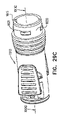
本発明の別の好ましい実施形態により構成され動作するルアーロックアダプタの簡略化されたそれぞれ第1の側面図、第2の側面図、第1の端面図、第2の端面図および図27Dの線XXVIIE-XXVIIEに沿った断面図である図27A、27B、27C、27Dおよび27E、ならびに図27A~27Eのルアーロックアダプタの簡略化された分解図である図28をここで参照する。 Simplified first side view, second side view, first end view, second end view and line of FIG. 27D, respectively, of a luer lock adapter configured and operating according to another preferred embodiment of the present invention. See here are FIGS. 27A, 27B, 27C, 27D and 27E, which are cross-sectional views along XXVIIE-XXVIIE, and FIG. 28, which is a simplified exploded view of the luer lock adapters of FIGS. 27A-27E.

図27A~27Eおよび28で把握されるように、長手軸1501に概ね沿って延在しルアー接続端部1502およびポート接続端部1504を有するルアーロックアダプタ1500が提供される。ルアーロックアダプタ1500は、前方ハウジング部1510および後方ハウジング部1520を含むことが好ましく、それらは相対的な軸方向移動およびそれらの間の軸1501周りの相対的な方位角方向移動の両方を妨げるように互いに固定的にスナップフィットされることが好ましい。代替として、前方ハウジング部1510および後方ハウジング部1520は、単一の統合ユニットとして形成されてもよい。図27Aで、前向き方向は左を向いている。 As illustrated in FIGS. 27A-27E and 28, a luer lock adapter 1500 is provided that extends approximately along the longitudinal axis 1501 and has a luer connection end 1502 and a port connection end 1504. The luer lock adapter 1500 preferably includes a front housing portion 1510 and a rear housing portion 1520 so that they interfere with both relative axial movement and relative azimuth movement around the axis 1501 between them. It is preferable that they are snap-fitted to each other in a fixed manner. Alternatively, the front housing section 1510 and the rear housing section 1520 may be formed as a single integrated unit. In FIG. 27A, the forward direction is to the left.

前方ハウジング部1510内に、好ましくはセプタム取付け部1536の前縁および後縁の超音波カシメによりセプタム取付け部1536に固定的にかつ封止的に保持された前方セプタム1532および後方セプタム1534を含むセプタムハウジング組立体1530が配置される。セプタムハウジング組立体1530は、それぞれが前方係合部1539を含む複数のセプタムハウジング取付け脚部1538を含むことが好ましく、該セプタムハウジング取付け脚部1538は通常、セプタム取付け部1536にスナップ取付けされる。 A septum comprising an anterior septum 1532 and a posterior septum 1534 that are fixedly and hermetically held to the septum mounting portion 1536 by ultrasonic caulking of the leading and trailing edges of the septum mounting portion 1536, preferably within the front housing portion 1510. The housing assembly 1530 is placed. The septum housing assembly 1530 preferably includes a plurality of septum housing mounting legs 1538, each including a front engaging portion 1539, the septum housing mounting legs 1538 usually snap-mounted to the septum mounting portion 1536.

後方ハウジング部1520内に、その後ろ向き端部でメスルアーコネクタ部1542を画定しその前向き端部で針取付け部1544を画定するハブ要素1540が配置される。針取付け部1544に取り付けられた針1546は、ポート接続端部1504でポート接続がない場合は針1546の尖端1550が後方セプタム1534と前方セプタム1532の間でセプタムハウジング1530内に位置するように、長手軸1501に沿って前方ハウジング部1510内に軸方向前方に延在する。図18A~26Fの実施形態とは異なり、圧縮ばねは提供されておらず、セプタムハウジング1530は、セプタムハウジング取付け脚部1538を介して前方ハウジング部1510に軸方向に摺動可能に取り付けられる。 Within the rear housing portion 1520, a hub element 1540 is disposed that defines a female luer connector portion 1542 at its rear facing end and a needle mounting portion 1544 at its front facing end. The needle 1546 attached to the needle attachment portion 1544 is such that the tip 1550 of the needle 1546 is located within the septum housing 1530 between the rear septum 1534 and the anterior septum 1532 if there is no port connection at the port connection end 1504. Along the longitudinal axis 1501, it extends axially forward within the anterior housing portion 1510. Unlike the embodiments of FIGS. 18A-26F, compression springs are not provided and the septum housing 1530 is axially slidably mounted to the front housing portion 1510 via the septum housing mounting legs 1538.

本発明の実施形態の特定の特徴は、ここでは軸1501である軸を画定する、ここではハウジング部1510および1520であるハウジングと、ここではハブ要素1540である内部ルアーロック要素であって、ルアーロック要素のハウジングに対する第1の回転方向での軸周りの回転を可能にし、ルアーロック要素のハウジングに対する、第1の回転方向と反対の第2の回転方向での軸周りの回転を制限するように、ハウジングの内方に配置され、ハウジングに対して軸周りに回転するためにハウジングに回転可能に取り付けられた該内部ルアーロック要素とを含み、そのことにより、ハウジングの内方に内部ルアーロック要素を配置することによって、第1の回転方向のその回転を制限する内部ルアーロック要素への手動アクセスが妨げられる、ここではルアーロックアダプタ1500であるルアーロックアダプタが提供されることである。 Specific features of the embodiments of the present invention are the housing, here the housing portions 1510 and 1520, which define the axis, which is the axis 1501, and the internal luer lock element, which here is the hub element 1540, which is a lure. Allows rotation around the axis in the first rotation direction with respect to the housing of the lock element, and limits rotation about the axis with respect to the housing of the luer lock element in the second rotation direction opposite to the first rotation direction. Includes the internal luer lock element located inside the housing and rotatably attached to the housing to rotate about an axis relative to the housing, thereby including an internal luer lock inside the housing. Placing the element prevents manual access to an internal luer lock element that limits its rotation in the first direction of rotation, where a lure lock adapter 1500, which is a luer lock adapter 1500, is provided.

図27A~28のルアーロックアダプタの前方ハウジング部の形成部の簡略化されたそれぞれ第1の側面図、第2の側面図、ルアー接続端部斜視図、および図29Cの線XXIXD-XXIXDに沿った断面図である図29A、29B、29Cおよび29Dをここでさらに参照する。 Simplified first side view, second side view, luer connection end perspective view, and line XXIXD-XXIXD, respectively, of the front housing portion of the luer lock adapters of FIGS. 27A-28. 29A, 29B, 29C and 29D, which are cross-sectional views, are further referred to here.

図29A~29Dで把握されるように、前方ハウジング部1510は、前方円周リム1602と、一対の逆方向を向いたポートコネクタ係合部1606が隣接して取り付けられた一対の反対側切り欠き部1604とを有する概ね円柱状の主部1600を備える。 As can be seen in FIGS. 29A-29D, the front housing section 1510 has a pair of opposite cutouts to which the front circumferential rim 1602 and the pair of oppositely oriented port connector engagement sections 1606 are attached adjacently. It comprises a generally columnar main portion 1600 having a portion 1604.

ポートコネクタ係合部1606はそれぞれ、格納式ポートコネクタ係合歯1610に連結するリブ付き指係合面1608を含むことが好ましい。ポートコネクタ係合部1606はそれぞれ、対応する切り欠き部1604にまで及ぶ屈曲性のある取付けアーチ1612によって主部1600に屈曲可能に取り付けられる。係合面1608を手で押すことによりポートコネクタ係合歯1610は格納され、したがって、両方のポートコネクタ係合部1606の係合面1608を同時に手で押すとポートコネクタ(図示せず)を円筒主部1600の内部から係合解除することが可能になる。 Each port connector engaging portion 1606 preferably includes a ribbed finger engaging surface 1608 that connects to the retractable port connector engaging teeth 1610. Each port connector engaging portion 1606 is flexibly attached to the main portion 1600 by a flexible mounting arch 1612 extending to the corresponding notch 1604. The port connector engaging teeth 1610 are retracted by manually pushing the engaging surface 1608, and thus the port connector (not shown) is cylindrical when the engaging surface 1608 of both port connector engaging portions 1606 is manually pushed. It becomes possible to disengage from the inside of the main portion 1600.

図29Dで明確に把握されるように、主部1600の反対側内部面はそれぞれ、セプタムハウジング1530の前方ハウジング部1510に対する前方変位を制限する前方止め画定壁面1614を有するセプタムハウジングガイド用凹部1613を画定する。 As is clearly grasped in FIG. 29D, each of the opposite inner surfaces of the main portion 1600 has a septum housing guide recess 1613 having a front stop demarcation wall surface 1614 that limits the forward displacement of the septum housing 1530 with respect to the front housing portion 1510. Delimit.

図29Cで特に明確に把握されるように、前方ハウジング部1510は、後ろ向き縁1615を含む。主部1600の半径方向外方面1620上で後ろ向き縁1615に隣接して、複数の相互に離間している周方向長尺突起1621が在る。 As is particularly clearly grasped in FIG. 29C, the front housing portion 1510 includes a rear facing edge 1615. On the radial outward 1620 of the main portion 1600, adjacent to the posterior edge 1615, there are a plurality of mutually spaced circumferential elongated projections 1621.

図29Dで把握されるように、前方ハウジング部1510の内向き周方向壁面1623の前方に、複数の凹部1624が提供され、複数の凹部1624はそれぞれ、内向き周方向壁面1623に対して半径方向外方に配置されかつその前方に在る内向き壁面を有する。凹部1624は、先細の肩部1626によって内向き周方向壁面1623からそれぞれ分離される。 As can be seen in FIG. 29D, a plurality of recesses 1624 are provided in front of the inward peripheral wall surface 1623 of the front housing portion 1510, and each of the plurality of recesses 1624 is radial with respect to the inward peripheral wall surface 1623. It has an inward facing wall that is located outward and in front of it. The recess 1624 is separated from the inward peripheral wall surface 1623 by a tapered shoulder portion 1626, respectively.

セプタムハウジング取付け脚部1538の前方係合部1539は、ポート接続端部1504が例えばバイアルアダプタなどのポートアダプタによって係合されないとき、対応する凹部1624に収まることが理解される。ポートアダプタとポート接続端部1504が係合すると、通常、前方係合部1539は、凹部1624の外へ半径方向内方かつ後方に、それぞれの先細の肩部1626を超えて押し進められ、内向き周方向壁面1623と係合される。 It is understood that the front engaging portion 1539 of the septum housing mounting leg 1538 fits into the corresponding recess 1624 when the port connection end 1504 is not engaged by a port adapter such as a vial adapter. When the port adapter and the port connection end 1504 engage, the anterior engaging portion 1539 is typically pushed radially inward and backward out of the recess 1624 over the respective tapered shoulders 1626 and inward. Engage with the circumferential wall surface 1623.

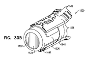
図27A~28のルアーロックアダプタのセプタムハウジング組立体の形成部の簡略化されたそれぞれ後ろ向き斜視図、前向き斜視図、側面図、図30Aの線XXXD-XXXDに沿った前向き端面図、および断面図である図30A、30B、30C、30Dおよび30Eをここで参照する。 Simplified backward perspective, forward perspective, side view, forward end view along line XXXD-XXXD of FIGS. 30A, and sectional views of the formation of the septum housing assembly of the luer lock adapters of FIGS. 27A-28, respectively. 30A, 30B, 30C, 30D and 30E are referred to herein.

上述のように、セプタムハウジング組立体1530は、好ましくはセプタム取付け部1536の前縁および後縁の超音波カシメによりセプタム取付け部1536に固定的にかつ封止的に保持された前方セプタム1532および後方セプタム1534を含む。セプタムハウジング組立体1530は、それぞれ前方係合部1539を含む複数のセプタムハウジング取付け脚部1538を含むことが好ましく、セプタムハウジング取付け脚部1538は通常、セプタム取付け部1536にスナップ取付けされる。 As mentioned above, the septum housing assembly 1530 preferably has an anterior septum 1532 and a rear septum 1532 that are fixedly and sealedly held to the septum mount 1536 by ultrasonic caulking of the leading and trailing edges of the septum mount 1536. Includes Septam 1534. The septum housing assembly 1530 preferably includes a plurality of septum housing mounting legs 1538, each including a front engaging portion 1539, which is typically snap-mounted to the septum mounting portion 1536.

図30A~30Eで把握されるように、セプタムハウジング組立体1530は、それぞれ前方セプタム1532および後方セプタム1534を収容するそれぞれ前方凹部1629および後方凹部1630につながる概ね円形のそれぞれ前方開口1627および後方開口1628を有する概ね円筒状の要素である。開口針収容チャネル1640は、前方凹部1629と後方凹部1630の間で軸501に沿って長手方向に延在する。 As can be seen in FIGS. 30A-30E, the septum housing assembly 1530 has a generally circular anterior opening 1627 and a rear opening 1628 that connect to the anterior recess 1629 and the posterior recess 1630, respectively, accommodating the anterior septum 1532 and the rear septum 1534, respectively. It is a substantially cylindrical element having. The opening needle accommodating channel 1640 extends longitudinally along the shaft 501 between the anterior recess 1629 and the posterior recess 1630.

特に図30A~30Eで把握されるように、前方セプタム1532は、好ましくは、ポリイソプレンなどのポリマーで形成された一体形成要素であり、セプタム取付け部1536の前方凹部1629に収まり後方を向いた前方セプタム面1642を画定することが好ましい相対的に太い後方円筒部1641、および後方円筒部1641の前方に延在し好ましくはセプタムハウジング組立体1530の前方開口1627を通ってその前方に延在し前方を向いた前方セプタム面1646を画定する相対的に細い円筒部1644を含む。後方セプタム1534は、好ましくは、ポリイソプレンなどのポリマーで形成された一体形成要素であり、円盤状の扁平円筒構成を有し、セプタムハウジング組立体1530の後方凹部1630に収まる。 In particular, as can be seen in FIGS. 30A-30E, the anterior septum 1532 is preferably an integral forming element made of a polymer such as polyisoprene, which fits into the anterior recess 1629 of the septum mounting portion 1536 and faces rearward. Extending anteriorly to the relatively thick rear cylindrical portion 1641, which preferably defines the septum surface 1642, and preferably anteriorly extending anteriorly through the anterior opening 1627 of the septum housing assembly 1530. Includes a relatively thin cylindrical portion 1644 defining an anterior septum surface 1646 facing. The rear septum 1534 is preferably an integral forming element made of a polymer such as polyisoprene, has a disc-shaped flat cylindrical configuration, and fits into the rear recess 1630 of the septum housing assembly 1530.

セプタム取付け部1536は、そこからセプタムハウジング取付け脚部1538が前方に延在する半径方向外方に突出する周方向帯1648がスナップ取付けされたまたは固定された概ね円筒状の外面1647を有することが把握される。一対の細い突起1649は、セプタムハウジングガイド用凹部1613および前方止め画定壁面1614と係合し、したがってセプタムハウジング組立体1530の前方ハウジング部1510内での前方変位を制限しセプタムハウジング部1530の軸1501周りの方位角方向の回転を妨げるために、周方向帯1648から半径方向外方に延在する。 The septum mounting portion 1536 may have a generally cylindrical outer surface 1647 to which the septum housing mounting legs 1538 extend radially outwardly and a circumferential band 1648 snap-mounted or secured. Be grasped. The pair of narrow protrusions 1649 engages with the septum housing guide recess 1613 and the front stop demarcation wall surface 1614, thus limiting forward displacement of the septum housing assembly 1530 within the front housing portion 1510 and the shaft 1501 of the septum housing portion 1530. It extends radially outward from the circumferential band 1648 to prevent rotation in the azimuthal direction around it.

ハブ要素1540の図の簡略化されたそれぞれ第1の側面図、第2の側面図、第1の斜視端面図、第2の斜視端面図、および図31Cの線XXXIE-XXXIEに沿った断面図である図31A、31B、31C、31Dおよび31Eをここで参照する。本明細書中で上述したように、ハブ要素1540は、後ろ向き端部でメスルアーコネクタ部1542を画定し、前向き端部で針取付け部1544を画定する。 Simplified first side view, second side view, first perspective end view, second perspective end view, and cross-sectional view along line XXXIE-XXXIE of FIG. 31C, respectively, which is a simplified diagram of the hub element 1540. 31A, 31B, 31C, 31D and 31E are referred to herein. As described above herein, the hub element 1540 defines the female luer connector portion 1542 at the rear facing end and the needle mounting portion 1544 at the forward facing end.

メスルアーコネクタ部1542と針取付け部1544の中間に、半径方向歯付き円周中間部1650が配置される。半径方向歯付き円周中間部1650は、一対の概ね反対側の周方向隙間1654によって分離されている一対の概ね反対側の外向きの円柱面部1652を含むことが好ましい。 A circumferential middle portion 1650 with radial teeth is arranged between the messuler connector portion 1542 and the needle mounting portion 1544. The radial middle portion 1650 with teeth preferably includes a pair of generally opposite outward facing cylindrical surfaces 1652 separated by a pair of generally opposite circumferential gaps 1654.

それぞれの隙間1654内に周方向にかつ外向きの円柱面部1652の周方向縁1656から半径方向外方に延在するのは、好ましくは均等に周方向に離間している一対の片持ち歯付きアーム1660であり、片持ち歯付きアーム1660はそれぞれ、概ね円周状のアーム部1662および歯部1664を含む。 Extending radially outward from the circumferential edge 1656 of the circumferential and outward cylindrical surface portion 1652 within each gap 1654 is preferably with a pair of cantilever teeth evenly spaced circumferentially apart. The arm 1660, the cantilevered arm 1660, includes a generally circumferential arm portion 1662 and a tooth portion 1664, respectively.

歯部1664は、前向き面1666および面1666に平行である後ろ向き面1668、面1666および1668に垂直に延在することが好ましい周方向かつ半径方向外方の傾斜面1670、半径方向外向きの係合面1674、ならびに時計回り向きの半径方向を向いた係止面1676を含むことが好ましい。 The tooth portion 1664 has a circumferential and radially outwardly inclined surface 1670, radially outwardly engaged, preferably extending perpendicular to the posterior surfaces 1668, surfaces 1666 and 1668 parallel to the forward surface 1666 and the surface 1666. It is preferred to include the mating surface 1674 as well as the locking surface 1676 pointing clockwise in the radial direction.

半径方向歯付き円周中間部1650の前方に、前向き面1680、外向き円筒縁面1682および後ろ向き面1684を有する前向きフランジ1678が在る。 Anterior to the radial middle circumference 1650 is a forward flange 1678 with a forward facing surface 1680, an outward cylindrical edge surface 1682 and a backward facing surface 1648.

後方ハウジング部1520の簡略化された斜視端面図、切り取り斜視端面図および断面図である図32A、32Bおよび32Cをここでさらに参照する。 Simplified perspective end views, cut perspective end views and cross-sectional views of the rear housing portion 1520 are further referenced herein by FIGS. 32A, 32B and 32C.

図28および32A~32Cで把握されるように、後方ハウジング部1520は、軸1501に沿って配置され、前方端部1700、後方端部1702、円柱外向き面1704および円柱内向き面1706を有する全体的に円柱状の要素であることが好ましい。前向き面1722および後ろ向き面1724を有する内方を向いたフランジ1720は、前方端部1700と後方端部1702の中間にあり、内向き面1706の半径方向内方に延在する。 As can be seen in FIGS. 28 and 32A-32C, the rear housing portion 1520 is arranged along the shaft 1501 and has a front end portion 1700, a rear end portion 1702, a cylindrical outward facing surface 1704 and a cylindrical inward facing surface 1706. It is preferably a columnar element as a whole. An inward-facing flange 1720 having an forward-facing surface 1722 and a rear-facing surface 1724 lies between the front end 1700 and the rear end 1702 and extends radially inward along the inward surface 1706.

内方を向いたフランジ1720の前方の円柱内向き面1706の周方向かつ半径方向内方に延在するのは、概ね等間隔の好ましくは4個の複数の歯1730であり、歯1730はそれぞれ、ゆるやかに傾斜した半径方向向きの面1732および反時計回り向きの半径方向を向いた係止面1734を有する。歯1730のそれぞれの半径方向内方の大きさは、内向き面1706から反時計回り向きの係止面1734に反時計回りに増大する。 Extending inwardly in the circumferential and radial directions of the cylindrical inward facing surface 1706 in front of the inwardly facing flange 1720 is preferably four plurality of teeth 1730 at approximately equal intervals, each of which is a tooth 1730. It has a gently sloping radial surface 1732 and a counterclockwise radial locking surface 1734. The radial inward magnitude of each of the teeth 1730 increases counterclockwise from the inward facing surface 1706 to the counterclockwise locking surface 1734.

ハブ要素1540の歯部1664および後方ハウジング部1520の歯1730の構成は、シリンジまたは他の要素(図示せず)のオスルアーコネクタが前向きの視点で、時計回りの回転方向でメスルアーコネクタ部1542にねじ込まれたとき、シリンジを前述の時計回り方向に回転させることを続けると、ハブ要素1540の前述の時計回り方向の対応する回転が生じ、時計回り向きの半径方向を向いた係止面1676は、後方ハウジング部1520の歯1730のうちの2個の歯の対応する反時計回り向きの半径方向を向いた係止面1734と係止係合するようなものであることが好ましい。前述の時計回りの回転方向は、図32Aでは矢印1770で示される。 The configuration of the teeth 1664 of the hub element 1540 and the teeth 1730 of the rear housing portion 1520 is such that the male lure connector of the syringe or other element (not shown) has a forward view and the messuler connector portion 1542 in the clockwise direction of rotation. Continue to rotate the syringe clockwise as described above when screwed into, resulting in the corresponding clockwise rotation of the hub element 1540, which is a clockwise radial locking surface 1676. Is preferably such as locking engagement with the corresponding counterclockwise radial locking surface 1734 of two of the teeth 1730 of the rear housing portion 1520. The above-mentioned clockwise rotation direction is indicated by arrow 1770 in FIG. 32A.

前方ハウジング部1510と後方ハウジング部1520のスナップフィット係合において前方ハウジング部1510の対応する突起1621を受け、それによって前方ハウジング部1510と後方ハウジング部1520の間に軸方向のかつ方位角方向の係止の両方を提供する複数の方位角方向に相互に離間している周方向凹部1738は、内向き面1706に形成される。 In the snap-fit engagement of the front housing section 1510 and the rear housing section 1520, it receives the corresponding protrusion 1621 of the front housing section 1510, thereby engaging axially and azimuthally between the front housing section 1510 and the rear housing section 1520. A plurality of azimuthally spaced circumferential recesses 1738 that provide both stops are formed in the inward facing surface 1706.

図1A~9Gおよび10A~17Fに示す実施形態では、それぞれハブ要素140および540は、それぞれ前方ハウジング部110および510に対してかつそれぞれ後方ハウジング部120および520に対して軸方向に移動可能であるが、図18A~24Cに示す実施形態に類似する図27A~32Cに示す実施形態では、前方ハウジング部1510と後方ハウジング部1520の上記の軸方向のかつ方位角方向の係止により、ハブ要素1540も前方ハウジング部1510に対してかつ後方ハウジング部1520に対して軸方向に係止されるが、ハブ要素1540の前方ハウジング部1510に対するかつ後方ハウジング部1520に対する軸1501周りの方位角方向の移動は可能であることが理解される。 In the embodiments shown in FIGS. 1A-9G and 10A-17F, the hub elements 140 and 540 are axially movable with respect to the front housing portions 110 and 510, respectively and with respect to the rear housing portions 120 and 520, respectively. However, in the embodiment shown in FIGS. 27A-32C, which is similar to the embodiment shown in FIGS. 18A-24C, the hub element 1540 is engaged by the above-mentioned axial and azimuth locking of the front housing portion 1510 and the rear housing portion 1520. Is axially locked to the front housing portion 1510 and to the rear housing portion 1520, but the azimuth movement of the hub element 1540 with respect to the front housing portion 1510 and with respect to the rear housing portion 1520 around the axis 1501. It is understood that it is possible.

ハブ要素1540の半径方向を向いた係止面1676および後方ハウジング部1520の対応する係止面1734の4つの異なる回転方位における相対的位置を示す図31F~31Iをここで参照する。 See here are FIGS. 31F-31I showing the relative positions of the radially oriented locking surfaces 1676 of the hub element 1540 and the corresponding locking surfaces 1734 of the rear housing section 1520 in four different rotational orientations.

図31Fで把握されるように、第1の回転方位では、ハブ要素1540の半径方向を向いた係止面1676は、後方ハウジング部1520の係止面1734と時計回り動作係止係合し、ハブ要素1540の後方ハウジング部1520に対する矢印1770で示すような前向きの視点で、時計回りの回転を妨げる。この方位では、ハブ要素1540の後方ハウジング部1520に対する反時計回りの移動は可能であることが理解される。 As can be seen in FIG. 31F, in the first rotational orientation, the radial locking surface 1676 of the hub element 1540 engages with the locking surface 1734 of the rear housing portion 1520 in a clockwise motion locking engagement. A forward view as indicated by arrow 1770 with respect to the rear housing portion 1520 of the hub element 1540, which impedes clockwise rotation. It is understood that in this orientation, counterclockwise movement of the hub element 1540 with respect to the rear housing portion 1520 is possible.

図31Gおよび31Hで把握されるように、第2のかつ第3の回転方位では、ハブ要素1540は、図31Fで示した方位から後方ハウジング部1520に対する前向きの視点で、反時計回りに回転している。ハブ要素1540の半径方向を向いた係止面1676は、後方ハウジング部1520の係止面1734と時計回り動作係止係合していない。これらの方位では、矢印1780で示すようなハブ要素1540の後方ハウジング部1520に対する前向きの視点で、反時計回りの回転は可能となることが理解される。図31Fで示した第1の回転方位に戻る、ハブ要素1540の後方ハウジング部1520に対する前向きの視点で、時計回りの制限された回転は可能であることも理解される。 As can be seen in FIGS. 31G and 31H, in the second and third rotational orientations, the hub element 1540 rotates counterclockwise from the orientation shown in FIG. 31F with a forward view to the rear housing portion 1520. ing. The radial locking surface 1676 of the hub element 1540 is not engaged in clockwise motion locking engagement with the locking surface 1734 of the rear housing portion 1520. It is understood that in these orientations, counterclockwise rotation is possible from a forward perspective with respect to the rear housing portion 1520 of the hub element 1540 as indicated by arrow 1780. It is also understood that a limited clockwise rotation is possible from a forward perspective with respect to the rear housing portion 1520 of the hub element 1540, returning to the first rotation orientation shown in FIG. 31F.

図31Iで把握されるように、第4の回転方位では、ハブ要素1540は、図31Fで示した方位から、前向きの視点で、矢印1780で示すように90°反時計回りに回転している。ハブ要素1540の半径方向を向いた係止面1676は、後方ハウジング部1520の係止面1734と時計回り動作係止係合し、ハブ要素1540の後方ハウジング部1520に対する前向きの視点で、時計回りの回転を妨げる。この方位では、ハブ要素1540の後方ハウジング部1520に対する反時計回りの移動は可能であることが理解される。 As can be seen in FIG. 31I, in the fourth rotational orientation, the hub element 1540 is rotated 90 ° counterclockwise as indicated by arrow 1780 from the orientation shown in FIG. 31F from a forward perspective. .. The radial locking surface 1676 of the hub element 1540 engages with the locking surface 1734 of the rear housing portion 1520 in a clockwise motion locking engagement, clockwise in a forward view of the hub element 1540 with respect to the rear housing portion 1520. Interfere with the rotation of. It is understood that in this orientation, counterclockwise movement of the hub element 1540 with respect to the rear housing portion 1520 is possible.

図27A~32Cのルアーロックアダプタの、従来のルアーロックシリンジに対するそれぞれ第1の動作方位、第2の動作方位、第3の動作方位、第4の動作方位、第5の動作方位および第6の動作方位における簡略化された図である図33A、33B、33C、33D、33Eおよび33Fをここで参照する。 The lure lock adapters of FIGS. 27A to 32C have a first operating orientation, a second operating orientation, a third operating orientation, a fourth operating orientation, a fifth operating orientation, and a sixth operating orientation with respect to the conventional luer lock syringe, respectively. References are made herein to FIGS. 33A, 33B, 33C, 33D, 33E and 33F, which are simplified views of the operating orientation.

図33Aは、図27A~32Cのルアーロックアダプタ1500に接続されようとするオスルアーコネクタ1802を有する従来のルアーロックシリンジ1800を示す。ルアーロックシリンジ1800がルアーロックアダプタ1500へ係合される前、前方ハウジング部1510と後方ハウジング部1520のスナップフィット係合、より具体的には、前方ハウジング部1510の対応する突起1621を受ける、後方ハウジング部の相互に方位角方向に離間している周方向凹部1738におけるスナップフィット係合により、ハブ要素1540は図27Eで把握されるように保持され、したがって、図33Aの表示Aの断面拡大図で見られるように、ハブ要素1540の歯部1664は、後方ハウジング部1520の歯1730と概ね同一平面内にあり、動作係合する。 33A shows a conventional luer lock syringe 1800 with an male luer connector 1802 attempting to be connected to the luer lock adapter 1500 of FIGS. 27A-32C. Before the luer lock syringe 1800 is engaged to the lure lock adapter 1500, it receives a snap fit engagement between the front housing portion 1510 and the rear housing portion 1520, more specifically the corresponding projection 1621 of the front housing portion 1510, rearward. The hub element 1540 is held as grasped in FIG. 27E by snap-fit engagement in the circumferential recesses 1738 that are azimuthally spaced apart from each other in the housing portion, thus an enlarged cross-sectional view of display A in FIG. 33A. As seen in, the tooth portions 1664 of the hub element 1540 are substantially in plane with the teeth 1730 of the rear housing portion 1520 and engage in motion.

通常、歯要素1664の時計回り向きの半径方向を向いた係止面1676は、後方ハウジング部1520の歯1730の反時計回り向きの半径方向を向いた係止面1734と係止係合し、それによって、矢印1780で表されるハブ要素1540の後方ハウジング部1520に対する前向きの視点で、反時計周りの回転は可能になるが、矢印1770で表されるハブ要素1540の後方ハウジング部1520に対する前向きの視点で、時計周りの回転は妨げられる。 Normally, the clockwise radial locking surface 1676 of the tooth element 1664 engages with the counterclockwise radial locking surface 1734 of the teeth 1730 of the rear housing portion 1520. This allows counterclockwise rotation from a forward perspective of the hub element 1540 represented by arrow 1780 with respect to the rear housing portion 1520, but forward with respect to the rear housing portion 1520 of the hub element 1540 represented by arrow 1770. From this point of view, clockwise rotation is hindered.

図33Bは、オスルアーコネクタ1820がメスルアーコネクタ部1542とその後ろ向き端部で接触係合するような、シリンジ1800のルアーロックアダプタ1500に対する軸1501に沿った初期前方軸方向変位を示す。後方ハウジング部1520とハブ要素1540の係止係合は、図33Aを参照して本明細書中で上述されたものと変わらない。 FIG. 33B shows an initial anterior axial displacement along axis 1501 of the syringe 1800 with respect to the luer lock adapter 1500 such that the male luer connector 1820 is in contact engagement with the female luer connector portion 1542 at its rearward end. The locking engagement between the rear housing portion 1520 and the hub element 1540 is the same as described above herein with reference to FIG. 33A.

図33Cは、オスルアーコネクタ1802がハブ要素1540のメスルアーコネクタ部1542と完全螺合摩擦係合するような、矢印1770で示すようなシリンジ1800のルアーロックアダプタ1500に対する軸1501周りの時計回りの回転を示す。この回転は、軸1501に沿ったさらなる前方軸力を加えることなく行われる。この完全螺合は、後方ハウジング部1520に対する時計回りの回転に対して、ハブ要素1540の回転の上記係止をすることよって可能になる。 FIG. 33C shows clockwise about the axis 1501 with respect to the luer lock adapter 1500 of the syringe 1800 as indicated by arrow 1770 such that the male luer connector 1802 is fully screwed and frictionally engaged with the female luer connector portion 1542 of the hub element 1540. Shows rotation. This rotation is performed without applying additional forward axial force along the shaft 1501. This complete screwing is made possible by the above locking of the rotation of the hub element 1540 with respect to the clockwise rotation with respect to the rear housing portion 1520.

図33D、33Eおよび33Fは、オスルアーコネクタ1802をハブ要素1540のメスルアーコネクタ部1542から係合解除しようとする試みにおいて、矢印1780で示すようなシリンジ1800の、ルアーロックアダプタ1500の後方ハウジング部1520に対する軸1501周りの反時計回りの回転を示す。この試みは、オスルアーコネクタ1802とハブ要素1540のメスルアーコネクタ部1542の摩擦係合により、かつ、ハブ要素1540はルアーロックアダプタ1500の残りの部分に対して反時計周りに回転自在であることにより、成功しない。図33Dおよび33Eの表示Aの断面拡大図で、ハブ要素1540の後方ハウジング部1520に対する反時計回りの移動により、歯要素1664の半径方向を向いた係止面1676は、後方ハウジング部1520の歯1730の反時計回り向きの半径方向を向いた係止面1734ともはや係止係合していないことが把握される。図33Fの表示Aの断面拡大図で把握されるように、シリンジ1800およびハブ要素1540の後方ハウジング部1520に対する90°の回転を受けて、歯要素1664の半径方向を向いた係止面1676は再度、後方ハウジング部1520の歯1730の反時計回り向きの半径方向を向いた係止面1734と係止係合し、ハブ要素1540の後方ハウジング部1520に対する時計回りの移動を妨げるが、ハブ要素1540の後方ハウジング部1520に対する反時計回りの移動を可能にする。 33D, 33E and 33F show the rear housing portion of the luer lock adapter 1500 of the syringe 1800 as indicated by arrow 1780 in an attempt to disengage the male luer connector 1802 from the female luer connector portion 1542 of the hub element 1540. Shows the counterclockwise rotation about the axis 1501 with respect to 1520. This attempt is due to the frictional engagement between the male luer connector 1802 and the mesh luer connector portion 1542 of the hub element 1540, and the hub element 1540 is rotatable counterclockwise with respect to the rest of the luer lock adapter 1500. Does not succeed. In the enlarged cross-sectional view of display A in FIGS. 33D and 33E, due to the counterclockwise movement of the hub element 1540 with respect to the rear housing portion 1520, the radial locking surface 1676 of the tooth element 1664 is the tooth of the rear housing portion 1520. It is noted that the 1730 is no longer engaged with the locking surface 1734 facing the counterclockwise radial direction. As can be seen in the enlarged cross section of display A in FIG. 33F, the locking surface 1676 of the tooth element 1664 facing in the clockwise direction is subjected to a 90 ° rotation with respect to the rear housing portion 1520 of the syringe 1800 and the hub element 1540. Again, it engages with the counterclockwise radial locking surface 1734 of the teeth 1730 of the rear housing portion 1520, preventing the hub element 1540 from moving clockwise with respect to the rear housing portion 1520, but the hub element. Allows counterclockwise movement of the 1540 with respect to the rear housing portion 1520.

図27A~32Cのルアーロックアダプタの、従来のルアーロックコネクタに対するそれぞれ第1の動作方位、第2の動作方位、第3の動作方位、第4の動作方位、第5の動作方位および第6の動作方位における簡略された図である図34A、34B、34C、34D、34Eおよび34Fをここで参照する。 The lure lock adapters of FIGS. 27A to 32C have a first operating orientation, a second operating orientation, a third operating orientation, a fourth operating orientation, a fifth operating orientation, and a sixth operating orientation with respect to the conventional lure lock connector, respectively. References are made herein to FIGS. 34A, 34B, 34C, 34D, 34E and 34F, which are simplified views of the operating orientation.

図34Aは、図27A~32Cのルアーロックアダプタ1500に接続されようとするオスルアーコネクタ1902を有する従来のルアーロックコネクタ1900を示す。ルアーロックコネクタ1900がルアーロックアダプタ1500へ係合される前、前方ハウジング部1510と後方ハウジング部1520のスナップフィット係合、より具体的には、前方ハウジング部1510の対応する突起1621を受ける、後方ハウジング部の相互に方位角方向に離間している周方向凹部1738におけるスナップフィット係合により、ハブ要素1540は図27Eで見られるように保持され、したがって、図34Aの表示Aの断面拡大図で見られるように、ハブ要素1540の歯部1664は、後方ハウジング部1520の歯1730と概ね同一平面内にあり動作係合する。 FIG. 34A shows a conventional luer lock connector 1900 having an male luer connector 1902 attempting to be connected to the luer lock adapter 1500 of FIGS. 27A-32C. Before the luer lock connector 1900 is engaged to the lure lock adapter 1500, it receives a snap fit engagement between the front housing portion 1510 and the rear housing portion 1520, more specifically the corresponding projection 1621 of the front housing portion 1510, rearward. The hub element 1540 is held as seen in FIG. 27E by snap-fit engagement in the circumferential recesses 1738 that are azimuthally spaced apart from each other in the housing portion, and thus in the enlarged cross-sectional view of display A in FIG. 34A. As can be seen, the tooth portion 1664 of the hub element 1540 is substantially coplanar with the tooth 1730 of the rear housing portion 1520 and engages in motion.

通常、歯要素1664の時計回り向きの半径方向を向いた係止面1676は、後方ハウジング部1520の歯1730の反時計回り向きの半径方向を向いた係止面1734と係止係合し、それによって、矢印1820で表されるハブ要素1540の後方ハウジング部1520に対する前向きの視点で、反時計周りの回転は可能になるが、矢印1770で表されるハブ要素1540の後方ハウジング部1520に対する前向きの視点で、時計周りの回転は妨げられる。 Normally, the clockwise radial locking surface 1676 of the tooth element 1664 engages with the counterclockwise radial locking surface 1734 of the teeth 1730 of the rear housing portion 1520. This allows counterclockwise rotation from a forward perspective of the hub element 1540 represented by arrow 1820 with respect to the rear housing portion 1520, but forward with respect to the rear housing portion 1520 of the hub element 1540 represented by arrow 1770. From this point of view, clockwise rotation is hindered.

図34Bは、オスルアーコネクタ1902がメスルアーコネクタ部1542とその後ろ向き端部で接触係合するような、ルアーロックコネクタ1900のルアーロックアダプタ1500に対する軸1501に沿った初期前方軸方向変位を示す。後方ハウジング部1520とハブ要素1540の係止係合は、図34Aを参照して本明細書中で上述されたものと変わらない。 FIG. 34B shows the initial anterior axial displacement of the luer lock connector 1900 with respect to the luer lock adapter 1500 such that the male luer connector 1902 is in contact engagement with the female luer connector portion 1542 at its rearward end. The locking engagement between the rear housing portion 1520 and the hub element 1540 is the same as described above herein with reference to FIG. 34A.

図34Cは、オスルアーコネクタ1902がハブ要素1540のメスルアーコネクタ部1542と完全螺合摩擦係合するような、ルアーロックコネクタ1900のルアーロックアダプタ1500に対する軸1501周りの時計回りの回転を示す。この回転は、軸1501に沿ったさらなる前方軸力を加えることなく行われる。この完全螺合は、後方ハウジング部1520に対する時計回りの回転に対して、ハブ要素1540の回転の上記係止をすることによって可能になる。 FIG. 34C shows the clockwise rotation of the luer lock connector 1900 with respect to the luer lock adapter 1500 such that the male luer connector 1902 is fully screwed and frictionally engaged with the female luer connector portion 1542 of the hub element 1540. This rotation is performed without applying additional forward axial force along the shaft 1501. This complete screwing is possible by locking the rotation of the hub element 1540 relative to the clockwise rotation of the rear housing portion 1520.

図34D、34Eおよび34Fは、オスルアーコネクタ1902をハブ要素1540のメスルアーコネクタ部1542から係合解除しようとする試みにおいて、矢印1820で示すようなルアーロックコネクタ1900の、ルアーロックアダプタ1500の後方ハウジング部1520に対する軸1501周りの反時計回りの回転を示す。この試みは、オスルアーコネクタ1902とハブ要素1540のメスルアーコネクタ部1542の摩擦係合により、かつ、ハブ要素1540はルアーロックアダプタ1500の残りの部分に対して反時計周りに回転自在であることにより、成功しない。図34Dおよび34Eの表示Aの断面拡大図で、ハブ要素1540の後方ハウジング部1520に対する反時計回りの移動により、歯要素1664の半径方向を向いた係止面1676は、後方ハウジング部1520の歯1730の反時計回り向きの半径方向を向いた係止面1734ともはや係止係合していないことが把握される。図34Fの表示Aの断面拡大図で見られるように、ルアーロックコネクタ1900およびハブ要素1540の後方ハウジング部1520に対する90°の回転を受けて、歯要素1664の半径方向を向いた係止面1676は再度、後方ハウジング部1520の歯1730の反時計回り向きの半径方向を向いた係止面1734と係止係合し、ハブ要素1540の後方ハウジング部1520に対する時計回りの移動を妨げるが、ハブ要素1540の後方ハウジング部1520に対する反時計回りの移動を可能にする。 34D, 34E and 34F show the rear of the luer lock adapter 1500 of the luer lock connector 1900 as indicated by the arrow 1820 in an attempt to disengage the male luer connector 1902 from the female luer connector portion 1542 of the hub element 1540. Shows counterclockwise rotation about the axis 1501 with respect to the housing portion 1520. This attempt is due to the frictional engagement between the male luer connector 1902 and the female luer connector portion 1542 of the hub element 1540, and the hub element 1540 is rotatable counterclockwise with respect to the rest of the luer lock adapter 1500. Does not succeed. In the enlarged cross-sectional view of display A in FIGS. 34D and 34E, due to the counterclockwise movement of the hub element 1540 with respect to the rear housing portion 1520, the radial locking surface 1676 of the tooth element 1664 is the tooth of the rear housing portion 1520. It is noted that the 1730 is no longer engaged with the locking surface 1734 facing the counterclockwise radial direction. As can be seen in the enlarged cross section of display A in FIG. 34F, the locking surface 1676 of the tooth element 1664 is oriented in the clockwise direction under 90 ° rotation with respect to the rear housing portion 1520 of the luer lock connector 1900 and the hub element 1540. Again locks and engages with the counterclockwise radial locking surface 1734 of the teeth 1730 of the rear housing portion 1520, preventing the hub element 1540 from moving clockwise with respect to the rear housing portion 1520, but the hub. Allows the element 1540 to move counterclockwise with respect to the rear housing portion 1520.

本発明は、本明細書中上記に具体的に示され記載されたものによって限定されないことが当業者に理解されよう。むしろ、本発明の範囲は、従来技術にはない、本明細書中上記に示されたまたは記載された様々な特徴の変更形態および変形形態ならびにその組み合わせおよびサブコンビネーションを含む。 It will be appreciated by those skilled in the art that the invention is not limited to those specifically indicated and described above herein. Rather, the scope of the invention includes modified and modified forms of the various features shown or described above herein, as well as combinations and subcombinations thereof, which are not present in the prior art.

Claims (19)

ルアーロックアダプタであって、
軸を画定するハウジングと、
ねじ切りを有する内部ルアーロック要素であって、前記ルアーロック要素の前記ハウジングに対して時計回りである第1の回転方向での前記軸周りの回転を可能にし、前記ルアーロック要素の前記ハウジングに対する、前記第1の回転方向と反対の第2の回転方向での前記軸周りの回転を制限するように、前記ハウジングの内方に配置され、前記ハウジングに対して前記軸周りに回転するために前記ハウジングに回転可能に取り付けられた内部ルアーロック要素と、
前記内部ルアーロック要素と螺合するように構成される外部ルアーロック要素とを備え、
そのことにより、前記ハウジングの内方に前記内部ルアーロック要素を配置することによって、時計回りである前記第1の回転方向の、前記ハウジングに対する前記内部ルアーロック要素の回転を制限する前記内部ルアーロック要素への手動アクセスが妨げられ、
前記ルアーロックアダプタは、ポートに繋がるように構成され、
前記内部ルアーロック要素は、メスルアーコネクタ部をその後ろ向き端部にさらに備えるハブ要素を備え、
前記ハブ要素は、2重歯付き周方向中間部を備える、ルアーロックアダプタ。
It is a lure lock adapter
The housing that defines the axis and
An internal lure lock element with threading that allows the lure lock element to rotate about the axis in a first rotation direction that is counterclockwise with respect to the housing of the lure lock element with respect to the housing. To limit rotation about the axis in a second direction of rotation opposite to the first direction of rotation, and to rotate about the axis with respect to the housing. An internal lure lock element rotatably attached to the housing,
It comprises an external luer lock element configured to be screwed with the internal luer lock element.
Thereby, by arranging the internal luer lock element inside the housing, the internal luer restricts the rotation of the internal luer lock element with respect to the housing in the counterclockwise direction of the first rotation. Manual access to the locking element is blocked and
The luer lock adapter is configured to connect to a port.
The internal luer lock element comprises a hub element further comprising a female luer connector portion at its rearward end.
The hub element is a luer lock adapter comprising a circumferential middle portion with double teeth.
前記内部ルアーロック要素の前記第2の回転方向の回転は制限されるので、前記外部ルアーロック要素は、前記内部ルアーロック要素との螺合において前記外部ルアーロック要素を前記第2の回転方向に回転させることにより、前記内部ルアーロック要素に摩擦螺合して螺合係止され得、
前記外部ルアーロック要素の前記内部ルアーロック要素への係止後、前記内部ルアーロック要素の前記第1の回転方向の回転は制限されないので、かつ、前記外部ルアーロック要素が前記第1の回転方向に回転されたとき、前記外部ルアーロック要素と前記内部ルアーロック要素の前記摩擦係合により、前記内部ルアーロック要素は前記外部ルアーロック要素と一緒に前記第1の回転方向に回転するので、前記外部ルアーロック要素は、前記外部ルアーロック要素を前記第1の回転方向に回転させることによって前記内部ルアーロック要素から螺合解除され得ない、請求項1に記載のルアーロックアダプタ。
Since the rotation of the internal luer lock element in the second rotation direction is restricted, the external luer lock element causes the external lure lock element to rotate in the second rotation direction when screwed with the internal lure lock element. By rotating, it can be screw-locked by frictionally screwing to the internal luer lock element.
After the external luer lock element is locked to the internal luer lock element, the rotation of the internal luer lock element in the first rotation direction is not restricted, and the external lure lock element is the first rotation direction. When rotated to, the internal luer lock element rotates together with the external lure lock element in the first rotation direction due to the frictional engagement between the external lure lock element and the internal lure lock element. The lure lock adapter according to claim 1, wherein the external luer lock element cannot be unscrewed from the internal lure lock element by rotating the external lure lock element in the first rotation direction.
前記ハウジングが、ポート接続端部を画定する前方ハウジング部およびルアー接続端部を画定する後方ハウジング部を備える、請求項2に記載のルアーロックアダプタ。 The luer lock adapter according to claim 2, wherein the housing includes a front housing portion that defines a port connection end and a rear housing portion that defines a luer connection end. 前記前方ハウジング部および前記後方ハウジング部が、相対的な軸方向移動およびそれらの間の前記軸に対する相対的な方位角方向移動の両方を妨げるように互いに固定的に装着される、請求項3に記載のルアーロックアダプタ。 3. The front housing portion and the rear housing portion are fixedly attached to each other so as to prevent both relative axial movement and relative azimuth movement with respect to the axis between them. The listed lure lock adapter. 前記前方ハウジング部内に配置されたセプタムハウジング部も備える、請求項3に記載のルアーロックアダプタ。 The lure lock adapter according to claim 3, further comprising a septum housing portion arranged in the front housing portion. 前記セプタムハウジングを、前記内部ルアーロック要素に対して前方に付勢する圧縮ばねも備える、請求項5に記載のルアーロックアダプタ。 The luer lock adapter according to claim 5, further comprising a compression spring that urges the septum housing forward against the internal luer lock element. 前記ハウジングが、ポート接続端部を画定する前方ハウジング部およびルアー接続端部を画定する後方ハウジング部を備える、請求項1に記載のルアーロックアダプタ。 The luer lock adapter according to claim 1, wherein the housing comprises a front housing portion defining a port connection end and a rear housing portion defining a luer connection end. 前記前方ハウジング部および前記後方ハウジング部が、相対的な軸方向移動およびそれらの間の前記軸に対する相対的な方位角方向移動の両方を妨げるように互いに固定的に装着される、請求項7に記載のルアーロックアダプタ。 7. According to claim 7, the front housing portion and the rear housing portion are fixedly attached to each other so as to prevent both relative axial movement and relative azimuth movement with respect to the axis between them. The listed lure lock adapter. 前記前方ハウジング部内に配置されたセプタムハウジング部も備える、請求項7に記載のルアーロックアダプタ。 The luer lock adapter according to claim 7, further comprising a septum housing portion arranged in the front housing portion. 前記セプタムハウジングを、前記内部ルアーロック要素に対して前方に付勢する圧縮ばねも備える、請求項9に記載のルアーロックアダプタ。 The luer lock adapter according to claim 9, further comprising a compression spring that urges the septum housing forward against the internal luer lock element. 前記ハブ要素が、その前向き端部に針取付け部を備え、尖端を有する針が、ポート接続がない場合には前記針の前記尖端が前記セプタムハウジング内に位置するように、前記針取付け部に取り付けられ、前記軸に沿って前記前方ハウジング部内に軸方向前方に延在する、請求項1に記載のルアーロックアダプタ。 The hub element has a needle attachment at its forward end so that a needle with a tip is located in the needle attachment so that the tip of the needle is located within the septum housing if there is no port connection. The luer lock adapter according to claim 1, which is attached and extends axially forward in the front housing portion along the shaft. 前記ハウジングおよび前記内部ルアーロック要素がそれぞれ、前記内部ルアーロック要素の前記ハウジングに対する前記第1の回転方向の前記軸周りの自在な回転を可能にし、前記内部ルアーロック要素の前記ハウジングに対する前記第2の回転方向の回転を制限するように協働する歯止め型部分を含む、請求項1に記載のルアーロックアダプタ。 The housing and the internal luer lock element, respectively, allow free rotation of the internal luer lock element around the axis in the first rotation direction with respect to the housing, and the second of the internal luer lock elements with respect to the housing. The luer lock adapter according to claim 1, further comprising a pawl type portion that cooperates to limit rotation in the direction of rotation of the lure. 前記歯止め型部分は、前記ハウジングに形成された少なくとも1つの歯付き縁および前記内部ルアーロック要素に形成された少なくとも1つの歯付き縁を含み、前記内部ルアーロック要素に形成された前記少なくとも1つの歯付き縁は、前記内部ルアーロック要素と前記ハウジングの前記第2の回転方向の前記軸周りの相対的回転を制限するために、前記ハウジングに形成された前記少なくとも1つの歯付き縁と協働するように配置されている、請求項12に記載のルアーロックアダプタ。 The pawl portion comprises at least one toothed edge formed on the housing and at least one toothed edge formed on the internal luer lock element and at least one formed on the internal luer lock element. The toothed edge cooperates with the at least one toothed edge formed in the housing to limit the relative rotation of the internal luer lock element and the housing around the axis in the second direction of rotation. The lure lock adapter according to claim 12, which is arranged so as to be used. 前記内部ルアーロック要素に形成された前記少なくとも1つの歯付き縁および前記ハウジングに形成された前記少なくとも1つの歯付き縁がそれぞれ、単一の歯付き縁を備える、請求項13に記載のルアーロックアダプタ。 13. The luer lock according to claim 13, wherein the at least one toothed edge formed on the internal luer lock element and the at least one toothed edge formed on the housing each have a single toothed edge. adapter. 前記内部ルアーロック要素に形成された前記少なくとも1つの歯付き縁および前記ハウジングに形成された前記少なくとも1つの歯付き縁がそれぞれ、一対の歯付き縁を備える、請求項13に記載のルアーロックアダプタ。 13. The luer lock adapter according to claim 13, wherein the at least one toothed edge formed on the internal luer lock element and the at least one toothed edge formed on the housing each have a pair of toothed edges. .. 前記内部ルアーロック要素が、第1の相対軸方向位置と第2の相対軸方向位置の間で前記ハウジングに対して前記軸に沿って軸方向に変位可能であり、前記ハウジングに形成された前記少なくとも1つの歯付き縁および前記内部ルアーロック要素に形成された少なくとも1つの歯付き縁は、前記内部ルアーロック要素が前記第1の相対軸方向位置および前記第2の相対軸方向位置のいずれかにあるとき、前記内部ルアーロック要素と前記ハウジングの前記第2の回転方向の前記軸周りの相対的回転を制限するために協働する、請求項15に記載のルアーロックアダプタ。 The internal lure lock element is axially displaceable along the axis with respect to the housing between a first relative axial position and a second relative axial position and is formed in the housing. The at least one toothed edge and the at least one toothed edge formed on the internal lure lock element are such that the internal lure lock element is in either the first relative axial position or the second relative axial position. 15. The lure lock adapter according to claim 15, which cooperates with the internal lure lock element to limit the relative rotation of the housing around the axis in the second direction of rotation. 前記ハウジングに形成された前記少なくとも1つの歯付き縁および前記内部ルアーロック要素に形成された少なくとも1つの歯付き縁は、前記内部ルアーロック要素が前記第1の相対軸方向位置と前記第2の相対軸方向位置の間のかつそれらを含む、前記ハウジングに対して任意の位置にあるとき、前記内部ルアーロック要素と前方ハウジングの前記第1の回転方向の前記軸周りの相対的回転を可能にするために協働する、請求項16に記載のルアーロックアダプタ。 The at least one toothed edge formed on the housing and the at least one toothed edge formed on the internal luer lock element are such that the internal luer lock element is in the first relative axial position and the second. Allows relative rotation of the internal luer lock element and the anterior housing around the axis in the first rotational direction when in any position with respect to the housing between and including relative axial positions. The lure lock adapter according to claim 16, which cooperates to do so. 前記歯止め型部分は、前記内部ルアーロック要素と前記ハウジングの前記第2の回転方向の前記軸周りの相対的回転を制限するために、前記ハウジングと前記内部ルアーロック要素の少なくとも一方に形成された少なくとも1つの半径方向に延在している歯、および前記ハウジングと前記内部ルアーロック要素の他方に形成された少なくとも1つの凹部を含む、請求項12に記載のルアーロックアダプタ。 The pawl portion is formed on at least one of the housing and the internal luer lock element in order to limit the relative rotation of the internal luer lock element and the housing around the axis in the second rotation direction. 12. The luer lock adapter according to claim 12, comprising at least one radially extending tooth and at least one recess formed in the other of the housing and the internal luer lock element. 前記少なくとも1つの半径方向に延在している歯が前記ハウジングに形成され、前記少なくとも1つの凹部が前記内部ルアーロック要素に形成される、請求項18に記載のルアーロックアダプタ。 18. The luer lock adapter according to claim 18, wherein the at least one radial extending tooth is formed in the housing and the at least one recess is formed in the internal luer lock element.
JP2018532722A 2016-01-21 2017-01-18 Lure lock adapter Active JP7101618B2 (en)

Applications Claiming Priority (3)

Application Number Priority Date Filing Date Title
US15/003,170 US10022531B2 (en) 2016-01-21 2016-01-21 Luer lock adaptor
US15/003,170 2016-01-21
PCT/IL2017/050063 WO2017125920A1 (en) 2016-01-21 2017-01-18 Luer lock adaptor

Publications (2)

Publication Number Publication Date
JP2019502458A JP2019502458A (en) 2019-01-31
JP7101618B2 true JP7101618B2 (en) 2022-07-15

Family

ID=59360855

Family Applications (1)

Application Number Title Priority Date Filing Date
JP2018532722A Active JP7101618B2 (en) 2016-01-21 2017-01-18 Lure lock adapter

Country Status (9)

Country Link
US (3) US10022531B2 (en)
EP (1) EP3405163A4 (en)
JP (1) JP7101618B2 (en)
CN (1) CN109069343B (en)
AU (1) AU2017208955B2 (en)
CA (1) CA3010409A1 (en)
IL (1) IL260140B1 (en)
RU (1) RU2748740C2 (en)
WO (1) WO2017125920A1 (en)

Families Citing this family (13)

* Cited by examiner, † Cited by third party
Publication number Priority date Publication date Assignee Title
WO2005041846A2 (en) 2003-10-30 2005-05-12 Teva Medical Ltd. Safety drug handling device
US10022531B2 (en) 2016-01-21 2018-07-17 Teva Medical Ltd. Luer lock adaptor
CN109152528B (en) 2016-03-11 2022-01-18 莱博瑞医疗技术公司 Pressure conduit and connector device
GB2568319B (en) * 2017-11-14 2020-04-08 Conceptomed As Fluid transfer devices
TWI645871B (en) * 2018-03-19 2019-01-01 蔡溪進 Infusion closed connector for preventing leakage of medical fluid or body fluid
US11596741B2 (en) * 2018-04-19 2023-03-07 Ethicon, Inc. Adapter manifold for multi-barrel syringe applicator
WO2020023608A2 (en) * 2018-07-26 2020-01-30 Laborie Medical Technologies Corp. Pressure catheter connector and charger for pressure sensing catheter
US10893834B2 (en) 2018-07-26 2021-01-19 Laborie Medical Technologies Corp. Charger for pressure sensing catheter
CA3061396A1 (en) * 2018-11-30 2020-05-30 Becton, Dickinson And Company Tactile features to guide user interaction with fluid connector
US11219383B2 (en) 2019-01-28 2022-01-11 Laborie Medical Technologies Corp. Radiofrequency detection and identification of pressure sensing catheters
DE102020202939A1 (en) 2020-03-06 2021-09-09 B. Braun Melsungen Aktiengesellschaft Coupling element for a closed fluid transfer system, mating coupling element for such a coupling element and coupling system
USD936217S1 (en) * 2020-06-26 2021-11-16 Sartorius Stedim North America Inc. Locking device for luer connection
US11628124B2 (en) 2021-04-28 2023-04-18 Silviya Das Feeding tube management

Citations (7)

* Cited by examiner, † Cited by third party
Publication number Priority date Publication date Assignee Title
JP2005524497A (en) 2002-05-08 2005-08-18 アラリス メディカル システムズ インコーポレイテッド Needleless medical connector with expandable valve mechanism and fluid flow control method
US20080103485A1 (en) 2006-10-31 2008-05-01 Peter Kruger Non-disconnectable positive luer-lock connector
US20080172039A1 (en) 2006-10-02 2008-07-17 B. Braun Medical Inc. Ratcheting luer lock connector
WO2011122296A1 (en) 2010-03-30 2011-10-06 テルモ株式会社 Connector and connector assembly
WO2012002316A1 (en) 2010-06-30 2012-01-05 テルモ株式会社 Connector and connector assembly
WO2015164413A1 (en) 2014-04-21 2015-10-29 Becton Dickinson and Company Limited Fluid transfer device and packaging therefor
WO2015173612A1 (en) 2014-05-12 2015-11-19 Industrie Borla S.P.A. Tubular fitting for medical fluid lines

Family Cites Families (99)

* Cited by examiner, † Cited by third party
Publication number Priority date Publication date Assignee Title
US2842276A (en) 1955-08-02 1958-07-08 Cutter Lab Container closure
US3359977A (en) 1965-03-19 1967-12-26 Burron Medical Prod Inc Air filter means
GB1257419A (en) 1970-04-07 1971-12-15
JPS4832585B1 (en) 1970-08-11 1973-10-06
US3872867A (en) 1971-06-02 1975-03-25 Upjohn Co Wet-dry additive assembly
US3853158A (en) 1973-02-05 1974-12-10 Sinai Hospital Of Detroit Apparatus for inserting a syringe needle into a vial
US4128098A (en) 1976-12-06 1978-12-05 American Hospital Supply Corporation Valved spike transfer device
SE434700B (en) 1983-05-20 1984-08-13 Bengt Gustavsson DEVICE FOR AIRED TRANSFER OF SUBSTANCE FROM A KERLE TO ANOTHER
EP0123659A1 (en) 1983-03-21 1984-10-31 Jan Ingemar Näslund An arrangement in apparatus for preparing solutions from harmful substances
EP0126718A3 (en) 1983-05-20 1985-10-23 Bengt Gustavsson A device for transferring a substance from one vessel to another and further to the intended application
US4743243A (en) 1984-01-03 1988-05-10 Vaillancourt Vincent L Needle with vent filter assembly
IT1173370B (en) 1984-02-24 1987-06-24 Erba Farmitalia SAFETY DEVICE TO CONNECT A SYRINGE TO THE MOUTH OF A BOTTLE CONTAINING A DRUG OR A TUBE FOR DISPENSING THE SYRINGE DRUG
US4619651A (en) 1984-04-16 1986-10-28 Kopfer Rudolph J Anti-aerosoling drug reconstitution device
US4588403A (en) 1984-06-01 1986-05-13 American Hospital Supply Corporation Vented syringe adapter assembly
US4759756A (en) 1984-09-14 1988-07-26 Baxter Travenol Laboratories, Inc. Reconstitution device
US4834152A (en) 1986-02-27 1989-05-30 Intelligent Medicine, Inc. Storage receptacle sealing and transfer apparatus
US4775376A (en) 1986-07-09 1988-10-04 Erbamont, Inc. Method and apparatus for catching fluids purged from a syringe
ES1002629Y (en) 1987-06-05 1989-01-16 Badia Marcelo Segura CONNECTION FOR CATHETERS, PERFUSION EQUIPMENT AND LIQUID BOTTLES TO BE PERFUSED
US4768568A (en) 1987-07-07 1988-09-06 Survival Technology, Inc. Hazardous material vial apparatus providing expansible sealed and filter vented chambers
US5100394A (en) 1988-01-25 1992-03-31 Baxter International Inc. Pre-slit injection site
FR2633675B1 (en) 1988-06-29 1991-02-15 Cit Alcatel TURBOMOLECULAR PUMP
CA2001732A1 (en) 1988-10-31 1990-04-30 Lawrence A. Lynn Intravenous line coupling device
US5167816A (en) 1990-08-20 1992-12-01 Abbott Laboratories Sterile coupling device for drug container
US5100010A (en) 1990-11-08 1992-03-31 The West Company, Incorporated Containment seal assembly
US5354287A (en) 1991-01-16 1994-10-11 Senetek Plc Injector for delivering fluid to internal target tissue
ES2027923A6 (en) 1991-01-30 1992-06-16 Segura Badia Marcelo Disinfecting connection for catheters and the like.
DE4104649A1 (en) 1991-02-15 1992-09-03 Deutsche Forsch Luft Raumfahrt DEVICE FOR INJECTING A FLUID IN A RECEIVER
US5184652A (en) 1991-07-02 1993-02-09 Fan Chin Fu Universal medication port
CN2126081U (en) 1992-05-09 1992-12-30 佟生 Disposable multfunctional blood transfusion set and infusion device
US6146362A (en) 1993-08-27 2000-11-14 Baton Development, Inc. Needleless IV medical delivery system
EP0717611B1 (en) 1993-09-07 1998-08-12 Debiotech S.A. Syringe device for mixing two compounds
JP3475414B2 (en) 1994-01-28 2003-12-08 ニプロ株式会社 Adapter for co-infusion
KR100441231B1 (en) 1994-06-24 2004-10-12 아이시유메디칼인코오포레이티드 Fluid transfer device and method of use
US5549566A (en) 1994-10-27 1996-08-27 Abbott Laboratories Valved intravenous fluid line infusion device
US5501676A (en) 1995-01-13 1996-03-26 Sanofi Winthrop, Inc. Coupling system for safety cannula
US5647845A (en) 1995-02-01 1997-07-15 Habley Medical Technology Corporation Generic intravenous infusion system
US5647409A (en) 1995-04-04 1997-07-15 Allergan On-site syringe filling apparatus for viscoelastic materials, and corresponding method for on-site syringe filling
SE509950C2 (en) 1995-05-02 1999-03-29 Carmel Pharma Ab Device for the administration of toxic liquid
US6120490A (en) 1995-07-11 2000-09-19 Debiotech S.A. Piercing pin for an infusion system
US5738663A (en) 1995-12-15 1998-04-14 Icu Medical, Inc. Medical valve with fluid escape space
ES2176661T3 (en) 1996-01-11 2002-12-01 Duoject Inc SUPPLY SYSTEM FOR PHARMACEUTICAL PRODUCTS PACKAGED IN VIALESPHARMACEUTICALS.
US5810792A (en) 1996-04-03 1998-09-22 Icu Medical, Inc. Locking blunt cannula
GB9611562D0 (en) 1996-06-03 1996-08-07 Applied Research Systems Device
FR2753624B1 (en) 1996-09-25 1999-04-16 Biodome CONNECTION DEVICE, PARTICULARLY BETWEEN A CONTAINER WITH PERFORABLE CAP AND A SYRINGE
GB9701413D0 (en) 1997-01-24 1997-03-12 Smithkline Beecham Biolog Novel device
IT236233Y1 (en) 1997-11-26 2000-08-08 Eurospital S P A DEVICE FOR THE CONNECTION OF A PHARMACEUTICAL PRODUCT CONTAINER TO A BAG OF LIQUID PRODUCT TO CARRY OUT THE
US6071270A (en) 1997-12-04 2000-06-06 Baxter International Inc. Sliding reconstitution device with seal
US6003566A (en) 1998-02-26 1999-12-21 Becton Dickinson And Company Vial transferset and method
DE69912264T2 (en) 1998-04-14 2004-07-22 Samsung Fine Chemicals Co., Ltd. METHOD FOR PRODUCING CHIRAL (S) -2,3-DISUBSTITUTED 1-PROPYLAMINE DERIVATIVES
US6378714B1 (en) 1998-04-20 2002-04-30 Becton Dickinson And Company Transferset for vials and other medical containers
US6209738B1 (en) 1998-04-20 2001-04-03 Becton, Dickinson And Company Transfer set for vials and medical containers
US6022339A (en) 1998-09-15 2000-02-08 Baxter International Inc. Sliding reconstitution device for a diluent container
SE513225C2 (en) 1998-12-03 2000-08-07 Carmel Pharma Ab Arrangement, procedure and gas container for sterile or aseptic handling
FR2789369B1 (en) 1999-02-10 2001-04-27 Biodome CONNECTION DEVICE BETWEEN A CONTAINER AND A CONTAINER AND READY-TO-USE ASSEMBLY COMPRISING SUCH A DEVICE
US6776776B2 (en) 1999-10-14 2004-08-17 Becton, Dickinson And Company Prefillable intradermal delivery device
US6453956B2 (en) 1999-11-05 2002-09-24 Medtronic Minimed, Inc. Needle safe transfer guard
AUPQ455999A0 (en) 1999-12-09 2000-01-06 Silverbrook Research Pty Ltd Memjet four color modular print head packaging
US6544246B1 (en) 2000-01-24 2003-04-08 Bracco Diagnostics, Inc. Vial access adapter and vial combination
US6706031B2 (en) 2000-02-15 2004-03-16 Comar, Inc. Needleless access apparatus and system
JP4372310B2 (en) 2000-04-10 2009-11-25 ニプロ株式会社 Adapter for mixed injection
US6394979B1 (en) 2000-06-09 2002-05-28 Inviro Medical Devices Ltd. Cannula for use with a medical syringe
SE517084C2 (en) 2000-08-10 2002-04-09 Carmel Pharma Ab Procedures and devices for aseptic preparation
JP4472137B2 (en) 2000-09-07 2010-06-02 株式会社アルテ Container / Syringe
FR2815328B1 (en) 2000-10-17 2002-12-20 Biodome CONNECTION DEVICE BETWEEN A CONTAINER AND A CONTAINER AND READY-TO-USE ASSEMBLY COMPRISING SUCH A DEVICE
AU2002237703A1 (en) 2000-11-09 2002-06-18 Biovalve Technologies, Inc. Microneedle adapter
CN2452515Y (en) 2000-12-21 2001-10-10 黄红军 Disposable syringe with contamination proof type medicine adding means
US20020087118A1 (en) 2000-12-29 2002-07-04 Duoject Medical Systems Inc. Pharmaceutical delivery system
JP3820889B2 (en) 2001-02-05 2006-09-13 ニプロ株式会社 Infusion container
CA2440888A1 (en) 2001-03-13 2002-09-19 Mdc Investment Holdings, Inc. Pre-filled safety vial injector
CN1237892C (en) 2001-07-31 2006-01-25 吴奕光 Production method of health-care food
US6715520B2 (en) 2001-10-11 2004-04-06 Carmel Pharma Ab Method and assembly for fluid transfer
DE60210735T2 (en) 2001-12-17 2007-03-29 Bristol-Myers Squibb Co. Transfer device and system with a cap assembly, a container and the transfer device
US6875205B2 (en) 2002-02-08 2005-04-05 Alaris Medical Systems, Inc. Vial adapter having a needle-free valve for use with vial closures of different sizes
US7744581B2 (en) 2002-04-08 2010-06-29 Carmel Pharma Ab Device and method for mixing medical fluids
US7867215B2 (en) 2002-04-17 2011-01-11 Carmel Pharma Ab Method and device for fluid transfer in an infusion system
ATE389427T1 (en) 2002-07-09 2008-04-15 Carmel Pharma Ab COUPLING MEANS FOR TRANSFER OF MEDICAL SUBSTANCES
US8377039B2 (en) 2002-10-04 2013-02-19 Nxstage Medical, Inc. Injection site for male luer or other tubular connector
US7086431B2 (en) 2002-12-09 2006-08-08 D'antonio Consultants International, Inc. Injection cartridge filling apparatus
US6948522B2 (en) 2003-06-06 2005-09-27 Baxter International Inc. Reconstitution device and method of use
WO2005041846A2 (en) 2003-10-30 2005-05-12 Teva Medical Ltd. Safety drug handling device
US8210166B2 (en) 2003-12-16 2012-07-03 Wolfe Tory Medical, Inc. Vial multi-access adapter
ITTO20050516A1 (en) * 2005-07-25 2007-01-26 Borla Ind MEDICAL CONNECTOR
US8177772B2 (en) 2005-09-26 2012-05-15 C. R. Bard, Inc. Catheter connection systems
CN101437463B (en) 2005-11-07 2012-12-05 伯尔拉工业有限公司 Vented safe handling vial adapter
DE102006020286A1 (en) 2006-04-27 2007-10-31 Johannes-Gutenberg-Universität Mainz Syringe extracting microliter quantities of fluid from container, has canula with side opening sealed in cover, when extracted from container
BRPI0810542A2 (en) 2007-04-23 2014-10-21 Plastmed Ltd METHOD FOR TRANSFER WITHOUT LIQUID CONTAMINATION, FLUID TRANSFER APPARATUS, EQUIPMENT COUPLING METHOD, CONNECTOR SECTION FOR USE IN A FLUID TRANSFER OPERATION AND CONNECTION SECTION COUPLING METHOD
WO2008144575A2 (en) 2007-05-18 2008-11-27 Optiscan Biomedical Corporation Fluid injection and safety system
JP2010538744A (en) 2007-09-18 2010-12-16 メディモップ・メディカル・プロジェクツ・リミテッド Drug mixing injection device
US8414542B2 (en) * 2008-03-04 2013-04-09 Infusion Innovations, Inc. Devices, assemblies, and methods for controlling fluid flow
US8123736B2 (en) 2009-02-10 2012-02-28 Kraushaar Timothy Y Cap adapters for medicament vial and associated methods
US9919113B2 (en) * 2009-06-03 2018-03-20 Becton Dickinson France Luer lock adaptor
NZ735577A (en) 2010-05-27 2019-05-31 J&J Solutions Inc Closed fluid transfer system
US8652104B2 (en) * 2010-06-25 2014-02-18 Smiths Medical Asd, Inc. Catheter assembly with seal member
CN102958558A (en) * 2010-06-30 2013-03-06 泰尔茂株式会社 Connector and connector assembly
IL212420A0 (en) 2011-04-17 2011-06-30 Medimop Medical Projects Ltd Liquid drug transfer assembly
US8915891B2 (en) * 2012-09-13 2014-12-23 Becton, Dickinson And Company Integrated catheter securement and luer access device
FR2996141B1 (en) * 2012-09-28 2023-04-07 Vygon ANTI-UNSCREWING MEDICAL CONNECTION SYSTEM
DE102013106550A1 (en) * 2013-06-24 2014-12-24 B. Braun Avitum Ag Luer lock connector with grooves
US10022531B2 (en) 2016-01-21 2018-07-17 Teva Medical Ltd. Luer lock adaptor

Patent Citations (7)

* Cited by examiner, † Cited by third party
Publication number Priority date Publication date Assignee Title
JP2005524497A (en) 2002-05-08 2005-08-18 アラリス メディカル システムズ インコーポレイテッド Needleless medical connector with expandable valve mechanism and fluid flow control method
US20080172039A1 (en) 2006-10-02 2008-07-17 B. Braun Medical Inc. Ratcheting luer lock connector
US20080103485A1 (en) 2006-10-31 2008-05-01 Peter Kruger Non-disconnectable positive luer-lock connector
WO2011122296A1 (en) 2010-03-30 2011-10-06 テルモ株式会社 Connector and connector assembly
WO2012002316A1 (en) 2010-06-30 2012-01-05 テルモ株式会社 Connector and connector assembly
WO2015164413A1 (en) 2014-04-21 2015-10-29 Becton Dickinson and Company Limited Fluid transfer device and packaging therefor
WO2015173612A1 (en) 2014-05-12 2015-11-19 Industrie Borla S.P.A. Tubular fitting for medical fluid lines

Also Published As

Publication number Publication date
IL260140A (en) 2018-07-31
WO2017125920A1 (en) 2017-07-27
AU2017208955A1 (en) 2018-07-05
US20180353744A1 (en) 2018-12-13
EP3405163A4 (en) 2019-09-11
CN109069343B (en) 2022-05-31
CA3010409A1 (en) 2017-07-27
EP3405163A1 (en) 2018-11-28
AU2017208955B2 (en) 2021-07-22
IL260140B1 (en) 2024-03-01
US11517731B2 (en) 2022-12-06
JP2019502458A (en) 2019-01-31
RU2018123210A3 (en) 2020-05-29
US10682505B2 (en) 2020-06-16
RU2748740C2 (en) 2021-05-31
RU2018123210A (en) 2020-02-21
US20200338330A1 (en) 2020-10-29
CN109069343A (en) 2018-12-21
US10022531B2 (en) 2018-07-17
US20170209682A1 (en) 2017-07-27

Similar Documents

Publication Publication Date Title
JP7101618B2 (en) Lure lock adapter
JP2019193857A (en) Multiple use disposable injection pen
JP6531298B2 (en) Drug delivery device subassembly and drug delivery device
ES2736965T3 (en) Multi-purpose disposable injection pen
US9478904B2 (en) Push-pull coupling locking connector
TW201502724A (en) Transmission assembly of photosensitive drum
US9531120B2 (en) Circular connectors
JP5811078B2 (en) Lever type connector
JP5925938B1 (en) Dust cap
US11865553B2 (en) Movable holder and shower assembly
JP2011169062A (en) Adjustable dial lock
JP7219948B2 (en) One-way clutch and rotary damper device with one-way clutch
JP6559904B2 (en) Detachable device having a lock mechanism and hinge device using the same
CA3010409C (en) Luer lock adaptor
JP7188732B2 (en) One-way clutch and rotary damper device with one-way clutch
JP6326089B2 (en) Lens adapter and its back lock type lens fixing device
JP2012064462A (en) Connector
JP7264417B2 (en) One-way clutch and rotary damper device with one-way clutch
WO2018021354A1 (en) Rotation position holding mechanism
JP6412963B2 (en) Multi-use disposable injection pen
JP5899723B2 (en) Detachable structure
TWI604867B (en) Syringe
US20130118218A1 (en) Lock assembly having outer and inner lock units
EP3620091A1 (en) Toilet hinge arrangement
TW201841128A (en) Connector locking device

Legal Events

Date Code Title Description
A621 Written request for application examination

Free format text: JAPANESE INTERMEDIATE CODE: A621

Effective date: 20200116

A977 Report on retrieval

Free format text: JAPANESE INTERMEDIATE CODE: A971007

Effective date: 20210203

A131 Notification of reasons for refusal

Free format text: JAPANESE INTERMEDIATE CODE: A131

Effective date: 20210216

A601 Written request for extension of time

Free format text: JAPANESE INTERMEDIATE CODE: A601

Effective date: 20210428

A521 Request for written amendment filed

Free format text: JAPANESE INTERMEDIATE CODE: A523

Effective date: 20210713

A711 Notification of change in applicant

Free format text: JAPANESE INTERMEDIATE CODE: A711

Effective date: 20210818

A521 Request for written amendment filed

Free format text: JAPANESE INTERMEDIATE CODE: A821

Effective date: 20210818

A131 Notification of reasons for refusal

Free format text: JAPANESE INTERMEDIATE CODE: A131

Effective date: 20211207

A601 Written request for extension of time

Free format text: JAPANESE INTERMEDIATE CODE: A601

Effective date: 20220301

A521 Request for written amendment filed

Free format text: JAPANESE INTERMEDIATE CODE: A523

Effective date: 20220309

A521 Request for written amendment filed

Free format text: JAPANESE INTERMEDIATE CODE: A523

Effective date: 20220502

TRDD Decision of grant or rejection written
A01 Written decision to grant a patent or to grant a registration (utility model)

Free format text: JAPANESE INTERMEDIATE CODE: A01

Effective date: 20220607

A61 First payment of annual fees (during grant procedure)

Free format text: JAPANESE INTERMEDIATE CODE: A61

Effective date: 20220705

R150 Certificate of patent or registration of utility model

Ref document number: 7101618

Country of ref document: JP

Free format text: JAPANESE INTERMEDIATE CODE: R150