JP7099042B2 - Refrigeration cycle device - Google Patents
Refrigeration cycle device Download PDFInfo
- Publication number
- JP7099042B2 JP7099042B2 JP2018093091A JP2018093091A JP7099042B2 JP 7099042 B2 JP7099042 B2 JP 7099042B2 JP 2018093091 A JP2018093091 A JP 2018093091A JP 2018093091 A JP2018093091 A JP 2018093091A JP 7099042 B2 JP7099042 B2 JP 7099042B2
- Authority
- JP
- Japan
- Prior art keywords
- refrigerant
- section
- compressor
- decompression device
- radiator
- Prior art date
- Legal status (The legal status is an assumption and is not a legal conclusion. Google has not performed a legal analysis and makes no representation as to the accuracy of the status listed.)
- Active
Links
Images


Classifications
-
- F—MECHANICAL ENGINEERING; LIGHTING; HEATING; WEAPONS; BLASTING
- F25—REFRIGERATION OR COOLING; COMBINED HEATING AND REFRIGERATION SYSTEMS; HEAT PUMP SYSTEMS; MANUFACTURE OR STORAGE OF ICE; LIQUEFACTION SOLIDIFICATION OF GASES
- F25B—REFRIGERATION MACHINES, PLANTS OR SYSTEMS; COMBINED HEATING AND REFRIGERATION SYSTEMS; HEAT PUMP SYSTEMS
- F25B41/00—Fluid-circulation arrangements
- F25B41/30—Expansion means; Dispositions thereof
-
- F—MECHANICAL ENGINEERING; LIGHTING; HEATING; WEAPONS; BLASTING
- F04—POSITIVE - DISPLACEMENT MACHINES FOR LIQUIDS; PUMPS FOR LIQUIDS OR ELASTIC FLUIDS
- F04C—ROTARY-PISTON, OR OSCILLATING-PISTON, POSITIVE-DISPLACEMENT MACHINES FOR LIQUIDS; ROTARY-PISTON, OR OSCILLATING-PISTON, POSITIVE-DISPLACEMENT PUMPS
- F04C29/00—Component parts, details or accessories of pumps or pumping installations, not provided for in groups F04C18/00 - F04C28/00
- F04C29/12—Arrangements for admission or discharge of the working fluid, e.g. constructional features of the inlet or outlet
-
- F—MECHANICAL ENGINEERING; LIGHTING; HEATING; WEAPONS; BLASTING
- F25—REFRIGERATION OR COOLING; COMBINED HEATING AND REFRIGERATION SYSTEMS; HEAT PUMP SYSTEMS; MANUFACTURE OR STORAGE OF ICE; LIQUEFACTION SOLIDIFICATION OF GASES
- F25B—REFRIGERATION MACHINES, PLANTS OR SYSTEMS; COMBINED HEATING AND REFRIGERATION SYSTEMS; HEAT PUMP SYSTEMS
- F25B1/00—Compression machines, plants or systems with non-reversible cycle
-
- F—MECHANICAL ENGINEERING; LIGHTING; HEATING; WEAPONS; BLASTING
- F25—REFRIGERATION OR COOLING; COMBINED HEATING AND REFRIGERATION SYSTEMS; HEAT PUMP SYSTEMS; MANUFACTURE OR STORAGE OF ICE; LIQUEFACTION SOLIDIFICATION OF GASES
- F25B—REFRIGERATION MACHINES, PLANTS OR SYSTEMS; COMBINED HEATING AND REFRIGERATION SYSTEMS; HEAT PUMP SYSTEMS
- F25B41/00—Fluid-circulation arrangements
Description
本開示は、蒸気圧縮式の冷凍サイクル装置に関する。 The present disclosure relates to a steam compression refrigeration cycle apparatus.
従来、一体型の空気調和装置として、筐体の内側に設けた支持具に対して、圧縮機、蒸発器、凝縮器、キャピラリチューブからなる冷凍サイクル、および送風機が設置されたものが知られている(例えば、特許文献1参照)。この特許文献1には、冷凍サイクルにおける圧縮機、蒸発器、凝縮器の接続態様について何ら記載されていないが、図面などを参酌すれば、圧縮機、蒸発器、凝縮器それぞれが冷媒配管によって接続されていると解される。
Conventionally, as an integrated air conditioner, it is known that a compressor, an evaporator, a condenser, a refrigerating cycle consisting of a capillary tube, and a blower are installed on a support provided inside the housing. (For example, see Patent Document 1). This
ところで、冷凍サイクル装置では、冷媒配管によって圧縮機、蒸発器、凝縮器が順次接続される構成になっているが、圧縮機の作動に伴う圧力脈動や機械振動による応力が、サイクル構成機器のうち細長く耐久性の確保が困難となる冷媒配管に対して作用する。特に、圧縮機の作動に伴う圧力脈動や機械振動による応力は、圧縮機に接続される冷媒配管に集中的に作用する傾向がある。このように圧縮機に接続される冷媒配管に対して応力が集中的に作用すると、疲労破壊等による経時的な劣化が回避し難く、冷凍サイクル装置全体としての耐久性が低下してしまう。 By the way, in the refrigeration cycle device, the compressor, the evaporator, and the condenser are sequentially connected by the refrigerant pipe, but the stress due to the pressure pulsation and mechanical vibration caused by the operation of the compressor is among the cycle constituent devices. It works on refrigerant pipes that are long and slender and difficult to ensure durability. In particular, stress due to pressure pulsation and mechanical vibration associated with the operation of the compressor tends to act intensively on the refrigerant piping connected to the compressor. When stress is concentrated on the refrigerant pipes connected to the compressor in this way, it is difficult to avoid deterioration over time due to fatigue fracture and the like, and the durability of the refrigeration cycle device as a whole deteriorates.
請求項1、7、11に記載の発明は、
蒸気圧縮式の冷凍サイクル装置であって、
冷媒を圧縮して吐出する圧縮機(2)と、
圧縮機から吐出された冷媒を放熱させる放熱器(3)と、
放熱器を通過した冷媒を減圧する減圧機器(4)と、
減圧機器で減圧された冷媒を蒸発させる蒸発器(5)と、を備え、
放熱器は、圧縮機から吐出された冷媒を内部に導入するための高圧導入部(31)を有しており、
蒸発器は、内部を通過した冷媒を圧縮機側に導出するための低圧導出部(52)を有しており、
圧縮機は、冷媒を圧縮する圧縮機構(24)、圧縮機構を収容する圧縮機ハウジング(20)を含んで構成されており、
圧縮機ハウジングには、高圧導入部が外部に露出しないように直結される冷媒吐出部(205)、および低圧導出部が外部に露出しないように直結される冷媒吸入部(203)が設けられている。
請求項1に記載の発明では、減圧機器は、圧縮機ハウジングの内部に設けられている。
請求項7に記載の発明では、圧縮機ハウジングには、冷媒吸入部から圧縮機構に至る吸入流路(202)に、液冷媒を貯留可能な低圧側貯留部(217、219)が設けられるとともに、吸入流路に低圧側貯留部(219)を収容するための貯留空間(218)が形成されており、低圧側貯留部は、貯留空間を形成する壁面との間に圧縮機構に吸入されるガス冷媒が流れるように前記貯留空間に配置されている。
請求項11に記載の発明では、放熱器は、内部を通過した冷媒を減圧機器側に導出するための高圧導出部(32)を有しており、蒸発器は、減圧機器で減圧された冷媒を内部に導入するための低圧導入部(51)を有しており、減圧機器は、圧縮機ハウジングの外部に配置され、外殻を構成するバルブ本体(41)、およびバルブ本体の内部に設けられた絞り機構(414、42)を含んで構成されており、バルブ本体には、放熱器を通過した冷媒を絞り機構に導くバルブ導入部(412)、および絞り機構を通過した冷媒を蒸発器に導くバルブ導出部(413)が設けられており、前記高圧導出部は、外部に露出しないように前記バルブ導入部に直結されており、低圧導入部は、外部に露出しないようにバルブ導出部に直結されており、バルブ本体と圧縮機ハウジングとの間には、圧縮機構を介して冷媒吸入部から冷媒吐出部に至る冷媒流路(200、202、204)と絞り機構を介してバルブ導入部からバルブ導出部に至る冷媒流路(411)とを熱的に分断するための熱交換抑制部(416)が設けられている。
The invention according to
It is a steam compression type refrigeration cycle device.
A compressor (2) that compresses and discharges the refrigerant,
A radiator (3) that dissipates heat from the refrigerant discharged from the compressor, and
A decompression device (4) that decompresses the refrigerant that has passed through the radiator, and
It is equipped with an evaporator (5) that evaporates the refrigerant decompressed by the decompression device.
The radiator has a high-pressure introduction unit (31) for introducing the refrigerant discharged from the compressor into the inside.
The evaporator has a low-pressure lead-out unit (52) for leading out the refrigerant that has passed through the inside to the compressor side.
The compressor includes a compression mechanism (24) for compressing the refrigerant and a compressor housing (20) for accommodating the compression mechanism.
The compressor housing is provided with a refrigerant discharge section (205) that is directly connected so that the high pressure introduction section is not exposed to the outside, and a refrigerant suction section (203) that is directly connected so that the low pressure lead section is not exposed to the outside. To.
In the invention according to
In the invention according to claim 7, the compressor housing is provided with a low pressure side storage unit (217, 219) capable of storing liquid refrigerant in the suction flow path (202) from the refrigerant suction unit to the compression mechanism. A storage space (218) for accommodating the low-pressure side storage portion (219) is formed in the suction flow path, and the low-pressure side storage portion is sucked into the compression mechanism between the suction flow path and the wall surface forming the storage space. It is arranged in the storage space so that the gas refrigerant flows.
In the invention according to claim 11, the radiator has a high pressure lead-out unit (32) for leading the refrigerant that has passed through the inside to the decompression device side, and the evaporator is the refrigerant decompressed by the decompression device. The decompression device is arranged outside the compressor housing, and is provided inside the valve body (41) constituting the outer shell and the inside of the valve body. It is configured to include a throttle mechanism (414, 42), and the valve body includes a valve introduction portion (412) that guides the refrigerant that has passed through the radiator to the throttle mechanism, and an evaporator that discharges the refrigerant that has passed through the throttle mechanism. A valve lead-out portion (413) is provided, and the high-pressure lead-out portion is directly connected to the valve introduction portion so as not to be exposed to the outside, and the low-pressure introduction portion is a valve lead-out portion so as not to be exposed to the outside. The valve is introduced between the valve body and the compressor housing via a refrigerant flow path (200, 202, 204) from the refrigerant suction section to the refrigerant discharge section via a compression mechanism and a throttle mechanism. A heat exchange suppressing section (416) is provided to thermally separate the refrigerant flow path (411) from the section to the valve lead-out section.
請求項1に記載の発明は、
蒸気圧縮式の冷凍サイクル装置であって、
冷媒を圧縮して吐出する圧縮機(2)と、
圧縮機から吐出された冷媒を放熱させる放熱器(3)と、
放熱器を通過した冷媒を減圧する減圧機器(4)と、
減圧機器で減圧された冷媒を蒸発させる蒸発器(5)と、を備え、
放熱器は、圧縮機から吐出された冷媒を内部に導入するための高圧導入部(31)を有しており、
蒸発器は、内部を通過した冷媒を圧縮機側に導出するための低圧導出部(52)を有しており、
圧縮機は、冷媒を圧縮する圧縮機構(24)、圧縮機構を収容する圧縮機ハウジング(20)を含んで構成されており、
圧縮機ハウジングには、高圧導入部が外部に露出しないように直結される冷媒吐出部(205)、および低圧導出部が外部に露出しないように直結される冷媒吸入部(203)が設けられている冷凍サイクル装置。
The invention according to
It is a steam compression type refrigeration cycle device.
A compressor (2) that compresses and discharges the refrigerant,
A radiator (3) that dissipates heat from the refrigerant discharged from the compressor, and
A decompression device (4) that decompresses the refrigerant that has passed through the radiator, and
It is equipped with an evaporator (5) that evaporates the refrigerant decompressed by the decompression device.
The radiator has a high-pressure introduction unit (31) for introducing the refrigerant discharged from the compressor into the inside.
The evaporator has a low-pressure lead-out unit (52) for leading out the refrigerant that has passed through the inside to the compressor side.
The compressor includes a compression mechanism (24) for compressing the refrigerant and a compressor housing (20) for accommodating the compression mechanism.
The compressor housing is provided with a refrigerant discharge section (205) that is directly connected so that the high pressure introduction section is not exposed to the outside, and a refrigerant suction section (203) that is directly connected so that the low pressure lead section is not exposed to the outside. Refrigerant cycle equipment.
このように、放熱器および蒸発器が圧縮機ハウジングに直結される構造とすれば、圧縮機の圧力脈動や機械振動による応力が、サイクル構成機器のうち放熱器および蒸発器といった大型で耐久性を有する機器に対して直接的に作用する。このため、冷媒配管を介して圧縮機、放熱器、蒸発器が接続される従来の構造に比べて冷凍サイクル装置の耐久性を確保することができる。 In this way, if the radiator and evaporator are directly connected to the compressor housing, the stress caused by the pressure pulsation and mechanical vibration of the compressor will be large and durable among the cycle components such as the radiator and evaporator. It acts directly on the equipment it has. Therefore, the durability of the refrigerating cycle device can be ensured as compared with the conventional structure in which the compressor, the radiator, and the evaporator are connected via the refrigerant pipe.
また、冷媒配管を介して圧縮機、放熱器、蒸発器が接続される従来の構造では、冷媒配管が外部に露出するため、周囲環境との熱交換による熱損失が避けられない。 Further, in the conventional structure in which the compressor, the radiator, and the evaporator are connected via the refrigerant pipe, the refrigerant pipe is exposed to the outside, so that heat loss due to heat exchange with the surrounding environment is unavoidable.
これに対して、本開示の冷凍サイクル装置では、放熱器の高圧導入部が外部に露出しないように圧縮機ハウジングの冷媒吐出部に直結され、蒸発器の低圧導出部が外部に露出しないように圧縮機ハウジングの冷媒吸入部に直結されされている。これによると、周囲環境との熱交換による熱損失を抑制することができる。 On the other hand, in the refrigeration cycle apparatus of the present disclosure, the high pressure introduction part of the radiator is directly connected to the refrigerant discharge part of the compressor housing so as not to be exposed to the outside, and the low pressure outlet part of the evaporator is not exposed to the outside. It is directly connected to the refrigerant suction part of the compressor housing. According to this, heat loss due to heat exchange with the surrounding environment can be suppressed.
なお、各構成要素等に付された括弧付きの参照符号は、その構成要素等と後述する実施形態に記載の具体的な構成要素等との対応関係の一例を示すものである。 The reference numerals in parentheses attached to each component or the like indicate an example of the correspondence between the component or the like and the specific component or the like described in the embodiment described later.
以下、本開示の実施形態について図面を参照して説明する。なお、以下の実施形態において、先行する実施形態で説明した事項と同一もしくは均等である部分には、同一の参照符号を付し、その説明を省略する場合がある。また、実施形態において、構成要素の一部だけを説明している場合、構成要素の他の部分に関しては、先行する実施形態において説明した構成要素を適用することができる。以下の実施形態は、特に組み合わせに支障が生じない範囲であれば、特に明示していない場合であっても、各実施形態同士を部分的に組み合わせることができる。 Hereinafter, embodiments of the present disclosure will be described with reference to the drawings. In the following embodiments, the same reference numerals may be assigned to parts that are the same as or equivalent to those described in the preceding embodiments, and the description thereof may be omitted. Further, when only a part of the component is described in the embodiment, the component described in the preceding embodiment can be applied to the other part of the component. The following embodiments can be partially combined with each other as long as the combination is not particularly hindered, even if not explicitly stated.
(第1実施形態)
本実施形態について、図1~図7を参照して説明する。本実施形態では、車両に搭載されるシート空調装置に対して、本開示の蒸気圧縮式の冷凍サイクル装置1を適用した例について説明する。シート空調装置は、シートの内側に配置されてシート付近を空調する空調機器である。
(First Embodiment)
This embodiment will be described with reference to FIGS. 1 to 7. In this embodiment, an example in which the steam compression type
図1に示すように、冷凍サイクル装置1は、圧縮機2と、放熱器3と、減圧機器4と、蒸発器5と、送風機6と、を備える。冷凍サイクル装置1は、圧縮機2、放熱器3、減圧機器4、蒸発器5の順序で冷媒が流れるように構成されている。冷凍サイクル装置1に用いられる冷媒には、圧縮機2内部の摺動部位等を保護するための冷凍機油が含まれている。
As shown in FIG. 1, the
本実施形態の冷凍サイクル装置1は、圧縮機2、放熱器3、減圧機器4、蒸発器5、および送風機6がz方向に直交する水平方向に並んで配置される横置型の構造になっている。なお、図中に示すx、y、zは、互いに直交する3つの方向を示すものである。本実施形態では、x方向が車載時における水平方向に平行な一方向、y方向が水平方向に平行であってx方向に直交する方向、z方向が水平方向に直交する垂直方向(すなわち、鉛直方向)を示している。
The
圧縮機2は、冷媒を吸入し、吸入した冷媒を圧縮して吐出する流体ポンプで構成されている。圧縮機2は、後述する圧縮機構24および電動機25を収容する圧縮機ハウジング20を有している。
The
圧縮機ハウジング20は、x方向における略中央部分がy方向に突き出る凸状の立体形状を有している。圧縮機ハウジング20の内部には、x方向における略中央部分に後述する圧縮機構24および電動機25を収容する収容空間200が形成されている。
The
また、圧縮機ハウジング20には、収容空間200に対して冷媒を導入するための吸入流路202、収容空間200から冷媒を導出するための吐出流路204が形成されている。吸入流路202および吐出流路204は、圧縮機ハウジング20における収容空間200を挟んで互いに対向する部位に形成されている。
Further, the
吸入流路202は、圧縮機ハウジング20の内部において収容空間200に連通する流路である。具体的には、吸入流路202は、x方向に延びる貫通穴202aとy方向に延びる有底穴202bとで形成されるL字状に曲がった流路で構成されている。吸入流路202を形成するx方向に延びる貫通穴202aは、外部に開口する開口部202cが柱状の閉塞部材202dによって閉塞されている。
The
また、吸入流路202の冷媒流れ上流側の端部には、後述する蒸発器5の低圧導出部52が外部に露出しないように直結される冷媒吸入部203が設けられている。冷媒吸入部203は、吸入流路202に冷媒を導入するために設けられている。冷媒吸入部203は、吸入流路202を形成する有底穴202bの端部に開口する開口部であり、後述する蒸発器5の低圧導出部52を嵌め込むことが可能な大きさを有している。なお、「直結」とは、あいだを隔てないで直接に結びついた状態を意味するものであり、冷媒配管を介することなく部材同士が連結された状態と解することができる。
Further, at the end of the
吐出流路204は、圧縮機ハウジング20の内部において収容空間200に連通する流路である。具体的には、吐出流路204は、x方向に延びる貫通穴204aとy方向に延びる有底穴204bとで形成されるL字状に曲がった流路である。吐出流路204を形成するx方向に延びる貫通穴204aは、外部に開口する開口部204cが柱状の閉塞部材204dによって閉塞されている。
The
また、吐出流路204の冷媒流れ下流側の端部には、後述する放熱器3の高圧導入部31が外部に露出しないように直結される冷媒吐出部205が設けられている。冷媒吐出部205は、吐出流路204を流れる冷媒を圧縮機ハウジング20の外部に導出するために設けられている。冷媒吐出部205は、吐出流路204を形成する有底穴204bの端部に開口する開口部であり、後述する放熱器3の高圧導入部31を嵌め込むことが可能な大きさを有している。
Further, at the end of the
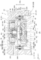
以下、本実施形態の圧縮機2の詳細について図2を参照して説明する。図2に示すように、圧縮機ハウジング20は、複数の金属製の部材が気密に組み合わされることによって構成される密閉容器である。具体的には、圧縮機ハウジング20は、吸入流路202および吐出流路204が形成されたメインハウジング部21、メインハウジング部21に形成された開口を閉塞する板状のサブハウジング部22、および内部ハウジング部23を含んで構成されている。
Hereinafter, the details of the
メインハウジング部21は、x方向における略中央部分に前述の収容空間200を形成するための有底円柱状の穴が形成されている。メインハウジング部21は、収容空間200の底面を形成する底壁部211、収容空間200の側面を形成する側壁部212、側壁部212においてy方向に突き出る膨出部213を含んで構成されている。底壁部211、側壁部212、および膨出部213は、一体の構造物として構成されている。
The main housing portion 21 is formed with a bottomed columnar hole for forming the above-mentioned
側壁部212には、吸入流路202および吐出流路204が形成されている。側壁部212の内側には、底壁部211から開口側に向かって段階的に断面積が大きくなるよう段部212aが形成されている。この段部212aは、側壁部212の内側の全周にわたって形成されている。
A
膨出部213は、図1に示すように、側壁部212における収容空間200を形成する部位からy方向に突き出ている。膨出部213は、圧縮機ハウジング20のうちx方向において放熱器3の一部および蒸発器5の一部に重なり合う部位である。
As shown in FIG. 1, the bulging portion 213 protrudes in the y direction from the portion of the side wall portion 212 forming the
膨出部213には、x方向に沿って貫通する貫通穴213aが形成されている。この貫通穴213aには、冷媒の減圧作用が発揮されるようにx方向における略中央部位に断面積が小さくなっている。本実施形態では、膨出部213に設けられた貫通穴213aの一部で減圧機器4が構成されている。なお、減圧機器4の詳細については後述する。
The bulging portion 213 is formed with a through
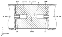
膨出部213には、放熱器3に対向する部位に後述する放熱器3の高圧導出部32が外部に露出しないように直結される中間導入部206が形成されている。中間導入部206は、放熱器3を通過した冷媒を減圧機器4に導くために設けられている。中間導入部206は、貫通穴213aの一端側に開口する開口部であり、後述する放熱器3の高圧導出部32を嵌め込むことが可能な大きさを有している。
The bulging portion 213 is formed with an
また、膨出部213には、蒸発器5に対向する部位に後述する蒸発器5の低圧導入部51が外部に露出しないように直結される中間導出部207が形成されている。中間導出部207は、減圧機器4を通過した冷媒を蒸発器5に導くために設けられている。中間導出部207は、貫通穴213aの他端側に開口する開口部であり、後述する蒸発器5の低圧導入部51を嵌め込むことが可能な大きさを有している。
Further, the bulging portion 213 is formed with an intermediate lead-out
ここで、本実施形態では、収容空間200、吸入流路202、および吐出流路204が、圧縮機構24を介して冷媒吸入部203から冷媒吐出部205に至る冷媒流路を構成する。また、本実施形態では、貫通穴213aが、減圧機器4を介して中間導入部206から中間導出部207に至る冷媒流路を構成する。
Here, in the present embodiment, the
サブハウジング部22は、図2に示すように、メインハウジング部21の開口を気密に閉塞可能な大きさを有する板状の部材で構成されている。圧縮機ハウジング20には、メインハウジング部21およびサブハウジング部22が気密に組み合わされることによって圧縮機構24および電動機25を収容する収容空間200が形成される。図示しないが、メインハウジング部21とサブハウジング部22との間には、ガスケットやOリング等からなるシール部材が配設されている。本実施形態では、メインハウジング部21およびサブハウジング部22が外殻形成部を構成している。
As shown in FIG. 2, the
内部ハウジング部23は、メインハウジング部21およびサブハウジング部22によって形成される収容空間200に収容されている。収容空間200は、内部ハウジング部23によって吸入空間200Aと吐出空間200Bとに分割されている。すなわち、内部ハウジング部23は、収容空間200を吸入空間200Aおよび吐出空間200Bに仕切る仕切部として機能する。
The
また、内部ハウジング部23は、圧縮機ハウジング20において圧縮機構24および電動機25を支持する支持部材として機能する。具体的には、内部ハウジング部23は、主軸26が挿通される円筒状の筒状部231、筒状部231に連なるとともに主軸26の径方向外側に延びる円環状のフランジ部232を備えている。筒状部231およびフランジ部232は、一体の構造物として構成されている。なお、本実施形態では、主軸26の軸心CLmに沿って延びる方向を軸方向DRaとし、当該軸方向DRaに直交する方向を径方向DRrとしている。
Further, the
筒状部231は、主軸26が挿通される挿通穴231aが形成されている。この挿通穴231aは、軸方向DRaに貫通する貫通穴で構成されている。この挿通穴231aには、主軸26を支持する第1軸受部263および第2軸受部264の軸方向DRaの位置を規制するための内側突起部231bが設けられている。
The tubular portion 231 is formed with an
具体的には、筒状部231は、圧縮機構24側からメインハウジング部21の底壁部211に向かって突き出る第1筒部233、電動機25側からサブハウジング部22に向かって突き出る第2筒部234を含んでいる。第1筒部233は、電動機25を支持する支持部である。また、第2筒部234は、圧縮機構24を支持する支持部である。
Specifically, the tubular portion 231 is a first cylinder portion 233 that protrudes from the
フランジ部232は、メインハウジング部21の段部212aの端面に対向するように、筒状部231から径方向DRrの外側に突き出ている。フランジ部232には、その外側部位に対して締結ボルト27が挿通される貫通穴232aが複数形成されている。また、フランジ部232には、旋回スクロール242に対向する部位に自転防止ピンPが嵌め込まれる溝232bが形成されている。
The
このように構成される内部ハウジング部23は、緩衝部材28を介してメインハウジング部21に連結されている。具体的には、内部ハウジング部23は、フランジ部232とメインハウジング部21の段部212aの端面との間に緩衝部材28が介在された状態で、締結ボルト27によってメインハウジング部21に連結されている。
The
ここで、緩衝部材28は、吸入空間200Aと吐出空間200Bとの連通を遮断し、且つ、圧縮機構24および電動機25の振動を減衰させることが可能な弾性体で構成されている。弾性体は、段部212aの端面を覆うことが可能な大きさを有する円環状の形状を有している。弾性体は、例えば、ガスバリア性および耐熱性に優れるゴム材料で構成されている。
Here, the cushioning
電動機25は、いわゆるアウタロータモータで構成されている。すなわち、電動機25は、回転磁界を生成するステータ251、ステータ251で生成された回転磁界によってステータ251の外側で回転するロータ252を含んで構成されている。
The
ステータ251は、金属製の磁性材料で形成された円筒状のステータコア251a、およびステータコア251aに巻き付けられたステータコイル251bで構成されている。ステータ251は、圧入等の固定手法によって内部ハウジング部23の第1筒部233の外側に固定されている。
The
ロータ252は、円筒状のロータ本体部252a、ロータ本体部252aの一方の開口を閉塞する端板部252b、ロータ本体部252aの内側に埋設された複数の磁石252cを含んで構成されている。
The
ロータ本体部252aには、複数の磁石252cがその周方向に所定の間隔をあけて埋設されている。端板部252bには、略中央部分に主軸26の電動機側端部261を受け入れるための貫通穴が形成されている。なお、電動機側端部261は、主軸26における圧縮機構24よりも電動機25側に近い端部である。
A plurality of
ロータ252は、磁石252cとステータコア251aとの間に微小な隙間が形成された状態で、連結機構29によって主軸26に連結されている。ロータ252と主軸26との連結機構29は、電動機側端部261に形成されたネジ溝291、ネジ溝291に螺合する連結ボルト292等で構成されている。
The
主軸26は、電動機25の回転動力を圧縮機構24に伝達する伝達部材である。主軸26は、上述の連結機構29が設けられた電動機側端部261、軸方向DRaにおける電動機側端部261の反対側の端部である圧縮側端部262を有している。
The
主軸26の電動機側端部261は、主軸26を筒状部231の挿通穴231aに挿通させた際に挿通穴231aから外部に露出するように構成されている。すなわち、主軸26は、筒状部231の挿通穴231aに挿通させた際に電動機側端部261が挿通穴231aの外部に露出するように軸方向DRaの寸法が設定されている。
The motor
主軸26は、第1軸受部263および第2軸受部264によって回転自在に支持されている。第1軸受部263は、主軸26のうち軸方向DRaにおいて電動機25側に近い部位を回転可能に支持するものである。第2軸受部264は、主軸26のうち軸方向DRaにおいて電動機25よりも圧縮機構24に近い部位を回転可能に支持するものである。
The
第1軸受部263および第2軸受部264それぞれは、内部ハウジング部23の筒状部231の内側に設置されている。第1軸受部263および第2軸受部264のうち、第1軸受部263は、径方向DRrにおいて、ステータ251と重なり合うように配置されている。すなわち、第1軸受部263は、筒状部231のうち、ステータ251が固定された部位の内側に設置されている。これにより、圧縮機2は、その軸方向DRaにおける体格が小さくなっている。
Each of the
主軸26の圧縮側端部262には、主軸26の軸心CLmに対して偏心する偏心軸部265が接続されている。この偏心軸部265は、その軸心CLsが主軸26の軸心CLmに対して主軸26の径方向DRrにずれている。偏心軸部265は、第3軸受部266を介して圧縮機構24に連結されている。具体的には、偏心軸部265の外周側は、第3軸受部266を介して圧縮機構24の旋回スクロール242が連結されている。第3軸受部266は、後述する旋回スクロール242のボス部242cの内側に圧入等の手段で固定されている。
An
ここで、主軸26に対して偏心軸部265が接続されていると、主軸26に対して偏心軸部265、第3軸受部266、旋回スクロール242の遠心力が作用する。このため、偏心軸部265には、主軸26に作用する遠心力を抑制するためのウェイトバランス267が設けられている。
Here, when the
圧縮機構24は、固定歯部241bと旋回歯部242bとを噛み合わせた状態で、旋回スクロール242を固定スクロール241に対して旋回させることで旋回スクロール242の外側から吸い込んだ冷媒を圧縮するスクロール型の圧縮機構で構成されている。
The
固定スクロール241は、内部ハウジング部23の第2筒部234の内側に固定された固定基板部241a、および固定基板部241aから突き出る渦巻き状の固定歯部241bを有する。固定基板部241aの略中央部分には、圧縮機構24で圧縮された冷媒を吐出する冷媒吐出口241cが形成されている。また、固定基板部241aには、冷媒吐出口241cから圧縮機構24への冷媒の逆流を防止するためのリード弁241dが設けられている。
The fixed
旋回スクロール242は、固定基板部241aのうち固定歯部241bが形成される面に対向して配置される旋回基板部242a、および旋回基板部242aから固定基板部241a側に向かって突き出る渦巻き状の旋回歯部242bを有する。
The
旋回基板部242aには、その略中央部分に偏心軸部265および第3軸受部266を受け入れるボス部242cが形成されている。また、旋回基板部242aには、自転防止ピンPと共に、旋回スクロール242の自転防止機構を構成する円形状のピン受入穴Hが形成されている。
The
固定スクロール241および旋回スクロール242は、固定歯部241bと旋回歯部242bとを噛み合わせることで、固定歯部241bと旋回歯部242bとの間に冷媒を圧縮する圧縮室が形成される。また、旋回スクロール242の外側には、圧縮室に冷媒を導入するための冷媒導入空間が形成される。
In the fixed
このように構成される圧縮機2は、例えば、内部ハウジング部23に対して圧縮機構24および電動機25を組み付けた組付体をメインハウジング部21に連結した後、メインハウジング部21の開口をサブハウジング部22で閉塞することによって得られる。
In the
続いて、冷凍サイクル装置1における圧縮機2以外の構成要素である放熱器3、減圧機器4、蒸発器5、送風機6について図1、図3~図6を参照して説明する。
Subsequently, the
放熱器3は、圧縮機2から吐出された高圧冷媒を後述する送風機6の第1送風部6Aによって供給される空気との熱交換によって放熱させる熱交換器である。放熱器3は、圧縮機ハウジング20に対して直に設置されている。
The
図1および図3に示すように、放熱器3は、圧縮機2から吐出された冷媒を内部に導入するための高圧導入部31が設けられている。この高圧導入部31は、y方向に沿って圧縮機ハウジング20側に突き出る筒形状の筒状部材で構成されている。また、放熱器3は、その内部を通過した冷媒を減圧機器4側に導出するための高圧導出部32が設けられている。この高圧導出部32は、x方向に沿って圧縮機ハウジング20側に突き出る筒形状の筒状部材で構成されている。
As shown in FIGS. 1 and 3, the
具体的には、放熱器3は、図3に示すように、複数のチューブ34とフィン35とで構成される熱交換コア部33、複数のチューブ34の長手方向の端部に接続される第1高圧タンク36と第2高圧タンク37を備える熱交換器で構成されている。
Specifically, as shown in FIG. 3, the
放熱器3は、第1高圧タンク36から熱交換コア部33の一部に流入した冷媒が第2高圧タンク37および熱交換コア部33の残部を介して第1高圧タンク36に流れるように構成されている。
The
このように構成される放熱器3は、第1高圧タンク36が、メインハウジング部21の側壁部212および膨出部213の双方に接するようにメインハウジング部21に対して設置されている。そして、第1高圧タンク36における圧縮機ハウジング20の冷媒吐出部205に対向する部位に高圧導入部31が設けられている。また、第1高圧タンク36における圧縮機ハウジング20の中間導入部206に対向する部位に高圧導出部32が設けられている。
The
ここで、放熱器3と圧縮機ハウジング20との連結手法の一例について図4を参照して説明する。図4に示すように、放熱器3は、中間導入部206に高圧導出部32を嵌め合わせた状態で、高圧導出部32を中心に回転させて冷媒吐出部205に高圧導入部31を嵌め合わせることで、圧縮機ハウジング20に対して連結することができる。
Here, an example of a connection method between the
減圧機器4は、放熱器3を通過した冷媒を減圧するものである。前述したように本実施形態の減圧機器4は、圧縮機ハウジング20の内部に形成されている。本実施形態の減圧機器4は、圧縮機ハウジング20の膨出部213に設けられた貫通穴213aに形成された固定絞りで構成されている。
The
具体的には、図5に示すように、貫通穴213aにおける中間導入部206と中間導出部207との間には、中間導入部206および中間導出部207よりも断面積が小さい縮小部213bが形成されている。減圧機器4を構成する固定絞りは、貫通穴213aの縮小部213bによって構成されている。
Specifically, as shown in FIG. 5, between the
蒸発器5は、減圧機器4で減圧された低圧冷媒を後述する送風機6の第2送風部6Bによって供給される空気との熱交換によって蒸発させる熱交換器である。蒸発器5は、放熱器3と同様に、圧縮機ハウジング20に対して直に設置されている。本実施形態の放熱器3および蒸発器5は、圧縮機ハウジング20の膨出部213を介して互いに対向するように、圧縮機ハウジング20に対して設置されている。
The
図1および図6に示すように、蒸発器5は、減圧機器4で減圧された冷媒を内部に導入するための低圧導入部51が設けられている。この低圧導入部51は、y方向に沿って圧縮機ハウジング20側に突き出る筒形状の筒状部材で構成されている。また、蒸発器5は、その内部を通過した冷媒を圧縮機2側に導出するための低圧導出部52が設けられている。この低圧導出部52は、x方向に沿って圧縮機ハウジング20側に突き出る筒形状の筒状部材で構成されている。
As shown in FIGS. 1 and 6, the
具体的には、蒸発器5は、図6に示すように、複数のチューブ54とフィン55とで構成される熱交換コア部53、複数のチューブ54の長手方向の端部に接続される第1低圧タンク56と第2低圧タンク57を備える熱交換器で構成されている。
Specifically, as shown in FIG. 6, the
蒸発器5は、第1低圧タンク56から熱交換コア部53の一部に流入した冷媒が第2低圧タンク57および熱交換コア部53の残部を介して第1低圧タンク56に流れるように構成されている。
The
このように構成される蒸発器5は、第1低圧タンク56が、メインハウジング部21の側壁部212および膨出部213の双方に接するようにメインハウジング部21に対して設置されている。そして、第1低圧タンク56における圧縮機ハウジング20の中間導出部207に対向する部位に低圧導入部51が設けられている。また、第1低圧タンク56における圧縮機ハウジング20の冷媒吸入部203に対向する部位に低圧導出部52が設けられている。
The
ここで、蒸発器5と圧縮機ハウジング20とは、放熱器3と圧縮機ハウジング20との連結手法と同様の手法によって連結することができる。すなわち、蒸発器5は、中間導出部207に低圧導入部51を嵌め合わせた状態で、低圧導入部51を中心に回転させて冷媒吸入部203に低圧導出部52を嵌め合わせることで、圧縮機ハウジング20に対して連結することができる。
Here, the
送風機6は、放熱器3および蒸発器5に対して空気を供給するものである。図1に示すように、送風機6は、放熱器3および蒸発器5との間に配置されている。送風機6は、放熱器3に対して空気を供給する第1送風部6Aおよび蒸発器5に対して空気を供給する第2送風部6Bを備えている。
The
第1送風部6Aは、放熱器3にて加熱された温風が流通する温風ケース61A、温風ケース61Aに収容される温風ファン62A、および温風ファン62Aを駆動するファンモータ63Aを備えている。図示しないが、温風ケース61Aは、シート付近に温風を吹き出す温風吹出ダクト、または、温風をシート付近以外の空間に排気する温風排気ダクトに接続されている。
The
また、第2送風部6Bは、蒸発器5にて冷却された冷風が流通する冷風ケース61B、冷風ケース61Bに収容される冷風ファン62B、および冷風ファン62Bを駆動するファンモータ63Bを備えている。図示しないが、冷風ケース61Bは、シート付近に冷風を吹き出す冷風吹出ダクト、または、冷風をシート付近以外の空間に排気する冷風排気ダクトに接続されている。
Further, the
次に、本実施形態の冷凍サイクル装置1の作動について図7を参照して説明する。シート付近の空調が開始される場合、車両に搭載されたバッテリから電動機25のステータ251、送風機6の各ファンモータ63A、63Bに対して給電される。これにより、電動機25によって圧縮機構24が駆動されることで冷凍サイクル装置1のサイクル内を冷媒が循環する。また、各ファンモータ63A、63Bによって温風ファン62Aおよび冷風ファン62Bが駆動されることで、放熱器3を通過する気流および蒸発器5を通過する気流が発生する。
Next, the operation of the
具体的には、圧縮機構24から吐出空間200Bに吐出された冷媒は、図7の矢印Fc1に示すように、吐出流路204および冷媒吐出部205を介して放熱器3に流入する。放熱器3に流入した冷媒は、図7の矢印Fc2に示すように、第1高圧タンク36→熱交換コア部33→第2高圧タンク37→熱交換コア部33→第1高圧タンク36の順に流れた後、中間導入部206を介して減圧機器4側に流入する。放熱器3に流入した冷媒は、熱交換コア部33を通過する際に、第1送風部6Aによって供給される空気と熱交換して放熱する。第1送風部6Aによって供給される空気は、図7の矢印Fa1に示すように、放熱器3を流れる冷媒によって加熱された後、所望の空間に吹き出される。
Specifically, the refrigerant discharged from the
減圧機器4に流入した冷媒は、固定絞りを構成する貫通穴213aの縮小部213bを通過する際に減圧される。減圧機器4にて減圧された冷媒は、中間導出部207を介して蒸発器5に流入する。
The refrigerant flowing into the
蒸発器5に流入した冷媒は、図7の矢印Fc3に示すように、第1低圧タンク56→熱交換コア部53→第2低圧タンク57→熱交換コア部53→第1低圧タンク56の順に流れた後、冷媒吸入部203を介して圧縮機2に流入する。蒸発器5に流入した冷媒は、熱交換コア部53を通過する際に、第2送風部6Bによって供給される空気と熱交換して蒸発する。第2送風部6Bによって供給される空気は、図7の矢印Fa2に示すように、蒸発器5を流れる冷媒の蒸発時の吸熱作用によって冷却された後、所望の空間に吹き出される。
As shown by the arrow Fc3 in FIG. 7, the refrigerant flowing into the
圧縮機2に吸入された冷媒は、図7の矢印Fc4に示すように、吸入流路202を介して収容空間200(具体的には、吸入空間200A)に流れる。その後、吸入空間200Aの冷媒が圧縮機構24に吸入され、吸入された冷媒が圧縮機構24で圧縮される。
As shown by the arrow Fc4 in FIG. 7, the refrigerant sucked into the
以上説明した冷凍サイクル装置1は、圧縮機ハウジング20に対して、放熱器3の高圧導入部31が外部に露出しないように直結される冷媒吐出部205、および蒸発器5の低圧導出部52が外部に露出しないように直結される冷媒吸入部203が設けられている。
In the
このように、放熱器3および蒸発器5が圧縮機ハウジング20に直結される構造とすれば、圧縮機2の圧力脈動や機械振動による応力が、サイクル構成機器のうち放熱器3および蒸発器5といった大型で耐久性を有する機器に対して直接的に作用する。このため、冷媒配管を介して圧縮機2、放熱器3、蒸発器5が接続される従来の構造に比べて冷凍サイクル装置1の耐久性を確保することができる。
As described above, if the
また、放熱器3および蒸発器5が圧縮機ハウジング20に直結される構造では、冷媒配管を介して圧縮機2、放熱器3、蒸発器5が接続される従来の構造に比べて、部品点数が少なくなるので、冷凍サイクル装置1の簡素化並びに小型化を図ることができる。
Further, in the structure in which the
ところで、サイクル内の冷媒の圧力損失は、冷媒流路が長いほど大きくなり、冷媒流路が短いほど小さくなる。このため、放熱器3および蒸発器5が圧縮機ハウジング20に直結される構造とすれば、冷媒配管を介して圧縮機2、放熱器3、蒸発器5が接続される従来の構造に比べて冷媒流路が短縮されるのでサイクル内における冷媒の圧力損失を抑制することが可能となる。
By the way, the pressure loss of the refrigerant in the cycle increases as the refrigerant flow path becomes longer, and decreases as the refrigerant flow path becomes shorter. Therefore, if the
また、冷媒配管を介して圧縮機2、放熱器3、蒸発器5が接続される従来の構造では、冷媒配管が外部に露出するため、周囲環境との熱交換による熱損失が避けられない。
Further, in the conventional structure in which the
これに対して、本実施形態の冷凍サイクル装置1では、放熱器3の高圧導入部31が外部に露出しないように冷媒吐出部205に直結され、蒸発器5の低圧導出部52が外部に露出しないように冷媒吸入部203に直結されている。これによると、周囲環境との熱交換による熱損失を抑制することができる。
On the other hand, in the refrigerating
加えて、本実施形態の冷凍サイクル装置1は、減圧機器4が圧縮機ハウジング20の内部に設けられている。そして、圧縮機ハウジング20に対して、放熱器3の高圧導出部32が外部に露出しないように直結される中間導入部206、および蒸発器5の低圧導入部51が外部に露出しないように直結される中間導出部207が設けられている。
In addition, in the
このように圧縮機ハウジング20の内部に減圧機器4を設ける構成とすれば、冷媒配管を介して放熱器3、減圧機器4、蒸発器5が接続される従来の構造に比べて冷凍サイクル装置1の耐久性を確保することができる。
If the
また、圧縮機ハウジング20の内部に減圧機器4を設ける構成とすれば、圧縮機ハウジング20の外部に別体の減圧機器4を設置する場合に比べて、冷凍サイクル装置1の簡素化を図ることができる。
Further, if the
また、本実施形態の冷凍サイクル装置1は、圧縮機ハウジング20のうち減圧機器4を構成する部位が放熱器3および蒸発器5に直結される構造になっている。このような構造では、冷媒配管を介して放熱器3、減圧機器4、蒸発器5が接続される従来の構造に比べて、部品点数が少なくなるので、冷凍サイクル装置1の簡素化並びに小型化を図ることができる。
Further, the refrigerating
具体的には、本実施形態の減圧機器4は、圧縮機ハウジング20の内部の貫通穴213aに形成された固定絞りで構成されている。このように減圧機器4を圧縮機ハウジング20に形成した固定絞りで構成すれば、減圧機器4を可変絞り機構を含む構成とする場合に比べて、部品点数が少なくなるので、冷凍サイクル装置1の簡素化並びに小型化を図ることができる。
Specifically, the
また、本実施形態の冷凍サイクル装置1は、圧縮機2の圧縮機構24がスクロール型の圧縮機構で構成されている。スクロール型の圧縮機構は、レシプロ型の圧縮機構の如く軸方向DRaに可動する可動部材が必要ないので、圧縮機構24全体として軸方向DRaの体格を小型化することができる。このため、圧縮機構24としてスクロール型の圧縮機構を採用すれば、圧縮機2全体としての軸方向DRaの体格を抑えることが可能となる。
Further, in the
特に、本実施形態の圧縮機2は、外殻を形成するメインハウジング部21およびサブハウジング部22に収容される内部ハウジング部23によって圧縮機構24および電動機25を支持される構成になっている。そして、内部ハウジング部23は、圧縮機構24および電動機25の振動を減衰させるための緩衝部材28を介してメインハウジング部21に連結されている。
In particular, the
これによると、圧縮機構24および電動機25に生ずる振動が緩衝部材28で減衰されることで、圧縮機ハウジング20のメインハウジング部21およびサブハウジング部22に圧縮機構24および電動機25の振動が伝達され難くなる。これにより、冷媒吐出部205および冷媒吸入部203が形成されたメインハウジング部21の振動が抑制されることで、圧縮機ハウジング20と放熱器3および蒸発器5の連結部分に加わる応力の抑えることができる。このことは、冷凍サイクル装置1の耐久性の向上に大きく寄与する。
According to this, the vibration generated in the
また、本実施形態の圧縮機2は、内部ハウジング部23に対して圧縮機構24および電動機25を組み付けた組付体をメインハウジング部21に対して連結した後、メインハウジング部21にサブハウジング部22を連結することで得られる。これによると、圧縮機構24、電動機25、および内部ハウジング部23をユニット化すれば、圧縮機2の製造時における組付性の向上を図ることができる。
Further, in the
(第2実施形態)
次に、第2実施形態について、図8~図10を参照して説明する。本実施形態では、圧縮機ハウジング20に対して高圧側貯留部215が設けられている点が第1実施形態と相違している。本実施形態では、第1実施形態と異なる部分について主に説明し、第1実施形態と同様の部分について説明を省略することがある。
(Second Embodiment)
Next, the second embodiment will be described with reference to FIGS. 8 to 10. The present embodiment is different from the first embodiment in that the
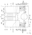
高圧側貯留部215は、サイクル内における余剰となる液冷媒を貯留するために設けられている。図8に示すように、高圧側貯留部215は、圧縮機ハウジング20のうちメインハウジング部21の膨出部213に対して設けられている。より詳細には、高圧側貯留部215は、膨出部213に形成された貫通穴213aのうち、中間導入部206と減圧機器4を構成する縮小部213bとの間に設けられている。すなわち、高圧側貯留部215は、貫通穴213aにおける縮小部213bよりも冷媒流れ上流側に設けられている。
The high-pressure
具体的には、高圧側貯留部215は、図9に示すように、鉛直方向(すなわち、z方向)に延びる有底穴215aおよび有底穴215aの開口を閉塞する閉塞板部215bで構成されている。この有底穴215aには、中間導入部206からの冷媒を流入させる上流側開口部215cおよび内部に貯留された冷媒を減圧機器4である縮小部213b側に流出させる下流側開口部215dが形成されている。高圧側貯留部215は、その内部に貯留された液冷媒が縮小部213b側に流れるように、下流側開口部215dが上流側開口部215cよりも鉛直方向の下方側に形成されている。
Specifically, as shown in FIG. 9, the high-pressure
ここで、減圧機器4および高圧側貯留部215を圧縮機ハウジング20の内部に形成すると、減圧機器4を流れる冷媒や高圧側貯留部215に貯留される液冷媒と、圧縮機構24に吸入される冷媒や圧縮機構24から吐出される冷媒とが熱交換してしまう。特に、高圧側貯留部215に貯留された液冷媒と圧縮機構24から吐出される冷媒とが熱交換すると、高圧側貯留部215に貯留された液冷媒が蒸発することが懸念される。
Here, when the
そこで、本実施形態では、圧縮機ハウジング20に対して、熱交換抑制部216が設けられている。図10に示すように、熱交換抑制部216は、圧縮機構24を介して冷媒吸入部203から冷媒吐出部205に至る冷媒流路と減圧機器4を介して中間導入部206から中間導出部207に至る冷媒流路との間に設けられたスリット状の溝216aで構成されている。この熱交換抑制部216によって、圧縮機構24を介して冷媒吸入部203から冷媒吐出部205に至る冷媒流路と減圧機器4を介して中間導入部206から中間導出部207に至る冷媒流路とが熱的に分断される。
Therefore, in the present embodiment, the
以上説明した本実施形態の冷凍サイクル装置1は、第1実施形態と共通の構成を備えている。このため、本実施形態の冷凍サイクル装置1は、第1実施形態と共通の構成から奏される作用効果を第1実施形態と同様に得ることができる。このことは、以降の実施形態においても同様である。
The refrigerating
本実施形態の冷凍サイクル装置1は、圧縮機ハウジング20に対して液冷媒を貯留可能な高圧側貯留部215が設けられている。このように、圧縮機ハウジング20に対して高圧側貯留部215を設ける構成とすれば、高圧側貯留部215にサイクル内の余剰となる液冷媒を一時的に貯留可能となるので、サイクルの負荷変動時にサイクル内の冷媒量が不足することを避けることができる。
The
加えて、高圧側貯留部215には、内部に中間導入部206からの冷媒を流入させる上流側開口部215c、内部に貯留された冷媒を減圧機器4側に流出させる下流側開口部215dが形成されている。そして、下流側開口部215dが、上流側開口部215cよりも鉛直方向の下方側に形成されている。
In addition, the high-pressure
これによると、高圧側貯留部215に貯留された液冷媒が減圧機器4側に流れ易くなる。すなわち、減圧機器4側には、エンタルピが小さい液冷媒が流れ易くなる。この結果、蒸発器5の前後のエンタルピ差を確保して、蒸発器5における吸熱能力の向上を図ることができる。なお、「鉛直方向」とは、水平面に対して垂直な方向を意味しており、重力が作用する方向を意味すると解釈することができる。
According to this, the liquid refrigerant stored in the high-pressure
また、圧縮機ハウジング20には、圧縮機構24を介して冷媒吸入部203から冷媒吐出部205に至る冷媒流路と減圧機器4を介して中間導入部206から中間導出部207に至る冷媒流路とが熱的に分断するための熱交換抑制部216が設けられている。
Further, in the
これによると、減圧機器4を流れる冷媒や高圧側貯留部215に貯留される液冷媒と、圧縮機構24に吸入される冷媒や圧縮機構24から吐出される冷媒との不必要な熱交換を抑制することができる。
According to this, unnecessary heat exchange between the refrigerant flowing through the
(第2実施形態の変形例)
上述の第2実施形態では、高圧側貯留部215の下流側開口部215dを上流側開口部215cよりも鉛直方向の下方側に形成される例について説明したが、これに限定されない。高圧側貯留部215は、例えば、下流側開口部215dが上流側開口部215cと鉛直方向において同等となる位置に形成されていてもよい。
(Modified example of the second embodiment)
In the second embodiment described above, an example in which the
上述の第2実施形態では、圧縮機ハウジング20に対して熱交換抑制部216が設けられた例について説明したが、これに限定されない。冷凍サイクル装置1は、圧縮機ハウジング20における熱交換抑制部216が省略された構成になっていてもよい。
In the second embodiment described above, an example in which the heat
上述の第2実施形態では、圧縮機ハウジング20に対して高圧側貯留部215が設けられた例について説明したが、これに限定されない。冷凍サイクル装置1は、圧縮機ハウジング20における高圧側貯留部215が省略された構成になっていてもよい。
In the second embodiment described above, an example in which the high-pressure
上述の第2実施形態では、熱交換抑制部216が圧縮機ハウジング20に形成されたスリット状の溝216aで構成される例について説明したが、これに限定されない。熱交換抑制部216は、圧縮機ハウジング20よりも熱抵抗の高い材料で構成される熱緩衝体で構成されていてもよい。
In the second embodiment described above, an example in which the heat
上述の第2実施形態では、横置型の構造を有する冷凍サイクル装置1の圧縮機ハウジング20に高圧側貯留部215を設ける構成を適用する例について説明したが、これに限定されない。圧縮機ハウジング20に高圧側貯留部215を設ける構成は、圧縮機2の上方に、放熱器3、減圧機器4、蒸発器5、および送風機6が設置される縦置型の構造を有する冷凍サイクル装置1に対しても適用可能である。この場合、高圧側貯留部215は、液冷媒が貯留可能なように、鉛直方向(すなわち、z方向)に延びる有底穴215aを含む構成とすればよい。
In the second embodiment described above, an example of applying a configuration in which the high-pressure
(第3実施形態)
次に、第3実施形態について、図11、図12を参照して説明する。本実施形態では、減圧機器4が圧縮機ハウジング20の外部に配置されている点が第1実施形態と相違している。本実施形態では、第1実施形態と異なる部分について主に説明し、第1実施形態と同様の部分について説明を省略することがある。
(Third Embodiment)
Next, the third embodiment will be described with reference to FIGS. 11 and 12. The present embodiment differs from the first embodiment in that the
図11に示すように、本実施形態の圧縮機ハウジング20は、x方向における略中央部分がy方向に突き出ていない直方体状の外形状を有している。すなわち、本実施形態の圧縮機ハウジング20は、第1実施形態における膨出部213に相当する構成が設けられていない。
As shown in FIG. 11, the
本実施形態の減圧機器4は、圧縮機ハウジング20の外部に配置されている。具体的には、減圧機器4は、放熱器3の第1高圧タンク36と蒸発器5の第1低圧タンク56とで挟持されるように放熱器3と蒸発器5との間に配置されている。
The
図12に示すように、減圧機器4は、外殻を構成するバルブ本体41、およびバルブ本体41の内部に設けられた絞り機構42を含んで構成されている。バルブ本体41は、金属製のブロック体で構成されている。
As shown in FIG. 12, the
バルブ本体41には、x方向に沿って貫通する貫通穴411が形成されている。この貫通穴411の内部には、冷媒の減圧作用を発揮する絞り機構42が配置されている。絞り機構42は、内部に絞り流路421aが形成された円筒形状のオリフィス421で構成されている。
The
バルブ本体41には、放熱器3に対向する部位に放熱器3の高圧導出部32が外部に露出しないように直結されるバルブ導入部412が形成されている。バルブ導入部412は、バルブ本体41の貫通穴411の一端側に開口する開口部であり、放熱器3の高圧導出部32を嵌め込むことが可能な大きさを有している。
The valve
バルブ本体41には、蒸発器5に対向する部位に蒸発器5の低圧導入部51が外部に露出しないように直結されるバルブ導出部413が形成されている。バルブ導出部413は、バルブ本体41の貫通穴411の他端側に開口する開口部であり、蒸発器5の低圧導入部51を嵌め込むことが可能な大きさを有している。
The valve
その他の構成は、第1実施形態と同様である。本実施形態の冷凍サイクル装置1は、圧縮機ハウジング20の外部に設けた減圧機器4が放熱器3および蒸発器5に直結される構造になっている。これによると、冷媒配管を介して放熱器3、減圧機器4、蒸発器5が接続される従来の構造に比べて、部品点数が少なくなるので、冷凍サイクル装置1の簡素化並びに小型化を図ることができる。
Other configurations are the same as those of the first embodiment. The refrigerating
(第4実施形態)
次に、第4実施形態について、図13~図15を参照して説明する。本実施形態では、減圧機器4のバルブ本体41に高圧側貯留部415が設けられている点が第3実施形態と相違している。本実施形態では、第3実施形態と異なる部分について主に説明し、第3実施形態と同様の部分について説明を省略することがある。
(Fourth Embodiment)
Next, the fourth embodiment will be described with reference to FIGS. 13 to 15. The present embodiment is different from the third embodiment in that the
図13に示すように、バルブ本体41には、貫通穴411におけるバルブ導入部412とバルブ導出部413との間に、バルブ導入部412とバルブ導出部413よりも断面積が小さい縮小部414が設けられている。この縮小部414は、冷媒の減圧作用を発揮する絞り機構として機能する。
As shown in FIG. 13, in the valve
また、バルブ本体41には、サイクル内における余剰となる液冷媒を貯留するための高圧側貯留部415が設けられている。高圧側貯留部415は、バルブ本体41に形成された貫通穴411のうち、バルブ導入部412と絞り機構42を構成する縮小部414との間に設けられている。すなわち、高圧側貯留部415は、貫通穴411における縮小部414よりも冷媒流れ上流側に設けられている。
Further, the valve
具体的には、高圧側貯留部415は、図14に示すように、z方向に延びる有底穴415aおよび有底穴415aの開口を閉塞する閉塞板部415bで構成されている。この有底穴415aには、バルブ導入部412からの冷媒を流入させる上流側開口部415cおよび内部に貯留された冷媒を絞り機構を構成する縮小部414側に流出させる下流側開口部415dが形成されている。高圧側貯留部415は、その内部に貯留された液冷媒が縮小部414側に流れるように、下流側開口部415dが上流側開口部415cよりも鉛直方向(すなわち、z方向)の下方側に形成されている。
Specifically, as shown in FIG. 14, the high-pressure
このように構成される減圧機器4は、圧縮機ハウジング20との間に、熱交換抑制部416が設けられている。図15に示すように、熱交換抑制部416は、圧縮機構24を介して冷媒吸入部203から冷媒吐出部205に至る冷媒流路と絞り機構である縮小部414を介してバルブ導入部412からバルブ導出部413に至る冷媒流路との間の空隙で構成されている。この熱交換抑制部416によって、圧縮機構24を介して冷媒吸入部203から冷媒吐出部205に至る冷媒流路と縮小部414を介してバルブ導入部412からバルブ導出部413に至る冷媒流路とが熱的に分断される。本実施形態では、バルブ本体41に形成された貫通穴411が、縮小部414を介してバルブ導入部412からバルブ導出部413に至る冷媒流路を構成している。
The
以上説明した本実施形態の冷凍サイクル装置1は、第3実施形態と共通の構成を備えている。このため、本実施形態の冷凍サイクル装置1は、第3実施形態と共通の構成から奏される作用効果を第3実施形態と同様に得ることができる。
The refrigerating
本実施形態の冷凍サイクル装置1は、バルブ本体41の貫通穴411のうちバルブ導入部412と減圧機器4として機能する縮小部414と間に液冷媒を貯留可能な高圧側貯留部415が設けられている。
The
このように、バルブ本体41に対して高圧側貯留部415を設ける構成とすれば、高圧側貯留部215にサイクル内の余剰となる液冷媒を一時的に貯留可能となるので、サイクルの負荷変動時にサイクル内の冷媒量が不足することを避けることができる。
In this way, if the high-pressure
加えて、高圧側貯留部415には、内部にバルブ導入部412からの冷媒を流入させる上流側開口部415c、内部に貯留された冷媒を絞り機構42である縮小部414側に流出させる下流側開口部415dが形成されている。そして、下流側開口部415dが、上流側開口部415cよりも鉛直方向の下方側に形成されている。
In addition, the high-pressure
これによると、高圧側貯留部415に貯留された液冷媒が縮小部414側に流れ易くなる。すなわち、縮小部414側には、エンタルピが小さい液冷媒が流れ易くなる。この結果、蒸発器5の前後のエンタルピ差を確保して、蒸発器5における吸熱能力の向上を図ることができる。
According to this, the liquid refrigerant stored in the high-pressure
また、バルブ本体41と圧縮機ハウジング20との間には、冷媒吸入部203から冷媒吐出部205に至る冷媒流路とバルブ導入部412からバルブ導出部413に至る冷媒流路とを熱的に分断する熱交換抑制部416が設けられている。これによると、縮小部414を流れる冷媒や高圧側貯留部415に貯留される液冷媒と、圧縮機構24に吸入される冷媒や圧縮機構24から吐出される冷媒との不必要な熱交換を抑制することができる。
Further, between the valve
(第4実施形態の変形例)
上述の第4実施形態では、高圧側貯留部415の下流側開口部415dを上流側開口部415cよりも鉛直方向の下方側に配置されている例について説明したが、これに限定されない。高圧側貯留部415は、例えば、下流側開口部415dが上流側開口部415cと鉛直方向において同等となる位置に配置されていてもよい。
(Modified example of the fourth embodiment)
In the above-mentioned fourth embodiment, an example in which the
上述の第4実施形態では、バルブ本体41と圧縮機ハウジング20との間に熱交換抑制部416が設けられた例について説明したが、これに限定されない。冷凍サイクル装置1は、熱交換抑制部216が省略された構成になっていてもよい。
In the fourth embodiment described above, an example in which the heat
上述の第4実施形態では、バルブ本体41に対して高圧側貯留部415が設けられた例について説明したが、これに限定されない。冷凍サイクル装置1は、バルブ本体41における高圧側貯留部415が省略された構成になっていてもよい。
In the above-mentioned fourth embodiment, an example in which the high-pressure
上述の第4実施形態では、熱交換抑制部416がバルブ本体41と圧縮機ハウジング20との間に設けられた空隙で構成される例について説明したが、これに限定されない。熱交換抑制部416は、バルブ本体41および圧縮機ハウジング20よりも熱抵抗の高い材料で構成される熱緩衝体で構成されていてもよい。
In the fourth embodiment described above, an example in which the heat
上述の第4実施形態では、絞り機構42がバルブ本体41に形成された縮小部414で構成される例について説明したが、これに限定されない。絞り機構42は、例えば、第3実施形態で説明したオリフィス421で構成されていてもよい。
In the above-mentioned fourth embodiment, an example in which the
上述の第4実施形態では、横置型の構造を有する冷凍サイクル装置1のバルブ本体41に高圧側貯留部415を設ける構成を適用する例について説明したが、これに限定されない。バルブ本体41に高圧側貯留部415を設ける構成は、圧縮機2の上方に、放熱器3、減圧機器4、蒸発器5、および送風機6が設置される縦置型の構造を有する冷凍サイクル装置1に対しても適用可能である。この場合、高圧側貯留部415は、液冷媒が貯留可能なように、鉛直方向(すなわち、z方向)に延びる有底穴415aを含む構成とすればよい。
In the above-mentioned fourth embodiment, an example of applying a configuration in which the high-pressure
(第5実施形態)
次に、第5実施形態について、図16、図17を参照して説明する。本実施形態では、圧縮機ハウジング20に対して低圧側貯留部217が設けられている点が第1実施形態と相違している。本実施形態では、第1実施形態と異なる部分について主に説明し、第1実施形態と同様の部分について説明を省略することがある。
(Fifth Embodiment)
Next, the fifth embodiment will be described with reference to FIGS. 16 and 17. The present embodiment is different from the first embodiment in that the
図16に示すように、低圧側貯留部217は、サイクル内における余剰となる液冷媒を貯留するために設けられている。低圧側貯留部217は、圧縮機ハウジング20のうち吸入流路202を構成する部位に対して設けられている。より詳細には、低圧側貯留部217は、圧縮機ハウジング20のうち冷媒吸入部203と収容空間200との間に設けられている。
As shown in FIG. 16, the low-pressure
具体的には、低圧側貯留部417は、図17に示すように、z方向に延びる有底穴217aおよび有底穴217aの開口を閉塞する閉塞板部217bで構成されている。この有底穴217aには、冷媒吸入部203からの冷媒を流入させる上流側開口部217cおよび内部に貯留された冷媒を収容空間200側に流出させる下流側開口部217dが形成されている。下流側開口部217dは、内部に貯留された液冷媒が収容空間200側に流れ難くなるように、鉛直方向において有底穴217aの底面よりも閉塞板部217bに近い位置に形成されている。なお、上流側開口部217cは、鉛直方向における下流側開口部217dと同等となる位置に形成されている。
Specifically, as shown in FIG. 17, the low-pressure side storage portion 417 is composed of a bottomed
その他の構成は、第1実施形態と同様である。本実施形態の冷凍サイクル装置1は、圧縮機ハウジング20に形成された吸入流路202に液冷媒を貯留可能な低圧側貯留部217が設けられている。このように、吸入流路202に低圧側貯留部417を設ける構成とすれば、低圧側貯留部217にサイクル内の余剰となる液冷媒を一時的に貯留可能となるので、サイクルの負荷変動時にサイクル内の冷媒量が不足することを避けることができる。
Other configurations are the same as those of the first embodiment. The
加えて、低圧側貯留部217は、その内部に貯留された液冷媒が収容空間200側に流れ難い構造になっている。これによると、圧縮機構24で液冷媒が圧縮されること(すなわち、液バック)を抑制することができる。
In addition, the low-pressure
(第5実施形態の変形例)
上述の第5実施形態では、低圧側貯留部217の下流側開口部217dが上流側開口部217cと同等なる位置に形成される例について説明したが、これに限定されない。低圧側貯留部217は、例えば、下流側開口部217dが上流側開口部217cよりも鉛直方向の上方側に形成されていてもよい。
(Variation example of the fifth embodiment)
In the fifth embodiment described above, an example in which the
上述の第5実施形態では、第1実施形態の冷凍サイクル装置1を前提とする構成に対して、圧縮機ハウジング20に低圧側貯留部217を設ける構成を適用する例について説明したが、これに限定されない。圧縮機ハウジング20に低圧側貯留部217を設ける構成は、第1実施形態以外の実施形態の冷凍サイクル装置1においても適用可能である。
In the fifth embodiment described above, an example in which a configuration in which the low-pressure
(第6実施形態)
次に、第6実施形態について、図18、図19を参照して説明する。本実施形態では、低圧側貯留部219が圧縮機ハウジング20とは別体で構成されている点が第5実施形態と相違している。本実施形態では、第5実施形態と異なる部分について主に説明し、第5実施形態と同様の部分について説明を省略することがある。
(Sixth Embodiment)
Next, the sixth embodiment will be described with reference to FIGS. 18 and 19. The present embodiment is different from the fifth embodiment in that the low pressure
圧縮機ハウジング20には、吸入流路202を構成する部位に、低圧側貯留部219を収容するための貯留空間218が形成されている。この貯留空間218は、圧縮機ハウジング20に形成された有底穴218a、有底穴218aを閉塞する閉塞部材218bによって形成されている。有底穴218aは、鉛直方向に沿って延びている。
In the
低圧側貯留部219は、圧縮機ハウジング20とは別体で構成されている。低圧側貯留部219は、液冷媒を貯留可能な有底筒状の部材で構成されている。具体的には、低圧側貯留部219には、有底筒状の貯留部219a、貯留部219aを圧縮機ハウジング20に対して連結するための連結部219bを有している。
The low-pressure
貯留部219aは、その上面が開口しており、当該開口が冷媒吸入部203からの冷媒を流入させる上流側開口部219cを構成している。また、貯留部219aの側壁部219dに対して、貯留部219aの内部に貯留された冷媒を収容空間200側に流出させる下流側開口部219eが形成されている。この下流側開口部219eは、貯留部219aの底壁部219fよりも上流側開口部219cに近い位置に形成されている。
The upper surface of the
低圧側貯留部219は、貯留空間218を形成する壁面である有底穴218aとの間に圧縮機構24に吸入されるガス冷媒が流れるように貯留空間218に配置されている。具体的には、低圧側貯留部219は、貯留部219aと有底穴218aとの間にガス冷媒が流れる冷媒流路218cが形成されるように、貯留部219aが有底穴218aから離間している。
The low-pressure
その他の構成は、第5実施形態と同様である。本実施形態の冷凍サイクル装置1は、第5実施形態と共通の構成を備えており、第5実施形態と共通の構成から奏される作用効果を第5実施形態と同様に得ることができる。
Other configurations are the same as those in the fifth embodiment. The refrigerating
本実施形態の冷凍サイクル装置1は、低圧側貯留部219と圧縮機ハウジング20の内部の貯留空間218を形成する壁面との間に圧縮機構24に吸入される低温の冷媒が流れる構造になっている。これによると、低圧側貯留部219に貯留された液冷媒に圧縮機ハウジング20の熱が伝わり難くなる。すなわち、圧縮機ハウジング20の熱によって低圧側貯留部219に貯留された液冷媒の蒸発を抑制することができる。これにより、サイクルの負荷変動時にサイクル内の冷媒量が不足することを避けることができる。
The refrigerating
(第7実施形態)
次に、第7実施形態について、図20、図21を参照して説明する。本実施形態では、冷凍サイクル装置1の圧縮機2の上方に放熱器3、減圧機器4、蒸発器5が設置されている点が第6実施形態と相違している。本実施形態では、第6実施形態と異なる部分について主に説明し、第6実施形態と同様の部分について説明を省略することがある。
(7th Embodiment)
Next, the seventh embodiment will be described with reference to FIGS. 20 and 21. The present embodiment is different from the sixth embodiment in that the
図20に示すように、冷凍サイクル装置1は、圧縮機2の上方に、放熱器3、減圧機器4、蒸発器5、および送風機6が設置される縦置型の構造になっている。すなわち、本実施形態の冷凍サイクル装置1は、放熱器3、減圧機器4、蒸発器5、送風機6が、鉛直方向(すなわち、z方向)において圧縮機2と重なり合うように配置されている。
As shown in FIG. 20, the
このような縦置型の構造を有する冷凍サイクル装置1では、図20および図21に示すように、圧縮機ハウジング20に対して鉛直方向(すなわち、z方向)に延びる円柱状の貯留空間218が形成される。この貯留空間218に対して、鉛直方向に延びる貯留部219aが収容される構成になっている。これにより、縦置型の構造を有する冷凍サイクル装置1においても、低圧側貯留部219に対して液冷媒を貯留することが可能となる。
In the refrigerating
その他の構成は、第6実施形態と同様である。本実施形態の冷凍サイクル装置1は、第6実施形態と共通の構成を備えており、第6実施形態と共通の構成から奏される作用効果を第7実施形態と同様に得ることができる。
Other configurations are the same as those in the sixth embodiment. The refrigerating
(第8実施形態)
次に、第8実施形態について、図22を参照して説明する。本実施形態では、減圧機器4がキャピラリチューブ43で構成されている点が第1実施形態と相違している。本実施形態では、第1実施形態と異なる部分について主に説明し、第1実施形態と同様の部分について説明を省略することがある。
(8th Embodiment)
Next, the eighth embodiment will be described with reference to FIG. 22. The present embodiment is different from the first embodiment in that the
図22に示すように、本実施形態の冷凍サイクル装置1は、減圧機器4がキャピラリチューブ43で構成されている。キャピラリチューブ43は、圧縮機ハウジング20の外部に配置されて減圧作用を発揮する細長い配管である。キャピラリチューブ43は、冷媒流れ上流側の一端部に放熱器3の高圧導出部32が外部に露出しないように直結するための上流側連結部431が設けられている。また、キャピラリチューブ43は、冷媒流れ下流側の一端部に蒸発器5の低圧導入部51が外部に露出しないように直結するための下流側連結部432が設けられている。
As shown in FIG. 22, in the refrigerating
その他の構成は、第1実施形態と同様である。本実施形態の冷凍サイクル装置1は、放熱器3の高圧導出部32が、外部に露出しないように減圧機器4を構成するキャピラリチューブ43の一端部に直結されている。また、冷凍サイクル装置1は、蒸発器5の低圧導入部51が、外部に露出しないように減圧機器4を構成するキャピラリチューブ43の他端部に直結されている。このように、減圧機器4を構成するキャピラリチューブ43を放熱器3および蒸発器5に直結する構造とすれば、冷媒配管を介して放熱器3、減圧機器4、蒸発器5が接続される構造に比べて、部品点数が少なくなる。このため、冷凍サイクル装置1の簡素化並びに小型化を図ることができる。
Other configurations are the same as those of the first embodiment. In the
(他の実施形態)
以上、本開示の代表的な実施形態について説明したが、本開示は、上述の実施形態に限定されることなく、例えば、以下のように種々変形可能である。
(Other embodiments)
Although the typical embodiments of the present disclosure have been described above, the present disclosure is not limited to the above-described embodiments, and can be variously modified as follows, for example.
上述の実施形態では、圧縮機2、放熱器3、減圧機器4、蒸発器5、送風機6の具体的な配置形態について例示したが、これに限定されない。圧縮機2、放熱器3、減圧機器4、蒸発器5の配置形態は、上述の配置形態以外の他の配置形態になっていてもよい。
In the above-described embodiment, the specific arrangement of the
上述の実施形態では、圧縮機2の内部ハウジング部23が圧縮機構24および電動機25の振動を減衰させるための緩衝部材28を介してメインハウジング部21に連結される例について説明したが、これに限定されない。圧縮機2は、例えば、内部ハウジング部23が緩衝部材28を介さずにメインハウジング部21に連結される構成になっていてもよい。
In the above-described embodiment, an example in which the
上述の実施形態では、圧縮機2の圧縮機構24がスクロール型の圧縮機構で構成される例について説明したが、これに限定されない。圧縮機構24は、例えば、レシプロ型の圧縮機構やローリングピストン型の圧縮機構で構成されていてもよい。
In the above-described embodiment, an example in which the
上述の実施形態では、圧縮機2の電動機25がアウタロータモータで構成される例について説明したが、これに限定されない。電動機25は、例えば、インナロータモータで構成されていてもよい。
In the above-described embodiment, an example in which the
上述の実施形態では、圧縮機2が電動機25で圧縮機構24を駆動する電動圧縮機で構成される例について説明したが、これに限定されない。圧縮機2は、例えば、内燃機関を用いて圧縮機構24を駆動するもので構成されていてもよい。
In the above-described embodiment, an example in which the
上述の実施形態では、放熱器3が複数のチューブ34、フィン35、第1高圧タンク36、第2高圧タンク37を備える熱交換器で構成される例について説明したが、これに限定されない。放熱器3は、例えば、蛇行状に曲げられたチューブおよびプレートフィンを備えるタンクレス型の熱交換器で構成されていてもよい。
In the above embodiment, an example in which the
上述の実施形態では、減圧機器4が固定絞り等で構成される例について説明したが、これに限定されない。減圧機器4は、例えば、絞り開度を変更可能な可変絞り型の膨張弁で構成されていてもよい。
In the above-described embodiment, an example in which the
上述の実施形態では、蒸発器5が複数のチューブ54、フィン55、第1低圧タンク56、第2低圧タンク57を備える熱交換器で構成される例について説明したが、これに限定されない。蒸発器5は、例えば、蛇行状に曲げられたチューブおよびプレートフィンを備えるタンクレス型の熱交換器で構成されていてもよい。
In the above-described embodiment, the example in which the
上述の実施形態では、送風機6の第1送風部6Aおよび第2送風部6Bそれぞれに対してファンモータ63A、63Bが設けられた例について説明したが、これに限定されない。送風機6は、単一のファンモータによって温風ファン62Aおよび冷風ファン62Bが駆動される構成になっていてもよい。
In the above-described embodiment, an example in which the
上述の実施形態では、本開示の冷凍サイクル装置1をシート空調装置に適用した例について説明したが、これに限定されない。本開示の冷凍サイクル装置1は、車載される空調装置に限らず、例えば、家屋などの室内空調装置や、機器温調装置に対しても広く適用可能である。
In the above-described embodiment, an example in which the refrigerating
上述の実施形態において、実施形態を構成する要素は、特に必須であると明示した場合および原理的に明らかに必須であると考えられる場合等を除き、必ずしも必須のものではないことは言うまでもない。 Needless to say, in the above-described embodiment, the elements constituting the embodiment are not necessarily essential except when it is clearly indicated that they are essential and when they are clearly considered to be essential in principle.
上述の実施形態において、実施形態の構成要素の個数、数値、量、範囲等の数値が言及されている場合、特に必須であると明示した場合および原理的に明らかに特定の数に限定される場合等を除き、その特定の数に限定されない。 In the above-described embodiment, when numerical values such as the number, numerical value, quantity, range, etc. of the components of the embodiment are mentioned, when it is clearly indicated that it is particularly essential, and when it is clearly limited to a specific number in principle. Except for cases, etc., it is not limited to the specific number.
上述の実施形態において、構成要素等の形状、位置関係等に言及するときは、特に明示した場合および原理的に特定の形状、位置関係等に限定される場合等を除き、その形状、位置関係等に限定されない。 In the above-described embodiment, when the shape, positional relationship, etc. of a component or the like is referred to, the shape, positional relationship, etc. are not specified unless otherwise specified or limited in principle to a specific shape, positional relationship, etc. Not limited to, etc.
(まとめ)
上述の実施形態の一部または全部で示された第1の観点によれば、冷凍サイクル装置は、圧縮機ハウジングに、放熱器の高圧導入部が直結される冷媒吐出部、および蒸発器の低圧導出部が直結される冷媒吸入部が設けられている。
(summary)
According to the first aspect shown in part or all of the above embodiments, the refrigerating cycle apparatus has a refrigerant discharge part in which a high pressure introduction part of the radiator is directly connected to the compressor housing, and a low pressure of the evaporator. A refrigerant suction section is provided to which the lead-out section is directly connected.
第2の観点によれば、冷凍サイクル装置の圧縮機ハウジングには、冷媒吸入部から圧縮機構に至る吸入流路に、液冷媒を貯留可能な低圧側貯留部が設けられている。 According to the second aspect, the compressor housing of the refrigeration cycle apparatus is provided with a low pressure side storage portion capable of storing the liquid refrigerant in the suction flow path from the refrigerant suction portion to the compression mechanism.
単に、放熱器および蒸発器が圧縮機ハウジングに直結する構造(すなわち、配管レス構造)とすると、冷媒配管がないことでサイクル内への冷媒の充填量が少なくなり、サイクルの負荷変動時にサイクル内の冷媒量が不足してしまうことが懸念される。 If the radiator and evaporator are simply connected directly to the compressor housing (that is, a pipeless structure), the amount of refrigerant filled in the cycle is reduced due to the absence of refrigerant piping, and the cycle is filled when the load of the cycle fluctuates. There is a concern that the amount of refrigerant will be insufficient.
これに対して、圧縮機ハウジングに対して低圧側貯留部を設ける構成とすれば、低圧側貯留部にサイクル内の余剰となる液冷媒を一時的に貯留可能となるので、サイクルの負荷変動時にサイクル内の冷媒量が不足することを避けることができる。 On the other hand, if the compressor housing is provided with a low-pressure side storage section, the excess liquid refrigerant in the cycle can be temporarily stored in the low-pressure side storage section, so that when the load of the cycle fluctuates. It is possible to avoid running out of refrigerant in the cycle.
第3の観点によれば、冷凍サイクル装置の圧縮機ハウジングには、吸入流路に低圧側貯留部を収容するための貯留空間が形成されている。そして、低圧側貯留部は、有底筒状の部材で構成され、貯留空間を形成する壁面との間に圧縮機構に吸入されるガス冷媒が流れるように貯留空間に配置されている。 According to the third aspect, the compressor housing of the refrigerating cycle apparatus is formed with a storage space for accommodating the low pressure side storage portion in the suction flow path. The low-pressure side storage unit is composed of a bottomed cylindrical member, and is arranged in the storage space so that the gas refrigerant sucked into the compression mechanism flows between the storage space and the wall surface forming the storage space.
圧縮機ハウジングは、圧縮機構で圧縮された冷媒から受熱することで温度が高くなり易い。このため、単に、圧縮機ハウジングに対して低圧側貯留部を設けると、圧縮機ハウジングの熱によって低圧側貯留部に貯留された液冷媒が蒸発してしまう虞がある。 The temperature of the compressor housing tends to rise by receiving heat from the refrigerant compressed by the compression mechanism. Therefore, if the low-pressure side storage portion is simply provided for the compressor housing, the liquid refrigerant stored in the low-pressure side storage portion may evaporate due to the heat of the compressor housing.
これに対して、低圧側貯留部と圧縮機ハウジングの内部の貯留空間を形成する壁面との間に圧縮機構に吸入される低温の冷媒が流れる構成とすれば、低圧側貯留部に貯留された液冷媒に圧縮機ハウジングの熱が伝わり難くなる。すなわち、圧縮機ハウジングの熱によって低圧側貯留部に貯留された液冷媒の蒸発を抑制することができる。これにより、低圧側貯留部に液冷媒が適切に貯留されるので、サイクルの負荷変動時にサイクル内の冷媒量が不足することを避けることができる。 On the other hand, if the low-temperature refrigerant sucked into the compression mechanism flows between the low-pressure side storage section and the wall surface forming the storage space inside the compressor housing, the low-temperature refrigerant is stored in the low-pressure side storage section. It becomes difficult for the heat of the compressor housing to be transferred to the liquid refrigerant. That is, it is possible to suppress the evaporation of the liquid refrigerant stored in the low-pressure side storage portion by the heat of the compressor housing. As a result, the liquid refrigerant is appropriately stored in the low-pressure side storage portion, so that it is possible to avoid a shortage of the amount of refrigerant in the cycle when the load of the cycle fluctuates.
第4の観点によれば、冷凍サイクル装置の放熱器は、その内部を通過した冷媒を減圧機器側に導出するための高圧導出部を有している。また、蒸発器は、減圧機器で減圧された冷媒を内部に導入するための低圧導入部を有している。減圧機器は、圧縮機ハウジングの内部に設けられている。圧縮機ハウジングには、放熱器を通過した冷媒を減圧機器に導く中間導入部および減圧機器を通過した冷媒を蒸発器に導く中間導出部が設けられている。そして、高圧導出部は、外部に露出しないように中間導入部に直結されている。また、低圧導入部は、外部に露出しないように中間導出部に直結されている。 According to the fourth aspect, the radiator of the refrigerating cycle apparatus has a high-pressure outlet for guiding the refrigerant that has passed through the inside to the decompression device side. Further, the evaporator has a low pressure introduction unit for introducing the refrigerant decompressed by the decompression device into the inside. The decompression device is provided inside the compressor housing. The compressor housing is provided with an intermediate introduction section that guides the refrigerant that has passed through the radiator to the decompression device and an intermediate derivation section that guides the refrigerant that has passed through the decompression device to the evaporator. The high-voltage lead-out unit is directly connected to the intermediate introduction unit so as not to be exposed to the outside. Further, the low pressure introduction section is directly connected to the intermediate lead-out section so as not to be exposed to the outside.
このように圧縮機ハウジングの内部に減圧機器を設ける構成とすれば、圧縮機ハウジングの外部に別体の減圧機器を設置する場合に比べて、冷凍サイクル装置の簡素化を図ることができる。 If the decompression device is provided inside the compressor housing in this way, the refrigeration cycle device can be simplified as compared with the case where another decompression device is installed outside the compressor housing.
加えて、本開示の冷凍サイクル装置は、圧縮機ハウジングのうち減圧機器を構成する部位が放熱器および蒸発器に直結される構造になっている。このような構造では、配管を介して放熱器、減圧機器、蒸発器が接続される従来の構造に比べて、部品点数が少なくなるので、冷凍サイクル装置の簡素化並びに小型化を図ることができる。 In addition, the refrigeration cycle device of the present disclosure has a structure in which a portion of the compressor housing constituting the decompression device is directly connected to the radiator and the evaporator. In such a structure, the number of parts is reduced as compared with the conventional structure in which a radiator, a decompression device, and an evaporator are connected via piping, so that the refrigeration cycle device can be simplified and downsized. ..
第5の観点によれば、冷凍サイクル装置の減圧機器は、圧縮機ハウジングの内部の貫通穴に形成される固定絞りで構成されている。このように減圧機器を圧縮機ハウジングに形成される固定絞りで構成すれば、減圧機器を可変絞り機構を含む構成とする場合に比べて、部品点数が少なくなるので、冷凍サイクル装置の簡素化並びに小型化を図ることができる。 According to the fifth aspect, the decompression device of the refrigeration cycle device is composed of a fixed throttle formed in a through hole inside the compressor housing. If the decompression device is configured with a fixed throttle formed in the compressor housing in this way, the number of parts is smaller than when the decompression device is configured to include a variable throttle mechanism, so that the refrigeration cycle device can be simplified and the refrigeration cycle device can be simplified. It is possible to reduce the size.
第6の観点によれば、冷凍サイクル装置の圧縮機ハウジングには、圧縮機構を介して冷媒吸入部から冷媒吐出部に至る冷媒流路と減圧機器を介して中間導入部から中間導出部に至る冷媒流路とを熱的に分断するための熱交換抑制部が設けられている。 According to the sixth aspect, in the compressor housing of the refrigerating cycle apparatus, the refrigerant flow path from the refrigerant suction section to the refrigerant discharge section via the compression mechanism and the intermediate introduction section to the intermediate lead-out section via the decompression device are reached. A heat exchange suppressing unit is provided for thermally separating the refrigerant flow path.
単に、減圧機器を圧縮機ハウジングの内部に形成すると、減圧機器を流れる冷媒と圧縮機構に吸入される冷媒や圧縮機構から吐出される冷媒との不必要な熱交換が行われることが懸念される。 If the decompression device is simply formed inside the compressor housing, there is concern that unnecessary heat exchange will occur between the refrigerant flowing through the decompression device and the refrigerant sucked into the compression mechanism or discharged from the compression mechanism. ..
これに対して、圧縮機ハウジングに対して冷媒吸入部から冷媒吐出部に至る冷媒流路と中間導入部から中間導出部に至る冷媒流路とを熱的に分断するための熱交換抑制部を設ける構成とすれば、上述した不必要な熱交換を抑えることができる。 On the other hand, for the compressor housing, a heat exchange suppression section for thermally dividing the refrigerant flow path from the refrigerant suction section to the refrigerant discharge section and the refrigerant flow path from the intermediate introduction section to the intermediate lead-out section is provided. If the configuration is provided, the above-mentioned unnecessary heat exchange can be suppressed.
第7の観点によれば、冷凍サイクル装置の圧縮機ハウジングには、中間導入部から中間導出部に至る冷媒流路における中間導入部と減圧機器との間に液冷媒を貯留可能な高圧側貯留部が設けられている。 According to the seventh aspect, in the compressor housing of the refrigerating cycle device, the liquid refrigerant can be stored between the intermediate introduction section and the decompression device in the refrigerant flow path from the intermediate introduction section to the intermediate lead-out section. A part is provided.
このように、圧縮機ハウジングに対して高圧側貯留部を設ける構成とすれば、高圧側貯留部にサイクル内の余剰となる液冷媒を一時的に貯留可能となるので、サイクルの負荷変動時にサイクル内の冷媒量が不足することを避けることができる。 In this way, if the high-pressure side storage section is provided for the compressor housing, the excess liquid refrigerant in the cycle can be temporarily stored in the high-pressure side storage section, so that the cycle will occur when the load of the cycle fluctuates. It is possible to avoid a shortage of the amount of the refrigerant inside.
第8の観点によれば、冷凍サイクル装置の高圧側貯留部には、内部に中間導入部からの冷媒を流入させる上流側開口部、内部に貯留された冷媒を減圧機器側に流出させる下流側開口部が形成されている。そして、下流側開口部は、上流側開口部よりも鉛直方向の下方側に形成されている。 According to the eighth viewpoint, the high-pressure side storage portion of the refrigeration cycle apparatus has an upstream opening for allowing the refrigerant from the intermediate introduction portion to flow into the inside, and a downstream side for allowing the refrigerant stored inside to flow out to the decompression equipment side. An opening is formed. The downstream opening is formed on the lower side in the vertical direction with respect to the upstream opening.
これによると、高圧側貯留部に貯留された液冷媒を減圧機構側に流れ易くなる。すなわち、減圧機器側には、エンタルピが小さい液冷媒が流れ易くなる。この結果、蒸発器の前後のエンタルピ差を確保して、蒸発器における吸熱能力の向上を図ることができる。なお、「鉛直方向」とは、水平面に対して垂直な方向を意味しており、重力が作用する方向を意味すると解釈することができる。 According to this, the liquid refrigerant stored in the high-pressure side storage section can easily flow to the decompression mechanism side. That is, a liquid refrigerant having a small enthalpy easily flows on the decompression device side. As a result, the difference in enthalpy before and after the evaporator can be secured, and the endothermic capacity of the evaporator can be improved. The "vertical direction" means a direction perpendicular to the horizontal plane, and can be interpreted as meaning a direction in which gravity acts.
第9の観点によれば、冷凍サイクル装置の放熱器は、その内部を通過した冷媒を減圧機器側に導出するための高圧導出部を有している。また、蒸発器は、減圧機器で減圧された冷媒を内部に導入するための低圧導入部を有している。減圧機器は、圧縮機ハウジングの外部に配置され、外殻を構成するバルブ本体、およびバルブ本体の内部に設けられた絞り機構を含んで構成されている。バルブ本体には、放熱器を通過した冷媒を絞り機構に導くバルブ導入部、および絞り機構を通過した冷媒を蒸発器に導くバルブ導出部が設けられている。そして、高圧導出部は、外部に露出しないようにバルブ導入部に直結されている。また、低圧導入部は、外部に露出しないようにバルブ導出部に直結されている。 According to the ninth aspect, the radiator of the refrigerating cycle apparatus has a high-pressure outlet for guiding the refrigerant that has passed through the inside to the decompression device side. Further, the evaporator has a low pressure introduction unit for introducing the refrigerant decompressed by the decompression device into the inside. The decompression device is arranged outside the compressor housing, and includes a valve body constituting the outer shell and a throttle mechanism provided inside the valve body. The valve body is provided with a valve introduction section that guides the refrigerant that has passed through the radiator to the throttle mechanism, and a valve lead-out section that guides the refrigerant that has passed through the throttle mechanism to the evaporator. The high-pressure lead-out portion is directly connected to the valve introduction portion so as not to be exposed to the outside. Further, the low pressure introduction section is directly connected to the valve lead-out section so as not to be exposed to the outside.
このように、圧縮機ハウジングの外部に設けた減圧機器を放熱器および蒸発器に直結する構造とすれば、冷媒配管を介して放熱器、減圧機器、蒸発器が接続される構造に比べて、部品点数が少なくなる。このため、冷凍サイクル装置の簡素化並びに小型化を図ることができる。 In this way, if the decompression device provided outside the compressor housing is directly connected to the radiator and the evaporator, the structure is compared with the structure in which the radiator, the decompression device, and the evaporator are connected via the refrigerant pipe. The number of parts is reduced. Therefore, the refrigeration cycle device can be simplified and downsized.
第10の観点によれば、冷凍サイクル装置は、バルブ本体および圧縮機ハウジングの間に、冷媒吸入部から冷媒吐出部に至る冷媒流路とバルブ導入部からバルブ導出部に至る冷媒流路とを熱的に分断するための熱交換抑制部が設けられている。 According to the tenth aspect, the refrigerating cycle device has a refrigerant flow path from the refrigerant suction portion to the refrigerant discharge portion and a refrigerant flow path from the valve introduction portion to the valve outlet portion between the valve body and the compressor housing. A heat exchange suppressing portion for thermally dividing is provided.
バルブ本体と圧縮機ハウジングとが密着していると、バルブ本体の内部を流れる冷媒と圧縮機構に吸入される冷媒や圧縮機構から吐出される冷媒との不必要な熱交換が行われることが懸念される。 If the valve body and the compressor housing are in close contact with each other, there is concern that unnecessary heat exchange will occur between the refrigerant flowing inside the valve body and the refrigerant sucked into the compression mechanism or discharged from the compression mechanism. Will be done.
これに対して、圧縮機ハウジングとバルブ本体部との間に冷媒吸入部から冷媒吐出部に至る冷媒流路と中間導入部から中間導出部に至る冷媒流路とを熱的に分断するための熱交換抑制部を設ける構成とすれば、上述した不必要な熱交換を抑えることができる。 On the other hand, for thermally dividing the refrigerant flow path from the refrigerant suction portion to the refrigerant discharge portion and the refrigerant flow path from the intermediate introduction portion to the intermediate outlet portion between the compressor housing and the valve main body portion. If the heat exchange suppressing unit is provided, the above-mentioned unnecessary heat exchange can be suppressed.
第11の観点によれば、冷凍サイクル装置のバルブ本体には、中間導入部から中間導出部に至る冷媒流路におけるバルブ導入部と絞り機構との間にサイクル内の余剰となる液冷媒を貯留するための高圧側貯留部が形成されている。 According to the eleventh viewpoint, the valve body of the refrigeration cycle device stores excess liquid refrigerant in the cycle between the valve introduction portion and the throttle mechanism in the refrigerant flow path from the intermediate introduction portion to the intermediate lead-out portion. A high-pressure side reservoir is formed for this purpose.
このように、バルブ本体に対して高圧側貯留部を設ける構成とすれば、高圧側貯留部にサイクル内の余剰となる液冷媒を一時的に貯留可能となるので、サイクルの負荷変動時にサイクル内の冷媒量が不足することを避けることができる。 In this way, if the high-pressure side storage section is provided for the valve body, the excess liquid refrigerant in the cycle can be temporarily stored in the high-pressure side storage section, so that it can be stored in the cycle when the load of the cycle fluctuates. It is possible to avoid a shortage of the amount of the refrigerant in the above.
第12の観点によれば、冷凍サイクル装置の高圧側貯留部は、内部にバルブ導入部からの冷媒を流入させる上流側開口部、内部に貯留された冷媒を絞り機構側に流出させる下流側開口部が形成されている。そして、下流側開口部は、上流側開口部よりも鉛直方向の下方側に形成されている。 According to the twelfth aspect, the high-pressure side storage portion of the refrigeration cycle apparatus has an upstream opening for allowing the refrigerant from the valve introduction portion to flow into the inside, and a downstream opening for allowing the refrigerant stored inside to flow out to the throttle mechanism side. The part is formed. The downstream opening is formed on the lower side in the vertical direction with respect to the upstream opening.
これによると、高圧側貯留部に貯留された液冷媒が減圧機構側に流れ易くなる。すなわち、減圧機器側には、エンタルピが小さい液冷媒が流れ易くなる。この結果、蒸発器の前後のエンタルピ差を確保して、蒸発器における吸熱能力の向上を図ることができる。 According to this, the liquid refrigerant stored in the high-pressure side storage portion easily flows to the decompression mechanism side. That is, a liquid refrigerant having a small enthalpy easily flows on the decompression device side. As a result, the difference in enthalpy before and after the evaporator can be secured, and the endothermic capacity of the evaporator can be improved.
第13の観点によれば、冷凍サイクル装置の放熱器は、その内部を通過した冷媒を減圧機器側に導出するための高圧導出部を有している。また、蒸発器は、減圧機器で減圧された冷媒を内部に導入するための低圧導入部を有している。減圧機器は、圧縮機ハウジングの外部に配置されて減圧作用を発揮するキャピラリチューブで構成されている。そして、高圧導出部は、外部に露出しないようにキャピラリチューブの一端部に直結されている。また、低圧導入部は、外部に露出しないようにキャピラリチューブの他端部に直結されている。 According to the thirteenth aspect, the radiator of the refrigerating cycle apparatus has a high-pressure outlet for guiding the refrigerant that has passed through the inside to the decompression device side. Further, the evaporator has a low pressure introduction unit for introducing the refrigerant decompressed by the decompression device into the inside. The decompression device is composed of a capillary tube that is arranged outside the compressor housing and exerts a decompression effect. The high-voltage lead-out portion is directly connected to one end of the capillary tube so as not to be exposed to the outside. Further, the low pressure introduction portion is directly connected to the other end of the capillary tube so as not to be exposed to the outside.
このように、減圧機器を構成するキャピラリチューブを放熱器および蒸発器に直結する構造とすれば、冷媒配管を介して放熱器、減圧機器、蒸発器が接続される構造に比べて、部品点数が少なくなるので、冷凍サイクル装置の簡素化並びに小型化を図ることができる。 In this way, if the capillary tube constituting the decompression device is directly connected to the radiator and the evaporator, the number of parts is larger than that of the structure in which the radiator, the decompression device, and the evaporator are connected via the refrigerant pipe. Since the number is reduced, the refrigerating cycle apparatus can be simplified and downsized.
第14の観点によれば、冷凍サイクル装置の圧縮機ハウジングは、外殻を形成する外殻形成部、および圧縮機構を支持する支持部材を含んで構成されている。外殻形成部には、少なくとも冷媒吐出部および冷媒吸入部が設けられている。そして、支持部材は、圧縮機構の振動を減衰させるための緩衝部材を介して外殻形成部に連結されている。 According to the fourteenth aspect, the compressor housing of the refrigeration cycle apparatus is configured to include an outer shell forming portion forming an outer shell and a support member for supporting the compression mechanism. The outer shell forming portion is provided with at least a refrigerant discharge portion and a refrigerant suction portion. The support member is connected to the outer shell forming portion via a cushioning member for attenuating the vibration of the compression mechanism.
これによると、圧縮機構に生ずる振動が緩衝部材で減衰されることで、圧縮機ハウジングの外殻形成部に圧縮機構の振動が伝達され難くなる。これにより、外殻形成部の振動が抑制されることで、圧縮機ハウジングと放熱器および蒸発器の連結部分に加わる応力の抑えることができるので、冷凍サイクル装置の耐久性を確保することができる。 According to this, the vibration generated in the compression mechanism is damped by the cushioning member, so that the vibration of the compression mechanism is less likely to be transmitted to the outer shell forming portion of the compressor housing. As a result, the vibration of the outer shell forming portion is suppressed, so that the stress applied to the connecting portion between the compressor housing and the radiator and the evaporator can be suppressed, so that the durability of the refrigeration cycle device can be ensured. ..
2 圧縮機
20 圧縮機ハウジング
203 冷媒吸入部
205 冷媒吐出部
24 圧縮機構
3 放熱器
31 高圧導入部
4 減圧機器
5 蒸発器
52 低圧導出部
2
Claims (14)
冷媒を圧縮して吐出する圧縮機(2)と、
前記圧縮機から吐出された冷媒を放熱させる放熱器(3)と、
前記放熱器を通過した冷媒を減圧する減圧機器(4)と、
前記減圧機器で減圧された冷媒を蒸発させる蒸発器(5)と、を備え、
前記放熱器は、前記圧縮機から吐出された冷媒を内部に導入するための高圧導入部(31)を有しており、
前記蒸発器は、内部を通過した冷媒を前記圧縮機側に導出するための低圧導出部(52)を有しており、
前記圧縮機は、冷媒を圧縮する圧縮機構(24)、前記圧縮機構を収容する圧縮機ハウジング(20)を含んで構成されており、
前記圧縮機ハウジングには、前記高圧導入部が外部に露出しないように直結される冷媒吐出部(205)、および前記低圧導出部が外部に露出しないように直結される冷媒吸入部(203)が設けられており、
前記減圧機器は、前記圧縮機ハウジングの内部に設けられている冷凍サイクル装置。 It is a steam compression type refrigeration cycle device.
A compressor (2) that compresses and discharges the refrigerant,
A radiator (3) that dissipates heat from the refrigerant discharged from the compressor, and
A decompression device (4) that decompresses the refrigerant that has passed through the radiator, and
An evaporator (5) for evaporating the refrigerant decompressed by the decompression device is provided.
The radiator has a high-pressure introduction unit (31) for introducing the refrigerant discharged from the compressor into the inside.
The evaporator has a low-pressure lead-out unit (52) for leading out the refrigerant that has passed through the inside to the compressor side.
The compressor includes a compression mechanism (24) for compressing the refrigerant and a compressor housing (20) for accommodating the compression mechanism.
The compressor housing has a refrigerant discharge section (205) directly connected so that the high pressure introduction section is not exposed to the outside, and a refrigerant suction section (203) directly connected to the low pressure lead section so as not to be exposed to the outside. It is provided ,
The decompression device is a refrigeration cycle device provided inside the compressor housing .
前記蒸発器は、前記減圧機器で減圧された冷媒を内部に導入するための低圧導入部(51)を有しており、The evaporator has a low pressure introduction unit (51) for introducing the refrigerant decompressed by the decompression device into the inside.
前記圧縮機ハウジングには、前記放熱器を通過した冷媒を前記減圧機器に導く中間導入部(206)および前記減圧機器を通過した冷媒を前記蒸発器に導く中間導出部(207)が設けられており、The compressor housing is provided with an intermediate introduction section (206) that guides the refrigerant that has passed through the radiator to the decompression device and an intermediate lead section (207) that guides the refrigerant that has passed through the decompression device to the evaporator. Ori,
前記高圧導出部は、外部に露出しないように前記中間導入部に直結されており、The high-voltage lead-out portion is directly connected to the intermediate introduction portion so as not to be exposed to the outside.
前記低圧導入部は、外部に露出しないように前記中間導出部に直結されている請求項1に記載の冷凍サイクル装置。The refrigeration cycle apparatus according to claim 1, wherein the low-pressure introduction section is directly connected to the intermediate lead-out section so as not to be exposed to the outside.
前記下流側開口部は、前記上流側開口部よりも鉛直方向の下方側に形成されている請求項5に記載の冷凍サイクル装置。 The high-pressure side storage portion has an upstream opening (215c) for allowing the refrigerant from the intermediate introduction portion to flow into the inside, and a downstream opening (215d) for allowing the refrigerant stored inside to flow out to the decompression device side. Is formed and
The refrigeration cycle apparatus according to claim 5 , wherein the downstream opening is formed on the lower side in the vertical direction with respect to the upstream opening.
冷媒を圧縮して吐出する圧縮機(2)と、
前記圧縮機から吐出された冷媒を放熱させる放熱器(3)と、
前記放熱器を通過した冷媒を減圧する減圧機器(4)と、
前記減圧機器で減圧された冷媒を蒸発させる蒸発器(5)と、を備え、
前記放熱器は、前記圧縮機から吐出された冷媒を内部に導入するための高圧導入部(31)を有しており、
前記蒸発器は、内部を通過した冷媒を前記圧縮機側に導出するための低圧導出部(52)を有しており、
前記圧縮機は、冷媒を圧縮する圧縮機構(24)、前記圧縮機構を収容する圧縮機ハウジング(20)を含んで構成されており、
前記圧縮機ハウジングには、前記高圧導入部が外部に露出しないように直結される冷媒吐出部(205)、および前記低圧導出部が外部に露出しないように直結される冷媒吸入部(203)が設けられており、
前記圧縮機ハウジングには、前記冷媒吸入部から前記圧縮機構に至る吸入流路(202)に、液冷媒を貯留可能な低圧側貯留部(217、219)が設けられるとともに、前記吸入流路に前記低圧側貯留部(219)を収容するための貯留空間(218)が形成されており、
前記低圧側貯留部は、前記貯留空間を形成する壁面との間に前記圧縮機構に吸入されるガス冷媒が流れるように前記貯留空間に配置されている冷凍サイクル装置。 It is a steam compression type refrigeration cycle device.
A compressor (2) that compresses and discharges the refrigerant,
A radiator (3) that dissipates heat from the refrigerant discharged from the compressor, and
A decompression device (4) that decompresses the refrigerant that has passed through the radiator, and
An evaporator (5) for evaporating the refrigerant decompressed by the decompression device is provided.
The radiator has a high-pressure introduction unit (31) for introducing the refrigerant discharged from the compressor into the inside.
The evaporator has a low-pressure lead-out unit (52) for leading out the refrigerant that has passed through the inside to the compressor side.
The compressor includes a compression mechanism (24) for compressing the refrigerant and a compressor housing (20) for accommodating the compression mechanism.
The compressor housing has a refrigerant discharge section (205) directly connected so that the high pressure introduction section is not exposed to the outside, and a refrigerant suction section (203) directly connected to the low pressure lead section so as not to be exposed to the outside. It is provided ,
The compressor housing is provided with a low-pressure side storage section (217, 219) capable of storing liquid refrigerant in the suction flow path (202) from the refrigerant suction section to the compression mechanism, and the suction flow path is provided with a low pressure side storage section (217, 219). A storage space (218) for accommodating the low-pressure side storage unit (219) is formed.
The low-pressure side storage unit is a refrigeration cycle device arranged in the storage space so that a gas refrigerant sucked into the compression mechanism flows between the low-pressure side storage unit and the wall surface forming the storage space .
前記蒸発器は、前記減圧機器で減圧された冷媒を内部に導入するための低圧導入部(51)を有しており、
前記減圧機器は、前記圧縮機ハウジングの内部に設けられており、
前記圧縮機ハウジングには、前記放熱器を通過した冷媒を前記減圧機器に導く中間導入部(206)および前記減圧機器を通過した冷媒を前記蒸発器に導く中間導出部(207)が設けられており、
前記高圧導出部は、外部に露出しないように前記中間導入部に直結されており、
前記低圧導入部は、外部に露出しないように前記中間導出部に直結されている請求項7または8に記載の冷凍サイクル装置。 The radiator has a high-pressure lead-out unit (32) for leading out the refrigerant that has passed through the inside to the decompression device side.
The evaporator has a low pressure introduction unit (51) for introducing the refrigerant decompressed by the decompression device into the inside.
The decompression device is provided inside the compressor housing.
The compressor housing is provided with an intermediate introduction section (206) that guides the refrigerant that has passed through the radiator to the decompression device and an intermediate lead section (207) that guides the refrigerant that has passed through the decompression device to the evaporator. Ori,
The high-voltage lead-out portion is directly connected to the intermediate introduction portion so as not to be exposed to the outside.
The refrigeration cycle apparatus according to claim 7 or 8, wherein the low pressure introduction section is directly connected to the intermediate lead-out section so as not to be exposed to the outside.
前記蒸発器は、前記減圧機器で減圧された冷媒を内部に導入するための低圧導入部(51)を有しており、
前記減圧機器は、前記圧縮機ハウジングの外部に配置されて減圧作用を発揮するキャピラリチューブ(43)で構成されており、
前記高圧導出部は、外部に露出しないように前記キャピラリチューブの一端部に直結されており、
前記低圧導入部は、外部に露出しないように前記キャピラリチューブの他端部に直結されている請求項7または8に記載の冷凍サイクル装置。 The radiator has a high-pressure lead-out unit (32) for leading out the refrigerant that has passed through the inside to the decompression device side.
The evaporator has a low pressure introduction unit (51) for introducing the refrigerant decompressed by the decompression device into the inside.
The decompression device is composed of a capillary tube (43) that is arranged outside the compressor housing and exerts a decompression action.
The high-voltage lead-out portion is directly connected to one end of the capillary tube so as not to be exposed to the outside.
The refrigerating cycle apparatus according to claim 7 or 8 , wherein the low pressure introduction portion is directly connected to the other end of the capillary tube so as not to be exposed to the outside.
冷媒を圧縮して吐出する圧縮機(2)と、
前記圧縮機から吐出された冷媒を放熱させる放熱器(3)と、
前記放熱器を通過した冷媒を減圧する減圧機器(4)と、
前記減圧機器で減圧された冷媒を蒸発させる蒸発器(5)と、を備え、
前記放熱器は、前記圧縮機から吐出された冷媒を内部に導入するための高圧導入部(31)を有しており、
前記蒸発器は、内部を通過した冷媒を前記圧縮機側に導出するための低圧導出部(52)を有しており、
前記圧縮機は、冷媒を圧縮する圧縮機構(24)、前記圧縮機構を収容する圧縮機ハウジング(20)を含んで構成されており、
前記圧縮機ハウジングには、前記高圧導入部が外部に露出しないように直結される冷媒吐出部(205)、および前記低圧導出部が外部に露出しないように直結される冷媒吸入部(203)が設けられており、
前記放熱器は、内部を通過した冷媒を前記減圧機器側に導出するための高圧導出部(32)を有しており、
前記蒸発器は、前記減圧機器で減圧された冷媒を内部に導入するための低圧導入部(51)を有しており、
前記減圧機器は、前記圧縮機ハウジングの外部に配置され、外殻を構成するバルブ本体(41)、および前記バルブ本体の内部に設けられた絞り機構(414、42)を含んで構成されており、
前記バルブ本体には、前記放熱器を通過した冷媒を前記絞り機構に導くバルブ導入部(412)、および前記絞り機構を通過した冷媒を前記蒸発器に導くバルブ導出部(413)が設けられており、
前記高圧導出部は、外部に露出しないように前記バルブ導入部に直結されており、
前記低圧導入部は、外部に露出しないように前記バルブ導出部に直結されており、
前記バルブ本体と前記圧縮機ハウジングとの間には、前記圧縮機構を介して前記冷媒吸入部から前記冷媒吐出部に至る冷媒流路(200、202、204)と前記絞り機構を介して前記バルブ導入部から前記バルブ導出部に至る冷媒流路(411)とを熱的に分断するための熱交換抑制部(416)が設けられている冷凍サイクル装置。 It is a steam compression type refrigeration cycle device.
A compressor (2) that compresses and discharges the refrigerant,
A radiator (3) that dissipates heat from the refrigerant discharged from the compressor, and
A decompression device (4) that decompresses the refrigerant that has passed through the radiator, and
An evaporator (5) for evaporating the refrigerant decompressed by the decompression device is provided.
The radiator has a high-pressure introduction unit (31) for introducing the refrigerant discharged from the compressor into the inside.
The evaporator has a low-pressure lead-out unit (52) for leading out the refrigerant that has passed through the inside to the compressor side.
The compressor includes a compression mechanism (24) for compressing the refrigerant and a compressor housing (20) for accommodating the compression mechanism.
The compressor housing has a refrigerant discharge section (205) directly connected so that the high pressure introduction section is not exposed to the outside, and a refrigerant suction section (203) directly connected to the low pressure lead section so as not to be exposed to the outside. It is provided ,
The radiator has a high-pressure lead-out unit (32) for leading out the refrigerant that has passed through the inside to the decompression device side.
The evaporator has a low pressure introduction unit (51) for introducing the refrigerant decompressed by the decompression device into the inside.
The decompression device is arranged outside the compressor housing and includes a valve body (41) constituting the outer shell and a throttle mechanism (414, 42) provided inside the valve body. ,
The valve body is provided with a valve introduction portion (412) that guides the refrigerant that has passed through the radiator to the throttle mechanism, and a valve lead-out portion (413) that guides the refrigerant that has passed through the throttle mechanism to the evaporator. Ori,
The high-pressure lead-out portion is directly connected to the valve introduction portion so as not to be exposed to the outside.
The low pressure introduction portion is directly connected to the valve outlet portion so as not to be exposed to the outside.
Between the valve body and the compressor housing, the refrigerant flow path (200, 202, 204) from the refrigerant suction portion to the refrigerant discharge portion via the compression mechanism and the valve via the throttle mechanism. A refrigeration cycle device provided with a heat exchange suppressing section (416) for thermally dividing the refrigerant flow path (411) from the introduction section to the valve lead-out section .
前記下流側開口部は、前記上流側開口部よりも鉛直方向の下方側に形成されている請求項12に記載の冷凍サイクル装置。 The high-pressure side storage portion is formed with an upstream opening (415c) for allowing the refrigerant from the valve introduction portion to flow into the inside, and a downstream opening (415d) for allowing the refrigerant stored inside to flow out to the throttle mechanism side. Has been
The refrigeration cycle apparatus according to claim 12 , wherein the downstream opening is formed on the lower side in the vertical direction with respect to the upstream opening.
前記外殻形成部には、少なくとも前記冷媒吐出部(205)および前記冷媒吸入部(203)が設けられており、
前記支持部材は、前記圧縮機構の振動を減衰させるための緩衝部材(28)を介して前記外殻形成部に連結されている請求項1ないし13のいずれか1つに記載の冷凍サイクル装置。 The compressor housing includes an outer shell forming portion (21, 22) that forms an outer shell, and a support member (23) that supports the compression mechanism.
The outer shell forming portion is provided with at least the refrigerant discharge portion (205) and the refrigerant suction portion (203).
The refrigeration cycle device according to any one of claims 1 to 13 , wherein the support member is connected to the outer shell forming portion via a cushioning member (28) for attenuating the vibration of the compression mechanism.
Priority Applications (2)
| Application Number | Priority Date | Filing Date | Title |
|---|---|---|---|
| JP2018093091A JP7099042B2 (en) | 2018-05-14 | 2018-05-14 | Refrigeration cycle device |
| PCT/JP2019/017772 WO2019220923A1 (en) | 2018-05-14 | 2019-04-25 | Refrigeration cycle device |
Applications Claiming Priority (1)
| Application Number | Priority Date | Filing Date | Title |
|---|---|---|---|
| JP2018093091A JP7099042B2 (en) | 2018-05-14 | 2018-05-14 | Refrigeration cycle device |
Publications (3)
| Publication Number | Publication Date |
|---|---|
| JP2019199975A JP2019199975A (en) | 2019-11-21 |
| JP2019199975A5 JP2019199975A5 (en) | 2020-08-13 |
| JP7099042B2 true JP7099042B2 (en) | 2022-07-12 |
Family
ID=68539925
Family Applications (1)
| Application Number | Title | Priority Date | Filing Date |
|---|---|---|---|
| JP2018093091A Active JP7099042B2 (en) | 2018-05-14 | 2018-05-14 | Refrigeration cycle device |
Country Status (2)
| Country | Link |
|---|---|
| JP (1) | JP7099042B2 (en) |
| WO (1) | WO2019220923A1 (en) |
Families Citing this family (7)
| Publication number | Priority date | Publication date | Assignee | Title |
|---|---|---|---|---|
| JP2022149690A (en) * | 2021-03-25 | 2022-10-07 | 株式会社デンソー | Refrigeration cycle device |
| JP2023148745A (en) * | 2022-03-30 | 2023-10-13 | 株式会社豊田自動織機 | Heat pump device for moving body |
| JP2023148747A (en) * | 2022-03-30 | 2023-10-13 | 株式会社豊田自動織機 | Air-conditioner for moving body |
| WO2023188882A1 (en) * | 2022-03-30 | 2023-10-05 | 株式会社豊田自動織機 | Heat pump device for moving body |
| JP2023148750A (en) * | 2022-03-30 | 2023-10-13 | 株式会社豊田自動織機 | Heat pump device for moving body |
| WO2023188883A1 (en) * | 2022-03-30 | 2023-10-05 | 株式会社豊田自動織機 | Heat pump device for mobile body |
| DE102022213574A1 (en) | 2022-10-10 | 2024-04-11 | Vertiv Srl | HEAT PUMP WITH VIBRATION CONTROL DEVICE |
Citations (3)
| Publication number | Priority date | Publication date | Assignee | Title |
|---|---|---|---|---|
| JP2008180408A (en) | 2007-01-23 | 2008-08-07 | Matsushita Electric Ind Co Ltd | Integral air conditioner |
| JP2013203099A (en) | 2012-03-27 | 2013-10-07 | Panasonic Corp | Air conditioning device for vehicle, and compression apparatus |
| JP2014152703A (en) | 2013-02-08 | 2014-08-25 | Kobe Steel Ltd | Compression equipment |
Family Cites Families (7)
| Publication number | Priority date | Publication date | Assignee | Title |
|---|---|---|---|---|
| JPS539934Y2 (en) * | 1973-08-06 | 1978-03-16 | ||
| JPS57167376U (en) * | 1981-04-15 | 1982-10-21 | ||
| ZA858943B (en) * | 1984-11-22 | 1986-08-27 | Hitachi Ltd | Compression refrigerating machine with vapor-liquid separator |
| JPH07151399A (en) * | 1993-11-30 | 1995-06-13 | Sanyo Electric Co Ltd | Refrigerant circuit |
| JPH08108739A (en) * | 1994-10-07 | 1996-04-30 | Nippondenso Co Ltd | Air conditioner for vehicle |
| JPH11277167A (en) * | 1998-03-25 | 1999-10-12 | Showa Alum Corp | Roll bond panel and its manufacture |
| JP5831390B2 (en) * | 2012-08-10 | 2015-12-09 | カルソニックカンセイ株式会社 | Heat exchanger fixing structure |
-
2018
- 2018-05-14 JP JP2018093091A patent/JP7099042B2/en active Active
-
2019
- 2019-04-25 WO PCT/JP2019/017772 patent/WO2019220923A1/en active Application Filing
Patent Citations (3)
| Publication number | Priority date | Publication date | Assignee | Title |
|---|---|---|---|---|
| JP2008180408A (en) | 2007-01-23 | 2008-08-07 | Matsushita Electric Ind Co Ltd | Integral air conditioner |
| JP2013203099A (en) | 2012-03-27 | 2013-10-07 | Panasonic Corp | Air conditioning device for vehicle, and compression apparatus |
| JP2014152703A (en) | 2013-02-08 | 2014-08-25 | Kobe Steel Ltd | Compression equipment |
Also Published As
| Publication number | Publication date |
|---|---|
| WO2019220923A1 (en) | 2019-11-21 |
| JP2019199975A (en) | 2019-11-21 |
Similar Documents
| Publication | Publication Date | Title |
|---|---|---|
| JP7099042B2 (en) | Refrigeration cycle device | |
| BR102017008102A2 (en) | LINEAR COMPRESSOR | |
| JP6470697B2 (en) | Compressor | |
| JP4816220B2 (en) | Refrigeration equipment | |
| WO2016206054A1 (en) | Rotary compressor and refrigerating cycle device having same | |
| US7155925B2 (en) | Refrigerant cycle apparatus | |
| KR20090130043A (en) | Mechanism for controlling and operating compressor capacity and air conditioner havig the same | |
| JP2017101592A (en) | Scroll compressor | |
| JP2008169816A (en) | Compressor | |
| JP2017186924A (en) | Compressor | |
| US20220316474A1 (en) | Scroll compressor and air conditioner having same | |
| JP6204867B2 (en) | Electric compressor | |
| WO2018016364A1 (en) | Hermetic rotary compressor and refrigeration and air-conditioning device | |
| JP2004308968A (en) | Heat exchanger | |
| JP2018127903A (en) | Compressor | |
| JP2010223088A (en) | Rotary compressor and air conditioner | |
| JP7130833B2 (en) | Rotary compressor and refrigeration cycle equipment | |
| JP7260804B2 (en) | Compressor with refrigerant introduction pipe | |
| WO2018163727A1 (en) | Refrigeration device | |
| JP2023006134A (en) | Compressor comprising oil equalizing seat | |
| CN111684158B (en) | Compressor and refrigeration cycle device | |
| KR102443952B1 (en) | Electric compressor | |
| JP2014085104A (en) | Refrigeration cycle device | |
| JP6604262B2 (en) | Electric compressor | |
| JP2021017852A (en) | Compressor, outdoor unit and air conditioning device |
Legal Events
| Date | Code | Title | Description |
|---|---|---|---|
| A521 | Request for written amendment filed |
Free format text: JAPANESE INTERMEDIATE CODE: A523 Effective date: 20200701 |
|
| A621 | Written request for application examination |
Free format text: JAPANESE INTERMEDIATE CODE: A621 Effective date: 20210420 |
|
| TRDD | Decision of grant or rejection written | ||
| A01 | Written decision to grant a patent or to grant a registration (utility model) |
Free format text: JAPANESE INTERMEDIATE CODE: A01 Effective date: 20220531 |
|
| A61 | First payment of annual fees (during grant procedure) |
Free format text: JAPANESE INTERMEDIATE CODE: A61 Effective date: 20220613 |
|
| R150 | Certificate of patent or registration of utility model |
Ref document number: 7099042 Country of ref document: JP Free format text: JAPANESE INTERMEDIATE CODE: R150 |