WO2018163727A1 - Refrigeration device - Google Patents
Refrigeration device Download PDFInfo
- Publication number
- WO2018163727A1 WO2018163727A1 PCT/JP2018/004989 JP2018004989W WO2018163727A1 WO 2018163727 A1 WO2018163727 A1 WO 2018163727A1 JP 2018004989 W JP2018004989 W JP 2018004989W WO 2018163727 A1 WO2018163727 A1 WO 2018163727A1
- Authority
- WO
- WIPO (PCT)
- Prior art keywords
- header
- plate
- heat transfer
- heat exchanger
- outdoor
- Prior art date
Links
Images


Classifications
-
- F—MECHANICAL ENGINEERING; LIGHTING; HEATING; WEAPONS; BLASTING
- F24—HEATING; RANGES; VENTILATING
- F24F—AIR-CONDITIONING; AIR-HUMIDIFICATION; VENTILATION; USE OF AIR CURRENTS FOR SCREENING
- F24F1/00—Room units for air-conditioning, e.g. separate or self-contained units or units receiving primary air from a central station
- F24F1/06—Separate outdoor units, e.g. outdoor unit to be linked to a separate room comprising a compressor and a heat exchanger
- F24F1/56—Casing or covers of separate outdoor units, e.g. fan guards
-
- F—MECHANICAL ENGINEERING; LIGHTING; HEATING; WEAPONS; BLASTING
- F28—HEAT EXCHANGE IN GENERAL
- F28F—DETAILS OF HEAT-EXCHANGE AND HEAT-TRANSFER APPARATUS, OF GENERAL APPLICATION
- F28F9/00—Casings; Header boxes; Auxiliary supports for elements; Auxiliary members within casings
- F28F9/02—Header boxes; End plates
-
- F—MECHANICAL ENGINEERING; LIGHTING; HEATING; WEAPONS; BLASTING
- F24—HEATING; RANGES; VENTILATING
- F24F—AIR-CONDITIONING; AIR-HUMIDIFICATION; VENTILATION; USE OF AIR CURRENTS FOR SCREENING
- F24F1/00—Room units for air-conditioning, e.g. separate or self-contained units or units receiving primary air from a central station
- F24F1/06—Separate outdoor units, e.g. outdoor unit to be linked to a separate room comprising a compressor and a heat exchanger
- F24F1/14—Heat exchangers specially adapted for separate outdoor units
- F24F1/16—Arrangement or mounting thereof
-
- F—MECHANICAL ENGINEERING; LIGHTING; HEATING; WEAPONS; BLASTING
- F28—HEAT EXCHANGE IN GENERAL
- F28D—HEAT-EXCHANGE APPARATUS, NOT PROVIDED FOR IN ANOTHER SUBCLASS, IN WHICH THE HEAT-EXCHANGE MEDIA DO NOT COME INTO DIRECT CONTACT
- F28D1/00—Heat-exchange apparatus having stationary conduit assemblies for one heat-exchange medium only, the media being in contact with different sides of the conduit wall, in which the other heat-exchange medium is a large body of fluid, e.g. domestic or motor car radiators
- F28D1/02—Heat-exchange apparatus having stationary conduit assemblies for one heat-exchange medium only, the media being in contact with different sides of the conduit wall, in which the other heat-exchange medium is a large body of fluid, e.g. domestic or motor car radiators with heat-exchange conduits immersed in the body of fluid
- F28D1/04—Heat-exchange apparatus having stationary conduit assemblies for one heat-exchange medium only, the media being in contact with different sides of the conduit wall, in which the other heat-exchange medium is a large body of fluid, e.g. domestic or motor car radiators with heat-exchange conduits immersed in the body of fluid with tubular conduits
- F28D1/053—Heat-exchange apparatus having stationary conduit assemblies for one heat-exchange medium only, the media being in contact with different sides of the conduit wall, in which the other heat-exchange medium is a large body of fluid, e.g. domestic or motor car radiators with heat-exchange conduits immersed in the body of fluid with tubular conduits the conduits being straight
- F28D1/0535—Heat-exchange apparatus having stationary conduit assemblies for one heat-exchange medium only, the media being in contact with different sides of the conduit wall, in which the other heat-exchange medium is a large body of fluid, e.g. domestic or motor car radiators with heat-exchange conduits immersed in the body of fluid with tubular conduits the conduits being straight the conduits having a non-circular cross-section
- F28D1/05366—Assemblies of conduits connected to common headers, e.g. core type radiators
- F28D1/05391—Assemblies of conduits connected to common headers, e.g. core type radiators with multiple rows of conduits or with multi-channel conduits combined with a particular flow pattern, e.g. multi-row multi-stage radiators
-
- F—MECHANICAL ENGINEERING; LIGHTING; HEATING; WEAPONS; BLASTING
- F28—HEAT EXCHANGE IN GENERAL
- F28F—DETAILS OF HEAT-EXCHANGE AND HEAT-TRANSFER APPARATUS, OF GENERAL APPLICATION
- F28F9/00—Casings; Header boxes; Auxiliary supports for elements; Auxiliary members within casings
-
- F—MECHANICAL ENGINEERING; LIGHTING; HEATING; WEAPONS; BLASTING
- F28—HEAT EXCHANGE IN GENERAL
- F28D—HEAT-EXCHANGE APPARATUS, NOT PROVIDED FOR IN ANOTHER SUBCLASS, IN WHICH THE HEAT-EXCHANGE MEDIA DO NOT COME INTO DIRECT CONTACT
- F28D21/00—Heat-exchange apparatus not covered by any of the groups F28D1/00 - F28D20/00
- F28D2021/0019—Other heat exchangers for particular applications; Heat exchange systems not otherwise provided for
- F28D2021/0068—Other heat exchangers for particular applications; Heat exchange systems not otherwise provided for for refrigerant cycles
-
- F—MECHANICAL ENGINEERING; LIGHTING; HEATING; WEAPONS; BLASTING
- F28—HEAT EXCHANGE IN GENERAL
- F28F—DETAILS OF HEAT-EXCHANGE AND HEAT-TRANSFER APPARATUS, OF GENERAL APPLICATION
- F28F2215/00—Fins
- F28F2215/12—Fins with U-shaped slots for laterally inserting conduits
-
- F—MECHANICAL ENGINEERING; LIGHTING; HEATING; WEAPONS; BLASTING
- F28—HEAT EXCHANGE IN GENERAL
- F28F—DETAILS OF HEAT-EXCHANGE AND HEAT-TRANSFER APPARATUS, OF GENERAL APPLICATION
- F28F2250/00—Arrangements for modifying the flow of the heat exchange media, e.g. flow guiding means; Particular flow patterns
- F28F2250/06—Derivation channels, e.g. bypass
-
- F—MECHANICAL ENGINEERING; LIGHTING; HEATING; WEAPONS; BLASTING
- F28—HEAT EXCHANGE IN GENERAL
- F28F—DETAILS OF HEAT-EXCHANGE AND HEAT-TRANSFER APPARATUS, OF GENERAL APPLICATION
- F28F2275/00—Fastening; Joining
- F28F2275/04—Fastening; Joining by brazing
Definitions
- the present invention relates to a refrigeration apparatus.
- a heat exchanger is usually arranged in a casing, and as a fixing method of the heat exchanger to the casing, it is common to use screw fixing through a fixing member.
- Patent Document 2 Japanese Patent Laid-Open No. 2013-139930
- a heat exchanger is screwed and fixed to a side plate of a casing via a bracket brazed to a header collecting pipe. .
- Patent Document 1 wind shielding plate that shields the header collecting pipe side
- Patent Document 2 the technique of Patent Document 2 is used.
- screw fixing to the casing by the bracket the cost increases with the increase in the number of parts.
- an object of the present invention is to provide a refrigeration apparatus that suppresses a decrease in reliability while suppressing costs.
- the refrigeration apparatus includes a casing, a heat exchanger, and a wind shield.
- the casing forms a first space and a second space inside.
- the heat exchanger is accommodated in the casing.
- the heat exchanger includes a plurality of heat transfer tubes. In the heat transfer tube, refrigerant flows.
- the heat exchanger includes a heat exchange part and a header collecting pipe.
- the heat exchange part is disposed in the first space.
- the heat exchange unit exchanges heat between the refrigerant and the air flow.
- the header collecting pipe is connected to the heat transfer pipe and disposed in the second space.
- the windshield plate includes a windshield surface.
- the wind shielding surface shields the second space against the air flow.
- the header collecting pipe includes a header main body.
- the header main body extends along the longitudinal direction.
- the wind shield is fixed to the header collecting pipe.
- the wind shielding plate is fixed to the casing or another member disposed in the casing.
- the wind shielding plate includes a wind shielding surface that shields the second space from the air flow.
- a wind shielding surface that shields the second space from the air flow.
- the wind shield is fixed to the header collecting pipe of the heat exchanger and is fixed to the casing or another member arranged in the casing.
- the wind shield plate can function as a fixing member for fixing the heat exchanger (that is, the wind shield plate can have both a function as a shielding member and a function as a fixing member). Becomes).
- the shielding member and the fixing member which are conventionally configured as separate members, and the number of parts can be reduced.
- the refrigeration apparatus is the refrigeration apparatus according to the first aspect, and the header collecting pipe forms the header internal space inside.
- the refrigerant enters and exits the header internal space.
- the header body portion forms an opening in the cross section in the short direction.
- the wind shield is joined to the header body so as to cover the opening.
- the wind shield forms a header internal space together with the header body.
- the header main body portion of the header collecting pipe forms an opening in a cross section in the short direction, and the wind shield is joined to the header main body portion so as to cover the opening, A header internal space is formed together with the portion.
- the constituent members of the header collecting pipe can be used as the wind shielding plate and the fixing member. Therefore, the number of parts is further reduced, and the cost can be further suppressed.
- the refrigeration apparatus is the refrigeration apparatus according to the first aspect or the second aspect, and the wind shielding surface extends along the longitudinal direction of the header body.
- the wind-shielding surface shields one end from the other end of the header main body in the longitudinal direction against the air flow. Thereby, a header main-body part is shielded with respect to an air flow. As a result, the reliability deterioration due to the corrosion of the header main body due to electric corrosion or salt damage is accurately suppressed.
- the refrigeration apparatus is the refrigeration apparatus according to any one of the first to third aspects, wherein one of the wind shielding plate and the header main body is provided with a protrusion.
- An engagement hole is formed in the other of the wind shield and the header main body.
- the protrusion engages with the engagement hole in a state where the wind shield and the header main body are fixed. Thereby, it becomes easy to fix a windshield to a header main-body part. That is, the assemblability when assembling the header collecting pipe is improved.
- the refrigeration apparatus according to the fifth aspect of the present invention is the refrigeration apparatus according to any one of the first to fourth aspects, and the wind shield is brazed to the header body. As a result, the wind shield is firmly fixed to the header body. Therefore, the rigidity of the header collecting pipe is improved, and the reliability is further suppressed.
- the refrigeration apparatus according to the sixth aspect of the present invention is the refrigeration apparatus according to the fifth aspect, and the wind shield plate is made of a brazing material at a portion that abuts the header collecting pipe. Thereby, the brazing property when the windshield plate and the header collecting pipe are brazed and joined is improved.
- the refrigeration apparatus is the refrigeration apparatus according to any one of the first to sixth aspects, and the heat transfer tube is a flat tube. An insertion port is formed in the wind shield. Each heat transfer tube is inserted into the outlet. Thereby, it becomes possible to make a windshield plate function as a tube plate for supporting a flat tube, and the reduction of a number of parts is further accelerated
- the refrigeration apparatus according to the eighth aspect of the present invention is the refrigeration apparatus according to the seventh aspect, and the windshield plate is configured such that the edge portion of the insertion port is made of brazing material. Thereby, the brazing property at the time of brazing and joining a windshield plate and a heat exchanger tube improves.
- the windshield plate can function as a fixing member for fixing the heat exchanger (that is, the windshield plate can have both a function as a shielding member and a function as a fixing member). Becomes).
- the shielding member and the fixing member which are conventionally configured as separate members, and the number of parts can be reduced. Therefore, a reduction in reliability can be suppressed while cost is suppressed.
- the constituent members of the header collecting pipe can be used also as the wind shielding plate and the fixing member. Therefore, the number of parts is further reduced, and the cost can be further suppressed.
- the assemblability is improved.
- the rigidity of the header collecting pipe is improved, and the decrease in reliability is further suppressed.
- the brazing performance when the windshield plate and the header collecting pipe are brazed and joined is improved.
- the cost is further suppressed.
- the brazing performance when the windshield plate and the heat transfer tube are brazed and joined is improved.
- the schematic block diagram of the air conditioning apparatus which concerns on one Embodiment of this invention.
- the front view of an outdoor unit The perspective view of an outdoor unit.
- the enlarged view of the XI part of FIG. The left view of a header collecting pipe.
- the left view of a header main-body part The rear view of a header main-body part.
- the front view of a header main-body part The top view of a header main-body part.
- the right view of a board member The left view of a board member.
- the rear view of a board member The front view of a board member.
- the top view of a board member The top view of a horizontal partition plate.
- an air-conditioning apparatus 100 including an outdoor unit 10 (refrigeration apparatus) according to an embodiment of the present invention will be described with reference to the drawings.
- the following embodiments are specific examples of the present invention and do not limit the technical scope of the present invention, and can be modified as appropriate without departing from the scope of the invention.
- gas refrigerant includes not only saturated or superheated gas refrigerant but also gas-liquid two-phase refrigerant, and “liquid refrigerant” is saturated. Alternatively, not only a supercooled liquid refrigerant but also a gas-liquid two-phase refrigerant is included.
- FIG. 1 is a schematic configuration diagram of an air-conditioning apparatus 100 according to an embodiment of the present invention.
- the air conditioning apparatus 100 is an apparatus that realizes air conditioning in a target space by performing a cooling operation (forward cycle operation) or a heating operation (reverse cycle operation).
- the air conditioner 100 mainly includes an outdoor unit 10 as a heat source unit and an indoor unit 30 as a utilization unit.
- the refrigerant circuit RC is configured by connecting the outdoor unit 10 and the indoor unit 30 by the gas side communication pipe GP and the liquid side communication pipe LP.
- a vapor compression refrigeration cycle is performed in which the refrigerant sealed in the refrigerant circuit RC is compressed, cooled or condensed, depressurized, heated or evaporated, and then compressed again.
- the refrigerant sealed in the refrigerant circuit RC is compressed, cooled or condensed, depressurized, heated or evaporated, and then compressed again.
- coolant enclosed with the refrigerant circuit RC For example, HFC refrigerant
- Outdoor unit 10 The outdoor unit 10 mainly includes a compressor 11, a four-way switching valve 12, an outdoor heat exchanger 15, an expansion valve 16, and a plurality of refrigerant pipes (first pipe P1- A sixth pipe P6).
- the outdoor unit 10 also has an outdoor fan 18 that generates an air flow that passes through the outdoor heat exchanger 15 and exchanges heat with the refrigerant in the outdoor heat exchanger 15.
- the compressor 11 is a device that sucks and compresses a low-pressure gas refrigerant and then discharges it as a high-pressure gas refrigerant.
- the compressor 11 has a sealed structure in which a compressor motor (not shown) as a drive source is built.
- the compressor 11 includes compression elements (not shown) such as a rotary type and a scroll type.
- the compressor 11 is inverter-controlled during operation, and the rotation speed is adjusted according to the situation. That is, the compressor 11 has a variable capacity.
- the four-way switching valve 12 is a switching valve for switching the refrigerant flow direction in the refrigerant circuit RC.
- the state of the four-way switching valve 12 is controlled according to the situation. During the cooling operation, the four-way switching valve 12 connects the first pipe P1 and the second pipe P2 and also connects the third pipe P3 and the fourth pipe P4 (first-way switching valve 12 in FIG. 1). (See the solid line).
- the four-way switching valve 12 is controlled to a second state in which the first pipe P1 and the third pipe P3 are connected and the second pipe P2 and the fourth pipe P4 are connected during the heating operation (FIG. 1). (Refer to the broken line of the four-way switching valve 12).
- the outdoor heat exchanger 15 functions as a refrigerant condenser (or radiator) during the cooling operation, and a refrigerant evaporator (or heater) during the heating operation.
- the gas side inlet / outlet 151 is connected to the four-way switching valve 12 via the fourth pipe P4, and the liquid side inlet / outlet 152 is connected to the expansion valve 16 via the fifth pipe P5. .
- the high-pressure gas refrigerant compressed by the compressor 11 flows into the outdoor heat exchanger 15 from the gas side inlet / outlet 151.
- low-pressure liquid refrigerant decompressed by the expansion valve 16 mainly flows into the outdoor heat exchanger 15 from the liquid side inlet / outlet 152.
- the details of the outdoor heat exchanger 15 will be described in “(4) Details of the outdoor heat exchanger 15” described later.
- the expansion valve 16 is a motor-operated valve that depressurizes the passing refrigerant according to the opening degree.
- the opening of the expansion valve 16 is appropriately controlled according to the situation during operation.
- Each refrigerant pipe (the first pipe P1 to the sixth pipe P6) constitutes a refrigerant flow path between the devices.
- the material of each refrigerant pipe is appropriately selected according to the design specifications and installation environment, but in this embodiment is a copper pipe.
- the first pipe P ⁇ b> 1 has one end connected to the gas side communication pipe GP and the other end connected to the four-way switching valve 12.
- the second pipe P ⁇ b> 2 has one end connected to the four-way switching valve 12 and the other end connected to the suction port of the compressor 11.
- the third pipe P3 has one end connected to the discharge port of the compressor 11 and the other end connected to the four-way switching valve 12.
- the fourth pipe P4 has one end connected to the four-way switching valve 12 and the other end connected to the outdoor heat exchanger 15.
- the fifth pipe P5 has one end connected to the outdoor heat exchanger 15 and the other end connected to the expansion valve 16.
- the sixth pipe P6 has one end connected to the expansion valve 16 and the other end connected to the liquid side communication pipe LP.
- these refrigerant pipes (P1-P6) may actually be constituted by a single pipe, or may be constituted by a plurality of pipes connected through joints or the like.
- the outdoor fan 18 flows into the outdoor unit 10 from the outside, passes through the outdoor heat exchanger 15, and then flows out of the outdoor unit 10 (the two-dot chain arrows in FIGS. 4, 8, and 9). Reference).
- the type of the outdoor fan 18 is selected according to the design specifications and the installation environment, for example, a propeller fan.
- the outdoor fan 18 includes an outdoor fan motor (not shown) that is a drive source. The rotational speed of the outdoor fan 18 is appropriately adjusted according to the situation during operation.
- the outdoor unit 10 has various sensors in addition to the above devices.
- the outdoor unit 10 includes an outdoor temperature sensor for detecting the temperature of the refrigerant in the outdoor heat exchanger 15, a suction temperature sensor for detecting the temperature of the refrigerant sucked into the compressor 11, and outside air (outdoor air flow AF ) And the like (not shown).
- the outdoor unit 10 has an outdoor control unit (not shown) that controls the state of various devices in the outdoor unit 10.
- the outdoor control unit includes a microcomputer composed of an MPU, a memory, and the like, and is electrically connected to various devices and various sensors.
- the outdoor control unit controls the state of the refrigerant in the refrigerant circuit RC by controlling the state of various devices according to the input command, detection values of various sensors, and the like during operation.
- the indoor unit 30 is installed in a target space where air conditioning is performed.
- the indoor unit 30 mainly includes an indoor heat exchanger 31 as a device constituting the refrigerant circuit RC.
- the indoor unit 30 includes an indoor fan 32 that generates an indoor air flow that passes through the indoor heat exchanger 31 and exchanges heat with the refrigerant in the indoor heat exchanger 31.
- the indoor heat exchanger 31 is a heat exchanger that functions as a refrigerant evaporator (or heater) during cooling operation and functions as a refrigerant condenser (or radiator) during heating operation.
- the indoor heat exchanger 31 has a gas side communication pipe GP connected to a gas side refrigerant inlet / outlet and a liquid side communication pipe LP connected to a liquid side refrigerant inlet / outlet.
- the low-pressure liquid refrigerant decompressed by the expansion valve 16 flows into the indoor heat exchanger 31.
- the high-pressure gas refrigerant compressed by the compressor 11 flows into the indoor heat exchanger 31.
- the indoor fan 32 is a blower that generates an indoor air flow that flows into the indoor unit 30 from the target space, passes through the indoor heat exchanger 31, and then flows out into the target space.
- the type of the indoor fan 32 is selected according to the design specifications and installation environment, and is, for example, a centrifugal fan such as a cross flow fan or a turbo fan.
- the indoor fan 32 includes an indoor fan motor (not shown) that is a drive source. The rotational speed of the indoor fan 32 is appropriately adjusted according to the situation during operation.
- the indoor unit 30 has various sensors in addition to the above devices.
- the indoor unit 30 includes an indoor temperature sensor for detecting the temperature of the refrigerant in the indoor heat exchanger 31, a target space temperature sensor for detecting the temperature of the target space (indoor air flow), and the like ( (Not shown).
- the indoor unit 30 also has an indoor control unit (not shown) that controls the state of various devices in the indoor unit 30.
- the indoor control unit includes a microcomputer including an MPU, a memory, and the like, and is electrically connected to various devices, various sensors, and the outdoor control unit.
- the indoor control unit controls the state of the refrigerant in the refrigerant circuit RC by controlling the state of various devices in accordance with an input command, detection values of various sensors, and the like during operation.
- a low-pressure gas refrigerant is sucked into the compressor 11 through the second pipe P2.
- the refrigerant sucked into the compressor 11 is compressed and discharged as a high-pressure gas refrigerant.
- the refrigerant discharged from the compressor 11 flows into the gas side inlet / outlet 151 of the outdoor heat exchanger 15 through the third pipe P3, the four-way switching valve 12, and the fourth pipe P4.
- the refrigerant flowing into the outdoor heat exchanger 15 exchanges heat with the outdoor air flow AF, condenses and becomes a high-pressure liquid refrigerant and flows out from the liquid side inlet / outlet 152.
- the refrigerant that has flowed out of the outdoor heat exchanger 15 flows into the expansion valve 16 through the fifth pipe P5, and is decompressed according to the opening degree of the expansion valve 16 to become a low-pressure gas-liquid two-phase refrigerant.
- the refrigerant that has passed through the expansion valve 16 flows into the indoor heat exchanger 31 through the sixth pipe P6 and the liquid side connection pipe LP.
- the refrigerant flowing into the indoor heat exchanger 31 exchanges heat with the indoor air flow and evaporates to become a low-pressure gas refrigerant.
- the refrigerant that has passed through the indoor heat exchanger 31 is again sucked into the compressor 11 via the gas side communication pipe GP, the first pipe P1, the four-way switching valve 12, and the second pipe P2.
- the refrigerant circulates in the positive cycle in the refrigerant circuit RC.
- the four-way switching valve 12 is in the second state (the state indicated by the broken line in FIG. 1), and the discharge side of the compressor 11 is routed through the first pipe P1 and the third pipe P3.
- the suction side of the compressor 11 communicates with the gas side inlet / outlet 151 of the outdoor heat exchanger 15 via the second pipe P2 and the fourth pipe P4. .
- a low-pressure gas refrigerant is sucked into the compressor 11 through the second pipe P2.
- the refrigerant sucked into the compressor 11 is compressed and discharged as a high-pressure gas refrigerant.
- the refrigerant discharged from the compressor 11 flows into the indoor heat exchanger 31 through the third pipe P3, the four-way switching valve 12, the first pipe P1, and the gas side connection pipe GP.
- the refrigerant flowing into the indoor heat exchanger 31 exchanges heat with the indoor air flow, condenses and becomes high-pressure liquid refrigerant and flows out of the indoor heat exchanger 31.
- the refrigerant that has flowed out of the indoor heat exchanger 31 flows into the expansion valve 16 through the liquid side connection pipe LP and the sixth pipe P6, and is depressurized according to the opening degree of the expansion valve 16, and the low-pressure gas-liquid two-phase refrigerant and Become.
- the refrigerant that has passed through the expansion valve 16 flows into the liquid side inlet / outlet 152 of the outdoor heat exchanger 15 through the fifth pipe P5.
- the refrigerant flowing into the outdoor heat exchanger 15 exchanges heat with the outdoor air flow AF and evaporates to become a low-pressure gas refrigerant and flows out from the gas side inlet / outlet 151.
- the refrigerant flowing out of the outdoor heat exchanger 15 is sucked into the compressor 11 again through the fourth pipe P4, the four-way switching valve 12, and the second pipe P2.
- the refrigerant circulates in the reverse cycle in the refrigerant circuit RC.
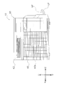
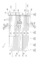
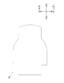
- FIG. 2 is a front view of the outdoor unit 10.
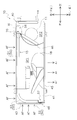
- FIG. 3 is a perspective view of the outdoor unit 10.
- FIG. 4 is a horizontal sectional view of the outdoor unit 10. 3 and 4, some of the devices arranged in the outdoor unit 10 are omitted.
- the outdoor unit 10 is installed outside the target space where the indoor unit 30 is arranged, such as outdoors or underground space.
- the outdoor unit 10 constitutes a substantially rectangular parallelepiped outline, and has a unit casing 40 (corresponding to a “casing” described in claims) that accommodates each device.
- the unit casing 40 includes a bottom plate 41 constituting a bottom surface portion, a top plate 42 constituting a top surface portion, a right side plate 43 mainly constituting a right side portion, and a left side plate 44 mainly constituting a left side portion and a left rear portion. , And a front plate 45 constituting the front portion.
- the unit casing 40 is formed with suction ports 40a for taking the outdoor air flow AF into the unit casing 40 at the rear and right side portions. Moreover, the unit casing 40 is formed with a blower outlet 40b serving as an outlet of the taken outdoor air flow AF in the front portion.
- the unit casing 40 forms a fan room SP1 and a machine room SP2 inside. More specifically, the unit casing 40 has a partition plate 46 disposed therein, and the partition plate 46 partitions the internal space of the unit casing 40 into the blower chamber SP1 and the machine chamber SP2.
- the partition plate 46 is disposed on the left side of the center on the bottom plate 41.
- the blower chamber SP1 (corresponding to the “first space” described in the claims) is a space located on the right side in the unit casing 40.
- devices such as a heat exchanging unit 50 (described later) and a second end 57 (described later) of the outdoor heat exchanger 15 and an outdoor fan 18 are arranged.
- the machine room SP2 (corresponding to the “second space” described in the claims) is a space located on the left side in the unit casing 40.
- devices such as the compressor 11, the four-way switching valve 12, the expansion valve 16, and the header collecting pipe 70 (described later) of the outdoor heat exchanger 15 are arranged.
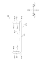
- FIG. 5 is a front view of the outdoor heat exchanger 15.
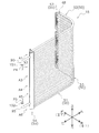
- FIG. 6 is a perspective view of the outdoor heat exchanger 15.
- the outdoor heat exchanger 15 is disposed across the blower chamber SP1 and the machine chamber SP2 in the unit casing 40 (mainly disposed in the blower chamber SP1).
- the outdoor heat exchanger 15 has a substantially L shape in plan view.
- the outdoor heat exchanger 15 is disposed on the bottom plate 41 along the suction port 40 a formed in the back surface portion and the right surface portion of the unit casing 40.
- the outdoor heat exchanger 15 mainly includes a heat exchanging part 50, a first end part 56 and a second end part 57 (hereinafter referred to as “both end parts 55” together with the first end part 56 and the second end part 57). And).
- FIG. 7 is a schematic diagram schematically showing the heat exchanging portion 50 and both end portions 55.
- the heat exchange unit 50 is a part that performs heat exchange between the refrigerant and the outdoor air flow AF.
- the heat exchange unit 50 is located in the blower room SP1.
- the outdoor heat exchanger 15 mainly includes a first heat exchange unit 51, a second heat exchange unit 52, and a third heat exchange unit 53 as the heat exchange unit 50.
- the 1st heat exchange part 51, the 2nd heat exchange part 52, and the 3rd heat exchange part 53 are extended continuously and comprised integrally, it demonstrates separately for convenience of explanation.
- the first heat exchanging part 51 is a part extending in the left-right direction along the suction port 40a in the rear part in the unit casing 40.
- the second heat exchange part 52 is a part extending in the front-rear direction along the suction port 40 a of the right side part in the unit casing 40.
- the third heat exchange unit 53 is a part that connects the first heat exchange unit 51 and the second heat exchange unit 52.
- the third heat exchange unit 53 is connected to the right end of the first heat exchange unit 51 and is connected to the rear end of the second heat exchange unit 52.
- the third heat exchanging portion 53 extends while curving from the back surface portion to the right side surface portion at a position corresponding to the right rear portion of the outdoor heat exchanger 15 in the unit casing 40.
- Both end portions 55 are portions corresponding to the end portions of the outdoor heat exchanger 15 in the heat transfer tube extending direction (here, the horizontal direction in the installed state).
- the first end 56 mainly constitutes the left end of the outdoor heat exchanger 15.
- the first end portion 56 is adjacent to the left side of the first heat exchange unit 51.
- the first end portion 56 is located in the machine room SP2.
- the outdoor heat exchanger 15 has a header collecting pipe 70 in which a gas side inlet / outlet 151 and a liquid side inlet / outlet 152 are formed at a first end portion 56. Details of the header collecting pipe 70 will be described later.
- the second end portion 57 is a portion constituting an end portion on the opposite side to the first end portion 56.
- the second end 57 is adjacent to the front side of the second heat exchange unit 52.
- the second end portion 57 is shielded from the outdoor air flow AF by the shielding plate 48 in the installed state (see FIG. 4).
- a tube plate 67 that supports a heat transfer tube 60 (60i-60l) to be described later is disposed at the second end portion 57.
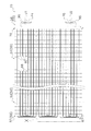
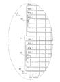
- the outdoor heat exchanger 15 including the heat exchange part 50 and both end parts 55 in this aspect is divided into a plurality of (here, six) regions as shown in FIG. Specifically, the outdoor heat exchanger 15 is divided into a first region A1, a second region A2, a third region A3, a fourth region A4, a fifth region A5, and a sixth region A6.
- region A1 is a part located above the dashed-dotted line L1 of the outdoor heat exchanger 15.
- FIG. The first region A1 is a region through which an overheated gas refrigerant flows during operation.
- region A2 is a part located between the dashed-dotted line L1 and the dashed-dotted line L2 of the outdoor heat exchanger 15.
- region A3 is a portion located between the one-dot chain line L2 and the one-dot chain line L3 of the outdoor heat exchanger 15.
- region A4 is a part located between the dashed-dotted line L3 and the dashed-dotted line L4 of the outdoor heat exchanger 15.
- FIG. The fifth region A5 is a portion located between the one-dot chain line L4 and the one-dot chain line L5 of the outdoor heat exchanger 15.
- region A6 is a part located below the dashed-dotted line L5 of the outdoor heat exchanger 15.
- FIG. The sixth region A6 is a region where the supercooled liquid refrigerant flows during the heating operation.
- the header collecting pipe 70 forms a plurality of spaces inside. More specifically, a plurality of (herein, five) horizontal partition plates 85 (described later) extending in the horizontal direction are arranged in the header collecting pipe 70, and thereby a plurality of internal spaces (firsts) through which the refrigerant enters and exits. A header internal space S1 to a fourth header internal space S4) are formed. Specifically, in the header collecting pipe 70, the first header internal space S1, the second header internal space S2, the third header internal space S3, and the fourth header internal space S4 are arranged in this order from top to bottom. Yes.
- the first header internal space S1 is a space located in the first area A1.
- the second header internal space S2 is a space located in the second area A2 and the third area A3.
- the third header internal space S3 is a space located in the fourth area A4 and the fifth area A5.
- the fourth header internal space S4 is a space located in the sixth region A6.
- header collecting pipe 70 is formed with a gas side inlet / outlet 151 communicating with the first header inner space S1 and a liquid side inlet / outlet 152 communicating with the fourth header inner space S4.
- the outdoor heat exchanger 15 has a plurality of (here, 12) heat transfer tubes 60 through which the refrigerant flows.
- the outdoor heat exchanger 15 includes a first heat transfer tube 60a, a second heat transfer tube 60b, a third heat transfer tube 60c, and a fourth heat transfer tube 60d extending in parallel with each other in the first region A1 and the second region A2.
- the outdoor heat exchanger 15 includes a fifth heat transfer tube 60e, a sixth heat transfer tube 60f, a seventh heat transfer tube 60g, and an eighth heat transfer tube 60h extending in parallel with each other in the third region A3 and the fourth region A4. ing.
- the outdoor heat exchanger 15 includes a ninth heat transfer tube 60i, a tenth heat transfer tube 60j, an eleventh heat transfer tube 60k, and a twelfth heat transfer tube 60l extending in parallel with each other in the fifth region A5 and the sixth region A6. ing.
- Each heat transfer tube 60 (60a-60l) has one end and the other end connected to the header collecting tube 70. More specifically, one end of each heat transfer tube 60 (60a-60d) arranged in the first area A1 and the second area A2 communicates with the first header internal space S1, and the other end of the second header internal space S2. Are connected to the header collecting pipe 70 so as to communicate with each other.
- Each of the heat transfer tubes 60 (60e-60h) disposed in the third region A3 and the fourth region A4 has one end communicating with the second header internal space S2 and the other end communicating with the third header internal space S3. In this way, the header collecting pipe 70 is connected.
- Each of the heat transfer tubes 60 (60i-60l) arranged in the fifth region A5 and the sixth region A6 has one end communicating with the third header internal space S3 and the other end communicating with the fourth header internal space S4. In this way, the header collecting pipe 70 is connected.
- Each heat transfer tube 60 includes an extending portion 61 extending in the horizontal direction in the heat exchanging portion 50.
- each heat transfer tube 60 includes a folded portion 65 that is folded back in a substantially U shape toward the other region (here, the region one step below) at the second end portion 57. In each folded portion 65, each heat transfer tube 60 mainly extends along the vertical direction.
- the first heat transfer tube 60a to the fourth heat transfer tube 60d are folded at the second end portion 57 from the first region A1 toward the lower second region A2.
- the fifth heat transfer tube 60e to the eighth heat transfer tube 60h are folded at the second end portion 57 from the third region A3 toward the fourth region A4 below.
- the ninth heat transfer tube 60i to the twelfth heat transfer tube 60l are folded at the second end portion 57 from the fifth region A5 toward the lower sixth region A6.
- the ninth heat transfer tube 60i to the twelfth heat transfer tube 60l are inserted into and supported by the tube plate 67 at the second end portion 57.
- the heat transfer tubes 60 (60a-60d) having such an aspect are arranged in order of the first heat transfer tube 60a, the second heat transfer tube 60b, the third heat transfer tube 60c, and the fourth heat transfer tube 60d from top to bottom.
- the first heat transfer tube 60a, the second heat transfer tube 60b, the third heat transfer tube 60c, and the fourth heat transfer tube 60d are arranged in this order from the outside to the inside, and in the second region A2, the fourth heat transfer tube 60d.
- the third heat transfer tube 60c, the second heat transfer tube 60b, and the first heat transfer tube 60a are arranged from top to bottom in this order.
- the heat transfer tubes 60 are arranged from top to bottom in the order of the fifth heat transfer tube 60e, the sixth heat transfer tube 60f, the seventh heat transfer tube 60g, and the eighth heat transfer tube 60h in the third region A3.
- the fifth heat transfer tube 60e, the sixth heat transfer tube 60f, the seventh heat transfer tube 60g, and the eighth heat transfer tube 60h are arranged in order from the outside to the inside, and in the fourth region A4, the eighth heat transfer tube 60h,
- the heat transfer tubes 60g, the sixth heat transfer tubes 60f, and the fifth heat transfer tubes 60e are arranged in order from the top to the bottom.
- the heat transfer tubes 60 (60i-60l) are arranged from top to bottom in the order of the ninth heat transfer tube 60i, the tenth heat transfer tube 60j, the eleventh heat transfer tube 60k, and the twelfth heat transfer tube 60l in the fifth region A5.
- the ninth heat transfer tube 60i, the tenth heat transfer tube 60j, the eleventh heat transfer tube 60k, and the twelfth heat transfer tube 60l are arranged in order from the outside to the inner side, and in the sixth region A6, the twelfth heat transfer tube 601 and the eleventh heat transfer tube 60l.
- the heat transfer tubes 60k, the tenth heat transfer tube 60j, and the ninth heat transfer tube 60i are arranged in order from the top to the bottom.
- a plurality of pipes extending along the heat transfer tube extending direction (here, the horizontal direction, in particular, the left-right direction in the first heat exchange unit 51 and the front-rear direction in the second heat exchange unit 52).
- the heat transfer tubes 60 are stacked at intervals in the heat transfer tube stacking direction (the vertical direction here). Note that the heat transfer tube extending direction coincides with the direction in which the heat exchanging portion 50 extends in a plan view.
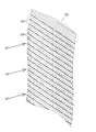
- FIG. 8 is a perspective view of the heat exchange unit 50 as seen from the flow direction of the outdoor air flow AF.
- FIG. 9 is a schematic diagram of the heat transfer tubes 60 and the heat transfer fins 68 as viewed from the heat transfer tube extending direction.
- Each heat transfer tube 60 is a flat tube made of aluminum or made of aluminum alloy and formed in a flat shape. More specifically, the heat transfer tube 60 is a flat multi-hole tube in which a plurality of refrigerant channels RP are formed in the tube. A plurality of refrigerant flow paths RP are arranged in the heat transfer tube 60 along the flow direction of the outdoor air flow AF. Each heat transfer tube 60 includes two main surfaces (a first main surface 601 and a second main surface 602).
- the first main surface 601 faces upward in the extending portion 61 located in the first region A1, the third region A3, and the fifth region A5, and is located in the second region A2, the fourth region A4, and the sixth region A6. It faces downward in the extending portion 61 that performs. Further, the first main surface 601 faces the outside direction of the outdoor heat exchanger 15 (direction opposite to the direction of the heat exchanging unit 50) at the folded portion 65.
- the second main surface 602 faces downward in the extending portion 61 located in the first region A1, the third region A3, and the fifth region A5, and is located in the second region A2, the fourth region A4, and the sixth region A6. It faces upward in the extending portion 61 that performs.
- the second main surface 602 faces the inner side of the outdoor heat exchanger 15 at the folded portion 65.
- the outdoor heat exchanger 15 includes a plurality of heat transfer fins 68 arranged along the longitudinal direction of the heat transfer tube 60 (horizontal direction in the installed state) in each heat exchange unit 50.
- the heat transfer fins 68 are flat members (plate fins) that increase the heat transfer area between the heat transfer tubes 60 and the outdoor air flow AF.
- the heat transfer fins 68 are made of aluminum or aluminum alloy.
- the heat transfer fins 68 extend along the heat transfer tube stacking direction so as to intersect the heat transfer tubes 60 in each heat exchange unit 50.
- the heat transfer fins 68 are formed with a plurality of slits 68a arranged in the heat transfer tube stacking direction, and the corresponding heat transfer tubes 60 are inserted in the respective slits 68a.
- the heat transfer fins 68 are in contact with the heat transfer tubes 60 at the edge portions of the respective slits 68 a and are thermally connected to the heat transfer tubes 60.
- Each heat transfer fin 68 is brazed to the heat transfer tube 60 at a contact portion with the heat transfer tube 60. More specifically, each heat transfer fin 68 is brazed in the furnace in a state of being temporarily assembled to the heat transfer tube 60 (a state in which the heat transfer tube 60 is inserted into the slit 68a).
- the heat transfer fins 68 are not arranged at both end portions 55 of the outdoor heat exchanger 15. That is, the heat transfer fins 68 are not in contact with the folded portions 65 of the heat transfer tubes 60.
- FIG. 10 is an enlarged view of a portion X in FIG.
- the heat transfer tubes (60i-60l) arranged in the fifth region A5 and the sixth region A6 are respectively connected to the heat transfer tubes (60e-60h) arranged in the third region A3 and the fourth region A4.
- the heat transfer tubes (60a-60d) arranged in the first region A1 and the second region A2 the amount of protrusion in the folded portion 65 (specifically, the horizontal dimension at the second end portion 57).
- the horizontal dimension outside the heat transfer fins 68 disposed on the outermost side) is configured to be larger by the length corresponding to the dimension d1.
- the ninth heat transfer tube 60i is configured such that the allowance at the turn-up portion 65 is larger by a length corresponding to the dimension d1 than the first heat transfer tube 60a and the fifth heat transfer tube 60e.
- the tenth heat transfer tube 60j is configured such that the allowance at the turn-up portion 65 is larger than the second heat transfer tube 60b and the sixth heat transfer tube 60f by a length corresponding to the dimension d1.
- the eleventh heat transfer tube 60k is configured such that the allowance at the turn-up portion 65 is larger than the third heat transfer tube 60c and the seventh heat transfer tube 60g by a length corresponding to the dimension d1.
- the twelfth heat transfer tube 60l is configured such that the allowance at the turn-up portion 65 is larger by a length corresponding to the dimension d1 than the fourth heat transfer tube 60d and the eighth heat transfer tube 60h.
- the amount of protrusion in the folded-back portion 65 of each heat transfer tube 60 varies depending on the region, as described below, from the viewpoint of suppressing an increase in cost while suppressing a decrease in reliability. ing.
- the heat transfer is performed at a position away from the curved folded portion 65 from the viewpoint of suppressing the deformation of the heat transfer fins 68.
- the heat fins 68 are inserted into the heat transfer tubes 60 (the extending portions 61).
- the tube plate 67 is also inserted into the heat transfer tube 60 at a position away from the folded portion 65 from the viewpoint of suppressing deformation. That is, in such a flat tube heat exchanger, in order to suppress a decrease in reliability, between each heat transfer tube 60 and the heat transfer fin 68 located on the outermost side, or between each heat transfer tube 60 and the tube plate 67. Therefore, it is desirable to secure a dimension (dimension of the heat transfer tube 60) for suppressing the deformation of the heat transfer fins 68 or the tube plate 67.
- each heat transfer tube 60 (heat transfer tubes 60i-60l supported by the tube plate 67) arranged in the fifth region A5 and the sixth region A6 has a protruding amount at the turn-up portion 65. Since the heat transfer tubes 60 arranged in the region (heat transfer tubes 60a-60h not supported by the tube plate 67) are configured to have a length corresponding to the dimension d1, the tube plate 67 and the heat transfer fins 68 are deformed. It is suppressed and the deterioration of reliability is suppressed.
- the heat transfer tubes 60 heat transfer tubes 60a-60h that are not supported by the tube plate 67
- the heat transfer tubes 60a-60h are arranged in the fifth region A5 and the sixth region A6. It is configured to have a smaller allowance than the heat transfer pipe 60 (60i-60l) (more specifically, the minimum allowance required for properly inserting the heat transfer fins 68). The length is suppressed and the increase in cost is suppressed.
- the refrigerant flows through the second region A2 and the first region A1, flows into the first header internal space S1, and flows out through the gas side inlet / outlet 151.
- the liquid side inlet / outlet 152 functions as the refrigerant inlet
- the gas side inlet / outlet 151 functions as the refrigerant outlet.
- the sixth region A6 functions as the outbound route for the most upstream refrigerant
- the fourth region A4 functions as the outbound route for the downstream refrigerant
- the second region A2 functions as the outbound route for the most downstream refrigerant.
- the fifth area A5 functions as a return path for the most upstream refrigerant
- the third area A3 functions as a return path for the downstream refrigerant
- the first area A1 functions as a return path for the most downstream refrigerant.
- the refrigerant flows into the first header internal space S1 through the gas side inlet / outlet 151.
- the refrigerant that has flowed into the first header internal space S1 flows through the first region A1 and the second region A2, and returns from the second region A2 to the third region A3 in the second header internal space S2.
- the refrigerant flows through the third region A3 and the fourth region A4, and turns back from the fourth region A4 to the fifth region A5 in the third header internal space S3.
- the refrigerant flows through the fifth region A5 and the sixth region A6, flows into the fourth header internal space S4, and flows out through the liquid side inlet / outlet 152.
- the gas side inlet / outlet 151 functions as the refrigerant inlet
- the liquid side inlet / outlet 152 functions as the refrigerant outlet.
- the first region A1 functions as the outbound route for the most upstream refrigerant
- the third region A3 functions as the outbound route for the downstream refrigerant
- the fifth region A5 functions as the outbound route for the most downstream refrigerant.
- the second area A2 functions as a return path for the most upstream refrigerant
- the fourth area A4 functions as a return path for the downstream refrigerant
- the sixth area A6 functions as a return path for the most downstream refrigerant.
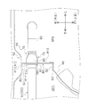
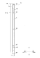
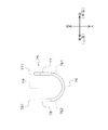
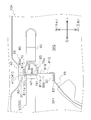
- FIG. 11 is an enlarged view of a portion XI in FIG.
- FIG. 12 is a left side view of the header collecting pipe 70.
- FIG. 13 is a rear view of the header collecting pipe 70.
- the header collecting pipe 70 is located in the machine room SP2 in the unit casing 40.
- the header collecting pipe 70 has a longitudinal direction extending along the vertical direction.
- the header collecting pipe 70 is a pipe through which the refrigerant enters and exits each heat transfer pipe 60, and functions as a refrigerant diversion header or a folding header.
- the header collecting pipe 70 is configured by combining a plurality of members manufactured by extrusion molding or machining.
- the header collecting pipe 70 mainly has a header main body 75, a plate member 80, a horizontal partition plate 85, a gas side connection pipe 90, and a liquid side connection pipe 95.
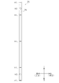
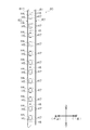
- FIG. 14 is a right side view of the header main body 75.
- FIG. 15 is a left side view of the header main body 75.
- FIG. 16 is a rear view of the header main body 75.
- FIG. 17 is a front view of the header main body 75.
- FIG. 18 is a plan view of the header main body 75.
- the header main body 75 is a member constituting most of the header collecting pipe 70.
- the header main body 75 is a semi-cylindrical member made of aluminum or aluminum alloy that extends along the vertical direction (that is, the longitudinal direction of the header collecting pipe 70).
- the header main body 75 is configured such that a cross section in the horizontal direction (short direction) is substantially U-shaped. That is, the header main body 75 is configured to open in a predetermined direction (here, the right direction) in the cross section in the short direction, and to form the opening Ha (see FIG. 18).
- the header main body 75 includes a main body first portion 76, a main body second portion 77, and a main body third portion 78.
- the main body first portion 76, the main body second portion 77, and the main body third portion 78 are configured integrally and extend continuously, but these will be described separately for convenience of explanation.
- Main body first part 76 The main body first portion 76 is a portion that is disposed on the left side in the installed state, and is a portion that is curved so as to swell leftward in a plan view.
- the main body first portion 76 has a substantially U shape in plan view.
- the longitudinal direction of the main body first portion 76 extends from the upper end to the lower end of the header main body portion 75.
- the main body first portion 76 is formed with a plurality of main body partition plate insertion holes H1 into which the horizontal partition plates 85 are inserted (the same number as the number of horizontal partition plates 85 arranged in the header collecting pipe 70, here five). ing.
- the main body partition plate insertion holes H1 are arranged in the vertical direction so that the horizontal partition plates 85 are appropriately arranged according to the positions of the spaces (S1-S4) formed in the header collecting pipe 70. .
- the edge portion of the main body partition plate insertion hole H1 is made of a brazing material, and is joined to the inserted horizontal partition plate 85 by brazing.
- a gas side connection pipe insertion hole H2 into which the gas side connection pipe 90 is inserted is formed in the main body first portion 76.
- the gas side connection pipe insertion hole H2 is formed at a position corresponding to the arrangement position of the gas side connection pipe 90 (a position corresponding to the first header internal space S1 in this embodiment).
- the edge part of the gas side connection pipe insertion hole H2 is made of a brazing material, and is joined to the gas side connection pipe 90 by brazing so that the gap is completely closed.
- the main body first portion 76 has a liquid side connection pipe insertion hole H3 into which the liquid side connection pipe 95 is inserted.
- the liquid side connection pipe insertion hole H3 is formed at a position corresponding to the arrangement position of the liquid side connection pipe 95 (a position corresponding to the fourth header internal space S4 in this embodiment).
- the edge part of the liquid side connection pipe insertion hole H3 is made of a brazing material, and is joined to the liquid side connection pipe 95 by brazing so that the gap is completely closed.
- Main body second part 77 The main body second portion 77 is a portion arranged on the back side in the installed state.
- the main body second portion 77 is a plate-like portion that linearly extends in the left-right direction in plan view.
- the longitudinal direction of the main body second portion 77 extends from the upper end to the lower end of the header main body portion 75.
- the left end portion of the main body second portion 77 is connected to the rear end portion 761 (see FIG. 18) of the main body first portion 76.
- the main body second portion 77 is provided with a plurality of first ribs 771 (corresponding to “protruding portions” described in claims) extending in the left-right direction at the right end (see FIGS. 16 and 18).
- a plurality of (here, twelve) first ribs 771 are arranged in the vertical direction at intervals.
- Each of the first ribs 771 is provided in one-to-one correspondence with any one of the first rib insertion holes H4 (see FIGS. 19 and 20) formed in the plate member 80.
- Each of the first ribs 771 extends in the vertical direction and is configured to have a size that engages with the corresponding first rib insertion hole H4 (see FIGS. 19 and 20).
- the first rib 771 is inserted into and engaged with the corresponding first rib insertion hole H4.
- the plurality of first ribs 771 are inserted into and engaged with all of the first rib insertion holes H4 formed in the plate member 80.
- Each of the first ribs 771 is disposed at a predetermined position.
- Each first rib 771 is joined to the plate member 80 at the edge portion of the corresponding first rib insertion hole H4.
- the main body second portion 77 is brazed and joined to the plate member 80 so that the first rib insertion holes H4 into which the first ribs 771 are inserted are completely closed. That is, each first rib 771 engages with the first rib insertion hole H4 in a state where the header main body 75 and the plate member 80 are fixed.
- Main body third part 78 The main body third portion 78 is a portion arranged on the front side in the installed state.
- the main body third portion 78 is a plate-like portion that linearly extends in the left-right direction in plan view.
- the longitudinal direction of the main body third portion 78 extends from the upper end to the lower end of the header main body portion 75.
- the main body third portion 78 is arranged to face the main body second portion 77.
- the left end portion of the main body third portion 78 is connected to the front end portion 762 (see FIG. 18) of the main body first portion 76.
- the main body third portion 78 is provided with a plurality of second ribs 781 (corresponding to “protruding portions” described in claims) extending in the left-right direction at the left end (see FIGS. 17 and 18).
- a plurality of (here, twelve) second ribs 781 are arranged in the vertical direction at intervals.
- Each of the second ribs 781 is provided in one-to-one correspondence with any one of the second rib insertion holes H5 (see FIGS. 19 and 20) formed in the plate member 80.
- Each of the second ribs 781 extends in the vertical direction and is configured to have a size that engages with the corresponding second rib insertion hole H5 (see FIGS. 19 and 20).
- the second rib 781 is inserted and engaged with the corresponding second rib insertion hole H5.
- a plurality of second ribs 781 are inserted into and engaged with all of the second rib insertion holes H5 formed in the plate member 80.
- Each of the second ribs 781 is disposed at a predetermined position.
- Each second rib 781 is joined to the plate member 80 at the edge portion of the corresponding second rib insertion hole H5.
- the main body third portion 78 is brazed and joined to the plate member 80 so that the second rib insertion holes H5 into which the second ribs 781 are inserted are completely closed. That is, each second rib 781 engages with the second rib insertion hole H5 in a state where the header main body 75 and the plate member 80 are fixed.
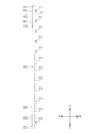
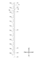
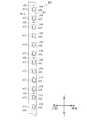
- FIG. 19 is a right side view of the plate member 80.
- FIG. 20 is a left side view of the plate member 80.
- FIG. 21 is a rear view of the plate member 80.
- FIG. 22 is a front view of the plate member 80.
- FIG. 23 is a plan view of the plate member 80.
- the plate member 80 is a plate-like member made of aluminum or an aluminum alloy. More specifically, the plate member 80 is made of a three-layer clad material including a brazing material, a core material, and a sacrificial material.
- the plate member 80 constitutes one surface (here, the right surface) of the header collecting pipe 70 and forms each space (S1-S4) in the header collecting pipe 70 together with the header main body 75.
- the plate member 80 functions as a tube plate that supports the end of each heat transfer tube 60.
- the plate member 80 functions as a fixing member for fixing the header collecting pipe 70 (or the outdoor heat exchanger 15) by being fixed to the unit casing 40 or another member.
- the plate member 80 also functions as a wind shield that shields the machine room SP2 from the outdoor air flow AF.
- the plate member 80 is brazed to the header body 75. More specifically, the plate member 80 is joined to the header body 75 so as to cover the opening Ha of the header body 75 from the right side.
- the plate member 80 forms a header internal space (S1-S4) together with the header body 75.
- the plate member 80 mainly includes a first plate portion 81, a second plate portion 82, and a third plate portion 83.
- the first plate portion 81, the second plate portion 82, and the third plate portion 83 are integrally configured and extend continuously, but these will be described separately for convenience of explanation.
- the first plate portion 81 is a portion constituting the right side surface (the surface on the heat exchange unit 50 side) of the header collecting pipe 70.
- the first plate portion 81 has a plate shape extending in the front-rear direction in plan view. The longitudinal direction of the first plate portion 81 extends from the upper end to the lower end of the plate member 80.
- the first plate portion 81 includes a front side surface 811 which is a main surface facing the blower chamber SP1 side (here, the right side). Moreover, the 1st board part 81 contains the back side surface 812 which is a main surface which faces machine room SP2 side (here left side).
- the dimensions of the front side surface 811 and the back side surface 812 in the front-rear direction is a predetermined ratio (here, the size). 2 times or more) and large. Further, the length in the vertical direction (longitudinal direction) of the front side surface 811 and the back side surface 812 is larger than the length of the header main body portion 75 in the vertical direction.
- the front side surface 811 of the first plate portion 81 shields the machine room SP2 (apparatus arranged in the machine room SP2) against the outdoor air flow AF. That is, the front side surface 811 corresponds to a “wind shield surface” that shields the header main body 75, the gas side connection pipe 90, the liquid side connection pipe 95, and the like from the outdoor air flow AF.
- the front side surface 811 shields one end from the other end in the longitudinal direction (here, the vertical direction) of the header main body 75 against the outdoor airflow AF.
- the first plate portion 81 including the front side surface 811 is a constituent member of the header collecting pipe 70 and functions as a wind shielding plate.
- the first plate portion 81 can be said to be a wind shield configured integrally with the header collecting pipe 70.
- the plate member 80 includes a wind shield fixed to the header collecting pipe 70. That is, when the plate member 80 is interpreted as a “wind shield plate” that shields the machine room SP2 from the outdoor air flow AF, the wind shield plate (plate member 80) is fixed to the header collecting pipe 70. Can also be interpreted.
- a plurality of openings are formed in the first plate portion 81.
- the first plate portion 81 has a plurality of first rib insertion holes H4 (corresponding to “engagement holes” in the claims) into which the first ribs 771 are inserted (provided in the header main body 75). The same number of first ribs 771 formed).
- the first rib insertion hole H4 is formed according to the shape of the first rib 771. In the present embodiment, the longitudinal direction of the first rib insertion hole H4 is the vertical direction.
- the first plate portion 81 has a plurality of second rib insertion holes H5 (corresponding to “engagement holes” recited in the claims) into which the second ribs 781 are inserted (provided in the header body 75). The same number as the second ribs 781).
- the second rib insertion hole H5 is formed according to the shape of the second rib 781. In the present embodiment, the longitudinal direction of the second rib insertion hole H5 is the vertical direction.
- the first rib insertion hole H4 and the second rib insertion hole H5 are arranged side by side in a horizontal direction below or above a heat transfer tube insertion port H7 described later. More specifically, each first rib insertion hole H4 and each second rib insertion hole H5 are formed between a pair of upper and lower heat transfer tube insertion holes H7.
- the edge portions of the first rib insertion hole H4 and the second rib insertion hole H5 are each made of a brazing material, and are joined to the inserted first rib 771 or second rib 781 by brazing. That is, as for the 1st board part 81, the part contact
- the first plate portion 81 is formed with a plurality of partition plate insertion holes H6 into which the horizontal partition plates 85 are inserted (the same number as the number of horizontal partition plates 85 arranged in the header collecting pipe 70, here five). ing.
- the partition plate insertion holes H6 are arranged in the vertical direction so that the horizontal partition plates 85 are properly arranged according to the positions of the spaces (S1-S4) formed in the header collecting pipe 70.
- the edge portion of the partition plate insertion hole H6 is made of a brazing material, and is joined to the inserted horizontal partition plate 85 by brazing.
- the first plate portion 81 has a one-to-one correspondence with any one of the heat transfer tubes 60 (60a-60l), and one end or the other end of the corresponding heat transfer tube 60 is inserted (patented) (Corresponding to “insertion port” described in the claims).
- the first plate portion 81 has the same number (24) of heat transfer tube insertion ports H7 as the number of one end and the other end of the heat transfer tube 60.
- Each heat transfer tube insertion port H7 is disposed at the position (here, the height position) of the heat transfer tube 60 to be inserted.
- each heat exchanger tube insertion port H7 is comprised with the brazing material, and the 1st board part 81 is brazed and joined with the heat exchanger tube 60 in the state by which the heat exchanger tube 60 was inserted in each heat exchanger tube insertion port H7.
- the heat transfer tube 60 is inserted and joined to the first plate portion 81, so that the plate member 80 functions as a tube plate that supports the end portion of each heat transfer tube 60.
- the 2nd board part 82 is a part arrange
- the second plate portion 82 is a plate-like portion that linearly extends in the left-right direction in plan view.
- the longitudinal direction of the second plate portion 82 extends from the upper end to the lower end of the plate member 80.
- the left end portion of the second plate portion 82 is connected to the rear end portion 81a (see FIG. 23) of the first plate portion 81.
- the screw hole TH1 is formed in the vicinity of the upper end and the lower end of the second plate part 82, respectively.
- the second plate portion 82 is screwed and fixed to the unit casing 40 via each screw hole TH1.
- the second plate portion 82 is screwed and fixed to the back portion of the left side plate 44 and the rising portion 411 of the bottom plate 41 with screws SC (see FIG. 11). That is, the plate member 80 is fixed to the unit casing 40 at the second plate portion 82. That is, the plate member 80 having the second plate portion 82 corresponds to a “fixing member” for fixing the header collecting pipe 70 (outdoor heat exchanger 15) to a predetermined member.
- the second plate part 82 includes a second part back side surface 821 which is a main surface facing the back side (that is, the unit casing 40 side to be screwed and fixed), and a second part front side surface which is a main surface facing the front side. 822 (see FIG. 23).
- the second part back side surface 821 is a part that comes into contact with the unit casing 40 (the bottom plate 41 or the left side plate 44), and is made of a sacrificial material. Thereby, the plate member 80 is protected from the core material by the sacrificial material with respect to the electrolytic corrosion at the contact portion with the unit casing 40, and the corrosion is suppressed.
- the third plate portion 83 is a portion arranged on the front side in the installed state.
- the third plate portion 83 is a plate-like portion that linearly extends in the left-right direction in plan view.
- the longitudinal direction of the third plate portion 83 extends from the upper end to the lower end of the plate member 80.
- the left end portion of the third plate portion 83 is connected to the front end portion 81 b (see FIG. 23) of the first plate portion 81.
- Screw hole TH2 is formed in the vicinity of the upper end and the lower end of third plate portion 83, respectively.
- the third plate portion 83 is screwed and fixed to a member disposed in the unit casing 40 through each screw hole TH2.
- the third plate portion 83 is screwed and fixed to the partition plate 46 with screws SC (see FIG. 11). That is, the plate member 80 is fixed to a member (partition plate 46) arranged in the unit casing 40 in the third plate portion 83. That is, the plate member 80 having the third plate portion 83 corresponds to a “fixing member” for fixing the header collecting pipe 70 (outdoor heat exchanger 15) to a predetermined member.
- the third plate portion 83 includes a third portion back side surface 831 which is a main surface facing the front side (that is, the side of the partition plate 46 to be screwed and fixed), and a third portion front side surface which is a main surface facing the back side. 832 (see FIG. 23).
- the third part back side surface 831 is a part that abuts against the partition plate 46 and is made of a sacrificial material.
- FIG. 24 is a plan view of the horizontal partition plate 85.
- the horizontal partition plate 85 is a member that extends in the horizontal direction (direction intersecting with the longitudinal direction of the header collecting pipe 70) in the header collecting pipe 70 and partitions the space up and down.
- the horizontal partition plate 85 is configured to have an area corresponding to the cross-sectional area of the header collecting pipe 70.
- the horizontal partition plate 85 is inserted into the main body partition plate insertion hole H1 of the header main body portion 75 and the partition plate insertion hole H6 of the plate member 80, and the edges of the main body partition plate insertion hole H1 and the partition plate insertion hole H6.
- the portion is joined to each of the header body 75 and the plate member 80. More specifically, the horizontal partition plate 85, the header main body 75, and the plate member 80 are brazed and joined so that the main body partition plate insertion hole H1 and the partition plate insertion hole H6 are completely closed.
- a plurality of (six in this case) horizontal partition plates 85 are arranged in the header collecting pipe 70 at intervals in the vertical direction, so that the first header is arranged inside the header collecting pipe 70.
- An internal space S1, a second header internal space S2, a third header internal space S3, and a fourth header internal space S4 are formed.
- the top surface portion of the header collecting pipe 70 is constituted by the horizontal partition plate 85 arranged at the uppermost stage. Further, the bottom portion of the header collecting pipe 70 is constituted by the horizontal partition plate 85 arranged at the lowermost stage.
- Gas side connection pipe 90, liquid side connection pipe 95 The gas side connection pipe 90 and the liquid side connection pipe 95 are pipes made of aluminum or aluminum alloy. The pipe diameters and pipe lengths of the gas side connection pipe 90 and the liquid side connection pipe 95 are individually selected according to design specifications and installation environment.
- the gas side connection pipe 90 and the liquid side connection pipe 95 are connected to a copper refrigerant pipe (the fourth pipe P4 or the fifth pipe P5) in the outdoor unit 10. That is, the gas side connection pipe 90 and the liquid side connection pipe 95 are connected to other pipes made of different metals.
- the gas side connection pipe 90 is disposed in the vicinity of the upper end of the header collecting pipe 70.
- the gas side connection pipe 90 forms a gas side inlet / outlet 151 at one end and communicates with the first header internal space S1 at the other end.
- One end of the gas side connection pipe 90 is connected to the fourth pipe P4.
- the other end of the gas side connection pipe 90 is brazed and joined to the gas side connection pipe insertion hole H ⁇ b> 2 of the header body 75.
- the connection part J1 (refer FIG. 5) of the gas side connection piping 90 and the 4th piping P4 is arrange
- the liquid side connection pipe 95 is disposed near the lower end of the header collecting pipe 70.
- the liquid side connection pipe 95 forms a liquid side inlet / outlet 152 at one end and communicates with the fourth header internal space S4 at the other end.
- One end of the liquid side connection pipe 95 is connected to the fifth pipe P5.
- the other end of the liquid side connection pipe 95 is brazed to the liquid side connection pipe insertion hole H3 of the header main body 75.
- the connection part J2 (refer FIG. 5) of the liquid side connection piping 95 and the 5th piping P5 is arrange
- the outdoor heat exchanger 15 is assembled by, for example, the following steps. However, the following steps are merely examples, and can be changed as appropriate.
- each first rib 771 and each second rib 781 of the header main body 75 is inserted into the corresponding first rib insertion hole H4 or second rib insertion hole H5 of the plate member 80 using a jig.
- the header main body 75 and the plate member 80 are temporarily assembled by being inserted and engaged with the edge portion of the inserted hole.
- each horizontal partition plate 85 is inserted into the main body partition plate insertion hole H1 of the header main body portion 75 so that the horizontal partition plate 85 is sandwiched between the header main body portion 75 and the plate member 80, and the other end side is connected.
- the header main body 75 and the plate member 80 are temporarily assembled.
- the gas side connection pipe 90 is inserted into the gas side connection pipe insertion hole H2 of the header main body 75, and is engaged with the edge portion of the inserted hole. It becomes a temporarily assembled state.
- the liquid side connection pipe 95 is inserted into the liquid side connection pipe insertion hole H3 of the header main body 75 and engaged with the edge portion of the inserted hole. It becomes a temporarily assembled state.
- a second step of appropriately inserting each heat transfer tube 60 into the heat transfer tube insertion port H7 of the assembled header collecting tube 70 is performed using a jig.
- the header collecting pipe 70 and the heat transfer pipes 60 are temporarily assembled.
- a third step of assembling the heat exchange unit 50 by combining the heat transfer tubes 60 and the heat transfer fins 68 is performed.
- a fourth step is performed in which each part in the assembled outdoor heat exchanger 15 is joined by brazing in the furnace.
- each heat exchanging part 50 is deformed into an approximately L shape in plan view by performing an R-bending process in the third heat exchanging part 53 (that is, the first heat in each heat exchanging part 50).
- the fifth step (which constitutes the exchange unit 51, the second heat exchange unit 52, and the third heat exchange unit 53) is performed.
- the outdoor heat exchanger 15 is installed at a predetermined position of the unit casing 40, and the unit casing 40 (the bottom plate 41, the left side plate 44, etc.) is formed by the plate member 80 (the first plate portion 81, the second plate portion 82, etc.). Or it is screwed and fixed to other members (partition plate 46 grade).
- a windshield plate that shields a header collecting pipe or a machine room in which the header collecting pipe is arranged with respect to an air flow is arranged.
- such a heat exchanger is usually arranged in a casing, and as a method of fixing the heat exchanger to the casing, it is common to use screw fixing through a fixing member.
- the windshield plate is arranged to suppress a decrease in reliability, and when the heat exchanger is screwed and fixed to the casing via the fixing member, The cost increases with the increase in the number of parts.
- the plate member 80 corresponds to the front side surface 811 that shields the machine room SP2 from the outdoor airflow AF (corresponding to “wind blocking surface” in the claims). ) Is included. Thereby, the inflow of the outdoor air flow AF into the machine room SP2 is suppressed. As a result, salt damage and electrolytic corrosion are suppressed with respect to the header collecting pipe 70 arranged in the machine room SP2 and its peripheral portion. Moreover, the air volume fall in fan room SP1 in which the heat exchange part 50 is arrange
- the plate member 80 is fixed to the header collecting pipe 70 of the outdoor heat exchanger 15 and is fixed to the unit casing 40 or another member (partition plate 46) disposed in the unit casing 40.
- the outdoor heat exchanger 15 can be fixed to the unit casing 40 or another member (partition plate 46) via the plate member 80.
- the plate member 80 can function as a “fixing member” for fixing the outdoor heat exchanger 15 (that is, the plate member 80 functions as a “shielding member” and a “fixing member”. It is possible to have both functions as).
- the header main body 75 of the header collecting pipe 70 forms the opening Ha in the cross section in the short direction, and the plate member 80 covers the opening Ha so as to cover the opening Ha. It is joined to the main body 75 and forms the header internal space (S1-S4) together with the header main body 75.
- the constituent member of the header collecting pipe 70 can be used as a “fixing member” for fixing the “wind shield” and the outdoor heat exchanger 15. Therefore, the number of parts is particularly reduced as compared with the conventional case, and the cost is suppressed.
- the front side surface 811 (wind shield surface) of the plate member 80 extends along the longitudinal direction (vertical direction) of the header main body 75, and the header main body 75.
- the header main-body part 75 is shielded with respect to the outdoor airflow AF.
- the header body 75 is provided with “projections” (first ribs 771 and second ribs 781), and the plate member 80 has “engagement holes”.
- the first rib insertion hole H4 and the second rib insertion hole H5) are formed, and the “projection part” is related to the “engagement hole” in a state where the plate member 80 and the header main body part 75 are fixed. Configured to match. Thereby, it is easy to fix the plate member 80 to the header main body 75. That is, the assemblability when assembling the header collecting pipe 70 is improved.
- the plate member 80 is brazed to the header main body 75 and is firmly fixed to the header main body 75. Thereby, the rigidity of the header collecting pipe 70 is improved.
- the plate member 80 is a portion (a second rib insertion hole H5 of the first rib insertion hole H4) that abuts the header main body 75 (header collecting pipe 70).
- the edge portion is made of brazing material.
- the heat transfer tube 60 is a flat tube
- the plate member 80 is formed with a heat transfer tube insertion port H7 into which each heat transfer tube 60 is inserted.
- the plate member 80 includes a brazing material at the edge of the heat transfer tube insertion port H7. Thereby, the brazing property when the plate member 80 and the heat transfer tube 60 are joined by brazing (particularly brazing in a furnace) is improved.
- the plate member 80 is a portion that contacts the unit casing 40 or another member (partition plate 46) (the second back surface 821 and the third back surface). 831) is made of a sacrificial material. Thus, the plate member 80 is protected from the core material by the sacrificial material with respect to the electrolytic corrosion at the contact portion with the unit casing 40 or other members, and the corrosion is suppressed.
- the header collecting pipe 70 is made of aluminum or an aluminum alloy. That is, although the header collecting pipe 70 is made of aluminum or an aluminum alloy that needs to be particularly taken into consideration for salt damage countermeasures and electric corrosion countermeasures, the main body portion of the header collecting pipe 70 is against the outdoor air flow AF. It is shielded and corrosion is suppressed.
- the plate member 80 is made of aluminum or an aluminum alloy. As a result, the occurrence of electrolytic corrosion at the contact portion between the plate member 80 and the header main body 75 is suppressed.
- the header collecting pipe 70 is connected to refrigerant pipes (P4, P5) made of metal (copper) different from the header collecting pipe 70,
- the connecting portions (J1, J2) are arranged in the machine room SP2 shielded against the outdoor air flow AF. That is, even when the refrigerant pipes (P4, P5) made of different metals are connected to the header collecting pipe 70, the connecting portion between the header collecting pipe 70 and the refrigerant pipe is connected to the outdoor air by the plate member 80. It is shielded against the flow AF, and the occurrence of corrosion (particularly electrolytic corrosion) at such a connection portion is suppressed.
- the plate member 80 is configured such that the portions (first rib insertion hole H4, second rib insertion hole H5) that contact the header main body 75 are made of brazing material. From the viewpoint of improving the brazing property between the plate member 80 and the header main body 75, the plate member 80 is preferably configured in this manner.
- the plate member 80 is not necessarily limited to this, and the portion of the plate member 80 that is in contact with the header main body portion 75 does not necessarily need to be formed of a brazing material.
- the brazing material is used to improve the brazing property by configuring the portion of the first rib 771 or the second rib 781 that contacts the edge of the first rib insertion hole H4 or the second rib insertion hole H5 with a brazing material. May be.
- the plate member 80 has a portion that contacts the heat transfer tube 60 (an edge portion of the heat transfer tube insertion port H7) made of a brazing material. From the viewpoint of improving the brazing property between the heat transfer tube 60 and the plate member 80, the plate member 80 is preferably configured in this manner. However, the plate member 80 is not necessarily limited to this, and the portion of the plate member 80 that is in contact with the heat transfer tube 60 is not necessarily made of the brazing material.
- abuts the plate member 80 to the unit casing 40 or the partition plate 46 was comprised with the sacrificial material.
- the plate member 80 is preferably configured in such a manner.
- the plate member 80 does not necessarily need to be made of a sacrificial material at the portion that contacts the unit casing 40 or the partition plate 46.
- the plate member 80 does not necessarily need to be formed of a three-layer clad material including a brazing material, a core material, and a sacrificial material, and the configuration can be changed as appropriate.
- the plate member 80 may be formed of a brazing material and a clad material made only of a core material.
- the 4th piping P4 and the 5th piping P5 are copper pipes, and when it connects with the gas side connection piping 90 or the liquid side connection piping 95 made from aluminum or aluminum alloy (namely, it connects with dissimilar metals) Explained).
- the present invention is not necessarily limited thereto, and the fourth pipe P4 and the fifth pipe P5 may be made of the same material (metal) as the gas side connection pipe 90 or the liquid side connection pipe 95.
- the plate member 80 has a plurality of functions (specifically, mainly the following functions (a) to (d)).
- the plate member 80 has the above (a)-(d). It is desirable to fulfill each of the functions. However, the plate member 80 does not necessarily have to fulfill all these functions, and some functions may be omitted as appropriate.
- the function (a) may be omitted.
- the plate member 80 functions as a “tube plate”, a “fixing member”, and a “wind shield plate”, so that the effects described in (6-1) above can be realized.
- the plate member 80 may be appropriately configured and arranged in a shape and size suitable for functioning as the above (b)-(d).
- a predetermined opening H4, H5, H6 may be omitted, and may be fixed to the outer surface of the header collecting pipe 70 by brazing or the like.
- the function (b) may be omitted.
- the plate member 80 functions as a “fixing member” and a “wind shield plate”, the effects described in (6-1) above can be realized.
- the plate member 80 may be appropriately configured and arranged in a shape and size suitable to function as the above (c)-(d).
- the heat transfer tube insertion port H7 is omitted.
- the header main body 75 is formed with “projections” (first ribs 771 and second ribs 781), and the plate member 80 is engaged with the “engagement holes” (first ribs).
- the insertion hole H4 and the second rib insertion hole H5) are formed, and the "protruding part” is inserted into the "engaging hole” and engaged, whereby the header body 75 and the plate member 80 are temporarily assembled. .
- a “projection” (rib corresponding to the first rib 771 and the second rib 781) is formed on the plate member 80, and the header main body 75 is engaged with the “projection”.
- "Engagement holes” holes corresponding to the first rib insertion holes H4 and the second rib insertion holes H5) may be formed. Even in such a case, the same effect as the above-described embodiment is realized.
- the shape and configuration of the “protrusion” are not necessarily limited to those of the above-described embodiment, and can be appropriately changed according to the design specifications and the installation environment.
- the “projection” may be a substantially L-shaped nail having a heel.
- the shape and position of the “engagement hole” may be appropriately selected according to the configuration of the “projection”.
- the header main body portion 75 is provided with 12 first ribs 771 and 12 second ribs 781 each has been described.
- the number of the first ribs 771 and the second ribs 781 provided in the header main body 75 can be changed as appropriate.
- the number of the first ribs 771 and the second ribs 781 may be 13 or more, or 11 or less.
- the number of the first ribs 771 and the second ribs 781 is not necessarily the same, and may be different.
- one of the first rib 771 and the second rib 781 may be omitted as appropriate. In such a case, one of the first rib insertion hole H4 and the second rib insertion hole H5 is also omitted.
- the header main body 75 is formed with “projections” (first ribs 771 and second ribs 781), and the plate member 80 is engaged with the “engagement holes” (first ribs).
- the insertion hole H4 and the second rib insertion hole H5) are formed, and the “protruding part” is inserted into the “engaging hole” and engaged, whereby the header body part 75 and the plate member 80 are temporarily assembled. explained.
- the “protrusion part” and “engagement hole” of this aspect are formed.
- the “projection portion” and the “engagement hole” are not necessarily required and can be omitted as appropriate.
- the header main body 75 and the plate member 80 may be joined (such as brazed joining) in such a manner as to completely close the gap at the contact portion.
- each part was joined by brazing the outdoor heat exchanger 15 in a furnace.
- the present invention is not necessarily limited to this, and the outdoor heat exchanger 15 may be joined to each other by brazing outside the furnace (for example, local brazing by manual work).
- each part of the outdoor heat exchanger 15 may be joined by a method other than brazing, such as welding.
- the outdoor heat exchanger 15 demonstrated the case where the heat exchanger tube extending
- the present invention is not necessarily limited thereto, and the outdoor heat exchanger 15 may be configured and arranged such that, in the installed state, the heat transfer tube extending direction is the vertical direction and the heat transfer tube stacking direction is the horizontal direction.
- header internal spaces (S1, S2, S3, S4) are formed in the header collecting pipe 70.
- the number and size of the header internal space formed inside the header collecting pipe 70 may be appropriately selected according to the design specifications and the installation environment.
- the horizontal partition plate 85 may be arranged according to the number of header internal spaces to be formed.
- the header inner space (S1-S4) is formed inside the header collecting pipe 70 by appropriately arranging the horizontal partition plate 85 configured as a separate member from the header body 75 and the plate member 80. It had been.
- the form of forming the header internal space is not necessarily limited to this.
- the header inner space (S 1 -S 4) may be formed inside the header collecting pipe 70 by appropriately configuring the horizontal partition plate 85 integrally with the header body 75 or the plate member 80.
- the outdoor heat exchanger 15 was comprised so that substantially L shape might be exhibited in planar view.
- the outdoor heat exchanger 15 may be comprised in another shape.
- the outdoor heat exchanger 15 is a so-called one-surface heat exchanger that is substantially I-shaped in a plan view, a so-called three-surface heat exchanger that is substantially U-shaped in a plan view, or a so-called four-surface that is substantially rectangular in a plan view. You may apply to a heat exchanger etc.
- the outdoor heat exchanger 15 has the header collecting pipe 70 at the first end portion 56.
- the header collecting pipe 70 may be disposed at a position other than the first end portion 56.
- the header collecting pipe 70 may be disposed at the first end portion 56 and / or at the second end portion 57 instead of being disposed at the first end portion 56.
- the plate member 80 may be disposed so as to shield the second end portion 57 from the outdoor air flow AF, and may be fixed to the right side plate 43, the front plate 45, or the like.
- the heat transfer tube 60 is a flat multi-hole tube in which a plurality of refrigerant flow paths RP are formed.
- the heat transfer tube 60 is not necessarily a flat multi-hole tube, and may be a flat tube that forms a single refrigerant flow path RP therein.
- the heat transfer tube 60 is not necessarily a flat tube having a flat cross section.
- the heat transfer tube 60 may be a circular tube having a circular cross section.
- the outdoor heat exchanger 15 is configured such that the gas side inlet / outlet 151 is positioned near the upper end of the header collecting pipe 70 and the liquid side inlet / outlet 152 is positioned near the lower end of the header collecting pipe 70.
- the outdoor heat exchanger 15 does not necessarily need to be configured in such a manner.
- the outdoor heat exchanger 15 may be configured such that the gas side inlet / outlet 151 is positioned near the lower end of the header collecting pipe 70 and the liquid side inlet / outlet 152 is positioned near the upper end of the header collecting pipe 70.
- the gas side inlet / outlet 151 or the liquid side inlet / outlet 152 is not necessarily arranged at the first end portion 56, and may be arranged at the second end portion 57.
- the outdoor heat exchanger 15 was comprised so that it might have the three heat exchange parts 50 (51-53).
- the number of heat exchange units 50 configured in the outdoor heat exchanger 15 can be changed as appropriate.
- the outdoor heat exchanger 15 may have two or less, or four or more heat exchange units 50.
- the outdoor heat exchanger 15 is configured to include six regions (A1-A6).
- the number of regions configured in the outdoor heat exchanger 15 can be appropriately changed according to design specifications and installation environment.
- the outdoor heat exchanger 15 may be configured to include five or less regions or seven or more regions.
- the outdoor heat exchanger 15 has two folded spaces (second header inner space S2 and third header inner space S3) at the first end portion 56, and three folded portions at the second end portion 57. Part 65.
- the number of the folded portions of the refrigerant included in the first end portion 56 and the second end portion 57 can be appropriately changed according to the design specifications and the installation environment.
- the outdoor heat exchanger 15 may have one or three or more folded portions (folded spaces) at the first end portion 56.
- the outdoor heat exchanger 15 may have two or less or four or more folded portions 65 at the second end portion 57.
- the outdoor heat exchanger 15 has twelve heat transfer tubes 60 (60a-60l).
- the number of heat transfer tubes 60 included in the outdoor heat exchanger 15 can be appropriately changed according to design specifications and installation environment.
- the outdoor heat exchanger 15 may have 11 or less or 13 or more heat transfer tubes 60.
- the outdoor unit 10 employs a so-called trunk type that takes in the outdoor airflow AF from the back side and the side surface and blows it out in the front direction.
- the outdoor unit 10 is not necessarily limited to this, and other types may be adopted.
- the outdoor unit 10 may employ a so-called top blowing type in which the suction port for the outdoor air flow AF is formed on the side surface and the outlet is formed on the top surface.
- the refrigerant circuit RC in the said embodiment, it can change suitably according to installation environment or design specification. Specifically, some of the circuit elements in the refrigerant circuit RC may be replaced with other devices, and may be omitted as appropriate when not necessary. For example, the four-way switching valve 12 may be omitted as appropriate. Further, the refrigerant circuit RC may include devices (for example, a supercooling heat exchanger and a receiver) that are not illustrated in FIG. 1 and a refrigerant flow path (a circuit that bypasses the refrigerant). Further, for example, in the above embodiment, a plurality of compressors 11 may be arranged in series or in parallel.
- the refrigerant circuit RC is configured by connecting one outdoor unit 10, one indoor unit 30, and connecting pipes (LP, GP).
- the number of outdoor units 10 and indoor units 30 can be changed as appropriate.
- the air conditioning apparatus 100 may have a plurality of outdoor units 10 connected in series or in parallel.
- the air conditioning apparatus 100 may have a plurality of indoor units 30 connected in series or in parallel, for example.
- this invention was applied to the outdoor unit 10 of the air conditioning apparatus 100 as a freezing apparatus.
- the present invention may be applied to other refrigeration apparatuses.
- the present invention may be applied to other refrigeration apparatuses having a refrigerant circuit and a heat exchanger such as a low-temperature refrigeration apparatus used in a refrigeration / refrigeration container, a warehouse, a showcase, etc., a hot water supply apparatus, or a heat pump chiller. Good.
- the outdoor unit 10 may be configured as an outdoor unit 10A shown in FIG.
- the outdoor unit 10A will be described. Note that a description of portions common to the outdoor unit 10 is omitted.
- FIG. 25 is a diagram showing the state of FIG. 11 for the outdoor unit 10A.
- the header collecting pipe 70 has a header body 75 a instead of the header body 75.
- the header body 75a has no opening Ha.
- a plurality of heat transfer tube insertion ports H7 are formed in the header body 75a, and one end of the heat transfer tube 60 is connected via the heat transfer tube insertion port H7.
- the outdoor unit 10A has a plate member 80A instead of the plate member 80. Unlike the plate member 80, the plate member 80A does not function as a member that forms the header internal space (S1-S4).
- the plate member 80A includes a first plate member 80a and a second plate member 80b that are separated from each other.
- the first plate member 80a is disposed on the rear side of the header main body 75a.
- the first plate member 80a includes the second plate portion 82 of the plate member 80 and a part of the first plate portion 81 (rear side first plate portion 81A).
- the rear first plate portion 81 ⁇ / b> A corresponds to a portion located on the rear side of the header main body portion 75 of the first plate portion 81.
- the first plate member 80a further includes a rear fourth plate portion 84A.
- the rear fourth plate portion 84A extends along a direction (here, the left-right direction) intersecting the direction in which the rear first plate portion 81A extends in plan view, and the end portion of the rear first plate portion 81A ( The second plate 82 is connected to the end opposite to the end to which the second plate 82 is connected.
- the direction extending from the connection portion with the rear first plate portion 81A of the rear fourth plate portion 84A is opposite to the direction in which the second plate portion 82 extends from the connection portion with the rear first plate portion 81A. is there.
- the rear fourth plate portion 84A is adjacent to the rear side of the header body 75a.
- the rear fourth plate portion 84A is a portion joined to the header main body portion 75a in the first plate member 80a.
- a brazing material is disposed on the portion of the rear fourth plate portion 84A that is joined to the header main body portion 75a (the portion that contacts the header main body portion 75a).
- the second plate portion 82, the rear first plate portion 81A, and the rear fourth plate portion 84A are configured continuously, and are each longitudinally extending from the upper end to the lower end of the header body portion 75a. It extends along.
- the 1st board member 80a comprised in this way is exhibiting step shape in planar view.
- the first plate member 80a is disposed independently of the second plate member 80b on the rear side of the header main body portion 75a, and is brazed to the header main body portion 75a on the rear fourth plate portion 84A.
- the main surface of the first plate member 80a on the blower chamber SP1 side constitutes a first front side surface 811a.
- the length of the first front side surface 811a in the vertical direction (longitudinal direction) is larger than the length of the header main body 75a in the vertical direction.
- the first front side surface 811a shields the machine room SP2 (equipment arranged in the machine room SP2) against the outdoor airflow AF. That is, the first front side surface 811a corresponds to a “wind shield surface” that shields the header main body 75a, the gas side connection pipe 90, the liquid side connection pipe 95, and the like from the outdoor air flow AF.
- the first front side surface 811a shields one end from the other end in the longitudinal direction (here, the vertical direction) of the header main body 75a against the outdoor airflow AF.
- the first plate member 80a including the first front side surface 811a is a wind shield configured integrally with the header main body 75a.
- the first plate member 80a includes a wind shield fixed to the header main body 75a. That is, when the first plate member 80a is interpreted as a “wind shield plate” that shields the machine room SP2 from the outdoor air flow AF, the wind shield plate (first plate member 80a) is formed on the header body 75a. It can also be interpreted as being fixed.
- the second plate member 80b is disposed on the front side of the header body 75a.
- the second plate member 80b includes the third plate portion 83 of the plate member 80 and a part of the first plate portion 81 (front first plate portion 81B).
- the front first plate portion 81 ⁇ / b> B corresponds to a portion located on the front side of the header main body portion 75 of the first plate portion 81.
- the second plate member 80b further includes a front fourth plate portion 84B.
- the front fourth plate portion 84B extends along a direction (here, the left-right direction) intersecting the direction in which the front first plate portion 81B extends in plan view, and the end portion (third plate) of the front first plate portion 81B.
- the end portion on the side opposite to the end portion on the side to which the portion 83 is connected is connected.
- the direction extending from the connection portion of the front fourth plate portion 84B with the front first plate portion 81B in a plan view is opposite to the direction in which the third plate portion 83 extends from the connection portion with the front first plate portion 81B.
- the front fourth plate portion 84B is adjacent to the front side of the header main body 75a.
- the front side fourth plate portion 84B is a portion joined to the header main body portion 75a in the second plate member 80b.
- a brazing material is disposed on a portion of the front fourth plate portion 84B that is joined to the header body portion 75a (a portion that contacts the header body portion 75a).
- the third plate portion 83, the front first plate portion 81B, and the front fourth plate portion 84B are configured continuously, and each extend in the longitudinal direction from the upper end to the lower end of the header main body portion 75a. It extends.
- the 2nd board member 80b comprised in this way is exhibiting step shape in planar view.
- the second plate member 80b is disposed independently of the first plate member 80a on the front side of the header body portion 75a, and is brazed to the header body portion 75a on the front side fourth plate portion 84B.
- the main surface of the second plate member 80b on the blower chamber SP1 side constitutes a second front side surface 811b.
- the length in the vertical direction (longitudinal direction) of the second front side surface 811b is larger than the length in the vertical direction of the header body 75a.
- the second front side surface 811b shields the machine room SP2 (equipment arranged in the machine room SP2) from the outdoor air flow AF. That is, the second front side surface 811b corresponds to a “wind shield surface” that shields the header main body 75a, the gas side connection pipe 90, the liquid side connection pipe 95, and the like from the outdoor air flow AF.
- the second front side surface 811b shields one end from the other end in the longitudinal direction (here, the vertical direction) of the header body 75a against the outdoor airflow AF.
- the second plate member 80b including the second front side surface 811b is a wind shield configured integrally with the header body 75a.
- the second plate member 80b includes a wind shield fixed to the header body 75a. That is, when the second plate member 80b is interpreted as a “wind shield plate” that shields the machine room SP2 from the outdoor airflow AF, the wind shield plate (second plate member 80b) is formed on the header body 75a. It can also be interpreted as being fixed.
- the plate member 80 ⁇ / b> A does not have a function as a constituent member of the header collecting pipe 70 and a function as a tube sheet that supports the heat transfer pipe 60.
- the plate member 80A has a function as a fixing member for fixing the header collecting pipe 70 to the unit casing 40 or other members, and a function as a wind shielding plate that shields the machine room SP2 from the outdoor air flow AF. Has the same as the plate member 80. Therefore, even in the outdoor unit 10A having the plate member 80A, the functions and effects described in (6-1) above can be realized.
- the configuration such as the shape and dimensions of the header main body 75a can be appropriately changed.
- the header main body 75a may be formed in a hollow cylindrical shape having a top surface and a bottom surface.
- the configuration such as the shape and size of each part (second plate part 82, rear first plate part 81A, and / or rear fourth plate part 84A) of the first plate member 80a, and / or the second plate.
- the configuration aspects such as the shape and size of each part (third plate part 83, front first plate part 81B, and / or front fourth plate part 84B) of member 80b
- the flow of outdoor air flow AF into machine room SP2 As long as there is no hindrance to the function of shutting off, and there is no hindrance to joining to the header main body 75a, it can be appropriately changed according to the design specifications and installation environment.
- the first plate member 80a and / or the second plate member 80b are not necessarily configured to have a step shape in plan view, and are configured to have a substantially L shape or a substantially U shape. Also good.
- the present invention can be used for a refrigeration apparatus.
Abstract
This air conditioning device (100) is provided with a unit casing (40), an outdoor heat exchanger (15) contained within the unit casing (40), and a plate member (80). The unit casing (40) has formed therein a blower compartment (SP1) and a machine compartment (SP2). The outdoor heat exchanger (15) has: a heat exchange section (50) which includes a plurality of heat transfer pipes (60) through which a refrigerant flows, is disposed in the blower compartment (SP1), and exchanges heat between the refrigerant and an outdoor air flow (AF); and a header collecting pipe (70) connected to the heat transfer pipes (60) and disposed in the machine compartment (SP2). The header collecting pipe (70) includes a header body (75). The plate member (80) includes a front surface (811) for shielding the machine compartment (SP2) from the outdoor air flow (AF). The plate member (80) is affixed to the header collecting pipe (70) and is also affixed to the unit casing (40) or a partition plate (46) disposed in the unit casing (40).
Description
本発明は、冷凍装置に関する。
The present invention relates to a refrigeration apparatus.
従来、冷凍装置においては、冷媒と空気流とを熱交換させる熱交換器を有するものが広く普及している。係る冷凍装置では、以下の観点から信頼性低下を抑制すべく各種対策を講じる必要がある。例えば、冷凍装置が沿岸地方に設置されるケースに対応するべく、塩害対策を講じる必要がある。また、熱交換器において異種金属(例えば銅とアルミニウム/アルミニウム合金)の配管や器具が接続されるケースに対応するべく、電食対策についても考慮する必要がある。さらに、空気流が熱交換器の伝熱部分(熱交換部)を適正に通過することなく熱交換器のヘッダ集合管側へバイパスする場合には性能低下が生じうることから、係るバイパスを抑制する必要がある。これらの観点に鑑みて、特許文献1(特開2013-137126号公報)に開示される空気調和装置の室外ユニットでは、空気流に対してヘッダ集合管又はヘッダ集合管が配置される空間(機械室)を遮蔽する遮風板が配置されている。
Conventionally, as a refrigeration apparatus, one having a heat exchanger for exchanging heat between a refrigerant and an air flow has been widely used. In such a refrigeration apparatus, it is necessary to take various measures to suppress a decrease in reliability from the following viewpoints. For example, it is necessary to take measures against salt damage in order to cope with a case where a refrigeration system is installed in a coastal region. In addition, it is necessary to consider electric corrosion countermeasures in order to cope with a case where pipes or instruments of different metals (for example, copper and aluminum / aluminum alloy) are connected in the heat exchanger. In addition, if the air flow bypasses the heat transfer part (heat exchange part) of the heat exchanger properly and bypasses it to the header collecting pipe side of the heat exchanger, performance deterioration may occur, so the bypass is suppressed. There is a need to. In view of these viewpoints, in the outdoor unit of the air conditioner disclosed in Patent Document 1 (Japanese Patent Laid-Open No. 2013-137126), a header collecting pipe or a space in which the header collecting pipe is disposed with respect to the air flow (machine A wind shield that shields the room) is arranged.
一方、このような熱交換器はケーシング内に配置されるのが通常であるところ、ケーシングへの熱交換器の固定方法としては、固定部材を介した螺着固定によることが一般的である。特許文献2(特開2013-139930号公報)に開示される空気調和装置の室外ユニットでは、ヘッダ集合管にロウ付けされたブラケットを介してケーシングの側板に熱交換器が螺着固定されている。
On the other hand, such a heat exchanger is usually arranged in a casing, and as a fixing method of the heat exchanger to the casing, it is common to use screw fixing through a fixing member. In an outdoor unit of an air conditioner disclosed in Patent Document 2 (Japanese Patent Laid-Open No. 2013-139930), a heat exchanger is screwed and fixed to a side plate of a casing via a bracket brazed to a header collecting pipe. .
ここで、上述のような熱交換器を有する冷凍装置において、信頼性低下を抑制すべく特許文献1の技術(ヘッダ集合管側を遮蔽する遮風板)を採用するとともに、特許文献2の技術(ブラケットによるケーシングへの螺着固定)を採用した場合には、部品点数増加に伴うコスト増大が生じることとなる。
Here, in the refrigeration apparatus having the heat exchanger as described above, the technique of Patent Document 1 (wind shielding plate that shields the header collecting pipe side) is adopted to suppress the decrease in reliability, and the technique of Patent Document 2 is used. When (screw fixing to the casing by the bracket) is adopted, the cost increases with the increase in the number of parts.
そこで、本発明の課題は、コストを抑制しつつ信頼性低下を抑制する冷凍装置を提供することである。
Therefore, an object of the present invention is to provide a refrigeration apparatus that suppresses a decrease in reliability while suppressing costs.
本発明の第1観点に係る冷凍装置は、ケーシングと、熱交換器と、遮風板と、を備える。ケーシングは、内部において第1空間及び第2空間を形成する。熱交換器は、ケーシング内に収容される。熱交換器は、複数の伝熱管を含む。伝熱管においては、冷媒が流れる。熱交換器は、熱交換部と、ヘッダ集合管と、を有する。熱交換部は、第1空間に配置される。熱交換部は、冷媒と空気流とを熱交換させる。ヘッダ集合管は、伝熱管に接続され第2空間に配置される。遮風板は、遮風面を含む。遮風面は、空気流に対し、第2空間を遮蔽する。ヘッダ集合管は、ヘッダ本体部を含む。ヘッダ本体部は、長手方向に沿って延びる。遮風板は、ヘッダ集合管に固定される。遮風板は、ケーシング又はケーシングに配置される他の部材に、固定される。
The refrigeration apparatus according to the first aspect of the present invention includes a casing, a heat exchanger, and a wind shield. The casing forms a first space and a second space inside. The heat exchanger is accommodated in the casing. The heat exchanger includes a plurality of heat transfer tubes. In the heat transfer tube, refrigerant flows. The heat exchanger includes a heat exchange part and a header collecting pipe. The heat exchange part is disposed in the first space. The heat exchange unit exchanges heat between the refrigerant and the air flow. The header collecting pipe is connected to the heat transfer pipe and disposed in the second space. The windshield plate includes a windshield surface. The wind shielding surface shields the second space against the air flow. The header collecting pipe includes a header main body. The header main body extends along the longitudinal direction. The wind shield is fixed to the header collecting pipe. The wind shielding plate is fixed to the casing or another member disposed in the casing.
本発明の第1観点に係る冷凍装置では、遮風板は、空気流に対し第2空間を遮蔽する遮風面を含む。これにより、第2空間への空気流の流入が抑制される。その結果、第2空間に配置されるヘッダ集合管又はその周辺部分に関して、塩害及び電食が抑制される。また、熱交換部が配置される第1空間における風量低下が抑制され、これに関連し冷凍装置の性能低下が抑制される。
In the refrigeration apparatus according to the first aspect of the present invention, the wind shielding plate includes a wind shielding surface that shields the second space from the air flow. Thereby, inflow of the airflow to 2nd space is suppressed. As a result, salt damage and galvanic corrosion are suppressed with respect to the header collecting pipe or its peripheral portion arranged in the second space. Moreover, the air volume fall in the 1st space where a heat exchange part is arrange | positioned is suppressed, and the performance fall of a freezing apparatus is suppressed related to this.
また、本発明の第1観点に係る冷凍装置では、遮風板は、熱交換器のヘッダ集合管に固定されるとともに、ケーシング又はケーシングに配置される他の部材に固定される。これにより、遮風板を介して熱交換器をケーシング又はケーシングに配置される他の部材に固定することが可能となる。すなわち、遮風板を、熱交換器を固定するための固定部材として機能させることが可能となる(つまり、遮風板に遮蔽部材としての機能と固定部材としての機能の双方をもたせることが可能となる)。その結果、従来、別部材として構成された遮蔽部材と固定部材とを一体化することが可能となり、部品点数の削減が可能となる。
Further, in the refrigeration apparatus according to the first aspect of the present invention, the wind shield is fixed to the header collecting pipe of the heat exchanger and is fixed to the casing or another member arranged in the casing. Thereby, it becomes possible to fix a heat exchanger to a casing or another member arrange | positioned at a casing via a windshield. In other words, the wind shield plate can function as a fixing member for fixing the heat exchanger (that is, the wind shield plate can have both a function as a shielding member and a function as a fixing member). Becomes). As a result, it is possible to integrate the shielding member and the fixing member, which are conventionally configured as separate members, and the number of parts can be reduced.
よって、コストが抑制されつつ信頼性低下が抑制されうる。
Therefore, it is possible to suppress a decrease in reliability while suppressing costs.
本発明の第2観点に係る冷凍装置は、第1観点に係る冷凍装置であって、ヘッダ集合管は、ヘッダ内部空間を内側に形成する。ヘッダ内部空間には、冷媒が出入りする。ヘッダ本体部は、短手方向の断面において、開口を形成する。遮風板は、開口を覆うようにヘッダ本体部に接合される。遮風板は、ヘッダ本体部とともにヘッダ内部空間を形成する。
The refrigeration apparatus according to the second aspect of the present invention is the refrigeration apparatus according to the first aspect, and the header collecting pipe forms the header internal space inside. The refrigerant enters and exits the header internal space. The header body portion forms an opening in the cross section in the short direction. The wind shield is joined to the header body so as to cover the opening. The wind shield forms a header internal space together with the header body.
本発明の第2観点に係る冷凍装置では、ヘッダ集合管のヘッダ本体部は短手方向の断面において開口を形成し、遮風板は、開口を覆うようにヘッダ本体部に接合され、ヘッダ本体部とともにヘッダ内部空間を形成する。これにより、ヘッダ集合管の構成部材を、遮風板及び固定部材としても用いることが可能となる。よって、部品点数がさらに削減されることとなり、コストがさらに抑制されうる。
In the refrigeration apparatus according to the second aspect of the present invention, the header main body portion of the header collecting pipe forms an opening in a cross section in the short direction, and the wind shield is joined to the header main body portion so as to cover the opening, A header internal space is formed together with the portion. As a result, the constituent members of the header collecting pipe can be used as the wind shielding plate and the fixing member. Therefore, the number of parts is further reduced, and the cost can be further suppressed.
本発明の第3観点に係る冷凍装置は、第1観点又は第2観点に係る冷凍装置であって、遮風面は、ヘッダ本体部の長手方向に沿って延びる。遮風面は、ヘッダ本体部の長手方向の一端から他端を、空気流に対して遮蔽する。これにより、空気流に対してヘッダ本体部が遮蔽される。その結果、ヘッダ本体部が電食や塩害により腐食することによる信頼性低下が精度よく抑制される。
The refrigeration apparatus according to the third aspect of the present invention is the refrigeration apparatus according to the first aspect or the second aspect, and the wind shielding surface extends along the longitudinal direction of the header body. The wind-shielding surface shields one end from the other end of the header main body in the longitudinal direction against the air flow. Thereby, a header main-body part is shielded with respect to an air flow. As a result, the reliability deterioration due to the corrosion of the header main body due to electric corrosion or salt damage is accurately suppressed.
本発明の第4観点に係る冷凍装置は、第1観点から第3観点のいずれかに係る冷凍装置であって、遮風板及びヘッダ本体部のうち、一方には突出部が設けられる。遮風板及びヘッダ本体部のうち、他方には係合孔が形成される。突出部は、遮風板及びヘッダ本体部が固定された状態において、係合孔に係合する。これにより、遮風板をヘッダ本体部に固定しやすくなる。すなわち、ヘッダ集合管を組み上げる際の組立性が向上する。
The refrigeration apparatus according to the fourth aspect of the present invention is the refrigeration apparatus according to any one of the first to third aspects, wherein one of the wind shielding plate and the header main body is provided with a protrusion. An engagement hole is formed in the other of the wind shield and the header main body. The protrusion engages with the engagement hole in a state where the wind shield and the header main body are fixed. Thereby, it becomes easy to fix a windshield to a header main-body part. That is, the assemblability when assembling the header collecting pipe is improved.
本発明の第5観点に係る冷凍装置は、第1観点から第4観点のいずれかに係る冷凍装置であって、遮風板は、ヘッダ本体部に対してロウ付け接合される。これにより、遮風板がヘッダ本体部に強固に固定される。よって、ヘッダ集合管の剛性が向上し、信頼性低下がさらに抑制される。
The refrigeration apparatus according to the fifth aspect of the present invention is the refrigeration apparatus according to any one of the first to fourth aspects, and the wind shield is brazed to the header body. As a result, the wind shield is firmly fixed to the header body. Therefore, the rigidity of the header collecting pipe is improved, and the reliability is further suppressed.
本発明の第6観点に係る冷凍装置は、第5観点に係る冷凍装置であって、遮風板は、ヘッダ集合管に当接する部分が、ロウ材で構成される。これにより、遮風板とヘッダ集合管とがロウ付け接合される際のロウ付け性が向上する。
The refrigeration apparatus according to the sixth aspect of the present invention is the refrigeration apparatus according to the fifth aspect, and the wind shield plate is made of a brazing material at a portion that abuts the header collecting pipe. Thereby, the brazing property when the windshield plate and the header collecting pipe are brazed and joined is improved.
本発明の第7観点に係る冷凍装置は、第1観点から第6観点のいずれかに係る冷凍装置であって、伝熱管は、扁平管である。遮風板には、差込口が形成される。差込口には、各伝熱管が差し込まれる。これにより、遮風板を、扁平管を支持するための管板として機能させることが可能となり、部品点数の削減がさらに促進される。よって、コストが更に抑制される。
The refrigeration apparatus according to the seventh aspect of the present invention is the refrigeration apparatus according to any one of the first to sixth aspects, and the heat transfer tube is a flat tube. An insertion port is formed in the wind shield. Each heat transfer tube is inserted into the outlet. Thereby, it becomes possible to make a windshield plate function as a tube plate for supporting a flat tube, and the reduction of a number of parts is further accelerated | stimulated. Therefore, the cost is further suppressed.
本発明の第8観点に係る冷凍装置は、第7観点に係る冷凍装置であって、遮風板は、差込口の縁部分が、ロウ材で構成される。これにより、遮風板と伝熱管とがロウ付け接合される際のロウ付け性が向上する。
The refrigeration apparatus according to the eighth aspect of the present invention is the refrigeration apparatus according to the seventh aspect, and the windshield plate is configured such that the edge portion of the insertion port is made of brazing material. Thereby, the brazing property at the time of brazing and joining a windshield plate and a heat exchanger tube improves.
本発明の第1観点に係る冷凍装置では、第2空間に配置されるヘッダ集合管及びその周辺部分に関して、塩害及び電食が抑制される。また、熱交換部が配置される第1空間における風量低下が抑制され、これに関連し冷凍装置の性能低下が抑制される。また、遮風板を、熱交換器を固定するための固定部材として機能させることが可能となる(つまり、遮風板に遮蔽部材としての機能と固定部材としての機能の双方をもたせることが可能となる)。その結果、従来、別部材として構成された遮蔽部材と固定部材とを一体化することが可能となり、部品点数の削減が可能となる。よって、コストが抑制されつつ信頼性低下が抑制されうる。
In the refrigeration apparatus according to the first aspect of the present invention, salt damage and electrolytic corrosion are suppressed with respect to the header collecting pipe and its peripheral portion arranged in the second space. Moreover, the air volume fall in the 1st space where a heat exchange part is arrange | positioned is suppressed, and the performance fall of a freezing apparatus is suppressed related to this. In addition, the windshield plate can function as a fixing member for fixing the heat exchanger (that is, the windshield plate can have both a function as a shielding member and a function as a fixing member). Becomes). As a result, it is possible to integrate the shielding member and the fixing member, which are conventionally configured as separate members, and the number of parts can be reduced. Therefore, a reduction in reliability can be suppressed while cost is suppressed.
本発明の第2観点に係る冷凍装置では、ヘッダ集合管の構成部材を、遮風板及び固定部材としても用いることが可能となる。よって、部品点数がさらに削減されることとなり、コストがさらに抑制されうる。
In the refrigeration apparatus according to the second aspect of the present invention, the constituent members of the header collecting pipe can be used also as the wind shielding plate and the fixing member. Therefore, the number of parts is further reduced, and the cost can be further suppressed.
本発明の第3観点に係る冷凍装置では、ヘッダ本体部が電食や塩害により腐食することによる信頼性低下が精度よく抑制される。
In the refrigeration apparatus according to the third aspect of the present invention, a decrease in reliability due to corrosion of the header main body due to electric corrosion or salt damage is accurately suppressed.
本発明の第4観点に係る冷凍装置では、組立性が向上する。
In the refrigeration apparatus according to the fourth aspect of the present invention, the assemblability is improved.
本発明の第5観点に係る冷凍装置では、ヘッダ集合管の剛性が向上し、信頼性低下がさらに抑制される。
In the refrigeration apparatus according to the fifth aspect of the present invention, the rigidity of the header collecting pipe is improved, and the decrease in reliability is further suppressed.
本発明の第6観点に係る冷凍装置では、遮風板とヘッダ集合管とがロウ付け接合される際のロウ付け性が向上する。
In the refrigeration apparatus according to the sixth aspect of the present invention, the brazing performance when the windshield plate and the header collecting pipe are brazed and joined is improved.
本発明の第7観点に係る冷凍装置では、コストが更に抑制される。
In the refrigeration apparatus according to the seventh aspect of the present invention, the cost is further suppressed.
本発明の第8観点に係る冷凍装置では、遮風板と伝熱管とがロウ付け接合される際のロウ付け性が向上する。
In the refrigeration apparatus according to the eighth aspect of the present invention, the brazing performance when the windshield plate and the heat transfer tube are brazed and joined is improved.
以下、図面を参照しながら、本発明の一実施形態に係る室外ユニット10(冷凍装置)を含む空気調和装置100について説明する。なお、以下の実施形態は、本発明の具体例であって、本発明の技術的範囲を限定するものではなく、発明の要旨を逸脱しない範囲で適宜変更が可能である。
Hereinafter, an air-conditioning apparatus 100 including an outdoor unit 10 (refrigeration apparatus) according to an embodiment of the present invention will be described with reference to the drawings. The following embodiments are specific examples of the present invention and do not limit the technical scope of the present invention, and can be modified as appropriate without departing from the scope of the invention.
また、以下の説明において、上、下、左、右、正面(前)又は背面(後)といった方向は、図2から図4、図6及び図11から図24に示す方向を意味する。なお、左右方向、及び/又は前後方向に関しては、適宜反転されてもよい。また、以下の説明においては、特にことわりのない限り、「ガス冷媒」には飽和状態又は過熱状態のガス冷媒のみならず気液二相状態の冷媒も含まれ、「液冷媒」には飽和状態又は過冷却状態の液冷媒のみならず気液二相状態の冷媒も含まれる。
In the following description, directions such as up, down, left, right, front (front) or back (rear) mean the directions shown in FIGS. 2 to 4, 6 and 11 to 24. Note that the left-right direction and / or the front-rear direction may be appropriately reversed. In the following description, unless otherwise specified, “gas refrigerant” includes not only saturated or superheated gas refrigerant but also gas-liquid two-phase refrigerant, and “liquid refrigerant” is saturated. Alternatively, not only a supercooled liquid refrigerant but also a gas-liquid two-phase refrigerant is included.
(1)空気調和装置100
図1は、本発明の一実施形態に係る空気調和装置100の概略構成図である。空気調和装置100は、冷房運転(正サイクル運転)又は暖房運転(逆サイクル運転)を行って、対象空間の空気調和を実現する装置である。空気調和装置100は、主として、熱源ユニットとしての室外ユニット10と、利用ユニットとしての室内ユニット30と、を有している。空気調和装置100においては、室外ユニット10と室内ユニット30とが、ガス側連絡配管GP及び液側連絡配管LPによって接続されることで、冷媒回路RCが構成されている。 (1)Air conditioner 100
FIG. 1 is a schematic configuration diagram of an air-conditioning apparatus 100 according to an embodiment of the present invention. The air conditioning apparatus 100 is an apparatus that realizes air conditioning in a target space by performing a cooling operation (forward cycle operation) or a heating operation (reverse cycle operation). The air conditioner 100 mainly includes an outdoor unit 10 as a heat source unit and an indoor unit 30 as a utilization unit. In the air conditioner 100, the refrigerant circuit RC is configured by connecting the outdoor unit 10 and the indoor unit 30 by the gas side communication pipe GP and the liquid side communication pipe LP.
図1は、本発明の一実施形態に係る空気調和装置100の概略構成図である。空気調和装置100は、冷房運転(正サイクル運転)又は暖房運転(逆サイクル運転)を行って、対象空間の空気調和を実現する装置である。空気調和装置100は、主として、熱源ユニットとしての室外ユニット10と、利用ユニットとしての室内ユニット30と、を有している。空気調和装置100においては、室外ユニット10と室内ユニット30とが、ガス側連絡配管GP及び液側連絡配管LPによって接続されることで、冷媒回路RCが構成されている。 (1)
FIG. 1 is a schematic configuration diagram of an air-
空気調和装置100では、冷媒回路RC内に封入された冷媒が、圧縮され、冷却又は凝縮され、減圧され、加熱又は蒸発された後に、再び圧縮される、という蒸気圧縮式の冷凍サイクルが行われる。冷媒回路RCに封入される冷媒については、特に限定されないが、例えば、R32やR410AのようなHFC冷媒が封入されている。
In the air conditioner 100, a vapor compression refrigeration cycle is performed in which the refrigerant sealed in the refrigerant circuit RC is compressed, cooled or condensed, depressurized, heated or evaporated, and then compressed again. . Although it does not specifically limit about the refrigerant | coolant enclosed with the refrigerant circuit RC, For example, HFC refrigerant | coolants like R32 and R410A are enclosed.
(1-1)室外ユニット10
室外ユニット10は、冷媒回路RCを構成する機器として、主として、圧縮機11と、四路切換弁12と、室外熱交換器15と、膨張弁16と、複数の冷媒配管(第1配管P1-第6配管P6)と、を有している。また、室外ユニット10は、室外熱交換器15を通過して室外熱交換器15内の冷媒と熱交換を行う空気流を生成する室外ファン18を有している。 (1-1)Outdoor unit 10
Theoutdoor unit 10 mainly includes a compressor 11, a four-way switching valve 12, an outdoor heat exchanger 15, an expansion valve 16, and a plurality of refrigerant pipes (first pipe P1- A sixth pipe P6). The outdoor unit 10 also has an outdoor fan 18 that generates an air flow that passes through the outdoor heat exchanger 15 and exchanges heat with the refrigerant in the outdoor heat exchanger 15.
室外ユニット10は、冷媒回路RCを構成する機器として、主として、圧縮機11と、四路切換弁12と、室外熱交換器15と、膨張弁16と、複数の冷媒配管(第1配管P1-第6配管P6)と、を有している。また、室外ユニット10は、室外熱交換器15を通過して室外熱交換器15内の冷媒と熱交換を行う空気流を生成する室外ファン18を有している。 (1-1)
The
圧縮機11は、低圧のガス冷媒を吸入し、圧縮した後、高圧のガス冷媒として吐出する機器である。圧縮機11は、駆動源である圧縮機モータ(図示省略)を内蔵された密閉式の構造を有している。圧縮機11内には、ロータリ式やスクロール式等の圧縮要素(図示省略)が含まれている。圧縮機11は、運転中、インバータ制御され、状況に応じて回転数を調整される。すなわち、圧縮機11は、容量可変である。
The compressor 11 is a device that sucks and compresses a low-pressure gas refrigerant and then discharges it as a high-pressure gas refrigerant. The compressor 11 has a sealed structure in which a compressor motor (not shown) as a drive source is built. The compressor 11 includes compression elements (not shown) such as a rotary type and a scroll type. The compressor 11 is inverter-controlled during operation, and the rotation speed is adjusted according to the situation. That is, the compressor 11 has a variable capacity.
四路切換弁12は、冷媒回路RCにおける冷媒の流れ方向を切り換えるための切換弁である。四路切換弁12は、状況に応じて状態を制御される。四路切換弁12は、冷房運転時には、第1配管P1と第2配管P2とを接続するとともに第3配管P3と第4配管P4とを接続する第1状態(図1の四路切換弁12の実線を参照)に制御される。また、四路切換弁12は、暖房運転時には、第1配管P1と第3配管P3とを接続するとともに第2配管P2と第4配管P4とを接続する第2状態に制御される(図1の四路切換弁12の破線を参照)。
The four-way switching valve 12 is a switching valve for switching the refrigerant flow direction in the refrigerant circuit RC. The state of the four-way switching valve 12 is controlled according to the situation. During the cooling operation, the four-way switching valve 12 connects the first pipe P1 and the second pipe P2 and also connects the third pipe P3 and the fourth pipe P4 (first-way switching valve 12 in FIG. 1). (See the solid line). The four-way switching valve 12 is controlled to a second state in which the first pipe P1 and the third pipe P3 are connected and the second pipe P2 and the fourth pipe P4 are connected during the heating operation (FIG. 1). (Refer to the broken line of the four-way switching valve 12).
室外熱交換器15(特許請求の範囲記載の「熱交換器」に相当)は、冷房運転時には冷媒の凝縮器(又は放熱器)として機能し、暖房運転時には冷媒の蒸発器(又は加熱器)として機能する熱交換器である。室外熱交換器15は、ガス側出入口151が第4配管P4を介して四路切換弁12と接続されており、液側出入口152が第5配管P5を介して膨張弁16と接続されている。冷房運転時には、室外熱交換器15に、圧縮機11で圧縮された高圧のガス冷媒がガス側出入口151から流入する。暖房運転時には、室外熱交換器15に、主として、膨張弁16で減圧された低圧の液冷媒が液側出入口152から流入する。なお、室外熱交換器15の詳細については、後述の「(4)室外熱交換器15の詳細」において説明する。
The outdoor heat exchanger 15 (corresponding to the “heat exchanger” described in the claims) functions as a refrigerant condenser (or radiator) during the cooling operation, and a refrigerant evaporator (or heater) during the heating operation. As a heat exchanger. In the outdoor heat exchanger 15, the gas side inlet / outlet 151 is connected to the four-way switching valve 12 via the fourth pipe P4, and the liquid side inlet / outlet 152 is connected to the expansion valve 16 via the fifth pipe P5. . During the cooling operation, the high-pressure gas refrigerant compressed by the compressor 11 flows into the outdoor heat exchanger 15 from the gas side inlet / outlet 151. During the heating operation, low-pressure liquid refrigerant decompressed by the expansion valve 16 mainly flows into the outdoor heat exchanger 15 from the liquid side inlet / outlet 152. The details of the outdoor heat exchanger 15 will be described in “(4) Details of the outdoor heat exchanger 15” described later.
膨張弁16は、通過する冷媒を、開度に応じて減圧する電動弁である。膨張弁16は、運転中、状況に応じて開度を適宜制御される。
The expansion valve 16 is a motor-operated valve that depressurizes the passing refrigerant according to the opening degree. The opening of the expansion valve 16 is appropriately controlled according to the situation during operation.
各冷媒配管(第1配管P1-第6配管P6)は、各機器間の冷媒流路を構成する。各冷媒配管の素材は、設計仕様や設置環境に応じて適宜選定されるが、本実施形態においては銅管である。第1配管P1は、一端がガス側連絡配管GPに接続され、他端が四路切換弁12に接続されている。第2配管P2は、一端が四路切換弁12に接続され、他端が圧縮機11の吸入ポートに接続されている。第3配管P3は、一端が圧縮機11の吐出ポートに接続され、他端が四路切換弁12に接続されている。第4配管P4は、一端が四路切換弁12に接続され、他端が室外熱交換器15に接続されている。第5配管P5は、一端が室外熱交換器15に接続され、他端が膨張弁16に接続されている。第6配管P6は、一端が膨張弁16に接続され、他端が液側連絡配管LPに接続されている。なお、これらの冷媒配管(P1―P6)は、実際には、単一の配管で構成されてもよいし、継手等を介して複数の配管で接続されることで構成されてもよい。
Each refrigerant pipe (the first pipe P1 to the sixth pipe P6) constitutes a refrigerant flow path between the devices. The material of each refrigerant pipe is appropriately selected according to the design specifications and installation environment, but in this embodiment is a copper pipe. The first pipe P <b> 1 has one end connected to the gas side communication pipe GP and the other end connected to the four-way switching valve 12. The second pipe P <b> 2 has one end connected to the four-way switching valve 12 and the other end connected to the suction port of the compressor 11. The third pipe P3 has one end connected to the discharge port of the compressor 11 and the other end connected to the four-way switching valve 12. The fourth pipe P4 has one end connected to the four-way switching valve 12 and the other end connected to the outdoor heat exchanger 15. The fifth pipe P5 has one end connected to the outdoor heat exchanger 15 and the other end connected to the expansion valve 16. The sixth pipe P6 has one end connected to the expansion valve 16 and the other end connected to the liquid side communication pipe LP. Note that these refrigerant pipes (P1-P6) may actually be constituted by a single pipe, or may be constituted by a plurality of pipes connected through joints or the like.
室外ファン18は、外部から室外ユニット10内に流入し室外熱交換器15を通過してから室外ユニット10外へ流出する室外空気流AF(図4、図8及び図9における二点鎖線矢印を参照)を生成する送風機である。室外ファン18の型式については、設計仕様や設置環境に応じて選択され、例えばプロペラファンである。室外ファン18は、駆動源である室外ファンモータ(図示省略)を含む。室外ファン18は、運転中、状況に応じて回転数を適宜調整される。
The outdoor fan 18 flows into the outdoor unit 10 from the outside, passes through the outdoor heat exchanger 15, and then flows out of the outdoor unit 10 (the two-dot chain arrows in FIGS. 4, 8, and 9). Reference). The type of the outdoor fan 18 is selected according to the design specifications and the installation environment, for example, a propeller fan. The outdoor fan 18 includes an outdoor fan motor (not shown) that is a drive source. The rotational speed of the outdoor fan 18 is appropriately adjusted according to the situation during operation.
室外ユニット10は、上記機器の他に各種センサを有している。例えば、室外ユニット10は、室外熱交換器15内の冷媒の温度を検出するための室外温度センサや、圧縮機11に吸入される冷媒の温度を検出する吸入温度センサ、外気(室外空気流AF)の温度を検出する外気温センサ等を有している(図示省略)。
The outdoor unit 10 has various sensors in addition to the above devices. For example, the outdoor unit 10 includes an outdoor temperature sensor for detecting the temperature of the refrigerant in the outdoor heat exchanger 15, a suction temperature sensor for detecting the temperature of the refrigerant sucked into the compressor 11, and outside air (outdoor air flow AF ) And the like (not shown).
また、室外ユニット10は、室外ユニット10内の各種機器の状態を制御する室外制御部(図示省略)を有している。室外制御部は、MPUやメモリ等で構成されるマイクロコンピュータを含み、各種機器や各種センサと電気的に接続されている。室外制御部は、運転中、入力されているコマンドや各種センサの検出値等に応じて各種機器の状態を制御することで、冷媒回路RC内における冷媒の状態を制御する。
Further, the outdoor unit 10 has an outdoor control unit (not shown) that controls the state of various devices in the outdoor unit 10. The outdoor control unit includes a microcomputer composed of an MPU, a memory, and the like, and is electrically connected to various devices and various sensors. The outdoor control unit controls the state of the refrigerant in the refrigerant circuit RC by controlling the state of various devices according to the input command, detection values of various sensors, and the like during operation.
(1-2)室内ユニット30
室内ユニット30は、空気調和を行う対象空間に設置される。室内ユニット30は、主として、冷媒回路RCを構成する機器として、主として、室内熱交換器31を有している。また、室内ユニット30は、室内熱交換器31を通過して室内熱交換器31内の冷媒と熱交換を行う室内空気流を生成する室内ファン32を有している。 (1-2)Indoor unit 30
Theindoor unit 30 is installed in a target space where air conditioning is performed. The indoor unit 30 mainly includes an indoor heat exchanger 31 as a device constituting the refrigerant circuit RC. The indoor unit 30 includes an indoor fan 32 that generates an indoor air flow that passes through the indoor heat exchanger 31 and exchanges heat with the refrigerant in the indoor heat exchanger 31.
室内ユニット30は、空気調和を行う対象空間に設置される。室内ユニット30は、主として、冷媒回路RCを構成する機器として、主として、室内熱交換器31を有している。また、室内ユニット30は、室内熱交換器31を通過して室内熱交換器31内の冷媒と熱交換を行う室内空気流を生成する室内ファン32を有している。 (1-2)
The
室内熱交換器31は、冷房運転時には冷媒の蒸発器(又は加熱器)として機能し、暖房運転時には冷媒の凝縮器(又は放熱器)として機能する熱交換器である。室内熱交換器31は、ガス側の冷媒出入口にガス側連絡配管GPが接続され、液側の冷媒出入口に液側連絡配管LPが接続されている。冷房運転時には、室内熱交換器31に、膨張弁16で減圧された低圧の液冷媒が流入する。暖房運転時には、室内熱交換器31に、圧縮機11で圧縮された高圧のガス冷媒が流入する。
The indoor heat exchanger 31 is a heat exchanger that functions as a refrigerant evaporator (or heater) during cooling operation and functions as a refrigerant condenser (or radiator) during heating operation. The indoor heat exchanger 31 has a gas side communication pipe GP connected to a gas side refrigerant inlet / outlet and a liquid side communication pipe LP connected to a liquid side refrigerant inlet / outlet. During the cooling operation, the low-pressure liquid refrigerant decompressed by the expansion valve 16 flows into the indoor heat exchanger 31. During the heating operation, the high-pressure gas refrigerant compressed by the compressor 11 flows into the indoor heat exchanger 31.
室内ファン32は、対象空間から室内ユニット30内に流入し室内熱交換器31を通過してから対象空間へ流出する室内空気流を生成する送風機である。室内ファン32の型式については、設計仕様や設置環境に応じて選択され、例えばクロスフローファンやターボファン等の遠心ファンである。室内ファン32は、駆動源である室内ファンモータ(図示省略)を含む。室内ファン32は、運転中、状況に応じて回転数を適宜調整される。
The indoor fan 32 is a blower that generates an indoor air flow that flows into the indoor unit 30 from the target space, passes through the indoor heat exchanger 31, and then flows out into the target space. The type of the indoor fan 32 is selected according to the design specifications and installation environment, and is, for example, a centrifugal fan such as a cross flow fan or a turbo fan. The indoor fan 32 includes an indoor fan motor (not shown) that is a drive source. The rotational speed of the indoor fan 32 is appropriately adjusted according to the situation during operation.
室内ユニット30は、上記機器の他に各種センサを有している。例えば、室内ユニット30は、室内熱交換器31内の冷媒の温度を検出するための室内温度センサや、対象空間(室内空気流)の温度を検出する対象空間温度センサ等を有している(図示省略)。
The indoor unit 30 has various sensors in addition to the above devices. For example, the indoor unit 30 includes an indoor temperature sensor for detecting the temperature of the refrigerant in the indoor heat exchanger 31, a target space temperature sensor for detecting the temperature of the target space (indoor air flow), and the like ( (Not shown).
また、室内ユニット30は、室内ユニット30内の各種機器の状態を制御する室内制御部(図示省略)を有している。室内制御部は、MPUやメモリ等で構成されるマイクロコンピュータを含み、各種機器、各種センサ及び室外制御部と電気的に接続されている。室内制御部は、運転中、入力されているコマンドや各種センサの検出値等に応じて各種機器の状態を制御することで、冷媒回路RC内における冷媒の状態を制御する。
The indoor unit 30 also has an indoor control unit (not shown) that controls the state of various devices in the indoor unit 30. The indoor control unit includes a microcomputer including an MPU, a memory, and the like, and is electrically connected to various devices, various sensors, and the outdoor control unit. The indoor control unit controls the state of the refrigerant in the refrigerant circuit RC by controlling the state of various devices in accordance with an input command, detection values of various sensors, and the like during operation.
(2)空気調和装置100の冷媒の流れ
(2-1)冷房運転時
冷房運転時には、四路切換弁12が第1状態(図1の実線で示される状態)となり、圧縮機11の吐出側が第3配管P3及び第4配管P4を介して室外熱交換器15のガス側出入口151に連通し、かつ、圧縮機11の吸入側が第1配管P1及び第2配管P2を介してガス側連絡配管GPに連通する。 (2) Flow of refrigerant in air conditioner 100 (2-1) During cooling operation During cooling operation, the four-way switching valve 12 is in the first state (the state shown by the solid line in FIG. 1), and the discharge side of the compressor 11 is It communicates with the gas side inlet / outlet 151 of the outdoor heat exchanger 15 via the third pipe P3 and the fourth pipe P4, and the suction side of the compressor 11 is connected to the gas side communication pipe via the first pipe P1 and the second pipe P2. Communicate with GP.
(2-1)冷房運転時
冷房運転時には、四路切換弁12が第1状態(図1の実線で示される状態)となり、圧縮機11の吐出側が第3配管P3及び第4配管P4を介して室外熱交換器15のガス側出入口151に連通し、かつ、圧縮機11の吸入側が第1配管P1及び第2配管P2を介してガス側連絡配管GPに連通する。 (2) Flow of refrigerant in air conditioner 100 (2-1) During cooling operation During cooling operation, the four-
圧縮機11が駆動すると、低圧のガス冷媒が第2配管P2を介して圧縮機11に吸入される。圧縮機11に吸入された冷媒は、圧縮されて高圧のガス冷媒として吐出される。圧縮機11から吐出された冷媒は、第3配管P3、四路切換弁12及び第4配管P4を経て室外熱交換器15のガス側出入口151に流入する。室外熱交換器15に流入した冷媒は、室外空気流AFと熱交換を行い、凝縮して高圧の液冷媒となって液側出入口152から流出する。
When the compressor 11 is driven, a low-pressure gas refrigerant is sucked into the compressor 11 through the second pipe P2. The refrigerant sucked into the compressor 11 is compressed and discharged as a high-pressure gas refrigerant. The refrigerant discharged from the compressor 11 flows into the gas side inlet / outlet 151 of the outdoor heat exchanger 15 through the third pipe P3, the four-way switching valve 12, and the fourth pipe P4. The refrigerant flowing into the outdoor heat exchanger 15 exchanges heat with the outdoor air flow AF, condenses and becomes a high-pressure liquid refrigerant and flows out from the liquid side inlet / outlet 152.
室外熱交換器15から流出した冷媒は、第5配管P5を経て膨張弁16に流入し、膨張弁16の開度に応じて減圧され、低圧の気液二相冷媒となる。膨張弁16を通過した冷媒は、第6配管P6及び液側連絡配管LPを経て室内熱交換器31に流入する。室内熱交換器31に流入した冷媒は、室内空気流と熱交換を行い、蒸発して低圧のガス冷媒となる。室内熱交換器31を通過した冷媒は、ガス側連絡配管GP、第1配管P1、四路切換弁12及び第2配管P2を経て、圧縮機11に再び吸入される。
The refrigerant that has flowed out of the outdoor heat exchanger 15 flows into the expansion valve 16 through the fifth pipe P5, and is decompressed according to the opening degree of the expansion valve 16 to become a low-pressure gas-liquid two-phase refrigerant. The refrigerant that has passed through the expansion valve 16 flows into the indoor heat exchanger 31 through the sixth pipe P6 and the liquid side connection pipe LP. The refrigerant flowing into the indoor heat exchanger 31 exchanges heat with the indoor air flow and evaporates to become a low-pressure gas refrigerant. The refrigerant that has passed through the indoor heat exchanger 31 is again sucked into the compressor 11 via the gas side communication pipe GP, the first pipe P1, the four-way switching valve 12, and the second pipe P2.
このように、冷房運転時には、冷媒回路RCにおいて冷媒が正サイクルで循環する。
Thus, during the cooling operation, the refrigerant circulates in the positive cycle in the refrigerant circuit RC.
(2-2)暖房運転時
暖房運転時には、四路切換弁12が第2状態(図1の破線で示される状態)となり、圧縮機11の吐出側が第1配管P1及び第3配管P3を介してガス側連絡配管GP(室内熱交換器31)に連通し、かつ、圧縮機11の吸入側が第2配管P2及び第4配管P4を介して室外熱交換器15のガス側出入口151に連通する。 (2-2) During heating operation During heating operation, the four-way switching valve 12 is in the second state (the state indicated by the broken line in FIG. 1), and the discharge side of the compressor 11 is routed through the first pipe P1 and the third pipe P3. To the gas side communication pipe GP (indoor heat exchanger 31), and the suction side of the compressor 11 communicates with the gas side inlet / outlet 151 of the outdoor heat exchanger 15 via the second pipe P2 and the fourth pipe P4. .
暖房運転時には、四路切換弁12が第2状態(図1の破線で示される状態)となり、圧縮機11の吐出側が第1配管P1及び第3配管P3を介してガス側連絡配管GP(室内熱交換器31)に連通し、かつ、圧縮機11の吸入側が第2配管P2及び第4配管P4を介して室外熱交換器15のガス側出入口151に連通する。 (2-2) During heating operation During heating operation, the four-
圧縮機11が駆動すると、低圧のガス冷媒が第2配管P2を介して圧縮機11に吸入される。圧縮機11に吸入された冷媒は、圧縮されて高圧のガス冷媒として吐出される。圧縮機11から吐出された冷媒は、第3配管P3、四路切換弁12、第1配管P1及びガス側連絡配管GPを経て、室内熱交換器31に流入する。室内熱交換器31に流入した冷媒は、室内空気流と熱交換を行い、凝縮して高圧の液冷媒となって室内熱交換器31から流出する。
When the compressor 11 is driven, a low-pressure gas refrigerant is sucked into the compressor 11 through the second pipe P2. The refrigerant sucked into the compressor 11 is compressed and discharged as a high-pressure gas refrigerant. The refrigerant discharged from the compressor 11 flows into the indoor heat exchanger 31 through the third pipe P3, the four-way switching valve 12, the first pipe P1, and the gas side connection pipe GP. The refrigerant flowing into the indoor heat exchanger 31 exchanges heat with the indoor air flow, condenses and becomes high-pressure liquid refrigerant and flows out of the indoor heat exchanger 31.
室内熱交換器31から流出した冷媒は、液側連絡配管LP及び第6配管P6を経て膨張弁16に流入し、膨張弁16の開度に応じて減圧され、低圧の気液二相冷媒となる。膨張弁16を通過した冷媒は、第5配管P5を経て室外熱交換器15の液側出入口152に流入する。室外熱交換器15に流入した冷媒は、室外空気流AFと熱交換を行い、蒸発して低圧のガス冷媒となってガス側出入口151から流出する。室外熱交換器15から流出した冷媒は、第4配管P4、四路切換弁12及び第2配管P2を経て、圧縮機11に再び吸入される。
The refrigerant that has flowed out of the indoor heat exchanger 31 flows into the expansion valve 16 through the liquid side connection pipe LP and the sixth pipe P6, and is depressurized according to the opening degree of the expansion valve 16, and the low-pressure gas-liquid two-phase refrigerant and Become. The refrigerant that has passed through the expansion valve 16 flows into the liquid side inlet / outlet 152 of the outdoor heat exchanger 15 through the fifth pipe P5. The refrigerant flowing into the outdoor heat exchanger 15 exchanges heat with the outdoor air flow AF and evaporates to become a low-pressure gas refrigerant and flows out from the gas side inlet / outlet 151. The refrigerant flowing out of the outdoor heat exchanger 15 is sucked into the compressor 11 again through the fourth pipe P4, the four-way switching valve 12, and the second pipe P2.
このように、暖房運転時には、冷媒回路RCにおいて冷媒が逆サイクルで循環する。
Thus, during the heating operation, the refrigerant circulates in the reverse cycle in the refrigerant circuit RC.
(3)室外ユニット10の詳細
図2は、室外ユニット10の正面図である。図3は、室外ユニット10の斜視図である。図4は、室外ユニット10の水平断面図である。なお、図3及び図4においては、室外ユニット10内に配置される機器の一部は、省略されている。 (3) Details ofOutdoor Unit 10 FIG. 2 is a front view of the outdoor unit 10. FIG. 3 is a perspective view of the outdoor unit 10. FIG. 4 is a horizontal sectional view of the outdoor unit 10. 3 and 4, some of the devices arranged in the outdoor unit 10 are omitted.
図2は、室外ユニット10の正面図である。図3は、室外ユニット10の斜視図である。図4は、室外ユニット10の水平断面図である。なお、図3及び図4においては、室外ユニット10内に配置される機器の一部は、省略されている。 (3) Details of
室外ユニット10は、屋外や地下空間等、室内ユニット30が配置される対象空間外に設置される。室外ユニット10は、略直方体状の外郭を構成し、各機器を収容するユニットケーシング40(特許請求の範囲記載の「ケーシング」に相当)を有している。ユニットケーシング40は、底面部分を構成する底板41、天面部分を構成する天板42、主に右側方部分を構成する右側板43、主に左側方部分及び左後部分を構成する左側板44、及び正面部分を構成する正面板45を有している。
The outdoor unit 10 is installed outside the target space where the indoor unit 30 is arranged, such as outdoors or underground space. The outdoor unit 10 constitutes a substantially rectangular parallelepiped outline, and has a unit casing 40 (corresponding to a “casing” described in claims) that accommodates each device. The unit casing 40 includes a bottom plate 41 constituting a bottom surface portion, a top plate 42 constituting a top surface portion, a right side plate 43 mainly constituting a right side portion, and a left side plate 44 mainly constituting a left side portion and a left rear portion. , And a front plate 45 constituting the front portion.
ユニットケーシング40は、後方及び右側方部分に、ユニットケーシング40内に室外空気流AFを取り込むための吸込口40aを形成されている。また、ユニットケーシング40は、正面部分に、取り込んだ室外空気流AFの出口となる吹出口40bを形成されている。
The unit casing 40 is formed with suction ports 40a for taking the outdoor air flow AF into the unit casing 40 at the rear and right side portions. Moreover, the unit casing 40 is formed with a blower outlet 40b serving as an outlet of the taken outdoor air flow AF in the front portion.
ユニットケーシング40は、内部において送風機室SP1と、機械室SP2とを形成する。より詳細には、ユニットケーシング40は内部に仕切板46を配置されており、仕切板46によってユニットケーシング40の内部空間が送風機室SP1と機械室SP2とに仕切られている。仕切板46は、底板41上において中央より左側に配置されている。
The unit casing 40 forms a fan room SP1 and a machine room SP2 inside. More specifically, the unit casing 40 has a partition plate 46 disposed therein, and the partition plate 46 partitions the internal space of the unit casing 40 into the blower chamber SP1 and the machine chamber SP2. The partition plate 46 is disposed on the left side of the center on the bottom plate 41.
送風機室SP1(特許請求の範囲記載の「第1空間」に相当)は、ユニットケーシング40内において右側に位置する空間である。送風機室SP1には、室外熱交換器15の熱交換部50(後述)及び第2端部57(後述)や、室外ファン18等の機器が配置されている。機械室SP2(特許請求の範囲記載の「第2空間」に相当)は、ユニットケーシング40内において左側に位置する空間である。機械室SP2には、圧縮機11、四路切換弁12、膨張弁16及び室外熱交換器15のヘッダ集合管70(後述)等の機器が配置されている。
The blower chamber SP1 (corresponding to the “first space” described in the claims) is a space located on the right side in the unit casing 40. In the blower room SP1, devices such as a heat exchanging unit 50 (described later) and a second end 57 (described later) of the outdoor heat exchanger 15 and an outdoor fan 18 are arranged. The machine room SP2 (corresponding to the “second space” described in the claims) is a space located on the left side in the unit casing 40. In the machine room SP2, devices such as the compressor 11, the four-way switching valve 12, the expansion valve 16, and the header collecting pipe 70 (described later) of the outdoor heat exchanger 15 are arranged.
(4)室外熱交換器15の詳細
(4-1)室外熱交換器15の構成態様
図5は、室外熱交換器15の正面図である。図6は、室外熱交換器15の斜視図である。室外熱交換器15は、ユニットケーシング40内において、送風機室SP1及び機械室SP2に跨って配置されている(主として、送風機室SP1に配置されている)。室外熱交換器15は、平面視において略L字状を呈している。室外熱交換器15は、ユニットケーシング40の背面部分及び右側面部分に形成された吸込口40aに沿って底板41上に配置されている。 (4) Details of Outdoor Heat Exchanger 15 (4-1) Configuration ofOutdoor Heat Exchanger 15 FIG. 5 is a front view of the outdoor heat exchanger 15. FIG. 6 is a perspective view of the outdoor heat exchanger 15. The outdoor heat exchanger 15 is disposed across the blower chamber SP1 and the machine chamber SP2 in the unit casing 40 (mainly disposed in the blower chamber SP1). The outdoor heat exchanger 15 has a substantially L shape in plan view. The outdoor heat exchanger 15 is disposed on the bottom plate 41 along the suction port 40 a formed in the back surface portion and the right surface portion of the unit casing 40.
(4-1)室外熱交換器15の構成態様
図5は、室外熱交換器15の正面図である。図6は、室外熱交換器15の斜視図である。室外熱交換器15は、ユニットケーシング40内において、送風機室SP1及び機械室SP2に跨って配置されている(主として、送風機室SP1に配置されている)。室外熱交換器15は、平面視において略L字状を呈している。室外熱交換器15は、ユニットケーシング40の背面部分及び右側面部分に形成された吸込口40aに沿って底板41上に配置されている。 (4) Details of Outdoor Heat Exchanger 15 (4-1) Configuration of
室外熱交換器15は、主として、熱交換部50と、第1端部56及び第2端部57(以下、第1端部56と第2端部57とを併せて「両端部55」と称する)と、を有している。
The outdoor heat exchanger 15 mainly includes a heat exchanging part 50, a first end part 56 and a second end part 57 (hereinafter referred to as “both end parts 55” together with the first end part 56 and the second end part 57). And).
図7は、熱交換部50及び両端部55を概略的に示した模式図である。熱交換部50は、冷媒と室外空気流AFとの熱交換を行わせる部分である。熱交換部50は、送風機室SP1に位置している。室外熱交換器15は、熱交換部50として、主に、第1熱交換部51、第2熱交換部52及び第3熱交換部53を有している。なお、第1熱交換部51、第2熱交換部52及び第3熱交換部53は、連続的に延びており一体に構成されるが、説明の便宜上、分けて説明する。
FIG. 7 is a schematic diagram schematically showing the heat exchanging portion 50 and both end portions 55. The heat exchange unit 50 is a part that performs heat exchange between the refrigerant and the outdoor air flow AF. The heat exchange unit 50 is located in the blower room SP1. The outdoor heat exchanger 15 mainly includes a first heat exchange unit 51, a second heat exchange unit 52, and a third heat exchange unit 53 as the heat exchange unit 50. In addition, although the 1st heat exchange part 51, the 2nd heat exchange part 52, and the 3rd heat exchange part 53 are extended continuously and comprised integrally, it demonstrates separately for convenience of explanation.
第1熱交換部51は、ユニットケーシング40内において、背面部分の吸込口40aに沿って左右方向に延びる部分である。第2熱交換部52は、ユニットケーシング40内において、右側面部分の吸込口40aに沿って前後方向に延びる部分である。第3熱交換部53は、第1熱交換部51と第2熱交換部52とを連結する部分である。第3熱交換部53は、第1熱交換部51の右側の端部に接続されるとともに、第2熱交換部52の後側の端部に接続されている。第3熱交換部53は、ユニットケーシング40内において、室外熱交換器15の右後部分に相当する位置において、背面部分から右側面部分にかけて湾曲しながら延びている。
The first heat exchanging part 51 is a part extending in the left-right direction along the suction port 40a in the rear part in the unit casing 40. The second heat exchange part 52 is a part extending in the front-rear direction along the suction port 40 a of the right side part in the unit casing 40. The third heat exchange unit 53 is a part that connects the first heat exchange unit 51 and the second heat exchange unit 52. The third heat exchange unit 53 is connected to the right end of the first heat exchange unit 51 and is connected to the rear end of the second heat exchange unit 52. The third heat exchanging portion 53 extends while curving from the back surface portion to the right side surface portion at a position corresponding to the right rear portion of the outdoor heat exchanger 15 in the unit casing 40.
両端部55は、室外熱交換器15の伝熱管延伸方向(ここでは設置状態における水平方向)の端部に相当する部分である。第1端部56は、主として、室外熱交換器15の左側の端部を構成する。第1端部56は、第1熱交換部51の左側に隣接している。第1端部56は、機械室SP2に位置している。室外熱交換器15は、第1端部56において、ガス側出入口151及び液側出入口152を形成されるヘッダ集合管70を有している。ヘッダ集合管70の詳細については後述する。
Both end portions 55 are portions corresponding to the end portions of the outdoor heat exchanger 15 in the heat transfer tube extending direction (here, the horizontal direction in the installed state). The first end 56 mainly constitutes the left end of the outdoor heat exchanger 15. The first end portion 56 is adjacent to the left side of the first heat exchange unit 51. The first end portion 56 is located in the machine room SP2. The outdoor heat exchanger 15 has a header collecting pipe 70 in which a gas side inlet / outlet 151 and a liquid side inlet / outlet 152 are formed at a first end portion 56. Details of the header collecting pipe 70 will be described later.
第2端部57は、第1端部56とは反対側の端部を構成する部分である。第2端部57は、第2熱交換部52の正面側に隣接している。第2端部57は、設置状態において、遮蔽板48により室外空気流AFに対して遮蔽されている(図4参照)。第2端部57には、後述の伝熱管60(60i-60l)を支持する管板67が配置されている。
The second end portion 57 is a portion constituting an end portion on the opposite side to the first end portion 56. The second end 57 is adjacent to the front side of the second heat exchange unit 52. The second end portion 57 is shielded from the outdoor air flow AF by the shielding plate 48 in the installed state (see FIG. 4). A tube plate 67 that supports a heat transfer tube 60 (60i-60l) to be described later is disposed at the second end portion 57.
係る態様の熱交換部50及び両端部55を含む室外熱交換器15は、図7に示すように複数(ここでは6つ)の領域に分けられる。具体的に、室外熱交換器15は、第1領域A1、第2領域A2、第3領域A3、第4領域A4、第5領域A5及び第6領域A6に分けられる。
The outdoor heat exchanger 15 including the heat exchange part 50 and both end parts 55 in this aspect is divided into a plurality of (here, six) regions as shown in FIG. Specifically, the outdoor heat exchanger 15 is divided into a first region A1, a second region A2, a third region A3, a fourth region A4, a fifth region A5, and a sixth region A6.
第1領域A1は、室外熱交換器15の1点鎖線L1より上方に位置する部分である。第1領域A1は、運転中、過熱状態のガス冷媒が流れる領域である。
1st area | region A1 is a part located above the dashed-dotted line L1 of the outdoor heat exchanger 15. FIG. The first region A1 is a region through which an overheated gas refrigerant flows during operation.
第2領域A2は、室外熱交換器15の1点鎖線L1と1点鎖線L2の間に位置する部分である。第3領域A3は、室外熱交換器15の1点鎖線L2と1点鎖線L3の間に位置する部分である。
2nd area | region A2 is a part located between the dashed-dotted line L1 and the dashed-dotted line L2 of the outdoor heat exchanger 15. FIG. The third region A3 is a portion located between the one-dot chain line L2 and the one-dot chain line L3 of the outdoor heat exchanger 15.
第4領域A4は、室外熱交換器15の1点鎖線L3と1点鎖線L4の間に位置する部分である。第5領域A5は、室外熱交換器15の1点鎖線L4と1点鎖線L5の間に位置する部分である。
4th area | region A4 is a part located between the dashed-dotted line L3 and the dashed-dotted line L4 of the outdoor heat exchanger 15. FIG. The fifth region A5 is a portion located between the one-dot chain line L4 and the one-dot chain line L5 of the outdoor heat exchanger 15.
第6領域A6は、室外熱交換器15の1点鎖線L5より下方に位置する部分である。第6領域A6は、暖房運転中、過冷却状態の液冷媒が流れる領域である。
6th area | region A6 is a part located below the dashed-dotted line L5 of the outdoor heat exchanger 15. FIG. The sixth region A6 is a region where the supercooled liquid refrigerant flows during the heating operation.
ヘッダ集合管70は、内側において複数の空間を形成している。より詳細には、ヘッダ集合管70内には、水平方向に沿って延びる水平仕切板85(後述)が複数(ここでは5枚)配置され、これにより冷媒が出入りする複数の内部空間(第1ヘッダ内部空間S1-第4ヘッダ内部空間S4)が形成されている。具体的に、ヘッダ集合管70内において、上から下に向かって、第1ヘッダ内部空間S1、第2ヘッダ内部空間S2、第3ヘッダ内部空間S3、第4ヘッダ内部空間S4の順に配置されている。
The header collecting pipe 70 forms a plurality of spaces inside. More specifically, a plurality of (herein, five) horizontal partition plates 85 (described later) extending in the horizontal direction are arranged in the header collecting pipe 70, and thereby a plurality of internal spaces (firsts) through which the refrigerant enters and exits. A header internal space S1 to a fourth header internal space S4) are formed. Specifically, in the header collecting pipe 70, the first header internal space S1, the second header internal space S2, the third header internal space S3, and the fourth header internal space S4 are arranged in this order from top to bottom. Yes.
第1ヘッダ内部空間S1は、第1領域A1に位置する空間である。第2ヘッダ内部空間S2は、第2領域A2及び第3領域A3に位置する空間である。第3ヘッダ内部空間S3は、第4領域A4及び第5領域A5に位置する空間である。第4ヘッダ内部空間S4は、第6領域A6に位置する空間である。
The first header internal space S1 is a space located in the first area A1. The second header internal space S2 is a space located in the second area A2 and the third area A3. The third header internal space S3 is a space located in the fourth area A4 and the fifth area A5. The fourth header internal space S4 is a space located in the sixth region A6.
また、ヘッダ集合管70には、第1ヘッダ内部空間S1に連通するガス側出入口151、及び第4ヘッダ内部空間S4に連通する液側出入口152が形成されている。
Further, the header collecting pipe 70 is formed with a gas side inlet / outlet 151 communicating with the first header inner space S1 and a liquid side inlet / outlet 152 communicating with the fourth header inner space S4.
室外熱交換器15は、冷媒が流れる伝熱管60を複数(ここでは12本)有している。具体的に、室外熱交換器15は、第1領域A1及び第2領域A2において、互いに平行に延びる第1伝熱管60a、第2伝熱管60b、第3伝熱管60c及び第4伝熱管60dを有している。また、室外熱交換器15は、第3領域A3及び第4領域A4において、互いに平行に延びる第5伝熱管60e、第6伝熱管60f、第7伝熱管60g及び第8伝熱管60hを有している。また、室外熱交換器15は、第5領域A5及び第6領域A6において、互いに平行に延びる第9伝熱管60i、第10伝熱管60j、第11伝熱管60k及び第12伝熱管60lを有している。
The outdoor heat exchanger 15 has a plurality of (here, 12) heat transfer tubes 60 through which the refrigerant flows. Specifically, the outdoor heat exchanger 15 includes a first heat transfer tube 60a, a second heat transfer tube 60b, a third heat transfer tube 60c, and a fourth heat transfer tube 60d extending in parallel with each other in the first region A1 and the second region A2. Have. The outdoor heat exchanger 15 includes a fifth heat transfer tube 60e, a sixth heat transfer tube 60f, a seventh heat transfer tube 60g, and an eighth heat transfer tube 60h extending in parallel with each other in the third region A3 and the fourth region A4. ing. The outdoor heat exchanger 15 includes a ninth heat transfer tube 60i, a tenth heat transfer tube 60j, an eleventh heat transfer tube 60k, and a twelfth heat transfer tube 60l extending in parallel with each other in the fifth region A5 and the sixth region A6. ing.
各伝熱管60(60a-60l)は、一端及び他端がヘッダ集合管70に接続されている。より詳細には、第1領域A1及び第2領域A2に配置される各伝熱管60(60a-60d)は、一端が第1ヘッダ内部空間S1に連通し、他端が第2ヘッダ内部空間S2に連通するように、ヘッダ集合管70に接続されている。また、第3領域A3及び第4領域A4に配置される各伝熱管60(60e-60h)は、一端が第2ヘッダ内部空間S2に連通し、他端が第3ヘッダ内部空間S3に連通するように、ヘッダ集合管70に接続されている。また、第5領域A5及び第6領域A6に配置される各伝熱管60(60i-60l)は、一端が第3ヘッダ内部空間S3に連通し、他端が第4ヘッダ内部空間S4に連通するように、ヘッダ集合管70に接続されている。
Each heat transfer tube 60 (60a-60l) has one end and the other end connected to the header collecting tube 70. More specifically, one end of each heat transfer tube 60 (60a-60d) arranged in the first area A1 and the second area A2 communicates with the first header internal space S1, and the other end of the second header internal space S2. Are connected to the header collecting pipe 70 so as to communicate with each other. Each of the heat transfer tubes 60 (60e-60h) disposed in the third region A3 and the fourth region A4 has one end communicating with the second header internal space S2 and the other end communicating with the third header internal space S3. In this way, the header collecting pipe 70 is connected. Each of the heat transfer tubes 60 (60i-60l) arranged in the fifth region A5 and the sixth region A6 has one end communicating with the third header internal space S3 and the other end communicating with the fourth header internal space S4. In this way, the header collecting pipe 70 is connected.
各伝熱管60は、熱交換部50において水平方向に沿って延びる延伸部61を含んでいる。また、各伝熱管60は、第2端部57において、他の領域(ここでは1段下の領域)に向かって略U字状に折り返す折返し部65を含んでいる。各折返し部65において、各伝熱管60は、主として、上下方向に沿って延びている。
Each heat transfer tube 60 includes an extending portion 61 extending in the horizontal direction in the heat exchanging portion 50. In addition, each heat transfer tube 60 includes a folded portion 65 that is folded back in a substantially U shape toward the other region (here, the region one step below) at the second end portion 57. In each folded portion 65, each heat transfer tube 60 mainly extends along the vertical direction.
具体的に、第1伝熱管60a-第4伝熱管60dは、第2端部57において、第1領域A1から下方の第2領域A2に向かって折り返している。また、第5伝熱管60e-第8伝熱管60hは、第2端部57において、第3領域A3から下方の第4領域A4に向かって折り返している。また、第9伝熱管60i-第12伝熱管60lは、第2端部57において、第5領域A5から下方の第6領域A6に向かって折り返している。なお、第9伝熱管60i-第12伝熱管60lは、第2端部57において管板67に挿入され、支持されている。
Specifically, the first heat transfer tube 60a to the fourth heat transfer tube 60d are folded at the second end portion 57 from the first region A1 toward the lower second region A2. The fifth heat transfer tube 60e to the eighth heat transfer tube 60h are folded at the second end portion 57 from the third region A3 toward the fourth region A4 below. Further, the ninth heat transfer tube 60i to the twelfth heat transfer tube 60l are folded at the second end portion 57 from the fifth region A5 toward the lower sixth region A6. The ninth heat transfer tube 60i to the twelfth heat transfer tube 60l are inserted into and supported by the tube plate 67 at the second end portion 57.
このような態様の各伝熱管60(60a―60d)は、第1領域A1においては第1伝熱管60a、第2伝熱管60b、第3伝熱管60c、第4伝熱管60dの順に上から下に並び、折返し部65においては第1伝熱管60a、第2伝熱管60b、第3伝熱管60c、第4伝熱管60dの順に外側から内側に並び、第2領域A2においては第4伝熱管60d、第3伝熱管60c、第2伝熱管60b、第1伝熱管60aの順に上から下に並ぶ。
In the first region A1, the heat transfer tubes 60 (60a-60d) having such an aspect are arranged in order of the first heat transfer tube 60a, the second heat transfer tube 60b, the third heat transfer tube 60c, and the fourth heat transfer tube 60d from top to bottom. In the folded portion 65, the first heat transfer tube 60a, the second heat transfer tube 60b, the third heat transfer tube 60c, and the fourth heat transfer tube 60d are arranged in this order from the outside to the inside, and in the second region A2, the fourth heat transfer tube 60d. The third heat transfer tube 60c, the second heat transfer tube 60b, and the first heat transfer tube 60a are arranged from top to bottom in this order.
また、各伝熱管60(60e―60h)は、第3領域A3においては第5伝熱管60e、第6伝熱管60f、第7伝熱管60g、第8伝熱管60hの順に上から下に並び、折返し部65においては第5伝熱管60e、第6伝熱管60f、第7伝熱管60g、第8伝熱管60hの順に外側から内側に並び、第4領域A4においては第8伝熱管60h、第7伝熱管60g、第6伝熱管60f、第5伝熱管60eの順に上から下に並ぶ。
In addition, the heat transfer tubes 60 (60e-60h) are arranged from top to bottom in the order of the fifth heat transfer tube 60e, the sixth heat transfer tube 60f, the seventh heat transfer tube 60g, and the eighth heat transfer tube 60h in the third region A3. In the folded portion 65, the fifth heat transfer tube 60e, the sixth heat transfer tube 60f, the seventh heat transfer tube 60g, and the eighth heat transfer tube 60h are arranged in order from the outside to the inside, and in the fourth region A4, the eighth heat transfer tube 60h, The heat transfer tubes 60g, the sixth heat transfer tubes 60f, and the fifth heat transfer tubes 60e are arranged in order from the top to the bottom.
また、各伝熱管60(60i―60l)は、第5領域A5においては第9伝熱管60i、第10伝熱管60j、第11伝熱管60k、第12伝熱管60lの順に上から下に並び、折返し部65においては第9伝熱管60i、第10伝熱管60j、第11伝熱管60k、第12伝熱管60lの順に外側から内側に並び、第6領域A6においては第12伝熱管60l、第11伝熱管60k、第10伝熱管60j、第9伝熱管60iの順に上から下に並ぶ。
In addition, the heat transfer tubes 60 (60i-60l) are arranged from top to bottom in the order of the ninth heat transfer tube 60i, the tenth heat transfer tube 60j, the eleventh heat transfer tube 60k, and the twelfth heat transfer tube 60l in the fifth region A5. In the folded portion 65, the ninth heat transfer tube 60i, the tenth heat transfer tube 60j, the eleventh heat transfer tube 60k, and the twelfth heat transfer tube 60l are arranged in order from the outside to the inner side, and in the sixth region A6, the twelfth heat transfer tube 601 and the eleventh heat transfer tube 60l. The heat transfer tubes 60k, the tenth heat transfer tube 60j, and the ninth heat transfer tube 60i are arranged in order from the top to the bottom.
以上のように、室外熱交換器15においては、伝熱管延伸方向(ここでは水平方向、特に第1熱交換部51では左右方向、第2熱交換部52では前後方向)に沿って延びる複数の伝熱管60が、伝熱管積層方向(ここでは上下方向)に間隔を置いて積層されている。なお、伝熱管延伸方向は、平面視において熱交換部50が延びる方向と一致する。
As described above, in the outdoor heat exchanger 15, a plurality of pipes extending along the heat transfer tube extending direction (here, the horizontal direction, in particular, the left-right direction in the first heat exchange unit 51 and the front-rear direction in the second heat exchange unit 52). The heat transfer tubes 60 are stacked at intervals in the heat transfer tube stacking direction (the vertical direction here). Note that the heat transfer tube extending direction coincides with the direction in which the heat exchanging portion 50 extends in a plan view.
図8は、室外空気流AFの流れ方向から見た熱交換部50の斜視図である。図9は、伝熱管延伸方向から見た伝熱管60と伝熱フィン68の模式図である。
FIG. 8 is a perspective view of the heat exchange unit 50 as seen from the flow direction of the outdoor air flow AF. FIG. 9 is a schematic diagram of the heat transfer tubes 60 and the heat transfer fins 68 as viewed from the heat transfer tube extending direction.
各伝熱管60は、扁平形状に構成された、アルミニウム製もしくはアルミニウム合金製の扁平管である。より詳細には、伝熱管60は、管内に複数の冷媒流路RPを形成された扁平多穴管である。伝熱管60内には、室外空気流AFの流れ方向に沿って複数の冷媒流路RPが並べられている。各伝熱管60は、2つの主面(第1主面601及び第2主面602)を含んでいる。
Each heat transfer tube 60 is a flat tube made of aluminum or made of aluminum alloy and formed in a flat shape. More specifically, the heat transfer tube 60 is a flat multi-hole tube in which a plurality of refrigerant channels RP are formed in the tube. A plurality of refrigerant flow paths RP are arranged in the heat transfer tube 60 along the flow direction of the outdoor air flow AF. Each heat transfer tube 60 includes two main surfaces (a first main surface 601 and a second main surface 602).
第1主面601は、第1領域A1、第3領域A3及び第5領域A5に位置する延伸部61において上方向に面し、第2領域A2、第4領域A4及び第6領域A6に位置する延伸部61において下方向に面する。また、第1主面601は、折返し部65において室外熱交換器15の外側方向(熱交換部50方向とは反対の方向)に面する。
The first main surface 601 faces upward in the extending portion 61 located in the first region A1, the third region A3, and the fifth region A5, and is located in the second region A2, the fourth region A4, and the sixth region A6. It faces downward in the extending portion 61 that performs. Further, the first main surface 601 faces the outside direction of the outdoor heat exchanger 15 (direction opposite to the direction of the heat exchanging unit 50) at the folded portion 65.
第2主面602は、第1領域A1、第3領域A3及び第5領域A5に位置する延伸部61において下方向に面し、第2領域A2、第4領域A4及び第6領域A6に位置する延伸部61において上方向に面する。また、第2主面602は、折返し部65において室外熱交換器15の内側方向に面する。
The second main surface 602 faces downward in the extending portion 61 located in the first region A1, the third region A3, and the fifth region A5, and is located in the second region A2, the fourth region A4, and the sixth region A6. It faces upward in the extending portion 61 that performs. In addition, the second main surface 602 faces the inner side of the outdoor heat exchanger 15 at the folded portion 65.
室外熱交換器15は、各熱交換部50において、伝熱管60の長手方向(設置状態における水平方向)に沿って並ぶ複数の伝熱フィン68を含んでいる。伝熱フィン68は、伝熱管60と室外空気流AFとの伝熱面積を増大させる平板状の部材(プレートフィン)である。伝熱フィン68は、アルミニウム製もしくはアルミニウム合金製である。伝熱フィン68は、各熱交換部50において、各伝熱管60に交差するように伝熱管積層方向に沿って延びている。
The outdoor heat exchanger 15 includes a plurality of heat transfer fins 68 arranged along the longitudinal direction of the heat transfer tube 60 (horizontal direction in the installed state) in each heat exchange unit 50. The heat transfer fins 68 are flat members (plate fins) that increase the heat transfer area between the heat transfer tubes 60 and the outdoor air flow AF. The heat transfer fins 68 are made of aluminum or aluminum alloy. The heat transfer fins 68 extend along the heat transfer tube stacking direction so as to intersect the heat transfer tubes 60 in each heat exchange unit 50.
伝熱フィン68には、複数のスリット68aが伝熱管積層方向に並ぶように形成されており、各スリット68aにおいて対応する伝熱管60を挿入されている。伝熱フィン68は、各スリット68aの縁部分において伝熱管60に当接しており、伝熱管60と熱的に接続されている。各伝熱フィン68は、伝熱管60との当接部分において伝熱管60にロウ付け接合される。より詳細には、各伝熱フィン68は、伝熱管60に仮組みされた状態(スリット68aに伝熱管60が挿入された状態)で炉中ロウ付けされる。
The heat transfer fins 68 are formed with a plurality of slits 68a arranged in the heat transfer tube stacking direction, and the corresponding heat transfer tubes 60 are inserted in the respective slits 68a. The heat transfer fins 68 are in contact with the heat transfer tubes 60 at the edge portions of the respective slits 68 a and are thermally connected to the heat transfer tubes 60. Each heat transfer fin 68 is brazed to the heat transfer tube 60 at a contact portion with the heat transfer tube 60. More specifically, each heat transfer fin 68 is brazed in the furnace in a state of being temporarily assembled to the heat transfer tube 60 (a state in which the heat transfer tube 60 is inserted into the slit 68a).
なお、室外熱交換器15の両端部55においては、伝熱フィン68は配置されていない。すなわち、伝熱フィン68は、伝熱管60の各折返し部65には当接していない。
Note that the heat transfer fins 68 are not arranged at both end portions 55 of the outdoor heat exchanger 15. That is, the heat transfer fins 68 are not in contact with the folded portions 65 of the heat transfer tubes 60.
図10は、図5のX部分の拡大図である。図10に示すように、第5領域A5及び第6領域A6に配置される各伝熱管(60i-60l)は、第3領域A3及び第4領域A4に配置される各伝熱管(60e-60h)や第1領域A1及び第2領域A2に配置される各伝熱管(60a-60d)と比較して、折返し部65における出代(具体的には、第2端部57における水平方向の寸法であり、最も外側に配置される伝熱フィン68よりも外側における水平方向の寸法)を、寸法d1に相当する長さ分大きく構成されている。
FIG. 10 is an enlarged view of a portion X in FIG. As shown in FIG. 10, the heat transfer tubes (60i-60l) arranged in the fifth region A5 and the sixth region A6 are respectively connected to the heat transfer tubes (60e-60h) arranged in the third region A3 and the fourth region A4. ) And the heat transfer tubes (60a-60d) arranged in the first region A1 and the second region A2, the amount of protrusion in the folded portion 65 (specifically, the horizontal dimension at the second end portion 57). The horizontal dimension outside the heat transfer fins 68 disposed on the outermost side) is configured to be larger by the length corresponding to the dimension d1.
より詳細には、第9伝熱管60iは、折返し部65における出代を、第1伝熱管60a及び第5伝熱管60eと比較して寸法d1に相当する長さ分大きく構成されている。また、第10伝熱管60jは、折返し部65における出代を、第2伝熱管60b及び第6伝熱管60fと比較して寸法d1に相当する長さ分大きく構成されている。また、第11伝熱管60kは、折返し部65における出代を、第3伝熱管60c及び第7伝熱管60gと比較して寸法d1に相当する長さ分大きく構成されている。また、第12伝熱管60lは、折返し部65における出代を、第4伝熱管60d及び第8伝熱管60hと比較して寸法d1に相当する長さ分大きく構成されている。
More specifically, the ninth heat transfer tube 60i is configured such that the allowance at the turn-up portion 65 is larger by a length corresponding to the dimension d1 than the first heat transfer tube 60a and the fifth heat transfer tube 60e. In addition, the tenth heat transfer tube 60j is configured such that the allowance at the turn-up portion 65 is larger than the second heat transfer tube 60b and the sixth heat transfer tube 60f by a length corresponding to the dimension d1. In addition, the eleventh heat transfer tube 60k is configured such that the allowance at the turn-up portion 65 is larger than the third heat transfer tube 60c and the seventh heat transfer tube 60g by a length corresponding to the dimension d1. Further, the twelfth heat transfer tube 60l is configured such that the allowance at the turn-up portion 65 is larger by a length corresponding to the dimension d1 than the fourth heat transfer tube 60d and the eighth heat transfer tube 60h.
このような態様で、各伝熱管60の折返し部65における出代を、領域によって異ならせているのは、以下のように、信頼性低下を抑制しつつコスト増大を抑制をするという観点に基づいている。
In such a manner, the amount of protrusion in the folded-back portion 65 of each heat transfer tube 60 varies depending on the region, as described below, from the viewpoint of suppressing an increase in cost while suppressing a decrease in reliability. ing.
すなわち、室外熱交換器15のように平板状の伝熱フィン68を有する扁平管熱交換器では、伝熱フィン68の変形を抑制するという観点上、湾曲する折返し部65から離れた位置で伝熱フィン68が伝熱管60(延伸部61)に差し込まれることが望ましい。また、管板67についても、変形を抑制するという観点上、折返し部65から離れた位置で伝熱管60に差し込まれることが望ましい。つまり、このような扁平管熱交換器では、信頼性低下を抑制するため、各伝熱管60と最も外側に位置する伝熱フィン68との間、又は各伝熱管60と管板67との間において、伝熱フィン68又は管板67の変形を抑制するための寸法(伝熱管60の寸法)を確保されることが望ましい。
That is, in the flat tube heat exchanger having the flat heat transfer fins 68 like the outdoor heat exchanger 15, the heat transfer is performed at a position away from the curved folded portion 65 from the viewpoint of suppressing the deformation of the heat transfer fins 68. It is desirable that the heat fins 68 are inserted into the heat transfer tubes 60 (the extending portions 61). Moreover, it is desirable that the tube plate 67 is also inserted into the heat transfer tube 60 at a position away from the folded portion 65 from the viewpoint of suppressing deformation. That is, in such a flat tube heat exchanger, in order to suppress a decrease in reliability, between each heat transfer tube 60 and the heat transfer fin 68 located on the outermost side, or between each heat transfer tube 60 and the tube plate 67. Therefore, it is desirable to secure a dimension (dimension of the heat transfer tube 60) for suppressing the deformation of the heat transfer fins 68 or the tube plate 67.
一方で、係る寸法を大きく確保しすぎると、伝熱管60の配管長が大きくなる分、コストが増大する。
On the other hand, if the dimension concerned is secured too much, the cost increases as the piping length of the heat transfer tube 60 increases.
室外熱交換器15では、第5領域A5及び第6領域A6に配置される各伝熱管60(管板67によって支持される伝熱管60i-60l)は、折返し部65における出代が、他の領域に配置される各伝熱管60(管板67によって支持されない伝熱管60a-60h)よりも寸法d1に相当する長さ分大きく構成されることで、管板67及び伝熱フィン68の変形が抑制され、信頼性低下が抑制されている。一方で、第1領域A1-第4領域A4に配置される各伝熱管60(管板67によって支持されない伝熱管60a-60h)については、第5領域A5及び第6領域A6に配置される各伝熱管60(60i-60l)よりも係る出代を小さく構成される(より具体的には、伝熱フィン68を適正に挿入するうえで必要最低限の出代とされる)ことで、配管長が抑えられておりコスト増大が抑制されている。
In the outdoor heat exchanger 15, each heat transfer tube 60 (heat transfer tubes 60i-60l supported by the tube plate 67) arranged in the fifth region A5 and the sixth region A6 has a protruding amount at the turn-up portion 65. Since the heat transfer tubes 60 arranged in the region (heat transfer tubes 60a-60h not supported by the tube plate 67) are configured to have a length corresponding to the dimension d1, the tube plate 67 and the heat transfer fins 68 are deformed. It is suppressed and the deterioration of reliability is suppressed. On the other hand, the heat transfer tubes 60 (heat transfer tubes 60a-60h that are not supported by the tube plate 67) arranged in the first region A1 to the fourth region A4 are arranged in the fifth region A5 and the sixth region A6. It is configured to have a smaller allowance than the heat transfer pipe 60 (60i-60l) (more specifically, the minimum allowance required for properly inserting the heat transfer fins 68). The length is suppressed and the increase in cost is suppressed.
(4-2)室外熱交換器15における冷媒の流れ
冷房運転時(正サイクル運転時)には、冷媒が液側出入口152を介して第4ヘッダ内部空間S4に流入する。第4ヘッダ内部空間S4に流入した冷媒は、第6領域A6及び第5領域A5を流れ、第3ヘッダ内部空間S3において第5領域A5から第4領域A4に折り返す。その後、冷媒は、第4領域A4及び第3領域A3を流れ、第2ヘッダ内部空間S2において第3領域A3から第2領域A2に折り返す。その後、冷媒は、第2領域A2及び第1領域A1を流れ、第1ヘッダ内部空間S1に流入し、ガス側出入口151を介して流出する。換言すると、冷房運転時には、液側出入口152が冷媒の入口として機能し、ガス側出入口151が冷媒の出口として機能する。また、第6領域A6が最上流の冷媒の往路として機能し、第4領域A4が下流側の冷媒の往路として機能し、第2領域A2が最下流の冷媒の往路として機能する。また、第5領域A5が最上流の冷媒の復路として機能し、第3領域A3が下流側の冷媒の復路として機能し、第1領域A1が最下流の冷媒の復路として機能する。 (4-2) Flow of Refrigerant inOutdoor Heat Exchanger 15 During the cooling operation (during normal cycle operation), the refrigerant flows into the fourth header internal space S4 via the liquid side inlet / outlet 152. The refrigerant that has flowed into the fourth header internal space S4 flows through the sixth region A6 and the fifth region A5, and turns back from the fifth region A5 to the fourth region A4 in the third header internal space S3. Thereafter, the refrigerant flows through the fourth region A4 and the third region A3, and turns back from the third region A3 to the second region A2 in the second header internal space S2. Thereafter, the refrigerant flows through the second region A2 and the first region A1, flows into the first header internal space S1, and flows out through the gas side inlet / outlet 151. In other words, during the cooling operation, the liquid side inlet / outlet 152 functions as the refrigerant inlet, and the gas side inlet / outlet 151 functions as the refrigerant outlet. In addition, the sixth region A6 functions as the outbound route for the most upstream refrigerant, the fourth region A4 functions as the outbound route for the downstream refrigerant, and the second region A2 functions as the outbound route for the most downstream refrigerant. The fifth area A5 functions as a return path for the most upstream refrigerant, the third area A3 functions as a return path for the downstream refrigerant, and the first area A1 functions as a return path for the most downstream refrigerant.
冷房運転時(正サイクル運転時)には、冷媒が液側出入口152を介して第4ヘッダ内部空間S4に流入する。第4ヘッダ内部空間S4に流入した冷媒は、第6領域A6及び第5領域A5を流れ、第3ヘッダ内部空間S3において第5領域A5から第4領域A4に折り返す。その後、冷媒は、第4領域A4及び第3領域A3を流れ、第2ヘッダ内部空間S2において第3領域A3から第2領域A2に折り返す。その後、冷媒は、第2領域A2及び第1領域A1を流れ、第1ヘッダ内部空間S1に流入し、ガス側出入口151を介して流出する。換言すると、冷房運転時には、液側出入口152が冷媒の入口として機能し、ガス側出入口151が冷媒の出口として機能する。また、第6領域A6が最上流の冷媒の往路として機能し、第4領域A4が下流側の冷媒の往路として機能し、第2領域A2が最下流の冷媒の往路として機能する。また、第5領域A5が最上流の冷媒の復路として機能し、第3領域A3が下流側の冷媒の復路として機能し、第1領域A1が最下流の冷媒の復路として機能する。 (4-2) Flow of Refrigerant in
暖房運転時(逆サイクル運転時)には、冷媒がガス側出入口151を介して第1ヘッダ内部空間S1に流入する。第1ヘッダ内部空間S1に流入した冷媒は、第1領域A1及び第2領域A2を流れ、第2ヘッダ内部空間S2において第2領域A2から第3領域A3に折り返す。その後、冷媒は、第3領域A3及び第4領域A4を流れ、第3ヘッダ内部空間S3において第4領域A4から第5領域A5に折り返す。その後、冷媒は、第5領域A5及び第6領域A6を流れ、第4ヘッダ内部空間S4に流入し、液側出入口152を介して流出する。換言すると、暖房運転時には、ガス側出入口151が冷媒の入口として機能し、液側出入口152が冷媒の出口として機能する。また、第1領域A1が最上流の冷媒の往路として機能し、第3領域A3が下流側の冷媒の往路として機能し、第5領域A5が最下流の冷媒の往路として機能する。また、第2領域A2が最上流の冷媒の復路として機能し、第4領域A4が下流側の冷媒の復路として機能し、第6領域A6が最下流の冷媒の復路として機能する。
During the heating operation (reverse cycle operation), the refrigerant flows into the first header internal space S1 through the gas side inlet / outlet 151. The refrigerant that has flowed into the first header internal space S1 flows through the first region A1 and the second region A2, and returns from the second region A2 to the third region A3 in the second header internal space S2. Thereafter, the refrigerant flows through the third region A3 and the fourth region A4, and turns back from the fourth region A4 to the fifth region A5 in the third header internal space S3. Thereafter, the refrigerant flows through the fifth region A5 and the sixth region A6, flows into the fourth header internal space S4, and flows out through the liquid side inlet / outlet 152. In other words, during the heating operation, the gas side inlet / outlet 151 functions as the refrigerant inlet, and the liquid side inlet / outlet 152 functions as the refrigerant outlet. Further, the first region A1 functions as the outbound route for the most upstream refrigerant, the third region A3 functions as the outbound route for the downstream refrigerant, and the fifth region A5 functions as the outbound route for the most downstream refrigerant. Further, the second area A2 functions as a return path for the most upstream refrigerant, the fourth area A4 functions as a return path for the downstream refrigerant, and the sixth area A6 functions as a return path for the most downstream refrigerant.
(5)ヘッダ集合管70の詳細
図11は、図4のXI部分の拡大図である。図12は、ヘッダ集合管70の左側面図である。図13は、ヘッダ集合管70の背面図である。 (5) Details ofHeader Collecting Pipe 70 FIG. 11 is an enlarged view of a portion XI in FIG. FIG. 12 is a left side view of the header collecting pipe 70. FIG. 13 is a rear view of the header collecting pipe 70.
図11は、図4のXI部分の拡大図である。図12は、ヘッダ集合管70の左側面図である。図13は、ヘッダ集合管70の背面図である。 (5) Details of
ヘッダ集合管70は、ユニットケーシング40内において、機械室SP2に位置している。ヘッダ集合管70は、長手方向が上下方向に沿って延びている。ヘッダ集合管70は、各伝熱管60に冷媒を出入りさせる管であり、冷媒の分流ヘッダ又は折返しヘッダとして機能する。
The header collecting pipe 70 is located in the machine room SP2 in the unit casing 40. The header collecting pipe 70 has a longitudinal direction extending along the vertical direction. The header collecting pipe 70 is a pipe through which the refrigerant enters and exits each heat transfer pipe 60, and functions as a refrigerant diversion header or a folding header.
本実施形態において、ヘッダ集合管70は、押し出し成形や機械加工によって製造される複数の部材を組み合わされて構成されている。ヘッダ集合管70は、主として、ヘッダ本体部75、板部材80、水平仕切板85、ガス側接続配管90及び液側接続配管95を有している。
In the present embodiment, the header collecting pipe 70 is configured by combining a plurality of members manufactured by extrusion molding or machining. The header collecting pipe 70 mainly has a header main body 75, a plate member 80, a horizontal partition plate 85, a gas side connection pipe 90, and a liquid side connection pipe 95.
(5-1)ヘッダ本体部75
図14は、ヘッダ本体部75の右側面図である。図15は、ヘッダ本体部75の左側面図である。図16は、ヘッダ本体部75の背面図である。図17は、ヘッダ本体部75の正面図である。図18は、ヘッダ本体部75の平面図である。 (5-1)Header body 75
FIG. 14 is a right side view of the headermain body 75. FIG. 15 is a left side view of the header main body 75. FIG. 16 is a rear view of the header main body 75. FIG. 17 is a front view of the header main body 75. FIG. 18 is a plan view of the header main body 75.
図14は、ヘッダ本体部75の右側面図である。図15は、ヘッダ本体部75の左側面図である。図16は、ヘッダ本体部75の背面図である。図17は、ヘッダ本体部75の正面図である。図18は、ヘッダ本体部75の平面図である。 (5-1)
FIG. 14 is a right side view of the header
ヘッダ本体部75は、ヘッダ集合管70の大部分を構成する部材である。ヘッダ本体部75は、上下方向(すなわち、ヘッダ集合管70の長手方向)に沿って延びるアルミニウム又はアルミニウム合金製の半円筒状の部材である。ヘッダ本体部75は、水平方向(短手方向)の断面が略U字状を呈するように構成されている。すなわち、ヘッダ本体部75は、短手方向の断面において、所定方向(ここでは右方向)に開放しており、開口Haを形成するように構成されている(図18参照)。
The header main body 75 is a member constituting most of the header collecting pipe 70. The header main body 75 is a semi-cylindrical member made of aluminum or aluminum alloy that extends along the vertical direction (that is, the longitudinal direction of the header collecting pipe 70). The header main body 75 is configured such that a cross section in the horizontal direction (short direction) is substantially U-shaped. That is, the header main body 75 is configured to open in a predetermined direction (here, the right direction) in the cross section in the short direction, and to form the opening Ha (see FIG. 18).
ヘッダ本体部75は、本体第1部76と、本体第2部77と、本体第3部78と、含んでいる。なお、本体第1部76、本体第2部77、及び本体第3部78は、一体に構成され、連続的に延びているが、説明の便宜上、これらを分けて説明する。
The header main body 75 includes a main body first portion 76, a main body second portion 77, and a main body third portion 78. The main body first portion 76, the main body second portion 77, and the main body third portion 78 are configured integrally and extend continuously, but these will be described separately for convenience of explanation.
(5-1-1)本体第1部76
本体第1部76は、設置状態において左側に配置される部分であり、平面視において左方向に膨らむように湾曲する部分である。本体第1部76は、平面視において略U字状を呈している。本体第1部76の長手方向は、ヘッダ本体部75の上端から下端にかけて延びている。 (5-1-1) Main bodyfirst part 76
The main bodyfirst portion 76 is a portion that is disposed on the left side in the installed state, and is a portion that is curved so as to swell leftward in a plan view. The main body first portion 76 has a substantially U shape in plan view. The longitudinal direction of the main body first portion 76 extends from the upper end to the lower end of the header main body portion 75.
本体第1部76は、設置状態において左側に配置される部分であり、平面視において左方向に膨らむように湾曲する部分である。本体第1部76は、平面視において略U字状を呈している。本体第1部76の長手方向は、ヘッダ本体部75の上端から下端にかけて延びている。 (5-1-1) Main body
The main body
本体第1部76には、水平仕切板85を挿入される本体部仕切板挿入孔H1が複数(ヘッダ集合管70に配置される水平仕切板85の数と同数、ここでは5つ)形成されている。本体部仕切板挿入孔H1は、ヘッダ集合管70内に形成される各空間(S1-S4)の位置に応じて水平仕切板85が適正に配置されるように、上下方向に並べられている。本体部仕切板挿入孔H1の縁部分はロウ材で構成されており、挿入された水平仕切板85とロウ付け接合される。
The main body first portion 76 is formed with a plurality of main body partition plate insertion holes H1 into which the horizontal partition plates 85 are inserted (the same number as the number of horizontal partition plates 85 arranged in the header collecting pipe 70, here five). ing. The main body partition plate insertion holes H1 are arranged in the vertical direction so that the horizontal partition plates 85 are appropriately arranged according to the positions of the spaces (S1-S4) formed in the header collecting pipe 70. . The edge portion of the main body partition plate insertion hole H1 is made of a brazing material, and is joined to the inserted horizontal partition plate 85 by brazing.
また、本体第1部76には、ガス側接続配管90を挿入されるガス側接続配管挿入孔H2が形成されている。ガス側接続配管挿入孔H2は、ガス側接続配管90の配置位置に応じた位置(本実施形態では第1ヘッダ内部空間S1に相当する位置)に形成されている。ガス側接続配管挿入孔H2の縁部分はロウ材で構成されており、隙間が完全に塞がられるようにガス側接続配管90とロウ付け接合される。
Further, a gas side connection pipe insertion hole H2 into which the gas side connection pipe 90 is inserted is formed in the main body first portion 76. The gas side connection pipe insertion hole H2 is formed at a position corresponding to the arrangement position of the gas side connection pipe 90 (a position corresponding to the first header internal space S1 in this embodiment). The edge part of the gas side connection pipe insertion hole H2 is made of a brazing material, and is joined to the gas side connection pipe 90 by brazing so that the gap is completely closed.
また、本体第1部76には、液側接続配管95を挿入される液側接続配管挿入孔H3が形成されている。液側接続配管挿入孔H3は、液側接続配管95の配置位置に応じた位置(本実施形態では第4ヘッダ内部空間S4に相当する位置)に形成されている。液側接続配管挿入孔H3の縁部分はロウ材で構成されており、隙間が完全に塞がられるように液側接続配管95とロウ付け接合される。
The main body first portion 76 has a liquid side connection pipe insertion hole H3 into which the liquid side connection pipe 95 is inserted. The liquid side connection pipe insertion hole H3 is formed at a position corresponding to the arrangement position of the liquid side connection pipe 95 (a position corresponding to the fourth header internal space S4 in this embodiment). The edge part of the liquid side connection pipe insertion hole H3 is made of a brazing material, and is joined to the liquid side connection pipe 95 by brazing so that the gap is completely closed.
(5-1-2)本体第2部77
本体第2部77は、設置状態において背面側に配置される部分である。本体第2部77は、平面視において左右方向に直線的に延びる板状の部分である。本体第2部77の長手方向は、ヘッダ本体部75の上端から下端にかけて延びている。本体第2部77の左側の端部は、本体第1部76の背面側の端部761(図18参照)と繋がっている。 (5-1-2) Main bodysecond part 77
The main bodysecond portion 77 is a portion arranged on the back side in the installed state. The main body second portion 77 is a plate-like portion that linearly extends in the left-right direction in plan view. The longitudinal direction of the main body second portion 77 extends from the upper end to the lower end of the header main body portion 75. The left end portion of the main body second portion 77 is connected to the rear end portion 761 (see FIG. 18) of the main body first portion 76.
本体第2部77は、設置状態において背面側に配置される部分である。本体第2部77は、平面視において左右方向に直線的に延びる板状の部分である。本体第2部77の長手方向は、ヘッダ本体部75の上端から下端にかけて延びている。本体第2部77の左側の端部は、本体第1部76の背面側の端部761(図18参照)と繋がっている。 (5-1-2) Main body
The main body
本体第2部77には、右側端部において左右方向に延びる第1リブ771(特許請求の範囲記載の「突出部」に相当)が複数設けられている(図16及び図18参照)。本体第2部77においては、複数(ここでは12個)の第1リブ771が、間隔を置いて上下方向に並んでいる。各第1リブ771は、板部材80に複数形成される第1リブ挿入孔H4(図19及び図20参照)のいずれかに1対1に対応して設けられる。各第1リブ771は、上下方向に延び、対応する第1リブ挿入孔H4(図19及び図20参照)に係合する寸法に構成される。第1リブ771は、対応する第1リブ挿入孔H4に挿入され係合する。換言すると、本体第2部77においては、板部材80において複数形成される第1リブ挿入孔H4の全てに第1リブ771が挿入され係合するように、所定の形状に構成された複数の第1リブ771のそれぞれが所定の位置において配置されている。各第1リブ771は、対応する第1リブ挿入孔H4の縁部分において、板部材80に接合される。本実施形態において本体第2部77は、各第1リブ771を挿入された第1リブ挿入孔H4が完全に塞がれるように、板部材80とロウ付け接合される。すなわち、各第1リブ771は、ヘッダ本体部75及び板部材80が固定された状態において、第1リブ挿入孔H4に係合する。
The main body second portion 77 is provided with a plurality of first ribs 771 (corresponding to “protruding portions” described in claims) extending in the left-right direction at the right end (see FIGS. 16 and 18). In the main body second portion 77, a plurality of (here, twelve) first ribs 771 are arranged in the vertical direction at intervals. Each of the first ribs 771 is provided in one-to-one correspondence with any one of the first rib insertion holes H4 (see FIGS. 19 and 20) formed in the plate member 80. Each of the first ribs 771 extends in the vertical direction and is configured to have a size that engages with the corresponding first rib insertion hole H4 (see FIGS. 19 and 20). The first rib 771 is inserted into and engaged with the corresponding first rib insertion hole H4. In other words, in the main body second portion 77, the plurality of first ribs 771 are inserted into and engaged with all of the first rib insertion holes H4 formed in the plate member 80. Each of the first ribs 771 is disposed at a predetermined position. Each first rib 771 is joined to the plate member 80 at the edge portion of the corresponding first rib insertion hole H4. In the present embodiment, the main body second portion 77 is brazed and joined to the plate member 80 so that the first rib insertion holes H4 into which the first ribs 771 are inserted are completely closed. That is, each first rib 771 engages with the first rib insertion hole H4 in a state where the header main body 75 and the plate member 80 are fixed.
(5-1-3)本体第3部78
本体第3部78は、設置状態において正面側に配置される部分である。本体第3部78は、平面視において左右方向に直線的に延びる板状の部分である。本体第3部78の長手方向は、ヘッダ本体部75の上端から下端にかけて延びている。本体第3部78は、本体第2部77に対向するように配置されている。本体第3部78の左側の端部は、本体第1部76の正面側の端部762(図18参照)と繋がっている。 (5-1-3) Main bodythird part 78
The main bodythird portion 78 is a portion arranged on the front side in the installed state. The main body third portion 78 is a plate-like portion that linearly extends in the left-right direction in plan view. The longitudinal direction of the main body third portion 78 extends from the upper end to the lower end of the header main body portion 75. The main body third portion 78 is arranged to face the main body second portion 77. The left end portion of the main body third portion 78 is connected to the front end portion 762 (see FIG. 18) of the main body first portion 76.
本体第3部78は、設置状態において正面側に配置される部分である。本体第3部78は、平面視において左右方向に直線的に延びる板状の部分である。本体第3部78の長手方向は、ヘッダ本体部75の上端から下端にかけて延びている。本体第3部78は、本体第2部77に対向するように配置されている。本体第3部78の左側の端部は、本体第1部76の正面側の端部762(図18参照)と繋がっている。 (5-1-3) Main body
The main body
本体第3部78には、左側端部において左右方向に延びる第2リブ781(特許請求の範囲記載の「突出部」に相当)が複数設けられている(図17及び図18参照)。本体第3部78においては、複数(ここでは12個)の第2リブ781が、間隔を置いて上下方向に並んでいる。各第2リブ781は、板部材80に複数形成される第2リブ挿入孔H5(図19及び図20参照)のいずれかに1対1に対応して設けられる。各第2リブ781は、上下方向に延び、対応する第2リブ挿入孔H5(図19及び図20参照)に係合する寸法に構成される。第2リブ781は、対応する第2リブ挿入孔H5に挿入され係合する。換言すると、本体第3部78においては、板部材80において複数形成される第2リブ挿入孔H5の全てに第2リブ781が挿入され係合するように、所定の形状に構成された複数の第2リブ781のそれぞれが所定の位置において配置されている。各第2リブ781は、対応する第2リブ挿入孔H5の縁部分において、板部材80に接合される。本実施形態において本体第3部78は、各第2リブ781を挿入された第2リブ挿入孔H5が完全に塞がれるように、板部材80とロウ付け接合される。すなわち、各第2リブ781は、ヘッダ本体部75及び板部材80が固定された状態において、第2リブ挿入孔H5に係合する。
The main body third portion 78 is provided with a plurality of second ribs 781 (corresponding to “protruding portions” described in claims) extending in the left-right direction at the left end (see FIGS. 17 and 18). In the main body third portion 78, a plurality of (here, twelve) second ribs 781 are arranged in the vertical direction at intervals. Each of the second ribs 781 is provided in one-to-one correspondence with any one of the second rib insertion holes H5 (see FIGS. 19 and 20) formed in the plate member 80. Each of the second ribs 781 extends in the vertical direction and is configured to have a size that engages with the corresponding second rib insertion hole H5 (see FIGS. 19 and 20). The second rib 781 is inserted and engaged with the corresponding second rib insertion hole H5. In other words, in the main body third portion 78, a plurality of second ribs 781 are inserted into and engaged with all of the second rib insertion holes H5 formed in the plate member 80. Each of the second ribs 781 is disposed at a predetermined position. Each second rib 781 is joined to the plate member 80 at the edge portion of the corresponding second rib insertion hole H5. In the present embodiment, the main body third portion 78 is brazed and joined to the plate member 80 so that the second rib insertion holes H5 into which the second ribs 781 are inserted are completely closed. That is, each second rib 781 engages with the second rib insertion hole H5 in a state where the header main body 75 and the plate member 80 are fixed.
(5-2)板部材80
図19は、板部材80の右側面図である。図20は、板部材80の左側面図である。図21は、板部材80の背面図である。図22は、板部材80の正面図である。図23は、板部材80の平面図である。 (5-2)Plate member 80
FIG. 19 is a right side view of theplate member 80. FIG. 20 is a left side view of the plate member 80. FIG. 21 is a rear view of the plate member 80. FIG. 22 is a front view of the plate member 80. FIG. 23 is a plan view of the plate member 80.
図19は、板部材80の右側面図である。図20は、板部材80の左側面図である。図21は、板部材80の背面図である。図22は、板部材80の正面図である。図23は、板部材80の平面図である。 (5-2)
FIG. 19 is a right side view of the
板部材80は、アルミニウム又はアルミニウム合金で構成される板状の部材である。より詳細には、板部材80は、ロウ材、心材、及び犠牲材を含む3層クラッド材で構成されている。
The plate member 80 is a plate-like member made of aluminum or an aluminum alloy. More specifically, the plate member 80 is made of a three-layer clad material including a brazing material, a core material, and a sacrificial material.
板部材80は、ヘッダ集合管70の一面(ここでは右側の面)を構成し、ヘッダ本体部75とともにヘッダ集合管70内の各空間(S1-S4)を形成する部材である。また、板部材80は、各伝熱管60の端部を支持する管板として機能する。さらに板部材80は、ユニットケーシング40又は他の部材に固定されることで、ヘッダ集合管70(又は室外熱交換器15)を固定するための固定部材としても機能する。さらに、板部材80は、室外空気流AFに対し機械室SP2を遮蔽する遮風板としても機能する。
The plate member 80 constitutes one surface (here, the right surface) of the header collecting pipe 70 and forms each space (S1-S4) in the header collecting pipe 70 together with the header main body 75. The plate member 80 functions as a tube plate that supports the end of each heat transfer tube 60. Furthermore, the plate member 80 functions as a fixing member for fixing the header collecting pipe 70 (or the outdoor heat exchanger 15) by being fixed to the unit casing 40 or another member. Further, the plate member 80 also functions as a wind shield that shields the machine room SP2 from the outdoor air flow AF.
板部材80は、ヘッダ本体部75にロウ付け接合される。より詳細には、板部材80は、ヘッダ本体部75の開口Haを右側から覆うようにヘッダ本体部75に接合される。板部材80は、ヘッダ本体部75とともにヘッダ内部空間(S1-S4)を形成する。
The plate member 80 is brazed to the header body 75. More specifically, the plate member 80 is joined to the header body 75 so as to cover the opening Ha of the header body 75 from the right side. The plate member 80 forms a header internal space (S1-S4) together with the header body 75.
板部材80は、主として、第1板部81と、第2板部82と、第3板部83と、を含んでいる。なお、第1板部81、第2板部82、及び第3板部83は、一体に構成され、連続的に延びているが、説明の便宜上、これらを分けて説明する。
The plate member 80 mainly includes a first plate portion 81, a second plate portion 82, and a third plate portion 83. The first plate portion 81, the second plate portion 82, and the third plate portion 83 are integrally configured and extend continuously, but these will be described separately for convenience of explanation.
(5-2-1)第1板部81
第1板部81は、ヘッダ集合管70の右側面(熱交換部50側の面)を構成する部分である。第1板部81は、平面視において前後方向に沿って延びる板状を呈している。
第1板部81の長手方向は、板部材80の上端から下端にかけて延びている。 (5-2-1)First plate portion 81
Thefirst plate portion 81 is a portion constituting the right side surface (the surface on the heat exchange unit 50 side) of the header collecting pipe 70. The first plate portion 81 has a plate shape extending in the front-rear direction in plan view.
The longitudinal direction of thefirst plate portion 81 extends from the upper end to the lower end of the plate member 80.
第1板部81は、ヘッダ集合管70の右側面(熱交換部50側の面)を構成する部分である。第1板部81は、平面視において前後方向に沿って延びる板状を呈している。
第1板部81の長手方向は、板部材80の上端から下端にかけて延びている。 (5-2-1)
The
The longitudinal direction of the
第1板部81は、送風機室SP1側(ここでは右側)に面する主面である表側面811を含んでいる。また、第1板部81は、機械室SP2側(ここでは左側)に面する主面である裏側面812を含んでいる。表側面811及び裏側面812の前後方向(すなわち第1熱交換部51の伝熱管60が延びる方向に交差する方向)の寸法は、ヘッダ本体部75の前後の寸法よりも所定の割合(ここでは2倍以上)で大きい。また、表側面811及び裏側面812の上下方向(長手方向)の長さは、ヘッダ本体部75の上下方向の長さよりも大きい。
The first plate portion 81 includes a front side surface 811 which is a main surface facing the blower chamber SP1 side (here, the right side). Moreover, the 1st board part 81 contains the back side surface 812 which is a main surface which faces machine room SP2 side (here left side). The dimensions of the front side surface 811 and the back side surface 812 in the front-rear direction (that is, the direction intersecting the direction in which the heat transfer tube 60 of the first heat exchange unit 51 extends) is a predetermined ratio (here, the size). 2 times or more) and large. Further, the length in the vertical direction (longitudinal direction) of the front side surface 811 and the back side surface 812 is larger than the length of the header main body portion 75 in the vertical direction.
ここで、第1板部81の表側面811は、室外空気流AFに対して、機械室SP2(機械室SP2に配置される機器)を遮蔽する。すなわち、表側面811は、ヘッダ本体部75、ガス側接続配管90及び液側接続配管95等を室外空気流AFに対して遮蔽する「遮風面」に相当する。表側面811は、ヘッダ本体部75の長手方向(ここでは上下方向)の一端から他端を、室外空気流AFに対して遮蔽する。
Here, the front side surface 811 of the first plate portion 81 shields the machine room SP2 (apparatus arranged in the machine room SP2) against the outdoor air flow AF. That is, the front side surface 811 corresponds to a “wind shield surface” that shields the header main body 75, the gas side connection pipe 90, the liquid side connection pipe 95, and the like from the outdoor air flow AF. The front side surface 811 shields one end from the other end in the longitudinal direction (here, the vertical direction) of the header main body 75 against the outdoor airflow AF.
このような表側面811を含む第1板部81は、ヘッダ集合管70の構成部材であるととともに遮風板として機能する。すなわち、第1板部81は、ヘッダ集合管70と一体に構成される遮風板といえる。
The first plate portion 81 including the front side surface 811 is a constituent member of the header collecting pipe 70 and functions as a wind shielding plate. In other words, the first plate portion 81 can be said to be a wind shield configured integrally with the header collecting pipe 70.
また、観点を変えると板部材80は、ヘッダ集合管70に固定される遮風板を含んでいる、ともいえる。すなわち、板部材80を、室外空気流AFに対して機械室SP2を遮蔽する「遮風板」として解釈した場合には、遮風板(板部材80)がヘッダ集合管70に固定されている、と解釈することも可能である。
Further, from a different viewpoint, it can be said that the plate member 80 includes a wind shield fixed to the header collecting pipe 70. That is, when the plate member 80 is interpreted as a “wind shield plate” that shields the machine room SP2 from the outdoor air flow AF, the wind shield plate (plate member 80) is fixed to the header collecting pipe 70. Can also be interpreted.
第1板部81には、複数の開口が形成されている。具体的に、第1板部81には、第1リブ771を挿入される第1リブ挿入孔H4(特許請求の範囲記載の「係合孔」に相当)が複数(ヘッダ本体部75に設けられた第1リブ771の数と同数)形成されている。第1リブ挿入孔H4は、第1リブ771の形状に応じて形成される。本実施形態において、第1リブ挿入孔H4は、長手方向が上下方向である。
A plurality of openings are formed in the first plate portion 81. Specifically, the first plate portion 81 has a plurality of first rib insertion holes H4 (corresponding to “engagement holes” in the claims) into which the first ribs 771 are inserted (provided in the header main body 75). The same number of first ribs 771 formed). The first rib insertion hole H4 is formed according to the shape of the first rib 771. In the present embodiment, the longitudinal direction of the first rib insertion hole H4 is the vertical direction.
また、第1板部81には、第2リブ781を挿入される第2リブ挿入孔H5(特許請求の範囲記載の「係合孔」に相当)が複数(ヘッダ本体部75に設けられた第2リブ781の数と同数)形成されている。第2リブ挿入孔H5は、第2リブ781の形状に応じて形成される。本実施形態において、第2リブ挿入孔H5は、長手方向が上下方向である。
The first plate portion 81 has a plurality of second rib insertion holes H5 (corresponding to “engagement holes” recited in the claims) into which the second ribs 781 are inserted (provided in the header body 75). The same number as the second ribs 781). The second rib insertion hole H5 is formed according to the shape of the second rib 781. In the present embodiment, the longitudinal direction of the second rib insertion hole H5 is the vertical direction.
第1リブ挿入孔H4及び第2リブ挿入孔H5は、後述の伝熱管挿入口H7の下方又は上方において、水平方向に並べて配置されている。より詳細には、各第1リブ挿入孔H4及び各第2リブ挿入孔H5は、上下1対の伝熱管挿入口H7に挟まれて形成されている。
The first rib insertion hole H4 and the second rib insertion hole H5 are arranged side by side in a horizontal direction below or above a heat transfer tube insertion port H7 described later. More specifically, each first rib insertion hole H4 and each second rib insertion hole H5 are formed between a pair of upper and lower heat transfer tube insertion holes H7.
第1リブ挿入孔H4及び第2リブ挿入孔H5の縁部分はそれぞれロウ材で構成されており、挿入された第1リブ771又は第2リブ781とロウ付け接合される。すなわち、第1板部81は、ヘッダ本体部75(ヘッダ集合管70)に当接する部分が、ロウ材で構成されている。
The edge portions of the first rib insertion hole H4 and the second rib insertion hole H5 are each made of a brazing material, and are joined to the inserted first rib 771 or second rib 781 by brazing. That is, as for the 1st board part 81, the part contact | abutted to the header main-body part 75 (header collecting pipe 70) is comprised with the brazing material.
また、第1板部81には、水平仕切板85を挿入される仕切板挿入孔H6が複数(ヘッダ集合管70に配置される水平仕切板85の数と同数、ここでは5つ)形成されている。仕切板挿入孔H6は、ヘッダ集合管70内に形成される各空間(S1-S4)の位置に応じて水平仕切板85が適正に配置されるように、上下方向に並べられている。仕切板挿入孔H6の縁部分はロウ材で構成されており、挿入された水平仕切板85とロウ付け接合される。
The first plate portion 81 is formed with a plurality of partition plate insertion holes H6 into which the horizontal partition plates 85 are inserted (the same number as the number of horizontal partition plates 85 arranged in the header collecting pipe 70, here five). ing. The partition plate insertion holes H6 are arranged in the vertical direction so that the horizontal partition plates 85 are properly arranged according to the positions of the spaces (S1-S4) formed in the header collecting pipe 70. The edge portion of the partition plate insertion hole H6 is made of a brazing material, and is joined to the inserted horizontal partition plate 85 by brazing.
また、第1板部81には、各伝熱管60(60a―60l)のいずれかに1対1に対応し、対応する伝熱管60の一端又は他端を差し込まれる伝熱管挿入口H7(特許請求の範囲記載の「差込口」に相当)が形成されている。第1板部81は、伝熱管挿入口H7は、伝熱管60の一端及び他端の数と同数(24個)形成されている。各伝熱管挿入口H7は、差し込まれる伝熱管60の位置(ここでは高さ位置)に配置されている。各伝熱管挿入口H7の縁部分はロウ材で構成されており、第1板部81は各伝熱管挿入口H7に伝熱管60を差し込まれた状態で伝熱管60とロウ付け接合される。係る態様で第1板部81に伝熱管60が差し込まれ接合されることで、板部材80は各伝熱管60の端部を支持する管板として機能する。
Further, the first plate portion 81 has a one-to-one correspondence with any one of the heat transfer tubes 60 (60a-60l), and one end or the other end of the corresponding heat transfer tube 60 is inserted (patented) (Corresponding to “insertion port” described in the claims). The first plate portion 81 has the same number (24) of heat transfer tube insertion ports H7 as the number of one end and the other end of the heat transfer tube 60. Each heat transfer tube insertion port H7 is disposed at the position (here, the height position) of the heat transfer tube 60 to be inserted. The edge part of each heat exchanger tube insertion port H7 is comprised with the brazing material, and the 1st board part 81 is brazed and joined with the heat exchanger tube 60 in the state by which the heat exchanger tube 60 was inserted in each heat exchanger tube insertion port H7. In this manner, the heat transfer tube 60 is inserted and joined to the first plate portion 81, so that the plate member 80 functions as a tube plate that supports the end portion of each heat transfer tube 60.
(5-2-2)第2板部82
第2板部82は、設置状態において背面側に配置される部分である。第2板部82は、平面視において左右方向に直線的に延びる板状の部分である。第2板部82の長手方向は、板部材80の上端から下端にかけて延びている。第2板部82の左側の端部は、第1板部81の後側端部81a(図23参照)と繋がっている。 (5-2-2)Second plate portion 82
The2nd board part 82 is a part arrange | positioned at the back side in the installation state. The second plate portion 82 is a plate-like portion that linearly extends in the left-right direction in plan view. The longitudinal direction of the second plate portion 82 extends from the upper end to the lower end of the plate member 80. The left end portion of the second plate portion 82 is connected to the rear end portion 81a (see FIG. 23) of the first plate portion 81.
第2板部82は、設置状態において背面側に配置される部分である。第2板部82は、平面視において左右方向に直線的に延びる板状の部分である。第2板部82の長手方向は、板部材80の上端から下端にかけて延びている。第2板部82の左側の端部は、第1板部81の後側端部81a(図23参照)と繋がっている。 (5-2-2)
The
第2板部82の上端近傍及び下端近傍には、ネジ孔TH1がそれぞれ形成されている。第2板部82は、各ネジ孔TH1を介して、ユニットケーシング40に螺着固定されている。本実施形態において、第2板部82は、左側板44の背面部分、及び底板41の立ち上がり部411にネジSCで螺着固定されている(図11参照)。すなわち、板部材80は、第2板部82において、ユニットケーシング40に固定されている。つまり、第2板部82を有する板部材80は、ヘッダ集合管70(室外熱交換器15)を所定の部材に固定するための「固定部材」に相当する。
The screw hole TH1 is formed in the vicinity of the upper end and the lower end of the second plate part 82, respectively. The second plate portion 82 is screwed and fixed to the unit casing 40 via each screw hole TH1. In the present embodiment, the second plate portion 82 is screwed and fixed to the back portion of the left side plate 44 and the rising portion 411 of the bottom plate 41 with screws SC (see FIG. 11). That is, the plate member 80 is fixed to the unit casing 40 at the second plate portion 82. That is, the plate member 80 having the second plate portion 82 corresponds to a “fixing member” for fixing the header collecting pipe 70 (outdoor heat exchanger 15) to a predetermined member.
第2板部82は、背面側(すなわち螺着固定されるユニットケーシング40側)に面する主面である第2部裏側面821と、正面側に面する主面である第2部表側面822と、を含んでいる(図23参照)。第2部裏側面821は、ユニットケーシング40(底板41又は左側板44)に当接する部分であり、犠牲材で構成されている。これにより、板部材80は、ユニットケーシング40との当接部分における電食に関し犠牲材によって心材が保護されることとなり、腐食が抑制されている。
The second plate part 82 includes a second part back side surface 821 which is a main surface facing the back side (that is, the unit casing 40 side to be screwed and fixed), and a second part front side surface which is a main surface facing the front side. 822 (see FIG. 23). The second part back side surface 821 is a part that comes into contact with the unit casing 40 (the bottom plate 41 or the left side plate 44), and is made of a sacrificial material. Thereby, the plate member 80 is protected from the core material by the sacrificial material with respect to the electrolytic corrosion at the contact portion with the unit casing 40, and the corrosion is suppressed.
(5-2-3)第3板部83
第3板部83は、設置状態において正面側に配置される部分である。第3板部83は、平面視において左右方向に直線的に延びる板状の部分である。第3板部83の長手方向は、板部材80の上端から下端にかけて延びている。第3板部83の左側の端部は、第1板部81の前側端部81b(図23参照)と繋がっている。 (5-2-3)Third plate portion 83
Thethird plate portion 83 is a portion arranged on the front side in the installed state. The third plate portion 83 is a plate-like portion that linearly extends in the left-right direction in plan view. The longitudinal direction of the third plate portion 83 extends from the upper end to the lower end of the plate member 80. The left end portion of the third plate portion 83 is connected to the front end portion 81 b (see FIG. 23) of the first plate portion 81.
第3板部83は、設置状態において正面側に配置される部分である。第3板部83は、平面視において左右方向に直線的に延びる板状の部分である。第3板部83の長手方向は、板部材80の上端から下端にかけて延びている。第3板部83の左側の端部は、第1板部81の前側端部81b(図23参照)と繋がっている。 (5-2-3)
The
第3板部83の上端近傍及び下端近傍には、ネジ孔TH2がそれぞれ形成されている。第3板部83は、各ネジ孔TH2を介して、ユニットケーシング40に配置される部材に螺着固定されている。本実施形態において、第3板部83は、仕切板46にネジSCで螺着固定されている(図11参照)。すなわち、板部材80は、第3板部83において、ユニットケーシング40に配置される部材(仕切板46)に固定されている。つまり、第3板部83を有する板部材80は、ヘッダ集合管70(室外熱交換器15)を所定の部材に固定するための「固定部材」に相当する。
Screw hole TH2 is formed in the vicinity of the upper end and the lower end of third plate portion 83, respectively. The third plate portion 83 is screwed and fixed to a member disposed in the unit casing 40 through each screw hole TH2. In the present embodiment, the third plate portion 83 is screwed and fixed to the partition plate 46 with screws SC (see FIG. 11). That is, the plate member 80 is fixed to a member (partition plate 46) arranged in the unit casing 40 in the third plate portion 83. That is, the plate member 80 having the third plate portion 83 corresponds to a “fixing member” for fixing the header collecting pipe 70 (outdoor heat exchanger 15) to a predetermined member.
第3板部83は、正面側(すなわち螺着固定される仕切板46側)に面する主面である第3部裏側面831と、背面側に面する主面である第3部表側面832と、を含んでいる(図23参照)。第3部裏側面831は、仕切板46に当接する部分であり、犠牲材で構成されている。これにより、板部材80は、仕切板46との当接部分における電食に関し犠牲材によって心材が保護されることとなり、腐食が抑制されている。
The third plate portion 83 includes a third portion back side surface 831 which is a main surface facing the front side (that is, the side of the partition plate 46 to be screwed and fixed), and a third portion front side surface which is a main surface facing the back side. 832 (see FIG. 23). The third part back side surface 831 is a part that abuts against the partition plate 46 and is made of a sacrificial material. Thus, the plate member 80 is protected from the core material by the sacrificial material with respect to the electrolytic corrosion at the contact portion with the partition plate 46, and the corrosion is suppressed.
(5-3)水平仕切板85
図24は、水平仕切板85の平面図である。水平仕切板85は、ヘッダ集合管70内において水平方向(ヘッダ集合管70の長手方向に交差する方向)に延び、空間を上下に仕切る部材である。水平仕切板85は、ヘッダ集合管70の断面積に相当する面積を有するように構成されている。水平仕切板85は、ヘッダ本体部75の本体部仕切板挿入孔H1、及び板部材80の仕切板挿入孔H6に対して挿入され、本体部仕切板挿入孔H1及び仕切板挿入孔H6の縁部分において、ヘッダ本体部75及び板部材80のそれぞれに接合されている。より詳細には、水平仕切板85と、ヘッダ本体部75及び板部材80とは、本体部仕切板挿入孔H1及び仕切板挿入孔H6が完全に塞がれるように、ロウ付け接合される。 (5-3)Horizontal divider 85
FIG. 24 is a plan view of thehorizontal partition plate 85. The horizontal partition plate 85 is a member that extends in the horizontal direction (direction intersecting with the longitudinal direction of the header collecting pipe 70) in the header collecting pipe 70 and partitions the space up and down. The horizontal partition plate 85 is configured to have an area corresponding to the cross-sectional area of the header collecting pipe 70. The horizontal partition plate 85 is inserted into the main body partition plate insertion hole H1 of the header main body portion 75 and the partition plate insertion hole H6 of the plate member 80, and the edges of the main body partition plate insertion hole H1 and the partition plate insertion hole H6. The portion is joined to each of the header body 75 and the plate member 80. More specifically, the horizontal partition plate 85, the header main body 75, and the plate member 80 are brazed and joined so that the main body partition plate insertion hole H1 and the partition plate insertion hole H6 are completely closed.
図24は、水平仕切板85の平面図である。水平仕切板85は、ヘッダ集合管70内において水平方向(ヘッダ集合管70の長手方向に交差する方向)に延び、空間を上下に仕切る部材である。水平仕切板85は、ヘッダ集合管70の断面積に相当する面積を有するように構成されている。水平仕切板85は、ヘッダ本体部75の本体部仕切板挿入孔H1、及び板部材80の仕切板挿入孔H6に対して挿入され、本体部仕切板挿入孔H1及び仕切板挿入孔H6の縁部分において、ヘッダ本体部75及び板部材80のそれぞれに接合されている。より詳細には、水平仕切板85と、ヘッダ本体部75及び板部材80とは、本体部仕切板挿入孔H1及び仕切板挿入孔H6が完全に塞がれるように、ロウ付け接合される。 (5-3)
FIG. 24 is a plan view of the
本実施形態では、上述のように、ヘッダ集合管70に水平仕切板85が上下方向に間隔を置いて複数(ここでは6枚)配置されることで、ヘッダ集合管70の内側において第1ヘッダ内部空間S1、第2ヘッダ内部空間S2、第3ヘッダ内部空間S3及び第4ヘッダ内部空間S4が形成されている。
In the present embodiment, as described above, a plurality of (six in this case) horizontal partition plates 85 are arranged in the header collecting pipe 70 at intervals in the vertical direction, so that the first header is arranged inside the header collecting pipe 70. An internal space S1, a second header internal space S2, a third header internal space S3, and a fourth header internal space S4 are formed.
本実施形態では、最上段に配置される水平仕切板85により、ヘッダ集合管70の天面部分が構成される。また、最下段に配置される水平仕切板85により、ヘッダ集合管70の底面部分が構成される。
In the present embodiment, the top surface portion of the header collecting pipe 70 is constituted by the horizontal partition plate 85 arranged at the uppermost stage. Further, the bottom portion of the header collecting pipe 70 is constituted by the horizontal partition plate 85 arranged at the lowermost stage.
(5-4)ガス側接続配管90、液側接続配管95
ガス側接続配管90及び液側接続配管95は、アルミニウム製又はアルミニウム合金製の配管である。ガス側接続配管90及び液側接続配管95の配管径や配管長は、設計仕様や設置環境に応じて、個別に選定される。ガス側接続配管90及び液側接続配管95は、室外ユニット10内の銅製の冷媒配管(第4配管P4又は第5配管P5)に接続されている。すなわち、ガス側接続配管90及び液側接続配管95は、異種金属で構成される他の配管と接続されている。 (5-4) Gasside connection pipe 90, liquid side connection pipe 95
The gasside connection pipe 90 and the liquid side connection pipe 95 are pipes made of aluminum or aluminum alloy. The pipe diameters and pipe lengths of the gas side connection pipe 90 and the liquid side connection pipe 95 are individually selected according to design specifications and installation environment. The gas side connection pipe 90 and the liquid side connection pipe 95 are connected to a copper refrigerant pipe (the fourth pipe P4 or the fifth pipe P5) in the outdoor unit 10. That is, the gas side connection pipe 90 and the liquid side connection pipe 95 are connected to other pipes made of different metals.
ガス側接続配管90及び液側接続配管95は、アルミニウム製又はアルミニウム合金製の配管である。ガス側接続配管90及び液側接続配管95の配管径や配管長は、設計仕様や設置環境に応じて、個別に選定される。ガス側接続配管90及び液側接続配管95は、室外ユニット10内の銅製の冷媒配管(第4配管P4又は第5配管P5)に接続されている。すなわち、ガス側接続配管90及び液側接続配管95は、異種金属で構成される他の配管と接続されている。 (5-4) Gas
The gas
ガス側接続配管90は、ヘッダ集合管70の上端近傍に配置されている。ガス側接続配管90は、一端においてガス側出入口151を形成し、他端において第1ヘッダ内部空間S1に連通している。ガス側接続配管90は、一端が第4配管P4に接続されている。ガス側接続配管90は、他端がヘッダ本体部75のガス側接続配管挿入孔H2にロウ付け接合されている。なお、ガス側接続配管90と第4配管P4との接続部分J1(図5参照)は、機械室SP2に配置されている。
The gas side connection pipe 90 is disposed in the vicinity of the upper end of the header collecting pipe 70. The gas side connection pipe 90 forms a gas side inlet / outlet 151 at one end and communicates with the first header internal space S1 at the other end. One end of the gas side connection pipe 90 is connected to the fourth pipe P4. The other end of the gas side connection pipe 90 is brazed and joined to the gas side connection pipe insertion hole H <b> 2 of the header body 75. In addition, the connection part J1 (refer FIG. 5) of the gas side connection piping 90 and the 4th piping P4 is arrange | positioned in machine room SP2.
液側接続配管95は、ヘッダ集合管70の下端近傍に配置されている。液側接続配管95は、一端において液側出入口152を形成し、他端において第4ヘッダ内部空間S4に連通している。液側接続配管95は、一端が第5配管P5に接続されている。液側接続配管95は、他端がヘッダ本体部75の液側接続配管挿入孔H3にロウ付け接合されている。なお、液側接続配管95と第5配管P5との接続部分J2(図5参照)は、機械室SP2に配置されている。
The liquid side connection pipe 95 is disposed near the lower end of the header collecting pipe 70. The liquid side connection pipe 95 forms a liquid side inlet / outlet 152 at one end and communicates with the fourth header internal space S4 at the other end. One end of the liquid side connection pipe 95 is connected to the fifth pipe P5. The other end of the liquid side connection pipe 95 is brazed to the liquid side connection pipe insertion hole H3 of the header main body 75. In addition, the connection part J2 (refer FIG. 5) of the liquid side connection piping 95 and the 5th piping P5 is arrange | positioned in machine room SP2.
(6)室外熱交換器15の組立て方法
室外熱交換器15は、例えば、以下の各工程により組み立てられる。但し、以下の各工程はあくまでも一例であり、適宜変更が可能である。 (6) Assembling method of theoutdoor heat exchanger 15 The outdoor heat exchanger 15 is assembled by, for example, the following steps. However, the following steps are merely examples, and can be changed as appropriate.
室外熱交換器15は、例えば、以下の各工程により組み立てられる。但し、以下の各工程はあくまでも一例であり、適宜変更が可能である。 (6) Assembling method of the
まず、ヘッダ集合管70が組み上げられる(仮組みされる)第1工程が行われる。第1工程においては、治具を用いて、ヘッダ本体部75の各第1リブ771及び各第2リブ781が、板部材80の対応する第1リブ挿入孔H4又は第2リブ挿入孔H5に挿入され、挿入された孔の縁部分に係合することで、ヘッダ本体部75と板部材80とが仮組みされた状態となる。
First, the first step in which the header collecting pipe 70 is assembled (temporarily assembled) is performed. In the first step, each first rib 771 and each second rib 781 of the header main body 75 is inserted into the corresponding first rib insertion hole H4 or second rib insertion hole H5 of the plate member 80 using a jig. The header main body 75 and the plate member 80 are temporarily assembled by being inserted and engaged with the edge portion of the inserted hole.
また、この際、各水平仕切板85が、ヘッダ本体部75と板部材80に挟まれるようにして、一端側をヘッダ本体部75の本体部仕切板挿入孔H1に挿入され、他端側を板部材80の仕切板挿入孔H6に挿入され、挿入された孔の縁部分にそれぞれ係合することで、ヘッダ本体部75及び板部材80と仮組みされた状態となる。
At this time, each horizontal partition plate 85 is inserted into the main body partition plate insertion hole H1 of the header main body portion 75 so that the horizontal partition plate 85 is sandwiched between the header main body portion 75 and the plate member 80, and the other end side is connected. By being inserted into the partition plate insertion hole H6 of the plate member 80 and engaging with the edge portions of the inserted holes, the header main body 75 and the plate member 80 are temporarily assembled.
さらに、第1工程においては、ガス側接続配管90が、ヘッダ本体部75のガス側接続配管挿入孔H2に挿入され、挿入された孔の縁部分に係合することで、ヘッダ本体部75と仮組みされた状態となる。さらに、第1工程においては、液側接続配管95が、ヘッダ本体部75の液側接続配管挿入孔H3に挿入され、挿入された孔の縁部分に係合することで、ヘッダ本体部75と仮組みされた状態となる。
Further, in the first step, the gas side connection pipe 90 is inserted into the gas side connection pipe insertion hole H2 of the header main body 75, and is engaged with the edge portion of the inserted hole. It becomes a temporarily assembled state. Furthermore, in the first step, the liquid side connection pipe 95 is inserted into the liquid side connection pipe insertion hole H3 of the header main body 75 and engaged with the edge portion of the inserted hole. It becomes a temporarily assembled state.
第1工程の完了後、治具を用いて、組み上げられたヘッダ集合管70の伝熱管挿入口H7に、各伝熱管60を適宜挿入する第2工程が行われる。第2工程により、ヘッダ集合管70と各伝熱管60とが仮組みされた状態となる。
After completion of the first step, a second step of appropriately inserting each heat transfer tube 60 into the heat transfer tube insertion port H7 of the assembled header collecting tube 70 is performed using a jig. By the second step, the header collecting pipe 70 and the heat transfer pipes 60 are temporarily assembled.
第2工程の完了後、各伝熱管60と各伝熱フィン68とを組み合わせて熱交換部50を組み上げる第3工程が行われる。
After completion of the second step, a third step of assembling the heat exchange unit 50 by combining the heat transfer tubes 60 and the heat transfer fins 68 is performed.
第3工程の完了後、組み上げられた室外熱交換器15における各部の接合を、炉中ロウ付けによって行う第4工程が行われる。
After completion of the third step, a fourth step is performed in which each part in the assembled outdoor heat exchanger 15 is joined by brazing in the furnace.
第4工程の完了後、各熱交換部50を、第3熱交換部53において、R曲げ加工することで、平面視略L字状に変形する(すなわち、各熱交換部50において第1熱交換部51、第2熱交換部52、及び第3熱交換部53を構成する)第5工程が行われる。
After completion of the fourth step, each heat exchanging part 50 is deformed into an approximately L shape in plan view by performing an R-bending process in the third heat exchanging part 53 (that is, the first heat in each heat exchanging part 50). The fifth step (which constitutes the exchange unit 51, the second heat exchange unit 52, and the third heat exchange unit 53) is performed.
その後、室外熱交換器15は、ユニットケーシング40の所定位置に設置され、板部材80(第1板部81及び第2板部82等)により、ユニットケーシング40(底板41及び左側板44等)又は他の部材(仕切板46等)に、螺着固定される。
Thereafter, the outdoor heat exchanger 15 is installed at a predetermined position of the unit casing 40, and the unit casing 40 (the bottom plate 41, the left side plate 44, etc.) is formed by the plate member 80 (the first plate portion 81, the second plate portion 82, etc.). Or it is screwed and fixed to other members (partition plate 46 grade).
(7)特徴
(7-1)
冷凍装置においては、冷媒と空気流とを熱交換させる熱交換器を有するものが広く普及しているが、以下の観点から信頼性低下を抑制すべく各種対策を講じる必要がある。例えば、冷凍装置が沿岸地方に設置されるケースに対応するべく、塩害対策を講じる必要がある。また、熱交換器において異種金属(例えば銅とアルミニウム/アルミニウム合金)の配管や器具が接続されるケースに対応するべく、電食対策についても考慮する必要がある。さらに、空気流が熱交換器の伝熱部分を適正に通過することなく熱交換器のヘッダ集合管側へバイパスする場合には性能低下が生じうることから、係るバイパスを抑制する必要がある。これらの観点に鑑みて、従来、冷凍装置(特に冷凍装置の室外ユニット)では、空気流に対してヘッダ集合管又はヘッダ集合管が配置される機械室を遮蔽する遮風板が配置されている。 (7) Features (7-1)
In the refrigeration apparatus, those having a heat exchanger for exchanging heat between the refrigerant and the air flow are widely used. However, it is necessary to take various measures to suppress a decrease in reliability from the following viewpoints. For example, it is necessary to take measures against salt damage in order to cope with a case where a refrigeration system is installed in a coastal region. In addition, it is necessary to consider electric corrosion countermeasures in order to cope with a case where pipes or instruments of different metals (for example, copper and aluminum / aluminum alloy) are connected in the heat exchanger. In addition, when the air flow bypasses the heat transfer portion of the heat exchanger properly to the header collecting pipe side of the heat exchanger, performance deterioration may occur, and it is necessary to suppress such bypass. In view of these viewpoints, conventionally, in a refrigeration apparatus (particularly, an outdoor unit of the refrigeration apparatus), a windshield plate that shields a header collecting pipe or a machine room in which the header collecting pipe is arranged with respect to an air flow is arranged. .
一方、係る熱交換器はケーシング内に配置されるのが通常であるところ、ケーシングへの熱交換器の固定方法としては、固定部材を介した螺着固定によることが一般的である。
On the other hand, such a heat exchanger is usually arranged in a casing, and as a method of fixing the heat exchanger to the casing, it is common to use screw fixing through a fixing member.
すなわち、上述のような熱交換器を有する冷凍装置において、信頼性低下を抑制すべく遮風板を配置するとともに、熱交換器を、固定部材を介してケーシングへ螺着固定する場合には、部品点数増加に伴うコスト増大が生じることとなる。
That is, in the refrigeration apparatus having the heat exchanger as described above, the windshield plate is arranged to suppress a decrease in reliability, and when the heat exchanger is screwed and fixed to the casing via the fixing member, The cost increases with the increase in the number of parts.
上記実施形態に係る空気調和装置100(室外ユニット10)では、板部材80は、室外空気流AFに対し機械室SP2を遮蔽する表側面811(特許請求の範囲記載の「遮風面」に相当)を含んでいる。これにより、機械室SP2への室外空気流AFの流入が抑制されるようになっている。その結果、機械室SP2に配置されるヘッダ集合管70並びにその周辺部分に関して、塩害及び電食が抑制されるようになっている。また、熱交換部50が配置される送風機室SP1における風量低下が抑制され、これに関連し空気調和装置100の性能低下が抑制されるようになっている。
In the air conditioner 100 (outdoor unit 10) according to the above embodiment, the plate member 80 corresponds to the front side surface 811 that shields the machine room SP2 from the outdoor airflow AF (corresponding to “wind blocking surface” in the claims). ) Is included. Thereby, the inflow of the outdoor air flow AF into the machine room SP2 is suppressed. As a result, salt damage and electrolytic corrosion are suppressed with respect to the header collecting pipe 70 arranged in the machine room SP2 and its peripheral portion. Moreover, the air volume fall in fan room SP1 in which the heat exchange part 50 is arrange | positioned is suppressed, and the performance fall of the air conditioning apparatus 100 is suppressed related to this.
また、空気調和装置100では、板部材80は、室外熱交換器15のヘッダ集合管70に固定されるとともに、ユニットケーシング40又はユニットケーシング40に配置される他の部材(仕切板46)に固定されている。これにより、板部材80を介して、室外熱交換器15を、ユニットケーシング40又は他の部材(仕切板46)に固定することが可能となっている。すなわち、板部材80を、室外熱交換器15を固定するための「固定部材」として機能させることが可能となっている(つまり、板部材80に「遮蔽部材」としての機能と「固定部材」としての機能の双方をもたせることが可能となっている)。その結果、従来、別部材として構成された「遮蔽部材」と「固定部材」とを一体化することが可能となっており、部品点数の削減が可能となっている。
In the air conditioner 100, the plate member 80 is fixed to the header collecting pipe 70 of the outdoor heat exchanger 15 and is fixed to the unit casing 40 or another member (partition plate 46) disposed in the unit casing 40. Has been. Thus, the outdoor heat exchanger 15 can be fixed to the unit casing 40 or another member (partition plate 46) via the plate member 80. That is, the plate member 80 can function as a “fixing member” for fixing the outdoor heat exchanger 15 (that is, the plate member 80 functions as a “shielding member” and a “fixing member”. It is possible to have both functions as). As a result, it is possible to integrate a “shielding member” and a “fixing member” that are conventionally configured as separate members, thereby reducing the number of components.
よって、コストが抑制されつつ信頼性低下が抑制されている。
Therefore, the reduction in reliability is suppressed while the cost is suppressed.
(7-2)
上記実施形態に係る空気調和装置100(室外ユニット10)では、ヘッダ集合管70のヘッダ本体部75は短手方向の断面において開口Haを形成し、板部材80は、開口Haを覆うようにヘッダ本体部75に接合され、ヘッダ本体部75とともにヘッダ内部空間(S1-S4)を形成している。これにより、ヘッダ集合管70の構成部材を、「遮風板」及び室外熱交換器15を固定するための「固定部材」としても用いることが可能となっている。よって、従来よりも部品点数が特に削減されコストが抑制されている。 (7-2)
In the air conditioner 100 (outdoor unit 10) according to the above embodiment, the headermain body 75 of the header collecting pipe 70 forms the opening Ha in the cross section in the short direction, and the plate member 80 covers the opening Ha so as to cover the opening Ha. It is joined to the main body 75 and forms the header internal space (S1-S4) together with the header main body 75. Thereby, the constituent member of the header collecting pipe 70 can be used as a “fixing member” for fixing the “wind shield” and the outdoor heat exchanger 15. Therefore, the number of parts is particularly reduced as compared with the conventional case, and the cost is suppressed.
上記実施形態に係る空気調和装置100(室外ユニット10)では、ヘッダ集合管70のヘッダ本体部75は短手方向の断面において開口Haを形成し、板部材80は、開口Haを覆うようにヘッダ本体部75に接合され、ヘッダ本体部75とともにヘッダ内部空間(S1-S4)を形成している。これにより、ヘッダ集合管70の構成部材を、「遮風板」及び室外熱交換器15を固定するための「固定部材」としても用いることが可能となっている。よって、従来よりも部品点数が特に削減されコストが抑制されている。 (7-2)
In the air conditioner 100 (outdoor unit 10) according to the above embodiment, the header
(7-3)
上記実施形態に係る空気調和装置100(室外ユニット10)では、板部材80の表側面811(遮風面)は、ヘッダ本体部75の長手方向(上下方向)に沿って延び、ヘッダ本体部75の長手方向の一端から他端を、室外空気流AFに対して遮蔽している。これにより、室外空気流AFに対してヘッダ本体部75が遮蔽されている。その結果、ヘッダ本体部75が電食や塩害により腐食することが精度よく抑制されている。 (7-3)
In the air conditioner 100 (outdoor unit 10) according to the above embodiment, the front side surface 811 (wind shield surface) of theplate member 80 extends along the longitudinal direction (vertical direction) of the header main body 75, and the header main body 75. Are shielded from the outdoor air flow AF from one end to the other in the longitudinal direction. Thereby, the header main-body part 75 is shielded with respect to the outdoor airflow AF. As a result, it is possible to accurately suppress the header body 75 from being corroded by electric corrosion or salt damage.
上記実施形態に係る空気調和装置100(室外ユニット10)では、板部材80の表側面811(遮風面)は、ヘッダ本体部75の長手方向(上下方向)に沿って延び、ヘッダ本体部75の長手方向の一端から他端を、室外空気流AFに対して遮蔽している。これにより、室外空気流AFに対してヘッダ本体部75が遮蔽されている。その結果、ヘッダ本体部75が電食や塩害により腐食することが精度よく抑制されている。 (7-3)
In the air conditioner 100 (outdoor unit 10) according to the above embodiment, the front side surface 811 (wind shield surface) of the
(7-4)
上記実施形態に係る空気調和装置100(室外ユニット10)では、ヘッダ本体部75には「突出部」(第1リブ771、第2リブ781)が設けられ、板部材80には「係合孔」(第1リブ挿入孔H4、第2リブ挿入孔H5)が形成されており、「突出部」は、板部材80及びヘッダ本体部75が固定された状態において、「係合孔」に係合するように構成されている。これにより、板部材80をヘッダ本体部75に固定しやすくなっている。すなわち、ヘッダ集合管70を組み上げる際の組立性が向上している。 (7-4)
In the air conditioner 100 (outdoor unit 10) according to the above embodiment, theheader body 75 is provided with “projections” (first ribs 771 and second ribs 781), and the plate member 80 has “engagement holes”. (The first rib insertion hole H4 and the second rib insertion hole H5) are formed, and the “projection part” is related to the “engagement hole” in a state where the plate member 80 and the header main body part 75 are fixed. Configured to match. Thereby, it is easy to fix the plate member 80 to the header main body 75. That is, the assemblability when assembling the header collecting pipe 70 is improved.
上記実施形態に係る空気調和装置100(室外ユニット10)では、ヘッダ本体部75には「突出部」(第1リブ771、第2リブ781)が設けられ、板部材80には「係合孔」(第1リブ挿入孔H4、第2リブ挿入孔H5)が形成されており、「突出部」は、板部材80及びヘッダ本体部75が固定された状態において、「係合孔」に係合するように構成されている。これにより、板部材80をヘッダ本体部75に固定しやすくなっている。すなわち、ヘッダ集合管70を組み上げる際の組立性が向上している。 (7-4)
In the air conditioner 100 (outdoor unit 10) according to the above embodiment, the
(7-5)
上記実施形態に係る空気調和装置100(室外ユニット10)では、板部材80は、ヘッダ本体部75に対してロウ付け接合されており、ヘッダ本体部75に強固に固定されている。これにより、ヘッダ集合管70の剛性が向上している。 (7-5)
In the air conditioner 100 (outdoor unit 10) according to the above embodiment, theplate member 80 is brazed to the header main body 75 and is firmly fixed to the header main body 75. Thereby, the rigidity of the header collecting pipe 70 is improved.
上記実施形態に係る空気調和装置100(室外ユニット10)では、板部材80は、ヘッダ本体部75に対してロウ付け接合されており、ヘッダ本体部75に強固に固定されている。これにより、ヘッダ集合管70の剛性が向上している。 (7-5)
In the air conditioner 100 (outdoor unit 10) according to the above embodiment, the
(7-6)
上記実施形態に係る空気調和装置100(室外ユニット10)では、板部材80は、ヘッダ本体部75(ヘッダ集合管70)に当接する部分(第1リブ挿入孔H4の第2リブ挿入孔H5の縁部分)が、ロウ材で構成されている。これにより、板部材80とヘッダ集合管70とがロウ付け(特に炉中ロウ付け)接合される際におけるロウ付け性が向上している。 (7-6)
In the air conditioner 100 (outdoor unit 10) according to the above embodiment, theplate member 80 is a portion (a second rib insertion hole H5 of the first rib insertion hole H4) that abuts the header main body 75 (header collecting pipe 70). The edge portion is made of brazing material. Thereby, the brazing property when the plate member 80 and the header collecting pipe 70 are joined by brazing (particularly brazing in the furnace) is improved.
上記実施形態に係る空気調和装置100(室外ユニット10)では、板部材80は、ヘッダ本体部75(ヘッダ集合管70)に当接する部分(第1リブ挿入孔H4の第2リブ挿入孔H5の縁部分)が、ロウ材で構成されている。これにより、板部材80とヘッダ集合管70とがロウ付け(特に炉中ロウ付け)接合される際におけるロウ付け性が向上している。 (7-6)
In the air conditioner 100 (outdoor unit 10) according to the above embodiment, the
(7-7)
上記実施形態に係る空気調和装置100(室外ユニット10)では、伝熱管60は扁平管であり、板部材80には、各伝熱管60が差し込まれる伝熱管挿入口H7が形成されている。これにより、板部材80を、扁平管を支持するための管板として機能させることが可能となっており、部品点数削減がさらに促進されている。 (7-7)
In the air conditioner 100 (outdoor unit 10) according to the above embodiment, theheat transfer tube 60 is a flat tube, and the plate member 80 is formed with a heat transfer tube insertion port H7 into which each heat transfer tube 60 is inserted. Thereby, it is possible to make the plate member 80 function as a tube plate for supporting a flat tube, and the reduction in the number of parts is further promoted.
上記実施形態に係る空気調和装置100(室外ユニット10)では、伝熱管60は扁平管であり、板部材80には、各伝熱管60が差し込まれる伝熱管挿入口H7が形成されている。これにより、板部材80を、扁平管を支持するための管板として機能させることが可能となっており、部品点数削減がさらに促進されている。 (7-7)
In the air conditioner 100 (outdoor unit 10) according to the above embodiment, the
(7-8)
上記実施形態に係る空気調和装置100(室外ユニット10)では、板部材80は、伝熱管挿入口H7の縁部分が、ロウ材で構成されている。これにより、板部材80と伝熱管60とがロウ付け(特に炉中ロウ付け)接合される際におけるロウ付け性が向上している。 (7-8)
In the air conditioner 100 (outdoor unit 10) according to the above-described embodiment, theplate member 80 includes a brazing material at the edge of the heat transfer tube insertion port H7. Thereby, the brazing property when the plate member 80 and the heat transfer tube 60 are joined by brazing (particularly brazing in a furnace) is improved.
上記実施形態に係る空気調和装置100(室外ユニット10)では、板部材80は、伝熱管挿入口H7の縁部分が、ロウ材で構成されている。これにより、板部材80と伝熱管60とがロウ付け(特に炉中ロウ付け)接合される際におけるロウ付け性が向上している。 (7-8)
In the air conditioner 100 (outdoor unit 10) according to the above-described embodiment, the
(7-9)
上記実施形態に係る空気調和装置100(室外ユニット10)では、板部材80は、ユニットケーシング40又は他の部材(仕切板46)に当接する部分(第2部裏側面821及び第3部裏側面831)が犠牲材で構成されている。これにより、板部材80は、ユニットケーシング40又は他の部材との当接部分における電食に関し犠牲材によって心材が保護されるようになってなり、腐食が抑制されている。 (7-9)
In the air conditioning apparatus 100 (outdoor unit 10) according to the above-described embodiment, theplate member 80 is a portion that contacts the unit casing 40 or another member (partition plate 46) (the second back surface 821 and the third back surface). 831) is made of a sacrificial material. Thus, the plate member 80 is protected from the core material by the sacrificial material with respect to the electrolytic corrosion at the contact portion with the unit casing 40 or other members, and the corrosion is suppressed.
上記実施形態に係る空気調和装置100(室外ユニット10)では、板部材80は、ユニットケーシング40又は他の部材(仕切板46)に当接する部分(第2部裏側面821及び第3部裏側面831)が犠牲材で構成されている。これにより、板部材80は、ユニットケーシング40又は他の部材との当接部分における電食に関し犠牲材によって心材が保護されるようになってなり、腐食が抑制されている。 (7-9)
In the air conditioning apparatus 100 (outdoor unit 10) according to the above-described embodiment, the
(7-10)
上記実施形態に係る空気調和装置100(室外ユニット10)では、ヘッダ集合管70は、アルミニウム又はアルミニウム合金で構成されている。すなわち、ヘッダ集合管70が、塩害対策及び電食対策について特に考慮する必要があるアルミニウム又はアルミニウム合金で構成されているにも関わらず、室外空気流AFに対してヘッダ集合管70の本体部分が遮蔽されており腐食が抑制されている。 (7-10)
In the air conditioning apparatus 100 (outdoor unit 10) according to the above embodiment, theheader collecting pipe 70 is made of aluminum or an aluminum alloy. That is, although the header collecting pipe 70 is made of aluminum or an aluminum alloy that needs to be particularly taken into consideration for salt damage countermeasures and electric corrosion countermeasures, the main body portion of the header collecting pipe 70 is against the outdoor air flow AF. It is shielded and corrosion is suppressed.
上記実施形態に係る空気調和装置100(室外ユニット10)では、ヘッダ集合管70は、アルミニウム又はアルミニウム合金で構成されている。すなわち、ヘッダ集合管70が、塩害対策及び電食対策について特に考慮する必要があるアルミニウム又はアルミニウム合金で構成されているにも関わらず、室外空気流AFに対してヘッダ集合管70の本体部分が遮蔽されており腐食が抑制されている。 (7-10)
In the air conditioning apparatus 100 (outdoor unit 10) according to the above embodiment, the
(7-11)
上記実施形態に係る空気調和装置100(室外ユニット10)では、板部材80は、アルミニウム又はアルミニウム合金で構成されている。これにより、板部材80とヘッダ本体部75との当接部分において電食が生じることが抑制されている。 (7-11)
In the air conditioning apparatus 100 (outdoor unit 10) according to the embodiment, theplate member 80 is made of aluminum or an aluminum alloy. As a result, the occurrence of electrolytic corrosion at the contact portion between the plate member 80 and the header main body 75 is suppressed.
上記実施形態に係る空気調和装置100(室外ユニット10)では、板部材80は、アルミニウム又はアルミニウム合金で構成されている。これにより、板部材80とヘッダ本体部75との当接部分において電食が生じることが抑制されている。 (7-11)
In the air conditioning apparatus 100 (outdoor unit 10) according to the embodiment, the
(7-12)
上記実施形態に係る空気調和装置100(室外ユニット10)では、ヘッダ集合管70は、ヘッダ集合管70とは異なる金属(銅)で構成される冷媒配管(P4、P5)に接続されており、その接続部分(J1、J2)が室外空気流AFに対して遮蔽された機械室SP2に配置されている。すなわち、異種金属により構成される冷媒配管(P4、P5)がヘッダ集合管70に接続される場合であっても、板部材80により、ヘッダ集合管70と係る冷媒配管との接続部分が室外空気流AFに対して遮蔽されており、係る接続部分において腐食(特に電食)が生じることが抑制されている。 (7-12)
In the air conditioning apparatus 100 (outdoor unit 10) according to the embodiment, theheader collecting pipe 70 is connected to refrigerant pipes (P4, P5) made of metal (copper) different from the header collecting pipe 70, The connecting portions (J1, J2) are arranged in the machine room SP2 shielded against the outdoor air flow AF. That is, even when the refrigerant pipes (P4, P5) made of different metals are connected to the header collecting pipe 70, the connecting portion between the header collecting pipe 70 and the refrigerant pipe is connected to the outdoor air by the plate member 80. It is shielded against the flow AF, and the occurrence of corrosion (particularly electrolytic corrosion) at such a connection portion is suppressed.
上記実施形態に係る空気調和装置100(室外ユニット10)では、ヘッダ集合管70は、ヘッダ集合管70とは異なる金属(銅)で構成される冷媒配管(P4、P5)に接続されており、その接続部分(J1、J2)が室外空気流AFに対して遮蔽された機械室SP2に配置されている。すなわち、異種金属により構成される冷媒配管(P4、P5)がヘッダ集合管70に接続される場合であっても、板部材80により、ヘッダ集合管70と係る冷媒配管との接続部分が室外空気流AFに対して遮蔽されており、係る接続部分において腐食(特に電食)が生じることが抑制されている。 (7-12)
In the air conditioning apparatus 100 (outdoor unit 10) according to the embodiment, the
(8)変形例
上記実施形態は、以下の変形例に示すように適宜変形が可能である。なお、各変形例は、矛盾が生じない範囲で他の変形例と組み合わせて適用されてもよい。 (8) Modifications The above embodiment can be appropriately modified as shown in the following modifications. Each modification may be applied in combination with another modification as long as no contradiction occurs.
上記実施形態は、以下の変形例に示すように適宜変形が可能である。なお、各変形例は、矛盾が生じない範囲で他の変形例と組み合わせて適用されてもよい。 (8) Modifications The above embodiment can be appropriately modified as shown in the following modifications. Each modification may be applied in combination with another modification as long as no contradiction occurs.
(8-1)変形例1
上記実施形態では、板部材80は、ヘッダ本体部75に当接する部分(第1リブ挿入孔H4、第2リブ挿入孔H5)がロウ材で構成されていた。板部材80とヘッダ本体部75とのロウ付け性を向上する、という観点によれば、板部材80は、係る態様で構成されることが好ましい。しかし、必ずしもこれに限定されず、板部材80は、必ずしもヘッダ本体部75に当接する部分がロウ材で構成される必要はない。 (8-1) Modification 1
In the embodiment described above, theplate member 80 is configured such that the portions (first rib insertion hole H4, second rib insertion hole H5) that contact the header main body 75 are made of brazing material. From the viewpoint of improving the brazing property between the plate member 80 and the header main body 75, the plate member 80 is preferably configured in this manner. However, the plate member 80 is not necessarily limited to this, and the portion of the plate member 80 that is in contact with the header main body portion 75 does not necessarily need to be formed of a brazing material.
上記実施形態では、板部材80は、ヘッダ本体部75に当接する部分(第1リブ挿入孔H4、第2リブ挿入孔H5)がロウ材で構成されていた。板部材80とヘッダ本体部75とのロウ付け性を向上する、という観点によれば、板部材80は、係る態様で構成されることが好ましい。しかし、必ずしもこれに限定されず、板部材80は、必ずしもヘッダ本体部75に当接する部分がロウ材で構成される必要はない。 (8-1) Modification 1
In the embodiment described above, the
また、係る場合、第1リブ771又は第2リブ781の、第1リブ挿入孔H4又は第2リブ挿入孔H5の縁に当接する部分をロウ材で構成することで、ロウ付け性を向上させてもよい。
In such a case, the brazing material is used to improve the brazing property by configuring the portion of the first rib 771 or the second rib 781 that contacts the edge of the first rib insertion hole H4 or the second rib insertion hole H5 with a brazing material. May be.
(8-2)変形例2
上記実施形態では、板部材80は、伝熱管60に当接する部分(伝熱管挿入口H7の縁部分)がロウ材で構成されていた。伝熱管60と板部材80とのロウ付け性を向上する、という観点によれば、板部材80は、係る態様で構成されることが好ましい。しかし、必ずしもこれに限定されず、板部材80は、必ずしも伝熱管60に当接する部分がロウ材で構成される必要はない。 (8-2)Modification 2
In the above-described embodiment, theplate member 80 has a portion that contacts the heat transfer tube 60 (an edge portion of the heat transfer tube insertion port H7) made of a brazing material. From the viewpoint of improving the brazing property between the heat transfer tube 60 and the plate member 80, the plate member 80 is preferably configured in this manner. However, the plate member 80 is not necessarily limited to this, and the portion of the plate member 80 that is in contact with the heat transfer tube 60 is not necessarily made of the brazing material.
上記実施形態では、板部材80は、伝熱管60に当接する部分(伝熱管挿入口H7の縁部分)がロウ材で構成されていた。伝熱管60と板部材80とのロウ付け性を向上する、という観点によれば、板部材80は、係る態様で構成されることが好ましい。しかし、必ずしもこれに限定されず、板部材80は、必ずしも伝熱管60に当接する部分がロウ材で構成される必要はない。 (8-2)
In the above-described embodiment, the
(8-3)変形例3
上記実施形態では、板部材80は、ユニットケーシング40又は仕切板46に当接する部分が犠牲材で構成されていた。板部材80の電食を抑制するという観点によれば、係る態様で板部材80が構成されることが好ましい。しかし、板部材80は、必ずしもユニットケーシング40又は仕切板46に当接する部分が犠牲材で構成される必要はない。 (8-3) Modification 3
In the said embodiment, the part which contact | abuts theplate member 80 to the unit casing 40 or the partition plate 46 was comprised with the sacrificial material. From the viewpoint of suppressing the electrolytic corrosion of the plate member 80, the plate member 80 is preferably configured in such a manner. However, the plate member 80 does not necessarily need to be made of a sacrificial material at the portion that contacts the unit casing 40 or the partition plate 46.
上記実施形態では、板部材80は、ユニットケーシング40又は仕切板46に当接する部分が犠牲材で構成されていた。板部材80の電食を抑制するという観点によれば、係る態様で板部材80が構成されることが好ましい。しかし、板部材80は、必ずしもユニットケーシング40又は仕切板46に当接する部分が犠牲材で構成される必要はない。 (8-3) Modification 3
In the said embodiment, the part which contact | abuts the
また、板部材80は、必ずしもロウ材、心材、及び犠牲材を含む3層クラッド材で構成される必要はなく、構成態様については適宜変更が可能である。例えば、板部材80は、ロウ材及び心材のみのクラッド材で構成されてもよい。
Further, the plate member 80 does not necessarily need to be formed of a three-layer clad material including a brazing material, a core material, and a sacrificial material, and the configuration can be changed as appropriate. For example, the plate member 80 may be formed of a brazing material and a clad material made only of a core material.
(8-4)変形例4
上記実施形態では、伝熱管60、伝熱フィン68、ヘッダ本体部75、板部材80、水平仕切板85、ガス側接続配管90及び液側接続配管95は、アルミニウム又はアルミニウム合金で構成される場合について説明した。しかし、伝熱管60、伝熱フィン68、ヘッダ本体部75、板部材80、水平仕切板85、ガス側接続配管90又は液側接続配管95の素材については、必ずしもこれに限定されず、適宜変更されてもよい。 (8-4)Modification 4
In the said embodiment, when theheat exchanger tube 60, the heat exchanger fin 68, the header main-body part 75, the board member 80, the horizontal partition plate 85, the gas side connection piping 90, and the liquid side connection piping 95 are comprised with aluminum or aluminum alloy. Explained. However, the materials of the heat transfer tubes 60, the heat transfer fins 68, the header main body 75, the plate member 80, the horizontal partition plate 85, the gas side connection pipe 90, or the liquid side connection pipe 95 are not necessarily limited to this, and are appropriately changed. May be.
上記実施形態では、伝熱管60、伝熱フィン68、ヘッダ本体部75、板部材80、水平仕切板85、ガス側接続配管90及び液側接続配管95は、アルミニウム又はアルミニウム合金で構成される場合について説明した。しかし、伝熱管60、伝熱フィン68、ヘッダ本体部75、板部材80、水平仕切板85、ガス側接続配管90又は液側接続配管95の素材については、必ずしもこれに限定されず、適宜変更されてもよい。 (8-4)
In the said embodiment, when the
(8-5)変形例5
上記実施形態では、第4配管P4及び第5配管P5が銅管であり、アルミニウム又はアルミニウム合金製のガス側接続配管90又は液側接続配管95と接続される場合(すなわち、異種金属同士で接続される場合)について説明した。しかし、必ずしもこれに限定されず、第4配管P4及び第5配管P5は、ガス側接続配管90又は液側接続配管95と同じ素材(金属)で構成されてもよい。 (8-5) Modification 5
In the said embodiment, the 4th piping P4 and the 5th piping P5 are copper pipes, and when it connects with the gas side connection piping 90 or the liquid side connection piping 95 made from aluminum or aluminum alloy (namely, it connects with dissimilar metals) Explained). However, the present invention is not necessarily limited thereto, and the fourth pipe P4 and the fifth pipe P5 may be made of the same material (metal) as the gasside connection pipe 90 or the liquid side connection pipe 95.
上記実施形態では、第4配管P4及び第5配管P5が銅管であり、アルミニウム又はアルミニウム合金製のガス側接続配管90又は液側接続配管95と接続される場合(すなわち、異種金属同士で接続される場合)について説明した。しかし、必ずしもこれに限定されず、第4配管P4及び第5配管P5は、ガス側接続配管90又は液側接続配管95と同じ素材(金属)で構成されてもよい。 (8-5) Modification 5
In the said embodiment, the 4th piping P4 and the 5th piping P5 are copper pipes, and when it connects with the gas side connection piping 90 or the liquid side connection piping 95 made from aluminum or aluminum alloy (namely, it connects with dissimilar metals) Explained). However, the present invention is not necessarily limited thereto, and the fourth pipe P4 and the fifth pipe P5 may be made of the same material (metal) as the gas
(8-6)変形例6
上記実施形態では、板部材80は、複数の機能(具体的には、主に以下の(a)―(d)の機能)を担っていた。
(a)ヘッダ集合管70の構成部材としての機能
(b)伝熱管60を支持する管板としての機能
(c)ヘッダ集合管70をユニットケーシング40又は他の部材に固定するための固定部材としての機能
(d)室外空気流AFに対し機械室SP2を遮蔽する遮風板としての機能
部品点数を削減しコスト抑制を図るという観点によれば、板部材80は上記(a)―(d)の各機能を果たすことが望ましい。しかし、板部材80は、必ずしもこれらの全ての機能を果たす必要はなく、一部の機能については適宜省略されてもよい。 (8-6) Modification 6
In the above embodiment, theplate member 80 has a plurality of functions (specifically, mainly the following functions (a) to (d)).
(A) Function as a constituent member of the header collecting pipe 70 (b) Function as a tube plate for supporting the heat transfer pipe 60 (c) As a fixing member for fixing theheader collecting pipe 70 to the unit casing 40 or other members Function (d) Function as a windshield for shielding the machine room SP2 against the outdoor air flow AF From the viewpoint of reducing the number of parts and reducing the cost, the plate member 80 has the above (a)-(d). It is desirable to fulfill each of the functions. However, the plate member 80 does not necessarily have to fulfill all these functions, and some functions may be omitted as appropriate.
上記実施形態では、板部材80は、複数の機能(具体的には、主に以下の(a)―(d)の機能)を担っていた。
(a)ヘッダ集合管70の構成部材としての機能
(b)伝熱管60を支持する管板としての機能
(c)ヘッダ集合管70をユニットケーシング40又は他の部材に固定するための固定部材としての機能
(d)室外空気流AFに対し機械室SP2を遮蔽する遮風板としての機能
部品点数を削減しコスト抑制を図るという観点によれば、板部材80は上記(a)―(d)の各機能を果たすことが望ましい。しかし、板部材80は、必ずしもこれらの全ての機能を果たす必要はなく、一部の機能については適宜省略されてもよい。 (8-6) Modification 6
In the above embodiment, the
(A) Function as a constituent member of the header collecting pipe 70 (b) Function as a tube plate for supporting the heat transfer pipe 60 (c) As a fixing member for fixing the
例えば、板部材80に関して、上記(a)の機能については省略されてもよい。係る場合でも、板部材80は、「管板」、「固定部材」及び「遮風板」として機能するため、上記(6-1)等で記載した作用効果については実現可能である。なお、係る場合、板部材80は、上記(b)-(d)として機能するのに適した形状・寸法に構成されるとともに適宜配置されればよく、例えば、所定の開口(H4、H5、H6)については省略され、ヘッダ集合管70の外面にロウ付け接合される等して固定されてもよい。
For example, regarding the plate member 80, the function (a) may be omitted. Even in such a case, the plate member 80 functions as a “tube plate”, a “fixing member”, and a “wind shield plate”, so that the effects described in (6-1) above can be realized. In such a case, the plate member 80 may be appropriately configured and arranged in a shape and size suitable for functioning as the above (b)-(d). For example, a predetermined opening (H4, H5, H6) may be omitted, and may be fixed to the outer surface of the header collecting pipe 70 by brazing or the like.
また、例えば、上記(b)の機能についても省略されてもよい。係る場合でも、板部材80は、「固定部材」及び「遮風板」として機能するため、上記(6-1)等で記載した作用効果については実現可能である。なお、係る場合、板部材80は、上記(c)-(d)として機能するのに適した形状・寸法に構成されるとともに適宜配置されればよく、例えば伝熱管挿入口H7については省略される。
Also, for example, the function (b) may be omitted. Even in such a case, since the plate member 80 functions as a “fixing member” and a “wind shield plate”, the effects described in (6-1) above can be realized. In such a case, the plate member 80 may be appropriately configured and arranged in a shape and size suitable to function as the above (c)-(d). For example, the heat transfer tube insertion port H7 is omitted. The
(8-7)変形例7
上記実施形態では、ヘッダ本体部75に「突出部」(第1リブ771及び第2リブ781)が形成され、板部材80に「突出部」に係合する「係合孔」(第1リブ挿入孔H4、第2リブ挿入孔H5)が形成され、「突出部」が「係合孔」に差し込まれ係合することでヘッダ本体部75と板部材80との仮組みが行われていた。 (8-7) Modification 7
In the above embodiment, the headermain body 75 is formed with “projections” (first ribs 771 and second ribs 781), and the plate member 80 is engaged with the “engagement holes” (first ribs). The insertion hole H4 and the second rib insertion hole H5) are formed, and the "protruding part" is inserted into the "engaging hole" and engaged, whereby the header body 75 and the plate member 80 are temporarily assembled. .
上記実施形態では、ヘッダ本体部75に「突出部」(第1リブ771及び第2リブ781)が形成され、板部材80に「突出部」に係合する「係合孔」(第1リブ挿入孔H4、第2リブ挿入孔H5)が形成され、「突出部」が「係合孔」に差し込まれ係合することでヘッダ本体部75と板部材80との仮組みが行われていた。 (8-7) Modification 7
In the above embodiment, the header
しかし、これに限定されず、例えば、板部材80に「突出部」(第1リブ771及び第2リブ781に相当するリブ)が形成され、ヘッダ本体部75に当該「突出部」に係合する「係合孔」(第1リブ挿入孔H4及び第2リブ挿入孔H5に相当する孔)が形成されてもよい。係る場合でも、上記実施形態と同様の作用効果が実現される。
However, the present invention is not limited to this. For example, a “projection” (rib corresponding to the first rib 771 and the second rib 781) is formed on the plate member 80, and the header main body 75 is engaged with the “projection”. "Engagement holes" (holes corresponding to the first rib insertion holes H4 and the second rib insertion holes H5) may be formed. Even in such a case, the same effect as the above-described embodiment is realized.
また、係る「突出部」の形状や構成態様については必ずしも上記実施形態のものには限定されず、設計仕様や設置環境に応じて適宜変更が可能である。例えば、「突出部」は鍔を有する略L字状の爪であってもよい。また、「係合孔」の形状や位置については「突出部」の構成態様に応じて適宜選択されればよい。
Further, the shape and configuration of the “protrusion” are not necessarily limited to those of the above-described embodiment, and can be appropriately changed according to the design specifications and the installation environment. For example, the “projection” may be a substantially L-shaped nail having a heel. Further, the shape and position of the “engagement hole” may be appropriately selected according to the configuration of the “projection”.
(8-8)変形例8
上記実施形態では、ヘッダ本体部75に第1リブ771及び第2リブ781が12個ずつ設けられる場合について説明した。しかし、ヘッダ本体部75に設けられる第1リブ771及び第2リブ781の数については適宜変更が可能である。例えば、第1リブ771及び第2リブ781の数はそれぞれ13個以上であってもよいし、11個以下であってもよい。また、第1リブ771及び第2リブ781の数は、必ずしも同数である必要はなく、異なっていてもよい。また、第1リブ771、第2リブ781の一方については適宜省略されてもよい。係る場合、第1リブ挿入孔H4及び第2リブ挿入孔H5の一方についても省略される。 (8-8) Modification 8
In the above embodiment, the case where the headermain body portion 75 is provided with 12 first ribs 771 and 12 second ribs 781 each has been described. However, the number of the first ribs 771 and the second ribs 781 provided in the header main body 75 can be changed as appropriate. For example, the number of the first ribs 771 and the second ribs 781 may be 13 or more, or 11 or less. Further, the number of the first ribs 771 and the second ribs 781 is not necessarily the same, and may be different. Further, one of the first rib 771 and the second rib 781 may be omitted as appropriate. In such a case, one of the first rib insertion hole H4 and the second rib insertion hole H5 is also omitted.
上記実施形態では、ヘッダ本体部75に第1リブ771及び第2リブ781が12個ずつ設けられる場合について説明した。しかし、ヘッダ本体部75に設けられる第1リブ771及び第2リブ781の数については適宜変更が可能である。例えば、第1リブ771及び第2リブ781の数はそれぞれ13個以上であってもよいし、11個以下であってもよい。また、第1リブ771及び第2リブ781の数は、必ずしも同数である必要はなく、異なっていてもよい。また、第1リブ771、第2リブ781の一方については適宜省略されてもよい。係る場合、第1リブ挿入孔H4及び第2リブ挿入孔H5の一方についても省略される。 (8-8) Modification 8
In the above embodiment, the case where the header
(8-9)変形例9
上記実施形態では、ヘッダ本体部75に「突出部」(第1リブ771及び第2リブ781)が形成され、板部材80に「突出部」に係合する「係合孔」(第1リブ挿入孔H4、第2リブ挿入孔H5)が形成され、「突出部」が「係合孔」に差し込まれ係合することでヘッダ本体部75と板部材80との仮組みが行われる場合について説明した。 (8-9) Modification 9
In the above embodiment, the headermain body 75 is formed with “projections” (first ribs 771 and second ribs 781), and the plate member 80 is engaged with the “engagement holes” (first ribs). The insertion hole H4 and the second rib insertion hole H5) are formed, and the “protruding part” is inserted into the “engaging hole” and engaged, whereby the header body part 75 and the plate member 80 are temporarily assembled. explained.
上記実施形態では、ヘッダ本体部75に「突出部」(第1リブ771及び第2リブ781)が形成され、板部材80に「突出部」に係合する「係合孔」(第1リブ挿入孔H4、第2リブ挿入孔H5)が形成され、「突出部」が「係合孔」に差し込まれ係合することでヘッダ本体部75と板部材80との仮組みが行われる場合について説明した。 (8-9) Modification 9
In the above embodiment, the header
仮組みを容易とし、組立性を向上するという観点によれば、係る態様の「突出部」及び「係合孔」が形成されることが好ましい。しかし、ヘッダ本体部75と板部材80とを接合するうえで「突出部」及び「係合孔」については必ずしも必要ではなく、適宜省略が可能である。係る場合、ヘッダ本体部75と板部材80とは互いの当接部分において隙間を完全に塞ぐ態様で接合(ロウ付け接合等)されればよい。
From the viewpoint of facilitating temporary assembly and improving assemblability, it is preferable that the “protrusion part” and “engagement hole” of this aspect are formed. However, when the header body 75 and the plate member 80 are joined, the “projection portion” and the “engagement hole” are not necessarily required and can be omitted as appropriate. In such a case, the header main body 75 and the plate member 80 may be joined (such as brazed joining) in such a manner as to completely close the gap at the contact portion.
(8-10)変形例10
上記実施形態では、室外熱交換器15が炉中ロウ付けされることで各部の接合を行われる場合について説明した。しかし、必ずしもこれに限定されず、室外熱交換器15は、炉外によるロウ付け(例えば手作業による局所ロウ付け)により各部の接合が行われてもよい。また、室外熱交換器15は、溶接等、ロウ付け以外の方法により各部が接合されてもよい。 (8-10)Modification 10
In the said embodiment, the case where each part was joined by brazing theoutdoor heat exchanger 15 in a furnace was demonstrated. However, the present invention is not necessarily limited to this, and the outdoor heat exchanger 15 may be joined to each other by brazing outside the furnace (for example, local brazing by manual work). Moreover, each part of the outdoor heat exchanger 15 may be joined by a method other than brazing, such as welding.
上記実施形態では、室外熱交換器15が炉中ロウ付けされることで各部の接合を行われる場合について説明した。しかし、必ずしもこれに限定されず、室外熱交換器15は、炉外によるロウ付け(例えば手作業による局所ロウ付け)により各部の接合が行われてもよい。また、室外熱交換器15は、溶接等、ロウ付け以外の方法により各部が接合されてもよい。 (8-10)
In the said embodiment, the case where each part was joined by brazing the
(8-11)変形例11
上記実施形態では、室外熱交換器15は、設置状態において、伝熱管延伸方向が水平方向であり伝熱管積層方向が鉛直方向(上下方向)である場合について説明した。しかし、必ずしもこれに限定されず、室外熱交換器15は、設置状態において、伝熱管延伸方向が鉛直方向であり、伝熱管積層方向が水平方向であるように構成・配置されてもよい。 (8-11)Modification 11
In the said embodiment, theoutdoor heat exchanger 15 demonstrated the case where the heat exchanger tube extending | stretching direction was a horizontal direction and the heat exchanger tube lamination direction was the vertical direction (up-down direction) in the installation state. However, the present invention is not necessarily limited thereto, and the outdoor heat exchanger 15 may be configured and arranged such that, in the installed state, the heat transfer tube extending direction is the vertical direction and the heat transfer tube stacking direction is the horizontal direction.
上記実施形態では、室外熱交換器15は、設置状態において、伝熱管延伸方向が水平方向であり伝熱管積層方向が鉛直方向(上下方向)である場合について説明した。しかし、必ずしもこれに限定されず、室外熱交換器15は、設置状態において、伝熱管延伸方向が鉛直方向であり、伝熱管積層方向が水平方向であるように構成・配置されてもよい。 (8-11)
In the said embodiment, the
(8-12)変形例12
上記実施形態では、ヘッダ集合管70の内部に、4つのヘッダ内部空間(S1、S2、S3、S4)が形成されていた。しかし、ヘッダ集合管70の内部において形成されるヘッダ内部空間の数や大きさについては、設計仕様や設置環境に応じて適宜選択されればよい。係る場合、形成されるヘッダ内部空間の数に応じて水平仕切板85が配置されればよい。 (8-12)Modification 12
In the above embodiment, four header internal spaces (S1, S2, S3, S4) are formed in theheader collecting pipe 70. However, the number and size of the header internal space formed inside the header collecting pipe 70 may be appropriately selected according to the design specifications and the installation environment. In such a case, the horizontal partition plate 85 may be arranged according to the number of header internal spaces to be formed.
上記実施形態では、ヘッダ集合管70の内部に、4つのヘッダ内部空間(S1、S2、S3、S4)が形成されていた。しかし、ヘッダ集合管70の内部において形成されるヘッダ内部空間の数や大きさについては、設計仕様や設置環境に応じて適宜選択されればよい。係る場合、形成されるヘッダ内部空間の数に応じて水平仕切板85が配置されればよい。 (8-12)
In the above embodiment, four header internal spaces (S1, S2, S3, S4) are formed in the
(8-13)変形例13
上記実施形態では、ヘッダ本体部75及び板部材80とは別部材として構成される水平仕切板85が適宜配置されることで、ヘッダ集合管70の内部にヘッダ内部空間(S1-S4)が形成されていた。しかし、ヘッダ内部空間の形成態様については必ずしもこれに限定されない。例えば、ヘッダ本体部75又は板部材80と一体に水平仕切板85が適宜構成されることで、ヘッダ集合管70の内部にヘッダ内部空間(S1-S4)が形成されてもよい。 (8-13) Modification 13
In the above embodiment, the header inner space (S1-S4) is formed inside theheader collecting pipe 70 by appropriately arranging the horizontal partition plate 85 configured as a separate member from the header body 75 and the plate member 80. It had been. However, the form of forming the header internal space is not necessarily limited to this. For example, the header inner space (S 1 -S 4) may be formed inside the header collecting pipe 70 by appropriately configuring the horizontal partition plate 85 integrally with the header body 75 or the plate member 80.
上記実施形態では、ヘッダ本体部75及び板部材80とは別部材として構成される水平仕切板85が適宜配置されることで、ヘッダ集合管70の内部にヘッダ内部空間(S1-S4)が形成されていた。しかし、ヘッダ内部空間の形成態様については必ずしもこれに限定されない。例えば、ヘッダ本体部75又は板部材80と一体に水平仕切板85が適宜構成されることで、ヘッダ集合管70の内部にヘッダ内部空間(S1-S4)が形成されてもよい。 (8-13) Modification 13
In the above embodiment, the header inner space (S1-S4) is formed inside the
(8-14)変形例14
上記実施形態では、室外熱交換器15は、平面視において略L字状を呈するように構成されていた。しかし、これに限定されず、室外熱交換器15は、他の形状に構成されてもよい。例えば、室外熱交換器15は、平面視において略I字状のいわゆる1面熱交換器や、平面視において略U字状のいわゆる3面熱交換器、又は平面視において略矩形のいわゆる4面熱交換器等に適用されてもよい。 (8-14) Modification 14
In the said embodiment, theoutdoor heat exchanger 15 was comprised so that substantially L shape might be exhibited in planar view. However, it is not limited to this, The outdoor heat exchanger 15 may be comprised in another shape. For example, the outdoor heat exchanger 15 is a so-called one-surface heat exchanger that is substantially I-shaped in a plan view, a so-called three-surface heat exchanger that is substantially U-shaped in a plan view, or a so-called four-surface that is substantially rectangular in a plan view. You may apply to a heat exchanger etc.
上記実施形態では、室外熱交換器15は、平面視において略L字状を呈するように構成されていた。しかし、これに限定されず、室外熱交換器15は、他の形状に構成されてもよい。例えば、室外熱交換器15は、平面視において略I字状のいわゆる1面熱交換器や、平面視において略U字状のいわゆる3面熱交換器、又は平面視において略矩形のいわゆる4面熱交換器等に適用されてもよい。 (8-14) Modification 14
In the said embodiment, the
(8-15)変形例15
上記実施形態では、本発明が室外熱交換器15に適用される場合について説明した。しかし、本発明は、空気流と冷媒との熱交換を行わせる他の熱交換器に適用されてもよい。例えば、本発明は、室内熱交換器31に適用されてもよい。 (8-15)Modification 15
In the above embodiment, the case where the present invention is applied to theoutdoor heat exchanger 15 has been described. However, the present invention may be applied to other heat exchangers that perform heat exchange between the air flow and the refrigerant. For example, the present invention may be applied to the indoor heat exchanger 31.
上記実施形態では、本発明が室外熱交換器15に適用される場合について説明した。しかし、本発明は、空気流と冷媒との熱交換を行わせる他の熱交換器に適用されてもよい。例えば、本発明は、室内熱交換器31に適用されてもよい。 (8-15)
In the above embodiment, the case where the present invention is applied to the
(8-16)変形例16
上記実施形態では、室外熱交換器15は、第1端部56においてヘッダ集合管70を有していた。しかし、ヘッダ集合管70は、第1端部56以外の位置に配置されてもよい。例えば、ヘッダ集合管70は、第1端部56に配置されるとともに/第1端部56に配置されるのに代えて、第2端部57に配置されてもよい。係る場合、板部材80は、室外空気流AFに対して第2端部57を遮蔽するように配置され、右側板43や正面板45等に固定されてもよい。 (8-16)Modification 16
In the above embodiment, theoutdoor heat exchanger 15 has the header collecting pipe 70 at the first end portion 56. However, the header collecting pipe 70 may be disposed at a position other than the first end portion 56. For example, the header collecting pipe 70 may be disposed at the first end portion 56 and / or at the second end portion 57 instead of being disposed at the first end portion 56. In such a case, the plate member 80 may be disposed so as to shield the second end portion 57 from the outdoor air flow AF, and may be fixed to the right side plate 43, the front plate 45, or the like.
上記実施形態では、室外熱交換器15は、第1端部56においてヘッダ集合管70を有していた。しかし、ヘッダ集合管70は、第1端部56以外の位置に配置されてもよい。例えば、ヘッダ集合管70は、第1端部56に配置されるとともに/第1端部56に配置されるのに代えて、第2端部57に配置されてもよい。係る場合、板部材80は、室外空気流AFに対して第2端部57を遮蔽するように配置され、右側板43や正面板45等に固定されてもよい。 (8-16)
In the above embodiment, the
(8-17)変形例17
上記実施形態では、伝熱管60は、複数の冷媒流路RPを形成される扁平多穴管であった。しかし、伝熱管60は、必ずしも扁平多穴管である必要はなく、内部に単一の冷媒流路RPを形成する扁平管であってもよい。 (8-17) Modification 17
In the above embodiment, theheat transfer tube 60 is a flat multi-hole tube in which a plurality of refrigerant flow paths RP are formed. However, the heat transfer tube 60 is not necessarily a flat multi-hole tube, and may be a flat tube that forms a single refrigerant flow path RP therein.
上記実施形態では、伝熱管60は、複数の冷媒流路RPを形成される扁平多穴管であった。しかし、伝熱管60は、必ずしも扁平多穴管である必要はなく、内部に単一の冷媒流路RPを形成する扁平管であってもよい。 (8-17) Modification 17
In the above embodiment, the
また、伝熱管60は、必ずしも断面が扁平形状の扁平管である必要はない。例えば、伝熱管60は、断面が円形状の円管であってもよい。
Also, the heat transfer tube 60 is not necessarily a flat tube having a flat cross section. For example, the heat transfer tube 60 may be a circular tube having a circular cross section.
(8-18)変形例18
上記実施形態では、室外熱交換器15は、ヘッダ集合管70の上端近傍にガス側出入口151が位置し、ヘッダ集合管70の下端近傍に液側出入口152が位置するように構成されていた。しかし、室外熱交換器15は、必ずしも係る態様で構成される必要はない。例えば、室外熱交換器15は、ヘッダ集合管70の下端近傍にガス側出入口151が位置し、ヘッダ集合管70の上端近傍に液側出入口152が位置するように構成されてもよい。また、ガス側出入口151又は液側出入口152は、必ずしも第1端部56に配置される必要はなく、第2端部57に配置されてもよい。 (8-18)Modification 18
In the above embodiment, theoutdoor heat exchanger 15 is configured such that the gas side inlet / outlet 151 is positioned near the upper end of the header collecting pipe 70 and the liquid side inlet / outlet 152 is positioned near the lower end of the header collecting pipe 70. However, the outdoor heat exchanger 15 does not necessarily need to be configured in such a manner. For example, the outdoor heat exchanger 15 may be configured such that the gas side inlet / outlet 151 is positioned near the lower end of the header collecting pipe 70 and the liquid side inlet / outlet 152 is positioned near the upper end of the header collecting pipe 70. Further, the gas side inlet / outlet 151 or the liquid side inlet / outlet 152 is not necessarily arranged at the first end portion 56, and may be arranged at the second end portion 57.
上記実施形態では、室外熱交換器15は、ヘッダ集合管70の上端近傍にガス側出入口151が位置し、ヘッダ集合管70の下端近傍に液側出入口152が位置するように構成されていた。しかし、室外熱交換器15は、必ずしも係る態様で構成される必要はない。例えば、室外熱交換器15は、ヘッダ集合管70の下端近傍にガス側出入口151が位置し、ヘッダ集合管70の上端近傍に液側出入口152が位置するように構成されてもよい。また、ガス側出入口151又は液側出入口152は、必ずしも第1端部56に配置される必要はなく、第2端部57に配置されてもよい。 (8-18)
In the above embodiment, the
(8-19)変形例19
上記実施形態では、室外熱交換器15は、3つの熱交換部50(51―53)を有するように構成された。しかし、室外熱交換器15において構成される熱交換部50の数については適宜変更が可能である。例えば、室外熱交換器15においては、2つ以下、又は4つ以上の熱交換部50を有していてもよい。 (8-19) Modification 19
In the said embodiment, theoutdoor heat exchanger 15 was comprised so that it might have the three heat exchange parts 50 (51-53). However, the number of heat exchange units 50 configured in the outdoor heat exchanger 15 can be changed as appropriate. For example, the outdoor heat exchanger 15 may have two or less, or four or more heat exchange units 50.
上記実施形態では、室外熱交換器15は、3つの熱交換部50(51―53)を有するように構成された。しかし、室外熱交換器15において構成される熱交換部50の数については適宜変更が可能である。例えば、室外熱交換器15においては、2つ以下、又は4つ以上の熱交換部50を有していてもよい。 (8-19) Modification 19
In the said embodiment, the
(8-20)変形例20
上記実施形態では、室外熱交換器15は、6つの領域(A1-A6)を含むように構成されていた。しかし、室外熱交換器15において、構成される領域の数については、設計仕様や設置環境に応じて適宜変更が可能である。例えば、室外熱交換器15は、5つ以下又は7つ以上の領域を含むように構成されてもよい。 (8-20) Modification 20
In the embodiment described above, theoutdoor heat exchanger 15 is configured to include six regions (A1-A6). However, the number of regions configured in the outdoor heat exchanger 15 can be appropriately changed according to design specifications and installation environment. For example, the outdoor heat exchanger 15 may be configured to include five or less regions or seven or more regions.
上記実施形態では、室外熱交換器15は、6つの領域(A1-A6)を含むように構成されていた。しかし、室外熱交換器15において、構成される領域の数については、設計仕様や設置環境に応じて適宜変更が可能である。例えば、室外熱交換器15は、5つ以下又は7つ以上の領域を含むように構成されてもよい。 (8-20) Modification 20
In the embodiment described above, the
(8-21)変形例21
上記実施形態では、室外熱交換器15は、第1端部56において2つの折返し空間(第2ヘッダ内部空間S2、第3ヘッダ内部空間S3)を有し、第2端部57において3つの折返し部65を有していた。しかし、第1端部56及び第2端部57に含まれる冷媒の折返し部分の数については、設計仕様や設置環境に応じて適宜変更が可能である。例えば、室外熱交換器15は、第1端部56において、1つ又は3つ以上の折返し部分(折返し空間)を有していてもよい。また、例えば、室外熱交換器15は、第2端部57において、2つ以下又は4つ以上の折返し部65を有していてもよい。 (8-21) Modification 21
In the above embodiment, theoutdoor heat exchanger 15 has two folded spaces (second header inner space S2 and third header inner space S3) at the first end portion 56, and three folded portions at the second end portion 57. Part 65. However, the number of the folded portions of the refrigerant included in the first end portion 56 and the second end portion 57 can be appropriately changed according to the design specifications and the installation environment. For example, the outdoor heat exchanger 15 may have one or three or more folded portions (folded spaces) at the first end portion 56. For example, the outdoor heat exchanger 15 may have two or less or four or more folded portions 65 at the second end portion 57.
上記実施形態では、室外熱交換器15は、第1端部56において2つの折返し空間(第2ヘッダ内部空間S2、第3ヘッダ内部空間S3)を有し、第2端部57において3つの折返し部65を有していた。しかし、第1端部56及び第2端部57に含まれる冷媒の折返し部分の数については、設計仕様や設置環境に応じて適宜変更が可能である。例えば、室外熱交換器15は、第1端部56において、1つ又は3つ以上の折返し部分(折返し空間)を有していてもよい。また、例えば、室外熱交換器15は、第2端部57において、2つ以下又は4つ以上の折返し部65を有していてもよい。 (8-21) Modification 21
In the above embodiment, the
(8-22)変形例22
上記実施形態では、室外熱交換器15は、12本の伝熱管60(60a―60l)を有していた。しかし、室外熱交換器15に含まれる伝熱管60の本数については、設計仕様や設置環境に応じて、適宜変更が可能である。例えば、室外熱交換器15は、11本以下又は13本以上の伝熱管60を有していてもよい。 (8-22) Modification 22
In the embodiment described above, theoutdoor heat exchanger 15 has twelve heat transfer tubes 60 (60a-60l). However, the number of heat transfer tubes 60 included in the outdoor heat exchanger 15 can be appropriately changed according to design specifications and installation environment. For example, the outdoor heat exchanger 15 may have 11 or less or 13 or more heat transfer tubes 60.
上記実施形態では、室外熱交換器15は、12本の伝熱管60(60a―60l)を有していた。しかし、室外熱交換器15に含まれる伝熱管60の本数については、設計仕様や設置環境に応じて、適宜変更が可能である。例えば、室外熱交換器15は、11本以下又は13本以上の伝熱管60を有していてもよい。 (8-22) Modification 22
In the embodiment described above, the
(8-23)変形例23
上記実施形態では、室外ユニット10は、背面側及び側面側から室外空気流AFを取り込み正面方向へ吹き出す、いわゆるトランク型が採用された。しかし、室外ユニット10は、必ずしもこれに限定されず、他の型式のものが採用されてもよい。例えば、室外ユニット10は、室外空気流AFの吸込口が側面に形成され吹出口が天面に形成される、いわゆる上吹き型が採用されてもよい。 (8-23) Modification 23
In the above embodiment, theoutdoor unit 10 employs a so-called trunk type that takes in the outdoor airflow AF from the back side and the side surface and blows it out in the front direction. However, the outdoor unit 10 is not necessarily limited to this, and other types may be adopted. For example, the outdoor unit 10 may employ a so-called top blowing type in which the suction port for the outdoor air flow AF is formed on the side surface and the outlet is formed on the top surface.
上記実施形態では、室外ユニット10は、背面側及び側面側から室外空気流AFを取り込み正面方向へ吹き出す、いわゆるトランク型が採用された。しかし、室外ユニット10は、必ずしもこれに限定されず、他の型式のものが採用されてもよい。例えば、室外ユニット10は、室外空気流AFの吸込口が側面に形成され吹出口が天面に形成される、いわゆる上吹き型が採用されてもよい。 (8-23) Modification 23
In the above embodiment, the
(8-24)変形例24
上記実施形態における冷媒回路RCの構成態様については、設置環境や設計仕様に応じて適宜変更が可能である。具体的に、冷媒回路RCにおいて回路要素の一部が、他の機器に置き換えられてもよいし、必ずしも必要でない場合には適宜省略されてもよい。例えば、四路切換弁12については適宜省略されてもよい。また、冷媒回路RCには、図1において図示されない機器(例えば、過冷却熱交換器やレシーバ等)や冷媒流路(冷媒をバイパスする回路等)が含まれていてもよい。また、例えば、上記実施形態においては、圧縮機11が直列或いは並列に複数台配置されてもよい。 (8-24) Modification 24
About the structure aspect of the refrigerant circuit RC in the said embodiment, it can change suitably according to installation environment or design specification. Specifically, some of the circuit elements in the refrigerant circuit RC may be replaced with other devices, and may be omitted as appropriate when not necessary. For example, the four-way switching valve 12 may be omitted as appropriate. Further, the refrigerant circuit RC may include devices (for example, a supercooling heat exchanger and a receiver) that are not illustrated in FIG. 1 and a refrigerant flow path (a circuit that bypasses the refrigerant). Further, for example, in the above embodiment, a plurality of compressors 11 may be arranged in series or in parallel.
上記実施形態における冷媒回路RCの構成態様については、設置環境や設計仕様に応じて適宜変更が可能である。具体的に、冷媒回路RCにおいて回路要素の一部が、他の機器に置き換えられてもよいし、必ずしも必要でない場合には適宜省略されてもよい。例えば、四路切換弁12については適宜省略されてもよい。また、冷媒回路RCには、図1において図示されない機器(例えば、過冷却熱交換器やレシーバ等)や冷媒流路(冷媒をバイパスする回路等)が含まれていてもよい。また、例えば、上記実施形態においては、圧縮機11が直列或いは並列に複数台配置されてもよい。 (8-24) Modification 24
About the structure aspect of the refrigerant circuit RC in the said embodiment, it can change suitably according to installation environment or design specification. Specifically, some of the circuit elements in the refrigerant circuit RC may be replaced with other devices, and may be omitted as appropriate when not necessary. For example, the four-
(8-25)変形例25
上記実施形態では、1台の室外ユニット10と、1台の室内ユニット30と、連絡配管(LP、GP)で接続されることで冷媒回路RCが構成されていた。しかし、室外ユニット10及び室内ユニット30の台数については、適宜変更が可能である。例えば、空気調和装置100は、直列又は並列に接続される複数台の室外ユニット10を有していてもよい。また、空気調和装置100は、例えば、直列又は並列に接続される複数台の室内ユニット30を有していてもよい。 (8-25) Modification 25
In the above embodiment, the refrigerant circuit RC is configured by connecting oneoutdoor unit 10, one indoor unit 30, and connecting pipes (LP, GP). However, the number of outdoor units 10 and indoor units 30 can be changed as appropriate. For example, the air conditioning apparatus 100 may have a plurality of outdoor units 10 connected in series or in parallel. Moreover, the air conditioning apparatus 100 may have a plurality of indoor units 30 connected in series or in parallel, for example.
上記実施形態では、1台の室外ユニット10と、1台の室内ユニット30と、連絡配管(LP、GP)で接続されることで冷媒回路RCが構成されていた。しかし、室外ユニット10及び室内ユニット30の台数については、適宜変更が可能である。例えば、空気調和装置100は、直列又は並列に接続される複数台の室外ユニット10を有していてもよい。また、空気調和装置100は、例えば、直列又は並列に接続される複数台の室内ユニット30を有していてもよい。 (8-25) Modification 25
In the above embodiment, the refrigerant circuit RC is configured by connecting one
(8-26)変形例26
上記実施形態では、冷媒回路RCを循環する冷媒としてR32やR410AのようなHFC冷媒が用いられる場合について説明した。しかし、冷媒回路RCで用いられる冷媒は、特に限定されない。例えば、冷媒回路RCでは、HFO1234yf、HFO1234ze(E)やこれらの冷媒の混合冷媒などが用いられてもよい。また、冷媒回路RCでは、R407C等のHFC系冷媒が用いられてもよい。また、冷媒回路RCでは、CO2やアンモニア等のHFC系冷媒以外の冷媒が用いられても良い。 (8-26) Modification 26
In the above embodiment, the case where an HFC refrigerant such as R32 or R410A is used as the refrigerant circulating in the refrigerant circuit RC has been described. However, the refrigerant used in the refrigerant circuit RC is not particularly limited. For example, in the refrigerant circuit RC, HFO1234yf, HFO1234ze (E), a mixed refrigerant of these refrigerants, or the like may be used. In the refrigerant circuit RC, an HFC refrigerant such as R407C may be used. In the refrigerant circuit RC, a refrigerant other than an HFC refrigerant such as CO 2 or ammonia may be used.
(8-27)変形例27
上記実施形態では、本発明は、冷凍装置としての空気調和装置100の室外ユニット10に適用された。しかし、本発明は、他の冷凍装置に適用されてもよい。例えば、本発明は、冷凍・冷蔵コンテナや倉庫・ショーケース等において用いられる低温用の冷凍装置や、給湯装置又はヒートポンプチラー等、冷媒回路及び熱交換器を有する他の冷凍装置に適用されてもよい。 (8-27) Modification 27
In the said embodiment, this invention was applied to theoutdoor unit 10 of the air conditioning apparatus 100 as a freezing apparatus. However, the present invention may be applied to other refrigeration apparatuses. For example, the present invention may be applied to other refrigeration apparatuses having a refrigerant circuit and a heat exchanger such as a low-temperature refrigeration apparatus used in a refrigeration / refrigeration container, a warehouse, a showcase, etc., a hot water supply apparatus, or a heat pump chiller. Good.
上記実施形態では、本発明は、冷凍装置としての空気調和装置100の室外ユニット10に適用された。しかし、本発明は、他の冷凍装置に適用されてもよい。例えば、本発明は、冷凍・冷蔵コンテナや倉庫・ショーケース等において用いられる低温用の冷凍装置や、給湯装置又はヒートポンプチラー等、冷媒回路及び熱交換器を有する他の冷凍装置に適用されてもよい。 (8-27) Modification 27
In the said embodiment, this invention was applied to the
(8-28)変形例28
上記実施形態に係る室外ユニット10の構成態様は適宜変更が可能である。例えば室外ユニット10は、図25に示される室外ユニット10Aのように構成されてもよい。以下、室外ユニット10Aについて説明する。なお、室外ユニット10と共通する部分については説明を省略する。 (8-28) Modification 28
The configuration aspect of theoutdoor unit 10 according to the above embodiment can be changed as appropriate. For example, the outdoor unit 10 may be configured as an outdoor unit 10A shown in FIG. Hereinafter, the outdoor unit 10A will be described. Note that a description of portions common to the outdoor unit 10 is omitted.
上記実施形態に係る室外ユニット10の構成態様は適宜変更が可能である。例えば室外ユニット10は、図25に示される室外ユニット10Aのように構成されてもよい。以下、室外ユニット10Aについて説明する。なお、室外ユニット10と共通する部分については説明を省略する。 (8-28) Modification 28
The configuration aspect of the
図25は、室外ユニット10Aに関して図11の状態を示した図である。室外ユニット10Aにおいては、ヘッダ集合管70は、ヘッダ本体部75に代えてヘッダ本体部75aを有している。ヘッダ本体部75aには、ヘッダ本体部75とは異なり、開口Haが形成されていない。また、ヘッダ本体部75aには、複数の伝熱管挿入口H7が形成されており、伝熱管挿入口H7を介して伝熱管60の一端が接続されている。
FIG. 25 is a diagram showing the state of FIG. 11 for the outdoor unit 10A. In the outdoor unit 10 </ b> A, the header collecting pipe 70 has a header body 75 a instead of the header body 75. Unlike the header body 75, the header body 75a has no opening Ha. In addition, a plurality of heat transfer tube insertion ports H7 are formed in the header body 75a, and one end of the heat transfer tube 60 is connected via the heat transfer tube insertion port H7.
室外ユニット10Aは、板部材80に代えて板部材80Aを有している。板部材80Aは、板部材80とは異なり、ヘッダ内部空間(S1-S4)を形成する部材としては機能しない。また、板部材80Aは、互いに分離された第1板部材80a及び第2板部材80bを含んでいる。
The outdoor unit 10A has a plate member 80A instead of the plate member 80. Unlike the plate member 80, the plate member 80A does not function as a member that forms the header internal space (S1-S4). The plate member 80A includes a first plate member 80a and a second plate member 80b that are separated from each other.
第1板部材80aは、ヘッダ本体部75aよりも後側に配置されている。第1板部材80aは、板部材80の第2板部82と、第1板部81の一部(後側第1板部81A)と、を有している。後側第1板部81Aは、第1板部81のヘッダ本体部75よりも後側に位置する部分に相当する。
The first plate member 80a is disposed on the rear side of the header main body 75a. The first plate member 80a includes the second plate portion 82 of the plate member 80 and a part of the first plate portion 81 (rear side first plate portion 81A). The rear first plate portion 81 </ b> A corresponds to a portion located on the rear side of the header main body portion 75 of the first plate portion 81.
また、第1板部材80aは、後側第4板部84Aをさらに有している。後側第4板部84Aは、平面視において後側第1板部81Aが延びる方向に交差する方向(ここでは左右方向)に沿って延びており、後側第1板部81Aの端部(第2板部82が接続される側の端部とは反対側の端部)に接続されている。平面視において後側第4板部84Aの後側第1板部81Aとの接続部分から延びる方向は、第2板部82が後側第1板部81Aとの接続部分から延びる方向と反対である。後側第4板部84Aは、ヘッダ本体部75aの後側に隣接している。後側第4板部84Aは、第1板部材80aにおいて、ヘッダ本体部75aに接合される部分である。後側第4板部84Aのヘッダ本体部75aに接合される部分(ヘッダ本体部75aに当接する部分)にはロウ材が配置されている。
The first plate member 80a further includes a rear fourth plate portion 84A. The rear fourth plate portion 84A extends along a direction (here, the left-right direction) intersecting the direction in which the rear first plate portion 81A extends in plan view, and the end portion of the rear first plate portion 81A ( The second plate 82 is connected to the end opposite to the end to which the second plate 82 is connected. In plan view, the direction extending from the connection portion with the rear first plate portion 81A of the rear fourth plate portion 84A is opposite to the direction in which the second plate portion 82 extends from the connection portion with the rear first plate portion 81A. is there. The rear fourth plate portion 84A is adjacent to the rear side of the header body 75a. The rear fourth plate portion 84A is a portion joined to the header main body portion 75a in the first plate member 80a. A brazing material is disposed on the portion of the rear fourth plate portion 84A that is joined to the header main body portion 75a (the portion that contacts the header main body portion 75a).
第1板部材80aにおいて、第2板部82、後側第1板部81A及び後側第4板部84Aは、連続的に構成されており、それぞれヘッダ本体部75aの上端から下端にかけて長手方向に沿って延びている。このように構成される第1板部材80aは、平面視において階段状を呈している。第1板部材80aは、ヘッダ本体部75aよりも後側において第2板部材80bとは独立に配置されており、後側第4板部84Aにおいてヘッダ本体部75aにロウ付け接合されている。
In the first plate member 80a, the second plate portion 82, the rear first plate portion 81A, and the rear fourth plate portion 84A are configured continuously, and are each longitudinally extending from the upper end to the lower end of the header body portion 75a. It extends along. The 1st board member 80a comprised in this way is exhibiting step shape in planar view. The first plate member 80a is disposed independently of the second plate member 80b on the rear side of the header main body portion 75a, and is brazed to the header main body portion 75a on the rear fourth plate portion 84A.
第1板部材80aの送風機室SP1側の主面は、第1表側面811aを構成する。第1表側面811aの上下方向(長手方向)の長さは、ヘッダ本体部75aの上下方向の長さよりも大きい。第1表側面811aは、室外空気流AFに対して、機械室SP2(機械室SP2に配置される機器)を遮蔽する。すなわち、第1表側面811aは、ヘッダ本体部75a、ガス側接続配管90及び液側接続配管95等を室外空気流AFに対して遮蔽する「遮風面」に相当する。第1表側面811aは、ヘッダ本体部75aの長手方向(ここでは上下方向)の一端から他端を、室外空気流AFに対して遮蔽する。
The main surface of the first plate member 80a on the blower chamber SP1 side constitutes a first front side surface 811a. The length of the first front side surface 811a in the vertical direction (longitudinal direction) is larger than the length of the header main body 75a in the vertical direction. The first front side surface 811a shields the machine room SP2 (equipment arranged in the machine room SP2) against the outdoor airflow AF. That is, the first front side surface 811a corresponds to a “wind shield surface” that shields the header main body 75a, the gas side connection pipe 90, the liquid side connection pipe 95, and the like from the outdoor air flow AF. The first front side surface 811a shields one end from the other end in the longitudinal direction (here, the vertical direction) of the header main body 75a against the outdoor airflow AF.
このような第1表側面811aを含む第1板部材80aは、ヘッダ本体部75aと一体に構成される遮風板といえる。また、観点を変えると第1板部材80aは、ヘッダ本体部75aに固定される遮風板を含んでいる、ともいえる。すなわち、第1板部材80aを、室外空気流AFに対して機械室SP2を遮蔽する「遮風板」として解釈した場合には、遮風板(第1板部材80a)がヘッダ本体部75aに固定されている、と解釈することも可能である。
It can be said that the first plate member 80a including the first front side surface 811a is a wind shield configured integrally with the header main body 75a. In other words, it can be said that the first plate member 80a includes a wind shield fixed to the header main body 75a. That is, when the first plate member 80a is interpreted as a “wind shield plate” that shields the machine room SP2 from the outdoor air flow AF, the wind shield plate (first plate member 80a) is formed on the header body 75a. It can also be interpreted as being fixed.
第2板部材80bは、ヘッダ本体部75aよりも前側に配置されている。第2板部材80bは、板部材80の第3板部83と、第1板部81の一部(前側第1板部81B)と、を有している。前側第1板部81Bは、第1板部81のヘッダ本体部75よりも前側に位置する部分に相当する。
The second plate member 80b is disposed on the front side of the header body 75a. The second plate member 80b includes the third plate portion 83 of the plate member 80 and a part of the first plate portion 81 (front first plate portion 81B). The front first plate portion 81 </ b> B corresponds to a portion located on the front side of the header main body portion 75 of the first plate portion 81.
また、第2板部材80bは、前側第4板部84Bをさらに有している。前側第4板部84Bは、平面視において前側第1板部81Bが延びる方向に交差する方向(ここでは左右方向)に沿って延びており、前側第1板部81Bの端部(第3板部83が接続される側の端部とは反対側の端部)に接続されている。平面視において前側第4板部84Bの前側第1板部81Bとの接続部分から延びる方向は、第3板部83が前側第1板部81Bとの接続部分から延びる方向と反対である。前側第4板部84Bは、ヘッダ本体部75aの前側に隣接している。前側第4板部84Bは、第2板部材80bにおいて、ヘッダ本体部75aに接合される部分である。前側第4板部84Bのヘッダ本体部75aに接合される部分(ヘッダ本体部75aに当接する部分)にはロウ材が配置されている。
The second plate member 80b further includes a front fourth plate portion 84B. The front fourth plate portion 84B extends along a direction (here, the left-right direction) intersecting the direction in which the front first plate portion 81B extends in plan view, and the end portion (third plate) of the front first plate portion 81B. The end portion on the side opposite to the end portion on the side to which the portion 83 is connected is connected. The direction extending from the connection portion of the front fourth plate portion 84B with the front first plate portion 81B in a plan view is opposite to the direction in which the third plate portion 83 extends from the connection portion with the front first plate portion 81B. The front fourth plate portion 84B is adjacent to the front side of the header main body 75a. The front side fourth plate portion 84B is a portion joined to the header main body portion 75a in the second plate member 80b. A brazing material is disposed on a portion of the front fourth plate portion 84B that is joined to the header body portion 75a (a portion that contacts the header body portion 75a).
第2板部材80bにおいて、第3板部83、前側第1板部81B及び前側第4板部84Bは、連続的に構成されており、それぞれヘッダ本体部75aの上端から下端にかけて長手方向に沿って延びている。このように構成される第2板部材80bは、平面視において階段状を呈している。第2板部材80bは、ヘッダ本体部75aよりも前側において第1板部材80aとは独立に配置されており、前側第4板部84Bにおいてヘッダ本体部75aにロウ付け接合されている。
In the second plate member 80b, the third plate portion 83, the front first plate portion 81B, and the front fourth plate portion 84B are configured continuously, and each extend in the longitudinal direction from the upper end to the lower end of the header main body portion 75a. It extends. The 2nd board member 80b comprised in this way is exhibiting step shape in planar view. The second plate member 80b is disposed independently of the first plate member 80a on the front side of the header body portion 75a, and is brazed to the header body portion 75a on the front side fourth plate portion 84B.
第2板部材80bの送風機室SP1側の主面は、第2表側面811bを構成する。第2表側面811bの上下方向(長手方向)の長さは、ヘッダ本体部75aの上下方向の長さよりも大きい。第2表側面811bは、室外空気流AFに対して、機械室SP2(機械室SP2に配置される機器)を遮蔽する。すなわち、第2表側面811bは、ヘッダ本体部75a、ガス側接続配管90及び液側接続配管95等を室外空気流AFに対して遮蔽する「遮風面」に相当する。第2表側面811bは、ヘッダ本体部75aの長手方向(ここでは上下方向)の一端から他端を、室外空気流AFに対して遮蔽する。
The main surface of the second plate member 80b on the blower chamber SP1 side constitutes a second front side surface 811b. The length in the vertical direction (longitudinal direction) of the second front side surface 811b is larger than the length in the vertical direction of the header body 75a. The second front side surface 811b shields the machine room SP2 (equipment arranged in the machine room SP2) from the outdoor air flow AF. That is, the second front side surface 811b corresponds to a “wind shield surface” that shields the header main body 75a, the gas side connection pipe 90, the liquid side connection pipe 95, and the like from the outdoor air flow AF. The second front side surface 811b shields one end from the other end in the longitudinal direction (here, the vertical direction) of the header body 75a against the outdoor airflow AF.
このような第2表側面811bを含む第2板部材80bは、ヘッダ本体部75aと一体に構成される遮風板といえる。また、観点を変えると第2板部材80bは、ヘッダ本体部75aに固定される遮風板を含んでいる、ともいえる。すなわち、第2板部材80bを、室外空気流AFに対して機械室SP2を遮蔽する「遮風板」として解釈した場合には、遮風板(第2板部材80b)がヘッダ本体部75aに固定されている、と解釈することも可能である。
It can be said that the second plate member 80b including the second front side surface 811b is a wind shield configured integrally with the header body 75a. In other words, it can be said that the second plate member 80b includes a wind shield fixed to the header body 75a. That is, when the second plate member 80b is interpreted as a “wind shield plate” that shields the machine room SP2 from the outdoor airflow AF, the wind shield plate (second plate member 80b) is formed on the header body 75a. It can also be interpreted as being fixed.
室外ユニット10Aでは、板部材80Aは、ヘッダ集合管70の構成部材としての機能及び伝熱管60を支持する管板としての機能については有していない。しかし、板部材80Aは、ヘッダ集合管70をユニットケーシング40又は他の部材に固定するための固定部材としての機能、並びに室外空気流AFに対し機械室SP2を遮蔽する遮風板としての機能については、板部材80同様に有している。よって、板部材80Aを有する室外ユニット10Aにおいても、上記(6-1)等で記載した作用効果については実現可能である。
In the outdoor unit 10 </ b> A, the plate member 80 </ b> A does not have a function as a constituent member of the header collecting pipe 70 and a function as a tube sheet that supports the heat transfer pipe 60. However, the plate member 80A has a function as a fixing member for fixing the header collecting pipe 70 to the unit casing 40 or other members, and a function as a wind shielding plate that shields the machine room SP2 from the outdoor air flow AF. Has the same as the plate member 80. Therefore, even in the outdoor unit 10A having the plate member 80A, the functions and effects described in (6-1) above can be realized.
なお、室外ユニット10Aにおいて、ヘッダ本体部75aの形状や寸法等の構成態様については適宜変更が可能である。例えばヘッダ本体部75aは、天面及び底面を有する中空の円筒形状に構成されてもよい。
In addition, in the outdoor unit 10A, the configuration such as the shape and dimensions of the header main body 75a can be appropriately changed. For example, the header main body 75a may be formed in a hollow cylindrical shape having a top surface and a bottom surface.
また、第1板部材80aの各部(第2板部82、後側第1板部81A、及び/又は後側第4板部84A)の形状や寸法等の構成態様、及び/又は第2板部材80bの各部(第3板部83、前側第1板部81B、及び/又は前側第4板部84B)の形状や寸法等の構成態様については、機械室SP2への室外空気流AFの流れを遮断する機能に支障が生じず、またヘッダ本体部75aへの接合に支障が生じない限り、設計仕様や設置環境に応じて適宜変更が可能である。例えば、第1板部材80a及び/又は第2板部材80bは、必ずしも平面視において階段状を呈するように構成される必要はなく、略L字状又は略U字状を呈するように構成されてもよい。
In addition, the configuration such as the shape and size of each part (second plate part 82, rear first plate part 81A, and / or rear fourth plate part 84A) of the first plate member 80a, and / or the second plate. Regarding the configuration aspects such as the shape and size of each part (third plate part 83, front first plate part 81B, and / or front fourth plate part 84B) of member 80b, the flow of outdoor air flow AF into machine room SP2 As long as there is no hindrance to the function of shutting off, and there is no hindrance to joining to the header main body 75a, it can be appropriately changed according to the design specifications and installation environment. For example, the first plate member 80a and / or the second plate member 80b are not necessarily configured to have a step shape in plan view, and are configured to have a substantially L shape or a substantially U shape. Also good.
本発明は、冷凍装置に利用可能である。
The present invention can be used for a refrigeration apparatus.
10、10A :室外ユニット(冷凍装置)
15 :室外熱交換器(熱交換器)
18 :室外ファン
30 :室内ユニット
40 :ユニットケーシング(ケーシング)
40a :吸込口
40b :吹出口
41 :底板
42 :天板
43 :右側板
44 :左側板
45 :正面板
46 :仕切板
50 :熱交換部
51 :第1熱交換部
52 :第2熱交換部
53 :第3熱交換部
55 :両端部
56 :第1端部
57 :第2端部
60 :伝熱管
60a-60l :第1伝熱管-第12伝熱管
61 :延伸部
65 :折返し部
67 :管板
68 :伝熱フィン
70 :ヘッダ集合管
75、75a :ヘッダ本体部
76 :本体第1部
77 :本体第2部
78 :本体第3部
80、80A :板部材(遮風板)
80a :第1板部材(遮風板)
80b :第2板部材(遮風板)
81 :第1板部
81A :後側第1板部
81B :前側第2板部
82 :第2板部
83 :第3板部
84A :後側第4板部
84B :前側第4板部
85 :水平仕切板
90 :ガス側接続配管
95 :液側接続配管
100 :空気調和装置(冷凍装置)
151 :ガス側出入口
152 :液側出入口
411 :立ち上がり部
771 :第1リブ(突出部)
781 :第2リブ(突出部)
811 :表側面(遮風面)
811a :第1表側面(遮風面)
811b :第2表側面(遮風面)
812 :裏側面
821 :第2部裏側面
822 :第2部表側面
831 :第3部裏側面
832 :第3部表側面
A1-A6 :第1領域-第6領域
AF :室外空気流(空気流)
GP :ガス側連絡配管
H1 :本体部仕切板挿入孔
H2 :ガス側接続配管挿入孔
H3 :液側接続配管挿入孔
H4 :第1リブ挿入孔(係合孔)
H5 :第2リブ挿入孔(係合孔)
H6 :仕切板挿入孔
H7 :伝熱管挿入口(差込口)
Ha :開口
LP :液側連絡配管
P1-P6 :第1配管-第6配管
RC :冷媒回路
RP :冷媒流路
S1-S4 :第1ヘッダ内部空間-第4ヘッダ内部空間(ヘッダ内部空間)
SC :ネジ
SP1 :送風機室(第1空間)
SP2 :機械室(第2空間)
TH1、TH2 :ネジ孔 10, 10A: Outdoor unit (refrigeration equipment)
15: Outdoor heat exchanger (heat exchanger)
18: Outdoor fan 30: Indoor unit 40: Unit casing (casing)
40a:Suction port 40b: Air outlet 41: Bottom plate 42: Top plate 43: Right side plate 44: Left side plate 45: Front plate 46: Partition plate 50: Heat exchange part 51: First heat exchange part 52: Second heat exchange part 53: 3rd heat exchange part 55: Both ends 56: 1st end part 57: 2nd end part 60: Heat transfer pipe 60a-60l: 1st heat transfer pipe-twelfth heat transfer pipe 61: Extending part 65: Folding part 67: Tube plate 68: Heat transfer fin 70: Header collecting tube 75, 75a: Header main body 76: Main body first part 77: Main body second part 78: Main body third part 80, 80A: Plate member (wind shield)
80a: 1st board member (wind shielding board)
80b: Second plate member (wind shield plate)
81:First plate portion 81A: Rear first plate portion 81B: Front second plate portion 82: Second plate portion 83: Third plate portion 84A: Rear fourth plate portion 84B: Front fourth plate portion 85: Horizontal partition plate 90: Gas side connection pipe 95: Liquid side connection pipe 100: Air conditioning apparatus (refrigeration apparatus)
151: Gas side inlet / outlet 152: Liquid side inlet / outlet 411: Rising part 771: First rib (protruding part)
781: 2nd rib (protrusion part)
811: Front side (wind shield surface)
811a: 1st front side surface (wind shield surface)
811b: 2nd front side surface (wind shield surface)
812: Back side 821: Second part back side 822:Part 2 front side 831: Part 3 back side 832: Part 3 front side A1-A6: First region-sixth region AF: Outdoor air flow (air Flow)
GP: Gas side communication pipe H1: Main body partition plate insertion hole H2: Gas side connection pipe insertion hole H3: Liquid side connection pipe insertion hole H4: First rib insertion hole (engagement hole)
H5: Second rib insertion hole (engagement hole)
H6: Partition plate insertion hole H7: Heat transfer tube insertion port (insertion port)
Ha: Opening LP: Liquid side connection piping P1-P6: First piping-sixth piping RC: Refrigerant circuit RP: Refrigerant flow path S1-S4: First header inner space-fourth header inner space (header inner space)
SC: Screw SP1: Fan room (first space)
SP2: Machine room (second space)
TH1, TH2: Screw holes
15 :室外熱交換器(熱交換器)
18 :室外ファン
30 :室内ユニット
40 :ユニットケーシング(ケーシング)
40a :吸込口
40b :吹出口
41 :底板
42 :天板
43 :右側板
44 :左側板
45 :正面板
46 :仕切板
50 :熱交換部
51 :第1熱交換部
52 :第2熱交換部
53 :第3熱交換部
55 :両端部
56 :第1端部
57 :第2端部
60 :伝熱管
60a-60l :第1伝熱管-第12伝熱管
61 :延伸部
65 :折返し部
67 :管板
68 :伝熱フィン
70 :ヘッダ集合管
75、75a :ヘッダ本体部
76 :本体第1部
77 :本体第2部
78 :本体第3部
80、80A :板部材(遮風板)
80a :第1板部材(遮風板)
80b :第2板部材(遮風板)
81 :第1板部
81A :後側第1板部
81B :前側第2板部
82 :第2板部
83 :第3板部
84A :後側第4板部
84B :前側第4板部
85 :水平仕切板
90 :ガス側接続配管
95 :液側接続配管
100 :空気調和装置(冷凍装置)
151 :ガス側出入口
152 :液側出入口
411 :立ち上がり部
771 :第1リブ(突出部)
781 :第2リブ(突出部)
811 :表側面(遮風面)
811a :第1表側面(遮風面)
811b :第2表側面(遮風面)
812 :裏側面
821 :第2部裏側面
822 :第2部表側面
831 :第3部裏側面
832 :第3部表側面
A1-A6 :第1領域-第6領域
AF :室外空気流(空気流)
GP :ガス側連絡配管
H1 :本体部仕切板挿入孔
H2 :ガス側接続配管挿入孔
H3 :液側接続配管挿入孔
H4 :第1リブ挿入孔(係合孔)
H5 :第2リブ挿入孔(係合孔)
H6 :仕切板挿入孔
H7 :伝熱管挿入口(差込口)
Ha :開口
LP :液側連絡配管
P1-P6 :第1配管-第6配管
RC :冷媒回路
RP :冷媒流路
S1-S4 :第1ヘッダ内部空間-第4ヘッダ内部空間(ヘッダ内部空間)
SC :ネジ
SP1 :送風機室(第1空間)
SP2 :機械室(第2空間)
TH1、TH2 :ネジ孔 10, 10A: Outdoor unit (refrigeration equipment)
15: Outdoor heat exchanger (heat exchanger)
18: Outdoor fan 30: Indoor unit 40: Unit casing (casing)
40a:
80a: 1st board member (wind shielding board)
80b: Second plate member (wind shield plate)
81:
151: Gas side inlet / outlet 152: Liquid side inlet / outlet 411: Rising part 771: First rib (protruding part)
781: 2nd rib (protrusion part)
811: Front side (wind shield surface)
811a: 1st front side surface (wind shield surface)
811b: 2nd front side surface (wind shield surface)
812: Back side 821: Second part back side 822:
GP: Gas side communication pipe H1: Main body partition plate insertion hole H2: Gas side connection pipe insertion hole H3: Liquid side connection pipe insertion hole H4: First rib insertion hole (engagement hole)
H5: Second rib insertion hole (engagement hole)
H6: Partition plate insertion hole H7: Heat transfer tube insertion port (insertion port)
Ha: Opening LP: Liquid side connection piping P1-P6: First piping-sixth piping RC: Refrigerant circuit RP: Refrigerant flow path S1-S4: First header inner space-fourth header inner space (header inner space)
SC: Screw SP1: Fan room (first space)
SP2: Machine room (second space)
TH1, TH2: Screw holes
Claims (8)
- 内部において第1空間(SP1)及び第2空間(SP2)を形成するケーシング(40)と、
前記ケーシング内に収容され、冷媒が流れる複数の伝熱管(60)を含み前記第1空間に配置され冷媒と空気流(AF)とを熱交換させる熱交換部(50)と、前記伝熱管に接続され前記第2空間に配置されるヘッダ集合管(70)と、を有する熱交換器(15)と、
前記空気流に対し前記第2空間を遮蔽する遮風面(811、811a、811b)を含む遮風板(80、80A)と、
を備え、
前記ヘッダ集合管は、長手方向に沿って延びるヘッダ本体部(75、75a)を含み、
前記遮風板は、前記ヘッダ集合管に固定されるとともに、前記ケーシング又は前記ケーシングに配置される他の部材(46)に固定される、
冷凍装置(10、10A)。 A casing (40) forming a first space (SP1) and a second space (SP2) therein;
A heat exchange section (50), which is housed in the casing and includes a plurality of heat transfer tubes (60) through which the refrigerant flows, is disposed in the first space and exchanges heat between the refrigerant and the air flow (AF), and the heat transfer tubes A heat exchanger (15) having a header collecting pipe (70) connected and disposed in the second space;
A wind shielding plate (80, 80A) including a wind shielding surface (811, 811a, 811b) for shielding the second space against the air flow;
With
The header collecting pipe includes a header main body (75, 75a) extending along the longitudinal direction,
The windshield plate is fixed to the header collecting pipe and fixed to the casing or another member (46) disposed in the casing.
Refrigeration equipment (10, 10A). - 前記ヘッダ集合管は、冷媒が出入りするヘッダ内部空間(S1、S2、S3、S4)を内側に形成し、
前記ヘッダ本体部(75)は、短手方向の断面において開口(Ha)を形成し、
前記遮風板(80)は、前記開口を覆うように前記ヘッダ本体部に接合され、前記ヘッダ本体部とともに前記ヘッダ内部空間を形成する、
請求項1に記載の冷凍装置(10)。 The header collecting pipe forms a header internal space (S1, S2, S3, S4) where refrigerant flows in and out,
The header main body (75) forms an opening (Ha) in the cross section in the short direction,
The wind shield (80) is joined to the header body so as to cover the opening, and forms the header internal space together with the header body.
The refrigeration apparatus (10) according to claim 1. - 前記遮風面は、前記長手方向に沿って延び、前記ヘッダ本体部の前記長手方向の一端から他端を前記空気流に対して遮蔽する、
請求項1又は2に記載の冷凍装置(10、10A)。 The wind-shielding surface extends along the longitudinal direction, and shields the other end from the longitudinal direction of the header body portion against the air flow.
The refrigeration apparatus (10, 10A) according to claim 1 or 2. - 前記遮風板及び前記ヘッダ本体部のうち、一方には突出部(771、781)が設けられ、他方には係合孔(H4、H5)が形成され、
前記突出部は、前記遮風板及び前記ヘッダ本体部が固定された状態において前記係合孔に係合する、
請求項1から3のいずれか1項に記載の冷凍装置(10)。 Of the windshield plate and the header body, one is provided with a protrusion (771, 781), and the other is formed with an engagement hole (H4, H5).
The protrusion engages with the engagement hole in a state where the windshield plate and the header main body are fixed.
The refrigeration apparatus (10) according to any one of claims 1 to 3. - 前記遮風板は、前記ヘッダ本体部に対してロウ付け接合される、
請求項1から4のいずれか1項に記載の冷凍装置(10、10A)。 The windshield plate is brazed to the header main body,
The refrigeration apparatus (10, 10A) according to any one of claims 1 to 4. - 前記遮風板は、前記ヘッダ集合管に当接する部分がロウ材で構成される、
請求項5に記載の冷凍装置(10、10A)。 The windshield plate is formed of a brazing material at a portion that contacts the header collecting pipe.
The refrigeration apparatus (10, 10A) according to claim 5. - 前記伝熱管は、扁平管であり、
前記遮風板(80)には、各前記伝熱管を差し込まれる差込口(H7)が形成される、
請求項1から6のいずれか1項に記載の冷凍装置(10)。 The heat transfer tube is a flat tube,
In the wind shield plate (80), an insertion port (H7) into which each heat transfer tube is inserted is formed.
The refrigeration apparatus (10) according to any one of claims 1 to 6. - 前記遮風板は、前記差込口の縁部分がロウ材で構成される、
請求項7に記載の冷凍装置(10)。 The windshield, the edge portion of the insertion port is made of brazing material,
The refrigeration apparatus (10) according to claim 7.
Priority Applications (4)
| Application Number | Priority Date | Filing Date | Title |
|---|---|---|---|
| JP2019504412A JP6729788B2 (en) | 2017-03-10 | 2018-02-14 | Refrigeration equipment |
| EP18764010.7A EP3594576A4 (en) | 2017-03-10 | 2018-02-14 | Refrigeration device |
| US16/492,744 US11248856B2 (en) | 2017-03-10 | 2018-02-14 | Refrigeration apparatus |
| CN201880015802.6A CN110382963A (en) | 2017-03-10 | 2018-02-14 | Refrigerating plant |
Applications Claiming Priority (2)
| Application Number | Priority Date | Filing Date | Title |
|---|---|---|---|
| JP2017046521 | 2017-03-10 | ||
| JP2017-046521 | 2017-03-10 |
Publications (1)
| Publication Number | Publication Date |
|---|---|
| WO2018163727A1 true WO2018163727A1 (en) | 2018-09-13 |
Family
ID=63448577
Family Applications (1)
| Application Number | Title | Priority Date | Filing Date |
|---|---|---|---|
| PCT/JP2018/004989 WO2018163727A1 (en) | 2017-03-10 | 2018-02-14 | Refrigeration device |
Country Status (5)
| Country | Link |
|---|---|
| US (1) | US11248856B2 (en) |
| EP (1) | EP3594576A4 (en) |
| JP (1) | JP6729788B2 (en) |
| CN (1) | CN110382963A (en) |
| WO (1) | WO2018163727A1 (en) |
Cited By (1)
| Publication number | Priority date | Publication date | Assignee | Title |
|---|---|---|---|---|
| JP7374356B2 (en) | 2021-02-04 | 2023-11-06 | 三菱電機株式会社 | Outdoor unit and refrigeration cycle equipment |
Citations (6)
| Publication number | Priority date | Publication date | Assignee | Title |
|---|---|---|---|---|
| JP2006329464A (en) * | 2005-05-24 | 2006-12-07 | Matsushita Electric Ind Co Ltd | Outdoor unit for separation type air conditioner |
| JP2013137126A (en) | 2011-12-28 | 2013-07-11 | Daikin Industries Ltd | Outdoor unit |
| JP2013139930A (en) | 2011-12-28 | 2013-07-18 | Daikin Industries Ltd | Outdoor unit for refrigeration device |
| WO2013121933A1 (en) * | 2012-02-13 | 2013-08-22 | ダイキン工業株式会社 | Outdoor unit for refrigeration device |
| JP2014137157A (en) * | 2013-01-15 | 2014-07-28 | Mitsubishi Electric Corp | Air conditioner outdoor unit |
| JP2015031435A (en) * | 2013-08-01 | 2015-02-16 | ダイキン工業株式会社 | Outdoor unit of air conditioning device |
Family Cites Families (22)
| Publication number | Priority date | Publication date | Assignee | Title |
|---|---|---|---|---|
| JP2968063B2 (en) * | 1991-02-20 | 1999-10-25 | サンデン株式会社 | Heat exchanger |
| JPH0622018U (en) * | 1992-08-27 | 1994-03-22 | サンデン株式会社 | Bracket structure of heat exchanger |
| JPH10227582A (en) * | 1996-12-10 | 1998-08-25 | Showa Alum Corp | Heat exchanger |
| US6390180B1 (en) * | 1999-12-10 | 2002-05-21 | Mark W. Olsen | Heat exchanger isolation device |
| US20050086965A1 (en) * | 2003-10-22 | 2005-04-28 | Rejean Lalumiere | Cooling mechanism for refrigeration systems |
| JP4470755B2 (en) * | 2005-02-21 | 2010-06-02 | パナソニック株式会社 | Outdoor unit of separate air conditioner |
| US20110073277A1 (en) * | 2008-07-23 | 2011-03-31 | Karl Andrew E | Adapter for heat exchanger |
| JP2010139088A (en) * | 2008-12-09 | 2010-06-24 | Showa Denko Kk | Heat exchanger |
| JP4890602B2 (en) * | 2009-11-04 | 2012-03-07 | シャープ株式会社 | Air conditioner outdoor unit |
| JP2012163290A (en) * | 2011-02-08 | 2012-08-30 | Daikin Industries Ltd | Outdoor unit for air conditioner |
| JP5240377B2 (en) * | 2011-05-20 | 2013-07-17 | ダイキン工業株式会社 | Air conditioner outdoor unit |
| JP5464207B2 (en) * | 2011-12-28 | 2014-04-09 | ダイキン工業株式会社 | Refrigeration unit outdoor unit |
| JP5263381B2 (en) * | 2011-12-28 | 2013-08-14 | ダイキン工業株式会社 | Refrigeration unit outdoor unit |
| JP2014228223A (en) * | 2013-05-24 | 2014-12-08 | 日立アプライアンス株式会社 | Air conditioner |
| CN103759344A (en) * | 2014-01-10 | 2014-04-30 | 广东美的制冷设备有限公司 | Air conditioner and outdoor unit thereof |
| JP5850118B1 (en) * | 2014-09-30 | 2016-02-03 | ダイキン工業株式会社 | Heat exchanger and air conditioner |
| JP6224564B2 (en) * | 2014-09-30 | 2017-11-01 | ダイキン工業株式会社 | Heat exchanger header |
| JP6156323B2 (en) * | 2014-10-27 | 2017-07-05 | ダイキン工業株式会社 | Outdoor unit for heat exchanger assembly and refrigeration system |
| JP6583071B2 (en) * | 2015-03-20 | 2019-10-02 | 株式会社デンソー | Tank and heat exchanger |
| US10451363B2 (en) * | 2016-01-15 | 2019-10-22 | Johnson Controls Technology Company | Bracket assembly for a heat exchanger |
| US20180209742A1 (en) * | 2017-01-24 | 2018-07-26 | FHP Manufacturing | Heat Exchanger Fluid Circuit Arrangement |
| JP6678620B2 (en) | 2017-04-12 | 2020-04-08 | 日立ジョンソンコントロールズ空調株式会社 | Outdoor unit and refrigeration cycle device |
-
2018
- 2018-02-14 WO PCT/JP2018/004989 patent/WO2018163727A1/en unknown
- 2018-02-14 JP JP2019504412A patent/JP6729788B2/en active Active
- 2018-02-14 US US16/492,744 patent/US11248856B2/en active Active
- 2018-02-14 CN CN201880015802.6A patent/CN110382963A/en active Pending
- 2018-02-14 EP EP18764010.7A patent/EP3594576A4/en not_active Withdrawn
Patent Citations (6)
| Publication number | Priority date | Publication date | Assignee | Title |
|---|---|---|---|---|
| JP2006329464A (en) * | 2005-05-24 | 2006-12-07 | Matsushita Electric Ind Co Ltd | Outdoor unit for separation type air conditioner |
| JP2013137126A (en) | 2011-12-28 | 2013-07-11 | Daikin Industries Ltd | Outdoor unit |
| JP2013139930A (en) | 2011-12-28 | 2013-07-18 | Daikin Industries Ltd | Outdoor unit for refrigeration device |
| WO2013121933A1 (en) * | 2012-02-13 | 2013-08-22 | ダイキン工業株式会社 | Outdoor unit for refrigeration device |
| JP2014137157A (en) * | 2013-01-15 | 2014-07-28 | Mitsubishi Electric Corp | Air conditioner outdoor unit |
| JP2015031435A (en) * | 2013-08-01 | 2015-02-16 | ダイキン工業株式会社 | Outdoor unit of air conditioning device |
Non-Patent Citations (1)
| Title |
|---|
| See also references of EP3594576A4 |
Cited By (1)
| Publication number | Priority date | Publication date | Assignee | Title |
|---|---|---|---|---|
| JP7374356B2 (en) | 2021-02-04 | 2023-11-06 | 三菱電機株式会社 | Outdoor unit and refrigeration cycle equipment |
Also Published As
| Publication number | Publication date |
|---|---|
| CN110382963A (en) | 2019-10-25 |
| US11248856B2 (en) | 2022-02-15 |
| EP3594576A1 (en) | 2020-01-15 |
| US20210148651A1 (en) | 2021-05-20 |
| JPWO2018163727A1 (en) | 2019-12-26 |
| EP3594576A4 (en) | 2020-12-30 |
| JP6729788B2 (en) | 2020-07-22 |
Similar Documents
| Publication | Publication Date | Title |
|---|---|---|
| JP5983335B2 (en) | Heat exchanger | |
| US8205470B2 (en) | Indoor unit for air conditioner | |
| JP4827882B2 (en) | Heat exchanger module, heat exchanger, indoor unit and air-conditioning refrigeration apparatus | |
| JP5287949B2 (en) | Heat exchanger | |
| JP6224564B2 (en) | Heat exchanger header | |
| JP2011102650A (en) | Heat exchanger and air conditioner loading the same | |
| JP6985603B2 (en) | Refrigerator with heat exchanger or heat exchanger | |
| JP4179092B2 (en) | Heat exchanger | |
| JP6521116B1 (en) | Refrigeration apparatus having a heat exchanger or heat exchanger | |
| JP2007139288A (en) | Heat exchanger and air conditioner | |
| WO2018163727A1 (en) | Refrigeration device | |
| JPWO2017068723A1 (en) | Heat exchanger and refrigeration cycle apparatus | |
| JP2014081150A (en) | Air conditioner | |
| WO2017130975A1 (en) | Heat exchanger | |
| WO2021234961A1 (en) | Heat exchanger, outdoor unit for air conditioning device, and air conditioning device | |
| WO2016151755A1 (en) | Air conditioner | |
| WO2016038865A1 (en) | Outdoor unit and refrigeration cycle device using same | |
| JP2017015388A (en) | Heat exchanger | |
| JP6486718B2 (en) | Heat exchanger | |
| JP7137092B2 (en) | Heat exchanger | |
| WO2022014516A1 (en) | Heat exchanger | |
| JP2018146170A (en) | Heat exchanger or freezer | |
| JP6888686B2 (en) | Heat exchanger and air conditioner equipped with it | |
| JP5849697B2 (en) | Outdoor unit | |
| JP6801600B2 (en) | Heat exchanger |
Legal Events
| Date | Code | Title | Description |
|---|---|---|---|
| 121 | Ep: the epo has been informed by wipo that ep was designated in this application |
Ref document number: 18764010 Country of ref document: EP Kind code of ref document: A1 |
|
| ENP | Entry into the national phase |
Ref document number: 2019504412 Country of ref document: JP Kind code of ref document: A |
|
| NENP | Non-entry into the national phase |
Ref country code: DE |
|
| ENP | Entry into the national phase |
Ref document number: 2018764010 Country of ref document: EP Effective date: 20191010 |