JP7097879B2 - Magnetic particle imaging - Google Patents
Magnetic particle imaging Download PDFInfo
- Publication number
- JP7097879B2 JP7097879B2 JP2019522617A JP2019522617A JP7097879B2 JP 7097879 B2 JP7097879 B2 JP 7097879B2 JP 2019522617 A JP2019522617 A JP 2019522617A JP 2019522617 A JP2019522617 A JP 2019522617A JP 7097879 B2 JP7097879 B2 JP 7097879B2
- Authority
- JP
- Japan
- Prior art keywords
- field
- magnetic
- feedback path
- magnet
- reluctance
- Prior art date
- Legal status (The legal status is an assumption and is not a legal conclusion. Google has not performed a legal analysis and makes no representation as to the accuracy of the status listed.)
- Active
Links
- 238000003384 imaging method Methods 0.000 title claims description 49
- 239000006249 magnetic particle Substances 0.000 title claims description 20
- 230000005291 magnetic effect Effects 0.000 claims description 118
- 230000004907 flux Effects 0.000 claims description 116
- 239000000463 material Substances 0.000 claims description 11
- 239000002245 particle Substances 0.000 description 16
- 239000000700 radioactive tracer Substances 0.000 description 15
- 238000000034 method Methods 0.000 description 14
- 230000008859 change Effects 0.000 description 11
- XEEYBQQBJWHFJM-UHFFFAOYSA-N Iron Chemical compound [Fe] XEEYBQQBJWHFJM-UHFFFAOYSA-N 0.000 description 10
- 238000004590 computer program Methods 0.000 description 5
- 230000014509 gene expression Effects 0.000 description 5
- 229910052742 iron Inorganic materials 0.000 description 5
- 238000010586 diagram Methods 0.000 description 4
- 230000015654 memory Effects 0.000 description 4
- 238000007792 addition Methods 0.000 description 3
- 230000008901 benefit Effects 0.000 description 3
- 238000001816 cooling Methods 0.000 description 3
- 230000004048 modification Effects 0.000 description 3
- 238000012986 modification Methods 0.000 description 3
- 230000003287 optical effect Effects 0.000 description 3
- 206010020843 Hyperthermia Diseases 0.000 description 2
- 206010028980 Neoplasm Diseases 0.000 description 2
- 230000002411 adverse Effects 0.000 description 2
- 238000004458 analytical method Methods 0.000 description 2
- 201000011510 cancer Diseases 0.000 description 2
- 238000009833 condensation Methods 0.000 description 2
- 230000005494 condensation Effects 0.000 description 2
- 230000007423 decrease Effects 0.000 description 2
- 230000005670 electromagnetic radiation Effects 0.000 description 2
- 239000011554 ferrofluid Substances 0.000 description 2
- 238000010438 heat treatment Methods 0.000 description 2
- 230000036031 hyperthermia Effects 0.000 description 2
- 230000003993 interaction Effects 0.000 description 2
- 210000004185 liver Anatomy 0.000 description 2
- 230000037361 pathway Effects 0.000 description 2
- XLYOFNOQVPJJNP-UHFFFAOYSA-N water Substances O XLYOFNOQVPJJNP-UHFFFAOYSA-N 0.000 description 2
- 230000005355 Hall effect Effects 0.000 description 1
- 241001465754 Metazoa Species 0.000 description 1
- 229910000831 Steel Inorganic materials 0.000 description 1
- 230000003321 amplification Effects 0.000 description 1
- 238000003491 array Methods 0.000 description 1
- 230000009286 beneficial effect Effects 0.000 description 1
- 230000015572 biosynthetic process Effects 0.000 description 1
- 210000004204 blood vessel Anatomy 0.000 description 1
- 238000001514 detection method Methods 0.000 description 1
- 238000002059 diagnostic imaging Methods 0.000 description 1
- 230000000694 effects Effects 0.000 description 1
- 230000005684 electric field Effects 0.000 description 1
- 239000003302 ferromagnetic material Substances 0.000 description 1
- 239000004973 liquid crystal related substance Substances 0.000 description 1
- 230000004807 localization Effects 0.000 description 1
- 239000000696 magnetic material Substances 0.000 description 1
- 230000007246 mechanism Effects 0.000 description 1
- 229910000595 mu-metal Inorganic materials 0.000 description 1
- 239000002105 nanoparticle Substances 0.000 description 1
- 238000003199 nucleic acid amplification method Methods 0.000 description 1
- 230000008569 process Effects 0.000 description 1
- 230000001737 promoting effect Effects 0.000 description 1
- 230000009467 reduction Effects 0.000 description 1
- 230000004044 response Effects 0.000 description 1
- 230000001953 sensory effect Effects 0.000 description 1
- 239000010959 steel Substances 0.000 description 1
- 230000000638 stimulation Effects 0.000 description 1
- 239000000126 substance Substances 0.000 description 1
- 238000002560 therapeutic procedure Methods 0.000 description 1
- 230000000007 visual effect Effects 0.000 description 1
Images


Classifications
-
- G—PHYSICS
- G01—MEASURING; TESTING
- G01R—MEASURING ELECTRIC VARIABLES; MEASURING MAGNETIC VARIABLES
- G01R33/00—Arrangements or instruments for measuring magnetic variables
- G01R33/12—Measuring magnetic properties of articles or specimens of solids or fluids
- G01R33/1276—Measuring magnetic properties of articles or specimens of solids or fluids of magnetic particles, e.g. imaging of magnetic nanoparticles
-
- A—HUMAN NECESSITIES
- A61—MEDICAL OR VETERINARY SCIENCE; HYGIENE
- A61B—DIAGNOSIS; SURGERY; IDENTIFICATION
- A61B5/00—Measuring for diagnostic purposes; Identification of persons
- A61B5/05—Detecting, measuring or recording for diagnosis by means of electric currents or magnetic fields; Measuring using microwaves or radio waves
- A61B5/0515—Magnetic particle imaging
-
- G—PHYSICS
- G01—MEASURING; TESTING
- G01N—INVESTIGATING OR ANALYSING MATERIALS BY DETERMINING THEIR CHEMICAL OR PHYSICAL PROPERTIES
- G01N27/00—Investigating or analysing materials by the use of electric, electrochemical, or magnetic means
- G01N27/72—Investigating or analysing materials by the use of electric, electrochemical, or magnetic means by investigating magnetic variables
-
- G—PHYSICS
- G01—MEASURING; TESTING
- G01R—MEASURING ELECTRIC VARIABLES; MEASURING MAGNETIC VARIABLES
- G01R33/00—Arrangements or instruments for measuring magnetic variables
- G01R33/02—Measuring direction or magnitude of magnetic fields or magnetic flux
- G01R33/0213—Measuring direction or magnitude of magnetic fields or magnetic flux using deviation of charged particles by the magnetic field
-
- G—PHYSICS
- G01—MEASURING; TESTING
- G01R—MEASURING ELECTRIC VARIABLES; MEASURING MAGNETIC VARIABLES
- G01R33/00—Arrangements or instruments for measuring magnetic variables
- G01R33/02—Measuring direction or magnitude of magnetic fields or magnetic flux
- G01R33/10—Plotting field distribution ; Measuring field distribution
Description
関連出願への相互参照.
本出願は、「磁気粒子イメージング」と題され、2016年7月12日に出願された米国仮特許出願第62/361,463号及び、「磁気粒子イメージング」と題され2016年7月12日に出願された米国仮特許出願第62/361,475号に基づく優先権を主張し、それぞれの内容は全体を通して参照により本明細書に組み込まれる。
Cross-reference to related applications.
This application is entitled "Magnetic Particle Imaging" and is entitled US Provisional Patent Application No. 62 / 361, 463 filed on July 12, 2016 and July 12, 2016, entitled "Magnetic Particle Imaging". Claims priority under US Provisional Patent Application No. 62 / 361, 475 filed in, the respective contents of which are incorporated herein by reference in their entirety.
磁気粒子イメージング(MPI)は、特定のナノ粒子の検出を可能にする技術であって、例えば診断向けイメージングの応用に用いられ得る。イメージングはフィールドフリー領域を生成するよう設計された磁石を通じて容易にされる。フィールドフリー領域の例は、フィールドフリー点(FFP)及びフィールドフリー線(FFL)を含む。 Magnetic particle imaging (MPI) is a technique that enables the detection of specific nanoparticles and can be used, for example, in diagnostic imaging applications. Imaging is facilitated through magnets designed to generate field-free regions. Examples of field-free regions include field-free points (FFP) and field-free lines (FFL).
磁気粒子イメージング(MPI)システムが開示される。 A magnetic particle imaging (MPI) system is disclosed.
実施例は、磁場を生成し、かつ当該磁場中に、軸及び中心を有するフィールドフリー線を有するよう構成された磁石を含んでよい。フィールドフリー線の概ね中央の第1磁束経路は第1リラクタンスを有し、フィールドフリー線の中心から離れた第2磁束経路は第2リラクタンスを有し、第2リラクタンスは第1リラクタンスよりも低いように構成された磁束帰還路が、磁石とともに組み込まれてよい。 The embodiment may include a magnet that is configured to generate a magnetic field and have a field-free wire with an axis and a center in the magnetic field. The first magnetic flux path approximately in the center of the field-free line has a first reluctance, the second magnetic flux path away from the center of the field-free line has a second reluctance, and the second reluctance seems to be lower than the first reluctance. The magnetic flux feedback path configured in may be incorporated with the magnet.
いくつかの変形例では、磁束帰還路は、段差を含む端点を有するポールピースを備える。磁束帰還路は複数の層を有してよく、第1磁束経路は第1層を通過し、第2磁束経路は第2層を通過してよい。第1層及び第2層は段差を形成してよい。 In some variants, the flux feedback path comprises a pole piece with endpoints including steps. The magnetic flux feedback path may have a plurality of layers, the first magnetic flux path may pass through the first layer, and the second magnetic flux path may pass through the second layer. The first layer and the second layer may form a step.
他の変形例では、磁束帰還路は、湾曲しているか又はなめらかに変化し得る端点を有するポールピースを含み得る。ポールピースは、テーパの近くの磁束密度を増加させてフィールドフリー線を近づけることができる。 In another variant, the flux feedback path may include a pole piece with endpoints that are curved or can change smoothly. The pole piece can increase the magnetic flux density near the taper to bring the field free line closer.
さらに他の変形例では、磁束帰還路はポールピースと、ポールピースよりもフィールドフリー線から遠く位置する磁束帰還路アームを含んでよい。少なくとも1つの磁束帰還路アームは、イメージング容積中のフィールドフリー線に向けて角度がつけられていてもよい。 In yet another modification, the flux feedback path may include a pole piece and a flux feedback path arm located farther from the field-free line than the pole piece. The at least one flux feedback path arm may be angled towards the field-free line in the imaging volume.
他の変形例では、第2リラクタンスは、第2磁束経路の近傍において、第1磁束経路の近傍における材料のリラクタンスよりも低いリラクタンスの材料を含む磁束帰還路に少なくとも部分的に起因して、第2リラクタンスは第1リラクタンスよりも低い。 In another variant, the second reluctance is due, at least in part, to a flux feedback path that contains a material with a reluctance that is lower than the reluctance of the material in the vicinity of the first magnetic flux path in the vicinity of the second magnetic flux path. The 2 reluctance is lower than the 1st reluctance.
磁気粒子イメージング(MPI)システムが開示される。実施例は、磁場を生成し、かつ当該磁場中に、軸及び中心を有するフィールドフリー線を有するように構成された磁石を含んでよい。第1シム磁石は、フィールドフリー線の上に位置し、磁場を変更するように構成されてよい。 A magnetic particle imaging (MPI) system is disclosed. An embodiment may include a magnet that is configured to generate a magnetic field and have a field-free wire with an axis and a center in the magnetic field. The first shim magnet may be located above the field-free wire and configured to change the magnetic field.
いくつかの変形例では、第2シム磁石はフィールドフリー線の下に位置し得る。第2シム磁石は磁場を変更するように構成されてよい。第1シム磁石は受動的シムであるか、能動的シムであるか、概ねフィールドフリー線に向かって向けられた角度をつけたシム磁石であるか、又は細長くてよい。 In some variants, the second shim magnet may be located below the field-free line. The second shim magnet may be configured to change the magnetic field. The first shim magnet may be a passive shim, an active shim, an angled shim magnet generally directed towards a field-free line, or an elongated shim magnet.
他の変形例では、第1シム磁石は、フィールドフリー線の軸に沿った勾配を減少させるように構成されるか、又はフィールドフリー線の忠実度を増加させてよい。 In another variant, the first shim magnet may be configured to reduce the gradient along the axis of the field-free line or increase the fidelity of the field-free line.
さらに他の変形例では、磁石は磁束帰還路を含まないか、又は第1シム磁石が水冷を必要としない場合に磁石に組み込まれた磁束帰還路を含んでよい。第1シム磁石は、フィールドフリー線を概ね楕円形のフィールドフリー領域に再形成するように構成されるか、又は平板イメージングのために構成されてよい。 In yet another modification, the magnet may not include a flux feedback path, or may include a flux feedback path incorporated into the magnet if the first shim magnet does not require water cooling. The first shim magnet may be configured to reshape the field-free line into a generally elliptical field-free region, or may be configured for flat plate imaging.
他の変形例では、第1シム磁石は、勾配強度の変化に起因するフィールドフリー線の忠実度の減少に逆作用するよう能動的に制御されるように構成されてよい。第1シム磁石は、イメージングの間のフィールドフリー線の移動に起因するフィールドフリー線の忠実度の低下に逆作用するよう能動的に制御されるように構成されてもよい。 In another variant, the first shim magnet may be configured to be actively controlled to counteract the decrease in field-free line fidelity due to changes in gradient intensity. The first shim magnet may be configured to be actively controlled to counteract the loss of field-free line fidelity due to the movement of the field-free line during imaging.
いくつかの変形例では、コントロールシステムは、イメージング対象の特定の一部分を興奮させることを避けながらのイメージングのために構成されてよい。コントロールシステムは、ハイブリッドイメージング及び磁気駆動のMPIにおいて空間的選択性を増加させるように構成されてよい。 In some variants, the control system may be configured for imaging while avoiding excitement of a particular portion of the imaged object. The control system may be configured to increase spatial selectivity in hybrid imaging and magnetically driven MPIs.
さらに他の変形例では、シム磁石は、磁気粒子イメージングシステムが空間的に選択可能な磁性流体癌温熱療法への応用のために構成されているとき、局所化された加熱及びエネルギーの3次元的凝縮を提供するように構成されてよい。 In yet another variant, the shim magnet is a three-dimensional localized heating and energy configuration when the magnetic particle imaging system is configured for application to spatially selectable ferrofluid cancer hyperthermia. It may be configured to provide condensation.
現在の要旨の実施例は、実行されて、1つ以上のマシン(たとえばコンピュータ)に説明された特徴の1つ以上を実現する動作を引き起こすことが可能な、明白に実施されたマシン可読媒体を備える物品に加え、本明細書に提供される説明と一致する方法を含み得るが、それらに限定されない。同様に、1つ以上のプロセッサと当該プロセッサに結合された1つ以上のメモリを含み得るコンピュータシステムも想定されている。コンピュータ可読記憶媒体を含み得るメモリは、1つ以上のプロセッサに本明細書に説明される動作の1つ以上を実行させる1つ以上のプログラムを、含むか、エンコードするか、又は格納する等してよい。現在の要旨の1つ以上の実施例に係るコンピュータ実装の方法は、単一の計算システム内、又は複数の計算システムにわたって存在する1つ以上のデータプロセッサにより実装され得る。そういった複数の計算システムは接続されてよく、1つ以上の接続を通じてデータ及び/又はコマンド若しくは他の命令等を交換可能であり、当該接続はネットワーク経由の接続(例えばインターネット、無線広域ネットワーク、ローカルエリアネットワーク、広域ネットワーク、有線ネットワーク等)、当該複数の計算システムのうち1つ以上の間の直接接続を通じた接続などを含み得るが、これらに限定されない。 An embodiment of the current gist is a clearly implemented machine-readable medium that can be run to trigger an operation that achieves one or more of the features described for one or more machines (eg, a computer). In addition to the articles provided, methods may include, but are not limited to, methods consistent with the description provided herein. Similarly, a computer system that may include one or more processors and one or more memories coupled to such processors is also envisioned. A memory that may include a computer-readable storage medium may include, encode, or store one or more programs that cause one or more processors to perform one or more of the operations described herein. You can do it. The computer implementation method according to one or more embodiments of the current gist can be implemented by one or more data processors present within a single computational system or across multiple computational systems. Such multiple computing systems may be connected and data and / or commands or other commands may be exchanged through one or more connections, the connection being a connection over a network (eg, the Internet, a wide area network, a local area). (Network, wide area network, wired network, etc.), connection through direct connection between one or more of the plurality of computing systems, and the like, but are not limited thereto.
本明細書で説明される要旨の1つ以上の変形の詳細は、添付の図面及び以下の説明に記載される。本明細書で説明される要旨の他の特徴及び利点は、説明及び図面、並びに特許請求の範囲から明らかとなる。例示を目的として、現在開示される要旨の特定の特徴は特定の実施例に触れながら説明されているが、そういった特徴が限定を意図するものではないことは即座に理解されるべきである。本開示に続く特許請求の範囲は、保護される要旨の保護範囲を定めることを意図するものである。 Details of one or more variations of the gist described herein are set forth in the accompanying drawings and the following description. Other features and advantages of the gist described herein will be apparent from the description and drawings, as well as the claims. For purposes of illustration, certain features of the abstracts currently disclosed are described with reference to specific embodiments, but it should be immediately understood that such features are not intended to be limiting. The claims that follow this disclosure are intended to define the scope of protection of the gist to be protected.
本明細書に組み込まれてその一部を構成する添付の図面は、本明細書に開示される要旨の特定の態様を示し、明細書とともに、開示された実施形態に関係づけられた原理のうちのいくつかを説明するのを助ける。 The accompanying drawings, which are incorporated and in part thereof, show a particular aspect of the gist disclosed herein and, together with the specification, are among the principles associated with the disclosed embodiments. Help explain some of the.
MPIシステムは、物体内に存在する、例えば人間又は動物の分析において、トレーサ粒子をイメージングするために用いられ得る。MPIシステムは、トレーサ粒子に局所的に変化する磁場に応答する電磁放射を放出させることで、トレーサ粒子をイメージングすることができる。磁場の変化は外部から加えられる磁場の変化、トレーサ粒子の移動、又はそれら2つの組み合わせの結果として得られる。 The MPI system can be used to image tracer particles in the analysis of, for example, humans or animals that are present within an object. The MPI system can image tracer particles by causing the tracer particles to emit electromagnetic radiation in response to a locally changing magnetic field. The change in the magnetic field is obtained as a result of the change in the magnetic field applied from the outside, the movement of the tracer particles, or a combination of the two.
多数の実施例において、MPIシステムはフィールドフリー領域又は磁気ナルを含む磁場を発生する。物体内に存在するトレーサ粒子は、そういった領域を通過するか、又はそういった領域がトレーサ粒子を通過する際に、その磁気モーメントの方向を変化させることができ、トレーサ粒子が受ける磁場はある方向に向けられている状態から別の方向に向けられた状態へと変化する。 In many embodiments, the MPI system produces a magnetic field that includes a field-free region or a magnetic null. Tracer particles present in an object can change the direction of their magnetic moment as they pass through such regions, or when such regions pass through tracer particles, and the magnetic field received by the tracer particles is directed in one direction. It changes from being struck to being pointed in another direction.
MPIシステムは典型的にはトレーサ粒子からの電磁放射を検出するか、又は磁場の変化に応答するか若しくは磁場を通過して動くトレーサ粒子につながる磁束を検出する、ディテクタを含む。この電磁信号はイメージング容積中のトレーサ粒子の画像を生成するのに用いることができる。 MPI systems typically include detectors that detect electromagnetic radiation from tracer particles, or detect magnetic flux that responds to changes in the magnetic field or leads to tracer particles moving through the magnetic field. This electromagnetic signal can be used to generate an image of the tracer particles in the imaging volume.
磁気粒子イメージングのいくつかの実施例は、撮像される物体を移動させるステップか、フィールドフリー領域を移動させるステップか、又は2つの組み合わせを含み得る。 Some embodiments of magnetic particle imaging may include moving an object to be imaged, moving a field-free region, or a combination of the two.
ある物体において撮像されるトレーサ粒子の分布は、特定の診断の特徴若しくは物体の物理的構造(例えば、空洞又は血管に蓄積された粒子)に、又はトレーサ粒子が結合された物体(例えば、トレーサ粒子と積極的に結合する性質を有する種類の特定の分子、細胞若しくは組織、又はトレーサ粒子と結合されるか若しくはトレーサ粒子内に含まれる分子)中の要素の分布に関連づけられ得る。こうすることで、決定されたトレーサ粒子の位置は、物体内の特徴をイメージングするために用いられ得る。 The distribution of tracer particles imaged in an object is a particular diagnostic feature or physical structure of the object (eg, particles accumulated in a cavity or blood vessel) or an object to which the tracer particles are bound (eg, tracer particles). It can be associated with the distribution of elements in a particular molecule, cell or tissue of the type that has the property of actively binding to, or a molecule that is bound to or contained within the tracer particle. In this way, the determined tracer particle position can be used to image features within the object.
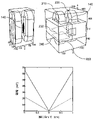
図1は、本開示の特定の態様に係る四極磁場、FFP130、及びFFL140を示す図である。MPIシステムは磁気ナル、ゼロ点又はフィールドフリー領域120を含む四極磁場(図1の上部)を発生することができる。図1の単純化された例では、逆方向に流れる電流を伴う2つのコイルが四極磁場を生成している。四極磁場の4つの「極」110は、短い矢印により示される。極110は、図1に示される2つの向かい合うコイルに等価な磁気構成の例として提供される。2つのコイルに流れる電流が同じ大きさかつ逆方向の場合には、極110は2つのコイルの対称点に位置する。
FIG. 1 is a diagram showing a quadrupole magnetic field, FFP130, and FFL140 according to a particular aspect of the present disclosure. The MPI system can generate a quadrupole magnetic field (top of FIG. 1) containing a magnetic null, zero point or field-free region 120. In the simplified example of FIG. 1, two coils with currents flowing in opposite directions generate a quadrupole magnetic field. The four "poles" 110 of the quadrupole magnetic field are indicated by short arrows. The
いくつかの実施例において、フィールドフリー領域120は、(図1の右下の半分の模式図により示されるように)FFP130であり得る。他の実施例において、フィールドフリー領域は、(図1の右下の半分の模式図に示されるように)フィールドフリー線140の形をとることができる。図1のプロットのY軸は、後の図と一貫して典型的にはフィールドフリー線140の垂直方向を示すように、垂直とラベル付けされる。MPIシステムがフィールドフリー線140を生成するように構成されているならば、MPI信号は点のかわりに線から受信される。FFL構成は従って投影ベースのイメージング及び再構成技術を利用し得る。
In some embodiments, the field-free region 120 can be the FFP 130 (as shown by the schematic diagram in the lower right half of FIG. 1). In another embodiment, the field-free region can take the form of a field-free line 140 (as shown in the schematic diagram of the lower right half of FIG. 1). The Y-axis of the plot of FIG. 1 is labeled vertical to consistently indicate the vertical direction of the field-
フィールドフリー線140は一般に長さ及び厚さを有する細長い領域であり、そこはMPIシステムにより生成された磁場において磁場が他の位置よりも大幅に弱い。本明細書で用いられるに際し、「フィールドフリー線」は、線は完璧に直線ではあり得ず、磁場が完全にないわけでもないという事実から構成されると理解されるが、一般にはそのようなものがFFLのゴールである。
The field-
フィールドフリー線140は、いくつかの実施例において、全体的に細長いか、又はMPIシステムのイメージング容積の中のみ「線形」であり得る。FFLにとって、イメージング容積外において線形性を保つことは重要性が低く、従ってフィールドフリー線140は中央、即ちイメージング容積の中心の近傍、から離れた場所では別の形に乖離していてもよい。同様に、本明細書で用いられる際、「フィールドフリー点」は概ね球形の低磁場の領域を指す。
The field-
図2は、FFL140を伴う単純化されたMPIシステムを、左上端に示す。図2は右上端においては、磁束帰還路250及び2つの磁束経路230,240を伴うMPIシステムを示す。図2の下部は、本開示の特定の態様に係る磁束帰還路250の内包に起因する磁場勾配の増加の例を詳説するグラフを含む。
FIG. 2 shows a simplified MPI system with FFL140 in the upper left corner. FIG. 2 shows an MPI system with a
図2に示すように、MPIシステムは内側にフィールドフリー線140を有する磁場を生成するように構成される磁石を含み得る。図2に示される設計の例では、磁石は第1磁石210及び第2磁石220を含む。しかしながら本開示は、必要な磁場及びフィールドフリー線は任意の数及び任意の種類の磁石により生成されてよいと想定している。例えば、磁石は複数の磁石(2つ、3つ、4つ等)を組み込んでよく、当該磁石は例えば、永久磁石、電流を流すコイル(電磁石)、磁束帰還路を伴う電磁石、又はそういった磁石の任意の組み合わせであり得る。実際、フィールドフリー線を生成することが可能である(例えばハルバッハ円筒)限り、磁石は単一の磁石であってよい。本明細書における磁石の設計の例は、限定を意図するものではない。
As shown in FIG. 2, the MPI system may include a magnet configured to generate a magnetic field with field-
フィールドフリー線140は、フィールドフリー線140の長さ方向に沿った軸と、一般にイメージング容積の中心の近傍と理解される軸の中心とを有すると理解される。
It is understood that the field-
図2の右上端は、磁石(ここでは第1及び第2磁石210,220を含むよう示される)とともに組み込まれた磁束帰還路250を示す。本開示で用いられるに際し「磁束帰還路」は、磁束を形成する材料成分の任意の配置を指す。磁束帰還路250は、磁束を伝え、誘導し、形成し、又は集中させるために、例えば鉄(又は他の物質と比較して、又は空気と比較して低いリラクタンスを有する他の材料)等の強磁性の材料を含んでよい。磁束帰還路250は、例えば、2つの個別の半分又は、積み重ねが可能か、そうでなくても組み立てて磁束帰還路250を形成可能な複数の薄板の層で製造され得る。
The upper right corner of FIG. 2 shows a
本開示の磁束帰還路は、例えば変化するリラクタンスの磁束経路を作ることにより、磁束分布を形成可能である。例えば、空気と比較して多量の鉄を含む経路は、鉄がより少なく空気がより多い、同じ長さの経路よりも低いリラクタンスを有する。本明細書で用いられるに際し、磁気抵抗、磁気リラクタンス、又は「リラクタンス」は、磁気回路の解析において用いられる概念であり、電子回路における抵抗と類似のものである。電場が電気抵抗の最も低い経路に電流を流すのと同様に、磁場は磁気リラクタンスの最も低い経路に磁束を流す。これは電気抵抗に似てスカラ、すなわち示容量である。磁気リラクタンスの単位はヘンリーの逆数、すなわちH-1である。 The magnetic flux feedback path of the present disclosure can form a magnetic flux distribution, for example, by creating a magnetic flux path of changing reluctance. For example, a pathway containing a large amount of iron compared to air has a lower reluctance than a pathway of the same length, with less iron and more air. As used herein, reluctance, or "reluctance," is a concept used in the analysis of magnetic circuits and is similar to resistance in electronic circuits. A magnetic field causes a magnetic flux to flow through the path of lowest reluctance, just as an electric field carries an electric current through the path of lowest reluctance. This is a scalar, or indicated capacitance, similar to electrical resistance. The unit of reluctance is Henry's reciprocal, or H -1 .
図2の下部に示す通り、誘導する磁束及び磁束帰還路の集中効果は、より高い磁場勾配を作るのに活用される。磁場勾配において、磁束帰還路を伴わない磁気システムとは対極に、磁束帰還路250を用いるとより強い磁場が得られる。図2の下部のグラフは、磁場中の、磁束帰還路が利用されているときに増加する勾配を示す。
As shown in the lower part of FIG. 2, the concentrated effect of the induced magnetic flux and the magnetic flux feedback path is utilized to create a higher magnetic field gradient. In the magnetic field gradient, a stronger magnetic field can be obtained by using the magnetic
磁場の対称性及び忠実度は、所望の形及び磁束密度にマッチする磁石配置(例えば対称なFFL140など)により、いかによく磁場が実現されるかにより記述され得る。本明細書で用いられるに際し「磁場忠実度」は、それが例えばFFL140の形及び質に関係することから、磁場パターンの質を指す。例えば、FFL140の軸に沿って低い勾配を伴うが、FFL140を取り囲む軸に直交する方向には高い勾配を伴う、高い線形性を持つ対称なFFL140を有することは有益であり得る。
The symmetry and fidelity of the magnetic field can be described by how well the magnetic field is achieved by a magnet arrangement that matches the desired shape and magnetic flux density (eg, symmetric FFL140). As used herein, "magnetic field fidelity" refers to the quality of the magnetic field pattern, as it relates to, for example, the shape and quality of FFL140. For example, it may be beneficial to have a
図3に示す本開示に係るMPIシステムのある実施例において、磁石が細長い(すなわち、1つの次元に関して別の次元よりも長く、円形でない)、高出力で水冷の電磁石を4つ含む。図3は、本開示の特定の態様に係る磁束帰還路250の例も示す。
In one embodiment of the MPI system according to the present disclosure shown in FIG. 3, the magnets are elongated (ie, longer than another in one dimension and not circular), and include four high power, water-cooled electromagnets. FIG. 3 also shows an example of a
いくつかの実施例において、磁石のうちの2つは、FFL140の位置を、例えばZ軸に沿ってシフトさせるための同種の磁場を生成するように構成されてよい;これらの磁石は「シフト磁石」と呼ばれ、Z1及びZ2の符号がふられている(図5参照)。本明細書においてX1及びX2(図5参照)の符号をふられたメイン磁石は、FFL140の位置をシフトさせるやり方で磁場を変更するように構成されてもよい。他の実施例において、FFL140の位置を急速にシフトさせるよう振る舞う高速駆動磁場を生成するのに、追加の磁石が用いられ得る。
In some embodiments, two of the magnets may be configured to generate a homogeneous magnetic field for shifting the position of the
図3に示すように、MPIシステムは撮影される対象を受ける穴310も含み得る。FFL140は穴310に鉛直に伸び得る。いくつかの実施例では、MPIシステムは穴310の軸に関して回転するように構成され得る。そのような実施例において、磁場の方向及びFFL140は対応するように変化する。
As shown in FIG. 3, the MPI system may also include a
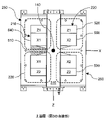
図4は、図3のMPIシステムの断面図(図3の太い実線部分で示され、システムの中央から見た、図3のXY平面に対応する)である。図4は、この特定の実施形態において、4つの磁石を囲む磁束帰還路250を示す。また、本開示の特定の態様に係るFFL140及び2つの磁束経路230,240も示される。
FIG. 4 is a cross-sectional view of the MPI system of FIG. 3 (shown by the thick solid line portion of FIG. 3 and corresponding to the XY plane of FIG. 3 as viewed from the center of the system). FIG. 4 shows a
図5は、図3のMPIシステムの別の断面図(図3のシステムの周囲の点線で示され、図3のXZ平面に対応する)である。図5は、本開示の特定の態様に係る磁束帰還路250も示し、それに含まれるポールピースも示す。ポールピース510(図示のため十字ハッチングで示す)は、例えばメイン磁石210,220の、図5にX1,X2で示される中心を通過可能である。
FIG. 5 is another cross-sectional view of the MPI system of FIG. 3 (shown by a dotted line around the system of FIG. 3 and corresponding to the XZ plane of FIG. 3). FIG. 5 also shows the
ある実施形態の例では、磁束帰還路250は、フィールドフリー線140の概ね中心の第1磁束経路230が第1リラクタンスを有し、フィールドフリー線140の中心から離れた第2磁束経路240は第2リラクタンスを有し、第2リラクタンスは第1リラクタンスよりも低いように構成される(図3及び図4に点線で示された磁束経路230,240の模式図を参照)。この実施形態では、「フィールドフリー線140の中心から離れた」第2磁束経路240は、単に磁束経路240がより短い距離を移動するというだけの理由ではなく、(同じくFFL140の中心から離れた点にある)磁束帰還路250の設計によって低いリラクタンスを有することが想定される。本実施形態の説明において、磁束経路230,240は各々フィールドフリー線140に隣接する点を通るように広がる経路であることが想定される。
In an example of one embodiment, in the magnetic
図6は、磁束帰還路250の例の断面図を通じて、この実施形態の例のある実施例を示す。図7は、図6の磁束帰還路を作り上げる33の薄板のうちの2つを示す。
FIG. 6 shows an example of this embodiment through a cross-sectional view of an example of the magnetic
図6及び図7に示す通り、磁束帰還路250は、1つの端点を有するポールピース510を含み得て、当該端点は段差を含み得る。段差を形成するために、磁束帰還路250は複数の薄板又は層を含んでよく、第1薄板610及び第2薄板620は段差を形成する。この例では、第1磁束経路230は第1薄板610を通過し、第2磁束経路240は第2薄板620を通過する。図示の通り、ポールピース510の段差は、底の薄板620がポールピース510の中心の薄板610よりもイメージング空間に突出するように構成され、従ってポールピースの底部における磁束帰還路材料(例えば鉄)の量を増加させ、FFL140の中心から離れた点におけるリラクタンスを低下させる。このリラクタンスが変化する設計は、異なる形の薄板を用いることで段差を形成するよう示されるが、これは類似の仕様に機械作製された単一のポールピースか、又は(単一又は複数の)薄板と機械作製された(単一又は複数の)ポールピースの組み合わせにより形成されてもよい。段差の実装はポールピース510に関連づけて示されたが、磁束帰還路250の外側部分(たとえば、610,620の符号の近傍)に同様のステップが実装されてもよいことが想定されている。
As shown in FIGS. 6 and 7, the
上述のリラクタンスが変化する性質は、例えば説明されたポールピース510中の、「段差」によって生成されてよいが、これらの性質はポールピースを機械作製して、よりなめらかに変化する磁束帰還路のポール外形を生成することによっても達成され得る。例えば、ポールピース510は同様にイメージング容積に向かって突出するFFL140の中心から離れた点に結びつく、連続又は部分的な曲面に機械作製され得る。なめらかに変化するポールピースは、例えば円弧、弦、放物線、双曲線、又は双曲線正接形の形をとり得る。さらに他の実施例では、セミスムーズの、又は細かく段差がついたポールピースを形成するために、長さが変化するいくつの薄板又は何層のポールピースがあってもよい。
The above-mentioned reluctance-changing properties may be generated by "steps" in, for example, the described
また別の実施例では、第2磁束経路240の近傍における磁束帰還路250が、第1磁束経路230の近傍における材料のリラクタンスよりも低いリラクタンスの材料を少なくとも部分的に含むことにより、第2リラクタンスは第1リラクタンスよりも低くてよい。
In yet another embodiment, the second reluctance is such that the
さらに別の実施例では、選択された磁束帰還路の材料に組み合わせて、磁束帰還路の形状により、第2リラクタンスは第1リラクタンスよりも低くあり得る。 In yet another embodiment, the second reluctance can be lower than the first reluctance, depending on the shape of the flux feedback path, in combination with the material of the selected flux feedback path.
磁束帰還路250は、ポールピース510が担い得る役割とは別に、磁束を形成又は集中させる役割を担うこともできる、「磁束帰還路アーム」(例えば図6の630)を含み得る。
The magnetic
図8は、本開示も特定の態様に係る、角度をつけた磁束帰還路アーム810を含む磁束帰還路250の例の模式図である。図8に示す通り、磁束帰還路アームは、イメージング容積におけるフィールドフリー線に向けて角度がついている。この角度付けは、図6及び図7に示すような、一般に穴310の軸と鉛直に向けられた磁束帰還路710と異なる。このように角度付けされた磁束帰還路アームは、イメージング容積の位置のFFL140の領域において、磁束をさらに収束又は形成することができる。図8はこのような角度をつけた磁束帰還路アームによる磁力線も示す。
FIG. 8 is a schematic diagram of an example of a magnetic
MPIのための磁束密度が形成又は最適化される別のやり方は、例えば図6及び図7に示され、ポールピース510はテーパを含むやり方で製造され得る。このようなポールピース510中のテーパは、テーパの近く及びフィールドフリー線140の近傍における磁束密度を増加させる。
Another way in which the magnetic flux density for MPI is formed or optimized is shown, for example, in FIGS. 6 and 7, where the
ここでいうテーパは(図に示されるように)FFL140に向かって徐々に細くなる。すなわちポール510の外形は、FFl140に向けて徐々に細る。テーパは図示されるように線形であってよいし、又は十字部の全部若しくは一部にわたってなめらかに変化してもよい(又はなめらかな変化と線形な部分の組み合わせでもあり得る)。テーパはポールピース510の端点まで来てもよいし、(図の例で示すように)ポールピース510の平坦な端点で途切れる部分的なテーパであってもよい。テーパは機械作製又はポールピース510若しくは磁束帰還路250を作り上げる材料の異なるサイズの層の任意の組み合わせにより製造され得る。
The taper here gradually tapers towards FFL140 (as shown in the figure). That is, the outer shape of the
MPIシステム中の磁場は、シミングにより変更又はさらに形成され得る。例えばシミングは、磁場を形成してフィールドフリー線140の忠実度を改善するか又はフィールドフリー線140の形を変えるために実行されてよい。
The magnetic field in the MPI system can be altered or further formed by shimming. For example, shimming may be performed to form a magnetic field to improve the fidelity of the field-
受動的シミングは、磁場を形成するためにMPIシステムに付属された永久磁石又は他の磁性材料(例えば鉄、鋼鉄、ミュー金属等)の機械的な付属品を指す。いくつかの実施例は、特定の所定の動作点又はメイン勾配磁石の強度にある磁場を最適化するための受動的シムセットの追加を含む。そのような受動的シムセットは、一定の範囲(たとえば4-7T/m)にわたる磁場の分布を十分に最適化する。しかしながら、最適化された範囲の外側の勾配動作点が求められるとき、受動的シムの別のセットを利用せねばならないことがあり得る。 Passive shimming refers to the mechanical accessories of permanent magnets or other magnetic materials (eg iron, steel, mu metal, etc.) attached to the MPI system to form a magnetic field. Some embodiments include the addition of a passive shim set to optimize the magnetic field at a particular predetermined operating point or the strength of the main gradient magnet. Such a passive shimset fully optimizes the distribution of the magnetic field over a range (eg 4-7 T / m). However, it may be necessary to utilize another set of passive shims when gradient operating points outside the optimized range are sought.
能動的シミングは、M磁場を形成するためにMPIシステム内に含まれる電磁石に電源を供給することを指し、しばしばシム磁石を駆動する電源が磁気粒子イメージングシステムの動作中に能動的に変えられる方法で行われる。 Active shiming refers to powering the electromagnets contained within an MPI system to form an M magnetic field, a method in which the power source driving the shim magnets is often actively altered during the operation of the magnetic particle imaging system. It is done in.
MPIシステムのシミングは、能動的シム、受動的シム、又はその療法の組み合わせを利用して実行され得る。 Simming of the MPI system can be performed utilizing active shims, passive shims, or a combination of therapies thereof.
図9は本開示の特定の態様に係るシム磁石の例を示すMPIシステムの例の斜視図である。図10は当該MPIシステムの上面図、図11は当該MPIシステムの側面図を示す。 FIG. 9 is a perspective view of an example of an MPI system showing an example of a shim magnet according to a particular aspect of the present disclosure. FIG. 10 shows a top view of the MPI system, and FIG. 11 shows a side view of the MPI system.
図9に示すように、シム磁石910は穴310の長さ方向に沿って中心に置かれ、元来磁束帰還路205の中心に位置合わせされ、及び複数のポールピース510同士の間に位置付けされてもよい。図11に示す通り、この位置において、シム磁石910は、穴310内のイメージング空間に位置するフィールドフリー線140の一部分の上(本明細書では「フィールドフリー線の上」という)で、概ね中心に置かれる。図11に示されるように、シム磁石1110は同様に、穴310内のイメージング空間に位置するフィールドフリー線140の一部分の下(本明細書では「フィールドフリー線の下」という)で、概ね中心の位置に置かれる。ある特定の実施例においては、シム磁石910及び1110は、FFLがイメージング空間の中央に位置するとき(この場合、穴310の中心であり、磁石210及び220の間で中央に置かれる)、FFL140の軸上で中心に置かれ、従って下でさらに説明されるようなFFL140の形成を可能にする。イメージングの間、FFL140はイメージング空間内の異なる位置にシフトしてもよく、従ってシム磁石910及び1110はそのような時にのみ、FFL140の上で概ね中心に置かれる。
As shown in FIG. 9, the
図9-11の例では向かい合う複数のシム磁石910,1110の1つの組が示されるが、本開示は、穴310に沿った任意の場所に、穴310の周囲の任意の角度(例えば図のY軸のかわりにX軸に沿って向けられる)で位置し、穴310の周囲の任意の数(1個,2個,4個,6個など)のシム磁石があってもよいことを想定している。加えて、能動的シム磁石は別の能動的シム磁石と直列又は並列に電気的に接続されてよいし、又は別の能動的シム磁石とは完全に独立していてもよい。
Although the example of FIG. 9-11 shows one set of facing
図12及び図13は代替の、本開示の特定の態様に係る角度をつけたシム磁石1210,1220を示す。この角度をつけたシム磁石は、FFL140をさらに形成又は制御するのに用いることができ、FFL140の軸から離れた(すなわちFFL140上でない)場所に位置していてもよいが、選択的に概ねFFL140に向けられる。角度をつけたシム磁石1210,1220は、Z軸方向に生成された磁場の成分がFFL140の軸において大きく打ち消し合され得るように、対称に配置され得る。角度を付けたシム磁石1210,1220はFFL140に対して、例えば、図に示されるように約45度、0度(つまりFFL140と平行)、30度、60度等の、どのような角度を有してもよい。図11に示す通り、穴310の下に、角度をつけたシム磁石1210,1220と反対の、同様の配置の角度をつけたシム磁石1310,1320があってもよい。
12 and 13 show alternative,
図14は、本開示の特定の態様に係る細長いシム磁石1410を示すMPIシステムの上面図であり、図15は当該細長いシム磁石1410を示す側面図である。細長いシム磁石1410は、シム磁石910に類似だが、穴310の長さ方向に沿って引き延ばされている。図15に示す通り、特定の実施形態は穴310の下に向かい合う細長いシム磁石1510も含む。
FIG. 14 is a top view of the MPI system showing an
本開示のFFLの上、FFLの下又はFFLの上及び下に1つのシム磁石を有する実施形態では、(単一又は複数の)シム磁石は、磁石の周囲の磁束分布の形成(例えば、ポールピース510と磁束帰還路アーム630の間の所望の磁束を準備する)を補助するように構成されてよい。このやり方で構成された(単一又は複数の)シム磁石は、フィールドフリー線の忠実度を改善し、フィールドフリー線の軸に沿った勾配の減少を招き得る。ある実施例では、シム磁石は、メイン磁石が磁束帰還路を必要としないような所望の磁束分布を促すのに十分な強度のものであり得る。別の実施例において、シム磁石の磁束を促す性質は、比較的高い忠実度のFFLを促し、それゆえシム磁石に必要な電源をシム磁石が水冷を必要としない点まで減少させる、磁石及び磁束帰還路の設計とともに利用される。
In embodiments with one shim magnet above, below, or above and below the FFL of the present disclosure, the shim magnet (single or plural) forms a magnetic flux distribution around the magnet (eg, pole). It may be configured to assist (prepare the desired flux between the
他の実施例において、シム磁石は、上述の高忠実度フィールドフリー線のための所望の磁束分布を補助する構成とは対照的に、メイン磁石の周囲の通常の磁束分布に逆に作用するために用いられ得る。この逆作用の構成のシム磁石によりFFLは、例えばフィールドフリー点、又は楕円形のフィールドフリー領域等の異なる形へと再形成され得る。そういった構成において、FFLタイプの磁石は、よりフィールドフリー点磁石に近い振る舞いをするように構成され、従って、対象の一部からの信号を回避したい場合(例えば、肝臓の近くの小さなソースを検出しようとする時に、肝臓からの大きな信号を最小化したい時など)に、改善されたイメージングを可能にする。磁気粒子イメージングに関係づけられたコントロールシステムは従って、イメージング対象の特定の一部分を興奮させることを避けるように構成され得る。加えて、そういった構成は、ハイブリッドイメージング及び磁気駆動のMPIシステムにおける空間的選択性の増加を可能にし得る。 In another embodiment, the shim magnet acts in opposition to the normal flux distribution around the main magnet, as opposed to the configuration that aids in the desired flux distribution for the high fidelity field-free wire described above. Can be used for. A shim magnet with this adverse configuration can reshape the FFL into a different shape, such as a field-free point, or an elliptical field-free region. In such configurations, FFL-type magnets are configured to behave more like field-free point magnets, so if you want to avoid signals from parts of the subject (eg, detect a small source near the liver). When you want to minimize the large signal from the liver, etc.), it enables improved imaging. The control system associated with magnetic particle imaging can therefore be configured to avoid exciting a particular portion of the imaged object. In addition, such configurations may allow for increased spatial selectivity in hybrid imaging and magnetically driven MPI systems.
シム磁石がメイン磁石の周囲の通常の磁束分布に逆作用するように構成される構成において、楕円形のフィールドフリー空間が作られ得て、従って有益な平板イメージングを可能にする。 In a configuration in which the shim magnet is configured to counteract the normal flux distribution around the main magnet, an elliptical field-free space can be created, thus enabling useful plate imaging.
いくつかの実施形態において、シム磁石のメイン磁石磁束分布に逆作用するそのような構成は、高い電力増幅、独立したドライブ機構及びシム磁石を冷却するためのシステムを必要とし得る。 In some embodiments, such a configuration that counteracts the main magnet flux distribution of the shim magnet may require high power amplification, an independent drive mechanism and a system for cooling the shim magnet.
本開示は、イメージングシーケンスの間、磁石(たとえば磁石520,530,540,550)を能動的にシミングするシステム及び方法を想定する。
The present disclosure envisions systems and methods for actively shimming magnets (eg,
磁束帰還路におけるサチュレーションの非線形性から、FFL140の充実度は、磁石勾配強度が変化するのと同様に変化し得る。たとえば、FFL140はある特定の勾配強度において高レベルの忠実度を有し得るが、イメージングシーケンスが勾配強度の変化を要求して磁束分布に変化をもたらす場合に、FFL140の忠実度に悪影響を及ぼし得る。本開示は、本明細書で議論された通り、シム磁石の磁場の追加により忠実度の低下に逆作用するための能動的シムの利用を想定する。
Due to the non-linearity of saturation in the flux feedback path, the fulfillment of the
同様に、FFL140はイメージング容積の中心に位置する時に高レベルの忠実度を有し得る一方、イメージングの間にFFLが中央から離れてシフトされるに際し、FFLは忠実度の低下を喫し得る。本開示は、本明細書で議論された通り、忠実殿低下に逆作用するための能動的シムの利用を想定する。
Similarly, the
本明細書で議論されたシミング方法及びシム磁石の特定の実施例において、メイン磁場勾配忠実度は、特定の設計フィールドに関して設計され得て、その後設計フィールドからの強度及び位置の偏差が、シム磁石の使用により補われ得る。シム磁石(及び他の磁石)を流れる電流は、先験的モデルを用いて、実験的に計測されてルックアップテーブルを用いて設定されてよく、及び/又は、例えばホール効果探査及びフィードバックを用いてリアルタイムで計測、調整され得る。若しくは電流は、それらの任意の組み合わせによって設定されてもよい。 In the shimming methods and specific examples of shim magnets discussed herein, the main field gradient fidelity can be designed for a particular design field, after which the strength and position deviations from the design field are the shim magnets. Can be supplemented by the use of. The current through the shim magnet (and other magnets) may be measured experimentally using a priori models and set using a look-up table and / or using, for example, Hall effect exploration and feedback. Can be measured and adjusted in real time. Alternatively, the current may be set by any combination thereof.
特定の実施形態において、本開示により想定されるシム磁石は、例えば磁気粒子イメージングシステムが空間的に選択可能な磁性流体癌温熱療法/刺激への応用のために構成されている時、加熱のさらなる局所化及びエネルギーの3次元的凝縮を提供するように構成されてもよい。例えば、フィールドフリー線を点様又は楕円形のフィールドフリー領域に再形成することは、フィールドフリー線の線全体よりも小さい領域を加熱又は駆動することを含む。 In certain embodiments, the shim magnets envisioned by the present disclosure are further heated, eg, when the magnetic particle imaging system is configured for spatially selectable ferrofluid cancer hyperthermia / stimulation applications. It may be configured to provide localization and three-dimensional condensation of energy. For example, reshaping a field-free line into a point-like or elliptical field-free region involves heating or driving a region smaller than the entire line of the field-free line.
本開示は、本明細書の実施形態において開示された演算が、本明細書で教示された同じ概念を適用する複数のやり方で実行されてよく、かつそういった演算は開示された実施形態と等価であることを想定する。 The present disclosure is such that the operations disclosed in the embodiments of the present specification may be performed in a plurality of ways applying the same concepts taught herein, and such operations are equivalent to the disclosed embodiments. I assume there is.
本明細書に説明された要旨の1つ以上の態様又は特徴は、デジタル電子回路、組み込み回路、空間的に設計された特定用途向け組み込み回路(ASIC)、フィールドプログラマブルゲートアレイ(FPGA)コンピュータハードウェア、ファームウェア、ソフトウェア及び/又はそれらの組み合わせにより実現され得る。これらの様々な態様又は特徴は、データ及び命令を受信しデータ及び命令を送信するためのストレージシステム、少なくとも1つの入力デバイス及び少なくとも1つの出力デバイスと接続された少なくとも1つの、空間的又は汎用の、プログラマブルプロセッサを含むプログラマブルシステム状で実行可能又は解釈可能な1つ以上のコンピュータプログラムによる実装を含み得る。プログラマブルシステム又は計算システムは、クライアント及びサーバを含み得る。クライアント及びサーバは一般に互いから遠隔であり、典型的には遠隔通信ネットワークを通じて相互作用する。クライアント及びサーバの関係は、それぞれの対応するコンピュータ上で実行されたコンピュータプログラム及び互いに対するクライアント-サーバ関係を有することにより発生する。 One or more aspects or features of the gist described herein include digital electronic circuits, embedded circuits, spatially designed application specific integrated circuits (ASICs), field programmable gate arrays (FPGAs), and computer hardware. , Firmware, software and / or combinations thereof. These various aspects or features are a storage system for receiving data and instructions and transmitting data and instructions, at least one spatial or general purpose connected to at least one input device and at least one output device. , May include implementation by one or more computer programs feasible or interpretable in a programmable system, including a programmable processor. The programmable system or computing system may include clients and servers. Clients and servers are generally remote from each other and typically interact through telecommunications networks. The client-server relationship arises by having a computer program running on each corresponding computer and a client-server relationship with each other.
これらのコンピュータプログラムは、プログラム、ソフトウェア、ソフトウェアアプリケーション、アプリケーション、コンポーネント又はコードとも呼ばれ、プログラマブルプロセッサに対するマシン命令を含み、高レベル手続型言語、オブジェクト指向プログラミング言語、関数型プログラミング言語、論理プログラミング言語及び/又はアセンブリ/マシン言語により実装され得る。本明細書で用いるに際し、「マシン可読媒体」(又は「コンピュータ可読媒体」)の用語は、例えば磁気ディスク、光ディスク得、メモリ及びプログラマブル論理デバイス(PLD)等の、マシン命令及び/又はデータをプログラマブルプロセッサに提供するのに用いられるコンピュータプログラム製品、装置及び/又はデバイスを指し、マシン可読信号としてマシン命令を受信するマシン可読媒体を含む。「マシン可読信号」(又は「コンピュータ可読信号」)の用語は、プログラマブルプロセッサにマシン命令及び/又はデータを提供するのに用いられる任意の信号を指す。マシン可読媒体は、例えば非一時的ソリッドステートメモリ又は磁気ハードドライブ若しくは等価な任意の記憶媒体がそうであるように、そのようなマシン命令を非一時的に格納することができる。マシン可読媒体は代替又は追加で、例えばプロセッサキャッシュ又は1つ以上の物理プロセッサコアと関係づけられた他のランダムアクセスメモリがそうであるように、一時的なやり方でそういったマシン命令を格納することができる。 These computer programs, also called programs, software, software applications, applications, components or codes, include machine instructions for programmable processors, high-level procedural languages, object-oriented programming languages, functional programming languages, logical programming languages and / Or can be implemented by assembly / machine language. As used herein, the term "machine readable medium" (or "computer readable medium") is programmable for machine instructions and / or data such as, for example, magnetic disks, optical disk gains, memory and programmable logic devices (PLDs). Refers to computer program products, devices and / or devices used to provide a processor, including machine-readable media that receive machine instructions as machine-readable signals. The term "machine readable signal" (or "computer readable signal") refers to any signal used to provide machine instructions and / or data to a programmable processor. Machine-readable media can store such machine instructions non-temporarily, as is the case with non-temporary solid-state memory or magnetic hard drives or any equivalent storage medium. Machine-readable media may be alternative or additional to store such machine instructions in a temporary manner, as is the case with, for example, the processor cache or other random access memory associated with one or more physical processor cores. can.
ユーザとのインタラクションを提供するために、本明細書に説明される要旨の1つ以上の態様又は特徴は、例えばカソードレイチューブ(CRT)又は液晶ディスプレイ(LCD)又は発光ダイオード(LED)モニタ等の、情報をユーザに表示するための表示デバイスと、ユーザがコンピュータに入力を提供するための、キーボードと、例えばマウス又はトラックボール等といったポインティングデバイスとを有するコンピュータ上で実装され得る。ユーザとのインタラクションを提供するために、他の種類のデバイスも用いられ得る。例えば、ユーザに提供されるフィードバックは、例えば視覚フィードバックといった感覚フィードバック、聴覚フィードバック、又は触覚フィードバックの任意の形であってよい;ユーザからの入力は、音、声、又は接触の入力を含む任意の形で受信されてよいが、これらに限定されない。他の可能な入力デバイスは、タッチスクリーン、又は、シングルポイント又はマルチポイントの抵抗式又は静電容量式トラックパッドといった他の接触感知デバイス、音声認識ハードウェア及びソフトウェア、光学スキャナ、光学ポインタ、デジタルイメージキャプチャデバイス、及び関係づけられた翻訳ソフトウェアなどを含むが、これらに限定されない。 To provide interaction with the user, one or more aspects or features of the gist described herein include, for example, a cathode ray tube (CRT) or a liquid crystal display (LCD) or a light emitting diode (LED) monitor. , May be implemented on a computer having a display device for displaying information to the user, a keyboard for the user to provide input to the computer, and a pointing device such as a mouse or trackball. Other types of devices may also be used to provide interaction with the user. For example, the feedback provided to the user may be in any form of sensory feedback, auditory feedback, or tactile feedback, eg visual feedback; input from the user may be any form including sound, voice, or contact input. It may be received in the form, but is not limited to these. Other possible input devices are touch screens or other contact sensing devices such as single-point or multi-point resistance or capacitive trackpads, voice recognition hardware and software, optical scanners, optical pointers, digital images. Includes, but is not limited to, capture devices, associated translation software, and the like.
上記の説明及び特許請求の範囲において、「少なくとも1つの」又は「1つ以上の」に類する表現は、要素又は特徴の接続的なリストにより追随されて現れ得る。「及び/又は」の用語も、2つ以上の要素又は特徴のリストにおいても現れ得る。これらの表現は、前後の文脈で暗に又は明に言及されているのでない限り、記載された要素又は特徴のいずれかを個別に意味するか、又は、列挙された要素又は特徴のいずれか1つを、他の列挙された要素又は特徴のいずれか1つと組み合わせたものを意味することを意図するものである。例えば、「A及びBの少なくとも1つ」、「A及びBのうち1つ以上」及び「A及び/又はB」の表現はいずれも、「Aのみ、Bのみ、又はA及びBの両方」を意味する。同様の解釈は、3つ以上のものを含むリストにおいても同様に意図されている。例えば、「A、B及びCの少なくとも1つ」、「A、B及びCのうち1つ以上」及び「A、B及び/又はC」の表現はいずれも、「Aのみ、Bのみ、Cのみ、A及びBの両方、A及びCの両方、B及びCの両方、並びに、A~Cのすべて」を意味することが意図されている。上述及び特許請求の範囲における「~に基づいて」の表現は、「少なくとも部分的に~に基づいて」を意味し、列挙されていない特徴又は要素も許容するものである。 In the above description and claims, expressions similar to "at least one" or "one or more" may appear followed by a connected list of elements or features. The term "and / or" may also appear in a list of two or more elements or features. These expressions individually mean any of the described elements or features, or any one of the listed elements or features, unless implicitly or explicitly referred to in context. It is intended to mean one in combination with any one of the other listed elements or features. For example, the expressions "at least one of A and B", "one or more of A and B" and "A and / or B" are all "A only, B only, or both A and B". Means. Similar interpretations are intended for lists containing three or more. For example, the expressions "at least one of A, B and C", "one or more of A, B and C" and "A, B and / or C" are all "A only, B only, C". Only, both A and B, both A and C, both B and C, and all of A to C are intended to mean. The expressions "based on" above and in the claims mean "at least partially based on" and allow features or elements not listed.
本明細書で説明された要旨は、所望される配置によってシステム、装置、方法、コンピュータプログラム及び/又は物品の上で実施され得る。添付の図面で示され、及び/又は本明細書で説明された方法又はロジックフローは、所望の結果を達成するために、必ずしも示された順序、又は手続順序を必要としない。先述の説明で記載された実施例は、本明細書で説明された要旨と一致する全ての実施例を表現するものではなく、それらは説明された要旨に関連する態様と一致するいくつかの例に過ぎない。いくつかの変形は上記で詳細に説明されたが、他の変更又は追加も可能である。特に、本明細書に記載されたものに加え、さらなる特徴及び/又は変形が提供され得る。上述された実施例は、開示された要素の様々な組み合わせ及び部分的組み合わせ、及び/又は上で示された、いくつかのさらなる特徴の組み合わせ及び部分的組み合わせが対象となり得る。さらに、上で説明された利点は、発行されるいかなる特許請求の範囲の応用をも、いずれか又は全ての利点を達成するプロセス又は構造に限定することを意図しない。 The gist described herein can be implemented on systems, devices, methods, computer programs and / or articles in the desired arrangement. The methods or logic flows shown in the accompanying drawings and / or described herein do not necessarily require the order shown or the order of procedure to achieve the desired result. The examples described in the above description do not represent all the examples consistent with the gist described herein, but some examples consistent with aspects relating to the gist described. It's just that. Some variants have been described in detail above, but other modifications or additions are possible. In particular, additional features and / or variations may be provided in addition to those described herein. The examples described above may cover various combinations and partial combinations of the disclosed elements, and / or combinations and / or partial combinations of some additional features shown above. Moreover, the advantages described above are not intended to limit the application of any claims issued to the process or structure that achieves any or all of the advantages.
加えて、節の見出しは、本開示から発行し得るいかなる特許請求の範囲に定められる単一又は複数の発明をも、限定又は特徴付け得ない。特に、かつ例として、見出しが「技術分野」を参照しても、そういった特許請求の範囲は、いわゆる技術分野を説明するために本見出しの元で選択された言語により限定されるべきではない。さらに、「技術的背景」における技術の説明は、当該技術が本開示のいずれかの単一又は複数の発明に対する先行技術であることの自認として構成されるものではない。「発明の概要」も、主張する特許請求の範囲に記載された単一又は複数の発明の特徴として認識されるものではない。さらに、本開示への一般の参照又は単数形の「発明」という語の使用は、下で記載される特許請求の範囲におけるいかなる限定をも示唆するものではない。複数の発明が、本開示により主張される複数の特許請求の範囲の限定により記載され得る。またそれに応じて、そういった複数の特許請求の範囲が、それにより保護される単一若しくは複数の発明及びそれらの均等を定める。 In addition, the section headings may not limit or characterize any single or multiple inventions defined in any claims that can be issued from this disclosure. In particular, and by way of example, even if the heading refers to "technical field", the scope of such claims should not be limited by the language selected under this heading to describe the so-called technical field. Furthermore, the description of the technique in the "Technical Background" is not construed as a pledge that the technique is prior art to any one or more inventions of the present disclosure. The "outline of the invention" is also not recognized as a feature of the single or multiple inventions described in the claimed claims. Moreover, the general reference to this disclosure or the use of the singular term "invention" does not imply any limitation in the claims described below. Multiple inventions may be described by limiting the scope of the claims claimed in the present disclosure. Accordingly, the scope of such claims defines the single or multiple inventions protected thereby and their equality.
Claims (8)
磁場を生成するように構成された磁石であって、軸及び中心を有する前記磁場内のフィールドフリー線を有する磁石と、
前記磁石に組み込まれ、前記フィールドフリー線の概ね中心の第1磁束経路は第1リラクタンスを有し、前記フィールドフリー線の中心から離れた第2磁束経路は第2リラクタンスを有するように構成された磁束帰還路と、
を備え、
前記第2リラクタンスは前記第1リラクタンスよりも低い、
磁気粒子イメージングシステム。 Magnetic particle imaging (MPI) system,
A magnet configured to generate a magnetic field, with a magnet having a field-free line in the magnetic field having an axis and a center, and a magnet.
The first magnetic flux path incorporated in the magnet and approximately central to the field-free wire is configured to have a first reluctance, and the second magnetic flux path away from the center of the field-free wire has a second reluctance. Magnetic flux feedback path and
Equipped with
The second reluctance is lower than the first reluctance,
Magnetic particle imaging system.
請求項1に記載の磁気粒子イメージングシステム。 The flux feedback path comprises a pole piece having endpoints, the endpoints comprising a step.
The magnetic particle imaging system according to claim 1.
請求項2に記載の磁気粒子イメージングシステム。 The magnetic flux feedback path further comprises a plurality of layers, the first magnetic flux path passes through the first layer, the second magnetic flux path passes through the second layer, and the first layer and the second layer are the steps. Form,
The magnetic particle imaging system according to claim 2.
請求項1に記載の磁気粒子イメージングシステム。 The flux feedback path comprises a pole piece having a taper, which increases the magnetic flux density in the vicinity of the taper and in the vicinity of the field-free line.
The magnetic particle imaging system according to claim 1.
ポールピースと、
前記ポールピースよりも前記フィールドフリー線から離れて位置する少なくとも1つの磁束帰還路アームとを備える、
請求項1に記載の磁気粒子イメージングシステム。 The magnetic flux feedback path is
With pole piece,
It comprises at least one flux feedback path arm located farther from the field-free line than the pole piece.
The magnetic particle imaging system according to claim 1.
請求項6に記載の磁気粒子イメージングシステム。 The at least one flux feedback path arm is angled towards the field-free line in the imaging volume.
The magnetic particle imaging system according to claim 6.
請求項1に記載の磁気粒子イメージングシステム。
The second reluctance is due, at least in part, to the fact that the flux feedback path contains a material with a reluctance lower than the reluctance of the material in the vicinity of the first flux path in the vicinity of the second flux path. Lower than reluctance,
The magnetic particle imaging system according to claim 1.
Priority Applications (1)
| Application Number | Priority Date | Filing Date | Title |
|---|---|---|---|
| JP2022104008A JP2022126838A (en) | 2016-07-12 | 2022-06-28 | magnetic particle imaging |
Applications Claiming Priority (5)
| Application Number | Priority Date | Filing Date | Title |
|---|---|---|---|
| US201662361463P | 2016-07-12 | 2016-07-12 | |
| US201662361475P | 2016-07-12 | 2016-07-12 | |
| US62/361,475 | 2016-07-12 | ||
| US62/361,463 | 2016-07-12 | ||
| PCT/US2017/041783 WO2018013731A1 (en) | 2016-07-12 | 2017-07-12 | Magnetic particle imaging using flux return or shim magnet |
Related Child Applications (1)
| Application Number | Title | Priority Date | Filing Date |
|---|---|---|---|
| JP2022104008A Division JP2022126838A (en) | 2016-07-12 | 2022-06-28 | magnetic particle imaging |
Publications (3)
| Publication Number | Publication Date |
|---|---|
| JP2019523115A JP2019523115A (en) | 2019-08-22 |
| JP2019523115A5 JP2019523115A5 (en) | 2020-08-20 |
| JP7097879B2 true JP7097879B2 (en) | 2022-07-08 |
Family
ID=59388183
Family Applications (3)
| Application Number | Title | Priority Date | Filing Date |
|---|---|---|---|
| JP2019522617A Active JP7097879B2 (en) | 2016-07-12 | 2017-07-12 | Magnetic particle imaging |
| JP2019522618A Active JP7097357B2 (en) | 2016-07-12 | 2017-07-12 | Magnetic particle imaging with a rotating magnet |
| JP2022104008A Pending JP2022126838A (en) | 2016-07-12 | 2022-06-28 | magnetic particle imaging |
Family Applications After (2)
| Application Number | Title | Priority Date | Filing Date |
|---|---|---|---|
| JP2019522618A Active JP7097357B2 (en) | 2016-07-12 | 2017-07-12 | Magnetic particle imaging with a rotating magnet |
| JP2022104008A Pending JP2022126838A (en) | 2016-07-12 | 2022-06-28 | magnetic particle imaging |
Country Status (5)
| Country | Link |
|---|---|
| US (3) | US10466316B2 (en) |
| EP (3) | EP4085827A1 (en) |
| JP (3) | JP7097879B2 (en) |
| CN (3) | CN109952060B (en) |
| WO (2) | WO2018013731A1 (en) |
Families Citing this family (18)
| Publication number | Priority date | Publication date | Assignee | Title |
|---|---|---|---|---|
| US10466316B2 (en) | 2016-07-12 | 2019-11-05 | Magnetic Insight, Inc. | Magnetic particle imaging |
| WO2019225111A1 (en) * | 2018-05-21 | 2019-11-28 | 三菱電機株式会社 | Electro-magnet device for magnetic particle imaging and magnetic particle imaging device |
| JP2022523753A (en) * | 2019-03-13 | 2022-04-26 | マグネティック・インサイト・インコーポレイテッド | Magnetic particle operation |
| CN110367983B (en) * | 2019-07-15 | 2020-09-22 | 中国科学院自动化研究所 | Magnetic particle imaging system based on non-magnetic field line scanning |
| DE102020202097B3 (en) * | 2020-02-19 | 2021-04-08 | Bruker Biospin Mri Gmbh | MPI imaging device, method for generating a magnetic field with a gradient and a field-free line by means of an MPI imaging device |
| KR102545062B1 (en) | 2020-06-25 | 2023-06-20 | 한국전자통신연구원 | Apparatus and Method for Nano Magnetic Particle Imaging |
| DE102020211948B3 (en) | 2020-09-23 | 2021-10-14 | Bruker Biospin Mri Gmbh | Magnet arrangement for generating a selection magnetic field, device with magnet arrangement and method for generating a selection magnetic field |
| KR102655930B1 (en) * | 2020-09-24 | 2024-04-11 | 한국전자통신연구원 | Apparatus for generating Field Free, Apparatus and Method for Nano Magnetic Particle Image |
| CN112635152A (en) * | 2020-12-14 | 2021-04-09 | 瑞声精密制造科技(常州)有限公司 | Annular array magnetic steel system and magnetic attraction positioning system |
| CN113288106B (en) * | 2021-05-24 | 2022-11-15 | 中国科学院自动化研究所 | Magnetic particle imaging detection system and method and electronic equipment |
| CN113397521B (en) * | 2021-06-15 | 2022-05-27 | 中国科学院自动化研究所 | Helical scanning magnetic particle projection tomography method, system and equipment |
| WO2023042265A1 (en) * | 2021-09-14 | 2023-03-23 | 三菱電機株式会社 | Magnetic micro-particle imaging device |
| US11733324B2 (en) | 2021-09-24 | 2023-08-22 | Mitsubishi Electric Corporation | Magnetic particle imaging system and magnetic particle imaging method |
| US11940502B2 (en) * | 2021-09-24 | 2024-03-26 | Analog Devices International Unlimited Company | Magnetic field sensing based on particle position within container |
| CN114521882B (en) * | 2022-04-22 | 2022-07-19 | 北京航空航天大学 | Magnetic particle-based field-free line scanning imaging and field-free point positioning thermotherapy fusion device |
| CN114521881B (en) * | 2022-04-22 | 2022-07-19 | 北京航空航天大学 | Magnetic particle imaging and thermal therapy fusion device based on field-free line and inertial scanning |
| CN115778354B (en) * | 2023-02-07 | 2023-04-28 | 北京航空航天大学 | Human body scale closed-pore MPI device based on radial-Cartesian trajectory scanning |
| CN115792747B (en) * | 2023-02-13 | 2023-04-28 | 北京航空航天大学 | Multi-mode magnetic particle imaging fixing and registering calibration system |
Citations (3)
| Publication number | Priority date | Publication date | Assignee | Title |
|---|---|---|---|---|
| US20120065491A1 (en) | 2009-05-18 | 2012-03-15 | Koninklijke Philips Electronics N.V. | Arrangement and method for influencing and/or detecting magnetic particles |
| US20140306698A1 (en) | 2011-11-16 | 2014-10-16 | Koninklijke Philips N.V. | Apparatus and method for influencing and/or detecting magnetic particles having a large field of view |
| US20140320132A1 (en) | 2011-12-02 | 2014-10-30 | Koninklijke Philips N.V. | Coil arrangement for mpi |
Family Cites Families (67)
| Publication number | Priority date | Publication date | Assignee | Title |
|---|---|---|---|---|
| US1567423A (en) | 1925-02-02 | 1925-12-29 | George L Comlossy | Drain seal for refrigerator cars |
| JPS59155239A (en) | 1983-02-23 | 1984-09-04 | 株式会社東芝 | Diagnostic nuclear magnetic resonance apparatus |
| US4538130A (en) | 1984-04-23 | 1985-08-27 | Field Effects, Inc. | Tunable segmented ring magnet and method of manufacture |
| JPH01209706A (en) * | 1988-02-17 | 1989-08-23 | Kobe Steel Ltd | Structure of magnetic pole |
| DE3821984A1 (en) | 1988-06-30 | 1990-04-12 | Philips Patentverwaltung | CIRCUIT ARRANGEMENT FOR GENERATING HIGH-FREQUENCY SIGNALS FOR NUCLEAR SPIN EXAMS |
| US5461282A (en) * | 1993-02-05 | 1995-10-24 | Litton Systems, Inc. | Advanced center post electron gun |
| US5510711A (en) | 1994-08-05 | 1996-04-23 | Picker International, Inc. | Digital combination and correction of quadrature magnetic resonance receiver coils |
| GB9506909D0 (en) | 1995-04-04 | 1995-05-24 | Scient Generics Ltd | Spatial magnetic interrogation system |
| US5606254A (en) * | 1995-10-19 | 1997-02-25 | General Motors Corporation | Rotation sensor employing coil wound on assembly of a core interposed between two magnets |
| GB9608329D0 (en) | 1996-04-23 | 1996-06-26 | Scient Genarics Ltd | Improved methods for coding magnetic tags |
| EP0906583B1 (en) | 1996-06-19 | 2003-08-27 | Flying Null Limited | Magnetic reading devices |
| GB9619896D0 (en) | 1996-09-24 | 1996-11-06 | Flying Null Ltd | Improvements in or relating to magnetic sensors |
| GB9620190D0 (en) | 1996-09-27 | 1996-11-13 | Flying Null Ltd | Improved methods for coding magnetic tags |
| JP2001502087A (en) | 1996-10-09 | 2001-02-13 | フライング・ナル・リミテッド | Magnetic inquiry technology |
| DE69822841T2 (en) | 1997-08-19 | 2005-04-21 | Flying Null Ltd | IMPROVEMENT IN SURGERY EQUIPMENT AND ITS LOCALIZATION |
| GB9717574D0 (en) | 1997-08-19 | 1997-10-22 | Flying Null Ltd | Catheter location |
| GB9800064D0 (en) | 1998-01-05 | 1998-03-04 | Sentec Ltd | Uni-directional magnetic tag |
| GB9805824D0 (en) | 1998-03-18 | 1998-05-13 | Flying Null Ltd | Magnetic patterns |
| GB9806923D0 (en) | 1998-03-31 | 1998-05-27 | Flying Null Ltd | Position sensing |
| GB9817803D0 (en) | 1998-08-14 | 1998-10-14 | Flying Null Ltd | Magnetic information carriers |
| EP1145048B1 (en) | 1998-12-23 | 2003-07-23 | Flying Null Limited | Reading devices for magnetic tags |
| US7022987B2 (en) * | 2001-02-20 | 2006-04-04 | Carl Zeiss Nis Gmbh | Particle-optical arrangements and particle-optical systems |
| DE10151778A1 (en) | 2001-10-19 | 2003-05-08 | Philips Corp Intellectual Pty | Method for determining the spatial distribution of magnetic particles |
| DE10238853A1 (en) | 2002-08-24 | 2004-03-04 | Philips Intellectual Property & Standards Gmbh | Process for local heating with magnetic particles |
| EP2335574B1 (en) * | 2003-04-15 | 2012-10-31 | Philips Intellectual Property & Standards GmbH | Magnetic gas bubble composition and functionalised magnetic particle composition |
| CN100548214C (en) | 2003-04-15 | 2009-10-14 | 皇家飞利浦电子股份有限公司 | The equipment of influencing magnetic particles |
| WO2004091394A2 (en) | 2003-04-15 | 2004-10-28 | Philips Intellectual Property & Standards Gmbh | Method to determine the spatial distribution of magnetic particles and magnetic particle administering compositions |
| US7619408B2 (en) | 2003-04-15 | 2009-11-17 | Koninklijke Philips Electronics N.V. | Spatially resolved determination of magnetic particle anisotropy in an area of examination |
| US7758622B2 (en) | 2003-04-15 | 2010-07-20 | Koninklijke Philips Electronics N.V. | Method and apparatus for influencing magnetic particles |
| US20050073309A1 (en) | 2003-10-01 | 2005-04-07 | Williams Neil R. | Magnetic resonance coil modules |
| EP2019667A4 (en) | 2006-04-27 | 2012-08-22 | Barnes Jewish Hospital | Detection and imaging of target tissue |
| US8183860B2 (en) | 2006-12-20 | 2012-05-22 | Koninklijke Philips Electronics N.V. | Arrangement and method for influencing and/or detecting magnetic particles in a region of action |
| CN101563032B (en) * | 2006-12-20 | 2013-02-13 | 皇家飞利浦电子股份有限公司 | Method and arrangement for influencing and/or detecting magnetic particles in a region of action |
| US8368394B2 (en) | 2006-12-20 | 2013-02-05 | Koninklijke Philips Electronics N.V. | Arrangement and method for influencing and/or detecting magnetic particles in a region of action |
| CN101626725B (en) | 2007-02-15 | 2011-08-10 | 皇家飞利浦电子股份有限公司 | Arrangement for magnetic particle imaging, method for influencing and/or detecting magnetic particles and magnetic particle |
| DE102007009210A1 (en) | 2007-02-26 | 2008-08-28 | Siemens Ag | Magnetic particle localizing method for magnetic resonance imaging, involves superimposing alternating field to static gradient field of system, where gradient field is approximately equal to zero in analysis region |
| JP5100212B2 (en) * | 2007-06-15 | 2012-12-19 | 株式会社東芝 | Magnetic particle imaging apparatus, detection coil arrangement method, and magnetic flux detection apparatus |
| US7994786B2 (en) | 2007-06-19 | 2011-08-09 | Mary Hitchcock Memorial Hospital | System and method for use of nanoparticles in imaging and temperature measurement |
| US8954131B2 (en) * | 2007-06-19 | 2015-02-10 | The Trustees Of Dartmouth College | Magnetic particle imaging (MPI) system and method for use of iron-based nanoparticles in imaging and diagnosis |
| US8884617B2 (en) | 2008-06-23 | 2014-11-11 | The Regents Of The University Of California | Magnetic particle imaging devices and methods |
| US8847592B2 (en) * | 2008-06-23 | 2014-09-30 | The Regents Of The University Of California | Techniques for magnetic particle imaging |
| BRPI0917610A2 (en) * | 2008-12-10 | 2015-11-17 | Konink Philps Electronics Nv | '' setting to influence and / or detect magnetic particles in a region of action '' |
| EP2223719A1 (en) | 2009-02-27 | 2010-09-01 | Koninklijke Philips Electronics N.V. | Therapeutic apparatus for treating a subject using magnetic nanoparticles |
| EP2427108A1 (en) | 2009-05-08 | 2012-03-14 | Koninklijke Philips Electronics N.V. | Arrangement and method for heating of a magnetic material |
| JP5763631B2 (en) | 2009-07-01 | 2015-08-12 | コーニンクレッカ フィリップス エヌ ヴェ | Stimulus-responsive carrier for MPI-induced drug delivery |
| CN102469951B (en) | 2009-07-20 | 2014-12-24 | 皇家飞利浦电子股份有限公司 | Apparatus and method for influencing and/or detecting magnetic particles |
| CN102497810B (en) * | 2009-09-11 | 2014-12-17 | 皇家飞利浦电子股份有限公司 | Apparatus and method for influencing and/or detecting magnetic particles in a field of view |
| CN102481118B (en) | 2009-09-14 | 2015-08-19 | 皇家飞利浦电子股份有限公司 | For equipment that is mobile and Activation Activity agent |
| EP3143929B1 (en) | 2010-03-17 | 2020-07-29 | The Regents of The University of California | Magnetic particle imaging devices and methods |
| EP2452622A1 (en) * | 2010-11-11 | 2012-05-16 | Philips Intellectual Property & Standards GmbH | Colon screening by using magnetic particle imaging |
| RU2594815C2 (en) | 2010-12-10 | 2016-08-20 | Конинклейке Филипс Электроникс Н.В. | Apparatus and method for influencing and/or detecting magnetic particles |
| US8757166B2 (en) | 2011-01-24 | 2014-06-24 | Actium BioSystems, LLC | System for defining energy field characteristics to illuminate nano-particles used to treat invasive agents |
| US20120190979A1 (en) | 2011-01-24 | 2012-07-26 | Actium BioSystems, LLC | System for automatically amending energy field characteristics in the application of an energy field to a living organism for treatment of invasive agents |
| US8968171B2 (en) | 2011-01-24 | 2015-03-03 | Endomagnetics Limited | System for correlating energy field characteristics with target particle characteristics in the application of an energy field to a living organism for imaging and treatment of invasive agents |
| US20120265050A1 (en) * | 2011-04-04 | 2012-10-18 | Ge Wang | Omni-Tomographic Imaging for Interior Reconstruction using Simultaneous Data Acquisition from Multiple Imaging Modalities |
| AU2012300534B2 (en) | 2011-08-26 | 2016-12-01 | Endomagnetics Ltd | Apparatus for the generation of an energy field for the treatment of cancer in body cavities and parts that are cavity-like |
| US9622809B2 (en) * | 2011-09-23 | 2017-04-18 | Weinberg Medical Physics Inc | Apparatus and method for spatially selective interventional neuroparticles |
| EP2790574B1 (en) | 2011-12-15 | 2018-03-21 | Koninklijke Philips N.V. | Removal of background in mpi |
| US9927500B2 (en) * | 2012-09-14 | 2018-03-27 | Bruker Biospin Mri Gmbh | Device for generating a magnetic field profile which meets the requirements for MPI and for MRI |
| US10222438B2 (en) * | 2012-11-01 | 2019-03-05 | The Trustees Of Dartmouth College | System and apparatus for combined magnetic resonance imaging with magnetic spectroscopy of brownian motion and/or magnetic nanoparticle imaging |
| JP6235601B2 (en) | 2012-11-07 | 2017-11-22 | コーニンクレッカ フィリップス エヌ ヴェKoninklijke Philips N.V. | Magnetic element for MPI device |
| DE102012221838B3 (en) * | 2012-11-29 | 2014-04-30 | Bruker Biospin Mri Gmbh | Device for the sequential examination of a measurement object by means of the methods MPI and MRI |
| US9846206B2 (en) | 2012-12-10 | 2017-12-19 | General Electric Company | Systems and methods for magnetic material imaging |
| EP3043703A1 (en) * | 2013-09-11 | 2016-07-20 | Koninklijke Philips N.V. | Mpi apparatus with fast field of view motion. |
| US20160354495A1 (en) | 2015-06-02 | 2016-12-08 | Endomagnetics Ltd | Multicore Magnetic Particles |
| WO2017083643A1 (en) * | 2015-11-12 | 2017-05-18 | Massachusetts, University Of | Apparatus and methods for spatial encoding of ffl-based mpi devices |
| US10466316B2 (en) | 2016-07-12 | 2019-11-05 | Magnetic Insight, Inc. | Magnetic particle imaging |
-
2017
- 2017-07-12 US US15/648,421 patent/US10466316B2/en active Active
- 2017-07-12 CN CN201780053595.9A patent/CN109952060B/en active Active
- 2017-07-12 CN CN201780053587.4A patent/CN109937005B/en active Active
- 2017-07-12 WO PCT/US2017/041783 patent/WO2018013731A1/en unknown
- 2017-07-12 EP EP22181395.9A patent/EP4085827A1/en active Pending
- 2017-07-12 EP EP17743441.2A patent/EP3484358B1/en active Active
- 2017-07-12 EP EP17743158.2A patent/EP3484357B1/en active Active
- 2017-07-12 US US15/648,401 patent/US11204398B2/en active Active
- 2017-07-12 CN CN202310779666.0A patent/CN116807441A/en active Pending
- 2017-07-12 US US15/648,403 patent/US10775452B2/en active Active
- 2017-07-12 JP JP2019522617A patent/JP7097879B2/en active Active
- 2017-07-12 JP JP2019522618A patent/JP7097357B2/en active Active
- 2017-07-12 WO PCT/US2017/041792 patent/WO2018013738A1/en unknown
-
2022
- 2022-06-28 JP JP2022104008A patent/JP2022126838A/en active Pending
Patent Citations (3)
| Publication number | Priority date | Publication date | Assignee | Title |
|---|---|---|---|---|
| US20120065491A1 (en) | 2009-05-18 | 2012-03-15 | Koninklijke Philips Electronics N.V. | Arrangement and method for influencing and/or detecting magnetic particles |
| US20140306698A1 (en) | 2011-11-16 | 2014-10-16 | Koninklijke Philips N.V. | Apparatus and method for influencing and/or detecting magnetic particles having a large field of view |
| US20140320132A1 (en) | 2011-12-02 | 2014-10-30 | Koninklijke Philips N.V. | Coil arrangement for mpi |
Also Published As
| Publication number | Publication date |
|---|---|
| WO2018013731A1 (en) | 2018-01-18 |
| CN109952060B (en) | 2023-07-18 |
| EP3484357A1 (en) | 2019-05-22 |
| US11204398B2 (en) | 2021-12-21 |
| CN109937005A (en) | 2019-06-25 |
| EP4085827A1 (en) | 2022-11-09 |
| JP7097357B2 (en) | 2022-07-07 |
| US20180017639A1 (en) | 2018-01-18 |
| CN109937005B (en) | 2023-08-08 |
| CN109952060A (en) | 2019-06-28 |
| JP2022126838A (en) | 2022-08-30 |
| EP3484357B1 (en) | 2021-04-14 |
| US10466316B2 (en) | 2019-11-05 |
| JP2019523115A (en) | 2019-08-22 |
| EP3484358A1 (en) | 2019-05-22 |
| JP2019527606A (en) | 2019-10-03 |
| US20180017640A1 (en) | 2018-01-18 |
| EP3484358B1 (en) | 2022-06-29 |
| US20180017641A1 (en) | 2018-01-18 |
| US10775452B2 (en) | 2020-09-15 |
| WO2018013738A1 (en) | 2018-01-18 |
| CN116807441A (en) | 2023-09-29 |
Similar Documents
| Publication | Publication Date | Title |
|---|---|---|
| JP7097879B2 (en) | Magnetic particle imaging | |
| JP6791928B2 (en) | Systems and methods for radiation therapy by magnetic resonance imaging | |
| US8829462B2 (en) | Multipole magnet | |
| JP2017527425A5 (en) | ||
| Constantin et al. | A study of the effect of in‐line and perpendicular magnetic fields on beam characteristics of electron guns in medical linear accelerators | |
| US20130043403A1 (en) | System, apparatus and method for deflecting a particle beam | |
| JP2018061838A5 (en) | ||
| US11363962B2 (en) | Electro-magnet device for magnetic particle imaging and magnetic particle imaging device | |
| CN109219990A (en) | Field compensation in linear accelerator | |
| JP2015032609A (en) | Driving device, charged particle beam irradiation apparatus, and device manufacturing method | |
| JP6892161B1 (en) | Electromagnet, magnetic field application system | |
| JP6832711B2 (en) | Magnetic field correction method in superconducting electromagnet device and superconducting electromagnet device | |
| JP7068083B2 (en) | Scanning electromagnet device and charged particle beam irradiation system | |
| JP2007502183A (en) | Magnetic field generation system applicable to nuclear magnetic resonance apparatus | |
| US20190385773A1 (en) | Magnetic field generators based on high magnetic permeability materials | |
| US8884256B2 (en) | Septum magnet and particle beam therapy system | |
| JP2014155360A (en) | Linear motor, movable stage including the same, and electron microscope | |
| JP2020198258A (en) | Heating device | |
| JIA et al. | CROSSTALK ANALYSIS FOR HIGH-PRECISION OPTICAL PICKUP ACTUATOR SYSTEM | |
| JPH04180732A (en) | Magnetic resonance imaging device | |
| JP2004267600A (en) | Magnetic resonance imaging equipment |
Legal Events
| Date | Code | Title | Description |
|---|---|---|---|
| RD02 | Notification of acceptance of power of attorney |
Free format text: JAPANESE INTERMEDIATE CODE: A7422 Effective date: 20190613 |
|
| RD04 | Notification of resignation of power of attorney |
Free format text: JAPANESE INTERMEDIATE CODE: A7424 Effective date: 20190614 |
|
| A521 | Request for written amendment filed |
Free format text: JAPANESE INTERMEDIATE CODE: A523 Effective date: 20190703 |
|
| A521 | Request for written amendment filed |
Free format text: JAPANESE INTERMEDIATE CODE: A523 Effective date: 20200713 |
|
| A621 | Written request for application examination |
Free format text: JAPANESE INTERMEDIATE CODE: A621 Effective date: 20200713 |
|
| A711 | Notification of change in applicant |
Free format text: JAPANESE INTERMEDIATE CODE: A711 Effective date: 20210518 |
|
| A521 | Request for written amendment filed |
Free format text: JAPANESE INTERMEDIATE CODE: A821 Effective date: 20210519 |
|
| A521 | Request for written amendment filed |
Free format text: JAPANESE INTERMEDIATE CODE: A523 Effective date: 20210706 |
|
| A521 | Request for written amendment filed |
Free format text: JAPANESE INTERMEDIATE CODE: A523 Effective date: 20210707 |
|
| A131 | Notification of reasons for refusal |
Free format text: JAPANESE INTERMEDIATE CODE: A131 Effective date: 20210831 |
|
| A601 | Written request for extension of time |
Free format text: JAPANESE INTERMEDIATE CODE: A601 Effective date: 20211129 |
|
| A521 | Request for written amendment filed |
Free format text: JAPANESE INTERMEDIATE CODE: A523 Effective date: 20220131 |
|
| TRDD | Decision of grant or rejection written | ||
| A01 | Written decision to grant a patent or to grant a registration (utility model) |
Free format text: JAPANESE INTERMEDIATE CODE: A01 Effective date: 20220607 |
|
| A61 | First payment of annual fees (during grant procedure) |
Free format text: JAPANESE INTERMEDIATE CODE: A61 Effective date: 20220628 |
|
| R150 | Certificate of patent or registration of utility model |
Ref document number: 7097879 Country of ref document: JP Free format text: JAPANESE INTERMEDIATE CODE: R150 |