JP7096695B2 - Turbine blades and gas turbines - Google Patents
Turbine blades and gas turbines Download PDFInfo
- Publication number
- JP7096695B2 JP7096695B2 JP2018078907A JP2018078907A JP7096695B2 JP 7096695 B2 JP7096695 B2 JP 7096695B2 JP 2018078907 A JP2018078907 A JP 2018078907A JP 2018078907 A JP2018078907 A JP 2018078907A JP 7096695 B2 JP7096695 B2 JP 7096695B2
- Authority
- JP
- Japan
- Prior art keywords
- blade
- passage
- turbulator
- height direction
- turbulators
- Prior art date
- Legal status (The legal status is an assumption and is not a legal conclusion. Google has not performed a legal analysis and makes no representation as to the accuracy of the status listed.)
- Active
Links
Images


Classifications
-
- F—MECHANICAL ENGINEERING; LIGHTING; HEATING; WEAPONS; BLASTING
- F01—MACHINES OR ENGINES IN GENERAL; ENGINE PLANTS IN GENERAL; STEAM ENGINES
- F01D—NON-POSITIVE DISPLACEMENT MACHINES OR ENGINES, e.g. STEAM TURBINES
- F01D5/00—Blades; Blade-carrying members; Heating, heat-insulating, cooling or antivibration means on the blades or the members
- F01D5/12—Blades
- F01D5/14—Form or construction
- F01D5/18—Hollow blades, i.e. blades with cooling or heating channels or cavities; Heating, heat-insulating or cooling means on blades
- F01D5/187—Convection cooling
-
- F—MECHANICAL ENGINEERING; LIGHTING; HEATING; WEAPONS; BLASTING
- F01—MACHINES OR ENGINES IN GENERAL; ENGINE PLANTS IN GENERAL; STEAM ENGINES
- F01D—NON-POSITIVE DISPLACEMENT MACHINES OR ENGINES, e.g. STEAM TURBINES
- F01D9/00—Stators
- F01D9/02—Nozzles; Nozzle boxes; Stator blades; Guide conduits, e.g. individual nozzles
- F01D9/023—Transition ducts between combustor cans and first stage of the turbine in gas-turbine engines; their cooling or sealings
-
- F—MECHANICAL ENGINEERING; LIGHTING; HEATING; WEAPONS; BLASTING
- F02—COMBUSTION ENGINES; HOT-GAS OR COMBUSTION-PRODUCT ENGINE PLANTS
- F02C—GAS-TURBINE PLANTS; AIR INTAKES FOR JET-PROPULSION PLANTS; CONTROLLING FUEL SUPPLY IN AIR-BREATHING JET-PROPULSION PLANTS
- F02C7/00—Features, components parts, details or accessories, not provided for in, or of interest apart form groups F02C1/00 - F02C6/00; Air intakes for jet-propulsion plants
- F02C7/12—Cooling of plants
- F02C7/16—Cooling of plants characterised by cooling medium
- F02C7/18—Cooling of plants characterised by cooling medium the medium being gaseous, e.g. air
-
- F—MECHANICAL ENGINEERING; LIGHTING; HEATING; WEAPONS; BLASTING
- F05—INDEXING SCHEMES RELATING TO ENGINES OR PUMPS IN VARIOUS SUBCLASSES OF CLASSES F01-F04
- F05D—INDEXING SCHEME FOR ASPECTS RELATING TO NON-POSITIVE-DISPLACEMENT MACHINES OR ENGINES, GAS-TURBINES OR JET-PROPULSION PLANTS
- F05D2220/00—Application
- F05D2220/30—Application in turbines
- F05D2220/32—Application in turbines in gas turbines
- F05D2220/321—Application in turbines in gas turbines for a special turbine stage
-
- F—MECHANICAL ENGINEERING; LIGHTING; HEATING; WEAPONS; BLASTING
- F05—INDEXING SCHEMES RELATING TO ENGINES OR PUMPS IN VARIOUS SUBCLASSES OF CLASSES F01-F04
- F05D—INDEXING SCHEME FOR ASPECTS RELATING TO NON-POSITIVE-DISPLACEMENT MACHINES OR ENGINES, GAS-TURBINES OR JET-PROPULSION PLANTS
- F05D2240/00—Components
- F05D2240/35—Combustors or associated equipment
-
- F—MECHANICAL ENGINEERING; LIGHTING; HEATING; WEAPONS; BLASTING
- F05—INDEXING SCHEMES RELATING TO ENGINES OR PUMPS IN VARIOUS SUBCLASSES OF CLASSES F01-F04
- F05D—INDEXING SCHEME FOR ASPECTS RELATING TO NON-POSITIVE-DISPLACEMENT MACHINES OR ENGINES, GAS-TURBINES OR JET-PROPULSION PLANTS
- F05D2250/00—Geometry
- F05D2250/10—Two-dimensional
- F05D2250/18—Two-dimensional patterned
- F05D2250/185—Two-dimensional patterned serpentine-like
-
- F—MECHANICAL ENGINEERING; LIGHTING; HEATING; WEAPONS; BLASTING
- F05—INDEXING SCHEMES RELATING TO ENGINES OR PUMPS IN VARIOUS SUBCLASSES OF CLASSES F01-F04
- F05D—INDEXING SCHEME FOR ASPECTS RELATING TO NON-POSITIVE-DISPLACEMENT MACHINES OR ENGINES, GAS-TURBINES OR JET-PROPULSION PLANTS
- F05D2250/00—Geometry
- F05D2250/30—Arrangement of components
- F05D2250/31—Arrangement of components according to the direction of their main axis or their axis of rotation
- F05D2250/314—Arrangement of components according to the direction of their main axis or their axis of rotation the axes being inclined in relation to each other
-
- F—MECHANICAL ENGINEERING; LIGHTING; HEATING; WEAPONS; BLASTING
- F05—INDEXING SCHEMES RELATING TO ENGINES OR PUMPS IN VARIOUS SUBCLASSES OF CLASSES F01-F04
- F05D—INDEXING SCHEME FOR ASPECTS RELATING TO NON-POSITIVE-DISPLACEMENT MACHINES OR ENGINES, GAS-TURBINES OR JET-PROPULSION PLANTS
- F05D2260/00—Function
- F05D2260/20—Heat transfer, e.g. cooling
- F05D2260/221—Improvement of heat transfer
- F05D2260/2212—Improvement of heat transfer by creating turbulence
-
- F—MECHANICAL ENGINEERING; LIGHTING; HEATING; WEAPONS; BLASTING
- F05—INDEXING SCHEMES RELATING TO ENGINES OR PUMPS IN VARIOUS SUBCLASSES OF CLASSES F01-F04
- F05D—INDEXING SCHEME FOR ASPECTS RELATING TO NON-POSITIVE-DISPLACEMENT MACHINES OR ENGINES, GAS-TURBINES OR JET-PROPULSION PLANTS
- F05D2260/00—Function
- F05D2260/20—Heat transfer, e.g. cooling
- F05D2260/221—Improvement of heat transfer
- F05D2260/2214—Improvement of heat transfer by increasing the heat transfer surface
- F05D2260/22141—Improvement of heat transfer by increasing the heat transfer surface using fins or ribs
Description
本開示は、タービン翼及びガスタービンに関する。 The present disclosure relates to turbine blades and gas turbines.
ガスタービン等のタービン翼において、タービン翼の内部に形成された冷却通路に冷却流体を流すことにより、高温のガス流れ等に曝されるタービン翼を冷却することが知られている。このような冷却通路の内壁面には、冷却通路における冷却流体の流れの乱れを促進させて冷却流体とタービン翼との間の熱伝達率を向上させるために、リブ状のタービュレータが設けられることがある。 It is known that in a turbine blade such as a gas turbine, the turbine blade exposed to a high temperature gas flow or the like is cooled by flowing a cooling fluid through a cooling passage formed inside the turbine blade. A rib-shaped turbulator is provided on the inner wall surface of such a cooling passage in order to promote turbulence of the flow of the cooling fluid in the cooling passage and improve the heat transfer coefficient between the cooling fluid and the turbine blade. There is.
例えば、特許文献1には、翼高さ方向に沿って延びる冷却通路の内壁面に、冷却流体の流れ方向に沿って複数のタービュレータが設けられたタービン翼が開示されている。
For example,
ところで、近年、例えばガスタービンにおいては高出力化に伴い、タービン翼に作用する負荷が大きくなる傾向にある。このように増大傾向にある負荷に耐え得る強度をタービン翼にもたせるため、タービンの径方向(すなわちタービン翼の翼高さ方向)の一方側においてタービン翼の背腹方向の翼幅を、他方側に比べて大きくすることがある。
このように、径方向の一方側においてタービン翼の背腹方向の翼幅を大きくする場合、タービン翼の内部に形成される冷却通路の幅(又は流路断面積)も、径方向において該一方側のほうが大きくなる場合がある。
By the way, in recent years, for example, in a gas turbine, the load acting on the turbine blade tends to increase as the output increases. In order to give the turbine blades the strength to withstand such an increasing load, the blade width in the dorsoventral direction of the turbine blades on one side in the radial direction of the turbine (that is, the blade height direction of the turbine blades) is set on the other side. May be larger than.
In this way, when the blade width in the dorsal ventral direction of the turbine blade is increased on one side in the radial direction, the width (or flow path cross-sectional area) of the cooling passage formed inside the turbine blade is also the one in the radial direction. The side may be larger.
タービン翼の翼幅の変化に対応させて、適正なタービュレータを選択して、冷却通路の内部冷却が最適化された冷却通路を備えた翼構造が望まれる。 It is desirable to have a blade structure with a cooling passage that optimizes the internal cooling of the cooling passage by selecting an appropriate turbulator in response to changes in the blade width of the turbine blade.
上述の事情に鑑みて、本発明の少なくとも一実施形態は、効率的な冷却が可能なタービン翼及びガスタービンを提供することを目的とする。 In view of the above circumstances, at least one embodiment of the present invention aims to provide a turbine blade and a gas turbine capable of efficient cooling.
(1)本発明の少なくとも一実施形態に係るタービン翼は、
翼高さ方向における両端部である第1端部と、第2端部とを有する翼体と、
前記翼体の内部において前記翼高さ方向に沿って延在する冷却通路と、
前記冷却通路の内壁面に設けられ、前記冷却通路に沿って配列された複数のタービュレータと、を備え、
前記第2端部における前記翼体の前記冷却通路の通路幅は、前記第1端部における前記冷却通路の前記通路幅よりも大きく、
前記複数のタービュレータの高さは、前記翼高さ方向において前記第1端部側から前記第2端部側に向かうにつれて高くなることを特徴とする。
(1) The turbine blade according to at least one embodiment of the present invention is
A wing body having a first end portion which is both ends in the wing height direction and a second end portion,
A cooling passage extending along the blade height direction inside the blade body,
A plurality of turbulators provided on the inner wall surface of the cooling passage and arranged along the cooling passage are provided.
The passage width of the cooling passage of the wing body at the second end portion is larger than the passage width of the cooling passage at the first end portion.
The height of the plurality of turbulators is characterized in that the height increases from the first end side to the second end side in the blade height direction.
上記(1)の構成では、翼高さ方向において冷却通路の通路幅が比較的小さい第1端部側から冷却通路の通路幅が比較的大きい第2端部側に近づくにつれて、タービュレータの高さが高くなるようにしたので、第2端部側において、タービュレータによる熱伝達率の向上効果を、第1端部側と同程度に得ることができる。また、上記(1)の構成では、翼高さ方向において第1端部側においてタービュレータ高さが比較的低いので、冷却通路の通路幅が比較的狭く圧力損失が大きくなる傾向にある第1端部側において、タービュレータの存在による圧力損失を抑制することができる。よって、上記(1)の構成によれば、翼高さ方向において冷却通路の通路幅が変化するタービン翼を効率的に冷却することができる。 In the configuration of (1) above, the height of the turbulator increases from the first end side where the passage width of the cooling passage is relatively small in the blade height direction to the second end side where the passage width of the cooling passage is relatively large. Therefore, the effect of improving the heat transfer coefficient by the turbulator on the second end side can be obtained to the same extent as on the first end side. Further, in the configuration of (1) above, since the turbulator height is relatively low on the first end side in the blade height direction, the passage width of the cooling passage is relatively narrow and the pressure loss tends to be large. On the part side, the pressure loss due to the presence of the turbulator can be suppressed. Therefore, according to the configuration of (1) above, it is possible to efficiently cool the turbine blade whose passage width of the cooling passage changes in the blade height direction.
(2)幾つかの実施形態では、上記(1)の構成において、
前記複数のタービュレータの高さeと、該複数のタービュレータの前記翼高さ方向の位置における前記冷却通路の前記背腹方向における通路幅Dとの比(e/D)と、前記複数のタービュレータについての前記比(e/D)の平均(e/D)AVEとの関係は、0.5≦(e/D)/(e/D)AVE≦2.0を満たす。
(2) In some embodiments, in the configuration of (1) above,
The ratio (e / D) of the height e of the plurality of turbulators to the passage width D of the cooling passage in the dorsoventral direction at the position of the plurality of turbulators in the blade height direction, and the plurality of turbulators. The relationship of the ratio (e / D) with the average (e / D) AVE satisfies 0.5 ≦ (e / D) / (e / D) AVE ≦ 2.0.
上記(2)の構成によれば、冷却通路に設けられた複数のタービュレータのうちのあるタービュレータに関するタービュレータの高さeと通路幅Dとの比(e/D)が、該冷却通路に設けられた複数のタービュレータに関する(e/D)の平均である(e/D)AVEに近い値となるようにしたので、翼高さ方向における熱伝達率の低下や冷却流体の圧力損失の増加の極端な変化を抑制することができる。よって、効果的にタービン翼を冷却することができる。 According to the configuration of (2) above, the ratio (e / D ) of the height e of the turbulator and the passage width D for a turbulator among a plurality of turbulators provided in the cooling passage is provided in the cooling passage. Since the value is close to (e / D) AVE , which is the average of ( e / D ) for multiple turbulators, the heat transfer coefficient decreases in the blade height direction and the pressure loss of the cooling fluid increases extremely. Changes can be suppressed. Therefore, the turbine blade can be effectively cooled.
(3)幾つかの実施形態では、上記(1)又は(2)の構成において、
前記複数のタービュレータのうち、前記翼高さ方向において最も前記第1端部側に位置するタービュレータの位置における前記冷却通路の前記通路幅をD1とし、前記翼高さ方向において最も前記第2端部側に位置するタービュレータの位置における前記冷却通路の前記通路幅をD2としたとき、前記通路幅D1と前記通路幅D2との比(D2/D1)は、1.5≦(D2/D1)の関係を満たす。
(3) In some embodiments, in the configuration of (1) or (2) above,
Among the plurality of turbulators, the passage width of the cooling passage at the position of the turbulator located closest to the first end portion in the blade height direction is D1, and the second end portion is the most in the blade height direction. When the passage width of the cooling passage at the position of the turbulator located on the side is D2, the ratio (D2 / D1) of the passage width D1 to the passage width D2 is 1.5 ≦ (D2 / D1). Meet the relationship.
上記(3)の構成によれば、第2端部側の冷却通路の通路幅D2が、第1端部側の冷却通路の通路幅D1よりも大幅に大きいタービン翼において、冷却通路の通路幅が大きい第2端部側の翼高さ方向位置においてタービュレータの高さが高くなるようにしたので、上記(1)で述べたように、タービン翼を効率的に冷却することができる。 According to the configuration (3) above, in a turbine blade in which the passage width D2 of the cooling passage on the second end side is significantly larger than the passage width D1 of the cooling passage on the first end side, the passage width of the cooling passage. Since the height of the turbulator is increased at the position in the blade height direction on the side of the second end where the turbine blade is large, the turbine blade can be efficiently cooled as described in (1) above.
(4)幾つかの実施形態では、上記(1)乃至(3)の何れかの構成において、
前記翼高さ方向において隣り合う一対のタービュレータの前記翼高さ方向におけるピッチは、前記翼高さ方向において前記第1端部から前記第2端部に向かうにつれて増大する。
(4) In some embodiments, in any of the configurations (1) to (3) above,
The pitch of a pair of turbulators adjacent to each other in the blade height direction in the blade height direction increases from the first end portion to the second end portion in the blade height direction.
タービュレータによる熱伝達率の向上効果は、翼高さ方向において隣り合うタービュレータ間のピッチに応じて変化し、高い熱伝達率が得られるタービュレータのピッチと高さの比が存在する。この点、上記(4)の構成によれば、翼高さ方向において第1端部から第2端部に近づくにつれて、すなわち、タービュレータの高さが高くなるにつれて、翼高さ方向において隣り合うタービュレータ間のピッチが増大するようにしたので、冷却通路内でタービュレータが設けられた翼高さ方向範囲において高い熱伝達率を得ることができる。 The effect of improving the heat transfer coefficient by the turbulator changes according to the pitch between adjacent turbulators in the blade height direction, and there is a ratio between the pitch and the height of the turbulator that can obtain a high heat transfer coefficient. In this regard, according to the configuration of (4) above, the turbulators adjacent to each other in the blade height direction as they approach from the first end to the second end in the blade height direction, that is, as the height of the turbulator increases. Since the pitch between them is increased, a high heat transfer rate can be obtained in the blade height direction range in which the turbulator is provided in the cooling passage.
(5)幾つかの実施形態では、上記(1)乃至(4)の何れかの構成において、
前記複数のタービュレータのうち、前記翼高さ方向において隣り合う一対のタービュレータ間のピッチPと、該一対のタービュレータの高さの平均eaとの比(P/ea)と、前記複数のタービュレータについての前記比(P/ea)の平均(P/ea)AVEとの関係は、0.5≦(P/ea)/(P/ea)AVE≦2.0を満たす。
(5) In some embodiments, in any of the configurations (1) to (4) above,
Of the plurality of turbulators, the ratio (P / ea) of the pitch P between a pair of turbulators adjacent to each other in the blade height direction and the average ea of the heights of the pair of turbulators, and the plurality of turbulators. The relationship of the ratio (P / ea) with the average (P / ea) AVE satisfies 0.5 ≦ (P / ea) / (P / ea) AVE ≦ 2.0.
上記(5)の構成によれば、冷却通路に設けられた複数のタービュレータのうちのある一対のタービュレータに関するP/eaが、該冷却通路に設けられた複数のタービュレータに関するP/eaの平均である(P/ea)AVEに近い値となるようにしたので、翼高さ方向において第1端部から第2端部に近づくにつれて、すなわち、タービュレータの高さが高くなるにつれて、隣り合うタービュレータ間のピッチが増大する傾向となる。よって、P/ea又は(P/ea)AVEを適切に設定することで、冷却通路内でタービュレータが設けられた翼高さ方向範囲において高い熱伝達率を得ることができる。 According to the configuration of (5) above, the P / ea for a pair of turbulators among the plurality of turbulators provided in the cooling passage is the average of the P / ea for the plurality of turbulators provided in the cooling passage. (P / ea) Since the value is close to AVE , the distance between adjacent turbulators increases as the blade height approaches from the first end to the second end, that is, as the height of the turbulator increases. The pitch tends to increase. Therefore, by appropriately setting P / ea or (P / ea) AVE , a high heat transfer coefficient can be obtained in the blade height direction range in which the turbulator is provided in the cooling passage.
(6)幾つかの実施形態では、上記(1)乃至(5)の何れかの構成において、
前記冷却通路は、前記翼体の内部に形成されたサーペンタイン流路を構成する複数のパスのうちの1つである。
(6) In some embodiments, in any of the configurations (1) to (5) above,
The cooling passage is one of a plurality of paths constituting the serpentine flow path formed inside the wing body.
上記(6)の構成では、冷却流体が流れる内部流路としてサーペンタイン流路が設けられたタービン翼において、サーペンタイン流路を構成するパスが上記(1)で述べた構成を有する冷却通路である。よって、上述のパス(冷却通路)の第2端部側において、タービュレータによる熱伝達率の向上効果を、第1端部側と同程度に得ることができるとともに、上述のパス(冷却通路)の通路幅が比較的狭く圧力損失が大きくなる傾向にある第1端部側において、タービュレータの存在による圧力損失を抑制することができる。よって、上記(6)の構成によれば、翼高さ方向においてサーペンタイン流路のパス(冷却通路)の通路幅が変化するタービン翼を効率的に冷却することができる。 In the configuration of the above (6), in the turbine blade provided with the serpentine flow path as the internal flow path through which the cooling fluid flows, the path constituting the serpentine flow path is the cooling passage having the configuration described in the above (1). Therefore, on the second end side of the above-mentioned pass (cooling passage), the effect of improving the heat transfer coefficient by the turbulator can be obtained to the same extent as on the first end side, and the above-mentioned pass (cooling passage) can be obtained. The pressure loss due to the presence of the turbulator can be suppressed on the first end side where the passage width is relatively narrow and the pressure loss tends to be large. Therefore, according to the configuration of (6) above, it is possible to efficiently cool the turbine blade whose passage width of the path (cooling passage) of the serpentine flow path changes in the blade height direction.
(7)幾つかの実施形態では、上記(6)の構成において、
前記冷却通路は、前記サーペンタイン流路を構成する前記複数のパスのうち、最も後縁側に位置する最終パス以外のパスであり、
前記タービン翼は、前記最終パスの背側及び腹側の内壁面に設けられ、前記翼高さ方向に沿って配列された複数の最終パスタービュレータを備え、
前記タービュレータ又は前記最終パスタービュレータの高さをeとし、該タービュレータ又は最終パスタービュレータの前記翼高さ方向の位置における前記冷却通路又は前記最終パスの前記背腹方向における通路幅をDとしたとき、
前記複数のタービュレータのうち、前記翼高さ方向において最も前記第1端部側に位置するタービュレータについての前記高さと前記通路幅との比(e/D)E1と、前記複数のタービュレータについての前記高さと前記通路幅との比(e/D)の平均(e/D)AVEと、前記複数の最終パスタービュレータのうち、前記翼高さ方向において最も前記第1端部側に位置する最終パスタービュレータについての前記高さと前記通路幅との比(e/D)T_E1と、及び、前記複数の最終パスタービュレータについての前記高さと前記通路幅との比(e/D)Tの平均(e/D)T_AVEとの関係は、
[(e/D)E1/(e/D)AVE]<[(e/D)T_E1/(e/D)T_AVE]
を満たす。
(7) In some embodiments, in the configuration of (6) above,
The cooling passage is a path other than the final path located on the most trailing edge side among the plurality of paths constituting the serpentine flow path.
The turbine blades are provided on the dorsal and ventral inner wall surfaces of the final path and include a plurality of final paster bursors arranged along the blade height direction.
The height of the turbulator or the final paster burator was defined as e, and the width of the cooling passage or the passage width of the final path in the dorsoventral direction at the position of the turbulator or the final paster burator in the blade height direction was defined as D. When
Among the plurality of turbulators, the ratio (e / D) E1 of the height to the passage width of the turbulator located closest to the first end side in the blade height direction, and the said of the plurality of turbulators. The average (e / D) AVE of the ratio (e / D) of the height to the passage width, and the final position on the first end side of the plurality of final pastor burators in the blade height direction. The average of the ratio (e / D) T_E1 of the height to the aisle width for the paster burator and the ratio (e / D) T of the height to the aisle width for the plurality of final pastor burators. (E / D) The relationship with T_AVE is
[(E / D) E1 / (e / D) AVE ] <[(e / D) T_E1 / (e / D) T_AVE ]
Meet.
上記(1)で述べたように、最終パス以外のパス(冷却通路)に設けられたタービュレータについては、冷却通路の通路幅が比較的狭い第1端部側から冷却通路の通路幅が比較的広い第2端部側に向かうにつれてタービュレータの高さが高くなるため、タービュレータの高さeと通路幅Dとの比(e/D)が一定に近くなる傾向となる(すなわち、上記関係式の左辺が1に近くなる)。このことから、上述の関係式は、最終パスでは、翼高さ方向において第2端部側から第1端部側に向かうにつれて、最終パスの通路幅Dが減少するのに対し、最終パスタービュレータの高さeは、上記通路幅Dほど減少しないことを意味する。
すなわち、上記(7)の構成によれば、サーペンタイン流路の最終パスでは、複数の最終パスタービュレータの高さeが、翼高さ方向においてそれほど変化しない。よって、サーペンタイン流路において冷却流体が比較的高温となる最終パスにおいて、冷却流体の流れの下流側に通常位置する第1端部側における冷却流体の流速を増大させることができる。これにより、最終パスを流れる冷却流体によってタービン翼をより効果的に冷却することができる。
As described in (1) above, for turbulators provided in paths (cooling passages) other than the final path, the passage width of the cooling passage is relatively narrow from the first end side where the passage width of the cooling passage is relatively narrow. Since the height of the turbulator increases toward the wide second end side, the ratio (e / D ) of the height e of the turbulator and the passage width D tends to be close to constant (that is, in the above relational expression). The left side is close to 1). From this, in the above relational expression, in the final pass, the passage width D of the final pass decreases from the second end side to the first end side in the blade height direction, whereas the final paster view The height e of the rotor means that the height e does not decrease as much as the passage width D.
That is, according to the configuration of (7) above, in the final path of the serpentine flow path, the heights e of the plurality of final paster burators do not change so much in the blade height direction. Therefore, in the final path where the cooling fluid becomes relatively hot in the serpentine flow path, the flow velocity of the cooling fluid on the first end side normally located on the downstream side of the flow of the cooling fluid can be increased. This allows the turbine blades to be cooled more effectively by the cooling fluid flowing through the final path.
(8)幾つかの実施形態では、上記(1)乃至(7)の構成において、
前記冷却通路は、前記サーペンタイン流路を構成する前記複数のパスのうち、最も後縁側に位置する最終パス以外のパスであり、
前記タービン翼は、前記最終パスの背側及び腹側の内壁面に設けられ、前記翼高さ方向に沿って配列された複数の最終パスタービュレータを備え、
前記最終パスの前記第2端部を基準にした翼高さ方向における前記最終パスタービュレータの高さは、冷却流体の流れ方向の上流側に位置する他のパスの翼高さ方向の同じ位置におけるタービュレータの高さ以下である。
(8) In some embodiments, in the configurations (1) to (7) above,
The cooling passage is a path other than the final path located on the most trailing edge side among the plurality of paths constituting the serpentine flow path.
The turbine blades are provided on the dorsal and ventral inner wall surfaces of the final path and include a plurality of final paster bursors arranged along the blade height direction.
The height of the final paster burator in the blade height direction with respect to the second end of the final path is the same position in the blade height direction of another path located upstream in the flow direction of the cooling fluid. It is less than or equal to the height of the turbulator in.
上記(8)の構成によれば、最終タービュレータと他のパスのタービュレータについて、翼高さ方向の同じ位置におけるタービュレータの高さを比べた場合、最終タービュレータの高さが、他のパスのタービュレータの高さ以下となるので、最終タービュレータの高い熱伝達率を維持しつつ、最終パスを流れる冷却流体に与える過大な圧力損失の発生を抑制できる。 According to the configuration of (8) above, when comparing the heights of the turbulators at the same position in the blade height direction for the final turbulator and the turbulators of other paths, the height of the final turbulator is the same as that of the turbulators of other paths. Since the height is lower than the height, it is possible to suppress the occurrence of excessive pressure loss applied to the cooling fluid flowing through the final path while maintaining the high heat transfer coefficient of the final turbulator.
(9)幾つかの実施形態では、上記(1)乃至(8)の何れかの構成において、
前記冷却通路は、前記サーペンタイン流路を構成する前記複数のパスのうち、最も後縁側に位置する最終パス以外のパスであり、
前記タービン翼は、前記最終パスの背側及び腹側の内壁面に設けられ、前記翼高さ方向に沿って配列された複数の最終パスタービュレータを備え、
前記最終パスの前記最終パスタービュレータの高さは、前記複数のパスのうち、前記最終パスに対して冷却流体の流れ方向の上流側に隣接して位置するとともに前記最終パスと相互に連通する上流側冷却通路の前記タービュレータの高さ以下である。
(9) In some embodiments, in any of the configurations (1) to (8) above,
The cooling passage is a path other than the final path located on the most trailing edge side among the plurality of paths constituting the serpentine flow path.
The turbine blades are provided on the dorsal and ventral inner wall surfaces of the final path and include a plurality of final paster bursors arranged along the blade height direction.
The height of the final paster burator of the final path is located adjacent to the upstream side of the final path in the flow direction of the cooling fluid among the plurality of paths and communicates with the final path. It is equal to or less than the height of the turbulator in the upstream cooling passage.
上記(9)の構成によれば、サーペンタイン流路において最も後縁側に位置する最終パスのタービュレータ(最終パスタービュレータ)の高さが、該最終パスに隣接して連通する上流側冷却通路のタービュレータの高さ以下となるようにしたので、サーペンタイン流路を構成する複数のパスのうち、流路面積が比較的狭いとともに、冷却流体が比較的高温となる最終パスにおいて、より多数のタービュレータを設けることができる。これにより、最終パスを流れる冷却流体によってタービン翼をより効果的に冷却することができる。 According to the configuration of (9) above, the height of the turbulator (final paste turbulator) of the final path located on the most trailing edge side in the serpentine flow path is the turbulator of the upstream cooling passage communicating adjacent to the final path. Since the height is set to be less than or equal to the height of, a larger number of turbulators are provided in the final path in which the flow path area is relatively small and the cooling fluid is relatively hot among the plurality of paths constituting the serpentine flow path. be able to. This allows the turbine blades to be cooled more effectively by the cooling fluid flowing through the final path.
(10)幾つかの実施形態では、上記(1)乃至(9)の何れかの構成において、
前記タービン翼は、
前記冷却通路よりも前記翼体の前縁側において前記翼体の内部に設けられ、前記翼高さ方向に沿って延在する前縁側通路と、
前記前縁側通路の内壁面に設けられ、前記翼高さ方向に沿って配列された複数の前縁側タービュレータと、をさらに備え、
前記タービュレータ又は前記前縁側タービュレータの高さをeとし、該タービュレータ又は前縁側タービュレータの前記翼高さ方向の位置における前記冷却通路又は前記前縁側通路の前記背腹方向における通路幅をDとしたとき、
前記複数のタービュレータのうち、前記翼高さ方向において最も前記第2端部側に位置するタービュレータについての前記高さと前記通路幅との比(e/D)E2と、前記複数のタービュレータについての前記高さと前記通路幅との比e/Dの平均(e/D)AVEと、前記複数の前縁側タービュレータのうち、前記翼高さ方向において最も前記第2端部側に位置する前縁側タービュレータについての前記高さと前記通路幅との比(e/D)L_E2と、及び、前記複数の前縁側タービュレータについての前記高さと前記通路幅との比(e/D)Lの平均(e/D)L_AVEとの関係は、
[(e/D)E2/(e/D)AVE]>[(e/D)L_E2/(e/D)L_AVE]
を満たす。
(10) In some embodiments, in any of the configurations (1) to (9) above,
The turbine blade
A front veranda passage provided inside the blade on the front edge side of the blade with respect to the cooling passage and extending along the blade height direction.
A plurality of front porch turbulators provided on the inner wall surface of the front porch passage and arranged along the blade height direction are further provided.
When the height of the turbulator or the front veranda turbulator is e, and the passage width of the turbulator or the front veranda turbulator in the dorsoventral direction of the cooling passage or the front edge side passage at the position in the blade height direction is D. ,
Among the plurality of turbulators, the ratio (e / D) E2 of the height to the passage width of the turbulator located closest to the second end side in the blade height direction, and the said of the plurality of turbulators. The average (e / D) AVE of the ratio e / D of the height to the passage width, and the front edge side turbulator located closest to the second end side in the blade height direction among the plurality of front edge side turbulators. The ratio of the height to the aisle width (e / D) L_E2 and the ratio of the height to the aisle width (e / D) L for the plurality of front edge side turbulators (e / D). The relationship with L_AVE is
[(E / D) E2 / (e / D) AVE ]> [(e / D) L_E2 / (e / D) L_AVE ]
Meet.
上記(1)で述べたように、冷却通路に設けられたタービュレータについては、冷却通路の通路幅が比較的狭い第1端部側から冷却通路の通路幅が比較的広い第2端部側に向かうにつれてタービュレータの高さが高くなるため、タービュレータの高さeと通路幅Dとの比(e/D)が一定に近くなる傾向となる(すなわち、上記関係式の左辺が1に近くなる)。このことから、上述の関係式は、翼高さ方向において第1端部側から第2端部側に向かうにつれて、最終パスの通路幅Dが増大するのに対し、前縁側タービュレータの高さeは、上記通路幅Dほど増大しないことを意味する。
すなわち、上記(10)の構成によれば、前縁側通路では、複数の前縁側タービュレータの高さeが、翼高さ方向においてそれほど変化しない。よって、比較的低温の冷却流体が供給される前縁側通路において、冷却流体の流れの上流側に位置する第2端部側でのタービュレータによる熱伝達率の向上効果を抑制して、第1端部側に向けて流れる冷却流体の温度上昇を抑制することができる。これにより、タービン翼をより効果的に冷却することができる。
As described in (1) above, for the turbulator provided in the cooling passage, from the first end side where the passage width of the cooling passage is relatively narrow to the second end side where the passage width of the cooling passage is relatively wide. Since the height of the turbulator increases as it goes toward it, the ratio (e / D ) of the height e of the turbulator and the passage width D tends to be close to constant (that is, the left side of the above relational expression is close to 1). .. From this, in the above relational expression, the passage width D of the final path increases from the first end side to the second end side in the blade height direction, whereas the height e of the front porch side turbulator. Means that it does not increase as much as the passage width D.
That is, according to the configuration of (10) above, in the front edge side passage, the heights e of the plurality of front edge side turbulators do not change so much in the blade height direction. Therefore, in the front edge side passage to which the relatively low temperature cooling fluid is supplied, the effect of improving the heat transfer coefficient by the turbulator on the second end side located on the upstream side of the flow of the cooling fluid is suppressed, and the first end. It is possible to suppress the temperature rise of the cooling fluid flowing toward the portion side. This makes it possible to cool the turbine blades more effectively.
(11)幾つかの実施形態では、上記(1)乃至(10)の何れかの構成において、
前記冷却通路の流路断面積は、前記翼高さ方向において前記第1端部から前記第2端部に向かうにつれて増大する。
(11) In some embodiments, in any of the configurations (1) to (10) above,
The flow path cross-sectional area of the cooling passage increases from the first end portion to the second end portion in the blade height direction.
上記(11)の構成によれば、翼高さ方向において冷却通路の流路断面積が比較的小さい第1端部から冷却通路の流路断面積が比較的大きい第2端部に近づくにつれて、タービュレータの高さが高くなるようにしたので、第2端部側において、タービュレータによる熱伝達率の向上効果を、第1端部側と同程度に得ることができる。また、上記(11)の構成では、翼高さ方向において第1端部側においてタービュレータ高さが比較的低いので、流路断面積が比較的狭く圧力損失が大きくなる傾向にある第1端部側において、タービュレータの存在による圧力損失を抑制することができる。よって、上記(11)の構成によれば、翼高さ方向において冷却通路の流路断面積が変化するタービン翼を効率的に冷却することができる。 According to the configuration of (11) above, as the first end having a relatively small flow path cross-sectional area of the cooling passage approaches the second end having a relatively large flow path cross-sectional area of the cooling passage in the blade height direction, Since the height of the turbulator is increased, the effect of improving the heat transfer coefficient by the turbulator on the second end side can be obtained to the same extent as on the first end side. Further, in the configuration of (11) above, since the turbulator height is relatively low on the first end side in the blade height direction, the first end portion where the cross-sectional area of the flow path is relatively narrow and the pressure loss tends to be large. On the side, the pressure loss due to the presence of the turbulator can be suppressed. Therefore, according to the configuration of (11) above, it is possible to efficiently cool the turbine blade whose flow path cross-sectional area of the cooling passage changes in the blade height direction.
(12)幾つかの実施形態では、上記(1)乃至(11)の何れかの構成において、
前記冷却通路における冷却流体の流れ方向に対する前記複数のタービュレータの傾き角θと、前記複数のタービュレータについての前記傾き角の平均θAVEとの関係は、0.5≦θ/θAVE≦2.0を満たす。
(12) In some embodiments, in any of the configurations (1) to (11) above,
The relationship between the tilt angle θ of the plurality of turbulators with respect to the flow direction of the cooling fluid in the cooling passage and the average θ AVE of the tilt angles for the plurality of turbulators is 0.5 ≤ θ / θ AVE ≤ 2.0. Meet.
タービュレータによる熱伝達率の向上効果は、冷却通路における冷却流体の流れ方向に対するタービュレータの傾き角θに応じて変化し、高い熱伝達率が得られるタービュレータの傾き角が存在する。この点、上記(12)の構成によれば、翼高さ方向にタービュレータの傾き角θがほぼ一定となるようにしたので、冷却通路内でタービュレータが設けられた翼高さ方向範囲において高い熱伝達率を得ることができる。 The effect of improving the heat transfer coefficient by the turbulator changes according to the inclination angle θ of the turbulator with respect to the flow direction of the cooling fluid in the cooling passage, and there is an inclination angle of the turbulator that can obtain a high heat transfer coefficient. In this regard, according to the configuration of (12) above, since the tilt angle θ of the turbulator is set to be substantially constant in the blade height direction, high heat is generated in the blade height direction range in which the turbulator is provided in the cooling passage. The transmission rate can be obtained.
(13)幾つかの実施形態では、上記(1)乃至(12)の何れかの構成において、
前記タービン翼は動翼であり、
前記第1端部は、前記第2端部の径方向外側に位置する。
(13) In some embodiments, in any of the configurations (1) to (12) above,
The turbine blade is a moving blade and is
The first end is located radially outside the second end.
上記(13)の構成によれば、タービン翼としてのガスタービンの動翼が上記(1)乃至(12)の何れかの構成を有するので、動翼を効率的に冷却することができるため、ガスタービンの熱効率を向上させることができる。 According to the configuration of (13) above, since the moving blade of the gas turbine as the turbine blade has any of the configurations (1) to (12) above, the moving blade can be efficiently cooled. The thermal efficiency of the gas turbine can be improved.
(14)幾つかの実施形態では、上記(1)乃至(12)の何れかの構成において、
前記タービン翼は静翼であり、
前記第1端部は、前記第2端部の径方向内側に位置する。
(14) In some embodiments, in any of the configurations (1) to (12) above,
The turbine blade is a stationary blade and
The first end is located radially inside the second end.
上記(14)の構成によれば、タービン翼としてのガスタービンの静翼が上記(1)乃至(12)の何れかの構成を有するので、静翼を効率的に冷却することができるため、ガスタービンの熱効率を向上させることができる。 According to the configuration of (14) above, since the stationary blade of the gas turbine as the turbine blade has any of the configurations (1) to (12) above, the stationary blade can be efficiently cooled. The thermal efficiency of the gas turbine can be improved.
(15)本発明の少なくとも一実施形態に係るガスタービンは、
上記(1)乃至(14)の何れかに記載のタービン翼と、
前記タービン翼が設けられる燃焼ガス流路を流れる燃焼ガスを生成するための燃焼器と、
を備える。
(15) The gas turbine according to at least one embodiment of the present invention is
The turbine blade according to any one of (1) to (14) above,
A combustor for generating combustion gas flowing through a combustion gas flow path provided with the turbine blades, and a combustor.
To prepare for.
上記(15)の構成によれば、タービン翼が上記(1)~(14)の何れかの構成を有するので、タービン翼の冷却のために蛇行流路に供給する冷却流体の量を削減できるため、ガスタービンの熱効率を向上させることができる。 According to the configuration of (15) above, since the turbine blade has any of the configurations (1) to (14) above, the amount of cooling fluid supplied to the meandering flow path for cooling the turbine blade can be reduced. Therefore, the thermal efficiency of the gas turbine can be improved.
本発明の少なくとも一実施形態によれば、タービン翼の冷却通路の最適化が図られ、冷却流体量が低減され、タービンの熱効率が向上する。 According to at least one embodiment of the present invention, the cooling passage of the turbine blade is optimized, the amount of cooling fluid is reduced, and the thermal efficiency of the turbine is improved.
以下、添付図面を参照して本発明の幾つかの実施形態について説明する。ただし、実施形態として記載されている又は図面に示されている構成部品の寸法、材質、形状、その相対的配置等は、本発明の範囲をこれに限定する趣旨ではなく、単なる説明例にすぎない。 Hereinafter, some embodiments of the present invention will be described with reference to the accompanying drawings. However, the dimensions, materials, shapes, relative arrangements, etc. of the components described as embodiments or shown in the drawings are not intended to limit the scope of the present invention to this, but are merely explanatory examples. do not have.
まず、幾つかの実施形態に係るタービン翼が適用されるガスタービンについて説明する。 First, a gas turbine to which the turbine blades according to some embodiments are applied will be described.
図1は、一実施形態に係るタービン翼が適用されるガスタービンの概略構成図である。図1に示すように、ガスタービン1は、圧縮空気を生成するための圧縮機2と、圧縮空気及び燃料を用いて燃焼ガスを発生させるための燃焼器4と、燃焼ガスによって回転駆動されるように構成されたタービン6と、を備える。発電用のガスタービン1の場合、タービン6には不図示の発電機が連結される。
FIG. 1 is a schematic configuration diagram of a gas turbine to which a turbine blade according to an embodiment is applied. As shown in FIG. 1, the
圧縮機2は、圧縮機車室10側に固定された複数の静翼16と、静翼16に対して交互に配列されるようにロータ8に植設された複数の動翼18と、を含む。
圧縮機2には、空気取入口12から取り込まれた空気が送られるようになっており、この空気は、複数の静翼16及び複数の動翼18を通過して圧縮されることで高温高圧の圧縮空気となる。
The compressor 2 includes a plurality of
Air taken in from the
燃焼器4には、燃料と、圧縮機2で生成された圧縮空気とが供給されるようになっており、該燃焼器4において燃料と圧縮空気が混合され、燃焼され、タービン6の作動流体である燃焼ガスが生成される。燃焼器4は、図1に示すように、ケーシング20内にロータを中心として周方向に沿って複数配置されていてもよい。
Fuel and compressed air generated by the compressor 2 are supplied to the combustor 4, and the fuel and the compressed air are mixed and burned in the combustor 4, and the working fluid of the
タービン6は、タービン車室22内に形成される燃焼ガス流路28を有し、該燃焼ガス流路28に設けられる複数の静翼24及び動翼26を含む。
静翼24はタービン車室22側に固定されており、ロータ8の周方向に沿って配列される複数の静翼24が静翼列を構成している。また、動翼26はロータ8に植設されており、ロータ8の周方向に沿って配列される複数の動翼26が動翼列を構成している。静翼列と動翼列とは、ロータ8の軸方向において交互に配列されている。
タービン6では、燃焼ガス流路28に流れ込んだ燃焼器4からの燃焼ガスが複数の静翼24及び複数の動翼26を通過することでロータ8が回転駆動され、これにより、ロータ8に連結された発電機が駆動されて電力が生成されるようになっている。タービン6を駆動した後の燃焼ガスは、排気室30を介して外部へ排出される。
The
The
In the
幾つかの実施形態において、タービン6の動翼26又は静翼24の少なくとも一方は、以下に説明するタービン翼40である。
以下においては、主としてタービン翼40としての動翼26の図を参照しながら説明するが、タービン翼40としての静翼24についても、基本的には同様の説明が適用できる。
In some embodiments, at least one of the
In the following, the description will be made mainly with reference to the figure of the moving
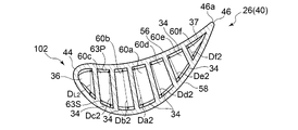
図2は、一実施形態に係る動翼26(タービン翼40)の翼高さ方向に沿った部分断面図であり、図3は、図2のB-B断面を示す図である。なお、図中の矢印は、冷却流体の流れの向きを示す。また、図4A~図4Cは、それぞれ、翼高さ方向において異なる3つの位置における動翼26の断面図であり、図4Aは図2の先端48近傍のA-A断面を示す図であり、図4Bは図2の翼高さ方向の中間領域近傍のB-B断面を示す図(即ち図3と同等の図)であり、図4Cは図2の基端50近傍のC-C断面を示す図である。
FIG. 2 is a partial cross-sectional view of the moving blade 26 (turbine blade 40) according to the embodiment along the blade height direction, and FIG. 3 is a diagram showing a BB cross section of FIG. The arrows in the figure indicate the direction of the flow of the cooling fluid. 4A to 4C are cross-sectional views of the
図2及び図3に示すように、一実施形態に係るタービン翼40である動翼26は、翼体42と、プラットフォーム80と、翼根部82と、を備えている。翼根部82は、ロータ8(図1参照)に埋設され、動翼26は、ロータ8と共に回転する。プラットフォーム80は、翼根部82と一体的に構成されている。
As shown in FIGS. 2 and 3, the moving
翼体42は、ロータ8の径方向(以下、単に「径方向」又は「スパン方向」ということがある。)に沿って延在するように設けられており、プラットフォーム80に固定される基端50と、翼高さ方向(ロータ8の径方向)において基端50とは反対側(径方向外側)に位置し、翼体42の頂部を形成する天板49からなる先端48と、を有する。
また、動翼26の翼体42は、基端50から先端48にかけて前縁44及び後縁46を有し、該翼体42の翼面は、基端50と先端48との間において翼高さ方向に沿って延在する翼面が凹状に形成された圧力面(腹面)56と翼面が凸状に形成された負圧面(背面)58とを含む。
The
Further, the
翼体42の内部には、タービン翼40を冷却するための冷却流体(例えば空気)を流すための冷却流路が設けられている。図2及び図3に示す例示的な実施形態では、翼体42には、冷却流路として、2つのサーペンタイン流路(蛇行流路)61A,61Bと、サーペンタイン流路61A,61Bよりも前縁44側に位置する前縁側通路36とが形成されている。サーペンタイン流路61A,61B及び前縁側通路36には、内部流路84A,84B,85をそれぞれ介して外部からの冷却流体が供給されるようになっている。
このように、サーペンタイン流路61A,61Bや前縁側通路36等の冷却流路に冷却流体を供給することにより、タービン6の燃焼ガス流路28に設けられて高温の燃焼ガスに曝される翼体42を翼体42の内壁面側から対流冷却するようになっている。
Inside the
In this way, by supplying the cooling fluid to the cooling flow paths such as the
2つのサーペンタイン流路は、前縁44側に位置するサーペンタイン流路61Aと、後縁46側に位置するサーペンタイン流路61Bと、を含み、これらのサーペンタイン流路61A,61Bは、翼体42の内部に設けられ、翼高さ方向に沿って延びるリブ(隔壁)31によって仕切られている。
また、前縁側に位置するサーペンタイン流路61Aと、前縁側通路36とは、翼体42の内部に設けられ、翼高さ方向に沿って延びるリブ29によって仕切られている。
The two serpentine flow paths include a
Further, the
また、2つのサーペンタイン流路61A,61Bは、翼高さ方向に沿って延びる複数のパス60(パス60a~60c,60d~60f)をそれぞれ有している。
Further, the two
各サーペンタイン流路61A,61Bにおいて互いに隣り合うパス60は、翼体42の内部に設けられ、翼高さ方向に沿って延びるリブ32によって仕切られている。
また、各サーペンタイン流路61A,61Bにおいて互いに隣り合うパス60は、先端48側又は基端50側において互いに接続され、この接続部において、冷却流体の流れの方向が翼高さ方向において逆向きに折り返すリターン流路33が形成され、サーペンタイン流路61A,61B全体として径方向に蛇行した形状を有している。すなわち、複数のパス60a~60c及び複数のパス60d~60fは、それぞれ、互いにリターン流路33を介して連通してサーペンタイン流路61A,61Bを形成している。
The
Further, the
図2及び図3に示す例示的な実施形態では、前縁側のサーペンタイン流路61Aは、3本のパス60a~60cを含み、これらのパス60a~60cは後縁46側から前縁44側に向かってこの順に配列されている。また、後縁側のサーペンタイン流路61Bは、3本のパス60d~60fを含み、これらのパス60d~60fは前縁44側から後縁46側に向かってこの順に配列されている。
In the exemplary embodiment shown in FIGS. 2 and 3, the leading edge side
サーペンタイン流路61A,61Bを形成する複数のパス60は、冷却流体の流れの最下流側に位置する最終パス66を含む。すなわち、サーペンタイン流路61Aにおいては、最も前縁44側に位置するパス60cが最終パス66であり、サーペンタイン流路61Bにおいては、最も後縁46側に位置するパス60fが最終パス66である。
The plurality of
上述したサーペンタイン流路61A,61Bを有するタービン翼40では、冷却流体は、例えば翼根部82の内部に形成された内部流路84A,84Bを介してサーペンタイン流路61A,61Bの最上流側のパス(図2及び図3に示す例ではパス60a及びパス60d)に導入され、サーペンタイン流路61A,61Bの各々を構成する複数のパス60を下流側に向かって順に流れる。そして、複数のパス60のうち、冷却流体流れ方向の最も下流側の最終パス66を流れる冷却流体は、翼体42の先端48側に設けられた出口開口64A,64Bを介してタービン翼40の外部の燃焼ガス流路28に流出するようになっている。出口開口64A,64Bは天板49に形成される開口である。最終パス66を流れる冷却流体の少なくとも一部が、出口開口64Bから排出される。後縁46側の最終パス66に出口開口64Bを設けることにより、最終パス66の天板49付近の空間に冷却流体のよどみ空間が発生し、天板49の内壁面が過熱されるのを抑制できる。
In the
なお、サーペンタイン流路61A,61Bの形状は、図2及び図3に示される形状に限定されるものではない。例えば、1つのタービン翼40の翼体42の内部に形成されるサーペンタイン流路の数は、2つに限定されず、1つ又は3つ以上であってもよい。あるいは、サーペンタイン流路は、該サーペンタイン流路上の分岐点において複数の流路に分岐していてもよい。いずれの場合も、サーペンタイン流路を構成するパスのうち、最も後縁側に位置するパスは、通常、該サーペンタイン流路の最終パスである。
The shapes of the
また、前縁側通路36は、最も前縁44に近接して配置された冷却通路59であり、最も熱負荷の高くなる通路である。前縁側通路36は、基端50側で内部流路85に連通し、先端48側の天板49に形成された出口開口38に連通している。内部流路85を介して前縁側通路36に供給された冷却流体は、一方向通路である前縁側通路36を基端50側から先端48側に流れ、出口開口38から燃焼ガス流路28に排出される。冷却流体は、前縁側通路36を流れる過程で、前縁側通路36の内壁面を対流冷却している。
Further, the leading
幾つかの実施形態では、図2に示すように、翼体42の後縁部47(後縁46を含む部分)には、翼高さ方向に沿って配列するように複数の冷却孔70が形成されている。複数の冷却孔70は、翼体42の内部に形成された冷却流路(図示する例においては後縁側のサーペンタイン流路61Bの最終パス66であるパス60f)に連通するとともに、翼体42の後縁部47における表面に開口している。なお、図3においては、冷却孔70の図示を省略している。
In some embodiments, as shown in FIG. 2, the trailing edge 47 (the portion including the trailing edge 46) of the
冷却流路を流れる冷却流体の一部は、該冷却流路に連通する上述の冷却孔70を通過して、翼体42の後縁部47の開口からタービン翼40の外部の燃焼ガス流路28に流出する。このようにして冷却流体が冷却孔70を通過することにより、翼体42の後縁部47が対流冷却されるようになっている。
A part of the cooling fluid flowing through the cooling flow path passes through the above-mentioned
動翼26の翼体42は、翼高さ方向における両端部である第1端部101及び第2端部102を有する。このうち第1端部101は、翼体42の先端48側の端部であり、第2端部102は、翼体42の基端50側の端部である。すなわち、動翼26において、第1端部101は、第2端部102の径方向外側に位置する。
The
図4A~図4Cに示すように、翼体42の背腹方向における翼幅は、第2端部102側(基端50側)において、第1端部101側(先端48側)よりも大きくなっている。即ち、翼体42において、第2端部102のほうが、第1端部に比べて背腹方向の翼幅が大きくなっている。
As shown in FIGS . 4A to 4C , the wingspan of the
また、図4A~Cに示すように、動翼26において、第2端部102(即ち基端50側)における翼体42の背腹方向におけるサーペンタイン流路61A,61Bの各パス60及び前縁側通路36の通路幅D2(図4Cに示すDL2,Da2、Db2…等;以下、まとめて「D2」とも表記する。)は、第1端部101(即ち先端48側)における冷却流路の通路幅D1(図4Aに示すDL1,Da1、Db1…等;以下、まとめて「D1」とも表記する。)よりも大きい。
Further, as shown in FIGS. 4A to 4C, in the
ここで、翼体42の背腹方向における冷却流路の通路幅D(DL,Da、Db…等;以下、まとめて「D」とも表記する。)は、各通路(各パス60及び前縁側通路36)において、翼体42の圧力面56側の内壁面63P(図4B参照)から計測した、該内壁面63Pと負圧面58側の内壁面63S(図4B参照)との間の距離の最大値として定義される。
Here, the passage width D (DL, Da, Db, etc .; hereinafter collectively referred to as “D”) of the cooling flow path in the dorsoventral direction of the
なお、冷却流路の通路幅Dは、矩形状断面ではなく、例えば、菱形状断面、台形形状断面、三角形状断面のように変形した通路形状の場合を考慮して、下記式(I)に示す等価直径EDにより表す場合もある。等価直径EDが、上述の通路幅Dに相当する。 The passage width D of the cooling flow path is not a rectangular cross section, but is expressed in the following formula (I) in consideration of a modified passage shape such as a rhombic cross section, a trapezoidal cross section, or a triangular cross section. It may be represented by the equivalent diameter ED shown. The equivalent diameter ED corresponds to the passage width D described above.
ED=4A/L ・・・(I)
上記式(I)において、EDは等価直径を示し、Aは通路断面積を示し、Lは通路断面の濡れ長さ(一つの通路断面の全周の長さ)を示す。従って、以下の説明では、通路幅Dは、等価直径EDと読み替えてもよい。
ED = 4A / L ... (I)
In the above formula (I), ED indicates the equivalent diameter, A indicates the passage cross-sectional area, and L indicates the wet length of the passage cross section (the length of the entire circumference of one passage cross section). Therefore, in the following description, the passage width D may be read as the equivalent diameter ED.
例えば、翼体42に設けられた複数の通路(サーペンタイン流路61A,61Bの各パス60及び前縁側通路36)のうち、前縁44側から数えて3つ目の通路であるパス60bに着目した場合、第1端部101側(先端48側)の通路幅Db1と、第2端部102側(基端50側)の通路幅Db2とは、Db1<Db2の関係を満たす。また、他の通路についても同様の関係が成り立つ。
For example, focus on the
なお、通路幅Dは、翼高さ方向において第1端部101側から第2端部102側に向かうにつれて、徐々に増大するようになっていてもよい。
また、パス60の各々の流路断面積は、翼高さ方向において前記第1端部から前記第2端部に近づくにつれて増大するようになっていてもよい。
The passage width D may be gradually increased from the
Further, the cross-sectional area of each flow path of the
サーペンタイン流路61A,61Bを構成する複数のパス60のうち少なくとも幾つかの内壁面63(圧力面56側の内壁面63P及び/又は負圧面58側の内壁面63S)には、リブ状のタービュレータ34が設けられている。図2~図4Cに示す例示的な実施形態では、複数のパス60の各々の圧力面56側の内壁面63P及び負圧面58側の内壁面63Sに、翼高さ方向に沿って複数のタービュレータ34が設けられている。
A rib-shaped turbulator is provided on at least some of the inner wall surfaces 63 (
また、幾つかの実施形態では、図2~図4Cに示すように、前縁側通路36の内壁面にも、翼高さ方向に沿って複数のタービュレータ35(前縁側タービュレータ35)が設けられている。
Further, in some embodiments, as shown in FIGS. 2 to 4C , a plurality of turbulators 35 (front edge side turbulators 35) are also provided on the inner wall surface of the front
ここで、図5及び図6は、それぞれ、一実施形態に係るタービュレータ34の構成を説明するための模式図であり、図5は、図2~図4Cに示すタービン翼40の翼高さ方向(ロータ8の径方向)及び背腹方向(略ロータ8の周方向)を含む平面に沿った部分的な断面の模式図であり、図6は、図2~図4Cに示すタービン翼40の翼高さ方向(ロータ8の径方向)及びロータ8の軸方向を含む平面に沿った部分的な断面の模式図である。
Here, FIGS. 5 and 6 are schematic views for explaining the configuration of the
図5に示すように、各タービュレータ34は、パス60の内壁面63に設けられており、該タービュレータ34の該内壁面63を基準とした高さはeである。また、図5及び図6に示すように、パス60において、複数のタービュレータ34は、ピッチPの間隔で設けられている。また、図6に示すように、パス60における冷却流体の流れ方向(図6の矢印LF)と、各タービュレータ34との間のなす角度(ただし鋭角;以下、「傾き角」ともいう。)は、傾き角θである。
As shown in FIG. 5, each turbulator 34 is provided on the
パス60に上述のタービュレータ34が設けられていると、冷却流体がパス60を流れるときに、タービュレータ34近傍で渦の発生等の流れの乱れが促進される。すなわち、タービュレータ34を乗り越えた冷却流体は、下流側に配置された隣接のタービュレータ34の間に渦流を形成する。これにより、冷却流体の流れ方向において隣り合うタービュレータ34同士の中間位置付近では、冷却流体の乱流を形成する渦流がパス60の内壁面63に付着し、冷却流体と、翼体42との間の熱伝達率を増大させることができ、タービン翼40を効果的に冷却することができる。
When the above-mentioned
すなわち、ガスタービンの高出力化に伴い、タービン翼にかかる熱負荷が増大するので、タービン翼を支持する基端50側の第2端部102における背腹方向の翼幅を大きくしつつ、先端48側の第1端部101を小型化したい場合がある。その場合、第1端部101側の翼幅を小さく、第2端部102側の翼幅を大きくする翼形状を選定するため、翼体の内部に配置された冷却流路は、第1端部101側の冷却流路の流路断面積は小さく、第2端部102側の冷却流路の流路断面積は大きく選定することになる。タービュレータ34は、冷却流路の内壁面の熱伝達を増大させるための乱流促進部材であり、冷却流路の流路断面積の変化に応じて、適正なタービュレータの高さe、ピッチP、傾き角θを選択して、翼体に対して最大限の冷却性能を発揮させることが重要である。
That is, as the output of the gas turbine increases, the heat load applied to the turbine blades increases. There are cases where it is desired to reduce the size of the
タービュレータ34による熱伝達率の向上効果は、タービュレータの高さe、ピッチP、傾き角θ、及び、パス(通路)の通路幅Dに応じて変化する。
例えば、タービュレータ34の傾き角θにより、冷却流体の渦流の発生状態が変化し、翼内壁との間の熱伝達率に影響する。また、タービュレータ34のピッチPと比較して、タービュレータの高さeが高すぎる場合、渦流が内壁面63に付着しない場合がある。従って、熱伝達率とタービュレータ34の傾き角θ並びに熱伝達率とピッチPと高さeとの比率P/eとの間には、後述のように適正な範囲が存在する。また、タービュレータ34の高さeが通路幅Dと比較して高すぎると、冷却流体の圧力損失を増大させる。一方、タービュレータ34の高さeと比較して背腹方向におけるパス(通路)の通路幅Dが広すぎたりすると、渦流による熱伝達率の増大効果が期待できず、熱伝達率を低下させ、冷却性能を低下させる原因になる。すなわち、冷却流路の形状の変化に応じて、高い熱伝達率が得られるタービュレータ34の適正な高さe、ピッチP、傾き角θが存在する。
The effect of improving the heat transfer coefficient by the turbulator 34 changes according to the height e of the turbulator, the pitch P, the inclination angle θ, and the passage width D of the path (passage).
For example, the inclination angle θ of the turbulator 34 changes the generation state of the eddy flow of the cooling fluid, which affects the heat transfer coefficient with the inner wall of the blade. Further, if the height e of the turbulator is too high as compared with the pitch P of the
なお、前縁側通路36に設けられるタービュレータ35(前縁側タービュレータ)による熱伝達率の向上効果も、上述のタービュレータ34の場合と同様に、タービュレータ35の傾き角、ピッチ、高さ、及び背腹方向における前縁側通路36の通路幅に応じて変化する。
The effect of improving the heat transfer coefficient by the turbulator 35 (front edge side turbulator) provided in the front
以下、図2~図4C、及び図7~9を参照して、幾つかの実施形態に係るタービン翼40の特徴について、タービュレータ34の特徴も含めてより詳細に説明するが、その前に、図9を参照して、一実施形態に係る静翼24(タービン翼40)の構成について説明する。
ここで、図7は、図2~図4Cに示す動翼26(タービン翼40)の模式的な断面図であり、図8は、図7のD-D断面を示す模式図である。また、図9は、一実施形態に係る静翼24(タービン翼40)の模式的な断面図である。図中の矢印は、冷却流体の流れの向きを示す。
Hereinafter, with reference to FIGS. 2 to 4C and FIGS. 7 to 9, the characteristics of the
Here, FIG. 7 is a schematic cross-sectional view of the moving blade 26 (turbine blade 40) shown in FIGS. 2 to 4C, and FIG. 8 is a schematic cross - sectional view showing a DD cross section of FIG. 7. Further, FIG. 9 is a schematic cross-sectional view of the stationary blade 24 (turbine blade 40) according to the embodiment. The arrows in the figure indicate the direction of the flow of the cooling fluid.
図9に示すように、一実施形態に係る静翼24(タービン翼40)は、翼体42と、翼体42に対して径方向内側に位置する内側シュラウド86と、翼体42に対して径方向外側に位置する外側シュラウド88と、を備えている。外側シュラウド88はタービン車室22(図1参照)に支持され、静翼24は外側シュラウド88を介してタービン車室22に支持される。翼体42は、外側シュラウド88側(すなわち径方向外側)に位置する外側端52と、内側シュラウド86側(すなわち径方向内側)に位置する内側端54と、を有する。
As shown in FIG. 9, the stationary blade 24 (turbine blade 40) according to the embodiment has the
静翼24の翼体42は、外側端52から内側端54にかけて前縁44及び後縁46を有し、翼体42の翼面は、外側端52と内側端54との間において、翼高さ方向に沿って延在する圧力面(腹面)56と負圧面(背面)58を含む。
The
静翼24の翼体42の内部には、複数のパス60により形成されるサーペンタイン流路61が形成される。図9に示す例示的な実施形態では、5本のパス60a~60eによりサーペンタイン流路61が形成されている。パス60a~60eは、前縁44側から後縁46側に向かってこの順に配列されている。
Inside the
図9に示す静翼24(タービン翼40)では、冷却流体は、外側シュラウド88の内部に形成された内部流路(不図示)を介してサーペンタイン流路61に導入され、複数のパス60を下流側に向かって順に流れる。そして、複数のパス60のうち、冷却流体の流れ方向の最も下流側の最終パス66(パス60e)を流れる冷却流体は、翼体42の内側端54側(内側シュラウド86側)に設けられた出口開口64を介して静翼24(タービン翼40)の外部の燃焼ガス流路28に流出するか、又は後述する後縁部47の冷却孔70から燃焼ガス中に排出されるようになっている。
In the stationary blade 24 (turbine blade 40) shown in FIG. 9, the cooling fluid is introduced into the
静翼24において、複数のパス60のうち少なくとも幾つかの内壁面には、上述したタービュレータ34が設けられている。図9に示す例示的な実施形態では、複数のパス60の各々の内壁面に、複数のタービュレータ34が設けられている。
In the
静翼24において、翼体42の後縁部47には、翼高さ方向に沿って配列するように、複数の冷却孔70が形成されていてもよい。
In the
静翼24の翼体42は、翼高さ方向における両端部である第1端部101及び第2端部102を有する。このうち第1端部101は、翼体42の内側端54側の端部であり、第2端部102は、翼体42の外側端52側の端部である。すなわち、静翼24において、第1端部101は、第2端部102の径方向内側に位置する。
The
静翼24(タービン翼40)における翼体42の背腹方向の翼幅は、外側端52側(第2端部102側)において、内側端54側(第1端部101側)よりも大きくなっている。即ち、翼体42において、第2端部102のほうが、第1端部101に比べて翼幅が大きくなっている。
The wingspan of the
また、特に図示しないが、パス60の通路幅Dについては、上述した動翼26の場合と同様に、第2端部102(即ち外側端52側)における翼体42の背腹方向におけるサーペンタイン流路61の各パス60の通路幅D2は、第1端部101(即ち内側端54側)における通路幅D1よりも大きい。
通路幅Dは、翼高さ方向において第1端部101側から第2端部102側に向かうにつれて、徐々に増大するようになっていてもよい。
また、パス60の各々の流路断面積は、翼高さ方向において前記第1端部から前記第2端部に近づくにつれて増大するようになっていてもよい。なお、前述した等価直径EDの考え方は、静翼24の通路幅Dにも適用できる。
Further, although not particularly shown, regarding the passage width D of the
The passage width D may be gradually increased from the
Further, the cross-sectional area of each flow path of the
次に、図2~図4C、及び、図7~図9を参照して幾つかの実施形態に係るタービン翼40のより具体的な特徴について説明する。
Next, more specific features of the
幾つかの実施形態に係るタービン翼40(動翼26又は静翼24)では、パス60a~60fの少なくとも1つである冷却通路59に設けられた複数のタービュレータ34の高さは、翼高さ方向において第1端部101側(動翼26における先端48側、静翼24における内側端54側)から第2端部102(動翼26における基端50側、静翼24における外側端52側)側に向かうにつれて高くなることを特徴とする。すなわち、翼高さ方向において、第1端部101側から第2端部102側に向かうにつれて、冷却通路59の通路幅Dが増大するのに従い、タービュレータ34の高さeが高くなる。あるいは、翼高さ方向において、第1端部101側から第2端部102側に向かうにつれて、冷却通路59の流路断面積が増大するのに従い、タービュレータ34の高さe(冷却通路59の内壁面63を基準とした高さ)が高くなる。
In the turbine blade 40 (moving
複数のタービュレータ34の高さは、翼高さ方向において、タービュレータ34毎に徐々に変化するようになっていてもよい。すなわち、翼高さ方向位置が異なる任意の2つのタービュレータ34のうち、第2端部102に近いほうの一方のタービュレータ34の高さeが、他方のタービュレータ34(すなわち第1端部101に近いほうのタービュレータ34)の高さよりも高くなるように、該冷却通路59に設けられた複数のタービュレータ34の各々の高さeが設定されていてもよい。
The height of the plurality of
あるいは、複数のタービュレータ34の高さは、翼高さ方向の領域毎に段階的に変化するようになっていてもよい。すなわち、冷却通路59を翼高さ方向の複数の領域に区分けして、各翼高さ方向領域に属するタービュレータ34は同一の高さeとなるようにしたうえで、第2端部102により近い翼高さ方向領域に属するタービュレータ34の高さeが、それよりも第1端部101により近い翼高さ方向領域に属するタービュレータ34の高さeよりも高くなるように、複数のタービュレータ34の各々の高さeが設定されていてもよい。
Alternatively, the height of the plurality of
このように、複数のタービュレータ34の高さが翼高さ方向の領域毎に変化する場合の一例について、図8を参照して説明する。ここで、図8は、サーペンタイン流路61を構成する冷却通路59のうちの1つ(ここでは動翼26のサーペンタイン流路61Aのパス60b)の断面を示す図である。
As described above, an example in which the heights of the plurality of
図8に示す例示的な冷却通路59は、翼高さ方向に3つの領域に区分けされている。そして、この冷却通路59に設けられた複数のタービュレータ34は、上述の3つの領域のうち、最も第1端部101に近い領域(先端48側の領域)に属するタービュレータ34aと、最も第2端部102に近い領域(基端50側の領域)に属するタービュレータ34cと、これら2つの間の領域(中間領域)に属するタービュレータ34bと、を含む。
The
先端48側の領域に属するタービュレータ34aの位置における冷却通路59の背腹方向における代表的な通路幅Da、中間領域に属するタービュレータ34bの位置における冷却通路59の背腹方向における代表的な通路幅Db、及び、基端50側の領域に属するタービュレータ34cの位置における冷却通路59の背腹方向における代表的な通路幅DDcとは、Da<Db<Dcの関係を満たす。
なお、各領域における冷却通路59の背腹方向における代表的な通路幅Dとは、該領域に属するタービュレータ34の各々の翼高さ方向の位置における冷却通路59の通路幅Dの平均値であってもよい。
A typical passage width Da in the dorsoventral direction of the
The typical passage width D in the dorsoventral direction of the
また、各翼高さ方向の領域に属する複数のタービュレータ34a、34b、34cは、それぞれ同じ高さを有し、先端48側の領域に属するタービュレータ34aの高さea、中間領域に属するタービュレータ34bの高さeb、及び、基端50側の領域に属するタービュレータ34cの高さecとは、ea<eb<ecの関係を満たす。
Further, the plurality of
このように、冷却通路59に設けられた複数のタービュレータ34の高さeは、翼高さ方向の領域毎に段階的に変化するようになっていてもよい。
なお、図7に示すタービン翼40(動翼26)及び図9に示すタービン翼40(静翼24)では、サーペンタイン流路61を構成するパス60a~60fのうち、最終パス66(図7におけるパス60f、及び、図9におけるパス60e)以外の冷却通路59について、図8の例と同様に、複数のタービュレータ34は、翼高さ方向の領域毎に段階的に変化するようになっている。
In this way, the height e of the plurality of
In the turbine blade 40 (moving blade 26) shown in FIG. 7 and the turbine blade 40 (static blade 24) shown in FIG. 9, the final path 66 (in FIG. 7) of the
なお、図8に示す例では、冷却通路59は翼高さ方向において3つの領域に区分けされ、タービュレータ34の高さは3段階で変化するようになっていたが、他の例では(他の冷却通路59では)、冷却通路59は翼高さ方向においてn個の領域に区分けされ、タービュレータ34の高さはn段階で変化するようになっていてもよい(ただしnは2以上の整数)。
なお、図7に示す動翼26におけるパス60a~60e(冷却通路)、及び、図9に示す静翼24におけるパス60a~60d(冷却通路)は、それぞれ、翼高さ方向においてn個(ただしnは2以上5以下)の領域に区分され、タービュレータ34の高さは、翼高さ方向においてn段階で変化するようになっている。
In the example shown in FIG. 8, the
The
冷却通路59の内壁面63にタービュレータ34を設けることにより、該内壁面63が平滑面である場合に比べて冷却流体とタービン翼40との間の熱伝達率が向上する。しかしながら、冷却通路59の通路幅Dが翼高さ方向において変化する場合において、タービュレータ34の高さeを一定として同じ高さとしてしまうと、冷却通路59の通路幅Dが比較的広い翼高さ方向の位置においては、冷却通路59の通路幅Dが比較的狭い翼高さ方向の位置に比べて、熱伝達率を向上させる効果が低下してしまう。これは、冷却通路59の通路幅Dに対してタービュレータ34の高さが相対的に低くなると、相対的に幅広の冷却通路59を流れる冷却流体において乱流を形成する渦流を効果的に生成することが難しくなるためである。
By providing the
この点、上述した実施形態では、冷却通路59の通路幅Dが、翼高さ方向に変化しても、翼面における熱伝達率が維持されるように、タービュレータ34の高さeを選定するのが望ましい。翼高さ方向において冷却通路59の通路幅Dが比較的小さい第1端部101から冷却通路59の通路幅Dが比較的大きい第2端部102に近づくにつれて、翼面における熱伝達率が維持されるように、タービュレータ34の高さが高くなるようにした。その結果、第2端部102側において、タービュレータ34により渦流を効果的に生成でき、タービュレータ34による熱伝達率の向上効果を、第1端部101側と同程度に得ることができる。
一方、通路幅Dの大きい第2端部102側と比較して、通路幅Dの小さい第1端部側のタービュレータ高さeを適正な高さより高くするのは、冷却流体の圧力損失の増大の点から望ましくない。上述した実施形態では、翼高さ方向の第1端部101側において、冷却通路59の通路幅Dが小さくなると共に、タービュレータ34の高さeを低く設定している。そのため、冷却流路を流れる冷却流体の圧力損失の点から、冷却通路59の通路幅Dが比較的狭くなるため圧力損失が大きくなる傾向にある第1端部101側において、タービュレータ34の存在による圧力損失の増加を抑制することができる。
よって、上述の実施形態によれば、翼高さ方向において冷却通路59の通路幅Dが変化するタービン翼40を効率的に冷却することができる。
In this regard, in the above-described embodiment, the height e of the
On the other hand, making the turbulator height e on the first end side having a small passage width D higher than the appropriate height as compared with the
Therefore, according to the above-described embodiment, the
幾つかの実施形態では、上述の冷却通路(パス60a~60fの少なくとも1つ)に設けられた複数のタービュレータ34のうち、任意の1つのタービュレータ34高さeと、該タービュレータ34の翼高さ方向の位置における該冷却通路59の背腹方向における通路幅Dとの比(e/D)と、該冷却通路59に設けられた複数のタービュレータ34(すなわち、該冷却通路59に設けられた全てのタービュレータ34)についての前記比(e/D)の平均(e/D)AVEとは、0.5≦(e/D)/(e/D)AVE≦2.0の関係を満たす。
また、幾つかの実施形態では、上述のe/Dと(e/D)AVEとは、0.9≦(e/D)/(e/D)AVE≦1.1を満たしていてもよい。
あるいは、幾つかの実施形態では、上述の(e/D)と(e/D)AVEとは、(D1/D2)≦(e/D)/(e/D)AVE≦(D2/D1)を満たしていてもよい。ここで、D1は、複数のタービュレータ34のうち、翼高さ方向において最も第1端部101側に位置するタービュレータ34の位置における冷却通路59の通路幅である。D2は、翼高さ方向において最も第2端部102側に位置するタービュレータ34の位置における冷却通路59の通路幅である。
なお、上述の冷却通路59に設けられた複数のタービュレータ34の各々(全て)について、上記関係式の関係が成立するようになっていてもよい。
In some embodiments, any one of the plurality of
Further, in some embodiments, the above-mentioned e / D and (e / D) AVE may satisfy 0.9 ≦ (e / D) / (e / D) AVE ≦ 1.1. ..
Alternatively, in some embodiments, the (e / D) and (e / D) AVEs described above are (D1 / D2) ≤ (e / D) / (e / D) AVE ≤ (D2 / D1). May be satisfied. Here, D1 is the passage width of the
The relationship of the above relational expression may be established for each (all) of the plurality of
上述の実施形態では、冷却通路59に設けられた複数のタービュレータ34のうちの任意のタービュレータ34に関する(e/D)が、該冷却通路に設けられた全ての複数のタービュレータの(e/D)の平均である(e/D)AVEに近い値となるように設定している。あるいは、翼高さ方向において第1端部101から第2端部102に向けて、上記(e/D)の変化が冷却通路の通路幅Dの変化よりも小さくなるように設定している。従って、翼高さ方向における熱伝達率の極端な低下や圧力損失の極端な増大を抑制することができ、翼壁のメタル温度の不均一分布を抑制しながら、効果的にタービン翼40を冷却することができる。
In the above-described embodiment, the (e / D) of any
幾つかの実施形態では、上述の冷却通路59(パス60a~60fの少なくとも1つ)に設けられた複数のタービュレータ34のうち、翼高さ方向において最も第1端部101側に位置するタービュレータ34の位置における冷却通路59の通路幅DをD1とし、翼高さ方向において最も第2端部102側に位置するタービュレータ34の位置における冷却通路59の通路幅DをD2としたとき、前記通路幅D1と前記通路幅D2との比(D2/D1)は、1.5≦(D2/D1)の関係を満たす。
あるいは、前記通路幅D1と前記通路幅D2とは、2.0≦(D2/D1)の関係を満たしていてもよい。
あるいは、前記通路幅D1と前記通路幅D2とは、2.5≦(D2/D1)の関係を満たしていてもよい。
In some embodiments, among the plurality of
Alternatively, the passage width D1 and the passage width D2 may satisfy the relationship of 2.0 ≦ (D2 / D1).
Alternatively, the passage width D1 and the passage width D2 may satisfy the relationship of 2.5 ≦ (D2 / D1).
上述の実施形態では、第2端部102側の冷却通路59の通路幅D2が、第1端部101側の冷却通路59の通路幅D1よりも大幅に大きいタービン翼40において、冷却通路59の通路幅Dが大きい第2端部102側の翼高さ方向位置においてタービュレータ34の高さが高くなるようにしたので、翼高さ方向において冷却通路59の通路幅Dが変化するタービン翼40を効率的に冷却することができる。
In the above embodiment, in the
幾つかの実施形態では、上述の冷却通路59(パス60a~60fの少なくとも1つ)に設けられた複数のタービュレータ34のうち、翼高さ方向において隣り合う一対のタービュレータ34の翼高さ方向におけるピッチPは、翼高さ方向において第1端部101から第2端部102に近づくにつれて増大する。
In some embodiments, among the plurality of
タービュレータ34による熱伝達率の向上効果は、翼高さ方向において隣り合うタービュレータ34間のピッチPに応じて変化し、高い熱伝達率が得られるタービュレータ34のピッチPと高さeの比が存在する。この点、上述の実施形態によれば、翼高さ方向において第1端部101から第2端部102に近づくにつれて、すなわち、タービュレータ34の高さeが高くなるにつれて、翼高さ方向において隣り合うタービュレータ34間のピッチPが増大するようにしている。そのため、該冷却通路59内でタービュレータ34が設けられた翼高さ方向の第1端部101から第2端部102までの全範囲において高い熱伝達率を得ることができる。
The effect of improving the heat transfer coefficient by the turbulator 34 changes according to the pitch P between
なお、上述の実施形態において、翼高さ方向において隣り合う一対のタービュレータ34の翼高さ方向におけるピッチPは、翼高さ方向において、一対のタービュレータ34毎に徐々に変化するようになっていてもよい。すなわち、翼高さ方向位置が異なる任意の2組の一対のタービュレータ34のうち、第2端部102に近いほうの一方の一対のタービュレータ34のピッチPが、他方の一対のタービュレータ34(すなわち第1端部101に近いほうの一対のタービュレータ34)のピッチPよりも大きくなるように、該冷却通路59に設けられた複数のタービュレータ34の各々のピッチPが設定されていてもよい。
In the above-described embodiment, the pitch P of the pair of
あるいは、翼高さ方向において隣り合う一対のタービュレータ34の翼高さ方向におけるピッチPは、翼高さ方向の領域毎に段階的に変化するようになっていてもよい。すなわち、冷却通路59を翼高さ方向の複数の領域に区分けして、各翼高さ方向領域に属する複数のタービュレータ34については同一のピッチPとなるようにしたうえで、第2端部102により近い翼高さ方向領域に属する複数のタービュレータ34のピッチPが、それよりも第1端部101により近い翼高さ方向領域に属するタービュレータ34のピッチPよりも大きくなるように、該冷却通路59に設けられた複数のタービュレータ34の各々のピッチPが設定されていてもよい。
Alternatively, the pitch P of the pair of
例えば、図8に示す例示的な冷却通路59は、上述したように、翼高さ方向に3つの領域に区分けされており、この冷却通路59に設けられた複数のタービュレータ34は、最も第1端部101に近い領域(先端48側の領域)に属するタービュレータ34aと、最も第2端部102に近い領域(基端50側の領域)に属するタービュレータ34cと、これら2つの間の領域(中間領域)に属するタービュレータ34bと、を含む。
For example, the
先端48側の領域に属する複数のタービュレータ34aのピッチPa、中間領域に属する複数のタービュレータ34bのピッチPb、及び、基端50側の領域に属する複数のタービュレータ34cのピッチPbは、Pa<Pb<Pcの関係を満たす。
The pitch Pa of the plurality of
このように、冷却通路59に設けられた複数のタービュレータ34のピッチPは、翼高さ方向の領域毎に段階的に変化するようになっていてもよい。
すなわち、ある冷却通路59において、該冷却通路59は翼高さ方向においてn個の領域に区分けされ、タービュレータ34のピッチPはn段階で変化するようになっていてもよい(ただしnは2以上の整数)。
In this way, the pitch P of the plurality of
That is, in a
幾つかの実施形態では、上述の冷却通路59(パス60a~60fの少なくとも1つ)に設けられた複数のタービュレータ34のうち、翼高さ方向において隣り合う任意の一対のタービュレータ34間のピッチPと、該一対のタービュレータ34の高さの平均eaとの比P/eaと、複数のタービュレータ34についての前記比P/eaの平均(P/ea)AVEとは、0.5≦(P/ea)/(P/ea)AVE≦2.0の関係を満たす。
また、幾つかの実施形態では、上述のP/eaと(P/ea)AVEとは、0.9≦(P/ea)/(P/ea)AVE≦1.1を満たしていてもよい。
In some embodiments, the pitch P between any pair of
Further, in some embodiments, the above-mentioned P / ea and (P / ea) AVE may satisfy 0.9 ≦ (P / ea) / (P / ea) AVE ≦ 1.1. ..
上述の実施形態では、冷却通路59に設けられた複数のタービュレータ34のうちの任意の一対のタービュレータ34に関する(P/ea)が、該冷却通路59に設けられた複数のタービュレータ34(全てのタービュレータ34)に関する(P/ea)の平均である(P/ea)AVEに近い値となるようにしたので、翼高さ方向において第1端部101から第2端部102に近づくにつれて、すなわち、タービュレータ34の高さeが高くなるにつれて、隣り合うタービュレータ34間のピッチPが増大する傾向となる。よって、(P/ea)又は(P/ea)AVEを適切に設定することで、該冷却通路59内でタービュレータ34が設けられた翼高さ方向範囲において高い熱伝達率を得ることができる。
In the above-described embodiment, the (P / ea) relating to any pair of
幾つかの実施形態では、上述の冷却通路59(パス60a~60fの少なくとも1つ)における冷却流体の流れ方向に対する任意のタービュレータ34の傾き角θと、複数のタービュレータ(該冷却通路59に設けられた全てのタービュレータ)についての傾き角の平均θAVEとは、0.5≦θ/θAVE≦2.0の関係を満たす。
In some embodiments, the tilt angle θ of any turbulator 34 with respect to the flow direction of the cooling fluid in the cooling passage 59 (at least one of the
タービュレータ34による熱伝達率の向上効果は、冷却通路59における冷却流体の流れ方向に対するタービュレータ34の傾き角θに応じて変化し、高い熱伝達率が得られるタービュレータ34の傾き角が存在する。この点、上述の実施形態によれば、翼高さ方向にタービュレータ34の傾き角θがほぼ一定となるようにしたので、冷却通路59内でタービュレータ34が設けられた翼高さ方向範囲において高い熱伝達率を得ることができる。
The effect of improving the heat transfer coefficient by the turbulator 34 changes according to the inclination angle θ of the turbulator 34 with respect to the flow direction of the cooling fluid in the
幾つかの実施形態では、上述の冷却通路59は、サーペンタイン流路61を構成する複数のパス60a~60fのうち、最終パス(動翼26におけるパス60f(図7参照)、静翼におけるパス60e(図9参照))以外のパス60の少なくとも1つである。最終パス(図7のパス60f、図9のパス60e)の背側及び腹側の内壁面には、翼高さ方向に沿って配列された複数の最終パスタービュレータ37が設けられている。
そして、タービュレータ34又は最終パスタービュレータ37の高さをeとし、該タービュレータ34又は最終パスタービュレータ37の翼高さ方向の位置における冷却通路59又は最終パス66の背腹方向における通路幅をDとしたとき、下記式(II)の関係が成り立つ。
[(e/D)E1/(e/D)AVE]<[(e/D)T_E1/(e/D)T_AVE]
・・・(II)
上記式(II)において、(e/D)E1は、複数のタービュレータ34のうち、翼高さ方向において最も第1端部101側に位置するタービュレータ34T(図7及び図9参照)についての前記高さと前記通路幅との比であり、(e/D)AVEは、複数のタービュレータ34についての前記高さと前記通路幅との比(e/D)の平均であり、(e/D)T_E1は、複数の最終パスタービュレータ37のうち、翼高さ方向において最も第1端部101側に位置する最終パスタービュレータ37T(図7及び図9参照)についての前記高さと前記通路幅との比であり、(e/D)T_AVEは、複数の最終パスタービュレータ37についての前記高さと前記通路幅との比(e/D)Tの平均である。
In some embodiments, the
Then, the height of the
[(E / D) E1 / (e / D) AVE ] <[(e / D) T_E1 / (e / D) T_AVE ]
... (II)
In the above formula (II), (e / D) E1 is the
既に述べたように、最終パス66以外のパス60である冷却通路59に設けられたタービュレータ34については、冷却通路59の通路幅Dが比較的狭い第1端部101側から冷却通路59の通路幅Dが比較的広い第2端部102側に向かうにつれてタービュレータ34の高さeが高くなるため、タービュレータ34の高さeと通路幅Dとの比(e/D)が一定に近くなる傾向となる(すなわち、上記関係式の左辺が1に近くなる)。このことから、上述の関係式は、最終パス66では、翼高さ方向において第2端部102側から第1端部101側に向かうにつれて、最終パス66の通路幅Dが減少するのに対し、最終パスタービュレータ37の高さeは、上記通路幅Dほど減少しないことを意味する。
As described above, regarding the
すなわち、上述の実施形態では、サーペンタイン流路61の最終パス66では、複数の最終パスタービュレータ37の高さeが、他のパス60と比較して翼高さ方向においてそれほど大きく変化しない。つまり、後縁部47近傍の最終パス66では、最終パス66の通路幅Dが狭くなり、前述の冷却通路59の通路幅Dに対応させたタービュレータ高さeを選定することが難しい。すなわち、最終パス66の通路幅Dに対して最終タービュレータ37の高さeが小さくなり過ぎて、タービュレータの加工が困難になる場合がある。そこで、最終パス66を流れる冷却流体の圧力損失が許容される範囲で、通路幅Dに対するタービュレータ34の適正な高さeより相対的に高さeが大きい最終タービュレータ37を選定する場合がある。最終パス66に形成される最終タービュレータ37は、最終パス66以外の他のパス60のタービュレータ34より高さeが小さくなるものの、高さeと通路幅Dとの比(e/D)は、他のパス60に適用される高さeと通路幅Dとの比(e/D)より大きくなる。また、前述のように、最終タービュレータ37のピッチPと高さeとの比(P/e)は、翼高さ方向に一定となるように選定される。最終タービュレータ37の高さeは、他のパス60より小さくなるので、配置される最終タービュレータ37の数が他のパスより多くなる。従って、高さeと通路幅Dとの比(e/D)とピッチPと高さeとの比(P/e)の両面から、最終パス66は他のパス60と比較して熱伝達率が高くなる。
That is, in the above-described embodiment, in the
更に、サーペンタイン流路61において冷却流体が比較的高温となる最終パス66において、第2端部102から第1端部101に向かうと共に、最終パス66の流路断面積を小さくして、他のパス60より冷却流体の流速を増大させることができる。これにより、最終パス66においては、冷却通路59を流れる冷却流体の流速の増大効果と、最終タービュレータ37の高さeと通路幅Dとの比(e/D)及び最終タービュレータ37の設置数の増大効果とが重畳的に作用して、他のパス60より熱伝達率が高い冷却通路59が形成される。従って、熱負荷の厳しい最終パス66を流れる冷却流体によってタービン翼40をより効果的に冷却することができる。
Further, in the
幾つかの実施形態では、最終パス66に設けられた最終パスタービュレータ37の高さeは、複数のパス60のうち、最終パス66に対して冷却流体の流れ方向の上流側に隣接して位置するとともに最終パス66と相互に連通する上流側冷却通路のタービュレータ34の高さ以下である。
In some embodiments, the height e of the
例えば、図7に示す動翼26に係る実施形態では、最終パス66(パス60f)に対して冷却流体の流れ方向の上流側に隣接して位置し、最終パス66と相互に連通する上流側冷却通路は、パス60eである。そして、最終パス66(パス60f)に設けられた最終パスタービュレータ37の高さは、上流側冷却通路であるパス60eに設けられたタービュレータ34の高さ以下である。
また、例えば、図9に示す静翼24に係る実施形態では、最終パス66(パス60e)に対して冷却流体の流れ方向の上流側に隣接して位置し、最終パス66と相互に連通する上流側冷却通路は、パス60dである。そして、最終パス66(パス60e)に設けられた最終パスタービュレータ37の高さは、上流側冷却通路であるパス60dに設けられたタービュレータ34の高さ以下である。
For example, in the embodiment according to the moving
Further, for example, in the embodiment according to the
また、第2端部102における基端50を基準にして、翼高さ方向に第1端部101の先端48までの間の高さが同じ位置における各パス60のタービュレータ高さeを比較した場合、最終パス66の最終タービュレータ37の高さeは、冷却流体の流れ方向の上流側に位置する他のパス60の同じ翼高さの位置におけるタービュレータ34の高さe以下になるように選定されている。その結果、最終タービュレータの高い熱伝達率を維持しつつ、最終パスを流れる冷却流体に与える過大な圧力損失の発生を抑制できる。
Further, the turbulator height e of each
上述の実施形態によれば、サーペンタイン流路61において最も後縁側に位置する最終パス66のタービュレータ(最終パスタービュレータ37)の高さが、該最終パス66に隣接して連通する上流側冷却通路のタービュレータの高さ以下となるように選定したので、サーペンタイン流路61を構成する複数のパス60のうち、流路面積が比較的狭く、冷却流体が比較的高温となる最終パス66において、より多数のタービュレータ(最終パスタービュレータ37)を設けることができる。これにより、最終パス66を流れる冷却流体によってタービン翼40をより効果的に冷却することができる。
According to the above-described embodiment, the height of the turbulator (final paster burator 37) of the
幾つかの実施形態では、冷却通路59に設けられたタービュレータ34又は前縁側通路36に設けられた前縁側タービュレータ35の高さをeとし、該タービュレータ34又は前縁側タービュレータ35の翼高さ方向の位置における冷却通路59又は前縁側通路36の背腹方向における通路幅をDとしたとき、下記式(III)が成り立つ。
[(e/D)E2/(e/D)AVE]>[(e/D)L_E2/(e/D)L_AVE]
・・・(III)
上記式(III)において、(e/D)E2は、複数のタービュレータ34のうち、翼高さ方向において最も第2端部102側に位置するタービュレータ34H(図7参照)についての前記高さと前記通路幅との比であり、(e/D)AVEは、複数のタービュレータ34についての前記高さeと前記通路幅Dとの比(e/D)の平均であり、(e/D)L_E2は、複数の前縁側タービュレータ35のうち、翼高さ方向において最も第2端部102側に位置する前縁側タービュレータ35Hについての前記高さeと前記通路幅Dとの比であり、(e/D)L_AVEは、複数の前縁側タービュレータ35についての前記高さeと前記通路幅Dとの比(e/D)Lの平均である。
In some embodiments, the height of the front edge side turbulator 35 provided in the
[(E / D) E2 / (e / D) AVE ]> [(e / D) L_E2 / (e / D) L_AVE ]
... (III)
In the above formula (III), (e / D) E2 is the height of the
既に述べたように、冷却通路59に設けられたタービュレータ34については、冷却通路59の通路幅Dが比較的狭い第1端部101側から冷却通路59の通路幅Dが比較的広い第2端部102側に向かうにつれてタービュレータの高さが高くなるため、タービュレータ34の高さeと通路幅Dとの比(e/D)が一定に近くなる傾向となる(すなわち、上記関係式の左辺が1に近くなる)。このことから、上述の関係式は、翼高さ方向において第1端部101側から第2端部102側に向かうにつれて、最終パス66の通路幅Dが増大するのに対し、前縁側タービュレータ35の高さeは、上記通路幅Dほど増大しないことを意味する。
すなわち、上述の実施形態によれば、前縁側通路36では、複数の前縁側タービュレータ35の高さeが、翼高さ方向においてそれほど変化しない。よって、比較的低温の冷却流体が供給される前縁側通路36において、冷却流体の流れの上流側に位置する第2端部102側でのタービュレータ(前縁側タービュレータ35)による熱伝達率の向上効果を抑制して、第1端部101側に向けて流れる冷却流体の温度上昇を抑制することができる。これにより、タービン翼40をより効果的に冷却することができる。
As described above, regarding the
That is, according to the above-described embodiment, in the front
以上、本発明の実施形態について説明したが、本発明は上述した実施形態に限定されることはなく、上述した実施形態に変形を加えた形態や、これらの形態を適宜組み合わせた形態も含む。 Although the embodiment of the present invention has been described above, the present invention is not limited to the above-described embodiment, and includes a modification of the above-mentioned embodiment and a combination of these embodiments as appropriate.
本明細書において、「ある方向に」、「ある方向に沿って」、「平行」、「直交」、「中心」、「同心」或いは「同軸」等の相対的或いは絶対的な配置を表す表現は、厳密にそのような配置を表すのみならず、公差、若しくは、同じ機能が得られる程度の角度や距離をもって相対的に変位している状態も表すものとする。
例えば、「同一」、「等しい」及び「均質」等の物事が等しい状態であることを表す表現は、厳密に等しい状態を表すのみならず、公差、若しくは、同じ機能が得られる程度の差が存在している状態も表すものとする。
また、本明細書において、四角形状や円筒形状等の形状を表す表現は、幾何学的に厳密な意味での四角形状や円筒形状等の形状を表すのみならず、同じ効果が得られる範囲で、凹凸部や面取り部等を含む形状も表すものとする。
また、本明細書において、一の構成要素を「備える」、「含む」、又は、「有する」という表現は、他の構成要素の存在を除外する排他的な表現ではない。
In the present specification, an expression representing a relative or absolute arrangement such as "in a certain direction", "along a certain direction", "parallel", "orthogonal", "center", "concentric" or "coaxial". Strictly represents not only such an arrangement, but also a tolerance or a state of relative displacement at an angle or distance to the extent that the same function can be obtained.
For example, expressions such as "same", "equal", and "homogeneous" that indicate that things are in the same state not only represent exactly the same state, but also have tolerances or differences to the extent that the same function can be obtained. It shall also represent the existing state.
Further, in the present specification, the expression representing a shape such as a square shape or a cylindrical shape not only represents a shape such as a square shape or a cylindrical shape in a geometrically strict sense, but also within a range in which the same effect can be obtained. , The shape including the uneven portion, the chamfered portion, etc. shall also be represented.
Further, in the present specification, the expression "comprising", "including", or "having" one component is not an exclusive expression excluding the existence of another component.
1 ガスタービン
2 圧縮機
4 燃焼器
6 タービン
8 ロータ
10 圧縮機車室
12 空気取入口
16 静翼
18 動翼
20 ケーシング
22 タービン車室
24 静翼
26 動翼
28 燃焼ガス流路
29 リブ
30 排気室
31 リブ
32 リブ
33 リターン流路
34 タービュレータ
35 前縁側タービュレータ
36 前縁側通路
38 出口開口
37 最終パスタービュレータ
40 タービン翼
42 翼体
44 前縁
46 後縁
47 後縁部
48 先端
49 天板
50 基端
52 外側端
54 内側端
56 圧力面
58 負圧面
59 冷却通路
60,60a-60f パス
61,61A,61B サーペンタイン流路
63 内壁面
64,64A,64B 出口開口
66 最終パス
70 冷却孔
80 プラットフォーム
82 翼根部
84A,84B 内部流路
85 内部流路
86 内側シュラウド
88 外側シュラウド
101 第1端部
102 第2端部
D 通路幅
P タービュレータピッチ
e タービュレータ高さ
θ 傾き角
1 Gas turbine 2 Compressor 4
Claims (14)
前記翼体の内部において前記翼高さ方向に沿って延在する冷却通路と、
前記冷却通路の内壁面に設けられ、前記冷却通路に沿って配列された複数のタービュレータと、を備え、
前記第2端部における前記翼体の背腹方向における前記冷却通路の通路幅は、前記第1端部における前記冷却通路の前記通路幅よりも大きく、
前記複数のタービュレータの高さは、前記翼高さ方向において前記第1端部側から前記第2端部側に向かうにつれて高くなり、
前記冷却通路は、前記翼体の内部に形成されたサーペンタイン流路を構成する複数のパスのうちの1つである
ことを特徴とするタービン翼。 A wing body having a first end portion which is both ends in the wing height direction and a second end portion,
A cooling passage extending along the blade height direction inside the blade body,
A plurality of turbulators provided on the inner wall surface of the cooling passage and arranged along the cooling passage are provided.
The passage width of the cooling passage in the dorsoventral direction of the wing body at the second end portion is larger than the passage width of the cooling passage at the first end portion.
The height of the plurality of turbulators increases from the first end side to the second end side in the blade height direction .
The cooling passage is one of a plurality of paths constituting the serpentine flow path formed inside the wing body.
Turbine blades that are characterized by that.
請求項1に記載のタービン翼。 The ratio (e / D) of the height e of the plurality of turbulators to the passage width D of the cooling passage in the dorsoventral direction at the position of the plurality of turbulators in the blade height direction, and the plurality of turbulators. The turbine according to claim 1, wherein the relationship between the ratio (e / D) and the average (e / D) AVE is 0.5 ≤ (e / D) / (e / D) AVE ≤ 2.0. Wings.
請求項1又は2に記載のタービン翼。 Among the plurality of turbulators, the passage width of the cooling passage at the position of the turbulator located closest to the first end portion in the blade height direction is D1, and the second end portion is the most in the blade height direction. When the passage width of the cooling passage at the position of the turbulator located on the side is D2, the ratio (D2 / D1) of the passage width D1 to the passage width D2 is 1.5 ≦ (D2 / D1). The turbine blade according to claim 1 or 2, which satisfies the relationship.
請求項1乃至3の何れか一項に記載のタービン翼。 Any of claims 1 to 3, wherein the pitch of the pair of turbines adjacent to each other in the blade height direction in the blade height direction increases from the first end portion to the second end portion in the blade height direction. The turbine blade described in item 1.
請求項1乃至4の何れか一項に記載のタービン翼。 Of the plurality of turbulators, the ratio (P / ea) of the pitch P between a pair of turbulators adjacent to each other in the blade height direction and the average ea of the heights of the pair of turbulators, and the plurality of turbulators. The relationship between the ratio (P / ea) and the average (P / ea) AVE is any one of claims 1 to 4 satisfying 0.5 ≦ (P / ea) / (P / ea) AVE ≦ 2.0. The turbine blade according to paragraph 1.
前記最終パスの背側及び腹側の内壁面に設けられ、前記翼高さ方向に沿って配列された複数の最終パスタービュレータを備え、
前記タービュレータ又は前記最終パスタービュレータの高さをeとし、該タービュレータ又は最終パスタービュレータの前記翼高さ方向の位置における前記冷却通路又は前記最終パスの前記背腹方向における通路幅をDとしたとき、
前記複数のタービュレータのうち、前記翼高さ方向において最も前記第1端部側に位置するタービュレータについての前記高さと前記通路幅との比(e/D)E1と、前記複数のタービュレータについての前記高さと前記通路幅との比(e/D)の平均(e/D)AVEと、前記複数の最終パスタービュレータのうち、前記翼高さ方向において最も前記第1端部側に位置する最終パスタービュレータについての前記高さと前記通路幅との比(e/D)T_E1と、及び、前記複数の最終パスタービュレータについての前記高さと前記通路幅との比(e/D)Tの平均(e/D)T_AVEとの関係は、
[(e/D)E1/(e/D)AVE]<[(e/D)T_E1/(e/D)T_AVE]
を満たす
請求項1に記載のタービン翼。 The cooling passage is a path other than the final path located on the most trailing edge side among the plurality of paths constituting the serpentine flow path.
It is provided on the dorsal and ventral inner walls of the final path and is provided with a plurality of final paster burators arranged along the wing height direction.
The height of the turbulator or the final paster burator was defined as e, and the width of the cooling passage or the passage width of the final path in the dorsoventral direction at the position of the turbulator or the final paster burator in the blade height direction was defined as D. When
Among the plurality of turbulators, the ratio (e / D) E1 of the height to the passage width of the turbulator located closest to the first end side in the blade height direction, and the said of the plurality of turbulators. The average (e / D) AVE of the ratio (e / D) of the height to the passage width, and the final position on the first end side of the plurality of final pastor burators in the blade height direction. The average of the ratio (e / D) T_E1 of the height to the aisle width for the paster burator and the ratio (e / D) T of the height to the aisle width for the plurality of final pastor burators. (E / D) The relationship with T_AVE is
[(E / D) E1 / (e / D) AVE ] <[(e / D) T_E1 / (e / D) T_AVE ]
The turbine blade according to claim 1 .
前記最終パスの背側及び腹側の内壁面に設けられ、前記翼高さ方向に沿って配列された複数の最終パスタービュレータを備え、
前記最終パスの前記第2端部を基準にした翼高さ方向における前記最終パスタービュレータの高さは、冷却流体の流れ方向の上流側に位置する他のパスの翼高さ方向の同じ位置におけるタービュレータの高さ以下である
請求項1乃至6のいずれか一項に記載のタービン翼。 The cooling passage is a path other than the final path located on the most trailing edge side among the plurality of paths constituting the serpentine flow path.
It is provided on the dorsal and ventral inner walls of the final path and is provided with a plurality of final paster burators arranged along the wing height direction.
The height of the final paster burator in the blade height direction with respect to the second end of the final path is the same position in the blade height direction of the other paths located upstream in the flow direction of the cooling fluid. The turbine blade according to any one of claims 1 to 6 , which is equal to or less than the height of the turbulator in the above.
前記最終パスの背側及び腹側の内壁面に設けられ、前記翼高さ方向に沿って配列された複数の最終パスタービュレータを備え、
前記最終パスの前記最終パスタービュレータの高さは、前記複数のパスのうち、前記最終パスに対して冷却流体の流れ方向の上流側に隣接して位置するとともに前記最終パスと相互に連通する上流側冷却通路の前記タービュレータの高さ以下である請求項1乃至7の何れか一項に記載のタービン翼。 The cooling passage is a path other than the final path located on the most trailing edge side among the plurality of paths constituting the serpentine flow path.
It is provided on the dorsal and ventral inner walls of the final path and is provided with a plurality of final paster burators arranged along the wing height direction.
The height of the final paster burator of the final path is located adjacent to the upstream side of the final path in the flow direction of the cooling fluid among the plurality of paths and communicates with the final path. The turbine blade according to any one of claims 1 to 7 , which is equal to or less than the height of the turbulator in the upstream cooling passage.
前記翼体の内部において前記翼高さ方向に沿って延在する冷却通路と、
前記冷却通路の内壁面に設けられ、前記冷却通路に沿って配列された複数のタービュレータと、を備え、
前記第2端部における前記翼体の背腹方向における前記冷却通路の通路幅は、前記第1端部における前記冷却通路の前記通路幅よりも大きく、
前記複数のタービュレータの高さは、前記翼高さ方向において前記第1端部側から前記第2端部側に向かうにつれて高くなり、
前記冷却通路よりも前記翼体の前縁側において前記翼体の内部に設けられ、前記翼高さ方向に沿って延在する前縁側通路と、
前記前縁側通路の内壁面に設けられ、前記翼高さ方向に沿って配列された複数の前縁側タービュレータと、をさらに備え、
前記タービュレータ又は前記前縁側タービュレータの高さをeとし、該タービュレータ又は前縁側タービュレータの前記翼高さ方向の位置における前記冷却通路又は前記前縁側通路の前記背腹方向における通路幅をDとしたとき、
前記複数のタービュレータのうち、前記翼高さ方向において最も前記第2端部側に位置するタービュレータについての前記高さと前記通路幅との比(e/D)E2と、前記複数のタービュレータについての前記高さと前記通路幅との比e/Dの平均(e/D)AVEと、前記複数の前縁側タービュレータのうち、前記翼高さ方向において最も前記第2端部側に位置する前縁側タービュレータについての前記高さと前記通路幅との比(e/D)L_E2と、及び、前記複数の前縁側タービュレータについての前記高さと前記通路幅との比(e/D)Lの平均(e/D)L_AVEとの関係は、
[(e/D)E2/(e/D)AVE]>[(e/D)L_E2/(e/D)L_AVE]
を満たす
タービン翼。 A wing body having a first end portion which is both ends in the wing height direction and a second end portion,
A cooling passage extending along the blade height direction inside the blade body,
A plurality of turbulators provided on the inner wall surface of the cooling passage and arranged along the cooling passage are provided.
The passage width of the cooling passage in the dorsoventral direction of the wing body at the second end portion is larger than the passage width of the cooling passage at the first end portion.
The height of the plurality of turbulators increases from the first end side to the second end side in the blade height direction.
A front veranda passage provided inside the blade on the front edge side of the blade with respect to the cooling passage and extending along the blade height direction.
A plurality of front porch turbulators provided on the inner wall surface of the front porch passage and arranged along the blade height direction are further provided.
When the height of the turbulator or the front veranda turbulator is e, and the passage width of the turbulator or the front veranda turbulator in the dorsoventral direction of the cooling passage or the front edge side passage at the position in the blade height direction is D. ,
Among the plurality of turbulators, the ratio (e / D) E2 of the height to the passage width of the turbulator located closest to the second end side in the blade height direction, and the said of the plurality of turbulators. The average (e / D) AVE of the ratio e / D of the height to the passage width, and the front edge side turbulator located closest to the second end side in the blade height direction among the plurality of front edge side turbulators. The ratio of the height to the aisle width (e / D) L_E2 and the ratio of the height to the aisle width (e / D) L for the plurality of front edge side turbulators (e / D). The relationship with L_AVE is
[(E / D) E2 / (e / D) AVE ]> [(e / D) L_E2 / (e / D) L_AVE ]
Meet
Turbine blade.
請求項1乃至9の何れか一項に記載のタービン翼。 The turbine blade according to any one of claims 1 to 9 , wherein the flow path cross-sectional area of the cooling passage increases from the first end portion to the second end portion in the blade height direction.
前記第1端部は、前記第2端部の径方向外側に位置する
請求項1乃至11の何れか一項に記載のタービン翼。 The turbine blade is a moving blade and is
The turbine blade according to any one of claims 1 to 11 , wherein the first end portion is located radially outside the second end portion.
前記第1端部は、前記第2端部の径方向内側に位置する
請求項1乃至11の何れか一項に記載のタービン翼。 The turbine blade is a stationary blade and
The turbine blade according to any one of claims 1 to 11 , wherein the first end portion is located inside the second end portion in the radial direction.
前記タービン翼が設けられる燃焼ガス流路を流れる燃焼ガスを生成するための燃焼器と、
を備えるガスタービン。 The turbine blade according to any one of claims 1 to 13 .
A combustor for generating combustion gas flowing through a combustion gas flow path provided with the turbine blades, and a combustor.
A gas turbine equipped with.
Priority Applications (8)
| Application Number | Priority Date | Filing Date | Title |
|---|---|---|---|
| JP2018078907A JP7096695B2 (en) | 2018-04-17 | 2018-04-17 | Turbine blades and gas turbines |
| DE112019000898.6T DE112019000898T5 (en) | 2018-04-17 | 2019-04-12 | TURBINE BLADE AND GAS TURBINE |
| CN201980018488.1A CN111868352A (en) | 2018-04-17 | 2019-04-12 | Turbine blade and gas turbine |
| MX2020010640A MX2020010640A (en) | 2018-04-17 | 2019-04-12 | Turbine blade and gas turbine. |
| US17/043,869 US11242759B2 (en) | 2018-04-17 | 2019-04-12 | Turbine blade and gas turbine |
| PCT/JP2019/015994 WO2019203158A1 (en) | 2018-04-17 | 2019-04-12 | Turbine blade and gas turbine |
| KR1020207026189A KR102467118B1 (en) | 2018-04-17 | 2019-04-12 | Turbine blades and gas turbines |
| TW108113188A TWI710696B (en) | 2018-04-17 | 2019-04-16 | Turbine blades and gas turbines |
Applications Claiming Priority (1)
| Application Number | Priority Date | Filing Date | Title |
|---|---|---|---|
| JP2018078907A JP7096695B2 (en) | 2018-04-17 | 2018-04-17 | Turbine blades and gas turbines |
Publications (3)
| Publication Number | Publication Date |
|---|---|
| JP2019183805A JP2019183805A (en) | 2019-10-24 |
| JP2019183805A5 JP2019183805A5 (en) | 2021-04-01 |
| JP7096695B2 true JP7096695B2 (en) | 2022-07-06 |
Family
ID=68240175
Family Applications (1)
| Application Number | Title | Priority Date | Filing Date |
|---|---|---|---|
| JP2018078907A Active JP7096695B2 (en) | 2018-04-17 | 2018-04-17 | Turbine blades and gas turbines |
Country Status (8)
| Country | Link |
|---|---|
| US (1) | US11242759B2 (en) |
| JP (1) | JP7096695B2 (en) |
| KR (1) | KR102467118B1 (en) |
| CN (1) | CN111868352A (en) |
| DE (1) | DE112019000898T5 (en) |
| MX (1) | MX2020010640A (en) |
| TW (1) | TWI710696B (en) |
| WO (1) | WO2019203158A1 (en) |
Families Citing this family (3)
| Publication number | Priority date | Publication date | Assignee | Title |
|---|---|---|---|---|
| CN113586165B (en) * | 2021-07-20 | 2022-09-16 | 西安交通大学 | Turbine blade with single kerosene cooling channel |
| CN114087027B (en) * | 2021-11-23 | 2024-02-27 | 浙江燃创透平机械有限公司 | Gas turbine stationary blade with honeycomb duct |
| JP2023165485A (en) * | 2022-05-06 | 2023-11-16 | 三菱重工業株式会社 | Turbine blade and gas turbine |
Citations (4)
| Publication number | Priority date | Publication date | Assignee | Title |
|---|---|---|---|---|
| JP2003193805A (en) | 2001-12-11 | 2003-07-09 | United Technol Corp <Utc> | Coolable rotor blade for industrial gas turbine engine |
| US20080170945A1 (en) | 2007-01-11 | 2008-07-17 | Rolls-Royce Plc | Aerofoil configuration |
| JP2015010539A (en) | 2013-06-28 | 2015-01-19 | 三菱重工業株式会社 | Turbine blade and rotary machine including the same |
| JP2016211546A (en) | 2015-04-29 | 2016-12-15 | ゼネラル・エレクトリック・カンパニイ | Turbine airfoil turbulator arrangement |
Family Cites Families (18)
| Publication number | Priority date | Publication date | Assignee | Title |
|---|---|---|---|---|
| US4180373A (en) * | 1977-12-28 | 1979-12-25 | United Technologies Corporation | Turbine blade |
| US4278400A (en) * | 1978-09-05 | 1981-07-14 | United Technologies Corporation | Coolable rotor blade |
| JPS55107005A (en) * | 1979-02-13 | 1980-08-16 | United Technologies Corp | Turbine blade |
| US5232343A (en) * | 1984-05-24 | 1993-08-03 | General Electric Company | Turbine blade |
| JPS61205301A (en) * | 1985-03-06 | 1986-09-11 | Hitachi Ltd | Gas turbine blade |
| US5681144A (en) * | 1991-12-17 | 1997-10-28 | General Electric Company | Turbine blade having offset turbulators |
| US5695321A (en) * | 1991-12-17 | 1997-12-09 | General Electric Company | Turbine blade having variable configuration turbulators |
| US5695320A (en) * | 1991-12-17 | 1997-12-09 | General Electric Company | Turbine blade having auxiliary turbulators |
| US5700132A (en) * | 1991-12-17 | 1997-12-23 | General Electric Company | Turbine blade having opposing wall turbulators |
| US5738493A (en) | 1997-01-03 | 1998-04-14 | General Electric Company | Turbulator configuration for cooling passages of an airfoil in a gas turbine engine |
| JPH10280905A (en) * | 1997-04-02 | 1998-10-20 | Mitsubishi Heavy Ind Ltd | Turbulator for gas turbine cooling blade |
| JPH11241602A (en) * | 1998-02-26 | 1999-09-07 | Toshiba Corp | Gas turbine blade |
| EP0945595A3 (en) * | 1998-03-26 | 2001-10-10 | Mitsubishi Heavy Industries, Ltd. | Gas turbine cooled blade |
| US6988872B2 (en) | 2003-01-27 | 2006-01-24 | Mitsubishi Heavy Industries, Ltd. | Turbine moving blade and gas turbine |
| EP1921268A1 (en) * | 2006-11-08 | 2008-05-14 | Siemens Aktiengesellschaft | Turbine blade |
| SI2025869T1 (en) * | 2007-08-08 | 2011-04-29 | Alstom Technology Ltd | Gas turbine blade with internal cooling structure |
| ES2442873T3 (en) * | 2008-03-31 | 2014-02-14 | Alstom Technology Ltd | Aerodynamic gas turbine profile |
| CN106536858B (en) * | 2014-07-24 | 2019-01-01 | 西门子公司 | With the turbine airfoil cooling system for extending stream block device along the span |
-
2018
- 2018-04-17 JP JP2018078907A patent/JP7096695B2/en active Active
-
2019
- 2019-04-12 US US17/043,869 patent/US11242759B2/en active Active
- 2019-04-12 DE DE112019000898.6T patent/DE112019000898T5/en active Pending
- 2019-04-12 KR KR1020207026189A patent/KR102467118B1/en active IP Right Grant
- 2019-04-12 WO PCT/JP2019/015994 patent/WO2019203158A1/en active Application Filing
- 2019-04-12 CN CN201980018488.1A patent/CN111868352A/en active Pending
- 2019-04-12 MX MX2020010640A patent/MX2020010640A/en unknown
- 2019-04-16 TW TW108113188A patent/TWI710696B/en active
Patent Citations (4)
| Publication number | Priority date | Publication date | Assignee | Title |
|---|---|---|---|---|
| JP2003193805A (en) | 2001-12-11 | 2003-07-09 | United Technol Corp <Utc> | Coolable rotor blade for industrial gas turbine engine |
| US20080170945A1 (en) | 2007-01-11 | 2008-07-17 | Rolls-Royce Plc | Aerofoil configuration |
| JP2015010539A (en) | 2013-06-28 | 2015-01-19 | 三菱重工業株式会社 | Turbine blade and rotary machine including the same |
| JP2016211546A (en) | 2015-04-29 | 2016-12-15 | ゼネラル・エレクトリック・カンパニイ | Turbine airfoil turbulator arrangement |
Also Published As
| Publication number | Publication date |
|---|---|
| MX2020010640A (en) | 2020-10-28 |
| KR20200118859A (en) | 2020-10-16 |
| JP2019183805A (en) | 2019-10-24 |
| CN111868352A (en) | 2020-10-30 |
| TW202003999A (en) | 2020-01-16 |
| WO2019203158A1 (en) | 2019-10-24 |
| TWI710696B (en) | 2020-11-21 |
| DE112019000898T5 (en) | 2020-11-05 |
| US11242759B2 (en) | 2022-02-08 |
| US20210025279A1 (en) | 2021-01-28 |
| KR102467118B1 (en) | 2022-11-14 |
Similar Documents
| Publication | Publication Date | Title |
|---|---|---|
| JP6283462B2 (en) | Turbine airfoil | |
| US8840371B2 (en) | Methods and systems for use in regulating a temperature of components | |
| US9175569B2 (en) | Turbine airfoil trailing edge cooling slots | |
| JP7096695B2 (en) | Turbine blades and gas turbines | |
| JP2006511757A (en) | Turbine blade having an inclined squealer tip | |
| US11339669B2 (en) | Turbine blade and gas turbine | |
| JP2019183805A5 (en) | ||
| US20170234225A1 (en) | Component cooling for a gas turbine engine | |
| JP2018506678A (en) | Turbine blade cooling system with a squealer tip cooling channel extending in the chordal direction | |
| US20230243268A1 (en) | Airfoils for gas turbine engines | |
| JP6996947B2 (en) | Turbine blades and gas turbines | |
| JPS59231102A (en) | Gas turbine blade | |
| WO2018153796A1 (en) | A turbomachine blade or vane having a cooling channel with a criss-cross arrangement of pins | |
| JP2019031973A (en) | Engine component with uneven chevron pin | |
| US11187085B2 (en) | Turbine bucket with a cooling circuit having an asymmetric root turn | |
| JP2019085973A5 (en) | ||
| WO2023106125A1 (en) | Turbine blade and gas turbine | |
| JP2023165485A (en) | Turbine blade and gas turbine | |
| JP2021071085A (en) | Turbine blade and gas turbine equipped with the same | |
| US20230383661A1 (en) | Turbine stator vane and gas turbine |
Legal Events
| Date | Code | Title | Description |
|---|---|---|---|
| A521 | Request for written amendment filed |
Free format text: JAPANESE INTERMEDIATE CODE: A523 Effective date: 20210217 |
|
| A621 | Written request for application examination |
Free format text: JAPANESE INTERMEDIATE CODE: A621 Effective date: 20210217 |
|
| A131 | Notification of reasons for refusal |
Free format text: JAPANESE INTERMEDIATE CODE: A131 Effective date: 20211207 |
|
| A711 | Notification of change in applicant |
Free format text: JAPANESE INTERMEDIATE CODE: A712 Effective date: 20220114 |
|
| A521 | Request for written amendment filed |
Free format text: JAPANESE INTERMEDIATE CODE: A523 Effective date: 20220117 |
|
| TRDD | Decision of grant or rejection written | ||
| A01 | Written decision to grant a patent or to grant a registration (utility model) |
Free format text: JAPANESE INTERMEDIATE CODE: A01 Effective date: 20220614 |
|
| A61 | First payment of annual fees (during grant procedure) |
Free format text: JAPANESE INTERMEDIATE CODE: A61 Effective date: 20220624 |
|
| R150 | Certificate of patent or registration of utility model |
Ref document number: 7096695 Country of ref document: JP Free format text: JAPANESE INTERMEDIATE CODE: R150 |