JP7093347B2 - Manufacturing methods for motors, compressors, and air conditioners, and motors - Google Patents
Manufacturing methods for motors, compressors, and air conditioners, and motors Download PDFInfo
- Publication number
- JP7093347B2 JP7093347B2 JP2019524743A JP2019524743A JP7093347B2 JP 7093347 B2 JP7093347 B2 JP 7093347B2 JP 2019524743 A JP2019524743 A JP 2019524743A JP 2019524743 A JP2019524743 A JP 2019524743A JP 7093347 B2 JP7093347 B2 JP 7093347B2
- Authority
- JP
- Japan
- Prior art keywords
- rotor
- heat
- electric motor
- heat sink
- resin
- Prior art date
- Legal status (The legal status is an assumption and is not a legal conclusion. Google has not performed a legal analysis and makes no representation as to the accuracy of the status listed.)
- Active
Links
Images


Classifications
-
- H—ELECTRICITY
- H02—GENERATION; CONVERSION OR DISTRIBUTION OF ELECTRIC POWER
- H02K—DYNAMO-ELECTRIC MACHINES
- H02K5/00—Casings; Enclosures; Supports
- H02K5/04—Casings or enclosures characterised by the shape, form or construction thereof
- H02K5/08—Insulating casings
-
- H—ELECTRICITY
- H02—GENERATION; CONVERSION OR DISTRIBUTION OF ELECTRIC POWER
- H02K—DYNAMO-ELECTRIC MACHINES
- H02K5/00—Casings; Enclosures; Supports
- H02K5/04—Casings or enclosures characterised by the shape, form or construction thereof
- H02K5/18—Casings or enclosures characterised by the shape, form or construction thereof with ribs or fins for improving heat transfer
-
- H—ELECTRICITY
- H02—GENERATION; CONVERSION OR DISTRIBUTION OF ELECTRIC POWER
- H02K—DYNAMO-ELECTRIC MACHINES
- H02K15/00—Methods or apparatus specially adapted for manufacturing, assembling, maintaining or repairing of dynamo-electric machines
- H02K15/12—Impregnating, heating or drying of windings, stators, rotors or machines
-
- H—ELECTRICITY
- H02—GENERATION; CONVERSION OR DISTRIBUTION OF ELECTRIC POWER
- H02K—DYNAMO-ELECTRIC MACHINES
- H02K15/00—Methods or apparatus specially adapted for manufacturing, assembling, maintaining or repairing of dynamo-electric machines
- H02K15/14—Casings; Enclosures; Supports
-
- H—ELECTRICITY
- H02—GENERATION; CONVERSION OR DISTRIBUTION OF ELECTRIC POWER
- H02K—DYNAMO-ELECTRIC MACHINES
- H02K9/00—Arrangements for cooling or ventilating
- H02K9/22—Arrangements for cooling or ventilating by solid heat conducting material embedded in, or arranged in contact with, the stator or rotor, e.g. heat bridges
- H02K9/227—Heat sinks
-
- F—MECHANICAL ENGINEERING; LIGHTING; HEATING; WEAPONS; BLASTING
- F04—POSITIVE - DISPLACEMENT MACHINES FOR LIQUIDS; PUMPS FOR LIQUIDS OR ELASTIC FLUIDS
- F04D—NON-POSITIVE-DISPLACEMENT PUMPS
- F04D25/00—Pumping installations or systems
- F04D25/02—Units comprising pumps and their driving means
- F04D25/08—Units comprising pumps and their driving means the working fluid being air, e.g. for ventilation
- F04D25/082—Units comprising pumps and their driving means the working fluid being air, e.g. for ventilation the unit having provision for cooling the motor
-
- F—MECHANICAL ENGINEERING; LIGHTING; HEATING; WEAPONS; BLASTING
- F24—HEATING; RANGES; VENTILATING
- F24F—AIR-CONDITIONING; AIR-HUMIDIFICATION; VENTILATION; USE OF AIR CURRENTS FOR SCREENING
- F24F1/00—Room units for air-conditioning, e.g. separate or self-contained units or units receiving primary air from a central station
- F24F1/0007—Indoor units, e.g. fan coil units
- F24F1/00073—Indoor units, e.g. fan coil units comprising a compressor in the indoor unit housing
-
- F—MECHANICAL ENGINEERING; LIGHTING; HEATING; WEAPONS; BLASTING
- F24—HEATING; RANGES; VENTILATING
- F24F—AIR-CONDITIONING; AIR-HUMIDIFICATION; VENTILATION; USE OF AIR CURRENTS FOR SCREENING
- F24F1/00—Room units for air-conditioning, e.g. separate or self-contained units or units receiving primary air from a central station
- F24F1/06—Separate outdoor units, e.g. outdoor unit to be linked to a separate room comprising a compressor and a heat exchanger
- F24F1/08—Compressors specially adapted for separate outdoor units
Description
本発明は、ヒートシンクを有する電動機に関する。 The present invention relates to a motor having a heat sink.
一般に、電動機の熱を外部に放出するため、放熱部材としてのヒートシンクが用いられている。例えば、U字型のヒートシンクを備えた電動機が提案されている(例えば、特許文献1参照)。 Generally, a heat sink as a heat radiating member is used to release the heat of the motor to the outside. For example, an electric motor provided with a U-shaped heat sink has been proposed (see, for example, Patent Document 1).
しかしながら、特許文献1で開示されているヒートシンクはU字型であるため、加工が複雑化するという問題がある。さらに、特許文献1で開示されているヒートシンクは、樹脂で覆われており、放熱効率が低下するという問題がある。
However, since the heat sink disclosed in
本発明の目的は、電動機における放熱効率を高めることである。 An object of the present invention is to improve heat dissipation efficiency in a motor.
本発明の電動機は、樹脂を有する固定子組立と、前記固定子組立の内側に備えられた回転子と、前記固定子組立に固定されており、前記固定子組立の熱を放出するヒートシンクとを備え、前記ヒートシンクは、前記樹脂と嵌合しているベース部と、互いに平行に形成された複数のフィンを有し、前記ベース部と一体的に形成された放熱部とを有し、前記回転子の軸方向と直交する平面において、前記ベース部は、前記回転子の回転軸を中心とする周方向に延在しているとともに前記放熱部の全周を囲んでおり、前記複数のフィンは、前記樹脂から前記回転子の軸方向に突出している。 The motor of the present invention has a stator assembly having a resin, a rotor provided inside the stator assembly, and a heat sink fixed to the stator assembly and releasing heat of the stator assembly. The heat sink has a base portion fitted with the resin and a plurality of fins formed in parallel with each other, and has a heat radiating portion integrally formed with the base portion. In a plane orthogonal to the axial direction of the child, the base portion extends in the circumferential direction about the rotation axis of the rotor and surrounds the entire circumference of the heat dissipation portion, and the plurality of fins are present. , Projects from the resin in the axial direction of the rotor .
本発明によれば、電動機における放熱効率を高めることができる。 According to the present invention, the heat dissipation efficiency in the motor can be improved.
実施の形態1.
本発明の実施の形態1に係る電動機1について以下に説明する。
各図に示されるxyz直交座標系において、z軸方向(z軸)は、電動機1のシャフト22の軸線A1(すなわち、回転子2の回転軸)と平行な方向(「回転子2の軸方向」又は単に「軸方向」ともいう)を示し、x軸方向(x軸)は、z軸方向(z軸)に直交する方向を示し、y軸方向は、z軸方向及びx軸方向の両方に直交する方向を示す。
The
In the xyz orthogonal coordinate system shown in each figure, the z-axis direction (z-axis) is a direction parallel to the axis A1 (that is, the rotation axis of the rotor 2) of the
図1は、本発明の実施の形態1に係る電動機1の構造を概略的に示す断面図である。
図2は、電動機1の構造を概略的に示す正面図である。
図3は、固定子組立3の構造を概略的に示す正面図である。ただし、図3に示される固定子組立3は、樹脂6の成形前の状態である。FIG. 1 is a cross-sectional view schematically showing the structure of the
FIG. 2 is a front view schematically showing the structure of the
FIG. 3 is a front view schematically showing the structure of the
電動機1(モールド電動機ともいう)は、回転子2(回転子組立ともいう)と、固定子組立3(モールド固定子ともいう)と、放熱部材としてのヒートシンク5と、ベアリング7a及び7bとを有する。図1に示される例では、電動機1は、さらに、ブラケット8と、電動機1を密閉する防水ゴム9とを有する。電動機1は、例えば、永久磁石同期電動機であるが、これに限定されない。ベアリング7a及び7bは、回転子2のシャフト22の両端を回転自在に支持する。
The motor 1 (also referred to as a mold motor) has a rotor 2 (also referred to as a rotor assembly), a stator assembly 3 (also referred to as a mold stator), a
回転子2は、回転子鉄心21と、シャフト22とを有する。回転子2は、回転軸(すなわち、軸線A1)を中心として回転自在である。回転子2は、固定子組立3(具体的には、固定子30)の内側に、空隙を介して回転自在に備えられている。回転子2は、さらに、回転子2の磁極を形成するための永久磁石を有してもよい。
The
固定子組立3は、固定子30と、プリント基板4と、プリント基板4に接続されたリード線41と、プリント基板4の表面に固定された駆動回路42と、樹脂6(モールド樹脂ともいう)とを有する。
The
図4は、固定子30の構造を概略的に示す正面図である。
図5は、固定子30の構造を概略的に示す側面図である。FIG. 4 is a front view schematically showing the structure of the
FIG. 5 is a side view schematically showing the structure of the
固定子30は、複数の電磁鋼板が軸方向に積層された固定子鉄心31と、巻線32(固定子巻線ともいう)と、絶縁部としてのインシュレータ33とを有する。複数の電磁鋼板の各々は、打ち抜き処理によって、予め定められた形状に形成され、かしめ、溶接、又は接着等によって互いに固定される。
The
巻線32は、例えば、マグネットワイヤである。巻線32が、固定子鉄心31と組み合わされたインシュレータ33に巻回されることによりコイルが形成される。巻線32は、端子32a(巻線端子)と電気的に接続されている。図5に示される例では、巻線32の端部は、端子32aのフック部に引っ掛けられており、ヒュージング又は半田などによって端子32aに固定されている。端子32aは、インシュレータ33に固定されており、プリント基板4と電気的に接続されている。
The
インシュレータ33は、プリント基板4を固定する少なくとも1つの固定部331を有する。インシュレータ33は、例えば、PBT(ポリブチレンテレフタレート)等の熱可塑性樹脂である。インシュレータ33は、固定子鉄心31(例えば、固定子鉄心31のティース部)を電気的に絶縁する。インシュレータ33は、例えば、固定子鉄心31と一体に成形される。ただし、予めインシュレータ33を成形し、成形されたインシュレータ33を固定子鉄心31と組み合わせてもよい。
The
プリント基板4は、インシュレータ33の固定部331(具体的には、突起331a)と係合する位置決め穴43(単に「穴」ともいう)を有する。
The printed
インシュレータ33の固定部331は、突起331aと支持部331bとを有する。突起331aは、プリント基板4に形成された位置決め穴43に挿入されている(図3)。これにより、プリント基板4がインシュレータ33に固定される。支持部331bは、プリント基板4を軸方向に支持し、軸方向においてプリント基板4を位置決めする。
The
プリント基板4は、樹脂6によって固定子30と一体化されている(図1)。駆動回路42は、回転子2の回転を制御する。駆動回路42は、例えば、駆動素子42a及びホールIC(Integrated Circuit)42bを含む。
The printed
駆動素子42aは、例えば、パワートランジスタである。駆動素子42aは、電気的に巻線32と接続されており、電動機1の外部又は内部(例えば、バッテリ)から供給された電流に基づく駆動電流を巻線32に供給する。これにより、駆動素子42aは、回転子2の回転を制御する。
The
例えば、ホールIC42bは、回転子2からの磁界を検出することにより、回転子2の回転位置を検出する。
For example, the
樹脂6は、例えば、BMC(バルクモールディングコンパウンド)などの熱硬化性樹脂である。BMCは、低圧成形を可能にするため、インサート成形に適している。これにより、金型を用いて樹脂6の成形を行うときに、プリント基板4又は固定子30などのインサート物の変形を防止することができ、電動機1の品質を向上させることができる。
The
樹脂6は、PPS(ポリフェニレンスルファイド)などの熱可塑性樹脂でもよい。PPSは、BMCに比べて熱伝導率が向上するので、固定子組立3の熱がヒートシンク5に伝わりやすい。これにより、電動機1の放熱性が向上し、プリント基板4及び巻線32の温度上昇を抑えることができる。
The
ヒートシンク5は、例えば、アルミニウムなどの金属材料によって形成される。図2に示される例では、ヒートシンク5の外形(具体的には、xy平面上における平面形状)は円形である。ヒートシンク5の一部(後述するベース部51)が樹脂6と嵌合することにより、ヒートシンク5が樹脂6によって固定子組立3と一体化されている。
The
ヒートシンク5は、固定子組立3に固定されており、固定子組立3の熱(例えば、固定子30又は駆動回路42から生じる熱)を電動機1の外部に放出する。ヒートシンク5の一部(例えば、図2に示される放熱部52)は、電動機1(具体的には、樹脂6)の外部に露出している。これにより、固定子組立3から生じる熱が電動機1の外部に放出される。
The
ヒートシンク5は、プリント基板4に接触していてもよい。ヒートシンク5がプリント基板4に接触している場合、プリント基板4の熱を効率的に電動機1の外部に放出させることができる。
The
プリント基板4とヒートシンク5との間に、高い熱伝導率を持つ材料で形成された放熱補助部材を配置してもよい。これにより、固定子組立3の熱を効率的に電動機1の外部に放出させることができる。放熱補助部材は、例えば、シート状又はブロック状に形成することができる。
A heat dissipation assisting member made of a material having high thermal conductivity may be arranged between the printed
図6(a)は、ヒートシンク5の一例を概略的に示す平面図であり、図6(b)は、図6(a)に示される線6b-6bに沿った断面図である。
ヒートシンク5は、ベース部51と、ベース部51と一体的に形成された放熱部52とを有する。6 (a) is a plan view schematically showing an example of the
The
ベース部51は、ヒートシンク5の外縁であり、ヒートシンク5の径方向(「回転子2の径方向」又は、単に「径方向」ともいう)における幅を持つ。図6(a)に示される例では、ベース部51の外形(具体的には、xy平面上における平面形状)は円形である。放熱部52は、径方向におけるベース部51の内側に形成されている。放熱部52は、複数のフィン53を有する。各フィン53は、軸方向に突出している。放熱部52は、少なくとも1つの放熱面53aを有する。放熱面53aは、各フィン53の上面である。
The
電動機1の製造方法の一例について以下に説明する。
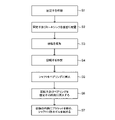
図7は、電動機1の製造工程の一例を示すフローチャートである。電動機1の製造方法は、以下に説明されるステップを含む。An example of the manufacturing method of the
FIG. 7 is a flowchart showing an example of the manufacturing process of the
ステップS1では、固定子30を作製する。例えば、複数の電磁鋼板を軸方向に積層することにより、固定子鉄心31を形成する。さらに、固定子鉄心31に、予め形成されたインシュレータ33を取り付け、固定子鉄心31及びインシュレータ33に巻線32を巻き付ける。これにより、固定子30が得られる。さらに、プリント基板4の位置決め穴43に、インシュレータ33の突起331aを挿入する。プリント基板4の表面には、駆動回路42が予め固定されている。リード線41も、プリント基板4に予め取り付けておくことが望ましい。熱溶着又は超音波溶着などによって、位置決め穴43から突出した突起331aを、プリント基板4に固定してもよい。
In step S1, the
図8は、金型100内に配置された固定子30及びヒートシンク5を示す断面図である。
ステップS2では、固定子30及びヒートシンク5を金型100内に配置する。具体的には、金型100の固定側の第1の型101内に固定子30を配置し、予め作製されたヒートシンク5を固定子30と組み合わせる。さらに、金型100の可動側の第2の型102の内側表面102aがヒートシンク5のベース部51に接触するように、第2の型102を第1の型101と組み合わせる。この場合、第2の型102の内側表面102aとベース部51との間に隙間が生じないように第2の型102を第1の型101と組み合わせる。FIG. 8 is a cross-sectional view showing a
In step S2, the
ステップS3では、樹脂6を成形する。具体的には、樹脂6を金型100内に注入する。これにより、ベース部51が樹脂6と嵌合し、ヒートシンク5が、樹脂6によって固定子30及びプリント基板4と一体化される。これにより、固定子組立3が得られる。
In step S3, the
ステップS4では、回転子2を作製する。例えば、回転子鉄心21に形成された軸穴にシャフト22を挿入し、回転子2を得る。磁極を形成する永久磁石を、予め回転子鉄心21に取り付けておいてもよい。
In step S4, the
ステップS5では、シャフト22をベアリング7a及び7bに挿入する。
In step S5, the
ステップS1からステップS5までの順序は、図7に示される順序に限られない。例えば、ステップS1からステップS3までのステップと、ステップS4とは、互いに並行して行うことができる。ステップS4は、ステップS1からステップS3までのステップよりも先に行われてもよい。 The order from step S1 to step S5 is not limited to the order shown in FIG. For example, the steps from step S1 to step S3 and step S4 can be performed in parallel with each other. Step S4 may be performed before the steps from step S1 to step S3.
ステップS6では、固定子組立3(具体的には、固定子30)の内側に、回転子2をベアリング7a及び7bと共に挿入する。
In step S6, the
ステップS7では、樹脂6の内側にブラケット8を嵌め、シャフト22に防水ゴム9を嵌める。
In step S7, the
以上に説明した工程により電動機1が組み立てられる。
The
変形例.
図9(a)は、ヒートシンク5の他の例を、ヒートシンク5aとして概略的に示す平面図であり、図9(b)は、図9(a)に示される線9b-9bに沿った断面図である。Modification example.
9 (a) is a plan view schematically showing another example of the
ヒートシンク5aにおいて、放熱部52aの構造がヒートシンク5の放熱部52の構造と異なる。ヒートシンク5aのその他の構造は、ヒートシンク5と同じである。ヒートシンク5aは、ヒートシンク5の代わりに電動機1に適用可能である。
In the
具体的には、ヒートシンク5aは、ベース部51と、放熱部52aとを有する。放熱部52aは、複数のフィン53と、放熱面54a(第1の放熱面)と、放熱面53a(第2の放熱面)と、外周面54bと、中空部54cとを有する。中空部54cは、軸方向にベース部51及び放熱部52を貫通している。中空部54cは、周方向に延在しており、軸方向における幅を持つ。中空部54cの軸方向における長さは、ベアリング7bの位置に応じて調整すればよい。
Specifically, the
放熱面54aは、軸方向においてベース部51とは反対側に形成されており、且つ回転子2の回転軸(すなわち、軸線A1)を中心とするヒートシンク5の周方向(以下、単に「周方向」という)に延在する。放熱面54aは、径方向における幅を持つ。
The
実施の形態1に係る電動機1の効果(変形例の効果を含む)及び電動機1の製造方法の効果を以下に説明する。
The effects of the electric motor 1 (including the effects of the modified examples) and the effects of the manufacturing method of the
実施の形態1に係る電動機1によれば、固定子組立3にヒートシンク5が固定されているので、電動機1の放熱効率を高めることができる。
According to the
さらに、実施の形態1に係る電動機1によれば、電動機1の製造工程(具体的には、図7におけるステップS2)において、金型100の可動側の第2の型102の内側表面102aがヒートシンク5のベース部51に接触するように、第2の型102を第1の型101と組み合わせることができる。これにより、樹脂6を金型100内に注入するとき(具体的には、図7におけるステップS3)、第2の型102の内側表面102aとベース部51との間を樹脂6が通り抜けることを防ぐことができる。その結果、樹脂6が放熱部52(例えば、フィン53)へ入り込むことを防ぐことができる。
Further, according to the
したがって、放熱部52の一部、具体的には、複数のフィン53が電動機1の外部に露出されるので、電動機1における放熱効率を高めることができる。
Therefore, since a part of the
変形例では、放熱部52aは中空部54cを有するので、ベアリング7bが中空部54cの内側に位置するようにヒートシンク5を固定子組立3と一体化させることができる。これにより、固定子組立3(例えば、プリント基板4及び駆動回路42)からヒートシンク5までの距離が短くなるので、電動機1における放熱効率を高めることができる。
In the modified example, since the
実施の形態2.
実施の形態2に係る電動機に用いられるヒートシンク5bについて説明する。
図10(a)は、ヒートシンク5bの構造を概略的に示す平面図であり、図10(b)は、図10(a)に示される線10b-10bに沿った断面図である。
実施の形態2に係る電動機では、ヒートシンク5bの構造が実施の形態1に係る電動機1におけるヒートシンク5の構造と異なる。実施の形態2に係る電動機において、ヒートシンク5b以外の構造は、実施の形態1に係る電動機1の構造と同じである。
The
10 (a) is a plan view schematically showing the structure of the
In the electric motor according to the second embodiment, the structure of the
ヒートシンク5bは、ベース部51と、ベース部51と一体的に形成された放熱部52bとを有する。放熱部52bは、複数のフィン53と、放熱面54a(第1の放熱面)と、放熱面53a(第2の放熱面)と、放熱壁(第1の壁)としての外周面54bと、中空部54cと、放熱壁54d(第2の壁)とを有する。中空部54cは、軸方向にベース部51及び放熱部52bを貫通している。
The
放熱面54aは、軸方向においてベース部51とは反対側に形成されており、且つ周方向に延在する。ヒートシンク5bは、さらにヒートシンク5bの位置決め用の少なくとも1つの窪み55を有する。本実施の形態では、窪み55は、放熱面54aに形成されている。ただし、窪み55の位置は放熱面54a以外でもよい。窪み55は、例えば、切り欠き又は穴である。電動機1の製造工程において、固定子組立3に備えられた突起を窪み55に挿入することにより、固定子組立3に対するヒートシンク5bの位置決めを容易に行うことができる。
The
放熱面53aは、各フィン53の上面である。放熱面53aは、放熱面54aよりも軸方向及び径方向における外側に形成されている。
The
外周面54bは、周方向における放熱部52bの外側表面を形成し、且つ軸方向に長い。
The outer
放熱壁54dは、放熱面54aと放熱面53aとの間に形成されている。放熱壁54dは、周方向に延在しており、軸方向における幅を持つ。
The
実施の形態2に係る電動機の製造方法の一例について以下に説明する。
図11は、金型100内に配置された固定子30及びヒートシンク5bを示す断面図である。
実施の形態2に係る電動機の製造方法では、図7に示されるステップS2における処理が、実施の形態1に係る電動機1の製造方法と異なる。An example of the method for manufacturing an electric motor according to the second embodiment will be described below.
FIG. 11 is a cross-sectional view showing a
In the method for manufacturing the electric motor according to the second embodiment, the process in step S2 shown in FIG. 7 is different from the method for manufacturing the
具体的には、金型100の固定側の第1の型101内に固定子30を配置し、予め作製されたヒートシンク5bを固定子30と組み合わせる。さらに、金型100の可動側の第2の型102の内側表面102aが、ベース部51、外周面54b、放熱面54a、及び放熱壁54dに接触するように、第2の型102を第1の型101と組み合わせる。この場合、第2の型102の内側表面102aと、ベース部51、外周面54b、放熱面54a、及び放熱壁54dとの間に隙間が生じないように第2の型102を第1の型101と組み合わせる。
Specifically, the
実施の形態2に係る電動機の製造方法において、ステップS2以外の処理は、実施の形態1に係る電動機1の製造方法と同じである。
In the method for manufacturing the motor according to the second embodiment, the processing other than step S2 is the same as the method for manufacturing the
実施の形態2に係る電動機は、実施の形態1に係る電動機1の効果(変形例の効果を含む)と同じ効果を有する。
The electric motor according to the second embodiment has the same effect as the effect of the
実施の形態2に係る電動機の製造方法は、実施の形態1に係る電動機1の製造方法と同じ効果を有する。
The method for manufacturing the electric motor according to the second embodiment has the same effect as the method for manufacturing the
さらに、実施の形態2に係る電動機によれば、製造工程(具体的には、図7におけるステップS2)において、金型100の可動側の第2の型102の内側表面102aが、ベース部51、外周面54b、放熱面54a、及び放熱壁54dに接触するように、第2の型102を第1の型101と組み合わせることができる。これにより、樹脂6を金型100内に注入するとき(具体的には、図7におけるステップS3)、第2の型102の内側表面102aとベース部51との間を樹脂6が通り抜けることを防ぐことができる。その結果、放熱部52b(例えば、フィン53)が樹脂6で覆われることを防ぐことができる。
Further, according to the electric motor according to the second embodiment, in the manufacturing process (specifically, step S2 in FIG. 7), the
第2の型102の内側表面102aとベース部51との間を樹脂6が通り抜けた場合でも、内側表面102aが外周面54bと接触しているので、放熱部52b(例えば、フィン53)が樹脂6で覆われることを防ぐことができる。
Even when the
さらに、内側表面102aが放熱面54aと接触しているので、中空部54cの内側に流入した樹脂6が、内側表面102aと放熱面54aとの間を通り抜けることを防ぐことができる。内側表面102aと放熱面54aとの間を樹脂6が通り抜けた場合でも、内側表面102aが放熱壁54dと接触しているので、放熱部52b(例えば、フィン53)が樹脂6で覆われることを防ぐことができる。
Further, since the
したがって、放熱部52bの一部、具体的には、複数のフィン53が実施の形態2に係る電動機の外部に露出されるので、この電動機における放熱効率を高めることができる。
Therefore, since a part of the
実施の形態3.
実施の形態3に係る電動機に用いられるヒートシンク5cについて説明する。
図12(a)は、ヒートシンク5cの構造を概略的に示す平面図であり、図12(b)は、図12(a)に示される線12b-12bに沿った断面図である。
実施の形態3に係る電動機では、ヒートシンク5cの構造が実施の形態1に係る電動機1におけるヒートシンク5の構造と異なる。実施の形態3に係る電動機において、ヒートシンク5c以外の構造は、実施の形態1に係る電動機1の構造と同じである。実施の形態2に係る電動機と比較すると、実施の形態3に係る電動機において、ヒートシンク5cのベース部51aの構造が、ヒートシンク5bのベース部51と異なる。
The
12 (a) is a plan view schematically showing the structure of the
In the electric motor according to the third embodiment, the structure of the
ヒートシンク5cは、ベース部51aと、ベース部51aと一体的に形成された放熱部52bとを有する。
The
ベース部51aは、少なくとも1つの突出部56と、フランジ部57とを有する。
The
突出部56は、突出部56の上面であるベース面56a(第1のベース面)を有する。突出部56は、フランジ部57から径方向における外側に向けて突出している。したがって、ベース面56aは径方向における外側に向けて突出している。本実施の形態では、4つの突出部56がヒートシンク5cに形成されている。
The
フランジ部57は、ベース面57a(第2のベース面)と、軸方向に長い段差57b(ベース壁ともいう)とを有する。ベース面57aは、ベース面56aよりも軸方向における外側(-z側)に形成されており、且つベース面56aよりも径方向における内側に形成されている。すなわち、ベース面57aは、ベース面56aと放熱面53aとの間に位置する面である。ベース面57aは、周方向に延在しており、径方向に突出している。すなわち、ベース面57aは、径方向における幅を持つ。
The
段差57bは、ベース面56aとベース面57aとの間に形成されている。段差57bは、周方向に延在している。段差57bは、軸方向における幅を持つ。
The
実施の形態3に係る電動機の製造方法の一例について以下に説明する。
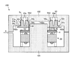
図13は、金型100内に配置された固定子30及びヒートシンク5cを示す断面図である。
実施の形態3に係る電動機の製造方法では、図7に示されるステップS2及びステップS3における処理が、実施の形態1に係る電動機1の製造方法と異なる。An example of the method for manufacturing an electric motor according to the third embodiment will be described below.
FIG. 13 is a cross-sectional view showing a
In the method for manufacturing the electric motor according to the third embodiment, the processes in steps S2 and S3 shown in FIG. 7 are different from the manufacturing method for the
具体的には、ステップS2において、金型100の固定側の第1の型101内に固定子30を配置し、予め作製されたヒートシンク5cを固定子30と組み合わせる。さらに、金型100の可動側の第2の型102の内側表面102aが、ベース面57a、外周面54b、放熱面54a、及び放熱壁54dに接触するように、第2の型102を第1の型101と組み合わせる。この場合、第2の型102の内側表面102aと、ベース面57a、外周面54b、放熱面54a、及び放熱壁54dとの間に隙間が生じないように第2の型102を第1の型101と組み合わせる。内側表面102aとベース部51aの一部(具体的には、ベース面56a)との間には隙間を設ける。
Specifically, in step S2, the
ステップS3では、樹脂6を成形する。具体的には、樹脂6を金型100内に注入する。さらに具体的には、内側表面102aとベース部51aの一部(具体的には、突出部56のベース面56a)との間に樹脂6が入り込むように、樹脂6を金型100内に注入する。さらに、突出部56が樹脂6で覆われるように、樹脂6を金型100内に注入する。これにより、ベース部51aの一部(具体的には、突出部56のベース面56a)が樹脂6と嵌合し、ヒートシンク5が、樹脂6によって固定子30及びプリント基板4と一体化される。さらに、突出部56が樹脂6で覆われる。これにより、固定子組立3が得られる。
In step S3, the
実施の形態3に係る電動機の製造方法において、ステップS2及びステップS3以外の処理は、実施の形態1に係る電動機1の製造方法と同じである。
In the method for manufacturing the motor according to the third embodiment, the processes other than steps S2 and S3 are the same as the method for manufacturing the
実施の形態3に係る電動機は、実施の形態1に係る電動機1の効果(変形例の効果を含む)及び実施の形態2に係る電動機と同じ効果を有する。
The electric motor according to the third embodiment has the same effects as the
実施の形態3に係る電動機の製造方法は、実施の形態1に係る電動機1の製造方法及び実施の形態2に係る電動機の製造方法と同じ効果を有する。
The method for manufacturing an electric motor according to the third embodiment has the same effect as the method for manufacturing the
さらに、実施の形態3に係る電動機によれば、突出部56が樹脂6で覆われるので、ヒートシンク5cが樹脂6に対して回転することを防ぐことができる。言い換えると、樹脂6に対する周方向におけるヒートシンク5cのずれを防ぐことができる。
Further, according to the electric motor according to the third embodiment, since the protruding
さらに、実施の形態3に係る電動機によれば、金型100の内側表面102aと突出部56(具体的には、ベース面56a)との間に樹脂6が充填されるので、樹脂6に対する軸方向におけるヒートシンク5cのずれを防ぐことができる。
Further, according to the electric motor according to the third embodiment, the
したがって、ねじ等の固定部品を用いずにヒートシンク5cを固定子組立3と一体化させることができる。したがって、実施の形態3に係る電動機の部品数及び電動機の製造工程が削減され、電動機のコストを低減することができる。
Therefore, the
さらに、ベース部51aに突出部56が形成されていることにより、金型100(具体的には、第2の型102)に溝を形成せずに、ベース部51aの一部を樹脂6で覆うことができる。したがって、金型100の製造コストを低減することができる。さらに、ベース部51aに突出部56が形成されているので、樹脂6で覆われる部分を得ることができるとともに、ヒートシンク5cにおける放熱部52bの表面積の割合を大きくすることができる。これにより、電動機における放熱効率を高めることができる。
Further, since the protruding
実施の形態4.
本発明の実施の形態4に係る空気調和機10について説明する。
図14は、本発明の実施の形態4に係る空気調和機10の構成を概略的に示す図である。
The
FIG. 14 is a diagram schematically showing the configuration of the
実施の形態4に係る空気調和機10(例えば、冷凍空調装置)は、送風機(第1の送風機)としての室内機11と、冷媒配管12と、冷媒配管12によって室内機11に接続された送風機(第2の送風機)としての室外機13とを備える。
The air conditioner 10 (for example, a refrigerating air conditioner) according to the fourth embodiment is an
室内機11は、電動機11a(例えば、実施の形態1に係る電動機1)と、電動機11aによって駆動されることにより、送風する送風部11bと、電動機11a及び送風部11bを覆うハウジング11cとを有する。送風部11bは、例えば、電動機11aによって駆動される羽根を有する。
The
室外機13は、電動機13a(例えば、実施の形態1に係る電動機1)と、送風部13bと、圧縮機14と、熱交換器(図示しない)とを有する。送風部13bは、電動機13aによって駆動されることにより、送風する。送風部13bは、例えば、電動機13aによって駆動される羽根を有する。圧縮機14は、電動機14a(例えば、実施の形態1に係る電動機1)と、電動機14aによって駆動される圧縮機構14b(例えば、冷媒回路)と、電動機14a及び圧縮機構14bを覆うハウジング14cとを有する。
The
空気調和機10において、室内機11及び室外機13の少なくとも1つは、実施の形態1から3で説明した電動機(変形例を含む)を有する。具体的には、送風部の駆動源として、電動機11a及び13aの少なくとも一方に、実施の形態1から3で説明した電動機が適用される。さらに、圧縮機14の電動機14aとして、実施の形態1から3で説明した電動機(変形例を含む)を用いてもよい。
In the
空気調和機10は、例えば、室内機11から冷たい空気を送風する冷房運転、又は温かい空気を送風する暖房運転等の運転を行うことができる。室内機11において、電動機11aは、送風部11bを駆動するための駆動源である。送風部11bは、調整された空気を送風することができる。
The
実施の形態4に係る空気調和機10によれば、電動機11a及び13aの少なくとも一方に、実施の形態1から3で説明した電動機(変形例を含む)が適用されるので、実施の形態1から3で説明した効果と同じ効果を得ることができる。これにより、電動機の発熱に起因する空気調和機10の故障を防止することができる。さらに、空気調和機10において実施の形態1から3で説明した電動機を用いることにより、空気調和機10のコストを低減することができる。
According to the
さらに、送風機(例えば、室内機11)の駆動源として、実施の形態1から3に係る電動機(変形例を含む)を用いることにより、実施の形態1から3で説明した効果と同じ効果を得ることができる。これにより、電動機の発熱に起因する送風機の故障を防止することができる。 Further, by using the motors (including the modified examples) according to the first to third embodiments as the drive source of the blower (for example, the indoor unit 11), the same effects as those described in the first to third embodiments can be obtained. be able to. This makes it possible to prevent the blower from malfunctioning due to the heat generated by the motor.
さらに、圧縮機14の駆動源として、実施の形態1から3に係る電動機(変形例を含む)を用いることにより、実施の形態1から3で説明した効果と同じ効果を得ることができる。これにより、電動機の発熱に起因する圧縮機14の故障を防止することができる。
Further, by using the electric motors (including the modified examples) according to the first to third embodiments as the drive source of the
実施の形態1から3で説明した電動機は、空気調和機10以外に、換気扇、家電機器、又は工作機など、駆動源を有する機器に搭載できる。
The electric motor described in the first to third embodiments can be mounted on a device having a drive source, such as a ventilation fan, a home electric appliance, or a machine tool, in addition to the
以上に説明した各実施の形態における特徴及び変形例における特徴は、互いに適宜組み合わせることができる。 The features in each of the embodiments described above and the features in the modified examples can be appropriately combined with each other.
1,11a,13a,14a 電動機、 2 回転子、 3 固定子組立、 4 プリント基板、 5,5a,5b,5c ヒートシンク、 6 樹脂、 7a,7b ベアリング、 8 ブラケット、 9 防水ゴム、 10 空気調和機、 11 室内機(送風機)、 12 冷媒配管、 13 室外機(送風機)、 30 固定子、 31 固定子鉄心、 32 巻線、 33 インシュレータ、 42 駆動回路、 51,51a ベース部、 52,52a,52b 放熱部、 53 フィン、 53a,54a 放熱面、 54b 外周面、 54c 中空部、 54d 放熱壁、 56 突出部、 56a,57a ベース面、 57 フランジ部、 57b 段差。 1,11a, 13a, 14a motor, 2 rotor, 3 stator assembly, 4 printed circuit board, 5,5a, 5b, 5c heat sink, 6 resin, 7a, 7b bearing, 8 bracket, 9 waterproof rubber, 10 air conditioner , 11 Indoor unit (blower), 12 refrigerant piping, 13 outdoor unit (blower), 30 stator, 31 stator core, 32 windings, 33 insulator, 42 drive circuit, 51, 51a base, 52, 52a, 52b Heat sink, 53 fins, 53a, 54a heat sink surface, 54b outer peripheral surface, 54c hollow part, 54d heat sink wall, 56 protrusion, 56a, 57a base surface, 57 flange part, 57b step.
Claims (15)
前記固定子組立の内側に備えられた回転子と、
前記固定子組立に固定されており、前記固定子組立の熱を放出するヒートシンクと
を備え、
前記ヒートシンクは、
前記樹脂と嵌合しているベース部と、
互いに平行に形成された複数のフィンを有し、前記ベース部と一体的に形成された放熱部と
を有し、
前記回転子の軸方向と直交する平面において、前記ベース部は、前記回転子の回転軸を中心とする周方向に延在しているとともに前記放熱部の全周を囲んでおり、
前記複数のフィンは、前記樹脂から前記回転子の軸方向に突出している
電動機。 Stator assembly with resin,
With the rotor provided inside the stator assembly,
It is fixed to the stator assembly and is equipped with a heat sink that dissipates the heat of the stator assembly.
The heat sink is
The base part fitted with the resin and
It has a plurality of fins formed in parallel with each other, and has a heat radiating portion integrally formed with the base portion.
In a plane orthogonal to the axial direction of the rotor, the base portion extends in the circumferential direction about the rotation axis of the rotor and surrounds the entire circumference of the heat dissipation portion .
The plurality of fins project from the resin in the axial direction of the rotor.
Electric motor.
前記放熱部は、前記回転子の軸方向において前記ベース部に対して前記回転子鉄心とは反対側に形成されており、且つ前記回転子の回転軸を中心とする周方向に延在する第1の放熱面を有する請求項1に記載の電動機。 The rotor has a rotor core and
The heat radiating portion is formed on the side opposite to the rotor core with respect to the base portion in the axial direction of the rotor, and extends in the circumferential direction about the rotation axis of the rotor. The electric motor according to claim 1, which has a heat dissipation surface of 1.
前記突出部は、前記回転子の径方向における外側に向けて突出する第1のベース面を有し、
前記ベース部は、前記第1のベース面と前記第2の放熱面との間に位置しており、且つ前記第1のベース面よりも前記回転子の径方向における内側に形成された第2のベース面を有する請求項4又は5に記載の電動機。 The base portion has a protruding portion that protrudes outward in the radial direction of the rotor.
The protrusion has a first base surface that projects outward in the radial direction of the rotor.
The base portion is located between the first base surface and the second heat radiation surface, and is formed inside the rotor in the radial direction with respect to the first base surface. The motor according to claim 4 or 5, which has a base surface of the above.
前記ヒートシンクは、前記プリント基板に接触している
請求項1から11のいずれか1項に記載の電動機。 The stator assembly has a printed circuit board and
The motor according to any one of claims 1 to 11 , wherein the heat sink is in contact with the printed circuit board.
前記電動機によって駆動される圧縮機構と、
前記電動機及び前記圧縮機構を覆うハウジングと
を備え、
前記電動機は、
樹脂を有する固定子組立と、
前記固定子組立の内側に備えられた回転子と、
前記固定子組立に固定されており、前記固定子組立の熱を放出するヒートシンクと
を有し、
前記ヒートシンクは、
前記樹脂と嵌合しているベース部と、
互いに平行に形成された複数のフィンを有し、前記ベース部と一体的に形成された放熱部と
を有し、
前記回転子の軸方向と直交する平面において、前記ベース部は、前記回転子の回転軸を中心とする周方向に延在しているとともに前記放熱部の全周を囲んでおり、
前記複数のフィンは、前記樹脂から前記回転子の軸方向に突出している
圧縮機。 With an electric motor
The compression mechanism driven by the motor and
A housing that covers the motor and the compression mechanism is provided.
The motor is
Stator assembly with resin,
With the rotor provided inside the stator assembly,
It is fixed to the stator assembly and has a heat sink that dissipates the heat of the stator assembly.
The heat sink is
The base part fitted with the resin and
It has a plurality of fins formed in parallel with each other, and has a heat radiating portion integrally formed with the base portion.
In a plane orthogonal to the axial direction of the rotor, the base portion extends in the circumferential direction about the rotation axis of the rotor and surrounds the entire circumference of the heat dissipation portion .
The plurality of fins project from the resin in the axial direction of the rotor.
Compressor.
前記室内機に接続された室外機と
を備え、
前記室内機及び前記室外機の少なくとも1つは電動機を有し、
前記電動機は、
樹脂を有する固定子組立と、
前記固定子組立の内側に備えられた回転子と、
前記固定子組立に固定されており、前記固定子組立の熱を放出するヒートシンクと
を有し、
前記ヒートシンクは、
前記樹脂と嵌合しているベース部と、
互いに平行に形成された複数のフィンを有し、前記ベース部と一体的に形成された放熱部と
を有し、
前記回転子の軸方向と直交する平面において、前記ベース部は、前記回転子の回転軸を中心とする周方向に延在しているとともに前記放熱部の全周を囲んでおり、
前記複数のフィンは、前記樹脂から前記回転子の軸方向に突出している
空気調和機。 Indoor unit and
With an outdoor unit connected to the indoor unit,
At least one of the indoor unit and the outdoor unit has an electric motor.
The motor is
Stator assembly with resin,
With the rotor provided inside the stator assembly,
It is fixed to the stator assembly and has a heat sink that dissipates the heat of the stator assembly.
The heat sink is
The base part fitted with the resin and
It has a plurality of fins formed in parallel with each other, and has a heat radiating portion integrally formed with the base portion.
In a plane orthogonal to the axial direction of the rotor, the base portion extends in the circumferential direction about the rotation axis of the rotor and surrounds the entire circumference of the heat dissipation portion .
The plurality of fins project from the resin in the axial direction of the rotor.
Air conditioner.
前記回転子の軸方向と直交する平面において、前記ベース部は、前記回転子の回転軸を中心とする周方向に延在しているとともに前記放熱部の全周を囲んでおり、
前記固定子を作製するステップと、
前記固定子及び前記ヒートシンクを金型の第1の型に配置するステップと、
前記金型の第2の型の内側表面が、前記ヒートシンクの前記ベース部に接触するように、前記第2の型を前記第1の型と組み合わせるステップと、
前記ベース部が樹脂と嵌合するように前記金型内に前記樹脂を注入するステップと、
前記回転子を前記固定子の内側に挿入するステップと、
を備え、
前記複数のフィンは、前記樹脂から前記回転子の軸方向に突出するように構成される
電動機の製造方法。 A method of manufacturing an electric motor including a rotor, a stator, and a heat sink having a base portion and a heat sink having a radiator portion having a plurality of fins formed inside the base portion in the radial direction and formed parallel to each other. And
In a plane orthogonal to the axial direction of the rotor, the base portion extends in the circumferential direction about the rotation axis of the rotor and surrounds the entire circumference of the heat dissipation portion.
The step of making the stator and
The step of arranging the stator and the heat sink in the first mold of the mold,
A step of combining the second mold with the first mold so that the inner surface of the second mold of the mold contacts the base portion of the heat sink.
The step of injecting the resin into the mold so that the base portion fits with the resin,
The step of inserting the rotor inside the stator, and
Equipped with
The plurality of fins are configured to project from the resin in the axial direction of the rotor.
How to make an electric motor.
Applications Claiming Priority (1)
| Application Number | Priority Date | Filing Date | Title |
|---|---|---|---|
| PCT/JP2017/022658 WO2018235157A1 (en) | 2017-06-20 | 2017-06-20 | Electric motor, compressor, air conditioner, and method for manufacturing electric motor |
Publications (2)
| Publication Number | Publication Date |
|---|---|
| JPWO2018235157A1 JPWO2018235157A1 (en) | 2019-11-07 |
| JP7093347B2 true JP7093347B2 (en) | 2022-06-29 |
Family
ID=64735577
Family Applications (1)
| Application Number | Title | Priority Date | Filing Date |
|---|---|---|---|
| JP2019524743A Active JP7093347B2 (en) | 2017-06-20 | 2017-06-20 | Manufacturing methods for motors, compressors, and air conditioners, and motors |
Country Status (4)
| Country | Link |
|---|---|
| US (1) | US11381137B2 (en) |
| JP (1) | JP7093347B2 (en) |
| CN (1) | CN110741540B (en) |
| WO (1) | WO2018235157A1 (en) |
Families Citing this family (2)
| Publication number | Priority date | Publication date | Assignee | Title |
|---|---|---|---|---|
| SE542616C2 (en) * | 2018-09-27 | 2020-06-16 | Leine & Linde Ab | Rotary encoder and method for manufacturing a rotary encoder |
| WO2023148949A1 (en) * | 2022-02-07 | 2023-08-10 | 三菱電機株式会社 | Electric motor and air conditioner |
Citations (4)
| Publication number | Priority date | Publication date | Assignee | Title |
|---|---|---|---|---|
| JP2007267568A (en) | 2006-03-30 | 2007-10-11 | Mitsubishi Electric Corp | Mold motor and air harmonic unit |
| JP2009131127A (en) | 2007-11-28 | 2009-06-11 | Panasonic Corp | Brushless motor |
| WO2010029623A1 (en) | 2008-09-11 | 2010-03-18 | 三菱電機株式会社 | Hoist for elevator |
| JP2010178463A (en) | 2009-01-28 | 2010-08-12 | Nidec Shibaura Corp | Motor and manufacturing method thereof |
Family Cites Families (21)
| Publication number | Priority date | Publication date | Assignee | Title |
|---|---|---|---|---|
| JP2720623B2 (en) * | 1991-04-12 | 1998-03-04 | 三菱電機株式会社 | Mold motor |
| JPH0898441A (en) * | 1994-09-20 | 1996-04-12 | Fujitsu General Ltd | Molded motor |
| JP3536394B2 (en) * | 1994-12-22 | 2004-06-07 | 日本電産シバウラ株式会社 | Manufacturing method of molded motor |
| JP3509288B2 (en) | 1995-04-25 | 2004-03-22 | 日本電産シバウラ株式会社 | Brushless DC motor |
| US5789833A (en) | 1995-11-24 | 1998-08-04 | Kabushiki Kaisha Toshiba | Totally-enclosed traction motor for electric railcar |
| JPH09205758A (en) | 1995-11-24 | 1997-08-05 | Toshiba Corp | Totally-enclosed main motor for vehicle |
| JPH09252563A (en) * | 1996-03-14 | 1997-09-22 | Toshiba Corp | Motor with built-in controller |
| US6774514B2 (en) | 2000-02-25 | 2004-08-10 | Kabushiki Kaisha Toshiba | Totally enclosed type driving electric motor |
| JP3756733B2 (en) | 2000-07-07 | 2006-03-15 | 財団法人鉄道総合技術研究所 | Fully-closed drive motor for railway vehicles |
| JP2001327152A (en) | 2000-05-12 | 2001-11-22 | Yaskawa Electric Corp | Linear motor |
| JP2005094841A (en) * | 2003-09-12 | 2005-04-07 | Matsushita Electric Ind Co Ltd | Mold motor |
| JP4881280B2 (en) * | 2007-11-14 | 2012-02-22 | 住友建機株式会社 | Swing control device |
| US8395289B2 (en) * | 2008-04-03 | 2013-03-12 | Yu Tian | Brushless DC motor and a radiator thereof |
| TW201014125A (en) * | 2008-09-16 | 2010-04-01 | Joy Ride Tech Co Ltd | Motor with heat dissipation device |
| JP4806461B2 (en) * | 2008-09-26 | 2011-11-02 | 三洋電機株式会社 | Electric motor and electric vehicle |
| JP2010279207A (en) * | 2009-05-29 | 2010-12-09 | Sanyo Electric Co Ltd | Molded motor, electric vehicle and manufacturing method for molded motor |
| JP4894903B2 (en) * | 2009-10-26 | 2012-03-14 | パナソニック株式会社 | Mold electric motor |
| JP5687027B2 (en) * | 2010-10-27 | 2015-03-18 | 三菱重工業株式会社 | Inverter-integrated electric compressor |
| JP2012174734A (en) | 2011-02-17 | 2012-09-10 | Toyota Motor Corp | Heat sink and semiconductor package provided with heat sink |
| JP2017169348A (en) * | 2016-03-16 | 2017-09-21 | ミネベアミツミ株式会社 | motor |
| CN109792188A (en) * | 2016-09-28 | 2019-05-21 | 三菱电机株式会社 | The manufacturing method of motor, air blower, air conditioner and motor |
-
2017
- 2017-06-20 CN CN201780090977.9A patent/CN110741540B/en active Active
- 2017-06-20 JP JP2019524743A patent/JP7093347B2/en active Active
- 2017-06-20 US US16/605,686 patent/US11381137B2/en active Active
- 2017-06-20 WO PCT/JP2017/022658 patent/WO2018235157A1/en active Application Filing
Patent Citations (4)
| Publication number | Priority date | Publication date | Assignee | Title |
|---|---|---|---|---|
| JP2007267568A (en) | 2006-03-30 | 2007-10-11 | Mitsubishi Electric Corp | Mold motor and air harmonic unit |
| JP2009131127A (en) | 2007-11-28 | 2009-06-11 | Panasonic Corp | Brushless motor |
| WO2010029623A1 (en) | 2008-09-11 | 2010-03-18 | 三菱電機株式会社 | Hoist for elevator |
| JP2010178463A (en) | 2009-01-28 | 2010-08-12 | Nidec Shibaura Corp | Motor and manufacturing method thereof |
Also Published As
| Publication number | Publication date |
|---|---|
| US11381137B2 (en) | 2022-07-05 |
| WO2018235157A1 (en) | 2018-12-27 |
| CN110741540A (en) | 2020-01-31 |
| JPWO2018235157A1 (en) | 2019-11-07 |
| US20200119621A1 (en) | 2020-04-16 |
| CN110741540B (en) | 2022-01-18 |
Similar Documents
| Publication | Publication Date | Title |
|---|---|---|
| JP6664505B2 (en) | Electric motor, blower, air conditioner, and method for manufacturing electric motor | |
| JP6895996B2 (en) | Motors, air conditioners, and methods for manufacturing motors | |
| JP7093347B2 (en) | Manufacturing methods for motors, compressors, and air conditioners, and motors | |
| JP2023054248A (en) | Rotor, electric motor, blower, air conditioner, and manufacturing method of rotor | |
| JP7042968B2 (en) | How to manufacture motors, blowers, air conditioners and motors | |
| JP7183401B2 (en) | MOTOR, BLOWER, AIR CONDITIONER, AND MOTOR MANUFACTURING METHOD | |
| WO2022180708A1 (en) | Stator, electric motor, and air conditioner | |
| WO2022249307A1 (en) | Electric motor and air conditioner | |
| WO2023233609A1 (en) | Electric motor and air conditioner | |
| US11962229B2 (en) | Motor, fan, air conditioner, and manufacturing method of motor | |
| US20220352780A1 (en) | Motor, fan, air conditioner, and manufacturing method of motor | |
| JP7301972B2 (en) | Electric motor, blower, air conditioner, and method for manufacturing electric motor | |
| WO2023148949A1 (en) | Electric motor and air conditioner | |
| WO2020026403A1 (en) | Rotor, motor, fan, air-conditioner, and rotor manufacturing method | |
| JPWO2020026406A1 (en) | How to manufacture rotors, motors, fans, air conditioners, and rotors |
Legal Events
| Date | Code | Title | Description |
|---|---|---|---|
| A521 | Request for written amendment filed |
Free format text: JAPANESE INTERMEDIATE CODE: A523 Effective date: 20190708 |
|
| A621 | Written request for application examination |
Free format text: JAPANESE INTERMEDIATE CODE: A621 Effective date: 20190708 |
|
| A131 | Notification of reasons for refusal |
Free format text: JAPANESE INTERMEDIATE CODE: A131 Effective date: 20200428 |
|
| A521 | Request for written amendment filed |
Free format text: JAPANESE INTERMEDIATE CODE: A523 Effective date: 20200612 |
|
| A02 | Decision of refusal |
Free format text: JAPANESE INTERMEDIATE CODE: A02 Effective date: 20201110 |
|
| A521 | Request for written amendment filed |
Free format text: JAPANESE INTERMEDIATE CODE: A523 Effective date: 20210115 |
|
| C60 | Trial request (containing other claim documents, opposition documents) |
Free format text: JAPANESE INTERMEDIATE CODE: C60 Effective date: 20210115 |
|
| A911 | Transfer to examiner for re-examination before appeal (zenchi) |
Free format text: JAPANESE INTERMEDIATE CODE: A911 Effective date: 20210125 |
|
| C21 | Notice of transfer of a case for reconsideration by examiners before appeal proceedings |
Free format text: JAPANESE INTERMEDIATE CODE: C21 Effective date: 20210126 |
|
| A912 | Re-examination (zenchi) completed and case transferred to appeal board |
Free format text: JAPANESE INTERMEDIATE CODE: A912 Effective date: 20210226 |
|
| C211 | Notice of termination of reconsideration by examiners before appeal proceedings |
Free format text: JAPANESE INTERMEDIATE CODE: C211 Effective date: 20210302 |
|
| C22 | Notice of designation (change) of administrative judge |
Free format text: JAPANESE INTERMEDIATE CODE: C22 Effective date: 20210622 |
|
| C13 | Notice of reasons for refusal |
Free format text: JAPANESE INTERMEDIATE CODE: C13 Effective date: 20210907 |
|
| A521 | Request for written amendment filed |
Free format text: JAPANESE INTERMEDIATE CODE: A523 Effective date: 20211104 |
|
| RD13 | Notification of appointment of power of sub attorney |
Free format text: JAPANESE INTERMEDIATE CODE: A7433 Effective date: 20220202 |
|
| C302 | Record of communication |
Free format text: JAPANESE INTERMEDIATE CODE: C302 Effective date: 20220214 |
|
| C13 | Notice of reasons for refusal |
Free format text: JAPANESE INTERMEDIATE CODE: C13 Effective date: 20220222 |
|
| A521 | Request for written amendment filed |
Free format text: JAPANESE INTERMEDIATE CODE: A523 Effective date: 20220302 |
|
| A521 | Request for written amendment filed |
Free format text: JAPANESE INTERMEDIATE CODE: A523 Effective date: 20220324 |
|
| RD17 | Notification of extinguishment of power of sub attorney |
Free format text: JAPANESE INTERMEDIATE CODE: A7437 Effective date: 20220421 |
|
| C22 | Notice of designation (change) of administrative judge |
Free format text: JAPANESE INTERMEDIATE CODE: C22 Effective date: 20220426 |
|
| C22 | Notice of designation (change) of administrative judge |
Free format text: JAPANESE INTERMEDIATE CODE: C22 Effective date: 20220426 |
|
| C23 | Notice of termination of proceedings |
Free format text: JAPANESE INTERMEDIATE CODE: C23 Effective date: 20220510 |
|
| C03 | Trial/appeal decision taken |
Free format text: JAPANESE INTERMEDIATE CODE: C03 Effective date: 20220614 |
|
| C30A | Notification sent |
Free format text: JAPANESE INTERMEDIATE CODE: C3012 Effective date: 20220614 |
|
| A61 | First payment of annual fees (during grant procedure) |
Free format text: JAPANESE INTERMEDIATE CODE: A61 Effective date: 20220617 |
|
| R150 | Certificate of patent or registration of utility model |
Ref document number: 7093347 Country of ref document: JP Free format text: JAPANESE INTERMEDIATE CODE: R150 |