JP4881280B2 - Swing control device - Google Patents
Swing control device Download PDFInfo
- Publication number
- JP4881280B2 JP4881280B2 JP2007296005A JP2007296005A JP4881280B2 JP 4881280 B2 JP4881280 B2 JP 4881280B2 JP 2007296005 A JP2007296005 A JP 2007296005A JP 2007296005 A JP2007296005 A JP 2007296005A JP 4881280 B2 JP4881280 B2 JP 4881280B2
- Authority
- JP
- Japan
- Prior art keywords
- turning
- detection unit
- boom
- operation amount
- torque
- Prior art date
- Legal status (The legal status is an assumption and is not a legal conclusion. Google has not performed a legal analysis and makes no representation as to the accuracy of the status listed.)
- Expired - Fee Related
Links
Images


Description
本発明は、電動機で旋回体を旋回させる建機用旋回制御装置に関し、より具体的には、旋回体の状態に基づいて旋回トルクを制御する建機用旋回制御装置に関する。 The present invention relates to a turning control device for construction equipment that turns a turning body with an electric motor, and more specifically, relates to a turning control device for construction equipment that controls turning torque based on the state of the turning body.
従来、一定回転数で運転するエンジンによって駆動される発電機の電気エネルギー、又は、その発電機の電気エネルギーを充電するバッテリの電気エネルギーにより電動機を駆動しながら建機の各機構を動作させる油圧駆動装置が知られている(例えば、特許文献1参照。)。 Conventionally, a hydraulic drive that operates each mechanism of a construction machine while driving an electric motor with electric energy of a generator driven by an engine that operates at a constant rotational speed, or electric energy of a battery that charges the electric energy of the generator. An apparatus is known (for example, refer to Patent Document 1).
この油圧駆動装置は、オペレータのレバー操作に滑らかに追従させるための優れた操作性が要求される機構としてアームシリンダ機構及びブームシリンダ機構を定義し、電動機ではなく、回転数可変のエンジンで直接駆動される油圧ポンプによって、それら機構を作動させるようにする。 This hydraulic drive system defines an arm cylinder mechanism and a boom cylinder mechanism as a mechanism that requires excellent operability to smoothly follow the lever operation of the operator, and is directly driven by an engine with variable speed, not an electric motor. These mechanisms are operated by a hydraulic pump.
一方、この油圧駆動装置は、オペレータのレバー操作に滑らかに追従させるための優れた操作性があまり要求されない機構としてバケットシリンダ機構、旋回機構及び走行機構を定義し、それら機構を電動機によって作動させるようにする。 On the other hand, this hydraulic drive device defines a bucket cylinder mechanism, a turning mechanism, and a traveling mechanism as mechanisms that do not require excellent operability for smoothly following an operator's lever operation, and these mechanisms are operated by an electric motor. To.
このようにエンジンの力で作動させる機構と電動機の力で作動させる機構とを予め区別しておくことにより、この油圧駆動装置は、アームシリンダ機構及びブームシリンダ機構における優れた操作性を確保しつつも、その他の機構を作動させるときに電動機を利用することで、エンジン負担を軽減しながらエネルギー効率を高めることができる。
しかしながら、特許文献1に記載の油圧駆動装置は、エンジンの力で作動させる機構と電動機の力で作動させる機構とを予め区別しておくだけであり、特定の電動機の動作を制御するものではなく、アタッチメント(ブーム、アーム又はバケット等をいう。)の姿勢や荷の有無に応じて変化する所要旋回トルクに対応することができない。
However, the hydraulic drive device described in
そこで、本発明は、上記の点に鑑みてなされたものであって、旋回体の旋回操作性を向上させる旋回制御装置を提供することを目的とする。 Therefore, the present invention has been made in view of the above points, and an object thereof is to provide a turning control device that improves the turning operability of the turning body.
本発明の一観点によれば、電動機で旋回体を旋回させる建機用旋回制御装置であって、一又は二以上のセンサの出力を受けてその旋回体の状態を検知する旋回体状態検知部と、その旋回体の旋回操作を制御するレバーの出力を受けてそのレバーの操作量を検知する操作量検知部と、その旋回体状態検知部が検知した旋回体の状態とその操作量検知部が検知した操作量とに基づいて旋回トルクを制御する信号を電動機に対して出力するコントローラと、を備えることを特徴とする旋回制御装置が提供される。 According to one aspect of the present invention, there is provided a turning control device for a construction machine that turns a turning body with an electric motor, and detects the state of the turning body by receiving the output of one or more sensors. An operation amount detection unit that receives an output of a lever that controls a turning operation of the revolving body, detects an operation amount of the lever, a state of the revolving body detected by the revolving body state detection unit, and an operation amount detection unit thereof And a controller that outputs a signal for controlling the turning torque to the electric motor based on the detected operation amount.
また、上記旋回体状態検知部は、その旋回体の状態として、その旋回体のアタッチメントの姿勢によって変化する旋回半径を検知するようにしてもよい。 In addition, the revolving body state detection unit may detect a turning radius that changes depending on the posture of the attachment of the revolving body as the state of the revolving body.
また、上記旋回体状態検知部は、その旋回体の状態として、ブームシリンダ圧を検知するようにしてもよい。 The revolving unit state detection unit may detect the boom cylinder pressure as the state of the revolving unit.
また、上記旋回制御装置は、その旋回体状態検知部が検知した旋回体の状態に基づいて慣性モーメントを導出する慣性モーメント導出部を更に備え、そのコントローラは、その慣性モーメント導出部が導出した慣性モーメントとその操作量検知部が検知した操作量とに基づいて旋回トルクを制御する信号を電動機に対して出力するようにしてもよい。 The turning control device further includes an inertia moment deriving unit that derives an inertia moment based on the state of the turning body detected by the turning body state detecting unit, and the controller includes an inertia derived by the inertia moment deriving unit. A signal for controlling the turning torque based on the moment and the operation amount detected by the operation amount detection unit may be output to the electric motor.
本発明によれば、旋回体の旋回操作性を向上させる旋回制御装置を提供することができる。 ADVANTAGE OF THE INVENTION According to this invention, the turning control apparatus which improves the turning operability of a turning body can be provided.
以下、本発明の実施の形態について説明する。 Embodiments of the present invention will be described below.
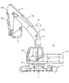
図1は、本発明に係る旋回制御装置が搭載された油圧ショベルの構成例を示す図である。図1において、油圧ショベル10は、クローラ式の下部走行体11の上に、旋回機構12を介して、上部旋回体13を旋回中心X周りに旋回自在に搭載している。
FIG. 1 is a diagram showing a configuration example of a hydraulic excavator equipped with a turning control device according to the present invention. In FIG. 1, a
また、上部旋回体13は、その前方側部にキャブ14を備え、かつ、前方中央部に、ブーム15、アーム16及びバケット17、並びに、これらをそれぞれ駆動するアクチュエータとしてのブームシリンダ18、アームシリンダ19及びバケットシリンダ20から構成される掘削アタッチメントEを備える。
The
図2は、油圧ショベル10のシステムブロック図であり、エンジン21、変速機22、発電機23、バッテリ24、油圧ポンプ25、旋回操作レバー26、旋回用電動機27、ブーム操作レバー28、コントロールバルブ29、ブーム圧センサ30、ブーム角度センサ31、アーム角度センサ32、バケット角度センサ33、インバータ34及びメインコントローラ35を含む。
FIG. 2 is a system block diagram of the
エンジン21は、所定回転数で回転しながら変速機22を介して発電機23を駆動し、また、必要に応じて回転数を変化させながら油圧ポンプ25を駆動する。
The
変速機22は、所定の減速比でエンジンの回転を発電機23に伝達するための装置である。
The
発電機23は、機械エネルギーを電磁作用により電気エネルギーに変換して電力を得る装置であり、例えば、エンジン21によって駆動され、発電した電気エネルギーを電力供給先(旋回用電動機27を含む。)に供給し、或いは、発電した電気エネルギーでバッテリ24を充電する。
The
バッテリ24は、放電だけでなく、充電を行うことにより元の放電前の状態を回復できる装置であり、例えば、鉛蓄電池、リチウムイオン電池、ニッケル水素電池、電気二重層キャパシタ等がある。
The
油圧ポンプ25は、圧油を吐出するためのポンプであり、エンジン21によって駆動され、必要に応じて吐出量を変化させながらブームシリンダ18を含む油圧アクチュエータに圧油を供給する。
The
旋回操作レバー26は、上部旋回体13の旋回を操作するための操作装置であり、例えば、レバーの傾倒操作に連動するポテンショメータが検出した値をレバー操作量としてメインコントローラ35に出力する。
The
旋回用電動機27は、旋回機構12を旋回させるための電動機であり、例えば、メインコントローラ35による制御の下、インバータ34を介して発電機23又はバッテリ24から供給される電気エネルギーを利用して旋回機構12を旋回させる。
The turning
ブーム操作レバー28は、ブーム15を操作するための操作装置であり、例えば、レバーの傾倒操作に応じてリモコン弁(図示せず。)を切り換え、補助ポンプ(図示せず。)が吐出する圧油によって生ずる制御圧をレバー操作量としてコントロールバルブ29に伝える。
The
コントロールバルブ29は、油圧アクチュエータを制御するためのバルブであり、例えば、ブーム操作レバー28からの制御圧に応じて油圧ポンプ25とブームシリンダ18との間の油路を切り換えてブームシリンダ18を伸縮させる。
The
ブーム圧センサ30は、ブームシリンダ18内の圧力を検出するためのセンサであり、例えば、半導体歪みゲージを用いたセンサであって、ブームシリンダ18のロッド180を押し出す側の油室181における圧力を検出する。
The boom pressure sensor 30 is a sensor for detecting the pressure in the
ブーム角度センサ31、アーム角度センサ32及びバケット角度センサ33は、例えば、レゾルバ式角度センサであって、それぞれ、ブーム15の傾斜角度α、アーム16の傾斜角度β又はバケット17の傾斜角γを検出する。
The boom angle sensor 31, the arm angle sensor 32, and the
インバータ34は、直流電力を交流電力に変換するための装置であり、例えば、メインコントローラ33が出力する制御信号に基づいて発電機23又はバッテリ24の直流電力を交流電力に変換して旋回用電動機27に供給する。なお、インバータ34は、メインコントローラ33に一体化されていてもよい。
The
図3は、ブーム15の傾斜角度α、アーム16の傾斜角度β、バケット17の傾斜角度γ及び旋回半径Lの関係を示す図であり、図3(A)は、掘削アタッチメントEの慣性モーメント(例えば、掘削アタッチメントEの重量×旋回半径Lで表される。)が小さい状態を示し、図3(B)は、掘削アタッチメントEの慣性モーメントが大きい状態を示す。
FIG. 3 is a diagram showing the relationship between the inclination angle α of the
図3(A)に示されるように、ブームフート連結ピン40におけるブーム15の傾斜角度αが大きく、アーム連結ピン41におけるアーム16の傾斜角度βが小さいほど旋回半径Lは小さくなり、反対に、図3(B)に示されるように、ブーム15の傾斜角度αが小さく、アーム16の傾斜角度βが大きいほど旋回半径Lは大きくなる。
As shown in FIG. 3A, as the inclination angle α of the
なお、旋回半径Lは、例えば、旋回中心Xとバケット連結ピン42との間の水平距離をいうが、旋回中心Xとバケット17の先端との間の水平距離であってもよく、その場合、バケット17の傾斜角度γが大きいほど旋回半径は大きくなり、バケット17の傾斜角度γが小さいほど旋回半径は小さくなる。
Note that the turning radius L is, for example, a horizontal distance between the turning center X and the
メインコントローラ35は、インバータ34を介して電動機23又はバッテリ24の電気エネルギーを各種電動機に供給するための装置であり、例えば、旋回操作レバー26、ブーム圧センサ30、ブーム角度センサ31、アーム角度センサ32及びバケット角度センサ33からの出力を受けて旋回用電動機27に供給すべき電気エネルギーを演算し、その演算結果に基づいてインバータ34を制御しながら発電機23又はバッテリ24の電気エネルギーを旋回用電動機27に供給する。
The
また、メインコントローラ35は、CPU(Central Processing Unit)、RAM(Random Access Memory)、ROM(Read Only Memory)等を備えたコンピュータを含み、例えば、操作量検知部350、旋回体状態検知部351及び旋回トルク制御部352のそれぞれに対応するプログラムをROMに記憶しながら、各部に対応する演算処理をCPUに実行させる。
The
次に、メインコントローラ35が有する各種制御部について説明する。
Next, various control units included in the
操作量検知部350は、各種操作レバーの操作量を検知するための手段であり、例えば、旋回操作レバー26が出力する値を受けて旋回操作レバー26の操作量(例えば、操作方向、操作角度、操作速度等である。)を検知する。
The operation
操作量検知部350は、同様に、ブームシリンダ18、アームシリンダ19、バケットシリンダ20、走行モータ等を操作するためのレバーの操作量を検知するようにしてもよい。
Similarly, the
旋回体状態検知部351は、旋回機構12上で旋回する旋回体の状態を検知するための手段であり、例えば、ブーム角度センサ31が出力するブーム15の傾斜角度α及びアーム角度センサ32が出力するアームの傾斜角度βに基づいて掘削アタッチメントEの状態を検知する。
The turning body
なお、旋回体状態検知部351は、掘削アタッチメントEの状態を検知するためにバケット角度センサ33が出力するバケット17の傾斜角度γを考慮するようにしてもよい。掘削アタッチメントEの状態をより正確に検知するためである。
Note that the swing body
また、掘削アタッチメントEの状態には、姿勢、重量、旋回半径等が含まれ、旋回体状態検知部351は、掘削アタッチメントEの状態を表す指標として掘削アタッチメントEの慣性モーメント(旋回半径×重量)を導出するようにしてもよい。
The state of the excavation attachment E includes posture, weight, turning radius, and the like, and the turning body
この場合、掘削アタッチメントEの旋回半径は、例えば、傾斜角度α及びβから導出され、また、掘削アタッチメントEの重量は、バケット17に荷が入っていない状態における既知の標準重量であってもよく、ブーム圧センサ30が出力するブームシリンダ圧に基づいて推定されるバケット17内の荷の重さを標準重量に加えた重量であってもよい。
In this case, the turning radius of the excavation attachment E is derived from, for example, the inclination angles α and β, and the weight of the excavation attachment E may be a known standard weight when the
バケット17に荷が入っていない状態における、旋回半径に対応するブームシリンダ圧(以下、「標準ブームシリンダ圧」とする。)は既知であることから、旋回体状態検知部351は、任意の旋回半径における標準ブームシリンダ圧とブーム圧センサ30が出力する実際のブームシリンダ圧との差に基づいてバケット17内の荷の重さを推定することができるからである。
Since the boom cylinder pressure corresponding to the turning radius (hereinafter referred to as “standard boom cylinder pressure”) in a state where the
更に、旋回体状態検知部351は、バケット連結ピン42付近に取り付けられた電波発信機(受信機)と旋回中心X付近に取り付けられた電波受信機(発信機)とから構成され、受信電波強度により二点間の距離を測定する距離センサを用いて旋回半径Lを導出し、掘削アタッチメントEの状態を検知するようにしてもよい。
Further, the revolving body
更に、旋回体状態検知部351は、リニアポジションセンサ等を用いてブームシリンダ18及びアームシリンダ19のシリンダ長さを測定し、測定したシリンダ長さに基づいて掘削アタッチメントEの状態を検知するようにしてもよい。
Furthermore, the swing body
なお、旋回体状態検知部351は、他の如何なるセンサ出力の組み合わせに基づいて掘削アタッチメントEの状態を検知するようにしてもよく、例えば、ブーム圧センサ30及びアーム圧センサ(例えば、アームシリンダ19のロッドを引き入れる側の油室における圧力を測定するセンサである。)の出力に基づいて掘削アタッチメントEの状態を検知するようにしてもよく、ブーム圧センサ30の出力及びブーム角度センサ31の出力に基づいて、或いは、ブーム圧センサ30の出力のみに基づいて掘削アタッチメントEの状態を検知するようにしてもよい。
The swing body
このように、旋回体状態検知部351は、利用するセンサが多いほど掘削アタッチメントEの状態を高精度に検知することができ、一方で、利用するセンサが少ないほど掘削アタッチメントEの状態を簡易かつ低コストに検知することができる。
As described above, the swirling body
旋回トルク制御部352は、旋回用電動機27における旋回トルクを制御するための手段であり、例えば、旋回体状態検知部351が検知した掘削アタッチメントEの状態に基づいて旋回用電動機27に供給する電気エネルギーを増減させる。
The turning
図4は、旋回半径(縦軸)とブームシリンダ圧(横軸)との間の関係の一例を示すグラフであり、旋回半径が増大するにつれてブームシリンダ圧が増大することを示す。ブームシリンダ圧は、バケット17内の荷の重さを含む掘削アタッチメントEの重量にその掘削アタッチメントEの重心とブームフート連結ピン40との間の距離を乗じた慣性モーメントが増大するにつれて増大するからであり、旋回半径が増大するにつれてその距離ひいてはその慣性モーメントが増大するからである。
FIG. 4 is a graph showing an example of the relationship between the turning radius (vertical axis) and the boom cylinder pressure (horizontal axis), and shows that the boom cylinder pressure increases as the turning radius increases. The boom cylinder pressure increases as the moment of inertia increases by multiplying the weight of the excavation attachment E including the weight of the load in the
また、図4は、バケット17内に荷が無い状態であれば、掘削アタッチメントEの重量が既知であることによる既知の関係(図4の太線参照。)を用いながら、ブーム圧センサ30が出力するブームシリンダ圧に基づいて旋回半径を導出でき、反対に、ブーム角度センサ31及びアーム角度センサ32の出力、又は、ブーム角度センサ31、アーム角度センサ32及びバケット角度センサ33の出力から導出される旋回半径に基づいてブームシリンダ圧を導出できることを示す。
Also, in FIG. 4, when there is no load in the
また、図4は、旋回半径及びブームシリンダ圧の双方が特定された場合には、バケット17内の荷の重さを一意的に導出できることを示す。
FIG. 4 shows that the weight of the load in the
なお、図4は、「荷(無)」(バケット17内に荷が無い状態をいう。)、「荷(軽)」(バケット17内の荷が軽い状態をいう。)、及び、「荷(重)」(バケット17内の荷が重い状態をいう。)の三段階の線分を代表として示すが、これら線分の間にはより多くの段階の線分が存在するものとする。後述の図5及び図6においても同様である。
4 shows “load (no)” (refers to a state where there is no load in the bucket 17), “load (light)” (refers to a state where the load in the
図5は、旋回半径(縦軸)とその旋回半径を有する掘削アタッチメントEを所定角速度(例えば、毎秒60°である。)で旋回させるのに必要な旋回トルク(横軸)との間の関係の一例を示すグラフであり、旋回半径が増大するにつれて必要な旋回トルク(以下、「所要旋回トルク」とする。)が増大することを示す。所要旋回トルクは、ブームシリンダ圧と同様、慣性モーメントが増大するにつれて増大するからである。 FIG. 5 shows the relationship between the turning radius (vertical axis) and the turning torque (horizontal axis) required to turn the excavation attachment E having the turning radius at a predetermined angular velocity (for example, 60 ° per second). FIG. 6 is a graph showing an example in which the required turning torque (hereinafter referred to as “required turning torque”) increases as the turning radius increases. This is because the required turning torque increases as the moment of inertia increases, like the boom cylinder pressure.
また、図5は、バケット17内に荷が無い状態であれば、掘削アタッチメントEの重量が既知であることによる既知の関係(図5の太線参照。)を用いながら、旋回半径に基づいて所要旋回トルクを導出できることを示す。
Further, FIG. 5 shows that, if there is no load in the
また、図5は、旋回半径とバケット17内の荷の重さとの双方が特定された場合には、所要旋回トルクを一意的に導出できることを示す。
FIG. 5 shows that the required turning torque can be uniquely derived when both the turning radius and the weight of the load in the
図6は、ブームシリンダ圧(縦軸)とそのブームシリンダ圧を有する掘削アタッチメントEを所定角速度(例えば、毎秒60°である。)で旋回させるのに必要な旋回トルク(横軸)との間の関係の一例を示すグラフであり、ブームシリンダ圧が増大するにつれて所要旋回トルクが増大することを示す。 FIG. 6 shows the relationship between the boom cylinder pressure (vertical axis) and the turning torque (horizontal axis) necessary for turning the excavation attachment E having the boom cylinder pressure at a predetermined angular velocity (for example, 60 ° per second). It is a graph which shows an example of this relationship, and shows that a required turning torque increases as boom cylinder pressure increases.
また、図6は、図4及び図5が示す関係から導出される関係であって、バケット17内に荷が無い状態であれば、掘削アタッチメントEの重量が既知であることによる既知の関係(図6の太線参照。)を用いながら、ブームシリンダ圧に基づいて所要旋回トルクを導出できることを示す。
FIG. 6 is a relationship derived from the relationship shown in FIGS. 4 and 5. If there is no load in the
また、図6は、ブームシリンダ圧とバケット17内の荷の重さとの双方が特定された場合には、所要旋回トルクを一意的に導出できることを示す。
FIG. 6 also shows that the required turning torque can be uniquely derived when both the boom cylinder pressure and the weight of the load in the
更に、図6は、バケット17内の荷の重さが大きいほど所要旋回トルクの増大率が大きくなることを示す。掘削アタッチメントEの姿勢が同じであっても、バケット17内の荷の重さが大きいほど掘削アタッチメントEの重心がバケット17寄り(旋回半径方向外側)により大きく移動するからであり、その結果、バケット17内の荷の重さが無い又は小さいときに比べ慣性モーメントもより大きくなるからである。
Furthermore, FIG. 6 shows that the increase rate of the required turning torque increases as the weight of the load in the
図7は、掘削アタッチメントEの慣性モーメント(縦軸)とその慣性モーメントを有する掘削アタッチメントEを所定角速度で旋回させるのに必要な旋回トルク(横軸)との関係の一例を示すグラフであり、慣性モーメントが増大するにつれて所要旋回トルクが増大することを示す。 FIG. 7 is a graph showing an example of the relationship between the moment of inertia (vertical axis) of the excavation attachment E and the turning torque (horizontal axis) necessary for turning the excavation attachment E having the moment of inertia at a predetermined angular velocity, It shows that the required turning torque increases as the moment of inertia increases.
また、図7は、慣性モーメントが特定された場合(例えば、ブームシリンダ圧とブームフート連結ピン40におけるブーム15の傾斜角度α及びアーム連結ピン41におけるアーム16の傾斜角度βとに基づいてバケット17内の荷の重さを含む掘削アタッチメントEの重量と旋回半径が特定されている状態である。)、所要旋回トルクを一意的に導出できることを示す。
7 shows the case where the moment of inertia is specified (for example, based on the boom cylinder pressure and the inclination angle α of the
図8は、旋回操作レバー26のレバー操作量(横軸)とそのレバー操作量に対応する旋回トルク(縦軸)の変化パターンとの関係の一例を示すグラフであり、図4〜図7の関係に基づいて所要旋回トルク(図8における線分の平坦部分に対応する。)が決まれば、レバー操作量に対応する旋回トルクの変化パターンも一意的に決定されることを示す。
FIG. 8 is a graph showing an example of the relationship between the lever operation amount (horizontal axis) of the turning
また、図8は、ブームフート連結ピン40におけるブーム15の傾斜角度α、アーム連結ピン41におけるアーム16の傾斜角度β及びブームシリンダ圧に基づいて比較的小さな慣性モーメントM1が導出された場合、レバー操作量が所定量Aとなったときに旋回トルクT0を発生させ、レバー操作量が所定量Aから所定量Bに変化するときに旋回トルクを徐々に増大させながら、レバー操作量が所定量Bとなったときに所要旋回トルクT1を発生させ、レバー操作量が所定量Bを超えたときに旋回トルクを所要旋回トルクT1で維持させることを示す。
FIG. 8 shows the lever operation when a relatively small moment of inertia M1 is derived based on the inclination angle α of the
また、図8は、比較的大きな慣性モーメントM2が導出された場合、レバー操作量が所定量Aとなったときに旋回トルクT0を発生させ、レバー操作量が所定量Aから所定量Bに変化するときに旋回トルクを徐々に増大させながら、レバー操作量が所定量Bとなったときに所要旋回トルクT2を発生させ、レバー操作量が所定量Bを超えたときに旋回トルクを所要旋回トルクT2で維持させることを示す。 Further, FIG. 8 shows that when a relatively large moment of inertia M2 is derived, the turning torque T0 is generated when the lever operation amount reaches the predetermined amount A, and the lever operation amount changes from the predetermined amount A to the predetermined amount B. The required turning torque T2 is generated when the lever operation amount reaches the predetermined amount B while the turning torque is gradually increased, and the turning torque is converted into the required turning torque when the lever operation amount exceeds the predetermined amount B. It shows that it is maintained at T2.
同様に、図8は、慣性モーメントM1と慣性モーメントM2との中間にある慣性モーメントが導出された場合にも、レバー操作量が所定量Aとなったときに旋回トルクT0を発生させ、レバー操作量が所定量Aから所定量Bに変化するときに旋回トルクを徐々に増大させながら、レバー操作量が所定量Bとなったときに各慣性モーメントに応じた所要旋回トルクを発生させ、レバー操作量が所定量Bを超えたときにも旋回トルクをそれぞれの所要旋回トルクで維持させることを示す。 Similarly, FIG. 8 shows that when an inertia moment intermediate between the inertia moment M1 and the inertia moment M2 is derived, the turning torque T0 is generated when the lever operation amount reaches the predetermined amount A, and the lever operation is performed. While the turning torque is gradually increased when the amount changes from the predetermined amount A to the predetermined amount B, the required turning torque corresponding to each moment of inertia is generated when the lever operation amount reaches the predetermined amount B, and the lever operation It shows that the turning torque is maintained at the required turning torque even when the amount exceeds the predetermined amount B.
また、図8は、レバー操作量が所定量Aと所定量Bとの間にあるときには、掘削アタッチメントEの慣性モーメントに見合う所要旋回トルク未満の旋回トルクを発生させることを示し、この範囲におけるレバー操作量は、掘削アタッチメントEを所定角速度(例えば、毎秒60°である。)よりも小さい角速度でゆっくりと旋回させたい場合(インチングさせたい場合をいう。)に有効である。 FIG. 8 shows that when the lever operation amount is between the predetermined amount A and the predetermined amount B, a turning torque less than the required turning torque commensurate with the moment of inertia of the excavation attachment E is generated. The manipulated variable is effective when the excavation attachment E is desired to be turned slowly at an angular velocity smaller than a predetermined angular velocity (for example, 60 ° per second) (referred to as inching).
また、図8は、レバー操作量が所定量Bを超えたときにも所要旋回トルクを維持させることを示し、これは、掘削アタッチメントEの角速度が所定角速度を超えることがないよう制限することを意味する。 FIG. 8 also shows that the required turning torque is maintained even when the lever operation amount exceeds the predetermined amount B, which restricts the angular velocity of the excavation attachment E from exceeding the predetermined angular velocity. means.
また、図8は、レバー操作量が所定量A未満のときには、旋回トルクを発生させないことを示す。旋回操作レバー26に遊びを設けるためである。
FIG. 8 shows that no turning torque is generated when the lever operation amount is less than the predetermined amount A. This is to provide play for the turning
なお、図8には、二段階の慣性モーメントのそれぞれに対応する線分が示されるが、実際にはより多くの段階の線分が存在するものとする。また、図8では、その多くの段階を区別する指標として慣性モーメントが用いられているが、慣性モーメントの代わりに旋回半径又はブームシリンダ圧が指標として採用されてもよい。 FIG. 8 shows line segments corresponding to the two stages of moments of inertia, but it is assumed that there are actually more stages of line segments. In FIG. 8, the moment of inertia is used as an index for distinguishing the many stages. However, the turning radius or the boom cylinder pressure may be used as the index instead of the moment of inertia.
図4〜図8を参照しながら、操作レバーに応じた旋回トルクを決定するまでの方法を説明したが、図4〜図8に示す関係は、制御マップとしてメインコントローラ35のROM等に記憶されており、また、図4〜図8における比例関係(直線関係)は、二次曲線等の非直線で表される関係であってもよい。
The method up to determining the turning torque corresponding to the operation lever has been described with reference to FIGS. 4 to 8, but the relationships shown in FIGS. 4 to 8 are stored in the ROM or the like of the
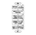
次に、図9を参照しながら、メインコントローラ35が旋回用電動機27における旋回トルクを制御する処理(以下、「旋回トルク制御処理」とする。)について説明する。なお、図9は、旋回トルク制御処理の流れを示すフローチャートである。
Next, a process in which the
最初に、旋回体状態検知部351は、ブーム角度センサ31が出力するブーム15の傾斜角度α、アーム角度センサ32が出力するアーム16の傾斜角度β、及び、ブーム圧センサ30が出力するブームシリンダ圧を取得する(ステップS1)。
First, the swing body
なお、旋回体状態検知部351は、上部旋回体13の状態を簡易に検知するために、バケット角度センサ33が出力するバケット17の傾斜角度γを考慮していないが、バケット角度センサ33が出力するバケット17の傾斜角度γをも考慮して上部旋回体13の状態をより詳細に検知するようにしてもよい。
The swing body
その後、旋回体状態検知部351は、ROMに記憶された制御マップを参照しながら、傾斜角度α及びβから導出される旋回半径とブーム圧センサ30が出力するブームシリンダ圧とに基づいてバケット17内の荷の重さを推定することで(図4参照。)、掘削アタッチメントEの状態を検知する(ステップS2)。
Thereafter, the revolving unit
その後、旋回トルク制御部352は、推定した荷の重さと旋回半径とに基づいて(図5参照。)、或いは、推定した荷の重さとブームシリンダ圧とに基づいて(図6参照。)、その掘削アタッチメントEの状態に対応する所要旋回トルクを取得する(ステップS3)。
Thereafter, the turning
なお、旋回トルク制御部352は、ROMに記憶された制御マップを参照しながら、傾斜角度α、β及びブームシリンダ圧から導出される慣性モーメントに基づいて(図7参照。)、その掘削アタッチメントEの状態に対応する所要旋回トルクを取得するようにしてもよい。
The turning
その後、旋回トルク制御部352は、その所要旋回トルクに対応する旋回トルクの変化パターン(図8参照。)を取得し(ステップS4)、その変化パターンを参照しながら、操作量検知部350が検知した旋回操作レバー26の操作量に応じた旋回トルクを実現させるために、インバータ34を介して発電機23又はバッテリ24から旋回用電動機27に電気エネルギーを供給させるようにする(ステップS5)。
Thereafter, the turning
以上の構成により、油圧ショベル10は、上部旋回体13の状態に応じて旋回トルクを制御することにより、慣性モーメントが小さい(旋回半径が小さい)ときの旋回におけるハンチング(旋回角速度が大きいために旋回と停止とを小刻みに繰り返す操作によって生ずる旋回動作をいう。)を抑えながらも、慣性モーメントが大きい(旋回半径が大きい)ときの旋回を滑らかにする等、旋回操作性を向上させることができる。
With the above configuration, the
また、油圧ショベル10は、上部旋回体13の姿勢に加え、バケット17内の荷の有無をも考慮しながら旋回トルクを制御することにより、旋回操作性を更に向上させることができる。
Further, the
また、油圧ショベル10は、レバー操作量が小さい場合(図8のA−B間を参照。)に所要旋回トルク未満の旋回トルクを発生させるようにするので、掘削アタッチメントEを僅かに旋回させるインチング操作における旋回操作性を向上させることができる。
Further, since the
以上、本発明の実施の形態について詳述したが、本発明は特定の実施形態に限定されるものではなく、特許請求の範囲に記載された本発明の要旨の範囲内において、種々の変形及び変更が可能である。 Although the embodiment of the present invention has been described in detail above, the present invention is not limited to the specific embodiment, and various modifications and changes are within the scope of the gist of the present invention described in the claims. It can be changed.
例えば、上述の実施例において、油圧ショベル10は、傾斜角度α、β及びブームシリンダ圧に基づいて掘削アタッチメントEの姿勢及びバケット17内の荷の状態を検知しながら旋回トルクを制御するが、傾斜角度α及びβのみに基づいて掘削アタッチメントEの姿勢を検知しながら旋回トルクを制御するようにしてもよく、ブームシリンダ圧のみに基づいて掘削アタッチメントEの姿勢を検知しながら旋回トルクを制御するようにしてもよい。
For example, in the above-described embodiment, the
参照する情報が少なくなるにつれて掘削アタッチメントEの姿勢の検知精度は低下するが、それでもなお、上部旋回体13の旋回操作性を向上させるべく旋回トルクを制御する上で必要十分な情報を取得できるからであり、より簡易にかつより迅速に旋回トルクを制御することができるからである。
Although the accuracy of detecting the attitude of the excavation attachment E decreases as the information to be referred to decreases, it is still possible to acquire information necessary and sufficient for controlling the turning torque to improve the turning operability of the
また、上述の実施例において、油圧ショベル10は、ブーム15、アーム16及びバケット17から構成される掘削アタッチメントEを備えるが、バケット17の代わりに、マグネット、グラップル、クランプアーム、フォーク等を備えた他のアタッチメントを備えるようにしてもよい。
In the above-described embodiment, the
10 油圧ショベル、11 下部走行体、12 旋回機構、13 上部旋回体、14 キャブ、15 ブーム、16 アーム、17 バケット、18 ブームシリンダ、19 アームシリンダ、20 バケットシリンダ、21 エンジン、22 変速機、23 発電機、24 バッテリ、25 油圧ポンプ、26 旋回操作レバー、27 旋回用電動機、28 ブーム操作レバー、29 コントロールバルブ、30 ブーム圧センサ、31 ブーム角度センサ、32 アーム角度センサ、33 バケット角度センサ、34 インバータ、35 メインコントローラ、40 ブームフート連結ピン、41 アーム連結ピン、42 バケット連結ピン、180 ロッド、181 油室、350 操作量検知部、351 旋回体状態検知部、352 旋回トルク制御部、L 旋回半径、X 旋回中心、α、β 傾斜角度
DESCRIPTION OF
Claims (3)
一又は二以上のセンサの出力を受けて前記旋回体のアタッチメントの姿勢によって変化する旋回半径を該旋回体の状態として検知する旋回体状態検知部と、
前記旋回体の旋回操作を制御するレバーの出力を受けて該レバーの操作量を検知する操作量検知部と、
前記旋回体状態検知部が検知した旋回体の状態と前記操作量検知部が検知した操作量とに基づいて旋回トルクを制御する信号を前記電動機に対して出力するコントローラと、を備え、
前記コントローラは、前記旋回体状態検知部が検知した旋回半径の増大とともに、前記インバータから前記電動機への電気エネルギーを増加させて前記旋回トルクが大きくなるように制御する、
ことを特徴とする旋回制御装置。 A turning control device for a construction machine that turns a turning body with an electric motor driven by electric energy supplied from an inverter ,
A turning body state detection unit that receives an output of one or more sensors and detects a turning radius that changes according to the posture of the attachment of the turning body as a state of the turning body;
An operation amount detector that receives an output of a lever that controls a turning operation of the revolving body and detects an operation amount of the lever;
A controller that outputs a signal for controlling the turning torque to the electric motor based on the state of the turning body detected by the turning body state detection unit and the operation amount detected by the operation amount detection unit;
The controller controls the turning torque to be increased by increasing the electric energy from the inverter to the electric motor as the turning radius detected by the turning body state detection unit is increased.
A turning control device characterized by that.
前記コントローラは、前記旋回体状態検知部が検知したブームシリンダ圧の増大とともに前記旋回トルクが大きくなるように制御する、
ことを特徴とする請求項1に記載の旋回制御装置。 The revolving unit state detection unit further detects boom cylinder pressure as the state of the revolving unit,
The controller controls the turning torque to increase as the boom cylinder pressure detected by the turning body state detection unit increases.
The turning control device according to claim 1.
前記コントローラは、前記慣性モーメント導出部が導出した慣性モーメントと前記操作量検知部が検知した操作量とに基づいて旋回トルクを制御する信号を前記電動機に対して出力する、
ことを特徴とする請求項1又は2に記載の旋回制御装置。 An inertia moment deriving unit for deriving the inertia moment of the swivel body based on the state of the swivel body detected by the revolving body state detection unit;
The controller outputs a signal for controlling a turning torque to the electric motor based on the inertia moment derived by the inertia moment deriving unit and the operation amount detected by the operation amount detection unit;
The turning control device according to claim 1 or 2.
Priority Applications (1)
| Application Number | Priority Date | Filing Date | Title |
|---|---|---|---|
| JP2007296005A JP4881280B2 (en) | 2007-11-14 | 2007-11-14 | Swing control device |
Applications Claiming Priority (1)
| Application Number | Priority Date | Filing Date | Title |
|---|---|---|---|
| JP2007296005A JP4881280B2 (en) | 2007-11-14 | 2007-11-14 | Swing control device |
Publications (2)
| Publication Number | Publication Date |
|---|---|
| JP2009121127A JP2009121127A (en) | 2009-06-04 |
| JP4881280B2 true JP4881280B2 (en) | 2012-02-22 |
Family
ID=40813573
Family Applications (1)
| Application Number | Title | Priority Date | Filing Date |
|---|---|---|---|
| JP2007296005A Expired - Fee Related JP4881280B2 (en) | 2007-11-14 | 2007-11-14 | Swing control device |
Country Status (1)
| Country | Link |
|---|---|
| JP (1) | JP4881280B2 (en) |
Families Citing this family (7)
| Publication number | Priority date | Publication date | Assignee | Title |
|---|---|---|---|---|
| JP6039302B2 (en) * | 2012-08-14 | 2016-12-07 | 富士機械製造株式会社 | Printing agent remaining amount acquisition method and printing agent remaining amount acquisition device |
| JP6278793B2 (en) * | 2014-03-31 | 2018-02-14 | 住友重機械工業株式会社 | Electric swivel device |
| JP6486664B2 (en) * | 2014-11-21 | 2019-03-20 | 住友重機械工業株式会社 | Excavator |
| JP6869749B2 (en) * | 2017-02-27 | 2021-05-12 | 住友建機株式会社 | Excavator |
| US11381137B2 (en) * | 2017-06-20 | 2022-07-05 | Mitsubishi Electric Corporation | Electric motor, compressor, air conditioner, and method for manufacturing electric motor |
| JP2020165256A (en) * | 2019-03-29 | 2020-10-08 | 住友重機械工業株式会社 | Shovel |
| US20230175236A1 (en) * | 2021-12-03 | 2023-06-08 | Deere & Company | Work machine with grade control using external field of view system and method |
Family Cites Families (4)
| Publication number | Priority date | Publication date | Assignee | Title |
|---|---|---|---|---|
| JP3594839B2 (en) * | 1999-05-24 | 2004-12-02 | 新キャタピラー三菱株式会社 | Turning machine for work machine |
| JP4002369B2 (en) * | 1999-06-29 | 2007-10-31 | 株式会社神戸製鋼所 | Swing control device for swivel work machine |
| JP2005139658A (en) * | 2003-11-05 | 2005-06-02 | Hitachi Constr Mach Co Ltd | Controller for hydraulic working machine |
| EP2910690A1 (en) * | 2004-11-17 | 2015-08-26 | Komatsu Ltd. | Rotation control device and construction machine |
-
2007
- 2007-11-14 JP JP2007296005A patent/JP4881280B2/en not_active Expired - Fee Related
Also Published As
| Publication number | Publication date |
|---|---|
| JP2009121127A (en) | 2009-06-04 |
Similar Documents
| Publication | Publication Date | Title |
|---|---|---|
| JP4881280B2 (en) | Swing control device | |
| JP6899818B2 (en) | Excavator | |
| CN102985621B (en) | Energy management system for heavy equipment | |
| JP4946733B2 (en) | Swivel control device and work machine equipped with the same | |
| JP5785714B2 (en) | Swing motor control method for hydraulic system for excavator of open center system | |
| JP3941951B2 (en) | Drive control device for hybrid work machine | |
| AU2021273658A1 (en) | System and method for estimating a payload of an industrial machine | |
| US8666613B2 (en) | Swing control system for hybrid construction machine | |
| JP5873456B2 (en) | Work machine drive control system, work machine including the same, and drive control method thereof | |
| KR101747611B1 (en) | Construction machine | |
| CN109594966A (en) | Rotary drilling rig movable mast control system and control method | |
| JP4248378B2 (en) | Drive control device for hybrid work machine | |
| WO2020166241A1 (en) | Monitoring device and construction machine | |
| JP2013189767A (en) | Electrically driven turning device | |
| JP4024192B2 (en) | Drive control device for hybrid work machine | |
| JP2005086892A (en) | Drive controller for hybrid work machine | |
| JP6917941B2 (en) | Hydraulic work machine | |
| AU2016238931B2 (en) | Control system for mining machine | |
| JP6679334B2 (en) | Power generator and shovel using the same | |
| JP4685119B2 (en) | Swing braking force control system | |
| JP6952659B2 (en) | Construction machinery | |
| JP2020133225A (en) | Safety device and construction machine | |
| JP6964054B2 (en) | Construction machinery | |
| JP6486664B2 (en) | Excavator | |
| JP2022080513A (en) | Revolving controller and work machine |
Legal Events
| Date | Code | Title | Description |
|---|---|---|---|
| A711 | Notification of change in applicant |
Free format text: JAPANESE INTERMEDIATE CODE: A712 Effective date: 20090623 |
|
| A521 | Written amendment |
Free format text: JAPANESE INTERMEDIATE CODE: A523 Effective date: 20090724 |
|
| A521 | Written amendment |
Free format text: JAPANESE INTERMEDIATE CODE: A523 Effective date: 20090731 |
|
| RD04 | Notification of resignation of power of attorney |
Free format text: JAPANESE INTERMEDIATE CODE: A7424 Effective date: 20091008 |
|
| A977 | Report on retrieval |
Free format text: JAPANESE INTERMEDIATE CODE: A971007 Effective date: 20100709 |
|
| A131 | Notification of reasons for refusal |
Free format text: JAPANESE INTERMEDIATE CODE: A131 Effective date: 20100727 |
|
| A521 | Written amendment |
Free format text: JAPANESE INTERMEDIATE CODE: A523 Effective date: 20100927 |
|
| A131 | Notification of reasons for refusal |
Free format text: JAPANESE INTERMEDIATE CODE: A131 Effective date: 20110208 |
|
| A521 | Written amendment |
Free format text: JAPANESE INTERMEDIATE CODE: A523 Effective date: 20110401 |
|
| TRDD | Decision of grant or rejection written | ||
| A01 | Written decision to grant a patent or to grant a registration (utility model) |
Free format text: JAPANESE INTERMEDIATE CODE: A01 Effective date: 20111129 |
|
| A01 | Written decision to grant a patent or to grant a registration (utility model) |
Free format text: JAPANESE INTERMEDIATE CODE: A01 |
|
| A61 | First payment of annual fees (during grant procedure) |
Free format text: JAPANESE INTERMEDIATE CODE: A61 Effective date: 20111202 |
|
| R150 | Certificate of patent or registration of utility model |
Ref document number: 4881280 Country of ref document: JP Free format text: JAPANESE INTERMEDIATE CODE: R150 Free format text: JAPANESE INTERMEDIATE CODE: R150 |
|
| FPAY | Renewal fee payment (event date is renewal date of database) |
Free format text: PAYMENT UNTIL: 20141209 Year of fee payment: 3 |
|
| LAPS | Cancellation because of no payment of annual fees |