JP6895996B2 - Motors, air conditioners, and methods for manufacturing motors - Google Patents
Motors, air conditioners, and methods for manufacturing motors Download PDFInfo
- Publication number
- JP6895996B2 JP6895996B2 JP2018562819A JP2018562819A JP6895996B2 JP 6895996 B2 JP6895996 B2 JP 6895996B2 JP 2018562819 A JP2018562819 A JP 2018562819A JP 2018562819 A JP2018562819 A JP 2018562819A JP 6895996 B2 JP6895996 B2 JP 6895996B2
- Authority
- JP
- Japan
- Prior art keywords
- heat radiating
- electric motor
- heat
- motor
- stator
- Prior art date
- Legal status (The legal status is an assumption and is not a legal conclusion. Google has not performed a legal analysis and makes no representation as to the accuracy of the status listed.)
- Active
Links
Images


Classifications
-
- H—ELECTRICITY
- H02—GENERATION; CONVERSION OR DISTRIBUTION OF ELECTRIC POWER
- H02K—DYNAMO-ELECTRIC MACHINES
- H02K1/00—Details of the magnetic circuit
- H02K1/06—Details of the magnetic circuit characterised by the shape, form or construction
- H02K1/12—Stationary parts of the magnetic circuit
- H02K1/14—Stator cores with salient poles
- H02K1/146—Stator cores with salient poles consisting of a generally annular yoke with salient poles
-
- F—MECHANICAL ENGINEERING; LIGHTING; HEATING; WEAPONS; BLASTING
- F24—HEATING; RANGES; VENTILATING
- F24F—AIR-CONDITIONING; AIR-HUMIDIFICATION; VENTILATION; USE OF AIR CURRENTS FOR SCREENING
- F24F1/00—Room units for air-conditioning, e.g. separate or self-contained units or units receiving primary air from a central station
- F24F1/0003—Room units for air-conditioning, e.g. separate or self-contained units or units receiving primary air from a central station characterised by a split arrangement, wherein parts of the air-conditioning system, e.g. evaporator and condenser, are in separately located units
-
- F—MECHANICAL ENGINEERING; LIGHTING; HEATING; WEAPONS; BLASTING
- F24—HEATING; RANGES; VENTILATING
- F24F—AIR-CONDITIONING; AIR-HUMIDIFICATION; VENTILATION; USE OF AIR CURRENTS FOR SCREENING
- F24F1/00—Room units for air-conditioning, e.g. separate or self-contained units or units receiving primary air from a central station
- F24F1/06—Separate outdoor units, e.g. outdoor unit to be linked to a separate room comprising a compressor and a heat exchanger
- F24F1/20—Electric components for separate outdoor units
-
- H—ELECTRICITY
- H02—GENERATION; CONVERSION OR DISTRIBUTION OF ELECTRIC POWER
- H02K—DYNAMO-ELECTRIC MACHINES
- H02K1/00—Details of the magnetic circuit
- H02K1/06—Details of the magnetic circuit characterised by the shape, form or construction
- H02K1/12—Stationary parts of the magnetic circuit
- H02K1/18—Means for mounting or fastening magnetic stationary parts on to, or to, the stator structures
- H02K1/185—Means for mounting or fastening magnetic stationary parts on to, or to, the stator structures to outer stators
-
- H—ELECTRICITY
- H02—GENERATION; CONVERSION OR DISTRIBUTION OF ELECTRIC POWER
- H02K—DYNAMO-ELECTRIC MACHINES
- H02K15/00—Methods or apparatus specially adapted for manufacturing, assembling, maintaining or repairing of dynamo-electric machines
-
- H—ELECTRICITY
- H02—GENERATION; CONVERSION OR DISTRIBUTION OF ELECTRIC POWER
- H02K—DYNAMO-ELECTRIC MACHINES
- H02K15/00—Methods or apparatus specially adapted for manufacturing, assembling, maintaining or repairing of dynamo-electric machines
- H02K15/12—Impregnating, heating or drying of windings, stators, rotors or machines
-
- H—ELECTRICITY
- H02—GENERATION; CONVERSION OR DISTRIBUTION OF ELECTRIC POWER
- H02K—DYNAMO-ELECTRIC MACHINES
- H02K21/00—Synchronous motors having permanent magnets; Synchronous generators having permanent magnets
- H02K21/12—Synchronous motors having permanent magnets; Synchronous generators having permanent magnets with stationary armatures and rotating magnets
- H02K21/14—Synchronous motors having permanent magnets; Synchronous generators having permanent magnets with stationary armatures and rotating magnets with magnets rotating within the armatures
- H02K21/16—Synchronous motors having permanent magnets; Synchronous generators having permanent magnets with stationary armatures and rotating magnets with magnets rotating within the armatures having annular armature cores with salient poles
-
- H—ELECTRICITY
- H02—GENERATION; CONVERSION OR DISTRIBUTION OF ELECTRIC POWER
- H02K—DYNAMO-ELECTRIC MACHINES
- H02K5/00—Casings; Enclosures; Supports
- H02K5/04—Casings or enclosures characterised by the shape, form or construction thereof
- H02K5/08—Insulating casings
-
- H—ELECTRICITY
- H02—GENERATION; CONVERSION OR DISTRIBUTION OF ELECTRIC POWER
- H02K—DYNAMO-ELECTRIC MACHINES
- H02K5/00—Casings; Enclosures; Supports
- H02K5/04—Casings or enclosures characterised by the shape, form or construction thereof
- H02K5/18—Casings or enclosures characterised by the shape, form or construction thereof with ribs or fins for improving heat transfer
-
- H—ELECTRICITY
- H02—GENERATION; CONVERSION OR DISTRIBUTION OF ELECTRIC POWER
- H02K—DYNAMO-ELECTRIC MACHINES
- H02K9/00—Arrangements for cooling or ventilating
- H02K9/02—Arrangements for cooling or ventilating by ambient air flowing through the machine
-
- H—ELECTRICITY
- H02—GENERATION; CONVERSION OR DISTRIBUTION OF ELECTRIC POWER
- H02K—DYNAMO-ELECTRIC MACHINES
- H02K9/00—Arrangements for cooling or ventilating
- H02K9/22—Arrangements for cooling or ventilating by solid heat conducting material embedded in, or arranged in contact with, the stator or rotor, e.g. heat bridges
- H02K9/227—Heat sinks
-
- F—MECHANICAL ENGINEERING; LIGHTING; HEATING; WEAPONS; BLASTING
- F24—HEATING; RANGES; VENTILATING
- F24F—AIR-CONDITIONING; AIR-HUMIDIFICATION; VENTILATION; USE OF AIR CURRENTS FOR SCREENING
- F24F1/00—Room units for air-conditioning, e.g. separate or self-contained units or units receiving primary air from a central station
- F24F1/06—Separate outdoor units, e.g. outdoor unit to be linked to a separate room comprising a compressor and a heat exchanger
- F24F1/08—Compressors specially adapted for separate outdoor units
Description
本発明は、放熱部材を備えた電動機に関する。 The present invention relates to an electric motor provided with a heat radiating member.
一般に、電動機の熱を外部に放出するため、放熱部材としてのヒートシンクが用いられている。例えば、円形のヒートシンクが軸方向における端部に取り付けられた電動機が提案されている(例えば、特許文献1参照)。 Generally, a heat sink is used as a heat radiating member in order to release the heat of the motor to the outside. For example, an electric motor in which a circular heat sink is attached to an end portion in the axial direction has been proposed (see, for example, Patent Document 1).
しかしながら、従来の電動機では、1つの円形のヒートシンクが軸方向における電動機の端部に取り付けられているため、電動機の構造を考慮した効率的な放熱特性が得られず、1つのヒートシンクの大きさが電動機の直径と同程度であるため、ヒートシンクの製造コストが大きいという問題がある。 However, in a conventional motor, since one circular heat sink is attached to the end of the motor in the axial direction, efficient heat dissipation characteristics considering the structure of the motor cannot be obtained, and the size of one heat sink is large. Since it is about the same diameter as the motor, there is a problem that the manufacturing cost of the heat sink is high.
本発明の目的は、製造コストの小さいヒートシンクを用いて電動機の放熱性能を向上させることである。 An object of the present invention is to improve the heat dissipation performance of a motor by using a heat sink having a low manufacturing cost.
本発明の電動機は、回転子と、固定部が複数形成されるとともに固定子とプリント基板を一体化する樹脂を有する固定子組立と、前記固定部と係合する圧入部を備え、前記固定子組立の外表面に固定される複数の放熱部材とを有する。 The motor of the present invention includes a rotor, a stator assembly having a resin in which a plurality of fixing portions are formed and a stator and a printed circuit board are integrated, and a press-fitting portion that engages with the fixing portion. It has a plurality of heat radiating members fixed to the outer surface of the assembly.
本発明によれば、電動機の放熱性能を向上させることができる。 According to the present invention, the heat dissipation performance of the motor can be improved.
実施の形態1.
本発明の実施の形態1に係る電動機1について以下に説明する。
各図に示されるxyz直交座標系において、z軸方向(z軸)は、電動機1のシャフト22の軸線A1(回転中心)と平行な方向(「軸方向」ともいう)を示し、x軸方向(x軸)は、z軸方向(z軸)に直交する方向を示し、y軸方向は、z軸方向及びx軸方向の両方に直交する方向を示す。
The
In the xyz Cartesian coordinate system shown in each figure, the z-axis direction (z-axis) indicates a direction parallel to the axis A1 (center of rotation) of the
図1は、本発明の実施の形態1に係る電動機1の構造を概略的に示す断面図である。
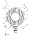
図2は、電動機1の構造を概略的に示す正面図である。
図3は、固定子組立3の構造を概略的に示す正面図である。ただし、図3に示される固定子組立3は、樹脂6が取り付けられていない状態である。FIG. 1 is a cross-sectional view schematically showing the structure of the
FIG. 2 is a front view schematically showing the structure of the
FIG. 3 is a front view schematically showing the structure of the
電動機1(モールド電動機ともいう)は、回転子2(回転子組立ともいう)と、固定子組立3(モールド固定子ともいう)と、放熱部材としての複数のヒートシンク5と、ベアリング7a及び7bとを有する。図1に示される例では、電動機1は、さらに、ブラケット8と、電動機1を密閉する防水ゴム9とを有する。電動機1は、例えば、永久磁石同期電動機であるが、これに限定されない。ベアリング7a及び7bは、回転子2のシャフト22の両端を回転自在に支持する。
The electric motor 1 (also referred to as a mold motor) includes a rotor 2 (also referred to as a rotor assembly), a stator assembly 3 (also referred to as a mold stator), a plurality of
回転子2は、回転子鉄心21と、シャフト22とを有する。回転子2は、回転軸(軸線A1)を中心として回転自在である。回転子2は、固定子組立3(具体的には、固定子30)の内側に、空隙を介して回転自在に配置されている。回転子2は、さらに、回転子2の磁極を形成するための永久磁石を有してもよい。
The
固定子組立3は、固定子30と、プリント基板4と、プリント基板4に接続されたリード線41と、プリント基板4の表面に固定された駆動回路42と、樹脂6とを有する。
The
図4は、固定子30の構造を概略的に示す正面図である。
図5は、固定子30の構造を概略的に示す側面図である。FIG. 4 is a front view schematically showing the structure of the
FIG. 5 is a side view schematically showing the structure of the
固定子30は、複数の電磁鋼板が軸方向に積層された固定子鉄心31と、巻線32(固定子巻線ともいう)と、絶縁部としてのインシュレータ33とを有する。複数の電磁鋼板の各々は、打ち抜き処理によって、予め定められた形状に形成され、かしめ、溶接、又は接着等によって互いに固定される。
The
巻線32は、例えば、マグネットワイヤである。巻線32が、固定子鉄心31と組み合わされたインシュレータ33に巻回されることによりコイルが形成される。巻線32は、端子32a(巻線端子)と電気的に接続されている。図5に示される例では、巻線32の端部は、端子32aのフック部に引っ掛けられており、ヒュージング又は半田などによって端子32aに固定されている。端子32aは、インシュレータ33に固定されており、プリント基板4と電気的に接続されている。
The
インシュレータ33は、プリント基板4を固定する少なくとも1つの固定部331を有する。インシュレータ33は、例えば、PBT(ポリブチレンテレフタレート)等の熱可塑性樹脂である。インシュレータ33は、固定子鉄心31(例えば、固定子鉄心31のティース部)を電気的に絶縁する。インシュレータ33は、例えば、固定子鉄心31と一体に成形される。ただし、予めインシュレータ33を成形し、成形されたインシュレータ33を固定子鉄心31と組み合わせてもよい。
The
プリント基板4は、インシュレータ33の固定部331(具体的には、突起331a)と係合する位置決め穴43(単に「穴」ともいう)を有する。
The printed circuit board 4 has a positioning hole 43 (also simply referred to as a “hole”) that engages with a fixing portion 331 (specifically, a
インシュレータ33の固定部331は、突起331aと支持部331bとを有する。突起331aは、プリント基板4に形成された位置決め穴43に挿入されている(図3)。これにより、プリント基板4がインシュレータ33に固定される。支持部331bは、プリント基板4を軸方向に支持し、軸方向においてプリント基板4を位置決めする。
The
プリント基板4は、樹脂6によって固定子30と一体化されている(図1)。駆動回路42は、回転子2の回転を制御する。駆動回路42は、例えば、駆動素子42a及びホールIC(Integrated Circuit)42bを含む。
The printed circuit board 4 is integrated with the
駆動素子42aは、例えば、パワートランジスタである。駆動素子42aは、電気的に巻線32と接続されており、電動機1の外部又は内部(例えば、バッテリ)から供給された電流に基づく駆動電流を巻線32に供給する。これにより、駆動素子42aは、回転子2の回転を制御する。
The
例えば、ホールIC42bは、回転子2からの磁界を検出することにより、回転子2の回転位置を検出する。
For example, the
樹脂6は、例えば、BMC(バルクモールディングコンパウンド)などの熱硬化性樹脂である。BMCは、低圧成形を可能にするため、インサート成形に適している。これにより、金型を用いて樹脂6の成形を行うときに、プリント基板4又は固定子30などのインサート物の変形を防止することができ、電動機1の品質を向上させることができる。
The
樹脂6は、ヒートシンク5を固定するヒートシンク固定部61(図1)を有する。ヒートシンク固定部61は、例えば、穴である。樹脂6は、PPS(ポリフェニレンスルファイド)などの熱可塑性樹脂でもよい。PPSは、BMCに比べて熱伝導率が向上するので、固定子組立3の熱がヒートシンク5に伝わりやすい。これにより、電動機1の放熱性が向上し、プリント基板4及び巻線32の温度上昇を防止することができる。
The
ヒートシンク5は、例えば、A6063などのアルミニウムによって形成される。図2に示される例では、各ヒートシンク5の形状(具体的には、xy平面上における平面形状)は矩形である。各ヒートシンク5は、固定子組立3に固定されており、固定子組立3の熱(例えば、固定子30又は駆動回路42から生じる熱)を電動機1の外部に放出する。ヒートシンク5の一部(例えば、図2に示されるフィン51)は、樹脂6の外部に露出している。これにより、固定子組立3から生じる熱が電動機1の外部に放出される。
The
本実施の形態では、複数のヒートシンク5が、電動機1の軸方向における一端側に、回転子2の回転中心(軸線A1)を中心として放射状に配列されている。本実施の形態では、複数のヒートシンク5は、電動機1の軸方向における一端側に固定されているが、固定子組立3の外周面に複数のヒートシンク5が取り付けられていてもよい。
In the present embodiment, the plurality of
ヒートシンク5は、プリント基板4に接触していてもよい。ヒートシンク5がプリント基板4に接触している場合、プリント基板4からの熱を効率的に電動機1の外部に放出させることができる。
The
図6(a)は、ヒートシンク5の一例を概略的に示す平面図であり、図6(b)は、ヒートシンク5の一例を概略的に示す側面図である。
複数のヒートシンク5の各々は、複数のフィン51(放熱フィン)と、固定子組立3(例えば、樹脂6)と係合する圧入部52とを有する。圧入部52は、例えば、樹脂6のヒートシンク固定部61に圧入される。これにより、ヒートシンク5が樹脂6に固定される。FIG. 6A is a plan view schematically showing an example of the
Each of the plurality of
図2に示される例では、各フィン51は、固定子組立3の径方向に延在している。すなわち、図2に示される例では、各フィン51が径方向に延在するように、各ヒートシンク5が配置されている。
In the example shown in FIG. 2, each
複数のヒートシンク5は、互いに異なる材料で形成されていてもよく、互いに異なる構造であってもよい。
The plurality of
図1に示される例では、圧入部52は、樹脂6と係合しており、これにより位置ずれが防止される。さらに、圧入部52が樹脂6と係合しているので、ヒートシンク5が電動機1から外れることを防止することができる。
In the example shown in FIG. 1, the press-fitting
変形例1.
図7(a)は、ヒートシンク5の他の例を概略的に示す平面図であり、図7(b)は、ヒートシンク5の他の例を概略的に示す側面図である。
図7(a)及び(b)に示されるように、ヒートシンク5は、圧入部52の代わりに、インシュレータ33の固定部331(具体的には、突起331a)と係合する取付け穴52a(単に「穴」ともいう)を有してもよい。例えば、取付け穴52aに突起331aを挿入し、熱溶着又は超音波溶着などによって、取付け穴52aから突出した突起331aを、ヒートシンク5に固定することができる。これにより、ねじ等の固定部品を用いずにヒートシンク5を固定子組立3に固定することができる。したがって、電動機1の部品数及び電動機1の製造工程が削減され、電動機1のコストを低減することができる。Modification example 1.
FIG. 7A is a plan view schematically showing another example of the
As shown in FIGS. 7A and 7B, the
図7(a)及び(b)に示されるヒートシンク5を、ねじ(例えば、タッピングねじ)又はボルトを用いて固定子組立3に固定してもよい。この場合、固定子組立3には、ねじ用の穴が形成されている。タッピングねじを用いる場合は、ナットが不要になり、部品数を削減することができる。
The
変形例2.
図8は、放熱補助部材53を備えた変形例2に係る電動機1aの構造を概略的に示す断面図である。
変形例2に係る電動機1aは、少なくとも1つの放熱補助部材53を有し、その他の構造は、実施の形態1に係る電動機1と同じである。放熱補助部材53は、少なくとも1つのヒートシンク5と固定子組立3との間に配置されている。放熱補助部材53は、固定子組立3の熱をヒートシンク5に伝達する。放熱補助部材53は、例えば、シート状又はブロック状に形成することができる。放熱補助部材53は、粘着性であることが望ましい。ヒートシンク5と固定子組立3との間に放熱補助部材53を配置することにより、ヒートシンク5と固定子組立3との密着性が向上し、放熱性能を向上させることができる。Modification example 2.
FIG. 8 is a cross-sectional view schematically showing the structure of the
The
変形例3.
図9は、変形例3に係る電動機1bの構造を概略的に示す正面図である。
変形例3に係る電動機1bは、複数の連結部54を有し、その他の構造は、実施の形態1に係る電動機1と同じである。連結部54は、周方向において隣接する2つのヒートシンク5を連結する。例えば、連結部54には、ヒートシンク5を固定するための凹部などが形成されている。連結部54は、例えば、樹脂によって形成されている。ただし、連結部54の材料は樹脂に限定されない。電動機1bの製造工程において、複数のヒートシンク5を連結部54で予め連結しておくことにより、複数のヒートシンク5を一度に固定子組立3に取り付けることができる。したがって、電動機1bの製造コストを低減することができる。Modification example 3.
FIG. 9 is a front view schematically showing the structure of the
The
変形例4.
図10は、変形例4に係る電動機1cの構造を概略的に示す正面図である。
変形例4に係る電動機1cは、複数のヒートシンク5(変形例4では、2個のヒートシンク5)の配置が、実施の形態1に係る電動機1と異なり、その他の構造は、実施の形態1に係る電動機1と同じである。図10に示されるように、発熱の大きい部品の近傍(例えば、駆動回路42と対向する位置)に複数のヒートシンク5を集中的に配置してもよい。これにより、電動機1cの特定の部品からの熱を外部に効率的に排出することができる。さらに、電動機1cの特定の部品の近傍のみにヒートシンク5を配置することにより、電動機1cのコストを低減することができる。Modification example 4.
FIG. 10 is a front view schematically showing the structure of the
In the
変形例5.
図11は、変形例5に係る電動機1dの構造を概略的に示す正面図である。
変形例5に係る電動機1dは、放熱部材としてのヒートシンク5aの形状が実施の形態1に係る電動機1のヒートシンク5の形状と異なり、その他の構造は、実施の形態1に係る電動機1と同じである。ヒートシンク5aの形状(具体的には、xy平面上における平面形状)は台形である。Modification example 5.
FIG. 11 is a front view schematically showing the structure of the
The shape of the
変形例6.
図12は、変形例6に係る電動機1eの構造を概略的に示す正面図である。
変形例6に係る電動機1eは、放熱部材としてのヒートシンク5bの形状が実施の形態1に係る電動機1のヒートシンク5の形状と異なり、その他の構造は、実施の形態1に係る電動機1と同じである。ヒートシンク5bの形状(具体的には、xy平面上における平面形状)は扇形である。Modification example 6.
FIG. 12 is a front view schematically showing the structure of the
The shape of the
変形例7.
図13は、変形例7に係る電動機1fの構造を概略的に示す正面図である。
変形例7に係る電動機1fは、ヒートシンク5の配置が実施の形態1に係る電動機1と異なり、その他の構造は、実施の形態1に係る電動機1と同じである。
電動機1fでは、複数のヒートシンク5のフィン51の向きが互いに同じ向き(すなわち、1方向)になるように、各ヒートシンク5が配置されている。例えば、第1の放熱部材としてのヒートシンク5の第1のフィン(フィン51)の向きと、第1の放熱部材とは異なる第2の放熱部材としてのヒートシンク5の第2のフィン(フィン51)の向きとが、互いに同じになるように、各ヒートシンク5が配置されている。Modification example 7.
FIG. 13 is a front view schematically showing the structure of the
The
In the
図13に示される例では、電動機1fを使用する際に、各ヒートシンク5のフィン51が鉛直方向(図13では、y軸方向)に延在するように、各ヒートシンク5が配置されている。これにより、電動機1fの熱が各フィン51によって形成された風路を通して上方に排出されやすくなる。
In the example shown in FIG. 13, each
電動機1の製造方法の一例について以下に説明する。
図14は、電動機1の製造工程の一例を示すフローチャートである。電動機1の製造方法は、以下に説明されるステップを含む。An example of the manufacturing method of the
FIG. 14 is a flowchart showing an example of the manufacturing process of the
ステップS1では、固定子30を作製する。例えば、複数の電磁鋼板を軸方向に積層することにより、固定子鉄心31を形成する。さらに、固定子鉄心31に、予め形成されたインシュレータ33を取り付け、固定子鉄心31及びインシュレータ33に巻線32を巻き付ける。これにより、固定子30が得られる。
In step S1, the
ステップS2では、固定子組立3を作製する。例えば、プリント基板4の位置決め穴43に、インシュレータ33の突起331aを挿入する。この際、プリント基板4を支持部331bに押し当てる。これにより、プリント基板4が位置決めされ、固定子組立3が得られる。プリント基板4の表面には、駆動回路42が予め固定されている。リード線41も、プリント基板4に予め取り付けておくことが望ましい。熱溶着又は超音波溶着などによって、位置決め穴43から突出した突起331aを、プリント基板4に固定してもよい。
In step S2, the
ステップS3では、樹脂6を用いて固定子30とプリント基板4とを一体化させる。例えば、固定子30及びプリント基板4を、金型に配置し、樹脂6の材料(例えば、バルクモールディングコンパウンドなどの熱硬化性樹脂)を金型に注入する。樹脂6の成形において、ヒートシンク固定部61も同時に成形される。
In step S3, the
ステップS4では、複数のヒートシンク5の成形を行う。本実施の形態では、押出形成を用いて複数のヒートシンク5を成形する。ただし、複数のヒートシンク5の成形は、ステップS1からS3における処理と並行に行ってもよく、ステップS1の前に行ってもよい。
In step S4, a plurality of
ステップS5では、複数のヒートシンク5を固定子組立3に固定する。本実施の形態では、各ヒートシンク5の圧入部52を樹脂6のヒートシンク固定部61に圧入する。
In step S5, the plurality of
ステップS6では、回転子2を作製する。例えば、回転子鉄心21に形成された軸穴にシャフト22を挿入し、回転子2を得る。磁極を形成する永久磁石を、予め回転子鉄心21に取り付けておいてもよい。
In step S6, the
ステップS7では、シャフト22をベアリング7a及び7bに挿入する。
In step S7, the
ステップS1からステップS7までの順序は、図14に示される順序に限られない。例えば、ステップS1からステップS5までのステップと、ステップS6とは、互いに並行して行うことができる。ステップS6は、ステップS1からステップS5までのステップよりも先に行われてもよい。 The order from step S1 to step S7 is not limited to the order shown in FIG. For example, the steps from step S1 to step S5 and step S6 can be performed in parallel with each other. Step S6 may be performed before the steps from step S1 to step S5.
ステップS8では、固定子組立3(具体的には、固定子30)の内側に、回転子2をベアリング7a及び7bと共に挿入する。
In step S8, the
ステップS9では、樹脂6の内側にブラケット8を嵌め、シャフト22に防水ゴム9を嵌める。
In step S9, the
以上に説明した工程により電動機1が組み立てられる。
The
実施の形態1に係る電動機1の効果(変形例の効果を含む)及び電動機1の製造方法の効果を以下に説明する。
The effects of the motor 1 (including the effects of the modified examples) and the effects of the manufacturing method of the
実施の形態1に係る電動機1によれば、固定子組立3に複数のヒートシンク5が固定されているので、電動機1の放熱性能を向上させることができる。
According to the
複数のヒートシンク5を、電動機1(回転子2)の回転軸を中心として放射状に配置することにより、効率的な放熱経路を形成することができる。例えば、複数のフィン51が径方向に延在している場合、径方向に風路を形成することができる。これより、電動機1の熱を外部に効率的に排出することができる。
By arranging the plurality of
従来の電動機では、1つの円形のヒートシンクが軸方向における電動機の端部に取り付けられているため、電動機の構造を考慮した風路を形成することが困難であったが、本実施の形態では、電動機1の構造を考慮してフィン51の向きを設定することができる。したがって、電動機1の構造を考慮して放熱性能の高い風路を設定することができる。
In a conventional motor, since one circular heat sink is attached to the end of the motor in the axial direction, it is difficult to form an air passage in consideration of the structure of the motor, but in the present embodiment, it is difficult to form an air passage. The orientation of the
ヒートシンク5が矩形である場合、ヒートシンク5の製造工程において容易に成形することができ、加工コストを低減することができる。例えば、押出成形を用いて成形する場合、成形後の機械加工を少なくすることができるので、ヒートシンク5の製造コストを低減することができる。
When the
さらに、ヒートシンク5の圧入部52を固定子組立3(例えば、樹脂6)に圧入することができ、ねじ等の固定部品を用いずにヒートシンク5を固定子組立3に固定することができる。したがって、電動機1の部品数が削減され、電動機1のコストを低減することができる。
Further, the press-fitting
変形例1で説明したように、ヒートシンク5が圧入部52の代わりに取付け穴52aを有する場合、取付け穴52aに突起331aを挿入し、熱溶着又は超音波溶着などによって、取付け穴52aから突出した突起331aを、ヒートシンク5に固定することができる。これにより、ねじ等の固定部品を用いずにヒートシンク5を固定子組立3に固定することができる。したがって、電動機1の部品数及び電動機1の製造工程が削減され、電動機1のコストを低減することができる。
As described in the first modification, when the
変形例2に係る電動機1aによれば、放熱補助部材53が、少なくとも1つのヒートシンク5と固定子組立3との間に配置されているとき、ヒートシンク5と固定子組立3との密着性が向上し、放熱性能を向上させることができる。
According to the
変形例3に係る電動機1bによれば、複数のヒートシンク5が連結部54によって連結されているとき、複数のヒートシンク5を一度に固定子組立3に取り付けることができる。したがって、電動機1bの製造コストを低減することができる。
According to the
変形例4に係る電動機1cでは、複数のヒートシンク5は、発熱の大きい部品の近傍(例えば、駆動回路42と対向する位置)に集中的に配置されている。これにより、電動機1の特定の部品からの熱を外部に効率的に排出することができる。さらに、電動機1の特定の部品の近傍のみにヒートシンク5を配置することにより、電動機1のコストを低減することができる。
In the
変形例5及び6で説明したように、ヒートシンク5の形状は、従来のヒートシンクのような円形に限られない。例えば、ヒートシンク5の平面形状は台形又は扇形でもよい。したがって、ヒートシンク5を配置する場所に応じて、適切な形状のヒートシンク5を用いることができ、電動機の放熱性能を向上させることができる。
As described in the modified examples 5 and 6, the shape of the
変形例7で説明したように、電動機1fでは、複数のヒートシンク5のフィン51の向きが互いに同じ向きである。例えば、電動機1fを使用する際に、各ヒートシンク5のフィン51が鉛直方向に延在するように、各ヒートシンク5が配置されている。これにより、電動機1fの熱が各フィン51によって形成された風路を通して上方に排出されやすくなる。
As described in the modified example 7, in the
実施の形態1に係る電動機1の製造方法によれば、押出成形を用いて複数のヒートシンク5を製造することができるので、製造コストの小さい複数のヒートシンク5を製造することができる。さらに、電動機1の製造方法によれば、電動機の構造を考慮して各ヒートシンク5を配置することができるので、放熱性能が向上された電動機1を製造することができる。
According to the method for manufacturing the
一般に、ダイキャストを用いた成形又は鍛造では、形成可能なフィンの高さ、幅、及びピッチに制約があり、ボイドなどの成形不良を生じやすい。一方、本実施の形態では、押出成形を用いてヒートシンク5を成形するので、ミリ単位での成形が可能であり、例えば、フィン51の幅が2mm以下、フィン51の高さが10mm以上、且つ、フィン51のピッチが5mm以下となるようにヒートシンク5を成形することができる。すなわち、押出成形を用いることにより、フィン51の高さを高くすることができ、フィン51のピッチを狭くすることができる。その結果、放熱性能の高いヒートシンク5を成形することができる。
In general, in molding or forging using die casting, there are restrictions on the height, width, and pitch of fins that can be formed, and molding defects such as voids are likely to occur. On the other hand, in the present embodiment, since the
さらに、押出成形を用いることにより、A6063などのアルミニウムなどの熱伝導性に優れる材料で小型且つ軽量のヒートシンク5を成形することができる。例えば、ヒートシンク5の形状を矩形に成形することにより、成形後の機械加工を削減することができ、ヒートシンク5の製造コストを低減することができる。
Further, by using extrusion molding, a small and
実施の形態2.
本発明の実施の形態2に係る空気調和機10について説明する。
図15は、本発明の実施の形態2に係る空気調和機10の構成を概略的に示す図である。
The
FIG. 15 is a diagram schematically showing the configuration of the
実施の形態2に係る空気調和機10(例えば、冷凍空調装置)は、送風機(第1の送風機)としての室内機11と、冷媒配管12と、冷媒配管12によって室内機11と接続された送風機(第2の送風機)としての室外機13とを備える。
The air conditioner 10 (for example, a refrigerating air conditioner) according to the second embodiment is an
室内機11は、電動機11a(例えば、実施の形態1に係る電動機1)と、電動機11aによって駆動されることにより、送風する送風部11bと、電動機11a及び送風部11bを覆うハウジング11cとを有する。送風部11bは、例えば、電動機11aによって駆動される羽根を有する。
The
室外機13は、電動機13a(例えば、実施の形態1に係る電動機1)と、送風部13bと、圧縮機14と、熱交換器(図示しない)とを有する。送風部13bは、電動機13aによって駆動されることにより、送風する。送風部13bは、例えば、電動機13aによって駆動される羽根を有する。圧縮機14は、電動機14a(例えば、実施の形態1に係る電動機1)と、電動機14aによって駆動される圧縮機構14b(例えば、冷媒回路)と、電動機14a及び圧縮機構14bを覆うハウジング14cとを有する。
The
実施の形態2に係る空気調和機10において、室内機11及び室外機13の少なくとも1つは、実施の形態1で説明した電動機1(変形例を含む)を有する。具体的には、送風部の駆動源として、電動機11a及び13aの少なくとも一方に、実施の形態1で説明した電動機1が適用される。さらに、圧縮機14の電動機14aとして、実施の形態1で説明した電動機1(変形例を含む)を用いてもよい。
In the
空気調和機10は、例えば、室内機11から冷たい空気を送風する冷房運転、又は温かい空気を送風する暖房運転等の運転を行うことができる。室内機11において、電動機11aは、送風部11bを駆動するための駆動源である。送風部11bは、調整された空気を送風することができる。
The
実施の形態2に係る空気調和機10によれば、電動機11a及び13aの少なくとも一方に、実施の形態1で説明した電動機1(変形例を含む)が適用されるので、実施の形態1で説明した効果と同様の効果を得ることができる。これにより、電動機の発熱に起因する空気調和機10の故障を防止することができる。さらに、空気調和機10において実施の形態1で説明した電動機1を用いることにより、空気調和機10のコストを低減することができる。
According to the
さらに、送風機(例えば、室内機11)の駆動源として、実施の形態1に係る電動機1(変形例を含む)を用いることにより、実施の形態1で説明した効果と同様の効果を得ることができる。これにより、電動機の発熱に起因する送風機の故障を防止することができる。 Further, by using the motor 1 (including the modified example) according to the first embodiment as the drive source of the blower (for example, the indoor unit 11), the same effect as that described in the first embodiment can be obtained. it can. This makes it possible to prevent the blower from malfunctioning due to the heat generated by the motor.
さらに、圧縮機14の駆動源として、実施の形態1に係る電動機1(変形例を含む)を用いることにより、実施の形態1で説明した効果と同様の効果を得ることができる。これにより、電動機の発熱に起因する圧縮機14の故障を防止することができる。
Further, by using the motor 1 (including the modified example) according to the first embodiment as the drive source of the
実施の形態1で説明した電動機1は、空気調和機10以外に、換気扇、家電機器、又は工作機など、駆動源を有する機器に搭載できる。
The
以上に説明した各実施の形態における特徴及び各変形例における特徴は、互いに適宜組み合わせることができる。 The features in each embodiment and the features in each modification described above can be appropriately combined with each other.
1,1a,1b,1c,1d,1e,1f 電動機、 2 回転子、 3 固定子組立、 4 プリント基板、 5,5a,5b ヒートシンク(放熱部材)、 6 樹脂、 7a,7b ベアリング、 8 ブラケット、 9 防水ゴム、 10 空気調和機、 11 室内機(送風機)、 12 冷媒配管、 13 室外機(送風機)、 30 固定子、 31 固定子鉄心、 32 巻線、 33 インシュレータ、 42 駆動回路、 51 フィン、 52 圧入部、 52a 取付け穴、 53 放熱補助部材。 1,1a, 1b, 1c, 1d, 1e, 1f motor, 2 rotor, 3 stator assembly, 4 printed circuit board, 5,5a, 5b heat sink (heat dissipation member), 6 resin, 7a, 7b bearing, 8 bracket, 9 Waterproof rubber, 10 Air conditioner, 11 Indoor unit (blower), 12 Coolant piping, 13 Outdoor unit (blower), 30 Stator, 31 Stator iron core, 32 windings, 33 insulator, 42 Drive circuit, 51 fins, 52 Press-fitting part, 52a mounting hole, 53 Heat dissipation auxiliary member.
Claims (9)
固定部が複数形成されるとともに固定子とプリント基板を一体化する樹脂を有する固定子組立と、
前記固定部と係合する圧入部を備え、前記固定子組立の外表面に固定される複数の放熱部材と、
を備える電動機。 Rotor and
Assembling a stator having a resin that integrates the stator and the printed circuit board while forming a plurality of fixing parts,
A plurality of heat radiating members, which are provided with a press-fitting portion that engages with the fixing portion and are fixed to the outer surface of the stator assembly.
A motor equipped with.
前記複数の放熱部材のうちの第2の放熱部材は、第2の放熱フィンを有し、
前記第1の放熱フィンの向きと前記第2の放熱フィンの向きとが互いに同じである請求項1に記載の電動機。 The first heat radiating member among the plurality of heat radiating members has a first heat radiating fin.
The second heat radiating member among the plurality of heat radiating members has a second heat radiating fin.
The electric motor according to claim 1, wherein the direction of the first heat radiation fin and the direction of the second heat radiation fin are the same as each other.
前記室内機に接続された室外機と
を備え、
前記室内機及び前記室外機の少なくとも1つは電動機を有し、
前記電動機は、
回転子と、
固定部が複数形成されるとともに固定子とプリント基板を一体化する樹脂を有する固定子組立と、
前記固定部と係合する圧入部を備え、前記固定子組立の外表面に固定される複数の放熱部材と、
を有する空気調和機。 Indoor unit and
It is equipped with an outdoor unit connected to the indoor unit.
At least one of the indoor unit and the outdoor unit has an electric motor.
The motor
Rotor and
Assembling a stator having a resin that integrates the stator and the printed circuit board while forming a plurality of fixing parts,
A plurality of heat radiating members, which are provided with a press-fitting portion that engages with the fixing portion and are fixed to the outer surface of the stator assembly.
Air conditioner with.
固定部が複数形成されるとともに固定子とプリント基板を一体化する樹脂を有する固定子組立を作製するステップと、
前記回転子を前記固定子組立の内側に挿入するステップと、
前記固定部と係合する圧入部を備えた複数の放熱部材を成形するステップと、
前記圧入部を前記固定部と係合させ、複数の放熱部材を前記固定子組立の外表面に固定するステップと
を備える電動機の製造方法。 Steps to make a rotor and
A step of forming a stator assembly having a resin that integrates the stator and the printed circuit board while forming a plurality of fixing parts.
The step of inserting the rotor inside the stator assembly,
A step of forming a plurality of heat radiating members having a press-fitting portion that engages with the fixing portion, and
A method of manufacturing an electric motor including a step of engaging the press-fitting portion with the fixing portion and fixing a plurality of heat radiating members to the outer surface of the stator assembly.
Applications Claiming Priority (1)
| Application Number | Priority Date | Filing Date | Title |
|---|---|---|---|
| PCT/JP2017/001865 WO2018134959A1 (en) | 2017-01-20 | 2017-01-20 | Electric motor, air conditioner, and method for manufacturing electric motor |
Publications (2)
| Publication Number | Publication Date |
|---|---|
| JPWO2018134959A1 JPWO2018134959A1 (en) | 2019-04-25 |
| JP6895996B2 true JP6895996B2 (en) | 2021-06-30 |
Family
ID=62907907
Family Applications (1)
| Application Number | Title | Priority Date | Filing Date |
|---|---|---|---|
| JP2018562819A Active JP6895996B2 (en) | 2017-01-20 | 2017-01-20 | Motors, air conditioners, and methods for manufacturing motors |
Country Status (6)
| Country | Link |
|---|---|
| US (1) | US11817740B2 (en) |
| EP (1) | EP3573219B1 (en) |
| JP (1) | JP6895996B2 (en) |
| KR (1) | KR102222961B1 (en) |
| CN (2) | CN110168872A (en) |
| WO (1) | WO2018134959A1 (en) |
Families Citing this family (3)
| Publication number | Priority date | Publication date | Assignee | Title |
|---|---|---|---|---|
| US10608505B1 (en) * | 2018-02-09 | 2020-03-31 | Wisk Aero Llc | Cooling motor controller with a motor with duct |
| JP7374293B2 (en) * | 2020-02-27 | 2023-11-06 | 三菱電機株式会社 | Outdoor unit and air conditioner |
| US20220271615A1 (en) * | 2021-02-25 | 2022-08-25 | Regal Beloit America, Inc. | Electric machine assembly having a terminal box |
Family Cites Families (34)
| Publication number | Priority date | Publication date | Assignee | Title |
|---|---|---|---|---|
| JPS6023273B2 (en) | 1980-10-06 | 1985-06-06 | 株式会社クボタ | rotary dryer |
| JPS5765570U (en) * | 1980-10-08 | 1982-04-19 | ||
| JPH04150746A (en) * | 1990-10-09 | 1992-05-25 | Toshiba Corp | Electric rotating machine |
| JP2720623B2 (en) * | 1991-04-12 | 1998-03-04 | 三菱電機株式会社 | Mold motor |
| JPH077882A (en) * | 1993-06-15 | 1995-01-10 | Showa Alum Corp | Motor housing |
| JPH099575A (en) * | 1995-06-19 | 1997-01-10 | Hitachi Ltd | Rotary electric machine |
| JP3262716B2 (en) * | 1996-08-02 | 2002-03-04 | 山洋電気株式会社 | Molded motor |
| JP3652455B2 (en) * | 1996-09-20 | 2005-05-25 | 日本電産シバウラ株式会社 | Built-in mold motor |
| JP2001186706A (en) * | 1999-12-27 | 2001-07-06 | Mitsubishi Electric Corp | Molded motor, manufacturing method of molded motor and air conditioner |
| JP2002017066A (en) * | 2000-06-29 | 2002-01-18 | Namiki Precision Jewel Co Ltd | Radiating structure for small cylindrical coreless motor |
| JP2002223553A (en) * | 2001-01-29 | 2002-08-09 | Matsushita Electric Ind Co Ltd | Dc brushless motor, and fan motor using the same |
| JP4398437B2 (en) | 2006-02-21 | 2010-01-13 | 三菱電機株式会社 | Motor stator, motor and air conditioner |
| JP4994025B2 (en) | 2006-12-26 | 2012-08-08 | 新電元工業株式会社 | Resin-sealed electronic equipment |
| JP2008178190A (en) * | 2007-01-17 | 2008-07-31 | Tamagawa Seiki Co Ltd | Stator structure |
| JP4402712B2 (en) * | 2007-11-16 | 2010-01-20 | 三菱電機株式会社 | Controller-integrated rotating electrical machine |
| JP5186899B2 (en) | 2007-11-28 | 2013-04-24 | パナソニック株式会社 | Brushless motor |
| JP2009142084A (en) * | 2007-12-06 | 2009-06-25 | Hitachi Ltd | Rotary electric machine |
| US8395289B2 (en) * | 2008-04-03 | 2013-03-12 | Yu Tian | Brushless DC motor and a radiator thereof |
| JP4841605B2 (en) * | 2008-10-09 | 2011-12-21 | 三菱電機株式会社 | Mold electric motor, pump, air conditioner, and heat pump hot water supply device |
| CN101771298A (en) * | 2008-12-26 | 2010-07-07 | 三洋电机株式会社 | Molded motor and electric vehicle |
| US8912696B2 (en) * | 2009-04-22 | 2014-12-16 | Mitsubishi Electric Corporation | Motor, electric equipment, and method of manufacturing motor for reducing electric corosion of bearings |
| JP4851575B2 (en) * | 2009-11-02 | 2012-01-11 | 三菱電機株式会社 | Controller-integrated rotating electrical machine |
| JP5014445B2 (en) * | 2010-02-10 | 2012-08-29 | 三菱電機株式会社 | Electric power supply unit integrated rotating electric machine |
| JP5216038B2 (en) * | 2010-03-25 | 2013-06-19 | 株式会社日立製作所 | Rotating motor |
| JP5511621B2 (en) * | 2010-10-13 | 2014-06-04 | 三菱電機株式会社 | Semiconductor device |
| DE112011105425T5 (en) | 2011-07-08 | 2014-04-03 | Mitsubishi Electric Corp. | electric motor |
| EP2863515B1 (en) * | 2012-06-14 | 2016-09-14 | Panasonic Intellectual Property Management Co., Ltd. | Motor |
| CA2914431A1 (en) | 2013-05-07 | 2014-11-13 | Magnadrive Corporation | Apparatus, systems and methods for reducing noise generated by rotating couplings and drives |
| DE112015002343B4 (en) * | 2014-05-20 | 2022-06-09 | Mitsubishi Electric Corp. | Inverter integrated motor device |
| KR102257795B1 (en) | 2014-08-29 | 2021-05-28 | 한온시스템 주식회사 | Electric compressor |
| WO2016057558A1 (en) * | 2014-10-08 | 2016-04-14 | Remy Technologies, Llc | Centrally located control electronics for electric machine |
| US9748822B2 (en) * | 2014-11-21 | 2017-08-29 | Hamilton Sundstrand Corporation | Cooling for electrical machines |
| CN109792188A (en) * | 2016-09-28 | 2019-05-21 | 三菱电机株式会社 | The manufacturing method of motor, air blower, air conditioner and motor |
| CN106532994B (en) * | 2016-12-14 | 2019-01-18 | 华南理工大学 | High thermal conductivity automobile motor stator module based on 3D phase transformation hot pipe technique |
-
2017
- 2017-01-20 JP JP2018562819A patent/JP6895996B2/en active Active
- 2017-01-20 KR KR1020197013772A patent/KR102222961B1/en active IP Right Grant
- 2017-01-20 WO PCT/JP2017/001865 patent/WO2018134959A1/en unknown
- 2017-01-20 CN CN201780078524.4A patent/CN110168872A/en active Pending
- 2017-01-20 US US16/461,412 patent/US11817740B2/en active Active
- 2017-01-20 EP EP17893389.1A patent/EP3573219B1/en active Active
- 2017-01-20 CN CN202310257864.0A patent/CN116094233A/en active Pending
Also Published As
| Publication number | Publication date |
|---|---|
| KR102222961B1 (en) | 2021-03-05 |
| CN110168872A (en) | 2019-08-23 |
| WO2018134959A1 (en) | 2018-07-26 |
| US20190348892A1 (en) | 2019-11-14 |
| US11817740B2 (en) | 2023-11-14 |
| EP3573219B1 (en) | 2021-11-24 |
| EP3573219A1 (en) | 2019-11-27 |
| JPWO2018134959A1 (en) | 2019-04-25 |
| EP3573219A4 (en) | 2019-11-27 |
| CN116094233A (en) | 2023-05-09 |
| KR20190069490A (en) | 2019-06-19 |
Similar Documents
| Publication | Publication Date | Title |
|---|---|---|
| JP6664505B2 (en) | Electric motor, blower, air conditioner, and method for manufacturing electric motor | |
| JP6895996B2 (en) | Motors, air conditioners, and methods for manufacturing motors | |
| JP4675268B2 (en) | Molded motor and air conditioner | |
| JP7093347B2 (en) | Manufacturing methods for motors, compressors, and air conditioners, and motors | |
| JP7042968B2 (en) | How to manufacture motors, blowers, air conditioners and motors | |
| WO2022180708A1 (en) | Stator, electric motor, and air conditioner | |
| WO2020213149A1 (en) | Motor, blower, air conditioner, and method for manufacturing motor | |
| WO2022249307A1 (en) | Electric motor and air conditioner | |
| WO2023233609A1 (en) | Electric motor and air conditioner | |
| WO2023095316A1 (en) | Electric motor and air conditioner | |
| WO2023148949A1 (en) | Electric motor and air conditioner | |
| US11962229B2 (en) | Motor, fan, air conditioner, and manufacturing method of motor | |
| JP2014241691A (en) | Electric motor and electric device | |
| JP7301972B2 (en) | Electric motor, blower, air conditioner, and method for manufacturing electric motor | |
| US20220352780A1 (en) | Motor, fan, air conditioner, and manufacturing method of motor | |
| WO2021171474A1 (en) | Consequent-pole-type rotor, electric motor, fan, and air conditioner |
Legal Events
| Date | Code | Title | Description |
|---|---|---|---|
| A521 | Request for written amendment filed |
Free format text: JAPANESE INTERMEDIATE CODE: A523 Effective date: 20181226 |
|
| A621 | Written request for application examination |
Free format text: JAPANESE INTERMEDIATE CODE: A621 Effective date: 20181226 |
|
| A131 | Notification of reasons for refusal |
Free format text: JAPANESE INTERMEDIATE CODE: A131 Effective date: 20200114 |
|
| A601 | Written request for extension of time |
Free format text: JAPANESE INTERMEDIATE CODE: A601 Effective date: 20200129 |
|
| A521 | Request for written amendment filed |
Free format text: JAPANESE INTERMEDIATE CODE: A523 Effective date: 20200325 |
|
| A131 | Notification of reasons for refusal |
Free format text: JAPANESE INTERMEDIATE CODE: A131 Effective date: 20200929 |
|
| A521 | Request for written amendment filed |
Free format text: JAPANESE INTERMEDIATE CODE: A523 Effective date: 20201127 |
|
| TRDD | Decision of grant or rejection written | ||
| A01 | Written decision to grant a patent or to grant a registration (utility model) |
Free format text: JAPANESE INTERMEDIATE CODE: A01 Effective date: 20210511 |
|
| A61 | First payment of annual fees (during grant procedure) |
Free format text: JAPANESE INTERMEDIATE CODE: A61 Effective date: 20210608 |
|
| R150 | Certificate of patent or registration of utility model |
Ref document number: 6895996 Country of ref document: JP Free format text: JAPANESE INTERMEDIATE CODE: R150 |