JP7091200B2 - Deterioration diagnosis system for streaks and deterioration diagnosis method - Google Patents
Deterioration diagnosis system for streaks and deterioration diagnosis method Download PDFInfo
- Publication number
- JP7091200B2 JP7091200B2 JP2018172215A JP2018172215A JP7091200B2 JP 7091200 B2 JP7091200 B2 JP 7091200B2 JP 2018172215 A JP2018172215 A JP 2018172215A JP 2018172215 A JP2018172215 A JP 2018172215A JP 7091200 B2 JP7091200 B2 JP 7091200B2
- Authority
- JP
- Japan
- Prior art keywords
- deterioration
- information
- vehicle
- line
- image data
- Prior art date
- Legal status (The legal status is an assumption and is not a legal conclusion. Google has not performed a legal analysis and makes no representation as to the accuracy of the status listed.)
- Active
Links
Images


Description
本発明は、トロリ線や吊架線、き電線など電流が流れる電車線(以下、線条)の劣化診断システムおよび劣化診断方法に関し、特に線条の表面温度に基づいて劣化状態を診断するのに利用して有用な技術に関する。 The present invention relates to a deterioration diagnosis system and a deterioration diagnosis method for a train line (hereinafter referred to as a line) through which an electric current flows, such as a trolley wire, a suspension line, and a wire, and particularly for diagnosing a deterioration state based on the surface temperature of the line. Regarding useful techniques to utilize.
従来、電車線設備における線条のメンテナンスは、トロリ線や吊架線、き電線等の線条の種類ごとに定めた一律周期による保全(TBM:時間基準保全)、具体的には所定期間の経過(例えば1年毎)で行うのが一般的であった。また、線条の取替も、例えば耐用年数を経過すると実施するようなことが行われていた。しかも、従来の線条の検査・取替は、き電停止及び保守用車・重機を用いての作業が必要であり、多大な作業量とコストが発生する。 Conventionally, maintenance of lines in train line equipment is maintenance by a uniform cycle (TBM: time-based maintenance) determined for each type of line such as trolley lines, overhead lines, feeders, etc., specifically, the passage of a predetermined period. It was common to do it (for example, every year). In addition, the replacement of the streaks was also carried out, for example, after the useful life had expired. Moreover, the conventional inspection / replacement of the wire requires work to stop the feeder and use a maintenance vehicle / heavy machine, which causes a large amount of work and cost.
しかし、実際には使用環境や個体差などにより劣化状態は線条ごとに異なる。そのため、劣化の有無に拘わらず検査・取替を行う上記一律周期の保全方式にあっては、無駄な取替えが行われることでメンテナンスコストの増大を招くという課題がある。従って、線条個々の状態を把握しそれに基づいた検査・取替を行う保全(CBM:状態基準保全)が望ましい。
従来、電線やケーブルなどの線条の検査に関する技術としては、素線切れを起こすと抵抗が増加して線条の温度が上昇するので、その温度上昇を検出するため、電線やケーブルの表面温度を赤外線温度計または赤外熱的作像カメラにより撮影するようにした発明がある(例えば特許文献1および2)。
However, in reality, the deterioration state differs for each line due to the usage environment and individual differences. Therefore, in the above-mentioned uniform cycle maintenance method in which inspection and replacement are performed regardless of the presence or absence of deterioration, there is a problem that maintenance cost increases due to unnecessary replacement. Therefore, it is desirable to perform maintenance (CBM: state standard maintenance) in which the state of each line is grasped and inspection / replacement is performed based on the state.
Conventionally, as a technique for inspecting wires such as electric wires and cables, when a wire breaks, resistance increases and the temperature of the wires rises, so the surface temperature of the wires and cables is detected in order to detect the temperature rise. There is an invention in which the image is taken with an infrared thermometer or an infrared thermal image pickup camera (for example, Patent Documents 1 and 2).
しかしながら、特許文献1に記載されている発明は、赤外線温度計を用いた計測装置を提供するもので、計測した温度に基づいて電線の劣化を具体的にどのようにして検出するのか開示していない。
また、特許文献2に記載されている発明は、ケーブルもしくは電線束(ワイヤ)に電解質的性質をもつ流体を加える工程を設け、該流体を加えた後に赤外熱的作像カメラにより検出を行うようにしているため、作業が煩雑であり多大な作業とコストが発生するという課題がある。
However, the invention described in Patent Document 1 provides a measuring device using an infrared thermometer, and discloses how to specifically detect deterioration of an electric wire based on the measured temperature. do not have.
Further, the invention described in
本発明は、上記のような背景の下になされたもので、その目的とするところは、サーモグラフィーを用いてトロリ線や吊架線、き電線等の線条の劣化状態を診断することができる線条の劣化診断システムおよび劣化診断方法を提供することにある。
本出願の他の目的は、機器の設置に伴う多大な作業とコストを発生させることなく線条の劣化状態を診断することができる線条の劣化診断システムおよび劣化診断方法を提供することにある。
The present invention has been made under the above-mentioned background, and an object thereof is a line capable of diagnosing a deterioration state of a wire such as a trolley wire, an overhead wire, or a wire by using thermography. The purpose is to provide a deterioration diagnosis system and a deterioration diagnosis method.
Another object of the present application is to provide a linear deterioration diagnosis system and a deterioration diagnosis method capable of diagnosing a deterioration state of a linear without incurring a large amount of work and cost associated with the installation of equipment. ..
上記課題を解決するために、本発明は、
診断対象の線条の一部を撮影可能に設置された赤外線撮像手段と、前記赤外線撮像手段によって撮影された画像データを記憶する記憶装置と、記憶された画像データを解析して前記線条の劣化状態を判定する劣化診断装置と、を備えた劣化診断システムにおいて、
前記劣化診断装置は、
診断対象の線条が敷設されている区間における車両の走行に関する情報を取得する車両情報取得手段と、
前記車両情報取得手段により取得した情報に基づいて診断対象の線条に電流が流れるタイミングを算出して前記赤外線撮像手段への撮影指令を生成し出力する指令出力手段と、
前記赤外線撮像手段によって撮影された画像データを解析して劣化状態を判定する劣化判定手段と、を備えるようにしたものである。
In order to solve the above problems, the present invention
An infrared image pickup means installed so that a part of a line to be diagnosed can be photographed, a storage device for storing image data taken by the infrared image pickup means, and an analysis of the stored image data of the line. In a deterioration diagnosis system equipped with a deterioration diagnosis device for determining a deterioration state,
The deterioration diagnostic device is
Vehicle information acquisition means for acquiring information on the running of the vehicle in the section where the line to be diagnosed is laid, and
A command output means that calculates the timing at which a current flows through the line to be diagnosed based on the information acquired by the vehicle information acquisition means and generates and outputs a shooting command to the infrared imaging means.
It is provided with a deterioration determination means for analyzing image data captured by the infrared imaging means and determining a deterioration state.
上記のような劣化診断システムによれば、撮影された画像(サーモグラフィー)を用いてトロリ線や吊架線、き電線等の線条の劣化状態を診断することができる。具体的には、線条が劣化すると抵抗値が上がり同一電流が流れた場合に温度が上昇する性質を利用し、サーモグラフィーにより撮影した線条の温度から劣化状態を判断するというものである。また、車両の位置情報に基づいて診断対象の線条に電流が流れているタイミングを算出して赤外線撮像手段への撮影指令を出力して画像を撮影させるため、線条に電流が流れていないときに無駄に画像の撮影を行うのを回避し、メモリの記憶容量の低減を図ることができるとともに、記憶されている撮影画像の中から線条に電流が流れているときの画像を選定する作業が不要になり、効率良く線条の劣化状態を診断することができる。 According to the deterioration diagnosis system as described above, it is possible to diagnose the deterioration state of wires such as trolley wires, overhead wires, feeders, etc. by using captured images (thermography). Specifically, the deterioration state is determined from the temperature of the striatum taken by thermography by utilizing the property that the resistance value rises when the streak deteriorates and the temperature rises when the same current flows. In addition, since the timing at which the current is flowing in the line to be diagnosed is calculated based on the position information of the vehicle and the shooting command is output to the infrared imaging means to take an image, no current is flowing in the line. It is possible to avoid unnecessary shooting of images at times, reduce the storage capacity of the memory, and select an image from the stored shot images when a current is flowing in the streak. No work is required, and the deterioration state of the streak can be efficiently diagnosed.
ここで、望ましくは、前記赤外線撮像手段は線路沿線の構造物に設置されており、
前記車両の走行に関する情報は、車両の列車ダイヤ情報もしくは位置情報であり、
前記指令出力手段は、前記車両情報取得手段により取得した列車ダイヤ情報もしくは位置情報に基づいて診断対象の線条に電流が流れるタイミングを算出して前記赤外線撮像手段への撮影指令を生成し出力するように構成する。
Here, preferably, the infrared imaging means is installed in a structure along the railroad track.
The information regarding the traveling of the vehicle is the train timetable information or the position information of the vehicle.
The command output means calculates the timing at which a current flows through the line to be diagnosed based on the train timetable information or position information acquired by the vehicle information acquisition means, and generates and outputs an imaging command to the infrared imaging means. It is configured as follows.
かかる構成によれば、列車ダイヤ情報もしくは位置情報に基づいて診断対象の線条に電流が流れるタイミングを算出して赤外線撮像手段への撮影指令を出力し撮影を実行させるため、既存の列車運行管理システム等から撮影タイミングを算出する情報を取得することができるので、発明の実施に際して必要な新たな設備の追加を最小限に抑えつつ線条の劣化状態を診断するシステムを実現することができる。 According to this configuration, the existing train operation management is performed in order to calculate the timing at which a current flows through the line to be diagnosed based on the train timetable information or the position information, output a shooting command to the infrared imaging means, and execute shooting. Since the information for calculating the shooting timing can be obtained from the system or the like, it is possible to realize a system for diagnosing the deterioration state of the streak while minimizing the addition of new equipment necessary for carrying out the invention.
本出願に係る他の発明は、
診断対象の線条の一部を撮影可能に設置された赤外線撮像手段からの画像データをコンピュータによって解析して線条の劣化状態を判定する劣化診断方法において、
診断対象の線条が敷設されている区間における車両の走行に関する情報を取得するステップと、
取得した車両の走行に関する情報に基づいて診断対象の線条に電流が流れているタイミングを算出して前記赤外線撮像手段への撮影指令を生成し出力するステップと、
前記赤外線撮像手段によって撮影された画像データをコンピュータへ移管するステップと、
移管された画像データをコンピュータによって解析して劣化状態を判定する判定ステップと、
判定結果を出力するステップと、を含んでいるようにしたものである。
Other inventions according to this application
In a deterioration diagnosis method that determines the deterioration state of a streak by analyzing image data from an infrared imaging means installed so that a part of the streak to be diagnosed can be photographed by a computer.
Steps to acquire information on the running of the vehicle in the section where the line to be diagnosed is laid, and
A step of calculating the timing at which a current is flowing in the line to be diagnosed based on the acquired information on the running of the vehicle, and generating and outputting a shooting command to the infrared imaging means.
The step of transferring the image data taken by the infrared imaging means to a computer,
A judgment step in which the transferred image data is analyzed by a computer to determine the deterioration state, and
It is designed to include a step to output the determination result.
上記のような劣化診断方法によれば、撮影された画像(サーモグラフィー)を用いてトロリ線や吊架線、き電線等の線条の劣化状態を診断することができる。また、車両の位置情報に基づいて診断対象の線条に電流が流れているタイミングを算出して赤外線撮像手段への撮影指令を出力して画像を撮影させるため、メモリの記憶容量の低減を図ることができるとともに、効率良く線条の劣化状態を診断することができる。 According to the deterioration diagnosis method as described above, it is possible to diagnose the deterioration state of wires such as trolley wires, overhead wires, and feeders by using captured images (thermography). In addition, the storage capacity of the memory is reduced because the timing at which the current is flowing in the line to be diagnosed is calculated based on the position information of the vehicle and an imaging command is output to the infrared imaging means to capture an image. At the same time, it is possible to efficiently diagnose the deterioration state of the streaks.
ここで、望ましくは、変電所より前記線条に供給した電流の計測値を計測時間情報と共に取得するステップを有し、
前記判定ステップにおいては、前記変電所より取得した電流計測値および計測時間情報と画像データとに基づいて劣化状態を判定するようにする。
かかる方法によれば、変電所より取得した電流計測値と関連してサーモグラフィーから劣化状態を判定する、つまり誤って線条に電流が流れていないときのサーモグラフィーから劣化状態を判定してしまうのを回避することができるため、精度よく確実に線条の劣化状態を診断することができる。
Here, it is desirable to have a step of acquiring the measured value of the current supplied from the substation to the strip together with the measurement time information.
In the determination step, the deterioration state is determined based on the current measurement value and measurement time information acquired from the substation and the image data.
According to such a method, the deterioration state is determined from the thermography in relation to the current measurement value acquired from the substation, that is, the deterioration state is determined from the thermography when no current is erroneously flowing in the streak. Since it can be avoided, the deterioration state of the streak can be diagnosed accurately and surely.
また、望ましくは、前記赤外線撮像手段は、車両に設置された赤外線撮像手段であるようにする。
かかる方法によれば、線条の画像を撮影する多数の赤外線撮像手段(赤外線カメラ)を軌道に沿って設置する必要がなく、撮像手段の設置に伴う多大な作業とコストを発生させることなく線条の劣化状態を診断に必要な画像を取得することができる。
Further, preferably, the infrared image pickup means is an infrared image pickup means installed in a vehicle.
According to such a method, it is not necessary to install a large number of infrared imaging means (infrared cameras) for taking images of streaks along the trajectory, and the line does not incur a large amount of work and cost associated with the installation of the imaging means. It is possible to acquire an image necessary for diagnosing the deterioration state of the strip.
本発明の劣化診断システムおよび劣化診断方法によれば、サーモグラフィーを用いてトロリ線や吊架線、き電線等の線条の劣化状態を診断することができる。また、機器の設置に伴う多大な作業とコストを発生させることなく線条の劣化状態を診断することができるという効果を有する。 According to the deterioration diagnosis system and the deterioration diagnosis method of the present invention, it is possible to diagnose the deterioration state of wires such as trolley wires, overhead wires, and feeders by using thermography. It also has the effect of being able to diagnose the deterioration state of the streaks without incurring a great deal of work and cost associated with the installation of the equipment.
以下、本発明に係る線条の劣化診断方法およびそれを用いた劣化診断システムの実施形態について、図面を参照しながら説明する。図1は、本実施形態における線条の劣化状態の診断を行うシステム全体の構成を示した図である。なお、トロリ線については、摩耗状態を監視して張替え計画を策定する技術が既に確立され実施されているとともに、き電線については、弱点箇所である圧縮接続箇所を、サーモグラフィーを活用して劣化診断する技術が既に実用化されている。そこで、以下の実施形態では、吊架線を診断対象としたシステムについて説明する。 Hereinafter, a method for diagnosing deterioration of a streak according to the present invention and an embodiment of a deterioration diagnosis system using the method will be described with reference to the drawings. FIG. 1 is a diagram showing the configuration of the entire system for diagnosing the deterioration state of the streaks in the present embodiment. For trolley wires, the technology to monitor the wear condition and formulate a replacement plan has already been established and implemented, and for feeders, deterioration diagnosis is performed using thermography at the compression connection points, which are weak points. Technology has already been put into practical use. Therefore, in the following embodiment, a system for diagnosing the overhead wire will be described.
図1において、符号10が付されているのは電車線としての吊架線である。図示しないが、吊架線10は電気車に設けられているパンタグラフが接触するトロリ線を吊架する線条であり、所定の距離を置いて設けられている変電所11Aまたは11Bから、直流電力(例えばDC1500V系)が供給されるように構成されている。
In FIG. 1,
本実施形態においては、変電所11A-11B間の任意の地点に吊架線10の状態を監視するための赤外線カメラ12A,12B,12C……が設置されている。また、赤外線カメラ12A,12B,12C……に対して撮影指令(コマンドコード)を出力したり、撮影された画像(サーモグラフィー)のデータを受け取って解析したりする劣化診断装置20が設けられている。赤外線カメラ12A,12B,12C……の取付け箇所としては、例えば軌道に沿って配設されている電柱など既存の線路沿線の構造物が考えられる。
In the present embodiment,
劣化診断装置20は、撮影された画像データやデータ解析用のソフトウェア(解析ツール)等を記憶する半導体メモリあるいは磁気ディスク装置などからなるデータ記憶装置21、画像データ(サーモグラフィー)を解析するための演算等を行なうマイクロコンピュータのような演算処理装置、キーボードやマウスなどの入力装置、液晶モニタのような表示装置などを備えたコンピュータ装置によって構成することができる。
The
また、本実施形態においては、劣化診断装置20は、変電所11A、11Bにおいて計測された電流値および計測時刻等のデータを受信して診断に利用するとともに、列車13の位置を把握し運行を管理する既存の列車運行管理装置もしくは列車運行管理システム30からデータベース31に記憶されている列車運行に関する列車ダイヤ情報(駅発着時刻、遅延時分等)を受信して、赤外線カメラ12A,12B,12C……による撮影タイミングを算出し撮影指令を出力する機能を有するように構成されている。
Further, in the present embodiment, the
なお、既存の列車運行管理システム30には、無線通信により走行する列車13から位置情報を受信して、あるいは軌道回路に接続され軌道回路から列車在線情報を収集する機能を有する連動装置32からの信号に基づいて列車位置を把握しているものがあるので、その場合には、リアルタイムの列車位置情報を劣化診断装置20へ送信するようにしても良い。列車運行管理システム30から劣化診断装置20へのデータの送信は、専用の通信回線あるいはインターネットのようなネットワークを介して行うことができる。
The existing train
本実施形態における赤外線カメラ12A,12B,12C……による撮影は、吊架線10に電流が流れるタイミングで実施するのが望ましい。一方、変電所区間には、列車が加速(力行運転)も減速(回生運転)もせずに走行(惰行運転)する区間が存在しており、すべての列車が惰行運転をしているタイミングで赤外線カメラによる撮影を行なっても、吊架線10に電流が流れていないため有効な画像データ(サーモグラフィー)を得ることができない。
一方、変電所区間において、列車が加速(力行運転)または減速(回生運転)を行う区間は、例えば駅構内もしくはその近傍の区間やカーブや坂(傾斜)のある区間など大体決まっている。従って、列車ダイヤ情報あるいは列車位置情報が分かれば、適切な撮影タイミングを算出することができる。
It is desirable that the imaging with the
On the other hand, in the substation section, the section in which the train accelerates (powering operation) or decelerates (regenerative operation) is generally determined, for example, a section in or near the station yard or a section having a curve or a slope (inclination). Therefore, if the train timetable information or the train position information is known, an appropriate shooting timing can be calculated.
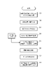
次に、劣化診断装置20における診断処理の内容について、図2のフローチャートを用いて説明する。
劣化診断装置20は、先ず列車運行管理システム30から列車ダイヤ情報を取得する(ステップS1)。続いて、取得した列車ダイヤ情報に基づいて列車位置を算出し(ステップS2)、列車位置に基づいて撮影タイミングを算出する(ステップS3)。そして、算出したタイミングになった時点で、各赤外線カメラ12A,12B,12C……へ撮影指令を出力する(ステップS4)。その後、赤外線カメラ12A,12B,12C……から撮影した画像データを受信して記憶装置21に記憶する(ステップS5)。
Next, the contents of the diagnosis process in the
The
次に、劣化診断装置20は、記憶装置21から画像データを読み出して解析し(ステップS6)、診断対象の吊架線の劣化の有無や程度を判定する(ステップS7)。具体的には、温度が局所的に高くなっている箇所があれば、それを劣化箇所と判定する。そして、劣化があった箇所については、劣化の状態や程度を位置情報と共に表示装置へ出力して表示させる(ステップS8)。なお、ステップS1で列車運行管理システム30から列車ダイヤ情報を取得する代わりに、列車位置情報を取得しても良く、その場合にはステップS2は不要となる。
Next, the
上記のような劣化診断処理によれば、作業員が現場に赴くことなく、遠隔から吊架線の劣化の状態や程度を検出することかできるため、従来に比べて大幅に人手による作業量およびそれに伴うコストを低減することができる。
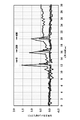
図6には、本発明者らが営業列車が走行している軌道のある場所の既設の吊架線について赤外線カメラによる撮影と解析を行なった結果の一例を示す。なお、撮影は、1秒間に60枚の画像を撮影可能な赤外線カメラを使用し、列車運行管理システムが保有する列車ダイヤ情報から、当該吊架線に電流が流れていると推定されるタイミングを算出して行なった。
According to the deterioration diagnosis process as described above, the state and degree of deterioration of the overhead wire can be detected remotely without the worker going to the site. The costs involved can be reduced.
FIG. 6 shows an example of the results of photography and analysis by the present inventors with an infrared camera on an existing overhead wire at a place where a commercial train is traveling. For shooting, an infrared camera capable of shooting 60 images per second is used, and the timing at which it is estimated that current is flowing through the overhead line is calculated from the train timetable information held by the train operation management system. I did it.
図6において、▲印は長さ方向600ピクセルの撮影画像(サーモグラフィー)における0ピクセル位置での初期温度からの変化量を撮影時間0秒から30秒までプロットしたもの、○印は200ピクセル位置での初期温度からの変化量を撮影時間0秒から30秒までプロットしたもの、◇印は400ピクセル位置での初期温度からの変化量を撮影時間0秒から30秒までプロットしたものである。
図6のグラフより、400ピクセル位置で、初期温度からの変化量が大きく増加していることから、劣化して温度変化量が大きくなった場合に、画像解析で検出できることが充分に予想される。
In FIG. 6, the ▲ mark is a plot of the amount of change from the initial temperature at the 0 pixel position in the captured image (thermography) of 600 pixels in the length direction from the shooting time of 0 seconds to 30 seconds, and the ○ mark is at the 200 pixel position. The amount of change from the initial temperature is plotted from 0 to 30 seconds in the shooting time, and the ◇ mark is the plot of the amount of change from the initial temperature at the 400 pixel position from 0 to 30 seconds in the shooting time.
From the graph of FIG. 6, since the amount of change from the initial temperature is greatly increased at the 400 pixel position, it is fully expected that it can be detected by image analysis when the amount of change is large due to deterioration. ..
次に、劣化診断装置20における診断処理の変形例について、図3のフローチャートを用いて説明する。図3の劣化診断処理は、図2のフローチャートのステップS6の解析処理の後に、変電所11A、11Bから計測した電流値および計測時刻等のデータを受信する処理ステップS6aを設けるとともに、ステップS7では、変電所からの電流値データも勘案して、劣化の状態や程度を判定するようにしたものである。
Next, a modified example of the diagnostic process in the deterioration
具体的には、例えば変電所11A、11Bで計測された電流値が比較的小さいにも関わらず赤外線カメラ12A,12B,12C……で捉えた温度変化が大きい場合に、より深刻な劣化が発生していると判断する。また、変電所11A、11Bで計測された電流値が比較的大きいにもかかわらず、赤外線カメラ12A,12B,12C……で捉えた温度変化が小さい場合には劣化が進んでいないと判断する。
Specifically, for example, when the current value measured at the
次に、本発明に係る線条の劣化診断方法およびそれを用いた劣化診断システムの第2の実施形態について、図4および図5を用いて説明する。
第2の実施形態の劣化診断システムは、図4に示すように、赤外線カメラ12を線路沿線の構造物ではなく走行する車両の屋根上(例えばパンタグラフを搭載する舟体の近傍)に設けて、電車線の画像を撮影するようにしたものである。吊架線を撮影する場合、真下に赤外線カメラを設置するとトロリ線によって隠れてしまうので、横にずれた位置に設置して斜め下方から吊架線を撮影するようにするのが良い。なお、赤外線カメラ12を設置する位置は車両の屋根上に限定されるものでなく、吊架線を撮影可能な位置であれば、車両のどこに設置しても良い。
Next, a method for diagnosing deterioration of the streaks according to the present invention and a second embodiment of the deterioration diagnosis system using the method will be described with reference to FIGS. 4 and 5.
In the deterioration diagnosis system of the second embodiment, as shown in FIG. 4, the
また、本実施形態においては、走行する車両に、赤外線カメラ12へ撮影指令を出力する車上制御装置40および赤外線カメラ12により撮影された画像データを記憶する記憶装置(メモリ)41が搭載されている。記憶装置41に記憶された画像データは、通信手段によって地上側の劣化診断装置20へ送信される。車両が車庫や留置線等に移動してから、伝送ケーブルあるいはUSBメモリなどの記憶媒体を用いて画像データを劣化診断装置20へ移管するようにしても良い。また、記憶装置41には、予め撮影したい位置の情報を記憶しておくようにしても良い。
Further, in the present embodiment, the traveling vehicle is equipped with an on-
さらに、車上制御装置40には、運転席に設けられているノッチハンドルの位置情報(ブレーキノッチを含む)が入力されており、このノッチ情報から電車線に電流(回生電流を含む)が流れるタイミングを算出して撮影タイミングを算出するように構成されている。また、速度発電機からの信号および地上子からの位置情報を受信した信号に基づいて車両位置を算出する車上装置から車両位置情報を受け取って撮影タイミングを算出するように構成しても良い。
Further, the position information (including the brake notch) of the notch handle provided in the driver's seat is input to the on-
図5には、本実施形態の劣化診断システムにおける車上制御装置40による画像データの取得処理の手順が示されている。
車上制御装置40は、ノッチ情報を読み込んで(ステップS11)、ノッチが入っているか否か判定する(ステップS12)。ここで、ノッチが入っていない(No)と判定すると、ステップS11へ戻る。また、ノッチが入っている(Yes)と判定すると、ステップS13へ進んで、赤外線カメラ12へ撮影指令を出力する。続いて、赤外線カメラ12から撮影した画像データを読み込んで、撮影時刻や撮影時の車両の位置情報と共に記憶装置51に記憶する(ステップS14)。
FIG. 5 shows a procedure for acquiring image data by the on-
The on-
その後、記憶装置51に記憶した画像データを、撮影時刻や車両位置情報と共に劣化診断装置20へ送信する(ステップS15)。
本実施形態における劣化診断装置20の処理は、図2や図3のフローチャートのステップS6以降の処理と同じで良いので、説明は省略する。
上記変形例によれば、地上側に赤外線カメラを設置する作業が不要となるため、大幅に作業量およびそれに伴うコストを低減することができるという利点がある。
After that, the image data stored in the storage device 51 is transmitted to the
Since the processing of the
According to the above modification, since the work of installing the infrared camera on the ground side becomes unnecessary, there is an advantage that the amount of work and the cost associated therewith can be significantly reduced.
以上、本発明を実施例に基づいて説明したが、本発明は上記実施例に限定されるものではない。例えば上記実施例では、地上側に設置された劣化診断装置で赤外線カメラの撮影画像に基づいて線条の劣化を診断するようにしているが、車両に搭載された劣化診断装置によってリアルタイムで劣化診断を行うようにすることも可能である。
また、上記実施例では、本発明は吊架線の劣化診断に適用した場合について説明したが、本発明は吊架線の劣化診断に限定されず、トロリ線やき電線の劣化診断にも適用することができる。
Although the present invention has been described above based on the above examples, the present invention is not limited to the above examples. For example, in the above embodiment, the deterioration diagnosis device installed on the ground side diagnoses the deterioration of the streaks based on the image taken by the infrared camera, but the deterioration diagnosis device mounted on the vehicle diagnoses the deterioration in real time. It is also possible to do.
Further, in the above embodiment, the case where the present invention is applied to the deterioration diagnosis of the suspension wire has been described, but the present invention is not limited to the deterioration diagnosis of the suspension wire, but can also be applied to the deterioration diagnosis of the trolley wire and the wire. can.
10 吊架線
11 変電所
12 赤外線カメラ
20 劣化診断装置
21 記憶装置
30 列車運行管理システム
40 車上制御装置
10
Claims (5)
前記劣化診断装置は、
診断対象の線条が敷設されている区間における車両の走行に関する情報を取得する車両情報取得手段と、
前記車両情報取得手段により取得した情報に基づいて診断対象の線条に電流が流れるタイミングを算出して前記赤外線撮像手段への撮影指令を生成し出力する指令出力手段と、
前記赤外線撮像手段によって撮影された画像データを解析して劣化状態を判定する劣化判定手段と、
を備えていることを特徴とする線条の劣化診断システム。 An infrared image pickup means installed so that a part of a line to be diagnosed can be photographed, a storage device for storing image data taken by the infrared image pickup means, and an analysis of the stored image data of the line. It is a deterioration diagnosis system equipped with a deterioration diagnosis device for determining a deterioration state.
The deterioration diagnostic device is
Vehicle information acquisition means for acquiring information on the running of the vehicle in the section where the line to be diagnosed is laid, and
A command output means that calculates the timing at which a current flows through the line to be diagnosed based on the information acquired by the vehicle information acquisition means and generates and outputs a shooting command to the infrared imaging means.
Deterioration determination means for analyzing image data captured by the infrared imaging means to determine a deterioration state, and
A linear deterioration diagnostic system characterized by being equipped with.
前記車両の走行に関する情報は、車両の列車ダイヤ情報もしくは位置情報であり、
前記指令出力手段は、前記車両情報取得手段により取得した列車ダイヤ情報もしくは位置情報に基づいて診断対象の線条に電流が流れるタイミングを算出して前記赤外線撮像手段への撮影指令を生成し出力するように構成されていることを特徴とする請求項1に記載の線条の劣化診断システム。 The infrared imaging means is installed in a structure along a railroad track, and is
The information regarding the traveling of the vehicle is the train timetable information or the position information of the vehicle.
The command output means calculates the timing at which a current flows through the line to be diagnosed based on the train timetable information or position information acquired by the vehicle information acquisition means, and generates and outputs an imaging command to the infrared imaging means. The linear deterioration diagnosis system according to claim 1, wherein the system is configured as follows.
診断対象の線条が敷設されている区間における車両の走行に関する情報を取得するステップと、
取得した車両の走行に関する情報に基づいて診断対象の線条に電流が流れているタイミングを算出して前記赤外線撮像手段への撮影指令を生成し出力するステップと、
前記赤外線撮像手段によって撮影された画像データをコンピュータへ移管するステップと、
移管された画像データをコンピュータによって解析して劣化状態を判定する判定ステップと、
判定結果を出力するステップと、
を含んでいることを特徴とする線条の劣化診断方法。 It is a deterioration diagnosis method that determines the deterioration state of the streak by analyzing the image data from the infrared imaging means installed so that a part of the streak to be diagnosed can be photographed by a computer.
Steps to acquire information on the running of the vehicle in the section where the line to be diagnosed is laid, and
A step of calculating the timing at which a current is flowing in the line to be diagnosed based on the acquired information on the running of the vehicle, and generating and outputting a shooting command to the infrared imaging means.
The step of transferring the image data taken by the infrared imaging means to a computer,
A judgment step in which the transferred image data is analyzed by a computer to determine the deterioration state, and
The step to output the judgment result and
A method for diagnosing deterioration of streaks, which is characterized by containing.
前記判定ステップにおいては、前記変電所より取得した電流計測値および計測時間情報と画像データとに基づいて劣化状態を判定することを特徴とする請求項3に記載の線条の劣化診断方法。 It has a step to acquire the measured value of the current supplied from the substation to the strip together with the measurement time information.
The method for diagnosing deterioration of streaks according to claim 3, wherein in the determination step, the deterioration state is determined based on the current measurement value acquired from the substation, the measurement time information, and the image data.
Priority Applications (1)
| Application Number | Priority Date | Filing Date | Title |
|---|---|---|---|
| JP2018172215A JP7091200B2 (en) | 2018-09-14 | 2018-09-14 | Deterioration diagnosis system for streaks and deterioration diagnosis method |
Applications Claiming Priority (1)
| Application Number | Priority Date | Filing Date | Title |
|---|---|---|---|
| JP2018172215A JP7091200B2 (en) | 2018-09-14 | 2018-09-14 | Deterioration diagnosis system for streaks and deterioration diagnosis method |
Publications (2)
| Publication Number | Publication Date |
|---|---|
| JP2020046192A JP2020046192A (en) | 2020-03-26 |
| JP7091200B2 true JP7091200B2 (en) | 2022-06-27 |
Family
ID=69901114
Family Applications (1)
| Application Number | Title | Priority Date | Filing Date |
|---|---|---|---|
| JP2018172215A Active JP7091200B2 (en) | 2018-09-14 | 2018-09-14 | Deterioration diagnosis system for streaks and deterioration diagnosis method |
Country Status (1)
| Country | Link |
|---|---|
| JP (1) | JP7091200B2 (en) |
Families Citing this family (2)
| Publication number | Priority date | Publication date | Assignee | Title |
|---|---|---|---|---|
| JP2021164375A (en) * | 2020-04-03 | 2021-10-11 | 古河電気工業株式会社 | Degradation determination system of power transmission line attachment and deterioration determination method of the power transmission line attachment |
| KR102419959B1 (en) * | 2020-09-04 | 2022-07-13 | 주식회사 알티자동화 | Real-time monitoring system of logistics automation equipment |
Citations (4)
| Publication number | Priority date | Publication date | Assignee | Title |
|---|---|---|---|---|
| JP2004352108A (en) | 2003-05-29 | 2004-12-16 | Aichi Corp | Exoergic detecting device for track equipment |
| JP2005287184A (en) | 2004-03-30 | 2005-10-13 | Railway Technical Res Inst | Monitor apparatus |
| JP2015148522A (en) | 2014-02-07 | 2015-08-20 | 株式会社明電舎 | Overhead wire position measurement apparatus using image processing, and overhead wire position measurement method |
| US20180148076A1 (en) | 2016-11-28 | 2018-05-31 | Taiwan Semiconductor Manufacturing Co., Ltd. | Monitor vehicle for a rail system and method thereof |
Family Cites Families (6)
| Publication number | Priority date | Publication date | Assignee | Title |
|---|---|---|---|---|
| JPH0738011B2 (en) * | 1988-05-16 | 1995-04-26 | 株式会社日立製作所 | Abnormality diagnosis system for high-voltage power equipment |
| JP2512688Y2 (en) * | 1991-08-02 | 1996-10-02 | 財団法人鉄道総合技術研究所 | Trolley wire temperature monitoring device |
| JPH1016777A (en) * | 1996-06-28 | 1998-01-20 | Aichi Corp | Heating part detector of track equipment |
| JP2004042837A (en) * | 2002-07-15 | 2004-02-12 | Toshiba Corp | Overhead wire measuring device |
| JP6330176B2 (en) * | 2014-06-12 | 2018-05-30 | 株式会社明電舎 | Line temperature monitoring device by image processing |
| JP6813322B2 (en) * | 2016-09-29 | 2021-01-13 | 東日本旅客鉄道株式会社 | Power supply system for electric cars |
-
2018
- 2018-09-14 JP JP2018172215A patent/JP7091200B2/en active Active
Patent Citations (4)
| Publication number | Priority date | Publication date | Assignee | Title |
|---|---|---|---|---|
| JP2004352108A (en) | 2003-05-29 | 2004-12-16 | Aichi Corp | Exoergic detecting device for track equipment |
| JP2005287184A (en) | 2004-03-30 | 2005-10-13 | Railway Technical Res Inst | Monitor apparatus |
| JP2015148522A (en) | 2014-02-07 | 2015-08-20 | 株式会社明電舎 | Overhead wire position measurement apparatus using image processing, and overhead wire position measurement method |
| US20180148076A1 (en) | 2016-11-28 | 2018-05-31 | Taiwan Semiconductor Manufacturing Co., Ltd. | Monitor vehicle for a rail system and method thereof |
Also Published As
| Publication number | Publication date |
|---|---|
| JP2020046192A (en) | 2020-03-26 |
Similar Documents
| Publication | Publication Date | Title |
|---|---|---|
| JP6125559B2 (en) | Railway vehicle damage estimation method | |
| KR101111569B1 (en) | Monitering System of Railroad Facilities using Railway Vehicle | |
| WO2017175555A1 (en) | Wear inspection apparatus and wear inspection method | |
| CN109142971A (en) | The method for inspecting and inspection device of transmission line polling robot | |
| JP4415330B2 (en) | Train line departure detection device and train line departure detection method | |
| JP7091200B2 (en) | Deterioration diagnosis system for streaks and deterioration diagnosis method | |
| JP2009234338A (en) | Integrity diagnostic system for trolley line of railway | |
| KR101414370B1 (en) | Train car position measurement device for electric railway maintenance | |
| CN113466247B (en) | Rail weld detection method and system based on inertial technology and machine vision fusion | |
| JP2013044694A (en) | Trolley line data comparing device | |
| JP5151845B2 (en) | Apparatus and method for measuring vertical acceleration of pantograph by image processing | |
| KR101806814B1 (en) | the railroad tunnel inspecting system using train with the function of automatic registrating railroads tie ID and the sensing railroads tie ID | |
| RU150721U1 (en) | SYSTEM OF CONTROL OF DEFORMATION OF RAIL LASHES OF CANDLESS RAILWAY | |
| RU100967U1 (en) | DIAGNOSTIC AND REMOTE MONITORING SYSTEM OF THE RAILWAY CONTACT NETWORK | |
| JP2007302250A (en) | Method and device for monitoring vehicle traveling state | |
| KR20090085214A (en) | System and method to monitor a rail | |
| JP6825548B2 (en) | Tram wire abnormality diagnosis method, trolley wire abnormality diagnosis device and electric mobile body | |
| NEZU et al. | Contactless measuring method of overhead contact line positions by stereo image measurement and laser distance measurement | |
| KR101806810B1 (en) | he railroad tunnel inspecting system using train | |
| JP2005287184A (en) | Monitor apparatus | |
| JP4045094B2 (en) | Vehicle running state monitoring method and apparatus | |
| JP5402096B2 (en) | Vehicle position measuring device for electric railway maintenance | |
| JP5402272B2 (en) | Vehicle position measuring device for electric railway maintenance | |
| CN109631800B (en) | Method and device for detecting dynamic lifting amount of contact line | |
| JP2000038133A (en) | Underfloor equipment monitor system for rolling stock |
Legal Events
| Date | Code | Title | Description |
|---|---|---|---|
| A621 | Written request for application examination |
Free format text: JAPANESE INTERMEDIATE CODE: A621 Effective date: 20210702 |
|
| TRDD | Decision of grant or rejection written | ||
| A977 | Report on retrieval |
Free format text: JAPANESE INTERMEDIATE CODE: A971007 Effective date: 20220531 |
|
| A01 | Written decision to grant a patent or to grant a registration (utility model) |
Free format text: JAPANESE INTERMEDIATE CODE: A01 Effective date: 20220614 |
|
| A61 | First payment of annual fees (during grant procedure) |
Free format text: JAPANESE INTERMEDIATE CODE: A61 Effective date: 20220615 |
|
| R150 | Certificate of patent or registration of utility model |
Ref document number: 7091200 Country of ref document: JP Free format text: JAPANESE INTERMEDIATE CODE: R150 |