JP7089340B2 - Robot system - Google Patents
Robot system Download PDFInfo
- Publication number
- JP7089340B2 JP7089340B2 JP2016243135A JP2016243135A JP7089340B2 JP 7089340 B2 JP7089340 B2 JP 7089340B2 JP 2016243135 A JP2016243135 A JP 2016243135A JP 2016243135 A JP2016243135 A JP 2016243135A JP 7089340 B2 JP7089340 B2 JP 7089340B2
- Authority
- JP
- Japan
- Prior art keywords
- sticking
- sandwiching
- sticking member
- base
- robot hand
- Prior art date
- Legal status (The legal status is an assumption and is not a legal conclusion. Google has not performed a legal analysis and makes no representation as to the accuracy of the status listed.)
- Active
Links
Images


Landscapes
- Manipulator (AREA)
- Labeling Devices (AREA)
- Feeding Of Articles By Means Other Than Belts Or Rollers (AREA)
- Folding Of Thin Sheet-Like Materials, Special Discharging Devices, And Others (AREA)
- Automatic Assembly (AREA)
Description
本発明は、不織布などの貼付部材を挟着して、自動車内装部材(例:デッキボード)などの被貼付物に貼付け可能なロボットシステムに関する。 The present invention relates to a robot system capable of sandwiching a sticking member such as a non-woven fabric and sticking it to an attached object such as an automobile interior member (eg, deck board).
近年、工場においては、ロボットを用いた省人化が進められている。特許文献1では、針ユニットを有する付着材剥離ユニットを用いて、対象物の粘着部を覆う付着材を剥離させる技術が開示されている。特許文献1では、対象物の付着材を針ユニットの尖鋭部に対して予め設定された所定の進入角度で進入させて対象物と付着材を剥離させている。
In recent years, labor saving using robots has been promoted in factories.
特許文献1の技術では、付着材を剥離させる方法が複雑であるためにロボットの設定に手間がかかる。
In the technique of
本発明はこのような事情に鑑みてなされたものであり、複雑な設定を行うことなく、カバー材から貼付部材を剥離して、被貼付物に貼付け可能なロボットシステムを提供するものである。 The present invention has been made in view of such circumstances, and provides a robot system capable of peeling a sticking member from a cover material and sticking it to a sticking object without making complicated settings.
本発明によれば、貼付部材を挟着して被貼付物に貼付け可能に構成される貼付機構と、前記貼付部材を供給可能な供給機構を備えるロボットシステムであって、前記貼付機構は、前記貼付部材の挟着及び解放が可能に構成されたロボットハンドと、前記ロボットハンドを移動可能に構成されたロボットアームを備え、前記供給機構は、前記貼付機構とは別体であり、且つ前記貼付部材がカバー材に貼着された状態で前記貼付部材を供給し、且つ前記カバー材を前記貼付部材から離れる方向に屈曲させることによって前記貼付部材を前記カバー材から剥離させた状態で前記ロボットハンドが前記貼付部材を挟着可能になるように構成される、ロボットシステムが提供される。 According to the present invention, the robot system includes a sticking mechanism capable of sandwiching a sticking member and sticking it to an object to be stuck, and a supply mechanism capable of supplying the sticking member. A robot hand configured to be able to pinch and release the sticking member and a robot arm configured to be able to move the robot hand are provided, and the supply mechanism is separate from the sticking mechanism and the sticking mechanism is provided. The robot hand is supplied with the sticking member attached to the cover material, and the sticking member is peeled off from the cover material by bending the cover material in a direction away from the sticking member. Provided is a robot system configured to be capable of sandwiching the sticking member.
本発明では、カバー材を屈曲させることによって貼付部材をカバー材から剥離させた状態でロボットハンドが貼付部材を挟着可能になるように構成されているので、複雑な設定を行うことなく、カバー材から貼付部材を剥離して、被貼付物に貼付けることが可能である。また、供給機構が貼付機構と別体になっているので、ロボットハンドの小型化が可能になる。 In the present invention, the cover is configured so that the robot hand can sandwich the sticking member in a state where the sticking member is peeled off from the cover material by bending the cover material, so that the cover can be covered without complicated settings. It is possible to peel off the sticking member from the material and stick it to the object to be stuck. Moreover, since the supply mechanism is separate from the sticking mechanism, the robot hand can be miniaturized.
以下、本発明の種々の実施形態を例示する。以下に示す実施形態は互いに組み合わせ可能である。
好ましくは、前記ロボットハンドは、前記貼付部材の挟着及び解放が可能に構成された挟着ユニットを備える。
好ましくは、前記挟着ユニットは、前記貼付部材の挟着及び解放が可能に構成された挟着機構と、前記貼付部材を前記被貼付物に対して押し付け可能に構成された押圧機構を備える。
好ましくは、前記挟着機構は、ベース面を有する挟着ベースと、第1シリンダ機構を備え、第1シリンダ機構は、第1シリンダベースと、これからの突出長が可変に構成された第1ロッドを備え、前記挟着機構は、前記ベース面と第1ロッドの間に前記貼付部材を挟着するように構成される。
好ましくは、前記押圧機構は、前記挟着ベースに対して回動可能な回動ベースと、前記回動ベースに設けられ且つ前記貼付部材に押し付けられる押圧部を有する。
好ましくは、前記回動ベースは、前記押圧部が前記貼付部材に押し付けられる押付方向に付勢されている。
好ましくは、前記押圧機構は、第2シリンダ機構を備え、第2シリンダ機構は、第2シリンダベースと、これからの突出長が可変に構成された第2ロッドを備え、前記押圧機構は、第2ロッドの突出長を変化させることによって前記挟着ベースに対する前記回動ベースの相対角度を調節可能に構成されている。
好ましくは、前記ロボットハンドは、第3シリンダ機構を有し、第3シリンダ機構は、第3シリンダベースと、これからの突出長が可変に構成された第3ロッドを備え、前記挟着ユニットは、第3ロッドに設けられる。
好ましくは、前記ロボットハンドは、一列に並んだ複数の前記挟着ユニットを備え、前記供給機構は、一列に並んだ複数の前記貼付部材を供給可能に構成されており、前記ロボットハンドは、複数の前記挟着ユニットで複数の前記貼付部材を一度に挟着するように構成される。
好ましくは、前記ロボットハンドは、複数の前記挟着ユニットを1つずつ突出させて、複数の前記貼付部材を1つずつ前記被貼付物に貼付けるように構成される。
好ましくは、前記貼付部材は、不織布である。
Hereinafter, various embodiments of the present invention will be illustrated. The embodiments shown below can be combined with each other.
Preferably, the robot hand includes a pinching unit configured to be able to pinch and release the sticking member.
Preferably, the pinching unit includes a pinching mechanism configured to allow the sticking member to be pinched and released, and a pressing mechanism configured to allow the sticking member to be pressed against the sticking object.
Preferably, the pinching mechanism includes a pinching base having a base surface and a first cylinder mechanism, and the first cylinder mechanism includes a first cylinder base and a first rod having a variable protrusion length from the first cylinder base. The fastening mechanism is configured to sandwich the sticking member between the base surface and the first rod.
Preferably, the pressing mechanism has a rotating base that is rotatable with respect to the sandwiching base, and a pressing portion that is provided on the rotating base and pressed against the sticking member.
Preferably, the rotating base is urged in the pressing direction in which the pressing portion is pressed against the affixing member.
Preferably, the pressing mechanism comprises a second cylinder mechanism, the second cylinder mechanism comprises a second cylinder base and a second rod having a variable protrusion length from the second cylinder mechanism, and the pressing mechanism has a second. The relative angle of the rotation base with respect to the sandwiching base can be adjusted by changing the protrusion length of the rod.
Preferably, the robot hand has a third cylinder mechanism, the third cylinder mechanism comprises a third cylinder base, and a third rod having a variable protrusion length from the third cylinder mechanism. It is provided on the third rod.
Preferably, the robot hand includes a plurality of the sandwiching units arranged in a row, and the supply mechanism is configured to be capable of supplying a plurality of the affixing members arranged in a row. It is configured to sandwich a plurality of the pasting members at once by the sandwiching unit of the above.
Preferably, the robot hand is configured so that the plurality of the sandwiching units are projected one by one and the plurality of the attachment members are attached to the attachment one by one.
Preferably, the sticking member is a non-woven fabric.
以下、本発明の実施形態について説明する。以下に示す実施形態中で示した各種特徴事項は、互いに組み合わせ可能である。また、各特徴事項について独立して発明が成立する。 Hereinafter, embodiments of the present invention will be described. The various features shown in the embodiments shown below can be combined with each other. In addition, the invention is independently established for each characteristic item.
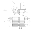
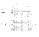
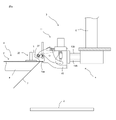
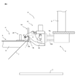
図1に示すように、本発明の一実施形態のロボットシステム10は、貼付部材1を挟着して被貼付物2に貼付け可能に構成される貼付機構3と、貼付部材1を供給可能な供給機構4を備える。貼付機構3は、貼付部材1の挟着及び解放が可能に構成されたロボットハンド5と、ロボットハンド5を移動可能に構成されたロボットアーム6を備える。
As shown in FIG. 1, the
<貼付部材1、被貼付物2、供給機構4>
図2に示すように、貼付部材1は、一面に粘着剤層1aを備えており、粘着剤層1aを被貼付物2に対向させて状態で貼付部材1を被貼付物2に押し付けることによって貼付部材1を被貼付物2に貼付け可能になっている。本実施形態では、貼付部材1としては、ある程度の厚さを有するものが想定されており、貼付部材1の厚さは、例えば0.5~5mmであり、具体的には例えば、0.5、1、1.5、2、2.5、3、3.5、4、4.5、5mmであり、ここで例示した数値の何れか2つの間の範囲内であってもよい。貼付部材1は、ガタツキ、振動、静音化などの目的で被貼付物2に貼着されるものであり、その材質は特に限定されないが、例えば、不織布である。不織布は、通気性を有するために真空吸引機構によってピックアップすることが難しい。後述するように本実施形態では、貼付機構3は、貼付部材1をロボットハンド5で挟着することによって貼付部材1をピックアップするので、不織布のような通気性を有する貼付部材1であっても確実にピックアップすることが可能である。被貼付物2は、例えば、デッキボードなどの自動車内装部材である。
<
As shown in FIG. 2, the
貼付部材1は、粘着剤層1a側の面にカバー材7が貼着されている。カバー材7は、粘着剤層1aを被覆する機能を有するものであり、カバー材7としては、粘着剤層1aに対向する面が易剥離処理されている紙やシート(いわゆる、離型紙)が好適に用いられる。カバー材7上には、多数の貼付部材1がマス目状に配列されている。カバー材7の幅方向(長手方向に垂直な方向)には3つの貼付部材1が一列に並んで配列されている。カバー材7の長手方向には、多数の貼付部材1が連続的に配列されている。カバー材7上に多数の貼付部材1が配置されて構成されるテープ部材Tは、粘着剤層を有する大面積シートの粘着剤層にカバー材7を貼着し、その後、大面積シートが多数の貼付部材1となるように大面積シートに切り込みを入れる(ハーフカットする)ことによって形成することができる。大面積シートのハーフカットによって容易に製造可能であるという観点で、貼付部材1は、長方形又は正方形であることが好ましい。貼付部材1の長手方向及び幅方向の長さは、それぞれ、1~5cmが好ましく、具体的には例えば、1、2、3、4、5cmであり、ここで例示した数値の何れか2つの間の範囲内であってもよい。
A
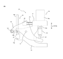
供給機構4は、送出ローラR1と、巻取ローラR2と、その間に設けられた屈曲治具8を備える。テープ部材Tが巻回されてなるテープ部材ロールが送出ローラR1に装着され、送出ローラR1の、巻き戻し方向の回転に伴ってテープ部材Tが屈曲治具8に向けて供給される。屈曲治具8では、カバー材7が貼付部材1から離れる方向に屈曲されることによって、貼付部材1がカバー材7から剥離される。この状態で貼付部材1がロボットハンド5で挟着される。カバー材7は、巻取ローラR2の回転に伴って巻き取られる。送出ローラR1と巻取ローラR2の回転速度は、カバー材7にテンションが加えられた状態が維持されるように調節される。また、送出ローラR1と巻取ローラR2の間には、カバー材7に加わるテンションを調節するテンションローラが適宜設けられる。
The
貼付部材1が不織布のような厚さが大きいものである場合、テープ部材ロールの外周径が大きくなりやすい。そのため、供給機構4を貼付機構3に一体化させることが困難である。このため、貼付部材1が不織布のような厚さが大きいものである場合に、本実施形態のように、供給機構4が貼付機構3から分離されている構成を採用することの技術的意義が顕著である。
When the sticking
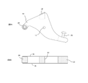
屈曲治具8は、先端8a、上面8b、及び傾斜面8cを備える。先端8aは、上面8bと傾斜面8cに繋がるように設けられる。カバー材7は、送出ローラR1から上面8b、先端8a、及び傾斜面8cをこの順で経由して巻取ローラR2に導かれる。先端8aでの上面8bと傾斜面8cの間の角度は、特に限定されないが、例えば、15~75度であり、30~60度が好ましく、40~50度がさらに好ましい。このような角度の場合、貼付部材1がカバー材7から剥離されやすいからである。先端8aの曲率半径は、貼付部材1の長手方向の長さL以下であることが好ましい。この場合、貼付部材1がカバー材7から剥離されやすいからである。先端8aの曲率半径/長さLの値は、例えば0.1~1であり、具体的には例えば、0.01、0.05、0.1、0.2、0.3、0.4、0.5、0.6、0.7、0.8、0.9、1であり、ここで例示した数値の何れか2つの間の範囲内であってもよい。また、先端8aの曲率半径は、例えば、0.1~20mmであり、好ましくは、0.5~5mmであり、具体的には例えば、0.1、0.5、1、2、3、4、5、6、7、8、9、10、11、12、13、14、15、16、17、18、19、20mmであり、ここで例示した数値の何れか2つの間の範囲内であってもよい。
The bending
上面8bに対向する位置には、押圧手段26が設けられている。押圧手段26は、図1~図2に示すように、先頭列C1の貼付部材1がカバー材7から剥離されている状態で、先頭列C1の貼付部材1を押圧せずに、2列目C2の貼付部材1を押圧するように設けられている。押圧手段26で2列目C2の貼付部材1を押圧した状態で、貼付機構3のロボットハンド5が先頭列C1の貼付部材1を挟着してピックアップすることによって、2列目C2の貼付部材1が一緒にピックアップされることを防ぐことができる。押圧手段26は、2列目C2の貼付部材1のみを押圧してもよく、3列目以降の貼付部材1を一緒に押圧してもよい。押圧手段26は、一例では、貼付部材1に当接する板部26aと、板部26aを貼付部材1に押し付けるためのシリンダ機構26bによって構成される。
A pressing means 26 is provided at a position facing the
<貼付機構3>
貼付機構3は、ロボットハンド5とロボットアーム6を備える。ロボットアーム6は、ロボットハンド5を移動させる機能を有し、具体的には、ロボットハンド5が貼付部材1を挟着してピックアップした後にロボットハンド5を被貼付物2の貼付位置にまで移動させる機能を有する。ロボットアーム6は、上記機能の実現に必要な軸数を有するものであればよく、6軸以上を有するものが好ましい。
<
The
ロボットハンド5は、保持プレート9を備える。図3に示すように、保持プレート9には、9つシリンダ機構13が固定されている。幅方向に一列に並ぶように互いに隣接した3つのシリンダ機構13によってシリンダ機構群13gが構成される。従って、保持プレート9に固定されている9つのシリンダ機構13によって3つのシリンダ機構群13gが構成される。隣接するシリンダ機構群13gの間は間隔が開けられている。
The
各シリンダ機構13は、シリンダベース13aと、これからの突出長が可変に構成されたロッド13bを備える。各ロッド13bには、挟着ユニット11が取着される。幅方向に一列に並ぶように互いに隣接した3つの挟着ユニット11によって挟着ユニット群11gが構成される。3つのシリンダ機構群13gに対応するように、3つの挟着ユニット群11gが構成される。隣接する挟着ユニット群11gの間は間隔が開けられている。
Each
各挟着ユニット11は、1つの貼付部材1を挟着及び解放可能に構成されている。従って、幅方向に一列に並んだ3つの挟着ユニット11で構成される挟着ユニット群11gは、図2に示すように、幅方向に一列に並んだ3つの貼付部材1を一度に挟着することが可能になっている。
Each sandwiching
1つ目の挟着ユニット群11gが先頭列C1の3つの貼付部材1を挟着してピックアップすると、貼付部材1の長手方向の一列の長さ分だけ、送出ローラR1と巻取ローラR2が回転して、2列目C2の貼付部材1がカバー材7から剥離されながら、先頭列C1の位置まで送り出される。次に、2つ目の挟着ユニット群11gが先頭列C1の位置まで送り出された3つの貼付部材1を挟着してピックアップする。この後、同様の工程がもう一度行われて、3つ目の挟着ユニット群11gが先頭列C1の位置まで送り出された3つの貼付部材1を挟着してピックアップする。以上の工程により、3度の操作によって、9つの挟着ユニット11によって9つの貼付部材1が挟着及びピックアップされる。
When the first
9つの挟着ユニット11によって挟着されている9つの貼付部材1は、被貼付物2上に1つずつ貼り付けられる。貼付部材1は粘着剤層1aが露出されているので、1つの貼付部材1を被貼付物2に貼り付けるために挟着ユニット11を被貼付物2に近づけると、別の貼付部材1が意図せずして被貼付物2に貼り付けられてしまう虞がある。そこで、本実施形態では、図4に示すように、被貼付物2に貼り付けようとする貼付部材1を挟着している挟着ユニット11が取り付けられているシリンダ機構13を作動させてロッド13bの突出長を長くすることによって、1つの挟着ユニット11を他の挟着ユニット11よりも突出させている。このような構成によれば、突出している挟着ユニット11を残りの挟着ユニット11よりも被貼付物2に近づけることができるので、貼り付けようとする貼付部材1のみを被貼付物2に貼り付けることが可能になる。つまり、9つのシリンダ機構13を1つずつ作動させることによって、9つの挟着ユニット11を1つずつ突出させ、それによって、9つの貼付部材1を1つずつ貼り付けることが可能になっている。
The nine
図5~図7に示すように、挟着ユニット11は、挟着ベース15と、回動ベース16を備える。回動ベース16は、軸部17において、挟着ベース15に対して相対回転可能に固定されている。挟着ベース15には、シリンダ機構18,19が設けられている。シリンダ機構18は、シリンダベース18aと、これからの突出長が可変に構成されたロッド18bを備える。シリンダ機構19は、シリンダベース19aと、これからの突出長が可変に構成されたロッド19bを備える。シリンダベース18a,19aが挟着ベース15に固定されている。図5の状態からシリンダ機構18を作動させてロッド18bの突出長を長くすると、ロッド18bとベース面15aの間に貼付部材1を挟着可能になっている。ロッド18bの先端には、貼付部材1に当接する当接部27が取り付けられている。当接部27は、ロッド18bよりも柔らかい材料で形成されていることが好ましく、この場合、当接部27が貼付部材1に当接することによって貼付部材1が挟着時に損傷されることを防ぐことができる。ロッド19bには、位置決めボルト25に当接する当接部28が設けられている。挟着ベース15には、付勢部材20を支持する付勢部材支持部21が設けられている。
As shown in FIGS. 5 to 7, the sandwiching
図6に示すように、回動ベース16は、板状の部材であり、一対の回動ベース16の間には、当接ブロック22、支持ブロック23、及び押圧部24が設けられている。支持ブロック23には、位置決めボルト25が設けられている。押圧部24は、例えば、回動ベース16に対して回転可能に支持されたローラである。
As shown in FIG. 6, the
図5に示すように、付勢部材20は、例えばコイルバネなどの弾性部材であり、付勢部材支持部21と当接ブロック22の間において自然長よりも縮んだ状態で配置されている(なお、図7は、付勢部材20が自然長になっている状態を示している。)。このため、付勢部材20は、自然長に戻ろうとする復元力を有しており、この復元力によって回動ベース16が反時計回りに付勢される。回動ベース16が反時計回りに回動すると、当接部27とベース面15aの間に挟着されている貼付部材1に押圧部24が押し付けられるので、本実施形態では、反時計回りが特許請求の範囲の「押付方向」である。
As shown in FIG. 5, the urging
回動ベース16が反時計回り方向に付勢されると、位置決めボルト25が当接部28に押し付けられる。当接部28は、ロッド19bに固定されているので、ロッド19bが後退しない限り(ロッド19bの突出長が短くならない限り)当接部28は移動しない。このため、ロッド19bが後退しない限り、挟着ベース15に対する回動ベース16の相対角度は、図5の状態に維持される。一方、ロッド19bが後退すると、付勢部材20の復元力によって回動ベース16が反時計回りに回転して当接部27とベース面15aの間に挟着されている貼付部材1に押圧部24が押し付けられるようになる(図13を参照)。このように、ロッド19bの突出長を変化させることによって挟着ベース15に対する回動ベース16の相対角度が調節可能に構成されている。
When the
以上のように、挟着ベース15及びシリンダ機構18等によって、貼付部材1の挟着及び解放が可能に構成された挟着機構が実現される。また、回動ベース16、押圧部24、付勢部材20、シリンダ機構19等によって、貼付部材1を被貼付物2に対して押し付け可能に構成された押圧機構が実現される。
As described above, the pinching mechanism is realized by the pinching
<貼付部材1の貼付け方法>
次に、図8~図14を用いて、貼付部材1を被貼付物2に貼り付ける方法を説明する。
(1)まず、図8に示すように、先頭列C1の3つの貼付部材1をカバー材7から剥離する。
(2)次に、図8に示すように、押圧手段26によって2列目C2の貼付部材1を押圧する。
(3)次に、図8に示すように、貼付部材1を挟着しようとする挟着ユニット11が取り付けられているシリンダ機構13を作動させてロッド13bの突出長を長くすることによって、貼付部材1を挟着しようとする挟着ユニット11を残りの挟着ユニット11よりも突出させる(図4を参照)。ここでは、3つの挟着ユニット11からなる挟着ユニット群11gによって先頭列C1の3つの貼付部材1を一度に挟着するので、挟着ユニット群11gが取り付けられているシリンダ機構群13gの各ロッド13bの突出長を長くする。その状態で、貼付部材1をベース面15aと当接部27の間に配置する。この際に、貼付部材1の粘着剤層1aをベース面15aに接触させてもよい。
(4)次に、図9に示すように、ロッド18bの突出長を増大させることによってベース面15aと当接部27の間に貼付部材1を挟着する。この際、挟着ユニット群11gを構成する3つの挟着ユニット11が先頭列C1の3つの貼付部材1を同時に挟着する。
(5)次に、図10に示すように、ロボットアーム6で挟着ユニット11を移動させるとともにロッド13bの突出長を短くすることによって貼付部材1をテープ部材Tから完全に分離する。
(6)ここまでの工程を3つの挟着ユニット群11gについて行うことによって、9つの挟着ユニット11に9つの貼付部材1が挟着される。
<Attachment method of affixing
Next, a method of attaching the
(1) First, as shown in FIG. 8, the three
(2) Next, as shown in FIG. 8, the pressing means 26 presses the sticking
(3) Next, as shown in FIG. 8, the attachment is performed by operating the
(4) Next, as shown in FIG. 9, the sticking
(5) Next, as shown in FIG. 10, the sticking
(6) By performing the steps up to this point for the three sandwiching
(7)次に、図11に示すように、貼付部材1が被貼付物2に近づくようにロボットハンド5を傾斜させると共に、貼り付けようとする貼付部材1を保持する挟着ユニット11が取り付けられているシリンダ機構13を作動させてロッド13bの突出長を長くすることによって、1つの挟着ユニット11を別の挟着ユニット11よりも突出させる(図4を参照)。
(8)次に、図12に示すように、ロッド19b(図5を参照)の突出長を短縮することによって付勢部材20の復元力により回動ベース16を反時計回りに回転させて押圧部24を貼付部材1に接触させる。図12の状態では、当接部28と位置決めボルト25が当接している。ロッド19bの突出長は、押圧部24が貼付部材1に接触するが、付勢部材20の復元力が貼付部材1に加わらないように設定されている。
(9)次に、図13に示すように、貼付部材1を被貼付物2に接触させる。図13の状態では、当接部28と位置決めボルト25は当接しておらず、付勢部材20の復元力が押圧部24を通じて貼付部材1に加えられている。
(10)次に、図13~図14に示すように、ロッド18bの突出長を短縮することによって、ベース面15aと当接部27による挟着状態から貼付部材1を解放する。次に、図14の矢印Xで示すように、被貼付物2の表面に沿って挟着ユニット11を移動させることによって貼付部材1を被貼付物2に貼り付ける。
(11)次に、(7)~(10)を全ての貼付部材1について繰り返し行うことによって、被貼付物2の9箇所に貼付部材1を貼り付けることができる。
(7) Next, as shown in FIG. 11, the
(8) Next, as shown in FIG. 12, the
(9) Next, as shown in FIG. 13, the sticking
(10) Next, as shown in FIGS. 13 to 14, the sticking
(11) Next, by repeating (7) to (10) for all the affixing
本発明は、以下の態様でも実施可能である。
・テープ部材Tの各列に設けられる貼付部材1の数は1又は2つであってもよく、4つ以上であってもよく、複数であることが好ましい。
・挟着ユニット群11gを構成する挟着ユニット11の数は、1又は2つであってもよく、4つ以上であってもよく、複数であることが好ましい。
・挟着ユニット群11gの数は、1又は2つであってもよく、4つ以上であってもよく、複数であることが好ましい。
・上記工程(7)~(10)に含まれる各動作は、適宜順序を入れ替えることができる。
・貼付部材1を被貼付物2に接触させた後に、押圧部24を貼付部材1に接触させてもよい。
・押圧部24を貼付部材1に接触させた後にロッド13bの突出長を長くしてもよい。
・押圧部24を貼付部材1に接触させた後にロボットハンド5を傾斜させてもよい。
The present invention can also be implemented in the following aspects.
-The number of the sticking
-The number of the sandwiching
-The number of the
-The order of each operation included in the above steps (7) to (10) can be changed as appropriate.
The
The protruding length of the
The
1 :貼付部材
1a :粘着剤層
2 :被貼付物
3 :貼付機構
4 :供給機構
5 :ロボットハンド
6 :ロボットアーム
7 :カバー材
8 :屈曲治具
8a :先端
8b :上面
8c :傾斜面
9 :保持プレート
10 :ロボットシステム
11 :挟着ユニット
11g :挟着ユニット群
13 :シリンダ機構
13a :シリンダベース
13b :ロッド
13g :シリンダ機構群
15 :挟着ベース
15a :ベース面
16 :回動ベース
17 :軸部
18 :シリンダ機構
18a :シリンダベース
18b :ロッド
19 :シリンダ機構
19a :シリンダベース
19b :ロッド
20 :付勢部材
21 :付勢部材支持部
22 :当接ブロック
23 :支持ブロック
24 :押圧部
25 :位置決めボルト
26 :押圧手段
26a :板部
26b :シリンダ機構
27 :当接部
28 :当接部
R1 :送出ローラ
R2 :巻取ローラ
T :テープ部材
1: Sticking
Claims (10)
前記貼付機構は、前記貼付部材の挟着及び解放が可能に構成されたロボットハンドと、前記ロボットハンドを移動可能に構成されたロボットアームを備え、
前記供給機構は、前記貼付機構とは別体であり、且つ前記貼付部材がカバー材に貼着された状態で前記貼付部材を供給し、且つ前記カバー材を前記貼付部材から離れる方向に屈曲させることによって前記貼付部材を前記カバー材から剥離させた状態で前記ロボットハンドが前記貼付部材を挟着可能になるように構成され、
前記ロボットハンドは、一列に並んだ複数の挟着ユニットを備え、
前記挟着ユニットは、それぞれ、前記貼付部材の挟着及び解放が可能に構成され、
前記供給機構は、一列に並んだ複数の前記貼付部材を供給可能に構成されており、
前記ロボットハンドは、複数の前記挟着ユニットで複数の前記貼付部材を一度に挟着するように構成され、
前記ロボットハンドは、複数の前記挟着ユニットを1つずつ突出させて、複数の前記貼付部材を1つずつ前記被貼付物に貼付けるように構成され、
前記貼付部材は、不織布である、ロボットシステム。 A robot system including a sticking mechanism capable of sandwiching a sticking member and sticking it to an object to be stuck, and a supply mechanism capable of supplying the sticking member.
The sticking mechanism includes a robot hand configured to be able to pinch and release the sticking member, and a robot arm configured to be able to move the robot hand.
The supply mechanism is separate from the sticking mechanism, supplies the sticking member in a state where the sticking member is stuck to the cover material, and bends the cover material in a direction away from the sticking member. As a result, the robot hand is configured so that the sticking member can be sandwiched in a state where the sticking member is peeled off from the cover material.
The robot hand is provided with a plurality of sandwiching units arranged in a row.
The sandwiching unit is configured to be capable of sandwiching and releasing the sticking member, respectively.
The supply mechanism is configured to be able to supply a plurality of the pasting members arranged in a row.
The robot hand is configured to sandwich the plurality of attachment members at once by the plurality of sandwiching units.
The robot hand is configured to project a plurality of the sandwiching units one by one and attach the plurality of affixing members one by one to the affixed object.
The sticking member is a non-woven fabric, which is a robot system.
第1シリンダ機構は、第1シリンダベースと、これからの突出長が可変に構成された第1ロッドを備え、
前記挟着機構は、前記ベース面と第1ロッドの間に前記貼付部材を挟着するように構成される、請求項2に記載のシステム。 The sandwiching mechanism includes a sandwiching base having a base surface and a first cylinder mechanism.
The first cylinder mechanism includes a first cylinder base and a first rod having a variable protrusion length from the first cylinder base.
The system according to claim 2, wherein the pinching mechanism is configured to sandwich the sticking member between the base surface and the first rod.
前記貼付機構は、前記貼付部材の挟着及び解放が可能に構成されたロボットハンドと、前記ロボットハンドを移動可能に構成されたロボットアームを備え、
前記供給機構は、前記貼付機構とは別体であり、且つ前記貼付部材がカバー材に貼着された状態で前記貼付部材を供給し、且つ前記カバー材を前記貼付部材から離れる方向に屈曲させることによって前記貼付部材を前記カバー材から剥離させた状態で前記ロボットハンドが前記貼付部材を挟着可能になるように構成され、
前記ロボットハンドは、前記貼付部材の挟着及び解放が可能に構成された挟着ユニットを備え
前記挟着ユニットは、前記貼付部材の挟着及び解放が可能に構成された挟着機構と、前記貼付部材を前記被貼付物に対して押し付け可能に構成された押圧機構を備え、
前記挟着機構は、ベース面を有する挟着ベースと、第1シリンダ機構を備え、
第1シリンダ機構は、第1シリンダベースと、これからの突出長が可変に構成された第1ロッドを備え、
前記挟着機構は、前記ベース面と第1ロッドの間に前記貼付部材を挟着するように構成され、
前記押圧機構は、前記挟着ベースに対して回動可能な回動ベースと、前記回動ベースに設けられ且つ前記貼付部材に押し付けられる押圧部を有する、ロボットシステム。 A robot system including a sticking mechanism capable of sandwiching a sticking member and sticking it to an object to be stuck, and a supply mechanism capable of supplying the sticking member.
The sticking mechanism includes a robot hand configured to be able to pinch and release the sticking member, and a robot arm configured to be able to move the robot hand.
The supply mechanism is separate from the sticking mechanism, supplies the sticking member in a state where the sticking member is stuck to the cover material, and bends the cover material in a direction away from the sticking member. As a result, the robot hand is configured so that the sticking member can be sandwiched in a state where the sticking member is peeled off from the cover material.
The robot hand includes a pinching unit configured to be able to pinch and release the sticking member, and the pinching unit includes a pinching mechanism configured to be able to pinch and release the sticking member. It is equipped with a pressing mechanism configured to be able to press the sticking member against the sticking object.
The sandwiching mechanism includes a sandwiching base having a base surface and a first cylinder mechanism.
The first cylinder mechanism includes a first cylinder base and a first rod having a variable protrusion length from the first cylinder base.
The sandwiching mechanism is configured to sandwich the sticking member between the base surface and the first rod.
The pressing mechanism is a robot system having a rotating base that can rotate with respect to the sandwiching base and a pressing portion provided on the rotating base and pressed against the sticking member.
前記供給機構は、一列に並んだ複数の前記貼付部材を供給可能に構成されており、
前記ロボットハンドは、複数の前記挟着ユニットで複数の前記貼付部材を一度に挟着するように構成される、請求項5に記載のシステム。 The robot hand includes a plurality of the sandwiching units arranged in a row.
The supply mechanism is configured to be able to supply a plurality of the pasting members arranged in a row.
The system according to claim 5, wherein the robot hand is configured to sandwich the plurality of attachment members at once by the plurality of sandwiching units.
第2シリンダ機構は、第2シリンダベースと、これからの突出長が可変に構成された第2ロッドを備え、
前記押圧機構は、第2ロッドの突出長を変化させることによって前記挟着ベースに対する前記回動ベースの相対角度を調節可能に構成されている、請求項8に記載のシステム。 The pressing mechanism includes a second cylinder mechanism.
The second cylinder mechanism includes a second cylinder base and a second rod having a variable protrusion length.
The system according to claim 8, wherein the pressing mechanism is configured so that the relative angle of the rotation base with respect to the sandwiching base can be adjusted by changing the protrusion length of the second rod.
前記貼付機構は、前記貼付部材の挟着及び解放が可能に構成されたロボットハンドと、前記ロボットハンドを移動可能に構成されたロボットアームを備え、
前記供給機構は、前記貼付機構とは別体であり、且つ前記貼付部材がカバー材に貼着された状態で前記貼付部材を供給し、且つ前記カバー材を前記貼付部材から離れる方向に屈曲させることによって前記貼付部材を前記カバー材から剥離させた状態で前記ロボットハンドが前記貼付部材を挟着可能になるように構成され、
前記ロボットハンドは、一列に並んだ複数の挟着ユニットを備え、
前記挟着ユニットは、それぞれ、前記貼付部材の挟着及び解放が可能に構成され、
前記供給機構は、一列に並んだ複数の前記貼付部材を供給可能に構成されており、
前記ロボットハンドは、複数の前記挟着ユニットで複数の前記貼付部材を一度に挟着するように構成され、
前記ロボットハンドは、複数の前記挟着ユニットを1つずつ突出させて、複数の前記貼付部材を1つずつ前記被貼付物に貼付けるように構成され、
前記ロボットハンドは、第3シリンダ機構を有し、
第3シリンダ機構は、第3シリンダベースと、これからの突出長が可変に構成された第3ロッドを備え、
前記挟着ユニットは、第3ロッドに設けられる、ロボットシステム。 A robot system including a sticking mechanism capable of sandwiching a sticking member and sticking it to an object to be stuck, and a supply mechanism capable of supplying the sticking member.
The sticking mechanism includes a robot hand configured to be able to pinch and release the sticking member, and a robot arm configured to be able to move the robot hand.
The supply mechanism is separate from the sticking mechanism, supplies the sticking member in a state where the sticking member is stuck to the cover material, and bends the cover material in a direction away from the sticking member. As a result, the robot hand is configured so that the sticking member can be sandwiched in a state where the sticking member is peeled off from the cover material.
The robot hand is provided with a plurality of sandwiching units arranged in a row.
The sandwiching unit is configured to be capable of sandwiching and releasing the sticking member, respectively.
The supply mechanism is configured to be able to supply a plurality of the pasting members arranged in a row.
The robot hand is configured to sandwich the plurality of attachment members at once by the plurality of sandwiching units.
The robot hand is configured to project a plurality of the sandwiching units one by one and attach the plurality of affixing members one by one to the affixed object.
The robot hand has a third cylinder mechanism and has a third cylinder mechanism.
The third cylinder mechanism includes a third cylinder base and a third rod having a variable protrusion length.
The sandwiching unit is a robot system provided on the third rod.
Priority Applications (6)
| Application Number | Priority Date | Filing Date | Title |
|---|---|---|---|
| JP2016243135A JP7089340B2 (en) | 2016-12-15 | 2016-12-15 | Robot system |
| KR1020197020435A KR102456986B1 (en) | 2016-12-15 | 2017-12-14 | robot system |
| PCT/JP2017/044990 WO2018110677A1 (en) | 2016-12-15 | 2017-12-14 | Robot system and cutting blade |
| US16/468,559 US11247338B2 (en) | 2016-12-15 | 2017-12-14 | Robot system and cutting blade |
| EP17880315.1A EP3556670B1 (en) | 2016-12-15 | 2017-12-14 | Robot system |
| CN201780077515.3A CN110072779B (en) | 2016-12-15 | 2017-12-14 | Robot system |
Applications Claiming Priority (1)
| Application Number | Priority Date | Filing Date | Title |
|---|---|---|---|
| JP2016243135A JP7089340B2 (en) | 2016-12-15 | 2016-12-15 | Robot system |
Publications (2)
| Publication Number | Publication Date |
|---|---|
| JP2018095297A JP2018095297A (en) | 2018-06-21 |
| JP7089340B2 true JP7089340B2 (en) | 2022-06-22 |
Family
ID=62632175
Family Applications (1)
| Application Number | Title | Priority Date | Filing Date |
|---|---|---|---|
| JP2016243135A Active JP7089340B2 (en) | 2016-12-15 | 2016-12-15 | Robot system |
Country Status (1)
| Country | Link |
|---|---|
| JP (1) | JP7089340B2 (en) |
Families Citing this family (3)
| Publication number | Priority date | Publication date | Assignee | Title |
|---|---|---|---|---|
| JP7312470B2 (en) * | 2021-02-24 | 2023-07-21 | 株式会社ウエーブ | Adhesive tape sticking method and sticking device |
| JP7323869B2 (en) * | 2021-02-24 | 2023-08-09 | 株式会社ウエーブ | Method and Apparatus for Attaching Hook-and-Loop Tape |
| CN115674268B (en) * | 2022-09-27 | 2025-06-06 | 珠海格力智能装备有限公司 | Side posture module, manipulator and control method |
Citations (3)
| Publication number | Priority date | Publication date | Assignee | Title |
|---|---|---|---|---|
| JP2002205718A (en) | 2000-12-28 | 2002-07-23 | Nisca Corp | Label feeding apparatus and label feeding method |
| JP2002274516A (en) | 2001-03-14 | 2002-09-25 | Ricoh Co Ltd | Adhesive seal gripping mechanism |
| JP2005206192A (en) | 2004-01-22 | 2005-08-04 | Sato Corp | Labeling system |
Family Cites Families (5)
| Publication number | Priority date | Publication date | Assignee | Title |
|---|---|---|---|---|
| JPS6342512U (en) * | 1986-09-04 | 1988-03-22 | ||
| JPS63114048A (en) * | 1986-10-31 | 1988-05-18 | Nippon Carbide Ind Co Ltd | Outer label for dry cell and its production |
| JPH081831Y2 (en) * | 1990-05-28 | 1996-01-24 | 日合エンジニアリング株式会社 | Sheet cutting device |
| JP3530575B2 (en) * | 1994-05-24 | 2004-05-24 | 多摩川精機株式会社 | Label sticking method |
| US5705024A (en) * | 1995-09-28 | 1998-01-06 | Becton, Dickinson And Company | System for application of labels |
-
2016
- 2016-12-15 JP JP2016243135A patent/JP7089340B2/en active Active
Patent Citations (3)
| Publication number | Priority date | Publication date | Assignee | Title |
|---|---|---|---|---|
| JP2002205718A (en) | 2000-12-28 | 2002-07-23 | Nisca Corp | Label feeding apparatus and label feeding method |
| JP2002274516A (en) | 2001-03-14 | 2002-09-25 | Ricoh Co Ltd | Adhesive seal gripping mechanism |
| JP2005206192A (en) | 2004-01-22 | 2005-08-04 | Sato Corp | Labeling system |
Also Published As
| Publication number | Publication date |
|---|---|
| JP2018095297A (en) | 2018-06-21 |
Similar Documents
| Publication | Publication Date | Title |
|---|---|---|
| JP5801811B2 (en) | Sheet peeling apparatus and peeling method, sheet sticking apparatus and sticking method | |
| JP7089340B2 (en) | Robot system | |
| WO2018110677A1 (en) | Robot system and cutting blade | |
| JP4415126B2 (en) | Laminating film laminating equipment | |
| JP2009253083A (en) | Sheet sticking device and sticking method | |
| JP2009145428A (en) | Label sheet and label sheet producing apparatus | |
| JP2006182396A (en) | Labeling device | |
| JP6631324B2 (en) | Mount stripping device | |
| JP2004224353A (en) | Label peeling device | |
| JP5186572B2 (en) | Labeling device | |
| JP2012059930A (en) | Sheet pasting roller, and sheet pasting device and method using the same | |
| JP4651840B2 (en) | Release paper separator | |
| JP2014240300A (en) | Label pasting device | |
| JP4341760B2 (en) | Thin plate feeder | |
| KR20000057008A (en) | Laminator | |
| JP5113646B2 (en) | Sheet sticking device and sticking method | |
| JP2008081125A (en) | Pasting head, and sheet pasting method using the same | |
| JP2012035887A (en) | Sheet releasing apparatus and releasing method | |
| JP6823921B2 (en) | Sheet manufacturing equipment and manufacturing method, and sheet pasting equipment and sticking method | |
| JP7037888B2 (en) | Work piece manufacturing method | |
| JP2013166582A (en) | Labeling apparatus | |
| JPH0487225A (en) | How to attach the click plate or movable contact piece | |
| JP2010120672A (en) | Labeling device | |
| JPH11246111A (en) | Sheet peeling device and sheet peeling method | |
| JP4589246B2 (en) | Sheet sticking device and sticking method |
Legal Events
| Date | Code | Title | Description |
|---|---|---|---|
| A621 | Written request for application examination |
Free format text: JAPANESE INTERMEDIATE CODE: A621 Effective date: 20191015 |
|
| A131 | Notification of reasons for refusal |
Free format text: JAPANESE INTERMEDIATE CODE: A131 Effective date: 20201013 |
|
| A521 | Request for written amendment filed |
Free format text: JAPANESE INTERMEDIATE CODE: A523 Effective date: 20201030 |
|
| A02 | Decision of refusal |
Free format text: JAPANESE INTERMEDIATE CODE: A02 Effective date: 20210309 |
|
| A521 | Request for written amendment filed |
Free format text: JAPANESE INTERMEDIATE CODE: A523 Effective date: 20210331 |
|
| C60 | Trial request (containing other claim documents, opposition documents) |
Free format text: JAPANESE INTERMEDIATE CODE: C60 Effective date: 20210331 |
|
| A911 | Transfer to examiner for re-examination before appeal (zenchi) |
Free format text: JAPANESE INTERMEDIATE CODE: A911 Effective date: 20210409 |
|
| C21 | Notice of transfer of a case for reconsideration by examiners before appeal proceedings |
Free format text: JAPANESE INTERMEDIATE CODE: C21 Effective date: 20210413 |
|
| A912 | Re-examination (zenchi) completed and case transferred to appeal board |
Free format text: JAPANESE INTERMEDIATE CODE: A912 Effective date: 20210514 |
|
| C211 | Notice of termination of reconsideration by examiners before appeal proceedings |
Free format text: JAPANESE INTERMEDIATE CODE: C211 Effective date: 20210518 |
|
| C22 | Notice of designation (change) of administrative judge |
Free format text: JAPANESE INTERMEDIATE CODE: C22 Effective date: 20220412 |
|
| C23 | Notice of termination of proceedings |
Free format text: JAPANESE INTERMEDIATE CODE: C23 Effective date: 20220510 |
|
| C03 | Trial/appeal decision taken |
Free format text: JAPANESE INTERMEDIATE CODE: C03 Effective date: 20220607 |
|
| C30A | Notification sent |
Free format text: JAPANESE INTERMEDIATE CODE: C3012 Effective date: 20220607 |
|
| A61 | First payment of annual fees (during grant procedure) |
Free format text: JAPANESE INTERMEDIATE CODE: A61 Effective date: 20220610 |
|
| R150 | Certificate of patent or registration of utility model |
Ref document number: 7089340 Country of ref document: JP Free format text: JAPANESE INTERMEDIATE CODE: R150 |
|
| R250 | Receipt of annual fees |
Free format text: JAPANESE INTERMEDIATE CODE: R250 |