JP7083176B2 - Electro-hydraulic molding equipment - Google Patents
Electro-hydraulic molding equipment Download PDFInfo
- Publication number
- JP7083176B2 JP7083176B2 JP2019563689A JP2019563689A JP7083176B2 JP 7083176 B2 JP7083176 B2 JP 7083176B2 JP 2019563689 A JP2019563689 A JP 2019563689A JP 2019563689 A JP2019563689 A JP 2019563689A JP 7083176 B2 JP7083176 B2 JP 7083176B2
- Authority
- JP
- Japan
- Prior art keywords
- electrode
- peripheral
- electro
- central electrode
- mold
- Prior art date
- Legal status (The legal status is an assumption and is not a legal conclusion. Google has not performed a legal analysis and makes no representation as to the accuracy of the status listed.)
- Active
Links
Images


Classifications
-
- B—PERFORMING OPERATIONS; TRANSPORTING
- B21—MECHANICAL METAL-WORKING WITHOUT ESSENTIALLY REMOVING MATERIAL; PUNCHING METAL
- B21D—WORKING OR PROCESSING OF SHEET METAL OR METAL TUBES, RODS OR PROFILES WITHOUT ESSENTIALLY REMOVING MATERIAL; PUNCHING METAL
- B21D26/00—Shaping without cutting otherwise than using rigid devices or tools or yieldable or resilient pads, i.e. applying fluid pressure or magnetic forces
- B21D26/02—Shaping without cutting otherwise than using rigid devices or tools or yieldable or resilient pads, i.e. applying fluid pressure or magnetic forces by applying fluid pressure
- B21D26/06—Shaping without cutting otherwise than using rigid devices or tools or yieldable or resilient pads, i.e. applying fluid pressure or magnetic forces by applying fluid pressure by shock waves
- B21D26/12—Shaping without cutting otherwise than using rigid devices or tools or yieldable or resilient pads, i.e. applying fluid pressure or magnetic forces by applying fluid pressure by shock waves initiated by spark discharge
Landscapes
- Physics & Mathematics (AREA)
- Fluid Mechanics (AREA)
- Engineering & Computer Science (AREA)
- Mechanical Engineering (AREA)
- Shaping Metal By Deep-Drawing, Or The Like (AREA)
- Physical Or Chemical Processes And Apparatus (AREA)
- Treatments Of Macromolecular Shaped Articles (AREA)
Description
本発明は、電気液圧成形装置に関する。 The present invention relates to an electro-hydraulic molding apparatus.
電気液圧成形は、動圧を加えることによって材料のブランクを型に対して変形させることを可能にする。この目的のために、液体、例えば水で満たされたチャンバ内に配置された少なくとも2つの電極間で放電を発生させる。その結果、2つの電極間に電気アークが形成されて、高い温度勾配と液体の蒸発が引き起こされる。一般に「衝撃波」としても知られる圧力波が高速で移動し、材料のブランクを金型に押し付ける。電気液圧成形は、スプリングバックを減少させ、形成される部品の刻印の細部および/または角張った縁部および/または破断前局所伸びを改善するので、他の成形方法と比較して特に有利である。 Electro-hydraulic molding makes it possible to deform a blank of material with respect to a mold by applying dynamic pressure. For this purpose, a discharge is generated between at least two electrodes placed in a chamber filled with liquid, eg water. As a result, an electric arc is formed between the two electrodes, causing a high temperature gradient and evaporation of the liquid. A pressure wave, commonly known as a "shock wave," moves at high speed and presses a blank of material against the mold. Electro-hydraulic forming is particularly advantageous compared to other forming methods as it reduces springback and improves engraved details and / or angular edges and / or pre-break local elongation of the part to be formed. be.
しかし、電気液圧成形は欠点を有する。電気液圧成形の欠点の1つは、電極が急速に消耗することである。その結果、電極間の距離が広がり、放電が弱くなる。電気液圧成形の効率は低下する。この欠点を軽減するために、電極は定期的に交換される。電極の交換は追加の保守費用を招き、装置を一時的に停止した後の操業度の低下を伴う。 However, electro-hydraulic molding has drawbacks. One of the drawbacks of electro-hydraulic molding is the rapid wear of the electrodes. As a result, the distance between the electrodes increases and the discharge becomes weaker. The efficiency of electro-hydraulic molding is reduced. To alleviate this drawback, the electrodes are replaced regularly. Replacing the electrodes leads to additional maintenance costs and is accompanied by a decrease in operating rate after the equipment is temporarily shut down.
特許文献1は、長手方向に延びる中央電極と、中央電極を囲む成形チャンバの壁によって形成された周辺電極とを備える電気液圧成形装置を記載している。周辺電極の消耗はより広い表面にわたって分散され、電極間の距離は、ほとんどの場合円錐形である2つの電極が向かい合って配置され、したがってその活性部が非常に局所化されている装置よりも変動が少ない。 Patent Document 1 describes an electro-hydraulic molding apparatus including a central electrode extending in the longitudinal direction and a peripheral electrode formed by a wall of a molding chamber surrounding the central electrode. Peripheral electrode wear is distributed over a wider surface, and the distance between the electrodes varies more than in devices where two electrodes, which are mostly conical, are placed facing each other and therefore their active parts are highly localized. Less is.
したがって、電気液圧成形の効率、特に衝撃波によって発生する圧力に影響を与えることなく、電極をより長く使用することができる。しかしながら、電極の交換は、電気液圧成形チャンバ全体を交換することを含み、これは、従来技術の他の装置よりも高い保守費用と、電極を交換するための装置のより長い一時的停止とを招く。 Therefore, the electrodes can be used longer without affecting the efficiency of electro-hydraulic molding, especially the pressure generated by the shock wave. However, electrode replacement involves replacing the entire electro-hydraulic forming chamber, which results in higher maintenance costs than other devices of the prior art and longer temporary outages of the device for replacing electrodes. Invite.
本発明の目的は、特に、前述の従来技術の欠点を軽減することである。 An object of the present invention is, in particular, to alleviate the above-mentioned drawbacks of the prior art.
この目的のために、本発明は、材料のブランクを成形するための電気液圧成形装置であって、
電気液圧成形チャンバと、
いわゆる長手方向に延び、電気液圧成形チャンバの内部に配置された第1の端部を備える少なくとも1つのいわゆる中央電極と、
中央電極の端部から離間してその周りに配置され、前記中央電極に対して横断面内に延在する端部を有する、各中央電極から電気的に絶縁された少なくとも1つのいわゆる周辺電極と、
各中央電極を電気液圧成形チャンバに導入するための孔を備え、前記電気液圧成形チャンバを部分的に形成する本体部と、
金型と、
を備える装置を提案する。
For this purpose, the present invention is an electro-hydraulic molding apparatus for molding a blank of a material.
Electro-hydraulic forming chamber and
With at least one so-called central electrode extending in the so-called longitudinal direction and having a first end located inside the electro-hydraulic forming chamber,
With at least one so-called peripheral electrode electrically isolated from each central electrode, arranged around it away from the end of the central electrode and having an end extending in the cross section with respect to the central electrode. ,
A main body portion having a hole for introducing each central electrode into the electro-hydraulic molding chamber and partially forming the electro-hydraulic molding chamber, and a main body portion.
With the mold
We propose a device equipped with.
さらに、各周辺電極は前記本体部から分離されている。 Further, each peripheral electrode is separated from the main body portion.
本発明によれば、電気液圧成形チャンバを部分的に形成する本体部とは別の周辺電極を使用することにより、交換される周辺電極の寸法、および、電極を交換する場合の装置の停止時間を減少させることができ、したがって保守費用を低減することができる。 According to the present invention, by using a peripheral electrode different from the main body portion that partially forms the electro-hydraulic molding chamber, the dimensions of the peripheral electrode to be replaced and the stoppage of the device when the electrode is replaced are stopped. Time can be reduced and therefore maintenance costs can be reduced.
一実施形態では、少なくとも1つの周辺電極が本体部に対して突出しているので、放電が発生する場所をよりよく制御し、電気液圧成形の効率を高めることが可能になる。 In one embodiment, since at least one peripheral electrode protrudes from the main body portion, it is possible to better control the place where the electric discharge occurs and improve the efficiency of electrohydraulic molding.
一実施形態では、少なくとも1つの周辺電極は電極ホルダによって支持されている。 In one embodiment, at least one peripheral electrode is supported by an electrode holder.
電極ホルダを用いることにより、交換が必要な周辺電極の寸法を小さくすることができ、周辺電極の交換を簡単にすることができる。有利には、電極ホルダはブランクホルダとしても機能し得る。したがって、小型で組み立てが容易な電気液圧成形装置が得られる。 By using the electrode holder, the size of the peripheral electrode that needs to be replaced can be reduced, and the replacement of the peripheral electrode can be facilitated. Advantageously, the electrode holder can also function as a blank holder. Therefore, it is possible to obtain an electro-hydraulic molding apparatus that is small and easy to assemble.
一実施形態では、装置は単一の周辺電極と少なくとも一つの中央電極とを備える。 In one embodiment, the device comprises a single peripheral electrode and at least one central electrode.
特に、大きな寸法で形成される部品の場合、単一の周辺電極と組み合わせた複数の中央電極を使用することが有利であり得る。様々な場所で複数の同時または遅延放電を発生させることによって、従来技術の電気液圧成形装置を用いるよりもより均質であるか、またはより先進的であるか、またはより深い電気液圧成形を得ることが可能である。他の実施形態では、電気液圧成形装置は、1つ以上の金型と組み合わされた複数対の中央電極および周辺電極を備えることができる。したがって、複数の放電を同時に実施することによって、並行して複数の部品を、または1つの大きな部品を製造することが可能である。 In particular, for parts formed in large dimensions, it may be advantageous to use multiple central electrodes in combination with a single peripheral electrode. By generating multiple simultaneous or delayed discharges at different locations, a more homogeneous, more advanced, or deeper electrohydraulic molding than using prior art electrohydraulic molding equipment. It is possible to get. In another embodiment, the electro-hydraulic molding apparatus can include a plurality of pairs of central and peripheral electrodes combined with one or more molds. Therefore, by performing a plurality of discharges at the same time, it is possible to manufacture a plurality of parts or one large part in parallel.
一実施形態では、電気液圧成形チャンバは、本体部と周辺電極の端部とによって形成される。したがって、電気液圧成形チャンバは、変形される材料のブランクによって封止される。前記実施形態は、機械加工および組み立てが容易であるため有利である。 In one embodiment, the electro-hydraulic forming chamber is formed by a body and the ends of peripheral electrodes. Therefore, the electro-hydraulic forming chamber is sealed with a blank of material to be deformed. The embodiment is advantageous because it is easy to machine and assemble.
一実施形態では、材料のブランクは周辺電極の端部と金型との間に保持される。したがって、小型で組み立てが容易な電気液圧成形装置が得られる。有利には、周辺電極の端部は肩部を備え、その肩部に材料のブランクが収容される。したがって、周辺電極はブランクホルダとして機能し、材料のブランクを金型に対して保持することを可能にする。 In one embodiment, the blank of material is held between the end of the peripheral electrode and the mold. Therefore, it is possible to obtain an electro-hydraulic molding apparatus that is small and easy to assemble. Advantageously, the ends of the peripheral electrodes are provided with shoulders, which accommodate blanks of material. Therefore, the peripheral electrode acts as a blank holder, allowing the material blank to be held against the mold.
一実施形態では、装置は、周辺電極の端部と金型との間に配置されたブランクホルダを備える。 In one embodiment, the device comprises a blank holder disposed between the end of the peripheral electrode and the mold.
一実施形態では、装置は、形成される部品に応じて金型をより容易に変更することを可能にする金型支持体をさらに備える。 In one embodiment, the device further comprises a mold support that allows the mold to be more easily modified depending on the parts to be formed.
一実施形態では、中央電極は、その長さの一部にわたって電気絶縁体により包囲される。 In one embodiment, the central electrode is surrounded by an electrical insulator over a portion of its length.
別の代替実施形態では、本体部は中央電極と電気的に接触しており、さらに周辺電極を中央電極から絶縁するための電気絶縁体を備える。 In another alternative embodiment, the body is in electrical contact with the central electrode and further comprises an electrical insulator for insulating the peripheral electrodes from the central electrode.
中央電極がその長さの一部にわたって電気絶縁体により包囲されている場合、本体部が周辺電極を中央電極から絶縁するための電気絶縁体を備える場合よりも、本体部の機械加工および組み立てが容易である。 If the central electrode is surrounded by an electrical insulator over a portion of its length, the body will be machined and assembled more than if the body had an electrical insulator to insulate the peripheral electrodes from the center electrode. It's easy.
有利には、本体部は電気液圧成形チャンバを部分的に形成するキャビティをさらに備え、電気絶縁体は少なくとも部分的に前記キャビティの側壁を形成する。特に有利には、電気絶縁体はキャビティの側壁を構成する。 Advantageously, the body further comprises a cavity that partially forms the electro-hydraulic forming chamber, and the electrical insulator at least partially forms the sidewall of the cavity. Particularly advantageous, the electrical insulator constitutes the sidewall of the cavity.
中央電極が引き込まれたキャビティの後壁に向かって衝撃波の一部が伝播するので、側壁上に配置された絶縁体は、中央電極を包囲し、キャビティの後壁を部分的に形成する場合よりも受ける圧力が少ない。 An insulator placed on the side wall surrounds the central electrode and partially forms the posterior wall of the cavity, as part of the shock wave propagates towards the posterior wall of the cavity into which the central electrode is retracted. Also receives less pressure.
一実施形態では、周辺電極の端部と金型とは電気的に接触しており、第1の電位を受け、中央電極は第2の電位を受ける。 In one embodiment, the ends of the peripheral electrodes are in electrical contact with the mold and receive a first potential and the central electrode receives a second potential.
周辺電極と金型が、場合によっては金型支持体および/またはブランクホルダによって、電気的に接触しており、中央電極はさらに絶縁されている場合には、中央電極または本体部を、中央電極と電気的に接触しているならば、インパルス電圧発生器の一方の端子に接続することによって、および、周辺電極と電気的に接触している要素の一方をインパルス電圧発生器の他方の端子に接続することによって、放電を発生することは容易である。したがって、高電圧インパルス発生器の端子との電気的接続が必ずしも中央電極および周辺電極の位置で確立されていないので、電気液圧成形装置の設計はより容易である。 If the peripheral electrode and the mold are in electrical contact, possibly with a mold support and / or a blank holder, and the center electrode is further insulated, the center electrode or body may be referred to as the center electrode. By connecting to one terminal of the impulse voltage generator, if in electrical contact with, and to one of the elements in electrical contact with the peripheral electrode to the other terminal of the impulse voltage generator. By connecting, it is easy to generate a discharge. Therefore, the electrical connection with the terminals of the high voltage impulse generator is not always established at the positions of the central electrode and the peripheral electrodes, so that the design of the electro-hydraulic forming apparatus is easier.
本発明の詳細および利点は、添付の図面を参照して行われる以下の説明からより明らかになるであろう。 The details and advantages of the present invention will become clearer from the following description made with reference to the accompanying drawings.
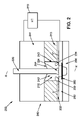
図1Aは、本発明による電気液圧成形装置の第1の実施形態を示す。電気液圧成形装置100は、電気液圧成形チャンバ110と、中央電極120と、周辺電極130とを備える。中央電極120は、長手方向XX´に延び、電気液圧成形チャンバ110の内部に配置された第1の端部122を含む。周辺電極130は、中央電極120の端部122から間隔を置いてその周りに配置された端部132を有する。周辺電極130の端部132は、前記中央電極120に対して横方向の面内、すなわち軸線XX´に垂直な面内に延在する。
FIG. 1A shows a first embodiment of an electro-hydraulic molding apparatus according to the present invention. The electro-
また、電気液圧成形装置100は、本体部140と金型150とを備える。本体部140は内部空洞142を備え、中央電極120と交差している。本体部の内部空洞142は、周辺電極130の端部132と共に電気液圧成形チャンバ110を形成する。
Further, the electric
電気液圧成形チャンバ110は、液体、例えば水で満たされるように意図されており、変形される材料のブランク160によって封止されている。材料のブランク160は、電気液圧成形チャンバ110内を伝播する衝撃波への曝露によって、金型150に対して押圧され、金型150に対して変形する。衝撃波は、電極120と電極130との間に高電圧電気インパルスを印加し、電極間に放電を発生させた後に、発生する。放電により電気アークが発生し、温度が上昇し、液体が気化して、衝撃波の発生がもたらされる。
The electro-hydraulic forming
本明細書に記載の実施形態では、周辺電極130の端部132の一部は、中央電極120の下端部122を包囲する。中央電極120および周辺電極130のそれぞれの、活性部と呼ばれる2つの領域124および134の間に電気アークが優先的に形成される。各放電後に、中央電極120と周辺電極130との間の最短経路に対応する、中央電極120の活性部124の外面125と周辺電極130の活性部134の内面135との2つの異なる点の間に優先的にアークが発生する。したがって、各電極は、中央電極120の活性部124の外面125および周辺電極130の活性部134の内面135に分布した様々な点で局所的に消耗する。周辺電極の消耗はより広い表面にわたって分散され、電極間の距離は、ほとんどの場合には円錐形である2つの電極が向かい合って配置され、したがってそれらの活性部が極めて局在する従来技術の装置よりも変動が少ない。したがって、電気液圧成形の効率、特に衝撃波によって発生する圧力に影響を与えることなく、電極をより長く使用することができる。
In the embodiments described herein, a portion of the
さらに、中央電極の断面は、例えば図2を参照して示されるように、その長手方向軸線XX´に沿って必ずしも一定に形成されないことに留意されたい。さらに、電極の断面は必ずしも軸対称ではない。 Further, it should be noted that the cross section of the central electrode is not always formed consistently along its longitudinal axis XX', as shown, for example, with reference to FIG. Moreover, the cross section of the electrode is not necessarily axisymmetric.
材料のブランク160は、周辺電極130によって金型150に対して保持される(図1A)。この目的のために、周辺電極130は、その下面に、材料のブランク160を収容することができる肩部も備える。したがって、周辺電極130はブランクホルダとして機能し、金型150に対して材料のブランク160を保持することを可能にする。
The material blank 160 is held against the
図1Bに示す一代替実施形態では、図1Aを参照して示す装置と同様の構造である電気液圧成形装置100´が、周辺電極130を支持する電極ホルダ136をさらに備える。電極ホルダ136は、金型150と本体部140との間に配置される。電極ホルダは、その下面に、材料のブランク160を収容することができる肩部と、その上面に周辺電極132を受容するのに適したハウジングとを備える。したがって、電極ホルダ136は、材料のブランク160を金型150に対して保持するためのブランクホルダとしても機能する。
In one alternative embodiment shown in FIG. 1B, the electro-hydraulic forming
他の代替実施形態において、例えば図2を参照して示されるように、ブランクホルダとして機能し、変形される材料のブランクを金型に対して保持するために追加の部品280を使用することができる。この場合、電極ホルダ136はその下面に肩部を備えない。
In another alternative embodiment, as shown, eg, with reference to FIG. 2, an
さらに、本体部140、周辺電極130、および金型150が、スチールまたは他の任意の金属合金などの導電性材料から作られている場合、それらは互いに電気的に接触していることに留意されたい。本明細書に記載の実施形態では、電気絶縁体115が、中央電極120をその長さの一部にわたって、特に本体部140内に収容された中央電極120の一部にわたって包囲する。したがって、本体部140が周辺電極130と電気的に接触している場合でも、中央電極120は周辺電極130から電気的に絶縁されている。したがって、中央電極120は、それを高電圧インパルス発生器170の一方の端子に接続することによって、および本体部140、周辺電極130、または金型150を高電圧インパルス発生器170の他方の端子に接続することによって、第1の電位を受けることができる。本発明の前記実施形態は、機械加工および組み立てが容易であるため、特に有利である。
Further, it should be noted that if the
金型150は単一部品からなるか、または金型支持体と呼ばれる追加の部品に取り付けられて、形成される部品に応じて金型をより容易に変更することを可能にすることに留意されたい。
It is noted that the
本明細書に記載の電気液圧成形装置の様々な構成要素は、ねじを使用して互いに取り付けられ、特に、例えば中央電極の位置、周辺電極の位置、および金型の位置で液圧成形チャンバを封止するために、シールを用いることができることに留意されたい。かかる手段は当業者の到達できる範囲内であり、単純化のためにここではこれ以上詳細には説明しない。 The various components of the electro-hydraulic molding apparatus described herein are attached to each other using screws, especially in the position of the central electrode, the position of the peripheral electrodes, and the position of the mold in the hydraulic molding chamber. Note that a seal can be used to seal the seal. Such means are within the reach of those of skill in the art and will not be described in further detail here for the sake of brevity.
さらに、中央電極が体内に保持される方法は示されていないことに留意されたい。中央電極は、様々な手段によって電気液圧成形装置内に取り付けることができる。例えば、本体部から電気的に絶縁された付加的部品(図示せず)を使用して保持することができる。 Furthermore, it should be noted that no method has been shown for the central electrode to be retained in the body. The central electrode can be mounted in the electro-hydraulic molding apparatus by various means. For example, it can be held by using an additional component (not shown) that is electrically isolated from the body.
有利には、材料のブランクを周辺電極と金型との間に配置できるようにするために、金型と周辺電極とによって形成されたアセンブリは、中央電極を備える本体部に対して移動可能であり、本体部は優先的に固定される。このようにして、周辺電極は金型に取り付けられる。したがって、変形される材料のブランクが交換された際に、本体部に接続されている電流供給導体を移動させる必要はない。 Advantageously, the assembly formed by the mold and the peripheral electrodes is movable relative to the body with the central electrode so that the blank of material can be placed between the peripheral and the mold. Yes, the main body is preferentially fixed. In this way, the peripheral electrodes are attached to the mold. Therefore, it is not necessary to move the current supply conductor connected to the main body when the blank of the material to be deformed is replaced.
一代替実施形態では、金型はプレス機のプラットフォームに取り付けられ、周辺電極は本体部に直接取り付けられる。プレス機を使用して金型を周辺電極に対して保持すると、材料のブランクが周辺電極と金型との間に保持される。 In one alternative embodiment, the die is mounted on the platform of the press and the peripheral electrodes are mounted directly on the body. When the die is held against the peripheral electrode using a press, a blank of material is held between the peripheral electrode and the die.
本出願に記載されている電気液圧装置では、周辺電極は容易にアクセス可能であり、容易に交換できることに留意されたい。 It should be noted that in the electrohydraulic devices described in this application, the peripheral electrodes are easily accessible and easily replaceable.
図2は、本発明による電気液圧成形装置の第2の実施形態を示す。電気液圧成形装置200は、電気液圧成形チャンバ210、中央電極220、周辺電極230、本体部240および金型250を備えるという点で図1Aを参照して示した装置と同様である。図1Aを参照して示された電気液圧成形装置とは対照的に、電気液圧成形装置200は、ブランクホルダとして機能する付加的部品280をさらに備える。装置は、周辺電極230が取り付けられている電極ホルダ232をさらに備える。本体部240は、図1Aおよび図1Bを参照して示された本体部と中央電極との間にはもはやなく、例えば本体部240の下部に配置された電気絶縁体215をさらに備える。ここに示す実施形態では、電気絶縁体215は、電気液圧成形チャンバ210を部分的に形成するキャビティ240の側壁243を構成する。他の代替実施形態では、電気絶縁体215は側壁の一部のみを形成することができる。したがって、中央電極220と本体部240の上部241とは電気的に接触しており、本体部240の上部241は、例えば、高電圧インパルス発生器270の第1の端子に接続することができる。周辺電極230、電極ホルダ232、ブランクホルダ280および金型250は電気的に接触しており、周辺電極230は、ブランクホルダ280または金型250の電極ホルダ232によって高電圧インパルス発生器270の第2の端子に接続されており、したがって、中央電極220と周辺電極230との間の放電を生じさせる。このようにして発生した衝撃波は前記放電に垂直な平面内を伝播する。したがって、衝撃波の一部は後壁244に向かって伝播し、前記壁に衝突し、これを損傷し得る。それ故、絶縁体は、側壁上に配置されており、それほど応力がかからないので、その損傷の危険性が低減する。
FIG. 2 shows a second embodiment of the electro-hydraulic molding apparatus according to the present invention. The electro-
図1Aのように、本体部240はキャビティ242を備え、側壁243および後壁244は、変形される材料のブランクに向かう圧力波のより良好な封じ込めに適した様々な形態を有することができることに留意されたい。例えば、後壁244は、変形させる材料のブランクに向けてよりよく衝撃波を反射するように傾斜させることができる。
As shown in FIG. 1A, the
中央電極220の活性部224および周辺電極230の活性部234は、図2を参照して示されるように、必ずしも一定の断面および/または軸対称である必要はないことにも留意されたい。
It should also be noted that the
図1A、図1Bおよび図2を参照して説明した実施形態では、電気液圧成形装置は1つの中央電極と1つの周辺電極のみを備える。 In the embodiments described with reference to FIGS. 1A, 1B and 2, the electrohydraulic molding apparatus comprises only one central electrode and one peripheral electrode.
他の実施形態では、電気液圧成形装置は、1つまたは複数の金型と組み合わされた複数対の中央電極および周辺電極を備えることができる。したがって、複数の放電を同時に実施することによって、複数の部品を並行して、または1つの大きな部品を製造することが可能である。 In another embodiment, the electro-hydraulic molding apparatus can include a plurality of pairs of central and peripheral electrodes combined with one or more molds. Therefore, by performing a plurality of discharges at the same time, it is possible to manufacture a plurality of parts in parallel or one large part.
形成される部品の寸法が大きい場合、単一の周辺電極と組み合わされた複数の中央電極を使用することもまた有利であり得る。様々な場所で複数の同時または遅延放電を発生させることによって、より均一なまたはより漸進的なまたはより深い電気液圧成形を作り出すことが可能である。 If the dimensions of the parts to be formed are large, it may also be advantageous to use multiple central electrodes combined with a single peripheral electrode. By generating multiple simultaneous or delayed discharges at different locations, it is possible to create more uniform or more gradual or deeper electro-hydraulic molding.
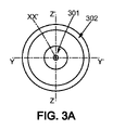
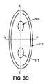
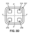
様々な形態の電極および様々な中央電極の配置が、図3A~図3Dを参照して示されている。 Arrangements of different forms of electrodes and different central electrodes are shown with reference to FIGS. 3A-3D.
図3A~図3Dは、中央電極の長手方向軸線XX´に垂直な平面(YY´、ZZ´)に沿った断面図で示される中央電極および周辺電極の活性部をより具体的に示す。 3A-3D show more specifically the active portions of the central and peripheral electrodes shown in cross-sectional view along a plane (YY', ZZ') perpendicular to the longitudinal axis XX'of the central electrode.
図3Aにおいて、中央電極の活性部301は円形であり、周辺電極の活性部302は円環形状である。
In FIG. 3A, the
図3Bにおいて、複数の中央電極の活性部303、305、307は、好ましくは角を丸くした長方形の断面を有し、対応する周辺電極の活性部308を形成する長方形の環の中央で共通の方向ZZ´に整列している。
In FIG. 3B, the
図3Cにおいて、複数の中央電極の活性部309、311は楕円形の断面であり、対応する周辺電極の活性部312を形成する楕円形の環の中央で共通の方向ZZ´に整列している。
In FIG. 3C, the
図3Dにおいて、4つの中央電極の活性部313、314、315、316は、好ましくは角を丸くした正方形の断面であり、対応する周辺電極の活性部317を形成する正方形の環の内側に配置されている。
In FIG. 3D, the
ここに記載した周辺電極は単一部品から形成されている。一代替実施形態では、周辺電極は、放電を発生させるために各中央電極に対向して配置されることを意図した様々な別々の部分を備える。したがって、これらの様々な部分は周辺電極の活性部を備える。それ故、周辺電極を交換するコストは、いくつかの部分を交換するだけに減少する。考慮される中央電極の活性部の外面と隣接する周辺電極の活性部の内面との間の距離が、考慮される活性部の表面の少なくとも一部と平面内で実質的に等距離である場合には、他の幾何学的形状も使用できることに留意されたい。 The peripheral electrodes described here are made of a single component. In one alternative embodiment, the peripheral electrodes are provided with various separate parts intended to be placed facing each center electrode to generate an electric discharge. Therefore, these various parts include the active part of the peripheral electrode. Therefore, the cost of replacing peripheral electrodes is reduced by replacing only a few parts. When the distance between the outer surface of the active part of the central electrode considered and the inner surface of the active part of the adjacent peripheral electrode is substantially equidistant in plane to at least a portion of the surface of the active part considered. Note that other geometric shapes can also be used for.
図2を参照して前述したように、電極の活性部の断面は図1A、図1Bおよび図2の軸線XX´によって示されるその長手方向に沿って一定とすることができ、または、変化することができる。 As mentioned above with reference to FIG. 2, the cross section of the active portion of the electrode can be constant or variable along its longitudinal direction as indicated by axis XX'in FIGS. 1A, 1B and 2. be able to.
上述した電気液圧成形装置の様々な実施形態は、中央電極を部分的に包囲する周辺電極を用いて材料のブランクを電気液圧成形することを可能にし、周辺電極は、電気液圧成形チャンバを部分的に形成する本体部から分離している。したがって、放電は電極の活性部の周囲に分散される。より大きい接触面を有する周辺電極は、よりゆっくりと消耗する。したがって、電極間の距離はそれほど変動せず、これにより、放電によって発生する圧力を実質的に一定に保つことによって電気液圧成形の効率を維持することが可能になる。しかしながら、電極を交換しなければならない場合、材料のブランクを配置するために電気液圧成形装置を開けた際に周辺電極を容易に交換することができ、周辺電極は本体部、および、周辺電極と金型の間に優先的に配置された材料のブランクから分離している。有利には、劣化の少ない活性部を周辺電極に提示するために、中央電極をその長手方向軸線に沿って移動させることができる。 Various embodiments of the electro-hydraulic forming apparatus described above allow for electro-hydraulic molding of a material blank using a peripheral electrode that partially surrounds the central electrode, the peripheral electrode being an electro-hydraulic forming chamber. Is separated from the main body that partially forms. Therefore, the discharge is dispersed around the active portion of the electrode. Peripheral electrodes with larger contact surfaces wear out more slowly. Therefore, the distance between the electrodes does not fluctuate so much, which makes it possible to maintain the efficiency of electro-hydraulic molding by keeping the pressure generated by the discharge substantially constant. However, if the electrodes must be replaced, the peripheral electrodes can be easily replaced when the electro-hydraulic forming apparatus is opened to place the material blank, and the peripheral electrodes are the main body and the peripheral electrodes. It is separated from the blank of the material preferentially placed between the mold and the mold. Advantageously, the central electrode can be moved along its longitudinal axis in order to present the less degraded active portion to the peripheral electrodes.
本発明は、説明され図示された様々な実施形態および言及された代替実施形態に限定されず、以下の特許請求の範囲内の当業者の範囲内の実施形態にも関する。 The present invention is not limited to the various embodiments described and illustrated and the alternative embodiments mentioned, but also to embodiments within the scope of those skilled in the art within the scope of the claims below.
Claims (12)
電気液圧成形チャンバ(110;210)と、
いわゆる長手方向(XX’)に延び、電気液圧成形チャンバ(110;210)の内部に配置された第1の端部(122)を備える少なくとも1つのいわゆる中央電極(120;220;301,303,305,307,309,311,313,314,315,316)と、
中央電極(120;220;301,303,305,307,309,311,313,314,315,316)の端部(122)から離間してその周りに配置され、前記中央電極(120;220;301,303,305,307,309,311,313,314,315,316)に対して横断面(YY’、ZZ’)内に延在する端部(132)を有する、各中央電極(120;220;301,303,305,307,309,311,313,314,315,316)から電気的に絶縁された少なくとも1つのいわゆる周辺電極(130;230;302,308,312,317)と、
各中央電極(120;220;301,303,305,307,309,311,313,314,315,316)を電気液圧成形チャンバ(110;210)に導入するための孔を備え、前記電気液圧成形チャンバを部分的に形成する本体部(140;240)と、
金型(150;250)と、
を備え、
各周辺電極(130;230;302,308,312,317)は前記本体部(140;240)から分離されており、
少なくとも1つの周辺電極(130;230;302,308,312,317)は電極ホルダ(136;232)によって支持されることを特徴とする装置(100;100’;200)。 An electro-hydraulic forming apparatus (100; 100'; 200) for forming a blank (160; 260) of a material.
With an electro-hydraulic forming chamber (110; 210),
At least one so-called central electrode (120; 220; 301, 303) extending in the so-called longitudinal direction (XX') and having a first end (122) located inside an electrohydraulic forming chamber (110; 210). , 305,307,309,311,313,314,315,316),
The central electrode (120; 220; 301; 220; Each central electrode (132) having an end (132) extending within the cross section (YY', ZZ') with respect to 301, 303, 305, 307, 309, 311, 313, 314, 315,316). 120; 220; 301, 303, 305, 307, 309, 311, 313, 314, 315,316) at least one so-called peripheral electrode (130; 230; 302, 308, 312, 317) electrically isolated. When,
Each central electrode (120; 220; 301, 303, 305, 307, 309, 311, 313, 314, 315, 316) is provided with a hole for introducing into the electro-hydraulic forming chamber (110; 210). The main body (140; 240) that partially forms the hydraulic forming chamber,
With the mold (150; 250),
Equipped with
Each peripheral electrode (130; 230; 302, 308, 312, 317) is separated from the main body portion (140; 240) .
A device (100; 100'; 200) characterized in that at least one peripheral electrode (130; 230; 302,308, 312,317) is supported by an electrode holder (136; 232 ).
Applications Claiming Priority (3)
| Application Number | Priority Date | Filing Date | Title |
|---|---|---|---|
| FR1751053 | 2017-02-08 | ||
| FR1751053A FR3062586B1 (en) | 2017-02-08 | 2017-02-08 | ELECTROHYDROFORMING DEVICE |
| PCT/EP2018/053214 WO2018146216A1 (en) | 2017-02-08 | 2018-02-08 | Electrohydraulic forming device |
Publications (2)
| Publication Number | Publication Date |
|---|---|
| JP2020506809A JP2020506809A (en) | 2020-03-05 |
| JP7083176B2 true JP7083176B2 (en) | 2022-06-10 |
Family
ID=58707742
Family Applications (1)
| Application Number | Title | Priority Date | Filing Date |
|---|---|---|---|
| JP2019563689A Active JP7083176B2 (en) | 2017-02-08 | 2018-02-08 | Electro-hydraulic molding equipment |
Country Status (6)
| Country | Link |
|---|---|
| US (1) | US11338346B2 (en) |
| EP (1) | EP3579990B1 (en) |
| JP (1) | JP7083176B2 (en) |
| CN (1) | CN110582360B (en) |
| FR (1) | FR3062586B1 (en) |
| WO (1) | WO2018146216A1 (en) |
Families Citing this family (1)
| Publication number | Priority date | Publication date | Assignee | Title |
|---|---|---|---|---|
| CN111300671A (en) * | 2020-02-28 | 2020-06-19 | 南方科技大学 | Wafer thinning device |
Family Cites Families (10)
| Publication number | Priority date | Publication date | Assignee | Title |
|---|---|---|---|---|
| US4068514A (en) * | 1976-07-12 | 1978-01-17 | Viktor Nikolaevich Chachin | Device for electrohydraulic die-forging |
| RU2060077C1 (en) * | 1992-09-02 | 1996-05-20 | Волгоградский государственный технический университет | Method of electrohydraulic pulse deformation of tubular blanks |
| JP4944322B2 (en) * | 2001-09-26 | 2012-05-30 | 本田技研工業株式会社 | Method for manufacturing hollow member |
| US7802457B2 (en) | 2008-05-05 | 2010-09-28 | Ford Global Technologies, Llc | Electrohydraulic forming tool and method of forming sheet metal blank with the same |
| US8567223B2 (en) * | 2009-09-21 | 2013-10-29 | Ford Global Technologies, Llc | Method and tool for expanding tubular members by electro-hydraulic forming |
| FR3000909B1 (en) * | 2013-01-11 | 2015-05-15 | Adm28 S Ar L | METHOD, TOOLING AND PRESS FOR FORMING A PIECE |
| FR3013243B1 (en) * | 2013-11-15 | 2016-01-01 | Adm28 S Ar L | ELECTRO-HYDROFORMING DEVICE |
| TW201600310A (en) * | 2014-06-17 | 2016-01-01 | Univ Nat Kaohsiung 1St Univ Sc | Drawing die provided with slant blank clamping surface |
| FR3031054B1 (en) * | 2014-12-29 | 2017-01-27 | Adm28 S Ar L | ELECTRO-HYDROFORMING DEVICE WITH OPTIMIZED CHAMBER |
| CN104785605B (en) * | 2015-03-31 | 2017-04-19 | 西北工业大学 | Electro-hydraulic forming device for pipe fitting and forming method |
-
2017
- 2017-02-08 FR FR1751053A patent/FR3062586B1/en not_active Expired - Fee Related
-
2018
- 2018-02-08 EP EP18703599.3A patent/EP3579990B1/en active Active
- 2018-02-08 WO PCT/EP2018/053214 patent/WO2018146216A1/en unknown
- 2018-02-08 US US16/484,734 patent/US11338346B2/en active Active
- 2018-02-08 CN CN201880008414.5A patent/CN110582360B/en active Active
- 2018-02-08 JP JP2019563689A patent/JP7083176B2/en active Active
Also Published As
| Publication number | Publication date |
|---|---|
| US11338346B2 (en) | 2022-05-24 |
| FR3062586B1 (en) | 2020-02-28 |
| US20200001344A1 (en) | 2020-01-02 |
| JP2020506809A (en) | 2020-03-05 |
| EP3579990B1 (en) | 2020-10-14 |
| CN110582360B (en) | 2020-12-04 |
| EP3579990A1 (en) | 2019-12-18 |
| WO2018146216A1 (en) | 2018-08-16 |
| FR3062586A1 (en) | 2018-08-10 |
| CN110582360A (en) | 2019-12-17 |
Similar Documents
| Publication | Publication Date | Title |
|---|---|---|
| KR101854922B1 (en) | Radio frequency (rf) ground return arrangements | |
| JP6258351B2 (en) | Method of electro-hydraulic molding of parts, mold and press machine | |
| JPH02192606A (en) | Discharge tube structure | |
| JP7083176B2 (en) | Electro-hydraulic molding equipment | |
| KR20200018656A (en) | Plasma processing equipment | |
| US3575631A (en) | Electrode for electrohydraulic high-energy-rate metal forming | |
| JP2017504954A (en) | Piezoelectric transformer and counter electrode | |
| US10392703B2 (en) | Plasma CVD apparatus | |
| JP2019537513A (en) | Electro-hydraulic forming method and related equipment | |
| US9802237B2 (en) | Head of an exploding-wire electrohydraulic discharge device | |
| WO2020239221A8 (en) | Integrated component and power switching device | |
| KR101794965B1 (en) | Apparatus and method for producing negative ion | |
| JP2015508232A (en) | Cover for energy storage unit, energy storage unit provided with cover, and method for manufacturing energy storage unit | |
| JP4925600B2 (en) | Plasma generator and film forming method using the same | |
| KR102099382B1 (en) | Substrate processing apparatus | |
| KR20150144411A (en) | TIG Welding Apparatus | |
| EP4369871A2 (en) | An anti-tip electrode type single electrode structure and electrode cleaning device | |
| JP6509135B2 (en) | Ion implantation system | |
| CN105191037B (en) | High-voltage components and high-voltage components device | |
| JP2023127762A (en) | Plasma processing apparatus | |
| JP6341839B2 (en) | Antenna device | |
| KR100683252B1 (en) | Power supplying device and plasma processing apparatus including the same | |
| KR20140022718A (en) | Electromagnetic wave generator and bit generator using oscillation of charged particle | |
| JP2019175709A (en) | Substrate processing apparatus | |
| JPH01218773A (en) | Electrifying cable for welding torch |
Legal Events
| Date | Code | Title | Description |
|---|---|---|---|
| A621 | Written request for application examination |
Free format text: JAPANESE INTERMEDIATE CODE: A621 Effective date: 20201204 |
|
| A977 | Report on retrieval |
Free format text: JAPANESE INTERMEDIATE CODE: A971007 Effective date: 20211020 |
|
| A131 | Notification of reasons for refusal |
Free format text: JAPANESE INTERMEDIATE CODE: A131 Effective date: 20211207 |
|
| A601 | Written request for extension of time |
Free format text: JAPANESE INTERMEDIATE CODE: A601 Effective date: 20220304 |
|
| A521 | Request for written amendment filed |
Free format text: JAPANESE INTERMEDIATE CODE: A523 Effective date: 20220419 |
|
| TRDD | Decision of grant or rejection written | ||
| A01 | Written decision to grant a patent or to grant a registration (utility model) |
Free format text: JAPANESE INTERMEDIATE CODE: A01 Effective date: 20220510 |
|
| A61 | First payment of annual fees (during grant procedure) |
Free format text: JAPANESE INTERMEDIATE CODE: A61 Effective date: 20220524 |
|
| R150 | Certificate of patent or registration of utility model |
Ref document number: 7083176 Country of ref document: JP Free format text: JAPANESE INTERMEDIATE CODE: R150 |