JP7082289B2 - Pachinko machine - Google Patents
Pachinko machine Download PDFInfo
- Publication number
- JP7082289B2 JP7082289B2 JP2018233136A JP2018233136A JP7082289B2 JP 7082289 B2 JP7082289 B2 JP 7082289B2 JP 2018233136 A JP2018233136 A JP 2018233136A JP 2018233136 A JP2018233136 A JP 2018233136A JP 7082289 B2 JP7082289 B2 JP 7082289B2
- Authority
- JP
- Japan
- Prior art keywords
- game
- control board
- state
- main control
- winning
- Prior art date
- Legal status (The legal status is an assumption and is not a legal conclusion. Google has not performed a legal analysis and makes no representation as to the accuracy of the status listed.)
- Active
Links
Images


Description
遊技機に関する。 Regarding gaming machines.
回胴式遊技機(スロットマシン)は、所定数の遊技メダルを投入後に遊技開始指示装置(スタートレバー)が操作されたことを契機として1ゲームが開始されて、複数の図柄が外周上に配置された複数列の回胴(リール)が回転動作し、当該回転動作を停止させるための回胴停止装置(ストップボタン)を駆使して回胴を停止させた結果、有効ライン上に所定の図柄の組合せ(例えば「777」等の入賞役)が並んだ場合には、通常遊技状態よりも遊技者にとって利益状態の高い特別遊技状態(通常時よりも小役等の抽選確率が上昇する遊技状態)に移行するタイプのものが一般的である。ここで、回胴式遊技機においては、遊技の興趣性を高めるための演出用の画像等が、リールの回転動作及び停止動作とシンクロした形で、液晶等のディスプレイ上にて表示される場合があり、回胴停止装置等を操作した際に、回胴上に表示された図柄とディスプレイ上に表示された演出用の画像等とを見比べながら、遊技の結果を予測して楽しむよう構成されているものが多い。また、遊技機に何らかの異常が発生した場合には遊技の進行が停止するエラーとなり得るよう構成されているものも多い。また、近年のぱちんこ遊技機としては、遊技盤面(遊技領域)上の始動口に遊技球が入球したことを契機として所定確率の大当り抽選がなされ、当該大当り抽選に当選した場合には大当り(特別遊技)状態へと移行し、遊技盤面に備えられた大入賞口が開放して大量の賞球を獲得できるぱちんこ遊技機が主流である。このように構成されたぱちんこ遊技機の内には、当該大当り抽選における当選確率を上昇させる確率変動遊技状態や当該大当り抽選における抽選結果を報知するための図柄変動の効率を上昇させる時間短縮遊技状態等を備え、これら遊技状態によって遊技者にとって有利な遊技進行状態を創り出すことで遊技の興趣性を高める遊技機も存在している。 In the spinning machine (slot machine), one game is started when the game start instruction device (start lever) is operated after a predetermined number of game medals are inserted, and a plurality of symbols are arranged on the outer circumference. As a result of rotating the rotating cylinders (reel) in multiple rows and stopping the rotating cylinders by making full use of the rotating cylinder stop device (stop button) for stopping the rotating operation, a predetermined symbol is displayed on the effective line. When a combination of (for example, a winning combination such as "777") is lined up, a special gaming state in which the player is in a higher profit state than in the normal gaming state (a gaming state in which the lottery probability of a small winning combination is higher than in the normal game state). ) Is generally the type that shifts to. Here, in the rotating cylinder type gaming machine, when an image or the like for directing to enhance the interest of the game is displayed on a display such as a liquid crystal in a form synchronized with the rotation operation and the stop operation of the reel. When operating the spinning machine stop device, etc., it is configured to predict and enjoy the result of the game while comparing the design displayed on the spinning machine with the image for staging displayed on the display. There are many things that are done. In addition, many of them are configured so that if some abnormality occurs in the gaming machine, an error may occur in which the progress of the gaming is stopped. Further, in recent pachinko gaming machines, a big hit lottery with a predetermined probability is performed when a game ball enters the starting port on the game board surface (game area), and if the big hit lottery is won, a big hit ( The mainstream is a pachinko machine that can shift to a special game) state and open the large prize opening provided on the game board to win a large number of prize balls. Among the pachinko gaming machines configured in this way, a time-shortening gaming state that increases the efficiency of probability fluctuation gaming states that increase the winning probability in the jackpot lottery and symbol fluctuations for notifying the lottery results in the jackpot lottery. There are also gaming machines that enhance the interest of the game by creating a gaming progress state that is advantageous to the player according to these gaming states.
しかしながら、このような遊技機は従来から多く存在しているため、更なる斬新な遊技性が実現されるような機種の開発が望まれているという課題が存在する。 However, since many such gaming machines have existed in the past, there is a problem that it is desired to develop a model that realizes further novel playability.
本態様に係る遊技機は、
第1情報表示手段と、
第2情報表示手段と、
第3情報表示手段と、
ホッパと、
ホッパに設けられているディスクと、
ディスクを回転させるホッパモータと、
ホッパモータの駆動を制御する駆動制御手段と
を備え、
遊技区間として、第1区間と、第2区間とを有し、
第2区間では、第1情報表示手段にストップスイッチの有利な操作態様に関する情報が表示可能となるよう構成されており、
第2区間では、第2情報表示手段にストップスイッチの有利な操作態様に関する情報が表示可能となるよう構成されており、
第2区間では、第3情報表示手段にストップスイッチの有利な操作態様に関する情報が表示可能となるよう構成されており、
第1情報表示手段はダイナミック点灯制御によりストップスイッチの有利な操作態様に関する情報が表示可能となるよう構成されており、
ダイナミック点灯制御により、所定の周期で第1情報表示手段を点灯させるよう構成されており、
第2区間であって、内部抽せん手段によって特定抽せん結果が決定された遊技では、指示遊技が実行される場合を有するよう構成されており、
内部抽せん手段によって特定抽せん結果が決定された第1の指示遊技において、最初の停止操作である所定のストップスイッチの操作が所定のタイミングで受け付けられた場合には、第3情報表示手段に表示されているストップスイッチの有利な操作態様に関する情報の表示態様が変化した後に、第2情報表示手段に表示されているストップスイッチの有利な操作態様に関する情報の表示態様が変化されるよう構成されており、
最小遊技時間が経過している所定の状況下でスタートスイッチの操作が受け付けられて実行された内部抽せん手段によって特定抽せん結果が決定された第2の指示遊技においては、第1情報表示手段にストップスイッチの有利な操作態様に関する情報が表示された後に、第3情報表示手段にストップスイッチの有利な操作態様に関する情報が表示され、第3情報表示手段にストップスイッチの有利な操作態様に関する情報が表示された後に、第2情報表示手段にストップスイッチの有利な操作態様に関する情報が表示されるよう構成されており、
前記第2の指示遊技において、第1情報表示手段にストップスイッチの有利な操作態様に関する情報が表示された後に、第2情報表示手段にストップスイッチの有利な操作態様に関する情報が表示されるまでの時間は、所定の周期よりも長くなるよう構成されており、
クレジットが上限値に達している遊技において、所定の条件を満たすと、駆動制御手段がホッパモータを駆動させて、メダルの払い出しを可能とする払出処理を実行するように構成され、
ディスクには、ホッパ内に貯留されているメダルを保持可能な保持部が複数設けられ、
特定の状況下でホッパモータが駆動してディスクが回転すると、保持部に保持されているメダルが放出部から順次払い出されるように形成され、
前記特定の状況下で実行された払出処理によって最後に払い出されるメダルが放出口から払い出された瞬間の当該最後に払い出されるメダルが保持されていた保持部の位置を、第1位置とし、
前記特定の状況下で実行された払出処理によって最後に払い出されるメダルが放出口から払い出された瞬間における、次回の払出処理で払い出され得る最初に払い出されるメダルが保持されている保持部の位置を、第2位置とし、
前記特定の状況下で実行された払出処理が終了しディスクの回転が停止したときは、前記次回の払出処理で払い出され得る最初に払い出されるメダルが保持されている保持部が、第1位置と第2位置との間に位置している
ことを特徴とする遊技機である。
<付記>
尚、本態様とは異なる別態様について以下に列記しておくが、これらには何ら限定されることなく実施することが可能である。
本別態様に係る遊技機は、
演出を表示可能な演出表示部と、
演出用可動物と
を備え、
演出表示部に表示される第一の演出と、第二の演出とを有し、
第一の演出の実行中においては、遊技者に有利な結果が付与される可能性が高いことを報知する結果示唆演出と、第二の演出とが実行され得るよう構成されており、
第一の演出の実行中において、第二の演出が特定態様になった場合に演出用可動物が動作し、その後、結果示唆演出が実行される場合があるよう構成されている
ことを特徴とする遊技機である。
The gaming machine according to this aspect is
First information display means and
Second information display means and
Third information display means and
Hopper and
The disc provided in the hopper and
A hopper motor that rotates the disk and
It is equipped with a drive control means that controls the drive of the hopper motor.
The game section has a first section and a second section.
In the second section, information regarding an advantageous operation mode of the stop switch can be displayed on the first information display means.
In the second section, the second information display means is configured to be able to display information on an advantageous operation mode of the stop switch.
In the second section, information regarding an advantageous operation mode of the stop switch can be displayed on the third information display means.
The first information display means is configured to be able to display information on an advantageous operation mode of the stop switch by dynamic lighting control.
It is configured to light the first information display means at a predetermined cycle by dynamic lighting control.
In the second section, the game in which the specific lottery result is determined by the internal lottery means is configured to have a case where the instruction game is executed.
In the first instruction game in which the specific lottery result is determined by the internal lottery means, when the operation of the predetermined stop switch, which is the first stop operation, is accepted at the predetermined timing, it is displayed on the third information display means. It is configured so that the display mode of the information regarding the advantageous operation mode of the stop switch displayed on the second information display means is changed after the display mode of the information regarding the advantageous operation mode of the stop switch is changed. ,
In the second instruction game in which the specific lottery result is determined by the internal lottery means executed by receiving the operation of the start switch under a predetermined situation where the minimum game time has elapsed, the first information display means is stopped. After the information on the advantageous operation mode of the switch is displayed, the third information display means displays the information on the advantageous operation mode of the stop switch, and the third information display means displays the information on the advantageous operation mode of the stop switch. After that, the second information display means is configured to display information regarding an advantageous operation mode of the stop switch.
In the second instruction game, after the information on the advantageous operation mode of the stop switch is displayed on the first information display means, until the information on the advantageous operation mode of the stop switch is displayed on the second information display means. The time is configured to be longer than the predetermined period.
In a game in which the credit has reached the upper limit, when a predetermined condition is satisfied, the drive control means is configured to drive a hopper motor to execute a payout process that enables medal payout.
The disc is provided with a plurality of holding parts that can hold medals stored in the hopper.
When the hopper motor is driven to rotate the disk under certain circumstances, the medals held in the holding section are formed so as to be sequentially ejected from the discharging section.
The position of the holding portion where the last medal to be paid out is held at the moment when the medal to be finally paid out by the payout process executed under the specific situation is paid out from the ejection port is set as the first position.
The holding unit that holds the first medal that can be paid out in the next payout process at the moment when the medal that is last paid out by the payout process executed under the specific situation is paid out from the ejection port. The position is set to the second position.
When the payout process executed under the specific situation ends and the rotation of the disk stops, the holding unit holding the first medal to be paid out that can be paid out in the next payout process is in the first position. It is a gaming machine characterized in that it is located between the second position and the second position.
<Additional Notes>
In addition, although other embodiments different from this embodiment are listed below, they can be implemented without any limitation.
The gaming machine according to this other aspect is
A staging display unit that can display staging, and a staging display unit
Equipped with movable objects for staging,
It has a first effect and a second effect displayed on the effect display unit.
During the execution of the first effect, the result suggestion effect for notifying the player that a favorable result is likely to be given and the second effect can be executed.
The feature is that during the execution of the first effect, the movable object for effect operates when the second effect becomes a specific mode, and then the result suggestion effect may be executed. It is a game machine to play.
本態様に係る遊技機によれば、遊技者にとって有利な遊技進行状態を創り出すという概念を採用した遊技機において、更なる斬新な遊技性を実現することができる。 According to the gaming machine according to this aspect, further novel game playability can be realized in a gaming machine that adopts the concept of creating a gaming progress state that is advantageous to the player.
はじめに、本明細書における各用語の意義について説明する。「乱数」とは、回胴式遊技機において何らかの遊技内容を決定するための抽選(電子計算機によるくじであり、抽せんとも称することがある)に使用される乱数であり、狭義の乱数の他に擬似乱数も含む(例えば、乱数としてはハード乱数、CPUを含む主制御チップによって生成された内蔵乱数、擬似乱数としてはソフト乱数)。例えば、遊技の結果に影響を与えるいわゆる「基本乱数」、具体的には、特別遊技に移行するための特別役や入賞役(小役、再遊技役)と関連した「当選乱数」、等を挙げることができる。「CPU」とは、当業界において周知であるものと同義であり、使用されているアーキテクチャ(CISC、RISC、ビット数等)や処理性能等には何ら限定されない。「電断(電源断)」とは、遊技機に設けられた電源スイッチの操作実行有無に係らず、遊技機に供給される電源電圧が一定レベル以下となったことを指し、例えば、電源供給ユニットの破損や停電等による不測の事態による電源供給の遮断をも包含する。「ROM」とは、当業界において周知であるものと同義であり、情報を物理的に保持する(例えば、データ読み出し用の電流を与えた場合、導通する素子構成であれば「1」、導通しない素子構成であれば「0」となる)。RAMとは、当業界において周知であるものと同義であり、情報を電気的に保持する(例えば、データ読み出し用の電流を与えた場合、蓄電されていれば「1」、蓄電されていなければ「0」となる。尚、RAM内で保持されているデータの一部又はすべてに対して、電断時にはバックアップ電源が供給されるよう構成されていることが一般的である)。「遊技状態」とは、例えば、遊技メダルが獲得容易であり遊技者にとって有利な特別遊技状態(いわゆる大当り遊技であり、ボーナス遊技や第1種BB・第2種BB等と呼ばれるものが該当する)、再遊技役の当選率があらかじめ定められた値である通常遊技状態よりも再遊技役の当選率が高い(又は低い)状態である再遊技確率変動遊技状態(RT状態)、当選した役を入賞させるためのリールの停止順、停止位置を報知し得るAT(アシストタイム)中状態、前記RT状態とAT中状態とが複合したART(アシストリプレイタイム)状態、等が挙げられる。また、通常遊技状態においても、RT状態、AT中状態、ART中状態への移行抽選確率が異なる、高確率通常遊技状態、低確率通常遊技状態、等(本例では、抽選状態と称している)が挙げられる。また、遊技状態は複合しても問題ない{更に、これらの遊技状態や機能(例えば、AT中状態への移行抽選や、リールの停止順に係る報知指示の出力等)は、遊技進行を制御する主制御基板側ですべて実装してしまっても問題ない}。また、本例においては、ATに関する状態とRT状態とを個別に記載し、RT状態が「RT1」且つATに関する状態が「通常遊技状態」等と称しているが、RT状態とATに関する状態とを纏めてARTに関する状態としてARTに関する状態が「通常遊技状態」等と称してもよい。「当選役」とは、内部抽選(内部注抽せんと称することがある)により当選した条件装置の種類(又は、条件装置番号)である。「報知状態」とは、後述する押し順ナビを実行可能なATに関する状態であり、リール停止順によって入賞する役が相違しないために押し順ナビが実行されない条件装置が当選したゲームであっても、ATに関する状態が押し順ナビを実行可能な状態であれば「報知状態」とするよう構成している。「カウンタ値」とは「報知遊技実行可能数」とも称し、後述する、AT残りゲーム数もしくはATカウンタM60のカウンタ値である。例えば、「報知遊技実行可能数」が1以上(「0」となった当該遊技も含めても良い)である場合には後述する押し順ナビが実行され得る。また、「報知遊技実行可能数」として、小役(主に、押し順ベル役)が当選したことに基づいて得られる遊技媒体の差枚数(払出し枚数から投入枚数を引いた枚数)や、押し順ベル役の当選回数、を採用しても良い。また、「特殊報知状態」とは、ATに関する状態のうち遊技者に最も有利となる状態であり、本例では、「上乗せ特化状態」と称している。また、「特定条件」とは、ATカウンタ値を減算し得る条件であり、例えば、1ゲームが終了した、所定役(例えば、押し順ベル役)が当選した、等が特定条件となる。「第1種特別役物」とは、規定数ごとの入賞に係る図柄の組合せの数を増加させ、又は規定数ごとの入賞に係る条件装置が作動する確率を上昇させる役物で、あらかじめ定められた場合に作動し12回を超えない回数の遊技の結果が得られるまで作動を継続することができるものであり、RB(レギュラーボーナス)と称することがある。「第1種特別役物連続作動装置」とは、第1種特別役物を連続して作動させることができる装置で、特定の図柄の組合せが表示された場合に作動しあらかじめ定められた場合に作動を終了するものであり、BB(ビッグボーナス)や第1種BBと称することがある。「第2種特別役物」とは、役抽選の結果に拘らず入賞に係る条件装置を作動させることとなる役物で、あらかじめ定められた場合に作動し1回の遊技の結果が得られた場合に作動を終了するものであり、CB(チャレンジボーナス)と称することがある。「第2種特別役物連続作動装置」とは、第2種特別役物を連続して作動させることができる装置で、特定の図柄の組合せが表示された場合に作動しあらかじめ定められた場合に作動を終了するものであり、MB(ミドルボーナス)や第2種BBと称することがある。「普通役物」とは、規定数毎の入賞に係る図柄の組合せの数を増加させ、又は、規定数毎の入賞に係る条件装置が作動する確率を上昇させる役物で、特定の図柄の組合せが表示された場合に作動し1回の遊技の結果が得られた場合に作動を終了することとされているものであり、SB(シングルボーナス)と称することがある。「オールJACINタイプ」とは、第1種BB役が入賞した場合にJACINしたものとみなし、第1種BBの実行中においては常にRB中とする構成である。また、「JACIN抽選タイプ」とは、第1種BBの実行時にて非RB中とRB中とを繰り返し実行する構成である。また、「無制御リール」とは、停止操作を行った後に実行され得る引込み制御が実行されない状態のリールであり、停止操作を受け付けたリール位置から停止し得る最も近いリール位置にて停止する状態のリールである。「オールCBタイプ」とは、第2種BBの実行時にて常にCB中となる構成である。「CB移行抽選タイプ」とは、第2種BBの実行時にて非CB中とCB中とを繰り返し実行する構成である。
First, the meaning of each term in the present specification will be described. A "random number" is a random number used in a lottery (a lottery by an electronic computer, which may also be called a lottery) for determining some kind of game content in a spinning-type game machine, and is a random number in a narrow sense. It also includes pseudo-random numbers (for example, hard random numbers as random numbers, built-in random numbers generated by a main control chip including a CPU, and soft random numbers as pseudo-random numbers). For example, so-called "basic random numbers" that affect the outcome of the game, specifically, "winning random numbers" related to special roles and winning roles (small roles, re-game roles) for transitioning to special games, etc. Can be mentioned. The term "CPU" is synonymous with what is well known in the art, and is not limited to the architecture (CISC, RISC, number of bits, etc.) and processing performance used. "Power outage" means that the power supply voltage supplied to the gaming machine is below a certain level regardless of whether or not the power switch provided in the gaming machine is operated. For example, power supply It also includes the interruption of power supply due to unforeseen circumstances such as damage to the unit or power outage. "ROM" is synonymous with what is well known in the art, and is "1" if the element configuration is conductive when a current for reading data is applied to physically hold information (for example, "1" for conduction. If the element configuration does not, it will be "0"). RAM is synonymous with what is well known in the industry and holds information electrically (for example, when a current for reading data is given, it is "1" if it is stored, and if it is not stored. It is set to "0". It should be noted that it is generally configured to supply backup power to a part or all of the data held in the RAM at the time of power failure). The "game state" corresponds to, for example, a special game state in which a game medal is easy to obtain and is advantageous for the player (a so-called big hit game, which is called a bonus game, a first-class BB, a second-class BB, or the like. ), The winning rate of the re-gaming combination is higher (or lower) than the normal gaming state in which the winning rate of the re-gaming combination is a predetermined value. Examples include the reel stop order for winning a medal, an AT (assist time) state in which a stop position can be notified, and an ART (assist replay time) state in which the RT state and the AT state are combined. Further, even in the normal gaming state, the lottery probability of transitioning to the RT state, the AT in progress state, and the ART in progress state is different, the high probability normal game state, the low probability normal game state, etc. (in this example, it is referred to as the lottery state. ). In addition, there is no problem even if the game states are combined {Furthermore, these game states and functions (for example, a lottery for shifting to the AT state, output of a notification instruction related to the reel stop order, etc.) control the game progress. There is no problem even if all are mounted on the main control board side}. Further, in this example, the AT-related state and the RT state are described separately, and the RT state is referred to as "RT1" and the AT-related state is referred to as "normal gaming state". The state related to ART may be collectively referred to as a "normal gaming state" or the like as a state related to ART. The "winning combination" is a type (or condition device number) of a conditional device that has been won by an internal lottery (sometimes referred to as an internal lottery). The "notification state" is a state related to an AT that can execute the push order navigation described later, and even if the game is won by a conditional device in which the push order navigation is not executed because the winning combination does not differ depending on the reel stop order. , If the state related to AT is a state in which push order navigation can be executed, it is configured to be a "notification state". The "counter value" is also referred to as "the number of games that can be executed for notification games", and is the number of remaining AT games or the counter value of the AT counter M60, which will be described later. For example, when the "number of playable notification games" is 1 or more (the game in which "0" is set may be included), the push order navigation described later can be executed. In addition, as the "number of playable notification games", the difference number of game media (the number of payouts minus the number of input) obtained based on the winning of small wins (mainly the push order bell role) and the number of pushes The number of times the winning bell role is won may be adopted. Further, the "special notification state" is a state that is most advantageous to the player among the states related to the AT, and in this example, it is referred to as an "additional specialization state". Further, the "specific condition" is a condition in which the AT counter value can be subtracted, and the specific condition is, for example, that one game is completed, a predetermined combination (for example, a push order bell combination) is won, and the like. "
尚、本実施形態は、あくまで一例であり、各手段が存在する場所や機能等、各種処理に関しての各ステップの順序、フラグのオン・オフのタイミング、各ステップの処理を担う手段名等に関し、以下の態様に限定されるものではない。また、上記した実施形態や変更例は、特定のものに対して適用されると限定的に解すべきでなく、どのような組み合わせであってもよい。例えば、ある実施形態についての変更例は、別の実施形態の変更例であると理解すべきであり、また、ある変更例と別の変更例が独立して記載されていたとしても、当該ある変更例と当該別の変更例を組み合わせたものも記載されていると理解すべきである。 It should be noted that this embodiment is merely an example, and relates to the order of each step regarding various processes such as the location and function where each means exists, the timing of turning on / off the flag, the name of the means responsible for the process of each step, and the like. It is not limited to the following aspects. Further, the above-described embodiments and modifications should not be limitedly understood to be applied to specific ones, and may be any combination. For example, it should be understood that a modification of one embodiment is a modification of another embodiment, even if one modification and another modification are described independently. It should be understood that a combination of the modified example and the other modified example is also described.
(本実施形態)
ここで、各構成要素について説明する前に、本実施形態に係る回胴式遊技機Pの特徴(概略)を説明する。以下、図面を参照しながら、各要素について詳述する。
(The present embodiment)
Here, before explaining each component, the features (outline) of the spinning machine P according to the present embodiment will be described. Hereinafter, each element will be described in detail with reference to the drawings.
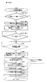
まず、図1(一部の構成については図2)を参照しながら、本実施形態に係る回胴式遊技機Pの前面側の基本構造を説明する。回胴式遊技機Pは、主に前扉(フロントドアとも称す)と、裏箱(キャビネット、基体とも称す)と裏箱内に設置されたリールユニット、ホッパ装置、電源供給ユニットE、主制御基板M(CPUMCを含む主制御チップCが搭載されている基板)、副制御基板S(CPUSCを含む副制御チップSCが搭載されている基板)で構成される。以下、これらを順に説明する。 First, with reference to FIG. 1 (FIG. 2 for a part of the configuration), the basic structure on the front side of the rotating cylinder type gaming machine P according to the present embodiment will be described. The revolving gaming machine P mainly consists of a front door (also called a front door), a back box (also called a cabinet or a base), a reel unit installed in the back box, a hopper device, a power supply unit E, and a main control. It is composed of a board M (a board on which a main control chip C including a CPU MC is mounted) and a sub control board S (a board on which a sub control chip SC including a CPU SC is mounted). Hereinafter, these will be described in order.
<前扉DU>
前扉DUは、遊技状態を視認可能にするための機構、遊技媒体の入力を可能にするための機構、リールユニットを操作するための機構、その他の機構等を含む。具体的には、遊技状態を視認可能にするための機構として、リール窓D160、投入数表示灯D210、スタートランプD180、再遊技ランプD290、投入可能ランプD300、特別遊技状態表示装置D250、クレジット数表示装置D200、払出数表示装置(押し順表示装置)D270(押し順表示装置D270と称することもある)、ATカウンタ値表示装置D280、有利区間表示器YH等が取り付けられている。また、遊技媒体の投入や賭け数(ベット数)の入力を可能にするための機構として、メダル投入口D170、ベットボタンD220、投入された遊技媒体の払い出しを可能にするための機構として、精算ボタンD60が取り付けられている。そして、リールを操作するための機構として、スタートレバーD50、停止ボタンD40が取り付けられている。なお、本実施形態における回胴式遊技機は、スタートレバーD50、停止ボタンD40、メダル投入口D170、ベットボタンD220、精算ボタンD60、サブ入力ボタンSB、十字キーSB2等が取り付けられている遊技者側にせり出した形状の操作卓を備えている。以下、各要素について詳述する。
<Front door DU>
The front door DU includes a mechanism for making the gaming state visible, a mechanism for enabling input of the game medium, a mechanism for operating the reel unit, and other mechanisms. Specifically, as a mechanism for making the game state visible, the reel window D160, the input number indicator light D210, the start lamp D180, the re-game lamp D290, the insertable lamp D300, the special game status display device D250, and the number of credits. A display device D200, a payout number display device (push order display device) D270 (sometimes referred to as a push order display device D270), an AT counter value display device D280, an advantageous section display YH, and the like are attached. In addition, as a mechanism for enabling the insertion of the game medium and the input of the number of bets (number of bets), the medal insertion slot D170, the bet button D220, and the mechanism for allowing the inserted game medium to be paid out are settled. Button D60 is attached. A start lever D50 and a stop button D40 are attached as a mechanism for operating the reel. The spinning machine in the present embodiment is equipped with a start lever D50, a stop button D40, a medal slot D170, a bet button D220, a settlement button D60, a sub input button SB, a cross key SB2, and the like. It is equipped with an operation console that protrudes to the side. Hereinafter, each element will be described in detail.
<遊技状態を視認可能にするための機構>
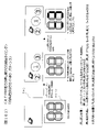
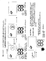
次に、遊技状態を視認可能にするための機構の要部について説明する。リール窓D160は、前扉DUの一部を構成する合成樹脂等によって形成された透明な部材であり、リール窓D160を通して遊技機枠内に設置されたリールユニットを視認可能に構成されている。また、投入数表示灯D210は、3つのLEDによって構成されており、現在ベット(一の遊技を開始するために必要な遊技メダルを投入すること)されているメダル数と同数のLEDが点灯するよう構成されている。具体的には、投入数表示灯D210は、1ベットランプD211、2ベットランプD212、3ベットランプD213の3つのLED(ランプ)によって構成されており、ベットされている遊技メダルが1枚である場合には1ベットランプD211:点灯、2ベットランプD212:消灯、3ベットランプD213:消灯となり、ベットされている遊技メダルが2枚である場合には1ベットランプD211:点灯、2ベットランプD212:点灯、3ベットランプD213:消灯となり、ベットされている遊技メダルが3枚である場合には1ベットランプD211:点灯、2ベットランプD212:点灯、3ベットランプD213:点灯となる(再遊技が停止表示した次ゲームにおいてはその限りではなく、詳細は後述する)。また、スタートランプD180は、LEDによって構成されており、スタートレバーD50の操作が有効(操作を受け付けている)である場合に点灯し、スタートレバーD50の操作が無効(操作を受け付けていない)である場合に消灯するよう構成されている。また、再遊技ランプD290は、LEDによって構成されており、再遊技が停止表示したことを契機として点灯し、再遊技が停止表示した次回の遊技が終了したことによって消灯するよう構成されている。また、投入可能ランプD300は、メダル投入口D170への遊技メダルの投入が有効である、又は、ベットボタンD220の操作が有効である場合に点灯(点滅としてもよい)し、遊技メダルの投入が無効である、又は、ベットボタンD220の操作が無効である場合に消灯するよう構成されている。また、特別遊技状態表示装置D250は、7セグメントディスプレイによって構成されており、特別遊技中に払い出された払出数の総数が表示されるよう構成されている。尚、特別遊技状態表示装置D250を設けない構成としてもよく、そのように構成した場合には、後述する演出表示装置S40(第二情報表示部とも称することがある)にて当該払出数の総数を表示するよう構成することで遊技者は特別遊技中に払い出された払出数の総数を認識することができユーザーフレンドリーな遊技機とすることができる。また、クレジット数表示装置D200は、7セグメントディスプレイによって構成されており、遊技者の持ちメダルとして遊技機内に貯留されているメダル数の総数(クレジット数)が表示されるよう構成されている。また、払出数表示装置(押し順表示装置)D270は、7セグメントディスプレイによって構成されており、現在払出されている遊技メダル数及びリール停止順(左停止ボタンD41、中停止ボタンD42、右停止ボタンD43の停止順)によって入賞する役が相違し得る条件装置{いわゆる押し順役(押し順あり役とも称することがある)であるが、入賞する役や停止表示される図柄組合せが相違した場合には、遊技者に付される利益率(払出枚数、その後のRT状態等)が異なり得るよう構成されているものが一般的である}が成立したゲームにて、遊技者に最も有利となるリール停止順を報知し得るよう構成されている(当該報知を押し順ナビと称することがある)。このように、払出数表示装置(押し順表示装置)D270は、現在払出されている遊技メダル数と遊技者に最も高利益となるリール停止順との2つの表示を実行し得るよう構成されており、実行されている表示が2つの表示のうちいずれであるかを遊技者が誤認しないような表示態様となっており、当該表示態様の詳細は後述することとする。また、ATカウンタ値表示装置D280は、ATに関する状態(詳細は後述する)のうち、押し順表示装置D270(第一情報表示部とも称することがある)に表示された押し順ナビ表示に従って遊技を進行した場合に保障されることとなる遊技者にとって有利なATに関する状態(本例では、押し順ナビ状態、報知遊技とも称することがあり詳細は後述する)に滞在し得るゲーム数を表示し得るよう構成されている。尚、ATカウンタ値表示装置D280を設けない構成としてもよく、そのように構成した場合には、AT中状態に滞在し得るゲーム数を演出表示装置S40にて表示するよう構成することで遊技者は当該有利なATに関する状態が保障されているゲーム数を認識することができユーザーフレンドリーな遊技機とすることができる。尚、払出数表示装置(押し順表示装置)D270は、払出数表示装置と押し順表示装置との2つの装置に分けるよう構成してもよい。
<Mechanism for making the game state visible>
Next, the main part of the mechanism for making the gaming state visible will be described. The reel window D160 is a transparent member formed of a synthetic resin or the like that constitutes a part of the front door DU, and is configured so that the reel unit installed in the gaming machine frame can be visually recognized through the reel window D160. Further, the input number indicator lamp D210 is composed of three LEDs, and the same number of LEDs as the number of medals currently bet (inserting the game medals necessary for starting one game) are lit. It is configured as. Specifically, the input number indicator lamp D210 is composed of three LEDs (lamps) of a 1-bet lamp D211, a 2-bet lamp D212, and a 3-bet lamp D213, and one game medal is bet. In that case, the 1-bet lamp D211: lights up, the 2-bet lamp D212: turns off, the 3-bet lamp D213: turns off, and if there are two game medals bet, the 1-bet lamp D211: lights up, and the 2-bet lamp D212: turns on. : Lights up, 3-bet lamp D213: turns off, and when there are 3 bet game medals, 1-bet lamp D211: lights up, 2-bet lamp D212: lights up, and 3-bet lamp D213: lights up (re-game). This is not the case in the next game where is stopped and displayed, and details will be described later). Further, the start lamp D180 is composed of LEDs and lights up when the operation of the start lever D50 is valid (operation is accepted), and the operation of the start lever D50 is invalid (operation is not accepted). It is configured to turn off in some cases. Further, the re-game lamp D290 is composed of LEDs, and is configured to be turned on when the re-game is stopped and displayed, and turned off when the next game when the re-game is stopped and displayed is completed. Further, the insertable lamp D300 is lit (may be blinking) when the insertion of the game medal into the medal insertion slot D170 is effective, or when the operation of the bet button D220 is effective, and the insertion of the game medal is performed. It is configured to turn off when it is invalid or when the operation of the bet button D220 is invalid. Further, the special game status display device D250 is configured by a 7-segment display, and is configured to display the total number of payouts paid out during the special game. It should be noted that the special game status display device D250 may not be provided, and in such a configuration, the total number of payouts may be made by the effect display device S40 (also referred to as the second information display unit) described later. By configuring to display, the player can recognize the total number of payouts paid out during the special game, and can be a user-friendly gaming machine. Further, the credit number display device D200 is configured by a 7-segment display, and is configured to display the total number of medals (number of credits) stored in the game machine as medals held by the player. Further, the payout number display device (push order display device) D270 is composed of a 7-segment display, and the number of game medals currently paid out and the reel stop order (left stop button D41, middle stop button D42, right stop button). The winning combination may differ depending on the stop order of D43). Is generally configured so that the profit margin (number of payouts, RT state after that, etc.) given to the player can be different}, which is the most advantageous reel for the player in the game. It is configured to notify the stop order (the notification may be referred to as push order navigation). In this way, the payout number display device (push order display device) D270 is configured to be able to execute two displays, that is, the number of game medals currently paid out and the reel stop order that is most profitable to the player. The display mode is such that the player does not misunderstand which of the two displays is being executed, and the details of the display mode will be described later. Further, the AT counter value display device D280 plays a game according to the push order navigation display displayed on the push order display device D270 (also referred to as the first information display unit) among the states related to AT (details will be described later). It is possible to display the number of games that can stay in a state related to AT that is advantageous for the player (in this example, a push order navigation state, which may also be referred to as a notification game, details will be described later), which is guaranteed when the game progresses. It is configured as. It should be noted that the AT counter value display device D280 may not be provided, and in such a configuration, the player may be configured to display the number of games that can stay in the AT state on the effect display device S40. Can recognize the number of games whose state regarding the advantageous AT is guaranteed, and can be a user-friendly gaming machine. The payout number display device (push order display device) D270 may be configured to be divided into two devices, a payout number display device and a push order display device.
また、有利区間表示器YHは、LEDによって構成されており、「有利区間」である場合には点灯し、「有利区間」でない場合には消灯するよう構成されている(点灯及び消灯タイミングについては後述する)。ここで、本例に係る回胴式遊技機においては、従来の回胴式遊技機と同様に、遊技メダルが獲得容易であり遊技者にとって有利な特別遊技状態(いわゆる大当り遊技であり、ボーナス遊技や第1種BB・第2種BB等と呼ばれるものが該当する)、再遊技役の当選率があらかじめ定められた値である通常遊技状態よりも再遊技役の当選率が高い(又は低い)状態である再遊技確率変動遊技状態(RT状態)、当選した役を入賞させるためのリールの停止順、停止位置を報知し得るAT(アシストタイム)中状態、前記RT状態とAT中状態とが複合したART(アシストリプレイタイム)状態、等を採り得るが、これらの「遊技状態」とは別に、「通常区間」、「待機区間」及び「有利区間」という3つの「遊技区間」のいずれかを設定可能となっている。尚、本例においては「待機区間」は設定しておらず、「通常区間」と「有利区間」とのいずれかの遊技区間を設定している。このうち、「有利区間」が他の「遊技区間」よりも、遊技者にとって相対的に有利となるものとして位置付けられており、例えば、「遊技状態」がAT中状態やART状態であることと「有利区間」とが対応付けされている。即ち、「遊技状態」がAT中状態やART状態であると、有利区間表示器YHが点灯するのであるが、後述するように、「遊技区間」の設定制御も「遊技状態」の設定制御と同様に、遊技進行を制御する主制御基板側で行われるため、有利区間表示器YHの点灯/消灯状況によって、遊技進行状況が遊技者にとって相対的に有利なものとなっているか否かが、嘘偽りなく遊技者に対して伝達可能となっている。尚、後述するように、「有利区間」が所定の上限ゲーム数(例えば、1500ゲーム)に達するまで継続すると「通常区間」が強制的に設定されるのであるが、その際には、残存するATに関する状態も強制的に終了させられる(AT中状態を維持するための情報がクリア・初期化される)ため、設定される「遊技区間」の変更が「遊技状態」の移行にも影響を与え得るものとなっており、それにより比較的設計自由度の高いAT中状態やART状態等の「遊技状態」によって、著しく射幸性が高まってしまうことを自動的に抑制できるものとなっているのである。尚、上述したように、「有利区間」が所定の上限ゲーム数(例えば、1500ゲーム)に達するまで継続すると「通常区間」が強制的に設定される、即ち、「有利区間」が終了することとなるが、「有利区間」の終了条件はこれには限定されない。本例に係る回胴式遊技機における「有利区間」の終了条件は、「押し順役(押し順あり役)を構成する小役の中で、払出し枚数が最も多い小役を獲得可能な押し順ナビ1回の実行(例えば、押し順役を構成する小役として、7枚、3枚、1枚の小役がある場合、払出し枚数が最も多い7枚が獲得可能な押し順ナビであって、押し順により7枚、又は1枚が獲得可能な押し順役と、押し順により3枚が獲得可能な押し順役があれば、3枚が獲得可能な押し順ナビは、ここでいう押し順ナビには該当しない)」、又は、「BB、RB、MB、のいずれかに当選」を満たし、且つ、「任意の終了条件(40G1セットのループ抽選に非当選(AT)、固定32G経過(ガセ前兆)等)」、又は、「有利区間1500G」を満たすことが終了条件となっている。尚、押し順ベル役が存在しないような仕様(例:RT状態を移行するためのリプレイの押し順は存在するが、押し順によって払出し枚数が異なる小役が存在しない仕様)の場合には、「払出し枚数が最も多い小役を獲得可能な押し順ナビ1回」という有利区間を終了するための条件は除外される。また、本実施形態では、押し順役を構成する小役として11枚役に対応する小役と1枚役に対応する小役を含む小役により構成されているため、「払出し枚数が最も多い小役を獲得可能な押し順ナビ1回の実行」とは、11枚のメダルが獲得可能(11枚役が入賞可能)な押し順を報知することを指す。
Further, the advantageous section indicator YH is composed of LEDs, and is configured to be turned on when it is an "advantageous section" and turned off when it is not an "advantageous section" (for lighting and extinguishing timing). Will be described later). Here, in the revolving gaming machine according to this example, as in the conventional revolving gaming machine, it is easy to obtain a game medal, which is an advantageous special gaming state for the player (so-called big hit game, bonus game). , 1st type BB, 2nd type BB, etc.), the winning rate of the replaying combination is higher (or lower) than the normal gaming state where the winning rate of the replaying combination is a predetermined value. The re-game probability fluctuation game state (RT state), the stop order of the reels for winning the winning combination, the AT (assist time) state in which the stop position can be notified, and the RT state and the AT state are A combined ART (assist replay time) state, etc. can be taken, but apart from these "game states", any one of the three "game sections" of "normal section", "waiting section" and "advantageous section". Can be set. In this example, the "waiting section" is not set, but one of the "normal section" and the "advantageous section" is set. Of these, the "advantageous section" is positioned as being relatively more advantageous to the player than the other "game sections", for example, the "gaming state" is in the AT state or the ART state. It is associated with an "advantageous section". That is, when the "game state" is in the AT state or the ART state, the advantageous section display YH lights up, but as will be described later, the setting control of the "game section" is also the setting control of the "game state". Similarly, since it is performed on the main control board side that controls the progress of the game, whether or not the progress of the game is relatively advantageous to the player depending on the lighting / extinguishing status of the advantageous section indicator YH. It is possible to convey to the player without telling a lie. As will be described later, if the "advantageous section" continues until the predetermined upper limit number of games (for example, 1500 games) is reached, the "normal section" is forcibly set, but in that case, it remains. Since the state related to AT is also forcibly terminated (the information for maintaining the AT state is cleared and initialized), the change of the set "game section" also affects the transition to the "game state". It can be given, and as a result, it is possible to automatically suppress the significant increase in gambling due to the "game state" such as the AT state or the ART state, which has a relatively high degree of freedom in design. It is. As described above, if the "advantageous section" continues until the predetermined upper limit number of games (for example, 1500 games) is reached, the "normal section" is forcibly set, that is, the "advantageous section" ends. However, the end condition of the "advantageous section" is not limited to this. The end condition of the "advantageous section" in the spinning-type gaming machine according to this example is that the small winning combination with the largest number of payouts can be obtained among the small winning combination that constitutes the "pushing order combination (combination with pushing order)". Sequential navigation One execution (for example, if there are 7 cards, 3 cards, and 1 small game as the small game that constitutes the push order game, the 7 cards with the largest number of payouts can be obtained. If there is a push order combination that can acquire 7 or 1 cards depending on the push order and a push order role that can acquire 3 cards depending on the push order, the push order navigation that can acquire 3 cards is referred to here. (Not applicable to push order navigation) "or" Winning any of BB, RB, MB ", and" Arbitrary end condition (
<遊技媒体の入力を可能にするための機構>
次に、遊技媒体の入力を可能にするための機構の要部について説明する。メダル投入口D170は、遊技メダルの投入口であり、メダル受付可能状態である状況下において当該投入口に投入された遊技メダルは遊技機内部へと誘導される。また、遊技機内部にはメダルの投入を検出するセンサとして、投入受付センサD10sと、第1投入センサD20sと、第2投入センサD30sと、が設けられており、遊技機内部へと誘導された遊技メダルが正常に投入されたと判断した場合に、投入されたメダルをベットされたメダルとして検出し得るよう構成されている。また、ベットボタンD220は、遊技者によって操作可能に構成されており、操作によって、貯留されているメダル(クレジットのメダル)をベットすることができるよう構成されている。また、精算ボタンD60は、遊技者によって操作可能に構成されており、操作によって、貯留されているメダル(クレジットのメダル)及び/又はベットされているメダルを遊技者に払い戻すことが可能となっている。尚、精算ボタンD60の操作によって払い戻された遊技メダルは、放出口D240に払い出されるよう構成されている。
<Mechanism for enabling input of game media>
Next, the main part of the mechanism for enabling the input of the game medium will be described. The medal slot D170 is a slot for inserting medals, and the game medals inserted in the slot are guided to the inside of the gaming machine under the condition that medals can be accepted. Further, as sensors for detecting the insertion of medals, the insertion reception sensor D10s, the first insertion sensor D20s, and the second insertion sensor D30s are provided inside the gaming machine, and are guided to the inside of the gaming machine. When it is determined that the game medal has been normally inserted, the inserted medal can be detected as a bet medal. Further, the bet button D220 is configured to be operable by the player, and is configured to be able to bet a stored medal (credit medal) by the operation. Further, the settlement button D60 is configured to be operable by the player, and the stored medals (credit medals) and / or the bet medals can be refunded to the player by the operation. There is. The game medals refunded by operating the settlement button D60 are configured to be paid out to the discharge port D240.
<リールユニットを操作するための機構>
次に、スタートレバーD50は、遊技者によって操作可能に構成されており、操作によってリールの動作を開始可能に構成されている。また、停止ボタンD40は、遊技者によって操作可能な左停止ボタンD41、中停止ボタンD42、右停止ボタンD43を備えており、夫々の停止ボタンを操作することによってリールの動作を順次停止可能に構成されている。
<Mechanism for operating the reel unit>
Next, the start lever D50 is configured to be operable by the player, and is configured to be able to start the operation of the reel by operation. Further, the stop button D40 includes a left stop button D41, a middle stop button D42, and a right stop button D43 that can be operated by the player, and the reel operations can be sequentially stopped by operating each stop button. Has been done.
<前扉DUに設けられたその他の機構>
次に前扉DUに設けられたその他の機構の要部について図2の前扉DUを開いて回胴式遊技機Pの内部の構成を示した斜視図も参照しつつ説明する。前扉DUには、遊技の興趣性を高めるための機構として、予告演出や背景演出等の演出を表示するための演出表示装置S40、様々な点灯態様にて点灯し得る遊技効果ランプD26(不図示)、信号中継用の扉基板D、投入されたメダルの検出等を行なうメダルセレクタDS、サウンドを出力し得るスピーカS20、合成樹脂等によって形成された部材である、中パネル(中装飾パネル)、上パネルD130及び下パネルD140、予告演出として用いられる可動体役物YK等が設けられている。なお、本例については、可動体役物YKは演出表示装置SGの上部に設けられている(初期位置が演出表示装置SGの上部である)ため、点線にて図示している。演出表示装置S40は、上パネルに形成された透視領域を介して演出等を表示する表示部が視認可能となるように前扉DUの裏面側上部に取り付けられている。また、装飾ランプユニットD150及びLEDランプユニットS10は、回胴式遊技機Pの遊技の進行に応じて発光する発光源を有しており、下パネルD140を挟んで右側及び左側の各々に装飾ランプユニットD150が設けられ、上パネルD130を挟んで右側及び左側の各々にLEDランプユニットS10が設けられている(装飾ランプユニットD150とLEDランプユニットS10とを総称して、ランプユニットと称することがある)。また、前扉DUの背面におけるリール窓D160の下方には、扉基板Dが取り付けられており、この扉基板Dには、前述した停止ボタンD40や、スタートレバーD50、精算ボタンD60等の入力信号が入力され、入力された信号を直接或いは加工して後述する主制御基板Mに出力する中継基板の機能を有している。また、メダル投入口D170に対応し、前扉DUの背面における扉基板Dの付近には、詳細後述するメダルセレクタDSが設けられており、メダル投入口D170から投入されたメダルの検出並びに簡易的な真贋を行ない、適正なメダルを後述するホッパH40に案内し、不適正なメダルを後述するメダル受け皿D230に返却する機能を有している。更に、扉基板Dの下方の左右にスピーカS20が夫々1つずつ設けられている。中パネルは、操作卓の上側、上パネルD130の下側の部分であり、前述したリール窓を含むパネル部分である。また、前述した操作卓D190に取り付けられているサブ入力ボタンSB及び十字キーSB2とは、後述するメニュー画面における操作や副制御基板S側でのボタン連打演出(サブ入力ボタンSBを連打操作することによって、ボーナスに当選しているか否かに関する演出を実行する)やミニゲーム(例えば、「AT中状態」への突入の成否の演出)等の進行等に用いる部材である。なお、回胴式遊技機Pの前扉DUには、放出口D240から放出された遊技メダル(或いは単にメダルと呼ぶことがある)を受けるメダル受け皿D230、前扉DUの開閉状態を検出可能な扉スイッチD80が設けられている。また、前扉DUには鍵穴D260が設けられており、鍵穴D260の形状と整合するキー(ドアキー)を鍵穴D260に差し込む{加えて、所定の方向(例えば、時計回り)に捻る}ことで、前扉DUを開放し得るよう構成されている。更に、本実施形態においては、ドアキーを鍵穴D260に差し込む{加えて、所定の方向(例えば、反時計回り)に捻る}ことで、エラー状態(ドア開放エラー等)を解除し得るよう構成されている。また、ベットボタンD220の内部にはベットボタンランプS50が設けられており、ベットボタンランプS50は、副制御基板Sにて制御されるLEDで構成されており、ベットボタンランプS50が点灯(又は点滅)することにより、ベットボタンD220の操作が有効であることを遊技者に知覚させることができる。また、停止ボタンD40の内部には停止ボタンランプS60が設けられており(左停止ボタンD41、中停止ボタンD42、右停止ボタンD43の3つの停止ボタンに夫々設けられている)、停止ボタンランプS60は、副制御基板Sにて制御されるLEDで構成されており、停止ボタンランプS60の点灯(又は点滅)の有無及び/又は点灯色により、停止ボタンD40の操作が有効であることを遊技者に知覚させることができる。尚、有効である停止ボタンD40に対応した点灯色にて点灯するのは有効である停止ボタンD40に対応した停止ボタンランプS60のみとなるよう構成されているため、例えば、左停止ボタンD41が無効、中停止ボタンD42が有効、右停止ボタンD43が有効である場合には、左停止ボタンD41に対応した停止ボタンランプS60が消灯、中停止ボタンD42に対応した停止ボタンランプS60が点灯、右停止ボタンD43に対応した停止ボタンランプS60が点灯のように、3つの停止ボタンランプS60の点灯態様が夫々相違し得るよう構成されている。また、停止ボタンランプS60の点灯色や点灯態様を相違させることにより(点灯・点滅のように相違させたり、低速点滅・高速点滅のように相違させてもよい)、押し順ナビが実行されるゲームにて、現在停止操作するべき停止ボタンを遊技者が判別し易くなるよう構成してもよく、例えば、すべてのリールが回転中であり、「左→中→右」の押し順が正解(最大の払出枚数)となる押し順ベルに当選している場合に、左停止ボタンに対応する停止ボタンランプを白色で点滅させ、中停止ボタンに対応する停止ボタンランプと右停止ボタンに対応する停止ボタンランプとを青色に点灯させ、その後、遊技者が左停止ボタンを操作して左リールを停止させた場合には、左停止ボタンに対応する停止ボタンランプを消灯させ、中停止ボタンに対応する停止ボタンランプを白色で点滅させ、右停止ボタンに対応する停止ボタンランプとを青色に点灯させるよう構成してもよい。
<Other mechanisms provided on the front door DU>
Next, the main parts of other mechanisms provided in the front door DU will be described with reference to a perspective view showing the internal configuration of the rotating cylinder type gaming machine P by opening the front door DU of FIG. The front door DU has an effect display device S40 for displaying effects such as a notice effect and a background effect, and a game effect lamp D26 that can be turned on in various lighting modes as a mechanism for enhancing the interest of the game. (Fig.), Door substrate D for signal relay, medal selector DS for detecting inserted medals, speaker S20 capable of outputting sound, middle panel (intermediate decorative panel) which is a member formed of synthetic resin or the like. , Upper panel D130 and lower panel D140, movable body accessory YK used as a notice effect, and the like are provided. In this example, since the movable body accessory YK is provided on the upper part of the effect display device SG (the initial position is the upper part of the effect display device SG), it is shown by a dotted line. The effect display device S40 is attached to the upper part on the back surface side of the front door DU so that the display unit for displaying the effect or the like can be visually recognized through the fluoroscopic region formed on the upper panel. Further, the decorative lamp unit D150 and the LED lamp unit S10 have a light emitting source that emits light according to the progress of the game of the rotating cylinder type gaming machine P, and the decorative lamps are on the right side and the left side of the lower panel D140. The unit D150 is provided, and the LED lamp unit S10 is provided on each of the right side and the left side of the upper panel D130 (the decorative lamp unit D150 and the LED lamp unit S10 may be collectively referred to as a lamp unit). ). Further, a door board D is attached below the reel window D160 on the back surface of the front door DU, and input signals such as the above-mentioned stop button D40, start lever D50, and settlement button D60 are attached to the door board D. Is input, and has the function of a relay board that directly or processes the input signal and outputs it to the main control board M described later. Further, corresponding to the medal insertion slot D170, a medal selector DS, which will be described in detail later, is provided near the door substrate D on the back surface of the front door DU to detect medals inserted from the medal insertion slot D170 and to simplify the detection. It has a function of performing proper authenticity, guiding the proper medal to the hopper H40 described later, and returning the inappropriate medal to the medal tray D230 described later. Further, one speaker S20 is provided on each of the left and right below the door substrate D. The middle panel is an upper part of the operation console and a lower part of the upper panel D130, and is a panel part including the reel window described above. Further, the sub-input button SB and the cross-shaped key SB2 attached to the above-mentioned operation console D190 are an operation on the menu screen described later and a button repeated hitting effect on the sub-control board S side (a continuous hitting operation of the sub-input button SB). It is a member used for the progress of a mini-game (for example, an effect of success or failure of entering the "AT in progress") or the like (for example, an effect relating to whether or not a bonus has been won). The front door DU of the spinning machine P can detect the open / closed state of the medal tray D230 for receiving the game medal (or simply called a medal) released from the discharge port D240, and the front door DU. A door switch D80 is provided. Further, the front door DU is provided with a keyhole D260, and a key (door key) matching the shape of the keyhole D260 is inserted into the keyhole D260 {in addition, twisted in a predetermined direction (for example, clockwise)}. It is configured so that the front door DU can be opened. Further, in the present embodiment, the error state (door opening error, etc.) can be canceled by inserting the door key into the keyhole D260 {in addition, twisting it in a predetermined direction (for example, counterclockwise)}. There is. Further, a bet button lamp S50 is provided inside the bet button D220, and the bet button lamp S50 is composed of an LED controlled by the sub-control board S, and the bet button lamp S50 is lit (or blinks). ), It is possible to make the player perceive that the operation of the bet button D220 is effective. Further, a stop button lamp S60 is provided inside the stop button D40 (provided in each of the three stop buttons of the left stop button D41, the middle stop button D42, and the right stop button D43), and the stop button lamp S60. Is composed of LEDs controlled by the sub-control board S, and the player indicates that the operation of the stop button D40 is effective depending on the presence / absence (or blinking) of the stop button lamp S60 and / or the lighting color. Can be perceived by. Since only the stop button lamp S60 corresponding to the effective stop button D40 is configured to light in the lighting color corresponding to the effective stop button D40, for example, the left stop button D41 is invalid. When the middle stop button D42 is valid and the right stop button D43 is valid, the stop button lamp S60 corresponding to the left stop button D41 is turned off, the stop button lamp S60 corresponding to the middle stop button D42 is turned on, and the right stop is stopped. As the stop button lamp S60 corresponding to the button D43 is lit, the lighting modes of the three stop button lamps S60 are configured to be different from each other. Further, by differentiating the lighting color and lighting mode of the stop button lamp S60 (may be different such as lighting / blinking or low-speed blinking / high-speed blinking), the push order navigation is executed. In the game, it may be configured so that the player can easily determine the stop button that should be stopped at present. For example, all reels are rotating, and the pressing order of "left → middle → right" is correct (the correct answer). When the push order bell that is the maximum number of payouts is won, the stop button lamp corresponding to the left stop button blinks in white, and the stop button lamp corresponding to the middle stop button and the stop corresponding to the right stop button are stopped. When the button lamp is turned on in blue and then the player operates the left stop button to stop the left reel, the stop button lamp corresponding to the left stop button is turned off and the middle stop button is supported. The stop button lamp may be configured to blink in white, and the stop button lamp corresponding to the right stop button may be lit in blue.
次に裏箱(キャビネット、基体とも称す)並びに、裏箱内に設置される各装置について説明する。裏箱の略中央には、リール窓D160を介してその一部が視認可能となるようにリールユニットが取付られている。リールユニットは、リールM50とリールM50の駆動源(ステッピングモータ等)とを備えている。また、リールM50は、左リールM51、中リールM52、右リールM53を備えている。ここで、夫々のリール部は合成樹脂等により形成され、リール部の外周上(リール帯MO上)には複数の図柄が描かれている。そして、スタートレバーD50及び停止ボタンD40における各停止ボタンの操作に基づき、夫々のリール部の回転動作及び停止動作を可能とするよう構成されている。また、図示しないが、左リールM51、中リールM52及び右リールM53の内部にはLED(以下、リールバックライトと呼ぶことがある)が設けられており、LEDが点灯した際にはリール部外周を透過した光によって、リール部外周が点灯したように視認できるよう構成されている。また、リールM50の上方には、各リール(左リールM51、中リールM52、右リールM53)を駆動するための後述する回胴基板Kが格納されている。 Next, the back box (also referred to as a cabinet or a substrate) and each device installed in the back box will be described. A reel unit is attached to substantially the center of the back box so that a part thereof can be visually recognized via the reel window D160. The reel unit includes a reel M50 and a drive source (stepping motor or the like) for the reel M50. Further, the reel M50 includes a left reel M51, a middle reel M52, and a right reel M53. Here, each reel portion is formed of synthetic resin or the like, and a plurality of symbols are drawn on the outer periphery of the reel portion (on the reel band MO). Then, based on the operation of each stop button on the start lever D50 and the stop button D40, it is configured to enable the rotation operation and the stop operation of each reel portion. Although not shown, LEDs (hereinafter, may be referred to as reel backlights) are provided inside the left reel M51, the middle reel M52, and the right reel M53, and when the LEDs are turned on, the outer periphery of the reel portion is provided. It is configured so that the outer periphery of the reel portion can be visually recognized as if it is lit by the light transmitted through the reel. Further, above the reel M50, a rotating cylinder K, which will be described later, for driving each reel (left reel M51, middle reel M52, right reel M53) is stored.
また、リールM50の上方には、遊技全体の制御を司る後述する主制御基板Mが格納され、リールM50の左方には、図1に示した演出表示装置S40、LEDランプユニットS10、スピーカS20等を用いて行われる各種演出の制御を司る後述する副制御基板Sが格納されている。なお、主制御基板Mには、後述する設定変更装置制御処理を実行するため(設定変更を行うため)に使用する設定キースイッチM20、設定値の変更やエラー解除等を実行し得る設定/リセットボタンM30が接続されている。図2において、設定キースイッチM20、設定/リセットボタンM30については何れも不図示としているが、主制御基板Mの基板上等の適宜位置に設けられていればよい(即ち、前扉DUを開かなければ人為的なアクセスが困難な位置に設けられていればよい)。 Further, above the reel M50, a main control board M, which will be described later, which controls the entire game, is stored, and on the left side of the reel M50, the effect display device S40, the LED lamp unit S10, and the speaker S20 shown in FIG. A sub-control board S, which will be described later, is stored, which controls various effects performed by using the above. The main control board M has a setting key switch M20 used for executing the setting change device control process (to change the setting) described later, and a setting / reset capable of changing the setting value and canceling an error. The button M30 is connected. Although the setting key switch M20 and the setting / reset button M30 are not shown in FIG. 2, they may be provided at appropriate positions such as on the main control board M (that is, the front door DU is opened). If not, it may be installed in a position where artificial access is difficult).
リールM50の下方には、投入された遊技メダルが集められるホッパH40や、遊技メダルを払い出すメダル払出装置Hが設けられており、回胴式遊技機P全体に電源を供給するための電源基板Eが格納されている。メダル払出装置Hから払い出された遊技メダルは、コインシュータD90を通って、放出口D240から払い出されるようになっている。また、電源基板E(電源供給ユニットEとも称することがある)の前面には、回胴式遊技機Pの電源を投入するための電源スイッチE10も設けられている。なお、メダル払出装置Hの詳細については後述する。 Below the reel M50, a hopper H40 for collecting inserted game medals and a medal payout device H for paying out game medals are provided, and a power supply board for supplying power to the entire spinning machine P. E is stored. The game medals paid out from the medal payout device H are paid out from the discharge port D240 through the coin shooter D90. Further, on the front surface of the power supply board E (which may also be referred to as a power supply unit E), a power switch E10 for turning on the power of the rotating drum type gaming machine P is also provided. The details of the medal payout device H will be described later.
<メダルセレクタDS>
次に、メダルセレクタDSについて、図3を交えつつ詳細に説明する。図3は、回胴式遊技機P内部における、メダル投入口D170に投入された遊技メダルの経路(セレクタ)を示した斜視図である。メダルセレクタDSは、扉基板Dの付近にメダル投入口D170から投入された遊技メダルの通路となる投入受付センサD10sが設けられており、投入受付センサD10sの下方には、遊技メダルを放出口D240に導くためのコインシュータD90などが設けられている。投入受付センサD10sは、メダル投入口D170から投入された遊技メダルを主に寸法に基づいて選別し、規格寸法に適合した遊技メダルだけを受け入れる機能を有しており、この機能により適合しないと判断されたメダル(又は、その他の異物)は、ブロッカD100により放出口D240に払い戻されるよう構成されている。遊技者がスタートレバーD50を操作する前に(遊技メダルの投入が有効である状態にて)遊技メダルを投入すると、遊技メダルは投入受付センサD10sによって選別され、規格を満足しているものだけがホッパH40内に投入され、規格を満たしていないメダルは、コインシュータD90を通って、放出口D240に返却されるようになっている。これに対して、スタートレバーD50が操作された後に(遊技メダルの投入が有効でない状態にて)遊技メダルが投入された場合は、規格を満たしているか否かに拘らず、投入された遊技メダルはコインシュータD90を通って、放出口D240に返却される。また、投入受付センサD10sの内部(流路の奥)には、詳細後述するメダル投入に係るセンサが設けられており、寸法規格を満たして受け入れられた遊技メダルが通過すると、第1投入センサD20s及び第2投入センサD30sによって検出されて、その信号が後述する主制御基板Mに供給されるようになっている。
<Medal Selector DS>
Next, the medal selector DS will be described in detail with reference to FIG. FIG. 3 is a perspective view showing a path (selector) of a game medal inserted into the medal insertion slot D170 inside the rotating drum type gaming machine P. The medal selector DS is provided with an insertion reception sensor D10s that serves as a passage for game medals inserted from the medal insertion slot D170 near the door board D, and a game medal ejection port D240 is provided below the insertion reception sensor D10s. A coin shooter D90 or the like is provided to guide the user. The insertion reception sensor D10s has a function of sorting game medals inserted from the medal insertion slot D170 mainly based on the dimensions and accepting only the game medals conforming to the standard dimensions, and it is determined that this function does not conform. The medals (or other foreign objects) that have been awarded are configured to be refunded to the outlet D240 by the blocker D100. If a game medal is inserted before the player operates the start lever D50 (when the insertion of the game medal is valid), the game medals are selected by the insertion reception sensor D10s, and only those that satisfy the standard are satisfied. The medals that have been inserted into the hopper H40 and do not meet the standards are returned to the discharge port D240 through the coin shooter D90. On the other hand, when the game medal is inserted after the start lever D50 is operated (when the insertion of the game medal is not valid), the inserted game medal is inserted regardless of whether or not the standard is satisfied. Is returned to the discharge port D240 through the coin shooter D90. Further, inside the insertion reception sensor D10s (in the back of the flow path), a sensor related to medal insertion, which will be described in detail later, is provided, and when a game medal that meets the dimensional standards and is accepted passes, the first insertion sensor D20s And, it is detected by the second input sensor D30s, and the signal is supplied to the main control board M which will be described later.
次に、メダル投入に係るセンサについて詳述する。メダル投入口D170に投入された遊技メダルは、まず投入受付センサD10sを通過する。投入受付センサD10sは機械式のダブルセンサになっており、遊技メダルが通過することによって、2つの突起した機構が押下されることによりオンとなり遊技メダルが正常に通路を通過することができることとなる。また、このような構成により、遊技メダルではない異物(規格を満足していない異物であり、例えば、遊技メダルよりも径が小さいもの)が投入された場合には、2つの突起した機構が押下されない。このようなメダルは、起立した状態をメダルが維持できないため、通路を通過できず(メダルが倒れこむ)、前述したようにコインシュータD90を通って放出口D240に払い戻されることとなる。そのほかにも、投入受付センサD10sは、オンとなっている時間が所定時間以上連続した場合等にも、エラーであると判定し得る(その結果、ブロッカD100がオフとなり得る)よう構成されている。 Next, the sensor related to the medal insertion will be described in detail. The game medal inserted into the medal insertion slot D170 first passes through the insertion reception sensor D10s. The input reception sensor D10s is a mechanical double sensor, and when the game medal passes, it is turned on by pressing the two protruding mechanisms, and the game medal can normally pass through the passage. .. Further, with such a configuration, when a foreign substance that is not a game medal (a foreign substance that does not satisfy the standard and has a diameter smaller than that of the game medal, for example) is inserted, the two protruding mechanisms are pressed. Not done. Since the medal cannot maintain the standing state, such a medal cannot pass through the passage (the medal collapses) and is returned to the discharge port D240 through the coin shooter D90 as described above. In addition, the input reception sensor D10s is configured to be able to determine an error (as a result, the blocker D100 may be turned off) even when the ON time is continuous for a predetermined time or longer. ..
遊技メダルがブロッカD100を正常に通過した場合に、通過直後に第1投入センサD20s及び第2投入センサD30sを通過することとなる。この投入センサ(第1投入センサD20s及び第2投入センサD30s)は2つのセンサで構成されており(遊技メダルの規格上の直径よりも小さい間隔で隣接配置されており)、夫々のセンサのオン・オフ状況(第1投入センサD20s及び第2投入センサD30sのオン・オフの組み合わせの遷移していく順序、等)及びオン・オフとなっている時間を監視することにより様々なエラーを検出可能に構成されている。 When the game medal normally passes through the blocker D100, it passes through the first throwing sensor D20s and the second throwing sensor D30s immediately after passing. This throw-in sensor (first throw-in sensor D20s and second throw-in sensor D30s) is composed of two sensors (adjacently arranged at intervals smaller than the standard diameter of the game medal), and each sensor is turned on. -Various errors can be detected by monitoring the off status (the transition order of the on / off combination of the first input sensor D20s and the second input sensor D30s, etc.) and the on / off time. It is configured in.
<メダル払出装置H>
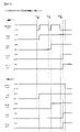
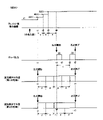
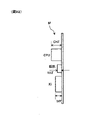
次に、図4のメダル払出装置Hの正面図及び上面図を用いてメダル払出装置Hを詳細に説明する。メダル払出装置Hは、クレジット(遊技機内部に電子的に貯留されている遊技メダル)又はベットされているメダル(遊技を開始するために投入されたメダル)が存在する状態で、精算ボタンが操作された、又は、入賞により遊技メダルが払い出される場合に作動することとなる。作動する場合には、まず、ホッパモータH80が駆動することにより、ディスク回転軸H50aを中心にディスクH50が回転する。回転によりメダル払出装置H内の遊技メダルは放出付勢手段H70を変位させて遊技メダル出口H60から放出口D240に向かって流下していくこととなる。尚、払出センサ(第1払出センサH10s及び第2払出センサH20s)は2つのセンサで構成されており、夫々のセンサのオン・オフ状況(第1払出センサH10s及び第2払出センサH20sのオン・オフの組み合わせの遷移していく順序、等)及びオン・オフとなっている時間を監視することにより様々なエラーを検出可能に構成されている。より具体的には、例えば、遊技メダル出口H60を正常に通過する際には、放出付勢手段H70の変位により、第1払出センサH10s=オフ・第2払出センサH20s=オフの状態から、第1払出センサH10s=オフ・第2払出センサH20s=オフ→第1払出センサH10s=オン・第2払出センサH20s=オフ→第1払出センサH10s=オン・第2払出センサH20s=オン→第1払出センサH10s=オフ・第2払出センサH20s=オン→第1払出センサH10s=オフ・第2払出センサH20s=オフ、というセンサ状態遷移となるため、このセンサ状態遷移と反する動きを検出した場合には、エラーとするよう構成することを例示することができる。
<Medal payout device H>
Next, the medal payout device H will be described in detail with reference to the front view and the top view of the medal payout device H of FIG. The medal payout device H is operated by the settlement button in a state where credits (game medals electronically stored inside the game machine) or bet medals (medals inserted to start the game) are present. It will be activated when the game medal is paid out by winning or winning. When operating, first, the hopper motor H80 is driven to rotate the disk H50 around the disk rotation shaft H50a. Due to the rotation, the game medals in the medal payout device H displace the release urging means H70 and flow down from the game medal outlet H60 toward the discharge port D240. The payout sensor (first payout sensor H10s and second payout sensor H20s) is composed of two sensors, and the on / off status of each sensor (first payout sensor H10s and second payout sensor H20s on / off). It is configured to be able to detect various errors by monitoring the transition order of the off combination, etc.) and the on / off time. More specifically, for example, when the game medal exit H60 is normally passed, the first payout sensor H10s = off and the second payout sensor H20s = off due to the displacement of the release urging means H70. 1 payout sensor H10s = off, 2nd payout sensor H20s = off → 1st payout sensor H10s = on, 2nd payout sensor H20s = off → 1st payout sensor H10s = on, 2nd payout sensor H20s = on → 1st payout Since the sensor state transition is sensor H10s = off, second payout sensor H20s = on → first payout sensor H10s = off, second payout sensor H20s = off, if a movement contrary to this sensor state transition is detected, , It can be exemplified to configure it to be an error.
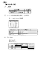
次に、図5は、本実施形態における、回胴式遊技機の基本仕様一覧である。本実施形態に係る回胴式遊技機は、規定数(1ゲームにてベットできる遊技メダルの最大枚数)が3枚、左リールM51、中リールM52及び右リールM53のコマ数はいずれも20コマ、入賞判定される有効ラインは「左リールM51上段、中リールM52中段、右リールM53下段」の1ラインとなっている。尚、最大払出枚数は11枚、最小払出枚数は1枚(入賞役と払出枚数との対応付けは後述)である。また、優先入賞順(引き込み優先順)は、「再遊技役→小役(ベル、スイカ、等)→ボーナス」となっており、例えば、再遊技役とボーナスが同時に成立している場合には、再遊技役となる図柄組み合わせが停止表示し且つボーナスは入賞不能である。また、ベルとスイカが成立している場合には、どちらも引き込める位置(入賞する停止位置まで4コマ以内の位置)で停止ボタンを押した場合には払出枚数が多い小役を優先して引きこむよう構成されている。尚、同図に示した構成はあくまで一例であり、各リールのコマ数を変更(例えば、21コマに変更)したり、有効ラインの構成を変更(例えば、横3ライン、斜め2ラインの5ラインに変更、左リールM51下段、中リールM52中段、右リールM53上段の1ラインに変更)しても何ら問題ない。また、特に押し順によって遊技者にとって異なる利益が付与される押し順小役が当選したときの引き込み制御としては、予め定められた正解の押し順で操作された場合には払出し枚数の多い小役を優先して引き込むように制御(枚数優先制御)しており、正解の押し順とは異なる不正解の押し順で操作された場合には停止表示可能な(停止操作から4コマ以内の位置に配置されている)図柄のうち入賞可能性を高める(入賞可能な複数図柄組合せのうち入賞する可能性が最も多くなる)図柄を引き込む制御(個数優先制御)を行っている。 Next, FIG. 5 is a list of basic specifications of the rotating drum type gaming machine in the present embodiment. The spinning-type gaming machine according to the present embodiment has a specified number (maximum number of game medals that can be bet in one game) of 3, and the number of frames of the left reel M51, the middle reel M52, and the right reel M53 is 20. The effective line for which the winning is determined is one of "left reel M51 upper stage, middle reel M52 middle stage, right reel M53 lower stage". The maximum number of payouts is 11, and the minimum number of payouts is one (the correspondence between the winning combination and the number of payouts will be described later). In addition, the priority winning order (pull-in priority order) is "replaying role-> small role (bell, watermelon, etc.)-> bonus". For example, when the replaying role and the bonus are established at the same time. , The symbol combination that becomes the re-game role is stopped and displayed, and the bonus cannot be won. In addition, when the bell and watermelon are established, if the stop button is pressed at the position where both can be retracted (the position within 4 frames to the stop position where the prize is won), priority is given to the small winning combination with a large number of payouts. It is configured to pull in. The configuration shown in the figure is just an example, and the number of frames on each reel can be changed (for example, changed to 21 frames), or the configuration of effective lines can be changed (for example, 5 horizontal lines and 2 diagonal lines). There is no problem even if it is changed to one line, left reel M51 lower stage, middle reel M52 middle stage, right reel M53 upper stage). In addition, as a pull-in control when a push order small combination that gives different benefits to the player depending on the push order is won, a small combination with a large number of payouts when operated in a predetermined correct push order. Is controlled to pull in with priority (number of sheets priority control), and if the operation is performed in the wrong answer pressing order different from the correct answer pressing order, the stop display is possible (within 4 frames from the stop operation). Control (number priority control) is performed to increase the possibility of winning among the (arranged) symbols (the most likely to win among the combinations of multiple symbols that can be won).
次に、図6は、本実施形態における、回胴式遊技機のリール配列一覧である。同図に示されるように、左リールM51、中リールM52及び右リールM53のコマ数はいずれも20コマ(0番~19番)であり、図柄は「黒セブン」、「白セブン」、「羊」、「ブランク」、「ベル」、「リプレイA」、「リプレイB」、「スイカA」、「スイカB」、「チェリー」の10種類となっている。ここで、「ブランク」は、その他の図柄と同様に当選役を構成する図柄組み合わせに含まれる図柄であり、当選役を構成しない図柄という意味ではなく、「ブランク」を含む当選役を構成する図柄組み合わせとしては、例えば、「スイカB・リプレイA・ブランク」で再遊技02となっている。尚、同図に示した構成はあくまで一例であり、図柄の種類を増減・変更しても何ら問題ない。 Next, FIG. 6 is a list of reel arrangements of the rotating drum type gaming machine in the present embodiment. As shown in the figure, the number of frames of the left reel M51, the middle reel M52, and the right reel M53 is 20 frames (0th to 19th), and the symbols are "black seven", "white seven", and " There are 10 types: "sheep", "blank", "bell", "replay A", "replay B", "watermelon A", "watermelon B", and "cherry". Here, the "blank" is a symbol included in the symbol combination constituting the winning combination like other symbols, and does not mean a symbol not constituting the winning combination, but a symbol constituting the winning combination including the "blank". As a combination, for example, "Watermelon B / Replay A / Blank" is replay 02. The configuration shown in the figure is just an example, and there is no problem even if the types of symbols are increased / decreased / changed.
次に、図7~図9は、本実施形態における図柄組み合わせ一覧1~3である。本実施形態においては、夫々の条件装置に対して複数の図柄組み合わせが存在しており、後述するように、左リールM51、中リールM52及び右リールM53の停止順番や停止位置に応じて、いずれか一の図柄組み合わせが有効ライン(前述した1ライン)上に停止表示されるよう構成されている。尚、有効ライン上に同一種類の図柄が揃っていない場合にも遊技者から見ると有効ライン以外のライン上にて一列に同一の図柄が揃いやすく構成されている(スイカの場合には中段に横一直線に揃う等、リール上のいずれかに一直線にスイカ図柄が3つ揃うよう構成されている)。また、本実施形態においては、第1種BB役(いわゆる第1種特別役物に係る役物連続作動装置であるが、以下、単にBB役と呼ぶことがある)となる図柄組み合わせして、1種BB‐A(RB-Aを連続作動させ、264枚を超える払出で終了)となる「羊・羊・羊」と、1種BB‐B(RB-Bを連続作動させ、132枚を超える払出で終了)となる「黒セブン・黒セブン・黒セブン」と、1種BB‐C(RB-Bを連続作動させ、132枚を超える払出で終了)となる「白セブン・白セブン・白セブン」との3つの図柄組み合わせを有している。尚、本実施形態においては、第1種BB役が入賞し、BBが実行された(役物が作動した)場合には、当該BB実行中においては、BB中のすべてのゲームにおいて、1つの抽選テーブルを参照して、役物以外の当選役(小役、再遊技役)を抽選するよう構成されている(1回のBBの実行中において役抽選の際に参照するテーブルを切り替えない方式であり、以下、オールJACINタイプと呼ぶことがある)。尚、第1種BB役の形式に関しては、これには限定されず、1回のBBの実行中において役抽選の際に参照するテーブルを切り替え得るよう構成してもよい。また、RT状態が「RT1」である場合に14番~16番に対応する再遊技04となる図柄組み合わせが停止表示されると、RT0に移行するよう構成されている(RT状態の詳細については後述する)。尚、「RT1」よりも「RT0」の方が遊技者に不利なRT状態であるため、「RT1」から「RT0」に移行することを転落すると称することがある。また、17番に対応する再遊技05となる図柄組み合わせが停止表示されると、左リールM51、中リールM52及び右リールM53の下段に「黒セブン」が停止表示され得ることとなり、18番に対応する再遊技05となる図柄組み合わせが停止表示されると、左リールM51、中リールM52及び右リールM53の下段に「白セブン」が停止表示され得ることとなる(詳細は後述することとする)。また、後述する「入賞‐A1」~「入賞‐A6」の条件装置である押し順ベルが当選した場合には、遊技者にとって最も有利な押し順にてリールを停止させると、21番~27番に対応する「入賞01」~「入賞03」となる図柄組み合わせが停止表示され、11枚の遊技メダルが払い出される一方、遊技者にとって最も有利な押し順とは異なる押し順にてリールを停止させると、39番~56番に対応する「入賞08」~「入賞11」となる図柄組み合わせが停止表示され、1枚の遊技メダルが払い出されることとなる。尚、同図における「‐」はいずれの図柄が停止表示されてもよい旨を示しており、例えば、23番に対応する「ベル・‐・ベル」は左リールM51及び右リールM53の有効ライン上にベルが停止表示されれば中リールM52の有効ライン上にはどの図柄が停止表示されても11枚の遊技メダルが獲得できる。
Next, FIGS. 7 to 9 are a list of
次に、図10は、本実施形態における条件装置一覧である。尚、同図においては、条件装置番号を当選番号と称しており、以降においても条件装置番号を当選番号と称することがある。本実施形態においては、再遊技役は再遊技‐A~再遊技‐D3(当選番号1~6)まで設けられており、左リールM51、中リールM52及び右リールM53の停止順番や停止位置に応じて、停止表示する再遊技役が相違し得るよう構成されている。ここで、本実施形態においては、最も右の列である「条件装置」の項目に図示されているように、左リールM51、中リールM52及び右リールM53の停止順番や停止位置に応じて複数種類の条件装置が停止表示され得るよう構成されており、当該複数種類の条件装置のうち同一の当選番号となる条件装置を纏めて、右から3番目の列である「条件装置(名称)」の項目にて図示している。具体的には、例えば、当選番号1に対応する条件装置である「再遊技‐A」においては、左リールM51、中リールM52及び右リールM53の停止順番や停止位置に応じて、「再遊技01」、「再遊技02」、「再遊技03」の3種類の条件装置が停止表示され得るよう構成されている。尚、「条件装置(名称)」を単に条件装置と称することがある。また、「再遊技01」等の再遊技に関する条件装置を再遊技役と称することがあり、「入賞01」等の入賞することで遊技メダルが払い出される条件装置を小役と称することがあり、「1種BB‐A」等の停止表示されることによりBBが開始することとなる条件装置をBB役と称することがある。また、当選番号21~23及び25~27に当選した場合には、BB役と小役とが重複して当選することとなり、そのような場合には、当選した小役に対応する図柄が停止表示し得る位置にて左停止ボタンD41、中停止ボタンD42及び右停止ボタンD43を操作するとBB役に対応する図柄が停止表示せずに小役に対応する図柄が停止表示する一方、小役に対応する図柄が停止表示しない(引き込めない)位置にて左停止ボタンD41、中停止ボタンD42及び右停止ボタンD43を操作すると小役に対応する図柄が停止表示せずにBB役に対応する図柄が停止表示するよう構成されている。具体的には、例えば、当選番号21の条件装置である「1種BB‐B+入賞‐C」に当選した場合には、「入賞12」又は「入賞13」であるチェリーと、「1種BB‐B」である黒セブンとのいずれかが停止表示し得ることとなる。より具体的には、左リールM51→中リールM52→右リールM53の順番にリールを停止させる場合において、(1)第1停止にて左リールM51の上段に図柄番号0~4番(図6のリール配列を参照)が位置している操作タイミングにて左停止ボタンD41を操作した場合には、左リールM51の上段に「入賞12」に対応する図柄番号4番が停止し、中リールM52及び右リールM53の停止位置に拘らず、「入賞12」が停止表示される。(2)第1停止にて左リールM51の上段に図柄番号5~12番が位置している操作タイミングにて左停止ボタンD41を操作した場合には、左リールM51の上段に「入賞13」に対応する図柄番号6番、11番、又は16番が停止し、中リールM52及び右リールM53の停止位置に拘らず、「入賞13」が停止表示される。(3‐1)第1停止にて左リールM51の上段に図柄番号13~19番が位置している操作タイミングにて左停止ボタンD41を操作した場合には、左リールM51の上段に「1種BB‐B」に対応する図柄番号17番又は19番が停止する。(3‐2)第2停止にて中リールM52の中段に図柄番号14~18番が位置している操作タイミングにて中停止ボタンD42を操作した場合には、中リールM52の中段に「1種BB‐B」に対応する図柄番号18番が停止し、その後、第3停止にて右リールM53の下段に図柄番号13~17番が位置している操作タイミングにて右停止ボタンD43を操作した場合には、右リールM53の下段に「1種BB‐B」に対応する図柄番号17番が停止し、BB役が停止表示されることとなる。(3‐3)第2停止にて中リールM52の中段に図柄番号19~13番が位置している操作タイミングにて中停止ボタンD42を操作した場合には、中リールM52の中段に「1種BB‐B」に対応する図柄番号18番が停止できず、いずれの条件装置も停止表示されないこととなる。
Next, FIG. 10 is a list of condition devices according to this embodiment. In the figure, the conditional device number is referred to as a winning number, and the conditional device number may be referred to as a winning number thereafter. In the present embodiment, the re-game combinations are provided from re-game-A to re-game-D3 (winning
次に、「役割」の項目には、「条件装置(名称)」がどのような役割となっているかを図示しており、当選番号1に対応する「通常リプレイ」は、停止ボタンの押し順に拘らず、RT状態が移行しない再遊技役が停止表示される再遊技に係る条件装置であり、当選番号2に対応する「逆押し白7揃いリプレイ」は、停止ボタンの押し順に拘らず、RT状態が移行しない再遊技役が停止表示される再遊技に係る条件装置であるが、逆押し(右リールM53→中リールM52→左リールM51の順にリールを停止させること)にて、右リールM53の図柄番号18~2番の範囲、中リールM52の図柄番号9~13番の範囲、左リールM51の図柄番号5~10番の範囲が各リールの下段に位置している操作タイミングにて停止ボタンを操作することにより、右リールM53、中リールM52及び左リールM51の下段に「白セブン」が停止表示され、遊技者から見ると白セブンが下段に揃っているように見えるよう構成されている。尚、再遊技‐Bに当選し、AT上乗せ抽選に当選したゲームにおいて、逆押しで「白セブン」を狙うよう指示する演出(詳細は後述する)を実行することにより、AT上乗せ抽選に当選した旨を遊技者に報知し得るよう構成されている。当選番号3に対応する「順押し黒7揃いリプレイ」は、停止ボタンの押し順に拘らず、RT状態が移行しない再遊技役が停止表示される再遊技に係る条件装置であるが、順押し(左リールM51→中リールM52→右リールM53の順にリールを停止させること)にて、左リールM51の図柄番号13~19番の範囲、中リールM52の図柄番号14~18番の範囲、右リールM53の図柄番号13~17番の範囲が各リールの下段に位置している操作タイミングにて停止ボタンを操作することにより、左リールM51、中リールM52及び右リールM53の下段に「黒セブン」が停止表示され、遊技者から見ると黒セブンが下段に揃っているように見えるよう構成されている。尚、再遊技‐Cに当選し、AT上乗せ抽選に当選したゲームにおいて、順押しで「黒セブン」を狙うよう指示する演出(詳細は後述する)を実行することにより、AT上乗せ抽選に当選した旨を遊技者に報知し得るよう構成されている。
Next, in the "role" item, the role of the "conditional device (name)" is illustrated, and the "normal replay" corresponding to the winning
また、当選番号4に対応する「RT維持RP1**(3択)」は第1停止リールを左リールM51と中リールM52と右リールM53とのいずれにするか(いずれの停止ボタンを操作するか)によって、停止表示される再遊技役が相違し得る条件装置であり、第1停止リールを左リールM51とした場合には、RT状態が移行しない再遊技01、再遊技02又は再遊技03が停止表示され、第1停止リールを中リールM52又は右リールM53とした場合には、RT状態が「RT1」から「RT0」に移行し得る再遊技04が停止表示される。また、当選番号5に対応する「RT維持RP*1*(3択)」は第1停止リールを左リールM51と中リールM52と右リールM53とのいずれにするか(いずれの停止ボタンを操作するか)によって、停止表示される再遊技役が相違し得る条件装置であり、第1停止リールを中リールM52とした場合には、RT状態が移行しない再遊技03が停止表示され、第1停止リールを左リールM51又は右リールM53とした場合には、RT状態が「RT1」から「RT0」に移行し得る再遊技04が停止表示される。また、当選番号6に対応する「RT維持RP**1(3択)」は第1停止リールを左リールM51と中リールM52と右リールM53とのいずれにするか(いずれの停止ボタンを操作するか)によって、停止表示される再遊技役が相違し得る条件装置であり、第1停止リールを右リールM53とした場合には、RT状態が移行しない再遊技01又は再遊技03が停止表示され、第1停止リールを左リールM51又は中リールM52とした場合には、RT状態が「RT1」から「RT0」に移行し得る再遊技04が停止表示される。
In addition, "RT maintenance RP1 ** (3 choices)" corresponding to the winning
また、当選番号7~12に対応する、「押し順ベル123」~「押し順ベル321」は、リール停止順を6択のいずれとするかによって入賞する小役が相違し得る条件装置であり、例えば、「左リールM51:1、中リールM52:2、右リールM53:3」となっており「123」の場合「左リールM51→中リールM52→右リールM53」の押し順で停止させるという意味であり、例えば、「入賞A‐1」(当選番号7)の場合には、「123」=「左→中→右」の順に停止させる(押し順に正解する)と最大獲得枚数である11枚の遊技メダルが獲得できる「入賞01」となる図柄組み合わせが停止表示することとなる。尚、「押し順ベル123」の「123」等はその当選番号における最大獲得枚数を獲得可能な押し順(リール停止順)を示している。尚、最大獲得枚数を獲得可能な押し順以外の押し順にてリールを停止させた場合には、即ち、押し順に正解できないと1枚の払出となるよう構成されており、このように構成することで、「AT中状態」等のATに関する状態にて再遊技役の押し順やベルの押し順をナビ(押し順表示装置D270にて最高利益となる押し順を表示)し、「通常遊技状態」等のATに関する状態には押し順をナビしないという遊技者の利益率が異なる複数の遊技状態を創出することができる。尚、ATに関する状態については後述する。
Further, the "push
また、当選番号13に対応する、「共通ベル」は、入賞04~入賞07のいずれが停止しても最大獲得枚数である11枚の遊技メダルが獲得できる、即ち、押し順に拘らず最大利益が獲得できる条件装置であり、押し順不問ベルと称することがある。また、当選番号15に対応する、「スイカA」は、平行ラインにスイカ(スイカAとスイカBのいずれか)が3つ揃いし易いよう構成されており、例えば、図9における60番の入賞14は各リール中段にスイカAが3つ揃いすることとなる。また、当選番号16に対応する、「スイカB」は、斜めラインにスイカ(スイカAとスイカBのいずれか)が3つ揃いし易いよう構成されており、例えば、図9における66番の入賞16は左リールM51上段にスイカB、中リールM52中段にスイカB、右リールM53下段にスイカAのように、斜め右下がりにスイカが3つ揃いすることとなる。また、当選番号17に対応する、「BB中弱レア小役(斜めベル揃い)」は、有効ライン上にベルが3つ揃いし得る条件装置であり、詳細は後述するが、BB中に当選することによってAT上乗せ抽選が実行される条件装置である。また、当選番号18に対応する、「BB中強レア小役(V字ベル揃い)」は、左リールM51上段、中リールM52中段、右リールM53上段にベルが停止表示され得る条件装置であり、詳細は後述するが、BB中に当選することによってAT上乗せ抽選が実行される条件装置である。
In addition, the "common bell" corresponding to the winning
次に、「ボーナス当選情報」の項目には、0~3までの数値が当選番号毎に振り分けられている。本実施形態においては、ボーナス(BB役)が含まれない当選番号はボーナス当選情報を0とし、ボーナス(BB役)が含まれる当選番号として、1種BB‐Aが含まれる当選番号(19)のボーナス当選情報を1、1種BB‐Bが含まれる当選番号(20~23)のボーナス当選情報を2、1種BB‐Cが含まれる当選番号(24~27)のボーナス当選情報を3としている。ボーナス当選情報を主制御基板Mが記憶することによっていずれのBB成立の有無やいずれのBB役に当選したかに係る情報を記憶することができる。尚、ボーナス当選情報の詳細については後述する。
Next, in the item of "bonus winning information", numerical values from 0 to 3 are assigned to each winning number. In the present embodiment, the winning number that does not include the bonus (BB role) has the bonus winning information set to 0, and the winning number that includes the bonus (BB role) is the winning number (19) that includes one type BB-A. Bonus winning information of 1,
次に、「入賞・再遊技当選情報」の項目には、0~18までの数値が当選番号毎に振り分けられている。本実施形態においては、再遊技役と小役とが含まれない当選番号(ハズレに対応する当選番号0とボーナスに対応する当選番号19・20・24)は入賞・再遊技当選情報を0とし、再遊技役又は小役が含まれる当選番号に対して1~18入賞・再遊技当選情報を条件装置毎に振り分けている。入賞・再遊技当選情報を主制御基板Mが記憶することによっていずれの再遊技役又は小役に当選したかに係る情報を記憶することができる。尚、入賞・再遊技当選情報の詳細については後述する。
Next, in the item of "winning / replay winning information", numerical values from 0 to 18 are assigned to each winning number. In the present embodiment, the winning numbers (winning
次に、「演出グループ番号」の項目には、0~11までの数値が当選番号毎に振り分けられている。演出グループ番号を主制御基板M側から副制御基板S側に送信することによって、副制御基板S側が実行する演出を決定することができるよう構成されている。尚、演出グループ番号の詳細については後述する。 Next, in the item of "directing group number", numerical values from 0 to 11 are assigned to each winning number. By transmitting the effect group number from the main control board M side to the sub control board S side, the effect to be executed by the sub control board S side can be determined. The details of the production group number will be described later.
次に、「出玉グループ番号」の項目には、0~13までの数値が当選番号毎に振り分けられている。出玉グループ番号を主制御基板Mが記憶し、当該記憶した出玉グループ番号をATに関する抽選(例えば、AT抽選、AT上乗せ抽選)を実行する際に使用することにより、ATに関する抽選処理を実行するためのプログラム、データ容量を削減することができる。尚、出玉グループ番号が0となる条件装置が当選してもAT抽選及びAT上乗せ抽選は実行されない。一方、出玉グループ番号が0でない条件装置が当選した場合には、AT抽選又はAT上乗せ抽選が実行され得ることとなる。尚、出玉グループ番号の詳細については後述する。また、出玉グループ番号が0となる条件装置が当選した場合にも、AT抽選又はAT上乗せ抽選が実行され得るよう構成してもよく、そのように構成した場合には、出玉グループ番号が0となる条件装置が当選してAT抽選又はAT上乗せ抽選が実行された場合には、当該抽選結果がかならずハズレ(非当選)となるよう構成することが好適である。 Next, in the item of "ball output group number", numerical values from 0 to 13 are assigned to each winning number. The main control board M stores the payout group number, and the stored payout group number is used when executing a lottery related to AT (for example, AT lottery, AT additional lottery) to execute a lottery process related to AT. It is possible to reduce the program and data capacity for this. Even if the condition device in which the payout group number is 0 is won, the AT lottery and the AT addition lottery are not executed. On the other hand, if the conditional device whose payout group number is not 0 is won, the AT lottery or the AT addition lottery can be executed. The details of the payout group number will be described later. Further, even if the condition device in which the payout group number is 0 is won, the AT lottery or the AT addition lottery may be configured so that the payout group number can be executed. When the condition device to be 0 is won and the AT lottery or the AT addition lottery is executed, it is preferable to configure the lottery result so that the lottery result is always lost (non-winning).
次に、図11は、本実施形態における小役、再遊技役に関する当選番号(条件装置番号、当選役とも称す)及びボーナス(BB、BB役とも称す)が役抽選手段により決定される抽選確率(当選率とも称する)を示す一覧である。同図においては、当選番号の当選率を図示している。 Next, FIG. 11 shows a lottery probability in which the winning numbers (also referred to as conditional device numbers and winning combinations) and bonuses (also referred to as BB and BB combinations) relating to the small winning combination and the replaying combination in the present embodiment are determined by the winning combination lottery means. It is a list showing (also called a winning rate). In the figure, the winning rate of the winning numbers is shown.
まず、BB未作動時である「RT0」、「RT1」及び「RT2」における抽選確率について詳述する。本実施形態においては、RT状態によって当選役(特に、再遊技役)の出現率(抽選確率)が相違し得るよう構成されており、「再遊技役」(すべての再遊技役を合計した出現率)は「RT1」の場合においてその他のRT状態よりも出現率が高くなっている。また、当選番号4~6にて停止表示し得る「再遊技04」(いわゆる転落再遊技役であり、「RT1」であり且つボーナスが当選していない状況下において当該再遊技役に対応する図柄組合せが停止表示されると、以降「RT0」に移行することとなる)は「RT1」にて主に当選し、「RT0」においてはほぼ出現しないようになっている。尚、「RT2」においては、当選番号4~6にて停止表示し得る「再遊技04」が出現し得ることとなるが、「再遊技04」が停止表示されてもRT状態は移行しない。尚、「RT1」において「再遊技04」が停止表示された場合には、「RT0」に移行した、即ち、RT状態が転落した旨を報知する演出である転落演出(例えば、演出表示装置S40に「残念」と表示)を実行し、「RT0」において「再遊技04」が停止表示された場合には、転落演出を実行しないよう構成してもよい。そのように構成することにより、「再遊技04」が停止表示されたにも拘らず、転落演出が実行されなかったことにより、BBに当選していることを認識することができ、遊技の興趣性を高めることができる。尚、そのように構成した場合には、「再遊技04」が停止表示されたことにより出力される効果音と「再遊技04」以外の再遊技役(例えば、RT状態が移行しない「再遊技01」)が停止表示されたことにより出力される効果音とが相違するよう構成してもよく、そのように構成することにより、「再遊技04」が停止表示されたことを遊技者が認識し易く構成することができる。また、押し順ナビが発生しないATに関する状態(例えば、「通常遊技状態」であり、非AT遊技状態と称することがある)である場合と押し順ナビが発生し得るATに関する状態(例えば、「AT中状態」であり、AT遊技状態と称することがある)である場合との両方の場合において「RT1」に滞在することがある。このとき、「RT1」から「RT0」へ移行(転落)する可能性がある当選番号が当選したとき、非AT遊技状態のときにはRT状態が転落する可能性があることを示す特殊な効果音をスタートレバーD50の操作に基づいて出力しないように構成されていても良い。これにより、非AT遊技状態においては「RT0」に転落する可能性があることを遊技者に悟らせることなく、遊技状態を移行させることが可能となる。一方、AT遊技状態のときにはRT状態が転落する可能性があることを示す特殊な効果音をスタートレバーの操作に基づいて出力する(且つ、RT状態が転落しない再遊技役が停止表示される押し順ナビを報知する)ように構成されていても良い。これにより、RT状態が転落しないよう遊技者は気を付けて、特殊な効果音が報知された以降の停止ボタンD40の操作を行なうことが可能となる。また、当選番号2又は3にて停止表示し得る「再遊技05」(AT状態にて停止表示された場合にAT上乗せ抽選に当選した旨を報知し得る再遊技役)は主に「RT1」で出現し、その他のRT状態ではほぼ出現しないようになっている。尚、これら再遊技役となる図柄組み合わせの停止表示に伴うRT状態に関する状態の遷移については後述する。また、後述するように、本実施形態においては、遊技者に最も有利となるリール停止順を報知する押し順ナビを押し順表示装置D270及び演出表示装置S40にて実行し得るよう構成されている。尚、当該抽選確率を適宜変更しても何ら問題ない。また、本実施形態においては、ボーナスは小役と重複し得るよう構成されており、スイカA、スイカB、チェリーの一部と重複している。具体的には、当選番号21~23及び当選番号25~27がボーナスと小役とが重複している条件装置となっている。
First, the lottery probabilities in "RT0", "RT1", and "RT2" when the BB is not operating will be described in detail. In the present embodiment, the appearance rate (lottery probability) of the winning combination (particularly, the re-gaming combination) can be different depending on the RT state, and the "re-gaming combination" (the total appearance of all the re-gaming combinations) appears. The rate) is higher in the case of "RT1" than in other RT states. In addition, "re-game 04" (so-called fall re-game combination, "RT1", which can be stopped and displayed at winning
また、「RT2」である状況においては、BBに当選しており、且つ、BBが未作動である状況であるため、当選番号20及び24のBB役(小役とは重複していない単独のBB役であり、単独BB役、単独BBと称することがある)に当選した場合には、BB役の新たな当選は無効となり、小役の当選のみが有効となる。具体的には、例えば、「RT2」であり、且つ、1種BB‐Aに当選している(持ち越している)状況下、当選番号24の「1種BB‐C」に当選した場合には、当該当選番号24に係る1種BB‐Cは無効となる。即ち、当選番号0の「ハズレ」に当選した場合と同様の状況となる。尚、持ち越している1種BB‐Aは当選している状態が継続される。また、「RT2」である状況においては、BBに当選しており、且つ、BBが未作動である状況であるため、当選番号21~23及び当選番号25~27の小役とBB役とが重複している条件装置に当選した場合には、BB役の新たな当選は無効となり、小役の当選のみが有効となる。具体的には、例えば、「RT2」であり、且つ、1種BB‐Aに当選している(持ち越している)状況下、当選番号21の「1種BB‐B+入賞‐C」に当選した場合には、当該当選番号21に係る1種BB‐Bは無効となり、入賞‐Cのみが有効となる。即ち、当選番号14の「入賞‐C」に当選した場合と同様の状況となる。尚、持ち越している1種BB‐Aは当選している状態が継続される。尚、ボーナスとの重複は小役に限られるものでなく、再遊技役の一部とで重複していても良い。例えば、当選番号4~6の再遊技役の一部でボーナス役と重複しても良い。このように、ボーナスがRT移行リプレイ(RT状態が移行し得る再遊技役)を含む条件装置とも重複するようにすることで、RT移行リプレイを含む条件装置が当選したときにもボーナスが当選する可能性があり、RT移行リプレイが停止表示されても、ボーナスの否定をしないこととなるため、遊技者に期待を持たせることが可能となる。なお、このように構成した場合には、RT移行リプレイが停止表示されてもRT状態は移行しないように制御する。これにより、遊技者はRT状態が移行(リプレイ確率が相対的に低いRT状態に移行)しているはずであるのにリプレイ確率が低確率になっていない(頻繁にリプレイに当選する)こと等から、ボーナスに当選している可能性が高いかもしれないといった遊技に関する興趣を高めることが可能となる。
Further, in the situation of "RT2", since the BB has been won and the BB is not in operation, the BB roles of the winning
次に、BB作動時である「1種BB‐A,B,C」における抽選確率について詳述する。本実施形態においては、BB作動中においては、当選番号13の「共通ベル」と当選番号17の「BB中弱レア小役(斜めベル揃い)」と当選番号18の「BB中強レア小役(V字ベル揃い)」との3つの小役が当選し得るよう構成されており、「AT中状態」にて当選したBBの作動中において「BB中弱レア小役(斜めベル揃い)」又は「BB中強レア小役(V字ベル揃い)」に当選した場合にはAT上乗せ抽選が実行されるよう構成されている(詳細は後述することとする)。
Next, the lottery probability in "
また、同図上段においては、設定値が1である場合の小役出現率を例示しており、共通ベル(当選番号13)においては、RT状態に拘らず出現率が一律となっているが、同図下段に示すように、共通ベルの出現率は設定値(本例では、6段階)によって相違するよう構成されている。具体的には、設定1における置数が3204、設定2における置数が3404、設定3における置数が3604、設定4における置数が3904、設定5における置数が4204、設定6における置数が4504、となっており、設定値が高くなる程出現率が高くなるよう構成されている。このように構成することにより、例えば、遊技者が共通ベルの出現回数(当選回数)を計測しながら遊技を進行した場合、共通ベルに頻繁に当選することにより、遊技している遊技機に係る設定値が相対的に高い設定値であることに期待を抱きながら遊技を進行することができる。また、設定値が高くなるほど1遊技当たりにおける期待値が高くなり、設定値が高くなるほど出玉率が高くなるように構成されている。なお、共通ベルの出現率は設定値によって相違するよう構成されているが、当該共通ベルの当選によっては、後述するAT抽選、AT上乗せ抽選、及び、高確率状態移行抽選は実行されないので、ATに関する状態の移行抽選(ATに関する抽選とも称する。)には影響を及ぼさないよう構成されている。 Further, in the upper part of the figure, the small winning combination appearance rate when the set value is 1 is illustrated, and in the common bell (winning number 13), the appearance rate is uniform regardless of the RT state. As shown in the lower part of the figure, the appearance rate of the common bell is configured to differ depending on the set value (6 steps in this example). Specifically, the number in setting 1 is 3204, the number in setting 2 is 3404, the number in setting 3 is 3604, the number in setting 4 is 3904, the number in setting 5 is 4204, and the number in setting 6 is. Is 4504, and the higher the set value, the higher the appearance rate. With this configuration, for example, when a player advances a game while measuring the number of appearances (winning times) of a common bell, the common bell is frequently won to relate to the gaming machine being played. The game can be advanced with the expectation that the set value is a relatively high set value. Further, the higher the set value, the higher the expected value per game, and the higher the set value, the higher the ball output rate. The appearance rate of the common bell is configured to differ depending on the set value, but depending on the winning of the common bell, the AT lottery, the AT addition lottery, and the high-probability state transition lottery, which will be described later, are not executed. It is configured so as not to affect the transition lottery of the state related to (also referred to as a lottery related to AT).
また、同図中段は、押し順ナビあり時における期待値一覧である。同図においては、「AT中状態」等の押し順表示装置D270及び演出表示装置S40にて押し順ナビが実行され得る状態において押し順ナビが実行された場合に、当該ナビに従ってリールを停止させた場合の1遊技あたりの平均払出数(入賞した小役によって払い出される平均のメダルの枚数であり、1ゲームで得られる遊技媒体の期待数とも称する)と、1遊技あたりのメダル増減期待値(3枚ベットにて遊技した場合のメダル投入枚数に対するメダル払出枚数の比率であり、1より大きい場合には期待値がプラスとなりメダルが増加していくこととなる一方、1より小さい場合には期待値がマイナスとなりメダルが減少していくこととなる)とを図示している。尚、1遊技あたりの平均払出数は、「再遊技役の置数の総和(当選番号1~6についての置数の総和)×再遊技役における払出枚数(3枚)+小役(11枚役)の置数(小役出現率)の総和(当選番号7~16についての置数の総和)×小役(11枚役)における払出枚数(11枚)/すべての置数の総和(65536)」のようにして算出することができる。また、1遊技あたりのメダル増減期待値は、「1遊技あたりの平均払出数/1遊技あたりのメダル投入枚数(3枚)」のようにして算出することができる。尚、1ゲームあたりのメダル投入数(1ゲームを行う際の遊技媒体の投入数)は3枚となっており、1遊技あたりの平均払出数が3より大きい場合に1遊技あたりのメダル増減期待値が1より大きくなるよう構成されている。同図に示されるように、本実施形態においては、「RT1」が1遊技あたりのメダル増減期待値が相対的に最も大きくなっている。尚、同図における数値はボーナスによるメダルの増減は考慮していない。即ち、押し順ナビが発生する状況において遊技を進行した場合(最適操作態様で操作された場合、有利操作態様で操作された場合とも称す)、「RT1」ではメダルが増えていくこととなる。尚、「RT0」及び「RT2」においては、不図示であるが、押し順ナビが発生していない状況下においては、1遊技あたりのメダル増減期待値は1より小さい値となっており、メダルが減少していくこととなる。尚、本実施形態においては、「RT0」又は「RT2」においても押し順ナビあり時においては1遊技あたりのメダル増減期待値が1より大きくなっているが、これには限定されず、「RT0」又は「RT2」における押し順ナビあり時の1遊技あたりのメダル増減期待値が1より小さくなるよう構成してもよい。尚、再遊技役となる図柄組み合わせが停止表示した場合には実際には前回遊技における賭け枚数(3枚)が自動ベットされるが、本実施形態におけるメダル増減期待値を算出するにあたっては、メダル3枚の払出しと仮定して算出している。尚、1遊技を1ゲームと称することがある。
In addition, the middle part of the figure is a list of expected values when there is push order navigation. In the figure, when the push order navigation is executed in a state where the push order navigation can be executed by the push order display device D270 and the effect display device S40 such as "AT in progress state", the reel is stopped according to the navigation. The average number of medals paid out per game (the average number of medals paid out by the winning small winning combination, also called the expected number of game media obtained in one game) and the expected value of medal increase / decrease per game ( It is the ratio of the number of medals paid out to the number of medals inserted when playing with a 3-card bet. If it is larger than 1, the expected value will be positive and the number of medals will increase, while if it is smaller than 1, it is expected. The value becomes negative and the number of medals decreases). The average number of payouts per game is "total number of replays (total number of
また、各RT状態における、1遊技あたりの平均払出数は、RT状態が「RT0」の場合には3.511291504であり、RT状態が「RT1」の場合には4.737915039であり、RT状態が「RT2」の場合には3.67137146となっている。また、各RT状態における、1遊技あたりのメダル増減期待値は、RT状態が「RT0」の場合には1.170430501であり、RT状態が「RT1」の場合には1.579305013でありRT状態が「RT2」の場合には1.223790487となっており、押し順ナビあり時においては、RT状態が「RT1」の場合が遊技者にとって最も有利なRT状態となっている。尚、当該数値は設定1である場合の値となっている。尚、上記小役、再遊技役に関する当選番号及びボーナスの抽選確率はあくまで一例であり、例えば、BBが内部成立中となる「RT2」における1遊技あたりのメダル増減期待値(押し順ナビあり時のメダル増減期待値)が1未満となるよう構成してもよい。そのように構成することにより、押し順ナビが発生する状況且つ「RT2」である場合(BBが内部成立中である場合)に、ボーナスを揃えることができるゲームにてボーナスを揃えなかった場合にも、徐々に持ちメダルが減少していくこととなり、押し順ナビが発生する状況且つ「RT2」である場合(BBが内部成立中である場合)に、ボーナスを揃えることができるゲームにて故意にボーナスを揃えないことにより持ちメダルを増加させていくような攻略を防止することができる。具体的には、「RT2」においてハズレとなる確率を、「RT2」において当選する全ての小役(入賞-A1~入賞-I)の当選確率よりも高くなるように設計することが好ましく、そのように設計されるように再遊技役の当選確率を定めることが好ましい(再遊技役の当選確率を高く設計するとその分ハズレとなる確率が低くなってしまうため、再遊技役の当選確率が高くなり過ぎないように設計することが好ましい)。尚、本例の「RT2」においては、すべての小役を合算した当選確率は18784/65536であり、すべての再遊技の合算した当選確率は、12501/65536であり、ハズレとなる確率は、34251/65536となっており(図11参照)、ハズレとなる確率の方がすべての小役を合算した当選確率よりも高くなるように設計されている。 Further, the average number of payouts per game in each RT state is 3.511291504 when the RT state is "RT0" and 4.737915039 when the RT state is "RT1", which is the RT state. In the case of "RT2", it is 3.67137146. Further, the expected value of medal increase / decrease per game in each RT state is 1.170430501 when the RT state is "RT0" and 1.579305013 when the RT state is "RT1", which is the RT state. In the case of "RT2", it is 1.223790487, and when there is push order navigation, the RT state of "RT1" is the most advantageous RT state for the player. The numerical value is the value when the setting is 1. The winning numbers and bonus lottery probabilities for the small winning combination and the re-gaming combination are just examples. For example, the expected value of medal increase / decrease per game in "RT2" in which BB is internally established (when there is push order navigation). The expected value of medal increase / decrease) may be configured to be less than 1. With such a configuration, when push order navigation occurs and when it is "RT2" (when BB is being established internally), when the bonus is not aligned in the game where the bonus can be aligned. However, the number of medals held will gradually decrease, and if the push order navigation occurs and if it is "RT2" (when BB is being established internally), the bonus can be arranged intentionally in the game. It is possible to prevent a strategy that increases the number of medals held by not arranging bonuses. Specifically, it is preferable to design so that the probability of losing in "RT2" is higher than the winning probability of all the small winning combinations (winning-A1 to winning-I) won in "RT2". It is preferable to determine the winning probability of the re-gaming role so that it is designed so as to be. It is preferable to design it so that it does not become too much). In "RT2" of this example, the winning probability of all the small wins is 18784/65536, the total winning probability of all the replays is 12501/65536, and the probability of losing is It is 34251/65536 (see FIG. 11), and it is designed so that the probability of losing is higher than the winning probability of all the small winning combinations.
また、図11に示すように、本実施形態においては、1種BB‐Aの出現率は、設定1~設定6の全てについて同一の置数である40が割り当てられている。また、1種BB‐Cの出現率は、設定1~設定6の全てについて同一の置数である160が割り当てられている。これに対して、1種BB‐Bの出現率は、設定1に対して160が割り当てられ、設定2に対して180が割り当てられ、設定3に対して200が割り当てられ、設定4に対して220が割り当てられ、設定5に対して240が割り当てられ、設定6に対して270が割り当てられている。即ち、1種BB‐Bの出現率は、設定値によって割り当てられている置数が異なっている。このように、1種BB‐A及び1種BB‐Cは、設定差のないBB(1種BB‐A、1種BB‐Cを設定差なしBB、設定差なしボーナスと称することがある)として機能し、1種BB‐Bは、設定差のあるBB(1種BB‐Bを設定差ありBB、設定差ありボーナスと称することがある)として機能する。また、1種BB‐A、1種BB‐Bと1種BB‐CのいずれもRT状態に拘らず(「RT0」と「RT1」とで)出現率は一律である。尚、1種BB‐A及び1種BB‐C(合算)の出現率は設定値に拘らず同一であるが、1種BB‐B(合算)の出現率は設定値によって相違する。尚、1種BB‐Bの出現率として合算した出現率は設定値が相違しても同一であるが、当選番号毎の出現率が設定値によって相違するよう構成してもよく、そのように構成した場合にも1種BB‐Bを設定差ありBBと称してもよい。
Further, as shown in FIG. 11, in the present embodiment, the appearance rate of the first type BB-A is assigned to 40, which is the same number for all of the
次に、図12のブロック図を参照しながら、本実施形態に係る回胴式遊技機Pの電気的な概略構成を説明する。はじめに、本実施形態に係る回胴式遊技機は、遊技の進行を制御する主制御基板Mを中心として、副制御基板S、扉基板D、回胴基板K、電源基板E、中継基板IN、設定キースイッチM20、設定/リセットボタンM30等がデータをやり取り可能に接続されて構成されている。尚、図中の実線部がデータのやり取りに関する動きを示したものであり、図中の破線部が電源供給ルートを示したものである。尚、電源供給ルートはこれに限られたものではなく、例えば電源基板Eから主制御基板を介さずに中継基板INや扉基板Dに電源を供給しても良い。 Next, with reference to the block diagram of FIG. 12, the electrical schematic configuration of the rotating cylinder type gaming machine P according to the present embodiment will be described. First, in the revolving gaming machine according to the present embodiment, the main control board M that controls the progress of the game is centered, and the sub-control board S, the door board D, the revolving board K, the power supply board E, and the relay board IN. The setting key switch M20, the setting / reset button M30, and the like are connected so as to be able to exchange data. The solid line part in the figure shows the movement related to the exchange of data, and the broken line part in the figure shows the power supply route. The power supply route is not limited to this, and for example, power may be supplied from the power supply board E to the relay board IN and the door board D without going through the main control board.
主制御基板(主制御手段、主基板、メイン制御手段、メイン基板、主遊技部と称することがある)Mは、回胴式遊技機Pで行われる遊技全体の進行を司る基板である。主制御基板Mには、主制御チップCが搭載されており、主制御チップCには、CPUC100(CPUMCとも称することがある)、内蔵ROMC110、内蔵RAMC120等がバスによって互いにデータをやり取り可能に接続されて搭載されている。そして、主制御基板Mは、前扉DUに搭載された扉基板Dから、スタートレバーD50等が操作されたことを示す信号等を受け取って、副制御基板Sや、扉基板D、回胴基板K等に向かって制御コマンド(あるいは制御信号)を出力することにより、これら各種基板の動作を制御している{例えば、副制御基板Sに向かって指示番号(押し順番号、指示情報、操作情報とも称する)を出力することにより、副制御基板Sは演出表示装置S40上で押し順ナビを実行することが可能となっている}。 The main control board (sometimes referred to as a main control means, a main board, a main control means, a main board, and a main game unit) M is a board that controls the progress of the entire game performed by the spinning machine P. The main control chip C is mounted on the main control board M, and the CPUC100 (also referred to as CPUMC), the built-in ROMC110, the built-in RAMC120, and the like are connected to the main control chip C so that data can be exchanged with each other by a bus. It is installed. Then, the main control board M receives a signal or the like indicating that the start lever D50 or the like has been operated from the door board D mounted on the front door DU, and receives the sub control board S, the door board D, and the cylinder board. The operation of these various boards is controlled by outputting a control command (or control signal) toward K or the like {for example, an instruction number (push order number, instruction information, operation information) toward the sub-control board S. By outputting (also referred to as), the sub-control board S can execute push order navigation on the effect display device S40}.
また、副制御基板(副制御手段、副基板、サブ制御手段、サブ基板、副遊技部と称することがある)Sにも、前述した主制御基板Mと同様に、副制御チップSCが搭載されており、副制御チップSCには、CPUSC100や、ROM、RAM等が設けられていて、バスによって互いにデータをやり取り可能に接続されて構成されている。また、副制御基板Sには、各種LEDランプS10(ベットボタンランプS50や停止ボタンランプS60が含まれている)、スピーカS20、演出表示装置S40、回胴バックライト(バックランプ、回胴バックランプとも称する)S30等が接続されている。ここで回胴バックライトS30とは、左リールM51、中リールM52、右リールM53夫々の内部に設けられ、リールの表面に描かれた図柄を裏側から照らすライトである。副制御基板Sは、主制御基板Mから受け取った制御コマンドを解析して、各種LEDランプS10、スピーカS20、演出表示装置S40、回胴バックライトS30等にそれぞれ駆動信号を出力することにより、各種の演出を行っている。尚、本例に係る回胴式遊技機においては、左リールの上段、中段、下段、中リールの上段、中段、下段、右リールの上段、中段、下段、の9個の範囲を遊技者が個別に識別できるよう、回胴バックライトS30として複数のLEDが設けられている。一例としては、左リールの上段に対応するLEDが点灯し、その他のLEDがすべて消灯することによって、遊技者は左リール上段が点灯していると識別することができる。また、本例に係る回胴式遊技機は、所定の図柄組み合わせが停止表示した際に、回胴バックライトS30の点灯態様を変化させることによって当該所定の図柄組み合わせが停止表示した旨を遊技者に示唆するバックランプ演出(バックライト演出と称することがある)を実行可能に構成されている。 Further, the sub-control board SC (sometimes referred to as a sub-control means, a sub-board, a sub-control means, a sub-board, and a sub-game unit) S also has a sub-control chip SC mounted on the sub-control board M as well as the above-mentioned main control board M. The sub-control chip SC is provided with a CPU SC100, a ROM, a RAM, and the like, and is configured to be connected by a bus so that data can be exchanged with each other. Further, the sub-control board S includes various LED lamps S10 (including a bet button lamp S50 and a stop button lamp S60), a speaker S20, an effect display device S40, and a rotating cylinder backlight (back lamp, rotating cylinder back lamp). (Also also referred to as) S30 and the like are connected. Here, the rotating cylinder backlight S30 is a light provided inside each of the left reel M51, the middle reel M52, and the right reel M53, and illuminates the pattern drawn on the surface of the reel from the back side. The sub control board S analyzes the control commands received from the main control board M and outputs various drive signals to the various LED lamps S10, the speaker S20, the effect display device S40, the rotating cylinder backlight S30, and the like. Is being produced. In the rotating cylinder type gaming machine according to this example, the player covers nine ranges of the left reel upper stage, middle stage, lower stage, middle reel upper stage, middle stage, lower stage, and right reel upper stage, middle stage, and lower stage. A plurality of LEDs are provided as the reel back light S30 so that they can be individually identified. As an example, the LED corresponding to the upper stage of the left reel is turned on, and all the other LEDs are turned off, so that the player can identify that the upper stage of the left reel is turned on. Further, in the rotating drum type gaming machine according to this example, when the predetermined symbol combination is stopped and displayed, the player indicates that the predetermined symbol combination is stopped and displayed by changing the lighting mode of the rotating cylinder backlight S30. It is configured to be feasible to perform the backlight effect (sometimes referred to as the backlight effect) suggested in.
扉基板Dには、前述した投入受付センサD10s、第1投入センサD20s、第2投入センサD30s、回転しているリールM50を停止するための停止ボタンD40、リールM50の回転を開始するためのスタートレバーD50、貯留されている遊技メダル(クレジット)や投入された遊技メダルを払い出して遊技を終了するための精算ボタンD60、遊技の状態を表示する各種の表示パネルD70{不図示であるが、前述した、投入数表示灯D210、スタートランプD180、再遊技ランプD290、投入可能ランプD300、特別遊技状態表示装置D250、払出数表示装置(押し順表示装置)D270は、クレジット数表示装置D200、有利区間表示器YH、等の表示装置の集合体}、前扉の開閉判定やエラーの解除や設定値の変更を実行するための扉スイッチD80、投入された後に適合しないと判断された遊技メダル(又は、その他の異物)を放出口D240に払い戻すためのブロッカD100等が接続されている。また、この扉基板Dは、前述した主制御基板Mとデータをやり取り可能に接続されている。このため、前扉DUに設けられたスタートレバーD50や、停止ボタンD40、精算ボタンD60等を操作すると、扉基板Dを介して、操作に係る信号が主制御基板Mに供給されるようになっている。また、投入受付センサD10sが遊技メダルの通過を検出した信号も、扉基板Dを介して主制御基板Mに供給される。 On the door substrate D, the above-mentioned input reception sensor D10s, the first input sensor D20s, the second input sensor D30s, the stop button D40 for stopping the rotating reel M50, and the start for starting the rotation of the reel M50. Lever D50, settlement button D60 for paying out stored game medals (credits) and inserted game medals to end the game, and various display panels D70 {not shown, but described above. The input number display lamp D210, start lamp D180, replay lamp D290, inputtable lamp D300, special game status display device D250, payout number display device (push order display device) D270 are credit number display device D200, advantageous section. A collection of display devices such as the display YH}, a door switch D80 for determining the opening / closing of the front door, canceling an error, and changing a set value, a game medal (or a game medal) judged to be incompatible after being inserted. , Other foreign matter) is connected to the blocker D100 or the like for refunding to the discharge port D240. Further, the door board D is connected to the main control board M described above so as to be able to exchange data. Therefore, when the start lever D50, the stop button D40, the settlement button D60, etc. provided on the front door DU are operated, the signal related to the operation is supplied to the main control board M via the door board D. ing. Further, the signal that the insertion reception sensor D10s detects the passage of the game medal is also supplied to the main control board M via the door board D.
また、回胴基板Kには、リールM50を回転させるための回胴モータK10と、リールM50の回転位置を検出するための回胴センサK20等が接続されている。回胴基板Kは、当該回胴センサK20によって、リールM50の回転位置を検出しながら回胴モータK10を駆動することにより、リールM50を、決定された停止位置で停止させることが可能となっている。また、本実施形態の回胴式遊技機においては、回胴モータK10には、所謂ステップモータ(ステッピングモータと称することがある)が使用されている。尚、ステップモータは、リールM50が1回転するステップ数として、480ステップが設定されている。また、各リール(左リールM51、中リールM52、右リールM53)には略均一の大きさで所定数(例えば、20個)の図柄が設定されており、1図柄分に相当するステップ数としては、24ステップ(=480/20)が設定されている。尚、ステップ数、リール1周あたりの図柄の数は変更しても何ら問題ない。 Further, a rotating cylinder motor K10 for rotating the reel M50, a rotating cylinder sensor K20 for detecting the rotation position of the reel M50, and the like are connected to the rotating cylinder substrate K. The reel M50 can be stopped at a determined stop position by driving the reel motor K10 while detecting the rotation position of the reel M50 by the reel sensor K20. There is. Further, in the spinning machine of the present embodiment, a so-called step motor (sometimes referred to as a stepping motor) is used for the spinning motor K10. In the step motor, 480 steps are set as the number of steps for the reel M50 to rotate once. Further, each reel (left reel M51, middle reel M52, right reel M53) is set with a predetermined number (for example, 20) of symbols having a substantially uniform size, and the number of steps corresponding to one symbol is set. Is set to 24 steps (= 480/20). There is no problem even if the number of steps and the number of symbols per reel lap are changed.
また、メダル払出装置Hは、中継基板INを介して、主制御基板Mに接続されており、主制御基板Mからの制御信号に基づいて、所定枚数(例えば、10枚)の遊技メダルを払い出す動作を行う。尚、メダル払出装置Hにはメダルが正常に払い出されたか否かの判定や払い出された遊技メダルの数の計測を実行する第1払出センサH10s及び第2払出センサH20sと、ディスクH50を回転させるためのホッパモータH80と、が接続されている。 Further, the medal payout device H is connected to the main control board M via the relay board IN, and pays a predetermined number (for example, 10) of game medals based on the control signal from the main control board M. Perform the action to put out. The medal payout device H includes a first payout sensor H10s and a second payout sensor H20s, and a disk H50, which determine whether or not the medals have been paid out normally and measure the number of game medals paid out. A hopper motor H80 for rotating is connected to the hopper motor H80.
これら各種制御基板、及び基板で消費される電力は、電源基板E(電源スイッチE10により電源供給の有無を制御する基板)から供給されている。図12では、電源基板Eから電力が供給される様子を破線の矢印で表している。図示されているように、主制御基板Mおよび副制御基板Sには、電源基板Eから電力が直接供給されており、各種基板(扉基板D、回胴基板K、中継基板IN)には、主制御基板Mを介して電力が供給されている。電源基板Eには所定量(例えば、100V)の交流電圧が供給されており、この電力を規定電圧の直流電圧に変換した後、夫々の制御基板及び基板に供給している。 The various control boards and the electric power consumed by the boards are supplied from the power supply board E (the board that controls the presence / absence of power supply by the power supply switch E10). In FIG. 12, a state in which electric power is supplied from the power supply board E is represented by a broken line arrow. As shown in the figure, electric power is directly supplied from the power supply board E to the main control board M and the sub control board S, and various boards (door board D, cylinder board K, relay board IN) are supplied with electric power. Power is supplied via the main control board M. A predetermined amount (for example, 100 V) of AC voltage is supplied to the power supply board E, and after converting this power into a DC voltage of a specified voltage, the power is supplied to each control board and board.
また、主制御基板Mには、後述する設定変更装置制御処理を実行するため(設定変更を行うため)に使用する設定キースイッチM20、設定値の変更やエラー解除等を実行し得る設定/リセットボタンM30、が接続されている。また、主制御基板Mは、リールM50(左リールM51、中リールM52、右リールM53)の回転や停止を制御するリール制御手段と、遊技者にとって有利なATに関する状態である「AT中状態」に移行するためのAT移行抽選を実行するAT抽選手段と、「AT中状態」に滞在可能なゲーム数であるAT残りゲーム数(又は、ATカウンタM60のカウンタ値)を増加させるAT上乗せ抽選を実行するAT上乗せ抽選手段と、を有している。 Further, on the main control board M, a setting key switch M20 used for executing the setting change device control process (to change the setting) described later, and a setting / reset capable of changing the setting value and canceling an error, etc. Button M30, is connected. Further, the main control board M is a state relating to a reel control means for controlling the rotation and stopping of the reels M50 (left reel M51, middle reel M52, right reel M53) and an AT advantageous to the player. AT lottery means to execute AT transition lottery to shift to, and AT addition lottery to increase the number of remaining AT games (or the counter value of AT counter M60), which is the number of games that can stay in the "AT in progress state". It has an AT addition lottery means to be executed.
次に、図13~36は、本実施形態における、主制御基板Mが行う一般的な処理の流れを示したフローチャートである。 Next, FIGS. 13 to 36 are flowcharts showing a general flow of processing performed by the main control board M in the present embodiment.
尚、フローチャートは主に、処理ステップ(長方形にて図示)、判断(ひし形にて図示)、流れ線(矢印)、開始・終了・復帰等を示す端子(角丸長方形にて図示)によって構成されている。また、処理ステップの内、別のフローチャートにて詳細を図示している場合、当該別のフローチャートを参照するものをサブルーチン(左右の線が二重線である長方形にて図示)として図示している。ここで、遊技機の開発段階においては、スペック違いの遊技機を同時に開発することも行われているが、本例においては、メイン側の処理内に、スペック違いの遊技機で実行するサブルーチン(通常は使用しないサブルーチン)を残さないよう構成しており、ノイズや不正行為によって、通常時には実行されない未使用サブルーチンに係る処理が実行されることを防止している。 The flowchart is mainly composed of terminals (shown by rounded rectangles) indicating processing steps (shown by rectangles), judgments (shown by diamonds), flow lines (arrows), start / end / return, etc. ing. Further, when the details of the processing steps are shown in another flowchart, the one that refers to the other flowchart is shown as a subroutine (shown by a rectangle in which the left and right lines are double lines). .. Here, at the stage of developing a gaming machine, it is also possible to develop a gaming machine with different specifications at the same time, but in this example, a subroutine (in this example, executed by a gaming machine with different specifications) in the processing on the main side. Subroutines that are not normally used) are not left behind, preventing processing related to unused subroutines that are not normally executed due to noise or fraudulent activity.
まず、図13は、回胴式遊技機Pの電源を投入した後(或いはシステムリセットやユーザリセット時において)、主制御基板MのCPUC100にて初めて実行される処理の流れを示したフローチャートである。まず、ステップ1000で、回胴式遊技機Pの電源を投入した後、ステップ1002で、主制御基板MのCPUC100は、タイマ割り込みの初期設定を実行する(ここでは、タイマ割り込みが開始されるのではなくタイマ割り込みの種類をセットするのみであり、以降の処理において、タイマ割り込みが開始されると定期的に後述するタイマ割り込み時処理に係るフローチャートが実行される)。次に、ステップ1004で、主制御基板MのCPUC100は、主制御チップCの機能設定としてシリアル通信の設定(速度、データの長さ、データ送信方法の設定)等を実行する。次に、ステップ1006で、主制御基板MのCPUC100は、RAM領域の先頭アドレスからチェックサム領域直前のアドレスまでのチェックサムを算出する。次に、ステップ1008で、主制御基板MのCPUC100は、RAM領域をチェックし(例えば、当該算出したチェックサムとチェックサム領域に保持されているチェックサムデータとに基づき、電源断・電源断復帰により内蔵RAMC120に格納されているデータが正しく保持されているか否かをチェックし)、電源断復帰データを生成する。次に、ステップ1010で、主制御基板MのCPUC100は、設定キースイッチM20のスイッチ状態を確認する。次に、ステップ1014で、主制御基板MのCPUC100は、設定キースイッチM20がオフであるか否かを判定する。
First, FIG. 13 is a flowchart showing the flow of processing that is executed for the first time on the CPUC100 of the main control board M after the power of the spinning machine P is turned on (or at the time of system reset or user reset). .. First, in
ステップ1014でYesの場合、ステップ1016で、主制御基板MのCPUC100は、RAM内の電源断処理済みフラグのオン・オフ(ステップ1904でオンとなる)及び全RAMのチェックサム状態(ステップ1006でのチェック結果)を参照し、RAM内の電源断復帰データは正常であるか否かを判定する。ステップ1016でYesの場合、ステップ1020で、主制御基板MのCPUC100は、決定された初期化範囲で、RAM領域の初期化を実行する。次に、ステップ1022で、主制御基板MのCPUC100は、電源断時の処理(ステップ1902)にて保存したスタックポインタに係るデータに基づき、スタックポインタを復帰する。次に、ステップ1036で、主制御基板MのCPUC100は、RAM領域内を参照し、RAM領域内の設定値に係るデータは正常範囲内(本例では、0~5)であるか否かを判定する。ステップ1036でYesの場合、ステップ1038で、主制御基板MのCPUC100は、入力ポートの読み込みを実行する。次に、ステップ1040で、主制御基板MのCPUC100は、ステップ1002にてセットしたタイマ割り込みを開始する。次に、ステップ1042で、主制御基板MのCPUC100は、電源断処理済みフラグをオフにし、復帰したスタックポインタに従い電源断時の処理に復帰する。
In the case of Yes in step 1014, in
また、ステップ1016でNoの場合、ステップ1024で、主制御基板MのCPUC100は、バックアップエラー表示をセットする(例えば、レジスタ領域内にエラー番号をセットする)。次に、ステップ1300で、主制御基板MのCPUC100は、後述する、復帰不可能エラー処理を実行する。
If No in
また、ステップ1036でNoの場合、ステップ1046で、主制御基板MのCPUC100は、設定値エラー表示(例えば、払出数表示装置D270に表示されることとなる)をセットする(例えば、レジスタ領域内にセットする)。次に、ステップ1300で、主制御基板MのCPUC100は、後述する復帰不可能エラー処理を実行する。
If No in step 1036, the CPUC100 of the main control board M sets the set value error display (for example, it will be displayed on the payout number display device D270) in step 1046 (for example, in the register area). Set to). Next, in
また、ステップ1014でNoの場合、ステップ1028で、主制御基板MのCPUC100は、RAM内の電源断処理済みフラグのオン・オフ(ステップ1904でオンとなる)及び全RAMのチェックサム状態(ステップ1006でのチェック結果)を参照し、RAM内の電源断復帰データは正常であるか否かを判定する。ステップ1028でYesの場合、ステップ1030で、主制御基板MのCPUC100は、RAMの初期化範囲をRAM内の設定値(設定値データ)を記憶する記憶領域を除く所定範囲に決定してセット(例えば、レジスタ領域内にセット)し、ステップ1034に移行する。RAMの初期化範囲に含まれない範囲は、設定値(設定値データ)を記憶する記憶領域のみには限定されず、「有利区間」の総累計ゲーム数、遊技区間の総累計(有利区間+通常区間)ゲーム数、「有利区間」の滞在割合を算出した結果、等もRAMの初期化範囲に含まれない範囲となっている。このように構成することにより、遊技における「有利区間」に滞在している比率(有利区間比率)を算出及び表示することができることとなる。また、有利区間比率の算出処理は、単位遊技が終了するタイミングで算出するよう構成されている。また、有利区間比率は、遊技機の電源が投入されると表示される(例えば、4桁の7セグメントディスプレイに表示される)。具体的な表示態様としては、「有利区間比率→6000ゲームあたりの連続役物比率→6000ゲームあたりの役物比率→累積の連続役物比率→累積の役物比率」の順に5秒間隔で繰り返し表示される。尚、連続役物比率とは「RBが作動している状態での払出し数/総払出し数」であり、役物比率とは「RB、CB、又はSBが作動している状態での払出し数/総払出し数」である。他方、ステップ1028でNoの場合、ステップ1032で、主制御基板MのCPUC100は、RAMの初期化範囲をRAM内の設定値(設定値データ)を記憶する記憶領域を含む特定範囲に決定してセット(例えば、レジスタ領域内にセット)し、ステップ1034に移行する。次に、ステップ1034で、主制御基板MのCPUC100は、ステップ1030又はステップ1032にて決定された初期化範囲で、RAM領域の初期化を実行する。次に、ステップ1100で、主制御基板MのCPUC100は、後述する、設定変更装置制御処理を実行する。
If No in step 1014, in step 1028, the CPUC100 of the main control board M turns on / off the power off processing flag in the RAM (turns on in step 1904) and the checksum state of all RAMs (step 1904). (Check result in 1006) is referred to, and it is determined whether or not the power supply cutoff / recovery data in the RAM is normal. In the case of Yes in step 1028, in step 1030, the CPUC100 of the main control board M determines and sets the initialization range of the RAM to a predetermined range excluding the storage area for storing the set value (set value data) in the RAM. For example, it is set in the register area), and the process proceeds to step 1034. The range not included in the initialization range of the RAM is not limited to the storage area for storing the set value (set value data), and the total number of games in the "advantageous section" and the total cumulative number of game sections (advantageous section +). As a result of calculating the number of games (normal section) and the stay ratio of the "advantageous section", etc. are also within the range not included in the initialization range of the RAM. With this configuration, the ratio of staying in the "advantageous section" in the game (advantageous section ratio) can be calculated and displayed. Further, the calculation process of the advantageous section ratio is configured to be calculated at the timing when the unit game ends. Further, the advantageous section ratio is displayed when the power of the gaming machine is turned on (for example, it is displayed on a 4-digit 7-segment display). As a specific display mode, it is repeated at 5 second intervals in the order of "advantageous section ratio-> continuous bonus ratio per 6000 games-> bonus ratio per 6000 games-> cumulative continuous bonus ratio-> cumulative bonus ratio". Is displayed. The continuous bonus ratio is "the number of payouts / total payouts when the RB is operating", and the bonus ratio is the "number of payouts when the RB, CB, or SB is operating". / Total number of payouts ". On the other hand, if No in step 1028, in step 1032, the CPUC100 of the main control board M determines the initialization range of the RAM to be a specific range including the storage area for storing the set value (set value data) in the RAM. It is set (for example, set in the register area), and the process proceeds to step 1034. Next, in step 1034, the CPUC100 of the main control board M executes initialization of the RAM area within the initialization range determined in step 1030 or step 1032. Next, in
尚、不図示ではあるが、主制御基板Mが搭載する一時記憶領域(RAM領域等)の初期値(処理開始時の値)は、特別遊技が実行される値とならないよう構成することが好適である(プログラムの処理開始直後に、ノイズや不正行為により、特別遊技の実行判定を行う処理を実行してしまった場合に特別遊技が誤って実行されることを防止するため)。また、不図示ではあるが、主制御基板MのRAM領域内に当選乱数等の乱数を記憶する場合には、専用の記憶領域を確保し、乱数に係る情報を記憶しているバイト内には当該乱数に係る情報のみを記憶する(各種タイマ値等、その他の情報を記憶しない)よう構成することが好適である(同じ1バイト内に記憶した別のデータを操作する際に、ノイズ等によって乱数に係る情報が書き換わってしまうことを防止するため)。 Although not shown, it is preferable that the initial value (value at the start of processing) of the temporary storage area (RAM area, etc.) mounted on the main control board M is configured so as not to be a value at which a special game is executed. (To prevent the special game from being erroneously executed when the process of determining the execution of the special game is executed due to noise or fraudulent activity immediately after the start of the program process). Further, although not shown, when a random number such as a winning random number is stored in the RAM area of the main control board M, a dedicated storage area is secured and the information related to the random number is stored in the byte. It is preferable to configure it so that only the information related to the random number is stored (other information such as various timer values is not stored) (when operating another data stored in the same 1 byte, due to noise or the like). To prevent the information related to random numbers from being rewritten).
次に、図14は、図13におけるステップ1100のサブルーチンに係る、設定変更装置制御処理のフローチャートであり、設定変更モードとも称する。まず、ステップ1102で、主制御基板MのCPUC100は、スタックポインタをセットする(当該処理の先頭アドレスで初期化する)。次に、ステップ1104で、主制御基板MのCPUC100は、タイマ割り込みを起動する。次に、ステップ1106で、主制御基板MのCPUC100は、RAM領域内の設定値(設定値データ)は正常範囲内(本例では、0~5)ではないか否かを判定する。尚、設定値(設定値データ)を1~6で管理していた場合、RAMの初期化を実行し設定値が「0」となったときに「1」に戻す処理が必要となる。そこで、本例においては、設定値(設定値データ)の正常範囲を0~5として管理することにより、RAMの初期化を実行した後の設定値(設定値データ)の補正処理(ステップ1106及びステップ1108の処理)を不要とすることができ、処理時間を短縮することや処理の容量を削減することが可能となる。ステップ1106でYesの場合、ステップ1108で、主制御基板MのCPUC100は、設定値(設定値データ)に所定値(例えば、0=遊技者にとって最も不利となる値)をセットし、ステップ1110に移行する。他方、ステップ1106でNoの場合にもステップ1110に移行する。次に、ステップ1110で、主制御基板MのCPUC100は、エラー表示LED(例えば、払出数表示装置D270)に設定変更装置作動中である旨(例えば、全セグメントを点灯させる「88」)を表示し、設定表示LED(不図示)に設定値を表示(設定値に係る表示はRAM内で保持している設定値(設定値データ)に1を加算した数値となっている)し、ステップ1112に移行する。尚、前述したように、払出数表示装置D270は押し順を報知する際にも使用される。そのように構成されているため、例えば、7セグLEDの一部に故障が発生している(点灯できないセグがある)ような場合において押し順を報知する際、誤った情報を報知することがあり得る。このような事態を防止するため、設定変更装置作動中において払出数表示装置D270に7セグメントを全点灯「88」させることにより、7セグメントが故障しているか否かが確認でき、遊技者に不利益等を与えることを防止できる。また、設定値(設定値データ)の表示に係る構成として、設定値を記憶する記憶領域における設定値(設定値データ)に1を加算したデータを記憶しておく設定値表示用のRAMの記憶領域を有し、当該記憶領域を参照して設定値を表示するよう構成しても良い。尚、不図示であるが、ステップ1110の処理を実行した後、副制御基板S側に設定変更モードに移行していることを示すコマンドを送信するための処理を実行している。
Next, FIG. 14 is a flowchart of the setting change device control process according to the subroutine of
次に、ステップ1112で、主制御基板MのCPUC100は、設定/リセットボタンM30がオフからオンに切り替わったか否かを判定する。ステップ1112でYesの場合、ステップ1114で、主制御基板MのCPUC100は、現在の設定値(設定値データ)に1を加算し(加算した結果設定値(設定値データ)が5を超過した場合には、設定値(設定値データ)は0となる)、ステップ1116に移行する。尚、ステップ1112でNoの場合にも、ステップ1116に移行する。次に、ステップ1116で、主制御基板MのCPUC100は、スタートレバーD50がオフからオンに切り替わったか否かを判定する。ステップ1116でNoの場合には、ステップ1112に移行し、ステップ1112~ステップ1116の処理をループする。ステップ1116でYesの場合、ステップ1118で、主制御基板MのCPUC100は、設定キースイッチM20がオンからオフに切り替わったか否かを判定する。ステップ1118でNoの場合には、ステップ1118の処理をループする。他方、ステップ1118でYesの場合、ステップ1120で、主制御基板MのCPUC100は、エラー表示LED(不図示)に設定変更装置の作動が終了した旨を表示し、設定表示LED(不図示)の設定値(設定値データ)の表示を消去し、ステップ1200の遊技進行制御処理に移行する。尚、不図示であるが、ステップ1120の処理を実行した後、副制御基板S側に設定変更モードを終了することを示すコマンドを送信するための処理を実行している。
Next, in step 1112, the CPUC100 of the main control board M determines whether or not the setting / reset button M30 has been switched from off to on. In the case of Yes in step 1112, in
次に、図15は、図13におけるステップ1300の(及び他のフローチャートにおいて呼び出された)サブルーチンに係る、復帰不可能エラー処理のフローチャートである。まず、ステップ1302で、主制御基板MのCPUC100は、割り込みを禁止する(以降は、後述するタイマ割り込み時処理に係るフローチャートが実行されない)。次に、ステップ1304で、主制御基板MのCPUC100は、出力ポートアドレス及び出力ポート数をセットする。次に、ステップ1306で、主制御基板MのCPUC100は、出力ポート(本例では、0~6であり、各種LEDへの表示出力や各種モータへの駆動出力)をオフにする。次に、ステップ1308で、主制御基板MのCPUC100は、次のポート出力アドレスをセットする(この繰り返しにより、各種LEDへの表示出力や各種モータへの駆動出力が順次停止される)。次に、ステップ1310で、主制御基板MのCPUC100は、各出力ポートへの出力が終了したか否かを判定する。ステップ1310でYesの場合には、ステップ1312で、主制御基板MのCPUC100は、セットされているエラー表示を実行し(本処理を実行する際には何らかのエラーが発生している)、当該処理の実行を繰り返し、電源電圧が低下することでリセット信号が入力されて終了する。(即ち、無限ループに突入するので、復帰を促す一切の操作を受け付けない)。尚、ステップ1310でNoの場合には、ステップ1306に移行する。尚、ステップ1306~ステップ1310の処理は、LED・モータへの出力をクリアする処理である(但し、外部出力信号はクリアしないので、エラーに関する情報やエラー発生時における遊技進行状況等をホールコンピュータ側へ出力することは可能である)。 Next, FIG. 15 is a flowchart of non-recoverable error processing according to the subroutine of step 1300 (and called in another flowchart) in FIG. First, in step 1302, the CPUC100 of the main control board M prohibits interrupts (after that, the flowchart related to the timer interrupt time processing described later is not executed). Next, in step 1304, the CPUC100 of the main control board M sets the output port address and the number of output ports. Next, in step 1306, the CPUC100 of the main control board M turns off the output ports (0 to 6 in this example, display outputs to various LEDs and drive outputs to various motors). Next, in step 1308, the CPUC100 of the main control board M sets the next port output address (by repeating this, the display output to various LEDs and the drive output to various motors are sequentially stopped). Next, in step 1310, the CPUC100 of the main control board M determines whether or not the output to each output port is completed. In the case of Yes in step 1310, in step 1312, the CPUC100 of the main control board M executes the set error display (some error has occurred when executing this process), and the process is concerned. Is repeated, and when the power supply voltage drops, a reset signal is input and the process ends. (That is, since it enters an infinite loop, it does not accept any operation that prompts it to return). If No in step 1310, the process proceeds to step 1306. The processes of steps 1306 to 1310 are processes for clearing the output to the LED / motor (however, since the external output signal is not cleared, information on the error and the game progress status when the error occurs are displayed on the hall computer side. It is possible to output to).
次に、図16は、図14におけるステップ1200のサブルーチンに係る、遊技進行制御処理(1枚目)のフローチャートである。まず、ステップ1202で、主制御基板MのCPUC100は、スタックポインタをセットする(当該処理の先頭アドレスで初期化する)。次に、ステップ1203で、主制御基板MのCPUC100は、当該ゲームに必要なRAM領域内のデータ(例えば、ベット上限数、入賞の有効ライン、等)をセットする。尚、ステップ1203は、前回の遊技で使用したデータ{例えば、条件装置番号(当選番号)、演出グループ番号、指示情報}をクリアするためのデータ(RAMのアドレスをクリアするための「0」のデータ)をRAMにセットする処理も含まれる。尚、条件装置番号、演出グループ番号、指示情報等はクリアせずに、次遊技が実行された際に選択された番号を上書きするように構成するようにしても良い。次に、ステップ1204で、主制御基板MのCPUC100は、当該ゲームにおけるRT状態(例えば、「RT0」等)をセットする(図27のステップ1704で決定したRT状態をセットする)。次に、ステップ1205で、主制御基板MのCPUC100は、ステップ1204でセットしたRT状態に関するコマンド(サブ側へのコマンド)をセットする。尚、RT状態をセットする処理は、図27のステップ1704にて実行してもよい。また、ステップ1704にてRT状態に関するコマンド(サブ側へのコマンド)をセットしても良い。また、RT状態をサブ側に送信する場合には常時送信する必要はなく、遊技区間が「有利区間」である場合にのみRT状態をサブ側に送信するよう構成してもよい。次に、ステップ1206で、主制御基板MのCPUC100は、当該ゲームにおけるATに関する状態(例えば、「AT中状態」等)をセットする(図21のステップ1420、ステップ1429、図22のステップ1435、ステップ1439、ステップ1443、図23のステップ1444‐3、ステップ1444‐4で決定したATに関する状態をセットする)。次に、ステップ1207で、主制御基板MのCPUC100は、ステップ1206でセットしたATに関する状態に関するコマンド(サブ側へのコマンド)をセットする。また、ATに関する状態をセットする処理は、図21のステップ1416、ステップ1428、図22のステップ1438、図23のステップ1444‐1にて実行してもよい。また、ATに関する状態をサブ側に送信する場合には常時送信する必要はなく、遊技区間が「有利区間」である場合にのみATに関する状態をサブ側に送信するよう構成してもよい。次に、ステップ1208で、主制御基板MのCPUC100は、当該ゲームにおける遊技区間(例えば、「有利区間」等)をセットする(図31のステップ3510、ステップ3516、ステップ3520で決定した遊技区間をセットする)。次に、ステップ1208‐1で、主制御基板MのCPUC100は、ステップ1208でセットした遊技区間に関するコマンド(サブ側へのコマンド)をセットする。次に、ステップ1209で、主制御基板MのCPUC100は、メダル払出装置Hが遊技メダルで満杯ではないか否かを判定する。具体的には、メダル払出装置Hから溢れ出たメダルを格納するメダル補助タンクHS(詳細は後述する)を備え、メダル補助タンクHSの内部に侵入可能な2つの満杯検知電極DE(詳細は後述する)による電流の導通/非導通にて判定する(メダルを介して電流が導通した場合には、満杯と判定する)。ステップ1209でYesの場合、ステップ1218に移行する。
Next, FIG. 16 is a flowchart of the game progress control process (first sheet) according to the subroutine of
他方、ステップ1209でNoの場合、ステップ1210で、主制御基板MのCPUC100は、メダル満杯エラーフラグをオンにする(例えば、RAM領域のメダル満杯エラーフラグ領域内をオンに相当する値で更新する)。次に、ステップ1212で、主制御基板MのCPUC100は、メダル満杯エラーに対応したエラー番号の表示を7セグLED(例えば、貯留表示LED又は獲得枚数LED)で実行する。次に、ステップ1214で、主制御基板MのCPUC100は、メダル満杯エラーが解除されたか否か(例えば、メダル補助タンクHSに設けられた2つの満杯検知電極による電流が非導通、且つ、設定/リセットボタンM30が押下されたか否か)を判定する。ステップ1214でYesの場合、ステップ1216で、主制御基板MのCPUC100は、メダル満杯エラーフラグをオフにし(例えば、RAM領域のメダル満杯エラーフラグ領域内をオフに相当する値で更新し)、ステップ1218に移行する。他方、ステップ1214でNoの場合には、ステップ1212に移行する。次に、ステップ1218で、主制御基板MのCPUC100は、メダル投入受付を許可し(再遊技役の次ゲームにおいては自動にて投入動作が実行されることとなる)、次の処理(ステップ1220の処理)に移行する。ここで、ステップ1218では、ブロッカD100のオン処理(メダル流路が形成する処理)を行う。具体的には、前回遊技で再遊技役が成立した場合には、現在の貯留数(クレジット)が所定値(本例では、50枚)未満であることを条件として、ブロッカD100のオン処理を実行する。換言すると、現在の貯留数(クレジット)が所定値である場合には、ブロッカD100のオン処理を実行しない。一方、前回遊技で再遊技役が成立しなかった場合には、一律にブロッカD100のオン処理を実行するようにしている。このように構成することにより、再遊技役が成立した場合であっても貯留数(クレジット)が所定値に達していない場合には、遊技メダルが投入できるように構成され、「RT1」等のRT状態よりも再遊技役の当選確率の高いRT状態(例えば、「RT1」)に滞在しているときや、見た目では再遊技役とは分かり辛い再遊技役(小役に見せかけた再遊技:無効ライン上にベル-ベル-ベルや、左リールにチェリーが停止した図柄組合せ)が停止した場合であっても、遊技者はリズム良く(違和感なく)遊技を行うことができる。 On the other hand, if No in step 1209, in step 1210, the CPUC100 of the main control board M turns on the medal full error flag (for example, the inside of the medal full error flag area in the RAM area is updated with a value corresponding to on. ). Next, in step 1212, the CPUC100 of the main control board M executes the display of the error number corresponding to the medal full error with the 7-segment LED (for example, the storage display LED or the acquired number LED). Next, in step 1214, the CPUC100 of the main control board M determines whether or not the medal full error has been canceled (for example, the current from the two full detection electrodes provided in the medal auxiliary tank HS is non-conducting and is set / set /. Whether or not the reset button M30 is pressed) is determined. In the case of Yes in step 1214, in step 1216, the CPUC100 of the main control board M turns off the medal full error flag (for example, updates the inside of the medal full error flag area in the RAM area with a value corresponding to off), and steps. Move to 1218. On the other hand, if No in step 1214, the process proceeds to step 1212. Next, in step 1218, the CPUC100 of the main control board M permits the acceptance of medal insertion (the insertion operation is automatically executed in the next game of the replaying combination), and the next process (step 1220). Process). Here, in step 1218, the blocker D100 is turned on (process for forming the medal flow path). Specifically, when the re-game combination is established in the previous game, the blocker D100 is turned on on the condition that the current storage number (credit) is less than a predetermined value (50 in this example). Run. In other words, when the current storage number (credit) is a predetermined value, the blocker D100 is not turned on. On the other hand, if the re-game combination is not established in the previous game, the blocker D100 is uniformly turned on. With this configuration, even if the re-game combination is established, if the stored number (credit) does not reach the predetermined value, the game medal can be inserted, such as "RT1". When staying in the RT state (for example, "RT1") where the winning probability of the re-game role is higher than that of the RT state, or when the re-game role is difficult to understand by appearance (re-game pretending to be a small role: Even when the bell-bell-bell or the symbol combination in which the cherry is stopped on the left reel is stopped on the invalid line, the player can play the game with good rhythm (without discomfort).
次に、図17は、図16におけるステップ1200のサブルーチンに係る、遊技進行制御処理(2枚目)のフローチャートである。まず、ステップ1220で、主制御基板MのCPUC100は、遊技メダルがベットされていない、又は貯蓄されていない(クレジットが存在していない)か否かを判定する。ステップ1220でYesの場合、ステップ1221で、主制御基板MのCPUC100は、設定値表示条件を充足している(例えば、扉スイッチD80、設定キースイッチM20がすべてオンとなると当該条件を充足する)か否かを判定する。ステップ1221でYesの場合、ステップ1222で、主制御基板MのCPUC100は、設定表示LED(不図示だが、払出数表示装置D270、クレジット数表示装置D200、投入数表示灯D210としてもよい)に設定値を表示し(設定確認モードに移行し)、設定キースイッチM20がオフとなったことを条件にステップ1221に移行する。尚、設定変更モードの移行条件を満たしたときには、副制御基板S側に設定変更モードを開始することを示すコマンドを送信するための処理、設定変更モードの終了条件を満たしたときに設定変更モードを終了することを示すコマンドを送信するための処理を実行している。ステップ1220又はステップ1221でNoの場合、ステップ1224で、主制御基板MのCPUC100は、遊技メダルの投入及び精算に係る管理を実行する。次に、ステップ1225で、主制御基板MのCPUC100は、遊技メダルの受付可能枚数を確認する。次に、ステップ1226で、主制御基板MのCPUC100は、ブロッカD100がオンか否かを判定する。ステップ1226でYesの場合、ステップ1227で、主制御基板MのCPUC100は、第1投入センサD20s又は第2投入センサD30sがオンであるか否かを判定する(本実施形態においてはメダルの投入を検出するための投入センサを2つ有しており、第1投入センサD20s又は第2投入センサD30sがオンとなると、遊技メダルを1枚受け付けたと判定する)。ステップ1227でYesの場合、ステップ1230で、主制御基板MのCPUC100は、第1投入センサD20s及び第2投入センサD30sがオフであるか否かを判定する(第1投入センサD20s又は第2投入センサD30sがオンとなった後、第1投入センサD20s及び第2投入センサD30sがオフとなると、受け付けた1枚の遊技メダルが第1投入センサD20s及び第2投入センサD30sを通過したと判定する)。ステップ1230でYesの場合、ステップ1231で、主制御基板MのCPUC100は、1枚の正常な遊技メダルの投入を受け付けたと判定する。不図示であるが、ステップ1231の後、主制御基板MのCPUC100は、クレジットが上限数(本例では、50)、且つ、ベット数が最大数(本例では、3)であるか否かを判定し、Yesと判定した場合にはブロッカD100をオフ(メダル流路を形成しない状態)に制御する。尚、ステップ1230でNoの場合には、ステップ1230の処理を繰り返し、ステップ1226またはステップ1227でNoの場合には、ステップ1232に移行する。
Next, FIG. 17 is a flowchart of the game progress control process (second sheet) according to the subroutine of
次に、ステップ1232で、主制御基板MのCPUC100は、精算ボタンD60の操作があったか否かを判定する。ステップ1232でYesの場合、ステップ1233で、主制御基板MのCPUC100は、クレジットの残り枚数又はベットされている遊技メダルが存在するか否かを判定する。ステップ1233でYesの場合、ステップ1234で、主制御基板MのCPUC100は、ホッパ駆動フラグ(RAM領域内のフラグであり、ホッパモータH80を駆動している際にオンとするフラグ)をオンにし、遊技メダル1枚の払出を実行する。次に、ステップ1236で、主制御基板MのCPUC100は、第1払出センサH10s又は第2払出センサH20sがオンであるか否かを判定する(本実施形態においてはメダルの払出を検出するための払出センサを2つ有しており、第1払出センサH10s又は第2払出センサH20sがオンとなると、遊技メダル1枚の払出動作が行われていると判定する)。ステップ1236でYesの場合、ステップ1247に移行する。ここで、フローチャート上には明記してはいないが、前回遊技が再遊技役であった場合にはクレジットの残り枚数のみが精算の対象となる。
Next, in step 1232, the CPUC100 of the main control board M determines whether or not the settlement button D60 has been operated. In the case of Yes in step 1232, in
他方、ステップ1236でNoの場合、ステップ1241で、主制御基板MのCPUC100は、ホッパ駆動後(ステップ1234の処理のタイミング後)から所定時間(例えば、5秒)経過したか否かを判定する。具体的には、ホッパ駆動信号をホッパモータH80に送信している(ホッパモータH80が回転している)のにもかかわらず、メダルが払い出されていないと判定している状況が所定時間継続したか否かを判定する。ステップ1241でYesの場合、ステップ1242で、主制御基板MのCPUC100は、メダル空エラーフラグをオンにする(例えば、メダル空エラーフラグ領域内をオンに相当する値で更新する)。次に、ステップ1244で、主制御基板MのCPUC100は、メダル空エラー表示を実行する。次に、ステップ1245で、主制御基板MのCPUC100は、メダル空エラーが解除されたか否か(例えば、設定/リセットボタンM30が押下されたか否か)を判定する。ステップ1245でYesの場合、ステップ1246で、主制御基板MのCPUC100は、メダル空エラーフラグをオフにし(例えば、RAM領域のメダル空エラーフラグ領域内をオフに相当する値で更新し)、ステップ1247に移行する。他方、ステップ1245でNoの場合、ステップ1244に移行する。
On the other hand, if No in
次に、ステップ1247で、主制御基板MのCPUC100は、第1払出センサH10s及び第2払出センサH20sがオフであるか否かを判定する(第1払出センサH10s又は第2払出センサH20sがオンとなった後、第1払出センサH10s及び第2払出センサH20sがオフとなると、払出動作が行われていた1枚の遊技メダルの払出動作が完了したと判定する)。ステップ1247でYesの場合、ステップ1248で、主制御基板MのCPUC100は、ホッパ駆動フラグをオフにし、ステップ1233に移行する。尚、ステップ1241又はステップ1247でNoの場合には、ステップ1236に移行する。
Next, in
他方、ステップ1232又はステップ1233でNoの場合、ステップ1251で、主制御基板MのCPUC100は、スタートレバーD50が有効であり(例えば、ゲームを開始するための規定枚数の遊技メダルが投入された等)、且つ、当該スタートレバーD50の操作があったか否かを判定する。ステップ1251でYesの場合、ステップ1253で、主制御基板MのCPUC100は、RAM領域内の設定値は正常範囲内(本例では、0~5)であるか否かを判定する。ステップ1253でYesの場合、ステップ1254で、主制御基板MのCPUC100は、乱数の取得、ブロッカD100をオフにする処理を実行した後に、次の処理(ステップ3600の処理)に移行する。他方、ステップ1253でNoの場合、ステップ1256で、主制御基板MのCPUC100は、設定値エラー表示をセットする(例えば、レジスタ領域内にエラー番号をセットする)。次に、ステップ1300で、主制御基板MのCPUC100は、復帰不可能エラー処理を実行する。尚、ステップ1251でNoの場合には、ステップ1220に移行する。
On the other hand, if No in step 1232 or
次に、図18は、図16におけるステップ1200のサブルーチンに係る、遊技進行制御処理(3枚目)のフローチャートである。まず、ステップ3600で、主制御基板MのCPUC100は、後述する、内部抽選実行処理を実行する。次に、ステップ1259で、主制御基板MのCPUC100は、現在のATに関する状態はAT上乗せ抽選可能な状態であるか否かを判定する。ここで、本例においては、AT上乗せ抽選を実行可能なATに関する状態は、「AT中状態」、「上乗せ特化状態」、「特化前兆状態」、「有利BB状態」となっており、「有利BB内部中遊技」においては、ATカウンタ値が0より大きい状態となり得るがAT上乗せ抽選は実行しないよう構成されている。これは、「有利BB内部中遊技」において、遊技者が敢えてBBの図柄組合せを揃えさせないことの方が、遊技者にとって有利となってしまうことを防止するためである。尚、「有利BB内部中遊技」にてAT上乗せ抽選を実行し得るよう構成してもよく、そのように構成した場合には、「有利BB内部中遊技」にてAT上乗せ抽選に当選してもすぐには報知せずに、その後BBが終了したタイミングでAT上乗せ抽選に当選した旨、又は、ATゲーム数が上乗せされた後のAT残りゲーム数を報知するよう構成してもよい。
Next, FIG. 18 is a flowchart of the game progress control process (third sheet) according to the subroutine of
ステップ1259でYesの場合、ステップ1500で、主制御基板MのCPUC100は、後述する、ゲーム数上乗せ実行処理を実行し、ステップ1400に移行する。他方、ステップ1259でNoの場合にもステップ1400に移行する。このゲーム数上乗せ実行処理は、ATに関する状態に応じて異なる抽選テーブルを用いて抽選を実行することも可能であるが、設定値に応じては抽選確率が異ならない(同一の抽選テーブルを用いて抽選を実行する)ことが好適である。次に、ステップ1400で、主制御基板MのCPUC100は、後述する、AT状態移行制御処理を実行する。次に、ステップ1450で、主制御基板MのCPUC100は、後述する、条件装置番号管理処理を実行する。
In the case of Yes in step 1259, in
ここで、本例におけるATに関する状態を列挙し詳述する(図30のAT状態遷移図でも示されている)。(1)「低確率状態」とは、ATに当選していない(「AT中状態」に移行する権利を獲得していない)状態であり、且つ、ボーナス役に当選していない状態である。尚、「低確率状態」とは、所謂「通常状態」であるため、「通常状態」と称することもある。(2)「通常BB内部中遊技」とは、「低確率状態」においてBB役に当選した、且つ、BB役が入賞していない、且つ、AT抽選に当選していない状態である。(3)「通常BB状態」とは、「低確率状態」においてBB役に当選し、且つ、AT抽選に当選していない状況にて、BB役に対応する図柄組合せが停止表示されたとき、又は、「通常BB内部中遊技」においてBB役に対応する図柄組合せが停止表示されたときに実行される状態である。(4)「高確率状態」とは、AT抽選に当選していない(「AT中状態」に移行する権利を獲得していない)状態であり、且つ、ボーナス役に当選していない状態であり、前述した「低確率状態」よりもATに当選し易い状態である。尚、後述するように、新たに「高確率状態」に移行した場合には高確保障ゲーム数が経過するまでは「低確率状態」に移行しないよう構成されている(5)「AT中状態」とは、AT(押し順ナビ)を行い、且つ、AT残りゲーム数(ATカウンタ値)の減算を行う状態である。尚、ATカウンタ値が0となっても、後述する継続抽選に当選した場合には、ATカウンタに所定値がセットされ、「AT中状態」が継続する(6)「特化前兆状態」とは、「AT中状態」よりもATゲーム数が相対的に上乗せされ易い状態である「上乗せ特化状態」に移行する権利を獲得している状態である。(7)「上乗せ特化状態」とは、「AT中状態」よりもATゲーム数が相対的に上乗せされ易い状態である。(8)「有利BB内部中遊技」とは、「高確率状態」、「AT中状態」、「特化前兆状態」又は「上乗せ特化状態」においてBB役に当選し、且つ、BB役が入賞していない状態である。(9)「待機BB内部中遊技」とは、「低確率状態」においてBB役に当選し、且つ、BB役によってAT抽選に当選しており、且つ、BB役が入賞していない状態である。(10)「有利BB状態」とは、「高確率状態」、「AT中状態」、「特化前兆状態」又は「上乗せ特化状態」においてBB役に当選しBB役に対応する図柄組合せが停止表示されたとき、又は、「有利BB内部中遊技」においてBB役に対応する図柄組合せが停止表示されたときに実行される状態、又は、「低確率状態」においてBB役に当選し、且つ、BB役によってAT抽選に当選しており、且つ、BB役に対応する図柄組合せが停止表示されたとき、又は、「待機BB内部中遊技」においてBB役に対応する図柄組み合わせが停止表示された時に実行される状態である。(12)「復活可否演出用状態」とは、ATカウンタ値が0となり、かつ、後述する継続抽選に非当選となった場合に移行するATに関する状態であり。「復活可否演出用状態」においては、後述する復活抽選が実行され、復活抽選に当選した場合には「AT中状態」に移行(ATカウンタに所定値がセットされる)し、復活抽選に非当選となった場合には「低確率状態」に移行することとなる。 Here, the states related to AT in this example are listed and described in detail (also shown in the AT state transition diagram of FIG. 30). (1) The "low probability state" is a state in which the AT has not been won (the right to shift to the "AT in progress state" has not been acquired), and the bonus combination has not been won. Since the "low probability state" is a so-called "normal state", it may also be referred to as a "normal state". (2) The "normal BB internal medium game" is a state in which the BB combination is won in the "low probability state", the BB combination is not won, and the AT lottery is not won. (3) The "normal BB state" is when the symbol combination corresponding to the BB combination is stopped and displayed in a situation where the BB combination is won in the "low probability state" and the AT lottery is not won. Alternatively, it is a state to be executed when the symbol combination corresponding to the BB combination is stopped and displayed in the "normal BB internal middle game". (4) The "high probability state" is a state in which the AT lottery has not been won (the right to shift to the "AT in progress state" has not been acquired), and the bonus role has not been won. , It is a state where it is easier to win the AT than the above-mentioned "low probability state". As will be described later, when the game newly shifts to the "high probability state", it is configured not to shift to the "low probability state" until the number of high-securing obstacle games has elapsed. (5) "AT in progress state" "" Is a state in which AT (push order navigation) is performed and the number of remaining AT games (AT counter value) is subtracted. Even if the AT counter value becomes 0, if the continuous lottery described later is won, the predetermined value is set in the AT counter and the "AT in progress state" continues (6) "Specialization precursor state". Is a state in which the right to shift to the "additional specialization state", which is a state in which the number of AT games is relatively easier to be added than in the "AT in progress state", has been acquired. (7) The "additional specialization state" is a state in which the number of AT games is relatively easier to be added than in the "AT in progress state". (8) "Advantageous BB internal medium game" means that the BB role is won in the "high probability state", "AT in progress state", "specialization precursor state" or "additional specialization state", and the BB role is It is in a state where no prize has been won. (9) "Standby BB internal medium game" is a state in which the BB role is won in the "low probability state", the AT lottery is won by the BB role, and the BB role is not won. .. (10) The "advantageous BB state" is a combination of symbols corresponding to the BB role by winning the BB role in the "high probability state", "AT in progress state", "specialization precursor state" or "additional specialization state". The BB combination is won and is executed when the stop display is displayed, or when the symbol combination corresponding to the BB combination is stopped and displayed in the "advantageous BB internal medium game", or in the "low probability state". , The AT lottery was won by the BB combination, and the symbol combination corresponding to the BB combination was stopped and displayed, or the symbol combination corresponding to the BB combination was stopped and displayed in the "standby BB internal medium game". It is a state that is sometimes executed. (12) The "state for effecting resurrection" is a state related to the AT that shifts when the AT counter value becomes 0 and the continuous lottery described later is not won. In the "resurrection possibility production state", the revival lottery described later is executed, and if the revival lottery is won, the state shifts to the "AT in progress state" (a predetermined value is set in the AT counter), and the revival lottery is not performed. If you win, you will be in a "low probability state".
次に、ステップ1550で、主制御基板MのCPUC100は、後述する、全リールの回転を開始し、ステップ1261‐1に移行する。次に、ステップ1261‐1で、主制御基板MのCPUC100は、引き込みポイント作成要求(回転している左リールM51、中リールM52、右リールM53の停止位置を決定するために要求され、停止順番や他のリールの停止位置に応じて適宜要求される)があったか否かを判定する。ステップ1261‐1でYesの場合、ステップ1262で、主制御基板MのCPUC100は、引き込みポイントを作成し、ステップ1263に移行する。他方、ステップ1261‐1でNoの場合にも、ステップ1263に移行する。このように、「BB内部中遊技」においては、押し順ベルに当選したゲームにおいて、停止ボタンを11枚の払出となる正解の押し順にて停止させなかった(例えば、入賞‐A1の場合には停止ボタンを「左→中→右」の順で停止させなかった)場合(不正解の押し順にてリールを停止させた場合)にも、リールの停止制御によって11枚の払出となる図柄組み合わせが入賞するよう構成されている。次に、ステップ1263で、主制御基板MのCPUC100は、リール停止受付可否チェックを実行する。次に、ステップ1264で、主制御基板MのCPUC100は、いずれかの停止ボタン(左停止ボタンD41、中停止ボタンD42、右停止ボタンD43)の操作があったか否かを判定する。ステップ1264でYesの場合、ステップ1265で、主制御基板MのCPUC100は、操作があった停止ボタンに対応したリール(例えば、左停止ボタンD41には左リールM51が対応)の停止位置を決定する。他方、ステップ1264でNoの場合にも、ステップ1266に移行する。次に、ステップ1266で、主制御基板MのCPUC100は、全リール停止チェック処理を実行する。次に、ステップ1267で、主制御基板MのCPUC100は、すべてのリール(左リールM51、中リールM52、右リールM53)が停止したか否かを判定する。ステップ1267でYesの場合、ステップ1268で、主制御基板MのCPUC100は、RAM内の図柄停止位置データと、内部当選役停止可能位置データとを比較する。次に、ステップ1269で、主制御基板MのCPUC100は、表示された図柄の組み合わせが正常であるか否かを判定する(内部抽選によって決定された入賞可能となる役と一致していなければ異常であると判定される)。尚、ステップ1269における表示された図柄の組み合わせが正常であるか否かの判定は、停止ボタンの操作に基づくリールの停止制御が正常に完了したか否かを判定しており、入賞役に当選しているゲームにて、当該入賞役が入賞可能な操作態様で停止ボタンの操作が実行された場合において、実際に停止したリール位置が正常でなかった(内部抽選によって決定された入賞可能となる役が遊技者からの見た目上では停止表示なかった)場合であっても、遊技機内部の処理によってリールの停止制御が正常に実行完了した場合には、当該入賞役の入賞に基づく遊技メダルの払い出しが実行されるよう構成されている。ステップ1269でYesの場合にはステップ1274に移行する。他方、ステップ1269でNoの場合、ステップ1270で、主制御基板MのCPUC100は、表示判定エラー表示をセットする(例えば、レジスタ領域内にセットする)。次に、ステップ1300で、主制御基板MのCPUC100は、復帰不可能エラー処理を実行する。他方、ステップ1267でNoの場合、ステップ1261‐1に移行する。
Next, in
次に、ステップ1274で、主制御基板MのCPUC100は、入賞による遊技メダルの払出処理を実行する。次に、ステップ1275で、主制御基板MのCPUC100は、遊技メダルを払い出す入賞があったか否かを判定する{入賞によって獲得した遊技メダルが、クレジットの最大数(本例では、50)を超過した場合に、遊技メダルの払出が実行される}。ステップ1275でYesの場合、ステップ1276で、主制御基板MのCPUC100は、ホッパ駆動フラグ(ホッパモータH80を駆動している際にオンとするフラグ)をオンにし、遊技メダル1枚の払出を実行する。次に、ステップ1277で、主制御基板MのCPUC100は、第1払出センサH10s又は第2払出センサH20sがオンであるか否かを判定する(第1払出センサH10s又は第2払出センサH20sがオンとなると、遊技メダル1枚の払出動作が行われていると判定する)。ステップ1277でYesの場合にはステップ1286に移行する。
Next, in step 1274, the CPUC100 of the main control board M executes a game medal payout process by winning a prize. Next, in
他方、ステップ1277でNoの場合、ステップ1279で、主制御基板MのCPUC100は、ホッパ駆動後(ステップ1276の処理のタイミング後)から所定時間(例えば、5秒)経過したか否かを判定する。ステップ1279でYesの場合、ステップ1280で、主制御基板MのCPUC100は、メダル空エラーフラグをオンにする(例えば、RAM領域のメダル空エラーフラグ領域内をオンに相当する値で更新する)。次に、ステップ1281で、主制御基板MのCPUC100は、メダル空エラー表示を7セグLEDで実行する。次に、ステップ1282で、主制御基板MのCPUC100は、メダル空エラーが解除されたか否か(例えば、設定/リセットボタンM30が押下されたか否か)を判定する。ステップ1282でYesの場合、ステップ1283で、主制御基板MのCPUC100は、メダル空エラーフラグをオフにし(例えば、RAM領域のメダル空エラーフラグ領域内をオフに相当する値で更新し)、ステップ1286に移行する。他方、ステップ1282でNoの場合、ステップ1281に移行する。
On the other hand, if No in step 1277, in
次に、ステップ1286で、主制御基板MのCPUC100は、第1払出センサH10s及び第2払出センサH20sがオフであるか否かを判定する(第1払出センサH10s又は第2払出センサH20sがオンとなった後、第1払出センサH10s及び第2払出センサH20sがオフとなると、払出動作が行われていた1枚の遊技メダルの払出動作が完了したと判定する)。ステップ1286でYesの場合、ステップ1288で、主制御基板MのCPUC100は、ホッパ駆動フラグをオフにし、ステップ1290に移行する。尚、ステップ1279又はステップ1286でNoの場合には、ステップ1277に移行する。次に、ステップ1290で、主制御基板MのCPUC100は、当該入賞(ステップ1275でYesとなった入賞)に対応した払出が完了したか否かを判定する。ステップ1290でYesの場合にはステップ3400に移行する。尚、ステップ1286でNoの場合には、ステップ1277に移行し、ステップ1275でNoの場合には、ステップ3400に移行し、ステップ1290でNoの場合には、ステップ1276に移行する。
Next, in step 1286, the CPUC100 of the main control board M determines whether or not the first payout sensor H10s and the second payout sensor H20s are off (the first payout sensor H10s or the second payout sensor H20s is turned on). When the first payout sensor H10s and the second payout sensor H20s are turned off, it is determined that the payout operation of one game medal in which the payout operation has been performed is completed). In the case of Yes in step 1286, in step 1288, the CPUC100 of the main control board M turns off the hopper drive flag and proceeds to step 1290. If No in
次に、ステップ3400で、主制御基板MのCPUC100は、後述する、残りゲーム数管理処理を実行する。次に、ステップ1700で、主制御基板MのCPUC100は、後述する、RT状態移行制御処理を実行する。次に、ステップ1750で、主制御基板MのCPUC100は、後述する、AT状態開始制御処理を実行する。次に、ステップ3500で、主制御基板MのCPUC100は、後述する、遊技区間移行制御処理を実行する。次に、ステップ1293で、主制御基板MのCPUC100は、遊技終了処理(例えば、ベット数のクリア、遊技状態の移行処理等)を実行し、次の処理(ステップ1202の処理)に移行する。
Next, in
次に、図19は、本実施形態における、図18のステップ3600のサブルーチンに係る、内部抽選実行処理のフローチャートである。まず、ステップ3602で、主制御基板MのCPUC100は、内部抽選テーブル(当選番号や取得した乱数と比較するための置数等が記憶されている、内部抽選を実行する際に用いるテーブル)をセットし、ステップ3604に移行する。次に、ステップ3604で、主制御基板MのCPUC100は、セットされている内部抽選テーブルアドレスに係る当選番号を取得する。尚、当選番号から入賞・再遊技当選情報を生成することができる。また、ボーナスと小役とが重複して当選したり、ボーナスと再遊技役とが重複して当選したりした場合には、当選番号から入賞・再遊技当選情報とボーナス当選情報との双方の当選情報を生成することができる。具体的な生成の処理については、後述する。次に、ステップ3606で、主制御基板MのCPUC100は、セットされている内部抽選テーブルアドレスに係る繰り返し回数を取得する。ここで、繰り返し回数とは、出玉グループ番号が同一であり、且つ、取得した乱数と比較するための置数が同一である連続した当選番号の数であり、主制御基板MのROMに予め記憶されている。例えば、出玉グループ番号2は、当選番号4~12の9個の当選番号が含まれており、押し順再遊技役である当選番号4~6の連続する3個については前記置数が同一となっており、押し順ベル役である当選番号7~12の連続する6個については前記置数が同一となっているため、押し順再遊技役に係る繰り返し回数は3となり、押し順ベル役に係る繰り返し回数は6となる。尚、押し順再遊技役である当選番号4~6を取得した際に用いる抽選テーブルと押し順ベル役である当選番号7~12を取得した際に用いる抽選テーブルとは単一の抽選テーブルとして構成されている。次に、ステップ3608で、主制御基板MのCPUC100は、セットされている内部抽選テーブルアドレスに係る出玉グループ番号を取得し、ステップ3610に移行する。
Next, FIG. 19 is a flowchart of the internal lottery execution process according to the subroutine of step 3600 of FIG. 18 in the present embodiment. First, in step 3602, the CPUC100 of the main control board M sets an internal lottery table (a table used when executing an internal lottery in which a winning number, a set number for comparison with a acquired random number, etc. are stored). Then, the process proceeds to step 3604. Next, in
次に、ステップ3610で、主制御基板MのCPUC100は、設定値データを取得する。次に、ステップ3612で、主制御基板MのCPUC100は、指定アドレスデータを取得する。次に、ステップ3614で、主制御基板MのCPUC100は、内部抽選に当選したか否か(取得した乱数が今回検索した内部抽選テーブル内に存在したか否か)を判定する。ステップ3614でYesの場合には、内部抽選に当選したと判定したため、その後の内部抽選テーブルアドレスに関しては判定(抽選)を実行せずに、次の処理(ステップ1259の処理)に移行する。他方、ステップ3614でNoの場合、ステップ3616で、主制御基板MのCPUC100は、繰り返し回数を更新する。次に、ステップ3618で、主制御基板MのCPUC100は、残っている繰り返し回数があるか否かを判定する。ステップ3618でYesの場合、ステップ3610に移行し、残っている繰り返し回数がなくなる又は内部抽選に当選するまで、ステップ3610~ステップ3618の処理を繰り返し実行する。尚、ステップ3618でNoの場合、ステップ3620で、主制御基板MのCPUC100は、内部抽選テーブルアドレスを更新(次の出玉グループ番号に係るアドレスに更新)し、ステップ3604に移行してステップ3604以降の処理を実行する。尚、内部抽選の具体的な処理については後述することとなる。
Next, in step 3610, the CPUC100 of the main control board M acquires the set value data. Next, in step 3612, the CPUC100 of the main control board M acquires the designated address data. Next, in step 3614, the CPUC100 of the main control board M determines whether or not the internal lottery has been won (whether or not the acquired random number exists in the internal lottery table searched this time). In the case of Yes in step 3614, since it is determined that the internal lottery has been won, the process proceeds to the next process (process of step 1259) without executing the determination (lottery) for the subsequent internal lottery table address. On the other hand, if No in step 3614, the
次に、図20は、本実施形態における、図18のステップ1500のサブルーチンに係る、ゲーム数上乗せ実行処理のフローチャートである。まず、ステップ1502で、主制御基板MのCPUC100は、ATに関する状態は「AT中状態」、「特化前兆状態」又は「上乗せ特化状態」であるか否かを判定する。ステップ1502でYesの場合、ステップ1504で、主制御基板MのCPUC100は、当該ゲームに係る出玉グループ番号はAT中上乗せ役(「AT中状態」において、残りATゲーム数を上乗せし得る当選番号であり、本例では、再遊技‐B、再遊技‐C、入賞‐Dとなっている)に関する出玉グループ番号(本例では、1、3)であるか否かを判定する。ステップ1504でYesの場合にはステップ1514に移行する。また、ステップ1502でNoの場合、換言すると、ATに関する状態が有利BB状態であった場合、ステップ1512で、主制御基板MのCPUC100は、当該ゲームに関する出玉グループ番号はBB中上乗せ役(「有利BB状態」において、残りATゲーム数を上乗せし得る当選番号であり、本例では、入賞‐H、入賞‐I)に関する出玉グループ番号(本例では、5、6)であるか否かを判定する。ステップ1512でYesの場合には、ステップ1514に移行し、ステップ1512でNoの場合には、ステップ1518に移行する。また、ステップ1504でNoの場合、ステップ1506で、主制御基板MのCPUC100は、ATに関する状態は「上乗せ特化状態」であるか否かを判定する。ステップ1506でYesの場合、ステップ1508で、主制御基板MのCPUC100は、当該ゲームに関する出玉グループ番号は特化中上乗せ役(「上乗せ特化状態」において、残りATゲーム数を上乗せし得る且つ「AT中状態」においては残りATゲーム数を上乗せしない当選番号であり、本例では、再遊技‐A、再遊技‐D1~D3、入賞‐A1~A6となっている)に関する出玉グループ番号(本例では、2、13)であるか否かを判定する。ステップ1508でYesの場合、ステップ1514に移行する。尚、ステップ1506又はステップ1508でNoの場合にはステップ1518に移行する。
Next, FIG. 20 is a flowchart of the game number addition execution process according to the subroutine of
次に、ステップ1514で、主制御基板MのCPUC100は、当選時上乗せゲーム数抽選テーブルを参照し、当該ゲームに係る出玉グループ番号に基づいてAT上乗せゲーム数を決定する(例えば、欄外にて示す抽選テーブルにおいて、ラッチした乱数値がいずれの範囲内に収まっているか否かで判定する)。尚、AT上乗せゲーム数を決定することを、AT上乗せ抽選を実行するとも称する。次に、ステップ1516で、主制御基板MのCPUC100は、当該決定したAT上乗せゲーム数をATカウンタM60のカウンタ値に加算し、当該加算後のATカウンタ値をATカウンタM60にセットする。次に、ステップ1517で、主制御基板MのCPUC100は、当該決定したAT上乗せゲーム数に係るコマンド(副制御基板S側へのコマンドであり、副制御基板Sは当該コマンドを受信することにより、ATゲーム数上乗せが実行されたか否かと上乗せゲーム数が何ゲームであるかを認識することができる)をセットし、ステップ1518に移行する。尚、ボーナスが含まれる当選番号(当選番号19~27)に係る出玉グループ番号である、出玉グループ番号7~11の場合にもATに関する抽選(AT抽選、AT上乗せ抽選)が実行され得る。
Next, in step 1514, the CPUC100 of the main control board M refers to the winning game number lottery table, and determines the number of AT added games based on the payout group number related to the game (for example, in the margin). In the lottery table shown, it is determined whether or not the latched random number value falls within the range). It should be noted that determining the number of AT addition games is also referred to as executing an AT addition lottery. Next, in step 1516, the CPUC100 of the main control board M adds the determined number of AT additional games to the counter value of the AT counter M60, and sets the AT counter value after the addition to the AT counter M60. Next, in
ここで、同図欄外にて示す抽選テーブルは、当選時上乗せゲーム数抽選テーブルの一例であり、本実施形態においては、押し順ナビが実行されるATに関する状態の一部(本例では、「AT中状態」、「特化前兆状態」、「上乗せ特化状態」、「有利BB状態」)にて当選時上乗せ役が当選した場合には、当該ゲームに係る出玉グループ番号に基づいて、AT上乗せゲーム数は「0」~「300」が抽選によって決定され、当該決定された値がATカウンタM60のカウンタ値に加算されることとなる。尚、「0」が決定された場合にはAT残りゲーム数は増加しないこととなる(「0」が決定された場合には、AT上乗せ抽選に非当選と称することがある)。 Here, the lottery table shown in the margin of the figure is an example of a lottery table for the number of additional games at the time of winning, and in this embodiment, a part of the state related to the AT in which the push order navigation is executed (in this example, " If the additional winning combination is won in "AT in progress state", "specialization precursor state", "additional specialization state", "advantageous BB state"), based on the payout group number related to the game, The number of AT additional games is determined by lottery from "0" to "300", and the determined value is added to the counter value of the AT counter M60. If "0" is determined, the number of remaining AT games will not increase (if "0" is determined, it may be referred to as non-winning in the AT addition lottery).
また、当選時上乗せ役に当選した場合のAT上乗せゲーム数の平均値(期待値)は、図示されるような値となっており、具体的な算出方法としては、当選役がスイカAである場合には、{置数(600)×AT上乗せゲーム数(0)+置数(100)×AT上乗せゲーム数(10)+置数(300)×AT上乗せゲーム数(30)+置数(24)×AT上乗せゲーム数(100)}/置数の総数(1024)=12.1(ゲーム)、のようにして算出することができる。 In addition, the average value (expected value) of the number of AT additional games when the additional combination is won at the time of winning is a value as shown in the figure, and as a specific calculation method, the winning combination is watermelon A. In the case, {number of placements (600) x number of AT addition games (0) + number of placements (100) x number of AT addition games (10) + number of placements (300) x number of AT addition games (30) + number of placements ( 24) × number of AT additional games (100)} / total number of placements (1024) = 12.1 (game).
次に、当選役が再遊技‐B又は再遊技‐Cである場合には、{置数(500)×AT上乗せゲーム数(0)+置数(200)×AT上乗せゲーム数(50)+置数(300)×AT上乗せゲーム数(100)+置数(24)×AT上乗せゲーム数(300)}/置数の総数(1024)=46.1(ゲーム)、のようにして算出することができる。 Next, if the winning combination is re-game-B or re-game-C, {number of placements (500) x number of AT additional games (0) + number of placements (200) x number of AT additional games (50) + Calculated as the number of units (300) x number of AT additional games (100) + number of units (24) x number of AT additional games (300)} / total number of units (1024) = 46.1 (game). be able to.
次に、当選役が再遊技‐A又は再遊技‐D1~D3、入賞‐A1~A6である場合には、{置数(300)×AT上乗せゲーム数(10)+置数(600)×AT上乗せゲーム数(30)+置数(124)×AT上乗せゲーム数(50)}/置数の総数(1024)=26.61(ゲーム)、のようにして算出することができる。尚、当選役が再遊技‐A又は再遊技‐D1~D3、入賞‐A1~A6である場合にATゲーム数が上乗せされるのはATに関する状態が「上乗せ特化状態」である場合のみとなっている。 Next, if the winning combination is re-game-A or re-game-D1 to D3, and winning-A1 to A6, {number (300) x number of AT additional games (10) + number (600) x It can be calculated as follows: number of AT additional games (30) + number of placements (124) × number of AT addition games (50)} / total number of AT additions (1024) = 26.61 (games). In addition, when the winning combination is re-game-A or re-game-D1 to D3, and winning-A1 to A6, the number of AT games is added only when the state related to AT is "additional specialization state". It has become.
次に、当選役がBB中弱レア役である場合には、{置数(800)×AT上乗せゲーム数(0)+置数(100)×AT上乗せゲーム数(10)+置数(100)×AT上乗せゲーム数(30)+置数(24)×AT上乗せゲーム数(100)}/置数の総数(1024)=6.3(ゲーム)、のようにして算出することができる。 Next, if the winning combination is a BB medium-weak rare role, {number of placements (800) x number of AT additional games (0) + number of placements (100) x number of AT addition games (10) + number of placements (100) ) × Number of AT additional games (30) + Number of placements (24) × Number of AT additional games (100)} / Total number of placements (1024) = 6.3 (game).
次に、当選役がBB中強レア役である場合には、{置数(300)×AT上乗せゲーム数(0)+置数(300)×AT上乗せゲーム数(30)+置数(400)×AT上乗せゲーム数(50)+置数(24)×AT上乗せゲーム数(300)}/置数の総数(1024)=35.4(ゲーム)、のようにして算出することができる。 Next, if the winning combination is a BB medium-strong rare role, {number of placements (300) x number of AT additional games (0) + number of placements (300) x number of AT addition games (30) + number of placements (400) ) × Number of AT additional games (50) + Number of placements (24) × Number of AT additional games (300)} / Total number of placements (1024) = 35.4 (game).
尚、本実施形態においては、AT上乗せ抽選を実行した場合には、当選役の種類によってAT上乗せゲーム数の平均値が相違し得るよう構成されているが、設定値によってはAT上乗せゲーム数の平均値は相違しないよう構成されている。ここで、当選番号に基づいてAT上乗せ抽選を実行するよう構成する場合には、例えば、当選番号7と当選番号8とでAT上乗せ抽選として同一の処理を実行する場合、当選番号が7であるか8であるかを判断する処理を実行しなければならないが、本実施形態のように、出玉グループ番号に基づいてAT上乗せ抽選を実行するよう構成することにより、当選番号7と当選番号8とでAT上乗せ抽選として同一の処理を実行する場合には、出玉グループ番号が2であるかを判断するのみで当選番号7と当選番号8とのいずれのAT上乗せ抽選に関する処理も実行することができることとなる。
In this embodiment, when the AT addition lottery is executed, the average value of the AT addition games may differ depending on the type of winning combination, but the AT addition games number may differ depending on the set value. The average values are configured so that they do not differ. Here, when the AT addition lottery is configured to be executed based on the winning number, for example, when the winning
フローチャートの説明に戻ると、次に、ステップ1518で、主制御基板MのCPUC100は、当該ゲームに係る当選番号(又は入賞・再遊技当選情報、又は出玉グループ番号、等で判断してもよい)は再遊技‐B(逆押しで停止させることによって無効ラインに白セブンが一直線になり得る再遊技である逆押し白7リプレイ)に関する当選番号であるか否かを判定する。ステップ1518でYesの場合、ステップ1520で、主制御基板MのCPUC100は、再遊技‐BによるATゲーム数上乗せがあったか否か、換言すると、再遊技‐Bに当選したことによるAT上乗せゲーム数は0ではなかったか否かを判定する。ステップ1520でYesの場合、ステップ1522で、主制御基板MのCPUC100は、逆押し指示コマンド(副制御基板S側へのコマンドであり、逆押し(「右→中→左」)にて無効ラインに白セブンを揃えるよう指示する演出を実行することとなる)をセットし、ステップ1526に移行する。他方、ステップ1520でNoの場合、ステップ1524で、主制御基板MのCPUC100は、逆押し回避コマンド(副制御基板S側へのコマンドであり、逆押し(「右→中→左」)以外の押し順を指示し、無効ラインに白セブンを揃えないようにする演出を実行することとなる)をセットし、ステップ1526に移行する。尚、ステップ1518でNoの場合にも、ステップ1526に移行する。次に、ステップ1526で、主制御基板MのCPUC100は、当該ゲームに係る当選番号(又は入賞・再遊技当選情報、又は出玉グループ番号、等で判断してもよい)は再遊技‐C(順押しで停止させることによって無効ラインに黒セブンが一直線になり得る再遊技である順押し黒7リプレイ)であるか否かを判定する。ステップ1526でYesの場合、ステップ1528で、主制御基板MのCPUC100は、再遊技‐CによるATゲーム数上乗せがあったか否か、換言すると、再遊技‐Cに当選したことによるAT上乗せゲーム数は0ではなかったか否かを判定する。ステップ1528でYesの場合、ステップ1530で、主制御基板MのCPUC100は、順押し指示コマンド(副制御基板S側へのコマンドであり、順押し(「左→中→右」)にて無効ラインに黒セブンを揃えるよう指示する演出を実行することとなる)をセットし、次の処理(ステップ1400の処理)に移行する。他方、ステップ1528でNoの場合、ステップ1532で、主制御基板MのCPUC100は、順押し回避コマンド(副制御基板S側へのコマンドであり、順押し(「左→中→右」)以外の押し順を指示し、無効ラインに黒セブンを揃えないようにする演出を実行することとなる)をセットし、次の処理(ステップ1400の処理)に移行する。尚、ステップ1526でNoの場合にも、次の処理(ステップ1400の処理)に移行する。尚、本実施形態においては、逆押し指示コマンド、逆押し回避コマンド、順押し指示コマンド、順押し回避コマンドを副制御基板Sに送信し、副制御基板Sがこれらコマンドを受信することによって、副制御基板S側にて押し順ナビに関する演出を実行し得るよう構成したが、これには限定されず、AT上乗せ抽選に当選した場合に、AT上乗せ抽選に当選した旨及びAT上乗せゲーム数に係るコマンド(例えば、ステップ1517の処理に係るAT上乗せゲーム数に係るコマンド)を副制御基板S側に送信し、副制御基板S側が当該コマンドを受信した場合に、副制御基板S側で押し順ナビに関する演出の実行タイミングや演出態様を決定するよう構成してもよい。一例としては、再遊技‐Bが当選した遊技であって、副制御基板S側で前記コマンドを受信したゲーム(ATゲーム数上乗せがあるゲーム)にて逆押しを指示する演出態様を選択して実行するよう構成してもよいし、副制御基板S側で前記コマンドを受信したゲームでは逆押しを指示する演出を実行せず、その後の所定条件(例えば、特定の再遊技役(例えば、再遊技‐B又はC)に当選した)を充足したゲームにて無効ラインにて7揃いが可能な押し順を指示する演出を実行するよう構成してもよい。又は、再遊技‐Bが当選した遊技であって、副制御基板S側で前記コマンドを受信したゲーム(ATゲーム数の上乗せがあるゲーム)では、逆押しを指示する演出を実行せず、その後の所定条件(例えば、所定ゲーム数後(同時に連続演出を実行しても良く、その場合には連続演出の最終ゲーム)を充足したゲームにてATゲーム数上乗せ演出(演出表示装置S40にて表示されるAT残りゲーム数に係る表示が増加する演出であり、例えば、「+30G」と表示)を実行しても良い。尚、本例においては、演出表示装置S40においても、AT残りゲーム数に係る表示を表示し得るよう構成されており、当該表示と主制御基板側で記憶しているAT残りゲーム数とは同一であってもよいし、相違していてもよい。尚、再遊技‐Bが当選した遊技であって、副制御基板S側で前記コマンドを受信したゲーム(ATゲーム数の上乗せがあるゲーム)で、逆押しを指示する演出を実行せず、その後の所定条件を充足したゲームにてATゲーム数上乗せ演出を実行する場合の例としては、副制御基板S側でボーナスの当選を煽る特別な演出(例えば、所定の連続演出)を実行しているとき(ボーナス内部中では再遊技‐Bの当選確率が低い(0%も含む)ため、7揃いが可能な押し順を報知してしまうとボーナス当選していないことが遊技者に認識されてしまう)等、副制御基板S側が特別な演出を実行しているときが挙げられる。尚、主制御基板M側にてAT上乗せ抽選に当選し、AT残りゲーム数の上乗せがあったことを副制御基板S側が判断する情報としては、(1)AT残りゲーム数に関する情報をAT上乗せ抽選後に主制御基板M側から副制御基板S側に送信する。その後、副制御基板S側で、前回送信されたAT残りゲーム数に関する情報と今回送信されたAT残りゲーム数に関する情報との差分を算出し、AT上乗せ抽選で当選したAT上乗せゲーム数を把握する、(2)主制御基板M側のAT上乗せ抽選の結果として得られたAT上乗せゲーム数に関するコマンドを副制御基板S側に送信する。また、AT上乗せ抽選に当選しなかった場合には、AT上乗せ抽選に当選しなかった旨に係るコマンドを副制御基板S側に送信し、副制御基板S側が当該コマンドを受信した場合に、副制御基板S側で押し順ナビに関する演出の演出態様を決定するよう構成してもよい。一例としては、再遊技‐Bが当選した遊技であって、副制御基板S側で前記コマンドを受信したゲーム(ATゲーム数上乗せがなかったゲーム)にて中押し(第1停止として中停止ボタンを操作することであり、7揃いを回避する押し順)を指示する演出態様を選択して実行するよう構成してもよい。尚、主制御基板M側にてAT上乗せ抽選が実行されたが、AT残りゲーム数の上乗せがなかったことを副制御基板S側が判断する情報としては、(1)AT残りゲーム数に関する情報をAT上乗せ抽選後に主制御基板M側から副制御基板S側に送信する。その後、副制御基板S側で、前回送信されたAT残りゲーム数に関する情報と今回送信されたAT残りゲーム数に関する情報との差分を算出し、AT上乗せ抽選で当選したAT上乗せゲーム数を把握する(前回送信されたAT残りゲーム数に関する情報から今回送信されたAT残りゲーム数に関する情報を減算した値が1である場合にAT上乗せ抽選に当選しなかったと判断する)、(2)主制御基板M側のAT上乗せ抽選の結果としてAT上乗せゲーム数が0ゲームである旨に関するコマンドを副制御基板S側に送信する。
Returning to the explanation of the flowchart, next, in step 1518, the CPUC100 of the main control board M may determine by the winning number (or the winning / replay winning information, the payout group number, etc.) related to the game. ) Is a winning number for re-game-B (reverse-push white 7 replay, which is a re-game in which White Seven can be aligned with the invalid line by stopping by reverse-push). In the case of Yes in step 1518, in step 1520, whether or not the CPUC100 of the main control board M has added the number of AT games by the replay-B, in other words, the number of AT games added by winning the replay-B. It is determined whether or not it was 0. In the case of Yes in step 1520, in step 1522, the CPUC100 of the main control board M is an invalid line by the reverse push instruction command (command to the sub control board S side and reverse push (“right → middle → left”). Will be executed to instruct to align the white sevens), and the process proceeds to step 1526. On the other hand, in the case of No in step 1520, in step 1524, the CPUC100 of the main control board M is a command to avoid the reverse push (a command to the sub control board S side, and is a command other than the reverse push (“right → middle → left”). The push order is instructed, and the effect of not aligning the white sevens on the invalid line is set), and the process proceeds to step 1526. Even if No in step 1518, the process proceeds to step 1526. Next, in step 1526, the CPUC100 of the main control board M may determine the winning number (or the winning / replay winning information, the payout group number, etc.) related to the game as the replay-C (or the payout group number, etc.). It is determined whether or not it is a forward push black 7 replay, which is a replay in which the black seven can be aligned with the invalid line by stopping by the forward push. In the case of Yes in step 1526, in step 1528, whether or not the CPUC100 of the main control board M has added the number of AT games by the replay-C, in other words, the number of AT games added by winning the regame-C. It is determined whether or not it was 0. In the case of Yes in step 1528, in
次に、図21は、本実施形態における、図18のステップ1400のサブルーチンに係る、AT状態移行制御処理のフローチャート(1枚目)である。まず、ステップ1402で、主制御基板MのCPUC100は、現在のATに関する状態は、AT抽選を実行可能なATに関する状態であるか否かを判定する。尚、本実施形態においては、AT抽選を実行可能なATに関する状態は、「高確率状態」のみとなっており、「高確率状態」にてBBに当選することにより「有利BB内部中遊技」に移行し、その後BB役が入賞することにより、「有利BB状態」に移行し、実行されたBBが終了することにより、「AT中状態」に移行すると共に、ATカウンタにATゲーム数の初期値である50回がセットされることとなる。尚、「低確率状態」にてBBに当選しても、「通常BB内部中遊技」に移行して、その後「AT中状態」には移行しない。尚、これには限定されず、「通常遊技状態」にてBBに当選した場合にBB役を契機としてAT抽選に当選し得るよう構成してもよい。そのように構成した場合には、「通常遊技状態」にてBBに当選した場合にBB役を契機としてAT抽選に当選した場合には、「有利BB内部中遊技」に移行し、その後BBを揃えることで「有利BB状態」に移行することとなる。尚、「通常遊技状態」にてBBに当選し、且つ、BBを揃えていない内部中の状態においては、遊技区間を「有利区間」としてもよいし、「待機区間」としてもよい。ステップ1402でYesの場合、ステップ1404で、主制御基板MのCPUC100は、当該ゲームに係る条件装置はAT抽選役(本例では、設定差なしBB役である第1種BB‐A又は第1種BB‐C)であるか否かを判定する。尚、本実施形態においては、設定差なしBB単独の当選番号(当選番号19、24)と設定差なしBBと小役が重複している当選番号(当選番号、25、26、27)とのいずれもがAT抽選役となっている。ステップ1404でYesの場合、ステップ1406で、主制御基板MのCPUC100は、次ゲーム以降のATに関する状態を「有利BB内部中遊技」に決定し、ステップ1410に移行する。また、ステップ1402又はステップ1404でNoの場合にも、ステップ1410に移行する。尚、本実施形態においてはATに関する状態が相違した場合にAT抽選に係るAT当選率(当選し得るか当選しないか)が相違するよう構成されているが、ATに関する状態が同一である場合には、設定値が相違してもAT抽選に係るAT当選率は同一となっている(「高確率状態」にてBBに当選した場合には設定値に拘らず必ずATに当選する=その後「AT中状態」に移行する)。
Next, FIG. 21 is a flowchart (first sheet) of the AT state transition control process according to the subroutine of step 1400 of FIG. 18 in the present embodiment. First, in
次に、ステップ1410で、主制御基板MのCPUC100は、次ゲーム以降のATに関する状態が決定されていないか否かを判定する。ステップ1410でYesの場合、ステップ1412で、主制御基板MのCPUC100は、現在のATに関する状態は「低確率状態」であるか否かを判定する。ステップ1412でYesの場合、ステップ1414で、主制御基板MのCPUC100は、当該ゲームに係る条件装置は状態昇格役(当選することによって「低確率状態」から「高確率状態」に移行し得る小役であり、本例では、チェリー)であるか否かを判定する。ステップ1414でYesの場合、ステップ1416で、主制御基板MのCPUC100は、所定確率(本例では、1/2であり、設定値によって相違していなければ変更しても問題ない)にて当選する高確率状態移行抽選を実行する。次に、ステップ1418で、主制御基板MのCPUC100は、当該実行した高確率状態移行抽選に当選したか否かを判定する。ステップ1418でYesの場合、ステップ1420で、主制御基板MのCPUC100は、次ゲーム以降のATに関する状態を「高確率状態」に決定し、ステップ1430に移行する。
Next, in step 1410, the CPUC100 of the main control board M determines whether or not the state related to the AT after the next game has been determined. In the case of Yes in step 1410, in step 1412, the CPUC100 of the main control board M determines whether or not the current state related to the AT is a “low probability state”. In the case of Yes in step 1412, in step 1414, the CPUC100 of the main control board M is a small state device in which the condition device related to the game can shift from the “low probability state” to the “high probability state” by winning. It is a role, and in this example, it is determined whether or not it is a cherry). In the case of Yes in step 1414, in
また、ステップ1412でNoの場合、ステップ1424で、主制御基板MのCPUC100は、現在のATに関する状態は「高確率状態」であるか否かを判定する。ステップ1424でYesの場合、ステップ1426で、主制御基板MのCPUC100は、高確保障カウンタKHcのカウンタ値が1(高確保障最終ゲームであり、「高確率状態」となってから10ゲーム目)であるか否かを判定する。ステップ1426でYesの場合、ステップ1428で、主制御基板MのCPUC100は、低確率移行条件を充足しているか否かを判定する。ここで、本実施形態においては、ATに関する状態が「高確率状態」である場合には遊技区間が「有利区間」となっており、遊技区間が「有利区間」である場合には、押し順ナビが1回以上実行される、又は、所定ゲーム数(本例では、1500ゲーム)「有利区間」が継続することを充足しなければ「有利区間」が終了しないよう構成されている(即ち、低確率状態移行抽選に当選したとしても、押し順ナビが1回以上実行されていない等により低確率移行条件を充足していない場合には、「高確率状態」が終了しないよう構成されている)。尚、「有利区間」中にBB役が当選し、BBを実行した場合には、「有利区間」にて押し順ナビを1回も実行していなくても「有利区間」を任意のタイミングで終了し得るように構成されていてもよい。ステップ1428でYesの場合、ステップ1429で、主制御基板MのCPUC100は、次ゲーム以降のATに関する状態を「低確率状態」に決定し、ステップ1430に移行する。ここで、低確率移行条件は、押し順ナビが1回実行されたことで充足する。尚、押し順役(リール停止順によって入賞する役が相違し、遊技者の利益率が相違する当選番号)として、最大払出枚数が8枚の役と最大払出枚数が11枚の役とを設けた場合には、最大払出枚数が多い最大払出枚数が11枚の役の押し順ナビが1回実行されたことを低確率移行条件としてもよい。尚、ステップ1410、ステップ1414、ステップ1418、ステップ1424、ステップ1426又はステップ1428でNoの場合にもステップ1430に移行する。このように、本実施形態においては、新たに「高確率状態」に移行した場合には、高確保障カウンタKHcに高確保障ゲームである10ゲームをセットし、当該カウンタ値が0となるまでは「低確率状態」に移行しないよう構成されている。尚、このような抽選方式はあくまで一例であり、例えば、「高確率状態」に移行してから10ゲーム間は低確率状態移行抽選を実行せず(「高確率状態」の滞在が保障される)、当該10ゲーム経過後から毎ゲームで所定の確率(例えば、1/20)で「高確率状態」から「低確率状態」に移行する抽選を実行するよう構成してもよい。尚、AT抽選役(低確AT抽選役、高確AT抽選役)、状態昇格役は、全設定値において同一の当選確率となっている。
Further, in the case of No in step 1412, in
次に、図22は、本実施形態における、図18のステップ1400のサブルーチンに係る、AT状態移行制御処理のフローチャート(2枚目)である。まず、ステップ1430で、主制御基板MのCPUC100は、現在のATに関する状態は「AT中状態」であるか否かを判定する。ステップ1430でYesの場合、ステップ1431で、主制御基板MのCPUC100は、ATカウンタM60のカウンタ値は所定値(本例では、4)以上であるか否か判定する。ここで、本実施形態においては、ATに関する状態が「AT中状態」である場合において、ATカウンタ値が4以上である、換言するとAT残りゲーム数が4ゲーム以上である場合においては、スイカBに当選した際の1/2の確率で「上乗せ特化状態」への移行権利を獲得し、「特化前兆状態」に移行し得る一方、ATに関する状態が「AT中状態」である場合において、ATカウンタ値が3以下である、換言するとAT残りゲーム数が3ゲーム以下である場合においては、スイカBに当選しても「上乗せ特化状態」への移行権利を獲得する抽選(特化状態移行抽選とも称することがある)を実行せず、「特化前兆状態」及び「上乗せ特化状態」に移行しないよう構成されている。尚、これには限定されず、ATカウンタ値が3以下である場合であっても、スイカBに当選して「上乗せ特化状態」への移行権利を獲得する抽選(特化状態移行抽選とも称することがある)を実行し得るよう構成してもよく、そのように構成し、ATカウンタ値が3以下である状況にてスイカBに当選して「上乗せ特化状態」への移行権利を獲得する抽選に当選した場合には、当該抽選に当選した次ゲームから「特化前兆状態」又は「上乗せ特化状態」となり得る(に移行し得る)よう構成してもよいし、ATカウンタ値が所定値(例えば、1又は0)となったときに「特化前兆状態」又は「上乗せ特化状態」となり得る(に移行し得る)よう構成してもよいし、当該抽選に当選した遊技から所定数の遊技の実行後に「特化前兆状態」又は「上乗せ特化状態」となり得る(に移行し得る)よう構成してもよい。また、「上乗せ特化状態」に移行する場合には、必ずしも「特化前兆状態」を経由する必要はなく、例えば、「AT中状態」から「上乗せ特化状態」に直接移行し得るよう構成してもよい。ステップ1431でYesの場合、ステップ1432で、主制御基板MのCPUC100は、当該ゲームに係る条件装置は特化移行役(「上乗せ特化状態」への移行権利を獲得する抽選を実行し得る小役であり、本例では、スイカB)であるか否かを判定する。ステップ1432でYesの場合、ステップ1433で、主制御基板MのCPUC100は、所定確率(本例では、1/2)で当選する特化状態移行抽選を実行する。次に、ステップ1434で、主制御基板MのCPUC100は、当該実行した特化状態移行抽選に当選したか否かを判定する。ステップ1434でYesの場合、ステップ1435で、主制御基板MのCPUC100は、次ゲーム以降のATに関する状態を「特化前兆状態」に決定し、ステップ1444‐1に移行する。他方、ステップ1431でNoの場合、ステップ1436で、主制御基板MのCPUC100は、ATカウンタM60のカウンタ値が1(ATカウンタ値が1の場合はAT最終ゲームとなる)であるか否かを判定する。ステップ1436でYesの場合、ステップ1437で、主制御基板MのCPUC100は、所定確率(本例では、2/3)で当選する継続抽選を実行する。次に、ステップ1438で、主制御基板MのCPUC100は、当該実行した継続抽選に当選したか否かを判定する。ステップ1438でYesの場合、ステップ1439で、主制御基板MのCPUC100は、次ゲーム以降のATに関する状態を「AT中状態」に決定し、ステップ1444‐1に移行する(AT状態移行可能条件を充足するためATカウンタにAT初期ゲーム数(本例では、50)がセットされることになる)。他方、ステップ1438でNoの場合、ステップ1443で、主制御基板MのCPUC100は、次ゲーム以降のATに関する状態を「復活可否演出用状態」に決定し、ステップ1444‐1に移行する。尚、ステップ1430、ステップ1432、ステップ1434又はステップ1436でNoの場合にも、ステップ1444‐1に移行する。このように、本実施形態においては、AT最終ゲームにて継続抽選を実行し、継続抽選に当選した場合には、再度ATカウンタM60に初期値である50ゲームがセットされる。即ち、ATゲーム数上乗せを考慮しない場合、1セットあたり50ゲームのATが2/3でループし続ける遊技性となっている。尚、継続抽選の実行タイミングはAT最終ゲームには限定されず、例えば、ATの最初のゲーム(新たに「AT中状態」となった最初のゲームやATカウンタM60に初期値がセットされてから最初のゲーム)に継続抽選を実行するよう構成してもよい。そのように構成することにより、「AT中状態」にてすでに次回のセット(継続抽選の当選に係るAT)が実行されるか否か(ATが継続するか否か)が決定されているため、継続抽選に当選している場合と継続抽選に当選しなかった場合とでAT中の演出を相違させることができ、例えば、継続抽選に当選している場合には、ATカウンタM60のカウンタ値が1以上の状況(ATの実行途中)にてBGMを変更(歌が流れる、等)したり、継続抽選に当選していることが確定的となる演出を実行することができる。
Next, FIG. 22 is a flowchart (second sheet) of the AT state transition control process according to the subroutine of step 1400 of FIG. 18 in the present embodiment. First, in
次に、図23は、本実施形態における、図18のステップ1400のサブルーチンに係る、AT状態移行制御処理のフローチャート(3枚目)である。まず、ステップ1444‐1で、主制御基板MのCPUC100は、現在のATに関する状態は復活可否演出用状態であるか否かを判定する。ステップ1444‐1でYesの場合、ステップ1444‐2で、主制御基板MのCPUC100は、当該ゲームに関する条件装置は復活役(「復活可否演出用状態」にて当選することにより次回のゲームにて「AT中状態」に移行可能となる役、換言すると、ATを引き戻せる役)であるか否かを判定する。ここで、本実施形態においては復活役は、スイカA、スイカB、チェリー、ボーナス役(設定差なしBB役のみであり、設定差ありBB役は含まない)のいずれかが含まれている役となっており、当該ゲームに関する条件装置が復活役となった場合を、復活抽選に当選すると称している。ステップ1444‐2でYesの場合、ステップ1444‐3で、主制御基板MのCPUC100は、次ゲーム以降のATに関する状態を「AT中状態」に決定し、ステップ1445に移行する。ここで、AT状態移行可能条件を充足するためATカウンタにAT初期ゲーム数(本例では、50)がセットされることとなる。他方、ステップ1444‐2でNoの場合、ステップ1444‐4で、主制御基板MのCPUC100は、次ゲーム以降のATに関する状態を「低確率状態」に決定し、ステップ1445に移行する。尚、ステップ1441‐1でNoの場合にも、ステップ1445に移行する。このように、本実施形態においては、AT最終ゲームとなり、かつ、継続抽選に非当選となった場合においても「復活可否演出用状態」に移行し、当該「復活可否演出用状態」にて復活抽選に当選することができれば、次回のゲームから「AT中状態」に移行するよう構成されている。尚、「復活可否演出用状態」は「有利区間」となっているが、「AT中状態」におけるATに関する抽選(AT上乗せ抽選、継続抽選、等)は実行されず、復活抽選を実行可能に構成されており、「AT中状態」と「復活可否演出用状態」とではATに関する抽選の実行態様が相違している。 Next, FIG. 23 is a flowchart (third sheet) of the AT state transition control process according to the subroutine of step 1400 of FIG. 18 in the present embodiment. First, in step 1444-1, the CPUC100 of the main control board M determines whether or not the current state related to the AT is a state for effecting resurrection. In the case of Yes in step 1444-1, in step 1444-2, in the CPUC100 of the main control board M, the condition device related to the game is a resurrection role (by winning in the "resurrection possibility production state", in the next game. It is determined whether or not it is a role that can shift to the "AT in progress state", in other words, a role that can pull back the AT). Here, in the present embodiment, the resurrection role includes any of watermelon A, watermelon B, cherry, and a bonus role (only the BB role with no setting difference and not the BB role with the setting difference). When the condition device related to the game becomes a resurrection role, it is said that the resurrection lottery is won. In the case of Yes in step 1444-2, in step 1444-3, the CPUC100 of the main control board M determines the state related to AT after the next game to "AT in progress state", and proceeds to step 1445. Here, the number of AT initial games (50 in this example) is set in the AT counter in order to satisfy the AT state transitionable condition. On the other hand, in the case of No in step 1444-2, in step 1444-4, the CPUC100 of the main control board M determines the state related to AT after the next game to the "low probability state", and shifts to step 1445. Even if No in step 1441-1, the process proceeds to step 1445. As described above, in the present embodiment, even if the game is the final AT game and the continuous lottery is not won, the game shifts to the "recoverable / non-recoverable production state" and is revived in the "revival / non-recoverable production state". If the lottery can be won, it is configured to shift to the "AT in progress state" from the next game. In addition, although the "state for revival possibility production" is an "advantageous section", the lottery related to AT in the "AT in progress state" (AT addition lottery, continuous lottery, etc.) is not executed, and the revival lottery can be executed. It is configured, and the execution mode of the lottery regarding AT is different between the "AT in progress state" and the "recoverable / non-recoverable staging state".
次に、ステップ1445で、主制御基板MのCPUC100は、次ゲーム以降のATに関する状態が決定されていないか否かを判定する。ステップ1445でYesの場合、ステップ1446で、主制御基板MのCPUC100は、ATに関する状態の移行条件を充足したか否かを判定する(例えば、図30にて示されるように、「特化前兆状態」にて前兆ゲーム数である10ゲームを消化した場合に充足する)。ステップ1446でYesの場合、ステップ1447で、主制御基板MのCPUC100は、次ゲーム以降のATに関する状態を決定し、ステップ1448に移行する(例えば、図30にて示されるように、「特化前兆状態」にて前兆ゲーム数を消化した場合には「上乗せ特化状態」に決定)。尚、ステップ1445又はステップ1446でNoの場合にも、ステップ1448に移行する。次に、ステップ1448で、主制御基板MのCPUC100は、高確保障カウンタ値コマンド(本例では、サブ側へのコマンドであり、現在の高確保障カウンタ値、換言すると、高確率状態が保障されている残りのゲーム数に係るコマンド)をセットし、ステップ1449‐1に移行する。次に、ステップ1449‐1で、主制御基板MのCPUC100は、次ゲーム以降のATに関する状態は「有利BB内部中遊技」に決定するか否かを判定する。ステップ1449‐1でYesの場合、ステップ1449‐2で、主制御基板MのCPUC100は、高確保障カウンタKHcのカウンタ値をゼロクリアし、次の処理(ステップ1450の処理)に移行する。尚、ステップ1499‐1でNoの場合にも、次の処理(ステップ1450の処理)に移行する。 Next, in step 1445, the CPUC100 of the main control board M determines whether or not the state related to the AT after the next game has been determined. In the case of Yes in step 1445, in step 1446, the CPUC100 of the main control board M determines whether or not the transition condition of the state related to the AT is satisfied (for example, as shown in FIG. 30, “specialization precursor”. Satisfied when 10 games, which is the number of precursor games, are exhausted in "State"). In the case of Yes in step 1446, in step 1447, the CPUC100 of the main control board M determines the state related to the AT after the next game, and proceeds to step 1448 (for example, as shown in FIG. 30, "specialization". If the number of precursor games is exhausted in "precursor state", it is decided to be "additional specialization state"). Even if No in step 1445 or 1446, the process proceeds to step 1448. Next, in step 1448, the CPUC100 of the main control board M guarantees a high secured fault counter value command (in this example, it is a command to the sub side, and the current high secured fault counter value, in other words, a high probability state is guaranteed. The command related to the remaining number of games that has been played) is set, and the process proceeds to step 1449-1. Next, in step 1449-1, the CPUC100 of the main control board M determines whether or not the state related to the AT after the next game is determined to be "advantageous BB internal middle game". In the case of Yes in step 1449-1, in step 1449-2, the CPUC100 of the main control board M clears the counter value of the high securing failure counter KHc to zero, and proceeds to the next process (process of step 1450). Even if No in step 1499-1, the process proceeds to the next process (process in step 1450).
尚、本実施形態においては、抽選状態によってAT当選率が相違するよう構成されており、「低確率状態」にてBB役(設定差なしBB役)に当選した場合にはAT移行抽選に当選しない(その後「AT中状態」に移行しない)一方、「高確率状態」にてBB役(設定差なしBB役)に当選した場合にはAT移行抽選に当選する(その後「AT中状態」に移行する)よう構成したが、これには限定されず、所定の条件装置である条件装置AをAT抽選役とし、「有利区間」であるATに関する状態として「高確率状態A」と「高確率状態B」とを有するよう構成した場合に、「高確率状態A」にて条件装置Aに当選した場合には1/10でAT移行抽選に当選し、「高確率状態B」にて条件装置Aに当選した場合には1/2でAT移行抽選に当選するよう構成してもよい。尚、AT移行抽選に当選した場合には、ATに関する状態として「AT中状態」へ移行するまでの準備状態である「AT準備状態」に移行し、その後所定の終了条件(例えば、「AT準備状態」に移行してから10ゲーム経過)を充足した場合に「AT中状態」に移行するよう構成してもよい。 In this embodiment, the AT winning rate is configured to differ depending on the lottery state, and if the BB combination (BB combination with no setting difference) is won in the "low probability state", the AT transition lottery is won. No (then does not shift to the "AT in progress state") On the other hand, if the BB role (BB role with no setting difference) is won in the "high probability state", the AT transition lottery is won (then to the "AT in progress state"). (Migrate), but not limited to this, the condition device A, which is a predetermined condition device, is used as an AT lottery, and the "high probability state A" and "high probability" are the states related to the AT, which is the "advantageous section". When configured to have "state B", if the condition device A is won in the "high probability state A", the AT transition lottery is won at 1/10, and the condition device is won in the "high probability state B". If A is won, the AT transition lottery may be won at 1/2. If the AT transition lottery is won, the AT transition state is changed to the "AT preparation state", which is the preparation state until the transition to the "AT in progress state", and then a predetermined end condition (for example, "AT preparation"). It may be configured to shift to the "AT in progress state" when 10 games have passed since the shift to the "state".
次に、図24は、本実施形態における、図18のステップ1450のサブルーチンに係る、条件装置番号管理処理のフローチャートである。まず、ステップ1451で、主制御基板MのCPUC100は、現在の遊技区間は「有利区間」であるか否かを判定する。ステップ1451でYesの場合、ステップ1452で、主制御基板MのCPUC100は、入賞・再遊技当選情報に係るコマンド(副制御基板S側のコマンドであり、例えば、当該ゲームに係る入賞・再遊技当選情報に係るコマンド)をセットする。次に、ステップ1454で、主制御基板MのCPUC100は、当該ゲームに係る条件装置は押し順あり役(押し順によって入賞する役が相違する条件装置であり、例えば、入賞‐A1等)であるか否かを判定する。ステップ1454でYesの場合、ステップ1458で、主制御基板MのCPUC100は、当該ゲームに係る入賞・再遊技当選情報に基づき、当該ゲーム中における指示番号(押し順番号とも称す)を決定し、指示番号を記憶するためのRAMアドレス(押し順ナビを表示するためRAMアドレスとは異なるアドレス)に記憶する。尚、指示番号とは押し順に係る情報であり、本例においては、主制御基板Mが決定し、副制御基板Sに送信されることとなる(詳細は後述する)。また、副制御基板Sは当該指示番号を受信することにより演出表示装置S40上で押し順ナビを表示することができることとなる。尚、押し順ナビを実行しない場合にも指示番号が決定(不図示であるが指示番号をクリアすることに基づいて指示番号が初期値となる)されるよう構成されている。尚、押し順当てゲームを実行する場合には、押し順当てゲーム専用の所定の指示番号(例えば、AX)を決定するよう構成してもよい。次に、ステップ1460で、主制御基板MのCPUC100は、当該ゲームに係る指示番号に基づいて押し順表示装置D270にて押し順ナビ表示を実行する(主制御基板側の押し順ナビ表示の表示イメージは図34を参照)。次に、ステップ1466で、主制御基板MのCPUC100は、ステップ1458で決定した指示番号に係るコマンド(サブ側へのコマンド)をセット(例えば、レジスタ領域内にセット)し、ステップ1472に移行する(副制御基板側の押し順ナビ表示の表示イメージは図34を参照)。尚、本例では、押し順表示装置D270及び演出表示装置S40にて遊技者に最も高利益となるリールの停止順を表示することを押し順ナビ、押し順ナビ表示を表示する、等と称している。尚、本実施形態においては指示番号に基づいて押し順ナビを表示しており、例えば、「左→中→右」の押し順は押し順表示装置D270にて「=1」で表示するよう構成されており、押し順ベルの場合も押し順再遊技の場合もいずれも「=1」で表示するよう構成している。尚、これには限定されず、押し順ベルに係るゲームにて「左→中→右」の押し順ナビを押し順表示装置D270に表示する場合と、押し順再遊技に係るゲームにて「左→中→右」の押し順ナビを押し順表示装置D270に表示する場合とで異なる表示態様となるよう構成してもよい。即ち、押し順表示装置D270に表示される押し順ナビの表示態様の種類数は入賞・再遊技当選情報の種類数と同数となるよう構成してもよい。
Next, FIG. 24 is a flowchart of the condition device number management process according to the subroutine of step 1450 of FIG. 18 in the present embodiment. First, in step 1451, the CPUC100 of the main control board M determines whether or not the current gaming section is an “advantageous section”. In the case of Yes in step 1451, in step 1452, the CPUC100 of the main control board M is a command related to winning / replay winning information (a command on the sub control board S side, for example, winning / replay winning related to the game). Set the command related to information). Next, in
また、ステップ1451又はステップ1454でNoの場合、ステップ1468で、主制御基板MのCPUC100は、当該ゲームの入賞・再遊技当選情報にマスク処理を実行し、マスク処理をした情報をRAMの所定アドレスに記憶する。ここで、当該ゲームに係る入賞・再遊技当選情報を副制御基板S側に送信した場合に、不正な行為により当該入賞・再遊技当選情報が認識されてしまうと、当該ゲームに係る高利益となる押し順(リール停止順)が認識されてしまうこととなる。そこで、本例においては、当該ゲームに係る入賞・再遊技当選情報にマスク処理{入賞・再遊技当選情報(特に押し順に係る情報)を秘匿的にする処理}を実行してから副制御基板Sに送信するよう構成することにより、高利益な押し順が認識できないよう構成している。尚、本実施形態における、マスク処理の方法としては、複数の入賞・再遊技当選情報(同様の役割を持った入賞・再遊技当選情報が好適であり、例えば、押し順によってRT状態が移行する再遊技役となる図柄組み合わせが停止表示し得る複数の入賞・再遊技当選情報)を1つの演出グループ番号(例えば、入賞・再遊技当選情報4~6を演出グループ4とする等)として、演出グループ番号を副制御基板S側に送信するよう構成している。尚、マスク処理の方法としては、これには限定されず、例えば、設けられている入賞・再遊技当選情報(本例では、0~18)の後に、新たにマスク処理後の入賞・再遊技当選情報を設けるよう構成してもよい。また、そのような場合にも、演出グループ番号のように既存の入賞・再遊技当選情報のうち複数の入賞・再遊技当選情報を1つの入賞・再遊技当選情報としてマスク処理後の入賞・再遊技当選情報を設けるよう構成することが望ましい(例えば、入賞・再遊技当選情報4~6を、マスク処理後の入賞・再遊技当選情報である入賞・再遊技当選情報19(新たに設けた入賞・再遊技当選情報)とする等)。尚、主制御基板MにおけるATに関する状態等に基づき、操作情報(押し順ナビ)を報知する遊技であると判断した場合には、副制御基板S側に入賞・再遊技当選情報を送信し、操作情報を報知しない遊技では副制御基板S側に演出グループ番号を送信するようにしても良い。このように構成した場合、指示番号に係るコマンドを副制御基板S側に送信しても良いし、送信しないように構成しても良い。
If No in
次に、ステップ1470で、主制御基板MのCPUC100は、当該マスク処理を実行した後の演出グループ番号に係るコマンド(サブ側へのコマンド)をセット(例えば、レジスタ領域内にセット)し、ステップ1472に移行する。次に、ステップ1472で、主制御基板MのCPUC100は、ボーナス当選情報(ボーナスに当選したか否かがサブ側で認識できることとなる)に係るコマンド(サブ側へのコマンド)をセット(例えば、レジスタ領域内にセット)し、次の処理(ステップ1550の処理)に移行する。尚、本実施形態においては、当選番号から入賞・再遊技当選情報とボーナス当選情報とを導出するよう構成されているが、当該導出方法については後述することとする。また、同図下段に示すように、押し順ナビの表示例としては、「AT中状態」の場合には、(1)転落再遊技役が含まれる場合→転落再遊技役が停止表示されない押し順をナビ、(2)ベル(1枚役・11枚役)の場合→最も払出枚数が多くなる押し順をナビ、等のように構成されている。このように、本実施形態においては、遊技区間が「有利区間」である場合には、副制御基板S側に入賞・再遊技当選情報(当選役の種類と遊技者にとって最も有利な押し順とを特定できる番号)や指示番号(遊技者にとって最も有利な押し順を特定できる番号)を送信し得るよう構成されている一方、遊技区間が「通常区間」である場合には、副制御基板S側に演出グループ番号(当選役の概要のみ特定できる番号)を送信し得るよう構成されている。即ち、「有利区間」においては、押し順によって遊技の結果及び遊技者の利益が相違する入賞・再遊技当選情報を含めた、当該ゲームに係る入賞・再遊技当選情報をそのまま副制御基板S側に送信し得る一方、「有利区間」でない遊技区間においては、当該ゲームに係る入賞・再遊技当選情報は送信せずに、押し順によって遊技の結果及び遊技者の利益が相違する入賞・再遊技当選情報の場合には押し順に係る情報を秘匿した演出グループ番号を副制御基板S側に送信するよう構成されている。
Next, in
尚、遊技区間が「有利区間」でない場合等においては、主制御基板Mで決定された入賞・再遊技当選情報を副制御基板Sに送信する際にマスク処理を実行して演出グループ番号を決定し、当該演出グループ番号を副制御基板Sに送信するよう構成している。尚、演出グループ番号とは入賞・再遊技当選情報を、同様の役割となる当選役(例えば、転落再遊技役が含まれる再遊技役、押し順ベル、等)に係る入賞・再遊技当選情報をグループ化して、番号を振り分けたものである。当該ゲームに係る入賞・再遊技当選情報にマスク処理{入賞・再遊技当選情報(特に押し順に係る情報)を秘匿的にする処理}を実行してから副制御基板Sに送信するよう構成することにより、不正な行為により当該入賞・再遊技当選情報に係る情報が認識され、当該ゲームに係る高利益となる押し順(リール停止順)が認識されてしまう事態を防止している。 When the game section is not an "advantageous section", mask processing is executed when the winning / re-game winning information determined by the main control board M is transmitted to the sub control board S to determine the effect group number. However, the effect group number is configured to be transmitted to the sub-control board S. In addition, the staging group number is the winning / replay winning information related to the winning role (for example, the replaying role including the falling replaying role, the push order bell, etc.). Are grouped and numbers are assigned. It is configured to execute mask processing {processing to keep the winning / replay winning information (especially information related to the push order) confidential} on the winning / replay winning information related to the game, and then send it to the sub-control board S. This prevents a situation in which the information related to the winning / replay winning information is recognized due to an illegal act, and the pushing order (reel stop order) that is highly profitable related to the game is recognized.
次に、図25は、本実施形態における、図18のステップ1550のサブルーチンに係る、リール回転開始準備処理のフローチャートである。まず、ステップ1552で、主制御基板MのCPUC100は、遊技間隔最小時間タイマM70(減算タイマ)のタイマ値が0であるか否かを判定する。ここで、遊技間隔最小時間タイマM70は、あるゲーム開始タイミング(リール回転開始タイミング)から次のゲーム開始タイミング(リール回転開始タイミング)までに担保されるべき時間(本例では、4.1秒)を計測するタイマである。ステップ1552でYesの場合、ステップ1554で、主制御基板MのCPUC100は、遊技間隔最小時間タイマM70のタイマ値に新たに最小時間(本例では、4.1秒)をセットしてスタートする。他方、ステップ1552でNoの場合、主制御基板MのCPUC100は、無限ループ処理を実行する。次に、ステップ1556で、主制御基板MのCPUC100は、終了したゲームに係るリール停止順に係る情報及び押し順に係る情報をクリアする。次に、ステップ1558で、主制御基板MのCPUC100は、終了したゲームに係るリール停止中に係る情報及び引き込みポイント作成要求をクリアする。次に、ステップ1560で、主制御基板MのCPUC100は、終了したゲームに係る図柄停止位置データを初期化する。次に、ステップ1562で、主制御基板MのCPUC100は、当該ゲームに係るリール回転開始待機時の出力要求をセットする。次に、ステップ1564で、主制御基板MのCPUC100は、当該ゲームに係るリール制御コマンドをセットし、次の処理(ステップ1260の処理)に移行する。換言すると、ステップ1562及びステップ1564の処理によって、副制御基板Sにリールが回転開始することを示すためのコマンドが送信可能となる。
Next, FIG. 25 is a flowchart of the reel rotation start preparation process according to the subroutine of
次に、図26は、本実施形態における、図18のステップ3400のサブルーチンに係る、残りゲーム数管理処理のフローチャートである。まず、ステップ3402で、主制御基板MのCPUC100は、現在の遊技区間は「有利区間」であるか否かを判定する。尚、詳細は後述することとなるが、「有利区間」とは遊技区間のうちの1つであり、ATに関する状態が「AT中状態」である場合などの遊技者にとって有利である遊技の状況にてセットされ易い遊技区間となっている。ステップ3402でYesの場合、ステップ3404で、主制御基板MのCPUC100は、有利区間残りゲーム数カウンタYKc‐1(デクリメントカウンタであり、「有利区間」に滞在し得る最大ゲーム数である1500が初期値としてセットされ、「有利区間」である期間にて毎ゲーム減算され得るカウンタ)のカウンタ値を1減算する。
Next, FIG. 26 is a flowchart of the remaining game number management process according to the subroutine of
次に、ステップ3408で、主制御基板MのCPUC100は、現在のATに関する状態は「AT中状態」であるか否かを判定する。ステップ3408でYesの場合、ステップ3410で、主制御基板MのCPUC100は、ATカウンタ値を1減算する。次に、ステップ3412で、主制御基板MのCPUC100は、ATに関する状態が高確率状態であるか否かを判定する。ステップ3412でYesの場合、ステップ3414で、主制御基板MのCPUC100は、高確保障カウンタKHcのカウンタ値を1減算し、次の処理(ステップ1700の処理)に移行する。尚、ステップ3402、ステップ3408又はステップ3412でNoの場合にも、次の処理(ステップ1700の処理)に移行する。このように、本実施形態においては、押し順ナビが表示し得るATに関する状態として「AT中状態」である場合には、毎ゲームATカウンタ値が減算されるが、「有利BB状態」、「有利BB内部中遊技」、「特化前兆状態」又は「上乗せ特化状態」である場合には、ゲームが実行されてもATカウンタ値は減算されないよう構成されている。即ち、ATカウンタ値が残存している(1以上残っている)状況にて「AT中状態」から「特化前兆状態」に移行した場合には、ATカウンタ値を維持したまま、「AT中状態」→「特化前兆状態」→「上乗せ特化状態」と遷移(移行)することができるよう構成されている。尚、ATに関する状態が「AT中状態」であっても、その遊技でボーナス役を含む当選番号が決定された場合に、ATカウンタ値を1減算しないようにすることができる。このとき、例えば、主制御基板MのRAMに記憶されるATカウンタ値は減算しないが、副制御基板Sによって制御される演出表示装置S40に表示される残りATゲーム数は減算するように表示を制御しても良い。例えば、ATカウンタ値が「30」で、演出表示装置S40に表示されている残りAT残りゲーム数が「30」のときに遊技が実行され且つボーナスが当選した場合、ATカウンタ値は「30」を維持、又は当該遊技に係るAT上乗せ抽選により得られた値「α」を加算した値である「30+α」を記憶するが、スタートレバーD50の操作を契機に、演出表示装置S40に表示されているAT残りゲーム数として「29」、又はAT上乗せ抽選により得られた値「α」を加算した値である「29+α」を表示しても良い(尚、上乗せ抽選により得られた「α」は、当該遊技で報知せずに、当該遊技以降の特定の遊技(ボーナス遊技開始時、ボーナス遊技中、ボーナス遊技終了時、又はボーナス遊技終了後から所定の条件を満たした遊技)において「α」を報知しても良い)。そして、演出表示装置S40に表示されているAT残りゲーム数は、「有利BB内部中遊技」においても遊技毎に1ずつ減算し、ボーナス確定を示唆する演出(例えば、ボーナス確定画面)を出力するまでAT残りゲーム数が遊技毎に減算されるように構成することができる。このように構成することによって、「AT中状態」等の押し順ナビが実行され得る状態にてボーナスに当選した場合において、ボーナス当選を遊技者に直ぐに把握されないようにすることができる。つまり、ボーナス役を含む当選番号が決定された後に、ボーナスに当選したか否かを煽る複数遊技に亘る連続演出を演出表示装置S40等を用いて実行し、遊技の興趣を高めることができる。尚、ボーナス遊技が終了した後に演出表示装置S40に表示されるATの残りゲーム数は「30」又はAT上乗せ抽選の結果上乗せに当選し上乗せした結果を報知する場合は、「30」以上の値を表示するように制御するようにすることができる。尚、ATカウンタ値が「1」で、且つ演出表示装置S40に表示されている残りATゲーム数が「1」のときに遊技が実行されボーナスが当選した場合、演出表示装置S40に表示されているAT残りゲーム数に係る表示は「0」となるが、この状態を維持したまま、ボーナスに当選したか否かを煽る複数遊技に亘る連続演出を実行し、ATカウンタ値が「1」で、演出表示装置S40に表示されているAT残りゲーム数が「1」のときに遊技が実行され且つAT上乗せ抽選が実行され得る当選番号(又は入賞・再遊技当選情報、又は出玉グループ番号)が当選し、且つ、AT上乗せ抽選に当選しなかった場合には、ATゲーム数が「0」となるとともに演出表示装置S40に表示されているATゲーム数は「0」となる。また、AT残りゲーム数が少ない場合には、AT残りゲーム数が多い場合よりも連続演出を実行する確率を低く(0%も含む)設定するように構成しても良い。 Next, in step 3408, the CPUC100 of the main control board M determines whether or not the current AT-related state is the “AT in progress state”. In the case of Yes in step 3408, in step 3410, the CPUC100 of the main control board M subtracts 1 from the AT counter value. Next, in step 3412, the CPUC100 of the main control board M determines whether or not the state related to the AT is a high probability state. In the case of Yes in step 3412, in step 3414, the CPUC100 of the main control board M subtracts 1 from the counter value of the high securing failure counter KHc, and proceeds to the next process (process of step 1700). Even if No in step 3402, step 3408 or step 3412, the process proceeds to the next process (process of step 1700). As described above, in the present embodiment, when the state related to the AT that can be displayed by the push order navigation is the "AT in progress state", the AT counter value for each game is subtracted, but the "advantageous BB state" and "advantageous BB state" In the case of "advantageous BB internal middle game", "specialization precursor state" or "additional specialization state", the AT counter value is not subtracted even if the game is executed. That is, when the AT counter value remains (1 or more remains) and the state shifts from the "AT in progress state" to the "specialization precursor state", the "AT in progress state" is maintained while the AT counter value is maintained. It is configured so that the transition (transition) can be performed in the order of "state"-> "specialization precursor state"-> "additional specialization state". Even if the state related to AT is "AT in progress", it is possible not to subtract 1 from the AT counter value when the winning number including the bonus combination is determined in the game. At this time, for example, the AT counter value stored in the RAM of the main control board M is not subtracted, but the remaining number of AT games displayed on the effect display device S40 controlled by the sub control board S is displayed so as to be subtracted. You may control it. For example, when the game is executed and the bonus is won when the AT counter value is "30" and the number of remaining AT remaining games displayed on the effect display device S40 is "30", the AT counter value is "30". Is stored, or "30 + α", which is the value obtained by adding the value "α" obtained by the AT addition lottery related to the game, is stored, but is displayed on the staging display device S40 when the start lever D50 is operated. You may display "29" as the number of remaining AT games, or "29 + α" which is the sum of the value "α" obtained by the AT addition lottery (note that the "α" obtained by the addition lottery is , "Α" in a specific game after the game (a game that meets certain conditions at the start of the bonus game, during the bonus game, at the end of the bonus game, or after the end of the bonus game) without notifying the game. You may notify). Then, the number of AT remaining games displayed on the effect display device S40 is subtracted by 1 for each game even in the "advantageous BB internal medium game", and an effect suggesting bonus confirmation (for example, a bonus confirmation screen) is output. It can be configured so that the number of AT remaining games is subtracted for each game. With this configuration, it is possible to prevent the player from immediately grasping the bonus winning when the bonus is won in a state where the push order navigation such as "AT in progress" can be executed. That is, after the winning number including the bonus combination is determined, a continuous effect over a plurality of games that encourages whether or not the bonus is won can be executed by using the effect display device S40 or the like to enhance the interest of the game. The number of remaining AT games displayed on the effect display device S40 after the bonus game is completed is "30", or a value of "30" or more when notifying the result of winning and adding as a result of the AT addition lottery. Can be controlled to display. If the game is executed and the bonus is won when the AT counter value is "1" and the number of remaining AT games displayed on the effect display device S40 is "1", the game is displayed on the effect display device S40. The display related to the number of remaining AT games is "0", but while maintaining this state, continuous production over multiple games is executed to encourage whether or not the bonus is won, and the AT counter value is "1". , The winning number (or winning / re-game winning information, or ball ejection group number) in which the game can be executed and the AT addition lottery can be executed when the number of remaining AT games displayed on the effect display device S40 is "1". If is won and the AT addition lottery is not won, the number of AT games is "0" and the number of AT games displayed on the effect display device S40 is "0". Further, when the number of remaining AT games is small, the probability of executing the continuous effect may be set lower (including 0%) than when the number of remaining AT games is large.
次に、図27は、本実施形態における、図18のステップ1700のサブルーチンに係る、RT状態移行制御処理のフローチャートである。まず、ステップ1702で、主制御基板MのCPUC100は、当該ゲームにてRT状態移行可能条件が充足したか否かを判定する。ここで、本実施形態においては、RT状態移行可能条件は、RAMクリアの実行(RAMの初期化)、再遊技の停止表示(本例では、再遊技04の停止表示)、BBの当選・開始・終了にて充足し得るよう構成されている。ステップ1702でYesの場合、ステップ1704で、主制御基板MのCPUC100は、当該充足したRT状態移行可能条件に基づきRT状態移行可否及び次ゲーム以降のRT状態を決定し(図28のRT状態遷移図を参照)、次の処理(ステップ1750の処理)に移行する。尚、ステップ1702でNoの場合にも次の処理(ステップ1750の処理)に移行する。尚、本実施形態においては、全リールの停止後にRT状態移行制御処理を実行しているが、「RT1」に移行する場合には当該移行タイミングはレバーオン時に移行しても良い。RT状態を移行する(RT番号をRAMに記憶する)タイミングは、適宜定めることができる。 Next, FIG. 27 is a flowchart of the RT state transition control process according to the subroutine of step 1700 of FIG. 18 in the present embodiment. First, in step 1702, the CPUC100 of the main control board M determines whether or not the RT state transition enable condition is satisfied in the game. Here, in the present embodiment, the RT state transitionable conditions are the execution of RAM clear (RAM initialization), the stop display of the re-game (in this example, the stop display of the re-game 04), and the winning / starting of the BB. -It is configured to be satisfied at the end. In the case of Yes in step 1702, in step 1704, the CPUC100 of the main control board M determines whether or not RT state transition is possible and the RT state after the next game based on the satisfied RT state transition enable condition (RT state transition in FIG. 28). (Refer to the figure), the process proceeds to the next process (process of step 1750). Even if No in step 1702, the process proceeds to the next process (process in step 1750). In the present embodiment, the RT state transition control process is executed after all reels are stopped, but when shifting to "RT1", the shift timing may be shifted when the lever is turned on. The timing for shifting the RT state (storing the RT number in the RAM) can be appropriately determined.
次に、図28は、本実施形態における、RT状態遷移図である。本実施形態においては、「RT0」~「RT2」及び「1種BB‐A,B,C」の4つのRT状態が存在しており、図中の矢印に示される条件を満たすことによってRT状態が移行することとなる。RT状態の具体的な移行例としては、RT状態が「RT1」である場合に、RAM初期化が実行される、又は、再遊技04が停止表示された場合に「RT0」に移行する。再遊技04が停止表示とは、具体的には、RT状態が「RT1」である状況にて「再遊技‐D1」に当選した場合に、第一停止として左停止ボタンを操作した場合には、再遊技01~03が停止表示し、RT状態として「RT1」が維持される。一方、RT状態が「RT1」である状況にて「再遊技‐D1」に当選した場合に、第一停止として中停止ボタン又は右停止ボタンを操作した場合には、再遊技04が停止表示し、RT状態は「RT1」から「RT0」に移行する。
Next, FIG. 28 is an RT state transition diagram in this embodiment. In the present embodiment, there are four RT states of "RT0" to "RT2" and "
また、RT状態が「RT0」又は「RT1」の場合に、BB役に当選し、当該当選したゲームにてBB役を入賞させない(1種BB‐A,B,Cに係る条件装置が作動する)とRT状態が「RT2」に移行する。また、「RT2」にてBB役を入賞させる(1種BB‐A,B,Cが作動する)と「1種BB‐A,B,C」に移行する。また、「1種BB‐A,B,C」にてBBが終了(1種BB‐A,B,Cの作動が終了)すると「RT1」に移行する。尚、ATに関する状態が「低確率状態」である場合にBBに当選し、BBが終了した場合には、RT状態は遊技者にとって高利益な「RT1」に移行することとなるが、ATに関する状態は押し順ナビが発生しない状態であるため、「再遊技‐D1~D3」に当選した際に不正解の押し順(第1停止が左ボタン、中ボタン、右ボタンの3択であり、3択のうち1つが正解の押し順であり再遊技04以外の再遊技が停止表示され、3択のうち2つが不正解の押し順であり再遊技04が停止表示される)にてリールを停止させることにより再遊技04が停止表示してしまい、「RT1」から「RT0」に移行することとなる。また、ATに関する状態が「高確率状態」、「AT中状態」、「特化前兆状態」又は「上乗せ特化状態」である場合にBBに当選し、BBが終了した場合には、RT状態は遊技者にとって高利益な「RT1」に移行することとなると共に、ATに関する状態は押し順ナビが発生する状態であり、「再遊技‐D1~D3」に当選した際にも、再遊技04が停止表示しない正解の押し順をナビしてくれるため、「RT1」を維持することができることとなる。
Further, when the RT state is "RT0" or "RT1", the BB combination is won and the BB combination is not won in the winning game (the condition device related to the first type BB-A, B, C operates. ) And the RT state shifts to "RT2". In addition, when the BB role is won in "RT2" (
次に、図29は、本実施形態における、図18のステップ1750のサブルーチンに係る、AT状態開始制御処理のフローチャートである。まず、ステップ1752で、主制御基板MのCPUC100は、当該ゲームにてAT状態移行可能条件が充足したか否かを判定する。尚、AT状態移行可能条件とは、例えば、(1)「高確率状態」にて当選した設定差なしBBが終了した場合、(2)継続抽選に当選した場合、(3)復活抽選に当選した場合に充足する。ステップ1752でYesの場合、ステップ1754で、主制御基板MのCPUC100は、新たに「AT前兆状態」に移行したことを契機として、AT初期ゲーム数(本例では、50であり、「AT中状態」に移行した後から減算が開始されるゲーム数)をATカウンタM60にセットし、ステップ1756に移行する。尚、ステップ1752でNoの場合にも、ステップ1756に移行する。次にステップ1756で、主制御基板MのCPUC100は、現在のATに関する状態は高確率状態ではないか否かを判定する。ステップ1756でYesの場合、ステップ1758で、主制御基板MのCPUC100は、次のゲームのATに関する状態は高確率状態であるか否かを判定する。ステップ1758でYesの場合、ステップ1760で、主制御基板MのCPUC100は、高確保障ゲーム数(本例では、10)を高確保障カウンタにセットし、次の処理(ステップ3500の処理)に移行する。尚、ステップ1756又はステップ1758でNoの場合にも、次の処理(ステップ3500の処理)に移行する。尚、「高確率状態」にてBBに当選し「有利BB内部中遊技」に移行した後、BBを入賞させることにより「有利BB状態」に移行し、当該「有利BB状態」にてATゲーム数が上乗せされた場合には、BBが終了し「有利BB状態」から「AT中状態」に移行した時点で、ATカウンタにセットされる初期値は50を超過していることとなる。具体的には、「有利BB状態」でATゲーム数が30ゲーム上乗せされた後、「AT中状態」に移行した場合には、ATカウンタに80(初期値50+上乗せ30)がセットされることになる。このとき、「有利BB状態」において30ゲーム上乗せされたことを遊技者に報知する演出を行った場合、「AT中状態」の開始時に、AT初期ゲーム数として80ゲームである旨を遊技者に報知するのが望ましいが、別の報知方法として、あえて、「有利BB状態」において30ゲーム上乗せされたことを遊技者に報知する演出を行わずに、「AT中状態」の開始時に初期値である50ゲームを遊技者に提示した後、AT中(例えば、「AT中状態」の開始直後や、演出表示装置S40におけるAT残りゲーム数が少ない状態)に30ゲーム上乗せされたことを遊技者に報知する演出を行う報知方法も考えられる。このようにすることで、遊技者は「有利BB状態」でATゲーム数上乗せが行われたのか、または、何ゲームのゲーム数上乗せが行われたのか、を明確に把握することができないため、AT中(押し順ナビが発生し得る状態)にて原因不明で突如発生する上乗せ演出に対する興趣を高めることができる。尚、本例においては、ステップ1754にてAT初期ゲーム数をATカウンタM60にセットするよう構成しているが、AT初期ゲーム数をセットする処理の実行タイミングは本例のものには限定されず、前述したステップ1400のAT状態移行制御処理を実行するタイミングにAT初期ゲーム数をATカウンタM60にセットするよう構成してもよい。また、ATカウンタM60にセットされたゲーム数(AT初期ゲーム数)は、BBが終了した後の遊技(ATに関する状態が「AT中状態」)になったときから減算されるよう構成されている(BB中には減算開始しない)。また、ATカウンタM60のカウンタ値は主制御基板MのRAMの記憶領域に記憶されるよう構成されている。
Next, FIG. 29 is a flowchart of the AT state start control process according to the subroutine of
次に、図30は、本実施形態における、AT状態遷移図である。本実施形態においては、「低確率状態」、「通常BB内部中遊技」、「通常BB状態」、「高確率状態」、「AT中状態」、「特化前兆状態」、「上乗せ特化状態」、「有利BB内部中遊技」、「有利BB状態」、「復活可否演出用状態」の10個のATに関する状態が存在しており、図中の矢印に示される条件を満たすことによってATに関する状態が移行することとなる。例えば、「AT中状態」にてスイカBに当選し、1/2で当選する特化状態移行抽選に当選した場合には「特化前兆状態」に移行する。また、「特化前兆状態」に移行してから10ゲームが経過(消化)した場合には「上乗せ特化状態」に移行するよう構成されている。尚、遊技区間としては、「低確率状態」、「通常BB内部中遊技」、「通常BB状態」の3つのATに関する状態が「通常区間」に設定され、「高確率状態」、「AT中状態」、「特化前兆状態」、「上乗せ特化状態」、「有利BB内部中遊技」、「有利BB状態」、「復活可否演出用状態」の7つのATに関する状態が「有利区間」に設定される。即ち、「有利区間」となる7つのATに関する状態を遷移(移行)していても、「通常区間」に設定せずに1500ゲーム経過した場合には「有利区間」は強制的に終了して「通常区間」に設定される。また、押し順ナビが表示される報知遊技状態である「AT中状態」、「特化前兆状態」又は「上乗せ特化状態」である場合に、再遊技04が停止表示された場合であっても、遊技状態は維持される。 Next, FIG. 30 is an AT state transition diagram in this embodiment. In this embodiment, "low probability state", "normal BB internal medium game", "normal BB state", "high probability state", "AT in progress state", "specialization precursor state", "additional specialization state" , "Advantageous BB internal game", "Advantageous BB state", and "Resurrection possibility production state", and there are 10 AT-related states. The state will shift. For example, if the watermelon B is won in the "AT in progress state" and the special state transition lottery in which the watermelon B is won in 1/2 is won, the state shifts to the "specialization precursor state". In addition, when 10 games have passed (digested) after shifting to the "specialized precursor state", the game is configured to shift to the "additional specialized state". As the game section, the states related to the three ATs of "low probability state", "normal BB internal medium game", and "normal BB state" are set to "normal section", and "high probability state" and "AT in progress". The seven AT-related states of "state", "specialization precursor state", "additional specialization state", "advantageous BB internal medium game", "advantageous BB state", and "recoverable / non-recoverable production state" have become "advantageous sections". Set. That is, even if the state related to the seven ATs that are the "advantageous section" is transitioned (shifted), if 1500 games have passed without setting the "normal section", the "advantageous section" is forcibly terminated. It is set to "normal section". In addition, the re-game 04 is stopped and displayed when the notification game state in which the push order navigation is displayed is the "AT in progress state", the "specialization precursor state", or the "additional specialization state". However, the game state is maintained.
尚、前述したように、「AT中状態」である場合に、ATカウンタM60のカウンタ値が0であり且つ継続抽選非当選の場合には、「復活可否演出用状態」となる。「復活可否演出用状態」で復活抽選に当選した場合には、再び「AT中状態」に戻ることができる。一方、「復活可否演出用状態」で復活抽選に当選しなかった場合には、「低確率状態」に移行し、「有利区間」から「通常区間」になる。 As described above, when the AT counter M60 is in the "AT in progress state" and the counter value of the AT counter M60 is 0 and the continuous lottery is not won, the "revival possibility / rejection effect state" is set. If the revival lottery is won in the "resurrection possibility production state", it is possible to return to the "AT in progress state" again. On the other hand, if the revival lottery is not won in the "resurrection possibility production state", the process shifts to the "low probability state" and the "advantageous section" changes to the "normal section".
「高確率状態」にて設定差なしBB(1種BB‐A又は1種BB‐C)に当選し、設定差なしBBが作動し、「有利BB状態」が終了したときには、「AT中状態」に移行する。また、「AT中状態」に設定差なしBB(1種BB‐A又は1種BB‐C)に当選し、設定差なしBBが作動し、「有利BB状態」が終了したときにも、「AT中状態」に移行する。尚、「復活可否演出用状態」にて設定差なしBB(1種BB‐A又は1種BB‐C)に当選し、設定差なしBBが作動し、「有利BB状態」が終了したときにも「AT中状態」に移行する(復活抽選に当選するため)。尚、「復活可否演出用状態」にて設定差ありBB(1種BB‐B)に当選し、設定差ありBBが作動し、「有利BB状態」が終了したときには、設定差ありBBが単独のBB役に係る当選番号(当選番号20)であった場合にはBB終了後に「低確率状態」となり(設定差ありBB役を契機として復活抽選に当選しないため)、設定差ありBBがレア役と重複している当選番号(当選番号21~23)であった場合にはBB終了後に「AT中状態」となる(レア役を契機として復活抽選に当選するため)。
When the BB without setting difference (
また、「有利区間」で且つ「高確率状態」である場合に設定差ありBB(1種BB‐B)に当選し、設定差ありBBが作動し、「有利BB状態」が終了したときには、「高確率状態」に移行する。
In addition, when the BB with a setting difference (
また、「有利BB状態」の終了後に移行するATに関する状態は、AT中(「AT中状態」、「特化前兆状態」、「上乗せ特化状態」)にて当選したBB終了後(設定差ありBBと設定差なしBBとのいずれも)には「AT中状態」、「特化前兆状態」又は「上乗せ特化状態」のうちBB当選時のATに関する状態に移行し、非AT中(「高確率状態」)にて当選した設定差なしBB終了後には、「AT中状態」に移行する。また、非AT中(「高確率状態」)にて当選した設定差ありBB終了後には、「高確率状態」に移行する。 In addition, the state related to the AT that shifts after the end of the "advantageous BB state" is the state after the end of the winning BB during the AT ("AT in progress state", "specialization precursor state", "additional specialization state") (setting difference). (Both with BB and BB without setting difference) shifts to the state related to AT at the time of BB winning among "AT in progress state", "specialization precursor state" or "additional specialization state", and is in non-AT ( After the end of the BB with no setting difference won in the "high probability state"), the state shifts to the "AT in progress state". In addition, there is a setting difference in winning during non-AT (“high probability state”), and after the end of BB, the state shifts to the “high probability state”.
尚、ATに関する状態は本実施形態のものには限定されず、例えば、「低確率状態」又は「高確率状態」にて所定の当選番号に当選することによってAT抽選が実行され、当該AT抽選に当選することにより「前兆状態」に移行し、16~32ゲーム経過後に「AT中状態」に移行するよう構成してもよいし、そのように構成した場合には、前記所定の条件装置に当選することによってAT抽選が実行され、当該AT抽選に当選しなかった場合には、「ガセ前兆状態」に移行し、16~32ゲーム経過後に「低確率状態」又は「高確率状態」に移行するよう構成してもよい。また、遊技区間として「有利区間」とも「通常区間」とも異なる「待機区間」を設けてもよく、例えば、「チェリー」に当選することによってAT抽選が実行される遊技性とした場合に、BBとチェリーが重複した「BB+チェリー」に当選し、AT抽選に当選した場合には、「BB+チェリー」の「BB」が入賞するまでのBB内部中の状態を「待機区間」とするよう構成してもよい。このように、「待機区間」を設けることにより、「低確率状態」にてBBに当選、且つ、AT抽選に非当選である場合と、「低確率状態」にてBBに当選、且つ、AT抽選に当選している場合とで、BBの図柄組合せが揃うまで(有利区間表示器が点灯するまで)の期間においては、有利区間表示器YHが消灯しているため、AT抽選に当選しているか否かを遊技者に対して煽ることができる。また、「上乗せ特化状態」においてBBが当選した場合には、当該BB終了後に「上乗せ特化状態」が再開するよう構成してもよく、そのように構成した場合には、当該BB中は「上乗せ特化状態」において当選したBBとして「AT中状態」にて当選したBBとは異なるAT上乗せ抽選を実行する(例えば、「AT中状態」にて当選したBBよりもAT上乗せ抽選に当選し易い、ATゲーム数上乗せ1回あたりのゲーム数が相対的に多い)よう構成してもよい。また、「特化前兆状態」においてBBが当選した場合には、当該BB終了後に「上乗せ特化状態」に移行するよう構成してもよく、そのように構成した場合には、当該BB中は「上乗せ特化状態」において当選したBBと同様にAT上乗せ抽選が実行されるよう構成してもよい。 The state related to AT is not limited to that of the present embodiment. For example, an AT lottery is executed by winning a predetermined winning number in a "low probability state" or a "high probability state", and the AT lottery is performed. By winning the game, the player may be configured to shift to the "precursor state" and shift to the "AT in progress state" after 16 to 32 games have elapsed. By winning, the AT lottery is executed, and if the AT lottery is not won, it shifts to the "Gase precursor state" and shifts to the "low probability state" or "high probability state" after 16 to 32 games have passed. It may be configured to do so. Further, a "waiting section" different from the "advantageous section" and the "normal section" may be provided as the game section. For example, when the AT lottery is executed by winning the "cherry", the BB If you win the "BB + Cherry" where the cherry and the cherry overlap, and you win the AT lottery, the state inside the BB until the "BB" of the "BB + Cherry" wins is configured as the "waiting section". You may. In this way, by providing the "waiting section", the BB is won in the "low probability state" and the AT lottery is not won, and the BB is won in the "low probability state" and the AT. In the case where the lottery is won and the period until the symbol combinations of BB are complete (until the advantageous section indicator lights up), the advantageous section indicator YH is off, so the AT lottery is won. It is possible to instigate the player whether or not it is. Further, if the BB is won in the "additional specialization state", the "additional specialization state" may be restarted after the end of the BB. Executes an AT additional lottery different from the BB won in the "AT in progress state" as the BB won in the "addition specialization state" (for example, wins the AT additional lottery than the BB won in the "AT in progress state". It may be configured so that the number of AT games is added and the number of games per game is relatively large). Further, if the BB is elected in the "specialization precursor state", it may be configured to shift to the "additional specialization state" after the end of the BB. The AT addition lottery may be executed in the same manner as the winning BB in the "addition specialization state".
次に、図31は、本実施形態における、図18のステップ3500のサブルーチンに係る、遊技区間移行制御処理のフローチャートである。はじめに、本実施形態においては、遊技の状態に係る区間として遊技区間を有しており、遊技区間としては、相対的に遊技者にとって低利益な「通常区間」と、相対的に遊技者にとって高利益な区間である「有利区間」と、の2つの遊技区間を有している。フローチャートの説明としては、まず、ステップ3508で、主制御基板MのCPUC100は、当該ゲームに係る遊技区間は「通常区間」であるか否かを判定する。ステップ3508でYesの場合、ステップ3510で、主制御基板MのCPUC100は、次ゲーム以降の遊技区間を現在のATに関する状態及び現在の遊技の状況に対応する遊技区間に決定し、ステップ3528に移行する。他方、ステップ3508でNoの場合、換言すると遊技区間が「有利区間」である場合、ステップ3514で、主制御基板MのCPUC100は、有利区間残りゲーム数カウンタYKc‐1のカウンタ値が0であるか否か、換言すると、「有利区間」が継続可能な最大ゲーム数に到達したか否かを判定する。ステップ3514でYesの場合、ステップ3515で、主制御基板MのCPUC100は、ATに関連する情報をすべてクリアする(それにより、ATカウンタ値が0となり、「特化前兆状態」の滞在ゲーム数といったものも0となる)。他方、ステップ3514でNoの場合、ステップ3518で、主制御基板MのCPUC100は、任意の有利区間終了条件を充足していないか否かを判定する。ここで、任意の有利区間終了条件とは、有利区間残りゲーム数カウンタYKc‐1のカウンタ値が0となった場合以外の「有利区間」の終了条件であり、例えば、ATカウンタ値が0となった場合や、押し順ナビが所定回数実行された場合等となっている。ステップ3518でNoの場合、即ち、任意の有利区間終了条件を充足した場合にはステップ3515に移行する。このように、本実施形態においては、「有利区間」が終了して次ゲーム以降に「通常区間」に設定する場合には、ATに関連する情報(AT継続ゲーム数、AT残りゲーム数、等に係る情報)をすべてクリアするので、以降の「通常区間」において再度「有利区間」となる際の条件が緩和されることがなくなる。尚、ステップ3515の処理(有利区間終了時の処理)によりクリアするATに関連する情報としては、有利区間残りゲーム数カウンタYKc‐1のカウンタ値、遊技状態を示すフラグ等がある。また、これらの情報は設定変更時のRAMクリアによってもクリアされることとなるが、設定変更時のRAMクリアによっては、「役物連続作動装置(BB)に係る条件装置」や「RT状態」、「貯留枚数」等に係る情報もクリアするのに対し、ステップ3515の処理(有利区間終了時の処理)によっては、「役物連続作動装置(BB)に係る条件装置」や「RT状態」、「貯留枚数」等に係る情報はクリアされない。このように、設定変更時のRAMクリア範囲と「有利区間」終了時(例えば、ステップ3515の処理実行時)のクリア範囲は相違している。尚、設定変更時のRAMクリアによって、「役物連続作動装置(BB)に係る条件装置」や「RT状態」を保持するように構成していても良い。また、「有利区間」終了時にクリアする範囲のアドレスは連続している。このように「有利区間」終了時にクリアする範囲のアドレスを連続させることにより、クリア処理時にクリアする先頭アドレスと、クリアするアドレスの範囲を指定するという簡易的な処理でクリアすることができる。また、「有利区間」が終了した場合には、「有利区間」が終了した旨に係るコマンドを主制御基板Mから副制御基板Sに送信する。但し、副制御基板S側は当該コマンドを受信しても、「有利区間」であった旨や、「AT中状態」を何ゲーム実行したかに係る情報等の遊技履歴は消去しないよう構成されている。但し、設定変更時のRAMクリアを実行した場合には、副制御基板S側における、「有利区間」であった旨や、「AT中状態」を何ゲーム実行したかに係る情報等の遊技履歴も消去されることとなる。
Next, FIG. 31 is a flowchart of the game section transition control process according to the subroutine of
尚、有利区間残りゲーム数カウンタYKc‐1のカウンタ値が0となったために「有利区間」が終了した場合には、(1)現在のATに関する状態が「高確率状態」であった場合には、次ゲームにてATに関する状態が「低確率状態」となる、(2)現在のATに関する状態が「有利BB内部中遊技」であった場合には、次ゲームにてATに関する状態が「通常BB内部中遊技」となる、(3)現在のATに関する状態が「有利BB状態」であった場合には、次ゲームにてATに関する状態が「通常BB状態」となる、(4)現在のATに関する状態が「AT中状態」、「特化前兆状態」、「上乗せ特化状態」又は「復活可否演出用状態」であった場合には、次ゲームにてATに関する状態が「低確率状態」となるよう構成されている(ATに関連する情報がクリアされるため)。 When the "advantageous section" ends because the counter value of the game number counter YKc-1 remaining in the advantageous section becomes 0, (1) when the current AT-related state is the "high probability state". In the next game, the state related to AT becomes a "low probability state", and (2) if the current state related to AT is "advantageous BB internal middle game", the state related to AT becomes "low probability state" in the next game. "Normal BB internal game", (3) If the current AT-related state is "advantageous BB state", the AT-related state will be "normal BB state" in the next game, (4) Currently If the AT-related state of is "AT in progress state", "specialization precursor state", "additional specialization state", or "recoverable / non-recoverable production state", the AT-related state is "low probability" in the next game. It is configured to be "state" (because the information related to AT is cleared).
次に、ステップ3516で、主制御基板MのCPUC100は、次ゲーム以降の遊技区間を「通常区間」に設定する。次に、ステップ3517で、主制御基板MのCPUC100は、「有利区間」が終了したため有利区間表示器YHを消灯し、ステップ3528に移行する。尚、「有利区間」が終了して「通常区間」に設定する際に有利区間表示器YHを消灯するよう構成されているが、詳細な消灯のタイミングは本実施形態のタイミングには限定されず、例えば、「有利区間」が終了して「通常区間」となるゲームに係る遊技メダル投入時に有利区間表示器YHを消灯するよう構成してもよい。換言すると、次遊技が開始可能となるスタートレバーD50が操作される前に有利区間表示器YHを消灯するように構成していれば良い。他方、ステップ3518でYesの場合、ステップ3520で、主制御基板MのCPUC100は、次ゲーム以降の遊技区間を「有利区間」に決定し、ステップ3528に移行する。
Next, in step 3516, the CPUC100 of the main control board M sets the game section after the next game to the “normal section”. Next, in step 3517, the CPUC100 of the main control board M turns off the advantageous section indicator YH because the “advantageous section” is completed, and proceeds to step 3528. It should be noted that the advantageous section indicator YH is configured to be turned off when the "advantageous section" is completed and set to the "normal section", but the detailed turn-off timing is not limited to the timing of the present embodiment. For example, the advantageous section indicator YH may be turned off when a game medal is inserted for a game in which the "advantageous section" ends and becomes the "normal section". In other words, the advantageous section indicator YH may be turned off before the start lever D50, which enables the start of the next game, is operated. On the other hand, in the case of Yes in step 3518, in
次に、ステップ3528で、主制御基板MのCPUC100は、次ゲームにて新たに「有利区間」に設定することが決定した(「通常区間」から「有利区間」に設定することが決定した)か否かを判定する。ステップ3528でYesの場合、ステップ3530で、主制御基板MのCPUC100は、有利区間残りゲーム数カウンタYKc‐1に所定値をセットする。尚、当該有利区間残りゲーム数カウンタYKc‐1にセットする所定値は、すべての設定値において共通する固定の数値(本例では、1500)となっている。次に、ステップ3534で、主制御基板MのCPUC100は、有利区間表示器YHを点灯し、次の処理(ステップ1293の処理)に移行する。尚、ステップ3528でNoの場合にも、次の処理(ステップ1293の処理)に移行する。尚、本実施形態においては、ステップ3534のタイミングにて有利区間表示器YHの点灯処理を実行したが、有利区間表示器YHの点灯タイミングはこれには限定されず、有利区間表示器YHの点灯タイミングは新たに「有利区間」となる前のゲーム(「通常区間」のゲーム)におけるスタートレバーの操作タイミングから新たに「有利区間」となるゲームにおける遊技メダル投入可能となるタイミングまで(新たに「有利区間」となる前のゲームが再遊技に係るゲームであった場合には、新たに「有利区間」となるゲームにおけるスタートレバーの操作が有効となるタイミングまで)の期間にて適宜設定してもよい。
Next, in
次に、図32は、本実施形態におけるステップ1600のサブルーチンに係る、タイマ割り込み時処理のフローチャートである。当該サブルーチンの処理は、ステップ1040又はステップ1104の処理にて、タイマ割り込みが開始された場合に実行開始され、以降、所定時間(本例では、Tとしているが、例えば、2ms程度の時間が設定される)を周期として定期的に実行されるよう構成されている。
Next, FIG. 32 is a flowchart of timer interrupt processing according to the subroutine of
まず、ステップ1602で、主制御基板MのCPUC100は、割り込み開始時の処理(例えば、CPUC100内のレジスタで保持されているデータの退避、電源断検知信号の入力ポートチェック等)を実行する。次に、ステップ1604で、主制御基板MのCPUC100は、現在(今回の割り込み処理にて)電源断を検知していないか否かを判定する。ステップ1604でNoの場合、ステップ1900で、主制御基板MのCPUC100は、後述する、電源断時処理を実行する。他方、ステップ1604でYesの場合、ステップ1606で、主制御基板MのCPUC100は、タイマ計測(ソフトウエアで管理する各種タイマの更新処理)を開始する。次に、ステップ1608で、主制御基板MのCPUC100は、入力ポートデータを生成して、当該データを記憶する(RAM領域内の各入力ポートデータの格納領域を更新する)。ここで、入力ポートデータとは、精算ボタンD60、スタートレバーD50、停止ボタンD40、扉スイッチD80、設定キースイッチM20、設定/リセットボタンM30、電源断検知信号、投入受付センサD10s、第1投入センサD20s、第2投入センサD30s、第1払出センサH10s、第2払出センサH20s、等の検出に係る情報である(即ち、これらの操作部材での操作有無やセンサ検知状態が、割り込み間隔Tでサンプリングされる)。
First, in
次に、ステップ1610で、主制御基板MのCPUC100は、RAM領域内の入力ポートデータを参照し、各入力ポートデータのサンプリング結果に応じて、扉スイッチフラグ、設定キースイッチフラグのオン・オフを切り替える(例えば、扉スイッチD80のスイッチ状態が複数回のサンプリングに亘って連続してオンである場合に、扉スイッチフラグをオンとすることで、ノイズの影響を受けることなく前扉DUが開状態であることを検出することもできる)。次に、ステップ6100で、主制御基板MのCPUC100は、全リール(左リールM51、中リールM52、右リールM53)の回胴駆動制御処理(リールM50の駆動の制御に係る処理であり、詳細は後述する)を実行する。次に、ステップ1612で、主制御基板MのCPUC100は、ATカウンタM60を参照し、当該カウンタ値が0より大きいか否かを判定する。ステップ1612でYesの場合、ステップ1613で、主制御基板MのCPUC100は、ATカウンタ値表示装置D280にてAT残りゲーム数(ATゲーム数)を表示し、ステップ1614に移行する。尚、ステップ1612でNoの場合にもステップ1614に移行する。尚、主制御基板Mで制御されるATカウンタ値表示装置D280を備えていない場合には、ステップ1612及びステップ1613の処理は不要である。次に、ステップ1614で、主制御基板MのCPUC100は、出力データを出力ポートに出力する。ここで、出力データとは、リールM50、ブロッカD100、等を駆動するためのデータである。次に、ステップ1616で、主制御基板MのCPUC100は、すべてのエラーフラグがオフ(不図示であるが、投入メダル逆流エラーフラグ、投入枚数エラーフラグ、投入メダル滞留エラーフラグ、投入異常エラーフラグ、払出異常エラーフラグ、払出メダル滞留エラーフラグ、扉スイッチフラグ、等のエラーに係るフラグが全てオフ)であるか否かを判定する。ステップ1616でYesの場合、ステップ1618で、主制御基板MのCPUC100は、エラー未検出コマンド(サブ側へのコマンドであり、エラーが検出されていない旨に係るコマンド)をセットし(例えば、レジスタ領域内にセットし)、ステップ1622に移行する。他方、ステップ1616でNoの場合、ステップ1620で、主制御基板MのCPUC100は、エラー検出コマンド(サブ側へのコマンドであり、エラーが検出されている旨に係るコマンド)をセットし(例えば、レジスタ領域内にセットし)、ステップ1622に移行する。尚、ステップ1620においては、オンとなっているエラーフラグに対応したエラー(現在発生しているエラー)に係る情報がサブ側に送信されるよう構成されている。また、エラー未検出コマンドはエラーが発生していた状態からエラーが解除された場合にのみ(フラグがオフになったと判定された場合にのみ)セットしても良いし、エラー未検出のときには当該情報のセット処理を実行しなくても良い(ステップ1618が無くても良い)。更に、エラー検出コマンドはエラーが発生していない状態からエラーが発生した場合にのみセット処理を実行しても良いし、第1のエラー(例えば、投入メダル滞留エラー)が発生している状態から第2のエラー(例えば、払出メダル滞留エラー)のようにエラーの種類が変わった場合にセット処理を実行してもよい。
Next, in
次に、ステップ1622で、主制御基板MのCPUC100は、制御コマンド(サブ側のコマンド)を送信する(例えば、ステップ1618やステップ1620でレジスタ領域内にセットされている場合には、そのセットされた制御コマンドを送信することとなる)。ここで、副制御基板Sに送信するコマンドとして、スタートレバー操作タイミングに係るコマンド(スタートレバー操作直後に送信される)、第1リール停止受付タイミングに係るコマンド(第1停止として停止ボタンを操作した直後に送信される)、第2リール停止受付タイミングに係るコマンド(第2停止として停止ボタンを操作した直後に送信される)、第3リール停止受付タイミングに係るコマンド(第3停止として停止ボタンを操作した直後に送信される)、全リールが停止した直後に送信される)、停止表示図柄の停止タイミングに係るコマンド(表示図柄停止として停止ボタンを操作した直後に送信される)、入賞・再遊技当選情報に係るコマンド(スタートレバー操作直後に送信される(有利区間中に限る))、ボーナス当選情報に係るコマンド(スタートレバー操作直後に送信される)、RT状態に係るコマンド(全リールが停止してから次のゲームが開始されるまでの間に送信される)、ATに関する状態に係るコマンド(全リールが停止してから次のゲームが開始されるまでの間に送信される)、高確保障カウンタ値コマンド(スタートレバー操作直後に送信される)、AT残りゲーム数に係るコマンド(全リールが停止してから次のゲームが開始されるまでの間、又は、スタートレバー操作直後に送信される)、遊技区間に関するコマンド(全リールが停止してから次のゲームが開始されるまでの間に送信される)、等がある。次に、ステップ1624で、主制御基板MのCPUC100は、外部端子信号(回胴式遊技機Pから外部のホールコンピュータ等へ情報伝達するための信号)を出力する。尚、当該外部信号にて出力されるエラーに係る情報としては、不図示であるが、ドア開放エラー、投入異常エラー、払出異常エラー、投入受付センサ滞留エラー、等が出力される。尚、ドア開放エラーは、前扉DUが開放されドアスイッチフラグがオンとなった場合にエラーとなるよう構成されており、投入受付センサ滞留エラーは投入受付センサが遊技メダルの滞留を検出した場合にエラーとなるよう構成されている。次に、ステップ1626で、主制御基板MのCPUC100は、LED(7セグLEDランプ、等)の出力データ(例えば、複数の7セグLEDユニットのうち、所定の7セグLEDユニットを点灯させ、7セグの所定のセグメントを点灯させる)を出力する(所謂、ダイナミック点灯)。次に、ステップ1628で、主制御基板MのCPUC100は、LEDの点灯態様(例えば、LEDの点灯色を変更)を実行する。尚、ステップ1628は実行されなくてもよい。次に、ステップ1630で、主制御基板MのCPUC100は、ソフト乱数管理処理(ソフトウエアで管理する乱数値の更新処理等)を実行する。次に、ステップ1632で、主制御基板MのCPUC100は、内部情報レジスタデータを取得する(内部情報レジスタには、乱数発生回路に異常が出ると異常フラグ用ビットが立つ領域が存在している)。次に、ステップ1634で、主制御基板MのCPUC100は、乱数更新用クロックの周波数は正常であるか否か(当該周波数異常を示す異常フラグ用ビットが立っていないか否か)を判定する。具体的には、乱数更新用クロックの周波数が所定値を下回った場合に異常用フラグビットが立つ。ステップ1634でYesの場合、ステップ1636で、主制御基板MのCPUC100は、内蔵乱数の更新状態は正常であるか否か(当該更新状態異常を示す異常フラグ用ビットが立っていないか否か)を判定する。ステップ1636でYesの場合、ステップ1638で、主制御基板MのCPUC100は、割り込み終了処理を実行し、次の処理(ステップ1602の処理)に移行する。他方、ステップ1634又はステップ1636でNoの場合には、ステップ1640で、主制御基板MのCPUC100は、内蔵乱数エラー表示をセットする(例えば、レジスタ領域内にエラー番号をセットする)。次に、ステップ1300で、主制御基板MのCPUC100は、前述した、復帰不可能エラー処理を実行する。
Next, in step 1622, the CPUC100 of the main control board M transmits a control command (command on the sub side) (for example, if it is set in the register area in
次に、図33は、本実施形態における、図32のステップ6100のサブルーチンに係る、回胴駆動制御処理のフローチャートである。尚、本処理においては、1つのリールについての処理を例示しているが、左リールM51、中リールM52、右リールM53のそれぞれに対応する処理を実行することを補足しておく。まず、ステップ6102で、主制御基板MのCPUMCは、リール回転開始待機状態開始タイミング(例えば、図25のステップ1564の処理の実行後のタイミング)に到達したか否かを判定する。ステップ6102でYesの場合、ステップ6104で、主制御基板MのCPUMCは、リール駆動状態を、リール回転開始待機状態に更新し、ステップ6106に移行する。他方、ステップ6102でNoの場合にもステップ6106に移行する。 Next, FIG. 33 is a flowchart of the rotating cylinder drive control process according to the subroutine of step 6100 of FIG. 32 in the present embodiment. In this process, the process for one reel is illustrated, but it is supplemented that the process corresponding to each of the left reel M51, the middle reel M52, and the right reel M53 is executed. First, in step 6102, the CPUMC of the main control board M determines whether or not the reel rotation start standby state start timing (for example, the timing after the execution of the process of step 1564 in FIG. 25) has been reached. In the case of Yes in step 6102, in step 6104, the CPUMC of the main control board M updates the reel drive state to the reel rotation start standby state, and shifts to step 6106. On the other hand, even if No in step 6102, the process proceeds to step 6106.
次に、ステップ6106で、主制御基板MのCPUMCは、リール加速状態開始タイミング(リール回転開始待機状態が終了し、リールの加速処理を実行開始するタイミングであり、例えば、図18のステップ1260の処理の実行タイミング)に到達したか否かを判定する。ステップ6106でYesの場合、ステップ6108で、主制御基板MのCPUMCは、リール駆動状態を、リール加速状態に更新する。次に、ステップ6110で、主制御基板MのCPUMCは、リール加速処理を実行し、ステップ6112に移行する。尚、リールが停止している場合には、本処理によってリールの回転が開始することとなる。他方、ステップ6106でNoの場合にも、ステップ6112に移行する。 Next, in step 6106, the CPUMC of the main control board M is the reel acceleration state start timing (the timing at which the reel rotation start standby state ends and the reel acceleration process starts to be executed. For example, in step 1260 of FIG. It is determined whether or not the processing execution timing) has been reached. In the case of Yes in step 6106, in step 6108, the CPUMC of the main control board M updates the reel drive state to the reel acceleration state. Next, in step 6110, the CPUMC of the main control board M executes the reel acceleration process, and proceeds to step 6112. When the reel is stopped, the rotation of the reel is started by this process. On the other hand, even if No in step 6106, the process proceeds to step 6112.
次に、ステップ6112で、主制御基板MのCPUMCは、現在のリール駆動状態はリール加速状態であるか否かを判定する。ステップ6112でYesの場合、ステップ6114で、主制御基板MのCPUMCは、リール加速状態の終了タイミング(例えば、後述する図35におけるリール加速状態における「割り込み実行回数」分の割り込み処理をすべて実行したタイミング)に到達したか否かを判定する。ステップ6114でYesの場合、ステップ6116で、主制御基板MのCPUMCは、リール駆動状態を、リール定速状態に更新する。次に、ステップ6118で、主制御基板MのCPUMCは、リール定速維持処理を実行し、ステップ6120に移行する。尚、ステップ6112又はステップ6114でNoの場合にも、ステップ6120に移行する。 Next, in step 6112, the CPUMC of the main control board M determines whether or not the current reel driving state is the reel acceleration state. In the case of Yes in step 6112, in step 6114, the CPUMC of the main control board M has executed all interrupt processing for the end timing of the reel acceleration state (for example, the “number of interrupt executions” in the reel acceleration state in FIG. 35 described later). It is determined whether or not the timing) has been reached. In the case of Yes in step 6114, in step 6116, the CPUMC of the main control board M updates the reel drive state to the reel constant speed state. Next, in step 6118, the CPUMC of the main control board M executes the reel constant speed maintenance process, and proceeds to step 6120. Even if No in step 6112 or 6114, the process proceeds to step 6120.
次に、ステップ6120で、主制御基板MのCPUMCは、現在のリール駆動状態はリール定速状態であるか否かを判定する。ステップ6120でYesの場合、ステップ6122で、主制御基板MのCPUMCは、リール定速状態となってから(ステップ6116の処理を実行してから)、リールセンサがリール(本サブルーチンの処理に対応するリール)に設けられたインデックスを検出したか否かを判定する。ここで、不図示であるが、各リールには、1個(2個以上であってもよい)のインデックスが設けられている。インデックスは、リールの例えば周側面に凸状に設けられており、リールが所定位置を通過したか否かや、1回転したか否か等を検出するときに用いられる。そして、各インデックスは、リールセンサにより検知される。リールセンサの信号は、主制御基板Mに電気的に接続されている。そして、リールセンサがインデックスを検出する(切る)と、その入力信号が主制御基板Mに入力され、そのリールが所定位置を通過したことが検知されるよう構成されている。ステップ6122でYesの場合、リールの回転速度が定速になったと判定し、ステップ6130の処理に移行する。他方、ステップ6122でNoの場合、ステップ6124で、主制御基板MのCPUMCは、リール駆動状態がリール定速状態となってから所定時間(例えば、割り込み処理を400回実行する時間値)が経過したか否かを判定する。ステップ6124でNoの場合には、リールの回転速度が定速になったと判定し、ステップ6130の処理に移行する。このように、本例においては、リール駆動状態がリール定速状態になってから所定時間以内にリールセンサがインデックスを検出することでリール回転速度が正常に定速になっているかを判定可能に構成されている。尚、前記所定時間は、本例では割り込み処理400回を実行する時間値となっており(割り込み処理400回で400ステップ回転できるよう構成されている)、リール回転速度が定速である場合にリールが1回転(1周)する時間(例えば、リール1回転分は336ステップであり、割り込み処理を336回実行する時間値)よりも長時間となっている。このように構成することにより、リール駆動状態が定速状態となったタイミングにおけるインデックスとリールセンサとの距離(リールが回転してインデックスがリールセンサに検出されるまでの距離)がどれだけ離れていても、リール回転速度が定速であった場合には、リール駆動状態がリール定速状態となってから前記所定時間以内(割り込み処理を400回実行する時間値)にインデックスをリールセンサが検出することができるよう構成されている。 Next, in step 6120, the CPUMC of the main control board M determines whether or not the current reel driving state is the reel constant speed state. In the case of Yes in step 6120, in step 6122, after the CPUMC of the main control board M is in the reel constant speed state (after executing the process of step 6116), the reel sensor corresponds to the reel (corresponds to the process of this subroutine). It is determined whether or not the index provided on the reel) is detected. Here, although not shown, each reel is provided with one (or two or more) indexes. The index is provided on the peripheral side surface of the reel, for example, in a convex shape, and is used when detecting whether or not the reel has passed a predetermined position, whether or not the reel has made one rotation, and the like. Then, each index is detected by the reel sensor. The signal of the reel sensor is electrically connected to the main control board M. Then, when the reel sensor detects (turns off) the index, the input signal is input to the main control board M, and it is detected that the reel has passed a predetermined position. In the case of Yes in step 6122, it is determined that the rotation speed of the reel has reached a constant speed, and the process proceeds to step 6130. On the other hand, if No in step 6122, the CPUMC of the main control board M has elapsed a predetermined time (for example, a time value for executing interrupt processing 400 times) after the reel drive state is changed to the reel constant speed state in step 6124. Determine if it has been done. If No in step 6124, it is determined that the rotation speed of the reel has reached a constant speed, and the process proceeds to step 6130. As described above, in this example, it is possible to determine whether the reel rotation speed is normally set to the constant speed by detecting the index by the reel sensor within a predetermined time after the reel drive state becomes the reel constant speed state. It is configured. In this example, the predetermined time is a time value for executing 400 interrupt processes (configured so that 400 steps can be rotated with 400 interrupt processes), and the reel rotation speed is a constant speed. It is longer than the time for one rotation (one turn) of the reel (for example, one rotation of the reel is 336 steps, which is the time value for executing the interrupt process 336 times). With this configuration, how far is the distance between the index and the reel sensor (distance until the reel rotates and the index is detected by the reel sensor) at the timing when the reel drive state becomes the constant speed state. However, when the reel rotation speed is constant, the reel sensor detects the index within the predetermined time (time value for executing interrupt processing 400 times) after the reel drive state becomes the reel constant speed state. It is configured to be able to.
フローチャートの説明に戻ると、ステップ6124でYesの場合、ステップ6126で、主制御基板MのCPUMCは、リール駆動状態を、リール加速状態に更新する。次に、ステップ6128で、主制御基板MのCPUMCは、リール再加速処理を実行し、ステップ6130の処理に移行する。このように、本例においては、リール駆動状態がリール定速状態になってから所定時間(例えば、割り込み処理を400回実行する時間値)以内にリールセンサがインデックスを検出しなかった場合には、リール駆動状態をリール加速状態に再度更新し、リール再加速処理(ステッピングモータの励磁態様はリール加速処理と同様となっている)を実行するよう構成されている。尚、ステップ6120でNoの場合にも、ステップ6130の処理に移行することとなる。尚、リール再加速処理は前述したリール加速処理と同一の処理としなくともよく、リール再加速処理とリール加速処理とで、ステッピングモータの励磁する相の組み合わせや励磁する相の組み合わせ毎の割り込み処理の実行回数を相違させてもよい。
Returning to the explanation of the flowchart, in the case of Yes in step 6124, the CPUMC of the main control board M updates the reel drive state to the reel acceleration state in step 6126. Next, in step 6128, the CPUMC of the main control board M executes the reel reacceleration process, and shifts to the process of step 6130. As described above, in this example, when the reel sensor does not detect the index within a predetermined time (for example, the time value for executing the interrupt
次に、図34は、本実施形態における、図32のステップ6200のサブルーチンに係る、リール回転停止処理のフローチャートである。まず、ステップ6106で、主制御基板MのCPUMCは、リール減速待機状態開始タイミング(リール定速状態が終了するタイミングであり、例えば、停止ボタンが操作されることによってリール減速待機状態開始タイミングとなったと判定する)に到達したか否かを判定する。ステップ6130でYesの場合、ステップ6132で、主制御基板MのCPUMCは、リール駆動状態を、リール減速待機状態に更新し、ステップ6134に移行する。他方、ステップ6130でNoの場合にも、ステップ6134に移行する。 Next, FIG. 34 is a flowchart of the reel rotation stop process according to the subroutine of step 6200 of FIG. 32 in the present embodiment. First, in step 6106, the CPUMC of the main control board M is the reel deceleration standby state start timing (the timing at which the reel constant speed state ends, and for example, the reel deceleration standby state start timing is set by operating the stop button. It is determined whether or not the reels have been reached. In the case of Yes in step 6130, in step 6132, the CPUMC of the main control board M updates the reel drive state to the reel deceleration standby state, and shifts to step 6134. On the other hand, even if No in step 6130, the process proceeds to step 6134.
次に、ステップ6134で、主制御基板MのCPUMCは、現在のリール駆動状態は、リール減速待機状態であるか否かを判定する。ステップ6136でYesの場合、主制御基板MのCPUMCは、リール減速待機状態終了タイミング(リール減速処理を実行開始するタイミング)に到達したか否かを判定する。ステップ6136でYesの場合、ステップ6138で、主制御基板MのCPUMCは、リールの減速(リール減速処理)を開始する。次に、ステップ6140で、主制御基板MのCPUMCは、リール駆動状態を、リール減速状態に更新し、ステップ6142の処理に移行する。尚、ステップ6134又はステップ6136でNoの場合にも、ステップ6142の処理に移行する。 Next, in step 6134, the CPUMC of the main control board M determines whether or not the current reel drive state is the reel deceleration standby state. In the case of Yes in step 6136, the CPUMC of the main control board M determines whether or not the reel deceleration standby state end timing (timing to start execution of the reel deceleration process) has been reached. In the case of Yes in step 6136, in step 6138, the CPUMC of the main control board M starts deceleration of the reel (reel deceleration process). Next, in step 6140, the CPUMC of the main control board M updates the reel drive state to the reel deceleration state, and shifts to the process of step 6142. Even if No in step 6134 or step 6136, the process proceeds to step 6142.
次に、ステップ6142で、主制御基板MのCPUMCは、現在のリール駆動状態はリール減速状態であるか否かを判定する。ステップ6142でYesの場合、ステップ6144で、主制御基板MのCPUMCは、リール減速状態終了タイミング(リール減速処理を実行終了するタイミング)に到達したか否かを判定する。ステップ6144でYesの場合、ステップ6146で、主制御基板MのCPUMCは、リール駆動状態を、リール停止状態に更新し、次の処理(ステップ1612の処理)に移行する。尚、ステップ6142又はステップ6144でNoの場合にも、次の処理(ステップ1612の処理)に移行する。 Next, in step 6142, the CPUMC of the main control board M determines whether or not the current reel drive state is the reel deceleration state. In the case of Yes in step 6142, in step 6144, the CPUMC of the main control board M determines whether or not the reel deceleration state end timing (timing at which the reel deceleration process is executed ends) has been reached. In the case of Yes in step 6144, in step 6146, the CPUMC of the main control board M updates the reel drive state to the reel stop state, and shifts to the next process (process of step 1612). Even if No in step 6142 or step 6144, the process proceeds to the next process (process in step 1612).
次に、図35を用いて、本例に係る回胴式遊技機のリールM50の回転動作について詳述する。本例に係る回胴式遊技機は、スタートレバーD50が操作されたことに基づいてステッピングモータの回転を開始し、リールの回転速度が定速に達すると、以下、定速を維持する(リール駆動状態がリール定速状態となるとリール定速維持処理を実行するが、実際に回転速度が定速に達していない場合もある)。そして、いずれかの停止ボタンが操作されると、操作された停止ボタンに対応するリール(ステッピングモータ)について停止制御を行う。ここで、ステッピングモータは、Φ0,Φ1,Φ2,Φ3という4つの相を有する4相ステッピングモータ(4相ステッピングモータでなくとも問題ない)であり、励磁する相を切り替え、ステッピングモータを1-2相励磁することで回転制御を行う。すなわち、駆動パルスデータ(励磁する相の組み合わせ)を循環的に変化させていくことで、ステッピングモータを正方向に回転させることができる。同図においては、Φ0~Φ3のうち、どの相を励磁するのかを指定している様を表すものを「励磁する相」の列に示している(詳細は後述する)。 Next, with reference to FIG. 35, the rotational operation of the reel M50 of the spinning machine according to this example will be described in detail. The rotating cylinder type gaming machine according to this example starts the rotation of the stepping motor based on the operation of the start lever D50, and when the rotation speed of the reel reaches a constant speed, the constant speed is maintained thereafter (reel). When the drive state becomes the reel constant speed state, the reel constant speed maintenance process is executed, but the rotation speed may not actually reach the constant speed). Then, when any of the stop buttons is operated, stop control is performed on the reel (stepping motor) corresponding to the operated stop button. Here, the stepping motor is a 4-phase stepping motor having four phases of Φ0, Φ1, Φ2, and Φ3 (there is no problem even if it is not a 4-phase stepping motor), the phase to be excited is switched, and the stepping motor is 1-2. Rotation control is performed by phase excitation. That is, the stepping motor can be rotated in the positive direction by cyclically changing the drive pulse data (combination of exciting phases). In the figure, among Φ0 to Φ3, the one indicating which phase is specified to be excited is shown in the column of “Phase to be excited” (details will be described later).
また、同図上段の「リール回転速度イメージ」に示すように、ステッピングモータが回転開始してから停止するまでの駆動状態を6つに分け、各駆動状態に応じた駆動パターンに従って、ステッピングモータを駆動制御している。ここで駆動状態には、「リール停止状態」、「リール回転開始待機状態」、「リール加速状態」、「リール定速状態」、「リール減速待機状態」、「リール減速状態」がある。尚、「リール回転速度イメージ」においては、縦軸はリール回転速度であり上方向に速度が速くなってゆき、横軸は時間であり時間が右方向に時間が経過してゆくよう図示している。また、同図に示す一例は、リールの回転不良が発生しなかった場合を例示しており、リールを手で押さえる、脱調が発生する等の要因でリール回転不良が発生した場合はこの限りではない(リール回転不良が発生した場合については後述することとする)。 In addition, as shown in the "reel rotation speed image" at the top of the figure, the drive state from the start of rotation to the stop of the stepping motor is divided into six, and the stepping motor is set according to the drive pattern according to each drive state. The drive is controlled. Here, the drive state includes a "reel stop state", a "reel rotation start standby state", a "reel acceleration state", a "reel constant speed state", a "reel deceleration standby state", and a "reel deceleration state". In the "reel rotation speed image", the vertical axis is the reel rotation speed and the speed increases upward, and the horizontal axis is time and the time elapses to the right. There is. In addition, the example shown in the figure illustrates the case where the reel rotation failure does not occur, and this is limited to the case where the reel rotation failure occurs due to factors such as holding the reel by hand or causing step-out. It is not (the case where the reel rotation failure occurs will be described later).
「リール停止状態」は、リールが停止している状態を示すものであり、「リール停止状態」になっているときは、リールは静止した状態になっており、ステッピングモータの4相すべての相が励磁されていない状態になっている。 The "reel stop state" indicates that the reel is stopped, and when the "reel stop state" is set, the reel is in a stationary state and all four phases of the stepping motor are in a stationary state. Is not excited.
次に、「リール停止状態」である状況にて、図中(1)のタイミングで、スタートレバーD50が操作されたことに基づいて、リール駆動状態が「リール回転開始待機状態」に更新される。ここで、「リール回転開始待機状態」は、スタートレバーD50が操作されてからステッピングモータの加速処理(リール加速処理)を開始するまで待機している状態を示すものである。この待機期間は、リール駆動状態が「リール停止状態」から「リール加速状態」へ移行するまでの期間になっている。例えば、前回の遊技でリールの駆動状態が「リール加速状態」になった時点からの時間を計時し、最小遊技時間(約4.1秒)経過前に今回の遊技に係るスタートレバーD50が操作された場合は、「リール回転開始待機状態」となる。 Next, in the "reel stop state", the reel drive state is updated to the "reel rotation start standby state" based on the operation of the start lever D50 at the timing (1) in the figure. .. Here, the "reel rotation start standby state" indicates a state of waiting from the operation of the start lever D50 until the acceleration processing (reel acceleration processing) of the stepping motor is started. This standby period is a period until the reel drive state shifts from the "reel stop state" to the "reel acceleration state". For example, the time from the time when the reel drive state becomes the "reel acceleration state" in the previous game is timed, and the start lever D50 related to this game is operated before the minimum game time (about 4.1 seconds) elapses. If this is the case, the "reel rotation start standby state" is set.
次に、図中(2)のタイミングで、リール駆動状態が「リール回転開始待機状態」から「リール加速状態」に更新される。ここで、「リール加速状態」は、リールが静止している状態から定速に到達するためにリールを加速している状態である。本例では、タイマ割り込み処理を220回(「100+60+30+15+8+4+2+1=220」であり、同図左下段のリール加速状態における割り込み実行回数を参照)実行すると加速状態が終了する(リール駆動状態を「リール定速状態」に更新する)よう構成されている。次に、図中(3)のタイミング、換言すると、「リール加速状態」があと1回のタイマ割り込み処理の実行により終了するタイミングで、リール回転速度が定速に到達する。尚、本タイミングでは、リール駆動状態は「リール加速状態」のままとなっている。次に、図中(4)のタイミングにて、リール駆動状態が「リール回転開始待機状態」から「リール加速状態」に更新されてから、タイマ割り込み処理が220回実行されたことにより、リール駆動状態が「リール定速状態」に更新される。このように、本例においては、リール回転速度が定速に到達した後に、タイマ割り込み処理1回分はリール駆動状態が「リール加速状態」のままになる、換言すると、「リール加速状態」における最終の励磁する相の組み合わせである「φ3、φ0」では割り込み処理を1回のみ実行するよう構成されており、励磁する相の組み合わせ毎に割り込み処理を1回実行する「リール定速状態」と同様の励磁態様となっている(リールの回転異常が発生しなかった場合)。このように構成することによって、リール回転速度が定速に到達するまでの加速処理を安定して実行することができる。 Next, at the timing (2) in the figure, the reel drive state is updated from the "reel rotation start standby state" to the "reel acceleration state". Here, the "reel acceleration state" is a state in which the reel is accelerated in order to reach a constant speed from the state in which the reel is stationary. In this example, when the timer interrupt process is executed 220 times (“100 + 60 + 30 + 15 + 8 + 4 + 2 + 1 = 220”, refer to the number of interrupt executions in the reel acceleration state in the lower left of the figure), the acceleration state ends (the reel drive state is “reel constant speed”. It is configured to update to "state"). Next, the reel rotation speed reaches a constant speed at the timing (3) in the figure, in other words, at the timing when the "reel acceleration state" ends by executing one more timer interrupt process. At this timing, the reel drive state remains the "reel acceleration state". Next, at the timing (4) in the figure, the reel drive state is updated from the "reel rotation start standby state" to the "reel acceleration state", and then the timer interrupt process is executed 220 times to drive the reel. The state is updated to "reel constant speed state". As described above, in this example, after the reel rotation speed reaches a constant speed, the reel drive state remains in the "reel acceleration state" for one timer interrupt process, in other words, the final in the "reel acceleration state". In "φ3, φ0", which is a combination of the phases to be excited, the interrupt processing is configured to be executed only once, which is the same as the "reel constant speed state" in which the interrupt processing is executed once for each combination of the phases to be excited. (When no abnormal rotation of the reel occurs). With this configuration, the acceleration process until the reel rotation speed reaches a constant speed can be stably executed.
ここで、同図下段は「ステップモータ励磁イメージ」である。同図においては、リール駆動状態が「リール加速状態」である場合におけるステップモータ励磁イメージと、リール駆動状態が「リール定速状態」である場合におけるステップモータ励磁イメージとを例示する。まず、リール駆動状態が「リール加速状態」である場合におけるステップモータ励磁イメージを、同図左下段を参照して詳述する。尚、「励磁する相」は励磁する相の組み合わせであり、「割り込み実行回数」は、その励磁する相の組み合わせで励磁することとなる割り込み処理を実行する回数を示している。本例においては、リール加速処理を実行する際には、ステップモータ(ステッピングモータ)をタイマ割り込み処理220回分励磁するよう構成されており、(KA)「φ0」にて割り込み処理を100回→(KB)「φ0、φ1」にて割り込み処理を60回→(KC)「φ1」にて割り込み処理を30回→(KD)「φ1、φ2」にて割り込み処理を15回→(KE)「φ2」にて割り込み処理を8回→(KF)「φ2、φ3」にて割り込み処理を4回→(KG)「φ3」にて割り込み処理を2回→(KH)「φ3、φ0」にて割り込み処理を1回、のように割り込み処理を実行してステップモータ(ステッピングモータ)を励磁するよう構成されている(割り込み処理の実行回数はあくまで一例であり変更しても問題ない)。このように、本例においては、リール加速処理の実行時においては、1の励磁する相の組み合わせにて割り込み処理を実行する回数を徐々に減少させていくよう構成されている。
Here, the lower part of the figure is a “step motor excitation image”. In the figure, a step motor excitation image when the reel drive state is the “reel acceleration state” and a step motor excitation image when the reel drive state is the “reel constant speed state” are illustrated. First, the step motor excitation image when the reel drive state is the “reel acceleration state” will be described in detail with reference to the lower left part of the figure. The "exciting phase" is a combination of the exciting phases, and the "number of interrupt executions" indicates the number of times the interrupt processing to be excited by the combination of the exciting phases is executed. In this example, when the reel acceleration process is executed, the step motor (stepping motor) is configured to excite 220 times of the timer interrupt process, and (KA) "φ0" interrupts the interrupt
次に、リール駆動状態が「リール定速状態」である場合におけるステップモータ励磁イメージを、同図右下段を参照して詳述する。本例においては、リール定速状態である場合(リール定速維持処理を実行する際)には、(TA)「φ0」にて割り込み処理を1回→(TB)「φ0、φ1」にて割り込み処理を1回→(TC)「φ1」にて割り込み処理を1回→(TD)「φ1、φ2」にて割り込み処理を1回→(TE)「φ2」にて割り込み処理を1回→(TF)「φ2、φ3」にて割り込み処理を1回→(TG)「φ3」にて割り込み処理を1回→(TH)「φ3、φ0」にて割り込み処理を1回→(TA)「φ0」にて割り込み処理を1回→(TB)「φ0、φ1」にて割り込み処理を1回→・・・、のように(TA)~(TG)を割り込み処理1回ずつ繰り返して実行してステップモータ(ステッピングモータ)を励磁するよう構成されている。このように、本例においては、リール定速維持処理の実行時においては、1の励磁する相の組み合わせにて割り込み処理を実行する回数がすべて1回となるよう構成されている。 Next, the step motor excitation image when the reel drive state is the “reel constant speed state” will be described in detail with reference to the lower right part of the figure. In this example, when the reel is in a constant speed state (when executing the reel constant speed maintenance process), interrupt processing is performed once at (TA) "φ0" → (TB) at "φ0, φ1". Interrupt processing once → (TC) “φ1” interrupt processing once → (TD) “φ1, φ2” interrupt processing once → (TE) “φ2” interrupt processing once → (TF) Interrupt processing once at "φ2, φ3" → (TG) Interrupt processing once at "φ3" → (TH) Interrupt processing once at "φ3, φ0" → (TA) " Interrupt processing is executed once at "φ0" → (TB) Interrupt processing is performed once at "φ0, φ1" → ..., (TA) to (TG) are repeatedly executed once for each interrupt processing. It is configured to excite a step motor (stepping motor). As described above, in this example, when the reel constant speed maintenance process is executed, the interrupt process is executed once with the combination of the exciting phases of 1.
次に、リール駆動状態が「リール定速状態」である状況にて、図中(5)のタイミングで、いずれかのリールに対応した停止ボタンが操作され、リール駆動状態が「リール減速待機状態」に更新される。ここで、「リール定速状態」は、リールの回転速度が定速になっている状態(励磁する相の組み合わせを1回の割り込み処理毎に切り替えている状態)であり、「リール減速待機状態」は、遊技者によって停止ボタンが操作されてから、停止制御を開始するまでの状態(リール減速待機状態においては、すべりコマ数に対応したリールのすべりが発生している)を示すものである。この駆動状態の期間は、停止ボタンの操作タイミングに基づいて定まる。 Next, in the situation where the reel drive state is the "reel constant speed state", the stop button corresponding to any of the reels is operated at the timing (5) in the figure, and the reel drive state is the "reel deceleration standby state". Is updated to. Here, the "reel constant speed state" is a state in which the rotation speed of the reel is constant (a state in which the combination of exciting phases is switched for each interrupt process), and is a "reel deceleration standby state". "" Indicates the state from the operation of the stop button by the player to the start of the stop control (in the reel deceleration standby state, the reel slips corresponding to the number of slip frames). .. The period of this drive state is determined based on the operation timing of the stop button.
次に、図中(6)のタイミングで、リール駆動状態が「リール減速待機状態」から「リール減速状態」に更新され、リールの減速が開始される。リール駆動状態が「リール減速待機状態」から「リール減速状態」に更新されると、リールの回転を停止すべくステッピングモータの特定の相を所定時間励磁し続けることとなり、一例としては、4相全てを励磁する4相励磁を行う。そして、所定時間励磁を行うと、図中(7)のタイミングにて、リール駆動状態が「リール減速状態」から「リール停止状態」に更新され、リールが停止することとなる。 Next, at the timing (6) in the figure, the reel drive state is updated from the "reel deceleration standby state" to the "reel deceleration state", and the reel deceleration is started. When the reel drive state is updated from the "reel deceleration standby state" to the "reel deceleration state", a specific phase of the stepping motor is continuously excited for a predetermined time in order to stop the rotation of the reel. Perform 4-phase excitation to excite everything. Then, when the excitation is performed for a predetermined time, the reel drive state is updated from the "reel deceleration state" to the "reel stop state" at the timing (7) in the figure, and the reel is stopped.
上述したように、本例に係る回胴遊技機は、リール駆動状態がリール定速状態になってから所定時間(例えば、割り込み処理を400回実行する時間値)以内にリールセンサがインデックスを検出しなかった場合には、リール駆動状態をリール加速状態に再度更新し、リール再加速処理(ステッピングモータの励磁態様はリール加速処理と同様となっている)を実行するよう構成されているため、リール駆動状態がリール加速状態である場合、換言すると、リール加速処理の実行中にはリールの加速が正常に実行されたか否かを判定していない。また、リールの加速が正常に行われたか、換言すると、リールが定速になっているか(リール回転不良が発生していないか)は、ステップ6124の処理(リール駆動状態がリール定速状態に更新されてから所定時間経過後に判定される)で判定することとなるが、ステップ6124の処理で、リールセンサがインデックスを検出しなかったことからリールが定速になっていない(リール回転不良が発生している)と判定した場合には、リール再加速処理を実行する、即ち、再度リール加速処理を初めから実行するよう構成されている。このように、リール加速処理の実行中にはリールの加速が正常に実行されたか否かを判定しないよう構成することにより、リール加速処理の実行中にリール回転不良が発生した場合においても、その後、リール回転不良が解消し、リール加速処理を実行終了するまでの残りのリール加速処理によって、リールの回転速度を定速に到達させることができた場合には、リール駆動状態がリール定速状態に更新されてから所定時間経過するまでにリールセンサがインデックスを検出することにより、再加速処理を実行せずにリール定速維持処理を実行することとなり、リール再加速処理の実行によって、遊技者が遊技を進行できない(停止ボタンを操作できない)事態を発生し難くすることができる。また、リール加速処理の実行中において、リールの加速が正常に実行されたか否かを判定する処理を実行しないよう構成することにより、リールの回転に関する処理に要するデータ量を少なくすることができる。尚、このように構成されていることから、本例に係る回胴式遊技機がリール加速処理を実行している途中にてリール回転不良が発生した場合には、以下のように作用することとなる。
As described above, in the reeling game machine according to this example, the reel sensor detects the index within a predetermined time (for example, the time value for executing the interrupt
<作用1>
リールの回転が開始→リール駆動状態をリール加速状態に更新→リール加速処理を実行→リール加速処理の実行終了→リール駆動状態をリール定速状態に更新→リール定速維持処理を実行→リール定速維持処理の実行中にリール回転不良が発生→リール回転不良を検知→リール再加速処理を実行
上記のように作用し得るよう構成されている。
尚、リール回転不良とは、リール窓D160等のリール近傍に設けられた部材によってリールの回転が阻害される(リール窓D160にリールが擦れる等)、脱調が発生する等によって、リールの加速が正常に実行されなかった場合を称している。このように、リール定速維持処理の実行中にリール回転不良が発生した場合にもリール再加速処理を実行するよう構成することにより、円滑に遊技を進行することができることとなる。
<
Reel rotation starts → Reel drive state is updated to reel acceleration state → Reel acceleration process is executed → Reel acceleration process execution ends → Reel drive state is updated to reel constant speed state → Reel constant speed maintenance process is executed → Reel constant Reel rotation failure occurs during execution of speed maintenance processing → Reel rotation failure is detected → Reel reacceleration processing is executed. It is configured to be able to operate as described above.
In addition, the reel rotation failure means that the reel rotation is hindered by a member provided near the reel such as the reel window D160 (the reel rubs against the reel window D160, etc.), and the reel is accelerated due to step-out. Refers to the case where is not executed normally. As described above, by configuring the reel re-acceleration process to be executed even when the reel rotation failure occurs during the execution of the reel constant speed maintenance process, the game can be smoothly advanced.
<作用2>
リールの回転が開始→リール駆動状態をリール加速状態に更新→リール加速処理を実行→リール加速処理の実行途中にリール回転不良が発生→リール加速処理を継続して実行→リール加速処理の実行終了→リール駆動状態をリール定速状態に更新→リール定速維持処理を実行→リール回転不良を検知→リール再加速処理を実行
上記のように作用し得るよう構成されている。このように、リール加速処理の実行中にリール回転不良が発生した場合にも、その後リール回転不良を検知した場合にリール再加速処理を実行するよう構成することにより、円滑に遊技を進行することができることとなる。また、上記のように、リール加速処理の実行途中にて回胴回転不良が発生した場合にも、リール加速処理を継続して実行し、回胴回転不良が発生していない場合と同様の割り込み回数分リール加速処理を実行した場合にリール加速処理の実行を終了することとなる。このように構成することにより、リール加速処理の実行開始直後にリール回転不良が発生した場合等にリール再加速処理を実行せずにリールの回転速度が定速に到達し易いよう構成することができる。
<
Reel rotation starts → Reel drive state is updated to reel acceleration state → Reel acceleration processing is executed → Reel rotation failure occurs during execution of reel acceleration processing → Reel acceleration processing is continuously executed → Reel acceleration processing execution ends → Update the reel drive state to the reel constant speed state → Execute the reel constant speed maintenance process → Detect the reel rotation failure → Execute the reel reacceleration process It is configured to be able to operate as described above. In this way, even if a reel rotation failure occurs during the execution of the reel acceleration process, the game can proceed smoothly by configuring the reel re-acceleration process to be executed when the reel rotation failure is subsequently detected. Will be possible. Further, as described above, even if a reel acceleration process occurs during the execution of the reel acceleration process, the reel acceleration process is continuously executed and an interrupt similar to the case where the reel acceleration process does not occur is interrupted. When the reel acceleration processing is executed for the number of times, the execution of the reel acceleration processing is terminated. With this configuration, if a reel rotation failure occurs immediately after the start of the reel acceleration process, the reel rotation speed can easily reach a constant speed without executing the reel reacceleration process. can.
<作用3>
リールの回転が開始→リール駆動状態をリール加速状態に更新→リール加速処理を実行→リール加速処理の実行途中に電源断処理を実行→電源断から復帰→リール加速処理を継続して実行(未処理のリール加速処理を実行)→リール加速処理の実行途中にリール回転不良が発生→リール加速処理を継続して実行(未処理のリール加速処理を実行)→リール加速処理の実行終了→リール駆動状態をリール定速状態に更新→リール定速維持処理を実行→リール回転不良を検知→リール再加速処理を実行
上記のように作用し得るよう構成されている。このように、リール加速処理の実行中に電源断処理を実行した場合にも、電源復帰後に継続してリール加速処理を実行し、その後リール駆動状態をリール定速状態に更新した後から所定時間以内にリールセンサがインデックスを検出しなかった場合にリール再加速処理を実行することにより、円滑に遊技を進行することができることとなる。また、リール加速処理の実行中に電源断処理を実行した場合に、電源復帰後に継続してリール加速処理を実行し、その後リール駆動状態をリール定速状態に更新した後から所定時間以内にリールセンサがインデックスを検出した場合にはリール再加速処理を実行しないよう構成されており、そのように構成することにより、リール再加速処理によって遊技者が遊技を進行できない(停止ボタンを操作できない)事態を発生し難くすることができる。なお、電源断処理を電源断時処理と称することがある。
<
Reel rotation starts → Reel drive state is updated to reel acceleration state → Reel acceleration processing is executed → Power off processing is executed during execution of reel acceleration processing → Recovery from power off → Reel acceleration processing is continuously executed (not yet) Execution of reel acceleration processing for processing) → Reel rotation failure occurs during execution of reel acceleration processing → Continue execution of reel acceleration processing (execution of unprocessed reel acceleration processing) → End of execution of reel acceleration processing → Reel drive The state is updated to the reel constant speed state → the reel constant speed maintenance process is executed → the reel rotation failure is detected → the reel reacceleration process is executed. In this way, even if the power cutoff process is executed during the reel acceleration process, the reel acceleration process is continuously executed after the power is restored, and then the reel drive state is updated to the reel constant speed state for a predetermined time. If the reel sensor does not detect the index within that time, the reel reacceleration process is executed, so that the game can proceed smoothly. Further, when the power cutoff process is executed during the reel acceleration process, the reel acceleration process is continuously executed after the power is restored, and then the reel drive state is updated to the reel constant speed state, and then the reel is reeled within a predetermined time. When the sensor detects the index, it is configured not to execute the reel reacceleration process, and by such a configuration, the player cannot proceed with the game by the reel reacceleration process (the stop button cannot be operated). Can be made less likely to occur. The power off processing may be referred to as a power off processing.
<<最終停止ボタン操作後の作用>>
本例に係る回胴式遊技機は、最終停止ボタン(第3停止ボタン)の操作後に最終のリール(最後まで回転しているリールであり、第3リールとも称する)が停止し、入賞役となる図柄組み合わせが停止表示した場合には遊技メダルの払出が実行され得るよう構成されているが、遊技メダルの払出に関する作用として、以下のように構成してもよい。
<< Action after operating the final stop button >>
In the spinning machine according to this example, the final reel (a reel that rotates to the end and is also referred to as a third reel) is stopped after the operation of the final stop button (third stop button), and the winning combination is obtained. Although it is configured so that the payout of the game medal can be executed when the symbol combination is stopped and displayed, the action related to the payout of the game medal may be configured as follows.
<作用1>
入賞役に当選したゲームとしてリールの回転が開始→リール駆動状態を定速状態に更新→定速状態維持処理を実行→停止ボタンの受付が有効になる→第1リールの停止操作として第1停止ボタンを操作→第1リールが停止表示→第2リールの停止操作として第2停止ボタンを操作→第2リールが停止表示→第3リールの停止操作として第3停止ボタンを操作(第3停止ボタンの操作を受け付ける)→リール駆動状態をリール減速状態に更新→電源断が発生→第3リールが停止表示位置まで移動(回転)→電源断を検出→電源断時処理を実行→電源復帰→リールに入賞役に対応する図柄組み合わせが停止表示→遊技メダルの払出に関する処理を実行
上記のように作用するよう構成してもよい。このように構成することで、前述した共通ベル等の、当選した場合には停止ボタンの操作タイミングに拘わらず入賞させることができる小役に当選したゲームにおいて、第3停止ボタンの停止操作を受け付けた直後に遊技場の停電などにより電源断が発生した場合にも、第3リールの停止予定位置に拘らず(すべりコマ数が最大であった場合にも)、電源断を検出する前に当該停止予定位置までの移動(回転)が完了するよう構成することができる。また、電源復帰後に入賞役を構成する図柄組み合わせ(例えば、共通ベル)が停止表示されている場合には、正常に遊技メダルの払出を実行することができ、遊技者に不利益が生じ難いよう構成することができる。
<
Reel rotation starts as a winning game → Reel drive state is updated to constant speed state → Constant speed state maintenance process is executed → Stop button reception is enabled → 1st stop as stop operation of 1st reel Operate the button → Display the stop of the 1st reel → Operate the 2nd stop button as the stop operation of the 2nd reel → Display the stop of the 2nd reel → Operate the 3rd stop button as the stop operation of the 3rd reel (3rd stop button) (Accepts the operation of) → Updates the reel drive state to the reel deceleration state → Power cut occurs → The third reel moves to the stop display position (rotation) → Power cut is detected → Power cut processing is executed → Power recovery → Reel The symbol combination corresponding to the winning combination may be configured to operate as described above by displaying the stop display → executing the process related to the payout of the game medal. With this configuration, the stop operation of the third stop button is accepted in the game such as the common bell mentioned above, in which a small winning combination that can be won regardless of the operation timing of the stop button if won is won. Even if a power outage occurs immediately after a power outage in the amusement park, regardless of the planned stop position of the third reel (even if the number of slip frames is the maximum), the power outage is detected before the power outage is detected. It can be configured to complete the movement (rotation) to the planned stop position. In addition, when the symbol combination (for example, the common bell) constituting the winning combination is stopped and displayed after the power is restored, the game medal can be paid out normally, and the player is unlikely to be disadvantaged. Can be configured.
<作用2>
入賞役に当選したゲームとしてリールの回転が開始→リール駆動状態を定速状態に更新→定速状態維持処理を実行→停止ボタンの受付が有効になる→第1リールの停止操作として第1停止ボタンを操作→第1リールが停止表示→第2リールの停止操作として第2停止ボタンを操作→第2リールが停止表示→第3リールの停止操作として第3停止ボタンを操作(第3停止ボタンの操作を受け付ける)→リール駆動状態をリール減速状態に更新→リール回転不良が発生→第3リールが遊技者から見て停止予定位置まで移動(回転)できない→遊技者から見てリールに入賞役に対応する図柄組み合わせが停止表示していないが、ステップ1269の判定処理では図柄組み合わせは正常であると判定(停止ボタンの操作に基づくリールの停止制御が正常に完了したと判定した場合であり、例えば、ベル役が当選しているゲームにおいて、遊技者から見てリールに入賞役であるベル役に対応する図柄組み合わせが停止表示しなかったが、遊技者の停止ボタンの操作に対応した遊技機内部の処理によってベル役に対応する図柄組み合わせを停止表示させるための停止制御を正常に実行した場合)→遊技メダルの払出に関する処理を実行
上記のように作用するよう構成してもよい。このように構成することで、第3停止ボタンの停止操作を受け付けた直後にリール回転不良が発生し、遊技者から見てリールに入賞役に対応する図柄組み合わせが停止表示していない場合にも、遊技機の内部処理にて入賞役に当選し、且つ当該入賞役に対応する図柄組み合わせを停止表示できるタイミングで各リール(左リール、中リール、右リール)に対応する停止ボタンの操作を受け付けており、当該入賞役に対応する図柄組み合わせを停止表示させるための停止制御が正常に実行された場合には、遊技メダルの払出を実行することができ、遊技者に不利益が生じ難いよう構成することができる。尚、リール回転不良が発生するタイミングは上記の例には限定されず、第2リールが停止表示してから遊技メダルの払出に関する処理を実行までの期間にリール回転不良が発生し、結果として第3停止に対応するリールが停止予定位置に停止できなかった場合にはすべて適用可能である(以下に例示するリール回転不良に関する作用にも適用可能である)。尚、上記作用2においては、入賞役に当選したゲームにおける作用を例示している。即ち、リール回転不良が発生しなかった場合には、以下のような作用となる(他の作用においても回転不良及び電源断が発生しなかった場合には、同様の作用となるよう構成してもよい)。
入賞役に当選したゲームとしてリールの回転が開始→リール駆動状態を定速状態に更新→定速状態維持処理を実行→停止ボタンの受付が有効になる→第1リールの停止操作として第1停止ボタンを操作→第1リールが停止表示→第2リールの停止操作として第2停止ボタンを操作→第2リールが停止表示→第3リールの停止操作として第3停止ボタンを操作(第3停止ボタンの操作を受け付ける)→リール駆動状態をリール減速状態に更新→第3リールが遊技者から見て停止予定位置まで移動する→遊技者から見てリールに入賞役に対応する図柄組み合わせが停止表示しており、ステップ1269の判定処理で図柄組み合わせは正常であると判定→遊技メダルの払出に関する処理を実行
尚、前述又は後述する作用における入賞役としては、当選したゲームにて停止ボタンの操作タイミングに拘わらず入賞可能な入賞役(例えば、共通ベル)としてもよいし、当選したゲームにて停止ボタンの操作タイミングによって入賞する場合と入賞しない場合とがある入賞役(例えば、スイカA、スイカB、チェリー)としてもよい。また、所定の遊技状態にて所定の入賞役に当選したゲームにおいて、リール回転不良や電源断が発生せず、当該所定の入賞役に対応する図柄組み合わせが停止表示した場合に、リールバックライト(バックランプと称することがある)が点滅する演出(バックランプ演出と称することがある)として当該所定の入賞役に対応するバックランプ演出を実行するよう構成した場合には、前記所定の遊技状態にて前記所定の入賞役に当選したゲームにて、リール回転不良が発生して、前記所定の入賞役に対応する図柄組み合わせが停止表示しなかった場合にも、前記所定の入賞役に対応するバックランプ演出を実行するよう構成してもよい。また、本作用においては、第3停止に対応するリールが停止予定位置に停止できなかった場合について例示したが、これには限定されず、第1停止に対応するリールがリール回転不良によって停止予定位置に停止できなかった場合に適用してもよいし、第2停止に対応するリールがリール回転不良によって停止予定位置に停止できなかった場合に適用してもよい(他の作用についても同様に適用可能である)。
<
Reel rotation starts as a winning game → Reel drive state is updated to constant speed state → Constant speed state maintenance process is executed → Stop button reception is enabled → 1st stop as stop operation of 1st reel Operate the button → Display the stop of the 1st reel → Operate the 2nd stop button as the stop operation of the 2nd reel → Display the stop of the 2nd reel → Operate the 3rd stop button as the stop operation of the 3rd reel (3rd stop button) (Accepts the operation of) → Updates the reel drive state to the reel deceleration state → Reel rotation failure occurs → The third reel cannot move (rotate) to the scheduled stop position from the player's point of view → The reel wins a prize from the player's point of view Although the symbol combination corresponding to is not stopped and displayed, it is determined that the symbol combination is normal in the determination process of step 1269 (when it is determined that the reel stop control based on the operation of the stop button is completed normally). For example, in a game in which the bell role is won, the symbol combination corresponding to the bell role, which is the winning combination, is not stopped and displayed on the reel from the player's point of view, but the game machine corresponding to the operation of the stop button of the player. When the stop control for stopping and displaying the symbol combination corresponding to the bell combination is normally executed by the internal processing) → The processing related to the payout of the game medal is executed. It may be configured to operate as described above. With this configuration, even if the reel rotation failure occurs immediately after accepting the stop operation of the third stop button, and the symbol combination corresponding to the winning combination is not stopped and displayed on the reel from the player's point of view. , Accepts the operation of the stop button corresponding to each reel (left reel, middle reel, right reel) at the timing when the winning combination is won by the internal processing of the gaming machine and the symbol combination corresponding to the winning combination can be stopped and displayed. If the stop control for displaying the symbol combination corresponding to the winning combination is normally executed, the game medal can be paid out, and the player is less likely to be disadvantaged. can do. The timing at which the reel rotation failure occurs is not limited to the above example, and the reel rotation failure occurs during the period from the stop display of the second reel to the execution of the process related to the payout of the game medal, and as a result, the first reel rotation failure occurs. 3 It is applicable to all cases where the reel corresponding to the stop cannot be stopped at the scheduled stop position (it can also be applied to the action related to the reel rotation failure illustrated below). In the
Reel rotation starts as a winning game → Reel drive state is updated to constant speed state → Constant speed state maintenance process is executed → Stop button reception is enabled → 1st stop as stop operation of 1st reel Operate the button → Display the stop of the 1st reel → Operate the 2nd stop button as the stop operation of the 2nd reel → Display the stop of the 2nd reel → Operate the 3rd stop button as the stop operation of the 3rd reel (3rd stop button) (Accepts the operation of) → Updates the reel drive state to the reel deceleration state → The third reel moves to the scheduled stop position from the player's point of view → The symbol combination corresponding to the winning combination is stopped and displayed on the reel from the player's point of view In the determination process of
<作用3>
入賞役に当選したゲームとしてリールの回転が開始→リール駆動状態を定速状態に更新→定速状態維持処理を実行→停止ボタンの受付が有効になる→第1リールの停止操作として第1停止ボタンを操作→第1リールが停止表示→第2リールの停止操作として第2停止ボタンを操作→第2リールが停止表示→電源断が発生して遊技機への電力の安定供給が停止→第3リールの停止操作として第3停止ボタンを操作(第3停止ボタンの操作を受け付ける)→リール駆動状態をリール減速状態に更新→電源断を検出→電源断時処理を実行→第3リールが遊技者から見て停止予定位置まで移動(回転)できない→遊技者から見てリールに入賞役に対応する図柄組み合わせが停止表示していないが、ステップ1269の判定処理では図柄組み合わせは正常であると判定(停止ボタンの操作に基づくリールの停止制御が正常に完了したと判定した場合であり、例えば、ベル役が当選しているゲームにおいて、遊技者から見てリールに入賞役であるベル役に対応する図柄組み合わせが停止表示しなかったが、遊技者の停止ボタンの操作に対応した遊技機内部の処理によってベル役に対応する図柄組み合わせを停止表示させるための停止制御を正常に実行した場合)→遊技メダルの払出に関する処理を実行
上記のように作用するよう構成してもよい。尚、電源断を検出するタイミング、電源断が発生して遊技機への電力の供給が停止するタイミング、ステップ1269の判定処理で図柄組み合わせは正常であると判定するタイミング、及び電源復帰するタイミングは、上記のタイミングには限定されず、第2リールが停止表示してから遊技メダルの払出に関する処理を実行までの期間に、電源断を検出するタイミング、電源断が発生して遊技機への電力の供給が停止するタイミング、ステップ1269の判定処理で図柄組み合わせは正常であると判定するタイミング、及び電源復帰するタイミングが存在していればよく、電源断の発生によって第3停止ボタンに対応するリールが停止予定位置に停止できなかった場合にはすべて適用可能である(以下に例示する電源断を含む作用についても同様である)。このように構成することで、第3停止ボタンの停止操作を受け付けた直前(又は直後)に電源断が発生し、遊技者から見てリールに入賞役に対応する図柄組み合わせが停止表示できなかった場合にも、遊技機の内部処理にて入賞役に当選し、且つ当該入賞役に対応する図柄組み合わせを停止表示できるタイミングで各リール(左リール、中リール、右リール)に対応する停止ボタンの操作を受け付けており、当該入賞役に対応する図柄組み合わせを停止表示させるための停止制御が正常に実行された場合には、電源復帰後に遊技メダルの払出(遊技メダルの払出には、ホッパの駆動による放出口からの払出のみではなく、クレジット数表示装置の表示(クレジット数)が増加することも含まれることとする)を実行することができ、遊技者に不利益が生じ難いよう構成することができる。尚、電源断が発生して遊技機への電力の供給が停止するタイミングを電源断が発生するタイミングと称することがある。また、所定の遊技状態にて所定の入賞役に当選したゲームにおいて、リール回転不良や電源断が発生せず、当該所定の入賞役に対応する図柄組み合わせが停止表示した場合に、リールバックライト(バックランプと称することがある)が点滅する演出(バックランプ演出と称することがある)として当該所定の入賞役に対応するバックランプ演出を実行するよう構成した場合には、前記所定の遊技状態にて前記所定の入賞役に当選したゲームにて、電源断が発生して、前記所定の入賞役に対応する図柄組み合わせが停止表示しなかった場合にも、前記所定の入賞役に対応するバックランプ演出を実行するよう構成してもよい。また、本作用においては、第3停止に対応するリールが停止予定位置に停止できなかった場合について例示したが、これには限定されず、第1停止に対応するリールが電源断によって停止予定位置に停止できなかった場合に適用してもよいし、第2停止に対応するリールが電源断によって停止予定位置に停止できなかった場合に適用してもよい(他の作用についても同様に適用可能である)。なお、本例における、「遊技機への電力の供給が停止」、「遊技機への電力の安定供給が停止」とは、遊技機に供給される電力が0であるということではなく、電源断の発生などにより、遊技機へ供給される電力が、遊技機稼働時に供給される電力未満となった場合、遊技機への電力の供給が遮断された場合などであってもよい。
<
Reel rotation starts as a winning game → Reel drive state is updated to constant speed state → Constant speed state maintenance process is executed → Stop button reception is enabled → 1st stop as stop operation of 1st reel Operate the button → Display the stop of the 1st reel → Operate the 2nd stop button as the stop operation of the 2nd reel → Display the stop of the 2nd reel → Power off occurs and the stable supply of power to the game machine stops → No. Operate the 3rd stop button as the 3 reel stop operation (accept the operation of the 3rd stop button) → Update the reel drive state to the reel deceleration state → Detect power off → Execute power off processing → 3 reel is a game Cannot move (rotate) to the scheduled stop position from the perspective of the player → The symbol combination corresponding to the winning combination is not stopped and displayed on the reel from the perspective of the player, but it is determined that the symbol combination is normal in the determination process of
<作用4>
ハズレとなったゲームとしてリールの回転が開始→リール駆動状態を定速状態に更新→定速状態維持処理を実行→停止ボタンの受付が有効になる→第1リールの停止操作として第1停止ボタンを操作→第1リールが停止表示→第2リールの停止操作として第2停止ボタンを操作→第2リールが停止表示→第3リールの停止操作として第3停止ボタンを操作(第3停止ボタンの操作を受け付ける)→リール駆動状態をリール減速状態に更新→リール回転不良が発生→第3リールが遊技者から見て停止予定位置まで移動(回転)できない→遊技者から見てリールに入賞役に対応する図柄組み合わせが停止表示しているが、ステップ1269の判定処理では図柄組み合わせは正常であると判定(停止ボタンの操作に基づくリールの停止制御が正常に完了したと判定した場合であり、例えば、ハズレとなったゲームにおいて、遊技者から見てリールにハズレに対応する図柄組み合わせが停止表示しなかったが、遊技者の停止ボタンの操作に対応した遊技機内部の処理によってハズレに対応する図柄組み合わせを停止表示させるための停止制御を正常に実行した場合)→遊技メダルの払出が実行されない
上記のように作用するよう構成してもよい。このように構成することで、役抽選の結果がハズレとなったゲームにおいて、第3停止ボタンの停止操作を受け付けた直後にリール回転不良が発生し、遊技者から見てリールに入賞役に対応する図柄組み合わせが停止表示している場合にも、遊技機の内部処理にてハズレとなり、且つハズレに対応する図柄組み合わせを停止表示できるタイミングで各リール(左リール、中リール、右リール)に対応する停止ボタンの操作を受け付けており、ハズレに対応する図柄組み合わせを停止表示させるための停止制御が正常に実行された場合には、入賞役に対応する図柄組み合わせが停止表示されていても遊技メダルの払出を実行しないよう構成することができ、公正な遊技機とすることができると共に、遊技場に意図しない不利益を生じさせない遊技機とすることができる。尚、上記作用4はハズレのみには限定されず、例えば、ベルに当選していないゲーム(再遊技役に当選しているゲーム、スイカに当選しているゲーム、等)において、リール回転不良が発生してベルに対応する図柄組み合わせが停止表示した場合にも適用することができることを補足しておく。また、このような場合においては、遊技者から見た停止表示されている図柄組み合わせは、回転不良により内部抽選結果と整合性のとれていない図柄組み合わせとなっているが、ステップ1269の判定処理では図柄組み合わせは正常であると判定しているため、表示判定エラー(復帰不可能エラー)は発生しない(表示判定エラーが発生したと判定しない)よう構成されている。
<
Reel rotation starts as a lost game → Reel drive state is updated to constant speed state → Constant speed state maintenance process is executed → Stop button reception is enabled → 1st stop button as stop operation of 1st reel → Operate the 1st reel stop display → Operate the 2nd stop button as the stop operation of the 2nd reel → Operate the 2nd stop button as the stop operation of the 2nd reel → Operate the 3rd stop button as the stop operation of the 3rd reel (Accept operation) → Update reel drive state to reel deceleration state → Reel rotation failure occurs → 3rd reel cannot move (rotate) to the scheduled stop position from the player's point of view → Reel wins from the player's point of view Although the corresponding symbol combination is displayed as stopped, it is determined that the symbol combination is normal in the determination process of step 1269 (when it is determined that the reel stop control based on the operation of the stop button is normally completed, for example. , In the game that was lost, the symbol combination corresponding to the loss was not stopped and displayed on the reel from the player's point of view, but the symbol corresponding to the loss is handled by the internal processing of the game machine corresponding to the operation of the stop button of the player. When the stop control for displaying the combination as a stop is normally executed) → The game medal is not paid out. It may be configured to operate as described above. With this configuration, in a game in which the result of the winning combination lottery is lost, a reel rotation failure occurs immediately after accepting the stop operation of the third stop button, and the reel corresponds to the winning combination from the player's point of view. Even if the symbol combination to be played is stopped and displayed, it will be lost in the internal processing of the gaming machine, and each reel (left reel, middle reel, right reel) will be supported at the timing when the symbol combination corresponding to the loss can be stopped and displayed. If the operation of the stop button is accepted and the stop control for displaying the stop display of the symbol combination corresponding to the loss is normally executed, the game medal is displayed even if the symbol combination corresponding to the winning combination is stopped and displayed. It can be configured not to execute the payout, and it can be a fair game machine and can be a game machine that does not cause an unintended disadvantage to the game field. It should be noted that the above-mentioned
<作用5>
ハズレとなったゲームとしてリールの回転が開始→リール駆動状態を定速状態に更新→定速状態維持処理を実行→停止ボタンの受付が有効になる→第1リールの停止操作として第1停止ボタンを操作→第1リールが停止表示→第2リールの停止操作として第2停止ボタンを操作→第2リールが停止表示→電源断が発生して遊技機への電力の供給が停止→第3リールの停止操作として第3停止ボタンを操作(第3停止ボタンの操作を受け付ける)→リール駆動状態をリール減速状態に更新→電源断を検出→電源断時処理を実行→第3リールが遊技者から見て停止予定位置まで移動(回転)できない→遊技者から見てリールに入賞役に対応する図柄組み合わせが停止表示しているが、ステップ1269の判定処理では図柄組み合わせは正常であると判定(停止ボタンの操作に基づくリールの停止制御が正常に完了したと判定した場合であり、例えば、ハズレとなったゲームにおいて、遊技者から見てリールにハズレに対応する図柄組み合わせが停止表示しなかったが、遊技者の停止ボタンの操作に対応した遊技機内部の処理によってハズレに対応する図柄組み合わせを停止表示させるための停止制御を正常に実行した場合)→電源復帰→遊技メダルの払出が実行されない
上記のように作用するよう構成してもよい。このように構成することで、役抽選の結果ハズレとなったゲームにおいて、第3停止ボタンの停止操作を受け付けた直後に電源断時処理を実行し、遊技者から見てリールに入賞役に対応する図柄組み合わせが停止表示している場合にも、遊技機の内部処理にてハズレとなり、且つハズレに対応する図柄組み合わせを停止表示できるタイミングで各リール(左リール、中リール、右リール)に対応する停止ボタンの操作を受け付けており、ハズレに対応する図柄組み合わせを停止表示させるための停止制御が正常に実行された場合には、入賞役に対応する図柄組み合わせが停止表示されていても遊技メダルの払出を実行しないよう構成することができ、公正な遊技機とすることができると共に、遊技場に意図しない不利益を生じさせない遊技機とすることができる。尚、上記作用5はハズレのみには限定されず、例えば、ベルに当選していないゲーム(再遊技役に当選しているゲーム、スイカに当選しているゲーム、等)において、リール回転不良が発生してベルに対応する図柄組み合わせが停止表示した場合にも適用することができることを補足しておく。また、このような場合においては、遊技者から見た停止表示されている図柄組み合わせは、回転不良により内部抽選結果と整合性のとれていない図柄組み合わせとなっているが、ステップ1269の判定処理では図柄組み合わせは正常であると判定しているため、表示判定エラー(復帰不可能エラー)は発生しない(表示判定エラーが発生したと判定しない)よう構成されている。
<
Reel rotation starts as a lost game → Reel drive state is updated to constant speed state → Constant speed state maintenance process is executed → Stop button reception is enabled → 1st stop button as stop operation of 1st reel → 1st reel stop display → 2nd stop button is operated as a stop operation of the 2nd reel → 2nd reel stop display → Power supply is cut off and power supply to the game machine is stopped → 3rd reel Operate the 3rd stop button as a stop operation (accepts the operation of the 3rd stop button) → Update the reel drive state to the reel deceleration state → Detect power off → Execute power off processing → 3 reel is from the player Cannot move (rotate) to the scheduled stop position → The symbol combination corresponding to the winning combination is stopped and displayed on the reel from the player's point of view, but in the determination process of
<作用6>
ハズレとなったゲームとしてリールの回転が開始→リール駆動状態を定速状態に更新→定速状態維持処理を実行→停止ボタンの受付が有効になる→第1リールの停止操作として第1停止ボタンを操作→第1リールが停止表示→第2リールの停止操作として第2停止ボタンを操作→第2リールが停止表示→第3リールの停止操作として第3停止ボタンを操作(第3停止ボタンの操作を受け付ける)→リール駆動状態をリール減速状態に更新→リール回転不良が発生→第3リールが遊技者から見て停止予定位置まで移動(回転)できない→遊技者から見てリールにボーナス役(例えば、BB役)に対応する図柄組み合わせが停止表示しているが、ステップ1269の判定処理では図柄組み合わせは正常であると判定(停止ボタンの操作に基づくリールの停止制御が正常に完了したと判定した場合であり、例えば、ボーナス役に当選しておらず、且つ、ハズレとなったゲームにおいて、遊技者から見てリールにボーナス役に対応する図柄組み合わせが停止表示したが、遊技者の停止ボタンの操作に対応した遊技機内部の処理によってハズレに対応する図柄組み合わせを停止表示させるための停止制御を正常に実行した場合)→ボーナスが開始せず、且つ、ボーナス開始時のフリーズが実行されない
上記のように作用するよう構成してもよい。このように構成することで、役抽選の結果がハズレとなったゲームにおいて、第3停止ボタンの停止操作を受け付けた直後にリール回転不良が発生し、遊技者から見てリールにボーナス役に対応する図柄組み合わせが停止表示している場合にも、遊技機の内部処理にてハズレとなり、且つハズレに対応する図柄組み合わせを停止表示できるタイミングで各リール(左リール、中リール、右リール)に対応する停止ボタンの操作を受け付けており、ハズレに対応する図柄組み合わせを停止表示させるための停止制御が正常に実行された場合には、ボーナス役に対応する図柄組み合わせが停止表示されていてもボーナスが開始しないよう構成することができ、公正な遊技機とすることができると共に、遊技場に意図しない不利益を生じさせない遊技機とすることができる。尚、上記作用6はハズレのみには限定されず、例えば、ボーナス役に当選しておらず(ボーナス内部中でなく)、且つボーナス役に当選しなかったゲーム(再遊技役に当選しているゲーム、スイカに当選しているゲーム、等)において、リール回転不良が発生してボーナス役に対応する図柄組み合わせが停止表示した場合にも適用することができることを補足しておく。尚、上記作用6においては、ボーナス役に当選しなかったゲームにおける作用を例示している。即ち、リール回転不良が発生しなかった場合には、以下のような作用となる(他の作用においても回転不良及び電源断が発生しなかった場合には、適用可能である)。
リールの回転が開始→リール駆動状態を定速状態に更新→定速状態維持処理を実行→停止ボタンの受付が有効になる→第1リールの停止操作として第1停止ボタンを操作→第1リールが停止表示→第2リールの停止操作として第2停止ボタンを操作→第2リールが停止表示→第3リールの停止操作として第3停止ボタンを操作(第3停止ボタンの操作を受け付ける)→リール駆動状態をリール減速状態に更新→第3リールが遊技者から見て停止予定位置まで移動する→遊技者から見てリールにボーナス役に対応する図柄組み合わせが停止表示しておらず、ステップ1269の判定処理で図柄組み合わせは正常であると判定→ボーナスが実行開始されない、且つボーナス開始時のフリーズが実行されない
のような作用となる。一方、ボーナス役に当選したゲーム又はボーナス内部中にて、リール回転不良が発生していなかった場合としては以下の作用となる。
リールの回転が開始→リール駆動状態を定速状態に更新→定速状態維持処理を実行→停止ボタンの受付が有効になる→第1リールの停止操作として第1停止ボタンを操作→第1リールが停止表示→第2リールの停止操作として第2停止ボタンを操作→第2リールが停止表示→第3リールの停止操作として第3停止ボタンを操作(第3停止ボタンの操作を受け付ける)→リール駆動状態をリール減速状態に更新→第3リールが遊技者から見て停止予定位置まで移動する→遊技者から見てリールにボーナス役に対応する図柄組み合わせが停止表示し、ステップ1269の判定処理で図柄組み合わせは正常であると判定→ボーナスが実行開始される、且つボーナス開始時のフリーズが実行される
のような作用を例示することができる。尚、上記では、ボーナスの開始時にフリーズを実行する場合を例示したが、ボーナスの種類(ボーナス役の種類)によって、フリーズが実行されるボーナスとフリーズが実行されないボーナスを有していてもよいし、ボーナス役に当選する遊技状態によってもフリーズの実行有無を相違させてもよい。
<
Reel rotation starts as a lost game → Reel drive state is updated to constant speed state → Constant speed state maintenance process is executed → Stop button reception is enabled → 1st stop button as stop operation of 1st reel → Operate the 1st reel stop display → Operate the 2nd stop button as the stop operation of the 2nd reel → Operate the 2nd stop button as the stop operation of the 2nd reel → Operate the 3rd stop button as the stop operation of the 3rd reel (Accept operation) → Update reel drive state to reel deceleration state → Reel rotation failure occurs → 3rd reel cannot move (rotate) to the scheduled stop position from the player's point of view → Bonus role to the reel from the player's point of view For example, the symbol combination corresponding to (BB combination) is stopped and displayed, but in the determination process of
Reel rotation starts → Update reel drive state to constant speed state → Execute constant speed state maintenance process → Acceptance of stop button becomes effective → Operate 1st stop button as stop operation of 1st reel → 1st reel Stop display → Operate the 2nd stop button as the stop operation of the 2nd reel → Stop display of the 2nd reel → Operate the 3rd stop button as the stop operation of the 3rd reel (accept the operation of the 3rd stop button) → Reel The drive state is updated to the reel deceleration state → The third reel moves to the scheduled stop position as seen from the player → The symbol combination corresponding to the bonus combination is not stopped and displayed on the reel from the player's point of view, and step 1269 In the judgment process, it is judged that the symbol combination is normal → the bonus is not executed, and the freeze at the start of the bonus is not executed. On the other hand, if the reel rotation failure does not occur in the game in which the bonus combination is won or inside the bonus, the following actions are obtained.
Reel rotation starts → Update reel drive state to constant speed state → Execute constant speed state maintenance process → Acceptance of stop button becomes effective → Operate 1st stop button as stop operation of 1st reel → 1st reel Stop display → Operate the 2nd stop button as the stop operation of the 2nd reel → Stop display of the 2nd reel → Operate the 3rd stop button as the stop operation of the 3rd reel (accept the operation of the 3rd stop button) → Reel Update the drive state to the reel deceleration state → The third reel moves to the scheduled stop position as seen from the player → The symbol combination corresponding to the bonus combination is stopped and displayed on the reel from the player's point of view, and in the judgment process of
<作用7>
ハズレとなったゲームとしてリールの回転が開始→リール駆動状態を定速状態に更新→定速状態維持処理を実行→停止ボタンの受付が有効になる→第1リールの停止操作として第1停止ボタンを操作→第1リールが停止表示→第2リールの停止操作として第2停止ボタンを操作→第2リールが停止表示→電源断が発生して遊技機への電力の供給が停止→第3リールの停止操作として第3停止ボタンを操作(第3停止ボタンの操作を受け付ける)→リール駆動状態をリール減速状態に更新→電源断を検出→電源断時処理を実行→第3リールが遊技者から見て停止予定位置まで移動(回転)できない→遊技者から見てリールにボーナス役(例えば、BB役)に対応する図柄組み合わせが停止表示しているが、ステップ1269の判定処理では図柄組み合わせは正常であると判定(停止ボタンの操作に基づくリールの停止制御が正常に完了したと判定した場合であり、例えば、ボーナス役に当選しておらず、且つ、ハズレとなったゲームにおいて、遊技者から見てリールにボーナス役に対応する図柄組み合わせが停止表示したが、遊技者の停止ボタンの操作に対応した遊技機内部の処理によってハズレに対応する図柄組み合わせを停止表示させるための停止制御を正常に実行した場合)→電源復帰→ボーナスが開始せず、且つ、ボーナス開始時のフリーズが実行されない
上記のように作用するよう構成してもよい。このように構成することで、役抽選の結果がハズレとなったゲームにおいて、第3停止ボタンの停止操作を受け付けた直後に電源断時処理を実行し、遊技者から見てリールにボーナス役に対応する図柄組み合わせが停止表示している場合にも、遊技機の内部処理にてハズレとなり、且つハズレに対応する図柄組み合わせを停止表示できるタイミングで各リール(左リール、中リール、右リール)に対応する停止ボタンの操作を受け付けており、ハズレに対応する図柄組み合わせを停止表示させるための停止制御が正常に実行された場合には、ボーナス役に対応する図柄組み合わせが停止表示されていても遊技メダルのボーナスを開始しないよう構成することができ、公正な遊技機とすることができると共に、遊技場に意図しない不利益を生じさせない遊技機とすることができる。尚、上記作用6はハズレのみには限定されず、例えば、ボーナス役に当選しておらず(ボーナス内部中でなく)、且つボーナス役に当選しなかったゲーム(再遊技役に当選しているゲーム、スイカに当選しているゲーム、等)において、リール回転不良が発生してボーナス役に対応する図柄組み合わせが停止表示した場合にも適用することができることを補足しておく。尚、上記作用6においては、ボーナス役に当選しなかったゲームにおける作用を例示している。即ち、電源断が発生しなかった場合には、以下のような作用となる(他の作用においても回転不良及び電源断が発生しなかった場合には、適用可能である)。
リールの回転が開始→リール駆動状態を定速状態に更新→定速状態維持処理を実行→停止ボタンの受付が有効になる→第1リールの停止操作として第1停止ボタンを操作→第1リールが停止表示→第2リールの停止操作として第2停止ボタンを操作→第2リールが停止表示→第3リールの停止操作として第3停止ボタンを操作(第3停止ボタンの操作を受け付ける)→リール駆動状態をリール減速状態に更新→第3リールが遊技者から見て停止予定位置まで移動する→遊技者から見てリールにボーナス役に対応する図柄組み合わせが停止表示しておらず、ステップ1269の判定処理で図柄組み合わせは正常であると判定→ボーナスが実行開始されない、且つボーナス開始時のフリーズが実行されない
のような作用となる。一方、ボーナス役に当選したゲーム又はボーナス内部中にて、リール電源断が発生していなかった場合としては以下の作用となる。
リールの回転が開始→リール駆動状態を定速状態に更新→定速状態維持処理を実行→停止ボタンの受付が有効になる→第1リールの停止操作として第1停止ボタンを操作→第1リールが停止表示→第2リールの停止操作として第2停止ボタンを操作→第2リールが停止表示→第3リールの停止操作として第3停止ボタンを操作(第3停止ボタンの操作を受け付ける)→リール駆動状態をリール減速状態に更新→第3リールが遊技者から見て停止予定位置まで移動する→遊技者から見てリールにボーナス役に対応する図柄組み合わせが停止表示し、ステップ1269の判定処理で図柄組み合わせは正常であると判定→ボーナスが実行開始される、且つボーナス開始時のフリーズが実行される
のような作用を例示することができる。尚、上記では、ボーナスの開始時にフリーズを実行する場合を例示したが、ボーナスの種類(ボーナス役の種類)によって、フリーズが実行されるボーナスとフリーズが実行されないボーナスを有していてもよいし、ボーナス役に当選する遊技状態によってもフリーズの実行有無を相違させてもよい。
<
Reel rotation starts as a lost game → Reel drive state is updated to constant speed state → Constant speed state maintenance process is executed → Stop button reception is enabled → 1st stop button as stop operation of 1st reel → 1st reel stop display → 2nd stop button is operated as a stop operation of the 2nd reel → 2nd reel stop display → Power supply is cut off and power supply to the game machine is stopped → 3rd reel Operate the 3rd stop button as a stop operation (accepts the operation of the 3rd stop button) → Update the reel drive state to the reel deceleration state → Detect power off → Execute power off processing → 3 reel is from the player Cannot move (rotate) to the scheduled stop position → The symbol combination corresponding to the bonus combination (for example, BB combination) is stopped and displayed on the reel from the player's point of view, but the symbol combination is normal in the determination process of
Reel rotation starts → Update reel drive state to constant speed state → Execute constant speed state maintenance process → Acceptance of stop button becomes effective → Operate 1st stop button as stop operation of 1st reel → 1st reel Stop display → Operate the 2nd stop button as the stop operation of the 2nd reel → Stop display of the 2nd reel → Operate the 3rd stop button as the stop operation of the 3rd reel (accept the operation of the 3rd stop button) → Reel The drive state is updated to the reel deceleration state → The third reel moves to the scheduled stop position as seen from the player → The symbol combination corresponding to the bonus combination is not stopped and displayed on the reel from the player's point of view, and step 1269 In the judgment process, it is judged that the symbol combination is normal → the bonus is not executed, and the freeze at the start of the bonus is not executed. On the other hand, if the reel power is not cut off in the game in which the bonus combination is won or inside the bonus, the following actions are obtained.
Reel rotation starts → Update reel drive state to constant speed state → Execute constant speed state maintenance process → Acceptance of stop button becomes effective → Operate 1st stop button as stop operation of 1st reel → 1st reel Stop display → Operate the 2nd stop button as the stop operation of the 2nd reel → Stop display of the 2nd reel → Operate the 3rd stop button as the stop operation of the 3rd reel (accept the operation of the 3rd stop button) → Reel Update the drive state to the reel deceleration state → The third reel moves to the scheduled stop position as seen from the player → The symbol combination corresponding to the bonus combination is stopped and displayed on the reel from the player's point of view, and in the judgment process of
<作用8>
ボーナス内部中に実行されたゲームとして、又はボーナス役に当選したゲームとしてリールの回転が開始→リール駆動状態を定速状態に更新→定速状態維持処理を実行→停止ボタンの受付が有効になる→第1リールの停止操作として第1停止ボタンを操作→第1リールが停止表示→第2リールの停止操作として第2停止ボタンを操作→第2リールが停止表示→第3リールの停止操作として第3停止ボタンを操作(第3停止ボタンの操作を受け付ける)→リール駆動状態をリール減速状態に更新→リール回転不良が発生→第3リールが遊技者から見て停止予定位置まで移動(回転)できない→遊技者から見てリールにボーナス役(例えば、BB役)に対応する図柄組み合わせが停止表示していないが、ステップ1269の判定処理では図柄組み合わせは正常であると判定→ボーナスが開始し、且つ、ボーナス開始時のフリーズが実行される
上記のように作用するよう構成してもよい。このように構成することで、ボーナスに当選している状況にて実行されたゲーム、又はボーナス役に当選したゲームにおいて、第3停止ボタンの停止操作を受け付けた直後にリール回転不良が発生し、遊技者から見てリールにボーナス役に対応する図柄組み合わせが停止表示していない場合にも、ボーナス役に対応する図柄組み合わせを停止表示できるタイミングで各リール(左リール、中リール、右リール)に対応する停止ボタンの操作を受け付けており、ボーナス役に対応する図柄組み合わせを停止表示させるための停止制御が正常に実行された場合には、ボーナス役に対応する図柄組み合わせが停止表示されていなくても、ボーナスを開始し且つボーナス開始時に実行されるフリーズを実行するよう構成することができ、ボーナスが開始されるべき状況でリール回転不良によってボーナスが開始されなくなってしまうような遊技者にとっての著しい不利益を生じさせないよう構成することができると共に、リール回転不良が発生しなかった場合と同様に、ボーナス開始時のフリーズを実行することによって、遊技者は違和感なく遊技を進行することができることとなる。
<
Reel rotation starts as a game executed inside the bonus or as a game that won the bonus role → Update the reel drive state to the constant speed state → Execute the constant speed state maintenance process → Acceptance of the stop button becomes effective → Operate the 1st stop button as the stop operation of the 1st reel → Operate the 2nd stop button as the stop operation of the 1st reel → Operate the 2nd stop button as the stop operation of the 2nd reel → Display the stop of the 2nd reel → As the stop operation of the 3rd reel Operate the 3rd stop button (accept the operation of the 3rd stop button) → Update the reel drive state to the reel deceleration state → Reel rotation failure occurs → The 3rd reel moves to the scheduled stop position as seen from the player (rotation) No → From the player's point of view, the symbol combination corresponding to the bonus combination (for example, BB combination) is not stopped and displayed on the reel, but in the determination process of
<作用9>
ボーナス内部中に実行されたゲームとして、又はボーナス役に当選したゲームとしてリールの回転が開始→リール駆動状態を定速状態に更新→定速状態維持処理を実行→停止ボタンの受付が有効になる→第1リールの停止操作として第1停止ボタンを操作→第1リールが停止表示→第2リールの停止操作として第2停止ボタンを操作→第2リールが停止表示→電源断が発生して遊技機への電力の供給が停止→第3リールの停止操作として第3停止ボタンを操作(第3停止ボタンの操作を受け付ける)→リール駆動状態をリール減速状態に更新→電源断を検出→電源断時処理を実行→第3リールが遊技者から見て停止予定位置まで移動(回転)できない→遊技者から見てリールにボーナス役(例えば、BB役)に対応する図柄組み合わせが停止表示していないが、ステップ1269の判定処理では図柄組み合わせは正常であると判定→電源復帰→ボーナスが開始し、且つ、ボーナス開始時のフリーズが実行される
上記のように作用するよう構成してもよい。このように構成することで、ボーナスに当選している状況にて実行されたゲーム、又はボーナス役に当選したゲームにおいて、第3停止ボタンの停止操作を受け付けた直後に電源断時処理を実行し、遊技者から見てリールにボーナス役に対応する図柄組み合わせが停止表示していない場合にも、ボーナス役に対応する図柄組み合わせを停止表示できるタイミングで各リール(左リール、中リール、右リール)に対応する停止ボタンの操作を受け付けており、ボーナス役に対応する図柄組み合わせを停止表示させるための停止制御が正常に実行された場合には、ボーナス役に対応する図柄組み合わせが停止表示されていなくても、ボーナスを開始し且つボーナス開始時に実行されるフリーズを実行するよう構成することができ、ボーナスが開始されるべき状況で電源断によってボーナスが開始されなくなってしまうような遊技者にとっての著しい不利益を生じさせないよう構成することができると共に、リール回転不良が発生しなかった場合と同様に、ボーナス開始時のフリーズを実行することによって、遊技者は違和感なく遊技を進行することができることとなる。
<
Reel rotation starts as a game executed inside the bonus or as a game that won the bonus role → Update the reel drive state to the constant speed state → Execute the constant speed state maintenance process → Acceptance of the stop button becomes effective → Operate the 1st stop button as the stop operation of the 1st reel → Operate the 2nd stop button as the stop operation of the 1st reel → Operate the 2nd stop button as the stop operation of the 2nd reel → Display the stop of the 2nd reel → The game occurs when the power is cut off Power supply to the machine is stopped → Operate the 3rd stop button as the stop operation of the 3rd reel (accept the operation of the 3rd stop button) → Update the reel drive state to the reel deceleration state → Detect power off → Power off Execute time processing → The 3rd reel cannot move (rotate) to the scheduled stop position from the player's point of view → The symbol combination corresponding to the bonus combination (for example, BB role) is not stopped and displayed on the reel from the player's point of view However, in the determination process of step 1269, it may be configured so that the symbol combination is determined to be normal → the power is restored → the bonus is started, and the freeze at the start of the bonus is executed as described above. With this configuration, in the game executed in the situation where the bonus is won, or in the game where the bonus combination is won, the power cutoff process is executed immediately after the stop operation of the third stop button is accepted. , Even if the symbol combination corresponding to the bonus combination is not stopped and displayed on the reel from the player's point of view, each reel (left reel, middle reel, right reel) can be stopped and displayed at the timing when the symbol combination corresponding to the bonus combination can be stopped and displayed. When the operation of the stop button corresponding to the bonus combination is accepted and the stop control for displaying the stop display of the symbol combination corresponding to the bonus combination is normally executed, the symbol combination corresponding to the bonus combination is not stopped and displayed. Even so, it can be configured to start the bonus and perform a freeze that runs at the start of the bonus, which is significant for players who would not start the bonus due to a power outage in situations where the bonus should start. It can be configured so as not to cause a disadvantage, and by executing the freeze at the start of the bonus as in the case where the reel rotation failure does not occur, the player can proceed with the game without discomfort. Become.
<作用10>
ハズレとなったゲームとしてリールの回転が開始→リール駆動状態を定速状態に更新→定速状態維持処理を実行→停止ボタンの受付が有効になる→第1リールの停止操作として第1停止ボタンを操作→第1リールが停止表示→第2リールの停止操作として第2停止ボタンを操作→第2リールが停止表示→第3リールの停止操作として第3停止ボタンを操作(第3停止ボタンの操作を受け付ける)→リール駆動状態をリール減速状態に更新→リール回転不良が発生→第3リールが遊技者から見て停止予定位置まで移動(回転)できない→遊技者から見てリールに再遊技役に対応する図柄組み合わせが停止表示しているが、ステップ1269の判定処理では図柄組み合わせは正常であると判定(停止ボタンの操作に基づくリールの停止制御が正常に完了したと判定した場合であり、例えば、ハズレとなったゲームにおいて、遊技者から見てリールに再遊技役に対応する図柄組み合わせが停止表示したが、遊技者の停止ボタンの操作に対応した遊技機内部の処理によってハズレに対応する図柄組み合わせを停止表示させるための停止制御を正常に実行した場合)→再遊技役の停止表示に対応する自動ベットが行われず、且つ再遊技ランプD290が新たに点灯しない
上記のように作用するよう構成してもよい。このように構成することで、役抽選の結果がハズレとなったゲームにおいて、第3停止ボタンの停止操作を受け付けた直後にリール回転不良が発生し、遊技者から見てリールに再遊技役に対応する図柄組み合わせが停止表示している場合にも、遊技機の内部処理にてハズレとなり、且つハズレに対応する図柄組み合わせを停止表示できるタイミングで各リール(左リール、中リール、右リール)に対応する停止ボタンの操作を受け付けており、ハズレに対応する図柄組み合わせを停止表示させるための停止制御が正常に実行された場合には、再遊技役に対応する図柄組み合わせが停止表示されていても自動ベットが行われず、且つ再遊技ランプD290が新たに点灯しないこととなる。また、作用10において、現在のRT状態にて停止表示した場合にRT状態が移行することとなる再遊技役に対応する図柄組み合わせが遊技者から見て停止表示していたとしても、遊技機の内部処理にてハズレとなり、且つハズレに対応する図柄組み合わせを停止表示できるタイミングで各リール(左リール、中リール、右リール)に対応する停止ボタンの操作を受け付けており、ハズレに対応する図柄組み合わせを停止表示させるための停止制御が正常に実行された場合には、RT状態は移行しないこととなる(再遊技役以外のRT状態が移行することとなる役に対応する図柄組み合わせが停止表示した場合にも同様に適用可能である)。このように構成することにより、遊技場に意図しない不利益を生じさせない遊技機とすることができる。尚、上記作用10はハズレのみには限定されず、例えば、再遊技役に当選していないゲームにおいて、リール回転不良が発生して再遊技役に対応する図柄組み合わせが停止表示した場合に適用することができることを補足しておく。即ち、リール回転不良が発生しなかった場合には、以下のような作用となる(他の作用においても回転不良及び電源断が発生しなかった場合には、適用可能である)。
リールの回転が開始→リール駆動状態を定速状態に更新→定速状態維持処理を実行→停止ボタンの受付が有効になる→第1リールの停止操作として第1停止ボタンを操作→第1リールが停止表示→第2リールの停止操作として第2停止ボタンを操作→第2リールが停止表示→第3リールの停止操作として第3停止ボタンを操作(第3停止ボタンの操作を受け付ける)→リール駆動状態をリール減速状態に更新→第3リールが遊技者から見て停止予定位置まで移動する→遊技者から見てリールにハズレに対応する図柄組み合わせが停止表示し、ステップ1269の判定処理で図柄組み合わせは正常であると判定→自動ベットが行われず、且つ再遊技ランプD290が新たに点灯しない
のような作用となる。
尚、自動ベットとは、再遊技役に当選したゲームにてベットしていた規定数(例えば、3枚)の遊技メダルが、再遊技役が停止表示したことにより、ベットボタン(マックスベットボタン)の操作やメダル投入口からの遊技メダルの投入がなくとも自動でベットされることとなっている。
一方、再遊技役に当選したゲームにてリール回転不良が発生しなかった場合としては以下の作用となる。
リールの回転が開始→リール駆動状態を定速状態に更新→定速状態維持処理を実行→停止ボタンの受付が有効になる→第1リールの停止操作として第1停止ボタンを操作→第1リールが停止表示→第2リールの停止操作として第2停止ボタンを操作→第2リールが停止表示→第3リールの停止操作として第3停止ボタンを操作(第3停止ボタンの操作を受け付ける)→リール駆動状態をリール減速状態に更新→第3リールが遊技者から見て停止予定位置まで移動する→遊技者から見てリールに再遊技役に対応する図柄組み合わせが停止表示し、ステップ1269の判定処理で図柄組み合わせは正常であると判定→自動ベットが実行される、且つ再遊技ランプD290が新たに点灯する(前回のゲームにて再遊技役に当選していた場合には再遊技ランプD290は点灯を継続する)
のような作用を例示することができる。
<
Reel rotation starts as a lost game → Reel drive state is updated to constant speed state → Constant speed state maintenance process is executed → Stop button reception is enabled → 1st stop button as stop operation of 1st reel → Operate the 1st reel stop display → Operate the 2nd stop button as the stop operation of the 2nd reel → Operate the 2nd stop button as the stop operation of the 2nd reel → Operate the 3rd stop button as the stop operation of the 3rd reel (Accept operation) → Update the reel drive state to the reel deceleration state → Reel rotation failure occurs → The third reel cannot move (rotate) to the scheduled stop position from the player's point of view → Re-playing role on the reel from the player's point of view The symbol combination corresponding to is displayed as stopped, but in the determination process of
Reel rotation starts → Update reel drive state to constant speed state → Execute constant speed state maintenance process → Acceptance of stop button becomes effective → Operate 1st stop button as stop operation of 1st reel → 1st reel Stop display → Operate the 2nd stop button as the stop operation of the 2nd reel → Stop display of the 2nd reel → Operate the 3rd stop button as the stop operation of the 3rd reel (accept the operation of the 3rd stop button) → Reel The drive state is updated to the reel deceleration state → The third reel moves to the scheduled stop position when viewed from the player → The symbol combination corresponding to the loss is displayed on the reel as stopped from the player's point of view, and the symbol is displayed in the judgment process of
The automatic bet is a bet button (max bet button) because the specified number of game medals (for example, 3 medals) bet in the game in which the re-game combination is won is displayed as stopped by the re-game combination. It is supposed to bet automatically even if there is no operation of or inserting a game medal from the medal slot.
On the other hand, if the reel rotation failure does not occur in the game in which the re-game combination is won, the following actions are obtained.
Reel rotation starts → Update reel drive state to constant speed state → Execute constant speed state maintenance process → Acceptance of stop button becomes effective → Operate 1st stop button as stop operation of 1st reel → 1st reel Stop display → Operate the 2nd stop button as the stop operation of the 2nd reel → Stop display of the 2nd reel → Operate the 3rd stop button as the stop operation of the 3rd reel (accept the operation of the 3rd stop button) → Reel The drive state is updated to the reel deceleration state → The third reel moves to the scheduled stop position as seen from the player → The symbol combination corresponding to the replaying combination is stopped and displayed on the reel from the player's point of view, and the determination process of
Such an action can be exemplified.
<作用11>
ハズレとなったゲームとしてリールの回転が開始→リール駆動状態を定速状態に更新→定速状態維持処理を実行→停止ボタンの受付が有効になる→第1リールの停止操作として第1停止ボタンを操作→第1リールが停止表示→第2リールの停止操作として第2停止ボタンを操作→第2リールが停止表示→電源断が発生して遊技機への電力の供給が停止→第3リールの停止操作として第3停止ボタンを操作(第3停止ボタンの操作を受け付ける)→リール駆動状態をリール減速状態に更新→電源断を検出→電源断時処理を実行→第3リールが遊技者から見て停止予定位置まで移動(回転)できない→遊技者から見てリールに再遊技役に対応する図柄組み合わせが停止表示しているが、ステップ1269の判定処理では図柄組み合わせは正常であると判定(停止ボタンの操作に基づくリールの停止制御が正常に完了したと判定した場合であり、例えば、ハズレとなったゲームにおいて、遊技者から見てリールに再遊技役に対応する図柄組み合わせが停止表示したが、遊技者の停止ボタンの操作に対応した遊技機内部の処理によってハズレに対応する図柄組み合わせを停止表示させるための停止制御を正常に実行した場合)→電源復帰→再遊技役の停止表示に対応する自動ベットが行われず、且つ再遊技ランプD290が新たに点灯しない
上記のように作用するよう構成してもよい。このように構成することで、役抽選の結果がハズレとなったゲームにおいて、第3停止ボタンの停止操作を受け付けた直後に電源断時処理を実行し、遊技者から見てリールに再遊技役に対応する図柄組み合わせが停止表示している場合にも、遊技機の内部処理にてハズレとなり、且つハズレに対応する図柄組み合わせを停止表示できるタイミングで各リール(左リール、中リール、右リール)に対応する停止ボタンの操作を受け付けており、ハズレに対応する図柄組み合わせを停止表示させるための停止制御が正常に実行された場合には、再遊技役に対応する図柄組み合わせが停止表示されていても自動ベットが行われず、且つ再遊技ランプD290が新たに点灯しないこととなる。また、作用10において、現在のRT状態にて停止表示した場合にRT状態が移行することとなる再遊技役に対応する図柄組み合わせが遊技者から見て停止表示していたとしても、遊技機の内部処理にてハズレとなり、且つハズレに対応する図柄組み合わせを停止表示できるタイミングで各リール(左リール、中リール、右リール)に対応する停止ボタンの操作を受け付けており、ハズレに対応する図柄組み合わせを停止表示させるための停止制御が正常に実行された場合には、RT状態は移行しないこととなる(再遊技役以外のRT状態が移行することとなる役に対応する図柄組み合わせが停止表示した場合にも同様に適用可能である)。このように構成することにより、遊技場に意図しない不利益を生じさせない遊技機とすることができる。尚、上記作用11はハズレのみには限定されず、例えば、再遊技役に当選していないゲームにおいて、電源断が発生して再遊技役に対応する図柄組み合わせが停止表示した場合に適用することができることを補足しておく。即ち、電源断が発生しなかった場合には、以下のような作用となる(他の作用においても回転不良及び電源断が発生しなかった場合には、適用可能である)。
リールの回転が開始→リール駆動状態を定速状態に更新→定速状態維持処理を実行→停止ボタンの受付が有効になる→第1リールの停止操作として第1停止ボタンを操作→第1リールが停止表示→第2リールの停止操作として第2停止ボタンを操作→第2リールが停止表示→第3リールの停止操作として第3停止ボタンを操作(第3停止ボタンの操作を受け付ける)→リール駆動状態をリール減速状態に更新→第3リールが遊技者から見て停止予定位置まで移動する→遊技者から見てリールにハズレに対応する図柄組み合わせが停止表示し、ステップ1269の判定処理で図柄組み合わせは正常であると判定→自動ベットが行われず、且つ再遊技ランプD290が新たに点灯しない
のような作用となる。一方、再遊技役に当選したゲームにて電源断が発生しなかった場合としては以下の作用となる。
リールの回転が開始→リール駆動状態を定速状態に更新→定速状態維持処理を実行→停止ボタンの受付が有効になる→第1リールの停止操作として第1停止ボタンを操作→第1リールが停止表示→第2リールの停止操作として第2停止ボタンを操作→第2リールが停止表示→第3リールの停止操作として第3停止ボタンを操作(第3停止ボタンの操作を受け付ける)→リール駆動状態をリール減速状態に更新→第3リールが遊技者から見て停止予定位置まで移動する→遊技者から見てリールに再遊技役に対応する図柄組み合わせが停止表示し、ステップ1269の判定処理で図柄組み合わせは正常であると判定→自動ベットが実行される、且つ再遊技ランプD290が新たに点灯する(前回のゲームにて再遊技役に当選していた場合には再遊技ランプD290は点灯を継続する)
のような作用を例示することができる。
<
Reel rotation starts as a lost game → Reel drive state is updated to constant speed state → Constant speed state maintenance process is executed → Stop button reception is enabled → 1st stop button as stop operation of 1st reel → 1st reel stop display → 2nd stop button is operated as a stop operation of the 2nd reel → 2nd reel stop display → Power supply is cut off and power supply to the game machine is stopped → 3rd reel Operate the 3rd stop button as a stop operation (accepts the operation of the 3rd stop button) → Update the reel drive state to the reel deceleration state → Detect power off → Execute power off processing → 3 reel is from the player Cannot move (rotate) to the scheduled stop position → The symbol combination corresponding to the replaying combination is stopped and displayed on the reel from the player's point of view, but it is determined that the symbol combination is normal in the determination process of step 1269 ( It is a case where it is determined that the stop control of the reel based on the operation of the stop button is normally completed. However, when the stop control for displaying the stop display of the symbol combination corresponding to the loss is normally executed by the processing inside the game machine corresponding to the operation of the stop button of the player) → power return → stop display of the re-game combination The corresponding automatic bet is not made and the reeling lamp D290 is not newly lit. It may be configured to operate as described above. With this configuration, in a game in which the result of the winning combination lottery is lost, the power cutoff process is executed immediately after accepting the stop operation of the third stop button, and the reel is replayed by the player. Even if the symbol combination corresponding to is stopped and displayed, each reel (left reel, middle reel, right reel) will be lost in the internal processing of the gaming machine and at the timing when the symbol combination corresponding to the loss can be stopped and displayed. When the operation of the stop button corresponding to the reel is accepted and the stop control for displaying the symbol combination corresponding to the loss is normally executed, the symbol combination corresponding to the reeling combination is stopped and displayed. However, automatic betting is not performed, and the replay lamp D290 is not newly lit. Further, in the
Reel rotation starts → Update reel drive state to constant speed state → Execute constant speed state maintenance process → Acceptance of stop button becomes effective → Operate 1st stop button as stop operation of 1st reel → 1st reel Stop display → Operate the 2nd stop button as the stop operation of the 2nd reel → Stop display of the 2nd reel → Operate the 3rd stop button as the stop operation of the 3rd reel (accept the operation of the 3rd stop button) → Reel The drive state is updated to the reel deceleration state → The third reel moves to the scheduled stop position when viewed from the player → The symbol combination corresponding to the loss is displayed on the reel as stopped from the player's point of view, and the symbol is displayed in the judgment process of
Reel rotation starts → Update reel drive state to constant speed state → Execute constant speed state maintenance process → Acceptance of stop button becomes effective → Operate 1st stop button as stop operation of 1st reel → 1st reel Stop display → Operate the 2nd stop button as the stop operation of the 2nd reel → Stop display of the 2nd reel → Operate the 3rd stop button as the stop operation of the 3rd reel (accept the operation of the 3rd stop button) → Reel The drive state is updated to the reel deceleration state → The third reel moves to the scheduled stop position as seen from the player → The symbol combination corresponding to the replaying combination is stopped and displayed on the reel from the player's point of view, and the determination process of
Such an action can be exemplified.
<作用12>
再遊技に当選したゲームとしてリールの回転が開始→リール駆動状態を定速状態に更新→定速状態維持処理を実行→停止ボタンの受付が有効になる→第1リールの停止操作として第1停止ボタンを操作→第1リールが停止表示→第2リールの停止操作として第2停止ボタンを操作→第2リールが停止表示→第3リールの停止操作として第3停止ボタンを操作(第3停止ボタンの操作を受け付ける)→リール駆動状態をリール減速状態に更新→リール回転不良が発生→第3リールが遊技者から見て停止予定位置まで移動(回転)できない→遊技者から見てリールに再遊技役に対応する図柄組み合わせが停止表示していないが、ステップ1269の判定処理では図柄組み合わせは正常であると判定→再遊技役の停止表示に対応する自動ベットが行われ、且つ再遊技ランプD290が新たに点灯する
上記のように作用するよう構成してもよい。このように構成することで、役抽選の結果が再遊技となったゲームにおいて、第3停止ボタンの停止操作を受け付けた直後にリール回転不良が発生し、遊技者から見てリールに再遊技役に対応する図柄組み合わせが停止表示していない場合にも、遊技機の内部処理にて再遊技に当選しており、且つ再遊技役に対応する図柄組み合わせを停止表示できるタイミングで各リール(左リール、中リール、右リール)に対応する停止ボタンの操作を受け付けており、再遊技役に対応する図柄組み合わせを停止表示させるための停止制御が正常に実行された場合には、再遊技役に対応する図柄組み合わせが停止表示されていなくても自動ベットが行われ、且つ再遊技ランプD290が新たに点灯することとなる。このように構成することにより、遊技者に意図しない不利益を生じさせない遊技機とすることができると共に、再遊技役に対応する図柄組み合わせが停止表示しないことにより、リールを視認しても再遊技役に当選したのか否かが判断できなくても、自動ベットの実行有無や再遊技ランプD290の点灯を視認することにより、遊技の状況を誤認し難くすることができる。また、作用12において、現在のRT状態にて停止表示した場合にRT状態が移行することとなる再遊技役に当選していた場合には、当該再遊技役に対応する図柄組み合わせが停止表示していなくとも、RT状態は移行することとなる。このように構成することにより、遊技の進行に不具合が生じ難い遊技機とすることができ、ユーザーフレンドリーな遊技機を構成することができる。
<
Reel rotation starts as a game won in the re-game → Reel drive state is updated to constant speed state → Constant speed state maintenance process is executed → Stop button reception becomes effective → 1st stop as stop operation of 1st reel Operate the button → Display the stop of the 1st reel → Operate the 2nd stop button as the stop operation of the 2nd reel → Display the stop of the 2nd reel → Operate the 3rd stop button as the stop operation of the 3rd reel (3rd stop button) (Accepts the operation of) → Updates the reel drive state to the reel deceleration state → Reel rotation failure occurs → The third reel cannot move (rotate) to the scheduled stop position from the player's point of view → Replay on the reel from the player's point of view The symbol combination corresponding to the combination is not stopped and displayed, but in the determination process of
<作用13>
再遊技に当選したゲームとしてリールの回転が開始→リール駆動状態を定速状態に更新→定速状態維持処理を実行→停止ボタンの受付が有効になる→第1リールの停止操作として第1停止ボタンを操作→第1リールが停止表示→第2リールの停止操作として第2停止ボタンを操作→第2リールが停止表示→電源断が発生して遊技機への電力の供給が停止→第3リールの停止操作として第3停止ボタンを操作(第3停止ボタンの操作を受け付ける)→リール駆動状態をリール減速状態に更新→電源断を検出→電源断時処理を実行→第3リールが遊技者から見て停止予定位置まで移動(回転)できない→遊技者から見てリールに再遊技役に対応する図柄組み合わせが停止表示していないが、ステップ1269の判定処理では図柄組み合わせは正常であると判定→電源復帰→再遊技役の停止表示に対応する自動ベットが行われ、且つ再遊技ランプD290が新たに点灯する
上記のように作用するよう構成してもよい。このように構成することで、役抽選の結果が再遊技となったゲームにおいて、第3停止ボタンの停止操作を受け付けた直後に電源断時処理を実行し、遊技者から見てリールに再遊技役に対応する図柄組み合わせが停止表示していない場合にも、遊技機の内部処理にて再遊技に当選しており、且つ再遊技役に対応する図柄組み合わせを停止表示できるタイミングで各リール(左リール、中リール、右リール)に対応する停止ボタンの操作を受け付けており、再遊技役に対応する図柄組み合わせを停止表示させるための停止制御が正常に実行された場合には、再遊技役に対応する図柄組み合わせが停止表示されていなくても自動ベットが行われ、且つ再遊技ランプD290が新たに点灯することとなる。このように構成することにより、遊技者に意図しない不利益を生じさせない遊技機とすることができると共に、再遊技役に対応する図柄組み合わせが停止表示しないことにより、リールを視認しても再遊技役に当選したのか否かが判断できなくても、自動ベットの実行有無や再遊技ランプD290の点灯を視認することにより、遊技の状況を誤認し難くすることができる。また、作用13において、現在のRT状態にて停止表示した場合にRT状態が移行することとなる再遊技役に当選していた場合には、当該再遊技役に対応する図柄組み合わせが停止表示していなくとも、RT状態は移行することとなる。このように構成することにより、遊技の進行に不具合が生じ難い遊技機とすることができ、ユーザーフレンドリーな遊技機を構成することができる。
<
Reel rotation starts as a game won in the re-game → Reel drive state is updated to constant speed state → Constant speed state maintenance process is executed → Stop button reception becomes effective → 1st stop as stop operation of 1st reel Operate the button → Display the stop of the 1st reel → Operate the 2nd stop button as the stop operation of the 2nd reel → Display the stop of the 2nd reel → The power supply is cut off and the power supply to the game machine is stopped → 3rd Operate the 3rd stop button as a reel stop operation (accept the operation of the 3rd stop button) → Update the reel drive state to the reel deceleration state → Detect power off → Execute power off processing → 3rd reel is the player Cannot move (rotate) to the scheduled stop position when viewed from → Power recovery → Automatic betting corresponding to the stop display of the re-game combination may be performed, and the re-game lamp D290 may be newly lit to operate as described above. With this configuration, in a game in which the result of the winning combination lottery is a replay, the power cutoff process is executed immediately after the stop operation of the third stop button is accepted, and the reel is replayed from the player's point of view. Even if the symbol combination corresponding to the combination is not stopped and displayed, each reel (left) is at the timing when the re-game is won by the internal processing of the gaming machine and the symbol combination corresponding to the re-game combination can be stopped and displayed. The operation of the stop button corresponding to (reel, middle reel, right reel) is accepted, and if the stop control for displaying the stop display of the symbol combination corresponding to the re-game combination is normally executed, the re-game combination is used. Even if the corresponding symbol combination is not stopped and displayed, automatic betting is performed and the re-game lamp D290 is newly turned on. By configuring in this way, it is possible to make a gaming machine that does not cause an unintended disadvantage to the player, and since the symbol combination corresponding to the re-gaming combination is not stopped and displayed, the re-gaming is performed even if the reel is visually recognized. Even if it cannot be determined whether or not the winning combination has been won, it is possible to make it difficult to misidentify the situation of the game by visually recognizing whether or not the automatic bet is executed and the lighting of the re-game lamp D290. Further, in the
<作用14>
RT状態が移行する役(RT移行役と称することがある)に当選したゲームとしてリールの回転が開始→リール駆動状態を定速状態に更新→定速状態維持処理を実行→停止ボタンの受付が有効になる→第1リールの停止操作として第1停止ボタンを操作→第1リールが停止表示→第2リールの停止操作として第2停止ボタンを操作→第2リールが停止表示→第3リールの停止操作として第3停止ボタンを操作(第3停止ボタンの操作を受け付ける)→リール駆動状態をリール減速状態に更新→リール回転不良が発生→第3リールが遊技者から見て停止予定位置まで移動(回転)できない→遊技者から見てRT移行役に対応する図柄組み合わせが停止表示していないが、ステップ1269の判定処理では図柄組み合わせは正常であると判定→RT状態が移行する
上記のように作用するよう構成してもよい。このように構成することで、RT移行役に当選したゲームにおいて、第3停止ボタンの停止操作を受け付けた直後にリール回転不良が発生し、遊技者から見てリールにRT移行役に対応する図柄組み合わせが停止表示していない場合にも、遊技機の内部処理にてRT移行役に当選しており、且つRT移行役に対応する図柄組み合わせを停止表示できるタイミングで各リール(左リール、中リール、右リール)に対応する停止ボタンの操作を受け付けており、RT移行役に対応する図柄組み合わせを停止表示させるための停止制御が正常に実行された場合には、RT移行役に対応する図柄組み合わせが停止表示されていなくてもRT状態が移行することとなる。このように構成することにより、遊技者に意図しない不利益を生じさせない遊技機とすることができると共に、遊技機が本来有する遊技状態の遷移に沿って遊技を進行させることができ、遊技場の管理者も安心して遊技機を稼働させることができる。尚、RT移行役とは、所定のRT状態にて図柄組み合わせが停止表示することにより、当該所定のRT状態とは異なるRT状態に移行する役であり、滞在しているRT状態によってRT移行役となるか否かが相違し得ることとなる。即ち、RT状態Aでは所定役AはRT移行役であるが、RT状態Bでは所定役AはRT移行役とならない場合があってもよいし、RT状態Aでは所定役AはRT移行役であるが、RT状態Bでは所定役Aに当選しない場合があってもよい。
<
Reel rotation starts as a game that wins the RT state transition role (sometimes called RT transition role) → Reel drive state is updated to constant speed state → Constant speed state maintenance process is executed → Stop button is accepted Enabled → Operate the 1st stop button as the stop operation of the 1st reel → Operate the 2nd stop button as the stop operation of the 1st reel → Operate the 2nd stop button as the stop operation of the 2nd reel → Display the stop of the 2nd reel → Operate the 3rd stop button as a stop operation (accept the operation of the 3rd stop button) → Update the reel drive state to the reel deceleration state → A reel rotation failure occurs → The 3rd reel moves to the scheduled stop position as seen from the player Cannot (rotate) → The symbol combination corresponding to the RT transition combination is not stopped and displayed from the player's point of view, but in the determination process of
<作用15>
RT状態が移行する役(RT移行役と称することがある)に当選したゲームとしてリールの回転が開始→リール駆動状態を定速状態に更新→定速状態維持処理を実行→停止ボタンの受付が有効になる→第1リールの停止操作として第1停止ボタンを操作→第1リールが停止表示→第2リールの停止操作として第2停止ボタンを操作→第2リールが停止表示→電源断が発生して遊技機への電力の供給が停止→第3リールの停止操作として第3停止ボタンを操作(第3停止ボタンの操作を受け付ける)→リール駆動状態をリール減速状態に更新→電源断を検出→電源断時処理を実行→第3リールが遊技者から見て停止予定位置まで移動(回転)できない→遊技者から見てRT移行役に対応する図柄組み合わせが停止表示していないが、ステップ1269の判定処理では図柄組み合わせは正常であると判定→RT状態が移行する(電源復帰後にRT状態が移行してもよいし、電源復帰前にRT状態が移行してもよい)
上記のように作用するよう構成してもよい。このように構成することで、RT移行役に当選したゲームにおいて、第3停止ボタンの停止操作を受け付けた直後に電源断時処理を実行し、遊技者から見てリールにRT移行役に対応する図柄組み合わせが停止表示していない場合にも、遊技機の内部処理にてRT移行役に当選しており、且つRT移行役に対応する図柄組み合わせを停止表示できるタイミングで各リール(左リール、中リール、右リール)に対応する停止ボタンの操作を受け付けており、RT移行役に対応する図柄組み合わせを停止表示させるための停止制御が正常に実行された場合には、RT移行役に対応する図柄組み合わせが停止表示されていなくてもRT状態が移行することとなる。このように構成することにより、遊技者に意図しない不利益を生じさせない遊技機とすることができると共に、遊技機が本来有する遊技状態の遷移に沿って遊技を進行させることができ、遊技場の管理者も安心して遊技機を稼働させることができる。
<
Reel rotation starts as a game that wins the RT state transition role (sometimes called RT transition role) → Reel drive state is updated to constant speed state → Constant speed state maintenance process is executed → Stop button is accepted Enabled → Operate the 1st stop button as the stop operation of the 1st reel → Operate the 2nd stop button as the stop operation of the 1st reel → Operate the 2nd stop button as the stop operation of the 2nd reel → Display the stop of the 2nd reel → Power off occurs Then, the supply of power to the game machine is stopped → the third stop button is operated as the stop operation of the third reel (the operation of the third stop button is accepted) → the reel drive state is updated to the reel deceleration state → the power failure is detected. → Execute power off processing → The 3rd reel cannot move (rotate) to the scheduled stop position from the player's point of view → The symbol combination corresponding to the RT transition role from the player's point of view is not stopped, but step 1269 In the judgment process of, it is judged that the symbol combination is normal → the RT state shifts (the RT state may shift after the power is restored, or the RT state may shift before the power is restored).
It may be configured to work as described above. With this configuration, in the game in which the RT transition combination is won, the power cutoff process is executed immediately after receiving the stop operation of the third stop button, and the reel corresponds to the RT transition combination from the player's point of view. Even if the symbol combination is not stopped and displayed, each reel (left reel, middle) is selected at the timing when the RT transition combination is won by the internal processing of the gaming machine and the symbol combination corresponding to the RT transition combination can be stopped and displayed. The operation of the stop button corresponding to the reel (reel, right reel) is accepted, and when the stop control for displaying the stop display of the symbol combination corresponding to the RT transition combination is normally executed, the symbol corresponding to the RT transition combination is accepted. Even if the combination is not displayed as stopped, the RT state will shift. With such a configuration, it is possible to make a gaming machine that does not cause an unintended disadvantage to the player, and it is possible to advance the game along the transition of the gaming state originally possessed by the gaming machine. The administrator can also operate the gaming machine with peace of mind.
<作用16>
RT状態が移行する役(RT移行役と称することがある)に当選していないゲームとしてリールの回転が開始→リール駆動状態を定速状態に更新→定速状態維持処理を実行→停止ボタンの受付が有効になる→第1リールの停止操作として第1停止ボタンを操作→第1リールが停止表示→第2リールの停止操作として第2停止ボタンを操作→第2リールが停止表示→第3リールの停止操作として第3停止ボタンを操作(第3停止ボタンの操作を受け付ける)→リール駆動状態をリール減速状態に更新→リール回転不良が発生→第3リールが遊技者から見て停止予定位置まで移動(回転)できない→遊技者から見てRT移行役に対応する図柄組み合わせが停止表示しているが、ステップ1269の判定処理では図柄組み合わせは正常であると判定→RT状態が移行しない
上記のように作用するよう構成してもよい。このように構成することで、RT移行役に当選していないゲームにおいて、第3停止ボタンの停止操作を受け付けた直後にリール回転不良が発生し、遊技者から見てリールにRT移行役に対応する図柄組み合わせが停止表示してしまった場合にも、RT状態が移行しないこととなる。このように構成することにより、例えば、AT中状態にて遊技者にとって不利なRT状態に移行させないための押し順ナビが実行された場合に、遊技者が押し順ナビに従って停止ボタンを操作下にも拘わらず、リール回転不良によりRT状態が移行してしまう(転落してしまう)図柄組み合わせが見た目上停止表示してしまった場合にも、RT状態が移行しないこととなり、遊技者に意図しない不利益を生じさせない遊技機とすることができると共に、遊技機が本来有する遊技状態の遷移に沿って遊技を進行させることができ、遊技場の管理者も安心して遊技機を稼働させることができる。
<
Reel rotation starts as a game that has not won the RT state transition role (sometimes called RT transition role) → Reel drive state is updated to constant speed state → Constant speed state maintenance process is executed → Stop button Reception becomes valid → Operate the 1st stop button as the stop operation of the 1st reel → Operate the 2nd stop button as the stop operation of the 1st reel → Operate the 2nd stop button as the stop operation of the 2nd reel → Stop display of the 2nd reel → 3rd Operate the 3rd stop button as the reel stop operation (accept the operation of the 3rd stop button) → Update the reel drive state to the reel deceleration state → Reel rotation failure occurs → The 3rd reel is the scheduled stop position as seen from the player Cannot move (rotate) to → The symbol combination corresponding to the RT transition combination is stopped and displayed from the player's point of view, but in the determination process of
<作用17>
RT状態が移行する役(RT移行役と称することがある)に当選していないゲームとしてリールの回転が開始→リール駆動状態を定速状態に更新→定速状態維持処理を実行→停止ボタンの受付が有効になる→第1リールの停止操作として第1停止ボタンを操作→第1リールが停止表示→第2リールの停止操作として第2停止ボタンを操作→第2リールが停止表示→電源断が発生して遊技機への電力の供給が停止→第3リールの停止操作として第3停止ボタンを操作(第3停止ボタンの操作を受け付ける)→リール駆動状態をリール減速状態に更新→電源断を検出→電源断時処理を実行→第3リールが遊技者から見て停止予定位置まで移動(回転)できない→遊技者から見てRT移行役に対応する図柄組み合わせが停止表示しているが、ステップ1269の判定処理では図柄組み合わせは正常であると判定→RT状態が移行しない
上記のように作用するよう構成してもよい。このように構成することで、RT移行役に当選していないゲームにおいて、第3停止ボタンの停止操作を受け付けた直後に電源断時処理を実行し、遊技者から見てリールにRT移行役に対応する図柄組み合わせが停止表示してしまった場合にも、RT状態が移行しないこととなる。このように構成することにより、例えば、AT中状態にて遊技者にとって不利なRT状態に移行させないための押し順ナビが実行された場合に、遊技者が押し順ナビに従って停止ボタンを操作下にも拘わらず、リール回転不良によりRT状態が移行してしまう(転落してしまう)図柄組み合わせが見た目上停止表示してしまった場合にも、RT状態が移行しないこととなり、遊技者に意図しない不利益を生じさせない遊技機とすることができると共に、遊技機が本来有する遊技状態の遷移に沿って遊技を進行させることができ、遊技場の管理者も安心して遊技機を稼働させることができる。
<
Reel rotation starts as a game that has not won the RT state transition role (sometimes called RT transition role) → Reel drive state is updated to constant speed state → Constant speed state maintenance process is executed → Stop button Reception becomes valid → Operate the 1st stop button as the stop operation of the 1st reel → Operate the 2nd stop button as the stop operation of the 1st reel → Operate the 2nd stop button as the stop operation of the 2nd reel → Stop display of the 2nd reel → Power off → Stops the supply of power to the game machine → Operates the 3rd stop button as the stop operation of the 3rd reel (accepts the operation of the 3rd stop button) → Updates the reel drive state to the reel deceleration state → Power off → Executes power off processing → The 3rd reel cannot move (rotate) to the scheduled stop position from the player's point of view → The symbol combination corresponding to the RT transition role from the player's point of view is stopped and displayed. In the determination process of
<作用18>
ハズレとなったゲームとしてリールの回転が開始→リール駆動状態を定速状態に更新→定速状態維持処理を実行→停止ボタンの受付が有効になる→第1リールの停止操作として第1停止ボタンを操作→第1リールが停止表示→第2リールの停止操作として第2停止ボタンを操作→リール回転不良が発生→第2リールが遊技者から見て停止予定位置まで移動(回転)できない→遊技者から見て第1リール及び第2リールにおける有効ライン上にボーナス役に対応する図柄組み合わせが停止表示→スピーカからテンパイ音が出力されない
また、
ハズレとなったゲームとしてリールの回転が開始→リール駆動状態を定速状態に更新→定速状態維持処理を実行→停止ボタンの受付が有効になる→第1リールの停止操作として第1停止ボタンを操作→第1リールが停止表示→第2リールの停止操作として第2停止ボタンを操作→リール回転不良が発生→第2リールが遊技者から見て停止予定位置まで移動(回転)できない→遊技者から見て第1リール及び第2リールにおける有効ライン上にボーナス役に対応する図柄組み合わせが停止表示しない(第2リールが停止予定位置まで移動した場合には、第1リール及び第2リールにおける有効ライン上にボーナス役に対応する図柄組み合わせが停止表示する)→スピーカからテンパイ音が出力される
上記のように作用するよう構成してもよい。また、リール回転不良が発生しなかった場合の作用としては、
ハズレとなったゲームとしてリールの回転が開始→リール駆動状態を定速状態に更新→定速状態維持処理を実行→停止ボタンの受付が有効になる→第1リールの停止操作として第1停止ボタンを操作→第1リールが停止表示→第2リールの停止操作として第2停止ボタンを操作→第2リールが遊技者から見て停止予定位置まで移動(回転)→遊技者から見て第1リール及び第2リールにおける有効ライン上にボーナス役に対応する図柄組み合わせが停止表示→スピーカからテンパイ音が出力される
また、
ハズレとなったゲームとしてリールの回転が開始→リール駆動状態を定速状態に更新→定速状態維持処理を実行→停止ボタンの受付が有効になる→第1リールの停止操作として第1停止ボタンを操作→第1リールが停止表示→第2リールの停止操作として第2停止ボタンを操作→第2リールが遊技者から見て停止予定位置まで移動(回転)→遊技者から見て第1リール及び第2リールにおける有効ライン上にボーナス役に対応する図柄組み合わせが停止表示しない→スピーカからテンパイ音が出力されない
上記のように作用するよう構成してもよい。
このように構成することで、役抽選の結果がハズレとなったゲームにおいて、第2停止ボタンの停止操作を受け付けた直後にリール回転不良が発生し、ボーナス図柄を構成する図柄組み合わせが第1停止及び第2停止に停止した、換言すると、ボーナス図柄がテンパイした場合にも、本例の停止予定位置にて停止した場合にはボーナス図柄がテンパイしない予定であった場合にはテンパイ音を出力しないこととなり、リール回転不良の発生によりリールにおける見た目上の停止位置が正常でない場合にも、スピーカからの出力によって遊技者はリール回転不良が発生していることをいち早く察知することができる。また、同様に、役抽選の結果がハズレとなったゲームにおいて、第2停止ボタンの停止操作を受け付けた直後にリール回転不良が発生し、ボーナス図柄を構成する図柄組み合わせが第1停止及び第2停止に停止しなかった、換言すると、ボーナス図柄がテンパイしなかった場合にも、本例の停止予定位置にて停止した場合にはボーナス図柄がテンパイする予定であった場合にはテンパイ音を出力することとなり、リール回転不良の発生によりリールにおける見た目上の停止位置が正常でない場合にも、スピーカからの出力によって遊技者はリール回転不良が発生していることをいち早く察知することができる。
<
Reel rotation starts as a lost game → Reel drive state is updated to constant speed state → Constant speed state maintenance process is executed → Stop button reception is enabled → 1st stop button as stop operation of 1st reel → 1st reel stop display → 2nd stop button is operated as a stop operation of the 2nd reel → Reel rotation failure occurs → 2nd reel cannot move (rotate) to the scheduled stop position as seen from the player → Game From the point of view of the person, the symbol combination corresponding to the bonus combination is stopped on the effective line on the 1st reel and the 2nd reel. → Tempai sound is not output from the speaker.
Reel rotation starts as a lost game → Reel drive state is updated to constant speed state → Constant speed state maintenance process is executed → Stop button reception is enabled → 1st stop button as stop operation of 1st reel → 1st reel stop display → 2nd stop button is operated as a stop operation of the 2nd reel → Reel rotation failure occurs → 2nd reel cannot move (rotate) to the scheduled stop position as seen from the player → Game The symbol combination corresponding to the bonus combination is not stopped and displayed on the effective line on the 1st reel and the 2nd reel from the viewpoint of the person (when the 2nd reel moves to the scheduled stop position, the 1st reel and the 2nd reel The symbol combination corresponding to the bonus combination is stopped and displayed on the effective line) → Tempai sound is output from the speaker. It may be configured to operate as described above. In addition, as an action when reel rotation failure does not occur,
Reel rotation starts as a lost game → Reel drive state is updated to constant speed state → Constant speed state maintenance process is executed → Stop button reception is enabled → 1st stop button as stop operation of 1st reel → 1st reel stop display → 2nd stop button is operated as a stop operation of the 2nd reel → 2nd reel moves (rotates) to the scheduled stop position as seen from the player → 1st reel as seen from the player And on the effective line on the 2nd reel, the symbol combination corresponding to the bonus combination is stopped and displayed → Tempai sound is output from the speaker.
Reel rotation starts as a lost game → Reel drive state is updated to constant speed state → Constant speed state maintenance process is executed → Stop button reception is enabled → 1st stop button as stop operation of 1st reel → 1st reel stop display → 2nd stop button is operated as a stop operation of the 2nd reel → 2nd reel moves (rotates) to the scheduled stop position as seen from the player → 1st reel as seen from the player And, the symbol combination corresponding to the bonus combination is not stopped and displayed on the effective line on the second reel. → The tempai sound is not output from the speaker. It may be configured to operate as described above.
With this configuration, in a game in which the result of the winning combination lottery is lost, a reel rotation failure occurs immediately after accepting the stop operation of the second stop button, and the symbol combination constituting the bonus symbol is stopped first. And stopped at the second stop, in other words, even if the bonus symbol is tempted, if it stops at the scheduled stop position of this example, the tempai sound is not output if the bonus symbol is not scheduled to be tempted. Therefore, even when the apparent stop position on the reel is not normal due to the occurrence of the reel rotation failure, the player can quickly detect that the reel rotation failure has occurred by the output from the speaker. Similarly, in a game in which the result of the winning combination lottery is lost, a reel rotation failure occurs immediately after accepting the stop operation of the second stop button, and the symbol combinations constituting the bonus symbols are the first stop and the second. It did not stop at the stop, in other words, even if the bonus symbol did not temper, if it stopped at the scheduled stop position of this example, the tempai sound is output if the bonus symbol was scheduled to be tempted. Therefore, even when the apparent stop position on the reel is not normal due to the occurrence of the reel rotation failure, the player can quickly detect that the reel rotation failure has occurred by the output from the speaker.
<作用19>
ハズレとなったゲームとしてリールの回転が開始→リール駆動状態を定速状態に更新→定速状態維持処理を実行→停止ボタンの受付が有効になる→第1リールの停止操作として第1停止ボタンを操作→第1リールが停止表示→電源断が発生して遊技機への電力の供給が停止→第2リールの停止操作として第2停止ボタンを操作→電源断を検出→電源断時処理を実行→第2リールが遊技者から見て停止予定位置まで移動(回転)できない→遊技者から見て第1リール及び第2リールにおける有効ライン上にボーナス役に対応する図柄組み合わせが停止表示→電源復帰→スピーカからテンパイ音が出力されない
また、
ハズレとなったゲームとしてリールの回転が開始→リール駆動状態を定速状態に更新→定速状態維持処理を実行→停止ボタンの受付が有効になる→第1リールの停止操作として第1停止ボタンを操作→第1リールが停止表示→電源断が発生して遊技機への電力の供給が停止→第2リールの停止操作として第2停止ボタンを操作→電源断を検出→電源断時処理を実行→第2リールが遊技者から見て停止予定位置まで移動(回転)できない→遊技者から見て第1リール及び第2リールにおける有効ライン上にボーナス役に対応する図柄組み合わせが停止表示しない(第2リールが停止予定位置まで移動した場合には、第1リール及び第2リールにおける有効ライン上にボーナス役に対応する図柄組み合わせが停止表示する)→電源復帰→スピーカからテンパイ音が出力される
上記のように作用するよう構成してもよい。また、電源断が発生しなかった場合の作用としては、
ハズレとなったゲームとしてリールの回転が開始→リール駆動状態を定速状態に更新→定速状態維持処理を実行→停止ボタンの受付が有効になる→第1リールの停止操作として第1停止ボタンを操作→第1リールが停止表示→第2リールの停止操作として第2停止ボタンを操作→第2リールが遊技者から見て停止予定位置まで移動(回転)→遊技者から見て第1リール及び第2リールにおける有効ライン上にボーナス役に対応する図柄組み合わせが停止表示→スピーカからテンパイ音が出力される
また、
ハズレとなったゲームとしてリールの回転が開始→リール駆動状態を定速状態に更新→定速状態維持処理を実行→停止ボタンの受付が有効になる→第1リールの停止操作として第1停止ボタンを操作→第1リールが停止表示→第2リールの停止操作として第2停止ボタンを操作→第2リールが遊技者から見て停止予定位置まで移動(回転)→遊技者から見て第1リール及び第2リールにおける有効ライン上にボーナス役に対応する図柄組み合わせが停止表示しない→スピーカからテンパイ音が出力されない
上記のように作用するよう構成してもよい。尚、スピーカからテンパイ音を出力するタイミングは、電源断時処理の実行終了前であってもよいし、電源断発生後の電源復帰後としてもよい。
このように構成することで、役抽選の結果がハズレとなったゲームにおいて、第2停止ボタンの停止操作を受け付けた直後に電源断時処理を実行し、ボーナス図柄を構成する図柄組み合わせが第1停止及び第2停止として停止した、換言すると、ボーナス図柄がテンパイした場合にも、本例の停止予定位置にて停止した場合にはボーナス図柄がテンパイしない予定であった場合にはテンパイ音を出力しないこととなり、リール回転不良の発生によりリールにおける見た目上の停止位置が正常でない場合にも、スピーカからの出力によって遊技者はリール回転不良が発生していることをいち早く察知することができる。また、同様に、役抽選の結果がハズレとなったゲームにおいて、第2停止ボタンの停止操作を受け付けた直後にリール回転不良が発生し、ボーナス図柄を構成する図柄組み合わせが第1停止及び第2停止として停止しなかった、換言すると、ボーナス図柄がテンパイしなかった場合にも、本例の停止予定位置にて停止した場合にはボーナス図柄がテンパイする予定であった場合にはテンパイ音を出力することとなり、リール回転不良の発生によりリールにおける見た目上の停止位置が正常でない場合にも、スピーカからの出力によって遊技者はリール回転不良が発生していることをいち早く察知することができる。尚、本作用では第2停止に対応するリールが停止予定位置に停止しなかった場合を例示したが、第1停止に対応するリールが停止予定位置に停止しなかった(第1停止操作を実行した直後にリール回転不良が発生した)場合としてもよい。
<
Reel rotation starts as a lost game → Reel drive state is updated to constant speed state → Constant speed state maintenance process is executed → Stop button reception is enabled → 1st stop button as stop operation of 1st reel → 1st reel stop display → Power cut occurs and power supply to the game machine stops → 2nd stop button is operated as a stop operation of the 2nd reel → Power cut is detected → Power cut processing is performed Execution → The 2nd reel cannot move (rotate) to the scheduled stop position from the player's point of view → The symbol combination corresponding to the bonus combination is stopped and displayed on the effective lines on the 1st and 2nd reels from the player's point of view → Power supply Return → Tempai sound is not output from the speaker.
Reel rotation starts as a lost game → Reel drive state is updated to constant speed state → Constant speed state maintenance process is executed → Stop button reception is enabled → 1st stop button as stop operation of 1st reel → 1st reel stop display → Power cut occurs and power supply to the game machine stops → 2nd stop button is operated as a stop operation of the 2nd reel → Power cut is detected → Power cut processing is performed Execution → The 2nd reel cannot move (rotate) to the scheduled stop position from the player's point of view → The symbol combination corresponding to the bonus combination is not stopped and displayed on the effective lines on the 1st and 2nd reels from the player's point of view ( When the 2nd reel moves to the scheduled stop position, the symbol combination corresponding to the bonus combination is stopped and displayed on the effective line on the 1st reel and the 2nd reel.) → Power recovery → Tempai sound is output from the speaker. It may be configured to work as described above. In addition, as an action when the power supply is not cut off,
Reel rotation starts as a lost game → Reel drive state is updated to constant speed state → Constant speed state maintenance process is executed → Stop button reception is enabled → 1st stop button as stop operation of 1st reel → 1st reel stop display → 2nd stop button is operated as a stop operation of the 2nd reel → 2nd reel moves (rotates) to the scheduled stop position as seen from the player → 1st reel as seen from the player And on the effective line on the 2nd reel, the symbol combination corresponding to the bonus combination is stopped and displayed → Tempai sound is output from the speaker.
Reel rotation starts as a lost game → Reel drive state is updated to constant speed state → Constant speed state maintenance process is executed → Stop button reception is enabled → 1st stop button as stop operation of 1st reel → 1st reel stop display → 2nd stop button is operated as a stop operation of the 2nd reel → 2nd reel moves (rotates) to the scheduled stop position as seen from the player → 1st reel as seen from the player And, the symbol combination corresponding to the bonus combination is not stopped and displayed on the effective line on the second reel. → The tempai sound is not output from the speaker. It may be configured to operate as described above. The timing of outputting the tempai sound from the speaker may be before the end of the execution of the power-off processing, or after the power is restored after the power-off occurs.
With this configuration, in a game in which the result of the winning combination lottery is lost, the power cutoff process is executed immediately after receiving the stop operation of the second stop button, and the symbol combination constituting the bonus symbol is the first. Stopped as a stop and a second stop, in other words, even if the bonus symbol is tempted, if it stops at the scheduled stop position in this example, the tempai sound is output if the bonus symbol is not scheduled to be tempted. Therefore, even if the apparent stop position on the reel is not normal due to the occurrence of the reel rotation failure, the player can quickly detect that the reel rotation failure has occurred by the output from the speaker. Similarly, in a game in which the result of the winning combination lottery is lost, a reel rotation failure occurs immediately after accepting the stop operation of the second stop button, and the symbol combinations constituting the bonus symbols are the first stop and the second. It did not stop as a stop, in other words, even if the bonus symbol did not temper, if it stopped at the scheduled stop position in this example, the tempai sound was output if the bonus symbol was scheduled to be tempted. Therefore, even when the apparent stop position on the reel is not normal due to the occurrence of the reel rotation failure, the player can quickly detect that the reel rotation failure has occurred by the output from the speaker. In this operation, the case where the reel corresponding to the second stop did not stop at the scheduled stop position was illustrated, but the reel corresponding to the first stop did not stop at the scheduled stop position (execution of the first stop operation). It may be the case that the reel rotation failure occurs immediately after the operation).
<作用20>
ボーナス内部中でなく、且つハズレとなったゲームとしてリールの回転が開始→リール駆動状態を定速状態に更新→定速状態維持処理を実行→停止ボタンの受付が有効になる→第1リールの停止操作として第1停止ボタンを操作→第1リールが停止表示→第2リールの停止操作として第2停止ボタンを操作→リール回転不良が発生→第2リールが遊技者から見て停止予定位置まで移動(回転)できない→遊技者から見て第1リール及び第2リールにおける有効ライン上にボーナス役に対応する図柄組み合わせが停止表示→スピーカからボーナス確定テンパイ音が出力されない
また、
ボーナス内部中である、又はボーナスに当選したゲームとしてリールの回転が開始→リール駆動状態を定速状態に更新→定速状態維持処理を実行→停止ボタンの受付が有効になる→第1リールの停止操作として第1停止ボタンを操作→第1リールが停止表示→第2リールの停止操作として第2停止ボタンを操作→リール回転不良が発生→第2リールが遊技者から見て停止予定位置まで移動(回転)できない→遊技者から見て第1リール及び第2リールにおける有効ライン上にボーナス役に対応する図柄組み合わせが停止表示しない(第2リールが停止予定位置まで移動した場合には、第1リール及び第2リールにおける有効ライン上にボーナス役に対応する図柄組み合わせが停止表示する)→スピーカからボーナス確定テンパイ音が出力される
上記のように作用するよう構成してもよい。また、リール回転不良が発生しなかった場合の作用としては、
ボーナス内部中である、又はボーナスに当選したゲームとしてリールの回転が開始→リール駆動状態を定速状態に更新→定速状態維持処理を実行→停止ボタンの受付が有効になる→第1リールの停止操作として第1停止ボタンを操作→第1リールが停止表示→第2リールの停止操作として第2停止ボタンを操作→第2リールが遊技者から見て停止予定位置まで移動(回転)→遊技者から見て第1リール及び第2リールにおける有効ライン上にボーナス役に対応する図柄組み合わせが停止表示→スピーカからボーナス確定テンパイ音が出力される
また、
ボーナス内部中でなく、且つハズレとなったゲームとしてリールの回転が開始→リール駆動状態を定速状態に更新→定速状態維持処理を実行→停止ボタンの受付が有効になる→第1リールの停止操作として第1停止ボタンを操作→第1リールが停止表示→第2リールの停止操作として第2停止ボタンを操作→第2リールが遊技者から見て停止予定位置まで移動(回転)→遊技者から見て第1リール及び第2リールにおける有効ライン上にボーナス役に対応する図柄組み合わせが停止表示しない→スピーカからボーナス確定テンパイ音が出力されない
上記のように作用するよう構成してもよい。尚、ボーナス確定テンパイ音とは、所定のボーナス図柄を構成する図柄が有効ラインに停止表示(テンパイ)し、且つ当該所定のボーナス図柄が停止表示可能な状況である場合にスピーカから出力され得るテンパイ音である。
このように構成することで、役抽選の結果がハズレであり、且つボーナス内部中でないゲームにおいて、第2停止ボタンの停止操作を受け付けた直後にリール回転不良が発生し、ボーナス図柄を構成する図柄組み合わせが第1停止及び第2停止として停止した、換言すると、ボーナス図柄がテンパイした場合にも、本例の停止予定位置にて停止した場合にはボーナス図柄がテンパイしない予定であった場合にはボーナス確定テンパイ音を出力しないこととなり、リール回転不良の発生によりリールにおける見た目上の停止位置が正常でない場合にも、スピーカからの出力によって遊技者はリール回転不良が発生していることをいち早く察知することができる。
また、同様に、役抽選の結果がボーナス役となったゲーム又はボーナス内部中に実行されたゲームにおいて、第2停止ボタンの停止操作を受け付けた直後にリール回転不良が発生し、ボーナス図柄を構成する図柄組み合わせが第1停止及び第2停止として停止しなかった、換言すると、ボーナス図柄がテンパイしなかった場合にも、本例の停止予定位置にて停止した場合にはボーナス図柄がテンパイする予定であった場合にはボーナス確定テンパイ音を出力することとなり、リール回転不良の発生によりリールにおける見た目上の停止位置が正常でない場合にも、スピーカからの出力によって遊技者はリール回転不良が発生していることをいち早く察知することができる。尚、本作用では第2停止に対応するリールが停止予定位置に停止しなかった場合を例示したが、第1停止に対応するリールが停止予定位置に停止しなかった(第1停止操作を実行した直後にリール回転不良が発生した)場合としてもよい。
<
Reel rotation starts as a game that is not inside the bonus and is lost → Update the reel drive state to the constant speed state → Execute the constant speed state maintenance process → The reception of the stop button becomes effective → The first reel Operate the 1st stop button as a stop operation → Operate the 2nd stop button as a stop operation of the 1st reel → Operate the 2nd stop button as a stop operation of the 2nd reel → A reel rotation failure occurs → The 2nd reel reaches the scheduled stop position as seen from the player Cannot move (rotate) → The symbol combination corresponding to the bonus combination is stopped on the effective line on the 1st and 2nd reels from the player's point of view → The bonus confirmation tempai sound is not output from the speaker.
Reel rotation starts as a game inside the bonus or won the bonus → Update the reel drive state to the constant speed state → Execute the constant speed state maintenance process → The reception of the stop button becomes effective → The first reel Operate the 1st stop button as a stop operation → Display the stop of the 1st reel → Operate the 2nd stop button as a stop operation of the 2nd reel → A reel rotation failure occurs → The 2nd reel reaches the scheduled stop position as seen from the player Cannot move (rotate) → The symbol combination corresponding to the bonus combination is not stopped and displayed on the effective lines on the 1st and 2nd reels from the player's point of view (when the 2nd reel moves to the scheduled stop position, the first The symbol combination corresponding to the bonus combination is stopped and displayed on the effective lines on the 1st reel and the 2nd reel.) → The bonus confirmation tempai sound is output from the speaker. In addition, as an action when reel rotation failure does not occur,
Reel rotation starts as a game inside the bonus or won the bonus → Update the reel drive state to the constant speed state → Execute the constant speed state maintenance process → The reception of the stop button becomes effective → The first reel Operate the 1st stop button as a stop operation → Operate the 2nd stop button as a stop operation of the 1st reel → Operate the 2nd stop button as a stop operation of the 2nd reel → Move (rotate) the 2nd reel to the scheduled stop position as seen from the player → Game From the perspective of the person, the symbol combination corresponding to the bonus combination is stopped on the effective line on the 1st reel and the 2nd reel. → The bonus confirmation tempai sound is output from the speaker.
Reel rotation starts as a game that is not inside the bonus and is lost → Update the reel drive state to the constant speed state → Execute the constant speed state maintenance process → The reception of the stop button becomes effective → The first reel Operate the 1st stop button as a stop operation → Operate the 2nd stop button as a stop operation of the 1st reel → Operate the 2nd stop button as a stop operation of the 2nd reel → Move (rotate) the 2nd reel to the scheduled stop position as seen from the player → Game The symbol combination corresponding to the bonus combination is not stopped and displayed on the effective lines on the first reel and the second reel from the viewpoint of the person. → The bonus confirmation tempai sound is not output from the speaker. It may be configured to operate as described above. The bonus confirmed tempai sound is a tempai that can be output from the speaker when the symbols constituting the predetermined bonus symbol are stopped and displayed on the effective line (tempai) and the predetermined bonus symbol can be stopped and displayed. It's a sound.
With this configuration, in a game where the result of the winning combination lottery is lost and the bonus is not inside, a reel rotation failure occurs immediately after accepting the stop operation of the second stop button, and the symbols constituting the bonus symbol. If the combination is stopped as the first stop and the second stop, in other words, even if the bonus symbol is tempted, if it is stopped at the planned stop position of this example, the bonus symbol is not scheduled to be tempted. Bonus confirmation Tempai sound will not be output, and even if the apparent stop position on the reel is not normal due to the occurrence of reel rotation failure, the player can quickly detect that reel rotation failure has occurred by the output from the speaker. can do.
Similarly, in a game in which the result of the winning combination lottery is a bonus winning combination or a game executed during the bonus, a reel rotation failure occurs immediately after the stop operation of the second stop button is accepted, and a bonus symbol is configured. The combination of symbols did not stop as the first stop and the second stop, in other words, even if the bonus symbol did not temper, if it stopped at the planned stop position in this example, the bonus symbol will be tempted. If this is the case, a bonus confirmation tempai sound will be output, and even if the apparent stop position on the reel is not normal due to the occurrence of reel rotation failure, the player will experience reel rotation failure due to the output from the speaker. You can quickly detect what you are doing. In this operation, the case where the reel corresponding to the second stop did not stop at the scheduled stop position was illustrated, but the reel corresponding to the first stop did not stop at the scheduled stop position (execution of the first stop operation). It may be the case that the reel rotation failure occurs immediately after the operation).
<作用21>
ハズレとなったゲームとしてリールの回転が開始→リール駆動状態を定速状態に更新→定速状態維持処理を実行→停止ボタンの受付が有効になる→第1リールの停止操作として第1停止ボタンを操作→第1リールが停止表示→電源断が発生して遊技機への電力の供給が停止→第2リールの停止操作として第2停止ボタンを操作→電源断を検出→電源断時処理を実行→第2リールが遊技者から見て停止予定位置まで移動(回転)できない→遊技者から見て第1リール及び第2リールにおける有効ライン上にボーナス役に対応する図柄組み合わせが停止表示→電源復帰→スピーカからテンパイ音が出力されない
また、
ハズレとなったゲームとしてリールの回転が開始→リール駆動状態を定速状態に更新→定速状態維持処理を実行→停止ボタンの受付が有効になる→第1リールの停止操作として第1停止ボタンを操作→第1リールが停止表示→電源断が発生して遊技機への電力の供給が停止→第2リールの停止操作として第2停止ボタンを操作→電源断を検出→電源断時処理を実行→第2リールが遊技者から見て停止予定位置まで移動(回転)できない→遊技者から見て第1リール及び第2リールにおける有効ライン上にボーナス役に対応する図柄組み合わせが停止表示しない(第2リールが停止予定位置まで移動した場合には、第1リール及び第2リールにおける有効ライン上にボーナス役に対応する図柄組み合わせが停止表示する)→電源復帰→スピーカからテンパイ音が出力される
上記のように作用するよう構成してもよい。また、電源断が発生しなかった場合の作用としては、
ハズレとなったゲームとしてリールの回転が開始→リール駆動状態を定速状態に更新→定速状態維持処理を実行→停止ボタンの受付が有効になる→第1リールの停止操作として第1停止ボタンを操作→第1リールが停止表示→第2リールの停止操作として第2停止ボタンを操作→第2リールが遊技者から見て停止予定位置まで移動(回転)→遊技者から見て第1リール及び第2リールにおける有効ライン上にボーナス役に対応する図柄組み合わせが停止表示→スピーカからテンパイ音が出力される
また、
ハズレとなったゲームとしてリールの回転が開始→リール駆動状態を定速状態に更新→定速状態維持処理を実行→停止ボタンの受付が有効になる→第1リールの停止操作として第1停止ボタンを操作→第1リールが停止表示→第2リールの停止操作として第2停止ボタンを操作→第2リールが遊技者から見て停止予定位置まで移動(回転)→遊技者から見て第1リール及び第2リールにおける有効ライン上にボーナス役に対応する図柄組み合わせが停止表示しない→スピーカからテンパイ音が出力されない
上記のように作用するよう構成してもよい。尚、スピーカからテンパイ音を出力するタイミングは、電源断時処理の実行終了前であってもよいし、電源断発生後の電源復帰後としてもよい。
このように構成することで、役抽選の結果がハズレとなったゲームにおいて、第2停止ボタンの停止操作を受け付けた直後に電源断時処理を実行し、ボーナス図柄を構成する図柄組み合わせが第1停止及び第2停止として停止した、換言すると、ボーナス図柄がテンパイした場合にも、本例の停止予定位置にて停止した場合にはボーナス図柄がテンパイしない予定であった場合にはテンパイ音を出力しないこととなり、電源断の発生によりリールにおける見た目上の停止位置が正常でない場合にも、スピーカからの出力によって遊技者は電源断の発生によってリールに異常が発生していることをいち早く察知することができる。また、同様に、役抽選の結果がハズレとなったゲームにおいて、第2停止ボタンの停止操作を受け付けた直後に電源断が発生し、ボーナス図柄を構成する図柄組み合わせが第1停止及び第2停止として停止しなかった、換言すると、ボーナス図柄がテンパイしなかった場合にも、本例の停止予定位置にて停止した場合にはボーナス図柄がテンパイする予定であった場合にはテンパイ音を出力することとなり、電源断の発生によりリールにおける見た目上の停止位置が正常でない場合にも、スピーカからの出力によって遊技者は電源断の発生によってリールに異常が発生していることをいち早く察知することができる。尚、本作用では第2停止に対応するリールが停止予定位置に停止しなかった場合を例示したが、第1停止に対応するリールが停止予定位置に停止しなかった(第1停止操作を実行した直後に電源断時処理を実行した)場合としてもよい。
<
Reel rotation starts as a lost game → Reel drive state is updated to constant speed state → Constant speed state maintenance process is executed → Stop button reception is enabled → 1st stop button as stop operation of 1st reel → 1st reel stop display → Power cut occurs and power supply to the game machine stops → 2nd stop button is operated as a stop operation of the 2nd reel → Power cut is detected → Power cut processing is performed Execution → The 2nd reel cannot move (rotate) to the scheduled stop position from the player's point of view → The symbol combination corresponding to the bonus combination is stopped and displayed on the effective lines on the 1st and 2nd reels from the player's point of view → Power supply Reel → Tempai sound is not output from the speaker Also
Reel rotation starts as a lost game → Reel drive state is updated to constant speed state → Constant speed state maintenance process is executed → Stop button reception is enabled → 1st stop button as stop operation of 1st reel → 1st reel stop display → Power cut occurs and power supply to the game machine stops → 2nd stop button is operated as a stop operation of the 2nd reel → Power cut is detected → Power cut processing is performed Execution → The 2nd reel cannot move (rotate) to the scheduled stop position from the player's point of view → The symbol combination corresponding to the bonus combination is not stopped and displayed on the effective lines on the 1st and 2nd reels from the player's point of view ( When the 2nd reel moves to the scheduled stop position, the symbol combination corresponding to the bonus combination is stopped and displayed on the effective line on the 1st reel and the 2nd reel.) → Power recovery → Tempai sound is output from the speaker. It may be configured to work as described above. In addition, as an action when the power supply is not cut off,
Reel rotation starts as a lost game → Reel drive state is updated to constant speed state → Constant speed state maintenance process is executed → Stop button reception is enabled → 1st stop button as stop operation of 1st reel → 1st reel stop display → 2nd stop button is operated as a stop operation of the 2nd reel → 2nd reel moves (rotates) to the scheduled stop position as seen from the player → 1st reel as seen from the player And on the effective line on the 2nd reel, the symbol combination corresponding to the bonus combination is stopped and displayed → Tempai sound is output from the speaker.
Reel rotation starts as a lost game → Reel drive state is updated to constant speed state → Constant speed state maintenance process is executed → Stop button reception is enabled → 1st stop button as stop operation of 1st reel → 1st reel stop display → 2nd stop button is operated as a stop operation of the 2nd reel → 2nd reel moves (rotates) to the scheduled stop position as seen from the player → 1st reel as seen from the player And, the symbol combination corresponding to the bonus combination is not stopped and displayed on the effective line on the second reel. → The tempai sound is not output from the speaker. It may be configured to operate as described above. The timing of outputting the tempai sound from the speaker may be before the end of the execution of the power-off processing, or after the power is restored after the power-off occurs.
With this configuration, in a game in which the result of the winning combination lottery is lost, the power cutoff process is executed immediately after receiving the stop operation of the second stop button, and the symbol combination constituting the bonus symbol is the first. Stopped as a stop and a second stop, in other words, even if the bonus symbol is tempted, if it stops at the scheduled stop position in this example, the tempai sound is output if the bonus symbol is not scheduled to be tempted. Even if the apparent stop position on the reel is not normal due to the power failure, the player can quickly detect that the reel has an abnormality due to the power failure due to the output from the speaker. Can be done. Similarly, in a game in which the result of the winning combination lottery is lost, the power is cut off immediately after the stop operation of the second stop button is accepted, and the symbol combinations constituting the bonus symbols are the first stop and the second stop. Even if the bonus symbol did not stop, if it stopped at the scheduled stop position in this example, the tempai sound is output if the bonus symbol was scheduled to be tempted. Therefore, even if the apparent stop position on the reel is not normal due to the occurrence of power failure, the player can quickly detect that an abnormality has occurred in the reel due to the occurrence of power interruption due to the output from the speaker. can. In this operation, the case where the reel corresponding to the second stop did not stop at the scheduled stop position was illustrated, but the reel corresponding to the first stop did not stop at the scheduled stop position (execution of the first stop operation). It may be the case that the power cutoff process is executed immediately after the operation is performed.
<作用22>
ボーナス内部中でなく、且つハズレとなったゲームとしてリールの回転が開始→リール駆動状態を定速状態に更新→定速状態維持処理を実行→停止ボタンの受付が有効になる→第1リールの停止操作として第1停止ボタンを操作→第1リールが停止表示→電源断が発生して遊技機への電力の供給が停止→第2リールの停止操作として第2停止ボタンを操作→電源断を検出→電源断時処理を実行→第2リールが遊技者から見て停止予定位置まで移動(回転)できない→遊技者から見て第1リール及び第2リールにおける有効ライン上にボーナス役に対応する図柄組み合わせが停止表示→スピーカからボーナス確定テンパイ音が出力されない
また、
ボーナス内部中である、又はボーナスに当選したゲームとしてリールの回転が開始→リール駆動状態を定速状態に更新→定速状態維持処理を実行→停止ボタンの受付が有効になる→第1リールの停止操作として第1停止ボタンを操作→第1リールが停止表示→電源断が発生して遊技機への電力の供給が停止→第2リールの停止操作として第2停止ボタンを操作→電源断を検出→電源断時処理を実行→第2リールが遊技者から見て停止予定位置まで移動(回転)できない→遊技者から見て第1リール及び第2リールにおける有効ライン上にボーナス役に対応する図柄組み合わせが停止表示しない(第2リールが停止予定位置まで移動した場合には、第1リール及び第2リールにおける有効ライン上にボーナス役に対応する図柄組み合わせが停止表示する)→スピーカからボーナス確定テンパイ音が出力される
上記のように作用するよう構成してもよい。また、電源断が発生しなかった場合の作用としては、
ボーナス内部中である、又はボーナスに当選したゲームとしてリールの回転が開始→リール駆動状態を定速状態に更新→定速状態維持処理を実行→停止ボタンの受付が有効になる→第1リールの停止操作として第1停止ボタンを操作→第1リールが停止表示→第2リールの停止操作として第2停止ボタンを操作→第2リールが遊技者から見て停止予定位置まで移動(回転)→遊技者から見て第1リール及び第2リールにおける有効ライン上にボーナス役に対応する図柄組み合わせが停止表示→スピーカからボーナス確定テンパイ音が出力される
また、
ボーナス内部中でなく、且つハズレとなったゲームとしてリールの回転が開始→リール駆動状態を定速状態に更新→定速状態維持処理を実行→停止ボタンの受付が有効になる→第1リールの停止操作として第1停止ボタンを操作→第1リールが停止表示→第2リールの停止操作として第2停止ボタンを操作→第2リールが遊技者から見て停止予定位置まで移動(回転)→遊技者から見て第1リール及び第2リールにおける有効ライン上にボーナス役に対応する図柄組み合わせが停止表示しない→スピーカからボーナス確定テンパイ音が出力されない
上記のように作用するよう構成してもよい。尚、ボーナス確定テンパイ音とは、所定のボーナス図柄を構成する図柄が有効ラインに停止表示(テンパイ)し、且つ当該所定のボーナス図柄が停止表示可能な状況である場合にスピーカから出力され得るテンパイ音である。
このように構成することで、役抽選の結果がハズレであり、且つボーナス内部中でないゲームにおいて、第2停止ボタンの停止操作を受け付けた直後に電源断時処理を実行し、ボーナス図柄を構成する図柄組み合わせが第1停止及び第2停止として停止した、換言すると、ボーナス図柄がテンパイした場合にも、本例の停止予定位置にて停止した場合にはボーナス図柄がテンパイしない予定であった場合にはボーナス確定テンパイ音を出力しないこととなり、電源断の発生によりリールにおける見た目上の停止位置が正常でない場合にも、スピーカからの出力によって遊技者は電源断によってリールに異常が発生していることをいち早く察知することができる。
また、同様に、役抽選の結果がボーナス役となったゲーム又はボーナス内部中に実行されたゲームにおいて、第2停止ボタンの停止操作を受け付けた直後に電源断時処理が発生し、ボーナス図柄を構成する図柄組み合わせが第1停止及び第2停止として停止しなかった、換言すると、ボーナス図柄がテンパイしなかった場合にも、本例の停止予定位置にて停止した場合にはボーナス図柄がテンパイする予定であった場合にはボーナス確定テンパイ音を出力することとなり、電源断の発生によりリールにおける見た目上の停止位置が正常でない場合にも、スピーカからの出力によって遊技者は電源断によってリールに異常が発生していることをいち早く察知することができる。尚、本作用では第2停止に対応するリールが停止予定位置に停止しなかった場合を例示したが、第1停止に対応するリールが停止予定位置に停止しなかった(第1停止操作を実行した直後に電源断時処理を実行した)場合としてもよい。
<
Reel rotation starts as a game that is not inside the bonus and is lost → Update the reel drive state to the constant speed state → Execute the constant speed state maintenance process → The reception of the stop button becomes effective → The first reel Operate the 1st stop button as a stop operation → Display the stop of the 1st reel → Stop the power supply to the game machine due to a power outage → Operate the 2nd stop button as a stop operation of the 2nd reel → Turn off the power Detect → Execute power off processing → The 2nd reel cannot move (rotate) to the scheduled stop position from the player's point of view → Corresponds to the bonus combination on the effective lines on the 1st and 2nd reels from the player's point of view Symbol combination is stopped display → Bonus confirmation Tempai sound is not output from the speaker Also
Reel rotation starts as a game inside the bonus or won the bonus → Update the reel drive state to the constant speed state → Execute the constant speed state maintenance process → The reception of the stop button becomes effective → The first reel Operate the 1st stop button as a stop operation → Display the stop of the 1st reel → Stop the power supply to the game machine due to a power off → Operate the 2nd stop button as a stop operation of the 2nd reel → Turn off the power Detect → Execute power off processing → The 2nd reel cannot move (rotate) to the scheduled stop position from the player's point of view → Corresponds to the bonus combination on the effective lines on the 1st and 2nd reels from the player's point of view The symbol combination does not stop and display (when the 2nd reel moves to the scheduled stop position, the symbol combination corresponding to the bonus combination is stopped and displayed on the effective lines on the 1st reel and the 2nd reel) → Bonus confirmed from the speaker The tempai sound may be output so as to act as described above. In addition, as an action when the power supply is not cut off,
Reel rotation starts as a game inside the bonus or won the bonus → Update the reel drive state to the constant speed state → Execute the constant speed state maintenance process → The reception of the stop button becomes effective → The first reel Operate the 1st stop button as a stop operation → Operate the 2nd stop button as a stop operation of the 1st reel → Operate the 2nd stop button as a stop operation of the 2nd reel → Move (rotate) the 2nd reel to the scheduled stop position as seen from the player → Game From the perspective of the person, the symbol combination corresponding to the bonus combination is stopped on the effective line on the 1st reel and the 2nd reel. → The bonus confirmation tempai sound is output from the speaker.
Reel rotation starts as a game that is not inside the bonus and is lost → Update the reel drive state to the constant speed state → Execute the constant speed state maintenance process → The reception of the stop button becomes effective → The first reel Operate the 1st stop button as a stop operation → Operate the 2nd stop button as a stop operation of the 1st reel → Operate the 2nd stop button as a stop operation of the 2nd reel → Move (rotate) the 2nd reel to the scheduled stop position as seen from the player → Game The symbol combination corresponding to the bonus combination is not stopped and displayed on the effective lines on the first reel and the second reel from the viewpoint of the person. → The bonus confirmation tempai sound is not output from the speaker. It may be configured to operate as described above. The bonus confirmed tempai sound is a tempai that can be output from the speaker when the symbols constituting the predetermined bonus symbol are stopped and displayed on the effective line (tempai) and the predetermined bonus symbol can be stopped and displayed. It's a sound.
With this configuration, in a game in which the result of the winning combination lottery is lost and the bonus is not inside, the power cutoff process is executed immediately after the stop operation of the second stop button is accepted, and the bonus symbol is configured. When the symbol combination is stopped as the first stop and the second stop, in other words, even if the bonus symbol is tempted, if it is stopped at the planned stop position of this example, the bonus symbol is not scheduled to be tempted. Will not output the bonus confirmation tempai sound, and even if the apparent stop position on the reel is not normal due to the power outage, the player will have an abnormality in the reel due to the power outage due to the output from the speaker. Can be detected quickly.
Similarly, in a game in which the result of the winning combination lottery becomes a bonus winning combination or a game executed during the bonus, the power cutoff process occurs immediately after the stop operation of the second stop button is accepted, and the bonus symbol is displayed. The constituent symbol combinations did not stop as the first stop and the second stop, in other words, even if the bonus symbol did not temper, the bonus symbol tempais if it stopped at the planned stop position in this example. If it was planned, a bonus confirmed tempai sound will be output, and even if the apparent stop position on the reel is not normal due to the occurrence of a power outage, the player will be abnormal on the reel due to the power outage due to the output from the speaker. Can be detected as soon as possible. In this operation, the case where the reel corresponding to the second stop did not stop at the scheduled stop position was illustrated, but the reel corresponding to the first stop did not stop at the scheduled stop position (execution of the first stop operation). It may be the case that the power cutoff process is executed immediately after the operation is performed.
<作用23>
クレジット数が1以上であり、所定の再遊技役に当選したゲームとしてリールの回転が開始→リール駆動状態を定速状態に更新→定速状態維持処理を実行→停止ボタンの受付が有効になる→第1リールの停止操作として第1停止ボタンを操作→第1リールが停止表示→第2リールの停止操作として第2停止ボタンを操作→第2リールが停止表示→第3リールの停止操作として第3停止ボタンを操作(第3停止ボタンの操作を受け付ける)→リール駆動状態をリール減速状態に更新→リール回転不良が発生→第3リールが遊技者から見て停止予定位置まで移動(回転)できない→前記所定の再遊技役に対応する図柄組み合わせが停止表示しない→マックスベットランプが点灯しない
また、
クレジット数が1以上であり、再遊技役に当選していないゲームとしてリールの回転が開始→リール駆動状態を定速状態に更新→定速状態維持処理を実行→停止ボタンの受付が有効になる→第1リールの停止操作として第1停止ボタンを操作→第1リールが停止表示→第2リールの停止操作として第2停止ボタンを操作→第2リールが停止表示→第3リールの停止操作として第3停止ボタンを操作(第3停止ボタンの操作を受け付ける)→リール駆動状態をリール減速状態に更新→リール回転不良が発生→第3リールが遊技者から見て停止予定位置まで移動(回転)できない→前記所定の再遊技役に対応する図柄組み合わせが停止表示→マックスベットランプが点灯する
上記のように作用するよう構成してもよい。また、リール回転不良が発生しなかった場合の作用としては、
クレジット数が1以上であり、所定の再遊技役に当選したゲームとしてリールの回転が開始→リール駆動状態を定速状態に更新→定速状態維持処理を実行→停止ボタンの受付が有効になる→第1リールの停止操作として第1停止ボタンを操作→第1リールが停止表示→第2リールの停止操作として第2停止ボタンを操作→第2リールが停止表示→第3リールの停止操作として第3停止ボタンを操作(第3停止ボタンの操作を受け付ける)→リール駆動状態をリール減速状態に更新→第3リールが遊技者から見て停止予定位置まで移動(回転)→前記所定の再遊技役に対応する図柄組み合わせが停止表示→マックスベットランプが点灯しない
また、
クレジット数が1以上であり、再遊技役に当選していないゲームとしてリールの回転が開始→リール駆動状態を定速状態に更新→定速状態維持処理を実行→停止ボタンの受付が有効になる→第1リールの停止操作として第1停止ボタンを操作→第1リールが停止表示→第2リールの停止操作として第2停止ボタンを操作→第2リールが停止表示→第3リールの停止操作として第3停止ボタンを操作(第3停止ボタンの操作を受け付ける)→リール駆動状態をリール減速状態に更新→第3リールが遊技者から見て停止予定位置まで移動(回転)→前記所定の再遊技役に対応する図柄組み合わせが停止表示しない→マックスベットランプが点灯する
上記のように作用するよう構成してもよい。
このように構成することで、再遊技に当選したゲームにおいて、第3停止ボタンの停止操作を受け付けた直後にリール回転不良が発生し、再遊技に対応する図柄組み合わせが停止表示しなかった場合にも、再遊技に対応する図柄組み合わせが停止表示した場合と同様に、マックスベットランプが点灯しないことにより、遊技者はマックスベットボタンの操作が有効でないことをいち早く察知することができる。また、再遊技に当選していないゲームにおいて、第3停止ボタンの停止操作を受け付けた直後にリール回転不良が発生し、再遊技に対応する図柄組み合わせが停止表示してしまった場合にも、再遊技に対応する図柄組み合わせが停止表示していない場合と同様に、マックスベットランプが点灯することにより、遊技者はマックスベットボタンの操作が有効であることをいち早く察知することができる。
<
The number of credits is 1 or more, and the reel starts rotating as a game that wins the predetermined re-game combination → the reel drive state is updated to the constant speed state → the constant speed state maintenance process is executed → the reception of the stop button becomes effective. → Operate the 1st stop button as the stop operation of the 1st reel → Operate the 2nd stop button as the stop operation of the 1st reel → Operate the 2nd stop button as the stop operation of the 2nd reel → Display the stop of the 2nd reel → As the stop operation of the 3rd reel Operate the 3rd stop button (accept the operation of the 3rd stop button) → Update the reel drive state to the reel deceleration state → Reel rotation failure occurs → The 3rd reel moves to the scheduled stop position as seen from the player (rotation) Cannot → The symbol combination corresponding to the predetermined re-game combination does not stop and display → The max bet lamp does not light up.
Reel rotation starts as a game in which the number of credits is 1 or more and the player has not won the replay role → Reel drive state is updated to the constant speed state → Constant speed state maintenance process is executed → Acceptance of the stop button becomes effective → Operate the 1st stop button as the stop operation of the 1st reel → Operate the 2nd stop button as the stop operation of the 1st reel → Operate the 2nd stop button as the stop operation of the 2nd reel → Display the stop of the 2nd reel → As the stop operation of the 3rd reel Operate the 3rd stop button (accept the operation of the 3rd stop button) → Update the reel drive state to the reel deceleration state → Reel rotation failure occurs → The 3rd reel moves to the scheduled stop position as seen from the player (rotation) No → The symbol combination corresponding to the predetermined re-game combination may be configured to stop display → the max bet lamp lights up as described above. In addition, as an action when reel rotation failure does not occur,
The number of credits is 1 or more, and the reel starts rotating as a game that wins the predetermined re-game combination → the reel drive state is updated to the constant speed state → the constant speed state maintenance process is executed → the reception of the stop button becomes effective. → Operate the 1st stop button as the stop operation of the 1st reel → Operate the 2nd stop button as the stop operation of the 1st reel → Operate the 2nd stop button as the stop operation of the 2nd reel → Display the stop of the 2nd reel → As the stop operation of the 3rd reel Operate the 3rd stop button (accept the operation of the 3rd stop button) → Update the reel drive state to the reel deceleration state → The 3rd reel moves (rotates) to the scheduled stop position as seen from the player → The predetermined replay The symbol combination corresponding to the role is stopped display → Max bet lamp does not light up Also
Reel rotation starts as a game in which the number of credits is 1 or more and the player has not won the replay role → Reel drive state is updated to the constant speed state → Constant speed state maintenance process is executed → Acceptance of the stop button becomes effective → Operate the 1st stop button as the stop operation of the 1st reel → Operate the 2nd stop button as the stop operation of the 1st reel → Operate the 2nd stop button as the stop operation of the 2nd reel → Display the stop of the 2nd reel → As the stop operation of the 3rd reel Operate the 3rd stop button (accept the operation of the 3rd stop button) → Update the reel drive state to the reel deceleration state → The 3rd reel moves (rotates) to the scheduled stop position as seen from the player → The predetermined replay The symbol combination corresponding to the combination does not stop and display → The max bet lamp lights up. It may be configured to operate as described above.
With this configuration, in the game in which the re-game is won, a reel rotation failure occurs immediately after the stop operation of the third stop button is accepted, and the symbol combination corresponding to the re-game is not stopped and displayed. However, as in the case where the symbol combination corresponding to the re-game is stopped and displayed, the max-bet lamp does not light, so that the player can quickly detect that the operation of the max-bet button is not effective. In addition, in a game in which the re-game has not been won, a reel rotation failure occurs immediately after the stop operation of the third stop button is accepted, and the symbol combination corresponding to the re-game is stopped and displayed again. By turning on the max bet lamp, the player can quickly detect that the operation of the max bet button is effective, as in the case where the symbol combination corresponding to the game is not stopped and displayed.
<作用24>
クレジット数が1以上であり、所定の再遊技役に当選したゲームとしてリールの回転が開始→リール駆動状態を定速状態に更新→定速状態維持処理を実行→停止ボタンの受付が有効になる→第1リールの停止操作として第1停止ボタンを操作→第1リールが停止表示→第2リールの停止操作として第2停止ボタンを操作→第2リールが停止表示→電源断が発生して遊技機への電力の供給が停止→第3リールの停止操作として第3停止ボタンを操作(第3停止ボタンの操作を受け付ける)→リール駆動状態をリール減速状態に更新→電源断を検出→電源断時処理を実行→第3リールが遊技者から見て停止予定位置まで移動(回転)できない→前記所定の再遊技役に対応する図柄組み合わせが停止表示しない→マックスベットランプが点灯しない
また、
クレジット数が1以上であり、再遊技役に当選していないゲームとしてリールの回転が開始→リール駆動状態を定速状態に更新→定速状態維持処理を実行→停止ボタンの受付が有効になる→第1リールの停止操作として第1停止ボタンを操作→第1リールが停止表示→第2リールの停止操作として第2停止ボタンを操作→第2リールが停止表示→電源断が発生して遊技機への電力の供給が停止→第3リールの停止操作として第3停止ボタンを操作(第3停止ボタンの操作を受け付ける)→リール駆動状態をリール減速状態に更新→電源断を検出→電源断時処理を実行→第3リールが遊技者から見て停止予定位置まで移動(回転)できない→前記所定の再遊技役に対応する図柄組み合わせが停止表示→マックスベットランプが点灯する
上記のように作用するよう構成してもよい。また、電源断が発生しなかった場合の作用としては、
クレジット数が1以上であり、所定の再遊技役に当選したゲームとしてリールの回転が開始→リール駆動状態を定速状態に更新→定速状態維持処理を実行→停止ボタンの受付が有効になる→第1リールの停止操作として第1停止ボタンを操作→第1リールが停止表示→第2リールの停止操作として第2停止ボタンを操作→第2リールが停止表示→第3リールの停止操作として第3停止ボタンを操作(第3停止ボタンの操作を受け付ける)→リール駆動状態をリール減速状態に更新→第3リールが遊技者から見て停止予定位置まで移動(回転)→前記所定の再遊技役に対応する図柄組み合わせが停止表示→マックスベットランプが点灯しない
また、
クレジット数が1以上であり、再遊技役に当選していないゲームとしてリールの回転が開始→リール駆動状態を定速状態に更新→定速状態維持処理を実行→停止ボタンの受付が有効になる→第1リールの停止操作として第1停止ボタンを操作→第1リールが停止表示→第2リールの停止操作として第2停止ボタンを操作→第2リールが停止表示→第3リールの停止操作として第3停止ボタンを操作(第3停止ボタンの操作を受け付ける)→リール駆動状態をリール減速状態に更新→第3リールが遊技者から見て停止予定位置まで移動(回転)→前記所定の再遊技役に対応する図柄組み合わせが停止表示しない→マックスベットランプが点灯する
上記のように作用するよう構成してもよい。
このように構成することで、再遊技に当選したゲームにおいて、第3停止ボタンの停止操作を受け付けた直後に電源断時処理を実行し、再遊技に対応する図柄組み合わせが停止表示しなかった場合にも、再遊技に対応する図柄組み合わせが停止表示した場合と同様に、マックスベットランプが点灯しないことにより、遊技者はマックスベットボタンの操作が有効でないことをいち早く察知することができる。また、再遊技に当選していないゲームにおいて、第3停止ボタンの停止操作を受け付けた直後に電源断時処理を実行し、再遊技に対応する図柄組み合わせが停止表示してしまった場合にも、再遊技に対応する図柄組み合わせが停止表示していない場合と同様に、マックスベットランプが点灯することにより、遊技者はマックスベットボタンの操作が有効であることをいち早く察知することができる。
<
The number of credits is 1 or more, and the reel starts rotating as a game that wins the predetermined re-game combination → the reel drive state is updated to the constant speed state → the constant speed state maintenance process is executed → the reception of the stop button becomes effective. → Operate the 1st stop button as the stop operation of the 1st reel → Operate the 2nd stop button as the stop operation of the 1st reel → Operate the 2nd stop button as the stop operation of the 2nd reel → Display the stop of the 2nd reel → The game occurs when the power is cut off Power supply to the machine is stopped → Operate the 3rd stop button as the stop operation of the 3rd reel (accept the operation of the 3rd stop button) → Update the reel drive state to the reel deceleration state → Detect power off → Power off Execute time processing → The 3rd reel cannot move (rotate) to the scheduled stop position when viewed from the player → The symbol combination corresponding to the predetermined re-game combination does not stop and display → The max bet lamp does not light up.
Reel rotation starts as a game in which the number of credits is 1 or more and the player has not won the replay role → Reel drive state is updated to the constant speed state → Constant speed state maintenance process is executed → Acceptance of the stop button becomes effective → Operate the 1st stop button as the stop operation of the 1st reel → Operate the 2nd stop button as the stop operation of the 1st reel → Operate the 2nd stop button as the stop operation of the 2nd reel → Display the stop of the 2nd reel → The game occurs when the power is cut off Power supply to the machine is stopped → Operate the 3rd stop button as the stop operation of the 3rd reel (accept the operation of the 3rd stop button) → Update the reel drive state to the reel deceleration state → Detect power off → Power off Execute time processing → The 3rd reel cannot move (rotate) to the scheduled stop position when viewed from the player → The symbol combination corresponding to the predetermined re-game combination is stopped and displayed → The max bet lamp lights up. It may be configured to do so. In addition, as an action when the power supply is not cut off,
The number of credits is 1 or more, and the reel starts rotating as a game that wins the predetermined re-game combination → the reel drive state is updated to the constant speed state → the constant speed state maintenance process is executed → the reception of the stop button becomes effective. → Operate the 1st stop button as the stop operation of the 1st reel → Operate the 2nd stop button as the stop operation of the 1st reel → Operate the 2nd stop button as the stop operation of the 2nd reel → Display the stop of the 2nd reel → As the stop operation of the 3rd reel Operate the 3rd stop button (accept the operation of the 3rd stop button) → Update the reel drive state to the reel deceleration state → The 3rd reel moves (rotates) to the scheduled stop position as seen from the player → The predetermined replay The symbol combination corresponding to the role is stopped display → Max bet lamp does not light up Also
Reel rotation starts as a game in which the number of credits is 1 or more and the player has not won the replay role → Reel drive state is updated to the constant speed state → Constant speed state maintenance process is executed → Acceptance of the stop button becomes effective → Operate the 1st stop button as the stop operation of the 1st reel → Operate the 2nd stop button as the stop operation of the 1st reel → Operate the 2nd stop button as the stop operation of the 2nd reel → Display the stop of the 2nd reel → As the stop operation of the 3rd reel Operate the 3rd stop button (accept the operation of the 3rd stop button) → Update the reel drive state to the reel deceleration state → The 3rd reel moves (rotates) to the scheduled stop position as seen from the player → The predetermined replay The symbol combination corresponding to the combination does not stop and display → The max bet lamp lights up. It may be configured to operate as described above.
With this configuration, in the game in which the re-game is won, the power cutoff process is executed immediately after the stop operation of the third stop button is accepted, and the symbol combination corresponding to the re-game is not stopped and displayed. In addition, the player can quickly detect that the operation of the max bet button is not effective because the max bet lamp does not light, as in the case where the symbol combination corresponding to the re-game is stopped and displayed. In addition, in a game in which the re-game has not been won, the power off-time process is executed immediately after the stop operation of the third stop button is accepted, and the symbol combination corresponding to the re-game is stopped and displayed. By turning on the max bet lamp, the player can quickly detect that the operation of the max bet button is effective, as in the case where the symbol combination corresponding to the re-game is not stopped and displayed.
<作用25>
ボーナス実行中におけるゲームであり、且つ入賞役に当選しており、当該入賞役の入賞に対応する遊技メダルが遊技者に付与されることでボーナスの終了条件を充足することとなるゲームとしてリールの回転が開始→リール駆動状態を定速状態に更新→定速状態維持処理を実行→停止ボタンの受付が有効になる→第1リールの停止操作として第1停止ボタンを操作→第1リールが停止表示→第2リールの停止操作として第2停止ボタンを操作→第2リールが停止表示→第3リールの停止操作として第3停止ボタンを操作(第3停止ボタンの操作を受け付ける)→リール駆動状態をリール減速状態に更新→リール回転不良が発生→第3リールが遊技者から見て停止予定位置まで移動(回転)できない→前記入賞役に対応する図柄組み合わせが停止表示しない→ボーナスが終了し、ボーナス終了時フリーズが実行される
上記のように作用するよう構成してもよい。また、リール回転不良が発生しなかった場合の作用としては、
ボーナス実行中におけるゲームであり、且つ入賞役に当選しており、当該入賞役の入賞に対応する遊技メダルが遊技者に付与されることでボーナスの終了条件を充足することとなるゲームとしてリールの回転が開始→リール駆動状態を定速状態に更新→定速状態維持処理を実行→停止ボタンの受付が有効になる→第1リールの停止操作として第1停止ボタンを操作→第1リールが停止表示→第2リールの停止操作として第2停止ボタンを操作→第2リールが停止表示→第3リールの停止操作として第3停止ボタンを操作(第3停止ボタンの操作を受け付ける)→リール駆動状態をリール減速状態に更新→第3リールが遊技者から見て停止予定位置まで移動(回転)→前記入賞役に対応する図柄組み合わせが停止表示→ボーナスが終了し、ボーナス終了時フリーズが実行される
上記のように作用するよう構成してもよい。
このように構成することで、ボーナス最終ゲームにて入賞役に当選し、第3停止ボタンの停止操作を受け付けた直後にリール回転不良が発生し、入賞役に対応する図柄組み合わせが停止表示しなかった場合にも、入賞役に対応する図柄組み合わせが停止表示した場合と同様に、ボーナスが終了すると共に、ボーナス終了時フリーズが実行されることにより、遊技者はボーナスが正常に終了したことをいち早く察知することができ、遊技の進行に対する違和感を抱かせることのない遊技機を提供することができる。
<
It is a game during the execution of the bonus, and the winning combination has been won, and the game medal corresponding to the winning combination of the winning combination is given to the player, so that the end condition of the bonus is satisfied as a game of Lille. Rotation starts → Reel drive state is updated to constant speed state → Constant speed state maintenance process is executed → Acceptance of stop button becomes effective → 1st stop button is operated as stop operation of 1st reel → 1st reel stops Display → Operate the 2nd stop button as the stop operation of the 2nd reel → Display the stop of the 2nd reel → Operate the 3rd stop button as the stop operation of the 3rd reel (accept the operation of the 3rd stop button) → Reel drive state Is updated to the reel deceleration state → Reel rotation failure occurs → The third reel cannot move (rotate) to the scheduled stop position as seen from the player → The symbol combination corresponding to the winning combination is not stopped and displayed → The bonus ends, The freeze at the end of the bonus may be configured to work as described above. In addition, as an action when reel rotation failure does not occur,
It is a game during the execution of the bonus, and the winning combination has been won, and the game medal corresponding to the winning combination of the winning combination is given to the player, so that the end condition of the bonus is satisfied as a game of Lille. Rotation starts → Reel drive state is updated to constant speed state → Constant speed state maintenance process is executed → Acceptance of stop button becomes effective → 1st stop button is operated as stop operation of 1st reel → 1st reel stops Display → Operate the 2nd stop button as the stop operation of the 2nd reel → Display the stop of the 2nd reel → Operate the 3rd stop button as the stop operation of the 3rd reel (accept the operation of the 3rd stop button) → Reel drive state Is updated to the reel deceleration state → The 3rd reel moves (rotates) to the scheduled stop position as seen from the player → The symbol combination corresponding to the winning combination is stopped and displayed → The bonus ends and the freeze is executed at the end of the bonus It may be configured to work as described above.
With this configuration, the winning combination is won in the final bonus game, and the reel rotation failure occurs immediately after the stop operation of the 3rd stop button is accepted, and the symbol combination corresponding to the winning combination is not stopped and displayed. In such a case, as in the case where the symbol combination corresponding to the winning combination is stopped and displayed, the bonus ends and the freeze is executed at the end of the bonus, so that the player can promptly indicate that the bonus has ended normally. It is possible to provide a gaming machine that can be detected and does not give a sense of discomfort to the progress of the game.
<作用26>
ボーナス実行中におけるゲームであり、且つ入賞役に当選しており、当該入賞役の入賞に対応する遊技メダルが遊技者に付与されることでボーナスの終了条件を充足することとなるゲームとしてリールの回転が開始→リール駆動状態を定速状態に更新→定速状態維持処理を実行→停止ボタンの受付が有効になる→第1リールの停止操作として第1停止ボタンを操作→第1リールが停止表示→第2リールの停止操作として第2停止ボタンを操作→第2リールが停止表示→電源断が発生して遊技機への電力の供給が停止→第3リールの停止操作として第3停止ボタンを操作(第3停止ボタンの操作を受け付ける)→リール駆動状態をリール減速状態に更新→電源断を検出→電源断時処理を実行→第3リールが遊技者から見て停止予定位置まで移動(回転)できない→前記入賞役に対応する図柄組み合わせが停止表示しない→ボーナスが終了し、ボーナス終了時フリーズが実行される
上記のように作用するよう構成してもよい。また、電源断が発生しなかった場合の作用としては、
ボーナス実行中におけるゲームであり、且つ入賞役に当選しており、当該入賞役の入賞に対応する遊技メダルが遊技者に付与されることでボーナスの終了条件を充足することとなるゲームとしてリールの回転が開始→リール駆動状態を定速状態に更新→定速状態維持処理を実行→停止ボタンの受付が有効になる→第1リールの停止操作として第1停止ボタンを操作→第1リールが停止表示→第2リールの停止操作として第2停止ボタンを操作→第2リールが停止表示→第3リールの停止操作として第3停止ボタンを操作(第3停止ボタンの操作を受け付ける)→リール駆動状態をリール減速状態に更新→第3リールが遊技者から見て停止予定位置まで移動(回転)→前記入賞役に対応する図柄組み合わせが停止表示→ボーナスが終了し、ボーナス終了時フリーズが実行される
上記のように作用するよう構成してもよい。
このように構成することで、ボーナス最終ゲームにて入賞役に当選し、第3停止ボタンの停止操作を受け付けた直後に電源断時処理を実行し、入賞役に対応する図柄組み合わせが停止表示しなかった場合にも、入賞役に対応する図柄組み合わせが停止表示した場合と同様に、ボーナスが終了すると共に、ボーナス終了時フリーズが実行されることにより、遊技者はボーナスが正常に終了したことをいち早く察知することができ、遊技の進行に対する違和感を抱かせることのない遊技機を提供することができる。
<
It is a game during the execution of the bonus, and the winning combination has been won, and the game medal corresponding to the winning combination of the winning combination is given to the player, so that the end condition of the bonus is satisfied as a game of Lille. Rotation starts → Reel drive state is updated to constant speed state → Constant speed state maintenance process is executed → Acceptance of stop button becomes effective → 1st stop button is operated as stop operation of 1st reel → 1st reel stops Display → Operate the 2nd stop button as the stop operation of the 2nd reel → Stop display of the 2nd reel → Stop the power supply to the game machine due to the power failure → 3rd stop button as the stop operation of the 3rd reel (Accepts the operation of the 3rd stop button) → Updates the reel drive state to the reel deceleration state → Detects power off → Executes power off processing → Moves the 3rd reel to the scheduled stop position as seen by the player ( (Rotation) is not possible → The symbol combination corresponding to the winning combination is not stopped and displayed → The bonus ends and the freeze is executed at the end of the bonus. In addition, as an action when the power supply is not cut off,
It is a game during the execution of the bonus, and the winning combination has been won, and the game medal corresponding to the winning combination of the winning combination is given to the player, so that the end condition of the bonus is satisfied as a game of Lille. Rotation starts → Reel drive state is updated to constant speed state → Constant speed state maintenance process is executed → Acceptance of stop button becomes effective → 1st stop button is operated as stop operation of 1st reel → 1st reel stops Display → Operate the 2nd stop button as the stop operation of the 2nd reel → Display the stop of the 2nd reel → Operate the 3rd stop button as the stop operation of the 3rd reel (accept the operation of the 3rd stop button) → Reel drive state Is updated to the reel deceleration state → The 3rd reel moves (rotates) to the scheduled stop position as seen from the player → The symbol combination corresponding to the winning combination is stopped and displayed → The bonus ends and the freeze is executed at the end of the bonus It may be configured to work as described above.
With this configuration, the winning combination is won in the final bonus game, the power cutoff process is executed immediately after accepting the stop operation of the third stop button, and the symbol combination corresponding to the winning combination is stopped and displayed. Even if there is no such thing, the player will be notified that the bonus has ended normally by executing the freeze at the end of the bonus as well as the end of the bonus, as in the case where the symbol combination corresponding to the winning combination is stopped and displayed. It is possible to provide a gaming machine that can be detected quickly and does not give a sense of discomfort to the progress of the game.
尚、上述した本例に係る回胴式遊技機におけるリール加速処理に関する構成から、
リール加速処理の実行中に回胴回転不良が発生しなかった場合のリール加速処理の実行期間=A
リール加速処理の実行中に回胴回転不良が発生した場合の、回胴回転不良が発生するまでのリール加速処理の実行期間=B
リール加速処理の実行中に回胴回転不良が発生した場合の、回胴回転不良が発生した後のリール加速処理の実行期間=C
とした場合、
A=B+C
となるよう構成されている。
また、
リール加速処理の実行中に回胴回転不良が発生しなかった場合のリール加速処理の割り込み処理実行回数=D
リール加速処理の実行中に回胴回転不良が発生した場合の、回胴回転不良が発生するまでのリール加速処理の割り込み処理実行回数=E
リール加速処理の実行中に回胴回転不良が発生した場合の、回胴回転不良が発生した後のリール加速処理の割り込み処理実行回数=F
とした場合、
D=E+F
となるよう構成されている。
In addition, from the configuration related to the reel acceleration processing in the spinning machine according to this example described above,
Execution period of reel acceleration processing when no rotation failure of the reel occurs during execution of reel acceleration processing = A
Execution period of reel acceleration processing until the rotation failure of the reel occurs when the rotation failure of the reel occurs during the execution of the reel acceleration processing = B
Execution period of reel acceleration processing after the occurrence of rotation failure when the rotation failure occurs during the execution of reel acceleration processing = C
If so,
A = B + C
It is configured to be.
again,
Number of interrupt processing executions of reel acceleration processing when no reel rotation failure occurs during execution of reel acceleration processing = D
When a spinning reel rotation failure occurs during the execution of the reel acceleration processing, the number of interrupt processing executions of the reel acceleration processing until the reel rotation failure occurs = E
When a spinning reel rotation failure occurs during the execution of the reel acceleration processing, the number of interrupt processing executions of the reel acceleration processing after the spinning reel rotation failure occurs = F
If so,
D = E + F
It is configured to be.
次に、図36は、図35におけるステップ1900のサブルーチンに係る、電源断時処理のフローチャートである。まず、ステップ1902で、主制御基板MのCPUC100は、スタックポインタを保存する。次に、ステップ1904で、主制御基板MのCPUC100は、電源断処理済みフラグをオンにする(例えば、RAM領域の電源断処理済みフラグ領域内をオンに相当する値で更新する)。次に、ステップ1906で、主制御基板MのCPUC100は、RAM領域の先頭アドレスからチェックサム領域直前アドレスまでのチェックサムを算出し、当該算出したチェックサムに基づく誤り検出用情報(例えば、当該算出したチェックサムにおける下位1バイト、或いは、その補数となるもの)をチェックサム領域にてセットする。次に、ステップ1912で、主制御基板MのCPUC100は、RAMの書き込みを禁止し、ステップ1914に移行する。次に、ステップ1914で、主制御基板MのCPUC100は、リセットを待機するための無限ループ処理を実行する。
Next, FIG. 36 is a flowchart of the power cutoff process according to the subroutine of
次に、図37は、本例に係る回胴式遊技機の押し順表示のイメージ図の一例を示したものである。図上の表は、実行される押し順ナビが示すリール停止順と指示番号(押し順に係る情報であり、本例においては、主制御基板Mが決定し、副制御基板Sに送信される)との対応を示す表である。例えば、押し順として、「中→右→左」を報知する場合の指示番号は、「A5」であることを示している。次に、図中左側は、押し順が「左→中→右」である場合(対応する指示番号は、「A1」)の押し順表示装置D270、有利区間表示器YH、及び演出表示装置S40に表示されるイメージを図示している。ここで、本例の押し順表示装置D270は、7セグメントの表示方式であり、払出数表示装置を兼ねている。また、メダルの払出が実行された場合に、当該払い出されたメダルの枚数は押し順表示装置D270にて2桁の数字で表示される。ここで、押し順ナビを実行する際にも、押し順表示装置D270の表示を2桁の数値で表示してしまうと、押し順表示装置D270における表示が、メダルの払出枚数であるか押し順ナビ表示であるかが判別困難になってしまう。そのため、メダルの払出枚数であるか押し順ナビ表示であるかの区別がつくように、押し順表示装置D270には、「=1」のように左側の桁には「=」を表示するよう構成することにより、押し順表示装置D270の表示が2桁の数値であった場合にはメダルの払出枚数の表示であり、押し順表示装置D270の表示として左側が「=」、右側が数字であった場合には押し順ナビの表示であると判別可能に構成し、遊技者の誤認を防ぐことができるように構成している。更に、押し順表示装置D270の右下部に備えられた、有利区間表示器YHにおいて、現在の遊技区間が、「有利区間」であることを示すランプが点灯している。同時に当該「有利区間」(又は、「AT中状態」)の残りゲーム数を示す「残り40ゲーム」の表示が演出表示装置S40上にて表示されている。また、図中右側が、押し順が「中→左→右」である場合(対応する指示番号は「A3」)の押し順表示装置D270及び演出表示装置S40に表示されるイメージを図示している。加えて、現在の遊技区間が「有利区間」であるため、有利区間表示器YHが点灯し、当該「有利区間」の残りゲーム数を示す「残り25ゲーム」の表示が演出表示装置S40上にて表示されている。尚、押し順あり役(リール停止順によって停止表示される役が相違する条件装置のうち、メダルの払出を伴う条件装置であり、例えば、ベル)と押し順あり再遊技役(リール停止順によって停止表示される役が相違する条件装置のうち、再遊技役に係る条件装置)の指示番号のセグメント表示を異なるものとしてもよいし、押し順表示装置D270の表示方式は7セグメントに限定されるものではなく、例えば、LED表示器を用いて、指示番号に対応する点灯パターンに従い、複数のLEDを点灯させることで、指示を行うように構成してもよい。尚、クレジット数表示装置D200の右下部に、有利区間表示器YHを備える構成としてもよい。この場合の有利区間表示器YHを点灯させるタイミングは、精算ボタンD60の操作が有効となるまで、であることが好ましい。遊技者が遊技をやめる際は、クレジット数表示装置D200を視認してメダルが残っていないかを確認することになる。そして、メダルが残っていれば、精算ボタンD60が操作される。即ち、精算ボタンD60が有効となるまでに点灯させることで、次遊技から「有利区間」であるのに、誤って遊技をやめてしまうことを防止することができる、というユーザフレンドリーな遊技機とすることができる。 Next, FIG. 37 shows an example of an image diagram of a push order display of the rotating drum type gaming machine according to this example. The table on the figure shows the reel stop order and the instruction number indicated by the push order navigation to be executed (information related to the push order, which is determined by the main control board M and transmitted to the sub control board S in this example). It is a table showing the correspondence with. For example, it is shown that the instruction number when notifying "middle-> right-> left" as the push order is "A5". Next, on the left side of the figure, the push order display device D270, the advantageous section display YH, and the staging display device S40 when the push order is “left → middle → right” (corresponding instruction number is “A1”). The image displayed in is illustrated. Here, the push order display device D270 of this example is a 7-segment display method and also serves as a payout number display device. Further, when the medals are paid out, the number of the paid out medals is displayed as a two-digit number on the push order display device D270. Here, even when the push order navigation is executed, if the display of the push order display device D270 is displayed as a two-digit numerical value, the display on the push order display device D270 is whether the number of medals to be paid out or the push order. It becomes difficult to determine whether it is a navigation display. Therefore, in order to distinguish between the number of medals to be paid out and the push order navigation display, the push order display device D270 should display "=" in the left digit like "= 1". By configuring, when the display of the push order display device D270 is a two-digit number, it is a display of the number of medals to be paid out, and the left side is "=" and the right side is a number as the display of the push order display device D270. If there is, it is configured so that it can be determined that it is a push order navigation display, and it is configured to prevent misidentification of the player. Further, in the advantageous section display YH provided at the lower right of the push order display device D270, a lamp indicating that the current game section is an "advantageous section" is lit. At the same time, the display of "remaining 40 games" indicating the number of remaining games in the "advantageous section" (or "AT in progress") is displayed on the effect display device S40. Further, the right side in the figure shows an image displayed on the push order display device D270 and the effect display device S40 when the push order is “middle → left → right” (corresponding instruction number is “A3”). There is. In addition, since the current game section is an "advantageous section", the advantageous section display YH lights up, and the display of "remaining 25 games" indicating the number of remaining games in the "advantageous section" is displayed on the effect display device S40. Is displayed. It should be noted that, among the condition devices in which the combination displayed as stopped depending on the reel stop order is different, the combination with the push order (the condition device accompanied by the payout of medals, for example, the bell) and the replay combination with the push order (depending on the reel stop order). Among the condition devices having different combinations to be stopped and displayed, the segment display of the instruction number of the condition device related to the replay combination) may be different, and the display method of the push order display device D270 is limited to 7 segments. Instead, for example, an LED display may be used to light a plurality of LEDs according to a lighting pattern corresponding to an instruction number to give an instruction. In addition, the advantageous section display YH may be provided at the lower right of the credit number display device D200. In this case, the timing for turning on the advantageous section indicator YH is preferably until the operation of the settlement button D60 becomes effective. When the player quits the game, he / she visually checks the credit number display device D200 to check if there are any medals left. Then, if there are medals remaining, the settlement button D60 is operated. That is, by turning on the settlement button D60 before it becomes effective, it is possible to prevent the game from being accidentally stopped even though it is an "advantageous section" from the next game. be able to.
また、有利区間表示器YHにおける遊技区間の報知態様は、本例には限定されず、2つの7セグメント両方の右下に有利区間表示器YHと同様の区間表示器を備える(区間表示器を2つ備える)構成としてもよく、そのように構成した場合には、左側の区間表示器が点灯した場合には、現在の遊技区間が「通常区間」である旨を報知し、他方、右側の区間表示器が点灯した場合には、現在の遊技区間が「有利区間」である旨を報知するよう構成してもよい。更に、区間表示器の点灯時における色彩や点灯態様によって、「通常区間」と「有利区間」を区別する(例えば、「通常区間」においては「緑」、「有利区間」においては「赤」としたり、「通常区間」においては点灯、「有利区間」においては「点滅」とする)よう構成してもよい。更には、「有利区間」における「AT中BB内部中遊技」、「AT中BB状態」、「AT前兆状態」、「AT中状態」等によって、区間表示器の表示態様を変更するよう構成してもよい。更に、現在の遊技区間が「待機区間」であることを、「通常区間」及び、「有利区間」と区別して認識できるよう構成してもよい。但し、「通常区間」と「有利区間」の区別については使用する区間表示器を異ならせる等、区別し易い態様とし、遊技者が現在の遊技区間が「有利区間」であるか否かを認識し易くすることが好ましい。 Further, the notification mode of the game section in the advantageous section indicator YH is not limited to this example, and a section indicator similar to the advantageous section indicator YH is provided at the lower right of both of the two 7 segments (the section indicator is provided). It may be configured (with two), and in such a configuration, when the section indicator on the left side lights up, it notifies that the current game section is a "normal section", and on the other hand, it is on the right side. When the section display lights up, it may be configured to notify that the current game section is an "advantageous section". Furthermore, the "normal section" and the "advantageous section" are distinguished by the color and lighting mode when the section indicator is lit (for example, "green" in the "normal section" and "red" in the "advantageous section". Alternatively, it may be configured to be lit in the "normal section" and "blinking" in the "advantageous section"). Furthermore, the display mode of the section display is configured to be changed according to "AT during BB internal game", "AT during BB state", "AT precursor state", "AT during state", etc. in the "advantageous section". You may. Further, it may be configured so that the current gaming section can be recognized as a "waiting section" by distinguishing it from a "normal section" and an "advantageous section". However, the distinction between "normal section" and "advantageous section" is made easy to distinguish, such as by using different section indicators, and the player recognizes whether or not the current game section is the "advantageous section". It is preferable to make it easy to do.
また、「有利区間」の残りゲーム数を示す演出表示装置S40上の表示については、例えば、「AT前兆状態」や「AT準備中」においては、当該「有利区間」の残りゲーム数を表示しない構成(遊技者にとって相対的に低利益な状態において、「有利区間」の残りゲーム数が減算されていくという、遊技者にとっての不利益を報知しない)としてもよい。但し、このように構成した場合であっても、区間表示器は点灯させ、遊技者に「有利区間」中である旨を報知することが好適である。同時に、区間表示器は、主制御基板M側が制御するよう構成すると共に、当該表示が、遊技者にとって視認容易な位置に区間表示器を設置するよう構成することが好ましい。 Further, regarding the display on the effect display device S40 indicating the number of remaining games in the "advantageous section", for example, in the "AT precursor state" or "AT preparation", the number of remaining games in the "advantageous section" is not displayed. It may be configured (not notifying the disadvantage to the player that the number of remaining games in the "advantageous section" is subtracted in a state where the profit is relatively low for the player). However, even in such a configuration, it is preferable to turn on the section indicator to notify the player that the section is in the "advantageous section". At the same time, it is preferable that the section display is configured to be controlled by the main control board M side, and the section display is installed at a position where the display is easily visible to the player.
次に、図38~図57を参照して、副制御基板S側で実行される制御処理を説明する。 Next, the control process executed on the sub-control board S side will be described with reference to FIGS. 38 to 57.
<サブ側プログラム開始処理>
はじめに、図38は、サブ側プログラム開始処理を示すサブルーチンである。このサブ側プログラム開始処理は、電源が投入されたことにより呼び出されて実行される。
<Sub-side program start processing>
First, FIG. 38 is a subroutine showing a sub-side program start process. This sub-side program start process is called and executed when the power is turned on.
まず、ステップ2002で、副制御基板SのCPUSCは、割り込みを禁止する。次に、ステップ2004で、副制御基板SのCPUSCは、CPUやRAMの初期化、チェックサムの算出等の各種の初期化処理を実行する。 First, in step 2002, the CPUSC of the sub-control board S disables interrupts. Next, in step 2004, the CPU SC of the sub-control board S executes various initialization processes such as initialization of the CPU and RAM, calculation of the checksum, and the like.
次に、ステップ2008で、副制御基板SのCPUSCは、電源投入時に算出したチェックサム値と、電源断時に算出して記憶しているチェックサム値とが一致するか否かを判断する。ステップ2008でYesの場合、換言すると、ステップ2008の判断処理で、双方のチェックサム値が一致すると判別した場合には、ステップ2010で、副制御基板SのCPUSCは、後述する1コマンド処理の実行中に電源断が発生した状態から復帰した状態であるか否か、すなわち、完全復帰した状態であるか否かを判断する。 Next, in step 2008, the CPUSC of the sub-control board S determines whether or not the checksum value calculated when the power is turned on and the checksum value calculated and stored when the power is turned off match. In the case of Yes in step 2008, in other words, if it is determined in the determination process of step 2008 that both checksum values match, the CPUSC of the sub-control board S executes one command process described later in step 2010. It is determined whether or not the state has been restored from the state in which the power was cut off, that is, whether or not the state has been completely restored.
ステップ2010でYesの場合、換言すると、完全復帰であると判別した場合には、ステップ2012で、副制御基板SのCPUSCは、割り込みを許可し、電源断が発生したときに実行をしていた1コマンド処理に処理を戻す。 In the case of Yes in step 2010, in other words, when it is determined that the command is completely restored, the CPUSC of the sub-control board S permits interrupts in step 2012, and executes the command when a power failure occurs. 1 Return the process to command processing.
一方、ステップ2008でNoの場合、換言すると、前述したステップ2008の判断処理で、双方のチェックサム値が一致しないと判別した場合には、ステップ2014で、副制御基板SのCPUSCは、RAMクリアを実行する。尚、ステップ2014の処理を実行した後、又は、ステップ2010でNoの場合には、処理をサブメインループ処理に移行させる。 On the other hand, in the case of No in step 2008, in other words, when it is determined in the determination process of step 2008 that both checksum values do not match, in step 2014, the CPUSC of the sub-control board S clears the RAM. To execute. After executing the process of step 2014, or if No in step 2010, the process is shifted to the sub-main loop process.
<サブメインループ処理>
次に、図39は、サブメインループ処理を示すサブルーチンである。サブメインループ処理は、図38に示すサブ側プログラム開始処理が実行された後に、呼び出されて実行される。
<Sub-main loop processing>
Next, FIG. 39 is a subroutine showing the sub-main loop processing. The sub-main loop process is called and executed after the sub-side program start process shown in FIG. 38 is executed.
まず、ステップ2102で、副制御基板SのCPUSCは、ウォッチドッグタイマをクリアする。次に、ステップ2104で、副制御基板SのCPUSCは、ウォッチドッグタイマの作動を開始する。次に、ステップ2106で、副制御基板SのCPUSCは、割り込みを許可する。次に、ステップ2108で、副制御基板SのCPUSCは、コマンド受信処理を実行する。このコマンド受信処理は、主制御基板Mから送信された各種のコマンドを受信する処理である。 First, in step 2102, the CPUSC of the sub-control board S clears the watchdog timer. Next, in step 2104, the CPUSC of the sub-control board S starts the operation of the watchdog timer. Next, in step 2106, the CPUSC of the sub-control board S permits interrupts. Next, in step 2108, the CPUSC of the sub-control board S executes the command reception process. This command reception process is a process of receiving various commands transmitted from the main control board M.
次に、ステップ2250で、副制御基板SのCPUSCは、後述する、1コマンド処理を実行する。この1コマンド処理は、主制御手段100からの制御コマンドに基づいて実行される処理である。具体的な処理は後述する。ステップ2110で、副制御基板SのCPUSCは、所定時間、例えば16msが経過したか否かを判断し、経過していないと判別したときには、ステップ2108に処理を戻す。一方、所定時間が経過していると判別したときには、ステップ2102に処理を戻す。なお、所定時間は、16msに限られず、処理に応じて適宜に変更することができる。 Next, in step 2250, the CPUSC of the sub-control board S executes one command process described later. This one command process is a process executed based on a control command from the main control means 100. Specific processing will be described later. In step 2110, the CPUSC of the sub-control board S determines whether or not a predetermined time, for example, 16 ms has elapsed, and if it is determined that the predetermined time has not elapsed, the process returns to step 2108. On the other hand, when it is determined that the predetermined time has elapsed, the process is returned to step 2102. The predetermined time is not limited to 16 ms and can be appropriately changed according to the process.
<サブ側電源断処理>
次に、図40は、副制御基板S側で実行されるサブ側電源断処理を示すサブルーチンである。サブ側電源断処理は、副制御基板Sが電源断を検知したことにより開始される処理である。
<Sub-side power off processing>
Next, FIG. 40 is a subroutine showing the sub-side power cutoff process executed on the sub-control board S side. The sub-side power cut-off process is a process started when the sub-control board S detects a power-off.
まず、ステップ2202で、副制御基板SのCPUSCは、ウォッチドッグタイマを停止する。ステップ2204で、副制御基板SのCPUSCは、サブ側プログラム開始処理の実行中であるか否かを判定する。ステップ2204でYesの場合にはステップ2210に移行する。他方、ステップ2204でNoの場合、ステップ2206で、副制御基板SのCPUSCは、チェックサムを算出する。次に、ステップ2208で、副制御基板SのCPUSCは、各種データ(チェックサムの算出結果や、実行していたプログラムの番地等)を退避させ、ステップ2210に移行する。 First, in step 2202, the CPUSC of the sub-control board S stops the watchdog timer. In step 2204, the CPUSC of the sub-control board S determines whether or not the sub-side program start process is being executed. If Yes in step 2204, the process proceeds to step 2210. On the other hand, if No in step 2204, the CPUSC of the sub-control board S calculates the checksum in step 2206. Next, in step 2208, the CPUSC of the sub-control board S saves various data (checksum calculation result, address of the program being executed, etc.), and proceeds to step 2210.
次に、ステップ2210で、副制御基板SのCPUSCは、500msが経過したか否かを判定する。ここで、500msが経過していると判別したときには、電源断処理を終了する。他方、ステップ2210でNoの場合、ステップ2212で、副制御基板SのCPUSCは、電源が復帰したか否かを判定する。ステップ2212でYesの場合、ステップ2214で、副制御基板SのCPUSCは、瞬断発生回数を更新する。次に、ステップ2216で、副制御基板SのCPUSCは、ウォッチドッグタイマの作動を開始し、電源断時に実行していた処理に戻す。尚、ステップ2212の判断処理で、電源が復帰していないと判別した場合には、前述したステップ2210に処理を戻す。 Next, in step 2210, the CPUSC of the sub-control board S determines whether or not 500 ms has elapsed. Here, when it is determined that 500 ms has elapsed, the power cutoff process is terminated. On the other hand, if No in step 2210, in step 2212, the CPUSC of the sub-control board S determines whether or not the power supply has been restored. In the case of Yes in step 2212, in step 2214, the CPUSC of the sub-control board S updates the number of momentary interruption occurrences. Next, in step 2216, the CPUSC of the sub-control board S starts the operation of the watchdog timer and returns to the process executed when the power is turned off. If it is determined in the determination process of step 2212 that the power supply has not been restored, the process is returned to step 2210 described above.
<1コマンド処理>
次に、図41は、図39のステップ2250の処理で呼び出されて実行される1コマンド処理を示すサブルーチンである。
<1 command processing>
Next, FIG. 41 is a subroutine showing one command process called and executed in the process of step 2250 of FIG. 39.
次に、ステップ2252で、副制御基板SのCPUSCは、スタートレバーの操作タイミングではないか否かを判定する。ステップ2252でNoの場合、換言すると、スタートレバーの操作タイミングであると判別したときには、ステップ3000で、副制御基板SのCPUSCは、後述するスタートレバー操作時演出関連決定処理のサブルーチンを呼び出して実行する。次に、ステップ2300で、副制御基板SのCPUSCは、後述するスタートレバー操作時処理を実行し、ステップ7100に移行する。
Next, in step 2252, the CPUSC of the sub-control board S determines whether or not it is the operation timing of the start lever. In the case of No in step 2252, in other words, when it is determined that it is the operation timing of the start lever, in
次に、ステップ2252でYesの場合、換言すると、スタートレバーの操作タイミングでない場合には、副制御基板SのCPUSCは、ステップ2254で、第1リール停止受付タイミングではないか否かを判定する。ステップ2254でNoの場合、換言すると、第1リール停止受付タイミングである場合には、ステップ2500で、副制御基板SのCPUSCは、後述する第1回胴停止受付時処理のサブルーチンを呼び出して実行し、ステップ7100に移行する。
Next, in the case of Yes in step 2252, in other words, if it is not the operation timing of the start lever, the CPUSC of the sub-control board S determines in step 2254 whether or not it is the first reel stop acceptance timing. In the case of No in step 2254, in other words, in the case of the first reel stop acceptance timing, in
次に、ステップ2254でYesの場合、換言すると、第1リール停止受付タイミングでない場合には、ステップ2258で、副制御基板SのCPUSCは、第2リール停止受付タイミングではないか否かを判定する。ステップ2258でNoの場合、換言すると、第2リール停止受付タイミングである場合には、ステップ2550で、副制御基板SのCPUSCは、後述する第2回胴停止受付時処理のサブルーチンを呼び出して実行し、ステップ7100に移行する。 Next, in the case of Yes in step 2254, in other words, if it is not the first reel stop acceptance timing, in step 2258, the CPUSC of the sub-control board S determines whether or not it is the second reel stop acceptance timing. .. In the case of No in step 2258, in other words, in the case of the second reel stop acceptance timing, in step 2550, the CPUSC of the sub-control board S calls and executes the subroutine of the second cylinder stop acceptance processing described later. Then, the process proceeds to step 7100.
次に、ステップ2258でYesの場合、換言すると、第2リール停止受付タイミングでない場合には、ステップ2262で、副制御基板SのCPUSCは、第3リール停止受付タイミングではないか否かを判定する。ステップ2262でNoの場合、換言すると、第3リール停止受付タイミングである場合には、ステップ3200で、副制御基板SのCPUSCは、後述する第3回胴停止時演出関連決定処理のサブルーチンを呼び出して実行する。次に、ステップ2600で、副制御基板SのCPUSCは、後述する第3回胴停止受付時処理を実行し、ステップ7100に移行する。 Next, in the case of Yes in step 2258, in other words, if it is not the second reel stop acceptance timing, the CPUSC of the sub-control board S determines in step 2262 whether or not it is the third reel stop acceptance timing. .. In the case of No in step 2262, in other words, in the case of the third reel stop acceptance timing, in step 3200, the CPUSC of the sub-control board S calls the subroutine of the third reel stop time effect related determination process described later. And execute. Next, in step 2600, the CPUSC of the sub-control board S executes the third body stop acceptance processing described later, and proceeds to step 7100.
次に、ステップ2262でYesの場合、換言すると、第3リール停止受付タイミングでない場合には、ステップ2266で、副制御基板SのCPUSCは、停止表示図柄の停止タイミングであるか否かを判定する。ステップ2266でYesの場合、換言すると、停止表示図柄の停止タイミングである場合には、ステップ2268で、副制御基板SのCPUSCは、停止表示図柄時処理(図示せず)を実行し、ステップ7100に移行する。他方、ステップ2266でNoの場合、換言すると、停止表示図柄の停止タイミングでない場合には、副制御基板SのCPUSCは、直ちに、ステップ7000に移行する。 Next, in the case of Yes in step 2262, in other words, if it is not the third reel stop acceptance timing, the CPUSC of the sub-control board S determines in step 2266 whether or not it is the stop timing of the stop display symbol. .. In the case of Yes in step 2266, in other words, in the case of the stop timing of the stop display symbol, the CPUSC of the sub-control board S executes the stop display symbol time processing (not shown) in step 2268, and step 7100. Move to. On the other hand, if No in step 2266, in other words, if it is not the stop timing of the stop display symbol, the CPUSC of the sub-control board S immediately shifts to step 7000.
次に、ステップ7000で、副制御基板SのCPUSCは、可動体役物制御処理を実行する。可動体役物制御処理では、可動体役物YKの可動タイミングであるか否かを判定し、可動タイミングであれば、所定のパターン(可動パターン、動作チェックパターン等)により可動体役物YKを可動させる。可動タイミングでなければ、次の処理(ステップ7100)へ移行する。 Next, in step 7000, the CPUSC of the sub-control board S executes the movable body accessory control process. In the movable body accessory control process, it is determined whether or not the movable body accessory YK is at the movable timing, and if it is the movable timing, the movable body accessory YK is set according to a predetermined pattern (movable pattern, operation check pattern, etc.). Make it movable. If it is not movable timing, the process proceeds to the next process (step 7100).
次に、ステップ7100で、副制御基板SのCPUSCは、後述するメニュー画面表示制御処理を実行する。次にステップ7200で、副制御基板SのCPUSCは、後述する待機画面表示制御処理を実行し、次の処理(ステップ2110の処理)に移行する。
Next, in step 7100, the CPUSC of the sub-control board S executes the menu screen display control process described later. Next, in
次に、図42は、図41のステップ3000の処理で呼び出されて実行されるスタートレバー操作時演出関連決定処理を示すサブルーチンである。まず、ステップ3002で、副制御基板SのCPUSCは、当該ゲームのATに関する状態は「高確率状態」であるか否かを判定する。ステップ3002でYesの場合、ステップ3004で、副制御基板SのCPUSCは、主制御基板M側から受信した高確保障カウンタ値コマンドに基づき、現時点で残っている高確保障ゲーム数(高確率状態があと何ゲーム保障されているか)を確認する。次に、ステップ3050で、副制御基板SのCPUSCは、後述するバトル演出実行可否決定処理のサブルーチンを呼び出して実行し、ステップ3006に移行する。次に、ステップ3006で、副制御基板SのCPUSCは、当該ゲームにおいてはバトル演出が実行されことが決定されているか否かを判定する。ステップ3006でYesの場合、ステップ3008で、副制御基板SのCPUSCは、現在の滞在ステージと、当該ゲームのATに関する状態と、次ゲームのATに関する状態と、現在の高確保障ゲーム数とに基づき、滞在ステージ決定テーブル(図44参照)を参照して、滞在ステージ移行抽選(滞在ステージを変更するか否かの抽選)を実行し、次の処理(ステップ2300の処理)に移行する。尚、ステップ3006でNoの場合にも、次の処理(ステップ2300の処理)に移行する。他方、ステップ3002でNoの場合、ステップ3010で、副制御基板SのCPUSCは、当該ゲームのATに関する状態は「低確率状態」であるか否かを判定する。ステップ3010でYesの場合、ステップ3012で、副制御基板SのCPUSCは、現在の滞在ステージと、当該ゲームのATに関する状態と、次ゲームのATに関する状態とに基づき、滞在ステージ決定テーブル(図44参照)を参照して、滞在ステージ移行抽選を実行し、次の処理(ステップ2300の処理)に移行する。他方、ステップ3010でNoの場合、ステップ3014で、副制御基板SのCPUSCは、当該ゲームのATに関する状態は「AT中状態」であるか否かを判定する。ステップ3014でYesの場合、ステップ3100で、副制御基板SのCPUSCは、後述するAT中演出決定処理のサブルーチンを呼び出して実行し、次の処理(ステップ2300の処理)に移行する。他方、ステップ3014でNoの場合、ステップ3016で、副制御基板SのCPUSCは、当該ゲームのATに関する状態は「復活可否演出用状態」であるか否かを判定する。ステップ3016でYesの場合、ステップ3150で、副制御基板SのCPUSCは、後述する復活可否演出決定処理のサブルーチンを呼び出して実行し、次の処理(ステップ2300の処理)に移行する。他方、ステップ3016でNoの場合、ステップ3018で、副制御基板SのCPUSCは、現在の滞在ステージと当該ゲームのATに関する状態と、次ゲームのATに関する状態とに基づき、予告演出及び滞在ステージを決定し、次の処理(ステップ2300の処理)に移行する。尚、滞在ステージとは演出表示装置S40にて表示される背景演出を主とした演出のことであり、常にいずれかの滞在ステージが設定されるよう構成されている。尚、滞在ステージが異なると、背景演出、予告演出、等の各種演出の傾向が相違することとなる。
Next, FIG. 42 is a subroutine showing the effect-related determination process at the time of start lever operation, which is called and executed in the process of
次に、図43は、図42のステップ3050の処理で呼び出されて実行されるバトル演出実行可否決定処理を示すサブルーチンである。まず、ステップ3052で、副制御基板SのCPUSCは、高確保障ゲーム数は4以上であるか否かを判定する。ステップ3052でYesの場合、ステップ3054で、副制御基板SのCPUSCは、当該ゲームに係る条件装置はBB役であるか否かを判定する。ステップ3054でYesの場合、ステップ3056で、副制御基板SのCPUSCは、所定確率(本例では、1/2)で当選するバトル演出実行可否抽選(バトル演出(勝利)を実行するか否かの抽選)を実行する。次に、ステップ3058で、副制御基板SのCPUSCは、ステップ3056で実行したバトル演出実行可否抽選に当選したか否かを判定する。ステップ3058でYesの場合、ステップ3060で、副制御基板SのCPUSCは、当該ゲームに係る演出をバトル演出(勝利)に決定し、次の処理(ステップ3006の処理)に移行する。他方、ステップ3058でNoの場合、ステップ3062で、副制御基板SのCPUSCは、当該ゲームに係る演出をバトル演出以外の演出に決定し、次の処理(ステップ3006の処理)に移行する。ここで、バトル演出とは、複数ゲームに亘って実行される連続演出であり、バトル演出に勝利する、即ち、バトル演出(勝利)が実行されることにより、BB役に当選した且つAT抽選に当選したことが確定的となるよう構成されている。尚、バトル演出に関する構成はこれには限定されず、AT抽選には当選していなくともBB役に当選している場合(BB終了後には「低確率状態」又は「高確率状態」に移行する)にバトル演出(勝利)を実行し得るよう構成してもよい。
Next, FIG. 43 is a subroutine showing a battle effect execution possibility determination process that is called and executed in the process of
また、ステップ3054でNoの場合、副制御基板SのCPUSCは、当該ゲームに係る条件装置はレア役であるか否かを判定する。ここで、本例においては、レア役は、入賞-C(チェリー)、入賞-D(スイカA)及び入賞-E(スイカB)となっており、BB役と重複して当選し得る役となっている。即ち、遊技者はレア役が停止表示されることにより、BB役と同時当選していることに期待感を抱くこととなるステップ3064でYesの場合、ステップ3066で、副制御基板SのCPUSCは、所定確率(本例では、1/3であり、ステップ3056における所定確率よりも低い確率となっている)で当選するガセバトル演出実行可否抽選(バトル演出(敗北)を実行するか否かの抽選)を実行する。次に、ステップ3068で、副制御基板SのCPUSCは、ステップ3066で実行したガセバトル演出実行可否抽選に当選したか否かを判定する。ステップ3068でYesの場合、ステップ3070で、副制御基板SのCPUSCは、当該ゲームに係る演出をバトル演出(敗北)に決定し、次の処理(ステップ3006の処理)に移行する。また、ステップ3052、ステップ3064又はステップ3068でNoの場合、ステップ3072で、副制御基板SのCPUSCは、当該ゲームに係る演出をバトル演出以外の演出に決定し、次の処理(ステップ3006の処理)に移行する。ここで、バトル演出(敗北)は「通常区間」であっても実行し得るよう構成してもよい。
If No in step 3054, the CPUSC of the sub-control board S determines whether or not the condition device related to the game is a rare combination. Here, in this example, the rare roles are prize-C (cherry), prize-D (watermelon A), and prize-E (watermelon B), and the role can be won in duplicate with the BB role. It has become. That is, in the case of Yes in
このように、高確保障ゲーム数が所定数以上である場合、例えば4以上である場合に、複数ゲームに亘ってバトル演出のような連続演出を実行し得る一方、高確保障ゲーム数が所定数未満である場合、例えば、4未満である場合に、バトル演出のような連続演出を実行しないよう構成されているため、連続演出の実行途中であるにもかかわらず、「低確率状態」への移行(「通常区間」が設定されること)によって有利区間表示器YHが消灯することを防止でき、バトル演出が終了するまでの有利区間表示器YHの点灯を確保できる場合にのみバトル演出を実行することにより、遊技者のBB当選への期待感を損なうことがなく、ユーザーフレンドリーな遊技機とすることができる。 In this way, when the number of high-securing obstacle games is a predetermined number or more, for example, when it is 4 or more, continuous production such as a battle effect can be executed over a plurality of games, while the number of high-securing obstacle games is predetermined. If it is less than the number, for example, if it is less than 4, it is configured not to execute a continuous effect such as a battle effect, so that the "low probability state" is entered even though the continuous effect is being executed. It is possible to prevent the advantageous section indicator YH from turning off due to the transition of ("normal section" is set), and the battle effect is performed only when the advantageous section indicator YH can be lit until the battle effect is completed. By executing this, it is possible to make the game machine user-friendly without impairing the player's expectation for winning the BB.
また、レア役に当選しているときには、バトル演出(敗北)などの連続演出を実行し得るよう構成されているので、バトル演出の実行頻度を担保でき常に期待感を持って遊技を進行することができる。 In addition, when the role of rare is won, it is configured to be able to execute continuous production such as battle production (defeat), so it is possible to guarantee the execution frequency of battle production and always proceed with the game with a sense of expectation. Can be done.
次に、図44は、滞在ステージ決定テーブルの一例である。尚、図44に示す滞在ステージ決定テーブルは、一部のみを抜粋したものである。図44に示す滞在ステージ決定テーブルは、当該ゲームが「低確率状態」であるときに使用するテーブルと、当該ゲームが「高確率状態」且つ高確保障ゲーム数が4以上であるときに使用するテーブルと、当該ゲームが「高確率状態」且つ高確保障ゲーム数が3以下であるときに使用するテーブルとの3種類からなる。 Next, FIG. 44 is an example of a stay stage determination table. The stay stage determination table shown in FIG. 44 is an excerpt of only a part. The stay stage determination table shown in FIG. 44 is used when the game is in the "low probability state" and when the game is in the "high probability state" and the number of high secured obstacle games is 4 or more. It consists of three types: a table and a table used when the game is in a "high probability state" and the number of high-securing obstacle games is 3 or less.
当該ゲームが「低確率状態」であるときに使用する滞在ステージ決定テーブルでは、現在の滞在ステージと、次ゲームのATに関する状態と、当骸ゲームの滞在ステージと、対応する置数との関係が規定されている。「低確率状態」である場合には、現在の滞在ステージとして、砂漠ステージと街ステージとの2種類の演出ステージからなり、移行するステージとしては、砂漠ステージと街ステージと会議室ステージと洞窟ステージとの4種類の演出ステージからなる。次ゲームのATに関する状態として、「低確率状態」、「通常BB内部中遊技」と、「高確率状態」との3つの状態がある。 In the stay stage determination table used when the game is in the "low probability state", the relationship between the current stay stage, the state related to the AT of the next game, the stay stage of the skeleton game, and the corresponding number is It is stipulated. In the case of "low probability state", the current stay stage consists of two types of production stages, the desert stage and the city stage, and the transition stages are the desert stage, the city stage, the conference room stage, and the cave stage. It consists of four types of production stages. There are three states related to the AT of the next game: a "low probability state", a "normal BB internal medium game", and a "high probability state".
現在の滞在ステージが砂漠ステージであり次ゲームで「低確率状態」又は「通常BB内部中遊技」に移行する場合に当該ゲームで砂漠ステージが維持される場合の置数として0~979が割り当てられている。また、現在の滞在ステージが砂漠ステージであり次ゲームで「低確率状態」又は「通常BB内部中遊技」に移行する場合に当該ゲームで砂漠ステージから街ステージに移行する場合の置数として980~999が割り当てられている。 When the current stay stage is the desert stage and the next game shifts to the "low probability state" or "normal BB internal medium game", 0 to 979 is assigned as the number of units when the desert stage is maintained in the game. ing. In addition, when the current stay stage is the desert stage and the next game shifts to the "low probability state" or "normal BB internal medium game", the number of placements when shifting from the desert stage to the city stage in the game is 980 to 999 is assigned.
さらに、現在の滞在ステージが街ステージであり次ゲームで「低確率状態」又は「通常BB内部中遊技」に移行する場合に当該ゲームで街ステージから砂漠ステージに移行する場合の置数として0~19が割り当てられている。現在の滞在ステージが街ステージであり次ゲームで「低確率状態」又は「通常BB内部中遊技」に移行する場合に当該ゲームで街ステージが維持される場合の置数として20~999が割り当てられている。 Furthermore, if the current stay stage is the city stage and the next game shifts to the "low probability state" or "normal BB internal medium game", the number of placements when shifting from the city stage to the desert stage in the game is 0 to 19 is assigned. When the current stay stage is the city stage and the next game shifts to the "low probability state" or "normal BB internal medium game", 20 to 999 is assigned as the number of places when the city stage is maintained in the game. ing.
また、現在の滞在ステージが砂漠ステージであり次ゲームで「高確率状態」に移行する場合に当該ゲームで砂漠ステージが維持される場合の置数として0~249が割り当てられている。現在の滞在ステージが砂漠ステージであり次ゲームで「高確率状態」に移行する場合に当該ゲームで砂漠ステージから街ステージに移行する場合の置数として250~499が割り当てられている。現在の滞在ステージが砂漠ステージであり次ゲームで「高確率状態」に移行する場合に当該ゲームで砂漠ステージから会議室ステージに移行する場合の置数として500~749が割り当てられている。現在の滞在ステージが砂漠ステージであり次ゲームで「高確率状態」に移行する場合に当該ゲームで砂漠ステージから洞窟ステージに移行する場合の置数として750~999が割り当てられている。 Further, when the current stay stage is the desert stage and the game shifts to the "high probability state" in the next game, 0 to 249 are assigned as the number of units when the desert stage is maintained in the game. When the current stay stage is the desert stage and the next game shifts to the "high probability state", 250 to 499 is assigned as the number of positions when shifting from the desert stage to the city stage in the game. When the current stay stage is the desert stage and the next game shifts to the "high probability state", 500 to 749 are assigned as the number of positions when shifting from the desert stage to the conference room stage in the game. When the current stay stage is the desert stage and the game shifts to the "high probability state" in the next game, 750 to 999 are assigned as the number of positions when shifting from the desert stage to the cave stage in the game.
現在の滞在ステージが街ステージであり次ゲームで「高確率状態」に移行する場合に当該ゲームで街ステージから砂漠ステージに移行する場合の置数として0~249が割り当てられている。現在の滞在ステージが街ステージであり次ゲームで「高確率状態」に移行する場合に当該ゲームで街ステージが維持される場合の置数として250~499が割り当てられている。現在の滞在ステージが街ステージであり次ゲームで「高確率状態」に移行する場合に当該ゲームで街ステージから会議室ステージに移行する場合の置数として500~749が割り当てられている。現在の滞在ステージが街ステージであり次ゲームで「高確率状態」に移行する場合に当該ゲームで街ステージから洞窟ステージに移行する場合の置数として750~999が割り当てられている。 When the current stay stage is the city stage and the game shifts to the "high probability state" in the next game, 0 to 249 are assigned as the number of positions when shifting from the city stage to the desert stage in the game. When the current stay stage is the city stage and the next game shifts to the "high probability state", 250 to 499 is assigned as the number of units when the city stage is maintained in the game. When the current stay stage is the city stage and the next game shifts to the "high probability state", 500 to 749 are assigned as the number of positions when shifting from the city stage to the conference room stage in the game. When the current stay stage is the city stage and the game shifts to the "high probability state" in the next game, 750 to 999 are assigned as the number of positions when shifting from the city stage to the cave stage in the game.
当該ゲームが「高確率状態」且つ高確保障ゲーム数が4以上であるときに使用する滞在ステージ決定テーブルでは、現在の滞在ステージと、当骸ゲームの滞在ステージと、置数との関係が規定されている。現在の滞在ステージ及び移行するステージとして、砂漠ステージと街ステージと会議室ステージと洞窟ステージとの4種類の演出ステージからなる。 In the stay stage determination table used when the game is in the "high probability state" and the number of highly secured obstacle games is 4 or more, the relationship between the current stay stage, the stay stage of the skeleton game, and the number of placements is defined. Has been done. The current stay stage and the transition stage consist of four types of production stages: the desert stage, the city stage, the conference room stage, and the cave stage.
現在の滞在ステージが砂漠ステージであり当該ゲームで砂漠ステージが維持される場合の置数として0~879が割り当てられている。現在の滞在ステージが砂漠ステージであり当該ゲームで砂漠ステージから街ステージに移行する場合の置数として880~929が割り当てられている。現在の滞在ステージが砂漠ステージであり当該ゲームで砂漠ステージから会議室ステージに移行する場合の置数として930~959が割り当てられている。現在の滞在ステージが砂漠ステージであり当該ゲームで砂漠ステージから洞窟ステージに移行する場合の置数として960~999が割り当てられている。 If the current stay stage is the desert stage and the desert stage is maintained in the game, 0 to 879 is assigned as the number of units. The current stay stage is the desert stage, and 880 to 929 are assigned as the number of positions when shifting from the desert stage to the city stage in the game. The current stay stage is the desert stage, and 930 to 959 are assigned as the number of units when shifting from the desert stage to the conference room stage in the game. The current stay stage is the desert stage, and 960 to 999 are assigned as the number of positions when shifting from the desert stage to the cave stage in the game.
現在の滞在ステージが街ステージであり当該ゲームで街ステージから砂漠ステージに移行する場合の置数として0~879が割り当てられている。現在の滞在ステージが街ステージであり当該ゲームで街ステージが維持される場合の置数として880~929が割り当てられている。現在の滞在ステージが街ステージであり当該ゲームで街ステージから会議室ステージに移行する場合の置数として930~959が割り当てられている。現在の滞在ステージが街ステージであり当該ゲームで街ステージから洞窟ステージに移行する場合の置数として960~999が割り当てられている。 The current stay stage is the city stage, and 0 to 879 is assigned as the number of positions when shifting from the city stage to the desert stage in the game. When the current stay stage is the city stage and the city stage is maintained in the game, 880 to 929 are assigned as the number of places. The current stay stage is the city stage, and 930 to 959 are assigned as the number of positions when the game shifts from the city stage to the conference room stage. The current stay stage is the city stage, and 960 to 999 are assigned as the number of positions when shifting from the city stage to the cave stage in the game.
現在の滞在ステージが会議室ステージであり当該ゲームで会議室ステージから砂漠ステージに移行する場合の置数として0~49が割り当てられている。現在の滞在ステージが会議室ステージであり当該ゲームで会議室ステージから街ステージに移行する場合の置数として50~99が割り当てられている。現在の滞在ステージが会議室ステージであり当該ゲームで会議室ステージが維持される場合の置数として100~949が割り当てられている。現在の滞在ステージが会議室ステージであり当該ゲームで会議室ステージから洞窟ステージに移行する場合の置数として950~999が割り当てられている。 The current stay stage is the conference room stage, and 0 to 49 are assigned as the number of units when shifting from the conference room stage to the desert stage in the game. The current stay stage is the conference room stage, and 50 to 99 are assigned as the number of units when the game shifts from the conference room stage to the city stage. When the current stay stage is the conference room stage and the conference room stage is maintained in the game, 100 to 949 are assigned as the number of positions. The current stay stage is the conference room stage, and 950 to 999 are assigned as the number of units when the game shifts from the conference room stage to the cave stage.
現在の滞在ステージが洞窟ステージであり当該ゲームで洞窟ステージから砂漠ステージに移行する場合の置数として0~49が割り当てられている。現在の滞在ステージが洞窟ステージであり当該ゲームで洞窟ステージから街ステージに移行する場合の置数として50~99が割り当てられている。現在の滞在ステージが洞窟ステージであり当該ゲームで洞窟ステージから会議室ステージに移行する場合の置数として100~199が割り当てられている。現在の滞在ステージが洞窟ステージであり当該ゲームで洞窟ステージが維持される場合の置数として200~999が割り当てられている。 The current stay stage is the cave stage, and 0 to 49 are assigned as the number of positions when transitioning from the cave stage to the desert stage in the game. The current stay stage is the cave stage, and 50 to 99 are assigned as the number of units when transitioning from the cave stage to the city stage in the game. The current stay stage is a cave stage, and 100 to 199 are assigned as the number of units when shifting from the cave stage to the conference room stage in the game. If the current stay stage is a cave stage and the cave stage is maintained in the game, 200 to 999 are assigned as the number of placements.
当該ゲームが「高確率状態」且つ高確保障ゲーム数が3以下であるときに使用する滞在ステージ決定テーブルでは、現在の滞在ステージと、次ゲームのATに関する状態と、当骸ゲームの滞在ステージと、置数との関係が規定されている。現在の滞在ステージ及び移行するステージとして、砂漠ステージと街ステージと会議室ステージと洞窟ステージとの4種類の演出ステージからなる。次ゲームのATに関する状態として、「高確率状態」、「有利BB内部中遊技」と、「低確率状態」との3つの状態がある。 In the stay stage determination table used when the game is in the "high probability state" and the number of high secured obstacle games is 3 or less, the current stay stage, the state related to the AT of the next game, and the stay stage of the skeleton game are displayed. , The relationship with the number is specified. The current stay stage and the transition stage consist of four types of production stages: the desert stage, the city stage, the conference room stage, and the cave stage. There are three states related to the AT of the next game: "high probability state", "advantageous BB internal medium game", and "low probability state".
現在の滞在ステージが砂漠ステージであり次ゲームで「高確率状態」又は「有利BB内部中遊技」に移行する場合に当該ゲームで砂漠ステージが維持される場合の置数として0~979が割り当てられている。現在の滞在ステージが砂漠ステージであり次ゲームで「高確率状態」又は「有利BB内部中遊技」に移行する場合に当該ゲームで砂漠ステージから街ステージに移行する場合の置数として980~999が割り当てられている。 If the current stay stage is a desert stage and the next game shifts to a "high probability state" or "advantageous BB internal medium game", 0 to 979 is assigned as the number of units when the desert stage is maintained in the game. ing. If the current stay stage is the desert stage and you want to move to the "high probability state" or "advantageous BB internal medium game" in the next game, the number of places to move from the desert stage to the city stage in the game is 980 to 999. Assigned.
現在の滞在ステージが街ステージであり次ゲームで「高確率状態」又は「有利BB内部中遊技」に移行する場合に当該ゲームで街ステージから砂漠ステージに移行する場合の置数として0~19が割り当てられている。現在の滞在ステージが街ステージであり次ゲームで「高確率状態」又は「有利BB内部中遊技」に移行する場合に当該ゲームで街ステージが維持される場合の置数として20~999が割り当てられている。 If the current stay stage is the city stage and you want to move to the "high probability state" or "advantageous BB internal medium game" in the next game, the number of places to move from the city stage to the desert stage in the game is 0 to 19. Assigned. When the current stay stage is the city stage and the next game shifts to the "high probability state" or the "advantageous BB internal medium game", 20 to 999 is assigned as the number of units when the city stage is maintained in the game. ing.
現在の滞在ステージが会議室ステージであり次ゲームで「高確率状態」又は「有利BB内部中遊技」に移行する場合に当該ゲームで会議室ステージから砂漠ステージに移行する場合の置数として0~29が割り当てられている。現在の滞在ステージが会議室ステージであり次ゲームで「高確率状態」又は「有利BB内部中遊技」に移行する場合に当該ゲームで会議室ステージから街ステージに移行する場合の置数として30~59が割り当てられている。現在の滞在ステージが会議室ステージであり次ゲームで「高確率状態」又は「有利BB内部中遊技」に移行する場合に当該ゲームで会議室ステージが維持される場合の置数として60~999が割り当てられている。 When the current stay stage is the conference room stage and the next game shifts to "high probability state" or "advantageous BB internal medium game", the number of placements when shifting from the conference room stage to the desert stage in the game is 0 to 29 is assigned. When the current stay stage is the conference room stage and the next game shifts to the "high probability state" or "advantageous BB internal medium game", the number of placements when shifting from the conference room stage to the city stage in the game is 30 to 59 is assigned. When the current stay stage is the conference room stage and the next game shifts to the "high probability state" or the "advantageous BB internal medium game", the number of units when the conference room stage is maintained in the game is 60 to 999. Assigned.
現在の滞在ステージが洞窟ステージであり次ゲームで「高確率状態」又は「有利BB内部中遊技」に移行する場合に当該ゲームで洞窟ステージから砂漠ステージに移行する場合の置数として0~29が割り当てられている。現在の滞在ステージが洞窟ステージであり次ゲームで「高確率状態」又は「有利BB内部中遊技」に移行する場合に当該ゲームで洞窟ステージから街ステージに移行する場合の置数として30~59が割り当てられている。現在の滞在ステージが洞窟ステージであり次ゲームで「高確率状態」又は「有利BB内部中遊技」に移行する場合に当該ゲームで洞窟ステージから会議室ステージに移行する場合の置数として60~99が割り当てられている。現在の滞在ステージが洞窟ステージであり次ゲームで「高確率状態」又は「有利BB内部中遊技」に移行する場合に当該ゲームで洞窟ステージが維持される場合の置数として100~999が割り当てられている。 If the current stay stage is a cave stage and you want to move to a "high probability state" or "advantageous BB internal medium game" in the next game, the number of places to move from the cave stage to the desert stage in that game is 0 to 29. Assigned. If the current stay stage is a cave stage and the next game shifts to "high probability state" or "advantageous BB internal medium game", the number of placements when shifting from the cave stage to the city stage in the game is 30 to 59. Assigned. When the current stay stage is a cave stage and the next game shifts to "high probability state" or "advantageous BB internal medium game", the number of placements when shifting from the cave stage to the conference room stage in the game is 60 to 99. Is assigned. When the current stay stage is a cave stage and the next game shifts to "high probability state" or "advantageous BB internal medium game", 100 to 999 is assigned as the number of units when the cave stage is maintained in the game. ing.
現在の滞在ステージが砂漠ステージであり次ゲームで「低確率状態」に移行する場合に当該ゲームで砂漠ステージが維持される場合の置数として0~499が割り当てられている。現在の滞在ステージが砂漠ステージであり次ゲームで「低確率状態」に移行する場合に当該ゲームで砂漠ステージから街ステージに移行する場合の置数として500~999が割り当てられている。 When the current stay stage is the desert stage and the game shifts to the "low probability state" in the next game, 0 to 499 is assigned as the number of units when the desert stage is maintained in the game. When the current stay stage is the desert stage and the game shifts to the "low probability state" in the next game, 500 to 999 is assigned as the number of positions when shifting from the desert stage to the city stage in the game.
現在の滞在ステージが街ステージであり次ゲームで「低確率状態」に移行する場合に当該ゲームで街ステージから砂漠ステージに移行する場合の置数として0~499が割り当てられている。現在の滞在ステージが街ステージであり次ゲームで「低確率状態」に移行する場合に当該ゲームで街ステージが維持される場合の置数として500~999が割り当てられている。 When the current stay stage is the city stage and the game shifts to the "low probability state" in the next game, 0 to 499 is assigned as the number of positions when shifting from the city stage to the desert stage in the game. When the current stay stage is the city stage and the next game shifts to the "low probability state", 500 to 999 is assigned as the number of units when the city stage is maintained in the game.
現在の滞在ステージが会議室ステージであり次ゲームで「低確率状態」に移行する場合に当該ゲームで会議室ステージから砂漠ステージに移行する場合の置数として0~499が割り当てられている。現在の滞在ステージが会議室ステージであり次ゲームで「低確率状態」に移行する場合に当該ゲームで会議室ステージから街ステージに移行する場合の置数として500~999が割り当てられている。 When the current stay stage is the conference room stage and the game shifts to the "low probability state" in the next game, 0 to 499 is assigned as the number of units when shifting from the conference room stage to the desert stage in the game. When the current stay stage is the conference room stage and the next game shifts to the "low probability state", 500 to 999 is assigned as the number of units when shifting from the conference room stage to the city stage in the game.
現在の滞在ステージが洞窟ステージであり次ゲームで「低確率状態」に移行する場合に当該ゲームで洞窟ステージから砂漠ステージに移行する場合の置数として0~499が割り当てられている。現在の滞在ステージが洞窟ステージであり次ゲームで低確率状態に移行する場合に当該ゲームで洞窟ステージから街ステージに移行する場合の置数として500~999が割り当てられている。 When the current stay stage is a cave stage and the game shifts to the "low probability state" in the next game, 0 to 499 is assigned as the number of positions when shifting from the cave stage to the desert stage in the game. When the current stay stage is a cave stage and the next game shifts to a low probability state, 500 to 999 is assigned as the number of positions when shifting from the cave stage to the city stage in the game.
このように、「低確率状態」であるときには、砂漠ステージ又は街ステージの2つのステージが選択され得る(図42のステップ3012)。一方、「高確率状態」であるときには、砂漠ステージ、街ステージ、会議室ステージ、洞窟ステージの4つのステージが選択され得る(図42のステップ3008)。換言すると、「有利区間」である場合には4つの滞在ステージが選択され得る一方、「通常区間」においては2つの滞在ステージが選択され得るよう構成されており、「通常区間」において選択され得る2の滞在ステージは、「有利区間」においても選択され得る。このように構成することで、AT抽選の当選に期待が持てない「通常区間」においても、「有利区間」における滞在ステージとなり得る滞在ステージを選択することにより、「通常区間」においても飽きることなく遊技機を進行することができる。また、「高確率状態」から「低確率状態」に移行する場合、即ち、「有利区間」から「通常区間」となる場合に、「有利区間」の段階で、「通常区間」で選択される演出ステージを選択しておくことで、「有利区間」から「通常区間」に移行することを遊技者に判別しにくくし、期待感を保って遊技を継続させることができる。
Thus, in the "low probability state", two stages, a desert stage or a city stage, may be selected (
尚、「通常区間」で選択される演出ステージの一部が、「有利区間」で選択される演出ステージと重複する(「通常区間」において選択され得るが「有利区間」では選択されない演出ステージを有する)ようにしてもよい。 A part of the production stage selected in the "normal section" overlaps with the production stage selected in the "advantageous section" (a production stage that can be selected in the "normal section" but is not selected in the "advantageous section". You may have).
また、高確保障ゲーム数が4以上であるときに使用する滞在ステージ決定テーブルと、高確保障ゲーム数が3以下であるときに使用する滞在ステージ決定テーブルとを相違させ、高確保障ゲーム数が少なくなった(3ゲーム以下になった)場合には、現在の滞在ステージよりも「有利区間」である期待度の高い滞在ステージへの移行(例えば、砂漠ステージ→会議室ステージ)をしないよう構成することにより、より期待度の高い滞在ステージに移行したにもかかわらず、少ないゲーム数にて「通常区間」なってしまい遊技者を落胆させることを防止することができる。尚、滞在ステージは「有利区間」である期待度が低い(「有利区間」にて選択され難い)ものから「砂漠ステージ、街ステージ、洞窟ステージ、会議室ステージ」の順になっている。 In addition, the stay stage determination table used when the number of high-securing obstacle games is 4 or more is different from the stay stage determination table used when the number of high-securing obstacle games is 3 or less, and the number of high-securing obstacle games is increased. When the number of games decreases (3 games or less), do not shift to a stay stage with high expectations, which is an "advantageous section" than the current stay stage (for example, desert stage → conference room stage). By configuring it, it is possible to prevent the player from being discouraged because the "normal section" is reached with a small number of games even though the stage has shifted to a stay stage with higher expectations. The stay stages are in the order of "desert stage, town stage, cave stage, conference room stage" from those with low expectations (difficult to select in "advantageous section"), which are "advantageous sections".
尚、滞在ステージの構成は本例のものには限定されず、滞在ステージによって示唆され得るものを、「有利区間」である期待度とAT抽選に当選している期待度とBBに当選している期待度を示唆し得るよう構成してもよい。一例としては、BB役やレア役に当選したゲームにて滞在ステージが移行し得るよう構成し(BB役によってAT抽選に当選した場合と単独レア役に当選してAT抽選が実行されていない場合とを含む)、移行した滞在ステージによってAT抽選に当選している期待度が相違するよう構成し、期待度が低い順に「砂漠ステージ、街ステージ、洞窟ステージ、会議室ステージ」の順に構成してもよいし、移行した滞在ステージによってBB役に当選している期待度が相違するよう構成し、期待度が低い順に「砂漠ステージ、街ステージ、洞窟ステージ、会議室ステージ」の順に構成してもよい(例えば、会議室ステージに移行した場合には、BB内部当選中又はAT抽選に当選していることが確定的となる、等)。 In addition, the composition of the stay stage is not limited to that of this example, and what can be suggested by the stay stage is won in the expectation degree which is an "advantageous section", the expectation degree which has won the AT lottery, and the BB. It may be configured to suggest a certain degree of expectation. As an example, the stay stage can be changed in the game in which the BB role or the rare role is won (when the AT lottery is won by the BB role and when the AT lottery is not executed by winning the single rare role. (Including), the expectations of winning the AT lottery will differ depending on the stage of stay that has been transferred, and the expectations will be in the order of "desert stage, city stage, cave stage, conference room stage". It is also possible to configure the stage so that the expectation of winning the BB role differs depending on the stage of stay that has been transferred, and configure the stage in the order of "desert stage, town stage, cave stage, conference room stage" in ascending order of expectation. Good (for example, when moving to the conference room stage, it is definite that the BB internal winning or the AT lottery has been won, etc.).
次に、図45は、図42のステップ3100の処理で呼び出されて実行されるAT中演出決定処理を示すサブルーチンである。まず、ステップ3102で、副制御基板SのCPUSCは、AT残りゲーム数は3ゲーム以下であるか否かを判定する。ステップ3102でYesの場合、ステップ3104で、副制御基板SのCPUSCは、AT最終ゲームであるか否かを判定する。ステップ3104でYesの場合、ステップ3106で、副制御基板SのCPUSCは、継続抽選に当選しているか否かを判定する。ステップ3106でYesの場合、ステップ3108で、副制御基板SのCPUSCは、当該ゲームに係る演出をAT継続煽り演出(成功)(ATが継続してATカウンタM60に初期値がセットされる、換言すると、次ゲームのATに関する状態が「AT中状態」となることを報知する演出)又はAT継続煽り演出(失敗)(ATが継続してATカウンタM60に初期値がセットされることが確定的とならず、次ゲームのATに関する状態が「AT中状態」又は「復活可否演出用状態」となることを報知する演出)に決定し、ステップ3126に移行する。ここで、継続抽選に当選している場合には、AT継続煽り演出(成功)対AT継続煽り演出(失敗)は、4対1の割合で決定する。即ち、本実施形態においては、継続抽選に当選している場合においても、AT継続煽り演出(失敗)が実行される場合があり、そのような場合には、次回のセットの最初のゲームに該当する次ゲームにおいて、復活演出(成功)が実行されることとなり、遊技者は恰も復活抽選に当選したかのように感じるよう構成されている(実際は継続抽選に当選しており、主制御基板M側の制御としてはAT継続煽り演出(成功)が実行された場合と同様)。このように構成することにより、「復活可否演出用状態」において復活抽選に当選することは稀であるが{1ゲームで2320/65536(設定1の場合)の抽選に当選}、継続演出に当選した場合にも復活演出(成功)を実行し得るよう構成することにより、復活演出が実行された場合に復活演出(成功)が実行される割合を高めることができ、遊技者は復活演出に期待感を高めることができる。
Next, FIG. 45 is a subroutine showing an AT-in-time effect determination process that is called and executed in the process of
また、ステップ3106でNoの場合、ステップ3110で、副制御基板SのCPUSCは、当該ゲームに係る演出をAT継続煽り演出(失敗)に決定し、ステップ3126に移行する。また、ステップ3104でNoの場合、ステップ3112で、副制御基板SのCPUSCは、当該ゲームに係る演出をAT終盤演出に決定し、ステップ3126に移行する。また、ステップ3102でNoの場合、ステップ3114で、副制御基板SのCPUSCは、AT継続煽り演出(失敗)が実行された次ゲームであるか否かを判定する。ステップ3114でYesの場合、ステップ3116で、副制御基板SのCPUSCは、当該ゲームに係る演出を復活演出(成功)(「復活可否演出用状態」にて実行される復活演出(成功)と同様の演出態様であり、本処理では「AT中状態」が継続していた旨に係る演出)に決定し、ステップ3126に移行する。他方、ステップ3114でNoの場合にも、ステップ3126に移行する。
Further, in the case of No in
次に、ステップ3126で、副制御基板SのCPUSCは、当該ゲームにてATゲーム数上乗せがあったか否かを判定する。ステップ3126でYesの場合、ステップ3028で、副制御基板SのCPUSCは、当該ゲームに係る演出を上乗せ演出(AT残りゲーム数が上乗せされた旨を報知する演出であり、例えば、「+50GET」等)に決定し、次の処理(ステップ2300の処理)に移行する。他方、ステップ3126でNoの場合、副制御基板SのCPUSCは、当該ゲームに係る演出をAT中演出(「AT中状態」等のAT中に実行される演出)に決定し、次の処理(ステップ2300の処理)に移行する。 Next, in step 3126, the CPUSC of the sub-control board S determines whether or not the number of AT games has been added in the game. In the case of Yes in step 3126, in step 3028, the CPUSC of the sub-control board S is an effect of adding an effect related to the game (an effect of notifying that the number of remaining AT games has been added, for example, "+50 GET" or the like. ), And the process proceeds to the next process (process of step 2300). On the other hand, if No in step 3126, the CPUSC of the sub-control board S determines the effect related to the game to be an AT-in-AT effect (an effect executed during AT such as "AT-in-time state"), and the next process ( The process proceeds to step 2300).
次に、図46は、図42のステップ3150の処理で呼び出されて実行される復活可否演出決定処理を示すサブルーチンである。まず、ステップ3152で、副制御基板SのCPUSCは、復活抽選に当選したか否かを判定する。ステップ3152でYesの場合、ステップ3154で、副制御基板SのCPUSCは、当該ゲームに係る演出を復活演出(成功)(前述した、ステップ3116にて実行される演出と同様の演出態様であり、「復活可否演出用状態」にて復活抽選に当選した旨を報知する演出であり、次ゲームにて「AT中状態」に移行し、ATカウンタM60に初期値がセットされることとなる)に決定し、次の処理(ステップ2300の処理)に移行する。他方、ステップ3152でNoの場合、ステップ3156で、副制御基板SのCPUSCは、当該ゲームに係る演出を復活演出(失敗)(「復活可否演出用状態」にて復活抽選に非当選であった旨を報知する演出であり、次ゲームにて「低確率状態」に移行することとなる)に決定し、次の処理(ステップ2300の処理)に移行する。
Next, FIG. 46 is a subroutine showing a resurrection possibility effect determination process that is called and executed in the process of
尚、前述したように、「復活可否演出用状態」も有利区間となっている、即ち、「有利区間」であるAT最終ゲーム(「AT中状態」の最終ゲーム)にて継続抽選に当選しなかった場合にも、次ゲームである「復活可否演出用状態」においても「有利区間」を延長するよう構成されているため、遊技者は有利区間表示器YHが点灯しているか否かを確認しただけでは、復活演出が成功するか否かを判別することが困難となり、復活演出の結果に注目することとなる。また、前述したように「AT中状態」と「復活可否演出用状態」とではATに関する抽選の実行態様が相違している。即ち、復活演出(成功)が実行される継続抽選に当選した次ゲームと、復活演出(成功)が実行される復活抽選に当選したゲームと、ではATに関する抽選の実行態様が相違することとなる。 As mentioned above, the "recoverable / non-recoverable state" is also an advantageous section, that is, the continuous lottery is won in the AT final game (the final game of the "AT in progress") which is the "advantageous section". Even if it does not exist, the player confirms whether or not the advantageous section indicator YH is lit because it is configured to extend the "advantageous section" even in the next game "state for effect of resurrection". It becomes difficult to determine whether or not the revival production is successful, and the result of the revival production will be paid attention to. Further, as described above, the execution mode of the lottery regarding AT is different between the “AT in progress state” and the “recoverable / non-recoverable effect state”. That is, the execution mode of the lottery related to AT is different between the next game that wins the continuous lottery in which the resurrection effect (success) is executed and the game that wins the resurrection lottery in which the resurrection effect (success) is executed. ..
尚、本実施形態においては、AT中状態が終了した次のゲームにて1ゲームの「復活可否演出用状態」に移行し、当該「復活可否演出用状態」にて復活抽選を実行するよう構成することで、復活演出(成功)の実行ゲームと復活演出(失敗)の実行ゲームとのいずれも「有利区間」とする、即ち、有利区間表示器YHを点灯するよう構成することで、演出の結果を確認せずともATが終了するか否かを判別できてしまうことを防止したが、このような構成としては、以下のように構成してもよい。
(1)復活抽選を実行する1ゲームにおいてもATに関する状態を「AT中状態」とし、復活抽選を実行する1ゲームにおいては復活フラグをオンにし、復活抽選を実行するゲーム以前のゲームにおいては復活フラグをオフにすることにより、ATに関する異なる抽選態様とする。
(2)復活抽選を実行しないよう構成し、主制御基板M側の制御ではあくまで継続抽選に当選するか否かで「AT中状態」が終了するか否かが決定するよう構成し、かつ、継続抽選の実行タイミングをAT最終ゲームよりも前のゲーム(AT最終ゲームの1ゲーム前、実行中のセットの最初のゲーム、等)とする。そのように構成し、AT最終ゲームにて副制御基板S側の演出として復活演出(成功)と復活演出(失敗)とが実行され得る。演出の一例としては、「AT最終ゲームの前ゲーム:AT継続煽り演出(成功)→AT最終ゲーム:次セットのATが開始される旨の演出」、「AT最終ゲームの前ゲーム:AT継続煽り演出(次ゲームに継続)→AT最終ゲーム:AT継続煽り演出(成功)」、「AT最終ゲームの前ゲーム:AT継続煽り演出(失敗)→AT最終ゲーム:復活演出(成功)」、「AT最終ゲームの前ゲーム:AT継続煽り演出(失敗)→AT最終ゲーム:復活演出(失敗)」、等が実行するよう構成してもよい。即ち、主制御基板M側では継続抽選に当選するか否かによって「AT中状態」が継続する(次セットが実行される)か否かを決定しており、副制御基板S側の演出にてAT継続煽り演出や復活演出を実行するよう構成してもよい。
(3)復活演出(成功)が実行されるゲームにて、所定のタイミングまで復活演出(失敗)と同様の演出態様にて演出を実行し、当該所定のタイミングから復活演出(成功)である旨を報知する、即ち、当該所定のタイミングにて遊技者にATが継続する旨を報知するよう構成してもよい。そのように構成した場合における、前記所定のタイミングとしては、
(1)復活演出(成功)が実行されるゲームに係るベットボタン操作タイミング(遊技メダル投入タイミング)であり、継続抽選に当選している場合に実行可能となる、
(2)復活演出(成功)が実行されるゲームに係るスタートレバー操作タイミングであり、スタートレバー操作タイミングとなった場合には復活演出(敗北)と同様の演出態様となる演出は実行されない、
(3)復活演出(成功)が実行されるゲームに係る第1停止となる停止ボタンを押下したタイミング(第1停止オンとなったタイミング)、
(4)復活演出(成功)が実行されるゲームに係る第1停止となる停止ボタンを押下した後停止ボタンを離したタイミング(第1停止オン→オフとなったタイミング)、
(5)復活演出(成功)が実行されるゲームに係る第2停止となる停止ボタンを押下したタイミング(第2停止オンとなったタイミング)、
(6)復活演出(成功)が実行されるゲームに係る第2停止となる停止ボタンを押下した後停止ボタンを離したタイミング(第2停止オン→オフとなったタイミング)、
(7)復活演出(成功)が実行されるゲームに係る第3停止となる停止ボタンを押下したタイミング(第3停止オンとなったタイミング)、
(8)復活演出(成功)が実行されるゲームに係る第3停止となる停止ボタンを押下した後停止ボタンを離したタイミング(第3停止オン→オフとなったタイミング)、
等としてもよいし、
(9)復活演出(成功)が実行されるゲームの次ゲームに係るベットボタン操作タイミング(遊技メダル投入タイミング)、
(10)復活演出(成功)が実行されるゲームの次ゲームに係るスタートレバー操作タイミング、
等としてもよい。また、上記の(1)~(10)のような様々なタイミングのうちいずれのタイミングとするかを抽選によって決定するよう構成した場合には、第1停止となる停止ボタンを押下したタイミング以降において、継続抽選と復活抽選とのいずれにも当選していない場合にも有利区間表示器YHが継続して点灯しているため、遊技者は、第3停止となる停止ボタンを押下した後停止ボタンを離したタイミング、又は、復活演出が実行されるゲームの次ゲームに係るスタートレバー操作タイミングまで、ATが継続することに期待感を抱きながら遊技をすることができる。
In addition, in this embodiment, in the next game in which the AT in-progress state is completed, one game is shifted to the "revival possibility production state", and the revival lottery is executed in the "revival possibility production state". By doing so, both the execution game of the resurrection effect (success) and the execution game of the resurrection effect (failure) are set as "advantageous sections", that is, by configuring the advantageous section indicator YH to be turned on, the effect of the effect is produced. Although it was prevented that it could be determined whether or not the AT was terminated without confirming the result, such a configuration may be configured as follows.
(1) The state related to AT is set to "AT in progress" even in one game in which the resurrection lottery is executed, the resurrection flag is turned on in one game in which the resurrection lottery is executed, and the resurrection in the game before the game in which the resurrection lottery is executed. By turning off the flag, a different lottery mode regarding AT is obtained.
(2) It is configured not to execute the revival lottery, and the control on the main control board M side is configured to determine whether or not the "AT in progress state" ends depending on whether or not the continuous lottery is won. The execution timing of the continuous lottery is set to a game before the AT final game (one game before the AT final game, the first game of the running set, etc.). With such a configuration, a resurrection effect (success) and a resurrection effect (failure) can be executed as the effect on the sub-control board S side in the AT final game. As an example of the production, "Game before the final AT game: AT continuation fanning production (success) → AT final game: Production to the effect that the next set of AT will start", "Game before the AT final game: AT continuation fanning" Direction (continue to the next game) → AT final game: AT continuation fanning production (success) "," Game before AT final game: AT continuation fanning production (failure) → AT final game: resurrection production (success) "," AT It may be configured to execute the game before the final game: AT continuation fanning effect (failure) → AT final game: resurrection effect (failure). That is, the main control board M side determines whether or not the "AT in progress state" continues (the next set is executed) depending on whether or not the continuous lottery is won, and the sub-control board S side is directed. It may be configured to execute the AT continuous fanning effect or the revival effect.
(3) In a game in which a resurrection effect (success) is executed, the effect is executed in the same manner as the resurrection effect (failure) until a predetermined timing, and the effect is that the resurrection effect (success) is performed from the predetermined timing. That is, it may be configured to notify the player that the AT will continue at the predetermined timing. In the case of such a configuration, the predetermined timing is
(1) This is the bet button operation timing (game medal insertion timing) related to the game in which the revival effect (success) is executed, and can be executed when the continuous lottery is won.
(2) It is the start lever operation timing related to the game in which the revival effect (success) is executed, and when the start lever operation timing is reached, the effect having the same effect mode as the revival effect (defeat) is not executed.
(3) Timing at which the stop button, which is the first stop related to the game in which the revival effect (success) is executed, is pressed (timing when the first stop is turned on),
(4) Timing when the stop button, which is the first stop related to the game in which the revival effect (success) is executed, is pressed and then the stop button is released (timing when the first stop is turned on → off),
(5) Timing at which the stop button, which is the second stop related to the game in which the revival effect (success) is executed, is pressed (timing when the second stop is turned on),
(6) Timing when the stop button, which is the second stop related to the game in which the revival effect (success) is executed, is pressed and then the stop button is released (timing when the second stop is turned on → off),
(7) Timing at which the stop button, which is the third stop related to the game in which the revival effect (success) is executed, is pressed (timing when the third stop is turned on),
(8) Timing when the stop button, which is the third stop related to the game in which the revival effect (success) is executed, is pressed and then the stop button is released (timing when the third stop is turned on → off),
Etc.
(9) Bet button operation timing (game medal insertion timing) related to the next game of the game in which the revival effect (success) is executed,
(10) Start lever operation timing related to the next game of the game in which the revival effect (success) is executed,
And so on. In addition, when it is configured to determine which of the various timings (1) to (10) to be used by lottery, after the timing when the stop button, which is the first stop, is pressed, is used. Since the advantageous section indicator YH is continuously lit even when neither the continuous lottery nor the revival lottery is won, the player presses the stop button which is the third stop and then the stop button. You can play the game with the expectation that the AT will continue until the timing when the AT is released or the start lever operation timing related to the next game in which the revival effect is executed.
<スタートレバー操作時処理>
次に、図47は、図41のステップ2300の処理で呼び出されて実行されるスタートレバー操作時処理を示すサブルーチンである。
<Processing when operating the start lever>
Next, FIG. 47 is a subroutine showing a process during start lever operation that is called and executed in the process of step 2300 of FIG.
次に、ステップ2302で、副制御基板SのCPUSCは、ATに関する状態がAT中状態であるか否かを判定する。ステップ2302でYesの場合、換言すれば、ATに関する状態がAT中状態である場合には、ステップ2350で、副制御基板SのCPUSCは、後述するスタートレバー操作時AT中処理を読み出して実行し、次の処理(ステップ2110の処理)に移行させる。
Next, in step 2302, the CPUSC of the sub-control board S determines whether or not the state related to AT is the AT-during state. In the case of Yes in step 2302, in other words, when the state related to AT is the AT-in-AT state, in
次に、ステップ2302でNoの場合、換言すれば、ATに関する状態がAT中状態でない場合には、ステップ2304で、副制御基板SのCPUSCは、ATに関する状態が特化前兆状態であるか否かを判定する。ステップ2304でYesの場合、換言すれば、ATに関する状態が特化前兆状態である場合には、ステップ2400で、副制御基板SのCPUSCは、後述するスタートレバー操作時特化前兆処理を読み出して実行し、次の処理(ステップ2110の処理)に移行させる。
Next, in the case of No in step 2302, in other words, if the state related to AT is not in the AT state, in step 2304, the CPUSC of the sub-control board S determines whether or not the state related to AT is a special precursor state. Is determined. In the case of Yes in step 2304, in other words, when the state related to AT is the special precursor state, in
次に、ステップ2304でNoの場合、換言すれば、ATに関する状態が「特化前兆状態」でない場合には、ステップ2306で、副制御基板SのCPUSCは、ATに関する状態が「上乗せ特化状態」であるか否かを判定する。ステップ2306でYesの場合、換言すれば、ATに関する状態が「上乗せ特化状態」である場合には、ステップ2450で、副制御基板SのCPUSCは、後述するスタートレバー操作時上乗せ特化処理を読み出して実行し、次の処理(ステップ2110の処理)に移行させる。
Next, in the case of No in step 2304, in other words, when the state related to AT is not the "specialization precursor state", in
次に、ステップ2306でNoの場合、換言すれば、ATに関する状態が「上乗せ特化状態」でない場合には、ステップ2307で、副制御基板SのCPUSCは、ATに関する状態は「有利BB内部中遊技」であるか否かを判定する。ステップ2307でYesの場合、換言すると、ATに関する状態は「有利BB内部中遊技」である場合には、ステップ2700で、副制御基板SのCPUSCは、スタートレバー操作時有利BB内部中処理のサブルーチンを呼び出して実行し、次の処理(ステップ2110の処理)に移行させる。
Next, in the case of No in
ステップ2307でNoの場合、換言すると、ATに関する状態は「有利BB内部中遊技」でない場合には、ステップ2308で、副制御基板SのCPUSCは、RT状態は、「RT1」であるか否かを判定する。ステップ2308でYesの場合、換言すれば、RT状態は、「RT1」である場合には、ステップ2310で、副制御基板SのCPUSCは、ATに関する状態は、押し順ナビなし(押し順ナビが発生しないATに関する状態であり、「低確率状態」、「通常BB内部中遊技」、「通常BB状態」等となっている)であるか否かを判定する。ステップ2310でYesの場合、換言すれば、ATに関する状態が押し順ナビなしである場合には、ステップ2312で、副制御基板SのCPUSCは、回避コマンドを受信したか否かを判定する。尚、前述したように、逆押し指示コマンド、逆押し回避コマンド、順押し指示コマンド、順押し回避コマンドを副制御基板S側が受信したことにより、押し順ナビに関する演出を実行し得る構成ではなく、AT上乗せ抽選に当選した場合に、主制御基板M側がAT上乗せ抽選に当選した旨及びAT上乗せゲーム数に係るコマンドを副制御基板S側に送信し、副制御基板S側が当該コマンドを受信した場合に、副制御基板S側で押し順ナビに関する演出の実行タイミングや演出態様を決定するよう構成してもよい。
In the case of No in
ステップ2312でYesの場合、換言すれば、回避コマンドを受信した場合には、ステップ2314で、副制御基板SのCPUSCは、押し順ナビ表示として成立を回避する画像を第1の数字表示態様グループで演出表示装置S40に表示し、次の処理(ステップ2110の処理)に移行させる。このように、本実施形態においては、「RT1」且つ「AT中状態」である状況からゲーム数が経過してATカウンタ値が0となることにより「RT1」且つ「低確率状態」に移行した場合に(再遊技04が停止表示される前に)、逆押し白7揃いリプレイ又は順押し黒7揃いリプレイに当選した場合には、ATゲーム数上乗せが発生しないため、白セブン又は黒セブンが一直線とならない押し順がナビされるよう構成されている。また、「RT1」且つ「AT中状態」である状況からゲーム数が経過してATカウンタ値が0となることにより「RT1」且つ「低確率状態」に移行した場合には、まだ「有利区間」とし、押し順ベルに当選したゲームにおいては押し順ナビが発生可能であるが、押し順再遊技に当選したゲームにおいては押し順ナビが発生しないよう構成してもよい。
In the case of Yes in
副制御基板SのCPUSCは、ステップ2308でNoの場合、ステップ2310でNoの場合、ステップ2312でNoの場合には、ステップ2316で、ATに関する状態に基づき演出画像及び背景画像を表示し、次の処理(ステップ2110の処理)に移行させる。
When the CPUSC of the sub-control board S is No in step 2308, No in step 2310, and No in
<スタートレバー操作時AT中処理>
次に、図48は、図47のステップ2350の処理で呼び出されて実行されるスタートレバー操作時AT中処理を示すサブルーチンである。
<Processing during AT when operating the start lever>
Next, FIG. 48 is a subroutine showing a process during AT at the time of start lever operation, which is called and executed in the process of
次に、副制御基板SのCPUSCは、ステップ2352で、当該ゲームに係る条件装置に関する情報を読出し、ステップ2354で、当該ゲームに係る入賞・再遊技当選情報を確認し、ステップ2356で、指示番号に係るコマンドを確認する。このように、「AT中状態」等の押し順ナビが実行され得るATに関する状態においては、主制御基板Mが入賞・再遊技当選情報に係るコマンドを副制御基板S側に送信し、「低確率状態」等の押し順ナビが実行されないATに関する状態(遊技区間が「通常区間」の場合も該当する)において演出グループ番号を送信する場合には、指示番号に係るコマンドを送信しなくても良い。さらにまた、主制御基板Mは、押し順ナビが実行され得るATに関する状態であっても押し順ナビが実行されないATに関する状態と同様に演出グループ番号を送信し、演出グループ番号と、指示番号に係るコマンドとに基づいて、押し順ベル(又は、押し順再遊技)が当選したこと、及び正解の押し順が把握できるように構成されていても良い。例えば、押し順ベル実行時の押し順ナビ表示と押し順再遊技の押し順ナビ表示とを同一の表示態様グループ(例えば、数字にて押し順を報知し、且つ、数字に係る表示色が同一)にて表示するように構成した場合に適用することができる。また、そのように構成した場合には、演出表示装置S40にて押し順ナビ実行時に、押し順ナビ表示とは異なる演出用画像(例えば、キャラクタ画像)を表示するよう構成し、押し順ベルに係る押し順ナビ実行時と押し順再遊技に係る押し順ナビ実行時とで異なる演出用画像を表示するよう構成してもよい。 Next, the CPUSC of the sub-control board S reads information about the condition device related to the game in step 2352, confirms the winning / replay winning information related to the game in step 2354, and the instruction number in step 2356. Check the command related to. In this way, in the state related to AT where the push order navigation such as "AT in progress state" can be executed, the main control board M sends a command related to the winning / replay winning information to the sub control board S side, and "low". When sending the production group number in a state related to AT where push order navigation such as "probability state" is not executed (also applicable when the game section is "normal section"), the command related to the instruction number is not sent. good. Furthermore, the main control board M transmits the effect group number to the effect group number and the instruction number in the same manner as in the state related to the AT in which the push order navigation is not executed even if the state is related to the AT in which the push order navigation can be executed. Based on the command, the push order bell (or push order replay) may be won, and the correct push order may be grasped. For example, the push order navigation display when the push order bell is executed and the push order navigation display of the push order replay game are displayed in the same display mode group (for example, the push order is notified by a number and the display color related to the number is the same. ) Can be applied when it is configured to be displayed. Further, in such a configuration, the effect display device S40 is configured to display an effect image (for example, a character image) different from the push order navigation display when the push order navigation is executed, and the push order bell is used. It may be configured to display different effects images when the push order navigation is executed and when the push order navigation related to the push order replay is executed.
次に、ステップ2358で、副制御基板SのCPUSCは、当該ゲームの条件装置は押し順ベルであるか否かを判定する。ここで、押し順ベルは、前述した入賞‐A1~入賞‐A6のいずれかとなっている。 Next, in step 2358, the CPUSC of the sub-control board S determines whether or not the condition device of the game is a push order bell. Here, the push order bell is one of the above-mentioned winning-A1 to winning-A6.
ステップ2358でYesの場合、換言すれば、当該ゲームの条件装置は押し順ベルである場合には、ステップ2360で、副制御基板SのCPUSCは、押し順ナビ表示として、押し順ベルの6択の押し順のうちの正解の押し順を示唆する画像を第1の数字表示態様グループで演出表示装置S40に表示する。押し順は、第一停止ボタン、第二停止ボタン及び第三停止ボタンの各々を、左停止ボタンD41、中停止ボタンD42及び右停止ボタンD43に対応させた情報である。例えば、押し順ベルである入賞‐A1に当選した場合には、最大払出枚数を獲得可能な押し順である「左→中→右」に対応する押し順を示唆する数字を、円で囲った表示態様で表示する。 In the case of Yes in step 2358, in other words, when the condition device of the game is a push order bell, in step 2360, the CPUSC of the sub-control board S has 6 selections of the push order bell as the push order navigation display. An image suggesting the correct pressing order of the pressing order of is displayed on the effect display device S40 in the first numerical display mode group. The pressing order is information in which each of the first stop button, the second stop button, and the third stop button is associated with the left stop button D41, the middle stop button D42, and the right stop button D43. For example, if you win the prize-A1 which is the push order bell, the number suggesting the push order corresponding to the push order "left → middle → right" that can obtain the maximum number of payouts is circled. Display in the display mode.
次に、ステップ2358でNoの場合、換言すれば、当該ゲームの条件装置は押し順ベルでない場合には、ステップ2362で、副制御基板SのCPUSCは、当該ゲームの条件装置は押し順再遊技であるか否かを判定する。ここで、押し順再遊技は、再遊技‐D1~D3のいずれかとなっている。 Next, in the case of No in step 2358, in other words, if the condition device of the game is not a push order bell, in step 2362, the CPUSC of the sub-control board S determines that the condition device of the game is a push order replay. It is determined whether or not it is. Here, the push order replay is one of the replay-D1 to D3.
ステップ2362でYesの場合、換言すれば、当該ゲームの条件装置は押し順再遊技である場合には、ステップ2364で、副制御基板SのCPUSCは、押し順ナビ表示として、押し順再遊技の3択の押し順のうちの正解の押し順を示唆する画像を演出表示装置S40に表示する。ここで、押し順は、3択であるので、第一停止ボタンを、左停止ボタンD41、中停止ボタンD42又は右停止ボタンD43のいずれかに対応させる情報である。例えば、第一停止ボタンが左停止ボタンD41である場合には、数字の1のみが、押し順ナビ表示として表示される。
In the case of Yes in step 2362, in other words, when the condition device of the game is the push order replay, in step 2364, the CPUSC of the sub-control board S displays the push order navigation as the push order replay. An image suggesting the correct pressing order among the three-choice pressing order is displayed on the effect display device S40. Here, since there are three push orders, the information is such that the first stop button corresponds to any of the left stop button D41, the middle stop button D42, and the right stop button D43. For example, when the first stop button is the left stop button D41, only the
ステップ2362でNoの場合、換言すれば、当該ゲームの条件装置は押し順再遊技である場合には、ステップ2366で、副制御基板SのCPUSCは、回避コマンドを受信したか否かを判定する。ここで、順押し回避コマンドと逆押し回避コマンドとを総称して回避コマンドと称している。ステップ2366でYesの場合、換言すれば、回避コマンドを受信した場合には、ステップ2368で、副制御基板SのCPUSCは、押し順ナビ表示として、成立を回避する画像を第1の数字表示態様グループで演出表示装置S40に表示する。 In the case of No in step 2362, in other words, when the condition device of the game is a push order replay, in step 2366, the CPUSC of the sub-control board S determines whether or not the avoidance command has been received. .. Here, the forward push avoidance command and the reverse push avoidance command are collectively referred to as an avoidance command. In the case of Yes in step 2366, in other words, when the avoidance command is received, in step 2368, the CPUSC of the sub-control board S displays the image for avoiding establishment as the push order navigation display in the first numerical display mode. It is displayed on the effect display device S40 as a group.
次に、副制御基板SのCPUSCは、ステップ2366でNoの場合、前述したステップ2360、2364又は2368の処理を実行した後、ステップ2370で、AT中背景画像を演出表示装置S40に表示する。 Next, if No in step 2366, the CPUSC of the sub-control board S executes the process of step 2360, 2364 or 2368 described above, and then displays the background image during AT on the effect display device S40 in step 2370.
次に、ステップ2372で、副制御基板SのCPUSCは、AT残りゲーム数が3ゲーム以下であるか否かを判定する。ステップ2372でYesの場合、換言すれば、AT残りゲーム数が3ゲーム以下である場合には、ステップS2374で、副制御基板SのCPUSCは、AT残りゲーム数を表示態様B(後述する表示態様Aよりも目立たない表示態様)で演出表示装置S40に表示する。 Next, in step 2372, the CPUSC of the sub-control board S determines whether or not the number of AT remaining games is 3 games or less. In the case of Yes in step 2372, in other words, when the number of AT remaining games is 3 games or less, in step S2374, the CPUSC of the sub-control board S displays the number of AT remaining games in display mode B (display mode described later). It is displayed on the effect display device S40 in a display mode that is less conspicuous than A).
次に、ステップ2376で、副制御基板SのCPUSCは、順押し指示コマンドを受信したか否かを判定する。ステップ2376で、Yesの場合、換言すれば、順押し指示コマンドを受信した場合には、ステップ2378で、副制御基板SのCPUSCは、押し順ナビ表示として、成立を回避する画像を第1の数字表示態様グループで演出表示装置S40に表示する。
Next, in
ステップ2376で、Noの場合、又はステップ2378の処理を実行した場合には、ステップ2380で、副制御基板SのCPUSCは、逆押し指示コマンドを受信したか否かを判定する。ステップ2380で、Yesの場合、換言すれば、逆押し指示コマンドを受信した場合には、ステップ2382で、副制御基板SのCPUSCは、押し順ナビ表示として、成立を回避する画像を第1の数字表示態様グループで演出表示装置S40に表示する。
In the case of No in
副制御基板SのCPUSCは、ステップ2380で、Noの場合、又はステップ2382の処理実行した場合には、次の処理(ステップ2110の処理)に移行させる。 The CPUSC of the sub-control board S shifts to the next process (process of step 2110) in the case of No in step 2380 or when the process of step 2382 is executed.
ステップ2372でNoの場合、換言すれば、AT残りゲーム数が4ゲーム以上である場合には、ステップS2384で、副制御基板SのCPUSCは、AT残りゲーム数を表示態様A(前述した表示態様Bよりも目立つ表示態様)で演出表示装置S40に表示する。ここで、4ゲーム以上である場合には、表示態様Aで表示し、3ゲーム以下である場合には、表示態様Bで表示する。 In the case of No in step 2372, in other words, when the number of AT remaining games is 4 or more, in step S2384, the CPUSC of the sub-control board S displays the number of AT remaining games in the display mode A (the above-mentioned display mode). It is displayed on the effect display device S40 in a display mode that is more conspicuous than B). Here, if there are four or more games, the display mode A is displayed, and if there are three games or less, the display mode B is displayed.
次に、ステップ2386で、副制御基板SのCPUSCは、順押し指示コマンドを受信したか否かを判定する。ステップ2386で、Yesの場合、換言すれば、順押し指示コマンドを受信した場合には、ステップ2388で、副制御基板SのCPUSCは、押し順ナビ表示として、「左→中→右」に対応する押し順を示唆する画像を矢印の画像で演出表示装置S40に表示する。 Next, in step 2386, the CPUSC of the sub-control board S determines whether or not the forward push instruction command has been received. In the case of Yes in step 2386, in other words, when the forward push instruction command is received, the CPUSC of the sub-control board S corresponds to "left → middle → right" as the push order navigation display in step 2388. An image suggesting the order of pressing is displayed on the effect display device S40 as an image of an arrow.
ステップ2386で、Noの場合、又はステップ2388の処理実行した場合には、ステップ2390で、副制御基板SのCPUSCは、逆押し指示コマンドを受信したか否かを判定する。ステップ2390で、Yesの場合、換言すれば、逆押し指示コマンドを受信した場合には、ステップ2392で、副制御基板SのCPUSCは、押し順ナビ表示として、「右→中→左」に対応する押し順を示唆する画像を矢印の画像で演出表示装置S40に表示する。 In step 2386, if No, or if the process of step 2388 is executed, in step 2390, the CPUSC of the sub-control board S determines whether or not the reverse push instruction command has been received. In the case of Yes in step 2390, in other words, when the reverse push instruction command is received, the CPUSC of the sub-control board S corresponds to "right → middle → left" as the push order navigation display in step 2392. An image suggesting the order of pressing is displayed on the effect display device S40 as an image of an arrow.
副制御基板SのCPUSCは、ステップ2390で、Noの場合、又はステップ2392の処理実行した場合には、次の処理(ステップ2110の処理)に移行させる。このように、AT残りゲーム数が少ない場合、換言するとAT残りゲーム数の表示を表示態様Aよりも目立つ表示態様である表示態様Bにて表示している場合には、順押し指示コマンド又は逆押し指示コマンドを受信しても矢印の画像と共に「7を狙え!」と表示する演出を実行せず、白セブン及び黒セブンが無効ラインに停止表示しない押し順である中リールを第1停止リールとする押し順ナビを実行するよう構成した。このように構成することにより、AT残りゲーム数が少ない状況において、AT残りゲーム数が少ないことを遊技者に対して煽る表示態様である表示態様BにてAT残りゲーム数を表示している場合には、矢印の画像や「7を狙え!」の表示によって当該表示態様BのAT残りゲーム数の表示の視認性を妨げないよう構成することができる。同様に、演出表示装置S40に表示されているAT残りゲーム数が少ない状況にて「AT中状態」(押し順ナビが実行され得るATに関する状態)が継続するか否かを煽る連続演出(例えば、バトル演出)を実行するよう構成した場合にも、バトル演出の実行中は矢印の画像や「7を狙え!」が表示されないよう構成することで、バトル演出の視認性を妨げないよう構成することができる。また、このように構成することにより、演出表示装置S40におけるAT残りゲーム数が0となり且つバトル演出に敗北して「AT中状態」が終了する旨が表示された場合にも、当該バトル演出中に順押し指示コマンド又は逆押し指示コマンドを受信していた場合には、「AT中状態」が終了する旨が表示された以降のベットボタンD220の操作タイミング等にて順押し指示コマンド又は逆押し指示コマンドに基づく(順押し黒7リプレイ又は逆押し白7リプレイの当選に基づく)AT上乗せゲーム数を報知する、即ち、AT上乗せ抽選に当選したゲームではATゲーム数が上乗せされたことを報知せず、以降のタイミングにて当該ATゲーム数が上乗せされたことを報知するよう構成することができ、遊技の興趣性が高まることとなる。 The CPUSC of the sub-control board S shifts to the next process (process of step 2110) in the case of No in step 2390 or when the process of step 2392 is executed. In this way, when the number of remaining AT games is small, in other words, when the display of the number of remaining AT games is displayed in the display mode B, which is a display mode that is more conspicuous than the display mode A, the forward push instruction command or the reverse Even if a push instruction command is received, the effect of displaying "Aim for 7!" Along with the image of the arrow is not executed, and the white seven and black seven do not stop and display on the invalid line. It is configured to execute the push order navigation. With this configuration, when the number of AT remaining games is small, the number of AT remaining games is displayed in the display mode B, which is a display mode that encourages the player to have a small number of AT remaining games. Can be configured so as not to interfere with the visibility of the display of the number of remaining AT games in the display mode B by displaying an arrow image or "Aim for 7!". Similarly, in a situation where the number of remaining AT games displayed on the effect display device S40 is small, a continuous effect (for example, a state related to AT in which push order navigation can be executed) is continued. , Battle effect) is configured so that the arrow image and "Aim for 7!" Are not displayed during the battle effect so as not to interfere with the visibility of the battle effect. be able to. Further, by configuring in this way, even when the number of remaining AT games in the effect display device S40 becomes 0 and it is displayed that the battle effect is defeated and the "AT in progress state" ends, the battle effect is in progress. If a forward push instruction command or a reverse push instruction command has been received, the forward push instruction command or the reverse push command is performed at the operation timing of the bet button D220 after the message that "AT in progress" is terminated is displayed. Notify the number of AT additional games based on the instruction command (based on the winning of forward push black 7 replay or reverse push white 7 replay), that is, notify that the number of AT games has been added to the game that won the AT additional lottery. Instead, it can be configured to notify that the number of AT games has been added at a subsequent timing, and the fun of the game is enhanced.
<スタートレバー操作時特化前兆処理>
次に、図49は、図47のステップ2400の処理で呼び出されて実行されるスタートレバー操作時特化前兆処理を示すサブルーチンである。
<Specialized precursor processing when operating the start lever>
Next, FIG. 49 is a subroutine showing a special precursor process at the time of start lever operation, which is called and executed in the process of
次に、副制御基板SのCPUSCは、ステップ2402で、当該ゲームに係る条件装置に関する情報を読出し、ステップ2404で、当該ゲームに係る入賞・再遊技当選情報を確認し、ステップ2406で、指示番号に係るコマンドを確認する。このように、「AT中状態」等の押し順ナビが実行され得るATに関する状態においては、主制御基板Mが入賞・再遊技当選情報に係るコマンドを副制御基板S側に送信し、「低確率状態」等の押し順ナビが実行されないATに関する状態(遊技区間が「通常区間」の場合も該当する)において演出グループ番号を送信する場合には、指示番号に係るコマンドを送信しなくても良い。さらにまた、主制御基板Mは、押し順ナビが実行され得るATに関する状態であっても押し順ナビが実行されないATに関する状態と同様に演出グループ番号を送信し、演出グループ番号と、指示番号に係るコマンドとに基づいて、押し順ベル(又は、押し順再遊技)が当選したこと、及び正解の押し順が把握できるように構成されていても良い。 Next, the CPUSC of the sub-control board S reads the information about the condition device related to the game in step 2402, confirms the winning / replay winning information related to the game in step 2404, and the instruction number in step 2406. Check the command related to. In this way, in the state related to AT where the push order navigation such as "AT in progress state" can be executed, the main control board M sends a command related to the winning / replay winning information to the sub control board S side, and "low". When sending the production group number in a state related to AT where push order navigation such as "probability state" is not executed (also applicable when the game section is "normal section"), the command related to the instruction number is not sent. good. Furthermore, the main control board M transmits the effect group number to the effect group number and the instruction number in the same manner as in the state related to the AT in which the push order navigation is not executed even if the state is related to the AT in which the push order navigation can be executed. Based on the command, the push order bell (or push order replay) may be won, and the correct push order may be grasped.
次に、ステップ2408で、副制御基板SのCPUSCは、当該ゲームの条件装置は押し順ベルであるか否かを判定する。ここで、押し順ベルは、前述した入賞‐A1~入賞‐A6のいずれかとなっている。
Next, in
ステップ2408でYesの場合、換言すれば、当該ゲームの条件装置は押し順ベルである場合には、ステップ2410で、副制御基板SのCPUSCは、押し順ナビ表示として、押し順ベルの6択の押し順のうちの正解の押し順を示唆する画像を第2の数字表示態様グループで演出表示装置S40に表示する。押し順は、第一停止ボタン、第二停止ボタン及び第三停止ボタンの各々を、左停止ボタンD41、中停止ボタンD42及び右停止ボタンD43に対応させた情報である。例えば、押し順ベルである入賞‐A2に当選した場合には、最大払出枚数を獲得可能な押し順である「左→右→中」に対応する押し順を示唆する数字を星印で囲った表示態様で表示する。前述した第1の数字表示態様グループ及び第2の数字表示態様グループは、押し順を示唆する数値を、互いに異なる表示態様グループで表示すればよく、例えば、第1の数字表示態様グループは、数字を青色で表示し、第2の数字表示態様グループは、数字を赤色で表示するなどにすることができる。
In the case of Yes in
次に、ステップ2408でNoの場合、換言すれば、当該ゲームの条件装置は押し順ベルでない場合には、副制御基板SのCPUSCは、ステップ2412で、当該ゲームの条件装置は押し順再遊技であるか否かを判定する。ここで、押し順再遊技は、再遊技‐D1~D3のいずれかとなっている。
Next, if No in
ステップ2412でYesの場合、換言すれば、当該ゲームの条件装置は押し順再遊技である場合には、ステップ2414で、副制御基板SのCPUSCは、押し順ナビ表示として、押し順再遊技の3択の押し順のうちの正解の押し順を示唆する画像を第2の数字表示態様グループで演出表示装置S40に表示する。ここで、押し順は、3択であるので、第一停止ボタンを、左停止ボタンD41、中停止ボタンD42又は右停止ボタンD43のいずれかに対応させる情報である。例えば、正解の押し順として第一停止ボタンが左停止ボタンD41である場合には、演出表示装置S40の中央より左下側に数字の「1」が表示され、第一停止ボタンが中停止ボタンD42である場合には、演出表示装置S40の中央下側に数字の「1」が表示され、第一停止ボタンが右停止ボタンD43である場合には、演出表示装置S40の中央より右下側に数字の「1」が、押し順ナビ表示として表示される。換言すると、演出表示装置S40における停止すべきリールに対応する停止ボタンD40に近い位置に押し順の情報が表示される。 In the case of Yes in step 2412, in other words, when the condition device of the game is the push order replay, in step 2414, the CPUSC of the sub-control board S displays the push order navigation as the push order replay. An image suggesting the correct pressing order among the three-choice pressing order is displayed on the effect display device S40 in the second numerical display mode group. Here, since there are three push orders, the information is such that the first stop button corresponds to any of the left stop button D41, the middle stop button D42, and the right stop button D43. For example, when the first stop button is the left stop button D41 as the correct pressing order, the number "1" is displayed on the lower left side from the center of the effect display device S40, and the first stop button is the middle stop button D42. In the case of, the number "1" is displayed on the lower right side of the center of the effect display device S40, and when the first stop button is the right stop button D43, it is on the lower right side of the center of the effect display device S40. The number "1" is displayed as a push order navigation display. In other words, the push order information is displayed at a position close to the stop button D40 corresponding to the reel to be stopped in the effect display device S40.
次に、ステップ2412でNoの場合、換言すれば、当該ゲームの条件装置は押し順再遊技でない場合には、ステップ2416で、副制御基板SのCPUSCは、順押し指示コマンドを受信したか否かを判断する。ステップ2416でYesの場合、換言すれば、順押し指示コマンドを受信した場合には、ステップ2418で、副制御基板SのCPUSCは、押し順ナビ表示として、「左→中→右」に対応する押し順を示唆する画像を矢印の画像で演出表示装置S40に表示する。
Next, in the case of No in step 2412, in other words, if the condition device of the game is not a push order replay, in step 2416, whether or not the CPUSC of the sub-control board S has received the forward push instruction command. Judge. In the case of Yes in step 2416, in other words, when the forward push instruction command is received, the CPUSC of the sub-control board S corresponds to "left → middle → right" as the push order navigation display in
次に、ステップ2416でNoの場合、換言すれば、順押し指示コマンドを受信していない場合には、ステップ2420で、副制御基板SのCPUSCは、逆押し指示コマンドを受信したか否かを判断する。ステップ2420でYesの場合、換言すれば、逆押し指示コマンドを受信した場合には、ステップ2422で、副制御基板SのCPUSCは、押し順ナビ表示として、「右→中→左」に対応する押し順を示唆する画像を矢印の画像で演出表示装置S40に表示する。 Next, in the case of No in step 2416, in other words, if the forward push instruction command has not been received, in step 2420, the CPUSC of the sub-control board S determines whether or not the reverse push instruction command has been received. to decide. In the case of Yes in step 2420, in other words, when the reverse push instruction command is received, the CPUSC of the sub-control board S corresponds to "right-> middle-> left" as the push order navigation display in step 2422. An image suggesting the pressing order is displayed on the effect display device S40 as an image of an arrow.
次に、ステップ2420でNoの場合、換言すれば、逆押し指示コマンドを受信していない場合には、ステップ2424で、副制御基板SのCPUSCは、回避コマンドを受信したか否かを判断する。ここで、順押し回避コマンドと、逆押し回避コマンドとを総称して回避コマンドを称している。ステップ2424でYesの場合、換言すれば、回避コマンドを受信した場合には、ステップ2426で、副制御基板SのCPUSCは、押し順ナビ表示として、成立を回避する画像を第2の数字表示態様グループで演出表示装置S40に表示する。
Next, in the case of No in step 2420, in other words, if the reverse push instruction command has not been received, the CPUSC of the sub-control board S determines in
次に、副制御基板SのCPUSCは、ステップ2410、2414、2418、2422、2426の処理を実行した場合、又は、ステップ2424でNoの場合には、ステップ2428で、AT中背景画像を演出表示装置S40に表示し、ステップS2430で、AT残りゲーム数を表示態様Aで演出表示装置S40に表示し、次の処理(ステップ2110の処理)に移行させる。
Next, when the CPUSC of the sub-control board S executes the processes of
<スタートレバー操作時上乗せ特化処理>
次に、図50は、図47のステップ2450の処理で呼び出されて実行されるスタートレバー操作時上乗せ特化処理を示すサブルーチンである。
<Special processing for adding when operating the start lever>
Next, FIG. 50 is a subroutine showing the addition specialization process at the time of start lever operation, which is called and executed in the process of step 2450 of FIG. 47.
次に、副制御基板SのCPUSCは、ステップ2452で、当該ゲームに係る条件装置に関する情報を読出し、ステップ2454で、当該ゲームに係る入賞・再遊技当選情報を確認し、ステップ2456で、指示番号に係るコマンドを確認する。このように、「AT中状態」等の押し順ナビが実行され得るATに関する状態においては、主制御基板Mが入賞・再遊技当選情報に係るコマンドを副制御基板S側に送信し、「低確率状態」等の押し順ナビが実行されないATに関する状態(遊技区間が「通常区間」の場合も該当する)において演出グループ番号を送信する場合には、指示番号に係るコマンドを送信しなくても良い。さらにまた、主制御基板Mは、押し順ナビが実行され得るATに関する状態であっても押し順ナビが実行されないATに関する状態と同様に演出グループ番号を送信し、演出グループ番号と、指示番号に係るコマンドとに基づいて、押し順ベル(又は、押し順再遊技)が当選したこと、及び正解の押し順が把握できるように構成されていても良い。 Next, the CPUSC of the sub-control board S reads information about the condition device related to the game in step 2452, confirms the winning / replay winning information related to the game in step 2454, and the instruction number in step 2456. Check the command related to. In this way, in the state related to AT where the push order navigation such as "AT in progress state" can be executed, the main control board M sends a command related to the winning / replay winning information to the sub control board S side, and "low". When sending the production group number in a state related to AT where push order navigation such as "probability state" is not executed (also applicable when the game section is "normal section"), the command related to the instruction number is not sent. good. Furthermore, the main control board M transmits the effect group number to the effect group number and the instruction number in the same manner as in the state related to the AT in which the push order navigation is not executed even if the state is related to the AT in which the push order navigation can be executed. Based on the command, the push order bell (or push order replay) may be won, and the correct push order may be grasped.
次に、ステップ2458で、副制御基板SのCPUSCは、当該ゲームの条件装置は押し順ベル又は共通ベルであるか否かを判定する。ここで、押し順ベルは、前述した入賞‐A1~入賞‐A6、入賞‐Bのいずれかとなっている。
Next, in
ステップ2458でYesの場合、換言すれば、当該ゲームの条件装置は押し順ベル又は共通ベルである場合には、ステップ2460で、副制御基板SのCPUSCは、押し順ナビ表示として、押し順ベルの6択の押し順のうちの正解の押し順を示唆する画像を第1の数字表示態様グループで演出表示装置S40に表示する。押し順は、第一停止ボタン、第二停止ボタン及び第三停止ボタンの各々を、左停止ボタンD41、中停止ボタンD42及び右停止ボタンD43に対応させた情報である。例えば、押し順ベルである入賞‐A4に当選した場合には、最大払出枚数を獲得可能な押し順である「右→左→中」に対応する押し順を示唆する数字を、星印で囲った表示態様で表示する。前述した第1の数字表示態様グループ及び第2の数字表示態様グループは、押し順を示唆する数値を、互いに異なる表示態様グループで表示すればよく、例えば、第1の数字表示態様グループは、数字を青色で表示し、第2の数字表示態様グループは、数字を赤色で表示するなどにすることができる。
In the case of Yes in
次に、前述したステップ2458でNoの場合、換言すれば、当該ゲームの条件装置は押し順ベルでも共通ベルでもない場合には、ステップ2462で、副制御基板SのCPUSCは、当該ゲームの条件装置は押し順再遊技であるか否かを判定する。ここで、押し順再遊技は、再遊技‐D1~D3のいずれかとなっている。
Next, if No in
ステップ2462でYesの場合、換言すれば、当該ゲームの条件装置は押し順再遊技である場合には、ステップ2464で、副制御基板SのCPUSCは、押し順ナビ表示として、押し順再遊技の3択の押し順のうちの正解の押し順を示唆する画像を第1の数字表示態様グループで演出表示装置S40に表示する。ここで、押し順は、3択であるので、第一停止ボタンを、左停止ボタンD41、中停止ボタンD42又は右停止ボタンD43のいずれかに対応させた情報である。例えば、正解の押し順として第一停止ボタンが左停止ボタンD41である場合には、演出表示装置S40の中央より左下側に数字の「1」が表示され、第一停止ボタンが中停止ボタンD42である場合には、演出表示装置S40の中央下側に数字の「1」が表示され、第一停止ボタンが右停止ボタンD43である場合には、演出表示装置S40の中央より右下側に数字の「1」が、押し順ナビ表示として表示される。換言すると、停止すべきリールに対応するストップスイッチに近い位置に押し順の情報が表示される。 In the case of Yes in step 2462, in other words, when the condition device of the game is the push order replay, in step 2464, the CPUSC of the sub-control board S displays the push order navigation as the push order replay. An image suggesting the correct pressing order among the three-choice pressing order is displayed on the effect display device S40 in the first numerical display mode group. Here, since there are three push orders, the information is such that the first stop button corresponds to any of the left stop button D41, the middle stop button D42, and the right stop button D43. For example, when the first stop button is the left stop button D41 as the correct pressing order, the number "1" is displayed on the lower left side from the center of the effect display device S40, and the first stop button is the middle stop button D42. In the case of, the number "1" is displayed on the lower right side of the center of the effect display device S40, and when the first stop button is the right stop button D43, it is on the lower right side of the center of the effect display device S40. The number "1" is displayed as a push order navigation display. In other words, the push order information is displayed at a position close to the stop switch corresponding to the reel to be stopped.
次に、前述したステップ2462でNoの場合、換言すれば、当該ゲームの条件装置は押し順再遊技でない場合には、ステップ2466で、副制御基板SのCPUSCは、順押し指示コマンドを受信したか否かを判定する。ステップ2466でYesの場合、換言すれば、順押し指示コマンドを受信した場合には、ステップ2468で、副制御基板SのCPUSCは、押し順ナビ表示として、「左→中→右」に対応する押し順を示唆する画像を矢印の画像で演出表示装置S40に表示する。すなわち、押し順は、順押しであるので、第一停止ボタン、第二停止ボタン及び第三停止ボタンは、順に、左停止ボタンD41、中停止ボタンD42及び右停止ボタンD43であり、左から右に向く矢印の画像によって押し順を示唆することができる。
Next, if No in step 2462 described above, in other words, if the condition device of the game is not a push order replay, the CPUSC of the sub-control board S received the forward push instruction command in step 2466. Judge whether or not. In the case of Yes in step 2466, in other words, when the forward push instruction command is received, the CPUSC of the sub-control board S corresponds to "left → middle → right" as the push order navigation display in
次に、前述したステップ2466でNoの場合、換言すれば、順押し指示コマンドを受信していない場合には、ステップ2470で、副制御基板SのCPUSCは、逆押し指示コマンドを受信したか否かを判定する。ステップ2470でYesの場合、換言すれば、逆押し指示コマンドを受信した場合には、ステップ2472で、副制御基板SのCPUSCは、押し順ナビ表示として、「右→中→左」に対応する押し順を示唆する画像を矢印の画像で演出表示装置S40に表示する。すなわち、押し順は、逆押しであるので、第一停止ボタン、第二停止ボタン及び第三停止ボタンは、順に、右停止ボタンD43、中停止ボタンD42及び左停止ボタンD41であり、右から左に向く矢印の画像によって押し順を示唆することができる。
Next, in the case of No in step 2466 described above, in other words, if the forward push instruction command has not been received, in
次に、前述したステップ2470でNoの場合、換言すれば、逆押し指示コマンドを受信していない場合には、ステップ2474で、副制御基板SのCPUSCは、回避コマンドを受信したか否かを判定する。ステップ2474でYesの場合、換言すれば、回避コマンドを受信した場合には、ステップ2476で、副制御基板SのCPUSCは、押し順ナビ表示として、成立を回避する画像を第1の数字表示態様グループで演出表示装置S40に表示する。ここで、回避コマンドは、順押し回避コマンドと逆押し回避コマンドとの双方のコマンドを総称する。したがって、順押し回避コマンドを受信した場合でも、逆押し回避コマンドを受信した場合でも、ステップ2476の処理が実行される。例えば、順押し回避コマンドを受信した場合には、順押し「左→中→右」を回避するために、演出表示装置S40の中央より右下側に数字の「1」を表示して、第一停止ボタンが右停止ボタンD43であるかのような情報を、押し順ナビ表示として表示する。
Next, in the case of No in
次に、副制御基板SのCPUSCは、前述したステップ2460、2464、2468、2472、2476の処理を実行した場合、又は2474でNoの場合には、ステップ2480で、AT中背景画像を演出表示装置S40に表示し、ステップ2482で、AT残りゲーム数を表示態様Aで演出表示装置S40に表示し、次の処理(ステップ2110の処理)に移行させる。
Next, when the CPUSC of the sub-control board S executes the above-mentioned processes of
<スタートレバー操作時有利BB内部中処理>
次に、図51は、図47のステップ2700の処理で呼び出されて実行されるスタートレバー操作時有利BB内部中処理を示すサブルーチンである。
<Advantageous BB internal processing when operating the start lever>
Next, FIG. 51 is a subroutine showing the internal processing of the advantageous BB at the time of starting lever operation, which is called and executed in the processing of
次に、副制御基板SのCPUSCは、ステップ2702で、当該ゲームに係る条件装置に関する情報を読出し、ステップ2704で、当該ゲームに係る入賞・再遊技当選情報を確認し、ステップ2706で、指示番号に係るコマンドを確認する。このように、「AT中状態」等の押し順ナビが実行され得るATに関する状態においては、主制御基板Mが入賞・再遊技当選情報に係るコマンドを副制御基板S側に送信し、「低確率状態」等の押し順ナビが実行されないATに関する状態(遊技区間が「通常区間」の場合も該当する)において演出グループ番号を送信する場合には、指示番号に係るコマンドを送信しなくても良い。さらにまた、主制御基板Mは、押し順ナビが実行され得るATに関する状態であっても押し順ナビが実行されないATに関する状態と同様に演出グループ番号を送信し、演出グループ番号と、指示番号に係るコマンドとに基づいて、押し順ベル(又は、押し順再遊技)が当選したこと、及び正解の押し順が把握できるように構成されていても良い。 Next, the CPUSC of the sub-control board S reads information about the condition device related to the game in step 2702, confirms the winning / replay winning information related to the game in step 2704, and in step 2706, the instruction number. Check the command related to. In this way, in the state related to AT where the push order navigation such as "AT in progress state" can be executed, the main control board M sends a command related to the winning / replay winning information to the sub control board S side, and "low". When sending the production group number in a state related to AT where push order navigation such as "probability state" is not executed (also applicable when the game section is "normal section"), the command related to the instruction number is not sent. good. Furthermore, the main control board M transmits the effect group number to the effect group number and the instruction number in the same manner as in the state related to the AT in which the push order navigation is not executed even if the state is related to the AT in which the push order navigation can be executed. Based on the command, the push order bell (or push order replay) may be won, and the correct push order may be grasped.
次に、ステップ2708で、副制御基板SのCPUSCは、有利BB内部中遊技に移行してから所定ゲーム(5ゲーム)が経過していないか否かを判定する。ステップ2708でYesの場合、換言すれば、有利BB内部中遊技に移行してから所定ゲーム(5ゲーム)が経過していない場合には、ステップ2710で、副制御基板SのCPUSCは、当該ゲームの条件装置は押し順ベル又は共通ベルであるか否かを判定する。ここで、押し順ベルは、前述した入賞‐A1~入賞‐A6、入賞‐Bのいずれかとなっている。
Next, in
ステップ2710でYesの場合、換言すれば、当該ゲームの条件装置は押し順ベル又は共通ベルである場合には、ステップ2712で、副制御基板SのCPUSCは、押し順ナビ表示として、押し順ベルの6択の押し順のうちの正解の押し順を示唆する画像を第1の数字表示態様グループで演出表示装置S40に表示する。押し順は、第一停止ボタン、第二停止ボタン及び第三停止ボタンの各々を、左停止ボタンD41、中停止ボタンD42及び右停止ボタンD43に対応させた情報である。例えば、押し順ベルである入賞‐A4に当選した場合には、最大払出枚数を獲得可能な押し順である「右→左→中」に対応する押し順を示唆する数字を、星印で囲った表示態様で表示する。前述した第1の数字表示態様グループ及び第2の数字表示態様グループは、押し順を示唆する数値を、互いに異なる表示態様グループで表示すればよく、例えば、第1の数字表示態様グループは、数字を青色で表示し、第2の数字表示態様グループは、数字を赤色で表示するなどにすることができる。 In the case of Yes in step 2710, in other words, if the condition device of the game is a push order bell or a common bell, in step 2712, the CPUSC of the sub-control board S displays the push order bell as a push order navigation display. An image suggesting the correct pressing order among the six-choice pressing order is displayed on the effect display device S40 in the first numerical display mode group. The pressing order is information in which each of the first stop button, the second stop button, and the third stop button is associated with the left stop button D41, the middle stop button D42, and the right stop button D43. For example, if you win the prize-A4, which is the push order bell, the numbers that suggest the push order corresponding to the push order "right → left → middle" that can obtain the maximum number of payouts are surrounded by a star. It is displayed in the display mode. The first number display mode group and the second number display mode group described above may display numerical values suggesting the push order in different display mode groups. For example, the first number display mode group is a number. Can be displayed in blue, and the second number display mode group can display numbers in red and the like.
次に、前述したステップ2710でNoの場合、換言すれば、当該ゲームの条件装置は押し順ベルでも共通ベルでもない場合には、ステップ2714で、副制御基板SのCPUSCは、当該ゲームの条件装置は押し順再遊技であるか否かを判定する。ここで、押し順再遊技は、再遊技‐D1~D3のいずれかとなっている。 Next, if No in step 2710 described above, in other words, if the condition device of the game is neither a push order bell nor a common bell, in step 2714, the CPUSC of the sub-control board S is the condition of the game. The device determines whether or not it is a push order replay. Here, the push order replay is one of the replay-D1 to D3.
ステップ2714でYesの場合、換言すれば、当該ゲームの条件装置は押し順再遊技である場合には、ステップ2716で、副制御基板SのCPUSCは、押し順ナビ表示として、押し順再遊技の3択の押し順のうちの正解の押し順を示唆する画像を第1の数字表示態様グループで演出表示装置S40に表示する。ここで、押し順は、3択であるので、第一停止ボタンを、左停止ボタンD41、中停止ボタンD42又は右停止ボタンD43のいずれかに対応させた情報である。例えば、正解の押し順として第一停止ボタンが左停止ボタンD41である場合には、演出表示装置S40の中央より左下側に数字の「1」が表示され、第一停止ボタンが中停止ボタンD42である場合には、演出表示装置S40の中央下側に数字の「1」が表示され、第一停止ボタンが右停止ボタンD43である場合には、演出表示装置S40の中央より右下側に数字の「1」が、押し順ナビ表示として表示される。換言すると、停止すべきリールに対応するストップスイッチに近い位置に押し順の情報が表示される。 In the case of Yes in step 2714, in other words, when the condition device of the game is the push order replay, in step 2716, the CPUSC of the sub-control board S displays the push order navigation as the push order replay. An image suggesting the correct pressing order among the three-choice pressing order is displayed on the effect display device S40 in the first numerical display mode group. Here, since there are three push orders, the information is such that the first stop button corresponds to any of the left stop button D41, the middle stop button D42, and the right stop button D43. For example, when the first stop button is the left stop button D41 as the correct pressing order, the number "1" is displayed on the lower left side from the center of the effect display device S40, and the first stop button is the middle stop button D42. In the case of, the number "1" is displayed on the lower right side of the center of the effect display device S40, and when the first stop button is the right stop button D43, it is on the lower right side of the center of the effect display device S40. The number "1" is displayed as a push order navigation display. In other words, the push order information is displayed at a position close to the stop switch corresponding to the reel to be stopped.
次に、前述したステップ2714でNoの場合、換言すれば、当該ゲームの条件装置は押し順再遊技でない場合には、ステップ2718で、副制御基板SのCPUSCは、7リプレイに関するコマンドを受信したか否かを判定する。ここで、順押し指示コマンドと逆押し指示コマンドと順押し回避コマンドと逆押し回避コマンドとを総称して7リプレイコマンドと称する。ステップ2718でYesの場合、換言すれば、7リプレイに関するコマンドを受信した場合には、ステップ2720で、副制御基板SのCPUSCは、押し順ナビ表示として、成立を回避する画像を第1の数字表示態様グループで演出表示装置S40に表示する。
Next, in the case of No in step 2714 described above, in other words, when the condition device of the game is not a push order replay, in step 2718, the CPUSC of the sub-control board S received a command related to 7 replays. Judge whether or not. Here, the forward push instruction command, the reverse push instruction command, the forward push avoidance command, and the reverse push avoidance command are collectively referred to as a 7 replay command. In the case of Yes in step 2718, in other words, when a command related to 7 replays is received, in
次に、副制御基板SのCPUSCは、前述したステップ2712、2716、2720の処理を実行した場合、又はステップ2718でNoの場合には、ステップ2722で、AT中背景画像を演出表示装置S40に表示し、ステップS2724で、AT残りゲーム数を表示態様Aで演出表示装置S40に表示し、次の処理(ステップ2110の処理)に移行させる。
Next, when the CPUSC of the sub-control board S executes the process of
ステップ2708でNoの場合、換言すれば、有利BB内部中遊技に移行してから所定ゲーム(5ゲーム)が経過した場合には、ステップ2726で、副制御基板SのCPUSCは、演出表示装置S40にて、BBに当選していることを報知し(この処理では、押し順ナビは表示しない)、次の処理(ステップ2110の処理)に移行させる。
In the case of No in
<第1回胴停止受付時処理>
次に、図52は、図41のステップ2500の処理で呼び出されて実行される第1回胴停止受付時処理を示すサブルーチンである。
<Processing at the time of receiving the 1st body stop>
Next, FIG. 52 is a subroutine showing the first processing at the time of receiving the body stop, which is called and executed in the processing of
次に、ステップ2502で、副制御基板SのCPUSCは、当該ゲームにおいて押し順ナビが表示中であるか否かを判定する。ステップ2502でYesの場合、換言すれば、押し順ナビが表示中である場合には、ステップ2504で、副制御基板SのCPUSCは、第1停止として正解の押し順に基づく停止ボタンの操作があるか否かを判定する。 Next, in step 2502, the CPUSC of the sub-control board S determines whether or not the push order navigation is being displayed in the game. In the case of Yes in step 2502, in other words, when the push order navigation is being displayed, in step 2504, the CPUSC of the sub-control board S has an operation of the stop button based on the correct push order as the first stop. Judge whether or not.
次に、ステップ2504でYesの場合、換言すれば、第1停止として正解の押し順に基づく停止ボタンの操作がある場合には、ステップ2506で、副制御基板SのCPUSCは、押し順ナビ表示における第1停止に係る表示を消去し、次の処理(ステップ2110の処理)に移行させる。 Next, in the case of Yes in step 2504, in other words, if there is an operation of the stop button based on the correct pressing order as the first stop, in step 2506, the CPUSC of the sub-control board S is displayed in the pressing order navigation display. The display related to the first stop is erased, and the process proceeds to the next process (process of step 2110).
次に、ステップ2504でNoの場合、換言すれば、第1停止として正解の押し順に基づく停止ボタンの操作がない場合には、ステップ2508で、副制御基板SのCPUSCは、順押しナビ又は逆押しナビに係る押し順ナビの表示中であるか否かを判定する。ここで、7リプレイとは、順押し黒7揃いリプレイと逆押し白7揃いリプレイとの総称である。ステップ2508で、Yesの場合には、ステップ2510で、副制御基板SのCPUSCは、押し順ナビを暗転表示し(当該ゲーム中では暗転表示され続ける)、次の処理(ステップ2110の処理)に移行させる。
Next, in the case of No in step 2504, in other words, if there is no operation of the stop button based on the correct pressing order as the first stop, in
ステップ2508でNoの場合、換言すれば、7リプレイに係る押し順ナビの表示中でない場合には、ステップ2512で、副制御基板SのCPUSCは、押し順ナビ表示を全て消去し、押し順失敗演出を実行し、次の処理(ステップ2110の処理)に移行させる。
If No in
<第2回胴停止受付時処理>
次に、図53は、図41のステップ2550の処理で呼び出されて実行される第2回胴停止受付時処理を示すサブルーチンである。
<Processing at the time of receiving the second body stop>
Next, FIG. 53 is a subroutine showing the second processing at the time of receiving the body stop, which is called and executed in the processing of step 2550 of FIG.
次に、ステップ2552で、副制御基板SのCPUSCは、当該ゲームにおいて押し順ナビが表示中であるか否かを判定する。ステップ2552でYesの場合、換言すると、押し順ナビが表示中である場合には、ステップ2554で、副制御基板SのCPUSCは、当該ゲームに係る条件装置は押し順ベルであるか否かを判定する。ステップ2554でYesの場合、換言すると、当該ゲームに係る条件装置は押し順ベルである場合には、ステップ2556で、副制御基板SのCPUSCは、第2停止として正解の押し順に基づく停止ボタンの操作があるか否かを判定する。 Next, in step 2552, the CPUSC of the sub-control board S determines whether or not the push order navigation is being displayed in the game. In the case of Yes in step 2552, in other words, when the push order navigation is being displayed, in step 2554, the CPUSC of the sub-control board S determines whether or not the condition device related to the game is the push order bell. judge. In the case of Yes in step 2554, in other words, when the condition device according to the game is a push order bell, in step 2556, the CPUSC of the sub-control board S is a stop button based on the correct push order as the second stop. Determine if there is an operation.
次に、ステップ2556でYesの場合、換言すると、第2停止として正解の押し順に基づく停止ボタンの操作がある場合には、ステップ2558で、副制御基板SのCPUSCは、押し順ナビ表示における第2停止に係る表示を消去し、次の処理(ステップ2110の処理)に移行させる。 Next, in the case of Yes in step 2556, in other words, if there is an operation of the stop button based on the correct pressing order as the second stop, in step 2558, the CPUSC of the sub-control board S is the second stop in the pressing order navigation display. 2 The display related to the stop is erased, and the process proceeds to the next process (process of step 2110).
次に、ステップ2556でNoの場合、換言すると、第2停止として正解の押し順に基づく停止ボタンの操作がない場合には、ステップ2560で、副制御基板SのCPUSCは、押し順ナビ表示をすべて消去し、押し順失敗演出を実行し、次の処理(ステップ2110の処理)に移行させる。 Next, in the case of No in step 2556, in other words, if there is no operation of the stop button based on the correct pressing order as the second stop, in step 2560, the CPUSC of the sub-control board S displays all the pressing order navigation displays. It is erased, the push order failure effect is executed, and the process proceeds to the next process (process of step 2110).
次に、ステップ2552でNoの場合、換言すると、押し順ナビが表示中でない場合、又は、ステップ2554でNoの場合、換言すると、当該ゲームに係る条件装置は押し順ベルでない場合には、直ちに、次の処理(ステップ2110の処理)に移行させる。 Next, if No in step 2552, in other words, if the push order navigation is not displayed, or if No in step 2554, in other words, if the condition device related to the game is not a push order bell, immediately. , Move to the next process (process of step 2110).
<第3回胴停止時演出関連決定処理>
次に、図54は、図41のステップ3200の処理で呼び出されて実行される第3回胴停止時演出関連決定処理を示すサブルーチンである。
<3rd production-related decision processing when the body is stopped>
Next, FIG. 54 is a subroutine showing the third effect-related determination process at the time of stopping the body, which is called and executed in the process of step 3200 of FIG.
次に、ステップ3202で、副制御基板SのCPUSCは、BB役が入賞したか否かを判定する。ステップ3202でYesの場合、換言すると、BB役が入賞した場合には、ステップ3204で、副制御基板SのCPUSCは、非AT中(「低確率状態」又は「高確率状態」)に当選したBB役であるか否かを判定する。ステップ3204でYesの場合、換言すると、非AT中に当選したBB役である場合、ステップ3206で、副制御基板SのCPUSCは、非AT中BB開始演出決定テーブルを参照し、当該ゲームのATに関する状態及びBB役に基づき、BB開始演出(BB役を入賞させると実行される演出)を決定して実行し、次の処理(ステップ2600の処理)に移行する。
Next, in step 3202, the CPUSC of the sub-control board S determines whether or not the BB combination has won a prize. In the case of Yes in step 3202, in other words, if the BB combination wins, in
次に、ステップ3204でNoの場合、換言すると、AT中(「AT中状態」、「上乗せ特化状態」、「特化準備状態」又は「復活可否演出用状態」)に当選したBB役である場合、ステップ3208で、副制御基板SのCPUSCは、AT中BB開始演出決定テーブルを参照し、当該ゲームのATに関する状態及びBB役に基づき、BB開始演出を決定して実行し、次の処理(ステップ2600の処理)に移行させる。
Next, in the case of No in
次に、ステップ3202でNoの場合、換言すると、BB役が入賞しない場合、ステップ3210で、副制御基板SのCPUSCは、当該ゲームにて実行された演出に基づき演出を決定して実行し、次の処理(ステップ2600の処理)に移行させる。 Next, in the case of No in step 3202, in other words, if the BB combination does not win, in step 3210, the CPUSC of the sub-control board S determines and executes the effect based on the effect executed in the game. The process proceeds to the next process (process of step 2600).
図54の下左に示す非AT中BB開始演出決定テーブルは、非AT状態におけるBBの開始時点の演出を決定するためのテーブルである。非AT中BB開始演出決定テーブルは、BB役の種類とATに関する状態とBB開始演出の種類と確率(振分)との関係を規定するためのテーブルである。BB役の種類は、設定差ありBB(1種BB‐B)と、設定差なしBB(1種BB‐A及び1種BB‐C)との2種類である。ATに関する状態は、「通常BB内部中遊技」と、「有利BB内部中遊技」との2種類である。BB開始演出は、通常演出と高期待度演出とプレミア演出との3種類である。尚、非AT中にて当選したBBにおける、BB開始演出の種類によって、BB終了後に「AT中状態」に移行する期待度が相違するよう構成されており、期待度の低いものから「通常演出→高期待度演出→プレミア演出」の順になっている。
The non-AT BB start effect determination table shown on the lower left of FIG. 54 is a table for determining the effect at the start time of the BB in the non-AT state. The non-AT BB start effect determination table is a table for defining the relationship between the type of BB combination, the state related to AT, the type of BB start effect, and the probability (distribution). There are two types of BB roles: BB with a setting difference (
BB役が設定差ありBB(1種BB-B)であり、当該ゲームのATに関する状態が通常BB内部中遊技である場合に、BB開始演出が通常演出となる確率は、179/256である。BB役が設定差ありBB(1種BB-B)であり、当該ゲームのATに関する状態が「通常BB内部中遊技」である場合に、BB開始演出が高期待度演出となる確率は、77/256である。BB役が設定差ありBB(1種BB-B)であり、当該ゲームのATに関する状態が「通常BB内部中遊技」である場合に、BB開始演出がプレミア演出となる確率は、0/256である。
When the BB combination is a BB (
BB役が設定差ありBB(1種BB‐B)であり、当該ゲームのATに関する状態が「有利BB内部中遊技」である場合に、BB開始演出が通常演出となる確率は、179/256である。BB役が設定差ありBB(1種BB‐B)であり、当該ゲームのATに関する状態が「有利BB内部中遊技」である場合に、BB開始演出が高期待度演出となる確率は、77/256である。BB役が設定差ありBB(1種BB‐B)であり、当該ゲームのATに関する状態が「有利BB内部中遊技」である場合に、BB開始演出がプレミア演出となる確率は、0/256である。
When the BB role is BB (
BB役が設定差なしBB(1種BB‐A及び1種BB‐C)であり、当該ゲームのATに関する状態が「通常BB内部中遊技」である場合に、BB開始演出が通常演出となる確率は、179/256である。BB役が設定差なしBB(1種BB‐A及び1種BB‐C)であり、当該ゲームのATに関する状態が「通常BB内部中遊技」である場合に、BB開始演出が高期待度演出となる確率は、77/256である。BB役が設定差なしBB(1種BB‐A及び1種BB‐C)であり、当該ゲームのATに関する状態が「通常BB内部中遊技」である場合に、BB開始演出がプレミア演出となる確率は、0/256である。
When the BB combination is BB (
BB役が設定差なしBB(1種BB-A及び1種BB‐C)であり、当該ゲームのATに関する状態が「有利BB内部中遊技」である場合に、BB開始演出が通常演出となる確率は、67/256である。BB役が設定差なしBB(1種BB‐A及び1種BB‐C)であり、当該ゲームのATに関する状態が「有利BB内部中遊技」である場合に、BB開始演出が高期待度演出となる確率は、157/256である。BB役が設定差なしBB(1種BB‐A及び1種BB‐C)であり、当該ゲームのATに関する状態が「有利BB内部中遊技」である場合に、BB開始演出がプレミア演出となる確率は、32/256である。
When the BB combination is BB (
「通常区間」であるときには、設定差なしBB(1種BB‐A及び1種BB‐C)に当選した場合でも、設定差ありBB(1種BB‐B)に当選した場合でも、プレミア演出が選択されることはなく、高期待度演出よりも通常演出が選択される可能性が高くなるように定められている。 In the "normal section", even if you win the BB without setting difference (1st class BB-A and 1st class BB-C) or the BB with setting difference (1st class BB-B), the premiere production Is not selected, and it is stipulated that the possibility that a normal effect is selected is higher than that of a high-expectation effect.
有利区間であっても、設定差ありBB(1種BB‐B)に当選した場合には、プレミア演出が選択されることはなく、高期待度演出よりも通常演出が選択される可能性が高くなるように定められている。
Even if it is an advantageous section, if you win the BB (
「有利区間」であり、設定差なしBB(1種BB‐A及び1種BB‐C)に当選した場合には、プレミア演出が選択される可能性がある。このように構成したことにより、プレミア演出が選択されることで、設定差なしBBに当選したことで、設定差なしBBが終了した後に「AT中状態」に移行することが確定していることを遊技者に示すことができる。また、「有利区間」であり、設定差なしBB(1種BB‐A及び1種BB‐C)に当選した場合には、通常演出よりも高期待度演出が選択される可能性が高くなる(通常演出が選択される可能性が低くなる)ように定められている。このようにすることで、遊技者は、BB開始演出を確認することによって、BB終了後にATが開始されるのか否かを推測することができ、ATの当選に期待感を抱くことができる。尚、「通常BB内部中遊技」にて入賞した設定差ありBB(1種BB‐B)に係るBB開始演出の振分と、「通常BB内部中遊技」にて入賞した設定差なしBB(1種BB‐A及び1種BB‐C)に係るBB開始演出の振分とは同一の振分となっている。尚、これには限定されず、「通常BB内部中遊技」にて入賞した設定差ありBB(1種BB‐B)に係るBB開始演出の振分と、「通常BB内部中遊技」にて入賞した設定差なしBB(1種BB‐A及び1種BB‐C)に係るBB開始演出の振分とを相違させてもよく、そのように構成することにより、設定差ありBBに関するBB開始演出であるか設定差なしBBに関するBB開始演出であるかによって振分が相違するよう構成することができる。
If it is an "advantageous section" and the BB with no setting difference (
図54の下右に示すAT中BB開始演出決定テーブルは、AT中におけるBBの開始時点の演出を決定するためのテーブルである。AT中BB開始演出決定テーブルも、BB役の種類とATに関する状態とBB開始演出の種類と確率(振分)との関係を規定するためのテーブルである。BB役の種類は、設定差ありBB(1種BB‐B)と、設定差なしBB(1種BB‐A及び1種BB‐C)との2種類である。ATに関する状態は、「有利BB内部中遊技」との1種類である。BB開始演出は、上乗せ可能演出と上乗せ不可演出との2種類である。上乗せ可能演出はBBの実行中にAT上乗せ抽選が実行され得ることを示唆する演出であり、上乗せ不可演出はBBの実行中にAT上乗せ抽選が実行されないことを示唆する演出である。AT中に当選したBBについては、AT抽選に当選するか否かという要素がなく、BBの種類によってはAT上乗せ抽選が実行されるか否かが相違し得ることとなる。また、AT中においては、AT上乗せ抽選が実行されない設定差ありBBにおいても、遊技メダルが獲得できることとBB終了後には遊技者に有利なAT中となることにより、実行されるBBがAT上乗せ抽選が実行されるか否かを明確に報知するよう構成されている。以下、具体例を詳述する。
The BB start effect determination table during AT shown on the lower right of FIG. 54 is a table for determining the effect at the start time of BB during AT. The BB start effect determination table during AT is also a table for defining the relationship between the type of BB combination, the state related to AT, the type of BB start effect, and the probability (distribution). There are two types of BB roles: BB with a setting difference (
BB役が設定差ありBB(1種BB‐B)であり、当該ゲームのATに関する状態が「有利BB内部中遊技」である場合に、BB開始演出が上乗せ可能演出となる確率は、0/256であり、上乗せ可能演出が実行されることはない。BB役が設定差ありBB(1種BB‐B)であり、当該ゲームのATに関する状態が「有利BB内部中遊技」である場合に、BB開始演出が上乗せ不可演出となる確率は、256/256であり、必ず上乗せ不可演出が実行される。BB役が設定差なしBB(1種BB‐A及び1種BB‐C)であり、当該ゲームのATに関する状態が「有利BB内部中遊技」である場合に、BB開始演出が上乗せ可能演出となる確率は、256/256であり、必ず上乗せ可能演出が実行される。BB役が設定差なしBB(1種BB‐A及び1種BB‐C)であり、当該ゲームのATに関する状態が「有利BB内部中遊技」である場合に、BB開始演出が上乗せ不可演出となる確率は、0/256であり、上乗せ不可演出が実行されることはない。
When the BB role is BB (
<第3回胴停止受付時処理>
次に、図55は、図41のステップ2600の処理で呼び出されて実行される第3回胴停止受付時処理を示すサブルーチンである。
<Processing at the time of receiving the 3rd body stop>
Next, FIG. 55 is a subroutine showing the third processing at the time of receiving the body stop, which is called and executed in the processing of step 2600 of FIG.
次に、ステップ2602で、副制御基板SのCPUSCは、当該ゲームにおいて押し順ナビが表示中であるか否かを判定する。ステップ2602でYesの場合、換言すると、押し順ナビが表示中である場合には、ステップ2604で、副制御基板SのCPUSCは、当該ゲームに係る条件装置は押し順ベルであるか否かを判定する。ステップ2604でYesの場合、換言すると、当該ゲームに係る条件装置は押し順ベルである場合には、ステップ2606で、副制御基板SのCPUSCは、第3停止として正解の押し順に基づく停止ボタンの操作があるか否かを判定する。 Next, in step 2602, the CPUSC of the sub-control board S determines whether or not the push order navigation is being displayed in the game. In the case of Yes in step 2602, in other words, when the push order navigation is being displayed, in step 2604, the CPUSC of the sub-control board S determines whether or not the condition device related to the game is the push order bell. judge. In the case of Yes in step 2604, in other words, when the condition device related to the game is a push order bell, in step 2606, the CPUSC of the sub-control board S is a stop button based on the correct push order as the third stop. Determine if there is an operation.
次に、ステップ2606でYesの場合、換言すると、第3停止として正解の押し順に基づく停止ボタンの操作がある場合には、ステップ2608で、副制御基板SのCPUSCは、押し順成功演出として演出表示装置S40にて「GET!」を表示する。他方、ステップ2606でNoの場合、換言すると、第3停止として正解の押し順に基づく停止ボタンの操作がない場合には、ステップ2610で、副制御基板SのCPUSCは、押し順成功演出の「GET!」を表示しない。 Next, in the case of Yes in step 2606, in other words, if there is an operation of the stop button based on the correct pressing order as the third stop, in step 2608, the CPUSC of the sub-control board S is produced as a successful pressing order effect. "GET!" Is displayed on the display device S40. On the other hand, in the case of No in step 2606, in other words, when there is no operation of the stop button based on the correct pressing order as the third stop, in step 2610, the CPUSC of the sub-control board S determines the "GET" of the pressing order success effect. ! ”Is not displayed.
前述したステップ2602でNoの場合、換言すると、押し順ナビが表示中でない場合、ステップ2604でNoの場合、換言すると、当該ゲームに係る条件装置は押し順ベルでない場合、又は、ステップ2608若しくは2610の処理を実行した場合には、ステップ2612で、副制御基板SのCPUSCは、メイン側からAT上乗せゲーム数に係るコマンド(ステップ1517にてセットしたコマンド)を受信したか否かを判定する。尚、前述したように、主制御基板MがAT残りゲーム数を示すコマンドを副制御基板Sに送信し、副制御基板Sは前回受信したAT残りゲーム数を示すコマンドとの差分を算出することによりATゲーム数の上乗せが実行されたか否か及びAT上乗せゲーム数を判断し、AT上乗せゲーム数を表示可能に構成してもよい。 If No in step 2602 described above, in other words, if the push order navigation is not displayed, if No in step 2604, in other words, the condition device related to the game is not a push order bell, or step 2608 or 2610. In step 2612, the CPUSC of the sub-control board S determines whether or not a command related to the number of AT-added games (command set in step 1517) has been received from the main side. As described above, the main control board M transmits a command indicating the number of remaining AT games to the sub control board S, and the sub control board S calculates the difference from the command indicating the number of remaining AT games received last time. It is also possible to determine whether or not the number of AT games has been added and the number of AT games added, and to display the number of AT games added.
次に、ステップ2612でYesの場合、換言すると、メイン側からATゲーム数に係るコマンドを受信した場合には、ステップ2614で、副制御基板SのCPUSCは、演出表示装置S40にてAT上乗せゲーム数を表示し、次の処理(ステップ2110の処理)に移行させる。他方、ステップ2612でNoの場合、換言すると、メイン側からATゲーム数に係るコマンドを受信していない場合には、ステップ2616で、副制御基板SのCPUSCは、演出表示装置S40にてAT上乗せゲーム数を表示せずに、次の処理(ステップ2110の処理)に移行させる。また、AT上乗せゲーム数の報知方法として、(1)上乗せゲーム数の全てを当該遊技で報知する、(2)上乗せゲーム数の一部を当該遊技で報知し、残りの遊技数を当該遊技以降の遊技で報知する、(3)当該遊技では上乗せゲーム数を報知せず、当該遊技以降の遊技(例えば、7リプレイ当選時や、共通ベル当選時(本来上乗せされない役の当選時)や、複数遊技(連続演出)を実行した後や、演出表示装置S40の残り遊技数が「0」となった遊技、又は「0」となった遊技の次遊技のベットボタンD220操作、スタートレバーD50の操作)で報知したりすることができる。 Next, in the case of Yes in step 2612, in other words, when a command related to the number of AT games is received from the main side, in step 2614, the CPUSC of the sub-control board S is an AT addition game on the effect display device S40. The number is displayed and the process proceeds to the next process (process of step 2110). On the other hand, in the case of No in step 2612, in other words, when the command related to the number of AT games is not received from the main side, the CPUSC of the sub-control board S is added to the AT on the effect display device S40 in step 2616. The process proceeds to the next process (process of step 2110) without displaying the number of games. Further, as a method of notifying the number of AT additional games, (1) all of the additional games are notified by the game, (2) a part of the additional games is notified by the game, and the remaining games are notified after the game. (3) The number of additional games is not notified in the game, and the games after the game (for example, when 7 replays are won, when the common bell is won (when the role that is not originally added), or a plurality of games are notified. After executing a game (continuous effect), the bet button D220 operation of the game in which the number of remaining games of the effect display device S40 is "0", or the next game of the game in which "0" is set, and the operation of the start lever D50. ) Can be notified.
なお、「上乗せ特化状態」にて共通ベルに当選した場合には、押し順ナビに従って停止させた場合であっても、AT上乗せゲーム数に関する表示をしない(共通ベルではAT上乗せ抽選をしていない)。 In addition, when the common bell is won in the "addition specialization state", the number of AT addition games is not displayed even if the game is stopped according to the push order navigation (the AT addition lottery is performed in the common bell). do not have).
以上のように構成することにより、本実施形態に係る回胴式遊技機によれば、「有利区間」において有利区間表示器YHが点灯するよう構成した遊技機において、遊技者にとって有利である期間を適切に報知可能に構成することができる。また、「復活可否演出用状態」を設けることにより、継続演出に当選し、その後復活演出(成功)が実行される場合においては、当該復活演出(成功)が実行されるゲームのATに関する状態は「AT中状態」であるため有利区間表示器YHが点灯しており、一方、継続演出に非当選となり、その後復活演出(失敗)が実行される場合においても、当該復活演出(失敗)が実行されるゲームのATに関する状態を「復活可否演出用状態」とし、当該ATに関する状態を「有利区間」とすることにより、有利区間表示器YHは点灯することとなる。このように構成することにより、復活演出を実行するゲームにて有利区間表示器YHを視認することにより、復活演出が成功するのか失敗するのかを認識し難いよう構成することができることとなり、遊技者にとって有利である期間を適切に報知可能に構成された遊技機において、興趣性の高い遊技機を担保することができる。 According to the rotating body type gaming machine according to the present embodiment, the period advantageous for the player in the gaming machine configured to light the advantageous section indicator YH in the "advantageous section" by the above configuration. Can be appropriately notified. In addition, if the continuation effect is won by providing the "state for revival possibility effect" and then the revival effect (success) is executed, the state related to the AT of the game in which the revival effect (success) is executed is The advantageous section indicator YH is lit because it is in the "AT in progress state", and on the other hand, even if the revival effect (failure) is executed after the continuation effect is not won, the revival effect (failure) is executed. By setting the state related to the AT of the game to be "recoverable or not staging state" and the state related to the AT as "advantageous section", the advantageous section indicator YH is turned on. With this configuration, by visually recognizing the advantageous section indicator YH in the game that executes the revival effect, it is possible to configure it so that it is difficult to recognize whether the revival effect succeeds or fails. It is possible to secure a highly entertaining gaming machine in a gaming machine configured to be able to appropriately notify a period that is advantageous to the player.
尚、本例においては「高確率状態」にてBB役に当選した場合にAT抽選に当選し得るよう構成し、当該BB終了後には「AT中状態」に移行し得るよう構成したが、ATに関する構成は本例のものには限定されず、例えば、チェリー等のレア役にてAT抽選に当選し得る(BB役でなくとも当選し得る)よう構成し、AT抽選に当選した場合にはATに関する状態として「AT前兆状態」に移行し、「AT前兆状態」にて所定ゲーム数(例えば、10ゲーム)遊技をすることで「AT中状態」に移行するよう構成してもよい。 In this example, if the BB combination is won in the "high probability state", the AT lottery can be won, and after the end of the BB, the game can be changed to the "AT in progress state". The configuration related to is not limited to that of this example, for example, if the AT lottery can be won by a rare role such as cherry (it can be won even if it is not the BB role) and the AT lottery is won. It may be configured to shift to the "AT precursor state" as the state related to AT, and to shift to the "AT in progress state" by playing a predetermined number of games (for example, 10 games) in the "AT precursor state".
次に、図56は、本実施形態における、図41のステップ7100のサブルーチンに係る、メニュー画面表示制御処理のフローチャートである。まず、ステップ7102で、副制御基板SのCPUSCは、演出表示装置S40上にてメニュー画面が非表示であるか否かを判定する。ここで、メニュー画面とは、サブ入力ボタンSBを押下する等して演出表示装置SGに表示され得る画面であり、複数の項目から遊技者が選択して各種設定や遊技機に関する情報を確認することができる画面となっている。尚、項目の選択及び決定方法の一例としては、十字キーSB2(上ボタン、下ボタン、左ボタン、右ボタンの4つのボタンを有している)を操作して所望する項目にカーソルを合わせ、サブ入力ボタンSBを操作することにより、現在選択されている(カーソルがあっている)項目を決定し、当該項目に対応した画面が表示されることとなる。尚、本例では、項目を選択する画面と選択した項目を決定して表示される項目に対応する画面とのいずれもメニュー画面であるとしている。また、メニュー画面の表示態様は複数有していてもよく、例えば、遊技状態によってメニュー画面にて選択できる項目を相違させたり、背景画像のデザインを相違させたりしてもよく、換言すると、それらの相違点があったとしてもすべてメニュー画面と称することとしている。 Next, FIG. 56 is a flowchart of the menu screen display control process according to the subroutine of step 7100 of FIG. 41 in the present embodiment. First, in step 7102, the CPUSC of the sub-control board S determines whether or not the menu screen is hidden on the effect display device S40. Here, the menu screen is a screen that can be displayed on the effect display device SG by pressing the sub input button SB or the like, and the player selects from a plurality of items to check various settings and information on the gaming machine. It is a screen that can be used. As an example of the method of selecting and determining an item, operate the cross key SB2 (which has four buttons of an up button, a down button, a left button, and a right button) to move the cursor to a desired item. By operating the sub input button SB, the currently selected item (where the cursor is) is determined, and the screen corresponding to the item is displayed. In this example, it is assumed that both the screen for selecting an item and the screen corresponding to the item displayed after determining the selected item are menu screens. Further, the menu screen may have a plurality of display modes. For example, the items that can be selected on the menu screen may be different depending on the game state, or the design of the background image may be different. In other words, they may be different. Even if there are differences, they are all referred to as menu screens.
<メニュー画面で選択できる項目>
メニュー画面にて選択可能な項目の一例を以下に列挙する。
(1)音量調整:遊技機から出力する音量を遊技者が調整できるように構成してもよく、例えば、音量調整に対応する画面を表示させてから、十字キーSB2の右ボタンを操作すると出力音量が大きくなり、十字キーSB2の左ボタンを操作すると出力音量が小さくなるよう構成してもよい。
(2)光量調整:LEDランプS10(停止ボタンランプS60、ベットボタンランプS50)等の副制御基板Sにて制御する各種ランプの光量(輝度)を遊技者が調整できるように構成してもよく、例えば、光量調整に対応する画面を表示させてから、十字キーSB2の上ボタンを操作すると光量(輝度)が強く(明るく)なり、十字キーSB2の下ボタンを操作すると光量(輝度)が弱く(暗く)なるよう構成してもよい。
(3)キャラクタカスタマイズ:遊技中に登場するキャラクタ(主人公キャラ、押し順ナビの声、対戦キャラ、演出表示装置S40に常時表示される遊技進行をサポートするキャラ、等)を選択・変更できるように構成してもよく、キャラクタカスタマイズに対応する画面を表示させた後、十字キーSB2で選択したいキャラクタにカーソルを合わせ、サブ入力ボタンSBを操作することで決定する。
(4)リール配列表:リール配列表に対応する画面にリール配列を表示可能に構成してもよい。
(5)配当表:配当表に対応する画面に配当表(停止表示することで再遊技や入賞役を構成する図柄組み合わせの一覧表)を表示可能に構成してもよい。尚、配当表を複数画面に分割して表示する場合には、例えば、十字キーSB2の左ボタンと右ボタンとで配当表の画面を切り替えられるよう構成してもよい。
<Items that can be selected on the menu screen>
An example of the items that can be selected on the menu screen is listed below.
(1) Volume adjustment: The volume output from the gaming machine may be configured so that the player can adjust it. For example, after displaying the screen corresponding to the volume adjustment, the right button of the cross key SB2 is operated to output. The volume may be increased, and the output volume may be decreased when the left button of the cross key SB2 is operated.
(2) Light intensity adjustment: The light intensity (luminance) of various lamps controlled by the sub-control board S such as the LED lamp S10 (stop button lamp S60, bet button lamp S50) may be configured so that the player can adjust the light intensity. For example, if the screen corresponding to the light amount adjustment is displayed and then the upper button of the cross key SB2 is operated, the light amount (brightness) becomes stronger (brighter), and if the lower button of the cross key SB2 is operated, the light amount (brightness) becomes weaker. It may be configured to be (dark).
(3) Character customization: Characters that appear during the game (hero character, push order navigation voice, battle character, character that supports the game progress that is always displayed on the production display device S40, etc.) can be selected and changed. It may be configured, and after displaying the screen corresponding to the character customization, it is determined by moving the cursor to the character to be selected with the cross key SB2 and operating the sub input button SB.
(4) Reel arrangement table: The reel arrangement may be configured to be displayable on the screen corresponding to the reel arrangement table.
(5) Dividend table: A payout table (a list of symbol combinations constituting a replay or a winning combination by displaying a stop) may be displayed on the screen corresponding to the payout table. When the payout table is divided into a plurality of screens and displayed, for example, the screen of the payout table may be switched between the left button and the right button of the cross key SB2.
フローチャートの説明に戻ると、ステップ7102でYesの場合、ステップ7104で、副制御基板SのCPUSCは、メニュー画面表示可能状態であるか否かを判定する。ここで、メニュー画面表示可能状態とは、サブ入力ボタンSBの操作等、メニュー画面を表示し得る操作(時間経過で表示し得るよう構成してもよい)を実行した場合にメニュー画面が表示される状態であり、具体例としては、以下のように構成してもよい。
(1)遊技終了タイミング(第3停止ボタンをオン→オフとしたタイミング、表示判定タイミング、入賞に基づく払出完了タイミング、遊技終了処理として副制御基板S側に遊技終了に係るコマンドをセット又は送信したタイミング、遊技終了に係るコマンドを副制御基板S側が受信したタイミング等)から、遊技を進行しない(新たにベット操作がない、新たに再遊技の停止表示に基づく自動ベット動作がない、新たにスタートレバーの操作がない、新たにリールの回転開始がない、等)まま、所定時間(例えば、5秒)が経過した場合にメニュー画面表示可能状態としてもよい(それまではサブ入力ボタンSBを操作してもメニュー画面が表示されない)。尚、ベット操作とは、ベットボタンD220を操作してベットした場合と、メダル投入口D170に遊技メダルを投入してベットした場合のいずれをも含んでいる(再遊技の停止表示に基づく自動ベットもベット操作に含めてもよい)。
(2-1)遊技の実行中(遊技メダルがベットされている、リール回転開始までのウエイト期間中、リール回転中)にメニュー画面表示可能状態としないよう構成してもよい。
(2-2)遊技の実行中(遊技メダルがベットされている等)にメニュー画面表示可能状態とするよう構成してもよい。
(3)所定の演出実行中(ボーナスに当選しているか否かを報知する演出実行中、複数ゲームに亘って実行する連続演出実行中、ATゲーム数上乗せ抽選に当選しているかを報知する演出、等)は、メニュー画面表示可能状態としないよう構成してもよい。
(4)再遊技役の停止表示中にてメニュー画面表示可能状態としないよう構成してもよい。
尚、メニュー画面表示可能状態であることを遊技者に認識し易くするために、メニュー画面表示可能状態である場合には、サブ入力ボタンSB(サブ入力ボタンSBの内部に設けられたLED)を点滅表示するよう構成してもよい。
Returning to the explanation of the flowchart, in the case of Yes in step 7102, in step 7104, the CPUSC of the sub-control board S determines whether or not the menu screen can be displayed. Here, the menu screen displayable state means that the menu screen is displayed when an operation that can display the menu screen (may be configured to be displayed over time) such as an operation of the sub input button SB is executed. As a specific example, it may be configured as follows.
(1) Game end timing (timing when the third stop button is turned on → off, display judgment timing, payout completion timing based on winning, game end processing, a command related to the game end is set or transmitted to the sub-control board S side. The game does not proceed from the timing, the timing when the command related to the end of the game is received by the sub-control board S side, etc. (no new bet operation, no new automatic bet operation based on the stop display of the re-game, new start) The menu screen may be displayed when a predetermined time (for example, 5 seconds) has elapsed while the lever is not operated, the reel does not start rotating newly, etc. (until then, the sub input button SB is operated. But the menu screen is not displayed). The betting operation includes both the case of betting by operating the bet button D220 and the case of betting by inserting a game medal into the medal insertion slot D170 (automatic betting based on the stop display of replay). May be included in the betting operation).
(2-1) It may be configured so that the menu screen cannot be displayed during the execution of the game (the game medal is bet, the weight period until the reel rotation starts, and the reel is rotating).
(2-2) The menu screen may be displayable while the game is being executed (such as when a game medal is bet).
(3) During the execution of a predetermined effect (during the execution of the effect of notifying whether or not the bonus has been won, during the execution of the continuous effect executed over multiple games, the effect of notifying whether or not the lottery has been won by adding the number of AT games. , Etc.) may be configured so that the menu screen can be displayed.
(4) It may be configured so that the menu screen can not be displayed while the re-game combination is stopped and displayed.
In order to make it easier for the player to recognize that the menu screen can be displayed, the sub input button SB (LED provided inside the sub input button SB) is used when the menu screen can be displayed. It may be configured to blink.
フローチャートの説明に戻ると、ステップ7104でYesの場合、ステップ7106で、副制御基板SのCPUSCは、サブ入力ボタンSBの操作があったか否かを判定する。尚、本例においてはメニュー画面を表示する操作をサブ入力ボタンSBの操作としているが、メニュー画面を表示する操作を変更しても、メニュー画面を表示する操作を複数有するよう構成してもよい。ステップ7106でYesの場合、ステップ7108で、副制御基板SのCPUSCは、演出表示装置S40にメニュー画面を表示する。次に、ステップ7109で、副制御基板SのCPUSCは、待機タイマ(遊技終了タイミングから後述する待機画面に移行する時間を計測するためのタイマ)を停止して当該タイマ値をゼロクリアする。次に、ステップ7110で、副制御基板SのCPUSCは、待機タイマ計時中フラグ(待機タイマが計時しているときにオンとなるフラグ)をオフにする。次に、ステップ7111で、副制御基板SのCPUSCは、メニュー待機タイマ(メニュー画面から後述する待機画面に移行する時間を計測するためのタイマであり、メニュー画面が表示開始されたタイミングで初期値がセットされる)に所定時間B(本例では、300秒であり、後述する所定時間Aよりも長時間となっている)をセットして、当該タイマをスタートする。次に、ステップ7112で、副制御基板SのCPUSCは、メニュー待機タイマ計時中フラグ(メニュー待機タイマが計時しているときにオンとなるフラグ)をオンにし、次の処理(ステップ7200の処理)に移行する。 Returning to the explanation of the flowchart, in the case of Yes in step 7104, in step 7106, the CPUSC of the sub-control board S determines whether or not the sub-input button SB has been operated. In this example, the operation of displaying the menu screen is the operation of the sub input button SB, but the operation of displaying the menu screen may be changed or the operation of displaying the menu screen may be configured to have a plurality of operations. .. In the case of Yes in step 7106, in step 7108, the CPUSC of the sub-control board S displays the menu screen on the effect display device S40. Next, in step 7109, the CPUSC of the sub-control board S stops the standby timer (a timer for measuring the time from the game end timing to the standby screen to be described later) and clears the timer value to zero. Next, in step 7110, the CPUSC of the sub-control board S turns off the standby timer timing flag (a flag that is turned on when the standby timer is timing). Next, in step 7111, the CPUSC of the sub-control board S is a menu standby timer (a timer for measuring the time for transitioning from the menu screen to the standby screen described later, and is an initial value at the timing when the menu screen is started to be displayed. Is set) to a predetermined time B (in this example, it is 300 seconds, which is longer than the predetermined time A described later), and the timer is started. Next, in step 7112, the CPUSC of the sub-control board S turns on the menu standby timer timing flag (the flag that is turned on when the menu standby timer is timing), and the next process (process in step 7200). Move to.
また、ステップ7114で、副制御基板SのCPUSCは、メニュー画面終了条件を充足した否かを判定する。メニュー画面終了条件とは、メニュー画面の表示を終了する、換言すると、演出表示装置S40にて表示する画面(画像)をメニュー画面から他の画面(画像)に切り替える条件であり、充足する具体例としては、以下のように構成してもよい。
(1)新たにベット操作があった、新たにスタートレバーの操作があった、新たにリールの回転開始した場合に充足するよう構成してもよい。
(2)メニュー画面が表示され続けている状況下、メニュー画面の表示開始から所定時間(本例では、所定時間Bである300秒)が経過した場合に充足するよう構成してもよい。
(3)メニュー画面の所定の項目を選択及び決定し、当該所定の項目に対応する画面にて所定の操作を実行することで充足するよう構成してもよく、例えば、音量調整の項目にカーソルを合わせ、サブ入力ボタンSBを操作することによって、音量調整に対応した画面が表示され、十字キーSB2を操作して所望の音量に調整した後に、再度サブ入力ボタンSBを操作することで、選択中の大きさに音量が設定されると共に、メニュー画面の表示が終了し、メニュー画面が表示される前の画面(通常画面と称することがある)が表示される。
Further, in step 7114, the CPUSC of the sub-control board S determines whether or not the menu screen end condition is satisfied. The menu screen end condition is a condition for ending the display of the menu screen, in other words, switching the screen (image) displayed on the staging display device S40 from the menu screen to another screen (image), and is a specific example to be satisfied. It may be configured as follows.
(1) It may be configured to be satisfied when there is a new bet operation, a new start lever operation, or a new reel rotation start.
(2) In a situation where the menu screen is continuously displayed, it may be configured to be satisfied when a predetermined time (300 seconds, which is the predetermined time B in this example) has elapsed from the start of the display of the menu screen.
(3) It may be configured to be satisfied by selecting and deciding a predetermined item on the menu screen and performing a predetermined operation on the screen corresponding to the predetermined item. For example, the cursor is placed on the volume adjustment item. By operating the sub input button SB, the screen corresponding to the volume adjustment is displayed. After adjusting the volume to the desired level by operating the cross key SB2, select by operating the sub input button SB again. The volume is set to the medium size, the display of the menu screen ends, and the screen before the menu screen is displayed (sometimes called a normal screen) is displayed.
フローチャートの説明に戻ると、ステップ7114でYesの場合、ステップ7116で、副制御基板SのCPUSCは、演出表示装置S40にメニュー画面表示前に表示されていた画像を表示する。一例としては、主人公が森を歩いている画面が表示されている状況にて、サブ入力ボタンSBが操作されたことによりメニュー画面が表示された場合には、メニュー画面の表示が終了すると、再度主人公が森を歩いている画面が表示されることとなる。次に、ステップ7118で、副制御基板SのCPUSCは、メニュー待機タイマを停止してゼロクリアする。次に、ステップ7120で、副制御基板SのCPUSCは、メニュー待機タイマ計時中フラグをオフにし、次の処理(ステップ7200の処理)に移行する。 Returning to the explanation of the flowchart, in the case of Yes in step 7114, in step 7116, the CPUSC of the sub-control board S displays the image displayed on the effect display device S40 before the menu screen is displayed. As an example, if the menu screen is displayed due to the operation of the sub input button SB in the situation where the screen where the main character is walking in the forest is displayed, when the menu screen display ends, it will be displayed again. The screen where the hero is walking in the forest will be displayed. Next, in step 7118, the CPUSC of the sub-control board S stops the menu standby timer and clears it to zero. Next, in step 7120, the CPUSC of the sub-control board S turns off the menu standby timer timing flag and shifts to the next process (process of step 7200).
また、ステップ7114でNoの場合、ステップ7122で、副制御基板SのCPUSCは、サブ入力ボタンSB又は十字キーSB2の操作があったか否かを判定する。ステップ7122でYesの場合、ステップ7124で、副制御基板SのCPUSCは、メニュー待機タイマに所定時間B(本例では、300秒)を再セットし、次の処理(ステップ7200の処理)に移行する。尚、ステップ7104、ステップ7106又はステップ7122でNoの場合にも、次の処理(ステップ7200の処理)に移行する。このように、本実施形態においては、メニュー画面が表示されている状況にてサブ入力ボタンSB又は十字キーSB2の操作があった場合には、メニュー待機タイマに所定時間B(本例では、300秒)を再セットする、換言すると、待機画面が表示されるまでの時間の計測を初めからやり直すよう構成されている。尚、本例では、待機画面の表示に関するタイマとして、待機タイマとメニュー待機タイマとの2つのタイマを使用するよう構成したが、これには限定されず、待機画面の表示に関するタイマを1つのみ使用するよう構成してもよい。具体的には、待機画面の表示に関するタイマとして待機タイマのみを使用し、上述した待機タイマにセットする所定時間A(180秒)とメニュー待機タイマにセットする所定時間B(300秒)とを待機タイマにセットするよう構成してもよい。具体例としては、第3停止ボタンがオン→オフとなって待機タイマに所定時間A(180秒)がセットされ、その後、待機タイマのタイマ値が100秒の状況下、サブ入力ボタンSBが操作されてメニュー画面が表示開始されると、待機タイマに所定時間B(300秒が)セットされるよう構成してもよい。 If No in step 7114, the CPU SC of the sub control board S determines in step 7122 whether or not the sub input button SB or the cross key SB2 has been operated. In the case of Yes in step 7122, in step 7124, the CPUSC of the sub-control board S resets the predetermined time B (300 seconds in this example) to the menu standby timer, and shifts to the next process (process of step 7200). do. Even if No in step 7104, step 7106, or step 7122, the process proceeds to the next process (process in step 7200). As described above, in the present embodiment, when the sub input button SB or the cross key SB2 is operated while the menu screen is displayed, the menu standby timer is set to the predetermined time B (300 in this example). Seconds) are reset, in other words, the time until the standby screen is displayed is measured again from the beginning. In this example, two timers, a standby timer and a menu standby timer, are used as timers related to the display of the standby screen, but the present invention is not limited to this, and only one timer related to the display of the standby screen is used. It may be configured to be used. Specifically, only the standby timer is used as the timer related to the display of the standby screen, and the predetermined time A (180 seconds) set in the above-mentioned standby timer and the predetermined time B (300 seconds) set in the menu standby timer are waited for. It may be configured to be set in a timer. As a specific example, the third stop button is turned on and off, the standby timer is set to the predetermined time A (180 seconds), and then the sub input button SB is operated under the condition that the timer value of the standby timer is 100 seconds. When the menu screen is started to be displayed, the standby timer may be configured to set a predetermined time B (300 seconds).
次に、図57は、本実施形態における、図41のステップ7200のサブルーチンに係る、待機画面表示制御処理のフローチャートである。まず、ステップ7202で、副制御基板SのCPUSCは、待機画面は非表示であるか否かを判定する。ここで、待機画面とは、所定時間遊技が実行されていない(遊技が進行していない)と判定した場合に演出表示装置SGに表示され得る画面であり、遊技機にて実行される演出のストーリーに関する動画像が繰り返し再生されたり、「節電中」との表示が表示されたり、遊技機製造メーカーに関するロゴマークが表示されたりする。尚、本例においては、前述したメニュー画面を表示させる条件として遊技者による操作を必要としている一方、待機画面を表示させる条件としては遊技者による操作を必要としないよう構成されている。
Next, FIG. 57 is a flowchart of the standby screen display control process according to the subroutine of
ステップ7202でYesの場合、ステップ7204で、副制御基板SのCPUSCは、待機タイマ計時中フラグ(後述する待機タイマが計時しているときにオンとなるフラグ)がオフであるか否かを判定する。ステップ7204でYesの場合、ステップ7206で、副制御基板SのCPUSCは、遊技終了タイミングに到達したか否かを判定する。尚、本処理においては、第3停止ボタンがオン→オフとなったタイミングを遊技終了タイミングとしている。ステップ7206でYesの場合、ステップ7208で、副制御基板SのCPUSCは、待機タイマ(遊技終了時から待機画面に移行する時間を計測するためのタイマであり、遊技終了したタイミングで初期値がセットされる)に所定時間A(本例では、180秒であり、前述した所定時間Bよりも短時間となっている)をセットして、当該タイマをスタートする。次に、ステップ7210で、副制御基板SのCPUSCは、待機タイマ計時中フラグをオンにし、ステップ7212に移行する。尚、本実施形態においては、ステップ7208及びステップ7210の処理を実行する条件として、遊技終了タイミングに到達したことを条件としたが、これに加え、メニュー画面にてサブ入力ボタンSBを操作することにより、メニュー画面の表示前に表示されていた画像を表示した(メニュー画面の表示が終了した)ことを条件としてもよい。 In the case of Yes in step 7202, in step 7204, the CPUSC of the sub-control board S determines whether or not the standby timer timing flag (the flag that is turned on when the standby timer described later is timing) is off. do. In the case of Yes in step 7204, in step 7206, the CPUSC of the sub-control board S determines whether or not the game end timing has been reached. In this process, the timing at which the third stop button is turned from on to off is set as the game end timing. In the case of Yes in step 7206, in step 7208, the CPUSC of the sub-control board S is a standby timer (a timer for measuring the time from the end of the game to the standby screen, and the initial value is set at the timing when the game ends. The timer is started by setting a predetermined time A (in this example, 180 seconds, which is shorter than the predetermined time B described above). Next, in step 7210, the CPUSC of the sub-control board S turns on the standby timer timing flag and shifts to step 7212. In the present embodiment, the condition for executing the processes of steps 7208 and 7210 is that the game end timing has been reached, but in addition to this, the sub-input button SB is operated on the menu screen. Therefore, it may be a condition that the image displayed before the display of the menu screen is displayed (the display of the menu screen is finished).
次に、ステップ7212で、副制御基板SのCPUSCは、待機タイマのタイマ値が0となったか否かを判定する。ステップ7212でYesの場合、ステップ7214で、副制御基板SのCPUSCは、演出表示装置S40に待機画面を表示し、ステップ7216に移行する。次に、ステップ7216で、副制御基板SのCPUSCは、メニュー待機タイマを停止してゼロクリアする。次に、ステップ7218で、副制御基板SのCPUSCは、メニュー待機タイマ計時中フラグをオフにする。次に、ステップ7220で、副制御基板SのCPUSCは、待機タイマを停止してゼロクリアする。次に、ステップ7222で、副制御基板SのCPUSCは、待機タイマ計時中フラグをオフにし、ステップ7224に移行する。尚、ステップ7206でNoの場合にもステップ7224に移行する。 Next, in step 7212, the CPUSC of the sub-control board S determines whether or not the timer value of the standby timer has become 0. In the case of Yes in step 7212, in step 7214, the CPUSC of the sub-control board S displays the standby screen on the effect display device S40, and the process proceeds to step 7216. Next, in step 7216, the CPUSC of the sub-control board S stops the menu standby timer and clears it to zero. Next, in step 7218, the CPUSC of the sub-control board S turns off the menu standby timer timing flag. Next, in step 7220, the CPUSC of the sub-control board S stops the standby timer and clears to zero. Next, in step 7222, the CPUSC of the sub-control board S turns off the standby timer timing flag and shifts to step 7224. Even if No in step 7206, the process proceeds to step 7224.
次に、ステップ7224で、副制御基板SのCPUSCは、メニュー待機タイマ計時中フラグがオンであるか否かを判定する。ステップ7224でYesの場合、ステップ7226で、副制御基板SのCPUSCは、メニュー待機タイマのタイマ値が0となったか否かを判定する。ステップ7226でYesの場合、ステップ7228で、副制御基板SのCPUSCは、演出表示装置S40に待機画面を表示する。次に、ステップ7230で、副制御基板SのCPUSCは、メニュー待機タイマを停止してゼロクリアする。次に、ステップ7232で、副制御基板SのCPUSCは、メニュー待機タイマ計時中フラグをオフにする。次に、ステップ7234で、副制御基板SのCPUSCは、待機タイマを停止してゼロクリアする。次に、ステップ7236で、副制御基板SのCPUSCは、待機タイマ計時中フラグをオフにし、次の処理(ステップ2110の処理)に移行する。尚、ステップ7224又はステップ7226でNoの場合にも、次の処理(ステップ2110の処理)に移行する。 Next, in step 7224, the CPUSC of the sub-control board S determines whether or not the menu standby timer timing flag is on. If Yes in step 7224, in step 7226, the CPUSC of the sub-control board S determines whether or not the timer value of the menu standby timer has become 0. In the case of Yes in step 7226, in step 7228, the CPUSC of the sub-control board S displays the standby screen on the effect display device S40. Next, in step 7230, the CPUSC of the sub-control board S stops the menu standby timer and clears it to zero. Next, in step 7232, the CPUSC of the sub-control board S turns off the menu standby timer timing flag. Next, in step 7234, the CPUSC of the sub-control board S stops the standby timer and clears to zero. Next, in step 7236, the CPUSC of the sub-control board S turns off the standby timer timing flag and shifts to the next process (process of step 2110). Even if No in step 7224 or step 7226, the process proceeds to the next process (process in step 2110).
また、ステップ7204でNoの場合、換言すると、待機タイマ計時中フラグがオンである場合、ステップ7238で、副制御基板SのCPUSCは、待機タイマ計時終了条件を充足していないか否かを判定する。ここで、待機タイマ計時終了条件とは、待機タイマの計時を終了し、待機タイマのタイマ値をゼロクリアすることとなる条件であり、新たにベット操作があった、新たにスタートレバーの操作があった、新たにリールの回転が開始した、等が待機タイマ計時終了条件となっている。ステップ7238でYesの場合には、ステップ7212に移行し、他方、ステップ7238でNoの場合には、ステップ7216に移行する。 Further, in the case of No in step 7204, in other words, when the standby timer timekeeping flag is on, in step 7238, the CPUSC of the sub-control board S determines whether or not the standby timer timekeeping end condition is satisfied. do. Here, the standby timer timing end condition is a condition in which the standby timer timing is terminated and the timer value of the standby timer is cleared to zero, and there is a new bet operation and a new start lever operation. In addition, the standby timer timing end condition is such that the rotation of the reel is newly started. If Yes in step 7238, the process proceeds to step 7212, while if No in step 7238, the process proceeds to step 7216.
また、ステップ7202でNoの場合、ステップ7240で、副制御基板SのCPUSCは、待機画面終了条件を充足したか否かを判定する。ここで、待機画面終了条件とは、待機画面の表示を終了する条件であり、本例においては、新たにベット操作があった、新たにスタートレバーの操作があった、新たにリールの回転が開始した、等が待機画面終了条件となっている。尚、待機画面からメニュー画面に移行(メニュー画面を表示)可能に構成してもよく、例えば、待機画面が表示されている状況にてサブ入力ボタンSBを操作することによってメニュー画面が表示され得るよう構成してもよい。次に、ステップ7242で、副制御基板SのCPUSCは、演出表示装置S40に待機画面の表示前に表示されていた画像を表示し、次の処理(ステップ2110の処理)に移行する。一例としては、主人公が森を歩いている画面が表示されている状況にて、所定時間A遊技を進行しなかったことにより待機画面が表示された場合に、ベット操作を実行することによって再度主人公が森を歩いている画面が表示されることとなる。 If No in step 7202, the CPUSC of the sub-control board S determines in step 7240 whether or not the standby screen end condition is satisfied. Here, the standby screen end condition is a condition for ending the display of the standby screen. In this example, there is a new bet operation, a new start lever operation, and a new reel rotation. The start, etc. are the conditions for ending the standby screen. It should be noted that the standby screen may be configured to be able to shift to the menu screen (display the menu screen). For example, the menu screen may be displayed by operating the sub input button SB in the situation where the standby screen is displayed. It may be configured as follows. Next, in step 7242, the CPU SC of the sub-control board S displays the image displayed before the display of the standby screen on the effect display device S40, and shifts to the next process (process of step 2110). As an example, in the situation where the screen where the hero is walking in the forest is displayed, when the standby screen is displayed because the A game has not progressed for a predetermined time, the hero is executed again by executing the bet operation. Will be displayed on the screen walking in the forest.
次に、図58は、本実施形態に係る待機画面移行イメージ図である。まず(a)の場合、メニュー画面表示可能状態にてサブ入力ボタンSBの操作があったことによりメニュー画面が表示される。その後、メニュー画面が表示されている状況下、サブ入力ボタンSBやベットボタンD220の操作がないまま5分(所定時間Bであり300秒)経過し、待機画面が表示される。次に、(b)の場合、ゲームが実行され、遊技者がリールを停止させてゆき、第3停止ボタンの停止操作をすることですべてのリールが停止し、遊技者が第3停止ボタンを離したタイミングから3分(所定時間Aであり180秒)経過し、その間サブ入力ボタンSBやベットボタンD220の操作がなかったため、待機画面が表示される。このように、本例では、メニュー画面が表示されてから所定時間B経過した場合と、遊技を終了してから(第3停止ボタンがオン→オフとなってから)所定時間A経過した場合とで待機画面を表示し得るよう構成されており、所定時間Aよりも所定時間Bの方が長時間となっている。 Next, FIG. 58 is a standby screen transition image diagram according to the present embodiment. First, in the case of (a), the menu screen is displayed because the sub input button SB is operated while the menu screen can be displayed. After that, under the situation where the menu screen is displayed, 5 minutes (predetermined time B, 300 seconds) elapses without the operation of the sub input button SB or the bet button D220, and the standby screen is displayed. Next, in the case of (b), the game is executed, the player stops the reels, and all the reels are stopped by performing the stop operation of the third stop button, and the player presses the third stop button. Since 3 minutes (a predetermined time A and 180 seconds) have elapsed from the release timing and the sub input button SB and the bet button D220 have not been operated during that time, the standby screen is displayed. As described above, in this example, a predetermined time B elapses after the menu screen is displayed, and a predetermined time A elapses after the game is finished (after the third stop button is turned on → off). It is configured so that the standby screen can be displayed in, and the predetermined time B is longer than the predetermined time A.
<<本例に適用可能なメニュー画面と待機画面の構成>>
ここで、本例に係る回胴式遊技機に適用可能なメニュー画面と待機画面に関する構成を、本実施形態の構成も含めて以下に詳述する。尚、以下に列挙する構成については、上述したすべての実施形態に適用可能であり、1又は複数を適宜組み合わせて問題ないことを補足しておく。
<< Configuration of menu screen and standby screen applicable to this example >>
Here, the configurations related to the menu screen and the standby screen applicable to the spinning machine according to this example will be described in detail below, including the configuration of the present embodiment. It should be noted that the configurations listed below can be applied to all the above-described embodiments, and there is no problem by appropriately combining one or a plurality of configurations.
<待機タイマの計時開始タイミング>
待機画面を表示するまでの時間を計測する待機タイマに初期値をセットして計時を開始するタイミングとして、(1)最終停止操作として第3停止ボタン(最後まで回転しているリールに対応した停止ボタン)をオンにした後オフにしたタイミングから計時を開始する、(2)表示判定の実行タイミングから計時を開始する、(3)入賞に基づく払出完了タイミングから計時を開始する、(4)遊技終了処理として副制御基板S側に遊技終了に係るコマンドをセット又は送信したタイミングから計時を開始する、(5)遊技終了に係るコマンドを副制御基板S側が受信したタイミングから計時を開始するよう構成してもよい。また、初期値として所定時間A(待機タイマにセットするタイマ値であり、例えば、180秒)をセットしてもよい。
<Timekeeping start timing of standby timer>
As the timing to set the initial value in the standby timer that measures the time until the standby screen is displayed and start timing, (1) the third stop button as the final stop operation (stop corresponding to the reel rotating to the end) The timekeeping starts from the timing when the button) is turned on and then turned off, (2) the timekeeping starts from the execution timing of the display judgment, (3) the timekeeping starts from the payout completion timing based on the winning, and (4) the game. As the end process, the timing is started from the timing when the command related to the end of the game is set or transmitted to the sub control board S side. (5) The time counting is started from the timing when the command related to the end of the game is received by the sub control board S side. You may. Further, a predetermined time A (a timer value set in the standby timer, for example, 180 seconds) may be set as the initial value.
<メニュー待機タイマの計時開始タイミング>
メニュー画面を表示するまでの時間を計測するメニュー待機タイマに初期値をセットして計時を開始するタイミングとして、サブ入力ボタンSBを操作してメニュー画面を表示させたタイミングから計時を開始するよう構成してもよい。また、初期値として所定時間B(メニュー待機タイマにセットするタイマ値であり、例えば、300秒)をセットしてもよい。尚、メニュー待機タイマにセットする所定時間Bは、前述した待機タイマにセットする所定時間A(待機タイマにセットするタイマ値であり、例えば、180秒)よりも長時間となっている。
<Timekeeping start timing of menu standby timer>
As the timing to set the initial value in the menu standby timer that measures the time until the menu screen is displayed and start timing, the time is configured to start from the timing when the menu screen is displayed by operating the sub input button SB. You may. Further, a predetermined time B (a timer value set in the menu standby timer, for example, 300 seconds) may be set as an initial value. The predetermined time B set in the menu standby timer is longer than the predetermined time A (timer value set in the standby timer, for example, 180 seconds) set in the standby timer described above.
<サブ入力ボタンに関する構成>
メニュー待機タイマが計時している状況にて、メニュー待機タイマに初期値を再セットし得るよう構成してもよく、例えば、メニュー画面の表示中にサブ入力ボタンSB又は十字キーSB2を操作することによりメニュー待機タイマに初期値である所定時間B(メニュー待機タイマにセットするタイマ値であり、例えば、300秒)をセットするよう構成してもよい。一例としては、メニュー画面が表示開始されたことにより、メニュー待機タイマに300秒をセットして計時を開始し、100秒後にメニュー待機タイマのタイマ値が200秒である状況下、十字キーSB2を操作したことにより、メニュー待機タイマに300秒が再セットされるよう構成してもよい。また、サブ入力ボタンSBを操作することによりメニュー画面を表示開始し得るよう構成し、メニュー画面の表示中(メニュー画面を表示開始してからサブ入力ボタンSBや十字キーSB2を操作することにより画面が遷移した遷移先の画面もメニュー画面としてもよい)に十字キーSB2を操作することにより、メニュー待機タイマに初期値を再セットし得るよう構成してもよいし、メニュー画面の表示中(メニュー画面を表示開始してからサブ入力ボタンSBや十字キーSB2を操作することにより画面が遷移した遷移先の画面もメニュー画面としてもよい)にサブ入力ボタンSB又は十字キーSB2を操作することにより、メニュー待機タイマに初期値を再セットし得るよう構成してもよい。
<Configuration related to sub input buttons>
It may be configured so that the initial value can be reset to the menu standby timer in the situation where the menu standby timer is timing. For example, operating the sub input button SB or the cross key SB2 while the menu screen is displayed. Therefore, a predetermined time B (a timer value set in the menu standby timer, for example, 300 seconds), which is an initial value, may be set in the menu standby timer. As an example, when the menu screen is started to be displayed, 300 seconds is set in the menu standby timer to start timing, and after 100 seconds, the timer value of the menu standby timer is 200 seconds, and the cross key SB2 is pressed. By operating, the menu standby timer may be configured to reset 300 seconds. In addition, the menu screen can be started to be displayed by operating the sub input button SB, and the menu screen is being displayed (the screen is displayed by operating the sub input button SB or the cross key SB2 after starting the menu screen display. The initial value may be reset to the menu standby timer by operating the cross-shaped key SB2 on the transition destination screen to which the transition destination screen has transitioned to (the menu screen may also be used as the menu screen). By operating the sub-input button SB or the cross-shaped key SB2 to the transition destination screen to which the screen has transitioned by operating the sub-input button SB or the cross-shaped key SB2 after the screen is displayed, the sub-input button SB or the cross-shaped key SB2 may be operated. It may be configured so that the initial value can be reset in the menu standby timer.
<停止ボタンに関する構成>
待機タイマが計時している状況にて、最終停止操作として第3停止ボタン(最後まで回転しているリールに対応した停止ボタン)をオンにした後オフにし、その後、ベット操作を実行していない状況にて停止ボタン(左停止ボタン、中停止ボタン及び右停止ボタン)を操作しても、待機タイマに初期値を再セットしないよう構成してもよい。一例としては、最終停止操作として第3停止ボタン(最後まで回転しているリールに対応した停止ボタン)をオンにした後オフにし、待機タイマに180秒がセットされてタイマの計時を開始し、その後、ベット操作を実行していない、且つ待機タイマのタイマ値が100秒である状況にて、停止ボタンを操作しても待機タイマのタイマ値を新たに再セットせず、タイマ値は100秒のままとなっているよう構成してもよい。
<Configuration related to stop button>
In the situation where the standby timer is timing, the third stop button (the stop button corresponding to the reel that is rotating to the end) is turned on and then turned off as the final stop operation, and then the bet operation is not executed. The stop button (left stop button, middle stop button, right stop button) may be operated depending on the situation, or the standby timer may be configured not to reset the initial value. As an example, as the final stop operation, the third stop button (the stop button corresponding to the reel rotating to the end) is turned on and then turned off, 180 seconds is set in the standby timer, and the timer starts counting. After that, when the bet operation is not executed and the timer value of the standby timer is 100 seconds, even if the stop button is operated, the timer value of the standby timer is not newly reset and the timer value is 100 seconds. It may be configured to remain as it is.
<ベット操作に関する構成>
待機タイマが計時している状況にて、最終停止操作として第3停止ボタン(最後まで回転しているリールに対応した停止ボタン)をオンにした後オフにし、その後、ベット操作を実行した場合(ベットボタンD220を操作してベットした場合、又はメダル投入口D170に遊技メダルを投入してベットした場合)には、待機タイマの計時を停止し、タイマ値をゼロクリアする。即ち、待機タイマが計時している状況にて、最終停止操作として第3停止ボタン(最後まで回転しているリールに対応した停止ボタン)をオンにした後オフにし、その後、ベット操作を実行し、その他の操作を実行しないままであった場合には、時間経過によって待機画面が表示されることがないよう構成してもよい。尚、そのように構成した場合に、ベット操作からの時間経過によって待機画面が表示されることはないが、当該ベット操作から特定時間(例えば、100秒)経過した場合に出力中のサウンドの音量を0にする又は小さくするよう構成してもよい。このように構成することにより、残りの遊技メダルが規定数(例えば、3枚)未満となり(例えば、1枚)、残りの1枚の遊技メダルをベット(例えば、ベットボタンを操作)した状態で遊技を終了した場合や、遊技者がクレジットに規定数未満の遊技メダルを残存させて遊技を終了した(ベットはされていない)状態で、遊技場の店員が遊技機を清掃する際にベットボタンを操作してしまいベットされた場合等においても、意図しない音量でサウンドが出力されなくなる。また、最終停止操作として第3停止ボタンをオンにした後オフにし、その後ベット操作が実行されなかった場合にも、当該第3停止ボタンのオフのタイミング(リールが停止したタイミングとしてもよい)から前記特定時間(100秒)や前記所定時間A(180秒)経過した場合に、出力中のサウンドの音量を0にする又は小さくするよう構成してもよい。
<Structure related to bet operation>
When the third stop button (stop button corresponding to the reel rotating to the end) is turned on and then turned off as the final stop operation in the situation where the standby timer is timing, and then the bet operation is executed (). When a bet is made by operating the bet button D220, or when a game medal is inserted into the medal insertion slot D170 and a bet is made), the time counting of the standby timer is stopped and the timer value is cleared to zero. That is, in the situation where the standby timer is timing, the third stop button (the stop button corresponding to the reel rotating to the end) is turned on and then turned off as the final stop operation, and then the bet operation is executed. , If the other operations are not executed, the standby screen may not be displayed over time. In addition, in such a configuration, the standby screen is not displayed due to the passage of time from the bet operation, but the volume of the sound being output when a specific time (for example, 100 seconds) has elapsed from the bet operation. May be configured to be 0 or smaller. With this configuration, the number of remaining game medals is less than the specified number (for example, 3) (for example, 1), and the remaining 1 game medal is bet (for example, the bet button is operated). When the game is finished, or when the player finishes the game with less than the specified number of game medals remaining in the credit (no bet is made), the bet button is used when the clerk of the game hall cleans the game machine. Even if you operate and bet, the sound will not be output at an unintended volume. Further, even if the third stop button is turned on and then turned off as the final stop operation and the bet operation is not executed thereafter, the timing of turning off the third stop button (may be the timing when the reel is stopped) When the specific time (100 seconds) or the predetermined time A (180 seconds) has elapsed, the volume of the sound being output may be set to 0 or reduced.
<待機画面の表示条件>
待機画面の表示に関するデクリメントタイマ(本例では、待機タイマ、メニュー待機タイマ)のタイマ値が「1→0」になったことを条件にして待機画面を表示するよう構成してもよい。このように構成することにより、ベット操作が実行された場合やタイマ計測になんらかの異常が発生した場合に、タイマ値が「20→0」のように「1」を経由しないで「0」に到達した場合(ゼロクリアされた場合)にも、待機画面が表示されることはなく、意図しない待機画面の表示を防止することができる(その後、タイマ値が再セットされ、「1→0」になった場合に待機画面を表示するよう構成してもよい)。待機画面を表示するためのフラグを設けて、当該フラグがオンになった場合に待機画面を表示するよう構成してもよい。
<Display conditions for standby screen>
The standby screen may be displayed on condition that the timer value of the decrement timer (in this example, the standby timer and the menu standby timer) related to the display of the standby screen has changed from "1 to 0". With this configuration, when a bet operation is executed or some abnormality occurs in the timer measurement, the timer value reaches "0" without going through "1" like "20 → 0". Even if this is done (when zero is cleared), the standby screen will not be displayed, and it is possible to prevent the unintended display of the standby screen (then, the timer value is reset and the value changes from 1 to 0). It may be configured to display the standby screen in the event of a timer). A flag for displaying the standby screen may be provided so that the standby screen is displayed when the flag is turned on.
<精算ボタンに関する構成>
待機タイマが計時している状況にて、最終停止操作として第3停止ボタン(最後まで回転しているリールに対応した停止ボタン)をオンにした後オフにし、その後クレジットが1以上存在している状況にて、精算ボタンを操作してクレジットの精算を実行した場合、当該精算ボタンの操作タイミングから所定時間A(例えば、180秒)経過後又はクレジットの精算が終了したタイミング(最後の遊技メダルが放出口D240に返却されるタイミング)にて待機画面を表示するよう構成してもよい。
<Structure related to payment button>
In the situation where the standby timer is timing, the third stop button (stop button corresponding to the reel rotating to the end) is turned on and then turned off as the final stop operation, and then one or more credits exist. In the situation, when the settlement of credits is executed by operating the settlement button, a predetermined time A (for example, 180 seconds) has elapsed from the operation timing of the settlement button, or the timing when the settlement of credits is completed (the last game medal is The standby screen may be displayed at the timing of return to the discharge port D240).
<設定キースイッチに関する構成>
最終停止操作として第3停止ボタン(最後まで回転しているリールに対応した停止ボタン)をオンにした後オフにし、その後、電源が投入されている状況にて設定キースイッチをオフ→オンとしたタイミングから所定時間A(例えば、180秒)経過した場合に待機画面を表示するよう構成してもよい。また、最終停止操作として第3停止ボタン(最後まで回転しているリールに対応した停止ボタン)をオンにした後オフにし、その後、電源が投入されている状況にて、前扉を開放して設定キースイッチをオフ→オンとし、その後前扉を閉鎖したタイミングから所定時間A(例えば、180秒)経過した場合に待機画面を表示するよう構成してもよい。
<Configuration related to setting key switch>
As the final stop operation, the third stop button (stop button corresponding to the reel rotating to the end) was turned on and then turned off, and then the setting key switch was turned off → on while the power was on. The standby screen may be displayed when a predetermined time A (for example, 180 seconds) has elapsed from the timing. Also, as the final stop operation, the third stop button (the stop button corresponding to the reel that is rotating to the end) is turned on and then turned off, and then the front door is opened when the power is turned on. The setting key switch may be turned off → on, and then the standby screen may be displayed when a predetermined time A (for example, 180 seconds) has elapsed from the timing when the front door is closed.
また、最終停止操作として第3停止ボタン(最後まで回転しているリールに対応した停止ボタン)をオンにした後オフにし、その後、電源が投入されている状況にて設定キースイッチをオフ→オンとした場合においては、その後、設定キースイッチをオン→オフとしたタイミングから所定時間A(例えば、180秒)経過した場合に待機画面を表示するよう構成してもよい。また、最終停止操作として第3停止ボタン(最後まで回転しているリールに対応した停止ボタン)をオンにした後オフにし、その後、電源が投入されている状況にて、前扉を開放して設定キースイッチをオフ→オンとした場合においては、その後、設定キースイッチをオン→オフとした後に前扉を閉鎖したタイミングから所定時間A(例えば、180秒)経過した場合に待機画面を表示するよう構成してもよい。なお、本例における「停止ボタンをオンにする」とは、停止ボタンの操作が有効である状況にて停止ボタンの操作を受け付けることである。 Also, as the final stop operation, the third stop button (the stop button corresponding to the reel that is rotating to the end) is turned on and then turned off, and then the setting key switch is turned off and then on when the power is on. In this case, the standby screen may be displayed when a predetermined time A (for example, 180 seconds) has elapsed from the timing when the setting key switch is turned on → off. Also, as the final stop operation, the third stop button (the stop button corresponding to the reel that is rotating to the end) is turned on and then turned off, and then the front door is opened when the power is turned on. When the setting key switch is turned off → on, the standby screen is displayed when a predetermined time A (for example, 180 seconds) has elapsed from the timing when the front door is closed after the setting key switch is turned on → off. It may be configured as follows. In this example, "turning on the stop button" means accepting the operation of the stop button when the operation of the stop button is valid.
<所定のエラー発生時に関する構成>
最終停止操作として第3停止ボタン(最後まで回転しているリールに対応した停止ボタン)をオンにした後オフにし、その後、主制御基板M側に関する所定のエラー(例えば、遊技メダルがメダルセレクタDS内に滞留した場合に発生するエラー)が発生し、当該所定のエラーを解除したタイミングから所定時間A(例えば、180秒)経過した場合に待機画面を表示するよう構成してもよい。
<Configuration when a predetermined error occurs>
As the final stop operation, the third stop button (the stop button corresponding to the reel rotating to the end) is turned on and then turned off, and then a predetermined error regarding the main control board M side (for example, the game medal is the medal selector DS). The standby screen may be displayed when a predetermined time A (for example, 180 seconds) has elapsed from the timing when the predetermined error is cleared.
<前扉に関する構成>
最終停止操作として第3停止ボタン(最後まで回転しているリールに対応した停止ボタン)をオンにした後オフにすることで待機タイマが計時を開始し、その後、前扉を開放し、開放状態を維持している場合にも待機タイマの計時を継続するよう構成してもよい。また、最終停止操作として第3停止ボタン(最後まで回転しているリールに対応した停止ボタン)をオンにした後オフにすることで待機タイマが計時を開始し、その後、前扉を開放し、その後、前扉を閉鎖した場合にも待機タイマの計時を継続するよう構成してもよい。
<Structure related to front door>
As the final stop operation, the standby timer starts timing by turning on and then turning off the third stop button (the stop button corresponding to the reel that is rotating to the end), and then the front door is opened and the open state. It may be configured to continue the timing of the standby timer even when the time is maintained. In addition, as the final stop operation, the standby timer starts timing by turning on and then turning off the third stop button (the stop button corresponding to the reel that is rotating to the end), and then the front door is opened. After that, even if the front door is closed, the standby timer may be configured to continue timing.
<AT中に関する構成1>
非AT中(例えば、ATに関する状態が「通常遊技状態」)である状況にて、最終停止操作として第3停止ボタン(最後まで回転しているリールに対応した停止ボタン)をオンにした後オフにしたタイミングから所定時間A(例えば、180秒)経過した場合には待機画面を表示し得る一方、AT中(例えば、ATに関する状態が「AT中状態」)である状況にて、最終停止操作として第3停止ボタン(最後まで回転しているリールに対応した停止ボタン)をオンにした後オフにしたタイミングから所定時間A(例えば、180秒)経過した場合には待機画面を表示しないよう構成してもよい。また、同様に、連続演出の実行中、ボーナスの実行中、ART中においても、最終停止操作の終了後から所定時間A経過しても待機画面を表示しないよう構成してもよい。また、AT中(例えば、ATに関する状態が「AT中状態」)である状況にて、押し順ナビが実行されたゲームにおける最終停止操作として第3停止ボタン(最後まで回転しているリールに対応した停止ボタン)をオンにした後オフにしたタイミングから所定時間A(例えば、180秒)経過した場合には待機画面を表示しない一方、AT中(例えば、ATに関する状態が「AT中状態」)である状況にて、押し順ナビが実行されなかったゲームにおける最終停止操作として第3停止ボタン(最後まで回転しているリールに対応した停止ボタン)をオンにした後オフにしたタイミングから所定時間A(例えば、180秒)経過した場合には待機画面を表示し得るよう構成してもよい。
<
In a non-AT state (for example, the state related to AT is "normal game state"), the third stop button (stop button corresponding to the reel rotating to the end) is turned on and then turned off as the final stop operation. While the standby screen can be displayed when a predetermined time A (for example, 180 seconds) has elapsed from the set timing, the final stop operation is performed in a situation where AT is in progress (for example, the state related to AT is "AT in progress"). The standby screen is not displayed when a predetermined time A (for example, 180 seconds) elapses from the timing when the third stop button (stop button corresponding to the reel rotating to the end) is turned on and then turned off. You may. Similarly, even during the execution of the continuous effect, the execution of the bonus, or the ART, the standby screen may not be displayed even after a predetermined time A has elapsed from the end of the final stop operation. Also, in a situation where AT is in progress (for example, the state related to AT is "AT in progress"), the third stop button (corresponding to the reel rotating to the end) is supported as the final stop operation in the game in which the push order navigation is executed. When a predetermined time A (for example, 180 seconds) elapses from the timing when the button is turned on and then turned off, the standby screen is not displayed, while AT (for example, the state related to AT is "AT in progress"). In this situation, as the final stop operation in the game in which the push order navigation was not executed, the third stop button (the stop button corresponding to the reel rotating to the end) was turned on and then turned off for a predetermined time. It may be configured so that the standby screen can be displayed when A (for example, 180 seconds) has elapsed.
<AT中に関する構成2>
AT中(例えば、ATに関する状態が「AT中状態」)である状況にて、サブ入力ボタン操作等によりメニュー画面を表示させた場合、(1)所定時間B(例えば、300秒)経過することにより待機画面を表示可能、(2)所定時間B(例えば、300秒)経過することによりAT中の通常画面(メニュー画面の表示前に表示されていた画面)に復帰する、となるよう構成してもよい。
<
When the menu screen is displayed by operating the sub input button or the like in a situation where AT is in progress (for example, the state related to AT is "AT in progress"), (1) a predetermined time B (for example, 300 seconds) elapses. The standby screen can be displayed by You may.
<AT中に関する構成3>
非AT中(例えば、ATに関する状態が「通常遊技状態」)である状況にて、最終停止操作として第3停止ボタン(最後まで回転しているリールに対応した停止ボタン)をオンにした後オフにしたタイミングから所定時間A(例えば、60秒)経過した場合には待機画面を表示し得るよう構成し、非AT中(例えば、ATに関する状態が「通常遊技状態」)である状況にて、メニュー画面が表示され、メニュー画面の表示開始から所定時間B(例えば、60秒)経過した場合には待機画面を表示し得るよう構成し、AT中(例えば、ATに関する状態が「AT中状態」)である状況にて、メニュー画面が表示され、メニュー画面の表示開始から所定時間C(例えば、180秒)経過した場合にはAT中の通常画面(メニュー画面の表示前に表示されていた画面)に復帰するよう構成してもよい。即ち、時間値を比較した場合、「所定時間A=所定時間B<所定時間C」となるように構成してもよい。尚、所定時間Aと所定時間Bとの時間値を同一としなくてもよく、所定時間Cが最も長時間となっていればよい。
<
In a non-AT state (for example, the state related to AT is "normal game state"), the third stop button (stop button corresponding to the reel rotating to the end) is turned on and then turned off as the final stop operation. When a predetermined time A (for example, 60 seconds) has elapsed from the set timing, the standby screen can be displayed, and in a non-AT state (for example, the state related to AT is a "normal gaming state"). The menu screen is displayed, and the standby screen can be displayed when a predetermined time B (for example, 60 seconds) has elapsed from the start of the menu screen display. During AT (for example, the state related to AT is "AT in progress"". ), The menu screen is displayed, and when a predetermined time C (for example, 180 seconds) has elapsed from the start of the menu screen display, the normal screen during AT (the screen displayed before the menu screen is displayed) is displayed. ) May be configured. That is, when the time values are compared, it may be configured so that "predetermined time A = predetermined time B <predetermined time C". The time values of the predetermined time A and the predetermined time B do not have to be the same, and the predetermined time C may be the longest.
<その他の構成1>
待機画面の表示中にメダル投入口D170から遊技メダルを投入することによってメニュー画面を表示し得るよう構成してもよい。尚、待機画面の表示中にメダル投入口D170から遊技メダルを投入することによって表示されるメニュー画面は、(1)サブ入力ボタンを操作することによって表示されるメニュー画面と同一の画面、(2)サブ入力ボタンを操作することによって表示されるメニュー画面から所定の操作を実行する(所定の項目を選択して決定する)ことで表示される画面、(3)サブ入力ボタンを操作することによって表示されるメニュー画面と異なる画面、のように構成してもよい。また、待機画面の表示中にメダル投入口D170から遊技メダルを投入することによって表示されるメニュー画面の表示中にメダル投入口D170から遊技メダルを投入してもメニュー画面が表示され続ける一方、サブ入力ボタンを操作することによって表示されるメニュー画面の表示中にメダル投入口D170から遊技メダルを投入すると、メニュー画面の表示前に表示されていた画面に復帰するよう構成してもよい。また、待機画面の表示中にメダル投入口D170から遊技メダルを投入してベットするとメニュー画面が表示され、待機画面の表示中にベットボタンを操作してベットするとメニュー画面の表示前に表示されていた画面(電源投入直後に待機画面が表示された場合には、遊技中に表示される通常画面)が表示されるよう構成してもよい。また、待機画面の表示中にメダル投入口D170から遊技メダルを投入してベットするとメニュー画面が表示され、待機画面の表示中であり、クレジットに貯留されている遊技メダルが規定数である3枚以上の状況にてベットボタン(例えば、1回の操作によって3枚ベット可能なマックスベットボタン)を操作してベットするとメニュー画面の表示前に表示されていた画面(電源投入直後に待機画面が表示された場合には、遊技中に表示される通常画面)が表示され、待機画面の表示中であり、クレジットに貯留されている遊技メダルが規定数である3枚未満である状況にてベットボタン(例えば、1回の操作によって3枚ベット可能なマックスベットボタン)を操作してベットするとメニュー画面が表示されるよう構成してもよい。
<
The menu screen may be displayed by inserting a game medal from the medal insertion slot D170 while the standby screen is displayed. The menu screen displayed by inserting a game medal from the medal insertion slot D170 while the standby screen is displayed is (1) the same screen as the menu screen displayed by operating the sub input button, (2). ) The screen displayed by executing a predetermined operation (selecting and determining a predetermined item) from the menu screen displayed by operating the sub input button, (3) by operating the sub input button. It may be configured as a screen different from the displayed menu screen. Further, even if a game medal is inserted from the medal insertion slot D170 while the menu screen displayed by inserting the game medal from the medal insertion slot D170 while the standby screen is displayed is displayed, the menu screen continues to be displayed, while the sub. When a game medal is inserted from the medal insertion slot D170 while the menu screen displayed by operating the input button is displayed, the screen may be returned to the screen displayed before the menu screen is displayed. Also, if you insert a game medal from the medal slot D170 while the standby screen is displayed and bet, the menu screen will be displayed, and if you bet by operating the bet button while the standby screen is displayed, it will be displayed before the menu screen is displayed. The screen (normal screen displayed during the game when the standby screen is displayed immediately after the power is turned on) may be displayed. In addition, when a game medal is inserted from the medal slot D170 while the standby screen is displayed and a bet is made, a menu screen is displayed, the standby screen is being displayed, and the number of game medals stored in the credit is three. In the above situation, if you bet by operating the bet button (for example, the max bet button that allows you to bet 3 cards by one operation), the screen that was displayed before the menu screen was displayed (the standby screen is displayed immediately after the power is turned on). If this is the case, the normal screen displayed during the game) is displayed, the standby screen is being displayed, and the bet button is displayed when the number of game medals stored in the credit is less than the specified number of three. (For example, a max bet button that allows three bets by one operation) may be operated to display a menu screen.
<その他の構成2>
待機画面の表示態様を複数有しており、所定条件(例えば、メニュー画面にてパスワードを入力することにより、前回までの遊技履歴を引き継いで遊技していることを所定条件としてもよい)を充足していない場合にはストーリー紹介を行う動画像が待機画面として表示されるが、所定条件を充足している場合にはキャラクタ紹介を行う動画像が待機画面として表示されるよう構成してもよい。また、前記所定条件を充足していない場合と前記所定条件を充足している場合とのいずれにおいても、ストーリー紹介とキャラクタ紹介とが待機画面として表示され得るが、前記所定条件を充足しているか否かによって、ストーリー紹介とキャラクタ紹介とのいずれを表示するかの頻度が相違するよう構成してもよい。
<
It has a plurality of display modes of the standby screen, and satisfies a predetermined condition (for example, by inputting a password on the menu screen, it may be a predetermined condition that the game is inherited from the previous game history). If not, the moving image that introduces the story is displayed as the standby screen, but if the predetermined conditions are satisfied, the moving image that introduces the character may be displayed as the standby screen. .. Further, in both the case where the predetermined condition is not satisfied and the case where the predetermined condition is satisfied, the story introduction and the character introduction can be displayed as a standby screen, but is the predetermined condition satisfied? Depending on whether or not, the frequency of displaying the story introduction or the character introduction may be different.
<その他の変更例>
尚、本例においては、入賞することによって第1BBが実行される第1BB役と、入賞することによって遊技者にとって第1BBよりも低利益な第2BBが実行される第2BB役と、を有するよう構成してもよく、さらに、第1BB役と第2BB役とが重複当選し得るよう構成してもよい(「第1BB+第2BB」の役を設ける)。そのように構成し、「第1BB+第2BB」に当選した場合、高利益な第1BBの実行に対応する図柄組合せ(第1BB役)を停止表示可能とし、第1BBの実行が終了した後に、第2BBに対応する図柄組合せ(第2BB役)を停止表示可能としてもよい(第1BBの実行中においても第2BBに当選していることを持ち越す)。尚、「第1BB+第2BB」に当選した場合に、高利益な第1BBを先に実行することによって、例えば、遊技場の閉店時間が迫っている状況にて、「第1BB+第2BB」に当選した場合に、低利益な第2BBが先に実行され、当該第2BBの実行中に遊技場の閉店時間となってしまい、高利益な第1BBを実行できずに遊技を終了しなければならない事態を防止することができる。
<Other changes>
In this example, the player has a first BB combination in which the first BB is executed by winning a prize, and a second BB combination in which the second BB, which is less profitable for the player than the first BB, is executed by winning the prize. It may be configured, and further, it may be configured so that the first BB combination and the second BB combination can be won in duplicate (providing the combination of "first BB + second BB"). With such a configuration, when the "1st BB + 2nd BB" is won, the symbol combination (1st BB combination) corresponding to the highly profitable execution of the 1st BB can be stopped and displayed, and after the execution of the 1st BB is completed, the first The symbol combination (second BB combination) corresponding to the 2BB may be stopped and displayed (the winning of the second BB is carried over even during the execution of the first BB). In addition, when the "1st BB + 2nd BB" is won, by executing the highly profitable 1st BB first, for example, in the situation where the closing time of the amusement park is approaching, the "1st BB + 2nd BB" is won. In that case, the low-profit second BB is executed first, the game hall is closed during the execution of the second BB, and the high-profit first BB cannot be executed and the game must be terminated. Can be prevented.
第1BBの作動が終了した後は、即時、第2BBの当選を報知してもよいし、潜伏させてから(報知しないまま所定ゲーム経過した後に)報知してもよい、当該潜伏させる構成を採用した場合には、第1BBの作動が終了した後の潜伏期間においては、再遊技の当選確率を高くするよう構成してもよい。また、潜伏させている時は、第2BBの当選可能性を示唆する演出を実行するよう構成してもよい(例えば、演出表示装置S40にて「BB連荘チャンスタイム!!」と表示する)。そのように構成した場合には、第1BBの終了後に第2BBが当選しない場合も設けなければ、演出発生=第2BBが当選していることが確定的となってしまうため、第1BBのみに当選し、その第1BBの作動が終了した後も、第2BBの当選可能性を示唆する演出を実行するよう構成することが好適である(第1BB終了後の演出態様は、上述したものと同様に、例えば、演出表示装置S40にて「BB連荘チャンスタイム!!」と表示する)。また、第1BBのみに当選し、その第1BBの作動が終了した後に、再度第1BBに当選した時であっても、第2BBの当選可能性を示唆する演出の実行を中止しないように構成してもよい。また、一旦、第2BBの当選をガセ報知した後、第1BBの当選を報知するよう構成してもよい(例えば、「BB連荘チャンスタイム!!」の表示→「残念」の表示→「第1BB当選中!!」等のように表示)。更に、AT中に重複当選し、第1BBの作動が終了した後に、第2BBを潜伏させている時は、演出表示装置S40では、AT準備中等を経てATに復帰させる(復帰後は演出上の残り遊技数の減少等を行う)が、内部的な残り遊技数の減少等は引き続き、中断しておくよう構成してもよい。尚、第1BBと第2BBとが重複当選した場合、第1BBの作動開始から第2BBの作動終了するまでの払出枚数を累計して演出表示装置S40等にて表示するよう構成してもよい。 Immediately after the operation of the first BB is completed, the winning of the second BB may be notified, or the winning of the second BB may be notified (after a predetermined game has elapsed without notification). If this is the case, the probability of winning the re-game may be increased during the incubation period after the operation of the first BB is completed. Further, when it is hidden, it may be configured to execute an effect suggesting the possibility of winning the second BB (for example, the effect display device S40 displays "BB consecutive villa chance time !!"). .. In such a configuration, if the second BB is not won even if the second BB is not won after the end of the first BB, it will be definite that the effect generation = the second BB is won, so only the first BB is won. However, it is preferable to configure the so as to execute the effect suggesting the possibility of winning the second BB even after the operation of the first BB is completed (the effect mode after the end of the first BB is the same as described above. For example, the staging display device S40 displays "BB consecutive villa chance time !!"). Further, even when only the first BB is won and the first BB is won again after the operation of the first BB is completed, the execution of the effect suggesting the possibility of winning the second BB is not stopped. You may. Further, it may be configured to notify the winner of the first BB once after notifying the winner of the second BB (for example, the display of "BB consecutive villa chance time !!" → the display of "sorry" → the "first". 1BB is being won !! ”etc.). Further, when the second BB is hidden after the duplicate winning is won during the AT and the operation of the first BB is completed, the effect display device S40 returns to the AT after the AT is being prepared (after the return, the effect is displayed). (Reducing the number of remaining games, etc.), but the internal reduction of the number of remaining games, etc. may be continuously suspended. If the first BB and the second BB are both elected in duplicate, the number of payouts from the start of the operation of the first BB to the end of the operation of the second BB may be accumulated and displayed on the staging display device S40 or the like.
尚、本例においては、
(1)第1BBと小役Aが重複当選した場合には、第1BBを優先して停止制御する。
(2)第1BBと小役Bが重複当選した場合には、小役Bを優先して停止制御する。
即ち、BB役よりも優先して停止制御する小役と、BB役の方が優先して停止制御する小役とを設けてもよい。
(3)第1BBと小役Aが重複当選した場合には、小役Aが入賞したとき、又は、小役Aに対応する図柄組合せのうち一部の図柄(例えば、第1停止時、第2停止時)が停止した場合には小役Aに対応する報知(小役Aが入賞できるような報知)を行う。
即ち、本来であれば小役Aよりも優先して停止制御する第1BB役を報知するものを、第1停止や第2停止の結果(第1停止や第2停止の実行後の停止態様)によって、第3停止をどの位置で停止させるかに拘らず第1BB役が入賞不可能である場合(小役Aは入賞可能である)には、小役Aに対応する報知を行う。また、遊技の結果として小役Aが入賞した場合には小役Aに対応する報知を行う。このように構成することによって、ゲームの途中で変化する様々な遊技の状況に応じて遊技者に最も有利な報知を実行することができると共に、演出表示装置S40等によって報知された内容と実際に入賞する役が矛盾してしまうことを防止することができる。
(4)第1BBと小役Bが重複当選した場合には、全リール回転中に小役Bに対応する報知を行う。
In this example,
(1) When the first BB and the small winning combination A are elected in duplicate, the first BB is prioritized for stop control.
(2) When the first BB and the small winning combination B are elected in duplicate, the small winning combination B is prioritized for stop control.
That is, a small winning combination that gives priority to the stop control over the BB combination and a small winning combination that gives priority to the stop control of the BB combination may be provided.
(3) When the first BB and the small winning combination A are won in duplicate, when the small winning combination A wins, or a part of the symbol combinations corresponding to the small winning combination A (for example, at the time of the first stop, the first). 2 When stopped), the notification corresponding to the small winning combination A (notification so that the small winning combination A can win) is performed.
That is, the result of the first stop or the second stop (the stop mode after the execution of the first stop or the second stop) is to notify the first BB combination that is normally stopped and controlled in preference to the small winning combination A. Therefore, when the first BB combination cannot win a prize regardless of the position where the third stop is stopped (the small combination A can win a prize), the notification corresponding to the small combination A is performed. Further, when the small winning combination A wins as a result of the game, the notification corresponding to the small winning combination A is performed. With this configuration, it is possible to execute the most advantageous notification to the player according to various game situations that change in the middle of the game, and the content notified by the effect display device S40 or the like and the actual content. It is possible to prevent the winning roles from being inconsistent.
(4) When the first BB and the small winning combination B are elected in duplicate, the notification corresponding to the small winning combination B is performed during the rotation of all reels.
また、主制御基板Mにて制御する、停止表示された図柄(又は図柄組合せ)の番号を表示する表示器(7セグ等)を有するよう構成してもよい。そのように構成した場合に、演出表示装置S40では、停止表示された図柄(又は図柄組合せ)とは対応していない矛盾演出を行う。例えば、有効ライン上にリプレイ-リプレイ-リプレイの図柄組合せが停止しているときに、スイカが当選したときに出力される可能性が高い演出(例えば、ランプを緑色に光らせる)を実行する。 Further, it may be configured to have a display (7-segment or the like) that displays the number of the symbol (or symbol combination) that is stopped and displayed, which is controlled by the main control board M. In such a configuration, the effect display device S40 performs a contradiction effect that does not correspond to the stopped display symbol (or symbol combination). For example, when the replay-replay-replay symbol combination is stopped on the effective line, an effect that is likely to be output when the watermelon is won (for example, making the lamp glow green) is executed.
尚、本例においては、副制御基板S側から出力が可能な(入力はできない)イヤホンジャックを設け、以下のような特徴を有する構成としてもよい。
(1)遊技機のサブ入力ボタンによって、イヤホンジャックから出力される音量を複数段階から選択できる。
(2)イヤホンジャックを使用して遊技をしている場合においても、エラー発生時には、遊技機から予め定めた音量でエラー報知音が出力される(例えば、遊技機に設けたスピーカから出力される)。
(3)イヤホンジャックを使用して遊技をしている場合において、最大音量を選択しているときにおいても、イヤホンジャックから最大音量ではない所定の音量でエラー報知音が出力される。
In this example, an earphone jack that can output (cannot input) from the sub-control board S side may be provided and has the following features.
(1) The volume output from the earphone jack can be selected from a plurality of stages by using the sub input button of the gaming machine.
(2) Even when playing a game using the earphone jack, when an error occurs, an error notification sound is output from the gaming machine at a predetermined volume (for example, it is output from a speaker provided in the gaming machine). ).
(3) When playing a game using the earphone jack, an error notification sound is output from the earphone jack at a predetermined volume other than the maximum volume even when the maximum volume is selected.
また、AT中状態やBB実行中は、イヤホンジャックを使用して遊技をしている場合においても、遊技機から演出音が出力されるよう構成してもよい。また、イヤホンジャックを使用していない時用の音量と、イヤホンジャックを使用していない時用の音量を個別に記憶しておくよう構成してもよい。イヤホンが抜かれた場合であっても、すぐにはイヤホンジャックを使用している時用の音量はクリア(初期値に)しない構成としてもよい。例えば、10分間無操作であった時は、いずれの音量もクリア(初期値に)することとしてもよい。但し、イヤホンが挿されたままである時は、イヤホンジャックを使用している時用の音量はクリア(初期値に)しなくても良い。イヤホンジャックは、遊技の邪魔にならない箇所に設けられることが好ましい(例えば、イヤホンジャックにイヤホンを挿入している場合に、スタートレバーを操作しようとしてイヤホンコードが遊技者の腕に絡まないような箇所)。 Further, during the AT state or the BB execution, the effect sound may be output from the game machine even when the game is played using the earphone jack. Further, the volume for when the earphone jack is not used and the volume for when the earphone jack is not used may be stored separately. Even if the earphone is removed, the volume for when using the earphone jack may not be cleared (default) immediately. For example, if there is no operation for 10 minutes, any volume may be cleared (default value). However, when the earphone is still inserted, it is not necessary to clear (default) the volume for when using the earphone jack. The earphone jack is preferably provided in a place that does not interfere with the game (for example, when the earphone is inserted in the earphone jack, the earphone cord does not get entangled with the player's arm when trying to operate the start lever. ).
尚、本例においては、
(1)BB実行時において特定の枚数以上の獲得であった場合のBB終了後と、特定の枚数以下の獲得であった場合のBB終了後とで、再遊技役の当選確率が変動できるよう構成してもよい。
(2)再遊技役の当選確率が相対的に高いRT状態(例えば、RT1)が終了した場合に移行するRT状態を複数有していてもよい。例えば、「RT1」終了後に「RT0」に移行するよう構成してもよいし「RT3」(新たに設けたRT状態)に移行するよう構成してもよい。
(3)所定の役が入賞した場合にRT状態を移行する。即ちRT状態の移行を入賞との1対1対応とせずに、条件装置や入賞に拘らず一定確率で移行する(例えば、毎ゲーム一定確率でRT移行抽選を実行する)。
(4)0枚のRT移行目の搭載、0枚役の重複当選、0枚役の重複入賞を可能にする。即ち、どの押し順にて停止したとしても、どの位置で停止操作をおこなったとしても1枚以上の役が入賞しない役である0枚役を設け、当該0枚役の入賞によりRT状態が移行し得る、0枚役と7枚役との重複当選や0枚役Aと0枚役Bとの重複当選を可能に構成してもよい。尚、0枚役の重複当選時は、押し順により、RT移行する0枚役とRT移行しない0枚役のいずれかを入賞させるように構成してもよい。0枚役とBB役とを重複当選させ、0枚役を優先させて入賞させることも可能である。
In this example,
(1) The winning probability of the re-game combination can be changed between after the end of BB when the number of acquisitions is more than a specific number and after the end of BB when the number of acquisitions is less than a specific number. It may be configured.
(2) There may be a plurality of RT states that shift when the RT state (for example, RT1) in which the winning probability of the re-game combination is relatively high ends. For example, it may be configured to shift to "RT0" after the end of "RT1", or may be configured to shift to "RT3" (a newly provided RT state).
(3) The RT state is changed when a predetermined winning combination is won. That is, the transition of the RT state is not made to have a one-to-one correspondence with the winning, and the transition is made with a certain probability regardless of the conditional device and the winning (for example, the RT transition lottery is executed with a certain probability for each game).
(4) Equipped with 0 RT transition eyes, duplicate winning of 0 cards, and duplicate winning of 0 cards. That is, no matter which push order is stopped, no matter which position the stop operation is performed, a 0-card combination is provided, which is a combination in which one or more winning combinations are not won, and the RT state is changed by winning the 0-card winning combination. It may be configured to enable the duplicate winning of the 0-card combination and the 7-card combination or the duplicate winning of the 0-card combination A and the 0-card combination B. At the time of duplicate winning of the 0-card combination, either the 0-card combination that shifts to RT or the 0-card combination that does not shift to RT may be won depending on the pushing order. It is also possible to win the 0-card combination and the BB combination in duplicate, and give priority to the 0-card combination to win the prize.
尚、本例のように、押し順ベルの押し順が6択(「左→中→右」、「左→右→中」、「中→左→右」、「中→右→左」、「右→左→中」、「右→中→左」の6択)であり、押し順再遊技の押し順が3択(第1停止が左、中、右の3択)であるよう構成した場合には、押し順表示装置D270における押し順表示として、押し順ベルに係る押し順ナビ表示と押し順再遊技に係る押し順ナビ表示とが相違する、換言すると、6択の押し順ナビ表示と3択の押し順ナビ表示とが相違するよう構成してもよい。一例としては、6択に係る押し順表示として、「左→中→右」の場合には「=1」、「左→右→中」の場合には「=2」、「中→左→右」の場合には「=3」、「中→右→左」の場合には「=4」、「右→左→中」の場合には「=5」、「右→中→左」の場合には「=6」のように表示し、3択に係る押し順表示として、第1停止が左の場合には「=7」、第1停止が中の場合には「=8」、第1停止が右の場合には「=9」、のように表示するよう構成してもよい。 As in this example, the push order of the push order bell is 6 choices ("left → middle → right", "left → right → middle", "middle → left → right", "middle → right → left", 6 choices of "right → left → middle" and "right → middle → left"), and the push order of the push order replay is configured to be 3 choices (1st stop is 3 choices of left, middle, and right). In that case, as the push order display in the push order display device D270, the push order navigation display related to the push order bell and the push order navigation display related to the push order replay are different, in other words, the push order navigation of 6 choices. The display and the three-choice push order navigation display may be configured to be different. As an example, as the push order display related to 6 choices, "= 1" in the case of "left → middle → right", "= 2" in the case of "left → right → middle", "middle → left →" "= 3" for "right", "= 4" for "middle → right → left", "= 5" for "right → left → middle", "right → middle → left" In the case of, it is displayed as "= 6", and as the push order display related to the three choices, "= 7" when the first stop is on the left and "= 8" when the first stop is in the middle. , When the first stop is on the right, it may be configured to be displayed as "= 9".
尚、本例においては以下のように構成してもよい。
(1)「AT中状態」、「特化前兆状態」又は「上乗せ特化状態」にて連続して消化したゲーム数であるAT消化ゲーム数を演出表示装置にて表示可能に構成し、AT残りゲーム数が0となったことにより「AT中状態」から「通常遊技状態」に移行した後特定ゲーム以内に再度AT抽選に当選し「AT中状態」に移行した場合には、前回のAT消化ゲーム数を引き継いで加算していく一方、「有利区間」が所定ゲーム数(例えば、1500ゲーム)連続したことにより「AT中状態」から「通常遊技状態」に移行した後特定ゲーム以内に再度AT抽選に当選し「AT中状態」に移行した場合には、前回のAT消化ゲーム数を引き継がず、あらたに0ゲームからAT消化ゲーム数をカウントする。
(2)リールが回転を開始してから所定時間(例えば、30秒)停止ボタンを操作しなかった場合には、演出表示装置S40にてリールを停止することを促す表示(例えば、「リールを止めてください」と表示)するよう構成し、押し順ナビが発生しているゲームにてリールが回転を開始してから所定時間停止ボタンを操作しなかった場合には、(2‐1)演出表示装置S40における押し順ナビ表示とリールを停止することを促す表示との表示領域が重ならない、(2‐2)リールを停止することを促す表示が表示されない。
(3)押し順ナビが発生しているゲームにて電源を「オン→オフ→オン」とした場合には、リールの回転速度が定速となって停止ボタンの操作が有効となるよりも前のタイミングにて押し順ナビ(押し順表示装置D270における表示及び/又は演出表示装置S40における表示)が再表示される。
(4)或るATに関する状態と別のATに関する状態とでは、共通ベルが当選したゲームにて押し順ナビが発生する頻度が相違する、又は、押し順ナビが発生し得るATに関する状態である或るATに関する状態と、押し順ナビが発生し得るATに関する状態である別のATに関する状態とでは、共通ベルが当選したゲームにて押し順ナビが発生する頻度が相違する。
(5)最も再遊技の当選確率が高いRT状態(本例では「RT1」)である場合には、押し順ナビが発生するゲームの割合の方が押し順ナビが発生しないゲームの割合よりも高い。例えば、ベル役と再遊技役との合算当選率が1/2以上となっている。このように構成することにより、AT中に遊技者が飽きることなく遊技を進行することができる。
以上のように構成してもよい。
In this example, the configuration may be as follows.
(1) The number of AT digested games, which is the number of games continuously digested in the "AT in progress state", "specialization precursor state", or "additional specialization state", is configured to be displayable on the effect display device, and AT is configured. If the number of remaining games becomes 0 and the game shifts from "AT in progress" to "normal game state" and then wins the AT lottery again within a specific game and shifts to "AT in progress", the previous AT While the number of digested games is taken over and added, the "advantageous section" continues for a predetermined number of games (for example, 1500 games), so that the "AT in progress state" is changed to the "normal game state" and then again within a specific game. If the AT lottery is won and the state shifts to the "AT in progress state", the number of AT digestion games is not taken over from the previous number of AT digestion games, and the number of AT digestion games is newly counted from 0 games.
(2) If the stop button is not operated for a predetermined time (for example, 30 seconds) after the reel starts rotating, a display prompting the reel to be stopped by the effect display device S40 (for example, "reel" If you do not operate the stop button for a specified time after the reel starts rotating in a game in which push order navigation is occurring, (2-1) effect The display areas of the push order navigation display on the display device S40 and the display prompting to stop the reel do not overlap, and (2-2) the display prompting to stop the reel is not displayed.
(3) When the power is turned "on → off → on" in a game in which push order navigation is occurring, the rotation speed of the reel becomes a constant speed and before the operation of the stop button becomes effective. The push order navigation (display on the push order display device D270 and / or display on the effect display device S40) is redisplayed at the timing of.
(4) The state related to a certain AT and the state related to another AT are different in the frequency of occurrence of push order navigation in the game in which the common bell is won, or the state related to AT in which push order navigation can occur. The frequency of push order navigation in the game in which the common bell is won differs between the state related to a certain AT and the state related to another AT, which is a state related to an AT in which push order navigation can occur.
(5) In the RT state (“RT1” in this example), which has the highest probability of winning a replay, the percentage of games in which push-order navigation occurs is higher than the percentage of games in which push-order navigation does not occur. high. For example, the total winning rate of the bell role and the replaying role is 1/2 or more. With this configuration, the player can proceed with the game without getting bored during AT.
It may be configured as described above.
ここで、上述した遊技区間についての特徴点を以下に詳述することとする。 Here, the feature points of the above-mentioned game section will be described in detail below.
≪通常区間≫
(1)押し順ナビが押し順表示装置D270にて表示されない。
(2)押し順ナビが演出表示装置S40にて表示されない。
(3)押し順によって遊技者の利益率に差異が生じる条件装置に係るコマンド(信号)を主制御基板M側から副制御基板S側に送信しない。
(4)BBの内部当選中とBBの実行中を除いて「有利区間」への移行抽選を実行可能である。
≪Normal section≫
(1) The push order navigation is not displayed on the push order display device D270.
(2) The push order navigation is not displayed on the effect display device S40.
(3) The command (signal) related to the condition device in which the profit margin of the player differs depending on the pushing order is not transmitted from the main control board M side to the sub control board S side.
(4) The transition lottery to the "advantageous section" can be executed except during the internal winning of the BB and the execution of the BB.
≪待機区間≫
(1)押し順ナビが押し順表示装置D270にて表示されない。
(2)押し順ナビが演出表示装置S40にて表示されない。
(3)押し順によって遊技者の利益率に差異が生じる条件装置に係るコマンド(信号)を主制御基板M側から副制御基板S側に送信しない。
(4)「有利区間」への移行抽選が実行されない。
(5)「待機状態」にてBBが入賞した後は、次ゲームから「有利区間」となる。
≪Waiting section≫
(1) The push order navigation is not displayed on the push order display device D270.
(2) The push order navigation is not displayed on the effect display device S40.
(3) The command (signal) related to the condition device in which the profit margin of the player differs depending on the pushing order is not transmitted from the main control board M side to the sub control board S side.
(4) The transition lottery to the "advantageous section" is not executed.
(5) After the BB wins in the "standby state", it will be an "advantageous section" from the next game.
≪有利区間≫
(1)押し順ナビが押し順表示装置D270にて表示され得る。
(2)押し順ナビが演出表示装置S40にて表示され得る。
(3)押し順によって遊技者の利益率に差異が生じる条件装置に係るコマンド(信号)を主制御基板M側から副制御基板S側に送信され得る。
(4)「有利区間」の性能を変更する(例えば、ATに関する状態として「高確率状態」から「AT中状態」に移行する)抽選や、ATゲーム数上乗せ抽選等が実行され得る。
(5)「有利区間」中においては、有利区間表示器YHが常時点灯している。
(6)有利区間残りゲーム数カウンタYKc‐1のカウンタ値が0となった場合には、「有利区間」にてBB又は押し順ナビが1回以上実行されないと当該「有利区間」が基本的に終了しないよう構成されているが、例外として、「有利区間」が連続して所定ゲーム数(本例では、1500)継続した場合には「有利区間」にてBB及び押し順ナビが1回も実行されていなくとも当該「有利区間」が終了し得るよう構成されている。
(7)有利区間残りゲーム数カウンタYKc‐1の計測は「有利区間」におけるすべてのゲームにて実行される(例えば、BB実行中においても毎ゲームカウンタ値が加算されてゆく)。
≪Advantageous section≫
(1) The push order navigation can be displayed on the push order display device D270.
(2) The push order navigation can be displayed on the effect display device S40.
(3) A command (signal) relating to a condition device in which the profit margin of the player differs depending on the pressing order can be transmitted from the main control board M side to the sub control board S side.
(4) A lottery for changing the performance of the "advantageous section" (for example, shifting from the "high probability state" to the "AT in progress state" as the state related to AT), a lottery for adding the number of AT games, and the like can be executed.
(5) In the "advantageous section", the advantageous section indicator YH is always lit.
(6) Advantageous section When the counter value of the remaining game number counter YKc-1 becomes 0, the "advantageous section" is basically the "advantageous section" unless BB or push order navigation is executed once or more in the "advantageous section". However, as an exception, if the "advantageous section" continues for a predetermined number of games (1500 in this example), the BB and push order navigation will be performed once in the "advantageous section". Is configured so that the "advantageous section" can be terminated even if it is not executed.
(7) Advantageous section The measurement of the remaining game counter YKc-1 is executed in all the games in the "advantageous section" (for example, the value of each game counter is added even during BB execution).
ここで、「有利区間」への設定抽選に係る特徴点を以下に詳述する。
(1)役抽選の結果に基づいて「有利区間」への設定の有無が決定され、ゲーム数の経過等では「有利区間」への設定の有無は決定されない。
(2)設定値によって抽選確率の異なる条件装置が成立した場合には、当該条件装置の成立では「有利区間」への設定抽選が実行されない。
(3)ある条件装置が成立して「有利区間」への設定抽選が実行される場合においては、設定値が相違しても当該抽選確率は同一となっている。
(4)設定値によって「有利区間」の性能が相違しない(例えば、強チェリーが成立した場合において、設定1では「高確率状態」に移行し、設定6では「AT中状態」に移行する、等、設定値によって相違することはない)。
(5)「有利区間」への設定抽選に当選した場合には、基本的に次ゲームから「有利区間」となる(「通常区間」にて成立したBB役にて「有利区間」への設定抽選に当選した場合には、次ゲームでは「待機区間」とすることができる)。
Here, the feature points related to the set lottery for the "advantageous section" will be described in detail below.
(1) Whether or not the "advantageous section" is set is determined based on the result of the winning combination lottery, and whether or not the "advantageous section" is set is not determined as the number of games progresses.
(2) When a condition device having a different lottery probability is established depending on the set value, the set lottery for the "advantageous section" is not executed when the condition device is established.
(3) When a certain condition device is satisfied and the set lottery for the "advantageous section" is executed, the lottery probability is the same even if the set values are different.
(4) The performance of the "advantageous section" does not differ depending on the set value (for example, when a strong cherry is established, the setting 1 shifts to the "high probability state" and the setting 6 shifts to the "AT in progress state". Etc., it does not differ depending on the set value).
(5) Setting to "advantageous section" If you win the lottery, it will basically be "advantageous section" from the next game (setting to "advantageous section" by the BB role established in "normal section". If you win the lottery, you can set it as a "waiting section" in the next game).
ここで、「有利区間」の性能の変更に係る特徴点を以下に詳述する。
(1)設定値を参照して「有利区間」の性能を変更する抽選が実行されない(全設定値共通の条件として、所定ゲーム数が経過、所定の条件装置が成立、を条件としてもよい)。
(2)設定値によって抽選確率の異なる条件装置が成立した場合には、当該条件装置の成立では「有利区間」の性能を変更する抽選が実行されない。ATゲーム数上乗せ抽選等も実行されない。
(3)BBが内部当選している場合には「有利区間」の性能を変更する抽選が実行されない。ATゲーム数上乗せ抽選等も実行されない。
(4)BB実行中において、当該実行されているBBの契機となったBB役の抽選確率が設定値によって相違する場合には、当該BB実行中においては「有利区間」の性能を変更する抽選が実行されない。ATゲーム数上乗せ抽選等も実行されない。
(5)BB実行中において、当該実行されているBBの契機となったBB役の抽選確率が設定値によって相違しない場合には、当該BB実行中においては「有利区間」の性能を変更する抽選が実行され得る。ATゲーム数上乗せ抽選等も実行され得る。
Here, the feature points related to the change in the performance of the "advantageous section" will be described in detail below.
(1) The lottery to change the performance of the "advantageous section" with reference to the set value is not executed (as a condition common to all set values, a predetermined number of games may have passed and a predetermined condition device may be established). ..
(2) When a condition device having a different lottery probability is established depending on the set value, the lottery for changing the performance of the "advantageous section" is not executed when the condition device is established. The lottery for adding the number of AT games is not executed.
(3) When the BB is internally elected, the lottery for changing the performance of the "advantageous section" is not executed. The lottery for adding the number of AT games is not executed.
(4) If the lottery probability of the BB combination that triggered the BB being executed differs depending on the set value during the execution of the BB, a lottery to change the performance of the "advantageous section" during the execution of the BB. Is not executed. The lottery for adding the number of AT games is not executed.
(5) During BB execution, if the lottery probability of the BB combination that triggered the executed BB does not differ depending on the set value, a lottery to change the performance of the "advantageous section" during the BB execution. Can be executed. A lottery for adding the number of AT games can also be executed.
また、本例に係る回胴式遊技機は以下の構成を適用してもよい。また、以下の構成を単独で適用してもよいし、複数の構成を組み合わせてもよい。 Further, the following configuration may be applied to the rotating drum type gaming machine according to this example. Further, the following configurations may be applied independently, or a plurality of configurations may be combined.
<<ポイント1>>
(1)「有利区間」であるが「高確率状態」よりもAT抽選に当選し難いATに関する状態として「ガセ高確率状態」を有するよう構成する。
(2)連続演出は、少なくとも、所定G数以上の連続した遊技回数で構成する。
(3)AT抽選に100%で当選しない通常役とAT抽選に100%で当選する特殊役とを有しており、通常役を契機に連続演出を実行した場合且つAT抽選に当選していない場合に、当該連続演出中に特殊役に当選すると、連続演出途中であってもAT抽選に当選している旨を報知する演出を実行する(連続演出を差し替える)。
(4)高確保障ゲーム数の残りゲームが多い程、期待度(ボーナス当選の期待度、AT抽選当選の期待度)が高い連続演出を選択する確率が高く、高確保障ゲーム数の残りゲームが少ない程、期待度が低い連続演出を選択する確率が高い。
(5)高確保障ゲーム数の残りゲーム数が少ない程期待度(ボーナス当選の期待度、AT抽選当選の期待度)が高い1ゲーム完結の演出を選択する確率が高い。
(6)高確保障ゲーム数の残りゲーム数が所定値(例えば、4ゲーム)以下である場合、ハズレとなる連続演出は実行されないが、当りとなる連続演出(ボーナス当選、AT抽選当選)は実行され得る。換言すると、高確保障ゲーム数の残りゲーム数が所定値(例えば、4ゲーム)以下である場合、1ゲーム完結の演出はハズレの場合も当りの場合も実行され得るが、連続演出は当りの場合のみ実行され得る。
(7)有利区間の天井G数(1500ゲーム)まで所定値(4ゲーム)以下である場合、連続演出は実行されない。
(8)有利区間の天井G数まで所定値以下である場合と所定値より多い場合とで演出の選択傾向が相違する(連続演出の発生頻度、所定の演出の大当り期待度等)。
(9)「通常区間」におけるハズレの連続演出(例えば、敗北する演出)の途中で「有利区間」に新たに移行した場合、
(9‐1)連続演出を書き換える(「有利区間」移行ゲームにてステージチェンジ演出「振り向くとキャラがいてステチェン示唆セリフ」等)。連続演出(敗北)の途中にて演出が書き換えられる割合は、連続演出(勝利)の途中にて演出が書き換えられる割合よりも高い。
(9‐2)連続演出を最後まで実行した後に滞在ステージを変更する。連続演出の実行中に「有利区間」に移行した場合における、当該ゲームにて副制御基板S側で移行した旨を報知する割合と、連続演出を実行していない場合における、当該ゲームにて副制御基板S側で移行した旨を報知する割合とが相違する。
<<
(1) Although it is an "advantageous section", it is configured to have a "high probability state" as a state related to an AT that is more difficult to win the AT lottery than the "high probability state".
(2) The continuous effect is composed of at least the number of consecutive games of a predetermined G number or more.
(3) It has a normal role that does not win 100% in the AT lottery and a special role that wins 100% in the AT lottery. In this case, if a special role is won during the continuous production, an effect of notifying that the AT lottery has been won is executed even during the continuous production (the continuous production is replaced).
(4) The more games remaining in the number of high-securing obstacle games, the higher the probability of selecting a continuous production with a high degree of expectation (expectation of bonus winning, AT lottery winning degree), and the remaining games in the number of high-securing obstacle games. The smaller the number, the higher the probability of selecting a continuous production with low expectations.
(5) Highly secured The smaller the number of remaining games in the obstacle game, the higher the probability of selecting a one-game completion production with a high expectation (expectation of bonus winning, expectation of AT lottery winning).
(6) If the number of remaining games in the number of high-securing obstacle games is less than or equal to a predetermined value (for example, 4 games), the continuous production that is a loss is not executed, but the continuous production that is a hit (bonus winning, AT lottery winning) is Can be executed. In other words, when the number of remaining games in the number of high-securing obstacle games is less than or equal to a predetermined value (for example, 4 games), the production of completing one game can be executed in both cases of loss and hit, but continuous production is a hit. Can only be done if.
(7) If the ceiling G number (1500 games) in the advantageous section is less than the predetermined value (4 games), the continuous effect is not executed.
(8) The selection tendency of the effect differs depending on whether the number of ceiling G in the advantageous section is less than or equal to the predetermined value or more than the predetermined value (frequency of continuous effect, expected degree of jackpot of predetermined effect, etc.).
(9) When a new shift to the "advantageous section" is made during the continuous production of loss in the "normal section" (for example, the production of defeat).
(9-1) Rewrite the continuous production (stage change production in the "advantageous section" transition game, "When you turn around, there is a character and there is a Stechen suggestion line", etc.). The rate at which the effect is rewritten in the middle of the continuous effect (defeat) is higher than the rate at which the effect is rewritten during the continuous effect (win).
(9-2) Change the stay stage after executing the continuous production to the end. The ratio of notifying that the sub-control board S has moved to the "advantageous section" during the execution of the continuous effect, and the sub-game in the game when the continuous effect is not executed. The ratio of notifying that the shift has been made on the control board S side is different.
<<ポイント2>>
(1)「通常区間」にて設定され得る滞在ステージ(ステージA群とする)を遊技者が選択可能に構成する。例えば、サブ入力ボタンの操作によって選択可能とする。
(2)滞在ステージA群の1:「有利区間」となるか否かの抽選結果を、当該ゲームでのスタートレバーON時に先告知、
滞在ステージA群の2:「有利区間」となるか否かの抽選結果を、当該ゲームの終了時(又は次ゲームベット時(再遊技停止表示時はスタートレバー操作時))に後告知。
(3)「有利区間」且つ滞在ステージA群以外に滞在ステージである状態から、「通常区間」となった場合には、滞在ステージA群から滞在ステージを選択する。「有利区間」且つ演出A群以外に滞在ステージである状態から、「通常区間」となった場合には、滞在ステージを維持する。
(4)有利区間表示器が消灯且つ滞在ステージA群のときのAT期待度と、有利区間表示器が消灯且つ滞在ステージA群以外のときのAT期待度とが相違する。例えば、AT期待度の低いものから「有利区間表示器が消灯且つ滞在ステージA群→有利区間表示器が点灯且つ滞在ステージA群→有利区間表示器が点灯且つ滞在ステージA群以外」
(5)「通常区間」から「有利区間」となったゲームでの演出(1G完結の演出と連続演出とを含む)を契機として滞在ステージの移行(滞在ステージA群→滞在ステージB群)が発生する割合と、「有利区間」から「通常区間」となったゲームでの演出を契機として滞在ステージの移行が発生する割合とが相違する。
<<
(1) The stay stage (stage A group) that can be set in the "normal section" is configured to be selectable by the player. For example, it can be selected by operating the sub input button.
(2) The lottery result of whether or not it will be the 1: "advantageous section" of the stay stage A group will be announced in advance when the start lever is turned on in the game.
Stay stage A group 2: The lottery result of whether or not it will be an "advantageous section" will be announced later at the end of the game (or at the time of the next game bet (when the start lever is operated when the replay stop is displayed)).
(3) When the "normal section" is changed from the "advantageous section" and the stay stage other than the stay stage A group, the stay stage is selected from the stay stage A group. When the stage changes from the "advantageous section" and the stay stage other than the staging group A to the "normal section", the stay stage is maintained.
(4) The AT expectation when the advantageous section indicator is off and the stay stage A group is off is different from the AT expectation when the advantageous section indicator is off and other than the stay stage A group. For example, from the one with the lowest AT expectation, "advantageous section indicator is off and stay stage A group → advantageous section indicator is on and stay stage A group → advantageous section indicator is on and other than stay stage A group"
(5) The transition of the stay stage (stay stage A group → stay stage B group) is triggered by the production in the game that changed from the "normal section" to the "advantageous section" (including the production of 1G completion and the continuous production). There is a difference between the rate of occurrence and the rate of transition of the stay stage triggered by the production in the game that changed from the "advantageous section" to the "normal section".
<<ポイント3>>
(1)「有利区間」の保障ゲーム数(高確保障ゲーム数の残りゲーム数)が多い程、期待度(AT抽選に当選している期待度、ボーナスに当選している期待度)が高い滞在ステージを選択する確率が高く、「有利区間」の保障ゲーム数(高確保障ゲーム数の残りゲーム数)が少ない程、期待度(AT抽選に当選している期待度、ボーナスに当選している期待度)が高い滞在ステージを選択する確率が高い。
(2)「有利区間」の残り保障ゲームが所定値以下(4ゲーム以下)である場合、残り保障ゲーム数が少ない程、滞在ステージが移行する演出を選択する確率が低い。
(3)期待度(AT抽選に当選している期待度、ボーナスに当選している期待度)の高い滞在ステージに滞在していない状況で期待度の高い演出が選択された場合は、期待度(AT抽選に当選している期待度、ボーナスに当選している期待度)の高い滞在ステージに滞在している状況で期待度の高い演出が選択された場合よりも期待度(AT抽選に当選している期待度、ボーナスに当選している期待度)が高い。
<<
(1) The higher the number of guaranteed games in the "advantageous section" (the number of remaining games with high secured obstacle games), the higher the expectation (expectation of winning the AT lottery, expectation of winning the bonus). The higher the probability of selecting the stay stage, and the smaller the number of guaranteed games in the "advantageous section" (the number of remaining games of the number of high-securing obstacle games), the higher the expectation (expectation that has won the AT lottery, and the bonus). There is a high probability of selecting a stay stage with a high degree of expectation.
(2) When the remaining guaranteed games in the "advantageous section" are less than or equal to a predetermined value (4 games or less), the smaller the number of remaining guaranteed games, the lower the probability of selecting the effect of shifting the stay stage.
(3) If you are not staying in a stay stage with a high degree of expectation (expectation that you have won the AT lottery, expectation that you have won the bonus) and a production with a high degree of expectation is selected, the degree of expectation Expectation (winning AT lottery) than when a production with high expectation is selected in a situation where you are staying in a high stay stage (expectation of winning AT lottery, expectation of winning bonus) The degree of expectation that you are doing, the degree of expectation that you have won the bonus) is high.
<<ポイント4>>
(1)「復活可否演出用状態」にてBBに当選した場合には、
(1‐1)BB中にAT上乗せ抽選を実行してもよいし、実行しないようにしてもよい。
(1‐2)BB終了後に「AT中状態」に移行してもよいし、移行しないようにしてもよい。
(1‐3)BB中にAT上乗せ抽選を実行してもよいし、実行しないようにしてもよい。
(1‐4)BB終了後に「AT中状態」に移行した場合には、AT残りゲーム数を「復活可否演出用状態」における1ゲーム分減算してもよいし、減算しなくともよい。
(2)「復活可否演出用状態」にてAT上乗せ抽選を実行してもよいし、実行しないようにしてもよい。AT上乗せ抽選を実行した場合、
(3)「復活可否演出用状態」にて逆押し白7揃いリプレイ又は順押し黒7揃いリプレイに当選した場合には回避ナビが発生し、復活演出(成功)を実行した後のタイミングにて上乗せゲーム数を報知する。
(4)「復活可否演出用状態」にて「有利区間」に移行し得る役に当選した場合には、次ゲームの開始タイミングで有利区間表示器が消灯する一方、「復活可否演出用状態」にて復活抽選に当選しなかった場合の次ゲームで「有利区間」に移行し得る役に当選した場合には、次ゲームの開始タイミングで有利区間表示器が点灯し得る。
(5)「復活可否演出用状態」では有利区間ではあるがAT上乗せ抽選が行われない仕様の場合、
(5‐1)「復活可否演出用状態」にてAT上乗せ抽選を実行し得る役(例えば、スイカA)に当選してもATゲーム数は上乗せされないが、復活演出(成功)を実行する1G(「AT中状態」)で上乗せし得る役(例えば、スイカA)に当選した場合ATゲーム数は上乗せされ得る。
(6)AT終盤の演出として「バトル演出3G+復活演出(失敗)1G」を実行する予定の場合において、復活演出実行ゲームにてボーナスに当選して復活演出(成功)が実行された場合のボーナス中においてはATゲーム数上乗せが発生しないが、バトル演出実行ゲーム(3Gのいずれか)にてボーナスに当選して復活演出(成功)が実行された場合のボーナス中においてはATゲーム数上乗せが発生し得る。また、ボーナス中の演出傾向が相違していてもよい。
<<
(1) If you win the BB in the "Resurrection possibility production state",
(1-1) The AT addition lottery may or may not be executed during the BB.
(1-2) After the end of BB, it may or may not shift to the "AT in progress state".
(1-3) The AT addition lottery may or may not be executed during the BB.
(1-4) When the state shifts to the "AT in progress state" after the end of the BB, the number of remaining AT games may or may not be subtracted by one game in the "recoverable / non-resurrection production state".
(2) The AT addition lottery may or may not be executed in the "state for effect of resurrection". When the AT addition lottery is executed
(3) If you win the reverse push white 7 match replay or the forward push black 7 match replay in the "recovery possibility production state", avoidance navigation will occur and at the timing after executing the resurrection production (success) Notify the number of additional games.
(4) If a role that can shift to the "advantageous section" is won in the "recoverable / non-recoverable production state", the advantageous section indicator turns off at the start timing of the next game, while the "recoverable / non-recoverable production state". If a role that can shift to the "advantageous section" is won in the next game when the revival lottery is not won, the advantageous section indicator may light up at the start timing of the next game.
(5) In the case of the specification that the AT addition lottery is not performed although it is an advantageous section in the "state for revival possibility production"
(5-1) Even if you win a role (for example, Watermelon A) that can execute an AT additional lottery in the "Resurrection possibility production state", the number of AT games will not be added, but 1G that executes the resurrection production (success) If a winning combination (for example, watermelon A) that can be added in (“AT in progress”) is won, the number of AT games can be added.
(6) Bonus when the bonus is won and the resurrection production (success) is executed in the resurrection production execution game when "Battle production 3G + resurrection production (failure) 1G" is scheduled to be executed as the production at the end of AT. The number of AT games will not be added during the bonus, but the number of AT games will be added during the bonus when the bonus is won and the resurrection production (success) is executed in the battle production execution game (one of 3G). Can be. In addition, the staging tendency during the bonus may be different.
<<ポイント5>>
(1)「有利区間」であるATに関する状態として遊技状態Aと遊技状態Bとを有する場合、
(1‐1)AT上乗せ抽選の当選期待度は「遊技状態A>有利状態B」となる(遊技状態Aの方が遊技状態Bよりも相対的にATゲーム数が上乗せされ易い又はAT上乗せゲーム数が多い)。
(1‐2)遊技状態Aで役Xに当選したときに上乗せ可能な上乗せ数と、遊技状態Aで役Yに当選したときの上乗せ可能な上乗せ数は異なる。
(1‐3)遊技状態Bで役Xに当選したときに上乗せ可能な上乗せ数と、遊技状態Bで役Yに当選したときに上乗せ可能な上乗せ数は同じ。
<<
(1) When the game state A and the game state B are held as the states related to the AT which is the "advantageous section".
(1-1) The winning expectation of the AT addition lottery is "game state A> advantageous state B" (the number of AT games is more likely to be added in the game state A than in the game state B, or the AT addition game. a lot).
(1-2) The number of additional additions that can be added when the winning combination X is won in the gaming state A and the number of additional additions that can be added when the winning combination Y is won in the gaming state A are different.
(1-3) The number of additions that can be added when the combination X is won in the game state B and the number of additions that can be added when the combination Y is won in the game state B are the same.
<<ポイント6>>
(1)転落回避示唆表示の表示態様を、スタートレバー操作時(A)と、第1停止後~第2停止する前(B)と、第2停止後~第3停止する前(C)とで相違させる。
(1‐1)転落回避示唆表示の表示態様は遊技者にとって目立たないものから「A<B<C」の順になっている。
(2)「AT中状態」且つ「RT1」の状態からATが終了した「低確率状態」且つ「RT1」となった場合において、押し順役に当選した場合に、押し順表示装置にて押し順ナビを表示するが、演出表示装置においては押し順ナビを表示しない(「???」と表示する)。
(3)転落回避示唆表示が表示されるゲームにて第3停止にて入賞18(転落役)が入賞した場合には、第2停止後の表示態様と同一の表示態様にて表示を維持する。
(4)電源断から復帰した場合であり演出表示装置の表示に係る初期処理が完了していない状況にてスタートレバーを操作した場合には、演出表示装置の表示に係る初期処理の完了よりも前のタイミングにてスピーカからの音声(例えば、「左だっ!」)にて押し順ナビを実行する。
(5)「上乗せ特化状態」等の遊技者にとって高利益なATに関する状態であっても、転落役に当選した場合には、転落回避示唆演出が優先して表示される。
(6)「有利区間」にて転落役が入賞しても「有利区間」は維持される。
(7)転落役が押し順役(押し順によって停止表示するか否かが決定する)であるよう構成した場合において、転落役ではない押し順役(押し順ベル等)に当選し、押し順ナビが実行され、押し順ナビとは異なる押し順にて停止させた場合には、演出表示装置の表示が暗転し得る一方、転落役に当選した場合に押し順ナビとは異なる押し順にて停止させた場合には、演出表示装置の表示は暗転しない(もしくは、転落回避示唆演出の表示には暗転しない)。
<<
(1) The display mode of the fall avoidance suggestion display is when the start lever is operated (A), after the first stop to before the second stop (B), and after the second stop to before the third stop (C). Make a difference.
(1-1) The display mode of the fall avoidance suggestion display is in the order of "A <B <C" from the one that is not conspicuous to the player.
(2) When the AT is terminated from the "AT in progress state" and "RT1" state to the "low probability state" and "RT1", and the push order combination is won, the push order display device is used for pushing. The order navigation is displayed, but the push order navigation is not displayed on the staging display device (displayed as "???").
(3) If a prize 18 (falling combination) is won in the third stop in a game in which the fall avoidance suggestion display is displayed, the display is maintained in the same display mode as the display mode after the second stop. ..
(4) When the start lever is operated in a situation where the power is restored and the initial processing related to the display of the staging display device is not completed, the initial processing related to the display of the staging display device is completed. At the previous timing, the push order navigation is executed by the voice from the speaker (for example, "It's left!").
(5) Even in a state related to an AT that is highly profitable for the player, such as a "additional specialization state", if the fall combination is won, the fall avoidance suggestion effect is displayed with priority.
(6) Even if the falling combination wins in the "advantageous section", the "advantageous section" is maintained.
(7) When the falling combination is configured to be a pushing order combination (whether or not to display a stop is determined by the pushing order), a pushing order combination (pushing order bell, etc.) that is not a falling combination is won and the pushing order is selected. When the navigation is executed and stopped in a push order different from the push order navigation, the display of the staging display device may be dimmed, while when the falling role is won, it is stopped in a push order different from the push order navigation. In that case, the display of the effect display device is not dimmed (or the display of the fall avoidance suggestion effect is not dimmed).
<<ポイント7>>
(1)設定差ありBBに係るBB終了後に「RT3」且つ「AT準備状態」に移行するよう構成した場合(本実施形態からの変更例1と同様)。
(1‐1)「RT3」にて高確率で当選する役に当選することによりAT上乗せ抽選に当選する(100%当選してもよいし、所定確率で当選してもよい)。
(1‐2)BB役の種類によってBB終了後に移行するRT状態を相違させ、いずれかのRT状態にて出現し易い役に応じてAT上乗せ抽選の実行態様(上乗せ抽選を実行する役、上乗せ抽選当選確率、AT上乗せゲーム数)を相違させる。
(1‐3)ボーナスA→RT1→昇格リプレイA→RT3(リプレイ確率高)、ボーナスB→RT2→昇格リプレイB→RT3、となるように構成し、昇格リプレイAと昇格リプレイBとで上乗せの当選率もしくは平均上乗せゲーム数が相違する。
(1‐4)ボーナスA→RT1、ボーナスB→RT2とし、且つ、昇格リプレイAと昇格リプレイBとを有している場合、RT1とRT2とで昇格リプレイAと昇格リプレイBとの当選確率が相違する。
(1‐5)ボーナスA→RT1、ボーナスB→RT2とし、夫々昇格リプレイと転落リプレイが当選し得るよう構成し、RT1とRT2で昇格リプレイと転落リプレイの当選確率が相違する。
(1‐6)設定差ありBB終了後に専用のRT状態に移行し(「RT3」且つ「AT準備状態」)、その後昇格リプレイを契機として「上乗せ特化状態」に移行する。
<<
(1) When configured to shift to "RT3" and "AT ready state" after the end of BB related to BB with setting difference (similar to change example 1 from this embodiment).
(1-1) By winning a winning combination with a high probability in "RT3", the player wins the AT additional lottery (100% may be won or may be won with a predetermined probability).
(1-2) The RT state to be transferred after the end of the BB is different depending on the type of the BB combination, and the AT addition lottery execution mode (the combination to execute the addition lottery, the addition) according to the combination that is likely to appear in any of the RT states. The lottery winning probability and the number of AT additional games) are different.
(1-3) Bonus A->RT1-> Promotional Replay A-> RT3 (high replay probability), Bonus B->RT2-> Promotional Replay B-> RT3. The winning rate or the average number of additional games is different.
(1-4) If bonus A → RT1 and bonus B → RT2, and have promotion replay A and promotion replay B, the winning probability of promotion replay A and promotion replay B is high for RT1 and RT2. It's different.
(1-5) Bonus A → RT1 and bonus B → RT2 are configured so that promotion replay and fall replay can be won respectively, and the winning probabilities of promotion replay and fall replay differ between RT1 and RT2.
(1-6) There is a setting difference After the BB ends, it shifts to the dedicated RT state (“RT3” and “AT preparation state”), and then shifts to the “additional specialization state” triggered by the promotion replay.
<<ポイント8>>
(1)1種BB‐B1と1種BB‐B2とを有しており、1種BB‐B1終了後には「RT3」に移行し、1種BB‐B2終了後には「RT4」に移行するよう構成した場合。
(1‐1)「RT3」と「RT4」とではAT上乗せ抽選の実行態様(上乗せ抽選を実行する役、上乗せ抽選当選確率、AT上乗せゲーム数)が相違する。
(1‐2)1種BB‐B1に係るBB開始演出と1種BB‐B2に係るBB開始演出とでは、演出傾向が異なる(期待度の高いBB開始演出の選択率が異なる)。
(2)「AT準備状態」且つ「RT3」にて再遊技06よりも先に再遊技04が停止表示した場合に「RT4」に移行し、宝箱紛失演出を実行しない。「RT4」においては「RT3」に昇格する再遊技役が当選する。また、「RT4」から「RT3」となった場合には、その後再遊技‐E1~E3に当選しても宝箱開放上乗せ演出を実行しない。
(3)BB役を複数種類有しており、BB役を入賞させても遊技者からはどのBB役が入賞したかを見た目上判別し難いよう構成し、且つ、BBの種類によってBB終了後のRT状態を相違させ、昇格再遊技役に当選した際のAT上乗せ抽選の実行態様がRT状態によって相違する。そのように構成した場合には、BB中に実行される宝箱獲得演出の選択傾向をBBの種類によって相違させる(金の宝箱を獲得、銀の宝箱を獲得、銅の宝箱を獲得、等の置数振分が相違する)。
<<
(1) It has 1st class BB-B1 and 1st class BB-B2, and shifts to "RT3" after the completion of 1st class BB-B1 and shifts to "RT4" after the completion of 1st class BB-B2. When configured as.
(1-1) The execution mode of the AT additional lottery (the combination of executing the additional lottery, the additional lottery winning probability, the number of AT additional games) is different between "RT3" and "RT4".
(1-2) The production tendency is different between the BB start effect related to the
(2) When the re-game 04 is stopped and displayed before the re-game 06 in the "AT ready state" and "RT3", the process shifts to "RT4" and the treasure box loss effect is not executed. In "RT4", the re-gaming role promoted to "RT3" is won. In addition, when "RT4" is changed to "RT3", even if the player wins the replay-E1 to E3 after that, the treasure box opening addition effect is not executed.
(3) It has multiple types of BB roles, and even if the BB role is won, it is difficult for the player to visually determine which BB role has won, and depending on the type of BB, after the BB is completed. The RT state of the above is different, and the execution mode of the AT addition lottery when the promotion re-game combination is won differs depending on the RT state. When configured in this way, the selection tendency of the treasure chest acquisition effect performed during BB differs depending on the type of BB (gold treasure chest, silver treasure chest, copper treasure chest, etc.). The number distribution is different).
<<ポイント9>>
(1)AT中に当選した設定差ありBBに係るBB開始演出とAT中に当選した設定差なしBBに係る開始演出で同一の演出態様となる割合と、非AT中に当選した設定差ありBBに係るBB開始演出と非AT中に当選した設定差なしBBに係る開始演出で同一の演出態様となる割合とが相違する。
<<
(1) There is a setting difference won during AT There is a ratio of the same production mode between the BB start effect related to BB and the start effect related to BB won during AT, and there is a setting difference won during non-AT. There is a difference between the BB start effect related to BB and the start effect related to BB with no setting difference won during non-AT, which have the same effect mode.
<<ポイント10>>
(1)「有利区間」で設定差ありBBに当選したときに設定値を示唆する演出が選択される確率よりも、「通常区間」で設定差なしBBに当選したときに設定値を示唆する演出が選択される確率の方が高い。
(2)非AT中に当選したBBでは、設定差に応じて異なるBB開始演出を選択するが、AT中に当選したBBでは、設定差に拘らず同じBB開始演出を選択する。
(3)AT中に当選した設定差ありBBとAT中に当選した設定差なしBBとでBB開始演出が同一の演出態様となる割合と、非AT中に当選した設定差ありBBと非AT中に当選した設定差なしBBとでBB開始演出が同一の演出態様となる割合が相違する。
<< Point 10 >>
(1) The setting value is suggested when the setting difference is won in the "normal section" rather than the probability that the effect suggesting the setting value is selected when the BB with the setting difference is won in the "advantageous section". The probability that the production will be selected is higher.
(2) The BB won during non-AT selects a different BB start effect according to the setting difference, but the BB won during AT selects the same BB start effect regardless of the setting difference.
(3) The ratio of the BB start effect to the same effect mode between the BB with the setting difference won during AT and the BB without the setting difference won during AT, and the setting difference between BB and non-AT won during non-AT. The ratio of the BB start effect to the same effect mode is different between the winning BB and the BB with no setting difference.
<<ポイント11>>
(1)「設定差なし役(設定値によって当選率が相違しない役)+BB」当選時は、「設定差なし役」の当選時に実行可能な、「有利区間表示器点灯+演出B」を選択する確率よりも、「設定差あり役(設定値によって当選率が相違する役)」の当選時に実行可能な、「有利区間表示器消灯+演出A」を選択する確率の方が高い{「レア役+BB時」は、高確率状態への移行を煽る演出(例えば、高確率状態にて滞在し得る滞在ステージに移行する演出)よりも、BBの当選を煽う演出(例えば、バトル演出)の方が実行されやすい}。
(2)所定役(例えば、チェリー)に当選した場合に100%で高確率状態に移行するよう構成し、高確保障ゲーム数の振分を「50%→3G、40%→20G、10%→50G」のように振り分けて、3Gが選択された場合にはバトル敗北、その他の場合にはバトル勝利とする。また、バトル勝利した相手によって高確ゲーム数の長さ(20ゲームであるか50ゲームであるか)の期待度が異なる。また、上記の例の場合、高確20G目で継続可否を煽る演出(20ゲームであるか50ゲームであるかを煽る演出であり成功すると50ゲームであることが確定的となる)を実行する。
<< Point 11 >>
(1) "No setting difference combination (a combination whose winning rate does not differ depending on the set value) + BB" When winning, select "Advantageous section indicator lighting + Staging B" that can be executed when "No setting difference combination" is won. The probability of selecting "advantageous section indicator off + staging A", which can be executed at the time of winning the "combination with setting difference (combination with different winning rate depending on the set value)", is higher than the probability of selecting {"rare". "Role + BB time" is a production that encourages the winning of BB (for example, a battle production) rather than a production that fuels the transition to a high-probability state (for example, a production that shifts to a stay stage that can stay in a high-probability state). Is easier to execute}.
(2) When a predetermined role (for example, cherry) is won, it is configured to shift to a high probability state at 100%, and the distribution of the number of high-securing obstacle games is "50% → 3G, 40% → 20G, 10%". → 50G ”, and if 3G is selected, the battle will be defeated, and in other cases, the battle will be won. In addition, the degree of expectation of the length of the number of high-accuracy games (whether it is 20 games or 50 games) differs depending on the opponent who won the battle. Further, in the case of the above example, an effect of inciting whether or not to continue is executed at the 20th Gth high accuracy (it is an effect of inciting whether the game is 20 games or 50 games, and if it succeeds, it is definite that the game is 50 games). ..
<<ポイント12>>
(1)「通常区間」において実行され得る所定のフリーズ演出を有しており、当該フリーズ演出は設定値によって発生確率が相違する。
(1‐1)「有利区間」においては、所定のフリーズ演出が実行されない。
(1‐2)「有利区間」よりも「通常区間」の方が所定のフリーズ演出が実行され易い。
(1‐3)所定のフリーズ演出は設定差ありBB当選ゲームにて実行され得る。
(1‐4)所定のフリーズ演出は設定差ありBB入賞ゲームにて実行され得る。
(1‐5)所定のフリーズ演出はハズレ時に実行され得る。
<< Point 12 >>
(1) It has a predetermined freeze effect that can be executed in the "normal section", and the probability of occurrence of the freeze effect differs depending on the set value.
(1-1) In the "advantageous section", the predetermined freeze effect is not executed.
(1-2) The predetermined freeze effect is more likely to be executed in the "normal section" than in the "advantageous section".
(1-3) The predetermined freeze effect can be executed in the BB winning game with a setting difference.
(1-4) The predetermined freeze effect can be executed in the BB winning game with a setting difference.
(1-5) The predetermined freeze effect can be executed at the time of loss.
<<<本例に適用可能な構成>>>
本例に係る回胴式遊技機に適用可能な構成を以下に詳述する。尚、以下に詳述するいずれの構成も、前述したすべての実施形態に適用可能であり、以下に詳述する1の構成を適用してもよいし、以下に詳述する複数の構成を適用してもよいことを補足しておく。
<<< Configuration applicable to this example >>>
The configuration applicable to the spinning machine according to this example will be described in detail below. It should be noted that any of the configurations detailed below can be applied to all the above-described embodiments, one configuration detailed below may be applied, or a plurality of configurations detailed below may be applied. I will add that you may do it.
<<メモリマップの構成>>
まず、図59を参照して、本例に係る回胴式遊技機に適用可能な主制御基板MのRAM(第1RAMと称することがある)におけるメモリマップの一部の構成について詳述する。同図に示す領域には、上位アドレスから、(1)「設定値データ」:設定の段階を管理する番号に係るデータのための領域、(2)「外部信号系データ」:外部信号出力に関係する情報を格納するための領域、(3)「RAMチェックサムデータ」:電源投入時に実行するチェックサム算出処理にて使用するデータであって、電源断時にRAMに記憶されているデータから算出されたデータを記憶し、電源投入時に実行するチェックサム算出処理にて特定の値(例えば「0」)を算出させる為の情報を格納するための領域、(4)「制御コマンドバッファ」:副制御基板側に送信するためのコマンド情報を格納するための領域、(5)「スタックポインタ一時保存バッファ」:電源断復帰時に使用する情報であって、電源断時に現在のスタックポインタに記憶されているデータを記憶し、電源断復帰時にスタックポインタに記憶する情報を格納するための領域、(6)「未使用領域」:遊技に使用されない領域を格納するための領域、(7)「退避データ1~退避データ8」:CALL命令、PUSH命令などにより、退避されるデータが設計上最大に書き込まれる可能性があるRAM、の順に領域が使用されている。このように構成した場合において、設計上スタックポインタが示す最上位アドレスは「7FF8H」となっているが、想定しない不具合(予期しない電断など)が発生した場合には、「7FF8H」よりも上位のアドレスをスタックポインタが示してしまう事態が生じる可能性がある。その場合、予め退避されるデータの領域として確保していた「退避データ1~退避データ8」の領域を超えて、退避データが記憶されてしまう可能性がある。そのような事態を考慮して、前記想定しない不具合が発生した場合にスタックポインタが示してしまう恐れのあるアドレス(「7FF8H」に近いアドレス)には遊技の進行に影響がないデータ(影響が少ないデータ)を格納するよう構成することが好適である。具体的には、予め退避されるデータの領域として確保していた「退避データ1~退避データ8」から少なくとも1アドレス空けたアドレスに、「設定値データ」を記憶するアドレスを設けることにより、遊技者だけでなく遊技場に対しても不利益を与えない遊技機を提供することができる。尚、同図においては、(5)「スタックポインタ一時保存バッファ」は、電源断復帰後に遊技が進行している状況においては使用することのないデータであり、(4)「制御コマンドバッファ」においては、副制御基板S側にコマンドを送信できなくなっても遊技の進行には影響が生じにくく、(3)「RAMチェックサムデータ」は、電源断復帰後に遊技が進行している状況においては使用することのないデータであり、(2)「外部信号系データ」は、ホールコンピュータに送信するためのデータであるため、遊技の進行には影響の少ないデータである。一方、(1)「設定値データ」は遊技の結果に影響を及ぼす設定値に関するデータであるため、例えば、低い設定値に変更されてしまった場合には遊技者に著しい不利益が生じてしまう可能性がある。さらにまた、例えば、高い設定値に変更されてしまった場合には遊技場に著しい不利益が生じてしまう可能性がある。以上の通り、(1)「設定値データ」は、遊技の正常な進行にとって重要なデータとなっている。このような理由から、同図における(1)~(7)では、(1)「設定値データ」が最も上位のデータ(上位アドレスに記憶されるデータ)となっている。換言すると、(1)「設定値データ」と(7)「退避データ1~退避データ8」との間のアドレスには、(2)「外部信号系データ」、(3)「RAMチェックサムデータ」、(4)「制御コマンドバッファ」、(5)「スタックポインタ一時保存バッファ」、(6)「未使用領域」、が格納されている。このように構成することにより、遊技機に不具合が発生して、スタックポインタからRAMに退避されるデータ数が設計を超えてしまった場合においても、遊技に使用していないRAMを備えていることにより遊技機に異常状態が発生し難いよう構成することができる。尚、(2)「外部信号系データ」、(3)「RAMチェックサムデータ」、(4)「制御コマンドバッファ」、(5)「スタックポインタ一時保存バッファ」、(6)「未使用領域」の5つのデータを格納するアドレスの順序は変更しても問題なく、例えば、上位アドレスから「(3)→(2)→(4)→(5)→(6)」の順に格納してもよいし、上位アドレスから「(6)→(5)→(3)→(2)→(4)」の順に格納してもよい。また、(6)「未使用領域」を設けないよう構成してもよい。尚、上記(2)~(5)のRAM領域に格納されているデータは、RAM領域に格納されているデータが変更されてしまった場合においても、遊技メダルを投入不可能とならない(遊技メダルを投入不可能となるエラーが発生しない)データとなっている。
<< Memory map configuration >>
First, with reference to FIG. 59, the configuration of a part of the memory map in the RAM (sometimes referred to as the first RAM) of the main control board M applicable to the spinning machine according to this example will be described in detail. In the area shown in the figure, from the upper address, (1) "setting value data": area for data related to the number that manages the setting stage, (2) "external signal system data": external signal output. Area for storing related information, (3) "RAM check sum data": Data used in the check sum calculation process executed when the power is turned on, and calculated from the data stored in the RAM when the power is turned off. An area for storing the stored data and storing information for calculating a specific value (for example, "0") in the checksum calculation process executed when the power is turned on, (4) "Control command buffer": Sub Area for storing command information to be sent to the control board side, (5) "Stack pointer temporary storage buffer": Information used when power is turned off and restored, and is stored in the current stack pointer when power is turned off. Area for storing existing data and storing information to be stored in the stack pointer when the power is turned off and on, (6) "Unused area": Area for storing areas not used for games, (7) "Saved data" 1 to save
尚、図59に示す「設定値データ」を格納するための領域、換言すると、図59における(1)の領域には、以下のデータを格納し得るよう構成してもよい。
(A)総得点データ:実態的な遊技メダルを使用しない封入式の回胴式遊技機において投入可能な遊技メダルの総数と同様の役割を担う遊技価値数に関するデータを格納するための領域(総得点データを図59における(1)の領域に記憶する場合には、図59における(1)の領域として2バイトを有するよう構成してもよい)
(B)最小遊技時間:1回の最小遊技時間をカウントする(割り込み処理ごとにカウンタ値を減算していく)ためのデータ(1回の最小遊技時間は4.1秒)
(C)BB作動時の獲得枚数カウンタ:BBが終了することとなる条件(払出枚数)を充足したか否かを判定するためのカウンタ(遊技者に遊技価値を付与した値に対応してカウンタ値を減算していく)
(D)MB作動時の獲得枚数カウンタ:MBが終了することとなる条件(払出枚数)を充足したか否かを判定するためのカウンタ(遊技者に遊技価値を付与した値に対応してカウンタ値を減算していく)
尚、上記(A)~(D)と「設定値データ」とを複数格納し得る(異なるアドレスに格納する)よう構成してもよいし、いずれか1つのみ格納し得るよう構成してもよい。また、複数格納し得るよう構成する場合には、当該複数のデータのいずれもが、図59における(2)~(7)の領域よりも上位のアドレスに格納(格納するための領域を設ける)するよう構成することが好適である。そのように構成することにより、遊技者や遊技場に対して不利益を与えない遊技機を提供することができる。さらにまた、少なくとも(6)の領域よりも上位のアドレスであれば、設計上スタックポインタが示す最上位アドレスは「7FF8H」となっているが、想定しない不具合(予期しない電断など)が発生した場合に「7FF8H」よりも上位のアドレスをスタックポインタが示してしまう事態が生じる可能性があるが、遊技者や遊技場に対して不利益を与えない遊技機を提供することができる。
The area for storing the "set value data" shown in FIG. 59, in other words, the area (1) in FIG. 59 may be configured to store the following data.
(A) Total score data: An area for storing data related to the number of game values that play the same role as the total number of game medals that can be inserted in an enclosed rotary-type game machine that does not use actual game medals (total score data). When the score data is stored in the area (1) in FIG. 59, it may be configured to have 2 bytes as the area (1) in FIG. 59).
(B) Minimum game time: Data for counting the minimum game time of one time (counter value is subtracted for each interrupt process) (minimum game time of one time is 4.1 seconds)
(C) Counter for the number of acquired sheets when the BB is operated: A counter for determining whether or not the condition (number of payouts) for ending the BB is satisfied (counter corresponding to the value given to the player with the game value). Subtract the value)
(D) Counter for the number of acquired cards when the MB is activated: A counter for determining whether or not the condition (number of payouts) for ending the MB is satisfied (counter corresponding to the value given to the player with the game value). Subtract the value)
It should be noted that the above (A) to (D) and the "set value data" may be configured to be stored (stored at different addresses), or only one of them may be stored. good. Further, in the case of configuring so that a plurality of data can be stored, all of the plurality of data are stored at an address higher than the areas (2) to (7) in FIG. 59 (providing an area for storing). It is preferable to configure it so as to do so. With such a configuration, it is possible to provide a gaming machine that does not give a disadvantage to the player or the playing field. Furthermore, if the address is at least higher than the area (6), the highest address indicated by the stack pointer is "7FF8H" by design, but an unexpected problem (unexpected power failure, etc.) occurred. In some cases, the stack pointer may indicate an address higher than "7FF8H", but it is possible to provide a gaming machine that does not give a disadvantage to the player or the amusement park.
<<再遊技停止表示時に関する作用>>
次に、図60を参照して、本例に係る回胴式遊技機に適用可能な再遊技の当選したゲームにおける作用を詳述する。尚、以下に例示する構成は、再遊技の停止表示中においても遊技メダルを投入可能である構成を例示している。
<< Actions related to the display of replay stop >>
Next, with reference to FIG. 60, the action of the replay game applicable to the spinning machine according to this example in the winning game will be described in detail. In addition, the configuration illustrated below illustrates a configuration in which a game medal can be inserted even while the stop display of the re-game is displayed.
まず、再遊技に当選したゲームにおいて(前回のゲームはハズレとする)、2つのリールが停止、1つのリール(最終リールとも称する)が回転しており、1ベットランプD211、2ベットランプD212、3ベットランプD213が点灯している状況下、最終リールに対応する停止ボタンが操作され(停止ボタンはオンのままとなる)、図中(1)のタイミングにて、再遊技図柄が停止表示する。その後、図中(2)のタイミングにて、停止ボタンを離し(オン→オフ)、その後、図中(3)のタイミングにて、再遊技ランプD290が点灯する。その後、図中(4)のタイミングにて、2ベットランプD212と3ベットランプD213とが略同時に消灯する。その後、図中(5)のタイミングにて、停止表示した再遊技に係る自動ベット動作(再遊技が停止表示すると遊技メダルの投入やベットボタンの操作がなくともベットされる)として、2ベットランプD212が点灯する。その後、図中(6)のタイミングにて、スタートレバーD50の操作が有効になり、停止表示した再遊技に係る自動ベット動作として、3ベットランプD213が点灯すると共に、3ベットランプD213の点灯タイミングと略同時に、スタートランプD180及び投入可能ランプD300が点灯する(投入可能ランプD300は点滅するよう構成してもよい)。 First, in the game that won the re-game (the previous game is a loss), two reels are stopped and one reel (also called the final reel) is rotating, and the 1-bet lamp D211 and the 2-bet lamp D212, While the 3-bet lamp D213 is lit, the stop button corresponding to the final reel is operated (the stop button remains on), and the re-game symbol is stopped and displayed at the timing (1) in the figure. .. After that, the stop button is released (on → off) at the timing of (2) in the figure, and then the replay lamp D290 lights up at the timing of (3) in the figure. After that, at the timing (4) in the figure, the 2-bet lamp D212 and the 3-bet lamp D213 are turned off at substantially the same time. After that, at the timing of (5) in the figure, the 2-bet lamp is set as an automatic bet operation related to the re-game that is stopped and displayed (when the re-game is stopped and displayed, a bet is made without inserting a game medal or operating the bet button). D212 lights up. After that, at the timing (6) in the figure, the operation of the start lever D50 becomes effective, and the 3-bet lamp D213 lights up and the 3-bet lamp D213 lights up as the automatic betting operation related to the replay displayed as a stop. At about the same time, the start lamp D180 and the turnable lamp D300 are turned on (the turnable lamp D300 may be configured to blink).
ここで、同図における作用の特徴点について、以下に詳述する。 Here, the characteristic points of the action in the figure will be described in detail below.
<構成1>
再遊技が停止表示した次ゲームに係るスタートランプD180と3ベットランプD213とは略同時タイミングで点灯するよう構成されている。投入可能ランプD300をスタートランプD180よりも後に点灯させると、遊技者が遊技メダルを投入したい場合において、スタートランプD180が先に点灯したことを視認することで遊技メダルの投入ができないと認識してしまう場合があり、他方、スタートランプD180を投入可能ランプD300よりも後に点灯させると、遊技をスタートできないと認識してしまう場合がある。そこで、上記のように投入可能ランプD300とスタートランプD180とを略同時に点灯させることにより、遊技者の遊技メダル投入やスタートレバーD50の操作に関する判断を円滑にすることができ、誤った遊技メダルの投入やスタートレバーD50の操作を防ぐことができる。
<
The start lamp D180 and the 3-bet lamp D213 related to the next game in which the replay is stopped and displayed are configured to light at substantially the same timing. When the insertable lamp D300 is turned on after the start lamp D180, when the player wants to insert the game medal, it is recognized that the game medal cannot be inserted by visually recognizing that the start lamp D180 is turned on first. On the other hand, if the start lamp D180 is turned on after the turnable lamp D300, it may be recognized that the game cannot be started. Therefore, by lighting the insertable lamp D300 and the start lamp D180 substantially at the same time as described above, it is possible to facilitate the player's judgment regarding the insertion of the game medal and the operation of the start lever D50, and the wrong game medal can be obtained. It is possible to prevent turning on and operation of the start lever D50.
<構成2>
再遊技が停止表示するゲームに係るベット操作タイミングから、再遊技が停止表示した次ゲームの遊技終了まで、1ベットランプD211は常に点灯している。このように構成することにより、遊技者にとって再遊技当選による自動ベット動作が行われたということが認識し易くなると共に、いち早く再遊技が当選したことを告知することができるため、遊技の進行を円滑にすることができる。
<
The 1-bet lamp D211 is always lit from the bet operation timing related to the game in which the re-game is stopped and displayed to the end of the game in the next game in which the re-game is stopped and displayed. With this configuration, it becomes easier for the player to recognize that the automatic betting operation by winning the re-game has been performed, and it is possible to notify the player that the re-game has been won as soon as possible, so that the progress of the game can be promoted. Can be smooth.
<構成3>
再遊技が停止表示したことに基づく再遊技ランプD290の点灯は、スタートランプD180の点灯よりも前のタイミングとなっている。このように、再遊技ランプD290を先に点灯することで、再遊技が当選したことを先に告知し、その後、スタートランプD180を点灯させて再遊技当選によるスタートレバーD50の操作が可能になったことを遊技者に告知することで、遊技者は遊技状況の把握を円滑にすることができる。
<
The lighting of the re-game lamp D290 based on the stop display of the re-game is at a timing before the lighting of the start lamp D180. In this way, by turning on the re-game lamp D290 first, it is notified first that the re-game has been won, and then the start lamp D180 is turned on so that the start lever D50 can be operated by the re-game winning. By notifying the player of the fact, the player can smoothly grasp the game situation.
<構成4>
再遊技が停止表示したことに基づく再遊技ランプD290の点灯は、投入可能ランプD300の点灯よりも前のタイミングとなっている。このように、再遊技ランプD290を先に点灯することで、再遊技が当選したことを先に告知し、その後、投入可能ランプD300を点灯させて遊技メダルの投入が可能であることを告知することで遊技状況の把握を円滑にすることができる。
<
The lighting of the re-game lamp D290 based on the stop display of the re-game is at a timing before the lighting of the turnable lamp D300. In this way, by turning on the re-game lamp D290 first, it is notified first that the re-game has been won, and then, by turning on the insertable lamp D300, it is announced that the game medal can be inserted. This makes it possible to smoothly grasp the game situation.
<構成5>
再遊技が停止表示したことに基づく再遊技ランプD290の点灯は、3ベットランプD213の点灯よりも前のタイミングとなっている。このように、再遊技ランプD290を先に点灯することで、再遊技が当選したことを先に告知し、遊技者にとって再遊技当選による自動ベット動作が行われたということが認識し易くなると共に、いち早く再遊技が当選したことを告知することができるため、遊技の進行を円滑にすることができる。
<
The lighting of the re-game lamp D290 based on the stop display of the re-game is set before the lighting of the 3-bet lamp D213. In this way, by turning on the re-game lamp D290 first, it is notified first that the re-game has been won, and it becomes easier for the player to recognize that the automatic betting operation by the re-game winning has been performed. Since it is possible to announce that the re-game has been won as soon as possible, the progress of the game can be smoothed.
<構成6>
再遊技が停止表示したことに基づく再遊技ランプD290の点灯は、2ベットランプD212の点灯よりも前のタイミングとなっている。このように、再遊技ランプD290を先に点灯することで、再遊技が当選したことを先に告知し、遊技者にとって再遊技当選による自動ベット動作が行われたということが認識し易くなると共に、いち早く再遊技が当選したことを告知することができるため、遊技の進行を円滑にすることができる。
<
The lighting of the re-game lamp D290 based on the stop display of the re-game is set before the lighting of the 2-bet lamp D212. In this way, by turning on the re-game lamp D290 first, it is notified first that the re-game has been won, and it becomes easier for the player to recognize that the automatic betting operation by the re-game winning has been performed. Since it is possible to announce that the re-game has been won as soon as possible, the progress of the game can be smoothed.
<構成7>
再遊技が停止表示した次ゲームに係る2ベットランプD212と3ベットランプD213の点灯は、2ベットランプD212が点灯した後に3ベットランプD213が点灯する(2ベットランプD212と3ベットランプD213とは略同時に点灯しない)。このように構成することにより、遊技者にとって再遊技当選による自動ベット動作が行われたということが認識し易くなり、遊技の進行を円滑にすることができる。
<
Regarding the lighting of the 2-bet lamp D212 and the 3-bet lamp D213 related to the next game in which the replay is stopped and displayed, the 3-bet lamp D213 is lit after the 2-bet lamp D212 is lit (what are the 2-bet lamp D212 and the 3-bet lamp D213? Does not light up at about the same time). With such a configuration, it becomes easy for the player to recognize that the automatic betting operation by winning the re-game has been performed, and the progress of the game can be smoothed.
<構成8>
再遊技が停止表示した後の2ベットランプD212と3ベットランプD213の消灯タイミングは略同時となっている。複数のランプ(2ベットランプD212と3ベットランプD213)が点灯していると遊技状態の把握が困難になるため、2ベットランプD212と3ベットランプD213を略同時に消灯させることで、遊技者が遊技状態を素早く把握できるようになる。
<
After the replay is stopped and displayed, the 2-bet lamp D212 and the 3-bet lamp D213 are turned off at substantially the same time. If a plurality of lamps (2-bet lamp D212 and 3-bet lamp D213) are lit, it becomes difficult to grasp the gaming state. Therefore, by turning off the 2-bet lamp D212 and the 3-bet lamp D213 almost at the same time, the player You will be able to quickly grasp the game status.
<構成9>
再遊技が停止表示したことに基づく再遊技ランプD290の点灯タイミングは、再遊技が停止表示した後の2ベットランプD212の消灯タイミングよりも前になっている。このように、再遊技ランプD290を先に点灯することで、再遊技が当選したことを先に告知し、遊技者にとって再遊技当選による自動ベット動作が行われたということが認識し易くなると共に、いち早く再遊技が当選したことを告知することができるため、遊技の進行を円滑にすることができる。
<
The lighting timing of the re-game lamp D290 based on the stop display of the re-game is earlier than the extinguishing timing of the 2-bet lamp D212 after the stop display of the re-game. In this way, by turning on the re-game lamp D290 first, it is notified first that the re-game has been won, and it becomes easier for the player to recognize that the automatic betting operation by the re-game winning has been performed. Since it is possible to announce that the re-game has been won as soon as possible, the progress of the game can be smoothed.
<構成10>
再遊技が停止表示したことに基づく再遊技ランプD290の点灯タイミングは、再遊技が停止表示した後の3ベットランプD213の消灯タイミングよりも前になっている。このように、再遊技ランプD290を先に点灯することで、再遊技が当選したことを先に告知し、遊技者にとって再遊技当選による自動ベット動作が行われたということが認識し易くなると共に、いち早く再遊技が当選したことを告知することができるため、遊技の進行を円滑にすることができる。
<
The lighting timing of the re-game lamp D290 based on the stop display of the re-game is earlier than the extinguishing timing of the 3-bet lamp D213 after the stop display of the re-game. In this way, by turning on the re-game lamp D290 first, it is notified first that the re-game has been won, and it becomes easier for the player to recognize that the automatic betting operation by the re-game winning has been performed. Since it is possible to announce that the re-game has been won as soon as possible, the progress of the game can be smoothed.
<構成11>
再遊技が停止表示した次ゲームに係るスタートランプD180と3ベットランプD213との点灯タイミングは略同時となっている。このように構成することにより、遊技者にスタートレバーD50の操作が有効であることをいち早く告知することができるため、遊技の進行を円滑にすることができる。
<
The lighting timings of the start lamp D180 and the 3-bet lamp D213 related to the next game in which the replay is stopped and displayed are substantially the same. With such a configuration, it is possible to promptly notify the player that the operation of the start lever D50 is effective, so that the progress of the game can be smoothed.
<<その他の作用1>>
ここで、本例に係る回胴式遊技機に適用可能な再遊技の当選したゲームにおける図60の構成とは異なる作用を、その他の作用1として以下に詳述する。
<<
Here, an action different from the configuration of FIG. 60 in the winning game of the replay applicable to the spinning machine according to this example will be described in detail below as another
<構成12>
再遊技が停止表示するゲームに係るベット操作タイミングから、再遊技が停止表示した次ゲームの遊技終了まで、2ベットランプD212及び3ベットランプD213は常に点灯しているよう構成してもよい。このように構成することにより、遊技者にとって、再遊技当選による自動ベット動作が行われたということが認識し易くなると共に、いち早く再遊技が当選したことを告知することができるため、遊技の進行を円滑にすることができる。
<
The 2-bet lamp D212 and the 3-bet lamp D213 may be configured to be always lit from the bet operation timing related to the game in which the re-game is stopped and displayed to the end of the game in the next game in which the re-game is stopped and displayed. With this configuration, it becomes easier for the player to recognize that the automatic betting operation has been performed by winning the re-game, and it is possible to notify that the re-game has been won as soon as possible, so that the progress of the game can be achieved. Can be smoothed.
<構成13>
再遊技が停止表示したことに基づく再遊技ランプD290の点灯タイミングと、再遊技が停止表示した後の2ベットランプD212の消灯タイミングとを略同時に構成してもよい。遊技者に自動ベット動作が行われていることを報知したいが、ベットランプ(2ベットランプD212)を点灯し続けていると遊技状態の把握が困難になることから、一旦2ベットランプD212を消灯することで遊技状態の把握を円滑にすることができ、さらに再遊技ランプD290を再遊技が停止表示した次ゲームに係る2ベットランプD212の点灯タイミング(投入可能ランプD300の点灯タイミングとしてもよい)よりも先に点灯することで遊技メダルを投入しなくてもよいことを予め告知しておくことができる。
<
The lighting timing of the re-game lamp D290 based on the stop display of the re-game and the extinguishing timing of the 2-bet lamp D212 after the stop display of the re-game may be configured substantially at the same time. I want to notify the player that the automatic betting operation is being performed, but if the bet lamp (2-bet lamp D212) is kept on, it will be difficult to grasp the gaming state, so the 2-bet lamp D212 is temporarily turned off. By doing so, it is possible to smoothly grasp the game state, and further, the lighting timing of the 2-bet lamp D212 related to the next game in which the re-gaming lamp D290 is stopped and displayed (may be the lighting timing of the insertable lamp D300). It is possible to notify in advance that it is not necessary to insert the game medal by turning on the lamp before.
<構成14>
再遊技が停止表示したことに基づく再遊技ランプD290の点灯タイミングと、再遊技が停止表示した後の3ベットランプD213の消灯タイミングとを略同時に構成してもよい。遊技者に自動ベット動作が行われていることを報知したいが、ベットランプ(3ベットランプD213)を点灯し続けていると遊技状態の把握が困難になることから、一旦2ベットランプD212を消灯することで遊技状態の把握を円滑にすることができ、さらに再遊技ランプD290を再遊技が停止表示した次ゲームに係る3ベットランプD213の点灯タイミング(投入可能ランプD300の点灯タイミングとしてもよい)よりも先に点灯することで遊技メダルを投入しなくてもよいことを予め告知しておくことができる。
<
The lighting timing of the re-game lamp D290 based on the stop display of the re-game and the extinguishing timing of the 3-bet lamp D213 after the stop display of the re-game may be configured substantially at the same time. I want to notify the player that the automatic betting operation is being performed, but if the bet lamp (3-bet lamp D213) is kept on, it will be difficult to grasp the gaming state, so the 2-bet lamp D212 is temporarily turned off. By doing so, it is possible to smoothly grasp the game state, and further, the lighting timing of the 3-bet lamp D213 related to the next game in which the re-gaming lamp D290 is stopped and displayed (may be the lighting timing of the insertable lamp D300). It is possible to notify in advance that it is not necessary to insert the game medal by turning on the lamp before.
<構成15>
あるゲームにて再遊技に当選し、当該あるゲームの次ゲームにおいても再遊技に当選した場合には、当該あるゲームに係る再遊技が停止表示したことに基づいて再遊技ランプD290が点灯してから、当該あるゲームの次々ゲームの遊技終了まで再遊技ランプD290が点灯し続けるよう構成してもよい。このように、再遊技ランプD290を継続して点灯させることで、遊技者にいち早く再遊技の当選を告知でき、遊技の進行を円滑にすることができる。
<
If the re-game is won in a certain game and the re-game is also won in the next game of the certain game, the re-game lamp D290 is turned on based on the display that the re-game related to the certain game is stopped. Therefore, the re-game lamp D290 may be configured to continue to light until the end of the game of the game one after another. In this way, by continuously lighting the re-game lamp D290, the player can be notified of the winning of the re-game as soon as possible, and the progress of the game can be smoothed.
<構成16>
第3停止操作(又は、再遊技図柄停止表示)を契機として、再遊技ランプD290、3ベットランプD213、2ベットランプD212、1ベットランプD211、スタートランプD180、投入可能ランプD300、等の各種ランプの制御を実行してもよい。このように構成することで、遊技の進行タイミングに応じたランプによる告知を実行することができ、遊技者が遊技の進行状況を把握することが容易となる。
<
Various lamps such as the re-game lamp D290, the 3-bet lamp D213, the 2-bet lamp D212, the 1-bet lamp D211, the start lamp D180, and the insertable lamp D300, triggered by the third stop operation (or the re-game symbol stop display). You may perform control of. With such a configuration, it is possible to execute the notification by the lamp according to the progress timing of the game, and it becomes easy for the player to grasp the progress status of the game.
<構成17>
再遊技ランプD290とスタートランプD180と投入可能ランプD300との点灯タイミングが略同時となるよう構成してもよい。このように構成することで、再遊技の停止表示に基づくランプの点灯であることを明確に報知することができる。
<
The lighting timings of the replay lamp D290, the start lamp D180, and the insertable lamp D300 may be configured to be substantially simultaneous. With this configuration, it is possible to clearly notify that the lamp is lit based on the stop display of the replay.
<構成18>
再遊技が停止表示したことに基づいて、3ベットランプD213と2ベットランプD212と1ベットランプD211とが略同時に消灯し、その後、3ベットランプD213と2ベットランプD212と1ベットランプD211とが略同時に点灯するよう構成してもよい。このように構成することで、再遊技に当選した場合の自動ベットされる遊技メダル数が3枚であることを明確に報知できる。
<
Based on the stop display of the replay, the 3-bet lamp D213, the 2-bet lamp D212, and the 1-bet lamp D211 are turned off almost at the same time, and then the 3-bet lamp D213, the 2-bet lamp D212, and the 1-bet lamp D211 are turned off. It may be configured to light up at substantially the same time. With this configuration, it is possible to clearly notify that the number of game medals automatically bet when the player wins the re-game is three.
<構成19>
再遊技が停止表示したことに基づいて、3ベットランプD213と2ベットランプD212と1ベットランプD211とが略同時に消灯し、その後、3ベットランプD213と2ベットランプD212と1ベットランプD211と再遊技ランプD290とスタートランプD180と投入可能ランプD300とが略同時に点灯するよう構成してもよい。このように構成することで、再遊技に当選した場合の自動ベットされる遊技メダル数が3枚であることを明確に報知できると共に、再遊技の停止表示に基づくランプの点灯であることを明確に報知することができる。
<
Based on the stop display of the replay, the 3-bet lamp D213, the 2-bet lamp D212, and the 1-bet lamp D211 are turned off almost at the same time, and then the 3-bet lamp D213, the 2-bet lamp D212, and the 1-bet lamp D211 are turned off again. The game lamp D290, the start lamp D180, and the insertable lamp D300 may be configured to light at substantially the same time. With this configuration, it is possible to clearly notify that the number of game medals to be automatically bet is 3 when the re-game is won, and it is clear that the lamp is lit based on the stop display of the re-game. Can be notified to.
<<その他の作用2>>
ここで更に、本例に係る回胴式遊技機に適用可能な再遊技の当選したゲームにおける図60の構成とは異なる作用を、図61~図63を用いてその他の作用2として以下に詳述する。
<<
Here, further, an action different from the configuration of FIG. 60 in the winning game of the replay applicable to the spinning machine according to this example is described in detail below as another
<再遊技停止表示時に関する作用図2>
次に、図61を参照して、本例の回胴式遊技機に適用可能な作用を詳述する。
<Action diagram 2 when the replay stop is displayed>
Next, with reference to FIG. 61, the operation applicable to the rotating drum type gaming machine of this example will be described in detail.
まず、再遊技に当選したゲームにおいて(前回のゲームはハズレとする)、2つのリールが停止、1つのリール(最終リールとも称する)が回転しており、1ベットランプD211、2ベットランプD212、3ベットランプD213が点灯している状況下、最終リールに対応する停止ボタンが操作され(停止ボタンはオンのままとなる)、図中(1)のタイミングにて、再遊技図柄が停止表示するのと略同時に、再遊技ランプD290が点灯し、略同時のタイミングにて2ベットランプD212と3ベットランプD213とが消灯する。その後、図中(2)のタイミングにて、2ベットランプD212が点灯する。その後、図中(3)のタイミングにて、3ベットランプD213が点灯する。その後、図中(4)のタイミングにて、停止ボタンが離され(オン→オフ)、その後、図中(5)のタイミングにて、スタートレバーD50の操作が有効になり、スタートランプD180及び投入可能ランプD300が略同時に点灯する。尚、1ベットランプD211は点灯したままとなっている。 First, in the game that won the re-game (the previous game is a loss), two reels are stopped and one reel (also called the final reel) is rotating, and the 1-bet lamp D211 and the 2-bet lamp D212, While the 3-bet lamp D213 is lit, the stop button corresponding to the final reel is operated (the stop button remains on), and the re-game symbol is stopped and displayed at the timing (1) in the figure. At about the same time, the re-game lamp D290 is turned on, and at substantially the same time, the 2-bet lamp D212 and the 3-bet lamp D213 are turned off. After that, the 2-bet lamp D212 is turned on at the timing (2) in the figure. After that, the 3-bet lamp D213 is turned on at the timing (3) in the figure. After that, the stop button is released (on → off) at the timing of (4) in the figure, and then the operation of the start lever D50 becomes effective at the timing of (5) in the figure, and the start lamp D180 and the start lamp D180 are turned on. Possible lamp D300 lights up almost at the same time. The 1-bet lamp D211 remains lit.
<再遊技停止表示時に関する作用図3>
まず、再遊技に当選したゲームにおいて(前回のゲームはハズレとする)、2つのリールが停止、1つのリール(最終リールとも称する)が回転しており、1ベットランプD211、2ベットランプD212、3ベットランプD213が点灯している状況下、最終リールに対応する停止ボタンが操作され(停止ボタンはオンのままとなる)、図中(1)のタイミングにて、再遊技図柄が停止表示する。その後、図中(2)のタイミングにて、停止ボタンが離され(オン→オフ)、その後、図中(3)のタイミングにて、再遊技ランプD290が点灯する。その後、図中(4)のタイミングにて、スタートレバーD50の操作が有効になり、スタートランプD180及び投入可能ランプD300が略同時に点灯する。尚、1ベットランプD211と2ベットランプD212と3ベットランプD213とは点灯したままとなっている。
<Action diagram 3 when the replay stop is displayed>
First, in the game that won the re-game (the previous game is a loss), two reels are stopped and one reel (also called the final reel) is rotating, and the 1-bet lamp D211 and the 2-bet lamp D212, While the 3-bet lamp D213 is lit, the stop button corresponding to the final reel is operated (the stop button remains on), and the re-game symbol is stopped and displayed at the timing (1) in the figure. .. After that, the stop button is released (on → off) at the timing of (2) in the figure, and then the replay lamp D290 lights up at the timing of (3) in the figure. After that, at the timing (4) in the figure, the operation of the start lever D50 becomes effective, and the start lamp D180 and the turnable lamp D300 are turned on at substantially the same time. The 1-bet lamp D211, the 2-bet lamp D212, and the 3-bet lamp D213 are still lit.
<再遊技停止表示時に関する作用図4>
まず、再遊技に当選したゲームにおいて(前回のゲームはハズレとする)、2つのリールが停止、1つのリール(最終リールとも称する)が回転しており、1ベットランプD211、2ベットランプD212、3ベットランプD213が点灯している状況下、最終リールに対応する停止ボタンが操作され(停止ボタンはオンのままとなる)、図中(1)のタイミングにて、再遊技図柄が停止表示する。その後、図中(2)のタイミングにて、停止ボタンが離され(オン→オフ)、その後、図中(3)のタイミングにて、再遊技ランプD290が点灯するのと略同時にスタートランプD180及び投入可能ランプD300が点灯する。その後、図中(4)のタイミングにて、スタートレバーD50の操作が有効になる。尚、1ベットランプD211と2ベットランプD212と3ベットランプD213とは点灯したままとなっている。
<Action diagram 4 when the replay stop is displayed>
First, in the game that won the re-game (the previous game is a loss), two reels are stopped and one reel (also called the final reel) is rotating, and the 1-bet lamp D211 and the 2-bet lamp D212, While the 3-bet lamp D213 is lit, the stop button corresponding to the final reel is operated (the stop button remains on), and the re-game symbol is stopped and displayed at the timing (1) in the figure. .. After that, at the timing of (2) in the figure, the stop button is released (on → off), and then at the timing of (3) in the figure, the start lamp D180 and the start lamp D180 and the replay lamp D290 are turned on almost at the same time. The turnable lamp D300 lights up. After that, the operation of the start lever D50 becomes effective at the timing (4) in the figure. The 1-bet lamp D211, the 2-bet lamp D212, and the 3-bet lamp D213 are still lit.
<再遊技停止表示時に関する作用図5>
まず、再遊技に当選したゲームにおいて(前回のゲームはハズレとする)、2つのリールが停止、1つのリール(最終リールとも称する)が回転しており、1ベットランプD211、2ベットランプD212、3ベットランプD213が点灯している状況下、最終リールに対応する停止ボタンが操作され(停止ボタンはオンのままとなる)、図中(1)のタイミングにて、再遊技図柄が停止表示する。その後、図中(2)のタイミングにて、停止ボタンが離され(オン→オフ)、その後、図中(3)のタイミングにて、1ベットランプD211と2ベットランプD212と3ベットランプD213とが略同時に消灯する。その後、図中(4)のタイミングにて、1ベットランプD211と2ベットランプD212と再遊技ランプD290とが略同時に点灯する。その後、図中(5)のタイミングにて、スタートレバーD50の操作が有効になり、3ベットランプD213とスタートランプD180と投入可能ランプD300とが略同時に点灯する。
<Action diagram 5 when the replay stop is displayed>
First, in the game that won the re-game (the previous game is a loss), two reels are stopped and one reel (also called the final reel) is rotating, and the 1-bet lamp D211 and the 2-bet lamp D212, While the 3-bet lamp D213 is lit, the stop button corresponding to the final reel is operated (the stop button remains on), and the re-game symbol is stopped and displayed at the timing (1) in the figure. .. After that, at the timing of (2) in the figure, the stop button is released (on → off), and then at the timing of (3) in the figure, the 1-bet lamp D211 and the 2-bet lamp D212 and the 3-bet lamp D213 are displayed. Turns off at about the same time. After that, at the timing (4) in the figure, the 1-bet lamp D211 and the 2-bet lamp D212 and the replay lamp D290 are turned on at substantially the same time. After that, at the timing (5) in the figure, the operation of the start lever D50 becomes effective, and the 3-bet lamp D213, the start lamp D180, and the insertable lamp D300 are turned on at substantially the same time.
<再遊技停止表示時に関する作用図6>
まず、再遊技に当選したゲームにおいて(前回のゲームはハズレとする)、2つのリールが停止、1つのリール(最終リールとも称する)が回転しており、1ベットランプD211、2ベットランプD212、3ベットランプD213が点灯している状況下、最終リールに対応する停止ボタンが操作され(停止ボタンはオンのままとなる)、図中(1)のタイミングにて、再遊技図柄が停止表示する。その後、図中(2)のタイミングにて、停止ボタンが離され(オン→オフ)、その後、図中(3)のタイミングにて、再遊技ランプD290が点灯するのと略同時に、2ベットランプD212と3ベットランプD213とが消灯する。その後、図中(4)のタイミングにて、2ベットランプD212が点灯する。その後、図中(5)のタイミングにて、3ベットランプD213が点灯する。その後、図中(6)のタイミングにて、スタートレバーD50の操作が有効になり、スタートランプD180と投入可能ランプD300とが略同時に点灯する。尚、1ベットランプD211は点灯したままとなっている。
<Action diagram 6 when the replay stop is displayed>
First, in the game that won the re-game (the previous game is a loss), two reels are stopped and one reel (also called the final reel) is rotating, and the 1-bet lamp D211 and the 2-bet lamp D212, While the 3-bet lamp D213 is lit, the stop button corresponding to the final reel is operated (the stop button remains on), and the re-game symbol is stopped and displayed at the timing (1) in the figure. .. After that, the stop button is released (on → off) at the timing of (2) in the figure, and then, at the timing of (3) in the figure, the replay lamp D290 lights up almost at the same time as the 2-bet lamp. The D212 and the 3-bet lamp D213 are turned off. After that, the 2-bet lamp D212 is turned on at the timing (4) in the figure. After that, at the timing (5) in the figure, the 3-bet lamp D213 is turned on. After that, at the timing (6) in the figure, the operation of the start lever D50 becomes effective, and the start lamp D180 and the turnable lamp D300 are turned on at substantially the same time. The 1-bet lamp D211 remains lit.
<再遊技停止表示時に関する作用図7>
まず、再遊技に当選したゲームにおいて(前回のゲームはハズレとする)、2つのリールが停止、1つのリール(最終リールとも称する)が回転しており、1ベットランプD211、2ベットランプD212、3ベットランプD213が点灯している状況下、最終リールに対応する停止ボタンが操作され(停止ボタンはオンのままとなる)、図中(1)のタイミングにて、再遊技図柄が停止表示する。その後、図中(2)のタイミングにて、停止ボタンが離され(オン→オフ)、その後、図中(3)のタイミングにて、スタートレバーD50の操作が有効になり、再遊技ランプD290とスタートランプD180と投入可能ランプD300とが略同時に点灯する。尚、1ベットランプD211と2ベットランプD212と3ベットランプD213とは点灯したままとなっている。
<Action diagram 7 when the replay stop is displayed>
First, in the game that won the re-game (the previous game is a loss), two reels are stopped and one reel (also called the final reel) is rotating, and the 1-bet lamp D211 and the 2-bet lamp D212, While the 3-bet lamp D213 is lit, the stop button corresponding to the final reel is operated (the stop button remains on), and the re-game symbol is stopped and displayed at the timing (1) in the figure. .. After that, the stop button is released (on → off) at the timing of (2) in the figure, and then the operation of the start lever D50 becomes effective at the timing of (3) in the figure, and the replay lamp D290 is displayed. The start lamp D180 and the insertable lamp D300 light up at substantially the same time. The 1-bet lamp D211, the 2-bet lamp D212, and the 3-bet lamp D213 are still lit.
<再遊技停止表示時に関する作用図8>
まず、再遊技に当選したゲームにおいて(前回のゲームはハズレとする)、2つのリールが停止、1つのリール(最終リールとも称する)が回転しており、1ベットランプD211、2ベットランプD212、3ベットランプD213が点灯している状況下、最終リールに対応する停止ボタンが操作され(停止ボタンはオンのままとなる)、図中(1)のタイミングにて、再遊技図柄が停止表示する。その後、図中(2)のタイミングにて、停止ボタンが離され(オン→オフ)、その後、図中(3)のタイミングにて、1ベットランプD211と2ベットランプD212と3ベットランプD213とが略同時に消灯する。その後、図中(4)のタイミングにて、スタートレバーD50の操作が有効になり、再遊技ランプD290と1ベットランプD211と2ベットランプD212と3ベットランプD213とスタートランプD180と投入可能ランプD300とが略同時に点灯する。
<Action diagram 8 when the replay stop is displayed>
First, in the game that won the re-game (the previous game is a loss), two reels are stopped and one reel (also called the final reel) is rotating, and the 1-bet lamp D211 and the 2-bet lamp D212, While the 3-bet lamp D213 is lit, the stop button corresponding to the final reel is operated (the stop button remains on), and the re-game symbol is stopped and displayed at the timing (1) in the figure. .. After that, at the timing of (2) in the figure, the stop button is released (on → off), and then at the timing of (3) in the figure, the 1-bet lamp D211 and the 2-bet lamp D212 and the 3-bet lamp D213 are displayed. Turns off at about the same time. After that, at the timing (4) in the figure, the operation of the start lever D50 becomes effective, and the replay lamp D290, the 1-bet lamp D211 and the 2-bet lamp D212, the 3-bet lamp D213, the start lamp D180, and the insertable lamp D300 are activated. And lights up almost at the same time.
<再遊技停止表示時に関する作用図9>
まず、再遊技に当選したゲームにおいて(前回のゲームはハズレとする)、2つのリールが停止、1つのリール(最終リールとも称する)が回転しており、1ベットランプD211、2ベットランプD212、3ベットランプD213が点灯している状況下、最終リールに対応する停止ボタンが操作され(停止ボタンはオンのままとなる)、図中(1)のタイミングにて、再遊技図柄が停止表示する。その後、図中(2)のタイミングにて、停止ボタンが離され(オン→オフ)、その後、図中(3)のタイミングにて、再遊技ランプD290が点灯する。その後、図中(4)のタイミングにて、2ベットランプD212と3ベットランプD213とが略同時に消灯する。その後、図中(5)のタイミングにて、2ベットランプD212が点灯する。その後、図中(6)のタイミングにて、3ベットランプD213が点灯する。その後、図中(7)のタイミングにて、スタートレバーD50の操作が有効になり、スタートランプD180と投入可能ランプD300とが略同時に点灯する。尚、1ベットランプD211は点灯したままとなっている。
<Action diagram 9 when the replay stop is displayed>
First, in the game that won the re-game (the previous game is a loss), two reels are stopped and one reel (also called the final reel) is rotating, and the 1-bet lamp D211 and the 2-bet lamp D212, While the 3-bet lamp D213 is lit, the stop button corresponding to the final reel is operated (the stop button remains on), and the re-game symbol is stopped and displayed at the timing (1) in the figure. .. After that, the stop button is released (on → off) at the timing of (2) in the figure, and then the replay lamp D290 lights up at the timing of (3) in the figure. After that, at the timing (4) in the figure, the 2-bet lamp D212 and the 3-bet lamp D213 are turned off at substantially the same time. After that, the 2-bet lamp D212 is turned on at the timing (5) in the figure. After that, at the timing (6) in the figure, the 3-bet lamp D213 is turned on. After that, at the timing (7) in the figure, the operation of the start lever D50 becomes effective, and the start lamp D180 and the turnable lamp D300 are turned on at substantially the same time. The 1-bet lamp D211 remains lit.
<再遊技停止表示時に関する作用図10>
まず、再遊技に当選したゲームにおいて(前回のゲームはハズレとする)、2つのリールが停止、1つのリール(最終リールとも称する)が回転しており、1ベットランプD211、2ベットランプD212、3ベットランプD213が点灯している状況下、最終リールに対応する停止ボタンが操作され(停止ボタンはオンのままとなる)、図中(1)のタイミングにて、再遊技図柄が停止表示する。その後、図中(2)のタイミングにて、停止ボタンが離され(オン→オフ)、その後、図中(3)のタイミングにて、再遊技ランプD290が点灯する。その後、図中(4)のタイミングにて、スタートレバーD50の操作が有効になり、スタートランプD180と投入可能ランプD300とが略同時に点灯する。尚、1ベットランプD211と2ベットランプD212と3ベットランプD213とは点灯したままとなっている。
<Action diagram 10 when the replay stop is displayed>
First, in the game that won the re-game (the previous game is a loss), two reels are stopped and one reel (also called the final reel) is rotating, and the 1-bet lamp D211 and the 2-bet lamp D212, While the 3-bet lamp D213 is lit, the stop button corresponding to the final reel is operated (the stop button remains on), and the re-game symbol is stopped and displayed at the timing (1) in the figure. .. After that, the stop button is released (on → off) at the timing of (2) in the figure, and then the replay lamp D290 lights up at the timing of (3) in the figure. After that, at the timing (4) in the figure, the operation of the start lever D50 becomes effective, and the start lamp D180 and the turnable lamp D300 are turned on at substantially the same time. The 1-bet lamp D211, the 2-bet lamp D212, and the 3-bet lamp D213 are still lit.
尚、図61~図63に例示した構成のうち、上述した構成1~構成19と同様の構成となっているものに関しては、上述した構成1~構成19同様の効果を創出することができる。
Of the configurations exemplified in FIGS. 61 to 63, those having the same configuration as the above-mentioned
尚、上述した、再遊技図柄の停止表示タイミング、停止ボタンの操作タイミング、再遊技ランプD290の点灯・消灯タイミング、3ベットランプD213の点灯・消灯タイミング、2ベットランプD212の点灯・消灯タイミング、1ベットランプD211の点灯・消灯タイミング、スタートランプD180の点灯タイミング、投入可能ランプD300の点灯タイミングに関する構成は、いずれの構成(タイミング)を組み合わせても問題ないことを補足しておく。 It should be noted that, as described above, the stop display timing of the re-game symbol, the operation timing of the stop button, the on / off timing of the re-game lamp D290, the on / off timing of the 3-bet lamp D213, the on / off timing of the 2-bet lamp D212, 1 It should be added that there is no problem in combining the lighting / extinguishing timing of the bet lamp D211, the lighting timing of the start lamp D180, and the lighting timing of the turnable lamp D300.
尚、上記においては、再遊技の停止表示中においても遊技メダルを投入可能である構成を例示したが、これには限定されず、再遊技の停止表示中においては、遊技メダルを投入不可能に構成してもよい(上述したすべての構成に適用可能である)。そのように構成した場合には、再遊技が停止表示している期間は投入可能ランプD300が消灯したままとなる。 In the above, a configuration in which a game medal can be inserted even while the re-game stop display is displayed has been illustrated, but the present invention is not limited to this, and the game medal cannot be inserted while the re-game stop display is displayed. It may be configured (applicable to all configurations described above). In such a configuration, the insertable lamp D300 remains off during the period when the replay is stopped and displayed.
また、上述した略同時とは、遊技者が視認した際に見た目上同時であると認識できればよく、例えば、割り込み処理を10回実行する期間以内に実行される処理(点灯・消灯タイミング)であれば、略同時であるとしても問題ない。 Further, the above-mentioned substantially simultaneous is sufficient if it can be recognized as apparently simultaneous when the player visually recognizes it. For example, it may be a process (lighting / extinguishing timing) executed within a period in which the interrupt process is executed 10 times. For example, there is no problem even if they are almost simultaneous.
<<ベットボタンランプに関する構成>>
本例に係る回胴式遊技機におけるベットボタンランプS50に関する構成として、以下のように構成してもよい。
<< Configuration related to bet button lamps >>
The configuration of the bet button lamp S50 in the spinning machine according to this example may be as follows.
主制御基板Mの処理によってベットボタンD220を無効から有効にする処理が実行され、その後、主制御基板Mは副制御基板S側にベットボタンランプS50を点灯させるためのコマンドを送信し(主制御基板Mは副制御基板S側にベットボタンD220が有効になった旨のコマンドを送信するよう構成してもよい)、その後、副制御基板Sは、主制御基板Mから送信したベットボタンランプS50を点灯させるためのコマンドを受信したことにより、ベットボタンランプS50を点灯させるための処理を実行するよう構成してもよい。このように構成することにより、ベットボタンランプS50は副制御基板S側で点灯・消灯を管理しているが、主制御基板M側の遊技の状況に応じてベットボタンD220が有効である状況にて確実にベットボタンランプS50を点灯させることができ、遊技者がベットボタンランプS50の点灯を視認してベット(ベットボタンD220)が有効であるかを判断しても、主制御基板M側の遊技の状況との齟齬が生じないよう構成することができる。 The process of enabling the bet button D220 from invalid by the process of the main control board M is executed, and then the main control board M sends a command for lighting the bet button lamp S50 to the sub control board S side (main control). The board M may be configured to send a command to the effect that the bet button D220 is enabled on the sub control board S side), and then the sub control board S is set to the bet button lamp S50 transmitted from the main control board M. The process for lighting the bet button lamp S50 may be executed by receiving the command for lighting the bet button lamp S50. With this configuration, the bet button lamp S50 is controlled to be turned on and off on the sub control board S side, but the bet button D220 is effective depending on the game situation on the main control board M side. The bet button lamp S50 can be reliably turned on, and even if the player visually recognizes the lighting of the bet button lamp S50 and determines whether the bet (bet button D220) is effective, the main control board M side It can be configured so that there is no discrepancy with the situation of the game.
<<停止ボタンランプに関する構成>>
本例に係る回胴式遊技機における停止ボタンランプS60に関する構成として、以下のように構成してもよい。
<< Configuration related to stop button lamp >>
The configuration of the stop button lamp S60 in the spinning machine according to this example may be as follows.
主制御基板Mの処理によって停止ボタンD40(左停止ボタンD41、中停止ボタンD42、右停止ボタンD43のいずれか)を無効から有効にする処理が実行され、その後、主制御基板Mは副制御基板S側に停止ボタンランプS60(前記有効にする処理が実行された停止ボタンに対応する停止ボタンランプS60)を点灯させるためのコマンドを送信し{主制御基板Mは副制御基板S側に停止ボタンD40(左停止ボタンD41、中停止ボタンD42、右停止ボタンD43のいずれか)が有効になった旨のコマンドを送信するよう構成してもよい}、その後、副制御基板Sは、主制御基板Mから送信した停止ボタンランプS60を点灯させるためのコマンドを受信したことにより、停止ボタンランプS60を点灯させるための処理を実行するよう構成してもよい。このように構成することにより、停止ボタンランプS60は副制御基板S側で点灯・消灯を管理しているが、主制御基板M側の遊技の状況に応じて停止ボタンランプS60が有効である状況にて確実に停止ボタンランプS60を点灯させることができ、遊技者が停止ボタンランプS60の点灯を視認して停止ボタンD40(左停止ボタンD41、中停止ボタンD42、右停止ボタンD43のいずれか)が有効であるかを判断しても、主制御基板M側の遊技の状況と齟齬が生じないよう構成することができる。 The process of disabling the stop button D40 (any of the left stop button D41, the middle stop button D42, and the right stop button D43) is executed by the process of the main control board M, and then the main control board M is the sub control board. A command for lighting the stop button lamp S60 (the stop button lamp S60 corresponding to the stop button on which the process to be enabled is executed) is transmitted to the S side {the main control board M is the stop button on the sub control board S side. It may be configured to send a command indicating that D40 (any of the left stop button D41, the middle stop button D42, and the right stop button D43) is enabled}, and then the sub control board S is the main control board. By receiving the command for turning on the stop button lamp S60 transmitted from M, the process for turning on the stop button lamp S60 may be executed. With this configuration, the stop button lamp S60 is controlled to be turned on and off on the sub control board S side, but the stop button lamp S60 is effective depending on the game situation on the main control board M side. The stop button lamp S60 can be reliably turned on, and the player visually recognizes the lighting of the stop button lamp S60 and the stop button D40 (any of the left stop button D41, the middle stop button D42, and the right stop button D43). Even if it is determined whether or not is effective, it can be configured so that there is no discrepancy with the game situation on the main control board M side.
<<本例に適用可能なリールユニットRUに関する構成>>
図64及び図65に示すように、本例に係る回胴式遊技機は、リールM50(M51、M52及びM53)の各々を、リールユニットRUを介して回転可能に備える。尚、図64は、リールユニットRU及びホッパH40の配置を示す正面図である。図65は、リールユニットRU及びホッパH40の配置を示す断面図である。本例に係る回胴式遊技機のリールユニットRUは、3つのリールM51、M52及びM53の全てを回転可能に収納する一体型ユニットとなっている。リールユニットRUは、略半円筒状の形状を有し、開口部RU10が形成されている。3つのリールM51、M52及びM53の図柄が開口部RU10を介して視認できるように、3つのリールM51、M52及びM53は、リールユニットRUに設けられている。尚、詳細は後述することとなるが、3つのリールは夫々、リール枠MWにリール帯MOが取り付けられることにより形成されている。
<< Configuration related to reel unit RU applicable to this example >>
As shown in FIGS. 64 and 65, the spinning machine according to this example is provided with each of the reels M50 (M51, M52 and M53) rotatably via the reel unit RU. Note that FIG. 64 is a front view showing the arrangement of the reel unit RU and the hopper H40. FIG. 65 is a cross-sectional view showing the arrangement of the reel unit RU and the hopper H40. The reel unit RU of the spinning machine according to this example is an integrated unit that rotatably stores all three reels M51, M52, and M53. The reel unit RU has a substantially semi-cylindrical shape, and an opening RU10 is formed. The three reels M51, M52 and M53 are provided in the reel unit RU so that the symbols of the three reels M51, M52 and M53 can be visually recognized through the opening RU10. The details will be described later, but each of the three reels is formed by attaching a reel band MO to the reel frame MW.
図65に示すように、リールユニットRUは、開口部RU10を挟んで天部RU20及び底部RU30を有する。リールユニットRUの底部RU30を、後述する台座部BUの上面に載せることで、リールユニットRUを台座部BUに設けることができる。
As shown in FIG. 65, the reel unit RU has a
<貫通孔RU40>
図64及び図65に示すように、リールユニットRUの底部RU30の前側端部には、複数の、例えば、3つの貫通孔RU40が前側端部の長手方向(水平方向)に沿って形成されている。3つの貫通孔RU40は、例えば、左リールM51、中リールM52、右リールM53に対応するように形成されている。
<Through hole RU40>
As shown in FIGS. 64 and 65, a plurality of, for example, three through holes RU40 are formed in the front end of the
<<台座部BU>>
台座部BUは、金属板などで構成され、略板状の形状を有する。台座部BUの端部は、裏箱の左側側面、右側側面、背面などにビスなど(図示せず)で取り付けられ、台座部BUは、裏箱に固定されている。台座部BUは、水平方向に延在するように裏箱に取り付けられる。前述したように、台座部BUには、リールユニットRUが載置される。
<< Theravada BU >>
The pedestal portion BU is made of a metal plate or the like and has a substantially plate-like shape. The end portion of the pedestal portion BU is attached to the left side surface, the right side surface, the back surface, etc. of the back box with screws or the like (not shown), and the pedestal portion BU is fixed to the back box. The pedestal BU is attached to the back box so as to extend horizontally. As described above, the reel unit RU is mounted on the pedestal portion BU.
<ネジ穴BU10>
台座部BUの前面端部には、複数の、例えば、3つのネジ穴BU10が前面端部の長手方向(水平方向)に沿って形成されている。前述したリールユニットRUの底部RU30に形成されている複数の貫通孔RU40は、台座部BUの複数のネジ穴BU10の各々に対応するように形成されている。3つのネジ穴BU10は、例えば、左リールM51、中リールM52、右リールM53に対応するように形成されている。
<Screw hole BU10>
At the front end of the pedestal BU, a plurality of, for example, three
なお、貫通孔RU40及びネジ穴BU10の数や位置は、互いに対応し水平方向に沿って配置されていればよく、安定してリールユニットRUを台座部BUに載置できればよい。また、台座部BUのネジ穴BU10(及びビスBS)によって、リールユニットRUのみを台座部BUに取り付けるよう構成してもよいし、台座部BUのネジ穴BU10(及びビスBS)によって、リールユニットRUと1つのリール(左リールM51、中リールM52、又は右リールM53)との双方を台座部BUに取り付けるよう構成してもよい。 The number and positions of the through holes RU40 and the screw holes BU10 may be arranged in the horizontal direction corresponding to each other, and the reel unit RU may be stably mounted on the pedestal portion BU. Further, only the reel unit RU may be configured to be attached to the pedestal portion BU by the screw hole BU10 (and the screw BS) of the pedestal portion BU, or the reel unit may be configured by the screw hole BU10 (and the screw BS) of the pedestal portion BU. Both the RU and one reel (left reel M51, middle reel M52, or right reel M53) may be configured to be attached to the pedestal BU.
<<リールユニットRUの固定方法>>
図64及び図65に示すように、リールユニットRUを台座部BUに載置するとともに、リールユニットRUの貫通孔RU40の各々が、対応する台座部BUのネジ穴BU10と連通するように、リールユニットRUを位置づけ、リールユニットRUの貫通孔RU40を介して、ビスBSをネジ穴BU10に螺合することで、リールユニットRUを台座部BUの一定の位置に取り付けて保持することができる。このようにすることで、リールユニットRUを、台座部BUに着脱可能に取り付けることができる。
<< How to fix the reel unit RU >>
As shown in FIGS. 64 and 65, the reel unit RU is placed on the pedestal portion BU, and each of the through holes RU40 of the reel unit RU communicates with the screw hole BU10 of the corresponding pedestal portion BU. By positioning the unit RU and screwing the screw BS into the screw hole BU10 through the through hole RU40 of the reel unit RU, the reel unit RU can be attached and held at a fixed position on the pedestal portion BU. By doing so, the reel unit RU can be detachably attached to the pedestal portion BU.
ビスBSの他にネジやボルトなどの螺合部材によって取り付ける場合のほか、着脱可能なリベット、例えば、プッシュリベットなどの部材を用いてリールユニットRUを着脱可能に取り付けてもよい。係合部材や係止部材などによってリールユニットRUを着脱可能に台座部BUに取り付けることができればよい。 In addition to the case where the reel unit RU is attached by a screwing member such as a screw or a bolt in addition to the screw BS, the reel unit RU may be detachably attached by using a detachable rivet, for example, a member such as a push rivet. It suffices if the reel unit RU can be detachably attached to the pedestal portion BU by an engaging member, a locking member, or the like.
なお、本例においては、リールユニットRUを台座部BUに載置する構成を例示したが、これには限定されず、リールユニットRUの上部に貫通孔RU40を設けてビスBSによって筐体内部に固定する(ぶらさげるように固定する)よう構成してもよいし、リールユニットRUの両側側面部に貫通孔RU40を設けてビスBSによって筐体内部に固定するよう構成してもよい。また、そのように構成した場合にも、以下に詳述するビスBSの位置やビスBSの落下位置に関する構成(例えば、前扉DUが開閉する箇所に最も近い位置に配置されたビスBSに関する構成)を適用可能であることを補足しておく。 In this example, the configuration in which the reel unit RU is placed on the pedestal portion BU is illustrated, but the present invention is not limited to this, and a through hole RU40 is provided in the upper part of the reel unit RU and inside the housing by a screw BS. It may be configured to be fixed (fixed so as to hang), or it may be configured to provide through holes RU40 on both side surface portions of the reel unit RU and fix it inside the housing by a screw BS. Further, even in such a configuration, the configuration relating to the position of the screw BS and the drop position of the screw BS described in detail below (for example, the configuration relating to the screw BS arranged at the position closest to the position where the front door DU opens and closes). ) Is applicable.
<<ホッパH40及びメダル補助タンクHS>>
図66(a)は、ホッパH40の背面右側からの斜視図であり、図66(b)は、ホッパH40の背面左側からの斜視図である。尚、図66(a)及び(b)には、後述するビスBSの移動を示す矢印も記載している。このビスBSの移動を示す矢印は、ビスBSとホッパH40の位置(1)及び(2)の双方について、図66(a)及び(b)に記載している。
<< Hopper H40 and medal auxiliary tank HS >>
FIG. 66 (a) is a perspective view from the right side of the back surface of the hopper H40, and FIG. 66 (b) is a perspective view from the left side of the back surface of the hopper H40. It should be noted that FIGS. 66 (a) and 66 (b) also show arrows indicating the movement of the screw BS, which will be described later. The arrows indicating the movement of the screw BS are shown in FIGS. 66 (a) and 66 (b) for both the positions (1) and (2) of the screw BS and the hopper H40.
ホッパH40(主タンク部材と称することがある)は、ABS(アクリロニトリルブタジエンスチレン)樹脂などにより成型された漏斗型のタンクである。図66に示すように、ホッパH40は、前側側壁H42と、左側側壁H44と、後側側壁H46と、右側側壁H48とを有する。前側側壁H42と左側側壁H44と後側側壁H46と右側側壁H48とは、周回するように配置され、前側側壁H42と左側側壁H44と後側側壁H46と右側側壁H48とによって開口部H30が形成される。開口部H30は、上方に向かって開口するように形成されている。前述したメダル投入口D170から投入されたメダルは、開口部H30を介してホッパH40の内部に導入される。なお、ホッパH40は、複数の部材から構成されていてもよく、当該複数の部材を総称して、ホッパH40、主タンク部材、主タンクユニット、等と称してもよい。 The hopper H40 (sometimes referred to as a main tank member) is a funnel-shaped tank molded of ABS (acrylonitrile butadiene styrene) resin or the like. As shown in FIG. 66, the hopper H40 has a front side wall H42, a left side wall H44, a rear side wall H46, and a right side side wall H48. The front side wall H42, the left side wall H44, the rear side wall H46, and the right side wall H48 are arranged so as to rotate around each other, and an opening H30 is formed by the front side wall H42, the left side wall H44, the rear side wall H46, and the right side wall H48. To. The opening H30 is formed so as to open upward. The medals inserted from the above-mentioned medal insertion slot D170 are introduced into the hopper H40 via the opening H30. The hopper H40 may be composed of a plurality of members, and the plurality of members may be collectively referred to as a hopper H40, a main tank member, a main tank unit, and the like.
さらに、ホッパH40は、ホッパ底部H52と右側傾斜部H54及び左側傾斜部H56とを有する。右側傾斜部H54は、ホッパH40の右側に配置され、ホッパH40の右側に導入された遊技メダルは、自重で、後述するホッパ底部H52に向かって案内される。左側傾斜部H56は、ホッパH40の左側に配置され、ホッパH40の左側に導入されたメダルを自重でホッパ底部H52に向かって案内する。さらに、左側傾斜部H56は、被覆部H57を有する。被覆部H57は、左側傾斜部H56から延出し、後述するディスクH50の略左半分の上方を覆うように配置される。被覆部H57を設けたことにより、ホッパ底部H52で複数の遊技メダルが連架して落下できない状態となることを防止し、遊技メダルを円滑にホッパ底部H52に向かって案内することができる。 Further, the hopper H40 has a hopper bottom portion H52, a right side inclined portion H54, and a left side inclined portion H56. The right-side inclined portion H54 is arranged on the right side of the hopper H40, and the game medal introduced on the right side of the hopper H40 is guided toward the hopper bottom portion H52, which will be described later, by its own weight. The left inclined portion H56 is arranged on the left side of the hopper H40, and guides the medal introduced on the left side of the hopper H40 toward the hopper bottom H52 by its own weight. Further, the left inclined portion H56 has a covering portion H57. The covering portion H57 extends from the left inclined portion H56 and is arranged so as to cover above substantially the left half of the disk H50 described later. By providing the covering portion H57, it is possible to prevent a plurality of game medals from being connected in a row on the hopper bottom portion H52 so that they cannot fall, and the game medals can be smoothly guided toward the hopper bottom portion H52.
右側傾斜部H54、左側傾斜部H56及び被覆部H57を設けたことにより、開口部H30を介してホッパH40の内部に導入された遊技メダルはいずれもホッパ底部H52に案内することができる。右側傾斜部H54、左側傾斜部H56及び被覆部H57によって案内されたメダルは、ホッパ底部H52に貯留されていく。このように、右側傾斜部H54、左側傾斜部H56及び被覆部H57は、遊技メダルをホッパH40の内部に収納する収納用傾斜部として機能する。 By providing the right side inclined portion H54, the left side inclined portion H56, and the covering portion H57, any of the game medals introduced inside the hopper H40 via the opening H30 can be guided to the hopper bottom portion H52. The medals guided by the right inclined portion H54, the left inclined portion H56, and the covering portion H57 are stored in the hopper bottom portion H52. As described above, the right side inclined portion H54, the left side inclined portion H56, and the covering portion H57 function as a storage inclined portion for storing the game medal inside the hopper H40.
ホッパ底部H52には、回転体としてのディスクH50が配置されている。ディスクH50は、前述したホッパモータH80によって回転駆動され、ディスクH50の回転動作により、遊技メダルは、遊技メダル出口H60から排出される。このようにして、ホッパH40に貯留されているメダルを、1枚ずつ遊技メダル出口H60から排出することができる。 A disk H50 as a rotating body is arranged on the bottom H52 of the hopper. The disk H50 is rotationally driven by the hopper motor H80 described above, and the game medal is ejected from the game medal outlet H60 by the rotational operation of the disk H50. In this way, the medals stored in the hopper H40 can be ejected one by one from the game medal outlet H60.
<排出案内部H62>
前側側壁H42の内側には、前側側壁H42に沿って排出案内部H62が形成されている。排出案内部H62は、長尺な形状を有し、かつ、傾斜して形成された傾斜面H64を有する。ホッパH40が裏箱に配置されたときには、傾斜面H64の左側よりも傾斜面H64の右側が下方に位置する。傾斜面H64の幅は、略一定に形成されているが、下方に向かうに(左側から右側に向かう)従って若干広がるように形成されている。
<Discharge guide unit H62>
Inside the front side wall H42, a discharge guide portion H62 is formed along the front side wall H42. The discharge guide portion H62 has an elongated shape and has an inclined surface H64 formed in an inclined manner. When the hopper H40 is arranged in the back box, the right side of the inclined surface H64 is located below the left side of the inclined surface H64. The width of the inclined surface H64 is formed to be substantially constant, but is formed so as to be slightly widened downward (from the left side to the right side).
排出案内部H62は、遊技メダルがホッパH40に貯留されていき、遊技メダルがホッパH40から溢れるよりも前に、ホッパH40の上部にある遊技メダルをメダル補助タンクHSに案内し、ホッパH40に貯留されているメダルを減らすための部材である。傾斜面H64の右側には、排出口H66が形成されており、傾斜面H64によって案内された遊技メダルは、排出口H66を介して、メダル補助タンクHSに排出される。このように、排出案内部H62は、遊技メダルをホッパH40の外部に排出する排出用傾斜部として機能する。前述したように、右側傾斜部H54、左側傾斜部H56及び被覆部H57は、遊技メダルをホッパH40の内部に収納する収納用傾斜部として機能するのに対し、排出案内部H62は、遊技メダルをホッパH40の外部に排出する排出用傾斜部として機能し、右側傾斜部H54及び左側傾斜部H56とは逆の機能を有する。 The discharge guide unit H62 guides the game medal at the top of the hopper H40 to the medal auxiliary tank HS and stores it in the hopper H40 before the game medal is stored in the hopper H40 and the game medal overflows from the hopper H40. It is a member to reduce the number of medals. A discharge port H66 is formed on the right side of the inclined surface H64, and the game medal guided by the inclined surface H64 is discharged to the medal auxiliary tank HS via the discharge port H66. In this way, the discharge guide unit H62 functions as a discharge inclined portion for discharging the game medal to the outside of the hopper H40. As described above, the right side inclined portion H54, the left side inclined portion H56, and the covering portion H57 function as a storage inclined portion for storing the game medal inside the hopper H40, whereas the discharge guide unit H62 holds the game medal. It functions as a discharge inclined portion for discharging to the outside of the hopper H40, and has a function opposite to that of the right inclined portion H54 and the left inclined portion H56.
また、左側傾斜部H56及び被覆部H57並びに排出案内部H62は、いずれも左側から右側に向かって遊技メダルを移動させる。すなわち、左側傾斜部H56及び被覆部H57並びに排出案内部H62は、いずれも右下がりの傾斜を有している。左側傾斜部H56及び被覆部H57の最終目標は、ホッパ底部H52であり、排出案内部H62の最終目標は、メダル補助タンクHSであるが、傾きを同じにすることで、ホッパH40の全体的な遊技メダルの移動を左側から右側に揃えることができる。 Further, the left inclined portion H56, the covering portion H57, and the discharge guide portion H62 all move the game medal from the left side to the right side. That is, the left inclined portion H56, the covering portion H57, and the discharge guide portion H62 all have an inclined downward to the right. The final target of the left inclined portion H56 and the covering portion H57 is the hopper bottom portion H52, and the final target of the discharge guide portion H62 is the medal auxiliary tank HS. The movement of game medals can be aligned from the left side to the right side.
排出案内部H62の傾斜面H64の奥行き側の排出口H66の近傍には、傾斜面H64の長手方向に沿って、上方向に向かって突出する突出壁H58が立設されている。突出壁H58によって傾斜面H64に載ったメダルがホッパ底部H52に落下することを防止することができる。 A protruding wall H58 projecting upward along the longitudinal direction of the inclined surface H64 is erected in the vicinity of the discharge port H66 on the depth side of the inclined surface H64 of the discharge guide portion H62. The protruding wall H58 can prevent the medal placed on the inclined surface H64 from falling onto the bottom of the hopper H52.
<メダル補助タンクHS>
メダル補助タンクHSは、略四角柱状の形状を有し、底面と4つの側面とを有する。メダル補助タンクHSは、上部に開口部HS10を有し、ホッパH40から排出されたメダルは、開口部HS10を介して導入されメダル補助タンクHSの内部に貯留される。なお、メダル補助タンクHSの詳細な構造及び機能については、後述する。
<Medal auxiliary tank HS>
The medal auxiliary tank HS has a substantially square columnar shape, and has a bottom surface and four side surfaces. The medal auxiliary tank HS has an opening HS10 at the upper portion, and the medals discharged from the hopper H40 are introduced through the opening HS10 and stored inside the medal auxiliary tank HS. The detailed structure and function of the medal auxiliary tank HS will be described later.
<<リールユニットRUのビスBSの脱落>>
回胴式遊技機には、前扉DUが、裏箱に対して開閉可能に取り付けられている(前扉DUと裏箱とを合わせて筐体と称することがある)。前扉DUは、前扉DUの左側(遊技者から見て左側)を回転中心にして裏箱に回転可能に取り付けられている。このため、前扉DUの右側(遊技者から見て右側)が最も移動距離が大きく、前扉DUが閉じられるときには、裏箱との接触や衝突による衝撃が発生し裏箱に伝播する。回胴式遊技機の右側で衝撃は発生するために、回胴式遊技機の右側の衝撃が最も大きく、回胴式遊技機の左側では、徐々に衝撃が弱くなりやすい。
<< Dropping of screw BS of reel unit RU >>
A front door DU is attached to the revolving gaming machine so as to be openable and closable with respect to the back box (the front door DU and the back box may be collectively referred to as a housing). The front door DU is rotatably attached to the back box with the left side of the front door DU (left side when viewed from the player) as the center of rotation. Therefore, the right side of the front door DU (the right side when viewed from the player) has the largest movement distance, and when the front door DU is closed, an impact due to contact or collision with the back box is generated and propagates to the back box. Since the impact is generated on the right side of the revolving gaming machine, the impact on the right side of the revolving gaming machine is the largest, and the impact tends to be gradually weakened on the left side of the revolving gaming machine.
前述したように、リールユニットRUは、ビスBSによって台座部BUに着脱可能に取り付けられている。ビスBSは、左側、中央、右側の3箇所で台座部BUのネジ穴BU10に螺合されており、右側のネジ穴BU10に螺合されている右側ビスBSは、最も大きい衝撃が加えられる。このため、右側のネジ穴BU10に螺合されている右側ビスBSは衝撃によって最も緩み易く、螺合が解除されたときには、右側ビスBSは脱落して落下することになる。また、中央のネジ穴BU10に螺合されている中央ビスBSも、衝撃が加えられ、衝撃によって緩んで脱落する可能性がある。なお、左側のネジ穴BU10に螺合されている左ビスBSは、ある程度、衝撃が小さくなると想定されるが、衝撃の伝播の程度や使用時間などによって緩んで脱落する可能性は当然にある。 As described above, the reel unit RU is detachably attached to the pedestal portion BU by the screw BS. The screw BS is screwed into the screw hole BU10 of the pedestal portion BU at three points on the left side, the center, and the right side, and the right side screw BS screwed into the screw hole BU10 on the right side receives the largest impact. Therefore, the right side screw BS screwed into the right side screw hole BU10 is most likely to loosen due to an impact, and when the screwing is released, the right side screw BS falls off and falls. Further, the central screw BS screwed into the central screw hole BU10 is also subject to an impact, and may loosen and fall off due to the impact. The left screw BS screwed into the screw hole BU10 on the left side is expected to have a small impact to some extent, but it is naturally possible that the left screw BS will loosen and fall off depending on the degree of impact propagation and the usage time.
<<ビスBSとホッパH40の位置(1)>>
図64及び図65に示すように、ホッパH40(メダル払出装置H)及びメダル補助タンクHSは、リールユニットRUの下部に配置されている。図64に示す例では、前述した3つのビスBSのうち、少なくとも右側ビスBSの下方に、ホッパH40の傾斜面H64が位置する。
<< Position of screw BS and hopper H40 (1) >>
As shown in FIGS. 64 and 65, the hopper H40 (medal payout device H) and the medal auxiliary tank HS are arranged at the lower part of the reel unit RU. In the example shown in FIG. 64, the inclined surface H64 of the hopper H40 is located at least below the right side screw BS among the three screw BSs described above.
右側ビスBSが衝撃によって脱落した場合には、まず、下方に向かって自由落下する(矢印1A)。落下した右側ビスBSは、傾斜面H64に達し、右側ビスBSの自重によって、傾斜面H64に案内されながら傾斜面H64を転動し傾斜面H64に沿って移動する(矢印1B)。右側ビスBSが、排出口H66に達すると、メダル補助タンクHSに向かって自由落下し(矢印1C)、メダル補助タンクHSに収納される。
When the right screw BS falls off due to an impact, it first falls freely downward (
このように、右側ビスBSが衝撃によって脱落した場合であっても、ホッパH40から排出することができ、脱落したビスBSが、ホッパH40に進入することを未然に防止し、脱落したビスBSによってディスクH50の回転動作を妨げたりディスクH50を破損させたりすることを防ぎ、ホッパH40を安定的に動作させることができる。 In this way, even if the right side screw BS is dropped due to an impact, it can be discharged from the hopper H40, and the dropped screw BS is prevented from entering the hopper H40 by the dropped screw BS. It is possible to prevent the disk H50 from hindering the rotational operation or damaging the disk H50, and to operate the hopper H40 in a stable manner.
なお、前述した例では、右側ビスBSのみを対象にしたが、3つの左側ビスBS、中央ビスBS、右側ビスBSの全てが、ホッパH40の傾斜面H64の上方に位置するように、ホッパH40及びリールユニットRUを位置づけるようにしてもよい。いずれのビスBSが脱落した場合でも、脱落したビスBSをメダル補助タンクHSに案内することができる。また、本例においては、リールユニットRUを台座部BUに載置するためのビスBSを例示したが、これには限定されず、裏箱との接触や衝突による衝撃が発生し易い前扉DUの右側(遊技者から見て右側)に取り付けられたビスなどの部材に関しても、脱落した際にメダル補助タンクHSに収納されるよう構成してもよい。 In the above-mentioned example, only the right side screw BS is targeted, but the hopper H40 is such that all three left side screw BS, center screw BS, and right side screw BS are located above the inclined surface H64 of the hopper H40. And the reel unit RU may be positioned. Even if any of the screw BSs is dropped, the dropped screw BS can be guided to the medal auxiliary tank HS. Further, in this example, a screw BS for mounting the reel unit RU on the pedestal portion BU is exemplified, but the present invention is not limited to this, and the front door DU is prone to impact due to contact with the back box or collision. A member such as a screw attached to the right side (right side when viewed from the player) may also be configured to be stored in the medal auxiliary tank HS when it falls off.
<<ビスBSとホッパH40の位置(2)>>
図67は、リールユニットRU及びホッパH40の配置を示す正面図である。図67に示す例では、前述した3つのビスBSのうち、中央ビスBSの下方に、ホッパH40の傾斜面H64が位置し、右側ビスBSの下方には、メダル補助タンクHSが位置する。なお、図67において、図64と同様の構成については、同一の符号を付して示した。
<< Position of screw BS and hopper H40 (2) >>
FIG. 67 is a front view showing the arrangement of the reel unit RU and the hopper H40. In the example shown in FIG. 67, among the three screw BSs described above, the inclined surface H64 of the hopper H40 is located below the central screw BS, and the medal auxiliary tank HS is located below the right screw BS. In addition, in FIG. 67, the same configuration as in FIG. 64 is shown with the same reference numerals.
右側ビスBSが衝撃によって脱落した場合には、そのまま下方に向かって自由落下し(矢印2A)、そのまま(傾斜面H64に接触せずに)、メダル補助タンクHSに収納される。
When the right side screw BS falls off due to an impact, it freely falls downward (
中央ビスBSが衝撃によって脱落した場合には、まず、下方に向かって自由落下する(矢印3A)。落下した中央ビスBSは、傾斜面H64に達し、中央ビスBSの自重によって、傾斜面H64に案内されながら傾斜面H64を転動し傾斜面H64に沿って移動する(矢印3B)。中央ビスBSが、排出口H66に達すると、メダル補助タンクHSに向かって自由落下し(矢印3C)、メダル補助タンクHSに収納される。
When the central screw BS falls off due to an impact, it first falls freely downward (
脱落した右側ビスBSや中央ビスBSが、ホッパH40に進入することを未然に防止し、脱落したビスBSによってディスクH50の回転動作を妨げたりディスクH50を破損させたりすることを防ぎ、ホッパH40を安定的に動作させることができる。 Prevents the dropped right side screw BS and central screw BS from entering the hopper H40, and prevents the dropped screw BS from hindering the rotational operation of the disk H50 or damaging the disk H50. It can be operated stably.
なお、前述した例では、右側ビスBS及び中央ビスBSを対象にしたが、左側ビスBSも、ホッパH40の傾斜面H64の上方に位置するように、ホッパH40及びリールユニットRUを位置づけるようにしてもよい。いずれのビスBSが脱落した場合でも、脱落したビスBSをメダル補助タンクHSに案内することができる。 In the above-mentioned example, the right side screw BS and the center screw BS are targeted, but the left side screw BS also positions the hopper H40 and the reel unit RU so as to be located above the inclined surface H64 of the hopper H40. May be good. Even if any of the screw BSs is dropped, the dropped screw BS can be guided to the medal auxiliary tank HS.
前述したように、排出案内部H62の傾斜面H64の奥行き側に、傾斜面H64の長手方向に沿って、上方向に向かって突出する突出壁H58を形成するのが好ましい。突出壁H58を設けたことにより、脱落して傾斜面H64に載ったビスBSもホッパ底部H52に落下することを防止することができる。突出壁H58の高さは、ビスBSが傾斜面H64に落下したときに跳ね返る高さ以上である。ビスBSが、ホッパ底部H52に落下しないようにし、ビスBSがディスクH50の動作を妨げたり故障させたりすることを防止することができる。 As described above, it is preferable to form a protruding wall H58 protruding upward along the longitudinal direction of the inclined surface H64 on the depth side of the inclined surface H64 of the discharge guide portion H62. By providing the protruding wall H58, it is possible to prevent the screw BS that has fallen off and is placed on the inclined surface H64 from falling to the bottom of the hopper H52. The height of the protruding wall H58 is equal to or higher than the height at which the screw BS rebounds when it falls on the inclined surface H64. It is possible to prevent the screw BS from falling to the bottom H52 of the hopper and prevent the screw BS from interfering with the operation of the disk H50 or causing a failure.
このように、前扉DUの開閉による振動等により、リールユニットRUを取り付けるためのビスBSが脱着してしまった場合にも、当該脱着したビスBSがホッパH40内に侵入せずに、メダル補助タンクHSに落下するよう構成することによって、遊技場の管理者は脱着したビスBSを容易に回収することができる。 In this way, even if the screw BS for attaching the reel unit RU is detached due to vibration caused by opening and closing the front door DU, the detached screw BS does not enter the hopper H40 and assists the medal. By configuring the tank HS to fall into the tank HS, the manager of the amusement park can easily recover the detached screw BS.
<<ホッパH400>>
図67に示す例では、右側ビスBSが落下したときには、ホッパH40の外側(遊技者から見て右側側壁H48の右側)を通過して(矢印2A)メダル補助タンクHSに収納される。落下した右側ビスBSを、ホッパH40の内側を通過させずに、メダル補助タンクHSに収納させる構成とすることで、図64に示したホッパH40と共用することができる。
<< Hopper H400 >>
In the example shown in FIG. 67, when the right side screw BS falls, it passes through the outside of the hopper H40 (the right side of the right side wall surface H48 when viewed from the player) (
一方、図67の破線で示すように、右側側壁H48を右側に延伸させた構造(右側側壁H480)のホッパH400を用いてもよい。ホッパH400には、右側側壁H480の近くの底部に、底部開口H410が形成されており、右側ビスBSが落下したときには、ホッパH400の内部を通過し、さらに底部開口H410を介して、メダル補助タンクHSに収納される。このように、底部開口H410を介することで、落下した右側ビスBSをホッパH40内に侵入させずに、的確にメダル補助タンクHSに案内することができる。 On the other hand, as shown by the broken line in FIG. 67, the hopper H400 having a structure in which the right side wall surface H48 is extended to the right side (right side wall surface H480) may be used. The hopper H400 has a bottom opening H410 formed at the bottom near the right side wall H480, and when the right screw BS falls, it passes through the inside of the hopper H400 and further passes through the bottom opening H410 to enter the medal auxiliary tank. It is stored in the HS. In this way, through the bottom opening H410, the dropped right side screw BS can be accurately guided to the medal auxiliary tank HS without invading the hopper H40.
<<延出部RU50>>
前述した例では、ビスBSが、脱落した場合には、そのまま下方のメダル補助タンクHSに向かって自由落下するものであった。これに対して、図65の破線で示すように、リールユニットRUや台座部BUの下部に延出部ENを設けてもよい。延出部ENを設けることで、ビスBSが、脱落した場合でも、直ちに落下せず、一旦、延出部ENによって案内した後に、メダル補助タンクHSに落下させることができる。このように、延出部ENによって、ビスBSが取り付けられる位置と、メダル補助タンクHSの位置との整合を図ることができ、メダル補助タンクHSを配置する位置の自由度を高めることができる。
<< Extension RU50 >>
In the above-mentioned example, when the screw BS falls off, it freely falls toward the lower medal auxiliary tank HS as it is. On the other hand, as shown by the broken line in FIG. 65, the extension portion EN may be provided at the lower part of the reel unit RU or the pedestal portion BU. By providing the extension portion EN, even if the screw BS falls off, it does not fall immediately, but can be once guided by the extension portion EN and then dropped into the medal auxiliary tank HS. In this way, the extension portion EN makes it possible to match the position where the screw BS is attached with the position of the medal auxiliary tank HS, and it is possible to increase the degree of freedom in the position where the medal auxiliary tank HS is arranged.
<<メダル補助タンクHSの構成>>
<満杯検知電極用貫通孔HS20>
図68に示すように、メダル補助タンクHSには、奥側の面に少なくとも2つの満杯検知電極用貫通孔HS20が形成されている。また、裏箱の背面の下部には、2本の満杯検知電極DEと、導通検出基板CC(図65参照)とが設けられている。2本の満杯検知電極DEは、長尺な形状を有し、互いに平行にかつ水平に延在し、前方に向かって突出するように配置されている。メダル補助タンクHSの2つの満杯検知電極用貫通孔HS20は、2本の満杯検知電極DEに対応して形成されている。メダル補助タンクHSを裏箱の底部に配置すると、2本の満杯検知電極DBは、対応する満杯検知電極用貫通孔HS20を通過して、メダル補助タンクHSの内側に向かって突出する。
<< Configuration of medal auxiliary tank HS >>
<Through hole HS20 for full detection electrode>
As shown in FIG. 68, the medal auxiliary tank HS is formed with at least two through holes HS20 for full detection electrodes on the inner surface. Further, at the lower part of the back surface of the back box, two full detection electrodes DE and a continuity detection board CC (see FIG. 65) are provided. The two full detection electrodes DE have an elongated shape, extend parallel to each other and horizontally, and are arranged so as to project forward. The two full detection electrode through holes HS20 of the medal auxiliary tank HS are formed corresponding to the two full detection electrodes DE. When the medal auxiliary tank HS is arranged at the bottom of the back box, the two full detection electrode DBs pass through the corresponding fullness detection electrode through holes HS20 and project toward the inside of the medal auxiliary tank HS.
メダル補助タンクHSにメダルが貯留されていくに従って、貯留されている遊技メダルの最上部分UL(図69(c)参照)は、徐々に上昇して2本の満杯検知電極DEに近づいていく。なお、図69(c)は、メダル補助タンクHSに遊技メダルが貯留されている状態を示す断面図である。図69(c)に示した最上部分ULの線は、メダル補助タンクHSに貯留された遊技メダルのうち最上部分ULに位置する遊技メダルの輪郭を結んだ線(例えば、包絡線など)である(簡便のため、最上部分ULを滑らかな曲線にて図示している)。メダル補助タンクHSに貯留されている遊技メダルが2本の満杯検知電極DEに接触し、複数のメダルを介して2本の満杯検知電極DEが導通すると、2本の満杯検知電極DEの間に電気回路が形成される。電気回路の形成により、導通検出基板CCは、2本の満杯検知電極DEの間で導通したことを示す信号を出力する。このようにすることで、2本の満杯検知電極DEの位置まで遊技メダルが貯留された場合に、メダル満杯エラーを検出することができるよう構成されている。 As the medals are stored in the medal auxiliary tank HS, the uppermost portion UL of the stored game medals (see FIG. 69 (c)) gradually rises and approaches the two full detection electrodes DE. Note that FIG. 69 (c) is a cross-sectional view showing a state in which game medals are stored in the medal auxiliary tank HS. The line of the uppermost portion UL shown in FIG. 69 (c) is a line connecting the contours of the game medals located in the uppermost portion UL among the game medals stored in the medal auxiliary tank HS (for example, an envelope line). (For convenience, the uppermost UL is illustrated with a smooth curve). When the game medals stored in the medal auxiliary tank HS come into contact with the two full detection electrodes DE and the two full detection electrodes DE conduct with each other through the plurality of medals, between the two full detection electrodes DE. An electrical circuit is formed. Due to the formation of the electric circuit, the continuity detection board CC outputs a signal indicating that the continuity is conducted between the two full detection electrodes DE. By doing so, when the game medals are stored up to the positions of the two full detection electrodes DE, the medal full error can be detected.
なお、満杯検知電極DEの数は、2本だけでなく、3本以上設けてもよい。例えば、3本設ける場合には、前述した2本の満杯検知電極に加えて、当該2本の満杯検知電極の下方に1本の満杯検知電極を新たに設け、当該新たに設けた1本の満杯検知電極と、前述した2本の満杯検知電極のいずれか1本とが導通することによりメダル満杯エラーを検出することができるよう構成することができ、そのように構成することにより、メダル補助タンクHSに遊技メダルが均等に貯留されていない場合(例えば、メダル補助タンクHSの右側に偏って遊技メダルが貯留されている場合)においても、メダル満杯エラーを検出することができることとなる。 The number of full detection electrodes DE is not limited to two, but may be three or more. For example, in the case of providing three, in addition to the two full detection electrodes described above, one full detection electrode is newly provided below the two full detection electrodes, and the newly provided one is provided. It can be configured so that a medal full error can be detected by conducting the fullness detection electrode and any one of the two fullness detection electrodes described above, and by making such a configuration, the medal assist Even when the game medals are not evenly stored in the tank HS (for example, when the game medals are stored unevenly to the right side of the medal auxiliary tank HS), the medal full error can be detected.
<<ビスBSの素材及びメダルの素材>>
ビスBSの素材は、磁着可能で、かつ、導通可能なものである。例えば、鉄鋼材によって形成されている。また、メダルの素材は、磁着不可で、かつ、導通可能なものである。例えば、真鍮にメッキをしたものや、ステンレスによって形成されている。このように構成することにより、メダル補助タンクHSにビスBSが落下した場合においても、磁石等を用いることにより、簡便にメダル補助タンクHSからビスBSを取り出せることとなる。
<< Material of bis BS and material of medal >>
The material of the screw BS is magnetizable and conductive. For example, it is made of steel. Further, the material of the medal cannot be magnetized and is conductive. For example, it is made of brass plated or stainless steel. With this configuration, even if the screw BS falls on the medal auxiliary tank HS, the screw BS can be easily taken out from the medal auxiliary tank HS by using a magnet or the like.
<<ビスBSの全長BLと2本の満杯検知電極DEの間の距離ELとの関係>>
前述した左側ビスBS、中央ビスBS及び右側ビスBSは、リールユニットRUを台座部BUに取り付けるために用いられる。図69(b)は、ビスBSの全体を示す正面図である。このビスBSは、長手方向の全長BL(図69(b)参照)が、2本の満杯検知電極DEの間の距離EL(図69(a)参照)よりも短いものを用いる(ビスBSの全長BL<2本の満杯検知電極DEの間の距離EL)。このようにすることで、ビスBS(例えば、右側ビスBS)が脱落して、メダル補助タンクHSに入り込んだ場合であっても満杯検知電極DEの間よりも短いため、ビスBS単独で2本の満杯検知電極DEと導通することはない(ビスBSが2本の満杯検知電極DEに引っかかることがない)。なお、ビスBSの全長BLは、頭部の厚み(長さ)と呼び長さとの和である。また、図69(a)は、メダル補助タンクHSの内部に満杯検知電極DEが突出した状態を示すメダル補助タンクHSの奥側部分の平面図である。
<< Relationship between the total length BL of the screw BS and the distance EL between the two full detection electrodes DE >>
The left side screw BS, the center screw BS and the right side screw BS described above are used to attach the reel unit RU to the pedestal portion BU. FIG. 69B is a front view showing the entire screw BS. As this screw BS, one having a total length BL in the longitudinal direction (see FIG. 69 (b)) shorter than the distance EL between the two full detection electrodes DE (see FIG. 69 (a)) is used (of the screw BS). Total length BL <distance EL between two full detection electrodes DE). By doing so, even if the screw BS (for example, the right side screw BS) falls off and enters the medal auxiliary tank HS, it is shorter than between the full detection electrodes DE, so two screw BSs alone are used. It does not conduct with the full detection electrode DE (the screw BS does not get caught in the two full detection electrodes DE). The total length BL of the screw BS is the sum of the thickness (length) of the head and the nominal length. Further, FIG. 69 (a) is a plan view of a back portion of the medal auxiliary tank HS showing a state in which the fullness detection electrode DE protrudes inside the medal auxiliary tank HS.
<<ビスBSの座面の長さHRと満杯検知電極DEの直径EDとの関係>>
ビスBSの座面の径方向の長さHR(図69(b)参照)は、満杯検知電極DEの直径ED(図69(a)参照)よりも短い(ビスBSの座面の径方向の長さHR<満杯検知電極DEの直径ED)。このようにすることで、ビスBSが脱落して、メダル補助タンクHSに入り込んだ場合であっても、ビスBSの頭部が、一方の満杯検知電極DEに掛止されることがなく、ビスBSが満杯検知電極DEと接触した場合であっても直ちに離脱することができ、ビスBS単独で偶然に導通することはない。
<< Relationship between the length HR of the seating surface of the screw BS and the diameter ED of the full detection electrode DE >>
The radial length HR of the seat surface of the screw BS (see FIG. 69 (b)) is shorter than the diameter ED of the full detection electrode DE (see FIG. 69 (a)) (diametrical length of the seat surface of the screw BS). Length HR <Diameter ED of full detection electrode DE). By doing so, even if the screw BS falls off and enters the medal auxiliary tank HS, the head of the screw BS will not be caught by one of the full detection electrodes DE, and the screw will not be caught. Even when the BS comes into contact with the full detection electrode DE, it can be immediately detached, and the screw BS alone does not accidentally conduct.
特に、図69(c)に示すように、2本の満杯検知電極DEのうちの一方の満杯検知電極DE(例えば、図69(c)の右側の満杯検知電極DE)が既に貯留されているメダルと接触している状態(最上部分UL)となっているときに、他方の満杯検知電極DE(例えば、図69(c)の左側の満杯検知電極DE)とビスBSが一時的に接触するような場合が生じたとしても、ビスBSが満杯検知電極DEに掛止されることはなく、直ちにビスBSは満杯検知電極DEから離脱することができ(図69(c)の矢印F参照)、ビスBSを介して導通回路が形成されることはなく、メダル補助タンクHSの満杯状態を誤判断されることはない。 In particular, as shown in FIG. 69 (c), one of the two full detection electrodes DE, the full detection electrode DE (for example, the full detection electrode DE on the right side of FIG. 69 (c)) is already stored. When the medal is in contact with the medal (uppermost portion UL), the other full detection electrode DE (for example, the full detection electrode DE on the left side in FIG. 69 (c)) and the screw BS temporarily come into contact with each other. Even if such a case occurs, the screw BS is not hooked on the full detection electrode DE, and the screw BS can be immediately separated from the full detection electrode DE (see the arrow F in FIG. 69 (c)). , The conduction circuit is not formed via the screw BS, and the full state of the medal auxiliary tank HS is not erroneously determined.
なお、本例として、リールユニットRUとして、3つのリールの全てを収納する一体型ユニットである場合について説明したが、3つのリールの各々を別個に収納する別体型ユニットである場合でも、ビスBSによって台座部BUに着脱可能に取り付けられ、ビスBSが外れる可能性は同様に生ずる。このため、メダル補助タンクHSやビスBSなどの構成を同様に採用することができる。 As an example, the case where the reel unit RU is an integrated unit that stores all three reels has been described, but even if it is a separate unit that stores each of the three reels separately, the screw BS It is detachably attached to the pedestal portion BU by the reel, and there is a possibility that the screw BS may come off as well. Therefore, configurations such as the medal auxiliary tank HS and the screw BS can be similarly adopted.
<<リール帯の構成>>
図70(a)は、リール帯MOの全体を示す正面図である。図70(b)は、リール帯MOを湾曲させた状態を示す斜視図である。図70(c)は、リール帯MOの切れ目M59の近くを拡大して示した拡大正面図である。図70(d)は、「白セブン」図柄の近くを拡大して示した拡大正面図である。なお、「白セブン」図柄はボーナス図柄であり、有効ライン上に「白セブン・白セブン・白セブン」が停止表示することによりBBが開始されることとなる。リール帯MOは、薄い板状の長尺な形状(帯状)を有する。前述したように、リール帯MOには、長手方向に沿って、複数の図柄が描かれている。リール帯MOは、可撓性を有し、湾曲させることができる。また、透光性を有し、回胴バックライトから発せられた光によって背面から図柄を照明することができる。
<< Reel band configuration >>
FIG. 70A is a front view showing the entire reel band MO. FIG. 70B is a perspective view showing a state in which the reel band MO is curved. FIG. 70 (c) is an enlarged front view showing the vicinity of the cut M59 of the reel band MO in an enlarged manner. FIG. 70 (d) is an enlarged front view showing the vicinity of the “white seven” symbol in an enlarged manner. The "white seven" symbol is a bonus symbol, and BB is started when "white seven, white seven, white seven" is stopped and displayed on the valid line. The reel band MO has a long plate-like shape (strip shape). As described above, a plurality of symbols are drawn on the reel band MO along the longitudinal direction. The reel band MO is flexible and can be curved. In addition, it has translucency, and the design can be illuminated from the back by the light emitted from the rotating cylinder backlight.
リール帯MOの長手方向において第1の端部M55と第2の端部M57とを有する。第1の端部M55と第2の端部M57とが互いに向かい合うように湾曲させて、リール枠MWに取り付けることで環状(円筒状)のリールM50を形成する。リール枠MWは、主に、2本の同じ大きさの環状のフレームからなり、2本のフレームは、プラスチックなどの樹脂によって形成されて軽量化が図られている。2本のフレームは、互いに平行に、かつ双方の中心が同一の回転軸に位置するように配置されている。また、2本のフレームの間隔は、リール帯MOの幅と略同じになるように配置されている。2本のフレームの外周に沿って、2本のフレームの間にリール帯MOを貼付することで、リールM50を形成することができる。 It has a first end M55 and a second end M57 in the longitudinal direction of the reel band MO. The first end M55 and the second end M57 are curved so as to face each other and attached to the reel frame MW to form an annular (cylindrical) reel M50. The reel frame MW is mainly composed of two annular frames of the same size, and the two frames are made of a resin such as plastic to reduce the weight. The two frames are arranged parallel to each other and so that their centers are located on the same axis of rotation. Further, the distance between the two frames is arranged so as to be substantially the same as the width of the reel band MO. The reel M50 can be formed by attaching the reel band MO between the two frames along the outer circumference of the two frames.
<重畳部分M58及び切れ目M59>
リール帯MOは、リール帯MOの長手方向の長さがリール枠MWの全周の長さよりも若干長く形成されている。このため、リール帯MOをリール枠MWに取り付けたときには、第1の端部M55及び第2の端部M57の近くでリール帯MOの一部が重なる部分(重畳部分M58)が生ずる。このようにすることで、周方向(リール帯MOの長手方向)に沿って間隙が生ずることなく、リール枠MWの全周に亘ってリール帯MOを取り付けることができる。また、リール帯MOをリール枠MWに取り付けたときには、リール帯MOの一部が重なり、第1の端部M55によって切れ目M59が形成される。
<Overlapping part M58 and cut M59>
The reel band MO is formed so that the length of the reel band MO in the longitudinal direction is slightly longer than the length of the entire circumference of the reel frame MW. Therefore, when the reel band MO is attached to the reel frame MW, a portion (superimposed portion M58) in which a part of the reel band MO overlaps is generated near the first end portion M55 and the second end portion M57. By doing so, the reel band MO can be attached over the entire circumference of the reel frame MW without creating a gap along the circumferential direction (longitudinal direction of the reel band MO). Further, when the reel band MO is attached to the reel frame MW, a part of the reel band MO overlaps, and a cut M59 is formed by the first end portion M55.
図70(c)に示すように、第2の端部M57の上側にリール帯MOが貼り付けられて、第1の端部M55によって切れ目M59が形成される。尚、このようにリール帯MOをリール枠MWに取り付ける場合には、まず、リール帯MOを貼り始める際に、第2の端部M57からリール枠MWに貼り始め、その後、リール枠MWをリールM50の回転方向と同じ向きに徐々に回転させながら、リール帯MOを第2の端部M57から第1の端部M55に向かってリール枠MWの一周に沿って貼っていき、最後に、第2の端部M57の上側にリール帯MOを貼って、第1の端部M55まで貼り終わる。このような順序でリール帯MOを貼った場合には、第1の端部M55は、リールM50の回転方向とは逆向きに向かって貼り終わることとなり、リール帯MOの上に第1の端部M55が重なった状態となる。 As shown in FIG. 70 (c), the reel band MO is attached to the upper side of the second end portion M57, and the cut M59 is formed by the first end portion M55. When attaching the reel band MO to the reel frame MW in this way, first, when starting to attach the reel band MO, start attaching to the reel frame MW from the second end M57, and then attach the reel frame MW to the reel. While gradually rotating in the same direction as the rotation direction of the M50, the reel band MO is attached from the second end M57 toward the first end M55 along the circumference of the reel frame MW, and finally, the first The reel band MO is pasted on the upper side of the end portion M57 of 2, and the pasting is completed up to the first end portion M55. When the reel band MO is attached in such an order, the first end portion M55 ends to be attached in the direction opposite to the rotation direction of the reel M50, and the first end is placed on the reel band MO. The parts M55 are overlapped with each other.
一方、リール帯MOを第1の端部M55からリール枠MWに貼り始め、その後、リール枠MWをリールM50の回転方向と逆向きに徐々に回転させながら、リール帯MOを第1の端部M55から第2の端部M57に向かってリール枠MWの一周に沿って貼っていき、最後に、第1の端部M55の上側にリール帯MOを貼って、第2の端部M57まで貼り終わる。このような順序でリール帯MOを貼った場合には、第2の端部M57は、リールM50の回転方向と同じ向きに向かって貼り終わることとなり、リール帯MOの上に第2の端部M57が重なった状態となる。 On the other hand, the reel band MO is started to be attached to the reel frame MW from the first end M55, and then the reel band MO is gradually rotated in the direction opposite to the rotation direction of the reel M50 while the reel band MO is attached to the first end. Paste along the circumference of the reel frame MW from M55 toward the second end M57, and finally, paste the reel band MO on the upper side of the first end M55 and paste it up to the second end M57. It's over. When the reel band MO is pasted in such an order, the second end portion M57 ends to be pasted in the same direction as the rotation direction of the reel M50, and the second end portion is placed on the reel band MO. M57 is in an overlapping state.
ここで、リール帯MOを第1の端部M55からリール枠MWに貼り始め、その後第2の端部M57をリールM50の回転方向と同じ向きに向かって貼り終わり、リール帯MOの上に第2の端部M57が重なった状態となった場合においては、遊技を実行してリールM50が回転したときに、第2の端部M57の断面に空気が接触することで(空気抵抗が大きく)、第2の端部M57とその下側のリール帯MOとの間に空気が入り込みやすくなり、第2の端部M57近傍のリール帯MOが徐々に剥がれやすい状態となる。 Here, the reel band MO is started to be attached to the reel frame MW from the first end portion M55, and then the second end portion M57 is attached to the reel M50 in the same direction as the rotation direction, and the second end portion M57 is attached onto the reel band MO. In the case where the ends M57 of 2 are overlapped with each other, when the reel M50 rotates by executing the game, the air comes into contact with the cross section of the second end M57 (the air resistance is large). , Air easily enters between the second end M57 and the reel band MO on the lower side thereof, and the reel band MO near the second end M57 is gradually peeled off.
これに対して、リール帯MOを第2の端部M57からリール枠MWに貼り始め、その後第1の端部M55をリールM50の回転方向とは逆向きに向かって貼り終わり、リール帯MOの上に第1の端部M55が重なった状態となった場合においては、遊技を実行してリールM50が回転したときに、前述したリール帯MOの上に第2の端部M57が重なった状態と比較して、第1の端部M55の断面に空気が接触しにくく(空気抵抗が小さく)、第1の端部M55とその下側のリール帯MOとの間には空気が入り込みにくく、第1の端部M55近傍のリール帯MOが剥がれにくい状態となる。 On the other hand, the reel band MO is started to be attached to the reel frame MW from the second end M57, and then the first end M55 is attached in the direction opposite to the rotation direction of the reel M50, and the reel band MO is attached. In the case where the first end portion M55 is overlapped on the reel M55, the second end portion M57 is overlapped on the reel band MO described above when the reel M50 is rotated by executing the game. Compared with, it is difficult for air to come into contact with the cross section of the first end M55 (air resistance is small), and it is difficult for air to enter between the first end M55 and the reel band MO below it. The reel band MO near the first end M55 is in a state where it is difficult to peel off.
以上から、リール帯MOをリール枠MWに貼る際には、リール帯MOを第2の端部M57からリール枠MWに貼り始め、その後第1の端部M55をリールM50の回転方向とは逆向きに向かって貼り終わり、リール帯MOの上に第1の端部M55が重なった状態とすることが好適である。 From the above, when the reel band MO is attached to the reel frame MW, the reel band MO is started to be attached to the reel frame MW from the second end M57, and then the first end M55 is opposite to the rotation direction of the reel M50. It is preferable that the first end portion M55 is overlapped on the reel band MO after the pasting is completed in the direction.
<各種の誤差>
このように、リール帯MOをリール枠MWに取り付けたときには、第1の端部M55と第2の端部M57との間に重畳部分M58が形成され、第1の端部M55又は第2の端部M57のいずれかの端部によって切れ目M59が形成される。前述したリール枠MWは、プラスチックなどの樹脂で形成されているため、成形の際に誤差が生ずる場合がある。また、リール枠MWを組み立てる際に変形して誤差が生ずる場合もある。さらに、リール帯MOは、可撓性を有するため、リール帯MOをリール枠MWに取り付ける際に、リール帯MOに歪みなどが生じたままの状態で取り付けられたり、リール枠MWの大きさ(外周)が設計値とは若干異なる状態で取り付けられる場合もある。重畳部分M58の下側のリール帯MOに大きい図柄(例えば、「白セブン」)が位置するよう構成した場合には、これらの各種の誤差のために、リール帯MOの取り付け位置が、所望している位置からずれた場合に、当該大きい図柄に、重畳部分M58の上側のリール帯MOが重なることで、上側のリール帯MOによって、当該大きい図柄が覆われてしまうことも想定される。
<Various errors>
As described above, when the reel band MO is attached to the reel frame MW, the overlapping portion M58 is formed between the first end portion M55 and the second end portion M57, and the first end portion M55 or the second end portion M55 or the second end portion M58 is formed. A cut M59 is formed by any end of the end M57. Since the reel frame MW described above is made of a resin such as plastic, an error may occur during molding. In addition, when assembling the reel frame MW, it may be deformed and an error may occur. Further, since the reel band MO has flexibility, when the reel band MO is attached to the reel frame MW, the reel band MO can be attached in a state where the reel band MO is distorted or the like, or the size of the reel frame MW ( The outer circumference) may be installed in a state slightly different from the design value. When a large symbol (for example, "white seven") is configured to be located on the lower reel band MO of the superposed portion M58, the mounting position of the reel band MO is desired due to these various errors. It is also assumed that the upper reel band MO of the superposed portion M58 overlaps with the large symbol when the position is deviated from the above position, and the large symbol is covered by the upper reel band MO.
また、遊技者は、遊技状態に応じて、ボーナス図柄を狙って目押しをすることがあり、ボーナス図柄を切れ目M59の近くに配置した場合には、ボーナス図柄を狙って目押しをするときや、ボーナス図柄を停止させたときなどには、ボーナス図柄を視認する際に切れ目M59も視認させてしまう可能がある。前述したような各種の誤差が生じていた場合には、図柄だけでなく、切れ目M59のずれや図柄の位置のずれなども遊技者に視認させてしまうことも想定される。ボーナス図柄が図柄組み合わせとして停止表示した場合には、遊技者にとって高利益となる図柄組み合わせであるため、遊技者は喜びと共にボーナス図柄に注目することとなるが、その場合に切れ目M59のずれや図柄の位置のずれなどを視認してしまうと、ボーナス図柄となる図柄組み合わせが停止表示された喜びが減少してしまう可能性がある。 In addition, the player may aim at the bonus symbol depending on the game state, and when the bonus symbol is placed near the cut M59, the player may aim at the bonus symbol and press the button. , When the bonus symbol is stopped, the cut M59 may also be visually recognized when the bonus symbol is visually recognized. When various errors as described above occur, it is assumed that not only the symbol but also the deviation of the cut M59 and the deviation of the position of the symbol are visually recognized by the player. If the bonus symbol is stopped and displayed as a symbol combination, the player will pay attention to the bonus symbol with joy because it is a symbol combination that is highly profitable for the player. If you visually recognize the deviation of the position of, there is a possibility that the joy of stopping and displaying the symbol combination that is the bonus symbol will decrease.
<ボーナス図柄の場合>
このようなことを防止するために、切れ目M59に最も近い位置には、ボーナス図柄などの最も大きい図柄よりも小さい図柄が配置される。具体的には、図柄の長手方向(リール帯MOの長手方向)の長さが最も長い図柄(ボーナス図柄など)の長手方向の長さをLLとした場合に、長手方向の長さがLLよりも短い図柄(長手方向の長さSL)を、第1の端部M55と第2の端部M57との双方に最も近い位置に配置する。
<For bonus symbols>
In order to prevent such a situation, a symbol smaller than the largest symbol such as a bonus symbol is arranged at the position closest to the cut M59. Specifically, when the length in the longitudinal direction of the symbol (bonus symbol, etc.) having the longest length in the longitudinal direction (longitudinal direction of the reel band MO) is LL, the length in the longitudinal direction is longer than LL. A short design (longitudinal length SL) is placed closest to both the first end M55 and the second end M57.
このように、長手方向の長さが短い図柄を第1の端部M55及び第2の端部M57に最も近い位置に配置することで、各種の誤差が生じた場合であっても、これらの図柄は、重畳部分M58(切れ目M59)から離隔した位置に配置することができ、リール帯MOによって図柄が覆われることを防止することができる。さらに、前述した各種の誤差が生じていた場合であっても、切れ目M59のずれや図柄の位置のずれなどを遊技者に視認させることも防止することができる。尚、同図においては、ベル図柄(ベルに対応する図柄組み合わせを構成し得る図柄)の長手方向の長さとチェリー図柄(チェリーに対応する図柄組み合わせを構成し得る図柄)の長手方向の長さとを同一のSLとして図示しているが、ボーナス図柄(白セブン)の長手方向の長さであるLLよりも短ければ、ベル図柄の長手方向の長さとチェリー図柄の長手方向の長さとを相違させても問題ない。また、切れ目M59の近傍に配置する図柄は、ベル図柄とチェリー図柄のみには限定されず、ボーナス図柄でなければよく、例えば、再遊技図柄(再遊技に対応する図柄組み合わせを構成し得る図柄)やスイカ図柄(スイカに対応する図柄組み合わせを構成し得る図柄)を切れ目M59の近傍に配置するよう構成してもよい。また、本例においては、ボーナス図柄(白セブン)の長手方向の長さと、切れ目M59近傍に位置する図柄(例えば、ベル図柄)の長手方向の長さとを比較したが、これには限定されず、ボーナス図柄(白セブン)の短手方向の長さが、切れ目M59近傍に位置する図柄(例えば、ベル図柄)の短手方向の長さよりも長くなるよう構成してもよい。 In this way, by arranging the symbols having a short length in the longitudinal direction at the positions closest to the first end portion M55 and the second end portion M57, even if various errors occur, these The symbol can be arranged at a position separated from the overlapping portion M58 (cut M59), and it is possible to prevent the symbol from being covered by the reel band MO. Further, even when the above-mentioned various errors occur, it is possible to prevent the player from visually recognizing the deviation of the cut M59, the deviation of the position of the symbol, and the like. In the figure, the length in the longitudinal direction of the bell symbol (the symbol that can form the symbol combination corresponding to the bell) and the length in the longitudinal direction of the cherry symbol (the symbol that can form the symbol combination corresponding to the cherry) are shown. Although it is shown as the same SL, if it is shorter than LL, which is the longitudinal length of the bonus symbol (white seven), the longitudinal length of the bell symbol and the longitudinal length of the cherry symbol are different. There is no problem. Further, the symbols arranged in the vicinity of the cut M59 are not limited to the bell symbol and the cherry symbol, and may not be bonus symbols. For example, a replay symbol (a symbol that can form a symbol combination corresponding to the replay). Or watermelon symbol (a symbol that can form a symbol combination corresponding to watermelon) may be arranged in the vicinity of the cut M59. Further, in this example, the longitudinal length of the bonus symbol (white seven) is compared with the longitudinal length of the symbol (for example, the bell symbol) located near the cut M59, but the present invention is not limited to this. , The length of the bonus symbol (white seven) in the lateral direction may be longer than the length of the symbol (for example, the bell symbol) located near the cut M59 in the lateral direction.
前述した例では、図柄の長手方向の長さが最も長い図柄(ボーナス図柄など)の長手方向の長さをLLと、長手方向の長さがLLよりも短い図柄の長手方向の長さSLとの比較で図柄の配置を決定したが、短手方向(リール帯MOの長手方向に対して垂直な方向)の長さをLTと、短手方向の長さがLTよりも短い図柄の短手方向の長さSTとの比較で図柄の配置を決定してもよい。 In the above-mentioned example, the length in the longitudinal direction of the symbol having the longest length in the longitudinal direction (bonus symbol, etc.) is LL, and the length in the longitudinal direction is SL, which is shorter than LL. The arrangement of the symbols was decided by comparison, but the length in the lateral direction (direction perpendicular to the longitudinal direction of the reel band MO) is LT, and the length in the lateral direction is shorter than LT. The arrangement of the symbols may be determined by comparison with the length ST in the direction.
前述した長手方向の長さLL及びSLは、長手方向に沿って上側に最も突出した図柄の部分と下側に最も突出した図柄の部分との差の長さである。同様に、短手方向の長さLT及びSTは、短手方向に沿って上側に最も突出した図柄の部分と下側に最も突出した図柄の部分との差の長さである。 The lengths LL and SL in the longitudinal direction described above are the lengths of the difference between the portion of the symbol most protruding upward and the portion of the symbol most protruding downward along the longitudinal direction. Similarly, the length LT and ST in the lateral direction are the lengths of the difference between the portion of the symbol most protruding upward and the portion of the symbol most protruding downward along the lateral direction.
<小役図柄の場合>
さらに、ボーナス図柄のほかに、スイカ図柄やチェリー図柄等、当選していても停止ボタンの操作タイミングによっては有効ラインに停止表示しない図柄、換言すると、最大すべりコマ数以上に離れて配置されている箇所が少なくとも1か所以上存在する図柄(レア役に対応する図柄、取りこぼしが発生し得る図柄、等と称することがある)も目押しの対象になる図柄となり、遊技者が視認しようとする図柄である。また、レア役に当選したゲームにて、停止ボタンを操作する前に当該レア役への当選を報知しない場合があり、そのような場合においても遊技者はレア役を入賞させたいため、最もレア役を取得しやすい(最も遊技者にとって高利益となる)停止ボタンの操作タイミング(操作態様)にて停止ボタンを操作することが多い。尚、入賞した場合に1枚等少ない払出枚数となる入賞役を多数有している遊技機も存在し、そのような場合には、最も遊技者にとって高利益となる停止ボタンの操作タイミング(操作態様)にて停止ボタンを操作することが多い。尚、最も遊技者にとって高利益となる停止ボタンの操作タイミング(操作態様)にて停止ボタンを操作することを、最適遊技方法と称することがある。
<In the case of a small role pattern>
Furthermore, in addition to bonus symbols, symbols such as watermelon symbols and cherry symbols that do not stop and display on the effective line depending on the operation timing of the stop button even if they are won, in other words, are arranged at a distance of more than the maximum number of slip frames. A symbol that has at least one place (sometimes referred to as a symbol corresponding to a rare role, a symbol that may be missed, etc.) is also a symbol that is a target of the eye-catching, and is a symbol that the player wants to see. Is. In addition, in a game in which a rare role is won, the winning of the rare role may not be notified before the stop button is operated, and even in such a case, the player wants to win the rare role, so it is the rarest. In many cases, the stop button is operated at the operation timing (operation mode) of the stop button, which is easy to acquire a role (which is most profitable for the player). It should be noted that there are some gaming machines that have a large number of winning combinations, such as one that is paid out less than one when a prize is won, and in such a case, the operation timing (operation) of the stop button that is most profitable for the player. The stop button is often operated in the mode). It should be noted that operating the stop button at the operation timing (operation mode) of the stop button, which is the most profitable for the player, may be referred to as an optimum game method.
ここで、図71を参照して、最適遊技方法にて遊技を実行する際の切れ目M59との関係の一例を以下に詳述する。尚、図71に例示する遊技機においては、有効ラインは、左リール上段・中リール上段・右リール上段(上段一直線)と、左リール中段・中リール中段・右リール中段(中段一直線)と、左リール下段・中リール下段・右リール下段(下段一直線)と、左リール上段・中リール中段・右リール下段(右下がり一直線)と、左リール下段・中リール中段・右リール上段(右上がり一直線)と、の5ラインであり、規定数を3枚として構成している。また、レア役として、スイカ役とチェリー役とを有しており、スイカ役が入賞する場合には有効ライン上に「スイカ・スイカ・スイカ」が一直線に停止表示し、チェリー役が入賞する場合には有効ライン上に「チェリー・any・any」(anyはいずれの図柄でもよい旨を示している)が一直線に停止表示するよう構成されている。また、スイカ図柄とチェリー図柄とはいずれもレア役であるので、最大すべりコマ数以上に離れて配置されている箇所が少なくとも1か所以上存在する図柄となっている。 Here, with reference to FIG. 71, an example of the relationship with the break M59 when the game is executed by the optimum game method will be described in detail below. In the gaming machine illustrated in FIG. 71, the effective lines are the left reel upper stage, the middle reel upper stage, the right reel upper stage (upper stage straight line), the left reel middle stage, the middle reel middle stage, and the right reel middle stage (middle stage straight line). Left reel lower, middle reel lower, right reel lower (lower straight), left reel upper, middle reel middle, right reel lower (right down straight), left reel lower, middle reel middle, right reel upper (right up straight) ) And 5 lines, and the specified number is 3 sheets. In addition, it has a watermelon role and a cherry role as rare roles, and when the watermelon role wins, "watermelon, watermelon, watermelon" stops and displays in a straight line on the effective line, and the cherry role wins. Is configured to stop and display "cherry, any, any" (any symbol indicates that any symbol may be used) on the effective line. Further, since the watermelon symbol and the cherry symbol are both rare roles, the symbol has at least one location separated by the maximum number of slip frames or more.
図71は、リール帯MOの一部を拡大して示した拡大正面図である。尚、同図においては、左リールについてのみ例示している。図71に示す例では、リール帯MOに、スイカ、ベル、リプレイ、BAR、チェリーの順に配置され、かつ、これらの図柄は、第1の端部M55や第2の端部M57から離れた位置に配置されている。遊技者は、レア役が当選した場合に、当該レア役の当選を察知し易く、且つ、当該レア役を入賞させ易いリール上の位置を狙って停止ボタンを操作する場合が多く、レア役であるスイカ役又はチェリー役に当選した場合に、前述した最適遊技方法にて遊技することで当該レア役を入賞させることができることとなる。具体的には、当該レア役を入賞させることができる停止ボタンの操作タイミングとして、チェリー図柄が上段に位置しているタイミングからチェリー図柄が下段に位置しているタイミングまでの3コマの間に停止ボタンを操作することによって、スイカ役とチェリー役のいずれに当選した場合も入賞させることができる。このような操作タイミング(最適遊技方法)で停止ボタンを操作した場合には、チェリー図柄が上段~スイカ図柄が下段までの9コマの範囲が停止表示され得る範囲となっており、同図に示すように、当該9コマのいずれの範囲が停止表示された場合においても(9通りの停止表示態様のいずれとなっても)、第1の端部M55や第2の端部M57から離れた位置に配置されており(スイカの2コマ上に配置されている図柄の近傍に切れ目M59はなく、チェリーの2コマ下に配置されている図柄の近傍にも切れ目M59はない)、切れ目M59のずれや図柄の位置のずれなどを遊技者に視認させることを防止することができる。 FIG. 71 is an enlarged front view showing a part of the reel band MO in an enlarged manner. In the figure, only the left reel is illustrated. In the example shown in FIG. 71, watermelon, bell, replay, BAR, and cherry are arranged in this order on the reel band MO, and these symbols are located at positions away from the first end M55 and the second end M57. Is located in. When a rare role is won, the player often operates the stop button aiming at a position on the reel where it is easy to detect the winning of the rare role and it is easy to win the rare role. When a certain watermelon role or cherry role is won, the rare role can be won by playing with the above-mentioned optimum game method. Specifically, as the operation timing of the stop button that can win the rare role, it stops between three frames from the timing when the cherry symbol is located in the upper row to the timing when the cherry symbol is located in the lower row. By operating the button, you can win a prize regardless of whether you win the role of watermelon or the role of cherry. When the stop button is operated at such an operation timing (optimal game method), the range of 9 frames from the upper row of the cherry symbol to the lower row of the watermelon symbol is the range that can be stopped and displayed, as shown in the figure. As described above, even when any range of the nine frames is stopped and displayed (in any of the nine stop display modes), the position away from the first end M55 and the second end M57. (There is no cut M59 near the design placed two frames above the watermelon, and there is no cut M59 near the design placed two frames below the cherry), and the deviation of the cut M59. It is possible to prevent the player from visually recognizing the deviation of the position of the pattern or the pattern.
同図に示すように、前記レア役を入賞させ易いリール上の位置を狙って停止ボタンを操作した場合に停止表示し得る図柄を、第1の端部M55や第2の端部M57の近傍に設けないよう構成することにより、リールにおける頻繁に停止表示される位置に第1の端部M55や第2の端部M57が位置しないよう構成することができ、切れ目M59のずれや図柄の位置のずれなどが生じている場合にも、切れ目M59のずれや図柄の位置のずれが遊技者に視認され難くなるよう構成することができる。 As shown in the figure, a symbol that can be stopped and displayed when the stop button is operated aiming at a position on the reel where the rare combination is easy to win is displayed in the vicinity of the first end portion M55 and the second end portion M57. The first end portion M55 and the second end portion M57 can be configured not to be positioned at the position where the stop is frequently displayed on the reel. Even when the reels are misaligned, it can be configured so that the misalignment of the cut M59 and the misalignment of the symbol position are less likely to be visually recognized by the player.
尚、本例におけるリールの1周分のステップ数は336ステップとなっており、1つのリールに配置されている図柄数は20図柄(20コマ)となっている。ここで、336÷20=16余り16となっているため、20コマ(図柄)の振り分けとして、17ステップのコマ(図柄)が16個と16ステップのコマ(図柄)が4個とで1つのリールは構成されている。また、切れ目M59はできるだけ遊技者に視認されないよう構成した方が、見栄えが良く好適であるため、切れ目M59と隣接しているコマ(図柄)は、相対的にステップ数の少ない16ステップとすることが好適である。
In this example, the number of steps for one lap of the reel is 336 steps, and the number of symbols arranged on one reel is 20 symbols (20 frames). Here, since 336/20 = 16
尚、本例における回胴式遊技機の構成として、一般的な回胴式遊技機で用いられる実体的な遊技メダルを投入・払出する必要がなく、データ化された擬似的な遊技媒体を用いて遊技進行が可能とするよう構成してもよい。また、そのように構成した場合、実体的な遊技メダルを投入・払出する必要がない分だけ、回胴式遊技機内部への不正アクセスの防止効果を上げたり(例えば、遊技メダルの投入開口部や払出開口部を有さない、前面扉と裏箱とが一体化されている等により、異物が挿入される間隙を封鎖する)、不正な遊技メダルが使用される危険性を低下させたり、といった不正行為(いわゆるゴト行為)に対するセキュリティ性も向上させるよう構成することができる(封入式の回胴式遊技機と称することがある)。尚、封入式の回胴式遊技機の構成は、前述したいずれの実施形態(又は構成)にも適用可能であることを補足しておく。尚、前記クレジット及びクレジット数表示装置D200を有していないよう構成してもよく、例えば、前記クレジット及び総得点(合計の得点)を1つの総得点として纏めて、主制御基板M、払出制御基板H(遊技価値制御基板、遊技価値制御手段とも称することがある)、又はその他の基板にて、当該総得点の増減処理や表示処理を実行してもよい。 As the configuration of the spinning machine in this example, it is not necessary to insert and pay out the actual game medals used in the general spinning machine, and a pseudo game medium converted into data is used. It may be configured to enable the progress of the game. In addition, when configured in this way, the effect of preventing unauthorized access to the inside of the revolving pachinko machine can be improved by the amount that it is not necessary to insert and pay out the actual game medal (for example, the opening for inserting the game medal). It does not have a payout opening, the front door and the back box are integrated, etc. to block the gap where foreign matter is inserted), reduce the risk of illegal game medals being used, etc. It can also be configured to improve the security against such fraudulent acts (so-called goto acts) (sometimes referred to as an enclosed rotating drum type gaming machine). It should be added that the configuration of the enclosed type revolving gaming machine can be applied to any of the above-described embodiments (or configurations). The credit and the credit number display device D200 may not be provided. For example, the credit and the total score (total score) may be combined as one total score, and the main control board M and the payout control may be used. The total score may be increased / decreased or displayed on the board H (which may also be referred to as a game value control board or game value control means) or another board.
また、一般的な回胴式遊技機で用いられる実体的な遊技メダルに相当し、封入式の回胴式遊技機で遊技を行うために用いられる擬似的な遊技媒体として「得点」を有するよう構成してもよい。なお、「得点」を「得点情報」、「持ち点」、「持ち点情報」、「遊技価値」、「遊技価値情報」と称することもある。物理的に実在する実体的な遊技メダルは、遊技者が直接に手にして取り扱うことができる。これに対して、封入式の回胴式遊技機では、遊技者が実体的な遊技メダルを直接に扱うことなく遊技を進めることができる。得点は、実体的な遊技メダルではなく、主制御基板等のCPUが演算処理できるようにデータ化された擬似的な遊技媒体である。また、「クレジット」とは、得点のうち、ベット可能な状態又は精算可能な状態に一時的に貯留するための得点であり、主に主制御基板Mで管理されるデータである。また、「総得点」とは、封入式の回胴式遊技機に投入し得るすべての得点であり、主制御基板や払出制御基板にて管理されるデータとしてもよい。「総得点」は、実体的な遊技メダルを用いる一般的な回胴式遊技機のメダル受け皿に載せられている遊技メダルの数に相当する。尚、封入式の回胴式遊技機の構成を前述した実施形態に適用する場合には、本明細書内において「遊技メダル」と称しているものを、「得点」、「得点情報」、「持ち点」、「持ち点情報」、「遊技価値」、「遊技価値情報」等として扱うことは何等問題なく、適宜、「得点」、「得点情報」、「持ち点」、「持ち点情報」、「遊技価値」、「遊技価値情報」として称することに何ら問題無い。尚、「クレジット」を有していなくてもよい。また、クレジット数表示装置を、総得点表示装置として置き換えることも問題ない。 In addition, it corresponds to a substantive game medal used in a general rotating body type gaming machine, and has a "score" as a pseudo game medium used for playing a game in an enclosed type rotating body type gaming machine. It may be configured. In addition, "score" may be referred to as "score information", "points", "point information", "game value", and "game value information". Physically existing and substantive game medals can be directly picked up and handled by the player. On the other hand, in the enclosed type revolving gaming machine, the player can proceed with the game without directly handling the actual game medal. The score is not a real game medal, but a pseudo game medium that is digitized so that a CPU such as a main control board can perform arithmetic processing. Further, the "credit" is a score for temporarily storing the score in a bet-able state or a settlement-capable state, and is data mainly managed by the main control board M. Further, the "total score" is all the scores that can be put into the enclosed type rotating gaming machine, and may be data managed by the main control board or the payout control board. The "total score" corresponds to the number of game medals placed on the medal tray of a general rotating machine that uses a substantive game medal. When the configuration of the enclosed type revolving gaming machine is applied to the above-described embodiment, what is referred to as a "game medal" in the present specification is referred to as "score", "score information", and "score information". There is no problem in treating it as "points", "point information", "game value", "game value information", etc., and "score", "score information", "points", "point information" as appropriate. , There is no problem in calling it as "game value" or "game value information". It is not necessary to have "credit". Further, there is no problem in replacing the credit number display device with the total score display device.
(第2実施形態)
尚、本実施形態においては、遊技者に有利なATに関する状態としてAT中状態等を有するよう構成し、AT中状態(いわゆるAT)では押し順ナビを実行することにより、遊技者に有利な状態を設けると共に、遊技の興趣性を向上したが、ATを実行可能な遊技機の構成としては、本実施形態の構成には限定されない。そこで、本実施形態の構成とは異なるATを実行可能な回胴式遊技機の構成を第2実施形態として、以下、本実施形態との相違点についてのみ詳述する。
(Second Embodiment)
In addition, in this embodiment, it is configured to have an AT-in-progress state as a state related to AT which is advantageous to the player, and in the AT-in-progress state (so-called AT), the push order navigation is executed to be advantageous to the player. However, the configuration of the gaming machine capable of executing the AT is not limited to the configuration of the present embodiment. Therefore, the configuration of the rotating drum type gaming machine capable of executing an AT different from the configuration of the present embodiment is set as the second embodiment, and only the differences from the present embodiment will be described in detail below.
はじめに、図72は、第2実施形態における、図16のステップ1200のサブルーチンに係る、遊技進行制御処理(3枚目)のフローチャートである。同図における本実施形態との相違点は、ステップ4100(第2)及びステップ4200(第2)であり、即ち、ステップ1450で、前述した条件装置番号管理処理を実行した後、ステップ4100(第2)で、主制御基板MのCPUMCは、後述する、回転開始時フリーズ実行判定処理を実行し、ステップ1550に移行する。
First, FIG. 72 is a flowchart of the game progress control process (third sheet) according to the subroutine of
また、ステップ1750で、前述したAT中状態開始制御処理を実行した後、ステップ4200(第2)で、主制御基板MのCPUMCは、後述する停止時フリーズ実行判定処理を実行し、ステップ3500に移行する。詳細は後述することとなるが、第2実施形態においては、リールの回転開始時(スタートレバーD50操作時)と、リールの停止時(最終リールの停止時、第3リールの停止時)にフリーズ(所定時間リールが回転開始しない、所定時間次回の遊技に係るベット操作が実行できない)が発生し得るよう構成されている。
Further, in
次に、図73は、第2実施形態における、図72のステップ4100(第2)のサブルーチンに係る、回転開始時フリーズ実行判定処理のフローチャートである。まず、ステップ4102で、主制御基板MのCPUMCは、当該ゲームからATに関する状態が新たに「AT中状態」となったか否かを判定する。ここで、「新たにAT中状態となった」とは、AT抽選に当選した後、初めてATに関する状態が「AT中状態」となった場合(AT初当りとも称することがある)であり、一例としては、(1)「高確率状態」にてBBに当選する→「有利BB内部中状態」に移行→BB図柄(ボーナス図柄)が停止表示し、「有利BB状態」に移行→BBが終了し、新たに「AT中状態」に移行、(2)「高確率状態」にてチェリーに当選した場合に1/2でAT抽選に当選する、且つAT抽選に当選した後は前兆状態{AT抽選に当選しているか否かに係る期待感を遊技者に抱かせるためのATに関する状態であり、チェリーの当選に係るAT抽選に当選しなかった場合においても、「前兆状態」と同様の演出態様(背景演出等)である「ガセ前兆状態」を有するよう構成してもよい}に移行するよう構成した場合においては、「高確率状態」にてチェリーに当選し、チェリーの当選に基づくAT抽選に当選したため、「前兆状態」に移行する→「前兆状態」の終了条件となる所定ゲーム数が実行されたため、新たに「AT中状態」に移行する、等の遊技状態遷移が「新たにAT中状態となった」に該当することとなる。一方、「新たにAT中状態となった」に該当しない場合の一例としては、(1)「AT中状態」に滞在している→ATカウンタ値が0となったため「AT継続バトル状態」{「AT中状態」に再度移行する(連荘する)可能性がある状態}に移行する→再度「AT中状態」に移行する、(2)「AT中状態」にてBBに当選する→「有利BB内部中状態」に移行→BB図柄(ボーナス図柄)が停止表示し、「有利BB状態」に移行→BBが終了し、再度「AT中状態」に移行、等の遊技状態遷移は「新たにAT中状態となった」に該当しないこととなる。 Next, FIG. 73 is a flowchart of the freeze execution determination process at the start of rotation according to the subroutine of step 4100 (second) of FIG. 72 in the second embodiment. First, in step 4102, the CPUMC of the main control board M determines whether or not the state related to AT is newly changed to the "AT in progress state" from the game. Here, "newly in the AT state" is the case where the state related to the AT becomes the "AT in progress state" for the first time after winning the AT lottery (sometimes referred to as the first AT hit). As an example, (1) Win a BB in the "high probability state" → shift to the "advantageous BB internal medium state" → the BB symbol (bonus symbol) is stopped and displayed, and the transition to the "advantageous BB state" → BB After finishing, it shifts to the "AT in progress state", (2) If the cherry is won in the "high probability state", the AT lottery is won by 1/2, and after winning the AT lottery, the precursor state { It is a state related to AT to give the player a sense of expectation regarding whether or not he has won the AT lottery, and even if he does not win the AT lottery related to the winning of the cherry, it is the same as the "precursor state". In the case of being configured to have a "precursor state" which is an effect mode (background effect, etc.)}, the cherry is won in the "high probability state" and is based on the winning of the cherry. Since the AT lottery was won, the game state transitions to the "precursor state" → The game state transition such as the transition to the "AT in progress state" is newly performed because the predetermined number of games that are the end conditions of the "precursor state" have been executed. It is in the AT state. " On the other hand, as an example of the case that does not correspond to "newly in AT state", (1) staying in "AT in progress state" → "AT continuation battle state" because the AT counter value became 0 { Transition to "AT in progress" again (possible to stay in a row)} → Transition to "AT in progress" again, (2) Win BB in "AT in progress" → " Transition to "Advantageous BB internal medium state" → BB symbol (bonus symbol) is stopped and displayed, transition to "Advantageous BB state" → BB ends, transitions to "AT in progress" again, etc. It does not correspond to "AT in progress".
フローチャートの説明に戻ると、ステップ4102でYesの場合、ステップ4104で、主制御基板MのCPUMCは、AT開始フリーズ実行フラグ(オンとなることでリール回転開始時にフリーズが実行されることとなるフラグ)をオンにする。次に、ステップ4106で、主制御基板MのCPUMCは、AT開始フリーズ実行コマンド(副制御基板S側へのコマンドであり、当該コマンドを副制御基板S側が受信することにより、副制御基板S側にて、AT開始演出が実行されることとなる)をセットし、次の処理(ステップ1550の処理)に移行する。尚、ステップ4102でNoの場合にも、次の処理(ステップ1550の処理)に移行する。尚、同図にて例示しているフリーズはあくまで一例であり、様々な種類(実行条件や実行時間)のフリーズを有するよう構成しても問題ない。 Returning to the explanation of the flowchart, in the case of Yes in step 4102, in step 4104, the CPUMC of the main control board M has an AT start freeze execution flag (a flag that freezes at the start of reel rotation by being turned on). ) Is turned on. Next, in step 4106, the CPUMC of the main control board M is an AT start freeze execution command (a command to the sub control board S side, and when the sub control board S side receives the command, the sub control board S side (The AT start effect will be executed) is set, and the process proceeds to the next process (process of step 1550). Even if No in step 4102, the process proceeds to the next process (process in step 1550). The freeze illustrated in the figure is just an example, and there is no problem even if it is configured to have various types of freezes (execution conditions and execution time).
次に、図74は、第2実施形態における、図72のステップ1550のサブルーチンに係る、リール回転開始準備処理のフローチャートである。本実施形態との相違点は、ステップ1568(第2)~ステップ1574(第2)であり、即ち、ステップ1568(第2)で、主制御基板MのCPUMCは、AT開始フリーズ実行フラグがオンであるか否かを判定する。ステップ1568(第2)でYesの場合、ステップ1570(第2)で、主制御基板MのCPUMCは、AT開始フリーズ実行フラグをオフにする。次に、ステップ1572(第2)で、主制御基板MのCPUMCは、フリーズ実行タイマ(デクリメントタイマであり、新たに「AT中状態」となった場合に実行されるフリーズの実行時間と「AT中状態」が終了する際に実行されるフリーズの実行時間とを計測するためのタイマ)に、開始時フリーズ実行時間(本例では、5秒であり、新たに「AT中状態」となった場合に実行されるフリーズの実行時間)をセットして当該タイマをスタートし、ステップ1574(第2)に移行する。次に、ステップ1574(第2)で、主制御基板MのCPUMCは、フリーズ実行タイマのタイマ値が0となったか否かを判定する。ステップ1574(第2)でYesの場合には、ステップ1552に移行する。他方、ステップ1574(第2)でNoの場合、「AT中状態」開始時のフリーズの実行時間が経過するまで、ステップ1574(第2)の処理を繰り返し実行する。尚、ステップ1568(第2)でNoの場合にも、ステップ1552に移行する。
Next, FIG. 74 is a flowchart of the reel rotation start preparation process according to the subroutine of
このように、第2実施形態においては、新たに「AT中状態」が開始された場合にフリーズ(AT開始時のフリーズと称することがある)が実行されるよう構成されており、詳細は後述することとなるが、フリーズ実行中においては、副制御基板S側にてAT開始演出が実行されることとなる。本例においては、AT開始時のフリーズの実行時間を5秒としたが、当該実行時間は変更しても問題なく、AT開始演出の実行時間に合わせて設定することが好適である。尚、本例においては、後述宇するAT終了時のフリーズ実行時間は3秒となっており、AT終了時のフリーズ実行時間よりもAT開始時のフリーズ実行時間の方が長時間となるよう構成されている。このように、今後遊技者に有利な状況となるAT開始時のフリーズ実行時間をAT終了時のフリーズ実行時間よりも相対的に長時間とすることにより、遊技者の遊技意欲を高める興趣性の高い遊技機とすることができる。 As described above, in the second embodiment, the freeze (sometimes referred to as the freeze at the start of AT) is executed when the "AT in progress state" is newly started, and the details will be described later. However, while the freeze is being executed, the AT start effect is executed on the sub-control board S side. In this example, the freeze execution time at the start of AT is set to 5 seconds, but there is no problem even if the execution time is changed, and it is preferable to set it according to the execution time of the AT start effect. In this example, the freeze execution time at the end of AT, which will be described later, is 3 seconds, and the freeze execution time at the start of AT is longer than the freeze execution time at the end of AT. Has been done. In this way, by setting the freeze execution time at the start of AT, which will be advantageous to the player in the future, to be relatively longer than the freeze execution time at the end of AT, it is possible to increase the player's motivation to play. It can be a high-priced gaming machine.
次に、図75は、第2実施形態における、図75のステップ4200(第2)のサブルーチンに係る、停止時フリーズ実行判定処理のフローチャートである。まず、ステップ4202で、主制御基板MのCPUMCは、当該ゲームにてATカウンタ値が新たに0となったか否かを判定する。「ATカウンタ値が新たに0となった」とは、「AT中状態」などのATカウンタ値が減算していく状況にて、ATカウンタ値が「1→0」となった場合であり、ATに関する状態が「通常遊技状態」である状況等の、ATカウンタ値が常に0である場合は含んでいない。 Next, FIG. 75 is a flowchart of the stop freeze execution determination process according to the subroutine of step 4200 (second) of FIG. 75 in the second embodiment. First, in step 4202, the CPUMC of the main control board M determines whether or not the AT counter value has newly become 0 in the game. "The AT counter value has newly become 0" is a case where the AT counter value has changed from "1 to 0" in a situation where the AT counter value such as "AT in progress" is being subtracted. It does not include the case where the AT counter value is always 0, such as the situation where the state related to AT is "normal game state".
フローチャートの説明に戻ると、ステップ4202でYesの場合、ステップ4206に移行する。他方、ステップ4202でNoの場合、ステップ4204で、主制御基板MのCPUMCは、当該ゲームにて、有利区間残りゲーム数カウンタ値が新たに0となったか否かを判定する。「有利区間残りゲーム数カウンタ値が新たに0となった」とは、「AT中状態」などの有利区間残りゲーム数カウンタ値が減算していく状況にて、有利区間残りゲーム数カウンタ値が「1→0」となった場合であり、ATに関する状態が「通常遊技状態」である状況等の、有利区間残りゲーム数カウンタ値が常に0である場合は含んでいない。ステップ4204でYesの場合、ステップ4206に移行することとなる。次に、ステップ4206で、主制御基板MのCPUMCは、フリーズ実行タイマ(デクリメントタイマであり、新たに「AT中状態」となった場合に実行されるフリーズの実行時間と「AT中状態」が終了する際に実行されるフリーズの実行時間とを計測するためのタイマ)に、終了時フリーズ実行時間(本例では、3秒であり、「AT中状態」が終了する場合に実行されるフリーズの実行時間)をセットして当該タイマをスタートする。次に、ステップ4208で、主制御基板MのCPUMCは、AT終了フリーズ実行コマンド(副制御基板S側へのコマンドであり、当該コマンドを副制御基板S側が受信することにより、副制御基板S側にて、AT終了演出が実行されることとなる)をセットし、ステップ4210に移行する。次に、ステップ4210で、主制御基板MのCPUMCは、フリーズ実行タイマのタイマ値が0であるか否かを判定する。ステップ4210でYesの場合には、次の処理(ステップ3500の処理)に移行する。他方、ステップ4210でNoの場合、「AT中状態」終了時のフリーズの実行時間が経過するまで、ステップ4210の処理を繰り返し実行する。尚、ステップ4204でNoの場合には、次の処理(ステップ3500の処理)に移行する。
Returning to the explanation of the flowchart, if Yes in step 4202, the process proceeds to step 4206. On the other hand, if No in step 4202, in
次に、図76は、第2実施形態における、AT開始演出実行イメージ図である。同図においては、AT開始演出を実行途中で電源断が発生しなかった場合と電源断が発生した場合との一例を詳述することとする。 Next, FIG. 76 is an image diagram of AT start effect execution in the second embodiment. In the figure, an example of a case where the power cutoff does not occur and a case where the power supply cutoff occurs during the execution of the AT start effect will be described in detail.
まず、同図における(a)にて、AT開始演出の実行途中で電源断が発生しなかった場合について詳述する。まず、ATに関する状態が新たに「AT中状態」となるゲームに係るスタートレバーD50が操作された(ゲームの開始条件を充足した)ことにより、AT開始演出が実行開始されると共に、フリーズが実行される。また、AT開始演出の演出態様として、演出表示装置S40に「ワープ実行!」と1秒間表示される(AT開始演出の実行中は、常時AT開始演出実行時専用の背景演出が実行される)。尚、本例においては、AT開始演出及びフリーズの実行時間は5秒となっている。その後、フリーズ開始から1秒が経過し、演出表示装置S40にて「ワープ実行!」との表示が消去される。尚、AT開始演出実行時専用の背景演出のみが演出表示装置S40に表示されている状態は3秒間維持することとなる。その後、フリーズの実行開始から4秒経過すると、AT開始演出の演出態様として、演出表示装置S40に「AT50G START!!」と1秒間表示される。その後、フリーズの実行開始から5秒が経過すると、フリーズの実行が終了すると共に、AT開始演出の実行が終了し、リールの回転が開始されることとなる。尚、AT開始演出の実行が終了した場合には、演出表示装置S40の「AT50G START!!」の表示が消去されると共に、AT開始演出実行時専用の背景演出から、AT中状態にて表示可能な背景演出に切り替わることとなる。また、AT中状態の1ゲーム目にて、前述した押し順ナビが実行される場合には、(1)フリーズが実行開始→5秒経過したことによりフリーズが終了→リールが回転開始すると共に演出表示装置S40にて押し順ナビを表示、(2)フリーズが実行開始→5秒経過したことによりフリーズが終了→リールが回転開始→リール駆動状態がリール定速状態になると共に演出表示装置S40にて押し順ナビを表示、のように構成してもよい。このように構成することにより、フリーズの実行によってリールの回転開始タイミングが従来よりも遅いタイミングとなった場合においても、遊技者が誤って正解の押し順と異なる押し順に対応した停止ボタンを操作してしまう事態を防止することができる。 First, in (a) in the figure, the case where the power supply is not cut off during the execution of the AT start effect will be described in detail. First, when the start lever D50 related to the game in which the state related to AT is newly set to the "AT in progress state" is operated (the game start condition is satisfied), the AT start effect is started and the freeze is executed. Will be done. Further, as an effect mode of the AT start effect, "Warp execution!" Is displayed for 1 second on the effect display device S40 (during the execution of the AT start effect, the background effect dedicated to the execution of the AT start effect is always executed). .. In this example, the AT start effect and the freeze execution time are 5 seconds. After that, one second has elapsed from the start of the freeze, and the display "Warp executed!" Is erased on the effect display device S40. It should be noted that the state in which only the background effect dedicated to the execution of the AT start effect is displayed on the effect display device S40 is maintained for 3 seconds. After that, when 4 seconds have passed from the start of freeze execution, "AT50G START !!" is displayed for 1 second on the effect display device S40 as an effect mode of the AT start effect. After that, when 5 seconds have elapsed from the start of the freeze execution, the freeze execution ends, the AT start effect execution ends, and the reel rotation starts. When the execution of the AT start effect is completed, the display of "AT50G START !!" on the effect display device S40 is erased, and the background effect dedicated to the execution of the AT start effect is displayed in the AT state. It will be switched to a possible background effect. In addition, when the above-mentioned push order navigation is executed in the first game in the AT state, (1) Freeze starts to be executed → Freeze ends after 5 seconds have passed → The reel starts to rotate and is produced. The push order navigation is displayed on the display device S40, (2) Freeze starts execution → Freeze ends after 5 seconds have passed → Reel starts rotating → Reel drive state becomes reel constant speed state and the effect display device S40 You may configure it to display the push order navigation. With this configuration, even if the reel rotation start timing is later than before due to the execution of freeze, the player mistakenly operates the stop button corresponding to the pressing order different from the correct pressing order. It is possible to prevent the situation where it ends up.
次に、同図における(b)にて、AT開始演出の実行途中で電源断が発生した場合について詳述する。まず、ATに関する状態が新たに「AT中状態」となるゲームに係るスタートレバーD50が操作された(ゲームの開始条件を充足した)ことにより、AT開始演出が実行開始されると共に、フリーズが実行される。また、AT開始演出の演出態様として、演出表示装置S40に「ワープ実行!」と1秒間表示される(AT開始演出の実行中は、常時AT開始演出実行時専用の背景演出が実行される)。尚、本例においては、AT開始演出及びフリーズの実行時間は5秒となっている(電源断中の時間は除く)。その後、フリーズ開始から1秒が経過し、演出表示装置S40にて「ワープ実行!」との表示が消去される。尚、AT開始演出実行時専用の背景演出のみが演出表示装置S40に表示されている状態は3秒間維持することとなる。その後、フリーズの実行開始から2秒経過した時点で、電源断が発生する(例えば、遊技場が停電する)。その後、電源が復帰すると、演出表示装置S40に「AT50G START!!」と3秒間表示されると共に、フリーズが実行されたままとなる。その後、電源断中をのぞいたフリーズの実行開始からの合計の時間が5秒となった場合に、フリーズの実行が終了すると共に、AT開始演出の実行が終了し、リールの回転が開始されることとなる。このように、本例においては、フリーズの実行中(AT開始演出の実行中)に電源断が発生し、その後電源断から復帰した場合においては、フリーズの実行時間は電源断発生前の状態から継続して実行することとなる。一例としては、フリーズの実行時間が5秒である場合において、フリーズの実行開始から1秒後に電源断が発生した場合には、電源復帰後から4秒間フリーズが実行されることとなり、フリーズの実行開始から3秒後に電源断が発生した場合には、電源復帰後から2秒間フリーズが実行されることとなる。 Next, in (b) of the figure, the case where the power supply is cut off during the execution of the AT start effect will be described in detail. First, when the start lever D50 related to the game in which the state related to AT is newly set to the "AT in progress state" is operated (the game start condition is satisfied), the AT start effect is started and the freeze is executed. Will be done. Further, as an effect mode of the AT start effect, "Warp execution!" Is displayed for 1 second on the effect display device S40 (during the execution of the AT start effect, the background effect dedicated to the execution of the AT start effect is always executed). .. In this example, the AT start effect and the freeze execution time are 5 seconds (excluding the time when the power is off). After that, one second has elapsed from the start of the freeze, and the display "Warp executed!" Is erased on the effect display device S40. It should be noted that the state in which only the background effect dedicated to the execution of the AT start effect is displayed on the effect display device S40 is maintained for 3 seconds. After that, when 2 seconds have passed from the start of freeze execution, the power is cut off (for example, the playground is out of power). After that, when the power is restored, the effect display device S40 displays "AT50G START !!" for 3 seconds, and the freeze remains executed. After that, when the total time from the start of freeze execution except when the power is off is 5 seconds, the freeze execution ends, the AT start effect execution ends, and the reel rotation starts. It will be. As described above, in this example, when the power is cut off during the execution of the freeze (during the execution of the AT start effect) and then recovered from the power off, the freeze execution time is from the state before the power off. It will be executed continuously. As an example, when the freeze execution time is 5 seconds and the power is cut off 1 second after the freeze execution starts, the freeze is executed for 4 seconds after the power is restored, and the freeze is executed. If the power is cut off 3 seconds after the start, the freeze will be executed for 2 seconds after the power is restored.
また、AT開始演出の実行時間もフリーズの実行時間と同様に、AT開始演出の実行中に電源断が発生し、その後、電源断から復帰した場合においては、AT開始演出の実行時間は電源断発生前の状態から継続して実行することとなる。一方、AT開始演出の演出態様はAT開始演出の実行中に電源断が発生した場合と電源断が発生しなかった場合とで相違することとなり、具体的には、AT開始演出の実行中に電源断が発生しなかった場合においては、AT開始演出の実行開始から4秒が経過したタイミングにて、「AT50G START!!」と演出表示装置S40に表示される一方、AT開始演出の実行中に電源断が発生した場合においては、電源断の発生タイミングに拘わらず、電源断からの復帰後に、「AT50G START!!」と演出表示装置S40に表示されることとなる。尚、「AT50G START!!」との表示を、AT開始時ゲーム数表示と称することがある。また、同図においては、AT開始時ゲーム数表示として、AT開始時の(AT中状態開始時の)AT残りゲーム数が50ゲームである旨を報知するよう図示しているが、表示態様はこれには限定されず、例えば、AT中状態に移行する直前に実行された「有利BB状態」にてATゲーム数上乗せ抽選を実行可能に構成した場合においては、当該「有利BB状態」におけるATゲーム数上乗せ抽選の当選にて獲得したAT残りゲーム数をAT初期ゲーム数である50ゲームに上乗せしたAT残りゲーム数を、AT開始時ゲーム数表示として演出表示装置S40に表示するよう構成してもよい。一例としては、「有利BB状態」におけるATゲーム数上乗せ抽選によって30ゲームのAT残りゲーム数を獲得した場合には、AT開始時ゲーム数表示として、「AT80G START!!」と表示するよう構成してもよい。尚、同図においては、AT開始演出についてのみ例示したが、AT終了演出についても同様に、AT終了演出の演出態様はAT終了演出の実行中に電源断が発生した場合と電源断が発生しなかった場合とで相違するよう構成されている(例えば、AT終了演出の実行中に電源断が発生しなかった場合においては、AT終了演出の開始から2秒後に「AT終了 GET〇〇」と表示される一方、AT終了演出の実行中に電源断が発生した場合においては、電源断の発生タイミングに拘わらず、電源断からの復帰後に「AT終了 GET〇〇」と表示される)。また、AT開始演出又はAT終了演出の実行中に表示される演出であり、且つAT開始演出又はAT終了演出の実行中に電源断が発生した場合に、電源断復帰後には即時表示される演出であれば、AT開始時ゲーム数表示には限定されず、遊技者が視認できることで遊技をスムーズに進行できる表示であれば問題ない。 Further, the execution time of the AT start effect is also the same as the execution time of the freeze. If the power is cut off during the execution of the AT start effect and then the power is restored, the execution time of the AT start effect is the power off. It will be executed continuously from the state before the occurrence. On the other hand, the effect mode of the AT start effect differs between the case where the power cut occurs during the execution of the AT start effect and the case where the power cut does not occur. Specifically, during the execution of the AT start effect. If the power is not cut off, "AT50G START !!" is displayed on the effect display device S40 at the timing when 4 seconds have elapsed from the start of execution of the AT start effect, while the AT start effect is being executed. When the power is cut off, "AT50G START !!" is displayed on the staging display device S40 after the power is turned off, regardless of the timing of the power cut. The display of "AT50G START !!" may be referred to as the number of games displayed at the start of AT. Further, in the figure, as the display of the number of games at the start of AT, it is shown to notify that the number of remaining AT games (at the start of the AT state) is 50 games at the start of AT, but the display mode is The present invention is not limited to this, and for example, when the lottery for adding the number of AT games is enabled to be executed in the "advantageous BB state" executed immediately before the transition to the AT in-progress state, the AT in the "advantageous BB state" is used. Addition of the number of games The number of remaining AT games obtained by winning the lottery is added to 50 games, which is the initial number of AT games, and the number of remaining AT games is displayed on the effect display device S40 as the number of games at the start of AT. May be good. As an example, when the number of remaining AT games of 30 games is acquired by the lottery for adding the number of AT games in the "advantageous BB state", "AT80G START !!" is displayed as the number of games at the start of AT. You may. In the figure, only the AT start effect is illustrated, but similarly, the effect mode of the AT end effect is the case where the power is cut off during the execution of the AT end effect and the case where the power is cut off. It is configured to be different from the case where it was not (for example, when the power supply is not cut off during the execution of the AT end effect, "AT end GET 〇〇" is displayed 2 seconds after the start of the AT end effect. On the other hand, if the power is cut off during the execution of the AT end effect, "AT end GET 〇〇" is displayed after returning from the power cut, regardless of the timing of the power cut.). Further, it is an effect displayed during the execution of the AT start effect or the AT end effect, and is displayed immediately after the power is turned off when the power is cut off during the execution of the AT start effect or the AT end effect. If this is the case, the display is not limited to the number of games displayed at the start of AT, and there is no problem as long as the display allows the player to visually recognize the game so that the game can proceed smoothly.
以上のように構成することにより、第2実施形態に係る遊技機によれば、新たにAT中状態に移行した場合と、AT中状態が終了する場合とで、フリーズを実行可能に構成すると共に、新たにAT中状態に移行した場合におけるフリーズ実行中にはAT開始演出を実行し、AT中状態が終了する場合におけるフリーズ実行中にはAT終了演出を実行するよう構成した。このように構成した場合において、AT開始演出又はAT終了演出の実行中に電源断が発生した場合、電源断の復帰後には、AT開始演出又はAT終了演出における所定のタイミングから表示される予定の表示を、電源断復帰後に即時に表示するよう構成することによって、フリーズの実行中に意図しない電源断(例えば、遊技場の停電等)が発生した場合においても、AT残りゲーム数等の、遊技者が遊技の状況を把握するために必要な情報を即座に表示するよう構成することにより、遊技者が遊技の状況を把握できなくなる事態を防止することができる。 With the above configuration, according to the gaming machine according to the second embodiment, the freeze can be executed in the case of newly shifting to the AT in-state state and in the case of ending the AT in-progress state. The AT start effect is executed during the freeze execution when the state is newly changed to the AT state, and the AT end effect is executed during the freeze execution when the AT state ends. In such a configuration, if a power cut occurs during the execution of the AT start effect or the AT end effect, it is scheduled to be displayed from a predetermined timing in the AT start effect or the AT end effect after the power cut is restored. By configuring the display to be displayed immediately after the power is turned off and restored, even if an unintended power off (for example, a power failure in the amusement park) occurs during the execution of the freeze, the game such as the number of remaining AT games can be played. By configuring the player to immediately display the information necessary for grasping the situation of the game, it is possible to prevent the situation where the player cannot grasp the situation of the game.
尚、第2実施形態においては、新たにAT中状態に移行した場合と、AT中状態が終了する場合とで、フリーズを実行可能に構成したが、フリーズの実行態様はこれには限定されず、BB開始時やBB終了時等に実行し得るよう構成してもよいし、当選した条件装置や滞在している遊技状態に基づいて実行し得るよう構成してもよい。 In the second embodiment, the freeze can be executed depending on whether the state is newly changed to the AT state or the AT state is terminated, but the freeze execution mode is not limited to this. , It may be configured to be able to be executed at the start of BB, the end of BB, etc., or it may be configured to be able to be executed based on the winning condition device and the game state in which the player is staying.
尚、上述した本例に係る回胴式遊技機におけるフリーズに関する構成から、
フリーズの実行中に電源断が発生しなかった場合のフリーズの実行期間=A
フリーズの実行中に電源断が発生した場合の、電源断が発生するまでのフリーズの実行期間=B
フリーズの実行中に電源断が発生した場合の、電源断が発生した後のフリーズの実行期間=C
とした場合、
A=B+C
となるよう構成されている。
In addition, from the configuration related to the freeze in the rotating drum type gaming machine according to the above-mentioned example,
Freeze execution period when the power is not cut off during freeze execution = A
If the power is cut off during the execution of the freeze, the freeze execution period until the power is cut off = B
When the power is cut off during the execution of the freeze, the freeze execution period after the power outage occurs = C
If so,
A = B + C
It is configured to be.
尚、AT開始演出に係るフリーズが実行終了すると、前述したリール加速処理が実行されることとなる。 When the freeze related to the AT start effect ends, the reel acceleration process described above is executed.
<<<<本例に適用可能な構成2>>>>
本例に係る回胴式遊技機に適用可能な構成を以下に詳述する。尚、以下に詳述するいずれの構成も、前述したすべての実施形態に適用可能であり、以下に詳述する1の構成を適用してもよいし、以下に詳述する複数の構成を適用してもよいことを補足しておく。
<<<<<
The configuration applicable to the spinning machine according to this example will be described in detail below. It should be noted that any of the configurations detailed below can be applied to all the above-described embodiments, one configuration detailed below may be applied, or a plurality of configurations detailed below may be applied. I will add that you may do it.
<<<ランプユニットの構成>>>
まず、図77及び図78を用いて、本例に係る遊技機に適用可能なランプユニット(装飾ランプユニットD150とLEDランプユニットS10との総称)の点灯に関する構成を詳述する。
<<< Lamp unit configuration >>>
First, with reference to FIGS. 77 and 78, the configuration relating to the lighting of the lamp unit (general term for the decorative lamp unit D150 and the LED lamp unit S10) applicable to the gaming machine according to this example will be described in detail.
なお、本例におけるランプユニットのLEDは、フルカラーLED(複数の点灯色にて点灯可能)であり、副制御基板Sによる点灯制御によって1つのLED毎に点灯色を設定できるよう構成されている。また、ランプユニットは、遊技機が有する点灯パターン(詳細は後述する)に基づいて点灯するよう構成されており、点灯パターンはLED1つずつに対して設定してもよいし、複数のLEDを1つのグループとして当該1つのグループに対して設定してもよい。 The LED of the lamp unit in this example is a full-color LED (which can be lit with a plurality of lighting colors), and is configured so that the lighting color can be set for each LED by lighting control by the sub-control board S. Further, the lamp unit is configured to light up based on a lighting pattern (details will be described later) of the gaming machine, and the lighting pattern may be set for each LED, or a plurality of LEDs may be set to one. It may be set for the one group as one group.
また、ランプユニット(LED)の点灯制御にはI2C(Inter‐Integrated Circult)通信を用いてもよい。I2C通信とは、マスタICから複数のスレーブICに対して、各スレーブICに対応する点灯パターンを送信し、各スレーブICはデータを受け取ったときにACK信号(アクノリッジ信号)を返送する方式であり、各スレーブIC同士が接続されているため、マスタICを起点として順番にデータ(点灯パターン)を送信し、各スレーブICは、各スレーブICに対応するデータを取得してACK信号を返送する。このように構成することによって、高速通信を実行することが可能となる。 Further, I2C (Inter-Integrated Circuit) communication may be used for lighting control of the lamp unit (LED). I2C communication is a method in which a master IC transmits a lighting pattern corresponding to each slave IC to a plurality of slave ICs, and each slave IC returns an ACK signal (acknowledge signal) when data is received. Since each slave IC is connected to each other, data (lighting pattern) is transmitted in order starting from the master IC, and each slave IC acquires the data corresponding to each slave IC and returns an ACK signal. With this configuration, high-speed communication can be executed.
図77は、ランプユニット点灯構成イメージである。同図においては、本例に係る遊技機に適用可能なランプユニットの点灯に関する構成を詳述する。尚、同図に図示する各項目はあくまで一部の抜粋であり、例えば、要素1の欄に図示されている項目は、「赤色」~「色なし」の8個のみには限定されない。まず、図77に示すように、ランプユニットの点灯に関する要素として、要素1~要素6の6種類の要素を有している。
FIG. 77 is an image of a lamp unit lighting configuration. In the figure, the configuration relating to the lighting of the lamp unit applicable to the gaming machine according to this example will be described in detail. It should be noted that each item shown in the figure is only a partial excerpt, and for example, the items shown in the column of
<要素1>
要素1は点灯色となっており、「赤色」、「青色」、「緑色」、「白色」、「赤色+緑色」、「青色+緑色」、「青色+白色」、「色なし」の8種類の点灯色を要素1として有している。尚、本例に係るランプユニットは複数のLEDから構成されており、点灯色が「赤色」の場合は、すべてのLEDが赤色にて点灯することを示しており、点灯色が「赤色+青色」の場合は、合計のLEDの個数であるN個のLEDのうち、M個のLEDが赤色にて点灯し、L個のLEDが青色にて点灯することを示している(N=M+L)。尚、赤色にて点灯するLEDと青色にて点灯するLEDの順序の組み合わせは1通りのみであってもよいし、複数通りであってもよい(複数通り設ける場合には、点灯色として、「赤色+青色1」、「赤色+青色2」のように点灯色を複数設けてもよい)。また、「色なし」は消灯(非点灯)を示しており、常時消灯となる場合に選択される点灯色となっている。尚、前述したように、同図における要素1~要素6を構成する項目の数はあくまで一部の抜粋であり、要素1においては、「赤色+青色+緑色」等、3つ以上の色を組み合わせた点灯色を有するよう構成しても問題ない。
<
<要素2>
要素2は点灯時間となっており、「0.1秒」、「0.2秒」、「0.3秒」、「1秒」、「3秒」、「常時」、「点灯なし」の7種類の点灯時間を要素2として有している。尚、「常時」は、常時点灯となる場合に選択される点灯時間となっており、「点灯なし」は、常時消灯となる場合に選択される点灯時間となっている。
<
<要素3>
要素3は消灯時間となっており、「0.1秒」、「0.2秒」、「0.3秒」、「1秒」、「3秒」、「常時」、「消灯なし」の7種類の消灯時間を要素3として有している。尚、「常時」は、常時消灯となる場合に選択される点灯時間となっており、「消灯なし」は、常時点灯となる場合に選択される消灯時間となっている。
<
<要素4>
要素4は、点灯時間パターンとなっており、点灯時間パターンは、要素2である点灯時間と要素3である消灯時間とを組み合わせて構成されており、「0.1秒点灯→0.1秒消灯」、「0.1秒点灯→0.3秒消灯」、「0.2秒点灯→0.3秒消灯」、「1秒点灯→0.1秒消灯」、「3秒点灯→0.3秒消灯」、「常時点灯」、「常時消灯」の7種類の点灯時間パターンを要素4として有している。点灯時間パターンの一例としては、「0.1秒点灯→0.1秒消灯」の場合、要素2である「0.1秒」の点灯時間と要素3である「0.1秒」の消灯時間とを組み合わせて構成されている。尚、「常時点灯」は、常時点灯となる場合に選択される点灯時間パターンであり、要素2である「常時」の点灯時間と要素3である「消灯なし」の消灯時間とを組み合わせて構成されている。また、「常時消灯」は、常時消灯となる場合に選択される点灯時間パターンであり、要素2である「点灯なし」の点灯時間と要素3である「常時」の消灯時間とを組み合わせて構成されている。
<
The
<要素5>
要素5は、点灯要素となっており、点灯要素は、要素1である点灯色と要素4である点灯時間パターンとを組み合わせて構成されている。換言すると、点灯要素は、要素1である点灯色と要素2である点灯時間と要素3である消灯時間とを組み合わせて構成されている。尚、同図においては、説明の都合上、点灯要素の具体的な内容を点灯要素内容とし、点灯要素内容毎に振り分けた識別要素を点灯要素種別として図示している。点灯要素としては、
点灯要素種別a:「0.1秒赤色点灯→0.1秒消灯」
点灯要素種別b:「0.1秒青色点灯→0.1秒消灯」
点灯要素種別c:「0.1秒赤色点灯→0.3秒消灯」
点灯要素種別d:「0.1秒赤色+青色点灯→0.3秒消灯」
点灯要素種別e:「0.2秒赤色+青色点灯→0.3秒消灯」
点灯要素種別f:「0.2秒青色+緑色点灯→0.3秒消灯」
点灯要素種別g:「1秒白色点灯→0.1秒消灯」
点灯要素種別h:「1秒青色+白色点灯→0.1秒消灯」
点灯要素種別i:「3秒緑色点灯→0.3秒消灯」
点灯要素種別j:「3秒青色+緑色点灯→0.3秒消灯」
点灯要素種別k:「常時赤色点灯」
点灯要素種別l:「常時青色点灯」
点灯要素種別m:「常時緑色点灯」
点灯要素種別n:「常時白色点灯」
点灯要素種別o:「常時赤色+緑色点灯」
点灯要素種別p:「常時青色+緑色点灯」
点灯要素種別q:「常時青色+白色点灯」
点灯要素種別r:「常時消灯(色なし)」
の18種類の点灯要素を要素5として有している。点灯要素の一例としては、「0.1秒赤色点灯→0.1秒消灯」の場合、要素1である「赤色」と要素4である「0.1秒点灯→0.1秒消灯」の点灯時間パターン(上述したように点灯時間パターンは点灯時間と消灯時間との組み合わせである)とを組み合わせて構成されている。また、「常時赤色+緑色点灯」は、要素1である「赤色+緑色」と要素4である「常時点灯」とを組み合わせて構成されている。また、「常時消灯(色なし)」は、要素1である「色なし」と要素4である「常時消灯」とを組み合わせて構成されている。
<
The
Lighting element type a: "0.1 seconds red lighting → 0.1 seconds off"
Lighting element type b: "0.1 seconds blue lighting → 0.1 seconds off"
Lighting element type c: "0.1 seconds red lighting → 0.3 seconds off"
Lighting element type d: "0.1 seconds red + blue lighting → 0.3 seconds off"
Lighting element type e: "0.2 seconds red + blue lighting → 0.3 seconds off"
Lighting element type f: "0.2 seconds blue + green lighting → 0.3 seconds off"
Lighting element type g: "White lighting for 1 second → Off for 0.1 second"
Lighting element type h: "1 second blue + white lighting → 0.1 second off"
Lighting element type i: "Green lighting for 3 seconds → Off for 0.3 seconds"
Lighting element type j: "3 seconds blue + green lights → 0.3 seconds off"
Lighting element type k: "Always red lighting"
Lighting element type l: "Always blue lighting"
Lighting element type m: "Always green lighting"
Lighting element type n: "Always white lighting"
Lighting element type o: "Always red + green lighting"
Lighting element type p: "Always blue + green lighting"
Lighting element type q: "Always blue + white lighting"
Lighting element type r: "Always off (no color)"
It has 18 kinds of lighting elements as
<要素6>
要素6は、点灯パターンとなっており、要素5である点灯要素を1又は複数組み合わせて構成されている。尚、同図においては、説明の都合上、点灯パターンの具体的な内容を点灯パターン内容とし、点灯パターン内容毎に振り分けた識別要素を点灯パターン種別として図示している。点灯パターンとしては、
パターン1:「a→a→a→a」
パターン2:「b→b→b→b」
パターン3:「a→b→a→b」
パターン4:「a→a→g→g」
パターン5:「g→f→j」
パターン6:「i→h→b」
パターン7:「g→f→b」
パターン8:「i→j→g」
パターン9:「g→g→g」
パターン10:「k」
パターン11:「l」
パターン12:「m」
パターン13:「n」
パターン14:「o」
パターン15:「p」
パターン16:「q」
パターン17:「r」
の17種類の点灯パターンを要素6として有している。点灯パターンの一例としては、パターン1:「a→a→a→a」の場合、要素5である「0.1秒赤色点灯→0.1秒消灯」を4回繰り返すよう構成されている。また、パターン8「i→j→g」の場合、点灯要素種別i:「3秒緑色点灯→0.3秒消灯」と実行した後、点灯要素種別j:「3秒青色+緑色点灯→0.3秒消灯」を実行し、点灯要素種別g:「1秒白色点灯→0.1秒消灯」を実行するよう構成されている。尚、点灯パターンをさらに組み合わせて、パターン1→パターン4のようにランプユニットを点灯させてもよいし、パターン1→パターン4→パターン1→パターン4→パターン1→・・・のように、「パターン1→パターン4」を、点灯終了条件を充足するまで繰り返し点灯させてもよい。尚、点灯終了条件は、所定のエラー解除等の遊技の状況が変化した場合に充足するよう構成してもよいし、所定時間が経過した場合に充足するよう構成してもよい。
<
The
Pattern 1: "a->a->a->a"
Pattern 2: "b → b → b → b"
Pattern 3: "a → b → a → b"
Pattern 4: "a → a → g → g"
Pattern 5: "g → f → j"
Pattern 6: "i → h → b"
Pattern 7: "g → f → b"
Pattern 8: "i → j → g"
Pattern 9: "g → g → g"
Pattern 10: "k"
Pattern 11: "l"
Pattern 12: "m"
Pattern 13: "n"
Pattern 14: "o"
Pattern 15: "p"
Pattern 16: "q"
Pattern 17: "r"
It has 17 kinds of lighting patterns as
上記のように、本例に係る遊技機におけるランプユニットは点灯パターンの組み合わせによって点灯するよう構成されており、要素6の点灯パターンは、要素5の点灯要素の組み合わせによって構成されており、要素5の点灯要素は、要素1の点灯色と要素4の点灯時間パターンとの組み合わせによって構成されており、要素4の点灯時間パターンは、要素2の点灯時間と要素3の消灯時間との組み合わせによって構成されている。
As described above, the lamp unit in the gaming machine according to this example is configured to be lit by a combination of lighting patterns, and the lighting pattern of the
尚、ランプユニットの点灯に係る構成として、要素1~要素6から構成されているよう詳述したが、これには限定されず、要素の数を増減してもよいし、要素1~要素6の内容を変更してもよい(例えば、要素1を点灯輝度にする等)。
It should be noted that the configuration related to the lighting of the lamp unit has been described in detail as being composed of
次に、図78は、状況別報知態様の一例である。同図においては、本例に係る遊技機に適用可能な、ランプユニットの点灯パターン(ランプユニット点灯パターンとも称することがある)、回胴バックランプS30の点灯態様(バックランプ点灯態様とも称することがある)、及びスピーカS20から出力されるサウンド(スピーカのサウンドとも称することがある)に関する遊技の状況毎の構成の一例を詳述する。尚、同図に図示する各項目はあくまで一部の抜粋であり、例えば、BB実行中に実行される点灯パターンはパターン7の1種類のみには限定されず、BBの種類(BBに係る条件装置の種類)やBBに当選した遊技状態によって点灯パターンを相違させてもよいし、1回のBBにおいて、複数の点灯パターンを組み合わせた点灯態様(点灯の周期)をBBが終了するまで繰り返し実行するよう構成してもよいことを補足しておく。また、エラーについても、一例として、メダル空エラーを例示しているが、エラーの種類によってランプユニットの点灯パターンを相違させてもよい。尚、構成1~構成6のすべてにおいて、通常遊技中(エラー発生中でない、且つ、電源投入直後でない、且つ、待機画面の表示中でない、且つ、設定確認モードでない、且つ、設定変更モードでない、且つボーナス実行中でない状況)において選択させ得るランプユニットの点灯パターンは、パターン2、パターン5、パターン6、パターン7、パターン8、パターン9、パターン11、パターン15、パターン16、パターン17、のいずれか1つ又は複数の組み合わせとなるよう構成されている。尚、通常遊技中として、低確率状態やAT中状態などさまざまな遊技状態を有するよう構成しているため、遊技状態によって選択され得るランプユニットの点灯パターンを相違させてもよい。換言すると、特定の遊技状態では選択されない点灯パターンや特定の遊技状態でのみ選択され得る点灯パターンを有するよう構成してもよい。尚、電源投入時とは、電源投入から所定時間(例えば、1秒)経過まで(電源投入直後)の状況となっている。
Next, FIG. 78 is an example of a situation-specific notification mode. In the figure, a lighting pattern of the lamp unit (also referred to as a lamp unit lighting pattern) and a lighting mode of the rotating cylinder back lamp S30 (also referred to as a back lamp lighting mode) applicable to the gaming machine according to this example may be used. There is), and an example of the configuration for each game situation regarding the sound output from the speaker S20 (which may also be referred to as the sound of the speaker) will be described in detail. It should be noted that each item shown in the figure is only a partial excerpt. For example, the lighting pattern executed during BB execution is not limited to only one type of
<<構成1>>
<メダル空エラー発生中>
ランプユニット点灯パターン:パターン10(常時赤色点灯)
バックランプ点灯態様:相対的に小さい光量(通常の光量よりも小さい光量)で点灯
スピーカのサウンド:エラー解除までメダル空エラー発生中専用のサウンドをループ(繰り返し再生)
<電源投入時>
ランプユニット点灯パターン:パターン13(常時白色点灯)
バックランプ点灯態様:消灯
スピーカのサウンド:電源投入時専用のサウンドを所定時間出力
<待機画面表示中>
ランプユニット点灯パターン:パターン11(常時青色点灯)
バックランプ点灯態様:通常の光量で点灯
スピーカのサウンド:出力なし
<設定確認モード中>
ランプユニット点灯パターン:パターン12(常時緑色点灯)
バックランプ点灯態様:消灯
スピーカのサウンド:設定確認モード中専用のサウンド
<設定変更モード中>
ランプユニット点灯パターン:パターン9(「1秒白色点灯→0.1秒消灯」を3回繰り返す)
バックランプ点灯態様:消灯
スピーカのサウンド:設定変更モード中専用のサウンド
<BB実行中>
ランプユニット点灯パターン:パターン7(「1秒白色点灯→0.1秒消灯」→「0.2秒青色+緑色点灯→0.3秒消灯」→「0.1秒青色点灯→0.1秒消灯」)
バックランプ点灯態様:通常の光量で点灯
スピーカのサウンド:BB実行中専用のサウンドをループ(繰り返し再生)
上記のように構成されている。尚、電源投入時に実行される演出は、電源断が発生する前に実行されていた演出や電源断発生前の遊技状態によって相違し得るよう構成してもよい。
<<
<Medal empty error is occurring>
Lamp unit lighting pattern: Pattern 10 (always red lighting)
Back lamp lighting mode: Lights with a relatively small amount of light (light amount smaller than the normal amount of light) Speaker sound: Until the error is cleared During a medal empty error Looping (repeated playback)
<When the power is turned on>
Lamp unit lighting pattern: Pattern 13 (always white lighting)
Back lamp lighting mode: Off Speaker sound: Outputs a dedicated sound when the power is turned on for a specified time <Standby screen is displayed>
Lamp unit lighting pattern: Pattern 11 (always blue lighting)
Back lamp lighting mode: Lights with normal light intensity Speaker sound: No output <During setting confirmation mode>
Lamp unit lighting pattern: Pattern 12 (always green lighting)
Back lamp lighting mode: Off Speaker sound: Dedicated sound during setting confirmation mode <During setting change mode>
Lamp unit lighting pattern: Pattern 9 ("1 second white lighting → 0.1 second off" is repeated 3 times)
Back lamp lighting mode: Off Speaker sound: Dedicated sound during setting change mode <BB is running>
Lamp unit lighting pattern: Pattern 7 ("1 second white on → 0.1 second off" → "0.2 seconds blue + green on → 0.3 second off" → "0.1 second blue on → 0.1 second" Off ")
Back lamp lighting mode: Lights with normal light intensity Speaker sound: Loops (repeated playback) the dedicated sound during BB execution
It is configured as above. It should be noted that the effect executed when the power is turned on may be configured to be different depending on the effect executed before the power cut occurs and the gaming state before the power cut occurs.
構成1のように、メダル空エラー発生時等のエラー発生中と通常遊技中とで、ランプユニットの点灯パターンとして異なる点灯パターンのみを選択するよう構成し、且つ、点灯パターンを構成する点灯色として、メダル空エラー発生時には赤色が使用される一方、通常遊技中には赤色が使用されないよう構成する(所定の点灯色がエラー発生時にしか選択されないよう構成する)ことにより、遊技者や管理者が、エラーが発生している場合とエラーが発生していない場合とを容易に判別することができ、遊技場の営業や遊技の進行をスムーズにすることができる。また、電源投入直後と通常遊技中とで、ランプユニットの点灯パターンとして異なる点灯パターンを選択するよう構成することにより、遊技者や管理者が、電源投入直後と通常遊技中とを容易に判別することができ、遊技場の営業や遊技の進行をスムーズにすることができる。また、通常遊技中にも拘わらずエラーが発生したと誤認することがなく、遊技者はストレスなく遊技を進行できると共に、管理者はエラーが発生している遊技機を明確に判別することができることとなる。また、待機画面表示中と通常遊技中とで、ランプユニットの点灯パターンとして異なる点灯パターンを選択するよう構成することにより、遊技者や管理者が、待機画面表示中と通常遊技中とを容易に判別することができ、遊技場の営業や遊技の進行をスムーズにすることができる。また、待機画面の表示中において、遊技者が遊技を進行していないにも拘わらず、派手な点灯パターンを使用することによる消費電力を抑制することができる。また、設定確認モード中と通常遊技中とで、ランプユニットの点灯パターンとして異なる点灯パターンを選択するよう構成することにより、遊技者や管理者が、設定確認モード中と通常遊技中とを容易に判別することができ、遊技場の営業や遊技の進行をスムーズにすることができる。また、管理者が意図しない設定確認モードを即座に判別することができ、意図しない設定確認モードを迅速に判別することができると共に、設定キースイッチをオフにすることを失念してしまっても察知することができる。また、設定変更モード中と通常遊技中とで、ランプユニットの点灯パターンとして異なる点灯パターンを選択するよう構成することにより、遊技者や管理者が、設定変更モード中と通常遊技中とを容易に判別することができ、遊技場の営業や遊技の進行をスムーズにすることができる。また、管理者が意図しない設定変更モードを即座に判別することができ、意図しない設定変更モードを迅速に判別することができる。また、BB実行中と通常遊技中(BB実行中でない状態)とで、ランプユニットの点灯パターンとして異なる点灯パターンを選択するよう構成することにより、遊技者や管理者が、BB実行中と通常遊技中(BB実行中でない状態)とを容易に判別することができ、遊技者や管理者が遊技の状況を明確に判別することができる。
As in the
尚、上述したような、ランプユニットに係るエラー発生時と通常遊技中との相違点、電源投入直後と通常遊技中との相違点、待機画面の表示中と通常遊技中との相違点、設定確認モード中と通常遊技中との相違点、設定変更モード中と通常遊技中との相違点、BB実行中と通常遊技中との相違点、としては、通常遊技中において使用されない点灯色(要素1)を有するよう構成してもよいし、通常遊技中において使用されない点灯時間(要素2)を有するよう構成してもよいし、通常遊技中において使用されない消灯時間(要素3)を有するよう構成してもよいし、通常遊技中において使用されない点灯時間パターン(要素4)を有するよう構成してもよいし、通常遊技中において使用されない点灯要素(要素5)を有するよう構成してもよいし、通常遊技中において使用されない点灯パターン(要素6)を有するよう構成してもよい。 As described above, the difference between the time when the error related to the lamp unit occurs and the normal game, the difference between immediately after the power is turned on and the normal game, the difference between the display of the standby screen and the normal game, and the setting. The differences between the confirmation mode and the normal game, the differences between the setting change mode and the normal game, and the differences between the BB execution and the normal game are the lighting colors (elements) that are not used during the normal game. It may be configured to have a lighting time (element 2) that is not used during a normal game, or may be configured to have a lighting time (element 3) that is not used during a normal game. It may be configured to have a lighting time pattern (element 4) that is not used during a normal game, or may be configured to have a lighting element (element 5) that is not used during a normal game. , May be configured to have a lighting pattern (element 6) that is not used during a normal game.
<<構成2>>
<メダル空エラー発生中>
ランプユニット点灯パターン:パターン10(常時赤色点灯)
バックランプ点灯態様:通常の光量で点灯
スピーカのサウンド:エラー解除までメダル空エラー発生中専用のサウンドをループ(繰り返し再生)
<電源投入時>
ランプユニット点灯パターン:パターン17(常時消灯(色なし))
バックランプ点灯態様:消灯
スピーカのサウンド:出力なし
<待機画面表示中>
ランプユニット点灯パターン:パターン11(常時青色点灯)
バックランプ点灯態様:待機画面表示中専用のパターンで点灯(点滅)
スピーカのサウンド:出力なし
<設定確認モード中>
ランプユニット点灯パターン:パターン10(常時赤色点灯)
バックランプ点灯態様:通常の光量で点灯
スピーカのサウンド:出力なし
<設定変更モード中>
ランプユニット点灯パターン:パターン10(常時赤色点灯)
バックランプ点灯態様:通常の光量で点灯
スピーカのサウンド:出力なし
<BB実行中>
ランプユニット点灯パターン:パターン7(「1秒白色点灯→0.1秒消灯」→「0.2秒青色+緑色点灯→0.3秒消灯」→「0.1秒青色点灯→0.1秒消灯」)
バックランプ点灯態様:通常の光量で点灯
スピーカのサウンド:BB実行中専用のサウンドをループ(繰り返し再生)
上記のように構成されている。
<<
<Medal empty error is occurring>
Lamp unit lighting pattern: Pattern 10 (always red lighting)
Back lamp lighting mode: Lights with normal light intensity Speaker sound: Medal empty until error is cleared Looping dedicated sound (repeated playback)
<When the power is turned on>
Lamp unit lighting pattern: Pattern 17 (always off (no color))
Back lamp lighting mode: Off Speaker sound: No output <Standby screen is displayed>
Lamp unit lighting pattern: Pattern 11 (always blue lighting)
Back lamp lighting mode: Lights (blinks) in a dedicated pattern while the standby screen is displayed.
Speaker sound: No output <During setting confirmation mode>
Lamp unit lighting pattern: Pattern 10 (always red lighting)
Back lamp lighting mode: Lights with normal light intensity Speaker sound: No output <During setting change mode>
Lamp unit lighting pattern: Pattern 10 (always red lighting)
Back lamp lighting mode: Lights with normal light intensity Speaker sound: No output <BB is running>
Lamp unit lighting pattern: Pattern 7 ("1 second white on → 0.1 second off" → "0.2 seconds blue + green on → 0.3 second off" → "0.1 second blue on → 0.1 second" Off ")
Back lamp lighting mode: Lights with normal light intensity Speaker sound: Loops (repeated playback) the dedicated sound during BB execution
It is configured as above.
<<構成3>>
<メダル空エラー発生中>
ランプユニット点灯パターン:パターン1(「0.1秒赤色点灯→0.1秒消灯」を4回繰り返す)
バックランプ点灯態様:通常の光量で点灯
スピーカのサウンド:エラー解除までメダル空エラー発生中専用のサウンドをループ(繰り返し再生)
<電源投入時>
ランプユニット点灯パターン:パターン13(常時白色点灯)
バックランプ点灯態様:通常の光量で点灯
スピーカのサウンド:出力なし
<待機画面表示中>
ランプユニット点灯パターン:パターン5(「1秒白色点灯→0.1秒消灯」→「0.2秒青色+緑色点灯→0.3秒消灯」→「3秒緑色点灯→0.3秒消灯」)
バックランプ点灯態様:通常の光量で点灯
スピーカのサウンド:出力なし
<設定確認モード中>
ランプユニット点灯パターン:パターン10(常時赤色点灯)
バックランプ点灯態様:通常の光量で点灯
スピーカのサウンド:出力なし
<設定変更モード中>
ランプユニット点灯パターン:パターン10(常時赤色点灯)
バックランプ点灯態様:通常の光量で点灯
スピーカのサウンド:出力なし
<BB実行中>
ランプユニット点灯パターン:パターン6(「3秒緑色点灯→0.3秒消灯」→「1秒青色+白色点灯→0.1秒消灯」→「0.1秒青色点灯→0.1秒消灯」)
バックランプ点灯態様:通常の光量で点灯
スピーカのサウンド:BB実行中専用のサウンドをループ(繰り返し再生)
上記のように構成されている。
<<
<Medal empty error is occurring>
Lamp unit lighting pattern: Pattern 1 (Repeat "0.1 seconds red on → 0.1 seconds off" 4 times)
Back lamp lighting mode: Lights with normal light intensity Speaker sound: Medal empty until error is cleared Looping dedicated sound (repeated playback)
<When the power is turned on>
Lamp unit lighting pattern: Pattern 13 (always white lighting)
Back lamp lighting mode: Lights with normal light intensity Speaker sound: No output <Standby screen is displayed>
Lamp unit lighting pattern: Pattern 5 ("1 second white on → 0.1 second off" → "0.2 seconds blue + green on → 0.3 second off" → "3 seconds green on → 0.3 second off" )
Back lamp lighting mode: Lights with normal light intensity Speaker sound: No output <During setting confirmation mode>
Lamp unit lighting pattern: Pattern 10 (always red lighting)
Back lamp lighting mode: Lights with normal light intensity Speaker sound: No output <During setting change mode>
Lamp unit lighting pattern: Pattern 10 (always red lighting)
Back lamp lighting mode: Lights with normal light intensity Speaker sound: No output <BB is running>
Lamp unit lighting pattern: Pattern 6 ("3 seconds green on → 0.3 seconds off" → "1 second blue + white on → 0.1 seconds off" → "0.1 seconds blue on → 0.1 seconds off" )
Back lamp lighting mode: Lights with normal light intensity Speaker sound: Loops (repeated playback) the dedicated sound during BB execution
It is configured as above.
<<構成4>>
<メダル空エラー発生中>
ランプユニット点灯パターン:パターン14(常時赤色+緑色点灯)
バックランプ点灯態様:通常の光量で点灯
スピーカのサウンド:エラー解除までメダル空エラー発生中専用のサウンドをループ(繰り返し再生)
<電源投入時>
ランプユニット点灯パターン:パターン13(常時白色点灯)
バックランプ点灯態様:消灯
スピーカのサウンド:出力なし
<待機画面表示中>
ランプユニット点灯パターン:パターン11(常時青色点灯)
バックランプ点灯態様:消灯
スピーカのサウンド:出力なし
<設定確認モード中>
ランプユニット点灯パターン:パターン3(「0.1秒赤色点灯→0.1秒消灯」→「0.1秒青色点灯→0.1秒消灯」→「0.1秒赤色点灯→0.1秒消灯」→「0.1秒青色点灯→0.1秒消灯」)
バックランプ点灯態様:消灯
スピーカのサウンド:出力なし
<設定変更モード中>
ランプユニット点灯パターン:パターン3(「0.1秒赤色点灯→0.1秒消灯」→「0.1秒青色点灯→0.1秒消灯」→「0.1秒赤色点灯→0.1秒消灯」→「0.1秒青色点灯→0.1秒消灯」)
バックランプ点灯態様:消灯
スピーカのサウンド:出力なし
<BB実行中>
ランプユニット点灯パターン:パターン6(「3秒緑色点灯→0.3秒消灯」→「1秒青色+白色点灯→0.1秒消灯」→「0.1秒青色点灯→0.1秒消灯」)
バックランプ点灯態様:通常の光量で点灯
スピーカのサウンド:BB実行中専用のサウンドをループ(繰り返し再生)
上記のように構成されている。尚、メダル空エラー発生中にスピーカから出力する警告音と、設定確認モード中及び設定変更モード中にスピーカから出力する警告音とを同一の警告音とし、警告音とは別に、メダル空エラー発生中には「メダル空エラー発生中です」との音声をスピーカから出力し、設定確認モード中には「設定確認モード中です」とスピーカから出力し、設定変更モード中には「設定変更モード中です」とスピーカから出力するよう構成してもよい。尚、メダル空エラーとは異なるエラーに関しても同様に、警告音と「〇〇エラー中です」の音声とをスピーカから出力するよう構成してもよい。
<<
<Medal empty error is occurring>
Lamp unit lighting pattern: Pattern 14 (always red + green lighting)
Back lamp lighting mode: Lights with normal light intensity Speaker sound: Medal empty until error is cleared Looping dedicated sound (repeated playback)
<When the power is turned on>
Lamp unit lighting pattern: Pattern 13 (always white lighting)
Back lamp lighting mode: Off Speaker sound: No output <Standby screen is displayed>
Lamp unit lighting pattern: Pattern 11 (always blue lighting)
Back lamp lighting mode: Off Speaker sound: No output <During setting confirmation mode>
Lamp unit lighting pattern: Pattern 3 ("0.1 seconds red on → 0.1 seconds off" → "0.1 seconds blue on → 0.1 seconds off" → "0.1 seconds red on → 0.1 seconds""Off" → "0.1 seconds blue on → 0.1 seconds off")
Back lamp lighting mode: Off Speaker sound: No output <During setting change mode>
Lamp unit lighting pattern: Pattern 3 ("0.1 seconds red on → 0.1 seconds off" → "0.1 seconds blue on → 0.1 seconds off" → "0.1 seconds red on → 0.1 seconds""Off" → "0.1 seconds blue on → 0.1 seconds off")
Back lamp lighting mode: Off Speaker sound: No output <BB is running>
Lamp unit lighting pattern: Pattern 6 ("3 seconds green on → 0.3 seconds off" → "1 second blue + white on → 0.1 seconds off" → "0.1 seconds blue on → 0.1 seconds off" )
Back lamp lighting mode: Lights with normal light intensity Speaker sound: Loops (repeated playback) the dedicated sound during BB execution
It is configured as above. The warning sound output from the speaker while the medal empty error is occurring and the warning sound output from the speaker during the setting confirmation mode and the setting change mode are the same warning sound, and a medal empty error occurs separately from the warning sound. The sound "A medal empty error is occurring" is output from the speaker, "Setting confirmation mode is in progress" is output from the speaker during the setting confirmation mode, and "Setting change mode is in progress" during the setting change mode. It may be configured to output from the speaker. Similarly, for an error different from the medal empty error, the warning sound and the voice of "○○ error is in progress" may be output from the speaker.
<<構成5>>
<メダル空エラー発生中>
ランプユニット点灯パターン:パターン13(常時白色点灯)
バックランプ点灯態様:通常の光量で点灯
スピーカのサウンド:エラー解除までメダル空エラー発生中専用のサウンドをループ(繰り返し再生)
<電源投入時>
ランプユニット点灯パターン:パターン17(常時消灯(点灯なし))
バックランプ点灯態様:点灯→消灯(通常遊技中となった場合に点灯)
スピーカのサウンド:出力なし
<待機画面表示中>
ランプユニット点灯パターン:パターン17(常時消灯(点灯なし))
バックランプ点灯態様:消灯
スピーカのサウンド:出力なし
<設定確認モード中>
ランプユニット点灯パターン:パターン13(常時白色点灯)
バックランプ点灯態様:通常の光量で点灯
スピーカのサウンド:設定確認モード中専用のサウンド
<設定変更モード中>
ランプユニット点灯パターン:パターン13(常時白色点灯)
バックランプ点灯態様:通常の光量で点灯
スピーカのサウンド:設定変更モード中専用のサウンド
<BB実行中>
ランプユニット点灯パターン:パターン5(「1秒白色点灯→0.1秒消灯」→「0.2秒青色+緑色点灯→0.3秒消灯」→「3秒青色+緑色点灯→0.3秒消灯」)
バックランプ点灯態様:通常の光量で点灯
スピーカのサウンド:BB実行中専用のサウンドをループ(繰り返し再生)
上記のように構成されている。
<<
<Medal empty error is occurring>
Lamp unit lighting pattern: Pattern 13 (always white lighting)
Back lamp lighting mode: Lights with normal light intensity Speaker sound: Medal empty until error is cleared Looping dedicated sound (repeated playback)
<When the power is turned on>
Lamp unit lighting pattern: Pattern 17 (always off (no lighting))
Back lamp lighting mode: On → off (lights when normal game is in progress)
Speaker sound: No output <Standby screen is displayed>
Lamp unit lighting pattern: Pattern 17 (always off (no lighting))
Back lamp lighting mode: Off Speaker sound: No output <During setting confirmation mode>
Lamp unit lighting pattern: Pattern 13 (always white lighting)
Back lamp lighting mode: Lights with normal light intensity Speaker sound: Dedicated sound during setting confirmation mode <During setting change mode>
Lamp unit lighting pattern: Pattern 13 (always white lighting)
Back lamp lighting mode: Lights with normal light intensity Speaker sound: Dedicated sound during setting change mode <BB is running>
Lamp unit lighting pattern: Pattern 5 ("1 second white on → 0.1 second off" → "0.2 seconds blue + green on → 0.3 seconds off" → "3 seconds blue + green on → 0.3 seconds" Off ")
Back lamp lighting mode: Lights with normal light intensity Speaker sound: Loops (repeated playback) the dedicated sound during BB execution
It is configured as above.
<<構成6>>
<メダル空エラー発生中>
ランプユニット点灯パターン:パターン1(「0.1秒赤色点灯→0.1秒消灯」を4回繰り返す)
バックランプ点灯態様:通常の光量で点灯
スピーカのサウンド:エラー解除までメダル空エラー発生中専用のサウンドをループ(繰り返し再生)
<電源投入時>
ランプユニット点灯パターン:パターン17(常時消灯(点灯なし))
バックランプ点灯態様:消灯
スピーカのサウンド:出力なし
<待機画面表示中>
ランプユニット点灯パターン:パターン11(常時青色点灯)
バックランプ点灯態様:消灯
スピーカのサウンド:出力なし
<設定確認モード中>
ランプユニット点灯パターン:パターン4(「0.1秒赤色点灯→0.1秒消灯」→「0.1秒赤色点灯→0.1秒消灯」→「1秒白色点灯→0.1秒消灯」→「1秒白色点灯→0.1秒消灯」)
バックランプ点灯態様:通常の光量で点灯
スピーカのサウンド:設定確認モード中専用のサウンド
<設定変更モード中>
ランプユニット点灯パターン:パターン4(「0.1秒赤色点灯→0.1秒消灯」→「0.1秒赤色点灯→0.1秒消灯」→「1秒白色点灯→0.1秒消灯」→「1秒白色点灯→0.1秒消灯」)
バックランプ点灯態様:通常の光量で点灯
スピーカのサウンド:設定変更モード中専用のサウンド
<BB実行中>
ランプユニット点灯パターン:パターン5(「1秒白色点灯→0.1秒消灯」→「0.2秒青色+緑色点灯→0.3秒消灯」→「3秒青色+緑色点灯→0.3秒消灯」)
バックランプ点灯態様:通常の光量で点灯
スピーカのサウンド:BB実行中専用のサウンドをループ(繰り返し再生)
上記のように構成されている。
<<
<Medal empty error is occurring>
Lamp unit lighting pattern: Pattern 1 (Repeat "0.1 seconds red on → 0.1 seconds off" 4 times)
Back lamp lighting mode: Lights with normal light intensity Speaker sound: Medal empty until error is cleared Looping dedicated sound (repeated playback)
<When the power is turned on>
Lamp unit lighting pattern: Pattern 17 (always off (no lighting))
Back lamp lighting mode: Off Speaker sound: No output <Standby screen is displayed>
Lamp unit lighting pattern: Pattern 11 (always blue lighting)
Back lamp lighting mode: Off Speaker sound: No output <During setting confirmation mode>
Lamp unit lighting pattern: Pattern 4 ("0.1 seconds red on → 0.1 seconds off" → "0.1 seconds red on → 0.1 seconds off" → "1 second white on → 0.1 seconds off" → "White on for 1 second → Off for 0.1 seconds")
Back lamp lighting mode: Lights with normal light intensity Speaker sound: Dedicated sound during setting confirmation mode <During setting change mode>
Lamp unit lighting pattern: Pattern 4 ("0.1 seconds red on → 0.1 seconds off" → "0.1 seconds red on → 0.1 seconds off" → "1 second white on → 0.1 seconds off" → "White on for 1 second → Off for 0.1 seconds")
Back lamp lighting mode: Lights with normal light intensity Speaker sound: Dedicated sound during setting change mode <BB is running>
Lamp unit lighting pattern: Pattern 5 ("1 second white on → 0.1 second off" → "0.2 seconds blue + green on → 0.3 seconds off" → "3 seconds blue + green on → 0.3 seconds" Off ")
Back lamp lighting mode: Lights with normal light intensity Speaker sound: Loops (repeated playback) the dedicated sound during BB execution
It is configured as above.
尚、同図においては、構成1~構成6の6種類の構成を例示したが、当該構成はあくまで一例であり、遊技の状況毎のランプユニット点灯パターンやバックランプ点灯態様やスピーカから出力するサウンドを各構成から組み合わせてもよいし、どのように変更してもよい。また、ランプユニットの点灯パターンについては、ランプユニットに係る、エラー発生時と通常遊技中との相違点、電源投入直後と通常遊技中との相違点、待機画面の表示中と通常遊技中との相違点、設定確認モード中と通常遊技中との相違点、設定変更モード中と通常遊技中との相違点、BB実行中と通常遊技中との相違点、として、前述した要素1~要素6(図77参照)のいずれかを、通常遊技中には選択されないものが選択されるよう構成することが好適である。
In the figure, six types of
また、同図においては、エラーとしてメダル空エラーのみを例示しているが、これには限定されず、表示判定エラーやドア開放エラーについても、ランプユニットに係る、エラー発生時と通常遊技中との相違点、電源投入直後と通常遊技中との相違点、待機画面の表示中と通常遊技中との相違点、設定確認モード中と通常遊技中との相違点、設定変更モード中と通常遊技中との相違点、BB実行中と通常遊技中との相違点、として、前述した要素1~要素6(図77参照)のいずれかを、通常遊技中には選択されないものが選択されるよう構成してもよいし、メダル空エラーと表示判定エラーとで、ランプユニットに係る前述した要素1~要素6(図77参照)のいずれかを相違させる等、発生しているエラーの種類によって、ランプユニットに係る前述した要素1~要素6(図77参照)のいずれかを相違させてもよい。
Further, in the figure, only the medal empty error is illustrated as an error, but the error is not limited to this, and the display judgment error and the door opening error are also related to the lamp unit when an error occurs and during normal game. Differences, differences between immediately after the power is turned on and during normal game, differences between the standby screen display and normal game, differences between setting confirmation mode and normal game, setting change mode and normal game As the difference from the inside and the difference between the BB execution and the normal game, any one of the above-mentioned
また、再遊技役が停止表示した際には、ランプユニットの点灯態様によって遊技者に再遊技役に係る図柄組み合わせが停止表示したことを報知するよう構成してもよく、具体的には、所定の遊技状態にて実行されたゲームにおいて、再遊技役に当選して再遊技役に係る図柄組み合わせが停止表示した場合にランプユニットが点灯するよう構成し、且つ、要素1~要素6のいずれかを当該ランプユニットの点灯態様には含まれており、再遊技役に当選せずに再遊技役に係る図柄組み合わせとは異なる図柄組み合わせが停止表示した場合におけるランプユニットの点灯態様には含まれないよう構成してもよい。このように構成することにより、遊技者は再遊技役に当選したことを明確に認識することができる。
Further, when the re-game combination is stopped and displayed, the player may be notified that the symbol combination related to the re-game combination is stopped and displayed depending on the lighting mode of the lamp unit. In the game executed in the game state of, the lamp unit is configured to light up when the re-game combination is won and the symbol combination related to the re-game combination is stopped and displayed, and any one of the
<<<前扉開放と払出に関する構成>>>
次に、図79を用いて、本例に係る遊技機に適用可能な遊技メダルの払出に関する構成を詳述する。尚、同図に示す、「通常」とは、例えば、「低確率状態」にて入賞‐B(共通ベル)に当選し、共通ベルに対応する図柄組み合わせ(例えば、入賞04)が停止表示して11枚の遊技メダルを払い出すような場合を示している。また、「扉開放前に払出発生」や「扉開放後に払出発生」についても、入賞‐B(共通ベル)に当選し、共通ベルに対応する図柄組み合わせ(例えば、入賞04)が停止表示する場合を例示している。尚、同図においては、クレジット(クレジット数表示装置D200に表示されているクレジット数)が上限値(本例では、50)である場合について詳述している。
<<< Configuration of front door opening and payout >>>
Next, with reference to FIG. 79, the configuration relating to the payout of game medals applicable to the game machine according to this example will be described in detail. In addition, "normal" shown in the figure means, for example, that the winning-B (common bell) is won in the "low probability state", and the symbol combination corresponding to the common bell (for example, winning 04) is stopped and displayed. The case where 11 game medals are paid out is shown. Also, for "payout before opening the door" and "payout after opening the door", if the prize-B (common bell) is won and the symbol combination corresponding to the common bell (for example, prize 04) is stopped and displayed. Is illustrated. In the figure, the case where the credit (the number of credits displayed on the credit number display device D200) is the upper limit value (50 in this example) is described in detail.
<<構成1>>
<通常の払出の場合>
構成1における通常の払出が実行される場合について詳述する。まず、3つのリールのうち2つのリールが停止し、他の1つのリールが回転している状況下、第3停止ボタンが押下され(第3停止ボタンが押下されることを第3停止ボタンがオンになると称することがある)、入賞04が停止表示する。その後、第3停止ボタンが非押下中となり(遊技者が第3停止ボタンから指を離すこと等によって第3停止ボタンが押下中から非押下中となる。尚、第3停止ボタンが押下中から非押下中となることを、第3停止ボタンがオンからオフとなると称することがある)、入賞04に対応する遊技メダルが払い出されると共に、スピーカS20から遊技メダルの払出に対応した払出音(同図における音B)が所定時間出力される。
<<
<In the case of normal payout>
The case where the normal payout in
<扉開放前に払出が実行される場合>
次に、構成1における扉開放前に払出が実行される場合について詳述する。まず、3つのリールのうち2つのリールが停止し、他の1つのリールが回転している状況下、第3停止ボタンがオンとなり、入賞04が停止表示する。その後、第3停止ボタンがオンからオフとなり、入賞04に対応する遊技メダルが払い出されると共に、スピーカS20から遊技メダルの払出に対応した払出音が出力開始される。その後、遊技メダルの払出に対応した払出音が出力されている状況下、前扉DUが開放され、スピーカS20から前扉DUが開放していることを報知する前扉開放報知音(同図における音A)が出力される。即ち、払出音と前扉開放報知音とが同時に出力される。その後、払出音の出力開始から所定時間が経過して払出音の出力が終了すると共に、前扉開放報知音の出力が終了する。尚、前扉DUは開放されたままとなっており、即ち、前扉開放報知音は、前扉DUが開放された場合に出力開始され、その後前扉DUが開放されたままであっても出力開放から特定時間経過することによって出力が終了するよう構成されている。このように構成することによって、管理者が設定確認や設定変更を行うために前扉DUを開放した場合等において、設定確認又は設定変更が終了するまで前扉開放報知音が出力され続けることを防止することがなく、ストレスなく設定確認及び設定変更を行うことができることとなる。尚、同図においては、払出音の出力終了と同時に前扉開放音の出力が終了するよう図示しているが、これには限定されず、払出音の出力終了タイミングと前扉開放音の出力終了タイミングとが異なるタイミングとなっていても何ら問題ない。
<When payout is executed before the door is opened>
Next, the case where the payout is executed before the door is opened in the
<扉開放後に払出が実行される場合>
次に、構成1における扉開放後に払出が実行される場合について詳述する。まず、3つのリールのうち2つのリールが停止し、他の1つのリールが回転している状況下、第3停止ボタンがオンとなり、入賞04が停止表示する。その後、第3停止ボタンがオンである状況下、前扉DUが開放され、スピーカS20から前扉DUが開放していることを報知する前扉開放報知音(同図における音A)が出力される。即ち、第3停止ボタンのオン・オフに拘らず、前扉DUが開放されることによって前扉開放報知音が出力されるよう構成されている。その後、前扉DUが開放されており、且つ前扉開放報知音が出力されている状況下、第3停止ボタンがオンからオフとなり、入賞04に対応する遊技メダルが払い出されると共に、スピーカS20から遊技メダルの払出に対応した払出音が出力開始される。即ち、払出音と前扉開放報知音とが同時に出力される。その後、前扉DUの開放から特定時間が経過し、前扉開放報知音の出力が終了する。その後、払出音の出力開始から所定時間が経過して払出音の出力が終了する。
<When payout is executed after the door is opened>
Next, the case where the payout is executed after the door is opened in the
構成1のように、前扉DUの開放に拘らず遊技メダルの払出を実行可能に構成することにより、遊技場の管理者が遊技機に遊技メダルを補給する場合などに前扉DUを閉め忘れてしまった(しっかりと閉まってしない)場合等においても、遊技メダルを正常に払い出すことができ、遊技者に不利益が生じないよう構成することができる。また、前扉開放報知音と払出音とを同時に出力可能に構成することにより、遊技機の状況がリアルタイムで把握できることとなる。尚、上記構成1のように構成する場合には、前扉開放報知音と払出音とを区別し易いような出力態様(音色、音程、テンポ、等)にすることが好適である。
By configuring the game medal to be paid out regardless of the opening of the front door DU as in the
<<構成2>>
<通常の払出の場合>
構成2における通常の払出が実行される場合について詳述する。まず、3つのリールのうち2つのリールが停止し、他の1つのリールが回転している状況下、第3停止ボタンが押下され(第3停止ボタンが押下されることを第3停止ボタンがオンになると称することがある)、入賞04が停止表示する。その後、第3停止ボタンが非押下中となり(遊技者が第3停止ボタンから指を離すこと等によって第3停止ボタンが押下中から非押下中となる。尚、第3停止ボタンが押下中から非押下中となることを、第3停止ボタンがオンからオフとなると称することがある)、入賞04に対応する遊技メダルが払い出されると共に、スピーカS20から遊技メダルの払出に対応した払出音(同図における音B)が所定時間出力される。
<<
<In the case of normal payout>
The case where the normal payout in the
<扉開放前に払出が実行される場合>
次に、構成2における扉開放前に払出が実行される場合について詳述する。まず、3つのリールのうち2つのリールが停止し、他の1つのリールが回転している状況下、第3停止ボタンがオンとなり、入賞04が停止表示する。その後、第3停止ボタンがオンからオフとなり、入賞04に対応する遊技メダルが払い出されると共に、スピーカS20から遊技メダルの払出に対応した払出音が出力開始される。その後、遊技メダルの払出に対応した払出音が出力されている状況下、前扉DUが開放され、スピーカS20から前扉DUが開放していることを報知する前扉開放報知音(同図における音A)が出力されると共に、払出音の出力が終了する。その後、前扉DUの開放から特定時間経過し、前扉開放報知音の出力が終了する。尚、払出音の出力期間である所定時間は、前扉開放報知音の出力中に終了することとなる。
<When payout is executed before the door is opened>
Next, the case where the payout is executed before the door is opened in the
<扉開放後に払出が実行される場合>
次に、構成2における扉開放後に払出が実行される場合について詳述する。まず、3つのリールのうち2つのリールが停止し、他の1つのリールが回転している状況下、第3停止ボタンがオンとなり、入賞04が停止表示する。その後、第3停止ボタンがオンである状況下、前扉DUが開放され、スピーカS20から前扉DUが開放していることを報知する前扉開放報知音(同図における音A)が出力される。即ち、第3停止ボタンのオン・オフに拘らず、前扉DUが開放されることによって前扉開放報知音が出力されるよう構成されている。その後、前扉DUが開放されており、且つ前扉開放報知音が出力されている状況下、第3停止ボタンがオンからオフとなり、入賞04に対応する遊技メダルが払い出されるが、当該払出に対応した払出音は出力されない。その後、遊技メダルの払出が実行されている状況下、前扉DUの開放から特定時間経過し、前扉開放報知音の出力が終了すると共に、入賞04に対応する払出音が出力される。その後、入賞04に対応する遊技メダルの払出開始から所定時間経過し、払出音の出力が終了する。
<When payout is executed after the door is opened>
Next, the case where the payout is executed after the door is opened in the
構成2のように、前扉DUの開放に拘らず遊技メダルの払出を実行可能に構成することにより、遊技場の管理者が遊技機に遊技メダルを補給する場合などに前扉DUを閉め忘れてしまった(しっかりと閉まってしない)場合等においても、遊技メダルを正常に払い出すことができ、遊技者に不利益が生じないよう構成することができる。また、前扉開放報知音と払出音とを同時に出力しないよう構成することにより、前扉開放報知音と払出音との音色が混在することにより、遊技機の状況が判断し難くなる事態を防止することができる。尚、構成2において、前扉開放報知音の出力中においても、払出音を出力するよう構成し、払出音の音量を前扉開放報知音の音量と比較して相対的に小さく(音量0も含む)するよう構成してもよい。
By configuring the game medal to be paid out regardless of the opening of the front door DU as in the
<<その他の構成>>
図79に例示した構成を適用した場合、前扉DUの開放中においても、遊技メダルの投入、マックスベットボタン(本例では、ベットボタンD220)の操作、及びベットボタンランプS50(マックスベットランプとも称することがある)や投入可能ランプやベットランプ(1ベットランプ、2ベットランプ、3ベットランプ)の点灯が有効となるよう構成してもよい。即ち、前扉DUの開放中に遊技メダルを投入した場合には、遊技メダルの投入を検出可能であり(ブロッカがオンであり)、且つ当該投入が有効(クレジットが増加する、又は遊技メダルがベットされる)となるよう構成してもよい。そのように構成した場合には、遊技メダルの投入又はベットボタン(マックスベットボタン)の操作に対応したベット音(又はメダル投入音)をスピーカS20から出力するよう構成してもよい(前扉DUが開放していない場合においても、遊技メダルの投入又はベットボタン(マックスベットボタン)の操作に対応したベット音は出力可能)し、遊技メダルの投入又はベットボタン(マックスベットボタン)の操作に対応したベット音を出力しないよう構成してもよい。
<< Other configurations >>
When the configuration illustrated in FIG. 79 is applied, even while the front door DU is open, the game medal is inserted, the max bet button (in this example, the bet button D220) is operated, and the bet button lamp S50 (also known as the max bet lamp). It may be configured so that the lighting of the insertable lamp and the bet lamp (1 bet lamp, 2 bet lamp, and 3 bet lamp) is effective. That is, if a game medal is inserted while the front door DU is open, the insertion of the game medal can be detected (the blocker is on), and the insertion is valid (credit increases or the game medal is displayed). It may be configured to be bet). In such a configuration, the bet sound (or the medal insertion sound) corresponding to the insertion of the game medal or the operation of the bet button (max bet button) may be output from the speaker S20 (front door DU). Even when is not open, the bet sound corresponding to the insertion of the game medal or the operation of the bet button (max bet button) can be output), and the bet sound corresponding to the insertion of the game medal or the operation of the bet button (max bet button) is supported. It may be configured not to output the bet sound.
<<<電源断と払出に関する構成>>>
本例に係る遊技機に適用可能な、小役入賞時に第3停止を押下したまま電源断した場合の作用を以下に例示する。尚、以下に例示するいずれの構成も、本例に係るすべての実施形態に適用可能であることを補足しておく。尚、以下に詳述する構成は、クレジットが上限値(例えば、50)である場合、換言すると、小役の入賞により遊技メダルがメダル受け皿D230に払い出される場合を例示している。また、回胴バックライトS30の点滅による演出をバックランプ演出と称することがある。
<<< Configuration related to power off and payout >>>
The operation when the power is turned off while pressing the third stop at the time of winning a small winning combination, which is applicable to the gaming machine according to this example, is illustrated below. It should be added that any of the configurations exemplified below can be applied to all the embodiments according to this example. The configuration described in detail below exemplifies a case where the credit is an upper limit value (for example, 50), in other words, a game medal is paid out to the medal tray D230 by winning a small winning combination. Further, the effect of blinking the rotating cylinder backlight S30 may be referred to as a back lamp effect.
<構成1>
小役(例えば、入賞04の共通ベル)に当選したゲームにて、第3停止ボタンを押下して(オンにして)小役を入賞させる→第3停止ボタンを押下したまま電源断が発生する(遊技場に停電が発生する等)→第3停止ボタンを押下したまま電源復帰する→電源復帰すると共に前記小役に対応する遊技メダルの払出が実行される
上記の作用となるように構成してもよい。
<
In a game in which a small winning combination (for example, a common bell of winning 04) is won, the third stop button is pressed (turned on) to win a small winning combination → the power is cut off while the third stop button is pressed. (Power failure occurs in the game hall, etc.) → Power is restored while the third stop button is pressed → Power is restored and the game medal corresponding to the small winning combination is paid out. You may.
また、電源断が発生していない状況にて遊技が進行し、小役の入賞に基づく遊技メダルの払出が実行された場合には、小役の入賞に基づくバックランプ演出が実行可能であり、且つ小役の入賞に基づく払出音が出力可能となる一方、上述した構成1のように、第3停止ボタンを押下したまま電源復帰して、小役の入賞に基づく遊技メダルの払出が実行された場合には、小役の入賞に基づくバックランプ演出が実行されない、且つ小役の入賞に基づく払出音が出力されないよう構成してもよい。このように構成することにより、電源断復帰後にバックランプ演出と払出音の出力とが突然実行されることにより、遊技者を驚かすことがないよう構成することができる。
In addition, if the game progresses in a situation where the power is not cut off and the game medal is paid out based on the winning of the small winning combination, the back lamp effect based on the winning of the small winning combination can be executed. Moreover, while the payout sound based on the winning of the small winning combination can be output, the power is restored while pressing the third stop button as in the above-mentioned
このように構成することにより、遊技者が第3停止を押下している場合に電源断が発生し、即座に電源復帰した場合等においても、小役の入賞に基づく遊技メダルの払出を実行することができ、遊技者に不利益を生じないようにすることができる。尚、主制御基板M側が制御する所定の操作部材(例えば、スタートレバー、すべての停止ボタン、ベットボタン(マックスベットボタン)、精算ボタン、等)のいずれかが操作されていても、他の所定の操作部材が操作されていなければ、入賞に基づく遊技メダルの払出を実行可能に構成してもよい。例えば、電源断から復帰する場合に、第3停止ボタンとスタートレバーとの双方が操作されている(オンとなっている)場合には、入賞に基づく遊技メダルの払出を実行しないよう構成してもよい。また、そのように構成した場合には、(1)その後、第3停止ボタンを離すかスタートレバーを離すことによって(主制御基板M側が制御する操作部材のうちオンとなっている操作部材が1つのみとなることによって)、入賞に基づく遊技メダルの払出が実行されるよう構成してもよいし、(2)その後、第3停止ボタンとスタートレバーとを離すことによって(主制御基板M側が制御する操作部材がすべてオフとなることによって)、入賞に基づく遊技メダルの払出が実行されるよう構成してもよい。 With this configuration, even if the power is cut off when the player presses the third stop and the power is immediately restored, the game medal is paid out based on the winning of the small winning combination. It is possible to prevent the player from being disadvantaged. Even if any of the predetermined operating members controlled by the main control board M side (for example, the start lever, all the stop buttons, the bet button (max bet button), the settlement button, etc.) is operated, the other predetermined operation member is operated. If the operating member of the above is not operated, the payout of the game medal based on the winning may be feasible. For example, when recovering from a power failure, if both the third stop button and the start lever are operated (turned on), the game medal is not paid out based on the winning prize. May be good. Further, in such a configuration, (1) then, by releasing the third stop button or the start lever (the operating member controlled by the main control board M side is 1). The payout of the game medal based on the winning may be executed (by only one), or (2) by releasing the third stop button and the start lever (the main control board M side). (By turning off all the controlling operating members), the payout of the game medal based on the winning may be executed.
尚、上記電源断が発生する状況を例示すると、電源スイッチがオンからオフになる、電源を供給するケーブルが断線する、遊技場に停電が発生する、電源を供給するケーブルが差し込み口から抜ける、等が考えられ、いずれの場合にも、上述した構成に適用可能である。 To exemplify the situation where the power supply is cut off, the power switch is turned from on to off, the power supply cable is broken, a power failure occurs in the playground, the power supply cable is disconnected from the insertion port, and so on. Etc., and in any case, it can be applied to the above-mentioned configuration.
<構成2>
小役(例えば、入賞04の共通ベル)に当選したゲームにて、第3停止ボタンを押下して(オンにして)小役を入賞させる→第3停止ボタンを押下したまま前扉DUを開放(前扉DUを開放することでドア開放エラーが発生する)し、電源断が発生する(電源スイッチをオフにする等)→第3停止ボタンを押下したまま電源復帰する(電源スイッチをオンにする等)→第3停止ボタンを押下したまま前扉DUを閉鎖してドア開放エラーを解除する(例えば、ドアキーを鍵穴D260に差し込んで所定の方向に捻る)→ドア開放エラーが解除されると共に、前記小役に対応する遊技メダルの払出が実行される
上記の作用となるように構成してもよい。
<
In a game in which a small role (for example, a common bell of winning 04) is won, press (turn on) the 3rd stop button to win a small role → open the front door DU while pressing the 3rd stop button. (Opening the front door DU causes a door open error) and power is cut off (turning off the power switch, etc.) → Power is restored while pressing the 3rd stop button (turn on the power switch) → Close the front door DU while pressing the 3rd stop button to cancel the door opening error (for example, insert the door key into the keyhole D260 and twist it in the specified direction) → The door opening error is cleared and , It may be configured to have the above-mentioned action in which the payout of the game medal corresponding to the small winning combination is executed.
また、電源断が発生していない状況にて遊技が進行し、小役の入賞に基づく遊技メダルの払出が実行された場合には、小役の入賞に基づくバックランプ演出が実行可能であり、且つ小役の入賞に基づく払出音が出力可能となる一方、上述した構成2のように、第3停止ボタンを押下したままドア開放エラーが解除されて、小役の入賞に基づく遊技メダルの払出が実行された場合には、小役の入賞に基づくバックランプ演出が実行されない、且つ小役の入賞に基づく払出音が出力されないよう構成してもよい。このように構成することにより、ドア開放エラー解除後にバックランプ演出と払出音の出力とが突然実行されることにより、遊技者を驚かすことがないよう構成することができる。
In addition, if the game progresses in a situation where the power is not cut off and the game medal is paid out based on the winning of the small winning combination, the back lamp effect based on the winning of the small winning combination can be executed. Moreover, while the payout sound based on the winning of the small winning combination can be output, the door opening error is canceled while the third stop button is held down as in the
<構成3>
小役(例えば、入賞04の共通ベル)に当選したゲームにて、第3停止ボタンを押下して(オンにして)小役を入賞させる→第3停止ボタンを押下したまま電源断が発生する(遊技場に停電が発生する等)→第3停止ボタンから指を離す(第3停止ボタンをオンからオフにする)→電源復帰する→電源復帰すると共に前記小役に対応する遊技メダルの払出が実行される
上記のように構成してもよい。
<
In a game in which a small winning combination (for example, a common bell of winning 04) is won, the third stop button is pressed (turned on) to win a small winning combination → the power is cut off while the third stop button is pressed. (Power failure occurs in the game hall, etc.) → Release the finger from the 3rd stop button (turn the 3rd stop button from on to off) → Power is restored → Power is restored and the game medal corresponding to the small role is paid out. May be configured as described above.
また、電源断が発生していない状況にて遊技が進行し、小役の入賞に基づく遊技メダルの払出が実行された場合には、小役の入賞に基づくバックランプ演出が実行可能であり、且つ小役の入賞に基づく払出音が出力可能となる一方、上述した構成3のように、第3停止ボタンを押下したまま電源断が発生して、第3停止ボタンを離した後に電源復帰して、小役の入賞に基づく遊技メダルの払出が実行された場合には、小役の入賞に基づくバックランプ演出が実行されない、且つ小役の入賞に基づく払出音が出力されないよう構成してもよい。このように構成することにより、電源断復帰後にバックランプ演出と払出音の出力とが突然実行されることにより、遊技者を驚かせてしまうことがないよう構成することができる。
In addition, if the game progresses in a situation where the power is not cut off and the game medal is paid out based on the winning of the small winning combination, the back lamp effect based on the winning of the small winning combination can be executed. In addition, while the payout sound based on the winning of a small winning combination can be output, the power is turned off while the third stop button is pressed, and the power is restored after the third stop button is released, as in the
尚、上記構成1、構成2又は構成3のように構成した場合には、電源断復帰後の処理として、第3停止ボタンが押下されているか否か(オンであるか否か)を判定する処理(遊技進行制御処理にて実行される処理)を実行する前に、入賞に基づく遊技メダルの払出処理(遊技進行制御処理にて実行される処理)を実行するよう構成してもよい。また、前述したように、小役が入賞となる図柄組み合わせが停止表示した状況にて第3停止ボタンを押したまま電源断が発生し、その後第3停止ボタンを押下したまま電源断から復帰し、その後第3停止ボタンを離すことにより入賞に基づく遊技メダルの払出が実行されるよう構成してもよく、そのように構成した場合においては、当該払出に対応する払出音の出力とバックランプ演出は実行されないよう構成してもよい(電源断を介せずに入賞に基づく遊技メダルの払出が実行された場合には、払出音の出力とバックランプ演出とを実行する)。
In the case of the
<<<設定確認モードと払出に関する構成>>>
本例に係る遊技機に適用可能な、小役入賞時に第3停止を押下したまま設定キースイッチをオンにした場合の作用を以下に例示する。尚、以下に例示するいずれの構成も、本例に係るすべての実施形態に適用可能であることを補足しておく。尚、以下に詳述する構成は、クレジットが上限値(例えば、50)である場合、換言すると、小役の入賞により遊技メダルがメダル受け皿D230に払い出される場合を例示している。また、以下に詳述する構成は、リール停止中であり、且つ電源投入されており、且つ、スタートレバー、すべての停止ボタン、ベットボタン(マックスベットボタン)、精算ボタン、等の主制御基板側にて制御される各種操作部材が操作されていない(オンではない)状況にて、前扉DUを開放して設定キースイッチをオフからオンにした場合には、設定確認モードに移行可能に構成されている場合を例示している。尚、設定確認モード中においては、演出表示装置S40にて設定確認モード中である旨を報知するよう構成してもよいし、報知しないよう構成してもよい。
<<< Configuration for setting confirmation mode and payout >>>
The operation when the setting key switch is turned on while pressing the third stop at the time of winning a small winning combination, which is applicable to the gaming machine according to this example, is illustrated below. It should be added that any of the configurations exemplified below can be applied to all the embodiments according to this example. The configuration described in detail below exemplifies a case where the credit is an upper limit value (for example, 50), in other words, a game medal is paid out to the medal tray D230 by winning a small winning combination. Further, in the configuration described in detail below, the reel is stopped and the power is turned on, and the main control board side such as the start lever, all stop buttons, the bet button (max bet button), the settlement button, etc. When the front door DU is opened and the setting key switch is turned from off to on when the various operation members controlled by are not operated (not on), the setting confirmation mode can be entered. The case where it is done is illustrated. In the setting confirmation mode, the effect display device S40 may be configured to notify that the setting confirmation mode is in progress, or may be configured not to notify.
<構成1>
小役(例えば、入賞04の共通ベル)に当選したゲームにて、第3停止ボタンを押下して(オンにして)小役を入賞させる→第3停止ボタンを押下したまま前扉DUを開放(前扉DUを開放することでドア開放エラーが発生する)して設定キースイッチをオンにする(設定確認モードには移行しない)→第3停止ボタンを押下したまま前扉DUを閉鎖してドア開放エラーを解除する(例えば、ドアキーを鍵穴D260に差し込んで所定の方向に捻る)→第3停止ボタンを離しても設定確認モードに移行しない
上記のように構成してもよい。
<
In a game in which a small role (for example, a common bell of winning 04) is won, press (turn on) the 3rd stop button to win a small role → open the front door DU while pressing the 3rd stop button. (Opening the front door DU causes a door open error) and turns on the setting key switch (does not shift to the setting confirmation mode) → Close the front door DU while pressing the 3rd stop button. Canceling the door opening error (for example, inserting the door key into the keyhole D260 and twisting it in a predetermined direction) → The setting confirmation mode may not be entered even if the third stop button is released.
また、そのように構成した場合には、その後設定キースイッチがオンのまま、ベットが可能であり、ベットされている状況にてスタートレバーを操作することでリールが回転開始可能であり、停止ボタンを操作することによりリールを停止することが可能であるよう(遊技を進行可能に)構成してもよい。また、その後設定キースイッチがオンのままでは、ベットが不可能(遊技メダルの投入も不可能)としてもよいし、ベットは可能であるがスタートレバーを操作してもリールが回転開始しないよう構成してもよい。換言すると、設定キースイッチがオンのままでは、遊技の実行ができないよう構成してもよい。そのように構成した場合には、演出表示装置S40には設定確認モード中である旨の表示は表示されないことを補足しておく。また、設定キースイッチがオンのまま(上記構成1のような作用となった後)、再遊技図柄が停止表示していない状況にて前扉DUを開放した場合に、設定確認モードに移行し得るよう構成してもよいし、再遊技図柄が停止表示している状況にて前扉DUを開放した場合に、設定確認モードに移行しないよう構成してもよい。また、前記前扉DUを開放して設定確認モードに移行した場合においては、設定確認モードである旨を演出表示装置S40にて表示するよう構成してもよい。 In addition, in such a configuration, betting is possible with the setting key switch still on, and the reel can be started to rotate by operating the start lever in the betting situation, and the stop button. It may be configured so that the reel can be stopped by operating (the game can proceed). In addition, if the setting key switch remains on after that, betting may not be possible (game medals cannot be inserted), or betting is possible but the reel does not start rotating even if the start lever is operated. You may. In other words, the game may not be executed if the setting key switch remains on. It should be added that in such a configuration, the effect display device S40 does not display the display indicating that the setting confirmation mode is in progress. In addition, when the front door DU is opened while the setting key switch remains on (after the operation as in the above configuration 1) and the re-game symbol is not stopped and displayed, the mode shifts to the setting confirmation mode. It may be configured to obtain, or it may be configured not to shift to the setting confirmation mode when the front door DU is opened in the situation where the re-game symbol is stopped and displayed. Further, when the front door DU is opened to shift to the setting confirmation mode, the effect display device S40 may be configured to indicate that the setting confirmation mode is in effect.
<<<マックスベットランプの点灯に関する構成>>>
次に、図80~図83を参照して、本例に係る回胴式遊技機に適用可能なマックスベットランプ(ベットボタンランプS50とも称することがある)の点灯に関する作用を詳述する。尚、以下に例示する構成は、再遊技の停止表示中においても遊技メダルを投入可能である構成を例示している。尚、マックスベットランプとは、マックスベットボタン内部又は近傍に設けられている、マックスベットボタンの操作が有効である旨を報知する、副制御基板S側又は主制御基板M側にて制御されるランプである。尚、同図においては、マックスベットランプが点灯(又は点滅)していることをON、マックスベットランプが消灯していることをOFF、1ベットランプD211が点灯していることをON、1ベットランプD211が消灯していることをOFF、2ベットランプD212が点灯していることをON、2ベットランプD212が消灯していることをOFF、3ベットランプD213が点灯していることをON、3ベットランプD213が消灯していることをOFF、スタートランプD180が点灯(又は点滅)していることをON、スタートランプD180が消灯していることをOFF、と図示している。また、図中では遊技メダルを1枚ずつメダル投入口D170から投入する場合(投入受付センサD10s、第1投入センサD20s、第2投入センサD30s等のメダル投入口D170に投入された遊技メダルを検出するセンサが遊技メダルを1枚ずつ検出する場合)を例示しているが、ベットボタンとして、マックスベットボタンとは異なる、1回の操作(オフ→オン)によって1枚の遊技メダルをベット可能な1ベットボタンや、1回の操作(オフ→オン)によって2枚の遊技メダルをベット可能な2ベットボタンを設けてもよく、そのように構成した場合に、メダル投入口D170への1枚の遊技メダル投入(投入受付センサD10s、第1投入センサD20s、又は第2投入センサD30sによる1枚の遊技メダルの検出)と同様の作用を、1ベットボタンの1回の押下に適用しても問題ない。
<<< Configuration related to lighting of Maxbet lamp >>>
Next, with reference to FIGS. 80 to 83, the operation related to the lighting of the max bet lamp (which may also be referred to as the bet button lamp S50) applicable to the spinning machine according to this example will be described in detail. In addition, the configuration illustrated below illustrates a configuration in which a game medal can be inserted even while the stop display of the re-game is displayed. The max bet lamp is controlled on the sub control board S side or the main control board M side, which is provided inside or near the max bet button and notifies that the operation of the max bet button is effective. It's a lamp. In the figure, it is ON that the max bet lamp is lit (or blinking), OFF that the max bet lamp is off, and ON that the 1-bet lamp D211 is lit, and 1 bet. Turn off that the lamp D211 is off, turn on that the 2-bet lamp D212 is on, turn off that the 2-bet lamp D212 is off, and turn on that the 3-bet lamp D213 is on. It is shown that the 3-bet lamp D213 is OFF, the start lamp D180 is ON (or blinking), and the start lamp D180 is OFF. Further, in the figure, when the game medals are inserted one by one from the medal insertion slot D170 (the game medals inserted into the medal insertion slot D170 such as the insertion reception sensor D10s, the first insertion sensor D20s, and the second insertion sensor D30s are detected. (When the sensor detects one game medal at a time) is illustrated, but as a bet button, one game medal can be bet by one operation (off → on), which is different from the max bet button. A 1-bet button or a 2-bet button capable of betting two game medals by one operation (off → on) may be provided, and when such a configuration is provided, one medal slot D170 may be provided. Even if the same action as the game medal insertion (detection of one game medal by the insertion reception sensor D10s, the first insertion sensor D20s, or the second insertion sensor D30s) is applied to one pressing of the 1-bet button, there is a problem. do not have.
<<構成1>>
まず、図80における構成1について詳述する。回胴式遊技機に遊技メダルがベットされておらず、且つベットが有効である状況下において、マックスベットランプが点灯しており、1ベットランプD211が消灯しており、2ベットランプD212が消灯しており、3ベットランプD213が消灯しており、スタートランプD180が消灯している。その後、1枚目の遊技メダルが投入され、マックスベットランプが消灯する。その後、マックスベットランプが点灯すると共に、1ベットランプD211が点灯する。その後、2枚目の遊技メダルが投入され、マックスベットランプが消灯する。その後、マックスベットランプが点灯すると共に、2ベットランプD212が点灯する。その後、3枚目の遊技メダルが投入され、マックスベットランプが消灯、3ベットランプD213が点灯すると共に、スタートランプD180が点灯する。
<<
First, the
構成1のように、マックスベットランプが遊技メダル1枚投入する毎に「消灯→点灯」するよう構成することにより、遊技メダルがメダル投入口D170から遊技機内部に誘導されている期間は、マックスベットボタンの操作が無効となっているため、当該誘導されている期間にてマックスベットランプを消灯させることにより、マックスベットボタンが有効となっている期間を正確に報知することができる。また、マックスベットボタンが有効となっている期間を正確に報知することにより、遊技者は、マックスベットボタンが無効、換言すると、遊技メダルの投入が無効である期間を把握することができるため、当該無効の期間にて遊技メダルを投入してしまい、遊技メダルが正常に投入されない事態を防止することができ、テンポのよい遊技進行が実現可能となる。
As in the
また、構成1のように、3枚目の遊技メダルが投入されて、マックスベットランプが消灯した後に、3ベットランプD213が点灯するよう構成することにより、3ベットランプD213が点灯しているときにはマックスベットランプが消灯しているため、遊技者は規定数である3枚の遊技メダルがベットされたことを明確に認識することができる。
Further, as in the
<<構成2>>
次に、図80における構成2について詳述する。回胴式遊技機に遊技メダルがベットされておらず、且つベットが有効である状況下において、マックスベットランプが点灯しており、1ベットランプD211が消灯しており、2ベットランプD212が消灯しており、3ベットランプD213が消灯しており、スタートランプD180が消灯している。その後、1枚目の遊技メダルが投入され、マックスベットランプが点灯したままであると共に、1ベットランプD211が点灯する。その後、2枚目の遊技メダルが投入され、マックスベットランプが点灯したままであると共に、2ベットランプD212が点灯する。その後、3枚目の遊技メダルが投入され、3ベットランプD213が点灯すると共に、スタートランプD180が点灯する。その後、マックスベットランプが消灯する。
<<
Next, the
構成2のように、3枚目の遊技メダルが投入されて、3ベットランプD213が点灯した後にマックスベットランプが消灯するよう構成する、換言すると、3ベットランプD213を遊技者がマックスベットボタンを操作してからできるだけ早く点灯するよう構成することにより、遊技者の操作に合わせてシームレスに3ベットランプD213を点灯させることができ、遊技の進行をスムーズにすることができると共に、遊技者が余分に遊技メダルを投入したり、動作の遅さによる遊技機の性能や挙動に不信感を抱く事態を防止することができる。
As in
<<構成3>>
次に、図81における構成3について詳述する。回胴式遊技機に遊技メダルがベットされておらず、且つベットが有効である状況下において、マックスベットランプが点灯しており、1ベットランプD211が消灯しており、2ベットランプD212が消灯しており、3ベットランプD213が消灯しており、スタートランプD180が消灯している。その後、1枚目の遊技メダルが投入され、マックスベットランプが点灯したままであると共に、1ベットランプD211が点灯する。その後、2枚目の遊技メダルが投入され、マックスベットランプが点灯したままであると共に、2ベットランプD212が点灯する。その後、3枚目の遊技メダルが投入され、マックスベットランプが消灯すると共に、スタートランプD180が点灯する。その後、3ベットランプD213が点灯する。
<<
Next, the
構成3のように、3枚目の遊技メダルが投入されて、3ベットランプD213が点灯する前のマックスベットランプが消灯すると略同時にスタートランプD180が点灯するよう構成することにより、次回の遊技が開始可能である旨を遊技者にいち早く報知することができ、遊技の進行をスムーズにすることができると共に、遊技者が余分に遊技メダルを投入したり、動作の遅さによる遊技機の性能や挙動に不信感を抱く事態を防止することができる。
As in the
<<構成4>>
次に、図81における構成4について詳述する。回胴式遊技機に遊技メダルがベットされておらず、且つベットが有効である状況下において、マックスベットランプが点灯しており、1ベットランプD211が消灯しており、2ベットランプD212が消灯しており、3ベットランプD213が消灯しており、スタートランプD180が消灯している。その後、1枚目の遊技メダルが投入され、マックスベットランプが消灯する。その後、マックスベットランプが点灯すると共に、1ベットランプD211が点灯する。その後、2枚目の遊技メダルが投入され、マックスベットランプが消灯する。その後、マックスベットランプが点灯すると共に、2ベットランプD212が点灯する。その後、3枚目の遊技メダルが投入され、マックスベットランプが消灯する。その後、3ベットランプD213が点灯すると共に、スタートランプD180が点灯する。
<<
Next, the
<<構成5>>
次に、図82における構成5について詳述する。回胴式遊技機に遊技メダルがベットされておらず、且つベットが有効である状況下において、マックスベットランプが点滅しており、1ベットランプD211が点灯しており、2ベットランプD212が点灯しており、3ベットランプD213が点灯しており、スタートランプD180が消灯している。その後、1枚目の遊技メダルが投入され、2ベットランプD212及び3ベットランプD213が消灯する。その後、2枚目の遊技メダルが投入され、2ベットランプD212が点灯する。その後、3枚目の遊技メダルが投入され、3ベットランプD213が点灯すると共に、スタートランプD180が点灯する。その後、マックスベットランプが点滅する際の、点灯→消灯となるタイミングよりも前に(点灯の途中で)、マックスベットランプが消灯する。尚、同図においては、マックスベットランプが点灯→消灯を繰り返すこととなる点滅における、点灯している状況にて、3枚目の遊技メダルが投入された場合を例示しているため、3枚目の遊技メダルが投入されたタイミングにてマックスベットランプが点灯→消灯となっているが、マックスベットランプの点滅における、消灯している状況にて、3枚目の遊技メダルが投入された場合には、3枚目の遊技メダルが投入されたタイミング以降はマックスベットランプが消灯したままとなる。
<<
Next, the
構成5のように、ベットしていない状況にて、1ベットランプD211、2ベットランプD212、及び3ベットランプD213をすべて点灯させるよう構成した場合においても、遊技メダルの投入枚数(1枚目、2枚目、3枚目)によって、スタートランプD180、2ベットランプD212、及び3ベットランプD213の点灯・消灯の組み合わせを相違させることによって、遊技者は現在の遊技の状況(何枚の遊技メダルがベットされているか)を把握できることとなる。
Even when the 1-bet lamp D211, the 2-bet lamp D212, and the 3-bet lamp D213 are all lit in a non-bet situation as in the
<<構成6>>
次に、図82における構成6について詳述する。回胴式遊技機に遊技メダルがベットされておらず、且つベットが有効である状況下において、マックスベットランプが点灯しており、1ベットランプD211が消灯しており、2ベットランプD212が消灯しており、3ベットランプD213が消灯しており、スタートランプD180が消灯している。その後、1枚目の遊技メダルが投入され、マックスベットランプが点灯したままであると共に、1ベットランプD211が点灯する。その後、2枚目の遊技メダルが投入され、マックスベットランプが点灯したままであると共に、2ベットランプD212が点灯する。その後、3枚目の遊技メダルが投入され、当該遊技メダルの投入を検知したタイミング(構成2におけるスタートランプD180及び3ベットランプD213の点灯タイミングよりも早いタイミング)でスタートランプD180が点灯すると共に、3ベットランプD213が点灯する。その後、マックスベットランプが消灯する。
<<
Next, the
構成6のように、3枚目の遊技メダルが投入されて、3ベットランプD213が点灯した後にマックスベットランプが消灯するよう構成する、換言すると、3ベットランプD213を遊技者がマックスベットボタンを操作してからできるだけ早く点灯するよう構成することにより、遊技者の操作に合わせてシームレスに3ベットランプD213を点灯させることができ、遊技の進行をスムーズにすることができると共に、遊技者が余分に遊技メダルを投入したり、動作の遅さによる遊技機の性能や挙動に不信感を抱く事態を防止することができる。
As in
<<構成7>>
次に、図83における構成7について詳述する。回胴式遊技機に遊技メダルがベットされておらず、且つベットが有効である状況下において、マックスベットランプが点灯しており、1ベットランプD211が消灯しており、2ベットランプD212が消灯しており、3ベットランプD213が消灯しており、スタートランプD180が消灯している。その後、1枚目の遊技メダルが投入され、マックスベットランプが点灯したままであると共に、1ベットランプD211が点灯する。その後、スタートランプD180が点灯する(点滅を開始する)。その後、2枚目の遊技メダルが投入され、マックスベットランプが点灯したままであると共に、2ベットランプD212が点灯する。その後、3枚目の遊技メダルが投入され、マックスベットランプが消灯すると共に、3ベットランプD213が点灯する。
<<
Next, the
構成6のように、3枚目の遊技メダルを投入した後に、マックスベットランプの消灯と3ベットランプD213の点灯が略同時となるよう構成する、換言すると、3ベットランプD213を遊技者がマックスベットボタンを操作してからできるだけ早く点灯するよう構成することにより、遊技者の操作に合わせてシームレスに3ベットランプD213を点灯させることができ、遊技の進行をスムーズにすることができると共に、遊技者が余分に遊技メダルを投入したり、動作の遅さによる遊技機の性能や挙動に不信感を抱く事態を防止することができる。
As in the
尚、上述した構成1~構成4、構成6及び構成7において、マックスベットランプがオン=マックスベットランプが点灯としたが、マックスベットボタンが有効であることを遊技者が認識できる点灯態様であればよく、構成5と同様に、マックスベットランプがオン=マックスベットランプが点滅となるよう構成してもよい。また、構成5においても、マックスベットランプがオン=マックスベットランプが点灯となるように構成してもよい。また、同様に、構成1~構成6については、スタートランプD180がオン=スタートランプD180が点灯としたが、スタートレバーD50の操作が有効であることを遊技者が認識できる点灯態様であればよく、構成7と同様に、スタートランプD180がオン=スタートランプD180が点滅となるよう構成してもよい。また、構成7においても、スタートランプD180がオン=スタートランプD180が点灯となるように構成してもよい。また、マックスベットランプは、副制御基板S側で制御するよう構成してもよいし、主制御基板M側で制御するよう構成してもよい。
In the above-mentioned
<<<精算ボタン操作時に関する構成>>>
次に、図84~図87を参照して、本例に係る回胴式遊技機に適用可能な精算ボタンD60操作時の作用を詳述する。尚、以下の構成は、遊技機に3枚の遊技メダルがベットされており、クレジット数表示装置D200に表示されているクレジット数が4である場合を例示している。尚、同図においては、マックスベットランプが点灯(又は点滅)していることをON、マックスベットランプが消灯していることをOFF、精算ボタンの操作を新たに検出したことをON、精算ボタンの操作を検出していない、又は精算ボタンの操作を新たに検出していないことをOFF、1ベットランプD211が点灯していることをON、1ベットランプD211が消灯していることをOFF、2ベットランプD212が点灯していることをON、2ベットランプD212が消灯していることをOFF、3ベットランプD213が点灯していることをON、3ベットランプD213が消灯していることをOFF、スタートランプD180が点灯(又は点滅)していることをON、スタートランプD180が消灯していることをOFF、投入可能ランプD300が点灯(又は点滅)していることをON、投入可能ランプD300が消灯していることをOFF、クレジット数表示装置D200が1減算されることを、OFF→ON→OFFで1減算、と図示している。また、図中では遊技メダルを1枚ずつメダル投入口D170から投入する場合を例示しているが、ベットボタンとして、マックスベットボタンとは異なる、1回の操作(オフ→オン)によって1枚の遊技メダルをベット可能な1ベットボタンや、1回の操作(オフ→オン)によって2枚の遊技メダルをベット可能な2ベットボタンを設けてもよく、そのように構成した場合に、メダル投入口D170への1枚の遊技メダル投入と同様の作用を、1ベットボタンの1回の押下に適用しても問題ない。尚、以下に例示する構成は、再遊技の停止表示中においても遊技機に貯留されている遊技メダルを精算可能に構成してもよいし、再遊技の停止表示中においては遊技機に貯留されている遊技メダルを精算できないように構成してもよい。また、精算ボタンD60を操作して、ベットされている遊技メダルが放出口D240から払い出される条件として(精算ボタンが操作されたと判定する条件として)、精算ボタンが「オン→オフ」となったこととしてもよいし、「オン」となったこととしてもよいし、「0・5秒以上オン」となったこととしてもよい。
<<< Configuration related to operation of payment button >>>
Next, with reference to FIGS. 84 to 87, the operation at the time of operating the settlement button D60 applicable to the spinning machine according to this example will be described in detail. The following configuration illustrates a case where three game medals are bet on the game machine and the number of credits displayed on the credit number display device D200 is four. In the figure, it is ON that the Max Bet lamp is lit (or blinking), OFF that the Max Bet lamp is off, ON that the operation of the settlement button is newly detected, and the settlement button. Turn off that the operation of the checkout button is not detected, turn on that the 1-bet lamp D211 is on, and turn off that the 1-bet lamp D211 is off. Turn on that the 2-bet lamp D212 is on, turn off that the 2-bet lamp D212 is off, turn on that the 3-bet lamp D213 is on, and turn off that the 3-bet lamp D213 is off. OFF, ON that the start lamp D180 is lit (or blinking), OFF that the start lamp D180 is off, ON that the turnable lamp D300 is lit (or blinking), turnable lamp It is shown that turning off the D300 is OFF, and that the credit number display device D200 is decremented by 1 is decremented by 1 from OFF → ON → OFF. Further, in the figure, the case where the game medals are inserted one by one from the medal insertion slot D170 is illustrated, but as a bet button, one is performed by one operation (off → on), which is different from the max bet button. A 1-bet button that allows betting of game medals or a 2-bet button that allows betting of two game medals by one operation (off → on) may be provided. There is no problem even if the same action as the insertion of one game medal into the D170 is applied to the one pressing of the 1-bet button. In addition, the configuration exemplified below may be configured so that the game medals stored in the gaming machine can be settled even during the stop display of the re-game, or stored in the gaming machine while the stop display of the re-game is displayed. It may be configured so that the game medals that are being played cannot be settled. In addition, as a condition for operating the settlement button D60 and paying out the bet game medal from the ejection port D240 (as a condition for determining that the settlement button has been operated), the settlement button has changed from "on to off". It may be "on", it may be "on for 0.5 seconds or more", or it may be turned on.
<<構成1>>
まず、図84における構成1について詳述する。回胴式遊技機に遊技メダルが3枚ベットされており、且つベットが有効でない状況下において、マックスベットランプが消灯しており、1ベットランプD211が点灯しており、2ベットランプD212が点灯しており、3ベットランプD213が点灯しており、スタートランプD180が点灯しており、投入可能ランプD300が点灯している。その後、精算ボタンD60が1回操作され(オフ→オンとなり)、精算処理が開始したタイミングで、1ベットランプD211、2ベットランプD212、3ベットランプD213、スタートランプD180、及び投入可能ランプD300が消灯すると共に、ベットされている3枚の遊技メダルが放出口D240から払い出され(払出が開始される)、その後、クレジット数表示装置D200に表示されている遊技機に貯留されているクレジットである4枚の遊技メダルが放出口D240から払い出される。また、最後に払い出される遊技メダル(クレジット数表示装置D200の表示が1→0となる遊技メダル)が払い出されたタイミングで、投入可能ランプD300が点灯する。なお、同図においては、精算ボタンD60の操作が有効な状況(有効期間中)にて、精算ボタンD60がオフ→オンとなることで精算処理が実行され得る場合を例示したが、精算処理の実行態様はこれには限定されず、例えば、精算ボタンD60の操作が有効な状況(有効期間中)にて、精算ボタンD60がオフ→オンとなり、オンが所定時間以上継続した場合(精算ボタンD60を長押しした場合)に精算処理を実行し得るよう構成してもよい(図85乃至図87についても同様である)。
<<
First, the
構成1のように、ベットされている遊技メダルをクレジットよりも先に精算する(払い出す)よう構成することによって、遊技者が遊技を終了する際に、クレジットが0になったことを確認してすぐに離席したとしても、ベットされている遊技メダルの精算を忘れてしまうことが起こらないようにすることができる。特に、クレジット数が1~2枚等の少量である状況にて遊技を終了する場合は、遊技者が十分な遊技メダルを獲得できずに遊技を終了する可能性が相対的に高いため、遊技者の注意力も散漫になっている可能性がある。そのような場合にも、遊技者に意図しない不利益を生じないようにするために、ベットされている遊技メダルをクレジットよりも先に精算する(払い出す)よう構成しており、そのように構成されていることから、構成1においては、クレジット数表示装置D200に表示されているクレジット数が減算するよりも前に、1ベットランプD211、2ベットランプD212、3ベットランプD213、スタートランプD180、及び投入可能ランプD300が消灯するよう構成されている。
By configuring the bet game medal to be settled (paid out) before the credit as in the
<<構成2>>
次に、図84における構成2について詳述する。回胴式遊技機に遊技メダルが3枚ベットされており、且つベットが有効でない状況下において、マックスベットランプが消灯しており、1ベットランプD211が点灯しており、2ベットランプD212が点灯しており、3ベットランプD213が点灯しており、スタートランプD180が点灯しており、投入可能ランプD300が点灯している。その後、精算ボタンD60が1回操作され(オフ→オンとなり)、精算処理が開始したタイミングで、マックスベットランプが点灯すると共に、ベットされている3枚の遊技メダルが放出口D240から払い出される(払出が開始される)。その後、スタートランプD180が消灯すると共に、投入可能ランプD300が消灯する。その後、3ベットランプD213が消灯する。その後、2ベットランプD212が消灯する。その後、1ベットランプD211が消灯すると共に投入可能ランプD300が点灯する。尚、構成2においては、精算ボタンD60が1回操作されたと判定した場合、ベットされている遊技メダルを払い出すが、クレジットは払い出さないよう構成されており、ベットされている遊技メダルが0である状況にて精算ボタンD60が1回操作されたと判定した場合にクレジットを払い出すよう構成されている。
<<
Next, the
構成2のように、精算ボタンD60が1回操作されたと判定した場合、ベットされている遊技メダルを払い出すが、クレジットは払い出さないよう構成し、且つ、精算ボタンD60が操作された場合において、1ベットランプD211、2ベットランプD212、3ベットランプD213、スタートランプD180及び投入可能ランプD300の消灯よりも前のタイミングでマックスベットランプを点灯するよう構成することにより、遊技者が誤って精算ボタンを操作してしまった場合に、ベットされている遊技メダルのみが払い出されることとなり、遊技者はマックスベットボタンを再度操作してクレジットをベットしたいため、マックスベットボタンが操作可能である旨をいち早く報知するよう構成することにより、遊技の進行をスムーズにすることができる。
When it is determined that the settlement button D60 has been operated once as in the
<<構成3>>
次に、図85における構成3について詳述する。回胴式遊技機に遊技メダルが3枚ベットされており、且つベットが有効でない状況下において、マックスベットランプが消灯しており、1ベットランプD211が点灯しており、2ベットランプD212が点灯しており、3ベットランプD213が点灯しており、スタートランプD180が点灯しており、投入可能ランプD300が点灯している。その後、精算ボタンD60が1回操作され(オフ→オンとなり)、精算処理が開始したタイミングで、スタートランプD180及び投入可能ランプD300が消灯する。ベットされている3枚の遊技メダルが放出口D240から払い出され(払出が開始される)、その後、クレジット数表示装置D200に表示されている遊技機に貯留されているクレジットである4枚の遊技メダルが放出口D240から払い出されることとなる。また、精算ボタンD60から指を離したタイミングの後、3ベットランプD213→2ベットランプD212→1ベットランプD211の順に消灯していく。また、最後に払い出される遊技メダル(クレジット数表示装置D200の表示が1→0となる遊技メダル)が払い出されたタイミングで、投入可能ランプD300が点灯する。
<<
Next, the
<<構成4>>
次に、図85における構成4について詳述する。回胴式遊技機に遊技メダルが3枚ベットされており、且つベットが有効でない状況下において、マックスベットランプが消灯しており、1ベットランプD211が点灯しており、2ベットランプD212が点灯しており、3ベットランプD213が点灯しており、スタートランプD180が点灯しており、投入可能ランプD300が点灯している。その後、精算ボタンD60が1回操作され(オフ→オンとなり)、精算処理が開始したタイミングで、スタートランプD180及び投入可能ランプD300が消灯すると共に、ベットされている3枚の遊技メダルが放出口D240から払い出される(払出が開始される)。その後、3ベットランプD213が消灯する。その後、2ベットランプD212が消灯する。その後、1ベットランプD211が消灯すると共に投入可能ランプD300が点灯する。その後、マックスベットランプが点灯する。尚、構成4においては、精算ボタンD60が1回操作されたと判定した場合、ベットされている遊技メダルを払い出すが、クレジットは払い出さないよう構成されており、ベットされている遊技メダルが0である状況にて精算ボタンD60が1回操作されたと判定した場合にクレジットを払い出すよう構成されている。
<<
Next, the
構成4のように、ベットされている遊技メダルを払い出すが、クレジットは払い出さないよう構成し、且つ、投入可能ランプD300の点灯よりも後のタイミングでマックスベットランプを点灯するよう構成することにより、遊技者が3枚ベットした後に1枚ベットへの変更を所望した場合においては、精算ボタンD60を1回操作してベットされている3枚の遊技メダルを精算した後に、遊技メダルを1枚投入する又は1ベットボタンを操作することとなるため、そのような場合において、マックスベットランプよりも投入可能ランプD300を先に点灯させることで、遊技の進行をスムーズにすることができる。
As in the
<<構成5>>
次に、図86における構成5について詳述する。回胴式遊技機に遊技メダルが3枚ベットされており、且つベットが有効でない状況下において、マックスベットランプが消灯しており、1ベットランプD211が点灯しており、2ベットランプD212が点灯しており、3ベットランプD213が点灯しており、スタートランプD180が点灯しており、投入可能ランプD300が点灯している。その後、精算ボタンD60が1回操作され(オフ→オンとなり)、精算処理が開始したタイミングで、1ベットランプD211、2ベットランプD212、3ベットランプD213、スタートランプD180、及び投入可能ランプD300が消灯すると共に、ベットされている3枚の遊技メダルが放出口D240から払い出される(払出が開始される)。その後、投入可能ランプD300が点灯する。その後、マックスベットランプが点灯する。尚、構成5においては、精算ボタンD60が1回操作されたと判定した場合、ベットされている遊技メダルを払い出すが、クレジットは払い出さないよう構成されており、ベットされている遊技メダルが0である状況にて精算ボタンD60が1回操作されたと判定した場合にクレジットを払い出すよう構成されている。
<<
Next, the
<<構成6>>
次に、図86における構成6について詳述する。回胴式遊技機に遊技メダルが3枚ベットされており、且つベットが有効でない状況下において、マックスベットランプが消灯しており、1ベットランプD211が点灯しており、2ベットランプD212が点灯しており、3ベットランプD213が点灯しており、スタートランプD180が点灯しており、投入可能ランプD300が点灯している。その後、精算ボタンD60が押下されて精算処理が開始したタイミングで、投入可能ランプD300が消灯する。その後、スタートランプD180が消灯する。ベットされている3枚の遊技メダルが放出口D240から払い出され(払出が開始される)、その後、クレジット数表示装置D200に表示されている遊技機に貯留されているクレジットである4枚の遊技メダルが放出口D240から払い出されることとなる。また、精算ボタンD60が操作されたタイミングの後、3ベットランプD213→2ベットランプD212→1ベットランプD211の順に消灯していく。また、最後に払い出される遊技メダル(クレジット数表示装置D200の表示が1→0となる遊技メダル)が払い出された後、投入可能ランプD300が点灯する。尚、マックスベットランプは消灯したままとなっている。
<<
Next, the
<<構成7>>
次に、図87における構成7について詳述する。回胴式遊技機に遊技メダルが3枚ベットされており、且つベットが有効でない状況下において、マックスベットランプが消灯しており、1ベットランプD211が点灯しており、2ベットランプD212が点灯しており、3ベットランプD213が点灯しており、スタートランプD180が点灯しており、投入可能ランプD300が点灯している。その後、精算ボタンD60が押下されて精算処理が開始したタイミングで、マックスベットランプの点滅が開始し、スタートランプD180が消灯する。その後、投入可能ランプD300が消灯すると共に、ベットされている3枚の遊技メダルが放出口D240から払い出される(払出が開始される)。その後、3ベットランプD213が消灯する。その後、2ベットランプD212が消灯する。その後、1ベットランプD211が消灯する。その後、投入可能ランプD300が点灯する。尚、マックスベットランプは消灯したままとなっている。尚、構成7においては、精算ボタンD60が1回操作されたと判定した場合、ベットされている遊技メダルを払い出すが、クレジットは払い出さないよう構成されており、ベットされている遊技メダルが0である状況にて精算ボタンD60が1回操作されたと判定した場合にクレジットを払い出すよう構成されている。
<<
Next, the
<<<<電源断のタイミングによる動作の相違>>>>
図88は、遊技機への給電と電源断とのタイミングによる主制御基板M及び副制御基板Sの動作を説明するタイミングチャートである。図88(a)は、遊技機への給電と電源断とのタイミングの第1の態様を示すタイミングチャートであり、図88(b)は、遊技機への給電と電源断とのタイミングの第2の態様を示すタイミングチャートである。
<<<<< Difference in operation due to power failure timing >>>>>
FIG. 88 is a timing chart illustrating the operation of the main control board M and the sub control board S depending on the timing of supplying power to the gaming machine and turning off the power. FIG. 88 (a) is a timing chart showing a first aspect of the timing of power supply to the gaming machine and power off, and FIG. 88 (b) is a timing chart of the timing of power supply to the gaming machine and power off. It is a timing chart which shows the 2nd aspect.
第1の態様は、主制御基板Mのメインプログラムや、副制御基板Sのサブプログラムの実行が開始された後に、電源断が発生する態様である。一方、第2の態様は、主制御基板のメインプログラムや、副制御基板のサブプログラムの実行が開始されるよりも前に、電源断が発生する態様である。 The first aspect is an aspect in which a power failure occurs after the execution of the main program of the main control board M or the subprogram of the sub control board S is started. On the other hand, the second aspect is a mode in which the power supply is cut off before the execution of the main program of the main control board or the subprogram of the sub-control board is started.
本例では、電源断は、遊技機への給電が停止した状態であり、遊技機の電源スイッチがオフになった状態や、電源ケーブルが抜けた状態や、電源ケーブルが断線した状態や、停電でもよい。遊技場において意図せずに給電が停止した場合なども含む。尚、電源断が発生したタイミングとは、遊技機への給電が停止したタイミングであり、遊技機の電源スイッチがオフになったタイミングであり、電源ケーブルが抜けたタイミングであり、電源ケーブルが断線したタイミングであり、停電が発生したタイミングである。また、本例における、「電源断の発生」とは、遊技機への電源供給(給電)が遮断されることであり、「電源断を検出する」とは、遊技機が電源断の発生を検出することである。 In this example, a power failure is a state in which power supply to the gaming machine is stopped, a state in which the power switch of the gaming machine is turned off, a state in which the power cable is disconnected, a state in which the power cable is disconnected, or a power failure. But it may be. This includes cases where power supply is unintentionally stopped at the amusement park. The timing when the power supply is cut off is the timing when the power supply to the gaming machine is stopped, the timing when the power switch of the gaming machine is turned off, the timing when the power cable is disconnected, and the power cable is disconnected. It is the timing when the power failure occurred. Further, in this example, "occurrence of power outage" means that the power supply (power supply) to the gaming machine is cut off, and "detection of power outage" means that the gaming machine causes power outage. To detect.
図88(a)及び図88(b)において、ΔT1は、給電の開始から電源断が発生した後に主制御基板Mへの供給電圧がローレベル(オフレベルと称することがある)に到達するまでの時間であり、ΔT2は、給電の開始から主制御基板Mへの供給電圧が供給レベルに達するまでの時間であり、ΔT3は、電源断が発生したタイミングから主制御基板Mへの供給電圧がローレベルになるまでの時間であり、ΔT4は、主制御基板Mへの供給電圧が供給レベルに達してから副制御基板Sのサブプログラムが起動するまでの時間であり、ΔT5は、主制御基板Mへの供給電圧が供給レベルに達してから主制御基板Mのメインプログラムが起動するまでの時間である。ここで、ΔT5<ΔT1、ΔT2<ΔT3、ΔT5>ΔT3、ΔT4<ΔT5という関係が成立する。 In FIGS. 88 (a) and 88 (b), ΔT1 is shown from the start of power supply to the time when the supply voltage to the main control board M reaches a low level (sometimes referred to as an off level) after a power failure occurs. ΔT2 is the time from the start of power supply until the supply voltage to the main control board M reaches the supply level, and ΔT3 is the time from the timing when the power supply is cut off to the supply voltage to the main control board M. It is the time until the low level is reached, ΔT4 is the time from when the supply voltage to the main control board M reaches the supply level until the subprogram of the sub-control board S is activated, and ΔT5 is the time until the subprogram of the sub-control board S is started. This is the time from when the supply voltage to M reaches the supply level until the main program of the main control board M is started. Here, the relationships ΔT5 <ΔT1, ΔT2 <ΔT3, ΔT5> ΔT3, and ΔT4 <ΔT5 are established.
<<<第1の態様>>>
<<電源の状態の変化>>
時刻t1で遊技機の給電が開始され、時刻t3で電源断が発生し遊技機への給電が停止する。
<<< First aspect >>>
<< Changes in power supply status >>
The power supply to the gaming machine is started at time t1, the power supply is cut off at time t3, and the power supply to the gaming machine is stopped.
<<主制御基板の動作>>
<電源供給ユニットEから主制御基板に供給される電源電圧>
前述したように、時刻t1から遊技機への給電が開始される。遊技機への給電により、電源供給ユニットEは、時刻t1から主制御基板に給電を開始する。電源供給ユニットEから主制御基板Mに供給される電源電圧は、オフレベル(時刻t1)から供給レベル(時刻t2)まで増加し、時刻t2から供給レベルで一定となる。尚、同図においては、主制御基板に給電を開始してから電源電圧が供給レベルに到達するまでの時間が一定である場合を例示しているが、これには限定されず、主制御基板に給電を開始してから電源電圧が供給レベルに到達するまでの時間にばらつきが生じ得るよう(ランダムとなるよう)構成してもよい。また、副制御基板に給電を開始してから電源電圧が供給レベルに到達するまでの時間が一定である場合を例示しているが、これには限定されず、副制御基板に給電を開始してから電源電圧が供給レベルに到達するまでの時間にはばらつきが生じるよう(ランダムとなるよう)構成してもよい。尚、そのように構成した場合においても、主制御基板に給電を開始してから電源電圧が供給レベルに到達するまでの時間の最小値(最小時間)は、副制御基板に給電を開始してから電源電圧が供給レベルに到達するまでの時間の最大値(最大時間)よりも長時間となるよう構成することが好適である。
<< Operation of main control board >>
<Power supply voltage supplied from the power supply unit E to the main control board>
As described above, power supply to the gaming machine is started from time t1. By supplying power to the gaming machine, the power supply unit E starts supplying power to the main control board from time t1. The power supply voltage supplied from the power supply unit E to the main control board M increases from the off level (time t1) to the supply level (time t2), and becomes constant at the supply level from time t2. It should be noted that the figure illustrates a case where the time from the start of power supply to the main control board to the arrival of the power supply voltage at the supply level is constant, but the present invention is not limited to this, and the main control board is not limited to this. It may be configured so that the time from the start of power supply to the time when the power supply voltage reaches the supply level can vary (randomly). Further, the case where the time from the start of power supply to the sub-control board to the time when the power supply voltage reaches the supply level is constant is illustrated, but the present invention is not limited to this, and the power supply to the sub-control board is started. The time from when the power supply voltage reaches the supply level may be configured to vary (randomly). Even in such a configuration, the minimum value (minimum time) of the time from the start of power supply to the main control board until the power supply voltage reaches the supply level is the minimum value (minimum time) of the start of power supply to the sub control board. It is preferable to configure the voltage so that it is longer than the maximum value (maximum time) of the time from when the power supply voltage reaches the supply level.
その後、時刻t3で電源断が発生する。この電源断の発生により、電源供給ユニットEから主制御基板Mに供給される電源電圧は、供給レベル(時刻t3)から維持レベル(時刻t4)まで徐々に低下し、時刻t4から維持レベルで略一定となる。電源供給ユニットEには、コンデンサから構成されるバックアップ電源を有し、電源断が生じた場合でも、電源供給ユニットEは、一定の時間(時刻t4~時刻t5)に亘って略一定の電源電圧(維持レベル)を出力することができる(維持レベルの電圧が供給されている状況にて電源断時処理が実行されることとなる)。本例では、電源断時処理の実行開始(電源断を検出して)から維持レベルを保つ時間(時刻t4から時刻t5までの時間)は、最低でもタイマ割り込み処理を20回実行できる分の時間(タイマ割り込み時処理(図32)を20回呼び出して実行できる時間)担保できるよう構成されている。なお、同図においては、時刻t4から時刻t5までの時間を、最低でもタイマ割り込み処理を20回実行できる分の時間としているが、時刻t3から時刻t5までの時間、換言すると、遊技機への電源供給が遮断(電源断が発生)してから電源断時処理を実行できなくなるまでの時間が、最低でもタイマ割り込み処理を20回実行できる分の時間となるよう構成してもよい。 After that, the power is cut off at time t3. Due to the occurrence of this power failure, the power supply voltage supplied from the power supply unit E to the main control board M gradually decreases from the supply level (time t3) to the maintenance level (time t4), and is omitted from the time t4 at the maintenance level. It becomes constant. The power supply unit E has a backup power supply composed of capacitors, and even if the power supply is cut off, the power supply unit E has a substantially constant power supply voltage over a certain period of time (time t4 to time t5). (Maintenance level) can be output (power cutoff processing will be executed when the maintenance level voltage is supplied). In this example, the time to maintain the maintenance level (time from time t4 to time t5) from the start of execution of power off processing (detection of power off) is the time that timer interrupt processing can be executed at least 20 times. It is configured to guarantee (time during which the timer interrupt processing (FIG. 32) can be called and executed 20 times). In the figure, the time from time t4 to time t5 is defined as the time required to execute the timer interrupt process at least 20 times, but the time from time t3 to time t5, in other words, to the gaming machine. The time from when the power supply is cut off (power cutoff occurs) until the power cutoff process cannot be executed may be configured to be at least 20 times for the timer interrupt process to be executed.
その後、電源供給ユニットEから主制御基板Mに供給される電源電圧は、時刻t5から徐々に低下し、時刻t6でオフレベルとなる。 After that, the power supply voltage supplied from the power supply unit E to the main control board M gradually decreases from time t5 and becomes an off level at time t6.
<メインプログラムの起動>
主制御基板で実行されるメインプログラムは、電源電圧が一定になった時刻t2からΔT5まで経過した時刻taから起動する。このメインプログラムの実行により、前述した図13に示した主制御基板START(電源投入)の処理が実行される。
<Starting the main program>
The main program executed on the main control board is started from the time ta when the power supply voltage becomes constant from the time t2 to ΔT5. By executing this main program, the process of the main control board START (power on) shown in FIG. 13 described above is executed.
前述したように、図13のステップ1014の判断処理で、設定キースイッチがオフである場合には、ステップ1016~1022、1036~1046及び1300の処理が実行され、ステップ1040の処理によって、タイマ割り込みが起動される。
As described above, when the setting key switch is off in the determination process of step 1014 of FIG. 13, the processes of
また、図13のステップ1014の判断処理で、設定キースイッチがオンである場合には、ステップ1028~1034及び1100の処理が実行される。 Further, in the determination process of step 1014 of FIG. 13, when the setting key switch is turned on, the processes of steps 1028 to 1034 and 1100 are executed.
<タイマ割り込みの起動>
設定キースイッチがオフである場合には、図13のステップ1040の処理によってタイマ割り込みが起動され、設定キースイッチがオンである場合には、図14のステップ1104の処理によってタイマ割り込みが起動される。タイマ割り込みが起動された後には、所定の周期T毎に、図32に示すタイマ割り込み処理が呼び出されて実行される。タイマ割り込みが実行される周期Tは、1.8msecである。
<Activation of timer interrupt>
When the setting key switch is off, the timer interrupt is activated by the process of step 1040 in FIG. 13, and when the setting key switch is on, the timer interrupt is activated by the process of step 1104 of FIG. .. After the timer interrupt is activated, the timer interrupt process shown in FIG. 32 is called and executed every predetermined cycle T. The period T at which the timer interrupt is executed is 1.8 msec.
<電源断の発生の検知>
電源断が発生し、電圧の低下が進行して一定の電圧まで低下した場合は電源供給ユニットEから電源断検知信号が出力される。主制御基板Mは、電源断検知信号が入力される入力ポートを有する。電源断検知信号は、電源断が発生していない場合には、ハイレベルの信号であり、電源断が発生している場合には、ローレベルの信号である。主制御基板Mは、入力ポートから読み出したデータが、ハイレベルの信号であるか又はローレベルの信号であるかによって、電源断の発生の有無を判断することができる。
<Detection of power failure>
When a power failure occurs and the voltage drops to a certain level, a power failure detection signal is output from the power supply unit E. The main control board M has an input port into which a power failure detection signal is input. The power-off detection signal is a high-level signal when the power-off has not occurred, and is a low-level signal when the power-off has occurred. The main control board M can determine whether or not a power failure has occurred depending on whether the data read from the input port is a high-level signal or a low-level signal.
本例では、主制御基板Mは、図32のステップ1604の判断処理で電源断を検知する。具体的には、主制御基板Mは、連続する2回のタイマ割り込み処理において、2回とも入力ポートから読み出したデータがローレベルの信号である場合に電源断が発生したと判断する。
In this example, the main control board M detects a power failure in the determination process of
このように、本例では、連続する2回のタイマ割り込み処理によって電源断の発生を検知する。したがって、図13のステップ1040の処理や、図14のステップ1104の処理によってタイマ割り込みが起動された後に電源断が発生した場合には、電源断の発生を検知することができる。一方、タイマ割り込みが起動されるよりも前に電源断が発生した場合には、電源断の発生を検知することができない可能性がある。 As described above, in this example, the occurrence of power failure is detected by two consecutive timer interrupt processes. Therefore, when a power failure occurs after the timer interrupt is activated by the process of step 1040 of FIG. 13 or the process of step 1104 of FIG. 14, it is possible to detect the occurrence of the power failure. On the other hand, if the power cut occurs before the timer interrupt is activated, it may not be possible to detect the occurrence of the power cut.
このように、メインプログラムの実行が開始された後に電源断が発生し、図13のステップ1040の処理や図14のステップ1104の処理によってタイマ割り込みが起動された後に電源断が発生した場合には、割り込み処理によって電源断が発生したことを検出することができる。電源断が発生したことを検出したときには、図36に示す電源断時処理を実行することができる。 In this way, when the power is cut off after the execution of the main program is started and the timer interrupt is activated by the process of step 1040 in FIG. 13 or the process of step 1104 in FIG. 14, the power is cut off. , It is possible to detect that a power failure has occurred due to interrupt processing. When it is detected that a power outage has occurred, the power outage processing shown in FIG. 36 can be executed.
<<副制御基板の動作>>
<サブプログラムの起動>
副制御基板Sで実行されるサブプログラムは、電源電圧が一定になった時刻t2からΔT4が経過した時刻tbから起動する。このサブプログラムの実行により、前述した図38に示したサブ側プログラム開始処理が実行される。なお、ΔT4は、前述したΔT5よりも短く、副制御基板Sを主制御基板Mよりも先に起動させることで、副制御基板Sは、主制御基板Mから送信されるコマンドを取りこぼすことなく受信することができる。尚、同図においては、主制御基板Mに給電を開始してから電源電圧が供給レベルに到達するタイミングと、副制御基板Sに給電を開始してから電源電圧が供給レベルに到達するタイミングとを、同一の時刻tbとして図示しているが、主制御基板Mに給電を開始してから電源電圧が供給レベルに到達するまでの時間と副制御基板Sに給電を開始してから電源電圧が供給レベルに到達するまでの時間とが相違するよう構成してもよく、そのように構成した場合にも、主制御基板Mに給電を開始してから主制御基板Mのメインプログラムが起動するまでの時間を、副制御基板Sに給電を開始してから副制御基板Sのサブプログラムが起動するまでの時間よりも長時間に構成することが好適であり、主制御基板M側の電源電圧が供給レベルに到達してから主制御基板Mのメインプログラムが起動するまでの時間を、副制御基板S側の電源電圧が供給レベルに到達してから副制御基板Sのサブプログラムが起動するまでの時間よりも長時間に構成することが好適である。
<< Operation of sub-control board >>
<Starting a subprogram>
The subprogram executed on the sub-control board S is started from the time tb when ΔT4 elapses from the time t2 when the power supply voltage becomes constant. By executing this subprogram, the sub-program start process shown in FIG. 38 described above is executed. Note that ΔT4 is shorter than ΔT5 described above, and by starting the sub-control board S before the main control board M, the sub-control board S does not miss the command transmitted from the main control board M. Can be received. In the figure, the timing at which the power supply voltage reaches the supply level after starting the power supply to the main control board M and the timing at which the power supply voltage reaches the supply level after starting the power supply to the sub control board S. Is shown at the same time tb, but the time from the start of power supply to the main control board M until the power supply voltage reaches the supply level and the power supply voltage after the start of power supply to the sub control board S It may be configured so that the time required to reach the supply level is different, and even in such a configuration, from the start of power supply to the main control board M to the start of the main program of the main control board M. It is preferable to set the time to be longer than the time from the start of power supply to the sub control board S to the start of the subprogram of the sub control board S, and the power supply voltage on the main control board M side The time from when the supply level is reached until the main program of the main control board M is started is from when the power supply voltage on the sub control board S side reaches the supply level until the subprogram of the sub control board S is started. It is preferable to configure it for a longer time than the time.
<<<第2の態様>>>
図88(b)は、遊技機への給電と電源断とのタイミングの第2の態様を示すタイミングチャートである。第2の態様は、主制御基板Mで実行されるメインプログラムの実行が開始される前に電源断が発生する態様である。すなわち、電源供給ユニットEから副制御基板Sに供給される電源電圧が供給レベルになった時刻t2からΔT5まで経過するよりも前の時点で電源断が発生する態様である。
<<< Second aspect >>>
FIG. 88B is a timing chart showing the second aspect of the timing of supplying power to the gaming machine and turning off the power. The second aspect is a mode in which the power supply is cut off before the execution of the main program executed on the main control board M is started. That is, the power is cut off before the time t2 to ΔT5 when the power supply voltage supplied from the power supply unit E to the sub-control board S reaches the supply level elapses.
このように、第2の態様では、メインプログラムの実行が開始されるよりも前の時点で(タイマ割り込みが起動する前の時点で)電源断が発生するため、メインプログラムによって電源断が発生したことを検出することができず、図36に示す電源断時処理が実行されることなく、電源断により遊技機は停止する(供給電圧がローレベルに到達する)。 As described above, in the second aspect, the power is cut off before the execution of the main program is started (before the timer interrupt is activated), so that the power is cut off by the main program. This cannot be detected, and the gaming machine is stopped due to the power failure (the supply voltage reaches the low level) without executing the power cut-off process shown in FIG. 36.
<<主制御基板の動作>>
<電源供給ユニットEから主制御基板に供給される電源電圧>
時刻t1から遊技機への給電が開始される。遊技機への給電により、電源供給ユニットEは、時刻t1から主制御基板Mに給電を開始する。電源供給ユニットEから主制御基板Mに供給される電源電圧は、オフレベル(時刻t1)から供給レベル(時刻t2)まで増加し、時刻t2から供給レベルで一定となる。
<< Operation of main control board >>
<Power supply voltage supplied from the power supply unit E to the main control board>
Power supply to the gaming machine is started from time t1. By supplying power to the gaming machine, the power supply unit E starts supplying power to the main control board M from time t1. The power supply voltage supplied from the power supply unit E to the main control board M increases from the off level (time t1) to the supply level (time t2), and becomes constant at the supply level from time t2.
その後、時刻t13で電源断が発生する。この電源断の発生により、電源供給ユニットEから主制御基板Mに供給される電源電圧は、供給レベル(時刻t13)から維持レベル(時刻t14)まで徐々に低下し、時刻t14から維持レベルで略一定となる。その後、電源供給ユニットEから主制御基板Mに供給される電源電圧は、時刻t15から徐々に低下し時刻t16でオフレベルとなる。なお、説明の都合上、維持レベルで略一定としているが、実際は電源断の発生から電圧レベルは徐々に低下し続けており、動作が保証可能な電圧レベル(動作保証電圧レベル)を下回り、その後電圧レベルが0となる。つまり実際は、電源断を検知してから動作保証電圧レベルを下回るまでが20割り込み以上となるように設計している。なお、電源断が発生してから動作保証電圧レベルを下回るまでが20割り込み以上となるように設計してもよい。 After that, the power is cut off at time t13. Due to this power failure, the power supply voltage supplied from the power supply unit E to the main control board M gradually decreases from the supply level (time t13) to the maintenance level (time t14), and is omitted from the time t14 at the maintenance level. It becomes constant. After that, the power supply voltage supplied from the power supply unit E to the main control board M gradually decreases from the time t15 and becomes an off level at the time t16. For convenience of explanation, the maintenance level is set to be substantially constant, but in reality, the voltage level continues to gradually decrease from the occurrence of a power failure, and falls below the voltage level at which operation can be guaranteed (operation guaranteed voltage level), and then. The voltage level becomes 0. In other words, in reality, it is designed so that 20 interrupts or more are performed from the detection of a power failure to the time when the voltage level falls below the guaranteed operation voltage level. It should be noted that it may be designed so that the time from the occurrence of the power failure to the time when the voltage level falls below the guaranteed operation voltage level is 20 interrupts or more.
このように、第2の態様では、電源断が発生した後にメインプログラムの実行が開始されることとなるが、図13のステップ1040の処理や図14のステップ1104の処理によってタイマ割り込みが起動されるよりも前に、電源供給ユニットEから主制御基板Mに供給される電源電圧がオフレベルとなるよう構成されている。なお、メインプログラムが起動する直前のタイミング(例えば、タイマ割り込み処理1回分の時間が経過するとメインプログラムが起動するタイミング)で電源断が発生した場合は、タイマ割り込み処理を起動可能であり、電源断処理を問題なく実行できる。 As described above, in the second aspect, the execution of the main program is started after the power is cut off, but the timer interrupt is activated by the process of step 1040 in FIG. 13 and the process of step 1104 in FIG. The power supply voltage supplied from the power supply unit E to the main control board M is configured to be at the off level. If the power is cut off at the timing immediately before the main program starts (for example, the timing when the main program starts when the time for one timer interrupt process elapses), the timer interrupt process can be started and the power is turned off. The process can be executed without any problem.
尚、同図においては、第1の態様と第2の態様とを例示したが、本例に係る遊技機に適用可能な構成としては、
(1)主制御基板Mに給電を開始した直後(例えば、主制御基板Mに給電を開始してからタイマ割り込み処理を1回実行する時間経過後)に電源断が発生
→メインプログラムの実行が開始される前に電源供給ユニットEから主制御基板Mに供給される電源電圧がオフレベルとなる(メインプログラムの実行が開始されないこととなる)
(2)主制御基板Mに給電を開始
→電源供給ユニットEから主制御基板Mに供給される電源電圧が供給レベルに到達した直後(例えば、主制御基板Mに供給される電源電圧が供給レベルに到達してからタイマ割り込み処理を1回実行する時間経過後)に電源断が発生
→メインプログラムの実行が開始される前に電源供給ユニットEから主制御基板Mに供給される電源電圧がオフレベルとなる(メインプログラムの実行が開始されないこととなる)
上記のように構成してもよい。
Although the first aspect and the second aspect are illustrated in the figure, the configuration applicable to the gaming machine according to this example is as follows.
(1) Immediately after the power supply to the main control board M is started (for example, after the time has elapsed from the start of power supply to the main control board M to execute the timer interrupt process once), the power supply is cut off. The power supply voltage supplied from the power supply unit E to the main control board M becomes the off level before the start (the execution of the main program is not started).
(2) Start supplying power to the main control board M → Immediately after the power supply voltage supplied from the power supply unit E to the main control board M reaches the supply level (for example, the power supply voltage supplied to the main control board M is the supply level). Power off occurs after the time has elapsed to execute the timer interrupt process once after reaching Become a level (the execution of the main program will not start)
It may be configured as described above.
<<<設定キースイッチの状態と給電状態との関係>>>
図89(a)は、第1の態様での設定キースイッチの状態と給電状態と状況との関係を示す表であり、図89(b)は、第2の態様での設定キースイッチの状態と給電状態と状況との関係を示す表である。
<<< Relationship between the state of the setting key switch and the power supply state >>>
FIG. 89A is a table showing the relationship between the state of the setting key switch in the first aspect, the power supply state, and the situation, and FIG. 89B is a state of the setting key switch in the second aspect. It is a table showing the relationship between the power supply state and the situation.
<<第1の態様での設定キースイッチの状態と給電状態との関係>>
<状態1>
まず、図89(a)の状態1では、遊技機は、通常状態、すなわち、遊技が実行されている状態、又は遊技が実行可能な状態になっており、設定キースイッチは「オフ」となっており、「給電状態」は「オン」になっている。
<< Relationship between the state of the setting key switch and the power supply state in the first aspect >>
<
First, in the
<状態2>
状態2では、設定キースイッチが「オフ」となったままで電源断が生じ、「給電状態」は「オフ」となる。このとき、図36の電源断時処理が実行されて、通常状態で次に実行すべき処理の番地が、戻り番地として記憶領域に保存される。
<
In the
<状態3>
状態3では、「給電状態」が「オフ」のままの状態で、設定キースイッチが操作されて「オン」に切り替えられる。
<
In the
<状態4>
次に、状態4では、設定キースイッチが「オン」となった状態で、電源が供給されることで、「給電状態」は「オン」に切り替わる。「給電状態」が「オン」となることで、図13の主制御基板START(電源投入)処理が実行される。前述したように、第1の態様では、メインプログラムの実行が開始された後に、電源断が発生する態様であり、電源断が発生する(次の状態5)よりも前に、図13の主制御基板START(電源投入)処理を実行することができる。
<
Next, in the
前述した図13のステップ1014の判断処理では、設定キースイッチは、オンであると判断されて、ステップ1028~1034の処理が実行されて、ステップ1100で設定変更装置制御処理が呼び出されて実行され、通常状態から設定変更モードに移行する。なお、この設定変更装置制御処理で、図14に示すステップ1102の処理によって、記憶領域が初期化される。このように、設定キースイッチが「オン」である状態で、「給電状態」が「オン」となった場合には、設定変更モードに移行することとなり、その後設定変更スイッチやスタートレバーを操作することにより設定値の変更が可能となっている。また、図32のステップ1622の処理によって、設定変更開始コマンドが副制御基板Sに送信されることにより、副制御基板S側にて設定変更モード中である旨の報知が可能となっている。
In the determination process of step 1014 of FIG. 13 described above, it is determined that the setting key switch is on, the processes of steps 1028 to 1034 are executed, and the setting change device control process is called and executed in
<状態5>
次に、設定変更モードであるときであり、設定変更装置制御処理が実行されている状態で、電源断が生じると、「給電状態」は「オフ」に変化する。電源断が生じたことで、図36の電源断時処理が呼び出され実行され、ステップ1902の処理によって、設定変更装置制御処理(設定変更モード)で次に実行すべき処理の番地が、戻り番地として記憶領域に保存される。
<
Next, in the setting change mode, when the power is cut off while the setting change device control process is being executed, the "power supply state" changes to "off". When the power is cut off, the power off processing of FIG. 36 is called and executed, and by the processing of step 1902, the address of the processing to be executed next in the setting change device control processing (setting change mode) is the return address. Is stored in the storage area as.
<状態6>
状態6では、「給電状態」が「オフ」のままの状態で、設定キースイッチが操作されて、設定キースイッチが「オフ」に切り替えられる。
<
In the
<状態7>
状態7では、設定キースイッチが「オフ」となった状態で、電源が供給されて、「給電状態」は「オン」に切り替わる。「給電状態」が「オン」となることで、図13の主制御基板START(電源投入)処理が実行される。図13のステップ1014の判断処理では、設定キースイッチは、「オフ」であると判断されて、ステップ1022の処理が実行される。このステップ1022の処理によって、状態5で記憶領域に保存された戻り番地に復帰し、戻り番地の処理から実行が開始される。前述したように、状態5で記憶領域に保存された戻り番地は、設定変更装置制御処理における次に実行すべき処理の番地であり、復帰することによって、設定変更装置制御処理の処理が直ちに実行される。このように、第1の態様では、通常状態にて電源供給がオフとなり、電源供給がオフである状況にて設定キースイッチをオンにして電源供給をオンにすることで設定変更モードに移行することが設定変更モードに移行する場合の基本的な作用となっているが、設定変更モード中にて電源供給をオフにし、設定キースイッチをオフにしてから電源供給をオンにした場合にも、戻り番地として設定変更モードが記憶されているため設定変更モード中となるよう構成されている。このように構成することにより、設定変更モード中に電源断が発生した(例えば、遊技場が停電になった等)場合にも、電源断発生前の状態に戻ることができ、遊技機の異常な動作を発生し難くすることができる。
<
In the
<<第2の態様での設定キースイッチの状態と給電状態との関係>>
<状態1>
図89(b)の状態1は、第1の態様と同様に、遊技機は、通常状態、すなわち、遊技が実行されている状態や、遊技が実行可能な状態であり、設定キースイッチは「オフ」となっており、「給電状態」は「オン」になっている。
<< Relationship between the state of the setting key switch and the power supply state in the second aspect >>
<
In the
<状態2>
状態2も、第1の態様と同様に、設定キースイッチが「オフ」となったままで電源断が生じ、「給電状態」は「オフ」となる。このとき、図36の電源断時処理が実行されて、通常状態で次に実行すべき処理の番地が、戻り番地として記憶領域に保存される。
<
In the second state as well, as in the first aspect, the power supply is cut off while the setting key switch remains “off”, and the “power supply state” becomes “off”. At this time, the power off processing of FIG. 36 is executed, and the address of the processing to be executed next in the normal state is saved in the storage area as the return address.
<状態3>
状態3では、「給電状態」が「オフ」のままの状態で、設定キースイッチが操作されて「オン」に切り替えられる。
<
In the
<状態4>
状態4では、設定キースイッチが「オン」となった状態で、電源が供給されて、「給電状態」は「オン」に切り替わる。
<
In the
<状態5>
状態5では、設定キースイッチが「オン」となった状態で、電源断が発生して、「給電状態」は「オフ」に切り替わる。前述したように、第2の態様では、主制御基板Mで実行されるメインプログラムの実行が開始される前に電源断が発生する。したがって、第2の態様では、「給電状態」は、一旦、「オン」になるが(状態4)、状態4に係る「給電状態」が「オン」となった直後(例えば、タイマ割り込み処理を1回実行する時間の経過後)に「給電状態」は「オフ」に切り替わる。換言すると、図13の主制御基板START(電源投入)処理が実行される前(又は、タイマ割り込みを起動する前)に、電源供給ユニットEから主制御基板Mに供給される電源電圧がオフレベルとなる(状態5)。このため、設定変更装置制御処理が実行されることはなく、記憶領域に記憶されている戻り番地は変更されず、状態2で保存された戻り番地がそのまま記憶領域に保存されている。
<
In the
<状態6>
次に、状態6では、「給電状態」が「オフ」のままの状態で、設定キースイッチが操作されて、設定キースイッチが「オフ」に切り替えられる。
<
Next, in the
<状態7>
状態7では、設定キースイッチが「オフ」となった状態で、電源が供給されて、「給電状態」は「オン」に切り替わる。「給電状態」が「オン」となることで、図13の主制御基板START(電源投入)処理が実行される。図13のステップ1014の判断処理では、設定キースイッチは、オフであると判断されて、ステップ1022の処理が実行される。このステップ1022の処理によって、状態2で記憶領域に保存された戻り番地に復帰し、戻り番地から実行が開始される。前述したように、状態2で記憶領域に保存された戻り番地は、通常状態で次に実行すべき処理の番地であり、通常状態で次に実行すべき処理が実行される。このように、第2の態様では、設定キースイッチが「オン」となった状態で、「給電状態」が「オン」となった場合においても、主制御基板Mのメインプログラムが実行される前に電源供給が「オフ」となった場合には、その後、設定キースイッチが「オフ」となってから電源供給が「オン」となっても、設定変更モードには移行しないよう構成されている。第2の態様のように構成することにより、遊技機の電源投入直後に電源断が発生した場合に、設定変更モードに移行させてしまうと遊技機に意図しない不具合が発生しまう可能性があるため、設定キースイッチがオンであっても設定変更モードに移行しないよう構成することができ、より不具合が生じ難い遊技機を構成することができる。
<
In the
<<<メダルの付与の制御及び払出音の出力制御>>
前述したように、小役に入賞した場合(小役に対応する図柄組み合わせが停止表示した場合)には、入賞した小役に対応する払出し枚数のメダルが遊技者に付与される。
<<< Control of medal grant and output control of payout sound >>
As described above, when a small winning combination is won (when the symbol combination corresponding to the small winning combination is stopped and displayed), the player is awarded the number of medals to be paid out corresponding to the winning small winning combination.
<<メダル付与の処理>>
メダルを付与する処理には、クレジット数として加算して付与する処理と、実際に遊技メダルを遊技機外に払い出して付与する処理とがある。
<< Processing of medal award >>
The process of awarding medals includes a process of adding the number of credits and awarding them, and a process of actually paying out the game medals to the outside of the gaming machine and awarding them.
<クレジット数の加算処理>
主制御基板MのCPUC100は、現在のクレジット数が最大貯留数未満(例えば、50未満)であるときには、クレジット数が最大貯留数に達するまで払出し枚数に応じてクレジット数を加算する。このクレジット数の加算処理は、主制御基板MのCPUC100の演算処理により実行される。
<Addition processing of credits>
When the current number of credits is less than the maximum number of stored cards (for example, less than 50), the
<遊技メダルの払い出し処理>
主制御基板MのCPUC100は、現在のクレジット数が最大貯留数を超えたときには、ホッパH40を駆動してメダル払出装置Hからメダルを払い出することでメダルを付与する。メダル払出装置Hからの払出し処理は、主制御基板MからホッパH40に駆動信号を出力することで実行される。
<Payout processing of game medals>
When the current number of credits exceeds the maximum number of stored credits, the
<<メダル付与の態様>>
現在のクレジット数と付与するメダルの数とに応じて、クレジット数の加算処理のみの態様と、遊技メダルの払い出し処理のみの態様と、クレジット数の加算処理から遊技メダルの払い出し処理に移行する(クレジット数の加算処理とメダルの払い出し処理とのいずれも実行する)態様との3種類の態様がある。
<< Mode of medal award >>
Depending on the current number of credits and the number of medals to be granted, there is a shift from a mode of adding credits only, a mode of only paying out game medals, and a mode of adding credits to paying out game medals ( There are three types of modes (execution of both credit count addition processing and medal payout processing).
<クレジット数の加算処理のみの態様>
現在のクレジット数が最大貯留数以下である場合には、主制御基板MのCPUC100は、クレジット数が最大貯留数に達するまで払出し枚数に応じてクレジット数を加算する。払出し枚数を加算しても最大貯留数に達しない場合には、クレジット数の加算処理のみで、メダル付与の処理は終了する。
<Aspects of credit addition processing only>
When the current number of credits is equal to or less than the maximum number of stored cards, the CPUC100 of the main control board M adds the number of credits according to the number of payouts until the number of credits reaches the maximum number of stored cards. If the maximum number of stored cards is not reached even after adding the number of payouts, the process of granting medals is completed only by adding the number of credits.
<クレジット数の加算処理から遊技メダルの払い出し処理に移行する態様>
現在のクレジット数が最大貯留数以下である場合に、主制御基板MのCPUC100は、クレジット数が最大貯留数に達するまで払い出し枚数に応じてクレジット数を加算する。主制御基板MのCPUC100は、クレジット数が最大貯留数に達した場合には、クレジット数の加算処理から遊技メダルの払い出し処理に切り替える。主制御基板MのCPUC100は、払い出し枚数からクレジットの加算分を減じた残りの枚数の遊技メダルを、ホッパH40を駆動してメダル払出装置Hから払い出す。クレジットの加算分と、メダル払出装置Hから払い出した遊技メダルの数との総和が、入賞した小役に対応する払出枚数である。
<A mode of shifting from the credit number addition process to the game medal payout process>
When the current number of credits is equal to or less than the maximum number of stored cards, the CPUC100 of the main control board M adds the number of credits according to the number of payouts until the number of credits reaches the maximum number of stored cards. When the number of credits reaches the maximum number of stored credits, the CPUC100 of the main control board M switches from the processing of adding the number of credits to the processing of paying out game medals. The CPUC100 of the main control board M drives the hopper H40 to pay out the remaining number of game medals obtained by subtracting the credit addition amount from the number of payouts from the medal payout device H. The sum of the added amount of credits and the number of game medals paid out from the medal payout device H is the number of payouts corresponding to the winning small winning combination.
このように、クレジット数の加算処理から遊技メダルの払い出し処理に移行する場合には、主制御基板MのCPUC100は、クレジットの加算処理から遊技メダルの払い出し処理に切り替える。 In this way, when shifting from the credit number addition process to the game medal payout process, the CPUC100 of the main control board M switches from the credit addition process to the game medal payout process.
<遊技メダルの払い出し処理のみの態様>
現在のクレジット数が既に最大貯留数となっている場合には、主制御基板MのCPUC100は、ホッパH40に駆動信号を出力してメダル払出装置Hから払出枚数分の遊技メダルを払い出す。
<Aspects only for paying out game medals>
When the current number of credits has already reached the maximum number of stored cards, the CPUC100 of the main control board M outputs a drive signal to the hopper H40 and pays out the game medals for the number of medals to be paid out from the medal payout device H.
<<具体例>>
例えば、図90に示すように、現在のクレジット数が47であるときに、払出枚数5枚のメダルを遊技者に付与する場合には、まず、主制御基板MのCPUC100は、クレジット数を1つずつ加算する。具体的には、主制御基板MのCPUC100は、クレジット数を48、49、50と増やす。図90に示す例では、クレジット表示装置に表示されているクレジット数が、47→48(1枚目(時刻t1))→49(2枚目(時刻t2))→50(3枚目(時刻t3))と変化する。クレジット数が50となることで、最大貯留数(50枚)に達し、これ以上は、クレジットを増やすことができない。
<< Specific example >>
For example, as shown in FIG. 90, when the current number of credits is 47 and a player is given a medal with 5 payouts, the CPUC100 of the main control board M first sets the number of credits to 1. Add one by one. Specifically, the CPUC100 of the main control board M increases the number of credits to 48, 49, 50. In the example shown in FIG. 90, the number of credits displayed on the credit display device is 47 → 48 (first sheet (time t1)) → 49 (second sheet (time t2)) → 50 (third sheet (time)). It changes with t3)). When the number of credits reaches 50, the maximum number of stored cards (50 cards) is reached, and the number of credits cannot be increased any more.
次に、主制御基板MのCPUC100は、クレジットの加算処理から遊技メダルの払い出し処理に切り替え、ホッパH40に駆動信号を出力し、払出し枚数5枚から、クレジットの加算分の3枚を減じた残りの2枚をメダル払出装置Hから払い出す。 Next, the CPUC100 of the main control board M switches from the credit addition process to the game medal payout process, outputs a drive signal to the hopper H40, and subtracts 3 credits from the 5 payouts. 2 cards are paid out from the medal payout device H.
図90に示す例では、主制御基板MのCPUC100は、時刻t4でホッパH40に駆動信号を出力して払出処理を開始する。時刻t4~時刻t5で4枚目の遊技メダルが払い出され、時刻t6~時刻t7で5枚目の遊技メダルが払い出される。主制御基板MのCPUC100は、メダル払出装置Hから払い出されたメダルの数を計数しており、時刻t7で5枚目の遊技メダルが払い出されたことを検出して払い出し処理を終了する。 In the example shown in FIG. 90, the CPUC100 of the main control board M outputs a drive signal to the hopper H40 at time t4 to start the payout process. The fourth game medal is paid out from time t4 to time t5, and the fifth game medal is paid out from time t6 to time t7. The CPUC100 of the main control board M counts the number of medals paid out from the medal payout device H, detects that the fifth game medal has been paid out at time t7, and ends the payout process. ..
<<各種時間>>
<クレジット数の加算処理の単位処理時間及び遊技メダルの払い出し処理の単位処理時間>
主制御基板MのCPUC100によるクレジットの加算処理では、クレジット数mからクレジット数m+1に増やすのに単位処理時間aを要する。例えば、図90に示すように、クレジット数48(1枚目)からクレジット数49(2枚目)に増やすのに、時刻t2-時刻t1=aを要し、クレジット数49(2枚目)からクレジット数50(3枚目)に増やすのに、時刻t3-時刻t2=aを要する。クレジットの加算処理において、単位処理時間aは略一定である。
<< Various times >>
<Unit processing time for credit addition processing and unit processing time for game medal payout processing>
In the credit addition processing by the CPUC100 of the main control board M, a unit processing time a is required to increase the number of credits m to the number of credits m + 1. For example, as shown in FIG. 90, it takes time t2-time t1 = a to increase the number of credits from 48 (first) to 49 (second), and the number of credits is 49 (second). It takes time t3-time t2 = a to increase the number of credits from 50 (third). In the credit addition processing, the unit processing time a is substantially constant.
また、メダル払出装置Hから遊技メダルを払い出す処理では、n枚目の遊技メダルの払い出しからn+1枚目の遊技メダルの払い出しまでに単位処理時間cを要する。例えば、図90に示すように、4枚目の遊技メダルの払い出しから5枚目の遊技メダルの払い出しまでに、時刻t6-時刻t4=cを要する。遊技メダルの払い出し処理において、単位処理時間cは略一定である。 Further, in the process of paying out the game medals from the medal payout device H, a unit processing time c is required from the payout of the nth game medal to the payout of the n + 1th game medal. For example, as shown in FIG. 90, it takes time t6-time t4 = c from the payout of the fourth game medal to the payout of the fifth game medal. In the game medal payout process, the unit processing time c is substantially constant.
1つの単位処理時間aは、連続する2つの加算処理のタイミングの差で規定できる。例えば、単位処理時間aは、47から48への(1枚目の)加算処理のタイミング(時刻t1)と48から49への(2枚目の)加算処理のタイミング(時刻t2)との差や、48から49への(2枚目の)加算処理のタイミング(時刻t2)と49から50への(3枚目の)加算処理のタイミング(時刻t3)との差である。 One unit processing time a can be defined by the difference in timing between two consecutive addition processes. For example, the unit processing time a is the difference between the timing of the (first) addition process from 47 to 48 (time t1) and the timing of the (second) addition process from 48 to 49 (time t2). It is the difference between the timing (time t2) of the (second) addition process from 48 to 49 and the timing (time t3) of the (third sheet) addition process from 49 to 50.
また、1つの単位処理時間cは、連続する2つの払出処理の開始のタイミングの差で規定できる。例えば、単位処理時間cは、5枚目の処理の開始のタイミング(時刻t6)と4枚目の加算処理の開始のタイミング(時刻t4)との差である。このように、単位処理時間a及びcは一定の周期となるように規定すればよい。なお、以下の規定内容及び図90にて図示した構成はすべて、メダル払出装置H内に遊技メダルが十分貯留されており、ディスクD50のすべての溝に遊技メダルが載置されている状況にて遊技メダルを払い出す場合を例示している。 Further, one unit processing time c can be defined by the difference in the start timing of two consecutive payout processes. For example, the unit processing time c is the difference between the timing of starting the processing of the fifth sheet (time t6) and the timing of starting the addition processing of the fourth sheet (time t4). In this way, the unit processing times a and c may be specified so as to have a constant cycle. In all of the following provisions and the configuration shown in FIG. 90, the game medals are sufficiently stored in the medal payout device H, and the game medals are placed in all the grooves of the disc D50. The case of paying out a game medal is illustrated.
なお、t4やt6などの払出処理の開始のタイミングとしては、
(1)t4を4枚目の遊技メダルの払い出しによって、第1払出センサH1がオン→オフとなるタイミング、t6を5枚目の遊技メダルの払い出しによって、第1払出センサH1がオン→オフとなるタイミングとする、
(2)t4を4枚目の遊技メダルの払い出しによって、第2払出センサH2がオフ→オンとなるタイミング、t6を5枚目の遊技メダルの払い出しによって、第2払出センサH2がオフ→オンとなるタイミングとする、
(3)t4を4枚目の遊技メダルの払い出しによって、第2払出センサH2がオン→オフとなるタイミング、t6を5枚目の遊技メダルの払い出しによって、第2払出センサH2がオン→オフとなるタイミングとする、
(4)t4を4枚目の遊技メダルの払い出しによって、第1払出センサH1がオフ→オンとなるタイミング、t6を5枚目の遊技メダルの払い出しによって、第1払出センサH1がオフ→オンとなるタイミングとする、
(5)t4を4枚目の払い出しとなる遊技メダルの一部がディスクH50の外部に払い出されたタイミング、t5を5枚目の払い出しとなる遊技メダルの一部がディスクH50の外部に払い出されたタイミングとする、
(6)t4を4枚目の払い出しとなる遊技メダルの全部がディスクH50の外部に払い出されたタイミング、t5を5枚目の払い出しとなる遊技メダルの全部がディスクH50の外部に払い出されたタイミングとする、
(7)遊技メダル1枚の払い出し毎に払出処理を実行するよう構成した場合において、t4を4枚目の払出処理の開始タイミング、t6を5枚目の払出処理の開始タイミングとする、
上記のように構成してもよい。なお、第1払出センサH1及び第2払出センサH2の詳細については後述することとする。また、上述したような各種時間値やタイミングはあくまで設計値であるため、実際に遊技機が稼働している状況においては、多少のブレが生じる場合があり、そのような場合においても、本例に詳述している時間値の比較、タイミングの比較などは設計値を比較したものであることを補足しておく。また、上述したいずれの構成を採用したとしても、後述する時間値の比較は成立するよう構成できることを補足しておく。
The timing for starting the payout process such as t4 and t6 is
(1) When t4 is paid out of the fourth game medal, the first payout sensor H1 is turned on → off, and when t6 is paid out of the fifth game medal, the first payout sensor H1 is turned on → off. It will be the timing
(2) When t4 is paid out of the fourth game medal, the second payout sensor H2 is turned off → on, and when t6 is paid out of the fifth game medal, the second payout sensor H2 is turned off → on. It will be the timing
(3) The timing at which the second payout sensor H2 is turned on and off by paying out the fourth game medal for t4, and the second payout sensor H2 is turned on and off by paying out the fifth game medal for t6. It will be the timing
(4) When t4 is paid out of the fourth game medal, the first payout sensor H1 is turned off → on, and when t6 is paid out of the fifth game medal, the first payout sensor H1 is turned off → on. It will be the timing
(5) When a part of the game medal to be paid out of t4 is paid out to the outside of the disc H50, and a part of the game medal to be paid out of t5 is paid to the outside of the disc H50. It will be the timing when it was issued,
(6) When all of the game medals for which t4 is paid out for the fourth piece are paid out to the outside of the disc H50, and all of the game medals for which t5 is paid out for the fifth piece are paid out to the outside of the disc H50. The timing
(7) When the payout process is configured to be executed for each payout of one game medal, t4 is set as the start timing of the fourth payout process, and t6 is set as the start timing of the fifth payout process.
It may be configured as described above. The details of the first payout sensor H1 and the second payout sensor H2 will be described later. In addition, since the various time values and timings described above are just design values, some blurring may occur in the situation where the gaming machine is actually operating, and even in such a case, this example. It should be added that the comparison of time values and the comparison of timings described in detail in the above are comparisons of design values. In addition, it should be added that the time value comparison described later can be configured to be established regardless of which of the above configurations is adopted.
<クレジット数の加算処理から遊技メダルの払い出し処理への切り替え時間e>
前述したように、クレジット数が最大貯留数に達するまでクレジット数を加算し、払出枚数の全てを付与していない場合には、遊技メダルの払い出し処理に切り替える。主制御基板MのCPUC100が、クレジット数の加算処理から遊技メダルの払い出し処理に切り替えるのに切り替え時間eを要する。
<Switching time from credit addition processing to game medal payout processing e>
As described above, the number of credits is added until the number of credits reaches the maximum number of stored cards, and if all the number of payouts is not given, the process is switched to the payout process of the game medal. It takes a switching time e for the CPUC100 of the main control board M to switch from the credit number addition process to the game medal payout process.
<<時間の比較>> << Comparison of time >>
<単位処理時間aと単位処理時間c>
前述した単位処理時間aは、単位処理時間cと相違する。単位処理時間aは、主制御基板MのCPUC100の演算処理によって定まる時間であり、単位処理時間cは、主制御基板MのCPUC100の演算処理に要する時間と、メダル払出装置Hの駆動に要する時間との双方からなる。単位処理時間cを単位処理時間aよりも長くすることができる。このようにすることで、メダル払出装置Hの駆動時間も含めて的確に払出の制御をすることができる。
<Unit processing time a and unit processing time c>
The unit processing time a described above is different from the unit processing time c. The unit processing time a is the time determined by the arithmetic processing of the CPUC100 of the main control board M, and the unit processing time c is the time required for the arithmetic processing of the CPUC100 of the main control board M and the time required to drive the medal payout device H. It consists of both. The unit processing time c can be made longer than the unit processing time a. By doing so, it is possible to accurately control the payout including the drive time of the medal payout device H.
尚、前述したように、メダル払出装置Hの駆動に要する時間を調整することで、単位処理時間cを単位処理時間aと等しくすることもできる。このようにすることで、払出処理を迅速にすることができる。 As described above, the unit processing time c can be made equal to the unit processing time a by adjusting the time required to drive the medal payout device H. By doing so, the payout process can be expedited.
<切り替え時間e>
切り替え時間eは、単位処理時間aと相違する。切り替え時間eを単位処理時間aよりも長くすることができる。切り替え時間eを長くすることで、クレジット数の加算処理から遊技メダルの払い出し処理に安定して切り替えることができ、主制御基板MのCPUC100の演算処理からホッパH40の駆動に円滑に切り替えることができる。
<Switching time e>
The switching time e is different from the unit processing time a. The switching time e can be made longer than the unit processing time a. By lengthening the switching time e, it is possible to stably switch from the credit number addition process to the game medal payout process, and smoothly switch from the arithmetic process of the CPUC100 of the main control board M to the drive of the hopper H40. ..
また、切り替え時間eを単位処理時間aよりも短くすることもできる。切り替え時間eを短くすることで、クレジット数の加算処理から遊技メダルの払い出し処理に迅速に切り替えることができ、遊技メダルの払い出し処理を早めに終了することで、次の遊技を直ちに開始することで、遊技メダルの消費を増し、遊技場の利益を高めることができると共に、遊技機の稼働効率を高めることができる。 Further, the switching time e can be made shorter than the unit processing time a. By shortening the switching time e, it is possible to quickly switch from the credit number addition process to the game medal payout process, and by ending the game medal payout process early, the next game can be started immediately. , The consumption of game medals can be increased, the profit of the game field can be increased, and the operating efficiency of the game machine can be improved.
このように、切り替え時間eを単位処理時間aと相違させることで、遊技メダルの払い出し処理に切り替えるときに、払出しが一定の周期とは異なり、遊技メダルのメダル受け皿への払い出しが始まる高揚感や期待感を遊技に与えることができる。 In this way, by making the switching time e different from the unit processing time a, when switching to the game medal payout process, the payout is different from a fixed cycle, and the uplifting feeling that the payout of the game medal to the medal tray starts. Expectations can be given to the game.
切り替え時間eを単位処理時間aと一致させることもできる。切り替え時間eを単位処理時間aと一致させた場合には、一定の周期でメダルを遊技者に付与することができ、クレジット数の加算処理も遊技メダルの払い出し処理も同等のメダルの付与であることを遊技者に示すことで安心感を与えることができる。 The switching time e can be made to match the unit processing time a. When the switching time e is made to match the unit processing time a, medals can be given to the player at a fixed cycle, and the same medals are given in both the credit number addition process and the game medal payout process. It is possible to give a sense of security by showing the player that.
<<遊技媒体付与音の出力>>
主制御基板MのCPUC100は、クレジットの加算処理を開始するときに(時刻t1)、払い出し開始コマンドを副制御基板Sに出力する。副制御基板Sは、この払い出し開始コマンドを受信したことを契機にして、スピーカS20からの遊技媒体付与音の出力を開始する。
<< Output of game media sound >>
The CPUC100 of the main control board M outputs a payout start command to the sub-control board S when the credit addition process is started (time t1). Upon receiving this payout start command, the sub-control board S starts outputting the game medium addition sound from the speaker S20.
また、主制御基板MのCPUC100は、遊技メダルの払い出しが終了するときに(時刻t7)、払い出し終了コマンドを副制御基板Sに出力する。副制御基板Sは、この払い出し終了コマンドを受信したことを契機にして、スピーカS20からの遊技媒体付与音の出力を終了する。前述したように、主制御基板MのCPUC100は、メダル払出装置Hから払い出された遊技メダルの数を計数しており、入賞した小役に対応する払い出し枚数の遊技メダルの全てを遊技者に付与したか否かを判断する。主制御基板MのCPUC100は、入賞した小役に対応する払い出し枚数の遊技メダルの全てを付与したと判断したときには、払い出し終了コマンドの副制御基板Sへの出力を終了して、スピーカS20からの遊技媒体付与音の出力を終了する。尚、遊技媒体付与音を一定の周期のサウンドを繰り返し再生する(出力する)ような態様とした場合には、払い出し終了コマンドを副制御基板S側が受信したタイミングにて即座に遊技媒体付与音の出力を終了するよう構成してもよいし、払い出し終了コマンドを副制御基板S側が受信したタイミングにて出力している遊技媒体付与音の周期が終了したタイミングにて遊技媒体付与音の出力を終了するよう構成してもよい。
Further, the
遊技媒体付与音は、単位付与音データを少なくとも1回再生することでスピーカS20から出力される音である。単位付与音データは、副制御基板SのRAMに予め記憶されている。図90に示すように、単位付与音データの1回分の再生時間はdであり、副制御基板SのCPUSCは、単位付与音データをRAMから読み出し、払い出し開始コマンドを受信したときから払い出し終了コマンドを受信するまでの間に亘って、単位付与音データを複数回繰り返し再生することで、遊技媒体付与音をスピーカS20から出力する。 The game medium-assigned sound is a sound output from the speaker S20 by reproducing the unit-assigned sound data at least once. The unit-assigned sound data is stored in advance in the RAM of the sub-control board S. As shown in FIG. 90, the reproduction time for one time of the unit-assigned sound data is d, and the CPUSC of the sub-control board S reads the unit-assigned sound data from the RAM, and the payout end command is received from the time when the payout start command is received. The game medium-assigned sound is output from the speaker S20 by repeatedly playing back the unit-assigned sound data a plurality of times until the is received.
<第1の態様>
図90に示す遊技媒体付与音の第1の態様は、払い出し開始コマンドを受信したときから単位付与音データを再生時間d毎に繰り返し再生する態様である。このように再生することで、一定の周期で遊技媒体付与音が出力される。前述したように、クレジット数の加算処理から遊技メダルの払い出し処理に切り替える場合であっても、遊技媒体付与音が一定の周期で出力されるため、払出について遊技者に違和感を感じさせず、クレジット数の加算処理も遊技メダルの払い出し処理も同等の価値を付与していることを遊技者に示すことで安心感を与えることができる。
<First aspect>
The first aspect of the game medium imparted sound shown in FIG. 90 is an embodiment in which the unit assigned sound data is repeatedly reproduced every reproduction time d from the time when the payout start command is received. By playing in this way, the game medium-added sound is output at regular intervals. As described above, even when switching from the credit number addition process to the game medal payout process, the game medium granting sound is output at regular intervals, so that the player does not feel uncomfortable with the payout and the credits are paid. It is possible to give a sense of security by showing the player that both the number addition process and the game medal payout process give the same value.
<第2の態様>
また、図90に示す遊技媒体付与音の第2の態様は、払い出し開始コマンドを受信したときから単位付与音データを再生時間d毎に再生し、クレジット数の加算処理が終了した後に時間fだけ単位付与音データを再生し、その後、時刻t4で遊技メダルの払い出し処理の開始とともに、改めて単位付与音データの再生を開始する態様である。遊技メダルの払い出し処理に切り替えるときに、遊技媒体付与音が一定の周期とは異なるタイミングで出力されるため、遊技メダルのメダル受け皿への払出しが始まる高揚感や期待感を遊技に与えることができる。
<Second aspect>
Further, in the second aspect of the game medium imparted sound shown in FIG. 90, the unit assigned sound data is reproduced every playback time d from the time when the payout start command is received, and only the time f is completed after the credit number addition process is completed. This is an embodiment in which the unit-assigned sound data is reproduced, and then, at time t4, the game medal payout process is started and the unit-assigned sound data is reproduced again. When switching to the game medal payout process, the game medium granting sound is output at a timing different from a certain cycle, so that the game can be given an uplifting feeling and anticipation that the game medal starts to be paid out to the medal tray. ..
なお、メダル払出装置Hから遊技メダルを払い出している最中に、ホッパH40の遊技メダルがなくなり、ホッパエラーが発生した場合(例えば、ステップ1279の処理にてYesと判定した場合)には、副制御基板Sは、遊技媒体付与音の出力を停止し、ホッパエラーが発生したことを示す音声を出力する。ホッパH40に遊技メダルが供給され、払出可能な状態になると、主制御基板Mは、改めて払い出し開始コマンドを副制御基板Sに送信し、副制御基板Sは、遊技媒体付与音の出力を開始する。尚、これには限定されず、ホッパエラーが発生した場合にも遊技媒体付与音は継続して出力されることとなるが、遊技媒体付与音の音量をホッパエラーが発生したことを示す音声の音量と比較して小さい音量にて出力(音量=0としてもよい)し、ホッパエラーが解除されることにより、ホッパエラーが発生したことを示す音声の出力を終了すると共に、遊技媒体付与音の音量を元に戻すよう構成してもよい。 If the game medal of the hopper H40 disappears and a hopper error occurs while the game medal is being paid out from the medal payout device H (for example, if it is determined to be Yes in the process of step 1279), the sub The control board S stops the output of the game medium imparting sound, and outputs a sound indicating that a hopper error has occurred. When the game medal is supplied to the hopper H40 and becomes ready for payout, the main control board M again sends a payout start command to the sub control board S, and the sub control board S starts outputting the game medium imparting sound. .. It should be noted that the present invention is not limited to this, and even if a hopper error occurs, the game medium-assigned sound is continuously output, but the volume of the game medium-assigned sound is the volume of the sound indicating that the hopper error has occurred. It outputs at a volume lower than the volume (volume = 0 may be set), and when the hopper error is canceled, the output of the sound indicating that the hopper error has occurred is terminated, and the sound added to the game medium is used. It may be configured to restore the volume.
<<<基板における集積回路の配置>>
図91は、主制御基板Mに実装されている各種の電子部品の配置を示す正面図である。図92は、主制御基板Mに実装されている電子部品の配置を示す側面図である。
<<< Arrangement of integrated circuits on the board >>
FIG. 91 is a front view showing the arrangement of various electronic components mounted on the main control board M. FIG. 92 is a side view showing the arrangement of electronic components mounted on the main control board M.
主制御基板Mは、略板状で長方形状のプリント基板MPを有する。プリント基板MPの表側には、主に、CPUC100、IC、抵抗、コネクタなどが実装され、プリント基板MPの裏側には、主に、導体による回路パターンが形成されている。主制御基板M(プリント基板MP)は、互いに平行で長手方向に沿った2つの長手端部ML1及びML2と、互いに平行で短手方向に沿った2つの短手端部MS1及びMS2とからなる長方形状を有する。 The main control board M has a substantially plate-shaped and rectangular printed circuit board MP. A CPUC100, an IC, a resistor, a connector, and the like are mainly mounted on the front side of the printed circuit board MP, and a circuit pattern mainly made of conductors is formed on the back side of the printed circuit board MP. The main control board M (printed circuit board MP) is composed of two longitudinal end portions ML1 and ML2 that are parallel to each other and along the longitudinal direction, and two minor end portions MS1 and MS2 that are parallel to each other and along the lateral direction. It has a rectangular shape.
本例では、主制御基板Mは、遊技機の筐体内で立設するように取り付けられる。主制御基板Mが、立設して取り付けられたときには、長手端部ML1及びML2が水平方向に沿って配置され、短手端部MS1及びMS2が鉛直方向に沿って配置される。長手端部ML1は上側に位置し、長手端部ML2は下側に位置する。また、プリント基板MPの表側から見て、短手端部MS1は、短手端部MS2よりも左側に位置し、短手端部MS2は、短手端部MS1よりも右側に位置する。 In this example, the main control board M is mounted so as to stand upright in the housing of the gaming machine. When the main control board M is erected and mounted, the longitudinal end portions ML1 and ML2 are arranged along the horizontal direction, and the short end portions MS1 and MS2 are arranged along the vertical direction. The longitudinal end ML1 is located on the upper side and the longitudinal end ML2 is located on the lower side. Further, when viewed from the front side of the printed circuit board MP, the short end portion MS1 is located on the left side of the short end portion MS2, and the short end portion MS2 is located on the right side of the short end portion MS1.
以下では、長手端部ML1側を上側と称し、長手端部ML2側を下側と称し、短手端部MS1側を左側と称し、短手端部MS2側を右側と称する。 Hereinafter, the longitudinal end ML1 side is referred to as an upper side, the longitudinal end ML2 side is referred to as a lower side, the short end MS1 side is referred to as a left side, and the short end MS2 side is referred to as a right side.
<CPUC100>
CPUC100は、長尺な形状を有し、長手方向の長さはCLLであり、短手方向の長さはCSLである。CPUC100は複数のピンを有し(図示せず)、複数のピンは、本体部から突出して形成されている。CPUC100がプリント基板MPに取り付けられたときには、複数のピンによって電気的接続が形成され、複数のピンには互いに異なる電気信号が流れる。このため、CPUC100をプリント基板MPに取り付ける作業では、CPUC100に所望の動作をさせるべく、CPUC100を適正な向きに取り付ける必要がある。CPUC100の第1番目のピン(図91に示す1P)をCPUC100を配置するための基準ピンとしている。CPUC100の本体部には、第1番目のピン(1P)を視認するためのマークが形成されたり、CPUC100の向きを視認するための切り欠き(図示せず)が形成されたりしている。
<CPUC100>
The CPUC100 has a long shape, the length in the longitudinal direction is CLL, and the length in the lateral direction is CSL. The
本例では、CPUC100の長手方向が、主制御基板Mの長手方向と一致するように(平行となるように)、CPUC100はプリント基板MPに取り付けられる。本例では、図91に示すように、CPUC100の第1番目のピンが左下側に位置するようにCPUC100を配置することで、CPUC100を、後述するICの向きと揃えて配置することになり、CPUC100をプリント基板MPに取り付ける作業の際に、CPUC100の向きを間違えて取り付けるミスを低減することができる。
In this example, the
さらに、一般的に、CPUC100の本体部には、型番やメーカ名などの各種の文字情報(図示せず)が、印字されている。文字情報は、CPUC100の長手方向に沿って第1番目のピン側から離隔するように印字されている。CPUC100がプリント基板MPに取り付けられた状態で、型番やメーカ名などの文字情報を容易に視認できるようにするのが好ましい。上述したように、CPUC100の第1番目のピンが左下側に位置するようにCPUC100を配置することで、印字されている型番やメーカ名などを視認しやすい向きでCPUC100を配置することができる。
Further, in general, various character information (not shown) such as a model number and a maker name is printed on the main body of the
なお、CPUC100がプリント基板MPに取り付けられたときには、CPUC100のピンの番号は、プリント基板MPの表側から見て、第1番目のピン(1P)を始点にして反時計回りに沿って順に大きくなる。 When the CPUC100 is attached to the printed circuit board MP, the pin numbers of the CPUC100 increase in order in the counterclockwise direction starting from the first pin (1P) when viewed from the front side of the printed circuit board MP. ..
<IC>
プリント基板MPの表側には、各種のIC(集積回路)も取り付けられている。ICは、長尺な形状を有し、長手方向の長さはILLであり、短手方向の長さはISLである。CPUC100と同様に、ICも複数のピンを有し(図示せず)、複数のピンは、本体部から突出して形成されている。ICがプリント基板MPに取り付けられたときには、複数のピンによって電気的接続が形成され、複数のピンには互いに異なる電気信号が流れる。このため、ICをプリント基板MPに取り付ける作業においても、ICに所望する動作をさせるべく、ICを適正な向きに取り付ける必要がある。このため、ICの第1番目のピン(図91に示す1P)もICを配置するための基準ピンとしている。ICの本体部には、第1番目のピン(1P)を視認するためのマークが形成されたり、ICの向きを視認するための切り欠き(図示せず)が形成されたりしている。
<IC>
Various ICs (integrated circuits) are also mounted on the front side of the printed circuit board MP. The IC has a long shape, the length in the longitudinal direction is ILL, and the length in the lateral direction is ISL. Like the CPUC100, the IC also has a plurality of pins (not shown), and the plurality of pins are formed so as to project from the main body portion. When the IC is attached to the printed circuit board MP, a plurality of pins form an electrical connection, and different electrical signals flow through the plurality of pins. Therefore, even in the work of attaching the IC to the printed circuit board MP, it is necessary to attach the IC in an appropriate orientation so that the IC can perform the desired operation. Therefore, the first pin of the IC (1P shown in FIG. 91) is also used as a reference pin for arranging the IC. A mark for visually recognizing the first pin (1P) is formed on the main body of the IC, and a notch (not shown) for visually recognizing the direction of the IC is formed on the main body of the IC.
本例では、ICの長手方向が、CPUC100の長手方向や主制御基板Mの長手方向と一致するように(平行となるように)、ICはプリント基板MPに取り付けられる。さらに、ICの第1番目のピンが左下側に位置するようにICをプリント基板MPに配置している。このように、ICの第1番目のピンが、常に左下側に位置するようにICを配置することで、全てのICの向きを揃えて配置することになり、ICをプリント基板MPに取り付ける作業の際に、ICの向きを間違えて取り付けるようなミスを低減することができる。
In this example, the IC is attached to the printed circuit board MP so that the longitudinal direction of the IC coincides with (parallel to) the longitudinal direction of the
さらに、一般的に、ICの本体部には、型番やメーカ名などの各種の文字情報(図示せず)が、印字されている。文字情報は、第1番目のピン側からICの長手方向に沿って離隔するように印字されている。ICがプリント基板MPに取り付けられている状態で、ICの型番やメーカ名などの文字情報を容易に視認できるようにするのが好ましい。上述したように、ICの第1番目のピンが左下側に位置するようにICを配置することで、印字されている型番やメーカ名などを視認しやすい向きになるようにICを配置することもできる。 Further, in general, various character information (not shown) such as a model number and a maker name is printed on the main body of the IC. The character information is printed so as to be separated from the first pin side along the longitudinal direction of the IC. It is preferable that the character information such as the model number and the manufacturer name of the IC can be easily visually recognized while the IC is attached to the printed circuit board MP. As described above, by arranging the IC so that the first pin of the IC is located on the lower left side, the IC is arranged so that the printed model number, manufacturer name, etc. can be easily seen. You can also.
なお、ICがプリント基板MPに取り付けられたときには、ICのピンの番号は、プリント基板MPの表側から見て、第1番目のピン(1P)を始点にして反時計回りに沿って順に大きくなる。 When the IC is attached to the printed circuit board MP, the pin numbers of the IC increase in order in the counterclockwise direction starting from the first pin (1P) when viewed from the front side of the printed circuit board MP. ..
<抵抗>
プリント基板MPの表側には、各種の抵抗も取り付けられており、他の電子部品と電気的接続が形成されている。ICは、長尺な形状を有し、長手方向の長さはRLLであり、短手方向の長さはRSLである。
<Resistance>
Various resistors are also attached to the front side of the printed circuit board MP, and an electrical connection is formed with other electronic components. The IC has a long shape, the length in the longitudinal direction is RLL, and the length in the lateral direction is RSL.
<コネクタ>
プリント基板MPの表側には、コネクタも取り付けられており、他の電子部品と電気的接続が形成されている。主制御基板Mは、コネクタを介して副制御基板Sなどに接続され、各種の信号を送受信することができる。
<Connector>
A connector is also attached to the front side of the printed circuit board MP, and an electrical connection is formed with other electronic components. The main control board M is connected to the sub control board S or the like via a connector, and can transmit and receive various signals.
<CPUC100とICとの間隔>
図91の破線で示すように、CPUC100の周囲の所定の範囲CSR1の内側には、抵抗のみが配置され、ICは配置されていない。所定の範囲CSR1は、CPUC100の外周CORからの長さが所定の長さ以下となる範囲である。ここで、所定の長さは、例えば、少なくともCPUC100の短手方向の長さCSLにすることができる。ICには、各種の電流(時間的に変化する電流などであり、例えば、高周波信号)が流れ、ICがノイズの発生源となり得るため、CPUC100の動作に影響を与える可能性がある。このように、CPUC100の周囲の所定の範囲CSR1の内側にICを配置しないことで、ICをCPUC100からある程度の距離(例えば、長さCSL)だけ離隔した位置に配置し、ICから発せられるノイズを、CPUC100の動作に影響させないようにできる。
<Distance between CPUC100 and IC>
As shown by the broken line in FIG. 91, only the resistance is arranged inside the predetermined range CSR1 around the
また、CPUC100の外周CORからの所定の長さを、少なくとも抵抗の長手方向の長さRLLにしてもよい。抵抗には電流が流れるため、抵抗が熱源となり得るため、CPUC100の動作に影響を与える可能性がある。このため、CPUC100の周囲の所定の範囲CSR1の内側に、抵抗を配置しないようにすることで、抵抗をCPUC100からある程度の距離(例えば、長さRLL)だけ離隔した位置に配置し、抵抗から発せられる熱を、CPUC100の動作に影響させないようにできる。
Further, the predetermined length of the
<CPUC100の高さとICの高さと他の部品の高さとの関係>
図92は、図91に示した各種の電子部品の高さを示す側面図である。この図92に示すように、CPUC100の高さCHTが最も高く、次に、ICの高さIHTが高く、抵抗の高さRHTが最も低い。図91に示すように、CPUC100の周囲の所定の範囲CSR2(領域CSR2と称することがある)の内側には、CPUC100の高さCHT未満の部品のみが配置される。所定の範囲CSR2は、CPUC100の外周CORからの長さが所定の長さ以下となる範囲である。ここで、所定の長さは、例えば、抵抗の長手方向の長さRLLにすることができる。
<Relationship between the height of CPUC100, the height of IC, and the height of other parts>
FIG. 92 is a side view showing the heights of various electronic components shown in FIG. 91. As shown in FIG. 92, the height CHT of the CPUC100 is the highest, then the height IHT of the IC is the highest, and the height RHT of the resistance is the lowest. As shown in FIG. 91, only parts having a height CHT of the
CPUC100をプリント基板MPに取り付ける作業では、取り付け用具(図示せず)が用いられる。取り付け用具は、取り付け用具の先端部でCPUC100を挟持してプリント基板MPに近づけて取り付ける用具である。取り付け用具の先端部でCPUC100を挟持する構造であるため、CPUC100が挟持されているときには、CPUC100の周囲に取り付け用具の先端部が配置される。このため、CPUC100を取り付けるときには、取り付け用具の先端部もプリント基板MPに近づけざるを得ず、取り付け用具の先端部が他の電子部品と干渉しないように、取り付け用具の先端部のための空間を確保する必要がある。
In the work of attaching the CPUC100 to the printed circuit board MP, an attachment tool (not shown) is used. The mounting tool is a tool for mounting the CPUC100 by sandwiching it between the tips of the mounting tools and bringing it close to the printed circuit board MP. Since the structure is such that the
このため、CPUC100がプリント基板MPに取り付けられる位置の周辺の領域CSR2には、CPUC100の高さCHT未満の部品のみを配置する。このようにすることで、取り付け用具の先端部がプリント基板MPに最も近づいた状態であっても、取り付け用具の先端部が他の部品と干渉することはない。領域CSR2は、CPUC100の外周CORからの長さが所定の長さ以下となる範囲である。ここで、所定の長さは、例えば、少なくとも抵抗の長手方向の長さRLLにすることができる。
Therefore, only the parts having a height CHT of the
尚、CPUC100の高さCHT未満の部品のみを配置するのは、CPUC100がプリント基板MPに取り付けられる位置の周辺の領域のみとし、プリント基板MPにおけるCPUC100がプリント基板MPに取り付けられる位置の周辺の領域外には、CPUC100の高さCHT以上の部品が取り付けられるよう構成してもよいし、プリント基板MPに取り付けられるすべての部品がCPUC100の高さCHT未満の部品となるよう構成してもよい。 It should be noted that only the parts having a height CHT less than the height CHT of the CPUC100 are arranged only in the area around the position where the CPUC100 is attached to the printed circuit board MP, and the area around the position where the CPUC100 is attached to the printed circuit board MP in the printed circuit board MP. Outside, components having a height CHT of CPUC100 or higher may be attached, or all components attached to the printed circuit board MP may be configured to be components having a height CHT of CPUC100 or less.
このように、CPUC100の周囲の所定の範囲CSR2の内側には、CPUC100の高さCHTよりも低い電子部品のみを配置することで、取り付け用具の先端部を近づけられる空間を確保することができ、取り付け用具を用いても、他の電子部品に損傷を与えることなく、CPUC100をプリント基板MPに取り付けることができる。
In this way, by arranging only the electronic components lower than the height CHT of the CPUC100 inside the predetermined range CSR2 around the CPUC100, it is possible to secure a space where the tip of the mounting tool can be approached. Even if the mounting tool is used, the
なお、前述した例では主制御基板Mを一例として説明したが、副制御基板Sや扉基板Dや回胴基板Kや電源基板Eなど、CPUやICなどの電子部品が搭載される基板の全てに適用することができる。 In the above-mentioned example, the main control board M has been described as an example, but all the boards on which electronic components such as CPUs and ICs are mounted, such as the sub-control board S, the door board D, the rotating cylinder board K, and the power supply board E. Can be applied to.
<<<AT抽選に関する構成>>>
次に、図93を参照して、本例に係る回胴式遊技機に適用可能なAT状態移行制御処理の構成について詳述する。尚、同図に例示する構成は、ATを有するよう構成した場合においては、上述したすべての構成に適用可能であることを補足しておく。
<<< Structure related to AT lottery >>>
Next, with reference to FIG. 93, the configuration of the AT state transition control process applicable to the spinning machine according to this example will be described in detail. It should be added that the configuration illustrated in the figure is applicable to all the above-mentioned configurations when the configuration is configured to have an AT.
はじめに、図93は、本実施形態における、図18のステップ1400のサブルーチンに係る、AT状態移行制御処理のフローチャートである。まず、ステップ1401‐1で、主制御基板MのCPUMCは、現在のATに関する状態はAT抽選可能な状態であるか否かを判定する。尚、同図においては、低確率状態や高確率状態等のAT抽選に当選する確率の異なる複数の遊技状態は有しておらず、例えば、本実施形態における高確率状態等の1の遊技状態においてのみAT抽選を実行し得るよう構成されている。また、本実施形態との相違点として、BBの当選に基づいてAT抽選は実行しないよう構成されている。 First, FIG. 93 is a flowchart of the AT state transition control process according to the subroutine of step 1400 of FIG. 18 in the present embodiment. First, in step 1401-1, the CPUMC of the main control board M determines whether or not the current state related to AT is an AT lottery possible state. In addition, in the figure, a plurality of gaming states having different probabilities of winning an AT lottery such as a low probability state and a high probability state are not provided, and for example, one gaming state such as a high probability state in the present embodiment is not provided. It is configured so that the AT lottery can be executed only in. Further, as a difference from the present embodiment, the AT lottery is not executed based on the winning of the BB.
ステップ1401‐1でYesの場合、ステップ1401‐2で、主制御基板MのCPUMCは、AT抽選種別として「2」をセットし、所定のRAM領域に一時記憶する。ここで、AT抽選種別とは、AT抽選を実行するために要するデータ容量を削減するために設けている、AT抽選を実行する際に当選確率を識別するための種別である。次に、ステップ1401‐3で、主制御基板MのCPUMCは、当該ゲームに係る条件装置は設定差なし(抽選確率に設定差がない条件装置)であるか否かを判定する。同図に示す変更例においては、設定差なしとなる条件装置は、スイカB、チェリー、スイカA、再遊技(すべての再遊技役としてもよいし、一部の再遊技役としてもよい)、押し順ベルとなっており、本処理においては、設定差なしとなる条件装置に当選しているかどうかを判定している。尚、ハズレと共通ベルの抽選確率には設定差が設けられている(設定差ありとなっている)が、本処理においては、ハズレ又は共通ベルに当選したか否かを判定しないよう構成されている。尚、AT抽選種別を記憶する前記所定のRAM領域と、前述した当選番号や演出グループ番号を記憶するRAM領域とは異なる領域とすることが好適である。そのように構成することにより、当選確率に設定差のある条件装置に関する情報と当選確率に設定差のない条件装置に関する情報とが区別して記憶される領域である当選番号を記憶する領域と演出グループ番号を記憶する領域と、当選確率に設定差のある条件装置に関する情報と当選確率に設定差のない条件装置に関する情報とが区別せずに記憶される領域であるAT抽選種別を記憶する領域とを、混同しないよう構成することができる。 In the case of Yes in step 1401-1, in step 1401-2, the CPUMC of the main control board M sets “2” as the AT lottery type and temporarily stores it in a predetermined RAM area. Here, the AT lottery type is a type provided for reducing the data capacity required for executing the AT lottery, for identifying the winning probability when executing the AT lottery. Next, in step 1401-3, the CPUMC of the main control board M determines whether or not the condition device related to the game has no setting difference (condition device having no setting difference in the lottery probability). In the modified example shown in the figure, the condition devices having no setting difference are watermelon B, cherry, watermelon A, replay (may be all replays, or some replays), and so on. It is a push order bell, and in this process, it is determined whether or not the condition device with no setting difference has been won. In addition, although there is a setting difference between the lottery probability of the loss and the common bell (there is a setting difference), in this process, it is configured so as not to determine whether or not the loss or the common bell has been won. ing. It is preferable that the predetermined RAM area for storing the AT lottery type is different from the RAM area for storing the winning number and the effect group number described above. With such a configuration, an area for storing the winning number and an effect group, which is an area in which the information on the condition device having a setting difference in the winning probability and the information on the condition device having no setting difference in the winning probability are stored separately. An area for storing numbers and an area for storing AT lottery types, which is an area in which information about a condition device having a setting difference in winning probability and information about a condition device having no setting difference in winning probability are stored without distinction. Can be configured not to be confused.
ステップ1401‐3でYesの場合、ステップ1401‐4で、主制御基板MのCPUMCは、AT抽選種別テーブルを参照して、AT抽選種別をセットして前記所定のRAM領域(ステップ1401‐2に係る所定のRAM領域と同一のRAM領域)に一時記憶し(上書きされることとなる)、ステップ1401‐5に移行する。尚、ステップ1401‐3でNoの場合にも、ステップ1401‐5に移行する。ここで、同図右中段のAT抽選テーブルについて詳述する。本変更例においては、AT抽選を実行可能な状況にて設定差なしとなる条件装置に当選した場合には、スイカBに当選した場合はAT抽選種別として「0」を、チェリーに当選した場合はAT抽選種別として「0」を、スイカAに当選した場合はAT抽選種別として「1」を、再遊技に当選した場合はAT抽選種別として「2」を、押し順ベルに当選した場合はAT抽選種別として「2」を、セットするよう構成されている。 In the case of Yes in step 1401-3, in step 1401-4, the CPUMC of the main control board M refers to the AT lottery type table, sets the AT lottery type, and sets the AT lottery type to the predetermined RAM area (step 1401-2). (The same RAM area as the predetermined RAM area) is temporarily stored (overwritten), and the process proceeds to step 1401-5. Even if No in step 1401-3, the process proceeds to step 1401-5. Here, the AT lottery table in the middle right of the figure will be described in detail. In this modified example, when the condition device with no setting difference is won in the situation where the AT lottery can be executed, when the watermelon B is won, "0" is selected as the AT lottery type, and when the cherry is won. Is "0" as the AT lottery type, "1" as the AT lottery type when the watermelon A is won, "2" as the AT lottery type when the replay is won, and "2" when the push order bell is won. It is configured to set "2" as the AT lottery type.
次に、ステップ1401‐5で、主制御基板MのCPUMCは、セットされているAT抽選種別に基づき、AT抽選を実行する。ここで、同図右下段に示すように、AT抽選に当選する確率は、AT抽選種別が「0」の場合には56/256であり、AT抽選種別が「1」の場合には18/256であり、AT抽選種別が「2」の場合には1/256であり、AT抽選に当選し易いものから順に、「0→1→2」となっている。次に、ステップ1401‐6で、主制御基板MのCPUMCは、ステップ1401‐5で実行したAT抽選に当選したか否かを判定する。ステップ1401‐6でYesの場合、ステップ1401‐7で、主制御基板MのCPUMCは、ATカウンタにAT初期ゲーム数として所定値(例えば、50)をセットする。尚、本変更例においては、本実施形態とは異なり、AT状態移行制御処理にてATカウンタにAT初期ゲーム数をセットするよう構成しており、AT状態開始制御処理ではAT初期ゲーム数はセットしないよう構成されている(ATゲーム数上乗せに当選した場合には、ATゲーム数が加算される場合がある)。次に、ステップ1401‐8で、主制御基板MのCPUMCは、次ゲーム以降のATに関する状態を「AT中状態」に決定し、次の処理(ステップ1430の処理)に移行する。尚、ステップ1401‐1又はステップ1401‐6でNoの場合にも、次の処理(ステップ1430の処理)に移行する。 Next, in step 1401-5, the CPUMC of the main control board M executes the AT lottery based on the set AT lottery type. Here, as shown in the lower right of the figure, the probability of winning the AT lottery is 56/256 when the AT lottery type is "0", and 18 / when the AT lottery type is "1". It is 256, and when the AT lottery type is "2", it is 1/256, and it is "0 → 1 → 2" in order from the one that is easy to win the AT lottery. Next, in step 1401-6, the CPUMC of the main control board M determines whether or not the AT lottery executed in step 1401-5 has been won. In the case of Yes in step 1401-6, in step 1401-7, the CPUMC of the main control board M sets a predetermined value (for example, 50) as the number of AT initial games in the AT counter. In this modification, unlike the present embodiment, the AT state transition control process is configured to set the AT initial game number in the AT counter, and the AT state start control process sets the AT initial game number. It is configured not to (the number of AT games may be added if the number of AT games is added). Next, in step 1401-8, the CPUMC of the main control board M determines the state related to AT after the next game to "AT in progress state", and shifts to the next process (process of step 1430). Even if No in step 1401-1 or 1401-6, the process proceeds to the next process (process in step 1430).
従来の遊技機においては、AT抽選として、当選役を参照しない共通の抽選処理と、設定差なしとなる条件装置に当選した場合に実行される抽選処理(当選役を参照する抽選処理)とを有するよう構成した場合には、AT抽選を少なくとも2回実行する必要があったが、同図のようにAT抽選種別を設けることにより、当選役を参照しない共通の抽選処理(同図においては、ステップ1401‐2の処理が対応している)と、設定差なしとなる条件装置に当選した場合に実行される抽選処理(同図においては、ステップ1401‐4の処理が対応している)とを1回の抽選処理(同図においては、ステップ1401‐6の処理が対応している)にて実行することができることとなる。 In a conventional gaming machine, as an AT lottery, a common lottery process that does not refer to a winning combination and a lottery process that is executed when a condition device having no setting difference is won (a lottery process that refers to a winning combination) are performed. When configured to have, it was necessary to execute the AT lottery at least twice, but by providing the AT lottery type as shown in the figure, a common lottery process that does not refer to the winning combination (in the figure, the common lottery process). The process of step 1401-2 is supported) and the lottery process executed when the conditional device having no setting difference is won (in the figure, the process of step 1401-4 is supported). Can be executed in one lottery process (in the figure, the process of steps 1401-6 corresponds to).
以上、遊技機として、回胴式遊技機の構成を例示したが、上述した構成は、ぱちんこ遊技機やじゃん球遊技機やアレンジボールやゲーム機やカジノマシン等の様々な遊技用の機種に適用できる。 In the above, the configuration of a rotating cylinder type gaming machine has been illustrated as a gaming machine, but the above configuration is applicable to various gaming models such as pachinko gaming machines, rock-paper-scissors gaming machines, arrange balls, game machines, and casino machines. can.
尚、上述した構成のうち、設定変更モード、設定確認モード、設定キースイッチ、設定/リセットボタン等の設定に関する構成(例えば、図59に例示した構成)は、設定値を有するぱちんこ遊技機にも適用可能である。 Of the above configurations, the configuration related to the settings such as the setting change mode, the setting confirmation mode, the setting key switch, and the setting / reset button (for example, the configuration exemplified in FIG. 59) is also applicable to the pachinko gaming machine having the set value. Applicable.
<<<本例に係る遊技機に適用可能な押し順ナビに係る構成>>>
本例に係る遊技機においては、押し順ナビを実行可能に構成されている。ここで、本例に適用可能な押し順ナビの実行態様を以下に詳述する。なお、以下に詳述する構成は、すべての実施形態に適用可能であることを補足しておく。
<<< Configuration related to push order navigation applicable to the gaming machine according to this example >>>
The gaming machine according to this example is configured to be able to execute push order navigation. Here, the execution mode of the push order navigation applicable to this example will be described in detail below. It should be noted that the configurations detailed below are applicable to all embodiments.
また、本例における押し順ナビに関しては、以下の構成を押し順ナビと称している。
(1)主制御基板Mにて制御される押し順表示装置D270に遊技者に有利な停止ボタンの操作態様が表示されることを押し順ナビと称する。具体例としては、「=3」と表示することで、「中→左→右」の押し順を指示可能である。また、押し順表示装置D270に表示される押し順ナビを指示、指示表示と称することがあり、押し順表示装置D270にて押し順ナビを実行する遊技を指示遊技と称することがある。
(2)副制御基板Sにて制御される演出表示装置S40に遊技者に有利な停止ボタンの操作態様(を示唆する画像)が表示されることを押し順ナビと称する。具体例としては、「123」と表示することで、「左→中→右」の押し順を指示(示唆)可能である。
(3)副制御基板Sにて制御されるスピーカS20から遊技者に有利な停止ボタンの操作態様を示唆する音声を出力することを押し順ナビと称する。具体例としては、スタートレバーを操作した際に「左です」と出力することで、第1停止ボタンとして左停止ボタンを操作すべき旨を指示(示唆)可能である。
(4)副制御基板Sにて制御されるリール窓枠ランプD310が遊技者に有利な停止ボタンの操作態様を示唆するよう点灯(点滅)することを押し順ナビと称する。具体例としては、スタートレバーを操作した際に左リール及び左停止ボタンに対応したリール窓枠ランプD310が点灯することで、第1停止ボタンとして左停止ボタンを操作すべき旨を指示(示唆)可能である。
(5)主制御基板M、又は副制御基板Sにて制御される停止ボタンD40(左停止ボタンD41、中停止ボタンD42、右停止ボタンD43)の内部に設けられた停止ボタンランプS60が遊技者に有利な停止ボタンの操作態様を示唆するよう点灯(点滅)することを押し順ナビと称する。具体例としては、スタートレバーを操作した際に左リールに対応した左停止ボタンD41が点灯することで、第1停止ボタンとして左停止ボタンを操作すべき旨を指示(示唆)可能である。
Further, regarding the push order navigation in this example, the following configuration is referred to as a push order navigation.
(1) Displaying the operation mode of the stop button advantageous to the player on the push order display device D270 controlled by the main control board M is referred to as push order navigation. As a specific example, by displaying "= 3", it is possible to instruct the pressing order of "middle->left->right". Further, the push order navigation displayed on the push order display device D270 may be referred to as an instruction display, and a game for executing the push order navigation on the push order display device D270 may be referred to as an instruction game.
(2) Displaying the operation mode (an image suggesting) of the stop button advantageous to the player on the effect display device S40 controlled by the sub-control board S is referred to as push order navigation. As a specific example, by displaying "123", it is possible to instruct (suggest) the pressing order of "left → middle → right".
(3) Outputting a voice suggesting an operation mode of the stop button advantageous to the player from the speaker S20 controlled by the sub-control board S is referred to as push order navigation. As a specific example, it is possible to instruct (suggest) that the left stop button should be operated as the first stop button by outputting "left" when the start lever is operated.
(4) When the reel window frame lamp D310 controlled by the sub-control board S lights up (blinks) so as to suggest the operation mode of the stop button which is advantageous to the player, it is referred to as push order navigation. As a specific example, when the start lever is operated, the reel window frame lamp D310 corresponding to the left reel and the left stop button lights up, instructing (suggestion) that the left stop button should be operated as the first stop button. It is possible.
(5) The stop button lamp S60 provided inside the stop button D40 (left stop button D41, middle stop button D42, right stop button D43) controlled by the main control board M or the sub control board S is a player. Lighting (blinking) to suggest the operation mode of the stop button, which is advantageous for the user, is called push order navigation. As a specific example, when the left stop button D41 corresponding to the left reel lights up when the start lever is operated, it is possible to instruct (suggest) that the left stop button should be operated as the first stop button.
以下では、押し順役(押し順ベル、押し順再遊技役などの押し順によって払出枚数やRT状態の移行態様が相違し得る役)が当選役として決定された遊技に、押し順ナビの表示が開始されるタイミング、及び押し順ナビが終了するタイミングについて説明する。AT中状態において押し順役が当選役として決定されることで、遊技者に最も有利となる停止ボタンの操作態様(リール停止順や停止ボタンの操作タイミング)を報知する押し順ナビを実行し得るよう構成されている。 In the following, the push order navigation is displayed for the game in which the push order role (the role in which the number of payouts and the transition mode of the RT state may differ depending on the push order such as the push order bell and the push order re-game combination) is determined as the winning combination. The timing at which is started and the timing at which push order navigation ends will be described. By determining the push order combination as the winning combination in the AT state, it is possible to execute the push order navigation that informs the player of the most advantageous stop button operation mode (reel stop order or stop button operation timing). It is configured as.
<<押し順ナビの表示開始に係る構成>>
<ウエイトがない場合における押し順ナビの実行態様>
はじめに、ウエイトがない場合、換言すると、最小遊技時間が経過している(遊技間隔最小時間タイマM70のタイマ値が0である)場合にスタートレバーを操作して遊技が実行される場合の押し順ナビの実行態様について以下に説明する。
<< Configuration related to display start of push order navigation >>
<Execution mode of push order navigation when there is no weight>
First, if there is no weight, in other words, when the minimum game time has elapsed (the timer value of the game interval minimum time timer M70 is 0), the start lever is operated to execute the game. The execution mode of the navigation will be described below.
<構成1>
まず、図94の構成について説明する。ATに関する状態がAT中状態(押し順役に当選した場合に押し順ナビを実行する遊技状態)であり、最小遊技時間が経過している状況にて、スタートレバーが操作され、回胴回転開始処理を実行してリールが回転開始する(図18のステップ1260にて実行する)。なお、当該遊技においては、所定の押し順ベルに当選しており、「中→左→右」の順で停止操作することで遊技者に最も有利となる(払出枚数が多い)場合(例えば、「入賞‐A3」に当選した場合)について例示している。
<
First, the configuration of FIG. 94 will be described. The state related to AT is the AT in progress state (the game state in which the push order navigation is executed when the push order combination is won), and the start lever is operated and the reel rotation starts in the situation where the minimum game time has elapsed. The process is executed and the reel starts to rotate (executed in step 1260 of FIG. 18). In the game, if the player has won the predetermined push order bell and the stop operation is performed in the order of "middle → left → right", it is most advantageous to the player (for example, the number of payouts is large). (When winning "Prize-A3") is illustrated.
その後、回胴回転処理を実行した直後に、押し順表示装置D270にて押し順ナビとして「=3」が表示される。ここで、押し順表示装置D270における押し順ナビの一例として、
「=1」:「左→中→右」の押し順を指示
「=2」:「左→右→中」の押し順を指示
「=3」:「中→左→右」の押し順を指示
「=4」:「中→右→左」の押し順を指示
「=5」:「右→左→中」の押し順を指示
「=6」:「右→中→左」の押し順を指示
のように構成されている。
After that, immediately after executing the rotating cylinder rotation process, "= 3" is displayed as the push order navigation on the push order display device D270. Here, as an example of the push order navigation in the push order display device D270,
"= 1": Specify the push order of "left → middle → right" “= 2”: Specify the push order of “left → right → middle” “= 3”: Specify the push order of “middle → left → right” Instruction "= 4": Instruct the pressing order of "middle → right → left""=5": Instruct the pressing order of "right → left → middle""=6": Instructing the pressing order of "right → middle → left" Is configured as instructed.
なお、押し順表示装置D270にて押し順ナビを実行する場合の表示態様としては、上述した表示態様には限定されず、例えば、「=」を表示せずに、右側の桁(下位桁)のみに数字を表示してもよいし、右側の桁(下位桁)のみに停止ボタン(又はリール)に対応した数字ではない表示態様を表示するよう構成してもよい。また、右側の桁(下位桁)は次回停止操作すべき停止ボタン(又はリール)に対応した表示とし、左側の桁(上位桁)は当該遊技全体の押し順を示す表示とするよう構成してもよい。そのように構成した場合には、右側の桁(下位桁)は停止ボタンの停止操作毎に表示態様が変化し得る一方、左側の桁(上位桁)は停止ボタンの停止操作に拘らず同一の表示態様となる。 The display mode when the push order navigation is executed by the push order display device D270 is not limited to the above-mentioned display mode, for example, the right digit (lower digit) without displaying "=". A number may be displayed only on the right digit, or a display mode other than the number corresponding to the stop button (or reel) may be displayed only on the right digit (lower digit). In addition, the right digit (lower digit) is configured to indicate the display corresponding to the stop button (or reel) to be stopped next time, and the left digit (upper digit) is configured to indicate the pressing order of the entire game. May be good. In such a configuration, the display mode of the right digit (lower digit) may change for each stop operation of the stop button, while the left digit (upper digit) is the same regardless of the stop operation of the stop button. It becomes a display mode.
押し順表示装置D270にて押し順ナビとして「=3」が表示された後、演出表示装置S40にて押し順ナビとして「123」が表示されることとなる。ここで、演出表示装置S40における押し順ナビの一例として、
「123」:「左→中→右」の押し順を指示
「132」:「左→右→中」の押し順を指示
「213」:「中→左→右」の押し順を指示
「312」:「中→右→左」の押し順を指示
「231」:「右→左→中」の押し順を指示
「321」:「右→中→左」の押し順を指示
のように構成されている。
After "= 3" is displayed as the push order navigation on the push order display device D270, "123" is displayed as the push order navigation on the effect display device S40. Here, as an example of the push order navigation in the effect display device S40,
"123": Instruct the pressing order of "left → middle → right""132": Instruct the pressing order of "left → right → middle""213": Instruct the pressing order of "middle → left → right""312"": Instruct the pressing order of"middle->right-> left "" 231 ": Instruct the pressing order of"right->left-> middle "" 321 ": Instruct the pressing order of"right->middle-> left " Has been done.
なお、演出表示装置S40にて押し順ナビを実行する場合の表示態様としては、上述した表示態様には限定されず、算用数字以外の表示態様としてもよく、例えば、漢数字としてもよいし、数字ではないキャラクタの画像やシンボルの画像等としてもよい。また、すべての停止ボタンに対応した表示態様以外にも、例えば、第1停止のみを指示する「1- -」(第1停止として左停止ボタンを操作すべき旨を報知する押し順ナビ)のような押し順ナビを実行してもよい。 The display mode when the push order navigation is executed by the effect display device S40 is not limited to the above-mentioned display mode, and may be a display mode other than the arithmetic numeral, for example, a Chinese numeral. , An image of a character that is not a number, an image of a symbol, or the like may be used. In addition to the display mode corresponding to all the stop buttons, for example, "1--" (press order navigation for notifying that the left stop button should be operated as the first stop) for instructing only the first stop). You may execute the push order navigation like this.
なお、「表示」とは、表示するべき要素がすべて表示完了することとしてもよいし、表示するべき要素が表示を開始したこととしてもよい。例えば、演出表示装置S40に「123」を表示するとは、演出表示装置S40に「123」がすべて表示完了することとしてもよいし、演出表示装置S40にて「123」の表示が開始された(表示開始時のエフェクトが発生したなど)こととしてもよい。同様に、「表示終了」とは、表示を終了するべき要素がすべて表示されなくなることとしてもよいし、表示を終了するべき要素を表示されなくするための表示遷移を開始したこととしてもよい。例えば、演出表示装置S40にて「123」の表示を終了するとは、演出表示装置S40に「123」がすべて表示されなくなることとしてもよいし、演出表示装置S40にて「123」の表示の一部が消去され始めた(表示終了時のエフェクトが発生したなど)こととしてもよい。同様に、「表示を消去」とは、表示を消去するべき要素がすべて表示されなくなることとしてもよいし、表示を消去するべき要素を表示されなくするための表示遷移を開始したこととしてもよい。例えば、演出表示装置S40にて「123」の表示を消去するとは、演出表示装置S40に「123」がすべて表示されなくなることとしてもよいし、演出表示装置S40にて「123」の表示の一部が消去され始めた(表示消去時のエフェクトが発生したなど)こととしてもよい。また、同様に、演出表示装置S40にて「1」の表示を消去するとは、演出表示装置S40に「123」がすべて表示されている状況にて左停止ボタンが操作された後、演出表示装置S40に「1」が表示されなくなることとしてもよいし、演出表示装置S40にて「1」の表示の一部が消去され始めた(表示消去時のエフェクトが発生したなど)こととしてもよい。 The term "display" may mean that all the elements to be displayed have been displayed, or that the elements to be displayed have started to be displayed. For example, to display "123" on the effect display device S40 may mean that all the "123" are displayed on the effect display device S40, or the display of "123" is started on the effect display device S40 (. It may be that an effect has occurred at the start of display, etc.). Similarly, "end of display" may mean that all the elements to be terminated are not displayed, or may be the start of a display transition for hiding the elements to be terminated. For example, ending the display of "123" on the effect display device S40 may mean that all "123" is not displayed on the effect display device S40, or one of the displays of "123" on the effect display device S40. It may be assumed that the part has begun to be erased (an effect at the end of the display has occurred, etc.). Similarly, "clearing the display" may mean that all the elements for which the display should be erased are not displayed, or may mean that a display transition for hiding the elements for which the display should be erased is started. .. For example, erasing the display of "123" on the effect display device S40 may mean that all "123" is not displayed on the effect display device S40, or one of the displays of "123" on the effect display device S40. It may be assumed that the part has begun to be erased (an effect at the time of erasing the display has occurred, etc.). Similarly, to erase the display of "1" on the effect display device S40, the effect display device is operated after the left stop button is operated in the situation where all "123" are displayed on the effect display device S40. It may be assumed that "1" is not displayed in S40, or that a part of the display of "1" is started to be erased by the effect display device S40 (an effect at the time of erasing the display is generated, etc.).
演出表示装置S40にて押し順ナビが表示された後、停止ボタンの操作が有効になる。なお、リールの回転が開始した後、リール駆動状態がリール加速状態からリール定速状態となることで、停止ボタンの操作が有効となる。指示遊技においては、遊技者は押し順表示装置D270又は演出表示装置S40に表示される押し順ナビを確認して停止ボタンを操作するため、同図のように、停止ボタンが有効になるよりも前に押し順ナビを表示可能とすることで、遊技者が押し順を確認する前に停止ボタンを操作してしまう事態(押し順を間違えてしまう事態)を防止することができる。 After the push order navigation is displayed on the effect display device S40, the operation of the stop button becomes effective. After the reel rotation starts, the reel drive state changes from the reel acceleration state to the reel constant speed state, so that the operation of the stop button becomes effective. In the instruction game, the player operates the stop button after confirming the push order navigation displayed on the push order display device D270 or the effect display device S40, rather than enabling the stop button as shown in the figure. By making it possible to display the push order navigation in front, it is possible to prevent a situation in which the player operates the stop button before confirming the push order (a situation in which the push order is mistaken).
また、図94においては、押し順表示装置D270における押し順ナビの方が、演出表示装置S40における押し順ナビよりも先に表示される(表示開始される)こととなる。ここで、押し順表示装置D270の押し順ナビの表示について説明する。「入賞‐A3」が当選役として決定された場合に、主制御基板MのCPUC100は、タイマ割り込み時処理として、ステップ1622にて、制御コマンドとして入賞・再遊技当選情報に係るコマンドを副制御基板S側へ送信する。副制御基板SのCPUSCは、主制御基板MのCPUC100より受信した入賞・再遊技当選情報に係るコマンドに基づいて、ステップ2250のコマンド処理を実行する(コマンド処理としてステップ2360等の押し順ナビを表示するための押し順ナビ表示処理を実行する)。 Further, in FIG. 94, the push order navigation in the push order display device D270 is displayed (display starts) before the push order navigation in the effect display device S40. Here, the display of the push order navigation of the push order display device D270 will be described. When "Winning-A3" is determined as a winning combination, the CPUC100 of the main control board M issues a command related to winning / replay winning information as a control command in step 1622 as a timer interrupt processing, as a sub-control board. Send to the S side. The CPUSC of the sub-control board S executes the command processing of step 2250 based on the command related to the winning / replay winning information received from the CPUC100 of the main control board M (as the command processing, the push order navigation such as step 2360 is performed). Execute push order navigation display processing for display).
ここで、副制御基板S側で制御する演出表示装置S40にて押し順ナビを表示する場合の処理について詳述する。まず、副制御基板SのCPUSCが主制御基板MのCPUC100からの入賞・再遊技当選情報に係るコマンドを受信した後、コマンドデータの保存、コマンド解析処理、サブメイン基板(副制御基板S内の基板)から演出制御基板(副制御基板S内の基板)に押し順ナビの表示態様に係るコマンドを送信する処理を順次行い、入賞・再遊技当選情報に係るコマンドの受信から押し順ナビの表示態様に係るコマンドの送信までは約16msを要する。また、演出制御基板は押し順ナビの表示態様に係るコマンドを受信し、コマンドの内容に問題がない場合には描画処理を実行し、当該描画処理には約32msを要する。なお、一例として、主制御基板Mが副制御基板S側に送信するコマンドを入賞・再遊技当選情報に係るコマンドとしたが、あくまで一例であり、演出グループ番号に係るコマンドなど他のコマンドとしてもよく、所望する演出の実行タイミングによって適宜設計すればよい。 Here, the process of displaying the push order navigation on the effect display device S40 controlled on the sub-control board S side will be described in detail. First, after the CPUSC of the sub-control board S receives the command related to the winning / replay winning information from the CPUC100 of the main control board M, the command data is saved, the command analysis process is performed, and the sub-main board (in the sub-control board S). The process of transmitting the command related to the display mode of the push order navigation from the board) to the effect control board (the board in the sub control board S) is sequentially performed, and the command related to the winning / replay winning information is received and the push order navigation is displayed. It takes about 16 ms to transmit the command according to the embodiment. Further, the staging control board receives a command related to the display mode of the push order navigation, executes a drawing process if there is no problem in the content of the command, and the drawing process requires about 32 ms. As an example, the command transmitted by the main control board M to the sub control board S side is a command related to winning / replay winning information, but this is just an example and can be used as another command such as a command related to the production group number. It may be appropriately designed according to the execution timing of the desired effect.
また、主制御基板M側で制御する押し順表示装置D270にて押し順ナビを表示する場合については、押し順表示装置D270はダイナミック点灯にて点灯するよう構成されているため、タイマ割り込み処理の周期を2msとすると、5つの7セグLEDユニットをタイマ割り込み処理毎に順次点灯させるため、点灯が完了するまでは最大で10ms程度の時間を要する。このように構成されているため、主制御基板M側で制御する押し順表示装置D270にて押し順ナビを表示する契機(例えば、スタートレバーの操作)が発生してから押し順ナビの表示が完了するまでの時間よりも、副制御基板S側で制御する演出表示装置S40にて押し順ナビを表示する契機(例えば、主制御基板M側からの入賞・再遊技当選情報に係るコマンドの受信)が発生してから押し順ナビの表示が完了するまでの時間の方が長時間となるよう構成されている。 Further, when the push order navigation is displayed by the push order display device D270 controlled by the main control board M side, the push order display device D270 is configured to be lit by dynamic lighting, so that the timer interrupt processing is performed. Assuming that the cycle is 2 ms, the five 7-segment LED units are sequentially lit for each timer interrupt process, so it takes a maximum of about 10 ms to complete the lighting. Since it is configured in this way, the push order navigation is displayed after the trigger for displaying the push order navigation (for example, the operation of the start lever) occurs on the push order display device D270 controlled by the main control board M side. An opportunity to display the push order navigation on the effect display device S40 controlled by the sub control board S side rather than the time until completion (for example, reception of a command related to winning / replay winning information from the main control board M side). ) Is generated and the time until the display of the push order navigation is completed is configured to be longer.
ここで、本例における押し順ナビの表示を開始可能な期間として、主制御基板MのCPUC100が実行する処理を用いて詳しく説明することにする。遊技機は、主制御基板MのCPUC100が周辺機器等の制御を行うことで遊技を進行させていくよう設計されている。尚、本例における主制御基板MのCPUC100が実行する処理については、説明を簡素化するために特定のステップに限って説明するが、この限りではないことを補足しておく。例えば、ステップ1251の判断処理で主制御基板MのCPUC100が、スタートレバーD50の操作が行われたと判定すると、ステップ1550でリール回転開始準備処理を実行する。そして、ステップ6102のリール回転開始待機状態開始タイミングに到達したと判定することで、ステップ6106のリール加速状態開始タイミングに到達しているかを判定する。そして、ステップ6108、およびステップ6110によりリール駆動状態をリール加速状態に更新し、リールの回転が開始する。ここで、ステップ6102からステップ6108までの期間は、リール回転開始までのウエイト期間に相当する期間であり、例えば所定の条件としての遊技間隔最小時間タイマM70によるゲーム開始タイミング(リール回転開始タイミング)から次のゲーム開始タイミング(リール回転開始タイミング)までに担保されるべき時間(本例では、4.1秒)を満たしていないために発生する期間であり、最小遊技時間とも称することがある。次にステップ6114で主制御基板MのCPUC100は、ステップ6114のリール加速状態終了タイミングに到達したかを判定する。そして、主制御基板MのCPUC100は、ステップ6116、およびステップ6118でリール駆動状態をリール定速状態に更新し、リールの定速状態を維持するよう処理を行った後、停止ボタンの操作を有効にする処理が実行される。本例では、主制御基板MのCPUC100が上記の処理を実行する期間内のいずれかのタイミング、換言すると、スタートレバーの操作が実行されたときから停止ボタンの操作が有効になるまでのいずれかのタイミングにて、押し順ナビが表示(表示開始)されるよう構成されていればよい。
Here, a process executed by the
このように、スタートレバーD50の操作を行ったタイミングから停止ボタンの操作が有効になるまでの期間を、主制御基板MのCPUC100が実行する処理に従って説明したが、本例では、主制御基板MのCPUC100が実行する処理に従って、スタートレバー操作→最小遊技時間が経過→リール回転開始→リール加速状態→リール定速状態→停止ボタンの操作が有効(リール停止ボタンの操作が有効とも称する)、と期間を分けて規定することにする。例えば、図94では、押し順表示装置D270による押し順ナビは回胴回転開始処理を実行した直後のタイミング、演出表示装置S40による押し順ナビはリール加速状態中に実行される場合を例示している。 As described above, the period from the timing when the start lever D50 is operated to the time when the operation of the stop button becomes effective has been described according to the process executed by the CPUC100 of the main control board M. In this example, the main control board M has been described. According to the process executed by the CPUC100, the start lever operation → the minimum game time has elapsed → the reel rotation start → the reel acceleration state → the reel constant speed state → the operation of the stop button is valid (also called the operation of the reel stop button is valid). The period will be divided and specified. For example, FIG. 94 illustrates a case where the push order navigation by the push order display device D270 is executed at the timing immediately after the rotation start processing of the rotating cylinder is executed, and the push order navigation by the effect display device S40 is executed during the reel acceleration state. There is.
なお、図94においては、演出表示装置S40による押し順ナビがリール加速状態にて実行される場合を例示したが、主制御基板Mが副制御基板S側にコマンドを送信し、その後副制御基板Sが描画処理を実行して押し順ナビがリール加速状態の期間中に表示されるということであり、副制御基板S側の押し順ナビの表示に関する構成としては、以下のように構成してもよい。
(1)スタートレバー操作→最小遊技時間が経過→主制御基板Mが回胴回転開始処理を実行してリール回転開始→リール駆動状態を加速状態に更新→主制御基板Mが押し順表示装置D270にて押し順ナビをダイナミック点灯で表示→主制御基板Mが副制御基板S側に入賞・再遊技当選情報に係るコマンドを送信→副制御基板S側が入賞・再遊技当選情報に係るコマンドを受信→当該コマンドを契機として副制御基板S側が描画処理を実行し演出表示装置S40にて押し順ナビを表示→リール駆動状態を定速状態に更新
(2)スタートレバー操作→最小遊技時間が経過→主制御基板Mが回胴回転開始処理を実行してリール回転開始→リール駆動状態を加速状態に更新→主制御基板Mが押し順表示装置D270にて押し順ナビをダイナミック点灯で表示→主制御基板Mが副制御基板S側に入賞・再遊技当選情報に係るコマンドを送信→副制御基板S側が入賞・再遊技当選情報に係るコマンドを受信→主制御基板Mが副制御基板S側に所定のコマンドを送信→副制御基板S側が当該所定のコマンドを受信→当該所定のコマンドを契機として副制御基板S側が描画処理を実行し演出表示装置S40にて押し順ナビを表示→リール駆動状態を定速状態に更新
(3)スタートレバー操作→最小遊技時間が経過→主制御基板Mが回胴回転開始処理を実行してリール回転開始→リール駆動状態を加速状態に更新→主制御基板Mが押し順表示装置D270にて押し順ナビをダイナミック点灯で表示→主制御基板Mが副制御基板S側に入賞・再遊技当選情報に係るコマンドを送信→副制御基板S側が入賞・再遊技当選情報に係るコマンドを受信→リール駆動状態を定速状態に更新→当該コマンドを契機として副制御基板S側が描画処理を実行し演出表示装置S40にて押し順ナビを表示
(4)スタートレバー操作→最小遊技時間が経過→主制御基板Mが回胴回転開始処理を実行してリール回転開始→リール駆動状態を加速状態に更新→主制御基板Mが押し順表示装置D270にて押し順ナビをダイナミック点灯で表示→主制御基板Mが副制御基板S側に入賞・再遊技当選情報に係るコマンドを送信→副制御基板S側が入賞・再遊技当選情報に係るコマンドを受信→主制御基板Mが副制御基板S側に所定のコマンドを送信→副制御基板S側が当該所定のコマンドを受信→リール駆動状態を定速状態に更新→当該所定のコマンドを契機として副制御基板S側が描画処理を実行し演出表示装置S40にて押し順ナビを表示
上記のように構成してもよい。即ち、副制御基板S側が主制御基板M側から所定のコマンドを受信してから描画処理を実行するまでの時間値を設計して副制御基板S側の押し順ナビの表示タイミングを決定してもよいし、主制御基板M側が副制御基板S側に所定のコマンドを送信するタイミングを設計して副制御基板S側の押し順ナビの表示タイミングを決定してもよい。
In FIG. 94, the case where the push order navigation by the effect display device S40 is executed in the reel acceleration state is illustrated, but the main control board M sends a command to the sub control board S side, and then the sub control board. It means that S executes the drawing process and the push order navigation is displayed during the reel acceleration state, and the configuration related to the display of the push order navigation on the sub control board S side is configured as follows. May be good.
(1) Start lever operation → Minimum game time has elapsed → Main control board M executes rotation cylinder rotation start processing to start reel rotation → Update reel drive state to accelerated state → Main control board M pushes order display device D270 The push order navigation is displayed dynamically by lighting → The main control board M sends the command related to the winning / replay winning information to the sub control board S side → The sub control board S side receives the command related to the winning / replay winning information → The sub-control board S side executes the drawing process with the command, and the push order navigation is displayed on the effect display device S40 → The reel drive state is updated to the constant speed state (2) Start lever operation → The minimum game time has elapsed → The main control board M executes the rotating cylinder rotation start process to start reel rotation → the reel drive state is updated to the accelerated state → the main control board M displays the push order navigation by dynamic lighting on the push order display device D270 → main control The board M sends a command related to winning / replay winning information to the sub control board S side → the sub control board S side receives a command related to winning / replay winning information → the main control board M is specified to the sub control board S side → The sub-control board S side receives the predetermined command → The sub-control board S side executes the drawing process with the predetermined command as an opportunity, and the effect display device S40 displays the push order navigation → the reel drive state is displayed. Update to constant speed state (3) Start lever operation → Minimum game time has elapsed → Main control board M executes rotation cylinder rotation start processing and reel rotation starts → Update reel drive state to acceleration state → Main control board M The push order display device D270 displays the push order navigation with dynamic lighting → The main control board M sends a command related to winning / replay winning information to the sub control board S side → The sub control board S side wins / replay winning information Receive the command related to → Update the reel drive state to the constant speed state → The sub-control board S side executes the drawing process with the command and displays the push order navigation on the effect display device S40 (4) Start lever operation → Minimum Game time has elapsed → Main control board M executes rotation cylinder rotation start processing and reel rotation starts → Update reel drive state to acceleration state → Main control board M dynamically lights push order navigation on push order display device D270 Displayed with → Main control board M sends a command related to winning / replay winning information to the sub control board S side → Sub control board S side receives a command related to winning / replay winning information → Main control board M receives a command related to winning / replay winning information Send a predetermined command to the board S side → Sub-control The board S side receives the predetermined command → Update the reel drive state to the constant speed state → Sub-control with the predetermined command as an opportunity The board S side may execute the drawing process and display the push order navigation on the effect display device S40 as described above. That is, the time value from when the sub control board S side receives a predetermined command from the main control board M side to when the drawing process is executed is designed, and the display timing of the push order navigation on the sub control board S side is determined. Alternatively, the timing at which the main control board M side transmits a predetermined command to the sub control board S side may be designed to determine the display timing of the push order navigation on the sub control board S side.
<構成2>
次に、図95の構成について説明する。ATに関する状態がAT中状態(押し順役に当選した場合に押し順ナビを実行する遊技状態)であり、最小遊技時間が経過している状況にて、スタートレバーが操作され、回胴回転開始処理を実行してリールが回転開始する。なお、当該遊技においては、所定の押し順ベルに当選しており、「中→左→右」の順で停止操作することで遊技者に最も有利となる(払出枚数が多い)場合(例えば、「入賞‐A3」に当選した場合)について例示している。
<
Next, the configuration of FIG. 95 will be described. The state related to AT is the AT in progress state (the game state in which the push order navigation is executed when the push order combination is won), and the start lever is operated and the reel rotation starts in the situation where the minimum game time has elapsed. The process is executed and the reel starts rotating. In the game, if the player has won the predetermined push order bell and the stop operation is performed in the order of "middle → left → right", it is most advantageous to the player (for example, the number of payouts is large). (When winning "Prize-A3") is illustrated.
その後、停止ボタンの操作が有効になり、主制御基板Mから副制御基板S側にコマンドが送信されて、演出表示装置S40にて押し順ナビとして「213」が表示される。演出表示装置S40にて押し順ナビとして「213」が表示された後、押し順表示装置D270にて押し順ナビとして「=3」がダイナミック点灯にて表示される。図95では、演出表示装置S40の押し順ナビの方が、押し順表示装置D270の押し順ナビよりも先に表示される。例えば、図95では、演出表示装置S40による押し順ナビは回胴回転開始処理を実行した後のタイミング、押し順表示装置D270による押し順ナビはリール停止ボタンの操作が有効になる直前のタイミングで実行される。 After that, the operation of the stop button becomes effective, a command is transmitted from the main control board M to the sub control board S side, and "213" is displayed as the push order navigation on the effect display device S40. After "213" is displayed as the push order navigation on the effect display device S40, "= 3" is dynamically displayed as the push order navigation on the push order display device D270. In FIG. 95, the push order navigation of the effect display device S40 is displayed before the push order navigation of the push order display device D270. For example, in FIG. 95, the push order navigation by the effect display device S40 is at the timing after executing the rotation start processing, and the push order navigation by the push order display device D270 is at the timing immediately before the operation of the reel stop button becomes effective. Will be executed.
<効果1>
図94又は図95のように構成することにより、押し順表示装置D270、及び演出表示装置S40に表示される押し順ナビの開始タイミングを所定の期間(スタートレバー操作→最小遊技時間が経過→リール回転開始→リール加速状態→リール定速状態→停止ボタンの操作が有効、となるまでの期間)で定めることにより、例えば押し順表示装置D270、及び演出表示装置S40の双方で押し順ナビを開始するタイミングが遅れて遊技者がどちらの表示装置を見ても押し順ナビが認識できないという事態を確実に防止でき、遊技者に不利益等を与えることのないユーザーフレンドリーな遊技機を提供することができる。
<
By configuring as shown in FIG. 94 or FIG. 95, the start timing of the push order navigation displayed on the push order display device D270 and the effect display device S40 is set for a predetermined period (start lever operation → minimum game time elapses → reel). Rotation start-> reel acceleration state-> reel constant speed state-> period until the operation of the stop button becomes effective), for example, push order navigation is started on both the push order display device D270 and the effect display device S40. To provide a user-friendly gaming machine that can reliably prevent the situation where the player cannot recognize the push order navigation regardless of which display device is viewed due to the delay in the timing of the reeling, and does not give the player any disadvantage. Can be done.
<効果2>
また、図94又は図95のように構成することにより、押し順表示装置D270に表示される押し順ナビの開始タイミングと、演出表示装置S40上に表示される押し順ナビの開始タイミングを異ならせることで、2つの表示装置を同時に視認しなければならないという状態を回避でき、遊技者は押し順ナビが発生したタイミングで個々の表示装置にて押し順ナビを視認できるという遊技者の遊技負担を軽減できるユーザーフレンドリーな遊技機を提供することができる。
<
Further, by configuring as shown in FIG. 94 or FIG. 95, the start timing of the push order navigation displayed on the push order display device D270 and the start timing of the push order navigation displayed on the effect display device S40 are different. This avoids the situation where two display devices must be visually recognized at the same time, and the player can visually recognize the push order navigation on each display device at the timing when the push order navigation occurs. It is possible to provide a user-friendly gaming machine that can be reduced.
<構成3>
AT中状態において、押し順役(押し順ベル、押し順再遊技役など)が当選役として決定された場合に、押し順を報知する演出手段として、演出表示装置S40だけでなく、例えば図97、図98に記載されているように中パネル(中装飾パネル)に備えられたランプ(以下、リール窓枠ランプD310と称する)、もしくはスピーカS20から出力される音声などによって押し順を報知するような構成も可能である。構成3においては、指示遊技が実行された場合、リール窓枠ランプD310にて押し順ナビを実行可能に構成されている。リール窓枠ランプD310は、左リールM51、中リールM52、右リールM53のそれぞれに対応する位置(リール近傍)に備えられており、例えば、スタートランプD180と同様にLEDなどによって構成されている。リール窓枠ランプD310の点灯、及びスピーカS20から出力される音声などは、演出表示装置S40と同様に副制御基板Sにて制御管理されているものである。つまり、これらの演出手段によって押し順ナビを実行する場合には、演出表示装置S40の時と同様に、副制御基板SのCPUSCが、主制御基板MのCPUC100より受信したコマンドに基づいて、ステップ2108、ステップ2250によりコマンド処理(ここではリール窓枠ランプ点灯処理、音声出力処理と称する)を実行することで押し順ナビを実行することが可能となる。尚、リール窓枠ランプD310は、遊技者ができるだけ視認しやすい位置に備えられていることが好ましいため、例えばリール窓D160の上側、もしくは下側など(遊技者から見ると、リールが視認できるリール窓D160の上側、もしくは下側のスペース)に各リールに対応させるよう備えておくことが好ましい。
<
In the AT state, when the push order combination (push order bell, push order replay combination, etc.) is determined as the winning combination, as the effect means for notifying the push order, not only the effect display device S40 but also, for example, FIG. 97. , As shown in FIG. 98, the pressing order is notified by a lamp (hereinafter referred to as a reel window frame lamp D310) provided in the middle panel (intermediate decoration panel), a voice output from the speaker S20, or the like. Configuration is also possible. In the
図97を用いて構成3について説明する。ATに関する状態がAT中状態(押し順役に当選した場合に押し順ナビを実行する遊技状態)であり、最小遊技時間が経過している状況にて、スタートレバーが操作され、回胴回転開始処理を実行してリールが回転開始する。なお、当該遊技においては、所定の押し順ベルに当選しており、「中→左→右」の順で停止操作することで遊技者に最も有利となる(払出枚数が多い)場合(例えば、「入賞‐A3」に当選した場合)について例示している。
その後、回胴回転開始処理を実行した直後に、押し順表示装置D270にて押し順ナビとして「=3」がダイナミック点灯にて表示(表示開始)される。押し順表示装置D270にて押し順ナビとして「=3」が表示された後、リール窓枠ランプD310による押し順ナビとして、中リール(中停止ボタン)に対応するランプが点灯(点灯開始)する。その後、演出表示装置S40にて押し順ナビとして「213」が表示(表示開始)される。図97では、押し順ナビが表示される順番としては、「押し順表示装置→リール窓枠ランプ→演出表示装置」となっており、リール窓枠ランプD310の点灯による押し順ナビの表示が開始されるタイミングは、押し順表示装置D270よりも遅く、演出表示装置S40よりも早いタイミングとなっている。 After that, immediately after the rotation cylinder rotation start process is executed, "= 3" is dynamically lit and displayed (display start) as the push order navigation on the push order display device D270. After "= 3" is displayed as the push order navigation on the push order display device D270, the lamp corresponding to the middle reel (middle stop button) lights up (starts lighting) as the push order navigation by the reel window frame lamp D310. .. After that, "213" is displayed (display starts) as the push order navigation on the effect display device S40. In FIG. 97, the order in which the push order navigation is displayed is "push order display device-> reel window frame lamp-> effect display device", and the display of the push order navigation is started by lighting the reel window frame lamp D310. The timing is later than that of the push order display device D270 and earlier than that of the effect display device S40.
ここで、副制御基板S側で制御する演出表示装置S40にて押し順ナビを表示する場合には、副制御基板SのCPUSCが主制御基板MのCPUC100からの入賞・再遊技当選情報に係るコマンドを受信した後、コマンドデータの保存、コマンド解析処理を順次行った後、サブメイン基板(副制御基板S内の基板)から演出制御基板(副制御基板S内の基板)に押し順ナビの表示態様に係るコマンドを送信する処理及びサブメイン基板(副制御基板S内の基板)からランプ制御基板(副制御基板S内の基板)に押し順ナビの点灯態様に係るコマンドを送信する処理を行い、入賞・再遊技当選情報に係るコマンドの受信から押し順ナビの表示態様に係るコマンドの送信及び押し順ナビの点灯態様に係るコマンドの送信までは約16msを要する。また、演出制御基板は押し順ナビの表示態様に係るコマンドを受信し、コマンドの内容に問題がない場合には描画処理を実行し、当該描画処理には約32msを要する。一方、ランプ制御基板は押し順ナビの点灯態様に係るコマンドを受信し、コマンドの内容に問題がない場合にはすぐに点灯処理を実行する(点灯処理は描画処理よりも短時間で実行可能)ため、主制御基板Mから副制御基板S側に入賞・再遊技当選情報に係るコマンドを送信し、副制御基板S側が当該コマンドの受信を契機として、演出表示装置S40とリール窓枠ランプD310とによる押し順ナビを実行する場合には、演出表示装置S40による押し順ナビの表示よりも前にリール窓枠ランプD310による押し順ナビの表示(点灯表示)が実行されるよう構成されている。なお、主制御基板Mから送信されるコマンドは入賞・再遊技当選情報に係るコマンドには限定されず、演出グループ番号に係るコマンドなどとしてもよい。 Here, when the push order navigation is displayed on the effect display device S40 controlled on the sub-control board S side, the CPUSC of the sub-control board S relates to the winning / replay winning information from the CPUC100 of the main control board M. After receiving the command, the command data is saved and the command analysis process is performed in sequence, and then the push order navigation is performed from the sub-main board (board in the sub-control board S) to the production control board (board in the sub-control board S). The process of transmitting a command related to the display mode and the process of transmitting a command related to the lighting mode of the push order navigation from the sub-main board (board in the sub control board S) to the lamp control board (board in the sub control board S). It takes about 16 ms from the reception of the command related to the winning / replay winning information to the transmission of the command related to the display mode of the push order navigation and the transmission of the command related to the lighting mode of the push order navigation. Further, the staging control board receives a command related to the display mode of the push order navigation, executes a drawing process if there is no problem in the content of the command, and the drawing process requires about 32 ms. On the other hand, the lamp control board receives a command related to the lighting mode of the push order navigation, and if there is no problem with the content of the command, the lighting process is immediately executed (the lighting process can be executed in a shorter time than the drawing process). Therefore, a command related to winning / replay winning information is transmitted from the main control board M to the sub control board S side, and when the sub control board S side receives the command, the effect display device S40 and the reel window frame lamp D310 When the push order navigation is executed by the effect display device S40, the push order navigation display (lighting display) by the reel window frame lamp D310 is executed before the push order navigation display by the effect display device S40. The command transmitted from the main control board M is not limited to the command related to the winning / replay winning information, and may be a command related to the effect group number or the like.
このように、演出表示装置S40による押し順ナビの表示よりも前にリール窓枠ランプD310による押し順ナビの表示(点灯表示)が実行されるよう構成することにより、遊技者に簡素な報知をより早く実行することができ、遊技者が押し順を確認する前に停止ボタンを操作してしまう事態(押し順を間違えてしまう事態)を防止することができる。 In this way, by configuring the reel window frame lamp D310 to display the push order navigation (lighting display) before the push order navigation display by the effect display device S40, a simple notification is given to the player. It can be executed faster, and it is possible to prevent a situation in which the player operates the stop button before confirming the pressing order (a situation in which the pressing order is mistaken).
なお、押し順ナビが表示される順番としては、「押し順表示装置→演出表示装置→リール窓枠ランプ」とするよう構成してもよい。そのように構成する場合には、サブメイン基板が演出制御基板に押し順ナビに係るコマンドを送信した後に、サブメイン基板がランプ基板に押し順ナビに係るコマンドを送信するよう構成してもよいし、演出表示装置S40における押し順ナビが表示される契機となる主制御基板M側からのコマンドとリール窓枠ランプD310における押し順ナビが表示される契機となる主制御基板M側からのコマンドとを異なるコマンドとしてもよい。 The order in which the push order navigation is displayed may be configured as "push order display device-> effect display device-> reel window frame lamp". In such a configuration, the sub-main board may be configured to send a command related to push-order navigation to the effect control board, and then the sub-main board may send a command related to push-order navigation to the lamp board. Then, a command from the main control board M side that triggers the display of the push order navigation in the effect display device S40 and a command from the main control board M side that triggers the display of the push order navigation in the reel window frame lamp D310. May be a different command.
上記のように、押し順ナビが表示(表示開始)される順番として、「押し順表示装置→リール窓枠ランプ→演出表示装置」である場合の説明を行ったが、押し順ナビが表示(表示開始)される順番はこの限りではない。例えば押し順ナビが表示(表示開始)される順番の変形例として、「リール窓枠ランプ→押し順表示装置→演出表示装置」、「演出表示装置→押し順表示装置→リール窓枠ランプ」、「リール窓枠ランプ→演出表示装置→押し順表示装置」、「演出表示装置→リール窓枠ランプ→押し順表示装置」とするよう構成してもよい。そのように構成する場合には、サブメイン基板がランプ基板、及び演出制御基板に押し順ナビに係るコマンドを送信した後、主制御基板Mが、押し順表示装置D270にて押し順ナビをダイナミック点灯にて表示(表示開始)するよう構成してもよいし、演出表示装置S40における押し順ナビが表示される契機となる主制御基板M側からのコマンドとリール窓枠ランプD310における押し順ナビが表示される契機となる主制御基板M側からのコマンドとを異なるコマンドとしてもよい。このようにしてサブメイン基板からコマンドを送るタイミング、主制御基板Mが押し順ナビをダイナミック点灯にて表示(表示開始)するタイミングに応じて、
(1)押し順表示装置D270でのダイナミック点灯による押し順ナビを最先で実行する
(2)リール窓枠ランプD310による押し順ナビを最先で実行する
(3)演出表示装置S40による押し順ナビを最先で実行する
など、押し順ナビが表示(表示開始)される順番を変更可能となる。
As described above, the order in which the push order navigation is displayed (display start) is "push order display device-> reel window frame lamp-> effect display device", but the push order navigation is displayed (display start). The order in which the display is started) is not limited to this. For example, as a modification of the order in which the push order navigation is displayed (display start), "reel window frame lamp-> push order display device-> effect display device", "effect display device-> push order display device-> reel window frame lamp", It may be configured as "reel window frame lamp-> effect display device-> push order display device" and "effect display device-> reel window frame lamp-> push order display device". In such a configuration, after the sub-main board sends a command related to the push order navigation to the lamp board and the staging control board, the main control board M dynamically performs the push order navigation on the push order display device D270. It may be configured to display (start displaying) by lighting, or a command from the main control board M side that triggers the display of the push order navigation in the effect display device S40 and the push order navigation in the reel window frame lamp D310. May be different from the command from the main control board M side that triggers the display of. In this way, depending on the timing of sending commands from the sub-main board and the timing of the main control board M displaying (starting display) the push order navigation with dynamic lighting.
(1) The push order navigation by the dynamic lighting on the push order display device D270 is executed first (2) The push order navigation by the reel window frame lamp D310 is executed first (3) The push order by the effect display device S40 It is possible to change the order in which the push order navigation is displayed (display starts), such as executing the navigation first.
<効果>
このように、最小遊技時間が経過している状況にて、リール窓枠ランプD310での押し順ナビの開始タイミングを所定の期間(スタートレバー操作→リール回転開始→リール加速状態→リール定速状態→停止ボタンの操作が有効、となるまでの期間)で定めることにより、例えば、演出表示装置S40のような液晶ユニットを搭載していない遊技機であっても、押し順ナビをランプの点灯(本例ではリール窓枠ランプD310の点灯)などを用いて実行することができ、遊技者が押し順ナビ(停止ボタンの有利な操作態様)を認識できないといったことが起こり難いユーザーフレンドリーな遊技機を提供することができる。
<Effect>
In this way, in the situation where the minimum game time has elapsed, the start timing of the push order navigation on the reel window frame lamp D310 is set for a predetermined period (start lever operation → reel rotation start → reel acceleration state → reel constant speed state). → By determining by (the period until the operation of the stop button becomes effective), for example, even if the game machine is not equipped with a liquid crystal unit such as the effect display device S40, the push order navigation lamp lights up (the push order navigation is turned on). In this example, a user-friendly gaming machine that can be executed by using the reel window frame lamp D310, etc., and is unlikely to cause the player to recognize the push order navigation (advantageous operation mode of the stop button). Can be provided.
<構成4>
次に、構成4として、スピーカS20から出力される音声による押し順ナビの報知を実行する構成について説明する。構成4は、指示遊技において、音声によって押し順を報知するよう構成されており、例えば、「左です」、「中です」、「右です」などの台詞をスピーカから音声として出力し、当該停止操作を行うべきリール(操作するべき停止ボタン)に対応した押し順ナビを実行する。
<
Next, as the
図98を用いて構成4について説明する。ATに関する状態がAT中状態(押し順役に当選した場合に押し順ナビを実行する遊技状態)であり、最小遊技時間が経過している状況にて、スタートレバーが操作され、回胴回転開始処理を実行してリールが回転開始する。なお、当該遊技においては、所定の押し順ベルに当選しており、「中→左→右」の順で停止操作することで遊技者に最も有利となる(払出枚数が多い)場合(例えば、「入賞‐A3」に当選した場合)について例示している。
その後、回胴回転開始処理を実行した直後に、押し順表示装置D270にて押し順ナビとして「=3」がダイナミック点灯にて表示(表示開始)される。押し順表示装置D270にて押し順ナビとして「=3」が表示された後、スピーカS20による音声を出力する押し順ナビとして、「中です」(第1停止操作としては中停止ボタンを操作することを示唆する音声)との音声が出力される。その後、演出表示装置S40にて押し順ナビとして「213」が表示(表示開始)される。図98では、押し順ナビが表示される順番としては、「押し順表示装置→音声→演出表示装置」となっており、音声出力による押し順ナビの報知が開始されるタイミングは、リール窓枠ランプD310と同様に、押し順表示装置D270よりも遅く、演出表示装置S40よりも早いタイミングとなっている。 After that, immediately after the rotation cylinder rotation start process is executed, "= 3" is dynamically lit and displayed (display start) as the push order navigation on the push order display device D270. After "= 3" is displayed as the push order navigation on the push order display device D270, "Medium" is displayed as the push order navigation that outputs the sound by the speaker S20 (the middle stop button is operated as the first stop operation). A voice suggesting that) is output. After that, "213" is displayed (display starts) as the push order navigation on the effect display device S40. In FIG. 98, the order in which the push order navigation is displayed is "push order display device-> voice-> effect display device", and the timing at which the push order navigation notification by voice output is started is the reel window frame. Similar to the lamp D310, the timing is later than that of the push order display device D270 and earlier than that of the effect display device S40.
ここで、副制御基板S側で制御する演出表示装置S40にて押し順ナビを表示する場合には、副制御基板SのCPUSCが主制御基板MのCPUC100からの入賞・再遊技当選情報に係るコマンドを受信した後、コマンドデータの保存、コマンド解析処理を順次行った後、サブメイン基板(副制御基板S内の基板)から演出制御基板(副制御基板S内の基板)に押し順ナビの表示態様に係るコマンドを送信する処理及びサブメイン基板(副制御基板S内の基板)から音声制御基板(副制御基板S内の基板)に押し順ナビの出力態様に係るコマンドを送信する処理を行い、入賞・再遊技当選情報に係るコマンドの受信から押し順ナビの表示態様に係るコマンドの送信及び押し順ナビの出力態様に係るコマンドの送信までは約16msを要する。また、演出制御基板は押し順ナビの表示態様に係るコマンドを受信し、コマンドの内容に問題がない場合には描画処理を実行し、当該描画処理には約32msを要する。一方、音声制御基板は押し順ナビの出力態様に係るコマンドを受信し、コマンドの内容に問題がない場合にはすぐに音声出力処理を実行する(音声出力処理は描画処理よりも短時間で実行可能)ため、主制御基板Mから副制御基板S側に入賞・再遊技当選情報に係るコマンドを送信し、副制御基板S側が当該コマンドの受信を契機として、演出表示装置S40とスピーカS20とによる押し順ナビを実行する場合には、演出表示装置S40による押し順ナビの表示よりも前にスピーカS20による押し順ナビの出力(音声出力)が実行されるよう構成されている。なお、主制御基板Mから送信されるコマンドは入賞・再遊技当選情報に係るコマンドには限定されず、演出グループ番号に係るコマンドなどとしてもよい。 Here, when the push order navigation is displayed on the effect display device S40 controlled on the sub-control board S side, the CPUSC of the sub-control board S relates to the winning / replay winning information from the CPUC100 of the main control board M. After receiving the command, the command data is saved and the command analysis process is performed in sequence, and then the push order navigation is performed from the sub-main board (board in the sub-control board S) to the production control board (board in the sub-control board S). Processing to send commands related to the display mode and processing to send commands related to the output mode of push order navigation from the sub-main board (board in the sub-control board S) to the voice control board (board in the sub-control board S). It takes about 16 ms from the reception of the command related to the winning / replay winning information to the transmission of the command related to the display mode of the push order navigation and the transmission of the command related to the output mode of the push order navigation. Further, the staging control board receives a command related to the display mode of the push order navigation, executes a drawing process if there is no problem in the content of the command, and the drawing process requires about 32 ms. On the other hand, the voice control board receives the command related to the output mode of the push order navigation, and if there is no problem in the content of the command, the voice output process is immediately executed (the voice output process is executed in a shorter time than the drawing process). Therefore, a command related to winning / replay winning information is transmitted from the main control board M to the sub control board S side, and the sub control board S side receives the command as an opportunity for the effect display device S40 and the speaker S20. When the push order navigation is executed, the output (voice output) of the push order navigation by the speaker S20 is configured before the display of the push order navigation by the effect display device S40. The command transmitted from the main control board M is not limited to the command related to the winning / replay winning information, and may be a command related to the effect group number or the like.
このように、演出表示装置S40による押し順ナビの表示よりも前にスピーカS20による押し順ナビの出力(音声出力)が実行されるよう構成することにより、遊技者に簡素な報知をより早く実行することができると共に、遊技者は演出表示装置S40を見ていなくても音声によって押し順を認識することができ、押し順を確認する前に停止ボタンを操作してしまう事態(押し順を間違えてしまう事態)を防止することができる。 In this way, by configuring the output (voice output) of the push order navigation by the speaker S20 before the display of the push order navigation by the effect display device S40, a simple notification is executed to the player faster. At the same time, the player can recognize the pressing order by voice even if he / she is not looking at the effect display device S40, and operates the stop button before confirming the pressing order (the pressing order is wrong). It is possible to prevent the situation).
上記のように、押し順ナビが表示(表示開始)される順番として、「押し順表示装置→音声→演出表示装置」である場合の説明を行ったが、押し順ナビが表示(表示開始)される順番はこの限りではない。例えば押し順ナビが表示(表示開始)される順番の変形例として、「押し順表示装置→演出表示装置→音声」とするよう構成してもよい。そのように構成する場合には、サブメイン基板が演出制御基板に押し順ナビに係るコマンドを送信した後に、サブメイン基板が音声制御基板に押し順ナビに係るコマンドを送信するよう構成してもよいし、演出表示装置S40における押し順ナビが表示される契機となる主制御基板M側からのコマンドとスピーカS20からの音声における押し順ナビが表示される契機となる主制御基板M側からのコマンドとを異なるコマンドとしてもよい。 As described above, the order in which the push order navigation is displayed (display start) is "push order display device-> voice-> staging display device", but the push order navigation is displayed (display start). The order in which they are done is not limited to this. For example, as a modification of the order in which the push order navigation is displayed (display start), it may be configured as "push order display device-> effect display device-> voice". In such a configuration, even if the sub-main board is configured to send a command related to push order navigation to the staging control board, and then the sub-main board is configured to send a command related to push order navigation to the voice control board. Alternatively, the command from the main control board M side that triggers the display of the push order navigation in the effect display device S40 and the push order navigation in the voice from the speaker S20 are displayed from the main control board M side. The command may be different from the command.
更に、押し順ナビが表示(表示開始)される順番として、「音声→押し順表示装置→演出表示装置」、「音声→演出表示装置→押し順表示装置」、「演出表示装置→音声→押し順表示装置」、「演出表示装置→押し順表示装置→音声」などと構成することも可能である。そのように構成する場合には、サブメイン基板が音声制御基板、及び演出制御基板に押し順ナビに係るコマンドを送信した後、主制御基板Mが、押し順表示装置D270にて押し順ナビをダイナミック点灯にて表示(表示開始)するよう構成してもよいし、演出表示装置S40における押し順ナビが表示される契機となる主制御基板M側からのコマンドとスピーカS20からの音声における押し順ナビが表示される契機となる主制御基板M側からのコマンドとを異なるコマンドとしてもよい。このようにしてサブメイン基板からコマンドを送るタイミング、主制御基板Mが押し順ナビをダイナミック点灯にて表示(表示開始)するタイミングに応じて、
(1)押し順表示装置D270でのダイナミック点灯による押し順ナビを最先で実行する
(2)スピーカS20からの音声による押し順ナビを最先で実行する
(3)演出表示装置S40による押し順ナビを最先で実行する
など、押し順ナビが表示(表示開始)される順番を変更可能となる。
Furthermore, the order in which the push order navigation is displayed (display start) is "voice-> push order display device-> effect display device", "voice-> effect display device-> push order display device", "effect display device->voice->press". It is also possible to configure "sequential display device", "effect display device-> push order display device->voice", and the like. In such a configuration, after the sub-main board sends a command related to push order navigation to the voice control board and the staging control board, the main control board M performs push order navigation on the push order display device D270. It may be configured to be displayed (display start) by dynamic lighting, or the command from the main control board M side and the push order in the voice from the speaker S20, which triggers the display of the push order navigation in the effect display device S40. A command different from the command from the main control board M side that triggers the display of the navigation may be used. In this way, depending on the timing of sending commands from the sub-main board and the timing of the main control board M displaying (starting display) the push order navigation with dynamic lighting.
(1) The push order navigation by dynamic lighting on the push order display device D270 is executed first (2) The push order navigation by voice from the speaker S20 is executed first (3) The push order by the effect display device S40 It is possible to change the order in which the push order navigation is displayed (display starts), such as executing the navigation first.
<効果>
このように、最小遊技時間が経過している状況にて、音声での押し順ナビの開始タイミングを所定の期間(スタートレバー操作→リール回転開始→リール加速状態→リール定速状態→停止ボタンの操作が有効、となるまでの期間)で定めることにより、例えば、演出表示装置S40のような液晶ユニットを搭載していない遊技機であっても、押し順ナビを音声(本例ではスピーカS20から出力される音声)などを用いて実行することができ、遊技者が押し順ナビを認識できないといったことが起こり難いユーザーフレンドリーな遊技機を提供することができる。
<Effect>
In this way, in the situation where the minimum game time has elapsed, the start timing of the push order navigation by voice is set for a predetermined period (start lever operation → reel rotation start → reel acceleration state → reel constant speed state → stop button. By determining the period until the operation becomes effective), for example, even if the game machine is not equipped with a liquid crystal unit such as the effect display device S40, the push order navigation is voiced (in this example, from the speaker S20). It is possible to provide a user-friendly gaming machine that can be executed by using output voice) or the like, and it is unlikely that the player cannot recognize the push order navigation.
<<ウエイトがある場合における押し順ナビの実行態様>>
はじめに、ウエイトがある場合、換言すると、最小遊技時間が経過していない(遊技間隔最小時間タイマM70のタイマ値が0より大きい値である)状況にてスタートレバーを操作し、その後、遊技が実行される場合の押し順ナビの実行態様について以下に説明する。
<< Execution mode of push order navigation when there is a weight >>
First, if there is a weight, in other words, the start lever is operated in a situation where the minimum game time has not elapsed (the timer value of the game interval minimum time timer M70 is larger than 0), and then the game is executed. The execution mode of the push order navigation in the case of being performed will be described below.
<構成1>
まず、図99の構成1について説明する。ATに関する状態がAT中状態(押し順役に当選した場合に押し順ナビを実行する遊技状態)であり、最小遊技時間が経過していない状況にて、スタートレバーが操作される。なお、当該遊技においては、所定の押し順ベルに当選しており、「中→左→右」の順で停止操作することで遊技者に最も有利となる(払出枚数が多い)場合(例えば、「入賞‐A3」に当選した場合)について例示している。
<
First,
まず、最小遊技時間が経過していない状況にて、スタートレバーD50が操作され、主制御基板Mがタイマ割り込み処理にてスタートレバーD50の操作を検知することで、押し順表示装置D270に「=3」の押し順ナビをダイナミック点灯で表示(表示開始)する処理を実行する。その後、最小遊技時間が経過する前の期間中にて、演出表示装置S40にて押し順ナビとして「213」が表示(表示開始)される。図99では、押し順表示装置D270の押し順ナビの方が、演出表示装置S40の押し順ナビよりも先に表示される。 First, the start lever D50 is operated in a situation where the minimum game time has not elapsed, and the main control board M detects the operation of the start lever D50 by timer interrupt processing, so that the push order display device D270 is "=". Execute the process of displaying (starting display) the push order navigation of "3" with dynamic lighting. After that, during the period before the minimum game time elapses, "213" is displayed (display starts) as the push order navigation on the effect display device S40. In FIG. 99, the push order navigation of the push order display device D270 is displayed before the push order navigation of the effect display device S40.
<構成2>
次に、図100の構成2について説明する。ATに関する状態がAT中状態(押し順役に当選した場合に押し順ナビを実行する遊技状態)であり、最小遊技時間が経過していない状況にて、スタートレバーが操作される。なお、当該遊技においては、所定の押し順ベルに当選しており、「中→左→右」の順で停止操作することで遊技者に最も有利となる(払出枚数が多い)場合(例えば、「入賞‐A3」に当選した場合)について例示している。
<
Next, the
スタートレバーD50が操作されることで、主制御基板Mは、タイマ割り込み処理にて副制御基板S側に演出グループ番号に係るコマンドを送信する。副制御基板Sは、主制御基板Mから演出グループ番号に係るコマンドを受信した後に、演出表示装置S40にて押し順ナビとして「213」を表示(表示開始)する処理を実行する(前述した描画処理を実行する)。その後、最小遊技時間が経過し、回胴回転開始処理を実行してリールが回転開始し、主制御基板Mは、リール駆動状態が定速状態となって停止ボタンの操作が有効となるよりも前に(停止ボタンの操作が有効となる直前に)押し順表示装置D270にて押し順ナビとして「=3」をダイナミック点灯で表示(表示開始)する処理を実行する。図100では、演出表示装置S40の押し順ナビの方が、押し順表示装置D270の押し順ナビよりも先に表示される。尚、ここでは、副制御基板Sは演出グループ番号に係るコマンドを受信したことに基づいて演出表示装置S40にて押し順ナビとして「213」を表示(表示開始)する処理を実行しているが、演出表示装置S40にて押し順ナビを表示(表示開始)する処理を実行する契機となるコマンドはこれに限定されず、演出表示装置S40にて押し順ナビを表示(表示開始)するタイミングに応じて契機となる主制御基板Mから送信されるコマンドを決定すればよい。 When the start lever D50 is operated, the main control board M transmits a command related to the effect group number to the sub control board S side by timer interrupt processing. After receiving the command related to the effect group number from the main control board M, the sub control board S executes a process of displaying (starting display) "213" as the push order navigation on the effect display device S40 (drawing described above). Execute the process). After that, the minimum game time elapses, the reel rotation start process is executed, and the reel starts rotating. Before (immediately before the operation of the stop button becomes effective), the push order display device D270 executes a process of displaying (starting display) "= 3" as a push order navigation with dynamic lighting. In FIG. 100, the push order navigation of the effect display device S40 is displayed before the push order navigation of the push order display device D270. Here, the sub-control board S executes a process of displaying (starting display) "213" as the push order navigation on the effect display device S40 based on the reception of the command related to the effect group number. , The command that triggers the process of displaying (starting display) the push order navigation on the effect display device S40 is not limited to this, and at the timing of displaying (starting display) the push order navigation on the effect display device S40. The command to be transmitted from the main control board M, which serves as an opportunity, may be determined accordingly.
<構成3>
次に、図101の構成2について説明する。ATに関する状態がAT中状態(押し順役に当選した場合に押し順ナビを実行する遊技状態)であり、最小遊技時間が経過していない状況にて、スタートレバーが操作される。なお、当該遊技においては、所定の押し順ベルに当選しており、「中→左→右」の順で停止操作することで遊技者に最も有利となる(払出枚数が多い)場合(例えば、「入賞‐A3」に当選した場合)について例示している。
<
Next, the
最小遊技時間が経過していない状況にて、スタートレバーD50が操作され、主制御基板Mは、タイマ割り込み処理にて副制御基板S側に演出グループ番号に係るコマンドを送信する。副制御基板Sは、主制御基板Mから演出グループ番号に係るコマンドを受信した後に、演出表示装置S40にて押し順ナビとして「213」を表示(表示開始)する処理を実行する(前述した描画処理を実行する)。その後、主制御基板Mは、最小遊技時間が経過して、回胴回転開始処理を実行してリールが回転開始するタイミングで、押し順表示装置D270にて押し順ナビとして「=3」をダイナミック点灯で表示(表示開始)する処理を実行する。図101では、最小遊技時間が経過するまでに所定時間(例えば、タイマ割り込み処理5回分の時間値である10ms)以上の時間を要する状況にてスタートレバーが操作された場合には、演出表示装置S40の押し順ナビの方が、押し順表示装置D270の押し順ナビよりも先に表示される。また、最小遊技時間が経過するまでに所定時間(例えば、タイマ割り込み処理5回分の時間値である10ms)未満の時間しか残っていない状況にてスタートレバーが操作された場合、又は、最小遊技時間が経過している状況にてスタートレバーが操作された場合には、前述したように、主制御基板M側で制御する押し順表示装置D270にて押し順ナビを表示する契機(例えば、スタートレバーの操作)が発生してから押し順ナビの表示が完了するまでの時間よりも、副制御基板S側で制御する演出表示装置S40にて押し順ナビを表示する契機(例えば、主制御基板M側からの入賞・再遊技当選情報に係るコマンドの受信)が発生してから押し順ナビの表示が完了するまでの時間の方が長時間となるよう構成されているため、押し順表示装置D270の押し順ナビの方が、演出表示装置S40の押し順ナビよりも先に表示される。 The start lever D50 is operated in a situation where the minimum game time has not elapsed, and the main control board M transmits a command related to the effect group number to the sub control board S side by timer interrupt processing. After receiving the command related to the effect group number from the main control board M, the sub control board S executes a process of displaying (starting display) "213" as the push order navigation on the effect display device S40 (drawing described above). Execute the process). After that, the main control board M dynamically sets "= 3" as the push order navigation on the push order display device D270 at the timing when the minimum game time elapses and the reel rotation start process is executed and the reel starts to rotate. Executes the process of displaying (starting display) when lit. In FIG. 101, when the start lever is operated in a situation where it takes a predetermined time (for example, 10 ms, which is a time value for five timer interrupt processes) or more until the minimum game time elapses, the effect display device is displayed. The push order navigation of S40 is displayed before the push order navigation of the push order display device D270. Further, when the start lever is operated in a situation where less than a predetermined time (for example, 10 ms, which is the time value for five timer interrupt processes) remains before the minimum game time elapses, or the minimum game time. When the start lever is operated in the situation where The opportunity to display the push order navigation on the effect display device S40 controlled by the sub control board S side (for example, the main control board M) rather than the time from the occurrence of Since the time from the occurrence of the winning / re-game winning information command reception from the side) to the completion of the push order navigation display is configured to be longer, the push order display device D270 The push order navigation of is displayed before the push order navigation of the effect display device S40.
上記のように、押し順表示装置D270、及び演出表示装置S40での押し順ナビが表示(表示開始)されるタイミングについての一例の説明を行ったが、押し順ナビが表示(表示開始)されるタイミングはこの限りではない。例えば、図99における押し順ナビが表示(表示開始)されるタイミングの変形例として、最小遊技時間が経過する前の期間中にて、押し順表示装置D270よりも先に演出表示装置S40にて押し順ナビが表示(表示開始)される、最小遊技時間が経過する前の期間中にて、押し順表示装置D270と演出表示装置S40とで同時に押し順ナビが表示(表示開始)される、もしくは最小遊技時間が経過する前の期間中に押し順表示装置D270にて押し順ナビが表示(表示開始)され、最小遊技時間が経過した後に演出表示装置S40にて押し順ナビが表示(表示開始)する、更に最小遊技時間が経過する前の期間中に演出表示装置S40にて押し順ナビが表示(表示開始)され、最小遊技時間が経過した後に押し順表示装置D270にて押し順ナビが表示(表示開始)するなど、最小遊技時間の経過前後に跨って押し順ナビの表示(表示開始)タイミングを分けるよう構成してもよい。 As described above, an example of the timing at which the push order navigation on the push order display device D270 and the effect display device S40 is displayed (display start) has been described, but the push order navigation is displayed (display start). The timing is not limited to this. For example, as a modification of the timing at which the push order navigation in FIG. 99 is displayed (display start), the effect display device S40 precedes the push order display device D270 during the period before the minimum game time elapses. The push order navigation is displayed (display start), and the push order navigation is displayed (display start) at the same time by the push order display device D270 and the effect display device S40 during the period before the minimum game time elapses. Alternatively, the push order navigation is displayed (display starts) on the push order display device D270 during the period before the minimum game time has elapsed, and the push order navigation is displayed (displayed) on the effect display device S40 after the minimum game time has elapsed. The push order navigation is displayed (display start) on the effect display device S40 during the period before the minimum game time elapses, and the push order navigation is displayed on the push order display device D270 after the minimum game time has elapsed. May be configured to separate the display (display start) timing of the push order navigation before and after the lapse of the minimum game time, such as displaying (starting display).
<効果>
このように、押し順表示装置D270、及び演出表示装置S40に表示される押し順ナビの開始タイミングを所定の期間(スタートレバー操作→最小遊技時間が経過していない期間→リール回転開始→リール加速状態→リール定速状態→停止ボタンの操作が有効、となるまでの期間)で定めている。このように構成することで、押し順ナビを表示(表示開始)するタイミングを、押し順表示装置D270と演出表示装置S40とで異ならせることが可能となる。押し順表示装置D270と演出表示装置S40とで、押し順ナビを表示(表示開始)するタイミングを異ならせる効果として、
(1)押し順表示装置D270における押し順ナビの方が演出表示装置S40における押し順ナビよりも先に表示される場合
スタートレバーが操作され、主制御基板Mが、当選役(ここでは押し順ベル役とする)の決定に基づいて演出グループ番号を決定した直後のタイマ割り込み処理(例えば、2ms程度)により、押し順表示装置D270にて押し順ナビを表示(表示開始)可能に構成できるため、押し順ナビに係る情報を早急に遊技者に報知するユーザーフレンドリーな遊技機を提供することができる。
(2)演出表示装置S40における押し順ナビの方が押し順表示装置D270における押し順ナビよりも先に表示される場合
演出表示装置S40のような液晶ユニットを搭載している遊技機の場合、現在の遊技状態、もしくは当選役などに係る情報は、演出表示装置S40上にて示唆されるよう構成されていることが多いため、遊技者は演出表示装置S40を視認しながら遊技を進行させていくことになる。押し順表示装置D270に比べてサイズ(表示領域)が大きく、遊技者が視認しやすい演出表示装置S40にて早急に押し順ナビに係る情報を遊技者に報知できるよう構成することで、演出表示装置S40を視認した状態で押し順ナビが新たに実行された場合にも、演出表示装置S40を視認したまま押し順ナビを確認することができるため、押し順ナビが表示される度に他の表示装置に目を向けさせることのない、遊技者の遊技負担を軽減できるユーザーフレンドリーな遊技機を提供することができる。
また、押し順表示装置D270、及び演出表示装置S40の双方で押し順ナビを開始するタイミングが遅れて遊技者がどちらの表示装置を見ても押し順ナビが認識できないという事態を確実に防止でき、遊技者に不利益等を与えることのないユーザーフレンドリーな遊技機を提供することができる。
<Effect>
In this way, the start timing of the push order navigation displayed on the push order display device D270 and the effect display device S40 is set for a predetermined period (start lever operation → period during which the minimum game time has not elapsed → reel rotation start → reel acceleration. State → Reel constant speed state → Period until the operation of the stop button becomes effective). With this configuration, it is possible to make the timing of displaying (starting display) the push order navigation different between the push order display device D270 and the effect display device S40. As an effect of different timing of displaying (starting display) the push order navigation between the push order display device D270 and the effect display device S40.
(1) When the push order navigation in the push order display device D270 is displayed before the push order navigation in the staging display device S40 The start lever is operated and the main control board M is the winning combination (here, the push order). Since the timer interrupt process (for example, about 2 ms) immediately after the effect group number is determined based on the determination of the bell role, the push order navigation can be displayed (display start) on the push order display device D270. , It is possible to provide a user-friendly gaming machine that promptly notifies the player of information related to push order navigation.
(2) When the push order navigation in the effect display device S40 is displayed before the push order navigation in the push order display device D270 In the case of a game machine equipped with a liquid crystal unit such as the effect display device S40. Since the information related to the current game state or the winning combination is often configured to be suggested on the effect display device S40, the player advances the game while visually recognizing the effect display device S40. Will go. The size (display area) is larger than that of the push order display device D270, and the effect display device S40, which is easy for the player to visually recognize, is configured to promptly notify the player of the information related to the push order navigation. Even if the push order navigation is newly executed while the device S40 is visually recognized, the push order navigation can be confirmed while the effect display device S40 is visually recognized, so that another push order navigation is displayed each time the push order navigation is displayed. It is possible to provide a user-friendly game machine that can reduce the game burden of the player without paying attention to the display device.
In addition, it is possible to reliably prevent a situation in which the push order navigation is not recognized by the player regardless of which display device the player sees, because the timing for starting the push order navigation is delayed on both the push order display device D270 and the effect display device S40. , It is possible to provide a user-friendly gaming machine that does not give a disadvantage to the player.
更に、押し順表示装置D270に表示される押し順ナビの開始タイミングと、演出表示装置S40上に表示される押し順ナビの開始タイミングを異ならせることで、2つの表示装置を同時に視認しなければならないという状態を回避でき、遊技者は押し順ナビが発生したタイミングで個々の表示装置にて押し順ナビを視認できるという遊技者の遊技負担を軽減できるユーザーフレンドリーな遊技機を提供することができる。 Further, by making the start timing of the push order navigation displayed on the push order display device D270 different from the start timing of the push order navigation displayed on the effect display device S40, the two display devices must be visually recognized at the same time. It is possible to provide a user-friendly gaming machine that can avoid the situation of not becoming, and can reduce the player's game burden that the player can visually recognize the push order navigation on each display device at the timing when the push order navigation occurs. ..
<構成4>
次に、図102の構成4について説明する。なお、構成4においては、リール窓枠ランプD310を有している。ATに関する状態がAT中状態(押し順役に当選した場合に押し順ナビを実行する遊技状態)であり、最小遊技時間が経過していない状況にて、スタートレバーが操作される。なお、当該遊技においては、所定の押し順ベルに当選しており、「中→左→右」の順で停止操作することで遊技者に最も有利となる(払出枚数が多い)場合(例えば、「入賞‐A3」に当選した場合)について例示している。
<
Next, the
最小遊技時間が経過していない状況にてスタートレバーD50が操作され、主制御基板Mは、タイマ割り込み処理にて副制御基板S側に演出グループ番号に係るコマンドを送信する。副制御基板Sは、主制御基板Mから演出グループ番号に係るコマンドを受信した後に、リール窓枠ランプD310による押し順ナビとして、中リール(中停止ボタン)に対応するランプを点灯(点灯開始)する処理を実行する。その後、演出表示装置S40にて押し順ナビとして「213」を表示(表示開始)する処理を実行する。リール窓枠ランプD310の点灯による押し順ナビの表示が開始されるタイミングは、演出表示装置S40よりも先のタイミングとなっている。これは、前述したように、副制御基板Sが、主制御基板Mから演出グループ番号に係るコマンドを受信した際に、リール窓枠ランプD310におけるリール窓枠ランプ点灯処理の方が、押し順ナビを演出表示装置S40上に描画する処理よりも早く実行することができるからである。その後、最小遊技時間が経過し、回胴回転開始処理を実行してリールが回転開始し、その後、停止ボタンの操作が有効となるよりも前に押し順表示装置D270にて押し順ナビとして「=3」をダイナミック点灯で表示(表示開始)する処理を実行する。図102では、押し順ナビが表示される順番としては、「リール窓枠ランプ→演出表示装置→押し順表示装置」となっており、リール窓枠ランプD310の点灯による押し順ナビの表示が開始されるタイミングは、押し順表示装置D270よりも先であり、演出表示装置S40よりも先のタイミングとなっている。 The start lever D50 is operated in a situation where the minimum game time has not elapsed, and the main control board M transmits a command related to the effect group number to the sub control board S side by timer interrupt processing. After receiving the command related to the effect group number from the main control board M, the sub control board S lights (starts lighting) the lamp corresponding to the middle reel (middle stop button) as a push order navigation by the reel window frame lamp D310. Execute the process to be performed. After that, the effect display device S40 executes a process of displaying (starting display) "213" as the push order navigation. The timing at which the display of the push order navigation by lighting the reel window frame lamp D310 is started is the timing before the effect display device S40. This is because, as described above, when the sub control board S receives the command related to the effect group number from the main control board M, the reel window frame lamp lighting process in the reel window frame lamp D310 is a push order navigation. This is because it can be executed faster than the process of drawing on the effect display device S40. After that, the minimum game time elapses, the reel rotation start process is executed, the reel starts rotating, and then, before the operation of the stop button becomes effective, the push order display device D270 is used as a push order navigation. = 3 ”is displayed (display start) by dynamic lighting. In FIG. 102, the order in which the push order navigation is displayed is "reel window frame lamp-> effect display device-> push order display device", and the display of the push order navigation by lighting the reel window frame lamp D310 starts. The timing to be performed is earlier than the push order display device D270 and earlier than the effect display device S40.
なお、図102に例示するように構成した場合においても、最小遊技時間が経過する前の期間が終了する直前(例えば、最小遊技時間が経過するまで残り10ms程度)にスタートレバーが操作された(主制御基板Mが副制御基板S側に演出グループ番号に係るコマンドを送信した)場合には、押し順ナビが表示される順番が「押し順表示装置→リール窓枠ランプ→演出表示装置」又は「リール窓枠ランプ→押し順表示装置→演出表示装置」となる場合を有する。ここで、演出表示装置S40に押し順ナビを表示する場合においては、前述したように、副制御基板Sが主制御基板Mから演出グループ番号に係るコマンドを受信してから、演出表示装置S40にて押し順ナビとして「213」を表示(表示開始)するまで(描画処理を実行するまで)の時間として概ね32ms程度の時間を要するため、最小遊技時間が経過する前の期間が終了する直前(例えば、最小遊技時間が経過するまで残り10ms程度)にスタートレバーが操作された(主制御基板Mが副制御基板S側に演出グループ番号に係るコマンドを送信した)場合には、押し順表示装置D270やリール窓枠ランプD310による押し順ナビの表示よりも後に演出表示装置S40による押し順ナビが表示(表示開始)される場合がある。 Even in the case of the configuration as illustrated in FIG. 102, the start lever is operated immediately before the end of the period before the minimum game time elapses (for example, about 10 ms remaining until the minimum game time elapses) (for example, about 10 ms remaining until the minimum game time elapses). When the main control board M sends a command related to the effect group number to the sub control board S side), the order in which the push order navigation is displayed is "push order display device-> reel window frame lamp-> effect display device" or. It may be "reel window frame lamp-> push order display device-> effect display device". Here, in the case of displaying the push order navigation on the effect display device S40, as described above, after the sub control board S receives the command related to the effect group number from the main control board M, the effect display device S40 is displayed. It takes about 32 ms to display (start displaying) "213" as the push order navigation (until the drawing process is executed), so it is just before the end of the period before the minimum game time elapses (until the minimum game time elapses). For example, when the start lever is operated (the main control board M sends a command related to the effect group number to the sub control board S side) when the start lever is operated (about 10 ms remaining until the minimum game time elapses), the push order display device. The push order navigation by the effect display device S40 may be displayed (display start) after the push order navigation is displayed by the D270 or the reel window frame lamp D310.
また、リール窓枠ランプD310においても、最小遊技時間が経過する前の期間が終了する直前(例えば、最小遊技時間が経過するまで残り10ms程度)にスタートレバーが操作された(主制御基板Mが副制御基板S側に演出グループ番号に係るコマンドを送信した)場合には、主制御基板M側からの演出グループ番号に係るコマンドを副制御基板S側が受信するまでに時間を要することから、押し順表示装置D270による押し順ナビの表示よりも後にリール窓枠ランプによる押し順ナビが表示(表示開始)される場合がある。
押し順表示装置D270、及びリール窓枠ランプD310による押し順ナビが開始されるタイミングとしては、前述したとおり、スタートレバー操作→最小遊技時間が経過→リール回転開始→リール加速状態→リール定速状態→停止ボタンの操作が有効までの期間であれば、適宜、押し順ナビを表示させるタイミングを定めることができる。
Further, also in the reel window frame lamp D310, the start lever is operated immediately before the end of the period before the minimum game time elapses (for example, about 10 ms remaining until the minimum game time elapses) (main control board M). When the command related to the effect group number is transmitted to the sub control board S side), it takes time for the sub control board S side to receive the command related to the effect group number from the main control board M side. The push order navigation by the reel window frame lamp may be displayed (display start) after the push order navigation display by the order display device D270.
As described above, the timing for starting the push order navigation by the push order display device D270 and the reel window frame lamp D310 is as follows: start lever operation → minimum game time has elapsed → reel rotation start → reel acceleration state → reel constant speed state. → If the operation of the stop button is valid, you can set the timing to display the push order navigation as appropriate.
<効果>
このように、演出表示装置S40による押し順ナビの表示よりも前にリール窓枠ランプD310による押し順ナビの表示(点灯表示)が実行されるよう構成することにより、遊技者に簡素な報知をより早く実行することができ、遊技者が押し順を確認する前に停止ボタンを操作してしまう事態(押し順を間違えてしまう事態)を防止することができる。
<Effect>
In this way, by configuring the reel window frame lamp D310 to display the push order navigation (lighting display) before the push order navigation display by the effect display device S40, a simple notification is given to the player. It can be executed faster, and it is possible to prevent a situation in which the player operates the stop button before confirming the push order (a situation in which the push order is mistaken).
また、演出表示装置S40のような液晶ユニットを搭載していない遊技機であっても、押し順ナビをランプの点灯(本例ではリール窓枠ランプD310の点灯)などを用いて実行することができ、遊技者が押し順ナビを認識できないといったことが起こり難いユーザーフレンドリーな遊技機を提供することができる。 Further, even in a gaming machine that is not equipped with a liquid crystal unit such as the effect display device S40, the push order navigation can be executed by lighting the lamp (in this example, lighting the reel window frame lamp D310). It is possible to provide a user-friendly gaming machine that is unlikely to cause the player to be unable to recognize the push order navigation.
<構成5>
次に、図103の構成5について説明する。なお、構成5においては、指示遊技にてスピーカS20から出力される音声で押し順ナビを実行するよう構成されている。ATに関する状態がAT中状態(押し順役に当選した場合に押し順ナビを実行する遊技状態)であり、最小遊技時間が経過していない状況にて、スタートレバーが操作される。なお、当該遊技においては、所定の押し順ベルに当選しており、「中→左→右」の順で停止操作することで遊技者に最も有利となる(払出枚数が多い)場合(例えば、「入賞‐A3」に当選した場合)について例示している。
<
Next, the
スタートレバーD50が操作されることで、主制御基板Mは、最小遊技時間が経過していない期間中に、タイマ割り込み処理にて副制御基板S側に演出グループ番号に係るコマンドを送信する。副制御基板Sは、主制御基板Mから演出グループ番号に係るコマンドを受信した後に、スピーカS20による音声を出力する押し順ナビとして、「中です!」(第1停止操作としては中停止ボタンを操作することを示唆する音声)との音声を出力する処理を実行する。その後、演出表示装置S40にて押し順ナビとして「213」を表示(表示開始)する処理を実行する。スピーカS20からの音声による押し順ナビの表示が開始されるタイミングは、演出表示装置S40よりも先のタイミングとなっている。これは、副制御基板Sが、主制御基板Mから演出グループ番号に係るコマンドを受信した際に、スピーカS20からの音声出力処理の方が、押し順ナビを演出表示装置S40上に描画する処理よりも早く実行されるためである。その後、最小遊技時間が経過してリールが回転開始し、停止ボタンの操作が有効になり、主制御基板Mは、リールの回転速度が定速となって停止ボタンの操作が有効となるよりも前に押し順表示装置D270にて押し順ナビとして「=3」をダイナミック点灯で表示(表示開始)する処理を実行する。図103では、押し順ナビが表示される順番としては、「音声→演出表示装置→押し順表示装置」となっており、音声出力による押し順ナビの報知が開始されるタイミングは、押し順表示装置D270よりも先であり、演出表示装置S40よりも先のタイミングとなっている。 By operating the start lever D50, the main control board M transmits a command related to the effect group number to the sub control board S side by timer interrupt processing during the period when the minimum game time has not elapsed. The sub control board S receives a command related to the effect group number from the main control board M, and then, as a push order navigation that outputs the sound by the speaker S20, "is in the middle!" (The middle stop button is pressed as the first stop operation. The process of outputting the voice with the voice suggesting the operation) is executed. After that, the effect display device S40 executes a process of displaying (starting display) "213" as the push order navigation. The timing at which the display of the push order navigation by voice from the speaker S20 is started is the timing before the effect display device S40. This is a process in which when the sub control board S receives a command related to the effect group number from the main control board M, the audio output process from the speaker S20 draws the push order navigation on the effect display device S40. This is because it runs faster than. After that, the reel starts to rotate after the minimum game time elapses, and the operation of the stop button becomes effective. Previously, the push order display device D270 executes a process of displaying (starting display) "= 3" by dynamic lighting as a push order navigation. In FIG. 103, the order in which the push order navigation is displayed is "voice-> effect display device-> push order display device", and the timing at which the push order navigation notification by voice output is started is the push order display. The timing is ahead of the device D270 and ahead of the staging display device S40.
なお、図103に例示するように構成した場合においても、最小遊技時間が経過する前の期間が終了する直前(例えば、最小遊技時間が経過するまで残り10ms程度)にスタートレバーが操作された(主制御基板Mが副制御基板S側に演出グループ番号に係るコマンドを送信した)場合には、押し順ナビが表示される順番が「押し順表示装置→音声→演出表示装置」又は「音声→押し順表示装置→演出表示装置」となる場合を有する。ここで、演出表示装置S40に押し順ナビを表示する場合においては、前述したように、副制御基板Sが主制御基板Mから演出グループ番号に係るコマンドを受信してから、演出表示装置S40にて押し順ナビとして「213」を表示(表示開始)するまで(描画処理を実行するまで)の時間として概ね32ms程度の時間を要するため、最小遊技時間が経過する前の期間が終了する直前(例えば、最小遊技時間が経過するまで残り10ms程度)にスタートレバーが操作された(主制御基板Mが副制御基板S側に演出グループ番号に係るコマンドを送信した)場合には、押し順表示装置D270による押し順ナビの表示や音声による押し順ナビの報知よりも後に演出表示装置S40による押し順ナビが表示(表示開始)される場合がある。 Even in the case of the configuration as illustrated in FIG. 103, the start lever is operated immediately before the end of the period before the minimum game time elapses (for example, about 10 ms remaining until the minimum game time elapses) (for example, about 10 ms remaining until the minimum game time elapses). When the main control board M sends a command related to the effect group number to the sub control board S side), the order in which the push order navigation is displayed is "push order display device-> voice-> effect display device" or "voice->". There is a case where the push order display device → the effect display device is displayed. Here, in the case of displaying the push order navigation on the effect display device S40, as described above, after the sub control board S receives the command related to the effect group number from the main control board M, the effect display device S40 is displayed. It takes about 32 ms to display (start displaying) "213" as the push order navigation (until the drawing process is executed), so it is just before the end of the period before the minimum game time elapses (until the minimum game time elapses). For example, when the start lever is operated (the main control board M sends a command related to the effect group number to the sub control board S side) when the start lever is operated (about 10 ms remaining until the minimum game time elapses), the push order display device. The push order navigation by the effect display device S40 may be displayed (display start) after the push order navigation is displayed by D270 or the push order navigation is notified by voice.
また、スピーカS20においても、最小遊技時間が経過する前の期間が終了する直前(例えば、最小遊技時間が経過するまで残り10ms程度)にスタートレバーが操作された(主制御基板Mが副制御基板S側に演出グループ番号に係るコマンドを送信した)場合には、主制御基板M側からの演出グループ番号に係るコマンドを副制御基板S側が受信するまでに時間を要することから、押し順表示装置D270による押し順ナビの表示よりも後にスピーカS20からの音声による押し順ナビが報知される場合がある。 Further, also in the speaker S20, the start lever is operated immediately before the end of the period before the minimum game time elapses (for example, about 10 ms remaining until the minimum game time elapses) (the main control board M is the sub control board). When the command related to the effect group number is transmitted to the S side), it takes time for the sub control board S side to receive the command related to the effect group number from the main control board M side. The push order navigation by voice from the speaker S20 may be notified after the display of the push order navigation by D270.
押し順表示装置D270に押し順ナビの表示が開始されるタイミングとしては、前述したとおり、スタートレバー操作→最小遊技時間が経過していない期間→リール回転開始→リール加速状態→リール定速状態→停止ボタンの操作が有効、までの期間であれば、適宜、押し順ナビを表示させるタイミングを定めることができる。 As described above, the timing at which the push order navigation display is started on the push order display device D270 is as follows: start lever operation → period during which the minimum game time has not elapsed → reel rotation start → reel acceleration state → reel constant speed state → As long as the operation of the stop button is valid, the timing for displaying the push order navigation can be set as appropriate.
<効果>
このように、最小遊技時間が経過していない状況にてスタートレバーを操作した場合における音声での押し順ナビの開始タイミングを所定の期間(スタートレバー操作→最小遊技時間が経過→リール回転開始→リール加速状態→リール定速状態→停止ボタンの操作が有効、となるまでの期間)で定めることにより、例えば、演出表示装置S40のような液晶ユニットを搭載していない遊技機であっても、押し順ナビを音声(本例ではスピーカS20から出力される音声)という簡素な報知態様にて実行することができ、リール、もしくは停止ボタンに注目して演出表示装置S40を見ていない状況にて押し順ナビが実行された場合であっても、リール、もしくは停止ボタンに注目したままで、遊技者は音声によって押し順ナビを認識することができるため、遊技者が押し順ナビを認識できないといったことが起こり難いユーザーフレンドリーな遊技機を提供することができる。
<Effect>
In this way, when the start lever is operated in a situation where the minimum game time has not elapsed, the start timing of the push order navigation by voice is set for a predetermined period (start lever operation → minimum game time has elapsed → reel rotation start → By determining the reel acceleration state → reel constant speed state → period until the operation of the stop button becomes effective), for example, even if the gaming machine is not equipped with a liquid crystal unit such as the effect display device S40. The push order navigation can be executed in a simple notification mode of voice (voice output from the speaker S20 in this example), and the reel or the stop button is focused on and the effect display device S40 is not viewed. Even when the push order navigation is executed, the player can recognize the push order navigation by voice while paying attention to the reel or the stop button, so that the player cannot recognize the push order navigation. It is possible to provide a user-friendly gaming machine in which things are unlikely to occur.
押し順表示装置D270に押し順ナビを表示するタイミングと、演出表示装置S40上に押し順ナビを表示するタイミングの一例をウエイトがある場合と、ウエイトが無い場合とでそれぞれ説明を行ったが、各々の表示装置に押し順ナビを表示させるタイミングはこれらに限定されない。前述したスタートレバーD50の操作開始から、スタートレバー操作→最小遊技時間が経過→リール回転開始→リール加速状態→リール定速状態→停止ボタンの操作が有効までの期間であれば、適宜、押し順ナビを表示させるタイミングを定めることができる。また、演出表示装置S40上への押し順ナビの表示タイミングに関しては、上述した期間よりも狭くするよう設定することが好ましい。これは、副制御基板SのCPUSCが主制御基板MのCPUC100より所定のコマンドを受信してから押し順ナビを演出表示装置S40上に表示するまでに所定の時間(例えば32ms以上)を要するからである。更に演出表示装置S40上に表示される描画のコマ数が多ければそれだけ追加の時間を要することになる。スタートレバーD50の操作が行われた後に当選役が決定されるが、上記のように当選役が決定されてから演出表示装置S40上へ押し順ナビが表示されるまでに要する時間を考慮すると、演出表示装置S40上に押し順ナビの表示が開始されるタイミングとしては、一例として、最小遊技時間が経過していない期間(ウエイト有りの場合)→リール回転開始(ウエイト無しの場合)→リール加速状態→リール定速状態→停止ボタンの操作が有効までの期間と定めることが好ましい。このように定めることで、押し順表示装置D270に押し順ナビの表示が開始されるまでの期間と、演出表示装置S40上に押し順ナビの表示が開始されるまでの期間とを異ならせることができる。これらの期間の中で適宜、各々の表示装置に押し順ナビの表示を開始するタイミングを定めることが可能となる。 An example of the timing of displaying the push order navigation on the push order display device D270 and the timing of displaying the push order navigation on the effect display device S40 has been described for the case where there is a weight and the case where there is no weight. The timing for displaying the push order navigation on each display device is not limited to these. If the period is from the start of the operation of the start lever D50 to the start lever operation → the minimum game time elapses → the reel rotation start → the reel acceleration state → the reel constant speed state → the operation of the stop button becomes effective, the pressing order is appropriate. You can set the timing to display the navigation. Further, it is preferable to set the display timing of the push order navigation on the effect display device S40 to be narrower than the above-mentioned period. This is because it takes a predetermined time (for example, 32 ms or more) from the time when the CPUSC of the sub control board S receives a predetermined command from the CPUC100 of the main control board M until the push order navigation is displayed on the effect display device S40. Is. Further, if the number of drawing frames displayed on the effect display device S40 is large, an additional time will be required. The winning combination is determined after the start lever D50 is operated, but considering the time required from the determination of the winning combination to the display of the push order navigation on the staging display device S40 as described above, As an example, the timing at which the display of the push order navigation is started on the effect display device S40 is the period during which the minimum game time has not elapsed (when there is a weight) → the reel rotation starts (when there is no weight) → the reel acceleration. It is preferable to set the period until the operation of the state → reel constant speed state → stop button becomes effective. By defining in this way, the period until the display of the push order navigation on the push order display device D270 is started and the period until the display of the push order navigation on the effect display device S40 is started are different. Can be done. During these periods, it is possible to appropriately determine the timing at which the display of the push order navigation is started on each display device.
例えば、スタートレバー操作→最小遊技時間が経過→リール回転開始→リール加速状態→リール定速状態→停止ボタンの操作が有効までの期間において、押し順表示装置D270と演出表示装置S40、音声、リール窓枠ランプD310での押し順ナビの報知される順番の一例を記載すると、
(1)押し順表示装置→演出表示装置→音声→リール窓枠ランプ
(2)押し順表示装置→演出表示装置→リール窓枠ランプ→音声
(3)押し順表示装置→音声→演出表示装置→リール窓枠ランプ
(4)押し順表示装置→音声→リール窓枠ランプ→演出表示装置
(5)押し順表示装置→リール窓枠ランプ→演出表示装置→音声
(6)押し順表示装置→リール窓枠ランプ→音声→演出表示装置
(7)演出表示装置→押し順表示装置→音声→リール窓枠ランプ
(8)演出表示装置→押し順表示装置→リール窓枠ランプ→音声
(9)演出表示装置→音声→押し順表示装置→リール窓枠ランプ
(10)演出表示装置→音声→リール窓枠ランプ→押し順表示装置
(11)演出表示装置→リール窓枠ランプ→押し順表示装置→音声
(12)演出表示装置→リール窓枠ランプ→音声→押し順表示装置
(13)音声→押し順表示装置→演出表示装置→リール窓枠ランプ
(14)音声→押し順表示装置→リール窓枠ランプ→演出表示装置
(15)音声→演出表示装置→押し順表示装置→リール窓枠ランプ
(16)音声→演出表示装置→リール窓枠ランプ→押し順表示装置
(17)音声→リール窓枠ランプ→押し順表示装置→演出表示装置
(18)音声→リール窓枠ランプ→演出表示装置→押し順表示装置
(19)リール窓枠ランプ→押し順表示装置→演出表示装置→音声
(20)リール窓枠ランプ→押し順表示装置→音声→演出表示装置
(21)リール窓枠ランプ→演出表示装置→押し順表示装置→音声
(22)リール窓枠ランプ→演出表示装置→音声→押し順表示装置
(23)リール窓枠ランプ→音声→押し順表示装置→演出表示装置
(24)リール窓枠ランプ→音声→演出表示装置→押し順表示装置
のように、スタートレバー操作→最小遊技時間が経過→リール回転開始→リール加速状態→リール定速状態→停止ボタンの操作が有効までの期間において、適宜、押し順ナビが表示(表示開始)されるタイミングを定めるよう構成することが可能となる。
For example, in the period from the start lever operation → the minimum game time has elapsed → the reel rotation start → the reel acceleration state → the reel constant speed state → the operation of the stop button becomes effective, the push order display device D270 and the effect display device S40, voice, and reel An example of the order in which the push order navigation on the window frame lamp D310 is notified is described.
(1) Push order display device → effect display device → voice → reel window frame lamp (2) push order display device → effect display device → reel window frame lamp → voice (3) push order display device → voice → effect display device → Reel window frame lamp (4) Push order display device → Voice → Reel window frame lamp → Effect display device (5) Push order display device → Reel window frame lamp → Effect display device → Voice (6) Push order display device → Reel window Frame lamp → voice → effect display device (7) effect display device → push order display device → voice → reel window frame lamp (8) effect display device → push order display device → reel window frame lamp → voice (9) effect display device → Voice → Push order display device → Reel window frame lamp (10) Production display device → Voice → Reel window frame lamp → Push order display device (11) Production display device → Reel window frame lamp → Push order display device → Voice (12) ) Effect display device → reel window frame lamp → voice → push order display device (13) voice → push order display device → effect display device → reel window frame lamp (14) voice → push order display device → reel window frame lamp → effect Display device (15) Voice → Effect display device → Push order display device → Reel window frame lamp (16) Voice → Effect display device → Reel window frame lamp → Push order display device (17) Voice → Reel window frame lamp → Push order Display device → effect display device (18) voice → reel window frame lamp → effect display device → push order display device (19) reel window frame lamp → push order display device → effect display device → voice (20) reel window frame lamp → Push order display device → voice → effect display device (21) reel window frame lamp → effect display device → push order display device → voice (22) reel window frame lamp → effect display device → voice → push order display device (23) reel Window frame lamp → voice → push order display device → effect display device (24) Reel window frame lamp → voice → effect display device → start lever operation → minimum game time elapses → reel rotation start → like push order display device During the period from the reel acceleration state to the reel constant speed state to the activation of the stop button operation, it is possible to appropriately determine the timing at which the push order navigation is displayed (display start).
また、副制御基板Sにて制御される演出手段の1つとして、停止ボタンD40(左停止ボタンD41、中停止ボタンD42、右停止ボタンD43)の内部に設けられた副制御基板Sにて制御される停止ボタンランプS60により、遊技者に有利な停止ボタンの操作態様を示唆するよう点灯(点滅)するような押し順ナビを加えて構成することも可能である。スタートレバーD50が操作されることで、主制御基板Mは、タイマ割り込み処理にて副制御基板S側に演出グループ番号に係るコマンドを送信する。副制御基板Sは、主制御基板Mから演出グループ番号に係るコマンドを受信した後に、第1停止操作を行うべき第1停止ボタンの内部に設けられた停止ボタンランプS60を点灯(又は、点滅)させる処理を実行する。停止ボタンD40による押し順ナビを加えた構成の押し順ナビの表示(表示開始)される順番の一例を記載すると、
(25)押し順表示装置→音声→リール窓枠ランプ→停止ボタンランプ(第1停止ボタンのみ点灯(点滅))→演出表示装置
(26)押し順表示装置→音声→停止ボタンランプ(第1停止ボタンのみ点灯(点滅))→リール窓枠ランプ→演出表示装置
(27)押し順表示装置→音声→停止ボタンランプ(第1停止ボタンのみ点灯(点滅))及びリール窓枠ランプが略同時→演出表示装置
などのように構成することが可能であるが、ここでの順番は一例であり、この限りではない。例えば、上記(27)では、リール窓枠ランプD310と停止ボタンランプS60の点灯(点滅)のタイミングを同時としているが、更にスピーカS20からの音声を同時に出力させるよう構成することも可能である。主制御基板M側(押し順表示装置D270)の押し順ナビの表示(表示開始)に係るタイマ割り込み処理の実行タイミング(押し順表示装置D270)、もしくは副制御基板S(演出表示装置S40、リール窓枠ランプD310、スピーカS20からの音声、停止ボタンD40)の押し順ナビの報知に係るコマンドの送信タイミングによって、押し順ナビを表示(表示開始)する順番はどのように定めてもよい。尚、停止ボタンランプS60による押し順ナビを実行する場合は、全てのリールに対応する停止ボタンランプを点灯(点滅)させるのではなく、当該停止操作を行うべきリールに対応する停止ボタンランプのみを点灯(点滅)させるよう制御することが好ましい。停止ボタンランプS60により、例えば「213」:「中→左→右」の押し順ナビを実行する場合、中停止ボタンD42に対応した停止ボタンランプ(点灯)→中停止ボタンD42を操作→中停止ボタンD42に対応した停止ボタンランプ(消灯)→左停止ボタンD41に対応した停止ボタンランプ(点灯)→左停止ボタンD41を操作→左停止ボタンD41に対応した停止ボタンランプ(消灯)→右停止ボタンD43に対応した停止ボタンランプ(点灯)→右停止ボタンD43を操作→右停止ボタンD43に対応した停止ボタンランプ(消灯)のように遊技の進行に基づいて、リールに対応する停止ボタンランプが点灯(点滅)、消灯するよう構成される。
Further, as one of the staging means controlled by the sub control board S, it is controlled by the sub control board S provided inside the stop button D40 (left stop button D41, middle stop button D42, right stop button D43). It is also possible to add a push order navigation that lights up (blinks) so as to suggest an operation mode of the stop button that is advantageous to the player by the stop button lamp S60. When the start lever D50 is operated, the main control board M transmits a command related to the effect group number to the sub control board S side by timer interrupt processing. After receiving the command related to the effect group number from the main control board M, the sub control board S lights (or blinks) the stop button lamp S60 provided inside the first stop button on which the first stop operation should be performed. Execute the process to make it. To describe an example of the order in which the push order navigation is displayed (display start) in a configuration that includes the push order navigation by the stop button D40.
(25) Push order display device → Voice → Reel window frame lamp → Stop button lamp (only the first stop button lights up (blinks)) → Effect display device (26) Push order display device → Voice → Stop button lamp (1st stop) Button only lights up (blinks)) → reel window frame lamp → effect display device (27) Press order display device → voice → stop button lamp (only the first stop button lights up (blinks)) and reel window frame lamp lights almost at the same time → effect It is possible to configure it like a display device, but the order here is an example, and it is not limited to this. For example, in the above (27), the reel window frame lamp D310 and the stop button lamp S60 are turned on (blinking) at the same timing, but it is also possible to configure the speaker S20 to output sound at the same time. Execution timing of timer interrupt processing (push order display device D270) related to display (display start) of push order navigation on the main control board M side (push order display device D270), or sub control board S (effect display device S40, reel) The order in which the push order navigation is displayed (display start) may be determined depending on the transmission timing of the command related to the notification of the push order navigation of the window frame lamp D310, the voice from the speaker S20, and the stop button D40). When executing the push order navigation by the stop button lamp S60, instead of lighting (blinking) the stop button lamps corresponding to all reels, only the stop button lamps corresponding to the reels for which the stop operation should be performed are displayed. It is preferable to control the lighting (blinking). For example, when executing the push order navigation of "213": "middle → left → right" by the stop button lamp S60, the stop button lamp (lit) corresponding to the middle stop button D42 → the middle stop button D42 is operated → the middle stop. Stop button lamp corresponding to button D42 (off) → Stop button lamp corresponding to left stop button D41 (lit) → Operate left stop button D41 → Stop button lamp corresponding to left stop button D41 (off) → Right stop button Stop button lamp corresponding to D43 (lit) → Operate right stop button D43 → Stop button lamp corresponding to reel lights based on the progress of the game like the stop button lamp corresponding to right stop button D43 (off) (Blinking), configured to turn off.
また、停止ボタンD40(左停止ボタンD41、中停止ボタンD42、右停止ボタンD43)の内部に設けられた停止ボタンランプS60の制御を、副制御基板Sにて実行する場合を上述したが、停止ボタンD40(左停止ボタンD41、中停止ボタンD42、右停止ボタンD43)の内部に設けられた停止ボタンランプS60の制御は、主制御基板Mにて実行するよう構成してもよい。以下、主制御基板Mでの停止ボタンD40(左停止ボタンD41、中停止ボタンD42、右停止ボタンD43)の内部に設けられた停止ボタンランプS60の制御による押し順ナビの開始タイミングについて説明する。 Further, the case where the control of the stop button lamp S60 provided inside the stop button D40 (left stop button D41, middle stop button D42, right stop button D43) is executed by the sub-control board S has been described above. The control of the stop button lamp S60 provided inside the button D40 (left stop button D41, middle stop button D42, right stop button D43) may be configured to be executed by the main control board M. Hereinafter, the start timing of the push order navigation by the control of the stop button lamp S60 provided inside the stop button D40 (left stop button D41, middle stop button D42, right stop button D43) on the main control board M will be described.
主制御基板Mにて、停止ボタンランプS60の制御を行う場合、スタートレバーが操作され、当選役(ここでは押し順ベル役とする)の決定に基づいて演出グループ番号を決定した後のタイマ割り込み処理(例えば、演出グループ番号の決定からの最初の周期であれば、停止ボタンランプS60の点灯処理までにかかる時間は2ms程度)により、停止ボタンランプS60を点灯(又は、点滅)させる処理を実行することが可能となる。このように構成することで、停止ボタンランプS60による押し順ナビを加えた構成の押し順ナビの表示(表示開始)される順番の一例を記載すると、
(28)押し順表示装置→停止ボタンランプ(第1停止ボタンのみ点灯(点滅))→音声→リール窓枠ランプ→演出表示装置
(29)停止ボタンランプ(第1停止ボタンのみ点灯(点滅))→押し順表示装置→音声→リール窓枠ランプ→演出表示装置
(30)停止ボタンランプ(第1停止ボタンのみ点灯(点滅))及び押し順表示装置が略同時→音声→リール窓枠ランプ→演出表示装置
などのように構成することが可能であるが、ここでの順番は一例であり、この限りではない。例えば、上記(28)~(30)では、主制御基板M側で制御を行う停止ボタンランプS60による押し順ナビは、副制御基板S側で制御を行う演出表示装置S40、スピーカS20からの音声、リール窓枠ランプD310による押し順ナビよりも先に開始されるが、主制御基板M側で、停止ボタンランプS60を点灯(点滅)させるためのタイマ割り込み処理を実行するタイミングを変更して、副制御基板S側(例えば、演出表示装置S40、スピーカからの音声、リール窓枠ランプD310)での押し順ナビを開始した後に停止ボタンランプS60による押し順ナビを開始してもよい。主制御基板M側(押し順表示装置D270、停止ボタンランプS60)の押し順ナビの表示(表示開始)に係るタイマ割り込み処理の実行タイミング、もしくは副制御基板S(演出表示装置S40、リール窓枠ランプD310、スピーカS20からの音声)の押し順ナビの報知に係るコマンドの送信タイミングによって、押し順ナビを表示(表示開始)する順番はどのように定めてもよい。
When controlling the stop button lamp S60 on the main control board M, the start lever is operated, and a timer interrupt is performed after the effect group number is determined based on the determination of the winning combination (here, the pressing order bell combination). The process of turning on (or blinking) the stop button lamp S60 is executed by the process (for example, in the case of the first cycle from the determination of the effect group number, the time required for the stop button lamp S60 to turn on is about 2 ms). It becomes possible to do. With this configuration, an example of the order in which the push order navigation of the configuration including the push order navigation by the stop button lamp S60 is displayed (display start) is described.
(28) Press order display device → stop button lamp (only the first stop button lights up (blinks)) → voice → reel window frame lamp → effect display device (29) stop button lamp (only the first stop button lights up (blinks)) → Push order display device → Voice → Reel window frame lamp → Production display device (30) Stop button lamp (only the first stop button lights up (blinks)) and push order display device are almost simultaneous → Voice → Reel window frame lamp → Production It is possible to configure it like a display device, but the order here is an example, and it is not limited to this. For example, in the above (28) to (30), the push order navigation by the stop button lamp S60 controlled by the main control board M side is the sound from the effect display device S40 and the speaker S20 controlled by the sub control board S side. , It is started before the push order navigation by the reel window frame lamp D310, but on the main control board M side, change the timing to execute the timer interrupt process for lighting (blinking) the stop button lamp S60. After starting the push order navigation on the sub control board S side (for example, the effect display device S40, the sound from the speaker, the reel window frame lamp D310), the push order navigation by the stop button lamp S60 may be started. Execution timing of timer interrupt processing related to display (display start) of push order navigation on the main control board M side (push order display device D270, stop button lamp S60), or sub control board S (effect display device S40, reel window frame) The order in which the push order navigation is displayed (display start) may be determined depending on the transmission timing of the command related to the notification of the push order navigation of the lamp D310 and the sound from the speaker S20.
<<押し順ナビの表示終了に係る構成>>
次に、押し順表示装置D270と演出表示装置S40の押し順ナビの終了タイミングについて説明する。押し順ナビが終了するタイミングなどは、押し順ナビが開始するタイミングと同様、遊技者が当該遊技を終了する期間に応じてある程度自由に設計することができる。遊技者が当該遊技を終了する期間の一例としては、遊技者が第3停止ボタンの操作を行ったタイミングである。第3停止ボタンの操作を行い、全てのリールが完全に停止し、入賞となった場合には入賞に基づく遊技メダルの払出が完了することで当該遊技が終了となる。
<< Configuration related to the end of display of push order navigation >>
Next, the end timing of the push order navigation of the push order display device D270 and the effect display device S40 will be described. The timing at which the push order navigation ends can be freely designed to some extent according to the period during which the player ends the game, similar to the timing at which the push order navigation starts. An example of the period during which the player ends the game is the timing at which the player operates the third stop button. When the third stop button is operated and all reels are completely stopped and a prize is won, the game ends when the payout of the game medal based on the prize is completed.
押し順ナビの表示を終了する期間としては、第3停止ボタンの操作タイミングを起点として「第3停止ボタン操作(押下)→第3停止ボタン非押下→入賞判定→入賞に基づく払出完了」期間のいずれかのタイミングと規定することが可能となる。尚、本例では、押し順ナビが終了するタイミングとして、押し順役ごと(押し順ベル、押し順再遊技役)に押し順ナビの終了タイミングが異なるよう構成されている。例えば、押し順表示装置D270による押し順ナビの表示を終了するタイミングが、決定された当選役が押し順ベルであるか、もしくは押し順再遊技役であるかによって異なっているということである。 The period for ending the display of the push order navigation is the period of "3rd stop button operation (press) → 3rd stop button non-press → winning judgment → payout based on winning" starting from the operation timing of the 3rd stop button. It is possible to specify either timing. In this example, the end timing of the push order navigation is configured so that the end timing of the push order navigation is different for each push order combination (push order bell, push order replay combination). For example, the timing at which the display of the push order navigation by the push order display device D270 ends differs depending on whether the determined winning combination is the push order bell or the push order replay combination.
なお、以下に説明する構成1~構成5においては、押し順ナビの終了タイミングについて説明するため、第1停止ボタン、および第2停止ボタンが既に押下されている状態であって、且つ演出表示装置S40の第1停止ボタン、および第2停止ボタンに対応する押し順ナビも終了した状態であることを補足しておく。
In the
<構成1>
まず、図104の構成1について説明する。ATに関する状態がAT中状態(押し順役に当選した場合に押し順ナビを実行する遊技状態)にて指示遊技が実行され、第1停止ボタン、および第2停止ボタンが操作されており、第3停止に係る押し順ナビが演出表示装置S40に表示されており、当該遊技に係る押し順ナビが押し順表示装置D270に表示されている状況にて、第3停止として右停止ボタンが操作される(押下される)。当該停止ボタンを押下したことで、押し順表示装置D270における押し順ナビの表示が終了すると共に、演出表示装置S40に右リール(右停止ボタン)に係る押し順ナビ消滅エフェクトが表示(表示開始)される。なお、当該遊技においては、所定の押し順ベルに当選しており、「中→左→右」の順で停止操作することで遊技者に最も有利となる(払出枚数が多い)場合(例えば、「入賞‐A3」に当選した場合)について例示している。
<
First,
ここで、押し順ナビ消滅エフェクトは、演出表示装置に表示されている押し順ナビの表示が終了する場合に、終了に係るエフェクト表示として所定時間表示される。同図においては、演出表示装置S40に押し順ナビとして「3」が表示されている状況にて、右停止ボタンが操作され、右停止ボタンの操作を検出するセンサがオフからオンとなったことを主制御基板M側の割り込み処理によって検知したことにより、主制御基板M側から副制御基板S側に当該検知に係るコマンドが送信され、副制御基板S側は当該検知に係るコマンドを受信して、「3」の表示を消去する処理を実行することにより、「3」の表示が透過していった後に消去される押し順ナビ消滅エフェクトが表示されることとなる。 Here, the push order navigation disappearance effect is displayed for a predetermined time as an effect display related to the end when the display of the push order navigation displayed on the effect display device ends. In the figure, in the situation where "3" is displayed as the push order navigation on the effect display device S40, the right stop button is operated, and the sensor that detects the operation of the right stop button is turned from off to on. Is detected by the interrupt process on the main control board M side, so that the command related to the detection is transmitted from the main control board M side to the sub control board S side, and the sub control board S side receives the command related to the detection. Then, by executing the process of erasing the display of "3", the push order navigation disappearance effect that is erased after the display of "3" is transmitted is displayed.
その後、押し順表示装置D270における押し順ナビが終了している状況にて、押し順ナビ消滅エフェクトの表示が終了(演出表示装置S40における押し順ナビが終了)する。ここで、押し順表示装置D270の押し順ナビと演出表示装置S40の押し順ナビの終了契機としては、共に「第3停止ボタン押下」(第3停止ボタンの操作を検出するためのセンサがオフからオンとなったことを主制御基板M側の割り込み処理によって検知)であるが、図104では、押し順表示装置D270の押し順ナビの方が、演出表示装置S40の押し順ナビよりも先に表示の消去が完了する。これは、押し順ナビの開始時と同じであって、押し順ナビの終了タイミングを「第3停止ボタン押下時」としていた場合であっても、副制御基板SのCPUSCが、複数コマの描画を表示させる処理を行う分、演出表示装置S40の押し順ナビの終了が遅いためであるといえる。 After that, in the situation where the push order navigation in the push order display device D270 is finished, the display of the push order navigation disappearance effect is finished (the push order navigation in the effect display device S40 is finished). Here, as the end trigger of the push order navigation of the push order display device D270 and the push order navigation of the effect display device S40, both "press the third stop button" (the sensor for detecting the operation of the third stop button is turned off). It is detected by the interrupt process on the main control board M side), but in FIG. 104, the push order navigation of the push order display device D270 precedes the push order navigation of the staging display device S40. The display is completely erased. This is the same as when the push order navigation starts, and even if the end timing of the push order navigation is set to "when the third stop button is pressed", the CPUSC of the sub-control board S draws a plurality of frames. It can be said that this is because the end of the push order navigation of the effect display device S40 is delayed by the amount of processing for displaying.
押し順ナビの終了について詳述すると、押し順表示装置D270においては、押し順表示装置D270が点灯→消灯開始→消灯完了となることで押し順ナビが終了し、演出表示装置S40においては、押し順ナビの表示→押し順ナビ消滅エフェクトの表示開始→押し順ナビ消滅エフェクトの表示終了(消去完了)となることで押し順ナビが終了する。本例では、押し順表示装置D270が消灯開始するタイミングを押し順表示装置消灯、押し順ナビ消滅エフェクトの表示開始を押し順ナビ消滅エフェクトの表示(表示開始)と称している。なお、押し順表示装置消灯を押し順表示装置D270が消灯完了するタイミングに置き換えてもよいし、押し順ナビ消滅エフェクトの表示を押し順ナビ消滅エフェクトの表示終了するタイミングに置き換えてもよい。押し順表示装置消灯と押し順ナビ消滅エフェクトの表示(表示開始)とのタイミングは、押し順表示装置消灯→押し順ナビ消滅エフェクトの表示(表示開始)としてもよいし、押し順消滅エフェクトの表示(表示開始)→押し順表示装置消灯としてもよく、また、押し順表示装置消灯と押し順ナビ消滅エフェクトの表示(表示開始)とが同時であってもよい。 To elaborate on the end of the push order navigation, in the push order display device D270, the push order display device D270 is turned on → off start → off is completed, so that the push order navigation ends, and in the staging display device S40, the push order navigation is completed. The push order navigation ends when the display of the order navigation → the display of the push order navigation disappearance effect starts → the display of the push order navigation disappearance effect ends (erasure is completed). In this example, the timing at which the push order display device D270 starts to turn off is referred to as the push order display device turns off, and the display start of the push order navigation disappearance effect is referred to as the display (display start) of the push order navigation disappearance effect. The push order display device extinguishing may be replaced with the timing at which the push order display device D270 is completed, or the display of the push order navigation extinction effect may be replaced with the timing at which the display of the push order navigation extinction effect ends. The timing of turning off the push order display device and displaying the push order navigation disappearance effect (display start) may be set to turn off the push order display device → display the push order navigation disappearance effect (display start), or display the push order navigation disappearance effect. (Display start) → The push order display device may be turned off, or the push order display device may be turned off and the push order navigation disappearance effect may be displayed (display start) at the same time.
また、第3停止ボタン操作時に、押し順ナビの表示が終了する構成について上述したが、第3停止ボタン操作時とは、第3停止ボタンが押下されたタイミング(第3停止ボタンの操作を検出するためのセンサがオフからオンになったことを主制御基板M側の割り込み処理により検出したタイミングであり、以下では、「第3停止ボタン押下時」とも称することがある)と、第3停止ボタンが押下された後、第3停止ボタンを離した状態(主制御基板M側の割り込み処理によって、第3停止ボタンの操作を検出するためのセンサがオフからオンになったことを検出した後に、オンからオフになったことを検出したタイミングであり、以下では、「第3停止ボタン非押下時」とも称することがある)とを含んでおり、これらの状態ごとに押し順ナビが終了するタイミングを規定するよう構成することも可能である。例えば、押し順表示装置D270、演出表示装置S40において押し順ナビが終了するタイミングの順番においては更に詳細に、
(押し順ナビの終了が同時ではない場合)
(1)主制御基板M側の割り込み処理によって、第3停止ボタンの操作を検出するためのセンサがオフからオンになったことを検出→押し順表示装置消灯→主制御基板M側から副制御基板S側に第3停止ボタンの検知に係るコマンドを送信→副制御基板S側が当該コマンドを受信→押し順ナビ消滅エフェクトの表示(表示開始)
(2)主制御基板M側の割り込み処理によって、第3停止ボタンの操作を検出するためのセンサがオフからオンになったことを検出→押し順表示装置消灯→主制御基板M側の割り込み処理によって、第3停止ボタンの操作を検出するためのセンサがオフからオンになったことを検出→主制御基板M側から副制御基板S側に第3停止ボタンの検知に係るコマンドを送信→副制御基板S側が当該コマンドを受信→押し順ナビ消滅エフェクトの表示(表示開始)
(3)主制御基板M側の割り込み処理によって、第3停止ボタンの操作を検出するためのセンサがオンからオフになったことを検出→押し順表示装置消灯→主制御基板M側から副制御基板S側に第3停止ボタンの検知に係るコマンドを送信→副制御基板S側が当該コマンドを受信→押し順ナビ消滅エフェクトの表示(表示開始)
(4)主制御基板M側の割り込み処理によって、第3停止ボタンの操作を検出するためのセンサがオフからオンになったことを検出→主制御基板M側から副制御基板S側に第3停止ボタンの検知に係るコマンドを送信→副制御基板S側が当該コマンドを受信→押し順消滅エフェクトの表示(表示開始)→押し順表示装置消灯
(5)主制御基板M側の割り込み処理によって、第3停止ボタンの操作を検出するためのセンサがオフからオンになったことを検出→主制御基板M側から副制御基板S側に第3停止ボタンの検知に係るコマンドを送信→副制御基板S側が当該コマンドを受信→押し順消滅エフェクトの表示(表示開始)→主制御基板M側の割り込み処理によって、第3停止ボタンの操作を検出するためのセンサがオンからオフになったことを検出→押し順表示装置消灯
(6)主制御基板M側の割り込み処理によって、第3停止ボタンの操作を検出するためのセンサがオンからオフになったことを検出→主制御基板M側から副制御基板S側に第3停止ボタンの検知に係るコマンドを送信→副制御基板S側が当該コマンドを受信→押し順消滅エフェクトの表示(表示開始)→押し順表示装置消灯
(押し順ナビの終了が同時の場合)
(7)主制御基板M側の割り込み処理によって、第3停止ボタンの操作を検出するためのセンサがオフからオンになったことを検出→主制御基板M側から副制御基板S側に第3停止ボタンの検知に係るコマンドを送信→副制御基板S側が当該コマンドを受信→押し順消滅エフェクトの表示(表示開始)と同時に押し順表示装置消灯
(8)主制御基板M側の割り込み処理によって、第3停止ボタンの操作を検出するためのセンサがオンからオフになったことを検出→主制御基板M側から副制御基板S側に第3停止ボタンの検知に係るコマンドを送信→副制御基板S側が当該コマンドを受信→押し順消滅エフェクトの表示(表示開始)と同時に押し順表示装置消灯
と規定することが可能である。
Further, the configuration in which the display of the push order navigation ends when the third stop button is operated has been described above. However, when the third stop button is operated, the timing when the third stop button is pressed (the operation of the third stop button is detected). It is the timing when it is detected by the interrupt processing on the main control board M side that the sensor for performing is turned from off to on, and in the following, it may also be referred to as "when the third stop button is pressed") and the third stop. After the button is pressed, the third stop button is released (after detecting that the sensor for detecting the operation of the third stop button has been turned from off to on by the interrupt processing on the main control board M side). , It is the timing when it is detected that it has turned off from on, and in the following, it may also be referred to as "when the third stop button is not pressed"), and the push order navigation ends for each of these states. It can also be configured to specify the timing. For example, in the push order display device D270 and the effect display device S40, the order of the timing at which the push order navigation ends is described in more detail.
(When the end of push order navigation is not the same)
(1) It is detected that the sensor for detecting the operation of the third stop button is turned from off to on by the interrupt processing on the main control board M side → the push order display device is turned off → the sub control from the main control board M side. Send a command related to the detection of the 3rd stop button to the board S side → The sub-control board S side receives the command → Display the push order navigation disappearance effect (display start)
(2) It is detected that the sensor for detecting the operation of the third stop button is turned from off to on by the interrupt processing on the main control board M side → the push order display device is turned off → the interrupt processing on the main control board M side. Detects that the sensor for detecting the operation of the 3rd stop button is turned from off to on → Sends a command related to the detection of the 3rd stop button from the main control board M side to the sub control board S side → sub The control board S side receives the command → Display of push order navigation disappearance effect (display start)
(3) It is detected that the sensor for detecting the operation of the third stop button is turned from on to off by the interrupt processing on the main control board M side → the push order display device is turned off → the sub control from the main control board M side. Send a command related to the detection of the 3rd stop button to the board S side → The sub-control board S side receives the command → Display the push order navigation disappearance effect (display start)
(4) It is detected that the sensor for detecting the operation of the third stop button is turned from off to on by the interrupt processing on the main control board M side → the third from the main control board M side to the sub control board S side. Send a command related to the detection of the stop button → The sub control board S side receives the command → Display the push order disappearance effect (display start) → Turn off the push order display device (5) By interrupt processing on the main control board M side 3 Detects that the sensor for detecting the operation of the stop button has turned from off to on → Sends a command related to the detection of the third stop button from the main control board M side to the sub control board S side → sub control board S The side receives the command → Display of the push order disappearance effect (display start) → Detects that the sensor for detecting the operation of the 3rd stop button is turned from on to off by the interrupt processing on the main control board M side → Press order display device turned off (6) It is detected that the sensor for detecting the operation of the 3rd stop button has been turned from on to off by the interrupt processing on the main control board M side → Sub control board from the main control board M side Send a command related to the detection of the 3rd stop button to the S side → The sub-control board S side receives the command → Display the push order disappearance effect (display start) → Turn off the push order display device (end of push order navigation at the same time) case)
(7) It is detected that the sensor for detecting the operation of the third stop button is turned from off to on by the interrupt processing on the main control board M side → the third from the main control board M side to the sub control board S side. Send a command related to the detection of the stop button → The sub control board S side receives the command → The push order disappearance effect is displayed (display start) and the push order display device is turned off (8) By interrupt processing on the main control board M side Detects that the sensor for detecting the operation of the 3rd stop button has turned from on to off → Sends a command related to the detection of the 3rd stop button from the main control board M side to the sub control board S side → sub control board It is possible for the S side to specify that the push order display device is turned off at the same time as the command is received → the push order disappearance effect is displayed (display starts).
また、第3停止ボタン押下時ではなく、例えば、第1停止ボタン押下時、第2停止ボタン押下時における押し順ナビの表示態様についても補足として説明する。まず、押し順表示装置D270においては、点灯が開始されてから主制御基板M側の割り込み処理によって、第3停止ボタンの操作を検出するためのセンサがオフからオン(又はオンからオフ)になったことを検出して消灯するまでは、点灯している状態が継続する。一方、演出表示装置S40においては、例えば、第1停止ボタン押下(主制御基板M側の割り込み処理によって、第3停止ボタンの操作を検出するためのセンサがオフからオン(又はオンからオフ)になったことを検出)主制御基板M側から副制御基板S側に第1停止ボタンの検知に係るコマンドを送信→副制御基板S側が当該コマンドを受信→第1停止ボタンに対応する押し順消滅エフェクトの表示(表示開始)及び次に停止操作を行うべきリールに対応する押し順ナビ(例えば「2」の表示)の表示態様を変更開始(以下、「第2リール押し順ナビの表示態様の変更開始」とも称する)するよう構成されている。これらが実行される順番としては、
(9)第1停止ボタンに対応する押し順消滅エフェクトの表示(表示開始)→第2リール押し順ナビの表示態様の変更開始
(10)第2リール押し順ナビの表示態様の変更開始→第1停止ボタンに対応する押し順消滅エフェクトの表示(表示開始)
のどちらのように構成されていてもよい。また、第2停止ボタン操作時においても同様に、
(11)第2停止ボタンに対応する押し順消滅エフェクト(表示態様は変更されている)の表示(表示開始)→第3リール押し順ナビの表示態様の変更開始
(12)第3リール押し順ナビの表示態様の変更開始→第2停止ボタンに対応する押し順消滅エフェクト(表示態様は変更されている)の表示(表示開始)
のように構成することができる。
Further, the display mode of the push order navigation when the first stop button is pressed and when the second stop button is pressed, not when the third stop button is pressed, will be described as a supplement. First, in the push order display device D270, the sensor for detecting the operation of the third stop button is turned from off to on (or from on to off) by the interrupt process on the main control board M side after the lighting is started. The lighted state continues until it is detected and the light is turned off. On the other hand, in the effect display device S40, for example, the first stop button is pressed (the sensor for detecting the operation of the third stop button is turned from off to on (or from on to off) by the interrupt processing on the main control board M side). (Detection) The command related to the detection of the first stop button is sent from the main control board M side to the sub control board S side → the sub control board S side receives the command → the push order corresponding to the first stop button disappears. Start changing the display mode of the push order navigation (for example, "2" display) corresponding to the reel for which the effect display (display start) and the next stop operation should be performed (hereinafter, "the display mode of the second reel push order navigation"). It is also configured to "start change"). The order in which these are executed is
(9) Display of push order disappearance effect corresponding to the first stop button (display start) → Start changing the display mode of the second reel push order navigation (10) Start changing the display mode of the second reel push order navigation → No. 1 Display of the push order disappearance effect corresponding to the stop button (display start)
It may be configured as either of. Similarly, when the second stop button is operated, the same applies.
(11) Display of push order disappearance effect (display mode has been changed) corresponding to the 2nd stop button (display start) → Start of change of display mode of 3rd reel push order navigation (12) 3rd reel push order Start changing the display mode of the navigation → Display (start display) the push order disappearance effect (display mode has been changed) corresponding to the second stop button
It can be configured as follows.
<構成2>
次に、図105の構成2について説明する。ATに関する状態がAT中状態(押し順役に当選した場合に押し順ナビを実行する遊技状態)にて指示遊技が実行され、第1停止ボタン、および第2停止ボタンが操作されており、第3停止に係る押し順ナビが演出表示装置S40に表示されており、当該遊技に係る押し順ナビが押し順表示装置D270に表示されている状況にて、第3停止として右停止ボタンが操作される(押下される)。当該停止ボタンを押下したことで、演出表示装置S40に右リール(右停止ボタン)に係る押し順ナビ消滅エフェクトが表示(表示開始)される。なお、当該遊技においては、所定の押し順ベルに当選しており、「中→左→右」の順で停止操作することで遊技者に最も有利となる(払出枚数が多い)場合(例えば、「入賞‐A3」に当選した場合)について例示している。
<
Next,
その後、右停止ボタンを押下したまま、押し順ナビ消滅エフェクトの表示が終了(演出表示装置S40における押し順ナビが終了)する。その後、右停止ボタンを離反すると押し順表示装置D270における押し順ナビの表示が終了する。 After that, while pressing the right stop button, the display of the push order navigation disappearance effect ends (the push order navigation in the effect display device S40 ends). After that, when the right stop button is released, the display of the push order navigation on the push order display device D270 ends.
<構成3>
次に、図106の構成3について説明する。図106においては、押し順表示装置D270に表示される押し順ナビを「=3」ではなく「 3」としている。即ち、押し順表示装置D270における右側の桁に押し順ナビとして数値を表示し、左側の桁は非表示としている。また、押し順表示装置D270にて、押し順ナビの表示と獲得枚数の表示とを表示可能に構成されている。
<
Next,
ATに関する状態がAT中状態(押し順役に当選した場合に押し順ナビを実行する遊技状態)にて指示遊技が実行され、第1停止ボタン、および第2停止ボタンが操作されており、第3停止に係る押し順ナビが演出表示装置S40に表示されており、当該遊技に係る押し順ナビが押し順表示装置D270に表示されている状況にて、第3停止として右停止ボタンが操作される(押下される)。当該停止ボタンを押下したことで、主制御基板M側の割り込み処理によって、第3停止ボタンの操作を検出するためのセンサがオフからオンになったことを検出→主制御基板M側から副制御基板S側に第3停止ボタンの検知に係るコマンドを送信→副制御基板S側が当該コマンドを受信→演出表示装置S40に右リール(右停止ボタン)に係る押し順消滅エフェクトが表示(表示開始)される。なお、当該遊技においては、所定の押し順ベルに当選しており、「中→左→右」の順で停止操作することで遊技者に最も有利となる(払出枚数が多い)場合(例えば、「入賞‐A3」に当選した場合)について例示している。 The instruction game is executed when the state related to AT is in the AT state (the game state in which the push order navigation is executed when the push order combination is won), and the first stop button and the second stop button are operated. In the situation where the push order navigation related to the 3 stop is displayed on the effect display device S40 and the push order navigation related to the game is displayed on the push order display device D270, the right stop button is operated as the third stop. (Pressed). By pressing the stop button, it is detected that the sensor for detecting the operation of the third stop button is turned from off to on by the interrupt processing on the main control board M side → sub-control from the main control board M side. Send a command related to the detection of the third stop button to the board S side → The sub-control board S side receives the command → Display the push order disappearance effect related to the right reel (right stop button) on the effect display device S40 (display start) Will be done. In the game, if the player has won the predetermined push order bell and the stop operation is performed in the order of "middle → left → right", it is most advantageous to the player (for example, the number of payouts is large). (When winning "Prize-A3") is illustrated.
その後、右停止ボタンを押下したまま、押し順ベルに係る図柄組み合わせ(11枚の払出となる図柄組み合わせ)が停止表示され、押し順表示装置D270に「 0」が表示される。その後、右停止ボタンを離反すると、停止表示している図柄組み合わせに係る払出が開始され、押し順表示装置D270に「 1」→「 2」→「 3」→・・・「 10」→「 11」のように獲得枚数が表示される。押し順表示装置D270に「 11」が表示された後(獲得枚数を表示した後)、押し順表示装置D270の表示を終了する(非表示とする)。このように、押し順表示装置D270にて、押し順ナビと獲得枚数表示との双方を表示可能に構成し、且つ、押し順ナビ表示の表示態様を押し順表示装置D270の下位桁のみに数値を表示する態様とした場合、指示遊技にて遊技メダルが払い出される図柄組み合わせが停止表示した場合に、押し順表示装置D270にて、押し順ナビと獲得枚数表示との双方を表示するため、遊技者が押し順ナビ又は獲得枚数を誤認してしまう恐れがある。そこで、押し順ナビの表示を終了し、獲得枚数の表示を開始する間に「 0」を表示するよう構成することによって、停止表示している図柄組み合わせに係る払出枚数に拘らず(例えば、1枚である場合にも11枚である場合にも)、遊技者は獲得枚数の表示が開始されることを認識することができる。なお、上記「 0」は数値を変更してもよいし、押し順ナビとして表示され得る表示態様とは異なる表示態様とすることが好適である。 After that, while pressing the right stop button, the symbol combination related to the push order bell (the symbol combination for paying out 11 sheets) is stopped and displayed, and "0" is displayed on the push order display device D270. After that, when the right stop button is released, the payout related to the symbol combination displayed as stopped is started, and the push order display device D270 is displayed with "1" → "2" → "3" → ... "10" → "11". The number of acquired cards is displayed. After "11" is displayed on the push order display device D270 (after displaying the acquired number of sheets), the display of the push order display device D270 is terminated (hidden). In this way, the push order display device D270 is configured to be able to display both the push order navigation and the acquired number of sheets display, and the display mode of the push order navigation display is set to a numerical value only in the lower digit of the push order display device D270. In the mode of displaying, when the symbol combination for which the game medal is paid out is stopped and displayed in the instruction game, the push order display device D270 displays both the push order navigation and the acquired number of sheets display. There is a risk that a person may misidentify the push order navigation or the number of acquired medals. Therefore, by ending the display of the push order navigation and configuring to display "0" while starting the display of the acquired number of sheets, regardless of the number of payouts related to the symbol combination that is stopped and displayed (for example, 1). Whether the number is 11 or 11), the player can recognize that the display of the acquired number is started. The numerical value of "0" may be changed, and it is preferable that the display mode is different from the display mode that can be displayed as the push order navigation.
なお、押し順表示装置D270の押し順ナビの表示の終了タイミングを「第3停止ボタン非押下(離反後)」、つまり「 3」の表示(押し順表示装置の機能)から「 0」の表示(払出数表示装置の機能)に切り替わったときとしているが、例えば押し順表示装置D270の表示が完全に消える「入賞に基づく払出完了」のタイミングとしてもよい。演出表示装置S40の押し順ナビの終了タイミングを「第3停止ボタン押下時」とすることで、演出表示装置S40の押し順ナビの方が、押し順表示装置D270の押し順ナビよりも先に終了することがわかる。 It should be noted that the end timing of the display of the push order navigation of the push order display device D270 is "0" from the "3rd stop button not pressed (after separation)", that is, the display of "3" (function of the push order display device). Although it is assumed that the switch is made to (function of the payout number display device), for example, it may be the timing of "payout completion based on winning" in which the display of the push order display device D270 disappears completely. By setting the end timing of the push order navigation of the effect display device S40 to "when the third stop button is pressed", the push order navigation of the effect display device S40 precedes the push order navigation of the push order display device D270. You can see that it will end.
その他の例として、押し順表示装置D270に表示される押し順ナビを「=3」ではなく「13」、「23」、「33」のように構成する。表示された押し順ナビについて詳細に説明する。左側の桁である「1」、「2」、「3」は、それぞれ左リールM51、中リールM52、右リールM53に対応付けられており、当該停止操作を行うべきリールの位置を示すものである(例えば「1」であれば、停止操作を行うべきリールは左リールM51であり、「2」であれば停止操作を行うべきリールは中リールM52であることを示す)。右側の桁である「3」は、これまでの構成と同様に、演出表示装置S40上にて表示される押し順「中→左→右」(対応する指示番号は「A3」)に対応するものである。このように構成することで、押し順ナビが表示される順番としては、「23」→「13」→「33」のように表示されることになり、押し順に従って停止ボタンの操作を行ったタイミングで、当該停止操作を行ったリールに対応する押し順ナビが消え、次リールの停止操作を行うべきリールに対応する押し順ナビが表示される。そして、最終停止操作が行われた際に、最終停止操作に対応する押し順ナビ(本例では「33」)の表示が消えることで押し順表示装置D270による押し順ナビが終了する。 As another example, the push order navigation displayed on the push order display device D270 is configured as "13", "23", "33" instead of "= 3". The displayed push order navigation will be explained in detail. The left digits "1", "2", and "3" are associated with the left reel M51, the middle reel M52, and the right reel M53, respectively, and indicate the position of the reel on which the stop operation should be performed. (For example, "1" indicates that the reel to be stopped is the left reel M51, and "2" indicates that the reel to be stopped is the middle reel M52). The digit "3" on the right side corresponds to the push order "middle-> left-> right" (corresponding instruction number is "A3") displayed on the staging display device S40 as in the previous configuration. It is a thing. With this configuration, the push order navigation is displayed in the order of "23"-> "13"-> "33", and the stop button is operated according to the push order. At the timing, the push order navigation corresponding to the reel on which the stop operation is performed disappears, and the push order navigation corresponding to the reel on which the stop operation of the next reel should be performed is displayed. Then, when the final stop operation is performed, the display of the push order navigation (“33” in this example) corresponding to the final stop operation disappears, and the push order navigation by the push order display device D270 ends.
<効果>
このように、押し順表示装置D270、及び演出表示装置S40に表示される押し順ナビの終了タイミングを所定の期間(第3停止ボタン操作(押下)→第3停止ボタン非押下→入賞判定→入賞に基づく払出完了までの期間)で定めることにより、例えば押し順表示装置D270に表示される押し順ナビの終了タイミングと、演出表示装置S40上に表示される押し順ナビの終了タイミングを異ならせることで、2つの表示装置を同時に視認しなければならないという状態を回避でき、遊技者は押し順ナビが発生したタイミングで個々の表示装置にて押し順ナビの終了を視認できるという遊技者の遊技負担を軽減できるユーザーフレンドリーな遊技機を提供することができる。
<Effect>
In this way, the end timing of the push order navigation displayed on the push order display device D270 and the effect display device S40 is set for a predetermined period (third stop button operation (press) → third stop button non-press → winning determination → winning. By specifying (the period until the completion of payout based on), for example, the end timing of the push order navigation displayed on the push order display device D270 and the end timing of the push order navigation displayed on the staging display device S40 are different. Therefore, it is possible to avoid the situation where two display devices must be visually recognized at the same time, and the player can visually recognize the end of the push order navigation on each display device at the timing when the push order navigation occurs. It is possible to provide a user-friendly gaming machine that can reduce the number of problems.
また、押し順表示装置D270における押し順ナビ表示(演出表示装置S40における押し順ナビ表示)の終了契機を、主制御基板M側の割り込み処理によって停止ボタンの操作を検出するためのセンサがオンからオフとなること(停止ボタンを離すこと)と規定した場合には、遊技者が遊技の結果に期待感を抱いて最終停止ボタン(第3停止ボタン)を押したままにした場合にも、停止ボタンがオンからオフとなるまで押し順ナビが終了しないよう構成することができる。ここで、停止ボタンがオフからオンとなった直後に押し順ナビが消去されてしまうよう構成した場合には、遊技の結果が遊技者にとって有利な結果とならないのではないかとの期待感が削がれてしまう事象が発生する可能性があるため、停止ボタンがオンからオフとなるまで押し順ナビが終了しないよう構成することで、遊技の結果が遊技者にとって有利な結果とならないのではないかとの期待感を削がれる事象の発生を減少させることができる。 Further, the sensor for detecting the operation of the stop button by the interrupt processing on the main control board M side when the end of the push order navigation display (push order navigation display on the effect display device S40) on the push order display device D270 is turned on. If it is stipulated that it will be turned off (release the stop button), it will stop even if the player holds down the final stop button (third stop button) with a sense of expectation for the result of the game. It can be configured so that the push order navigation does not end until the button is turned from on to off. Here, if the push order navigation is configured to be deleted immediately after the stop button is turned from off to on, the expectation that the result of the game may not be advantageous to the player is reduced. Since there is a possibility that an event may occur, the result of the game may not be advantageous to the player by configuring the push order navigation not to end until the stop button is turned from on to off. It is possible to reduce the occurrence of events that reduce the expectation of the heel.
<構成4>
次に、図107の構成4について説明する。ATに関する状態がAT中状態(押し順役に当選した場合に押し順ナビを実行する遊技状態)にて指示遊技が実行され、第1停止ボタン、および第2停止ボタンが操作されており、第3停止に係る押し順ナビが演出表示装置S40に表示されており、当該遊技に係る押し順ナビが押し順表示装置D270に表示されている状況にて、第3停止として右停止ボタンが操作される(押下される)。当該停止ボタンを押下したことで、主制御基板M側の割り込み処理によって、第3停止ボタンの操作を検出するためのセンサがオフからオンになったことを検出→主制御基板M側から副制御基板S側に第3停止ボタンの検知に係るコマンドを送信→副制御基板S側が当該コマンドを受信→演出表示装置S40に右リール(右停止ボタン)に係る押し順消滅エフェクトの表示(表示開始)と共に押し順表示装置D270における押し順ナビが終了する。なお、当該遊技においては、所定の押し順再遊技に当選しており、「中→左→右」の順で停止操作することで遊技者に最も有利となる(再遊技当選確率が高いRT状態を維持可能)場合(例えば、中第1停止が最も高利益となる3択の押し順再遊技である「再遊技‐D2」に当選した場合)について例示している。
<
Next, the
その後、右停止ボタンを押下したまま、押し順ナビ消滅エフェクトの表示が終了(演出表示装置S40における押し順ナビが終了)する。その後、右停止ボタンを離反する(主制御基板M側の割り込み処理によって、第3停止ボタンの操作を検出するためのセンサがオンからオフになったことを検出する)と再遊技に係る図柄組み合わせが停止表示しているため、自動ベットが実行され、1ベットランプD211が点灯する(自動ベットが実行される場合には、例えば、1ベットランプD211→2ベットランプD212→3ベットランプD213の順に点灯することとなる)。 After that, while pressing the right stop button, the display of the push order navigation disappearance effect ends (the push order navigation in the effect display device S40 ends). After that, when the right stop button is released (it is detected that the sensor for detecting the operation of the third stop button is turned from on to off by the interrupt processing on the main control board M side), the symbol combination related to the replay is performed. Is stopped and displayed, so automatic betting is executed and the 1-bet lamp D211 lights up (when automatic betting is executed, for example, 1-bet lamp D211 → 2-bet lamp D212 → 3-bet lamp D213). It will be lit).
<構成5>
次に、図108の構成5について説明する。ATに関する状態がAT中状態(押し順役に当選した場合に押し順ナビを実行する遊技状態)にて指示遊技が実行され、第1停止ボタン、および第2停止ボタンが操作されており、第3停止に係る押し順ナビが演出表示装置S40に表示されており、当該遊技に係る押し順ナビが押し順表示装置D270に表示されている状況にて、第3停止として右停止ボタンが操作される(押下される)。当該停止ボタンを押下したことで、主制御基板M側の割り込み処理によって、第3停止ボタンの操作を検出するためのセンサがオフからオンになったことを検出→主制御基板M側から副制御基板S側に第3停止ボタンの検知に係るコマンドを送信→副制御基板S側が当該コマンドを受信→演出表示装置S40に右リール(右停止ボタン)に係る押し順ナビ消滅エフェクトが表示(表示開始)される。なお、当該遊技においては、所定の押し順再遊技に当選しており、「中→左→右」の順で停止操作することで遊技者に最も有利となる(再遊技当選確率が高いRT状態を維持可能)場合(例えば、中第1停止が最も高利益となる3択の押し順再遊技である「再遊技‐D2」に当選した場合)について例示している。
<
Next, the
その後、右停止ボタンを押下したまま、押し順ナビ消滅エフェクトの表示が終了(演出表示装置S40における押し順ナビが終了)する。その後、右停止ボタンを離反する(主制御基板M側の割り込み処理によって、第3停止ボタンの操作を検出するためのセンサがオンからオフになったことを検出する)と再遊技に係る図柄組み合わせが停止表示しているため、自動ベットが実行され、1ベットランプD211が点灯し、1ベットランプD211が点灯した後に、押し順表示装置D270における押し順ナビが終了する。 After that, while pressing the right stop button, the display of the push order navigation disappearance effect ends (the push order navigation in the effect display device S40 ends). After that, when the right stop button is released (it is detected that the sensor for detecting the operation of the third stop button is turned from on to off by the interrupt processing on the main control board M side), the symbol combination related to the replay is performed. Is stopped and displayed, so that automatic betting is executed, the 1-bet lamp D211 lights up, and after the 1-bet lamp D211 lights up, the push-order navigation in the push-order display device D270 ends.
このように、例えば、図104の構成1と、図108の構成5とを有している場合などで、停止表示された図柄の組み合わせにおいて、押し順ベル役、もしくは押し順再遊技役か区別が付かない遊技者であっても、押し順ナビの終了タイミングの違いにより、どちらの小役が入賞したかを判別することが可能となる遊技機を提供することができる。
In this way, for example, in the case of having the
以上のように、押し順役として押し順ベル、もしくは押し順再遊技役の場合による押し順ナビの終了タイミングについて説明した。演出表示装置S40においては、押し順ナビが終了するタイミングとしては、「第3停止ボタン押下時」の場合のみを一例として説明したが、この限りではない。当該遊技が終了する期間として、第3停止ボタン操作(押下)→第3停止ボタン非押下→入賞判定→入賞に基づく払出完了のいずれかであれば押し順ナビを終了するタイミングを任意で定めることが可能である。また、押し順表示装置D270においては、押し順ナビが終了するタイミングとして、当選役が押し順ベルである場合と、押し順再遊技役である場合とで押し順ナビが終了する期間を異ならせている。当選役が押し順再遊技役である場合の一例として、押し順ナビが終了するタイミングを「1ベットランプ点灯時」としており、1ベットランプD211の点灯タイミングを任意で設定することにより押し順表示装置D270の押し順ナビの終了タイミングが大きく変化する。一例として、1ベットランプD211の点灯タイミングが次遊技の開始時であれば、当選役が押し順ベルである場合の押し順ナビの終了期間である「第3停止ボタン操作(押下)→第3停止ボタン非押下→入賞判定→入賞に基づく払出完了」よりも後のタイミングとなり、「第3停止ボタン操作(押下)→第3停止ボタン非押下→入賞判定→入賞に基づく払出完了→1ベットランプ点灯時」となり、また、1ベットランプD211の点灯タイミングが、第3停止ボタン非押下であれば、「第3停止ボタン操作(押下)→第3停止ボタン非押下→1ベットランプ点灯時→入賞判定→入賞に基づく払出完了」となり、当選役が押し順ベルの際の押し順ナビの終了期間内に含まれることになる。 As described above, the end timing of the push order navigation in the case of the push order bell as the push order role or the push order replaying role has been described. In the effect display device S40, as the timing at which the push order navigation ends, only the case of "when the third stop button is pressed" has been described as an example, but the present invention is not limited to this. If the game ends in any of the following: 3rd stop button operation (press) → 3rd stop button non-press → winning judgment → payout completion based on winning, the timing to end the push order navigation is arbitrarily determined. Is possible. Further, in the push order display device D270, as the timing at which the push order navigation ends, the period during which the push order navigation ends differs depending on whether the winning combination is the push order bell or the push order replay combination. ing. As an example of the case where the winning combination is the push order replaying combination, the timing at which the push order navigation ends is set as "when the 1-bet lamp is lit", and the push order is displayed by arbitrarily setting the lighting timing of the 1-bet lamp D211. The end timing of the push order navigation of the device D270 changes significantly. As an example, if the lighting timing of the 1-bet lamp D211 is the start of the next game, the "third stop button operation (pressing)-> third, which is the end period of the pressing order navigation when the winning combination is the pressing order bell". The timing is after "No stop button pressed-> Winning judgment-> Completion of payout based on winning", "3rd stop button operation (pressing)-> No 3rd stop button pressed-> Winning judgment-> Completion of payout based on winning-> 1 bet lamp If the lighting timing of the 1-bet lamp D211 is not the third stop button, "3rd stop button operation (pressing)-> the 3rd stop button is not pressed-> when the 1-bet lamp is lit-> winning. Judgment → Completion of payout based on winning ”, and the winning combination will be included within the end period of the push order navigation at the time of the push order bell.
押し順ナビが表示(表示開始)されるタイミングと同様に、押し順ナビが終了するタイミングの順番についても、第3停止ボタン操作(押下)→第3停止ボタン非押下→入賞判定→入賞に基づく払出完了の期間において、押し順表示装置D270と演出表示装置S40、音声、リール窓枠ランプD310での押し順ナビが終了する順番の一例を記載すると、
(1)押し順表示装置→演出表示装置→音声→リール窓枠ランプ
(2)押し順表示装置→演出表示装置→リール窓枠ランプ→音声
(3)押し順表示装置→音声→演出表示装置→リール窓枠ランプ
(4)押し順表示装置→音声→リール窓枠ランプ→演出表示装置
(5)押し順表示装置→リール窓枠ランプ→演出表示装置→音声
(6)押し順表示装置→リール窓枠ランプ→音声→演出表示装置
(7)演出表示装置→押し順表示装置→音声→リール窓枠ランプ
(8)演出表示装置→押し順表示装置→リール窓枠ランプ→音声
(9)演出表示装置→音声→押し順表示装置→リール窓枠ランプ
(10)演出表示装置→音声→リール窓枠ランプ→押し順表示装置
(11)演出表示装置→リール窓枠ランプ→押し順表示装置→音声
(12)演出表示装置→リール窓枠ランプ→音声→押し順表示装置
(13)音声→押し順表示装置→演出表示装置→リール窓枠ランプ
(14)音声→押し順表示装置→リール窓枠ランプ→演出表示装置
(15)音声→演出表示装置→押し順表示装置→リール窓枠ランプ
(16)音声→演出表示装置→リール窓枠ランプ→押し順表示装置
(17)音声→リール窓枠ランプ→押し順表示装置→演出表示装置
(18)音声→リール窓枠ランプ→演出表示装置→押し順表示装置
(19)リール窓枠ランプ→押し順表示装置→演出表示装置→音声
(20)リール窓枠ランプ→押し順表示装置→音声→演出表示装置
(21)リール窓枠ランプ→演出表示装置→押し順表示装置→音声
(22)リール窓枠ランプ→演出表示装置→音声→押し順表示装置
(23)リール窓枠ランプ→音声→押し順表示装置→演出表示装置
(24)リール窓枠ランプ→音声→演出表示装置→押し順表示装置
このように、第3停止ボタン操作(押下)→第3停止ボタン非押下→入賞判定→入賞に基づく払出完了の期間において、適宜、押し順ナビが終了するタイミングを定めるよう構成することが可能となる。
Similar to the timing when the push order navigation is displayed (display start), the order of the timing when the push order navigation ends is also based on the third stop button operation (press) → the third stop button not pressed → winning judgment → winning. An example of the order in which the push order navigation on the push order display device D270, the effect display device S40, the voice, and the reel window frame lamp D310 is completed during the payout completion period will be described.
(1) Push order display device → effect display device → voice → reel window frame lamp (2) push order display device → effect display device → reel window frame lamp → voice (3) push order display device → voice → effect display device → Reel window frame lamp (4) Push order display device → Voice → Reel window frame lamp → Effect display device (5) Push order display device → Reel window frame lamp → Effect display device → Voice (6) Push order display device → Reel window Frame lamp → voice → effect display device (7) effect display device → push order display device → voice → reel window frame lamp (8) effect display device → push order display device → reel window frame lamp → voice (9) effect display device → Voice → Push order display device → Reel window frame lamp (10) Production display device → Voice → Reel window frame lamp → Push order display device (11) Production display device → Reel window frame lamp → Push order display device → Voice (12) ) Effect display device → reel window frame lamp → voice → push order display device (13) voice → push order display device → effect display device → reel window frame lamp (14) voice → push order display device → reel window frame lamp → effect Display device (15) Voice → Effect display device → Push order display device → Reel window frame lamp (16) Voice → Effect display device → Reel window frame lamp → Push order display device (17) Voice → Reel window frame lamp → Push order Display device → effect display device (18) voice → reel window frame lamp → effect display device → push order display device (19) reel window frame lamp → push order display device → effect display device → voice (20) reel window frame lamp → Push order display device → voice → effect display device (21) reel window frame lamp → effect display device → push order display device → voice (22) reel window frame lamp → effect display device → voice → push order display device (23) reel Window frame lamp → voice → push order display device → effect display device (24) Reel window frame lamp → voice → effect display device → push order display device In this way, the third stop button operation (press) → third stop button non- In the period of pressing → winning judgment → payout completion based on winning, it is possible to appropriately determine the timing at which the pushing order navigation ends.
また、副制御基板Sにて制御される演出手段の1つとして、停止ボタンD40(左停止ボタンD41、中停止ボタンD42、右停止ボタンD43)の内部に設けられた副制御基板Sにて制御される停止ボタンランプS60による押し順ナビを加えた構成の押し順ナビが終了する順番の一例を記載する。なお、停止ボタンランプS60による押し順ナビの終了までの処理としては、主制御基板Mが第3停止ボタンの操作を検出するためのセンサがオンからオフになったことを検出→主制御基板Mがタイマ割り込み処理にて副制御基板S側に当該第3停止ボタンの操作に係るコマンドを送信→副制御基板Sが当該コマンドを受信→第3停止ボタンの内部に設けられた停止ボタンランプS60を消灯(消灯開始)する。また、主制御基板Mが第1停止ボタンの操作を検出するためのセンサがオンからオフになったことを検出→主制御基板Mがタイマ割り込み処理にて副制御基板S側に当該第1停止ボタンの操作に係るコマンドを送信→副制御基板Sが当該コマンドを受信→第1停止ボタンの内部に設けられた停止ボタンランプS60を消灯(消灯開始)すると共に第2停止ボタンの内部に設けられた停止ボタンランプS60を点灯(点灯開始)する。
(25)押し順表示装置→演出表示装置→音声→リール窓枠ランプ→停止ボタン(第3停止ボタンランプが消灯)
(26)押し順表示装置→演出表示装置→リール窓枠ランプ→音声→停止ボタン(第3停止ボタンランプが消灯)
などのように構成することが可能となる。停止ボタンD40による押し順ナビの終了のタイミングとしては、ランプの点灯、消灯などで押し順ナビを実行するリール窓枠ランプD310のように、押し順表示装置D270と演出表示装置S40、音声、リール窓枠ランプD310より先でもよいし、後でもよい。また、第3停止ボタン操作時において、第3停止ボタン押下で消灯させてもよいし、第3停止ボタン非押下で消灯させてもよい。
Further, as one of the staging means controlled by the sub control board S, it is controlled by the sub control board S provided inside the stop button D40 (left stop button D41, middle stop button D42, right stop button D43). An example of the order in which the push order navigation of the configuration in which the push order navigation by the stop button lamp S60 is completed is described. As the processing until the end of the push order navigation by the stop button lamp S60, the main control board M detects that the sensor for detecting the operation of the third stop button is turned from on to off → the main control board M. Sends a command related to the operation of the third stop button to the sub control board S side by timer interrupt processing → The sub control board S receives the command → Stop button lamp S60 provided inside the third stop button Turns off (starts turning off). Further, the main control board M detects that the sensor for detecting the operation of the first stop button has been turned from on to off → the main control board M performs the first stop on the sub control board S side by timer interrupt processing. Send a command related to button operation → The sub-control board S receives the command → Turn off the stop button lamp S60 provided inside the first stop button (start turning off) and provide it inside the second stop button. Turns on (starts lighting) the stop button lamp S60.
(25) Press order display device → effect display device → voice → reel window frame lamp → stop button (third stop button lamp goes off)
(26) Press order display device → effect display device → reel window frame lamp → voice → stop button (third stop button lamp goes off)
It is possible to configure it as such. The timing of the end of the push order navigation by the stop button D40 is the push order display device D270 and the effect display device S40, voice, reel, like the reel window frame lamp D310 that executes the push order navigation by turning on or off the lamp. It may be before or after the window frame lamp D310. Further, when the third stop button is operated, the light may be turned off by pressing the third stop button, or may be turned off by not pressing the third stop button.
以上のように本例では、<<押し順ナビの表示開始に係る構成>>、及び<<押し順ナビの表示終了に係る構成>>に基づいて、1回の遊技が進行することになる。押し順ナビが表示(表示開始)されてから、押し順ナビが終了するまでの1遊技の流れの一例を具体的に記載すると、
1.押し順ナビの表示(表示開始)
スタートレバー操作→押し順ナビの表示(表示開始)(押し順表示装置D270)→押し順ナビの表示(表示開始)(演出表示装置S40)
2.第1停止ボタン操作~第2停止ボタン操作まで
2-1.演出表示装置S40
第1停止ボタンの操作に対応する押し順消滅エフェクトの表示(表示開始)→第1停止ボタンの操作に対応する押し順消滅エフェクトの表示の終了→第2リール押し順ナビの表示態様の変更
→第2停止ボタンの操作に対応する押し順消滅エフェクト(表示態様は変更されている)の表示(表示開始)→第2停止ボタンの操作に対応する押し順消滅エフェクトの表示の終了→第3リール押し順ナビの表示態様の変更
2-2.押し順表示装置D270
押し順表示装置D270は点灯した状態である。
3.第3停止ボタン操作~押し順ナビの表示終了
第3停止ボタン操作→押し順表示装置消灯→第3停止ボタンの操作に対応する押し順ナビ消滅エフェクトの表示(表示開始)→第3停止ボタンの操作に対応する押し順消滅エフェクトの表示の終了
このようにして、1遊技の流れが進行する。尚、上記に記載した例はほんの一例であり、例えば、1.押し順ナビの表示(表示開始)においては、リール窓枠ランプD310、及びスピーカS20から出力される音声などを含めた構成としてもよく、押し順ナビの表示(表示開始)のタイミング、及び押し順ナビを表示(表示開始)する順番などもこの限りではない。また、2.第1停止ボタン操作~第2停止ボタン操作においては、演出表示装置S40において、各停止ボタンに対応する押し順消滅エフェクトの表示(表示開始)、次リールに対応する押し順ナビの表示態様の変更する順番などもこの限りではない。また、3.第3停止ボタン操作~押し順ナビの表示終了においては、押し順表示装置D270と演出表示装置S40の押し順ナビの表示終了の順番はこの限りではなく、押し順ナビが終了するタイミングについて更に細かく規定(第3停止ボタン押下、第3停止ボタン非押下などで更に区分けできる)してもよい。
As described above, in this example, one game progresses based on << configuration related to the display start of the push order navigation >> and << configuration related to the display end of the push order navigation >>. .. To describe specifically an example of the flow of one game from the display (display start) of the push order navigation to the end of the push order navigation,
1. 1. Display of push order navigation (display start)
Start lever operation → Display of push order navigation (display start) (push order display device D270) → Display of push order navigation (display start) (effect display device S40)
2. 2. From the first stop button operation to the second stop button operation 2-1. Direction display device S40
Display of push order disappearance effect corresponding to operation of 1st stop button (display start) → End of display of push order disappearance effect corresponding to operation of 1st stop button → Change of display mode of 2nd reel push order navigation → Display of push order disappearance effect (display mode has been changed) corresponding to the operation of the 2nd stop button (display start) → End of display of push order disappearance effect corresponding to the operation of the 2nd stop button → 3rd reel Change of display mode of push order navigation 2-2. Push order display device D270
The push order display device D270 is in a lit state.
3. 3. 3rd stop button operation-end of push order navigation display 3rd stop button operation → push order display device turns off → display of push order navigation disappearance effect corresponding to 3rd stop button operation (display start) → 3rd stop button End of display of push order disappearance effect corresponding to operation In this way, the flow of one game progresses. The example described above is only one example, for example, 1. The push order navigation display (display start) may include the reel window frame lamp D310 and the sound output from the speaker S20, and the push order navigation display (display start) timing and push order may be included. The order in which the navigation is displayed (display starts) is not limited to this. In addition, 2. In the first stop button operation to the second stop button operation, the effect display device S40 displays the push order disappearance effect corresponding to each stop button (display start), and changes the display mode of the push order navigation corresponding to the next reel. The order of doing this is not limited to this. Also, 3. In the third stop button operation to the end of the display of the push order navigation, the order of the end of the display of the push order navigation of the push order display device D270 and the effect display device S40 is not limited to this, and the timing at which the push order navigation ends is more detailed. It may be specified (it can be further classified by pressing the third stop button, not pressing the third stop button, etc.).
本例のように構成することで、押し順表示装置D270に表示される押し順ナビの開始タイミングと、演出表示装置S40上に表示される押し順ナビの開始タイミングを異ならせることで、2つの表示装置を同時に視認しなければならないという状態を回避でき、遊技者は押し順ナビが発生したタイミングで個々の表示装置にて押し順ナビを視認できるという遊技者の遊技負担を軽減でき、押し順表示装置D270、及び演出表示装置S40に表示される押し順ナビの終了タイミングを所定の期間(第3停止ボタン操作(押下)→第3停止ボタン非押下→入賞判定→入賞に基づく払出完了までの期間)で定めることにより、例えば押し順表示装置D270に表示される押し順ナビの終了タイミングと、演出表示装置S40上に表示される押し順ナビの終了タイミングを異ならせることで、2つの表示装置を同時に視認しなければならないという状態を回避でき、遊技者は押し順ナビが発生したタイミングで個々の表示装置にて押し順ナビの終了を視認できるという遊技者の遊技負担を軽減できるユーザーフレンドリーな遊技機を提供することができる。 By configuring as in this example, the start timing of the push order navigation displayed on the push order display device D270 and the start timing of the push order navigation displayed on the effect display device S40 are different. It is possible to avoid the situation where the display devices must be visually recognized at the same time, and the player can reduce the game burden of the player being able to visually recognize the push order navigation on each display device at the timing when the push order navigation occurs. The end timing of the push order navigation displayed on the display device D270 and the effect display device S40 is set for a predetermined period (third stop button operation (press) → third stop button not pressed → winning judgment → completion of payout based on winning. By specifying the period), for example, by making the end timing of the push order navigation displayed on the push order display device D270 different from the end timing of the push order navigation displayed on the effect display device S40, the two display devices It is possible to avoid the situation where the push order navigation must be visually recognized at the same time, and the player can visually recognize the end of the push order navigation on each display device at the timing when the push order navigation occurs, which is user-friendly. A game machine can be provided.
<押し順不正解時の表示態様>
ここで、押し順ナビが実行されたゲームにおいて、押し順ナビとは異なる押し順(又は、異なる操作タイミング)にて遊技を実行した場合の、押し順ナビの表示態様の構成についての一例を詳述する。ここでは、押し順ベルに当選しており、正解の押し順が「左→中→右」であるゲームが実行される場合を例示する。
<Display mode when the push order is incorrect>
Here, in the game in which the push order navigation is executed, an example of the configuration of the display mode of the push order navigation when the game is executed in the push order (or different operation timing) different from the push order navigation is described in detail. Describe. Here, an example is given in which a game in which the push order bell is won and the correct push order is “left → middle → right” is executed.
演出表示装置S40にて押し順ナビとして「123」が表示されており、押し順表示装置D270にて押し順ナビとして「=1」が表示されている状況下、第1停止操作として中停止ボタン(正解の押し順は左停止ボタンに対応)が操作され、主制御基板M側の割り込み処理として第1停止ボタンの操作を検出するためのセンサがオフからオンになったことを検出→主制御基板M側から副制御基板S側に第1停止ボタンの検知に係るコマンドを送信→副制御基板S側が当該コマンドを受信→副制御基板S側は演出表示装置S40における「123」の表示をすべて消去する処理を実行する。
以上のように構成してもよい。なお、上述したように、押し順ナビが実行されたゲームにて、正解の押し順ではない停止ボタンが操作された場合には、副制御基板S側では、すべてのリール(又は、停止ボタン)に対応した押し順ナビを消去する一方、主制御基板M側では押し順ナビの表示を維持するよう構成されている。なお、主制御基板M側における押し順ナビ(押し順表示装置D270による押し順ナビ)は、第3停止操作時(主制御基板M側の割り込み処理として第3停止ボタンの操作を検出するためのセンサがオンからオフになったことを検出した時)に消去するよう構成されている。
In the situation where "123" is displayed as the push order navigation on the effect display device S40 and "= 1" is displayed as the push order navigation on the push order display device D270, the middle stop button is displayed as the first stop operation. (The correct pressing order corresponds to the left stop button) is operated, and it is detected that the sensor for detecting the operation of the first stop button is turned on from off as the interrupt processing on the main control board M side → main control The command related to the detection of the first stop button is transmitted from the board M side to the sub control board S side → the sub control board S side receives the command → the sub control board S side displays all “123” on the staging display device S40. Execute the process to erase.
It may be configured as described above. As described above, in the game in which the push order navigation is executed, when a stop button that is not the correct push order is operated, all reels (or stop buttons) are operated on the sub control board S side. While the push order navigation corresponding to the above is deleted, the display of the push order navigation is maintained on the main control board M side. The push order navigation on the main control board M side (push order navigation by the push order display device D270) is for detecting the operation of the third stop button as an interrupt process on the main control board M side during the third stop operation. It is configured to turn off when it detects that the sensor has turned from on to off).
<<リール制御と押し順ナビに係る構成>>
次に、リール停止制御と押し順ナビの表示制御(演出表示装置S40)に係る構成について説明する。なお、当該遊技においては、所定の押し順ベルに当選しており、「中→左→右」の順で停止操作することで遊技者に最も有利となる(払出枚数が多い)場合(例えば、「入賞‐A3」に当選した場合)について例示している。
<< Configuration related to reel control and push order navigation >>
Next, the configuration related to the reel stop control and the display control of the push order navigation (effect display device S40) will be described. In the game, if the player has won the predetermined push order bell and the stop operation is performed in the order of "middle → left → right", it is most advantageous to the player (for example, the number of payouts is large). (When winning "Prize-A3") is illustrated.
<構成1>
まず、図109の左上段図において、AT中状態にて押し順ベルに係る指示遊技が実行され、演出表示装置S40上に押し順ナビとして「213」が表示されている。中停止ボタンを中リールの中段が11番のリプレイ図柄が位置するタイミングにて押下し、中リールの押し順ナビ「1」に対応する表示が押し順ナビ消滅エフェクトに変化する。尚、中リール停止ボタンは押下中のままである。また、中リールは、正解の押し順である中リールの停止操作が行われたことで、最大獲得枚数である11枚の払出となる図柄組み合わせを構成する図柄を停止させるよう制御を行う。尚、本例では、中リールの中段(有効ライン)に15番のベルが停止するよう構成されている。即ち、このタイミングで中停止ボタンの操作が行われた際には、11番のリプレイAから最大コマ数(本例では4コマ)のスベリを発生させて15番のベルを入賞ラインに停止表示させるよう制御が行われる。
<
First, in the upper left diagram of FIG. 109, the instruction game related to the push order bell is executed in the AT state, and "213" is displayed as the push order navigation on the effect display device S40. The middle stop button is pressed at the timing when the 11th replay symbol is located in the middle of the middle reel, and the display corresponding to the push order navigation "1" on the middle reel changes to the push order navigation disappearance effect. The middle reel stop button is still being pressed. Further, the middle reel is controlled so as to stop the symbols constituting the symbol combination that is the maximum number of 11 cards to be paid out by the stop operation of the middle reel, which is the order of pushing the correct answer. In this example, the 15th bell is configured to stop at the middle stage (effective line) of the middle reel. That is, when the middle stop button is operated at this timing, the maximum number of frames (4 frames in this example) is slipped from the 11th replay A, and the 15th bell is stopped and displayed on the winning line. Control is done to make it.
ここで、停止操作が行われた後にリールが停止するまでのステッピングモータの動作制御を図35に基づいて説明する。例えばリールの停止操作が行われたタイミングで、図35<リール回転速度イメージ>の(4)のリール定速状態から(5)のリール減速待機状態へと遷移する。このリール減速待機状態において、停止操作が行われた位置と、当該遊技にて当選した条件装置に係る図柄組み合わせを構成する図柄との位置との距離を算出し、所定の期間(例えば190ms以内)で当該遊技にて当選した条件装置に係る図柄組み合わせを構成する図柄を入賞ラインに停止表示することが可能であると判断することで、当該遊技にて当選した条件装置に係る図柄組み合わせを構成する図柄を停止表示させるよう回転を継続させる。そして当該遊技にて当選した条件装置に係る図柄組み合わせを構成する図柄が入賞ラインまで差し掛かったタイミングで(6)のリール減速状態へと遷移し、(7)のリール停止状態へと遷移するよう制御する。 Here, the operation control of the stepping motor from the stop operation to the stop of the reel will be described with reference to FIG. 35. For example, at the timing when the reel stop operation is performed, the state transitions from the reel constant speed state of (4) in FIG. 35 <reel rotation speed image> to the reel deceleration standby state of (5). In this reel deceleration standby state, the distance between the position where the stop operation is performed and the position of the symbol constituting the symbol combination related to the conditional device won in the game is calculated, and a predetermined period (for example, within 190 ms) is calculated. By determining that it is possible to stop and display the symbols constituting the symbol combination related to the conditional device won in the game on the winning line, the symbol combination related to the conditional device won in the game is configured. Continue the rotation so that the symbol is stopped and displayed. Then, at the timing when the symbol constituting the symbol combination related to the condition device won in the game reaches the winning line, the reel deceleration state of (6) is transitioned and the reel stop state of (7) is controlled. do.
その後、図109の右上段に記載されているように演出表示装置S40では、中リールの押し順ナビ消滅エフェクトが消去され(表示終了し)、中リールは15番のベルを入賞ラインに停止表示させるためスベリ制御を継続させる。尚、中停止ボタンは押下中である。次に、図109の左下段のように、演出表示装置S40は次に停止操作が行われるべきリールに対応する押し順ナビを強調表示する表示態様に変化させる。このとき変化する表示態様としては、停止操作すべき停止ボタンを遊技者が認識できるようになっていればどのような態様でもよい(数字を大きく変化させる、数字に動きを付ける、数字を光らせるなど)。一方、中リールは15番のベルを入賞ラインに停止表示させるためスベリ制御を継続する。尚、中リール停止ボタンは押下中である。尚、次に停止操作が行われるべきリールに対応する押し順ナビを強調表示する表示態様に変化させるタイミングとしては、押し順ナビ消滅エフェクトが消去(表示終了)される前でもよいし、押し順ナビ消滅エフェクトが消去(表示終了)された後でもよいし、押し順ナビ消滅エフェクトが消去(表示終了)されるタイミングと同時でもよい。 After that, as shown in the upper right corner of FIG. 109, in the effect display device S40, the push order navigation disappearance effect of the middle reel is erased (display ends), and the middle reel stops and displays the 15th bell on the winning line. The slip control is continued in order to make it. The middle stop button is being pressed. Next, as shown in the lower left of FIG. 109, the effect display device S40 changes the display mode to highlight the push order navigation corresponding to the reel on which the stop operation should be performed next. The display mode that changes at this time may be any mode as long as the player can recognize the stop button to be stopped (significantly changing the number, moving the number, making the number shine, etc.). ). On the other hand, the middle reel continues the sliding control in order to stop and display the 15th bell on the winning line. The middle reel stop button is being pressed. The timing for changing the display mode to highlight the push order navigation corresponding to the reel to which the stop operation should be performed may be before the push order navigation disappearance effect is erased (display end) or the push order. It may be after the navigation disappearance effect is erased (display end), or it may be at the same time as the push order navigation disappearance effect is erased (display end).
その後、中停止ボタンの押下状態が所定時間継続した後、中リールの15番のベルが入賞ラインに停止表示される。ここでの所定時間とは、中リールの最大スベリ制御が行われる時間(例えば190msの間)である。このように本例では、押し順ナビに従って停止操作を行った場合に、当該停止操作を行ったリールが停止表示される前(次回の停止ボタンの操作が有効になる前)に、当該停止操作を行ったリールに対応する押し順ナビを消去し、次に停止すべきリールに対応する押し順ナビの表示態様を変化させることが可能なよう構成されている。 After that, after the middle stop button has been pressed for a predetermined time, the 15th bell on the middle reel is stopped and displayed on the winning line. The predetermined time here is the time during which the maximum slip control of the middle reel is performed (for example, during 190 ms). As described above, in this example, when the stop operation is performed according to the push order navigation, the stop operation is performed before the reel on which the stop operation is performed is displayed as a stop (before the next stop button operation becomes effective). It is configured so that the push order navigation corresponding to the reel to be stopped can be deleted and the display mode of the push order navigation corresponding to the reel to be stopped next can be changed.
ここで、本例で実施可能な一例として最大コマ数のスベリが発生する位置で停止操作を行った場合について説明を行ったが、例えば0コマスベリにて押し順役を構成する図柄を停止可能な位置で停止操作を行った場合については、次に停止操作が行われるべきリールに対応する押し順ナビを強調表示する表示態様に変化させるタイミングは、リールが停止表示された後となる。なお、0コマスベリであった場合においても、次回の停止ボタンの操作が有効になるタイミングよりも前に、前記次に停止操作が行われるべきリールに対応する押し順ナビを強調表示する表示態様に変化させるよう構成されている。このように構成することによって、0コマスベリであった場合においても、次に停止操作すべきリールを認識した後に停止ボタンを操作することとなり、遊技者が押し順を誤って停止操作してしまう事態を防止することができる。また、次に停止操作が行われるべきリールに対応する押し順ナビを強調表示する表示態様に変化させるタイミングは早い方がより好適であり、0コマスベリとなる場合においてもできる限り早いタイミングとすることが好適である。 Here, as an example that can be carried out in this example, the case where the stop operation is performed at the position where the maximum number of frames is slipped has been described. When the stop operation is performed at the position, the timing for changing the display mode to highlight the push order navigation corresponding to the reel to which the stop operation should be performed is after the reel is stopped and displayed. Even if the number of frames is 0, the display mode highlights the push order navigation corresponding to the reel on which the next stop operation should be performed before the timing when the next stop button operation becomes effective. It is configured to change. With this configuration, even if the number of frames is 0, the stop button will be operated after recognizing the reel to be stopped next, and the player will mistakenly perform the stop operation in the pressing order. Can be prevented. In addition, it is more preferable that the timing for changing the push order navigation corresponding to the reel to which the stop operation should be performed to the display mode for highlighting is earlier is more preferable, and even in the case of 0 frame slip, the timing should be as early as possible. Is suitable.
また本例では、押し順ベルを一例として説明したが、押し順ベルだけでなく、押し順ナビを発生させる全ての条件装置にて適用可能である。また、押し順を報知する演出手段として、リール窓枠ランプD310による点灯、もしくはスピーカS20から出力される音声を用いてもよい。例えば、リール窓枠ランプD310、もしくはスピーカS20から出力される音声を用いた押し順ナビを含めた場合、演出表示装置S40にて次リールに対応する押し順ナビの表示態様を変化させるよりも先に次リールに対応する押し順ナビを実行する(リール窓枠ランプD310であれば、次リールに対応するランプを点灯させ、音声であれば、次リールに対応する台詞を音声として出力する)よう構成することが可能である。 Further, in this example, the push order bell has been described as an example, but it can be applied not only to the push order bell but also to all the condition devices that generate the push order navigation. Further, as the effect means for notifying the pressing order, lighting by the reel window frame lamp D310 or the sound output from the speaker S20 may be used. For example, when the push order navigation using the voice output from the reel window frame lamp D310 or the speaker S20 is included, the display mode of the push order navigation corresponding to the next reel is changed before the effect display device S40 changes. Execute push order navigation corresponding to the next reel (in the case of reel window frame lamp D310, the lamp corresponding to the next reel is turned on, and in the case of voice, the dialogue corresponding to the next reel is output as voice). It is possible to configure.
また、本例における、<<リール制御と押し順ナビに係る構成>>に係る構成として、押し順ナビを実行する演出手段として演出表示装置S40による押し順ナビを一例として説明を行ったが、例えば、リール窓枠ランプD310、音声、停止ボタンD40(左停止ボタンD41、中停止ボタンD42、右停止ボタンD43)の内部に設けられた停止ボタンランプS60による押し順ナビを含めて構成してもよい。リール窓枠ランプD310による押し順ナビは、リール窓枠ランプの点灯(点滅)、消灯により実行され、音声による押し順ナビは、スピーカS20から「左です」、「右です」、「中です」と出力することにより実行され、停止ボタンD40(左停止ボタンD41、中停止ボタンD42、右停止ボタンD43)の内部に設けられた停止ボタンランプS60による押し順ナビは、リールに対応した左停止ボタンD41の点灯(点滅)、消灯により実行される。 Further, as the configuration related to << the configuration related to reel control and push order navigation >> in this example, the push order navigation by the effect display device S40 has been described as an example of the effect means for executing the push order navigation. For example, even if the reel window frame lamp D310, the voice, and the stop button D40 (left stop button D41, middle stop button D42, right stop button D43) are configured to include the push order navigation by the stop button lamp S60 provided inside. good. Push-order navigation by the reel window frame lamp D310 is executed by turning on (blinking) and turning off the reel window frame lamp, and push-order navigation by voice is "left", "right", and "middle" from the speaker S20. Is executed by outputting, and the push order navigation by the stop button lamp S60 provided inside the stop button D40 (left stop button D41, middle stop button D42, right stop button D43) is the left stop button corresponding to the reel. It is executed by turning on (blinking) and turning off D41.
例えば、本例における、<<リール制御と押し順ナビに係る構成>>に係る構成に、リール窓枠ランプD310、音声、停止ボタンD40(左停止ボタンD41、中停止ボタンD42、右停止ボタンD43)を含めて構成される場合、
(1)リール窓枠ランプD310
(1-1)当該停止操作が行われたリールに対応するランプの消灯
(1-2)次に停止操作が行われるべきリールに対応するランプの点灯
(2)音声
(2-1)次に停止操作が行われるべきリールに対応する音声の出力
(3)停止ボタンD40
(3-1)当該停止操作が行われたリールに対応するランプの消灯
(3-2)次に停止操作が行われるべきリールに対応するランプの点灯
(4)演出表示装置S40
(4-1)当該停止操作が行われたリールに対応する押し順消滅エフェクトを表示(表示終了)
(4-2)次に停止操作が行われるべきリールに対応する押し順ナビを強調表示する表示態様に変化
以上のような、演出手段ごとの押し順ナビに係る構成を規定することができる。これらの構成(1-1)~(4-2)を実行する順番として、どのように定めてもよい。例えば、演出手段ごとに実行する順番を定めてもよいし(一例として、リール窓枠ランプ→音声→停止ボタン→演出表示装置の順番で処理を行う)、リールごとに実行する順番を定めてもよいし(一例として、当該停止操作が行われたリールに係る処理→次に停止操作が行われるべきリールに係る処理の順番で処理を行う)、これらを組み合わせて構成してもよい。
For example, in the configuration related to << configuration related to reel control and push order navigation >> in this example, reel window frame lamp D310, voice, stop button D40 (left stop button D41, middle stop button D42, right stop button D43). ) Is included
(1) Reel window frame lamp D310
(1-1) Turn off the lamp corresponding to the reel on which the stop operation was performed (1-2) Turn on the lamp corresponding to the reel on which the stop operation should be performed (2) Voice (2-1) Next Audio output corresponding to the reel on which the stop operation should be performed (3) Stop button D40
(3-1) Turn off the lamp corresponding to the reel on which the stop operation is performed (3-2) Turn on the lamp corresponding to the reel on which the stop operation should be performed (4) Direction display device S40
(4-1) Display the push order disappearance effect corresponding to the reel on which the stop operation was performed (display end).
(4-2) Next, there is a change in the display mode for highlighting the push order navigation corresponding to the reel on which the stop operation should be performed. As described above, the configuration related to the push order navigation for each effect means can be specified. The order in which these configurations (1-1) to (4-2) are executed may be determined in any way. For example, the order of execution may be determined for each effect means (for example, processing is performed in the order of reel window frame lamp → sound → stop button → effect display device), or the order of execution may be determined for each reel. Alternatively, the processing may be performed in the order of the processing related to the reel on which the stop operation is performed → the processing related to the reel on which the stop operation should be performed next), or a combination of these may be configured.
また、本例における、<<リール制御と押し順ナビに係る構成>>として、図109を用いて説明を行い、図109では、第1停止操作を行った場合を一例として説明を行ったが、本例を適用可能な構成としては、第1停止操作時だけに限定されない。例えば、第2停止操作が行われた場合、第3停止操作が行われた場合であっても適用可能である。尚、第3停止操作時においては、次に停止操作が行われるべきリールに対応する処理(例えば、演出表示装置S40における「押し順ナビを強調表示する表示態様」への変化、リール窓枠ランプD310における「次に停止操作が行われるべきリールに対応するランプの点灯」)の処理は実行されない。 Further, in this example, << configuration related to reel control and push order navigation >> is described with reference to FIG. 109, and in FIG. 109, the case where the first stop operation is performed is described as an example. The configuration to which this example can be applied is not limited to the first stop operation. For example, when the second stop operation is performed, it is applicable even when the third stop operation is performed. At the time of the third stop operation, the process corresponding to the reel to which the stop operation should be performed next (for example, the change to the "display mode for highlighting the push order navigation" in the effect display device S40, the reel window frame lamp The process of "lighting of the lamp corresponding to the reel to which the stop operation should be performed next") in D310 is not executed.
<効果>
このように構成することで、押し順ナビに従って停止ボタンの操作を行い、当該停止ボタンに対応したリールが最大コマ数のすべりを伴う停止制御を実行する場合であっても、演出表示装置S40における当該停止ボタンに対応した押し順ナビ表示の終了(消滅エフェクトの表示開始から終了まで)、及び次に停止操作すべき停止ボタンに対応した押し順ナビ表示の表示態様の変化(強調表示の開始)を、次回の停止ボタンの操作が有効になる前に実行することができるので、遊技者が次に停止操作するべき停止ボタンを認識する前に誤って停止ボタンを操作してしまうことを防止できる。
<Effect>
With this configuration, even when the stop button is operated according to the push order navigation and the reel corresponding to the stop button executes the stop control accompanied by the slip of the maximum number of frames, the effect display device S40. End of push order navigation display corresponding to the stop button (from start to end of disappearance effect display), and change of display mode of push order navigation display corresponding to the stop button to be stopped next (start of highlighting) Can be executed before the next stop button operation becomes effective, so that it is possible to prevent the player from accidentally operating the stop button before recognizing the stop button to be stopped next. ..
<<<<第3実施形態 投入センサによるメダル加算処理>>>>
次に、第3実施形態として、メダル投入口D170に投入された遊技メダルをクレジットとして加算する処理のタイミングについて説明する(図113を参照)。メダル投入口D170から投入された遊技メダルは、遊技メダルの経路であるメダルセレクタDS内の投入受付センサD10sを通過し、所定の通過条件(通過している遊技メダルが規格を満足している、エラーであると判定されていないなど)を満たしている場合にエラーが発生することなく遊技メダルがメダルセレクタDS内のメダル流路DRを通って下方に流下する。そして、投入受付センサD10sの更に奥に第1投入センサD20s及び第2投入センサD30sが備えられており、寸法規格を満たして受け入れられた遊技メダルが第1投入センサD20s及び第2投入センサD30sを通過する際、正常に投入されたと判断した場合に、投入された遊技メダルをベットされたメダルとして検出し、クレジット加算が行われ得るよう構成されている。遊技メダルが通過すると、第1投入センサD20s及び第2投入センサD30sによって遊技メダルの投入が検出されて、その信号(第1投入センサD20sがオンになったタイミングの情報、第1投入センサD20sがオンになってからオフになるまでの時間の情報、第2投入センサD30sがオンになったタイミングの情報、第2投入センサD30sがオンになってからオフになるまでの時間の情報など)が主制御基板Mに供給されるようになっている。ここで、クレジット加算が行われ得るタイミングとしては、第1投入センサD20s及び第2投入センサD30sの夫々のセンサのオン・オフの状況によって定めることができる。
<<<<<< Medal addition processing by the input sensor >>>>>
Next, as a third embodiment, the timing of the process of adding the game medals inserted into the medal insertion slot D170 as credits will be described (see FIG. 113). The game medals inserted from the medal insertion slot D170 pass through the insertion reception sensor D10s in the medal selector DS, which is the path of the game medals, and the predetermined passing conditions (the passing game medals satisfy the standard). If the condition (such as not determined to be an error) is satisfied, the game medal flows downward through the medal flow path DR in the medal selector DS without causing an error. A first input sensor D20s and a second input sensor D30s are provided further behind the input reception sensor D10s, and a game medal that meets the dimensional standards and is accepted receives the first input sensor D20s and the second input sensor D30s. When it is determined that the medal has been inserted normally when passing through, the inserted game medal is detected as a bet medal, and credit addition can be performed. When the game medal passes, the first throwing sensor D20s and the second throwing sensor D30s detect the throwing of the game medal, and the signal (information on the timing when the first throwing sensor D20s is turned on, the first throwing sensor D20s is sent. Information on the time from when it is turned on to when it is turned off, information on the timing when the second input sensor D30s is turned on, information on the time when the second input sensor D30s is turned on and when it is turned off, etc.) It is supplied to the main control board M. Here, the timing at which the credit addition can be performed can be determined by the on / off status of each of the first input sensor D20s and the second input sensor D30s.
<<<第3実施形態 投入センサによる遊技メダル検知のタイミングチャート>>>
図110は、遊技メダルが第1投入センサD20s及び第2投入センサD30sを通過する際にタイミングチャートである。例えば、図中1のタイミングで第1投入センサD20sが遊技メダルの通過(オフ→オン)を検知したとする。続いて、図中2のタイミングで第2投入センサD30sが遊技メダルの通過(オフ→オン)を検知したとする。これらのタイミングに係る時間の情報等は前述した信号として主制御基板Mに供給されることになる。続いて図中3のタイミングで第1投入センサD20sが遊技メダルの検知を終了(オン→オフ)したとする。ここで、第1投入センサD20sが遊技メダルを検知してから遊技メダルの検知を終了するまでの時間Aが、主制御基板Mによって算出され、Aが所定の範囲内(第3実施形態では、4ms≦A<183ms)であれば正常に遊技メダルの通過を検知していると判断する。また、第2投入センサD30sが遊技メダルを検知してから第1投入センサD20sが検知を終了するまでの時間Bが、主制御基板Mによって算出され、Bが所定の範囲内(2ms≦B<115ms)であれば、正常に遊技メダルの通過を検知していると判断する。その後、図中4のタイミングで第2投入センサD30sが遊技メダルの検知を終了(オン→オフ)したとする。第2投入センサD30sが遊技メダルを検知してから第2投入センサD30sが検知を終了するまでの時間Cが、主制御基板Mによって算出され、Cが所定の範囲内(4ms≦C<183ms)であれば、正常に遊技メダルの通過を検知していると判断する。このようにして、第1投入センサD20s及び第2投入センサD30sのオンもしくはオフとなるタイミングで、正常に遊技メダルがメダルセレクタDS内を通過しているかを判定しており、更に第1投入センサD20s及び第2投入センサD30sのオンもしくはオフとなるいずれかのタイミングで投入された遊技メダルをベットされたメダルとして検出し、クレジット加算が行われることになる。
<<< Timing chart for detecting game medals by the input sensor >>>
FIG. 110 is a timing chart when the game medal passes through the first throwing sensor D20s and the second throwing sensor D30s. For example, it is assumed that the first input sensor D20s detects the passage (off → on) of the game medal at the timing of 1 in the figure. Subsequently, it is assumed that the second input sensor D30s detects the passage of the game medal (off → on) at the timing of 2 in the figure. The time information and the like related to these timings are supplied to the main control board M as the above-mentioned signals. Subsequently, it is assumed that the first input sensor D20s finishes detecting the game medal (on → off) at the timing of 3 in the figure. Here, the time A from the detection of the game medal by the first input sensor D20s to the end of the detection of the game medal is calculated by the main control board M, and A is within a predetermined range (in the third embodiment, in the third embodiment). If 4 ms ≦ A <183 ms), it is determined that the passage of the game medal is normally detected. Further, the time B from the detection of the game medal by the second input sensor D30s to the end of the detection by the first input sensor D20s is calculated by the main control board M, and B is within a predetermined range (2 ms ≦ B <. If it is 115 ms), it is determined that the passage of the game medal is normally detected. After that, it is assumed that the second input sensor D30s finishes the detection of the game medal (on → off) at the timing of 4 in the figure. The time C from the detection of the game medal by the second input sensor D30s to the end of the detection by the second input sensor D30s is calculated by the main control board M, and C is within a predetermined range (4 ms ≦ C <183 ms). If so, it is determined that the passage of the game medal is normally detected. In this way, it is determined whether the game medal has normally passed through the medal selector DS at the timing when the first input sensor D20s and the second input sensor D30s are turned on or off, and further, the first input sensor The game medal inserted at any timing when the D20s and the second insertion sensor D30s are turned on or off is detected as a bet medal, and credit addition is performed.
<<<第3実施形態 投入センサによるメダル加算処理の一例>>>
<<構成1>>
次に、第3実施形態において、投入された遊技メダルをベットされたメダルとして検出し、クレジット加算が行われるタイミングの一例を詳細に説明する。図111~図112は、ステップ1200のサブルーチンに係る遊技進行制御処理において、第3実施形態におけるクレジット加算タイミングにおける処理を反映したフローチャートである。図113は、投入された遊技メダルに対して正常に投入処理を実行した場合における、クレジット加算が行われるタイミングのイメージ図である。尚、図111のフローチャートにおいて、図17と同内容においては説明を省略する(ステップ1220~ステップ1225まで、及びステップ1232以降)。まず、図111において、ステップ1226‐1(第4)で、主制御基板MのCPUC100は、ブロッカD100がオンか否かを判定する。ステップ1226‐1(第4)でYesの場合、ステップ1226‐2(第4)で、主制御基板MのCPUC100は、第1投入センサD20sオン、且つ第2投入センサD30sがオフであるか否かを判定する(図113の中上段によるイメージ図 遊技メダルが第1投入センサD20sに差し掛かったタイミングで第1投入センサD20sがオフ→オンとなる)。ステップ1226‐2(第4)でYesの場合、ステップ1226‐3(第4)で、主制御基板MのCPUC100は、第1投入センサD20sオン且つ第2投入センサD30sオンであるか否かを判定する(図113の右上段によるイメージ図 遊技メダルが第2投入センサD30sに差し掛かったタイミングで第2投入センサD30sがオフ→オンとなる)。ステップ1226‐3(第4)でYesの場合、ステップ1226‐6(第4)で、主制御基板MのCPUC100は、第1投入センサD20sオフ且つ第2投入センサD30sオンであるか否かを判定する(図113の左下段によるイメージ図 遊技メダルが第1投入センサD20sの検知範囲を超えたタイミングで第1投入センサD20sがオン→オフとなる)。ステップ1226‐6(第4)でYesの場合、ステップ1226‐8(第4)で、主制御基板MのCPUC100は、1枚の正常な遊技メダルの投入を受け付けたと判定し、クレジット加算処理が行われる。また、ステップ1226‐9(第4)で、主制御基板MのCPUC100は、第1投入センサD20sオフ且つ第2投入センサD30sオフであるか否かを判定する(図113の中下段によるイメージ図 遊技メダルが第2投入センサD30sの検知範囲を超えたタイミングで第2投入センサD30sがオン→オフとなる)。ステップ1226‐9(第4)でYesの場合、1枚の正常な遊技メダルの投入が完了したと判定し、例えば、ベット数が規定数を満たしている場合に、スタートレバーD50の操作を有効にする等の処理が実行され、ステップ1232に移行する。
<<< Example of medal addition processing by the input sensor >>>
<<
Next, in the third embodiment, an example of the timing at which the inserted game medal is detected as a bet medal and the credit addition is performed will be described in detail. 111 to 112 are flowcharts reflecting the processing at the credit addition timing in the third embodiment in the game progress control processing according to the subroutine of
<効果1>
第3実施形態では、第1投入センサD20sがオフ、且つ第2投入センサD30sがオンのタイミングでクレジットの加算処理を実行する一例について説明した。従来では、「第1投入センサD20sがオフ且つ第2投入センサD30sがオン→第1投入センサD20sがオフ且つ第2投入センサD30sがオフ」となったタイミングでクレジット加算の処理を実行していたが、第3実施形態のように構成することで、例えば、第1投入センサD20sオフ、且つ第2投入センサD30sオンの状態では、まだクレジット加算処理を行っていないが、このタイミングでエラーが発生してしまった場合に、主制御基板MのCPUC100がエラーと判定し、所定のメダル投入エラー処理(例えばブロッカD100をオフにしてブロッカD100により放出口D240に遊技メダルを払い戻すなど)の実行処理が間に合わず、クレジット加算処理を実行していないにも拘わらず、遊技メダルが遊技機内に入り込んでしまうこと(飲み込み)を防止することが可能となる。
<
In the third embodiment, an example of executing the credit addition process at the timing when the first input sensor D20s is off and the second input sensor D30s is on has been described. In the past, the credit addition process was executed at the timing when "the first input sensor D20s is off and the second input sensor D30s is on → the first input sensor D20s is off and the second input sensor D30s is off". However, by configuring as in the third embodiment, for example, in the state where the first input sensor D20s is off and the second input sensor D30s is on, the credit addition process has not been performed yet, but an error occurs at this timing. If this happens, the CPUC100 of the main control board M determines that an error has occurred, and an execution process for performing a predetermined medal insertion error process (for example, turning off the blocker D100 and refunding the game medal to the discharge port D240 by the blocker D100) is performed. It is possible to prevent the game medal from getting into the game machine (swallowing) even though the credit addition process is not executed in time.
<効果2>
また、第2投入センサD30sがオフのままであり第1投入センサD20sのみがオンになったタイミングではクレジット加算処理を実行しないので、第2投入センサD30sと比較してメダル投入口170から近い位置に備えられている第1投入センサD20sによるゴト行為(例えば、クレマンゴト)などが行われることも防止でき、不正に強い遊技機を提供でき、ひいてはユーザーフレンドリーな遊技機を提供することができる。
<
Further, since the credit addition process is not executed at the timing when the second insertion sensor D30s remains off and only the first insertion sensor D20s is turned on, the position closer to the medal insertion slot 170 than the second insertion sensor D30s. It is also possible to prevent a goto action (for example, Clemangoto) by the first input sensor D20s provided in the above, to provide a fraudulently strong gaming machine, and to provide a user-friendly gaming machine.
<<<第3実施形態 投入センサエラーによるサブルーチン>>>
また、ステップ1226‐3(第4)、ステップ1226‐6(第4)、ステップ1226‐9(第4)でNoの場合、ステップ1226‐4(第4)、ステップ1226‐7(第4)、ステップ1226‐10(第4)により、主制御基板MのCPUC100は、所定のメダル投入エラーの発生条件を充足しているか否かを判定する。尚、ここでのメダル投入エラーとしては、例えば、投入メダル逆流エラー、投入枚数エラー、投入メダル滞留エラー等があり、第1投入センサ及び第2投入センサなどのセンサのオンオフ状況(時間も含む)に基づき、いずれかのエラーが発生しているか否かを判定する(エラーの種類によって発生条件は異なる)。これらのエラーは、例えば、図110の第1投入センサD20s、及び第2投入センサD30sのオンオフの検知に基づいて検出される。ステップ1226‐4(第4)、ステップ1226‐7(第4)、ステップ1226‐10(第4)のいずれかでYesの場合、ステップ1226‐5(第4)で、メダル投入エラー処理が実行される。図112は、メダル投入エラーが発生した際のサブルーチンに係るフローチャートである。まず、ステップ1226‐12(第4)で、主制御基板MのCPUC100は、いずれのエラーフラグがオンであるかが検出し、ステップ1226‐13(第4)で、エラー検出コマンド(サブ側へのコマンドであり、エラーが検出されている旨に係るコマンド)をセットし(例えば、レジスタ領域内にセットし)、ステップ1226‐14(第4)に移行する。尚、1226‐13(第4)においては、オンとなっているエラーフラグに対応したエラー(現在発生しているエラー)に係る情報が副制御基板側に送信されるよう構成されている。また、エラー未検出コマンドはエラーが発生していた状態からエラーが解除された場合にのみ(フラグがオフになったと判定された場合にのみ)セットしても良いし、エラー未検出のときには当該情報のセット処理を実行しなくても良い。発生したエラーの種類に応じてエラー処理が実行されることになるが、エラー検出コマンドはエラーが発生していない状態からいずれかのエラーが発生した場合にのみセット処理を実行しても良いし、第1のエラー(例えば、投入メダル滞留エラー)が発生している状態から第2のエラー(例えば、払出メダル滞留エラー)のようにエラーの種類が変わった場合にセット処理を実行してもよい。ステップ1226‐14(第4)で、主制御基板MのCPUC100は、現在発生しているエラーが解除されたか否かを判定する。エラーが解除されたと判定されたらステップ1226‐15で現在発生しているエラーフラグをオフにし、サブルーチンは終了となる。以上のように、第1投入センサD20s及び第2投入センサD30sによる遊技メダルの検知に基づいたエラーの検出についての一例を説明したが、エラーの検出において、例えばメダルセレクタDS内のメダル投入口D170付近に備えられた投入受付センサD10sの遊技メダルの検知に基づいてエラーの検出を行うことも可能であり、以下、投入受付センサD10sの遊技メダルの検知に基づいたエラー検出の一例の説明を行う。
<<< Subroutine due to input sensor error in the third embodiment >>>
If No in step 1226-3 (fourth), step 1226-6 (fourth), and step 1226-9 (fourth), step 1226-4 (fourth) and step 1226-7 (fourth). In step 1226-10 (fourth), the CPUC100 of the main control board M determines whether or not the condition for generating a predetermined medal insertion error is satisfied. The medal insertion error here includes, for example, an insertion medal backflow error, an insertion number error, an insertion medal retention error, and the on / off status (including time) of sensors such as the first insertion sensor and the second insertion sensor. Based on, it is determined whether or not any error has occurred (occurrence conditions differ depending on the type of error). These errors are detected, for example, based on the on / off detection of the first input sensor D20s and the second input sensor D30s in FIG. 110. If Yes in any of Step 1226-4 (4th), Step 1226-7 (4th), and Step 1226-10 (4th), medal insertion error processing is executed in Step 1226-5 (4th). Will be done. FIG. 112 is a flowchart relating to a subroutine when a medal insertion error occurs. First, in step 1226-12 (fourth), the CPUC100 of the main control board M detects which error flag is on, and in step 1226-13 (fourth), an error detection command (to the sub side). (For example, a command related to the fact that an error has been detected) is set (for example, set in the register area), and the process proceeds to step 1226-14 (fourth). In 1226-13 (fourth), the information related to the error corresponding to the error flag that is turned on (the error currently occurring) is configured to be transmitted to the sub-control board side. In addition, the error-undetected command may be set only when the error is cleared from the state in which the error occurred (only when it is determined that the flag is turned off), and when the error is not detected, the relevant command is applicable. It is not necessary to execute the information setting process. Error processing will be executed according to the type of error that has occurred, but the error detection command may execute set processing only when any error occurs from the state where no error has occurred. , Even if the set process is executed when the type of error changes from the state where the first error (for example, the inserted medal retention error) has occurred to the second error (for example, the payout medal retention error). good. In step 1226-14 (fourth), the CPUC100 of the main control board M determines whether or not the error currently occurring has been cleared. When it is determined that the error has been cleared, the error flag currently occurring in step 1226-15 is turned off, and the subroutine ends. As described above, an example of error detection based on the detection of the game medal by the first insertion sensor D20s and the second insertion sensor D30s has been described. In the error detection, for example, the medal insertion slot D170 in the medal selector DS has been described. It is also possible to detect an error based on the detection of the game medal of the insertion reception sensor D10s provided in the vicinity, and an example of error detection based on the detection of the game medal of the insertion reception sensor D10s will be described below. ..
<<<第3実施形態 投入監視カウンタに基づいたエラーの検出>>>
<<構成2>>
メダル投入口D170から投入された遊技メダルが通過する第1のセンサとして、投入受付センサD10sが備えられている。投入受付センサD10sは、メダル投入口D170から投入された遊技メダルを主に寸法に基づいて選別し、規格寸法に適合した遊技メダルだけを受け入れる機能を有しており、この機能により適合しないと判断されたメダル(又は、その他の異物)は、ブロッカD100により放出口D240に払い戻されるよう構成されている。このとき、適合した遊技メダルが通過したと判断した際に、投入受付センサD10sがオフからオンの状態となり、その信号が主制御基板Mに供給されるようになっている。主制御基板Mは、投入受付センサD10sがオンとなった信号を受信した際に、遊技メダルの通過をカウントするカウンタ(以下、投入監視カウンタと称する)にて0→1と加算処理を行う。そして、主制御基板Mは、遊技メダルがメダルセレクタDS内の経路を流下し、例えば、第2投入センサD30sがオンからオフになったタイミング(図110では、4のタイミングに相当)で投入監視カウンタにて1→0と減算処理を行う。このとき、例えば、図110のタイミングチャートで1~4までの期間で、遊技メダルの投入に関して何かしらの問題が生じた場合、投入監視カウンタの遊技メダルのカウント処理が正常に行われないこととなる。例えば、第2投入センサD30sがオンからオフにならなず、投入監視カウンタの減算処理が行われず、投入監視カウンタが加算され続けた場合に、投入メダル滞留エラーを検出できる。また、第2投入センサD30sが、投入受付センサD10sよりも先にオンからオフになり、投入監視カウンタの減算処理が先に行われることで投入監視カウンタがマイナスになる状況が発生した場合に、投入メダル逆流エラーを検出できる。
<<< Error detection based on the input monitoring counter of the third embodiment >>>
<<
As the first sensor through which the game medals inserted from the medal insertion slot D170 pass, the insertion reception sensor D10s is provided. The insertion reception sensor D10s has a function of sorting game medals inserted from the medal insertion slot D170 mainly based on the dimensions and accepting only the game medals conforming to the standard dimensions, and it is determined that this function does not conform. The medals (or other foreign objects) that have been awarded are configured to be refunded to the outlet D240 by the blocker D100. At this time, when it is determined that the matching game medal has passed, the input reception sensor D10s is changed from off to on, and the signal is supplied to the main control board M. When the main control board M receives the signal that the input reception sensor D10s is turned on, the main control board M performs an addition process from 0 to 1 by a counter (hereinafter referred to as an input monitoring counter) that counts the passage of game medals. Then, the main control board M flows down the path in the medal selector DS for the game medal, and for example, the insertion monitoring is performed at the timing when the second insertion sensor D30s is turned from on to off (corresponding to the timing of 4 in FIG. 110). The counter performs subtraction processing from 1 to 0. At this time, for example, if some problem occurs regarding the insertion of game medals in the period from 1 to 4 in the timing chart of FIG. 110, the game medal counting process of the insertion monitoring counter will not be performed normally. .. For example, when the second throw-in sensor D30s does not turn from on to off, the throw-in monitoring counter is not subtracted, and the throw-in monitoring counter continues to be added, the throw-in medal retention error can be detected. Further, when the second input sensor D30s is turned from on to off before the input reception sensor D10s and the subtraction process of the input monitoring counter is performed first, the input monitoring counter becomes negative. Inserted medal backflow error can be detected.
<効果>
このように、第1投入センサD20s及び第2投入センサD30s、更に投入受付センサD10sの3つのセンサにおける遊技メダルの検知に基づいてエラー判定が行えるようよう構成することで、遊技メダルの投入に係る種々のエラーを確実に検出することが可能となり、不正に強い遊技機を提供でき、ひいてはユーザーフレンドリーな遊技機を提供することができる。
<Effect>
In this way, it is related to the insertion of the game medal by configuring the error determination based on the detection of the game medal by the three sensors of the first insertion sensor D20s, the second insertion sensor D30s, and the insertion reception sensor D10s. It is possible to reliably detect various errors, provide a game machine that is resistant to fraud, and eventually provide a user-friendly game machine.
<<<第3実施形態 メダル投入音の出力>>>
第3実施形態において、投入された遊技メダルをベットされたメダルとして検出した後に出力されるメダル投入音の出力タイミングについて詳細に説明する。第3実施形態において、第1投入センサD20sがオフ、且つ第2投入センサD30sがオンのタイミングでクレジットの加算処理を実行する一例について説明したが、第1投入センサD20sがオフ、且つ第2投入センサD30sがオンとなった状態にて、エラーが発生する場合がある(例えば、第2投入センサD30sがオンの時間が異常に長いことによる投入メダル滞留エラーなど)。第3実施形態では、第1投入センサD20sがオフ、且つ第2投入センサD30sがオンのタイミングでクレジットの加算処理を実行するため、例えば、クレジット加算処理を実行した後にエラーが生じることも想定される。第3実施形態では、特にクレジット加算処理後に出力されるメダル投入音、及び第2投入センサD30sでのエラー検知によりスピーカS20から出力されるエラー音の出力タイミングについて説明する。
<<< Output of medal insertion sound in the third embodiment >>>
In the third embodiment, the output timing of the medal insertion sound output after detecting the inserted game medal as a bet medal will be described in detail. In the third embodiment, an example of executing the credit addition process at the timing when the first input sensor D20s is off and the second input sensor D30s is on has been described. However, the first input sensor D20s is off and the second input sensor D20s is on. An error may occur when the sensor D30s is on (for example, an insertion medal retention error due to an abnormally long turn-on time of the second insertion sensor D30s). In the third embodiment, the credit addition process is executed at the timing when the first input sensor D20s is off and the second input sensor D30s is on. Therefore, for example, it is assumed that an error occurs after the credit addition process is executed. To. In the third embodiment, the output timing of the medal insertion sound output after the credit addition processing and the error sound output from the speaker S20 due to the error detection by the second insertion sensor D30s will be described.
<<構成3>>
まず、タイミングAとして、メダル投入音を、第2投入センサD30sでのエラー検知によりスピーカS20から出力されるエラー音よりも先に出力するよう構成する。詳細に説明すると、図110のタイミングチャートにより、Cの期間の上限値である183msよりBの上限値である115msを差し引くと68msとなる。つまり、この期間で、主制御基板MのCPUC100が、「メダル投入受付→メダル投入受付に係るコマンドをセット→副制御基板側へコマンドを送信する→エラー検出コマンドをセット(エラーがある場合)」のように処理を実行することでメダル投入音を第2投入センサD30sでのエラー検知によりスピーカS20から出力されるエラー音よりも先に出力することが可能となる。
<<
First, as the timing A, the medal insertion sound is configured to be output before the error sound output from the speaker S20 due to the error detection by the second insertion sensor D30s. More specifically, according to the timing chart of FIG. 110, subtracting 115 ms, which is the upper limit of B, from 183 ms, which is the upper limit of the period of C, gives 68 ms. That is, in this period, the CPUC100 of the main control board M "sets the command related to the medal insertion acceptance-> the medal insertion acceptance-> sends the command to the sub-control board side-> sets the error detection command (if there is an error)". By executing the process as described above, the medal insertion sound can be output before the error sound output from the speaker S20 due to the error detection by the second insertion sensor D30s.
<<構成4>>
タイミングAの変形例として、クレジット加算処理のタイミングを異ならせてもよい。つまり、主制御基板MのCPUC100が、「メダル投入受付に係るコマンドをセット→クレジット加算処理を実行→副制御基板側へコマンドを送信する→エラー検出コマンドをセット(エラーがある場合)」と処理を行ってもよい。
<<
As a modification of the timing A, the timing of the credit addition process may be different. That is, the CPUC100 of the main control board M processes "set a command related to medal insertion reception-> execute credit addition processing-> send a command to the sub-control board side-> set an error detection command (if there is an error)". May be done.
<効果>
このように構成することで、「第1投入センサD20sがオン且つ第2投入センサD30sがオン→第1投入センサD20sがオフ且つ第2投入センサD30sがオン」となったタイミングでメダル投入受付に係る処理が実行され、その後のタイマ割り込み処理によって主制御基板M側から副制御基板S側にメダル投入受付に係るコマンドが送信され、副制御基板S側でメダル投入音が出力されることとなる。一方、上記「第1投入センサD20sがオフ且つ第2投入センサD30sがオン」の状況が継続して投入メダル滞留エラーが発生した場合には、すでにメダル投入音が出力された後で、投入メダル滞留エラーが発生したと判断するため(第1投入センサD20sがオフ且つ第2投入センサD30sがオンの状況が所定時間以上継続するため)、遊技者は、投入メダル滞留エラーに係るエラー音の出力前にメダル投入音を確認することができ、投入メダル滞留エラーによって正常に遊技メダルが投入されずに損をしてしまったのではないかと不安になる事態を防止することができる。
<Effect>
With this configuration, the medal insertion is accepted at the timing when "the first insertion sensor D20s is on and the second insertion sensor D30s is on → the first insertion sensor D20s is off and the second insertion sensor D30s is on". This process is executed, and the subsequent timer interrupt process sends a command related to medal insertion acceptance from the main control board M side to the sub control board S side, and the medal insertion sound is output on the sub control board S side. .. On the other hand, if the above-mentioned "first throwing sensor D20s is off and second throwing sensor D30s is on" continues and an throwing medal retention error occurs, the throwing medal is already output and then the throwing medal is thrown. Since it is determined that a retention error has occurred (because the first input sensor D20s is off and the second input sensor D30s is on for a predetermined time or longer), the player outputs an error sound related to the insertion medal retention error. It is possible to confirm the medal insertion sound before, and it is possible to prevent a situation in which it is worried that the game medal may not be inserted normally due to the insertion medal retention error and the loss may have occurred.
<<構成5>>
次に、タイミングBとして、メダル投入音を、第2投入センサD30sでのエラー検知によりスピーカS20から出力されるエラー音よりも後に出力するよう構成する。クレジット加算処理を行ってから、第2投入センサD30sでのエラーが検知されるまでに少なくとも67ms以上の時間があると判断するわけであるが、この期間では意図的に主制御基板MのCPUC100が、メダル投入受付に係るコマンドを副制御基板側へ送信しないよう構成する。その後、第2投入センサD30sでのエラー検知によるエラー検出コマンドをセットした後、メダル投入受付に係るコマンドを副制御基板側へ送信するように構成する。つまり、主制御基板MのCPU100が、「クレジット加算処理を実行→エラーフラグを検出→エラー検出コマンドをセット→副制御基板側へエラー検出コマンドを送信→メダル投入受付に係るコマンドをセット→副制御基板側へメダル投入受付に係るコマンドを送信」のように処理を実行するよう構成することでメダル投入音を、第2投入センサD30sでのエラー検知によりスピーカS20から出力されるエラー音よりも後に出力することが可能となる。このとき、メダル投入受付に係るコマンドをサブ側へ送信するタイミングとして、エラー検出コマンドを送信する際とは異なるタイマ割り込み時処理にて送信するよう構成することが好ましい。
<<
Next, as the timing B, the medal insertion sound is configured to be output after the error sound output from the speaker S20 due to the error detection by the second insertion sensor D30s. It is determined that there is at least 67 ms or more from the credit addition process until the error is detected in the second input sensor D30s, but during this period, the CPUC100 of the main control board M intentionally determines. , The command related to the medal insertion reception is configured not to be transmitted to the sub-control board side. After that, an error detection command based on error detection by the second insertion sensor D30s is set, and then a command related to medal insertion acceptance is transmitted to the sub-control board side. That is, the
<<構成6>>
タイミングBの変形例として、クレジット加算処理のタイミングを異ならせてもよい。つまり、主制御基板MのCPUC100が、「エラーフラグを検出→エラー検出コマンドをセット→副制御基板側へエラー検出コマンドを送信→メダル投入受付に係るコマンドをセット→クレジット加算処理を実行→副制御基板側へメダル投入受付に係るコマンドを送信」と処理を行ってもよい。
<<
As a modification of the timing B, the timing of the credit addition process may be different. That is, the CPUC100 of the main control board M "detects an error flag-> sets an error detection command-> sends an error detection command to the sub-control board side-> sets a command related to medal insertion reception-> executes credit addition processing-> sub-control. You may perform the process of "sending a command related to the acceptance of medal insertion to the board side".
<効果>
このように構成することで、「第1投入センサD20sがオン且つ第2投入センサD30sがオン→第1投入センサD20sがオフ且つ第2投入センサD30sがオン」となったタイミングで、まず投入メダル滞留エラーが発生したと判断(第1投入センサD20sがオフ且つ第2投入センサD30sがオンの状況が所定時間以上継続するため)し、主制御基板M側から副制御基板S側にエラー検出コマンドが送信され、投入メダル滞留エラーに係るエラー音を出力する。その後、メダル投入受付に係る処理が実行された後に、主制御基板M側から副制御基板S側にメダル投入受付に係るコマンドが送信され、副制御基板S側でメダル投入音が出力されることとなる。「第1投入センサD20sがオフ且つ第2投入センサD30sがオン」の状況が継続して投入メダル滞留エラーが発生した場合には、メダル投入音が出力される前に、投入メダル滞留エラーが発生したと判断するため(第1投入センサD20sがオフ且つ第2投入センサD30sがオンの状況が所定時間以上継続するため)、遊技者は、メダル投入音の出力前に投入メダル滞留エラーに係るエラー音を確認することができ、遊技者は、正常に遊技メダルが投入されていないことを早急に察知することができる。
<Effect>
With this configuration, the insertion medal is first set at the timing when "the first input sensor D20s is on and the second input sensor D30s is on → the first input sensor D20s is off and the second input sensor D30s is on". It is determined that a retention error has occurred (because the first input sensor D20s is off and the second input sensor D30s is on for a predetermined time or longer), and an error detection command is issued from the main control board M side to the sub control board S side. Is transmitted, and an error sound related to the inserted medal retention error is output. After that, after the process related to the medal insertion reception is executed, the command related to the medal insertion reception is transmitted from the main control board M side to the sub control board S side, and the medal insertion sound is output on the sub control board S side. It becomes. If the situation of "the first insertion sensor D20s is off and the second insertion sensor D30s is on" continues and an insertion medal retention error occurs, an insertion medal retention error occurs before the medal insertion sound is output. In order to determine that the medal has been inserted (because the first insertion sensor D20s is off and the second insertion sensor D30s is on for a predetermined time or longer), the player has an error related to the insertion medal retention error before the output of the medal insertion sound. The sound can be confirmed, and the player can immediately detect that the game medal has not been inserted normally.
<<構成7>>
次に、タイミングCとして、メダル投入音を、第2投入センサD30sでのエラー検知によりスピーカS20から出力されるエラー音よりも後に出力し、且つ当該エラーが解除された後に出力するよう構成する。クレジット加算処理を行ってから、第2投入センサD30sでのエラーが検知されるまでに少なくとも67ms以上の時間があると判断するわけであるが、この期間では意図的に主制御基板MのCPUC100が、メダル投入受付に係るコマンドを副制御基板側へ送信しないというのは第2のタイミングと同様であるが、更にステップ1226‐15にて主制御基板MのCPUC100が投入エラーフラグをオフにしたのちに、メダル投入受付に係るコマンドを副制御基板側へ送信するよう構成する。つまり、主制御基板MのCPU100が、「クレジット加算処理を実行→エラーフラグを検出→エラー検出コマンドをセット→副制御基板側へエラー検出コマンドを送信→・・・(この間でエラー解除処理)・・・→エラー未検出コマンドをセット→副制御基板側へエラー未検出コマンドを送信→メダル投入受付に係るコマンドをセット→副制御基板側へメダル投入受付に係るコマンドを送信」のように処理を実行するよう構成することでエラーを解除した後に、メダル投入音を出力することが可能となる。
<<
Next, as the timing C, the medal insertion sound is output after the error sound output from the speaker S20 by the error detection by the second insertion sensor D30s, and is output after the error is cleared. It is determined that there is at least 67 ms or more from the credit addition process until the error is detected in the second input sensor D30s, but during this period, the CPUC100 of the main control board M intentionally determines. , It is the same as the second timing that the command related to the medal insertion acceptance is not transmitted to the sub control board side, but after the CPUC100 of the main control board M turns off the insertion error flag in step 1226-15. It is configured to send a command related to medal insertion acceptance to the sub-control board side. That is, the
<<構成8>>
タイミングCの変形例として、クレジット加算処理のタイミングを異ならせてもよい。つまり、主制御基板MのCPUC100が、「エラーフラグを検出→エラー検出コマンドをセット→副制御基板側へエラー検出コマンドを送信→・・・(この間でエラー解除処理)・・・→エラー未検出コマンドをセット→副制御基板側へエラー未検出コマンドを送信→メダル投入受付に係るコマンドをセット→クレジット加算処理を実行→副制御基板側へメダル投入受付に係るコマンドを送信」と処理を行ってもよい。
<<
As a modification of the timing C, the timing of the credit addition process may be different. That is, the CPUC100 of the main control board M "detects an error flag-> sets an error detection command-> sends an error detection command to the sub-control board side-> ... (error cancellation processing during this period) ...-> error not detected. Set the command → Send the error undetected command to the sub control board side → Set the command related to the medal insertion reception → Execute the credit addition process → Send the command related to the medal insertion reception to the sub control board side ” May be good.
<効果>
このように構成することで、「第1投入センサD20sがオン且つ第2投入センサD30sがオン→第1投入センサD20sがオフ且つ第2投入センサD30sがオン」となったタイミングで、まず投入メダル滞留エラーが発生したと判断(第1投入センサD20sがオフ且つ第2投入センサD30sがオンの状況が所定時間以上継続するため)し、主制御基板M側から副制御基板S側にエラー検出コマンドが送信され、投入メダル滞留エラーに係るエラー音を出力する。エラーが解消された後に、エラー未検出コマンドをサブ側へ送信し、投入メダル滞留エラーに係るエラー音を終了する。そして、メダル投入受付に係る処理が実行された後に、主制御基板M側から副制御基板S側にメダル投入受付に係るコマンドが送信され、副制御基板S側でメダル投入音が出力されることとなる。「第1投入センサD20sがオフ且つ第2投入センサD30sがオン」の状況が継続して投入メダル滞留エラーが発生した場合には、メダル投入音が出力される前に、投入メダル滞留エラーが発生したと判断し(第1投入センサD20sがオフ且つ第2投入センサD30sがオンの状況が所定時間以上継続するため)、更にエラーが解消されてエラー音の出力を終了させるため、遊技者は、メダル投入音の出力前に投入メダル滞留エラーに係るエラー音を確認し、尚且つエラーが解消された後にメダル投入音を確認することができるので、遊技者は、エラーが解消された後に正常に遊技メダルが投入されていることを認識することができる。
<Effect>
With this configuration, the insertion medal is first set at the timing when "the first input sensor D20s is on and the second input sensor D30s is on → the first input sensor D20s is off and the second input sensor D30s is on". It is determined that a retention error has occurred (because the first input sensor D20s is off and the second input sensor D30s is on for a predetermined time or longer), and an error detection command is issued from the main control board M side to the sub control board S side. Is transmitted, and an error sound related to the inserted medal retention error is output. After the error is resolved, the error undetected command is sent to the sub side, and the error sound related to the inserted medal retention error is terminated. Then, after the process related to the medal insertion reception is executed, the command related to the medal insertion reception is transmitted from the main control board M side to the sub control board S side, and the medal insertion sound is output on the sub control board S side. It becomes. If the situation of "the first insertion sensor D20s is off and the second insertion sensor D30s is on" continues and an insertion medal retention error occurs, an insertion medal retention error occurs before the medal insertion sound is output. (Because the situation where the first input sensor D20s is off and the second input sensor D30s is on continues for a predetermined time or longer), the error is further resolved and the output of the error sound is terminated. Since the error sound related to the inserted medal retention error can be confirmed before the output of the medal insertion sound and the medal insertion sound can be confirmed after the error is resolved, the player can normally confirm the error sound after the error is resolved. It is possible to recognize that a game medal has been inserted.
<<<第3実施形態 シュートセンサによるメダルエラー検出>>>
次に、第3実施形態として、シュートセンサD40sを用いたエラーの検知について詳細に説明する。図114は、メダルセレクタDS内の遊技メダルの経路において、第1投入センサD20s及び第2投入センサD30sを通過した後のメダルの流路部材(第3実施形態ではシュート本体と称する)を示した図である。図114において、第1投入センサD20s及び第2投入センサD30sの下方にシュートセンサD40sが備えられており、シュートセンサD40sは、第1投入センサD20s及び第2投入センサD30sと同様に正常なメダル投入が行われているかを検知するものであるが、特に、第3実施形態では既にクレジット加算処理が実行された後によるエラー(例えば投入メダル滞留エラー、投入メダル逆流エラーなど)を検知できるよう構成されている。
<<< Third Embodiment: Medal error detection by shoot sensor >>>
Next, as a third embodiment, error detection using the shoot sensor D40s will be described in detail. FIG. 114 shows a medal flow path member (referred to as a chute body in the third embodiment) after passing through the first insertion sensor D20s and the second insertion sensor D30s in the path of the game medal in the medal selector DS. It is a figure. In FIG. 114, a shoot sensor D40s is provided below the first throwing sensor D20s and the second throwing sensor D30s, and the shoot sensor D40s is a normal medal throwing like the first throwing sensor D20s and the second throwing sensor D30s. However, in particular, in the third embodiment, it is configured to be able to detect an error (for example, a inserted medal retention error, an inserted medal backflow error, etc.) after the credit addition process has already been executed. ing.
シュートセンサD40sによるエラー検知について詳細に説明する。例えば、ホッパH40と連通するシュート本体において、シュートセンサD40sの更に下流にて遊技メダルの滞留が発生した場合を考えてみる。シュート本体内の遊技メダルの経路の幅は概ね遊技メダル1枚分の幅であり、1枚の遊技メダルがシュート本体内の遊技メダルの経路で滞留すると、その後に経路を通過する遊技メダルが次々と滞留し、投入メダル滞留エラーの状態となるわけである。第3実施形態では、遊技メダルの滞留が起こった位置から遊技メダル3枚分の位置がシュートセンサD40sにより検知される位置とするが、シュートセンサD40sが備えられる位置としてはこれに限定されない。 The error detection by the shoot sensor D40s will be described in detail. For example, consider a case where game medals are retained further downstream of the shoot sensor D40s in the shoot body communicating with the hopper H40. The width of the path of the game medals in the shoot body is approximately the width of one game medal, and when one game medal stays in the path of the game medals in the shoot body, the game medals that pass through the path after that are one after another. And it will be in the state of the inserted medal retention error. In the third embodiment, the position for three game medals is detected by the shoot sensor D40s from the position where the game medals are accumulated, but the position where the shoot sensor D40s is provided is not limited to this.
シュートセンサD40sの遊技メダルの検知は、第1投入センサD20s及び第2投入センサD30sによる遊技メダルの検知と同様に、遊技メダルが通過すると、シュートセンサD40sによって検知されて、その信号(シュートセンサD40sがオンになったタイミングの情報、シュートセンサD40sがオンになってからオフになるまでの時間の情報など)が主制御基板Mに供給されるようになっている。主制御基板Mは、シュートセンサD40sによって検知された信号に係る情報、更に第1投入センサD20s及び第2投入センサD30sによって検知された信号に係る情報に基づいて遊技メダルが正常に投入されていると判定する。具体的には、主制御基板Mが、第1投入センサD20sもしくは第2投入センサD30sが遊技メダルの検知を開始したタイミングからシュートセンサD40sが遊技メダルの検知を開始したタイミングまでの期間と、予め定められている期間(シュートセンサD40sが検知するべき時間 以下、理論的な期間とも称する)とを比較する。例えば、図114における4枚目の遊技メダルを検知する場合であれば、4枚目の遊技メダルが第1投入センサD20s、もしくは第2投入センサD30sにより検知されたタイミングから4枚目の遊技メダルがシュートセンサD40sにより検知されるまでの期間と、理論的な期間とを比較し、その期間の差がエラーとして検知されない範囲を超えてしまった場合に、エラー(第3実施形態ではシュートセンサメダル滞留エラー)が検知されることになる。尚、第1投入センサD20sが遊技メダルを検知したタイミング、第2投入センサD30sが遊技メダルの検知を開始したタイミング、もしくは第1投入センサD20sが遊技メダルの検知を終了したタイミング、第2投入センサD30sが遊技メダルの検知を終了したタイミングのいずれかを理論的な期間の開始タイミングとしてもよい。 Similar to the detection of the game medal by the first insertion sensor D20s and the second insertion sensor D30s, the detection of the game medal by the shoot sensor D40s is detected by the shoot sensor D40s when the game medal passes, and the signal (shoot sensor D40s) is detected. Information on the timing at which is turned on, information on the time from when the shoot sensor D40s is turned on to when it is turned off, etc.) is supplied to the main control board M. In the main control board M, the game medal is normally inserted based on the information related to the signal detected by the shoot sensor D40s and the information related to the signal detected by the first input sensor D20s and the second input sensor D30s. Is determined. Specifically, the period from the timing when the first input sensor D20s or the second input sensor D30s starts to detect the game medal to the timing when the shoot sensor D40s starts to detect the game medal on the main control board M, and in advance. Compare with the specified period (the time that the shoot sensor D40s should detect, also referred to as the theoretical period). For example, in the case of detecting the fourth game medal in FIG. 114, the fourth game medal from the timing when the fourth game medal is detected by the first throwing sensor D20s or the second throwing sensor D30s. Is compared with the period until it is detected by the shoot sensor D40s and the theoretical period, and when the difference between the periods exceeds the range not detected as an error, an error (shoot sensor medal in the third embodiment) is obtained. (Stagnant error) will be detected. The timing when the first insertion sensor D20s detects the game medal, the timing when the second insertion sensor D30s starts the detection of the game medal, or the timing when the first insertion sensor D20s finishes the detection of the game medal, the second insertion sensor. Any of the timings at which the D30s ends the detection of the game medal may be set as the start timing of the theoretical period.
<<第3実施形態 シュートセンサによる遊技メダル検知のタイミングチャート>>
図115は、遊技メダルが第1投入センサD20s及び第2投入センサD30s、シュートセンサD40sを通過する際のタイミングチャートである。例えば、図中1のタイミングで第1投入センサD20sが遊技メダルの通過(オフ→オン)を検知したとする。続いて、図中2のタイミングで第2投入センサD30sが遊技メダルの通過(オフ→オン)を検知したとする。これらのタイミングに係る時間の情報等は前述した信号として主制御基板Mに供給されることになる。その後、図中3のタイミングでシュートセンサD40sが遊技メダルの通過(オフ→オン)を検知したとする。第1投入センサD20sが遊技メダルを検知してからシュートセンサD40sが検知を開始するまでの期間D、第2投入センサD30sが遊技メダルを検知してからシュートセンサD40sが検知を開始するまでの期間Eが主制御基板Mによって算出され、これらの期間を理論的な期間として、シュートセンサD40sの検知に基づいた遊技メダルが正常にシュート本体を通過しているか否かを判断するわけである。また、遊技メダルが第1投入センサD20s、及び第2投入センサD30sを正常に通過したと判断された後に発生し得るエラーも、シュートセンサD40sを備えることで検出することが可能となる。
<< Third embodiment Timing chart for detecting game medals by shoot sensor >>
FIG. 115 is a timing chart when the game medal passes through the first throwing sensor D20s, the second throwing sensor D30s, and the shoot sensor D40s. For example, it is assumed that the first input sensor D20s detects the passage (off → on) of the game medal at the timing of 1 in the figure. Subsequently, it is assumed that the second input sensor D30s detects the passage of the game medal (off → on) at the timing of 2 in the figure. The time information and the like related to these timings are supplied to the main control board M as the above-mentioned signals. After that, it is assumed that the shoot sensor D40s detects the passage of the game medal (off → on) at the timing of 3 in the figure. The period D from the detection of the game medal by the first insertion sensor D20s to the start of detection by the shoot sensor D40s, and the period from the detection of the game medal by the second insertion sensor D30s to the start of detection by the shoot sensor D40s. E is calculated by the main control board M, and with these periods as theoretical periods, it is determined whether or not the game medal based on the detection of the shoot sensor D40s normally passes through the shoot body. Further, an error that may occur after it is determined that the game medal has normally passed the first throwing sensor D20s and the second throwing sensor D30s can be detected by including the shoot sensor D40s.
<効果>
このように構成することで、例えばシュートセンサD40s付近での遊技メダルの通過に拘わる何かしらのエラー(シュートセンサメダル滞留エラー)を検知し、更にエラーが発生している旨を遊技者に報知することが可能となる。また、シュートセンサD40sによる遊技メダルの正常な通過は、第1投入センサD20s及び第2投入センサD30sの遊技メダルの検知が開始されるタイミングに係る情報に基づいて判断が行われるため、第1投入センサD20s及び第2投入センサD30sによって遊技メダルの通過は検知されていないが、シュートセンサD40sによって遊技メダルの通過が検知された場合、つまり、投入メダル逆流に係るエラーなども確実に検知することが可能となり、不正に強い遊技機を提供でき、ひいてはユーザーフレンドリーな遊技機を提供することができる。
<Effect>
With this configuration, for example, some error related to the passage of the game medal near the shoot sensor D40s (shoot sensor medal retention error) is detected, and the player is notified that an error has occurred. Is possible. Further, since the normal passage of the game medal by the shoot sensor D40s is determined based on the information related to the timing at which the detection of the game medal by the first insertion sensor D20s and the second insertion sensor D30s is started, the first insertion is performed. Although the passage of the game medal is not detected by the sensor D20s and the second insertion sensor D30s, when the passage of the game medal is detected by the shoot sensor D40s, that is, an error related to the backflow of the insertion medal can be reliably detected. It is possible to provide a game machine that is resistant to fraud, and by extension, a user-friendly game machine.
<<<<第4実施形態 メダル返却部材>>>>
次に、第4実施形態として、遊技メダルのメダル受け皿D230への払い出し、もしくはメダル受け皿D230への返却が行われる際に遊技メダルが通過するメダル返却部材D340の機構の一例について説明することにする。
<<<<<< Fourth embodiment medal return member >>>>>
Next, as a fourth embodiment, an example of the mechanism of the medal return member D340 through which the game medal passes when the game medal is paid out to the medal tray D230 or returned to the medal tray D230 will be described. ..
まず、第4実施形態に係るメダル返却部材D340について詳細に説明するための図116~図119について説明する。図116はメダル返却部材D340の正面図である。図117は、メダル返却部材D340を、メダル受入口D341(後ほど説明)が備えられている方向から見た側面図である。図118は、ホッパH40のメダル払出装置Hから払い出され、メダル受入口D341(後ほど説明)を通過し、メダル受け皿D230に向かって流下する遊技メダルの軌跡図である。図119は、図117の側面図の内部においての遊技メダルの軌跡を描いたものである。 First, FIGS. 116 to 119 for explaining the medal return member D340 according to the fourth embodiment in detail will be described. FIG. 116 is a front view of the medal return member D340. FIG. 117 is a side view of the medal return member D340 as viewed from the direction in which the medal receiving port D341 (described later) is provided. FIG. 118 is a locus diagram of a game medal that is paid out from the medal payout device H of the hopper H40, passes through the medal receiving entrance D341 (described later), and flows down toward the medal tray D230. FIG. 119 depicts the locus of a game medal inside the side view of FIG. 117.
<<<第4実施形態 メダル返却部材の正面図>>>
図116は、第4実施形態におけるメダル返却部材D340の正面図である。メダル返却部材D340の一例として、メダル投入口D170から投入されたメダルの検出並びに簡易的な真贋を行なうメダルセレクタDSによりベット又はクレジットへの加算処理が実行されなかった遊技メダル(ブロッカがオフの状態でブロッカに到達した遊技メダル)をメダル受け皿D230に返却する際に遊技メダルが所定の流路(以下、第一流路と称する)を通過し、また、ホッパH40のメダル払出装置Hから払い出された遊技メダルが所定の流路(以下、第二流路と称する)を通過し、最終的に遊技メダルをメダル受け皿D230に払い出すよう構成されている。
<<< Front view of medal return member >>>
FIG. 116 is a front view of the medal return member D340 according to the fourth embodiment. As an example of the medal return member D340, a game medal (blocker is off) in which the bet or credit addition process is not executed by the medal selector DS that detects the medal inserted from the medal insertion slot D170 and performs simple authentication. When returning the game medal that reached the blocker to the medal tray D230, the game medal passes through a predetermined flow path (hereinafter referred to as the first flow path) and is paid out from the medal payout device H of the hopper H40. The game medal is configured to pass through a predetermined flow path (hereinafter referred to as a second flow path) and finally pay out the game medal to the medal tray D230.
メダル返却部材D340は、メダルセレクタDSにより検出された不適正な遊技メダルをメダル受け皿D230に返却する際に通過する第一流路と、ホッパH40のメダル払出装置Hから払い出された遊技メダルが通過する第二流路とを少なくとも有して構成されており、2つの流路を通過する遊技メダルは、メダル返却部材D340を通過し、メダル受け皿D230に向かって流下していく際に合流するよう構成されている。 The medal return member D340 passes through the first flow path through which an inappropriate game medal detected by the medal selector DS is returned to the medal tray D230, and the game medal paid out from the medal payout device H of the hopper H40. It is configured to have at least a second flow path, and the game medals passing through the two flow paths pass through the medal return member D340 and join when flowing down toward the medal tray D230. It is configured.
メダル返却部材D340における第二流路は少なくとも、ホッパH40から払い出された遊技メダルを受け入れるメダル受入口D341と、ホッパH40のメダル払出装置Hから払い出された遊技メダルが落下するメダル落下面D342を有するよう構成されている。更に、メダル落下面D342と対向して位置するメダル非落下面D343と、メダル受入口が設けられた壁面と、ホッパH40のメダル払出装置Hから払い出された遊技メダルが落下するメダル落下面D342とで囲まれた空間を有するよう構成されており、この空間内を、ホッパH40のメダル払出装置Hから払い出された遊技メダルが通過するよう構成されている。 The second flow path in the medal return member D340 is at least a medal receiving port D341 for receiving the game medals paid out from the hopper H40 and a medal falling surface D342 on which the game medals paid out from the medal payout device H of the hopper H40 fall. Is configured to have. Further, a medal non-drop surface D343 located opposite to the medal drop surface D342, a wall surface provided with a medal receiving entrance, and a medal drop surface D342 on which game medals paid out from the medal payout device H of the hopper H40 fall. It is configured to have a space surrounded by and, and a game medal paid out from the medal payout device H of the hopper H40 is configured to pass through this space.
メダル受入口D341は、ホッパH40のメダル払出装置Hと連通するよう構成されている。また、メダル受入口D341は開口しているため、ホッパH40のメダル払出装置Hから払い出された遊技メダルが確実にメダル受入口D341を通過することが可能となっている。また、特に、第4実施形態では、メダル受入口D341の開口部の周囲を縁部と称する(例えば、第4実施形態において、メダル受入口D341の開口部の形状における外周部を縁部と称する)。メダル受入口D341に係る長さ、距離の規定においては、メダル受入口D341の縁部にあたるいずれかの位置を起点とする。 The medal receiving entrance D341 is configured to communicate with the medal payout device H of the hopper H40. Further, since the medal receiving entrance D341 is open, the game medals paid out from the medal payout device H of the hopper H40 can surely pass through the medal receiving entrance D341. Further, in particular, in the fourth embodiment, the periphery of the opening of the medal receiving port D341 is referred to as an edge portion (for example, in the fourth embodiment, the outer peripheral portion in the shape of the opening of the medal receiving entrance D341 is referred to as an edge portion). ). In the regulation of the length and the distance related to the medal receiving entrance D341, the starting point is any position corresponding to the edge of the medal receiving entrance D341.
また、第4実施形態において、メダル落下面D342の形状は、略四角形状に形成されており、メダル落下面D342と対向して位置するメダル非落下面D343も同様に略四角形状に形成されているが、メダル落下面D342、及びメダル非落下面D343の形状はこれに限定されない。 Further, in the fourth embodiment, the shape of the medal falling surface D342 is formed in a substantially quadrangular shape, and the medal non-dropping surface D343 located facing the medal falling surface D342 is also formed in a substantially quadrangular shape. However, the shapes of the medal falling surface D342 and the medal non-dropping surface D343 are not limited to this.
第4実施形態においてメダル受入口D341は右下がり方向の傾斜状に設けられており、図116の正面視方向に備えられている衝突部(図示しておらず)に衝突した遊技メダルが落下するメダル落下面D342と略平行に傾斜するよう構成されている。このように構成することで、ホッパH40のメダル払出装置Hから払い出されてメダル落下面D342に落下した遊技メダルが重力によりメダル落下面D342から滑り落ち、確実にメダル受け皿D230へ遊技メダルを誘導することが可能となる。尚、メダル受入口D341、およびメダル落下面D342が傾斜する方向に関しては、この方向に限定されず、また、メダル受入口D341、およびメダル落下面D342が共に傾斜しないよう構成してもよい。尚、メダルセレクタDSにより検出された不適正なメダルは、メダル受入口D341の上記傾斜方向に対して直行する方向の遊技者から見て上方よりメダル受け皿D230の方向に落下するよう構成されている。 In the fourth embodiment, the medal receiving entrance D341 is provided so as to be inclined in the downward-sloping direction, and the game medal that collides with the collision portion (not shown) provided in the front view direction of FIG. 116 falls. It is configured to be inclined substantially parallel to the medal falling surface D342. With this configuration, the game medal paid out from the medal payout device H of the hopper H40 and dropped on the medal drop surface D342 slides down from the medal drop surface D342 due to gravity, and the game medal is surely guided to the medal tray D230. It becomes possible to do. The direction in which the medal receiving port D341 and the medal falling surface D342 are inclined is not limited to this direction, and the medal receiving entrance D341 and the medal falling surface D342 may not be inclined together. The improper medal detected by the medal selector DS is configured to fall in the direction of the medal tray D230 from above when viewed from the player in the direction perpendicular to the inclination direction of the medal receiving entrance D341. ..
<<<第4実施形態 メダル返却部材の側面図 遊技メダル流下の軌跡図(斜視図)>>>
次に、図117、および図118を用いて、第4実施形態のメダル受入部材の構成においての寸法規定について説明する。図117は、メダル返却部材D340を、メダル受入口D341が備えられている方向から見た側面図である。まず、遊技メダルにおいて、厚み、及び直径をそれぞれa、bと規定する(図116参照)。なお、遊技メダルの厚みであるaは、1.5mm~2.0mm程度とすることが好適であり、遊技メダルの直径であるbは、24.5mm~25.5mm程度とすることが好適である。
<<< Side view of the medal return member in the fourth embodiment Trajectory view of the flow of the game medal (perspective view) >>>
Next, with reference to FIGS. 117 and 118, dimensional specifications in the configuration of the medal receiving member of the fourth embodiment will be described. FIG. 117 is a side view of the medal return member D340 as viewed from the direction in which the medal receiving port D341 is provided. First, in the game medal, the thickness and the diameter are defined as a and b, respectively (see FIG. 116). The thickness a of the game medal is preferably about 1.5 mm to 2.0 mm, and the diameter b of the game medal is preferably about 24.5 mm to 25.5 mm. be.
次に、ホッパH40のメダル払出装置Hから払い出された後に、遊技メダルが落下するメダル落下面D342から、メダル受入口D341の縁部までの距離をc、メダル非落下面D343に対して垂直方向におけるメダル非落下面D343からメダル受入口の縁部までの最長の距離をd、メダル受入口D341の開口部の縁部において、底辺、もしくは高さ方向の内、少なくとも一方向(例えば、第4実施形態では略長方形の形状であるメダル受入口D341の開口部の高さ方向とする)の長さをe、メダル受入口D341の開口面に対して垂直方向におけるメダル落下面D342の最大の長さをfとしてそれぞれ規定する。第4実施形態では、このように規定した寸法において、所定の条件が設けられている。例えば、以下のような条件に基づいてメダル返却部材D340は構成されている、
c≧a・・・式(1)
b>d・・・式(2)
f≧2b・・式(3)
b>e・・・式(4)
尚、第4実施形態において、遊技メダルは25Φサイズ、30Φサイズのどちらでも適用が可能である。
Next, the distance from the medal falling surface D342 on which the game medal falls after being paid out from the medal payout device H of the hopper H40 to the edge of the medal receiving port D341 is c, which is perpendicular to the medal non-drop surface D343. The longest distance from the medal non-drop surface D343 in the direction to the edge of the medal entrance is d, and at the edge of the opening of the medal entrance D341, at least one direction (for example, the first) in the bottom or height direction. 4 In the embodiment, the length (in the height direction of the opening of the medal receiving port D341), which has a substantially rectangular shape, is e, and the maximum of the medal falling surface D342 in the direction perpendicular to the opening surface of the medal receiving port D341. The length is specified as f. In the fourth embodiment, predetermined conditions are provided in the dimensions defined in this way. For example, the medal return member D340 is configured based on the following conditions.
c ≧ a ... Equation (1)
b> d ... Equation (2)
f ≧ 2b ・ ・ Equation (3)
b> e ... Equation (4)
In the fourth embodiment, the game medal can be applied to either the 25Φ size or the 30Φ size.
まず、式(1)及び(3)を満たしていることで、1枚目の遊技メダルと2枚目の遊技メダルが衝突することを防ぐよう構成することが可能である。メダル落下面D342からメダル受入口341の底辺までの距離が遊技メダルの厚みaよりも大きく構成されており、且つ、メダル払出装置Hから払い出された遊技メダルがメダル受入口D341から衝突部に衝突するまでに十分な距離を有していることから、遊技メダルの重さで自由落下していき、衝突部に衝突した遊技メダルがメダル落下面D342に落下した場合(遊技メダルが寝ている状態)に、次にホッパH40のメダル払出装置Hから払い出される遊技メダルが通過する領域内から外れているため衝突を防ぐことができることとなる。 First, by satisfying the equations (1) and (3), it is possible to prevent the first game medal and the second game medal from colliding with each other. The distance from the medal falling surface D342 to the bottom of the medal receiving entrance 341 is configured to be larger than the thickness a of the game medal, and the game medal paid out from the medal payout device H is from the medal receiving entrance D341 to the collision portion. Since it has a sufficient distance before it collides, it falls freely under the weight of the game medal, and when the game medal that collides with the collision part falls on the medal falling surface D342 (the game medal is sleeping). In the state), the game medal to be paid out from the medal payout device H of the hopper H40 is out of the area through which the game medal passes, so that the collision can be prevented.
次に、式(4)を満たしていることで、ホッパH40のメダル払出装置Hから払い出された1枚目の遊技メダル(遊技メダルは寝ている、立っているに拘わらず)と、その後に払い出される2枚目の遊技メダルとが衝突することがなく、また、ホッパH40のメダル払出装置Hから払い出された遊技メダルが、メダル受入口D341を塞ぐことがないよう構成することが可能である。 Next, the first game medal (whether the game medal is sleeping or standing) paid out from the medal payout device H of the hopper H40 by satisfying the formula (4), and then It is possible to configure the game medal so that it does not collide with the second game medal paid out to the hopper H40 and the game medal paid out from the medal payout device H of the hopper H40 does not block the medal receiving entrance D341. Is.
次に、式(3)を満たしていることで、メダル落下面D342の遊技機内部方向への奥行きが遊技メダルの直径に対して十分な距離を有しており、衝突部に衝突した1枚目の遊技メダルが、メダル受入口D341まで跳ね返ってしまうという事態を防ぐよう構成することが可能となる Next, by satisfying the equation (3), the depth of the medal falling surface D342 toward the inside of the gaming machine has a sufficient distance from the diameter of the gaming medal, and one piece that collides with the collision portion. It is possible to prevent the game medal of the eye from bouncing back to the medal entrance D341.
式(1)~式(4)のように、メダル返却部材D340の構成において寸法規定を行うことで、スムーズなホッパH40のメダル払出装置Hからの遊技メダルの払い出し、及びスムーズな遊技メダルのメダル受け皿D230への誘導を行うことが可能となる。図118は、ホッパH40のメダル払出装置Hから払い出され、メダル受入口D341を通過し、メダル受け皿D230に向かって流下する遊技メダルの軌跡図である。例えば、式(1)~式(4)の寸法規定を行うことによる効果として、ホッパH40のメダル払出装置Hから払い出された1枚目の遊技メダルと、その後に払い出される2枚目の遊技メダルとが衝突することがなく、また、ホッパH40のメダル払出装置Hから払い出された遊技メダルが、メダル受入口D341を塞ぐことがないよう構成することが可能となる。 By defining the dimensions in the configuration of the medal return member D340 as in the formulas (1) to (4), the smooth hopper H40 pays out the game medal from the medal payout device H and the smooth game medal medal. It is possible to guide the saucer D230. FIG. 118 is a locus diagram of a game medal that is paid out from the medal payout device H of the hopper H40, passes through the medal receiving entrance D341, and flows down toward the medal tray D230. For example, as an effect of defining the dimensions of the formulas (1) to (4), the first game medal paid out from the medal payout device H of the hopper H40 and the second game medal paid out after that. It is possible to configure the game so that the medals do not collide with each other and the game medals paid out from the medal payout device H of the hopper H40 do not block the medal receiving entrance D341.
なお、図117に示すように、本例では、メダル返却部材D340の外部側のメダル受入口D341の外周全体に、突起した縁部を設けるよう構成しているが、メダル返却部材D340の内部側のメダル受入口D341の外周全体に突起した縁部を設けるよう構成してもよい。そのように構成することにより、メダル払出装置Hから払い出された遊技メダルが衝突部に衝突した後、メダル受入口D341に逆流してしまう事態がより発生し難いよう構成することができる。 As shown in FIG. 117, in this example, the protruding edge portion is provided on the entire outer circumference of the medal receiving port D341 on the outer side of the medal return member D340, but the inner side of the medal return member D340. A protruding edge may be provided on the entire outer circumference of the medal receiving port D341. With such a configuration, it is possible to make it more unlikely that the game medal paid out from the medal payout device H collides with the collision portion and then flows back to the medal receiving port D341.
<<<第4実施形態 遊技メダル流下の軌跡図(側面図)>>>
図118において、ホッパH40のメダル払出装置Hから払い出され、メダル受入口D341を通過し、メダル受け皿D230に向かって流下する遊技メダルの軌跡について、更に詳細に図119を用いて説明を行う。図119は、図117の側面図の内部においての遊技メダルの軌跡を描いたものである。まず、左上段図のように、1枚目の遊技メダルがメダル受入口D341から放出される。次に、右上段図のように、2枚目の遊技メダルが1枚目の遊技メダルと同様にメダル受入口D341から放出され、1枚目の遊技メダルは、図116の正面視方向に備えられている衝突部(図示しておらず)に衝突する。尚、1枚目の遊技メダルがメダル受入口D341から放出されてから2枚目の遊技メダルが放出されるまでの間隔は、メダル払出装置HのディスクH50の回転速度により定めることができ、その回転速度は任意で定めることが可能であるが、第4実施形態の右上段図のように、1枚目の遊技メダルがメダル払出装置Hから払い出された後に2枚目の遊技メダルがメダル払出装置Hから払い出されることとなるが、2枚目の遊技メダルがメダル払出装置Hから払い出されるタイミングとしては、(1)1枚目の遊技メダルが衝突部に衝突したタイミングと略同時、(2)1枚目の遊技メダルが衝突部に衝突するよりも前(直前)のタイミング、(3)1枚目の遊技メダルが衝突部に衝突するよりも後のタイミング、としてもよく、2枚目の遊技メダルがメダル払出装置Hから払い出されるタイミングに合わせて前記f(図117参照)の距離を調整してもよい。なお、上記(2)については、1枚目の遊技メダルがメダル払出装置Hから払い出されてメダル受入口D341を通過してから、遊技メダルの直径(前記b)以上水平方向に進んだ(発射された)後のタイミングとすることが好適である。また、2枚目の遊技メダルがメダル払出装置Hから払い出されるタイミングが、1枚目の遊技メダルがメダル払出装置Hから払い出されてからの時間が経過しているタイミングである程、1枚目の遊技メダルと2枚目の遊技メダルとが衝突する可能性を低くすることができる。一方、1枚目の遊技メダルがメダル払出装置Hから払い出されてからの時間を長時間としすぎると、遊技メダルの払出時間の間隔が長時間になりすぎて、遊技メダルを払い出すテンポが悪くなってしまう。また、遊技機の筐体の内部の大きさ(奥行き)は限られているため、前記f(メダル受入口D341の開口面に対して垂直方向におけるメダル落下面D342の最大の長さ)も所定距離以上は担保することが困難である。以上の理由から、2枚目の遊技メダルがメダル払出装置Hから払い出されるタイミングを1枚目の遊技メダルが衝突部に衝突した直後のタイミングとすることが最も好適となっている。このように構成することで、1枚目の遊技メダルが衝突部に衝突した後に、2枚目の遊技メダルと衝突してしまうことを防ぐことができる。なお、3枚目以降に払い出される遊技メダルにおいても遊技メダル同士が衝突しないよう構成することが望ましく、少なくとも、遊技機における設計上最大の払出枚数(例えば、15枚)目までの払い出された遊技メダル同士が衝突しないよう構成することが好適である。なお、1枚目と2枚目の払い出しではメダル同士が衝突しないが、2枚目と3枚目の払い出しではメダル同士が衝突するような場合であったとしても、返却部材D340内に払い出す遊技メダルが詰まりにくいという効果を創出することができる。これは遊技機において、2枚払い出すことが3枚払い出すことよりも発生頻度が多いことを意味している。また、衝突部においては、メダル返却部材D340の遊技メダルの衝突による耐久性を高めるために、例えば金属などで保護するよう構成してもよい。
<<< 4th Embodiment Game medal flow locus diagram (side view) >>>
In FIG. 118, the trajectory of the game medal that is paid out from the medal payout device H of the hopper H40, passes through the medal receiving entrance D341, and flows down toward the medal tray D230 will be described in more detail with reference to FIG. 119. FIG. 119 depicts the locus of a game medal inside the side view of FIG. 117. First, as shown in the upper left figure, the first game medal is released from the medal receiving entrance D341. Next, as shown in the upper right figure, the second game medal is released from the medal entrance D341 in the same manner as the first game medal, and the first game medal is prepared in the front view direction of FIG. 116. Collide with the colliding part (not shown). The interval from the release of the first game medal from the medal receiving entrance D341 to the release of the second game medal can be determined by the rotation speed of the disk H50 of the medal payout device H. The rotation speed can be arbitrarily determined, but as shown in the upper right figure of the fourth embodiment, after the first game medal is paid out from the medal payout device H, the second game medal is a medal. The second game medal will be paid out from the payout device H, but the timing at which the second game medal is paid out from the medal payout device H is (1) substantially at the same time as the timing when the first game medal collides with the collision portion. 2) The timing may be before (immediately before) the first game medal collides with the collision part, and (3) the timing may be after the first game medal collides with the collision part. The distance of f (see FIG. 117) may be adjusted according to the timing at which the game medal of the eye is paid out from the medal payout device H. Regarding (2) above, after the first game medal was paid out from the medal payout device H and passed through the medal receiving entrance D341, the first game medal proceeded horizontally by the diameter of the game medal (b) or more (above b). It is preferable to set the timing after (launched). Further, the timing at which the second game medal is paid out from the medal payout device H is the timing at which the time has elapsed since the first game medal was paid out from the medal payout device H. It is possible to reduce the possibility that the eye game medal and the second game medal collide with each other. On the other hand, if the time after the first game medal is paid out from the medal payout device H is too long, the interval between the payout times of the game medals becomes too long, and the tempo for paying out the game medals becomes too long. It gets worse. Further, since the internal size (depth) of the housing of the gaming machine is limited, the f (the maximum length of the medal falling surface D342 in the direction perpendicular to the opening surface of the medal receiving port D341) is also predetermined. It is difficult to secure more than the distance. For the above reasons, it is most preferable that the timing at which the second game medal is paid out from the medal payout device H is the timing immediately after the first game medal collides with the collision portion. With such a configuration, it is possible to prevent the first game medal from colliding with the second game medal after colliding with the collision portion. It is desirable to configure the game medals to be paid out so that the game medals do not collide with each other even in the third and subsequent game medals, and at least the maximum number of game medals to be paid out (for example, 15) in the game machine is paid out. It is preferable to configure the game medals so that they do not collide with each other. In addition, although the medals do not collide with each other in the first and second payouts, even if the medals collide with each other in the second and third payouts, the medals are paid out in the return member D340. It is possible to create the effect that the game medals are less likely to be clogged. This means that in a gaming machine, paying out two cards occurs more frequently than paying out three cards. Further, the collision portion may be configured to be protected by, for example, metal in order to enhance the durability of the medal return member D340 due to the collision of the game medal.
次に、左下段のように、1枚目の遊技メダルが衝突部に衝突した後、メダル落下面D342に落下する。2枚目の遊技メダルは、1枚目の遊技メダルの上方を通過し、1枚目の遊技メダルと同様に衝突部に向かう。このとき、式(1)のように構成されていることで、1枚目の遊技メダルと2枚目の遊技メダルとが衝突してしまうことを防ぐことができる。次に、右下段のように、メダル落下面D342に落下した1枚目の遊技メダルは、重力によりメダル落下面D342の傾斜方向に傾斜し、メダル落下面D342から落下することでメダル受け皿D230へと誘導される。2枚目の遊技メダルは、衝突部に衝突した後に1枚目の遊技メダルと同様にメダル落下面D342に落下する。このとき、1枚目の遊技メダルが、メダル落下面D342の傾斜方向に重力により傾斜するよう構成されているため、1枚目の遊技メダルと2枚目の遊技メダルとが衝突する、更には衝突部に衝突して跳ね返ったメダルが、メダル受入口D341の開口部に入り込んでしまう逆流を防ぐことができる Next, as shown in the lower left, the first game medal collides with the collision portion and then falls on the medal drop surface D342. The second game medal passes above the first game medal and heads toward the collision portion in the same manner as the first game medal. At this time, since it is configured as in the formula (1), it is possible to prevent the first game medal and the second game medal from colliding with each other. Next, as shown in the lower right row, the first game medal that has fallen on the medal falling surface D342 is inclined in the inclined direction of the medal falling surface D342 due to gravity, and falls from the medal falling surface D342 to the medal tray D230. Is induced. After colliding with the collision portion, the second game medal falls on the medal drop surface D342 in the same manner as the first game medal. At this time, since the first game medal is configured to be tilted by gravity in the tilting direction of the medal falling surface D342, the first game medal and the second game medal collide with each other, and further. It is possible to prevent backflow in which medals that collide with the collision portion and bounce off enter the opening of the medal receiving port D341.
<<効果1>>
メダル受入口D341から2枚目の遊技メダルが衝突部に向かって放出され、1枚目の遊技メダルは衝突部に衝突した後にメダル落下面D342に落下する。このとき、式(1)及び(3)を充足するように構成されている、換言すると、メダル落下面D342からメダル受入口341の底辺までの距離が遊技メダルの厚みaよりも大きく構成されており、且つ、メダル払出装置Hから払い出された遊技メダルがメダル受入口D341から衝突部に衝突するまでに十分な距離を有していることから、遊技メダルの重さで自由落下していき、衝突部に衝突した遊技メダルがメダル落下面D342に落下した場合(遊技メダルが寝ている状態)に、次にホッパH40のメダル払出装置Hから払い出される遊技メダルが通過する領域内から外れているため衝突を防ぐことができることとなる。
<<
The second game medal is discharged from the medal receiving port D341 toward the collision portion, and the first game medal falls on the medal drop surface D342 after colliding with the collision portion. At this time, the distance from the medal falling surface D342 to the bottom of the medal receiving entrance 341 is configured to be larger than the thickness a of the game medal, which is configured to satisfy the equations (1) and (3). In addition, since the game medal paid out from the medal payout device H has a sufficient distance from the medal receiving entrance D341 until it collides with the collision portion, the medal is freely dropped by the weight of the game medal. , When the game medal that collided with the collision part falls on the medal drop surface D342 (the state where the game medal is sleeping), the game medal to be paid out from the medal payout device H of the hopper H40 is out of the area through which the medal is passed. Therefore, it is possible to prevent a collision.
<<効果2>>
例えば式(2)、式(4)のように構成されていることで、衝突部に衝突して跳ね返ったメダルが、メダル受入口D341の開口部に入り込んでしまう逆流を防ぐことができる遊技機を提供することができる。
<<
For example, by being configured as the equations (2) and (4), it is possible to prevent a backflow in which a medal that collides with a collision portion and bounces off enters the opening of the medal receiving port D341. Can be provided.
<<効果3>>
例えば式(3)のように構成されていることで、メダル落下面D342の遊技機内部方向への奥行きが遊技メダルの直径に対して十分な距離を有しており、衝突部に衝突した1枚目の遊技メダルが、メダル受入口D341まで跳ね返ってしまうという事態を防ぐことが可能となる遊技機を提供することができる。
<<
For example, by being configured as in the equation (3), the depth of the medal falling surface D342 toward the inside of the gaming machine has a sufficient distance from the diameter of the gaming medal, and the medal collides with the collision portion1. It is possible to provide a gaming machine capable of preventing a situation in which the first gaming medal bounces off to the medal receiving entrance D341.
<<効果4>>
メダル落下面D342に落下した1枚目の遊技メダルがメダル落下面D342から落下し、メダル受け皿D230の方向に向かって流下することになり、2枚目の遊技メダルは、図119の左下段図のように、1枚目の遊技メダルが落下した位置と略同位置のメダル落下面D342に落下することになる。このように構成することで、ホッパH40のメダル払出装置Hから払い出された遊技メダルが、メダル受入口D341付近での滞留によるメダル受け皿D230へ遊技メダルが払い出されないという事態を防ぐことができる遊技機を提供することができる。
<<
The first game medal that has fallen on the medal drop surface D342 falls from the medal drop surface D342 and flows down toward the medal tray D230, and the second game medal is in the lower left diagram of FIG. 119. As described above, the first game medal will fall on the medal falling surface D342 at substantially the same position as the dropped position. With this configuration, it is possible to prevent the game medals paid out from the medal payout device H of the hopper H40 from being paid out to the medal tray D230 due to the retention near the medal receiving entrance D341. A game machine can be provided.
<<効果5>>
メダル払出装置Hから速度を伴って払い出される遊技メダルが衝突する衝突部に衝撃を和らげる緩衝材を有しているため、メダル返却部材D340の破損や劣化を防ぐことが可能となる遊技機を提供することができる。
<<
Provided is a game machine capable of preventing damage or deterioration of the medal return member D340 because it has a cushioning material that cushions the collision portion where the game medals discharged with speed from the medal payout device H collide. can do.
<<効果6>>
ホッパH40のメダル払出装置Hから払い出された遊技メダルが一度衝突部に衝突して払い出し当初の運動量を失うことで、遊技メダル同士の衝突(メダルセレクタDSから返却される遊技メダルとホッパH40のメダル払出装置Hから払い出された遊技メダルとの衝突、もしくはホッパH40のメダル払出装置Hから払い出された遊技メダル同士の衝突など)が起こり、リズミカルではないメダル受け皿D230への遊技メダルの流下となってしまうことを防ぐことができ、ユーザーフレンドリーな遊技機を提供することができる。
<<
The game medals paid out from the medal payout device H of the hopper H40 once collide with the collision part and lose the initial momentum of payout, so that the game medals collide with each other (the game medals returned from the medal selector DS and the hopper H40. A collision with a game medal paid out from the medal payout device H, or a collision between game medals paid out from the medal payout device H of the hopper H40, etc.) occurs, and the game medal flows down to the non-rhythmic medal tray D230. It is possible to prevent such a situation and provide a user-friendly gaming machine.
なお、メダル払出装置Hから払い出された遊技メダルが衝突する衝突部は、前扉DUの一部であってもよいし、メダル返却部材D340の一部分であってもよいし、衝突部のみ別体の部材として前扉DU又はメダル返却部材D340に取り付けられていてもよい。 The collision portion where the game medals paid out from the medal payout device H collide may be a part of the front door DU, a part of the medal return member D340, or only the collision portion is separate. As a member of the body, it may be attached to the front door DU or the medal return member D340.
また、本例においては、メダル払出装置Hから払い出された遊技メダルが衝突する衝突部は、メダル落下面D342に略垂直である平面の形状としたが、メダル払出装置Hから払い出された遊技メダルが衝突し、当該衝突した遊技メダルがメダル受け皿D230に向かって流下するよう構成されていればよく、例えば、メダル落下面D342が湾曲した形状となっており、衝突部と同様の役割を担うよう構成してもよいし、メダル返却部材D340におけるいずれかの面あるいは部分が湾曲して衝突部と同様の役割を担うよう構成してもよい。また、前述したように、衝突部のみ別体の部材として前扉DU又はメダル返却部材D340に取り付けられているよう構成し、当該衝突部が湾曲した形状となるよう構成してもよい。 Further, in this example, the collision portion where the game medals paid out from the medal payout device H collide has a flat shape substantially perpendicular to the medal drop surface D342, but is paid out from the medal payout device H. It suffices if the game medals collide and the collided game medals flow down toward the medal tray D230. For example, the medal falling surface D342 has a curved shape and plays the same role as the collision portion. It may be configured to carry, or any surface or portion of the medal return member D340 may be curved to play the same role as the collision portion. Further, as described above, only the collision portion may be configured to be attached to the front door DU or the medal return member D340 as a separate member, and the collision portion may be configured to have a curved shape.
<<<<第5実施形態 メダル払出装置の駆動制御>>>>
<<<第5実施形態 メダル払出装置の駆動制御のタイミングチャート>>>
次に、第5実施形態として、メダル払出装置Hの駆動制御について説明する。まず、メダル払出装置Hの動作制御について、図120を用いて説明する。図120は、遊技メダルがメダル払出装置Hから払い出される際に駆動するホッパモータH80と、第1払出センサH1及び第2払出センサH2の検知に係るタイミングチャートである。なお、第1払出センサH1及び第2払出センサH2の詳細については後述することとなるが、説明の都合上、図4における第1払出センサH10s→第2払出センサH2、図4における第2払出センサH20s→第1払出センサH1としており、遊技メダルを払い出していない初期位置(ディスクが回転していないときの初期位置)においては、第1払出センサH1:オン、第2払出センサH2:オフとなっている。まず、ホッパモータH80において、ホッパモータH80が駆動している際のホッパ駆動フラグはオンの状態であるとする。メダル払出装置Hにより、遊技メダルが払い出される際には、ホッパモータH80が駆動することにより、ディスク回転軸H50aを中心にディスクH50が回転し、メダル払出装置H内の遊技メダルは放出付勢手段H70を変位させて遊技メダル出口H60から放出口D240に向かって流下していくことで遊技メダルが払い出される。第5実施形態において、第1払出センサH1及び第2払出センサH2は、例えば放出付勢手段H70の変位に基づいてオン、もしくはオフが検知される。具体的に言えば、図中1のタイミングで、放出付勢手段H70が遊技メダルを払い出す位置まで変位していない状態(第5実施形態では初期位置と称する)において第1払出センサH1がオンの状態であることを示す信号を主制御基板Mに送信する。そして、放出付勢手段H70が遊技メダルを払い出す位置まで変位が開始し、放出付勢手段H70が初期位置から動き出すことで第1払出センサH1がオフの状態であることを示す信号を主制御基板Mに送信する(第1払出センサH1がオン→オフとなる)。図中2のタイミングで、放出付勢手段H70が遊技メダルを払い出す位置(第5実施形態では払出位置と称する)まで変位することで第2払出センサH2がオンの状態であることを示す信号を主制御基板Mに送信する(第2払出センサH2がオフ→オンとなる)。そして図中3のタイミングで、遊技メダルの払い出しが完了し、放出付勢手段H70が再び初期位置へ変位を開始することで第2払出センサH2がオフの状態であることを示す信号を主制御基板Mに送信する(第2払出センサH2がオン→オフとなる)。そして図中4のタイミングで、放出付勢手段H70が再び初期位置へ変位することで第1払出センサH1がオンの状態であることを示す信号を主制御基板Mに送信する(第1払出センサH1がオフ→オンとなる)。尚、第5実施形態では、例えば1のタイミングから2のタイミングまでの期間が所定の範囲A(A<26ms)であり、2のタイミングから3のタイミングまでの期間が所定の範囲B(9ms≦B<60ms)であり、3のタイミングから4のタイミングまでの期間が所定の範囲C(9ms≦C<60)であることを検知することでメダル払出装置Hが正常に機能しており、正常な遊技メダルの払い出しが行われると判断する。
<<<<< Drive control of the medal payout device in the fifth embodiment >>>>>
<<< Timing chart of drive control of the medal payout device >>>
Next, as a fifth embodiment, drive control of the medal payout device H will be described. First, the operation control of the medal payout device H will be described with reference to FIG. 120. FIG. 120 is a timing chart relating to the detection of the hopper motor H80 driven when the game medal is paid out from the medal payout device H, and the first payout sensor H1 and the second payout sensor H2. The details of the first payout sensor H1 and the second payout sensor H2 will be described later, but for convenience of explanation, the first payout sensor H10s in FIG. 4 → the second payout sensor H2 and the second payout in FIG. 4 Sensor H20s → 1st payout sensor H1. At the initial position where the game medal is not paid out (initial position when the disk is not rotating), the 1st payout sensor H1: is on and the 2nd payout sensor H2: is off. It has become. First, in the hopper motor H80, it is assumed that the hopper drive flag is on when the hopper motor H80 is being driven. When the game medals are paid out by the medal payout device H, the hopper motor H80 drives the disc H50 to rotate around the disc rotation shaft H50a, and the game medals in the medal payout device H are released by the discharge urging means H70. Is displaced and flows down from the game medal outlet H60 toward the discharge port D240, so that the game medal is paid out. In the fifth embodiment, the first payout sensor H1 and the second payout sensor H2 are detected to be on or off based on, for example, the displacement of the release urging means H70. Specifically, at the
<<<第5実施形態 メダル払出装置のメダル払出~メダル払出装置の停止>>>
<<構成>>
次に、図121を用いて、第5実施形態のメダル払出装置Hによるメダル払出開始~メダル払出装置Hの停止までの一連の流れについて説明する。まず、図121であるが、第5実施形態においては、遊技メダルの払出からメダル払出装置Hの停止までの一連の流れについての説明を簡潔に行うため、第5実施形態の構成に不要なメダル払出装置Hに係る構成はできるだけ排除したものとなっている。図121は、遊技メダルを払い出す際に回転駆動するディスクH50の正面図である。
<<< Fifth Embodiment Medal payout of medal payout device-Stop of medal payout device >>>
<< Configuration >>
Next, with reference to FIG. 121, a series of flow from the start of medal payout to the stop of the medal payout device H by the medal payout device H according to the fifth embodiment will be described. First, although it is FIG. 121, in the fifth embodiment, in order to briefly explain a series of flow from the payout of the game medal to the stop of the medal payout device H, medals unnecessary for the configuration of the fifth embodiment are given. The configuration related to the payout device H is excluded as much as possible. FIG. 121 is a front view of the disk H50 which is rotationally driven when paying out a game medal.
尚、第5実施形態において、メダル払出装置Hから遊技メダルを払い出す枚数を5枚としている。ディスクH50には、遊技メダルよりもサイズが大きい円形型の空洞を複数有し、ディスクH50は遊技メダルに対して覆い重なるよう構成されており、遊技メダルはディスクH50の下をディスクH50の回転によって移動することで、放出口D240から遊技メダルが払い出されるよう構成されている。まず、左上段図においては、ホッパモータH80が駆動前であり、第1払出センサH1がオンの状態である。この状態を、第5実施形態では放出付勢手段H70における初期位置としており、説明の明確化のため、ディスクH50の外周上に、ディスクH50の回転前の初期位置(ディスクH50)を設けることにする。この初期位置(ディスクH50)は、遊技メダルが払い出される度に、ディスクH50の回転方向に変位する。また、第5実施形態においては、ホッパモータH80の駆動状態は定速状態であり、更に4枚目の遊技メダルを払い出すタイミングから説明を行うこととする。 In the fifth embodiment, the number of game medals to be paid out from the medal payout device H is five. The disc H50 has a plurality of circular cavities that are larger in size than the game medal, and the disc H50 is configured to cover the game medal, and the game medal is configured by rotating the disc H50 under the disc H50. By moving, the game medal is configured to be paid out from the discharge port D240. First, in the upper left diagram, the hopper motor H80 is in the state before being driven, and the first payout sensor H1 is in the on state. In the fifth embodiment, this state is set as the initial position in the release urging means H70, and for the sake of clarification of the explanation, the initial position (disk H50) before the rotation of the disk H50 is provided on the outer circumference of the disk H50. do. This initial position (disc H50) is displaced in the rotational direction of the disc H50 each time a game medal is paid out. Further, in the fifth embodiment, the driving state of the hopper motor H80 is a constant speed state, and the description will be given from the timing of paying out the fourth game medal.
図121の上段図において、ホッパモータH80の駆動が定速回転であり、放出付勢手段H70が初期位置から払出位置まで変位して4枚目の遊技メダルを払い出す。このとき、初期位置(ディスクH50)においては、3枚目の遊技メダルが払い出された位置から角度Aだけ回転していることがわかる。つまり、ホッパモータH80の駆動状態が定速状態である場合、放出付勢手段H70が初期位置から払出位置まで変位するまでにディスクH50は角度Aだけ回転する。また、放出付勢手段H70が払出位置から初期位置に変位するまでに、ディスクH50は回転しない。 In the upper part of FIG. 121, the hopper motor H80 is driven by constant speed rotation, and the discharge urging means H70 is displaced from the initial position to the payout position to pay out the fourth game medal. At this time, it can be seen that at the initial position (disc H50), the third game medal is rotated by an angle A from the position where the third game medal is paid out. That is, when the driving state of the hopper motor H80 is a constant speed state, the disk H50 rotates by an angle A until the discharging urging means H70 is displaced from the initial position to the payout position. Further, the disk H50 does not rotate until the release urging means H70 is displaced from the discharge position to the initial position.
次に、図121の左下段において、ホッパモータH80の駆動が定速回転であり、放出付勢手段H70が初期位置から払出位置まで変位して5枚目の遊技メダルを払い出す。このとき、4枚目の遊技メダルを払い出した後に放出付勢手段H70は、払出位置から初期位置に変位しているが、この間に、ディスクH50は回転していないため、4枚目の遊技メダルを払い出したときと同様に、4枚目の遊技メダルを払い出した位置から角度Aだけ回転していることがわかる。 Next, in the lower left stage of FIG. 121, the hopper motor H80 is driven by constant speed rotation, and the discharge urging means H70 is displaced from the initial position to the payout position to pay out the fifth game medal. At this time, after the fourth game medal is paid out, the release urging means H70 is displaced from the payout position to the initial position, but during this time, the disc H50 is not rotating, so that the fourth game medal is paid out. It can be seen that the player is rotated by an angle A from the position where the fourth game medal is paid out, as in the case of paying out.
そして、右下段のように、5枚目の遊技メダルの払い出しが行われた後に、ホッパモータH80の駆動をオフとして、遊技メダルの払い出しが完了する。ホッパモータH80の駆動をオフにした後、ディスクH50の回転が停止するわけであるが、初期位置(ディスクH50)は5枚目の遊技メダルを払い出した位置から角度Bだけ回転方向にズレた位置で停止する。このように構成する理由として、特に、1枚目の遊技メダルを払い出す際に、ホッパモータH80は駆動開始からすぐに定速状態になるわけでなく、定速状態になるまでに所定の時間を要する。つまり、1枚目(ホッパモータH80は加速状態~定速状態)の遊技メダルを払い出す場合において放出付勢手段H70が初期位置であった場合は、2枚目以降(ホッパモータH80は定速状態)の遊技メダルを払い出す場合に比べて、ホッパモータH80が加速状態を有している分遅れることになる。 Then, as shown in the lower right row, after the fifth game medal is paid out, the drive of the hopper motor H80 is turned off, and the game medal payout is completed. After turning off the drive of the hopper motor H80, the rotation of the disc H50 is stopped, but the initial position (disc H50) is a position deviated from the position where the fifth game medal is paid out by an angle B in the rotation direction. Stop. The reason for this configuration is that, in particular, when paying out the first game medal, the hopper motor H80 does not immediately enter the constant speed state from the start of driving, and it takes a predetermined time to reach the constant speed state. It takes. That is, when the first piece (the hopper motor H80 is in the accelerated state to the constant speed state) is paid out and the release urging means H70 is in the initial position, the second and subsequent pieces (the hopper motor H80 is in the constant speed state). Compared to the case where the game medal is paid out, the hopper motor H80 is delayed by the amount of the accelerated state.
ここで、ホッパモータH80が停止している状態から1枚目の遊技メダルが払い出されるまでについて詳細に説明する。ホッパモータH80を駆動すると、ホッパモータH80が停止している状態から加速状態を経由して定速状態となる。ここで、定速状態の回転速度をA(m/t)とする。加速状態は、速度0から定速の速度Aまで加速処理を行う状態であり、速度0から定速状態となるまでの期間(加速状態である期間)における平均の回転速度をB(m/t)とすると、B<Aとなる。よって、ホッパモータH80が停止している状態から1枚目の遊技メダルが払い出されるまでの平均の回転速度C(m/t)は、B<C<Aとなる。
Here, a detailed description will be given from the state in which the hopper motor H80 is stopped until the first game medal is paid out. When the hopper motor H80 is driven, the hopper motor H80 goes from a stopped state to a constant speed state via an accelerated state. Here, the rotation speed in the constant speed state is A (m / t). The acceleration state is a state in which acceleration processing is performed from
次に、1枚目の遊技メダルが払い出されてから2枚目の遊技メダルが払い出されるまでについて詳細に説明する。1枚目の遊技メダルが払い出された時点でホッパモータH80は定速状態となっているため、1枚目の遊技メダルが払い出されてから2枚目の遊技メダルが払い出されるまで定速状態のままとなる。よって、1枚目の遊技メダルが払い出されてから2枚目の遊技メダルが払い出されるまでの平均の回転速度はAとなる。 Next, the period from the payment of the first game medal to the payment of the second game medal will be described in detail. Since the hopper motor H80 is in a constant speed state when the first game medal is paid out, it is in a constant speed state from the time when the first game medal is paid out until the second game medal is paid out. Will remain. Therefore, the average rotation speed from the payout of the first game medal to the payout of the second game medal is A.
上記のように、ホッパモータH80が停止している状態から1枚目の遊技メダルが払い出されるまでの平均の回転速度Cよりも、1枚目の遊技メダルが払い出されてから2枚目の遊技メダルが払い出されるまでの平均の回転速度Aの方が速いため、ホッパモータH80が停止している状態から1枚目の遊技メダルが払い出されるまでにディスクH50が回転する距離と、1枚目の遊技メダルが払い出されてから2枚目の遊技メダルが払い出されるまでにディスクH50が回転する距離とを、同一の距離とした場合には、ホッパモータH80が停止している状態から1枚目の遊技メダルが払い出されるまでに要する時間は、1枚目の遊技メダルが払い出されてから2枚目の遊技メダルが払い出されるまでに要する時間よりも長時間となってしまう。 As described above, the second game after the first game medal is paid out, rather than the average rotation speed C from the state where the hopper motor H80 is stopped until the first game medal is paid out. Since the average rotation speed A until the medals are paid out is faster, the distance that the disc H50 rotates from the state where the hopper motor H80 is stopped until the first game medal is paid out and the first game If the distance that the disc H50 rotates from the time the medal is paid out until the second game medal is paid out is the same distance, the first game from the state where the hopper motor H80 is stopped. The time required for the medals to be paid out is longer than the time required for the second game medal to be paid out after the first game medal is paid out.
図121に図示するように、本例においては、遊技メダルの払出処理として最後の遊技メダル(同図においては5枚目の遊技メダル)が払い出された後は、ディスクH50を所定の角度(第5実施形態では角度B)だけ回転方向にずれて停止する(回転する距離が長くなる)ようになっている。このように構成することで、ホッパモータH80が停止している状態から1枚目の遊技メダルが払い出されるまでにディスクH50が回転する距離を、1枚目の遊技メダルが払い出されてから2枚目の遊技メダルが払い出されるまでにディスクH50が回転する距離(2枚目の遊技メダルが払い出されてから3枚目の遊技メダルが払い出されるまでにディスクH50が回転する距離等も同一の距離)よりも短くすることができ、ホッパモータH80が停止している状態から1枚目の遊技メダルが払い出されるまでに要する時間を、1枚目の遊技メダルが払い出されてから2枚目の遊技メダルが払い出されるまでに要する時間に近づける(近似させる)ことができることとなり、テンポよく遊技メダルを払い出すことで遊技者は違和感なく遊技を進行することができる。 As shown in FIG. 121, in this example, after the final game medal (fifth game medal in the figure) is paid out as the game medal payout process, the disc H50 is set at a predetermined angle ( In the fifth embodiment, the vehicle is stopped by shifting in the rotation direction by the angle B) (the rotation distance becomes longer). With this configuration, the distance that the disc H50 rotates from the state where the hopper motor H80 is stopped until the first game medal is paid out is set to two after the first game medal is paid out. The distance that the disc H50 rotates before the eye game medal is paid out (the distance that the disc H50 rotates from the time the second game medal is paid out until the third game medal is paid out is the same distance, etc. ), And the time required from the state where the hopper motor H80 is stopped until the first game medal is paid out is the time required for the second game after the first game medal is paid out. The time required for the medals to be paid out can be approached (approxed), and by paying out the game medals at a good tempo, the player can proceed with the game without discomfort.
尚、ホッパモータH80の駆動後にディスクH50が停止する場合の回転方向へのズレの幅(角度B)であるが、これは、ホッパモータH80の駆動により加速状態から定速状態になるまでの期間に依存しており、この期間において、ホッパモータH80の加速状態で回転する幅とホッパモータH80の定速状態で回転する幅の差分を考慮することで、ホッパモータH80の駆動後にディスクH50を放出付勢手段H70が初期位置からどの程度回転方向にずらして停止させるかが定められることになる。ホッパモータH80の加速状態で回転する幅とホッパモータH80の定速状態で回転する幅の差分は、ホッパモータH80の放出付勢手段H70の初期位置に対応する位置から放出付勢手段H70の払出位置に対応する位置までの幅よりも十分に小さいため、角度Bは角度Aよりも十分に小さいことが好ましい。尚、角度Bだけ回転方向にずれた場合であっても、第1払出センサH1及び第2払出センサH2による遊技メダルの検知には影響が出ないよう構成されており、図120のタイミングチャートに基づいて、遊技メダルの検知が行われる。 The width (angle B) of the deviation in the rotation direction when the disk H50 stops after the hopper motor H80 is driven, but this depends on the period from the acceleration state to the constant speed state due to the drive of the hopper motor H80. During this period, the disc H50 is released after the hopper motor H80 is driven by considering the difference between the width of the hopper motor H80 rotating in the accelerated state and the width of the hopper motor H80 rotating in the constant speed state. It will be determined how much the rotation direction should be shifted from the initial position to stop. The difference between the width of the hopper motor H80 rotating in the accelerated state and the width of the hopper motor H80 rotating in the constant speed state corresponds to the discharge position of the release urging means H70 from the position corresponding to the initial position of the release urging means H70 of the hopper motor H80. It is preferable that the angle B is sufficiently smaller than the angle A because it is sufficiently smaller than the width to the position where the rotation is performed. It should be noted that even if the angle B is deviated in the rotation direction, the detection of the game medal by the first payout sensor H1 and the second payout sensor H2 is not affected, and the timing chart of FIG. 120 shows. Based on this, the game medal is detected.
<<効果>>
このように構成することで、遊技メダルの払い出しを受ける遊技者が所定の枚数の遊技メダルが払い出される際に、1枚目から所定の枚数まで略一定の間隔で遊技メダルの払い出しを受けることができ、例えば、第5実施形態に係る構成と第4実施形態に係る構成とを組み合わせることで、(1)遊技メダル同士が衝突しない、(2)遊技メダル同士の衝突によるメダル詰まりが発生しないよう構成することができ、円滑に遊技を進行することができる。
<< Effect >>
With this configuration, when a player who receives a game medal payout pays out a predetermined number of game medals, the player can receive the game medal payout from the first card to the predetermined number of games at approximately regular intervals. For example, by combining the configuration according to the fifth embodiment and the configuration according to the fourth embodiment, (1) game medals do not collide with each other, and (2) medal clogging due to collision between game medals does not occur. It can be configured and the game can proceed smoothly.
また、最後の遊技メダルが払い出された後は、ディスクH50を所定の角度(第5実施形態では角度B)だけ回転方向にずれて停止するよう構成することにより、放出口D240から不正器具を侵入させて遊技メダルを不正に獲得されてしまう事態を防ぐことができる。 Further, after the final game medal is paid out, the disc H50 is configured to be displaced by a predetermined angle (angle B in the fifth embodiment) in the rotation direction to stop, so that the illegal device can be removed from the discharge port D240. It is possible to prevent a situation in which a game medal is illegally obtained by invading.
<<<<第6実施形態 主制御基板と副制御基板の通信不可時の制御>>>>
次に、第6実施形態として、主制御基板Mと副制御基板Sとの通信が不可となった際の処理について説明する。ここでの主制御基板Mと副制御基板Sとの通信が不可になるケースとしては、特に、主制御基板M側から副制御基板S側へセットされる各種コマンドが送信できないことを想定している。主制御基板Mは、例えば、図16の遊技進行制御処理などにおいて、遊技の進行状況などに基づいて、遊技に係る各種コマンドが副制御基板側へ送信し、また、図32のステップ1622のように、サブルーチンに係る処理として、所定の時間(本例では、Tとしているが、例えば、2ms程度の時間が設定される)を周期として定期的に主制御基板側から副制御基板側へ各種コマンドを送信するよう構成されている。副制御基板Sは、主制御基板Mから送信される各種コマンドを受信し、コマンドに基づいた演出を実行するよう構成されている。尚、主制御基板Mと副制御基板Sの通信は主制御基板側からの一方通行であり、副制御基板Sは主制御基板Mからコマンドを受信することは可能であるが、主制御基板側へコマンドを送信することは不可となるよう構成されている。遊技機は、主制御基板Mと副制御基板Sでそれぞれ実行処理に係るプログラム(主制御基板Mが有するプログラムはメイン側プログラム、副制御基板Sが有するプログラムはサブ側プログラムと称する)を有しており、例えば、副制御基板Sは、主制御基板Mから所定のコマンドを受信することをトリガーとして演出を実行するようサブ側プログラムが構成されている。つまり、主制御基板Mからコマンドが受信できない状況下、副制御基板Sはサブ側プログラムに構成されている処理を実行することが不可能となる。副制御基板Sが主制御基板Mからコマンドが受信できないという状況が発生し得る場合としては、例えば、主制御基板Mと副制御基板Sとを電気的に接続するハーネスの接触不良などによる部材の不具合等が考えられる。しかし、主制御基板Mと副制御基板Sとの通信が不可になる場合であったとしても、遊技の進行を司る主制御基板Mのメイン側プログラムを実行することは可能なよう構成されており、メイン側プログラムに係る遊技自体は副制御基板Sとの通信が不可になった場合であっても実行可能とするよう構成されている。また、主制御基板Mと副制御基板Sとで通信が不可となっている状況から、主制御基板Mと副制御基板Sとで通信が復旧した場合には、メイン側のプログラムの進行状況に基づいて、主制御基板側から副制御基板側へ、通信が復旧した後の処理に係るコマンドが送信され、副制御基板Sは主制御基板Mから受信した通信が復旧した後の処理に係るコマンドに基づいて処理を実行する。以下では、図122~図126を用いて主制御基板Mにて種々のコマンドを実行している最中、副制御基板Sとの通信が不可になった場合において、主制御基板M、及び副制御基板Sにて行われる処理についての実施例を第6実施形態として説明することにする。
<<<<< 6th Embodiment Control when communication between the main control board and the sub control board is disabled >>>>
Next, as a sixth embodiment, a process when communication between the main control board M and the sub control board S becomes impossible will be described. As a case where communication between the main control board M and the sub control board S becomes impossible, it is assumed that various commands set from the main control board M side to the sub control board S side cannot be transmitted. There is. In the game progress control process of FIG. 16, for example, in the game progress control process of FIG. 16, various commands related to the game are transmitted to the sub control board side based on the progress of the game, and the main control board M is as shown in step 1622 of FIG. In addition, as a process related to the subroutine, various commands are periodically sent from the main control board side to the sub control board side with a predetermined time (in this example, T is set, but for example, a time of about 2 ms is set) as a cycle. Is configured to send. The sub-control board S is configured to receive various commands transmitted from the main control board M and execute an effect based on the commands. Communication between the main control board M and the sub control board S is one-way from the main control board side, and the sub control board S can receive commands from the main control board M, but the main control board side. It is configured so that it is not possible to send commands to. The game machine has a program related to execution processing on the main control board M and the sub control board S, respectively (the program possessed by the main control board M is referred to as a main side program, and the program possessed by the sub control board S is referred to as a sub side program). For example, the sub-control board S is configured with a sub-side program so as to execute an effect triggered by receiving a predetermined command from the main control board M. That is, in a situation where a command cannot be received from the main control board M, the sub control board S cannot execute the process configured in the sub-side program. When a situation may occur in which the sub-control board S cannot receive a command from the main control board M, for example, a member due to poor contact of a harness that electrically connects the main control board M and the sub-control board S. There may be a problem. However, even if communication between the main control board M and the sub control board S becomes impossible, it is configured so that the main side program of the main control board M that controls the progress of the game can be executed. The game itself related to the main program can be executed even when communication with the sub control board S becomes impossible. Further, when communication is restored between the main control board M and the sub control board S from the situation where communication is disabled between the main control board M and the sub control board S, the progress of the program on the main side is changed. Based on this, a command related to processing after communication is restored is transmitted from the main control board side to the sub control board side, and the sub control board S is a command related to processing after communication received from the main control board M is restored. Executes the process based on. In the following, when communication with the sub-control board S becomes impossible while various commands are being executed on the main control board M using FIGS. 122 to 126, the main control board M and the sub An embodiment of the processing performed on the control board S will be described as the sixth embodiment.
<<<第6実施形態 精算に係る処理の実行中における主制御基板と副制御基板との通信切断時における処理 コマンドとチャンネルが1対1の場合>>>
図122は、精算に係る処理の実行中に主制御基板Mと副制御基板Sとの通信が不可となった場合における処理の一例として、時系列的に処理の流れを示したものである。まず、遊技回数は、所定の遊技回数としてN遊技目を起点とし、N+1遊技目に跨って処理が行われるものであるとする。そして、第6実施形態では、主制御基板Mが行う処理として、特に、副制御基板Sに、遊技の進行に基づくコマンドを送信し、副制御基板Sが行う処理として、主制御基板Mから受信したコマンドに基づいた演出を実行することを1セット(第6実施形態では1つの順序としている)の処理とする。尚、副制御基板Sは、主制御基板Mから受信した全てのコマンドに基づいて演出を実行することはなく、受信したコマンドに基づいて演出を実行する場合もあれば、演出を実行しないこともある。例えば図122~図126では、副制御基板Sは、主制御基板Mが送信する各コマンドに対して演出を実行することを一例としているが、各コマンドの受信に基づいて、演出を実行する場合もあれば、演出を実行しない場合もあることを補足する。クレジットが1以上存在している状況にて、精算ボタンを操作してクレジットの精算を実行した場合、スピーカS20から遊技メダルの精算に対応した精算中の音がスピーカS20から出力されるわけであるが、精算中の音を出力する音声チャンネルは精算中の音のみに対応するチャンネルであるものとする。例えば、副制御基板Sは、主制御基板Mから受信したコマンドに基づいて、演出を実行するわけであるが、特に、スピーカS20から音声を出力する処理を実行する場合、主制御基板Mから受信したコマンドと、スピーカS20の音声チャンネルとの対応付けが行われている。つまり、受信したコマンドに対応する音声チャンネルから音声がスピーカS20から出力されるわけである。尚、コマンドと音声チャンネルとは1対1の関係でなくてもよい。具体的に言えば、1つの音声チャンネルに対して複数のコマンド(例えば、精算に開始係るコマンドや所定のエラー検出に係る複数のコマンドなど)を対応付けてもよい。このように構成することで、音声の出力に係るコマンドが増えた場合であっても、チャンネル数を増やすことなく音声を出力するよう構成することが可能となる。
<<< Sixth Embodiment: When the processing command and channel are one-to-one when the communication between the main control board and the sub-control board is disconnected during the execution of the processing related to the settlement >>>
FIG. 122 shows the flow of processing in chronological order as an example of the processing when the communication between the main control board M and the sub control board S becomes impossible during the execution of the processing related to the settlement. First, it is assumed that the number of games is a predetermined number of games, starting from the N game, and processing is performed over the N + 1 games. Then, in the sixth embodiment, a command based on the progress of the game is transmitted to the sub-control board S as a process performed by the main control board M, and a command is received from the main control board M as a process performed by the sub-control board S. Executing the effect based on the command is one set of processing (in the sixth embodiment, the order is one). The sub-control board S does not execute the effect based on all the commands received from the main control board M, and may or may not execute the effect based on the received command. be. For example, in FIGS. 122 to 126, the sub-control board S is taken as an example of executing an effect for each command transmitted by the main control board M, but when the effect is executed based on the reception of each command. It is supplemented that there are cases where the production is not performed. When the settlement button is operated to execute the settlement of the credit in the situation where one or more credits exist, the sound during the settlement corresponding to the settlement of the game medal is output from the speaker S20 from the speaker S20. However, it is assumed that the audio channel that outputs the sound being settled is a channel corresponding only to the sound being settled. For example, the sub-control board S executes the effect based on the command received from the main control board M. In particular, when executing the process of outputting sound from the speaker S20, the sub-control board S receives from the main control board M. The command is associated with the voice channel of the speaker S20. That is, the sound is output from the speaker S20 from the sound channel corresponding to the received command. The command and the audio channel do not have to have a one-to-one relationship. Specifically, a plurality of commands (for example, a command related to the start of settlement, a plurality of commands related to a predetermined error detection, etc.) may be associated with one voice channel. With this configuration, even if the number of commands related to audio output increases, it is possible to configure the audio output without increasing the number of channels.
<<構成1>>
図122について詳細に説明する。まず、処理の順序1として、主制御基板Mが精算の開始に基づくコマンドを副制御基板Sへ送信する。副制御基板Sは受信したコマンドに基づき、スピーカS20から精算中の音を出力する。<<第6実施形態 精算に係る処理の実行中における主制御基板と副制御基板との通信切断時における処理 コマンドとチャンネルが1対1の場合>>においては、精算中の音を出力する音声チャンネルは、精算の開始に係るコマンドのみが対応しており、その他のコマンドは対応していないものとしている。そして、副制御基板Sが精算中の音を出力している最中、主制御基板Mと副制御基板Sとの通信が切断状態になる。このとき、例えば、通信が切断状態になるケースとして、主制御基板Mと副制御基板Sとを電気的に接続するハーネス等の接続不良等など、主制御基板Mと副制御基板Sとの電気的な通信が切断されるケースはこれに限定されない。主制御基板Mと副制御基板Sとの電気的な通信が切断されればどのような場合であってもよい。副制御基板Sが精算中の音の出力を終了する場合、主制御基板Mが、精算ボタンの操作の検出に基づいて精算の処理を実行し、クレジット数分の遊技メダルの払出が完了したと判断することで、精算の終了に係るコマンドを副制御基板側に送信し、副制御基板Sが、主制御基板Mから精算の終了に係るコマンドを受信することで、精算中の音の出力を終了する処理を実行する。
<<
FIG. 122 will be described in detail. First, as the
順序2として、主制御基板Mは精算の終了に係るコマンドを副制御基板Sに送信するが、主制御基板Mと副制御基板Sとの通信が切断状態であるため、主制御基板Mは精算の終了に係るコマンドを副制御基板Sに送信することができない。このとき、副制御基板Sは主制御基板Mから精算の終了に係るコマンドを受信できないため、精算中の音の出力を終了せずに精算中の音の出力を続ける。尚、主制御基板Mが、精算ボタンの操作の検出に基づいて精算の処理を実行し、クレジット数分の遊技メダルの払出が完了したと判断している最中、主制御基板Mと副制御基板Sとの通信は切断状態であるが、遊技の進行を司る主制御基板Mが行う処理については進行している。
In
主制御基板Mが、精算ボタンの操作の検出に基づいて精算の処理を実行し、クレジット数分の遊技メダルの払出が完了した後、主制御基板Mと副制御基板Sとの通信を復帰させる。このとき、副制御基板Sは、主制御基板Mから精算の終了に係るコマンドを受信できていないが、主制御基板Mは、精算に係る処理が終了していると判断し、N遊技目の次処理に係るコマンドをセットする。 The main control board M executes the payment process based on the detection of the operation of the payment button, and after the payout of the game medals for the number of credits is completed, the communication between the main control board M and the sub control board S is restored. .. At this time, the sub-control board S has not received the command related to the end of the settlement from the main control board M, but the main control board M determines that the processing related to the settlement has been completed, and is the Nth game. Set the command related to the next process.
順序3として、N遊技目の遊技が開始され、遊技メダルがメダル投入口D170から投入されたと判断することで、主制御基板Mは、メダル投入受付に係るコマンドを副制御基板Sに送信する。副制御基板Sは主制御基板Mからのメダル投入受付に係るコマンドを受信したことに基づいて、メダル投入に対応するメダル投入音を出力する一方、主制御基板Mから精算の終了に係るコマンドを受信できないため、精算中の音の出力を終了せずに精算中の音の出力を続ける。主制御基板Mは、メダル投入受付に係る処理が終了していると判断し、N遊技目の次処理に係るコマンドをセットする。
As the
順序4として、スタートレバーD50が操作されたと判断することで、主制御基板Mは、スタートレバー操作に係るコマンドを副制御基板Sに送信する。副制御基板Sは主制御基板Mからのスタートレバー操作に係るコマンドを受信したことに基づいて、スタートレバー操作に係る効果音を出力する一方、主制御基板Mから精算の終了に係るコマンドを受信できないため、精算中の音の出力を終了せずに精算中の音の出力を続ける。主制御基板Mは、スタートレバー操作に係る処理が終了していると判断し、N遊技目の次処理に係るコマンドをセットする。
By determining that the start lever D50 has been operated in
順序5として、スタートレバー操作によりリールの回転が開始したと判断することで、主制御基板Mは、リール回転開始に係るコマンドを副制御基板Sに送信する。副制御基板Sは主制御基板Mからのリール回転開始に係るコマンドを受信したことに基づいて、リール回転開始に係る効果音を出力する一方、主制御基板Mから精算の終了に係るコマンドを受信できないため、精算中の音の出力を終了せずに精算中の音の出力を続ける。主制御基板Mは、リール回転開始に係る処理が終了していると判断し、N遊技目の次処理に係るコマンドをセットする。
In
順序6として、リールの回転開始に係る処理が終了し、遊技者がリールの停止操作を行うことが可能な状態となったとする。第1リールの停止操作(第1リールとは、複数のリールのうち、遊技者が最初に停止操作を行うリールである)が受け付けられたと判断することで、主制御基板Mは、第1リール停止操作受付に係るコマンドを副制御基板Sに送信する。副制御基板Sは主制御基板Mからの第1リール停止操作受付に係るコマンドを受信したことに基づいて、第1リール停止操作受付に係る効果音を出力する一方、主制御基板Mから精算の終了に係るコマンドを受信できないため、精算中の音の出力を終了せずに精算中の音の出力を続ける。主制御基板Mは、第1リール停止操作受付に係る処理が終了していると判断し、N遊技目の次処理に係るコマンドをセットする。
As the
順序7として、第2リールの停止操作(第2リールとは、複数のリールのうち、遊技者が2番目に停止操作を行うリールである)が受け付けられたと判断することで、主制御基板Mは、第2リール停止操作受付に係るコマンドを副制御基板Sに送信する。副制御基板Sは主制御基板Mからの第2リール停止操作受付に係るコマンドを受信したことに基づいて、第2リール停止操作受付に係る効果音を出力する一方、主制御基板Mから精算の終了に係るコマンドを受信できないため、精算中の音の出力を終了せずに精算中の音の出力を続ける。主制御基板Mは、第2リール停止操作受付に係る処理が終了していると判断し、N遊技目の次処理に係るコマンドをセットする。
As the
順序8として、第3リールの停止操作(第3リールとは、複数のリールのうち、遊技者が3番目に停止操作を行うリールである)が受け付けられたと判断することで、主制御基板Mは、第3リール停止操作受付に係るコマンドを副制御基板Sに送信する。副制御基板Sは主制御基板Mからの第3リール停止操作受付に係るコマンドを受信したことに基づいて、第3リール停止操作受付に係る効果音を出力する一方、主制御基板Mから精算の終了に係るコマンドを受信できないため、精算中の音の出力を終了せずに精算中の音の出力を続ける。主制御基板Mは、第3リール停止操作受付に係る処理が終了していると判断し、N遊技目の次処理に係るコマンドをセットする。このときセットされるコマンドとして、全てのリールの停止操作が行われ、表示図柄停止として停止ボタンを操作した直後に送信される停止表示図柄の停止に係るコマンドを一例にしているが、例えば、主制御基板Mからのコマンドに基づいて副制御基板Sが音声を出力するコマンドとして、N遊技目に遊技メダルが払い出される当選役(例えば押し順ベル役など)の当選が決定され、リールの停止操作に基づいて当選した条件装置に係る図柄組合せが停止表示した場合に係るコマンド(第6実施形態では「入賞に係るコマンド」とする)などを送信する(N遊技目の次処理のコマンドとして)ように構成することも可能である。
As the
順序9として、全てのリールの停止操作が行われたと判断することで、主制御基板Mは、停止表示図柄の停止に係るコマンドを副制御基板Sに送信する。副制御基板Sは停止表示図柄の停止に係るコマンドを受信したことに基づいて、停止表示図柄の停止に係るコマンドに係る効果音を出力する一方、主制御基板Mから精算の終了に係るコマンドを受信できないため、精算中の音の出力を終了せずに精算中の音の出力を続ける。主制御基板Mは、停止表示図柄の停止に係る処理が終了していると判断し、N遊技目に係る処理を終了する。N遊技目において、一時的に双方の通信が切断状態となったことで、副制御基板Sが主制御基板Mから受信できない状況が発生している。このとき副制御基板Sから主制御基板Mから受信できていないコマンドは、精算の終了に係るコマンドであり、N遊技目の遊技メダル投入から全てのリールの停止操作が行われるまでの期間において、精算中の音の出力を終了せずに精算中の音の出力を続けるよう構成されている。
By determining that the stop operation of all the reels has been performed in the
次に、N+1遊技目として、順序10、順序11に処理が進んでいく。順序10として、N遊技目における順序1と同様に、主制御基板Mが精算の開始に係るコマンドを副制御基板Sへ送信する。副制御基板Sは受信したコマンドに基づき、スピーカS20から精算中の音を出力する。このときスピーカS20から出力される精算中の音は、前述したように、N遊技目において出力した精算中の音と同じチャンネルでスピーカS20から出力されることになる。つまり、主制御基板MからN+1遊技目における精算ボタンの操作の検出に基づくコマンドを副制御基板Sに送信することで、副制御基板Sは、主制御基板Mから受信したN+1遊技目の精算の開始に係るコマンドに基づいて、精算中の音の出力を開始する一方、N遊技目に係る精算中に音の出力は終了する(副制御基板Sの処理として、N遊技目に係る精算中の音の出力→N+1遊技目に係る精算の開始に係るコマンドを受信→N遊技目に係る精算中の音の出力を終了→N+1遊技目に係る精算中の音の出力を開始となる)。
Next, as the N + 1 game, the process proceeds to the
順序11として、主制御基板Mが、精算ボタンの操作の検出に基づいて精算の処理を実行し、クレジット数分の遊技メダルの払出が完了したと判断することで、精算の終了に係るコマンドを副制御基板側に送信する。副制御基板Sは、受信したコマンドに基づき、N+1遊技目に係る精算中の音の出力を終了する処理を実行する。
As the
<効果1>
このように構成することで、例えば音声の出力を伴った処理を実行している最中、主制御基板Mと副制御基板Sとの通信が切断状態となった場合において、遊技者は音声の出力が終了しないため、遊技機において何かしらの問題が生じていることを認識することが可能なユーザーフレンドリーな遊技機を提供することができる。
<
With this configuration, for example, when the communication between the main control board M and the sub control board S is disconnected while executing a process accompanied by voice output, the player can hear the voice. Since the output does not end, it is possible to provide a user-friendly gaming machine capable of recognizing that some problem has occurred in the gaming machine.
<効果2>
また、エラーとして遊技を停止させるのではなく、主制御基板Mにおける遊技の進行は可能なよう構成しているため、エラー対応などにより遊技機を一時的に電断させたりすることなく、双方の通信が復帰することで、遊技を進めていく中で音声の出力を終了させることが可能なユーザーフレンドリーな遊技機を提供することができる。
<
In addition, since the game is configured so that the game can proceed on the main control board M instead of stopping the game as an error, both players do not have to temporarily shut down the game machine due to an error response or the like. By returning the communication, it is possible to provide a user-friendly gaming machine capable of ending the audio output while advancing the gaming.
<<<第6実施形態 精算に係る処理の実行中における主制御基板と副制御基板との通信切断時における処理 コマンドとチャンネルが1対1でない場合>>>
<<構成2>>
次に、図123について詳細に説明する。まず、処理の順序1として、主制御基板Mが精算の開始に基づくコマンドを副制御基板Sへ送信する。副制御基板Sは受信したコマンドに基づき、スピーカS20から精算中の音を出力する。<<第6実施形態 精算に係る処理の実行中における主制御基板と副制御基板との通信切断時における処理 コマンドとチャンネルが1対1でない場合>>においては、精算中の音を出力する音声チャンネルは、精算ボタンの操作の検出に基づくコマンドだけでなく、その他のコマンドも対応しているものとしている(ここでは、「ドア開放エラーフラグの検知によるエラー検出コマンド」としている)。そして、副制御基板Sが精算中の音を出力している最中、主制御基板Mと副制御基板Sとの通信が切断状態になる。副制御基板Sが精算中の音の出力を終了する場合、主制御基板Mが、精算ボタンの操作の検出に基づいて精算の処理を実行し、クレジット数分の遊技メダルの払出が完了したと判断することで、精算の終了に係るコマンドを副制御基板側に送信し、副制御基板Sが、主制御基板Mから精算の終了に係るコマンドを受信することで、精算中の音の出力を終了する処理を実行する。
<<< When the processing command and channel are not one-to-one when the communication between the main control board and the sub-control board is disconnected during the execution of the processing related to the sixth embodiment >>>
<<
Next, FIG. 123 will be described in detail. First, as the
順序2として、主制御基板Mは精算の終了に係るコマンドを副制御基板Sに送信するが、主制御基板Mと副制御基板Sとの通信が切断状態であるため、主制御基板Mは精算の終了に係るコマンドを副制御基板Sに送信することができない。このとき、副制御基板Sは主制御基板Mから精算の終了に係るコマンドを受信できないため、精算中の音の出力を終了せずに精算中の音の出力を続ける。尚、主制御基板Mが、精算ボタンの操作の検出に基づいて精算の処理を実行し、クレジット数分の遊技メダルの払出が完了したと判断している最中、主制御基板Mと副制御基板Sとの通信は切断状態であるが、遊技の進行を司る主制御基板Mが行う処理については進行している。
In
主制御基板Mが、精算ボタンの操作の検出に基づいて精算の処理を実行し、クレジット数分の遊技メダルの払出が完了した後、主制御基板Mと副制御基板Sとの通信を復帰させる。このとき、副制御基板Sは、主制御基板Mから精算の終了に係るコマンドを受信できていないが、主制御基板Mは、精算に係る処理が終了していると判断し、N遊技目の次処理に係るコマンドをセットする。 The main control board M executes the payment process based on the detection of the operation of the payment button, and after the payout of the game medals for the number of credits is completed, the communication between the main control board M and the sub control board S is restored. .. At this time, the sub-control board S has not received the command related to the end of the settlement from the main control board M, but the main control board M determines that the processing related to the settlement has been completed, and is the Nth game. Set the command related to the next process.
順序3として、N遊技目の遊技が開始され、遊技メダルがメダル投入口D170から投入されたと判断することで、主制御基板Mは、メダル投入受付に係るコマンドを副制御基板Sに送信する。副制御基板Sは主制御基板Mからのメダル投入受付に係るコマンドを受信したことに基づいて、メダル投入に対応するメダル投入音を出力する一方、主制御基板Mから精算の終了に係るコマンドを受信できないため、精算中の音の出力を終了せずに精算中の音の出力を続ける。主制御基板Mは、メダル投入受付に係る処理が終了していると判断し、N遊技目の次処理に係るコマンドをセットする。
As the
順序4として、スタートレバーD50が操作されたと判断することで、主制御基板Mは、スタートレバー操作に係るコマンドを副制御基板Sに送信する。副制御基板Sは主制御基板Mからのスタートレバー操作に係るコマンドを受信したことに基づいて、スタートレバー操作に係る効果音を出力する一方、主制御基板Mから精算の終了に係るコマンドを受信できないため、精算中の音の出力を終了せずに精算中の音の出力を続ける。主制御基板Mは、スタートレバー操作に係る処理が終了していると判断し、N遊技目の次処理に係るコマンドをセットする。
By determining that the start lever D50 has been operated in
順序5として、スタートレバー操作によりリールの回転が開始したと判断することで、主制御基板Mは、リール回転開始に係るコマンドを副制御基板Sに送信する。副制御基板Sは主制御基板Mからのリール回転開始に係るコマンドを受信したことに基づいて、リール回転開始に係る効果音を出力する一方、主制御基板Mから精算の終了に係るコマンドを受信できないため、精算中の音の出力を終了せずに精算中の音の出力を続ける。主制御基板Mは、リール回転開始に係る処理が終了していると判断し、N遊技目の次処理に係るコマンドをセットする。
In
順序6として、リールの回転開始に係る処理が終了し、遊技者がリールの停止操作を行うことが可能な状態となったとする。第1リールの停止操作が受け付けられたと判断することで、主制御基板Mは、第1リール停止操作受付に係るコマンドを副制御基板Sに送信する。副制御基板Sは主制御基板Mからの第1リール停止操作受付に係るコマンドを受信したことに基づいて、第1リール停止操作受付に係る効果音を出力する一方、主制御基板Mから精算の終了に係るコマンドを受信できないため、精算中の音の出力を終了せずに精査中の音の出力を続ける。主制御基板Mは、第1リール停止操作受付に係る処理が終了していると判断し、N遊技目の次処理に係るコマンドをセットする。
As the
順序7として、第2リールの停止操作が受け付けられたと判断することで、主制御基板Mは、第2リール停止操作受付に係るコマンドを副制御基板Sに送信する。副制御基板Sは主制御基板Mからの第2リール停止操作受付に係るコマンドを受信したことに基づいて、第2リール停止操作受付に係る効果音を出力する一方、主制御基板Mから精算の終了に係るコマンドを受信できないため、精算中の音の出力を終了せずに精算中の音の出力を続ける。主制御基板Mは、第2リール停止操作受付に係る処理が終了していると判断し、N遊技目の次処理に係るコマンドをセットする。
By determining that the stop operation of the second reel has been accepted in
順序8として、第3リールの停止操作が受け付けられたと判断することで、主制御基板Mは、第3リール停止操作受付に係るコマンドを副制御基板Sに送信する。副制御基板Sは主制御基板Mからの第3リール停止操作受付に係るコマンドを受信したことに基づいて、第3リール停止操作受付に係る効果音を出力する一方、主制御基板Mから精算の終了に係るコマンドを受信できないため、精算中の音の出力を終了せずに精算中の音の出力を続ける。主制御基板Mは、第3リール停止操作受付に係る処理が終了していると判断し、N遊技目の次処理に係るコマンドをセットする。このときセットされるコマンドとして、全てのリールの停止操作が行われ、表示図柄停止として停止ボタンを操作した直後に送信される停止表示図柄の停止に係るコマンドを一例にしているが、例えば、主制御基板Mからのコマンドに基づいて副制御基板Sが音声を出力するコマンドとして、入賞に係るコマンドなどを送信する(N遊技目の次処理のコマンドとして)ように構成することも可能である。
By determining that the stop operation of the third reel has been accepted in
順序9として、全てのリールの停止操作が行われたと判断することで、主制御基板Mは、停止表示図柄の停止に係るコマンドを副制御基板Sに送信する。副制御基板Sは停止表示図柄の停止に係るコマンドを受信したことに基づいて、停止表示図柄の停止に係るコマンドに係る効果音を出力する一方、主制御基板Mから精算の終了に係るコマンドを受信できないため、精算中の音の出力を終了せずに精算中の音の出力を続ける。主制御基板Mは、停止表示図柄の停止に係る処理が終了していると判断し、N遊技目に係る処理を終了する。N遊技目において、一時的に双方の通信が切断状態となったことで、副制御基板Sが主制御基板Mから受信できない状況が発生している。このとき副制御基板Sから主制御基板Mから受信できていないコマンドは、精算の終了に係るコマンドであり、N遊技目の遊技メダル投入から全てのリールの停止操作が行われるまでの期間において、精算中の音の出力を終了せずに精算中の音の出力を続けるよう構成されている。
By determining that the stop operation of all the reels has been performed in the
次に、N+1遊技目として、順序10に処理が進んでいく。順序10として、所定のエラーが発生したとする。このときのエラーとしては、ドア開放エラーを一例に説明するが、エラーの内容はこれに限定されず、投入異常エラー、払出異常エラー、投入受付センサ滞留エラー、等どのようなエラーであってもよい。主制御基板Mは、特に前扉DUが開放されていることにより、ドア開放エラーが発生していると判断すると、ドア開放エラーフラグの検知によるエラー検出コマンドを副制御基板Sに送信する。副制御基板Sはドア開放エラーフラグの検知によるエラー検出コマンドを受信したことに基づいて、ドア開放エラー報知音をスピーカS20より出力するよう処理を行う。尚、ここでは、精算ボタンの検出に基づくコマンドと、ドア開放エラーフラグの検知によるエラー検出コマンドがスピーカS20の同チャンネルに対応付けられていることは前述の通りである。つまり、副制御基板Sは、N遊技目より精算中の音の出力が継続されている最中、N+1遊技目においてドア開放エラーフラグの検知によるエラー検出コマンドを受信することで、N遊技目における精算中に音の出力を終了し、N+1遊技目におけるドア開放エラー報知音の出力を開始するよう構成されている。
Next, as the N + 1 game, the process proceeds in
<効果1>
このように構成することで、例えば音声の出力を伴った処理を実行している最中、主制御基板Mと副制御基板Sとの通信が切断状態となった場合において、遊技者は音声の出力が終了しないため、遊技機において何かしらの問題が生じていないことを認識することが可能なユーザーフレンドリーな遊技機を提供することができる。
<
With this configuration, for example, when the communication between the main control board M and the sub control board S is disconnected while executing a process accompanied by voice output, the player can hear the voice. Since the output does not end, it is possible to provide a user-friendly gaming machine capable of recognizing that no problem has occurred in the gaming machine.
<効果2>
また、エラーが発生した場合などにおいて、スピーカS20から出力する音声チャンネルを、エラー検出に係るコマンド等複数のコマンドと対応付けておくことで、エラー報知音は確実に出力し、遊技者にエラーが発生していることを確実に報知することができ、且つ双方の通信が復帰することで、遊技を進めていく中で音声の出力を終了させることが可能なユーザーフレンドリーな遊技機を提供することができる。
<
Further, when an error occurs, by associating the voice channel output from the speaker S20 with a plurality of commands such as commands related to error detection, the error notification sound is surely output and an error occurs in the player. To provide a user-friendly gaming machine that can reliably notify that an error has occurred and that the communication between the two can be restored so that the output of voice can be terminated while the game is being advanced. Can be done.
<<<第6実施形態 最小遊技時間が経過していない期間中における主制御基板と副制御基板との通信切断時における処理 コマンドとチャンネルが1対1の場合>>>
<<構成3>>
次に図124について詳細に説明する。ここでは特に、スタートレバーD50の操作が行われてからリールの回転が開始するまでの最小遊技時間が経過していない期間中において、主制御基板Mと副制御基板Sとの通信が不可となった場合の処理の流れについて説明する。まず、処理の順序1として、スタートレバーD50が操作されたと判断することで、主制御基板Mは、スタートレバー操作に係るコマンドを副制御基板Sに送信する。副制御基板Sは主制御基板Mからのスタートレバー操作に係るコマンドを受信したことに基づいて、スタートレバー操作に係る効果音(ここではウエイト音と称する)をスピーカS20から出力する。<<第6実施形態 最小遊技時間が経過していない期間中における主制御基板と副制御基板との通信切断時における処理 コマンドとチャンネルが1対1の場合>>においては、ウエイト音を出力する音声チャンネルは、スタートレバー操作に係るコマンドのみが対応しており、その他のコマンドは対応していないものとしている。そして、副制御基板Sがウエイト音を出力している最中、主制御基板Mと副制御基板Sとの通信が切断状態になる。このとき、例えば、通信が切断状態になるケースとして、主制御基板Mと副制御基板Sとを電気的に接続するハーネス等の接続不良等など、主制御基板Mと副制御基板Sとの電気的な通信が切断されるケースはこれに限定されない。主制御基板Mと副制御基板Sとの電気的な通信が切断されればどのような場合であってもよい。副制御基板Sがウエイト音の出力を終了する場合、主制御基板Mが、スタートレバー操作に基づいてリールの回転を開始する準備が整った状態が開始されている(ここではリール回転開始待機状態開始と称する)と判断することで、リール回転開始待機状態開始に係るコマンドを副制御基板Sに送信し、副制御基板Sが、リール回転開始待機状態開始に係るコマンドを受信することで、ウエイト音の出力を終了する処理を実行するよう構成されている。
<<< 6th Embodiment When the processing command and channel are one-to-one when the communication between the main control board and the sub control board is disconnected during the period when the minimum game time has not elapsed >>>
<<
Next, FIG. 124 will be described in detail. Here, in particular, communication between the main control board M and the sub control board S becomes impossible during the period in which the minimum gaming time from the operation of the start lever D50 to the start of rotation of the reel has not elapsed. The flow of processing in the case of the above will be described. First, as the
順序2として、主制御基板Mはリール回転開始待機状態開始に係るコマンドを副制御基板Sに送信するが、主制御基板Mと副制御基板Sとの通信が切断状態であるため、主制御基板Mはリール回転開始待機状態開始に係るコマンドを副制御基板Sに送信することができない。このとき、副制御基板Sは主制御基板Mからリール回転開始待機状態開始に係るコマンドを受信できないため、ウエイト音の出力を終了せずにウエイト音の出力を続ける。尚、主制御基板Mが、スタートレバー操作の検出に基づいてリール回転開始待機状態開始に係る処理を実行している最中、主制御基板Mと副制御基板Sとの通信は切断状態であるが、遊技の進行を司る主制御基板Mが行う処理については進行している。
In
主制御基板Mが、スタートレバー操作の検出に基づいてリール回転開始待機状態開始に係る処理を完了した後、主制御基板Mと副制御基板Sとの通信を復帰させる。このとき、副制御基板Sは、主制御基板Mからリール回転開始待機状態開始に係るコマンドを受信できていないが、主制御基板Mは、リール回転開始待機状態開始に係る処理が終了していると判断し、N遊技目の次処理に係るコマンドをセットする。 After the main control board M completes the process related to the start of the reel rotation start standby state based on the detection of the start lever operation, the communication between the main control board M and the sub control board S is restored. At this time, the sub-control board S has not received the command related to the start of the reel rotation start standby state from the main control board M, but the main control board M has completed the process related to the start of the reel rotation start standby state. And set the command related to the next processing of the N game.
順序3として、スタートレバー操作によりリールの回転が開始したと判断することで、主制御基板Mは、リール回転開始に係るコマンドを副制御基板Sに送信する。副制御基板Sは主制御基板Mからのリール回転開始に係るコマンドを受信したことに基づいて、リール回転開始に係る効果音を出力する一方、主制御基板Mからリール回転開始待機状態開始に係るコマンドを受信できないため、ウエイト音の出力を終了せずにウエイト音の出力を続ける。主制御基板Mは、リール回転開始に係る処理が終了していると判断し、N遊技目の次処理に係るコマンドをセットする。
In
順序4として、リールの回転開始に係る処理が終了し、遊技者がリールの停止操作を行うことが可能な状態となったとする。第1リールの停止操作が受け付けられたと判断することで、主制御基板Mは、第1リール停止操作受付に係るコマンドを副制御基板Sに送信する。副制御基板Sは主制御基板Mからの第1リール停止操作受付に係るコマンドを受信したことに基づいて、第1リール停止操作受付に係る効果音を出力する一方、主制御基板Mからリール回転開始待機状態開始に係るコマンドを受信できないため、ウエイト音の出力を終了せずにウエイト音の出力を続ける。主制御基板Mは、第1リール停止操作受付に係る処理が終了していると判断し、N遊技目の次処理に係るコマンドをセットする。
As the
順序5として、第2リールの停止操作が受け付けられたと判断することで、主制御基板Mは、第2リール停止操作受付に係るコマンドを副制御基板Sに送信する。副制御基板Sは主制御基板Mからの第2リール停止操作受付に係るコマンドを受信したことに基づいて、第2リール停止操作受付に係る効果音を出力する一方、主制御基板Mからリール回転開始待機状態開始に係るコマンドを受信できないため、ウエイト音の出力を終了せずにウエイト音の出力を続ける。主制御基板Mは、第2リール停止操作受付に係る処理が終了していると判断し、N遊技目の次処理に係るコマンドをセットする。
By determining that the stop operation of the second reel has been accepted as the
順序6として、第3リールの停止操作が受け付けられたと判断することで、主制御基板Mは、第3リール停止操作受付に係るコマンドを副制御基板Sに送信する。副制御基板Sは主制御基板Mからの第3リール停止操作受付に係るコマンドを受信したことに基づいて、第3リール停止操作受付に係る効果音を出力する一方、主制御基板Mからリール回転開始待機状態開始に係るコマンドを受信できないため、ウエイト音の出力を終了せずにウエイト音の出力を続ける。主制御基板Mは、第3リール停止操作受付に係る処理が終了していると判断し、N遊技目の次処理に係るコマンドをセットする。このときセットされるコマンドとして、全てのリールの停止操作が行われ、表示図柄停止として停止ボタンを操作した直後に送信される停止表示図柄の停止に係るコマンドを一例にしているが、例えば、主制御基板Mからのコマンドに基づいて副制御基板Sが音声を出力するコマンドとして、入賞に係るコマンドなどを送信する(N遊技目の次処理のコマンドとして)ように構成することも可能である。
By determining that the stop operation of the third reel has been accepted in
順序7として、全てのリールの停止操作が行われたと判断することで、主制御基板Mは、停止表示図柄の停止に係るコマンドを副制御基板Sに送信する。副制御基板Sは停止表示図柄の停止に係るコマンドを受信したことに基づいて、停止表示図柄の停止に係る効果音を出力する一方、主制御基板Mからリール回転開始待機状態開始に係るコマンドを受信できないため、ウエイト音の出力を終了せずにウエイト音の出力を続ける。主制御基板Mは、停止表示図柄の停止に係る処理が終了していると判断し、N遊技目に係る処理を終了する。N遊技目において、一時的に双方の通信が切断状態となったことで、副制御基板Sが主制御基板Mから受信できない状況が発生している。このとき副制御基板Sから主制御基板Mから受信できていないコマンドは、リール回転開始待機状態開始に係るコマンドであり、N遊技目の遊技メダル投入から全てのリールの停止操作が行われるまでの期間において、ウエイト音の出力を終了せずにウエイト音の出力を続けるよう構成されている。
By determining that the stop operation of all the reels has been performed in
次に、N+1遊技目として、順序8、順序9に処理が進んでいく。順序8として、遊技メダルがメダル投入口D170から投入されたと判断することで、主制御基板Mは、メダル投入受付に係るコマンドを副制御基板Sに送信する。副制御基板Sは主制御基板Mからのメダル投入受付に係るコマンドを受信したことに基づいて、メダル投入に対応するメダル投入音を出力する一方、主制御基板MからN遊技目のリール回転開始待機状態開始に係るコマンドを受信できないため、ウエイト音の出力を終了せずにウエイト音の出力を続ける。主制御基板Mは、メダル投入受付に係る処理が終了していると判断し、N+1遊技目の次処理に係るコマンドをセットする。
Next, as the N + 1 game, the process proceeds in
順序9として、主制御基板Mはリール回転開始待機状態開始に係るコマンドを副制御基板Sに送信する。副制御基板Sはリール回転開始待機状態開始に係るコマンドを受信したことに基づいて、ウエイト音を出力する。このときスピーカS20から出力されるウエイト音は、前述したように、N遊技目において出力したウエイト音と同じチャンネルでスピーカS20から出力されることになる。つまり、主制御基板MからN+1遊技目におけるリール回転開始待機状態開始に係るコマンドを副制御基板Sに送信することで、副制御基板Sは、主制御基板Mから受信したN+1遊技目のリール回転開始待機状態開始に係るコマンドに基づいて、ウエイト音の出力を開始する一方、N遊技目に係るウエイト音の出力は終了する(副制御基板Sの処理として、N遊技目に係るウエイト音の出力→N+1遊技目に係るリール回転開始待機状態開始に係るコマンドを受信→N遊技目に係るウエイト音の出力を終了→N+1遊技目に係るウエイト音の出力を開始となる)。
In
<効果1>
このように構成することで、例えば音声の出力を伴った処理を実行している最中、主制御基板Mと副制御基板Sとの通信が切断状態となった場合において、遊技者は音声の出力が終了しないため、遊技機において何かしらの問題が生じていることを認識することが可能なユーザーフレンドリーな遊技機を提供することができる。
<
With this configuration, for example, when the communication between the main control board M and the sub control board S is disconnected while executing a process accompanied by voice output, the player can hear the voice. Since the output does not end, it is possible to provide a user-friendly gaming machine capable of recognizing that some problem has occurred in the gaming machine.
<効果2>
また、エラーとして遊技を停止させるのではなく、主制御基板Mにおける遊技の進行は可能なよう構成しているため、エラー対応などにより遊技機を一時的に電断させたりすることなく、双方の通信が復帰することで、遊技を進めていく中で音声の出力を終了させることが可能なユーザーフレンドリーな遊技機を提供することができる。
<
In addition, since the game is configured so that the game can proceed on the main control board M instead of stopping the game as an error, both players do not have to temporarily shut down the game machine due to an error response or the like. By returning the communication, it is possible to provide a user-friendly gaming machine capable of ending the audio output while advancing the gaming.
<<<第6実施形態 払出処理の実行中における主制御基板と副制御基板との通信切断時における処理 コマンドとチャンネルが1対1でない場合>>>
<<構成4>>
次に図125について詳細に説明する。ここでは特に、ホッパH40から遊技メダルの払出が行われている状態において、主制御基板Mと副制御基板Sとの通信が不可となった場合の処理の流れについて説明する。まず、処理の順序1として、N遊技目で遊技メダルが払い出される当選役(例えば押し順ベル役など)が入賞し、遊技メダルがホッパH40から払い出される場合において、主制御基板Mは、ホッパH40からのメダル払出開始に係るコマンドを副制御基板Sに送信する。副制御基板SはホッパH40からのメダル払出開始に係るコマンドを受信したことに基づいて、遊技メダルの払出に係る効果音(ここではメダル払出音と称する)をスピーカS20から出力する。<<第6実施形態 払出処理の実行中における主制御基板と副制御基板との通信切断時における処理 コマンドとチャンネルが1対1でない場合>>においては、メダル払出音を出力する音声チャンネルは、ホッパH40からのメダル払出開始に係るコマンドだけでなく、その他のコマンドも対応しているものとしている(ここでは、「スタートレバー操作に係るコマンド」としている)。そして、副制御基板Sがメダル払出音を出力している最中、主制御基板Mと副制御基板Sとの通信が切断状態になる。副制御基板Sがメダル払出音の出力を終了する場合、主制御基板Mが、当該入賞に係る遊技メダルの払出枚数をカウントし、当該入賞により払い出されるべく遊技メダルの枚数がホッパH40から払い出されたと判断することで、ホッパH40からの遊技メダルの払出終了に係るコマンドを副制御基板Sに送信し、副制御基板Sが、ホッパH40からのメダル払出終了に係るコマンドを受信することで、メダル払出音の出力を終了する処理を実行するよう構成されている。
<<< When the processing command and channel are not one-to-one when the communication between the main control board and the sub-control board is disconnected during the execution of the payout process >>>
<<
Next, FIG. 125 will be described in detail. Here, in particular, a processing flow will be described when communication between the main control board M and the sub control board S becomes impossible in a state where the game medals are paid out from the hopper H40. First, as the
順序2として、ホッパH40からのメダル払出終了に係るコマンドを副制御基板Sに送信するが、主制御基板Mと副制御基板Sとの通信が切断状態であるため、主制御基板MはホッパH40からのメダル払出終了に係るコマンドを副制御基板Sに送信することができない。このとき、副制御基板Sは主制御基板MからホッパH40からのメダル払出終了に係るコマンドを受信できないため、メダル払出音の出力を終了せずにメダル払出音の出力を続ける。尚、主制御基板Mが、当該入賞に係る遊技メダルの払出枚数をカウントし、当該入賞により払い出されるべく遊技メダルがホッパH40から払い出される判断が終了している最中、遊技の進行を司る主制御基板Mが行う処理については進行している。
In
主制御基板Mが、当該入賞に係る遊技メダルの払出枚数をカウントし、当該入賞により払い出されるべく遊技メダルの枚数のホッパH40から払い出されたと判断が終了した後、主制御基板Mと副制御基板Sとの通信を復帰させる。このとき、副制御基板Sは、主制御基板Mからメダル払出終了に係るコマンドを受信できていないが、主制御基板Mは、当該入賞により払い出されるべく遊技メダルの枚数のホッパH40から払い出されたと判断しているため、N遊技目の処理が完了し、N+1遊技目に係るコマンドをセットする。 After the main control board M counts the number of game medals paid out related to the prize and determines that the number of game medals paid out from the hopper H40 to be paid out by the prize is completed, the main control board M and the sub-control The communication with the board S is restored. At this time, the sub-control board S has not received the command related to the end of medal payout from the main control board M, but the main control board M is paid out from the hopper H40 having the number of game medals to be paid out by the winning. Since it is determined that the game has been processed, the processing of the N game is completed, and the command related to the N + 1 game is set.
次に、N+1遊技目として、順序3、順序4に処理が進んでいく。順序3として、遊技メダルがメダル投入口D170から投入されたと判断することで、主制御基板Mは、メダル投入受付に係るコマンドを副制御基板Sに送信する。副制御基板Sは主制御基板Mからのメダル投入受付に係るコマンドを受信したことに基づいて、メダル投入に対応するメダル投入音を出力する一方、主制御基板MからN遊技目のメダル払出終了に係るコマンドを受信できないため、メダル払出音の出力を終了せずにメダル払出音の出力を続ける。主制御基板Mは、メダル投入受付に係る処理が終了していると判断し、N+1遊技目の次処理に係るコマンドをセットする。
Next, as the N + 1 game, the process proceeds to
順序4として、主制御基板Mはリール回転開始待機状態開始に係るコマンドを副制御基板Sに送信する。副制御基板Sはリール回転開始待機状態開始に係るコマンドを受信したことに基づいて、ウエイト音を出力する。尚、ここでは、ホッパH40からのメダル払出開始に係るコマンドと、リール回転開始待機状態開始に係るコマンドがスピーカS20の同チャンネルに対応付けられていることは前述の通りである。つまり、副制御基板Sは、N遊技目よりメダル払出音の出力が継続されている最中、N+1遊技目においてリール回転開始待機状態開始に係るコマンドを受信することで、N遊技目におけるメダル払出音の出力を終了し、N+1遊技目におけるウエイト音の出力を開始するよう構成されている。
In
<効果1>
このように構成することで、例えば音声の出力を伴った処理を実行している最中、主制御基板Mと副制御基板Sとの通信が切断状態となった場合において、遊技者は音声の出力が終了しないため、遊技機において何かしらの問題が生じていることを認識することが可能なユーザーフレンドリーな遊技機を提供することができる。
<
With this configuration, for example, when the communication between the main control board M and the sub control board S is disconnected while executing the process accompanied by the sound output, the player can hear the voice. Since the output does not end, it is possible to provide a user-friendly gaming machine capable of recognizing that some problem has occurred in the gaming machine.
<効果2>
また、遊技の進行に係るコマンド等複数のコマンドと対応付けておくことで、双方の通信が復帰することで、遊技を進めていく中で音声の出力を終了させることが可能なユーザーフレンドリーな遊技機を提供することができる。
<
In addition, by associating with multiple commands such as commands related to the progress of the game, communication between the two can be restored, and a user-friendly game that can end the audio output while the game is in progress. Machines can be provided.
<<<第6実施形態 払出処理の実行中における主制御基板と副制御基板との通信切断時における処理 コマンドとチャンネルが1対1の場合>>>
<<構成5>>
次に図126について詳細に説明する。ここでは特に、ホッパH40から遊技メダルの払出が行われている状態から所定の期間(ここではリールの回転が開始(加速処理が行われる)まで)、主制御基板Mと副制御基板Sとの通信が不可となった場合の処理の流れについて説明する。まず、処理の順序1として、N遊技目で遊技メダルが払い出される当選役(例えば押し順ベル役など)が入賞し、遊技メダルがホッパH40から払い出される場合において、主制御基板Mは、ホッパH40からのメダル払出開始に係るコマンドを副制御基板Sに送信する。副制御基板SはホッパH40からのメダル払出開始に係るコマンドを受信したことに基づいて、メダル払出音をスピーカS20から出力する。<<第6実施形態 払出処理の実行中における主制御基板と副制御基板との通信切断時における処理 コマンドとチャンネルが1対1の場合>>においては、メダル払出音を出力する音声チャンネルは、メダル払出開始に係るコマンドのみが対応しており、その他のコマンドは対応していないものとしている。そして、副制御基板Sがメダル払出音を出力している最中、主制御基板Mと副制御基板Sとの通信が切断状態になる。副制御基板Sがメダル払出音の出力を終了する場合、主制御基板Mが、当該入賞に係る遊技メダルの払出枚数をカウントし、当該入賞により払い出されるべく遊技メダルの枚数がホッパH40から払い出されたと判断することで、ホッパH40からの遊技メダルの払出終了に係るコマンドを副制御基板Sに送信し、副制御基板Sが、ホッパH40からの遊技メダルの払出終了に係るコマンドを受信することで、メダル払出音の出力を終了する処理を実行するよう構成されている。
<<< 6th Embodiment: When the processing command and channel are one-to-one when the communication between the main control board and the sub control board is disconnected during the execution of the payout process >>>
<<
Next, FIG. 126 will be described in detail. Here, in particular, from the state in which the game medals are paid out from the hopper H40 to a predetermined period (here, until the reel rotation starts (acceleration processing is performed)), the main control board M and the sub control board S The flow of processing when communication becomes impossible will be described. First, as the
順序2として、ホッパH40からの遊技メダルの払出終了に係るコマンドを副制御基板Sに送信するが、主制御基板Mと副制御基板Sとの通信が切断状態であるため、主制御基板MはホッパH40からのメダル払出終了に係るコマンドを副制御基板Sに送信することができない。このとき、副制御基板Sは主制御基板MからホッパH40からのメダル払出終了に係るコマンドを受信できないため、メダル払出音の出力を終了せずにメダル払出音の出力を続ける。尚、主制御基板Mが、当該入賞に係る遊技メダルの払出枚数をカウントし、当該入賞により払い出されるべく遊技メダルがホッパH40から払い出される判断が終了している最中、遊技の進行を司る主制御基板Mが行う処理については進行している。
In
次に、N+1遊技目として、順序3~順序10に処理が進んでいく。順序3として、遊技メダルがメダル投入口D170から投入されたと判断することで、主制御基板Mは、メダル投入受付に係るコマンドを副制御基板Sに送信するが、主制御基板Mと副制御基板Sとの通信が切断状態であるため、主制御基板Mはメダル投入受付に係るコマンドを副制御基板Sに送信することができない。このとき、副制御基板Sは主制御基板Mからメダル投入受付に係るコマンドを受信できないため、メダル投入に対応するメダル投入音を出力することができない一方、メダル払出音の出力を終了せずにメダル払出音の出力を続ける。つまり、主制御基板Mと副制御基板Sとの通信が切断状態であるため、副制御基板Sは、ホッパH40からのメダル払出終了に係るコマンドとメダル投入受付に係るコマンドが受信できない状態であるため、メダル払出音のみを出力する状態が継続する。
Next, as the N + 1 game, the process proceeds from
順序4として、スタートレバーD50が操作されたと判断することで、主制御基板Mは、スタートレバー操作に係るコマンドを副制御基板Sに送信するが、主制御基板Mと副制御基板Sとの通信が切断状態であるため、主制御基板Mはスタートレバー操作に係るコマンドを副制御基板Sに送信することができない。このとき、副制御基板Sは主制御基板Mからスタートレバー操作に係るコマンドを受信できないため、スタートレバー操作に係る効果音を出力することができない一方、メダル払出音の出力を終了せずにメダル払出音の出力を続ける。つまり、主制御基板Mと副制御基板Sとの通信が切断状態であるため、副制御基板Sは、ホッパH40からのメダル払出終了に係るコマンドとメダル投入受付に係るコマンド、そしてスタートレバー操作に係るコマンドが受信できない状態であるため、メダル払出音のみを出力する状態が継続する。
By determining that the start lever D50 has been operated in
順序5として、主制御基板Mはリール回転開始待機状態開始に係るコマンドを副制御基板Sに送信するが、主制御基板Mと副制御基板Sとの通信が切断状態であるため、主制御基板Mはリール回転開始待機状態開始に係るコマンドを副制御基板Sに送信することができない。このとき、副制御基板Sは主制御基板Mからリール回転開始待機状態開始に係るコマンドを受信できないため、ウエイト音を出力することができない一方、メダル払出音の出力を終了せずにメダル払出音の出力を続ける。つまり、主制御基板Mと副制御基板Sとの通信が切断状態であるため、副制御基板Sは、ホッパH40からのメダル払出終了に係るコマンドとメダル投入受付に係るコマンド、スタートレバー操作に係るコマンド、リール回転開始待機状態開始に係るコマンドが受信できない状態であるため、メダル払出音のみを出力する状態が継続する。
In
主制御基板Mが、リール回転開始待機状態開始であると判断した後、主制御基板Mと副制御基板Sとの通信を復帰させる。このとき、副制御基板Sは、主制御基板MからホッパH40からのメダル払出終了に係るコマンドとメダル投入受付に係るコマンド、スタートレバー操作に係るコマンド、リール回転開始待機状態開始に係るコマンドを受信できていないが、主制御基板Mは、スタートレバー操作に基づいてリールの回転を開始する準備が整った状態であると判断し、N+1遊技目の次処理に係るコマンドをセットする。 After the main control board M determines that the reel rotation start standby state has started, the communication between the main control board M and the sub control board S is restored. At this time, the sub control board S receives from the main control board M a command related to the end of medal payout from the hopper H40, a command related to the acceptance of medal insertion, a command related to the start lever operation, and a command related to the start of the reel rotation start standby state. Although not completed, the main control board M determines that the reels are ready to start rotating based on the start lever operation, and sets a command related to the next processing of the N + 1 game.
順序6として、スタートレバー操作によりリールの回転が開始したと判断することで、主制御基板Mは、リール回転開始に係るコマンドを副制御基板Sに送信する。副制御基板Sは主制御基板Mからのリール回転開始に係るコマンドを受信したことに基づいて、リール回転開始に係る効果音を出力する一方、主制御基板MからホッパH40からのメダル払出終了に係るコマンドを受信できないため、メダル払出音の出力を終了せずにメダル払出音の出力を続ける。主制御基板Mは、リール回転開始に係る処理が終了していると判断し、N+1遊技目の次処理に係るコマンドをセットする。
In
順序7として、リールの回転開始に係る処理が終了し、遊技者がリールの停止操作を行うことが可能な状態となったとする。第1リールの停止操作が受け付けられたと判断することで、主制御基板Mは、第1リール停止操作受付に係るコマンドを副制御基板Sに送信する。副制御基板Sは主制御基板Mからの第1リール停止操作受付に係るコマンドを受信したことに基づいて、第1リール停止操作受付に係る効果音を出力する一方、主制御基板MからホッパH40からのメダル払出終了に係るコマンドを受信できないため、メダル払出音の出力を終了せずにメダル払出音の出力を続ける。主制御基板Mは、第1リール停止操作受付に係る処理が終了していると判断し、N+1遊技目の次処理に係るコマンドをセットする。
As the
順序8として、第2リールの停止操作が受け付けられたと判断することで、主制御基板Mは、第2リール停止操作受付に係るコマンドを副制御基板Sに送信する。副制御基板Sは主制御基板Mからの第2リール停止操作受付に係るコマンドを受信したことに基づいて、第2リール停止操作受付に係る効果音を出力する一方、主制御基板MからホッパH40からのメダル払出終了に係るコマンドを受信できないため、メダル払出音の出力を終了せずにメダル払出音の出力を続ける。主制御基板Mは、第2リール停止操作受付に係る処理が終了していると判断し、N+1遊技目の次処理に係るコマンドをセットする。
By determining that the stop operation of the second reel has been accepted in
順序9として、第3リールの停止操作が受け付けられたと判断することで、主制御基板Mは、第3リール停止操作受付に係るコマンドを副制御基板Sに送信する。副制御基板Sは主制御基板Mからの第3リール停止操作受付に係るコマンドを受信したことに基づいて、第3リール停止操作受付に係る効果音を出力する一方、主制御基板MからホッパH40からのメダル払出終了に係るコマンドを受信できないため、メダル払出音の出力を終了せずにメダル払出音の出力を続ける。主制御基板Mは、第3リール停止操作受付に係る処理が終了していると判断し、N遊技目の次処理に係るコマンドをセットする。尚、N+1遊技目の次処理としては、簡潔に説明を行うため、ホッパH40からのメダル払出開始に係るコマンドにしているが、この間に主制御基板Mが副制御基板Sへ送信するコマンドとして、例えば停止表示図柄の停止に係るコマンド、もしくは入賞に係るコマンドなどを送信するように構成することも可能である。
By determining that the stop operation of the third reel has been accepted as the
順序10として、N+1遊技目で遊技メダルが払い出される当選役(例えば押し順ベル役など)による入賞が判定され、遊技メダルがホッパH40から払い出される場合において、主制御基板Mは、ホッパH40からの遊技メダルの払出開始に係るコマンドを副制御基板Sに送信する。副制御基板SはホッパH40からのメダル払出開始に係るコマンドを受信したことに基づいて、メダル払出音をスピーカS20から出力する。このときスピーカS20から出力されるメダル払出音は、前述したように、N遊技目において出力したメダル払出音と同じチャンネルでスピーカS20から出力されることになる。つまり、主制御基板MからN+1遊技目におけるホッパH40からのメダル払出開始に係るコマンドを副制御基板Sに送信することで、副制御基板Sは、主制御基板Mから受信したN+1遊技目のホッパH40からのメダル払出開始に係るコマンドに基づいて、メダル払出音の出力を開始する一方、N遊技目に係るメダル払出音の出力は終了する(副制御基板Sの処理として、N遊技目に係るメダル払出音の出力→N+1遊技目に係るホッパH40からのメダル払出開始に係るコマンドを受信→N遊技目に係るメダル払出音の出力を終了→N+1遊技目に係るメダル払出音の出力を開始となる)。
As the
<効果1>
このように構成することで、例えば音声の出力を伴った処理を実行している最中、主制御基板Mと副制御基板Sとの通信が切断状態となった場合において、遊技者は音声の出力が終了しないため、遊技機において何かしらの問題が生じていることを認識することが可能なユーザーフレンドリーな遊技機を提供することができる。
<
With this configuration, for example, when the communication between the main control board M and the sub control board S is disconnected while executing the process accompanied by the sound output, the player can hear the voice. Since the output does not end, it is possible to provide a user-friendly gaming machine capable of recognizing that some problem has occurred in the gaming machine.
<効果2>
また、エラーとして遊技を停止させるのではなく、主制御基板Mにおける遊技の進行は可能なよう構成しているため、エラー対応などにより遊技機を一時的に電断させたりすることなく、双方の通信が復帰することで、遊技を進めていく中で音声の出力を終了させることが可能なユーザーフレンドリーな遊技機を提供することができる。
<
In addition, since the game is configured so that the game can proceed on the main control board M instead of stopping the game as an error, both players do not have to temporarily shut down the game machine due to an error response or the like. By returning the communication, it is possible to provide a user-friendly gaming machine capable of ending the audio output while advancing the gaming.
<<本例に適用可能な置数に係る構成>>
ここで、本例に適用可能な内部抽選の置数に関する構成を以下に詳述する。なお、以下の構成は、本例におけるすべての実施形態に適用可能であることを補足しておく。
<< Configuration related to the number of units applicable to this example >>
Here, the configuration regarding the number of internal lottery positions applicable to this example will be described in detail below. It should be noted that the following configuration is applicable to all the embodiments in this example.
まず、図127を用いて、本例に適用可能な置数に関する構成を詳述する。 First, with reference to FIG. 127, the configuration regarding the number of units applicable to this example will be described in detail.
<BB非作動時>
図127に例示する遊技機は、1種BB(BBと称することがある)と2種BB(MBと称することがある)とを有しており、1種BBに関する役(当選した後に1種BBが作動する図柄組み合わせが停止表示可能となる役であり、1種BB役と称することがある)として、「1種BB単独」(1種BB役が単独で当選する条件装置)と「1種BB+チェリー」(1種BB役とチェリーが重複当選することとなる条件装置)とを有している。また、2種BBに関する役(当選した後に2種BBが作動する図柄組み合わせが停止表示可能となる役であり、2種BB役と称することがある)として、「2種BB単独」(2種BB役が単独で当選する条件装置)と「2種BB+チェリー」(2種BB役とチェリーが重複当選することとなる条件装置)とを有している。
<When BB is not operating>
The gaming machine illustrated in FIG. 127 has a
また、入賞役(停止表示することで遊技メダルが払い出される図柄組み合わせを有する役)として、ベルとスイカとシンボルとチェリーとの4種類の役を有しており、最も当選する置数が大きいベル(10400/65536で当選)をメイン小役と称することがある。 In addition, there are four types of winning roles (roles that have a combination of symbols for which game medals are paid out by stopping and displaying), bells, watermelons, symbols, and cherries, and the number of winnings is the largest. (Winning at 10400/65536) may be referred to as the main small role.
同図最上段に示す「BB非作動時」は、1種BB及び2種BBが作動していない状態(通常遊技状態等と称することがある)における置数に関する表である。「投入数」は、後述する各種期待値を算出するために3枚賭けにてゲームを実行したと仮定した場合の投入枚数となっており、1種BB作動中及び2種BB作動中における規定数は2枚であるが、「投入数」を3としている。また、「払出数」は、「投入数」を3とした場合に払い出される遊技メダル数となっており、例えば、1種BB作動時の遊技においては2枚賭けで15枚の払出となる役のみに当選することとなるが、「投入数」を3と仮定しているため、「払出数」も「15×3÷2=22.5」となっている。
“When BB is not operating” shown at the top of the figure is a table relating to the number of placements in a state where
「置数」は、条件装置毎の内部抽選によって決定される置数であり、分母は65536となっている。また、「確率」は、条件装置が内部抽選によって決定される確率である。 The "number of places" is a number of places determined by an internal lottery for each condition device, and the denominator is 65536. Further, the "probability" is the probability that the condition device is determined by the internal lottery.
「ゲーム数」は、後述する各種期待値を算出する場合に要するゲーム数である。「1種BB単独」、「1種BB+チェリー」、「2種BB単独」、「2種BB+チェリー」については、1種BB又は2種BBに当選したゲームにて1種BB又は2種BBに係る図柄組み合わせを停止表示させた場合を例示しているため、「ゲーム数」は1となっている。また、「1種合算」は、「1種BB単独」又は「1種BB+チェリー」に当選した後、1種BBが作動することとなる図柄組み合わせが停止表示した後に1種BBを実行する(消化する)場合を例示しているため、「ゲーム数」は24となっている。また、「2種合算」は、「2種BB単独」又は「2種BB+チェリー」に当選した後、2種BBが作動することとなる図柄組み合わせが停止表示した後に2種BBを実行する(消化する)場合を例示しているため、「ゲーム数」は8となっている。 The "number of games" is the number of games required when calculating various expected values described later. For "1 type BB alone", "1 type BB + cherry", "2 type BB alone", and "2 type BB + cherry", 1 type BB or 2 type BB in the game in which 1 type BB or 2 type BB is won. The "number of games" is 1 because the case where the symbol combination according to the above is stopped and displayed is illustrated. In addition, in "1st class total", after winning "1st class BB alone" or "1st class BB + cherry", the 1st class BB is executed after the symbol combination in which the 1st class BB is to be activated is stopped and displayed (1st class BB). The "number of games" is 24 because the case of (digestion) is illustrated. In addition, "2 types total" executes 2 types BB after winning "2 types BB alone" or "2 types BB + cherry" and then displaying the stop display of the symbol combination in which the 2 types BB will operate (2 types BB). The "number of games" is 8 because the case of digestion) is illustrated.
「投入数期待値」は、条件装置毎の内部抽選によって決定される確率を考慮した1ゲームあたりの投入枚数の期待値であり、「投入数×確率×ゲーム数」にて算出している。また、「払出数期待値」は、条件装置毎の内部抽選によって決定される確率を考慮した1ゲームあたりの払出枚数の期待値であり、「払出数×確率×ゲーム数」にて算出している。 The "expected value of the number of inputs" is an expected value of the number of inputs per game considering the probability determined by the internal lottery for each conditional device, and is calculated by "the number of inputs x the probability x the number of games". The "expected value of the number of payouts" is an expected value of the number of payouts per game considering the probability determined by the internal lottery for each conditional device, and is calculated by "number of payouts x probability x number of games". There is.
なお、同図における構成は、以下のように遊技した場合に適用してもよい。 The configuration in the figure may be applied when the game is played as follows.
<遊技方法1>
遊技者にとって最も高利益となる遊技方法にてゲームを実行する遊技方法であり、押し順ベルなどの押し順役ではない、ベル、スイカ、シンボル又はチェリーに当選したゲームにおいては、遊技メダルの払出がある図柄組み合わせを停止表示させる(入賞させる)停止操作態様(停止ボタンの操作態様であり、停止ボタンの押し順、停止ボタン操作タイミングなど)にてゲームを実行する。また、押し順ベルなどの押し順役(同図には図示していないが、押し順役を有するよう構成してもよい)に当選したゲームにおいては、最も多い払出枚数となる停止操作態様にてゲームを実行する。
<
A game medal is paid out in a game in which a bell, watermelon, symbol or cherry is won, which is a game method in which the game is executed by the game method that is most profitable for the player and is not a push order role such as a push order bell. The game is executed in a stop operation mode (a stop button operation mode, a stop button pressing order, a stop button operation timing, etc.) in which a certain symbol combination is stopped and displayed (winning). Further, in a game in which a push order combination such as a push order bell (not shown in the figure, but may be configured to have a push order combination) is won, the stop operation mode is the largest number of payouts. And run the game.
<遊技方法2>
押し順ベルなどの押し順役ではない、ベル、スイカ、シンボル又はチェリーに当選したゲームにおいては、遊技メダルの払出がある図柄組み合わせを停止表示させる(入賞させる)停止操作態様(停止ボタンの操作態様であり、停止ボタンの押し順、停止ボタン操作タイミングなど)にてゲームを実行する。また、押し順ベルなどの押し順役(同図には図示していないが、押し順役を有するよう構成してもよい)に当選したゲームにおいては、押し順ナビの実行有無に拘らずランダムな停止操作態様(停止ボタンの押し順、停止ボタン操作タイミングをランダム)にてゲームを実行する。なお、ランダムとは、例えば、停止ボタンの押し順に関しては、6種類の押し順をすべて均等な割合で選択することであり、停止タイミングに関しては20コマの停止操作タイミングをすべて均等な割合で選択することである。
<
In a game in which a bell, watermelon, symbol, or cherry is won, which is not a push order role such as a push order bell, a stop operation mode (stop button operation mode) for stopping and displaying (winning) a symbol combination with a payout of a game medal. The game is executed in the order of pressing the stop button, the operation timing of the stop button, etc.). In addition, in a game in which a push order role such as a push order bell (not shown in the figure, but may be configured to have a push order role) is won, the game is random regardless of whether or not the push order navigation is executed. The game is executed in various stop operation modes (the order in which the stop buttons are pressed and the timing of the stop button operations are random). Random means, for example, that all six types of pressing orders are selected at an equal ratio for the pressing order of the stop button, and 20 frames of stopping operation timing are selected at an equal ratio for the stopping timing. It is to be.
「内部中」は、「1種BB単独」、「1種BB+チェリー」、「2種BB単独」、「2種BB+チェリー」のいずれかに当選した後のゲームであり、且つ、1種BB又は2種BBが作動することとなる図柄組み合わせ及びベル、スイカ、シンボル、チェリー、再遊技、に係る図柄組み合わせが停止表示しないゲーム(1種BB又は2種BBの当選を持ち越している状況にて小役又は再遊技に当選しなかったゲーム)となっている。同図においては、290/65536で、1種BB又は2種BBの当選を持ち越している状況にて小役又は再遊技に当選しなかったゲームが実行され、「投入数期待値」は約0.013275146であり、「払出数期待値」は0となっている。 "Inside" is a game after winning any of "1st class BB alone", "1st class BB + cherry", "2nd class BB alone", and "2nd class BB + cherry", and 1st class BB. Or, a game in which the symbol combination in which the 2nd type BB is activated and the symbol combination related to the bell, watermelon, symbol, cherry, replay, etc. are not stopped and displayed (in the situation where the winning of the 1st type BB or the 2nd type BB is carried over). It is a game that did not win a small role or a replay). In the figure, at 290/65536, a game in which the winning of the 1st class BB or the 2nd class BB is carried over and the small role or the replay is not won is executed, and the "expected value of the number of inputs" is about 0. It is .013275146, and the "expected value of the number of payouts" is 0.
<1種BB作動中>
同図上段から2段目に示す「1種BB作動中」は、1種BBが作動している状態における置数に関する表である。1種BB作動中においては、規定数は2枚であり、ハズレには当選せずに、ベル、スイカ、シンボル、チェリーのいずれかに当選するように構成されている。また、ベル、スイカ、シンボル、チェリーのすべてで「払出数」が15となり、ベルに最も当選し易く(決定され易く)なっている。また、スイカ、シンボル及びチェリーに当選することとなる「置数」の1又は複数(すべてでもよい)を、「BB非作動時」と同一となるように構成してもよい。なお、上述したように、1種BB作動中におけるゲームにおいては、すべてのゲームにて2枚賭けで15枚の払出となるため、規定数3枚時の払出数期待値(「BB非作動時」における「1種合算」の「払出数」)は22.5となっている。
<
"
<2種BB作動中>
同図最下段に示す「2種BB作動中」は、2種BBが作動している状態における置数に関する表である。2種BB作動中においては、規定数は2枚であり、所定の停止操作態様にてゲームを実行した場合(例えば、「左→中→右」の押し順でゲームを実行した場合)には、ベルに係る図柄組み合わせのみが停止表示するように構成されている。また、ベルに係る図柄組み合わせが停止表示した場合の「払出数」は15となっている。なお、上述したように、2種BB作動中におけるゲームにおいては、すべてのゲームにて2枚賭けで15枚の払出となるため、規定数3枚時の払出数期待値(「BB非作動時」における「2種合算」の「払出数」)は22.5となっている。
<
"During
<BB非作動中>
再度、「BB非作動時」について詳述する。「再遊技なし」とは、ベル、スイカ、シンボル、チェリーの4種類の入賞役を示しており、「再遊技込み」とは、ベル、スイカ、シンボル、チェリー、再遊技の5種類の役を示している。「再遊技なし」における「入賞OUT」は、ベル、スイカ、シンボル、チェリーの払出数期待値を合算した値であり、約1.237258911となっている。また、「再遊技なし」における「入賞出玉率」は、「払出数期待値を合算した値(入賞OUT)」を「ベル、スイカ、シンボル、チェリーの投入数期待値を合算した値」で除算した値を100で乗算した値であり、即ち、入賞役を合算した出玉率であり、約222.8%となっている。
<BB is not operating>
Again, "when BB is not operating" will be described in detail. "No replay" means four types of winning roles of bell, watermelon, symbol, and cherry, and "with replay" means five types of roles of bell, watermelon, symbol, cherry, and replay. Shows. The "winning OUT" in "no replay" is the sum of the expected payout numbers of bells, watermelons, symbols, and cherries, and is about 1.237258911. In addition, the "winning payout rate" in "no replay" is the "value obtained by adding up the expected number of payouts (winning OUT)" to the "value obtained by adding up the expected number of bells, watermelons, symbols, and cherries". It is a value obtained by multiplying the divided value by 100, that is, the payout rate including the winning combinations, which is about 222.8%.
「再遊技込み」における「入賞OUT」は、ベル、スイカ、シンボル、チェリー、再遊技の払出数期待値を合算した値であり、約1.649246216となっている。なお、再遊技に係る図柄組み合わせが停止表示しても遊技メダルが実際に払い出されはしないが、3枚賭けにてゲームを実行し、再遊技に係る図柄組み合わせが停止表示した場合には、3枚分の自動ベットが実行されるため、再遊技に係る「払出数」は3となっている。また、「再遊技込み」における「入賞出玉率」は、「払出数期待値を合算した値(入賞OUT)」を「ベル、スイカ、シンボル、チェリー、再遊技の投入数期待値を合算した値」で除算した値を100で乗算した値であり、即ち、入賞役と再遊技を合算した出玉率であり、約170.5%となっている。 The "winning OUT" in the "replay included" is a total value of the expected number of payouts of the bell, watermelon, symbol, cherry, and replay, and is about 1.649246216. Even if the symbol combination related to the re-game is stopped and displayed, the game medal is not actually paid out, but if the game is executed with a three-card bet and the symbol combination related to the re-game is stopped and displayed, the symbol combination is stopped and displayed. Since the automatic betting for 3 cards is executed, the "number of payouts" related to the re-game is 3. In addition, for the "winning payout rate" in "replay included", the "value obtained by adding up the expected number of payouts (winning OUT)" is added to the "expected number of input numbers of bells, watermelons, symbols, cherries, and replays". It is a value obtained by dividing the value by "value" and multiplying it by 100, that is, the total payout rate of the winning combination and the replay, which is about 170.5%.
「1種合算出玉率」は、「1種合算」の払出数期待値を投入数期待値で除算した値を100で乗算した値であり、750.0%となっている。また、「2種合算出玉率」は、「2種合算」の払出数期待値を投入数期待値で除算した値を100で乗算した値であり、750.0%となっている。 The "1 type total calculation ball rate" is a value obtained by dividing the expected payout number of the "1 type total" by the expected input number value and multiplying by 100, and is 750.0%. Further, the "two-kind calculation ball rate" is a value obtained by dividing the expected payout number of the "two-kind sum" by the expected number of inputs and multiplying by 100, and is 750.0%.
<各種値の比較>
ここで、上述した値を比較した場合、以下のような関係性となっている。
(1)「2種合算」の「払出数期待値」<「再遊技なし」の合算の「払出数期待値」(入賞OUT)
(2)「2種合算」の「払出数期待値」<「再遊技込み」の合算の「払出数期待値」(入賞OUT)
(3)「2種合算」の払出数期待値<メイン小役の「払出数期待値」
(4)「内部中」の「投入数期待値」<メイン小役の「投入数期待値」
(5)「内部中」の「投入数期待値」<「再遊技」の「投入数期待値」
<Comparison of various values>
Here, when the above-mentioned values are compared, the relationship is as follows.
(1) "Expected value of payout number" of "total of 2 types"<Expected value of payout number of "no replay" (winning OUT)
(2) "Expected value of payout number" of "total of 2 types"<Expected value of payout number of "including replay" (winning OUT)
(3) Expected number of payouts for "total of 2 types"<Expected number of payouts for the main small role
(4) "Expected value of input number" of "Internal medium"<"Expected value of input number" of main small role
(5) "Expected value of input number" of "Internal medium"<"Expected value of input number" of "Replay"
また、2種BBが作動した場合は、1種BBが作動した場合よりも遊技者が獲得できる遊技メダル数が少なくなっており、当該2種BB作動中には1種BBは当選しないよう構成されているため、遊技者の遊技に対する期待感が薄れてしまうという懸念が生じる。そこで、上記(1)のように、「2種合算」の「払出数期待値」<「再遊技なし」の合算の「払出数期待値」となるよう設計することにより、2種BB作動中よりも小役の「払出数期待値」を高くすることができ、2種BB作動中においても、BBの作動中(ボーナスの作動中)ではなくBBの非作動中(ボーナスの非作動中)であると遊技者が感じやすくなり、遊技者に特別な状態であることを意識させずに遊技を行わせることができる。
In addition, when the
また、2種BBが作動した場合は、1種BBが作動した場合よりも遊技者が獲得できる遊技メダル数が少なくなっており、当該2種BB作動中には1種BBは当選しないよう構成されているため、遊技者の遊技に対する期待感が薄れてしまうという懸念が生じる。そこで、上記(2)のように、「2種合算」の「払出数期待値」<「再遊技込み」の合算の「払出数期待値」となるよう設計することにより、2種BB作動中よりも小役の「払出数期待値」を高くすることができ、2種BB作動中においても、BBの作動中(ボーナスの作動中)ではなくBBの非作動中(ボーナスの非作動中)であると遊技者が感じやすくなり、遊技者に特別な状態であることを意識させずに遊技を行わせることができる。
In addition, when the
また、2種BBが作動した場合は、1種BBが作動した場合よりも遊技者が獲得できる遊技メダル数が少なくなっており、当該2種BB作動中には1種BBは当選しないよう構成されているため、遊技者の遊技に対する期待感が薄れてしまうという懸念が生じる。そこで、上記(3)のように、「2種合算」の「払出数期待値」<メイン小役の「払出数期待値」となるよう設計することにより、2種BB作動中よりもメイン小役の「払出数期待値」を高くすることができ、2種BB作動中においても、BBの作動中(ボーナスの作動中)ではなくBBの非作動中(ボーナスの非作動中)であると遊技者が感じやすくなり、遊技者に特別な状態であることを意識させずに遊技を行わせることができる。
In addition, when the
なお、上記(1)~(3)の1又は複数の構成を有する遊技機として、2種BB作動中において、規定数を2枚、1ゲームあたりの平均の払出枚数を2枚とする等、2種BB作動中における出玉率(2種合算出玉率)を低くするよう構成してもよい。そのように構成することにより、上述した(1)~(3)の構成を有する場合の効果がより高まることとなる。
As a gaming machine having one or more configurations of the above (1) to (3), the specified number is set to 2 and the average payout number per game is set to 2 while the 2 types of BB are in operation. It may be configured to lower the ball ejection rate (the ball rate calculated for the two types) during the operation of the
また、「内部中」において、目押しのできない遊技者など技量の低い遊技者が遊技した場合には、当選している1種BB又は2種BBに係る図柄組み合わせを停止表示できず、技量の低い遊技者に著しい不利益が生じてしまうという懸念が生じる。そこで、上記(4)のように、「内部中」の「投入数期待値」<メイン小役の「投入数期待値」となるよう設計することにより、「内部中」においても、メイン小役であるベルが当選するゲームの比率を高めることができ、技量の低い遊技者が遊技した場合にも、不利益が生じ難い遊技機とすることができる。
In addition, when a player with low skill such as a player who cannot be pushed is played in "inside", the symbol combination related to the winning
また、「内部中」において、目押しのできない遊技者など技量の低い遊技者が遊技した場合には、当選している1種BB又は2種BBに係る図柄組み合わせを停止表示できず、技量の低い遊技者に著しい不利益が生じてしまうという懸念が生じる。そこで、上記(5)のように、「内部中」の「投入数期待値」<「再遊技」の「投入数期待値」となるよう設計することにより、「内部中」においても、再遊技が当選するゲームの比率を高めることができ、技量の低い遊技者が遊技した場合にも、不利益が生じ難い遊技機とすることができる。
In addition, when a player with low skill such as a player who cannot be pushed is played in "inside", the symbol combination related to the winning
<<<第7実施形態 ゲート技術>>>
次に、第7実施形態として、遊技機(筐体)の内部に設置される主制御基板Mを格納する主基板ケースM40が有するゲートの機構について説明する。尚、第7実施形態においては、主基板ケースM40を成形する際に樹脂材料(プラスチック)が流れ込む入り口部分のことをゲートと称している。
<<< 7th Embodiment Gate Technology >>>
Next, as a seventh embodiment, a gate mechanism included in the main board case M40 for storing the main control board M installed inside the gaming machine (housing) will be described. In the seventh embodiment, the entrance portion through which the resin material (plastic) flows when the main substrate case M40 is molded is referred to as a gate.
<<主基板ケースの成形>>
第7実施形態での主基板ケースM40は、材料として樹脂材料(プラスチック)を用いて構成されていることは前述した通りである。主基板ケースM40は、樹脂材料(プラスチック)を、ゲートから特定の決められた形状にするための金属製の型(以下、金型と称する)に射出注入し、冷却・固化の工程を経て成形品を得る射出成形法において成形されることが一般的である。尚、主基板ケースM40の成形法は射出成形法だけでなく、例えば、筒状のプラスチック中空体を金型で挟み、この中に空気を吹き込み型壁面に密着させて冷却・固化の工程を経て成形品を得るブロー成形法など、ゲートから樹脂材料(プラスチック)を流し込んで成形されればどのような成形法であったもよい。樹脂材料(プラスチック)を射出注入した後、ゲートはカットされ、カットされた部位は、ゲートを有さないフラットな面と比較して多少の凹みを有することになる。
<< Molding of main board case >>
As described above, the main substrate case M40 in the seventh embodiment is configured by using a resin material (plastic) as a material. The main substrate case M40 is molded by injecting a resin material (plastic) from a gate into a metal mold (hereinafter referred to as a mold) for forming a specific predetermined shape, and then performing a cooling / solidifying process. It is generally molded by an injection molding method for obtaining a product. The molding method of the main substrate case M40 is not limited to the injection molding method. For example, a tubular plastic hollow body is sandwiched between molds, and air is blown into the mold to bring it into close contact with the wall surface of the mold to cool and solidify it. Any molding method may be used as long as it is molded by pouring a resin material (plastic) from a gate, such as a blow molding method for obtaining a molded product. After injection of the resin material (plastic), the gate is cut and the cut portion will have some dents compared to a flat surface without a gate.
<<ゲート方式>>
射出成形法にてゲートから樹脂材料(プラスチック)を射出注入する際に、ゲートには様々な制約が設けられる。ここでは制約の一例として、樹脂材料(プラスチック)の流入速度、樹脂材料(プラスチック)の温度、およびゲート部M80の大きさ・形状等が挙げられる。つまり、成形対象である主基板ケースM40の大きさに応じた最適な条件(流入速度、温度、ゲートの大きさ・形状)を定め、その条件に応じた成形工程を経ることで質のよい成形品を得ることができるわけである。
<< Gate method >>
When a resin material (plastic) is injected and injected from a gate by an injection molding method, various restrictions are imposed on the gate. Here, examples of the restrictions include the inflow rate of the resin material (plastic), the temperature of the resin material (plastic), the size and shape of the gate portion M80, and the like. That is, by determining the optimum conditions (inflow speed, temperature, gate size / shape) according to the size of the main substrate case M40 to be molded, and performing a molding process according to the conditions, high-quality molding is performed. You can get the goods.
樹脂材料(プラスチック)を射出注入する際の方式として、大きく区分けすると、ゲートの大きさをできるだけ小さくして樹脂材料(プラスチック)の流入を制限する制限ゲートと、ゲートを介さずに直接樹脂材料(プラスチック)を流し込む非制限ゲートとがある。遊技機で用いられる多種のケース部材は、大きさ等の観点から見ても、ゲートの大きさをある程度小さくすることが可能であり、完成品の美観等を考慮して制限ゲートを用いる場合が多いが、第7実施形態においては、主基板ケースM40がゲートを有していれば、樹脂材料(プラスチック)を射出注入する際の方式についてはどのようにしても問題ない。 The method for injecting and injecting resin material (plastic) can be broadly divided into a restricted gate that limits the inflow of resin material (plastic) by making the size of the gate as small as possible, and a resin material (plastic) directly without going through the gate. There is an unrestricted gate into which plastic) is poured. For various case members used in gaming machines, it is possible to reduce the size of the gate to some extent from the viewpoint of size, etc., and there are cases where a restricted gate is used in consideration of the aesthetics of the finished product. However, in the seventh embodiment, if the main substrate case M40 has a gate, there is no problem with the method for injecting and injecting the resin material (plastic).
<<ゲートタイプ>>
制限ゲートによりゲートから樹脂材料(プラスチック)を射出注入する場合として、ゲートには様々な特徴を有するタイプがある。一例として、成形品の側面に配置されたゲートから樹脂材料(プラスチック)を射出注入するサイドゲートタイプ、1つの金型から複数の成形品を成形するピンゲートタイプ、また、金型にトンネル状に配置されたゲートから樹脂材料(プラスチック)を射出注入するサブマリンゲートタイプなどがある。第7実施形態で用いられる主基板ケースM40は、これらのゲートタイプうち、どのゲートタイプを用いて成形してもよい。
<< Gate type >>
There are various types of gates that have various characteristics when a resin material (plastic) is injected and injected from the gate using a restricted gate. As an example, a side gate type in which a resin material (plastic) is injected and injected from a gate arranged on the side surface of a molded product, a pin gate type in which a plurality of molded products are molded from one mold, and a tunnel-shaped arrangement in a mold. There is a submarine gate type in which a resin material (plastic) is injected and injected from the gate. The main substrate case M40 used in the seventh embodiment may be molded by using any of these gate types.
以上のようにして、第7実施形態として説明する主基板ケースM40は成形されており、以下、第7実施形態で用いられる主基板ケースM40について詳細に説明する。 As described above, the main board case M40 described as the seventh embodiment is molded, and the main board case M40 used in the seventh embodiment will be described in detail below.
<<主基板ケースM40の構成>>
まず、第7実施形態で用いられる主基板ケースM40の構成について説明する。図128は、第7実施形態で用いられる主基板ケースM40の正面図である。主基板ケースM40は、前述した通り、樹脂材料(プラスチック)が原材料として成形されている。主基板ケースM40の表面(例えば前扉DUを開放した際に、遊技者や遊技場の管理者などが視認可能な手前側の面)は、例えば、遊技機の型式情報等が記載されたシール部材である型式シールなどをはじめ、その他生産工場などで防犯対策したことを記録するかしめ記録用紙など遊技機に関連する情報を有するシール部材(図示せず)などが貼られている。また、樹脂材料(プラスチック)を射出注入したゲート跡(ゲートをカットした後の状態)を包含するゲート部M80を有している。尚、図128の主基板ケースM40の表面の形状は一例であり、これには限定されない。例えば正方形状、長方形状、もしくは台形状などの形状でもよい。
<< Configuration of main board case M40 >>
First, the configuration of the main board case M40 used in the seventh embodiment will be described. FIG. 128 is a front view of the main board case M40 used in the seventh embodiment. As described above, the main substrate case M40 is molded from a resin material (plastic) as a raw material. The surface of the main board case M40 (for example, the front surface that can be visually recognized by the player or the manager of the game hall when the front door DU is opened) is, for example, a sticker on which the model information of the gaming machine is described. In addition to model stickers, which are members, stickers (not shown) that have information related to gaming machines, such as caulking recording paper that records security measures taken at production factories, etc., are affixed. Further, it has a gate portion M80 including a gate trace (a state after the gate is cut) in which a resin material (plastic) is injected and injected. The shape of the surface of the main board case M40 in FIG. 128 is an example, and is not limited thereto. For example, it may have a square shape, a rectangular shape, or a trapezoidal shape.
<<主制御基板Mの収容図>>
次に、図129は、主基板ケースM40に主制御基板Mを収容した際の正面図である。尚、主基板ケースM40に主制御基板Mを収容する際、主制御基板Mを、主基板ケースM40とその他のケース部材(図示せず)で挟み込むよう収容し、更に主基板ケースM40とその他のケース部材とがビス(ねじ)の嵌合により一体となって主制御基板Mが主基板ケースM40の内部で固定されるよう構成することが一般的である。
<< Accommodation diagram of main control board M >>
Next, FIG. 129 is a front view when the main control board M is housed in the main board case M40. When the main control board M is housed in the main board case M40, the main control board M is housed so as to be sandwiched between the main board case M40 and other case members (not shown), and further, the main board case M40 and other cases. It is common that the case member and the main control board M are integrally fixed by fitting screws (screws) so that the main
主制御基板Mには、CPU機能を備えたIC素子としてのマイクロプロセッサCPUMCと、CPU機能を備えていないその他のIC素子IC01~IC05と、抵抗器R1~R6と、コンデンサC01~C02、コネクタCN01~CN04とが、実装されている。また、主制御基板Mには、設定値を表示可能な設定表示LEDM90と、後述する4桁のセグが横一列に並んで形成された性能表示装置SHなどが配置されている。なお、主制御基板Mには、ダイオードやLED等の他の電子部品も実装されることがあるが、それらについては図示を省略している。 The main control board M includes a microprocessor CPUMC as an IC element having a CPU function, other IC elements IC01 to IC05 not having a CPU function, resistors R1 to R6, capacitors C01 to C02, and a connector CN01. ~ CN04 is implemented. Further, on the main control board M, a setting display LED M90 capable of displaying a set value, a performance display device SH formed by arranging four-digit segments described later in a horizontal row, and the like are arranged. Other electronic components such as diodes and LEDs may be mounted on the main control board M, but they are not shown.
<<主基板ケースM40のゲート配置>>
主基板ケースM40は、主制御基板Mに覆い被さるよう配置されており(図129の点線箇所が主基板ケースM40に相当)、主基板ケースM40はプラスチックが原材料であるため、主基板ケースM40を透して主制御基板Mに実装された部品等を視認することが可能なよう構成されている。
<< Gate layout of main board case M40 >>
The main board case M40 is arranged so as to cover the main control board M (the dotted line in FIG. 129 corresponds to the main board case M40), and since the main board case M40 is made of plastic as a raw material, the main board case M40 is used. It is configured so that the parts and the like mounted on the main control board M can be visually recognized through the main control board M.
第7実施形態における主基板ケースM40では、前述したとおり、表面にゲート部M80を有するよう構成されている。これらのゲート部M80は、特に主制御基板Mに配置された部材の視認性を阻害しない位置に配置されることが好ましい。例えば、図129のように、主基板ケースM40を透して遊技場の管理者、もしくは警察庁などが確認する型式シール、性能表示装置SH、設定表示LEDM90などの視認を阻害しない位置に配置されるパターンが一例として挙げられる。より具体的には、主制御基板Mに対して垂直方向に、型式シール、性能表示装置SH、及び設定表示LEDM90を、主基板ケースM40上に投影した位置にはゲート部M80を配置しないよう構成されている。 As described above, the main substrate case M40 in the seventh embodiment is configured to have the gate portion M80 on the surface. It is particularly preferable that these gate portions M80 are arranged at positions that do not impair the visibility of the members arranged on the main control board M. For example, as shown in FIG. 129, the model seal, the performance display device SH, the setting display LED M90, etc., which are confirmed by the game hall manager or the National Police Agency through the main board case M40, are arranged at positions that do not obstruct the visibility. The pattern is given as an example. More specifically, the model seal, the performance display device SH, and the setting display LED M90 are configured so as not to be arranged at the position projected onto the main board case M40 in the direction perpendicular to the main control board M. Has been done.
<効果>
このようにゲート部M80が配置されることで、遊技者の管理者が、性能表示装置SHや設定表示LEDM90から遊技機に関連する情報等を確認する際に、ゲート部M80により視認性を妨げないようにすることが可能となる。また、ゲート部M80が型式シールなどの各種シール部材と重複した位置に配置されないよう構成することで、シール部材を剥がれ難くすることができる。
<Effect>
By arranging the gate portion M80 in this way, when the manager of the player confirms information related to the gaming machine from the performance display device SH or the setting display LED M90, the gate portion M80 hinders visibility. It is possible to avoid it. Further, by configuring the gate portion M80 so as not to be arranged at a position overlapping with various seal members such as a model seal, it is possible to prevent the seal member from being peeled off.
また、主制御基板Mに対して垂直方向に、CPUMCを、主基板ケースM40上に投影した位置にはゲート部M80を配置しない(投影した位置以外にゲート部M80を配置する)ことが好適である。詳細は後述することとなるが、主基板ケースM40において、ゲート部M80は脆い部分であるため、当該ゲート部M80を介して主基板ケースM40内部の主制御基板Mに対して所謂ゴト行為が行われてしまう可能性がある。そこで、主制御基板Mに対して垂直方向に、CPUMCを、主基板ケースM40上に投影した位置にはゲート部M80を配置しない(投影した位置以外にゲート部M80を配置する)よう構成することにより、遊技機の動作制御を司る主制御チップCと、遊技機の動作制御に係るプログラムを格納した内蔵ROMC110など有しており、遊技の結果に影響を及ぼすCPUMCからゲート部M80を遠ざけることができ、ゲート部M80を通じてプログラム改ざんなどの所謂ゴト行為が行われてしまうことを防止することができる。 Further, it is preferable not to arrange the gate portion M80 at the position where the CPUMC is projected onto the main board case M40 in the direction perpendicular to the main control board M (the gate portion M80 is arranged at a position other than the projected position). be. Details will be described later, but in the main board case M40, since the gate portion M80 is a fragile portion, a so-called goto action is performed on the main control board M inside the main board case M40 via the gate portion M80. There is a possibility that it will be damaged. Therefore, in the direction perpendicular to the main control board M, the CPUMC is configured so that the gate portion M80 is not arranged at the position projected onto the main board case M40 (the gate portion M80 is arranged at a position other than the projected position). Therefore, the main control chip C that controls the operation of the gaming machine and the built-in ROMC110 that stores the program related to the operation control of the gaming machine are provided, and the gate portion M80 can be kept away from the CPUMC that affects the result of the game. It is possible to prevent so-called goto acts such as program tampering through the gate portion M80.
また、主制御基板Mに配置されたIC素子(IC01~IC15)に電流が供給されると、IC素子からノイズが発生することがある。そのようなIC素子が、CPUMCの近傍に設置されていると、そのIC素子から発生したノイズが、少なからずCPUMCの動作に悪影響を及ぼす虞があるため、IC素子(IC01~IC15)等はCPUMCの近傍に配置しないことが好ましい。 Further, when a current is supplied to the IC elements (IC01 to IC15) arranged on the main control board M, noise may be generated from the IC elements. If such an IC element is installed in the vicinity of the CPUMC, noise generated from the IC element may adversely affect the operation of the CPUMC to a considerable extent. Therefore, the IC elements (IC01 to IC15) and the like are used for the CPUMC. It is preferable not to place it in the vicinity of.
第7実施形態では、主制御基板MにおけるCPUMCの近傍には、IC素子を配置しないようにしている。具体的には、いずれのIC素子においても、CPUMCの近傍領域内(ここでは、CPUMCのパッケージ本体の外周から、長方形である当該パッケージ本体上面の短辺の長さであるW1(図129における点線の仮想の境界線)以上離れた位置に配置している。なお、W1は、抵抗器(R1~R6)の1個分の長さ(実装時の長さ)以上の長さとなっている。 In the seventh embodiment, the IC element is not arranged in the vicinity of the CPU MC on the main control board M. Specifically, in any IC element, W1 (dotted line in FIG. 129) which is the length of the short side of the upper surface of the package body which is rectangular from the outer periphery of the package body of the CPUMC in the vicinity region of the CPUMC. It is arranged at a position separated from the virtual boundary line of the above. W1 has a length equal to or longer than the length (length at the time of mounting) of one of the resistors (R1 to R6).
このように、第7実施形態では、主制御基板Mに実装されるIC素子IC01~IC15はいずれも、CPUMCからW1以上離れて配置されている。このように構成することで、IC素子からノイズが発生しても、当該ノイズがCPUMCの動作に悪影響を及ぼす可能性を低減することが可能となる。 As described above, in the seventh embodiment, the IC elements IC01 to IC15 mounted on the main control board M are all arranged at a distance of W1 or more from the CPU MC. With such a configuration, even if noise is generated from the IC element, it is possible to reduce the possibility that the noise adversely affects the operation of the CPU MC.
<<ゲート部M80の構造>>
次に、第7実施形態におけるゲート部M80の構造について説明する。図130は、第7実施形態における主基板ケースM40の斜視図と、側面Aの方向から見た主基板ケースM40の側面図である。主基板ケースM40は、図128で説明したように、表面(例えば前扉DUを開放した際に、遊技者や遊技場の管理者などが視認可能な面)にゲート部M80を有しており、ゲート部M80は、前記表面におけるゲート部M80以外の部分と比較して多少の凹みを有している。
<< Structure of gate M80 >>
Next, the structure of the gate portion M80 in the seventh embodiment will be described. FIG. 130 is a perspective view of the main board case M40 according to the seventh embodiment and a side view of the main board case M40 as viewed from the direction of the side surface A. As described with reference to FIG. 128, the main board case M40 has a gate portion M80 on the surface (for example, a surface that can be visually recognized by a player or a game hall manager when the front door DU is opened). The gate portion M80 has some dents on the surface as compared with the portions other than the gate portion M80.
図130の主基板ケースM40の側面図において、主基板ケースA面(前述した表面)にゲート部M80を有し、主基板ケースB面にはゲート部を有していない。ここで主基板ケースA面について詳細に説明する。主基板ケースA面は、例えば図130の主基板ケースM40の側面図において、短軸の中心から前扉DU方向に近い面のことであり、主基板ケースB面は、短軸の中心を基準として、主制御基板M方向に近い面のことである。換言すると、主基板ケースA面は、前扉DUにより近い方の面であり、同様に主基板ケースB面は、主制御基板Mにより近い方の面であるといえる。換言すると、主制御基板Mは短軸の中心から主基板ケースB面側に設けられている。 In the side view of the main board case M40 of FIG. 130, the main board case A surface (the above-mentioned surface) has a gate portion M80, and the main board case B surface does not have a gate portion. Here, the A side of the main board case will be described in detail. For example, in the side view of the main board case M40 in FIG. 130, the main board case A surface is a surface close to the front door DU direction from the center of the short axis, and the main board case B surface is based on the center of the short axis. It is a surface close to the main control board M direction. In other words, it can be said that the main board case A side is the side closer to the front door DU, and similarly, the main board case B side is the side closer to the main control board M. In other words, the main control board M is provided on the B surface side of the main board case from the center of the short axis.
図131は、ゲート部M80の構造の詳細を示したものである。尚、第7実施形態で主基板ケースM40が有するゲート部M80の詳細な構造としては、以下に詳述するように構成してもよい。 FIG. 131 shows the details of the structure of the gate portion M80. The detailed structure of the gate portion M80 included in the main board case M40 in the seventh embodiment may be configured as described in detail below.
<<ゲート部M80の構造パターン1>>
まず、1つ目のゲート部M80の構造パターンとしては、主基板ケースB面がフラット(平ら)に構成されている。ゲート部M80は、図131の上部に図示するように、1つの凸部と2つの凹部によって構成されており、主基板ケースA面(ゲート部M80以外の部分)を水平方向に延長した面に対して、凸部の先端からは距離A、凹部の先端からは距離B離れている。このとき、AとBの関係においては、A<Bの関係が成り立っていることが好ましい。尚、ゲート部M80を構成する前記1つの凸部は、ゲートをカットした後の状態としてのゲート跡であることを補足しておく。また、A=0となるよう設計してもよい。
<<
First, as the structural pattern of the first gate portion M80, the B surface of the main substrate case is configured to be flat. As shown in the upper part of FIG. 131, the gate portion M80 is composed of one convex portion and two concave portions, and is formed by extending the main board case A surface (the portion other than the gate portion M80) in the horizontal direction. On the other hand, the distance A is from the tip of the convex portion and the distance B is from the tip of the concave portion. At this time, in the relationship between A and B, it is preferable that the relationship A <B holds. It should be added that the one convex portion constituting the gate portion M80 is a gate trace as a state after the gate is cut. Further, it may be designed so that A = 0.
<効果1>
ゲート部M80の凸部が主基板ケースA面から距離Aだけ離れていることで、例えば主基板ケースM40を遊技機から取り外す作業を行う場合、確認者がゲート部M80に係る部位を持った際に手が滑って主基板ケースM40を落下させてしまうなどの事故の発生を防止することが可能となる。
<
When the convex portion of the gate portion M80 is separated from the surface of the main board case A by a distance A, for example, when the main board case M40 is removed from the gaming machine, the confirmer holds the portion related to the gate portion M80. It is possible to prevent the occurrence of an accident such as the hand slipping and dropping the main board case M40.
<効果2>
また、ゲート部M80の凹部が主基板ケースA面から距離Bだけ離れていることで、主基板ケースM40を成形する際の樹脂成型(プラスチック)の流入をスムーズに行うことが可能となる。
<
Further, since the recess of the gate portion M80 is separated from the surface of the main substrate case A by a distance B, the inflow of resin molding (plastic) when molding the main substrate case M40 can be smoothly performed.
<効果3>
また、主基板ケースA面のゲート部M80の直下の主基板ケースB面がフラットであることで、主基板ケースM40を透して主制御基板Mを視認する場合において、ゲート部M80に係る面から視認する場合であっても、光の屈折による視認性を下げることなく主制御基板Mを視認することが可能となる。
<
Further, since the main board case B surface directly below the gate portion M80 on the main board case A surface is flat, the surface related to the gate portion M80 when the main control board M is visually recognized through the main board case M40. Even when visually recognizing from the above, it is possible to visually recognize the main control board M without lowering the visibility due to the refraction of light.
<<ゲート部M80の構造パターン2>>
次に、2つ目のゲート部M80の構造パターンとしては、主基板ケースBが凹んで構成されている(主基板ケースM40の外側に膨らんでいる)。同図下段におけるゲート部M80は、主基板ケースA面側が1つの凸部と2つの凹部によって構成されており、主基板ケースA面(ゲート部M80以外の部分)を水平方向に延長した面に対して、凸部の先端からは距離A、凹部の先端からは距離Bだけそれぞれ主基板ケースA面(フラットな面)より離れているのは1つ目のパターンと同様である。
<<
Next, as the structural pattern of the second gate portion M80, the main board case B is recessed (bulges outward from the main board case M40). The gate portion M80 in the lower part of the figure is formed by one convex portion and two concave portions on the A surface side of the main board case, and is a surface obtained by extending the A surface of the main board case (a portion other than the gate portion M80) in the horizontal direction. On the other hand, it is the same as the first pattern that the distance A from the tip of the convex portion and the distance B from the tip of the concave portion are separated from the main substrate case A surface (flat surface).
また、主基板ケースB面が凹んで構成されており、その凹部の最深部(最も外側に膨らんでいる部分)から、主基板ケースA面側の凸部までの距離はC、また、主基板ケースB面の凹部の先端から主基板ケースB面(ゲート部M80以外の部分)を水平方向に延長した面までの距離はDとなっており、CとDの関係においては、D<Cの関係が成り立っていることが好ましい。また、第7実施形態では、主基板ケースA面(ゲート部M80以外の部分)を水平方向に延長した面から主基板ケースB面(ゲート部M80以外の部分)を水平方向に延長した面までの距離においてもCとしているが、これに限定はされず、例えば主基板ケースA面(ゲート部M80以外の部分)を水平方向に延長した面から主基板ケースB面(ゲート部M80以外の部分)を水平方向に延長した面までの距離をC′として、C<C′としてもよいし、C>C′としてもよいし、C≒C′としてもよい。 Further, the main board case B surface is recessed, and the distance from the deepest portion (the portion bulging to the outermost side) of the recess to the convex portion on the main board case A surface side is C, and the main board. The distance from the tip of the recess on the case B surface to the surface extending the main board case B surface (the part other than the gate portion M80) in the horizontal direction is D, and in the relationship between C and D, D <C. It is preferable that the relationship is established. Further, in the seventh embodiment, from the surface where the main board case A surface (the portion other than the gate portion M80) is extended in the horizontal direction to the surface where the main board case B surface (the portion other than the gate portion M80) is extended in the horizontal direction. The distance is also C, but the present invention is not limited to this. ) May be C', C <C', C> C', or C≈C'.
<効果>
このように、主基板ケースB面の凹部の先端が主基板ケースB面(ゲート部M80以外の部分)を水平方向に延長した面から距離Dだけ離れていることで、例えば主基板ケースA面のゲート部M80に係る部材強度の低下を補填することが可能となる。換言すると、ゲート部M80はフラットな面と比較して凹んでおり、仮に主基板ケースM40を破壊しようとする力が加わった際、その凹みの距離(例えば構造パターン1の距離B)の分薄くなっているため、主基板ケースA面(ゲート部M80以外の部分)を水平方向に延長した面と比較して容易に破壊されてしまうことを防止できるよう構成されている。このようにして、ゲート部M80に係る面からであっても主基板ケースB面が所定の距離だけ凹んでいることで、主基板ケースA面のゲート部M80以外の部分と同等の材料強度を保つことが可能となる。
<Effect>
In this way, the tip of the recess on the B surface of the main board case is separated from the surface extending the B surface of the main board case (the portion other than the gate portion M80) in the horizontal direction by a distance D, for example, the A surface of the main board case. It is possible to compensate for the decrease in the strength of the member related to the gate portion M80. In other words, the gate portion M80 is recessed as compared with the flat surface, and when a force for breaking the main board case M40 is applied, the recessed distance (for example, the distance B of the structural pattern 1) is thinned. Therefore, it is configured to prevent the main board case A surface (the portion other than the gate portion M80) from being easily destroyed as compared with the horizontally extended surface. In this way, even from the surface related to the gate portion M80, the main board case B surface is recessed by a predetermined distance, so that the material strength equivalent to that of the portion other than the gate portion M80 of the main board case A surface can be obtained. It will be possible to keep.
以上、第7実施形態において、主基板ケースM40におけるゲート部M80の配置、構成について詳細に説明したが、本構成は、前述したその他のケース部材(主基板ケースM40と主制御基板Mを挟み込むケース部材)においても適用可能であり、上述した主基板ケースM40におけるゲート部M80と同様の効果を得ることが可能となる。 Although the arrangement and configuration of the gate portion M80 in the main board case M40 have been described in detail above in the seventh embodiment, this configuration is a case in which the above-mentioned other case members (main board case M40 and main control board M are sandwiched between them). It can also be applied to the member), and it is possible to obtain the same effect as the gate portion M80 in the main board case M40 described above.
<<<<第8実施形態 電源断とセンサ検知>>>>
次に、第8実施形態として、遊技機内部に設置された遊技メダルの検知に係るセンサ(例えば、投入受付センサD10s、第1投入センサD20s、第2投入センサD30s、シュートセンサD40s、第1払出センサH1、第2払出センサH2を対象とする)が遊技メダルの通過を検知する前でセンサはオフの状態、もしくは遊技メダルの通知を検知した後でセンサはオフ→オンの状態、更には遊技メダルがセンサの検知領域を通過してセンサはオン→オフの状態のいずれかの状態にて電源断が発生した場合における電源断時処理と遊技メダルの通過の検知に係る処理(第8実施形態では、第1投入センサD20sと第2投入センサD30sとに係る遊技メダルのクレジット加算処理、第2投入センサD30sとシュートセンサD40sとに係る投入監視カウンタのカウント処理、第1払出センサH1、第2払出センサH2に係る遊技メダルの払出枚数のカウント処理)との関係について説明する。
<<<<<< 8th Embodiment Power Off and Sensor Detection >>>>>
Next, as the eighth embodiment, sensors related to the detection of the game medal installed inside the game machine (for example, the insertion reception sensor D10s, the first insertion sensor D20s, the second insertion sensor D30s, the shoot sensor D40s, the first payout). The sensor is off before the sensor H1 and the second payout sensor H2 detect the passage of the game medal, or the sensor is off → on after the notification of the game medal is detected, and further, the game. When the medal passes through the detection area of the sensor and the sensor is turned off in any of the on → off states, the power off processing and the processing related to the detection of the passage of the game medal (8th embodiment). Then, the credit addition process of the game medal related to the first throwing sensor D20s and the second throwing sensor D30s, the counting process of the throwing monitoring counter related to the second throwing sensor D30s and the shoot sensor D40s, the first payout sensor H1, the second. The relationship with the counting process of the number of game medals to be paid out related to the payout sensor H2) will be described.
<<<電源断時処理と遊技メダルのクレジット加算処理の関係>>>
まず、メダル投入口D170から投入された遊技メダルは、遊技メダルの経路であるメダルセレクタDS内の投入受付センサD10sを通過(オフ→オン→オフ)し、エラーが発生することなく遊技メダルがメダルセレクタDS内のメダル流路DRを通って下方に流下する。
<<< Relationship between power off processing and game medal credit addition processing >>>
First, the game medal inserted from the medal insertion slot D170 passes through the insertion reception sensor D10s (off → on → off) in the medal selector DS, which is the path of the game medal, and the game medal is awarded without an error. It flows downward through the medal flow path DR in the selector DS.
遊技メダルのクレジット加算が行われるタイミングは、第3実施形態で詳述したとおりであり、例えば、ステップS1226-8の記載に基づき、第1投入センサD20sがオン→オフ、第2投入センサD30sがオフ→オンとなった場合に、投入された遊技メダルをベットされたメダルとして検出し、クレジットに加算可能となっているが、これには限定されず、第1投入センサD20sのオン・オフ又は第2投入センサD30sのオン・オフのいずれかが切り替わったタイミングで投入された遊技メダルをベットされたメダルとして検出し、クレジットに加算可能としてもよい。以下に詳述する第8実施形態での遊技メダルのクレジット加算が行われるタイミングは、第1投入センサD20sがオン→オフ、第2投入センサD30sがオフ→オンとなった場合に、クレジットに加算可能に構成されている。なお、前述したように、本例における、「電源断の発生」とは、遊技機への電源供給が遮断されることであり、「電源断を検出する」とは、遊技機が電源断の発生を検出することである。 The timing at which the credit addition of the game medal is performed is as described in detail in the third embodiment. For example, based on the description in step S1226-8, the first input sensor D20s is turned on → off, and the second input sensor D30s is set. When it is turned off → on, the inserted game medal is detected as a bet medal and can be added to the credit, but it is not limited to this, and the first input sensor D20s is turned on / off or The game medal inserted at the timing when any of the on / off of the second insertion sensor D30s is switched may be detected as a bet medal and may be added to the credit. The timing at which the credit addition of the game medal in the eighth embodiment described in detail below is performed is added to the credit when the first insertion sensor D20s is turned on → off and the second insertion sensor D30s is turned off → on. It is configured to be possible. As described above, in this example, "occurrence of power outage" means that the power supply to the gaming machine is cut off, and "detection of power outage" means that the gaming machine is out of power. It is to detect the occurrence.
電源断が発生してから電源断を検出するまでの時間は、遊技機を動作制御するプログラムによってある程度の自由度をもって定めることができ、搭載するコンデンサの容量に応じて設計値が決まる。なお、環境(例えば、室温、湿度など)に応じて電源断が発生してから電源断を検出するまでの時間は多少変化するが、設計値とはこれら要因を含んだ値とする。また、まれに設計値よりも大きく乖離した事象が発生する可能性はあるが、基本的な環境下では90%以上が設計値の範囲内に収まるようにしている。以下、時間と表現している箇所はこの設計値(設計時間)であり、時間値の比較として、例示した範囲を逸脱する事象が発生することがあった場合にも、設計値としては逸脱していないこととなる。また、電源断が発生してから電源断を検出するまでの時間以外についても同様であり、遊技メダルが流下する時間やメダル払出装置HのディスクD50に関する時間など、本例にて例示した種々の構成に適用可能である。 The time from the occurrence of a power outage to the detection of a power outage can be determined with a certain degree of freedom by a program that controls the operation of the gaming machine, and the design value is determined according to the capacity of the mounted capacitor. The time from the occurrence of a power outage to the detection of a power outage varies slightly depending on the environment (for example, room temperature, humidity, etc.), but the design value is a value including these factors. In rare cases, an event that deviates greatly from the design value may occur, but under a basic environment, 90% or more is within the range of the design value. Hereinafter, the part expressed as time is this design value (design time), and as a comparison of time values, even if an event that deviates from the illustrated range may occur, it deviates as a design value. It will not be. The same applies to the time other than the time from the occurrence of the power outage to the detection of the power outage, and various examples such as the time for the game medal to flow down and the time for the disk D50 of the medal payout device H are exemplified in this example. Applicable to the configuration.
電源断時処理と遊技メダルのクレジット加算処理の関係性を定義するために、電源断が発生してから電源断を検出するまでの時間をT1、投入受付センサD10sオフ→オンから第2投入センサD30sオン→オフまでの時間をT2、第1投入センサD20sオフ→オンから第2投入センサD30sオン→オンまでの時間をT3とする。本例に適用可能な、T1、T2、T3の関係性を以下に詳述する。なお、詳細は後述するが、T2の起点はあくまで一例であることを補足しておく。 In order to define the relationship between the power-off processing and the credit addition processing of the game medal, the time from the occurrence of the power-off to the detection of the power-off is set to T1, the input reception sensor D10s off → on to the second input sensor. The time from D30s on to off is T2, and the time from the first input sensor D20s off to on to the second input sensor D30s on to on is T3. The relationships of T1, T2, and T3 applicable to this example are described in detail below. The details will be described later, but it should be added that the starting point of T2 is just an example.
<<電源断時処理と遊技メダルのクレジット加算処理の作用パターン1>>
図133は、電源断時処理と遊技メダルのクレジット加算処理の作用パターンを各々のセンサのタイミングチャートに沿って反映したものの一例である。本構成が有する投入に係るセンサは、投入受付センサD10s、第1投入センサD20s、第2投入センサD30sであり、これらのセンサにおける遊技メダルの検知状況を図示している。尚、本作用パターンにおいて、種々の事象が発生したタイミングを(a1)~(a8)としており、時間が経過するにつれて(a1)から(a8)となる。
<<
FIG. 133 is an example of the operation pattern of the power off time processing and the credit addition processing of the game medal reflected along the timing chart of each sensor. The sensors related to the insertion of this configuration are the input reception sensor D10s, the first input sensor D20s, and the second input sensor D30s, and the detection status of the game medal in these sensors is illustrated. In this action pattern, the timings at which various events occur are set to (a1) to (a8), and as time elapses, they change from (a1) to (a8).
遊技機に電源が供給されており、ブロッカがオンである状況下、(a1)のタイミングで、投入受付センサD10sがオフ→オンとなる。また、第1投入センサD20sと第2投入センサD30sはいずれもオフとなっている。次に、(a2)のタイミングで、投入受付センサD10sがオン→オフとなる。次に、(a3)のタイミングで、電源断が発生する。次に、(a4)のタイミングで、第1投入センサD20sがオフ→オンとなる。 Under the situation where the power is supplied to the gaming machine and the blocker is on, the input reception sensor D10s is turned off → on at the timing of (a1). Further, both the first input sensor D20s and the second input sensor D30s are turned off. Next, at the timing of (a2), the input reception sensor D10s is turned on and off. Next, the power supply is cut off at the timing of (a3). Next, at the timing of (a4), the first input sensor D20s is turned off → on.
次に、(a5)のタイミングで、第2投入センサD30sがオフ→オンとなる(第1投入センサD20sはオンのままである)。次に、(a6)のタイミングで、第1投入センサD20sがオン→オフとなり(第2投入センサD30sはオンのままである)、クレジットの加算処理が実行される。次に、(a7)のタイミングで、第2投入センサD30sがオン→オフとなる。次に、(a8)のタイミングで、遊技機が電源断を検出し電源断処理が実行される。即ち、同図においては、遊技メダルが投入受付センサD10sを通過し、投入受付センサD10sがオン→オフとなった後に電源断が発生した場合においても、(a7)のタイミングで第2投入センサD30sがオン→オフとなった後に、遊技機が電源断を検出して電源断時処理が実行されるため、クレジットの加算処理を正常に実行することができることとなる。なお、第8実施形態では電源断を検出する割り込み処理を同じ割り込み処理にて電源断時処理を実行するよう構成されているが、これに限定されず、電源断の検出と、電源断時処理の実行は別々の割り込みにて処理を行うことも可能である。 Next, at the timing of (a5), the second input sensor D30s is turned off → on (the first input sensor D20s remains on). Next, at the timing of (a6), the first input sensor D20s is turned on → off (the second input sensor D30s remains on), and the credit addition process is executed. Next, at the timing of (a7), the second input sensor D30s is turned on and off. Next, at the timing of (a8), the gaming machine detects the power outage and executes the power outage process. That is, in the figure, even when the power is cut off after the game medal passes through the insertion reception sensor D10s and the insertion reception sensor D10s is turned on and off, the second insertion sensor D30s is performed at the timing of (a7). After turning on and off, the gaming machine detects the power outage and executes the power outage processing, so that the credit addition processing can be normally executed. In the eighth embodiment, the interrupt processing for detecting the power off is configured to execute the power off processing by the same interrupt processing, but the present invention is not limited to this, and the power off detection and the power off processing are performed. Execution can also be processed by separate interrupts.
また、同図においては、前述した期間T1、T2、T3の関係としては、T3<T1<T2となっている。T3<T1とすることによって、クレジット加算処理を実行した後に電源断時処理を実行することができる。また、T1<T2、T3<T2の関係性は遊技メダルの流下工程に基づくと明らかな関係であるといえる。 Further, in the figure, the relationship between the periods T1, T2, and T3 described above is T3 <T1 <T2. By setting T3 <T1, the power cutoff process can be executed after the credit addition process is executed. Further, it can be said that the relationship of T1 <T2 and T3 <T2 is a clear relationship based on the flow process of the game medal.
<効果>
このように、遊技メダルがメダル流路DRを流下している途中(投入受付センサD10sを通過した直後)に電源断が発生した場合においても、遊技メダルのクレジット加算処理が実行された後に電源断時処理を行うよう構成することで、投入された遊技メダルを確実にクレジット加算することが可能となり、ブロッカがオンであるために遊技メダルが遊技機内部に投入された(返却されない)にも拘わらずクレジットが加算されないという遊技者にとって不利益な状況の発生を防止することが可能となる。
<Effect>
In this way, even if the power is cut off while the game medal is flowing down the medal flow path DR (immediately after passing through the input reception sensor D10s), the power is turned off after the credit addition process of the game medal is executed. By configuring the time processing, it is possible to reliably add credits to the inserted game medals, even though the game medals are inserted (not returned) inside the game machine because the blocker is on. It is possible to prevent the occurrence of a disadvantageous situation for the player that the credit is not added.
なお、投入センサと電源断に関する構成として、以下の(1-1)乃至(1-3)、又は、(2-1)乃至(2-3)のように構成してもよい。
(1-1)投入受付センサD10sがオフ→オンとなった後に電源断が発生(図133の(a3)のタイミング)。
(1-2)第1投入センサD20sがオフ→オンとなる前に遊技機が電源断を検出して電源断時処理を実行(図133の(a3)と(a4)の間のタイミング)。
(1-3)ブロッカがオン→オフとなることにより、クレジット加算処理を実行せずに遊技メダルを返却することができる。
(2-1)投入受付センサD10sがオフ→オンとなった後に電源断が発生(図133の(a3)のタイミング)。
(2-2)第2投入センサD30sがオフ→オンとなる前に遊技機が電源断を検出して電源断時処理を実行(図133の(a4)と(a5)の間のタイミング)。
(2-3)ブロッカがオン→オフとなることにより、クレジット加算処理を実行せずに遊技メダルを返却することができる。
In addition, as the configuration regarding the on sensor and the power failure, the following (1-1) to (1-3) or (2-1) to (2-3) may be configured.
(1-1) A power failure occurs after the input reception sensor D10s is turned from off to on (timing of (a3) in FIG. 133).
(1-2) Before the first input sensor D20s is turned off → on, the gaming machine detects the power outage and executes the power outage processing (timing between (a3) and (a4) in FIG. 133).
(1-3) By turning the blocker on and off, the game medal can be returned without executing the credit addition process.
(2-1) A power failure occurs after the input reception sensor D10s is turned from off to on (timing of (a3) in FIG. 133).
(2-2) Before the second input sensor D30s is turned off → on, the gaming machine detects the power outage and executes the power outage processing (timing between (a4) and (a5) in FIG. 133).
(2-3) By turning the blocker on and off, the game medal can be returned without executing the credit addition process.
<<電源断時処理と遊技メダルのクレジット加算処理の作用パターン2>>
図134は、電源断時処理と遊技メダルのクレジット加算処理の作用パターンを各々のセンサのタイミングチャートに沿って反映したものの一例である。本構成が有する投入に係るセンサは、投入受付センサD10s、第1投入センサD20s、第2投入センサD30sであり、これらのセンサにおける遊技メダルの検知状況を図示している。尚、本作用パターンにおいて、種々の事象が発生したタイミングを(b1)~(b8)としており、時間が経過するにつれて(b1)から(b8)となる。
<<
FIG. 134 is an example of the operation pattern of the power off time processing and the credit addition processing of the game medal reflected along the timing chart of each sensor. The sensors related to the insertion of this configuration are the input reception sensor D10s, the first input sensor D20s, and the second input sensor D30s, and the detection status of the game medal in these sensors is illustrated. In this action pattern, the timings at which various events occur are set to (b1) to (b8), and change from (b1) to (b8) as time elapses.
遊技機に電源が供給されており、ブロッカがオンである状況下、(b1)のタイミングで、投入受付センサD10sがオフ→オンとなる。また、第1投入センサD20sと第2投入センサD30sはいずれもオフとなっている。次に、(b2)のタイミングで、投入受付センサD10sがオン→オフとなる。次に、(b3)のタイミングで、第1投入センサD20sがオフ→オンとなる。次に、(a4)のタイミングで、電源断が発生する。 Under the situation where the power is supplied to the gaming machine and the blocker is on, the input reception sensor D10s is turned off → on at the timing of (b1). Further, both the first input sensor D20s and the second input sensor D30s are turned off. Next, at the timing of (b2), the input reception sensor D10s is turned on and off. Next, at the timing of (b3), the first input sensor D20s is turned off → on. Next, the power supply is cut off at the timing of (a4).
次に、(b5)のタイミングで、第2投入センサD30sがオフ→オンとなる(第1投入センサD20sはオンのままである)。次に、(b6)のタイミングで、第1投入センサD20sがオン→オフとなり(第2投入センサD30sはオンのままである)、クレジットの加算処理が実行される。次に、(b7)のタイミングで、第2投入センサD30sがオン→オフとなる。次に、(a8)のタイミングで、遊技機が電源断を検出し電源断処理が実行される。即ち、同図においては、遊技メダルが第1投入センサD20sに到達し、第1投入センサD20sがオフ→オンとなった後に電源断が発生した場合においても、(b7)のタイミングで第2投入センサD30sがオン→オフとなった後に、遊技機が電源断を検出して電源断時処理が実行されるため、クレジットの加算処理を正常に実行することができることとなる。 Next, at the timing of (b5), the second input sensor D30s is turned off → on (the first input sensor D20s remains on). Next, at the timing of (b6), the first input sensor D20s is turned on → off (the second input sensor D30s remains on), and the credit addition process is executed. Next, at the timing of (b7), the second input sensor D30s is turned on and off. Next, at the timing of (a8), the gaming machine detects the power outage and executes the power outage process. That is, in the figure, even when the game medal reaches the first insertion sensor D20s and the power is cut off after the first insertion sensor D20s is turned off → on, the second insertion is performed at the timing of (b7). After the sensor D30s is turned on and off, the gaming machine detects the power outage and executes the power off time processing, so that the credit addition processing can be normally executed.
また、同図においては、前述した期間T1、T2、T3の関係としては、T3<T1<T2となっている。なお、T1<T3<T2が成り立つよう構成してもよい。いずれの構成とした場合においても、同図に示すように、(b3)のタイミングで第1投入センサD20sがオフ→オンとなった後に電源断が発生した場合にも、クレジット加算処理が終了した後に電源断時処理を実行することができる。 Further, in the figure, the relationship between the periods T1, T2, and T3 described above is T3 <T1 <T2. It should be noted that T1 <T3 <T2 may be configured to hold. In either configuration, as shown in the figure, the credit addition process is completed even when the power is cut off after the first input sensor D20s is turned off → on at the timing of (b3). The power cutoff process can be executed later.
<効果>
このように、遊技メダルがメダル流路DRを流下している途中(第1投入センサD20sがオフ→オンとなった直後)に電源断が発生した場合においても、遊技メダルのクレジット加算処理が実行された後に電源断時処理を行うよう構成することで、投入された遊技メダルを確実にクレジット加算することが可能となり、ブロッカがオンであるために遊技メダルが遊技機内部に投入された(返却されない)にも拘わらずクレジットが加算されないという遊技者にとって不利益な状況の発生を防止することが可能となる。
<Effect>
In this way, even if the power is cut off while the game medal is flowing down the medal flow path DR (immediately after the first input sensor D20s is turned off → on), the credit addition process of the game medal is executed. By configuring to perform power off processing after the power is turned off, it is possible to reliably add credits to the inserted game medals, and since the blocker is on, the game medals are inserted inside the game machine (return). It is possible to prevent the occurrence of a disadvantageous situation for the player that the credit is not added even though the credit is not added.
<<電源断時処理と遊技メダルのクレジット加算処理の作用パターン 変形例>>
また、電源断時処理と遊技メダルのクレジット加算処理の作用パターンの変形例として、例えば、電源断の発生のタイミングが、第1投入センサD20sがオン且つ第2投入センサD30sがオンの状態であった場合に、第1投入センサD20sがオフ且つ第2投入センサD30sがオフとなった後に電源断時処理を実行する、即ち、クレジットの加算処理を実行した後に電源断時処理を実行するように構成してもよい。
<< Action pattern modification of power off processing and game medal credit addition processing >>
Further, as a modification of the action pattern of the power cutoff processing and the credit addition processing of the game medal, for example, the timing of the power cutoff is such that the first turn-on sensor D20s is on and the second turn-on sensor D30s is on. In this case, the power-off process is executed after the first turn-on sensor D20s is turned off and the second turn-on sensor D30s is turned off, that is, the power-off process is executed after the credit addition process is executed. It may be configured.
<効果>
遊技メダルの投入中に電源断が発生した場合においても、遊技メダルのクレジット加算処理が実行された後に電源断時処理を行うことで、投入された遊技メダルを確実にクレジットに加算することが可能となり、遊技メダルが遊技機内部に投入されたにも拘わらずクレジット加算されないという遊技者にとって不利益な状況の発生を防止することが可能となる。
<Effect>
Even if the power is cut off while the game medal is being inserted, the inserted game medal can be reliably added to the credits by performing the power off time processing after the credit addition processing of the game medal is executed. Therefore, it is possible to prevent the occurrence of a disadvantageous situation for the player that the credit is not added even though the game medal is inserted inside the game machine.
また、電源断時処理と遊技メダルのクレジット加算処理の作用パターンの変形例として電源断を検出するタイミングを異ならせるよう構成することも可能である。例えば、電源断が発生するタイミングは<<電源断時処理と遊技メダルのクレジット加算処理の作用パターン1>>と同様とし、電源断を検出するタイミングを、遊技メダルが投入受付センサD10sを通過し、且つ第1投入センサD20sに到達する前のタイミングとしたとき、パターン1に基づく種々の事象の発生タイミングに基づいて、処理の流れとして、遊技機に電源が供給されており、ブロッカがオンである状況下、(a1)のタイミングで、投入受付センサD10sがオフ→オンとなる。また、第1投入センサD20sと第2投入センサD30sはいずれもオフとなっている。次に、(a2)のタイミングで、投入受付センサD10sがオン→オフとなる。次に、(a3)のタイミングで、電源断が発生する。次に、(a4)のタイミングで、遊技機が電源断を検出し、電源断時処理が実行され、その後、ブロッカがオフとなる。このように構成することで、投入された遊技メダルが投入受付センサD10sを通過した直後に電源断が発生した場合にも、遊技メダルが第1投入センサD20sに到達する前に電源断時処理を実行することができるため、クレジット加算処理が実行されないと共に、ブロッカがオフとなるため遊技メダルが返却口から返却され、遊技者が不利益となる事象を防止することができる。
Further, as a modification of the action pattern of the power cutoff process and the credit addition process of the game medal, it is possible to configure the timing to detect the power cutoff at different times. For example, the timing at which the power off occurs is the same as << the
<効果>
このように、遊技メダルが第1投入センサD20sに到達する前に電源断時処理を実行することで、電源断の発生により、投入された遊技メダルに係るクレジット加算処理が実行されない場合には、遊技者に遊技メダルを返却するよう構成することができ、遊技メダルが遊技機内部に投入されたにも拘わらずクレジット加算されないという遊技者にとって不利益な状況の発生を防止することが可能となる。
<Effect>
In this way, by executing the power-off processing before the game medal reaches the first insertion sensor D20s, if the power-off occurs and the credit addition processing related to the inserted game medal is not executed, the credit addition process is not executed. It is possible to configure the player to return the game medal, and it is possible to prevent the occurrence of a disadvantageous situation for the player that the credit is not added even though the game medal is inserted inside the game machine. ..
なお、第8実施形態においては、「投入受付センサD10sオフ→オンから第2投入センサD30sオン→オフまでの時間」をT2としたが、これには限定されず、「メダル投入口から投入された遊技メダルが遊技者から視認できなくなったタイミングから第2投入センサD30sオン→オフまでの時間」をT2としてもよいし、「メダル投入口から投入された遊技メダルの半分が遊技者から視認できなくなったタイミングから第2投入センサD30sオン→オフまでの時間」をT2としてもよいし、「メダル投入口から投入された遊技メダルの一部が遊技者から視認できなくなったタイミングから第2投入センサD30sオン→オフまでの時間」をT2としてもよい。 In the eighth embodiment, "time from the insertion reception sensor D10s off → on to the second insertion sensor D30s on → off" is set to T2, but the present invention is not limited to this, and "the medal is inserted from the medal insertion slot". The time from the timing when the game medal is no longer visible to the player to the second insertion sensor D30s on → off may be set as T2, or "half of the game medal inserted from the medal insertion slot can be visually recognized by the player". The time from the timing when the second insertion sensor D30s is turned on to off may be set as T2, or the second insertion sensor may be set from the timing when a part of the game medals inserted from the medal insertion slot cannot be visually recognized by the player. "Time from D30s on to off" may be set as T2.
<<<電源断時処理と遊技メダルの投入監視カウンタによるカウント処理の関係>>>
次に、電源断の発生に伴い、遊技機に電力が供給されていない状況下となり得るタイミングとして、遊技メダルの投入監視カウンタによるカウント処理に係るタイミングとの関係性について説明する。図135を参照すると、メダルセレクタDS内の遊技メダルの経路において、第1投入センサD20s及び第2投入センサD30sを通過した後のメダルの流路部材(第3実施形態ではシュート本体と称している)を示した図である。図135において、第1投入センサD20s及び第2投入センサD30sの下流にシュートセンサD40sが備えられており、シュートセンサD40sは、前述した投入受付センサD10s、第1投入センサD20s、第2投入センサD30sと同様に正常なメダル投入が行われているかの検知に係るセンサであり、特に、既にクレジット加算処理が実行された後に発生したエラー(例えば投入メダル滞留エラー、投入メダル逆流エラーなど)を検知できるよう構成されている。
<<< Relationship between power off processing and counting processing by the game medal input monitoring counter >>>
Next, the relationship with the timing related to the counting process by the game medal insertion monitoring counter will be described as the timing in which the power is not supplied to the gaming machine due to the occurrence of the power failure. Referring to FIG. 135, in the path of the game medal in the medal selector DS, the flow path member of the medal after passing through the first insertion sensor D20s and the second insertion sensor D30s (referred to as a chute main body in the third embodiment). ). In FIG. 135, a shoot sensor D40s is provided downstream of the first input sensor D20s and the second input sensor D30s, and the shoot sensor D40s includes the above-mentioned input reception sensor D10s, the first input sensor D20s, and the second input sensor D30s. Similar to the above, it is a sensor related to detecting whether normal medal insertion has been performed, and in particular, it can detect errors that have occurred after the credit addition process has already been executed (for example, inserted medal retention error, inserted medal backflow error, etc.). It is configured as.
遊技メダルの投入監視カウンタによるカウント処理が行われるタイミングは、第3実施形態で詳述したとおりであり、例えば、主制御基板Mは、第2投入センサD30sがオンからオフになったタイミングで投入監視カウンタにて0→1と加算処理を行う。そして、遊技メダルがメダルセレクタDS内の経路を流下し、例えば、シュートセンサD40sがオフからオンになったタイミングで投入監視カウンタにて1→0と減算処理を行う。尚、投入監視カウンタによる遊技メダルの加算(減算)処理を行うタイミングはこれに限定されない。後述にも記載されているが、例えば、第1投入センサがオフからオンになったタイミングで投入監視カウンタにて0→1と加算処理を行い、シュートセンサD40sがオンからオフになったタイミングで投入監視カウンタにて1→0と減算処理を行うよう構成するなど、遊技メダルが正常に通過したか否かを監視可能な構成であればよい。また、投入監視カウンタによる遊技メダルのカウント処理を加算→減算の順に行うのではなく、減算→加算の順(0→-1とした後、-1→0となる)としてもよい。なお、投入監視カウンタによってエラーが発生していると判定する構成としては、例えば、投入監視カウンタのカウンタ値Cが、「C<-3またはC<3」となった場合にエラーが発生していると判定するよう構成してもよい。 The timing at which the counting process by the game medal insertion monitoring counter is performed is as described in detail in the third embodiment. For example, the main control board M is inserted at the timing when the second insertion sensor D30s is turned from on to off. The monitoring counter performs addition processing from 0 to 1. Then, the game medal flows down the path in the medal selector DS, and for example, when the shoot sensor D40s is turned from off to on, the input monitoring counter performs a subtraction process from 1 to 0. The timing of adding (subtracting) game medals by the input monitoring counter is not limited to this. As described later, for example, when the first input sensor is turned from off to on, the input monitoring counter performs addition processing from 0 to 1, and when the shoot sensor D40s is turned from on to off. Any configuration may be used as long as it is possible to monitor whether or not the game medal has passed normally, such as by configuring the input monitoring counter to perform subtraction processing from 1 to 0. Further, the counting process of the game medals by the input monitoring counter may not be performed in the order of addition → subtraction, but may be in the order of subtraction → addition (after 0 → -1, then -1 → 0). As a configuration for determining that an error has occurred by the input monitoring counter, for example, an error occurs when the counter value C of the input monitoring counter becomes "C <-3 or C <3". It may be configured to determine that it is present.
電源断時処理と遊技メダルの投入監視カウンタによるカウント処理の関係性を定義するために、電源断が発生してから電源断を検出するまでの時間をT4、第2投入センサD30sオン→オフからシュートセンサD40sオフ→オンまでの時間をT5とし、T4とT5の関係性を以下に詳述する。なお、電源断が発生してから電源断を検出するまでの時間は、遊技機を動作制御するプログラムによってある程度の自由度をもって定めることができ、搭載するコンデンサの容量に応じて設計値が決まる。なお、環境(例えば、室温、湿度など)に応じて電源断が発生してから電源断を検出するまでの時間は多少変化するが、設計値とはこれら要因を含んだ値とする。また、まれに設計値よりも大きく乖離した事象が発生する可能性はあるが、基本的な環境下では90%以上が設計値の範囲内に収まるようにしている。以下、時間と表現している箇所はこの設計値(設計時間)であり、時間値の比較として例示した範囲を逸脱する事象が発生することがあった場合にも、設計値としては逸脱していないこととなる。また、電源断が発生してから電源断を検出するまでの時間以外についても同様であり、遊技メダルが流下する時間やメダル払出装置HのディスクD50に関する時間など、本例にて例示した種々の構成に適用可能である。 In order to define the relationship between the power-off processing and the counting processing by the game medal input monitoring counter, the time from the occurrence of the power-off to the detection of the power-off is set from T4, the second input sensor D30s on → off. The time from off to on of the shoot sensor D40s is T5, and the relationship between T4 and T5 will be described in detail below. The time from the occurrence of the power outage to the detection of the power outage can be determined with a certain degree of freedom by the program for controlling the operation of the gaming machine, and the design value is determined according to the capacity of the mounted capacitor. The time from the occurrence of a power outage to the detection of a power outage varies slightly depending on the environment (for example, room temperature, humidity, etc.), but the design value is a value including these factors. In rare cases, an event that deviates greatly from the design value may occur, but under a basic environment, 90% or more is within the range of the design value. Hereinafter, the part expressed as time is this design value (design time), and even if an event that deviates from the range exemplified as a comparison of time values may occur, it deviates as a design value. It will not be. The same applies to the time other than the time from the occurrence of the power outage to the detection of the power outage, and various examples such as the time for the game medal to flow down and the time for the disk D50 of the medal payout device H are exemplified in this example. Applicable to the configuration.
<<電源断時処理と遊技メダルの投入監視カウンタによるカウント処理の作用パターン1>>
図136は、電源断時処理と遊技メダルの投入監視カウンタによるカウント処理の作用パターンを各々のセンサのタイミングチャートに沿って反映したものの一例である。同図に示す投入に係るセンサは、第2投入センサD30s、シュートセンサD40sであり、これらのセンサが遊技メダルの通過を検知したか否か(オン、もしくはオフ)を示している。また、投入監視カウンタにおいては、規定のタイミングにて加算・減算処理が行われるよう構成されている(本作用パターンでは、第2投入センサD30sがオン→オフとなるタイミングで加算処理が、シュートセンサD40sがオフからオンになったタイミングで減算処理がそれぞれ行われる)。尚、本作用パターンにおいて、種々の事象が発生したタイミングを(c1)~(c6)としており、処理の流れとして、遊技機に電源が供給されており、ブロッカがオンである状況下、(c1)のタイミングで、電源断が発生(このときの種々のセンサにおけるタイミングとしては、第1投入センサD20sがオン、第2投入センサD30sがオフ、シュートセンサD40sがオフの状態である)。次に、(c2)のタイミングで、第2投入センサD30sがオフ→オンとなる。次に、(c3)のタイミングで、第2投入センサD30sがオン→オフとなると共に、投入監視カウンタによる遊技メダルの加算処理が実行され、投入監視カウンタのカウンタ値が0→1となる。なお、不図示であるが、(c2)と(c3)の間のタイミングで、第1投入センサD20sがオン→オフとなる。次に、(c4)のタイミングで、シュートセンサD40sがオフ→オンとなると共に、投入監視カウンタによる遊技メダルの減算処理が実行され、投入監視カウンタのカウンタ値が1→0となる。
<<
FIG. 136 is an example of the operation pattern of the power cutoff process and the count process by the game medal input monitoring counter reflected along the timing chart of each sensor. The sensors related to the insertion shown in the figure are the second insertion sensor D30s and the shoot sensor D40s, and indicate whether or not these sensors have detected the passage of the game medal (on or off). Further, the input monitoring counter is configured to perform addition / subtraction processing at a specified timing (in this operation pattern, the addition processing is performed at the timing when the second input sensor D30s is turned on → off, and the shoot sensor. The subtraction process is performed at the timing when D40s is turned from off to on). In this action pattern, the timings at which various events occur are set to (c1) to (c6), and as a processing flow, power is supplied to the gaming machine and the blocker is on, (c1). ), The power supply is cut off (the timing of the various sensors at this time is that the first closing sensor D20s is on, the second closing sensor D30s is off, and the shoot sensor D40s is off). Next, at the timing of (c2), the second input sensor D30s is turned off → on. Next, at the timing of (c3), the second throwing sensor D30s is turned on → off, the game medal addition process is executed by the throwing monitoring counter, and the counter value of the throwing monitoring counter becomes 0 → 1. Although not shown, the first input sensor D20s is turned on and off at the timing between (c2) and (c3). Next, at the timing of (c4), the shoot sensor D40s is turned off → on, the game medal subtraction process is executed by the throwing monitoring counter, and the counter value of the throwing monitoring counter becomes 1 → 0.
次に、(c5)のタイミングで、シュートセンサD40sがオン→オフとなる。次に、(c6)のタイミングで遊技機が電源断を検出し、電源断時処理が実行される。尚、第8実施形態では、電源断を検出する処理と、電源断時処理とを同一の割り込み処理内で実行するよう構成されているが、これに限定されず、電源断を検出する処理と、電源断時処理の実行は別々の割り込み処理で実行することも可能である。また、同図においては、投入監視カウンタのカウンタ値の減算処理を(c4)のタイミングで実行しているが、(C5)のタイミング(シュートセンサがオン→オフとなるタイミング)で投入監視カウンタのカウンタ値の減算処理を実行するよう構成してもよい。 Next, at the timing of (c5), the shoot sensor D40s is turned on and off. Next, the gaming machine detects the power outage at the timing of (c6), and the power outage processing is executed. In the eighth embodiment, the process of detecting the power failure and the process of detecting the power failure are configured to be executed within the same interrupt process, but the process is not limited to this, and the process of detecting the power failure is performed. , It is also possible to execute the power cutoff processing by separate interrupt processing. Further, in the figure, the subtraction process of the counter value of the input monitoring counter is executed at the timing of (c4), but the input monitoring counter is executed at the timing of (C5) (the timing when the shoot sensor is turned on → off). It may be configured to execute the counter value subtraction process.
このように、同図においては、遊技メダルが第2投入センサD30sに到達する前のタイミングで電源断が発生した場合においても、(c5)のタイミングでシュートセンサD40sがオン→オフとなった後に、遊技機が電源断を検出して電源断時処理が実行されるため、クレジットの加算処理と、投入監視カウンタのカウンタ値の加算・減算処理とを正常に実行することができることとなる。 As described above, in the figure, even when the power is cut off at the timing before the game medal reaches the second input sensor D30s, after the shoot sensor D40s is turned on → off at the timing of (c5). Since the gaming machine detects the power outage and executes the power outage processing, the credit addition processing and the addition / subtraction processing of the counter value of the input monitoring counter can be normally executed.
また、同図においては、前述した期間T4、T5の関係としては、T4>T5となっている。このように構成することにより、投入監視カウンタの加算処理を実行する直前(第1投入センサD20sオン且つ第2投入センサD30sオフ)のタイミングで電源断が発生した場合においても、遊技メダルの投入監視カウンタによる加算処理及び減算処理が終了した後に電源断時処理を実行するよう構成することができる。 Further, in the figure, the relationship between the periods T4 and T5 described above is T4> T5. With this configuration, even if the power is cut off immediately before the addition process of the charging monitoring counter is executed (first input sensor D20s on and second input sensor D30s off), the charging of game medals is monitored. It can be configured to execute the power-off processing after the addition processing and the subtraction processing by the counter are completed.
<効果>
遊技メダルの投入監視カウンタによるカウント処理(0→1→0)が実行された後に電源断時処理を行うことで、種々のセンサに検知に基づく投入監視カウンタによる遊技メダルのカウント処理を正常に実行することが可能となり、シュートセンサD40sに係るエラー等を正常に検出することが可能となる。
<Effect>
By performing the power cutoff process after the count process (0 → 1 → 0) by the game medal insertion monitoring counter is executed, the game medal counting process by the input monitoring counter based on the detection by various sensors is normally executed. It becomes possible to detect an error or the like related to the shoot sensor D40s normally.
<<電源断時処理と遊技メダルの投入監視カウンタによるカウント処理の作用パターン2>>
図137は、電源断時処理と遊技メダルの投入監視カウンタによるカウント処理の作用パターンを各々のセンサのタイミングチャートに沿って反映したものの一例である。本作用パターンにおいては、作用パターン1と電源断を検出するタイミングを異ならせるよう構成されている。ここでのセンサは、第2投入センサD30s、シュートセンサD40sであり、これらのセンサが遊技メダルの通過を検知したか否か(オン、もしくはオフ)を示している。また、投入監視カウンタにおいては、規定のタイミングにて加算・減算処理が行われる(本作用パターンでは、第2投入センサD30sがオン→オフとなるタイミングで加算処理が、シュートセンサD40sがオフからオンになったタイミングで減算処理がそれぞれ行われる)。尚、本作用パターンにおいて、種々の事象が発生したタイミングを(d1)~(d5)としており、処理の流れとして、(d1)のタイミングで電源断が発生(このときの種々のセンサにおけるタイミングとしては、第1投入センサD20sがオン、第2投入センサD30sがオフ、シュートセンサD40sがオフの状態である)する。次に、(d2)のタイミングで第2投入センサD30sがオフ→オンとなる。次に、(d3)のタイミングで、第2投入センサD30sがオン→オフとなると共に、投入監視カウンタによる遊技メダルの加算処理が実行され、投入監視カウンタのカウンタ値が0→1となる。なお、不図示であるが、(d2)と(d3)の間のタイミングで、第1投入センサD20sがオン→オフとなる。次に、(d4)遊技機が電源断を検出し、電源断時処理が実行される。次に、(d5)のタイミングで、遊技メダルがシュートセンサD40sに到達するが、電源断時処理が実行された後であるため、遊技メダルはシュートセンサD40sによって検出されないこととなる。なお、同図の例においては、ブロッカがオフとなる前に遊技メダルがブロッカを通過する場合について例示している。
<<
FIG. 137 is an example of the operation pattern of the power cutoff process and the count process by the game medal input monitoring counter reflected along the timing chart of each sensor. In this action pattern, the timing for detecting the power failure is different from that of the
尚、第8実施形態では、電源断を検出する処理と、電源断時処理とを同一の割り込み処理内で実行するよう構成されているが、これに限定されず、電源断を検出する処理と、電源断時処理の実行は別々の割り込み処理で実行することも可能である。 In the eighth embodiment, the process of detecting the power failure and the process of detecting the power failure are configured to be executed within the same interrupt process, but the process is not limited to this, and the process of detecting the power failure is performed. , It is also possible to execute the power cutoff processing by separate interrupt processing.
このように、同図においては、遊技メダルが第2投入センサD30sに到達する前のタイミングで電源断が発生した場合においても、(d4)のタイミングで遊技機が電源断を検出して電源断時処理が実行されるため、投入監視カウンタの減算処理は電源断時処理の実行前に実行することはできないが、クレジット加算処理は電源断時処理の実行前に実行可能となる。また、投入監視カウンタは、例えば、カウンタ値が5に到達した場合にエラーとなる(1枚の遊技メダルの投入によってカウンタ値がずれてしまった場合にも、すぐにエラーを検出しない)よう構成されているため、遊技場の営業中にで停電が起きるなど、電源断が発生する事態となった場合にも、1回の電源断では投入監視カウンタに係るエラーと判定しないため、クレジット加算処理が正常に実行できれば、正常な遊技の継続を担保することができるよう構成されている。 As described above, in the figure, even if the power is cut off at the timing before the game medal reaches the second input sensor D30s, the gaming machine detects the power outage at the timing of (d4) and the power is turned off. Since the time processing is executed, the subtraction processing of the input monitoring counter cannot be executed before the execution of the power off time processing, but the credit addition processing can be executed before the execution of the power off time processing. Further, the input monitoring counter is configured to cause an error when the counter value reaches 5, for example (even if the counter value shifts due to the insertion of one game medal, the error is not detected immediately). Therefore, even if a power outage occurs, such as a power outage during the operation of the amusement park, a single power outage does not determine an error related to the on monitoring counter, so credit addition processing is performed. Is configured to ensure the continuation of a normal game if it can be executed normally.
<<電源断時処理と遊技メダルの投入監視カウンタによるカウント処理の作用パターン3>>
図138は、電源断時処理と遊技メダルの投入監視カウンタによるカウント処理の作用パターンを各々のセンサのタイミングチャートに沿って反映したものの一例である。本作用パターンにおいては、電源断を検出するタイミングは<<電源断時処理と遊技メダルの投入監視カウンタによるカウント処理の作用パターン1>>と異なり、遊技メダルの投入監視カウンタによるカウント処理を行うタイミングが<<電源断時処理と遊技メダルの投入監視カウンタによるカウント処理の作用パターン1>>同一となるよう構成されている。また、本作用パターンにおいては、第2投入センサD30sがオン→オフとなったタイミングで遊技メダルの投入監視カウンタによる加算処理を行い、シュートセンサD40sがオフ→オンとなったタイミングで減算処理を行うよう構成されており、ここでのセンサは、第2投入センサD30s、シュートセンサD40sであり、これらのセンサが遊技メダルの通過を検知したか否か(オン、もしくはオフ)を示している。尚、本作用パターンにおいて、種々の事象が発生したタイミングを(e1)~(e6)としており、処理の流れとして、(e1)のタイミングで第2投入センサD30sがオフ→オンとなる。次に、(e2)のタイミングで、第2投入センサD30sがオン→オフとなると共に、投入監視カウンタによる遊技メダルの加算処理が実行され、投入監視カウンタのカウンタ値が0→1となる。なお、不図示であるが、(e2)と(e3)の間のタイミングで、第1投入センサD20sがオン→オフとなる。次に、(e3)のタイミングで電源断が発生する。次に、(e4)のタイミングで、シュートセンサD40sがオフ→オンとなると共に、投入監視カウンタによる遊技メダルの減算処理が実行され、投入監視カウンタのカウンタ値が1→0となる。次に、(e5)のタイミングで、シュートセンサD40sがオン→オフとなる。次に、(e6)のタイミングで、遊技機が電源断を検出し、電源断時処理が実行される。
<<
FIG. 138 is an example of the operation pattern of the power cutoff process and the count process by the game medal input monitoring counter reflected along the timing chart of each sensor. In this action pattern, the timing for detecting the power off is different from <<
尚、第8実施形態では、電源断を検出する処理と、電源断時処理とを同一の割り込み処理内で実行するよう構成されているが、これに限定されず、電源断を検出する処理と、電源断時処理の実行は別々の割り込み処理で実行することも可能である。 In the eighth embodiment, the process of detecting the power failure and the process of detecting the power failure are configured to be executed within the same interrupt process, but the process is not limited to this, and the process of detecting the power failure is performed. , It is also possible to execute the power cutoff processing by separate interrupt processing.
このように、同図においては、遊技メダルが第2投入センサD30sを通過した後であり、クレジット加算処理の実行後に電源断が発生した場合においても、(e6)のタイミングで遊技機が電源断を検出して電源断時処理が実行されるため、投入監視カウンタの加算処理と減算処理を実行した後に電源断時処理を実行するよう構成することができる。 As described above, in the figure, even if the game medal has passed the second input sensor D30s and the power is cut off after the credit addition process is executed, the game machine is turned off at the timing of (e6). Is detected and the power cutoff process is executed. Therefore, it can be configured to execute the power cutoff process after executing the addition process and the subtraction process of the ON monitoring counter.
また、同図においては、前述した期間T4、T5において、T4>T5の関係性となることが好ましい。電源断の検出が、シュートセンサD40sがオン→オフとなった後に行われることから、電源断の発生から電源断を検出するまでの期間T4は、投入監視カウンタによる遊技メダルのカウント処理(加算と減算)が実行される期間(例えば(e2)~(e4)の期間)よりも長く構成されていることが好ましい。このように構成されていることで、投入監視カウンタによる遊技メダルのカウント処理を確実に実行した後に電源断時処理を行うことができる可能性を高くすることが可能となる。 Further, in the figure, it is preferable that the relationship of T4> T5 is satisfied in the above-mentioned periods T4 and T5. Since the power failure is detected after the shoot sensor D40s is turned on and off, the period T4 from the occurrence of the power failure to the detection of the power failure is the counting process of the game medal by the input monitoring counter (addition and addition). It is preferably configured to be longer than the period during which the subtraction) is executed (for example, the period from (e2) to (e4)). With such a configuration, it is possible to increase the possibility that the power cutoff process can be performed after the game medal count process by the input monitoring counter is surely executed.
このように構成することにより、遊技メダルの投入監視カウンタによるカウント処理が実行された後に電源断時処理を行うことで、種々のセンサに検知に基づく投入監視カウンタによる遊技メダルのカウント処理を正常に実行することが可能となり、シュートセンサD40sに係るエラー等を確実に検出することが可能となる。 With this configuration, by performing the power off time processing after the count processing by the game medal insertion monitoring counter is executed, the game medal counting processing by the input monitoring counter based on the detection by various sensors is normally performed. It becomes possible to execute it, and it becomes possible to reliably detect an error or the like related to the shoot sensor D40s.
なお、図136乃至図138においては、投入監視カウンタの加算処理のタイミングを第2投入センサD30sがオン→オフとなったタイミング、減算処理のタイミングとシュートセンサD40sがオフ→オンとなったタイミングとしたが、これには限定されず、以下のように構成してもよく、加算処理のタイミングと減算処理のタイミングとはどのように組み合わせても問題ない。
(A1)投入監視カウンタの加算処理のタイミング:第1投入センサD20sオフ→オン
(A2)投入監視カウンタの加算処理のタイミング:第1投入センサD20sオン→オフ
(A3)投入監視カウンタの加算処理のタイミング:第2投入センサD30sオフ→オン
(A4)投入監視カウンタの加算処理のタイミング:第2投入センサD30sオン→オフ
(B1)投入監視カウンタの減算処理のタイミング:シュートセンサD40sオフ→オン
(B2)投入監視カウンタの減算処理のタイミング:シュートセンサD40sオン→オフ
In FIGS. 136 to 138, the timing of the addition process of the input monitoring counter is the timing when the second input sensor D30s is turned on → off, the timing of the subtraction process and the timing when the shoot sensor D40s is turned off → on. However, the present invention is not limited to this, and the configuration may be as follows, and there is no problem in any combination of the timing of addition processing and the timing of subtraction processing.
(A1) Timing of addition processing of input monitoring counter: 1st input sensor D20s off → on (A2) Timing of addition processing of input monitoring counter: 1st input sensor D20s on → off (A3) Addition processing of input monitoring counter Timing: 2nd input sensor D30s off → on (A4) Timing of addition processing of input monitoring counter: 2nd input sensor D30s on → off (B1) Timing of subtraction processing of input monitoring counter: Shoot sensor D40s off → on (B2) ) Timing of subtraction processing of input monitoring counter: Shoot sensor D40s On → Off
なお、図136乃至図138においては、シュートセンサD40sを有する遊技機に係る投入監視カウンタの構成について詳述したが、投入受付センサD10sを有する遊技機に投入監視カウンタの構成を適用してもよく、その場合には、投入監視カウンタの加算処理・減算処理のタイミングを以下のように構成してもよく、加算処理のタイミングと減算処理のタイミングとはどのように組み合わせても問題ない。
(C1)投入監視カウンタの加算処理のタイミング:投入受付センサD10sオフ→オン
(C2)投入監視カウンタの加算処理のタイミング:投入受付センサD10sオン→オフ
(D1)投入監視カウンタの減算処理のタイミング:第1投入センサD20sオフ→オン
(D2)投入監視カウンタの減算処理のタイミング:第1投入センサD20sオン→オフ
(D3)投入監視カウンタの減算処理のタイミング:第2投入センサD30sオフ→オン
(D4)投入監視カウンタの減算処理のタイミング:第2投入センサD30sオン→オフ
また、投入受付センサD10sを遊技メダルが通過したことにより、投入監視カウンタのカウンタ値に1加算された後、ブロッカがオフであるために当該遊技メダルが返却された場合には、投入監視カウンタのカウンタ値は1加算されたままになってしまう。そのような場合にも、本例に係る遊技機は、その後ブロッカがオフ→オンとなることで投入監視カウンタのカウンタ値を0に補正するよう構成されているため、遊技メダル投入中に実行される投入監視カウンタ判定処理で異常とならないよう構成することができる。
Although the configuration of the input monitoring counter related to the gaming machine having the shoot sensor D40s is described in detail in FIGS. 136 to 138, the configuration of the input monitoring counter may be applied to the gaming machine having the input reception sensor D10s. In that case, the timing of the addition processing / subtraction processing of the input monitoring counter may be configured as follows, and there is no problem in any combination of the timing of the addition processing and the timing of the subtraction processing.
(C1) Timing of addition processing of input reception counter: Input reception sensor D10s off → on (C2) Timing of addition processing of input reception counter: Input reception sensor D10s on → off (D1) Timing of subtraction processing of input monitoring counter: 1st input sensor D20s off → on (D2) Timing of subtraction processing of input monitoring counter: 1st input sensor D20s on → off (D3) Timing of subtraction processing of input monitoring counter: 2nd input sensor D30s off → on (D4) ) Timing of subtraction processing of the input monitoring counter: 2nd input sensor D30s on → off Also, when the game medal passes through the input reception sensor D10s, 1 is added to the counter value of the input monitoring counter, and then the blocker is off. Therefore, when the game medal is returned, the counter value of the input monitoring counter remains incremented by 1. Even in such a case, the gaming machine according to this example is configured to correct the counter value of the insertion monitoring counter to 0 by turning the blocker from off to on after that, so that the gaming machine is executed during the insertion of the game medal. It can be configured so that it does not become abnormal in the input monitoring counter judgment processing.
また、本例では、投入監視カウンタのカウンタ値を1加算した後1減算するよう構成したが、投入監視カウンタのカウンタ値を1減算した後1加算する(カウンタ値が「0→-1→0」のように推移する)よう構成してもよく、当該構成を上述したいずれの構成も適用可能である。 Further, in this example, the counter value of the input monitoring counter is added by 1 and then subtracted by 1, but the counter value of the input monitoring counter is decremented by 1 and then 1 is added (the counter value is "0 → -1 → 0". It may be configured to change as described above), and any of the configurations described above can be applied to the configuration.
<<<電源断時処理と遊技メダルの払出枚数カウント処理の関係>>>
次に、電源断の発生に伴い、遊技機に電力が供給されていない状況下となり得るタイミングとして、図139を用いて遊技メダルの払出枚数カウント処理に係るタイミングについて説明する。遊技メダルの払出枚数カウント処理においては、例えば、図120の図中4のタイミングにて行われる。具体的には、放出付勢手段H70が再び初期位置へ変位することで第1払出センサH1がオンの状態であることを示す信号を主制御基板Mに送信したタイミングにて払出枚数カウント処理が行われるよう構成されている。なお、払出枚数カウント処理としては、例えば、0→1→2・・・などのように正常に払い出された遊技メダルを加算する加算処理などを用いてカウントすることが一般的である。なお、払出カウント処理とは、遊技機が1枚の遊技メダルの払出を実行したと判定した場合に1カウントする(カウンタ値に加算してもよいし、減算してもよい)処理である。
<<< Relationship between power off processing and game medal payout count processing >>>
Next, the timing related to the payout number counting process of the game medals will be described with reference to FIG. 139 as the timing in which the power is not supplied to the gaming machine due to the occurrence of the power failure. In the process of counting the number of payouts of game medals, for example, it is performed at the timing of 4 in FIG. Specifically, the payout number counting process is performed at the timing when the release urging means H70 is displaced to the initial position again and a signal indicating that the first payout sensor H1 is in the ON state is transmitted to the main control board M. It is configured to be done. As the payout number counting process, for example, it is common to use an addition process for adding normally paid out game medals such as 0 → 1 → 2 .... The payout count process is a process of counting 1 (may be added to or subtracted from the counter value) when it is determined that the gaming machine has executed the payout of one game medal.
電源断が発生してから電源断を検出するまでの時間は、遊技機を動作制御するプログラムによってある程度の自由度をもって定めることができ、搭載するコンデンサの容量に応じて設計値が決まる。なお、環境(例えば、室温、湿度など)に応じて電源断が発生してから電源断を検出するまでの時間は多少変化するが、設計値とはこれら要因を含んだ値とする。また、まれに設計値よりも大きく乖離した事象が発生する可能性はあるが、基本的な環境下では90%以上が設計値の範囲内に収まるようにしている。以下、時間と表現している箇所はこの設計値(設計時間)であり、時間値の比較として例示した範囲を逸脱する事象が発生することがあった場合にも、設計値としては逸脱していないこととなる。また、電源断が発生してから電源断を検出するまでの時間以外についても同様であり、遊技メダルが流下する時間やメダル払出装置HのディスクD50に関する時間など、本例にて例示した種々の構成に適用可能である。 The time from the occurrence of a power outage to the detection of a power outage can be determined with a certain degree of freedom by a program that controls the operation of the gaming machine, and the design value is determined according to the capacity of the mounted capacitor. The time from the occurrence of a power outage to the detection of a power outage varies slightly depending on the environment (for example, room temperature, humidity, etc.), but the design value is a value including these factors. In rare cases, an event that deviates greatly from the design value may occur, but under a basic environment, 90% or more is within the range of the design value. Hereinafter, the part expressed as time is this design value (design time), and even if an event that deviates from the range exemplified as a comparison of time values may occur, it deviates as a design value. It will not be. The same applies to the time other than the time from the occurrence of the power outage to the detection of the power outage, and various examples such as the time for the game medal to flow down and the time for the disk D50 of the medal payout device H are exemplified in this example. Applicable to the configuration.
なお、同図及び図120などにおいては、図4における第1払出センサH10sを第2払出センサH2、図4における第2払出センサH20sを第1払出センサH1とし、放出付勢手段H70が初期位置の場合に、第1払出センサH1=オン・第2払出センサH2=オフとしている。即ち、放出付勢手段H70の変位により、
第1払出センサH1=オン・第2払出センサH2=オフ(初期位置)
第1払出センサH1=オフ・第2払出センサH2=オフ
第1払出センサH1=オフ・第2払出センサH2=オン
第1払出センサH1=オフ・第2払出センサH2=オフ
第1払出センサH1=オン・第2払出センサH2=オフ(初期位置)
というセンサ状態となる。
In addition, in FIG. 4 and FIG. 120, the first payout sensor H10s in FIG. 4 is referred to as the second payout sensor H2, the second payout sensor H20s in FIG. 4 is referred to as the first payout sensor H1, and the release urging means H70 is in the initial position. In the case of, the first payout sensor H1 = on and the second payout sensor H2 = off. That is, due to the displacement of the release urging means H70,
1st payout sensor H1 = on, 2nd payout sensor H2 = off (initial position)
1st payout sensor H1 = off, 2nd payout sensor H2 = off 1st payout sensor H1 = off, 2nd payout sensor H2 = on 1st payout sensor H1 = off, 2nd payout sensor H2 = off 1st payout sensor H1 = On / 2nd payout sensor H2 = Off (initial position)
It becomes the sensor state.
<<電源断時処理と遊技メダルの払出枚数カウント処理の作用パターン>>
図139は、電源断時処理と遊技メダルの払出枚数カウント処理の作用パターンを各々のセンサのタイミングチャートに沿って反映したものの一例である。ここでのセンサは、第1払出センサH1、第2払出センサH2である。尚、本作用パターンにおいて、電源断が発生するタイミングを、
作用パターンA: 第1払出センサH1がオン且つ第2払出センサH2がオフ
作用パターンB: 第1払出センサH1がオン→オフ且つ第2払出センサH2がオフ
と2つの作用パターンにて電源断時処理と遊技メダルの払出枚数カウント処理の関係性を説明する。
<< Action pattern of power off processing and game medal payout number counting processing >>
FIG. 139 is an example of the operation pattern of the power cutoff processing and the game medal payout number counting processing reflected along the timing chart of each sensor. The sensors here are the first payout sensor H1 and the second payout sensor H2. In this action pattern, the timing at which the power supply is cut off is set.
Action pattern A: The first payout sensor H1 is on and the second payout sensor H2 is off Action pattern B: The first payout sensor H1 is on → off and the second payout sensor H2 is off. The relationship between the processing and the processing for counting the number of payouts of game medals will be explained.
<<電源断時処理と遊技メダルの払出枚数カウント処理の作用パターンA>>
まず、作用パターンAの処理の流れとして、まず、放出付勢手段H70が初期位置である状態から変位を開始した後に電源断が発生(このときの種々のセンサにおけるタイミングとしては、第1払出センサH1がオン、第2払出センサH2がオフの状態である。)する。その後、放出付勢手段H70の変位により、
第1払出センサH1=オフ・第2払出センサH2=オフ
第1払出センサH1=オフ・第2払出センサH2=オン
第1払出センサH1=オフ・第2払出センサH2=オフ
第1払出センサH1=オン・第2払出センサH2=オフ(初期位置)
となり、払出枚数カウント処理を実行する。
<< Action pattern A of power cutoff processing and game medal payout number counting processing >>
First, as a flow of processing of the action pattern A, first, a power failure occurs after the release urging means H70 starts displacement from the initial position (the timing of the various sensors at this time is the first payout sensor. H1 is on and the second payout sensor H2 is off.) After that, due to the displacement of the release urging means H70,
1st payout sensor H1 = off, 2nd payout sensor H2 = off 1st payout sensor H1 = off, 2nd payout sensor H2 = on 1st payout sensor H1 = off, 2nd payout sensor H2 = off 1st payout sensor H1 = On / 2nd payout sensor H2 = Off (initial position)
Then, the payout number counting process is executed.
その後、遊技機が電源断を検出し、電源断時処理を実行する。尚、第8実施形態では電源断を検出し、同割り込み間隔にて電源断時処理を実行するよう構成されているが、これに限定されず、電源断の検出と、電源断時処理の実行は別々の割り込みにて処理を行うことも可能である。 After that, the gaming machine detects the power outage and executes the power outage processing. In the eighth embodiment, the power supply cutoff is detected and the power supply cutoff process is executed at the same interrupt interval, but the present invention is not limited to this, and the power supply cutoff detection and the power supply cutoff process are executed. Can also be processed by separate interrupts.
<効果>
このように構成することで、放出付勢手段H70が初期位置である状態から変位を開始した後に電源断が発生した場合にも、払出カウント処理を実行した後に電源断時処理を実行することができ、遊技メダルが払い出されたにも拘わらず払出枚数がカウントされていないといった、遊技者が不当な利益を得てしまう事態の発生を防止することが可能となる。
<Effect>
With this configuration, even if the power supply is cut off after the discharge urging means H70 starts displacement from the initial position, the power cutoff process can be executed after the payout count process is executed. This makes it possible to prevent the occurrence of a situation in which the player obtains an unreasonable profit, such as the number of payouts not being counted even though the game medals have been paid out.
<<電源断時処理と遊技メダルの払出枚数カウント処理の作用パターンB>>
まず、作用パターンBの処理の流れとして、まず、放出付勢手段H70が初期位置である状態から変位を開始し、
第1払出センサH1=オン・第2払出センサH2=オフ(初期位置)
第1払出センサH1=オフ・第2払出センサH2=オフ
となった後に電源断が発生する。その後、放出付勢手段H70の変位により、
第1払出センサH1=オフ・第2払出センサH2=オン
第1払出センサH1=オフ・第2払出センサH2=オフ
第1払出センサH1=オン・第2払出センサH2=オフ(初期位置)
となり、払出枚数カウント処理を実行する。
<< Action pattern B of power cutoff processing and game medal payout number counting processing >>
First, as a flow of processing of the action pattern B, first, the displacement is started from the state where the release urging means H70 is in the initial position.
1st payout sensor H1 = on, 2nd payout sensor H2 = off (initial position)
The power is cut off after the first payout sensor H1 = off and the second payout sensor H2 = off. After that, due to the displacement of the release urging means H70,
1st payout sensor H1 = off, 2nd payout sensor H2 = on 1st payout sensor H1 = off, 2nd payout sensor H2 = off 1st payout sensor H1 = on, 2nd payout sensor H2 = off (initial position)
Then, the payout number counting process is executed.
その後、遊技機が電源断を検出し、電源断時処理を実行する。尚、第8実施形態では電源断を検出し、同割り込み間隔にて電源断時処理を実行するよう構成されているが、これに限定されず、電源断の検出と、電源断時処理の実行は別々の割り込み処理の実行タイミングにて処理を行うことも可能である。 After that, the gaming machine detects the power outage and executes the power outage processing. The eighth embodiment is configured to detect a power failure and execute a power cut processing at the same interrupt interval, but the present invention is not limited to this, and the power cut detection and the power cut processing execution are executed. Can also be processed at the execution timing of separate interrupt processing.
<効果>
このように構成することで、放出付勢手段H70が初期位置である状態から変位を開始した後に電源断が発生した場合にも、払出カウント処理を実行した後に電源断時処理を実行することができ、遊技メダルが払い出されたにも拘わらず払出枚数がカウントされていないといった、遊技者が不当な利益を得てしまう事態の発生を防止することが可能となる。
<Effect>
With this configuration, even if the power supply is cut off after the discharge urging means H70 starts displacement from the initial position, the power cutoff process can be executed after the payout count process is executed. This makes it possible to prevent the occurrence of a situation in which the player obtains an unreasonable profit, such as the number of payouts not being counted even though the game medals have been paid out.
なお、払出カウント処理の実行タイミング(実行契機)は同図の構成には限定されず、
(1)第1払出センサH1=オフ・第2払出センサH2=オフ→第1払出センサH1=オフ・第2払出センサH2=オン、となったタイミング
(2)第1払出センサH1=オフ・第2払出センサH2=オン→第1払出センサH1=オフ・第2払出センサH2=オフ、となったタイミング
としてもよい。
The execution timing (execution trigger) of the payout count process is not limited to the configuration shown in the figure.
(1) Timing when the first payout sensor H1 = off, the second payout sensor H2 = off → the first payout sensor H1 = off, the second payout sensor H2 = on, (2) the first payout sensor H1 = off. The timing may be set such that the second payout sensor H2 = on → the first payout sensor H1 = off and the second payout sensor H2 = off.
<電源断時処理とセンサ検知に係る処理の関係 ぱちんこ遊技機への適用>
第8実施形態では、回胴式遊技機の内部に設置された種々のセンサが遊技メダルの通過を検知する前でセンサはオフの状態、もしくは遊技メダルの通知を検知した後でセンサはオフ→オンの状態、更には遊技メダルがセンサの検知領域を通過してセンサはオン→オフの状態のいずれかの状態にて電源断が発生した場合における電源断時処理と遊技メダルの通過の検知に係る処理との関係性について詳述したが、電源断時処理と遊技媒体(例えば遊技球)の通過に係る処理との関係性について、回胴式遊技機だけでなく、例えばぱちんこ遊技機、じゃん球遊技機、ゲーミングマシン、などにおいても適用が可能である。そこで、上述した構成をぱちんこ遊技機に適用した場合について、以下に詳述する。尚、ぱちんこ遊技機の内部に設置された種々のセンサは、例えば後述する特定領域入球検出装置2224-1、排出球検出装置2224-2、総排出確認センサC90sなどが該当し、遊技球の通過の検知に係る処理は、例えば後述する特定領域入球検出装置2224-1と排出球検出装置2224-2と総排出確認センサC90sとに係る総排出遊技球のカウント処理が該当する。
<Relationship between power-off processing and sensor detection processing Application to pachinko gaming machines>
In the eighth embodiment, the sensors are off before the various sensors installed inside the spinning machine detect the passage of the game medal, or the sensors are off after the notification of the game medal is detected. For power-off processing and detection of the passage of the game medal when the power is turned off in either the on state, or when the game medal passes through the detection area of the sensor and the sensor is in either the on-to-off state. The relationship with such processing has been described in detail, but regarding the relationship between the processing when the power is turned off and the processing related to the passage of the game medium (for example, a game ball), not only the spinning type gaming machine but also, for example, a pachinko gaming machine, Jan. It can also be applied to ball game machines, gaming machines, and the like. Therefore, the case where the above-mentioned configuration is applied to a pachinko gaming machine will be described in detail below. The various sensors installed inside the pachinko gaming machine correspond to, for example, the specific area entry detection device 2224-1, the discharge ball detection device 2224-2, the total discharge confirmation sensor C90s, which will be described later, and the game ball. The process related to the detection of passage corresponds to, for example, the counting process of the total discharged gaming balls related to the specific area entry detection device 2224-1, the discharge ball detection device 2224-2, and the total discharge confirmation sensor C90s, which will be described later.
はじめに、本例に適用可能なぱちんこ遊技機における各用語の意義について説明する。「入球」とは、賞球が払い出される入賞のみならず、賞球払い出しの無い「スルーチャッカー」への通過も含む。「識別情報」とは、五感(視覚、聴覚、触覚等)を通じて情報の種類を識別可能であればどのような形態でもよいが、好適には、視覚的なもの、例えば、数字、文字、図柄等の形状のあるものを挙げることができる。また、本明細書においては「識別情報」を、主遊技図柄・特別図柄(特図)や装飾図柄(装図)と呼ぶことがあるが、「特別図柄(特図)」は、主制御基板側にて表示制御される識別情報であり、「装飾図柄(装図)」は、副制御基板側にて表示される演出としての識別情報である。「識別情報を表示可能」とは、表示方法には何ら限定されず、例えば、発光手段(例えば液晶、LED、7セグ)の発光(発光の有無だけでなく、色の違いも含む)、物理的な表示(例えば、リール帯に描かれた図柄を所定位置に停止表示する)等、を挙げることができる。「演出」とは、遊技の興趣性を高める表示内容を指し、例えば、識別情報変動・停止や予告等をはじめ、アニメーションや実写等の動画像や絵、写真、文字等の静止画像又はこれらの組み合わせを挙げることができる。「開状態、開放状態」及び「閉状態、閉鎖状態」とは、例えば、一般的な大入賞口(いわゆる、アタッカー)の構成においては、開状態=入賞容易状態であり、閉状態=入賞非容易状態となる。また、例えば、遊技盤(遊技者側)から突き出した状態(以下、進出状態と呼ぶことがある)と遊技盤内(遊技者側と反対側)に引っ込んだ状態(以下、退避状態と呼ぶことがある)とを採り得る構成(いわゆる、ベロ型アタッカー)においては、進出状態=入賞容易状態であり、退避状態=入賞非容易状態となる。「乱数」とは、ぱちんこ遊技機において何らかの遊技内容を決定するための抽選(電子計算機によるくじ)に使用される乱数であり、狭義の乱数の他に擬似乱数も含む(例えば、乱数としてはハード乱数、擬似乱数としてはソフト乱数)。例えば、遊技の結果に影響を与えるいわゆる「基本乱数」、具体的には、特別遊技の移行と関連した「当選乱数(当否抽選用乱数)」、識別図柄の変動態様(又は変動時間)を決定するための「変動態様決定乱数」、停止図柄を決定する「図柄決定乱数」、特別遊技後に特定遊技(例えば確率変動遊技)に移行するか否かを決定する「当り図柄決定乱数」等を挙げることができる。尚、変動態様の内容や確定識別情報の内容等を決定する際、これらすべての乱数を使用する必要はなく、互いに同一又は相違する、少なくとも一つの乱数を使用すればよい。また、本明細書では、乱数の数とか複数個の乱数、といった形で乱数を個数表示していることがあるが、乱数取得の契機となる入球口(例えば始動入球口)の一回の入球により取得された乱数を一個と称している(即ち、前記の例だと、当選乱数+変動態様決定乱数+図柄決定乱数・・・という乱数の束を一個の乱数と称している)。また、例えば、一種の乱数(例えば当選乱数)が、別種の乱数(例えば図柄決定乱数)を兼ねていてもよい。「遊技状態」とは、ぱちんこ遊技機の場合、例えば、大入賞口が開放状態となり得る特別遊技状態、特別遊技状態への移行抽選確率が予め定められた値である非確率変動遊技状態よりも特別遊技状態への移行抽選確率が高い確率変動遊技状態、特別遊技への移行抽選契機となる始動口への入賞に対する補助が有る補助遊技状態(いわゆる、普通図柄時短状態、例えば、始動口に可変部材が取り付けられている場合では、可変部材の開放期間が長い、可変部材の開放当選確率が高い、可変部材の開放抽選の結果報知の時間が短い)、等の任意の一又は複数の組合せである。「遊技領域」とは、遊技球が転動可能な領域であり、遊技盤D35の手前(遊技者から見て)のみに限られず、例えば、遊技盤D35の奥側(遊技者から見て)と遊技盤D35の手前側(遊技者から見て)との双方を含む遊技球が転動可能な領域であってもよい。「左打ち」とは、後述する、遊技領域D30の左側(左打ちルートML10)を遊技球が流下するよう、遊技球の発射強度を調節して遊技球を打ち出すことである。「右打ち」とは、後述する、遊技領域D30の右側(右打ちルートMR10)を遊技球が流下するよう、遊技球の発射強度を調節して遊技球を打ち出すことである。また、「左打ち領域」とは、遊技領域中央を基準とした場合に遊技領域D30の左側の領域のことである。「右打ち領域」とは、遊技領域中央を基準とした場合に遊技領域D30の右側の領域のことである。「単位時間あたりにおける易入球遊技の期待平均実行時間」とは、補助遊技図柄の図柄変動が絶え間なく行われる状況(例えば、補助遊技図柄に係る保留が常に存在している状況)を仮定した場合において、始動口に取り付けられた可変部材の単位時間(例えば、5分間)あたりにおける開放期間が占める割合を意味しているが、内部処理的には、前述した遊技状態に基づき換言すると、例えば、始動口に可変部材が取り付けられている場合では、可変部材の開放期間の長短(いわゆる開放延長機能作動状態・非作動状態)、可変部材の開放契機となる普通図柄(補助遊技図柄)の当選確率の高低(いわゆる普図高確率抽選状態・低確率抽選状態)、可変部材の開放契機となる普通図柄(補助遊技図柄)の変動時間の長短(いわゆる普図変動短縮機能非作動状態・作動状態)、等の任意の一又は複数の組合せによって実現されるものである。「識別情報の変動表示期間の平均値」とは、識別情報の変動表示毎に変動表示期間を実測し、当該実測値に基づく平均値を採るという意味に限定されるものではない。より具体的には、識別情報の変動表示毎に、その変動表示期間を決定するよう構成されている場合であって、決定(選択)されるべき変動表示期間の候補が複数種類ある場合には、当該複数種類の変動表示期間に基づく期待値(「選択確率×変動表示期間」の総和)となるが、当該選択されるべき変動表示期間の候補が一種類である場合には、その一種類の変動表示期間そのものとなる(即ち、双方の概念を含むものである)。更には、ハズレ時における識別情報の変動表示期間の平均値のみに限定した概念又は当り時における識別情報の変動表示期間の平均値のみに限定した概念、或いは、最も選択確率の高い変動表示期間のみに限定した概念としてもよく、即ち、この文言の趣旨は、遊技者が体感できる遊技の進行スピードを指し示す指標として用いることにあることを補足しておく(よって、「識別情報の変動表示期間の平均値」を異ならせる実現方法としては、変動表示期間の候補及び/又は選択確率を異ならせる、或いは、変動表示期間の候補及び/又は選択確率が同一であっても更なる変動表示期間を付加する際の期間値を異ならせる、等の様々な手法はあるが、いずれかの手法に限定されるものではない)。「識別情報の変動表示期間の平均値が第一の期間となる第一変動期間状態と、識別情報の変動表示期間の平均値が当該第一の期間とは異なる第二の期間となる第二変動期間状態とを少なくとも有し、」とは、当該二つの状態のみならず、三つ以上の状態を有していてもよい(或いは、三つ以上の状態を有する場合におけるいずれか二つの状態を対象とする)という意味であり、例えば、識別情報の変動表示回数に応じて、「第一変動期間状態」→「第二変動期間状態」→「第三変動期間状態」との状態遷移を採り得るものも含む。この場合においては、夫々の状態における識別情報の変動表示期間の平均値が、「第一変動期間状態」<「第二変動期間状態」<「第三変動期間状態」となるよう構成した場合、高速な遊技進行状態→中速な遊技進行状態→低速な遊技進行状態、との状態遷移を構築することができる{勿論、この逆となる状態遷移(遊技進行状態)を構築してもよく、その場合、次回の大当りまで継続する確率変動遊技状態+電チュー特定遊技状態と併用する際において好適となる(次回の大当り発生が確定的である状況にも拘わらず、次回の大当りが得られない状況が続くほど、遊技の進行スピードが向上するため、いわゆるハマリ時における倦怠感を払拭できる)場合がある}。更には、各状態の特徴として、「第一変動期間状態」においては、ハズレ時における識別情報の変動表示期間の平均値と当り時における識別情報の変動表示期間の平均値との差が、「第二変動期間状態」におけるその差よりも小さい、「第三変動期間状態」においては、ハズレ時における識別情報の変動表示期間の平均値と当り時における識別情報の変動表示期間の平均値との差が、「第二変動期間状態」におけるその差よりも小さいことに加え、「第一変動期間状態」と比べて、特にハズレ時における識別情報の変動表示期間が相対的に長時間となり易い(即ち、当りやリーチを示唆する変動又はリーチ変動となり易い)、「第二変動期間状態」においては、他の状態と比べて、特に当り時における識別情報の変動表示期間が相対的に長時間となり易い{即ち、ハズレが確定的となる短変動ハズレの変動表示期間や当りを示唆する中変動ハズレの変動表示期間が選択されない(又は選択され難い)が、リーチ変動(長変動当り)の変動表示期間のみ選択される(又は選択され易い)}、といった特徴を有することを例示することができる。「特別遊技の実行終了後での高確率抽選状態における特定期間」とは、当該特別遊技の実行終了直後から所定回数分の図柄変動がなされるまでの期間であってもよいし、当該特別遊技の実行終了後における一又は複数回の図柄変動がなされた後から所定回数分の図柄変動がなされるまでの期間であってもよい(即ち、特別遊技の実行終了後にて高確率抽選状態が維持されている範囲内であれば、その範囲内における任意の期間であることを意味するが故、前述の「第一変動期間状態」→「第二変動期間状態」→「第三変動期間状態」との状態遷移を採り得る場合には、当該特定期間が「第一変動期間状態」及び/又は「第二変動期間状態」の滞在期間を意味するものとなり得る)。「保留に関する情報において所定条件を充足した際」とは、例えば、その保留消化時において特別遊技(いわゆる大当り遊技)が生起する可能性が高いことを意味するが、特別遊技が生起する可能性の判断基準には特に限定されない。より具体的には、「当選乱数(当否抽選用乱数)」、識別図柄の変動態様(又は変動時間)を決定するための「変動態様決定乱数」、停止図柄を決定する「図柄決定乱数」、特別遊技後に特定遊技(例えば確率変動遊技)に移行するか否かを決定する「当り図柄決定乱数」等の乱数値を判断基準としてもよいし、これら乱数値から導き出される事象内容(当否判定結果、変動時間の長さ、停止図柄の種類、特定遊技への移行可否等)を判断基準としてもよい。「保留の存在を示唆又は報知する」とは、示唆する場合には、例えば、当該保留に到るまでの保留消化時における演出(装飾図柄の図柄変動態様や、それと連動して行われている背景演出等)の実行態様を変化させる、等を挙げることができ、報知する場合には、例えば、当該保留生起時において保留表示灯(液晶表示装置上の画像であってもよい)の表示態様を変化させる(その場合には、表示色を変化させる、表示形状を変化させる、等)、当該保留生起時において保留発生音やBGM等の音響を変化させる、当該保留生起時において演出用のランプ(枠ランプ等)の点灯態様を変化させる、或いは、当該保留生起時において実行されている他の演出(装飾図柄の図柄変動態様や、それと連動して行われている背景演出等)の実行態様を変化させる、等を挙げることができる。 First, the meaning of each term in the pachinko gaming machine applicable to this example will be described. "Prize ball" includes not only a prize in which a prize ball is paid out, but also a passage to a "through chucker" in which no prize ball is paid out. The "identification information" may be in any form as long as the type of information can be identified through the five senses (visual, auditory, tactile, etc.), but preferably visual information such as numbers, letters, and patterns. Those having a shape such as, etc. can be mentioned. Further, in the present specification, the "identification information" may be referred to as a main game symbol / special symbol (special symbol) or a decorative symbol (designation), but the "special symbol (special symbol)" is the main control board. It is the identification information whose display is controlled on the side, and the "decorative pattern (designation)" is the identification information as an effect displayed on the sub-control board side. "Displayable identification information" is not limited to the display method, and includes, for example, light emission of light emitting means (for example, liquid crystal display, LED, 7-segment display) (including not only the presence or absence of light emission but also the difference in color) and physics. Display (for example, the symbol drawn on the reel band is stopped and displayed at a predetermined position) and the like. "Direction" refers to display content that enhances the interest of the game, for example, moving images such as animations and live-action photographs, still images such as pictures, photographs, characters, etc., including identification information fluctuation / stop, notice, etc. The combination can be mentioned. The "open state, open state" and "closed state, closed state" are, for example, in the configuration of a general large winning opening (so-called attacker), the open state = easy winning state, and the closed state = non-winning state. It will be in an easy state. Further, for example, a state of protruding from the game board (player side) (hereinafter, may be referred to as an advanced state) and a state of being retracted into the game board (the side opposite to the player side) (hereinafter referred to as an evacuation state). In a configuration that can take (there is) (so-called tongue-type attacker), the advance state = the winning state is easy, and the evacuation state = the winning non-easy state. A "random number" is a random number used in a lottery (lottery by an electronic computer) for determining some game content in a pachinko game machine, and includes pseudo-random numbers in addition to random numbers in a narrow sense (for example, hard as a random number). Random numbers, soft random numbers as pseudo-random numbers). For example, the so-called "basic random number" that affects the result of the game, specifically, the "winning random number (random number for winning or losing lottery)" related to the transition of the special game, and the variation mode (or variation time) of the identification symbol are determined. "Random number for determining variable mode", "Random number for determining stop symbol", "Random number for determining winning symbol" for determining whether to shift to a specific game (for example, probability variable game) after a special game, etc. be able to. It is not necessary to use all of these random numbers when determining the content of the variation mode and the content of the definite identification information, but at least one random number that is the same as or different from each other may be used. Further, in the present specification, the number of random numbers may be displayed in the form of the number of random numbers or a plurality of random numbers, but once the entry port (for example, the start entry port) that triggers the acquisition of random numbers. The random number obtained by entering the ball is called one (that is, in the above example, a bundle of random numbers such as winning random number + variation mode determination random number + symbol determination random number ... is referred to as one random number). .. Further, for example, a kind of random number (for example, a winning random number) may also serve as another kind of random number (for example, a symbol determination random number). In the case of a pachinko gaming machine, the "game state" is, for example, a special game state in which the large winning opening can be opened, or a non-probability variable game state in which the lottery probability for transition to the special game state is a predetermined value. Transition to special game state Probability fluctuation game state with high probability of lottery, auxiliary game state with assistance for winning a prize at the start opening that triggers the transition to special game (so-called normal symbol time saving state, for example, variable to the start opening) When the member is attached, the opening period of the variable member is long, the probability of winning the opening of the variable member is high, the time for notifying the result of the opening lottery of the variable member is short), etc. be. The "game area" is an area in which the game ball can roll, and is not limited to the front side of the game board D35 (as seen from the player), for example, the back side of the game board D35 (as seen from the player). It may be a region where the game ball including both the front side of the game board D35 and the front side (as seen from the player's point of view) can roll. "Left-handed" is to launch the game ball by adjusting the firing intensity of the game ball so that the game ball flows down the left side (left-handed route ML10) of the game area D30, which will be described later. "Right-handed" is to launch the game ball by adjusting the firing intensity of the game ball so that the game ball flows down on the right side (right-handed route MR10) of the game area D30, which will be described later. Further, the "left-handed area" is an area on the left side of the game area D30 when the center of the game area is used as a reference. The "right-handed area" is an area on the right side of the game area D30 when the center of the game area is used as a reference. The "expected average execution time of the easy-to-enter ball game per unit time" assumes a situation in which the symbol of the auxiliary game symbol is constantly changed (for example, a situation in which a hold related to the auxiliary game symbol always exists). In the case, it means the ratio occupied by the opening period per unit time (for example, 5 minutes) of the variable member attached to the starting port, but in terms of internal processing, in other words, in other words based on the above-mentioned gaming state, for example. , When a variable member is attached to the starting port, the length of the opening period of the variable member (so-called open extension function operating state / non-operating state), and the winning of the normal symbol (auxiliary game symbol) that triggers the opening of the variable member. High or low probability (so-called high-probability lottery state / low-probability lottery state), length of fluctuation time of normal symbol (auxiliary game symbol) that triggers the opening of variable members (so-called normal figure fluctuation shortening function non-operating state / operating state) ), Etc. are realized by any one or more combinations. The "average value of the variable display period of the identification information" is not limited to the meaning of actually measuring the variable display period for each variable display of the identification information and taking the average value based on the measured value. More specifically, when it is configured to determine the variable display period for each variable display of the identification information, and there are a plurality of types of variable display period candidates to be determined (selected). , The expected value based on the multiple types of variable display period (sum of "selection probability x variable display period"), but if there is only one type of candidate for the variable display period to be selected, that one type It becomes the variable display period itself (that is, it includes both concepts). Furthermore, the concept is limited to the average value of the variable display period of the identification information at the time of loss, the concept is limited to the average value of the variable display period of the identification information at the time of hit, or only the variable display period with the highest selection probability. It may be added that the concept may be limited to, that is, the purpose of this wording is to use it as an index indicating the progress speed of the game that the player can experience (hence, "the variable display period of the identification information". As a realization method for making the "mean value" different, the candidates and / or selection probabilities of the variable display period are different, or even if the candidates and / or selection probabilities of the variable display period are the same, a further variable display period is added. There are various methods such as different period values, but the method is not limited to one of them). "The first variable period state in which the average value of the variable display period of the identification information is the first period, and the second period in which the average value of the variable display period of the identification information is different from the first period. "Having at least a variable period state" means that it may have three or more states (or any two states when it has three or more states) as well as the two states. (Target), for example, the state transition from "first variable period state" → "second variable period state" → "third variable period state" according to the number of fluctuation display times of the identification information. Including those that can be obtained. In this case, when the average value of the fluctuation display period of the identification information in each state is configured to be "first fluctuation period state" <"second fluctuation period state" <"thirth fluctuation period state". It is possible to construct a state transition of high-speed game progress state → medium-speed game progress state → low-speed game progress state {Of course, the opposite state transition (game progress state) may be constructed. In that case, it is suitable when used in combination with the probability fluctuation game state that continues until the next big hit + the electric chew specific game state (despite the situation where the next big hit is definite, the next big hit cannot be obtained. As the situation continues, the speed of the game progresses, so it may be possible to dispel the fatigue at the time of so-called hamari). Furthermore, as a feature of each state, in the "first variable period state", the difference between the average value of the variable display period of the identification information at the time of loss and the average value of the variable display period of the identification information at the time of hit is ". In the "third variable period state", which is smaller than the difference in the "second variable period state", the average value of the variable display period of the identification information at the time of loss and the average value of the variable display period of the identification information at the time of hit are In addition to the difference being smaller than the difference in the "second variable period state", the variable display period of the identification information, especially at the time of loss, tends to be relatively long compared to the "first variable period state" ( That is, fluctuations suggesting hits and reach or reach fluctuations are likely to occur), and in the "second fluctuation period state", the fluctuation display period of the identification information at the time of hit is relatively longer than in other states. Easy {that is, the fluctuation display period of short fluctuation loss where the loss is deterministic and the fluctuation display period of medium fluctuation loss suggesting a hit are not selected (or difficult to select), but the fluctuation display of reach fluctuation (per long fluctuation) It can be exemplified that it has a feature that it is selected (or easily selected) only for a period. The "specific period in the high-probability lottery state after the end of the execution of the special game" may be the period from immediately after the end of the execution of the special game to the time when the symbol is changed for a predetermined number of times, or the special game. It may be a period from the time when the symbol change is made one or more times after the execution of the special game is completed until the symbol change is made for a predetermined number of times (that is, the high probability lottery state is maintained after the execution of the special game is completed). If it is within the specified range, it means that it is an arbitrary period within that range. Therefore, the above-mentioned "first variable period state"-> "second variable period state"-> "third variable period state" If the state transition with can be taken, the specific period can mean the period of stay in the "first variable period state" and / or the "second variable period state"). "When a predetermined condition is satisfied in the information regarding the hold" means that, for example, a special game (so-called big hit game) is likely to occur at the time of the hold digestion, but the special game may occur. The judgment criteria are not particularly limited. More specifically, "winning random number (win / fail lottery random number)", "variation mode determination random number" for determining the variation mode (or variation time) of the identification symbol, "symbol determination random number" for determining the stop symbol, A random number value such as a "hit symbol determination random number" that determines whether or not to shift to a specific game (for example, a probability fluctuation game) after a special game may be used as a judgment criterion, or the event content derived from these random number values (hit / fail judgment result). , Length of fluctuation time, type of stop symbol, availability of transition to specific game, etc.) may be used as judgment criteria. In the case of suggesting, "suggesting or notifying the existence of a hold" is, for example, an effect at the time of hold digestion until the hold is reached (the pattern variation mode of the decorative symbol and its interlocking performance). It is possible to change the execution mode of the background effect, etc.), and when notifying, for example, the display mode of the hold indicator lamp (which may be an image on the liquid crystal display device) at the time of the hold occurrence. (In that case, change the display color, change the display shape, etc.), change the sound of the hold occurrence and the sound such as BGM at the time of the hold occurrence, the lamp for staging at the time of the hold occurrence. The lighting mode of (frame lamp, etc.) is changed, or the execution mode of other effects (design variation mode of decorative symbols, background effect performed in conjunction with it, etc.) performed at the time of the pending occurrence. Can be mentioned.
尚、第9実施形態は、あくまで一例であり、各手段が存在する場所や機能等、各種処理に関しての各ステップの順序、フラグのオン・オフのタイミング、各ステップの処理を担う手段名等に関し、以下の態様に限定されるものではない。また、上記した実施形態や変更例は、特定のものに対して適用されると限定的に解すべきでなく、どのような組み合わせであってもよい。例えば、ある実施形態についての変更例は、別の実施形態の変更例であると理解すべきであり、また、ある変更例と別の変更例が独立して記載されていたとしても、当該ある変更例と当該別の変更例を組み合わせたものも記載されていると理解すべきである。 The ninth embodiment is merely an example, and relates to the order of each step regarding various processes such as the location and function where each means exists, the timing of turning on / off the flag, the name of the means responsible for the process of each step, and the like. , Not limited to the following aspects. Further, the above-described embodiments and modifications should not be limitedly understood to be applied to specific ones, and may be any combination. For example, it should be understood that a modification of one embodiment is a modification of another embodiment, even if one modification and another modification are described independently. It should be understood that a combination of the modified example and the other modified example is also described.
第9実施形態は、従来の第1種ぱちんこ遊技機を二つ混在させたような機種(第1種第1種複合機)である。但し、これには何ら限定されず、他の遊技機(例えば、従来の第1種、第2種、第3種、一般電役等のぱちんこ遊技機)に応用された場合も範囲内である。尚、第9実施形態は、あくまで一例であり、各手段が存在する場所や機能等、各種処理に関しての各ステップの順序、フラグのオン・オフのタイミング、各ステップの処理を担う手段名等に関し、以下の態様に限定されるものではない。また、上記した実施形態や変更例は、特定のものに対して適用されると限定的に解すべきでなく、どのような組み合わせであってもよい。例えば、ある実施形態についての変更例は、別の実施形態の変更例であると理解すべきであり、また、ある変更例と別の変更例が独立して記載されていたとしても、当該ある変更例と当該別の変更例を組み合わせたものも記載されていると理解すべきである。また、第9実施形態では、各種テーブルに関し、抽選テーブルと参照テーブルとが存在するが、これらも限定的ではなく、抽選テーブルを参照テーブルとしたり或いはこの逆としてもよい。また、本例において「テーブル」という場合には、その形式に限定されるものではなく、一又は複数の情報に基づき、複数の選択候補の中から一又は複数の選択候補が選択されるように対応付けられている態様であると理解すべきである。更に、以下の実施形態や変更例において示す具体的一例としての数値{例えば、抽選実行時における当選確率、特別遊技時における最大ラウンド数、図柄変動時間、各遊技状態における継続回数、等}は、あくまで一例であり、特に、異なる条件下(例えば、第1主遊技側と第2主遊技側との条件別、確率変動遊技時と非確率変動遊技時との条件別、時間短縮遊技時と非時間短縮遊技時との条件別、等)において示した数値の大小関係や組み合わせは、以下の実施形態や変更例の趣旨を大きく逸脱しない限りにおいては、適宜変更してもよいものであると理解すべきである。例えば、第1主遊技側と第2主遊技側とで、抽選実行時における当選確率や特別遊技時における最大ラウンド数の期待値における大小関係が、第1主遊技側=第2主遊技側となるよう例示されていたとしても、当該大小関係を第1主遊技側<第2主遊技側とする、或いは、第1主遊技側>第2主遊技側とするといったように適宜変更してもよい(その他の数値、条件下についても同様)。また、例えば、確率変動遊技状態の継続回数として、次回大当りが発生するまで継続するとの趣旨に基づき構成するに際し、継続回数として「65535」をセットするのか(実質的に継続するよう構成する)、或いは、継続回数をセットせずに次回大当りが発生するまで確率変動遊技状態を維持する、といった同一趣旨に基づく実現方法の選択肢においても、以下の実施形態や変更例の趣旨を大きく逸脱しない限りにおいては、適宜変更してもよいものであると理解すべきである。なお、本例に係るぱちんこ遊技機の実施形態におけるステップ番号や符号は、本例に係る回胴式遊技機の実施形態におけるステップ番号や符号とは異なるものであり、同一のステップ番号または符号を用いていても同一のもの(処理、機能、部材など)ではないことを補足しておく。
The ninth embodiment is a model (
<第9実施形態>
ここで、各構成要素について説明する前に、第9実施形態に係るぱちんこ遊技機の特徴(概略)を説明する。以下、図面を参照しながら、各要素について詳述する。
<9th embodiment>
Here, before explaining each component, the features (outline) of the pachinko gaming machine according to the ninth embodiment will be described. Hereinafter, each element will be described in detail with reference to the drawings.
尚、以下の実施形態におけるステップ番号、符号、手段名等は、他の実施形態におけるステップ番号、符号、手段名等と同一である場合があるが、これらはそれぞれ単独の実施形態におけるステップ番号、符号、手段名等であることを示している(例えば、第9実施形態におけるステップ2102は、別の実施形態におけるステップ2102であるため、それぞれ単独で機能する処理である)。 The step numbers, codes, means names, etc. in the following embodiments may be the same as the step numbers, codes, means names, etc. in other embodiments, but these are the step numbers, codes, means names, etc. in their respective embodiments. It indicates that it is a code, a means name, or the like (for example, step 2102 in the ninth embodiment is a process that functions independently because it is step 2102 in another embodiment).
まず、図140を参照しながら、第9実施形態に係るぱちんこ遊技機の前面側の基本構造を説明する。ぱちんこ遊技機は、主に遊技機枠と遊技盤D35で構成される。以下、これらを順に説明する。 First, with reference to FIG. 140, the basic structure on the front side of the pachinko gaming machine according to the ninth embodiment will be described. The pachinko gaming machine is mainly composed of a gaming machine frame and a gaming board D35. Hereinafter, these will be described in order.
はじめに、ぱちんこ遊技機の遊技機枠は、外枠D12、前枠D14、透明板D16、扉D18、上球皿D20、下球皿D22及び発射ハンドルD44を含む。まず、外枠D12は、ぱちんこ遊技機を設置すべき位置に固定するための枠体である。前枠D14は、外枠D12の開口部分に整合する枠体であり、図示しないヒンジ機構を介して外枠D12に開閉可能に取り付けられる。前枠D14は、遊技球を発射する機構、遊技盤D35を着脱可能に収容させるための機構、遊技球を誘導又は回収するための機構等を含む。透明板D16は、ガラス等により形成され、扉D18により支持される。扉D18は、図示しないヒンジ機構を介して前枠D14に開閉可能に取り付けられる。上球皿D20は、遊技球の貯留、発射レ-ルへの遊技球の送り出し、下球皿D22への遊技球の抜き取り等の機構を有する。下球皿D22は、遊技球の貯留、抜き取り等の機構を有する。また、遊技盤D35の右上方と左上方とにはスピーカD24が設けられており、遊技状態等に応じた効果音が出力される。 First, the gaming machine frame of the pachinko gaming machine includes an outer frame D12, a front frame D14, a transparent plate D16, a door D18, an upper ball plate D20, a lower ball plate D22, and a firing handle D44. First, the outer frame D12 is a frame body for fixing the pachinko gaming machine at a position where it should be installed. The front frame D14 is a frame body that matches the opening portion of the outer frame D12, and is attached to the outer frame D12 so as to be openable and closable via a hinge mechanism (not shown). The front frame D14 includes a mechanism for launching a game ball, a mechanism for detachably accommodating a game board D35, a mechanism for guiding or collecting a game ball, and the like. The transparent plate D16 is formed of glass or the like and is supported by the door D18. The door D18 is openably and closably attached to the front frame D14 via a hinge mechanism (not shown). The upper ball plate D20 has a mechanism for storing the game ball, sending the game ball to the launch rail, extracting the game ball to the lower ball plate D22, and the like. The lower ball plate D22 has a mechanism for storing and extracting game balls. Further, speakers D24 are provided on the upper right and upper left of the game board D35, and sound effects according to the game state and the like are output.
遊技盤D35と遊技機の前面の透明板D16(例えば、ガラス板)とは、13mmを超え25mmを超えない距離(本例では、19mm)の距離を保ち並行になるように遊技機枠に取り付けられている。ここで、遊技盤D35は、容易に動揺しないように固定機構によってしっかりと固定されている。 The gaming board D35 and the transparent plate D16 (for example, a glass plate) on the front surface of the gaming machine are attached to the gaming machine frame so as to maintain a distance of more than 13 mm and not more than 25 mm (19 mm in this example) and be parallel to each other. Has been done. Here, the game board D35 is firmly fixed by a fixing mechanism so as not to be easily shaken.
また、透明板D16(例えば、ガラス板)は、遊技盤の全体の構造の見通しを妨げず、遊技盤上の遊技球の位置を確認できるように遊技領域全体が無色透明で凹凸がないように形成されている。 Further, the transparent plate D16 (for example, a glass plate) does not obstruct the view of the entire structure of the game board, and the entire game area is colorless and transparent so that the position of the game ball on the game board can be confirmed. It is formed.
球皿(例えば、上球皿D20、下球皿D22)は、球皿上の遊技球が遊技者にとって可視的(遊技球の数を概ね確認可能)であり、遊技者が受け皿に受けた遊技球の取り出しを阻害しないような形状(遊技球を自由に取り出せるような形状)になっている。 In the ball plate (for example, upper ball plate D20, lower ball plate D22), the game ball on the ball plate is visible to the player (the number of game balls can be roughly confirmed), and the game received by the player in the saucer. It has a shape that does not hinder the removal of the ball (a shape that allows the game ball to be freely taken out).
次に、遊技盤D35は、外レールD32と内レールD34とにより区画された遊技領域D30が形成されており、透明板D16を介して遊技盤D35上(遊技領域D30上)を流下する遊技球の位置を確認できるようになっている。遊技領域D30は、左打ち領域DL10と右打ち領域DR10とに大別される。そして、当該遊技領域D30には、図示しない複数の遊技釘及び風車等の機構や各種一般入賞口の他、左打ちルートML10、右打ちルートMR10、第1主遊技始動口A10、第2主遊技始動口B10、補助遊技始動口H10、第1大入賞口C10、第2大入賞口C20、第1主遊技図柄表示装置A20、第2主遊技図柄表示装置B20、演出表示装置SG、補助遊技図柄表示装置H20、センター飾りD38、可動体役物YK、右一般入賞口用ランプLP10、左一般入賞口P10、右一般入賞口P20、サブ入力ボタンSB及びアウト口D36が設置されている。尚、第9実施形態においては、左打ちルートML10を第1流下ルートと称することがあり、右打ちルートMR10を第2流下ルートと称することがある。以下、各要素を順番に詳述する。 Next, in the game board D35, a game area D30 divided by an outer rail D32 and an inner rail D34 is formed, and a game ball that flows down on the game board D35 (on the game area D30) via the transparent plate D16. You can check the position of. The game area D30 is roughly divided into a left-handed area DL10 and a right-handed area DR10. In the game area D30, in addition to mechanisms such as a plurality of game nails and windmills (not shown) and various general winning openings, a left-handed route ML10, a right-handed route MR10, a first main game start port A10, and a second main game Starting port B10, auxiliary game starting port H10, first big winning opening C10, second big winning opening C20, first main game symbol display device A20, second main game symbol display device B20, effect display device SG, auxiliary game symbol A display device H20, a center decoration D38, a movable body accessory YK, a right general winning opening lamp LP10, a left general winning opening P10, a right general winning opening P20, a sub input button SB, and an out opening D36 are installed. In the ninth embodiment, the left-handed route ML10 may be referred to as a first flow-down route, and the right-handed route MR10 may be referred to as a second flow-down route. Hereinafter, each element will be described in detail in order.
次に、第1主遊技始動口A10は、第1主遊技に対応する始動入賞口として設置されている。具体的構成としては、第1主遊技始動口A10は、第1主遊技始動口入球検出装置A11sを備える。ここで、第1主遊技始動口入球検出装置A11sは、第1主遊技始動口A10への遊技球の入球を検出するセンサであり、入球時にその入球を示す第1主遊技始動口入球情報を生成する。 Next, the first main game start opening A10 is installed as a start winning opening corresponding to the first main game. As a specific configuration, the first main game start port A10 includes a first main game start port entry ball detection device A11s. Here, the first main game start port entry detection device A11s is a sensor that detects the entry of the game ball into the first main game start opening A10, and the first main game start indicating the entry at the time of entry. Generates mouth ball information.
次に、第2主遊技始動口B10は、第2主遊技に対応する始動入賞口として設置されている。具体的構成としては、第2主遊技始動口B10は、第2主遊技始動口入球検出装置B11sと、第2主遊技始動口電動役物B11dと、を備える。ここで、第2主遊技始動口入球検出装置B11sは、第2主遊技始動口B10への遊技球の入球を検出するセンサであり、入球時にその入球を示す第2主遊技始動口入球情報を生成する。次に、第2主遊技始動口電動役物B11dは、第2主遊技始動口B10に遊技球が入賞し難い閉鎖状態と当該閉鎖状態よりも遊技球が入賞し易い開放状態に可変する。 Next, the second main game start opening B10 is installed as a start winning opening corresponding to the second main game. As a specific configuration, the second main game start port B10 includes a second main game start port entry ball detection device B11s and a second main game start port electric accessory B11d. Here, the second main game start port entry detection device B11s is a sensor that detects the entry of the game ball into the second main game start opening B10, and the second main game start indicating the entry at the time of entry. Generates mouth ball information. Next, the second main game start port electric accessory B11d is variable to a closed state in which the game ball is difficult to win in the second main game start port B10 and an open state in which the game ball is easier to win than the closed state.
ここで、第9実施形態においては、第1主遊技始動口A10と第2主遊技始動口B10とが設けられており、遊技領域D30の左側(左打ち領域DL10)を流下する遊技球とが第1主遊技始動口A10に誘導され易い一方、遊技領域D30の右側(右打ち領域DR10)を流下する遊技球は第1主遊技始動口A10に誘導され難いよう構成されている。また、遊技領域D30の左側を流下する遊技球と遊技領域D30の右側を流下する遊技球とのいずれも第2主遊技始動口B10に誘導され得るよう構成されている。 Here, in the ninth embodiment, the first main game start port A10 and the second main game start port B10 are provided, and the game ball flowing down the left side of the game area D30 (left-handed area DL10) is provided. While it is easy to be guided to the first main game start port A10, the game ball flowing down the right side of the game area D30 (right-handed area DR10) is configured so as not to be easily guided to the first main game start port A10. Further, both the game ball flowing down on the left side of the game area D30 and the game ball flowing down on the right side of the game area D30 are configured to be guided to the second main game start port B10.
尚、第9実施形態では、第2主遊技始動口B10側に電動役物を設けるよう構成したが、これには限定されず、第1主遊技始動口A10側に電動役物を設けるよう構成してもよい。更には、第9実施形態では、第1主遊技始動口A10と第2主遊技始動口B10とが重ねるように配置されているが、これにも限定されず、第1主遊技始動口A10と第2主遊技始動口B10とを離隔して配置してもよい。 In the ninth embodiment, the electric accessory is provided on the second main game start port B10 side, but the present invention is not limited to this, and the electric accessory is provided on the first main game start port A10 side. You may. Further, in the ninth embodiment, the first main game start port A10 and the second main game start port B10 are arranged so as to overlap each other, but the present invention is not limited to this, and the first main game start port A10 and the first main game start port A10. It may be arranged apart from the second main game start opening B10.
次に、補助遊技始動口H10は、補助遊技始動口入球検出装置H11sを備える。ここで、補助遊技始動口入球検出装置H11sは、補助遊技始動口H10への遊技球の入球を検出するセンサであり、入球時にその入球を示す補助遊技始動口入球情報を生成する。尚、補助遊技始動口H10への遊技球の入球は、第2主遊技始動口B10の第2主遊技始動口電動役物B11dを拡開させるための抽選の契機となる。 Next, the auxiliary game start port H10 includes an auxiliary game start port entry ball detection device H11s. Here, the auxiliary game start opening ball entry detection device H11s is a sensor that detects the entry of a game ball into the auxiliary game start opening H10, and generates auxiliary game start opening entry information indicating the entry at the time of entry. do. The entry of the game ball into the auxiliary game start port H10 triggers a lottery for expanding the second main game start port electric accessory B11d of the second main game start port B10.
ここで、第9実施形態においては、遊技領域D30の右側(遊技領域中央を基準)を流下する遊技球が補助遊技始動口H10に誘導され易く、遊技領域D30の左側(遊技領域中央を基準)を流下する遊技球が補助遊技始動口H10に誘導され難くなるよう構成されている。但し、これには限定されず、遊技領域D30の右側及び左側(遊技領域中央を基準)を流下する遊技球が、補助遊技始動口H10に誘導され得るよう構成されていてもよい。 Here, in the ninth embodiment, the game ball flowing down the right side of the game area D30 (reference to the center of the game area) is easily guided to the auxiliary game start opening H10, and the left side of the game area D30 (reference to the center of the game area). It is configured so that the game ball flowing down is less likely to be guided to the auxiliary game start port H10. However, the present invention is not limited to this, and a game ball flowing down the right side and the left side (reference to the center of the game area) of the game area D30 may be configured to be guided to the auxiliary game start port H10.
次に、左一般入賞口P10は、左一般入賞口入球検出装置P11sを備える。左一般入賞口入球検出装置P11sは、左一般入賞口P10への遊技球の入球を検出するセンサであり、入球時にその入球を示す左一般入賞口入球情報を生成する。尚、左一般入賞口P10への遊技球の入球によって、所定数(例えば、3球)の遊技球が賞球として払い出されることとなる。尚、遊技領域D30の左側(遊技領域中央を基準)を流下する遊技球は左一般入賞口P10に入球し易く、遊技領域D30の右側(遊技領域中央を基準)を流下する遊技球は左一般入賞口P10に入球し難いよう構成されている。即ち、左打ち(遊技領域D30の左側である左打ち領域DL10(左打ちルートML10)を遊技球が流下するよう、遊技球の発射強度を調節して遊技球を打ち出すこと)を実行した際に左一般入賞口P10に入球し易いよう構成されている。 Next, the left general winning opening P10 includes a left general winning opening ball detection device P11s. The left general winning opening ball detection device P11s is a sensor that detects the entry of a game ball into the left general winning opening P10, and generates left general winning opening entry information indicating the entry at the time of entry. By entering the game ball into the left general prize opening P10, a predetermined number (for example, 3 balls) of game balls will be paid out as prize balls. The game ball flowing down the left side of the game area D30 (based on the center of the game area) is easy to enter the left general winning opening P10, and the game ball flowing down the right side of the game area D30 (based on the center of the game area) is on the left. It is configured so that it is difficult to enter the general winning opening P10. That is, when a left-handed hit (to launch the game ball by adjusting the firing intensity of the game ball so that the game ball flows down the left-handed hit area DL10 (left-handed route ML10) on the left side of the game area D30) is executed. It is configured so that it is easy to enter the left general winning opening P10.
次に、右一般入賞口P20は、右一般入賞口入球検出装置P21sを備える。右一般入賞口入球検出装置P21sは、右一般入賞口P20への遊技球の入球を検出するセンサであり、入球時にその入球を示す右一般入賞口入球情報を生成する。ここで、右一般入賞口P20は、右打ち領域DR10に配置され、補助遊技乱数を取得するという補助遊技始動口の役割と、賞球が払い出されるという一般入賞口の役割との双方を兼ね備えている。つまり、右一般入賞口P20への遊技球の入球は、第2主遊技始動口B10に取り付けられた第2主遊技始動口電動役物B11dを拡開させるための抽選の契機となる。また、右一般入賞口P20への遊技球の入球によって、所定数(例えば、2球)の遊技球が賞球として払い出されることとなる。尚、右一般入賞口P20への遊技球の入球によって、右一般入賞口P20から賞球として払い出される遊技球(例えば、2球)は、左一般入賞口P10への遊技球の入球によって、左一般入賞口P10から賞球として払い出される遊技球(例えば、3球)よりも少なくなるよう構成されている。尚、第9実施形態においては、右打ちを実行した遊技球が右一般入賞口P20に入球し得るよう構成されている。即ち、右打ち(遊技領域D30の右側である右打ち領域DR10(右打ちルートMR10)を遊技球が流下するよう、遊技球の発射強度を調節して遊技球を打ち出すこと)を実行した際に右一般入賞口P20に入球し易いよう構成されている。 Next, the right general winning opening P20 includes a right general winning opening ball detection device P21s. The right general winning opening entry detection device P21s is a sensor that detects the entry of a game ball into the right general winning opening P20, and generates right general winning opening entry information indicating the entry at the time of entry. Here, the right general winning opening P20 is arranged in the right-handed area DR10, and has both the role of the auxiliary game starting opening for acquiring the auxiliary game random number and the role of the general winning opening for paying out the prize ball. There is. That is, the entry of the game ball into the right general winning opening P20 triggers a lottery for expanding the second main game starting opening electric accessory B11d attached to the second main game starting opening B10. In addition, a predetermined number (for example, 2 balls) of game balls will be paid out as prize balls by entering the game balls into the right general prize opening P20. The game ball (for example, 2 balls) paid out as a prize ball from the right general winning opening P20 by the entry of the game ball into the right general winning opening P20 is due to the entry of the game ball into the left general winning opening P10. , It is configured to be less than the game balls (for example, 3 balls) paid out as prize balls from the left general winning opening P10. In the ninth embodiment, the game ball that has been hit right can enter the right general winning opening P20. That is, when right-handed (to launch the game ball by adjusting the firing intensity of the game ball so that the game ball flows down the right-handed area DR10 (right-handed route MR10) on the right side of the game area D30) is executed. It is configured so that it is easy to enter the right general winning opening P20.
ここで、第9実施形態においては、右打ちを実行した際に入球し得る入球口としては、上流から順に、「補助遊技始動口H10→右一般入賞口P20→第2大入賞口C20→第1大入賞口C10→第2主遊技始動口B10→アウト口D36」の順となっている。また、補助遊技始動口H10はゲートの形状をしているため、補助遊技始動口H10を通過した遊技球は遊技領域上を更に流下していくこととなり、下流にある入球口(上述した右一般入賞口P20等)に入球し得ることとなる。一方、右一般入賞口P20に入球した遊技球は遊技盤面奥側に流入することとなり、その後第1大入賞口C10や第2大入賞口C20に入球することはない(右打ちを実行して右一般入賞口P20に入球しなかった遊技球が第1大入賞口C10又は第2大入賞口C20に入球し得ることとなる)。 Here, in the ninth embodiment, as the entry openings that can be entered when the right-handed hit is executed, in order from the upstream, "auxiliary game start opening H10 → right general winning opening P20 → second major winning opening C20". → 1st big winning opening C10 → 2nd main game start opening B10 → out opening D36 ”. Further, since the auxiliary game start port H10 has the shape of a gate, the game ball that has passed through the auxiliary game start port H10 will further flow down on the game area, and the ball entry port located downstream (the above-mentioned right). You will be able to enter the general winning opening P20, etc.). On the other hand, the game ball that has entered the right general winning opening P20 will flow into the back side of the game board surface, and will not subsequently enter the first major winning opening C10 or the second major winning opening C20 (execution of right-handed strike). Then, the game ball that did not enter the right general winning opening P20 can enter the first major winning opening C10 or the second major winning opening C20).
尚、非時間短縮遊技状態における左打ちの実行時には(非時間短縮遊技状態においては左打ちにて遊技を進行する)、補助遊技始動口H10(及び右一般入賞口P20)に遊技球が入球し難いため第2主遊技始動口電動役物B11dが開放し難く、主遊技側の始動口として主に第1主遊技始動口A10への入球によって遊技を進行していくこととなり、一方、時間短縮遊技状態における右打ちの実行時には(時間短縮遊技状態においては右打ちにて遊技を進行する)、補助遊技始動口H10(及び右一般入賞口P20)に遊技球が入球し易いため第2主遊技始動口電動役物B11dが開放し易く、主遊技側の始動口として主に第2主遊技始動口B10への入球によって遊技を進行していくこととなる。また、非時間短縮遊技状態において左打ちにて遊技球を発射し続けた場合の第1主遊技始動口A10への入球容易性よりも、時間短縮遊技状態において右打ちにて遊技球を発射し続けた場合の第2主遊技始動口B10への入球容易性の方が高い、換言すると、非時間短縮遊技状態において左打ちにて遊技球を発射し続けた場合の第1主遊技始動口A10又は第2主遊技始動口B10への入球容易性よりも、時間短縮遊技状態において右打ちにて遊技球を発射し続けた場合の第1主遊技始動口A10又は第2主遊技始動口B10への入球容易性の方が高くなる。そこで、本例においては、左打ち実行時の方が右打ち実行時よりも入球し易い左一般入賞口P10に入球した際の賞球数(本例では、3球)を、右打ち実行時の方が左打ち実行時よりも入球し易い右一般入賞口P20に入球した際の賞球数(本例では、2球)よりも多く設計することにより、非時間短縮遊技状態にて左打ちで遊技を進行した場合と、時間短縮遊技状態にて右打ちで遊技を進行した場合との、入賞口へ入球することにより払い出される平均の賞球数の差分、即ち、ベース値(特別遊技に当選していない状況において、発射した遊技球100球に対する、払い出される賞球払出数の期待値)の差分が大きくなりすぎることを防止することができる。 When the left-handed player is executed in the non-time-reduced game state (the game is advanced by the left-handed player in the non-time-reduced game state), the game ball enters the auxiliary game start opening H10 (and the right general winning opening P20). The second main game start port electric accessory B11d is difficult to open because it is difficult to open, and the game proceeds mainly by entering the first main game start port A10 as the start port on the main game side. When right-handed is executed in the time-reduced game state (the game is advanced by right-handed in the time-reduced game state), the game ball easily enters the auxiliary game start opening H10 (and the right general winning opening P20). 2 Main game start port The electric accessory B11d is easy to open, and the game proceeds mainly by entering the second main game start port B10 as the start port on the main game side. Also, rather than the ease of entering the first main game start port A10 when the game ball is continuously fired by left-handed in the non-time-reduced game state, the game ball is fired by right-handed in the time-reduced game state. The ease of entering the second main game start port B10 is higher when the game is continued, in other words, the first main game start when the game ball is continuously fired by left-handed in the non-time shortened game state. The first main game start port A10 or the second main game start when the game ball is continuously fired by right-handed in the game state where the time is shortened rather than the ease of entering the mouth A10 or the second main game start port B10. The ease of entering the ball into the mouth B10 is higher. Therefore, in this example, the number of prize balls (3 balls in this example) when the ball is entered into the left general winning opening P10, which is easier to enter when the left-handed hit is executed, is right-handed. By designing more than the number of prize balls (2 balls in this example) when entering the right general winning opening P20, which is easier to enter at the time of execution than at the time of left-handed execution, the non-time reduction game state The difference between the average number of prize balls paid out by entering the winning opening, that is, the base It is possible to prevent the difference between the values (expected value of the number of prize balls to be paid out for 100 fired game balls in a situation where the special game is not won) to be too large.
また、右一般入賞口用ランプLP10は、例えば、液晶、LED等で構成されており、特別遊技の実行中に右一般入賞口に遊技球が入球することにより点灯し得るよう構成されている。また、詳細は後述することとなるが、右一般入賞口用ランプLP10の点灯色の違いにより特別遊技終了後に確率変動遊技状態に移行するか非確率変動遊技状態に移行するかを示唆し得るよう構成されている。尚、右一般入賞口用ランプLP10は、遊技領域D30上の、左打ち領域DL10に設けても良いし右打ち領域DR10に設けても良い。また、遊技領域D30以外の領域に設けてもよい。 Further, the right general winning opening lamp LP10 is composed of, for example, a liquid crystal display, an LED, or the like, and is configured to be lit by a game ball entering the right general winning opening during execution of a special game. .. Further, although the details will be described later, it is possible to suggest whether to shift to the probability-variable gaming state or the non-probability-variable gaming state after the end of the special game depending on the difference in the lighting color of the right general winning opening lamp LP10. It is configured. The right general winning opening lamp LP10 may be provided in the left-handed area DL10 or the right-handed area DR10 on the game area D30. Further, it may be provided in an area other than the game area D30.
また、右打ちルートMR10を流下した遊技球は、右打ちルート流出口D50を通過して右一般入賞口P20、第1大入賞口C10、第2大入賞口C20等の近傍に流下していくこととなる。 Further, the game ball that has flowed down the right-handed route MR10 passes through the right-handed route outlet D50 and flows down to the vicinity of the right general winning opening P20, the first major winning opening C10, the second major winning opening C20, and the like. It will be.
次に、アウト口D36の右上方には、第1大入賞口C10と第2大入賞口C20とが設けられており、遊技領域D30の右側(遊技領域中央を基準)を流下する遊技球は、アウト口D36に到達する前に、第1大入賞口C10及び第2大入賞口C20が配置されている領域を通過し易いよう構成されている。 Next, a first large winning opening C10 and a second large winning opening C20 are provided on the upper right side of the out opening D36, and the game ball flowing down the right side of the game area D30 (based on the center of the game area) is , It is configured to easily pass through the area where the first special winning opening C10 and the second special winning opening C20 are arranged before reaching the out opening D36.
次に、第1大入賞口C10は、第1主遊技図柄(特別図柄)又は第2主遊技図柄(特別図柄)が大当り図柄停止した場合に開状態となる、横長方形状を成しアウト口D36の右上方に位置した、主遊技に対応した入賞口である。具体的構成としては、第1大入賞口C10は、遊技球の入球を検出するための第1大入賞口入賞検出装置C11sと、第1大入賞口電動役物C11d{及び第1大入賞口電動役物ソレノイドC13}と、を備える。ここで、第1大入賞口入賞検出装置C11sは、第1大入賞口C10への遊技球の入球を検出するセンサであり、入球時にその入球を示す第1大入賞口入球情報を生成する。第1大入賞口電動役物C11dは、第1大入賞口C10に遊技球が入賞不能又は入賞困難な通常状態と遊技球が入賞し易い開放状態に第1大入賞口C10を可変させる(第1大入賞口電動役物ソレノイドC13を励磁して可変させる)。尚、第9実施形態では、大入賞口の態様を、横長方形状を成し遊技球が入賞不能又は入賞困難な通常状態と遊技球が入賞し易い開放状態とに可変させる態様としているが、これには限定されない。その場合には、例えば、大入賞口内に設けられた棒状部材が遊技者側に突き出した状態である進出状態と遊技者側に対して引っ込んだ状態である退避状態とを採り得る態様(いわゆる、ベロ型アタッカ-)や、遊技球が転動可能な通路上の開口部を大入賞口とし、当該開口部を閉鎖する状態と開放する状態とを採り得る態様(いわゆる、スライド式アタッカー)としてもよく、大入賞口への入球数を所定数(例えば、10個)とすることを担保したい場合において好適である。 Next, the first big winning opening C10 has a horizontal rectangular shape and is an out opening that opens when the first main game symbol (special symbol) or the second main game symbol (special symbol) stops the big hit symbol. It is a winning slot corresponding to the main game, located on the upper right side of D36. As a specific configuration, the first large winning opening C10 includes the first large winning opening winning detection device C11s for detecting the entry of a game ball, the first large winning opening electric accessory C11d {and the first large winning opening. The mouth electric accessory solenoid C13} is provided. Here, the first large winning opening winning detection device C11s is a sensor that detects the entry of a game ball into the first large winning opening C10, and the first large winning opening entry information indicating the entry at the time of entry. To generate. The first large winning opening electric accessory C11d changes the first large winning opening C10 into a normal state in which the game ball cannot or is difficult to win in the first large winning opening C10 and an open state in which the game ball is easy to win (the first). 1 Large winning opening The electric accessory solenoid C13 is excited and changed). In the ninth embodiment, the mode of the large winning opening is changed to a normal state in which the game ball has a horizontal rectangular shape and the game ball cannot win or is difficult to win, and an open state in which the game ball is easy to win. Not limited to this. In that case, for example, an advanced state in which the rod-shaped member provided in the large winning opening is projected toward the player side and a retracted state in which the rod-shaped member is retracted toward the player side can be adopted (so-called so-called). A tongue-type attacker) or an opening on the passage where the game ball can roll is used as a big winning opening, and the opening can be closed or opened (so-called slide-type attacker). It is often suitable when it is desired to ensure that the number of balls entered into the large winning opening is a predetermined number (for example, 10).
次に、第2大入賞口C20は、第1主遊技図柄(特別図柄)又は第2主遊技図柄(特別図柄)が大当り図柄で停止した場合に開状態となる、横長方形状を成しアウト口D36の右上方に位置した、主遊技に対応した入賞口である。具体的構成としては、第2大入賞口C20は、遊技球の入球を検出するための第2大入賞口入賞検出装置C21sと、第2大入賞口電動役物C21d{及び第2大入賞口電動役物ソレノイドC23}と、を備える。ここで、第2大入賞口入賞検出装置C21sは、第2大入賞口C20への遊技球の入球を検出するセンサであり、入球時にその入球を示す第2大入賞口入球情報を生成する。そして、第2大入賞口C20内に入球した遊技球は、第2大入賞口入賞検出装置C21sによって検出されるよう構成されている。次に、第2大入賞口電動役物C21dは、第2大入賞口C20に遊技球が入賞不能又は入賞困難な通常状態と遊技球が入賞し易い開放状態とに第2大入賞口C20を可変させる。尚、第9実施形態では、大入賞口の態様を、横長方形状を成し遊技球が入賞不能又は入賞困難な通常状態と遊技球が入賞し易い開放状態とに可変させる態様としているが、これには限定されない。その場合には、例えば、大入賞口内に設けられた棒状部材が遊技者側に突き出した状態である進出状態と遊技者側に対して引っ込んだ状態である退避状態とを採り得る態様(いわゆる、ベロ型アタッカー)や、遊技球が転動可能な通路上の開口部を大入賞口とし、当該開口部を閉鎖する状態と開放する状態とを採り得る態様(いわゆる、スライド式アタッカー)としてもよく、大入賞口への入球数を所定数(例えば、10個)とすることを担保したい場合において好適である。 Next, the second big winning opening C20 forms a horizontal rectangular shape and is out, which is opened when the first main game symbol (special symbol) or the second main game symbol (special symbol) stops at the jackpot symbol. It is a winning opening corresponding to the main game, which is located on the upper right side of the opening D36. As a specific configuration, the second major winning opening C20 includes a second major winning opening winning detection device C21s for detecting the entry of a game ball, a second major winning opening electric accessory C21d {and a second major winning opening. The mouth electric accessory solenoid C23} is provided. Here, the second special winning opening winning detection device C21s is a sensor that detects the entry of a game ball into the second large winning opening C20, and the second major winning opening entry information indicating the entry at the time of entry. To generate. The game ball that has entered the second special winning opening C20 is configured to be detected by the second large winning opening winning detection device C21s. Next, the second major winning opening electric accessory C21d has the second major winning opening C20 in a normal state in which the game ball cannot or is difficult to win in the second major winning opening C20 and in an open state in which the game ball is easily won. Make it variable. In the ninth embodiment, the mode of the large winning opening is changed to a normal state in which the game ball has a horizontal rectangular shape and the game ball cannot win or is difficult to win, and an open state in which the game ball is easy to win. Not limited to this. In that case, for example, an advanced state in which the rod-shaped member provided in the large winning opening is projected toward the player side and a retracted state in which the rod-shaped member is retracted toward the player side can be adopted (so-called so-called). A tongue-type attacker) or an opening on the passage where the game ball can roll is used as a big winning opening, and the opening can be closed or opened (so-called slide-type attacker). , It is suitable when it is desired to guarantee that the number of balls entered into the large winning opening is a predetermined number (for example, 10).
次に、第1主遊技図柄表示装置A20(第2主遊技図柄表示装置B20)は、第1主遊技(第2主遊技)に対応する第1主遊技図柄(第2主遊技図柄)に関連した表示等を実行する装置である。具体的構成としては、第1主遊技図柄表示装置A20(第2主遊技図柄表示装置B20)は、第1主遊技図柄表示部A21g(第2主遊技図柄表示部B21g)と、第1主遊技図柄保留表示部A21h(第2主遊技図柄保留表示部B21h)とを備える。ここで、第1主遊技図柄保留表示部A21h(第2主遊技図柄保留表示部B21h)は、4個のランプから構成され、当該ランプの点灯個数が、第1主遊技(第2主遊技)に係る乱数の保留数(実行されていない主遊技図柄の変動数)に相当する。尚、第1主遊技図柄表示部A21g(第2主遊技図柄表示部B21g)は、例えば7セグメントLEDで構成され、第1主遊技図柄(第2主遊技図柄)は、「0」~「9」の10種類の数字及びハズレの「-」で表示される{但し、これには限定されず、いずれの主遊技図柄が表示されたのかを遊技者が認識困難となるよう、7セグメントLEDを用いて記号等によって表示することが好適である。また、保留数表示においても、4個のランプから構成されていることには限定されず、最大4個分の保留数を表示可能に構成(例えば、1個のランプから構成されており、保留数1:点灯、保留数2:低速点滅、保留数3:中速点滅、保留数4:高速点滅、するよう構成)されていればよい}。 Next, the first main game symbol display device A20 (second main game symbol display device B20) is related to the first main game symbol (second main game symbol) corresponding to the first main game (second main game). It is a device that executes the displayed display. As a specific configuration, the first main game symbol display device A20 (second main game symbol display device B20) includes a first main game symbol display unit A21g (second main game symbol display unit B21g) and a first main game symbol display unit B21g. It is provided with a symbol hold display unit A21h (second main game symbol hold display unit B21h). Here, the first main game symbol hold display unit A21h (second main game symbol hold display unit B21h) is composed of four lamps, and the number of lighting of the lamps is the first main game (second main game). Corresponds to the number of pending random numbers related to (the number of fluctuations in the main game symbol that has not been executed). The first main game symbol display unit A21g (second main game symbol display unit B21g) is composed of, for example, a 7-segment LED, and the first main game symbol (second main game symbol) is "0" to "9". It is displayed with 10 kinds of numbers of "" and "-" of the loss {However, it is not limited to this, and the 7-segment LED is displayed so that it is difficult for the player to recognize which main game symbol is displayed. It is preferable to use and display by a symbol or the like. Further, the holding number display is not limited to being composed of four lamps, and is configured to be able to display a maximum of four holding numbers (for example, it is composed of one lamp and is held). Number 1: Lighting, Number of Holds 2: Low-speed blinking, Number of Holds 3: Medium-speed blinking, Number of Holds 4: High-speed blinking).
尚、主遊技図柄は必ずしも演出的な役割を持つ必要が無いため、第9実施形態では、第1主遊技図柄表示装置A20の大きさは、目立たない程度に設定されている。しかしながら、主遊技図柄自体に演出的な役割を持たせて装飾図柄を表示させないような手法を採用する場合には、後述する演出表示装置SGのような液晶ディスプレーに、主遊技図柄を表示させるように構成してもよい。 Since the main game symbol does not necessarily have to have a staging role, the size of the first main game symbol display device A20 is set to an inconspicuous degree in the ninth embodiment. However, when a method is adopted in which the main game symbol itself has a staging role and the decorative symbol is not displayed, the main game symbol is displayed on a liquid crystal display such as the staging display device SG described later. It may be configured in.
次に、演出表示装置SGは、主遊技図柄と連動して変動・停止する装飾図柄を含む演出画像の表示等を実行する装置である。ここで、具体的構成としては、演出表示装置SGは、装飾図柄の変動表示等を含めて演出が実行される表示領域SG10を備える。ここで、表示領域SG10は、例えば、スロットマシンのゲームを模した複数列の装飾図柄変動の動画像を表示する装飾図柄表示領域SG11と、主遊技保留情報を表示する第1保留表示部SG12及び第2保留表示部SG13と、を有している。尚、演出表示装置SGは、第9実施形態では液晶ディスプレーで構成されているが、機械式のドラムやLED等の他の表示手段で構成されていてもよい。次に、第1保留表示部SG12及び第2保留表示部SG13は夫々4個のランプから構成され、当該ランプは、主遊技図柄の保留ランプと連動している。 Next, the effect display device SG is a device that displays an effect image including a decorative symbol that fluctuates / stops in conjunction with the main game symbol. Here, as a specific configuration, the effect display device SG includes a display area SG10 in which the effect is executed including the variable display of the decorative symbol. Here, the display area SG10 is, for example, a decorative symbol display area SG11 for displaying a moving image of a plurality of rows of decorative symbol fluctuations imitating a game of a slot machine, a first hold display unit SG12 for displaying main game hold information, and the like. It has a second hold display unit SG13 and. Although the effect display device SG is configured by a liquid crystal display in the ninth embodiment, it may be configured by other display means such as a mechanical drum or an LED. Next, the first hold display unit SG12 and the second hold display unit SG13 are each composed of four lamps, and the lamps are interlocked with the hold lamps of the main game symbol.
次に、補助遊技図柄表示装置H20は、補助遊技図柄に関する表示等を実行する装置である。具体的構成としては、補助遊技図柄表示装置H20は、補助遊技図柄表示部H21gと、補助遊技図柄保留表示部H21hとを備える。ここで、補助遊技図柄保留表示部H21hは、4個のランプから構成され、当該ランプの点灯個数が、補助遊技図柄変動の保留数(実行されていない補助遊技図柄変動の数)に相当する。第9実施形態においては、補助遊技乱数を取得し得る入球口として、補助遊技始動口H10と右一般入賞口P20との2つの入球口を有しており、当該2つの入球口のいずれに入球した場合にも、取得した補助遊技乱数に関する表示は補助遊技図柄表示装置H20に表示されることとなる。 Next, the auxiliary game symbol display device H20 is a device that executes display and the like related to the auxiliary game symbol. As a specific configuration, the auxiliary game symbol display device H20 includes an auxiliary game symbol display unit H21g and an auxiliary game symbol hold display unit H21h. Here, the auxiliary game symbol hold display unit H21h is composed of four lamps, and the number of lighting of the lamps corresponds to the number of reserved auxiliary game symbol changes (the number of auxiliary game symbol changes that have not been executed). In the ninth embodiment, there are two entrances, an auxiliary game start opening H10 and a right general winning opening P20, as entrances from which the auxiliary game random numbers can be acquired. Regardless of which ball is entered, the display regarding the acquired auxiliary game random number will be displayed on the auxiliary game symbol display device H20.
次に、センター飾りD38は、演出表示装置SGの周囲に設置され、遊技球の流路、演出表示装置SGの保護、装飾等の機能を有する。また、遊技効果ランプD26は、遊技領域D30及び/又は遊技領域D30以外の領域に設けられ、点滅等することで演出の役割を果たす。 Next, the center decoration D38 is installed around the effect display device SG, and has functions such as a flow path of the game ball, protection of the effect display device SG, and decoration. Further, the game effect lamp D26 is provided in an area other than the game area D30 and / or the game area D30, and plays a role of staging by blinking or the like.
次に、可動体役物YKは、演出表示装置SGの近傍に設置され、図柄変動に伴う演出実行の際に駆動して遊技を盛り上げる役割を担っている。上下方向に移動したり、回転駆動したり、点灯したりして、駆動したことが目立つよう構成し、且つ、大当り期待度の高い図柄変動にて駆動し易い構成することが好適である。 Next, the movable body accessory YK is installed in the vicinity of the effect display device SG, and plays a role of driving and enlivening the game when the effect is executed due to the symbol change. It is preferable to configure it so that it is conspicuously driven by moving it in the vertical direction, driving it in rotation, or lighting it, and it is easy to drive it with a symbol variation having a high expectation of a big hit.
次に、サブ入力ボタンSBは、副制御基板Sと電気的に接続された、操作(押下)することによって当該操作に基づく演出が実行されることとなる操作部材である。尚、サブ入力ボタンSBの操作態様として、単発押し(短時間の1回のみサブ入力ボタンSBを押下する操作態様)と、連打(複数回サブ入力ボタンSBを押下する操作態様)と、長押し(所定期間サブ入力ボタンSBを押し続ける操作態様)と、を有するよう構成してもよい。また、副制御基板Sと電気的に接続された、操作(押下)することによって当該操作に基づく演出が実行されることとなる操作部材はサブ入力ボタンSBのみには限定されず、上、下、左、右の4つの操作部を有しており、当該操作部を操作することにより、実行する演出(予告演出等)を選択可能に構成される十字キー、手前に引くことにより演出(可動体役物が作動する、等)が実行されるレバー、等を有するよう構成してもよい。 Next, the sub-input button SB is an operation member that is electrically connected to the sub-control board S and is operated (pressed) to execute an effect based on the operation. As the operation mode of the sub input button SB, a single press (operation mode in which the sub input button SB is pressed only once for a short time), repeated hits (operation mode in which the sub input button SB is pressed multiple times), and a long press are performed. (Operation mode in which the sub input button SB is continuously pressed for a predetermined period), and may be configured to have. Further, the operation member electrically connected to the sub-control board S and for which the effect based on the operation is executed by operating (pressing) is not limited to the sub-input button SB, and the upper and lower parts are not limited to the sub-input button SB. It has four operation units, left and right, and a cross key that allows you to select the effect (notice effect, etc.) to be executed by operating the operation unit, and the effect (movable) by pulling it toward you. It may be configured to have a lever, etc. on which the body accessory is activated, etc.).
次に、アウト口D36は、遊技領域D30の下方に設けられた入球口であり、遊技領域D30に設けられたいずれの入賞口にも入球せずに流下した遊技球が入球する入球口であり、アウト口D36に遊技球が入球した場合には、乱数に基づく各種抽選や入球に基づく賞球等は実行されず、当該遊技球は遊技機外に排出されることとなる。なお、本実施例では、が遊技盤上の最下部にのみ、入賞口に入賞しなかった遊技球が入るアウト口D36が設けられているが、遊技盤の上部の所定箇所にアウト口を設けることも可能である。その場合には、当該入口が入賞口でないことを明らかにするため、シールを用いて、「OUT」を表示する等、入賞口と混同しないようにすることが望ましい。 Next, the out port D36 is an entry port provided below the game area D30, and the game ball that has flowed down without entering any of the winning openings provided in the game area D30 enters the ball. When a game ball enters the out port D36, which is a ball opening, various lottery based on random numbers and prize balls based on the entry ball are not executed, and the game ball is discharged to the outside of the game machine. Become. In this embodiment, the out port D36 for entering the game ball that did not win the winning opening is provided only at the bottom of the game board, but the out opening is provided at a predetermined position on the upper part of the game board. It is also possible. In that case, in order to clarify that the entrance is not a winning opening, it is desirable not to be confused with the winning opening, such as by displaying "OUT" with a sticker.
尚、不図示であるが、遊技盤D35(遊技領域D30)の大きさは、一辺が500mmである正方形の枠を超えず、かつ、直径が300mmである円を含む範囲が設定されている。 Although not shown, the size of the game board D35 (game area D30) is set to include a circle having a diameter of 300 mm and not exceeding a square frame having a side of 500 mm.
また、第9実施形態においては、役物が作動しない場合(大入賞口C10等の可変入賞口が閉鎖状態となっている場合)における入賞口(遊技球を入賞させることが可能なもの、換言すると発射された遊技球について物理的に可能な軌跡をもってしても入賞が不可能でないものであり、例えば、第1主遊技始動口A10)の数(入賞口の入口の数)は、5個(第1主遊技始動口A10が1個、左一般入賞口P10が3個、右一般入賞口P20が1個)となっている。尚、入賞口の数は適宜設定可能であるが、入賞割合と遊技の複雑化抑止の観点から5個~15個の範囲が望ましい。ここで、入賞口の入口とは、入賞口及び当該入賞口に連なる遊技釘等(その間を遊技球が通過できない形で連続配置されている遊技釘等)で構成される遊技球の通過面のうち、入賞口から最も離れた位置にある部分を指す。尚、役物が作動しない場合における入賞口の入口の大きさ(入賞口の入口のうち、遊技盤D35と平行な距離の最大値であり、遊技釘により設定されている場合には釘と釘の内法)は、13mmを超えないように構成することが望ましく、大入賞口以外の可変入賞装置(電動役物や非電動役物)の入賞口の入口の大きさ(前述の通り)は、55mmを超えないことが望ましい。また、大入賞口の入口の大きさ(遊技盤と平行な距離の最大値)は、他の役物と区別するために、55mmを超え、135mmを超えないようにすることが望ましい。 Further, in the ninth embodiment, a winning opening (a game ball can be won, in other words) when the accessory does not operate (when the variable winning opening such as the large winning opening C10 is closed). Then, it is not impossible to win a prize even if the launched game ball has a physically possible trajectory. For example, the number of the first main game start opening A10 (the number of entrances of the winning opening) is five. (The first main game start opening A10 is one, the left general winning opening P10 is three, and the right general winning opening P20 is one). The number of winning openings can be set as appropriate, but it is desirable that the number is in the range of 5 to 15 from the viewpoint of the winning ratio and the suppression of complication of the game. Here, the entrance of the winning opening is a passing surface of a game ball composed of the winning opening and a game nail connected to the winning opening (a game nail or the like continuously arranged so that the game ball cannot pass between them). Of these, it refers to the part farthest from the winning opening. The size of the entrance of the winning opening when the accessory does not operate (the maximum value of the distance parallel to the game board D35 among the entrances of the winning opening, and when it is set by the game nail, the nail and the nail It is desirable to configure the method so that it does not exceed 13 mm, and the size of the entrance of the winning opening of the variable winning device (electric or non-electric accessory) other than the large winning opening (as described above). It is desirable that it does not exceed 55 mm. In addition, it is desirable that the size of the entrance of the large winning opening (the maximum value of the distance parallel to the game board) exceeds 55 mm and does not exceed 135 mm in order to distinguish it from other accessories.
更に、普通図柄表示装置が作動する契機となっているゲート(例えば、補助遊技始動口H10)の大きさ(ゲート及び当該ゲートに連なる遊技釘等(その間を遊技球が通過できない形で連続配置されている遊技釘等)で構成される遊技球の通過面のうち、ゲートから最も離れた位置で遊技盤D35と平行な距離の最大値、即ち実質的なゲートの入口)は、13mmを超えないようにすることが望ましい。 Further, the size of the gate (for example, the auxiliary game start port H10) that normally triggers the operation of the symbol display device (the gate and the game nails connected to the gate (for example, the game balls are continuously arranged so that the game ball cannot pass between them). The maximum value of the distance parallel to the game board D35 at the position farthest from the gate, that is, the actual entrance of the gate) does not exceed 13 mm among the passing surfaces of the game balls composed of the game nails, etc. It is desirable to do so.
尚、第9実施形態においては、大入賞口を2つ(第1大入賞口C10と第2大入賞口C20との2つ)設けているが、射幸性の観点から2個を超えないように構成することが望ましい。また、第9実施形態のように、2個の大入賞口が開放等している否かにかかわらず物理的に明確に分離されていることが明らかな構造が望ましい。更に、第9実施形態のように、2個の大入賞口が水平方向に隣接することなく、2つの大入賞口の間に遊技球が通過可能となっていることが望ましい。また、第9実施形態では始動口として、第1主遊技始動口A10と第2主遊技始動口B10との2つが設けているが、一般入賞口の数(第9実施形態においては一般入賞口が4個設けられている)とのバランスを考慮し、3個を超えないように構成することが望ましい。 In the ninth embodiment, two large winning openings C10 and two large winning openings C20 are provided, but the number should not exceed two from the viewpoint of gambling. It is desirable to configure it in. Further, it is desirable to have a structure in which it is clear that the two large winning openings are physically and clearly separated regardless of whether or not they are open, as in the ninth embodiment. Further, it is desirable that the game ball can pass between the two large winning openings without the two large winning openings horizontally adjacent to each other as in the ninth embodiment. Further, in the ninth embodiment, two starting ports, a first main game starting port A10 and a second main game starting port B10, are provided, but the number of general winning openings (general winning openings in the ninth embodiment). It is desirable to configure it so that it does not exceed 3 in consideration of the balance with (4 is provided).
なお、始動口内に可動物を設け、既に始動口に入賞した遊技球の動きを当該可動物で変化させてもよい。この場合には、可動物は、常時一定の動作を継続(一連の動作を繰り返すものを含む。)させ、動作の調整が不可能な構成とすることが望ましい。 A movable object may be provided in the starting port, and the movement of the game ball that has already won a prize in the starting port may be changed by the movable object. In this case, it is desirable that the movable object has a structure in which a constant operation is always continued (including a device that repeats a series of operations) and the operation cannot be adjusted.
更に、前述の通り、遊技領域D30には、多数の遊技釘等が配置されているが、この配置は、遊技球の落下を一定の範囲で不規則にさせるものの、極端に不規則にしないことが望ましい。具体的には、電気的又はその他の動力(風車、その他の遊技球の落下の方向に変化を与えるための装置に遊技球が衝突したことにより、遊技球が落下の方向とは異なった方向に変化することを除く。)により遊技球を上昇させる装置(上昇させる程度がわずかであって、遊技球の落下の方向を著しく不規則にしないことが明らかなものを除く。)等は、発射した遊技球の順序と入賞口又はアウト口に入球する順序とが大きく相違する可能性があるため、このような装置は設けないことが望ましい。なお、遊技釘及び風車は、遊技板におおむね垂直(±5度程度)に打ち込まれている。また、いうまでもないが、遊技釘等その他遊技盤上に設ける構造物は遊技球の衝突により形状等が変化しない程度の耐久性(例えば、本例の遊技釘では、ビッカース硬度が150Hv~230Hvの真鍮製を用いている。)が確保されている。 Further, as described above, a large number of game nails and the like are arranged in the game area D30, and although this arrangement causes the falling of the game ball to be irregular within a certain range, it should not be extremely irregular. Is desirable. Specifically, when the game ball collides with an electric or other power source (a windmill or other device for changing the direction of the game ball's fall, the game ball moves in a direction different from the direction of the fall. Devices that raise the game ball by means of (excluding changes) (excluding those that raise the game ball only slightly and do not clearly make the direction of the game ball fall significantly irregular), etc. were fired. Since the order of the game balls and the order of entering the winning or out opening may be significantly different, it is desirable not to provide such a device. The game nails and the windmill are driven into the game board approximately vertically (about ± 5 degrees). Needless to say, the game nails and other structures provided on the game board are durable enough that the shape and the like do not change due to the collision of the game balls (for example, the Vickers hardness of the game nails of this example is 150 Hv to 230 Hv). Made of brass is used.) Is secured.
次に、図141を参照しながら、ぱちんこ遊技機の背面側における基本構造を説明する。ぱちんこ遊技機は、ぱちんこ遊技機の全体動作を制御し、特に第1主遊技始動口A10(第2主遊技始動口B10)へ入球したときの抽選等、遊技動作全般の制御(即ち、遊技者の利益と直接関係する制御)を行う主制御基板Mと、遊技内容に興趣性を付与する演出表示装置SG上での各種演出に係る表示制御等を行うサブメイン制御部SMと、主に演出表示を実行するサブサブ制御部SSと、所定のエラー発生時に点灯してエラー発生を報知するエラーランプSS3と、賞球タンクKT、賞球レールKR及び各入賞口への入賞に応じて賞球タンクKTから供給される遊技球を上球皿D20へ払い出す払出ユニットKE10等を備える賞球払出装置(セット基盤)KEと、所定のエラーを解除するためのエラー解除スイッチKH3aと、賞球払出ユニットKE10による払出動作を制御する賞球払出制御基板KHと、払出に係るエラーの発生状況を表示(例えば、7セグ表示)するエラー表示器KH3と、払出ユニットKE10による払出動作を制御する賞球払出制御基板KHと、上球皿D20の遊技球(貯留球)を遊技領域D30へ1球ずつ発射する発射装置D42と、発射装置D42の発射動作を制御する発射制御基板D40と、ぱちんこ遊技機の各部へ電力を供給する電源供給ユニットEと、ぱちんこ遊技機の電源をオン・オフするスイッチである電源スイッチEa等が、前枠D14裏面(遊技側と反対側)に設けられている。 Next, the basic structure on the back side of the pachinko gaming machine will be described with reference to FIG. 141. The pachinko gaming machine controls the overall operation of the pachinko gaming machine, and controls the overall gaming operation (that is, the game, such as a lottery when the ball enters the first main game starting port A10 (second main game starting port B10). Mainly the main control board M that performs control that is directly related to the interests of the pachinko machine, and the sub-main control unit SM that performs display control related to various effects on the effect display device SG that gives interest to the game content. The sub-sub control unit SS that executes the effect display, the error lamp SS3 that lights up when a predetermined error occurs and notifies the occurrence of the error, the prize ball tank KT, the prize ball rail KR, and the prize ball according to the prizes to each prize opening. A prize ball payout device (set base) KE equipped with a payout unit KE10 or the like for paying out game balls supplied from the tank KT to the upper ball plate D20, an error release switch KH3a for clearing a predetermined error, and a prize ball payout. The prize ball payout control board KH that controls the payout operation by the unit KE10, the error display KH3 that displays the occurrence status of the error related to the payout (for example, 7-segment display), and the prize ball that controls the payout operation by the payout unit KE10. The payout control board KH, the launching device D42 that launches the game balls (reservoir balls) of the upper ball plate D20 one by one to the game area D30, the launching control board D40 that controls the launching operation of the launching device D42, and the pachinko gaming machine. A power supply unit E for supplying power to each part of the pachinko machine, a power switch Ea for turning on / off the power of the pachinko gaming machine, and the like are provided on the back surface of the front frame D14 (on the opposite side to the gaming side).
また、主制御基板M上には、第1主遊技始動口A10、第2主遊技始動口B10、左一般入賞口P10、右一般入賞口P20、第1大入賞口C10、第2大入賞口C20、等の入賞口への遊技球の入球状況を表示し得る入球状態表示装置J10が設けられており、4桁の8セグメント表示器が横一列に整列されて取り付けられている。尚、同図における入球状態表示装置J10は、主制御基板Mの遊技機の裏側方向の面に設けられており、遊技場側が所持している鍵で扉ユニットD18を解錠して扉ユニットD18を開放し、扉ユニットD18(遊技盤)の裏面に取り付けられた基板類を確認する必要があるので、遊技者は確認することができないよう構成されている。尚、入球状態表示装置J10に表示する前記入球状況の一例としては、総アウト個数による区間情報やベース比率(『(低確払出個数÷低確アウト個数)×100』で算出される値)等が挙げられる。尚、ステップ1550‐10の処理を実行するROM・RAM領域と、ステップ1000‐1~ステップ3500の処理を実行するROM・RAM領域とを異なる(互いにアドレスが重複していない)領域となるよう構成してもよい。 Further, on the main control board M, the first main game start opening A10, the second main game start opening B10, the left general winning opening P10, the right general winning opening P20, the first major winning opening C10, and the second major winning opening A ball entry status display device J10 capable of displaying the entry status of a game ball into a winning opening such as C20 is provided, and four-digit 8-segment indicators are arranged and attached in a horizontal row. The ball entry status display device J10 in the figure is provided on the back side surface of the game machine of the main control board M, and the door unit D18 is unlocked with the key possessed by the game hall side to unlock the door unit. Since it is necessary to open the D18 and check the boards attached to the back surface of the door unit D18 (game board), the player cannot check the boards. As an example of the ball entry status displayed on the ball entry status display device J10, the section information based on the total number of outs and the base ratio (value calculated by "(low probability payout number ÷ low probability out number) x 100"). ) Etc. can be mentioned. The ROM / RAM area for executing the process of step 1550-10 and the ROM / RAM area for executing the process of steps 1000-1 to 3500 are configured to be different areas (addresses do not overlap with each other). You may.
次に、図142及び図143を参照しながら、第9実施形態に係るぱちんこ遊技機の賞球払出ユニットKE10の構造と遊技球の払出を行う動作原理を説明することとする。まず、図142上段に示されるように、賞球払出ユニットKE10は、払出の際に駆動される払出モータ(ステッピングモータと称することがある)KE10mを有している。そして、図142下段に示されるように、賞球払出ユニットKE10は、ステッピングモータKE10mと連結したスプロケットKE10pを有している。このような構造の賞球払出ユニットKE10は、下記の原理に従い動作する。まず、遊技領域内の入賞口に遊技球が入球すると、入賞信号が主制御基板Mに送られ主制御基板Mは払出個数を決定し、賞球払出制御基板KHへ賞球の信号を送信する。或いは、カードユニットR等の遊技球貸出装置から賞球払出制御基板KHへ球貸しの要求がなされる。これを受けて賞球払出制御基板KHは賞球払出ユニットKE10を作動させ、賞球払出ユニットKE10内のステッピングモータKE10mが遊技球の払出を実行する。図143に示されるように、ステッピングモータKE10mが回転することにより、スプロケットKE10p(第1スプロケットKE10p1、第2スプロケットKE10p2及び回転確認用部材KE10p3が一体となっている部材)が回転し、遊技球が1球ずつ払い出される。また、払い出された遊技球は、賞球払出ユニットKE10の下流に連続して設けられた払出カウントセンサKE10sにより検知される。尚、断面C‐Cについては、図示されるように、遊技球の流路に沿った(流路が見えやすい)断面を図示していることを補足しておく。 Next, with reference to FIGS. 142 and 143, the structure of the prize ball payout unit KE10 of the pachinko gaming machine according to the ninth embodiment and the operating principle for paying out the game balls will be described. First, as shown in the upper part of FIG. 142, the prize ball payout unit KE10 has a payout motor (sometimes referred to as a stepping motor) KE10m driven at the time of payout. As shown in the lower part of FIG. 142, the prize ball payout unit KE10 has a sprocket KE10p connected to the stepping motor KE10m. The prize ball payout unit KE10 having such a structure operates according to the following principle. First, when a game ball enters the winning opening in the game area, a winning signal is sent to the main control board M, the main control board M determines the number of payouts, and the prize ball signal is transmitted to the prize ball payout control board KH. do. Alternatively, a request for ball lending is made from a game ball lending device such as a card unit R to the prize ball payout control board KH. In response to this, the prize ball payout control board KH operates the prize ball payout unit KE10, and the stepping motor KE10m in the prize ball payout unit KE10 executes the payout of the game ball. As shown in FIG. 143, the rotation of the stepping motor KE10m causes the sprocket KE10p (a member in which the first sprocket KE10p1, the second sprocket KE10p2, and the rotation confirmation member KE10p3 are integrated) to rotate, and the game ball is rotated. It will be paid out one by one. Further, the paid out game balls are detected by the payout count sensor KE10s continuously provided downstream of the prize ball payout unit KE10. As for the cross sections CC, it should be added that, as shown in the figure, the cross section along the flow path of the game ball (the flow path is easily visible) is shown.
また、図142下段は、ロータ位置確認センサ(払出モータ位置センサ)KE10msと回転体(スプロケット)KE10pとを模式的に示した図である(一例)。ロータ位置確認センサKE10msは、一対の測定部を有しており、測定部間の物体を光の投受光により検出するフォトセンサである。ここで、一対の測定部は、光を投光する投光部と、投光部からの光を受光する受光部であり、回転確認用部材KE10p3を挟んで配置されている。ここで、回転確認用部材KE10p3は、円周に沿って6個の凹部が形成されており、回転確認用部材KE10p3がこれら投光部と受光部との間に介在しているときにはオフとなり、回転確認用部材KE10p3がこれら投光部と受光部との間に介在していないときにはオン(図142下段の状態)となる。 Further, the lower part of FIG. 142 is a diagram schematically showing a rotor position confirmation sensor (payout motor position sensor) KE10ms and a rotating body (sprocket) KE10p (one example). The rotor position confirmation sensor KE10ms has a pair of measuring units, and is a photo sensor that detects an object between the measuring units by transmitting and receiving light. Here, the pair of measuring units are a light emitting unit that emits light and a light receiving unit that receives light from the light emitting unit, and are arranged so as to sandwich the rotation confirmation member KE10p3. Here, the rotation confirmation member KE10p3 has six recesses formed along the circumference, and is turned off when the rotation confirmation member KE10p3 is interposed between the light projecting portion and the light receiving portion. When the rotation confirmation member KE10p3 is not interposed between the light emitting part and the light receiving part, it is turned on (the state in the lower part of FIG. 142).
次に、図144のブロック図を参照しながら、第9実施形態に係るぱちんこ遊技機の電気的な概略構成を説明する。はじめに、第9実施形態に係るぱちんこ遊技機は、前述したように、遊技の進行を制御する主制御基板Mと、主制御基板Mからの情報(信号、コマンド等)に基づいて遊技球の払出を制御する賞球払出制御基板KHと、主制御基板Mからの情報(信号、コマンド等)に基づいて装飾図柄の変動・停止等の演出表示装置SG上での各種演出、スピーカD24からの音響、遊技効果ランプD26の点灯、エラー報知等の実行を制御する副制御基板S(本例では、サブメイン制御部SMとサブサブ制御部SSとが一つの基板上に配置されている)と、これらの制御基板を含む遊技機全体に電源を供給する電源供給ユニットEと、を主体として構成されている。ここで、副制御基板Sは、装飾図柄の変動・停止等の演出表示装置SG上での各種演出、スピーカD24からの音響、遊技効果ランプD26の点灯、エラー報知を制御するサブメイン制御部SMと、演出表示装置SG上での装飾図柄の変動表示・停止表示及び保留表示や予告表示等の表示処理を実行するサブサブ制御部SSの2つの制御部とを備えている。尚、主制御基板M、賞球払出制御基板KH、サブメイン制御部SM及びサブサブ制御部SSには、様々な演算処理を行うCPU、CPUの演算処理を規定したプログラムを予め記憶するROM、CPUが取り扱うデータ(遊技中に発生する各種データやROMから読み出されたコンピュータプログラム等)を一時的に記憶するRAM、電断時に情報を保持するためのバックアップ領域(及びバックアップ用電源)が搭載されている。 Next, the electrical schematic configuration of the pachinko gaming machine according to the ninth embodiment will be described with reference to the block diagram of FIG. 144. First, as described above, the pachinko gaming machine according to the ninth embodiment pays out the gaming ball based on the main control board M that controls the progress of the game and the information (signals, commands, etc.) from the main control board M. Various effects on the display device SG such as fluctuation / stop of decorative patterns based on the information (signals, commands, etc.) from the prize ball payout control board KH and the main control board M, and the sound from the speaker D24. , The sub-control board S that controls the lighting of the game effect lamp D26, the execution of error notification, etc. (in this example, the sub-main control unit SM and the sub-sub control unit SS are arranged on one board) and these. It is mainly composed of a power supply unit E that supplies power to the entire gaming machine including the control board of the above. Here, the sub-control board S is a sub-main control unit SM that controls various effects on the effect display device SG such as fluctuation / stop of decorative symbols, sound from the speaker D24, lighting of the game effect lamp D26, and error notification. It also has two control units, a sub-sub control unit SS, which executes display processing such as variable display / stop display, hold display, and notice display of decorative symbols on the effect display device SG. The main control board M, the prize ball payout control board KH, the sub-main control unit SM, and the sub-sub control unit SS include a CPU that performs various arithmetic processing, a ROM that stores in advance a program that defines the arithmetic processing of the CPU, and a CPU. It is equipped with a RAM that temporarily stores the data handled by the CPU (various data generated during the game, computer programs read from the ROM, etc.), and a backup area (and power supply for backup) for holding information in the event of a power failure. ing.
以下、各基板の概略構成及び各基板・装置間の電気的な接続態様について概説する。まず、主制御基板Mは、入賞口センサNs{前述した第1主遊技始動口入球検出装置A11s、第2主遊技始動口入球検出装置B11s、補助遊技始動口入球検出装置H11s、第1大入賞口入賞検出装置C11s、第2大入賞口入賞検出装置C21s、一般入賞口入球検出装置P11s}、図示略する駆動ソレノイド(前述した、第1大入賞口電動役物ソレノイドC13、第2大入賞口電動役物ソレノイドC23等)、情報表示LED(不図示)等、遊技の進行に必須となる入出力装置である遊技周辺機器(図中の、第1主遊技周辺機器A、第2主遊技周辺機器B、第1・第2主遊技共用周辺機器C、補助遊技周辺機器H)と電気的に接続され、各入力装置からの入力信号に基づいて遊技の進行を制御している。更に、主制御基板Mは、賞球払出制御基板KHと、副制御基板S(サブメイン制御部SM・サブサブ制御部SS)とも電気的に接続されており、遊技進行に基づいて、賞球払出等に関する情報(コマンド)を賞球払出制御基板KHに、演出・遊技の進行状態等に関する情報(コマンド)を副制御基板Sにそれぞれ送信可能に構成されている。
Hereinafter, the schematic configuration of each board and the electrical connection mode between each board / device will be outlined. First, the main control board M has a winning opening sensor Ns {the above-mentioned first main game start opening ball entry detection device A11s, second main game start opening entry ball detection device B11s, auxiliary game start opening entry ball detection device H11s, first. 1 big prize opening winning detection device C11s, 2nd big winning opening winning detection device C21s, general winning opening winning ball detection device P11s}, drive solenoid (described above, 1st big winning opening electric accessory solenoid C13,
また、第9実施形態では、図144の矢印表記の通り、主制御基板Mと賞球払出制御基板KHとは、双方向通信が可能となるよう構成されている一方、主制御基板Mとサブメイン制御部SMとは、主制御基板Mからサブメイン制御部SMへの一方向通信が可能となるよう構成されている(通信方法は、シリアル通信、パラレル通信のいずれを用いてもよい)。尚、制御基板間(制御装置間)の通信については一方向通信でも双方向通信でもよい。また、主制御基板M及び賞球払出制御基板KHは、外部中継端子板Gを介して、遊技関連情報や払出関連情報を、外部出力情報としてホールコンピュータHCに出力(ホールコンピュータHC側に出力する一方向通信)可能に構成されている。 Further, in the ninth embodiment, as shown by the arrow in FIG. 144, the main control board M and the prize ball payout control board KH are configured to enable bidirectional communication, while the main control board M and the sub The main control unit SM is configured to enable one-way communication from the main control board M to the sub-main control unit SM (either serial communication or parallel communication may be used as the communication method). The communication between the control boards (between the control devices) may be one-way communication or two-way communication. Further, the main control board M and the prize ball payout control board KH output game-related information and payout-related information to the hall computer HC as external output information (output to the hall computer HC side) via the external relay terminal board G. One-way communication) is possible.
次に、賞球払出制御基板KHは、遊技球の払出を実行する賞球払出装置KEと、遊技者によって操作可能な装置であって遊技球の貸出要求を受付けて賞球払出制御基板KHに伝達する遊技球貸出装置R(カードユニットRと称することがある)とに接続されている。また、図示略するが、第9実施形態では、賞球払出制御基板KH内に、発射装置の制御回路部(発射制御基板D40)が併設されており、賞球払出制御基板KHと発射装置D42(発射ハンドル・発射モータ・球送り装置等)とも接続されている。尚、第9実施形態では、遊技球貸出装置Rを別体として遊技機に隣接する形態を採用しているが、遊技機と一体としてもよく、その場合には、賞球払出制御基板KHにより貸出制御及び電子マネー等貸出用の記録媒体の管理制御等を統括して行ってもよい。 Next, the prize ball payout control board KH is a prize ball payout device KE that executes the payout of the game ball, and a device that can be operated by the player and receives a request for lending the game ball to the prize ball payout control board KH. It is connected to a game ball lending device R (sometimes referred to as a card unit R) for transmission. Further, although not shown, in the ninth embodiment, the control circuit unit (launch control board D40) of the launching device is provided in the prize ball payout control board KH, and the prize ball payout control board KH and the launching device D42 are provided. It is also connected to (launch handle, launch motor, ball feeder, etc.). In the ninth embodiment, the gaming ball lending device R is separated from the gaming machine and adjacent to the gaming machine, but it may be integrated with the gaming machine. In that case, the prize ball payout control board KH is used. Lending control and management control of recording media for lending such as electronic money may be supervised.
ここで、発射装置D42は、遊技者が発射ハンドルD44を直接操作したことが検出(タッチ検出)された場合に発射ハンドルの操作量に基づいて発射強度(発射位置)を決定し、遊技領域D30の任意の位置に向けて遊技球を1球ずつ発射できるように構成されており、連続して遊技球を発射する場合でも遊技球が1分間に100個を超えて発射できないようにカウンタやタイマ等により一定間隔(例えば599.9ms/1個)で遊技球が発射されるように構成されている。換言すると、確率変動遊技状態等の遊技状態や特別遊技の実行有無等の遊技の状態に関係することなく、常時一定間隔で遊技球の発射が行われる(発射速度が相違しない)ように構成されており、これにより、遊技の状態にかかわらず遊技者の発射技量が適切に反映されるようになっている。詳述すると、遊技者が右打ちを所望する場合には、右打ちを実行可能な発射強度に対応する位置に発射ハンドルD44を操作することにより右打ちを実行可能であり、遊技者が左打ちを所望する場合には、左打ちを実行可能な発射強度に対応する位置に発射ハンドルD44を操作することにより左打ちを実行可能となっており、特別遊技の実行中であるか否かなど遊技の状態に拘わらず、常時発射ハンドルD44の操作に基づく発射強度にて遊技球を発射可能に構成されているのである。 Here, the launching device D42 determines the firing intensity (launching position) based on the amount of operation of the firing handle when it is detected (touch detection) that the player directly operates the firing handle D44, and the game area D30. It is configured so that the game balls can be fired one by one toward any position of, and even if the game balls are fired continuously, the counter and timer are prevented so that the game balls cannot be fired more than 100 pieces per minute. The game balls are configured to be fired at regular intervals (for example, 599.9 ms / piece). In other words, it is configured so that the game balls are always fired at regular intervals (the rate of fire does not differ) regardless of the game state such as the probability fluctuation game state or the game state such as whether or not a special game is executed. As a result, the player's rate of fire is appropriately reflected regardless of the state of the game. More specifically, if the player desires a right-handed strike, the right-handed strike can be performed by operating the firing handle D44 at a position corresponding to the firing strength at which the right-handed strike can be performed, and the player can perform a left-handed strike. If desired, the left-handed strike can be executed by operating the launch handle D44 at a position corresponding to the launch strength at which the left-handed strike can be executed, and the game such as whether or not a special game is being executed is performed. Regardless of the state of the above, the game ball can be launched with the firing strength based on the operation of the constant firing handle D44.
なお、発射ハンドルD44には、発射停止スイッチ(不図示)が設けられており、遊技者が任意のタイミングで遊技球の発射を停止することができる(1球単位で発射できる)ように構成されている。具体的には、遊技者が発射ハンドルD44を操作している(発射ハンドルD44を直接操作したことが検出(タッチ検出)されている)場合においても、発射停止スイッチを操作することにより遊技球の発射を停止することが可能となっている。ここで、「直接操作」とは、遊技者の身体の一部を使用し、遊技機に接触して遊技を行うことを意味する。また、本例においては射幸性の観点から、発射装置D42の性能が所定期間に亘って、或いは外来ノイズ等で変化しないよう、また耐久性が担保されるように発射モータ、発射ハンドル(強度調整機能)、発射装置の制御回路が夫々設計されている。また、発射ハンドルD44には、遊技者による発射位置の調整を阻害することがないように、発射ハンドルD44が振動する機能等を搭載しないことが望ましい。 The launch handle D44 is provided with a launch stop switch (not shown) so that the player can stop the launch of the game ball at any timing (can be launched in units of one ball). ing. Specifically, even when the player is operating the launch handle D44 (it is detected (touch detection) that the launch handle D44 is directly operated), by operating the launch stop switch, the game ball can be operated. It is possible to stop the launch. Here, the "direct operation" means that a part of the player's body is used and the player touches the gaming machine to play the game. Further, in this example, from the viewpoint of gambling, the launch motor and the launch handle (strength adjustment) so that the performance of the launcher D42 does not change over a predetermined period or due to external noise and the durability is guaranteed. Function), the control circuit of the launcher is designed respectively. Further, it is desirable that the launch handle D44 is not equipped with a function of vibrating the launch handle D44 so as not to hinder the adjustment of the launch position by the player.
また、遊技球の発射に係る装置総体である発射装置D42における遊技球に運動エネルギーを与える部分は、1の発射モータにより構成されている。また、発射ハンドルD44は、遊技者が直接操作していないときにその発射強度が0に戻るよう(ばね等により基準位置方向に付勢され発射ハンドルD44から手を離すと基準位置に戻るよう)になっており、遊技者の強度調整技能が遊技結果に反映可能となっている。 Further, the portion of the launching device D42, which is the entire device related to the launching of the gaming ball, to give kinetic energy to the gaming ball is composed of one launch motor. Further, the firing strength of the firing handle D44 returns to 0 when the player is not directly operating it (so that it is urged in the reference position direction by a spring or the like and returns to the reference position when the hand is released from the firing handle D44). The strength adjustment skill of the player can be reflected in the game result.
尚、本例において、使用する遊技球は、直径11mm、質量が5.4g以上5.7g以下の玉が用いられる。 In this example, the game ball used is a ball having a diameter of 11 mm and a mass of 5.4 g or more and 5.7 g or less.
次に、副制御基板Sは、前述したように装飾図柄等を表示する演出表示装置SGと、スピーカD24と、遊技効果ランプD26と、その他演出用の駆動装置(不図示であるが、いわゆる演出用の可動体役物のモータ・ソレノイド等)と接続されている。また、所定の操作(長押しや押下)を実行することにより、ベース値の計測の開始又は終了、所定の演出の実行、又は、メンテナンスモードの表示開始、等が実行可能となるサブ入力ボタンSBも副制御基板Sを接続されている。また、サブ入力ボタン検出装置SBsが検出することにより、サブ入力ボタンSBが操作されたと判定し得る。第9実施形態では、前述の通り、副制御基板S内にサブメイン制御部SMとサブサブ制御部SSとを有しており、サブメイン制御部SMによりスピーカD24から出力させる音声の制御、遊技効果(電飾)ランプD26の点灯制御並びに、演出表示装置SG上で表示する表示内容の決定制御が行われ、サブサブ制御部SSにより、演出表示装置SG上の表示制御(実体的な表示制御)が行われるように構成されている。尚、第9実施形態では、サブメイン制御部SMとサブサブ制御部SSとを、副制御基板Sにて一体化されるよう構成されているが、これに限定されるわけではない(別基板として構成してもよいが、一体化するよう構成することでスペースメリットや配線等にノイズが混入してしまう事態を低減できるといったメリットが生ずる)。また、両制御部での作業分担についても、例えばサブサブ制御部SSにより音声制御を実行させる(VDPに音声制御回路が一体化されたものを採用する場合に好適)等、適宜変更できる。また、賞球として物理的な賞球を付与せずに電子的な価値を付与してもよい。 Next, as described above, the sub-control board S includes an effect display device SG for displaying decorative patterns, a speaker D24, a game effect lamp D26, and a drive device for other effects (not shown, but a so-called effect). It is connected to the motor, solenoid, etc. of the movable body accessory. Further, by executing a predetermined operation (long press or press), the sub-input button SB that can execute the start or end of the measurement of the base value, the execution of the predetermined effect, the display start of the maintenance mode, etc. Is also connected to the sub-control board S. Further, it can be determined that the sub-input button SB has been operated by detecting the sub-input button detection devices SBs. In the ninth embodiment, as described above, the sub-main control unit SM and the sub-sub control unit SS are provided in the sub-control board S, and the sub-main control unit SM controls the sound output from the speaker D24 and the game effect. (Illuminations) Lighting control of the lamp D26 and determination control of the display content to be displayed on the staging display device SG are performed, and display control (substantial display control) on the staging display device SG is performed by the sub-sub control unit SS. It is configured to be done. In the ninth embodiment, the sub-main control unit SM and the sub-sub control unit SS are configured to be integrated by the sub-control board S, but the present invention is not limited to this (as a separate board). It may be configured, but by configuring it to be integrated, there are merits such as space merit and reduction of the situation where noise is mixed in the wiring etc.). Further, the division of work between both control units can be appropriately changed, for example, voice control is executed by the sub-sub control unit SS (suitable when a voice control circuit integrated with VDP is adopted). Further, an electronic value may be given without giving a physical prize ball as a prize ball.
次に、同図下段の、遊技球の流路イメージ図を参照し、遊技に供される遊技球の流路について説明する。第9実施形態における遊技機においては、遊技領域D30内に発射された遊技球は、各入球口{第1主遊技始動口A10、第2主遊技始動口B10、第1大入賞口C10、第2大入賞口C20、一般入賞口P10、アウト口C80}のいずれかに入球し、各入球口に対応する入球センサを通過して遊技機内(遊技機枠D内)に誘導される。ここで、第1主遊技始動口A10に入球した遊技球については、不正検出の為に設けられた第1主遊技始動口確認センサA11s2を通過する。その後、遊技機内に誘導されたすべての遊技球は、総排出確認センサC90sを通過して遊技機外に排出されることとなるのである。尚、本例では特に図示していないが、入球確認用のスイッチ{各入球口(例えば、第1主遊技始動口A10、第2主遊技始動口B10、第1大入賞口C10、第2大入賞口C20、一般入賞口)に入球した遊技球が通過するスイッチであって、各入球口への入球を検出するためのスイッチとは異なる一又は複数のスイッチ}を有しているものとする。 Next, the flow path of the game ball used for the game will be described with reference to the flow path image diagram of the game ball in the lower part of the figure. In the gaming machine according to the ninth embodiment, the gaming balls launched into the gaming area D30 have each entry port {1st main game start opening A10, 2nd main game start opening B10, 1st big winning opening C10, The ball enters any of the second major winning openings C20, general winning opening P10, and out opening C80}, passes through the entry sensor corresponding to each entry opening, and is guided into the gaming machine (inside the gaming machine frame D). To. Here, the game ball that has entered the first main game start port A10 passes through the first main game start port confirmation sensor A11s2 provided for fraud detection. After that, all the gaming balls guided into the gaming machine pass through the total discharge confirmation sensor C90s and are discharged to the outside of the gaming machine. Although not particularly shown in this example, a switch for confirming ball entry {each entry port (for example, first main game start port A10, second main game start port B10, first large winning opening C10, first) It is a switch through which a game ball that has entered the two major winning openings C20 (general winning opening) passes, and has one or more switches that are different from the switch for detecting entry into each entry opening}. It is assumed that it is.
次に、図145は、主制御基板Mが行う一般的な処理の流れを示したメインフローチャートである。遊技機の電源投入後、同図(a)の処理が実行される。即ち、遊技機の電源投入後、初期設定を行った後(不図示)、ステップ1002で、主制御基板Mは、RAMクリアボタンの入力ポートを確認し、電源供給ユニットEのリセットボタン(RAMクリアボタン)が操作されたか否か、即ち、遊技場の管理者等によって意図的にRAMの内容をクリアさせる操作が行われたか否かを判定する。ステップ1002でYesの場合、ステップ1004で、主制御基板MのCPUMCは、主制御基板M側のRAM内容を全てクリアする。次に、ステップ1006で、主制御基板MのCPUMCは、主制御基板MのRAMをクリアしたことを示すRAMクリア情報(コマンド)をサブメイン制御部SM側に送信し(当該タイミングにて送信してもよいし、当該タイミングではコマンドをセットしておき後述する制御コマンド送信処理にて送信するよう構成してもよい)、ステップ1015の処理に移行する。他方、ステップ1002でNoの場合は、ステップ1007で、主制御基板MのCPUMCは、正常に電源断が行われたことを示す情報がRAMに保存されていないか否かを判定する。ステップ1007でYesの場合、ステップ1008で、主制御基板MのCPUMCは、主制御基板MにおけるRAM領域の内容をチェックする(例えば、電断時に記録されたチェックサムとRAM領域に保存されている情報量との比較を行う)。次に、ステップ1010で、主制御基板MのCPUMCは、当該チェック結果に基づきRAMの内容が正常でないか否か(正確に電断時の情報がRAMにバックアップされていないか否か)を判定する。ステップ1010でYes、即ちRAMにバックアップされていたデータが異常な場合には、ステップ1004の処理(前述したRAMクリア処理)に移行する。他方、ステップ1007でNo、即ちRAMに正常に電源断したことを示す情報が保存されていた場合、又は、ステップ1010でNo、即ちRAMにバックアップされていたデータが正常な場合、ステップ1012で、主制御基板MのCPUMCは、主制御基板MにおけるRAM内に記憶(バックアップ)されている電断時の各種情報コマンドを取得し、ステップ1014で、取得した各種情報コマンドをサブメイン制御部SM側に送信し(当該タイミングにて送信してもよいし、当該タイミングではコマンドをセットしておき後述する制御コマンド送信処理にて送信するよう構成してもよい)、ステップ1014‐1で、主制御基板MのCPUMCは、ソレノイドの復帰設定{第2主遊技始動口B10の第2主遊技始動口電動役物B11d、大入賞口(例えば、第1大入賞口C10、第2大入賞口C20)の開放又は閉鎖状態を電源断前の状態に復帰させるため、第2主遊技始動口電動役物B11d、大入賞口、可動片の順に、ソレノイド作動ビットがオンか否かを判断し、オンの場合には、(電源断前に第2主遊技始動口/大入賞口/可動片が開放中と判断して、改めて開放させるために)ソレノイド作動フラグを対応するアドレスに格納する}を行い、ステップ1015の処理に移行する。ステップ1015で、主制御基板MのCPUMCは、正常に電源が投入されたことを示す情報をRAMに保存し、ステップ1016の処理に移行する。次に、ステップ1016で、主制御基板MのCPUMCは、同図(b)によって示される主制御基板M側のメイン処理に係る実行定時割り込み(例えば、約1.5ms毎のハードウエア割り込みを契機とするが、本例では、当該割り込み周期をTとする)を許可し{その結果、当該実行定時割り込みタイミング到達時には、同図(b)が実行されることとなる}、ステップ1018の処理に移行する。尚、ステップ1018後は、次の定時割り込みタイミングに到達するまで、主制御基板MのCPUMCは、各種乱数更新処理(例えば、乱数カウンタのインクリメント処理)を繰り返し実行することとなる。
Next, FIG. 145 is a main flowchart showing a general flow of processing performed by the main control board M. After the power of the gaming machine is turned on, the process of the figure (a) is executed. That is, after the power of the gaming machine is turned on and the initial setting is performed (not shown), in step 1002, the main control board M confirms the input port of the RAM clear button, and the reset button of the power supply unit E (RAM clear). It is determined whether or not the button) has been operated, that is, whether or not the operation of intentionally clearing the contents of the RAM has been performed by the administrator of the game hall or the like. In the case of Yes in step 1002, in step 1004, the CPUMC of the main control board M clears all the RAM contents on the main control board M side. Next, in
次に、図146は、主制御基板Mが行うタイマ割り込み処理の流れを示したフローチャートである。主制御基板MのCPUMCは、定時割り込みタイミングに到達した場合に発生する割り込み要求に基づいて、同図(b)の処理を実行する。即ち、定時割り込み周期Tの到達時(例えば、約1.5ms毎のハードウエア割り込み)を契機として、ステップ1000‐1で、主制御基板MのCPUMCは、後述の入力処理を実行する。次に、ステップ1000‐2で、主制御基板MのCPUMCは、後述の各種乱数更新処理を実行する。次に、ステップ1000‐3で、主制御基板MのCPUMCは、後述の初期値更新型乱数更新処理を実行する。次に、ステップ1000‐4で、主制御基板MのCPUMCは、後述の初期値乱数更新処理を実行する。次に、ステップ1000‐5で、主制御基板MのCPUMCは、後述のタイマ減算処理を実行する。次に、ステップ1000‐6で、主制御基板MのCPUMCは、後述の始動口2有効期間設定処理(第2主遊技始動口B10の有効期間を設定する処理)を実行する。次に、ステップ1000‐7で、主制御基板MのCPUMCは、後述の入賞監視処理を実行する。次に、ステップ3000で、主制御基板MのCPUMCは、後述の賞球払出コマンド送信制御処理を実行する。尚、各入賞口に遊技球が入賞した場合の賞球払出数は、第1主遊技始動口A10が4球、第2主遊技始動口B10が1球、第1大入賞口C10及び第2大入賞口C20が13球、左一般入賞口(一般入賞口とも称することがある)P10が3球、右一般入賞口P20が2球となっている。尚、これらの賞球払出数は一例であり、第1主遊技始動口A10に入球した場合と、第2主遊技始動口B10に入球した場合との賞球払出数が異なるように構成してもよいし、第1大入賞口C10に入球した場合と、第2大入賞口C20に入球した場合との賞球払出数を異なるようにしてもよい。尚、左一般入賞口P10に遊技球が入球した場合には、当否抽選等の抽選は実行されず、所定の賞球払出数(本例では、3球)が遊技者に付与されるよう構成されている。また、右一般入賞口P20に遊技球が入球した場合には、補助遊技側の乱数を取得すると共に、所定の賞球払出数(本例では、2球)が遊技者に付与されるよう構成されている。但し、本例に係るぱちんこ遊技機に設けられている全ての入賞口の賞球個数は、1の入賞(入球)に対して15個を超えず、且つ、遊技状態に関わらず一定(異常状況下やエラー発生中等により無効化されている場合を除く)となるように構成され、また、入賞以外で賞球払出が行われないように構成されており、様々な遊技状態を実現しつつ、直接的な遊技の結果が「発射した遊技球が所定の入賞口に入賞するか否か」に集約されるようになっている。
Next, FIG. 146 is a flowchart showing the flow of timer interrupt processing performed by the main control board M. The CPUMC of the main control board M executes the process of FIG. 3B based on the interrupt request generated when the scheduled interrupt timing is reached. That is, when the scheduled interrupt cycle T is reached (for example, a hardware interrupt every about 1.5 ms), the CPU MC of the main control board M executes the input process described later in step 1000-1. Next, in step 1000-2, the CPUMC of the main control board M executes various random number update processes described later. Next, in step 1000-3, the CPUMC of the main control board M executes the initial value update type random number update process described later. Next, in step 1000-4, the CPUMC of the main control board M executes the initial value random number update process described later. Next, in step 1000-5, the CPUMC of the main control board M executes the timer subtraction process described later. Next, in step 1000-6, the CPUMC of the main control board M executes a
なお、本例では、具体的な賞球払出制御処理が主制御基板Mではなく賞球払出制御基板KHで行われるため、主制御基板Mでは、その払出制御の途中経過をリアルタイムで管理することが難しく、1個の遊技球の入賞に対する払出中に停電等の突発事項により障害があったときには、正確な個数の賞球が行えない場合がある。このため、本例では、改めて当該入賞に対する遊技球の払出しを行う異常時リトライ機能(例えば、第1主遊技始動口A10に遊技球が入賞して、1球の遊技球が払い出された時点で電源断が発生し、その後、電源復帰後に残りの3球の遊技球の払出を実行する機能)を有している。無論、賞球払出制御基板KHにバックアップ機能を付与することでこのような異常が発生した場合にも正確な個数の賞球払出を実現することも可能であり、この場合には、異常時リトライ機能を設けなくてもよい。 In this example, since the specific prize ball payout control process is performed not by the main control board M but by the prize ball payout control board KH, the main control board M manages the progress of the payout control in real time. It is difficult to make a prize, and if there is an obstacle due to a sudden matter such as a power outage during the payout for a prize of one game ball, it may not be possible to obtain an accurate number of prize balls. Therefore, in this example, the retry function at the time of abnormality in which the game ball is paid out again for the prize (for example, when the game ball wins in the first main game start opening A10 and one game ball is paid out). It has a function of executing the payout of the remaining three game balls after the power is turned off and then the power is restored. Of course, by adding a backup function to the prize ball payout control board KH, it is possible to realize an accurate number of prize ball payouts even when such an abnormality occurs. In this case, retry at the time of abnormality is possible. It is not necessary to provide a function.
次に、ステップ2000で、主制御基板MのCPUMCは、後述の入球検出処理を実行する。次に、ステップ1100で、主制御基板MのCPUMCは、後述の補助遊技内容決定乱数取得処理を実行する。次に、ステップ1200で、主制御基板MのCPUMCは、後述の電動役物駆動判定処理を実行する。次に、ステップ1300で、主制御基板MのCPUMCは、後述の主遊技内容決定乱数取得処理を実行する。次に、ステップ1400で、主制御基板MのCPUMCは、後述の主遊技図柄表示処理を実行する。次に、ステップ1600で、主制御基板MのCPUMCは、後述の特別遊技制御処理を実行する。次に、ステップ1601で、主制御基板MのCPUMCは、大入賞口有効期間設定処理を実行する。次に、ステップ1550で、主制御基板MのCPUMCは、後述の特別遊技作動条件判定処理を実行する。次に、ステップ1550‐1で、主制御基板MのCPUMCは、異常検知処理を実行する。次に、ステップ1550‐2で、主制御基板MのCPUMCは、入球通過時間異常検出処理を実行する。次に、ステップ1550‐3で、主制御基板MのCPUMCは、遊技状態表示処理を実行する。次に、ステップ1550‐4で、主制御基板MのCPUMCは、ハンドル状態信号検査処理を実行する。次に、ステップ1550‐5で、主制御基板MのCPUMCは、アウト口監視処理を実行する。次に、ステップ1550‐6で、主制御基板MのCPUMCは、LED出力処理を実行する。次に、ステップ1900で、主制御基板MのCPUMCは、後述の不正検知情報管理処理を実行する。次に、ステップ1950で、主制御基板MのCPUMCは、後述のエラー管理処理を実行する。次に、ステップ1550‐7で、主制御基板MのCPUMCは、後述の発射制御信号出力処理を実行する。次に、ステップ1550‐8で、主制御基板MのCPUMCは、試験信号出力処理を実行する。次に、ステップ1550‐9で、主制御基板MのCPUMCは、ソレノイド出力処理を実行する。次に、ステップ1999で、主制御基板MのCPUMCは、制御コマンド送信処理(前述の各処理でセットされたコマンドをサブメイン制御部側に送信する)を実行する。次に、ステップ3500で、主制御基板MのCPUMCは、後述の外部信号出力処理を実行する。次に、ステップ1550‐10で、主制御基板MのCPUMCは、入球状態制御処理を実行する。次に、ステップ1550‐11で、主制御基板MのCPUMCは、タイマ割り込みの発生を許可するよう設定し、本割り込み処理の実行直前に実行されていた処理に復帰する。
Next, in
尚、入力処理とは、センサ等の入力装置から主制御基板Mに入力される信号を判定し、当該信号に対応するフラグ等を設定する処理であり、本例においては、遊技盤面に取り付けられているスイッチ(例えば、第1主遊技始動口入球検出装置A11s、第2主遊技始動口入球検出装置B11s、補助遊技始動口入球検出装置H11s、第1大入賞口入賞検出装置C11s、第2大入賞口入賞検出装置C21s、一般入賞検出装置等)、アウト口D36への入球を検出するアウト球カウントスイッチ、断線短絡電源異常検知信号、開放信号(例えば、前枠D14、扉D18等)、磁気検知信号1(磁気検出センサ1による検出信号)、電波検知信号、衝撃検知信号、タッチ状態信号及び磁気検知信号2(磁気検出センサ2による検出信号)の入力を監視する処理である。尚、本例においては、RAMクリアスイッチ等の特殊な入力については、当該入力処理とは別の処理により入力判定等が行われている。 The input process is a process of determining a signal input to the main control board M from an input device such as a sensor and setting a flag or the like corresponding to the signal. In this example, the input process is attached to the game board surface. Switches (for example, 1st main game start opening ball entry detection device A11s, 2nd main game start opening entry ball detection device B11s, auxiliary game start opening entry ball detection device H11s, 1st big winning opening winning detection device C11s, 2nd big winning opening winning detection device C21s, general winning detection device, etc.), out ball count switch that detects entry into the out opening D36, disconnection short circuit power supply abnormality detection signal, open signal (for example, front frame D14, door D18) Etc.), magnetic detection signal 1 (detection signal by magnetic detection sensor 1), radio wave detection signal, impact detection signal, touch state signal and magnetic detection signal 2 (detection signal by magnetic detection sensor 2) are monitored. .. In this example, for a special input such as a RAM clear switch, an input determination or the like is performed by a process different from the input process.
尚、各種乱数更新処理とは、出玉への影響が極めて低い抽選に用いられる乱数を比較的単純に更新(例えば、定数を加算)する処理であり、本例においては、普通図柄変動パターン乱数(例えば、補助遊技図柄変動態様乱数)及び変動パターン乱数(例えば、変動態様抽選乱数)を更新する処理である。 In addition, various random number update processes are processes for relatively simply updating (for example, adding constants) random numbers used in lottery having an extremely low effect on ball output. In this example, ordinary symbol variation pattern random numbers are used. (For example, the auxiliary game symbol variation mode random number) and the variation pattern random number (for example, the variation mode lottery random number) are updated.
尚、初期値更新型乱数更新処理とは、出玉への影響が一定程度生じる抽選に用いられる乱数を更新する処理(前述した、各種乱数更新処理とは異なる処理)であり、本例においては、普通図柄当り乱数(例えば、補助遊技図柄当選乱数)、普通図柄図柄乱数(例えば、補助遊技図柄停止図柄乱数)、特別図柄図柄乱数(例えば、図柄抽選乱数)、後述の特別図柄当りソフト乱数等を更新するための処理である。 The initial value update type random number update process is a process for updating a random number used in a lottery that has a certain effect on the payout (a process different from the above-mentioned various random number update processes), and in this example, it is a process. , Ordinary symbol per random number (for example, auxiliary game symbol winning random number), normal symbol symbol random number (for example, auxiliary game symbol stop symbol random number), special symbol symbol random number (for example, symbol lottery random number), soft random number per special symbol described later, etc. It is a process for updating.
尚、初期値乱数更新処理とは、前述した出玉への影響が一定程度生じる抽選に用いられる初期値更新型乱数更新処理で更新される乱数の初期値決定用の乱数を更新する処理であり、本例における、更新する乱数の一例としては、普通図柄当り初期値乱数、普通図柄図柄初期値乱数、特別図柄図柄初期値乱数及び特別図柄当りソフト初期値乱数等が例示できる。尚、普通図柄当り初期値乱数及び普通図柄図柄初期値乱数は、補助遊技内容決定乱数を複数有するよう構成した場合に初期値乱数更新処理にて更新される乱数となっている。 The initial value random number update process is a process of updating the random number for determining the initial value of the random number updated by the initial value update type random number update process used in the lottery in which the above-mentioned influence on the ball output occurs to some extent. As an example of the random number to be updated in this example, an initial value random number per normal symbol, a normal symbol initial value random number, a special symbol symbol initial value random number, a soft initial value random number per special symbol, and the like can be exemplified. The initial value random number per normal symbol and the normal symbol initial value random number are random numbers updated by the initial value random number update process when a plurality of auxiliary game content determination random numbers are configured.
また、タイマ減算処理とは、2バイトタイマ(例えば、第1・第2主遊技図柄変動管理用タイマMP11t-C、第2主遊技始動口電動役物開放タイマMP22t-B、特別遊技用タイマMP34t、開放時間タイマ等)の更新を行う処理である。 The timer subtraction process includes a 2-byte timer (for example, a timer MP11t-C for managing changes in the first and second main game symbols, a timer MP22t-B for opening an electric accessory at the second main game start port, and a timer MP34t for special games. , Open time timer, etc.) is updated.
また、始動口2有効期間設定処理とは、普通電動役物(例えば、第2主遊技始動口電動役物B11d)の作動状態により、普通電動役物が作動することにより入賞容易となる入賞口(例えば、第2主遊技始動口B10)の有効期間を設定する処理である。
Further, the
また、入賞監視処理とは、スイッチの通過カウンタの更新、外部端子板へ出力するセキュリティの出力要求の作成及び演出制御基板に送信するコマンドの送信要求を行う処理である。 The winning monitoring process is a process of updating the pass counter of the switch, creating a security output request to be output to the external terminal board, and requesting the transmission of a command to be transmitted to the staging control board.
また、大入賞口有効期間設定処理とは、大入賞口(例えば、第1大入賞口C10、第2大入賞口C20)の有効期間判定の結果を保存する処理である。尚、後述する第10実施形態のように、大入賞口内に特定領域C22を有するよう構成した場合には、大入賞口有効期間設定処理によって特定領域C22の有効期間判定の結果を保存するよう構成してもよい。 Further, the large winning opening valid period setting process is a process of storing the result of the valid period determination of the large winning opening (for example, the first large winning opening C10 and the second large winning opening C20). When the specific area C22 is configured to be included in the large winning opening as in the tenth embodiment described later, the result of the valid period determination of the specific area C22 is saved by the large winning opening valid period setting process. You may.
また、異常検知処理とは、磁気の監視、断線・短絡の監視・電源の監視、電波の監視、ガラス枠セット・遊技盤D35の枠の開閉状態の監視及び衝撃の監視等を行う処理である。 The abnormality detection process is a process for monitoring magnetism, disconnection / short circuit / power supply, radio wave, glass frame set / game board D35 frame open / closed state, impact monitoring, and the like. ..
また、入球通過時間異常検出処理とは、各種入球口(例えば、第1主遊技始動口A10)に遊技球が入球する際の入球通過時間異常の検出を行うため、各スイッチレベルの連続オン時間(入球センサの連続オン時間)の監視を行う処理である。 In addition, the ball entry passage time abnormality detection process is to detect the ball entry passage time abnormality when the game ball enters various entry ports (for example, the first main game start port A10), so that each switch level is used. It is a process of monitoring the continuous on-time of the ball (the continuous on-time of the ball entry sensor).
また、遊技状態表示処理とは、特別電動役物が連続して作動する回数(大当りにおける実行ラウンド数)、エラー状態、普通図柄表示装置の作動保留球数(補助遊技図柄表示装置H20に表示される現在の補助遊技保留球数)及び特別図柄表示装置の作動保留球数(第1主遊技図柄表示装置A20又は第2主遊技図柄表示装置B20に表示される現在の主遊技保留球数)の表示要求を行う処理である。 Further, the game state display process is displayed on the number of times the special electric accessory is continuously operated (the number of execution rounds in the big hit), the error state, and the number of balls on hold for operation of the normal symbol display device (auxiliary game symbol display device H20). (Current number of reserved balls for auxiliary games) and number of reserved balls for operation of the special symbol display device (current number of reserved balls for main game displayed on the first main game symbol display device A20 or the second main game symbol display device B20). This is a process for making a display request.
また、ハンドル状態信号検査処理とは、発射ハンドル(例えば、発射ハンドルD44)のタッチ状態の監視を行う処理である。 Further, the handle state signal inspection process is a process of monitoring the touch state of the launch handle (for example, the launch handle D44).
また、アウト口監視処理とは、セキュリティの出力要求の作成を行うため、アウト口(例えば、アウト口D36)の監視を行う処理である。 Further, the out port monitoring process is a process of monitoring the out port (for example, the out port D36) in order to create a security output request.
また、LED出力処理とは、特別図柄表示装置における表示(例えば、第1主遊技図柄表示装置A20における第1主遊技図柄の表示、第2主遊技図柄表示装置B20における第2主遊技図柄の表示、第1主遊技図柄表示装置A20における第1主遊技側の作動保留球数の表示、第2主遊技図柄表示装置B20における第2主遊技側の作動保留球数の表示)、普通図柄表示装置における表示(補助遊技図柄表示装置H20における補助図柄の表示、補助遊技図柄表示装置H20における補助遊技側の作動保留球数の表示)、エラー状態の表示、遊技状態の表示、打ち分けの表示(例えば、右打ちするべき状況、左打ちをするべき状況である旨を表示する)及び特別電動役物が連続して作動する回数の表示(大当りにおけるラウンド数の表示)を行うため、表示の初期化、表示データの出力等の主制御基板M側にて制御するLED出力の制御を順次行う処理である。 Further, the LED output processing is a display on the special symbol display device (for example, display of the first main game symbol on the first main game symbol display device A20, display of the second main game symbol on the second main game symbol display device B20). , Display of the number of operation-reserved balls on the first main game side in the first main game symbol display device A20, display of the number of operation-reserved balls on the second main game side in the second main game symbol display device B20), normal symbol display device (Display of auxiliary symbols on the auxiliary game symbol display device H20, display of the number of balls on hold for operation on the auxiliary game side in the auxiliary game symbol display device H20), error status display, game status display, and separate display (for example). , Display that the situation should be right-handed, the situation that should be left-handed) and the number of times the special electric accessory operates continuously (display the number of rounds in the big hit), so the display is initialized. This is a process for sequentially controlling the LED output controlled on the main control board M side such as the output of display data.
また、発射制御信号出力処理とは、遊技球の発射の禁止又は許可の信号を出力する処理であり、詳細については後述する。 Further, the launch control signal output process is a process of outputting a signal for prohibiting or permitting the launch of a game ball, and the details will be described later.
また、試験信号出力処理とは、遊技機外部の試験装置に出力する信号を作成し、対応した出力ポートに出力する処理である。 Further, the test signal output process is a process of creating a signal to be output to a test device outside the gaming machine and outputting it to a corresponding output port.
また、ソレノイド出力処理とは、普通電動役物(例えば、第2主遊技始動口電動役物B11d)ソレノイド及び大入賞口(例えば、第1大入賞口C10、第2大入賞口C20)ソレノイドの出力データの出力を行う処理である。尚、後述する第4実施形態のように大入賞口内に遮蔽部材(上遮蔽部材C24、下遮蔽部材C25)を有するよう構成した場合には、ソレノイド出力処理にて可動片ソレノイドの出力データの出力を実行する。 Further, the solenoid output processing is a solenoid of an ordinary electric accessory (for example, the second main game start port electric accessory B11d) and a large winning opening (for example, the first major winning opening C10, the second major winning opening C20) solenoid. This is a process for outputting output data. When the shielding member (upper shielding member C24, lower shielding member C25) is configured to be provided in the large winning opening as in the fourth embodiment described later, the output data of the movable piece solenoid is output by the solenoid output processing. To execute.
また、入球状態制御処理では、入球状態表示装置J10に表示するためのベース値の演算、当該演算結果の記憶、演算結果の表示制御等を実行する。このとき、後述する設定変更手段を設けた場合においては、設定値ごとに通常時賞球数カウンタ値、通常時アウト個数カウンタ値、総アウト個数カウンタ値、直前区間の最終ベース値等を記憶し、入球状態表示装置にて表示するよう構成することも可能である。より具体的には、電源投入時に、現在の設定に対応する遊技機の性能(例えば、大当り当選確率や各入賞口の賞球数)を読み出し、さらに、現在の設定に対応する記憶領域(例えば、通常時賞球数カウンタ値、通常時アウト個数カウンタ値、総アウト個数カウンタ値、直前区間の最終ベース値等を記憶する記憶領域)をセットする。そして、それぞれの記憶領域に記憶された値をもとに入状状態情報の生成及び表示を行う。このように構成することで、設定毎の入球状態情報(例えば、ベース値)を適切に生成及び表示することが可能となる。また、入球状態表示装置に表示する入球状態情報について、専用の入球状態表示切替ボタンを操作することにより、又は、設定変更ボタンを操作することにより表示内容が切り替わるよう構成する(例えば、現在の設定が1の場合、入球状態表示切替ボタンが1回操作されると、設定2の入球状態情報が表示され、さらにもう1回操作されると、設定3の入球状態情報が表示される)ことで、設定毎の最新情報を確認可能としてもよい。ここで、設定変更ボタンを用いる場合、設定変更ボタンを操作することで設定が変更されてしまうことがないように、上述した設定キーを用いる構成(例えば、電源オン且つ設定キーを左に回している状態で、設定変更ボタンを操作することで、表示内容が切り替わる構成)が好ましい。尚、入球状態表示切替ボタンや設定変更ボタンにより、入球状態情報の表示を切り替えた場合、所定時間経過すると現在の設定の表示に戻すよう構成してもよい。 Further, in the ball entry state control process, the calculation of the base value for displaying on the ball entry state display device J10, the storage of the calculation result, the display control of the calculation result, and the like are executed. At this time, when the setting changing means described later is provided, the normal prize ball counter value, the normal out number counter value, the total out number counter value, the final base value of the immediately preceding section, etc. are stored for each set value. , It is also possible to configure the display on the ball entry status display device. More specifically, when the power is turned on, the performance of the gaming machine corresponding to the current setting (for example, the jackpot winning probability and the number of winning balls of each winning opening) is read out, and further, the storage area corresponding to the current setting (for example). , Normal time prize ball counter value, normal time out number counter value, total out number counter value, storage area for storing the final base value of the immediately preceding section, etc.) is set. Then, the entry state information is generated and displayed based on the values stored in each storage area. With this configuration, it is possible to appropriately generate and display the entry state information (for example, the base value) for each setting. Further, the display contents of the ball entry status information displayed on the ball entry status display device are configured to be switched by operating the dedicated ball entry status display switching button or by operating the setting change button (for example,). When the current setting is 1, when the ball entry status display switching button is operated once, the ball entry status information of setting 2 is displayed, and when it is operated once more, the ball entry status information of setting 3 is displayed. By displaying), the latest information for each setting may be confirmed. Here, when using the setting change button, a configuration using the above-mentioned setting key (for example, turning the power on and turning the setting key counterclockwise) so that the setting is not changed by operating the setting change button. It is preferable that the display content is switched by operating the setting change button while the device is on. When the display of the ball entry status information is switched by the ball entry status display switching button or the setting change button, the display may be returned to the current setting display after a predetermined time has elapsed.
次に、図147は、主制御基板Mが行うNMI割り込み処理(電断時)の流れを示したメインフローチャートである。まず、NMI割り込み処理について説明する。前述の通り、主制御基板MのCPUMCは、リセットICからの電断信号がCPUのNMI端子に入力されるように構成されており、遊技機における電源断時において、同図(c)の処理が実行される。即ち、遊技機の電源断時(本例では、NMI割り込み時)において、ステップ1019‐1で、主制御基板MのCPUMCは、タイマ割り込み中ではないか否かを判定する。ステップ1019‐1でYesの場合、ステップ1019‐2で、主制御基板MのCPUMCは、正常に電源投入されたことを示す情報がRAMに保存されていないか否かを判定する。他方、ステップ1019‐1でNoの場合、再度ステップ1019‐1の処理を行う。ステップ1019‐2でYesの場合、ステップ1019‐3で、主制御基板MのCPUMCは、異常な電源断であることを示す情報をRAMに保存し、次のステップ1022に移行する。他方、ステップ1019‐2でNoの場合、ステップ1019‐4で、主制御基板MのCPUMCは、正常な電源断であることを示す情報をRAMに保存し、ステップ1020で、主制御基板MのCPUMCは、RAM領域の情報に基づき電断時情報(例えば、チェックサム)をセットする。次に、ステップ1022で、主制御基板MのCPUMCは、RAM領域への書き込みを禁止すると共に、タイマ割り込み処理を禁止し、電源断待ちループ処理に移行する。尚、電断信号がCPUのNMI端子に入力されることで電断処理(図147)を実行する例を説明したが、これに限らず、電断信号を特定の入力ポートに入力するように設定し、主制御基板側メイン処理(図145)やタイマ割り込み時処理(図146)にて特定の入力ポートを監視することで電断を判断して電断処理を行うようにしてもよい。
Next, FIG. 147 is a main flowchart showing the flow of NMI interrupt processing (at the time of power interruption) performed by the main control board M. First, NMI interrupt processing will be described. As described above, the CPUMC of the main control board M is configured so that the power cutoff signal from the reset IC is input to the NMI terminal of the CPU, and the process shown in FIG. Is executed. That is, when the power of the gaming machine is turned off (in this example, when the NMI is interrupted), in step 1019-1, the CPUMC of the main control board M determines whether or not the timer is interrupted. In the case of Yes in step 1019-1, in step 1019-2, the CPUMC of the main control board M determines whether or not the information indicating that the power has been turned on normally is not stored in the RAM. On the other hand, if No in step 1019-1, the process of step 1019-1 is performed again. In the case of Yes in step 1019-2, in step 1019-3, the CPUMC of the main control board M saves the information indicating that the power is cut off abnormally in the RAM, and proceeds to the
次に、図148は、図146におけるステップ3000のサブルーチンに係る、賞球払出コマンド送信制御処理のフローチャートである。まず、ステップ3100で、主制御基板Mは、後述する対払出制御基板送信制御処理を実行する。次に、ステップ3200で、主制御基板Mは、後述する対払出制御基板受信制御処理を実行し、次の処理(ステップ3500の処理)に移行する。
Next, FIG. 148 is a flowchart of the prize ball payout command transmission control process according to the subroutine of
次に、図149は、図146のステップ3100のサブルーチンに係る、対払出制御基板送信制御処理のフローチャートを示したものである。まず、ステップ3105で、主制御基板MのCPUMCは、し、払出信号がOFFであるか否か、即ち、現在払出が実行されていないか否かを判定する。ステップ3105でYesの場合、ステップ3110で、主制御基板MのCPUMCは、未払出賞球(まだ賞球払出コマンドを賞球払出制御基板KH側に送信していない賞球)が存在するか否かを判定する。ステップ3110でYesの場合、ステップ3115で、主制御基板MのCPUMCは、賞球払出を行うことが不適なエラーである賞球払出関連エラー(例えば、払出モータの故障に関するエラー、上皿満タン、球切れエラー等)が発生していないか否かを判定する。ステップ3115でYesの場合、ステップ3120で、主制御基板MのCPUMCは、今回払出処理が実行される順番の未払出賞球情報に対応した賞球払出数分の賞球払出コマンド(図151参照)をセットする。そして、ステップ3125で、主制御基板MのCPUMCは、今回セットした賞球払出コマンドに対応する未払出賞球情報を消去し、以後の情報をシフトさせる処理を実行する。次に、ステップ3130で、主制御基板MのCPUMCは、セットした賞球払出コマンドを賞球払出制御基板KH側に送信し、次の処理(ステップ3200の対払出制御基板受信制御処理)に移行する。尚、ステップ3105、ステップ3110及びステップ3115でNoの場合にも、次の処理(ステップ3200の処理)に移行する。
Next, FIG. 149 shows a flowchart of the payout control board transmission control process according to the subroutine of
《主制御基板/払出制御基板間で送受信されるコマンド・情報の内容》
ここで、図150を参照しながら、主制御基板M及び賞球払出制御基板KH間で送受信されるコマンド及び情報の内容を説明する。ここで、第9実施形態に係る主制御基板Mから賞球払出制御基板KHへのコマンドは、賞球払出コマンドであることの特定情報及び賞球個数の情報からなる。具体的には、ビット7~4は、1001固定である(当該コマンドが賞球払出コマンドであることの識別情報)。次に、ビット3~0は、賞球個数に関するものであり、例えば、0(0000B)は賞球0個であることを意味し、15(1111A)は賞球15個であることを意味する。
<< Contents of commands and information sent and received between the main control board / payout control board >>
Here, the contents of commands and information transmitted / received between the main control board M and the prize ball payout control board KH will be described with reference to FIG. 150. Here, the command from the main control board M to the prize ball payout control board KH according to the ninth embodiment includes specific information that the command is a prize ball payout command and information on the number of prize balls. Specifically,
次に、賞球払出制御基板KHから主制御基板M側に送信される払出関連情報を説明することとする。ここで、一例として、払出関連情報(賞球払出関連情報又は払出異常関連情報)は、固定値(スタートビット)、払出モータ動作エラー情報、過剰払出エラー情報、球経路エラー情報、払出モータエラー情報、賞球装置エラー情報、受け皿満タンエラー及び賞球払出完了情報からなる。ここで、夫々のエラー内容の詳細については後述するが、夫々のエラーに対応したビットは、「0」であれば当該エラーが発生していないことを意味し、「1」であれば当該エラーが発生していることを意味する。尚、ビット0は、賞球払出完了に関するものであり、「0」は賞球払出完了であることを意味し、「1」は賞球払出未完了であることを意味する。
Next, the payout-related information transmitted from the prize ball payout control board KH to the main control board M side will be described. Here, as an example, the payout-related information (prize ball payout-related information or payout abnormality-related information) includes a fixed value (start bit), payout motor operation error information, excessive payout error information, ball path error information, and payout motor error information. , Prize ball device error information, saucer full tank error, and prize ball payout completion information. Here, the details of each error content will be described later, but if the bit corresponding to each error is "0", it means that the error has not occurred, and if it is "1", the error is concerned. Means that is occurring. Note that
次に、図151は、図146のステップ3200のサブルーチンに係る、対払出制御基板受信制御処理のフローチャートを示したものである。まず、ステップ3205で、主制御基板MのCPUMCは、払出関連情報を受信したか否かを判定する。ここで、ステップ3205でYesの場合、ステップ3210で、主制御基板MのCPUMCは、受信した払出関連情報中にエラー情報(球切れエラー、上皿満タンエラー、他の払出関連エラー)が存在するか否かを判定する。ステップ3210でYesの場合、ステップ3215で、主制御基板MのCPUMCは、該当するエラーに係るエラーフラグをオンにすることで、賞球払出制御基板KH側でのエラー情報を主制御基板M側でも管理(一元管理)する。他方、ステップ3210でNoの場合、ステップ3220で、主制御基板MのCPUMCは、賞球払出制御基板KH側でのエラーに係るエラーフラグをオフにする。そして、ステップ3225で、主制御基板MのCPUMCは、受信した払出関連情報中に賞球払出完了情報が存在するか否かを判定する。ステップ3225でYesの場合、ステップ3230で、主制御基板MのCPUMCは、セットされている賞球払出コマンド(今回の払出完了に係る賞球払出コマンド)をクリアし、次の処理(ステップ3500の処理)に移行する。尚、ステップ3205及びステップ3225でNoの場合にも、次の処理(ステップ3500の処理)に移行する。 Next, FIG. 151 shows a flowchart of the payout control board reception control process according to the subroutine of step 3200 of FIG. 146. First, in step 3205, the CPUMC of the main control board M determines whether or not the payout-related information has been received. Here, in the case of Yes in step 3205, in step 3210, the CPUMC of the main control board M has error information (ball out error, upper plate full tank error, other payout related error) in the received payout related information. Judge whether or not. In the case of Yes in step 3210, in step 3215, the CPUMC of the main control board M turns on the error flag related to the corresponding error, so that the error information on the prize ball payout control board KH side is transmitted to the main control board M side. But manage (centralized management). On the other hand, if No in step 3210, in step 3220, the CPUMC of the main control board M turns off the error flag related to the error on the prize ball payout control board KH side. Then, in step 3225, the CPUMC of the main control board M determines whether or not the prize ball payout completion information exists in the received payout-related information. In the case of Yes in step 3225, in step 3230, the CPUMC of the main control board M clears the set prize ball payout command (prize ball payout command related to the completion of this payout), and the next process (step 3500). Process). Even if No in step 3205 and step 3225, the process proceeds to the next process (process in step 3500).
次に、図152は、図146におけるステップ1100のサブルーチンに係る、補助遊技内容決定乱数取得処理のフローチャートである。まず、ステップ1102で、主制御基板MのCPUMCは、補助遊技始動口H10に遊技球が入球(流入、ゲートの場合は通過)したか否かを判定する。ステップ1102でYesの場合、ステップ1103で、主制御基板MのCPUMCは、補助遊技始動口H10に入球した旨に関するコマンドである補助遊技始動口入球コマンドをサブメイン制御部SMへ送信するためのコマンド送信用バッファMT10にセット(ステップ1999の制御コマンド送信処理によってサブメイン制御部SM側に送信される)し、ステップ1110の処理に移行する。他方、ステップ1102でNoの場合、ステップ1104で、主制御基板MのCPUMCは、右一般入賞口P20に入球したか否かを判定する。ステップ1104でYesの場合、ステップ1106で、主制御基板MのCPUMCは、特別遊技実行フラグがオンであるか否かを判定する。ステップ1106でYesの場合、ステップ1108で、主制御基板MのCPUMCは、右一般入賞口P20に入球した旨に関するコマンドである右一般入賞口入球コマンドをサブメイン制御部SMへ送信するためのコマンド送信用バッファMT10にセット(ステップ1999の制御コマンド送信処理によってサブメイン制御部SM側に送信される)し、ステップ1110の処理に移行する。尚、ステップ1106でNoの場合にも、ステップ1110の処理に移行する。次に、ステップ1110で、主制御基板MのCPUMCは、保留球が上限(例えば、4個)でないか否かを判定する。ステップ1110でYesの場合、ステップ1112で、主制御基板MのCPUMCは、補助遊技内容決定乱数(例えば、補助遊技図柄当選乱数)を取得する。次に、ステップ1114で、主制御基板MのCPUMCは、何個目の保留であるかという情報と共に、主制御基板MのRAM領域にセットする形で保留球を1加算し、次の処理(ステップ1200の処理)に移行する。尚、ステップ1104及びステップ1110でNoの場合も、次の処理(ステップ1200の処理)に移行する。ここで、第9実施形態においては、補助遊技始動口H10又は右一般入賞口P20に入球した場合に補助遊技側の乱数を取得し得るよう構成されている。また、補助遊技始動口H10はゲートの形状をしているため、補助遊技始動口H10に入球(補助遊技始動口H10を通過)した遊技球は、遊技盤面を引き続き流下することとなり補助遊技始動口H10よりも下流の入球口(右一般入賞口P20等)に入球し得る一方、右一般入賞口P20に入球した遊技球は、遊技盤面の奥に流下していき、以降他の入球口には入球しないよう構成されている。尚、詳細は後述することとなるが、補助遊技始動口H10に遊技球が入球(補助遊技始動口H10を遊技球が通過)しても賞球の払出はないが、右一般入賞口P20に遊技球が入球した場合には賞球の払出が発生するよう構成されている。
Next, FIG. 152 is a flowchart of the auxiliary game content determination random number acquisition process according to the subroutine of
次に、図153は、図146におけるステップ2000のサブルーチンに係る、入球検出処理のフローチャートである。まず、ステップ2150で、主制御基板MのCPUMCは、後述する補助遊技始動口入球検出処理を実行する。次に、ステップ2200で、主制御基板MのCPUMCは、後述する主遊技始動口入球検出処理を実行する。次に、ステップ2350で、入球判定手段は、後述する第1(第2)大入賞口入球検出処理を実行する。次に、ステップ2400で、主制御基板MのCPUMCは、後述する一般入賞口入球検出処理を実行する。次に、ステップ2500で、主制御基板MのCPUMCは、後述する排出球検出処理を実行する。次に、ステップ2600で、主制御基板MのCPUMCは、後述するアウト口入球検出処理を実行する。次に、ステップ2700で、主制御基板MのCPUMCは、後述する賞球決定処理を実行し、次の処理(ステップ1100の処理)に移行する。
Next, FIG. 153 is a flowchart of the ball entry detection process according to the subroutine of
次に、図154は、図153におけるステップ2150のサブルーチンに係る、補助遊技始動口入球検出処理のフローチャートである。まず、ステップ2152で、主制御基板MのCPUMCは、補助遊技始動口検出継続フラグがオフであるか否かを判定する。ステップ2152でYesの場合、ステップ2154で、主制御基板MのCPUMCは、補助遊技始動口入球検出装置H11sからの入力が入球検出時間(当該時間以上、補助遊技始動口入球検出装置H11sが入力を検知すると補助遊技始動口H10に入球があったとみなす時間)以上ONであるか否かを判定する。ステップ2154でYesの場合、ステップ2156で、主制御基板MのCPUMCは、補助遊技始動フラグをオンにする。次に、ステップ2158で、主制御基板MのCPUMCは、補助遊技始動口検出継続フラグをオンにし、次の処理(ステップ2200の処理)に移行する。 Next, FIG. 154 is a flowchart of the auxiliary game start opening ball entry detection process according to the subroutine of step 2150 in FIG. 153. First, in step 2152, the CPUMC of the main control board M determines whether or not the auxiliary game start port detection continuation flag is off. In the case of Yes in step 2152, in step 2154, the CPUMC of the main control board M receives the input from the auxiliary game start opening ball entry detection device H11s for the ball entry detection time (the time or more, the auxiliary game start opening ball entry detection device H11s). When the input is detected, it is determined whether or not it is ON for more than the time (time when it is considered that the ball has entered the auxiliary game start port H10). In the case of Yes in step 2154, in step 2156, the CPUMC of the main control board M turns on the auxiliary game start flag. Next, in step 2158, the CPUMC of the main control board M turns on the auxiliary game start port detection continuation flag, and proceeds to the next process (process of step 2200).
他方、ステップ2152でNoの場合、ステップ2160で、主制御基板MのCPUMCは、補助遊技始動口入球検出装置H11sからの入力が検出終了時間(当該時間以上、補助遊技始動口入球検出装置H11sが入力を検知していない場合、遊技球が補助遊技始動口入球検出装置H11sを通過完了したとみなす時間)以上OFFであるか否かを判定する。ステップ2160でYesの場合、ステップ2162で、主制御基板MのCPUMCは、補助遊技始動口検出継続フラグをオフにし、次の処理(ステップ2200の処理)に移行する。尚、ステップ2154又はステップ2160でNoの場合にも、次の処理(ステップ2200の処理)に移行する。 On the other hand, in the case of No in step 2152, in step 2160, the CPUMC of the main control board M receives the input from the auxiliary game start opening ball entry detection device H11s for the detection end time (the time or more, the auxiliary game start opening ball entry detection device). When the H11s does not detect the input, it is determined whether or not the game ball is OFF for more than the time (time when it is considered that the game ball has completed passing through the auxiliary game start port entry detection device H11s). In the case of Yes in step 2160, in step 2162, the CPUMC of the main control board M turns off the auxiliary game start port detection continuation flag, and proceeds to the next process (process of step 2200). Even if No in step 2154 or 2160, the process proceeds to the next process (process in step 2200).
次に、図155は、図153におけるステップ2200のサブルーチンに係る、主遊技始動口入球検出処理のフローチャートである。まず、ステップ2202で、主制御基板MのCPUMCは、第1主遊技始動口検出継続フラグがオフであるか否かを判定する。ステップ2202でYesの場合、ステップ2204で、主制御基板MのCPUMCは、第1主遊技始動口入球検出装置A11sからの入力は入球検出時間(当該時間以上、第1主遊技始動口入球検出装置A11sが入力を検知すると第1主遊技始動口A10に入球があったとみなす時間)以上ONであるか否かを判定する。ステップ2204でYesの場合、ステップ2206で、主制御基板MのCPUMCは、第1主遊技始動フラグをオンにする。次に、ステップ2210で、主制御基板MのCPUMCは、第1主遊技始動口検出継続フラグをオンにする。 Next, FIG. 155 is a flowchart of the main game start opening ball entry detection process according to the subroutine of step 2200 in FIG. 153. First, in step 2202, the CPUMC of the main control board M determines whether or not the first main game start port detection continuation flag is off. In the case of Yes in step 2202, in step 2204, the CPUMC of the main control board M receives the input from the first main game start port entry detection device A11s for the entry detection time (the time or more, the first main game start opening entry). When the ball detection device A11s detects the input, it is determined whether or not the ball detection device A11s is ON for more than the time (time when it is considered that the ball has entered the first main game start port A10). In the case of Yes in step 2204, in step 2206, the CPUMC of the main control board M turns on the first main game start flag. Next, in step 2210, the CPUMC of the main control board M turns on the first main game start port detection continuation flag.
次に、ステップ2212‐1で、主制御基板MのCPUMCは、現在の遊技状態が非確率変動遊技状態且つ非時間短縮遊技状態(主遊技確変フラグがオフ且つ主遊技時短フラグがオフ)であるか否かを判定する。尚、非時間短縮遊技状態である場合を主遊技時短フラグがオフである場合としてもよいし、補助遊技時短フラグがオフである場合(電動役物の開放延長機能非作動時)としてもよい。また、時間短縮遊技状態である場合を主遊技時短フラグがオンである場合としてもよいし、補助遊技時短フラグがオンである場合(電動役物の開放延長機能作動時)としてもよい。ステップ2212‐1でYesの場合、ステップ2212‐2で、主制御基板MのCPUMCは、現在特別遊技の実行中ではない(条件装置作動フラグがオフである)か否かを判定する。ステップ2212‐2でYesの場合、ステップ2212‐3で、主制御基板MのCPUMCは、始動口入球数カウンタMJ12cのカウンタ値に1を加算(インクリメント)し、ステップ2222に移行する。 Next, in step 2212-1, the CPUMC of the main control board M is in a non-probability variable gaming state and a non-time shortening gaming state (the main game probability change flag is off and the main game time reduction flag is off). Judge whether or not. The non-time reduction game state may be the case where the main game time reduction flag is off, or the auxiliary game time reduction flag may be off (when the open extension function of the electric accessory is not activated). Further, the time shortening game state may be the case where the main game time reduction flag is on, or the auxiliary game time reduction flag may be on (when the opening extension function of the electric accessory is activated). In the case of Yes in step 2212-1, in step 2212-2, the CPUMC of the main control board M determines whether or not the special game is currently being executed (the condition device operation flag is off). In the case of Yes in step 2212-2, in step 2212-3, the CPUMC of the main control board M adds (increments) 1 to the counter value of the starting port entry number counter MJ12c, and proceeds to step 2222.
他方、ステップ2202でNoの場合、ステップ2213で、主制御基板MのCPUMCは、入球数カウンタMJ10cからの入力が検出時間(当該時間以上、第1主遊技始動口入球検出装置A11sが入力を検知していない場合、遊技球が第1主遊技始動口入球検出装置A11sを通過完了したとみなす時間)以上OFFであるか否かを判定する。次に、ステップ2214で、主制御基板MのCPUMCは、第1主遊技始動口検出継続フラグをオフにする。次に、ステップ2215で、主制御基板MのCPUMCは、第1主遊技始動口長時間検出フラグをオフにし、ステップ2222に移行する。尚、ステップ2204、ステップ2212‐1、ステップ2212‐2、又はステップ2213でNoの場合にも、ステップ2222に移行する。 On the other hand, if No in step 2202, in step 2213, the CPUMC of the main control board M inputs the input from the ball entry counter MJ10c for the detection time (the time or more, the first main game start port entry detection device A11s inputs. If is not detected, it is determined whether or not the game ball is OFF for more than the time (time when it is considered that the game ball has completed passing through the first main game start port input ball detection device A11s). Next, in step 2214, the CPUMC of the main control board M turns off the first main game start port detection continuation flag. Next, in step 2215, the CPUMC of the main control board M turns off the first main game start port long-time detection flag, and proceeds to step 2222. In addition, even if No in step 2204, step 2212-1, step 2212-2, or step 2213, the process proceeds to step 2222.
次に、ステップ2222で、主制御基板MのCPUMCは、第2主遊技始動口検出継続フラグがオフであるか否かを判定する。ステップ2222でYesの場合、ステップ2224で、第2主遊技始動口入球判定手段MJ11‐Bは、第2主遊技始動口入球検出装置B11sからの入力は入球検出時間(当該時間以上、第2主遊技始動口入球検出装置B11sが入力を検知すると第2主遊技始動口B10に入球があったとみなす時間)以上ONであるか否かを判定する。ステップ2224でYesの場合、ステップ2225で、主制御基板MのCPUMCは、第2主遊技始動口有効期間中フラグがオンであるか否かを判定する。ステップ2225でYesの場合、ステップ2226で、主制御基板MのCPUMCは、第2主遊技始動フラグをオンにする。次に、ステップ2230で、主制御基板MのCPUMCは、第2主遊技始動口検出継続フラグをオンにする。
Next, in
次に、ステップ2231‐1で、主制御基板MのCPUMCは、現在の遊技状態が非確率変動遊技状態且つ非時間短縮遊技状態(主遊技確変フラグがオフ且つ主遊技時短フラグがオフ)であるか否かを判定する。ステップ2231‐1でYesの場合、ステップ2231‐2で、主制御基板MのCPUMCは、現在特別遊技の実行中ではない(条件装置作動フラグがオフである)か否かを判定する。ステップ2231‐2でYesの場合、ステップ2231‐3で、主制御基板MのCPUMCは、始動口入球数カウンタMJ12cのカウンタ値に1を加算(インクリメント)し、ステップ2240に移行する。このように、第9実施形態においては、非確率変動遊技状態且つ非時間短縮遊技状態(主遊技確変フラグがオフ且つ主遊技時短フラグがオフ)であり、且つ、特別遊技の実行中でない(条件装置作動フラグがオフである)場合に、第1主遊技始動口A10又は第2主遊技始動口B10に遊技球が入球した場合に始動口入球数カウンタMJ12cのカウンタ値に1を加算するよう構成されている。 Next, in step 2231-1, the CPUMC of the main control board M is in a non-probability variable gaming state and a non-time shortening gaming state (the main game probability change flag is off and the main game time reduction flag is off). Judge whether or not. In the case of Yes in step 2231-1, in step 2231-2, the CPUMC of the main control board M determines whether or not the special game is currently being executed (the condition device operation flag is off). In the case of Yes in step 2231-2, in step 2231-3, the CPUMC of the main control board M adds (increments) 1 to the counter value of the starting port entry number counter MJ12c, and proceeds to step 2240. As described above, in the ninth embodiment, the non-probability variable gaming state and the non-time shortening gaming state (the main game probability change flag is off and the main game time reduction flag is off), and the special game is not being executed (condition). When the game ball enters the first main game start port A10 or the second main game start port B10 when the device operation flag is off), 1 is added to the counter value of the start port entry number counter MJ12c. It is configured as.
他方、ステップ2225でNoの場合(第2主遊技始動口B10への入球が有効でない期間中に遊技球の入球を検出した場合)、ステップ2232で、主制御基板MのCPUMCは、第2主遊技始動口B10に不正な入球があったと判定し、第2主遊技始動口不正入球コマンド(副制御基板S側へのコマンド)をセットし、ステップ2240に移行する。尚、ステップ2231‐1、ステップ2231‐2又はステップ2224でNoの場合にも、ステップ2240に移行する。
On the other hand, if No in step 2225 (when the entry of the game ball is detected during the period when the entry into the second main game start port B10 is not valid), the CPUMC of the main control board M is the second in step 2232. 2 It is determined that there is an illegal entry in the main game start opening B10, an illegal entry command for the second main game start opening (command to the sub control board S side) is set, and the process proceeds to step 2240. In addition, even if No in step 2231-1, step 2231-2 or
他方、ステップ2222でNoの場合、ステップ2233で、主制御基板MのCPUMCは、第2主遊技始動口入球検出装置B11sからの入力が検出時間(当該時間以上、第2主遊技始動口入球検出装置B11sが入力を検知していない場合、遊技球が第2主遊技始動口入球検出装置B11sを通過完了したとみなす時間)以上OFFであるか否かを判定する。ステップ2233でYesの場合、ステップ2234で、主制御基板MのCPUMCは、第2主遊技始動口検出継続フラグをオフにする。次に、ステップ2238で、主制御基板MのCPUMCは、第2主遊技始動口長時間検出フラグをオフにし、ステップ2240に移行する。尚、ステップ2233でNoの場合にも、ステップ2240に移行する。
On the other hand, if No in
次に、ステップ2240で、主制御基板MのCPUMCは、第1主遊技始動口入球検出装置A11s(第2主遊技始動口入球検出装置B11s)が不正検出時間(通常の入球として検出される時間を超えた時間であり、不正が行われていると判定する時間)以上ONとなっているか否かを判定する。ステップ2240でYesの場合、ステップ2242で、主制御基板MのCPUMCは、第1(第2)主遊技始動口長時間検出フラグをオンにし、次の処理(ステップ2350の処理)に移行する。他方、ステップ2240でNoの場合にも、次の処理(ステップ2350の処理)に移行する。 Next, in step 2240, the CPUMC of the main control board M detects an illegal detection time (as a normal ball entry) by the first main game start opening ball entry detection device A11s (second main game start opening ball entry detection device B11s). It is a time exceeding the time to be performed, and it is determined whether or not it is ON for more than the time for determining that fraud is being performed. In the case of Yes in step 2240, in step 2242, the CPU MC of the main control board M turns on the first (second) main game start port long-time detection flag, and proceeds to the next process (process of step 2350). On the other hand, even if No in step 2240, the process proceeds to the next process (process in step 2350).
次に、図156は、図153におけるステップ2350のサブルーチンに係る、第1(第2)大入賞口入球検出処理のフローチャートである。まず、ステップ2352で、主制御基板MのCPUMCは、第1(第2)大入賞口検出継続フラグがオフであるか否かを判定する。ステップ2352でYesの場合、ステップ2354で、主制御基板MのCPUMCは、第1大入賞口入賞検出装置C11s(第2大入賞口入賞検出装置C21s)からの入力が入球検出時間(当該時間以上、入球検出装置が入力を検知すると、当該入球口に入球があったとみなす時間)以上ONであるか否かを判定する。ステップ2354でYesの場合、ステップ2355で、主制御基板MのCPUMCは、第1(第2)大入賞口有効期間中フラグがオンであるか否かを判定する。ステップ2355でYesの場合、ステップ2356で、主制御基板MのCPUMCは、第1(第2)大入賞口入球フラグをオンにする。次に、ステップ2360で、主制御基板MのCPUMCは、第1(第2)大入賞口検出継続フラグをオンにし、ステップ2370に移行する。
Next, FIG. 156 is a flowchart of the first (second) grand prize opening ball entry detection process according to the subroutine of
他方、ステップ2355でNoの場合(大入賞口への入球が有効でない期間中に遊技球の入球を検出した場合)、ステップ2361で、主制御基板MのCPUMCは、大入賞口に不正な入球があったと判定し、第1(第2)大入賞口不正入球コマンド(副制御基板S側へのコマンド)をセットし、ステップ2370に移行する。尚、ステップ2354でNoの場合にも、ステップ2320に移行する。 On the other hand, if No in step 2355 (when the entry of the game ball is detected during the period when the entry into the large winning opening is not valid), the CPUMC of the main control board M is illegal in the large winning opening in step 2361. It is determined that there was a bad ball, and the first (second) large winning opening illegal ball entry command (command to the sub control board S side) is set, and the process proceeds to step 2370. Even if No in step 2354, the process proceeds to step 2320.
他方、ステップ2352でNoの場合、ステップ2362で、主制御基板MのCPUMCは、第1大入賞口入賞検出装置C11s(第2大入賞口入賞検出装置C21s)からの入力が検出時間{当該時間以上、第1大入賞口入賞検出装置C11s(第2大入賞口入賞検出装置C21s)が入力を検知していない場合、遊技球が第1大入賞口入賞検出装置C11s(第2大入賞口入賞検出装置C21s)を通過完了したとみなす時間}以上OFFであるか否かを判定する。ステップ2362でYesの場合、ステップ2364で、主制御基板MのCPUMCは、第1(第2)大入賞口検出継続フラグをオフにする。次に、ステップ2368で、主制御基板MのCPUMCは、第1(第2)大入賞口長時間検出フラグをオフにし、ステップ2370に移行する。 On the other hand, in the case of No in step 2352, in step 2362, the CPUMC of the main control board M receives the input from the first prize opening prize detection device C11s (second prize opening prize detection device C21s) for the detection time {the time. As mentioned above, when the first big prize opening prize detection device C11s (the second big prize opening prize detection device C21s) does not detect the input, the game ball is the first big prize opening winning detection device C11s (the second big winning opening winning detection device C11s). It is determined whether or not it is OFF for the time when it is considered that the passage has been completed in the detection device C21s) or more. In the case of Yes in step 2362, in step 2364, the CPUMC of the main control board M turns off the first (second) winning opening detection continuation flag. Next, in step 2368, the CPU MC of the main control board M turns off the first (second) grand prize opening long-time detection flag, and proceeds to step 2370.
次に、ステップ2370で、主制御基板MのCPUMCは、第1大入賞口入賞検出装置C11s(第2大入賞口入賞検出装置C21s)からの入力が不正検出時間{当該時間以上、第1大入賞口入賞検出装置C11s(第2大入賞口入賞検出装置C21s)が入力を検知した場合、第1大入賞口C10(第2大入賞口C20)への不正な入球が検知されたとみなす時間}以上ONであるか否かを判定する。ステップ2370でYesの場合、ステップ2372で、主制御基板MのCPUMCは、第1(第2)大入賞口長時間検出フラグをオンにし、次の処理(ステップ2400の処理)に移行する。他方、ステップ2370でNoの場合にも、次の処理(ステップ2400の処理)に移行する。 Next, in step 2370, in the CPUMC of the main control board M, the input from the first prize opening prize detection device C11s (second prize opening prize detection device C21s) is the illegal detection time {the time or more, the first major When the winning opening winning detection device C11s (second major winning opening winning detection device C21s) detects an input, the time for considering that an illegal entry into the first major winning opening C10 (second major winning opening C20) is detected. } Determine whether or not it is ON. In the case of Yes in step 2370, in step 2372, the CPUMC of the main control board M turns on the first (second) large winning opening long-time detection flag, and proceeds to the next process (process of step 2400). On the other hand, even if No in step 2370, the process proceeds to the next process (process in step 2400).
次に、図157は、図153におけるステップ2400のサブルーチンに係る、一般入賞口入球検出処理のフローチャートである。尚、一般入賞口P10(左一般入賞口P10と右一般入賞口P20とを総称して一般入賞口P10を称することがある)は、遊技球が入球することで、賞球を払い出すが、遊技の進行には影響しない(遊技の進行に影響する抽選を実行しない)入球口であり、遊技球の入球を検出するセンサである一般入賞口入球検出装置P11s(第9実施形態においては、左一般入賞口P10への遊技球の入球を検出するセンサである一般入賞口入球検出装置P11sと右一般入賞口P20への遊技球の入球を検出するセンサである一般入賞口入球検出装置P11sとの2つの一般入賞口入球検出装置P11sを有している)を備えている。
Next, FIG. 157 is a flowchart of the general winning opening ball entry detection process according to the subroutine of
まず、ステップ2402で、主制御基板MのCPUMCは、一般入賞口検出継続フラグがオフであるか否かを判定する。ステップ2402でYesの場合、ステップ2404で、主制御基板MのCPUMCは、一般入賞口入球検出装置からの入力が入球検出時間(当該時間以上、一般入賞口入球検出装置が入力を検知すると一般入賞口に入球があったとみなす時間)以上ONであるか否かを判定する。ステップ2404でYesの場合、ステップ2406で、主制御基板MのCPUMCは、一般入賞口入球フラグをオンにする。次に、ステップ2410で、主制御基板MのCPUMCは、一般入賞口検出継続フラグをオンにする。次に、ステップ2411‐1で、主制御基板MのCPUMCは、現在の遊技状態は非確率変動遊技状態且つ非時間短縮遊技状態(主遊技確変フラグがオフ且つ主遊技時短フラグがオフ)であるか否かを判定する。ステップ2411‐1でYesの場合、ステップ2411‐2で、主制御基板MのCPUMCは、現在特別遊技の実行中ではない(条件装置作動フラグがオフである)か否かを判定する。ステップ2411‐2でYesの場合、ステップ2411‐3で、主制御基板MのCPUMCは、一般入球数カウンタMJ13cのカウンタ値に1を加算(インクリメント)し、ステップ2420に移行する。他方、ステップ2402でNoの場合、ステップ2412で、主制御基板MのCPUMCは、一般入賞口入球検出装置からの入力が入球検出時間(当該時間以上、一般入賞口入球検出装置が入力を検知しなかった場合、遊技球が一般入賞口入球検出装置を通過完了したとみなす時間)以上OFFであるか否かを判定する。ステップ2412でYesの場合、ステップ2414で、主制御基板MのCPUMCは、一般入賞口検出継続フラグをオフにする。次に、ステップ2418で、主制御基板MのCPUMCは、一般入賞口長時間検出フラグをオフにし、ステップ2420に移行する。尚、ステップ2404、ステップ2411‐1、2411‐2又はステップ2412でNoの場合にも、ステップ2420に移行する。このように、第9実施形態においては、非確率変動遊技状態且つ非時間短縮遊技状態(主遊技確変フラグがオフ且つ主遊技時短フラグがオフ)であり、且つ、特別遊技の実行中でない(条件装置作動フラグがオフである)場合に、一般入賞口P10に遊技球が入球した場合に一般入球数カウンタMJ13cのカウンタ値に1を加算するよう構成されている。
First, in step 2402, the CPUMC of the main control board M determines whether or not the general winning opening detection continuation flag is off. In the case of Yes in step 2402, in step 2404, the CPUMC of the main control board M detects the input from the general winning opening ball entry detection device for the entry detection time (the time or more, the general winning opening entry ball detection device detects the input). Then, it is determined whether or not it is ON for more than the time (time when it is considered that there is a ball in the general winning opening). In the case of Yes in step 2404, in step 2406, the CPUMC of the main control board M turns on the general winning opening entry flag. Next, in step 2410, the CPUMC of the main control board M turns on the general winning opening detection continuation flag. Next, in step 2411-1, the CPUMC of the main control board M is in a non-probability variable game state and a non-time reduction game state (the main game probability change flag is off and the main game time reduction flag is off). Judge whether or not. In the case of Yes in step 2411-1, in step 2411-2, the CPUMC of the main control board M determines whether or not the special game is currently being executed (the condition device operation flag is off). In the case of Yes in step 2411-2, in step 2411-3, the CPU MC of the main control board M adds (increments) 1 to the counter value of the general ball entry counter MJ13c, and proceeds to step 2420. On the other hand, in the case of No in step 2402, in step 2412, the CPUMC of the main control board M receives the input from the general winning opening ball detection device for the ball entry detection time (the time or more, the general winning opening ball detecting device inputs. If is not detected, it is determined whether or not the game ball is OFF for more than the time (time when it is considered that the game ball has completed passing through the general winning opening ball detection device). In the case of Yes in step 2412, in step 2414, the CPUMC of the main control board M turns off the general winning opening detection continuation flag. Next, in
次に、ステップ2420で、主制御基板MのCPUMCは、一般入賞口入球検出装置からの入力が不正検出時間{当該時間以上、一般入賞口入球検出装置が入力を検知した場合、一般入賞口への不正な入球が検知されたとみなす時間}以上ONであるか否かを判定する。ステップ2420でYesの場合、ステップ2422で、主制御基板MのCPUMCは、一般入賞口長時間検出フラグをオンにし、次の処理(ステップ2500の処理)に移行する。尚、ステップ2420でNoの場合にも、次の処理(ステップ2500の処理)に移行する。 Next, in step 2420, the CPUMC of the main control board M determines that the input from the general winning opening ball detection device is an illegal detection time {when the general winning opening ball detecting device detects the input for that time or longer, the general winning opening is won. It is determined whether or not the time is ON for more than the time when it is considered that an illegal entry into the mouth is detected. In the case of Yes in step 2420, in step 2422, the CPUMC of the main control board M turns on the general winning opening long-time detection flag, and proceeds to the next process (process of step 2500). Even if No in step 2420, the process proceeds to the next process (process in step 2500).
次に、図158は、図153におけるステップ2500のサブルーチンに係る、排出球検出処理のフローチャートである。まず、ステップ2502で、主制御基板MのCPUMCは、排出確認検出継続フラグがオフであるか否かを判定する。ステップ2502でYesの場合、ステップ2504で、主制御基板MのCPUMCは、総排出確認センサC90sからの入力が入球検出時間(当該時間以上、総排出確認センサC90sが入力を検知すると総排出確認センサC90sに入球があったとみなす時間)以上ONであるか否かを判定する。ステップ2504でYesの場合、ステップ2506で、主制御基板MのCPUMCは、排出確認検出継続フラグをオンにする。次に、ステップ2508で、主制御基板MのCPUMCは、総排出確認数カウンタMJ11c‐C90に1を加算(インクリメント)し、次の処理(ステップ2600の処理)に移行する。
Next, FIG. 158 is a flowchart of the ejection ball detection process according to the subroutine of
他方、ステップ2502でNoの場合、ステップ2510で、主制御基板MのCPUMCは、総排出確認センサC90sからの入力が検出終了時間(当該時間以上、総排出確認センサC90sが入力を検知しなかった場合、遊技球が総排出確認センサC90sを通過完了したとみなす時間)以上OFFであるか否かを判定する。ステップ2510でYesの場合、ステップ2512で、主制御基板MのCPUMCは、排出確認検出継続フラグをオフにする。次に、ステップ2514で、主制御基板MのCPUMCは、排出確認長時間検出フラグをオフにし、次の処理(ステップ2600の処理)に移行する。尚、ステップ2504又はステップ2510でNoの場合にも、次の処理(ステップ2600の処理)に移行する。 On the other hand, in the case of No in step 2502, in step 2510, the CPUMC of the main control board M did not detect the input from the total emission confirmation sensor C90s for the detection end time (the total emission confirmation sensor C90s did not detect the input for that time or longer). In this case, it is determined whether or not the game ball is OFF for more than the time (time when it is considered that the game ball has completed passing through the total discharge confirmation sensor C90s). In the case of Yes in step 2510, in step 2512, the CPUMC of the main control board M turns off the emission confirmation detection continuation flag. Next, in step 2514, the CPUMC of the main control board M turns off the emission confirmation long-time detection flag, and proceeds to the next process (process of step 2600). Even if No in step 2504 or step 2510, the process proceeds to the next process (process in step 2600).
次に、図159は、図153におけるステップ2600のサブルーチンに係る、アウト口入球検出処理のフローチャートである。まず、ステップ2602で、主制御基板MのCPUMCは、アウト口検出継続フラグがオフであるか否かを判定する。ステップ2602でYesの場合、ステップ2604で、主制御基板MのCPUMCは、アウト口入球検出装置C80sからの入力が入球検出時間(当該時間以上、アウト口入球検出装置C80sが入力を検知するとアウト口C80に入球があったとみなす時間)以上ONであるか否かを判定する。ステップ2604でYesの場合、ステップ2606で、主制御基板MのCPUMCは、アウト口検出継続フラグをオンにし、ステップ2620の処理に移行する。 Next, FIG. 159 is a flowchart of the out-port / in-ball detection process according to the subroutine of step 2600 in FIG. 153. First, in step 2602, the CPU MC of the main control board M determines whether or not the out port detection continuation flag is off. In the case of Yes in step 2602, in step 2604, the CPUMC of the main control board M detects the input from the out-port entry ball detection device C80s for the entry detection time (the time or more, the out-port entry ball detection device C80s detects the input). Then, it is determined whether or not the ball is ON for more than the time (time when it is considered that the ball has entered the out port C80). In the case of Yes in step 2604, in step 2606, the CPUMC of the main control board M turns on the out port detection continuation flag and proceeds to the process of step 2620.
他方、ステップ2602でNoの場合、ステップ2610で、主制御基板MのCPUMCは、アウト口入球検出装置C80sからの入力が検出終了時間(当該時間以上、アウト口入球検出装置C80sが入力を検知していない場合、遊技球がアウト口入球検出装置C80sを通過完了したとみなす時間)以上OFFであるか否かを判定する。ステップ2610でYesの場合、ステップ2612で、主制御基板MのCPUMCは、アウト口検出継続フラグをオフにする。次に、ステップ2615で、主制御基板MのCPUMCは、アウト口長時間検出フラグをオフにし、ステップ2620に移行する。他方、ステップ2604又はステップ2610でNoの場合にも、ステップ2620に移行する。 On the other hand, in the case of No in step 2602, in step 2610, the CPUMC of the main control board M receives the input from the out-port entry ball detection device C80s for the detection end time (the time or more, the out-port entry ball detection device C80s inputs the input. If it is not detected, it is determined whether or not the game ball is OFF for more than the time (time when it is considered that the game ball has completed passing through the out-mouth / entry-in-ball detection device C80s). In the case of Yes in step 2610, in step 2612, the CPU MC of the main control board M turns off the out port detection continuation flag. Next, in step 2615, the CPUMC of the main control board M turns off the out port long-time detection flag, and proceeds to step 2620. On the other hand, even if No in step 2604 or step 2610, the process proceeds to step 2620.
次に、ステップ2620で、主制御基板MのCPUMCは、アウト口入球検出装置C80sからの入力が不正検出時間(当該時間以上、アウト口入球検出装置C80sが入力を検知している場合に、アウト口C80への不正な入球が行われているとみなす時間)以上ONであるか否かを判定する。ステップ2620でYesの場合、ステップ2622で、主制御基板MのCPUMCは、アウト口長時間検出フラグをオンにし、次の処理(ステップ2700の処理)に移行する。他方、ステップ2620でNoの場合にも、次の処理(ステップ2700の処理)に移行する。 Next, in step 2620, the CPUMC of the main control board M determines that the input from the out-port / entry ball detection device C80s is an illegal detection time (when the out-port / entry ball detection device C80s detects the input for that time or longer). , Time to be considered that an illegal entry into the out port C80 has been performed) It is determined whether or not the ball is ON. In the case of Yes in step 2620, in step 2622, the CPUMC of the main control board M turns on the out port long-time detection flag and shifts to the next process (process of step 2700). On the other hand, even if No in step 2620, the process proceeds to the next process (process in step 2700).
次に、図160は、図153におけるステップ2700のサブルーチンに係る、賞球数決定処理のフローチャートである。まず、ステップ2702で、主制御基板MのCPUMCは、第1主遊技始動フラグがオンであるか否かを判定する。ステップ2702でYesの場合、ステップ2704で、主制御基板MのCPUMCは、賞球数カウンタMHcのカウンタ値に、第1主遊技始動口A10に係る賞球払出数(本例では、3)を加算する。次に、ステップ2708で、主制御基板MのCPUMCは、第1主遊技始動口A10に係る賞球を払い出す旨の情報(例えば、賞球払出数に係る情報)を一時記憶し、ステップ2712に移行する。他方、ステップ2702でNoの場合もステップ2712に移行する。
Next, FIG. 160 is a flowchart of the prize ball number determination process according to the subroutine of
次に、ステップ2712で、主制御基板MのCPUMCは、第2主遊技始動フラグがオンであるか否かを判定する。ステップ2712でYesの場合、ステップ2714で、主制御基板MのCPUMCは、賞球数カウンタMHcのカウンタ値に、第2主遊技始動口B10に係る賞球払出数(本例では、3)を加算する。次に、ステップ2718で、主制御基板MのCPUMCは、第2主遊技始動口B10に係る賞球を払い出す旨の情報(例えば、賞球払出数に係る情報)を一時記憶し、ステップ2722に移行する。他方、ステップ2712でNoの場合もステップ2722に移行する。 Next, in step 2712, the CPUMC of the main control board M determines whether or not the second main game start flag is on. In the case of Yes in step 2712, in step 2714, the CPUMC of the main control board M sets the counter value of the prize ball counter MHc to the number of prize balls paid out related to the second main game start port B10 (3 in this example). to add. Next, in step 2718, the CPUMC of the main control board M temporarily stores information (for example, information related to the number of prize balls paid out) to pay out the prize balls related to the second main game start port B10, and steps 2722. Move to. On the other hand, if No in step 2712, the process proceeds to step 2722.
次に、ステップ2722で、主制御基板MのCPUMCは、第1(第2)大入賞口入球フラグがオンであるか否かを判定する。ステップ2722でYesの場合、ステップ2723で、主制御基板MのCPUMCは、第1(第2)大入賞口入球フラグをオフにする。次に、ステップ2724で、主制御基板MのCPUMCは、賞球数カウンタMHcのカウンタ値に第1大入賞口C10(第2大入賞口C20)に係る賞球払出数(本例では、13)を加算する。次に、ステップ2728で、主制御基板MのCPUMCは、第1大入賞口C10(第2大入賞口C20)に係る賞球を払い出す旨の情報(例えば、賞球払出数に係る情報)を一時記憶し、ステップ2732に移行する。他方、ステップ2722でNoの場合もステップ2732に移行する。 Next, in step 2722, the CPUMC of the main control board M determines whether or not the first (second) grand prize opening entry flag is on. In the case of Yes in step 2722, in step 2723, the CPUMC of the main control board M turns off the first (second) grand prize opening entry ball flag. Next, in step 2724, the CPUMC of the main control board M sets the counter value of the prize ball counter MHc to the number of prize balls paid out related to the first prize opening C10 (second prize opening C20) (13 in this example). ) Is added. Next, in step 2728, the CPUMC of the main control board M pays out the prize balls related to the first prize opening C10 (second prize opening C20) (for example, information related to the number of prize balls paid out). Is temporarily stored, and the process proceeds to step 2732. On the other hand, if No in step 2722, the process proceeds to step 2732.
次に、ステップ2732で、主制御基板MのCPUMCは、一般入賞口入球フラグがオンであるか否かを判定する。ステップ2732でYesの場合、ステップ2733で、主制御基板MのCPUMCは、一般入賞口入球フラグをオフにする。次に、ステップ2734で、主制御基板MのCPUMCは、賞球数カウンタMHcのカウンタ値に、一般入賞口に係る賞球払出数(本例では、10)を加算する。次に、ステップ2738で、主制御基板MのCPUMCは、一般入賞口に係る賞球を払い出す旨の情報(例えば、賞球払出数に係る情報)を一時記憶し、次の処理(ステップ1100の処理)に移行する。他方、ステップ2732でNoの場合にも、次の処理(ステップ1100の処理)に移行する。 Next, in step 2732, the CPUMC of the main control board M determines whether or not the general winning opening entry flag is on. In the case of Yes in step 2732, in step 2733, the CPUMC of the main control board M turns off the general winning opening entry flag. Next, in step 2734, the CPUMC of the main control board M adds the number of prize balls paid out (10 in this example) to the counter value of the prize ball number counter MHc. Next, in step 2738, the CPUMC of the main control board M temporarily stores information to pay out the prize balls related to the general winning opening (for example, information related to the number of prize balls paid out), and next processing (step 1100). Process). On the other hand, even if No in step 2732, the process proceeds to the next process (process in step 1100).
次に、図161は、図146におけるステップ1200のサブルーチンに係る、電動役物駆動判定処理のフローチャートである。まず、ステップ1202で、主制御基板MのCPUMCは、電動役物開放中フラグがオフであるか否かを判定する。ステップ1202でYesの場合、ステップ1204で、主制御基板MのCPUMCは、補助遊技図柄変動中フラグがオフであるか否かを判定する。ステップ1204でYesの場合、ステップ1206で、主制御基板MのCPUMCは、補助遊技図柄に関する保留球があるか否かを判定する。ステップ1206でYesの場合、ステップ1216で、主制御基板MのCPUMCは、補助遊技側の遊技状態(補助遊技時短フラグのフラグ状態)を取得すると共に、補助遊技図柄決定用抽選テーブルMN41ta-Hを参照し、当該取得した補助遊技側の遊技状態及び当該保留球に基づく補助遊技図柄当選乱数に基づき停止図柄を決定(例えば、補助遊技時短フラグがオンである場合には、オフである場合と比して高確率で当選図柄を選択)して主制御基板MのCPUMCのRAM領域に一時記憶する。
Next, FIG. 161 is a flowchart of the electric accessory drive determination process according to the subroutine of
ここで、同図右は、補助遊技停止図柄決定用抽選テーブルの一例である。同テーブルに示されるように、本例においては、停止図柄は「D0、D1、D2」が存在し、当り図柄となる停止図柄は「D1、D2」であり、夫々が停止したことに起因して開放することとなる電動役物の開放態様は、非時間短縮遊技時においては、停止した図柄が「D1」である場合、開放態様は(0.2秒間開放→閉鎖)であり、停止した図柄が「D2」である場合、開放態様は(0.2秒間開放→0.8秒間閉鎖→2.0秒間開放、閉鎖)である(最長開放)。また、時間短縮遊技時においては、停止した図柄が「D1」である場合、開放態様は(1秒間開放→1秒間閉鎖→1秒間開放→1秒間閉鎖→1秒間開放→閉鎖)であり、停止した図柄が「D2」である場合、開放態様は(0.2秒間開放→0.8秒間閉鎖→4.0秒間開放→閉鎖)であるよう構成されている。尚、非時間短縮遊技時には停止図柄はハズレ図柄「D0」となり易く、時間短縮遊技時には停止図柄は当り図柄「D1」となり易いよう構成されている。 Here, the right side of the figure is an example of a lottery table for determining an auxiliary game stop symbol. As shown in the same table, in this example, the stop symbols are "D0, D1, D2", and the stop symbols that are the hit symbols are "D1, D2", which are caused by the fact that each of them has stopped. In the non-time reduction game, when the stopped symbol is "D1", the opening mode is (opening → closing for 0.2 seconds), and the electric accessory is stopped. When the symbol is "D2", the opening mode is (opening for 0.2 seconds → closing for 0.8 seconds → opening for 2.0 seconds, closing) (maximum opening). Further, in the time shortening game, when the stopped symbol is "D1", the opening mode is (open for 1 second → closed for 1 second → open for 1 second → closed for 1 second → open for 1 second → closed) and stopped. When the symbol is "D2", the opening mode is configured to be (open for 0.2 seconds → closed for 0.8 seconds → open for 4.0 seconds → closed). It should be noted that the stop symbol is likely to be a lost symbol "D0" during the non-time reduction game, and the stop symbol is likely to be a hit symbol "D1" during the time reduction game.
次に、ステップ1218で、主制御基板MのCPUMCは、補助遊技側の遊技状態(補助遊技時短フラグのフラグ状態)に基づき、補助遊技図柄変動管理用タイマMP11t-Hに補助遊技図柄の変動時間に係る所定時間(例えば、補助遊技時短フラグがオンの場合には1秒、補助遊技時短フラグがオフの場合には10秒)をセットする。そして、ステップ1220で、主制御基板MのCPUMCは、補助遊技図柄変動中フラグをオンにする。次に、ステップ1222で、主制御基板MのCPUMCは、補助遊技図柄に関する当該保留球を1減算した上で主制御基板MのCPUMCのRAM領域に記録されている保留情報を更新すると共に、補助遊技図柄変動管理用タイマMP11t-Hをスタートした後、補助遊技図柄表示部H21g上で補助遊技図柄の変動表示を開始する。
Next, in step 1218, the CPUMC of the main control board M sets the auxiliary game symbol change time to the auxiliary game symbol change management timer MP11t-H based on the game state of the auxiliary game side (flag state of the auxiliary game time reduction flag). (For example, 1 second when the auxiliary game time reduction flag is on, 10 seconds when the auxiliary game time reduction flag is off) is set. Then, in
次に、ステップ1224で、主制御基板MのCPUMCは、補助遊技図柄変動管理用タイマMP11t-Hを参照して、補助遊技図柄の変動時間に係る所定時間に到達したか否かを判定する。ステップ1224でYesの場合、ステップ1226で、主制御基板MのCPUMCは、補助遊技図柄の停止図柄を取得すると共に、当該取得した補助遊技図柄の停止図柄を補助遊技図柄表示部H21g上で確定表示する。そして、ステップ1228で、主制御基板MのCPUMCは、補助遊技図柄変動中フラグをオフにする。次に、ステップ1230で、主制御基板MのCPUMCは、当該補助遊技図柄の停止図柄が「当り」(本例では、D1・D2)であるか否かを判定する。ステップ1230でYesの場合、ステップ1232で、主制御基板MのCPUMCは、補助遊技側の当り図柄に基づき、開放態様(例えば、当り図柄「D1」の場合には、1秒間開放→1秒間閉鎖→1秒間開放→1秒間閉鎖→1秒間開放→閉鎖となる開放態様、当り図柄「D2」の場合には、0.2秒間開放、0.8秒間閉鎖、5秒間開放となる開放態様、)を決定し、第2主遊技始動口電動役物開放タイマMP22t-Bに電動役物の開放時間(開閉時間)に係る所定時間をセットする。次に、ステップ1234で、主制御基板MのCPUMCは、電動役物開放中フラグをオンにする。そして、ステップ1236で、主制御基板MのCPUMCは、第2主遊技始動口B10の第2主遊技始動口電動役物B11dを開放し、ステップ1242に移行する。尚、ステップ1202でNoの場合にも、ステップ1242に移行する。尚、第9実施形態においては、主遊技時短フラグオフ且つ補助遊技停止図柄が所定の当り図柄(D2)である場合に第2主遊技始動口電動役物B11dを開放し続ける時間が最長となるよう構成されている。
Next, in
次に、ステップ1242で、主制御基板MのCPUMCは、第2主遊技始動口電動役物開放タイマMP22t-Bを参照して、電動役物の開放時間に係る所定時間に到達したか否かを判定する。ステップ1242でYesの場合、ステップ1244及びステップ1246で、主制御基板MのCPUMCは、第2主遊技始動口電動役物B11dを閉鎖すると共に、電動役物開放中フラグをオフにし、次の処理(ステップ1300の処理)に移行する。 Next, in step 1242, whether or not the CPUMC of the main control board M has reached a predetermined time related to the opening time of the electric accessory with reference to the second main game start port electric accessory opening timer MP22t-B. To judge. In the case of Yes in step 1242, in steps 1244 and 1246, the CPUMC of the main control board M closes the second main game start port electric accessory B11d, turns off the electric accessory opening flag, and performs the next process. (Processing in step 1300).
尚、ステップ1204でNoの場合にはステップ1224に移行し、ステップ1206、ステップ1224、ステップ1230及びステップ1242でNoの場合には次の処理(ステップ1300の処理)に移行する。
If No in step 1204, the process proceeds to step 1224, and if No in step 1206,
また、本フローチャートでは、便宜上、ステップ1226での停止図柄表示後、すぐに次のステップに移行しているが、これには限定されない。その場合には、500ms程度の停止表示固定時間を経てから次の処理に移行するよう構成してもよい(例えば、停止表示固定中フラグ及びタイマを利用して分岐処理を行うことによりこの処理を達成可能である)。また、補助遊技内容決定乱数は複数あってもよく、補助遊技の当否を決定するための補助遊技図柄当選乱数、補助遊技図柄の停止図柄を決定するための補助遊技図柄停止図柄乱数、補助遊技図柄の変動時間を決定するための補助遊技図柄変動態様乱数等を備えていてもよい。
Further, in this flowchart, for convenience, after the stop symbol is displayed in
尚、不図示であるが、第2主遊技始動口電動役物B11dの1回の開放動作(1回の補助遊技当り図柄の停止に基づく開放動作)において、第2主遊技始動口B10に遊技球が所定数(例えば、10球)入球した場合にも、第2主遊技始動口電動役物B11dの開放動作を終了するよう構成されている、即ち、時間短縮遊技状態(補助遊技時短フラグオン)の場合に補助遊技停止図柄「D2」に基づく第2主遊技始動口電動役物B11dの開放(最長開放)が実行された場合には、「0.2秒間開放→0.8秒間閉鎖→4秒間開放→閉鎖」の開放時間が終了する、或いは当該第2主遊技始動口電動役物B11dの開放期間中に前記所定数(例えば、10球)の遊技球が第2主遊技始動口B10に入球した場合のいずれか早い方の達成により、第2主遊技始動口電動役物B11dの開放(開放期間)が終了するよう構成されている。また、非時間短縮遊技状態(補助遊技時短フラグオフ)の場合に補助遊技停止図柄「D2」に基づく第2主遊技始動口電動役物B11dの開放(最長開放)が実行された場合には、「0.2秒間開放→0.8秒間閉鎖→2.0秒間開放→閉鎖」の開放時間が終了する、或いは当該第2主遊技始動口電動役物B11dの開放期間中に前記所定数(例えば、10球)の遊技球が第2主遊技始動口B10に入球した場合のいずれか早い方の達成により、第2主遊技始動口電動役物B11dの開放(開放期間)が終了するよう構成されている。また、時間短縮遊技状態(補助遊技時短フラグオン)における最長開放時(補助遊技停止図柄が「D2」の場合)の普通電動役物が開放している時間の合計は4.2秒であり、非時間短縮遊技状態(補助遊技時短フラグオフ)における最長開放時(補助遊技停止図柄が「D2」の場合)の普通電動役物が開放している時間の合計は2.2秒であり、いずれの遊技状態においても、一回の最大開放時間が通じて6秒を超えないよう構成されていると共に、作動中の最大入賞数が概ね10個を超えないように遊技状態毎(時間短縮遊技状態であるか非時間短縮遊技状態であるか)に予め定められている。 Although not shown, in the one-time opening operation of the second main game starting port electric accessory B11d (opening operation based on the stop of the symbol per auxiliary game), the game is played at the second main game starting port B10. Even when a predetermined number of balls (for example, 10 balls) are entered, the opening operation of the second main game start port electric accessory B11d is configured to end, that is, the time reduction game state (auxiliary game time reduction flag on). ), If the opening (longest opening) of the second main game start port electric accessory B11d based on the auxiliary game stop symbol "D2" is executed, "open for 0.2 seconds → close for 0.8 seconds → The opening time of "opening → closing for 4 seconds" ends, or during the opening period of the second main game starting port electric accessory B11d, the predetermined number (for example, 10 balls) of game balls is the second main game starting port B10. The opening (opening period) of the second main game start port electric accessory B11d is configured to be completed by the achievement of whichever comes first when the ball enters the ball. In addition, when the second main game start port electric accessory B11d based on the auxiliary game stop symbol "D2" is opened (maximum opening) in the non-time shortening game state (auxiliary game time reduction flag off), " The opening time of "opening for 0.2 seconds-> closing for 0.8 seconds-> opening for 2.0 seconds-> closing" ends, or during the opening period of the second main game start port electric accessory B11d, the predetermined number (for example, for example). The opening (opening period) of the second main game starting port electric accessory B11d is configured to be completed by achieving the earlier of the cases where the game ball (10 balls) enters the second main game starting port B10. ing. In addition, the total time during which the normal electric accessory is open during the longest opening (when the auxiliary game stop symbol is "D2") in the time-reduced game state (auxiliary game time reduction flag on) is 4.2 seconds, which is not the case. The total time that the normal electric accessory is open at the longest opening (when the auxiliary game stop symbol is "D2") in the time shortening game state (auxiliary game time reduction flag off) is 2.2 seconds, and any game. Even in the state, it is configured so that the maximum opening time of one time does not exceed 6 seconds, and each game state (time shortened game state) so that the maximum number of winnings during operation does not exceed approximately 10. (Whether it is a non-time reduction game state).
また、本例では、普通電動役物(第2主遊技始動口電動役物B11d)の作動契機となっている普通図柄(補助遊技図柄)が当り態様で確定表示されると、ただちに(例えば、遊技機における最短の図柄変動時間より短い500ms以内)作動するように構成されており、普通電動役物がどの契機に基づいて作動しているのかが明確に対応づけられるようになっている。尚、普通電動役物(第2主遊技始動口電動役物B11d)の閉鎖動作中(開放→閉鎖となる動作の途中)に多数の遊技球が入賞することを抑止するために、普通電動役物(第2主遊技始動口電動役物B11d)が短時間で未作動中の状態に戻るように駆動源(ソレノイド)が選定されており、必要以上に遊技球が入賞してしまって出玉設計と大きく異なることがないようになっている。 Further, in this example, when the normal symbol (auxiliary game symbol) that is the trigger for the operation of the normal electric accessory (second main game start port electric accessory B11d) is confirmed and displayed in the winning mode, it is immediately (for example, for example). It is configured to operate (within 500 ms, which is shorter than the shortest symbol fluctuation time in the gaming machine), and it is possible to clearly correspond to which trigger the ordinary electric accessory is operating. In addition, in order to prevent a large number of game balls from winning during the closing operation (during the operation of opening → closing) of the ordinary electric accessory (second main game start port electric accessory B11d), the ordinary electric accessory The drive source (solenoid) is selected so that the object (second main game start port electric accessory B11d) returns to the inactive state in a short time, and the game ball wins more than necessary and the ball is ejected. It does not differ significantly from the design.
次に、図162は、図146におけるステップ1300のサブルーチンに係る、主遊技内容決定乱数取得処理のフローチャートである。まず、ステップ1302で、主制御基板MのCPUMCは、第1主遊技始動口A10の第1主遊技始動口入球検出装置A11sから第1主遊技始動口入球情報を受信したか否かを判定する。ステップ1302でYesの場合、ステップ1303で、主制御基板MのCPUMCは、第1主遊技始動口A10に入球した旨に関するコマンドである第1主遊技始動口入球コマンドをサブメイン制御部SMへ送信するためのコマンド送信用バッファMT10にセット(ステップ1999の制御コマンド送信処理によってサブメイン制御部SM側に送信される)し、ステップ1304の処理に移行する。次に、ステップ1304で、主制御基板MのCPUMCは、主遊技(特に第1主遊技側)に関する保留球が上限(例えば4個)内であるか否かを判定する。ステップ1304でYesの場合、ステップ1306で、主制御基板MのCPUMCは、第1主遊技内容決定乱数を取得する。なお、本実施例では、第1主遊技内容決定乱数として、当否を決定するための当否抽選乱数、当り時の図柄を決定するための図柄抽選乱数、特別図柄の変動パターン(変動時間)を決定するための変動態様抽選乱数の3つの乱数を取得している。ちなみに、これら3つの乱数は夫々更新周期・乱数範囲の異なる乱数生成手段から生成され、本タイミングで一連的に取得するようになっている。次に、ステップ1308で、主制御基板MのCPUMCは、当該取得した乱数を主制御基板MのRAM領域に一時記憶(保留)する。次に、ステップ1310で、主制御基板MのCPUMCは、第1主遊技乱数が取得された旨の情報(保留発生コマンド)を、サブメイン制御部SMへ送信するためのコマンド送信用バッファMT10にセット(ステップ1999の制御コマンド送信処理によってサブメイン制御部SM側に送信される)する。
Next, FIG. 162 is a flowchart of the main game content determination random number acquisition process according to the subroutine of
尚、当否抽選乱数は、1つの乱数により構成されるものでもよいし、2つ以上の乱数により生成される乱数でもよい。2つ以上の乱数により生成される乱数として、CPUのクロックや外部クロックに基づいて更新されるCPU内蔵乱数とタイマ割り込み処理により更新される特別図柄(主遊技図柄)当りソフト乱数とを備え、双方を演算(例えば加算)した結果を用いる等していてもよい。 The winning / failing lottery random number may be composed of one random number or may be a random number generated by two or more random numbers. Random numbers generated by two or more random numbers include a CPU built-in random number that is updated based on the CPU clock or an external clock, and a soft random number per special symbol (main game symbol) that is updated by timer interrupt processing. You may use the result of calculation (for example, addition) of.
次に、ステップ1312で、主制御基板MのCPUMCは、第2主遊技始動口B10の第2主遊技始動口入球検出装置B11sから第2主遊技始動口入球情報を受信したか否かを判定する。ステップ1312でYesの場合、ステップ1314で、主制御基板MのCPUMCは、主遊技(特に第2主遊技側)に関する保留球が上限(例えば4個)内であるか否かを判定する。ステップ1314でYesの場合、ステップ1316で、主制御基板MのCPUMCは、第2主遊技内容決定乱数を取得する。なお、第9実施形態では、第2主遊技内容決定乱数として、第1主遊技側と同様に当否抽選乱数、図柄抽選乱数、変動態様抽選乱数の3つの乱数を取得している。ちなみに、第1主遊技側の各乱数の取得範囲と第2主遊技側の各乱数の取得範囲(例えば第1主遊技用の当否抽選乱数と第2主遊技用の当否抽選乱数の取得範囲)を同じに設定している。次に、ステップ1318で、主制御基板MのCPUMCは、当該取得した乱数をRAM領域に一時記憶(保留)する。次に、ステップ1320で、主制御基板MのCPUMCは、第2主遊技乱数が取得された旨の情報(保留発生コマンド)を、サブメイン制御部SMへ送信するためのコマンド送信用バッファMT10にセット(ステップ1999の制御コマンド送信処理によってサブメイン制御部SM側に送信される)し、次の処理(ステップ1400の処理)に移行する。尚、ステップ1302及びステップ1304でNoの場合にはステップ1312に移行し、ステップ1312及びステップ1314でNoの場合には次の処理(ステップ1400の処理)に移行する。 Next, in step 1312, whether or not the CPUMC of the main control board M has received the second main game start opening ball entry information from the second main game start opening entry ball detection device B11s of the second main game start opening B10. To judge. In the case of Yes in step 1312, in step 1314, the CPUMC of the main control board M determines whether or not the reserved balls for the main game (particularly the second main game side) are within the upper limit (for example, four). In the case of Yes in step 1314, in step 1316, the CPUMC of the main control board M acquires the second main game content determination random number. In the ninth embodiment, as the second main game content determination random number, three random numbers of a win / fail lottery random number, a symbol lottery random number, and a variation mode lottery random number are acquired as in the case of the first main game side. By the way, the acquisition range of each random number on the first main game side and the acquisition range of each random number on the second main game side (for example, the acquisition range of the winning / failing lottery random number for the first main game and the winning / failing lottery random number for the second main game). Is set to the same. Next, in step 1318, the CPUMC of the main control board M temporarily stores (holds) the acquired random numbers in the RAM area. Next, in step 1320, the CPUMC of the main control board M sends the information (hold generation command) to the effect that the second main game random number has been acquired to the command transmission buffer MT10 for transmitting the information to the sub-main control unit SM. It is set (transmitted to the sub-main control unit SM side by the control command transmission process in step 1999), and the process proceeds to the next process (process in step 1400). If No in step 1302 and 1304, the process proceeds to step 1312, and if No in steps 1312 and 1314, the process proceeds to the next process (process in step 1400).
次に、図163は、図146におけるステップ1400のサブルーチンに係る、主遊技図柄表示処理のフローチャートである。まず、ステップ1401で、主制御基板MのCPUMCは、主制御基板MのRAM領域を参照し、第2主遊技図柄の保留が存在していないか否かを確認する。ステップ1401でYesの場合、ステップ1400(1)で、主制御基板MのCPUMCは、後述の第1主遊技図柄表示処理を実行し、次の処理{ステップ1400(1)、(2)の処理}に移行する。他方、ステップ1401でNoの場合、ステップ1400(2)で、主制御基板MのCPUMCは、後述の第2主遊技図柄表示処理を実行し、次の処理{ステップ1400(1)、(2)の処理}に移行する。
Next, FIG. 163 is a flowchart of the main game symbol display process according to the subroutine of step 1400 in FIG. 146. First, in
このように、第9実施形態においては、第2主遊技図柄の保留球が存在する場合には、第1主遊技図柄の保留球の存在に係らず(たとえ入賞順序が第1主遊技図柄の保留の方が先でも)、第2主遊技図柄の保留消化を優先して実行するよう構成されているが、これには限定されない(入賞順序に基づく保留消化や、双方の主遊技図柄を同時並行的に抽選する並列抽選を実行するよう構成してもよい)。 As described above, in the ninth embodiment, when the reserved ball of the second main game symbol exists, regardless of the existence of the reserved ball of the first main game symbol (even if the winning order is the first main game symbol). It is configured to prioritize the hold digestion of the second main game symbol (even if the hold comes first), but it is not limited to this (hold digestion based on the winning order and both main game symbols at the same time). It may be configured to execute a parallel lottery that draws in parallel).
次に、図164は、図163におけるステップ1400(1){ステップ1400(2)}のサブルーチンに係る、第1主遊技図柄表示処理(第2主遊技図柄表示処理)のフローチャートである。尚、本処理は、第1主遊技図柄側と第2主遊技図柄とで略同一の処理となるため、第1主遊技図柄側について主に説明し、第2主遊技図柄側の処理については括弧書きとする。まず、ステップ1403で、主制御基板MのCPUMCは、変動開始条件が充足しているか否かを判定する。ここで、当該変動開始条件は、特別遊技中(又は条件装置作動中)でない、且つ、主遊技図柄変動中でない、且つ、主遊技図柄の保留が存在することが条件となる。尚、本例では図示していないが、変動固定時間(主遊技図柄の確定表示後、当該確定表示図柄を停止表示する時間)を設ける場合、変動固定時間中には、次変動の変動開始条件を満たさないよう構成してもよい。 Next, FIG. 164 is a flowchart of the first main game symbol display process (second main game symbol display process) according to the subroutine of step 1400 (1) {step 1400 (2)} in FIG. 163. Since this processing is substantially the same for the first main game symbol side and the second main game symbol, the first main game symbol side will be mainly described, and the processing on the second main game symbol side will be described. Write in parentheses. First, in step 1403, the CPUMC of the main control board M determines whether or not the fluctuation start condition is satisfied. Here, the change start condition is a condition that the special game is not in progress (or the condition device is in operation), the main game symbol is not changing, and the main game symbol is held. Although not shown in this example, when a variable fixed time (time for stopping and displaying the confirmed display symbol after the final display of the main game symbol) is provided, the variable start condition of the next fluctuation is set during the variable fixed time. It may be configured not to satisfy.
ステップ1403でYesの場合、ステップ1405及びステップ1406で、主制御基板MのCPUMCは、主制御基板MのRAM領域に一時記憶されている、今回の図柄変動に係る第1主遊技内容決定乱数(第2主遊技内容決定乱数)を読み出すと共に、主制御基板MのRAM領域から削除し、当該一時記憶されている残りの保留情報をシフトする(保留消化処理)。次に、ステップ1410-1で、主制御基板MのCPUMCは、各遊技状態に対応する主遊技テーブル1を参照し、第1主遊技内容決定乱数(第2主遊技内容決定乱数)(特に、当選抽選乱数)に基づき、主遊技図柄当否抽選を実行する。
In the case of Yes in step 1403, in
ここで、図165(主遊技テーブル1)は、第1主遊技用当否抽選テーブル(第2主遊技用当否抽選テーブル)の一例である。本例に示されるように、第9実施形態においては、確率変動遊技状態時における大当り当選確率は、非確率変動遊技状態時における大当り当選確率よりも高確率となるよう構成されている。尚、当選確率はあくまでも一例であり、これには何ら限定されない。 Here, FIG. 165 (main game table 1) is an example of a first main game winning / failing lottery table (second main game winning / failing lottery table). As shown in this example, in the ninth embodiment, the jackpot winning probability in the probability-variable gaming state is configured to be higher than the jackpot winning probability in the non-probability-variable gaming state. The winning probability is just an example, and is not limited to this.
次に、ステップ1410-2で、主制御基板MのCPUMCは、第1主遊技図柄決定用抽選テーブル(第2主遊技図柄決定用抽選テーブル)を参照し、主遊技図柄当否抽選結果及び第1主遊技内容決定乱数(第2主遊技内容決定乱数)(特に、図柄抽選乱数)に基づいて主遊技図柄に関する停止図柄を決定し、これらをRAM領域に一時記憶する。 Next, in step 1410-2, the CPUMC of the main control board M refers to the first main game symbol determination lottery table (second main game symbol determination lottery table), and refers to the main game symbol winning / failing result and the first. A stop symbol related to the main game symbol is determined based on the main game content determination random number (second main game content determination random number) (particularly, the symbol lottery random number), and these are temporarily stored in the RAM area.
ここで、図165(主遊技テーブル2)は、第1主遊技図柄決定用抽選テーブル(第2主遊技図柄決定用抽選テーブル)の一例である。本例に示されるように、第9実施形態においては、大当りに当選した場合、複数の主遊技図柄候補(本例では、「4A・5A・7A」及び「4B・5B・7B」)の内から一つの主遊技図柄が大当り図柄として決定されるよう構成されている。尚、当該主遊技図柄を参照して決定される特別遊技のラウンド数は、4A、4B、5A、5Bが8R、7A、7Bが10Rとなっている。尚、乱数値や停止図柄の種類についても、あくまで一例であり、これには限定されない{例えば、ハズレ図柄は一種類の図柄であることには限定されず、複数種類の図柄を設けるよう構成してもよい}。 Here, FIG. 165 (main game table 2) is an example of the first main game symbol determination lottery table (second main game symbol determination lottery table). As shown in this example, in the ninth embodiment, when a big hit is won, among a plurality of main game symbol candidates (in this example, "4A / 5A / 7A" and "4B / 5B / 7B"). It is configured so that one main game symbol is determined as a jackpot symbol. The number of rounds of the special game determined with reference to the main game symbol is 8R for 4A, 4B, 5A and 5B, and 10R for 7A and 7B. It should be noted that the random value and the type of the stop symbol are also examples, and are not limited to this. {For example, the lost symbol is not limited to one type of symbol, and a plurality of types of symbols are provided. May}.
次に、ステップ1412で、主制御基板MのCPUMCは、各遊技状態に対応する第1主遊技変動態様決定用抽選テーブル(第2主遊技変動態様決定用抽選テーブル)を参照し、主遊技図柄当否抽選結果及び第1主遊技内容決定乱数(第2主遊技内容決定乱数)(特に、変動態様抽選乱数)に基づいて主遊技図柄の変動態様を決定し、これらを主制御基板MのRAM領域に一時記憶して、ステップ1414に移行する。 Next, in step 1412, the CPUMC of the main control board M refers to the first main game variation mode determination lottery table (second main game variation mode determination lottery table) corresponding to each game state, and refers to the main game symbol. The variation mode of the main game symbol is determined based on the winning / fail lottery result and the first main game content determination random number (second main game content determination random number) (particularly, the variation mode lottery random number), and these are determined in the RAM area of the main control board M. It is temporarily stored in and the process proceeds to step 1414.
ここで、図165に示す主遊技テーブル3は、第1主遊技変動態様決定用抽選テーブル(第2主遊技変動態様決定用抽選テーブル)の一例である。本図に示されるように、第9実施形態においては、主遊技図柄の当否抽選結果、主遊技時短フラグ状態に基づき、ある乱数値に対する主遊技図柄の変動態様(変動時間)が決定され得るよう構成されている。例えば、ある乱数値に関して、主遊技図柄の当否抽選結果が当りの場合には、相対的に変動時間が長時間となる変動態様が決定され易く、主遊技時短フラグがオンである場合(時間短縮遊技状態である場合)には、相対的に変動時間が短時間となる変動態様が決定され易いよう構成されている。尚、本例はあくまでも一例であり、変動態様(変動時間)の種類や選択率等には何ら限定されない。また、時間短縮遊技状態(主遊技時短フラグがオンの場合)における第1主遊技側の図柄変動時間が相対的に長時間となるよう構成してもよい{第2主遊技側での図柄変動が実行されることが遊技者にとって有利となるよう構成されていた際、第1主遊技側の図柄変動効率を低下させることで第2主遊技側の保留が生起し易い(遊技者にとって有利となる)状況を構築することを趣旨とするため、第1主遊技側の始動口と第2主遊技側の始動口とを打ち分けできない場合において特に効果を発揮する}。 Here, the main game table 3 shown in FIG. 165 is an example of the first main game variation mode determination lottery table (second main game variation mode determination lottery table). As shown in this figure, in the ninth embodiment, the variation mode (variation time) of the main game symbol with respect to a certain random number value can be determined based on the winning / failing lottery result of the main game symbol and the main game time reduction flag state. It is configured. For example, when the winning / failing lottery result of the main game symbol is a hit for a certain random number value, it is easy to determine the fluctuation mode in which the fluctuation time is relatively long, and the main game time reduction flag is on (time reduction). In the game state), it is configured so that the variation mode in which the variation time is relatively short can be easily determined. It should be noted that this example is merely an example, and is not limited to the type of variation mode (variation time), selection rate, or the like. Further, the symbol variation time on the first main game side may be configured to be relatively long in the time reduction game state (when the main game time reduction flag is on) {the symbol variation on the second main game side. Is configured to be advantageous to the player, and by reducing the symbol variation efficiency of the first main game side, the hold of the second main game side is likely to occur (advantageous to the player). Since the purpose is to build a situation, it is particularly effective when the starting port on the first main game side and the starting port on the second main game side cannot be separated}.
次に、ステップ1414で、主制御基板MのCPUMCは、主制御基板MのRAM領域に一時記憶された主遊技図柄に係るコマンド(停止図柄情報、停止図柄の属性情報、変動態様情報等)及び現在の遊技状態に係るコマンド(図柄変動表示開始指示コマンド)を、サブメイン制御部SM側に送信するためのコマンド送信用バッファMT10にセット(ステップ1999の制御コマンド送信処理によってサブメイン制御部SM側に送信される)する。次に、ステップ1415で、主制御基板MのCPUMCが、主遊技図柄の変動時間に係る所定時間を第1・第2主遊技図柄変動管理用タイマMP11t-Cにセットする。次に、ステップ1416で、主制御基板MのCPUMCは、第1主遊技図柄表示装置A20(第2主遊技図柄表示装置B20)の第1主遊技図柄表示部A21g(第2主遊技図柄表示部B21g)上で、主制御基板MのRAM領域に記憶された変動態様に従い、主遊技図柄の変動表示を開始する。次に、ステップ1417で、主制御基板MのCPUMCは、変動中フラグをオンにし、ステップ1420に移行する。
Next, in step 1414, the CPUMC of the main control board M receives commands (stop symbol information, stop symbol attribute information, variation mode information, etc.) related to the main game symbol temporarily stored in the RAM area of the main control board M. The command related to the current game state (design variation display start instruction command) is set in the command transmission buffer MT10 for transmitting to the sub-main control unit SM side (sub-main control unit SM side by the control command transmission process in step 1999). Will be sent to). Next, in
他方、ステップ1403でNoの場合、ステップ1419で、主制御基板MのCPUMCは、変動中フラグがオンであるか否かを判定する。ステップ1419でYesの場合にはステップ1420に移行し、ステップ1419でNoの場合には次の処理(ステップ1550の処理)に移行する。
On the other hand, if No in step 1403, in
次に、ステップ1420で、主制御基板MのCPUMCは、主遊技図柄の変動時間に係る所定時間に到達したか否かを判定する。ステップ1420でYesの場合、ステップ1422で、主制御基板MのCPUMCは、図柄変動が終了する旨の情報(図柄確定表示指示コマンド)を、サブメイン制御部SM側に送信するためのコマンド送信用バッファMT10にセット(ステップ1999の制御コマンド送信処理によってサブメイン制御部SM側に送信される)する。次に、ステップ1423で、主制御基板MのCPUMCは、第1主遊技図柄表示装置A20(第2主遊技図柄表示装置B20)の第1主遊技図柄表示部A21g(第2主遊技図柄表示部B21g)上での主遊技図柄の変動表示を停止し、主制御基板MのRAM領域に記憶されている停止図柄を確定停止図柄として表示制御する。次に、ステップ1424で、主制御基板MのCPUMCは、変動中フラグをオフにする。
Next, in step 1420, the CPUMC of the main control board M determines whether or not the predetermined time related to the fluctuation time of the main game symbol has been reached. In the case of Yes in step 1420, in
次に、ステップ1430で、主制御基板MのCPUMCは、主制御基板MのRAM領域を参照し、当該主遊技図柄の停止図柄が大当り図柄であるか否かを判定する。ステップ1430でYesの場合、ステップ1440で、主制御基板MのCPUMCは、条件装置作動フラグをオンにし、ステップ1500に移行する。他方、ステップ1430でNoの場合には、ステップ1500に移行する。
Next, in
次に、ステップ1500で、主制御基板MのCPUMCは、後述の特定遊技終了判定処理を実行し、次の処理(ステップ1550の処理)に移行する。尚、ステップ1420でNoの場合にも、次の処理(ステップ1550の処理)に移行する。
Next, in
次に、図166は、図164におけるステップ1500のサブルーチンに係る、特定遊技終了判定処理のフローチャートである。まず、ステップ1506で、主制御基板MのCPUMCは、主遊技確変フラグがオフであるか判定する。ステップ1506でYesの場合、ステップ1510で、主制御基板MのCPUMCは、時短回数カウンタMP52cを参照し、当該カウンタ値が0より大きいか否かを判定する。ステップ1510でYesの場合、ステップ1512で、主制御基板MのCPUMCは、時短回数カウンタMP52cのカウンタ値を1減算(デクリメント)する。次に、ステップ1514で、主制御基板MのCPUMCは、時短回数カウンタMP52cを参照し、当該カウンタ値が0であるか否かを判定する。ステップ1514でYesの場合、ステップ1516で、主制御基板MのCPUMCは、主遊技時短フラグをオフにする。次に、ステップ1518で、主制御基板MのCPUMCは、補助遊技時短フラグをオフにし、次の処理(ステップ1550の処理)に移行する。尚、ステップ1506、ステップ1510又はステップ1514でNoの場合にも次の処理(ステップ1550の処理)に移行する。このように、本例においては、残り時短回数(特別遊技終了後からの図柄変動終了回数によって時間短縮遊技状態が終了することとなる残りの図柄変動回数)を副制御基板Sに送信するよう構成されている。
Next, FIG. 166 is a flowchart of the specific game end determination process according to the subroutine of
次に、図167は、図146におけるステップ1600のサブルーチンに係る、特別遊技制御処理のフローチャートである。まず、ステップ1602で、主制御基板MのCPUMCは、特別遊技移行許可フラグがオンであるか否かを判定する。ステップ1602でYesの場合、ステップ1604及びステップ1606で、主制御基板MのCPUMCは、特別遊技移行許可フラグをオフにすると共に特別遊技実行フラグをオンにする。次に、ステップ1607で、主制御基板MのCPUMCは、ラウンド数カウンタ(不図示)に初期値(本例では、1)をセットする。次に、ステップ1608で、主制御基板MのCPUMCは、特別遊技を開始する旨の情報(特別遊技開始表示指示コマンド)を、サブメイン制御部側に送信するためのコマンド送信用バッファMT10にセット(ステップ1999の制御コマンド送信処理にて、サブメイン制御部SM側に送信される)し、ステップ1612に移行する。
Next, FIG. 167 is a flowchart of the special game control process according to the subroutine of
他方、ステップ1602でNoの場合、ステップ1610で、主制御基板MのCPUMCは、特別遊技実行フラグがオンであるか否かを判定する。そして、ステップ1610でYesの場合には、ステップ1612に移行する。尚、ステップ1610でNoの場合には、主制御基板MのCPUMCは、特別遊技の許可が下りていないと判定し、次の処理(ステップ1997の処理)に移行する。
On the other hand, if No in
次に、ステップ1612で、主制御基板MのCPUMCは、ラウンド継続フラグがオフであるか否か、換言すれば、各ラウンドの開始直前であるか否かを判定する。ステップ1612でYesの場合、即ち、各ラウンドの開始直前である場合、まず、ステップ1614で、セットした開放パターン(例えば、開放し続ける開放パターン、開放と閉鎖を複数回行うパターン)をセットする。次に、ステップ1616で、主制御基板MのCPUMCは、入賞球カウンタMP33cのカウンタ値をゼロクリアする。次に、ステップ1618で、主制御基板MのCPUMCは、ラウンド継続フラグをオンにする。次に、ステップ1620で、主制御基板MのCPUMCは、第1大入賞口C10の第1大入賞口電動役物C11d(又は第2大入賞口電動役物C21d)を駆動して第1大入賞口C10(又は第2大入賞口C20)を開放し、特別遊技用タイマMP34t(特に開放時間タイマ)に所定時間(例えば30秒)をセットしてスタートし、ステップ1622に移行する。他方、ステップ1612でNoの場合、即ち、大入賞口が開放中である場合、ステップ1614~1620の処理を行うことなく、ステップ1622に移行する。
Next, in step 1612, the CPUMC of the main control board M determines whether or not the round continuation flag is off, in other words, whether or not it is just before the start of each round. In the case of Yes in step 1612, that is, immediately before the start of each round, first, the set opening pattern (for example, an opening pattern that keeps opening, a pattern that opens and closes a plurality of times) is set in
次に、ステップ1622で、主制御基板MのCPUMCは、現在の特別遊技中に係る遊技状態コマンド(例えば、現在のラウンド数や遊技球の入賞個数等)を、サブメイン制御部SM側に送信するためのコマンド送信用バッファMT10にセット(ステップ1999の制御コマンド送信処理にて、サブメイン制御部SM側に送信される)する。次に、ステップ1624で、主制御基板MのCPUMCは、入賞球カウンタMP33cのカウンタ値を参照し、当該ラウンドで第1大入賞口C10(又は第2大入賞口C20)に所定個数(例えば、10球)の入賞球があったか否かを判定する。ステップ1624でYesの場合には、ステップ1628に移行する。他方、ステップ1624でNoの場合、ステップ1626で、主制御基板MのCPUMCは、特別遊技用タイマMP34t(特に開放時間タイマ)を参照して大入賞口の開放に係る所定時間(例えば、30秒)が経過したか否かを判定する。ステップ1626でYesの場合にも、ステップ1628に移行する。尚、ステップ1626でNoの場合には、次の処理(ステップ1997の処理)に移行する。
Next, in step 1622, the CPUMC of the main control board M transmits a game state command (for example, the current number of rounds, the number of winning games balls, etc.) related to the current special game to the sub-main control unit SM side. It is set in the command transmission buffer MT10 (transmitted to the sub-main control unit SM side in the control command transmission process in step 1999). Next, in step 1624, the CPUMC of the main control board M refers to the counter value of the winning ball counter MP33c, and in the round, a predetermined number (for example, the second winning opening C20) is inserted into the first winning opening C10 (or the second winning opening C20). It is determined whether or not there is a winning ball (10 balls). If Yes in step 1624, the process proceeds to step 1628. On the other hand, in the case of No in step 1624, in
次に、ステップ1628で、主制御基板MのCPUMCは、第1大入賞口C10の第1大入賞口電動役物C11d(又は第2大入賞口C20の第2大入賞口電動役物C21d)の駆動を停止して第1大入賞口C10(又は第2大入賞口C20)を閉鎖する。次に、ステップ1630で、主制御基板MのCPUMCは、特別遊技用タイマMP34t(特に開放時間タイマ)をリセットする。次に、ステップ1632で、主制御基板MのCPUMCは、ラウンド継続フラグをオフにする。次に、ステップ1633で、主制御基板MのCPUMCは、ラウンド数カウンタ(不図示)のカウンタ値に1を加算する。次に、ステップ1634で、最終ラウンドが終了したか否か(例えば、ラウンド数カウンタ(不図示)のカウンタ値が最大ラウンド数を超過したか否か)を判定する。ステップ1634でYesの場合、ステップ1636で、主制御基板MのCPUMCは、特別遊技実行フラグをオフにする。次に、ステップ1638で、主制御基板MのCPUMCは、特別遊技を終了する旨の情報(特別遊技終了表示指示コマンド)を、サブメイン制御部SM側に送信するためのコマンド送信用バッファMT10にセット(ステップ1999の制御コマンド送信処理にて、サブメイン制御部SM側に送信される)する。そして、ステップ1650で、後述の特別遊技終了後の遊技状態決定処理を実行し、次の処理(ステップ1997の処理)に移行する。尚、ステップ1634でNoの場合にも、次の処理(ステップ1997の処理)に移行する。 Next, in step 1628, the CPUMC of the main control board M is the first large winning opening electric accessory C11d of the first large winning opening C10 (or the second large winning opening electric accessory C21d of the second large winning opening C20). 1st big winning opening C10 (or 2nd big winning opening C20) is closed. Next, in step 1630, the CPUMC of the main control board M resets the special gaming timer MP34t (particularly the open time timer). Next, in step 1632, the CPUMC of the main control board M turns off the round continuation flag. Next, in step 1633, the CPUMC of the main control board M adds 1 to the counter value of the round number counter (not shown). Next, in step 1634, it is determined whether or not the final round has ended (for example, whether or not the counter value of the round number counter (not shown) exceeds the maximum number of rounds). In the case of Yes in step 1634, in step 1636, the CPUMC of the main control board M turns off the special game execution flag. Next, in step 1638, the CPUMC of the main control board M sends information to the effect that the special game is ended (special game end display instruction command) to the command transmission buffer MT10 for transmitting to the sub-main control unit SM side. Set (transmitted to the sub-main control unit SM side in the control command transmission process in step 1999). Then, in step 1650, the game state determination process after the end of the special game, which will be described later, is executed, and the process proceeds to the next process (process in step 1997). Even if No in step 1634, the process proceeds to the next process (process in step 1997).
尚、本例では、1の単位遊技(1回のラウンドの実行)においてプログラム上として設定された遊技球の最大入賞数は、10個として設定されており、当該最大入賞数に達した場合には、大入賞口(例えば、第1大入賞口C10、第2大入賞口C20)を直ちに閉鎖するように制御し、最大入賞数を超える遊技球の入賞を阻止する一方、球がみ(大入賞口の閉鎖動作中に遊技球が扉と遊技盤との間で一時的に停留する)等の不測の事態によって最大入賞数を超えた場合でも、所定条件下(閉鎖後の所定期間内)に限り、当該最大入賞数を超えた入賞を有効な入賞として処理するようになっている。 In this example, the maximum number of winnings of the game balls set as the program in one unit game (execution of one round) is set as 10, and when the maximum number of winnings is reached. Controls to immediately close the big winning opening (for example, the first big winning opening C10, the second big winning opening C20), and prevents the winning of the game ball exceeding the maximum winning number, while the ball is squeezed (large). Even if the maximum number of winnings is exceeded due to an unexpected situation such as (the game ball temporarily stops between the door and the game board during the closing operation of the winning opening), the specified conditions (within the specified period after closing) Only in the case of, the prizes exceeding the maximum number of prizes are treated as valid prizes.
より具体的には、大当りにおける第1ラウンドで第1大入賞口C10が開放する場合、第1ラウンドにおいて第1大入賞口C10に所定個数(例えば、10球)の入賞があった場合に第1ラウンドが終了することとなるが、第1ラウンドにおいて第1大入賞口C10に9球の遊技球が入球した状況にて、第1大入賞口C10への10球目の入球と11球目の入球とが略同時に発生することによって、第1ラウンドが終了することとなる所定個数(例えば、10球)を超過した遊技球が第1大入賞口C10に入球した場合でも、入賞を有効として賞球払出を行うように構成されている。一方、大入賞口の駆動機構(ソレノイドや駆動伝達機構)や開閉部(扉等)は、過剰入賞(最大入賞数を超える入賞)を抑止するように、閉鎖処理の実行とリアルタイムに大入賞口が閉鎖し、閉鎖動作直前に複数の遊技球が開閉部材やその近傍に滞留しないよう構造設計、電気設計がなされている。これにより、出玉設計値と乖離した遊技性能となることを抑止しつつ、遊技者に不利となるようなことがないように構成されている。 More specifically, when the first big winning opening C10 is opened in the first round of the big hit, and when a predetermined number (for example, 10 balls) of winnings are made in the first big winning opening C10 in the first round. The first round will be completed, but in the situation where 9 game balls have entered the 1st prize opening C10 in the 1st round, the 10th ball and 11 will enter the 1st prize opening C10. Even if the number of game balls exceeding a predetermined number (for example, 10 balls) at which the first round ends due to the occurrence of the ball's entry at approximately the same time enters the first large winning opening C10. It is configured to pay out the prize ball with the winning as valid. On the other hand, the drive mechanism (solenoid and drive transmission mechanism) and the opening / closing part (door, etc.) of the large winning opening are closed and the large winning opening is executed in real time so as to prevent excessive winning (winning exceeding the maximum number of winnings). Is closed, and structural design and electrical design are made so that a plurality of game balls do not stay in or near the opening / closing member immediately before the closing operation. As a result, it is configured so as not to be disadvantageous to the player while suppressing the game performance from being different from the ball ejection design value.
また、1の単位遊技(1回のラウンドの実行)においてプログラム上として設定された最大開放時間は、1の単位遊技を通じて30秒以下となるように設定されており、最大開放時間経過前に大入賞口への遊技球の入賞数が最大入賞数に達した場合には、大入賞口を直ちに閉鎖するように制御し、最大開放時間経過後には、遊技球の入賞を阻止する一方、球がみ(大入賞口の閉鎖動作中に遊技球が扉と遊技盤との間で一時的に停留する)等の不測の事態によって最大開放時間経過後に入賞した場合でも、所定条件下(閉鎖後の所定期間内)に限り、当該入賞を有効な入賞として処理するようになっている。 In addition, the maximum opening time set as a program in one unit game (execution of one round) is set to be 30 seconds or less through one unit game, and is large before the maximum opening time elapses. When the number of winnings of the game ball to the winning opening reaches the maximum number of winnings, the big winning opening is controlled to be closed immediately, and after the maximum opening time elapses, the winning of the game ball is blocked, while the ball is Even if a prize is won after the maximum opening time has elapsed due to an unforeseen situation such as (the game ball temporarily stops between the door and the game board during the closing operation of the large winning opening), the specified conditions (after closing) Only within a predetermined period), the prize is treated as a valid prize.
より具体的には、大当りにおける1回のラウンドを実行する際の大入賞口の開放態様として、大当りの種類や単位遊技の回数(実行ラウンド数)に応じて「15秒開放→2秒閉鎖→14.5秒開放→閉鎖」、「29.5秒開放→閉鎖」等、複数の作動パターンのいずれかが設定されるようになっているが、いずれの作動パターンであっても大入賞口が開放している時間の合計が30秒以下となるよう構成され、1回のラウンドにおいて大入賞口の最大開放時間(29.5秒)が経過して、大入賞口の閉鎖処理中に遊技球が入球した場合であっても、有効期間(大入賞口の閉鎖処理終了後から1000ms程度)内であれば入賞を有効として賞球払出を行うように構成されている。一方、大入賞口の駆動機構(ソレノイドや駆動伝達機構)や開閉部(扉等)は、最大開放時間の経過後の入賞を抑止するように、閉鎖処理の実行とリアルタイムに大入賞口が閉鎖し、閉鎖動作直前に複数の遊技球が開閉部材やその近傍に滞留しないよう構造設計、電気設計がなされている。これにより、出玉設計値と乖離した遊技性能となることを抑止しつつ、遊技者に不利となるようなことがないように構成されている。 More specifically, as an opening mode of the big winning opening when executing one round in the big hit, "15 seconds open → 2 seconds closed → depending on the type of big hit and the number of unit games (number of execution rounds). One of multiple operation patterns such as "14.5 seconds open → close", "29.5 seconds open → close", etc. is set, but the big prize opening is set regardless of any operation pattern. It is configured so that the total open time is 30 seconds or less, and the maximum opening time (29.5 seconds) of the big winning opening has elapsed in one round, and the game ball is being closed during the closing process of the big winning opening. Even if the ball is entered, the prize ball is paid out with the winning valid within the valid period (about 1000 ms after the closing process of the large winning opening). On the other hand, the drive mechanism (solenoid and drive transmission mechanism) and the opening / closing part (door, etc.) of the large winning opening are closed by executing the closing process and closing the large winning opening in real time so as to suppress the winning after the lapse of the maximum opening time. However, structural design and electrical design are made so that a plurality of game balls do not stay in or near the opening / closing member immediately before the closing operation. As a result, it is configured so as not to be disadvantageous to the player while suppressing the game performance from being different from the ball ejection design value.
次に、図168は、図167におけるステップ1650のサブルーチンに係る、特別遊技終了後の遊技状態決定処理のフローチャートである。まず、ステップ1652で、主制御基板MのCPUMCは、主遊技図柄の停止図柄は、確変大当り図柄(特別遊技終了後に確率変動遊技状態に移行することとなる大当り図柄であり、本例では、「5A・7A・5B・7B」)であるか否かを判定する。ステップ1652でYesの場合、ステップ1654で、主制御基板MのCPUMCは、主遊技確変フラグをオンにし、ステップ1656に移行する。他方、ステップ1652でNoの場合(本例では、特別遊技終了後に非確率変動遊技状態に移行することとなる大当り図柄である非確変大当り図柄が停止図柄の場合であり、本例では、「4A・4B」の場合)にも、ステップ1656に移行する。次に、ステップ1656で、主制御基板MのCPUMCは、時短回数カウンタMP52cに所定回数(本例では、100)をセットする。次に、ステップ1658で、主制御基板MのCPUMCは、主遊技時短フラグをオンにする。次に、ステップ1660で、主制御基板MのCPUMCは、補助遊技時短フラグをオンにし、次の処理(ステップ1997の処理)に移行する。 Next, FIG. 168 is a flowchart of the game state determination process after the end of the special game, which relates to the subroutine of step 1650 in FIG. 167. First, in step 1652, the CPUMC of the main control board M determines that the stop symbol of the main game symbol is a probabilistic jackpot symbol (a jackpot symbol that shifts to a probability-variable gaming state after the end of the special game, and in this example, " 5A, 7A, 5B, 7B ")") is determined. In the case of Yes in step 1652, in step 1654, the CPUMC of the main control board M turns on the main game probability change flag and proceeds to step 1656. On the other hand, in the case of No in step 1652 (in this example, the non-probability variable jackpot symbol, which is the jackpot symbol that shifts to the non-probability variable gaming state after the end of the special game, is the stop symbol, and in this example, "4A". (In the case of "4B"), the process proceeds to step 1656. Next, in step 1656, the CPUMC of the main control board M sets a predetermined number of times (100 in this example) in the time reduction counter MP52c. Next, in step 1658, the CPUMC of the main control board M turns on the main game time reduction flag. Next, in step 1660, the CPUMC of the main control board M turns on the auxiliary game time reduction flag and shifts to the next process (process of step 1997).
また、本例においては、大当りの終了に基づいてのみ電サポ遊技状態(普通電動役物に係る入賞口の開放等の時間、開放等までの時間、開放等の回数及び普通電動役物が作動することとなる図柄の組合せが表示される確率を入賞が容易となるように変動させる状態であり、時間短縮遊技状態、補助遊技時間短縮遊技状態とも称することがある)に新たに移行し、当該状態は、特別図柄の確率変動中(確率変動遊技状態である場合)を除き、予め定められた所定回(例えば、100回)の主遊技図柄の変動が行われるまで(所定回目の主遊技図柄の変動が終了するまで)の間に限られている。更に、他の入賞口への入賞と合わせて獲得される遊技球数が、発射された遊技球数と略同じ(出玉率が1を超えない)か、それ以下となるように電サポ遊技状態中の出玉設計(各入賞口の配置や普通電動役物の作動内容、補助遊技図柄の当り確率等が設計)されており、電サポ遊技状態の出玉性能が、大当り遊技の出玉性能よりも高くならないようになっている。このように構成することで、主遊技図柄に関する遊技と補助遊技図柄に関する遊技とが遊技上の主従関係となり、遊技が必要以上に複雑化しない。 Further, in this example, the electric support game state (time for opening the winning opening related to the ordinary electric accessory, time until opening, the number of times of opening, etc., and the ordinary electric accessory are activated only based on the end of the big hit. It is a state in which the probability that the combination of symbols to be displayed is displayed is changed so as to facilitate winning, and it may be referred to as a time-reduced game state or an auxiliary game time-reduced game state). The state is until the main game symbol is changed a predetermined number of times (for example, 100 times) (for example, the predetermined time of the main game symbol), except during the probability change of the special symbol (in the case of the probability fluctuation game state). Limited to (until the end of the fluctuation). Furthermore, the electric support game so that the number of game balls acquired in combination with the prizes in other winning openings is approximately the same as the number of fired game balls (the ball output rate does not exceed 1) or less. The ball ejection design in the state (arrangement of each winning opening, operation content of ordinary electric accessory, hit probability of auxiliary game symbol, etc. is designed), and the ball ejection performance in the electric support game state is the ball ejection performance of the big hit game. It is designed not to be higher than the performance. With this configuration, the game related to the main game symbol and the game related to the auxiliary game symbol become a master-slave relationship in the game, and the game is not complicated more than necessary.
次に、図169は、図146におけるステップ1550のサブルーチンに係る、特別遊技作動条件判定処理のフローチャートである。まず、ステップ1552で、主制御基板MのCPUMCは、条件装置作動フラグがオンであるか否かを判定する。ステップ1552でYesの場合、ステップ1554で、主制御基板MのCPUMCは、特定遊技フラグ(主遊技確変フラグ・主遊技時短フラグ・補助遊技時短フラグ)をオフにする。次に、ステップ1558で、主制御基板MのCPUMCは、時短回数カウンタMP52cの値をクリアする。次に、ステップ1560で、主制御基板MのCPUMCは、特別遊技移行許可フラグをオンにする。次に、ステップ1562で、主制御基板MのCPUMCは、条件装置作動フラグをオフにし、次の処理(ステップ1600の処理)に移行する。尚、ステップ1552でNoの場合も、次の処理(ステップ1600の処理)に移行する。
Next, FIG. 169 is a flowchart of the special game operation condition determination process according to the subroutine of
次に、図170は、図146におけるステップ1900のサブルーチンに係る、不正検知情報管理処理のフローチャートである。まず、ステップ1902で、主制御基板MのCPUMCは、不正電波センサを参照し、不正電波センサからの入力が所定回数連続でONであるか否かを判定する(例えば、当該処理はタイマ割り込み処理にて実行される処理であり、所定回数の割り込みにおいて連続でONとなっているか否かを判定することで、ノイズの影響を除去する趣旨である、尚、以下、同図におけるの処理にて「所定回数連続で」という場合には、同様の趣旨である)。ステップ1902でYesの場合、ステップ1904で、主制御基板MのCPUMCは、不正電波が検出されたと判定し、不正電波検出フラグをオンにし、ステップ1912に移行する。他方、ステップ1902でNoの場合、ステップ1906で、主制御基板MのCPUMCは、不正電波センサを参照し、不正電波センサからの入力が所定回数連続でOFFであるか否かを判定する。ステップ1906でYesの場合、ステップ1908で、主制御基板MのCPUMCは、不正電波の検出が終了したと判定し、不正電波検出フラグをオフにし、ステップ1912に移行する。尚、ステップ1906でNoの場合にも、ステップ1912に移行する。
Next, FIG. 170 is a flowchart of fraud detection information management processing according to the subroutine of
次に、ステップ1912で、主制御基板MのCPUMCは、不正磁気センサを参照し、不正磁気センサからの入力が所定回数連続でONであるか否かを判定する。ステップ1912でYesの場合、ステップ1914で、主制御基板MのCPUMCは、不正磁気が検出されたと判定し、不正磁気検出フラグをオンにし、ステップ1922に移行する。他方、ステップ1912でNoの場合、ステップ1916で、主制御基板MのCPUMCは、不正磁気センサを参照し、不正磁気センサからの入力が所定回数連続でOFFであるか否かを判定する。ステップ1916でYesの場合、ステップ1918で、主制御基板MのCPUMCは、不正磁気の検出が終了したと判定し、不正磁気検出フラグをオフにし、ステップ1922に移行する。尚、ステップ1916でNoの場合にも、ステップ1922に移行する。 Next, in step 1912, the CPUMC of the main control board M refers to the illegal magnetic sensor and determines whether or not the input from the illegal magnetic sensor is ON continuously a predetermined number of times. In the case of Yes in step 1912, in step 1914, the CPUMC of the main control board M determines that the illegal magnetism has been detected, turns on the illegal magnetism detection flag, and proceeds to step 1922. On the other hand, if No in step 1912, in step 1916, the CPUMC of the main control board M refers to the illegal magnetic sensor and determines whether or not the input from the illegal magnetic sensor is continuously turned off a predetermined number of times. In the case of Yes in step 1916, in step 1918, the CPUMC of the main control board M determines that the detection of the illegal magnetism is completed, turns off the illegal magnetism detection flag, and proceeds to step 1922. Even if No in step 1916, the process proceeds to step 1922.
次に、ステップ1922で、主制御基板MのCPUMCは、扉開放センサを参照し、扉開放センサからの入力が所定回数連続でONであるか否かを判定する。ステップ1922でYesの場合、ステップ1924で、主制御基板MのCPUMCは、扉ユニットD18が開放されたと判定し、扉開放中フラグをオンにし、ステップ1932に移行する。他方、ステップ1922でNoの場合、ステップ1926で、主制御基板MのCPUMCは、扉開放センサを参照し、扉開放センサからの入力が所定回数連続でOFFであるか否かを判定する。ステップ1926でYesの場合、ステップ1928で、主制御基板MのCPUMCは、扉ユニットD18が開放されたと判定し、扉開放中フラグをオフにし、ステップ1932に移行する。尚、ステップ1926でNoの場合にも、ステップ1932に移行する。
Next, in step 1922, the CPUMC of the main control board M refers to the door opening sensor and determines whether or not the input from the door opening sensor is continuously ON a predetermined number of times. In the case of Yes in step 1922, in step 1924, the CPUMC of the main control board M determines that the door unit D18 has been opened, turns on the door opening flag, and proceeds to step 1932. On the other hand, if No in step 1922, in step 1926, the CPUMC of the main control board M refers to the door opening sensor and determines whether or not the input from the door opening sensor is continuously turned off a predetermined number of times. In the case of Yes in step 1926, in
次に、ステップ1932で、主制御基板MのCPUMCは、枠開放センサを参照し、枠開放センサからの入力が所定回数連続でONであるか否かを判定する。ステップ1932でYesの場合、ステップ1934で、主制御基板MのCPUMCは、遊技機枠Dが開放されたと判定し、枠開放中フラグをオンにし、ステップ1934に移行する。他方、ステップ1932でNoの場合、ステップ1936で、主制御基板MのCPUMCは、枠開放センサを参照し、枠開放センサからの入力が所定回数連続でOFFであるか否かを判定する。ステップ1936でYesの場合、ステップ1938で、主制御基板MのCPUMCは、遊技機枠Dが開放されたと判定し、枠開放中フラグをオフにし、次の処理(ステップ1950の処理)に移行する。尚、ステップ1936でNoの場合にも、次の処理(ステップ1950の処理)に移行する。 Next, in step 1932, the CPUMC of the main control board M refers to the frame opening sensor and determines whether or not the input from the frame opening sensor is continuously ON a predetermined number of times. In the case of Yes in step 1932, in step 1934, the CPUMC of the main control board M determines that the gaming machine frame D has been opened, turns on the frame opening flag, and proceeds to step 1934. On the other hand, if No in step 1932, in step 1936, the CPUMC of the main control board M refers to the frame opening sensor and determines whether or not the input from the frame opening sensor is continuously turned off a predetermined number of times. In the case of Yes in step 1936, in step 1938, the CPUMC of the main control board M determines that the gaming machine frame D has been opened, turns off the frame opening flag, and proceeds to the next process (process of step 1950). .. Even if No in step 1936, the process proceeds to the next process (process in step 1950).
次に、図171は、図146におけるステップ1950のサブルーチンに係る、エラー管理処理のフローチャートである。まず、ステップ1952で、主制御基板MのCPUMCは、エラー発生条件が充足されたか否かを判定する。ステップ1952でYesの場合、ステップ1954で、主制御基板MのCPUMCは、エラーが発生した旨及びエラー種別情報に係るコマンド(副制御基板S側へのコマンド)を送信する(ステップ1990の制御コマンド送信処理によってサブメイン制御部SM側に送信される)。次に、ステップ1956で、主制御基板MのCPUMCは、エラー解除条件が充足されたか否かを判定する。ステップ1956でYesの場合、ステップ1958で、主制御基板MのCPUMCは、エラーが解除された旨の情報に係るコマンド(副制御基板S側へのコマンド)を送信(ステップ1990の制御コマンド送信処理によってサブメイン制御部SM側に送信される)し、次の処理(ステップ3000の処理)に移行する。尚、ステップ1952又はステップ1956でNoの場合にも次の処理(ステップ3000の処理)に移行する。 Next, FIG. 171 is a flowchart of the error management process according to the subroutine of step 1950 in FIG. 146. First, in step 1952, the CPUMC of the main control board M determines whether or not the error generation condition is satisfied. In the case of Yes in step 1952, in step 1954, the CPUMC of the main control board M transmits a command (command to the sub control board S side) relating to the fact that an error has occurred and the error type information (control command in step 1990). It is transmitted to the sub-main control unit SM side by the transmission process). Next, in step 1956, the CPUMC of the main control board M determines whether or not the error cancellation condition is satisfied. In the case of Yes in step 1956, in step 1958, the CPUMC of the main control board M transmits a command (command to the sub control board S side) related to the information that the error has been canceled (control command transmission process in step 1990). Is transmitted to the sub-main control unit SM side), and the process proceeds to the next process (process of step 3000). Even if No in step 1952 or step 1956, the process proceeds to the next process (process of step 3000).
次に、図172は、図146におけるステップ1550‐7のサブルーチンに係る、発射制御信号出力処理のフローチャートである。まず、ステップ1550‐7‐1で、主制御基板MのCPUMCは、払出制御基板(賞球払出制御基板KHと称することがある)と通信状態(BIT0)及び断線短絡電源異常(BIT1)を示すエラーフラグを取得する。通信状態を示すBIT0は、「00000000B」であれば正常を示し、「00000001B」であれば異常を示す。断線短絡電源異常を示すBIT1では、「00000000B」であれば正常を示し、「00000010B」であれば異常を示す。次に、ステップ1550‐7‐2で、主制御基板MのCPUMCは、ステップ1550‐7‐1で取得したエラーフラグと、判定データ(「00000011B」)の論理積を算出する。次に、ステップ1550‐7‐3で、主制御基板MのCPUMCは、発射許可信号ビットデータをセットする。例えば、出力ポートのBIT5が発射許可信号を示しており、「00000000B」であればエラー(異常)を示し、「00100000B」であれば正常を示す。次に、ステップ1550‐7‐4で、主制御基板MのCPUMCは、出力ポートへ出力し、次の処理(ステップ1550‐8の処理)に移行する。ここで出力ポートは、例えば、BIT0がデジット1ビットデータ、BIT1がデジット2ビットデータ、BIT2がデジット3ビットデータ、BIT3がデジット4ビットデータ、BIT4がデジット5ビットデータ、BIT5が発射許可信号ビットデータ、BIT6が演出ストローブビットデータ、BIT7がセキュリティビットのように構成されている。
Next, FIG. 172 is a flowchart of the emission control signal output process according to the subroutine of step 1550-7 in FIG. 146. First, in step 1550-7-1, the CPUMC of the main control board M indicates a payout control board (sometimes referred to as a prize ball payout control board KH), a communication state (BIT0), and a disconnection short-circuit power supply error (BIT1). Get the error flag. BIT0 indicating the communication state indicates normal if it is "0000000000B", and indicates an abnormality if it is "00000001B". In BIT1 indicating a disconnection short-circuit power supply abnormality, "0000000000B" indicates normality, and "00000010B" indicates an abnormality. Next, in step 1550-7-2, the CPUMC of the main control board M calculates the logical product of the error flag acquired in step 1550-7-1 and the determination data (“00000011B”). Next, in step 1550-7-3, the CPUMC of the main control board M sets the emission permission signal bit data. For example, BIT5 of the output port indicates a launch permission signal, and if it is "0000000000B", it indicates an error (abnormality), and if it is "001000000B", it indicates normality. Next, in step 1550-7-4, the CPUMC of the main control board M outputs to the output port and proceeds to the next process (process of step 1550-8). Here, the output port is, for example, BIT0 is
次に、図173は、図146におけるステップ3500のサブルーチンに係る、外部信号出力処理のフローチャートである。まず、ステップ3502で、主制御基板MのCPUMCは、遊技状態一時記憶手段MBを参照し、遊技機の状態を確認する。次に、ステップ3504で、主制御基板MのCPUMCは、外部端子送信内容決定テーブル1を参照して、当該確認した遊技機の状態に基づき、外部中継端子板Gを介して、ホールコンピュータHCに遊技機の状態を示す信号を出力し、次の処理(ステップ1990の処理)に移行する。
Next, FIG. 173 is a flowchart of the external signal output process according to the subroutine of
(外部中継端子板)
ここで、同図下段(信号出力のイメージ図)を参照しながら、第9実施形態に係る外部中継端子板Gを介しての信号出力について説明する。外部中継端子板Gには、各種ケーブルコネクタが接続される出力端子部としての複数の外部接続端子{例えば、賞球払出に関する情報、入賞や図柄停止に関する情報、現在の遊技状態(通常遊技状態、特定遊技状態、特別遊技状態等)に関する情報を出力するための遊技状態情報出力用の端子、扉が開放している際に開放検知センサ等によって検出される各種エラー情報を出力するためのエラー情報出力用の端子等}が設けられている。そして、後述するように、当該複数の出力端子は、ケーブルハーネスによってホールコンピュータHCと結線されることで、当該複数の出力端子からホールコンピュータHCへ情報出力可能に構成されている。ここで、第9実施形態においては、賞球払出制御基板KHから出力される情報であって複数種類の情報である払出関連情報の出力用端子として、一の出力端子が割り当てられている。尚、当該一の出力端子以外の出力端子は主制御基板Mから出力される信号の出力用端子であり、例えば、大当り時に大当りの間信号を出力する大当り出力用端子(大当りの種類によって複数あり)、ガラス扉D18が開放している間信号を出力する扉開放出力用端子、始動口に入賞した際に信号を出力する始動口入賞時出力用端子、賞球タンクKTに球が不足している間信号を出力する球切れ時出力用端子、特別図柄確定停止時に信号を出力する特別図柄確定回数用出力用端子等のように、遊技場運営者側にとって重要な情報である遊技関連情報の出力用端子である。即ち、当該払出関連情報の出力用端子を一の出力端子とすることで、これら重要な遊技関連情報の出力用端子が枯渇してしまうことを回避できるよう構成されているのである。
(External relay terminal board)
Here, the signal output via the external relay terminal board G according to the ninth embodiment will be described with reference to the lower part of the figure (image diagram of the signal output). The external relay terminal board G has a plurality of external connection terminals as output terminals to which various cable connectors are connected {for example, information on prize ball payout, information on winning or symbol stop, current game state (normal game state, Terminal for outputting game status information for outputting information related to specific game status, special game status, etc., error information for outputting various error information detected by the open detection sensor when the door is open, etc. Output terminals, etc.} are provided. Then, as will be described later, the plurality of output terminals are connected to the hall computer HC by a cable harness so that information can be output from the plurality of output terminals to the hall computer HC. Here, in the ninth embodiment, one output terminal is assigned as an output terminal for payout-related information which is information output from the prize ball payout control board KH and is a plurality of types of information. The output terminals other than the one output terminal are output terminals for signals output from the main control board M. For example, there are a plurality of jackpot output terminals that output a signal during a jackpot at the time of a jackpot (there are a plurality of terminals depending on the type of jackpot). ), The door open output terminal that outputs a signal while the glass door D18 is open, the start port output terminal that outputs a signal when a prize is won in the start port, and the prize ball tank KT are short of balls. Game-related information that is important information for the game hall operator, such as an output terminal when the ball is out, which outputs a signal while the door is running, and an output terminal for the number of times the special symbol is confirmed, which outputs a signal when the special symbol confirmation is stopped. It is an output terminal. That is, by setting the output terminal of the payout-related information as one output terminal, it is possible to prevent the output terminal of these important game-related information from being exhausted.
また、第9実施形態においては、主制御基板M及び賞球払出制御基板KHは、外部中継端子板Gに対して遊技関連情報及び払出関連情報を一方向シリアル送信の形で送信するよう構成されている。即ち、外部中継端子板Gから主制御基板M及び賞球払出制御基板KHへは送信線が設けられていないのである(外部中継端子板GからホールコンピュータHCへの情報送信も同様)。 Further, in the ninth embodiment, the main control board M and the prize ball payout control board KH are configured to transmit game-related information and payout-related information to the external relay terminal board G in the form of one-way serial transmission. ing. That is, no transmission line is provided from the external relay terminal board G to the main control board M and the prize ball payout control board KH (the same applies to information transmission from the external relay terminal board G to the hall computer HC).
ここで、第9実施形態に係るぱちんこ遊技機の情報伝達方式についての概略を説明すると、まず、主制御基板M及び賞球払出制御基板KHと外部中継端子板Gとの間、並びに外部中継端子板GとホールコンピュータHCとの間はケーブルハーネスによって結線されている。他方、本例に示すように、外部中継端子板Gは通信用継電器(所謂、リレー)によって構成されているため、主制御基板M及び賞球払出制御基板KHとホールコンピュータHCとは常時導通している訳ではない。即ち、主制御基板M及び賞球払出制御基板KHから外部中継端子板Gの入力端子に入力された電気的な信号(電圧がHiレベル/Lowレベルである2値論理の信号)が、当該リレー部によって一旦物理的な信号(スイッチ状態がオン/オフである2値論理の信号)に置き換えられた上で、外部中継端子板Gの出力端子からホールコンピュータHCへと出力されるのである。より具体的には、外部中継端子板Gは、夫々の入出力端子と対応した複数のリレーコイルG1及び接点部G2を有している。そして、入力端子に入力されたパルス信号に基づきリレーコイルG1を励磁すると磁力が発生し、当該発生した磁力によって接点部G2が閉状態となることで、出力端子とホールコンピュータHCが導通する。また、リレーコイルG1を消磁した場合には、接点部G2が開状態に復帰することで、出力端子とホールコンピュータHCが導通しなくなる。よって、ホールコンピュータHC側では、当該導通した期間を検出することで、外部中継端子板Gの入力端子に入力されたパルス信号と略同一のパルス信号を得ることができるのである。このような構成となっているため、主制御基板M及び賞球払出制御基板KHからホールコンピュータHCへの一方向通信を物理的に担保することができ、ホールコンピュータHC側から主制御基板M及び賞球払出制御基板KHを不正に操作するゴト行為(所謂、遠隔操作ゴト)を防止しているのである。尚、本例では、リレーコイルを用いた機構によって、ゴト行為を防止しつつ、ホールコンピュータHCへの一方向通信を可能に構成したが、これには限定されず、例えば、一対の発光部と受光部を持つフォトセンサによっても、一方向通信を可能に構成する(例えば、主制御基板M及び賞球払出制御基板KHに接続された発光部からの光を、ホールコンピュータHCに接続された受光部で読み取ることで、信号を受信する)ことができることを補足しておく。 Here, to explain the outline of the information transmission method of the pachinko gaming machine according to the ninth embodiment, first, between the main control board M and the prize ball payout control board KH and the external relay terminal board G, and the external relay terminal. The plate G and the hall computer HC are connected by a cable harness. On the other hand, as shown in this example, since the external relay terminal board G is composed of a communication relay (so-called relay), the main control board M, the prize ball payout control board KH, and the hall computer HC are always conductive. Not that. That is, the electrical signal (a binary logic signal whose voltage is Hi level / Low level) input from the main control board M and the prize ball payout control board KH to the input terminal of the external relay terminal board G is the relay. After being once replaced with a physical signal (a signal of binary logic whose switch state is on / off) by the unit, it is output from the output terminal of the external relay terminal board G to the hall computer HC. More specifically, the external relay terminal board G has a plurality of relay coils G1 and contact portions G2 corresponding to the respective input / output terminals. Then, when the relay coil G1 is excited based on the pulse signal input to the input terminal, a magnetic force is generated, and the contact portion G2 is closed by the generated magnetic force, so that the output terminal and the hall computer HC are electrically connected. Further, when the relay coil G1 is degaussed, the contact portion G2 returns to the open state, so that the output terminal and the hall computer HC do not conduct with each other. Therefore, on the hall computer HC side, by detecting the conduction period, it is possible to obtain a pulse signal substantially the same as the pulse signal input to the input terminal of the external relay terminal board G. With such a configuration, one-way communication from the main control board M and the prize ball payout control board KH to the hall computer HC can be physically secured, and the main control board M and the main control board M from the hall computer HC side can be secured. This is to prevent the goto act (so-called remote control goto) of illegally operating the prize ball payout control board KH. In this example, a mechanism using a relay coil is configured to enable one-way communication to the hall computer HC while preventing a goto action, but the present invention is not limited to this, and for example, with a pair of light emitting units. A photosensor having a light receiving unit also enables one-way communication (for example, light from a light emitting unit connected to the main control board M and the prize ball payout control board KH is received by a light receiving unit connected to the hall computer HC. It should be added that the signal can be received by reading by the unit.
しかしながら、一旦物理的な信号(スイッチ状態がオン/オフ)に置き換えられる構成となるため、主制御基板M及び賞球払出制御基板KHからホールコンピュータHCに対して、外部中継端子板Gにおける一の入出力端子を用いて複雑な情報を送信することは困難であり、当該一の入出力端子を用いて一の種類の情報を送信する(例えば、特別図柄確定回数用出力用端子であれば、「特別図柄の1変動が終了」した旨の情報のみを送信可能とする)よう構成することが通例となっている。 However, since the configuration is such that the physical signal (switch state is on / off) is temporarily replaced, the main control board M and the prize ball payout control board KH are one of the external relay terminal boards G for the hall computer HC. It is difficult to transmit complicated information using the input / output terminals, and one type of information is transmitted using the one input / output terminal (for example, if it is an output terminal for a special symbol fixed number of times). It is customary to configure so that only the information that "one change of the special symbol has been completed" can be transmitted).
次に、図174を参照しながら、第9実施形態における外部中継端子板への送信信号について説明する。尚、本例にて示す信号の具体的な内容(数値、報知態様、重複時の処置等)はあくまで一例であり、本例の概念を大きく逸脱しない限りは、変更可能であることを補足しておく。 Next, the transmission signal to the external relay terminal board in the ninth embodiment will be described with reference to FIG. 174. It should be noted that the specific contents of the signal shown in this example (numerical value, notification mode, measures at the time of duplication, etc.) are merely examples, and it is supplemented that they can be changed as long as the concept of this example is not significantly deviated. Keep it.
まず、その他の信号である;常にオフであることを出力する予備的な信号は;電源投入{例えば、図145の(a)主制御基板側メイン処理の実行開始}後の任意のタイミングから;常時、オフ信号を出力する信号である。尚、当該信号は、開発機種(遊技性の複雑さ)毎に応じて使用有無が異なる信号である。 First, there are other signals; the preliminary signal that outputs that it is always off; from any timing after the power is turned on {for example, (a) main control board side main process execution start in FIG. 145}. It is a signal that always outputs an off signal. It should be noted that the signal is a signal that is used or not depending on the developed model (complexity of game playability).
次に、IN/OUT係の信号である;遊技領域D30上に配置された全ての入球口(アウト口を含む)へ入球した遊技球個数(≒遊技領域D30に打ち込まれた遊技球個数)を出力する信号は;総排出確認センサC90sにて検出された遊技球数(例えば、総排出確認数カウンタMJ11c-C90の値であるが、入球数カウンタMJ10cの値であってもよい)が所定数(10)の倍数に達する毎に;0.2秒間に亘ってオン信号を出力した後、0.2秒間に亘ってオフ信号を出力する信号である。尚、出力期間が重複した場合には、今回出力している1信号の出力期間が満了するまで、次回の出力を待機するよう構成されている。 Next, it is a signal of the IN / OUT section; the number of game balls that have entered all the entry ports (including the out ports) arranged on the game area D30 (≈ the number of game balls that have been driven into the game area D30). ) Is output; the number of game balls detected by the total discharge confirmation sensor C90s (for example, the value of the total discharge confirmation counter MJ11c-C90, but may be the value of the ball entry counter MJ10c). Is a signal that outputs an on signal for 0.2 seconds and then outputs an off signal for 0.2 seconds each time it reaches a multiple of a predetermined number (10). If the output periods overlap, the next output is waited until the output period of one signal output this time expires.
次に、IN/OUT係の信号である;遊技機が払い出した遊技球個数を出力する信号は;払出カウントセンサKE10sにて検出された遊技球数が所定数(10)の倍数に達する毎に;0.2秒間に亘ってオン信号を出力した後、0.2秒間に亘ってオフ信号を出力する信号である。尚、出力期間が重複した場合には、今回出力している1信号の出力期間が満了するまで、次回の出力を待機するよう構成されている。また、前記出力タイミングを初めて満たす場合には、所定期間の経過後(1割り込み分=0.004秒)から出力開始するよう構成してもよく、且つ、次回の出力を待機している場合には、今回の出力期間が満了した直後に(前記した所定期間が経過せずとも)出力開始するよう構成してもよい。 Next, the signal in charge of IN / OUT; the signal to output the number of game balls paid out by the game machine; every time the number of game balls detected by the payout count sensor KE10s reaches a multiple of a predetermined number (10). A signal that outputs an on signal for 0.2 seconds and then outputs an off signal for 0.2 seconds. If the output periods overlap, the next output is waited until the output period of one signal output this time expires. Further, when the output timing is satisfied for the first time, the output may be configured to start after the lapse of a predetermined period (1 interrupt = 0.004 seconds), and when the next output is awaited. May be configured to start output immediately after the current output period has expired (even if the predetermined period described above has not elapsed).
次に、ユニット監視系の信号である;遊技機のガラス扉(透明板が着装された枠体であり、例えば、ガラス扉D18)が開放中であることを出力する信号は;扉ユニット開放検知センサD18sが、オフ→オンに変化した場合(例えば、ステップ1924で、扉開放中フラグをオンとした場合){※但し、オフ→オンに変化した後、所定期間(0.1秒間)オンが連続したことを出力タイミングとしてもよい};当該検知センサがオンである期間中(例えば、扉開放中フラグがオンである期間中)は、常時オン信号を出力する信号である{※但し、オン→オフに変化した後、所定期間(0.1秒間)が経過するまではオン信号を出力し続けてもよい}。 Next, the signal of the unit monitoring system; the signal that outputs that the glass door of the gaming machine (a frame body with a transparent plate attached, for example, the glass door D18) is open; is the door unit open detection. When the sensor D18s changes from off to on (for example, when the door opening flag is turned on in step 1924) {* However, after changing from off to on, it is turned on for a predetermined period (0.1 seconds). The output timing may be continuous}; during the period when the detection sensor is on (for example, during the period when the door opening flag is on), it is a signal that always outputs an on signal {* However, it is on. → After turning off, the on signal may continue to be output until a predetermined period (0.1 seconds) elapses}.
次に、ユニット監視系の信号である;遊技機の前枠(遊技盤が着装された枠体であり、例えば、前枠ユニットD14)が開放中であることを出力する信号は;前枠ユニット開放検知センサD14sが、オフ→オンに変化した場合(例えば、ステップ1934で枠開放中フラグをオンとした場合){※但し、オフ→オンに変化した後、所定期間(0.1秒間)オンが連続したことを出力タイミングとしてもよい};当該検知センサがオンである期間中(例えば、枠開放中フラグがオンである期間中)は、常時オン信号を出力する信号である{※但し、オン→オフに変化した後、所定期間(0.1秒間)が経過するまではオン信号を出力し続けてもよい}。 Next, the signal of the unit monitoring system; the signal that outputs that the front frame of the game machine (the frame body to which the game board is attached, for example, the front frame unit D14) is open; is the front frame unit. When the open detection sensor D14s changes from off to on (for example, when the frame opening flag is turned on in step 1934) {* However, after changing from off to on, it is turned on for a predetermined period (0.1 seconds). The output timing may be continuous}; during the period when the detection sensor is on (for example, during the period when the frame opening flag is on), it is a signal that always outputs an on signal {* However, After changing from on to off, the on signal may be continuously output until a predetermined period (0.1 seconds) elapses}.
次に、ユニット監視系の信号である;遊技機の受け皿枠(球受け皿が着装された枠体であり球皿ユニットD17)が開放中であることを出力する信号は;球皿ユニット開放検知センサD20sが、オフ→オンに変化した場合{※但し、オフ→オンに変化した後、所定期間(0.1秒間)オンが連続したことを出力タイミングとしてもよい};当該検知センサがオンである期間中は、常時オン信号を出力する信号である{※但し、オン→オフに変化した後、所定期間(0.1秒間)が経過するまではオン信号を出力し続けてもよい}。 Next, the signal of the unit monitoring system; the signal that outputs that the saucer frame of the game machine (the frame body to which the ball saucer is attached and the ball plate unit D17) is open; is the signal of the ball plate unit open detection sensor. When D20s changes from off to on {* However, after changing from off to on, the continuous on for a predetermined period (0.1 seconds) may be the output timing}; the detection sensor is on. During the period, it is a signal that always outputs an on signal {* However, after changing from on to off, the on signal may continue to be output until a predetermined period (0.1 seconds) elapses}.
ここで、上記3種類のユニット監視系の信号は、各ユニット間の構成に応じて、同一の出力信号としてもよい。その場合には、いずれかの開放検知センサがオンである期間中は、オン信号を出力し続ければよい。また、各ユニットの開放検知センサは、主制御基板Mに接続していてもよいし、賞球払出制御基板KH側に接続されていてもよい(主制御基板Mと賞球払出制御基板KHとは、双方向通信可能であるため)。 Here, the signals of the above three types of unit monitoring systems may be the same output signal depending on the configuration between the units. In that case, the ON signal may be continuously output while any of the open detection sensors is ON. Further, the openness detection sensor of each unit may be connected to the main control board M or may be connected to the prize ball payout control board KH side (main control board M and prize ball payout control board KH). Because bidirectional communication is possible).
次に、図柄変動系の信号である;大入賞口(アタッカー)を開放させる契機となる図柄変動の全てを対象とし、その図柄変動回数を出力する信号は;第1主遊技図柄又は第2主遊技図柄の変動表示が終了した場合(例えば、ステップ1424で変動中フラグをオン→オフとした場合){※尚、変動表示が終了した後、図柄を固定表示している期間が終了した場合(又は開始した場合、期間中である場合)を出力タイミングとしてもよい};0.5秒間に亘ってオン信号を出力する信号である。尚、出力期間は、第1主遊技図柄及び第2主遊技図柄の変動表示期間が採り得る最短期間よりも短くなるよう構成しておくことが好適となる。また、主遊技図柄の変動固定時間中である期間、当該信号を出力するよう構成してもよい。 Next, the signal of the symbol fluctuation system; the signal that outputs the number of symbol fluctuations for all the symbol fluctuations that trigger the opening of the big winning opening (attacker); the first main game symbol or the second main When the variation display of the game symbol ends (for example, when the changing flag is turned on → off in step 1424) {* When the period during which the symbol is fixedly displayed ends after the variation display ends (for example) Alternatively, when it is started, when it is in the period), it may be set as the output timing}; It is a signal that outputs an on signal for 0.5 seconds. It is preferable that the output period is configured so that the variable display period of the first main game symbol and the second main game symbol is shorter than the shortest possible period. Further, the signal may be output for a period during the variable fixed time of the main game symbol.
次に、図柄変動系の信号である;大入賞口(アタッカー)を開放させる契機となる図柄変動の一部(例えば、第2主遊技側の図柄変動)を対象とし、その図柄変動回数を出力する信号は;第2主遊技図柄の変動表示が終了した場合(例えば、第2主遊技図柄表示処理における、ステップ1424にて、変動中フラグをオン→オフとした場合){※尚、変動表示が終了した後、図柄を固定表示している期間が終了した場合(又は開始した場合、期間中である場合)を出力タイミングとしてもよい};0.5秒間に亘ってオン信号を出力する信号である。尚、出力期間は、第2主遊技図柄の変動表示期間が採り得る最短期間よりも短くなるよう構成しておくことが好適となる。
Next, it is a signal of the symbol fluctuation system; a part of the symbol fluctuation that triggers the opening of the big winning opening (attacker) (for example, the symbol fluctuation on the second main game side) is targeted, and the number of symbol fluctuations is output. The signal to be displayed is; when the fluctuation display of the second main game symbol is completed (for example, when the changing flag is turned on → off in
次に、大当り系の信号である;大入賞口(アタッカー)を開放させ得る期間中(役物連続作動装置作動中)であることを出力する信号は;特別遊技が開始された場合(例えば、ステップ1606で、役物連続作動装置作動フラグをオフ→オンとした場合であるが、ステップ1432で条件装置作動フラグをオフ→オンとした場合でもよい){※尚、開始デモ期間の開始前、期間中、終了後を出力タイミングとしてもよい};特別遊技が実行中である期間中(例えば、役物連続作動装置作動フラグ又は条件装置作動フラグがオンである期間中)は、常時オン信号を出力する信号である。 Next, the signal of the big hit system; the signal to output that the big winning opening (attacker) can be opened (during the continuous operation of the accessory); when the special game is started (for example,). In step 1606, the accessory continuous operation device operation flag is turned off → on, but in step 1432, the condition device operation flag may be turned off → on) {* Before the start of the start demo period, The output timing may be during the period and after the end}; During the period during which the special game is being executed (for example, during the period when the accessory continuous operation device operation flag or the condition device operation flag is on), the on signal is always output. It is a signal to be output.
次に、大当り系の信号である;大入賞口(アタッカー)を開放させ得る期間中(役物連続作動装置作動中)である、及び、大入賞口(アタッカー)を開放させる契機となる図柄変動の時間短縮遊技中(変動時間短縮機能作動中)であることを出力する信号は;特別遊技が開始された場合(例えば、ステップ1606で、役物連続作動装置作動フラグをオフ→オンとした場合、又はステップ1432で条件装置作動フラグをオフ→オンとした場合)、及び、時間短縮遊技が開始された場合(例えば、ステップ1708で主遊技時短フラグをオフ→オンとした場合、及び/又は、ステップ1710で、補助遊技時短フラグをオフ→オンとした場合);特別遊技が実行中である期間中(例えば、役物連続作動装置作動フラグ及び/又は条件装置作動フラグがオンである期間中)、及び、時間短縮遊技が実行されている期間中(例えば、主遊技時短フラグ及び/又は補助遊技時短フラグがオンである期間中)は、常時オン信号を出力する信号である。 Next, it is a signal of the big hit system; during the period when the big winning opening (attacker) can be opened (during the continuous operation of the accessory), and the symbol change that triggers the opening of the big winning opening (attacker). The signal to output that the time reduction game is in progress (variation time reduction function is in operation); when the special game is started (for example, in step 1606, when the accessory continuous operation device operation flag is turned off → on). , Or when the condition device operation flag is turned off → on in step 1432, and when the time reduction game is started (for example, when the main game time reduction flag is turned off → on in step 1708), and / or In step 1710, when the auxiliary game time reduction flag is turned off → on); during the period during which the special game is being executed (for example, during the period during which the accessory continuous operation device operation flag and / or the condition device operation flag is on). , And, during the period during which the time reduction game is being executed (for example, during the period during which the main game time reduction flag and / or the auxiliary game time reduction flag is on), it is a signal that always outputs an on signal.
次に、その他の信号である;遊技機を一意に識別するための情報を出力する{※遊技機製造業者の識別コード(2バイト)、遊技機型式名識別コード(64バイト)、メイン基板CPUの固有情報(チップコードレジスタ値=4バイト)を順に出力する}信号は;電源投入{例えば、図145の(a)主制御基板側メイン処理の実行開始}後の任意のタイミング(例えば、電源投入後から約10秒後);当該固有情報を1フレーム(スタートビット1ビット+データビット8ビット+パリティビット1ビット+ストップビット1ビット)毎に分割したものを、シリアル伝送方式(調歩同期、200bps)にてすべて出力するまでの期間、出力する信号である。尚、他の信号種別とは、信号形式(定格電圧、定格電流)を異ならせておくことが好適である。
Next, other signals; output information for uniquely identifying the game machine {* game machine manufacturer identification code (2 bytes), game machine model name identification code (64 bytes), main board CPU The unique information (chip code register value = 4 bytes) of the above is output in order} The signal is; (Approximately 10 seconds after input); The unique information is divided into 1 frame (start
次に、IN/OUT系の信号である;遊技機からの払い出し予定である遊技球個数を出力する信号は;賞球払出し対象となる各入賞口の入球センサにて遊技球の入球を検出した際に、払出すべき賞球数を合計し、当該合計した賞球数(例えば、賞球数カウンタMHcの値)が所定数(10)の倍数に達する毎に;0.1秒間に亘ってオン信号を出力した後、0.1秒間に亘ってオフ信号を出力する信号である。尚、出力期間が重複した場合には、今回出力している1信号の出力期間が満了するまで、次回の出力を待機するよう構成されている。また、前記出力タイミングを初めて満たす場合には、所定期間の経過後(1割り込み分=0.004秒)から出力開始するよう構成してもよく、且つ、次回の出力を待機している場合には、今回の出力期間が満了した直後に(前記した所定期間が経過せずとも)出力開始するよう構成してもよい。 Next, the IN / OUT signal; the signal that outputs the number of game balls scheduled to be paid out from the game machine; When detected, the number of prize balls to be paid out is totaled, and each time the total number of prize balls (for example, the value of the prize ball counter MHc) reaches a multiple of a predetermined number (10); in 0.1 seconds. It is a signal that outputs an off signal for 0.1 seconds after outputting an on signal over 0.1 seconds. If the output periods overlap, the next output is waited until the output period of one signal output this time expires. Further, when the output timing is satisfied for the first time, the output may be configured to start after the lapse of a predetermined period (1 interrupt = 0.004 seconds), and when the next output is awaited. May be configured to start output immediately after the current output period has expired (even if the predetermined period described above has not elapsed).
次に、セキュリティ系の信号である;遊技機にてRAM初期化操作が行われたことを出力する信号は;RAM初期化操作を伴う、電源投入(例えば、ステップ1002でYesと判定した場合)後の任意のタイミング{電源投入後から所定期間(1割り込み分=0.004秒)の経過後}から;0.2秒間に亘ってオン信号を出力する信号である。尚、IN/OUT系や入賞検知系における出力期間と同一の出力期間となるよう構成してもよい。 Next, it is a security signal; a signal that outputs that the RAM initialization operation has been performed by the game machine; the power is turned on with the RAM initialization operation (for example, when it is determined as Yes in step 1002). It is a signal that outputs an on signal for 0.2 seconds from an arbitrary timing after {after a predetermined period (1 interrupt = 0.004 seconds) has elapsed after the power is turned on}. It should be noted that the output period may be the same as the output period in the IN / OUT system or the winning detection system.
次に、セキュリティ系の信号である;大入賞口(アタッカー)を開放させ得る期間中(特別電動役物の作動から作動終了後における所定期間経過まで)以外の期間{例えば、第1(第2)大入賞口有効期間中フラグがオフである期間}において、大入賞口(アタッカーであり、例えば、第1大入賞口C10又は第2大入賞口C20)への入球を検出したことを出力する信号は;特別遊技中における各ラウンドの実行期間(排出待ち期間やラウンド間期間を含む)以外{例えば、第1(第2)大入賞口有効期間中フラグがオフである期間}において、大入賞口の入球センサにて遊技球の入球を検出した場合(例えば、ステップ2305でNoと判定した場合);0.2秒間に亘ってオン信号を出力した後、0.2秒間に亘ってオフ信号を出力する信号である。尚、出力期間が重複した場合には、今回出力している1信号の出力期間が満了するまで、次回の出力を待機するよう構成されている。 Next, it is a security signal; a period other than the period during which the large winning opening (attacker) can be opened (from the operation of the special electric accessory to the lapse of a predetermined period after the operation is completed) {for example, the first (second). ) During the period when the flag is off during the valid period of the big winning opening}, it is output that the ball has been detected in the big winning opening (attacker, for example, the first big winning opening C10 or the second big winning opening C20). The signal to be signaled; When the entry sensor of the winning opening detects the entry of a game ball (for example, when it is determined as No in step 2305); after outputting the on signal for 0.2 seconds, it lasts for 0.2 seconds. It is a signal that outputs an off signal. If the output periods overlap, the next output is waited until the output period of one signal output this time expires.
次に、セキュリティ系の信号である;磁石センサエラー(磁石の接近を感知するセンサが異常な磁気を検出)があったことを出力する信号は;磁石センサからの信号がオンとなった場合(例えば、ステップ1914で不正磁気検出中フラグをオフ→オンとした場合){※但し、当該オンとなった後から所定期間(1秒)以内に、再度オンとなった場合には出力タイミングを満たさない};0.2秒間に亘ってオン信号を出力する信号である。尚、出力タイミングと、出力期間との関係性から、出力期間は重複し得ないよう構成されている。 Next, the security signal; the signal that outputs that there was a magnet sensor error (the sensor that detects the approach of the magnet detects abnormal magnetism); when the signal from the magnet sensor is turned on ( For example, when the fraudulent magnetism detection in-progress flag is turned off → on in step 1914) {* However, if it is turned on again within a predetermined period (1 second) after it is turned on, the output timing is satisfied. No}; It is a signal that outputs an on signal for 0.2 seconds. Due to the relationship between the output timing and the output period, the output periods are configured so that they cannot overlap.
次に、セキュリティ系の信号である;電波センサエラー(電波を感受するセンサが異常な電波を検出)があったことを出力する信号は;電波センサからの信号がオンとなった場合(例えば、ステップ1904で不正電波検出中フラグをオフ→オンとした場合){※但し、当該オンとなった後から所定期間(1秒)以内に、再度オンとなった場合には出力タイミングを満たさない};0.2秒間に亘ってオン信号を出力する信号である。尚、出力タイミングと、出力期間との関係性から、出力期間は重複し得ないよう構成されている。 Next, it is a security signal; a signal that outputs that there is a radio wave sensor error (a sensor that senses radio waves detects an abnormal radio wave); when the signal from the radio wave sensor is turned on (for example,). When the illegal radio wave detection flag is turned off → on in step 1904) {* However, if it is turned on again within a predetermined period (1 second) after it is turned on, the output timing is not satisfied} A signal that outputs an on-signal for 0.2 seconds. Due to the relationship between the output timing and the output period, the output periods are configured so that they cannot overlap.
次に、セキュリティ系の信号である;払出制御基板側(例えば、賞球払出制御基板KH)にて電波センサエラー(電波を感受するセンサが異常な電波を検出)があったことを出力する信号は;払出制御基板側に入力される電波センサからの信号がオンとなった場合(例えば、ステップ3215で、賞球払出制御基板KHからの電波検知エラーに係る情報を確認した場合){※但し、当該オンとなった後から所定期間(1秒)以内に、再度オンとなった場合には出力タイミングを満たさない};0.2秒間に亘ってオン信号を出力する信号である。尚、出力タイミングと、出力期間との関係性から、出力期間は重複し得ない。また、払出制御基板(例えば、賞球払出制御基板KH)側から主制御基板(例えば、主制御基板M)側に対して、電波センサからの信号がオンとなった旨のコマンドを送信し、当該コマンドを受信した主制御基板が信号を出力するよう構成してもよい。 Next, it is a security signal; a signal that outputs that there is a radio wave sensor error (a sensor that senses radio waves detects an abnormal radio wave) on the payout control board side (for example, the prize ball payout control board KH). Is; when the signal from the radio wave sensor input to the payout control board side is turned on (for example, when the information related to the radio wave detection error from the prize ball payout control board KH is confirmed in step 3215) {* However. If it is turned on again within a predetermined period (1 second) after it is turned on, the output timing is not satisfied}; It is a signal that outputs an on signal for 0.2 seconds. Due to the relationship between the output timing and the output period, the output periods cannot overlap. Further, a command indicating that the signal from the radio wave sensor is turned on is transmitted from the payout control board (for example, the prize ball payout control board KH) side to the main control board (for example, the main control board M) side. The main control board that has received the command may be configured to output a signal.
次に、セキュリティ系の信号である;賞球払い出しの対象となる各入賞口への不正な入球(例えば、所定時間内における所定回数以上の入球、入球検出センサが所定時間以上ON継続、特別遊技中における大入賞口への入球数が、特別遊技の実行態様毎に定められた所定個数以上、ある入球有効期間中における設計値を超える数の入球、等)があったことを出力する信号は;1.各入賞口への入球を検出するためのスイッチで一の入球を検出した後、各入賞口毎に定められた期間内に再度、一の入球を検出した事象が、合計して所定回数以上発生した場合、及び2.各入賞口への入球を検出するためのスイッチで、所定期間に亘って入球を検出し続けた場合、及び3.ある特別遊技(例えば、16ラウンド大当り)の実行中において、大入賞口への入球センサにて検出された入球数が、当該期間中を通して規定数(例えば、160)を超えた場合、の1~3のいずれかを満たした場合;0.2秒間に亘ってオン信号を出力した後、0.2秒間に亘ってオフ信号を出力する信号である。尚、出力期間が重複した場合には、今回出力している1信号の出力期間が満了するまで、次回の出力を待機するよう構成されている。また、前記3の場合には、特別遊技の実行内容に応じて、規定数を異ならせておくことが好適である(例1:最大ラウンド数が10ラウンドの場合には、規定数=100。例2:大入賞口が短開放のみを行う場合には、前記3を適用しない)。 Next, it is a security signal; an illegal entry into each winning opening to be paid out (for example, a predetermined number of entries or more within a predetermined time, the entry detection sensor keeps ON for a predetermined time or longer). , The number of balls entered into the large winning opening during the special game is equal to or greater than the predetermined number determined for each execution mode of the special game, and the number of balls entered exceeds the design value during a certain entry validity period, etc.) The signal to output that is; 1. After detecting one ball with the switch for detecting the ball entering each winning opening, the event that the one ball is detected again within the period specified for each winning opening is determined in total. If it occurs more than once, and 2. 2. When the switch for detecting the entry into each winning opening continues to detect the entry for a predetermined period, and 3. When the number of balls entered by the ball entry sensor to the big winning opening exceeds the specified number (for example, 160) throughout the period during the execution of a special game (for example, 16 round big hit). When any of 1 to 3 is satisfied; it is a signal that outputs an on signal for 0.2 seconds and then outputs an off signal for 0.2 seconds. If the output periods overlap, the next output is waited until the output period of one signal output this time expires. Further, in the case of 3 above, it is preferable to make the specified number different according to the execution content of the special game (Example 1: When the maximum number of rounds is 10 rounds, the specified number = 100. Example 2: If the large winning opening is only short-opened, the above 3 does not apply).
次に、セキュリティ系の信号である;遊技機にてRAM初期化操作が行われたこと、及び、遊技機にて検出可能な不正行為{例えば、不正入賞・・・大入賞口(アタッカー)を開放させ得る期間中(特別電動役物の作動時)以外の期間において、大入賞口(アタッカー)への入球を所定個数(5個)以上検出した、又は普通電動役物が開放し得ない期間中において、普通電動役物への入球を所定個数(5個)以上検出した。電波センサエラー・・・電波を感受するセンサが異常な電波を検出、又は、当該センサが未接続。盤面スイッチエラー・・・遊技盤面に設けられた、近接センサによって物体の接近を検出。磁石センサエラー・・・磁石の接近を感知するセンサが異常な磁気を検出、又は、当該センサが未接続、等}が行われていることを出力する信号は;1.RAM初期化操作が行われた(例えば、ステップ1002でYesと判定した場合)後の任意のタイミング、及び2.前記不正行為(不正入賞1、電波センサエラー)の検出時、及び3.前記不正行為(盤面スイッチエラー、磁石センサエラー)の検出時、の1~3のいずれかを満たした場合;前記1の場合には、第一期間(30秒間)に亘ってオン信号を出力し、前記2の場合には、第二期間(30秒間)に亘ってオン信号を出力し、前記3の場合には、第三期間(各不正行為の検出中)に亘ってオン信号を出力する信号である。尚、出力期間が重複した場合には、すべての出力期間を重複させ、すべての出力期間が満了するまで、オン信号の出力を維持するよう構成されている。また、前記1の場合と、前記2の場合とでは、出力期間を異ならせておいてもよい Next, it is a security signal; the RAM initialization operation was performed on the gaming machine, and the fraudulent activity that can be detected by the gaming machine {for example, the illegal winning ... the big winning opening (attacker) During a period other than the period during which the special electric accessory can be opened (when the special electric accessory is activated), more than a predetermined number (5) of balls have been entered into the large winning opening (attacker), or the normal electric accessory cannot be released. During the period, the number of balls entering the ordinary electric accessory was detected in a predetermined number (5) or more. Radio wave sensor error: A sensor that senses radio waves detects abnormal radio waves, or the sensor is not connected. Board switch error: The proximity sensor provided on the game board detects the approach of an object. Magnet sensor error: The signal that outputs that the sensor that detects the approach of the magnet detects abnormal magnetism, or the sensor is not connected, etc.} is; 1. Arbitrary timing after the RAM initialization operation is performed (for example, when it is determined as Yes in step 1002), and 2. When the above fraudulent activity (illegal winning 1, radio wave sensor error) is detected, and 3. When any of 1 to 3 is satisfied when the fraudulent activity (board switch error, magnet sensor error) is detected; in the case of 1, the on signal is output for the first period (30 seconds). In the case of 2 above, an on-signal is output over a second period (30 seconds), and in the case of 3, an on-signal is output over a third period (during detection of each fraudulent activity). It is a signal. When the output periods overlap, all the output periods are overlapped, and the on-signal output is maintained until all the output periods expire. Further, the output period may be different between the case of 1 and the case of 2.
次に、セキュリティ系の信号である;遊技機にてRAM初期化操作が行われたこと、及び、遊技機にて検出可能な不正行為{例えば、異常入賞エラー・・・大入賞口(アタッカー)を開放させ得る期間中(特別電動役物の作動時)以外の期間において、大入賞口(アタッカー)への入球を検出した、普通電動役物が開放し得ない期間中(閉鎖直後の所定期間を除く)において、普通電動役物への入球を検出した、等。磁石センサエラー・・・磁石の接近を感知するセンサが異常な磁気を検出、等。排出エラー・・・賞球払い出し対象となる各入球口への入球を検出するためのスイッチで検出された入球数と、当該スイッチよりも下流にある入球確認用のスイッチ(特に図示していないが、各入球口に入球した遊技球が通過するスイッチであって、各入球口への入球を検出するためのスイッチとは異なる一又は複数のスイッチ)にて検出された入球数との差が所定数(100)を超えた、等}が行われていることを出力する信号は;1.RAM初期化操作が行われた(例えば、ステップ1002でYesと判定した場合)後の任意のタイミング、及び2.前記不正行為(異常入賞エラー、磁石センサエラー)の検出時、及び3.前記不正行為(排出エラー)の検出時;前記1、2の場合には、0.2秒間に亘ってオン信号を出力した後、0.2秒間に亘ってオフ信号を出力し、前記3の場合には、次回の前記1を満たすまでオン信号を出力する信号である。尚、出力期間が重複(前記3以外)した場合には、今回出力している1信号の出力期間が満了するまで、次回の出力を待機するよう構成されている。また、前記1、2に係る出力期間であっても、前記3に係る出力タイミングとなった時点でオン信号の出力を維持し、前記3に係る出力期間中において、前記1、2に係る出力タイミングとなった場合であっても、オン信号の出力を維持するよう構成されている。
Next, it is a security signal; the RAM initialization operation was performed on the gaming machine, and the fraudulent activity that can be detected by the gaming machine {for example, an abnormal winning error ... a big winning opening (attacker) During the period other than the period when the special electric accessory can be opened (when the special electric accessory is activated), the normal electric accessory cannot be opened during the period when the ball is detected in the big winning opening (attacker) (predetermined immediately after closing). In (excluding the period), it was detected that the ball entered an ordinary electric accessory, etc. Magnet sensor error: A sensor that detects the approach of a magnet detects abnormal magnetism, etc. Discharge error: The number of balls entered by the switch for detecting the entry of balls into each entry port for which the prize ball is to be paid out, and the switch for confirming the entry of balls downstream from the switch (especially in the figure). Although not shown, it is a switch through which a game ball that has entered each entry port passes, and is detected by one or more switches that are different from the switch for detecting entry into each entry port). The signal that outputs that the difference from the number of incoming balls exceeds a predetermined number (100), etc.} is performed; 1. Arbitrary timing after the RAM initialization operation is performed (for example, when it is determined as Yes in step 1002), and 2. When the above fraudulent activity (abnormal winning error, magnet sensor error) is detected, and 3. When the fraudulent activity (discharge error) is detected; in the cases of 1 and 2, the on signal is output for 0.2 seconds and then the off signal is output for 0.2 seconds. In this case, it is a signal that outputs an on signal until the
次に、入賞検知系の信号である;大入賞口(アタッカー)を開放させる契機となる図柄変動に係る始動口の全てを対象とし、各始動口への入球回数を出力する信号は;第1主遊技始動口への入球を検出するためのスイッチで一の入球を検出した場合、及び、第2主遊技始動口(電動役物が搭載されているものが1つ、電動役物が搭載されていないものが一つ)への入球を検出するためのスイッチで一の入球を検出した場合(例えば、ステップ2206で、第1主遊技始動フラグをオフ→オンとした場合、又はステップ2226で、第2主遊技始動フラグをオフ→オンとした場合);0.1秒間に亘ってオン信号を出力した後、0.1秒間に亘ってオフ信号を出力する信号である。尚、出力期間が重複した場合には、今回出力している1信号の出力期間が満了するまで、次回の出力を待機するよう構成されている。また、第2主遊技始動口(電動役物が搭載されているもの)への不正な入球を検出した場合には、当該入球を契機として出力タイミングを満たさないよう構成してもよい。 Next, the signal of the winning detection system; the signal that outputs the number of times the ball has been entered into each starting opening for all the starting openings related to the symbol change that triggers the opening of the large winning opening (attacker); 1 When one ball is detected by the switch for detecting the entry into the main game start port, and the second main game start port (one equipped with an electric accessory, an electric accessory) When one ball is detected by the switch for detecting the ball entering (for example, one that is not equipped with) (for example, when the first main game start flag is turned off → on in step 2206) Alternatively, in step 2226, when the second main game start flag is set from off to on); it is a signal that outputs an on signal for 0.1 seconds and then outputs an off signal for 0.1 seconds. If the output periods overlap, the next output is waited until the output period of one signal output this time expires. Further, when an illegal entry into the second main game start port (the one on which the electric accessory is mounted) is detected, the output timing may not be satisfied with the entry.
次に、図175~図186のフローチャートを参照しながら、賞球払出制御基板KH側での処理を詳述することとする。 Next, the processing on the prize ball payout control board KH side will be described in detail with reference to the flowcharts of FIGS. 175 to 186.
まず、図175は、賞球払出制御基板KH側で実行されるメインルーチン4000のフローチャートである。はじめに、ステップ4100で、払出制御基板(払出制御手段)KHは、後述する異常検出時エラー制御処理を実行する。次に、ステップ4200で、払出制御基板(払出制御手段)KHは、主制御基板Mとの間での、後述する賞球払出関連情報送受信処理を実行する。次に、ステップ4300で、払出制御基板(払出制御手段)KHは、後述する賞球払出制御処理(賞球払出開始・モータ駆動開始時)を実行する。次に、ステップ4400で、払出制御基板(払出制御手段)KHは、後述する賞球払出制御処理(モータ駆動終了時・賞球払出終了時)を実行する。次に、ステップ4500で、払出制御基板(払出制御手段)KHは、後述する賞球払出制御処理(モータ駆動実行時)を実行する。そして、ステップ4600で、払出制御基板(払出制御手段)KHは、後述するモータエラー時処理を実行し、ステップ4100に移行する。 First, FIG. 175 is a flowchart of the main routine 4000 executed on the prize ball payout control board KH side. First, in step 4100, the payout control board (payout control means) KH executes an error control process at the time of abnormality detection, which will be described later. Next, in step 4200, the payout control board (payout control means) KH executes a prize ball payout-related information transmission / reception process, which will be described later, with the main control board M. Next, in step 4300, the payout control board (payout control means) KH executes the prize ball payout control process (at the time of starting the prize ball payout / starting the motor drive), which will be described later. Next, in step 4400, the payout control board (payout control means) KH executes the prize ball payout control process (at the end of motor drive / at the end of prize ball payout), which will be described later. Next, in step 4500, the payout control board (payout control means) KH executes the prize ball payout control process (when the motor is driven), which will be described later. Then, in step 4600, the payout control board (payout control means) KH executes the motor error processing described later, and proceeds to step 4100.
ここで、同図右のブロック図を参照しながら、第9実施形態における遊技機の、賞球払出制御基板KHは、主制御基板M側やカードユニットR側等とのコマンド・情報の送受信の制御を司る送受信制御手段3100と、賞球払出制御基板KH側での払出等に関連したエラーの制御を実行するエラー制御手段3200と、賞球払出コマンドや貸球コマンドを受けて所定数の遊技球の払出処理を実行する払出制御手段3300と、を有している。以下、各手段について詳述する。 Here, referring to the block diagram on the right side of the figure, the prize ball payout control board KH of the game machine according to the ninth embodiment transmits / receives commands / information to / from the main control board M side, the card unit R side, and the like. A transmission / reception control means 3100 that controls control, an error control means 3200 that controls errors related to payout on the prize ball payout control board KH side, and a predetermined number of games that receive prize ball payout commands and ball lending commands. It has a payout control means 3300 that executes a payout process of balls. Hereinafter, each means will be described in detail.
まず、送受信制御手段3100は、主制御基板MやカードユニットRからの情報(例えば、コマンドや信号)の受信制御を司る受信制御手段3110と、主制御基板MやカードユニットRへの情報の送信制御を司る送信制御手段3120と、を有している。 First, the transmission / reception control means 3100 transmits information to the reception control means 3110 that controls reception of information (for example, commands and signals) from the main control board M and the card unit R, and information to the main control board M and the card unit R. It has a transmission control means 3120 that controls control.
ここで、受信制御手段3110は、主制御基板Mからの情報(例えば、コマンド)の受信制御を司るメイン側受信制御手段3111を更に有している。そして、メイン側受信制御手段3111は、主制御基板M側から送信されてきた情報が一時記憶されるメイン側受信情報一時記憶手段3111aを更に有している。また、送信制御手段3120は、主制御基板M側に送信するための払出動作に係るエラー情報が一時記憶される払出関連エラー情報一時記憶手段3121を更に有している。 Here, the reception control means 3110 further includes a main side reception control means 3111 that controls reception of information (for example, a command) from the main control board M. The main-side reception control means 3111 further includes a main-side reception information temporary storage means 3111a in which the information transmitted from the main control board M side is temporarily stored. Further, the transmission control means 3120 further includes a payout-related error information temporary storage means 3121 in which error information related to the payout operation for transmission to the main control board M side is temporarily stored.
次に、エラー制御手段3200は、賞球払出制御基板KH側での払出等のエラーフラグのオン・オフ状態を一時記憶するためのエラーフラグ一時記憶手段3221と、払出モータ動作異常が検出された際のエラー制御を司る払出モータ動作異常検出時エラー制御手段3230と、払出異常が検出された際のエラー制御を司る払出異常検出時エラー制御手段3240と、球経路異常が検出された際のエラー制御を司る球経路異常検出時エラー制御手段3250と、払出モータ異常が検出された際のエラー制御を司る払出モータ異常検出時エラー制御手段3260と、賞球払出動作に係る致命的な異常が検出された際のエラー制御を司る要払出停止異常検出時エラー制御手段3270と、賞球払出ユニットKE10の玉噛みエラーが発生した場合に当該エラー報知の期間を管理する玉噛みエラー発生タイマ3200tと、払出カウントセンサKE10sの未通過エラーが発生した場合に当該エラー報知の期間を管理する未通過エラー発生タイマ3200t2と、を更に有している。ここで、払出モータ動作異常検出時エラー制御手段3230は、払出モータ動作異常が検出された回数を累積してカウントするための不正払出累積カウンタ3231を更に有している。また、払出異常検出時エラー制御手段3240は、過剰な賞球の払出個数を累積してカウントするための過剰払出累積カウンタ3241を更に有している。また、球経路異常検出時エラー制御手段3250は、賞球払出に係る払出間隔の時間延長処理を実行する払出間隔延長制御手段3251を更に有している。また、払出モータ異常検出時エラー制御手段3260は、払出モータKE10mの異常動作解消を図るための再試行動作(リトライ動作)を実行するリトライ動作制御手段3261を更に有している。
Next, the error control means 3200 detected an error flag temporary storage means 3221 for temporarily storing the on / off state of the error flag such as payout on the prize ball payout control board KH side, and a payout motor operation abnormality. Error control means 3230 when a payout motor operation abnormality is detected, error control means 3240 when a payout error is detected, and an error when a ball path abnormality is detected. Error control means 3250 at the time of ball path abnormality detection that controls control, error control means 3260 at the time of payout motor error detection that controls error control when a payout motor abnormality is detected, and a fatal abnormality related to the prize ball payout operation are detected. An error control means 3270 for detecting a payout stop abnormality that controls the error control when the error is made, a ball bite
次に、払出制御手段3300は、払出処理の際に必要な情報を一時記憶するための払出処理関連情報一時記憶手段3310を有している。ここで、払出処理関連情報一時記憶手段3310は、払出に関連した状態(例えば、払出中か否か・払出異常が発生しているか否か)を一時記憶するための払出状態フラグ一時記憶手段3311と、払出処理時に、払い出されるべき遊技球数がセットされる払出カウンタ3312と、払出モータKE10mの駆動されるべきステップ数を一時記憶するためのステップカウンタ一時記憶手段3313と、払出モータKE10mが駆動されている際、励磁されているステータの位置情報を一時記憶するための励磁ステータ位置特定カウンタ値一時記憶手段3314と、1回の連続払出動作(単位払出動作)後における所定時間(球通過待ち時間・モータ休止時間)を計時するための球通過待ちタイマ3315と、単位払出動作によって払出されるべき遊技球数がセットされる単位払出カウンタ3317と、を更に有している。ここで、第9実施形態においては、球通過待ちタイマ3315はデクリメント方式のタイマであり、タイマ値が0となった時点で停止するよう構成されているが、これには限定されず、インクリメント方式のタイマを用いて構成することも可能である。以下、各サブルーチンを詳述することとする。 Next, the payout control means 3300 has a payout process-related information temporary storage means 3310 for temporarily storing information necessary for the payout process. Here, the payout process-related information temporary storage means 3310 temporarily stores the payout-related state (for example, whether or not the payout is in progress or whether or not a payout abnormality has occurred), and the payout state flag temporary storage means 3311. The payout counter 3312, in which the number of game balls to be paid out is set at the time of payout processing, the step counter temporary storage means 3313 for temporarily storing the number of steps to be driven by the payout motor KE10m, and the payout motor KE10m are driven. Excited stator position specifying counter value temporary storage means 3314 for temporarily storing the position information of the excited stator, and a predetermined time (waiting for ball passage) after one continuous payout operation (unit payout operation). It further has a ball passing wait timer 3315 for measuring time (time / motor pause time), and a unit payout counter 3317 in which the number of game balls to be paid out by the unit payout operation is set. Here, in the ninth embodiment, the ball passage waiting timer 3315 is a decrement type timer, and is configured to stop when the timer value becomes 0, but is not limited to this, and is an increment type. It is also possible to configure using the timer of. Hereinafter, each subroutine will be described in detail.
次に、図176は、図175のステップ4100のサブルーチンに係る、異常検出時エラー制御処理のフローチャートである。はじめに、ステップ4110で、エラー制御手段3200は、後述する払出モータ動作異常検出時エラー制御処理を実行する。次に、ステップ4120で、エラー制御手段3200は、後述する払出異常検出時エラー制御処理を実行する。次に、ステップ4140で、エラー制御手段3200は、後述する球経路異常検出時エラー制御処理を実行する。次に、ステップ4170で、エラー制御手段3200は、後述する払出モータ異常検出時エラー制御処理を実行する。次に、ステップ4190で、エラー制御手段3200は、後述する要払出停止異常検出時エラー制御処理を実行し、次の処理(ステップ4200の賞球払出関連情報送受信処理)へ移行する。
Next, FIG. 176 is a flowchart of the error control process at the time of abnormality detection according to the subroutine of step 4100 of FIG. 175. First, in step 4110, the error control means 3200 executes an error control process when a payout motor operation abnormality is detected, which will be described later. Next, in step 4120, the error control means 3200 executes an error control process at the time of payout abnormality detection, which will be described later. Next, in step 4140, the error control means 3200 executes an error control process when a ball path abnormality is detected, which will be described later. Next, in step 4170, the error control means 3200 executes an error control process when a payout motor abnormality is detected, which will be described later. Next, in
次に、図177は、図176のステップ4110のサブルーチンに係る、払出モータ動作異常検出時エラー制御処理のフローチャートである。はじめに、本処理の目的は、後述する払出モータ動作異常を検出した場合には、当該異常発生回数をカウントすることと、当該異常発生回数が閾値以上となった場合には、エラー発生を示すフラグをオンにすることである。まず、ステップ4111で、払出モータ動作異常検出時エラー制御手段3230は、払出状態フラグ一時記憶手段3311を参照し、払出モータ動作異常検出フラグがオンであるか否かを判定する。ここで、後述するように、払出モータ動作異常検出フラグは、賞球払出制御基板KH側での賞球払出処理を実行していない状況下で、払出カウントセンサKE10sにて遊技球の通過を検出した場合(払出モータ動作異常)にオンとなるフラグである。ステップ4111でYesの場合、ステップ4112で、払出モータ動作異常検出時エラー制御手段3230は、払出状態フラグ一時記憶手段3311にアクセスし、払出モータ動作異常検出フラグをオフにする。次に、ステップ4113で、払出モータ動作異常検出時エラー制御手段3230は、不正払出累積カウンタ3231のカウンタ値を1加算(インクリメント)する。次に、ステップ4114で、払出モータ動作異常検出時エラー制御手段3230は、不正払出累積カウンタ3231のカウンタ値を参照し、当該カウント値が所定数(例えば、25)以上であるか否かを判定する。ステップ4114でYesの場合、ステップ4115で、払出モータ動作異常検出時エラー制御手段3230は、エラーフラグ一時記憶手段3221内の払出モータ動作エラーフラグをオンにし、ステップ4116へ移行する。尚、ステップ4111又はステップ4114でNoの場合にも、ステップ4116へ移行する。 Next, FIG. 177 is a flowchart of an error control process when a payout motor operation abnormality is detected according to the subroutine of step 4110 of FIG. 176. First, the purpose of this process is to count the number of occurrences of the abnormality when a payout motor operation abnormality, which will be described later, is detected, and to indicate the occurrence of an error when the number of occurrences of the abnormality exceeds the threshold value. Is to turn on. First, in step 4111, the payout motor operation abnormality detection error control means 3230 refers to the payout state flag temporary storage means 3311, and determines whether or not the payout motor operation abnormality detection flag is on. Here, as will be described later, the payout motor operation abnormality detection flag detects the passage of the game ball by the payout count sensor KE10s under the condition that the prize ball payout process is not executed on the prize ball payout control board KH side. This is a flag that turns on when this is done (delivery motor operation error). In the case of Yes in step 4111, in step 4112, the payout motor operation abnormality detection error control means 3230 accesses the payout state flag temporary storage means 3311 and turns off the payout motor operation abnormality detection flag. Next, in step 4113, the error control means 3230 at the time of detecting an abnormality in the payout motor operation adds 1 (increments) the counter value of the illegal payout cumulative counter 3231. Next, in step 4114, the error control means 3230 at the time of detecting an abnormality in the payout motor refers to the counter value of the illegal payout cumulative counter 3231, and determines whether or not the count value is a predetermined number (for example, 25) or more. do. In the case of Yes in step 4114, in step 4115, the payout motor operation abnormality detection error control means 3230 turns on the payout motor operation error flag in the error flag temporary storage means 3221, and proceeds to step 4116. Even if No in step 4111 or 4114, the process proceeds to step 4116.
次に、ステップ4116で、払出モータ動作異常検出時エラー制御手段3230は、エラーフラグ一時記憶手段3221を参照し、払出モータ動作エラーフラグがオンであるか否かを判定する。ステップ4116でYesの場合、ステップ4119で、払出モータ動作異常検出時エラー制御手段3230は、払出関連エラー情報として払出モータ動作エラーを、払出関連エラー情報一時記憶手段3121にセットし、次の処理(ステップ4120の払出異常検出時エラー制御処理)へ移行する。尚、ステップ4116でNoの場合にも、次の処理(ステップ4120の払出異常検出時エラー制御処理)へ移行する。 Next, in step 4116, the error control means 3230 at the time of detecting an abnormality in the payout motor refers to the error flag temporary storage means 3221 and determines whether or not the payout motor operation error flag is on. In the case of Yes in step 4116, in step 4119, the payout motor operation abnormality detection error control means 3230 sets the payout motor operation error as the payout-related error information in the payout-related error information temporary storage means 3121, and performs the next process ( The process proceeds to the error control process when a payout abnormality is detected in step 4120). Even if No in step 4116, the process proceeds to the next process (error control process when a payout abnormality is detected in step 4120).
次に、図178は、図176のステップ4120のサブルーチンに係る、払出異常検出時エラー制御処理のフローチャートである。はじめに、本処理の目的は、後述する払出異常を検出した場合には、当該異常に起因した過剰な遊技球の払出数をカウントすることと、当該カウント数が閾値以上となった場合には、エラー発生を示すフラグをオンにすることである。まず、ステップ4121で、払出異常検出時エラー制御手段3240は、払出状態フラグ一時記憶手段3311を参照し、払出異常検出フラグがオンであるか否かを判定する。ここで、後述するように、払出異常検出フラグは、主制御基板M側から送信されたコマンドに基づく所定の賞球払出数を超過して、過剰な遊技球の払出が検出された場合(払出異常)にオンとなるフラグである。ステップ4121でYesの場合、ステップ4122で、払出異常検出時エラー制御手段3240は、払出状態フラグ一時記憶手段3311にアクセスし、払出異常検出フラグをオフにする。次に、ステップ4123で、払出異常検出時エラー制御手段3240は、払出処理関連情報一時記憶手段3310に一時記憶されている過剰払出数を取得すると共に、当該過剰払出数を過剰払出累積カウンタ3241に加算する。次に、ステップ4124で、払出異常検出時エラー制御手段3240は、過剰払出累積カウンタ3241のカウンタ値を参照し、当該カウント値が所定数(例えば、25)以上であるか否かを判定する。ステップ4124でYesの場合、ステップ4125で、払出異常検出時エラー制御手段3240は、エラーフラグ一時記憶手段3221内の過剰払出エラーフラグをオンにし、ステップ4126へ移行する。尚、ステップ4121又はステップ4124でNoの場合にも、ステップ4126へ移行する。尚、当該過剰払出エラー(過剰払出エラーフラグがオンである状態)は、電源の再投入によってのみ、解消されるよう構成されているが、本例はあくまで一例であり、これには限定されず、例えば、エラー解除スイッチの押下や、所定時間経過、等によって当該エラーが解消されるよう構成してもよい。 Next, FIG. 178 is a flowchart of the error control process at the time of payout abnormality detection according to the subroutine of step 4120 of FIG. 176. First, the purpose of this process is to count the number of excessive game ball payouts caused by the abnormality when a payout abnormality described later is detected, and when the count number exceeds the threshold value. Turn on the flag that indicates the occurrence of an error. First, in step 4121, the payout abnormality detection error control means 3240 refers to the payout state flag temporary storage means 3311, and determines whether or not the payout abnormality detection flag is on. Here, as will be described later, the payout abnormality detection flag exceeds the predetermined number of prize ball payouts based on the command transmitted from the main control board M side, and when an excessive payout of game balls is detected (payout). It is a flag that is turned on when (abnormal). In the case of Yes in step 4121, in step 4122, the payout abnormality detection error control means 3240 accesses the payout state flag temporary storage means 3311 and turns off the payout abnormality detection flag. Next, in step 4123, the payout abnormality detection error control means 3240 acquires the excess payout number temporarily stored in the payout processing-related information temporary storage means 3310, and transfers the excess payout number to the excess payout cumulative counter 3241. to add. Next, in step 4124, the payout abnormality detection error control means 3240 refers to the counter value of the excess payout cumulative counter 3241, and determines whether or not the count value is a predetermined number (for example, 25) or more. In the case of Yes in step 4124, in step 4125, the payout abnormality detection error control means 3240 turns on the excessive payout error flag in the error flag temporary storage means 3221, and proceeds to step 4126. Even if No in step 4121 or 4124, the process proceeds to step 4126. The overpayment error (state in which the overpayment error flag is on) is configured to be resolved only by turning on the power again, but this example is merely an example and is not limited to this. For example, the error may be resolved by pressing the error canceling switch, elapse of a predetermined time, or the like.
次に、ステップ4126で、払出異常検出時エラー制御手段3240は、エラーフラグ一時記憶手段3221を参照し、過剰払出エラーフラグがオンであるか否かを判定する。ステップ4126でYesの場合、ステップ4129で、払出異常検出時エラー制御手段3240は、払出関連エラー情報として過剰払出エラーを、払出関連エラー情報一時記憶手段3121にセットし、次の処理(ステップ4140の球経路異常検出時エラー制御処理)へ移行する。尚、ステップ4126でNoの場合にも、次の処理(ステップ4140の球経路異常検出時エラー制御処理)へ移行する。 Next, in step 4126, the payout abnormality detection error control means 3240 refers to the error flag temporary storage means 3221 and determines whether or not the excessive payout error flag is on. In the case of Yes in step 4126, in step 4129, the payout abnormality detection error control means 3240 sets the excessive payout error as the payout-related error information in the payout-related error information temporary storage means 3121, and the next process (step 4140). Move to error control processing when ball path abnormality is detected). Even if No in step 4126, the process proceeds to the next process (error control process when ball path abnormality is detected in step 4140).
次に、図179は、図176のステップ4140のサブルーチンに係る、球経路異常検出時エラー制御処理のフローチャートである。はじめに、本処理の目的は、後述する球経路異常を検出した場合には、(1)賞球タンクKT又は賞球払出ユニットKE10内に遊技球が存在していない(球切れ)異常が発生したか、又は賞球払出ユニットKE10内に存在する遊技球が少量である(球不足)異常が発生したかを調査すると共に、当該球切れ異常又は球不足異常に相当する異常を検出した場合には、エラー発生を示すフラグをオンにすることである。また、(2)球切れ異常又は球不足異常に相当する異常を検出した場合には、賞球払出の払出間隔を延長することで、球切れ異常又は球不足異常が解消されるまでの待ち時間を作り出すことである。まず、ステップ4141で、球経路異常検出時エラー制御手段3250は、払出状態フラグ一時記憶手段3311を参照し、球経路異常検出フラグがオンであるか否かを判定する。ここで、後述するように、球経路異常検出フラグは、賞球払出制御基板KH側で予定されている所定個数の払出動作(単位払出動作)実行終了時であって、モータ駆動が正常に動作していると判断されている状況下において、当該払出が予定されている所定個数に満たない状況が検出された場合にオンとなるフラグである。ステップ4141でYesの場合、ステップ4142で、球経路異常検出時エラー制御手段3250は、払出状態フラグ一時記憶手段3311にアクセスし、球経路異常検出フラグをオフにする。次に、ステップ4143で、球経路異常検出時エラー制御手段3250は、球切れ異常又は球不足異常の発生条件を充足しているか否かを判定する。ここで、球切れ異常又は球不足異常の発生条件には特に限定されないが、例えば、賞球タンクKT又は賞球払出ユニットKE10内の所定の位置に遊技球の検出センサを設け、当該検出センサで遊技球の存在を検出できない場合に球切れ異常が発生している条件とする例や、賞球払出ユニットKE10内のスプロケットKE10pの直上における球流路(本例では、2条の球流路が存在)の夫々に遊技球の検出センサを設け、当該検出センサの何れかで遊技球の存在を検出できない場合に球不足異常が発生している条件とする例を挙げることができる。ステップ4143でYesの場合、ステップ4144で、球経路異常検出時エラー制御手段3250は、エラーフラグ一時記憶手段3221内の球経路エラーフラグをオンにする。そして、ステップ4146で、球経路異常検出時エラー制御手段3250は、払出関連エラー情報として球経路エラーを、払出関連エラー情報一時記憶手段3121にセットし、ステップ4151へ移行する。尚、ステップ4141又はステップ4143でNoの場合にも、ステップ4151へ移行する。 Next, FIG. 179 is a flowchart of the error control process at the time of ball path abnormality detection according to the subroutine of step 4140 of FIG. 176. First, the purpose of this process is that when a ball path abnormality, which will be described later, is detected, (1) an abnormality occurs in which a game ball does not exist in the prize ball tank KT or the prize ball payout unit KE10 (ball out). Or, if an abnormality has occurred in which the number of game balls existing in the prize ball payout unit KE10 is small (ball shortage) has occurred, and if an abnormality corresponding to the ball out abnormality or the ball shortage abnormality is detected. , Turn on the flag that indicates the occurrence of an error. In addition, (2) when an abnormality corresponding to a ball shortage abnormality or a ball shortage abnormality is detected, the waiting time until the ball shortage abnormality or the ball shortage abnormality is resolved by extending the payout interval of the prize ball payout. Is to create. First, in step 4141, the ball path abnormality detection error control means 3250 refers to the payout state flag temporary storage means 3311, and determines whether or not the ball path abnormality detection flag is on. Here, as will be described later, the ball path abnormality detection flag is at the end of execution of a predetermined number of payout operations (unit payout operations) scheduled on the prize ball payout control board KH side, and the motor drive operates normally. It is a flag to be turned on when a situation is detected in which the number of payouts is less than the predetermined number to be paid out in the situation where it is determined that the payout is made. In the case of Yes in step 4141, in step 4142, the ball path abnormality detection error control means 3250 accesses the payout state flag temporary storage means 3311 and turns off the ball path abnormality detection flag. Next, in step 4143, the error control means 3250 at the time of detecting a ball path abnormality determines whether or not the condition for generating the ball out abnormality or the ball shortage abnormality is satisfied. Here, the conditions for generating the ball shortage abnormality or the ball shortage abnormality are not particularly limited, but for example, a game ball detection sensor is provided at a predetermined position in the prize ball tank KT or the prize ball payout unit KE10, and the detection sensor is used. An example in which an abnormality in ball breakage occurs when the presence of a game ball cannot be detected, or a ball flow path directly above the sprocket KE10p in the prize ball payout unit KE10 (in this example, the two ball flow paths are An example is given in which a detection sensor for a game ball is provided in each of the presence), and when the presence of the game ball cannot be detected by any of the detection sensors, the condition is that a ball shortage abnormality occurs. In the case of Yes in step 4143, in step 4144, the error control means 3250 at the time of detecting a ball path abnormality turns on the ball path error flag in the error flag temporary storage means 3221. Then, in step 4146, the ball path abnormality detection error control means 3250 sets the ball path error as the payout-related error information in the payout-related error information temporary storage means 3121, and proceeds to step 4151. Even if No in step 4141 or 4143, the process proceeds to step 4151.
次に、ステップ4151で、球経路異常検出時エラー制御手段3250は、エラーフラグ一時記憶手段3221を参照し、球経路エラーフラグがオンであるか否かを判定する。ステップ4151でYesの場合、ステップ4152で、球経路異常検出時エラー制御手段3250は、球切れ異常又は球不足異常の解消条件を充足しているか否かを判定する。ここで、球切れ異常又は球不足異常の解消条件には特に限定されず、前述の球切れ異常又は球不足異常の発生条件が未充足となった場合に当該異常が解消された条件とする例を挙げることができる。ステップ4152でYesの場合、ステップ4153で、球経路異常検出時エラー制御手段3250は、エラーフラグ一時記憶手段3221内の球経路エラーフラグをオフにする。そして、ステップ4155で、払出間隔延長制御手段3251は、通常動作時における励磁タイミング(例えば、3ms×8ステップ=24msに1個の速度で所定個数の払出動作を行うよう連続して励磁)や球通過待ち時間(例えば、500ms)を設定し、次の処理(ステップ4170の払出モータ異常検出時エラー制御処理)へ移行する。他方、ステップ4152でNoの場合、ステップ4156で、払出間隔延長制御手段3251は、通常動作時と比較して相対的に球1個の払出速度が低速となるよう励磁タイミングや球通過待ち時間を変更し、次の処理(ステップ4170の払出モータ異常検出時エラー制御処理)へ移行する。尚、ステップ4151でNoの場合にも、次の処理(ステップ4170の払出モータ異常検出時エラー制御処理)へ移行する。ここで、当該変更する励磁タイミングには特に限定されないが、例えば、3ms×8ステップ=24msに1個の速度で球1個分の払出動作を実行した後、所定時間(例えば5秒)の待ち時間を設け、当該待ち時間経過後に、再度3ms×8ステップ=24msに1個の速度で払出動作を実行するよう励磁タイミングを変更する例を挙げることができる。また、当該変更する球通過待ち時間にも特に限定されない(例えば、500msから30秒へ変更)。 Next, in step 4151, the error control means 3250 at the time of detecting a ball path abnormality refers to the error flag temporary storage means 3221 and determines whether or not the ball path error flag is on. In the case of Yes in step 4151, in step 4152, the error control means 3250 at the time of detecting a ball path abnormality determines whether or not the condition for resolving the ball shortage abnormality or the ball shortage abnormality is satisfied. Here, the condition for resolving the ball shortage abnormality or the ball shortage abnormality is not particularly limited, and an example in which the abnormality is resolved when the above-mentioned ball shortage abnormality or ball shortage abnormality occurrence condition is unsatisfied. Can be mentioned. In the case of Yes in step 4152, in step 4153, the error control means 3250 at the time of detecting a ball path abnormality turns off the ball path error flag in the error flag temporary storage means 3221. Then, in step 4155, the payout interval extension control means 3251 continuously excites a predetermined number of payout operations at a speed of one in 3 ms × 8 steps = 24 ms during normal operation) and balls. A passing waiting time (for example, 500 ms) is set, and the process proceeds to the next process (error control process when a payout motor abnormality is detected in step 4170). On the other hand, in the case of No in step 4152, in step 4156, the payout interval extension control means 3251 sets the excitation timing and the ball passage waiting time so that the payout speed of one ball is relatively low as compared with the normal operation. The change is made, and the process proceeds to the next process (error control process when a payout motor abnormality is detected in step 4170). Even if No in step 4151, the process proceeds to the next process (error control process when a payout motor abnormality is detected in step 4170). Here, the excitation timing to be changed is not particularly limited, but for example, after executing the payout operation for one ball at a speed of one in 3 ms × 8 steps = 24 ms, a waiting time (for example, 5 seconds) is waited for. An example may be given in which a time is set and the excitation timing is changed so that the payout operation is executed again at a speed of 1 in 3 ms × 8 steps = 24 ms after the waiting time has elapsed. Further, the waiting time for passing the ball to be changed is not particularly limited (for example, changed from 500 ms to 30 seconds).
次に、図180は、図176のステップ4170のサブルーチンに係る、払出モータ異常検出時エラー制御処理のフローチャートである。はじめに、本処理の目的は、後述する払出モータ異常を検出した場合には、エラー発生を示すフラグをオンにすると共に、払出モータ(賞球払出ユニットKE10内のステッピングモータKE10m)のリトライ動作への切替制御処理を実行することである。まず、ステップ4171で、払出モータ異常検出時エラー制御手段3260は、払出状態フラグ一時記憶手段3311を参照し、払出モータ異常検出フラグがオンであるか否かを判定する。ここで、後述するように、払出モータ異常検出フラグは、球噛み等の外的要因により、モータ駆動が正常に動作していないと判断された場合にオンとなるフラグである。ステップ4171でYesの場合、ステップ4172で、払出モータ異常検出時エラー制御手段3260は、払出状態フラグ一時記憶手段3311内の払出モータ異常検出フラグをオフにする。次に、ステップ4173で、払出モータ異常検出時エラー制御手段3260は、エラーフラグ一時記憶手段3221内の払出モータエラーフラグをオンにする。次に、ステップ4175で、払出モータ異常検出時エラー制御手段3260は、払出関連エラー情報として払出モータエラーを、払出関連エラー情報一時記憶手段3121にセットする。そして、ステップ4176で、払出モータ異常検出時エラー制御手段3260は、払出状態フラグ一時記憶手段3311内のリトライ動作実行待機フラグをオンにして、ステップ4177へ移行する。尚、ステップ4171でNoの場合にも、ステップ4177へ移行する。ここで、リトライ動作実行待機フラグとは、後述するモータエラーが発生した後の所定時間はリトライ動作を待機状態とし、当該所定時間内でのモータエラーの解消待ち時間を設けるためのフラグである。 Next, FIG. 180 is a flowchart of the payout motor abnormality detection error control process according to the subroutine of step 4170 of FIG. 176. First, the purpose of this process is to turn on the flag indicating the occurrence of an error when a payout motor abnormality, which will be described later, is detected, and to retry the payout motor (stepping motor KE10m in the prize ball payout unit KE10). It is to execute the switching control process. First, in step 4171, the payout motor abnormality detection error control means 3260 refers to the payout state flag temporary storage means 3311, and determines whether or not the payout motor abnormality detection flag is on. Here, as will be described later, the payout motor abnormality detection flag is a flag that is turned on when it is determined that the motor drive is not operating normally due to an external factor such as ball biting. In the case of Yes in step 4171, in step 4172, the payout motor abnormality detection error control means 3260 turns off the payout motor abnormality detection flag in the payout state flag temporary storage means 3311. Next, in step 4173, the payout motor abnormality detection error control means 3260 turns on the payout motor error flag in the error flag temporary storage means 3221. Next, in step 4175, the payout motor abnormality detection error control means 3260 sets the payout motor error as the payout-related error information in the payout-related error information temporary storage means 3121. Then, in step 4176, the payout motor abnormality detection error control means 3260 turns on the retry operation execution standby flag in the payout state flag temporary storage means 3311, and proceeds to step 4177. Even if No in step 4171, the process proceeds to step 4177. Here, the retry operation execution standby flag is a flag for setting the retry operation in a standby state for a predetermined time after a motor error, which will be described later, and providing a waiting time for resolving the motor error within the predetermined time.
次に、ステップ4177で、払出モータ異常検出時エラー制御手段3260は、エラーフラグ一時記憶手段3221を参照し、払出モータエラーフラグがオンであるか否かを判定する。ステップ4177でYesの場合、ステップ4178で、リトライ動作制御手段3261は、払出状態フラグ一時記憶手段3311を参照し、リトライ動作実行許可フラグがオンであるか否かを判定する。ステップ4178でYesの場合、ステップ4179で、リトライ動作制御手段3261は、払出状態フラグ一時記憶手段3311内のリトライ動作実行許可フラグをオフにする。次に、ステップ4180で、リトライ動作制御手段3261は、リトライ動作時における所定のステップ数を、ステップカウンタ一時記憶手段3313内のステップカウンタ値(n)としてセットする。ここで、リトライ動作時における所定のステップ数には特に限定されないが、後述するリトライ動作時におけるロータ位置確認センサKE10msの確認タイミングと同数としておく例を挙げることができる。次に、ステップ4181で、リトライ動作制御手段3261は、励磁ステータ位置特定カウンタ値一時記憶手段3314内の励磁ステータ位置特定カウンタ値(j)として0をセットする。次に、ステップ4182で、リトライ動作制御手段3261は、ステッピングモータ動作に係るリトライ動作用の励磁方式(例えば、周知の1‐2相励磁方式)とリトライ動作用の1ステップの切替速度(例えば、6ms)を設定する。次に、ステップ4183で、リトライ動作制御手段3261は、ステッピングモータ動作に係る球通過待ち時間・モータ休止時間として所定値(例えば、500ms)を、球通過待ちタイマ3315にセットする。次に、ステップ4184で、リトライ動作制御手段3261は、払出状態フラグ一時記憶手段3311内のリトライ動作実行中フラグをオンにする。そして、ステップ4185で、リトライ動作制御手段3261は、払出状態フラグ一時記憶手段3311内のモータ駆動中フラグをオンにして、次の処理(ステップ4190の要払出停止異常検出時エラー制御処理)に移行する。尚、ステップ4177又はステップ4178でNoの場合にも、次の処理(ステップ4190の要払出停止異常検出時エラー制御処理)に移行する。
Next, in step 4177, the payout motor abnormality detection error control means 3260 refers to the error flag temporary storage means 3221 and determines whether or not the payout motor error flag is on. In the case of Yes in step 4177, in step 4178, the retry operation control means 3261 refers to the payout state flag temporary storage means 3311 and determines whether or not the retry operation execution permission flag is on. In the case of Yes in step 4178, in step 4179, the retry operation control means 3261 turns off the retry operation execution permission flag in the payout state flag temporary storage means 3311. Next, in step 4180, the retry operation control means 3261 sets a predetermined number of steps during the retry operation as the step counter value (n) in the step counter temporary storage means 3313. Here, although the number of predetermined steps during the retry operation is not particularly limited, an example may be mentioned in which the number is the same as the confirmation timing of the rotor position confirmation sensor KE10 ms during the retry operation, which will be described later. Next, in step 4181, the retry operation control means 3261
次に、図181は、図176のステップ4190のサブルーチンに係る、要払出停止異常検出時エラー制御処理のフローチャートである。はじめに、本処理の目的は、賞球払出処理の続行に係る致命的な異常を検出した場合には、エラー発生を示すフラグをオンにすると共に、当該賞球払出処理の続行に係る致命的な異常が解消されるまで賞球払出処理の続行を不能とすることである。ここで、賞球払出処理の続行に係る致命的な異常とは、主制御基板Mと賞球払出制御基板KH間の通信異常、カードユニットRと賞球払出制御基板KH間の通信異常、払出カウントセンサKE10sのセンサ異常、受け皿(上皿)満タン異常等が挙げられる。まず、ステップ4191‐1で、要払出停止異常検出時エラー制御手段3270は、エラーフラグ一時記憶手段3221を参照し、払出モータエラーフラグがオフからオンに切り替わったか否かを判定する。ステップ4191‐1でYesの場合、ステップ4191‐2で、要払出停止異常検出時エラー制御手段3270は、玉噛みエラー発生タイマ3200tにエラー継続時間(例えば、120秒)をセットしてスタートさせ、ステップ4192‐1に移行する。他方、ステップ4191‐1でNoの場合、ステップ4191‐3で、要払出停止異常検出時エラー制御手段3270は、玉噛みエラー発生タイマ3200tを参照し、当該タイマ値が0であるか否かを判定する。ステップ4191‐3でYesの場合、ステップ4191‐4で、要払出停止異常検出時エラー制御手段3270は、エラーフラグ一時記憶手段3221内にある、払出モータエラーフラグをオフにし、ステップ4192‐1に移行する。他方、ステップ4191‐3でNoの場合にも、ステップ4192‐1に移行する。
Next, FIG. 181 is a flowchart of an error control process when a payout stop abnormality is detected, which is related to the subroutine of
次に、ステップ4192‐1で、要払出停止異常検出時エラー制御手段3270は、エラーフラグ一時記憶手段3221を参照し、スイッチ未通過エラー検出フラグがオフからオンに切り替わったか否かを判定する。ステップ4192‐1でYesの場合、ステップ4192‐2で、要払出停止異常検出時エラー制御手段3270は、未通過エラー発生タイマ3200t2にエラー継続時間(例えば、120秒)をセットしてスタートさせ、ステップ4193‐1に移行する。他方、ステップ4192‐1でNoの場合、ステップ4192‐3で、要払出停止異常検出時エラー制御手段3270は、未通過エラー発生タイマ3200t2を参照し、当該タイマ値が0であるか否かを判定する。ステップ4192‐3でYesの場合、ステップ4192‐4で、要払出停止異常検出時エラー制御手段3270は、エラーフラグ一時記憶手段3221内にある、スイッチ未通過エラーフラグをオフにし、ステップ4193‐1に移行する。他方、ステップ4192‐3でNoの場合にも、ステップ4193‐1に移行する。 Next, in step 4192-1, the error control means 3270 at the time of detecting the payout stop abnormality refers to the error flag temporary storage means 3221, and determines whether or not the switch non-passing error detection flag has been switched from off to on. In the case of Yes in step 4192-1, in step 4192-2, the error control means 3270 at the time of detecting the payout stop abnormality sets the error duration (for example, 120 seconds) in the non-passing error occurrence timer 3200t2 and starts it. Move to step 4193-1. On the other hand, if No in step 4192-1, in step 4192-3, the error control means 3270 at the time of detecting a payout stop abnormality refers to the non-passing error occurrence timer 3200t2 and determines whether or not the timer value is 0. judge. In the case of Yes in step 4192-3, in step 4192-4, the error control means 3270 at the time of detecting a payout stop abnormality turns off the switch non-passing error flag in the error flag temporary storage means 3221, and step 4193-1. Move to. On the other hand, even if No in step 4192-3, the process proceeds to step 4193-1.
次に、ステップ4193‐1で、要払出停止異常検出時エラー制御手段3270は、エラー解除スイッチKH3aが押下されたか否かを判定する。ステップ4193‐1でYesの場合、ステップ4193‐2~ステップ4193‐5で、要払出停止異常検出時エラー制御手段3270は、当該エラー解除スイッチKH3aの押下をエラー解除条件に含むエラーに係るフラグ(例えば、払出モータ動作エラーフラグ、払出動作未完了時遊技球検出フラグ、払出モータエラーフラグ、スイッチ未通過エラー検出フラグ)をオフにし、ステップ4194‐1に移行する。他方、ステップ4193‐1でNoの場合にも、ステップ4194‐1に移行する。 Next, in step 4193-1, the error control means 3270 at the time of detecting the payout stop abnormality determines whether or not the error release switch KH3a is pressed. In the case of Yes in step 4193-1, in steps 4193-2 to 4193-5, the error control means 3270 at the time of detecting a payout stop abnormality is a flag related to an error including the pressing of the error release switch KH3a as an error release condition ( For example, the payout motor operation error flag, the game ball detection flag when the payout operation is not completed, the payout motor error flag, and the switch non-passage error detection flag) are turned off, and the process proceeds to step 4194-1. On the other hand, even if No in step 4193-1, the process proceeds to step 4194-1.
次に、ステップ4194‐1で、要払出停止異常検出時エラー制御手段3270は、主制御基板Mと賞球払出制御基板KH間の通信異常が検出されたか否かを判定する。ステップ4194‐1でYesの場合、ステップ4194‐2で、要払出停止異常検出時エラー制御手段3270は、エラーフラグ一時記憶手段3221内の通信エラーフラグをオンにして、ステップ4195‐1へ移行する。他方、ステップ4194‐1でNoの場合、ステップ4194‐3で、要払出停止異常検出時エラー制御手段3270は、エラーフラグ一時記憶手段3221内の通信エラーフラグをオフにして、ステップ4195‐1へ移行する。 Next, in step 4194-1, the error control means 3270 at the time of detecting the payout stop abnormality determines whether or not a communication abnormality between the main control board M and the prize ball payout control board KH is detected. In the case of Yes in step 4194-1, in step 4194-2, the error control means 3270 at the time of detecting a payout stop abnormality turns on the communication error flag in the error flag temporary storage means 3221, and proceeds to step 4195-1. .. On the other hand, if No in step 4194-1, in step 4194-3, the error control means 3270 at the time of detecting a payout stop abnormality turns off the communication error flag in the error flag temporary storage means 3221, and proceeds to step 4195-1. Transition.
次に、ステップ4195‐1で、要払出停止異常検出時エラー制御手段3270は、払出カウントセンサKE10sのセンサ異常(例えば、カウントセンサからの入力が無い、又は、所定時間以上、入力値が一定である、等)が検出されたか否かを判定する。ステップ4195‐1でYesの場合、ステップ4195‐2で、要払出停止異常検出時エラー制御手段3270は、エラーフラグ一時記憶手段3221内の賞球装置エラーフラグをオンにして、ステップ4196‐1へ移行する。他方、ステップ4195‐1でNoの場合、ステップ4195‐3で、要払出停止異常検出時エラー制御手段3270は、エラーフラグ一時記憶手段3221内の賞球装置エラーフラグをオフにして、ステップ4196‐1へ移行する。 Next, in step 4195-1, the error control means 3270 when a payout stop abnormality is detected has a sensor abnormality of the payout count sensor KE10s (for example, there is no input from the count sensor, or the input value is constant for a predetermined time or longer). Yes, etc.) is determined. In the case of Yes in step 4195-1, in step 4195-2, the error control means 3270 at the time of detecting a payout stop abnormality turns on the prize ball device error flag in the error flag temporary storage means 3221, and proceeds to step 4196-1. Transition. On the other hand, if No in step 4195-1, in step 4195-3, the error control means 3270 at the time of detecting a payout stop abnormality turns off the prize ball device error flag in the error flag temporary storage means 3221, and step 4196-. Move to 1.
次に、ステップ4196‐1で、要払出停止異常検出時エラー制御手段3270は、受け皿(上皿)満タン異常が検出されたか否かを判定する。ステップ4196‐1でYesの場合、ステップ4196‐2で、要払出停止異常検出時エラー制御手段3270は、エラーフラグ一時記憶手段3221内の受け皿満タンエラーフラグをオンにする。次に、ステップ4196‐3で、要払出停止異常検出時エラー制御手段3270は、副制御基板S側への、受け皿満タンコマンドを送信して、ステップ4197‐1へ移行する。他方、ステップ4196‐1でNoの場合、ステップ4196‐4で、要払出停止異常検出時エラー制御手段3270は、エラーフラグ一時記憶手段3221内の受け皿満タンエラーフラグをオフにする。次に、ステップ4196‐5で、要払出停止異常検出時エラー制御手段3270は、副制御基板S側への、受け皿満タン解除コマンドを送信して、ステップ4197‐1へ移行する。 Next, in step 4196-1, the error control means 3270 at the time of detecting the payout stop abnormality determines whether or not the saucer (upper plate) full tank abnormality is detected. In the case of Yes in step 4196-1, in step 4196-2, the error control means 3270 at the time of detecting the payout stop abnormality turns on the saucer full tank error flag in the error flag temporary storage means 3221. Next, in step 4196-3, the error control means 3270 at the time of detecting a payout stop abnormality transmits a saucer full tank command to the sub-control board S side, and proceeds to step 4197-1. On the other hand, if No in step 4196-1, in step 4196-4, the error control means 3270 at the time of detecting a payout stop abnormality turns off the saucer full tank error flag in the error flag temporary storage means 3221. Next, in step 4196-5, the error control means 3270 at the time of detecting a payout stop abnormality transmits a saucer full tank release command to the sub-control board S side, and proceeds to step 4197-1.
次に、ステップ4197‐1で、要払出停止異常検出時エラー制御手段3270は、カードユニットRの接続異常が検出されたか否かを判定する。ステップ4197‐1でYesの場合、ステップ4197‐2で、要払出停止異常検出時エラー制御手段3270は、エラーフラグ一時記憶手段3221内のCRユニット未接続エラーフラグをオンにして、ステップ4198‐1へ移行する。他方、ステップ4197‐1でNoの場合、ステップ4197‐3で、要払出停止異常検出時エラー制御手段3270は、エラーフラグ一時記憶手段3221内のCRユニット未接続エラーフラグをオフにして、ステップ4198‐1へ移行する。 Next, in step 4197-1, the error control means 3270 at the time of detecting the payout stop abnormality determines whether or not the connection abnormality of the card unit R is detected. In the case of Yes in step 4197-1, in step 4197-2, the error control means 3270 at the time of detecting a payout stop abnormality turns on the CR unit unconnected error flag in the error flag temporary storage means 3221, and steps 4198-1. Move to. On the other hand, if No in step 4197-1, in step 4197-3, the error control means 3270 at the time of detecting a payout stop abnormality turns off the CR unit unconnected error flag in the error flag temporary storage means 3221, and steps 4198. Move to -1.
次に、ステップ4198‐1で、要払出停止異常検出時エラー制御手段3270は、エラーフラグ一時記憶手段3221を参照し、払出動作停止に係るエラーの一部(例えば、過剰払出エラー、賞球装置エラー、払出モータ動作エラー、払出動作未完了時遊技球検出、払出モータエラー、スイッチ未通過エラー)に関するすべてのフラグがオフであるか否かを判定する。 Next, in step 4198-1, the error control means 3270 at the time of detecting a payout stop abnormality refers to the error flag temporary storage means 3221, and a part of the error related to the payout operation stop (for example, an excessive payout error, a prize ball device). It is determined whether or not all the flags related to (error, payout motor operation error, game ball detection when payout operation is not completed, payout motor error, switch non-passing error) are turned off.
ステップ4198‐1でYesの場合、ステップ4198‐2で、要払出停止異常検出時エラー制御手段3270は、エラーフラグ一時記憶手段3221を参照し、通信エラーフラグ、賞球装置エラーフラグ、受け皿満タンエラーフラグ、CRユニット未接続エラーフラグの全てのエラーフラグがオフであるか否かを判定する。ステップ4198‐2でYesの場合、ステップ4198‐3で、要払出停止異常検出時エラー制御手段3270は、払出制御手段3300における通常の払出動作を実行(即ち、後述するステップ4198‐4で払出動作を一時停止している場合において、当該払出動作を再開)し、次の処理(ステップ4200の処理)に移行する。他方、ステップ4198‐1又はステップ4198‐2でNoの場合、ステップ4198‐4で、要払出停止異常検出時エラー制御手段3270は、払出制御手段3300における払出動作を強制的に一時停止し、次の処理(ステップ4200の処理)に移行する。 In the case of Yes in step 4198-1, in step 4198-2, the error control means 3270 at the time of detecting a payout stop abnormality refers to the error flag temporary storage means 3221, and the communication error flag, the prize ball device error flag, and the saucer are full. It is determined whether or not all the error flags of the error flag and the CR unit unconnected error flag are off. In the case of Yes in step 4198-2, in step 4198-3, the error control means 3270 at the time of detecting a payout stop abnormality executes a normal payout operation in the payout control means 3300 (that is, a payout operation in step 4198-4 described later). Is paused, the payout operation is restarted), and the process proceeds to the next process (process of step 4200). On the other hand, in the case of No in step 4198-1 or step 4198-2, in step 4198-4, the error control means 3270 at the time of detecting the payout stop abnormality forcibly suspends the payout operation in the payout control means 3300, and then the next step. (Processing in step 4200).
次に、図182は、図175のステップ4200のサブルーチンに係る、賞球払出関連情報受信処理(対主制御基板)のフローチャートである。ここで、当該フローの前半が主制御基板Mからの情報受信処理(及びこれに伴う賞球払出数のセット処理)であり、当該フローの後半が主制御基板Mへの情報送信処理である。そこで、前半の主制御基板Mからの情報受信処理(及びこれに伴う賞球払出数のセット処理)から説明すると、まず、ステップ4205で、メイン側受信制御手段3111は、払出状態フラグ一時記憶手段3311を参照し、賞球払出中フラグがオフであるか否かを判定する。ここで、「賞球払出中フラグ」とは、払出制御側での賞球払出処理が実行中の場合(払出装置の払出モータが駆動動作中である場合や、球通過待ち時間・モータ休止時間中である場合)にオンになるフラグである。ステップ4205でYesの場合、ステップ4210で、メイン側受信制御手段3111は、メイン側受信情報一時記憶手段3111aを参照し、賞球払出コマンドを受信したか否かを判定する。ステップ4210でYesの場合、ステップ4215で、払出制御手段3300は、払出状態フラグ一時記憶手段3311のフラグ領域にアクセスし、賞球払出開始許可フラグをオンにする。次に、ステップ4220で、払出制御手段3300は、メイン側受信情報一時記憶手段3111aに一時記憶されている賞球払出コマンド情報に基づき、今回払い出されるべき賞球払出数を導き、当該賞球払出数情報を払出カウンタ3312にセットし、次の処理(ステップ4225)に移行する。以上で、通常の賞球払出処理が実行される際の、賞球払出数のセット処理を終了する。尚、ステップ4205及びステップ4210でNoの場合にも次の処理(ステップ4225)に移行する。 Next, FIG. 182 is a flowchart of the prize ball payout related information reception process (to the main control board) according to the subroutine of step 4200 of FIG. 175. Here, the first half of the flow is the information reception process from the main control board M (and the set processing of the number of prize balls to be paid out), and the second half of the flow is the information transmission process to the main control board M. Therefore, to explain from the information reception process from the main control board M in the first half (and the set process of the number of prize balls to be paid out), first, in step 4205, the main side reception control means 3111 is the payout state flag temporary storage means. With reference to 3311, it is determined whether or not the prize ball payout flag is off. Here, the "prize ball payout flag" means that the prize ball payout process is being executed on the payout control side (when the payout motor of the payout device is in the driving operation, the ball passing waiting time, and the motor pause time). It is a flag that is turned on when (when it is inside). In the case of Yes in step 4205, in step 4210, the main side reception control means 3111 refers to the main side reception information temporary storage means 3111a, and determines whether or not the prize ball payout command has been received. In the case of Yes in step 4210, in step 4215, the payout control means 3300 accesses the flag area of the payout state flag temporary storage means 3311 and turns on the prize ball payout start permission flag. Next, in step 4220, the payout control means 3300 derives the number of prize balls to be paid out this time based on the prize ball payout command information temporarily stored in the main side received information temporary storage means 3111a, and pays out the prize balls. The number information is set in the payout counter 3312, and the process proceeds to the next process (step 4225). This completes the process of setting the number of prize balls to be paid out when the normal prize ball payout process is executed. In addition, even if No in step 4205 and step 4210, the process proceeds to the next process (step 4225).
次に、主制御基板Mへの情報送信処理を説明すると、まず、ステップ4225で、送信制御手段3120は、エラーフラグ一時記憶手段3221を参照し、払出関連エラー送信フラグがオンであるか否かを判定する。ここで、「払出関連エラー送信フラグ」とは、前述のような払出関連エラー{払出モータ動作エラー、過剰払出エラー、球切れエラー、球不足エラー、払出モータエラー、払出停止エラー}が発生した際にオンとなり、当該エラー報知が主制御基板M側になされた後にオフとなるフラグである。ステップ4225でYesの場合、ステップ4230で、エラー制御手段3200は、エラーフラグ一時記憶手段3221内の払出関連エラー送信フラグをオフにする。そして、ステップ4235で、送信制御手段3120は、払出関連エラー情報一時記憶手段3121にセットされた払出関連エラー情報を主制御基板M側に送信し、次の処理(ステップ4240)に移行する。尚、ステップ4225でNoの場合にも次の処理(ステップ4240)に移行する。 Next, to explain the information transmission process to the main control board M, first, in step 4225, the transmission control means 3120 refers to the error flag temporary storage means 3221, and whether or not the payout-related error transmission flag is on. Is determined. Here, the "payout-related error transmission flag" is when the above-mentioned payout-related error {payout motor operation error, excessive payout error, ball out error, ball shortage error, payout motor error, payout stop error} occurs. This is a flag that is turned on and turned off after the error notification is sent to the main control board M side. In the case of Yes in step 4225, in step 4230, the error control means 3200 turns off the payout-related error transmission flag in the error flag temporary storage means 3221. Then, in step 4235, the transmission control means 3120 transmits the payout-related error information set in the payout-related error information temporary storage means 3121 to the main control board M side, and proceeds to the next process (step 4240). Even if No in step 4225, the process proceeds to the next process (step 4240).
次に、ステップ4240で、送信制御手段3120は、払出状態フラグ一時記憶手段3311を参照し、賞球払出完了フラグがオンであるか否かを判定する。ここで、「賞球払出完了フラグ」とは、払出制御手段3300により賞球払出が完了したと判定された場合にオンとなるフラグである。ステップ4240でYesの場合、ステップ4245で、送信制御手段3120は、払出状態フラグ一時記憶手段3311のフラグ領域にアクセスし、賞球払出完了フラグをオフにする。そして、ステップ4250で、送信制御手段3120は、主制御基板M側に対して賞球払出が完了した旨の情報を送信し、次の処理{ステップ4300の賞球払出制御処理(賞球払出開始・モータ駆動開始時)}に移行する。尚、ステップ4240でNoの場合にも、次の処理{ステップ4300の賞球払出制御処理(賞球払出開始・モータ駆動開始時)}に移行する。以上で、賞球払出完了情報送信処理を終了する。 Next, in step 4240, the transmission control means 3120 refers to the payout state flag temporary storage means 3311, and determines whether or not the prize ball payout completion flag is on. Here, the "prize ball payout completion flag" is a flag that is turned on when it is determined by the payout control means 3300 that the prize ball payout is completed. In the case of Yes in step 4240, in step 4245, the transmission control means 3120 accesses the flag area of the payout state flag temporary storage means 3311 and turns off the prize ball payout completion flag. Then, in step 4250, the transmission control means 3120 transmits information to the effect that the prize ball payout is completed to the main control board M side, and the next process {prize ball payout control process (prize ball payout start) in step 4300.・ At the start of motor drive)}. Even if No in step 4240, the process proceeds to the next process {prize ball payout control process in step 4300 (at the time of starting the prize ball payout / starting the motor drive)}. This completes the prize ball payout completion information transmission process.
次に、図183は、図175のステップ4300のサブルーチンに係る、賞球払出制御処理(賞球払出開始・モータ駆動開始時)のフローチャートである。ここで、当該処理は、次のステップ4400のモータ駆動処理を実行する前段階の処理であり、主制御基板M側からの賞球払出コマンドを受信したことを受けてモータ駆動のステップ数等をセットする処理である。まず、ステップ4305で、払出制御手段3300は、払出状態フラグ一時記憶手段3311を参照し、賞球払出開始許可フラグ(図182のステップ4215参照)がオンであるか否かを判定する。ステップ4305でYesの場合、ステップ4310及びステップ4315で、払出制御手段3300は、払出状態フラグ一時記憶手段3311にアクセスし、賞球払出中フラグをオンにすると共に賞球払出開始許可フラグをオフにする。 Next, FIG. 183 is a flowchart of the prize ball payout control process (at the time of starting the prize ball payout / starting the motor drive) according to the subroutine of step 4300 of FIG. 175. Here, the process is a process before executing the motor drive process of the next step 4400, and the number of motor drive steps and the like are determined in response to receiving the prize ball payout command from the main control board M side. It is a process to set. First, in step 4305, the payout control means 3300 refers to the payout state flag temporary storage means 3311, and determines whether or not the prize ball payout start permission flag (see step 4215 in FIG. 182) is on. In the case of Yes in step 4305, in step 4310 and step 4315, the payout control means 3300 accesses the payout state flag temporary storage means 3311, turns on the prize ball payout flag, and turns off the prize ball payout start permission flag. do.
次に、ステップ4320で、払出制御手段3300は、払出カウンタ3312にセットされている賞球払出個数が所定個数(例えば3個)以上であるか否かを判定する。ステップ4320でYesの場合、ステップ4325で、払出制御手段3300は、所定個数分払い出されるよう、ステップカウンタ一時記憶手段3313にカウンタ値(n)を一時記憶し、ステップ4332に移行する。ここで一時記憶されるカウンタ値(n)は、ステッピングモータのステップ数である。他方、ステップ4320でNoの場合、払出制御手段3300は、払出カウンタ3312にセットされている賞球払出個数が払い出されるよう、ステップカウンタ一時記憶手段3313にカウンタ値(n)を一時記憶し、ステップ4332に移行する。 Next, in step 4320, the payout control means 3300 determines whether or not the number of prize balls to be paid out set in the payout counter 3312 is a predetermined number (for example, three) or more. In the case of Yes in step 4320, in step 4325, the payout control means 3300 temporarily stores the counter value (n) in the step counter temporary storage means 3313 so that a predetermined number of payouts can be made, and proceeds to step 4332. The counter value (n) temporarily stored here is the number of steps of the stepping motor. On the other hand, if No in step 4320, the payout control means 3300 temporarily stores the counter value (n) in the step counter temporary storage means 3313 so that the number of prize balls to be paid out set in the payout counter 3312 is paid out, and the step. Move to 4332.
次に、ステップ4332で、払出制御手段3300は、今回の単位払出動作における払出予定個数(即ち、ステップ4325又はステップ4330で予定している払出個数)を、単位払出カウンタ3317にセットする。次に、ステップ4335で、払出制御手段3300は、励磁ステータ位置特定カウンタ値(j)として0をセットする。ここで、励磁ステータ位置特定カウンタは、ステータに対するロータの相対位置を示したものであり、「0」が払出待機(停止)時におけるデフォルト位置に相当する。次に、ステップ4337で、払出制御手段3300は、ステッピングモータ動作に係る通常動作用の励磁方式(例えば、周知の2‐2相励磁方式)と通常動作用の1ステップの切替速度(例えば、3ms)を設定する。次に、ステップ4338で、払出制御手段3300は、ステッピングモータ動作に係る球通過待ち時間・モータ休止時間として所定値(例えば、500ms)を、球通過待ちタイマ3315にセットする。次に、ステップ4339で、払出制御手段3300は、払出状態フラグ一時記憶手段3311にアクセスし、リトライ動作実行中フラグをオフにする。ここで、リトライ動作実行中フラグとは、前述のようにステッピングモータ動作に係るリトライ動作を実行中においてオンとなるフラグである。そして、ステップ4340で、払出制御手段3300は、払出状態フラグ一時記憶手段3311にアクセスし、モータ駆動中フラグをオンにし、次の処理{ステップ4400の賞球払出制御処理(モータ駆動終了時・賞球払出終了時)}に移行する。
Next, in step 4332, the payout control means 3300 sets the payout scheduled number in the unit payout operation (that is, the payout number scheduled in step 4325 or step 4330) in the unit payout counter 3317. Next, in step 4335, the payout control means 3300
他方、ステップ4305でNoの場合、ステップ4345で、払出制御手段3300は、払出状態フラグ一時記憶手段3311を参照し、モータ駆動中フラグがオンであるか否かを判定する。ステップ4345でYesの場合には、既にモータが駆動されているので、次の処理{ステップ4400の賞球払出制御処理(モータ駆動終了時・賞球払出終了時)}に移行する。 On the other hand, if No in step 4305, in step 4345, the payout control means 3300 refers to the payout state flag temporary storage means 3311 and determines whether or not the motor driving flag is on. In the case of Yes in step 4345, since the motor has already been driven, the process proceeds to the next process {prize ball payout control process in step 4400 (at the end of motor drive / at the end of prize ball payout)}.
他方、ステップ4345でNoの場合には、ステップ4350で、払出制御手段3300は、払出状態フラグ一時記憶手段3311にアクセスし、賞球払出継続フラグがオフであるか否かを判定する。ここで、賞球払出継続フラグとは、単位払出動作における所定ステップ数分のステッピングモータ動作後であって、球通過待ち時間・モータ休止時間経過時において、賞球払出動作を継続すべき場合(詳細な条件については後述する)にオンとなるフラグである。ステップ4350でYesの場合には、次の処理{ステップ4400の賞球払出制御処理(モータ駆動終了時・賞球払出終了時)}に移行する。 On the other hand, if No in step 4345, in step 4350, the payout control means 3300 accesses the payout state flag temporary storage means 3311 and determines whether or not the prize ball payout continuation flag is off. Here, the prize ball payout continuation flag is a case where the prize ball payout operation should be continued after the stepping motor operation for a predetermined number of steps in the unit payout operation and when the ball passage waiting time / motor pause time has elapsed (the prize ball payout continuation flag). It is a flag that is turned on (detailed conditions will be described later). In the case of Yes in step 4350, the process proceeds to the next process {prize ball payout control process in step 4400 (at the end of motor drive / at the end of prize ball payout)}.
他方、ステップ4350でNoの場合には、ステップ4352で、払出制御手段3300は、払出状態フラグ一時記憶手段3311にアクセスし、賞球払出継続フラグをオフにする。そして、ステップ4354で、払出制御手段3300は、単位払出カウンタ3317を参照し、当該カウンタ値が0超過であるか否か(即ち、今回の単位払出動作による払出予定個数分が全て払出されなかったか否か)を判定する。ステップ4354でYesの場合、ステップ4356で、払出制御手段3300は、払出状態フラグ一時記憶手段3311にアクセスし、球経路異常検出フラグをオンにして、ステップ4320へ移行する。他方、ステップ4354でNoの場合には、ステップ4356を実行することなくステップ4320へ移行する。即ち、賞球払出継続フラグがオンである場合には、主制御基板M側からの賞球払出コマンドの受信を契機とすることなく、再度モータ駆動のステップ数等をセットする処理を実行すると共に、今回の単位払出動作による払出予定個数分が全て払出されなかったと判定された場合には、球切れエラー又は球不足エラーの要因となる異常発生が検出されることとなる。
On the other hand, if No in step 4350, in step 4352, the payout control means 3300 accesses the payout state flag temporary storage means 3311 and turns off the prize ball payout continuation flag. Then, in step 4354, the payout control means 3300 refers to the unit payout counter 3317, and whether or not the counter value exceeds 0 (that is, whether or not all the planned payouts by the current unit payout operation have been paid out). Whether or not) is determined. In the case of Yes in step 4354, in
次に、図184は、図175のステップ4400のサブルーチンに係る、賞球払出制御処理(モータ駆動終了時・賞球払出終了時)のフローチャートである。ここで、当該処理は、前の処理(ステップ4300)で予定されているすべてのモータの駆動終了を実行し、或いは、予定されているすべての賞球払出が実行された際の終了処理である。ここで、ステップ4402~ステップ4419にかけてモータ駆動終了処理を実行し、ステップ4420~ステップ4425にかけて遊技球検知処理を実行し、ステップ4430~ステップ4462にかけて賞球払出終了処理を実行する。 Next, FIG. 184 is a flowchart of the prize ball payout control process (at the end of motor drive / at the end of prize ball payout) according to the subroutine of step 4400 of FIG. 175. Here, the process is an end process when all the motors scheduled to be driven and terminated in the previous process (step 4300) are executed, or all the prize ball payouts scheduled are executed. .. Here, the motor drive end process is executed from step 4402 to step 4419, the game ball detection process is executed from step 4420 to step 4425, and the prize ball payout end process is executed from step 4430 to step 4462.
はじめに、モータ駆動終了処理から説明すると、まず、ステップ4402で、払出制御手段3300は、払出状態フラグ一時記憶手段3311のフラグ領域を参照し、賞球払出中フラグがオンであるか否かを判定する。ステップ4402でYesの場合、ステップ4405で、払出制御手段3300は、払出状態フラグ一時記憶手段3311のフラグ領域を参照し、モータ駆動中フラグがオンであるか否かを判定する。ステップ4405でYesの場合、ステップ4410で、払出制御手段3300は、ステップカウンタ一時記憶手段3313内のカウンタ値(n)を参照し、カウンタ値が0であるか否か、即ち、図183のステップ4325又はステップ4330でセットした今回の単位払出動作におけるステップ数がすべて実行されたか否かを判定する。ステップ4410でYesの場合、ステップ4415で、払出制御手段3300は、払出状態フラグ一時記憶手段3311のフラグ領域にアクセスし、モータ駆動中フラグをオフにする。次に、ステップ4416で、払出制御手段3300は、払出状態フラグ一時記憶手段3311のフラグ領域を参照し、リトライ動作実行中フラグがオンであるか否かを判定する。ステップ4416でYesの場合、ステップ4417で、払出制御手段3300は、払出状態フラグ一時記憶手段3311のフラグ領域にアクセスし、リトライ動作実行中フラグをオフにして、ステップ4418へ移行する。他方、ステップ4416でNoの場合には、ステップ4418へ移行する。次に、ステップ4418で、払出制御手段3300は、ステッピングモータの休止状態を維持(本例では、励磁出力を下げた上で、現在の励磁ステータ位置特定カウンタ値(j)に継続励磁)する。次に、ステップ4419で、払出制御手段3300は、球通過待ちタイマ3315をスタートさせ、ステップ4420に移行する。尚、ステップ4405又はステップ4410でNoの場合にもステップ4420に移行する。以上で、モータ駆動終了処理を終了する。
First, to explain from the motor drive termination process, first, in step 4402, the payout control means 3300 refers to the flag area of the payout state flag temporary storage means 3311, and determines whether or not the prize ball payout flag is on. do. In the case of Yes in step 4402, in step 4405, the payout control means 3300 refers to the flag area of the payout state flag temporary storage means 3311 and determines whether or not the motor driving flag is on. In the case of Yes in step 4405, in step 4410, the payout control means 3300 refers to the counter value (n) in the step counter temporary storage means 3313, and whether or not the counter value is 0, that is, the step of FIG. 183. It is determined whether or not all the steps in the current unit payout operation set in 4325 or step 4330 have been executed. In the case of Yes in step 4410, in step 4415, the payout control means 3300 accesses the flag area of the payout state flag temporary storage means 3311 and turns off the motor driving flag. Next, in step 4416, the payout control means 3300 refers to the flag area of the payout state flag temporary storage means 3311, and determines whether or not the retry operation executing flag is on. In the case of Yes in step 4416, in
次に、遊技球検出処理を説明すると、まず、ステップ4420で、払出制御手段3300は、払出カウントセンサKE10sから遊技球検出信号を受信したか否かを判定する。ステップ4420でYesの場合、ステップ4422で、払出制御手段3300は、単位払出カウンタ3317に一時記憶されているカウンタ値を1減算する。次に、ステップ4425で、払出制御手段3300は、払出カウンタ3312に一時記憶されているカウンタ値を1減算し、ステップ4430に移行する。尚、ステップ4420でNoの場合にもステップ4430に移行する。ここで、本例では、払出カウンタ3312の値を、入球を検知する毎に1減算(デクリメント)するよう構成しているが、これには限定されず、複数の遊技球の入球を検出している場合には、当該入球数分の値を減算し得るよう構成してもよい。以上で、遊技球検出時処理を終了する。 Next, to explain the game ball detection process, first, in step 4420, the payout control means 3300 determines whether or not the game ball detection signal has been received from the payout count sensor KE10s. In the case of Yes in step 4420, in step 4422, the payout control means 3300 subtracts 1 from the counter value temporarily stored in the unit payout counter 3317. Next, in step 4425, the payout control means 3300 subtracts 1 from the counter value temporarily stored in the payout counter 3312, and proceeds to step 4430. Even if No in step 4420, the process proceeds to step 4430. Here, in this example, the value of the payout counter 3312 is configured to be decremented by 1 each time an incoming ball is detected, but the present invention is not limited to this, and the incoming ball of a plurality of game balls is detected. If so, it may be configured so that the value corresponding to the number of balls entered can be subtracted. This completes the game ball detection processing.
次に、賞球払出終了処理を説明すると、まず、ステップ4430で、払出制御手段3300は、払出カウンタ3312を参照し、カウント値が0以下であるか否かを判定する。ステップ4430でYesの場合、ステップ4431で、払出制御手段3300は、払出状態フラグ一時記憶手段3311のフラグエリアを参照し、モータ駆動中フラグがオンであるか否かを判定する。ステップ4431でYesの場合(即ち、当該払出に係るモータの駆動が終了していないにも拘わらず、当該払出に係る遊技球数分の遊技球がセンサに検知された場合)、ステップ4432で、払出制御手段3300は、エラーフラグ一時記憶手段3221内にある、払出未完了時遊技球検出フラグをオンにし、ステップ4435に移行する。他方、ステップ4431でNoの場合にも、ステップ4435に移行する。 Next, to explain the prize ball payout end process, first, in step 4430, the payout control means 3300 refers to the payout counter 3312 and determines whether or not the count value is 0 or less. In the case of Yes in step 4430, in step 4431, the payout control means 3300 refers to the flag area of the payout state flag temporary storage means 3311 and determines whether or not the motor driving flag is on. In the case of Yes in step 4431 (that is, when the sensor detects as many game balls as the number of game balls related to the payout even though the driving of the motor related to the payout is not completed), in step 4432. The payout control means 3300 turns on the game ball detection flag when the payout is not completed in the error flag temporary storage means 3221, and proceeds to step 4435. On the other hand, even if No in step 4431, the process proceeds to step 4435.
次に、ステップ4435及びステップ4440で、払出制御手段3300は、払出状態フラグ一時記憶手段3311にアクセスし、賞球払出中フラグをオフにすると共に賞球払出完了フラグをオンにする。次に、ステップ4441で、払出制御手段3300は、払出カウンタ3312を参照し、カウント値が0未満であるか否かを判定する。ステップ4441でYesの場合、ステップ4442で、払出制御手段3300は、払出状態フラグ一時記憶手段3311内の払出異常検出フラグをオンにする。次に、ステップ4443で、払出制御手段3300は、払出カウンタ3312を参照し、当該カウント値に基づき過剰払出数(例えば、カウンタ値が「-3」であれば、過剰払出数は「3」)を払出処理関連情報一時記憶手段3310に一時記憶し、次の処理{ステップ4500の賞球払出制御処理(モータ駆動実行時)}に移行する。尚、ステップ4441でNoの場合(即ち、払出カウンタ3312のカウント値が0であり、所定の払出個数分が正常に払出された場合)にも、次の処理{ステップ4500の賞球払出制御処理(モータ駆動実行時)}に移行する。尚、本例では、払出カウンタ3312の値が0以下となった時点で、過剰払出の検出を行っているが、これには限定されず、例えば、払出に係るモータの駆動が終了してから所定時間(例えば、当該駆動によって払い出された遊技球が払出カウントセンサKE10sによって検出されるまでに十分な検出待機時間)が経過した時点で、過剰払出の検出(払出カウンタ3312の値が0未満であるか否かの判定)を実行し得るよう構成してもよい(即ち、過剰払出とは、払出予定である遊技球数を超過した個数分の遊技球が払出されたという不測の事態が発生したことを意味し、設計上は極めて発生し難いこの不測の事態が発生したということは、払出機構のいずれかにて不具合が生じているか、払出動作を行っている最中に不正行為が行われた可能性が高いことを意味している)。 Next, in steps 4435 and 4440, the payout control means 3300 accesses the payout state flag temporary storage means 3311, turns off the prize ball payout flag, and turns on the prize ball payout completion flag. Next, in step 4441, the payout control means 3300 refers to the payout counter 3312 and determines whether or not the count value is less than 0. In the case of Yes in step 4441, in step 4442, the payout control means 3300 turns on the payout abnormality detection flag in the payout state flag temporary storage means 3311. Next, in step 4443, the payout control means 3300 refers to the payout counter 3312, and the number of overpayments is based on the count value (for example, if the counter value is “-3”, the number of overpayments is “3”). Is temporarily stored in the payout process-related information temporary storage means 3310, and the process proceeds to the next process {prize ball payout control process (at the time of motor drive execution) in step 4500}. Even if No in step 4441 (that is, when the count value of the payout counter 3312 is 0 and the predetermined number of payouts is normally paid out), the next process {prize ball payout control process in step 4500 is performed. (When driving the motor)}. In this example, the excess payout is detected when the value of the payout counter 3312 becomes 0 or less, but the present invention is not limited to this, and for example, after the motor related to the payout is driven. Excessive payout detection (value of payout counter 3312 is less than 0) when a predetermined time (for example, sufficient detection waiting time until the game ball paid out by the drive is detected by the payout count sensor KE10s) has elapsed. It may be configured to be able to execute (determination of whether or not it is) (that is, excessive payout is an unforeseen situation in which the number of game balls to be paid out exceeds the number of game balls to be paid out). This unforeseen situation, which means that it has occurred and is extremely unlikely to occur in terms of design, means that one of the payout mechanisms has a problem, or that fraudulent activity has occurred during the payout operation. It means that it is likely to have been done).
他方、ステップ4430でNoの場合、ステップ4445で、払出制御手段3300は、球通過待ちタイマ3315のタイマ値を参照し、当該タイマ値が0であるか否かを判定する。ステップ4445でYesの場合、ステップ4446で、払出制御手段3300は、エラーフラグ一時記憶手段3221内にある、スイッチ未通過エラー検出フラグをオンにする(尚、本例では、払出動作終了後、所定時間の球通過待ち時間を経過しても、当該払出動作に係る遊技球数分の遊技球が検出されなかった場合、即座にスイッチ未通過エラーが発生したと判定しているが、これには限定されず、当該事象が複数回発生した場合に、スイッチ未通過エラーが発生したと判定するよう構成してもよい)。 On the other hand, if No in step 4430, in step 4445, the payout control means 3300 refers to the timer value of the ball passage waiting timer 3315 and determines whether or not the timer value is 0. In the case of Yes in step 4445, in step 4446, the payout control means 3300 turns on the switch non-passage error detection flag in the error flag temporary storage means 3221 (in this example, it is predetermined after the payout operation is completed). If the number of game balls related to the payout operation is not detected even after the waiting time for passing the ball has elapsed, it is immediately determined that a switch non-passing error has occurred. It is not limited, and may be configured to determine that a switch non-passage error has occurred when the event occurs multiple times).
次に、ステップ4447で、払出制御手段3300は、払出状態フラグ一時記憶手段3311にアクセスし、リトライ動作実行待機フラグがオフであるか否かを判定する。ここで、リトライ動作実行待機フラグとは、前述のようにモータ駆動中においてモータエラーが発生した場合にオンとなるフラグである。ステップ4447でYesの場合、ステップ4450で、払出制御手段3300は、払出状態フラグ一時記憶手段3311にアクセスし、賞球払出継続フラグをオンにし、次の処理{ステップ4500の賞球払出制御処理(モータ駆動実行時)}へ移行する。他方、ステップ4447でNoの場合、ステップ4460及びステップ4462で、払出制御手段3300は、払出状態フラグ一時記憶手段3311にアクセスし、リトライ動作実行待機フラグをオフにすると共に、リトライ動作実行許可フラグをオンにし、次の処理{ステップ4500の賞球払出制御処理(モータ駆動実行時)}へ移行する。尚、ステップ4445でNoの場合にも、次の処理{ステップ2400の賞球払出制御処理(モータ駆動実行時)}へ移行する。 Next, in step 4447, the payout control means 3300 accesses the payout state flag temporary storage means 3311 and determines whether or not the retry operation execution standby flag is off. Here, the retry operation execution standby flag is a flag that is turned on when a motor error occurs while the motor is being driven, as described above. In the case of Yes in step 4447, in step 4450, the payout control means 3300 accesses the payout state flag temporary storage means 3311, turns on the prize ball payout continuation flag, and next process {the prize ball payout control process in step 4500 ( When the motor drive is executed)}. On the other hand, if No in step 4447, in step 4460 and 4462, the payout control means 3300 accesses the payout state flag temporary storage means 3311, turns off the retry operation execution standby flag, and sets the retry operation execution permission flag. Turn it on and move to the next process {prize ball payout control process in step 4500 (when driving the motor)}. Even if No in step 4445, the process proceeds to the next process {prize ball payout control process in step 2400 (when the motor is driven)}.
ここで、ステップ4402でNoの場合(即ち、賞球払出処理が実行中でない場合)には、ステップ4470で、払出制御手段3300は、払出カウントセンサKE10sから遊技球検出信号を受信したか否かを判定する。ステップ4470でYesの場合、ステップ4472で、払出制御手段3300は、払出状態フラグ一時記憶手段3311内の払出モータ動作異常検出フラグをオンにして、次の処理{ステップ4500の賞球払出制御処理(モータ駆動実行時)}へ移行する。尚、ステップ4470でNoの場合にも、次の処理{ステップ4500の賞球払出制御処理(モータ駆動実行時)}へ移行する。 Here, in the case of No in step 4402 (that is, when the prize ball payout process is not being executed), whether or not the payout control means 3300 has received the game ball detection signal from the payout count sensor KE10s in step 4470. To judge. In the case of Yes in step 4470, in step 4472, the payout control means 3300 turns on the payout motor operation abnormality detection flag in the payout state flag temporary storage means 3311, and next processing {the prize ball payout control process in step 4500 ( When the motor is driven)}. Even if No in step 4470, the process proceeds to the next process {prize ball payout control process in step 4500 (when the motor is driven)}.
次に、図185は、図175のステップ4500のサブルーチンに係る、賞球払出制御処理(モータ駆動実行時)のフローチャートである。ここで、当該処理は、前の処理(ステップ4400)でセットされたステップ数に基づき、実際にモータ駆動を実行する処理である。まず、ステップ4505で、払出制御手段3300は、払出状態フラグ一時記憶手段3311のフラグ領域を参照し、モータ駆動中フラグがオンであるか否かを判定する。尚、モータ駆動中フラグは、ステップカウンタ一時記憶手段3313に所定のステップカウンタ数がセットされた際にオンとなるフラグであり(図183のステップ4340参照)、当該所定のステップカウンタ数と対応した励磁がすべて実行された際にオフとなるフラグである。ここで、ステップ4505でYesの場合、ステップ4510で、払出制御手段3300は、ステップカウンタ一時記憶手段3313のステップカウンタ値(n)を1減算する。次に、ステップ4520で、払出制御手段3300は、励磁ステータ位置特定カウンタ値一時記憶手段3314における励磁ステータ位置特定カウンタ値(j)を更新(1インクリメント)する。次に、ステップ4525で、払出制御手段3300は、所定の励磁方式と切替速度に基づき、励磁ステータ位置特定カウンタ値一時記憶手段3314における励磁ステータ位置特定カウンタ値(j)に対応したステータを励磁する。 Next, FIG. 185 is a flowchart of the prize ball payout control process (at the time of motor drive execution) according to the subroutine of step 4500 of FIG. 175. Here, the process is a process of actually executing the motor drive based on the number of steps set in the previous process (step 4400). First, in step 4505, the payout control means 3300 refers to the flag area of the payout state flag temporary storage means 3311, and determines whether or not the motor driving flag is on. The motor driving flag is a flag that is turned on when a predetermined number of step counters is set in the step counter temporary storage means 3313 (see step 4340 in FIG. 183), and corresponds to the predetermined number of step counters. A flag that turns off when all excitation is performed. Here, in the case of Yes in step 4505, in step 4510, the payout control means 3300 subtracts 1 from the step counter value (n) of the step counter temporary storage means 3313. Next, in step 4520, the payout control means 3300 updates (1 increments) the excitation stator position specifying counter value (j) in the excitation stator position specifying counter value temporary storage means 3314. Next, in step 4525, the payout control means 3300 excites the stator corresponding to the excitation stator position specifying counter value (j) in the excitation stator position specifying counter value temporary storage means 3314 based on a predetermined excitation method and switching speed. ..
次に、ステップ4530で、払出制御手段3300は、励磁ステータ位置特定カウンタ値一時記憶手段3314内のカウンタ値(j)が、ロータ位置確認センサKE10msの確認タイミングであるか否かを判定する。ここで、ロータ位置確認センサKE10msの確認とは、モータ動作に係る異常動作(球噛み等による脱調現象)が発生しているか否かを確認する目的で行われるものである。ステップ4530でYesの場合、ステップ4550で、払出制御手段3300は、ロータ位置確認センサKE10msからの検知信号の有無を参照する。そして、ステップ4555で、エラー制御手段3200は、ステップ4550での検知信号の有無に基づき、ロータが正しく回転していないか否か、即ち、モータエラーが発生しているか否かを判定する。ステップ4555でYesの場合、ステップ4560で、エラー制御手段3200は、払出状態フラグ一時記憶手段3311におけるモータ位置異常フラグをオンにし、次の処理(ステップ4600のモータエラー時処理)に移行する。尚、ステップ4530でNoの場合にも、次の処理(ステップ4600のモータエラー時処理)に移行し、ステップ4555でNoの場合には、ステップ4565で、エラー制御手段3200は、エラーフラグ一時記憶手段3221におけるモータエラーフラグをオフにし、次の処理(ステップ4600のモータエラー時処理)に移行する。 Next, in step 4530, the payout control means 3300 determines whether or not the counter value (j) in the excitation stator position specifying counter value temporary storage means 3314 is the confirmation timing of the rotor position confirmation sensor KE10ms. Here, the confirmation of the rotor position confirmation sensor KE10ms is performed for the purpose of confirming whether or not an abnormal operation (step-out phenomenon due to ball biting or the like) related to the motor operation has occurred. In the case of Yes in step 4530, in step 4550, the payout control means 3300 refers to the presence / absence of the detection signal from the rotor position confirmation sensor KE10ms. Then, in step 4555, the error control means 3200 determines whether or not the rotor is rotating correctly, that is, whether or not a motor error has occurred, based on the presence or absence of the detection signal in step 4550. In the case of Yes in step 4555, in step 4560, the error control means 3200 turns on the motor position abnormality flag in the payout state flag temporary storage means 3311, and shifts to the next process (motor error time process in step 4600). Even if No in step 4530, the process proceeds to the next process (processing at the time of motor error in step 4600), and if No in step 4555, in step 4565, the error control means 3200 temporarily stores the error flag. The motor error flag in the means 3221 is turned off, and the process proceeds to the next process (motor error process in step 4600).
次に、図186は、図175のステップ4600のサブルーチンに係る、モータエラー時処理のフローチャートである。はじめに、本処理の目的は、モータエラーを検出した際には、モータ駆動を休止状態へと強制的に移行することである。まず、ステップ4605で、払出制御手段3300は、払出状態フラグ一時記憶手段3311を参照し、モータ位置異常フラグがオンであるか否かを判定する。ここで、図185のステップ4560に示すように、所定の検知タイミングにてモータが所定の回転位置に存在するか否かを検知した上、当該所定の回転位置に存在しない場合には脱調等をしたと判定し、このモータ位置異常フラグはオンとなる。ステップ4605でYesの場合、ステップ4610で、払出制御手段3300は、払出状態フラグ一時記憶手段3311にアクセスし、モータ位置異常フラグをオフにする。次に、ステップ4615で、払出制御手段3300は、払出状態フラグ一時記憶手段3311を内の払出モータ異常検出フラグをオンにする。そして、ステップ4620で、エラー制御手段3200は、ステップカウンタ一時記憶手段3313におけるステップカウンタ値(n)をクリアして、次の処理(ステップ4100の異常検出時エラー制御処理)に移行する。これは、モータエラー発生により、今回セットしたステップ数を実行しなくなったためであり、当該カウント値のクリア実行後は、モータ駆動が休止状態へと移行することとなる(図184のステップ4410及びステップ4415参照)。尚、ステップ4605でNoの場合にも、次の処理(ステップ4100の異常検出時エラー制御処理)に移行する。 Next, FIG. 186 is a flowchart of motor error processing according to the subroutine of step 4600 of FIG. 175. First, the purpose of this process is to forcibly shift the motor drive to the hibernate state when a motor error is detected. First, in step 4605, the payout control means 3300 refers to the payout state flag temporary storage means 3311 and determines whether or not the motor position abnormality flag is on. Here, as shown in step 4560 of FIG. 185, it is detected whether or not the motor is present at a predetermined rotation position at a predetermined detection timing, and if it is not present at the predetermined rotation position, step-out or the like is performed. This motor position abnormality flag is turned on. In the case of Yes in step 4605, in step 4610, the payout control means 3300 accesses the payout state flag temporary storage means 3311 and turns off the motor position abnormality flag. Next, in step 4615, the payout control means 3300 turns on the payout motor abnormality detection flag in the payout state flag temporary storage means 3311. Then, in step 4620, the error control means 3200 clears the step counter value (n) in the step counter temporary storage means 3313, and shifts to the next process (error control process at the time of abnormality detection in step 4100). This is because the number of steps set this time is no longer executed due to the occurrence of a motor error, and after the count value is cleared, the motor drive shifts to the hibernate state (step 4410 and step in FIG. 184). See 4415). Even if No in step 4605, the process proceeds to the next process (error control process when an abnormality is detected in step 4100).
次に、図187~図193を参照して、サブメイン制御部SM側で実行される制御処理を説明する。まず、図187は、第9実施形態に係るぱちんこ遊技機における、副制御基板S側(特に、サブメイン制御部SM側)のメインフローチャートである。ここで、同図(d)の処理は、遊技機への電源投入時等のリセット後に実行されるサブメイン制御部SM側での処理である。即ち、遊技機への電源投入時において、ステップ2002で、サブメイン制御部SMのCPUSCは、メイン側(主制御基板M側)から受信した情報に基づき、初期処理を実行する(例えば、RAMクリア情報を受信した場合→副制御基板S側のRAMを初期化、各種情報コマンドを受信した場合→電断時の演出関連情報を副制御基板S側のRAMに再セット)。その後、サブメイン制御部SMの繰り返し処理ルーチンである(f)を繰り返し実行するループ処理に移行する。ここで、(f)が実行された場合、同図(f)の処理に示されるように、まず、ステップ2100で、副制御基板SのCPUSCは、後述する指示画像表示制御処理を実行する。次に、ステップ2400で、副制御基板SのCPUSCは、後述する保留情報管理処理を実行する。次に、ステップ2700で、副制御基板SのCPUSCは、後述する装飾図柄表示内容決定処理を実行する。次に、ステップ2800で、副制御基板SのCPUSCは、後述する装飾図柄表示制御処理を実行する。次に、ステップ2900で、副制御基板SのCPUSCは、後述する特別遊技関連表示制御処理を実行する。次に、ステップ2999で、副制御基板SのCPUSCは、表示コマンド送信制御処理(これら一連のサブルーチンでセットされたコマンドをサブサブ制御部SS側に送信する)を実行し、本繰り返し処理ルーチンを終了する。
Next, the control process executed on the sub-main control unit SM side will be described with reference to FIGS. 187 to 193. First, FIG. 187 is a main flowchart of the sub-control board S side (particularly, the sub-main control unit SM side) in the pachinko gaming machine according to the ninth embodiment. Here, the process of FIG. 3D is a process on the sub-main control unit SM side that is executed after a reset such as when the power is turned on to the gaming machine. That is, when the power is turned on to the gaming machine, in step 2002, the CPUSC of the sub-main control unit SM executes initial processing based on the information received from the main side (main control board M side) (for example, RAM clear). When information is received → The RAM on the sub control board S side is initialized, and when various information commands are received → The effect-related information at the time of power failure is reset to the RAM on the sub control board S side). After that, the process shifts to the loop processing in which the iterative processing routine (f) of the sub-main control unit SM is repeatedly executed. Here, when (f) is executed, first, in step 2100, the CPUSC of the sub-control board S executes the instruction image display control process described later, as shown in the process of FIG. Next, in
以上のように、サブメイン制御部SMのCPUSCは、リセット後、サブメイン側ルーチン(S2100~S2999)をループ処理する形態を採用している。また、同図(e)の処理は、サブメイン制御部SMの割り込み時の処理であり、前述した主制御基板MにおけるSTB信号線からの信号がサブメイン制御部SMのCPUの一端子(本例では、NMI端子)に接続されていた場合における処理フロー(e)である。即ち、サブメイン制御部SMにおいてNMI割り込みが発生した場合(STB信号線がオンとなった場合)、ステップ2004で、副制御基板SのCPUSCは、主制御基板M側からのコマンド入力ポート(前述したデータ信号線の入力ポート)を確認する。そして、ステップ2006で、副制御基板SのCPUSCは、当該確認結果に基づき、サブメイン制御部SM側のRAM領域に、主制御基板M側から送信されたコマンドを一時記憶し、本割り込み処理直前に実行されていた処理へ復帰する。 As described above, the CPUSC of the sub-main control unit SM adopts a form in which the sub-main side routines (S2100 to S2999) are looped after being reset. Further, the process of FIG. 3E is a process at the time of interruption of the sub-main control unit SM, and the signal from the STB signal line in the main control board M described above is one terminal (this) of the CPU of the sub-main control unit SM. In the example, it is a processing flow (e) when it is connected to the NMI terminal). That is, when an NMI interrupt occurs in the sub-main control unit SM (when the STB signal line is turned on), in step 2004, the CPUSC of the sub-control board S is a command input port from the main control board M side (described above). Check the input port of the data signal line). Then, in step 2006, the CPUSC of the sub-control board S temporarily stores the command transmitted from the main control board M side in the RAM area on the sub-main control unit SM side based on the confirmation result, and immediately before the main interrupt process. Returns to the processing that was being executed in.
次に、図188は、図187におけるステップ2100のサブルーチンに係る、指示画像表示制御処理のフローチャートである。まず、ステップ2102で、副制御基板SのCPUSCは、特別遊技の実行中ではないか否かを判定する。ステップ2102でYesの場合、ステップ2104で、副制御基板SのCPUSCは、現在の遊技状態が非時間短縮遊技状態であるか否かを判定する。ステップ2104でYesの場合、ステップ2108の処理に移行する。他方、ステップ2102又はステップ2104でNoの場合、ステップ2106で、副制御基板SのCPUSCは、左打ち指示カウンタHSc(右打ちを実行した場合に入球し易い入球口への入球を計測するカウンタであり、カウンタ値が所定値に到達することにより、左打ちにて遊技を進行するべき状況にて左打ちが実行されていないと判定し、左打ち指示画像を表示することとなる)のカウンタ値をゼロクリアし、ステップ2116の処理に移行する。 Next, FIG. 188 is a flowchart of the instruction image display control process according to the subroutine of step 2100 in FIG. 187. First, in step 2102, the CPUSC of the sub-control board S determines whether or not the special game is being executed. In the case of Yes in step 2102, in step 2104, the CPUSC of the sub-control board S determines whether or not the current gaming state is the non-time shortened gaming state. If Yes in step 2104, the process proceeds to step 2108. On the other hand, if No in step 2102 or step 2104, in step 2106, the CPUSC of the sub-control board S measures the ball entering the left-handed instruction counter HSc (the ball is easily entered into the ball-entry port when right-handed is executed). When the counter value reaches a predetermined value, it is determined that the left-handed strike is not executed in the situation where the game should be advanced by the left-handed strike, and the left-handed strike instruction image is displayed.) The counter value of is cleared to zero, and the process proceeds to step 2116.
次に、ステップ2108で、副制御基板SのCPUSCは、主制御基板M側から補助遊技始動口入球コマンドを受信したか否かを判定する。ステップ2108でYesの場合、ステップ2110で、副制御基板SのCPUSCは、左打ち指示カウンタHScのカウンタ値に1を加算する。次に、ステップ2112で、副制御基板SのCPUSCは、左打ち指示カウンタ値は所定値(本例では、3)に到達したか否かを判定する。ステップ2112でYesの場合、ステップ2114で、副制御基板SのCPUSCは、左打ち指示画像を所定時間(例えば、5秒)表示するコマンドをセットする。次に、ステップ2115で、副制御基板SのCPUSCは、左打ち指示カウンタHScのカウンタ値をゼロクリアし、ステップ2116の処理に移行する。他方、ステップ2108又はステップ2112でNoの場合にもステップ2116の処理に移行する。ここで、同図右下は指示画像の表示イメージ図であり、最上段は、左打ち指示画像のイメージ図である。左打ち指示画像は演出表示装置SGにて表示される左打ちの実行を遊技者に促す画像であり、左打ちを実行するべき遊技の状況である、特別遊技が実行されていない且つ非時間短縮遊技状態にて、右打ちを実行していると判定した場合(補助遊技始動口H10に3球入球した場合)に所定時間(5秒)左打ち指示画像を表示するよう構成されている。尚、補助遊技始動口H10に入球した場合には左打ち指示カウンタHScのカウンタ値に1加算するが、右一般入賞口P20に入球した場合には左打ち指示カウンタHScのカウンタ値は増減しないよう構成されている。 Next, in step 2108, the CPUSC of the sub-control board S determines whether or not the auxiliary game start port entry command has been received from the main control board M side. In the case of Yes in step 2108, in step 2110, the CPUSC of the sub-control board S adds 1 to the counter value of the left-handed instruction counter HSc. Next, in step 2112, the CPUSC of the sub-control board S determines whether or not the left-handed instruction counter value has reached a predetermined value (3 in this example). In the case of Yes in step 2112, in step 2114, the CPUSC of the sub-control board S sets a command to display the left-handed instruction image for a predetermined time (for example, 5 seconds). Next, in step 2115, the CPUSC of the sub-control board S clears the counter value of the left-handed instruction counter HSc to zero, and proceeds to the process of step 2116. On the other hand, even if No in step 2108 or step 2112, the process proceeds to step 2116. Here, the lower right of the figure is a display image diagram of the instruction image, and the uppermost row is an image diagram of the left-handed instruction image. The left-handed instruction image is an image displayed on the effect display device SG that prompts the player to execute the left-handed stroke, and is the situation of the game in which the left-handed strike should be executed. The special game is not executed and the non-time is shortened. It is configured to display a left-handed instruction image for a predetermined time (5 seconds) when it is determined that right-handed hitting is being executed in the game state (when three balls are entered into the auxiliary game starting port H10). When the ball enters the auxiliary game start opening H10, 1 is added to the counter value of the left-handed instruction counter HSc, but when the ball enters the right general winning opening P20, the counter value of the left-handed instruction counter HSc increases or decreases. It is configured not to.
次に、ステップ2116で、副制御基板SのCPUSCは、特別遊技の実行中であるか否かを判定する。ステップ2116でYesの場合、ステップ2122の処理に移行する。他方、ステップ2116でNoの場合、ステップ2118で、副制御基板SのCPUSCは、現在の遊技状態は非時間短縮遊技状態であるか否かを判定する。ステップ2118でYesの場合、ステップ2120で、副制御基板SのCPUSCは、右打ち指示カウンタMSc(左打ちを実行した場合に入球し易い入球口への入球を計測するカウンタであり、カウンタ値が所定値に到達することにより、右打ちにて遊技を進行するべき状況にて右打ちが実行されていないと判定し、右打ち指示画像を表示することとなる)のカウンタ値をゼロクリアにし、次の処理(ステップ2400の処理)に移行する。他方、ステップ2118でNoの場合、ステップ2122の処理に移行する。
Next, in step 2116, the CPUSC of the sub-control board S determines whether or not the special game is being executed. If Yes in step 2116, the process proceeds to step 2122. On the other hand, if No in step 2116, in step 2118, the CPUSC of the sub-control board S determines whether or not the current gaming state is a non-time shortened gaming state. In the case of Yes in step 2118, in
次に、ステップ2122で、副制御基板SのCPUSCは、主制御基板M側から第1主遊技始動口入球コマンドを受信したか否かを判定する。ステップ2122でYesの場合、ステップ2124で、副制御基板SのCPUSCは、右打ち指示カウンタMScのカウンタ値に1を加算する。次に、ステップ2126で、副制御基板SのCPUSCは、右打ち指示カウンタ値は所定値(本例では、3)に到達したか否かを判定する。ステップ2126でYesの場合、ステップ2128で、副制御基板SのCPUSCは、右打ち指示画像を所定時間(例えば、5秒)表示するコマンドをセットする。次に、ステップ2129で、副制御基板SのCPUSCは、右打ち指示カウンタMScのカウンタ値をゼロクリアし、次の処理(ステップ2400の処理)に移行する。尚、ステップ2122及びステップ2126でNoの場合にも、次の処理(ステップ2400の処理)に移行する。ここで、同図右下は指示画像の表示イメージ図であり、2段目は、右打ち指示画像のイメージ図である。右打ち指示画像は演出表示装置SGにて表示される右打ちの実行を遊技者に促す画像であり、右打ちを実行するべき遊技の状況である、特別遊技の実行中又は時間短縮遊技状態にて、左打ちを実行していると判定した場合(第1主遊技始動口A10に3球入球した場合)に所定時間(5秒)右打ち指示画像を表示するよう構成されている。尚、最下段は、時短中右打ち画像のイメージ図であり、時間短縮遊技状態においては右打ちにて遊技を進行するため、時間短縮遊技状態においては時短中右打ち画像が表示され続けることとなる(特別遊技の実行中も表示され続ける)。尚、時短中右打ち画像と右打ち指示画像との演出表示装置SG上の表示領域は、重複しないよう構成されており、表示領域の大きさは、時短中右打ち画像よりも右打ち指示画像の方が大きくなっている(左打ち指示や右打ち指示画像は、警告を目的としているため、相対的に大きい表示領域にて表示している)。
Next, in
このように、第9実施形態においては、例えば、特別遊技の実行中でない且つ非時間短縮遊技状態に右打ちをしている場合、遊技球が補助遊技始動口H10を通過すると、副制御基板SのCPUSCは、通過回数をカウントすると共に、通過回数が所定値(本例では、3球)に到達すると、左打ち指示画像(例えば、「左打ち」と表示)を表示するように構成されている。また、例えば、特別遊技の実行中でない且つ非時間短縮遊技状態に右打ちをしている場合、遊技球が右一般入賞口P20を通過すると、副制御基板SのCPUSCは、通過回数をカウントせず、右打ち指示画像(例えば、「右打ち」という画像)を表示しないように構成されている。また、例えば、特別遊技中又は時間短縮遊技状態に左打ちをしている場合、遊技球が第1主遊技始動口A10に入球すると、副制御基板SのCPUSCは、入球回数をカウントし、入球回数が所定値(本例では、3球)に到達すると、右打ち指示画像(例えば、「右打ち」という画像)を表示するように構成されている。尚、第9実施形態においては、左打ち指示画像(例えば、「左打ち」という画像)又は右打ち指示画像(例えば、「右打ち」という画像)を、発射指示演出と称することがある。このように構成することにより、左打ちを実行するべき遊技の状況(特別遊技の実行中でない且つ非時間短縮遊技状態)において、遊技者が誤って右打ちを実行してしまった場合に、補助遊技始動口H10を通過した遊技球が右一般入賞口P20に入球することにより、遊技球1球の発射によって右打ち指示カウンタMScのカウンタ値が2増加してしまい、故意でない右打ちにも拘らず、左打ち指示画像が頻繁に表示されてしまうような本来意図していない頻度での注意喚起に関する表示を実行することを防止することができることとなる。尚、本例においては、左打ちカウンタ値が所定値(本例では、3)の倍数に到達する毎に左打ち指示画像を表示し得る{右打ちカウンタ値が所定値(本例では、3)の倍数に到達する毎に右打ち指示画像を表示し得る}よう構成したが、これには限定されず、左打ちカウンタ値が所定値(本例では、3)に到達した際に左打ち指示画像を表示し{右打ちカウンタ値が所定値(本例では、3)に到達した際に右打ち指示画像を表示し}、所定値(本例では、3)の2倍や3倍のカウンタ値となった場合には新たに左打ち指示画像(右打ち指示画像)を表示しないよう構成してもよい。また、左打ち指示画像(右打ち指示画像)は表示開始から所定時間(本例では、5秒)で消去するよう構成したが、これには限定されず、左打ち指示画像(右打ち指示画像)が表示された後、左打ち(右打ち)を実行したと判定した場合(例えば、左打ちを実行したと判定する場合は、第1主遊技始動口A10に遊技球が入球した場合、等であり、右打ちを実行したと判定する場合は、補助遊技始動口H10に遊技球が入球した場合、等である)又は遊技状態が移行した場合に、左打ち指示画像(右打ち指示画像)を消去するよう構成してもよい。 As described above, in the ninth embodiment, for example, when the special game is not being executed and the game ball is right-handed in the non-time-reduced game state, when the game ball passes through the auxiliary game start port H10, the sub-control board S The CPUSC is configured to count the number of passes and display a left-handed instruction image (for example, "left-handed") when the number of passes reaches a predetermined value (3 balls in this example). There is. Further, for example, when the game ball passes through the right general winning opening P20 when the special game is not being executed and the player is hitting right in the non-time shortened game state, the CPUSC of the sub-control board S counts the number of passes. It is configured not to display a right-handed instruction image (for example, an image called "right-handed"). Further, for example, in the case of a left-handed hit during a special game or in a time-reduced game state, when the game ball enters the first main game start port A10, the CPUSC of the sub-control board S counts the number of times the ball is entered. When the number of hits reaches a predetermined value (three balls in this example), a right-handed instruction image (for example, an image called "right-handed") is displayed. In the ninth embodiment, a left-handed instruction image (for example, an image called "left-handed") or a right-handed instruction image (for example, an image called "right-handed") may be referred to as a firing instruction effect. With this configuration, in the situation of the game in which the left-handed strike should be executed (the special game is not being executed and the non-time-reduced gaming state), the player mistakenly executes the right-handed strike. When the game ball that has passed through the game start opening H10 enters the right general winning opening P20, the counter value of the right-handed instruction counter MSc increases by 2 due to the launch of one game ball, and even unintentional right-handed hits. In spite of this, it is possible to prevent the display related to the alerting from being performed at an unintended frequency such that the left-handed instruction image is frequently displayed. In this example, a left-handed instruction image can be displayed every time the left-handed counter value reaches a multiple of a predetermined value (3 in this example) {the right-handed counter value is a predetermined value (3 in this example). ) Is configured to display a right-handed instruction image each time it reaches a multiple of), but it is not limited to this, and left-handed when the left-handed counter value reaches a predetermined value (3 in this example). Display the instruction image {display the right-handed instruction image when the right-handed counter value reaches the predetermined value (3 in this example)}, and double or triple the predetermined value (3 in this example). When the counter value is reached, the left-handed instruction image (right-handed instruction image) may not be newly displayed. Further, the left-handed instruction image (right-handed instruction image) is configured to be erased within a predetermined time (5 seconds in this example) from the display start, but the present invention is not limited to this, and the left-handed instruction image (right-handed instruction image) is deleted. ) Is displayed, and then it is determined that the left-handed (right-handed) is executed (for example, when it is determined that the left-handed is executed, when the game ball enters the first main game starting port A10). If it is determined that a right-handed hit has been executed, it is the case when a game ball enters the auxiliary game start port H10, etc.) or when the game state shifts, a left-handed instruction image (right-handed instruction) The image) may be configured to be erased.
ここで、「左打ち指示画像」を表示すべき状況においては、右側領域と左側領域の双方に打球が分散発射され、偶発的に遊技球が補助遊技始動口H10を通過している場合も考えられる。このため、所定期間内に遊技領域左側に配設された第1主遊技始動口A10や左一般入賞口P10に入賞した場合、換言すると、所定期間内に左打ちにて遊技を実行していると判定可能な場合には、前記所定値を変化させ(減算し)、或いは初期化して、左打ち指示画像を報知するまでの期間を延長させたり、報知方法(報知態様)を変化させる(例えば、音声報知は行わない、小さい表示による警告に変更する)等の処理を実行してもよい。尚、「右打ち指示画像」を表示する際についても同様の処理を実行してもよいが、「右打ち指示画像」を表示し得る遊技状態では、左打ちを行うことが著しく遊技者に不利益を与える仕様の場合もあり、このような仕様の場合には、「右打ち指示画像」を表示する場合には報知するまでの期間を延長させたり、報知方法(報知態様)を変化させる処理を行わないことが望ましい。 Here, in a situation where the "left-handed instruction image" should be displayed, it is also possible that the hit ball is distributed and fired in both the right side area and the left side area, and the game ball accidentally passes through the auxiliary game start port H10. Be done. Therefore, if a player wins a prize in the first main game start opening A10 or the left general winning opening P10 arranged on the left side of the game area within a predetermined period, in other words, the game is executed by left-handed within the predetermined period. If it can be determined, the predetermined value is changed (subtracted) or initialized to extend the period until the left-handed instruction image is notified, or the notification method (notification mode) is changed (for example). , Voice notification is not performed, and the warning is changed to a small display). The same process may be performed when displaying the "right-handed instruction image", but in a gaming state where the "right-handed instruction image" can be displayed, it is extremely unsuitable for the player to perform left-handed movement. In some cases, it is a specification that gives a profit, and in the case of such a specification, when displaying a "right-handed instruction image", a process of extending the period until notification or changing the notification method (notification mode). It is desirable not to do.
次に、図189は、図187におけるステップ2400のサブルーチンに係る、保留情報管理処理のフローチャートである。まず、ステップ2402で、副制御基板SのCPUSCは、主制御基板M側から新たな保留発生に係るコマンド(第1主遊技図柄又は第2主遊技図柄に係る保留情報)を受信したか否かを判定する。ステップ2402でYesの場合、ステップ2404で、副制御基板SのCPUSCは、装図保留カウンタ値(本例では、第1主遊技用が最大4個、第2主遊技用が最大4個)に「1」を加算する。次に、ステップ2406で、副制御基板SのCPUSCは、主制御基板M側から送信された保留情報(乱数値等)を、副制御基板SのRAM領域に一時記憶し、ステップ2418に移行する。
Next, FIG. 189 is a flowchart of the pending information management process according to the subroutine of
他方、ステップ2402でNoの場合、ステップ2410で、副制御基板SのCPUSCは、主制御基板M側から図柄変動表示開始指示コマンドを受信したか否かを判定する。ステップ2410でYesの場合、ステップ2412で、副制御基板SのCPUSCは、装図保留カウンタ値から「1」を減算する。次に、ステップ2414で、副制御基板SのCPUSCは、当該図柄変動に関わる保留情報(乱数値等)を、副制御基板SのRAM領域から削除すると共に、残りの保留情報をシフトする。次に、ステップ2416で、副制御基板SのCPUSCは、図柄内容決定許可フラグをオンにし、ステップ2418に移行する。尚、ステップ2410でNoの場合にもステップ2418に移行する。 On the other hand, if No in step 2402, in step 2410, the CPUSC of the sub-control board S determines whether or not the symbol variation display start instruction command has been received from the main control board M side. In the case of Yes in step 2410, in step 2412, the CPUSC of the sub-control board S subtracts “1” from the drawing hold counter value. Next, in step 2414, the CPUSC of the sub-control board S deletes the hold information (random value, etc.) related to the symbol variation from the RAM area of the sub-control board S, and shifts the remaining hold information. Next, in step 2416, the CPUSC of the sub-control board S turns on the symbol content determination permission flag, and proceeds to step 2418. Even if No in step 2410, the process proceeds to step 2418.
次に、ステップ2418で、主制御基板MのCPUMCは、演出表示装置SG上にて、装図保留カウンタ値と同数の保留表示画像を点灯表示し、次の処理(ステップ2700の処理)に移行する。
Next, in
次に、図190は、図187におけるステップ2700のサブルーチンに係る、装飾図柄表示内容決定処理のフローチャートである。まず、ステップ2702で、副制御基板SのCPUSCは、図柄内容決定許可フラグがオンであるか否かを判定する。ステップ2702でYesの場合、ステップ2704で、副制御基板SのCPUSCは、図柄内容決定許可フラグをオフにする。次に、ステップ2706で、副制御基板SのCPUSCは、一時記憶された図柄情報(主遊技図柄に係る停止図柄・変動態様)と、装図変動内容決定用抽選テーブルとを参照して、装飾図柄の停止図柄{例えば、主遊技図柄に係る停止図柄が大当り図柄である場合には、「7・7・7」等のゾロ目、ハズレ図柄である場合には、「1・3・5」等のバラケ目}及び変動態様を決定し副制御基板SのRAM領域に一時記憶する。
Next, FIG. 190 is a flowchart of the decorative symbol display content determination process according to the subroutine of
次に、ステップ2712で、副制御基板SのCPUSCは、図柄内容決定フラグをオンにし、次の処理(ステップ2800の処理)に移行する。尚、ステップ2702でNoの場合にも、次の処理(ステップ2800の処理)に移行する。 Next, in step 2712, the CPUSC of the sub-control board S turns on the symbol content determination flag and shifts to the next process (process of step 2800). Even if No in step 2702, the process proceeds to the next process (process in step 2800).
次に、図191は、図187におけるステップ2800のサブルーチンに係る、装飾図柄表示制御処理のフローチャートである。まず、ステップ2802で、副制御基板SのCPUSCは、図柄内容決定フラグがオンであるか否かを判定する。ステップ2802でYesの場合、ステップ2804で、副制御基板SのCPUSCは、図柄内容決定フラグをオフにする。次に、ステップ2806で、副制御基板SのCPUSCは、図柄変動中フラグをオンにする。次に、ステップ2809で、副制御基板SのCPUSCは、装図変動時間管理タイマSM21tをスタートし、ステップ2810に移行する。尚、ステップ2802でNoの場合にも、ステップ2810に移行する。 Next, FIG. 191 is a flowchart of the decorative symbol display control process according to the subroutine of step 2800 in FIG. 187. First, in step 2802, the CPUSC of the sub-control board S determines whether or not the symbol content determination flag is on. In the case of Yes in step 2802, in step 2804, the CPUSC of the sub-control board S turns off the symbol content determination flag. Next, in step 2806, the CPUSC of the sub-control board S turns on the symbol changing flag. Next, in step 2809, the CPUSC of the sub-control board S starts the map variation time management timer SM21t, and proceeds to step 2810. Even if No in step 2802, the process proceeds to step 2810.
次に、ステップ2810で、副制御基板SのCPUSCは、図柄変動中フラグがオンであるか否かを判定する。ステップ2810でYesの場合、ステップ2811で、副制御基板SのCPUSCは、装図変動時間管理タイマSM21tのタイマ値を確認する。次に、ステップ2812で、副制御基板SのCPUSCは、装図変動時間管理タイマSM21tと副制御基板SのRAM領域に一時記憶された変動態様とに基づき、装飾図柄の変動開始タイミングに到達したか否かを判定する。ステップ2812でYesの場合、ステップ2814で、副制御基板SのCPUSCは、演出表示装置SG上にて装飾図柄の変動を表示するコマンドをセット(ステップ2999の表示コマンド送信制御処理にて、サブサブ制御部SS側に送信される)し、ステップ2832に移行する。 Next, in step 2810, the CPUSC of the sub-control board S determines whether or not the symbol changing flag is on. In the case of Yes in step 2810, in step 2811, the CPUSC of the sub-control board S confirms the timer value of the map variation time management timer SM21t. Next, in step 2812, the CPUSC of the sub-control board S has reached the variation start timing of the decorative symbol based on the variation time management timer SM21t and the variation mode temporarily stored in the RAM area of the sub-control board S. Judge whether or not. In the case of Yes in step 2812, in step 2814, the CPUSC of the sub-control board S sets a command for displaying the variation of the decorative symbol on the effect display device SG (sub-sub control in the display command transmission control process in step 2999). It is transmitted to the unit SS side), and the process proceeds to step 2832.
他方、ステップ2812でNoの場合、ステップ2816で、副制御基板SのCPUSCは、装図変動時間管理タイマSM21tと副制御基板SのRAM領域に一時記憶された変動態様とに基づき、装飾図柄の停止表示タイミング(仮停止表示タイミング)に到達したか否かを判定する。ステップ2816でYesの場合、ステップ2818で、副制御基板SのCPUSCは、演出表示装置SG上にて装飾図柄の停止表示(仮停止表示)を表示するコマンドをセット(ステップ2999の表示コマンド送信制御処理にて、サブサブ制御部SS側に送信される)し、ステップ2832に移行する。 On the other hand, in the case of No in step 2812, in step 2816, the CPUSC of the sub-control board S has a decorative symbol based on the pattern variation time management timer SM21t and the variation mode temporarily stored in the RAM area of the sub-control board S. It is determined whether or not the stop display timing (temporary stop display timing) has been reached. In the case of Yes in step 2816, in step 2818, the CPUSC of the sub-control board S sets a command to display the stop display (temporary stop display) of the decorative symbol on the effect display device SG (display command transmission control in step 2999). In the process, it is transmitted to the sub-sub control unit SS side), and the process proceeds to step 2832.
他方、ステップ2816でNoの場合、ステップ2824で、副制御基板SのCPUSCは、装図変動時間管理タイマSM21tと副制御基板SのRAM領域に一時記憶された変動態様とに基づき、予告画像やリーチ画像の表示タイミングに到達したか否かを判定する。ステップ2824でYesの場合、ステップ2826で、副制御基板SのCPUSCは、当該予告画像やリーチ画像に係る画像表示を演出表示装置SGに表示するコマンドをセット(ステップ2999の表示コマンド送信制御処理にて、サブサブ制御部SS側に送信される)し、ステップ2832に移行する。尚、ステップ2824でNoの場合にも、ステップ2832に移行する。 On the other hand, in the case of No in step 2816, in step 2824, the CPUSC of the sub-control board S has a preview image or a notice image based on the variation mode temporarily stored in the RAM area of the drawing variation time management timer SM21t and the sub-control board S. It is determined whether or not the display timing of the reach image has been reached. In the case of Yes in step 2824, in step 2826, the CPUSC of the sub-control board S sets a command to display the image display related to the preview image and the reach image on the effect display device SG (in the display command transmission control process of step 2999). Then, it is transmitted to the sub-sub control unit SS side), and the process proceeds to step 2832. Even if No in step 2824, the process proceeds to step 2832.
次に、ステップ2832で、副制御基板SのCPUSCは、主遊技図柄が停止表示されたか否かを判定する(例えば、主制御基板M側から主遊技図柄が停止表示される旨の情報を受信したか否かを判定する)。ステップ2832でYesの場合、ステップ2834で、副制御基板SのCPUSCは、演出表示装置SGにて装飾図柄の停止表示コマンド(確定表示コマンド)をセット(ステップ2999の表示コマンド送信制御処理にてサブサブ制御部SS側に送信される)する。次に、ステップ2836で、副制御基板SのCPUSCは、装図変動時間管理タイマSM21tを停止すると共にリセット(ゼロクリア)する。次に、ステップ2838で、副制御基板SのCPUSCは、図柄変動中フラグをオフにし、次の処理(ステップ2900の処理)に移行する。尚、ステップ2810又はステップ2832でNoの場合にも、次の処理(ステップ2900の処理)に移行する。 Next, in step 2832, the CPUSC of the sub-control board S determines whether or not the main game symbol is stopped and displayed (for example, receives information from the main control board M side that the main game symbol is stopped and displayed). (Determine whether or not it was done). In the case of Yes in step 2832, in step 2834, the CPUSC of the sub-control board S sets a stop display command (confirmed display command) for the decorative symbol on the effect display device SG (sub-sub in the display command transmission control process in step 2999). It is transmitted to the control unit SS side). Next, in step 2836, the CPUSC of the sub-control board S stops and resets (zero clears) the drawing variation time management timer SM21t. Next, in step 2838, the CPUSC of the sub-control board S turns off the symbol changing flag and shifts to the next process (process of step 2900). Even if No in step 2810 or step 2832, the process proceeds to the next process (process in step 2900).
次に、図192は、図187におけるステップ2900のサブルーチンに係る、特別遊技関連表示制御処理のフローチャートである。まず、ステップ2902で、副制御基板SのCPUSCは、特別遊技中フラグがオフであるか否かを判定する。ステップ2902でYesの場合、ステップ2904で、副制御基板SのCPUSCは、主制御基板M側から特別遊技開始表示指示コマンドを受信したか否かを判定する。ステップ2904でYesの場合、ステップ2912で、副制御基板SのCPUSCは、特別遊技中フラグをオンにする。次に、ステップ2914で、副制御基板SのCPUSCは、演出表示装置SG上で大当り開始表示を行い(大当りの種類に基づき適宜表示を行う)、ステップ2920に移行する。尚、ステップ2902でNoの場合にも、ステップ2920に移行する。 Next, FIG. 192 is a flowchart of the special game-related display control process according to the subroutine of step 2900 in FIG. 187. First, in step 2902, the CPUSC of the sub-control board S determines whether or not the special gaming flag is off. In the case of Yes in step 2902, in step 2904, the CPUSC of the sub-control board S determines whether or not the special game start display instruction command has been received from the main control board M side. If Yes in step 2904, the CPUSC of the sub-control board S turns on the special gaming flag in step 2912. Next, in step 2914, the CPUSC of the sub-control board S performs a jackpot start display on the effect display device SG (displays appropriately based on the type of jackpot), and proceeds to step 2920. Even if No in step 2902, the process proceeds to step 2920.
次に、ステップ2920で、副制御基板SのCPUSCは、主制御基板M側から逐次送信されている遊技情報に基づき、演出表示装置SG上にてラウンド数と入賞個数と賞球数を逐次表示する(遊技性や大当りの種類等に基づき、必要に応じて適宜実行すればよい)コマンドをセットする。次に、ステップ3050で、副制御基板SのCPUSCは、後述する特別遊技中演出表示制御処理を実行する。次に、ステップ2926で、副制御基板SのCPUSCは、主制御基板M側から特別遊技終了表示指示コマンドを受信したか否かを判定する。ステップ2926でYesの場合、ステップ2928で、副制御基板SのCPUSCは、演出表示装置SG上で、大当り終了表示をするコマンドをセットする(大当りの種類に基づき適宜表示を行う)。次に、ステップ2929で、副制御基板SのCPUSCは、入球数カウンタNKc(特別遊技中における右一般入賞口P20への入球数を計測するカウンタ)をゼロクリアする。次に、ステップ2930で、副制御基板SのCPUSCは、特別遊技中フラグをオフにし、次の処理(ステップ2999の処理)に移行する。尚、ステップ2904又はステップ2926でNoの場合にも、次の処理(ステップ2999の処理)に移行する。
Next, in step 2920, the CPUSC of the sub-control board S sequentially displays the number of rounds, the number of winnings, and the number of prize balls on the effect display device SG based on the game information sequentially transmitted from the main control board M side. (It may be executed as needed based on the playability, the type of big hit, etc.) Set the command. Next, in
次に、図193は、図192におけるステップ3050のサブルーチンに係る、特別遊技中演出表示制御処理のフローチャートである。まず、ステップ3052で、副制御基板SのCPUSCは、主制御基板M側から右一般入賞口入球コマンドを受信したか否かを判定する。ステップ3052でYesの場合、ステップ3054で、副制御基板SのCPUSCは、右一般入賞口入球演出(特別遊技の実行中に右一般入賞口P20に遊技球が入球した際に演出表示装置SGにて表示される演出であり、例えば、「+2GET!」と表示)を表示し、且つ、賞球数に所定数(本例では、2球)を加算して表示するコマンドをセットする。ここで、第9実施形態においては、右一般入賞口P20は第1大入賞口C10及び第2大入賞口C20よりも上流に配置されているため、特別遊技の実行中に第1大入賞口C10及び第2大入賞口C20に向けて発射した遊技球(右打ちにて発射した遊技球)は第1大入賞口C10又は第2大入賞口C20に入球する前に右一般入賞口P20に入球し得ることとなる。このように構成することにより、特別遊技の実行中に第1大入賞口C10又は第2大入賞口C20に入球することにより獲得できる賞球数に加えて右一般入賞口P20に入球することにより更に遊技球を獲得することができ、特別遊技の実行にて獲得可能な遊技球数を増加させることができる。
Next, FIG. 193 is a flowchart of the special gaming effect display control process according to the subroutine of
次に、ステップ3056で、副制御基板SのCPUSCは、入球数カウンタNKcのカウンタ値に1を加算し、ステップ3058の処理に移行する。尚、ステップ3052でNoの場合にも、ステップ3058の処理に移行する。次に、ステップ3058で、副制御基板SのCPUSCは、入球数カウンタNKcのカウンタ値は所定値(本例では、5球)に到達したか否かを判定する。ステップ3058でYesの場合、ステップ3060で、副制御基板SのCPUSCは、右一般入賞口用ランプ点灯態様決定テーブル(図194参照)を参照し、停止中の大当り図柄に基づいて点灯態様を決定し、決定した点灯態様にて右一般入賞口用ランプLP10を点灯し、次の処理(ステップ2926の処理)に移行する。尚、ステップ3058でNoの場合にも、次の処理(ステップ2926の処理)に移行する。このように、第9実施形態においては、特別遊技中に、遊技球が右一般入賞口P20に入球した場合に、右一般入賞口入球演出を演出表示装置SG上に表示(例えば、「+2GET!」)し得るよう構成されており、遊技球が右一般入賞口P20に所定値(本例では、5球)入球すると、停止中の大当り図柄に基づいた点灯態様で右一般入賞口用ランプLP10を点灯させるように構成されている。尚、遊技球が右一般入賞口P20に入球した場合に実行する右一般入賞口入球演出は、演出表示装置SG上に表示するだけでなく、スピーカD24からの音声によって、「GET!」と出力するように構成してもよいし、画面上に「+2GET!」と表示すると同時に音声でも「GET!」と出力するように構成してもよい。また、スピーカD24からの音声の音量を複数段階設けて、音量の大きさにより特別遊技終了後の確率変動遊技状態への移行期待度を示唆し得るよう構成してもよい(音量が大の場合には音量が小の場合よりも確率変動遊技状態への移行期待度が高い、或いは本来出力されるべき音声である「GET!」が出力されない(出力自体を行わない/無音で出力する)と確率変動遊技状態への移行期待度が相対的に高い等)。
Next, in
次に、図194は、右一般入賞口用ランプ点灯態様決定テーブルの一例である。同図においては、停止中の大当り図柄が確率変動遊技状態に移行することとなる確変大当り図柄(本例では、5A、7A、5B、7B)である場合に参照される確変大当り図柄停止時テーブルと、停止中の大当り図柄が非確率変動遊技状態に移行することとなる非確変大当り図柄(本例では、4A、4B)である場合に参照される非確変大当り図柄停止時テーブルとから構成される。右一般入賞口用ランプLP10の点灯態様としては、「白色」、「青色」、「緑色」、「赤色」、「虹色」の5種類の表示態様を有しており、大当り終了後の確率変動遊技状態への移行期待度の低いものから順に「白色→青色→緑色→赤色→虹色」となっている。尚、「虹色」は大当り終了後に非確率変動遊技状態に移行する場合には点灯態様として選択されないため、右一般入賞口用ランプLP10が虹色にて点灯した場合には、大当り終了後には確率変動遊技状態に移行することが略確定的となる。尚、右一般入賞口用ランプLP10の点灯態様はあくまで一例であり種類数を増やしたり、置数の振分を変更しても問題ない。また、大当り中に所定数以上の遊技球が右一般入賞口P20に入球した場合に、大当りの終了タイミングにて右一般入賞口用ランプLP10が点灯するよう構成してもよいし、1回の大当り中に複数回右一般入賞口用ランプLP10が点灯し得るよう構成してもよい。更には、同じ点灯態様でも点灯態様の移行タイミングによって確率変動遊技状態への移行期待度を異ならせる、具体的には、同じ「赤」の態様でも後のタイミングで「赤」の態様に変化したほうが先のタイミングで「赤」の態様で変化している場合より確率変動遊技状態への移行期待度が高くなるよう設定(例えば、置数の振分をそのように設定)してもよく、このように構成することで、最初に態様が変化せず「白」のままだったとしても後から「赤」に変化すれば最初の変化態様が「赤」であった場合より期待度が高くなるため、継続して期待感を付与することができる。無論、逆に、早いタイミングで変化したほうが、信頼度が高いように設定することもでき、この場合には、早いタイミングでの変化をより大きく期待させることも可能である。 Next, FIG. 194 is an example of a right general winning opening lamp lighting mode determination table. In the figure, the probabilistic jackpot symbol stop table referred to when the stopped jackpot symbol is a probabilistic jackpot symbol (5A, 7A, 5B, 7B in this example) in which the stopped jackpot symbol shifts to the probability fluctuation gaming state. And a non-probability change jackpot symbol stop table that is referred to when the stopped jackpot symbol is a non-probability change jackpot symbol (4A, 4B in this example) that shifts to the non-probability fluctuation gaming state. To. The right general winning opening lamp LP10 has five display modes of "white", "blue", "green", "red", and "rainbow color", and the probability after the big hit is completed. The order is "white-> blue-> green-> red-> rainbow color" in order from the one with the lowest expectation of transition to the variable gaming state. Since "rainbow color" is not selected as a lighting mode when shifting to the non-probability variable gaming state after the big hit ends, when the right general winning opening lamp LP10 lights up in rainbow color, after the big hit ends, It is almost definite to shift to the probability fluctuation gaming state. The lighting mode of the right general winning opening lamp LP10 is just an example, and there is no problem even if the number of types is increased or the distribution of the number is changed. Further, when a predetermined number or more of game balls enter the right general winning opening P20 during the big hit, the right general winning opening lamp LP10 may be turned on at the end timing of the big hit, or once. The right general winning opening lamp LP10 may be configured to light up multiple times during the big hit. Furthermore, even in the same lighting mode, the degree of expectation of transition to the probability variation gaming state differs depending on the transition timing of the lighting mode. Specifically, even in the same "red" mode, the mode changes to the "red" mode at a later timing. It may be set so that the expectation of transition to the probability fluctuation gaming state is higher than the case where the change is made in the "red" mode at the earlier timing (for example, the distribution of the number is set as such). With this configuration, even if the mode does not change at first and remains "white", if it changes to "red" later, the degree of expectation is higher than when the first change mode is "red". Therefore, it is possible to continuously give a sense of expectation. Of course, on the contrary, it is possible to set the reliability to be higher when the change is made at an earlier timing, and in this case, it is possible to expect a larger change at an earlier timing.
<第10実施形態>
本例に適用可能なぱちんこ遊技機の構成として、大入賞口内に特定領域を有する構成を第10実施形態として以下に詳述する。
<10th Embodiment>
As a configuration of a pachinko gaming machine applicable to this example, a configuration having a specific area in the large winning opening will be described in detail below as a tenth embodiment.
まず、図195を参照しながら、第10実施形態における、第2大入賞口C20及び第1大入賞口C10の構造を詳述する。まず、第2大入賞口C20の内部には、概略、振分入賞検出装置2221、特定領域C22、遮蔽部材2224a、特定領域入球検出装置2224‐1及び排出球検出装置2224‐2が設けられており、第1大入賞口C10内部には、概略、通常入賞検出装置2121が設けられている。以下、これら大入賞口の構造について説明する。
First, with reference to FIG. 195, the structures of the second special winning opening C20 and the first large winning opening C10 in the tenth embodiment will be described in detail. First, inside the second large winning opening C20, roughly, a distribution winning
まず、図195に示されるように、第2大入賞口C20は、第1主遊技図柄(特別図柄)又は第2主遊技図柄(特別図柄)が大当り図柄で停止した場合に開状態となる、横長方形状を成し第1大入賞口C10の上方(遊技者から見て)に位置した、主遊技に対応した入賞口である。具体的構成としては、第2大入賞口C20は、遊技球の入球を検出するための振分入賞検出装置2221と、振分電動役物2222と、特定領域C22と、特定領域C22への遊技球の入球を遮蔽する遮蔽部材2224aと、特定領域への遊技球の入球を検出するための特定領域入球検出装置2224‐1と、排出球を検出するための排出球検出装置2224‐2と、を備える。ここで、振分入賞検出装置2221は、第2大入賞口C20への遊技球の入球を検出するセンサであり、入球時にその入球を示す振分大入賞口入球情報を生成する。振分電動役物2222は、第2大入賞口C20に遊技球が入賞不能又は入賞困難な通常状態と遊技球が入賞し易い開放状態に第2大入賞口C20を可変させる。特定領域C22は遊技球の入球の有無によって特別遊技終了後の遊技状態の決定要素となり、遮蔽部材2224aが開状態(退避状態)である場合、当該特定領域C22への遊技球の入球が可能(又は、容易)となり、遮蔽部材2224aが閉状態(進出状態)である場合、当該特定領域C22への遊技球の入球が不可能(又は、困難)となるよう構成されている。また、特定領域入球検出装置2224‐1は特定領域C22への遊技球の入球を検出するセンサであり、入球時にその入球を示す特定領域入球情報を生成する。また、第2大入賞口C20に入球した遊技球は、特定領域入球検出装置2224‐1と排出球検出装置2224‐2とのどちらか一方を通過することとなるよう構成されているため、特定領域入球検出装置2224‐1は、排出球を検出するセンサをも兼ねている(入球時には排出球入球情報をも生成する)。排出球検出装置2224‐2は第2大入賞口C20に入球した後特定領域C22に入球せず排出された遊技球を検出するセンサであり、入球時にその入球を示す排出球入球情報を生成する。尚、第9実施形態では、大入賞口の態様を、横長方形状を成し遊技球が入賞不能又は入賞困難な通常状態と遊技球が入賞し易い開放状態とに可変させる態様(傾倒型アタッカー)としているが、これには限定されない。その場合には、例えば、大入賞口内に設けられた棒状部材が遊技者側に突き出した状態である進出状態と遊技者側に対して引っ込んだ状態である退避状態とを採り得る態様(いわゆる、ベロ型アタッカー)としてもよく、大入賞口への入球数を所定数(例えば、10個)とすることを担保したい場合において好適である。
First, as shown in FIG. 195, the second big winning opening C20 is opened when the first main game symbol (special symbol) or the second main game symbol (special symbol) stops at the big hit symbol. It is a winning opening corresponding to the main game, which has a horizontal rectangular shape and is located above the first large winning opening C10 (as seen from the player). As a specific configuration, the second large winning opening C20 has a distribution winning
次に、第1大入賞口C10は、第1主遊技図柄(特別図柄)又は第2主遊技図柄(特別図柄)が大当り図柄で停止した場合に開状態となる、横長方形状を成し第2大入賞口C20の下方(遊技者から見て)に位置した、主遊技に対応した入賞口である。具体的構成としては、第1大入賞口C10は、遊技球の入球を検出するための通常入賞検出装置2121と、通常電動役物2122と、を備える。ここで、通常入賞検出装置2121は、第1大入賞口C10への遊技球の入球を検出するセンサであり、入球時にその入球を示す通常大入賞口入球情報を生成する。通常電動役物2122は、第1大入賞口C10に遊技球が入賞不能又は入賞困難な通常状態と遊技球が入賞し易い開放状態に第1大入賞口C10を可変させる。尚、第9実施形態では、大入賞口の態様を、横長方形状を成し遊技球が入賞不能又は入賞困難な通常状態と遊技球が入賞し易い開放状態とに可変させる態様(傾倒型アタッカー)としているが、これには限定されない。その場合には、例えば、大入賞口内に設けられた棒状部材が遊技者側に突き出した状態である進出状態と遊技者側に対して引っ込んだ状態である退避状態とを採り得る態様(いわゆる、ベロ型アタッカー)としてもよく、大入賞口への入球数を所定数(例えば、10個)とすることを担保したい場合において好適である。
Next, the first big winning opening C10 forms a horizontal rectangular shape that opens when the first main game symbol (special symbol) or the second main game symbol (special symbol) stops at the big hit symbol. It is a winning opening corresponding to the main game, located below the two major winning openings C20 (as seen from the player). As a specific configuration, the first large winning opening C10 includes a normal
尚、振分入賞検出装置2221、振分流路132、特定領域入球検出装置2224‐1、排出球検出装置2224‐2、通常入賞検出装置2121及び通常流路134の、遊技球の流路方向と垂直な断面の断面積は遊技球1球が滑らかに通過可能であるが遊技球2球は通過不能(又は困難)であることが望ましい。このように構成することにより、複数の遊技球が流路(振分流路132、通常流路134)にて詰まってしまい流下できなくなる事態を減少させることができる。
In addition, the flow path direction of the game ball of the distribution winning
また、2つの大入賞口が略接近しているため、特別遊技時には第2大入賞口C20又は第1大入賞口C10のどちらか一方が入球容易状態である状況でも、遊技者は同じ箇所を狙えばよいため、遊技球の打ち出し強度を変化させずに遊技が可能となる。この場合、更に、どちらの大入賞口が入球容易状態であるかを遊技者が視認し易いため、遊技者にとって違和感や負担の少ない遊技を実行出来る。 In addition, since the two major winning openings are approximately close to each other, the player can enter the same location even if either the second major winning opening C20 or the first major winning opening C10 is in an easy-to-enter state during a special game. Therefore, it is possible to play the game without changing the launch strength of the game ball. In this case, since it is easy for the player to visually recognize which of the large winning openings is in the easy-to-enter state, it is possible to execute the game with less discomfort and less burden on the player.
また、後述するように、入球可否が遊技者の利益に大きく関係する第2大入賞口C20を第1大入賞口C10の上とすることで、第1大入賞口C10に遊技球が挟まる等のアクシデントで閉鎖しない場合(第1大入賞口C10の下方への遊技球の流下を遮る場合)にも、第2大入賞口C20が開放されれば遊技球を入球させることができることとなる。また、本例では、振分入賞検出装置2221よりも下方に特定領域C22及び特定領域入球検出装置2224‐1(排出球検出装置2224‐2)を設けているため、第2大入賞口C20を第1大入賞口C10の上に設けた方が省スペースとなるのである。
Further, as will be described later, the game ball is sandwiched between the first large winning opening C10 by placing the second large winning opening C20, which has a great influence on the player's profit, on the first large winning opening C10. Even if it does not close due to an accident such as (when blocking the flow of the game ball below the first prize opening C10), if the second prize opening C20 is opened, the game ball can be entered. Become. Further, in this example, since the specific area C22 and the specific area entry detection device 2224-1 (exhaust ball detection device 2224-2) are provided below the distribution winning
次に、図195を参照しながら、第9実施形態に係る大入賞口(第2大入賞口C20及び第1大入賞口C10)に入球した遊技球の流下態様を詳述する。 Next, with reference to FIG. 195, the flow mode of the game ball that has entered the large winning opening (second large winning opening C20 and first large winning opening C10) according to the ninth embodiment will be described in detail.
まず、第2大入賞口C20に入球した遊技球は、振分入賞検出装置2221を通過し、振分流路132を流下し、特定領域C22に設けられている特定領域入球検出装置2224‐1と排出球検出装置2224‐2とのどちらか一方を通過することとなる。遮蔽部材2224aが閉状態(進出状態)である場合には、流下してきた遊技球は特定領域入球検出装置2224‐1を通過することはできず、すべて排出球検出装置2224‐2を通過することとなる。他方、遮蔽部材2224aが開状態(退避状態)である場合には、流下してきた遊技球は振分流路132の形状によりほぼ特定領域入球検出装置2224‐1を通過することとなる。尚、遮蔽部材2224aが開状態(退避状態)である場合には、流下してきた遊技球はすべて特定領域入球検出装置2224‐1を通過することが望ましい(遊技者の利益を損なわないため)。従って、流下してきた遊技球が特定領域入球検出装置2224‐1を通過し易いよう振分流路132の形状(特に、振分流路右側面の形状)を構成することが好適である。尚、後述するように、第9実施形態においては、特定領域入球検出装置2224‐1又は排出球検出装置2224‐2を通過した遊技球の数の和と振分入賞検出装置2221を通過した遊技球の数とが等しいかどうかによって排出球異常であるか否かを判定している。
First, the game ball that has entered the second major winning opening C20 passes through the distribution winning
他方、第1大入賞口C10に入球した遊技球は、通常入賞検出装置2121を通過し、通常流路134を流下し排出される。尚、第1大入賞口C10内には排出球を検出する装置は設けられていない。
On the other hand, the game ball that has entered the first large winning opening C10 passes through the normal
前述したように、第10実施形態に係る遊技機は、第2大入賞口C20の内部に、遊技球が入球可能な特定領域C22を有している。また、第10実施形態に係る遊技機は特別遊技実行中に特定領域C22に遊技球が入球することにより、当該特別遊技終了後に確率変動遊技所状態に移行するような構成(いわゆる、玉確機)となっている。 As described above, the gaming machine according to the tenth embodiment has a specific region C22 in which the gaming ball can enter inside the second major winning opening C20. Further, the gaming machine according to the tenth embodiment is configured such that when a gaming ball enters the specific area C22 during the execution of the special gaming, the gaming machine shifts to the probability-variable gaming center state after the completion of the special gaming (so-called ball accuracy). Machine).
次に、図196は、第10実施形態における、図146のステップ1400(1){ステップ1400(2)}のサブルーチンに係る、第1(第2)主遊技図柄表示処理のフローチャートである。ステップ1410‐2で主遊技図柄の停止図柄を決定した後、ステップ1408(第2)で、主制御基板MのCPUMCは、主遊技時短フラグがオフであるか否かを判定する。ステップ1408(第2)でYesの場合、ステップ1412‐1(第2)で、主制御基板MのCPUMCは、主遊技側乱数・当否抽選結果に基づき、主遊技図柄の変動態様を決定する。他方、ステップ1408(第2)でNoの場合、ステップ1411に移行し、主制御基板MのCPUMCは、限定頻度カウンタ値が0であるか否かを判定する。ステップ1411でYesの場合、即ち、限定頻度カウンタ値が0である場合、ステップ1412‐2(第2)で、主制御基板MのCPUMCは、主遊技側乱数・当否抽選結果に基づき、主遊技図柄の変動態様を決定する。
Next, FIG. 196 is a flowchart of the first (second) main game symbol display process according to the subroutine of step 1400 (1) {step 1400 (2)} of FIG. 146 in the tenth embodiment. After determining the stop symbol of the main game symbol in step 1410-2, in step 1408 (second), the CPUMC of the main control board M determines whether or not the main game time reduction flag is off. In the case of Yes in step 1408 (second), in step 1412-1 (second), the CPUMC of the main control board M determines the variation mode of the main game symbol based on the random number on the main game side and the result of the winning / failing lottery. On the other hand, if No in step 1408 (second), the process proceeds to step 1411, and the CPU MC of the main control board M determines whether or not the limited frequency counter value is 0. In the case of Yes in
ここで、図197は、第10実施形態における、主制御基板側での第1(第2)主遊技図柄表示処理にて用いられる主遊技テーブル構成図である。大当りとなる主遊技図柄のうち、特定領域に遊技球が入球容易となる特別遊技が実行されることとなる主遊技図柄は「5A・7A・3B・5B・7B」であり、特定領域C22に遊技球が入球困難となる特別遊技が実行されることとなる主遊技図柄は「2A」となっている。 Here, FIG. 197 is a main game table configuration diagram used in the first (second) main game symbol display process on the main control board side in the tenth embodiment. Among the main game symbols that are big hits, the main game symbol that makes it easy for the game ball to enter the specific area is "5A, 7A, 3B, 5B, 7B", and the specific area C22. The main game symbol on which a special game that makes it difficult for the game ball to enter is "2A".
次に、図198は、第10実施形態における、特別遊技制御処理のフローチャートである。ステップ1608でサブ側への特別遊技開始表示指示コマンドをセットした後、又は、ステップ1610で特別遊技実行フラグがオンであった場合、ステップ1611(第2)で、主制御基板MのCPUMCは、現在実行するラウンドが振分遊技実行ラウンド(本例では第2R、4R)であるか否かを判定する。ステップ1611(第2)でYesの場合、ステップ1850(第2)で、主制御基板MのCPUMCは、後述する振分遊技実行処理を実行し、ステップ1634に移行する。他方、ステップ1611(第2)でNoの場合には、ステップ1612に移行する。
Next, FIG. 198 is a flowchart of the special game control process in the tenth embodiment. After setting the special game start display instruction command to the sub side in
次に、図199は、第10実施形態における、図198のステップ1850(第2)のサブルーチンに係る、振分遊技実行処理のフローチャートである。まず、ステップ1852で、主制御基板MのCPUMCは、振分遊技実行中フラグがオンであるか否かを判定する。ステップ1852でYesの場合、ステップ1866に移行する。他方、ステップ1852でNoの場合、ステップ1854で、主制御基板MのCPUMCは、停止している主遊技図柄は長開放図柄(振分遊技実行ラウンドにおいて第2大入賞口C20が相対的に長時間開放する大当り図柄であり、本例では、3B・5A・5B・7A・7B)であるか否かを判定する。ステップ1854でYesの場合、ステップ1856で、主制御基板MのCPUMCは、特定領域C22を有する第2大入賞口C20の開放パターンとして、長開放パターン(例えば、15秒間の開放であって、特定領域C22への入球が確定的となるよう設計された開放パターン)をセットし、ステップ1860に移行する。ステップ1854でNoの場合、換言すると、停止図柄が2Aの場合、ステップ1858で、主制御基板MのCPUMCは、特定領域C22を有する第2大入賞口C20の開放パタ‐ンとして、短開放パタ‐ン(例えば、0.1秒間の開放であって、特定領域C22への非入球が確定的となるよう設計された開放パターン)をセットし、ステップ1860に移行する。尚、第10実施形態においては、第1主遊技側の長開放図柄は「5A・7A」となっており、大当り時に選択される割合は「524/1024」となっており、第2主遊技側の長開放図柄は「3B・5B・7B」となっており、大当り時に選択される割合は「1024/1024」となっているため、第1主遊技側の大当りよりも第2主遊技側の大当りの方が振分遊技実行ラウンドにおいて第2大入賞口C20が長開放となる割合が高い、即ち、大当り時に特定領域C22に遊技球が入球し易いよう構成されている。
Next, FIG. 199 is a flowchart of the distribution game execution process according to the subroutine of step 1850 (second) of FIG. 198 in the tenth embodiment. First, in step 1852, the CPUMC of the main control board M determines whether or not the distribution game execution flag is on. If Yes in step 1852, the process proceeds to step 1866. On the other hand, if No in step 1852, in step 1854, the CPUMC of the main control board M has a long open symbol for the stopped main game symbol (the second big winning opening C20 is relatively long in the distribution game execution round). It is a big hit symbol that opens for a time, and in this example, it is determined whether or not it is 3B, 5A, 5B, 7A, 7B). In the case of Yes in step 1854, in
次に、ステップ1860で、主制御基板MのCPUMCは、入賞球カウンタMP33cのカウンタ値をクリアする。次に、ステップ1862で、主制御基板MのCPUMCは、振分遊技継続フラグをオンにする。次に、ステップ1864で、主制御基板MのCPUMCは、セットされた開放パターンにて第2大入賞口C20を開放し、ステップ1866に移行する。
Next, in
次に、ステップ1866で、主制御基板MのCPUMCは、入賞球カウンタMP33cのカウンタ値を確認し、第2大入賞口C20に遊技球が所定個数(10個)入賞したか否かを判定する。ステップ1866でYesの場合、ステップ1870に移行する。他方、ステップ1866でNoの場合には、ステップ1868で、主制御基板MのCPUMCは、第2大入賞口C20の開放期間(セットされた開放パターン)が終了したか否かを判定する。ステップ1868でYesの場合、ステップ1870に移行する。次に、ステップ1870で、主制御基板MのCPUMCは、第2大入賞口C20を閉鎖する。次に、ステップ1872で、主制御基板MのCPUMCは、振分遊技実行中フラグをオフにする。次に、ステップ1874で、主制御基板MのCPUMCは、当該振分遊技の実行ラウンドにおいて特定領域C22への遊技球の入球があったか否かを判定する。ステップ1874でYesの場合、ステップ1876で、主制御基板MのCPUMCは、主遊技確変移行予約フラグをオンにし、ステップ1878に移行する。尚、ステップ1874でNoの場合も、ステップ1878に移行する。次に、ステップ1878で、主制御基板MのCPUMCは、ラウンド数カウンタに1を加算し(振分遊技の実行ラウンドを終了し)、次の処理(ステップ1634の処理)に移行する。尚、ステップ1868でNoの場合にも、次の処理(ステップ1634の処理)に移行する。
Next, in step 1866, the CPUMC of the main control board M confirms the counter value of the winning ball counter MP33c, and determines whether or not a predetermined number (10) of game balls have won in the second large winning opening C20. .. If Yes in step 1866, the process proceeds to step 1870. On the other hand, if No in step 1866, in step 1868, the CPUMC of the main control board M determines whether or not the opening period (set opening pattern) of the second special winning opening C20 has ended. If Yes in step 1868, the process proceeds to step 1870. Next, in step 1870, the CPUMC of the main control board M closes the second special winning opening C20. Next, in step 1872, the CPUMC of the main control board M turns off the distribution game executing flag. Next, in step 1874, the CPUMC of the main control board M determines whether or not the game ball has entered the specific area C22 in the execution round of the distribution game. In the case of Yes in step 1874, in step 1876, the CPUMC of the main control board M turns on the main game probability change transition reservation flag and proceeds to step 1878. Even if No in step 1874, the process proceeds to step 1878. Next, in
次に、図200は、第10実施形態における、図198のステップ1650のサブルーチンに係る特別遊技終了後の遊技状態決定処理のフローチャートである。本サブルーチンの実行時、ステップ1680(第2)で、主制御基板MのCPUMCは、主遊技確変移行予約フラグがオンであるか否かを判定する。ステップ1680(第2)でYesの場合、ステップ1682(第2)で、主制御基板MのCPUMCは、主遊技確変移行予約フラグをオフにする。次に、ステップ1652及びステップ1654で、主制御基板MのCPUMCは、確変回数カウンタMP51cに所定回数(本例では、80回)をセットすると共に、主遊技確変フラグをオンにする。次に、ステップ1684(第2)で、主制御基板MのCPUMCは、限定頻度カウンタMN52cに所定回数(本例では、80回)をセットする。次に、ステップ1656で、主制御基板MのCPUMCは、時短回数カウンタMP52cに所定回数A(本例では、80回)をセットしてステップ1658に移行する。 Next, FIG. 200 is a flowchart of the game state determination process after the end of the special game according to the subroutine of step 1650 of FIG. 198 in the tenth embodiment. At the time of executing this subroutine, in step 1680 (second), the CPUMC of the main control board M determines whether or not the main game probability change transition reservation flag is on. In the case of Yes in step 1680 (second), in step 1682 (second), the CPUMC of the main control board M turns off the main game probability change transition reservation flag. Next, in step 1652 and step 1654, the CPUMC of the main control board M sets a predetermined number of times (80 times in this example) in the probability variation number counter MP51c, and turns on the main game probability variation flag. Next, in step 1684 (second), the CPUMC of the main control board M sets a predetermined number of times (80 times in this example) in the limited frequency counter MN52c. Next, in step 1656, the CPUMC of the main control board M sets a predetermined number of times A (80 times in this example) in the time reduction counter MP52c, and proceeds to step 1658.
他方、ステップ1680(第2)でNoの場合、ステップ1686(第2)で、主制御基板MのCPUMCは、時短回数カウンタMP52cに所定回数B(本例では、50回であるが、これには限定されない。尚、所定回数A以下の値が好適である。)をセットし、ステップ1658に移行する。 On the other hand, in the case of No in step 1680 (second), in step 1686 (second), the CPUMC of the main control board M tells the time reduction counter MP52c a predetermined number of times B (in this example, 50 times, but this is the case. Is not limited. A value of A or less is preferable for a predetermined number of times), and the process proceeds to step 1658.
ここで、第10実施形態においては、特別遊技中における特定領域C22への入球有無に拘らず、特別遊技終了後には時間短縮遊技状態に移行するよう構成されている。また、特別遊技中に特定領域C22への遊技球の入球があった場合には当該特別遊技後にて時間短縮遊技状態となる変動回数が、確率変動遊技状態となる変動回数と同じ所定回数A(本例では80回)となり、特別遊技中に特定領域への遊技球の入球がなかった場合には当該特別遊技後にて時間短縮遊技状態となる変動回数が所定回数Aとは異なる(少ない)回数である所定回数B(本例では50回)となるように構成されている。これにより、万一、特定領域C22への入球が容易となる特別遊技中に特定領域C22を通過しなかった場合でも、一定程度の有利期間を提供でき、特定領域C22を通過しなかった場合の興趣低下の抑止が期待できる。また、時間短縮遊技状態時の主遊技図柄の変動態様は、所定回数Aの時間短縮遊技状態時においては3段階の限定頻度テーブル(限定頻度テーブル1、限定頻度テーブル2及び限定頻度テーブル3)が参照され、所定回数Bの時間短縮遊技状態時においては主遊技テーブル3‐2が参照され、また、演出内容も異なるテーブルを参照するよう構成されている。尚、当該構成は特別遊技の実行契機となった大当り図柄が同一の場合にも相違する場合にも適用される(例えば、同一の大当り図柄を契機とした特別遊技であっても、特別遊技実行中に特定領域C22に入球するか否かによって時短回数が相違する、等)。尚、本例はあくまで一例であり、これには限定されず、例えば、時間短縮遊技の変動上限回数が、大当り時の図柄に基づいて決定されるよう構成してもよい(例えば、特別遊技中に特定領域C22への入球がなされなかった場合、大当り図柄によって時間短縮遊技の変動上限回数が決定される、等)。 Here, in the tenth embodiment, regardless of whether or not the ball has entered the specific area C22 during the special game, the game is configured to shift to the time-reduced game state after the end of the special game. Further, when the game ball enters the specific area C22 during the special game, the number of fluctuations in the time-shortened game state after the special game is the same as the number of fluctuations in the probability-variable game state A. (80 times in this example), and if the game ball does not enter the specific area during the special game, the number of fluctuations in which the time is shortened after the special game is different from the predetermined number of times A (small). ) The predetermined number of times B (50 times in this example). As a result, even if the ball does not pass through the specific area C22 during a special game that facilitates entry into the specific area C22, a certain degree of advantageous period can be provided, and if the ball does not pass through the specific area C22. It can be expected to deter the decline in interest. Further, as for the variation mode of the main game symbol in the time-reduced game state, the three-stage limited frequency table (limited frequency table 1, limited frequency table 2 and limited frequency table 3) is used in the time-reduced game state of the predetermined number of times A. It is configured to refer to the main game table 3-2 in the time-reduced game state of the predetermined number of times B, and to refer to a table having a different effect content. It should be noted that the configuration is applied regardless of whether the jackpot symbols that triggered the execution of the special game are the same or different (for example, even if the special game is triggered by the same jackpot symbol, the special game is executed. The number of time reductions differs depending on whether or not the ball enters the specific area C22, etc.). Note that this example is merely an example, and the present invention is not limited to this, and for example, the upper limit of the number of fluctuations in the time-saving game may be configured to be determined based on the symbol at the time of a big hit (for example, during a special game). If the ball is not entered into the specific area C22, the upper limit of the number of fluctuations in the time-shortening game is determined by the jackpot symbol, etc.).
次に、図201は、第10実施形態における、演出内容決定テーブルの一例である。第10実施形態では、特別遊技中に特定領域C22に遊技球が入球しなかった場合、特別遊技後の遊技状態は確率変動遊技状態とならず、非確率変動遊技状態且つ時間短縮遊技状態(50変動)となる。そうなった場合、当該テーブルを参照し、演出内容を決定することとなる。尚、本例はあくまで一例であり、変動回数、演出内容、変動態様、テーブルの構成等、これには限定されない。 Next, FIG. 201 is an example of the effect content determination table in the tenth embodiment. In the tenth embodiment, when the game ball does not enter the specific area C22 during the special game, the game state after the special game does not become the probability-variable game state, but the non-probability-variable game state and the time-shortened game state ( 50 fluctuations). In that case, the content of the production will be decided by referring to the table. It should be noted that this example is merely an example, and is not limited to the number of fluctuations, the content of the effect, the mode of variation, the configuration of the table, and the like.
以上のように、第10実施形態に係る、特別遊技中の特定領域への遊技球の入球有無によって、当該特別遊技実行後に確率変動遊技状態へと移行するか否かを決定する(特定領域に入球ありで確率変動遊技状態に移行し、入球なしで確率変動遊技状態に移行しない)遊技機(いわゆる、玉確タイプの遊技機)において、確率変動遊技状態とならなかった場合の非確率変動遊技状態且つ時間短縮遊技状態中の変動態様(及び演出)を確率変動遊技状態中の変動態様(及び演出)と異ならせることで、遊技者の利益態様に応じた、適切な演出を実行することができるのである。尚、本例では特に図示していないが、振分遊技を実行する際には、専用の演出(第2大入賞口C20が長開放となるか否かを煽る演出、特定領域C22への入球がなされるか否かを煽る演出、特定領域C22への入球がなされた旨を報知する演出、等)が実行されるよう構成してもよい{実行態様には特に限定されないが、例えば、特定領域C22への入球がなされた旨を報知する演出である場合には、当該入球がなされたタイミング(直後であることが望ましい)にて、演出表示装置SGや演出表示装置SGの前面に設けられた演出装置(例えば、いわゆる演出用の可動体役物や導光板等)にて、当該報知を実行するよう構成することを例示することができる(例えば、演出表示装置SG上に「V」と描かれた画像を表示する、或いは、演出用の可動体役物を初期位置から演出可能な位置へ変位させる、或いは、導光板に光を照射することで導光板上に像を浮かび上がらせる、等)}。尚、特定領域C22への入球がなされた旨を報知する演出を実行するに際しては、特定の遊技状態(例えば、確率変動遊技状態)で特別遊技に当選したときや特定の特別図柄(大当り図柄)が当選したとき等の、特定領域C22への入球が略確定的となるよう設計された開放パターンが実行される特別遊技においては、「V」と描かれた画像を控えめに表示(例えば、小さく表示)するなど、特定領域C22への入球が略確定的となるよう設計された開放パターンが実行されない特別遊技が行われる可能性がある状況において(特別遊技における特定領域C22への入球容易性が不明である状況において)、その後、特定領域C22への入球が略確定的となるよう設計された開放パターンが実行された場合には、特定領域C22への入球がなされた旨を報知する演出と異なる演出を実行することも好適であり、これにより、必要に応じた優先度で演出を実行することができる。 As described above, depending on whether or not the gaming ball has entered the specific area during the special game according to the tenth embodiment, it is determined whether or not to shift to the probability-variable gaming state after the special game is executed (specific area). In a gaming machine (so-called ball-probability type gaming machine) that shifts to a probability-variable gaming state with a ball in, and does not shift to a probability-variable gaming state without a ball in By making the variation mode (and effect) in the probability variation gaming state and the time shortening gaming state different from the variation mode (and effect) in the probability variation gaming state, an appropriate effect is executed according to the profit aspect of the player. You can do it. Although not shown in this example, when the distribution game is executed, a special effect (an effect that encourages whether or not the second large winning opening C20 is open for a long time, entry into a specific area C22) is performed. It may be configured to execute an effect of inciting whether or not the ball is made, an effect of notifying that the ball has entered the specific area C22, etc.) {The execution mode is not particularly limited, but for example. In the case of an effect of notifying that the ball has entered the specific area C22, the effect display device SG or the effect display device SG can be used at the timing (preferably immediately after) the ball has been entered. It can be exemplified that the staging device provided on the front surface (for example, a so-called movable body accessory for staging, a light guide plate, etc.) is configured to execute the notification (for example, on the staging display device SG). An image drawn as "V" is displayed, a movable object for staging is displaced from an initial position to a position where staging is possible, or an image is displayed on the light guide plate by irradiating the light guide plate with light. Make it emerge, etc.)}. In addition, when executing the effect of notifying that the ball has entered the specific area C22, when the special game is won in a specific game state (for example, a probability fluctuation game state) or a specific special symbol (big hit symbol). ) Is won, and in a special game in which an open pattern designed to make the ball entering the specific area C22 is executed is executed, the image drawn with "V" is displayed conservatively (for example). In a situation where there is a possibility that a special game may be performed in which the opening pattern designed to make the entry into the specific area C22 is not executed, such as displaying the ball in a small size (displayed small) (entry into the specific area C22 in the special game). (In a situation where the ball ease is unknown), then if an opening pattern designed to make the ball into the specific area C22 substantially deterministic is executed, the ball is made into the specific area C22. It is also preferable to execute an effect different from the effect of notifying the effect, whereby the effect can be executed with a priority as necessary.
また、第10実施形態においては、第2大入賞口C20が開状態となる単位遊技(ラウンド)における開放態様が、複数存在する(例えば、2種類)。具体的には、特に図示していないが、第一の時間(好適には、遊技球の1発射間隔未満又は以下)開放し得る第一単位遊技と、前記第一の時間開放した後、所定時間の閉鎖を経て、前記第一の時間よりも長い第二の時間再び開放(又は開閉)し得る第二単位遊技と、を有する。このように、第一の単位遊技及び第二の単位遊技を実行可能と構成することにより、確率変動移行への期待度が低い第一の時間の開放動作が終了した後であっても、確率変動移行への期待度が高い第二の時間の開放動作が実行される可能性を持たせることができる。その結果、特別遊技中における遊技の興趣性を高めることが可能となる。尚、前記第二の時間は、特定領域への入球を担保すべく、遊技球の1発射間隔以上又は超であることが好適であり、(当該ラウンドの上限入賞個数の半分)×(遊技球の1発射間隔)以上又は超であることがより好適であり、(当該ラウンドの上限入賞個数)×(遊技球の1発射間隔)以上又は超であることが特に好適である。 Further, in the tenth embodiment, there are a plurality of open modes (for example, two types) in the unit game (round) in which the second big winning opening C20 is in the open state. Specifically, although not particularly shown, a first unit game that can be opened for the first time (preferably less than or less than one firing interval of the game ball), and a predetermined time after opening for the first time. It has a second unit game, which can be reopened (or opened and closed) for a second time longer than the first time, after the time is closed. In this way, by configuring the first unit game and the second unit game to be executable, the probability is even after the opening operation of the first time, which has a low expectation for the probability fluctuation transition, is completed. It is possible to have the possibility that the opening operation of the second time, which has a high expectation for the fluctuation transition, is executed. As a result, it is possible to enhance the interest of the game during the special game. In addition, it is preferable that the second time is equal to or longer than one firing interval of the game ball or more than one firing interval in order to secure the ball entering the specific area, and (half of the maximum number of winnings in the round) × (game). It is more preferable that the ball is at least one shot interval) or more, and it is particularly preferable that it is at least (the maximum number of winnings in the round) × (one shot interval of the game ball) or more.
以上のように、第10実施形態に係る、特別遊技中の特定領域への遊技球の入球有無によって、当該特別遊技実行後に確率変動遊技状態へと移行するか否かを決定する(特定領域に入球ありで確率変動遊技状態に移行し、入球なしで確率変動遊技状態に移行しない)遊技機(いわゆる、玉確タイプの遊技機)において、確率変動遊技状態とならなかった場合の非確率変動遊技状態且つ時間短縮遊技状態中の変動態様(及び演出)を確率変動遊技状態中の変動態様(及び演出)と異ならせることで、遊技者の利益態様に応じた、適切な演出を実行することができるのである。尚、本例では特に図示していないが、振分遊技を実行する際には、専用の演出(第2大入賞口C20が長開放となるか否かを煽る演出、特定領域C22への入球がなされるか否かを煽る演出、特定領域C22への入球がなされた旨を報知する演出、等)が実行されるよう構成してもよい{実行態様には特に限定されないが、例えば、特定領域C22への入球がなされた旨を報知する演出である場合には、当該入球がなされたタイミング(直後であることが望ましい)にて、演出表示装置SGや演出表示装置SGの前面に設けられた演出装置(例えば、いわゆる演出用の可動体役物や導光板等)にて、当該報知を実行するよう構成することを例示することができる(例えば、演出表示装置SG上に「V」と描かれた画像を表示する、或いは、演出用の可動体役物を初期位置から演出可能な位置へ変位させる、或いは、導光板に光を照射することで導光板上に像を浮かび上がらせる、等)}。 As described above, depending on whether or not the gaming ball has entered the specific area during the special game according to the tenth embodiment, it is determined whether or not to shift to the probability-variable gaming state after the special game is executed (specific area). In a gaming machine (so-called ball-probability type gaming machine) that shifts to a probability-variable gaming state with a ball in, and does not shift to a probability-variable gaming state without a ball in By making the variation mode (and effect) in the probability variation gaming state and the time shortening gaming state different from the variation mode (and effect) in the probability variation gaming state, an appropriate effect is executed according to the profit aspect of the player. You can do it. Although not shown in this example, when the distribution game is executed, a special effect (an effect that encourages whether or not the second large winning opening C20 is open for a long time, entry into a specific area C22) is performed. It may be configured to execute an effect of inciting whether or not the ball is made, an effect of notifying that the ball has entered the specific area C22, etc.) {The execution mode is not particularly limited, but for example. In the case of an effect of notifying that the ball has entered the specific area C22, the effect display device SG or the effect display device SG can be used at the timing (preferably immediately after) the ball has been entered. It can be exemplified that the staging device provided on the front surface (for example, a so-called movable body accessory for staging, a light guide plate, etc.) is configured to execute the notification (for example, on the staging display device SG). An image drawn as "V" is displayed, a movable object for staging is displaced from an initial position to a position where staging is possible, or an image is displayed on the light guide plate by irradiating the light guide plate with light. Make it emerge, etc.)}.
また、第10実施形態においては、第2大入賞口C20が開状態となる単位遊技(ラウンド)における開放態様が、複数存在する(例えば、2種類)。具体的には、特に図示していないが、第一の時間(好適には、遊技球が1球以上は入球可能であるが相対的に短時間となる開放時間)開放し得る第一単位遊技と、前記第一の時間開放した後、所定時間の閉鎖を経て、前記第一の時間よりも長い第二の時間再び開放(又は開閉)し得る第二単位遊技と、を有する。このように、第一の単位遊技及び第二の単位遊技を実行可能と構成することにより、確率変動遊技状態への移行期待度が低い第一の時間の開放動作が終了した後であっても、確率変動遊技状態への移行期待度が高い第二の時間の開放動作が実行される可能性を持たせることができる。その結果、特別遊技中における遊技の興趣性を高めることが可能となる。尚、前記第二の時間は、特定領域C22への入球を担保すべく、複数球の遊技球が第2大入賞口C20に入球容易となるよう構成することが好適であり、(当該ラウンドの上限入賞個数の半分)×(遊技球の1発射間隔)以上又は超であることがより好適であり、(当該ラウンドの上限入賞個数)×(遊技球の1発射間隔)以上又は超であることが特に好適である。 Further, in the tenth embodiment, there are a plurality of open modes (for example, two types) in the unit game (round) in which the second big winning opening C20 is in the open state. Specifically, although not shown in particular, the first unit that can be opened for the first time (preferably, an opening time in which one or more game balls can enter but is relatively short). It has a game and a second unit game that can be opened (or opened / closed) again for a second time longer than the first time after opening for the first time and then closing for a predetermined time. In this way, by configuring the first unit game and the second unit game to be executable, even after the opening operation of the first time in which the expectation of transition to the probability fluctuation game state is low is completed. , It is possible to have the possibility that the opening operation of the second time, which has a high expectation of transition to the probability fluctuation gaming state, is executed. As a result, it is possible to enhance the interest of the game during the special game. In addition, it is preferable that the second time is configured so that a plurality of game balls can easily enter the second large winning opening C20 in order to secure the entry into the specific area C22. It is more preferable that the maximum number of winnings in a round is half) x (1 firing interval of game balls) or more, and (the maximum number of winnings in the round) x (1 firing interval of game balls) or more or more. It is particularly preferable to have.
尚、第10実施形態のような特別遊技の実行中に特定領域C22に入球することにより、特別遊技終了後に確率変動遊技状態に移行し得る遊技機(いわゆる、玉確機)においては、(1)大入賞口を1つのみ設けて、当該1つの大入賞口にて通常ラウンド(特定領域C22への入球が無効となるラウンド)と振分遊技実行ラウンド(特定領域C22への入球が有効となるラウンド)とを実行する、(2)大入賞口Aと、特定領域C22を有する大入賞口Bとを設けて、大入賞口Aにて通常ラウンドを実行し、大入賞口Bにて振分遊技実行ラウンドを実行する、(3)大入賞口Aと、特定領域C22を有する大入賞口Bと上下に重なるような配置(大入賞口Bが上となっている)にて設け、大入賞口Aにて通常ラウンドを実行し、大入賞口Bにて振分遊技実行ラウンドを実行し、振分遊技実行ラウンドの実行中のみ特定領域C22がへの入球が有効となり得る、(4)大入賞口Aと、特定領域C22を有する大入賞口Bと上下に重なるような配置(大入賞口Bが上となっている)にて設け、大入賞口Aにて通常ラウンドを実行し、大入賞口Bにて振分遊技実行ラウンドを実行し、振分遊技実行ラウンドの実行中のみ特定領域C22に遊技球が入球し得る(遮蔽部材が設けられており、当該遮蔽部材が開放状態であると特定領域C22への入球が容易となり、当該遮蔽部材が閉鎖状態であると特定領域C22への入球が困難となる)、のように構成してもよい。 In a gaming machine (so-called ball-certaining machine) that can shift to a probability-variable gaming state after the end of the special game by entering the specific area C22 during the execution of the special game as in the tenth embodiment, ( 1) Only one large winning opening is provided, and a normal round (a round in which entry into the specific area C22 is invalid) and a distribution game execution round (entry into the specific area C22) are provided at the one large winning opening. (2) A large winning opening A and a large winning opening B having a specific area C22 are provided, and a normal round is executed at the large winning opening A, and the large winning opening B is executed. (3) The large winning opening A and the large winning opening B having the specific area C22 are arranged so as to overlap each other (the large winning opening B is on the top). It is possible to execute a normal round at the large winning opening A, execute a distribution game execution round at the large winning opening B, and enter the specific area C22 only during the execution of the distribution game execution round. , (4) The large winning opening A and the large winning opening B having the specific area C22 are arranged so as to overlap each other (the large winning opening B is on the top), and the normal round is provided at the large winning opening A. Is executed, the distribution game execution round is executed at the large winning opening B, and the game ball can enter the specific area C22 only during the execution of the distribution game execution round (a shielding member is provided, and the shielding member is provided. When the member is in the open state, it becomes easy to enter the specific area C22, and when the shielding member is in the closed state, it becomes difficult to enter the specific area C22).
(第10実施形態からの変更例1)
尚、第10実施形態においては、特別遊技実行中に特定領域C22に入球することによって当該特別遊技終了後に確率変動遊技状態に移行する遊技機の構成を例示したが、このような構成は第10実施形態に構成には限定されない。そこで、第10実施形態とは異なる特定領域C22を有する構成を第10実施形態からの変更例1とし、以下、第10実施形態からの変更点についてのみ詳述する。
(Example 1 of change from the tenth embodiment)
In the tenth embodiment, a configuration of a gaming machine that shifts to a probability-variable gaming state after the end of the special game by entering the specific area C22 during the execution of the special game has been exemplified. 10 The configuration is not limited to the embodiment. Therefore, the configuration having the specific region C22 different from the tenth embodiment is referred to as the first modification from the tenth embodiment, and the changes from the tenth embodiment will be described in detail below.
尚、以下の実施形態におけるステップ番号、符号、手段名等は、他の実施形態におけるステップ番号、符号、手段名等と同一である場合があるが、これらはそれぞれ単独の実施形態におけるステップ番号、符号、手段名等であることを示している。 The step numbers, codes, means names, etc. in the following embodiments may be the same as the step numbers, codes, means names, etc. in other embodiments, but these are the step numbers, codes, means names, etc. in their respective embodiments. It indicates that it is a code, a means name, or the like.
はじめに、図202は、第10実施形態からの変更例1における、主制御基板MのCPUMCが行う一般的な処理の流れを示したメインフローチャートである。第1主遊技始動口A10の賞球数は3球であり、第2主遊技始動口B10の賞球数は1球であり、第1大入賞口C10の賞球数は15球であり、第2大入賞口C20の賞球数は13球であり、一般入賞口の賞球数は10球である。このように、第10実施形態からの変更例1においては、第1大入賞口C10の賞球数よりも、第2大入賞口C20の賞球数の方が少なくなっている。 First, FIG. 202 is a main flowchart showing a general flow of processing performed by the CPU MC of the main control board M in the first modification from the tenth embodiment. The number of prize balls in the first main game start port A10 is three, the number of prize balls in the second main game start port B10 is one, and the number of prize balls in the first large prize opening C10 is fifteen. The number of prize balls in the second major winning opening C20 is 13, and the number of prize balls in the general winning opening is 10 balls. As described above, in the first modification from the tenth embodiment, the number of prize balls in the second prize opening C20 is smaller than the number of prize balls in the first prize opening C10.
次に、図203は、第10実施形態からの変更例1における、図163のステップ1400(1){ステップ1400(2)}のサブルーチンに係る、第1(第2)主遊技図柄表示処理のフローチャートである。はじめに、第10実施形態からの変更点は、ステップ1450(第2変1)、ステップ1431‐1(第2変1)及びステップ1431‐2(第2変1)であり、即ち、ステップ1411で限定頻度カウンタ値が0ではない場合、ステップ1450(第2変1)で、主制御基板MのCPUMCは、後述する限定頻度変動態様決定処理を実行し、ステップ1413に移行する。
Next, FIG. 203 shows the first (second) main game symbol display process according to the subroutine of step 1400 (1) {step 1400 (2)} of FIG. 163 in the first modification from the tenth embodiment. It is a flowchart. First, the changes from the tenth embodiment are step 1450 (second variation 1), step 1431-1 (second variation 1) and step 1431-2 (second variation 1), that is, in
また、ステップ1440で、条件装置作動フラグをオンにした後、ステップ1431‐1(第2変1)で、主制御基板MのCPUMCは、停止図柄が限度頻度大当り図柄(大当り終了後の時間短縮遊技状態が終了した後に限定頻度状態となる大当り図柄であり、本例では、7B)であるか否かを判定する。ステップ1431‐1(第2変1)でYesの場合、ステップ1431‐2(第2変1)で、主制御基板MのCPUMCは、限度頻度カウンタに所定回数(本例では、100回)をセットし、ステップ1500に移行する。 Further, after turning on the condition device operation flag in step 1440, in step 1431-1 (second variation 1), the CPUMC of the main control board M has a stop symbol with a limit frequency jackpot symbol (time reduction after the jackpot ends). It is a jackpot symbol that becomes a limited frequency state after the game state ends, and in this example, it is determined whether or not it is 7B). In the case of Yes in step 1431-1 (second change 1), in step 1431-2 (second change 1), the CPUMC of the main control board M sets the limit frequency counter to a predetermined number of times (100 times in this example). Set and move to step 1500.
次に、図204は、第10実施形態からの変更例1における、図203のステップ1450(第2変1)のサブルーチンに係る、限定頻度変動態様決定処理のフローチャートである。まず、ステップ1451‐1で、主制御基板MのCPUMCは、限定頻度カウンタ値Gが第1段階範囲内の値(100≧G>21)であるか否かを判定する。ステップ1451‐1でYesの場合、ステップ1451‐2で、主制御基板MのCPUMCは、主遊技テーブル3を参照して主遊技側乱数、当否抽選結果に基づき、主遊技図柄に係る変動態様(変動時間)を決定し、次の処理(ステップ1413の処理)に移行する。他方、ステップ1451‐1でNoの場合、ステップ1451‐3で、主制御基板MのCPUMCは、限定頻度カウンタ値Gが第2段階範囲内の値(G=21)であるか否かを判定する。尚、限定頻度カウンタ値が21の場合には、時間短縮遊技状態における最終変動となっている。ステップ1451‐3でYesの場合、ステップ1451‐4で、主制御基板MのCPUMCは、現在の遊技状態が確率変動遊技状態であるか否かを判定する。ステップ1451‐4でYesの場合、ステップ1451‐5で、主制御基板MのCPUMCは、限定頻度テーブル1を参照して、主遊技側乱数、当否抽選結果に基づき、主遊技図柄に係る変動態様(変動時間)を決定し、次の処理(ステップ1413の処理)に移行する。尚、ステップ1451‐4でNoの場合にはステップ1451‐2に移行し、主遊技テーブル3を参照して主遊技図柄に係る変動態様(変動時間)を決定する。このように、第10実施形態からの変更例1においては、時間短縮遊技状態の最終変動において、確率変動遊技状態である場合と非確率変動遊技状態である場合とで、変動態様を決定する際に参照するテーブルが相違する。換言すると、限度頻度大当り図柄である「7B」に係る大当りの実行中に特定領域C22に遊技球した場合と入球しなかった場合とで、当該大当り終了後の時間短縮遊技状態の最終図柄変動にて変動態様を決定する際に参照するテーブルが相違するよう構成されている。尚、ステップ1451‐3でNoの場合、ステップ1451‐6で、主制御基板MのCPUMCは、限定頻度テーブル2を参照して、主遊技側乱数、当否抽選結果に基づき、主遊技図柄に係る変動態様(変動時間)を決定し、次の処理(ステップ1413の処理)に移行する。また、第10実施形態からの変更例1においては、前述した、限度頻度大当り図柄である「7B」に係る大当りが終了した場合には、限定頻度カウンタに100回がセットされ、時短回数カウンタMP52cに80回がセットされる。このように構成しているため、限定頻度カウンタ値が第1段階範囲内でない、即ち、限定頻度カウンタ値が20以下の値である場合には、非時間短縮遊技状態且つ限定頻度カウンタ値が0より大きい状況となる。このような状態の場合に限定頻度テーブルを参照して主遊技図柄の変動態様を決定するよう構成することにより、限度頻度大当り図柄である「7B」に係る大当りが終了した場合には、「図柄変動80回分の時間短縮遊技状態→図柄変動20回分の限定頻度状態(非時間短縮遊技状態)」のように遷移していくこととなる。尚、このような構成には限定されず、時間短縮遊技状態においては80回の図柄変動の期間にて限定頻度状態A(参照する限定頻度テーブルが「限定頻度テーブルA1→限定頻度テーブルA2→限定頻度テーブルA3」と遷移する)となり、時間短縮遊技状態が終了し非時間短縮遊技状態に移行してから20回の図柄変動の期間にて限定頻度状態B(参照する限定頻度テーブルは「限定頻度テーブルB1」のみとなる)となる、即ち、限定頻度状態は、異なる遊技状態を跨がないよう構成してもよい。尚、限度頻度大当り図柄である「7B」が当選した場合には当該「7B」に係る特別遊技実行中に特定領域C22に入球するか否かに拘らず時短回数カウンタMP52cに80回がセットされ、限定頻度カウンタに100回がセットされる、即ち、時間短縮遊技状態の終了後に限定頻度状態に移行するよう構成されている。尚、限定頻度カウンタ値が0ではない状態にて大当りした場合には連荘中の大当りと見做し、前述した連荘回数カウンタ値を加算するよう構成してもよい(時間短縮遊技状態が終了していても、限定頻度状態にて大当りに当選したならば連荘の大当りと見做してよい)。尚、これには限定されず、限度頻度大当り図柄である「7B」が当選した場合において、当該「7B」に係る特別遊技実行中に特定領域C22に入球した場合には時短回数カウンタMP52cに80回がセットされ、限定頻度カウンタに100回がセットされる一方、特定領域C22に入球しなかった場合には時短回数カウンタMP52cに50回がセットされ、限定頻度カウンタに70回がセットされるように構成してもよい。また、限度頻度大当り図柄である「7B」が当選した場合において、当該「7B」に係る特別遊技実行中に特定領域C22に入球しなかった場合の、特別遊技終了後の時間短縮遊技状態における最終変動においては、当該最終変動のみにて参照される限定頻度テーブル(例えば、限定頻度テーブル3)を参照して主遊技図柄の変動態様を決定するよう構成してもよい。尚、限定頻度テーブル3の内容は、保留数に依存せず、当りの場合もハズレの場合も7秒の均一の変動時間が決定されるよう構成してもよい。また、限度頻度大当り図柄である「7B」が当選した場合において、当該「7B」に係る特別遊技実行中に特定領域C22に入球しなかった場合の、特別遊技終了後の時間短縮遊技状態における最終変動にて参照する限定頻度テーブルを、当該「7B」に係る特別遊技実行中に特定領域C22に入球した場合の、特別遊技終了後の時間短縮遊技状態における最終変動にて参照する限定頻度テーブルを同一とするよう構成してもよく、そのように構成した場合には、時間短縮遊技状態における最終変動における演出内容及び演出傾向を同一としてもよい。
Next, FIG. 204 is a flowchart of the limited frequency variation mode determination process according to the subroutine of step 1450 (second variation 1) of FIG. 203 in the
ここで、図205は、第10実施形態からの変更例1における、主制御基板側での第1(第2)主遊技図柄表示処理にて用いられる主遊技テーブル構成図である。第10実施形態からの変更点は、大当りとなる主遊技図柄の組み合わせが異なる点と、限定頻度テーブルを設けた点である。尚、大当りとなる主遊技図柄のうち、特定領域に遊技球が入球容易となる特別遊技が実行されることとなる主遊技図柄は「5A・7A・3B・5B・7B」であり、特定領域に遊技球が入球困難となる特別遊技が実行されることとなる主遊技図柄は「4A」となっている。また、前述した、限度頻度大当り図柄である「7B」に係る大当りが終了した場合には、80回の図柄変動の時間短縮遊技状態に移行し(主遊技テーブル3を参照して変動時間が決定される)、当該80回の図柄変動が終了すると、その後20回の図柄変動の限定頻度状態に移行する(限定頻度テーブル2を参照して変動時間が決定される)よう構成されている。尚、限定頻度テーブル2を参照する限定頻度状態の場合には、主遊技図柄の変動時間は、当否抽選結果に拘らず10秒を超過するような長時間が選択されないよう構成されている。また、限度頻度大当り図柄である「7B」に係る大当りが終了した場合に移行する時間短縮遊技状態の最終変動(大当り終了後から80変動目)においては、当該「7B」の実行中にて特定領域C22への入球があった場合には限定頻度テーブル1を参照して変動態様を決定する一方、当該「7B」の実行中にて特定領域C22への入球がなかった場合には主遊技テーブル3を参照して変動態様を決定するよう構成されている(主遊技テーブル3のハズレにおける最短変動時間よりも限定頻度テーブル1のハズレにおける最短変動時間の方が長時間となっている)。尚、時間短縮遊技状態における最終変動では限定頻度テーブル1又は主遊技テーブル3が参照され得るよう構成されているが、時間短縮遊技状態における最終変動が確率変動遊技状態である場合と非確率変動遊技状態である場合とで当該最終変動における演出内容を相違させる、即ち、特別遊技中に特定領域C22に遊技球が入球するか否かで当該最終変動における演出内容を相違させるよう構成してもよい。例えば、相対的に長時間の図柄変動となる限定頻度テーブル1を参照した場合には、当該図柄変動にて確率変動遊技状態且つ時間短縮遊技状態が終了するかもしくは大当りとなるかを煽るような演出を実行してもよい。 Here, FIG. 205 is a configuration diagram of a main game table used in the first (second) main game symbol display process on the main control board side in the first modification from the tenth embodiment. The changes from the tenth embodiment are that the combination of the main game symbols that are big hits is different and that a limited frequency table is provided. Of the main game symbols that are big hits, the main game symbol that makes it easy for the game ball to enter a specific area is "5A, 7A, 3B, 5B, 7B", which is specific. The main game symbol on which a special game that makes it difficult for the game ball to enter the area is executed is "4A". Further, when the jackpot related to the limit frequency jackpot symbol "7B" is completed, the game shifts to the time-reduced gaming state of 80 symbol fluctuations (the fluctuation time is determined with reference to the main game table 3). When the 80-time symbol variation is completed, the process shifts to the limited frequency state of the 20-time symbol variation (the variation time is determined with reference to the limited frequency table 2). In the case of the limited frequency state with reference to the limited frequency table 2, the fluctuation time of the main game symbol is configured so that a long time exceeding 10 seconds is not selected regardless of the result of the winning / failing lottery. In addition, in the final change of the time-shortening gaming state (80th change after the end of the big hit) that shifts when the big hit related to the limit frequency big hit symbol "7B" ends, it is specified during the execution of the "7B". When there is a ball entering the area C22, the variation mode is determined with reference to the limited frequency table 1, while when there is no ball entering the specific area C22 during the execution of the "7B", the main It is configured to determine the variation mode with reference to the game table 3 (the shortest variation time in the loss of the limited frequency table 1 is longer than the minimum variation time in the loss of the main game table 3). .. The limited frequency table 1 or the main game table 3 can be referred to in the final variation in the time-reduced gaming state, but the final variation in the time-reduced gaming state is the probability-variable gaming state and the non-probability-variable game. Even if the effect content in the final variation is different depending on the state, that is, the effect content in the final variation is different depending on whether or not the game ball enters the specific area C22 during the special game. good. For example, when the limited frequency table 1 in which the symbol changes for a relatively long time is referred to, it is possible to incite whether the probability fluctuation gaming state and the time shortening gaming state are terminated or a big hit is caused by the symbol fluctuation. You may perform the production.
次に、図206は、第10実施形態からの変更例1における、図146のステップ1600のサブルーチンに係る、特別遊技制御処理のフローチャートである。はじめに、第10実施形態からの変更点は、ステップ1611(第2変1)、ステップ1635‐1(第2変1)及び1635‐2(第2変1)であり、即ち、ステップ1608でサブ側への特別遊技開始表示指示コマンドをセットした後、又は、ステップ1610で特別遊技実行フラグがオンであった場合、ステップ1611(第2変1)で、主制御基板MのCPUMCは、現在実行するラウンドが振分遊技実行ラウンド(特定領域C22を有する第2大入賞口C20が開放することとなるラウンドであり、本例では、第2R及び第4R)であるか否かを判定する。ステップ1611(第2変1)でYesの場合、ステップ1850(第2)に移行し、Noの場合にはステップ1612に移行する。
Next, FIG. 206 is a flowchart of the special game control process according to the subroutine of
また、ステップ1634で特別遊技における最終ラウンドであった場合、ステップ1635‐1(第2変1)で、主制御基板MのCPUMCは、終了デモ実行許可フラグ(オンとなることにより特別遊技終了デモ時間が開始されることとなるフラグ)をオンにし、ステップ1635‐2(第2変1)に移行する。尚、ステップ1634でNoの場合にもステップ1635‐2(第2変1)に移行する。次に、ステップ1635‐2(第2変1)で、主制御基板MのCPUMCは、終了デモ実行許可フラグがオンであるか否かを判定する。ステップ1635‐2(第2変1)でYesの場合、ステップ1800(変1)に移行し、Noの場合には次の処理(ステップ1997の処理)に移行する。 Further, in the case of the final round in the special game in step 1634, in step 1635-1 (second change 1), the CPUMC of the main control board M is set to the end demo execution permission flag (when turned on, the special game end demo). Turn on the flag that will start the time) and move to step 1635-2 (second variation 1). Even if No in step 1634, the process proceeds to step 1635-2 (second variation 1). Next, in step 1635-2 (second variation 1), the CPUMC of the main control board M determines whether or not the end demo execution permission flag is on. In the case of Yes in step 1635-2 (second variation 1), the process proceeds to step 1800 (variation 1), and in the case of No, the process proceeds to the next process (process in step 1997).
次に、図207は、第10実施形態からの変更例1における、図206のステップ1800(変1)のサブルーチンに係る、終了デモ時間制御処理のフローチャートである。はじめに、第10実施形態からの変更点は、ステップ1803(第2変1)であり、即ち、ステップ1802で終了デモ実行中フラグがオフであった場合、ステップ1803(第2変1)で、主制御基板MのCPUMCは、当該特別遊技にて特定領域C22への入球があったか否かを判定する。ステップ1803(第2変1)でYesの場合にはステップ1806に移行し、Noの場合にはステップ1808に移行する。このように、第10実施形態からの変更例1においては、特別遊技の最終ラウンド終了後の期間である特別遊技終了デモ時間は、当該特別遊技の実行中に特定領域C22への遊技球の入球があったか否かによって時間値が相違するよう構成されている。尚、特別遊技終了デモ時間が相違する条件はこれには限定されず、例えば、大当りとなった時点での遊技状態によって相違させてもよい。具体的には、(1)確率変動遊技状態であるか非確率変動遊技状態であるかによって相違する、(2)時間短縮遊技状態であるか非時間短縮遊技状態であるかによって相違する、(3)確率変動遊技状態且つ時間短縮遊技状態と、確率変動遊技状態且つ非時間短縮遊技状態と、非確率変動遊技状態且つ時間短縮遊技状態と、非確率変動遊技状態且つ非時間短縮遊技状態と、の夫々が相違する、(4)確率変動遊技状態且つ時間短縮遊技状態と、確率変動遊技状態且つ非時間短縮遊技状態と、非確率変動遊技状態且つ時間短縮遊技状態と、非確率変動遊技状態且つ非時間短縮遊技状態と、の一部の組み合わせで相違する、よう構成してもよい。
Next, FIG. 207 is a flowchart of the end demo time control process according to the subroutine of step 1800 (variation 1) of FIG. 206 in the
また、本例においては、或る大当り図柄に係る特別遊技について、(1)非時間短縮遊技状態にて特別遊技に当選し、特別遊技中に特定領域C22への入球があった場合の特別遊技終了デモ時間は第一期間(10秒)、(2)非時間短縮遊技状態にて特別遊技に当選し、特別遊技中に特定領域C22への入球がなかった場合の特別遊技終了デモ時間は第二期間(3秒)、(3)時間短縮遊技状態にて特別遊技に当選し、特別遊技中に特定領域C22への入球があった場合の特別遊技終了デモ時間は第二期間(1秒)、(4)時間短縮遊技状態にて特別遊技に当選し、特別遊技中に特定領域C22への入球がなかった場合の特別遊技終了デモ時間は第三期間(3秒)、のように、「第二期間<第三期間<第一期間」となるよう構成してもよい。尚、このような構成は、非確率変動遊技状態且つ非時間短縮遊技状態又は確率変動遊技状態且つ時間短縮遊技状態にて当選した特別遊技に適用することが好適である。尚、特別遊技終了デモ時間にて実行される演出の具体例としては、第一期間においては、確率変動遊技状態に移行する旨を報知する演出、遊技球の貸出に使用するICカードの取り忘れの注意喚起に関する演出、のめりこみ防止を図る標語の表示演出、遊技機メーカーのロゴを表示する演出を実行し、第三期間においては、非確率変動遊技状態且つ時間短縮遊技状態に移行する旨を報知する演出、ICカードの取り忘れの注意喚起に関する演出を実行し、第二期間においては、確率変動遊技状態(連荘状態)が継続する旨を報知する演出を実行する。このように、特別遊技終了デモ時間の長さによって実行される演出が相違するよう構成してもよい。また、状況別の特別遊技終了デモ時間の長短を比較すると、特別遊技開始前が非確率変動遊技状態であり特別遊技終了後が確率変動遊技状態となる場合(初当り)の特別遊技終了デモ時間が10秒、特別遊技終了後が非確率変動遊技状態且つ時間短縮遊技状態となる場合の特別遊技終了デモ時間が3秒、特別遊技開始前が確率変動遊技状態であり特別遊技終了後が確率変動遊技状態となる場合(連荘継続)の特別遊技終了デモ時間が1秒、といった時間値の関係となるよう構成してもよい。 Further, in this example, regarding the special game related to a certain jackpot symbol, (1) the special game when the special game is won in the non-time shortened game state and the ball enters the specific area C22 during the special game. The game end demo time is the first period (10 seconds), (2) the special game end demo time when the special game is won in the non-time shortened game state and there is no entry into the specific area C22 during the special game. Is the second period (3 seconds), (3) The special game end demo time is the second period (3) when the special game is won in the time shortened game state and the ball enters the specific area C22 during the special game. 1 second), (4) The special game end demo time is the third period (3 seconds) when the special game is won in the time shortened game state and there is no entry into the specific area C22 during the special game. As such, it may be configured such that "second period <third period <first period". It should be noted that such a configuration is preferably applied to the special game won in the non-probability variable game state and the non-time reduction game state or the probability fluctuation game state and the time reduction game state. As a specific example of the effect executed during the special game end demo time, in the first period, the effect of notifying the transition to the probability fluctuation game state and forgetting to take out the IC card used for lending the game ball. In the third period, the game will shift to a non-probability variable game state and a time-saving game state. An effect of notifying and an effect of calling attention to forgetting to remove the IC card are executed, and in the second period, an effect of notifying that the probability fluctuation game state (consecutive villa state) is continued is executed. In this way, the effect to be executed may be different depending on the length of the special game end demo time. Comparing the length of the special game end demo time for each situation, the special game end demo time when the non-probability variable game state is before the start of the special game and the probability variable game state is after the special game ends (first hit). Is 10 seconds, the demo time for the end of the special game is 3 seconds when the game is in a non-probability variable game state and the time is shortened after the end of the special game, and the demo time is 3 seconds before the start of the special game. In the case of a game state (continuation of consecutive villas), the special game end demo time may be configured to have a time value relationship such as 1 second.
次に、図208は、第10実施形態からの変更例1における、特別遊技関連表示制御処理のフローチャートである。ステップ2430で特別遊技中をオフにした後、ステップ2480(第2変1)で、副制御基板SのCPUSCは、特別遊技終了コマンドは長開放コマンド(ステップ1810にてセットされる終了デモ時間情報に係るコマンドであり、終了デモ時間が長時間である10秒である旨に係るコマンド)であるか否かを判定する。ステップ2480(第2変1)でYesの場合、ステップ2482(第2変1)で、副制御基板SのCPUSCは、連荘継続画像(特別遊技終了後に確率変動遊技状態に移行する旨を報知する演出であり、例えば、「おめでとう!まだまだ継続!」と表示する)を長時間(本例では、10秒)表示するコマンドをセットし、次の処理(ステップ2900の処理)に移行する。他方、ステップ2480(第2変1)でNoの場合、即ち、特別遊技終了コマンドが短開放コマンドであった場合、ステップ2484(第2変1)で、連荘終了画像(特別遊技終了後に確率変動遊技状態に移行しない旨を報知する演出であり、例えば、「またね!」と表示する)を短時間(本例では、3秒)表示するコマンドをセットし、次の処理(ステップ2900の処理)に移行する。尚、特別遊技終了デモ時間が長時間(10秒)である場合と短時間(3秒)である場合とで、特別遊技終了デモ時間にて実行する演出態様が相違するよう構成したが、特別遊技終了デモ時間が長時間(10秒)である場合の特別遊技終了後の時間短縮遊技状態における演出態様(演出傾向)と、特別遊技終了デモ時間が短時間(3秒)である場合の特別遊技終了後の時間短縮遊技状態における演出態様(演出傾向)とは同一となるよう構成されている。 Next, FIG. 208 is a flowchart of the special game-related display control process in the first modification from the tenth embodiment. After turning off the special game in step 2430, in step 2480 (second change 1), the CPUSC of the sub-control board S determines that the special game end command is a long release command (end demo time information set in step 1810). It is a command related to, and it is determined whether or not it is a command related to the fact that the end demo time is 10 seconds, which is a long time. In the case of Yes in step 2480 (second change 1), in step 2482 (second change 1), the CPUSC of the sub-control board S notifies that the continuous villa continuation image (transition to the probability fluctuation game state after the end of the special game). For example, set a command to display "Congratulations! Still more!" For a long time (10 seconds in this example), and move to the next process (process in step 2900). On the other hand, if No in step 2480 (second change 1), that is, if the special game end command is a short open command, in step 2484 (second change 1), the consecutive villa end image (probability after the end of the special game). It is an effect to notify that the game does not shift to the variable game state. For example, a command for displaying "See you again!" For a short time (3 seconds in this example) is set, and the next process (step 2900) is performed. Process). It should be noted that the special game end demo time is configured to be different depending on whether the special game end demo time is a long time (10 seconds) or a short time (3 seconds). Shortening the time after the end of the special game when the game end demo time is long (10 seconds) The production mode (effect tendency) in the game state and the special when the special game end demo time is short (3 seconds) Time reduction after the end of the game It is configured to be the same as the effect mode (effect tendency) in the game state.
以上のように構成することにより、第10実施形態からの変更例1に係る遊技機においては、特別遊技における最終ラウンドが終了した後に特別遊技終了デモ時間を設け、実行中の特別遊技にて特定領域C22へ遊技球が入球したか否かによって、特別遊技終了デモ時間の期間が相違するよう構成することにより、特定領域C22に入球した場合には遊技者にとって高利益であることから長時間の遊技者を祝福するような演出を実行する一方、特定領域C22に入球しなかった場合には遊技者にとって高利益でないことから短時間の演出を実行した後通常遊技に戻るような、より抑揚のある遊技機とすることができる。 With the above configuration, in the gaming machine according to the change example 1 from the tenth embodiment, a special game end demo time is set after the final round in the special game is completed, and the special game is specified by the running special game. By configuring so that the period of the special game end demo time differs depending on whether or not the game ball has entered the area C22, it is highly profitable for the player when the ball enters the specific area C22. While performing an effect that congratulates the player of the time, if the ball is not entered in the specific area C22, it is not highly profitable for the player, so after performing a short period of effect, the game returns to the normal game. It can be a gaming machine with more intonation.
尚、第10実施形態からの変更例1においては、特別遊技開始デモ時間を設けてもよい。尚、特別遊技開始デモ時間においては、当該特別遊技にて特定領域C22に遊技球が入球するか否かが決定していないため、特定領域C22への入球有無によっては特別遊技開始デモ時間の期間は相違しないこととなる。但し、特別遊技に当選した際の遊技状態に応じて特別遊技開始デモ時間を相違させてもよく、例えば、非時間短縮遊技状態にて特別遊技に当選した場合には10秒(遊技者に右打ちの実行を促す演出を実行するため相対的に長時間)、非時間短縮遊技状態にて特別遊技に当選した場合には3秒(遊技者に右打ちの実行を促す演出を実行しないため相対的に短時間)となるよう構成してもよい。また、特定領域C22への入球が略確定的となるよう設計された開放パターンが実行される特別遊技が行われる際には、特別遊技開始デモ時間において「SUPERラッキー!」のように、実質的に特別遊技終了後に確率変動遊技状態となることを示唆するような演出を実行して抑揚を高めてもよい。 In addition, in the change example 1 from the tenth embodiment, the special game start demo time may be provided. In the special game start demo time, it is not determined whether or not the game ball enters the specific area C22 in the special game. Therefore, the special game start demo time depends on whether or not the game ball enters the specific area C22. The period of will not be different. However, the special game start demo time may be different depending on the game state when the special game is won. For example, when the special game is won in the non-time shortened game state, 10 seconds (right to the player). (Relatively long time to execute the effect that encourages the player to hit), 3 seconds if the special game is won in the non-time shortened game state (relative because the effect that encourages the player to execute the right hit is not executed) It may be configured to be for a short time). In addition, when a special game is performed in which an opening pattern designed so that the ball enters the specific area C22 is substantially definite, the special game start demo time is substantially like "SUPER Lucky!". In addition, the intonation may be enhanced by performing an effect that suggests that the game will be in a probability-variable game state after the end of the special game.
(第10実施形態からの変更例2)
尚、第10実施形態及び第10実施形態からの変更例1においては、特別遊技実行中に特定領域C22に入球することによって当該特別遊技終了後に確率変動遊技状態に移行する遊技機の構成を例示したが、このような構成としては第10実施形態及び第10実施形態からの変更例1の構成のみには限定されない。そこで、第10実施形態及び第10実施形態からの変更例1とは異なる特定領域C22を有する構成を第10実施形態からの変更例2とし、以下、第10実施形態からの変更点についてのみ詳述する。
(Example 2 of change from the tenth embodiment)
In the tenth embodiment and the first modification from the tenth embodiment, the configuration of the gaming machine that shifts to the probability-variable gaming state after the end of the special game by entering the specific area C22 during the execution of the special game is configured. Although exemplified, such a configuration is not limited to the configuration of the tenth embodiment and the configuration of the
尚、以下の実施形態におけるステップ番号、符号、手段名等は、他の実施形態におけるステップ番号、符号、手段名等と同一である場合があるが、これらはそれぞれ単独の実施形態におけるステップ番号、符号、手段名等であることを示している。 The step numbers, codes, means names, etc. in the following embodiments may be the same as the step numbers, codes, means names, etc. in other embodiments, but these are the step numbers, codes, means names, etc. in their respective embodiments. It indicates that it is a code, a means name, or the like.
はじめに、図209は、第10実施形態からの変更例2における、図146のステップ1600のサブルーチンに係る、特別遊技制御処理のフローチャートである。まず、第10実施形態との相違点は、ステップ1609‐1(第2変2)及びステップ3100(第2変2)であり、即ち、ステップ1608でサブ側への特別遊技開始表示指示コマンドをセットした後、ステップ1609‐1(第2変2)で、主制御基板MのCPUMCは、開始デモ実行許可フラグをオンにし、ステップ3100(第2変2)に移行する。他方、ステップ1610でYesの場合にも、ステップ3100(第2変2)に移行する。次に、ステップ3100(第2変2)で、主制御基板MのCPUMCは、後述する開始デモ時間制御処理を実行し、ステップ1610に移行する。
First, FIG. 209 is a flowchart of the special game control process according to the subroutine of
次に、図210は、第10実施形態からの変更例2における、図209のステップ1850(第2)のサブルーチンに係る、振分遊技実行処理のフローチャートである。はじめに、第10実施形態との相違点は、ステップ1851‐1(第2変2)、ステップ1899‐1(第2変2)~ステップ1899‐7(第2変2)であり、即ち、ステップ1851‐1(第2変2)で、主制御基板MのCPUMCは、振分デモ時間中フラグがオフであるか否かを判定する。ステップ1851‐1(第2変2)でYesの場合、ステップ1852に移行し、Noの場合にはステップ1854に移行する。また、ステップ1856で長開放パターンをセットした後、又は、ステップ1858で、短開放パターンをセットした後、ステップ1899‐1(第2変2)で、主制御基板MのCPUMCは、停止図柄は第1主遊技図柄(第1主遊技大当り図柄)であるか否かを判定する。ステップ1899‐1(第2変2)でYesの場合、ステップ1899‐2(第2変2)で、主制御基板MのCPUMCは、振分開始デモタイマに長時間{ステップ1899‐3(第2変2)でセットする時間値よりも長時間となる時間値であり、本例では、10秒}をセットしてスタートし、ステップ1899‐4(第2変2)に移行する。他方、ステップ1899‐1(第2変2)でNoの場合、換言すると、停止図柄が第2主遊技図柄(第2主遊技大当り図柄)であった場合、ステップ1899‐3(第2変2)で、主制御基板MのCPUMCは、振分開始デモタイマに短時間{ステップ1899‐2(第2変2)でセットする時間値よりも短時間となる時間値であり、本例では、3秒}をセットしてスタートし、ステップ1899‐4(第2変2)に移行する。次に、ステップ1899‐4(第2変2)で、主制御基板MのCPUMCは、決定した振分開始デモ時間情報に係るコマンド(サブ側へのコマンドであり、実行中の特別遊技の振分デモ時間の時間値に係るコマンド)をセットする。次に、ステップ1899‐5(第2変2)で、主制御基板MのCPUMCは、振分デモ時間中フラグ(オンとなることにより振分デモ時間が開始されるフラグ)をオンにし、ステップ1899‐6(第2変2)に移行する。尚、ステップ1851‐1(第2変2)でNoの場合にも、ステップ1899‐6(第2変2)に移行する。次に、ステップ1899‐6(第2変2)で、主制御基板MのCPUMCは、振分開始デモタイマの値が0であるか否かを判定する。ステップ1899‐6(第2変2)でYesの場合、ステップ1899‐7(第2変2)で、主制御基板MのCPUMCは、振分デモ時間中フラグをオフにし、ステップ1860に移行する。尚、ステップ1899‐6(第2変2)でNoの場合には、次の処理(ステップ1634の処理)に移行する。このように、第10実施形態からの変更例2においては、振分遊技実行ラウンドの開始デモ時間である、振分開始デモ時間は、第1主遊技側の大当りである場合の方が第2主遊技側の大当りである場合よりも長時間となっている。
Next, FIG. 210 is a flowchart of the distribution game execution process according to the subroutine of step 1850 (second) of FIG. 209 in the second modification from the tenth embodiment. First, the differences from the tenth embodiment are step 1851-1 (second variation 2), steps 1899-1 (second variation 2) to step 1899-7 (second variation 2), that is, step. In 1851-1 (second variation 2), the CPUMC of the main control board M determines whether or not the flag is off during the distribution demo time. In the case of Yes in step 1851-1 (second variation 2), the process proceeds to step 1852, and in the case of No, the process proceeds to step 1854. Further, after setting the long opening pattern in
次に、図211は、大入賞口の開放パターンの一例の構成図である。第10実施形態における大当り図柄は、第1主遊技大当り図柄が「4A・5A・7A」の3種類、第2主遊技大当り図柄が「4B・5B・7B」の3種類の合計6種類の大当り図柄を有しており、1回のラウンドにおける開放パターンは、「短開放=500ms開放→閉鎖」、「長開放=30000ms開放→閉鎖」の2種類のみとなっている。尚、大入賞口(第1大入賞口C10又は第2大入賞口C20)の開放パターンはこれには限定されず、種類を増やしてもよいし、1回のラウンドにおいて複数回開放するような開放パターン(例えば、「10000ms開放→10000ms閉鎖→10000ms開放→閉鎖」)としてもよい。ここで、第10実施形態からの変更例2においては、第2主遊技長開放大当りである「5B・7B」のみすべてのラウンド(10R)において大入賞口の開放パターンが長開放となっている。また、第2大入賞口C20が開放することとなる振分遊技実行ラウンドは第4ラウンドとなっており、その他のラウンドは第1大入賞口が開放することとなる。また、すべての大当りにおいて、実行されるラウンド数は4ラウンド以上となっており、振分遊技実行ラウンドが必ず実行されるよう構成されている。このように、第1主遊技長開放大当りである「5A・7A」には短開放となるラウンドが存在する(第2R)一方、第2主遊技長開放大当りである「5B・7B」には短開放となるラウンドが存在しない、即ち、短開放となるラウンド数は、第2主遊技長開放大当りよりも第1主遊技長開放大当りの方が多いよう構成されている。 Next, FIG. 211 is a configuration diagram of an example of an opening pattern of the large winning opening. The jackpot symbols in the tenth embodiment are three types of the first main game jackpot symbol "4A, 5A, 7A" and three types of the second main game jackpot symbol "4B, 5B, 7B", for a total of six types of jackpots. It has a symbol, and there are only two types of open patterns in one round: "short open = 500 ms open → closed" and "long open = 30000 ms open → closed". The opening pattern of the large winning opening (first large winning opening C10 or second large winning opening C20) is not limited to this, and the number of types may be increased, such as opening multiple times in one round. An open pattern (for example, "10000 ms open-> 10000 ms closed-> 10000 ms open-> closed") may be used. Here, in the second modification from the tenth embodiment, only the second main game chief opening jackpot "5B / 7B" has a long opening pattern of the big winning opening in all rounds (10R). .. In addition, the distribution game execution round in which the second big winning opening C20 is opened is the fourth round, and the first big winning opening is opened in the other rounds. Further, in all the big hits, the number of rounds to be executed is 4 or more, and the distribution game execution round is configured to be executed without fail. In this way, the first main game chief open jackpot "5A / 7A" has a round with a short opening (2nd R), while the second main game chief open jackpot "5B / 7B" has a round. There is no round that becomes a short opening, that is, the number of rounds that become a short opening is configured so that the number of rounds that become a short opening is larger than that of the second main game chief opening jackpot.
次に、図212は、第10実施形態からの変更例2における、図209のステップ3100(第2変2)のサブルーチンに係る開始デモ時間制御処理のフローチャートである。まず、ステップ3102で、主制御基板MのCPUMCは、開始デモ実行中フラグがオフであるか否かを判定する。ステップ3102でYesの場合、ステップ3104で、主制御基板MのCPUMCは、開始デモ時間タイマに開始デモ時間(本例では、3秒)をセットしてスタートする。次に、ステップ3016で、主制御基板MのCPUMCは、停止中の大当り図柄が第2主遊技大当り図柄(本例では、3B、5B及び7B)か否かを判定する。ステップ3106でYesの場合、ステップ3108で、主制御基板MのCPUMCは、サブ側への特別遊技開始表示指示コマンドとして、第2長開放コマンド(第2主遊技大当り図柄に係る特別遊技が開始された旨に係るコマンド)をセットし、ステップ3116に移行する。他方、ステップ3106でNoの場合、ステップ3110で、主制御基板MのCPUMCは、停止中の大当り図柄が第1主遊技長開放大当り図柄(本例では、5A及び7A)である否かを判定する。ステップ3110でYesの場合、ステップ3112で、主制御基板MのCPUMCは、サブ側への特別遊技開始表示指示コマンドとして、第1長開放コマンド(第1主遊技大当り図柄のうち第2大入賞口C20が長開放となる特別遊技が開始された旨に係るコマンド)をセットし、ステップ3116に移行する。他方、ステップ3110でNoの場合、換言すると、停止中の大当り図柄が第1主遊技長開放大当り図柄ではないの場合、即ち、第1主遊技短開放図柄(本例では、2A)である場合、ステップ3114で、主制御基板MのCPUMCは、サブ側への特別遊技開始表示指示コマンドとして、第1短開放コマンド(第1主遊技大当り図柄のうち第2大入賞口C20が短開放となる特別遊技が開始された旨に係るコマンド)をセットし、ステップ3116に移行する。
Next, FIG. 212 is a flowchart of the start demo time control process according to the subroutine of step 3100 (second variation 2) of FIG. 209 in the second modification from the tenth embodiment. First, in step 3102, the CPUMC of the main control board M determines whether or not the start demo executing flag is off. In the case of Yes in step 3102, in
次に、ステップ3116で、主制御基板MのCPUMCは、サブ側への決定した開始デモ時間情報に係るコマンドをセットする。次に、ステップ3118で、主制御基板MのCPUMCは、開始デモ実行中フラグをオンにし、ステップ3120に移行する。尚、ステップ3102でNoの場合にも、ステップ3120に移行する。次に、ステップ3120で、主制御基板MのCPUMCは、開始デモ時間タイマのタイマ値が0であるか否かを判定する。ステップ3120でYesの場合、ステップ3122で、主制御基板MのCPUMCは、開始デモ実行中フラグをオフにする。次に、ステップ3124で、主制御基板MのCPUMCは、開始デモ実行許可フラグをオフにする。次に、ステップ3124で、主制御基板MのCPUMCは、特別遊技実行フラグをオンにし、次の処理(ステップ1610の処理)に移行する。他方、ステップ3120でNoの場合にも、次の処理(ステップ1610の処理)に移行する。 Next, in step 3116, the CPUMC of the main control board M sets a command related to the determined start demo time information to the sub side. Next, in step 3118, the CPUMC of the main control board M turns on the start demo executing flag and proceeds to step 3120. Even if No in step 3102, the process proceeds to step 3120. Next, in step 3120, the CPUMC of the main control board M determines whether or not the timer value of the start demo time timer is 0. If Yes in step 3120, in step 3122, the CPUMC of the main control board M turns off the start demo running flag. Next, in step 3124, the CPUMC of the main control board M turns off the start demo execution permission flag. Next, in step 3124, the CPUMC of the main control board M turns on the special game execution flag and shifts to the next process (process of step 1610). On the other hand, even if No in step 3120, the process proceeds to the next process (process in step 1610).
次に、図213は、第10実施形態からの変更例2における、特別遊技関連表示制御処理のフローチャートである。第10実施形態からの変更点は、ステップ2403‐1(第2変2)~ステップ2403‐11(第2変2)及びステップ2350(第2変2)であり、即ち、ステップ2402で特別遊技中フラグをオフにした後、ステップ2403‐1(第2変2)で、副制御基板SのCPUSCは、開始デモ中フラグ(オンとなることにより特別遊技開始デモ時間が開始されることとなるフラグ)がオフである否かを判定する。ステップ2403‐1(第2変2)でYesの場合、ステップ2404に移行する。次に、ステップ2404でYesの場合、ステップ2403‐2(第2変2)で、副制御基板SのCPUSCは、開始デモ表示タイマに所定時間(例えば、3秒)をセットして当該タイマをスタートする。次に、ステップ2403‐3(第2変2)で、副制御基板SのCPUSCは、開始デモ中フラグをオンにする。次に、ステップ2350(第2変2)で、副制御基板SのCPUSCは、後述する開始デモ演出実行処理を実行し、ステップ2403‐4(第2変2)に移行する。尚、ステップ2403‐1(第2変2)でNoの場合にもステップ2403‐4(第2変2)に移行する。 Next, FIG. 213 is a flowchart of the special game-related display control process in the second modification from the tenth embodiment. The changes from the tenth embodiment are step 2403-1 (second variation 2) to step 2403-11 (second variation 2) and step 2350 (second variation 2), that is, the special game in step 2402. After turning off the middle flag, in step 2403-1 (second change 2), the CPUSC of the sub-control board S will start the special game start demo time by turning on the start demo in progress flag. Determines if the flag) is off. If Yes in step 2403-1 (second variation 2), the process proceeds to step 2404. Next, in the case of Yes in step 2404, in step 2403-2 (second variation 2), the CPUSC of the sub-control board S sets a predetermined time (for example, 3 seconds) in the start demo display timer and sets the timer. Start. Next, in step 2403-3 (second variation 2), the CPUSC of the sub-control board S turns on the start demo in progress flag. Next, in step 2350 (second change 2), the CPUSC of the sub-control board S executes the start demo effect execution process described later, and proceeds to step 2403-4 (second change 2). In addition, even if No in step 2403-1 (second variation 2), the process proceeds to step 2403-4 (second variation 2).
次に、ステップ2403‐4(第2変2)で、副制御基板SのCPUSCは、開始デモ時間タイマのタイマ値が0であるか否かを判定する。ステップ2403‐4(第2変2)でYesの場合、ステップ2403‐5(第2変2)で、副制御基板SのCPUSCは、開始デモ中フラグをオフにし、ステップ2412に移行する。他方、ステップ2403‐4(第2変2)でNoの場合、次の処理(ステップ2900の処理)に移行する。 Next, in step 2403-4 (second variation 2), the CPUSC of the sub-control board S determines whether or not the timer value of the start demo time timer is 0. In the case of Yes in step 2403-4 (second change 2), in step 2403-5 (second change 2), the CPUSC of the sub-control board S turns off the start demo in progress flag and proceeds to step 2412. On the other hand, if No in step 2403-4 (second variation 2), the process proceeds to the next process (process in step 2900).
また、ステップ2414で大当り開始表示に係るコマンドをセットした後、ステップ2403‐6(第2変2)で、副制御基板SのCPUSCは、メイン側から振分開始デモ時間情報に係るコマンドを受信したか否かを判定する。ステップ2403‐6(第2変2)でYesの場合、ステップ2403‐7(第2変2)で、副制御基板SのCPUSCは、振分開始デモ時間は長時間(本例では、10秒)であるかを判定する。尚、第10実施形態からの変更例2においては、振分開始デモ時間、即ち、振分遊技実行ラウンドの開始デモ時間の時間値は、長時間と短時間の2種類存在している。ステップ2403‐7(第2変2)でYesの場合、ステップ2403‐8(第2変2)で、副制御基板SのCPUSCは、長時間となる振分開始デモ時間にて入球容易未報知演出(振分遊技実行ラウンドにて第2大入賞口C20が長開放となるか否かを遊技者に確定的に報知しない演出)を実行し、ステップ2403‐10(第2変2)に移行する。他方、ステップ2403‐7(第2変2)でNoの場合、ステップ2403‐9(第2変2)で、副制御基板SのCPUSCは、短時間となる振分開始デモ時間にて入球容易報知演出(振分遊技実行ラウンドにて第2大入賞口C20が長開放となることを遊技者に確定的に報知する演出)を実行し、ステップ2403‐10(第2変2)に移行する。尚、ステップ2403‐6(第2変2)でNoの場合にも、ステップ2403‐10(第2変2)に移行する。このように、第10実施形態からの変更例2においては、第1主遊技図柄に係る振分遊技実行ラウンドにおいては入球容易未報知演出を実行し、第2主遊技図柄に係る振分遊技実行ラウンドにおいては入球容易報知演出を実行するよう構成されている。尚、これには限定されず、遊技状態によっても入球容易未報知演出と入球容易報知演出とのいずれの演出を実行するかを相違させてもよい。例えば、非時間短縮遊技状態且つ非確率変動遊技状態にて当選した第1主遊技側の長開放大当り(5A・7A)に係る振分遊技実行ラウンドにおいては入球容易未報知演出を実行し、時間短縮遊技状態且つ確率変動遊技状態にて当選した第2主遊技側の長開放大当り(3B・5B・7B)に係る振分遊技実行ラウンドにおいては入球容易報知演出を実行するよう構成してもよい。また、特別遊技に実行中において存在する保留の中に大当りとなる保留が存在している旨を遊技者に報知する保留内連荘演出を実行可能に構成し、当該保留内連荘演出が実行された場合においても入球容易未報知演出及び入球容易報知演出を遊技者にとって目立たないよう表示するよう構成してもよい。 Further, after setting the command related to the jackpot start display in step 2414, the CPUSC of the sub-control board S receives the command related to the distribution start demo time information from the main side in step 2403-6 (second variation 2). Determine if it has been done. In the case of Yes in step 2403-6 (second change 2), in step 2403-7 (second change 2), the CPUSC of the sub-control board S has a long distribution start demo time (10 seconds in this example). ). In the second modification from the tenth embodiment, there are two types of time values of the distribution start demo time, that is, the start demo time of the distribution game execution round, long time and short time. In the case of Yes in step 2403-7 (second change 2), in step 2403-8 (second change 2), the CPUSC of the sub-control board S does not easily enter the ball during the long distribution start demo time. A notification effect (an effect that does not definitely notify the player whether or not the second big winning opening C20 will be open for a long time in the distribution game execution round) is executed, and the step 2403-10 (second change 2) is performed. Transition. On the other hand, in the case of No in step 2403-7 (second change 2), in step 2403-9 (second change 2), the CPUSC of the sub-control board S enters the ball at the distribution start demo time which is short. Execute an easy notification effect (an effect that definitely informs the player that the second big winning opening C20 will be open for a long time in the distribution game execution round), and shifts to step 2403-10 (second change 2). do. Even if No in step 2403-6 (second variation 2), the process proceeds to step 2403-10 (second variation 2). As described above, in the second modification from the tenth embodiment, in the distribution game execution round related to the first main game symbol, the ball entry easy unnotified effect is executed, and the distribution game related to the second main game symbol is executed. In the execution round, it is configured to execute the ball entry easy notification effect. It should be noted that the present invention is not limited to this, and it is possible to make a difference between the effect of notifying the easy entry of the ball and the effect of notifying the easy entry of the ball depending on the game state. For example, in the distribution game execution round related to the long open jackpot (5A / 7A) on the first main game side, which is won in the non-time shortened game state and the non-probability variable game state, the ball entry easy unnotified effect is executed. In the distribution game execution round related to the long open jackpot (3B, 5B, 7B) on the second main game side, which is won in the time-shortened game state and the probability fluctuation game state, the ball entry easy notification effect is configured to be executed. May be good. In addition, it is configured to enable the player to be notified that there is a hold that is a big hit among the holds that exist during the execution of the special game, and the hold inner consecutive villa effect is executed. Even in the case of this, the player may be configured to display the ball entry easy non-notification effect and the ball entry easy notification effect inconspicuously to the player.
次に、ステップ2403‐10(第2変2)で、副制御基板SのCPUSCは、実行中の特別遊技は第2主遊技長開放大当り図柄に係る特別遊技であるか否かを判定する(第2主遊技長開放大当り図柄は、3B、5B及び7Bとなっている)。ステップ2403‐10(第2変2)でYesの場合にはステップ2416に移行する。他方、ステップ2403‐10(第2変2)でNoの場合、ステップ2403‐11(第2変2)で、副制御基板SのCPUSCは、入賞個数を遂次表示するコマンドをセット(短開放となるラウンドが存在する大当りでは、ラウンド数を報知しない)し、ステップ2426に移行する。このように、第10実施形態からの変更例2においては、すべてのラウンドにおいて第1大入賞口C10又は第2大入賞口C20が長開放となる大当り図柄である第2主遊技長開放大当り図柄に係る大当りにおいては、各ラウンドの実行時に実行中のラウンドを報知する(現在第何ラウンドを実行しているかを報知する)一方、いずれかのラウンドにおいて第1大入賞口C10又は第2大入賞口C20が短開放となる大当りにおいては(もしくは、第1大入賞口C10が短開放となるラウンドを有する大当りにおいては)、各ラウンドの実行時に実行中のラウンドを報知しないよう構成されている。また、実行中のラウンドを報知しない場合には、ラウンドを報知する表示の代わりにラウンド数(実質ラウンド数)に対応するオブジェクト画像(例えば、宝箱、等)を第1大入賞口C10又は第2大入賞口C20が長開放となるラウンドが実行される毎に追加して表示していくよう構成してもよい。また、特別遊技開始時(又は、特別遊技開始直後)にてオブジェクト画像を複数個表示しておき、当該オブジェクト画像の個数分のラウンド数が長開放となることを保障する演出を実行するよう構成してもよい。尚、すべてのラウンドが長開放となる特別遊技実行時には当該演出を実行しなくてもよいし、実行してもよいが、実行しない場合には現在実行しているラウンド数を表示するよう構成することが望ましい。尚、いずれかのラウンドにおいて第1大入賞口C10又は第2大入賞口C20が短開放となる大当りにおいては(もしくは、第1大入賞口C10が短開放となるラウンドを有する大当りにおいては)、第1大入賞口C10又は第2大入賞口C20が長開放となるラウンド数のみを報知するよう構成してもよい(例えば、「第1R=長開放、第2R=短開放、第3R=長開放」となる場合には、第3Rにて2ラウンド目であることを報知する、等)。尚、特別遊技の実行中に実行する演出はこれには限定されず、例えば、特別遊技実行中の振分遊技実行ラウンド以降の所定のラウンド(もしくは振分遊技実行ラウンド)にて保留内に大当りとなる保留が存在する場合には、大当りとなることが確定的である旨を報知する保留内連荘演出を実行し得るよう構成してもよい。尚、このように構成した場合には、振分遊技実行ラウンド以前のラウンドにて保留内連荘演出を実行した場合には、特別遊技終了後の遊技状態が決定していない(特定領域C22への入球有無が決定していない)ため、大当りとなることを報知したにも拘らず、当該報知対象となった保留に係る図柄変動がハズレとなってしまう可能性が生じるため、保留内連荘演出の実行タイミングは、振分遊技実行ラウンドにて特定領域C22に入球した後、もしくは、振分遊技実行ラウンドが終了した後とすることが好適である。また、振分遊技実行ラウンドはどのラウンドとしてもよく、例えば、第1ラウンドを振分遊技実行ラウンドとするよう構成してもよい(大入賞口が1つである場合にも適用可能である)が、打球すべき遊技球が存在しない場合(例えば、当りとなる図柄変動中に全ての遊技球を打ち切ってしまった場合)でも追加の遊技球の貸出が行える時間を十分とれるように第2ラウンド以降とすることが望ましい。 Next, in step 2403-10 (second variation 2), the CPUSC of the sub-control board S determines whether or not the special game being executed is a special game related to the second main game chief open jackpot symbol (2nd variation 2). The second main game chief open jackpot symbols are 3B, 5B and 7B). In the case of Yes in step 2403-10 (second variation 2), the process proceeds to step 2416. On the other hand, if No in step 2403-10 (second variation 2), in step 2403-11 (second variation 2), the CPUSC of the sub-control board S sets a command for sequentially displaying the number of winnings (short release). In the case of a big hit in which there is a round to be, the number of rounds is not notified), and the process proceeds to step 2426. As described above, in the second modification from the tenth embodiment, the second main game chief open jackpot symbol is a jackpot symbol in which the first big winning opening C10 or the second big winning opening C20 is long open in all rounds. In the jackpot related to, the round being executed is notified at the time of each round (notifying how many rounds are currently being executed), while the first big winning opening C10 or the second big winning in any of the rounds. In the big hit where the mouth C20 is short-opened (or in the big hit where the first big winning mouth C10 has a short-opened round), it is configured not to notify the running round at the time of executing each round. If the running round is not notified, an object image (for example, a treasure chest, etc.) corresponding to the number of rounds (actual number of rounds) is displayed in the first large winning opening C10 or the second instead of the display notifying the round. It may be configured to additionally display each time a round in which the large winning opening C20 is opened for a long time is executed. In addition, a plurality of object images are displayed at the start of the special game (or immediately after the start of the special game), and an effect that guarantees that the number of rounds corresponding to the number of the object images is long open is executed. You may. It should be noted that the effect may not be executed or may be executed when the special game is executed in which all rounds are open for a long time, but if it is not executed, the number of currently executed rounds is displayed. Is desirable. In any round, in the big hit where the first big winning opening C10 or the second big winning opening C20 is short-opened (or in the big hit where the first big winning opening C10 has a short opening). The first big winning opening C10 or the second big winning opening C20 may be configured to notify only the number of rounds in which the long opening is performed (for example, "1st R = long opening, 2nd R = short opening, 3R = long opening". In the case of "open", it is notified in the 3rd R that it is the second round, etc.). The effect to be executed during the execution of the special game is not limited to this, and for example, a big hit is held in a predetermined round (or a distribution game execution round) after the distribution game execution round during the special game execution. If there is a hold that becomes, it may be configured to be able to execute a hold in-house consecutive villa effect that notifies that it is certain that a big hit will be made. In the case of such a configuration, the game state after the end of the special game is not determined (to the specific area C22) when the holding inner consecutive villa effect is executed in the round before the distribution game execution round. Since it has not been decided whether or not to enter the ball), there is a possibility that the symbol change related to the hold that was the target of the notification will be lost even though it was notified that it will be a big hit. It is preferable that the execution timing of the villa effect is after entering the specific area C22 in the distribution game execution round or after the distribution game execution round is completed. Further, the distribution game execution round may be any round, and for example, the first round may be configured to be a distribution game execution round (it can also be applied when there is one big winning opening). However, even if there is no game ball to hit (for example, if all the game balls are cut off during the winning symbol change), the second round so that additional game balls can be rented out. It is desirable to do it after that.
次に、図214は、第10実施形態からの変更例2における、図160のステップ2350(第2変2)のサブルーチンに係る、開始デモ演出実行処理のフローチャートである。まず、ステップ2352で、副制御基板SのCPUSCは、メイン側から第2長開放コマンドを受信するか否かを判定する。ステップ2352でYesの場合、ステップ2360に移行する。他方、ステップ2352でNoの場合、ステップ2354で、副制御基板SのCPUSCは、メイン側から第1長開放コマンドを受信するか否かを判定する。ステップ2354でYesの場合、ステップ2356で、副制御基板SのCPUSCは、1/5で当選する確定演出実行抽選(実行中の特別遊技において第2大入賞口C20が長開放する旨を報知するか否かの抽選)を実行する。次に、ステップ2358で、副制御基板SのCPUSCは、当該確定演出実行抽選に当選したか否かを判定する。ステップ2358でYesの場合、ステップ2360に移行する。次に、ステップ2360で、副制御基板SのCPUSCは、開始デモ演出として、長開放確定報知演出(実行中の特別遊技において第2大入賞口C20が長開放する旨を報知する演出)を実行し、次の処理{ステップ2403‐4(第2変2)の処理}に移行する。尚、ステップ2354でNoの場合(メイン側から第1短開放コマンドを受信した場合)又はステップ2358でNoの場合、ステップ2362で、副制御基板SのCPUSCは、開始デモ演出として長開放有無非報知演出(実行中の特別遊技において第2大入賞口C20が長開放するのか短開放するのかを報知しない演出)を実行し、次の処理{ステップ2403‐4(第2変2)の処理}に移行する。尚、開始デモ演出が実行されることとなる特別遊技開始デモ時間においても、振分開始デモ時間と同様に、第1主遊技側の大当り(のうち高い割合)では10秒、第2主遊技側の大当り(のうち高い割合)では3秒となるように構成してもよい。 Next, FIG. 214 is a flowchart of the start demo effect execution process according to the subroutine of step 2350 (second variation 2) of FIG. 160 in the second modification from the tenth embodiment. First, in step 2352, the CPUSC of the sub-control board S determines whether or not to receive the second long release command from the main side. If Yes in step 2352, the process proceeds to step 2360. On the other hand, if No in step 2352, in step 2354, the CPUSC of the sub-control board S determines whether or not to receive the first long release command from the main side. In the case of Yes in step 2354, in step 2356, the CPUSC of the sub-control board S notifies that the final production execution lottery (the second big winning opening C20 is opened for a long time in the special game being executed) that is won by 1/5. Execute a lottery to see if or not. Next, in step 2358, the CPUSC of the sub-control board S determines whether or not the final staging execution lottery has been won. If Yes in step 2358, the process proceeds to step 2360. Next, in step 2360, the CPUSC of the sub-control board S executes a long-opening confirmation notification effect (an effect of notifying that the second large winning opening C20 is long-opened in the special game being executed) as a start demo effect. Then, the process proceeds to the next process {process of step 2403-4 (second variation 2)}. If No in step 2354 (when the first short release command is received from the main side) or No in step 2358, in step 2362, the CPUSC of the sub-control board S does not have a long open as a start demo effect. The notification effect (the effect of not notifying whether the second big winning opening C20 is long-opened or short-opened in the special game being executed) is executed, and the next process {process of step 2403-4 (second variation 2)}. Move to. In the special game start demo time when the start demo effect is to be executed, the jackpot on the first main game side (higher percentage) is 10 seconds, and the second main game is the same as the distribution start demo time. The jackpot on the side (higher percentage of them) may be configured to be 3 seconds.
以上のように構成することにより、第10実施形態からの変更例2においては、第2主遊技側に係る特別遊技においては、すべての特別遊技で振分遊技実行ラウンドにて第2大入賞口C20が長開放し、第1主遊技側に係る特別遊技においては、振分遊技実行ラウンドにて第2大入賞口C20が長開放する特別遊技と短開放する特別遊技とを設けるよう構成し、第2主遊技側の特別遊技においては、特別遊技の開始デモ時間にて第2大入賞口C20が長開放する旨を報知する一方、第1主遊技側の特別遊技においては、第2大入賞口C20が長開放する特別遊技であっても特別遊技の開始デモ時間にて第2大入賞口C20が長開放する旨を報知する場合と報知しない場合とを有するよう構成し、特別遊技中に特定領域C22に入球することが確定的な第2主遊技側の特別遊技では遊技者に第2大入賞口C20が長開放する旨を報知する一方、特別遊技中に特定領域C22に入球することが確定的ではない第1主遊技側の特別遊技では遊技者に第2大入賞口C20が長開放するか否かを煽る演出を基本的には実行するが確定的に報知する場合もあるよう構成することにより、特定領域C22への入球容易性に対応した演出を実行可能な興趣性の高い遊技機とすることができる。 With the above configuration, in the change example 2 from the tenth embodiment, in the special game related to the second main game side, the second big winning opening in the distribution game execution round in all the special games. In the special game in which the C20 opens for a long time and is related to the first main game side, a special game in which the second big winning opening C20 opens for a long time and a special game for which the second big winning opening C20 opens for a long time are provided in the distribution game execution round. In the special game on the 2nd main game side, it is notified that the 2nd big prize opening C20 will be open for a long time at the start demo time of the special game, while in the special game on the 1st main game side, the 2nd big prize is won. Even if it is a special game in which the mouth C20 is opened for a long time, it is configured to have a case where the second big winning mouth C20 is notified and a case where it is not notified at the start demo time of the special game, and during the special game. In the special game on the side of the second main game where it is certain that the ball will enter the specific area C22, the player is notified that the second large winning opening C20 will be open for a long time, while the ball enters the specific area C22 during the special game. In the special game on the side of the first main game, which is not definite, the player is basically given an effect of inciting whether or not the second big winning opening C20 is open for a long time, but there is also a case of definitely notifying the player. By configuring it as such, it is possible to make a highly entertaining gaming machine capable of performing an effect corresponding to the ease of entering the specific area C22.
尚、第10実施形態からの変更例2においては、入球容易報知演出及び入球容易未報知演出を振分開始デモ時間にて実行するよう構成したが、振分遊技実行ラウンドよりも前に実行されるラウンドの実行中(複数ラウンドに亘って実行してもよい)にて実行してもよいし、振分遊技実行ラウンドの実行中にて実行してもよい。 In the second modification from the tenth embodiment, the easy entry notification effect and the easy entry non-notification effect are configured to be executed at the distribution start demo time, but before the distribution game execution round. It may be executed during the execution of the round to be executed (may be executed over a plurality of rounds), or may be executed during the execution of the distribution game execution round.
<<<<第11実施形態 電源断とセンサ検知>>>>
次に、第11実施形態として、遊技機内部に設置された種々のセンサ(検出装置、入球検出装置などと称することがある)との関係について説明する。なお、第11実施形態では、第10実施形態と同様に、図195にて図示した第1大入賞口C10と第2大入賞口C20とを有している。即ち、第2大入賞口C10の内部に特定領域C22を有している。また、第11実施形態においては、特定領域入球検出装置2224-1、排出球検出装置2224-2、総排出確認センサC90sなどがセンサとして設けられている。
<<<<<< 11th Embodiment Power Off and Sensor Detection >>>>>
Next, as the eleventh embodiment, the relationship with various sensors (sometimes referred to as a detection device, a ball entry detection device, etc.) installed inside the gaming machine will be described. In the eleventh embodiment, similarly to the tenth embodiment, the first large winning opening C10 and the second large winning opening C20 shown in FIG. 195 are provided. That is, the specific region C22 is provided inside the second large winning opening C10. Further, in the eleventh embodiment, a specific area entry detection device 2224-1, a discharge ball detection device 2224-2, a total discharge confirmation sensor C90s, and the like are provided as sensors.
<<<電源断時処理と総排出遊技球のカウント処理の関係>>>
次に、電源断の発生に伴い、遊技機に電力が供給されていない状況下となり得るタイミングとして、総排出遊技球のカウント処理に係るタイミングについて説明する。総排出遊技球のカウント処理は、例えば、図153におけるステップ2500のサブルーチンに係る、排出球検出処理のフローチャートに基づくと、まず、ステップ2502で、主制御基板MのCPUMCは、排出確認検出継続フラグがオフであるか否かを判定する。ステップ2502でYesの場合、ステップ2504で、主制御基板MのCPUMCは、総排出確認センサC90sからの入力が入球検出時間(当該時間以上、総排出確認センサC90sが入力を検知すると総排出確認センサC90sに入球があったとみなす時間)以上ONであるか否かを判定する。ステップ2504でYesの場合、ステップ2506で、主制御基板MのCPUMCは、排出確認検出継続フラグをオンにする。次に、ステップ2508で、主制御基板MのCPUMCは、総排出確認数カウンタMJ11c‐C90に1を加算(インクリメント)する。このようにして総排出遊技球のカウント処理が行われる。
<<< Relationship between power off processing and total discharge game ball count processing >>>
Next, the timing related to the counting process of the total discharged gaming balls will be described as the timing in which the power is not supplied to the gaming machine due to the occurrence of the power failure. The counting process of the total ejected game balls is, for example, based on the flowchart of the ejected ball detection process according to the subroutine of
電源断が発生してから電源断を検出するまでの時間は、遊技機を動作制御するプログラムによってある程度の自由度をもって定めることができる。例えば、図146のタイマ割り込み時処理のフローチャートにおいて、割り込み間隔Tの所定時間の周期によって、電源断が発生し、短い割り込み間隔で電源断時処理を実行するか、もしくは長い割り込み間隔で電源断時処理を実行するかを定めることが可能となる。なお、電源断が発生してから電源断を検出するまでの時間は、搭載するコンデンサの容量に応じて設計値が決まる。なお、環境(例えば、室温、湿度など)に応じて電源断が発生してから電源断を検出するまでの時間は多少変化するが、設計値とはこれら要因を含んだ値とする。また、まれに設計値よりも大きく乖離した事象が発生する可能性はあるが、基本的な環境下では90%以上が設計値の範囲内に収まるようにしている。以下、時間と表現している箇所はこの設計値(設計時間)であり、時間値の比較として例示した範囲を逸脱する事象が発生することがあった場合にも、設計値としては逸脱していないこととなる。また、電源断が発生してから電源断を検出するまでの時間以外についても同様であり、遊技メダルが流下する時間やメダル払出装置HのディスクD50に関する時間など、本例にて例示した種々の構成に適用可能である。 The time from the occurrence of the power outage to the detection of the power outage can be determined with a certain degree of freedom by the program for controlling the operation of the gaming machine. For example, in the flowchart of the timer interrupt time processing of FIG. 146, the power is cut off depending on the cycle of the predetermined time of the interrupt interval T, and the power off time processing is executed at the short interrupt interval, or the power is turned off at the long interrupt interval. It is possible to determine whether to execute the process. The time from the occurrence of the power failure to the detection of the power failure is determined by the design value according to the capacity of the mounted capacitor. The time from the occurrence of a power outage to the detection of a power outage varies slightly depending on the environment (for example, room temperature, humidity, etc.), but the design value is a value including these factors. In rare cases, an event that deviates greatly from the design value may occur, but under a basic environment, 90% or more is within the range of the design value. Hereinafter, the part expressed as time is this design value (design time), and even if an event that deviates from the range exemplified as a comparison of time values may occur, it deviates as a design value. It will not be. Further, the same applies to the time other than the time from the occurrence of the power outage to the detection of the power outage, and various examples such as the time for the game medal to flow down and the time for the disk D50 of the medal payout device H are exemplified in this example. Applicable to the configuration.
<<電源断時処理とセンサに関する作用パターン1>>
図215は、電源断時処理と排出球異常に関するカウンタのカウント処理の作用パターンを各々のセンサのタイミングチャートに沿って反映したものの一例である。ここでのセンサは、振分入賞検出装置2221、特定領域入球検出装置2224-1であり、これらのセンサが遊技球の通過を検知したか否か(オン、もしくはオフ)を示している。尚、本作用パターンにおいて、種々の事象が発生したタイミングを(g1)~(g6)としており、時間が経過するにつれて(g1)から(g6)となる。尚、第11実施形態では電源断を検出し、同割り込み間隔にて電源断時処理を実行するよう構成されているが、これに限定されず、電源断の検出と、電源断時処理の実行は別々の割り込みにて行うことも可能である。
<<
FIG. 215 is an example of the operation pattern of the power off state processing and the counter count processing related to the discharge ball abnormality reflected along the timing chart of each sensor. The sensors here are the distribution winning
第2大入賞口C20に遊技球が流入している状況下、(g1)のタイミングにて、電源断が発生する。次に、(g2)のタイミングにて、振分入賞検出装置2221が遊技球を検出してオフ→オンとなると共に、排出球異常に関するカウンタ値の加算処理を実行する。次に、(g3)のタイミングにて、振分入賞検出装置2221がオン→オフとなる。次に、(g4)のタイミングにて、特定領域入球検出装置2224-1が遊技球を検出してオフ→オンとなると共に、排出球異常に関するカウンタ値の減算処理を実行する。なお、前述したように、第2大入賞口C20に流入した遊技球は、振分入賞検出装置2221を通過した後、特定領域入球検出装置2224-1と排出球検出装置2224-2とのいずれかを通過するよう構成されており、振分入賞検出装置2221が遊技球を検出すると排出球異常に関するカウンタ値の加算処理を実行し、特定領域入球検出装置2224-1又は排出球検出装置2224-2が遊技球を検出すると排出球異常に関するカウンタ値の減算処理を実行するよう構成されているため、遊技球が1球第2大入賞口C20に入球し、その後正常に流下していった場合には、当該カウンタ値が「0→1→0」のように推移することとなる。同図においては、第2大入賞口C20に流入した遊技球が、振分入賞検出装置2221を通過した後、特定領域入球検出装置2224-1を通過する場合について例示している。
Under the situation where the game ball is flowing into the second big winning opening C20, the power supply is cut off at the timing of (g1). Next, at the timing of (g2), the distribution winning
その後、(g5)のタイミングで、特定領域入球検出装置2224-1がオン→オフとなる。次に、(g6)のタイミングで、遊技機が電源断を検知し、電源断時処理が実行される。このように、第2大入賞口C20に遊技球が流入する際に電源断が発生した場合にも、特定領域入球検出装置2224-1又は排出球検出装置2224-2を遊技球が通過した後に電源断時処理が実行されるよう構成されているため、排出球異常に関するカウンタ値の加算・減算処理を正常に実行した後に電源断時処理を実行するよう構成することができ、排出球異常に関するカウンタ値の加算処理だけを実行した状態で電源断時処理を実行してしまい、排出球異常に関するカウンタ値が正常でないまま(0でないまま)遊技が進行してしまう事態、換言すると、電源断時処理の実行タイミングによる排出球異常の発生を防止することができる。 After that, at the timing of (g5), the specific area entry detection device 2224-1 is turned on → off. Next, at the timing of (g6), the gaming machine detects the power outage, and the power outage processing is executed. In this way, even when the power is cut off when the game ball flows into the second large winning opening C20, the game ball passes through the specific area entry detection device 2224-1 or the discharge ball detection device 2224-2. Since it is configured to execute the power-off process later, it can be configured to execute the power-off process after the addition / subtraction process of the counter value related to the discharge ball abnormality is normally executed. When the power is turned off while only the counter value addition process is executed, the game progresses while the counter value related to the discharge ball abnormality is not normal (while it is not 0), in other words, the power is turned off. It is possible to prevent the occurrence of a discharge ball abnormality due to the execution timing of the time processing.
なお、排出球異常に関するカウンタ値の加算・減算処理の実行タイミングとしては同図に例示した構成には限定されず、以下のいずれを採用してもよい。
(1)排出球異常に関するカウンタ値の加算処理の実行タイミング:振分入賞検出装置2221がオフ→オンとなったタイミング、排出球異常に関するカウンタ値の減算処理の実行タイミング:特定領域入球検出装置2224-1又は排出球検出装置2224-2がオフ→オンとなったタイミング
(2)排出球異常に関するカウンタ値の加算処理の実行タイミング:振分入賞検出装置2221がオフ→オンとなったタイミング、排出球異常に関するカウンタ値の減算処理の実行タイミング:特定領域入球検出装置2224-1又は排出球検出装置2224-2がオン→オフとなったタイミング
(3)排出球異常に関するカウンタ値の加算処理の実行タイミング:振分入賞検出装置2221がオン→オフとなったタイミング、排出球異常に関するカウンタ値の減算処理の実行タイミング:特定領域入球検出装置2224-1又は排出球検出装置2224-2がオフ→オンとなったタイミング
(4)排出球異常に関するカウンタ値の加算処理の実行タイミング:振分入賞検出装置2221がオン→オフとなったタイミング、排出球異常に関するカウンタ値の減算処理の実行タイミング:特定領域入球検出装置2224-1又は排出球検出装置2224-2がオン→オフとなったタイミング
<<電源断時処理とセンサに関する作用パターン2>>
図216は、電源断時処理と総排出確認数カウンタのカウント処理の作用パターンを各々のセンサのタイミングチャートに沿って反映したものの一例である。ここでのセンサは、第1主遊技始動口入球検出装置A11s、総排出確認センサC90sであり、これらのセンサが遊技球の通過を検知したか否か(オン、もしくはオフ)を示している。尚、本作用パターンにおいて、種々の事象が発生したタイミングを(h1)~(h6)としており、時間が経過するにつれて(h1)から(h6)となる。尚、第11実施形態では電源断を検出し、同じ割り込み処理にて電源断時処理を実行するよう構成されているが、これに限定されず、電源断の検出と、電源断時処理の実行は別々の割り込み処理にて行うことも可能である。
The execution timing of the addition / subtraction process of the counter value related to the discharge ball abnormality is not limited to the configuration illustrated in the figure, and any of the following may be adopted.
(1) Execution timing of counter value addition processing related to ejection ball abnormality: Timing when distribution winning detection device 2221 is turned off → ON, execution timing of counter value subtraction processing related to ejection ball abnormality: Specific area entry detection device Timing when 2224-1 or discharge ball detection device 2224-2 is turned off → on (2) Timing of execution of counter value addition processing related to discharge ball abnormality: Timing when distribution winning detection device 2221 is turned off → on, Execution timing of counter value subtraction processing related to ejection ball abnormality: Timing when the specific area entry detection device 2224-1 or ejection ball detection device 2224-2 is turned on → off (3) Counter value addition processing related to ejection ball abnormality Execution timing: Timing when the distribution winning detection device 2221 is turned on → off, execution timing of the counter value subtraction processing related to the ejection ball abnormality: Specific area entry detection device 2224-1 or ejection ball detection device 2224-2 Timing of turning off → on (4) Timing of execution of counter value addition processing related to ejection ball abnormality: Timing of turning on / off of distribution winning detection device 2221, execution timing of subtraction processing of counter value related to ejection ball abnormality : Timing when the specific area entry detection device 2224-1 or the ejection ball detection device 2224-2 is turned on → off << Operation pattern 2 related to power supply cutoff processing and sensor >>
FIG. 216 is an example of the operation pattern of the power off time processing and the counting processing of the total emission confirmation number counter reflected along the timing chart of each sensor. The sensors here are the first main game start port entry ball detection device A11s and the total discharge confirmation sensor C90s, and indicate whether or not these sensors have detected the passage of the game ball (on or off). .. In this action pattern, the timing at which various events occur is set to (h1) to (h6), and changes from (h1) to (h6) as time elapses. In the eleventh embodiment, it is configured to detect a power failure and execute a power cut processing by the same interrupt processing, but the present invention is not limited to this, and the power cut detection and the execution of the power cut processing are executed. Can also be performed by separate interrupt processing.
第1主遊技始動口A10に遊技球が流入している状況下、(h1)のタイミングにて、電源断が発生する。次に、(h2)のタイミングにて、第1主遊技始動口入球検出装置A11sが遊技球を検出してオフ→オンとなる。次に、(h3)のタイミングにて、第1主遊技始動口入球検出装置A11sがオン→オフとなる。次に、(h4)のタイミングにて、総排出確認センサC90sが遊技球を検出してオフ→オンとなると共に、総排出確認数カウンタMJ11c‐C90のカウンタ値の加算処理を実行する。なお、前述したように、総排出確認数カウンタMJ11c‐C90は、遊技機外部に総排出数(発射された遊技球の総数であってもよい)に関する情報を出力するためのカウンタである。その後、(h5)のタイミングで、総排出確認センサC90sがオン→オフとなる。次に、(h6)のタイミングで、遊技機が電源断を検知し、電源断時処理が実行される。このように、第1主遊技始動口A10に遊技球が流入する際に電源断が発生した場合にも、総排出確認センサC90sを遊技球が通過した後に電源断時処理が実行されるよう構成されているため、総排出確認数カウンタMJ11c‐C90のカウンタ値の加算処理を正常に実行した後に電源断時処理を実行するよう構成することができ、第1主遊技始動口A10に遊技球が入球したにも拘らず、総排出確認数カウンタMJ11c‐C90の加算処理が実行されないという事態を防止することができる。 Under the situation where the game ball is flowing into the first main game start port A10, the power supply is cut off at the timing of (h1). Next, at the timing of (h2), the first main game start port entry ball detection device A11s detects the game ball and turns off → on. Next, at the timing of (h3), the first main game start port entry ball detection device A11s is turned on → off. Next, at the timing of (h4), the total discharge confirmation sensor C90s detects the game ball and turns off → on, and at the same time, the counter value of the total discharge confirmation number counter MJ11c-C90 is added. As described above, the total emission confirmation number counter MJ11c-C90 is a counter for outputting information on the total emission number (which may be the total number of fired game balls) to the outside of the gaming machine. After that, at the timing of (h5), the total emission confirmation sensor C90s is turned on and off. Next, at the timing of (h6), the gaming machine detects the power outage, and the power outage processing is executed. As described above, even when the power is cut off when the game ball flows into the first main game start port A10, the power cutoff process is executed after the game ball has passed through the total discharge confirmation sensor C90s. Therefore, it can be configured to execute the power cutoff process after the addition process of the counter value of the total emission confirmation number counter MJ11c-C90 is normally executed, and the game ball is placed at the first main game start port A10. It is possible to prevent a situation in which the addition process of the total emission confirmation number counter MJ11c-C90 is not executed even though the ball has entered.
なお、同図においては、総排出確認センサC90sが遊技球を検出した際に総排出確認数カウンタMJ11c‐C90の加算処理が実行される構成を例示したが、図215に例示した構成のように、第1主遊技始動口入球検出装置A11s等の各種入球口の入球センサが遊技球を検出した際に、所定のカウンタ値への加算処理を実行し、総排出確認センサC90sが遊技球を検出した際に前記所定のカウンタ値への減算処理を実行することで、入球してきた遊技球数と排出される遊技球数とが一致しているか判定できるよう構成してもよい。 In addition, in the figure, the configuration in which the addition process of the total emission confirmation number counter MJ11c-C90 is executed when the total emission confirmation sensor C90s detects the game ball is illustrated, but it is as illustrated in FIG. 215. , 1st main game start port When the ball entry sensors of various entry ports such as the ball entry detection device A11s detect the game ball, the addition process to the predetermined counter value is executed, and the total discharge confirmation sensor C90s plays the game. By executing the subtraction process to the predetermined counter value when the ball is detected, it may be configured so that it can be determined whether or not the number of game balls that have entered and the number of game balls that have been discharged match.
なお、図215及び図216においても、前述した第8実施形態の構成と同様に、時間値の比較が可能である。電源断の発生から遊技機が電源断を検知するまでの時間をT1とし、T2を以下のいずれかとしてもよい。 In addition, also in FIGS. 215 and 216, it is possible to compare the time values as in the configuration of the eighth embodiment described above. The time from the occurrence of the power outage to the detection of the power outage by the gaming machine may be T1 and T2 may be any of the following.
図125においては、
(1)振分電動役物2222より内側(遊技者から奥側)に遊技球が全て流入してから特定領域入球検出装置2224-1又は排出球検出装置2224-2がオン→オフとなるまでの時間
(2)振分電動役物2222より内側(遊技者から奥側)に遊技球が全て流入してから特定領域入球検出装置2224-1又は排出球検出装置2224-2がオフ→オンとなるまでの時間
(3)振分電動役物2222より内側(遊技者から奥側)に遊技球(の体積)が半分流入してから特定領域入球検出装置2224-1又は排出球検出装置2224-2がオン→オフとなるまでの時間
(4)振分電動役物2222より内側(遊技者から奥側)に遊技球(の体積)が半分流入してから特定領域入球検出装置2224-1又は排出球検出装置2224-2がオフ→オンとなるまでの時間
(5)振分電動役物2222より内側(遊技者から奥側)に遊技球の一部が流入してから特定領域入球検出装置2224-1又は排出球検出装置2224-2がオン→オフとなるまでの時間
(6)振分電動役物2222より内側(遊技者から奥側)に遊技球の一部が半分流入してから特定領域入球検出装置2224-1又は排出球検出装置2224-2がオフ→オンとなるまでの時間
をT2としてもよい。
In FIG. 125,
(1) After all the game balls have flowed into the inside of the distribution electric accessory 2222 (from the player to the back side), the specific area entry detection device 2224-1 or the discharge ball detection device 2224-2 is turned on → off. Time until (2) After all the game balls have flowed into the inside of the distribution electric accessory 2222 (from the player to the back side), the specific area entry detection device 2224-1 or the discharge ball detection device 2224-2 is turned off. Time until it is turned on (3) Distribution Ball entry detection device 2224-1 or discharge ball detection after half of the game ball (volume) has flowed into the inside (from the player to the back side) of the
図126においては、
(1)第1主遊技始動口A10に流入した遊技球が遊技者から視認できなくなったタイミングから総排出カウンタC90がオン→オフとなるまでの時間
(2)第1主遊技始動口A10に流入した遊技球が遊技者から視認できなくなったタイミングから総排出カウンタC90がオフ→オンとなるまでの時間
(3)第1主遊技始動口A10に流入した遊技球の(体積の)半分が遊技者から視認できなくなったタイミングから総排出カウンタC90がオン→オフとなるまでの時間
(4)第1主遊技始動口A10に流入した遊技球の(体積の)半分が遊技者から視認できなくなったタイミングから総排出カウンタC90がオフ→オンとなるまでの時間
(5)第1主遊技始動口A10に流入した遊技球の一部が遊技者から視認できなくなったタイミングから総排出カウンタC90がオン→オフとなるまでの時間
(6)第1主遊技始動口A10に流入した遊技球の一部が遊技者から視認できなくなったタイミングから総排出カウンタC90がオフ→オンとなるまでの時間
をT2としてもよい。
In FIG. 126,
(1) Time from the timing when the game ball flowing into the first main game start port A10 becomes invisible to the player until the total discharge counter C90 is turned on → off (2) Inflow into the first main game start port A10 Time from the timing when the game ball is no longer visible to the player until the total discharge counter C90 turns off → on (3) Half of the game ball (of volume) that has flowed into the first main game start port A10 is the player. Time from the timing when the total discharge counter C90 turns off from the timing when it becomes invisible from (4) The timing when half (of the volume) of the game ball flowing into the first main game start port A10 becomes invisible to the player. Time until the total discharge counter C90 turns off → on (5) The total discharge counter C90 turns on → off from the timing when a part of the game ball that has flowed into the first main game start port A10 becomes invisible to the player. (6) Even if the time from the timing when a part of the game ball flowing into the first main game start port A10 becomes invisible to the player until the total discharge counter C90 is turned off → on is set as T2. good.
上述したように、T1及びT2を設定した場合に、第11実施形態においては第8実施形態と同様に、T1<T2が成り立つよう構成されている。 As described above, when T1 and T2 are set, T1 <T2 is configured to hold in the eleventh embodiment as in the eighth embodiment.
<<<第12実施形態 停止ボタン操作とリール停止制御>>>
次に、本例に係る回胴式遊技機に適用可能な停止ボタンとリール制御に関する構成を、第12実施形態として、以下に詳述する。
<<< 12th Embodiment Stop button operation and reel stop control >>>
Next, a configuration relating to a stop button and reel control applicable to the spinning machine according to this example will be described in detail below as a twelfth embodiment.
第12実施形態において、リールの停止ボタン(ここでは、左停止ボタンD41、中停止ボタンD42、右停止ボタンD43が該当する)の操作におけるリール停止制御について説明する。リール停止制御に係るステッピングモータの動作制御においては、前述したとおりであるが、特に図35の(6)に図示するリール駆動状態である「リール減速状態」へ遷移した後、リールの回転を停止すべくステッピングモータのすべての相(例えば、Φ0,Φ1,Φ2,Φ3の4相)が励磁される(4相励磁)ことでリールを停止させることができるよう構成されている。このようにすべての相(例えば、Φ0,Φ1,Φ2,Φ3の4相)が励磁される(4相励磁)処理のことを、第12実施形態では、「4相励磁処理」と称することがある。 In the twelfth embodiment, the reel stop control in the operation of the reel stop button (here, the left stop button D41, the middle stop button D42, and the right stop button D43 are applicable) will be described. In the operation control of the stepping motor related to the reel stop control, as described above, the reel rotation is stopped after transitioning to the "reel deceleration state" which is the reel drive state shown in FIG. 35 (6). It is configured so that the reel can be stopped by exciting all the phases of the stepping motor (for example, four phases of Φ0, Φ1, Φ2, Φ3) (four-phase excitation). In the twelfth embodiment, the process in which all the phases (for example, four phases of Φ0, Φ1, Φ2, Φ3) are excited (four-phase excitation) is referred to as “four-phase excitation process”. be.
回胴式遊技機においては、停止ボタン(左停止ボタンD41、中停止ボタンD42、右停止ボタンD43が該当する)の操作に応じた、各停止ボタンに内蔵されている停止ボタンセンサがオフ→オン、もしくはオン→オフとなった旨の情報によって、主制御基板Mは、回転しているリールを停止させるための制御を実行することが可能に構成されている。尚、第12実施形態における停止ボタンの操作とは、物理的な操作を示しており、例えば左停止ボタンD41を押下したり、また左停止ボタンD41を押下した状態から離反したりすることを指す。また、停止ボタンを操作していない状態のことは、例えば停止ボタンの非押下の状態と称することがある。また、停止ボタンが有効である状況にて停止ボタンセンサがオフ→オンとなることを、停止ボタンの操作が受け付けられたと称することがある。 In the reel-type gaming machine, the stop button sensor built into each stop button is turned off → on according to the operation of the stop button (corresponding to the left stop button D41, middle stop button D42, right stop button D43). Or, the main control board M is configured to be able to execute the control for stopping the rotating reel by the information that it is turned from on to off. The operation of the stop button in the twelfth embodiment indicates a physical operation, and refers to, for example, pressing the left stop button D41 or moving away from the state in which the left stop button D41 is pressed. .. Further, the state in which the stop button is not operated may be referred to as, for example, the state in which the stop button is not pressed. In addition, turning the stop button sensor from off to on when the stop button is valid may be referred to as the operation of the stop button being accepted.
第12実施形態においては、主として回胴しているリールを停止させるための停止ボタンの操作と、リールの停止制御について説明する。尚、第12実施形態においては、停止ボタンの操作と、リールの停止制御の関係性についてを詳細に説明するため、
パターン1: 停止ボタンセンサがオン→オフとなった後に4相励磁処理を実行する
パターン2: 停止ボタンセンサがオン→オフとなる前に4相励磁処理を実行する
という2つのパターンに大きく区分けする。第12実施形態において、停止ボタンの操作と、リールの停止制御の関係性についてこれら2つのパターンを有しているものとする。なお、4相励磁処理とは、前述したように、リール駆動状態がリール減速状態になった場合に実行されるステップモータの制御である。
In the twelfth embodiment, the operation of the stop button for mainly stopping the rotating reel and the stop control of the reel will be described. In the twelfth embodiment, in order to explain in detail the relationship between the operation of the stop button and the stop control of the reel,
Pattern 1: The 4-phase excitation process is executed after the stop button sensor is turned on → off. Pattern 2: The 4-phase excitation process is executed before the stop button sensor is turned on → off. .. In the twelfth embodiment, it is assumed that these two patterns are possessed with respect to the relationship between the operation of the stop button and the stop control of the reel. As described above, the four-phase excitation process is the control of the step motor executed when the reel drive state becomes the reel deceleration state.
停止ボタン(左停止ボタンD41、中停止ボタンD42、右停止ボタンD43が該当する)の操作と停止ボタンセンサがオフ→オン、またオン→オフになるタイミングについて説明する。停止ボタンセンサは、各停止ボタンに内蔵されているセンサであり、停止ボタンが初期位置(非操作の状態に対応する位置)から所定距離だけ押下されることでオフ→オンとなる(初期位置ではオフ)よう構成されており、停止ボタンセンサがオフ→オンとなることで、主制御基板Mは図34のフローに係るリール回転停止処理を実行可能に構成されている。尚、詳細は後述するが、停止ボタンセンサがオフ→オンとなる条件を満たすための所定距離は、適宜変更することが可能である。一例としては、停止ボタンを押下可能な最大距離としてもよいし、停止ボタンを押下可能な最大距離の半分の距離としてもよい。 The operation of the stop button (corresponding to the left stop button D41, the middle stop button D42, and the right stop button D43) and the timing at which the stop button sensor is turned off → on and on → off will be described. The stop button sensor is a sensor built into each stop button, and when the stop button is pressed for a predetermined distance from the initial position (position corresponding to the non-operation state), it turns off → on (at the initial position). It is configured to be off), and when the stop button sensor is turned from off to on, the main control board M is configured to be able to execute the reel rotation stop process according to the flow of FIG. 34. Although the details will be described later, the predetermined distance for satisfying the condition that the stop button sensor is turned off → on can be appropriately changed. As an example, the distance may be the maximum distance at which the stop button can be pressed, or the distance may be half the maximum distance at which the stop button can be pressed.
<<停止ボタンセンサオフの後に4相励磁処理が終了するパターン>>
図217は、回胴しているリールを停止させるよう操作を行う場合を時系列的に描画したイメージ図の一例である。尚、図217では、第12実施形態における停止ボタンの操作からリール停止までを、焦点とする事象ごとに(a1)~(f1)のコマごとに分割している。尚、第12実施形態では、回胴しているリールのうち、最初に停止させるリールを左リールM51、最初に停止させるリールに対応する停止ボタンを左停止ボタンD41として例示しているが、これに限定はされない。例えば、最初に停止させるリールを中リールM52、もしくは右リールM53としてもよく、最初に停止させるリールに対応する停止ボタンを中停止ボタンD42、もしくは右停止ボタンD43としてもよいし、第1停止に関するリール、停止ボタンにのみ適用可能な構成ではなく、すべての押し順に関する第1停止、第2停止、第3停止に適用可能であることを補足しておく。
<< Pattern in which 4-phase excitation processing ends after the stop button sensor is turned off >>
FIG. 217 is an example of an image diagram in which an operation is performed to stop the spinning reel in chronological order. In FIG. 217, the process from the operation of the stop button to the reel stop in the twelfth embodiment is divided into the frames (a1) to (f1) for each event to be focused on. In the twelfth embodiment, the reel to be stopped first is the left reel M51, and the stop button corresponding to the reel to be stopped first is the left stop button D41 among the reels that are rotating. Not limited to. For example, the reel to be stopped first may be the middle reel M52 or the right reel M53, and the stop button corresponding to the reel to be stopped first may be the middle stop button D42 or the right stop button D43. It should be added that the configuration is not applicable only to the reel and the stop button, but is applicable to the first stop, the second stop, and the third stop for all the pressing orders.
また、同図においては、左停止ボタンの操作が受け付けられ(停止ボタンセンサがオフ→オンとなり)、リール駆動状態がリール定速状態からリール減速待機状態となってから、左リールが停止するまでに、設計上の最大距離(最大スベリとも称する)回転した後停止する場合を例示している。なお、当該設計上の最大距離回転する場合における、左停止ボタンの操作が受け付けられ(停止ボタンセンサがオフ→オンとなり)、リール駆動状態がリール定速状態からリール減速待機状態となってから左リールが停止するまでの時間値(スベリ時間と称することがある)は、規則上のスベリ時間の最大値を190msとした場合、当該規則上の最大値を超過することがないように多少の余裕を持って設計するため、本例における一例としては、設計上のスベリ時間の最大値を185msとして、当該185msに対応する距離を前記設計上の最大距離としている。 Further, in the figure, the operation of the left stop button is accepted (the stop button sensor changes from off to on), and the reel drive state changes from the reel constant speed state to the reel deceleration standby state until the left reel stops. Illustrates the case where the reel stops after rotating for the maximum design distance (also referred to as maximum slip). It should be noted that the operation of the left stop button is accepted when rotating the maximum distance in the design (the stop button sensor is turned off → on), and the reel drive state changes from the reel constant speed state to the reel deceleration standby state, and then left. When the maximum value of the sliding time according to the rule is 190 ms, the time value until the reel stops (sometimes called the slip time) has some margin so as not to exceed the maximum value according to the rule. As an example in this example, the maximum value of the slip time in the design is 185 ms, and the distance corresponding to the 185 ms is the maximum distance in the design.
図217の(a1)~(f1)について詳細に説明する。まず、(a1)では、左停止ボタンD41の停止操作は行っておらず(非押下)、左停止ボタンD41は初期位置であるため、左停止ボタンセンサはオフであり、リールが回転している(左リールM51は回転中)状態となっている。 (A1) to (f1) of FIG. 217 will be described in detail. First, in (a1), the left stop button D41 is not stopped (not pressed), and the left stop button D41 is in the initial position, so the left stop button sensor is off and the reel is rotating. (The left reel M51 is rotating).
その後、左停止ボタンD41が押下(操作、摺動とも称することがある)されていき、初期位置からxの距離だけ押下された状態である(b1)で、左停止ボタンセンサがオフ→オンとなる。ここで、左停止ボタンD41が初期位置から押し込まれる距離はxとなっている。尚、後述するが、左停止ボタンD41は初期位置から最大距離dだけ押し込むことが可能に構成されており、押し込まれる距離の関係として、0<x<dの関係が成り立つものとする。尚、(b1)のタイミングで、左リールM51のリール駆動状態はリール定速状態からリール減速待機状態となる(リールの回転速度は定速回転のままである)。なお、リール駆動状態はリール定速状態からリール減速待機状態となった場合には、停止ボタンの操作状況(押し込まれるまでに有する時間など)に拘らず、リール(左リールM51)を停止させるための処理を実行し、(b1)のタイミングから設計上の最大距離移動してリール(左リールM51)が停止することとなる。 After that, the left stop button D41 is pressed (sometimes referred to as operation or sliding), and in a state where the left stop button D41 is pressed by a distance of x from the initial position (b1), the left stop button sensor is turned off → on. Become. Here, the distance at which the left stop button D41 is pushed from the initial position is x. As will be described later, the left stop button D41 is configured to be able to be pushed by the maximum distance d from the initial position, and it is assumed that the relation of 0 <x <d is established as the relation of the pushed distance. At the timing of (b1), the reel drive state of the left reel M51 changes from the reel constant speed state to the reel deceleration standby state (the reel rotation speed remains constant speed rotation). In addition, when the reel drive state changes from the reel constant speed state to the reel deceleration standby state, the reel (left reel M51) is stopped regardless of the operation status of the stop button (time until it is pushed, etc.). Is executed, the reel (left reel M51) is stopped after moving the maximum design distance from the timing of (b1).
その後、左停止ボタンD41が押下されていき、左停止ボタンD41が初期位置から最大距離であるdの距離だけ押下された状態である(c1)となる。(c1)においては、左停止ボタンセンサはオンの状態を維持しており、左リールM51のリール駆動状態は、リール減速待機状態を維持している。なお、(b1)から(c1)までの時間値は、遊技者の左停止ボタンD41への操作態様によって変動することとなるが、本例においては、遊技者が左停止ボタンD41に対する停止操作を実行した場合に要する一般的な時間値である短時間(例えば、5ms)で、左停止ボタンD41に対して停止操作を実行した場合を例示している。 After that, the left stop button D41 is pressed, and the left stop button D41 is in a state of being pressed by the distance d, which is the maximum distance from the initial position (c1). In (c1), the left stop button sensor is maintained in the ON state, and the reel drive state of the left reel M51 is maintained in the reel deceleration standby state. The time value from (b1) to (c1) varies depending on the operation mode of the player to the left stop button D41. In this example, the player performs a stop operation to the left stop button D41. An example shows a case where a stop operation is executed for the left stop button D41 in a short time (for example, 5 ms), which is a general time value required when the execution is performed.
その後、(c1)の状態になってすぐに左停止ボタンD41が離反され、左停止ボタンD41の付勢力によって初期位置に向かって摺動していき、初期位置からxの距離(正確には、x未満となったタイミング)まで戻った状態である(d1)で、左ボタンセンサがオン→オフとなる。なお、(b1)と(d1)とでは、どちらも初期位置からxの距離に左停止ボタンが位置している状態を図示しているが、初期位置からxの距離は停止ボタンセンサのオン・オフを示しているため、より正確には、初期位置からx以上の距離では停止ボタンセンサはオンとなっており、初期位置からx未満の距離では停止ボタンセンサはオフとなっている。なお、xについては適宜調整してもよいし、停止ボタンが初期位置の場合に停止ボタンセンサがオンであり、停止ボタンが初期位置でない場合(少しでも押下した場合)には停止ボタンセンサがオンになるよう構成してもよい。なお、左停止ボタンD41が最大距離d押し込まれた位置から初期位置に戻るまでの時間は、左停止ボタンD41が有するばねのばね定数に応じて変化する。 After that, immediately after the state of (c1) is reached, the left stop button D41 is separated and slides toward the initial position by the urging force of the left stop button D41, and the distance x from the initial position (to be exact, The left button sensor is turned on and off in the state of returning to (d1) when the timing becomes less than x). In both (b1) and (d1), the state where the left stop button is located at a distance of x from the initial position is shown, but the distance of x from the initial position is the on / off of the stop button sensor. Since it indicates off, more accurately, the stop button sensor is on at a distance of x or more from the initial position, and the stop button sensor is off at a distance of less than x from the initial position. Note that x may be adjusted as appropriate, and the stop button sensor is on when the stop button is in the initial position, and the stop button sensor is on when the stop button is not in the initial position (when the stop button is pressed even a little). It may be configured to be. The time from the position where the left stop button D41 is pushed to the maximum distance d to the initial position changes according to the spring constant of the spring of the left stop button D41.
また、(d1)においては、左リールM51のリール駆動状態は、リール減速待機状態を維持している。 Further, in (d1), the reel drive state of the left reel M51 maintains the reel deceleration standby state.
その後、左停止ボタンD41の付勢力によって初期位置に向かって摺動していき、左停止ボタンが初期位置に戻った状態である(e1)では、左停止ボタンセンサはオフのままであり、左リールM51のリール駆動状態は、リール減速待機状態からリール減速状態となり、ステップモータは4相励磁を実行する。なお、リール駆動状態がリール減速待機状態からリール減速状態に切り替わるタイミングは、同図の例には限定されず、左停止ボタンが初期位置に戻ったタイミングよりも前のタイミングでもよいし、後のタイミングでもよい。また、ステップモータの4相励磁に関して詳述すると、リール駆動状態がリール減速待機状態からリール減速状態に切り替わったとき(停止予定図柄と通過図柄が一致したとき)に回胴駆動パルス出力カウンタのカウンタ値として100(約223.5msに相当する値)をセットした後、4相励磁をオンにするため、より正確には、リール駆動状態がリール減速待機状態からリール減速状態に切り替わってから約0.5ms後に4相励磁がオンとなる。その後、4相励磁をオンにしている間に実行される割り込み処理にて回胴駆動パルス出力カウンタのカウンタ値を減算していき、回胴駆動パルス出力カウンタのカウンタ値が0になった場合に4相励磁をオフにするよう構成されている。 After that, it slides toward the initial position by the urging force of the left stop button D41, and in the state where the left stop button returns to the initial position (e1), the left stop button sensor remains off and the left. The reel drive state of the reel M51 changes from the reel deceleration standby state to the reel deceleration state, and the step motor executes 4-phase excitation. The timing at which the reel drive state is switched from the reel deceleration standby state to the reel deceleration state is not limited to the example in the figure, and may be a timing before or after the timing when the left stop button returns to the initial position. Timing may be acceptable. To elaborate on the 4-phase excitation of the step motor, the counter of the cylinder drive pulse output counter when the reel drive state is switched from the reel deceleration standby state to the reel deceleration state (when the scheduled stop symbol and the passing symbol match). Since 4-phase excitation is turned on after setting 100 (a value corresponding to about 223.5 ms) as a value, more accurately, about 0 after the reel drive state is switched from the reel deceleration standby state to the reel deceleration state. After 5.5 ms, 4-phase excitation is turned on. After that, the counter value of the rotating cylinder drive pulse output counter is subtracted by the interrupt processing executed while the 4-phase excitation is turned on, and when the counter value of the rotating cylinder drive pulse output counter becomes 0. It is configured to turn off 4-phase excitation.
その後、左停止ボタンは初期位置に停止したまま、左リールに対してステップモータは4相励磁による減速処理が実行され、左リールは前述した設計上の最大距離回転した位置で停止し、中停止ボタンD42と右停止ボタンD43との操作が有効(停止操作の受付が有効)になる。 After that, while the left stop button remains stopped at the initial position, the step motor performs deceleration processing by 4-phase excitation with respect to the left reel, and the left reel stops at the position rotated by the maximum distance in the design described above and stops in the middle. The operation of the button D42 and the right stop button D43 becomes valid (the reception of the stop operation is valid).
なお、同図においては、1の停止ボタンの操作を受け付けた後、当該1の停止ボタンに対応するリールが停止する(停止制御が終了する)までは、当該1の停止ボタン以外の停止ボタンの操作は有効とならない(停止操作を受け付けない)よう構成されている。 In the figure, after accepting the operation of the stop button of 1, until the reel corresponding to the stop button of 1 stops (stop control ends), the stop buttons other than the stop button of 1 are used. The operation is configured to be ineffective (does not accept stop operations).
このように、1の停止ボタンの操作を受け付けた後、他の停止ボタンについては当該1の停止ボタンに対応したリールが停止するまでは有効としないことによって、1のタイミングで複数のリールに対する駆動制御を行って、ステップモータに過度な負担がかかる事態を防止することができる。また、そのように構成した場合においても、1の停止ボタンの停止操作を実行してすぐに離反した場合(初期位置から最大距離dだけ押し込んですぐに離反した場合)において、当該離反から停止ボタンセンサがオン→オフとなるまでに要する最短時間の設計値は、停止ボタンオフ→オンとなってからステップモータの4相励磁が終了するまでの時間の設計値よりも短時間とすることができる。即ち、1の停止ボタンの停止操作を実行してすぐに離反した場合においても、リールが設計上の最大距離回転して停止する前、換言すると他の停止ボタンの停止操作が有効になる前に、当該1の停止ボタンは初期位置に戻ることができるよう構成されているため、遊技者は、他の停止操作を行ったリールが停止してすぐに他のリールに対応する停止ボタンの停止操作を行うことができるよう構成されている。
In this way, after accepting the operation of the stop button of 1, the other stop buttons are not enabled until the reel corresponding to the stop button of the 1 is stopped, so that the operation of the plurality of reels is driven at the timing of 1. Control can be performed to prevent an excessive load on the step motor. Further, even in such a configuration, when the stop operation of the
なお、1の停止ボタンの停止操作を実行してすぐに離反した場合における、当該離反から停止ボタンセンサがオン→オフとなるまでに要する最短時間の時間値と、停止ボタンオフ→オンとなってからステップモータの4相励磁が終了するまでの時間値とは、環境(例えば、室温、湿度など)によって多少変化するが、設計値とはこれら要因を含んだ値とする。また、まれに設計値よりも大きく乖離した事象が発生する可能性はあるが、基本的な環境下では90%以上が設計値の範囲内に収まるようにしている。本例における、時間と表現している箇所はこの設計値(設計時間)であり、時間値の比較として例示した範囲を逸脱する事象が発生することがあった場合にも、設計値としては逸脱していないこととなる。 In addition, when the stop operation of the stop button of 1 is executed and the sensor is separated immediately, the time value of the shortest time required from the separation to the stop button sensor turning on → off and the stop button off → on are obtained. The time value from to the end of 4-phase excitation of the step motor varies slightly depending on the environment (for example, room temperature, humidity, etc.), but the design value is a value including these factors. In rare cases, an event that deviates greatly from the design value may occur, but under a basic environment, 90% or more is within the range of the design value. In this example, the part expressed as time is this design value (design time), and even if an event that deviates from the range exemplified as a comparison of time values may occur, it deviates as a design value. It means that you have not done so.
なお、同図においては、初期位置から最大距離dだけ押し込んですぐに離反し、リールが設計上の最大距離回転して停止する前に停止ボタンが初期位置に戻っている構成を励磁したが、これには限定されず、初期位置から最大距離dだけ押し込んですぐに離反し、リールが設計上の最大距離回転して停止する前に停止ボタンセンサがオン→オフとなっていることを充足するよう構成してもよい。 In the figure, it was excited that the stop button returned to the initial position before the reel rotated the maximum distance by design and stopped by pushing it in by the maximum distance d from the initial position and immediately separating. Not limited to this, it satisfies that the stop button sensor is turned on → off before the reel rotates the maximum distance by design and stops by pushing in the maximum distance d from the initial position and immediately separating. It may be configured as follows.
<<停止ボタンセンサオフの前に4相励磁処理が終了するパターン1>>
図218は、回胴しているリールを停止させるよう操作を行う場合を時系列的に描画したイメージ図の一例である。尚、図218では、第12実施形態における停止ボタンの操作からリール停止までを、焦点とする事象ごとに(a2)~(f2)のコマごとに分割している。尚、第12実施形態では、回胴しているリールのうち、最初に停止させるリールを左リールM51、最初に停止させるリールに対応する停止ボタンを左停止ボタンD41として例示しているが、これに限定はされない。例えば、最初に停止させるリールを中リールM52、もしくは右リールM53としてもよく、最初に停止させるリールに対応する停止ボタンを中停止ボタンD42、もしくは右停止ボタンD43としてもよいし、第1停止に関するリール、停止ボタンにのみ適用可能な構成ではなく、すべての押し順に関する第1停止、第2停止、第3停止に適用可能であることを補足しておく。
<<
FIG. 218 is an example of an image diagram in which an operation is performed to stop the spinning reel in chronological order. In FIG. 218, the process from the operation of the stop button to the reel stop in the twelfth embodiment is divided into the frames (a2) to (f2) for each event to be focused on. In the twelfth embodiment, the reel to be stopped first is the left reel M51, and the stop button corresponding to the reel to be stopped first is the left stop button D41 among the reels that are rotating. Not limited to. For example, the reel to be stopped first may be the middle reel M52 or the right reel M53, and the stop button corresponding to the reel to be stopped first may be the middle stop button D42 or the right stop button D43. It should be added that the configuration is not applicable only to the reel and the stop button, but is applicable to the first stop, the second stop, and the third stop for all the pressing orders.
また、同図においては、左停止ボタンの操作が受け付けられ(停止ボタンセンサがオフ→オンとなり)、リール駆動状態がリール定速状態からリール減速待機状態となってから、左リールが停止するまでに、設計上の最大距離(最大スベリとも称する)回転した後停止する場合を例示している。 Further, in the figure, the operation of the left stop button is accepted (the stop button sensor changes from off to on), and the reel drive state changes from the reel constant speed state to the reel deceleration standby state until the left reel stops. Illustrates the case where the reel stops after rotating for the maximum design distance (also referred to as maximum slip).
図218の(a2)~(f2)について詳細に説明する。まず、(a2)では、左停止ボタンD41の停止操作は行っておらず(非押下)、左停止ボタンD41は初期位置であるため、左停止ボタンセンサはオフであり、リールが回転している(左リールM51は回転中)状態となっている。 FIGS. 218 (a2) to (f2) will be described in detail. First, in (a2), the left stop button D41 is not stopped (not pressed), and the left stop button D41 is in the initial position, so the left stop button sensor is off and the reel is rotating. (The left reel M51 is rotating).
その後、左停止ボタンD41が押下(操作、摺動とも称することがある)されていき、初期位置からxの距離だけ押下された状態である(b2)で、左停止ボタンセンサがオフ→オンとなる。尚、(b2)のタイミングで、左リールM51のリール駆動状態はリール定速状態からリール減速待機状態となる(リールの回転速度は定速回転のままである)。 After that, the left stop button D41 is pressed (sometimes referred to as operation or sliding), and in a state where the left stop button D41 is pressed by a distance of x from the initial position (b2), the left stop button sensor is turned off → on. Become. At the timing of (b2), the reel drive state of the left reel M51 changes from the reel constant speed state to the reel deceleration standby state (the reel rotation speed remains constant speed rotation).
その後、左停止ボタンD41が押下されていき、左停止ボタンD41が初期位置から最大距離であるdの距離だけ押下された状態である(c2)となる。(c2)においては、左停止ボタンセンサはオンの状態を維持しており、左リールM51のリール駆動状態は、リール減速待機状態からリール減速状態となり、ステップモータは4相励磁を実行する。なお、リール駆動状態がリール減速待機状態からリール減速状態に切り替わるタイミングは、同図の例には限定されず、左停止ボタンが初期位置に戻ったタイミングよりも前のタイミングでもよいし、後のタイミングでもよく、(c2)においてリールが回転中であればよい。 After that, the left stop button D41 is pressed, and the left stop button D41 is in a state of being pressed by the distance d, which is the maximum distance from the initial position (c2). In (c2), the left stop button sensor is maintained in the ON state, the reel drive state of the left reel M51 changes from the reel deceleration standby state to the reel deceleration state, and the step motor executes 4-phase excitation. The timing at which the reel drive state is switched from the reel deceleration standby state to the reel deceleration state is not limited to the example in the figure, and may be a timing before or after the timing when the left stop button returns to the initial position. The timing may be sufficient, as long as the reel is rotating in (c2).
その後、(c2)の状態になってすぐに左停止ボタンD41が離反され、左停止ボタンD41の付勢力によって初期位置に向かって摺動していき、初期位置からyの距離まで戻った状態である(d2)で、左リールが、リール駆動状態がリール定速状態からリール減速待機状態となってから、設計上の最大距離(最大スベリとも称する)回転した位置で停止する。なお、距離yは、y<dであればよく、y=xであってもよい。 After that, the left stop button D41 is immediately separated from the state of (c2), slides toward the initial position by the urging force of the left stop button D41, and returns to the distance y from the initial position. At a certain time (d2), the left reel stops at a position rotated by the maximum design distance (also referred to as maximum slip) after the reel driving state changes from the reel constant speed state to the reel deceleration standby state. The distance y may be y <d and may be y = x.
その後、左停止ボタンD41の付勢力によって初期位置に向かって摺動していき、左停止ボタンが初期位置からx未満の距離である(e2)となると、左停止ボタンセンサがオン→オフとなる。その後、左停止ボタンD41の付勢力によって初期位置に向かって摺動していき、(f2)にて左停止ボタンD41が初期位置に戻り、中停止ボタンD42及び右停止ボタンD43の停止操作が有効となる。なお、中停止ボタンD42及び右停止ボタンD43の停止操作が有効になるタイミングは、これには限定されず、左停止ボタンD41がオン→オフとなった(且つ左リールが停止している)タイミングとしてもよい。 After that, it slides toward the initial position by the urging force of the left stop button D41, and when the left stop button is at a distance less than x from the initial position (e2), the left stop button sensor is turned on → off. .. After that, it slides toward the initial position by the urging force of the left stop button D41, the left stop button D41 returns to the initial position at (f2), and the stop operation of the middle stop button D42 and the right stop button D43 is effective. Will be. The timing at which the stop operation of the middle stop button D42 and the right stop button D43 becomes effective is not limited to this, and the timing when the left stop button D41 is turned on → off (and the left reel is stopped). May be.
なお、同図においては、1の停止ボタンの操作を受け付けた後、当該1の停止ボタンに対応するリールが停止する(停止制御が終了する)までは、当該1の停止ボタン以外の停止ボタンの操作は有効とならない(停止操作を受け付けない)よう構成されている。 In the figure, after accepting the operation of the stop button of 1, until the reel corresponding to the stop button of 1 stops (stop control ends), the stop buttons other than the stop button of 1 are used. The operation is configured to be ineffective (does not accept stop operations).
このように、1の停止ボタンの操作を受け付けた後、他の停止ボタンについては当該1の停止ボタンに対応したリールが停止するまでは有効とならないことによって、1のタイミングで複数のリールに対する駆動制御を行って、ステップモータに過度な負担がかかる事態を防止することができる。また、そのように構成した場合、1の停止ボタンの停止操作を実行してすぐに離反した場合(初期位置から最大距離dだけ押し込んですぐに離反した場合)においても、リールが設計上の最大距離回転して停止した後に、当該1の停止ボタンは初期位置に戻るよう構成されているため、遊技者は、停止ボタンが初期位置に戻っていれば、他の停止ボタンの停止操作ができ、遊技をスムーズに進行することができる。
In this way, after the operation of the stop button of 1 is accepted, the other stop buttons are not effective until the reel corresponding to the stop button of the 1 is stopped, so that the operation of the plurality of reels is driven at the timing of 1. Control can be performed to prevent an excessive load on the step motor. In addition, in such a configuration, the reel is the maximum in design even when the stop operation of the
<<停止ボタンセンサオフの前に4相励磁処理が終了するパターン2>>
図219は、回胴しているリールを停止させるよう操作を行う場合を時系列的に描画したイメージ図の一例である。尚、図219では、第12実施形態における停止ボタンの操作からリール停止までを、焦点とする事象ごとに(a3)~(f3)のコマごとに分割している。尚、第12実施形態では、回胴しているリールのうち、最初に停止させるリールを左リールM51、最初に停止させるリールに対応する停止ボタンを左停止ボタンD41として例示しているが、これに限定はされない。例えば、最初に停止させるリールを中リールM52、もしくは右リールM53としてもよく、最初に停止させるリールに対応する停止ボタンを中停止ボタンD42、もしくは右停止ボタンD43としてもよいし、第1停止に関するリール、停止ボタンにのみ適用可能な構成ではなく、すべての押し順に関する第1停止、第2停止、第3停止に適用可能であることを補足しておく。
<<
FIG. 219 is an example of an image diagram in which an operation is performed to stop the spinning reel in chronological order. In FIG. 219, the process from the operation of the stop button to the reel stop in the twelfth embodiment is divided into the frames (a3) to (f3) for each event to be focused on. In the twelfth embodiment, among the reels that are rotating, the reel to be stopped first is exemplified as the left reel M51, and the stop button corresponding to the reel to be stopped first is exemplified as the left stop button D41. Not limited to. For example, the reel to be stopped first may be the middle reel M52 or the right reel M53, and the stop button corresponding to the reel to be stopped first may be the middle stop button D42 or the right stop button D43. It should be added that the configuration is not applicable only to the reel and the stop button, but is applicable to the first stop, the second stop, and the third stop for all the pressing orders.
また、同図においては、左停止ボタンの操作が受け付けられ(停止ボタンセンサがオフ→オンとなり)、リール駆動状態がリール定速状態からリール減速待機状態となってから、左リールが停止するまでに、設計上の最大距離(最大スベリとも称する)回転した後停止する場合を例示している。 Further, in the figure, the operation of the left stop button is accepted (the stop button sensor changes from off to on), and the reel drive state changes from the reel constant speed state to the reel deceleration standby state until the left reel stops. Illustrates the case of stopping after rotating for the maximum design distance (also referred to as maximum slip).
図219の(a3)~(f3)について詳細に説明する。まず、(a3)では、左停止ボタンD41の停止操作は行っておらず(非押下)、左停止ボタンD41は初期位置であるため、左停止ボタンセンサはオフであり、リールが回転している(左リールM51は回転中)状態となっている。 (A3) to (f3) of FIG. 219 will be described in detail. First, in (a3), the left stop button D41 is not stopped (not pressed), and the left stop button D41 is in the initial position, so the left stop button sensor is off and the reel is rotating. (The left reel M51 is rotating).
その後、左停止ボタンD41が押下(操作、摺動とも称することがある)されていき、初期位置からxの距離だけ押下された状態である(b3)で、左停止ボタンセンサがオフ→オンとなる。尚、(b3)のタイミングで、左リールM51のリール駆動状態はリール定速状態からリール減速待機状態となる(リールの回転速度は定速回転のままである)。 After that, the left stop button D41 is pressed (sometimes referred to as operation or sliding), and in a state where the left stop button D41 is pressed by a distance of x from the initial position (b3), the left stop button sensor is turned off → on. Become. At the timing of (b3), the reel drive state of the left reel M51 changes from the reel constant speed state to the reel deceleration standby state (the reel rotation speed remains constant speed rotation).
その後、左停止ボタンD41が押下されていき、左停止ボタンD41が初期位置から距離yだけ押下された状態である(c3)となる。(c3)になるまでに、左リールM51のリール駆動状態は、リール減速待機状態からリール減速状態になり、(c3)においては、左リールM51は停止することとなる。また、左停止ボタンセンサはオンのままである。なお、距離yは、y<dであればよい。 After that, the left stop button D41 is pressed, and the left stop button D41 is in a state of being pressed by a distance y from the initial position (c3). By the time (c3) is reached, the reel drive state of the left reel M51 changes from the reel deceleration standby state to the reel deceleration state, and in (c3), the left reel M51 is stopped. Also, the left stop button sensor remains on. The distance y may be y <d.
その後、左リールM51が押し込まれていき、左停止ボタンD41が初期位置から最大距離であるdの距離だけ押下された状態である(d3)となる。(d3)においては、左停止ボタンセンサはオンの状態を維持している。 After that, the left reel M51 is pushed in, and the left stop button D41 is in a state of being pressed by a distance d, which is the maximum distance from the initial position (d3). In (d3), the left stop button sensor remains on.
その後、左停止ボタンD41の付勢力によって初期位置に向かって摺動していき、左停止ボタンが初期位置からx未満の距離である(e3)となると、左停止ボタンセンサがオン→オフとなる。その後、左停止ボタンD41の付勢力によって初期位置に向かって摺動していき、(f3)にて左停止ボタンD41が初期位置に戻り、中停止ボタンD42及び右停止ボタンD43の停止操作が有効となる。なお、中停止ボタンD42及び右停止ボタンD43の停止操作が有効になるタイミングは、これには限定されず、左停止ボタンD41がオン→オフとなった(且つ左リールが停止している)タイミングとしてもよい。 After that, it slides toward the initial position by the urging force of the left stop button D41, and when the left stop button is at a distance less than x from the initial position (e3), the left stop button sensor is turned on → off. .. After that, it slides toward the initial position by the urging force of the left stop button D41, the left stop button D41 returns to the initial position at (f3), and the stop operation of the middle stop button D42 and the right stop button D43 is effective. Will be. The timing at which the stop operation of the middle stop button D42 and the right stop button D43 becomes effective is not limited to this, and the timing when the left stop button D41 is turned on → off (and the left reel is stopped). May be.
なお、同図においては、1の停止ボタンの操作を受け付けた後、当該1の停止ボタンに対応するリールが停止する(停止制御が終了する)までは、当該1の停止ボタン以外の停止ボタンの操作は有効とならない(停止操作を受け付けない)よう構成されている。 In the figure, after accepting the operation of the stop button of 1, until the reel corresponding to the stop button of 1 stops (stop control ends), the stop buttons other than the stop button of 1 are used. The operation is configured to be ineffective (does not accept stop operations).
このように、1の停止ボタンの操作を受け付けた後、他の停止ボタンについては当該1の停止ボタンに対応したリールが停止するまでは有効としないことによって、1のタイミングで複数のリールに対する駆動制御を行って、ステップモータに過度な負担がかかる事態を防止することができる。また、そのように構成した場合においても、1の停止ボタンの停止操作を実行してすぐに離反した場合(初期位置から最大距離dだけ押し込んですぐに離反した場合)においても、リールが設計上の最大距離回転して停止した後に、当該1の停止ボタンは初期位置に戻るよう構成されているため、遊技者は、停止ボタンが初期位置に戻っていれば、他の停止ボタンの停止操作ができ、遊技をスムーズに進行することができる。
In this way, after accepting the operation of the stop button of 1, the other stop buttons are not enabled until the reel corresponding to the stop button of the 1 is stopped, so that the operation of the plurality of reels is driven at the timing of 1. Control can be performed to prevent an excessive load on the step motor. Further, even in such a configuration, the reel is designed to be separated even when the stop operation of the
<<<<第13実施形態 性能表示装置SH>>>>
本例に係る遊技機には役物比率などの遊技機の稼働状況を表示する性能表示装置SHを設けるよう構成してもよく、性能表示装置SHを有する構成を第13実施形態として、以下に詳述する。
<<<<<< Performance Display Device SH >>>>>
The gaming machine according to this example may be configured to be provided with a performance display device SH that displays the operating status of the gaming machine such as the bonus ratio, and the configuration having the performance display device SH may be set as the thirteenth embodiment as follows. It will be described in detail.
まず、図220を用いて、本例に係る遊技機に適用可能な性能表示装置SHの表示例を例示する。性能表示装置SHは4桁のセグが横一列に並んで形成されており、上位2桁(左側の2桁)が識別セグSH10であり、下位2桁(右側の2桁)が比率セグSH20となっている。識別セグSH10には、現在表示している項目が識別可能な情報が表示され、比率セグSH20には、現在表示している項目に該当する数値情報が表示されるよう構成されている。また、識別セグSH10の下位桁(右側の桁)の右下部にはドットポイントSH30が設けられており、ドットポイントSH30の有無によって、識別セグSH10と比率セグSH20とが判別容易となるよう構成されている。尚、ドットポイントSH30を設けなくとも問題ない。 First, with reference to FIG. 220, a display example of the performance display device SH applicable to the gaming machine according to this example will be illustrated. The performance display device SH is formed by arranging four-digit segments side by side in a horizontal row, the upper two digits (two digits on the left side) are the identification segment SH10, and the lower two digits (two digits on the right side) are the ratio segment SH20. It has become. The identification seg SH10 is configured to display information that can identify the currently displayed item, and the ratio seg SH20 is configured to display numerical information corresponding to the currently displayed item. Further, a dot point SH30 is provided at the lower right of the lower digit (right digit) of the identification seg SH10, and is configured so that the identification seg SH10 and the ratio seg SH20 can be easily distinguished depending on the presence or absence of the dot point SH30. ing. There is no problem even if the dot point SH30 is not provided.
<<<設置位置>>>
性能表示装置SHの設置位置は主制御基板Mに直接取り付けるように構成してもよく、そのように構成した場合、主制御基板Mを覆う主基板ケースM40に貼り付いたシール等によって視認性が妨げられない位置に取り付けることが望ましい。
<<< Installation position >>>
The installation position of the performance display device SH may be configured to be directly attached to the main control board M, and in such a configuration, visibility is improved by a sticker or the like attached to the main board case M40 covering the main control board M. It is desirable to install it in an unobstructed position.
<<<表示項目>>>
性能表示装置SHに表示する項目の一例として、以下の項目が挙げられる。
(a)=累計の有利区間比率
「累計の有利区間比率」とは、総遊技回数(累計の遊技回数)に対する、有利区間にて遊技した累計の遊技回数が占める割合であり、「有利区間における累計の遊技回数÷総遊技回数×100(%)」にて算出できる。一例として、「遊技機稼働開始→通常区間A→有利区間A→通常区間B→有利区間B」のように遊技が進行した場合には、「(有利区間Aにおける遊技回数+有利区間Bにおける遊技回数)÷(通常区間Aにおける遊技回数+有利区間Aにおける遊技回数+通常区間Bにおける遊技回数+有利区間Bにおける遊技回数)×100(%)」にて算出できる。
<<< Display items >>
The following items are given as an example of the items to be displayed on the performance display device SH.
(A) = Cumulative advantageous section ratio The "cumulative advantageous section ratio" is the ratio of the total number of games played in the advantageous section to the total number of games (cumulative number of games), and is "in the advantageous section". It can be calculated by "cumulative number of games divided by total number of games x 100 (%)". As an example, when the game progresses like "start of operation of gaming machine-> normal section A-> advantageous section A-> normal section B-> advantageous section B", "(number of games in advantageous section A + game in advantageous section B" Number of times) ÷ (number of games in normal section A + number of games in advantageous section A + number of games in normal section B + number of games in advantageous section B) × 100 (%) ”.
尚、「累計」とは、遊技機が遊技場にて稼働を開始してから直近の性能表示装置SHに表示する項目の演算を実行するまで、所定の計測開始タイミングから直近の性能表示装置SHに表示する項目の演算を実行するまで等、性能表示装置SHに表示するための計測を開始してから性能表示装置SHに表示する項目の演算を実行するまでの累計を示している。 The "cumulative" is the latest performance display device SH from the predetermined measurement start timing from the start of operation of the gaming machine to the execution of the calculation of the item to be displayed on the latest performance display device SH. It shows the cumulative total from the start of the measurement for displaying on the performance display device SH to the execution of the calculation of the item to be displayed on the performance display device SH, such as until the calculation of the item to be displayed on is executed.
(b)=6000ゲーム間の連続役物比率
「連続役物比率」とは、総払出枚数に対する第1種特別役物作動時に払い出された払出枚数の合計が占める割合であり、「6000ゲーム間の連続役物比率」とは、「6000ゲーム間の第1種特別役物作動時の払出枚数÷6000ゲーム間の総払出枚数×100(%)」にて算出できる。一例として、6000ゲーム間の第1種特別役物作動時における遊技メダルの払出枚数:6000枚、その他の契機による払出枚数:8000枚であった場合には、「6000÷(6000+8000)×100≒42.9(%)」のように算出される。尚、「6000ゲーム間」とは、直近で連続役物比率を算出したタイミング以前の6000ゲーム間を示している。
(B) = Continuous bonus ratio between 6000 games The "continuous bonus ratio" is the ratio of the total number of payouts paid out when the
(c)=6000ゲーム間の役物比率
「役物比率」とは、総払出枚数に対する特別役物及び普通役物により払い出された払出枚数の合計が占める割合であり、「6000ゲーム間の役物比率」とは、「(6000ゲーム間の第1種特別役物作動時における払出枚数+6000ゲーム間の第2種特別役物作動時における払出枚数+6000ゲーム間の普通役物作動時における払出枚数)÷6000ゲーム間の総払出枚数×100(%)」にて算出できる。一例として、6000ゲーム間の第1種特別役物作動時における遊技メダルの払出枚数:5000枚、6000ゲーム間の第2種特別役物作動時における遊技メダルの払出枚数:3000枚、6000ゲーム間のその他の契機による払出枚数:8000枚であった場合には、「(5000+3000)÷(5000+3000+8000)×100=50(%)」のように算出される。尚、「6000ゲーム間」とは、直近で役物比率を算出したタイミング以前の6000ゲーム間を示している。
(C) = Character ratio between 6000 games The "character ratio" is the ratio of the total number of payouts paid out by special and ordinary characters to the total number of payouts, and is "between 6000 games". The "feature ratio" is "(the number of payouts when the first-class special bonus is activated between 6000 games + the number of payouts when the second-class special bonus is activated between 6000 games + the payout when the normal bonus is activated between 6000 games". Number of sheets) ÷ Total number of payouts between 6000 games x 100 (%) ”. As an example, the number of game medals paid out when the first-class special character is activated during 6000 games: 5000, and the number of game medals paid out when the second-class special character is operated between 6000 games: 3000, between 6000 games. If the number of payouts due to other triggers is 8000, it is calculated as "(5000 + 3000) ÷ (5000 + 3000 + 8000) x 100 = 50 (%)". In addition, "between 6000 games" indicates the interval between 6000 games before the timing when the bonus ratio was calculated most recently.
(d)=累計の連続役物比率
「累計の連続役物比率」とは、「累計の第1種特別役物作動時における払出枚数÷累計の総払出枚数×100(%)」にて算出できる。一例として、累計の第1種特別役物作動時における遊技メダルの払出枚数:600000枚、その他の契機による払出枚数:800000枚であった場合には、「600000÷(600000+800000)×100≒42.9(%)」のように算出される。
(D) = Cumulative continuous bonus ratio The "cumulative continuous bonus ratio" is calculated by "cumulative number of payouts when
(e)=累計の役物比率
「累計の役物比率」とは、「(累計の第1種特別役物作動時における払出枚数+累計の第2種特別役物作動時における払出枚数+累計の普通役物作動時における払出枚数)÷累計の総払出枚数×100(%)」にて算出できる。一例として、累計の第1種特別役物作動時における遊技メダルの払出枚数:500000枚、累計の第2種特別役物作動時における遊技メダルの払出枚数:300000枚、累計のその他の契機による払出枚数:800000枚であった場合には、「(500000+300000)÷(500000+300000+800000)×100=50(%)」のように算出される。
(E) = Cumulative bonus ratio The "cumulative bonus ratio" is "(cumulative number of payouts when
また、識別セグSH10に表示される「7U」は、累計の有利区間比率を表示している旨を示しており、識別セグSH10に表示される「6Y」は、6000ゲーム間の連続役物比率を表示している旨を示しており、識別セグSH10に表示される「7Y」は、6000ゲーム間の役物比率を表示している旨を示しており、識別セグSH10に表示される「6A」は、累計の連続役物比率を表示している旨を示しており、識別セグSH10に表示される「7A」は、累計の役物比率を表示している旨を示している。 Further, "7U" displayed on the identification seg SH10 indicates that the cumulative advantageous section ratio is displayed, and "6Y" displayed on the identification seg SH10 is the continuous character ratio between 6000 games. Is displayed, and "7Y" displayed on the identification seg SH10 indicates that the character ratio between 6000 games is displayed, and "6A" displayed on the identification seg SH10 is displayed. "" Indicates that the cumulative continuous bonus ratio is displayed, and "7A" displayed on the identification segment SH10 indicates that the cumulative bonus ratio is displayed.
なお、図220においては、(a)として累計の有利区間比率を表示するよう構成したが、これには限定されず、(a)として累計の指示込役物比率を表示するよう構成してもよい。ここで、累計の指示込役物比率とは、
主制御基板Mにおける押し順ナビ(指示とも称することがある)が実行される遊技における累計の払出し枚数+役物による累計の払出し枚数}÷すべての累計の払出し枚数×100(%)
によって算出できる比率であり、累計の有利区間比率と累計の指示込役物比率とのいずれを性能表示装置SHに表示するかは、遊技機の仕様によって適宜決定すればよい。
In addition, in FIG. 220, although it is configured to display the cumulative advantageous section ratio as (a), it is not limited to this, and even if it is configured to display the cumulative designated accessory ratio as (a). good. Here, what is the cumulative ratio of instructed accessories?
Cumulative number of payouts in the game in which the push order navigation (sometimes referred to as an instruction) on the main control board M is executed + total number of payouts by the character} ÷ all cumulative payouts x 100 (%)
It is a ratio that can be calculated by, and which of the cumulative advantageous section ratio and the cumulative indicated accessory ratio is displayed on the performance display device SH may be appropriately determined according to the specifications of the gaming machine.
なお、押し順ナビが実行された遊技において、押し順ナビとは異なる押し順にて停止操作をしたために、押し順ナビに従って停止操作した場合に入賞し得る図柄組合せに係る払出し枚数よりも少ない遊技メダルが払い出された場合にも、押し順ナビに従って停止操作した場合に入賞し得る図柄組合せに係る払出し枚数が、押し順ナビが実行される遊技における払出し枚数として計算が行われるよう構成されている。 In addition, in the game in which the push order navigation is executed, since the stop operation is performed in a push order different from the push order navigation, the number of game medals related to the symbol combination that can be won when the stop operation is performed according to the push order navigation is smaller than the number of payout medals. Is configured so that the number of payouts related to the symbol combination that can be won when the stop operation is performed according to the push order navigation is calculated as the number of payouts in the game in which the push order navigation is executed. ..
<<<表示態様>>>
性能表示装置SHにおける表示態様としては、以下のように構成してもよい。
・「(a)→(b)→(c)→(d)→(e)→(a)・・・」の順に約5秒ずつ表示を切り替えている。尚、表示を切り替える間隔を変更しても問題なく、例えば、3秒ずつ表示を切り替えるよう構成してもよい。
・非該当項目については、比率セグに「― ―」と表示する
なお、非該当項目とは、例えば、有利区間を有していない遊技機における、有利区間比率などである。
・比率表示数値{有利区間比率(%)、連続役物比率(%)、役物比率(%)であり、比率セグSH20に表示する}は小数点を切り捨てて表示する(100%の場合には「99」と表示する)
・比率表示数値が、有利区間比率70%、連続役物比率60%、役物比率70%以上の場合は、比率セグSH20を点滅表示する
・累計遊技数が400ゲームに満たない場合には、比率表示は「00」を表示する
・累計遊技数が6000ゲームに満たない場合には、6000ゲーム間の連続役物比率及び6000ゲーム間の役物比率を表示している際の識別セグSH10を点滅表示する{非該当項目(例えば、有利区間が設けられていない遊技機においては、有利区間比率が存在していないため、有利区間比率は非該当項目となる)も含む}
・累計の遊技回数が175000ゲームに満たない場合、累計の有利区間比率を表示する際に識別セグを点滅表示する。また、累計の遊技回数が17500ゲームに満たない場合、累計の連続役物比率を表示する際及び累計の役物比率を表示する際に識別セグを点滅表示する(連続役物を有さない遊技機である場合も含む)。即ち、累計の有利区間比率を表示するために累計の遊技回数を175000ゲーム以上計測可能とし、累計の連続役物比率及び累計の役物比率を表示するために累計の遊技回数を17500ゲーム以上計測可能となるよう構成されている。
<<< Display mode >>
The display mode in the performance display device SH may be configured as follows.
-The display is switched in the order of "(a)->(b)->(c)->(d)->(e)-> (a) ..." for about 5 seconds each. It should be noted that there is no problem even if the interval for switching the display is changed, and for example, the display may be configured to be switched every 3 seconds.
-For non-applicable items, "---" is displayed in the ratio segment. The non-applicable items are, for example, the advantageous section ratio in a gaming machine that does not have an advantageous section.
-Ratio display values {Advantageous section ratio (%), continuous bonus ratio (%), bonus ratio (%), displayed on the ratio segment SH20} are displayed with the decimal point truncated (in the case of 100%). Display as "99")
・ If the ratio display value is 70% for the advantageous section ratio, 60% for the continuous character ratio, and 70% or more for the character ratio, the ratio Seg SH20 is blinked. ・ If the cumulative number of games is less than 400 games, the ratio is displayed in blinking. The ratio display displays "00".-If the cumulative number of games is less than 6000 games, the identification segment SH10 when displaying the continuous bonus ratio between 6000 games and the bonus ratio between 6000 games is displayed. Flashing display {Including non-applicable items (for example, in a game machine that does not have an advantageous section, the advantageous section ratio is not applicable because the advantageous section ratio does not exist)}
-If the cumulative number of games played is less than 175,000 games, the identification segment is blinked when the cumulative advantageous section ratio is displayed. In addition, when the cumulative number of games is less than 17,500 games, the identification segment is blinked and displayed when displaying the cumulative continuous bonus ratio and when displaying the cumulative bonus ratio (games without continuous bonuses). Including the case of a machine). That is, the cumulative number of games can be measured for 175,000 games or more in order to display the cumulative advantageous section ratio, and the cumulative number of games can be measured for 17500 games or more in order to display the cumulative continuous bonus ratio and the cumulative bonus ratio. It is configured to be possible.
第13実施形態においては、性能表示装置SHに、上述した(a)、(b)、(c)、(d)、(e)の情報を表示し得るよう構成されている。(a)、(b)、(c)、(d)、(e)に係る情報の演算・表示等の処理を主制御基板(主制御基板MのCPUMC)にて実行する構成を以下に詳述する。 In the thirteenth embodiment, the performance display device SH is configured to be able to display the information of (a), (b), (c), (d), and (e) described above. The configuration for executing processing such as calculation and display of information related to (a), (b), (c), (d), and (e) on the main control board (CPUMC of the main control board M) is described in detail below. Describe.
<<<メモリマップ>>>
まず、図221を用いて、主制御チップCのメモリマップの一例について説明する。当該メモリマップには、「0000H」から「FFFFH」までのアドレス空間が示されている。このうち、「0000H」から「27FFH」までの空間には内蔵ROMC110が割り当てられ、「2800H」から「28FFH」までの空間には主制御チップC内の各回路に内蔵されているレジスタ領域が割り当てられ、「F000H」から「F2FFH」までの空間には内蔵RAMC120が割り当てられ、「FDD0H」から「FDFBH」までの空間にはXCSデコードエリア(与えられた機械語を内部表現として解釈するデコードを実行する領域)が割り当てられている。CPUC100に、これらの番地に対してアクセスする命令を実行させることにより、対応するハードウェアに対するアクセスを実行させることができる。
<<< Memory Map >>
First, an example of the memory map of the main control chip C will be described with reference to FIG. 221. The memory map shows the address space from "0000H" to "FFFFH". Of these, the built-in ROMC110 is allocated to the space from "0000H" to "27FFH", and the register area built in each circuit in the main control chip C is allocated to the space from "2800H" to "28FFH". The built-in RAMC120 is allocated to the space from "F000H" to "F2FFH", and the XCS decoding area (decoding to interpret the given machine language as an internal expression is executed in the space from "FDD0H" to "FDFBH". Area) is allocated. By causing the
尚、内蔵ROMC110は、主として遊技の進行を制御する領域である第1ROM領域と、主としてエラー関連等の遊技の正常な進行とは異なる処理を制御する領域である第2ROM領域と、を有しており、「0000H」から「1FFFH」までの空間には第1ROM領域が割り当てられ、「2000H」から「27FFH」までの空間には第2ROM領域が割り当てられている。尚、第1ROM領域は、第2ROM領域よりも容量が大きくなるよう構成されている(換言すれば、第1ROM領域内に存在しCPUC100からアクセスされるデータ容量は、第2ROM領域内に存在しCPUC100からアクセスされるデータ容量よりも大きくなるよう構成されている)。 The built-in ROMC 110 mainly has a first ROM area which is an area for controlling the progress of the game, and a second ROM area which is an area for controlling processing different from the normal progress of the game such as error-related. The first ROM area is allocated to the space from "0000H" to "1FFFH", and the second ROM area is allocated to the space from "2000H" to "27FFH". The first ROM area is configured to have a larger capacity than the second ROM area (in other words, the data capacity existing in the first ROM area and accessed from the CPUC100 exists in the second ROM area and is CPUC100. It is configured to be larger than the amount of data accessed from).
また、第1ROM領域は、プログラムコード(CPUC100に対する命令コードセット)が格納されている第1制御領域と、プログラムが使用する(このプログラムコードに基づくCPUC100の処理によって読みだされる)プログラムデータが格納されている第1データ領域と、各種識別情報(会社名、製造日、型式名等)が格納される領域と、主制御チップCを動作させる際に用いられる各種設定(乱数生成回路C140の動作設定、ウォッチドッグタイマC222の動作設定等)が格納されているプログラム管理エリアとを有している。尚、同図にて、第1ROM領域におけるメモリマップイメージを図示しておくが、各領域のバイト数や未使用領域の有無はあくまでも一例である。 Further, the first ROM area stores the first control area in which the program code (instruction code set for the CPUC100) is stored, and the program data used by the program (read by the processing of the CPUC100 based on this program code). The first data area is stored, the area where various identification information (company name, manufacturing date, model name, etc.) is stored, and various settings (operation of the random number generation circuit C140) used when operating the main control chip C. It has a program management area in which settings, operation settings of the watchdog timer C222, etc.) are stored. Although the memory map image in the first ROM area is illustrated in the figure, the number of bytes in each area and the presence / absence of an unused area are merely examples.
また、第2ROM領域は、プログラムコード(CPUC100に対する命令コードセット)が格納されている第2制御領域と、プログラムが使用する(このプログラムコードに基づくCPUC100の処理によって読みだされる)プログラムデータが格納されている第2データ領域と、を有しており、第2制御領域は、第1制御領域よりも容量が小さくなるよう構成されており(換言すれば、第2制御領域内に存在しCPUC100からアクセスされるプログラムコード容量は、第1制御領域内に存在しCPUC100からアクセスされるプログラムコード容量よりも小さくなり)、第2データ領域は、第1データ領域よりも容量が小さくなるよう構成されている(換言すれば、第2データ領域内に存在しCPUC100からアクセスされるプログラムデータ容量は、第1データ領域内に存在しCPUC100からアクセスされるプログラムデータ容量よりも小さくなる)。
Further, the second ROM area stores a second control area in which a program code (instruction code set for CPUC100) is stored, and program data used by the program (read by processing of the CPUC100 based on this program code). A second data area is provided, and the second control area is configured to have a smaller capacity than the first control area (in other words, it exists in the second control area and is CPUC100. The program code capacity accessed from is smaller than the program code capacity existing in the first control area and accessed from the CPUC100), and the second data area is configured to have a smaller capacity than the first data area. (In other words, the program data capacity existing in the second data area and accessed from the
他方、内蔵RAMC120は、主として遊技の進行に基づく情報を格納する領域である第1RAM領域と、主としてエラー関連等の遊技の正常な進行とは異なる処理に基づく情報を格納する領域である第2RAM領域と、プログラムが内部的にデータを保存しておく必要がある場合使用されるスタックエリアと、を有しており、「F000H」から「F1FFH」までの空間には第1RAM領域が割り当てられ、「F200H」から「F2C9H」までの空間には第2RAM領域が割り当てられ、「F2CAH」から「F2FFH」までの空間にはスタックエリアが割り当てられている(但し、各領域のバイト数はあくまでも一例である)。 On the other hand, the built-in RAMC 120 has a first RAM area that mainly stores information based on the progress of the game, and a second RAM area that mainly stores information based on processing different from the normal progress of the game such as error-related. It has a stack area that is used when the program needs to store data internally, and a first RAM area is allocated to the space from "F000H" to "F1FFH", and " A second RAM area is allocated to the space from "F200H" to "F2C9H", and a stack area is allocated to the space from "F2CAH" to "F2FFH" (however, the number of bytes in each area is just an example. ).
また、第1RAM領域は、主として遊技の進行に係る情報を一時記憶するための作業領域である第1作業領域を有しており、第2RAM領域は、主としてエラー関連等に係る情報を一時記憶するための作業領域である第2作業領域と、第1RAM領域及び第2RAM領域に一時記憶された情報の誤り検出を行うための作業領域であるチェックサム領域を有している。尚、第1RAM領域は、第2RAM領域よりも容量が大きくなるよう構成されている。また、本実施形態においては、チェックサム領域は第2RAM領域のみが有しており(第1RAM領域は有しておらず)、当該チェックサム領域が第1RAM領域と第2RAM領域との双方の(双方に一時記憶された情報を通算した)チェックサムを管理するよう構成されている。また、本実施形態においては、後述するように、チェックサムを算出する際、未使用領域をも含めて算出しているが、これには限定されず、未使用領域を除いた領域(第1作業領域及び第2作業領域)についてチェックサムを算出するよう構成してもよい。また、誤り検出を行う手法は、チェックサムチェックを行う手法に限らず、その他の手法(例えば、パリティチェック等)を行う手法を用いてもよく、その場合には、当該チェックサム領域が、これら手法を用いる際に必要となる誤り検出用の情報(例えば、パリティビット等)を格納する領域となる。 Further, the first RAM area mainly has a first work area which is a work area for temporarily storing information related to the progress of the game, and the second RAM area mainly temporarily stores information related to errors and the like. It has a second work area, which is a work area for the purpose, and a checksum area, which is a work area for detecting errors in the information temporarily stored in the first RAM area and the second RAM area. The capacity of the first RAM area is larger than that of the second RAM area. Further, in the present embodiment, the checksum area is possessed only by the second RAM area (there is no first RAM area), and the checksum area is both the first RAM area and the second RAM area (). It is configured to manage checksums (total of information temporarily stored on both sides). Further, in the present embodiment, as will be described later, when the checksum is calculated, the checksum is calculated including the unused area, but the present invention is not limited to this, and the area excluding the unused area (first). The checksum may be calculated for the work area and the second work area). Further, the method for performing error detection is not limited to the method for performing checksum check, and a method for performing other methods (for example, parity check, etc.) may be used. In that case, the checksum area is these. This is an area for storing error detection information (for example, a parity bit, etc.) required when using the method.
尚、各種識別情報(会社名、製造日、型式名等)が格納される領域のアドレスは、内蔵
RAMのアドレス以降としても何ら問題ない。また、未使用領域となっているアドレスも変更しても問題ないが、第1データ領域と第2制御領域との間(間のアドレス)には未使用領域を設けることが好適である。即ち、図221に示すようなメモリマップ構成である場合、第1制御領域内に存在しCPUC100からアクセスされるプログラムコードと、第2制御領域内に存在しCPUC100からアクセスされるプログラムコードとは、メモリマップ上において離隔して(アドレスが連続しない配置で)配置されており、未使用領域を間に挟んでいるため、プログラムソースコード上又はダンプリスト上において、双方のプログラムコードの配置位置を視覚上明確に切り分けることができる(その他、未使用領域を間に挟んでいる場合には、同様のことがいえる)。
There is no problem even if the address of the area where various identification information (company name, manufacturing date, model name, etc.) is stored is after the address of the built-in RAM. Further, although there is no problem even if the address that is the unused area is changed, it is preferable to provide an unused area between (the address between) the first data area and the second control area. That is, in the case of the memory map configuration as shown in FIG. 221, the program code existing in the first control area and accessed from the CPUC100 and the program code existing in the second control area and accessed from the CPUC100 are Since they are arranged apart (in an arrangement where the addresses are not continuous) on the memory map and an unused area is sandwiched between them, the arrangement position of both program codes can be visually observed on the program source code or the dump list. It can be clearly separated above (the same can be said when an unused area is sandwiched between them).
ここで、主制御基板Mが搭載するROMに関しては、不正行為によって改造されたプログラム等が書き込まれることを防止するため、未使用の領域(充填されていない領域)を設けないよう構成することが好適である(例えば、未使用領域を全て0によって充填、使用している領域を若い番地に詰めて書き込む、等)。また、第1制御領域及び第1データ領域には、ノイズや不正行為によって、通常時には参照しないデータを参照してしまうことを防止するため、未使用のデータ(例えば、スペック違いの遊技機において参照するデータや、開発段階でのテストにのみ使用するデータ等)を設けないよう構成することが好適である。また、第1制御領域、第1データ領域、第2制御領域、第2データ領域、第1作業領域及び第2作業領域は、若い番地に詰めて領域を使用し、当該領域内(当該領域内のアドレス)に未使用の領域を設けない(例えば、「0000H」~「0FA7H」の範囲となっている第1制御領域内の、「0010H」~「0050H」を未使用領域としない)よう構成することが好適である。尚、本例における、未使用領域は、すべてのビットが「0」となっており、当該未使用領域以外の領域は、いずれかのビットが「1」となっている(「0」ではなくなっている)。 Here, the ROM mounted on the main control board M may be configured so as not to provide an unused area (unfilled area) in order to prevent a program or the like modified by fraudulent activity from being written. It is suitable (for example, all unused areas are filled with 0, used areas are packed in a young address, etc.). Further, in the first control area and the first data area, in order to prevent data that is not normally referred to from being referred to due to noise or fraudulent activity, unused data (for example, referred to in a gaming machine having different specifications). It is preferable to configure it so that data to be used, data used only for testing at the development stage, etc.) are not provided. Further, the first control area, the first data area, the second control area, the second data area, the first work area, and the second work area are packed in a young address to use the area, and the area is within the area (inside the area). No unused area is provided in (address of) (for example, "0010H" to "0050H" in the first control area in the range of "0000H" to "0FA7H" is not regarded as an unused area). It is preferable to do so. In the unused area in this example, all the bits are "0", and in the area other than the unused area, any bit is "1" (not "0"). ing).
第13実施形態においては、特に、性能表示装置SHにて表示する情報の演算処理、または性能表示装置SHにて情報を表示する表示処理を主制御基板(主制御基板MのCPUMC)にて実行する際、第2ROM・RAM領域にて処理を行うよう構成されている。以下、第2ROM・RAM領域にて行われる処理の詳細について説明する。 In the thirteenth embodiment, in particular, the arithmetic processing of the information displayed on the performance display device SH or the display processing of displaying the information on the performance display device SH is executed on the main control board (CPUMC of the main control board M). When doing so, it is configured to perform processing in the second ROM / RAM area. Hereinafter, the details of the processing performed in the second ROM / RAM area will be described.
<<第1ROM・RAM領域における処理>>
図222は、第13実施形態におけるステップ1600のサブルーチンに係る、タイマ割り込み時処理のフローチャートである(本サブルーチンの実行タイミングは他の実施形態と同様)。当該サブルーチンの処理は、ステップ1040又はステップ1104の処理にて、タイマ割り込みが開始された場合に実行開始され、以降、所定時間(本例では、Tとしているが、例えば、2ms程度の時間が設定される)を周期として定期的に実行されるよう構成されている。
<< Processing in the 1st ROM / RAM area >>
FIG. 222 is a flowchart of timer interrupt processing according to the subroutine of
まず、ステップ1602で、主制御基板MのCPUC100は、割り込み開始時の処理(例えば、CPUC100内のレジスタで保持されているデータの退避、電源断検知信号の入力ポートチェック等)を実行する。次に、ステップ1604で、主制御基板MのCPUC100は、現在(今回の割り込み処理にて)電源断を検知していないか否かを判定する。ステップ1604でNoの場合、ステップ1900で、主制御基板MのCPUC100は、後述する、電源断時処理を実行する。他方、ステップ1604でYesの場合、ステップ1606で、主制御基板MのCPUC100は、タイマ計測(ソフトウエアで管理する各種タイマの更新処理)を開始する。次に、ステップ1608で、主制御基板MのCPUC100は、入力ポートデータを生成して、当該データを記憶する(RAM領域内の各入力ポートデータの格納領域を更新する)。ここで、入力ポートデータとは、精算ボタンD60、スタートレバーD50、停止ボタンD40、扉スイッチD80、設定キースイッチM20、設定/リセットボタンM30、電源断検知信号、投入受付センサD10s、第1投入センサD20s、第2投入センサD30s、第1払出センサH10s、第2払出センサH20s、等の検出に係る情報である(即ち、これらの操作部材での操作有無やセンサ検知状態が、割り込み間隔Tでサンプリングされる)。
First, in
次に、ステップ1610で、主制御基板MのCPUC100は、RAM領域内の入力ポートデータを参照し、各入力ポートデータのサンプリング結果に応じて、扉スイッチフラグ、設定キースイッチフラグのオン・オフを切り替える(例えば、扉スイッチD80のスイッチ状態が複数回のサンプリングに亘って連続してオンである場合に、扉スイッチフラグをオンとすることで、ノイズの影響を受けることなく前扉DUが開状態であることを検出することもできる)。次に、ステップ6100で、主制御基板MのCPUC100は、全リール(左リールM51、中リールM52、右リールM53)の回胴駆動制御処理(リールM50の駆動の制御に係る処理であり、詳細は後述する)を実行する。次に、ステップ1612で、主制御基板MのCPUC100は、ATカウンタM60を参照し、当該カウンタ値が0より大きいか否かを判定する。ステップ1612でYesの場合、ステップ1613で、主制御基板MのCPUC100は、ATカウンタ値表示装置D280にてAT残りゲーム数(ATゲーム数)を表示し、ステップ1614に移行する。尚、ステップ1612でNoの場合にもステップ1614に移行する。尚、主制御基板Mで制御されるATカウンタ値表示装置D280を備えていない場合には、ステップ1612及びステップ1613の処理は不要である。次に、ステップ1614で、主制御基板MのCPUC100は、出力データを出力ポートに出力する。ここで、出力データとは、リールM50、ブロッカD100、等を駆動するためのデータである。次に、ステップ1616で、主制御基板MのCPUC100は、すべてのエラーフラグがオフ(不図示であるが、投入メダル逆流エラーフラグ、投入枚数エラーフラグ、投入メダル滞留エラーフラグ、投入異常エラーフラグ、払出異常エラーフラグ、払出メダル滞留エラーフラグ、扉スイッチフラグ、等のエラーに係るフラグが全てオフ)であるか否かを判定する。ステップ1616でYesの場合、ステップ1618で、主制御基板MのCPUC100は、エラー未検出コマンド(サブ側へのコマンドであり、エラーが検出されていない旨に係るコマンド)をセットし(例えば、レジスタ領域内にセットし)、ステップ1622に移行する。他方、ステップ1616でNoの場合、ステップ1620で、主制御基板MのCPUC100は、エラー検出コマンド(サブ側へのコマンドであり、エラーが検出されている旨に係るコマンド)をセットし(例えば、レジスタ領域内にセットし)、ステップ1622に移行する。尚、ステップ1620においては、オンとなっているエラーフラグに対応したエラー(現在発生しているエラー)に係る情報がサブ側に送信されるよう構成されている。また、エラー未検出コマンドはエラーが発生していた状態からエラーが解除された場合にのみ(フラグがオフになったと判定された場合にのみ)セットしても良いし、エラー未検出のときには当該情報のセット処理を実行しなくても良い(ステップ1618が無くても良い)。更に、エラー検出コマンドはエラーが発生していない状態からエラーが発生した場合にのみセット処理を実行しても良いし、第1のエラー(例えば、投入メダル滞留エラー)が発生している状態から第2のエラー(例えば、払出メダル滞留エラー)のようにエラーの種類が変わった場合にセット処理を実行してもよい。
Next, in
次に、ステップ1622で、主制御基板MのCPUC100は、制御コマンド(サブ側のコマンド)を送信する(例えば、ステップ1618やステップ1620でレジスタ領域内にセットされている場合には、そのセットされた制御コマンドを送信することとなる)。ここで、副制御基板Sに送信するコマンドとして、スタートレバー操作タイミングに係るコマンド(スタートレバー操作直後に送信される)、第1リール停止受付タイミングに係るコマンド(第1停止として停止ボタンを操作した直後に送信される)、第2リール停止受付タイミングに係るコマンド(第2停止として停止ボタンを操作した直後に送信される)、第3リール停止受付タイミングに係るコマンド(第3停止として停止ボタンを操作した直後に送信される)、全リールが停止した直後に送信される)、停止表示図柄の停止タイミングに係るコマンド(表示図柄停止として停止ボタンを操作した直後に送信される)、入賞・再遊技当選情報に係るコマンド(スタートレバー操作直後に送信される(有利区間中に限る))、ボーナス当選情報に係るコマンド(スタートレバー操作直後に送信される)、RT状態に係るコマンド(全リールが停止してから次のゲームが開始されるまでの間に送信される)、ATに関する状態に係るコマンド(全リールが停止してから次のゲームが開始されるまでの間に送信される)、高確保障カウンタ値コマンド(スタートレバー操作直後に送信される)、AT残りゲーム数に係るコマンド(全リールが停止してから次のゲームが開始されるまでの間、又は、スタートレバー操作直後に送信される)、遊技区間に関するコマンド(全リールが停止してから次のゲームが開始されるまでの間に送信される)、等がある。次に、ステップ1624で、主制御基板MのCPUC100は、外部端子信号(回胴式遊技機Pから外部のホールコンピュータ等へ情報伝達するための信号)を出力する。尚、当該外部信号にて出力されるエラーに係る情報としては、不図示であるが、ドア開放エラー、投入異常エラー、払出異常エラー、投入受付センサ滞留エラー、等が出力される。尚、ドア開放エラーは、前扉DUが開放されドアスイッチフラグがオンとなった場合にエラーとなるよう構成されており、投入受付センサ滞留エラーは投入受付センサが遊技メダルの滞留を検出した場合にエラーとなるよう構成されている。次に、ステップ1626で、主制御基板MのCPUC100は、LED(7セグLEDランプ、等)の出力データ(例えば、複数の7セグLEDユニットのうち、所定の7セグLEDユニットを点灯させ、7セグの所定のセグメントを点灯させる)を出力する(所謂、ダイナミック点灯)。次に、ステップ1628で、主制御基板MのCPUC100は、LEDの点灯態様(例えば、LEDの点灯色を変更)を実行する。尚、ステップ1628は実行されなくてもよい。次に、ステップ1630で、主制御基板MのCPUC100は、ソフト乱数管理処理(ソフトウエアで管理する乱数値の更新処理等)を実行する。次に、ステップ1632で、主制御基板MのCPUC100は、内部情報レジスタデータを取得する(内部情報レジスタには、乱数発生回路に異常が出ると異常フラグ用ビットが立つ領域が存在している)。次に、ステップ1634で、主制御基板MのCPUC100は、乱数更新用クロックの周波数は正常であるか否か(当該周波数異常を示す異常フラグ用ビットが立っていないか否か)を判定する。具体的には、乱数更新用クロックの周波数が所定値を下回った場合に異常用フラグビットが立つ。ステップ1634でYesの場合、ステップ1636で、主制御基板MのCPUC100は、内蔵乱数の更新状態は正常であるか否か(当該更新状態異常を示す異常フラグ用ビットが立っていないか否か)を判定する。
Next, in step 1622, the CPUC100 of the main control board M transmits a control command (command on the sub side) (for example, if it is set in the register area in
ステップ1636でYesの場合、次に、ステップ1637(第13)で、主制御基板MのCPUMCは、第1ROM・RAM領域における処理として、第2ROM・RAM領域のカウント上限チェック処理を呼び出す。 In the case of Yes in step 1636, next, in step 1637 (13th), the CPUMC of the main control board M calls the count upper limit check process of the second ROM / RAM area as the process in the first ROM / RAM area.
<<第2ROM・RAM領域における処理>>
なお、不図示であるが、第2ROM・RAM領域における処理が呼び出された場合には、まず、主制御基板MのCPUMCは、スタックポインタの退避とスタックエリアの切り替えとを行い、第2スタックエリアを使用するための設定を行う。次に、主制御基板MのCPUMCは、第1ROM・RAM領域における処理で使用したレジスタの値を第2スタックエリアへ退避させる。次に、主制御基板MのCPUMCは、第1ROM・RAM領域における処理で使用された第1RAM領域やレジスタの値から外部出力するための信号を作成して出力する処理を実行する。
<< Processing in the 2nd ROM / RAM area >>
Although not shown, when the process in the second ROM / RAM area is called, the CPUMC of the main control board M first saves the stack pointer and switches the stack area, and then performs the second stack area. Make settings to use. Next, the CPUMC of the main control board M saves the value of the register used in the processing in the first ROM / RAM area to the second stack area. Next, the CPUMC of the main control board M executes a process of creating and outputting a signal for external output from the value of the first RAM area or the register used in the process in the first ROM / RAM area.
その後、図示されているように、ステップ1637‐1(第13)で、主制御基板MのCPUMCは、現在までの総遊技回数に係るカウンタ(総遊技回数カウンタと称することがある)のカウンタ値と、現在までの遊技メダルの総払出し枚数に係るカウンタ(総払出しカウンタと称することがある)のカウンタ値と、が予め定められた上限値に達しているか否かに係るチェック処理としてカウント上限チェック処理を行う。カウント上限チェック処理の詳細としては、例えば、第2ROM・RAM領域における所定のレジスタ(HLレジスタとする)にセットされた総払出しカウンタのアドレスと総遊技回数カウンタのアドレスとにおいて、予め定めた繰り返し回数分の演算処理に基づいて算出されたカウント上限フラグのデータに基づいてチェック処理が行われる。尚、繰り返し回数とカウント上限フラグのデータは、例えば未使用領域としてのBレジスタやCレジスタに記憶させることが可能である。 After that, as shown in the figure, in step 1637-1 (13th), the CPUMC of the main control board M has a counter value of a counter (sometimes referred to as a total number of games counter) related to the total number of games played so far. And the counter value of the counter (sometimes referred to as the total payout counter) related to the total number of game medals to be paid out up to now, and the count upper limit check as a check process related to whether or not the predetermined upper limit has been reached. Perform processing. The details of the count upper limit check process include, for example, a predetermined number of repetitions in the address of the total payout counter set in the predetermined register (referred to as the HL register) in the second ROM / RAM area and the address of the total game count counter. The check process is performed based on the data of the count upper limit flag calculated based on the arithmetic process of the minute. The number of repetitions and the data of the count upper limit flag can be stored in, for example, the B register or the C register as an unused area.
次に、ステップ1637-2(第13)で、主制御基板MのCPUMCは、現在までの累計の遊技回数のカウント処理を行う。遊技回数のカウント処理の詳細としては、例えば、第2ROM・RAM領域の所定のレジスタにセットされた総遊技回数カウンタのアドレスに、未使用領域としてのAレジスタに記憶されている加算値(ここでは1とする)をデータ加算する処理を行い、加算結果を所定のレジスタにセットされたアドレスのデータとして更新する。 Next, in step 1637-2 (13th), the CPUMC of the main control board M performs a counting process of the cumulative number of games played so far. The details of the game count processing include, for example, an addition value stored in the A register as an unused area at the address of the total game count counter set in a predetermined register in the second ROM / RAM area (here, in this case). 1) is added, and the addition result is updated as the data of the address set in the predetermined register.
次に、ステップ1637-3(第13)で、主制御基板MのCPUMCは、現在までの有利区間遊技回数のカウント処理を行う。有利区間遊技回数とは、有利区間にて実行された遊技回数の累計である。有利区間遊技回数のカウント処理の詳細としては、まず、第2ROM・RAM領域の所定のレジスタにセットされた遊技区間フラグのアドレスに記憶されているデータのうち、有利区間であることを示すフラグに係るビットが「1」である場合に、例えばDEレジスタに有利区間遊技回数カウンタのアドレスをセットする。その後、ステップ1637-2(第13)と同様にデータ加算する処理を実行し、加算結果を所定のレジスタにセットされたアドレスのデータとして更新する。 Next, in step 1637-3 (13th), the CPUMC of the main control board M performs counting processing of the number of advantageous section games up to now. The number of advantageous section games is the cumulative number of games played in the advantageous section. As details of the counting process of the number of advantageous section games, first, among the data stored in the address of the game section flag set in the predetermined register of the second ROM / RAM area, the flag indicating that it is an advantageous section is used. When the relevant bit is "1", for example, the address of the advantageous section game count counter is set in the DE register. After that, the process of adding data is executed in the same manner as in step 1637-2 (13th), and the addition result is updated as the data of the address set in the predetermined register.
次に、ステップ1637-4(第13)で、主制御基板MのCPUMCは、現在までの累計の払出し枚数と6000ゲーム間の払出し枚数とのカウント処理を行う。なお、当該払出し枚数とは、遊技メダルを払出す契機に拘らずすべての払出し枚数となっている。払出し枚数のカウント処理の詳細としては、まず、ステップ1637‐1(第13)でHLレジスタにセットされたカウント上限フラグのアドレスに記憶されているデータのフラグに係るビットが「0」でない場合、第2ROM・RAM領域の所定のレジスタに、総払出しカウンタ(累計の払出し枚数用のカウンタと6000ゲーム間の払出し枚数用のカウンタ)のアドレスをセットする。その後、第2ROM・RAM領域の所定のレジスタに、払出し枚数バッファに記憶されているデータをセットする。その後、ステップ1637-2(第13)と同様にデータ加算(ここでは払出し枚数の加算)する処理を実行し、加算結果を所定のレジスタにセットされたアドレスのデータとして更新する。 Next, in step 1637-4 (13th), the CPUMC of the main control board M performs a counting process of the cumulative number of payouts up to now and the number of payouts between 6000 games. The number of payouts is the total number of payouts regardless of the opportunity to pay out the game medals. The details of the counting process of the number of payouts are as follows: First, when the bit related to the data flag stored in the address of the count upper limit flag set in the HL register in step 1637-1 (13th) is not "0". The address of the total payout counter (counter for the cumulative number of payouts and the counter for the number of payouts between 6000 games) is set in a predetermined register in the second ROM / RAM area. After that, the data stored in the payout number buffer is set in a predetermined register in the second ROM / RAM area. After that, the process of adding data (here, adding the number of payouts) is executed in the same manner as in step 1637-2 (13th), and the addition result is updated as the data of the address set in the predetermined register.
次に、ステップ1637-5(第13)で、主制御基板MのCPUMCは、現在までの累計の役物払出し枚数と6000ゲーム間の役物払出し枚数とのカウント処理を行う。役物払出し枚数のカウント処理の詳細としては、まず、第2ROM・RAM領域の所定のレジスタに役物作動状態フラグのデータをセットする。ここで、セットされたデータに所定の論理演算を行い、論理演算の結果が「0」でなければ役物作動中であると判断する。その後、ステップ1637‐1(第13)でHLレジスタにセットされたカウント上限フラグのアドレスに記憶されているデータのフラグに係るビットが「0」でない場合、第2ROM・RAM領域の所定のレジスタに、役物払出しカウンタ(累計の役物払出し枚数用のカウンタと6000ゲーム間の役物払出し枚数用のカウンタ)のアドレスをセットする。その後、第2ROM・RAM領域の所定のレジスタに役物払出し枚数バッファに記憶されているデータをセットする。その後、ステップ1637-2(第13)と同様にデータ加算(ここでは払出し枚数の加算)する処理を実行し、加算結果を所定のレジスタにセットされたアドレスのデータとして更新する。なお、本処理における「役物」とは、第1種特別役物、第2種特別役物、普通役物となっている。
Next, in step 1637-5 (13th), the CPUMC of the main control board M counts the cumulative number of bonuses paid out up to now and the number of bonuses paid out between 6000 games. As details of the counting process of the number of bonuses paid out, first, the data of the bonus operating state flag is set in a predetermined register in the second ROM / RAM area. Here, a predetermined logical operation is performed on the set data, and if the result of the logical operation is not "0", it is determined that the accessory is operating. After that, if the bit related to the flag of the data stored in the address of the count upper limit flag set in the HL register in step 1637-1 (13th) is not "0", the bit is set to the predetermined register in the second ROM / RAM area. , Set the address of the bonus payout counter (counter for the cumulative number of bonus payouts and the counter for the number of bonus payouts between 6000 games). After that, the data stored in the bonus payout number buffer is set in a predetermined register in the second ROM / RAM area. After that, the process of adding data (here, adding the number of payouts) is executed in the same manner as in step 1637-2 (13th), and the addition result is updated as the data of the address set in the predetermined register. In addition, the "character" in this processing is a
次に、ステップ1637-6(第13)で、主制御基板MのCPUMCは、現在までの累計の連続役物払出し枚数と6000ゲーム間の連続役物払出し枚数とのカウント処理を行う。連続役物払出し枚数のカウント処理の詳細としては、まず、第2ROM・RAM領域の所定のレジスタにRB作動状態フラグのデータをセットする。ここで、セットされたデータに所定の論理演算を行い、論理演算の結果が「0」でなければRB作動中であると判断する。その後、ステップ1637‐1(第13)でHLレジスタにセットされたカウント上限フラグのアドレスに記憶されているデータのフラグに係るビットが「0」でない場合、第2ROM・RAM領域の所定のレジスタに、連続役物払出しカウンタ(累計の連続役物払出し枚数用のカウンタと6000ゲーム間の連続役物払出し枚数用のカウンタ)のアドレスをセットする。その後、第2ROM・RAM領域の所定のレジスタに連続役物払出し枚数バッファに記憶されているデータをセットする。その後、ステップ1637-2(第13)と同様にデータ加算(ここでは払出し枚数の加算)する処理を実行し、加算結果を所定のレジスタにセットされたアドレスのデータとして更新する。なお、本処理における「連続役物」とは、第1種特別役物(RBと称することがある)となっている。
Next, in step 1637-6 (13th), the CPUMC of the main control board M performs counting processing between the cumulative number of continuous bonus payouts up to the present and the number of continuous bonus payouts between 6000 games. As details of the counting process of the number of continuous bonuses to be paid out, first, the data of the RB operation state flag is set in a predetermined register in the second ROM / RAM area. Here, a predetermined logical operation is performed on the set data, and if the result of the logical operation is not "0", it is determined that the RB is in operation. After that, if the bit related to the flag of the data stored in the address of the count upper limit flag set in the HL register in step 1637-1 (13th) is not "0", the bit is set to the predetermined register in the second ROM / RAM area. , Set the address of the continuous bonus payout counter (counter for the cumulative number of continuous bonus payouts and the counter for the number of continuous bonus payouts between 6000 games). After that, the data stored in the continuous bonus payout number buffer is set in a predetermined register in the second ROM / RAM area. After that, the process of adding data (here, adding the number of payouts) is executed in the same manner as in step 1637-2 (13th), and the addition result is updated as the data of the address set in the predetermined register. The "continuous accessory" in this process is a
次に、ステップ1637-7(第13)で、主制御基板MのCPUMCは、比率計算処理を行う。尚、ここでの比率とは、下記を示している。
(1-1)累計の有利区間比率: 有利区間遊技回数÷総遊技回数×100(%)
(1-2)累計の指示込役物比率: {主制御基板Mにおける押し順ナビ(指示とも称することがある)が実行される遊技における払出し枚数+役物による払出し枚数}÷すべての払出し枚数×100(%)
(2)累計の連続役物比率: 第1種特別役物の作動中における累計の払出し枚数÷累計の総払出し枚数×100(%)
(3)累計の役物比率: (第1種特別役物の作動中における累計の払出し枚数+第2種特別役物の作動中における累計の払出し枚数+普通役物の作動中における累計の払出し枚数)÷累計の総払出し枚数×100(%)
(4)6000ゲーム間の連続役物比率: 第1種特別役物の作動中における6000ゲーム間の払出し枚数÷6000ゲーム間の総払出し枚数×100(%)
(5)6000ゲーム間の役物比率: (第1種特別役物の作動中における6000ゲーム間の払出し枚数+第2種特別役物の作動中における6000ゲーム間の払出し枚数+普通役物の作動中における6000ゲーム間の払出し枚数)÷6000ゲーム間の総払出し枚数×100(%)
上記、(1-1)乃至(5)を第13実施形態における比率計算の対象としている。尚、第13実施形態では、(1-1)の有利区間比率及び(1-2)の指示込役物比率においては、1遊技ごとに比率計算処理を行い、(2)~(5)においては400ゲームごとに比率計算処理を行うよう構成されているが、例えば(2)~(5)においても1遊技ごとに比率計算処理を行うよう構成してもよい。なお、前述したように、上記(1-1)と(1-2)とは遊技機の仕様に合わせていずれかを、算出及び表示するよう構成すればよい。
Next, in step 1637-7 (13th), the CPUMC of the main control board M performs the ratio calculation process. The ratio here is shown below.
(1-1) Cumulative advantageous section ratio: Number of advantageous section games ÷ Total number of games x 100 (%)
(1-2) Cumulative instruction-included bonus ratio: {Number of payouts in the game in which the push order navigation (also called instruction) on the main control board M is executed + Number of payouts by the bonus} ÷ All payouts × 100 (%)
(2) Cumulative continuous bonus number ratio: Cumulative number of payouts during operation of
(3) Cumulative bonus ratio: (Cumulative number of payouts during operation of
(4) Consecutive bonus ratio between 6000 games: Number of payouts between 6000 games during operation of
(5) Character ratio between 6000 games: (Number of payouts between 6000 games during operation of
The above (1-1) to (5) are the targets of the ratio calculation in the thirteenth embodiment. In the thirteenth embodiment, in the advantageous section ratio of (1-1) and the designated accessory ratio of (1-2), the ratio calculation process is performed for each game, and in (2) to (5). Is configured to perform the ratio calculation process every 400 games, but may also be configured to perform the ratio calculation process for each game in (2) to (5), for example. As described above, any of the above (1-1) and (1-2) may be configured to be calculated and displayed according to the specifications of the gaming machine.
図223は、ステップ1637-7(第13)での主制御基板MのCPUMCによる比率計算処理のサブルーチンのフローである。まず、ステップ1637-7-1(第13)で、主制御基板MのCPUMCは、第2ROM・RAM領域の所定のレジスタに比率計算の回数をセットする。次に、ステップ1637-7-2(第13)でステップ1637-7-1(第13)の所定のレジスタにセットされているデータ(ここでのデータは有利区間比率の計算番号に関するデータ)を取得する。次に、ステップ1637-7-3(第13)で取得したデータに対して所定の比較演算を行い、有利区間比率の計算に係る計算番号か否かを判定する。ステップ1637-7-3(第13)で有利区間比率に係る計算番号ではないと判定されると(Noと判定されると)、ステップ1637-7-4(第13)で、所定のレジスタに400ゲームカウンタに記憶されているデータ(例えば2バイト分)をセットし、このときのデータの値が「0」であるか否かを判定し、データの値が「0」であるとき、換言すると、このときの遊技回数は400ゲームの倍数であるとき(Yesと判定された場合)、ステップ1637-7-5(第13)で、予め第2ROMに記憶された比率計算アドレステーブルのアドレスデータを所定のレジスタにセットする。その後、ステップ1637-7-6(第13)で、セットされたアドレスデータに対して比率を算出するための所定の演算処理を行う。 FIG. 223 is a flow of the subroutine of the ratio calculation process by the CPUMC of the main control board M in step 1637-7 (13th). First, in step 1637-7-1 (13th), the CPUMC of the main control board M sets the number of ratio calculations in a predetermined register in the second ROM / RAM area. Next, the data set in the predetermined register of step 1637-7-1 (13th) in step 1637-7-2 (13th) (the data here is the data related to the calculation number of the advantageous interval ratio). get. Next, a predetermined comparison operation is performed on the data acquired in step 1637-7-3 (13th), and it is determined whether or not the number is the calculation number related to the calculation of the advantageous section ratio. If it is determined in step 1637-7-3 (13th) that the calculation number is not related to the advantageous section ratio (if it is determined to be No), in step 1637-7-4 (13th), the predetermined register is entered. The data stored in the 400 game counter (for example, 2 bytes) is set, it is determined whether or not the data value at this time is "0", and when the data value is "0", it is paraphrased. Then, when the number of games played at this time is a multiple of 400 games (when it is determined to be Yes), the address data of the ratio calculation address table stored in advance in the second ROM in step 1637-7-5 (13th). Is set in the specified register. After that, in step 1637-7-6 (13th), a predetermined arithmetic process for calculating the ratio to the set address data is performed.
その後、ステップ1637-7-7(第13)で、演算処理により得られたデータを、ステップ1637-7-2(第13)で取得したデータをセットした同レジスタにセットする。その後、ステップ1637-7-8(第13)で、演算処理により得られたデータに基づいて、比率が100%であるか否かを判定し、比率が100%であった場合、ステップ1637-7-9(第13)で、前述したように比率を99%で表示するためのデータを所定のレジスタ(例えばステップ1637-7-2(第13)で取得したデータをセットした同レジスタでもよい)にセットする(比率セグSH20が2桁であるため)。その後、ステップ1637-7-10(第13)で、得られた比率データをHLレジスタに保存し、次の処理に移行する。 Then, in step 1637-7-7 (13th), the data obtained by the arithmetic processing is set in the same register in which the data acquired in step 1637-7-2 (13th) is set. Then, in step 1637-7-8 (13th), it is determined whether or not the ratio is 100% based on the data obtained by the arithmetic processing, and if the ratio is 100%, step 1637-. In 7-9 (13th), the data for displaying the ratio at 99% as described above may be set in a predetermined register (for example, the same register in which the data acquired in step 1637-7-2 (13th) is set. ) (Because the ratio segment SH20 is two digits). Then, in step 1637-7-10 (13th), the obtained ratio data is stored in the HL register, and the process proceeds to the next process.
なお、ステップ1637-7-3(第13)でYesの場合には、ステップ1637-7-5(第13)に移行し、ステップ1637-7-4(第13)でNoの場合には、ステップ1637-7-9(第13)に移行し、ステップ1637-7-8(第13)でNoの場合には、ステップ1637-7-10(第13)に移行することとなる。 If Yes in step 1637-7-3 (13th), the process proceeds to step 1637-7-5 (13th), and if No in step 1637-7-4 (13th), the process proceeds to step 1637-7-5 (13th). The process proceeds to step 1637-7-9 (13th), and if No in step 1637-7-8 (13th), the process proceeds to step 1637-7-10 (13th).
次に、ステップ1637-8(第13)で、主制御基板MのCPUMCは、比率表示処理を行う。図224は、ステップ1637-8(第13)での主制御基板MのCPUMCによる比率表示処理のサブルーチンに係るフローチャートである。まず、ステップ1637-8-1(第13)で、主制御基板MのCPUMCは、第2ROM・RAM領域の所定のレジスタに比率表示番号をセットする。尚、このとき、LED表示カウンタのデータは例えばDレジスタに記憶されているものとする。次に、ステップ1637-8-2(第13)で、Dレジスタに記憶されているデータに基づいて性能表示装置SHにおける1000桁の表示要求を受信しているか否かを判定する。性能表示装置SHにおける1000桁の表示要求を受信していないと判定されると、次に、ステップ1637-8-3(第13)で、Dレジスタに記憶されているデータに基づいて性能表示装置SHにおける100桁の表示要求を受信しているか否かを判定する。性能表示装置SHにおける100桁の表示要求を受信していないと判定されると、次に、ステップ1637-8-4(第13)で、Dレジスタに記憶されているデータを取得し、所定の演算処理を行う。次に、ステップ1637-8-5(第13)で、Dレジスタに記憶されているデータに基づいて性能表示装置SHにおける1桁の表示要求を受信しているか否かを判定する。性能表示装置SHにおける1桁の表示要求を受信していないと判定されると、ステップ1637-8-6(第13)で、比率表示番号をセットしたレジスタに記憶されているデータの論理積演算を行う(例えば上位4ビットと下位4ビットを入れ変えるなどの演算)。 Next, in step 1637-8 (13th), the CPUMC of the main control board M performs the ratio display process. FIG. 224 is a flowchart relating to the subroutine of the ratio display processing by the CPUMC of the main control board M in step 1637-8 (13th). First, in step 1637-8-1 (13th), the CPUMC of the main control board M sets the ratio display number in a predetermined register in the second ROM / RAM area. At this time, it is assumed that the data of the LED display counter is stored in, for example, the D register. Next, in step 1637-8-2 (13th), it is determined whether or not a 1000-digit display request in the performance display device SH has been received based on the data stored in the D register. If it is determined that the performance display device SH has not received the 1000-digit display request, then, in step 1637-8-3 (13th), the performance display device is based on the data stored in the D register. It is determined whether or not a 100-digit display request in SH has been received. If it is determined that the performance display device SH has not received the 100-digit display request, then, in step 1637-8-4 (13th), the data stored in the D register is acquired and a predetermined value is obtained. Perform arithmetic processing. Next, in step 1637-8-5 (13th), it is determined whether or not a single digit display request in the performance display device SH is received based on the data stored in the D register. If it is determined that the performance display device SH has not received the one-digit display request, the logical product operation of the data stored in the register in which the ratio display number is set is performed in step 1637-8-6 (13th). (For example, an operation such as exchanging the upper 4 bits and the lower 4 bits).
次に、ステップ1637-8-7(第13)で、特定のレジスタ(例えばHLレジスタ)に比率表示セグメントデータテーブルのアドレスをセットする。次に、ステップ1637-8-8(第13)で、HLレジスタに記憶されているデータに所定の演算処理を行い、演算により得られたデータを取得する。次に、ステップ1637-8-9(第13)で、予め記憶されている点滅要求フラグに係るデータを所定のレジスタに記憶し、次の処理に移行する。 Next, in step 1637-8-7 (13th), the address of the ratio display segment data table is set in a specific register (for example, the HL register). Next, in step 1637-8-8 (13th), a predetermined arithmetic process is performed on the data stored in the HL register, and the data obtained by the arithmetic is acquired. Next, in step 1637-8-9 (13th), the data related to the blinking request flag stored in advance is stored in a predetermined register, and the process proceeds to the next process.
図222におけるフローチャートの説明に戻ると、次に、ステップ1637-9(第13)で、主制御基板Mは、第1ROM・RAM領域の呼び出し元に復帰する。 Returning to the description of the flowchart in FIG. 222, next, in step 1637-9 (13th), the main control board M returns to the caller of the first ROM / RAM area.
<<第1ROM・RAM領域における処理>>
次に、ステップ1638で、主制御基板MのCPUC100は、割り込み終了処理を実行し、次の処理(ステップ1602の処理)に移行する。他方、ステップ1634又はステップ1636でNoの場合には、ステップ1640で、主制御基板MのCPUC100は、内蔵乱数エラー表示をセットする(例えば、レジスタ領域内にエラー番号をセットする)。次に、ステップ1300で、主制御基板MのCPUC100は、前述した、復帰不可能エラー処理を実行する。
<< Processing in the 1st ROM / RAM area >>
Next, in step 1638, the CPUC100 of the main control board M executes an interrupt end process, and proceeds to the next process (process of step 1602). On the other hand, in the case of No in step 1634 or step 1636, in step 1640, the CPUC100 of the main control board M sets the built-in random number error display (for example, the error number is set in the register area). Next, in
<<第2ROM・RAM領域における処理 変形例1>>
次に、性能表示装置SHにて表示する情報の演算処理、または性能表示装置SHにて情報を表示する表示処理を第2ROM・RAM領域にて処理を行う場合の変形例について説明する。第13実施形態における<<第2ROM・RAM領域における処理>>の変形例1(第13実施形態からの変更例1と称することがある)として、例えば主制御基板Mの遊技進行制御処理(図16~図18まで)にて実行するよう構成することが可能である。以下、第2ROM・RAM領域における処理の変形例について説明する。
<< Processing in the 2nd ROM /
Next, a modification in the case where the calculation processing of the information to be displayed on the performance display device SH or the display processing for displaying the information on the performance display device SH is performed in the second ROM / RAM area will be described. As a modification 1 (sometimes referred to as a
図225は、第13実施形態からの変更例1における、図14のステップ1200のサブルーチンに係る、遊技進行制御処理(3枚目)のフローチャートである。尚、図18と同様の処理については、詳細な説明は割愛する。また、第2ROM・RAM領域における処理の内容(性能表示装置SHへの表示処理以外)は第13実施形態と同様のため、詳細な説明は割愛する。なお、第2ROM・RAM領域における処理を割り込み処理で実行している第13実施形態とは異なり、第13実施形態からの変更例1においては、性能表示装置SHに関する第2ROM・RAM領域における処理をメインループ処理(主制御基板M側の処理であり、割り込み処理とは異なる処理)で実行している。
FIG. 225 is a flowchart of the game progress control process (third sheet) according to the subroutine of
図225において、性能表示装置SHにて表示する情報の演算処理は、ステップ3500の遊技区間移行制御処理を行った後に実行するよう構成されている。尚、性能表示装置SHにて表示する情報の演算処理を行うタイミングはこのタイミングに限定されない。メインループ処理内であれば、例えば、ステップ3500の遊技区間移行制御処理を行う前であってもよい。
In FIG. 225, the calculation process of the information displayed by the performance display device SH is configured to be executed after the game section transition control process of
<<第1ROM・RAM領域における処理>>
フローチャートの説明としては、ステップ3500で、主制御基板MのCPUC100が遊技区間移行制御処理を実行した後、ステップ3501で、主制御基板MのCPUC100は、第1ROM・RAM領域における処理として、第2ROM・RAM領域のカウント上限チェック処理を呼び出す。
<< Processing in the 1st ROM / RAM area >>
As a description of the flowchart, in
<<第2ROM・RAM領域における処理>>
次に、ステップ3501-1(第13)(変1)で、主制御基板MのCPUC100は、カウント上限チェック処理を実行する。次に、ステップ3501-2(第13)(変1)で、主制御基板MのCPUC100は、遊技回数カウント処理を実行する。次に、ステップ3501-3(第13)(変1)で、主制御基板MのCPUC100は、有利区間遊技回数カウント処理を実行する。次に、ステップ3501-4(第13)(変1)で、主制御基板MのCPUC100は、払出枚数カウント処理を実行する。次に、ステップ3501-5(第13)(変1)で、主制御基板MのCPUC100は、役物払出枚数カウント処理を実行する。次に、ステップ3501-6(第13)(変1)で、主制御基板MのCPUC100は、連続役物払出枚数カウント処理を実行する。次に、ステップ3501-7(第13)(変1)で、主制御基板MのCPUC100は、比率計算処理を実行する。次に、ステップ3501-8(第13)(変1)で、主制御基板MのCPUC100は、第1ROM・RAM領域の呼び出し元に復帰する。
<< Processing in the 2nd ROM / RAM area >>
Next, in step 3501-1 (13th) (variation 1), the CPUC100 of the main control board M executes the count upper limit check process. Next, in step 3501-2 (13th) (variation 1), the CPUC100 of the main control board M executes the game count processing. Next, in step 3501-3 (13th) (variation 1), the CPUC100 of the main control board M executes the advantageous section game number counting process. Next, in step 3501-4 (13th) (variation 1), the CPUC100 of the main control board M executes the payout number counting process. Next, in step 3501-5 (13th) (variation 1), the CPUC100 of the main control board M executes the bonus payout number counting process. Next, in step 3501-6 (13th) (variation 1), the CPUC100 of the main control board M executes the continuous bonus payout number counting process. Next, in step 3501-7 (13th) (variation 1), the CPUC100 of the main control board M executes the ratio calculation process. Next, in step 3501-8 (13th) (variation 1), the CPUC100 of the main control board M returns to the caller of the first ROM / RAM area.
このように、第13実施形態からの変更例1においては、第2ROM・RAM領域における処理である、性能表示装置SHに表示する項目に係る演算処理(性能表示装置SHにて表示する情報の演算処理)をメインループ処理として実行するよう構成されている。また、詳細は後述することとなるが、第2ROM・RAM領域における処理である、性能表示装置SHへの表示処理は割り込み処理として実行するよう構成されている。 As described above, in the first modification from the thirteenth embodiment, the arithmetic processing related to the items to be displayed on the performance display device SH, which is the processing in the second ROM / RAM area (calculation of the information displayed on the performance display device SH). Processing) is configured to be executed as the main loop processing. Further, although the details will be described later, the display process on the performance display device SH, which is the process in the second ROM / RAM area, is configured to be executed as an interrupt process.
<<第1ROM・RAM領域における処理>>
次に、ステップ1293で、主制御基板MのCPUC100は、遊技終了処理を実行し、次の処理に移行する。
<< Processing in the 1st ROM / RAM area >>
Next, in step 1293, the CPUC100 of the main control board M executes the game end process and shifts to the next process.
次に、図226は、第13実施形態からの変更例1における、ステップ1600のサブルーチンに係る、タイマ割り込み時処理のフローチャートである。第2ROM・RAM領域における処理である、性能表示装置SHへの表示処理の内容は第13実施形態と同様であるため、詳細は割愛する。
Next, FIG. 226 is a flowchart of timer interrupt processing according to the subroutine of
<<第1ROM・RAM領域における処理>>
具体的には、ステップ1636で、内蔵乱数の更新状態が正常であった(Yes)場合、ステップ1637(第13)(変2)で、主制御基板MのCPUC100は、第1ROM・RAM領域における処理として、第2ROM・RAM領域の比率表示処理を呼び出す。
<< Processing in the 1st ROM / RAM area >>
Specifically, in step 1636, when the update state of the built-in random number is normal (Yes), in step 1637 (13th) (variation 2), the CPUC100 of the main control board M is in the first ROM / RAM area. As the process, the ratio display process of the second ROM / RAM area is called.
<<第2ROM・RAM領域における処理>>
次に、ステップ1637-1(第13)(変2)で、主制御基板MのCPUC100は、比率表示処理を実行する。次に、ステップ1637-2(第13)(変2)で、主制御基板MのCPUC100は、第1ROM・RAM領域の呼び出し元に復帰する。
<< Processing in the 2nd ROM / RAM area >>
Next, in step 1637-1 (13th) (variation 2), the CPUC100 of the main control board M executes the ratio display process. Next, in step 1637-2 (13th) (variation 2), the CPUC100 of the main control board M returns to the caller of the first ROM / RAM area.
<<第1ROM・RAM領域における処理>>
次に、ステップ1638で、主制御基板MのCPUC100は、割り込み終了処理を実行し、次の処理に移行する。
<< Processing in the 1st ROM / RAM area >>
Next, in step 1638, the CPUC100 of the main control board M executes an interrupt end process and shifts to the next process.
このように、第13実施形態からの変更例1においては、第2ROM・RAM領域における処理である、性能表示装置SHに関する処理として、性能表示装置SHに表示する項目に係る演算処理をメインループ処理として実行し、性能表示装置SHへの表示処理は割り込み処理として実行するよう構成されている。 As described above, in the first modification from the thirteenth embodiment, as the processing related to the performance display device SH, which is the processing in the second ROM / RAM area, the arithmetic processing related to the items to be displayed on the performance display device SH is the main loop processing. The display processing to the performance display device SH is configured to be executed as an interrupt processing.
このように構成することで、第13実施形態からの変更例1においては、常時処理を実行する(更新する)必要がある性能表示装置SHへの表示処理は割り込み処理で実行する一方、常時処理を実行する(更新する)必要のない性能表示装置SHに表示する項目に係る演算処理はメインループ処理として遊技毎に実行するよう構成することにより、無駄な処理を実行せずに使用するデータ容量を削減することができる。 With this configuration, in the change example 1 from the thirteenth embodiment, the display processing to the performance display device SH, which needs to be constantly executed (updated), is executed by the interrupt processing, while the constant processing is performed. The data capacity used without executing unnecessary processing by configuring the arithmetic processing related to the items to be displayed on the performance display device SH that does not need to be executed (updated) to be executed for each game as the main loop processing. Can be reduced.
<<<第13実施形態 性能表示装置SHのテスト表示>>>
次に、性能表示装置SHのテスト表示について説明する。第13実施形態及び第13実施形態からの変更例1においては、性能表示装置SHへの表示に関する構成として、性能表示装置SHのセグに問題等が発生していないか(例えば、セグの点灯箇所が満遍なく点灯するかなど)の確認をするためのテスト表示モードを有するよう構成されている。本例の遊技機に適用可能なテスト表示モードの構成について、以下に詳述する。
<<< Test display of the performance display device SH >>>
Next, the test display of the performance display device SH will be described. In the thirteenth embodiment and the first modification from the thirteenth embodiment, is there a problem in the seg of the performance display device SH as a configuration related to the display on the performance display device SH (for example, the lighting location of the seg)? It is configured to have a test display mode for confirming whether the lights are evenly lit. The configuration of the test display mode applicable to the gaming machine of this example will be described in detail below.
性能表示装置SHのテスト表示モードは以下のようなタイミングにて実行(表示)され得るよう構成されている。
(1)電源投入を契機として表示開始し、5秒以内に表示終了
(2)設定変更装置制御処理の開始(設定変更モードの開始)を契機として表示開始し、5秒以内に表示終了
(3)設定確認モードの開始を契機として表示開始し、設定確認モード中は常時表示
(4)主制御基板MのRAMの異常を遊技機が検出したことを契機として表示開始し、エラー(異常)が解消されるまで表示する
The test display mode of the performance display device SH is configured to be able to be executed (displayed) at the following timings.
(1) The display starts when the power is turned on and ends within 5 seconds. (2) The display starts when the setting change device control process starts (starts of the setting change mode) and ends within 5 seconds (3). ) The display starts when the setting confirmation mode starts, and is always displayed during the setting confirmation mode. (4) The display starts when the gaming machine detects an error in the RAM of the main control board M, and an error (abnormality) occurs. Display until resolved
図227は、性能表示装置SHがテスト表示モードになった際の性能表示装置SHにおけるテスト表示の一例である。まず、テスト表示パターン1について説明する。テスト表示パターン1は、電源が投入されたことを契機としてテスト表示が実行される場合を例示している。上述したように、電源が投入されたことを契機としてテスト表示が実行される場合には、表示開始から5秒以内に表示を終了することが好適であるが、同図においては、表示開始から5秒後にテスト表示が終了する場合を例示している。
FIG. 227 is an example of a test display in the performance display device SH when the performance display device SH is in the test display mode. First, the
<<第13実施形態 性能表示装置SHのテスト表示 テスト表示パターン1>>
テスト表示パターン1は、点灯パターン(a)と点灯パターン(b)と消灯パターン(c)(これはテスト表示の終了時における表示態様)の3つの表示態様にて構成されている。点灯パターン(a)は識別セグSH10の一部と比率セグSH20の一部とが点灯する表示態様となっている。また、点灯パターン(b)も識別セグSH10の一部と比率セグSH20の一部とが点灯する表示態様となっており、点灯パターン(a)と点灯パターン(b)とが交互に実行されることで識別セグSH10と比率セグSH20とのすべてのセグメントが少なくとも1回は点灯することとなり、故障して点灯しないセグメントなどを発見できるよう構成されている。尚、テスト表示パターンを構成する点灯パターンは、(a)、(b)のみに限定されないが、テスト表示として、テスト表示が終了するまでには少なくとも、識別セグSH10と比率セグSH20の点灯箇所(セグ)が全て点灯するような表示態様となる点灯パターンであることが好ましい(2つの点灯パターンを組み合わせて識別セグSH10と比率セグSH20の点灯箇所が全て点灯するような表示態様でも構わない)。
<< 13th Embodiment Test Display of Performance Display Device SH
The
また、テスト表示パターン1は、例えば点灯パターン(a)と点灯パターン(b)とが、(a)→(b)→(a)・・・のように交互に表示されるよう構成されており、各点灯パターンの点灯期間は0.5秒としている。そして、電源投入されたタイミングを起点(0秒)として、5秒後にテスト表示の終了を報知する消灯パターン(c)の表示態様が表示されることで性能表示装置SHのテスト表示が終了するよう構成されている。尚、テスト表示パターン1では各点灯パターンの点灯期間は0.5秒なので、例えば1点灯周期である(a)→(b)→(a)までの期間を1秒としており、テスト表示期間の5秒間にてテスト表示可能な点灯周期数は5、つまり点灯周期数は整数であるため、点灯パターン(b)の表示態様を0.5秒間表示した後にテスト表示が終了するよう構成されている。
Further, the
なお、同図においては、テスト表示が終了した場合に、(c)として図示しているように、識別セグSH10と比率セグSH20とを消灯する場合を例示しているが、これには限定されず、テスト表示が終了した場合には、図220にて前述した表示パターン(例えば、図220における(a)から表示を開始する)にて表示するよう構成してもよい。 In the figure, when the test display is completed, as shown in (c), the case where the identification seg SH10 and the ratio seg SH20 are turned off is illustrated, but the case is limited to this. Instead, when the test display is completed, the display may be configured to be displayed in the display pattern described above in FIG. 220 (for example, the display is started from (a) in FIG. 220).
<<第13実施形態 性能表示装置SHのテスト表示 テスト表示パターン1の変形例>>
本例の遊技機に適用可能な性能表示装置SHの構成として、テスト表示に関する変形例を以下に詳述する。
<< 13th Embodiment Test Display of Performance Display Device SH Modification Example of
As a configuration of the performance display device SH applicable to the gaming machine of this example, a modification related to the test display will be described in detail below.
図224にて例示した、(a)と(b)の各点灯パターンの点灯期間を1秒とする。このように定めると、1点灯周期である(a)→(b)→(a)までの期間は2秒であり、2点灯周期が終了すると4秒が経過し、次回の点灯周期(3回目の点灯周期)は最後まで実行することができない。このような場合においては、(a)→(b)→(a)の点灯周期を2回実行してテスト表示を終了する、換言すると、5秒内で実行することのできる最後の点灯周期を実行した場合にテスト表示を終了するよう構成してもよいし、(a)→(b)→(a)の点灯周期を2回実行した後に1秒間(a)にて点灯してテスト表示を終了する、換言すると、予め定められた5秒間は点灯周期を繰り返して実行し、当該5秒間が経過したタイミングでテスト表示を終了するよう構成してもよい。 The lighting period of each of the lighting patterns (a) and (b) illustrated in FIG. 224 is set to 1 second. With this determination, the period from (a) → (b) → (a), which is one lighting cycle, is 2 seconds, and 4 seconds elapses when the 2 lighting cycle ends, and the next lighting cycle (third time). Lighting cycle) cannot be executed to the end. In such a case, the lighting cycle of (a) → (b) → (a) is executed twice to end the test display, in other words, the last lighting cycle that can be executed within 5 seconds is set. It may be configured to end the test display when it is executed, or it lights up in (a) for 1 second after executing the lighting cycle of (a) → (b) → (a) twice to display the test display. It may be configured to end, in other words, to repeat the lighting cycle for a predetermined 5 seconds, and to end the test display at the timing when the 5 seconds have elapsed.
<<第13実施形態 性能表示装置SHのテスト表示 テスト表示パターン2>>
次にテスト表示パターン2について説明する。テスト表示パターン2は、設定確認モード中、もしくは主制御基板MのRAMの異常に係るエラー中などに実行されるものとする。尚、本例に係る遊技機にて発生し得るすべてのエラー(又は一部のエラー)中にもテスト表示を実行するよう構成してもよい。
<< 13th Embodiment Test Display of Performance Display Device SH
Next, the
テスト表示パターン2は、点灯パターン(d)と点灯パターン(e)と消灯パターン(c)(テスト表示の終了時における表示態様)の3つの表示態様にて構成されている。点灯パターン(d)は識別セグSH10と比率セグSH20の点灯箇所が全点灯する表示態様となっている。また、点灯パターン(e)は識別セグSH10と比率セグSH20の点灯箇所が全消灯する表示態様となっている。このように、テスト表示パターンとして点灯パターン(d)と点灯パターン(e)とが交互に実行されることで識別セグSH10と比率セグSH20とのすべてのセグメントが少なくとも1回は点灯することとなり、故障して点灯しないセグメントなどを発見できるよう構成されている。
The
また、テスト表示パターン2は、例えば、点灯パターン(d)と点灯パターン(e)とが、(d)→(e)→(d)・・・のように交互に点灯するよう構成されており、各点灯パターンの点灯期間は0.3秒としている。そして、設定確認モードとなったタイミングを起点(0秒)として、(d)→(e)→(d)・・・のように交互に0.3秒間テスト表示を行うよう構成されている。尚、所定のタイミング(ここでは設定確認モードとなったタイミングから3.1秒後)にて設定確認モードが終了すると、テスト表示も終了することになる。即ち、テスト表示の終了条件が満たされたタイミングで、点灯周期のタイミングに拘らずテスト表示を終了する。
Further, the
なお、同図においては、テスト表示が終了した場合に、(c)として図示しているように、識別セグSH10と比率セグSH20とを消灯する場合を例示しているが、これには限定されず、テスト表示が終了した場合には、図220にて前述した表示パターン(例えば、図220における(a)から表示を開始する)にて表示するよう構成してもよい。 In the figure, when the test display is completed, as shown in (c), the case where the identification seg SH10 and the ratio seg SH20 are turned off is illustrated, but the case is limited to this. Instead, when the test display is completed, the display may be configured to be displayed in the display pattern described above in FIG. 220 (for example, the display is started from (a) in FIG. 220).
<<第13実施形態 性能表示装置SHのテスト表示 テスト表示パターン3>>
次に、図228は、テスト表示パターン3を示したものである。テスト表示パターン1、およびテスト表示パターン2と比較して、テスト表示を実行し得るタイミングが重複した場合におけるテスト表示をテスト表示パターン3として説明することにする。尚、テスト表示における点灯パターンの表示態様、および各点灯パターンの点灯期間等は、テスト表示パターン1、およびテスト表示パターン2と同様としている。以下、図228について詳述する。
<< 13th Embodiment Test Display of Performance Display Device SH
Next, FIG. 228 shows the
まず、テスト表示パターン3を行う期間において説明すると、電源投入されたタイミングを起点(0秒)としていることはテスト表示パターン1と同様である。そして、電源投入されてから5秒以内の間(ここでは、電源投入されたタイミングから2.7秒後のタイミングとしている)に設定確認モードとなる。即ち、電源投入を契機として実行開始されたテスト表示が時間経過によって終了する前に、設定確認モードの開始を契機として新たにテスト表示の開始条件を充足する。その後、設定確認モードとなったタイミングを起点として、所定の時間経過後(ここでは、設定確認モードとなったタイミングから3.1秒後としている)に、設定確認モードが終了し、テスト表示が終了するという流れとなる。
First, to explain in the period in which the
テスト表示パターン3において、電源投入されたタイミングを起点として、2.7秒後に設定確認モードとなっているため、前述した点灯周期の終了タイミングで設定確認モードが開始していない。このような場合においても、設定確認モードが開始したことを契機としてテスト表示が開始した場合には、点灯周期の最初のタイミングからテスト表示として性能表示装置SHを点灯させるよう構成されている。より具体的には、
0.5秒間(a)にて点灯→0.5秒間(b)にて点灯→0.5秒間(a)にて点灯→0.5秒間(b)にて点灯→0.5秒間(a)にて点灯→0.2秒間(b)にて点灯→設定確認モードとなったことにより、0.3秒間(a)にて点灯→0.3秒間(b)にて点灯→・・・→設定確認モードが終了したことによりテスト表示が終了
のようにテスト表示が実行されることとなる。
In the
Lights in 0.5 seconds (a) → Lights in 0.5 seconds (b) → Lights in 0.5 seconds (a) → Lights in 0.5 seconds (b) → Lights in 0.5 seconds (a) ) → Lights in 0.2 seconds (b) → Lights in 0.3 seconds (a) → Lights in 0.3 seconds (b) → ... → When the setting confirmation mode ends, the test display will be executed as if the test display had ended.
<<第13実施形態 性能表示装置SHのテスト表示 テスト表示パターン3 変形例1>>
本構成におけるテスト表示パターン3においては、電源投入されたタイミングを起点として、設定確認モードが終了するまでの期間は、2.7秒+3.1秒=5.8秒であり、電源投入後のテスト期間である5秒間の範囲を超えているが、設定確認モードが早いタイミングで終了した場合、例えば、設定確認モードに係るテスト表示の期間が1.5秒であったとすると、電源投入されたタイミングを起点として、設定確認モードが終了するまでの期間は、2.7秒+1.5秒=4.2秒であり、電源投入後のテスト期間である5秒間の範囲を超えない。このような状況においては、設定確認モードが終了してから、電源投入後のテスト表示期間の終了タイミングまで、テスト表示を実行しない(設定確認モードの終了タイミングに拘らず、設定確認モードが終了するとテスト表示を終了する)よう構成してもよいし、電源投入後のテスト表示期間の残期間である0.8秒間で(電源投入から5秒が経過するまで)、電源投入後のテスト表示を再開するよう構成してもよいし、電源投入を契機としたテスト表示の終了タイミングまで、電源投入後のテスト表示を再開するよう構成してもよい。なお、電源投入後のテスト表示を再開する場合、例えば、設定確認モードが終了したタイミングを起点(このとき、設定確認モードによるテスト表示が終了し、再び電源投入されたタイミングであると判定するが、テスト表示期間は5秒間ではなく0.8秒間と新たに期間が設定される)として、テスト表示パターン1の表示態様に従って(a)→(b)→(a)・・・と0.8秒間テスト表示を行うよう構成してもよい。
<< 13th Embodiment Test Display of Performance Display Device SH
In the
<<第13実施形態 性能表示装置SHのテスト表示 テスト表示パターン3 変形例2>>
本構成におけるテスト表示パターン3の変形例2として例示した、テスト表示が重複した場合の構成は、あくまで一例であり、テスト表示として重複して実行されるすべての組み合わせに適用可能である。
<< 13th Embodiment Test Display of Performance Display Device SH
The configuration in the case where the test displays are duplicated, which is exemplified as the
また、第13実施形態においては、
(1)電源投入を契機として表示開始し、5秒以内に表示終了
(2)設定変更装置制御処理の開始(設定変更モードの開始)を契機として表示開始し、5秒以内に表示終了
(3)設定確認モードの開始を契機として表示開始し、設定確認モード中は常時表示
(4)主制御基板MのRAMの異常を遊技機が検出したことを契機として表示開始し、エラー(異常)が解消されるまで表示する
上記のような4つのテスト表示が実行され得るよう構成したが、これには限定されず、上記テスト表示の1又は複数のみが実行され得るよう構成してもよい。また、そのように構成した場合においても、上述したテスト表示に係る構成のいずれを適用してもよいことを補足しておく。
Further, in the thirteenth embodiment,
(1) The display starts when the power is turned on and ends within 5 seconds. (2) The display starts when the setting change device control process starts (starts of the setting change mode) and ends within 5 seconds (3). ) The display starts when the setting confirmation mode starts, and is always displayed during the setting confirmation mode. (4) The display starts when the gaming machine detects an error in the RAM of the main control board M, and an error (abnormality) occurs. It is configured so that the above-mentioned four test displays to be displayed until they are resolved can be executed, but the present invention is not limited to this, and only one or a plurality of the above-mentioned test displays may be configured to be executed. In addition, it should be added that any of the configurations related to the above-mentioned test display may be applied even in such a configuration.
また、上記(3)のテスト表示においては、設定変更モード中と設定確認モード中にて同様のテスト表示を実行するよう構成してもよい(設定変更モードの終了又は設定確認モードの終了でテスト表示を終了する)。また、上記(1)及び(2)に係る表示期間の5秒はあくまで一例であり、時間値を変更しても何ら問題ない。 Further, in the test display of (3) above, the same test display may be executed in the setting change mode and the setting confirmation mode (test at the end of the setting change mode or the end of the setting confirmation mode). End the display). Further, the 5 seconds of the display period according to the above (1) and (2) is only an example, and there is no problem even if the time value is changed.
また、第13実施形態においては、上記(1)の点灯パターンと上記(3)の点灯パターンを異なる点灯パターンとしたが、これには限定されず、同一の点灯パターン(点灯時間・消灯時間)としてもよい。 Further, in the thirteenth embodiment, the lighting pattern of the above (1) and the lighting pattern of the above (3) are different lighting patterns, but the lighting pattern is not limited to this, and the same lighting pattern (lighting time / extinguishing time) is used. May be.
なお、テスト表示の点灯パターンは上述した以外のパターンとしても問題ないが、図220にて上述したような通常時の点灯パターンとは区別がつく(管理者が視認してくべる可能となる)よう構成する(点灯態様を切り替える期間を相違させる、点灯しているセグを相違させる、など)ことが好適である。 The lighting pattern of the test display may be a pattern other than the above, but it can be distinguished from the normal lighting pattern as described above in FIG. 220 (it can be visually recognized by the administrator). It is preferable to configure (difference in the period for switching the lighting mode, different lighting seg, etc.).
なお、性能表示装置SHがテスト表示を実行している場合にも、性能表示装置SHに表示する項目の演算処理(性能表示装置SHにて表示する情報の演算処理)を実行可能に構成してもよい。そのように構成した場合の具体例として、以下のように構成してもよい。
(1)電源断が発生→(2)最終停止リールの操作を受け付ける→(3)性能表示装置SHに表示する項目の演算処理を実行する前に電源断時処理を実行→(4)遊技機への電力供給が0になる→(5)電源断から復帰する→(6)性能表示装置SHがテスト表示モードとなる→(7)テスト表示モード中に性能表示装置SHに表示する項目の演算処理を実行→(8)テスト表示モードが終了→(9)最新の演算結果に対応した、現在の性能表示装置SHにて表示する情報を性能表示装置SHに表示する
なお、上記(9)にて性能表示装置SHに表示する情報は、演算処理を実行した後の情報を表示するため電源断の発生前とは異なる情報である場合がある。また、最終停止リールを受け付けた後に電源断が発生した場合であっても性能表示装置SHに表示する項目の演算処理を実行する前に電源断時処理を実行する場合は、上記(3)以降は同様の流れとなる。
Even when the performance display device SH is executing the test display, the calculation processing of the items to be displayed on the performance display device SH (the calculation processing of the information displayed on the performance display device SH) can be executed. May be good. As a specific example of such a configuration, the configuration may be as follows.
(1) Power cutoff occurs → (2) Accepts the operation of the final stop reel → (3) Executes power cutoff processing before executing arithmetic processing of items to be displayed on the performance display device SH → (4) Game machine Power supply to 0 becomes 0 → (5) Recovery from power failure → (6) Performance display device SH becomes test display mode → (7) Calculation of items to be displayed on performance display device SH during test display mode Execution of processing → (8) Test display mode ends → (9) Information displayed on the current performance display device SH corresponding to the latest calculation result is displayed on the performance display device SH. Since the information displayed on the performance display device SH displays the information after the arithmetic processing is executed, the information may be different from the information before the power failure occurs. In addition, even if the power is cut off after receiving the final stop reel, if the power off time processing is executed before the arithmetic processing of the items displayed on the performance display device SH is executed, the above (3) and subsequent steps are performed. Will be the same flow.
<<第14実施形態 打ち止め・自動精算に関する構成>>
本例の遊技機に適用可能な構成として、遊技場の管理者が所望する営業形態に適した遊技進行を実行可能な遊技機に係る構成を以下に詳述する。
<< 14th Embodiment >> Configuration related to suspension / automatic settlement >>
As a configuration applicable to the gaming machine of this example, a configuration relating to a gaming machine capable of executing a gaming progress suitable for a business form desired by a game hall manager will be described in detail below.
遊技場の営業形態の一例として、
(1)定量性:あらかじめ定めた出玉の獲得で遊技の進行を停止し、当日分の遊技機の稼働を終了する
(2)1回交換:特定のタイミングで一旦遊技を終了する
(3)ラッキーナンバー制:特定の特典が付与された場合には遊技を継続可能であるが、所定の特典が付与された場合には遊技を一旦終了する
などの多様な営業形態が考えられる。このような営業形態を実現可能な遊技機の構成として、打ち止めや自動精算を実行・設定可能な遊技機が好適となっている。
As an example of the business form of the amusement park
(1) Quantitative: The progress of the game is stopped by the acquisition of a predetermined number of balls, and the operation of the game machine for the day is terminated. (2) One exchange: The game is temporarily terminated at a specific timing (3). Lucky number system: It is possible to continue the game when a specific privilege is given, but various business forms such as temporarily ending the game when a predetermined privilege is given can be considered. As a configuration of a gaming machine capable of realizing such a business form, a gaming machine capable of executing and setting stoppage and automatic settlement is suitable.
なお、「打ち止め」とは、所定の条件を満たしたときに遊技の進行を停止することであり、「自動精算」とは、特定の条件を満たしたときに精算処理を遊技者の操作を介さずに実行することである。また、遊技の進行を停止とは、スタートレバーの操作の受付が無効、又は、ベットが無効(ブロッカのオフにより遊技メダルの投入が不可、且つ、ベットボタンの操作の受付が無効)となることである。 In addition, "stop" means to stop the progress of the game when a predetermined condition is met, and "automatic settlement" means to perform the settlement process through the operation of the player when a specific condition is met. Do it without. In addition, stopping the progress of the game means that the reception of the start lever operation is invalid or the bet is invalid (the game medal cannot be inserted due to the blocker being turned off, and the reception of the bet button operation is invalid). Is.
ここで、ある遊技が終了した後に打ち止めとなる場合の作用を例示すると、ある遊技に係るリールの回転が開始し、その後、停止操作が行われて各リールが停止していき、最後に回転しているリール(ここでは、右リールM53とする)に対する停止操作が行われ、右リールM53のリール駆動状態は、リール減速待機状態からリール減速状態となり(停止予定図柄と通過図柄が一致し)、回胴駆動パルス出力カウンタのカウンタ値として100(約223.5msに相当する値)をセットした後、ステップモータの4相励磁をオンにする。その後、4相励磁をオンにしている間に実行される割り込み処理にて回胴駆動パルス出力カウンタのカウンタ値を減算していくこととなるが、
(1)前記ある遊技が遊技メダルの払い出しが発生しない遊技である場合には、回胴駆動パルス出力カウンタのカウンタ値が90以上である状況(100から90までの間)では打ち止め処理を実行せず、90未満となると打ち止め処理を実行し、前記ある遊技が遊技メダルの払い出しが発生する遊技である場合には、遊技メダルの払い出しが終了した後に(回胴駆動パルス出力カウンタのカウンタ値が0となった後に)打ち止め処理を実行する
(2)前記ある遊技が遊技メダルの払い出しが発生しない遊技であるか否かに拘らず、回胴駆動パルス出力カウンタのカウンタ値が0となった後に(遊技メダルの払い出しが終了した後に)打ち止め処理を実行する
上記のように構成してもよい。なお、上記(1)のように構成した場合には、回胴駆動パルス出力カウンタのカウンタ値が100から90となるまでの間はリールが動いている(回転している)可能性があるため、打ち止め処理を実行しないようにし、リールが完全に停止している90未満になった後で打ち止め処理を行うことよう構成することができ、リールが停止して遊技が終わったことを遊技者が認識しやすくなり、次回の遊技に係る遊技メダルの投入を行わなくてよいことを遊技者に対してより早く認識させることができる。
Here, exemplifying the action in the case of stopping after a certain game is completed, the rotation of the reels related to a certain game is started, and then the stop operation is performed to stop each reel, and finally the reels are rotated. A stop operation is performed on the reel (here, the right reel M53), and the reel drive state of the right reel M53 changes from the reel deceleration standby state to the reel deceleration state (the scheduled stop symbol and the passing symbol match). After setting 100 (a value corresponding to about 223.5 ms) as the counter value of the reel drive pulse output counter, the 4-phase excitation of the step motor is turned on. After that, the counter value of the rotating cylinder drive pulse output counter is subtracted by the interrupt processing executed while the 4-phase excitation is turned on.
(1) When the above-mentioned game is a game in which the payout of the game medal does not occur, the stop processing should be executed in the situation where the counter value of the rotating cylinder drive pulse output counter is 90 or more (between 100 and 90). If it becomes less than 90, the stop processing is executed, and if the above-mentioned game is a game in which the payout of the game medal occurs, the counter value of the rotating cylinder drive pulse output counter is 0 after the payout of the game medal is completed. (2) Regardless of whether or not the game is a game in which the payout of the game medal does not occur, after the counter value of the rotating cylinder drive pulse output counter becomes 0 (after) It may be configured as described above to execute the stop processing (after the payout of the game medal is completed). In the case of the above configuration (1), the reel may be moving (rotating) while the counter value of the rotating cylinder drive pulse output counter becomes 100 to 90. , The stop process can be configured to not perform the stop process and the stop process to be performed after the reel is completely stopped below 90, and the player can tell that the reel has stopped and the game is over. It becomes easier to recognize, and the player can be made to recognize earlier that it is not necessary to insert the game medal related to the next game.
また、自動精算に係る精算処理(特定の条件を満たした場合に実行される精算処理)と、精算ボタンを操作することにより実行される精算処理とは、同一の処理として実行可能に構成してもよいし、別々の異なる処理として実行可能に構成してもよい。 In addition, the settlement process related to automatic settlement (the settlement process executed when a specific condition is satisfied) and the settlement process executed by operating the settlement button are configured to be executable as the same process. It may be configured to be executable as separate and different processes.
次に、図229を参照して、本例に適用可能な打ち止め・自動精算に係る構成を詳述する。 Next, with reference to FIG. 229, the configuration related to the stop / automatic settlement applicable to this example will be described in detail.
まず、本例で選択可能な打ち止めが実行される所定の条件としては、(1)無し、(2)対象全BB終了時、(3)BB1終了時、(4)BB2終了時、(5)差枚数500枚超、(6)差枚数1000枚超、(7)AT3セット以上終了時、(8)特定のAT終了時、の8項目から選択可能に構成されている。 First, the predetermined conditions for executing the selectable stop in this example are (1) none, (2) at the end of all target BBs, (3) at the end of BB1, (4) at the end of BB2, and (5). It is configured to be selectable from eight items: (6) more than 500 difference sheets, (7) more than 1000 sheets of difference, (7) at the end of AT3 set or more, and (8) at the end of a specific AT.
また、本例で選択可能な自動精算が実行される所定の条件としては、(1)無し、(2)対象全BB終了時、(3)BB1終了時、(4)BB2終了時、(5)差枚数500枚超、(6)差枚数1000枚超、(7)AT3セット以上終了時、(8)特定のAT終了時、(9)打ち止め時、の9項目から選択可能に構成されている。 In addition, the predetermined conditions for executing the automatic settlement that can be selected in this example are (1) none, (2) at the end of all target BBs, (3) at the end of BB1, (4) at the end of BB2, and (5). ) Difference number exceeds 500, (6) Difference number exceeds 1000, (7) At the end of AT3 set or more, (8) At the end of a specific AT, (9) At the time of stop, 9 items can be selected. There is.
なお、上記(5)及び(6)については、差枚数が規定された枚数を超過した場合にBBの実行中や有利区間中など遊技者にとって有利な状態である場合には、当該有利な状態が終了したタイミングで、所定の条件又は特定の条件を満たしたと判定するよう構成してもよい。また、本例では、差枚数を500枚又は1000枚としたが、管理者が任意の枚数を設定可能に構成してもよい。また、差枚数のカウントは、有利区間が強制的に終了することとなる、1の有利区間における最大の差枚数をカウント可能なカウンタ(MYカウンタ、差枚数カウンタと称することがある)を設け、当該カウンタを用いて差枚数のカウントを行ってもよいし、当該カウンタとは異なる主制御基板Mにて制御される差枚数のカウント専用のカウンタを用いてもよい。また、差枚数500超、差枚数1000枚超ではなく、差枚数500以上、差枚数1000枚以上を所定の条件としてもよい。 Regarding (5) and (6) above, if the difference number exceeds the specified number and the player is in an advantageous state such as during BB execution or during an advantageous section, the advantageous state is concerned. It may be configured to determine that a predetermined condition or a specific condition is satisfied at the timing when the above is completed. Further, in this example, the difference number is 500 or 1000, but the administrator may be able to set any number. Further, for counting the difference number, a counter (may be referred to as a MY counter or a difference number counter) capable of counting the maximum difference number in one advantageous section, in which the advantageous section is forcibly terminated, is provided. The counter may be used to count the difference number of sheets, or a counter dedicated to counting the difference number of sheets controlled by the main control board M different from the counter may be used. Further, instead of the difference number exceeding 500 and the difference number exceeding 1000, the difference number of 500 or more and the difference number of 1000 or more may be set as predetermined conditions.
なお、MYカウンタは一のベット数でのみ更新するため、例えば、一のベット数を「3」とした場合において、3枚掛けで所定の遊技を行った結果、MYカウンタのカウンタ値が打ち止めとなる枚数として500枚に到達したが、当該到達タイミング以前において3枚賭け以外で遊技を実行していたために、実際の獲得枚数が500枚を下回っている場合がある。MYカウンタのカウンタ値に基づいて打ち止めを行うよう構成した場合には、上記のように、実際の獲得枚数が少なくても打ち止めとなってしまう場合がある。そこで、MYカウンタとは別の差枚数に係るカウンタを設け、いずれのベット数でも投入枚数と払出枚数をカウントすることで、実際の獲得枚数と打ち止めの実行との整合性を担保することができる。なお、2枚賭け遊技(3枚賭け以外の遊技)は設計上遊技者にとって不利な遊技であるため、2枚賭け遊技を何らかの攻略/不正とみてMYカウンタをもとに打ち止めを行ってもよい。 Since the MY counter is updated only with one bet number, for example, when the number of one bet is set to "3", the counter value of the MY counter is stopped as a result of playing a predetermined game with three cards. Although the number of cards reached 500 is reached, the actual number of cards to be acquired may be less than 500 because the game was executed other than the bet of 3 cards before the arrival timing. When the stop is performed based on the counter value of the MY counter, as described above, the stop may occur even if the actual number of acquired sheets is small. Therefore, by providing a counter related to the difference number different from the MY counter and counting the number of inserted and the number of payouts regardless of the number of bets, it is possible to ensure the consistency between the actual number of bets and the execution of the stop. .. Since the two-card betting game (a game other than the three-card betting) is a game that is disadvantageous to the player by design, the two-card betting game may be regarded as some kind of capture / fraud and stopped based on the MY counter. ..
なお、上記(7)については、例えば、AT(又はART)が3セット以上継続しており、且つ、AT及び有利区間が終了するタイミングとすることが好適である。また、いわゆるセット数管理ではないATを有する場合には、所定ゲーム数以上継続することなどを条件としてもよい。 Regarding (7), for example, it is preferable that AT (or ART) continues for 3 sets or more, and the timing is such that the AT and the advantageous section end. Further, in the case of having an AT that is not so-called set number management, it may be a condition that the game is continued for a predetermined number of games or more.
また、上記(8)の特定のATとは、例えば、所定枚数以上(例えば、500枚以上)の遊技メダルが獲得できる可能性が高いATなど、遊技者にとって相対的に有利なATとしてもよい。 Further, the specific AT in (8) above may be an AT that is relatively advantageous to the player, for example, an AT that is likely to obtain a predetermined number or more (for example, 500 or more) of game medals. ..
また、打ち止めが実行される所定の条件と自動精算が実行される特定の条件に関する情報は、特定のRAM領域(専用のRAM領域)に格納されており、電源投入時に特定のRAM領域を参照して、前記所定の条件と前記特定の条件とを決定するよう構成されている。なお、専用のRAM領域は第1ROM・RAM領域に設けるよう構成されている。 In addition, information about a predetermined condition in which the stop is executed and a specific condition in which automatic settlement is executed is stored in a specific RAM area (dedicated RAM area), and the specific RAM area is referred to when the power is turned on. It is configured to determine the predetermined condition and the specific condition. The dedicated RAM area is configured to be provided in the first ROM / RAM area.
なお、特定のRAM領域を参照して前記所定の条件と前記特定の条件とを決定するタイミングとしては、電源投入時のみには限定されず、設定変更モードの終了時、打ち止め/自動精算設定モードの終了時、設定/リセットボタンM30の操作時、打ち止め/自動精算設定モード中における決定項目の選択時などとしてもよいし、複数のタイミングで決定可能に構成してもよい。 The timing for determining the predetermined condition and the specific condition with reference to the specific RAM area is not limited to the time when the power is turned on, and the stop / automatic settlement setting mode is set at the end of the setting change mode. It may be the end of the operation, the operation of the setting / reset button M30, the selection of the determination item in the stop / automatic settlement setting mode, or the like, or it may be configured so that the determination can be made at a plurality of timings.
また、前記特定のRAM領域に格納されている前記所定の条件と前記特定の条件の変更方法としては、設定変更モード中に停止ボタンなどを操作することによって、設定を変更可能に構成されている。 Further, as a method of changing the predetermined condition and the specific condition stored in the specific RAM area, the setting can be changed by operating a stop button or the like during the setting change mode. ..
なお、図229にて例示した所定の条件及び特定の条件はあくまで一例であり、種類の数(選択肢の数)を変更してもよい。また、1つの項目のみを条件として決定するよう構成してもよいし、複数の項目を条件として決定するよう構成してもよい。 The predetermined conditions and specific conditions exemplified in FIG. 229 are merely examples, and the number of types (number of options) may be changed. Further, it may be configured to determine only one item as a condition, or may be configured to determine a plurality of items as a condition.
所定の条件又は特定の条件の変更例としては、以下のように構成してもよい。
(1)所定のボーナス内部中(内部抽選の結果、所定のボーナスに係る条件装置が決定され、当該条件装置に係る図柄組み合わせが停止表示していない状態)となった場合に充足する
所定のボーナス内部中が遊技者にとって相対的に不利な状態(遊技メダルの獲得期待値がマイナスである(払出枚数よりも投入枚数の方が多い)、ATの当選確率が低いなど)である場合に好適である。
(2)所定のボーナスが開始した場合に充足する
所定のボーナスの実行中は遊技者にとって相対的に不利な状態(遊技メダルの獲得期待値がマイナスである(払出枚数よりも投入枚数の方が多い)、ATの当選確率が低いなど)である場合に好適である。
(3)通常区間から有利区間に移行した場合に充足する
通常区間において有利区間に移行する抽選の当選率が高い(例えば、99/100)場合に好適である。
As an example of modification of a predetermined condition or a specific condition, it may be configured as follows.
(1) A predetermined bonus to be satisfied when the inside of a predetermined bonus (as a result of the internal lottery, the condition device related to the predetermined bonus is determined and the symbol combination related to the condition device is not stopped and displayed). It is suitable when the inside is in a relatively disadvantageous state for the player (the expected value of winning the game medal is negative (the number of input medals is larger than the number of payouts), the probability of winning the AT is low, etc.). be.
(2) A state that is relatively disadvantageous to the player during the execution of the predetermined bonus that is satisfied when the predetermined bonus starts (the expected value of the game medal is negative (the number of input medals is larger than the number of payouts). It is suitable when there are many) and the probability of winning the AT is low).
(3) Satisfied when shifting from a normal section to an advantageous section This is suitable when the winning rate of the lottery for shifting to an advantageous section is high (for example, 99/100) in the normal section.
次に、図230乃至232を参照して、前記所定の条件と前記特定の条件の変更方法の一例を詳述する。 Next, with reference to FIGS. 230 to 232, an example of the predetermined condition and the method of changing the specific condition will be described in detail.
まず、図230は、各モード移行イメージ図である。設定変更モードに移行すると、図中(a)のように、演出表示装置S40に「打ち止め/自動精算設定モード」と表示される。その後、右停止ボタンD43を操作することで、図中(b)のように、演出表示装置S40に、「打ち止め設定モード」として、前述した所定の条件の選択肢が表示される。なお、(b)においては、打ち止めの設定を行っていないため、所定の条件は「無し」となっており、カーソルも「1 無し」を選択している。なお、所定の条件が「無し」に設定されていると、打ち止めは実行されない。 First, FIG. 230 is an image diagram of each mode transition. When the mode is changed to the setting change mode, "stop / automatic settlement setting mode" is displayed on the effect display device S40 as shown in (a) in the figure. After that, by operating the right stop button D43, as shown in (b) in the figure, the effect display device S40 displays the options of the predetermined conditions described above as the "stop setting mode". In (b), since the stop is not set, the predetermined condition is "none", and the cursor also selects "1 none". If the predetermined condition is set to "None", the stop is not executed.
その後、右停止ボタンD43を操作することで、図中(c)のように、演出表示装置S40に、「自動精算設定モード」として、前述した特定の条件の選択肢が表示される。なお、(c)においては、自動精算の設定を行っていないため、特定の条件は「無し」となっており、カーソルも「1 無し」を選択している。なお、特定の条件が「無し」に設定されていると、自動精算は実行されない。 After that, by operating the right stop button D43, as shown in (c) in the figure, the effect display device S40 displays the options of the specific conditions described above as the "automatic settlement setting mode". In (c), since the automatic settlement is not set, the specific condition is "none", and the cursor also selects "1 none". If a specific condition is set to "None", automatic settlement will not be executed.
その後、右停止ボタンD43を操作することで、図中(d)のように、演出表示装置S40に、「報知設定モード」として、「1 無し」と「2 有り」とが設定される。「報知設定モード」として「無し」が決定されている場合には、打ち止めや自動精算となった場合にも演出表示装置S40にて打ち止めや自動精算に係る報知が実行されず、「報知設定モード」として「有り」が決定されている場合には、打ち止めや自動精算となった場合に演出表示装置S40にて打ち止めや自動精算に係る報知が実行されるよう構成されている。 After that, by operating the right stop button D43, "without 1" and "with 2" are set as the "notification setting mode" in the effect display device S40 as shown in (d) in the figure. When "None" is determined as the "notification setting mode", the staging display device S40 does not execute the notification related to the stop or automatic settlement even when the stop or automatic settlement is performed, and the "notification setting mode" is set. When "Yes" is determined as "Yes", the effect display device S40 is configured to execute the notification related to the stop or the automatic settlement when the stop or the automatic settlement is performed.
なお、右停止ボタンD43を操作してモードが移行した場合のカーソルの位置は、最上部の「1 無し」を選択するよう構成してもよいし、現在決定されている所定の条件、特定の条件又は報知設定モードの設定を選択するよう構成してもよい。 The cursor position when the mode is changed by operating the right stop button D43 may be configured to select "1 none" at the top, or may be configured to select a predetermined condition currently determined, a specific condition. It may be configured to select the setting of the condition or the notification setting mode.
その後、右停止ボタンD43を操作することで、再度図中(a)の「打ち止め/自動精算設定モード」となり、以降右停止ボタンD43の操作毎に(a)→(b)→(c)→(d)→(a)・・・のように切り替わっていくこととなる。 After that, by operating the right stop button D43, the "stop / automatic settlement setting mode" in (a) in the figure is set again, and thereafter (a) → (b) → (c) → for each operation of the right stop button D43. (D) → (a) ... will be switched.
なお、本例では、モード移行に係る操作部材として、右停止ボタンD43を使用する構成を例示したが、あくまで一例であり、左停止ボタンD41や中停止ボタンD42としても問題ない。 In this example, the configuration in which the right stop button D43 is used as the operation member related to the mode transition is illustrated, but this is just an example, and there is no problem even if the left stop button D41 or the middle stop button D42 is used.
次に、図231は、モード内項目選択イメージ図である。同図においては、図230にて前述した「打ち止め/自動精算設定モード」にて、1のモード内で項目を選択する場合の操作に関する構成を例示している。 Next, FIG. 231 is an image diagram of item selection in the mode. In the figure, FIG. 230 illustrates a configuration related to an operation when an item is selected in one mode in the above-mentioned "stop / automatic settlement setting mode".
設定変更モードに移行し、「打ち止め/自動精算設定モード」が表示された状態で右停止ボタンD43を操作することで、図中(e)のように、演出表示装置S40に、「打ち止め設定モード」として、前述した所定の条件の選択肢が表示される(図230の(b)と同様)。なお、(b)においては、打ち止めの設定を行っていないため、所定の条件は「無し」となっており、カーソルも「1 無し」を選択している。なお、所定の条件が「無し」に設定されていると、打ち止めは実行されない。 By shifting to the setting change mode and operating the right stop button D43 while the "stop / automatic settlement setting mode" is displayed, the effect display device S40 is displayed in the "stop setting mode" as shown in (e) in the figure. ", The options of the predetermined conditions described above are displayed (similar to (b) in FIG. 230). In (b), since the stop is not set, the predetermined condition is "none", and the cursor also selects "1 none". If the predetermined condition is set to "None", the stop is not executed.
その後、中停止ボタンD42を操作することで、図中(f)のように、「打ち止め設定モード」におけるカーソルが移動し、「2 対象全BB終了時」が選択される。 After that, by operating the middle stop button D42, as shown in (f) in the figure, the cursor in the "stop setting mode" moves, and "2 at the end of all BB targets" is selected.
その後、右停止ボタンD43を操作することで、図中(g)のように、演出表示装置S40に、「自動精算設定モード」として、前述した特定の条件の選択肢が表示される。なお、(g)においては、自動精算の設定を行っていないため、特定の条件は「無し」となっており、カーソルも「1 無し」を選択している。なお、特定の条件が「無し」に設定されていると、自動精算は実行されない。 After that, by operating the right stop button D43, as shown in (g) in the figure, the effect display device S40 displays the options of the specific conditions described above as the "automatic settlement setting mode". In (g), since the automatic settlement is not set, the specific condition is "none", and the cursor also selects "1 none". If a specific condition is set to "None", automatic settlement will not be executed.
その後、左停止ボタンD41を操作することで、図中(h)のように、演出表示装置S40に、「打ち止め設定モード」として、前述した所定の条件の選択肢が表示される。即ち、「打ち止め/自動精算設定モード」→「打ち止め設定モード」→「自動精算設定モード」→「報知設定モード」→「打ち止め/自動精算設定モード」の順に右停止ボタンD43の操作毎にモードが遷移していくこととなるが、左停止ボタンD41を操作することで、1つ前のモードに遷移するよう構成されている。また、中停止ボタンD42を操作することで現在のモードにおけるカーソルを移動させることができる(本例では1つ下に移動する)。なお、(f)にてカーソルが「2 対象全BB終了時」を選択していたため、(h)に遷移した際にもカーソルが「2 対象全BB終了時」を選択している。また、これには限定されず、新たにモードが遷移した場合には、カーソルは常に初期位置(「1 無し」など)を選択するよう構成してもよい。 After that, by operating the left stop button D41, as shown in (h) in the figure, the effect display device S40 displays the options of the predetermined conditions described above as the "stop setting mode". That is, the mode is changed for each operation of the right stop button D43 in the order of "stop / automatic settlement setting mode"-> "stop setting mode"-> "automatic settlement setting mode"-> "notification setting mode"-> "stop / automatic settlement setting mode". The transition will occur, but by operating the left stop button D41, it is configured to transition to the previous mode. In addition, the cursor in the current mode can be moved by operating the middle stop button D42 (in this example, the cursor is moved down by one). Since the cursor selected "at the end of all 2 targets BB" in (f), the cursor also selected "at the end of 2 targets all BBs" when transitioning to (h). Further, the present invention is not limited to this, and the cursor may be configured to always select the initial position (such as “1 none”) when a new mode transition occurs.
なお、図230と図231における、所定の条件、特定の条件、報知の有無の設定を決定する方法(前記特定のRAMに格納する情報を変更する方法)としては、以下のように構成してもよい。
(1)モードが遷移した時点でカーソルが選択していた項目に決定
(2)カーソルが選択している時間が所定時間(例えば、3秒)継続すると決定
(3)所定の操作部材(スタートレバーなど)の操作を受け付けることで、各モード滞在時にカーソルが選択していた項目に決定
(4)設定変更モード中の設定確定操作(例えば、スタートレバーの操作を受け付け)で、各モード滞在時にカーソルが選択していた項目に決定
(5)設定変更モードが終了する操作として、設定キースイッチをオン→オフとすることで、各モード滞在時にカーソルが選択していた項目に決定
上記のように構成してもよい。
The method of determining the predetermined condition, the specific condition, and the presence / absence of notification (the method of changing the information stored in the specific RAM) in FIGS. 230 and 231 is configured as follows. May be good.
(1) Determines the item selected by the cursor when the mode changes (2) Determines that the time selected by the cursor lasts for a predetermined time (for example, 3 seconds) (3) Predetermined operating member (start lever) By accepting operations such as), the item selected by the cursor when staying in each mode is determined. (5) As an operation to end the setting change mode, by turning the setting key switch on → off, the cursor is determined to the item selected when staying in each mode. You may.
また、図230及び図231に例示した「打ち止め/自動精算設定モード」のように、打ち止めに関する設定(所定の条件の設定、打ち止め機能の設定と称することがある)、自動精算に関する設定(特定の条件の設定、自動精算機能の設定と称することがある)が可能な状態においては、現在の状況で決定した場合に、打ち止め機能が有効となるか否かと自動精算機能が有効となるか否かとを、主制御基板Mにて制御する表示部(例えば、払出数表示装置D270)にて表示するよう構成してもよい。表示態様の一例としては、有効を「A」、無効を「F」として、払出数表示装置D270の10の位の桁に打ち止め機能の有効・無効を表示し、払出数表示装置D270の1の位の桁に自動精算機能の有効・無効を表示するよう構成してもよい。より具体的には、以下のような表示態様となる。
打ち止め機能:有効、自動精算機能:有効、払出数表示装置D270の表示「AA」
打ち止め機能:有効、自動精算機能:無効、払出数表示装置D270の表示「AF」
打ち止め機能:無効、自動精算機能:有効、払出数表示装置D270の表示「FA」
打ち止め機能:無効、自動精算機能:無効、払出数表示装置D270の表示「FF」
Further, as in the "stop / automatic settlement setting mode" exemplified in FIGS. 230 and 231, the setting related to the stop (sometimes referred to as the setting of a predetermined condition or the setting of the stop function) and the setting related to the automatic settlement (specific). In a state where conditions can be set and the automatic settlement function can be set), whether or not the stop function is effective and whether or not the automatic settlement function is effective when determined in the current situation. May be displayed on the display unit controlled by the main control board M (for example, the payout number display device D270). As an example of the display mode, valid is "A" and invalid is "F", and the validity / invalidity of the stop function is displayed in the tens digit of the payout number display device D270, and the payout number display device D270-1. It may be configured to display the validity / invalidity of the automatic settlement function in the digit of the digit. More specifically, the display mode is as follows.
Stop function: Enabled, automatic settlement function: Enabled, display of payout number display device D270 "AA"
Stop function: Enabled, automatic settlement function: disabled, display of payout number display device D270 "AF"
Stop function: Invalid, Automatic settlement function: Valid, Display of payout number display device D270 "FA"
Stop function: invalid, automatic settlement function: invalid, display of payout number display device D270 "FF"
なお、上記のような打ち止め機能と自動精算機能との有効・無効の表示は、打ち止め機能と自動精算機能とが決定する前の打ち止め/自動精算設定モードにて表示するよう構成してもよく、そのように構成した場合には、例えば、打ち止め設定モードにて「1 無し」以外が選択されている状況では、払出数表示装置D270の10の位の桁は「A」となり、打ち止め設定モードにて「1 無し」が選択されている状況では、払出数表示装置D270の10の位の桁は「F」となり、自動精算設定モードにて「1 無し」以外が選択されている状況では、払出数表示装置D270の1の位の桁は「A」となり、自動精算設定モードにて「1 無し」が選択されている状況では、払出数表示装置D270の1の位の桁は「F」となる。
It should be noted that the above-mentioned display of validity / invalidity between the stop function and the automatic settlement function may be configured to be displayed in the stop / automatic settlement setting mode before the stop function and the automatic settlement function are determined. In such a configuration, for example, in a situation where other than "1 None" is selected in the stop setting mode, the tens digit of the payout number display device D270 becomes "A", and the stop setting mode is set. In the situation where "1 None" is selected, the tens digit of the payout number display device D270 is "F", and in the situation where other than "1 None" is selected in the automatic settlement setting mode, the payout is made. The digit of the 1st place of the number display device D270 is "A", and in the situation where "
また、打ち止め機能と自動精算機能との有効・無効が決定した際に、上記のような打ち止め機能と自動精算機能との有効・無効の表示を表示するよう構成してもよく、そのように構成した場合には、例えば、打ち止め設定モードにて「1 無し」以外が決定された場合には当該決定から所定時間(例えば、5秒)払出数表示装置D270の10の位の桁に「A」を表示し、打ち止め設定モードにて「1 無し」が決定された場合には当該決定から所定時間払出数表示装置D270の10の位の桁に「F」を表示し、自動精算設定モードにて「1 無し」以外が決定された場合には当該決定から所定時間払出数表示装置D270の1の位の桁に「A」を表示し、自動精算設定モードにて「1 無し」が決定された場合には当該決定から所定時間払出数表示装置D270の1の位の桁に「F」を表示するよう構成してもよい。 Further, when the validity / invalidity of the stop function and the automatic settlement function is determined, the above-mentioned indication of the validity / invalidity of the stop function and the automatic settlement function may be displayed. In this case, for example, when a decision other than "1 None" is made in the stop setting mode, "A" is set in the tens digit of the payout number display device D270 for a predetermined time (for example, 5 seconds) from the decision. Is displayed, and if "1 None" is determined in the stop setting mode, "F" is displayed in the tens digit of the predetermined time payout number display device D270 from the determination, and in the automatic settlement setting mode. If a value other than "1 None" is determined, "A" is displayed in the digit of the 1st digit of the predetermined time payout number display device D270 from the determination, and "1 None" is determined in the automatic settlement setting mode. In this case, "F" may be displayed in the one-digit digit of the predetermined time payout number display device D270 from the determination.
なお、上記のような打ち止め機能と自動精算機能との有効・無効の表示は、払出数表示装置D270以外の主制御基板Mが制御する表示部に表示するよう構成してもよい。また、表示態様についてもあくまで一例であり、遊技メダルの払出枚数の表示や押し順ナビの表示やクレジットの表示等には使用しない表示態様にて適宜表示してもよい。 It should be noted that the valid / invalid display of the stop function and the automatic settlement function as described above may be configured to be displayed on the display unit controlled by the main control board M other than the payout number display device D270. Further, the display mode is only an example, and may be appropriately displayed in a display mode that is not used for displaying the number of game medals to be paid out, displaying the push order navigation, displaying credits, or the like.
また、上記のような打ち止め機能と自動精算機能との有効・無効の表示を、主制御基板Mが制御する表示部に表示する際には、副制御基板Sにて制御する表示部(例えば、演出表示装置S40)にも(同時に)打ち止め機能と自動精算機能との有効・無効の表示を表示するよう構成してもよい。そのように構成した場合の、副制御基板Sにて制御する表示部における表示態様は、遊技場の管理者が打ち止め機能と自動精算機能との有効・無効を認識しやすい表示態様にて適宜表示してもよい。 Further, when displaying the valid / invalid display of the stop function and the automatic settlement function as described above on the display unit controlled by the main control board M, the display unit controlled by the sub control board S (for example,). The effect display device S40) may also be configured to display the valid / invalid display of the stop function and the automatic settlement function (at the same time). In such a configuration, the display mode in the display unit controlled by the sub-control board S is appropriately displayed in a display mode in which the manager of the amusement park can easily recognize the validity / invalidity of the stop function and the automatic settlement function. You may.
次に、図232は、「報知設定モード」を「2 有り」に決定し、「打ち止め設定モード」を「3 BB1終了時」に決定した場合において、実際に打ち止めとなった場合の演出表示装置S40における表示イメージ図である。 Next, in FIG. 232, when the "notification setting mode" is determined to be "2 present" and the "stop setting mode" is determined to be "at the end of 3 BB1", the effect display device when the stop is actually performed. It is a display image figure in S40.
同図に示すように、演出表示装置S40には、打ち止めの契機となった「BB1終了」との表示と、BB1にて獲得した遊技メダル数である「獲得枚数300枚」との表示と、「報知設定モード」を「2 有り」にしたことで表示される「打ち止め中係員をお呼び下さい」との表示とが、表示されることとなる。このように、「報知設定モード」を「2 有り」にした場合には、遊技者に打ち止めとなった旨を報知することにより、遊技者が混乱することなく遊技を進行することができる。また、不図示であるが、自動精算が実行された場合にも同様に、演出表示装置S40に自動精算が実行された旨の情報を表示可能に構成されている。 As shown in the figure, the effect display device S40 displays "BB1 end" that triggered the stoppage, and "300 number of acquired medals" that is the number of game medals acquired in BB1. The message "Please call the staff during the suspension" that is displayed when the "Notification setting mode" is set to "2 Yes" will be displayed. In this way, when the "notification setting mode" is set to "2", the player can proceed with the game without being confused by notifying the player that the game has been stopped. Further, although not shown, the effect display device S40 is configured to be able to display information indicating that the automatic settlement has been executed even when the automatic settlement is executed.
なお、第14実施形態にて例示した、操作部材の構成はあくまで一例であり、主制御基板Mにて制御される操作部材であればどのような組み合わせとしても問題ない。 The configuration of the operating members illustrated in the 14th embodiment is just an example, and any combination of the operating members controlled by the main control board M may be used.
また、打ち止めとなった場合の解除方法としては、遊技者は解除できず管理者が解除できるよう構成されていればよく、例えば、前扉DUの開放(前扉DUを開放するためのキーをオフ→オン)や設定/リセットボタンM30の操作などによって解除可能に構成してもよい。 Further, as a release method in the case of a stop, the player may not be able to release it and the administrator may be able to release it. For example, opening the front door DU (key for opening the front door DU) It may be configured so that it can be canceled by (off → on) or by operating the setting / reset button M30.
また、自動精算が実行された場合には、遊技者が精算スイッチを操作した場合と同様に、精算が終了し次第遊技を実行可能(遊技メダルを投入可能)となるよう構成してもよいし、打ち止めと同様に管理者の操作を行った後に遊技を実行可能に構成してもよい。 Further, when the automatic settlement is executed, the game may be executed (a game medal can be inserted) as soon as the settlement is completed, as in the case where the player operates the settlement switch. , The game may be configured so that the game can be executed after the operation of the administrator is performed in the same manner as the stop.
なお、図230乃至図232にて例示した、「打ち止め/自動精算設定モード」への移行条件はあくまで一例であり、
(1)設定確認モードへの移行
(2)全リールが停止している状況にて設定/リセットボタンM30を長押し(例えば、3秒間オンを維持)する
(3)前扉DUを開放且つ主制御基板Mにて制御するいずれかの操作部材の操作
などを移行条件としてもよい。なお、上記(2)又は(3)のように構成した場合には、遊技場の営業中にも打ち止め/自動精算設定モードに移行させて、打ち止めや自動精算に関する設定を切り替えることができる。
The conditions for shifting to the "stop / automatic settlement setting mode" illustrated in FIGS. 230 to 232 are merely examples.
(1) Transition to the setting confirmation mode (2) Press and hold the setting / reset button M30 (for example, keep it on for 3 seconds) when all reels are stopped (3) Open the front door DU and main The transition condition may be the operation of any of the operating members controlled by the control board M. In addition, in the case of the above-mentioned (2) or (3), it is possible to shift to the stop / automatic settlement setting mode even during the business of the amusement park and switch the setting related to the stop / automatic settlement.
また、前述した特定のRAM領域の情報は、設定変更が行われた場合にクリアするよう構成してもよいし、クリアしないよう構成してもよい。 Further, the above-mentioned information of the specific RAM area may be configured to be cleared when the setting is changed, or may be configured not to be cleared.
<打ち止め・自動精算に係る適用可能なその他の構成>
本例に係る遊技機に適用可能な、打ち止め・自動精算に係る構成を以下に詳述する。なお、以下に詳述する1又は複数の構成を本例に係るすべての実施形態に適用可能であることを補足しておく。
<Other applicable configurations related to suspension / automatic settlement>
The configuration related to stop / automatic settlement applicable to the gaming machine according to this example will be described in detail below. It should be added that one or more configurations described in detail below can be applied to all the embodiments according to this example.
有利区間表示器YHの点灯・消灯に係る処理を実行した後に、打ち止め及び自動精算の処理を実行するよう構成してもよい。このように構成することにより、有利区間表示器YHの点灯又は消灯状況を次回の遊技の遊技区間と整合させることができる。 After executing the process related to turning on / off the advantageous section indicator YH, the process of stopping and the process of automatic settlement may be executed. With this configuration, the lighting or extinguishing status of the advantageous section indicator YH can be matched with the game section of the next game.
差枚数が規定値(例えば、500枚)以上であり、且つ、遊技者にとって有利な状態が終了した場合に、前記所定の条件又は前記特定の条件を満たすよう構成した場合において、差枚数が規定値を超えた時点で打ち止めフラグ又は自動精算フラグをオンにして、その後遊技者にとって有利な状態(例えば、有利区間)が終了するまでに、差枚数が再度規定値を下回った場合は、打ち止めフラグ又は自動精算フラグをオフにする(打ち止め又は自動精算が実行されない)よう構成してもよいし、オンのまま(打ち止め又は自動精算が実行される)にしてもよい。具体例としては、「5 差枚数500枚超」、「6 差枚数1000枚超」、「5 差枚数500枚以上」、「6 差枚数1000枚以上」のいずれかを所定の条件として設定(決定)した場合において、ある遊技が実行され、差枚数が所定の条件を満たした場合においても、当該ある遊技の終了後が所定のボーナスの実行中(所定の遊技状態と称することがある)である場合には、すぐに打ち止め処理を実行せず(フラグをオンにして)、当該所定のボーナスが終了した時点で打ち止め処理を実行するよう構成してもよい。
The difference number is specified when the difference number is equal to or more than the specified value (for example, 500 sheets) and the player is configured to satisfy the predetermined condition or the specific condition when the advantageous state for the player ends. If the stop flag or the automatic settlement flag is turned on when the value is exceeded, and then the difference number falls below the specified value again by the end of the advantageous state for the player (for example, the advantageous section), the stop flag is set. Alternatively, the automatic settlement flag may be configured to be turned off (stopping or automatic settlement is not executed), or may be left on (stopping or automatic settlement is executed). As a specific example, one of "5 difference number over 500", "6 difference number over 1000", "5
打ち止め又は自動精算によって遊技が停止するよう構成した場合において、打ち止め又は自動精算となる遊技にて再遊技図柄が停止表示した場合、当該再遊技に係る自動ベットを実行する前に打ち止め又は自動精算を実行するよう構成してもよいし、自動ベットを実行した後に打ち止め又は自動精算を実行するよう構成してもよい。 If the game is configured to be stopped by stopping or automatic settlement, and the re-game symbol is stopped and displayed in the game that is stopped or automatic settlement, the stop or automatic settlement is performed before the automatic bet related to the re-game is executed. It may be configured to execute, or it may be configured to execute a stop or automatic settlement after executing an automatic bet.
打ち止め又は自動精算によって遊技が停止した場合においても、遊技者によるサブ入力ボタンSBなどの副制御基板Sにて制御される操作部材の操作によって、メニュー画面やQRコードを表示可能に構成してもよい。このように構成することによって、遊技者が遊技停止となることを認識せずに、打ち止めによって遊技停止となってしまった場合にも、遊技履歴の保存などを問題なく実行することができる。また、そのように構成した場合、電源断が発生しても、遊技履歴に関するデータなどは保持可能に構成してもよい。 Even if the game is stopped due to stoppage or automatic settlement, the menu screen and QR code can be displayed by operating the operation member controlled by the sub control board S such as the sub input button SB by the player. good. With this configuration, even if the player does not recognize that the game is stopped and the game is stopped due to the stop, the game history can be saved without any problem. Further, in such a configuration, even if the power is cut off, the data related to the game history may be retained.
遊技者に有利な状態が終了する旨を報知する終了画面(ボーナス終了画面、有利区間終了画面、AT終了画面、など)の表示開始から、操作部材を操作せずに(遊技を進行せずに)所定時間経過することでで待機画面を表示可能に構成した場合、打ち止めによる遊技停止時に前記終了画面が表示された場合には、前記所定時間が経過しても待機画面を表示しないよう構成してもよい。また、終了画面の表示中に電源断が発生した場合には、電源復帰後には、通常画面(終了画面及び待機画面とは異なる画面)又は待機画面を表示するよう構成してもよい。 From the start of the display of the end screen (bonus end screen, advantageous section end screen, AT end screen, etc.) that informs the player that the advantageous state ends, without operating the operating members (without proceeding with the game). ) When the standby screen can be displayed after a predetermined time has elapsed, and when the end screen is displayed when the game is stopped due to a stop, the standby screen is not displayed even after the predetermined time has elapsed. You may. Further, when the power is cut off during the display of the end screen, the normal screen (a screen different from the end screen and the standby screen) or the standby screen may be displayed after the power is restored.
打ち止め又は自動精算によって遊技が停止した場合に、打ち止め又は自動精算に係る外部信号の出力条件を満たすよう構成した場合には、打ち止め又は自動精算によって遊技が停止した場合にも、当該外部信号は出力を継続可能に構成してもよい。 When the game is stopped due to stoppage or automatic settlement, if the output condition of the external signal related to stoppage or automatic settlement is configured, the external signal is output even if the game is stopped due to stoppage or automatic settlement. May be configured to be sustainable.
打ち止め又は自動精算によって遊技が停止するよう構成した場合には、当該遊技停止時には、ランプユニットを赤色点灯し、バックランプを消灯するなど、遊技場の管理者が遊技停止を認識し易いよう、遊技進行時と区別し易い点灯態様(ランプユニットの点灯態様とバックランプの点灯態様との組み合わせ)に点灯・消灯を実行するよう構成してもよい。 When the game is configured to be stopped by stopping or automatic settlement, the lamp unit is turned on in red and the back lamp is turned off when the game is stopped so that the game playground manager can easily recognize the game stop. It may be configured to turn on / off in a lighting mode (combination of the lighting mode of the lamp unit and the lighting mode of the back lamp) that can be easily distinguished from the progress.
遊技者が精算ボタンを操作することにより実行された精算と、自動精算とで、精算中の音声データは同一であってもよいし、異なっていてもよい。 The voice data being settled may be the same or different between the settlement executed by the player operating the settlement button and the automatic settlement.
クレジットに1以上の遊技メダルが電気的に貯留されており、1以上の遊技メダルがベットされている状況において、
(1)自動精算が実行された場合には、クレジットとベットとのいずれの遊技メダルも精算し、遊技者が精算ボタンを操作することにより精算が実行された場合にも、クレジットとベットとのいずれの遊技メダルも精算するよう構成してもよい。
(2)自動精算が実行された場合には、クレジットとベットとのいずれの遊技メダルも精算し、遊技者が精算ボタンを操作することにより精算が実行された場合には、ベットされた遊技メダルのみ精算するよう構成してもよい。
(3)自動精算が実行された場合には、クレジットとベットとのいずれの遊技メダルも精算し、遊技者が精算ボタンを操作することにより精算が実行された場合には、クレジットに貯留された遊技メダルのみ精算するよう構成してもよい。
In a situation where one or more game medals are electrically stored in the credit and one or more game medals are bet.
(1) When the automatic settlement is executed, both the credit and bet game medals are settled, and even when the settlement is executed by the player operating the settlement button, the credit and the bet are settled. Any game medal may be configured to be settled.
(2) When the automatic settlement is executed, both the credit and bet game medals are settled, and when the settlement is executed by the player operating the settlement button, the bet game medal is settled. It may be configured to settle only.
(3) When the automatic settlement is executed, both the credit and bet game medals are settled, and when the settlement is executed by the player operating the settlement button, the medals are stored in the credit. It may be configured to settle only the game medal.
図230及び図231にて前述したように、打ち止め/自動精算設定モードにて設定している途中で、打ち止め/自動精算設定モードの終了条件を充足した場合(遊技開始した場合、電源断が発生した場合、など)には、打ち止め/自動精算設定モードにて選択中であった(カーソルが選択していた)項目で確定する処理を実行するよう構成してもよい。 As described above in FIGS. 230 and 231., When the end condition of the stop / automatic settlement setting mode is satisfied during the setting in the stop / automatic settlement setting mode (when the game is started, the power is cut off). If this is the case, etc.), it may be configured to execute the process of confirming the item that was being selected (the cursor was selected) in the stop / automatic settlement setting mode.
オン・オフを物理的に切り替えられるメカ式のスイッチを設けるよう構成してもよい。一例としては、打ち止め用のメカ式スイッチと自動精算用のメカ式スイッチを設けてもよく、そのように構成した場合には、前記所定の条件と前記特定の条件は、遊技機に予め定められた条件としてもよい。また、打ち止め又は自動精算に係るメカ式のスイッチを設け、且つ、前述した打ち止め/自動精算設定モードにて打ち止め又は自動精算の設定が可能(ソフトにて設定が可能)に構成してもよい。なお、メカ式スイッチを有する場合には、当該スイッチがオフ→オンとなった時点で、打ち止め又は自動精算の実行条件が設定されることとなる。 A mechanical switch that can be physically switched on and off may be provided. As an example, a mechanical switch for stopping and a mechanical switch for automatic settlement may be provided, and in such a configuration, the predetermined condition and the specific condition are predetermined in the gaming machine. It may be a condition. Further, a mechanical switch related to stop or automatic settlement may be provided, and stop or automatic settlement may be set in the above-mentioned stop / automatic settlement setting mode (can be set by software). If a mechanical switch is provided, the execution conditions for stopping or automatic settlement will be set when the switch is turned from off to on.
本例に係る遊技機はエラー検出時(例えば、投入メダル滞留エラー検出時)に、主制御基板Mにて制御する表示部(例えば、払出数表示装置D270)にてエラー表示を実行するよう構成しているが、
(1)打ち止め又は自動精算にて遊技が停止した場合には、当該表示部では遊技が停止した旨の表示を実行しない
(2)打ち止め又は自動精算にて遊技が停止した場合には、当該表示部ではエラー検出時とは異なる表示態様の表示を実行する
(3)打ち止め又は自動精算にて遊技が停止した場合には、当該表示部ではエラー検出時と同様の表示態様の表示を実行する
上記のように構成してもよい。
The gaming machine according to this example is configured to execute an error display on a display unit (for example, payout number display device D270) controlled by the main control board M when an error is detected (for example, when a inserted medal retention error is detected). But
(1) If the game is stopped due to stop or automatic settlement, the display unit does not display that the game has stopped. (2) If the game is stopped due to stop or automatic settlement, the display is displayed. In the section, display of a display mode different from that at the time of error detection is executed. (3) When the game is stopped due to stop or automatic settlement, the display section executes the display of the same display mode as at the time of error detection. It may be configured as follows.
自動精算に係る精算処理の実行中に所定のエラー(例えば、投入メダル滞留エラー)を検出した場合には、当該精算処理の実行を停止し、所定のエラー状態とする(所定のエラーに係る報知を実行する)よう構成してもよい。また、そのように構成した場合には、所定のエラーを検出した後の最初の遊技メダルの払い出しを払出センサが検知した(第1払出センサと第2払出センサとのオンオフによって1枚の遊技メダルが払い出したとみなされた)直後に精算処理に係る払出を停止するよう構成してもよい。 If a predetermined error (for example, a inserted medal retention error) is detected during the execution of the settlement process related to the automatic settlement, the execution of the settlement process is stopped and the predetermined error state is set (notification related to the predetermined error). May be configured to execute). Further, in such a configuration, the payout sensor detects the payout of the first game medal after detecting a predetermined error (one game medal by turning on / off the first payout sensor and the second payout sensor). It may be configured to stop the payout related to the settlement process immediately after the payout is considered to have been paid out.
自動精算に係る精算処理の実行中に所定のエラー(例えば、投入メダル滞留エラー)を検出した場合には、当該精算処理を終了した後に所定のエラー状態とする(所定のエラーに係る報知を実行する)よう構成してもよい。また、そのように構成し、且つ自動精算の実行後に遊技が停止する(打ち止め処理を実行する)よう構成した場合には、打ち止め処理を実行した後に所定のエラー状態とすることによって、所定のエラー状態においても打ち止めに係る報知(遊技停止に係る報知)を実行可能とすることができる。 If a predetermined error (for example, a inserted medal retention error) is detected during the execution of the settlement process related to the automatic settlement, a predetermined error state is set after the settlement process is completed (notification related to the predetermined error is executed). It may be configured to do so. Further, in the case of such a configuration and the configuration in which the game is stopped (execution of the stop processing) after the execution of the automatic settlement, a predetermined error state is set after the stop processing is executed, so that a predetermined error occurs. It is possible to execute the notification related to the stop (notification related to the game stop) even in the state.
自動精算に係る精算処理の実行中に所定のエラー(例えば、投入メダル滞留エラー)を検出した場合に、当該精算処理を終了した後に所定のエラー状態とする(所定のエラーに係る報知を実行する)よう構成し、且つ自動精算の実行後に遊技が停止する(打ち止め処理を実行する)よう構成した場合には、打ち止め処理を実行する前に所定のエラー状態とするよう構成してもよい。そのように構成することにとって、いち早くエラー状態である旨を報知することができる。 When a predetermined error (for example, a inserted medal retention error) is detected during the execution of the settlement process related to the automatic settlement, a predetermined error state is set after the settlement process is completed (notification related to the predetermined error is executed). ), And when the game is configured to stop (execute the stop processing) after the execution of the automatic settlement, a predetermined error state may be set before the stop processing is executed. For such a configuration, it is possible to promptly notify that an error state has occurred.
打ち止めとなる遊技に係るリール停止後であって、打ち止め処理が実行される前のタイミングにて、所定のエラー(例えば、投入メダル滞留エラー)を検出した場合に、打ち止め処理を実行した後に所定のエラー状態とすることによって、所定のエラー状態においても打ち止めに係る報知(遊技停止に係る報知)を実行可能とすることができる。 If a predetermined error (for example, a inserted medal retention error) is detected at a timing before the stop processing is executed after the reel is stopped for the game to be stopped, a predetermined error is executed after the stop processing is executed. By setting the error state, it is possible to execute the notification related to the stop (notification related to the game stop) even in the predetermined error state.
打ち止めとなる遊技に係るリール停止後であって、打ち止め処理が実行される前のタイミングにて、所定のエラー(例えば、投入メダル滞留エラー)を検出した場合に、打ち止め処理を実行する前に所定のエラー状態とするよう構成してもよい。そのように構成することにとって、いち早くエラー状態である旨を報知することができる。 If a predetermined error (for example, a inserted medal retention error) is detected at a timing before the stop processing is executed after the reel is stopped for the game to be stopped, a predetermined error is made before the stop process is executed. It may be configured to be in the error state of. For such a configuration, it is possible to promptly notify that an error state has occurred.
打ち止め又は自動精算によって遊技が停止した場合には、サブ入力ボタンSBなどの副制御基板Sにて制御する操作部材の操作を無効にするよう構成してもよい。 When the game is stopped due to stoppage or automatic settlement, the operation of the operation member controlled by the sub-control board S such as the sub-input button SB may be invalidated.
打ち止め又は自動精算によって遊技が停止した場合には、ブロッカをオフ(遊技メダルが通過できない状態)とするよう構成することが好適である。 When the game is stopped due to stopping or automatic settlement, it is preferable to configure the blocker to be turned off (a state in which the game medal cannot pass).
打ち止め又は自動精算に係る報知を実行している(例えば、演出制御装置S40にて報知している)状況にて、所定のエラー(例えば、投入メダル滞留エラー)が検出された場合には、エラー報知を実行し、且つエラーに係る外部信号の出力を行ってもよい。なお、このような場合にエラー報知を実行する際には、
(1)打ち止め又は自動精算に係る報知を終了してエラー報知を実行する(報知は演出表示装置S40における表示でもよいし、スピーカによる音声でもよい)
(1-1)その後、エラーが解除され、打ち止め又は自動精算による遊技が停止している場合には、打ち止め又は自動精算に係る報知を再開する
(1-2)その後、エラーが解除され、打ち止め又は自動精算による遊技が停止している場合には、打ち止め又は自動精算に係る報知を再開しない
(2)打ち止め又は自動精算に係る報知とエラー報知とのいずれも認識できるように、演出表示装置S40の異なる領域(又は一部重複する領域)にて、打ち止め又は自動精算に係る報知とエラー報知とを報知する
上記のように構成してもよい。なお、本例においては、打ち止め又は自動精算によって遊技が停止した場合にも、所定のエラーであるか否かの判定処理を実行可能に構成されている。
If a predetermined error (for example, a inserted medal retention error) is detected in a situation where notification related to stoppage or automatic settlement is being executed (for example, notification is performed by the effect control device S40), an error occurs. Notification may be executed and an external signal related to the error may be output. In such a case, when executing error notification,
(1) The notification related to the stop or automatic settlement is terminated and the error notification is executed (the notification may be a display on the staging display device S40 or a voice by a speaker).
(1-1) After that, if the error is canceled and the game by stopping or automatic settlement is stopped, the notification related to stopping or automatic settlement is restarted (1-2) After that, the error is canceled and the game is stopped. Or, when the game by automatic settlement is stopped, the notification related to the stop or automatic settlement is not restarted. (2) The effect display device S40 so that both the notification related to the stop or automatic settlement and the error notification can be recognized. In different areas (or partially overlapping areas), the notification related to the stop or automatic settlement and the error notification may be configured as described above. In this example, even when the game is stopped due to stoppage or automatic settlement, it is possible to execute the determination process of whether or not the error is a predetermined error.
打ち止め/自動精算設定モード中にて、換言すると、図230の(a)乃至(d)のいずれかの画面が演出表示装置S40に表示されている状況においても、音量や光量の調整が可能となるよう構成してもよいし、図230にて図示していない新たな画面(例えば、(a)乃至(d)とは異なる(e))を設け、当該新たな画面の表示中に音量や光量の調整が可能となるよう構成してもよい。 In other words, the volume and the amount of light can be adjusted even when the screen of any of (a) to (d) of FIG. 230 is displayed on the staging display device S40 in the stop / automatic settlement setting mode. A new screen (for example, (e) different from (a) to (d)) not shown in FIG. 230 may be provided so that the volume and volume may be increased during the display of the new screen. It may be configured so that the amount of light can be adjusted.
打ち止め設定中(打ち止め設定モードにて「1 無し」以外が決定されている状況)においては、打ち止め設定中でない場合(打ち止め設定モードにて「1 無し」が決定されている状況)よりも、設定示唆演出(現在の設定値を示唆する演出であり、現在の設定値によって実行有無や実行頻度が相違する演出)の出現率を相対的に高くするよう構成してもよく、そのように構成することによって、打ち止め設定中における遊技者の遊技意欲を向上させることができる。 When the stop setting is in progress (the situation where "1 none" is determined in the stop setting mode), the setting is higher than when the stop setting is not in progress (the situation where "1 none" is determined in the stop setting mode). It may be configured to have a relatively high appearance rate of a suggestion effect (an effect that suggests the current set value, and the presence / absence of execution and the execution frequency differ depending on the current set value). This makes it possible to improve the player's willingness to play during the stop setting.
打ち止め処理が実行される所定の条件と自動精算処理が実行される特定の条件とが同一の条件として設定された場合において、当該同一の条件を満たした場合には、自動精算処理を実行した後に打ち止め処理を実行するよう構成してもよい。また、そのように構成した場合には、自動精算処理に係る最後の遊技メダルが払い出された(第1払出センサ及び第2払出センサを通過した)後に打ち止め処理を実行するよう構成してもよい。 When a predetermined condition for executing the stop processing and a specific condition for executing the automatic settlement processing are set as the same condition, and if the same condition is satisfied, after the automatic settlement processing is executed. It may be configured to execute the stop processing. Further, in such a configuration, even if the stop processing is executed after the last game medal related to the automatic settlement process is paid out (passes through the first payout sensor and the second payout sensor). good.
打ち止め機能のみ有効(打ち止めとなる所定の条件は設定されており、自動精算となる特定の条件は設定されていない)である場合、又は、打ち止め処理が実行される所定の条件と自動精算処理が実行される特定の条件とが異なる条件として設定されている場合において、打ち止め処理が実行された場合には、打ち止め中に精算ボタンを操作して精算処理を実行可能に構成してもよい。 When only the stop function is valid (the predetermined condition for stopping is set and the specific condition for automatic settlement is not set), or the predetermined condition for executing the stop processing and the automatic settlement processing are If the stop processing is executed when the specific condition to be executed is set as a different condition, the settlement button may be operated during the stop processing to enable the settlement process to be executed.
自動精算に係る精算処理の実行中においては、精算ボタンの操作による精算処理は実行しない(精算ボタンを操作することによって新たに精算処理を実行しない)よう構成してもよい。 While the settlement process related to the automatic settlement is being executed, the settlement process by operating the settlement button may not be executed (the settlement process may not be newly executed by operating the settlement button).
なお、上記打ち止め設定中である状況を「打ち止め機能が有効」と称することがあり、上記打ち止め設定中でない状況を「打ち止め機能が無効」や「打ち止め機能が有効でない」と称することがある。また、前記所定の条件を決定することを「所定条件を満たす」と称することがあり、図229などで前述した所定の条件の選択肢を「特定条件候補」と称することがあり、特定条件候補には「1 無し」を含んでいてもよいし、含んでいなくてもよい。また、決定されている前記所定の条件を満たすことを「特定条件を満たす」と称することがある。 The situation in which the stop setting is in progress may be referred to as "the stop function is effective", and the situation in which the stop setting is not in progress may be referred to as "the stop function is invalid" or "the stop function is not effective". Further, determining the predetermined condition may be referred to as "determining the predetermined condition", and the option of the predetermined condition described above in FIG. 229 or the like may be referred to as a "specific condition candidate", and may be referred to as a specific condition candidate. May include or may not include "1 none". Further, satisfying the determined predetermined condition may be referred to as "specific condition".
また、図229にて前述した、「5 差枚数500枚超」、「6 差枚数1000枚超」との所定の条件を、「所定の期間において獲得した遊技媒体数が所定数を超過したこと」と称することがあり、「5 差枚数500枚以上」、「6 差枚数1000枚以上」との所定の条件を、「所定の期間において獲得した遊技媒体数が所定数以上となったこと」と称することがある。 In addition, the predetermined conditions of "5 difference number over 500" and "6 difference number over 1000" described above in FIG. 229 are "the number of game media acquired in the predetermined period exceeds the predetermined number". The predetermined conditions of "5 difference number of 500 sheets or more" and "6 difference number of 1000 sheets or more" are sometimes referred to as "the number of game media acquired in a predetermined period is a predetermined number or more". May be called.
また、図229にて前述したように、本例においては、打ち止めに関する所定の条件の選択候補(特定条件A選択候補と称することがある)と、自動精算に関する特定の条件の選択候補(特定条件B選択候補と称することがある)とを、一部が重複するよう構成したが、打ち止めに関する所定の条件の選択候補と、自動精算に関する特定の条件の選択候補とを、
(1)すべての候補が異なる
(2)すべての候補が同一である
(3)一部のみ同一である
上記のいずれとしてもよい。なお、上記(2)又は(3)のように構成した場合においても、決定(設定)している所定の条件と決定(設定)している特定の条件とを同一にすることも可能であるし、相違させることも可能であることを補足しておく。
Further, as described above with reference to FIG. 229, in this example, a selection candidate for a predetermined condition regarding stoppage (sometimes referred to as a specific condition A selection candidate) and a selection candidate for a specific condition regarding automatic settlement (specific condition). (Sometimes referred to as B selection candidate)) is configured so that a part of it overlaps, but the selection candidate of a predetermined condition for stopping and the selection candidate of a specific condition for automatic settlement are
(1) All candidates are different (2) All candidates are the same (3) Only a part is the same Any of the above may be used. Even in the case of the above configuration (2) or (3), it is possible to make the predetermined condition to be determined (set) and the specific condition to be determined (set) the same. However, it should be added that it is possible to make a difference.
また、上記打ち止め機能は、ぱちんこ遊技機にも適用可能である。具体例として、打ち止め処理として、発射機能の停止処理(発射ハンドルD44を操作しても遊技球が発射されなくなる)や各種入球口への遊技球の入球を無効にする(入賞口に入球しても遊技球が払い出されない、入球口に入球しても乱数を取得しないなど)処理などが挙げられる。回胴式遊技機の差枚数に代わるものとしては発射球数と入賞に係る払出球数との差分を累積した差数(入賞に係る払出球数から発射球数を減算)や、入賞に係る払出球数を累積した総払出球数が挙げられる。 The stop function can also be applied to pachinko gaming machines. As a specific example, as a stop processing, the firing function stop processing (the game ball is not fired even if the firing handle D44 is operated) and the entry of the game ball into various entrances are invalidated (entry into the winning opening). Even if the ball is played, the game ball is not paid out, and even if the ball enters the entrance, a random number is not obtained.) Processing and the like can be mentioned. As an alternative to the difference in the number of spinning machines, the difference between the number of fired balls and the number of payout balls related to the prize (subtracting the number of fired balls from the number of payout balls related to the prize) and the prize The total number of payout balls, which is the cumulative number of payout balls, can be mentioned.
<本例に係る構成の組み合わせ>
以上のように、本実施形態に係る構成から第6実施形態に係る構成を有する遊技機について説明した。これら本例から第6実施形態までの構成においては、適宜、組み合わせて構成することが可能であり、以下、本例に係る構成から第6実施形態に係る構成に跨って組み合わせた遊技機の一例を列記する。
<Combination of configurations according to this example>
As described above, the gaming machine having the configuration according to the sixth embodiment from the configuration according to the present embodiment has been described. In the configurations from this example to the sixth embodiment, they can be appropriately combined and configured, and the following is an example of a gaming machine combined across the configurations according to the present example to the configuration according to the sixth embodiment. Are listed.
<組み合わせ構成1>
例えば、本例における、<<押し順ナビの表示開始に係る構成>><ウエイトがない場合における押し順ナビの実行態様>の<構成1>に係る構成と、第3実施形態における、<<<第3実施形態 投入センサによるメダル加算処理の一例>>>の<<構成1>>に係る構成とを組み合わせて構成された遊技機とする。
<
For example, in this example, << configuration related to the display start of push order navigation >><configuration related to <
<効果>
このように構成することで、例えば、押し順表示装置D270、及び演出表示装置S40の双方で押し順ナビを開始するタイミングが遅れて遊技者がどちらの表示装置を見ても押し順ナビが認識できないという事態を確実に防止でき、第1投入センサD20sオフ、且つ第2投入センサD30sオンの状態では、まだクレジット加算処理を行っていないが、このタイミングでエラーが発生してしまった場合に、主制御基板MのCPUC100がエラーと判定し、所定のメダル投入エラー処理(例えばブロッカD100をオフにしてブロッカD100により放出口D240に遊技メダルを払い戻すなど)の実行処理が間に合わず、クレジット加算処理を実行していないにも拘わらず、遊技メダルが遊技機内に入り込んでしまう(飲み込み)を防止することが可能とするユーザーフレンドリーな遊技機を提供することができる。
<Effect>
With this configuration, for example, the timing for starting the push order navigation on both the push order display device D270 and the effect display device S40 is delayed, and the push order navigation is recognized regardless of which display device the player sees. It is possible to surely prevent the situation that it cannot be done, and in the state where the first input sensor D20s is off and the second input sensor D30s is on, the credit addition process has not been performed yet, but if an error occurs at this timing, The CPUC100 of the main control board M determines that an error occurs, and the execution processing of a predetermined medal insertion error processing (for example, turning off the blocker D100 and refunding the game medal to the discharge port D240 by the blocker D100) cannot be performed in time, and the credit addition processing is performed. It is possible to provide a user-friendly game machine that can prevent the game medal from getting into the game machine (swallowing) even though it is not executed.
<組み合わせ構成2>
例えば、本例における<<押し順ナビの表示開始に係る構成>><ウエイトがない場合における押し順ナビの実行態様>の<構成1>に係る構成と、第4実施形態における、<<<<第4実施形態 メダル返却部材>>>>に係る構成とを組み合わせて構成された遊技機とする。
<
For example, the configuration according to <
<効果>
このように構成することで、例えば、押し順表示装置D270、及び演出表示装置S40の双方で押し順ナビを開始するタイミングが遅れて遊技者がどちらの表示装置を見ても押し順ナビが認識できないという事態を確実に防止でき、メダル落下面D342の遊技機内部方向への奥行きが遊技メダルの直径に対して十分な距離を有しており、衝突部に衝突した1枚目の遊技メダルが、メダル受入口D341まで跳ね返ってしまうという事態を防ぐことが可能となる遊技機を提供することができる。
<Effect>
With this configuration, for example, the timing for starting the push order navigation on both the push order display device D270 and the effect display device S40 is delayed, and the push order navigation is recognized regardless of which display device the player sees. It is possible to surely prevent the situation where it cannot be done, the depth of the medal falling surface D342 toward the inside of the game machine is sufficient with respect to the diameter of the game medal, and the first game medal that collides with the collision part is , It is possible to provide a game machine capable of preventing a situation in which the medal is bounced up to the medal receiving entrance D341.
<組み合わせ構成3>
例えば、本例における、<<押し順ナビの表示開始に係る構成>><ウエイトがない場合における押し順ナビの実行態様>の<構成1>に係る構成と、第5実施形態における、<<<<第5実施形態 メダル払出装置の駆動制御>>>>に係る構成とを組み合わせて構成された遊技機とする。
<
For example, in this example, << configuration related to the display start of push order navigation >><configuration related to <
<効果>
このように構成することで、例えば、押し順表示装置D270、及び演出表示装置S40の双方で押し順ナビを開始するタイミングが遅れて遊技者がどちらの表示装置を見ても押し順ナビが認識できないという事態を確実に防止でき、遊技メダルの払い出しを受ける遊技者が所定の枚数の遊技メダルが払い出される際に、1枚目から所定の枚数まで同間隔で遊技メダルの払い出しを受けることができ、遊技者に違和感を与えないユーザーフレンドリーな遊技機を提供することができる。
<Effect>
With this configuration, for example, the timing for starting the push order navigation on both the push order display device D270 and the effect display device S40 is delayed, and the push order navigation is recognized regardless of which display device the player sees. It is possible to surely prevent the situation where it cannot be done, and when the player who receives the payout of the game medal pays out the predetermined number of game medals, the player can receive the payout of the game medals from the first card to the predetermined number at the same interval. , It is possible to provide a user-friendly gaming machine that does not give a sense of discomfort to the player.
<組み合わせ構成4>
例えば、本例における、<<押し順ナビの表示開始に係る構成>><ウエイトがない場合における押し順ナビの実行態様>の<構成1>に係る構成と、第6実施形態における、<<<第6実施形態 精算に係る処理の実行中における主制御基板と副制御基板との通信切断時における処理 コマンドとチャンネルが1対1の場合>>>の<<構成1>>に係る構成とを組み合わせて構成された遊技機とする。
<
For example, in this example, << configuration related to the display start of push order navigation >><configuration related to <
<効果>
このように構成することで、例えば、押し順表示装置D270、及び演出表示装置S40の双方で押し順ナビを開始するタイミングが遅れて遊技者がどちらの表示装置を見ても押し順ナビが認識できないという事態を確実に防止でき、音声の出力を伴った処理を実行している最中、主制御基板Mと副制御基板Sとの通信が切断状態となった場合において、遊技者は音声の出力が終了しないため、遊技機において何かしらの問題が生じていないことを認識することが可能なユーザーフレンドリーな遊技機を提供することができる。
<Effect>
With this configuration, for example, the timing to start the push order navigation on both the push order display device D270 and the effect display device S40 is delayed, and the push order navigation is recognized regardless of which display device the player sees. It is possible to reliably prevent the situation where it cannot be done, and when the communication between the main control board M and the sub control board S is cut off while the process accompanied by the voice output is being executed, the player can hear the voice. Since the output does not end, it is possible to provide a user-friendly gaming machine capable of recognizing that no problem has occurred in the gaming machine.
<組み合わせ構成5>
例えば、第3実施形態における、<<<第3実施形態 投入センサによるメダル加算処理の一例>>>の<<構成1>>に係る構成と、第4実施形態における、<<<<第4実施形態 メダル返却部材>>>>に係る構成とを組み合わせて構成された遊技機とする。
<
For example, the configuration according to <<
<効果>
このように構成することで、例えば、第1投入センサD20sオフ、且つ第2投入センサD30sオンの状態では、まだクレジット加算処理を行っていないが、このタイミングでエラーが発生してしまった場合に、主制御基板MのCPUC100がエラーと判定し、所定のメダル投入エラー処理(例えばブロッカD100をオフにしてブロッカD100により放出口D240に遊技メダルを払い戻すなど)の実行処理が間に合わず、クレジット加算処理を実行していないにも拘わらず、遊技メダルが遊技機内に入り込んでしまう(飲み込み)を防止することを可能とし、メダル落下面D342の遊技機内部方向への奥行きが遊技メダルの直径に対して十分な距離を有しており、衝突部に衝突した1枚目の遊技メダルが、メダル受入口D341まで跳ね返ってしまうという事態を防ぐことが可能となる遊技機を提供することができる。
<Effect>
With this configuration, for example, in the state where the first input sensor D20s is off and the second input sensor D30s is on, the credit addition process has not been performed yet, but when an error occurs at this timing, , The CPUC100 of the main control board M determines that an error occurs, and the execution processing of a predetermined medal insertion error processing (for example, turning off the blocker D100 and refunding the game medal to the ejection port D240 by the blocker D100) cannot be performed in time, and the credit addition processing is performed. It is possible to prevent the medal from entering the game machine (swallowing) even though the above is not executed, and the depth of the medal falling surface D342 toward the inside of the game machine is relative to the diameter of the game medal. It is possible to provide a game machine having a sufficient distance and capable of preventing a situation in which the first game medal that has collided with the collision portion bounces back to the medal receiving port D341.
<組み合わせ構成6>
例えば、第3実施形態における、<<<第3実施形態 投入センサによるメダル加算処理の一例>>>の<<構成1>>に係る構成と、第5実施形態における、<<<<第5実施形態 メダル払出装置の駆動制御>>>>に係る構成とを組み合わせて構成された遊技機とする。
<
For example, the configuration according to <<
<効果>
このように構成することで、例えば、第1投入センサD20sオフ、且つ第2投入センサD30sオンの状態では、まだクレジット加算処理を行っていないが、このタイミングでエラーが発生してしまった場合に、主制御基板MのCPUC100がエラーと判定し、所定のメダル投入エラー処理(例えばブロッカD100をオフにしてブロッカD100により放出口D240に遊技メダルを払い戻すなど)の実行処理が間に合わず、クレジット加算処理を実行していないにも拘わらず、遊技メダルが遊技機内に入り込んでしまう(飲み込み)を防止することを可能とし、遊技メダルの払い出しを受ける遊技者が所定の枚数の遊技メダルが払い出される際に、1枚目から所定の枚数まで同間隔で遊技メダルの払い出しを受けることができ、遊技者に違和感を与えないユーザーフレンドリーな遊技機を提供することができる。
<Effect>
With this configuration, for example, in the state where the first input sensor D20s is off and the second input sensor D30s is on, the credit addition process has not been performed yet, but when an error occurs at this timing, , The CPUC100 of the main control board M determines that an error occurs, and the execution processing of a predetermined medal insertion error processing (for example, turning off the blocker D100 and refunding the game medal to the ejection port D240 by the blocker D100) cannot be performed in time, and the credit addition processing is performed. It is possible to prevent the game medals from getting into the game machine (swallowing) even though the game medal is not executed, and when the player who receives the game medal payout pays out a predetermined number of game medals. It is possible to receive the payout of game medals from the first card to a predetermined number at the same interval, and it is possible to provide a user-friendly game machine that does not give a sense of discomfort to the player.
<組み合わせ構成7>
例えば、第3実施形態における、<<<第3実施形態 投入センサによるメダル加算処理の一例>>>の<<構成1>>に係る構成と、第6実施形態における、<<<第6実施形態 精算に係る処理の実行中における主制御基板と副制御基板との通信切断時における処理 コマンドとチャンネルが1対1の場合>>>の<<構成1>>に係る構成とを組み合わせて構成された遊技機とする。
<
For example, the configuration according to <<
<効果>
このように構成することで、例えば、第1投入センサD20sオフ、且つ第2投入センサD30sオンの状態では、まだクレジット加算処理を行っていないが、このタイミングでエラーが発生してしまった場合に、主制御基板MのCPUC100がエラーと判定し、所定のメダル投入エラー処理(例えばブロッカD100をオフにしてブロッカD100により放出口D240に遊技メダルを払い戻すなど)の実行処理が間に合わず、クレジット加算処理を実行していないにも拘わらず、遊技メダルが遊技機内に入り込んでしまう(飲み込み)を防止することを可能とし、音声の出力を伴った処理を実行している最中、主制御基板Mと副制御基板Sとの通信が切断状態となった場合において、遊技者は音声の出力が終了しないため、遊技機において何かしらの問題が生じていないことを認識することが可能なユーザーフレンドリーな遊技機を提供することができる。
<Effect>
With this configuration, for example, in the state where the first input sensor D20s is off and the second input sensor D30s is on, the credit addition process has not been performed yet, but when an error occurs at this timing, , The CPUC100 of the main control board M determines that an error is made, and the execution processing of a predetermined medal insertion error processing (for example, turning off the blocker D100 and refunding the game medal to the ejection port D240 by the blocker D100) cannot be performed in time, and the credit addition processing is performed. It is possible to prevent the game medal from entering the game machine (swallowing) even though the above is not executed, and while the process accompanied by the audio output is being executed, the main control board M and A user-friendly gaming machine capable of recognizing that no problem has occurred in the gaming machine because the sound output does not end when the communication with the sub-control board S is disconnected. Can be provided.
<組み合わせ構成8>
例えば、第4実施形態における、<<<<第4実施形態 メダル返却部材>>>>に係る構成と、第5実施形態における、<<<<第5実施形態 メダル払出装置の駆動制御>>>>に係る構成とを組み合わせて構成された遊技機とする。
<
For example, the configuration according to <<<< 4th embodiment medal return member >>>> in the 4th embodiment and <<<<<< drive control of the medal payout device in the 5th embodiment >> in the 5th embodiment. A gaming machine configured by combining the configurations related to >>.
<効果>
このように構成することで、例えば、メダル落下面D342の遊技機内部方向への奥行きが遊技メダルの直径に対して十分な距離を有しており、衝突部に衝突した1枚目の遊技メダルが、メダル受入口D341まで跳ね返ってしまうという事態を防ぐことが可能とし、遊技メダルの払い出しを受ける遊技者が所定の枚数の遊技メダルが払い出される際に、1枚目から所定の枚数まで同間隔で遊技メダルの払い出しを受けることができ、遊技者に違和感を与えないユーザーフレンドリーな遊技機を提供することができる。
<Effect>
With this configuration, for example, the depth of the medal falling surface D342 toward the inside of the game machine has a sufficient distance with respect to the diameter of the game medal, and the first game medal that collides with the collision portion. However, it is possible to prevent the situation of bouncing back to the medal receiving entrance D341, and when the player who receives the payout of the game medal pays out the predetermined number of game medals, the same interval from the first to the predetermined number of medals. It is possible to receive payouts of game medals at, and it is possible to provide a user-friendly game machine that does not give a sense of discomfort to the player.
<組み合わせ構成9>
例えば、第4実施形態における、<<<<第4実施形態 メダル返却部材>>>>に係る構成と、第6実施形態における、<<<第6実施形態 精算に係る処理の実行中における主制御基板と副制御基板との通信切断時における処理 コマンドとチャンネルが1対1の場合>>>の<<構成1>>に係る構成とを組み合わせて構成された遊技機とする。
<
For example, the configuration according to <<<< 4th embodiment medal return member >>> in the 4th embodiment and <<< the main processing related to the settlement of the 6th embodiment in the 6th embodiment during execution. A gaming machine configured by combining the processing command at the time of communication disconnection between the control board and the sub-control board and the configuration related to <<
<効果>
このように構成することで、例えば、メダル落下面D342の遊技機内部方向への奥行きが遊技メダルの直径に対して十分な距離を有しており、衝突部に衝突した1枚目の遊技メダルが、メダル受入口D341まで跳ね返ってしまうという事態を防ぐことが可能とし、音声の出力を伴った処理を実行している最中、主制御基板Mと副制御基板Sとの通信が切断状態となった場合において、遊技者は音声の出力が終了しないため、遊技機において何かしらの問題が生じていないことを認識することが可能なユーザーフレンドリーな遊技機を提供することができる。
<Effect>
With this configuration, for example, the depth of the medal falling surface D342 toward the inside of the gaming machine has a sufficient distance from the diameter of the gaming medal, and the first gaming medal that collides with the collision portion. However, it is possible to prevent the situation where the medal is bounced up to the medal receiving port D341, and the communication between the main control board M and the sub control board S is disconnected while the process accompanied by the audio output is being executed. In such a case, since the output of the sound does not end, the player can provide a user-friendly gaming machine capable of recognizing that no problem has occurred in the gaming machine.
<組み合わせ構成10>
例えば、第5実施形態における、<<<<第5実施形態 メダル払出装置の駆動制御>>>>に係る構成と、第6実施形態における、<<<第6実施形態 精算に係る処理の実行中における主制御基板と副制御基板との通信切断時における処理 コマンドとチャンネルが1対1の場合>>>の<<構成1>>に係る構成とを組み合わせて構成された遊技機とする。
<
For example, the configuration according to <<<< drive control of the medal payout device of the fifth embodiment >>> in the fifth embodiment and the execution of the processing related to <<< the settlement of the sixth embodiment in the sixth embodiment. The gaming machine is configured by combining the processing command when the communication between the main control board and the sub control board is disconnected and the configuration related to <<
<効果>
このように構成することで、例えば、遊技メダルの払い出しを受ける遊技者が所定の枚数の遊技メダルが払い出される際に、1枚目から所定の枚数まで同間隔で遊技メダルの払い出しを受けることができるため遊技者に違和感を与えず、音声の出力を伴った処理を実行している最中、主制御基板Mと副制御基板Sとの通信が切断状態となった場合において、遊技者は音声の出力が終了しないため、遊技機において何かしらの問題が生じていないことを認識することが可能なユーザーフレンドリーな遊技機を提供することができる。
<Effect>
With this configuration, for example, when a player who receives a game medal payout pays out a predetermined number of game medals, the game medal can be paid out at the same interval from the first card to the predetermined number. Therefore, the player does not feel uncomfortable with the player, and the player hears the voice when the communication between the main control board M and the sub control board S is disconnected while the process accompanied by the voice output is being executed. Since the output of is not terminated, it is possible to provide a user-friendly gaming machine capable of recognizing that no problem has occurred in the gaming machine.
<組み合わせ構成11>
例えば、本例における、<<押し順ナビの表示開始に係る構成>><ウエイトがない場合における押し順ナビの実行態様>の<構成1>に係る構成と、第3実施形態における、<<<第3実施形態 投入センサによるメダル加算処理の一例>>>の<<構成1>>に係る構成と、第4実施形態における、<<<<第4実施形態 メダル返却部材>>>>に係る構成とを組み合わせて構成された遊技機とする。
<
For example, in this example, << configuration related to the display start of push order navigation >><configuration according to <
<効果>
このように構成することで、例えば、押し順表示装置D270、及び演出表示装置S40の双方で押し順ナビを開始するタイミングが遅れて遊技者がどちらの表示装置を見ても押し順ナビが認識できないという事態を確実に防止でき、第1投入センサD20sオフ、且つ第2投入センサD30sオンの状態では、まだクレジット加算処理を行っていないが、このタイミングでエラーが発生してしまった場合に、主制御基板MのCPUC100がエラーと判定し、所定のメダル投入エラー処理(例えばブロッカD100をオフにしてブロッカD100により放出口D240に遊技メダルを払い戻すなど)の実行処理が間に合わず、クレジット加算処理を実行していないにも拘わらず、遊技メダルが遊技機内に入り込んでしまう(飲み込み)を防止し、メダル落下面D342の遊技機内部方向への奥行きが遊技メダルの直径に対して十分な距離を有しており、衝突部に衝突した1枚目の遊技メダルが、メダル受入口D341まで跳ね返ってしまうという事態を防ぐことが可能とするユーザーフレンドリーな遊技機を提供することができる。
<Effect>
With this configuration, for example, the timing for starting the push order navigation on both the push order display device D270 and the effect display device S40 is delayed, and the push order navigation is recognized regardless of which display device the player sees. It is possible to surely prevent the situation that it cannot be done, and in the state where the first input sensor D20s is off and the second input sensor D30s is on, the credit addition process has not been performed yet, but if an error occurs at this timing, The CPUC100 of the main control board M determines that an error occurs, and the execution processing of a predetermined medal insertion error processing (for example, turning off the blocker D100 and refunding the game medal to the ejection port D240 by the blocker D100) cannot be performed in time, and the credit addition processing is performed. It prevents the medal from entering the game machine (swallowing) even though it is not executed, and the depth of the medal falling surface D342 toward the inside of the game machine has a sufficient distance from the diameter of the game medal. Therefore, it is possible to provide a user-friendly game machine capable of preventing the situation where the first game medal that collides with the collision portion bounces back to the medal receiving entrance D341.
<組み合わせ構成12>
例えば、本例における、<<押し順ナビの表示開始に係る構成>><ウエイトがない場合における押し順ナビの実行態様>の<構成1>に係る構成と、第3実施形態における、<<<第3実施形態 投入センサによるメダル加算処理の一例>>>の<<構成1>>に係る構成と、第4実施形態における、<<<<第4実施形態 メダル返却部材>>>>に係る構成と、第5実施形態における、<<<<第5実施形態 メダル払出装置の駆動制御>>>>に係る構成とを組み合わせて構成された遊技機とする。
<
For example, in this example, << configuration related to the display start of push order navigation >><configuration according to <
<効果>
このように構成することで、例えば、押し順表示装置D270、及び演出表示装置S40の双方で押し順ナビを開始するタイミングが遅れて遊技者がどちらの表示装置を見ても押し順ナビが認識できないという事態を確実に防止でき、第1投入センサD20sオフ、且つ第2投入センサD30sオンの状態では、まだクレジット加算処理を行っていないが、このタイミングでエラーが発生してしまった場合に、主制御基板MのCPUC100がエラーと判定し、所定のメダル投入エラー処理(例えばブロッカD100をオフにしてブロッカD100により放出口D240に遊技メダルを払い戻すなど)の実行処理が間に合わず、クレジット加算処理を実行していないにも拘わらず、遊技メダルが遊技機内に入り込んでしまう(飲み込み)を防止し、メダル落下面D342の遊技機内部方向への奥行きが遊技メダルの直径に対して十分な距離を有しており、衝突部に衝突した1枚目の遊技メダルが、メダル受入口D341まで跳ね返ってしまうという事態を防ぐことが可能とし、遊技メダルの払い出しを受ける遊技者が所定の枚数の遊技メダルが払い出される際に、1枚目から所定の枚数まで同間隔で遊技メダルの払い出しを受けることができるため遊技者に違和感を与えないユーザーフレンドリーな遊技機を提供することができる。
<Effect>
With this configuration, for example, the timing for starting the push order navigation on both the push order display device D270 and the effect display device S40 is delayed, and the push order navigation is recognized regardless of which display device the player sees. It is possible to surely prevent the situation that it cannot be done, and in the state where the first input sensor D20s is off and the second input sensor D30s is on, the credit addition process has not been performed yet, but if an error occurs at this timing, The CPUC100 of the main control board M determines that an error occurs, and the execution processing of a predetermined medal insertion error processing (for example, turning off the blocker D100 and refunding the game medal to the ejection port D240 by the blocker D100) cannot be performed in time, and the credit addition processing is performed. It prevents the medal from entering the game machine (swallowing) even though it is not executed, and the depth of the medal falling surface D342 toward the inside of the game machine has a sufficient distance from the diameter of the game medal. It is possible to prevent the situation where the first game medal that collides with the collision part bounces back to the medal receiving entrance D341, and the player who receives the payout of the game medal receives a predetermined number of game medals. When paying out, the game medals can be paid out at the same intervals from the first to a predetermined number, so that it is possible to provide a user-friendly game machine that does not give a sense of discomfort to the player.
<組み合わせ構成13>
例えば、本例における、<<押し順ナビの表示開始に係る構成>><ウエイトがない場合における押し順ナビの実行態様>の<構成1>に係る構成と、第3実施形態における、<<<第3実施形態 投入センサによるメダル加算処理の一例>>>の<<構成1>>に係る構成と、第4実施形態における、<<<<第4実施形態 メダル返却部材>>>>に係る構成と、第5実施形態における、<<<<第5実施形態 メダル払出装置の駆動制御>>>>に係る構成と、第6実施形態における、<<<第6実施形態 精算に係る処理の実行中における主制御基板と副制御基板との通信切断時における処理 コマンドとチャンネルが1対1の場合>>>の<<構成1>>に係る構成とを組み合わせて構成された遊技機とする。
<
For example, in this example, << configuration related to the display start of push order navigation >><configuration according to <
<効果>
このように構成することで、例えば、押し順表示装置D270、及び演出表示装置S40の双方で押し順ナビを開始するタイミングが遅れて遊技者がどちらの表示装置を見ても押し順ナビが認識できないという事態を確実に防止でき、第1投入センサD20sオフ、且つ第2投入センサD30sオンの状態では、まだクレジット加算処理を行っていないが、このタイミングでエラーが発生してしまった場合に、主制御基板MのCPUC100がエラーと判定し、所定のメダル投入エラー処理(例えばブロッカD100をオフにしてブロッカD100により放出口D240に遊技メダルを払い戻すなど)の実行処理が間に合わず、クレジット加算処理を実行していないにも拘わらず、遊技メダルが遊技機内に入り込んでしまう(飲み込み)を防止し、メダル落下面D342の遊技機内部方向への奥行きが遊技メダルの直径に対して十分な距離を有しており、衝突部に衝突した1枚目の遊技メダルが、メダル受入口D341まで跳ね返ってしまうという事態を防ぐことが可能とし、遊技メダルの払い出しを受ける遊技者が所定の枚数の遊技メダルが払い出される際に、1枚目から所定の枚数まで同間隔で遊技メダルの払い出しを受けることができるため遊技者に違和感を与えず、音声の出力を伴った処理を実行している最中、主制御基板Mと副制御基板Sとの通信が切断状態となった場合において、遊技者は音声の出力が終了しないため、遊技機において何かしらの問題が生じていないことを認識することが可能なユーザーフレンドリーな遊技機を提供することができる。
<Effect>
With this configuration, for example, the timing for starting the push order navigation on both the push order display device D270 and the effect display device S40 is delayed, and the push order navigation is recognized regardless of which display device the player sees. It is possible to surely prevent the situation that it cannot be done, and in the state where the first input sensor D20s is off and the second input sensor D30s is on, the credit addition process has not been performed yet, but if an error occurs at this timing, The CPUC100 of the main control board M determines that an error occurs, and the execution processing of a predetermined medal insertion error processing (for example, turning off the blocker D100 and refunding the game medal to the ejection port D240 by the blocker D100) cannot be performed in time, and the credit addition processing is performed. It prevents the medal from entering the game machine (swallowing) even though it is not executed, and the depth of the medal falling surface D342 toward the inside of the game machine has a sufficient distance from the diameter of the game medal. It is possible to prevent the situation where the first game medal that collides with the collision part bounces back to the medal receiving entrance D341, and the player who receives the payout of the game medal receives a predetermined number of game medals. When paying out, the game medals can be paid out at the same intervals from the first to the specified number, so the player does not feel uncomfortable, and while the process accompanied by the output of voice is being executed, the main When the communication between the control board M and the sub control board S is disconnected, the player can recognize that no problem has occurred in the game machine because the output of the voice is not completed. It is possible to provide a friendly gaming machine.
<組み合わせ構成14>
例えば、本例における、<<押し順ナビの表示開始に係る構成>><ウエイトがない場合における押し順ナビの実行態様>の<構成3>に係る構成と、第3実施形態における、<<<第3実施形態 投入センサによるメダル加算処理の一例>>>の<<構成1>>に係る構成とを組み合わせて構成された遊技機とする。
<
For example, in this example, << configuration related to the display start of push order navigation >><configuration related to <
<効果>
このように構成することで、リール窓枠ランプD310での押し順ナビの開始タイミングを所定の期間(スタートレバー操作→最小遊技時間が経過していない期間→リール回転開始→リール加速状態→リール定速状態→ストップスイッチの操作が有効までの期間)で定めることにより、例えば、演出表示装置S40のような液晶ユニットを搭載していない遊技機であっても、押し順ナビをランプの点灯(本例ではリール窓枠ランプD310の点灯)などを用いて実行することができ、遊技者が押し順ナビを認識できないといったことが起こり難く、第1投入センサD20sオフ、且つ第2投入センサD30sオンの状態では、まだクレジット加算処理を行っていないが、このタイミングでエラーが発生してしまった場合に、主制御基板MのCPUC100がエラーと判定し、所定のメダル投入エラー処理(例えばブロッカD100をオフにしてブロッカD100により放出口D240に遊技メダルを払い戻すなど)の実行処理が間に合わず、クレジット加算処理を実行していないにも拘わらず、遊技メダルが遊技機内に入り込んでしまう(飲み込み)を防止することが可能とするユーザーフレンドリーな遊技機を提供することができる。
<Effect>
With this configuration, the start timing of the push order navigation on the reel window frame lamp D310 is set for a predetermined period (start lever operation → period when the minimum game time has not elapsed → reel rotation start → reel acceleration state → reel fixed. By determining the speed state → the period until the operation of the stop switch becomes effective), for example, even in a gaming machine that is not equipped with a liquid crystal unit such as the effect display device S40, the push order navigation is turned on by the lamp (book). In the example, it can be executed by using (lighting of the reel window frame lamp D310) or the like, and it is unlikely that the player cannot recognize the push order navigation. In the state, the credit addition process has not been performed yet, but if an error occurs at this timing, the CPUC100 of the main control board M determines that the error has occurred, and a predetermined medal insertion error process (for example, the blocker D100 is turned off). Then, the blocker D100 prevents the game medal from getting into the game machine (swallowing) even though the execution process (such as refunding the game medal to the outlet D240) is not in time and the credit addition process is not executed. It is possible to provide a user-friendly gaming machine that makes it possible.
<組み合わせ構成15>
例えば、本例における、<<押し順ナビの表示開始に係る構成>><ウエイトがない場合における押し順ナビの実行態様>の<構成3>に係る構成と、第4実施形態における、<<<<第4実施形態 メダル返却部材>>>>に係る構成とを組み合わせて構成された遊技機とする。
<
For example, in this example, << configuration related to the display start of push order navigation >><configuration related to <
<効果>
このように構成することで、リール窓枠ランプD310での押し順ナビの開始タイミングを所定の期間(スタートレバー操作→最小遊技時間が経過していない期間→リール回転開始→リール加速状態→リール定速状態→ストップスイッチの操作が有効までの期間)で定めることにより、例えば、演出表示装置S40のような液晶ユニットを搭載していない遊技機であっても、押し順ナビをランプの点灯(本例ではリール窓枠ランプD310の点灯)などを用いて実行することができ、遊技者が押し順ナビを認識できないといったことが起こり難く、メダル落下面D342の遊技機内部方向への奥行きが遊技メダルの直径に対して十分な距離を有しており、衝突部に衝突した1枚目の遊技メダルが、メダル受入口D341まで跳ね返ってしまうという事態を防ぐことを可能とするユーザーフレンドリーな遊技機を提供することができる。
<Effect>
With this configuration, the start timing of the push order navigation on the reel window frame lamp D310 is set for a predetermined period (start lever operation → period when the minimum game time has not elapsed → reel rotation start → reel acceleration state → reel fixed. By determining the speed state → the period until the operation of the stop switch becomes effective), for example, even if the game machine is not equipped with a liquid crystal unit such as the effect display device S40, the push order navigation is turned on by the lamp (book). In the example, it can be executed by using the reel window frame lamp D310, etc.), and it is unlikely that the player cannot recognize the push order navigation, and the depth of the medal falling surface D342 toward the inside of the game machine is the game medal. A user-friendly game machine that has a sufficient distance to the diameter of the reel and makes it possible to prevent the situation where the first game medal that collides with the collision part bounces back to the medal receiving entrance D341. Can be provided.
<組み合わせ構成16>
例えば、本例における、<<押し順ナビの表示開始に係る構成>><ウエイトがない場合における押し順ナビの実行態様>の<構成3>に係る構成と、第5実施形態における、<<<<第5実施形態 メダル払出装置の駆動制御>>>>に係る構成とを組み合わせて構成された遊技機とする。
<
For example, in this example, << configuration related to the display start of push order navigation >><configuration related to <
<効果>
このように構成することで、リール窓枠ランプD310での押し順ナビの開始タイミングを所定の期間(スタートレバー操作→最小遊技時間が経過していない期間→リール回転開始→リール加速状態→リール定速状態→ストップスイッチの操作が有効までの期間)で定めることにより、例えば、演出表示装置S40のような液晶ユニットを搭載していない遊技機であっても、押し順ナビをランプの点灯(本例ではリール窓枠ランプD310の点灯)などを用いて実行することができ、遊技者が押し順ナビを認識できないといったことが起こり難く、遊技メダルの払い出しを受ける遊技者が所定の枚数の遊技メダルが払い出される際に、1枚目から所定の枚数まで同間隔で遊技メダルの払い出しを受けることができるため遊技者に違和感を与えないユーザーフレンドリーな遊技機を提供することができる。
<Effect>
With this configuration, the start timing of the push order navigation on the reel window frame lamp D310 is set for a predetermined period (start lever operation → period when the minimum game time has not elapsed → reel rotation start → reel acceleration state → reel fixed. By determining the speed state → the period until the operation of the stop switch becomes effective), for example, even if the game machine is not equipped with a liquid crystal unit such as the effect display device S40, the push order navigation is turned on by the lamp (book). In the example, it can be executed by using the reel window frame lamp D310, etc.), and it is unlikely that the player cannot recognize the push order navigation. When the reels are paid out, the game medals can be paid out at the same intervals from the first card to a predetermined number, so that it is possible to provide a user-friendly game machine that does not give the player a sense of discomfort.
<組み合わせ構成17>
例えば、本例における、<<押し順ナビの表示開始に係る構成>><ウエイトがない場合における押し順ナビの実行態様>の<構成3>に係る構成と、第6実施形態における、<<<第6実施形態 精算に係る処理の実行中における主制御基板と副制御基板との通信切断時における処理 コマンドとチャンネルが1対1の場合>>>の<<構成1>>に係る構成とを組み合わせて構成された遊技機とする。
<
For example, in this example, << configuration related to the display start of push order navigation >><configuration related to <
<効果>
このように構成することで、リール窓枠ランプD310での押し順ナビの開始タイミングを所定の期間(スタートレバー操作→最小遊技時間が経過していない期間→リール回転開始→リール加速状態→リール定速状態→ストップスイッチの操作が有効までの期間)で定めることにより、例えば、演出表示装置S40のような液晶ユニットを搭載していない遊技機であっても、押し順ナビをランプの点灯(本例ではリール窓枠ランプD310の点灯)などを用いて実行することができ、遊技者が押し順ナビを認識できないといったことが起こり難く、音声の出力を伴った処理を実行している最中、主制御基板Mと副制御基板Sとの通信が切断状態となった場合において、遊技者は音声の出力が終了しないため、遊技機において何かしらの問題が生じていないことを認識することを可能とするユーザーフレンドリーな遊技機を提供することができる。
<Effect>
With this configuration, the start timing of the push order navigation on the reel window frame lamp D310 is set for a predetermined period (start lever operation → period when the minimum game time has not elapsed → reel rotation start → reel acceleration state → reel fixed. By determining the speed state → the period until the operation of the stop switch becomes effective), for example, even in a gaming machine that is not equipped with a liquid crystal unit such as the effect display device S40, the push order navigation is turned on by the lamp (book). In the example, it can be executed by using the reel window frame lamp D310, etc.), and it is unlikely that the player cannot recognize the push order navigation. When the communication between the main control board M and the sub control board S is disconnected, the player cannot finish the audio output, so that it is possible to recognize that no problem has occurred in the game machine. Can provide user-friendly game machines.
<組み合わせ構成18>
例えば、本例における、<<押し順ナビの表示終了に係る構成>>に係る構成と、第3実施形態における、<<<第3実施形態 投入センサによるメダル加算処理の一例>>>の<<構成1>>に係る構成とを組み合わせて構成された遊技機とする。
<
For example, in this example, << configuration related to the display end of push order navigation >> and <<< example of medal addition processing by the insertion sensor in the third embodiment >>> in the third embodiment. A gaming machine configured by combining the configurations according to <
<効果>
このように構成することで、押し順表示装置D270に表示される押し順ナビの終了タイミングと、演出表示装置S40上に表示される押し順ナビの終了タイミングを異ならせることで、2つの表示装置を同時に視認しなければならないという状態を回避でき、遊技者は押し順ナビが発生したタイミングで個々の表示装置にて押し順ナビの終了を視認できるという遊技者の遊技負担を軽減でき、第1投入センサD20sオフ、且つ第2投入センサD30sオンの状態では、まだクレジット加算処理を行っていないが、このタイミングでエラーが発生してしまった場合に、主制御基板MのCPUC100がエラーと判定し、所定のメダル投入エラー処理(例えばブロッカD100をオフにしてブロッカD100により放出口D240に遊技メダルを払い戻すなど)の実行処理が間に合わず、クレジット加算処理を実行していないにも拘わらず、遊技メダルが遊技機内に入り込んでしまう(飲み込み)を防止することが可能とするユーザーフレンドリーな遊技機を提供することができる。
<Effect>
With this configuration, the end timing of the push order navigation displayed on the push order display device D270 and the end timing of the push order navigation displayed on the effect display device S40 are different, so that the two display devices are displayed. It is possible to avoid the situation where the push order navigation must be visually recognized at the same time, and the player can reduce the game burden of the player being able to visually recognize the end of the push order navigation on each display device at the timing when the push order navigation occurs. When the closing sensor D20s is off and the second closing sensor D30s is on, the credit addition process has not been performed yet, but if an error occurs at this timing, the CPUC100 of the main control board M determines that the error has occurred. , The execution process of the predetermined medal insertion error process (for example, the blocker D100 is turned off and the game medal is refunded to the discharge port D240 by the blocker D100) is not executed in time, and the game medal is not executed even though the credit addition process is not executed. It is possible to provide a user-friendly game machine that can prevent the user from getting into the game machine (swallowing).
<組み合わせ構成19>
例えば、本例における、<<押し順ナビの表示終了に係る構成>>に係る構成と、第4実施形態における、<<<<第4実施形態 メダル返却部材>>>>に係る構成とを組み合わせて構成された遊技機とする。
<
For example, in this example, the configuration related to << the configuration related to the display end of the push order navigation >> and the configuration related to <<<< the fourth embodiment medal return member >>>> in the fourth embodiment are shown. It is a gaming machine configured by combining them.
<効果>
このように構成することで、押し順表示装置D270に表示される押し順ナビの終了タイミングと、演出表示装置S40上に表示される押し順ナビの終了タイミングを異ならせることで、2つの表示装置を同時に視認しなければならないという状態を回避でき、遊技者は押し順ナビが発生したタイミングで個々の表示装置にて押し順ナビの終了を視認できるという遊技者の遊技負担を軽減でき、メダル落下面D342の遊技機内部方向への奥行きが遊技メダルの直径に対して十分な距離を有しており、衝突部に衝突した1枚目の遊技メダルが、メダル受入口D341まで跳ね返ってしまうという事態を防ぐことを可能とするユーザーフレンドリーな遊技機を提供することができる。
<Effect>
With this configuration, the end timing of the push order navigation displayed on the push order display device D270 and the end timing of the push order navigation displayed on the staging display device S40 are different, so that the two display devices are displayed. It is possible to avoid the situation where the push order navigation must be visually recognized at the same time, and the player can visually recognize the end of the push order navigation on each display device at the timing when the push order navigation occurs. The depth of the surface D342 toward the inside of the game machine has a sufficient distance from the diameter of the game medal, and the first game medal that collides with the collision portion bounces off to the medal receiving entrance D341. It is possible to provide a user-friendly gaming machine that makes it possible to prevent.
<組み合わせ構成20>
例えば、本例における、<<押し順ナビの表示終了に係る構成>>に係る構成と、第5実施形態における、<<<<第5実施形態 メダル払出装置の駆動制御>>>>に係る構成とを組み合わせて構成された遊技機とする。
<
For example, it relates to the configuration related to << configuration related to the display end of push order navigation >> in this example and <<<< the drive control of the medal payout device in the fifth embodiment >>> in the fifth embodiment. A gaming machine configured by combining the configurations.
<効果>
このように構成することで、押し順表示装置D270に表示される押し順ナビの終了タイミングと、演出表示装置S40上に表示される押し順ナビの終了タイミングを異ならせることで、2つの表示装置を同時に視認しなければならないという状態を回避でき、遊技者は押し順ナビが発生したタイミングで個々の表示装置にて押し順ナビの終了を視認できるという遊技者の遊技負担を軽減でき、遊技メダルの払い出しを受ける遊技者が所定の枚数の遊技メダルが払い出される際に、1枚目から所定の枚数まで同間隔で遊技メダルの払い出しを受けることができるため遊技者に違和感を与えないユーザーフレンドリーな遊技機を提供することができる。
<Effect>
With this configuration, the end timing of the push order navigation displayed on the push order display device D270 and the end timing of the push order navigation displayed on the staging display device S40 are different from each other, so that the two display devices are displayed. It is possible to avoid the situation where the push order navigation must be visually recognized at the same time, and the player can visually recognize the end of the push order navigation on each display device at the timing when the push order navigation occurs. When a predetermined number of game medals are paid out, the player who receives the payout can receive the payout of the game medals from the first piece to the predetermined number at the same interval, so that the player does not feel uncomfortable. A game machine can be provided.
<組み合わせ構成21>
例えば、本例における、<<押し順ナビの表示終了に係る構成>>に係る構成と、第6実施形態における、<<<第6実施形態 精算に係る処理の実行中における主制御基板と副制御基板との通信切断時における処理 コマンドとチャンネルが1対1の場合>>>の<<構成1>>に係る構成とを組み合わせて構成された遊技機とする。
<
For example, in this example, the configuration related to << configuration related to the display end of push order navigation >> and <<< the configuration related to the settlement of the sixth embodiment in the sixth embodiment, the main control board and the sub The gaming machine is configured by combining the processing command when the communication with the control board is disconnected and the configuration related to <<
<効果>
このように構成することで、押し順表示装置D270に表示される押し順ナビの終了タイミングと、演出表示装置S40上に表示される押し順ナビの終了タイミングを異ならせることで、2つの表示装置を同時に視認しなければならないという状態を回避でき、遊技者は押し順ナビが発生したタイミングで個々の表示装置にて押し順ナビの終了を視認できるという遊技者の遊技負担を軽減でき、音声の出力を伴った処理を実行している最中、主制御基板Mと副制御基板Sとの通信が切断状態となった場合において、遊技者は音声の出力が終了しないため、遊技機において何かしらの問題が生じていないことを認識することを可能とするユーザーフレンドリーな遊技機を提供することができる。
<Effect>
With this configuration, the end timing of the push order navigation displayed on the push order display device D270 and the end timing of the push order navigation displayed on the effect display device S40 are different from each other, so that the two display devices are displayed. It is possible to avoid the situation where the player must visually recognize the push order navigation at the same time, and the player can visually recognize the end of the push order navigation on each display device at the timing when the push order navigation occurs. If the communication between the main control board M and the sub control board S is disconnected while the process accompanied by the output is being executed, the player does not finish the audio output, so that some kind of thing is done in the gaming machine. It is possible to provide a user-friendly gaming machine that makes it possible to recognize that a problem has not occurred.
<組み合わせ構成22>
例えば、本例における、<<リール制御と押し順ナビに係る構成>>に係る構成と、第3実施形態における、<<<第3実施形態 投入センサによるメダル加算処理の一例>>>の<<構成1>>に係る構成とを組み合わせて構成された遊技機とする。
<
For example, the configuration related to << configuration related to reel control and push order navigation >> in this example, and << example of medal addition processing by the insertion sensor in the third embodiment >>> in the third embodiment. A gaming machine configured by combining the configurations according to <
<効果>
このように構成することで、押し順ナビに従って停止ボタンの操作を行い、停止ボタンを押下中であっても、次に停止操作を行うべきリールが当該リールの停止操作による押下中であっても明確になるため、押し順ミスなどにより最大獲得枚数を得られないなどの遊技者の意図しない不利益が生じ難く、第1投入センサD20sオフ、且つ第2投入センサD30sオンの状態では、まだクレジット加算処理を行っていないが、このタイミングでエラーが発生してしまった場合に、主制御基板MのCPUC100がエラーと判定し、所定のメダル投入エラー処理(例えばブロッカD100をオフにしてブロッカD100により放出口D240に遊技メダルを払い戻すなど)の実行処理が間に合わず、クレジット加算処理を実行していないにも拘わらず、遊技メダルが遊技機内に入り込んでしまう(飲み込み)を防止することが可能とするユーザーフレンドリーな遊技機を提供することができる。
<Effect>
With this configuration, the stop button is operated according to the push order navigation, and even if the stop button is being pressed, even if the reel to be stopped next is being pressed by the stop operation of the reel. Because it is clear, it is unlikely that the player will have an unintended disadvantage such as not being able to obtain the maximum number of medals due to a push order error, etc. If an error occurs at this timing even though the addition process is not performed, the CPUC100 of the main control board M determines that the error occurs, and a predetermined medal insertion error process (for example, the blocker D100 is turned off and the blocker D100 turns off the blocker D100). It is possible to prevent the game medal from getting into the game machine (swallowing) even though the execution process (such as refunding the game medal to the ejection port D240) is not in time and the credit addition process is not executed. It is possible to provide a user-friendly gaming machine.
<組み合わせ構成23>
例えば、本例における、<<リール制御と押し順ナビに係る構成>>に係る構成と、第4実施形態における、<<<<第4実施形態 メダル返却部材>>>>に係る構成とを組み合わせて構成された遊技機とする。
<
For example, the configuration related to << configuration related to reel control and push order navigation >> in this example and the configuration related to <<<< fourth embodiment medal return member >>>> in the fourth embodiment. It is a gaming machine configured by combining them.
<効果>
このように構成することで、押し順ナビに従って停止ボタンの操作を行い、停止ボタンを押下中であっても、次に停止操作を行うべきリールが当該リールの停止操作による押下中であっても明確になるため、押し順ミスなどにより最大獲得枚数を得られないなどの遊技者の意図しない不利益が生じ難く、メダル落下面D342の遊技機内部方向への奥行きが遊技メダルの直径に対して十分な距離を有しており、衝突部に衝突した1枚目の遊技メダルが、メダル受入口D341まで跳ね返ってしまうという事態を防ぐことを可能とするユーザーフレンドリーな遊技機を提供することができる。
<Effect>
With this configuration, the stop button is operated according to the push order navigation, and even if the stop button is being pressed, even if the reel to be stopped next is being pressed by the stop operation of the reel. Since it is clarified, it is unlikely that the player will have an unintended disadvantage such as not being able to obtain the maximum number of winning medals due to a mistake in the pushing order, and the depth of the medal falling surface D342 toward the inside of the game machine is relative to the diameter of the game medal. It is possible to provide a user-friendly gaming machine that has a sufficient distance and can prevent a situation in which the first gaming medal that collides with the collision portion bounces off to the medal receiving entrance D341. ..
<組み合わせ構成24>
例えば、本例における、<<リール制御と押し順ナビに係る構成>>に係る構成と、第5実施形態における、<<<<第5実施形態 メダル払出装置の駆動制御>>>>に係る構成とを組み合わせて構成された遊技機とする。
<
For example, it relates to the configuration related to << reel control and push order navigation >> in this example, and <<<< the drive control of the medal payout device in the fifth embodiment >>> in the fifth embodiment. It is a gaming machine configured by combining the configurations.
<効果>
このように構成することで、押し順ナビに従って停止ボタンの操作を行い、停止ボタンを押下中であっても、次に停止操作を行うべきリールが当該リールの停止操作による押下中であっても明確になるため、押し順ミスなどにより最大獲得枚数を得られないなどの遊技者の意図しない不利益が生じ難く、遊技メダルの払い出しを受ける遊技者が所定の枚数の遊技メダルが払い出される際に、1枚目から所定の枚数まで同間隔で遊技メダルの払い出しを受けることができるため遊技者に違和感を与えないユーザーフレンドリーな遊技機を提供することができる。
<Effect>
With this configuration, the stop button is operated according to the push order navigation, and even if the stop button is being pressed, even if the reel to be stopped next is being pressed by the stop operation of the reel. Because it is clarified, it is unlikely that the player will have an unintended disadvantage such as not being able to obtain the maximum number of winning medals due to a mistake in the pushing order, and when the player who receives the payout of the game medal pays out the predetermined number of game medals. Since the game medals can be paid out at the same intervals from the first card to a predetermined number, it is possible to provide a user-friendly game machine that does not give the player a sense of discomfort.
<組み合わせ構成25>
例えば、本例における、<<リール制御と押し順ナビに係る構成>>に係る構成と、第6実施形態における、<<<第6実施形態 精算に係る処理の実行中における主制御基板と副制御基板との通信切断時における処理 コマンドとチャンネルが1対1の場合>>>の<<構成1>>に係る構成とを組み合わせて構成された遊技機とする。
<
For example, in this example, the configuration related to << reel control and push order navigation >>, and the configuration related to <<< sixth embodiment settlement processing in the sixth embodiment, the main control board and the sub The gaming machine is configured by combining the processing command when the communication with the control board is disconnected and the configuration related to <<
<効果>
このように構成することで、押し順ナビに従って停止ボタンの操作を行い、停止ボタンを押下中であっても、次に停止操作を行うべきリールが当該リールの停止操作による押下中であっても明確になるため、押し順ミスなどにより最大獲得枚数を得られないなどの遊技者の意図しない不利益が生じ難く、音声の出力を伴った処理を実行している最中、主制御基板Mと副制御基板Sとの通信が切断状態となった場合において、遊技者は音声の出力が終了しないため、遊技機において何かしらの問題が生じていないことを認識することを可能とするユーザーフレンドリーな遊技機を提供することができる。
<Effect>
With this configuration, the stop button is operated according to the push order navigation, and even if the stop button is being pressed, even if the reel to be stopped next is being pressed by the stop operation of the reel. Because it is clarified, it is unlikely that the player will have an unintended disadvantage such as not being able to obtain the maximum number of cards to be acquired due to a mistake in the push order, etc. A user-friendly game that enables the player to recognize that no problem has occurred in the gaming machine because the sound output does not end when the communication with the sub-control board S is disconnected. The machine can be provided.
以上、本例に係る構成から第6実施形態に係る構成に跨って組み合わせた遊技機の一例について説明したが、これらは一例であり、本例に係る構成から第6実施形態に係る構成は適宜、組み合わせて構成することが可能である。 The example of the gaming machine combined from the configuration according to this example to the configuration according to the sixth embodiment has been described above, but these are examples, and the configuration according to the present example to the configuration according to the sixth embodiment are appropriate. , Can be combined and configured.
(まとめ)
尚、以上の実施例において示した構成に基づき、以下のような概念を抽出(列記)することができる。但し、以下に列記する概念はあくまで一例であり、これら列記した概念の結合や分離(上位概念化)は勿論のこと、以上の実施例において示した更なる構成に基づく概念を、これら概念に付加してもよい。
(summary)
The following concepts can be extracted (listed) based on the configurations shown in the above examples. However, the concepts listed below are just examples, and not only the combination and separation of these listed concepts (upper conceptualization), but also the concepts based on the further configuration shown in the above examples are added to these concepts. You may.
本態様(1)に係る遊技機は、
リール基部(例えば、リール枠MW)の外周に巻き付けられた帯状のリールテープ(例えば、リール帯MO)を有し、
前記リールテープには、前記リールテープの長手方向に沿って複数種類の図柄が配置されており、
前記図柄の種類として、第1図柄(例えば、白セブン図柄)と、第2図柄(例えば、ベル図柄)と、を少なくとも有し、
前記第1図柄の最大横幅値は前記第2図柄の最大横幅値よりも大きく構成されており、
前記リールテープの長手方向における両端部の少なくとも何れか一方には前記第2図柄が配置されており、且つ前記リールテープの長手方向における両端部の各々には前記第1図柄が配置されておらず、
前記リールテープの長手方向における長さは、前記リール基部における前記リールテープが巻きつけられる面の外周よりも長い
ことを特徴とする遊技機である。
The gaming machine according to this aspect (1) is
It has a strip-shaped reel tape (eg, reel strip MO) wound around the outer circumference of a reel base (eg, reel frame MW).
A plurality of types of symbols are arranged on the reel tape along the longitudinal direction of the reel tape.
As the type of the symbol, at least a first symbol (for example, a white seven symbol) and a second symbol (for example, a bell symbol) are included.
The maximum width value of the first symbol is configured to be larger than the maximum width value of the second symbol.
The second symbol is arranged at at least one of both ends in the longitudinal direction of the reel tape, and the first symbol is not arranged at each of both ends of the reel tape in the longitudinal direction. ,
The gaming machine is characterized in that the length of the reel tape in the longitudinal direction is longer than the outer circumference of the surface on which the reel tape is wound at the reel base.
本態様(2)に係る遊技機は、
遊技機本体と、
前記遊技機本体に開閉可能に取り付けられた前扉(例えば、前扉DU)と、
遊技機本体の内部にリールユニット(例えば、リールユニットRU)を備える回胴式遊技機において、
前記遊技機本体の内部には、
前記リールユニットが設置される台座部(例えば、台座部BU)と、
前記台座部の下方に設置され、遊技媒体が貯蔵される主タンク部材(例えば、ホッパH40)と、
前記主タンク部材の近傍に設置され、前記主タンク部材に貯蔵された余剰の遊技媒体を退避するための補助タンク部材(例えば、メダル補助タンクHS)と
が設けられ、
前記主タンク部材の一部には、前記主タンク部材から前記補助タンク部材へ向かって下るスロープ部(例えば、傾斜面H64)が設けられており、
前記リールユニットと前記台座部とは係止部品(例えば、ビスBS)によって着脱可能に保持され、
前記前扉が開閉する側に最も近い位置にある前記係止部品の鉛直下方に前記スロープ部が位置する
ことを特徴とする遊技機である。
The gaming machine according to this aspect (2) is
The main body of the game machine and
A front door (for example, a front door DU) that is openable and closable to the gaming machine body,
In a rotating cylinder type gaming machine provided with a reel unit (for example, a reel unit RU) inside the gaming machine main body,
Inside the main body of the gaming machine,
The pedestal portion (for example, the pedestal portion BU) on which the reel unit is installed and
A main tank member (for example, Hopper H40) installed below the pedestal portion and storing the game medium, and
An auxiliary tank member (for example, a medal auxiliary tank HS) installed in the vicinity of the main tank member and for retracting excess game media stored in the main tank member is provided.
A part of the main tank member is provided with a slope portion (for example, an inclined surface H64) that descends from the main tank member toward the auxiliary tank member.
The reel unit and the pedestal portion are detachably held by a locking component (for example, screw BS).
It is a gaming machine characterized in that the slope portion is located vertically below the locking component located at a position closest to the side where the front door opens and closes.
本態様(3)に係る遊技機は、
遊技機本体と、
前記遊技機本体に開閉可能に取り付けられた前扉(例えば、前扉DU)と、
遊技機本体の内部にリールユニット(例えば、リールユニットRU)を備える回胴式遊技機において、
前記遊技機本体の内部には、
前記リールユニットが設置される台座部(例えば、台座部BU)と、
前記台座部の下方に設置され、遊技媒体が貯蔵される主タンク部材(例えば、ホッパH40)と、
前記主タンク部材の近傍に設置され、前記主タンク部材に貯蔵された余剰の遊技媒体を退避するための補助タンク部材(例えば、メダル補助タンクHS)と
が設けられ、
前記リールユニットと前記台座部とは係止部品(例えば、ビスBS)によって着脱可能に保持され、
前記前扉が開閉する側に最も近い位置にある前記係止部品の鉛直下方に前記補助タンク部材が位置する
ことを特徴とする遊技機である。
The gaming machine according to this aspect (3) is
The main body of the game machine and
A front door (for example, a front door DU) that is openable and closable to the gaming machine body,
In a rotating cylinder type gaming machine provided with a reel unit (for example, a reel unit RU) inside the gaming machine main body,
Inside the main body of the gaming machine,
The pedestal portion (for example, the pedestal portion BU) on which the reel unit is installed and
A main tank member (for example, Hopper H40) installed below the pedestal portion and storing the game medium, and
An auxiliary tank member (for example, a medal auxiliary tank HS) installed in the vicinity of the main tank member and for retracting the surplus game medium stored in the main tank member is provided.
The reel unit and the pedestal portion are detachably held by a locking component (for example, screw BS).
The gaming machine is characterized in that the auxiliary tank member is located vertically below the locking component located at a position closest to the side where the front door opens and closes.
本態様(4)に係る遊技機は、
複数のリール(例えば、リールM50)と、
複数のストップスイッチ(例えば、停止ボタンD40)と、
演出を表示可能な演出表示部(例えば、演出表示装置S40)と、
演出の表示内容を変更可能な操作部材(例えば、サブ入力ボタンSB、十字キーSB2)と
を備え、
所定の遊技開始条件を満たすことで前記複数のリールを回転させた後、前記ストップスイッチの操作に応じて前記リールの回転を停止させ、前記複数のリールのうち最後に回転を停止させることとなる前記リールに対応する前記ストップスイッチの操作である最終ストップスイッチ操作が行われて前記複数のリールのすべてが停止されることで1遊技を終了可能であり、
前記最終ストップスイッチ操作が行われた場合、前記最終ストップスイッチ操作が行われた以降の所定のタイミングからベットが行われないまま第1所定時間が経過すると、演出表示部にて特定の画像(例えば、待機画面)を表示可能に構成されており、
1遊技を終了した後で所定の操作部材(例えば、サブ入力ボタンSB)が操作されると、演出表示部にて所定の画像(例えば、メニュー画面)を表示可能であり、
前記所定の操作部材が操作されて前記所定の画像が表示されている場合、前記所定の操作部材が操作された以降の特定のタイミングから前記所定の画像が表示されたまま第2所定時間が経過すると、演出表示部にて前記特定の画像を表示可能に構成されており、
前記第1所定時間よりも前記第2所定時間の方が長くなるよう構成されている
ことを特徴とする遊技機である。
The gaming machine according to this aspect (4) is
With multiple reels (eg reel M50),
With multiple stop switches (eg, stop button D40),
An effect display unit (for example, an effect display device S40) capable of displaying an effect,
It is equipped with an operation member (for example, sub-input button SB, cross key SB2) that can change the display content of the effect.
After rotating the plurality of reels by satisfying a predetermined game start condition, the rotation of the reels is stopped according to the operation of the stop switch, and the rotation of the plurality of reels is finally stopped. One game can be completed by performing the final stop switch operation, which is the operation of the stop switch corresponding to the reels, and stopping all of the plurality of reels.
When the final stop switch operation is performed, when the first predetermined time elapses without betting from the predetermined timing after the final stop switch operation is performed, a specific image (for example, for example) is displayed on the effect display unit. , Standby screen) is configured to be displayable,
1 When a predetermined operation member (for example, a sub input button SB) is operated after the game is completed, a predetermined image (for example, a menu screen) can be displayed on the effect display unit.
When the predetermined operating member is operated and the predetermined image is displayed, a second predetermined time elapses while the predetermined image is displayed from a specific timing after the predetermined operating member is operated. Then, the effect display unit is configured to be able to display the specific image.
The gaming machine is characterized in that the second predetermined time is longer than the first predetermined time.
本態様(5)に係る遊技機は、
複数のリール(例えば、リールM50)と、
複数のストップスイッチ(例えば、停止ボタンD40)と、
演出を表示可能な演出表示部(例えば、演出表示装置S40)と、
演出の表示内容を変更可能な操作部材(例えば、サブ入力ボタンSB、十字キーSB2)と
を備え、
所定の遊技開始条件を満たすことで前記複数のリールを回転させた後、前記ストップスイッチの操作に応じて前記リールの回転を停止させ、前記複数のリールのうち最後に回転を停止させることとなる前記リールに対応する前記ストップスイッチの操作である最終ストップスイッチ操作が行われて前記複数のリールのすべてが停止されることで1遊技を終了可能であり、
前記最終ストップスイッチ操作が行われた場合、前記最終ストップスイッチ操作が行われた以降の所定のタイミングからベットが行われないまま第1所定時間が経過すると、演出表示部にて特定の画像(例えば、待機画面)を表示可能に構成されており、
1遊技を終了した後で所定の操作部材(例えば、サブ入力ボタンSB)が操作されると、演出表示部にて所定の画像(例えば、メニュー画面)を表示可能であり、
前記所定の操作部材が操作されて前記所定の画像が表示されている場合、前記所定の操作部材が操作された以降の特定のタイミングから前記所定の画像が表示されたまま第2所定時間が経過すると、演出表示部にて前記特定の画像を表示可能に構成されており、
前記第1所定時間よりも前記第2所定時間の方が長くなるよう構成されており、
前記所定の操作部材が操作されて前記所定の画像が表示されている場合、前記所定の操作部材が操作された以降の特定のタイミングから前記所定の画像が表示されたまま前記第2所定時間が経過するよりも前に、特定の操作部材(例えば、十字キーSB2)が操作されると、前記所定の操作部材が操作された以降の特定のタイミングから前記所定の画像が表示されたまま前記第2所定時間が経過しても、演出表示部にて前記特定の画像が表示されない一方で、
前記最終ストップスイッチ操作が行われた場合、前記最終ストップスイッチ操作が行われた以降の所定のタイミングからベットが行われないまま前記第1所定時間が経過するよりも前に、新たに前記ストップスイッチの操作が行われても、前記最終ストップスイッチ操作が行われた以降の所定のタイミングからベットが行われないまま前記第1所定時間が経過すると、演出表示部にて前記特定の画像を表示可能に構成されており、
前記最終ストップスイッチ操作が行われた場合、前記最終ストップスイッチ操作が行われた以降の所定のタイミングからベットが行われないまま前記第1所定時間が経過するよりも前に、ベットが行われると、前記最終ストップスイッチ操作が行われた以降の所定のタイミングから前記第1所定時間が経過しても、演出表示部にて前記特定の画像が表示されないよう構成されている
ことを特徴とする遊技機である。
The gaming machine according to this aspect (5) is
With multiple reels (eg reel M50),
With multiple stop switches (eg, stop button D40),
An effect display unit (for example, an effect display device S40) capable of displaying an effect,
It is equipped with an operation member (for example, sub-input button SB, cross key SB2) that can change the display content of the effect.
After rotating the plurality of reels by satisfying a predetermined game start condition, the rotation of the reels is stopped according to the operation of the stop switch, and the rotation of the plurality of reels is finally stopped. One game can be completed by performing the final stop switch operation, which is the operation of the stop switch corresponding to the reels, and stopping all of the plurality of reels.
When the final stop switch operation is performed, when the first predetermined time elapses without betting from the predetermined timing after the final stop switch operation is performed, a specific image (for example, for example) is displayed on the effect display unit. , Standby screen) is configured to be displayable,
1 When a predetermined operation member (for example, a sub input button SB) is operated after the game is completed, a predetermined image (for example, a menu screen) can be displayed on the effect display unit.
When the predetermined operating member is operated and the predetermined image is displayed, a second predetermined time elapses while the predetermined image is displayed from a specific timing after the predetermined operating member is operated. Then, the effect display unit is configured to be able to display the specific image.
The second predetermined time is configured to be longer than the first predetermined time.
When the predetermined operating member is operated and the predetermined image is displayed, the second predetermined time is displayed while the predetermined image is displayed from a specific timing after the predetermined operating member is operated. When a specific operating member (for example, the cross key SB2) is operated before the lapse of time, the predetermined image is displayed while the predetermined image is displayed from a specific timing after the operation of the predetermined operating member. 2 While the specific image is not displayed on the effect display unit even after a predetermined time has elapsed,
When the final stop switch operation is performed, the stop switch is newly operated before the first predetermined time elapses without betting from the predetermined timing after the final stop switch operation is performed. Even if the operation of the above is performed, if the first predetermined time elapses without betting from the predetermined timing after the final stop switch operation is performed, the specific image can be displayed on the effect display unit. Is configured in
When the final stop switch operation is performed, if the bet is made before the first predetermined time elapses without betting from the predetermined timing after the final stop switch operation is performed. The game is characterized in that the specific image is not displayed on the effect display unit even after the first predetermined time has elapsed from the predetermined timing after the final stop switch operation is performed. It is a machine.
本態様(6)に係る遊技機は、
遊技の進行を制御する主遊技部(例えば、主制御基板M)と、
前記主遊技部と電気的に接続され、遊技者にとっての有利度に係る設定値の変更が可能な設定変更モード(例えば、設定変更モード)に移行させるために操作される設定スイッチ(例えば、設定キースイッチ)と
を備え、
前記主遊技部は、所定時間ごとに実行する処理である割り込み処理を実行可能に構成されており、
前記設定変更モードでない所定の遊技状態で電源断が発生し、遊技機に電力が供給されていない状況下で前記設定スイッチがオンとなり、遊技機に電力が供給開始され、前記設定変更モードに移行した後に電源断が発生し、前記設定スイッチがオフとなってから遊技機に電力が供給開始された場合には、前記設定変更モードに移行するよう構成されており、
前記設定変更モードでない所定の遊技状態で電源断が発生し、遊技機に電力が供給されていない状況下で前記設定スイッチがオンとなり、遊技機に電力が供給開始され、当該電力の供給開始から前記所定時間が経過する以前に電源断が発生し、前記設定スイッチがオフとなってから遊技機に電力が供給開始された場合には、前記設定変更モードに移行しないよう構成されている
ことを特徴とする遊技機である。
The gaming machine according to this aspect (6) is
The main game unit (for example, the main control board M) that controls the progress of the game,
A setting switch (for example, a setting) that is electrically connected to the main game unit and is operated to shift to a setting change mode (for example, a setting change mode) in which a setting value related to an advantage for the player can be changed. With a key switch)
The main game unit is configured to be able to execute interrupt processing, which is processing to be executed at predetermined time intervals.
The setting switch is turned on in a situation where the power is cut off in a predetermined gaming state other than the setting change mode and the power is not supplied to the gaming machine, the power is started to be supplied to the gaming machine, and the mode shifts to the setting change mode. If the power is cut off after the power is turned off and the power supply to the gaming machine is started after the setting switch is turned off, the mode is configured to shift to the setting change mode.
When the power is cut off in a predetermined gaming state other than the setting change mode and the power is not supplied to the gaming machine, the setting switch is turned on, the power is started to be supplied to the gaming machine, and the power is supplied from the start. If the power is cut off before the predetermined time elapses and the power supply to the gaming machine is started after the setting switch is turned off, it is configured not to shift to the setting change mode. It is a characteristic gaming machine.
本態様(7)に係る遊技機は、
複数種類の図柄が設けられた複数のリール(例えば、左リールM51、中リールM52、右リールM53)と、
各前記リールに対応して設けられ、前記リールの回転を停止させるときに遊技者が操作するストップスイッチ(例えば、左停止ボタンD41、中停止ボタンD42、右停止ボタンD43)と、
所定数の範囲内において遊技媒体を電気的に貯留可能な貯留手段(例えば、クレジット数表示装置D200)と、
遊技の進行に関する制御を行う主遊技部(例えば、主制御基板M)と、
演出音を出力するスピーカ(例えば、スピーカS20)と、
演出の出力に関する制御を行う副遊技部(例えば、副制御基板S)と
を備え、
主遊技部は、
役の抽選を実行する役抽選手段と、
前記ストップスイッチが操作されたときに、前記役抽選手段による役抽選結果に対応するように前記リールを停止制御するリール制御手段と
を備え、
前記貯留手段に貯留されている遊技媒体数を増加させる貯留数増加処理と、
遊技媒体の払出を実行する払出処理と
を実行可能であり、
リール制御手段により所定の図柄組み合わせが停止表示された場合、遊技者に遊技媒体を付与可能に構成されており、
貯留手段に貯留されている遊技媒体数が、前記所定数である状況にて、前記所定の図柄組み合わせが停止表示され、特定数の遊技媒体が付与される場合には、貯留数増加処理を実行せず、払出処理を実行するよう構成されており、
貯留手段に貯留されている遊技媒体数が、前記所定数から前記特定数を減算した値以下である状況にて、前記所定の図柄組み合わせが停止表示され、前記特定数の遊技媒体が付与される場合には、貯留数増加処理を実行し、払出処理を実行しないよう構成されており、
貯留手段に貯留されている遊技媒体数が、前記所定数から前記特定数を減算した値を超過し且つ前記所定数未満である状況にて、前記所定の図柄組み合わせが停止表示され、前記特定数の遊技媒体が付与される場合には、貯留数増加処理を実行した後に払出処理を実行するよう構成されており、
主遊技部は、
前記所定の図柄組み合わせが停止表示した後に、遊技媒体付与情報を副遊技部に送信可能に構成されており、
副遊技部は、
前記遊技媒体付与情報を受信したことに基づいて、遊技媒体の付与に関する演出音である遊技媒体付与音をスピーカから出力可能に構成されており、
貯留手段に貯留されている遊技媒体数が、前記所定数である状況にて、前記所定の図柄組み合わせが停止表示され、前記特定数の遊技媒体が付与される場合には、前記遊技媒体付与情報を受信したことに基づいて、所定の遊技媒体付与音(例えば、クレジットが1増加する際に出力される遊技媒体付与音、遊技メダルを1枚払い出す際に出力される遊技媒体付与音)を出力可能であり、
貯留手段に貯留されている遊技媒体数が、前記所定数から前記特定数を減算した値以下である状況にて、前記所定の図柄組み合わせが停止表示され、前記特定数の遊技媒体が付与される場合には、前記遊技媒体付与情報を受信したことに基づいて、前記所定の遊技媒体付与音を出力可能であり、
貯留手段に貯留されている遊技媒体数が、前記所定数から前記特定数を減算した値を超過し且つ前記所定数未満である状況にて、前記所定の図柄組み合わせが停止表示され、前記特定数の遊技媒体が付与される場合には、前記遊技媒体付与情報を受信したことに基づいて、前記所定の遊技媒体付与音を出力可能であり、
貯留数増加処理の実行中における、貯留手段に貯留されている遊技媒体数がA(Aは自然数)となってからA+1となるまでの時間値と、N(Nは自然数であり、2≦N)個の遊技媒体を払い出すこととなる払出処理の実行中における、M(Mは自然数であり、1≦M≦(N-1))個目の遊技媒体に関する払出処理の実行開始からM+1個目の遊技媒体に関する払出処理の実行開始までの時間値とが相違している
ことを特徴とする遊技機である。
The gaming machine according to this aspect (7) is
A plurality of reels (for example, left reel M51, middle reel M52, right reel M53) provided with a plurality of types of symbols, and
A stop switch (for example, a left stop button D41, a middle stop button D42, a right stop button D43) provided corresponding to each of the reels and operated by the player when the rotation of the reel is stopped.
A storage means (for example, a credit number display device D200) capable of electrically storing a game medium within a predetermined number range, and
The main game unit (for example, the main control board M) that controls the progress of the game,
A speaker that outputs a production sound (for example, speaker S20) and
It is equipped with a sub-game unit (for example, sub-control board S) that controls the output of the effect.
The main game club
The role lottery means to execute the role lottery, and
A reel control means for stopping and controlling the reel so as to correspond to the winning combination lottery result by the winning combination lottery means when the stop switch is operated is provided.
A storage number increase process that increases the number of game media stored in the storage means, and
It is possible to execute a payout process that executes payout of game media.
When a predetermined symbol combination is stopped and displayed by the reel control means, the game medium can be given to the player.
When the number of game media stored in the storage means is the predetermined number, the predetermined symbol combination is stopped and displayed, and a specific number of game media is given, the storage number increase process is executed. It is configured to perform the payout process without
When the number of game media stored in the storage means is equal to or less than the value obtained by subtracting the specific number from the predetermined number, the predetermined symbol combination is stopped and displayed, and the specific number of game media is given. In some cases, it is configured to execute the storage number increase processing and not to execute the payout processing.
In a situation where the number of game media stored in the storage means exceeds the value obtained by subtracting the specific number from the predetermined number and is less than the predetermined number, the predetermined symbol combination is stopped and displayed, and the specific number is displayed. When the game medium of is given, it is configured to execute the payout process after executing the stored number increase process.
The main game club
After the predetermined symbol combination is stopped and displayed, the game medium grant information can be transmitted to the sub-game unit.
The sub-game club
Based on the reception of the game medium addition information, the game medium addition sound, which is an effect sound related to the addition of the game medium, can be output from the speaker.
When the number of game media stored in the storage means is the predetermined number, the predetermined symbol combination is stopped and displayed, and the specific number of game media is given, the game medium grant information. Is received, a predetermined game medium granting sound (for example, a game medium granting sound output when the credit is increased by 1, a game medium granting sound output when paying out one game medal) is played. Can be output and
When the number of game media stored in the storage means is equal to or less than the value obtained by subtracting the specific number from the predetermined number, the predetermined symbol combination is stopped and displayed, and the specific number of game media is given. In this case, the predetermined game medium addition sound can be output based on the reception of the game medium addition information.
In a situation where the number of gaming media stored in the storage means exceeds the predetermined number minus the specific number and is less than the predetermined number, the predetermined symbol combination is stopped and displayed, and the specific number is displayed. When the game medium is given, the predetermined game medium giving sound can be output based on the reception of the game medium giving information.
The time value from when the number of game media stored in the storage means becomes A (A is a natural number) to A + 1 during the execution of the storage number increase process, and N (N is a natural number, 2 ≦ N). ) M + 1 pieces from the start of execution of the payout process for the M (M is a natural number, 1 ≦ M ≦ (N-1)) th game medium during the execution of the payout process for paying out the game media. It is a game machine characterized in that the time value until the start of execution of the payout process related to the game medium of the eye is different.
本態様(8)に係る遊技機は、
遊技の進行を制御する主遊技部(例えば、主制御基板M)と、
演出を制御する副遊技部(例えば、副制御基板S)と、
演出の実行時に点灯可能な遊技ランプ(例えば、ランプユニット)と、
設定値を表示可能な設定値表示部(例えば、設定表示LED)と
を備え、
遊技ランプは、点灯パターン(例えば、図77における要素6)を複数有しており、
前記点灯パターンは、点灯態様(例えば、図77における要素5)を複数組み合わせて構成されており、
前記点灯態様は、点灯色(例えば、図77における要素1)と点灯時間パターン(例えば、図77における要素4)との組み合わせであり、
前記点灯時間パターンは、点灯時間(例えば、図77における要素2)と消灯時間(例えば、図77における要素3)との組み合わせであり、
前記点灯色を複数有しており、点灯時間を複数有しており、消灯時間を複数有しており、
前記点灯パターンとして、所定の異常時に実施し得る第1点灯パターンと、設定値表示部に設定値が表示されている場合に実施し得る第2点灯パターンと、所定の異常時でない且つ設定値表示部に設定値が表示されていない場合に実施し得る第3点灯パターンと、を少なくとも有しており、
前記第1点灯パターンには所定の点灯態様が含まれるよう構成されており、
前記第2点灯パターン及び前記第3点灯パターンには前記所定の点灯態様が含まれないよう構成されており、
前記第2点灯パターンには特定の点灯態様が含まれるよう構成されており、
前記第1点灯パターン及び前記第3点灯パターンには前記特定の点灯態様が含まれないよう構成されている
ことを特徴とする遊技機である。
The gaming machine according to this aspect (8) is
The main game unit (for example, the main control board M) that controls the progress of the game,
A sub-game unit (for example, sub-control board S) that controls the effect,
A game lamp (for example, a lamp unit) that can be turned on when the effect is executed,
It is equipped with a setting value display unit (for example, setting display LED) that can display the setting value.
The game lamp has a plurality of lighting patterns (for example,
The lighting pattern is configured by combining a plurality of lighting modes (for example,
The lighting mode is a combination of a lighting color (for example,
The lighting time pattern is a combination of a lighting time (for example,
It has a plurality of lighting colors, has a plurality of lighting times, and has a plurality of extinguishing times.
As the lighting pattern, a first lighting pattern that can be carried out at a predetermined abnormality, a second lighting pattern that can be carried out when a set value is displayed on the set value display unit, and a set value display that is not at a predetermined abnormality. It has at least a third lighting pattern that can be implemented when the set value is not displayed in the unit.
The first lighting pattern is configured to include a predetermined lighting mode.
The second lighting pattern and the third lighting pattern are configured not to include the predetermined lighting mode.
The second lighting pattern is configured to include a specific lighting mode.
The gaming machine is characterized in that the first lighting pattern and the third lighting pattern are configured not to include the specific lighting mode.
本態様(9)に係る遊技機は、
所定数の範囲内において遊技媒体を電気的に貯留可能な貯留手段(例えば、本例においては、遊技メダルを遊技機内にクレジットとして電気的に貯留可能となっている)と、
貯留手段に貯留された遊技媒体をベットするときに操作されるスイッチであって、複数の遊技媒体をベット可能なベットスイッチ(例えば、マックスベットボタン)と、
所定の遊技状態における1遊技あたりの最大のベット数である規定数がベットされたことを報知可能な所定のランプ(例えば、3ベットランプD213)と、
ベットスイッチの操作が有効であることを報知可能な特定のランプ(例えば、マックスベットランプ)と、
当選役を決定可能な役決定手段と
を備え、
役決定手段が決定する当選役として、再遊技役を決定可能に構成されており、
前記所定の遊技状態であり、且つ直前に実行されたゲームにて再遊技役が当選しておらず、且つ貯留手段に貯留された遊技媒体とベット数との和が前記規定数以上であり、且つベット数が前記規定数未満である状況では、前記特定のランプが点灯するよう構成されており、
前記特定のランプが点灯している状況において、ベット数が前記規定数となった場合には、前記所定のランプが点灯した後に前記特定のランプが消灯する
ことを特徴とする遊技機である。
The gaming machine according to this aspect (9) is
A storage means capable of electrically storing the game medium within a predetermined number of ranges (for example, in this example, the game medal can be electrically stored as a credit in the game machine).
A switch that is operated when betting a game medium stored in a storage means, and is a bet switch (for example, a max bet button) capable of betting a plurality of game media.
A predetermined lamp (for example, 3-bet lamp D213) capable of notifying that a specified number, which is the maximum number of bets per game in a predetermined gaming state, has been bet, and
With certain lamps (eg, Max Bet Lamps) that can signal that the operation of the bet switch is valid,
Equipped with a role determination means that can determine the winning combination,
As a winning combination that is determined by the combination determining means, it is configured so that the replaying combination can be determined.
The sum of the game medium stored in the storage means and the number of bets is equal to or greater than the specified number, in the predetermined game state, the re-game combination has not been won in the game executed immediately before, and the game medium is stored in the storage means. Moreover, when the number of bets is less than the specified number, the specific lamp is configured to light up.
It is a gaming machine characterized in that when the number of bets reaches the specified number in a situation where the specific lamp is lit, the specific lamp is turned off after the predetermined lamp is lit.
本態様(10)に係る遊技機は、
遊技の進行を制御する主遊技部(例えば、主制御基板M)と、
演出を制御する副遊技部(例えば、副制御基板S)と
を備え、
遊技機に電力が供給開始されてから主遊技部のプログラムが起動するまでの時間は、電源断が発生してから遊技機への電力の供給が終了するまでの時間よりも長時間であるよう構成されており、
遊技機に電力が供給開始されてから主遊技部のプログラムが起動するまでの時間は、遊技機に電力が供給開始されてから副遊技部のプログラムが起動するまでの時間よりも長時間であるよう構成されている
ことを特徴とする遊技機である。
The gaming machine according to this aspect (10) is
The main game unit (for example, the main control board M) that controls the progress of the game,
It is equipped with a sub-game unit (for example, sub-control board S) that controls the production.
It seems that the time from the start of power supply to the gaming machine to the start of the program of the main gaming department is longer than the time from the occurrence of the power outage to the end of the power supply to the gaming machine. It is composed and
The time from the start of power supply to the gaming machine to the start of the program of the main gaming unit is longer than the time from the start of power supply to the gaming machine to the activation of the program of the sub-game unit. It is a gaming machine characterized by being configured as such.
本態様(A1)に係る遊技機は、
複数種類の図柄が設けられた複数のリール(例えば、左リールM51、中リールM52、右リールM53)と、
内部抽せん手段と、
前記リールを制御するリール制御手段と
を備え、
前記リール制御手段は、前記内部抽せん手段により所定の結果が決定された遊技では、遊技者の停止操作に基づいて、所定図柄組合せを停止可能となるよう構成され、
所定の遊技状態であり、且つ前記内部抽せん手段により前記所定の結果が決定された遊技において、遊技者の最終停止操作以外の停止操作により停止された各リールには前記所定図柄組合せに対応する図柄がそれぞれ停止されており、その後の遊技者の最終停止操作として所定のタイミングで停止操作されて前記所定図柄組合せが表示された後は、前記所定図柄組合せに対応する遊技価値を遊技者に付与し、
前記所定の遊技状態であり、且つ前記内部抽せん手段により前記所定の結果が決定された遊技において、前記各リールには前記所定図柄組合せに対応する図柄がそれぞれ停止されており、その後の遊技者の最終停止操作として前記所定のタイミングで停止操作されたにもかかわらず、当該最終停止操作に対応するリールへの所定の回転不良により前記所定図柄組合せ以外の図柄組合せが表示された後でも、前記所定図柄組合せに対応する遊技価値を遊技者に付与するよう構成されており、
前記所定の遊技状態であり、且つ前記内部抽せん手段により前記所定の結果とは異なる特定の結果が決定された遊技において、前記各リールには前記所定図柄組合せに対応する図柄がそれぞれ停止されており、その後の遊技者の最終停止操作として特定のタイミングで停止操作され、当該最終停止操作に対応するリールへの所定の回転不良により前記所定図柄組合せが表示されてしまった状況下でも、前記所定図柄組合せに対応する遊技価値を遊技者に付与しないよう構成されている
ことを特徴とする遊技機である。
The gaming machine according to this aspect (A1) is
A plurality of reels (for example, left reel M51, middle reel M52, right reel M53) provided with a plurality of types of symbols, and
Internal lottery means and
A reel control means for controlling the reel is provided.
The reel control means is configured to be able to stop a predetermined symbol combination based on a player's stop operation in a game in which a predetermined result is determined by the internal lottery means.
In a game in which the predetermined game state is set and the predetermined result is determined by the internal lottery means, each reel stopped by a stop operation other than the final stop operation of the player has a symbol corresponding to the predetermined symbol combination. Are stopped, and after the predetermined symbol combination is displayed after the stop operation is performed at a predetermined timing as the final stop operation of the player, the player is given a game value corresponding to the predetermined symbol combination. ,
In the game in which the predetermined game state is set and the predetermined result is determined by the internal lottery means, the symbols corresponding to the predetermined symbol combinations are stopped on the reels, respectively, and the subsequent game players can use the reels. Even after the symbol combination other than the predetermined symbol combination is displayed due to the predetermined rotation failure of the reel corresponding to the final stop operation even though the stop operation is performed at the predetermined timing as the final stop operation, the predetermined It is configured to give the player a game value corresponding to the symbol combination.
In the game in which the predetermined game state is set and a specific result different from the predetermined result is determined by the internal lottery means, the symbols corresponding to the predetermined symbol combinations are stopped on the reels. , The predetermined symbol combination is displayed even when the player is stopped at a specific timing as the final stop operation of the player and the predetermined symbol combination is displayed due to a predetermined rotation failure of the reel corresponding to the final stop operation. It is a gaming machine characterized in that it is configured so as not to give a gaming value corresponding to a combination to a player.
本態様(A2)に係る遊技機は、
複数種類の図柄が設けられた複数のリール(例えば、左リールM51、中リールM52、右リールM53)と、
内部抽せん手段と、
前記リールを制御するリール制御手段と
を備え、
電源断を検出した場合には、電源断時処理を実行可能に構成されており、
前記リール制御手段は、前記内部抽せん手段により所定の結果が決定された遊技では、遊技者の停止操作に基づいて、所定図柄組合せを停止可能となるよう構成され、
所定の遊技状態であり、且つ前記内部抽せん手段により前記所定の結果が決定された遊技において、遊技者の最終停止操作以外の停止操作により停止された各リールには前記所定図柄組合せに対応する図柄がそれぞれ停止されており、その後の遊技者の最終停止操作として所定のタイミングで停止操作されて前記所定図柄組合せが表示された後は、前記所定図柄組合せに対応する遊技価値を遊技者に付与し、
前記所定の遊技状態であり、且つ前記内部抽せん手段により前記所定の結果が決定された遊技において、前記各リールには前記所定図柄組合せに対応する図柄がそれぞれ停止されており、その後の遊技者の最終停止操作として前記所定のタイミングで停止操作されたにもかかわらず、電源断の検出に基づく電源断時処理が実行されたことにより前記所定図柄組合せ以外の図柄組合せが表示された場合でも、電源復帰後に前記所定図柄組合せに対応する遊技価値を遊技者に付与するよう構成されており、
前記所定の遊技状態であり、且つ前記内部抽せん手段により前記所定の結果とは異なる特定の結果が決定された遊技において、前記各リールには前記所定図柄組合せに対応する図柄がそれぞれ停止されており、その後の遊技者の最終停止操作として特定のタイミングで停止操作され、電源断の検出に基づく電源断時処理が実行されたことにより前記所定図柄組合せが表示されてしまった場合でも、前記所定図柄組合せに対応する遊技価値を遊技者に付与しないよう構成されている
ことを特徴とする遊技機である。
The gaming machine according to this aspect (A2) is
A plurality of reels (for example, left reel M51, middle reel M52, right reel M53) provided with a plurality of types of symbols, and
Internal lottery means and
A reel control means for controlling the reel is provided.
When a power outage is detected, it is configured to be able to execute power outage processing.
The reel control means is configured to be able to stop a predetermined symbol combination based on a player's stop operation in a game in which a predetermined result is determined by the internal lottery means.
In a game in which the predetermined game state is set and the predetermined result is determined by the internal lottery means, each reel stopped by a stop operation other than the final stop operation of the player has a symbol corresponding to the predetermined symbol combination. Are stopped, and after the predetermined symbol combination is displayed after the stop operation is performed at a predetermined timing as the final stop operation of the player, the player is given a game value corresponding to the predetermined symbol combination. ,
In the game in which the predetermined game state is set and the predetermined result is determined by the internal lottery means, the symbols corresponding to the predetermined symbol combinations are stopped on the reels, respectively, and the subsequent game players can use the reels. Even if a symbol combination other than the predetermined symbol combination is displayed due to the execution of the power off processing based on the detection of the power disconnection even though the stop operation is performed at the predetermined timing as the final stop operation, the power supply is supplied. After returning, it is configured to give the player a game value corresponding to the predetermined symbol combination.
In the game in which the predetermined game state is set and a specific result different from the predetermined result is determined by the internal lottery means, the symbols corresponding to the predetermined symbol combinations are stopped on the reels. , The predetermined symbol combination is displayed even if the stop operation is performed at a specific timing as the final stop operation of the player thereafter and the power cutoff process based on the detection of the power cutoff is executed, so that the predetermined symbol combination is displayed. It is a gaming machine characterized in that it is configured so as not to give a gaming value corresponding to a combination to a player.
本態様(A3)に係る遊技機は、
複数種類の図柄が設けられた複数のリール(例えば、左リールM51、中リールM52、右リールM53)と、
内部抽せん手段と、
前記リールを制御するリール制御手段と
を備え、
遊技の進行を遅延させるフリーズを実行可能であり、
前記リール制御手段は、前記内部抽せん手段により所定の結果が決定された遊技では、遊技者の停止操作に基づいて、所定図柄組合せを停止可能となるよう構成され、
所定の遊技状態であり、且つ前記内部抽せん手段により前記所定の結果が決定された遊技において、遊技者の最終停止操作以外の停止操作により停止された各リールには前記所定図柄組合せに対応する図柄がそれぞれ停止されており、その後の遊技者の最終停止操作として所定のタイミングで停止操作されて前記所定図柄組合せが表示された後は、前記所定図柄組合せに対応する遊技価値を遊技者に付与し、
前記所定の遊技状態であり、且つ前記内部抽せん手段により前記所定の結果が決定された遊技において、前記各リールには前記所定図柄組合せに対応する図柄がそれぞれ停止されており、その後の遊技者の最終停止操作として前記所定のタイミングで停止操作されたにもかかわらず、当該最終停止操作に対応するリールへの所定の回転不良により前記所定図柄組合せ以外の図柄組合せが表示された後でも、前記所定図柄組合せに対応する遊技価値を遊技者に付与するよう構成されており、
前記リール制御手段は、前記内部抽せん手段により特定の結果が決定された以降の所定の遊技においては、遊技者の停止操作に基づいて特定図柄組合せを停止可能となるよう構成され、
前記内部抽せん手段により特定の結果が決定された以降の所定の遊技において、前記各リールには前記特定図柄組合せに対応する図柄がそれぞれ停止されており、その後の遊技者の最終停止操作として特定のタイミングで停止操作されて前記特定図柄組合せが表示された後は、所定のフリーズ(例えば、ボーナス開始時のフリーズ)を実行可能に構成されており、
前記内部抽せん手段により特定の結果が決定された以降の所定の遊技において、前記各リールには前記特定図柄組合せに対応する図柄がそれぞれ停止されており、その後の遊技者の最終停止操作として特定のタイミングで停止操作されたのにもかかわらず、当該最終停止操作に対応するリールへの所定の回転不良により前記特定図柄組合せが表示されなかった後でも、前記所定のフリーズを実行可能に構成されている
The gaming machine according to this aspect (A3) is
A plurality of reels (for example, left reel M51, middle reel M52, right reel M53) provided with a plurality of types of symbols, and
Internal lottery means and
A reel control means for controlling the reel is provided.
It is possible to execute a freeze that delays the progress of the game,
The reel control means is configured to be able to stop a predetermined symbol combination based on a player's stop operation in a game in which a predetermined result is determined by the internal lottery means.
In a game in which the predetermined game state is set and the predetermined result is determined by the internal lottery means, each reel stopped by a stop operation other than the final stop operation of the player has a symbol corresponding to the predetermined symbol combination. Are stopped, and after the predetermined symbol combination is displayed after the stop operation is performed at a predetermined timing as the final stop operation of the player, the player is given a game value corresponding to the predetermined symbol combination. ,
In the game in which the predetermined game state is set and the predetermined result is determined by the internal lottery means, the symbols corresponding to the predetermined symbol combinations are stopped on the reels, respectively, and the subsequent game players can use the reels. Even after the symbol combination other than the predetermined symbol combination is displayed due to the predetermined rotation failure of the reel corresponding to the final stop operation even though the stop operation is performed at the predetermined timing as the final stop operation, the predetermined It is configured to give the player a game value corresponding to the symbol combination.
The reel control means is configured to be able to stop a specific symbol combination based on a player's stop operation in a predetermined game after a specific result is determined by the internal lottery means.
In a predetermined game after a specific result is determined by the internal lottery means, each of the reels has a symbol corresponding to the specific symbol combination stopped, and this is specified as the final stop operation of the player thereafter. After the stop operation is performed at the timing and the specific symbol combination is displayed, a predetermined freeze (for example, the freeze at the start of the bonus) can be executed.
In a predetermined game after a specific result is determined by the internal lottery means, each of the reels has a symbol corresponding to the specific symbol combination stopped, and this is specified as the final stop operation of the player thereafter. Even after the specific symbol combination is not displayed due to a predetermined rotation failure on the reel corresponding to the final stop operation even though the stop operation is performed at the timing, the predetermined freeze can be executed. Are
本態様(A4)に係る遊技機は、
複数種類の図柄が設けられた複数のリール(例えば、左リールM51、中リールM52、右リールM53)と、
内部抽せん手段と、
前記リールを制御するリール制御手段と
を備え、
前記リール制御手段は、前記内部抽せん手段により所定の結果が決定された遊技では、遊技者の停止操作に基づいて、所定図柄組合せを停止可能となるよう構成され、
所定の遊技状態であり、且つ前記内部抽せん手段により前記所定の結果が決定された遊技において、遊技者の最終停止操作以外の停止操作により停止された各リールには前記所定図柄組合せに対応する図柄がそれぞれ停止されており、その後の遊技者の最終停止操作として所定のタイミングで停止操作されて前記所定図柄組合せが表示された後は、前記所定図柄組合せに対応する遊技価値を遊技者に付与し、
前記所定の遊技状態であり、且つ前記内部抽せん手段により前記所定の結果が決定された遊技において、前記各リールには前記所定図柄組合せに対応する図柄がそれぞれ停止されており、その後の遊技者の最終停止操作として前記所定のタイミングで停止操作されたにもかかわらず、当該最終停止操作に対応するリールへの所定の回転不良により前記所定図柄組合せ以外の図柄組合せが表示された後でも、前記所定図柄組合せに対応する遊技価値を遊技者に付与するよう構成されており、
前記リール制御手段は、前記内部抽せん手段により特定の結果が決定された遊技では、遊技者の停止操作に基づいて特定図柄組合せを停止可能となるよう構成され、
前記所定の遊技状態であり、且つ前記内部抽せん手段により前記特定の結果が決定された遊技において、前記各リールには前記特定図柄組合せに対応する図柄がそれぞれ停止されており、その後の遊技者の最終停止操作として特定のタイミングで停止操作されて前記特定図柄組合せが表示された後は、遊技価値が投入されることによらず次の遊技が実行され得るよう構成されており、
前記所定の遊技状態であり、且つ前記内部抽せん手段により前記特定の結果が決定された遊技において、前記各リールには前記特定図柄組合せに対応する図柄がそれぞれ停止されており、その後の遊技者の最終停止操作として前記特定のタイミングで停止操作されたにもかかわらず、当該最終停止操作に対応するリールへの所定の回転不良により前記特定図柄組合せ以外の図柄組合せが表示された後でも、遊技価値が投入されることによらず次の遊技が実行され得るよう構成されている
The gaming machine according to this aspect (A4) is
A plurality of reels (for example, left reel M51, middle reel M52, right reel M53) provided with a plurality of types of symbols, and
Internal lottery means and
A reel control means for controlling the reel is provided.
The reel control means is configured to be able to stop a predetermined symbol combination based on a player's stop operation in a game in which a predetermined result is determined by the internal lottery means.
In a game in which the predetermined game state is set and the predetermined result is determined by the internal lottery means, each reel stopped by a stop operation other than the final stop operation of the player has a symbol corresponding to the predetermined symbol combination. Are stopped, and after the predetermined symbol combination is displayed after the stop operation is performed at a predetermined timing as the final stop operation of the player, the player is given a game value corresponding to the predetermined symbol combination. ,
In the game in which the predetermined game state is set and the predetermined result is determined by the internal lottery means, the symbols corresponding to the predetermined symbol combinations are stopped on the reels, respectively, and the subsequent game players can use the reels. Even after the symbol combination other than the predetermined symbol combination is displayed due to the predetermined rotation failure of the reel corresponding to the final stop operation even though the stop operation is performed at the predetermined timing as the final stop operation, the predetermined It is configured to give the player a game value corresponding to the symbol combination.
The reel control means is configured to be able to stop a specific symbol combination based on a player's stop operation in a game in which a specific result is determined by the internal lottery means.
In the game in which the predetermined game state is set and the specific result is determined by the internal lottery means, the symbols corresponding to the specific symbol combinations are stopped on the reels, respectively, and the subsequent player's game. After the stop operation is performed at a specific timing as the final stop operation and the specific symbol combination is displayed, the next game can be executed regardless of the game value being input.
In the game in which the predetermined game state is set and the specific result is determined by the internal lottery means, the symbols corresponding to the specific symbol combinations are stopped on the reels, respectively, and the subsequent game players can use the reels. Even after the symbol combination other than the specific symbol combination is displayed due to a predetermined rotation failure of the reel corresponding to the final stop operation even though the stop operation is performed at the specific timing as the final stop operation, the game value. Is configured so that the next game can be executed regardless of being thrown in.
本態様(A5)に係る遊技機は、
複数種類の図柄が設けられた複数のリール(例えば、左リールM51、中リールM52、右リールM53)と、
内部抽せん手段と、
前記リールを制御するリール制御手段と
を備え、
抽せん状態として、第1の抽せん状態と、第1の抽せん状態とは少なくとも特定の結果が決定される確率が相違する第2の抽せん状態と、を少なくとも有しており、
前記リール制御手段は、前記内部抽せん手段により所定の結果が決定された遊技では、遊技者の停止操作に基づいて、所定図柄組合せを停止可能となるよう構成され、
所定の遊技状態であり、且つ前記内部抽せん手段により前記所定の結果が決定された遊技において、遊技者の最終停止操作以外の停止操作により停止された各リールには前記所定図柄組合せに対応する図柄がそれぞれ停止されており、その後の遊技者の最終停止操作として所定のタイミングで停止操作されて前記所定図柄組合せが表示された後は、前記所定図柄組合せに対応する遊技価値を遊技者に付与し、
前記所定の遊技状態であり、且つ前記内部抽せん手段により前記所定の結果が決定された遊技において、前記各リールには前記所定図柄組合せに対応する図柄がそれぞれ停止されており、その後の遊技者の最終停止操作として前記所定のタイミングで停止操作されたにもかかわらず、当該最終停止操作に対応するリールへの所定の回転不良により前記所定図柄組合せ以外の図柄組合せが表示された後でも、前記所定図柄組合せに対応する遊技価値を遊技者に付与するよう構成されており、
前記リール制御手段は、前記内部抽せん手段により特定の結果が決定された遊技では、遊技者の停止操作に基づいて、特定図柄組合せを停止可能となるよう構成され、
前記第1の抽せん状態である場合に実行される遊技であり、且つ、前記内部抽せん手段により前記特定の結果が決定された遊技において、前記各リールには前記特定図柄組合せに対応する図柄がそれぞれ停止されており、その後の遊技者の最終停止操作として特定のタイミングで停止操作されて前記特定図柄組合せが表示された後は、前記第2の抽せん状態に移行可能となるよう構成されており、
前記第1の抽せん状態である場合に実行される遊技であり、且つ、前記内部抽せん手段により前記特定の結果が決定された遊技において、前記各リールには前記特定図柄組合せに対応する図柄がそれぞれ停止されており、その後の遊技者の最終停止操作として特定のタイミングで停止操作されたにもかかわらず、当該最終停止操作に対応するリールへの所定の回転不良により前記特定図柄組合せ以外の図柄組合せが表示された後でも、前記第2の抽せん状態に移行可能となるよう構成されている
ことを特徴とする遊技機である。
The gaming machine according to this aspect (A5) is
A plurality of reels (for example, left reel M51, middle reel M52, right reel M53) provided with a plurality of types of symbols, and
Internal lottery means and
A reel control means for controlling the reel is provided.
The lottery state has at least a first lottery state and a second lottery state in which the probability that a specific result is determined is different from the first lottery state.
The reel control means is configured to be able to stop a predetermined symbol combination based on a player's stop operation in a game in which a predetermined result is determined by the internal lottery means.
In a game in which the predetermined game state is set and the predetermined result is determined by the internal lottery means, each reel stopped by a stop operation other than the final stop operation of the player has a symbol corresponding to the predetermined symbol combination. Are stopped, and after the predetermined symbol combination is displayed after the stop operation is performed at a predetermined timing as the final stop operation of the player, the player is given a game value corresponding to the predetermined symbol combination. ,
In the game in which the predetermined game state is set and the predetermined result is determined by the internal lottery means, the symbols corresponding to the predetermined symbol combinations are stopped on the reels, respectively, and the subsequent game players can use the reels. Even after the symbol combination other than the predetermined symbol combination is displayed due to the predetermined rotation failure of the reel corresponding to the final stop operation even though the stop operation is performed at the predetermined timing as the final stop operation, the predetermined It is configured to give the player a game value corresponding to the symbol combination.
The reel control means is configured to be able to stop a specific symbol combination based on a player's stop operation in a game in which a specific result is determined by the internal lottery means.
In the game executed in the case of the first lottery state and the specific result is determined by the internal lottery means, each reel has a symbol corresponding to the specific symbol combination. It is stopped, and after the stop operation is performed at a specific timing as the final stop operation of the player and the specific symbol combination is displayed, it is configured to be able to shift to the second lottery state.
In the game executed in the case of the first lottery state and the specific result is determined by the internal lottery means, each reel has a symbol corresponding to the specific symbol combination. Even though the game has been stopped and the player has stopped at a specific timing as the final stop operation of the player, the symbol combination other than the specific symbol combination is due to a predetermined rotation failure of the reel corresponding to the final stop operation. It is a gaming machine characterized in that it is configured so that it can shift to the second lottery state even after is displayed.
本態様(A6)に係る遊技機は、
複数種類の図柄が設けられた複数のリール(例えば、左リールM51、中リールM52、右リールM53)と、
内部抽せん手段と、
前記リールを制御するリール制御手段と
特定の結果が決定されたことに基づいて点灯可能な所定のランプ(例えば、再遊技ランプD290)と
を備え、
前記リール制御手段は、前記内部抽せん手段により所定の結果が決定された遊技では、遊技者の停止操作に基づいて、所定図柄組合せを停止可能となるよう構成され、
所定の遊技状態であり、且つ前記内部抽せん手段により前記所定の結果が決定された遊技において、遊技者の最終停止操作以外の停止操作により停止された各リールには前記所定図柄組合せに対応する図柄がそれぞれ停止されており、その後の遊技者の最終停止操作として所定のタイミングで停止操作されて前記所定図柄組合せが表示された後は、前記所定図柄組合せに対応する遊技価値を遊技者に付与し、
前記所定の遊技状態であり、且つ前記内部抽せん手段により前記所定の結果が決定された遊技において、前記各リールには前記所定図柄組合せに対応する図柄がそれぞれ停止されており、その後の遊技者の最終停止操作として前記所定のタイミングで停止操作されたにもかかわらず、当該最終停止操作に対応するリールへの所定の回転不良により前記所定図柄組合せ以外の図柄組合せが表示された後でも、前記所定図柄組合せに対応する遊技価値を遊技者に付与するよう構成されており、
前記リール制御手段は、前記内部抽せん手段により特定の結果が決定された遊技では、遊技者の停止操作に基づいて特定図柄組合せを停止可能となるよう構成され、
前記所定の遊技状態であり、且つ前記内部抽せん手段により前記特定の結果が決定された遊技において、前記各リールには前記特定図柄組合せに対応する図柄がそれぞれ停止されており、その後の遊技者の最終停止操作として特定のタイミングで停止操作されて前記特定図柄組合せが表示された後は、前記所定のランプが点灯するよう構成されており、
前記所定の遊技状態であり、且つ前記内部抽せん手段により前記特定の結果が決定された遊技において、前記各リールには前記特定図柄組合せに対応する図柄がそれぞれ停止されており、その後の遊技者の最終停止操作として前記特定のタイミングで停止操作されたにもかかわらず、当該最終停止操作に対応するリールへの所定の回転不良により前記特定図柄組合せ以外の図柄組合せが表示された後でも、前記所定のランプが点灯するよう構成されている
ことを特徴とする遊技機である。
The gaming machine according to this aspect (A6) is
A plurality of reels (for example, left reel M51, middle reel M52, right reel M53) provided with a plurality of types of symbols, and
Internal lottery means and
It comprises a reel control means for controlling the reel and a predetermined lamp (eg, replay lamp D290) that can be turned on based on the determination of a particular result.
The reel control means is configured to be able to stop a predetermined symbol combination based on a player's stop operation in a game in which a predetermined result is determined by the internal lottery means.
In a game in which the predetermined game state is set and the predetermined result is determined by the internal lottery means, each reel stopped by a stop operation other than the final stop operation of the player has a symbol corresponding to the predetermined symbol combination. Are stopped, and after the predetermined symbol combination is displayed after the stop operation is performed at a predetermined timing as the final stop operation of the player, the player is given a game value corresponding to the predetermined symbol combination. ,
In the game in which the predetermined game state is set and the predetermined result is determined by the internal lottery means, the symbols corresponding to the predetermined symbol combinations are stopped on the reels, respectively, and the subsequent game players can use the reels. Even after the symbol combination other than the predetermined symbol combination is displayed due to the predetermined rotation failure of the reel corresponding to the final stop operation even though the stop operation is performed at the predetermined timing as the final stop operation, the predetermined It is configured to give the player a game value corresponding to the symbol combination.
The reel control means is configured to be able to stop a specific symbol combination based on a player's stop operation in a game in which a specific result is determined by the internal lottery means.
In the game in which the predetermined game state is set and the specific result is determined by the internal lottery means, the symbols corresponding to the specific symbol combinations are stopped on the reels, respectively, and the subsequent game players can use the reels. After the stop operation is performed at a specific timing as the final stop operation and the specific symbol combination is displayed, the predetermined lamp is configured to light up.
In the game in which the predetermined game state is set and the specific result is determined by the internal lottery means, the symbols corresponding to the specific symbol combinations are stopped on the reels, respectively, and the subsequent player's game. Even after the symbol combination other than the specific symbol combination is displayed due to the predetermined rotation failure of the reel corresponding to the final stop operation even though the stop operation is performed at the specific timing as the final stop operation, the predetermined It is a gaming machine characterized in that the lamp of the reel is lit.
本態様(A7)に係る遊技機は、
複数種類の図柄が設けられた複数のリール(例えば、左リールM51、中リールM52、右リールM53)と、
内部抽せん手段と、
前記リールを制御するリール制御手段と
特定の結果が決定されたことに基づいて点灯可能な所定のランプ(例えば、再遊技ランプD290)と
を備え、
電源断を検出した場合には、電源断時処理を実行可能に構成されており、
前記リール制御手段は、前記内部抽せん手段により所定の結果が決定された遊技では、遊技者の停止操作に基づいて、所定図柄組合せを停止可能となるよう構成され、
所定の遊技状態であり、且つ前記内部抽せん手段により前記所定の結果が決定された遊技において、遊技者の最終停止操作以外の停止操作により停止された各リールには前記所定図柄組合せに対応する図柄がそれぞれ停止されており、その後の遊技者の最終停止操作として所定のタイミングで停止操作されて前記所定図柄組合せが表示された後は、前記所定図柄組合せに対応する遊技価値を遊技者に付与し、
前記所定の遊技状態であり、且つ前記内部抽せん手段により前記所定の結果が決定された遊技において、前記各リールには前記所定図柄組合せに対応する図柄がそれぞれ停止されており、その後の遊技者の最終停止操作として前記所定のタイミングで停止操作されたにもかかわらず、電源断の検出に基づく電源断時処理が実行されたことにより前記所定図柄組合せ以外の図柄組合せが表示された場合でも、電源復帰後に前記所定図柄組合せに対応する遊技価値を遊技者に付与するよう構成されており、
前記リール制御手段は、前記内部抽せん手段により特定の結果が決定された遊技では、遊技者の停止操作に基づいて特定図柄組合せを停止可能となるよう構成され、
前記所定の遊技状態であり、且つ前記内部抽せん手段により前記特定の結果が決定された遊技において、前記各リールには前記特定図柄組合せに対応する図柄がそれぞれ停止されており、その後の遊技者の最終停止操作として特定のタイミングで停止操作されて前記特定図柄組合せが表示された後は、前記所定のランプが点灯するよう構成されており、
前記所定の遊技状態であり、且つ前記内部抽せん手段により前記特定の結果が決定された遊技において、前記各リールには前記特定図柄組合せに対応する図柄がそれぞれ停止されており、その後の遊技者の最終停止操作として前記特定のタイミングで停止操作されたにもかかわらず、電源断の検出に基づく電源断時処理が実行されたことにより前記特定図柄組合せ以外の図柄組合せが表示された場合でも、電源復帰後に前記所定のランプが点灯するよう構成されている
ことを特徴とする遊技機である。
The gaming machine according to this aspect (A7) is
A plurality of reels (for example, left reel M51, middle reel M52, right reel M53) provided with a plurality of types of symbols, and
Internal lottery means and
It comprises a reel control means for controlling the reel and a predetermined lamp (eg, replay lamp D290) that can be turned on based on the determination of a particular result.
When a power outage is detected, it is configured to be able to execute power outage processing.
The reel control means is configured to be able to stop a predetermined symbol combination based on a player's stop operation in a game in which a predetermined result is determined by the internal lottery means.
In a game in which the predetermined game state is set and the predetermined result is determined by the internal lottery means, each reel stopped by a stop operation other than the final stop operation of the player has a symbol corresponding to the predetermined symbol combination. Are stopped, and after the predetermined symbol combination is displayed after the stop operation is performed at a predetermined timing as the final stop operation of the player, the player is given a game value corresponding to the predetermined symbol combination. ,
In the game in which the predetermined game state is set and the predetermined result is determined by the internal lottery means, the symbols corresponding to the predetermined symbol combinations are stopped on the reels, respectively, and the subsequent game players can use the reels. Even if a symbol combination other than the predetermined symbol combination is displayed due to the execution of the power off processing based on the detection of the power disconnection even though the stop operation is performed at the predetermined timing as the final stop operation, the power supply is supplied. After returning, it is configured to give the player a game value corresponding to the predetermined symbol combination.
The reel control means is configured to be able to stop a specific symbol combination based on a player's stop operation in a game in which a specific result is determined by the internal lottery means.
In the game in which the predetermined game state is set and the specific result is determined by the internal lottery means, the symbols corresponding to the specific symbol combinations are stopped on the reels, respectively, and the subsequent player's game. After the stop operation is performed at a specific timing as the final stop operation and the specific symbol combination is displayed, the predetermined lamp is configured to light up.
In the game in which the predetermined game state is set and the specific result is determined by the internal lottery means, the symbols corresponding to the specific symbol combinations are stopped on the reels, respectively, and the subsequent player's game. Even if a symbol combination other than the specific symbol combination is displayed due to the execution of the power off processing based on the detection of the power off even though the stop operation is performed at the specific timing as the final stop operation, the power supply is supplied. It is a gaming machine characterized in that the predetermined lamp is lit after returning.
本態様(A8)に係る遊技機は、
複数種類の図柄が設けられたN個(Nは3以上の自然数)のリール(例えば、左リールM51、中リールM52、右リールM53)と、
演出音を出力するスピーカ(例えば、スピーカS20)と、
内部抽せん手段と、
前記リールを制御するリール制御手段と
を備え、
前記リール制御手段は、前記内部抽せん手段により所定の結果が決定された遊技では、遊技者の停止操作に基づいて、所定図柄組合せを停止可能となるよう構成され、
所定の遊技状態であり、且つ前記内部抽せん手段により前記所定の結果が決定された遊技において、遊技者の最終停止操作以外の停止操作により停止された各リールには前記所定図柄組合せに対応する図柄がそれぞれ停止されており、その後の遊技者の最終停止操作として所定のタイミングで停止操作されて前記所定図柄組合せが表示された後は、前記所定図柄組合せに対応する遊技価値を遊技者に付与し、
前記所定の遊技状態であり、且つ前記内部抽せん手段により前記所定の結果が決定された遊技において、前記各リールには前記所定図柄組合せに対応する図柄がそれぞれ停止されており、その後の遊技者の最終停止操作として前記所定のタイミングで停止操作されたにもかかわらず、当該最終停止操作に対応するリールへの所定の回転不良により前記所定図柄組合せ以外の図柄組合せが表示された後でも、前記所定図柄組合せに対応する遊技価値を遊技者に付与するよう構成されており、
特定の遊技状態にて実行された遊技において、遊技者のN-1番目のリールに対する停止操作として特定のタイミングで停止操作され、停止された各リールに特定図柄組合せに対応する図柄がそれぞれ停止された後は、スピーカから所定の演出音(例えば、テンパイ音)を出力可能に構成されており、
前記特定の遊技状態にて実行された遊技において、遊技者のN-1番目のリールに対する停止操作として前記特定のタイミングで停止操作されたにもかかわらず、N-1番目のリールに対する所定の回転不良により、停止された各リールに前記特定図柄組合せに対応する図柄以外の図柄が停止された後でも、スピーカから所定の演出音を出力可能に構成されている
ことを特徴とする遊技機である。
The gaming machine according to this aspect (A8) is
N reels (for example, left reel M51, middle reel M52, right reel M53) provided with a plurality of types of symbols (N is a natural number of 3 or more) and
A speaker that outputs a production sound (for example, speaker S20) and
Internal lottery means and
A reel control means for controlling the reel is provided.
The reel control means is configured to be able to stop a predetermined symbol combination based on a player's stop operation in a game in which a predetermined result is determined by the internal lottery means.
In a game in which the predetermined game state is set and the predetermined result is determined by the internal lottery means, each reel stopped by a stop operation other than the final stop operation of the player has a symbol corresponding to the predetermined symbol combination. Are stopped, and after the predetermined symbol combination is displayed after the stop operation is performed at a predetermined timing as the final stop operation of the player, the player is given a game value corresponding to the predetermined symbol combination. ,
In the game in which the predetermined game state is set and the predetermined result is determined by the internal lottery means, the symbols corresponding to the predetermined symbol combinations are stopped on the reels, respectively, and the subsequent game players can use the reels. Even after the symbol combination other than the predetermined symbol combination is displayed due to the predetermined rotation failure of the reel corresponding to the final stop operation even though the stop operation is performed at the predetermined timing as the final stop operation, the predetermined It is configured to give the player a game value corresponding to the symbol combination.
In a game executed in a specific game state, a stop operation is performed at a specific timing as a stop operation for the N-1th reel of the player, and each of the stopped reels is stopped with a symbol corresponding to the specific symbol combination. After that, it is configured to be able to output a predetermined effect sound (for example, tempai sound) from the speaker.
In the game executed in the specific gaming state, a predetermined rotation with respect to the N-1st reel is performed even though the stop operation is performed at the specific timing as the stop operation with respect to the N-1th reel of the player. It is a gaming machine characterized in that a predetermined effect sound can be output from a speaker even after a symbol other than the symbol corresponding to the specific symbol combination is stopped on each of the stopped reels due to a defect. ..
本態様(A9)に係る遊技機は、
複数種類の図柄が設けられた複数のリール(例えば、左リールM51、中リールM52、右リールM53)と、
所定数の範囲内において遊技価値を電気的に貯留可能な貯留手段(例えば、クレジット数表示装置D200)と、
貯留手段に貯留された遊技価値をベットするときに操作されるスイッチであって、複数の遊技価値をベット可能なベットスイッチ(例えば、マックスベットボタン)と、
ベットスイッチの操作が有効であることを報知可能な特定のランプ(例えば、マックスベットランプ)と、
内部抽せん手段と、
前記リールを制御するリール制御手段と
を備え、
前記リール制御手段は、前記内部抽せん手段により所定の結果が決定された遊技では、遊技者の停止操作に基づいて、所定図柄組合せを停止可能となるよう構成され、
所定の遊技状態であり、且つ前記内部抽せん手段により前記所定の結果が決定された遊技において、遊技者の最終停止操作以外の停止操作により停止された各リールには前記所定図柄組合せに対応する図柄がそれぞれ停止されており、その後の遊技者の最終停止操作として所定のタイミングで停止操作されて前記所定図柄組合せが表示された後は、前記所定図柄組合せに対応する遊技価値を遊技者に付与し、
前記所定の遊技状態であり、且つ前記内部抽せん手段により前記所定の結果が決定された遊技において、前記各リールには前記所定図柄組合せに対応する図柄がそれぞれ停止されており、その後の遊技者の最終停止操作として前記所定のタイミングで停止操作されたにもかかわらず、当該最終停止操作に対応するリールへの所定の回転不良により前記所定図柄組合せ以外の図柄組合せが表示された後でも、前記所定図柄組合せに対応する遊技価値を遊技者に付与するよう構成されており、
前記リール制御手段は、前記内部抽せん手段により特定の結果が決定された遊技では、遊技者の停止操作に基づいて特定図柄組合せを停止可能となるよう構成され、
前記貯留手段に1以上の遊技媒体が貯留されており、前記所定の遊技状態であり、且つ前記内部抽せん手段により前記特定の結果が決定された遊技において、前記各リールには前記特定図柄組合せに対応する図柄がそれぞれ停止されており、その後の遊技者の最終停止操作として特定のタイミングで停止操作されて前記特定図柄組合せが表示された後は、前記特定のランプが有効である報知がされないよう構成されており、
前記貯留手段に1以上の遊技媒体が貯留されており、前記所定の遊技状態であり、且つ前記内部抽せん手段により前記特定の結果が決定された遊技において、前記各リールには前記特定図柄組合せに対応する図柄がそれぞれ停止されており、その後の遊技者の最終停止操作として前記特定のタイミングで停止操作されたにもかかわらず、当該最終停止操作に対応するリールへの所定の回転不良により前記特定図柄組合せ以外の図柄組合せが表示された後でも、前記特定のランプが有効である報知がされないよう構成されている
ことを特徴とする遊技機である。
The gaming machine according to this aspect (A9) is
A plurality of reels (for example, left reel M51, middle reel M52, right reel M53) provided with a plurality of types of symbols, and
A storage means (for example, a credit number display device D200) capable of electrically storing the game value within a predetermined number, and
A switch that is operated when betting the game value stored in the storage means, and is a bet switch that can bet a plurality of game values (for example, a max bet button).
With certain lamps (eg, Max Bet Lamps) that can signal that the operation of the bet switch is valid,
Internal lottery means and
A reel control means for controlling the reel is provided.
The reel control means is configured to be able to stop a predetermined symbol combination based on a player's stop operation in a game in which a predetermined result is determined by the internal lottery means.
In a game in which the predetermined game state is set and the predetermined result is determined by the internal lottery means, each reel stopped by a stop operation other than the final stop operation of the player has a symbol corresponding to the predetermined symbol combination. Are stopped, and after the predetermined symbol combination is displayed after the stop operation is performed at a predetermined timing as the final stop operation of the player, the player is given a game value corresponding to the predetermined symbol combination. ,
In the game in which the predetermined game state is set and the predetermined result is determined by the internal lottery means, the symbols corresponding to the predetermined symbol combinations are stopped on the reels, respectively, and the subsequent game players can use the reels. Even after the symbol combination other than the predetermined symbol combination is displayed due to the predetermined rotation failure of the reel corresponding to the final stop operation even though the stop operation is performed at the predetermined timing as the final stop operation, the predetermined It is configured to give the player a game value corresponding to the symbol combination.
The reel control means is configured to be able to stop a specific symbol combination based on a player's stop operation in a game in which a specific result is determined by the internal lottery means.
In a game in which one or more game media are stored in the storage means, the game is in the predetermined game state, and the specific result is determined by the internal lottery means, each reel has the specific symbol combination. After each of the corresponding symbols is stopped and the specific symbol combination is displayed after the stop operation is performed at a specific timing as the final stop operation of the player thereafter, the notification that the specific lamp is valid is not given. It is composed and
In a game in which one or more game media are stored in the storage means, the game is in the predetermined game state, and the specific result is determined by the internal lottery means, the reels have the specific symbol combination. Although each of the corresponding symbols is stopped and the stop operation is performed at the specific timing as the final stop operation of the player thereafter, the specification is made due to a predetermined rotation failure to the reel corresponding to the final stop operation. The gaming machine is characterized in that even after a symbol combination other than the symbol combination is displayed, the specific lamp is configured so as not to be notified that it is valid.
本態様(A10)に係る遊技機は、
複数種類の図柄が設けられた複数のリール(例えば、左リールM51、中リールM52、右リールM53)と、
所定数の範囲内において遊技価値を電気的に貯留可能な貯留手段(例えば、クレジット数表示装置D200)と、
貯留手段に貯留された遊技価値をベットするときに操作されるスイッチであって、複数の遊技価値をベット可能なベットスイッチ(例えば、マックスベットボタン)と、
ベットスイッチの操作が有効であることを報知可能な特定のランプ(例えば、マックスベットランプ)と、
内部抽せん手段と、
前記リールを制御するリール制御手段と
を備え、
電源断を検出した場合には、電源断時処理を実行可能に構成されており、
前記リール制御手段は、前記内部抽せん手段により所定の結果が決定された遊技では、遊技者の停止操作に基づいて、所定図柄組合せを停止可能となるよう構成され、
所定の遊技状態であり、且つ前記内部抽せん手段により前記所定の結果が決定された遊技において、遊技者の最終停止操作以外の停止操作により停止された各リールには前記所定図柄組合せに対応する図柄がそれぞれ停止されており、その後の遊技者の最終停止操作として所定のタイミングで停止操作されて前記所定図柄組合せが表示された後は、前記所定図柄組合せに対応する遊技価値を遊技者に付与し、
前記所定の遊技状態であり、且つ前記内部抽せん手段により前記所定の結果が決定された遊技において、前記各リールには前記所定図柄組合せに対応する図柄がそれぞれ停止されており、その後の遊技者の最終停止操作として前記所定のタイミングで停止操作されたにもかかわらず、電源断の検出に基づく電源断時処理が実行されたことにより前記所定図柄組合せ以外の図柄組合せが表示された場合でも、電源復帰後に前記所定図柄組合せに対応する遊技価値を遊技者に付与するよう構成されており、
前記リール制御手段は、前記内部抽せん手段により特定の結果が決定された遊技では、遊技者の停止操作に基づいて特定図柄組合せを停止可能となるよう構成され、
前記貯留手段に1以上の遊技媒体が貯留されており、前記所定の遊技状態であり、且つ前記内部抽せん手段により前記特定の結果が決定された遊技において、前記各リールには前記特定図柄組合せに対応する図柄がそれぞれ停止されており、その後の遊技者の最終停止操作として特定のタイミングで停止操作されて前記特定図柄組合せが表示された後は、前記特定のランプが有効である報知がされないよう構成されており、
前記貯留手段に1以上の遊技媒体が貯留されており、前記所定の遊技状態であり、且つ前記内部抽せん手段により前記特定の結果が決定された遊技において、前記各リールには前記特定図柄組合せに対応する図柄がそれぞれ停止されており、その後の遊技者の最終停止操作として前記特定のタイミングで停止操作されたにもかかわらず、電源断の検出に基づく電源断時処理が実行されたことにより前記特定図柄組合せ以外の図柄組合せが表示された場合でも、電源復帰後に前記特定のランプが有効である報知がされないよう構成されている
ことを特徴とする遊技機である。
The gaming machine according to this aspect (A10) is
A plurality of reels (for example, left reel M51, middle reel M52, right reel M53) provided with a plurality of types of symbols, and
A storage means (for example, a credit number display device D200) capable of electrically storing the game value within a predetermined number, and
A switch that is operated when betting the game value stored in the storage means, and is a bet switch that can bet a plurality of game values (for example, a max bet button).
With certain lamps (eg, Max Bet Lamps) that can signal that the operation of the bet switch is valid,
Internal lottery means and
A reel control means for controlling the reel is provided.
When a power outage is detected, it is configured to be able to execute power outage processing.
The reel control means is configured to be able to stop a predetermined symbol combination based on a player's stop operation in a game in which a predetermined result is determined by the internal lottery means.
In a game in which the predetermined game state is set and the predetermined result is determined by the internal lottery means, each reel stopped by a stop operation other than the final stop operation of the player has a symbol corresponding to the predetermined symbol combination. Are stopped, and after the predetermined symbol combination is displayed after the stop operation is performed at a predetermined timing as the final stop operation of the player, the player is given a game value corresponding to the predetermined symbol combination. ,
In the game in which the predetermined game state is set and the predetermined result is determined by the internal lottery means, the symbols corresponding to the predetermined symbol combinations are stopped on the reels, respectively, and the subsequent game players can use the reels. Even if a symbol combination other than the predetermined symbol combination is displayed due to the execution of the power off processing based on the detection of the power disconnection even though the stop operation is performed at the predetermined timing as the final stop operation, the power supply is supplied. After returning, it is configured to give the player a game value corresponding to the predetermined symbol combination.
The reel control means is configured to be able to stop a specific symbol combination based on a player's stop operation in a game in which a specific result is determined by the internal lottery means.
In a game in which one or more game media are stored in the storage means, the game is in the predetermined game state, and the specific result is determined by the internal lottery means, each reel has the specific symbol combination. After each of the corresponding symbols is stopped and the specific symbol combination is displayed after the stop operation is performed at a specific timing as the final stop operation of the player thereafter, the notification that the specific lamp is valid is not given. It is composed and
In a game in which one or more game media are stored in the storage means, the game is in the predetermined game state, and the specific result is determined by the internal lottery means, the reels have the specific symbol combination. The corresponding symbols have been stopped, and even though the stop operation was performed at the specific timing as the final stop operation of the player after that, the power cutoff process based on the power cutoff detection was executed. The gaming machine is characterized in that even when a symbol combination other than the specific symbol combination is displayed, the specific lamp is not notified that the specific lamp is valid after the power is restored.
本態様(A11)に係る遊技機は、
複数種類の図柄が設けられた複数のリール(例えば、左リールM51、中リールM52、右リールM53)と、
所定数の範囲内において遊技価値を電気的に貯留可能な貯留手段(例えば、クレジット数表示装置D200)と、
貯留手段に貯留された遊技価値をベットするときに操作されるスイッチであって、複数の遊技価値をベット可能なベットスイッチ(例えば、マックスベットボタン)と、
ベットスイッチの操作が有効であることを報知可能な特定のランプ(例えば、マックスベットランプ)と、
内部抽せん手段と、
前記リールを制御するリール制御手段と
を備え、
前記リール制御手段は、前記内部抽せん手段により所定の結果が決定された遊技では、遊技者の停止操作に基づいて、所定図柄組合せを停止可能となるよう構成され、
所定の遊技状態であり、且つ前記内部抽せん手段により前記所定の結果が決定された遊技において、遊技者の最終停止操作以外の停止操作により停止された各リールには前記所定図柄組合せに対応する図柄がそれぞれ停止されており、その後の遊技者の最終停止操作として所定のタイミングで停止操作されて前記所定図柄組合せが表示された後は、前記所定図柄組合せに対応する遊技価値を遊技者に付与し、
前記所定の遊技状態であり、且つ前記内部抽せん手段により前記所定の結果が決定された遊技において、前記各リールには前記所定図柄組合せに対応する図柄がそれぞれ停止されており、その後の遊技者の最終停止操作として前記所定のタイミングで停止操作されたにもかかわらず、当該最終停止操作に対応するリールへの所定の回転不良により前記所定図柄組合せ以外の図柄組合せが表示された後でも、前記所定図柄組合せに対応する遊技価値を遊技者に付与するよう構成されており、
前記貯留手段に1以上の遊技媒体が貯留されており、前記所定の遊技状態であり、且つ前記内部抽せん手段により前記所定の結果が決定された遊技において、前記各リールには前記所定図柄組合せに対応する図柄がそれぞれ停止されており、その後の遊技者の最終停止操作として所定のタイミングで停止操作されて前記所定図柄組合せが表示された後は、前記特定のランプが有効である報知がされるよう構成されており
前記貯留手段に1以上の遊技媒体が貯留されており、前記所定の遊技状態であり、且つ前記内部抽せん手段により前記所定の結果が決定された遊技において、前記各リールには前記所定図柄組合せに対応する図柄がそれぞれ停止されており、その後の遊技者の最終停止操作として前記所定のタイミングで停止操作されたにもかかわらず、当該最終停止操作に対応するリールへの所定の回転不良により前記所定図柄組合せ以外の図柄組合せが表示された後でも、前記特定のランプが有効である報知がされるよう構成されている
ことを特徴とする遊技機である。
The gaming machine according to this aspect (A11) is
A plurality of reels (for example, left reel M51, middle reel M52, right reel M53) provided with a plurality of types of symbols, and
A storage means (for example, a credit number display device D200) capable of electrically storing the game value within a predetermined number, and
A switch that is operated when betting the game value stored in the storage means, and is a bet switch that can bet a plurality of game values (for example, a max bet button).
With certain lamps (eg, Max Bet Lamps) that can signal that the operation of the bet switch is valid,
Internal lottery means and
A reel control means for controlling the reel is provided.
The reel control means is configured to be able to stop a predetermined symbol combination based on a player's stop operation in a game in which a predetermined result is determined by the internal lottery means.
In a game in which the predetermined game state is set and the predetermined result is determined by the internal lottery means, each reel stopped by a stop operation other than the final stop operation of the player has a symbol corresponding to the predetermined symbol combination. Are stopped, and after the predetermined symbol combination is displayed after the stop operation is performed at a predetermined timing as the final stop operation of the player, the player is given a game value corresponding to the predetermined symbol combination. ,
In the game in which the predetermined game state is set and the predetermined result is determined by the internal lottery means, the symbols corresponding to the predetermined symbol combinations are stopped on the reels, respectively, and the subsequent game players can use the reels. Even after the symbol combination other than the predetermined symbol combination is displayed due to the predetermined rotation failure of the reel corresponding to the final stop operation even though the stop operation is performed at the predetermined timing as the final stop operation, the predetermined It is configured to give the player a game value corresponding to the symbol combination.
In a game in which one or more game media are stored in the storage means, the game is in the predetermined game state, and the predetermined result is determined by the internal lottery means, each reel has the predetermined symbol combination. Each of the corresponding symbols is stopped, and after the stop operation is performed at a predetermined timing as the final stop operation of the player and the predetermined symbol combination is displayed, it is notified that the specific lamp is valid. In a game in which one or more game media are stored in the storage means, the game is in the predetermined game state, and the predetermined result is determined by the internal lottery means, the reels are stored. Although each of the symbols corresponding to the predetermined symbol combination is stopped and the stop operation is performed at the predetermined timing as the final stop operation of the player thereafter, the predetermined reel corresponding to the final stop operation is specified. The gaming machine is characterized in that it is configured to notify that the specific lamp is valid even after a symbol combination other than the predetermined symbol combination is displayed due to a rotation defect.
本態様(A12)に係る遊技機は、
複数種類の図柄が設けられた複数のリール(例えば、左リールM51、中リールM52、右リールM53)と、
所定数の範囲内において遊技価値を電気的に貯留可能な貯留手段(例えば、クレジット数表示装置D200)と、
貯留手段に貯留された遊技価値をベットするときに操作されるスイッチであって、複数の遊技価値をベット可能なベットスイッチ(例えば、マックスベットボタン)と、
ベットスイッチの操作が有効であることを報知可能な特定のランプ(例えば、マックスベットランプ)と、
内部抽せん手段と、
前記リールを制御するリール制御手段と
を備え、
前記リール制御手段は、前記内部抽せん手段により所定の結果が決定された遊技では、遊技者の停止操作に基づいて、所定図柄組合せを停止可能となるよう構成され、
所定の遊技状態であり、且つ前記内部抽せん手段により前記所定の結果が決定された遊技において、遊技者の最終停止操作以外の停止操作により停止された各リールには前記所定図柄組合せに対応する図柄がそれぞれ停止されており、その後の遊技者の最終停止操作として所定のタイミングで停止操作されて前記所定図柄組合せが表示された後は、前記所定図柄組合せに対応する遊技価値を遊技者に付与し、
前記所定の遊技状態であり、且つ前記内部抽せん手段により前記所定の結果が決定された遊技において、前記各リールには前記所定図柄組合せに対応する図柄がそれぞれ停止されており、その後の遊技者の最終停止操作として前記所定のタイミングで停止操作されたにもかかわらず、電源断の検出に基づく電源断時処理が実行されたことにより前記所定図柄組合せ以外の図柄組合せが表示された場合でも、電源復帰後に前記所定図柄組合せに対応する遊技価値を遊技者に付与するよう構成されており、
前記貯留手段に1以上の遊技媒体が貯留されており、前記所定の遊技状態であり、且つ前記内部抽せん手段により前記所定の結果が決定された遊技において、前記各リールには前記所定図柄組合せに対応する図柄がそれぞれ停止されており、その後の遊技者の最終停止操作として所定のタイミングで停止操作されて前記所定図柄組合せが表示された後は、前記特定のランプが有効である報知がされるよう構成されており
前記貯留手段に1以上の遊技媒体が貯留されており、前記所定の遊技状態であり、且つ前記内部抽せん手段により前記所定の結果が決定された遊技において、前記各リールには前記所定図柄組合せに対応する図柄がそれぞれ停止されており、その後の遊技者の最終停止操作として前記所定のタイミングで停止操作されたにもかかわらず、電源断の検出に基づく電源断時処理が実行されたことにより前記所定図柄組合せ以外の図柄組合せが表示された場合でも、電源復帰後に前記特定のランプが有効である報知がされるよう構成されている
ことを特徴とする遊技機である。
The gaming machine according to this aspect (A12) is
A plurality of reels (for example, left reel M51, middle reel M52, right reel M53) provided with a plurality of types of symbols, and
A storage means (for example, a credit number display device D200) capable of electrically storing the game value within a predetermined number, and
A switch that is operated when betting the game value stored in the storage means, and is a bet switch that can bet a plurality of game values (for example, a max bet button).
With certain lamps (eg, Max Bet Lamps) that can signal that the operation of the bet switch is valid,
Internal lottery means and
A reel control means for controlling the reel is provided.
The reel control means is configured to be able to stop a predetermined symbol combination based on a player's stop operation in a game in which a predetermined result is determined by the internal lottery means.
In a game in which the predetermined game state is set and the predetermined result is determined by the internal lottery means, each reel stopped by a stop operation other than the final stop operation of the player has a symbol corresponding to the predetermined symbol combination. Are stopped, and after the predetermined symbol combination is displayed after the stop operation is performed at a predetermined timing as the final stop operation of the player, the player is given a game value corresponding to the predetermined symbol combination. ,
In the game in which the predetermined game state is set and the predetermined result is determined by the internal lottery means, the symbols corresponding to the predetermined symbol combinations are stopped on the reels, respectively, and the subsequent game players can use the reels. Even if a symbol combination other than the predetermined symbol combination is displayed due to the execution of the power off processing based on the detection of the power disconnection even though the stop operation is performed at the predetermined timing as the final stop operation, the power supply is supplied. After returning, it is configured to give the player a game value corresponding to the predetermined symbol combination.
In a game in which one or more game media are stored in the storage means, the game is in the predetermined game state, and the predetermined result is determined by the internal lottery means, the reels have the predetermined symbol combination. Each of the corresponding symbols is stopped, and after the stop operation is performed at a predetermined timing as the final stop operation of the player and the predetermined symbol combination is displayed, it is notified that the specific lamp is valid. In a game in which one or more game media are stored in the storage means, the game is in the predetermined game state, and the predetermined result is determined by the internal lottery means, the reels are stored. Even though each of the symbols corresponding to the predetermined symbol combination is stopped and the stop operation is performed at the predetermined timing as the final stop operation of the player thereafter, the power cutoff process based on the detection of the power outage is executed. It is a gaming machine characterized in that even when a symbol combination other than the predetermined symbol combination is displayed, the notification that the specific lamp is valid is given after the power is restored.
本態様(A13)に係る遊技機は、
複数種類の図柄が設けられた複数のリール(例えば、左リールM51、中リールM52、右リールM53)と、
内部抽せん手段と、
前記リールを制御するリール制御手段と
を備え、
遊技状態として、遊技者にとって有利な特別遊技状態を少なくとも有しており、
遊技の進行を遅延させるフリーズを実行可能であり、
前記リール制御手段は、前記内部抽せん手段により所定の結果が決定された遊技では、遊技者の停止操作に基づいて、所定図柄組合せを停止可能となるよう構成され、
所定の遊技状態であり、且つ前記内部抽せん手段により前記所定の結果が決定された遊技において、遊技者の最終停止操作以外の停止操作により停止された各リールには前記所定図柄組合せに対応する図柄がそれぞれ停止されており、その後の遊技者の最終停止操作として所定のタイミングで停止操作されて前記所定図柄組合せが表示された後は、前記所定図柄組合せに対応する遊技価値を遊技者に付与し、
前記所定の遊技状態であり、且つ前記内部抽せん手段により前記所定の結果が決定された遊技において、前記各リールには前記所定図柄組合せに対応する図柄がそれぞれ停止されており、その後の遊技者の最終停止操作として前記所定のタイミングで停止操作されたにもかかわらず、当該最終停止操作に対応するリールへの所定の回転不良により前記所定図柄組合せ以外の図柄組合せが表示された後でも、前記所定図柄組合せに対応する遊技価値を遊技者に付与するよう構成されており、
特別遊技状態の終了条件を充足した場合には、所定のフリーズ(例えば、ボーナス終了時フリーズ)を実行可能に構成されており、
特別遊技状態であり、前記所定図柄組合せに対応する遊技価値を遊技者に付与することで特別遊技状態の終了条件を充足する状況にて新たに実行された遊技であり、且つ、前記内部抽せん手段により前記所定役が決定された遊技において、前記各リールには前記所定図柄組合せに対応する図柄がそれぞれ停止されており、その後の遊技者の最終停止操作として所定のタイミングで停止操作されて前記所定図柄組合せが表示された後は、前記所定のフリーズを実行可能に構成されており、
特別遊技状態であり、前記所定図柄組合せに対応する遊技価値を遊技者に付与することで特別遊技状態の終了条件を充足する状況にて新たに実行された遊技であり、且つ、前記内部抽せん手段により前記所定役が決定された遊技において、前記各リールには前記所定図柄組合せに対応する図柄がそれぞれ停止されており、その後の遊技者の最終停止操作として前記所定のタイミングで停止操作されたにもかかわらず、当該最終停止操作に対応するリールへの所定の回転不良により前記所定図柄組合せ以外の図柄組合せが表示された後でも、前記所定のフリーズを実行可能に構成されている
ことを特徴とする遊技機である。
The gaming machine according to this aspect (A13) is
A plurality of reels (for example, left reel M51, middle reel M52, right reel M53) provided with a plurality of types of symbols, and
Internal lottery means and
A reel control means for controlling the reel is provided.
As a gaming state, it has at least a special gaming state that is advantageous to the player,
It is possible to execute a freeze that delays the progress of the game,
The reel control means is configured to be able to stop a predetermined symbol combination based on a player's stop operation in a game in which a predetermined result is determined by the internal lottery means.
In a game in which the predetermined game state is set and the predetermined result is determined by the internal lottery means, each reel stopped by a stop operation other than the final stop operation of the player has a symbol corresponding to the predetermined symbol combination. Are stopped, and after the predetermined symbol combination is displayed after the stop operation is performed at a predetermined timing as the final stop operation of the player, the player is given a game value corresponding to the predetermined symbol combination. ,
In the game in which the predetermined game state is set and the predetermined result is determined by the internal lottery means, the symbols corresponding to the predetermined symbol combinations are stopped on the reels, respectively, and the subsequent game players can use the reels. Even after the symbol combination other than the predetermined symbol combination is displayed due to the predetermined rotation failure of the reel corresponding to the final stop operation even though the stop operation is performed at the predetermined timing as the final stop operation, the predetermined It is configured to give the player a game value corresponding to the symbol combination.
When the end condition of the special game state is satisfied, a predetermined freeze (for example, a freeze at the end of the bonus) can be executed.
It is a special game state, and is a game newly executed in a situation where the end condition of the special game state is satisfied by giving the player a game value corresponding to the predetermined symbol combination, and the internal lottery means. In the game in which the predetermined combination is determined by the above, each reel has a symbol corresponding to the predetermined symbol combination stopped, and the predetermined stop operation is performed at a predetermined timing as the final stop operation of the player thereafter. After the symbol combination is displayed, it is configured to be able to execute the predetermined freeze.
It is a special game state, and is a game newly executed in a situation where the end condition of the special game state is satisfied by giving the player a game value corresponding to the predetermined symbol combination, and the internal lottery means. In the game in which the predetermined combination is determined, each of the reels has a symbol corresponding to the predetermined symbol combination stopped, and the stop operation is performed at the predetermined timing as the final stop operation of the player thereafter. Nevertheless, it is characterized in that the predetermined freeze can be executed even after a symbol combination other than the predetermined symbol combination is displayed due to a predetermined rotation failure on the reel corresponding to the final stop operation. It is a game machine to play.
本態様(A14)に係る遊技機は、
複数種類の図柄が設けられた複数のリール(例えば、左リールM51、中リールM52、右リールM53)と、
内部抽せん手段と、
前記リールを制御するリール制御手段と
を備え、
遊技状態として、遊技者にとって有利な特別遊技状態を少なくとも有しており、
遊技の進行を遅延させるフリーズを実行可能であり、
電源断を検出した場合には、電源断時処理を実行可能に構成されており、
前記リール制御手段は、前記内部抽せん手段により所定の結果が決定された遊技では、遊技者の停止操作に基づいて、所定図柄組合せを停止可能となるよう構成され、
所定の遊技状態であり、且つ前記内部抽せん手段により前記所定の結果が決定された遊技において、遊技者の最終停止操作以外の停止操作により停止された各リールには前記所定図柄組合せに対応する図柄がそれぞれ停止されており、その後の遊技者の最終停止操作として所定のタイミングで停止操作されて前記所定図柄組合せが表示された後は、前記所定図柄組合せに対応する遊技価値を遊技者に付与し、
前記所定の遊技状態であり、且つ前記内部抽せん手段により前記所定の結果が決定された遊技において、前記各リールには前記所定図柄組合せに対応する図柄がそれぞれ停止されており、その後の遊技者の最終停止操作として前記所定のタイミングで停止操作されたにもかかわらず、電源断の検出に基づく電源断時処理が実行されたことにより前記所定図柄組合せ以外の図柄組合せが表示された場合でも、電源復帰後に前記所定図柄組合せに対応する遊技価値を遊技者に付与するよう構成されており、
特別遊技状態の終了条件を充足した場合には、所定のフリーズ(例えば、ボーナス終了時フリーズ)を実行可能に構成されており、
特別遊技状態であり、前記所定図柄組合せに対応する遊技価値を遊技者に付与することで特別遊技状態の終了条件を充足する状況にて新たに実行された遊技であり、且つ、前記内部抽せん手段により前記所定役が決定された遊技において、前記各リールには前記所定図柄組合せに対応する図柄がそれぞれ停止されており、その後の遊技者の最終停止操作として所定のタイミングで停止操作されて前記所定図柄組合せが表示された後は、前記所定のフリーズを実行可能に構成されており、
特別遊技状態であり、前記所定図柄組合せに対応する遊技価値を遊技者に付与することで特別遊技状態の終了条件を充足する状況にて新たに実行された遊技であり、且つ、前記内部抽せん手段により前記所定役が決定された遊技において、前記各リールには前記所定図柄組合せに対応する図柄がそれぞれ停止されており、その後の遊技者の最終停止操作として前記所定のタイミングで停止操作されたにもかかわらず、電源断の検出に基づく電源断時処理が実行されたことにより前記所定図柄組合せ以外の図柄組合せが表示された場合でも、電源復帰後に前記所定のフリーズを実行可能に構成されている
ことを特徴とする遊技機である。
The gaming machine according to this aspect (A14) is
A plurality of reels (for example, left reel M51, middle reel M52, right reel M53) provided with a plurality of types of symbols, and
Internal lottery means and
A reel control means for controlling the reel is provided.
As a gaming state, it has at least a special gaming state that is advantageous to the player,
It is possible to execute a freeze that delays the progress of the game,
When a power outage is detected, it is configured to be able to execute power outage processing.
The reel control means is configured to be able to stop a predetermined symbol combination based on a player's stop operation in a game in which a predetermined result is determined by the internal lottery means.
In a game in which the predetermined game state is set and the predetermined result is determined by the internal lottery means, each reel stopped by a stop operation other than the final stop operation of the player has a symbol corresponding to the predetermined symbol combination. Are stopped, and after the predetermined symbol combination is displayed after the stop operation is performed at a predetermined timing as the final stop operation of the player, the player is given a game value corresponding to the predetermined symbol combination. ,
In the game in which the predetermined game state is set and the predetermined result is determined by the internal lottery means, the symbols corresponding to the predetermined symbol combinations are stopped on the reels, respectively, and the subsequent game players can use the reels. Even if a symbol combination other than the predetermined symbol combination is displayed due to the execution of the power off processing based on the detection of the power disconnection even though the stop operation is performed at the predetermined timing as the final stop operation, the power supply is supplied. After returning, it is configured to give the player a game value corresponding to the predetermined symbol combination.
When the end condition of the special game state is satisfied, a predetermined freeze (for example, a freeze at the end of the bonus) can be executed.
It is a special game state, and is a game newly executed in a situation where the end condition of the special game state is satisfied by giving the player a game value corresponding to the predetermined symbol combination, and the internal lottery means. In the game in which the predetermined combination is determined by the above, each reel has a symbol corresponding to the predetermined symbol combination stopped, and the predetermined stop operation is performed at a predetermined timing as the final stop operation of the player thereafter. After the symbol combination is displayed, it is configured to be able to execute the predetermined freeze.
It is a special game state, and is a game newly executed in a situation where the end condition of the special game state is satisfied by giving the player a game value corresponding to the predetermined symbol combination, and the internal lottery means. In the game in which the predetermined combination is determined, each of the reels has a symbol corresponding to the predetermined symbol combination stopped, and the stop operation is performed at the predetermined timing as the final stop operation of the player thereafter. Nevertheless, even if a symbol combination other than the predetermined symbol combination is displayed due to the execution of the power off processing based on the detection of the power disconnection, the predetermined freeze can be executed after the power is restored. It is a gaming machine characterized by this.
本態様(A15)に係る遊技機は、
複数種類の図柄が設けられた複数のリール(例えば、左リールM51、中リールM52、右リールM53)と、
内部抽せん手段と、
前記リールを制御するリール制御手段と
を備え、
前記リール制御手段は、前記内部抽せん手段により所定の結果が決定された遊技では、遊技者の停止操作に基づいて、所定図柄組合せを停止可能となるよう構成され、
所定の遊技状態であり、且つ前記内部抽せん手段により前記所定の結果が決定された遊技において、遊技者の最終停止操作以外の停止操作により停止された各リールには前記所定図柄組合せに対応する図柄がそれぞれ停止されており、その後の遊技者の最終停止操作として所定のタイミングで停止操作されて前記所定図柄組合せが表示された後は、前記所定図柄組合せに対応する遊技価値を遊技者に付与するよう構成されており、
前記所定の遊技状態であり、且つ前記内部抽せん手段により前記所定の結果とは異なる特定の結果が決定された遊技において、前記各リールには前記所定図柄組合せに対応する図柄がそれぞれ停止されており、その後の遊技者の最終停止操作として特定のタイミングで停止操作され、当該最終停止操作に対応するリールへの所定の回転不良により前記所定図柄組合せが表示されてしまった後は、前記所定図柄組合せに対応する遊技価値を遊技者に付与しないよう構成されている
ことを特徴とする遊技機である。
The gaming machine according to this aspect (A15) is
A plurality of reels (for example, left reel M51, middle reel M52, right reel M53) provided with a plurality of types of symbols, and
Internal lottery means and
A reel control means for controlling the reel is provided.
The reel control means is configured to be able to stop a predetermined symbol combination based on a player's stop operation in a game in which a predetermined result is determined by the internal lottery means.
In a game in which the predetermined game state is set and the predetermined result is determined by the internal lottery means, each reel stopped by a stop operation other than the final stop operation of the player has a symbol corresponding to the predetermined symbol combination. Are stopped, and after the predetermined symbol combination is displayed after the stop operation is performed at a predetermined timing as the final stop operation of the player, the player is given the game value corresponding to the predetermined symbol combination. Is configured to
In the game in which the predetermined game state is set and a specific result different from the predetermined result is determined by the internal lottery means, the symbols corresponding to the predetermined symbol combinations are stopped on the reels. After the stop operation is performed at a specific timing as the final stop operation of the player after that, and the predetermined symbol combination is displayed due to the predetermined rotation failure of the reel corresponding to the final stop operation, the predetermined symbol combination is displayed. It is a gaming machine characterized in that it is configured so as not to give the player a gaming value corresponding to the above.
本態様(A16)に係る遊技機は、
複数種類の図柄が設けられた複数のリール(例えば、左リールM51、中リールM52、右リールM53)と、
内部抽せん手段と、
前記リールを制御するリール制御手段と
を備え、
電源断を検出した場合には、電源断時処理を実行可能に構成されており、
前記リール制御手段は、前記内部抽せん手段により所定の結果が決定された遊技では、遊技者の停止操作に基づいて、所定図柄組合せを停止可能となるよう構成され、
所定の遊技状態であり、且つ前記内部抽せん手段により前記所定の結果が決定された遊技において、遊技者の最終停止操作以外の停止操作により停止された各リールには前記所定図柄組合せに対応する図柄がそれぞれ停止されており、その後の遊技者の最終停止操作として所定のタイミングで停止操作されて前記所定図柄組合せが表示された後は、前記所定図柄組合せに対応する遊技価値を遊技者に付与するよう構成されており、
前記所定の遊技状態であり、且つ前記内部抽せん手段により前記所定の結果とは異なる特定の結果が決定された遊技において、前記各リールには前記所定図柄組合せに対応する図柄がそれぞれ停止されており、その後の遊技者の最終停止操作として特定のタイミングで停止操作され、電源断の検出に基づく電源断時処理が実行されたことにより前記所定図柄組合せが表示されてしまった後は、前記所定図柄組合せに対応する遊技価値を遊技者に付与しないよう構成されている
ことを特徴とする遊技機である。
The gaming machine according to this aspect (A16) is
A plurality of reels (for example, left reel M51, middle reel M52, right reel M53) provided with a plurality of types of symbols, and
Internal lottery means and
A reel control means for controlling the reel is provided.
When a power outage is detected, it is configured to be able to execute power outage processing.
The reel control means is configured to be able to stop a predetermined symbol combination based on a player's stop operation in a game in which a predetermined result is determined by the internal lottery means.
In a game in which the predetermined game state is set and the predetermined result is determined by the internal lottery means, each reel stopped by a stop operation other than the final stop operation of the player has a symbol corresponding to the predetermined symbol combination. Are stopped, and after the predetermined symbol combination is displayed after the stop operation is performed at a predetermined timing as the final stop operation of the player, the player is given the game value corresponding to the predetermined symbol combination. Is configured to
In the game in which the predetermined game state is set and a specific result different from the predetermined result is determined by the internal lottery means, the symbols corresponding to the predetermined symbol combinations are stopped on the reels. After the predetermined symbol combination is displayed due to the stop operation being performed at a specific timing as the final stop operation of the player thereafter and the power cutoff process based on the detection of the power cutoff being executed, the predetermined symbol is displayed. It is a gaming machine characterized in that it is configured so as not to give a gaming value corresponding to a combination to a player.
本態様(A17)に係る遊技機は、
複数種類の図柄が設けられた複数のリール(例えば、左リールM51、中リールM52、右リールM53)と、
内部抽せん手段と、
前記リールを制御するリール制御手段と
を備え、
前記リール制御手段は、前記内部抽せん手段により特定の結果が決定された遊技では、遊技者の停止操作に基づいて特定図柄組合せを停止可能となるよう構成され、
前記所定の遊技状態であり、且つ前記内部抽せん手段により前記特定の結果が決定された遊技において、遊技者の最終停止操作以外の停止操作により停止された各リールには前記特定図柄組合せに対応する図柄がそれぞれ停止されており、その後の遊技者の最終停止操作として特定のタイミングで停止操作されて前記特定図柄組合せが表示された後は、遊技価値が投入されることによらず次の遊技が実行され得るよう構成されており、
前記所定の遊技状態であり、且つ前記内部抽せん手段により前記特定の結果とは異なる所定の結果が決定された遊技において、前記各リールには前記特定図柄組合せに対応する図柄がそれぞれ停止されており、その後の遊技者の最終停止操作として所定のタイミングで停止操作され、当該最終停止操作に対応するリールへの所定の回転不良により前記所定図柄組合せが表示されてしまった後は、遊技価値が投入されることによらず次の遊技が実行され得ないよう構成されている
ことを特徴とする遊技機である。
The gaming machine according to this aspect (A17) is
A plurality of reels (for example, left reel M51, middle reel M52, right reel M53) provided with a plurality of types of symbols, and
Internal lottery means and
A reel control means for controlling the reel is provided.
The reel control means is configured to be able to stop a specific symbol combination based on a player's stop operation in a game in which a specific result is determined by the internal lottery means.
In a game that is in the predetermined game state and the specific result is determined by the internal lottery means, each reel stopped by a stop operation other than the final stop operation of the player corresponds to the specific symbol combination. Each symbol is stopped, and after the specific symbol combination is displayed after the stop operation is performed at a specific timing as the final stop operation of the player after that, the next game is performed regardless of the game value being input. It is configured to be runable and
In the game in which the predetermined game state is set and the predetermined result different from the specific result is determined by the internal lottery means, the symbols corresponding to the specific symbol combinations are stopped on the reels. After that, the player is stopped at a predetermined timing as the final stop operation of the player, and the predetermined symbol combination is displayed due to a predetermined rotation failure of the reel corresponding to the final stop operation, and then the game value is input. It is a gaming machine characterized in that it is configured so that the next game cannot be executed regardless of being played.
本態様(A18)に係る遊技機は、
複数種類の図柄が設けられた複数のリール(例えば、左リールM51、中リールM52、右リールM53)と、
内部抽せん手段と、
前記リールを制御するリール制御手段と
を備え、
前記リール制御手段は、前記内部抽せん手段により特定の結果が決定された遊技では、遊技者の停止操作に基づいて特定図柄組合せを停止可能となるよう構成され、
前記所定の遊技状態であり、且つ前記内部抽せん手段により前記特定の結果が決定された遊技において、遊技者の最終停止操作以外の停止操作により停止された各リールには前記特定図柄組合せに対応する図柄がそれぞれ停止されており、その後の遊技者の最終停止操作として特定のタイミングで停止操作されて前記特定図柄組合せが表示された後は、遊技価値が投入されることによらず次の遊技が実行され得るよう構成されており、
前記所定の遊技状態であり、且つ前記内部抽せん手段により前記特定の結果が決定された遊技において、前記各リールには前記特定図柄組合せに対応する図柄がそれぞれ停止されており、その後の遊技者の最終停止操作として前記特定のタイミングで停止操作されたにもかかわらず、当該最終停止操作に対応するリールへの所定の回転不良により前記特定図柄組合せ以外の図柄組合せが表示された後でも、遊技価値が投入されることによらず次の遊技が実行され得るよう構成されている
ことを特徴とする遊技機である。
The gaming machine according to this aspect (A18) is
A plurality of reels (for example, left reel M51, middle reel M52, right reel M53) provided with a plurality of types of symbols, and
Internal lottery means and
A reel control means for controlling the reel is provided.
The reel control means is configured to be able to stop a specific symbol combination based on a player's stop operation in a game in which a specific result is determined by the internal lottery means.
In a game that is in the predetermined game state and the specific result is determined by the internal lottery means, each reel stopped by a stop operation other than the final stop operation of the player corresponds to the specific symbol combination. Each symbol is stopped, and after the specific symbol combination is displayed after the stop operation is performed at a specific timing as the final stop operation of the player after that, the next game is performed regardless of the game value being input. It is configured to be runable and
In the game in which the predetermined game state is set and the specific result is determined by the internal lottery means, the symbols corresponding to the specific symbol combinations are stopped on the reels, respectively, and the subsequent game players can use the reels. Even after the symbol combination other than the specific symbol combination is displayed due to a predetermined rotation failure of the reel corresponding to the final stop operation even though the stop operation is performed at the specific timing as the final stop operation, the game value. It is a gaming machine characterized in that it is configured so that the next game can be executed regardless of the fact that the reel is thrown in.
本態様(A19)に係る遊技機は、
複数種類の図柄が設けられた複数のリール(例えば、左リールM51、中リールM52、右リールM53)と、
内部抽せん手段と、
前記リールを制御するリール制御手段と
を備え、
遊技状態として、遊技者にとって有利な特別遊技移行可能状態を少なくとも有しており、
遊技の進行を遅延させるフリーズを実行可能であり、
前記リール制御手段は、前記内部抽せん手段により特定の結果が決定された以降の遊技においては、遊技者の停止操作に基づいて特定図柄組合せを停止可能となるよう構成され、
前記内部抽せん手段により特定の結果が決定されてから、前記特定図柄組合せが停止するまでは、前記特別遊技移行可能状態となり得るよう構成されており、
前記内部抽せん手段により特定の結果が決定された以降の所定の遊技において、遊技者の最終停止操作以外の停止操作により停止された各リールには前記特定図柄組合せに対応する図柄がそれぞれ停止されており、その後の遊技者の最終停止操作として特定のタイミングで停止操作されて前記特別図柄組合せが表示された後は、所定のフリーズ(例えば、ボーナス開始時のフリーズ)を実行可能に構成されており、
特別遊技移行可能状態ではなく、且つ、前記役抽選手段による役の抽選結果が前記特定の結果とは異なる所定の結果となった遊技において、前記各リールには前記特定図柄組合せに対応する図柄がそれぞれ停止されており、その後の遊技者の最終停止操作として所定のタイミングで停止操作され、当該最終停止操作に対応するリールへの所定の回転不良により前記特定図柄組合せが表示されてしまった後は、前記所定のフリーズを実行しないよう構成されている
ことを特徴とする遊技機である。
The gaming machine according to this aspect (A19) is
A plurality of reels (for example, left reel M51, middle reel M52, right reel M53) provided with a plurality of types of symbols, and
Internal lottery means and
A reel control means for controlling the reel is provided.
As a game state, it has at least a special game transitionable state that is advantageous for the player,
It is possible to execute a freeze that delays the progress of the game,
The reel control means is configured to be able to stop a specific symbol combination based on a player's stop operation in a game after a specific result is determined by the internal lottery means.
From the time when the specific result is determined by the internal lottery means until the specific symbol combination is stopped, the special game transition state can be achieved.
In a predetermined game after the specific result is determined by the internal lottery means, each reel stopped by a stop operation other than the player's final stop operation is stopped with a symbol corresponding to the specific symbol combination. After the special symbol combination is displayed after the stop operation is performed at a specific timing as the final stop operation of the player after that, a predetermined freeze (for example, the freeze at the start of the bonus) can be executed. ,
In a game in which the special game transition is not possible and the lottery result of the winning combination by the winning combination lottery means is a predetermined result different from the specific result, each reel has a symbol corresponding to the specific symbol combination. After each is stopped, the stop operation is performed at a predetermined timing as the final stop operation of the player thereafter, and the specific symbol combination is displayed due to a predetermined rotation failure to the reel corresponding to the final stop operation. , A gaming machine characterized in that it is configured not to execute the predetermined freeze.
本態様(A20)に係る遊技機は、
複数種類の図柄が設けられた複数のリール(例えば、左リールM51、中リールM52、右リールM53)と、
内部抽せん手段と、
前記リールを制御するリール制御手段と
を備え、
遊技の進行を遅延させるフリーズを実行可能であり、
前記リール制御手段は、前記内部抽せん手段により特定の結果が決定された以降の遊技においては、遊技者の停止操作に基づいて特定図柄組合せを停止可能となるよう構成され、
前記内部抽せん手段により特定の結果が決定された以降の所定の遊技において、遊技者の最終停止操作以外の停止操作により停止された各リールには前記特定図柄組合せに対応する図柄がそれぞれ停止されており、その後の遊技者の最終停止操作として特定のタイミングで停止操作されて前記特定図柄組合せが表示された後は、所定のフリーズ(例えば、ボーナス開始時のフリーズ)を実行可能に構成されており、
前記内部抽せん手段により特定の結果が決定された以降の所定の遊技において、前記各リールには前記特定図柄組合せに対応する図柄がそれぞれ停止されており、その後の遊技者の最終停止操作として特定のタイミングで停止操作されたのにもかかわらず、当該最終停止操作に対応するリールへの所定の回転不良により前記特定図柄組合せが表示されなかった後でも、前記所定のフリーズを実行可能に構成されている
ことを特徴とする遊技機である。
The gaming machine according to this aspect (A20) is
A plurality of reels (for example, left reel M51, middle reel M52, right reel M53) provided with a plurality of types of symbols, and
Internal lottery means and
A reel control means for controlling the reel is provided.
It is possible to execute a freeze that delays the progress of the game,
The reel control means is configured to be able to stop a specific symbol combination based on a player's stop operation in a game after a specific result is determined by the internal lottery means.
In a predetermined game after the specific result is determined by the internal lottery means, each reel stopped by a stop operation other than the player's final stop operation is stopped with a symbol corresponding to the specific symbol combination. Then, after the player is stopped at a specific timing as the final stop operation of the player and the specific symbol combination is displayed, a predetermined freeze (for example, a freeze at the start of the bonus) can be executed. ,
In a predetermined game after a specific result is determined by the internal lottery means, each of the reels has a symbol corresponding to the specific symbol combination stopped, and this is specified as the final stop operation of the player thereafter. Even after the specific symbol combination is not displayed due to a predetermined rotation failure on the reel corresponding to the final stop operation even though the stop operation is performed at the timing, the predetermined freeze can be executed. It is a gaming machine characterized by being a reel.
本態様(A21)に係る遊技機は、
複数種類の図柄が設けられた複数のリール(例えば、左リールM51、中リールM52、右リールM53)と、
内部抽せん手段と、
前記リールを制御するリール制御手段と
を備え、
抽せん状態として、第1の抽せん状態と、第1の抽せん状態とは少なくとも特定の結果が決定される確率が相違する第2の抽せん状態と、を少なくとも有しており、
前記リール制御手段は、前記内部抽せん手段により特定の結果が決定された遊技では、遊技者の停止操作に基づいて、特定図柄組合せを停止可能となるよう構成され、
前記第1の抽せん状態である場合に実行される遊技であり、且つ、前記内部抽せん手段により前記特定の結果が決定された遊技において、遊技者の最終停止操作以外の停止操作により停止された各リールには前記特定図柄組合せに対応する図柄がそれぞれ停止されており、その後の遊技者の最終停止操作として特定のタイミングで停止操作されて前記特定図柄組合せが表示された後は、前記第2の抽せん状態に移行可能となるよう構成されており、
前記第1の抽せん状態である場合に実行される遊技であり、且つ、前記内部抽せん手段により前記特定の結果とは異なる所定の結果が決定された遊技において、前記各リールには前記特定図柄組合せに対応する図柄がそれぞれ停止されており、その後の遊技者の最終停止操作として所定のタイミングで停止操作され、当該最終停止操作に対応するリールへの所定の回転不良により前記特定図柄組合せ以外の図柄組合せが表示された後は、前記第2の役抽選状態に移行しないよう構成されている
ことを特徴とする遊技機である。
The gaming machine according to this aspect (A21) is
A plurality of reels (for example, left reel M51, middle reel M52, right reel M53) provided with a plurality of types of symbols, and
Internal lottery means and
A reel control means for controlling the reel is provided.
The lottery state has at least a first lottery state and a second lottery state in which the probability that a specific result is determined is different from the first lottery state.
The reel control means is configured to be able to stop a specific symbol combination based on a player's stop operation in a game in which a specific result is determined by the internal lottery means.
Each of the games executed in the first lottery state and stopped by a stop operation other than the final stop operation of the player in the game in which the specific result is determined by the internal lottery means. Each of the symbols corresponding to the specific symbol combination is stopped on the reel, and after the stop operation is performed at a specific timing as the final stop operation of the player thereafter and the specific symbol combination is displayed, the second It is configured to be able to shift to the lottery state,
In a game that is executed in the case of the first lottery state and in which a predetermined result different from the specific result is determined by the internal lottery means, the specific symbol combination is attached to each reel. Each of the symbols corresponding to the above is stopped, and the stop operation is performed at a predetermined timing as the final stop operation of the player thereafter, and the symbols other than the specific symbol combination are caused by the predetermined rotation failure of the reel corresponding to the final stop operation. After the combination is displayed, the gaming machine is configured so as not to shift to the second winning combination lottery state.
本態様(B1)に係る遊技機は、
複数種類の図柄が設けられた複数のリール(例えば、左リールM51、中リールM52、右リールM53)と、
内部抽せん手段と、
前記リールを制御するリール制御手段と
を備え、
遊技の進行を遅延させるフリーズを実行可能であり、
電源断を検出した場合には、電源断時処理を実行可能に構成されており、
前記リール制御手段は、前記内部抽せん手段により所定の結果が決定された遊技では、遊技者の停止操作に基づいて、所定図柄組合せを停止可能となるよう構成され、
所定の遊技状態であり、且つ前記内部抽せん手段により前記所定の結果が決定された遊技において、遊技者の最終停止操作以外の停止操作により停止された各リールには前記所定図柄組合せに対応する図柄がそれぞれ停止されており、その後の遊技者の最終停止操作として所定のタイミングで停止操作されて前記所定図柄組合せが表示された後は、前記所定図柄組合せに対応する遊技価値を遊技者に付与し、
前記所定の遊技状態であり、且つ前記内部抽せん手段により前記所定の結果が決定された遊技において、前記各リールには前記所定図柄組合せに対応する図柄がそれぞれ停止されており、その後の遊技者の最終停止操作として前記所定のタイミングで停止操作されたにもかかわらず、電源断の検出に基づく電源断時処理が実行されたことにより前記所定図柄組合せ以外の図柄組合せが表示された場合でも、電源復帰後に前記所定図柄組合せに対応する遊技価値を遊技者に付与するよう構成されており、
前記リール制御手段は、前記内部抽せん手段により特定の結果が決定された以降の所定の遊技においては、遊技者の停止操作に基づいて特定図柄組合せを停止可能となるよう構成され、
前記内部抽せん手段により特定の結果が決定された以降の所定の遊技において、前記各リールには前記特定図柄組合せに対応する図柄がそれぞれ停止されており、その後の遊技者の最終停止操作として特定のタイミングで停止操作されて前記特定図柄組合せが表示された後は、所定のフリーズ(例えば、特別遊技開始時のフリーズ)を実行可能に構成されており、
前記内部抽せん手段により特定の結果が決定された以降の所定の遊技において、前記各リールには前記特定図柄組合せに対応する図柄がそれぞれ停止されており、その後の遊技者の最終停止操作として特定のタイミングで停止操作されたのにもかかわらず、電源断の検出に基づく電源断時処理が実行されたことにより前記特定図柄組合せが表示されなかった場合でも、電源復帰後に前記所定のフリーズを実行可能に構成されている
ことを特徴とする遊技機である。
The gaming machine according to this aspect (B1) is
A plurality of reels (for example, left reel M51, middle reel M52, right reel M53) provided with a plurality of types of symbols, and
Internal lottery means and
A reel control means for controlling the reel is provided.
It is possible to execute a freeze that delays the progress of the game,
When a power outage is detected, it is configured to be able to execute power outage processing.
The reel control means is configured to be able to stop a predetermined symbol combination based on a player's stop operation in a game in which a predetermined result is determined by the internal lottery means.
In a game in which the predetermined game state is set and the predetermined result is determined by the internal lottery means, each reel stopped by a stop operation other than the final stop operation of the player has a symbol corresponding to the predetermined symbol combination. Are stopped, and after the predetermined symbol combination is displayed after the stop operation is performed at a predetermined timing as the final stop operation of the player, the player is given a game value corresponding to the predetermined symbol combination. ,
In the game in which the predetermined game state is set and the predetermined result is determined by the internal lottery means, the symbols corresponding to the predetermined symbol combinations are stopped on the reels, respectively, and the subsequent game players can use the reels. Even if a symbol combination other than the predetermined symbol combination is displayed due to the execution of the power off processing based on the detection of the power disconnection even though the stop operation is performed at the predetermined timing as the final stop operation, the power supply is supplied. After returning, it is configured to give the player a game value corresponding to the predetermined symbol combination.
The reel control means is configured to be able to stop a specific symbol combination based on a player's stop operation in a predetermined game after a specific result is determined by the internal lottery means.
In a predetermined game after a specific result is determined by the internal lottery means, each of the reels has a symbol corresponding to the specific symbol combination stopped, and this is specified as the final stop operation of the player thereafter. After the stop operation is performed at the timing and the specific symbol combination is displayed, a predetermined freeze (for example, a freeze at the start of a special game) can be executed.
In a predetermined game after a specific result is determined by the internal lottery means, each of the reels has a symbol corresponding to the specific symbol combination stopped, and this is specified as the final stop operation of the player thereafter. Even if the specific symbol combination is not displayed due to the execution of the power off processing based on the detection of the power off even though the stop operation is performed at the timing, the predetermined freeze can be executed after the power is restored. It is a gaming machine characterized by being configured in.
本態様(B2)に係る遊技機は、
複数種類の図柄が設けられた複数のリール(例えば、左リールM51、中リールM52、右リールM53)と、
内部抽せん手段と、
前記リールを制御するリール制御手段と
を備え、
電源断を検出した場合には、電源断時処理を実行可能に構成されており、
前記リール制御手段は、前記内部抽せん手段により所定の結果が決定された遊技では、遊技者の停止操作に基づいて、所定図柄組合せを停止可能となるよう構成され、
所定の遊技状態であり、且つ前記内部抽せん手段により前記所定の結果が決定された遊技において、遊技者の最終停止操作以外の停止操作により停止された各リールには前記所定図柄組合せに対応する図柄がそれぞれ停止されており、その後の遊技者の最終停止操作として所定のタイミングで停止操作されて前記所定図柄組合せが表示された後は、前記所定図柄組合せに対応する遊技価値を遊技者に付与し、
前記所定の遊技状態であり、且つ前記内部抽せん手段により前記所定の結果が決定された遊技において、前記各リールには前記所定図柄組合せに対応する図柄がそれぞれ停止されており、その後の遊技者の最終停止操作として前記所定のタイミングで停止操作されたにもかかわらず、電源断の検出に基づく電源断時処理が実行されたことにより前記所定図柄組合せ以外の図柄組合せが表示された場合でも、電源復帰後に前記所定図柄組合せに対応する遊技価値を遊技者に付与するよう構成されており、
前記リール制御手段は、前記内部抽せん手段により特定の結果が決定された遊技では、遊技者の停止操作に基づいて特定図柄組合せを停止可能となるよう構成され、
前記所定の遊技状態であり、且つ前記内部抽せん手段により前記特定の結果が決定された遊技において、前記各リールには前記特定図柄組合せに対応する図柄がそれぞれ停止されており、その後の遊技者の最終停止操作として特定のタイミングで停止操作されて前記特定図柄組合せが表示された後は、遊技価値が投入されることによらず次の遊技が実行され得るよう構成されており、
前記所定の遊技状態であり、且つ前記内部抽せん手段により前記特定の結果が決定された遊技において、前記各リールには前記特定図柄組合せに対応する図柄がそれぞれ停止されており、その後の遊技者の最終停止操作として前記特定のタイミングで停止操作されたにもかかわらず、電源断の検出に基づく電源断時処理が実行されたことにより前記特定図柄組合せ以外の図柄組合せが表示された場合でも、電源復帰後に遊技価値が投入されることによらず次の遊技が実行され得るよう構成されている
ことを特徴とする遊技機である。
The gaming machine according to this aspect (B2) is
A plurality of reels (for example, left reel M51, middle reel M52, right reel M53) provided with a plurality of types of symbols, and
Internal lottery means and
A reel control means for controlling the reel is provided.
When a power outage is detected, it is configured to be able to execute power outage processing.
The reel control means is configured to be able to stop a predetermined symbol combination based on a player's stop operation in a game in which a predetermined result is determined by the internal lottery means.
In a game in which the predetermined game state is set and the predetermined result is determined by the internal lottery means, each reel stopped by a stop operation other than the final stop operation of the player has a symbol corresponding to the predetermined symbol combination. Are stopped, and after the predetermined symbol combination is displayed after the stop operation is performed at a predetermined timing as the final stop operation of the player, the player is given a game value corresponding to the predetermined symbol combination. ,
In the game in which the predetermined game state is set and the predetermined result is determined by the internal lottery means, the symbols corresponding to the predetermined symbol combinations are stopped on the reels, respectively, and the subsequent game players can use the reels. Even if a symbol combination other than the predetermined symbol combination is displayed due to the execution of the power off processing based on the detection of the power disconnection even though the stop operation is performed at the predetermined timing as the final stop operation, the power supply is supplied. After returning, it is configured to give the player a game value corresponding to the predetermined symbol combination.
The reel control means is configured to be able to stop a specific symbol combination based on a player's stop operation in a game in which a specific result is determined by the internal lottery means.
In the game in which the predetermined game state is set and the specific result is determined by the internal lottery means, the symbols corresponding to the specific symbol combinations are stopped on the reels, respectively, and the subsequent player's game. After the stop operation is performed at a specific timing as the final stop operation and the specific symbol combination is displayed, the next game can be executed regardless of the game value being input.
In the game in which the predetermined game state is set and the specific result is determined by the internal lottery means, the symbols corresponding to the specific symbol combinations are stopped on the reels, respectively, and the subsequent player's game. Even if a symbol combination other than the specific symbol combination is displayed due to the execution of the power off processing based on the detection of the power off even though the stop operation is performed at the specific timing as the final stop operation, the power supply is supplied. It is a gaming machine characterized in that the next game can be executed regardless of the game value being input after the return.
本態様(B3)に係る遊技機は、
複数種類の図柄が設けられた複数のリール(例えば、左リールM51、中リールM52、右リールM53)と、
内部抽せん手段と、
前記リールを制御するリール制御手段と
を備え、
抽せん状態として、第1の抽せん状態と、第1の抽せん状態とは少なくとも特定の結果が決定される確率が相違する第2の抽せん状態と、を少なくとも有しており、
電源断を検出した場合には、電源断時処理を実行可能に構成されており、
前記リール制御手段は、前記内部抽せん手段により所定の結果が決定された遊技では、遊技者の停止操作に基づいて、所定図柄組合せを停止可能となるよう構成され、
所定の遊技状態であり、且つ前記内部抽せん手段により前記所定の結果が決定された遊技において、遊技者の最終停止操作以外の停止操作により停止された各リールには前記所定図柄組合せに対応する図柄がそれぞれ停止されており、その後の遊技者の最終停止操作として所定のタイミングで停止操作されて前記所定図柄組合せが表示された後は、前記所定図柄組合せに対応する遊技価値を遊技者に付与し、
前記所定の遊技状態であり、且つ前記内部抽せん手段により前記所定の結果が決定された遊技において、前記各リールには前記所定図柄組合せに対応する図柄がそれぞれ停止されており、その後の遊技者の最終停止操作として前記所定のタイミングで停止操作されたにもかかわらず、電源断の検出に基づく電源断時処理が実行されたことにより前記所定図柄組合せ以外の図柄組合せが表示された場合でも、電源復帰後に前記所定図柄組合せに対応する遊技価値を遊技者に付与するよう構成されており、
前記リール制御手段は、前記内部抽せん手段により特定の結果が決定された遊技では、遊技者の停止操作に基づいて、特定図柄組合せを停止可能となるよう構成され、
前記第1の抽せん状態である場合に実行される遊技であり、且つ、前記内部抽せん手段により前記特定の結果が決定された遊技において、前記各リールには前記特定図柄組合せに対応する図柄がそれぞれ停止されており、その後の遊技者の最終停止操作として特定のタイミングで停止操作されて前記特定図柄組合せが表示された後は、前記第2の抽せん状態に移行可能となるよう構成されており、
前記第1の抽せん状態である場合に実行される遊技であり、且つ、前記内部抽せん手段により前記特定の結果が決定された遊技において、前記各リールには前記特定図柄組合せに対応する図柄がそれぞれ停止されており、その後の遊技者の最終停止操作として特定のタイミングで停止操作されたにもかかわらず、電源断の検出に基づく電源断時処理が実行されたことにより前記特定図柄組合せ以外の図柄組合せが表示された場合でも、電源復帰後に前記第2の抽せん状態に移行可能となるよう構成されている
ことを特徴とする遊技機である。
The gaming machine according to this aspect (B3) is
A plurality of reels (for example, left reel M51, middle reel M52, right reel M53) provided with a plurality of types of symbols, and
Internal lottery means and
A reel control means for controlling the reel is provided.
The lottery state has at least a first lottery state and a second lottery state in which the probability that a specific result is determined is different from the first lottery state.
When a power outage is detected, it is configured to be able to execute power outage processing.
The reel control means is configured to be able to stop a predetermined symbol combination based on a player's stop operation in a game in which a predetermined result is determined by the internal lottery means.
In a game in which the predetermined game state is set and the predetermined result is determined by the internal lottery means, each reel stopped by a stop operation other than the final stop operation of the player has a symbol corresponding to the predetermined symbol combination. Are stopped, and after the predetermined symbol combination is displayed after the stop operation is performed at a predetermined timing as the final stop operation of the player, the player is given a game value corresponding to the predetermined symbol combination. ,
In the game in which the predetermined game state is set and the predetermined result is determined by the internal lottery means, the symbols corresponding to the predetermined symbol combinations are stopped on the reels, respectively, and the subsequent game players can use the reels. Even if a symbol combination other than the predetermined symbol combination is displayed due to the execution of the power off processing based on the detection of the power disconnection even though the stop operation is performed at the predetermined timing as the final stop operation, the power supply is supplied. After returning, it is configured to give the player a game value corresponding to the predetermined symbol combination.
The reel control means is configured to be able to stop a specific symbol combination based on a player's stop operation in a game in which a specific result is determined by the internal lottery means.
In the game executed in the case of the first lottery state and the specific result is determined by the internal lottery means, each reel has a symbol corresponding to the specific symbol combination. It is stopped, and after the stop operation is performed at a specific timing as the final stop operation of the player and the specific symbol combination is displayed, it is configured to be able to shift to the second lottery state.
In the game executed in the case of the first lottery state and the specific result is determined by the internal lottery means, each reel has a symbol corresponding to the specific symbol combination. Although it has been stopped and the stop operation was performed at a specific timing as the final stop operation of the player thereafter, the power off time processing based on the detection of the power outage was executed, so that the symbols other than the specific symbol combination were executed. The gaming machine is characterized in that it can shift to the second lottery state after the power is restored even when the combination is displayed.
本態様(B4)に係る遊技機は、
複数種類の図柄が設けられたN個(Nは3以上の自然数)のリール(例えば、左リールM51、中リールM52、右リールM53)と、
演出音を出力するスピーカ(例えば、スピーカS20)と、
内部抽せん手段と、
前記リールを制御するリール制御手段と
を備え、
電源断を検出した場合には、電源断時処理を実行可能に構成されており、
前記リール制御手段は、前記内部抽せん手段により所定の結果が決定された遊技では、遊技者の停止操作に基づいて、所定図柄組合せを停止可能となるよう構成され、
所定の遊技状態であり、且つ前記内部抽せん手段により前記所定の結果が決定された遊技において、遊技者の最終停止操作以外の停止操作により停止された各リールには前記所定図柄組合せに対応する図柄がそれぞれ停止されており、その後の遊技者の最終停止操作として所定のタイミングで停止操作されて前記所定図柄組合せが表示された後は、前記所定図柄組合せに対応する遊技価値を遊技者に付与し、
前記所定の遊技状態であり、且つ前記内部抽せん手段により前記所定の結果が決定された遊技において、前記各リールには前記所定図柄組合せに対応する図柄がそれぞれ停止されており、その後の遊技者の最終停止操作として前記所定のタイミングで停止操作されたにもかかわらず、電源断の検出に基づく電源断時処理が実行されたことにより前記所定図柄組合せ以外の図柄組合せが表示された場合でも、電源復帰後に前記所定図柄組合せに対応する遊技価値を遊技者に付与するよう構成されており、
特定の遊技状態にて実行された遊技において、遊技者のN-1番目のリールに対する停止操作として特定のタイミングで停止操作され、停止された各リールに特定図柄組合せに対応する図柄がそれぞれ停止された後は、スピーカから所定の演出音(例えば、テンパイ音)を出力可能に構成されており、
前記特定の遊技状態にて実行された遊技において、遊技者のN-1番目のリールに対する停止操作として前記特定のタイミングで停止操作されたにもかかわらず、電源断の検出に基づく電源断時処理が実行されたことにより、停止された各リールに前記特定図柄組合せに対応する図柄以外の図柄が停止された場合でも、電源復帰後にスピーカから前記所定の演出音を出力可能に構成されている
ことを特徴とする遊技機である。
The gaming machine according to this aspect (B4) is
N reels (for example, left reel M51, middle reel M52, right reel M53) provided with a plurality of types of symbols (N is a natural number of 3 or more) and
A speaker that outputs a production sound (for example, speaker S20) and
Internal lottery means and
A reel control means for controlling the reel is provided.
When a power outage is detected, it is configured to be able to execute power outage processing.
The reel control means is configured to be able to stop a predetermined symbol combination based on a player's stop operation in a game in which a predetermined result is determined by the internal lottery means.
In a game in which the predetermined game state is set and the predetermined result is determined by the internal lottery means, each reel stopped by a stop operation other than the final stop operation of the player has a symbol corresponding to the predetermined symbol combination. Are stopped, and after the predetermined symbol combination is displayed after the stop operation is performed at a predetermined timing as the final stop operation of the player, the player is given a game value corresponding to the predetermined symbol combination. ,
In the game in which the predetermined game state is set and the predetermined result is determined by the internal lottery means, the symbols corresponding to the predetermined symbol combinations are stopped on the reels, respectively, and the subsequent game players can use the reels. Even if a symbol combination other than the predetermined symbol combination is displayed due to the execution of the power off processing based on the detection of the power disconnection even though the stop operation is performed at the predetermined timing as the final stop operation, the power supply is supplied. After returning, it is configured to give the player a game value corresponding to the predetermined symbol combination.
In a game executed in a specific game state, a stop operation is performed at a specific timing as a stop operation for the N-1th reel of the player, and each of the stopped reels is stopped with a symbol corresponding to the specific symbol combination. After that, it is configured to be able to output a predetermined effect sound (for example, tempai sound) from the speaker.
In the game executed in the specific gaming state, even though the stop operation is performed at the specific timing as the stop operation for the N-1th reel of the player, the power off processing based on the detection of the power outage is performed. Is executed, and even if a symbol other than the symbol corresponding to the specific symbol combination is stopped on each stopped reel, the predetermined effect sound can be output from the speaker after the power is restored. It is a gaming machine characterized by.
本態様(B5)に係る遊技機は、
複数種類の図柄が設けられた複数のリール(例えば、左リールM51、中リールM52、右リールM53)と、
内部抽せん手段と、
前記リールを制御するリール制御手段と
を備え、
抽せん状態として、第1の抽せん状態と、第1の抽せん状態とは少なくとも特定の結果が決定される確率が相違する第2の抽せん状態と、を少なくとも有しており、
前記リール制御手段は、前記内部抽せん手段により特定の結果が決定された遊技では、遊技者の停止操作に基づいて、特定図柄組合せを停止可能となるよう構成され、
前記第1の抽せん状態である場合に実行される遊技であり、且つ、前記内部抽せん手段により前記特定の結果が決定された遊技において、遊技者の最終停止操作以外の停止操作により停止された各リールには前記特定図柄組合せに対応する図柄がそれぞれ停止されており、その後の遊技者の最終停止操作として特定のタイミングで停止操作されて前記特定図柄組合せが表示された後は、前記第2の抽せん状態に移行可能となるよう構成されており、
前記第1の抽せん状態である場合に実行される遊技であり、且つ、前記内部抽せん手段により前記特定の結果が決定された遊技において、前記各リールには前記特定図柄組合せに対応する図柄がそれぞれ停止されており、その後の遊技者の最終停止操作として特定のタイミングで停止操作されたにもかかわらず、当該最終停止操作に対応するリールへの所定の回転不良により前記特定図柄組合せ以外の図柄組合せが表示された後でも、前記第2の抽せん状態に移行可能となるよう構成されている
ことを特徴とする遊技機である。
The gaming machine according to this aspect (B5) is
A plurality of reels (for example, left reel M51, middle reel M52, right reel M53) provided with a plurality of types of symbols, and
Internal lottery means and
A reel control means for controlling the reel is provided.
The lottery state has at least a first lottery state and a second lottery state in which the probability that a specific result is determined is different from the first lottery state.
The reel control means is configured to be able to stop a specific symbol combination based on a player's stop operation in a game in which a specific result is determined by the internal lottery means.
Each of the games executed in the first lottery state and stopped by a stop operation other than the final stop operation of the player in the game in which the specific result is determined by the internal lottery means. Each of the symbols corresponding to the specific symbol combination is stopped on the reel, and after the stop operation is performed at a specific timing as the final stop operation of the player thereafter and the specific symbol combination is displayed, the second It is configured to be able to shift to the lottery state,
In the game executed in the case of the first lottery state and the specific result is determined by the internal lottery means, each reel has a symbol corresponding to the specific symbol combination. Even though the game has been stopped and the player has stopped at a specific timing as the final stop operation of the player, the symbol combination other than the specific symbol combination is due to a predetermined rotation failure of the reel corresponding to the final stop operation. It is a gaming machine characterized in that it is configured so that it can shift to the second lottery state even after is displayed.
本態様(C1)に係る遊技機は、
所定条件を満たすと打ち止め機能が有効となるよう構成されており、
打ち止め機能が有効であるときに特定条件を満たすと遊技の進行を停止する打ち止め処理を実行可能に構成されており、
複数種類の特定条件候補の中から少なくとも1つの特定条件候補を前記特定条件として設定可能であるよう構成されている
ことを特徴とする遊技機である。
The gaming machine according to this aspect (C1) is
It is configured so that the stop function becomes effective when certain conditions are met.
It is configured to be able to execute a stop process that stops the progress of the game if a specific condition is met when the stop function is enabled.
The gaming machine is characterized in that at least one specific condition candidate can be set as the specific condition from a plurality of types of specific condition candidates.
本態様(C2)に係る遊技機は、 The gaming machine according to this aspect (C2) is
所定条件を満たすと打ち止め機能が有効となるよう構成されており、
打ち止め機能が有効であるときに特定条件を満たすと遊技の進行を停止する打ち止め処理を実行可能に構成されており、
複数種類の特定条件候補の中から少なくとも1つの特定条件候補を前記特定条件として設定可能であるよう構成されており、
前記特定条件候補として、所定の期間において獲得した遊技媒体数が所定数以上となったことを有している
ことを特徴とする遊技機である。
本態様(C3)に係る遊技機は、
所定条件を満たすと打ち止め機能が有効となるよう構成されており、
打ち止め機能が有効であるときに特定条件を満たすと遊技の進行を停止する打ち止め処理を実行可能に構成されており、
複数種類の特定条件候補の中から少なくとも1つの特定条件候補を前記特定条件として設定可能であるよう構成されており、
前記特定条件候補として、所定の期間において獲得した遊技媒体数が所定数以上となったことを有しており、
前記特定条件として、所定の期間において獲得した遊技媒体数が所定数以上となったことを設定している状況下において、ある遊技が実行された後、所定の遊技状態であり且つ当該特定条件を満たした場合には、打ち止め処理を実行しないよう構成されていることを特徴とする遊技機である。
It is configured so that the stop function becomes effective when certain conditions are met.
It is configured to be able to execute a stop process that stops the progress of the game if a specific condition is met when the stop function is enabled.
It is configured so that at least one specific condition candidate can be set as the specific condition from a plurality of types of specific condition candidates.
As the specific condition candidate, the gaming machine is characterized in that the number of gaming media acquired in a predetermined period is equal to or greater than a predetermined number.
The gaming machine according to this aspect (C3) is
It is configured so that the stop function becomes effective when certain conditions are met.
It is configured to be able to execute a stop process that stops the progress of the game if a specific condition is met when the stop function is enabled.
It is configured so that at least one specific condition candidate can be set as the specific condition from a plurality of types of specific condition candidates.
As the specific condition candidate, the number of game media acquired in a predetermined period is equal to or more than a predetermined number.
As the specific condition, in a situation where the number of game media acquired in a predetermined period is set to be equal to or more than a predetermined number, after a certain game is executed, the game is in a predetermined game state and the specific condition is set. It is a gaming machine characterized in that it is configured not to execute a stop processing when it is satisfied.
本態様(C4)に係る遊技機は、
所定条件を満たすと打ち止め機能が有効となるよう構成されており、
打ち止め機能が有効であるときに特定条件を満たすと遊技の進行を停止する打ち止め処理を実行可能に構成されており、
打ち止め処理を実行して遊技の進行を停止しているときであっても、所定のエラーに係る判定処理は実行可能であるよう構成されている
ことを特徴とする遊技機である。
The gaming machine according to this aspect (C4) is
It is configured so that the stop function becomes effective when certain conditions are met.
It is configured to be able to execute a stop process that stops the progress of the game if a specific condition is met when the stop function is enabled.
The gaming machine is characterized in that it is configured so that a determination process related to a predetermined error can be executed even when the stop process is executed and the progress of the game is stopped.
本態様(C5)に係る遊技機は、
所定条件Aを満たすと打ち止め機能が有効となるよう構成されており、
所定条件Bを満たすと自動精算機能が有効となるよう構成されており、
打ち止め機能が有効であるときに特定条件Aを満たすと遊技の進行を停止する打ち止め処理を実行可能に構成されており、
自動精算機能が有効であるときに特定条件Bを満たすと自動精算処理を実行可能に構成されており、
複数種類の特定条件A候補の中から少なくとも1つの特定条件A候補を前記特定条件Aとして設定可能であるよう構成されており、
複数種類の特定条件B候補の中から少なくとも1つの特定条件B候補を前記特定条件Bとして設定可能であるよう構成されており、
前記特定条件A候補と前記特定条件B候補とは、少なくとも1つが同一であり、
前記特定条件Aと前記特定条件Bとは異なる条件を設定可能であるよう構成されている
ことを特徴とする遊技機である。
The gaming machine according to this aspect (C5) is
It is configured so that the stop function becomes effective when the predetermined condition A is satisfied.
It is configured so that the automatic settlement function becomes effective when the predetermined condition B is satisfied.
It is configured to be able to execute a stop process that stops the progress of the game if the specific condition A is satisfied when the stop function is enabled.
It is configured to be able to execute the automatic settlement process if the specific condition B is satisfied when the automatic settlement function is enabled.
It is configured so that at least one specific condition A candidate can be set as the specific condition A from a plurality of types of specific condition A candidates.
It is configured so that at least one specific condition B candidate from a plurality of types of specific condition B candidates can be set as the specific condition B.
At least one of the specific condition A candidate and the specific condition B candidate is the same.
The gaming machine is characterized in that it is configured so that conditions different from the specific condition A and the specific condition B can be set.
<回胴式遊技機、ぱちんこ遊技機の双方に適用可能な演出>
次に、上述の回胴式遊技機及びぱちんこ遊技機の実施形態に適用可能な演出について、主にぱちんこ遊技機の構成を用いて説明する。
<Production that can be applied to both pachinko and pachinko machines>
Next, the effects applicable to the above-described rotating cylinder type gaming machine and the pachinko gaming machine will be described mainly using the configuration of the pachinko gaming machine.
<演出及び装飾図柄で当りを示す表示をするよりも前に可動体役物が動作する>
図233は、演出表示装置SGに表示される演出及び装飾図柄により当りが示されるより前に可動体役物YKが動作することにより当りを示す演出方法についてのイメージ図である。
<Movable body accessories operate before displaying a hit with a staging and decorative pattern>
FIG. 233 is an image diagram of an effect method for showing a hit by operating the movable body accessory YK before the effect and the decorative symbol displayed on the effect display device SG indicate the hit.
まず、演出表示装置SGには、スーパーリーチ演出に発展したところであり、味方キャラクタ(主人公キャラクタと称することがある)と敵キャラクタが対峙しているシーン(バトル演出の開始シーン)が表示されている。 First, the effect display device SG has just evolved into a super reach effect, and a scene in which an ally character (sometimes referred to as a hero character) and an enemy character are confronting each other (a start scene of a battle effect) is displayed. ..
尚、演出表示装置SGの右上に表示された第1装飾図柄がリーチ状態(あと1つ同じ数字が揃えば当りとなる状態)で表示されており、演出表示装置SGの左上に表示された第2装飾図柄が変動状態で表示されている。第2装飾図柄は最終結果表示されるまで仮停止してリーチ図柄態様等となることはなく、変動を継続する。また、演出表示装置SGの左下には、当該変動に係る消化された保留に対応する画像である当該変動示唆画像(保留画像と総称して、変動権利画像などと称することがある)が「○(白丸)」で表示され、保留画像が「●(黒丸)」(第1保留表示ということもある)で表示され、演出表示装置SGの左上(第2装飾図柄の右横)に、第1保留表示の数を示す第2保留表示が数字で(ここでは、「3」)表示されている。なお、当該変動示唆画像においても、保留画像においても、表示態様が変化し得るよう構成してもよい。変化するタイミングとしては、保留生起タイミング、保留消化タイミング、図柄変動中における所定のタイミングなどとしてもよい。また、変化し得る表示態様を複数有するよう構成し、当該表示態様によって変化した保留画像又は当該変動示唆画像に対応する図柄変動の大当り期待度が相違し得るよう構成してもよい。 The first decorative symbol displayed on the upper right of the effect display device SG is displayed in the reach state (a state in which if one more same number is aligned, it will be a hit), and the first decorative symbol displayed on the upper left of the effect display device SG. 2 The decorative pattern is displayed in a fluctuating state. The second decorative symbol is temporarily stopped until the final result is displayed, and does not become the reach symbol mode or the like, and continues to fluctuate. Further, in the lower left of the effect display device SG, the fluctuation suggestion image (collectively referred to as a hold image, etc.), which is an image corresponding to the digested hold related to the change, is displayed as "○". (White circle) ”, the reserved image is displayed as“ ● (black circle) ”(sometimes called the first reserved display), and the first is displayed on the upper left (right side of the second decorative pattern) of the staging display device SG. The second hold display indicating the number of hold displays is displayed numerically (here, "3"). It should be noted that the display mode may be changed in both the variation suggestion image and the reserved image. The timing of change may be a hold occurrence timing, a hold digestion timing, a predetermined timing during a symbol change, or the like. Further, it may be configured to have a plurality of display modes that can be changed, and the jackpot expectation of the symbol variation corresponding to the reserved image or the variation suggestion image changed depending on the display embodiment may be different.
次に、いずれのキャラクタが勝利する(=味方キャラクタが勝利して当りとなる)かを煽るため、双方が攻撃するシーンが順番に表示されている。 Next, in order to incite which character wins (= the ally character wins and wins), the scenes in which both sides attack are displayed in order.
次に、可動体役物YKが演出表示装置SGの前面側にて動作し、遊技者が視認し易い位置に移動している。演出表示装置SGでは、可動体役物YKの動作に伴い、エフェクト表示が行われている。遊技者はこの時点で、味方キャラクタが勝利し、当りになることを認識することが可能である(当りとなることを認識することが可能となる演出を当選認識演出と称することがある)。尚、第1装飾図柄は未だリーチ状態のままである。このように、バトル演出中に可動体役物YKが所定の動作パターンにて動作可能に構成されている。 Next, the movable body accessory YK operates on the front side of the effect display device SG, and is moved to a position where the player can easily see it. In the effect display device SG, an effect display is performed along with the operation of the movable body accessory YK. At this point, the player can recognize that the ally character wins and wins (the effect that enables recognition of the hit may be referred to as a winning recognition effect). The first decorative design is still in reach. In this way, the movable body accessory YK is configured to be operable in a predetermined motion pattern during the battle production.
なお、演出として可動体役物YKが演出表示装置SGの前面側にて動作し、停止位置に位置している場合においては、第2装飾図柄は遊技者に視認可能な位置に表示されており(正面から見て可動体役物によって第2装飾図柄の視認性が妨げられない)、第1装飾図柄は遊技者が正面から見て可動体役物によって第1装飾図柄の視認性が妨げられる、又は非表示となるよう構成してもよい。 When the movable body accessory YK operates on the front side of the effect display device SG as an effect and is located at the stop position, the second decorative symbol is displayed at a position visible to the player. (The visibility of the second decorative symbol is not obstructed by the movable body accessory when viewed from the front), and the visibility of the first decorative symbol is obstructed by the movable body accessory when the player sees from the front of the first decorative symbol. , Or may be configured to be hidden.
なお、同図における第1装飾図柄と第2装飾図柄との表示位置や表示領域の大きさについては、あくまで一例であり、例えば、バトル演出の実行中において、第1装飾図柄をバトル演出実行前と同一の大きさにて表示するよう構成してもよいし、非表示としてもよいし、バトル演出の結果として「777」を表示する場合には、第2装飾図柄はバトル演出実行中と同一の位置及び大きさにて「777」と表示する一方、第1装飾図柄はバトル演出実行中とは異なる位置及び/又は大きさにて「777」と表示したり、図柄1つのみで「7」と表示するよう構成してもよい。 The display position and the size of the display area of the first decorative symbol and the second decorative symbol in the figure are merely examples. For example, during the execution of the battle effect, the first decorative symbol is displayed before the battle effect is executed. It may be configured to be displayed in the same size as, or it may be hidden, and when "777" is displayed as a result of the battle effect, the second decorative symbol is the same as when the battle effect is being executed. While "777" is displayed in the position and size of, the first decorative symbol is displayed as "777" in a position and / or size different from that during the battle effect, or "7" is displayed with only one symbol. May be configured to be displayed.
また、本例における「777」などの停止表示した装飾図柄に係る表示は、確定停止している状態を示しているものとしてもよいし、仮停止(揺れ変動と称することがある)している状態を示しているものとしてもよい。 In addition, the display related to the decorative symbol that has been stopped and displayed, such as "777" in this example, may indicate a state of fixed stop, or is temporarily stopped (sometimes referred to as shaking fluctuation). It may indicate a state.
次に、演出表示装置SGには、味方キャラクタが必殺技で攻撃するシーンが表示されている。遊技者はこれにより、演出表示装置SGの表示でも当りになることを認識することが可能である。尚、この時点でも第1装飾図柄は未だリーチ状態のままである。味方キャラクタが必殺技で攻撃するシーンのように、遊技者が視認することにより遊技者にとって有利な事象が発生することを認識可能な表示(または、遊技者にとって有利な事象が発生する可能性が相対的に高いことを認識可能な表示)を、結果示唆表示と称することがある。 Next, the effect display device SG displays a scene in which a ally character attacks with a special move. This makes it possible for the player to recognize that the display of the effect display device SG is also a hit. Even at this point, the first decorative pattern is still in the reach state. A display that allows the player to recognize that an event that is advantageous to the player occurs (or an event that is advantageous to the player may occur, such as a scene in which an ally character attacks with a special move). A display that can be recognized as being relatively high) may be referred to as a result suggestion display.
尚、遊技者にとって有利な事象とは、ぱちんこ遊技機においては、大当りが実行される、小当りが実行される、時間短縮遊技状態に移行する、確率変動遊技状態に移行する、時間短縮遊技状態の継続を報知する、確率変動遊技状態の継続を報知する、などであり、回胴式遊技機においては、ボーナスが実行される、ボーナスに当選する、ATが開始する、ATの移行権利を得る、ATの期間が延長される、などである。 In the pachinko gaming machine, the events that are advantageous to the player are that a big hit is executed, a small hit is executed, a time-reduced gaming state is entered, a probability-variable gaming state is entered, and a time-reduced gaming state is entered. In the spinning machine, the bonus is executed, the bonus is won, the AT starts, and the AT transition right is obtained. , The AT period is extended, and so on.
次に、演出表示装置SGには、味方キャラクタが敵キャラクタを倒し、味方キャラクタが勝利しているシーンが表示されている。このとき、第1装飾図柄は「777」となり、当り表示態様となっている。また、第2装飾図柄も「777」となり、当り表示態様となっている。 Next, the effect display device SG displays a scene in which the ally character defeats the enemy character and the ally character wins. At this time, the first decorative symbol is "777", which is a hit display mode. Further, the second decorative symbol is also "777", which is a hit display mode.
このように構成することにより、遊技者に、演出表示装置に表示されるリーチ演出や第1装飾図柄にて当りを認識するよりも前に可動体役物が動作することにより当りを認識させることができ、可動体役物により注目させることが可能となる。 With this configuration, the player is made to recognize the hit by operating the movable body accessory before recognizing the hit by the reach effect displayed on the effect display device or the first decorative symbol. It is possible to draw more attention to the movable body accessory.
さらに、演出表示装置が故障している場合にも、可動体役物を動作可能に構成することで、演出表示装置が故障したとしても、可動体役物が動作することにより当りであるか否かを認識させることができる。 Further, even if the staging display device is out of order, by configuring the movable body accessory to be operable, even if the staging display device is out of order, whether or not the movable body accessory is a hit by operating. Can be recognized.
尚、同図における、味方キャラクタと敵キャラクタが対峙しているシーンから味方キャラクタが敵キャラクタを倒し、味方キャラクタが勝利しているシーンまでの一連の演出を、バトル演出や第一の演出と称することがある。 In the figure, a series of productions from the scene where the ally character and the enemy character face each other to the scene where the ally character defeats the enemy character and the ally character wins is called a battle production or the first production. Sometimes.
このように、本例においては、装飾図柄として第1装飾図柄と第2装飾図柄とを演出表示装置にて表示可能に構成されている。ここで、本例に係る遊技機に適用可能な第1装飾図柄及び第2装飾図柄の構成を以下に詳述する。 As described above, in this example, the first decorative symbol and the second decorative symbol can be displayed on the staging display device as decorative symbols. Here, the configurations of the first decorative symbol and the second decorative symbol applicable to the gaming machine according to this example will be described in detail below.
<第1装飾図柄と第2装飾図柄に係る構成>
本例に係る第1装飾図柄と第2装飾図柄については、以下に記載する構成(第1装飾図柄と第2装飾図柄との関係性)を適用してもよい。
(1)遊技者が認識しやすい装飾図柄である第1装飾図柄の表示領域の方が、表示を担保するための(装飾図柄の表示状態を補償するための)第2装飾図柄の表示領域よりも大きい、
(2)第1演出モードであるか第2演出モードであるかに応じて、第1装飾図柄の表示位置を異なる表示位置とすることで、演出モードに応じた装飾図柄での演出の多様性を実現できるよう構成してもよい。一方で、第2装飾図柄は装飾図柄の表示状態を補償する役割さえ果たせればよいため、第1演出モードであるか第2演出モードであるかにかかわらず、同一の表示位置としてもよい。
(3)第1演出モードであるか第2演出モードであるかに応じて、第1装飾図柄の表示態様を異なる表示態様とすることで、演出モードに応じた装飾図柄による演出の多様性を実現できる。例えば、第1演出モードでは数字の装飾図柄のみで第1装飾図柄が構成され(「1」、「2」、・・・、「8」)、第2演出モードでは数字の装飾図柄と味方キャラクタの装飾図柄とを組み合わせて第1装飾図柄が構成される(「1+キャラクタ画像A」、「2+キャラクタ画像B」・・・「8+キャラクタ画像H」)。一方で、第2装飾図柄は装飾図柄の表示状態を補償する役割さえ果たせればよいため、第1演出モードであるか第2演出モードであるかにかかわらず、同一の表示態様のみ、例えば数字の装飾図柄のみで第2装飾図柄を構成してもよい。
(4)第1装飾図柄の表示領域は、ノーマルリーチ中であるか否か、スーパーリーチ中であるか否か、などの状況によって相違し得るよう構成することにより、第1装飾図柄の演出に多様性を持たせることができる。一方で、第2装飾図柄は装飾図柄の表示状態を補償する役割さえ果たせればよいので、第2装飾図柄の表示領域は移動しないようにして余計な開発設計を行わずに済ませることが好適である。
(5)第1装飾図柄は変動状況(例えば、変動開始時、変動途中の所定のタイミング、リーチ演出中、など)に応じて変動速度が低速、中速、高速、超高速などに可変することで、第1装飾図柄の演出に多様性を持たせることができる。一方で、第2装飾図柄は装飾図柄の表示状態を補償する役割さえ果たせれば良いので、第2装飾図柄の変動速度は可変しない、もしくは可変する段階を第1装飾図柄よりも少なくする(例えば、低速と高速のみにする)ことで余計な開発設計を行わずに済ませることが好適である。また、変動方向についても、第1装飾図柄は、上から下への変動のみならず下から上への変動を可能とする(複数方向の変動を可能とする)一方で、第2装飾図柄は、上から下への変動のみとすることが好適である。なお、第1装飾図柄の変動方向の態様としては、すべての図柄が上から下への変動となる場合や下から上への変動となる場合を有していてもよいし、左図柄と右図柄は上から下へ変動し、中図柄は下から上へと変動する場合を有していてもよい。
(6)第1装飾図柄は確定停止するよりも前に仮停止を実行可能に構成してもよく、その際に数字以外の装飾図柄である特殊図柄(例えば、擬似連続変動を実行する旨を示す「続」図柄や、スーパーリーチ演出を実行する旨を示す「発展」図柄)を仮停止させることで、第1装飾図柄の演出とその他演出とに関連性を持たせることができる。一方で、第2装飾図柄は装飾図柄の表示状態を補償する役割さえ果たせれば良いので、第2装飾図柄は仮停止もしなければ、特殊図柄を仮停止させることもしないようにして余計な開発設計を行わずに済ませることが好適である。
(7)第1装飾図柄はその他の予告演出(例えば、バトル演出における主人公キャラクタや敵キャラクタなど)の表示領域と重複する。演出表示装置上の領域をできる限り用いて迫力ある演出を行うため、このような重畳表示を許容しているが、第2装飾図柄については、装飾図柄の表示状態を補償する役割を果たすため、第2装飾図柄の表示領域は当該その他予告演出の表示領域とは重複しないよう構成してもよい。なお、重複してしまう特殊な予告演出(例えば、画面全体に表示される背景予告)を実行する場合には、第2装飾図柄の表示優先度を、当該特殊な予告演出の表示優先度よりも高く設定する(第2装飾図柄のほうが当該特殊な予告演出よりも前面に表示されるよう設定する)ことが好適である。
(8)第1装飾図柄は演出としての可動体役物作動時には非表示となるよう構成してもよく、そのように構成した場合には、可動体役物が停止位置から初期位置に向かって移動開始したタイミングで表示を再開してもよいし、可動体役物が停止位置から初期位置に移動終了したタイミングで表示を再開してもよいし、可動体役物が停止位置から初期位置に向かって移動開始したタイミング以降の所定のタイミングで表示を再開してもよい。
<Structure related to the first decorative pattern and the second decorative pattern>
The configuration described below (relationship between the first decorative symbol and the second decorative symbol) may be applied to the first decorative symbol and the second decorative symbol according to this example.
(1) The display area of the first decorative symbol, which is a decorative symbol that is easy for the player to recognize, is larger than the display area of the second decorative symbol (to compensate for the display state of the decorative symbol) to secure the display. Is also big
(2) By setting the display position of the first decorative symbol to a different display position depending on whether it is the first effect mode or the second effect mode, there is a variety of effects with the decorative pattern according to the effect mode. May be configured to realize. On the other hand, since the second decorative symbol only needs to play a role of compensating for the display state of the decorative symbol, the same display position may be used regardless of whether the mode is the first effect mode or the second effect mode.
(3) By setting the display mode of the first decorative symbol to a different display mode depending on whether it is the first effect mode or the second effect mode, the variety of the effect by the decorative symbol according to the effect mode can be obtained. realizable. For example, in the first effect mode, the first decorative pattern is composed of only the decorative symbols of numbers (“1”, “2”, ..., “8”), and in the second effect mode, the decorative symbols of numbers and ally characters. The first decorative symbol is configured by combining with the decorative symbol of ("1 + character image A", "2 + character image B" ... "8 + character image H"). On the other hand, since the second decorative symbol only needs to play a role of compensating for the display state of the decorative symbol, only the same display mode, for example, a number, regardless of whether it is the first effect mode or the second effect mode. The second decorative symbol may be composed only of the decorative symbol of.
(4) The display area of the first decorative symbol can be configured to be different depending on the situation such as whether it is in normal reach or not, and whether it is in super reach, so that the display area of the first decorative symbol can be varied in the production of the first decorative symbol. It can be given sex. On the other hand, since the second decorative symbol only needs to play a role of compensating for the display state of the decorative symbol, it is preferable not to move the display area of the second decorative symbol and to avoid unnecessary development design. be.
(5) The fluctuation speed of the first decorative symbol is variable to low speed, medium speed, high speed, ultra high speed, etc. according to the fluctuation situation (for example, at the start of fluctuation, a predetermined timing during fluctuation, during reach production, etc.). Therefore, it is possible to give diversity to the production of the first decorative pattern. On the other hand, since the second decorative symbol only needs to play a role of compensating for the display state of the decorative symbol, the fluctuation speed of the second decorative symbol is not variable, or the step of varying is less than that of the first decorative symbol (for example). , Only low speed and high speed), it is preferable to avoid unnecessary development design. Also, regarding the direction of fluctuation, the first decorative symbol enables not only the fluctuation from top to bottom but also the fluctuation from bottom to top (it enables fluctuation in multiple directions), while the second decorative symbol allows fluctuation in multiple directions. , It is preferable to make only the fluctuation from top to bottom. In addition, as an aspect of the fluctuation direction of the first decorative symbol, there may be a case where all the symbols change from top to bottom or a case where the first decorative symbol changes from bottom to top, and the left symbol and the right The symbol may fluctuate from top to bottom, and the middle symbol may fluctuate from bottom to top.
(6) The first decorative symbol may be configured so that the temporary stop can be executed before the fixed stop, and at that time, a special symbol which is a decorative symbol other than the number (for example, pseudo continuous variation is executed). By temporarily stopping the "sequel" symbol to be shown and the "development" symbol to indicate that the super reach effect is to be executed, the effect of the first decorative symbol and other effects can be related. On the other hand, since the second decorative symbol only needs to play a role of compensating for the display state of the decorative symbol, the second decorative symbol is not temporarily stopped, nor is the special symbol temporarily stopped. It is preferable to avoid designing.
(7) The first decorative symbol overlaps with the display area of other notice effects (for example, the main character or the enemy character in the battle effect). In order to perform a powerful effect by using the area on the effect display device as much as possible, such superimposed display is allowed, but the second decorative pattern plays a role of compensating for the display state of the decorative pattern. The display area of the second decorative symbol may be configured so as not to overlap with the display area of the other notice effect. When executing a special notice effect that overlaps (for example, a background notice displayed on the entire screen), the display priority of the second decorative symbol is set to be higher than the display priority of the special notice effect. It is preferable to set it high (set the second decorative symbol to be displayed in front of the special notice effect).
(8) The first decorative symbol may be configured to be hidden when the movable body accessory is operated as an effect, and in such a configuration, the movable body accessory moves from the stop position to the initial position. The display may be resumed at the timing when the movement starts, the display may be resumed at the timing when the movable body accessory has finished moving from the stop position to the initial position, or the movable body accessory may be changed from the stop position to the initial position. The display may be resumed at a predetermined timing after the timing at which the movement is started.
なお、不図示であるが、バトル演出を実行する前について以下に詳述する。 Although not shown, the details before the battle effect is executed will be described below.
図柄変動が開始:第1装飾図柄と第2装飾図柄との変動(例えば、スクロール変動)が開始し、第1装飾図柄は第2装飾図柄よりも大きく表示されている(例えば、図238と同様の大きさで表示)
変動開始から30秒後:第1装飾図柄の右列と左列とが同一図柄でテンパイし、スーパーリーチ演出としてバトル演出が実行開始される(第1装飾図柄は演出表示装置SGの右上に小さくなって表示される)
Symbol variation starts: The variation between the first decorative symbol and the second decorative symbol (for example, scroll variation) starts, and the first decorative symbol is displayed larger than the second decorative symbol (for example, the same as in FIG. 238). Displayed in the size of
30 seconds after the start of fluctuation: The right column and the left column of the first decorative symbol are tempted with the same symbol, and the battle effect is started as a super reach effect (the first decorative symbol is small in the upper right of the effect display device SG). Is displayed)
このような構成は、図233乃至図237のいずれにも適用可能である。 Such a configuration is applicable to any of FIGS. 233 to 237.
なお、このように構成した場合には、以下のように構成してもよい。
(1)スーパーリーチ開始前においては、第1装飾図柄は「数字+キャラクタ」の表示態様となっており、スーパーリーチ開始後においては、第1装飾図柄は「数字」の表示態様となっている。
(2)スーパーリーチ開始前の第1装飾図柄の表示領域(図柄1つ分の表示領域)は、スーパーリーチ開始後の第1装飾図柄の表示領域よりも大きい。
(3)スーパーリーチ開始前の第1装飾図柄の表示領域(変動表示中に表示され得る範囲)は保留画像と重複する場合があるが、スーパーリーチ開始後の第1装飾図柄の表示領域は保留画像を重複しない。
In the case of such a configuration, the configuration may be as follows.
(1) Before the start of super reach, the first decorative symbol has a display mode of "number + character", and after the start of super reach, the first decorative symbol has a display mode of "number". ..
(2) The display area of the first decorative symbol (display area for one symbol) before the start of super reach is larger than the display area of the first decorative symbol after the start of super reach.
(3) The display area of the first decorative symbol before the start of super reach (the range that can be displayed during variable display) may overlap with the reserved image, but the display area of the first decorative symbol after the start of super reach is reserved. Do not duplicate images.
(変更例)
ここで、図233乃至図237に適用可能な演出の態様を以下に詳述する。
(Change example)
Here, the mode of the effect applicable to FIGS. 233 to 237 will be described in detail below.
尚、スーパーリーチ演出中に第1装飾図柄を表示しない場合又は可動体役物YKの動作時に第1装飾図柄を表示しない場合には、遊技者が視認可能な位置に第2装飾図柄を表示することで、現在変動中であることを遊技者が認識可能とするよう構成してもよい。 If the first decorative symbol is not displayed during the super reach effect, or if the first decorative symbol is not displayed during the operation of the movable body accessory YK, the second decorative symbol is displayed at a position visible to the player. This may be configured so that the player can recognize that it is currently changing.
また、第2装飾図柄を備えていない構成としてもよい。このように構成する場合、可動体役物YKの動作等があった場合であっても、遊技者が常に視認可能である演出表示装置SGの表示位置に第1装飾図柄を表示するよう構成するのが好適である。 Further, the configuration may not include the second decorative pattern. In this configuration, the first decorative symbol is displayed at the display position of the effect display device SG, which is always visible to the player, even when the movable body accessory YK is operated. Is preferable.
尚、演出表示や可動体役物YKの動作等に関係して、遊技者が視認可能となるよう第1装飾図柄、第2装飾図柄、第1保留表示又は第2保留表示の表示位置や大きさ等を変更してもよいし、スーパーリーチ演出中に第1保留表示を表示しない構成としてもよい。より具体的には、可動体役物YKが動作して演出表示装置SGの前面側の停止位置に停止している場合にも遊技者が視認可能な演出表示装置SGの表示領域に、第1装飾図柄、第2装飾図柄、第1保留表示、第2保留表示の1又は複数を表示させるよう構成してもよい。 In addition, the display position and size of the first decorative symbol, the second decorative symbol, the first hold display, or the second hold display so that the player can see them in relation to the effect display and the operation of the movable body accessory YK. The size may be changed, or the first hold display may not be displayed during the super reach effect. More specifically, even when the movable body accessory YK operates and is stopped at the stop position on the front side of the effect display device SG, the display area of the effect display device SG that can be visually recognized by the player is the first. It may be configured to display one or more of a decorative symbol, a second decorative symbol, a first hold display, and a second hold display.
ここで、ノーマルリーチ演出とは、例えば、装飾図柄がテンパイし、その後バトル演出などの一連の動画像が表示されずにすべての装飾図柄が停止するものを示し、スーパーリーチ演出とは、例えば、装飾図柄がテンパイし、その後バトル演出などの一連の動画像が表示されるものを示す。 Here, the normal reach effect means, for example, that the decorative pattern is tempted, and then all the decorative symbols are stopped without displaying a series of moving images such as the battle effect, and the super reach effect is, for example, decoration. The design is tempted, and then a series of moving images such as battle effects are displayed.
<演出で当りを示す表示をした後に可動体役物が動作する>
図234は、演出表示装置SGに表示される演出により当りが示された後に可動体役物YKが動作することでも当りを示す演出方法についてのイメージ図である。
<Movable body accessory operates after displaying a hit in the production>
FIG. 234 is an image diagram of an effect method for showing a hit by operating the movable body accessory YK after the hit is shown by the effect displayed on the effect display device SG.
まず、演出表示装置SGには、スーパーリーチ演出に発展したところであり、味方キャラクタと敵キャラクタが対峙しているシーンが表示されている。尚、演出表示装置SGの右上に表示された第1装飾図柄がリーチ状態で表示されている。 First, the effect display device SG has just developed into a super reach effect, and a scene in which a ally character and an enemy character are facing each other is displayed. The first decorative symbol displayed on the upper right of the effect display device SG is displayed in the reach state.
次に、いずれのキャラクタが勝利する(=味方キャラクタが勝利して当りとなる)かを煽るため、双方が攻撃するシーンが順番に表示されている。 Next, in order to incite which character wins (= the ally character wins and wins), the scenes in which both sides attack are displayed in order.
次に、演出表示装置SGには、味方キャラクタが必殺技で攻撃するシーンが表示されている。遊技者はこの演出表示装置SGの表示により、味方キャラクタが勝利し、当りになることを認識することが可能である。尚、第1装飾図柄は未だリーチ状態のままである。 Next, the effect display device SG displays a scene in which a ally character attacks with a special move. The player can recognize that the ally character wins and wins by displaying the effect display device SG. The first decorative design is still in reach.
次に、可動体役物YKが演出表示装置SGの前面側にて動作し、遊技者が視認し易い位置に移動している。演出表示装置SGでは、可動体役物YKの動作に伴いエフェクト表示が行われている。遊技者はこの時点で、可動体役物YKの動作によっても当りになることを認識することが可能である。尚、第1装飾図柄は未だリーチ状態のままである。 Next, the movable body accessory YK operates on the front side of the effect display device SG, and is moved to a position where the player can easily see it. In the effect display device SG, the effect is displayed along with the operation of the movable body accessory YK. At this point, the player can recognize that the movement of the movable body accessory YK also causes a hit. The first decorative design is still in reach.
次に、演出表示装置SGには、味方キャラクタが敵キャラクタを倒し、味方キャラクタが勝利しているシーンが表示されている。このとき、第1装飾図柄は「777」となり、当り表示態様となっている。また、第2装飾図柄も「777」となり、当り表示態様となっている。 Next, the effect display device SG displays a scene in which the ally character defeats the enemy character and the ally character wins. At this time, the first decorative symbol is "777", which is a hit display mode. Further, the second decorative symbol is also "777", which is a hit display mode.
このように構成することにより、遊技者に演出表示装置で表示されるリーチ演出にて当りを認識させた後、可動体役物が動作することによっても当りを認識させることができる。 With this configuration, it is possible to make the player recognize the hit in the reach effect displayed on the effect display device, and then make the player recognize the hit by operating the movable body accessory.
また、遊技者があまりにも想定しないタイミングで可動体役物が動作してしまうと、遊技者は可動体役物が動作したことに対して必要以上に驚きを与えられることになってしまうため、演出表示装置に表示する演出表示等により先に当りとなることを報知することで、演出表示等による当りの報知の後に可動体役物が動作することに対して心構えをすることができ、必要以上に驚くことがないようにすることができる。 In addition, if the movable body accessory moves at a timing that the player does not anticipate too much, the player will be surprised more than necessary for the movement of the movable body accessory. By notifying that the hit will occur first by the effect display displayed on the effect display device, it is possible to prepare for the operation of the movable body after the notification of the hit by the effect display, etc., which is necessary. You can not be surprised more than that.
さらに、演出表示装置が故障したとしても、可動体役物が動作することにより当りであるか否かを認識させることができる。 Further, even if the effect display device fails, it is possible to recognize whether or not it is a hit by operating the movable body accessory.
<演出で当りを示す表示をした後で、第1装飾図柄が特定態様(当り表示態様)となるときに可動体役物が動作する>
図235は、演出表示装置SGに表示される演出で当りを示す表示をした後で、第1装飾図柄が当り態様(当り表示態様)となるときに可動体役物が動作することでも当りを示す演出方法についてのイメージ図である。
<The movable body accessory operates when the first decorative symbol becomes a specific mode (hit display mode) after displaying a hit in the effect>
FIG. 235 also shows that the movable body accessory operates when the first decorative symbol is in the hit mode (hit display mode) after the display indicating the hit is displayed in the effect displayed on the effect display device SG. It is an image diagram about the staging method shown.
まず、演出表示装置SGには、スーパーリーチ演出に発展したところであり、味方キャラクタと敵キャラクタが対峙しているシーンが表示されている。尚、演出表示装置SGの右上に表示された第1装飾図柄はリーチ状態で表示されており、演出表示装置SGの左上に表示された第2装飾図柄は変動状態で表示されている。 First, the effect display device SG has just developed into a super reach effect, and a scene in which a ally character and an enemy character are facing each other is displayed. The first decorative symbol displayed on the upper right of the effect display device SG is displayed in the reach state, and the second decorative symbol displayed on the upper left of the effect display device SG is displayed in the variable state.
次に、いずれのキャラクタが勝利する(=味方キャラクタが勝利して当りとなる)かを煽るため、双方が攻撃するシーンが順番に表示されている。 Next, in order to incite which character wins (= the ally character wins and wins), the scenes in which both sides attack are displayed in order.
次に、演出表示装置SGには、味方キャラクタが必殺技で攻撃するシーンが表示されている。遊技者はこの演出表示装置SGの表示により、味方キャラクタが勝利し、当りになることを認識することが可能である。このとき、第1装飾図柄も「777」となり、当り表示態様となっている。 Next, the effect display device SG displays a scene in which a ally character attacks with a special move. The player can recognize that the ally character wins and wins by displaying the effect display device SG. At this time, the first decorative symbol is also "777", which is a hit display mode.
次に、可動体役物YKが演出表示装置SGの前面側にて動作し、遊技者が視認し易い位置に移動している。演出表示装置SGでは、可動体役物YKの動作に伴いエフェクト表示が行われている。遊技者はこの時点で、可動体役物YKの動作によっても当りになることを認識することが可能である。尚、第1装飾図柄は当り態様のまま表示されている。 Next, the movable body accessory YK operates on the front side of the effect display device SG, and is moved to a position where the player can easily see it. In the effect display device SG, the effect is displayed along with the operation of the movable body accessory YK. At this point, the player can recognize that the movement of the movable body accessory YK also causes a hit. In addition, the first decorative symbol is displayed as it is in the hitting mode.
次に、演出表示装置SGには、味方キャラクタが敵キャラクタを倒し、味方キャラクタが勝利しているシーンが表示されている。このとき、第2装飾図柄も「777」となり、当り表示態様となっている。 Next, the effect display device SG displays a scene in which the ally character defeats the enemy character and the ally character wins. At this time, the second decorative symbol is also "777", which is a hit display mode.
なお、同図においては、第1装飾図柄が演出表示装置の右上に「777」となる場合を例示しているが、これには限定されず、
(1)第1装飾図柄が演出表示装置SG中央付近に大きく表示された状態で「777」が停止表示する、
(2)第1装飾図柄が演出表示装置の右上に「777」と停止表示された直後に、演出表示装置SG中央付近に「777」が大きく表示される(表示領域が変更される)、
(3)第1装飾図柄が演出表示装置の右上に「777」と停止表示された直後に、演出表示装置SG中央付近に「7」が1つのみ大きく表示される(表示領域が変更される)、
(4)可動体役物YKの動作(演出としての動作)が終了した後に、演出表示装置SG中央付近に「777」が大きく表示される、
以上のように構成してもよい。
In the figure, the case where the first decorative symbol is "777" in the upper right of the staging display device is illustrated, but the present invention is not limited to this.
(1) "777" is stopped and displayed while the first decorative pattern is displayed large near the center of the staging display device SG.
(2) Immediately after the first decorative symbol is stopped and displayed as "777" in the upper right corner of the staging display device, "777" is displayed in large size near the center of the staging display device SG (the display area is changed).
(3) Immediately after the first decorative symbol is stopped and displayed as "777" in the upper right corner of the staging display device, only one "7" is displayed in a large size near the center of the staging display device SG (the display area is changed). ),
(4) After the operation of the movable body accessory YK (operation as an effect) is completed, "777" is displayed in large size near the center of the effect display device SG.
It may be configured as described above.
このように構成することにより、遊技者に演出表示装置で表示されるリーチ演出及び第1装飾図柄にて当りを認識させた後、可動体役物が動作することによっても当りを認識させることができる。 With this configuration, it is possible to make the player recognize the hit by the reach effect displayed on the effect display device and the first decorative symbol, and then recognize the hit by the operation of the movable body accessory. can.
また、遊技者があまりにも想定しないタイミングで可動体役物が動作してしまうと、遊技者は可動体役物が動作したことに対して必要以上に驚きを与えられることになってしまうため、演出表示装置に表示される演出表示等により先に当りとなることを報知することで、演出表示等による当りの報知の後に可動体役物が動作することに対して心構えをすることができ、必要以上に驚くことがないようにすることができる。 In addition, if the movable body accessory moves at a timing that the player does not anticipate too much, the player will be surprised more than necessary for the movement of the movable body accessory. By notifying that the hit will occur first by the effect display displayed on the effect display device, it is possible to prepare for the movement of the movable body accessory after the notification of the hit by the effect display or the like. You can avoid being surprised more than you need.
さらに、演出表示装置が故障したとしても、可動体役物が動作することにより当りであるか否かを認識させることができる。 Further, even if the effect display device fails, it is possible to recognize whether or not it is a hit by operating the movable body accessory.
なお、同図においては、可動体役物YKが動作する前に第1装飾図柄が「777」で停止表示されることにより、遊技者に当りとなることを認識させるよう構成したが、これには限定されず、敵キャラクタの体力を表す表示として「ライフ50」を表示しておき、主人公キャラが敵キャラに攻撃することでライフを減算していって、「ライフ0」を表示することによって、遊技者に当該図柄変動が当りとなることを認識させてもよいし、演出表示装置SG上の所定の画像が大当りが確定的である旨の表示色である虹色になることによって、遊技者に当該図柄変動が当りとなることを認識させてもよいし、当りとなることを想起させるBGM(当りの場合に出力可能であるがハズレの場合には出力されないBGM)を出力することによって、遊技者に当該図柄変動が当りとなることを認識させてもよい。
In addition, in the figure, the first decorative symbol is stopped and displayed at "777" before the movable body accessory YK operates, so that the player can recognize that it is a hit. Is not limited, and "
<演出で当りを示す表示をするよりも前に可動体役物が動作すること及び第1装飾図柄が特定態様(当り表示態様)で表示されることにより当りを示す>
図236は、演出表示装置SGに表示される演出により当りが示されるより前に可動体役物YKが動作すること及び第1装飾図柄が特定態様(当り表示態様)で表示されることにより当りを示す演出方法についてのイメージ図である。
<The hit is indicated by the fact that the movable body accessory operates before the display indicating the hit in the effect and the first decorative symbol is displayed in a specific mode (hit display mode)>
FIG. 236 shows that the movable body accessory YK operates before the hit is indicated by the effect displayed on the effect display device SG, and the first decorative symbol is displayed in a specific mode (hit display mode). It is an image diagram about the production method showing.
まず、演出表示装置SGには、スーパーリーチ演出に発展したところであり、味方キャラクタと敵キャラクタが対峙しているシーンが表示されている。尚、演出表示装置SGの右上に表示された第1装飾図柄がリーチ状態で表示されており、演出表示装置SGの左上に表示された第2装飾図柄は変動状態で表示されている。 First, the effect display device SG has just developed into a super reach effect, and a scene in which a ally character and an enemy character are facing each other is displayed. The first decorative symbol displayed on the upper right of the effect display device SG is displayed in the reach state, and the second decorative symbol displayed on the upper left of the effect display device SG is displayed in the variable state.
次に、いずれのキャラクタが勝利する(=味方キャラクタが勝利して当りとなる)かを煽るため、双方が攻撃するシーンが順番に表示されている。 Next, in order to incite which character wins (= the ally character wins and wins), the scenes in which both sides attack are displayed in order.
次に、可動体役物YKが演出表示装置SGの前面側にて動作し、遊技者が視認し易い位置に移動している。演出表示装置SGでは、可動体役物YKの動作に伴いエフェクト表示が行われている。遊技者はこの時点で、味方キャラクタが勝利し、当りになることを認識することが可能である。また、第1装飾図柄も「777」となり、当り表示態様となっている。 Next, the movable body accessory YK operates on the front side of the effect display device SG, and is moved to a position where the player can easily see it. In the effect display device SG, the effect is displayed along with the operation of the movable body accessory YK. At this point, the player can recognize that the ally character wins and wins. In addition, the first decorative symbol is also "777", which is a hit display mode.
次に、演出表示装置SGには、味方キャラクタが必殺技で攻撃するシーンが表示されている。遊技者はこの演出表示装置SGの表示によっても、味方キャラクタが勝利し、当りになることを認識することが可能である。尚、第1装飾図柄は当り態様のまま表示されている。 Next, the effect display device SG displays a scene in which a ally character attacks with a special move. The player can also recognize that the ally character wins and wins by the display of the effect display device SG. In addition, the first decorative symbol is displayed as it is in the hitting mode.
次に、演出表示装置SGには、味方キャラクタが敵キャラクタを倒し、味方キャラクタが勝利しているシーンが表示されている。このとき、第2装飾図柄も「777」となり、当り表示態様となっている。 Next, the effect display device SG displays a scene in which the ally character defeats the enemy character and the ally character wins. At this time, the second decorative symbol is also "777", which is a hit display mode.
このように構成することにより、遊技者に演出表示装置で表示されるリーチ演出で当りを認識させる前に、可動体役物が動作すること及び第1装飾図柄が当り表示態様で表示されることによって当りを認識させることができ、可動体役物及び第1装飾図柄に、より注目させることが可能となる。 With this configuration, the movable body accessory operates and the first decorative symbol is displayed in the hit display mode before the player recognizes the hit in the reach effect displayed on the effect display device. It is possible to recognize the hit, and it is possible to pay more attention to the movable body accessory and the first decorative symbol.
さらに、演出表示装置が故障したとしても、可動体役物が動作することにより当りであるか否かを認識させることができる。 Further, even if the effect display device fails, it is possible to recognize whether or not it is a hit by operating the movable body accessory.
<<複数種類の可動体役物が動作する場合と1種類の可動体役物が動作する場合の比較>>
次に、図237及び図238を用いて、複数種類の可動体役物が動作する場合と1種類の可動体役物が動作する場合の違いについて説明する。
<< Comparison between the case where multiple types of movable body accessories operate and the case where one type of movable body accessory operates >>
Next, with reference to FIGS. 237 and 238, the difference between the case where a plurality of types of movable body accessories operate and the case where one type of movable body accessory operates will be described.
<演出で当りを示す表示をするよりも前に複数種類の可動体役物が動作することにより当りを示す>
図237は、演出表示装置SGに表示される演出により当りが示されるより前に複数種類の可動体役物(可動体役物YK、可動体役物YK2)が動作することにより当りを示す演出方法についてのイメージ図である。
<Indicates a hit by operating multiple types of movable objects before displaying a hit in the production>
FIG. 237 shows an effect of showing a hit by operating a plurality of types of movable body accessories (movable body accessory YK, movable body accessory YK2) before the effect displayed on the effect display device SG indicates a hit. It is an image diagram about the method.
まず、演出表示装置SGには、スーパーリーチ演出に発展したところであり、味方キャラクタと敵キャラクタが対峙しているシーンが表示されている。尚、演出表示装置SGの右上に表示された第1装飾図柄がリーチ状態で表示されており、演出表示装置SGの左上に表示された第2装飾図柄は変動状態で表示されている。 First, the effect display device SG has just developed into a super reach effect, and a scene in which a ally character and an enemy character are facing each other is displayed. The first decorative symbol displayed on the upper right of the effect display device SG is displayed in the reach state, and the second decorative symbol displayed on the upper left of the effect display device SG is displayed in the variable state.
次に、いずれのキャラクタが勝利する(=味方キャラクタが勝利して当りとなる)かを煽るため、双方が攻撃するシーンが順番に表示されている。 Next, in order to incite which character wins (= the ally character wins and wins), the scenes in which both sides attack are displayed in order.
次に、可動体役物YK及び可動体役物YK2が演出表示装置SGの前面側にて動作し、遊技者が視認し易い位置に移動している。演出表示装置SGでは、可動体役物YK及び可動体役物YK2の動作に伴いエフェクト表示が行われている。遊技者はこの時点で、味方キャラクタが勝利し、当りになることを認識することが可能である。尚、第1装飾図柄は未だリーチ状態のままである。このように、同図に例示する構成においては、可動体役物として、可動体役物YKと可動体役物YK2との複数種類を有しており、バトル演出にて可動体役物が所定の動作パターンにて動作する場合には、可動体役物YKと可動体役物YK2との双方が駆動するよう構成されている。尚、可動体役物の動作パターンとして、可動体役物YKまたは可動体役物YK2の一方のみが駆動する動作パターンと、可動体役物YKと可動体役物YK2との双方が駆動する動作パターンとを有するよう構成してもよい。 Next, the movable body accessory YK and the movable body accessory YK2 operate on the front side of the effect display device SG, and move to a position where the player can easily see them. In the effect display device SG, the effect display is performed along with the operation of the movable body accessory YK and the movable body accessory YK2. At this point, the player can recognize that the ally character wins and wins. The first decorative design is still in reach. As described above, in the configuration exemplified in the figure, there are a plurality of types of the movable body accessory YK and the movable body accessory YK2 as the movable body accessory, and the movable body accessory is predetermined in the battle production. When operating according to the operation pattern of, both the movable body accessory YK and the movable body accessory YK2 are configured to be driven. As the operation pattern of the movable body accessory, the operation pattern in which only one of the movable body accessory YK or the movable body accessory YK2 is driven and the operation in which both the movable body accessory YK and the movable body accessory YK2 are driven are performed. It may be configured to have a pattern.
次に、演出表示装置SGには、味方キャラクタが必殺技で攻撃するシーンが表示されている。遊技者はこれにより、演出表示装置SGの表示でも当りになることを認識することが可能である。尚、この時点でも第1装飾図柄は未だリーチ状態のままである。 Next, the effect display device SG displays a scene in which a ally character attacks with a special move. This makes it possible for the player to recognize that the display of the effect display device SG is also a hit. Even at this point, the first decorative pattern is still in the reach state.
次に、演出表示装置SGには、味方キャラクタが敵キャラクタを倒し、味方キャラクタが勝利しているシーンが表示されている。このとき、第1装飾図柄は「777」となり、当り表示態様となっている。また、第2装飾図柄も「777」となり、当り表示態様となっている。 Next, the effect display device SG displays a scene in which the ally character defeats the enemy character and the ally character wins. At this time, the first decorative symbol is "777", which is a hit display mode. Further, the second decorative symbol is also "777", which is a hit display mode.
<スーパーリーチ演出中とは異なるタイミングで1つの可動体役物が動作することで当り以外の演出の発生を示す>
次に、図238は、所定のタイミングで1種類の可動体役物が動作することにより当り以外の演出の発生を示す演出方法についてのイメージ図である。なお、同図における可動体役物は、前述した可動体役物YKとは異なる、可動体役物YK2となっている。
<Indicating the occurrence of a non-hit effect by operating one movable object at a different timing than during the super reach effect>
Next, FIG. 238 is an image diagram of an effect method showing the occurrence of an effect other than a hit by operating one type of movable body accessory at a predetermined timing. The movable body accessory in the figure is a movable body accessory YK2, which is different from the above-mentioned movable body accessory YK.
まず、第1装飾図柄と第2装飾図柄がともに「861」で停止表示している。ここでは第1装飾図柄は、キャラクタと数字図柄によって構成されており、第2装飾図柄は、数字図柄のみで構成されている。 First, both the first decorative symbol and the second decorative symbol are stopped and displayed at "861". Here, the first decorative symbol is composed of a character and a numerical symbol, and the second decorative symbol is composed of only a numerical symbol.
次に、変動開始条件を充足したことに伴い、第1装飾図柄と第2装飾図柄はともに図柄変動を開始し、第1保留表示は1つ減少し、第2保留表示は1減少し、当該変動の演出用保留表示が表示されている。 Next, as the fluctuation start condition is satisfied, both the first decorative symbol and the second decorative symbol start the symbol variation, the first hold display is reduced by one, the second hold display is reduced by one, and the said. The hold display for the effect of fluctuation is displayed.
次に、第1装飾図柄、第2装飾図柄はともに左図柄と右図柄に「6」が表示されてリーチを形成した後、可動体役物YK2が演出表示装置SGの前面側に動作することにより、遊技者が視認容易となっている。 Next, in both the first decorative symbol and the second decorative symbol, "6" is displayed on the left symbol and the right symbol to form a reach, and then the movable body accessory YK2 operates on the front side of the staging display device SG. This makes it easier for the player to see.
次に、再変動(例えば、擬似連続変動)が実行されることを示す「NEXT」図柄が演出表示装置SGの略中央に表示されている。このとき、第2装飾図柄においては、再変動(例えば、擬似連続変動)を示唆する図柄が表示されることはない。 Next, a "NEXT" symbol indicating that the re-variation (for example, pseudo-continuous variation) is executed is displayed in the substantially center of the effect display device SG. At this time, in the second decorative symbol, the symbol suggesting re-variation (for example, pseudo continuous variation) is not displayed.
次に、「NEXT」図柄が表示された後、第1装飾図柄は、再度図柄変動を開始する(再度図柄変動が開始される前の第1装飾図柄の停止状態を「仮停止」とも言う)。 Next, after the "NEXT" symbol is displayed, the first decorative symbol starts the symbol variation again (the stopped state of the first decorative symbol before the symbol variation is started again is also called "temporary stop"). ..
このとき、保留数は3(個)のままであることから、1回の図柄変動において、複数回図柄変動しているかのように見せていることがわかる。 At this time, since the number of holdings remains 3 (pieces), it can be seen that it appears as if the symbol has changed a plurality of times in one symbol change.
次に、再度行われた図柄変動において、左図柄と右図柄が「7」で再度リーチが形成され、その後、スーパーリーチ演出を実行し、当該変動はハズレであったため、第1装飾図柄、第2装飾図柄がともにゾロ目ではないリーチハズレ図柄(「717」)で確定停止している。 Next, in the symbol change performed again, the left symbol and the right symbol were re-reached with "7", and then the super reach effect was executed. Since the variation was a loss, the first decorative symbol, the first 2 The decorative symbols are both fixed and stopped with reach-missing symbols ("717") that are not doublet.
尚、スーパーリーチ演出中には、演出表示装置SGの略中央にて味方キャラクタと敵キャラクタのバトル演出を表示しているため、第1装飾図柄であっても画面右上に数字図柄のみを小さく表示するようにし(「退避時表示態様」ともいう)、遊技者にバトル演出に注目させるようにしており、バトル演出終了後には変動開始時と同様にキャラクタと数字図柄によって構成される装飾図柄にて表示するのが好適である。 During the super reach effect, the battle effect between the ally character and the enemy character is displayed at the center of the effect display device SG, so even if it is the first decorative pattern, only the number symbol is displayed small in the upper right corner of the screen. (Also called "display mode at the time of evacuation"), the player is made to pay attention to the battle effect, and after the end of the battle effect, the decorative pattern composed of the character and the number pattern is used as at the start of the fluctuation. It is preferable to display it.
図237のように、複数種類の可動体役物が動作する場合には当りを示し、図238のように、1種類の可動体役物が動作する場合には当りとは異なる演出の発生(例えば、擬似連の発生、スーパーリーチ演出への発展、スーパーリーチ演出の発展、先読み演出の発生等)を示すよう構成することにより、遊技者に可動体役物が動作する種類数に注目させることができる。 As shown in FIG. 237, a hit is shown when a plurality of types of movable body accessories operate, and when one type of movable body accessory operates as shown in FIG. 238, an effect different from the hit occurs ( For example, by configuring to show the occurrence of pseudo-ream, the development to the super reach effect, the development of the super reach effect, the occurrence of the look-ahead effect, etc.), the player should pay attention to the number of types in which the movable body character operates. Can be done.
<演出で当りを示す表示した後に複数種類の可動体役物が動作することにより当りを示す>
図239は、演出表示装置SGに表示される演出により当りが示された後に複数種類の可動体役物(可動体役物YK、可動体役物YK2)が動作することにより当りを示す演出方法についてのイメージ図である。
<Indicates a hit by operating multiple types of movable objects after displaying a hit in the production>
FIG. 239 shows an effect method of showing a hit by operating a plurality of types of movable body accessories (movable body accessory YK, movable body accessory YK2) after the hit is shown by the effect displayed on the effect display device SG. It is an image diagram about.
まず、演出表示装置SGには、スーパーリーチ演出に発展したところであり、味方キャラクタと敵キャラクタが対峙しているシーンが表示されている。尚、演出表示装置SGの右上に表示された第1装飾図柄がリーチ状態で表示されており、演出表示装置SGの左上に表示された第2装飾図柄はすべての図柄が変動状態で表示されている。 First, the effect display device SG has just developed into a super reach effect, and a scene in which a ally character and an enemy character are facing each other is displayed. The first decorative symbol displayed on the upper right of the effect display device SG is displayed in the reach state, and all the symbols of the second decorative symbol displayed on the upper left of the effect display device SG are displayed in the variable state. There is.
次に、いずれのキャラクタが勝利する(=味方キャラクタが勝利して当りとなる)かを煽るため、双方が攻撃するシーンが順番に表示されている。 Next, in order to incite which character wins (= the ally character wins and wins), the scenes in which both sides attack are displayed in order.
次に、演出表示装置SGには、味方キャラクタが必殺技で攻撃するシーンが表示されている。遊技者はこれにより、演出表示装置SGの表示で当りになることを認識することが可能である。尚、この時点では第1装飾図柄は未だリーチ状態のままである。 Next, the effect display device SG displays a scene in which a ally character attacks with a special move. This makes it possible for the player to recognize that the display of the effect display device SG is a hit. At this point, the first decorative pattern is still in the reach state.
次に、可動体役物YK及び可動体役物YK2が演出表示装置SGの前面側にて動作し、遊技者が視認し易い位置に移動している。演出表示装置SGでは、可動体役物YK及び可動体役物YK2の動作に伴いエフェクト表示が行われている。遊技者はこの時点でも、味方キャラクタが勝利し、当りになることを認識することが可能である。尚、第1装飾図柄は未だリーチ状態のままである。 Next, the movable body accessory YK and the movable body accessory YK2 operate on the front side of the effect display device SG, and move to a position where the player can easily see them. In the effect display device SG, the effect display is performed along with the operation of the movable body accessory YK and the movable body accessory YK2. At this point, the player can still recognize that the ally character wins and wins. The first decorative design is still in reach.
次に、演出表示装置SGには、味方キャラクタが敵キャラクタを倒し、味方キャラクタが勝利しているシーンが表示されている。このとき、第1装飾図柄は「777」となり、当り表示態様となっている。また、第2装飾図柄も「777」となり、当り表示態様となっている。 Next, the effect display device SG displays a scene in which the ally character defeats the enemy character and the ally character wins. At this time, the first decorative symbol is "777", which is a hit display mode. Further, the second decorative symbol is also "777", which is a hit display mode.
このように構成することにより、演出表示装置が故障したとしても、複数種類の可動体役物が動作することにより当りであるか否かを認識させることができる。 With this configuration, even if the effect display device fails, it is possible to recognize whether or not it is a hit by operating a plurality of types of movable body accessories.
なお、図239におけるスーパーリーチの前までの演出は、図238に図示した構成と同様に構成してもよい。 The effect before the super reach in FIG. 239 may be configured in the same manner as the configuration shown in FIG. 238.
<当り時と動作チェック時の可動体役物の動作パターンの違い>
次に、図240を用いて、当り時の可動体役物YKの動作パターンと電源断復帰時の可動体役物の動作チェックパターンの相違点について説明する。
<Difference in movement pattern of movable body accessory at the time of hit and movement check>
Next, with reference to FIG. 240, the difference between the operation pattern of the movable body accessory YK at the time of hitting and the operation check pattern of the movable body accessory at the time of returning from power failure will be described.
なお、以下に詳述する構成は、図233乃至図244のいずれに適用してもよいことを補足しておく。 It should be added that the configuration described in detail below may be applied to any of FIGS. 233 to 244.
また、可動体役物YKの動作チェックについては、(1)電源断が発生し、その後電源復帰した場合にはすべて動作チェックを実行するよう構成してもよいし、(2)電源断が発生し、その後RAMクリアを実行して電源復帰した場合には動作チェックを実行し、RAMクリアを実行せずに電源復帰した場合には動作チェックを実行しないよう構成してもよい。 Further, regarding the operation check of the movable body accessory YK, (1) the operation check may be executed when the power is turned off and then the power is restored, or (2) the power is cut off. Then, when the power is restored by executing the RAM clear, the operation check may be executed, and when the power is restored without executing the RAM clear, the operation check may not be executed.
初めに、図240(a)の当り時動作パターンについて説明する。 First, the hit operation pattern of FIG. 240 (a) will be described.
まず、演出表示装置SGでスーパーリーチ演出において敵キャラクタが味方キャラクタを攻撃しているシーンが表示されており、当りか否かを煽る表示となっている。 First, the effect display device SG displays a scene in which an enemy character is attacking a ally character in a super reach effect, and it is a display that incites whether or not it is a hit.
次に、可動体役物YKが演出表示装置SGの前面側にて動作し、遊技者が視認し易い位置に移動している。演出表示装置SGでは、可動体役物YKの動作に伴いエフェクト表示が行われている。遊技者はこの時点で、可動体役物YKの動作によって当りになることを認識することが可能である。尚、第1装飾図柄は未だリーチ状態のまま表示されている。 Next, the movable body accessory YK operates on the front side of the effect display device SG, and is moved to a position where the player can easily see it. In the effect display device SG, the effect is displayed along with the operation of the movable body accessory YK. At this point, the player can recognize that the movement of the movable body accessory YK will result in a hit. The first decorative pattern is still displayed in the reach state.
このとき、可動体役物YKの動作パターンは、非動作位置→動作位置へ移動→5秒停止→非動作位置へ退避、となっている。ここで、非動作位置とは、可動体役物が所定の動作パターンなどの動作パターンで動作する前の初期位置、動作していない場合の位置である。また、同図においては、可動体役物YKは「非動作位置→動作位置へ移動」のように単純な動作をする場合と例示したが、これには限定されず、可動体役物YKの動作パターンとして回転する、複数の位置に移動する、発光する、など様々な態様にて動作するよう構成してもよい。なお、可動体役物YKが非動作位置(初期位置と称することがある)から動作位置(停止位置と称することがある)へ移動するのに要する時間は、動作位置から非動作位置へ移動するのに要する時間よりも短いよう構成してもよい。 At this time, the operation pattern of the movable body accessory YK is as follows: non-operation position → move to operation position → stop for 5 seconds → evacuate to non-operation position. Here, the non-operating position is an initial position before the movable body accessory operates in an operation pattern such as a predetermined operation pattern, and a position when the movable body accessory does not operate. Further, in the figure, the case where the movable body accessory YK performs a simple operation such as "moving from the non-operating position to the operating position" is exemplified, but the present invention is not limited to this, and the movable body accessory YK is used. It may be configured to operate in various modes such as rotating as an operation pattern, moving to a plurality of positions, and emitting light. The time required for the movable body accessory YK to move from the non-operating position (sometimes referred to as the initial position) to the operating position (sometimes referred to as the stop position) moves from the operating position to the non-operating position. It may be configured to be shorter than the time required for.
次に、演出表示装置SGには、味方キャラクタが敵キャラクタを必殺技で攻撃しているシーンが表示されており、遊技者が当りとなることを認識可能な状態となっている。尚、演出表示装置SGの右上に表示された第1装飾図柄は未だリーチ状態で表示されており、演出表示装置SGの左上に表示された第2装飾図柄は変動状態で表示されている。 Next, the effect display device SG displays a scene in which a ally character is attacking an enemy character with a special move, and the player can recognize that the player is a hit. The first decorative symbol displayed on the upper right of the effect display device SG is still displayed in the reach state, and the second decorative symbol displayed on the upper left of the effect display device SG is displayed in the variable state.
次に、図240(b)の電源断復帰時動作パターン(動作チェックパターン)について説明する。 Next, the operation pattern (operation check pattern) at the time of power supply cutoff / recovery in FIG. 240 (b) will be described.
まず、演出表示装置SGには、スーパーリーチ演出において敵キャラクタが味方キャラクタを攻撃しているシーンが表示されていた、即ち、スーパーリーチ演出中且つ可動体役物が初期位置にて停止している状況にて電源断が発生し、演出表示装置SGには何も表示されていないところである。 First, the effect display device SG displayed a scene in which the enemy character was attacking the ally character in the super reach effect, that is, the movable body accessory was stopped at the initial position during the super reach effect. The power is cut off depending on the situation, and nothing is displayed on the staging display device SG.
次に、電源断から復帰したため、可動体役物YKの動作チェックを行っている。演出表示装置SGでは、左下に「画面復帰中」の文字表示が行われているが、電源断前の演出表示は復帰していない。また、動作チェック時には可動体役物YKの動作に伴うエフェクト表示が行われていない。 Next, since the power was restored from the power failure, the operation of the movable body accessory YK is checked. In the effect display device SG, the character "Returning to screen" is displayed at the lower left, but the effect display before the power is turned off is not restored. Further, at the time of the operation check, the effect display accompanying the operation of the movable body accessory YK is not performed.
このとき、可動体役物YKの動作チェックの動作パターンは、非動作位置→動作位置へ移動→1秒停止→非動作位置へ退避、となっている。なお、可動体役物YKの動作チェックとして動作位置へ移動して停止している時間は、演出として可動体役物YKが動作位置へ移動して停止している時間と同一にしてもよい(例えば、どちらも5秒間演出表示装置の前で停止)。 At this time, the operation pattern of the operation check of the movable body accessory YK is as follows: non-operation position → move to operation position → stop for 1 second → evacuate to non-operation position. The time when the movable body accessory YK moves to the operation position and stops as an operation check may be the same as the time when the movable body accessory YK moves to the operation position and stops (as an effect). For example, both stop in front of the staging display device for 5 seconds).
次に、動作チェックが終了しているが、変動が終了するまで演出表示は復帰せず、「画面復帰中」の文字が表示されているのみである。 Next, although the operation check is completed, the effect display is not restored until the fluctuation is completed, and only the characters "Screen is being restored" are displayed.
尚、演出表示装置SGでは、電源断復帰後の背景画面を復帰後の遊技状態において異なるよう構成してもよい。例えば、確率変動状態であれば赤色背景画面+「画面復帰中」の文字表示、非確率変動状態且つ時間短縮遊技状態であれば青色背景画面+「画面復帰中」の文字表示、非確率変動状態且つ非時間短縮遊技状態であれば灰色背景画面+「画面復帰中」の文字表示等である。 In the effect display device SG, the background screen after the power is turned off and restored may be configured to be different in the gaming state after the power is restored. For example, a red background screen + "screen returning" character display in the probability fluctuation state, a blue background screen + "screen returning" character display in the non-probability fluctuation state and time-saving gaming state, non-probability fluctuation state Moreover, in the non-time reduction game state, a gray background screen + a character display of "returning to the screen" is displayed.
また、可動体役物YKは、電源断復帰時の動作チェックが終了した後は、当該変動において動作することがない、または所定時間動作することがないよう構成されている。 Further, the movable body accessory YK is configured so that it does not operate in the fluctuation or does not operate for a predetermined time after the operation check at the time of power supply cutoff / recovery is completed.
このように、当り時の可動体役物の動作パターンと電源断復帰時の動作チェックの動作パターンで動作パターン及び動作時間を異ならせることで、遊技者が当りであるのか、それとも、動作チェックであるのかを誤認しないようにすることできる。 In this way, by making the operation pattern and the operation time different depending on the operation pattern of the movable body accessory at the time of hit and the operation pattern of the operation check at the time of power failure recovery, whether the player is a hit or the operation check You can avoid misunderstanding that it exists.
尚、動作チェック時には、可動体の一部の動作チェックを行わないよう構成してもよい。例えば、プロペラ状の回転体を有する可動体役物を設け、可動体役物が演出として動作する場合には、「可動体役物が初期位置から演出表示装置の前面側に移動→可動体役物が演出表示装置の前面側の停止位置で停止し、プロペラ状の回転体が回転開始する→5秒後にプロペラ状の回転体の回転が終了し、可動体役物が初期位置に移動する」よう構成し、可動体役物が動作チェックとして動作する場合には、「可動体役物が初期位置から演出表示装置の前面側に移動→プロペラ状の回転体は回転せず、1秒後に可動体役物が初期位置に移動する」よう構成してもよい。 At the time of operation check, the operation of a part of the movable body may not be checked. For example, when a movable body accessory having a propeller-shaped rotating body is provided and the movable body accessory operates as an effect, "the movable body accessory moves from the initial position to the front side of the effect display device → the movable body role". The object stops at the stop position on the front side of the effect display device, and the propeller-shaped rotating body starts rotating → After 5 seconds, the rotation of the propeller-shaped rotating body ends, and the movable body accessory moves to the initial position. " When the movable body accessory operates as an operation check, "the movable body accessory moves from the initial position to the front side of the effect display device → the propeller-shaped rotating body does not rotate and moves after 1 second. It may be configured to "move the body accessory to the initial position".
また、可動体役物YKに搭載されたLEDの発光パターンが、当り時の発光パターンと電源断復帰時の動作チェックの発光パターンで異なるよう構成してもよい。例えば、当り時の発光パターンでは、可動体役物YKに搭載されたLEDを所定の順序で発光させるが、電源断復帰時の動作チェックの発光パターンでは、可動体役物YKに搭載されたLEDを一斉に発光させるよう構成してもよいし、可動体役物YKに搭載されたLEDを発光させないよう構成してもよい。 Further, the light emitting pattern of the LED mounted on the movable body accessory YK may be configured to be different depending on the light emitting pattern at the time of hitting and the light emitting pattern of the operation check at the time of power failure / recovery. For example, in the light emission pattern at the time of hitting, the LEDs mounted on the movable body accessory YK are made to emit light in a predetermined order, but in the light emission pattern of the operation check when the power is turned off and restored, the LEDs mounted on the movable body accessory YK are emitted. May be configured to emit light all at once, or the LED mounted on the movable body accessory YK may be configured not to emit light.
<当り時と動作チェック時の可動体役物の動作パターンの違い2>
次に、図241(a)の当り時動作パターンについて説明する。尚、(b)については、図240(b)と同様であるため説明を省略する。
<Difference in movement pattern of movable body accessory at the time of hit and movement check 2>
Next, the hit operation pattern of FIG. 241 (a) will be described. Since (b) is the same as FIG. 240 (b), the description thereof will be omitted.
まず、演出表示装置SGには、味方キャラクタが敵キャラクタを必殺技で攻撃しているシーンが表示されており、遊技者が当りとなることを認識可能な状態となっている。尚、演出表示装置SGの右上に表示された第1装飾図柄は未だリーチ状態で表示されており、演出表示装置SGの左上に表示された第2装飾図柄は変動状態で表示されている。 First, the effect display device SG displays a scene in which a ally character is attacking an enemy character with a special move, and the player can recognize that the player is a hit. The first decorative symbol displayed on the upper right of the effect display device SG is still displayed in the reach state, and the second decorative symbol displayed on the upper left of the effect display device SG is displayed in the variable state.
次に、可動体役物YKが演出表示装置SGの前面側にて動作し、遊技者が視認し易い位置に移動している。演出表示装置SGでは、可動体役物YKの動作に伴いエフェクト表示が行われている。遊技者はこの時点でも、可動体役物YKの動作によって当りになることを認識することが可能である。尚、第1装飾図柄は未だリーチ状態のまま表示されている。 Next, the movable body accessory YK operates on the front side of the effect display device SG, and is moved to a position where the player can easily see it. In the effect display device SG, the effect is displayed along with the operation of the movable body accessory YK. Even at this point, the player can recognize that the movement of the movable body accessory YK makes a hit. The first decorative pattern is still displayed in the reach state.
このとき、可動体役物YKの動作パターンは、非動作位置→動作位置へ移動→5秒停止→非動作位置へ退避、となっている。 At this time, the operation pattern of the movable body accessory YK is as follows: non-operation position → move to operation position → stop for 5 seconds → evacuate to non-operation position.
次に、演出表示装置SGには、味方キャラクタが敵キャラクタを倒し、味方キャラクタが勝利しているシーンが表示されている。このとき、第1装飾図柄は「777」となり、当り表示態様となっている。また、第2装飾図柄も「777」となり、当り表示態様となっている。 Next, the effect display device SG displays a scene in which the ally character defeats the enemy character and the ally character wins. At this time, the first decorative symbol is "777", which is a hit display mode. Further, the second decorative symbol is also "777", which is a hit display mode.
このように、当り時の可動体役物の動作パターンと電源断復帰時の動作チェックの動作パターンで動作パターン及び動作時間を異ならせることで、遊技者が当りであるのか、それとも、動作チェックであるのかを誤認しないようにすることできる。 In this way, by making the operation pattern and the operation time different depending on the operation pattern of the movable body accessory at the time of hit and the operation pattern of the operation check at the time of power failure recovery, whether the player is a hit or the operation check You can avoid misunderstanding that it exists.
<可動体役物の動作中に電源断が発生して復帰した際の可動体役物の動作チェック>
次に、図242は、可動体役物YKの動作中に電源断が発生して復帰した際の可動体役物YKの動作チェックを示すイメージ図である。
<Checking the operation of the movable body accessory when the power is cut off and restored during the operation of the movable body accessory>
Next, FIG. 242 is an image diagram showing an operation check of the movable body accessory YK when the power is cut off and restored during the operation of the movable body accessory YK.
まず、演出表示装置SGでスーパーリーチ演出において敵キャラクタが味方キャラクタを攻撃しているシーンが表示されており、当りを煽る状態となっている。尚、演出表示装置SGの右上に表示された第1装飾図柄はリーチ状態で表示されており、演出表示装置SGの左上に表示された第2装飾図柄は変動状態で表示されている。 First, the effect display device SG displays a scene in which an enemy character is attacking a ally character in a super reach effect, and is in a state of inciting a hit. The first decorative symbol displayed on the upper right of the effect display device SG is displayed in the reach state, and the second decorative symbol displayed on the upper left of the effect display device SG is displayed in the variable state.
次に、可動体役物YKが演出表示装置SGの前面側にて動作し、遊技者が視認し易い位置に移動している。演出表示装置SGでは、可動体役物YKの動作に伴いエフェクト表示が行われている。遊技者はこの時点で、可動体役物YKの動作によって当りになることを認識することが可能である。尚、第1装飾図柄は未だリーチ状態のまま表示されている。 Next, the movable body accessory YK operates on the front side of the effect display device SG, and is moved to a position where the player can easily see it. In the effect display device SG, the effect is displayed along with the operation of the movable body accessory YK. At this point, the player can recognize that the movement of the movable body accessory YK will result in a hit. The first decorative pattern is still displayed in the reach state.
次に、電源断が発生している。これにより、演出表示装置SGの表示は行われず、可動体役物YKは動作したまま停止している。 Next, the power is cut off. As a result, the effect display device SG is not displayed, and the movable body accessory YK is stopped while operating.
次に、電源断から復帰したことにより、可動体役物YKを初期位置へ戻す処理が行われている。演出表示装置SGでは、左下に「画面復帰中」の文字表示が行われており、電源断前の演出表示は復帰しておらず、変動終了まで当該表示が継続する。 Next, the process of returning the movable body accessory YK to the initial position is performed by recovering from the power failure. In the effect display device SG, the character "Returning to screen" is displayed at the lower left, the effect display before the power is turned off is not restored, and the display continues until the end of the fluctuation.
次に、可動体役物YKの動作チェックを開始している。動作チェックによる動作パターンは、非動作位置→動作位置へ移動→1秒停止→非動作位置へ退避、である。演出表示装置SGでは、可動体役物YKの動作に伴うエフェクト表示が行われていない。 Next, the operation check of the movable body accessory YK is started. The operation pattern by the operation check is non-operation position → move to operation position → stop for 1 second → save to non-operation position. In the effect display device SG, the effect display associated with the operation of the movable body accessory YK is not performed.
次に、動作チェックの終了により可動体役物YKが初期位置へ戻っている。尚、動作チェックが終了しても、電源断発生前の可動体役物YKの動作パターンによる動作が、再度又は途中から行われることはない。 Next, when the operation check is completed, the movable body accessory YK has returned to the initial position. Even if the operation check is completed, the operation according to the operation pattern of the movable body accessory YK before the power failure occurs is not performed again or from the middle.
このように、可動体役物の動作中に電源断が発生し、電源断から復帰した際には、動作中であった可動体役物を一旦初期位置へ戻し、その後に動作チェックを行うことで、正確に可動体役物の動作チェックを行うことができる。 In this way, when the power is cut off during the operation of the movable body accessory and the power is restored, the movable body accessory that was in operation is temporarily returned to the initial position, and then the operation is checked. Therefore, it is possible to accurately check the operation of the movable body accessory.
(変更例)
可動体役物YKの動作中に電源断が発生し、電源断から復帰した際には、可動体役物YKの動作チェックを開始するが、動作チェックの動作パターンは、動作位置へ移動→1秒停止→非動作位置へ退避、とする構成とし、電源断復帰後すぐに初期位置へ戻す処理を行わない構成としてもよい。この場合、電源断から復帰すると動作位置へ移動させるための処理が開始されるが、すぐに可動体役物YKが移動するのではなく、動作チェックによる可動体役物YKを移動させるための制御が、既に動作済みの位置に対応する制御となったときから、可動体役物YKは動作位置に移動することとなる。
(Change example)
When the power is cut off during the operation of the movable body accessory YK and the power is restored, the operation check of the movable body accessory YK is started, but the operation pattern of the operation check moves to the operation position → 1 The configuration may be such that the second stop → the evacuation to the non-operating position, and the process of returning to the initial position immediately after the power is turned off and restored may not be performed. In this case, when the power is restored from the power failure, the process for moving to the operating position is started, but the movable body accessory YK is not immediately moved, but the control for moving the movable body accessory YK by the operation check. However, the movable body accessory YK will move to the operating position from the time when the control corresponds to the position that has already been operated.
<可動体役物の動作中に電源断が発生して復帰した際の可動体役物の動作チェック2>
次に、図243もまた、可動体役物YKの動作中に電源断が発生して復帰した際の可動体役物YKの動作チェックを示すイメージ図である。
<
Next, FIG. 243 is also an image diagram showing an operation check of the movable body accessory YK when the power is cut off and restored during the operation of the movable body accessory YK.
図242との相違点は、まず、演出表示装置SGには、味方キャラクタが敵キャラクタを必殺技で攻撃しているシーンが表示されており、遊技者が当りとなることを認識可能な状態となっている点である。 The difference from FIG. 242 is that, first, the effect display device SG displays a scene in which a ally character is attacking an enemy character with a special move, and it is possible to recognize that the player is a hit. It is a point that has become.
このように構成した場合であっても、可動体役物の動作中に電源断が発生し、電源断から復帰した際には、動作中であった可動体役物を一旦初期位置へ戻し、その後に動作チェックを行うことで、正確に可動体役物の動作チェックを行うことができる。 Even in such a configuration, when the power is cut off during the operation of the movable body accessory and the power is restored, the movable body accessory that was in operation is temporarily returned to the initial position. By performing an operation check after that, it is possible to accurately check the operation of the movable body accessory.
本例に適用可能な可動体役物の動作中に電源断が発生した場合の具体例としては、以下のように構成してもよい。 As a specific example when the power supply is cut off during the operation of the movable body accessory applicable to this example, the configuration may be as follows.
<電源断が発生しない場合>
「図柄変動が開始→スーパーリーチ演出が実行開始→スーパーリーチ演出の所定のタイミングにて、可動体役物YKが初期位置から動作を開始→可動体役物YKが演出表示装置SGの前面側の停止位置にて5秒停止→可動体役物YKが初期位置に向けて移動を開始→可動体役物YKが初期位置に移動して動作を終了する」
<電源断が発生する場合>
「図柄変動が開始→スーパーリーチ演出が実行開始→スーパーリーチ演出の所定のタイミングにて、可動体役物YKが初期位置から動作を開始→可動体役物YKが演出表示装置SGの前面側の停止位置にて1秒停止→電源断が発生し、電源断時処理が実行される→電源断から復帰→可動体役物YKが初期位置に向けて移動を開始→可動体役物YKが動作チェックとして動作を開始→可動体役物YKが演出表示装置SGの前面側の停止位置にて1秒停止→可動体役物YKが初期位置に向けて移動を開始→可動体役物YKが初期位置に移動して動作を終了する」
<When the power is not cut off>
"The symbol fluctuation starts-> the super reach effect starts to be executed-> the movable body accessory YK starts operating from the initial position at the predetermined timing of the super reach effect-> the movable body accessory YK is on the front side of the effect display device SG. Stop for 5 seconds at the stop position → The movable body accessory YK starts moving toward the initial position → The movable body accessory YK moves to the initial position and ends the operation. "
<When the power is cut off>
"The symbol fluctuation starts-> the super reach effect starts to be executed-> the movable body accessory YK starts operating from the initial position at the predetermined timing of the super reach effect-> the movable body accessory YK is on the front side of the effect display device SG. Stops for 1 second at the stop position → Power off occurs and processing is executed when the power is turned off → Return from power off → Movable body accessory YK starts moving toward the initial position → Movable body accessory YK operates Starts operation as a check → Movable body accessory YK stops for 1 second at the stop position on the front side of the staging display device SG → Movable body accessory YK starts moving toward the initial position → Movable body accessory YK is initial Move to position and end operation "
なお、図柄変動の終了直前(例えば、変動終了1秒前)にて電源断が発生した場合には、次回の図柄変動の実行中において演出表示装置にて「画面復帰中」を表示し続けるよう構成してもよい。即ち、電源復帰してから図柄変動終了までの時間が所定時間以上である場合には、当該図柄変動終了時まで演出表示装置にて「画面復帰中」を表示し、電源復帰してから図柄変動終了までの時間が所定時間未満である場合には、次回の図柄変動終了時まで演出表示装置にて「画面復帰中」を表示するよう構成してもよい。 If the power is cut off immediately before the end of the symbol change (for example, 1 second before the end of the change), the effect display device will continue to display "Screen return" during the execution of the next symbol change. It may be configured. That is, if the time from the power return to the end of the symbol change is longer than a predetermined time, "Screen return in progress" is displayed on the effect display device until the end of the symbol change, and the symbol change after the power is restored. If the time until the end is less than the predetermined time, the effect display device may be configured to display "Screen return in progress" until the end of the next symbol change.
なお、上述したスーパーリーチ演出中の可動体役物の動作など、演出としての可動体役物の動作時間(初期位置から動作開始して、再度初期位置に戻って動作を終了するまでの時間)は、動作チェックの実行時間よりも長時間となるよう構成してもよい。そのように構成することにより、図柄変動の途中で電源断が発生してしまった場合にも、次回の図柄変動が開始する前に動作チェックを完了し易くなり、電源断の発生によって遊技者に不快感を与えることを防止することができる。 In addition, the operation time of the movable body accessory as an effect such as the operation of the movable body accessory during the above-mentioned super reach effect (the time from the operation start from the initial position to the return to the initial position and the end of the operation). May be configured to be longer than the execution time of the operation check. With such a configuration, even if the power supply is cut off in the middle of the symbol change, it becomes easy to complete the operation check before the next symbol change starts, and the player can easily complete the operation check due to the power cutoff. It is possible to prevent giving discomfort.
<回胴式遊技機における演出イメージ>
次に、図244は、回胴式遊技機における可動体役物YKの動作及び演出表示装置による演出のイメージ図である。上述した図233~図243に関する演出方法を回胴式遊技機においても適用可能であるが、回胴式遊技機には装飾図柄が設けられていない等、ぱちんこ遊技機と構成上の違いがあるため、回胴式遊技機における一例を説明する。
<Direction image of a rotating pachinko machine>
Next, FIG. 244 is an image diagram of the operation of the movable body accessory YK in the spinning machine and the effect of the effect display device. Although the above-mentioned production method according to FIGS. 233 to 243 can be applied to the spinning machine, there is a difference in configuration from the pachinko machine, such as the spinning machine is not provided with a decorative pattern. Therefore, an example of a rotating body type gaming machine will be described.
まず、連続演出の第1ゲームが開始したところであり、演出表示装置SGには、味方キャラクタと敵キャラクタが対峙しているシーンが表示されている。尚、それぞれのキャラクタの上に体力ゲージが表示されており、相手の体力ゲージを0にした方が勝ちとなることを示している。 First, the first game of continuous production has just started, and the effect display device SG displays a scene in which a ally character and an enemy character are facing each other. A physical strength gauge is displayed above each character, indicating that the player who sets the opponent's physical strength gauge to 0 wins.
次に、スタートレバーの操作により第2ゲーム(第1ゲームの次回のゲーム)が開始されると、味方キャラクタが攻撃するシーンが表示され、敵キャラクタの体力ゲージが微減している。尚、第2ゲーム終了まで当該シーンが表示される。なお、毎ゲームにてどのような演出を実行するのか(どちらが攻撃するかなど)については、連続演出の第1ゲームが開始する際(スタートレバーの操作を受け付けた際)に連続演出に係るすべてのゲームについて決定するよう構成してもよいし、毎ゲームの開始の際(スタートレバーの操作を受け付けた際)に実行されるゲームに係る演出を決定するよう構成してもよい。また、上記演出内容は内部抽選の結果によって相違し得るよう構成してもよい。 Next, when the second game (the next game of the first game) is started by operating the start lever, the scene where the ally character attacks is displayed, and the physical strength gauge of the enemy character is slightly reduced. The scene is displayed until the end of the second game. Regarding what kind of effect is to be executed in each game (which one attacks, etc.), everything related to the continuous effect when the first game of the continuous effect starts (when the operation of the start lever is accepted). It may be configured to determine the game of, or it may be configured to determine the effect related to the game to be executed at the start of each game (when the operation of the start lever is accepted). Further, the above-mentioned effect contents may be configured so as to be different depending on the result of the internal lottery.
次に、スタートレバーの操作により第3ゲーム(第2ゲームの次回のゲーム)が開始されると、敵キャラクタが攻撃するシーンが表示され、味方キャラクタの体力ゲージが微減している。尚、第3ゲーム終了まで当該シーンが表示される。 Next, when the third game (the next game of the second game) is started by operating the start lever, the scene where the enemy character attacks is displayed, and the physical strength gauge of the ally character is slightly reduced. The scene is displayed until the end of the third game.
尚、第2ゲームの味方キャラクタ及び第3ゲームの敵キャラクタの攻撃シーンの順序は逆でもよいし、第2ゲームと第3ゲームのいずれにおいても一方のキャラクタのみしか攻撃しない場合があってもよい。また、攻撃に強攻撃・中攻撃・弱攻撃を設け、体力ゲージの減少量に差を設けることで当りとなる期待度を示す構成としてもよい。 The order of the attack scenes of the ally character of the second game and the enemy character of the third game may be reversed, or only one character may be attacked in both the second game and the third game. .. In addition, a strong attack, a medium attack, and a weak attack may be provided for the attack, and a difference may be provided in the amount of decrease in the physical strength gauge to indicate the degree of expectation that will be a hit.
次に、スタートレバーの操作により第4ゲーム(第3ゲームの次回のゲーム)が開始されると、可動体役物YKが動作しており、遊技者が当りになることを認識することが可能となっている。 Next, when the fourth game (the next game of the third game) is started by operating the start lever, the movable body accessory YK is operating, and it is possible to recognize that the player is a hit. It has become.
次に、演出表示装置SGには味方キャラクタが必殺技にて攻撃しており、敵キャラクタの体力ゲージが0になったシーンが表示されており、遊技者が演出表示装置SGの表示でも当りとなることを認識することが可能となっている。即ち、前述したぱちんこ遊技機では装飾図柄の停止によって遊技者に当りとなることを認識させていたが、同図においては、敵キャラクタの体力ゲージが0になったシーンの表示によって、遊技者に当りとなることを認識させている。 Next, the scene where the ally character is attacking with a special move and the physical strength gauge of the enemy character becomes 0 is displayed on the effect display device SG, and the player is also hit on the display of the effect display device SG. It is possible to recognize that it will be. That is, in the above-mentioned pachinko gaming machine, the player was made to recognize that the decorative symbol was stopped to hit the player, but in the figure, the player is made to recognize the scene where the physical strength gauge of the enemy character becomes 0. It makes me realize that it will be a hit.
次に、味方キャラクタが敵キャラクタを倒し、「WIN」の文字が表示されたシーンが表示され、当りであることが確定的に示されている。 Next, a scene in which the ally character defeats the enemy character and the character "WIN" is displayed is displayed, and it is definitely shown that it is a hit.
このように、ぱちんこ遊技機と回胴式遊技機には構成上の違いが存在するが、演出方法については同様に用いることが可能である。 As described above, although there are structural differences between the pachinko gaming machine and the rotating cylinder type gaming machine, the production method can be used in the same manner.
尚、回胴式遊技機では、遊技者の操作(スタートレバー操作、第1停止ボタン操作、第2停止ボタン操作、第3停止ボタン操作)により遊技が進行するため、電源断が発生し、電源断から復帰した際であっても、直近の遊技者の操作があったタイミングによる演出表示から復帰可能となるよう構成することが可能である。 In the spinning machine, the game progresses by the player's operation (start lever operation, first stop button operation, second stop button operation, third stop button operation), so that the power is cut off and the power is supplied. Even when the player recovers from the disconnection, it is possible to configure the player so that the player can return from the effect display at the timing of the latest operation of the player.
(可動体役物の変更例)
尚、上述したぱちんこ遊技機及び回胴式遊技機の実施形態においては、遊技者が触れることのできないよう構成された可動体役物YKについて記載したが、遊技者が触れることが可能な可動体役物(例えば、遊技機枠に備えられた演出用の可動体役物、サブ入力ボタンSBが上方に突出するように動作するもの)も存在する。
(Example of changing movable body accessories)
In the embodiment of the pachinko gaming machine and the rotating body type gaming machine described above, the movable body accessory YK configured so as not to be touched by the player is described, but the movable body that the player can touch is described. There are also accessories (for example, a movable accessory for effect provided in the gaming machine frame, one that operates so that the sub input button SB projects upward).
電源断復帰時の動作チェック時に遊技者が触れることが可能な可動体役物を動作させてしまうと、遊技者が誤って触れてしまいケガをしてしまう虞がある。 If a movable body accessory that can be touched by the player is operated during the operation check when the power is turned off and restored, the player may accidentally touch the moving object and be injured.
そこで、電源断復帰時の動作チェックにおいて、遊技者が触れることが可能な可動体役物は動作させず(動作チェックを行わず)、遊技者が触れることができないよう構成された可動体役物と異なる制御としてもよい。 Therefore, in the operation check when the power is turned off and restored, the movable body accessory that can be touched by the player is not operated (the operation check is not performed), and the movable body accessory that is configured so that the player cannot touch it. It may be different from the control.
このように構成することで、遊技者にケガをさせにくい遊技機を提供することができる。 With such a configuration, it is possible to provide a gaming machine that does not easily injure a player.
また、可動体役物(可動体役物YK、可動体役物YK2)は、遊技者がサブ入力ボタンSBを押下したタイミングで動作するよう構成されてもよい。 Further, the movable body accessory (movable body accessory YK, movable body accessory YK2) may be configured to operate at the timing when the player presses the sub input button SB.
この場合、スーパーリーチ演出中にサブ入力ボタンSBの押下を促すためのボタン画像が演出表示装置SGに所定期間(例えば、3秒)表示され、所定期間内(=サブ入力ボタンSBの有効期間内)にサブ入力ボタンSBの押下が行われると可動体役物(可動体役物YK、可動体役物YK2)が動作する。 In this case, a button image for prompting the pressing of the sub input button SB during the super reach effect is displayed on the effect display device SG for a predetermined period (for example, 3 seconds), and within the predetermined period (= within the valid period of the sub input button SB). ) When the sub input button SB is pressed, the movable body accessory (movable body accessory YK, movable body accessory YK2) operates.
このように構成することで、遊技者は自らの操作により当りとなったかのように感じることができる。 With this configuration, the player can feel as if he / she was hit by his / her own operation.
尚、サブ入力ボタンSBの有効期間内にサブ入力ボタンSBの押下が行われず、有効期間が終了した場合には、有効期間が終了したタイミングで可動体役物(可動体役物YK、可動体役物YK2)が動作するように構成してもよい。 If the sub-input button SB is not pressed within the valid period of the sub-input button SB and the valid period ends, the movable body accessory (movable body accessory YK, movable body) is at the timing when the valid period ends. The accessory YK2) may be configured to operate.
尚、本例では可動体役物YKとして、演出表示装置SGの上方から落下する動作パターンとなる態様を例示したが、可動体役物YKの形状、動作パターン、初期位置などは適宜変更しても問題ない。 In this example, as the movable body accessory YK, an embodiment in which the moving body accessory YK falls from above the effect display device SG is illustrated, but the shape, operation pattern, initial position, etc. of the movable body accessory YK are appropriately changed. There is no problem.
可動体役物の変形例としては、例えば、演出表示装置SGの右側と左側とに夫々、横方向にスライド可能な扉部材を設け、初期位置では扉(シャッター)が開いているように見える位置に配置されており、可動体役物が動作すると扉(シャッター)が閉まっているように見える位置(演出表示装置SG上の演出は見えなくなる)に移動するよう構成してもよい。また、可動体役物YKに表示装置(サブ液晶と称することがある)を設けるよう構成してもよく、そのように構成した場合には、前述した演出表示装置SGに表示する演出を、可動体役物YKの表示装置にて表示するよう構成してもよい。 As a modification of the movable body accessory, for example, door members that can slide laterally are provided on the right side and the left side of the staging display device SG, respectively, and the door (shutter) seems to be open at the initial position. It may be configured to move to a position where the door (shutter) seems to be closed (the effect on the effect display device SG cannot be seen) when the movable body accessory is operated. Further, the movable body accessory YK may be configured to be provided with a display device (sometimes referred to as a sub liquid crystal display), and in such a configuration, the effect to be displayed on the above-mentioned effect display device SG may be movable. It may be configured to be displayed on the display device of the body accessory YK.
<可動体役物の動作タイミング>
次に、図245は、本例に係る遊技機に適用可能な、可動体役物の動作タイミングと演出の実行期間との関連性を示したタイミングチャートである。同図に示す構成は、本例に係るすべての構成に適用したり組合せたりしてもよい。また、ぱちんこ遊技機にも回胴式遊技機にも適用可能であることを補足しておく。
<Operation timing of movable body accessory>
Next, FIG. 245 is a timing chart showing the relationship between the operation timing of the movable body accessory and the execution period of the effect, which is applicable to the gaming machine according to this example. The configuration shown in the figure may be applied to or combined with all the configurations according to this example. In addition, it should be added that it can be applied to both pachinko and spinning machines.
なお、同図における演出1、演出2(演出実行内容)とは、例えば、異なるカメラワークとなる演出を演出1、演出2・・のように区切って定義しており、具体例としては、バトル演出における味方キャラクタと敵キャラクタが対峙しているシーンが演出1に相当し、味方キャラクタが敵キャラクタにパンチを繰り出すシーンが演出2に相当し、味方キャラクタのパンチが敵キャラクタにあたる演出と可動体役物が動作する演出が演出3に相当する。なお、演出1、演出2・・については、バトル演出中の各シーンで区切られる演出に限定するものではなく、例えば、変動開始から第1装飾図柄がリーチとなるまでを演出1、第1装飾図柄がリーチとなってノーマルリーチ演出が実行されている期間を演出2、ノーマルリーチ演出が終了してスーパーリーチ演出が実行開始し、味方キャラクタと敵キャラクタが対峙しているシーンが演出3となるよう区切ってもよい。
In the figure, the
また、回胴式遊技機においては、リール回転開始から第1停止操作(停止ボタンの操作)を受け付けるまでの期間を第1演出、第1停止操作(停止ボタンの操作)を受け付けてから第2停止操作(停止ボタンの操作)を受け付けるまでの期間を第2演出、のように主制御基板M側で制御する操作部材の操作毎に異なる演出として区切ってもよい。 Further, in the spinning machine, the period from the start of reel rotation to the reception of the first stop operation (operation of the stop button) is the first effect, and the period from the reception of the first stop operation (operation of the stop button) is the second. The period until the stop operation (operation of the stop button) is accepted may be divided into different effects for each operation of the operation member controlled on the main control board M side, such as the second effect.
また、当選認識演出とは、当りとなることを遊技者が認識することが可能となる演出であり、一例としては、味方キャラクタのパンチが敵キャラクタにあたる演出や、バトル演出の実行中に可動体役物が動作する演出や、背景が虹色にて表示される演出、スピーカから当りの場合にのみ出力される音が出力される演出や、「WIN」と表示される演出等が挙げられる。なお、当選認識演出は、演出1、演出2などの1つの演出実行内容の演出期間全体としてもよいし、演出1、演出2などの1つの演出実行内容の演出期間における遊技者が当りを認識することができるタイミング(味方キャラクタのパンチが敵キャラクタにあたったタイミング、バトル演出の実行中に可動体役物が動作開始したタイミング等)としてもよい。
In addition, the winning recognition effect is an effect that enables the player to recognize that it is a hit. For example, an effect in which the punch of a ally character hits an enemy character or a movable body during a battle effect is executed. Examples include an effect in which an accessory operates, an effect in which the background is displayed in rainbow colors, an effect in which a sound output only when a hit is made from a speaker, and an effect in which "WIN" is displayed. The winning recognition effect may be the entire effect period of one effect execution content such as
可動体役物の位置1、位置2とは、位置2が前述した初期位置に相当し、位置1が前述した停止位置(初期位置から動作した後演出表示装置の前面側で所定時間停止する位置)に相当する。
The
なお、同図においては、時間経過で左から右に作用することを図示している。 In the figure, it is shown that it acts from left to right over time.
<パターン1A>
パターン1Aの動作内容としては、
(1)演出1を実行開始
(2)演出1実行中に位置1に可動開始
(3)演出1実行中に位置1に可動完了
(4)演出1実行中に位置1で一定時間保持
(5)演出1実行中に位置2に可動開始
(6)演出1実行中に位置2に可動完了
(7)当選認識演出を表示
(8)演出2を実行開始
上記のように作用することとなる。
<
The operation content of
(1) Start executing effect 1 (2) Start moving to
(1)乃至(6)のように、可動体役物の動作開始から動作終了までを演出1という1つの演出実行内容で完了させるよう構成することにより、演出制御の負荷を軽減することができる。
As in (1) to (6), the load of the effect control can be reduced by configuring the movable body accessory from the start to the end of the operation with one effect execution content called the
また、(1)乃至(7)のように、1つの演出実行内容の期間内に可動体役物の動作と当選認識演出の表示とを実行させることにより、遊技者は、当りへの期待感を抱いてから当りを確信するまでを一連の演出で違和感なく体感することができる。 Further, as in (1) to (7), by executing the operation of the movable body accessory and the display of the winning recognition effect within the period of one effect execution content, the player has a feeling of expectation for hitting. You can experience the process from holding the ball to being convinced of the hit with a series of productions without any discomfort.
<パターン1B>
パターン1Bの動作内容としては、
(1)演出1を実行開始
(2)演出1実行中に位置1に可動開始
(3)演出1実行中に位置1に可動完了
(4)演出1実行中に位置1で一定時間保持
(5)演出1実行中に位置2に可動開始
(6)演出1実行中に位置2に可動完了
(7)演出2を実行開始
(8)当選認識演出を表示
上記のように作用することとなる。
<
The operation content of
(1) Start executing effect 1 (2) Start moving to
(1)乃至(6)のように、可動体役物の動作開始から動作終了までを演出1という1つの演出実行内容で完了させるよう構成することにより、演出制御の負荷を軽減することができる。
As in (1) to (6), the load of the effect control can be reduced by configuring the movable body accessory from the start to the end of the operation with one effect execution content called the
また、(1)乃至(7)のように、可動体役物の動作開始から動作完了までを演出1にて完結し、当選認識演出の表示を演出1とは異なる演出2にて実行するよう構成することで、遊技者は、可動体役物が動作する演出と当選認識演出とを区別して確実に認識することができ、演出の結果を誤認することを防止できる。
Further, as in (1) to (7), the process from the start of the operation to the completion of the operation of the movable body accessory is completed in the
なお、上述したパターン1A、パターン1Bにおいては、演出1と演出2が実行される場合を図示したが、これには限定されず、演出3、演出4等を設けてもよく、当選認識演出の実行タイミングを変更してもよい。具体例としては、パターン1Aにおいて、可動体役物の動作開始から動作終了までを演出1にて完了し、演出2を実行した後の演出3にて当選認識演出を実行するよう構成してもよい。
In the above-mentioned
<パターン2A>
パターン2Aの動作内容としては、
(1)演出1を実行開始
(2)演出1実行中に位置1に可動開始
(3)演出1実行中に位置1に可動完了
(4)当選認識演出を表示
(5)位置1で一定時間保持している状態で演出1から演出2に切り替わる
(6)演出2実行中に位置2に可動開始
(7)演出2実行中に位置2に可動完了
上記のように作用することとなる。
<
The operation content of
(1) Start executing effect 1 (2) Start moving to
(2)、(3)、(6)及び(7)のように、可動体役物の位置2から位置1へ駆動している期間又は位置1から位置2へ駆動している期間を1つの演出実行内容で完了させるよう構成することにより、演出制御の負荷を軽減することができる。
As in (2), (3), (6) and (7), one period of driving from
また、(1)乃至(5)のように、可動体役物の動作開始から動作完了までの期間にて当選認識演出を実行可能に構成することで、遊技者は可動体役物に注目したままスムーズに当選認識演出を視認することができる。 Further, as in (1) to (5), the player pays attention to the movable body accessory by configuring the winning recognition effect to be executable in the period from the start of the operation to the completion of the operation of the movable body accessory. You can see the winning recognition effect smoothly as it is.
また、(5)のように、可動体役物の動作開始から動作完了までを演出1と演出2との2つの演出実行内容に跨って実行するよう構成した場合において、演出1から演出2への切り替わりタイミングで可動体役物が停止位置にて停止するよう構成することにより、遊技者が可動体役物に注目して演出1から演出2への演出切替をスムーズに実行することができる。
Further, as in (5), in the case where the operation from the start to the completion of the operation of the movable body accessory is configured to be executed across the two effect execution contents of the
<パターン2B>
パターン2Bの動作内容としては、
(1)演出1を実行開始
(2)演出1実行中に位置1に可動開始
(3)演出1実行中に位置1に可動完了
(4)位置1で一定時間保持している状態で演出1から演出2に切り替わる
(5)演出2実行中に位置2に可動開始
(6)演出2実行中に位置2に可動完了
(7)当選認識演出を表示
上記のように作用することとなる。
<Pattern 2B>
The operation content of pattern 2B is as follows.
(1) Start executing effect 1 (2) Start moving to
(2)、(3)、(6)及び(7)のように、可動体役物の位置2から位置1へ駆動している期間又は位置1から位置2へ駆動している期間を1つの演出実行内容で完了させるよう構成することにより、演出制御の負荷を軽減することができる。
As in (2), (3), (6) and (7), one period of driving from
また、(4)のように、可動体役物の動作開始から動作完了までを演出1と演出2との2つの演出実行内容に跨って実行するよう構成した場合において、演出1から演出2への切り替わりタイミングで可動体役物が停止位置にて停止するよう構成することにより、遊技者が可動体役物に注目して演出1から演出2への演出切替をスムーズに実行することができる。
Further, as in (4), in the case where it is configured to execute from the start of the operation of the movable body accessory to the completion of the operation across the two effect execution contents of the
なお、上述したパターン2A、パターン2Bにおいては、演出1と演出2が実行される場合を図示したが、これには限定されず、演出3、演出4等を設けてもよく、当選認識演出の実行タイミングを変更してもよい。具体例としては、パターン2Bにおいて、可動体役物の動作開始から動作終了までを演出1、演出2にて完了し、演出2を実行した後の演出3にて当選認識演出を実行するよう構成してもよい。
In the above-mentioned
<パターン3A>
パターン3Aの動作内容としては、
(1)演出1を実行開始
(2)演出1実行中に位置1に可動開始
(3)演出2実行中に位置1に可動完了
(4)演出2実行中に位置1で一定時間保持
(5)演出2実行中に位置2に可動開始
(6)演出3実行中に位置2に可動完了
(7)当選認識演出を表示
(8)演出4を実行開始
上記のように作用することとなる。
<
The operation content of
(1) Start executing effect 1 (2) Start moving to
また、(6)及び(7)のように、可動体役物の動作期間と当選認識演出の実行タイミングとを同一の演出実行内容にて実行するよう構成することにより、遊技者は、当りへの期待感を抱いてから当りを確信するまでを一連の演出で違和感なく体感することができる。 Further, as in (6) and (7), the player can win by configuring the operation period of the movable body accessory and the execution timing of the winning recognition effect to be executed with the same effect execution content. You can experience the process from having a sense of expectation to being convinced of a hit with a series of productions without any discomfort.
また、(2)、(3)、(5)及び(6)のように、可動体役物の動作開始から動作完了までを演出1と演出2又は演出2と演出3との2つの演出実行内容に跨って実行するよう構成した場合において、演出実行内容の切り替わりタイミングで可動体役物が駆動することで、遊技者が可動体役物に注目して異なる演出実行内容への演出切替をスムーズに実行することができる。
Further, as in (2), (3), (5) and (6), two effects are executed, that is, the
<パターン3B>
パターン3Bの動作内容としては、
(1)演出1を実行開始
(2)演出1実行中に位置1に可動開始
(3)演出2実行中に位置1に可動完了
(4)演出2実行中に位置1で一定時間保持
(5)演出2実行中に位置2に可動開始
(6)演出3実行中に位置2に可動完了
(7)演出4を実行開始
(8)当選認識演出を表示
上記のように作用することとなる。
<
The operation content of
(1) Start executing effect 1 (2) Start moving to
また、(1)乃至(7)のように、可動体役物の動作開始から動作完了までを演出1、演出2、演出3にて完結し、当選認識演出の表示を演出4にて実行するよう構成することで、遊技者は、可動体役物が動作する演出と当選認識演出とを区別して確実に認識することができ、演出の結果を誤認することを防止できる。
Further, as in (1) to (7), the process from the start of the operation to the completion of the operation of the movable body accessory is completed in the
また、(2)、(3)、(5)及び(6)のように、可動体役物の動作開始から動作完了までを演出1と演出2又は演出2と演出3との2つの演出実行内容に跨って実行するよう構成した場合において、演出実行内容の切り替わりタイミングで可動体役物が駆動することで、遊技者が可動体役物に注目して異なる演出実行内容への演出切替をスムーズに実行することができる。
Further, as in (2), (3), (5) and (6), two effects are executed, that is, the
P 回胴式遊技機、DU 前扉(ドア)
D 扉基板、D10s 投入受付センサ
D20s 第1投入センサ、D30s 第2投入センサ
D40 停止ボタン、D41 左停止ボタン
D42 中停止ボタン、D43 右停止ボタン
D50 スタートレバー、D60 精算ボタン
D70 表示パネル、D80 扉スイッチ
D90 コインシュータ、D100 ブロッカ
D130 上パネル、D140 下パネル
D150 装飾ランプユニット、D160 リール窓
D170 メダル投入口、D180 スタートランプ
D290 再遊技ランプ、D300 投入可能ランプ
D200 クレジット数表示装置、D210 投入数表示灯
D220 ベットボタン、D230 メダル受け皿
D240 放出口、D250 特別遊技状態表示装置
D260 鍵穴、D270 払出数表示装置(押し順表示装置)
D280 ATカウンタ値表示装置
D310 リール窓枠ランプ
D340 メダル返却部材
D341 メダル受入口
D342 メダル落下面
D343 メダル非落下面
M 主制御基板
M20 設定キースイッチ、M30 設定/リセットボタン
C 主制御チップ、M50 リール
M51 左リール、M52 中リール
M53 右リール、M60 ATカウンタ
M70 遊技間隔最小タイマ
S 副制御基板、S10 LEDランプ
S20 スピーカ、S30 回胴バックライト
S40 演出表示装置、SC 副制御チップ
E 電源基板、E10 電源スイッチ
H メダル払出装置、H10s 第1払出センサ
H20s 第2払出センサ、H40 ホッパ
H50 ディスク、H50a ディスク回転軸
H60 遊技メダル出口、H70 放出付勢手段
H80 ホッパモータ
S50 ベットボタンランプ、S60 停止ボタンランプ
K 回胴基板、K10 回胴モータ
K20 回胴センサ
IN 中継基板、SB サブ入力ボタン
KHc 高確保障カウンタ、YKc‐1 有利区間残りゲーム数カウンタ
FZt フリーズ実行タイマ
RU リールユニット、BU 台座部、H62 排出案内部、H64 傾斜面
HS メダル補助タンク、BS ビス、DE 満杯検知電極
M55 第1の端部、M57 第2の端部、M58 重畳部分、M59 切れ目
MW リール枠、MO リール帯
M 主制御基板
MN11ta-A 第1主遊技用当否抽選テーブル、MN11ta-B 第2主遊技用当否抽選テーブル
MN11ta-H 補助遊技用当否抽選テーブル、MN41ta-A 第1主遊技図柄決定用抽選テーブル
MN41ta-B 第2主遊技図柄決定用抽選テーブル、MN41ta-H 補助遊技図柄決定用抽選テーブル
MN51ta-A 第1主遊技変動態様決定用抽選テーブル、MN51ta-B 第2主遊技変動態様決定用抽選テーブル
MN51ta-H 補助遊技変動態様決定用抽選テーブル、MP11t-C 第1・第2主遊技図柄変動管理用タイマ
MP11t-H 補助遊技図柄変動管理用タイマ、MP22t-B 第2主遊技始動口電動役物開放タイマ
MP33c 入賞球カウンタ、MP34t 特別遊技用タイマ
MP52c 時短回数カウンタ、MT10 コマンド送信用バッファ
A 第1主遊技周辺機器、A10 第1主遊技始動口
A11s 第1主遊技始動口入球検出装置、A20 第1主遊技図柄表示装置
A21g 第1主遊技図柄表示部、A21h 第1主遊技図柄保留表示部
B 第2主遊技周辺機器、B10 第2主遊技始動口
B11s 第2主遊技始動口入球検出装置、B11d 第2主遊技始動口電動役物
B20 第2主遊技図柄表示装置、B21g 第2主遊技図柄表示部
B21h 第2主遊技図柄保留表示部
C 第1・第2主遊技共用周辺機器、C10 第1大入賞口
C11s 第1大入賞口入賞検出装置、C11d 第1大入賞口電動役物
C20 第2大入賞口、C21s 第2大入賞口入賞検出装置
C21d 第2大入賞口電動役物、D30 遊技領域
D44 発射ハンドル
D32 外レール、D34 内レール
H 補助遊技周辺機器、H10 補助遊技始動口
H11s 補助遊技始動口入球検出装置、H20 補助遊技図柄表示装置
H21g 補助遊技図柄表示部、H21h 補助遊技図柄保留表示部
S 副制御基板、SM 演出表示制御手段(サブメイン制御基板)
SG 演出表示装置
SG10 表示領域、SG11 装飾図柄表示領域
SG12 第1保留表示部、SG13 第2保留表示部
KH 賞球払出制御基板
KE 賞球払出装置、KE10 払出ユニット
D16 透明板、KR 賞球レール
KT 賞球タンク、KH 賞球払出制御基板
Ea 電源スイッチ、D42 発射装置
E 電源供給ユニット、D40 発射制御基板
DL10 左打ち領域、DR10 右打ち領域
ML10 左打ちルート(第1流下ルート)、MR10 右打ちルート(第2流下ルート)
D50 右打ちルート流出口 NKc 入球数カウンタ
P10 左一般入賞口、P20 右一般入賞口
HSc 左打ち指示カウンタ、MSc 右打ち指示カウンタ
MP51c 確変回数カウンタ、MN52c 限定頻度カウンタ
MP41t 小当り遊技用タイマ、MP41t‐2 排出待機タイマ
C22 特定領域(V入賞口)、C20‐1 箱状部材
C23 第2大入賞口排出口、C23s 第2大入賞口排出検出装置
C24 上遮蔽部材、C25 下遮蔽部材
C22s V入賞口入球検出装置
SM26c 先読み演出実行カウンタ SM24t 電源投入タイマ
SM23c 滞在ステージ管理カウンタ、SM23c2 連荘回数カウンタ
SB サブ入力ボタン、SBs サブ入力ボタン入力検出装置
KH 賞球払出制御基板、KE 賞球払出装置
3100 送受信制御手段
3110 受信制御手段、3111メイン側受信情報一時記憶手段
3112 ECOユニット側受信情報一時記憶手段、3210 送信制御手段
3300 払出制御手段、 3310払出処理関連情報一時記憶手段
3311a 第1主遊技始動口入賞カウンタ、3311b 第2主遊技始動口入賞カウンタ
3311c 第1大入賞口入賞カウンタ、3311d 第2大入賞口入賞カウンタ
3311e 一般入賞口入賞カウンタ、3312 持ち球数カウンタ
3313 封入遊技球数カウンタ、3400 発射制御手段
3410 発射制御関連情報一時記憶手段、3500 電断時・電断復帰時初期処理制御手段
3510 電断時情報一時記憶手段
40 発射制御装置、42 発射装置
KS 賞球許可センサ類、EU ECOユニット
50 操作部装置、2121 通常入賞検出装置
2122 通常電動役物、2221 振分入賞検出装置
2222 振分電動役物、2224a 遮蔽部材
2224‐1 特定領域入球検出装置、2224‐2 排出球検出装置
M40 主基板ケース、M80 ゲート部
CPUMC マイクロプロセッサ、SH 性能表示装置
SH10 識別セグ、SH20 比率セグ
M90 設定表示LED
P-turning machine, DU front door (door)
D Door board, D10s Input reception sensor D20s 1st input sensor, D30s 2nd input sensor D40 Stop button, D41 Left stop button D42 Medium stop button, D43 Right stop button D50 Start lever, D60 Settlement button D70 Display panel, D80 Door switch D90 coin shooter, D100 blocker D130 upper panel, D140 lower panel D150 decorative lamp unit, D160 reel window D170 medal slot, D180 start lamp D290 replay lamp, D300 insertable lamp D200 credit count indicator, D210 insert count indicator D220 Bet button, D230 medal tray D240 outlet, D250 special game status display device D260 keyhole, D270 payout number display device (push order display device)
D280 AT counter value display device D310 Reel window frame lamp D340 Medal return member D341 Medal entrance D342 Medal drop surface D343 Medal non-drop surface M Main control board M20 Setting key switch, M30 Setting / reset button C Main control chip, M50 Reel M51 Left reel, M52 Middle reel M53 Right reel, M60 AT counter M70 Game interval minimum timer S sub-control board, S10 LED lamp S20 speaker, S30 turn-body backlight S40 effect display device, SC sub-control chip E power board, E10 power switch H medal payout device, H10s 1st payout sensor H20s 2nd payout sensor, H40 hopper H50 disc, H50a disc rotation shaft H60 game medal outlet, H70 discharge urging means H80 hopper motor S50 bet button lamp, S60 stop button lamp K spinning board , K10 times cylinder motor K20 times cylinder sensor IN relay board, SB sub input button KHc high securing obstacle counter, YKc-1 advantage section remaining game counter FZt freeze execution timer RU reel unit, BU pedestal part, H62 discharge guide part, H64 Inclined surface HS medal auxiliary tank, BS screw, DE full detection electrode M55 1st end, M57 2nd end, M58 superimposition part, M59 cut MW reel frame, MO reel band M main control board MN11ta-A 1st Win / Fail Lottery Table for Main Game, MN11ta-B 2nd Main Game Win / Fail Lottery Table MN11ta-H Auxiliary Game Win / Fail Lottery Table, MN41ta-A 1st Main Game Symbol Determination Lottery Table MN41ta-B 2nd Main Game Symbol Determination Lottery table, MN41ta-H Auxiliary game symbol determination lottery table MN51ta-A 1st main game variation mode determination lottery table, MN51ta-B 2nd main game variation mode determination lottery table MN51ta-H Auxiliary game variation mode determination lottery Table, MP11t-C 1st and 2nd main game symbol fluctuation management timer MP11t-H Auxiliary game symbol fluctuation management timer, MP22t-B 2nd main game start port Electric accessory opening timer MP33c Winning ball counter, MP34t Special game Timer MP52c Time reduction counter, MT10 Command transmission buffer A 1st main game peripheral device, A10 1st main game start port A11s 1st main game start port entry ball detection device, A20 1st main game symbol display device A 21g 1st main game symbol display unit, A21h 1st main game symbol hold display unit B 2nd main game peripheral device, B10 2nd main game start port B11s 2nd main game start port entry ball detection device, B11d 2nd main game Starting port Electric accessory B20 2nd main game symbol display device, B21g 2nd main game symbol display unit B21h 2nd main game symbol hold display unit C 1st and 2nd main game shared peripheral equipment, C10 1st big winning opening C11s 1st big prize opening winning detection device, C11d 1st big winning opening electric accessory C20 2nd big winning opening, C21s 2nd big winning opening winning detection device C21d 2nd big winning opening electric accessory, D30 game area D44 launch handle D32 Outer rail, D34 Inner rail H Auxiliary game peripheral device, H10 Auxiliary game start port H11s Auxiliary game start port entry ball detection device, H20 Auxiliary game symbol display device H21g Auxiliary game symbol display unit, H21h Auxiliary game symbol hold display unit S Sub Control board, SM effect display control means (sub-main control board)
SG effect display device SG10 display area, SG11 decorative symbol display area SG12 1st hold display unit, SG13 2nd hold display unit KH prize ball payout control board KE prize ball payout device, KE10 payout unit D16 transparent plate, KR prize ball rail KT Prize ball tank, KH prize ball payout control board Ea power switch, D42 launcher E power supply unit, D40 launch control board DL10 left-handed area, DR10 right-handed area ML10 left-handed route (first flow route), MR10 right-handed route (2nd flow route)
D50 Right-handed route outlet NKc Number of balls entered counter P10 Left general winning opening, P20 Right general winning opening HSc Left-handed instruction counter, MSc Right-handed instruction counter MP51c Probability change number counter, MN52c Limited frequency counter MP41t Small hit game timer, MP41t -2 Discharge standby counter C22 Specific area (V winning port), C20-1 Box-shaped member C23 2nd large winning port Discharge port, C23s 2nd large winning port Discharge detecting device C24 Upper shielding member, C25 Lower shielding member C22s V winning Mouth ball detection device SM26c Look-ahead effect execution counter SM24t Power-on timer SM23c Stay stage management counter, SM23c2 Number of consecutive villas counter SB sub input button, SBs sub input button input detection device KH prize ball payout control board, KE prize ball payout device 3100 Transmission / reception control means 3110 Reception control means 3111 Main side reception information temporary storage means 3112 ECO unit side reception information temporary storage means, 3210 Transmission control means 3300 Payout control means, 3310 Payout processing related information Temporary storage means 3311a First main game start port Winning counter, 3311b 2nd main game start opening winning counter 3311c 1st big winning opening winning counter, 3311d 2nd big winning opening winning counter 3311e General winning opening winning counter, 3312 Number of balls held counter 3313 Enclosed game ball number counter, 3400 firing Control means 3410 Launch control related information Temporary storage means, 3500 Initial processing control means at the time of power failure / recovery from power failure 3510 Information temporary storage means at power failure 40 Launch control device, 42 Launch device KS prize ball permission sensors, EU ECO unit 50 Operation unit device, 2121 Normal winning detection device 2122 Normal electric accessory, 2221 Distribution winning detection device 2222 Distribution electric accessory, 2224a Shielding member 2224-1 Specific area entry detection device, 2224-2 Discharge ball detection device M40 Main board case, M80 gate CPUMC microprocessor, SH performance display device SH10 identification segment, SH20 ratio segment M90 setting display LED
Claims (1)
第2情報表示手段と、
第3情報表示手段と、
ホッパと、
ホッパに設けられているディスクと、
ディスクを回転させるホッパモータと、
ホッパモータの駆動を制御する駆動制御手段と
を備え、
遊技区間として、第1区間と、第2区間とを有し、
第2区間では、第1情報表示手段にストップスイッチの有利な操作態様に関する情報が表示可能となるよう構成されており、
第2区間では、第2情報表示手段にストップスイッチの有利な操作態様に関する情報が表示可能となるよう構成されており、
第2区間では、第3情報表示手段にストップスイッチの有利な操作態様に関する情報が表示可能となるよう構成されており、
第1情報表示手段はダイナミック点灯制御によりストップスイッチの有利な操作態様に関する情報が表示可能となるよう構成されており、
ダイナミック点灯制御により、所定の周期で第1情報表示手段を点灯させるよう構成されており、
第2区間であって、内部抽せん手段によって特定抽せん結果が決定された遊技では、指示遊技が実行される場合を有するよう構成されており、
内部抽せん手段によって特定抽せん結果が決定された第1の指示遊技において、最初の停止操作である所定のストップスイッチの操作が所定のタイミングで受け付けられた場合には、第3情報表示手段に表示されているストップスイッチの有利な操作態様に関する情報の表示態様が変化した後に、第2情報表示手段に表示されているストップスイッチの有利な操作態様に関する情報の表示態様が変化されるよう構成されており、
最小遊技時間が経過している所定の状況下でスタートスイッチの操作が受け付けられて実行された内部抽せん手段によって特定抽せん結果が決定された第2の指示遊技においては、第1情報表示手段にストップスイッチの有利な操作態様に関する情報が表示された後に、第3情報表示手段にストップスイッチの有利な操作態様に関する情報が表示され、第3情報表示手段にストップスイッチの有利な操作態様に関する情報が表示された後に、第2情報表示手段にストップスイッチの有利な操作態様に関する情報が表示されるよう構成されており、
前記第2の指示遊技において、第1情報表示手段にストップスイッチの有利な操作態様に関する情報が表示された後に、第2情報表示手段にストップスイッチの有利な操作態様に関する情報が表示されるまでの時間は、所定の周期よりも長くなるよう構成されており、
クレジットが上限値に達している遊技において、所定の条件を満たすと、駆動制御手段がホッパモータを駆動させて、メダルの払い出しを可能とする払出処理を実行するように構成され、
ディスクには、ホッパ内に貯留されているメダルを保持可能な保持部が複数設けられ、
特定の状況下でホッパモータが駆動してディスクが回転すると、保持部に保持されているメダルが放出部から順次払い出されるように形成され、
前記特定の状況下で実行された払出処理によって最後に払い出されるメダルが放出口から払い出された瞬間の当該最後に払い出されるメダルが保持されていた保持部の位置を、第1位置とし、
前記特定の状況下で実行された払出処理によって最後に払い出されるメダルが放出口から払い出された瞬間における、次回の払出処理で払い出され得る最初に払い出されるメダルが保持されている保持部の位置を、第2位置とし、
前記特定の状況下で実行された払出処理が終了しディスクの回転が停止したときは、前記次回の払出処理で払い出され得る最初に払い出されるメダルが保持されている保持部が、第1位置と第2位置との間に位置している
ことを特徴とする遊技機。 First information display means and
Second information display means and
Third information display means and
Hopper and
The disc provided in the hopper and
A hopper motor that rotates the disk and
It is equipped with a drive control means that controls the drive of the hopper motor.
The game section has a first section and a second section.
In the second section, information regarding an advantageous operation mode of the stop switch can be displayed on the first information display means.
In the second section, the second information display means is configured to be able to display information on an advantageous operation mode of the stop switch.
In the second section, information regarding an advantageous operation mode of the stop switch can be displayed on the third information display means.
The first information display means is configured to be able to display information on an advantageous operation mode of the stop switch by dynamic lighting control.
It is configured to light the first information display means at a predetermined cycle by dynamic lighting control.
In the second section, the game in which the specific lottery result is determined by the internal lottery means is configured to have a case where the instruction game is executed.
In the first instruction game in which the specific lottery result is determined by the internal lottery means, when the operation of the predetermined stop switch, which is the first stop operation, is accepted at the predetermined timing, it is displayed on the third information display means. It is configured so that the display mode of the information regarding the advantageous operation mode of the stop switch displayed on the second information display means is changed after the display mode of the information regarding the advantageous operation mode of the stop switch is changed. ,
In the second instruction game in which the specific lottery result is determined by the internal lottery means executed by receiving the operation of the start switch under a predetermined situation where the minimum game time has elapsed, the first information display means is stopped. After the information on the advantageous operation mode of the switch is displayed, the third information display means displays the information on the advantageous operation mode of the stop switch, and the third information display means displays the information on the advantageous operation mode of the stop switch. After that, the second information display means is configured to display information regarding an advantageous operation mode of the stop switch.
In the second instruction game, after the information on the advantageous operation mode of the stop switch is displayed on the first information display means, until the information on the advantageous operation mode of the stop switch is displayed on the second information display means. The time is configured to be longer than the predetermined cycle,
In a game in which the credit has reached the upper limit, when a predetermined condition is satisfied, the drive control means is configured to drive a hopper motor to execute a payout process that enables medal payout.
The disc is provided with a plurality of holding parts that can hold medals stored in the hopper.
When the hopper motor is driven to rotate the disk under certain circumstances, the medals held in the holding section are formed so as to be sequentially ejected from the discharging section.
The position of the holding portion where the last medal to be paid out is held at the moment when the medal to be finally paid out by the payout process executed under the specific situation is paid out from the ejection port is set as the first position.
The holding unit that holds the first medal that can be paid out in the next payout process at the moment when the medal that is last paid out by the payout process executed under the specific situation is paid out from the ejection port. The position is set to the second position.
When the payout process executed under the specific situation ends and the rotation of the disk stops, the holding unit holding the first medal to be paid out that can be paid out in the next payout process is in the first position. A gaming machine characterized in that it is located between the second position and the second position.
Priority Applications (1)
| Application Number | Priority Date | Filing Date | Title |
|---|---|---|---|
| JP2018233136A JP7082289B2 (en) | 2018-12-13 | 2018-12-13 | Pachinko machine |
Applications Claiming Priority (1)
| Application Number | Priority Date | Filing Date | Title |
|---|---|---|---|
| JP2018233136A JP7082289B2 (en) | 2018-12-13 | 2018-12-13 | Pachinko machine |
Publications (3)
| Publication Number | Publication Date |
|---|---|
| JP2020092864A JP2020092864A (en) | 2020-06-18 |
| JP2020092864A5 JP2020092864A5 (en) | 2021-11-25 |
| JP7082289B2 true JP7082289B2 (en) | 2022-06-08 |
Family
ID=71085825
Family Applications (1)
| Application Number | Title | Priority Date | Filing Date |
|---|---|---|---|
| JP2018233136A Active JP7082289B2 (en) | 2018-12-13 | 2018-12-13 | Pachinko machine |
Country Status (1)
| Country | Link |
|---|---|
| JP (1) | JP7082289B2 (en) |
Citations (8)
| Publication number | Priority date | Publication date | Assignee | Title |
|---|---|---|---|---|
| JP2007241551A (en) | 2006-03-07 | 2007-09-20 | Juki Corp | Twin hopper type medal pay-out device |
| JP2008229375A (en) | 2008-05-16 | 2008-10-02 | Daito Giken:Kk | Game machine |
| JP2012000245A (en) | 2010-06-16 | 2012-01-05 | Daito Giken:Kk | Game machine |
| JP2016123450A (en) | 2014-12-26 | 2016-07-11 | 京楽産業.株式会社 | Game machine |
| JP2017225782A (en) | 2016-06-24 | 2017-12-28 | 株式会社藤商事 | Reel type game machine |
| JP2017225779A (en) | 2016-06-24 | 2017-12-28 | 株式会社藤商事 | Rotary drum type game machine |
| JP2018000249A (en) | 2016-06-27 | 2018-01-11 | サミー株式会社 | Slot machine |
| JP2018057658A (en) | 2016-10-06 | 2018-04-12 | サミー株式会社 | Game machine |
Family Cites Families (1)
| Publication number | Priority date | Publication date | Assignee | Title |
|---|---|---|---|---|
| JP2012055503A (en) * | 2010-09-09 | 2012-03-22 | Daito Giken:Kk | Game machine |
-
2018
- 2018-12-13 JP JP2018233136A patent/JP7082289B2/en active Active
Patent Citations (8)
| Publication number | Priority date | Publication date | Assignee | Title |
|---|---|---|---|---|
| JP2007241551A (en) | 2006-03-07 | 2007-09-20 | Juki Corp | Twin hopper type medal pay-out device |
| JP2008229375A (en) | 2008-05-16 | 2008-10-02 | Daito Giken:Kk | Game machine |
| JP2012000245A (en) | 2010-06-16 | 2012-01-05 | Daito Giken:Kk | Game machine |
| JP2016123450A (en) | 2014-12-26 | 2016-07-11 | 京楽産業.株式会社 | Game machine |
| JP2017225782A (en) | 2016-06-24 | 2017-12-28 | 株式会社藤商事 | Reel type game machine |
| JP2017225779A (en) | 2016-06-24 | 2017-12-28 | 株式会社藤商事 | Rotary drum type game machine |
| JP2018000249A (en) | 2016-06-27 | 2018-01-11 | サミー株式会社 | Slot machine |
| JP2018057658A (en) | 2016-10-06 | 2018-04-12 | サミー株式会社 | Game machine |
Also Published As
| Publication number | Publication date |
|---|---|
| JP2020092864A (en) | 2020-06-18 |
Similar Documents
| Publication | Publication Date | Title |
|---|---|---|
| JP6892609B2 (en) | Pachinko machine | |
| JP7025647B2 (en) | Pachinko machine | |
| JP6849925B2 (en) | Game machine | |
| JP7037077B2 (en) | Pachinko machine | |
| JP7041995B2 (en) | Pachinko machine | |
| JP2020151154A (en) | Game machine | |
| JP7082288B2 (en) | Pachinko machine | |
| JP7029067B2 (en) | Pachinko machine | |
| JP7041996B2 (en) | Pachinko machine | |
| JP7041998B2 (en) | Pachinko machine | |
| JP7041997B2 (en) | Pachinko machine | |
| JP2021074590A (en) | Game machine | |
| JP6967187B2 (en) | Pachinko machine | |
| JP7082289B2 (en) | Pachinko machine | |
| JP7025650B2 (en) | Pachinko machine | |
| JP7025648B2 (en) | Pachinko machine | |
| JP7025649B2 (en) | Pachinko machine | |
| JP7029066B2 (en) | Pachinko machine | |
| JP6982249B2 (en) | Pachinko machine | |
| JP6982248B2 (en) | Pachinko machine | |
| JP7001922B2 (en) | Pachinko machine | |
| JP6940781B2 (en) | Pachinko machine | |
| JP6940780B2 (en) | Pachinko machine | |
| JP6940779B2 (en) | Pachinko machine | |
| JP6940782B2 (en) | Pachinko machine |
Legal Events
| Date | Code | Title | Description |
|---|---|---|---|
| A521 | Request for written amendment filed |
Free format text: JAPANESE INTERMEDIATE CODE: A523 Effective date: 20211015 |
|
| A621 | Written request for application examination |
Free format text: JAPANESE INTERMEDIATE CODE: A621 Effective date: 20211028 |
|
| A871 | Explanation of circumstances concerning accelerated examination |
Free format text: JAPANESE INTERMEDIATE CODE: A871 Effective date: 20211105 |
|
| A131 | Notification of reasons for refusal |
Free format text: JAPANESE INTERMEDIATE CODE: A131 Effective date: 20220104 |
|
| A521 | Request for written amendment filed |
Free format text: JAPANESE INTERMEDIATE CODE: A523 Effective date: 20220208 |
|
| TRDD | Decision of grant or rejection written | ||
| A01 | Written decision to grant a patent or to grant a registration (utility model) |
Free format text: JAPANESE INTERMEDIATE CODE: A01 Effective date: 20220426 |
|
| A61 | First payment of annual fees (during grant procedure) |
Free format text: JAPANESE INTERMEDIATE CODE: A61 Effective date: 20220509 |
|
| R150 | Certificate of patent or registration of utility model |
Ref document number: 7082289 Country of ref document: JP Free format text: JAPANESE INTERMEDIATE CODE: R150 |