JP7081970B2 - Vacuum cleaner mouthpiece and vacuum cleaner with it - Google Patents
Vacuum cleaner mouthpiece and vacuum cleaner with it Download PDFInfo
- Publication number
- JP7081970B2 JP7081970B2 JP2018081086A JP2018081086A JP7081970B2 JP 7081970 B2 JP7081970 B2 JP 7081970B2 JP 2018081086 A JP2018081086 A JP 2018081086A JP 2018081086 A JP2018081086 A JP 2018081086A JP 7081970 B2 JP7081970 B2 JP 7081970B2
- Authority
- JP
- Japan
- Prior art keywords
- mouthpiece
- vacuum cleaner
- flap
- case body
- opening
- Prior art date
- Legal status (The legal status is an assumption and is not a legal conclusion. Google has not performed a legal analysis and makes no representation as to the accuracy of the status listed.)
- Active
Links
Images
Classifications
-
- A—HUMAN NECESSITIES
- A47—FURNITURE; DOMESTIC ARTICLES OR APPLIANCES; COFFEE MILLS; SPICE MILLS; SUCTION CLEANERS IN GENERAL
- A47L—DOMESTIC WASHING OR CLEANING; SUCTION CLEANERS IN GENERAL
- A47L5/00—Structural features of suction cleaners
- A47L5/12—Structural features of suction cleaners with power-driven air-pumps or air-compressors, e.g. driven by motor vehicle engine vacuum
- A47L5/22—Structural features of suction cleaners with power-driven air-pumps or air-compressors, e.g. driven by motor vehicle engine vacuum with rotary fans
- A47L5/36—Suction cleaners with hose between nozzle and casing; Suction cleaners for fixing on staircases; Suction cleaners for carrying on the back
-
- A—HUMAN NECESSITIES
- A47—FURNITURE; DOMESTIC ARTICLES OR APPLIANCES; COFFEE MILLS; SPICE MILLS; SUCTION CLEANERS IN GENERAL
- A47L—DOMESTIC WASHING OR CLEANING; SUCTION CLEANERS IN GENERAL
- A47L9/00—Details or accessories of suction cleaners, e.g. mechanical means for controlling the suction or for effecting pulsating action; Storing devices specially adapted to suction cleaners or parts thereof; Carrying-vehicles specially adapted for suction cleaners
- A47L9/02—Nozzles
- A47L9/04—Nozzles with driven brushes or agitators
- A47L9/0405—Driving means for the brushes or agitators
- A47L9/0422—Driving means for the brushes or agitators driven by the rotation of the supporting wheels on which the nozzle travels over the floor
-
- A—HUMAN NECESSITIES
- A47—FURNITURE; DOMESTIC ARTICLES OR APPLIANCES; COFFEE MILLS; SPICE MILLS; SUCTION CLEANERS IN GENERAL
- A47L—DOMESTIC WASHING OR CLEANING; SUCTION CLEANERS IN GENERAL
- A47L9/00—Details or accessories of suction cleaners, e.g. mechanical means for controlling the suction or for effecting pulsating action; Storing devices specially adapted to suction cleaners or parts thereof; Carrying-vehicles specially adapted for suction cleaners
- A47L9/02—Nozzles
- A47L9/06—Nozzles with fixed, e.g. adjustably fixed brushes or the like
- A47L9/0666—Nozzles with fixed, e.g. adjustably fixed brushes or the like with tilting, floating or similarly arranged brushes, combs, lips or pads
Landscapes
- Engineering & Computer Science (AREA)
- Mechanical Engineering (AREA)
- Nozzles For Electric Vacuum Cleaners (AREA)
Description
本発明は、電気掃除機の吸口体及びこれを備えた電気掃除機に関する。 The present invention relates to a mouthpiece of an electric vacuum cleaner and an electric vacuum cleaner including the mouthpiece.
本技術分野の背景技術として、特許第6105886号公報(特許文献1)がある。この公報に開示されている電気掃除機の吸口体は、前後方向に移動可能なケース体と、電動機と、前記ケース体に回転可能に配置され前記電動機によって駆動されることで塵埃を下流側へと導く回転体と、被掃除面に対向して開口し塵埃を吸い込む吸込口と、前記吸込口の前後に回動可能に配置された、被掃除面との接触により前記吸口体の反移動方向にそれぞれ回動して、移動方向前側に位置するものが前記吸込口体に傾斜上に倒れて前記回転体の下側に対向するとともに移動方向後ろ側に位置するものが被掃除面に対して起立する清掃部材とを備えている。 As a background technique in this technical field, there is Japanese Patent No. 6105886 (Patent Document 1). The mouthpiece of the vacuum cleaner disclosed in this publication includes a case body that can move in the front-rear direction, an electric motor, and a case body that is rotatably arranged on the case body and driven by the electric motor to move dust to the downstream side. The counter-moving direction of the suction body due to contact between the rotating body that leads to the surface to be cleaned, the suction port that opens facing the surface to be cleaned and sucks dust, and the surface to be cleaned that is rotatably arranged in front of and behind the suction port. The one located on the front side in the moving direction tilts upward toward the suction port and faces the lower side of the rotating body, and the one located on the rear side in the moving direction with respect to the surface to be cleaned. It is equipped with an upright cleaning member.
本発明では、大小様々な塵埃をより確実に塵埃を吸引でき、かつ操作性の軽い電気掃除機の吸口体およびこれを備えた電気掃除機を提供することを目的とする。 An object of the present invention is to provide a mouthpiece of an electric vacuum cleaner capable of more reliably sucking dust of various sizes and light operability, and an electric vacuum cleaner provided with the mouthpiece.
本発明は、下面に吸込口を有するケース体と、吸引力を発生する掃除機本体に連通し塵埃を吸い込む吸込口と、前記吸込口の後方に前記ケース体に対し回動可能に配置された後方フラップを備え、前記後方フラップは、前記ケース体の後進時に床面と接触して回動する接触回動部と、前記ケース体の後進時に被掃除面との間に開口を形成し、前記ケース体の前進時に前記開口を閉じるフラップ部とを備え、前記フラップ部は、前記開口を閉じた時に、前記被掃除面に対し前方に傾斜状に倒れた状態であるとともに、最下部が前記被掃除面と接触するかその近傍に位置することを特徴とする。 INDUSTRIAL APPLICABILITY The present invention has a case body having a suction port on the lower surface, a suction port that communicates with a vacuum cleaner body that generates suction force and sucks dust, and is rotatably arranged behind the suction port with respect to the case body. A rear flap is provided, and the rear flap forms an opening between a contact rotating portion that rotates in contact with the floor surface when the case body is moved backward and a surface to be cleaned when the case body is moved backward . A flap portion that closes the opening when the case body is advanced is provided, and the flap portion is in a state of being inclined forward with respect to the surface to be cleaned when the opening is closed, and the lowermost portion thereof is tilted forward. It is characterized in that it is in contact with or near the surface to be cleaned.
本発明によれば、吸込体の前進時及び後進時ともに、ケース体の移動方向前側に位置するフラップが開き被掃除面に対し開口を形成するとともに、ケース体の移動方向後側に位置するフラップが傾斜状に倒れた状態で閉じて床との密閉性を確保することで、大小様々な塵埃をより確実に塵埃を吸引でき、かつ、操作性の軽い電気掃除機の吸口体およびこれを備えた電気掃除機を提供することができる。 According to the present invention, the flaps located on the front side in the moving direction of the case body open to form an opening for the surface to be cleaned both when the suction body moves forward and backward, and the flaps located on the rear side in the moving direction of the case body are formed. By closing it in a slanted state and ensuring the airtightness with the floor, it is possible to more reliably suck dust of various sizes, and it is equipped with a mouthpiece of an electric vacuum cleaner with light operability. Can provide a vacuum cleaner.
以下、本発明に係る実施例について図面を参照して説明する。 Hereinafter, examples according to the present invention will be described with reference to the drawings.
以下、本発明に係る実施例1について図面を参照して説明する。図1に本発明の実施例1に係る電気掃除機の外観図を示す。電気掃除機1は、掃除機本体2と、ホース部3と接続し手元操作スイッチSW等が設けられた操作管4と、伸縮自在に設けられた延長管5と、吸口体6とで構成されている。
Hereinafter, Example 1 according to the present invention will be described with reference to the drawings. FIG. 1 shows an external view of the vacuum cleaner according to the first embodiment of the present invention. The
掃除機本体2は、吸引力を発生させる電動送風機2a、この電動送風機2aの吸引力で集塵した塵埃を収容する集塵部2bなどを備えている。なお、本実施例では、いわゆるサイクロン式の電気掃除機を例に挙げて説明するが、いわゆる紙パック式の電気掃除機に適用してもよい。
The vacuum cleaner
ホース部3の一端は、掃除機本体2の集塵部2bと連通するように掃除機本体2の接続口2cに接続されている。また、ホース部3の他端は、操作管4の一端に接続されている。
One end of the hose portion 3 is connected to the
操作管4は、手元操作スイッチSWなどを備えたハンドル4a、掃除機本体2から給電される図示しない給電端子などを備えている。この給電端子には、延長管5の一端に設けられる図示しない通電端子が接続される。
The
操作管4の手元操作スイッチSWを操作することによって、電動送風機2aの運転と停止や強中弱の切り替え、吸口体6に設けられた電動機40(図5参照)の運転と停止が可能となっている。
By operating the hand operation switch SW of the
延長管5は、外管5aと内管5bとを備え、外管5aの他端部に内管5bの一端部が挿入されて外管5aと内管5bとの内側に設けられた図示しない通風路が連通するように連結されて、伸縮自在に構成されている。なお、図1は、延長管5が最短の状態を図示している。
The
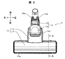
図2は、吸口体の上面図である。図2に示すように、吸口体6は、上面視において略T字形状を呈する吸口ケース10と、吸口ケース10に連結される吸口継手13とを備えている。
FIG. 2 is a top view of the mouthpiece. As shown in FIG. 2, the
吸口ケース10は、上面視において、左右方向(幅方向)に細長く形成された吸口本体11と、吸口本体11の左右方向の中央部に吸口継手13と連結される連結部12とを備えている。連結部12には、吸口本体11と吸口継手13とを連通させる流路R(図3参照)が形成されている。
The
吸口本体11には、前端面から左右側面にかけてバンパ11aが設けられている。バンパ11aは、使用時に吸口本体11内の気密を確保するとともに、電気掃除機1(図1参照)の使用時に吸口本体11が家具等に衝突した際に、当該家具等への傷付き防止と吸口本体11への衝撃を吸収する緩衝材の役割を果たしている。
The mouthpiece
吸口継手13は、連結部12に対して回動自在に連結される第1連結部14と、この第1連結部14に対して回動自在に連結される第2連結部15とを備えている。第1連結部14は、図2の上面視において略D字形状を呈し、連結部12と連結される円筒形状の軸14aを有している。この軸14aは、軸方向が吸口本体11の左右方向であって、軸14aの両端部が連結部12に形成された軸受部12g(図5参照)に支持されている。また、第1連結部14は、床面(清掃面)M(図4参照)に対して略平行な状態から略垂直な状態まで回動可能となるように構成されている。すなわち、第1連結部14を吸口ケース10に対して軸14aを支点として回動させることによって、延長管5(図1参照)を床面M(図4参照)に略平行な状態と略垂直な状態との間において回動させることができる。
The
第2連結部15は、第1連結部14に対して吸口本体11の左右方向に(図2の紙面時計回り方向および反時計回り方向に)回動可能となるように構成されている。これにより、例えば、延長管5を床面Mに対して略垂直にした状態から、延長管5を床面Mに略平行な状態に向けて倒すことができる。また、第2連結部15には、給電が行われる給電端子15aが設けられている。なお、本実施例の電気掃除機1(図1参照)では、吸口体6に給電する電力を、掃除機本体2からホース部3、操作管4、延長管5を通じて供給するように構成している。
The second connecting
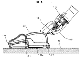
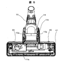
図3は、吸口体の下面図である。図4は、吸口体の側面図である。図3および図4に示すように、吸口体6は、回転ブラシ20を備えている。吸口ケース10(吸口本体11)には、下面(清掃面と向き合う面)に開口部を有するブラシ室Qと、同じく下面に開口部(吸引口)を有する均圧室Pとが形成されている。
FIG. 3 is a bottom view of the mouthpiece. FIG. 4 is a side view of the mouthpiece. As shown in FIGS. 3 and 4, the
回転ブラシ20は、吸口本体11の左右方向に沿って前後方向の前側に配置され、ブラシ室Q内に回転可能に支持されている。また、回転ブラシ20は、吸口本体11の左右方向(回転ブラシ20の軸方向)の一端側から他端側まで連続して設けられている。
The
また、回転ブラシ20は、硬さが異なるブラシなど複数種類のブラシ20a、20b、20cを備え、各ブラシ20a、20b、20cがらせん状に配設されている。なお、本実施の形態例では、3種類のブラシ20a、20b、20cを配設した場合を例に挙げて説明したが、これに限定されるものではなく、2種類以下であってもよく、4種類以上であってもよく、らせん状に配置されたブラシ間にゴムなどの弾性材料からなるブレード部材をらせん状に配置する構成を追加してもよく、適宜変更することができる。
Further, the
サイド固定刷毛70および71は、刷毛体等の弾性材料で構成されていて、吸口ケース10(吸口本体11)の左右方向両端に配置されている。サイド固定刷毛70および71は、吸口ケース10(吸口本体11)の左右方向両端付近の床面Mとの隙間を塞ぐことにより,ブラシ室Qと均圧室Pの気密性を向上させ,特に微細塵の集塵性能を向上させている。 The side fixed brushes 70 and 71 are made of an elastic material such as a brush body, and are arranged at both ends in the left-right direction of the mouthpiece case 10 (mouthpiece body 11). The side fixed brushes 70 and 71 improve the airtightness between the brush chamber Q and the pressure equalizing chamber P by closing the gap between the mouthpiece case 10 (mouthpiece body 11) and the floor surface M near both ends in the left-right direction, and are particularly fine. The dust collection performance is improved.
吸口体6は、吸口ケース10の連結部12の下面に、前方フラップ76、後方フラップ77、ブラシ駆動スイッチ16、車輪17、軸受押え部材31、32を備えている。
The
前方フラップ76は,軸方向(左右方向)に延在するフラップ76aと、床面Mから摩擦力を受け前方フラップ部76aを回動可能に動作させる前方接触回動部76b,76cと、軸部76dによって構成されており、回転ブラシ20に対して前方且つ平行に配置されており、吸口本体11の左右方向の一端側から他端側にかけて連続して回動可能に支持されている。
The
また、後方フラップも同様に、軸方向(左右方向)に延在するフラップ77aと、後方接触回動部77b,77cと、後方フラップ部77aを回動可能に動作させる軸部77dによって構成され、回転ブラシ20に対して後方且つ平行に配置されており、吸口本体11の左右方向の一端側から他端側にかけて連続して回動可能に支持されている。
Similarly, the rear flap is also composed of a
ブラシ駆動スイッチ16は、吸口体6の下面が床面M(清掃面)に接触しているか否かを検出するスイッチであり、車輪16aとともに構成されている。この車輪16aは、ばね等の付勢手段によって常に吸口ケース10(連結部12)の下面から一部が突出するように設けられている。そして、車輪16aが吸口ケース10から飛び出して床面Mと接触していないと検出されたときには、回路基板50(制御基板)(図5参照)の制御によって電動機40(図5参照)の駆動が停止され、回転ブラシ20の回転が停止する。また、車輪16aが押し込まれて床面Mと接触していると検出されたときには、回路基板50の制御によって電動機40が駆動され、回転ブラシ20が回転する。
The
車輪17は、操作管4で操作される前後動や回転操作の応力を受けて吸口体6の底面を床面Mに密着させ、これにより吸口体6の操作性能を向上する役割を有している。また、軸受押え部材31は、回転ブラシ20の回転軸を支持すると同時に、前方フラップ76及び後方フラップ77の軸部76d、77dの吸口ケース10へ取り付ける部分を覆うものであり、吸口ケース10にねじを用いて固定されている。軸受押え部材32は、回転ブラシ20の回転軸を支持すると同時に、前方フラップ76及び後方フラップ77の軸部76d、77dの吸口ケース10へ取り付ける部分を覆うものであり、取り外し可能となるように吸口ケース10にロック機構(図示せず)を用いて固定されている。
The
図5は、吸口体6の吸口ケース10の上側部分を取り外した状態の上面図である。図5に示すように、吸口体6は、回転ブラシ20(図3参照)の上方に、回転ブラシ20を駆動する電動機40および電動機40を制御する回路基板50を備えている。
FIG. 5 is a top view showing a state in which the upper portion of the
電動機40は、吸口本体11の左右方向の一端側に取り付けられている。また、電動機40は、その出力軸が吸口本体11の左右方向と平行に配置されている。また、電動機40の出力軸は、左右方向の一端側に向けて延び、吸口本体11内の一端部(図示右側の端部)において、歯付きベルト41を介して回転ブラシ20と連結されている。
The
回路基板50は、吸口本体11の左右方向で電動機40とは反対側に取り付けられている。また、回路基板50は、長辺が左右方向に沿って配置された長方形状の基板を有し、実装面が鉛直方向上向きの状態で吸口本体11内に配置されている。なお、実装面は、必ずしも鉛直方向上向きに限定されず、水平方向に対して傾斜してもよく、前後方向を向くように(縦向きに)してもよい。
The
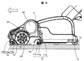
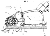
図6および図7は図2におけるA-A断面図であり、図6は、吸口体6の前進時を示しており、図7は後進時を示している。図6において、63はブラシ室Qと均圧室Pを隔てる前方隔壁、64は後方フラップ77と均圧室Pを隔てる後方隔壁である。本実施例では、前方隔壁63が前記第1の気密保持手段を構成し、後方隔壁64が第2の気密保持手段を構成している。
6 and 7 are cross-sectional views taken along the line AA in FIG. 2, FIG. 6 shows the time when the
図6に示すように、均圧室Pは床面Mに向かって開口(吸引口)を有しており、その他の面は吸口体筐体の隔壁により囲まれおり、図3に示す流路Rと流路的に連通している。この均圧室Pは、前方隔壁63と後方隔壁64により負圧を大きくすることができる。
As shown in FIG. 6, the pressure equalizing chamber P has an opening (suction port) toward the floor surface M, and the other surface is surrounded by the partition wall of the mouthpiece housing, and the flow path shown in FIG. It communicates with R in a flow path. The pressure equalizing chamber P can increase the negative pressure by the
吸口体前進時には、前方フラップ76は、前方接触回動部76b及び76cと床面Mとの摩擦力によって後方(移動方向後側)に回動し、前方フラップ部76aと床面Mとの間に開口を形成する。これにより吸口体の前方に位置する比較的大きな塵埃D1は、ブラシ室Q内に吸引され、回転ブラシ20によって掻きとられ、吸口体後方へ送られる。そして前方隔壁63と床面Mとの隙間を通って均圧室P内に吸引され、流路R(図3参照)に流入する。
When the mouthpiece is advanced, the
一方、後方フラップ77は、後方接触回動部77b及び77cと床面Mとの摩擦力によって、後方(移動方向後側)に回動し、床面Mと接する、または隙間を小さくすることで吸口内部の気密を高めるとともに、均圧室P内に吸引された塵埃D1が、吸口体6の後方へ取りこぼすことを抑制できる。このとき、後方フラップ部77aは吸口ケース10と当接し床面Mの垂直方向に対して後方に傾斜した状態となるため、吸口体6と床面Mの摩擦抵抗が小さく、吸口体6の前後操作を軽く行うことができる。また、後方フラップ部77aの材質や床面Mの接触代によって、床面Mとの間の摩擦抵抗が小さい場合もあり、このとき後方フラップ部77aが後方に傾斜させなくても良い。
On the other hand, the
吸口体後進時には、前方接触回動部76b及び76cと床面Mとの摩擦力によって、前方(移動方向後側)に回動し、床面Mと接する、または隙間を小さくすることで吸口内部の気密を高めるとともに、均圧室P内に吸引された塵埃D1が、吸口体6の前方へ取りこぼすことを抑制できる。このとき、前方フラップ部76aは吸口ケース10と当接し床面Mの垂直方向に対して前方に傾斜した状態となるため、吸口体と床面Mの摩擦抵抗が小さく、吸口体の前後操作を軽く行うことができる。また、前方フラップ部76aの材質や床面Mの接触代によって、床面Mとの間の摩擦抵抗が小さい場合もあり、このとき前方フラップ部76aは後方に傾斜させなくても良い。
When the mouthpiece is moved backward, the frictional force between the front
一方、後方フラップ77は、後方接触回動部77b及び77cと床面Mとの摩擦力によって前方(移動方向後側)に回動し、後方フラップ部77aと床面Mとの間に開口を形成する。これにより吸口体の前方に位置する比較的大きな塵埃D2は、後方隔壁64と床面Mとの隙間を通って均圧室P内に吸引され、流路R(図4参照)に流入する。
On the other hand, the
以上のように、吸込体の前進時及び後進時ともに、ケース体の移動方向前側に位置するフラップが開き被掃除面に対し開口を形成するとともに、ケース体の移動方向後側に位置するフラップが傾斜状に倒れた状態で閉じて床との密閉性を確保することで、大小様々な塵埃をより確実に塵埃を吸引でき、かつ、操作性の軽い電気掃除機の吸口体およびこれを備えた電気掃除機を提供することができるという効果を奏する。 As described above, the flap located on the front side in the moving direction of the case body opens to form an opening for the surface to be cleaned both when the suction body moves forward and backward, and the flap located on the rear side in the moving direction of the case body opens. By closing it in a slanted state and ensuring the airtightness with the floor, it is possible to more reliably suck dust of various sizes, and it is equipped with a mouthpiece of an electric vacuum cleaner with light operability. It has the effect of being able to provide an electric vacuum cleaner.
以下、本発明に係る実施例2について図8を参照して説明する。なお、実施例1と同一の構成物には同一番号を付している。 Hereinafter, Example 2 according to the present invention will be described with reference to FIG. The same components as those in the first embodiment are assigned the same numbers.
図8は、実施例2の前進時における吸口体の斜視図である。前方フラップ76Aの前方フラップ部76Aaは、床面Mに対して形成する開口を部分的に閉じる凸部76Aeを有している。これにより、開口から前方の塵埃D1を吸引するとともに、吸口体内部の気密性をより高めることができる。また、凸部76Aeを床面Mと接触させることで床面Mを引っ掻くことで床面Mにこびりついた塵埃D1を浮かせ、吸引しやすくすることができる。
FIG. 8 is a perspective view of the mouthpiece when the second embodiment is advanced. The front flap portion 76Aa of the
本実施例では、前方フラップについて述べたが、後方フラップで同様の構造を取っても同様の効果が得られる。 In this embodiment, the front flap has been described, but the same effect can be obtained by adopting the same structure with the rear flap.
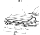
以下、本発明に係る実施例3について図9を参照して説明する。なお、実施例1と同一の構成物には同一番号を付している。 Hereinafter, Example 3 according to the present invention will be described with reference to FIG. The same components as those in the first embodiment are assigned the same numbers.
図9は、実施例3の前進時における吸口体の斜視図である。前方フラップ76Bのフラップ部76Baは、床面Mに対して形成する開口を部分的に閉じる凸部76Beを有しており、凸部76Beは床面Mの略平行な面76Bfを備えている。これにより、前方の塵埃D1を開口から吸引するとともに、吸口体内部の気密性をより高めることができ、また、面76Bfと床面Mの間を吸引風が通ることで床面M付近を通る吸引風の量が増えるため、絨毯上に散布された小麦粉や重曹などの細かい塵埃も吸引しやすくなる。
FIG. 9 is a perspective view of the mouthpiece when the third embodiment is advanced. The flap portion 76Ba of the
本実施例では、前方フラップについて述べたが、後方フラップに同構造を適用しても同様の効果が得られる。 In this embodiment, the front flap has been described, but the same effect can be obtained by applying the same structure to the rear flap.
以下、本発明に係る実施例4について図10を参照して説明する。なお、実施例1と同一の構成物には同一番号を付している。 Hereinafter, Example 4 according to the present invention will be described with reference to FIG. The same components as those in the first embodiment are assigned the same numbers.
図10は、実施例4の前進時における吸口体の斜視図である。前方フラップ76Cのフラップ部76Caは、床面Mに対して形成する開口を部分的に閉じる凸部76Ceを有しており、凸部76Ceは進行方向に平行な方向に対して、凹凸形状である凹凸部76Cgを備えている。これにより、前方の塵埃D1を開口から吸引するとともに、吸口体内部の気密性をより高めることができ、また、吸口体前進時に凸部76Ceに衝突する塵埃D1を凹凸部76Cgにより開口部に導きやすくなる。これにより、比較的大きな塵埃をより急いしやすくすることができる。なお、凹凸部76Cgは、凹凸形状ではなく、傾斜形状でも良い。 FIG. 10 is a perspective view of the mouthpiece when moving forward according to the fourth embodiment. The flap portion 76Ca of the front flap 76C has a convex portion 76Ce that partially closes the opening formed with respect to the floor surface M, and the convex portion 76Ce has an uneven shape with respect to a direction parallel to the traveling direction. It has an uneven portion of 76 Cg. As a result, the dust D1 in front can be sucked from the opening, the airtightness inside the mouthpiece can be further improved, and the dust D1 that collides with the convex portion 76Ce when the mouthpiece is advanced is guided to the opening by the uneven portion 76Cg. It will be easier. This makes it easier to rush relatively large dust. The uneven portion 76Cg may have an inclined shape instead of the uneven shape.
本実施例では、前方フラップについて述べたが、後方フラップに同構造を適用しても同様の効果が得られる。 In this embodiment, the front flap has been described, but the same effect can be obtained by applying the same structure to the rear flap.
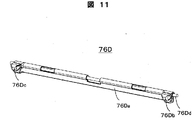
以下、本発明に係る実施例5について図11を参照して説明する。なお、実施例1と同一の構成物には同一番号を付している。 Hereinafter, Example 5 according to the present invention will be described with reference to FIG. The same components as those in the first embodiment are assigned the same numbers.
図11は、前方フラップ76Dの斜視図である。前方フラップ76Dは、金属やステンレススチールなどで形成された金属製の軸部76Ddに、別部材で構成されるフラップ部76Da、接触回動部76Db、76Dcを嵌合することで構成される。この時、軸部76Ddに十字リブやL字のリブなどの凹凸を備えることでフラップ部76Da、接触回動部76Db、76Dcの空転を防止することができる。接触回動部76Db、76Dcを同材料にて形成する場合は、これらを一体化した部品として軸部76Ddに嵌合してもよいし、これらを一体で軸部76Ddにインサート成形することで構成を簡略化でき、組立性が改善する。
FIG. 11 is a perspective view of the
本実施例では、前方フラップについて述べたが、後方フラップに同構造を適用しても同様の効果が得られる。 In this embodiment, the front flap has been described, but the same effect can be obtained by applying the same structure to the rear flap.
以下、本発明に係る実施例6について図12を参照して説明する。なお、実施例1と同一の構成物には同一番号を付している。 Hereinafter, Example 6 according to the present invention will be described with reference to FIG. The same components as those in the first embodiment are assigned the same numbers.
図12は、前方フラップ76Eの斜視図である。前方フラップ76Eは、樹脂や金属の硬質部材で形成される軸部76Edが一体化したフラップ部76Eaに、軟質部材で形成される別体の接触回動部76Eb、76Ecが嵌合され、構成される。この時、軸部76Edに十字リブやL字のリブなどの凹凸を備えることで接触回動部76Eb、76Ecの空転を防止することができる。軸部76Edとフラップ部76Eaを一体化することでインサート成形などの複雑な製造工程が無くなるとともに、成型工程を簡素化することができる。また、軟質部材は硬質部材と比較し高価であることが多く、接触回動部76Eb、76Ecのみ軟質部材で形成することで軟質部材の使用量を減らし、コストダウンを図ることもできる。
FIG. 12 is a perspective view of the
本実施例では、前方フラップについて述べたが、後方フラップに同構造を適用しても同様の効果が得られる。 In this embodiment, the front flap has been described, but the same effect can be obtained by applying the same structure to the rear flap.
以下、本発明に係る実施例7について図13を参照して説明する。なお、実施例1と同一の構成物には同一番号を付している。 Hereinafter, Example 7 according to the present invention will be described with reference to FIG. The same components as those in the first embodiment are assigned the same numbers.
図13は、後方フラップ77Fの斜視図である。後方フラップ77Fは、樹脂や金属の硬質部材で形成される軸部77Fdが一体化した、軸方向に連続して設けられる嵌合部77eを有するフラップ部77Faに、嵌合部77Feに嵌合されるシール部材77Ff、軸部77Fdに嵌合される軟質部材で形成される別体の接触回動部77Fb、77Fcによって構成される。
FIG. 13 is a perspective view of the
フラップ部77Faの先端に軟質部材または刷毛部材で形成されるシール部材77Ffを備えることで床面Mを傷つけることなく床面Mの開口を小さくし吸口体内部の気密を高めることができる。また、シール部材77Ffを変更することで吸口体内部の気密の調整を行うことができるため、用途や電気掃除機の機種によって床面への張り付きを調整し、様々な形態、吸引力を有する電気掃除機でも吸口体本体の形状を変更することなく、軽い操作性を実現することができる。 By providing the sealing member 77Ff formed of a soft member or a brush member at the tip of the flap portion 77Fa, the opening of the floor surface M can be reduced and the airtightness inside the mouthpiece can be improved without damaging the floor surface M. In addition, since the airtightness inside the mouthpiece can be adjusted by changing the seal member 77Ff, the sticking to the floor surface can be adjusted depending on the application and the model of the vacuum cleaner, and electricity having various forms and suction power can be adjusted. Even with a vacuum cleaner, light operability can be realized without changing the shape of the mouthpiece body.
本実施例では、後方フラップについて述べたが、前方フラップに同構造を適用しても同様の効果が得られる。 In this embodiment, the rear flap has been described, but the same effect can be obtained by applying the same structure to the front flap.
以下、本発明に係る実施例8について図14を参照して説明する。なお、実施例1と同一の構成物には同一番号を付している。 Hereinafter, Example 8 according to the present invention will be described with reference to FIG. The same components as those in the first embodiment are assigned the same numbers.
図14は、吸口ケース10の、軸受押え部材32を外した状態の斜視図である。後方フラップ77Gの軸部77Gdの先端にはバネ100が備えられており、バネの一端は吸口ケース10に当接し、多端は軸部77Gdに設けられたリブ77Ghに当接している。これにより後方フラップ77Gは吸口体を前後操作しない状態、または床面抵抗の小さい床面において可動せず、床面Mとの開口を閉じたまま後方に付勢され、吸口体の後方へ漏れる風切り音を低減することができる。
FIG. 14 is a perspective view of the
本実施例では、バネにてフラップを付勢する構成を説明したが、フラップを閉方向、または開方向に付勢出来れば、他の手段にて実施しても良い。 In this embodiment, a configuration in which the flap is urged by a spring has been described, but if the flap can be urged in the closing direction or the opening direction, other means may be used.
本実施例では、後方フラップについて述べたが、前方フラップに同構造を適用しても同様の効果が得られる。 In this embodiment, the rear flap has been described, but the same effect can be obtained by applying the same structure to the front flap.
また,本実施例では,床移動型の掃除機の吸口体について述べたが,いわゆるコードレススティック型掃除機の吸口体に適用しても,同様の効果が得られる。 Further, in this embodiment, the mouthpiece of the floor-moving type vacuum cleaner has been described, but the same effect can be obtained even if it is applied to the mouthpiece of a so-called cordless stick type vacuum cleaner.
1 電気掃除機
2 掃除機本体
2a 電動送風機
2b 集塵部
6 吸口体
10 吸口ケース
20 回転ブラシ
76 前方フラップ
77 後方フラップ
40 電動機
50 回路基板(制御基板)
70、71 実施例1によるサイド固定刷毛
M 床面
Q ブラシ室
P 均圧室
1
70, 71 Side fixed brush according to Example 1 M Floor surface Q Brush chamber P Pressure equalizing chamber
Claims (8)
前記後方フラップは、前記ケース体の後進時に床面と接触して回動する接触回動部と、前記ケース体の後進時に被掃除面との間に開口を形成し、前記ケース体の前進時に前記開口を閉じるフラップ部とを備え、
前記フラップ部は、前記開口を閉じた時に、前記被掃除面に対し前方に傾斜状に倒れた状態であるとともに、最下部が前記被掃除面と接触するかその近傍に位置することを特徴とする電気掃除機の吸口体。 A case body having a suction port on the lower surface, a suction port that communicates with a vacuum cleaner body that generates suction force to suck dust, and a rear flap that is rotatably arranged behind the suction port with respect to the case body. Prepare,
The rear flap forms an opening between the contact rotating portion that rotates in contact with the floor surface when the case body moves backward and the surface to be cleaned when the case body moves backward, and advances the case body. With a flap that sometimes closes the opening,
The flap portion is characterized in that when the opening is closed, the flap portion is tilted forward with respect to the surface to be cleaned, and the lowermost portion is in contact with or near the surface to be cleaned. The mouthpiece of an electric vacuum cleaner.
Priority Applications (3)
| Application Number | Priority Date | Filing Date | Title |
|---|---|---|---|
| JP2018081086A JP7081970B2 (en) | 2018-04-20 | 2018-04-20 | Vacuum cleaner mouthpiece and vacuum cleaner with it |
| TW107130970A TW201943375A (en) | 2018-04-20 | 2018-09-04 | Suction port body of electric vacuum cleaner and electric vacuum cleaner equipped with the same characterized in that the suction port body of electric vacuum cleaner can more certainly suck dusts in various sizes and is easy to handle |
| CN201910161269.0A CN110384437A (en) | 2018-04-20 | 2019-03-04 | Suction head of electric dust collector and electric dust collector comprising same |
Applications Claiming Priority (1)
| Application Number | Priority Date | Filing Date | Title |
|---|---|---|---|
| JP2018081086A JP7081970B2 (en) | 2018-04-20 | 2018-04-20 | Vacuum cleaner mouthpiece and vacuum cleaner with it |
Related Child Applications (1)
| Application Number | Title | Priority Date | Filing Date |
|---|---|---|---|
| JP2018197132A Division JP2019188117A (en) | 2018-10-19 | 2018-10-19 | Suction hole body of vacuum cleaner and vacuum cleaner comprising the same |
Publications (3)
| Publication Number | Publication Date |
|---|---|
| JP2019187579A JP2019187579A (en) | 2019-10-31 |
| JP2019187579A5 JP2019187579A5 (en) | 2021-03-11 |
| JP7081970B2 true JP7081970B2 (en) | 2022-06-07 |
Family
ID=68284929
Family Applications (1)
| Application Number | Title | Priority Date | Filing Date |
|---|---|---|---|
| JP2018081086A Active JP7081970B2 (en) | 2018-04-20 | 2018-04-20 | Vacuum cleaner mouthpiece and vacuum cleaner with it |
Country Status (3)
| Country | Link |
|---|---|
| JP (1) | JP7081970B2 (en) |
| CN (1) | CN110384437A (en) |
| TW (1) | TW201943375A (en) |
Families Citing this family (2)
| Publication number | Priority date | Publication date | Assignee | Title |
|---|---|---|---|---|
| CN115040027A (en) * | 2021-03-09 | 2022-09-13 | 凯迪吸尘器(苏州)有限公司 | Floor cleaning head |
| CN115104947B (en) * | 2021-03-17 | 2024-07-02 | 达利通香港有限公司 | Floor material recognition device and suction head and dust collector with same |
Citations (5)
| Publication number | Priority date | Publication date | Assignee | Title |
|---|---|---|---|---|
| JP2000157461A (en) | 1998-11-30 | 2000-06-13 | Sharp Corp | Sucking mouth body for vacuum cleaner |
| JP2007000602A (en) | 2005-06-22 | 2007-01-11 | Samsung Kwangju Electronics Co Ltd | Vacuum cleaner provided with wet cleaning function |
| JP2008132299A (en) | 2006-11-28 | 2008-06-12 | Samsung Kwangju Electronics Co Ltd | Vacuum cleaner |
| JP2008289852A (en) | 2007-05-28 | 2008-12-04 | Samsung Kwangju Electronics Co Ltd | Suction brush for vacuum cleaner |
| US20130145577A1 (en) | 2011-12-13 | 2013-06-13 | Electrolux Home Care Products, Inc. | Vacuum cleaner floor seal |
Family Cites Families (8)
| Publication number | Priority date | Publication date | Assignee | Title |
|---|---|---|---|---|
| JP3270248B2 (en) * | 1993-10-22 | 2002-04-02 | シャープ株式会社 | Electric vacuum cleaner |
| JP3243136B2 (en) * | 1995-02-08 | 2002-01-07 | 東芝テック株式会社 | Vacuum cleaner suction body |
| JPH10179460A (en) * | 1996-12-20 | 1998-07-07 | Fujitsu General Ltd | Intake tool for floor in vacuum cleaner |
| JP3457529B2 (en) * | 1998-02-25 | 2003-10-20 | シャープ株式会社 | Suction port for vacuum cleaner |
| JPH11299712A (en) * | 1998-04-16 | 1999-11-02 | Mitsubishi Electric Corp | Floor sucking brush of vacuum cleaner |
| JP2000083877A (en) * | 1998-09-10 | 2000-03-28 | Toshiba Tec Corp | Suction nozzle body of vacuum cleaner and vacuum cleaner |
| KR101361564B1 (en) * | 2007-06-11 | 2014-02-14 | 삼성전자주식회사 | Suction nozzle for vacuum cleaner |
| DE102016115977A1 (en) * | 2016-08-26 | 2018-03-01 | Vorwerk & Co. Interholding Gmbh | Base plate for a suction nozzle or an attachment |
-
2018
- 2018-04-20 JP JP2018081086A patent/JP7081970B2/en active Active
- 2018-09-04 TW TW107130970A patent/TW201943375A/en unknown
-
2019
- 2019-03-04 CN CN201910161269.0A patent/CN110384437A/en active Pending
Patent Citations (5)
| Publication number | Priority date | Publication date | Assignee | Title |
|---|---|---|---|---|
| JP2000157461A (en) | 1998-11-30 | 2000-06-13 | Sharp Corp | Sucking mouth body for vacuum cleaner |
| JP2007000602A (en) | 2005-06-22 | 2007-01-11 | Samsung Kwangju Electronics Co Ltd | Vacuum cleaner provided with wet cleaning function |
| JP2008132299A (en) | 2006-11-28 | 2008-06-12 | Samsung Kwangju Electronics Co Ltd | Vacuum cleaner |
| JP2008289852A (en) | 2007-05-28 | 2008-12-04 | Samsung Kwangju Electronics Co Ltd | Suction brush for vacuum cleaner |
| US20130145577A1 (en) | 2011-12-13 | 2013-06-13 | Electrolux Home Care Products, Inc. | Vacuum cleaner floor seal |
Also Published As
| Publication number | Publication date |
|---|---|
| JP2019187579A (en) | 2019-10-31 |
| TW201943375A (en) | 2019-11-16 |
| CN110384437A (en) | 2019-10-29 |
Similar Documents
| Publication | Publication Date | Title |
|---|---|---|
| CN111432704B (en) | Robot cleaner | |
| JP4468440B2 (en) | Vacuum cleaner and its suction port | |
| JP4816384B2 (en) | Vacuum cleaner suction tool and vacuum cleaner using the same | |
| CN105361798A (en) | Electric vacuum cleaner | |
| JP7081970B2 (en) | Vacuum cleaner mouthpiece and vacuum cleaner with it | |
| KR20070099763A (en) | Robot cleaner system having robot cleaner and docking station | |
| JP2022092039A (en) | Suction port of vacuum cleaner, and vacuum cleaner equipped with the same | |
| JP4817913B2 (en) | Suction port and vacuum cleaner | |
| US11324366B2 (en) | Vacuum cleaner | |
| WO2016027771A1 (en) | Electric vacuum cleaner | |
| JP6623114B2 (en) | Vacuum cleaner suction tool and vacuum cleaner including the same | |
| JP6851182B2 (en) | Vacuum cleaner | |
| JP3863096B2 (en) | Suction port and vacuum cleaner | |
| JP2017006185A (en) | Suction tool for vacuum cleaner and vacuum cleaner including the same | |
| JP2019188117A (en) | Suction hole body of vacuum cleaner and vacuum cleaner comprising the same | |
| KR102448087B1 (en) | Cleaner | |
| JP2017189269A (en) | Suction tool for vacuum cleaner and vacuum cleaner including the same | |
| WO2018078725A1 (en) | Suction tool and electric vacuum cleaner | |
| JP2016202427A (en) | Suction port body of vacuum cleaner and vacuum cleaner including the same | |
| JP4537274B2 (en) | Vacuum cleaner | |
| JP2020110506A (en) | Suction port body of vacuum cleaner and vacuum cleaner including the same | |
| JP4129405B2 (en) | Electric vacuum cleaner | |
| JP6668192B2 (en) | Suction body of vacuum cleaner and vacuum cleaner having the same | |
| JP4738262B2 (en) | Suction port and vacuum cleaner | |
| JP2009078081A (en) | Electric vacuum cleaner and suction port thereof |
Legal Events
| Date | Code | Title | Description |
|---|---|---|---|
| A521 | Request for written amendment filed |
Free format text: JAPANESE INTERMEDIATE CODE: A523 Effective date: 20180423 |
|
| A521 | Request for written amendment filed |
Free format text: JAPANESE INTERMEDIATE CODE: A523 Effective date: 20210122 |
|
| A621 | Written request for application examination |
Free format text: JAPANESE INTERMEDIATE CODE: A621 Effective date: 20210122 |
|
| RD02 | Notification of acceptance of power of attorney |
Free format text: JAPANESE INTERMEDIATE CODE: A7422 Effective date: 20210215 |
|
| RD04 | Notification of resignation of power of attorney |
Free format text: JAPANESE INTERMEDIATE CODE: A7424 Effective date: 20210224 |
|
| A521 | Request for written amendment filed |
Free format text: JAPANESE INTERMEDIATE CODE: A523 Effective date: 20210203 |
|
| A131 | Notification of reasons for refusal |
Free format text: JAPANESE INTERMEDIATE CODE: A131 Effective date: 20211102 |
|
| A977 | Report on retrieval |
Free format text: JAPANESE INTERMEDIATE CODE: A971007 Effective date: 20211105 |
|
| A521 | Request for written amendment filed |
Free format text: JAPANESE INTERMEDIATE CODE: A523 Effective date: 20211228 |
|
| TRDD | Decision of grant or rejection written | ||
| A01 | Written decision to grant a patent or to grant a registration (utility model) |
Free format text: JAPANESE INTERMEDIATE CODE: A01 Effective date: 20220426 |
|
| A61 | First payment of annual fees (during grant procedure) |
Free format text: JAPANESE INTERMEDIATE CODE: A61 Effective date: 20220526 |
|
| R150 | Certificate of patent or registration of utility model |
Ref document number: 7081970 Country of ref document: JP Free format text: JAPANESE INTERMEDIATE CODE: R150 |

