JP7081237B2 - Connection module and power storage module - Google Patents
Connection module and power storage module Download PDFInfo
- Publication number
- JP7081237B2 JP7081237B2 JP2018049568A JP2018049568A JP7081237B2 JP 7081237 B2 JP7081237 B2 JP 7081237B2 JP 2018049568 A JP2018049568 A JP 2018049568A JP 2018049568 A JP2018049568 A JP 2018049568A JP 7081237 B2 JP7081237 B2 JP 7081237B2
- Authority
- JP
- Japan
- Prior art keywords
- power storage
- connecting member
- bus bar
- holding
- storage elements
- Prior art date
- Legal status (The legal status is an assumption and is not a legal conclusion. Google has not performed a legal analysis and makes no representation as to the accuracy of the status listed.)
- Expired - Fee Related
Links
Images


Classifications
-
- H—ELECTRICITY
- H01—ELECTRIC ELEMENTS
- H01M—PROCESSES OR MEANS, e.g. BATTERIES, FOR THE DIRECT CONVERSION OF CHEMICAL ENERGY INTO ELECTRICAL ENERGY
- H01M50/00—Constructional details or processes of manufacture of the non-active parts of electrochemical cells other than fuel cells, e.g. hybrid cells
- H01M50/50—Current conducting connections for cells or batteries
- H01M50/572—Means for preventing undesired use or discharge
-
- H—ELECTRICITY
- H01—ELECTRIC ELEMENTS
- H01G—CAPACITORS; CAPACITORS, RECTIFIERS, DETECTORS, SWITCHING DEVICES, LIGHT-SENSITIVE OR TEMPERATURE-SENSITIVE DEVICES OF THE ELECTROLYTIC TYPE
- H01G2/00—Details of capacitors not covered by a single one of groups H01G4/00-H01G11/00
- H01G2/02—Mountings
-
- H—ELECTRICITY
- H01—ELECTRIC ELEMENTS
- H01G—CAPACITORS; CAPACITORS, RECTIFIERS, DETECTORS, SWITCHING DEVICES, LIGHT-SENSITIVE OR TEMPERATURE-SENSITIVE DEVICES OF THE ELECTROLYTIC TYPE
- H01G11/00—Hybrid capacitors, i.e. capacitors having different positive and negative electrodes; Electric double-layer [EDL] capacitors; Processes for the manufacture thereof or of parts thereof
- H01G11/10—Multiple hybrid or EDL capacitors, e.g. arrays or modules
-
- H—ELECTRICITY
- H01—ELECTRIC ELEMENTS
- H01G—CAPACITORS; CAPACITORS, RECTIFIERS, DETECTORS, SWITCHING DEVICES, LIGHT-SENSITIVE OR TEMPERATURE-SENSITIVE DEVICES OF THE ELECTROLYTIC TYPE
- H01G11/00—Hybrid capacitors, i.e. capacitors having different positive and negative electrodes; Electric double-layer [EDL] capacitors; Processes for the manufacture thereof or of parts thereof
- H01G11/74—Terminals, e.g. extensions of current collectors
- H01G11/76—Terminals, e.g. extensions of current collectors specially adapted for integration in multiple or stacked hybrid or EDL capacitors
-
- H—ELECTRICITY
- H01—ELECTRIC ELEMENTS
- H01M—PROCESSES OR MEANS, e.g. BATTERIES, FOR THE DIRECT CONVERSION OF CHEMICAL ENERGY INTO ELECTRICAL ENERGY
- H01M10/00—Secondary cells; Manufacture thereof
- H01M10/04—Construction or manufacture in general
- H01M10/0413—Large-sized flat cells or batteries for motive or stationary systems with plate-like electrodes
-
- H—ELECTRICITY
- H01—ELECTRIC ELEMENTS
- H01M—PROCESSES OR MEANS, e.g. BATTERIES, FOR THE DIRECT CONVERSION OF CHEMICAL ENERGY INTO ELECTRICAL ENERGY
- H01M10/00—Secondary cells; Manufacture thereof
- H01M10/42—Methods or arrangements for servicing or maintenance of secondary cells or secondary half-cells
- H01M10/425—Structural combination with electronic components, e.g. electronic circuits integrated to the outside of the casing
-
- H—ELECTRICITY
- H01—ELECTRIC ELEMENTS
- H01M—PROCESSES OR MEANS, e.g. BATTERIES, FOR THE DIRECT CONVERSION OF CHEMICAL ENERGY INTO ELECTRICAL ENERGY
- H01M50/00—Constructional details or processes of manufacture of the non-active parts of electrochemical cells other than fuel cells, e.g. hybrid cells
- H01M50/20—Mountings; Secondary casings or frames; Racks, modules or packs; Suspension devices; Shock absorbers; Transport or carrying devices; Holders
- H01M50/204—Racks, modules or packs for multiple batteries or multiple cells
- H01M50/207—Racks, modules or packs for multiple batteries or multiple cells characterised by their shape
- H01M50/209—Racks, modules or packs for multiple batteries or multiple cells characterised by their shape adapted for prismatic or rectangular cells
-
- H—ELECTRICITY
- H01—ELECTRIC ELEMENTS
- H01M—PROCESSES OR MEANS, e.g. BATTERIES, FOR THE DIRECT CONVERSION OF CHEMICAL ENERGY INTO ELECTRICAL ENERGY
- H01M50/00—Constructional details or processes of manufacture of the non-active parts of electrochemical cells other than fuel cells, e.g. hybrid cells
- H01M50/20—Mountings; Secondary casings or frames; Racks, modules or packs; Suspension devices; Shock absorbers; Transport or carrying devices; Holders
- H01M50/262—Mountings; Secondary casings or frames; Racks, modules or packs; Suspension devices; Shock absorbers; Transport or carrying devices; Holders with fastening means, e.g. locks
- H01M50/264—Mountings; Secondary casings or frames; Racks, modules or packs; Suspension devices; Shock absorbers; Transport or carrying devices; Holders with fastening means, e.g. locks for cells or batteries, e.g. straps, tie rods or peripheral frames
-
- H—ELECTRICITY
- H01—ELECTRIC ELEMENTS
- H01M—PROCESSES OR MEANS, e.g. BATTERIES, FOR THE DIRECT CONVERSION OF CHEMICAL ENERGY INTO ELECTRICAL ENERGY
- H01M50/00—Constructional details or processes of manufacture of the non-active parts of electrochemical cells other than fuel cells, e.g. hybrid cells
- H01M50/50—Current conducting connections for cells or batteries
- H01M50/502—Interconnectors for connecting terminals of adjacent batteries; Interconnectors for connecting cells outside a battery casing
- H01M50/507—Interconnectors for connecting terminals of adjacent batteries; Interconnectors for connecting cells outside a battery casing comprising an arrangement of two or more busbars within a container structure, e.g. busbar modules
-
- H—ELECTRICITY
- H01—ELECTRIC ELEMENTS
- H01M—PROCESSES OR MEANS, e.g. BATTERIES, FOR THE DIRECT CONVERSION OF CHEMICAL ENERGY INTO ELECTRICAL ENERGY
- H01M50/00—Constructional details or processes of manufacture of the non-active parts of electrochemical cells other than fuel cells, e.g. hybrid cells
- H01M50/50—Current conducting connections for cells or batteries
- H01M50/543—Terminals
-
- H—ELECTRICITY
- H01—ELECTRIC ELEMENTS
- H01G—CAPACITORS; CAPACITORS, RECTIFIERS, DETECTORS, SWITCHING DEVICES, LIGHT-SENSITIVE OR TEMPERATURE-SENSITIVE DEVICES OF THE ELECTROLYTIC TYPE
- H01G11/00—Hybrid capacitors, i.e. capacitors having different positive and negative electrodes; Electric double-layer [EDL] capacitors; Processes for the manufacture thereof or of parts thereof
- H01G11/78—Cases; Housings; Encapsulations; Mountings
- H01G11/82—Fixing or assembling a capacitive element in a housing, e.g. mounting electrodes, current collectors or terminals in containers or encapsulations
-
- H—ELECTRICITY
- H01—ELECTRIC ELEMENTS
- H01M—PROCESSES OR MEANS, e.g. BATTERIES, FOR THE DIRECT CONVERSION OF CHEMICAL ENERGY INTO ELECTRICAL ENERGY
- H01M2220/00—Batteries for particular applications
- H01M2220/20—Batteries in motive systems, e.g. vehicle, ship, plane
-
- H—ELECTRICITY
- H01—ELECTRIC ELEMENTS
- H01M—PROCESSES OR MEANS, e.g. BATTERIES, FOR THE DIRECT CONVERSION OF CHEMICAL ENERGY INTO ELECTRICAL ENERGY
- H01M50/00—Constructional details or processes of manufacture of the non-active parts of electrochemical cells other than fuel cells, e.g. hybrid cells
- H01M50/50—Current conducting connections for cells or batteries
- H01M50/502—Interconnectors for connecting terminals of adjacent batteries; Interconnectors for connecting cells outside a battery casing
- H01M50/514—Methods for interconnecting adjacent batteries or cells
- H01M50/516—Methods for interconnecting adjacent batteries or cells by welding, soldering or brazing
-
- Y—GENERAL TAGGING OF NEW TECHNOLOGICAL DEVELOPMENTS; GENERAL TAGGING OF CROSS-SECTIONAL TECHNOLOGIES SPANNING OVER SEVERAL SECTIONS OF THE IPC; TECHNICAL SUBJECTS COVERED BY FORMER USPC CROSS-REFERENCE ART COLLECTIONS [XRACs] AND DIGESTS
- Y02—TECHNOLOGIES OR APPLICATIONS FOR MITIGATION OR ADAPTATION AGAINST CLIMATE CHANGE
- Y02E—REDUCTION OF GREENHOUSE GAS [GHG] EMISSIONS, RELATED TO ENERGY GENERATION, TRANSMISSION OR DISTRIBUTION
- Y02E60/00—Enabling technologies; Technologies with a potential or indirect contribution to GHG emissions mitigation
- Y02E60/10—Energy storage using batteries
-
- Y—GENERAL TAGGING OF NEW TECHNOLOGICAL DEVELOPMENTS; GENERAL TAGGING OF CROSS-SECTIONAL TECHNOLOGIES SPANNING OVER SEVERAL SECTIONS OF THE IPC; TECHNICAL SUBJECTS COVERED BY FORMER USPC CROSS-REFERENCE ART COLLECTIONS [XRACs] AND DIGESTS
- Y02—TECHNOLOGIES OR APPLICATIONS FOR MITIGATION OR ADAPTATION AGAINST CLIMATE CHANGE
- Y02P—CLIMATE CHANGE MITIGATION TECHNOLOGIES IN THE PRODUCTION OR PROCESSING OF GOODS
- Y02P70/00—Climate change mitigation technologies in the production process for final industrial or consumer products
- Y02P70/50—Manufacturing or production processes characterised by the final manufactured product
Landscapes
- Chemical & Material Sciences (AREA)
- Chemical Kinetics & Catalysis (AREA)
- Electrochemistry (AREA)
- General Chemical & Material Sciences (AREA)
- Engineering & Computer Science (AREA)
- Power Engineering (AREA)
- Microelectronics & Electronic Packaging (AREA)
- Manufacturing & Machinery (AREA)
- Connection Of Batteries Or Terminals (AREA)
- Battery Mounting, Suspending (AREA)
- Electric Double-Layer Capacitors Or The Like (AREA)
Description
本明細書によって開示される技術は、接続モジュール、および蓄電モジュールに関する。 The techniques disclosed herein relate to connection modules, and storage modules.
車両用の電池モジュールは、正極及び負極の電極端子を有する複数の電池セルと、隣り合う電池セルの電極端子間を接続するバスバーと、電池セルに組み付けられてバスバーを保持するバスバー保持部材とを備えている。バスバー保持部材は、バスバーを囲む包囲壁を備えており、この包囲壁によって、バスバーの保持部材に対する位置決めがなされるとともに、隣接するバスバー間の絶縁が図られている(特許文献1参照)。 A battery module for a vehicle includes a plurality of battery cells having positive and negative electrode terminals, a bus bar connecting the electrode terminals of adjacent battery cells, and a bus bar holding member assembled to the battery cell to hold the bus bar. I have. The bus bar holding member includes a surrounding wall surrounding the bus bar, and the surrounding wall positions the bus bar with respect to the holding member and insulates between adjacent bus bars (see Patent Document 1).
近年、車両の高性能化に伴って、多くの部品を狭いスペースに効率的に配置することが求められており、蓄電モジュールにおいてバスバーを保持する構成についても、構造の簡素化が求められている。 In recent years, as the performance of vehicles has improved, it has been required to efficiently arrange many parts in a narrow space, and the structure for holding a bus bar in a power storage module is also required to be simplified. ..
本明細書によって開示される接続モジュールは、一縁に電極端子を備える複数の蓄電素子により構成される蓄電素子群に取り付けられて、複数の前記蓄電素子を電気的に接続する接続モジュールであって、隣り合う前記蓄電素子の前記電極端子同士を接続する接続部材と、前記接続部材を保持する保持部材とを備え、前記保持部材が、一面に前記接続部材が載置される載置領域を有しているとともに、前記載置領域に載置された前記接続部材を包囲する包囲壁を備えず、前記載置領域に載置された前記接続部材に係合することで、前記接続部材の前記保持部材からの離脱、および前記載置領域外への位置ずれを規制する規制部を備える。 The connection module disclosed by the present specification is a connection module that is attached to a group of power storage elements composed of a plurality of power storage elements having electrode terminals on one edge and electrically connects the plurality of power storage elements. A connecting member for connecting the electrode terminals of the adjacent storage elements and a holding member for holding the connecting member are provided, and the holding member has a mounting area on which the connecting member is mounted on one surface. In addition, the connecting member is not provided with a surrounding wall surrounding the connecting member placed in the previously described mounting area, and by engaging with the connecting member mounted in the previously described mounting area, the connecting member is said to be said. It is provided with a regulating unit that regulates the detachment from the holding member and the displacement to the outside of the above-mentioned placement area.
また、本明細書によって開示される蓄電モジュールは、一縁に電極端子を備える複数の蓄電素子により構成される蓄電素子群と、前記蓄電素子群に取り付けられて、複数の前記蓄電素子を電気的に接続する接続モジュールとを備え、前記接続モジュールが、隣り合う前記蓄電素子の前記電極端子同士を接続する接続部材と、前記接続部材を保持する保持部材とを備え、前記保持部材が、一面に前記接続部材が載置される載置領域を有しているとともに、前記載置領域に載置された前記接続部材を包囲する包囲壁を備えず、前記載置領域に載置された前記接続部材に係合することで、前記接続部材の前記保持部材からの離脱、および前記載置領域外への位置ずれを規制する規制部を備える。 Further, the power storage module disclosed in the present specification includes a power storage element group composed of a plurality of power storage elements having electrode terminals on one edge, and is attached to the power storage element group to electrically mount the plurality of power storage elements. The connection module includes a connection member for connecting the electrode terminals of the adjacent storage elements to each other and a holding member for holding the connection member, and the holding member is provided on one surface. The connection has a mounting area on which the connecting member is mounted, and does not have a surrounding wall surrounding the connecting member mounted in the previously described mounting area, and is mounted in the previously described mounting area. It is provided with a regulating unit that regulates the disconnection of the connecting member from the holding member and the displacement of the connecting member to the outside of the above-mentioned placement region by engaging with the member.
上記の構成によれば、接続部材を囲む包囲壁を設けるよりも簡素な構成で、接続部材の離脱防止および位置決めを図ることができる。このような構成は、隣接する接続部材間を絶縁する必要性が薄い低圧の蓄電モジュールに好適である。 According to the above configuration, it is possible to prevent the connecting member from coming off and to position it with a simpler configuration than providing a surrounding wall surrounding the connecting member. Such a configuration is suitable for a low voltage power storage module in which there is little need to insulate between adjacent connecting members.
上記の構成において、前記保持部材が、前記載置領域に隣接する位置に、前記電極端子を挿通するための挿通孔を有していても構わない。 In the above configuration, the holding member may have an insertion hole for inserting the electrode terminal at a position adjacent to the previously described placement region.
このように、接続部材の載置領域に隣接する位置に挿通孔を有する構成では、包囲壁を接続部材に隣接する位置に設けて接続部材に当接させ、接続部材の位置決めを行うことが難しい。このような場合においても、規制部によって、簡素な構成で、接続部材の離脱防止および位置決めを図ることができる。 As described above, in the configuration having the insertion hole at the position adjacent to the mounting area of the connecting member, it is difficult to provide the surrounding wall at the position adjacent to the connecting member and bring it into contact with the connecting member to position the connecting member. .. Even in such a case, the regulating unit can prevent the connecting member from coming off and position it with a simple structure.
上記の構成において、前記接続部材が、一対の端縁のうち一方の端縁から突出する係止突部と、他方の端縁から凹む係止凹部とを備えており、前記規制部が、前記載置領域の一端に配置されて、前記係止突部を挿入可能な規制凹部を有する規制受部と、前記載置領域の他端に配置されて、前記係止凹部の内部に収容されて前記接続部材に係合する規制片とで構成されていても構わない。 In the above configuration, the connecting member comprises a locking protrusion protruding from one end of the pair of edges and a locking recess recessed from the other edge, wherein the restricting portion is front. A regulated receiving portion which is arranged at one end of the described placement area and has a regulating recess into which the locking protrusion can be inserted, and a regulated receiving portion which is arranged at the other end of the previously described placement area and is housed inside the locking recess. It may be composed of a restricting piece that engages with the connecting member.
このような構成によれば、打ち抜き加工によって接続部材を製造する際に、母材において、先に打ち抜かれた接続部材の係止凹部の形状に対応して残った凸部から、次に打ち抜く接続部材の係止突部を取るようにすることができるので、複数の接続部材間の廃棄部分の大きさを最小限とすることができ、材料の無駄を最小限とすることができる。 According to such a configuration, when the connection member is manufactured by punching, the connection to be punched out next from the convex portion remaining corresponding to the shape of the locking recess of the connection member punched out earlier in the base material. Since the locking protrusions of the members can be removed, the size of the waste portion between the plurality of connecting members can be minimized, and the waste of materials can be minimized.
本明細書によって開示される接続モジュールおよび蓄電モジュールによれば、簡素な構成で、接続部材の離脱防止および位置決めを図ることができる。 According to the connection module and the power storage module disclosed by the present specification, it is possible to prevent disconnection and position the connection member with a simple configuration.
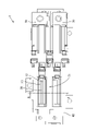
実施形態1を、図1~図9を参照しつつ説明する。本実施形態の蓄電モジュール1は、ガソリン車などの、電気エネルギーを車両の駆動のために用いない車両に搭載される、低圧のバッテリであって、複数の蓄電素子10により構成される蓄電素子群10Gと、この蓄電素子群10Gに組み付けられて、複数の蓄電素子10を電気的に接続する接続モジュール20とを備えている。
The first embodiment will be described with reference to FIGS. 1 to 9. The
[蓄電素子群10Gおよび蓄電素子10]
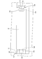
本実施形態の蓄電素子10はラミネート型の電池であり、全体として扁平な直方体状をなす。各蓄電素子10は、図2に示すように、発電要素(図示せず)をラミネートフィルムによって包むとともに縁部を溶着した電池本体11と、発電要素に接続されるとともに電池本体11の一縁(図2の上縁)から外側に突出する一対の電極端子(正極端子12、負極端子13)とを備える。電極端子12、13は、箔状のリード端子である。
[Power
The
蓄電素子10は、複数(本実施形態では4つ)が重ねられて、蓄電素子群10Gを構成している。隣り合う2つの蓄電素子10は、図2に示すように、互いに異なる極性の電極端子12、13が隣り合うように(一の蓄電素子10の正極端子12と、これと隣接する他の蓄電素子10の負極端子13とが互いに隣り合うように)配置されている。
A plurality of (four in this embodiment)
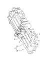
[接続モジュール20]
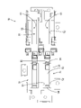
接続モジュール20は、図3に示すように、複数のバスバー30(接続部材に該当)と、複数のバスバー30を保持して蓄電素子群10Gに組み付けられる保持部材40とを備えている。
[Connection module 20]
As shown in FIG. 3, the
バスバー30は、金属などの導電性を有する材料により構成され、図8に示すように、細長い長方形の板状をなすバスバー本体31と、バスバー本体31から突出する係止突部32とを備えている。係止突部32は、バスバー本体31の両端縁のうち一方の端縁31A(図8の左側の端縁)から突出する、矩形の板片状の部分である。また、バスバー本体31は、両端縁のうち他方の端縁31B(図8の右側の端縁)から凹む係止凹部33を有している。係止凹部33は、他方の端縁31Bよりも内側に位置する奥縁33Aと、この奥縁33Aと他方の端縁31Bとを繋ぐ一対の側縁33Bとによって規定される凹部である。係止突部32と係止凹部33とは、どちらも、バスバー本体31の幅方向について同じ位置(一対の長辺間の中央位置)に配置されている。
The
このような形状のバスバー30を製造する際には、図9に示すように、帯状の母材80からプレス型を用いてバスバー30を順次打ち抜いていく。このとき、母材80において、先に打ち抜かれたバスバー30の係止凹部33の形状に対応して残った凸状の部分から、次に打ち抜くバスバー30の係止突部32を取るようにすることができるので、打ち抜き後に残る廃棄部分81の大きさを最小限とすることができ、材料の無駄を最小限とすることができる。
When manufacturing the
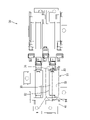
保持部材40は、合成樹脂製であって、図3、図4および図7に示すように、全体として長方形状の厚板状をなす保持本体41を備えている。図2および図5に示すように、保持本体41の表裏両面のうち一面が蓄電素子群10Gに対向する素子対向面41A、他面がバスバー30が保持されるバスバー保持面41Bとなっている。保持本体41において、一方の短辺側の半分(図7の左側の半分)には、2つのバスバー保持部51が並列して配置されている。また他方の短辺側の半分(図7の右側の半分)には、2つの接続端子保持部61と、1つのバスバー保持部51が並列して配置されている。バスバー保持部51は、2つの接続端子保持部61の間に配置されている。
The
複数のバスバー保持部51は、互いに同様の構成を有しているので、以下には、複数のバスバー保持部51のうち1つ(図7の左下のバスバー保持部51)を例にとり、詳細に説明する。
Since the plurality of bus
バスバー保持部51は、図4および図7に示すように、電極端子12、13を挿通可能な一対のスリット52(挿通孔に該当)と、バスバー30の離脱及び位置ずれを規制するための規制部(規制受部54および規制片56)とを備えている。
As shown in FIGS. 4 and 7, the bus
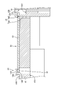
一対のスリット52のそれぞれは、図2に示すように、素子対向面41Aに電極端子12、13を挿入するための挿入口52Aを、バスバー保持面41Bに電極端子12、13を導出するための導出口52Bを有し、保持本体41を板厚方向に貫通している。一対のスリット52は、図7に示すように、互いに間隔を空け、平行に延びている。バスバー保持面41Bにおいて一対のスリット52の導出口52Bによって区画された領域は、図7に示すように、バスバー30が載置されるバスバー載置領域53(載置領域に該当)となっている。言い換えると、バスバー保持部51は、バスバー載置領域53に隣接する位置に、電極端子12、13をを挿通するためのスリット52を有している。
As shown in FIG. 2, each of the pair of
バスバー保持部51は、バスバー載置領域53の一端(図7の左端)に規制受部54を備え、他端(図7の右端)に規制片56を備えている。
The bus
規制受部54は、図5および図6に示すように、バスバー載置領域53の一端から垂直に立ち上がる奥壁部54Aと、この奥壁部54Aの延出端から、奥壁部54Aに対して垂直に、バスバー載置領域53の他端に向かって延びる天壁部54Bと、奥壁部54Aおよび天壁部54Bに対して垂直に延び、互いに間隔を空けて配置される一対の側壁部54Cとを備えている。奥壁部54Aと天壁部54Bと一対の側壁部54Cとで囲まれる空間は、バスバー30の係止突部32を内部に受け入れ可能な規制凹部54Dとなっている。
As shown in FIGS. 5 and 6, the
バスバー載置領域53の他端には、図5に示すように、バスバー保持面41Bから凹む規制片収容部55が設けられている。規制片収容部55は、バスバー保持面41Bよりも奥方に(素子対向面41Aに近接して)位置する底面55Aと、底面55Aとバスバー保持面41Bとを繋ぐ周壁面55Bとで規定される凹部であって、バスバー保持面41Bに開口している。規制片56は、図5に示すように、撓み部56Aと係合爪56Bとを備えている。撓み部56Aは、底面55Aから延び、先端部が規制片収容部55から外方に突出している板バネ状の部分であって、規制受部54に対して近接-離間する方向(図5の左右方向)に撓み可能とされている。係合爪56Bは、撓み部56Aの先端部から規制受部54に向かって突出し、バスバー30に係合する部分である。
As shown in FIG. 5, a restricting
バスバー30をバスバー保持部51に組み付ける際には、まず、係止突部32を規制凹部54Dの内部に差し込む。次に、規制片56を規制受部54から離間する方向に撓ませ、バスバー30をバスバー載置領域53に重ねて配置する。そして、規制片56を弾性復帰させると、規制片56が係止凹部33の内側に入り込み、バスバー30において係止凹部33の奥縁33Aに隣接する部分に係合爪56Bが係合する。
When assembling the
バスバー30は、図5に示すように、係合爪56Bと規制受部54とによって係止されることで、バスバー保持部51からの離脱(図5の上方への離脱)が規制されている。また、図6に示すように、係止突部32が2つの側壁部54Cの間に位置し、規制片56が2つの側縁33Bの間に位置しているから、バスバー30が幅方向(隣接する他のバスバー30に対して近接または離間する方向:図4および図6の上下方向)に移動しようとすると、係止突部32が側壁部54Cに、係合爪56Bが側縁33Bに突き当たり、それ以上の移動が規制される。これにより、バスバー30の幅方向への位置ずれが規制されている。
As shown in FIG. 5, the
2つの接続端子保持部61は、それぞれ、図7に示すように、バスバー保持部51が有するスリット52と同様の構成のスリット52を1つ有しているとともに、図1に示すように、蓄電素子群10Gと外部機器との接続のための接続端子70を保持している。
As shown in FIG. 7, each of the two connection
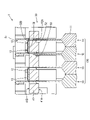
[接続モジュール20の蓄電素子群10Gへの組み付け]
接続モジュール20を、図2に示すように、素子対向面41Aが蓄電素子群10Gの方を向くように蓄電素子群10Gに沿って配置する。各バスバー保持部51の各スリット52内に、蓄電素子10の各電極端子12、13を挿通させる。次に、電極端子12、13のうちバスバー保持面41Bから突出した部分を折り曲げ、バスバー30に重ね合わせる。一のバスバー30には、隣り合う蓄電素子10における、互いに異なる極性の電極端子12、13が重ね合わせられる。例えば、一のバスバー保持部51(図2の右側のバスバー保持部51)に保持されたバスバー30には、一の蓄電素子10(図2の右端の蓄電素子)の正極端子12と、一の蓄電素子10に隣接する他の蓄電素子10(図2の右から2番目の蓄電素子)の負極端子13とが重ねられる。なお、一のバスバー30に重ねられる正極端子12と負極端子13とは、互いに直接接触しないように設定されている。また、同様に、各接続端子保持部61の各スリット52からも対応する電極端子12、13を導出し、接続端子70に重ね合わせる。
[Assembly of the
As shown in FIG. 2, the
電極端子12、13のうちバスバー30に重ね合わされた部分は、レーザー溶接により、バスバー30と導通接続される。同様に、電極端子12、13のうち接続端子70に重ね合わされた部分は、レーザー溶接により、接続端子70と導通接続される。このようにして、蓄電モジュール1が完成する。
The portion of the
[まとめ]
以上のように本実施形態によれば、蓄電モジュール1は、一縁に電極端子(正極端子12、負極端子13)を備える複数の蓄電素子10により構成される蓄電素子群10Gと、この蓄電素子群10Gに取り付けられて、複数の蓄電素子10を電気的に接続する接続モジュール20とを備える。接続モジュール20は、隣り合う蓄電素子10の電極端子12、13同士を接続するバスバー30と、バスバー30を保持する保持部材40とを備える。保持部材40が、バスバー保持面41Bにバスバー30が載置されるバスバー載置領域53を有しているとともに、バスバー載置領域53に載置されたバスバー30に係合することで、バスバー30の保持部材40からの離脱、およびバスバー載置領域53外への位置ずれを規制する規制受部54および規制片56を備える。
[summary]
As described above, according to the present embodiment, the
上記の構成によれば、バスバー30を囲む包囲壁を設けるよりも簡素な構成で、バスバー30の離脱防止および位置決めを図ることができる。このような構成は、例えば、ガソリン車などの、電気エネルギーを車両の駆動のために用いない車両に搭載されるバッテリに好適である。このようなバッテリは、比較的低圧であり、バスバーを囲む包囲壁を設けて隣接するバスバー間を絶縁する必要性が薄いためである。
According to the above configuration, it is possible to prevent the
また、保持部材40が、バスバー載置領域53に隣接する位置に、電極端子12、13を挿通するためのスリット52を有している。
Further, the holding
このように、バスバー載置領域53に隣接する位置にスリット52を有する構成では、包囲壁をバスバー30に隣接する位置に設けてバスバー30に当接させ、バスバー30の位置決めを行うことが難しい。このような場合においても、規制受部54および規制片56によって、簡素な構成で、バスバー30の離脱防止および位置決めを図ることができる。
As described above, in the configuration having the
また、バスバー30が、一対の端縁のうち一方の端縁31Aから突出する係止突部32と、他方の端縁31Bから凹む係止凹部33とを備えており、規制受部54が、バスバー載置領域53の一端に配置されて、係止突部32を挿入可能な規制凹部54Dを有しており、規制片56が、バスバー載置領域53の他端に配置されて、係止凹部33の内部に収容されてバスバー30に係合する。
Further, the
このような構成によれば、打ち抜き加工によってバスバー30を製造する際に、母材80において、先に打ち抜かれたバスバー30の係止凹部33の形状に対応して残った凸状の部分から、次に打ち抜くバスバー30の係止突部32を取るようにすることができるので、打ち抜き後に残る廃棄部分81の大きさを最小限とすることができ、材料の無駄を最小限とすることができる。
According to such a configuration, when the
<他の実施形態>
本明細書によって開示される技術は上記記述及び図面によって説明した実施形態に限定されるものではなく、例えば次のような種々の態様も含まれる。
(1)上記実施形態では、蓄電素子群10Gが4つの蓄電素子10により構成されていたが、蓄電素子の数は任意である。
(2)保持部材に保持される接続部材の数は、蓄電素子の数に合わせて任意に設定することができる。
<Other embodiments>
The techniques disclosed herein are not limited to the embodiments described above and in the drawings, and include, for example, various embodiments such as:
(1) In the above embodiment, the power
(2) The number of connecting members held by the holding members can be arbitrarily set according to the number of power storage elements.
1…蓄電モジュール
10…蓄電素子
10G…蓄電素子群
12…正極端子(電極端子)
13…負極端子(電極端子)
20…接続モジュール
30…バスバー(接続部材)
32…係止突部
33…係止凹部
40…保持部材
52…スリット(挿通孔)
53…バスバー載置領域(載置領域)
54D…規制凹部
54…規制受部(規制部)
56…規制片(規制部)
1 ...
13 ... Negative electrode terminal (electrode terminal)
20 ...
32 ... Locking
53 ... Bus bar mounting area (mounting area)
54D ...
56 ... Regulatory piece (regulatory department)
Claims (3)
隣り合う前記蓄電素子の前記電極端子同士を接続する接続部材と、前記接続部材を保持する保持部材とを備え、
前記保持部材が、一面に前記接続部材が載置される載置領域を有しているとともに、前記載置領域に載置された前記接続部材を包囲する包囲壁を備えず、前記載置領域に載置された前記接続部材に係合することで、前記接続部材の前記保持部材からの離脱、および前記載置領域外への位置ずれを規制する規制部を備え、
前記接続部材が、一対の端縁のうち一方の端縁から突出する係止突部と、他方の端縁から凹む係止凹部とを備えており、
前記規制部が、前記載置領域の一端に配置されて、前記係止突部を挿入可能な規制凹部を有する規制受部と、前記載置領域の他端に配置されて、前記係止凹部の内部に収容されて前記接続部材に係合する規制片とで構成されている、接続モジュール。 A connection module that is attached to a group of power storage elements composed of a plurality of power storage elements having electrode terminals on one edge and electrically connects the plurality of power storage elements.
A connecting member for connecting the electrode terminals of the adjacent storage elements and a holding member for holding the connecting member are provided.
The holding member has a mounting area on one surface on which the connecting member is mounted, and does not have a surrounding wall surrounding the connecting member mounted on the previously described mounting area. It is provided with a regulating unit that regulates the disconnection of the connecting member from the holding member and the displacement of the connecting member to the outside of the above-mentioned placement region by engaging with the connecting member mounted on the above-mentioned .
The connecting member includes a locking protrusion protruding from one of the pair of edge edges and a locking recess recessed from the other edge.
The restricting portion is arranged at one end of the previously described placement region and has a regulation receiving portion having a regulation recess into which the locking protrusion can be inserted, and the regulation receiving portion is arranged at the other end of the previously described placement region so as to have the locking recess. A connection module composed of a restricting piece housed inside and engaged with the connection member .
前記接続モジュールが、隣り合う前記蓄電素子の前記電極端子同士を接続する接続部材と、前記接続部材を保持する保持部材とを備え、
前記保持部材が、一面に前記接続部材が載置される載置領域を有しているとともに、前記載置領域に載置された前記接続部材を包囲する包囲壁を備えず、前記載置領域に載置された前記接続部材に係合することで、前記接続部材の前記保持部材からの離脱、および前記載置領域外への位置ずれを規制する規制部を備え、
前記接続部材が、一対の端縁のうち一方の端縁から突出する係止突部と、他方の端縁から凹む係止凹部とを備えており、
前記規制部が、前記載置領域の一端に配置されて、前記係止突部を挿入可能な規制凹部を有する規制受部と、前記載置領域の他端に配置されて、前記係止凹部の内部に収容されて前記接続部材に係合する規制片とで構成されている、蓄電モジュール。 It is provided with a power storage element group composed of a plurality of power storage elements having electrode terminals on one edge, and a connection module attached to the power storage element group to electrically connect the plurality of power storage elements.
The connection module includes a connection member for connecting the electrode terminals of the power storage elements adjacent to each other and a holding member for holding the connection member.
The holding member has a mounting area on one surface on which the connecting member is mounted, and does not have a surrounding wall surrounding the connecting member mounted on the previously described mounting area. It is provided with a regulating unit that regulates the disconnection of the connecting member from the holding member and the displacement of the connecting member to the outside of the above-mentioned placement region by engaging with the connecting member mounted on the above-mentioned .
The connecting member includes a locking protrusion protruding from one of the pair of edge edges and a locking recess recessed from the other edge.
The restricting portion is arranged at one end of the previously described placement region and has a regulation receiving portion having a regulation recess into which the locking protrusion can be inserted, and the regulation receiving portion is arranged at the other end of the previously described placement region so as to have the locking recess. A power storage module that is housed inside and is composed of a restricting piece that engages with the connection member .
Priority Applications (5)
| Application Number | Priority Date | Filing Date | Title |
|---|---|---|---|
| JP2018049568A JP7081237B2 (en) | 2018-03-16 | 2018-03-16 | Connection module and power storage module |
| PCT/JP2019/008036 WO2019176584A1 (en) | 2018-03-16 | 2019-03-01 | Connection module, and storage module |
| DE112019001379.3T DE112019001379T5 (en) | 2018-03-16 | 2019-03-01 | Connector module and energy storage module |
| CN201980016122.0A CN112106221B (en) | 2018-03-16 | 2019-03-01 | Connection module and power storage module |
| US16/979,702 US11289778B2 (en) | 2018-03-16 | 2019-03-01 | Connector module and power storage module |
Applications Claiming Priority (1)
| Application Number | Priority Date | Filing Date | Title |
|---|---|---|---|
| JP2018049568A JP7081237B2 (en) | 2018-03-16 | 2018-03-16 | Connection module and power storage module |
Publications (2)
| Publication Number | Publication Date |
|---|---|
| JP2019160736A JP2019160736A (en) | 2019-09-19 |
| JP7081237B2 true JP7081237B2 (en) | 2022-06-07 |
Family
ID=67907161
Family Applications (1)
| Application Number | Title | Priority Date | Filing Date |
|---|---|---|---|
| JP2018049568A Expired - Fee Related JP7081237B2 (en) | 2018-03-16 | 2018-03-16 | Connection module and power storage module |
Country Status (5)
| Country | Link |
|---|---|
| US (1) | US11289778B2 (en) |
| JP (1) | JP7081237B2 (en) |
| CN (1) | CN112106221B (en) |
| DE (1) | DE112019001379T5 (en) |
| WO (1) | WO2019176584A1 (en) |
Families Citing this family (7)
| Publication number | Priority date | Publication date | Assignee | Title |
|---|---|---|---|---|
| KR102769905B1 (en) * | 2019-10-24 | 2025-02-17 | 주식회사 엘지에너지솔루션 | Battery module, battery pack and vehicle comprising the battery module |
| KR102802982B1 (en) * | 2020-07-06 | 2025-04-30 | 주식회사 엘지에너지솔루션 | Battery module and battery pack including the same |
| KR20220021439A (en) * | 2020-08-13 | 2022-02-22 | 주식회사 엘지에너지솔루션 | Battery module with improved electrode lead connection structure, and battery pack and vehicle comprising the same |
| CN116742290A (en) * | 2022-03-04 | 2023-09-12 | 比亚迪股份有限公司 | Battery cell assembly, battery pack and vehicle |
| JP7759304B2 (en) * | 2022-10-06 | 2025-10-23 | 株式会社オートネットワーク技術研究所 | Wiring Module |
| JP7759305B2 (en) * | 2022-10-06 | 2025-10-23 | 株式会社オートネットワーク技術研究所 | Wiring Module |
| CN116031587B (en) * | 2023-02-09 | 2023-06-23 | 深圳海润新能源科技有限公司 | Energy storage device and electrical equipment |
Citations (9)
| Publication number | Priority date | Publication date | Assignee | Title |
|---|---|---|---|---|
| JP2006164895A (en) | 2004-12-10 | 2006-06-22 | Nec Lamilion Energy Ltd | Electrical device assembly and storage box structure |
| JP2011524624A (en) | 2008-06-30 | 2011-09-01 | エルジー・ケム・リミテッド | Battery cell interconnect and voltage sensing assembly and method of connecting a battery cell assembly thereto |
| US20120115015A1 (en) | 2010-11-05 | 2012-05-10 | Shi-Dong Park | Battery module |
| US20120328908A1 (en) | 2011-06-23 | 2012-12-27 | Samsung Sdi Co., Ltd. | Battery Pack |
| WO2015019570A1 (en) | 2013-08-08 | 2015-02-12 | パナソニックIpマネジメント株式会社 | Battery unit |
| KR101547400B1 (en) | 2013-11-15 | 2015-08-26 | 세방전지(주) | Serial sensing board for energy storage apparatus |
| JP2016115545A (en) | 2014-12-15 | 2016-06-23 | 矢崎総業株式会社 | Battery wiring module |
| JP2016157670A (en) | 2015-02-25 | 2016-09-01 | 三星エスディアイ株式会社Samsung SDI Co., Ltd. | Battery pack |
| JP2017098043A (en) | 2015-11-20 | 2017-06-01 | 矢崎総業株式会社 | Holding structure for terminal for voltage detection |
Family Cites Families (7)
| Publication number | Priority date | Publication date | Assignee | Title |
|---|---|---|---|---|
| KR102024002B1 (en) * | 2012-07-05 | 2019-09-23 | 에스케이이노베이션 주식회사 | Battery pack |
| JP6107570B2 (en) | 2013-09-25 | 2017-04-05 | 株式会社デンソー | Battery module and assembling method thereof |
| US9972815B2 (en) * | 2014-02-05 | 2018-05-15 | Ford Global Technologies, Llc | Traction battery spacer with retention element |
| JP6365437B2 (en) * | 2015-06-24 | 2018-08-01 | 株式会社オートネットワーク技術研究所 | Wiring module and power storage module |
| JP2017199501A (en) * | 2016-04-26 | 2017-11-02 | 株式会社オートネットワーク技術研究所 | Connection module |
| CN107403889B (en) * | 2016-05-20 | 2020-06-30 | 莫列斯有限公司 | Battery connection module |
| JP2018014297A (en) * | 2016-07-22 | 2018-01-25 | 株式会社オートネットワーク技術研究所 | Wiring module |
-
2018
- 2018-03-16 JP JP2018049568A patent/JP7081237B2/en not_active Expired - Fee Related
-
2019
- 2019-03-01 CN CN201980016122.0A patent/CN112106221B/en not_active Expired - Fee Related
- 2019-03-01 DE DE112019001379.3T patent/DE112019001379T5/en not_active Withdrawn
- 2019-03-01 US US16/979,702 patent/US11289778B2/en active Active
- 2019-03-01 WO PCT/JP2019/008036 patent/WO2019176584A1/en not_active Ceased
Patent Citations (9)
| Publication number | Priority date | Publication date | Assignee | Title |
|---|---|---|---|---|
| JP2006164895A (en) | 2004-12-10 | 2006-06-22 | Nec Lamilion Energy Ltd | Electrical device assembly and storage box structure |
| JP2011524624A (en) | 2008-06-30 | 2011-09-01 | エルジー・ケム・リミテッド | Battery cell interconnect and voltage sensing assembly and method of connecting a battery cell assembly thereto |
| US20120115015A1 (en) | 2010-11-05 | 2012-05-10 | Shi-Dong Park | Battery module |
| US20120328908A1 (en) | 2011-06-23 | 2012-12-27 | Samsung Sdi Co., Ltd. | Battery Pack |
| WO2015019570A1 (en) | 2013-08-08 | 2015-02-12 | パナソニックIpマネジメント株式会社 | Battery unit |
| KR101547400B1 (en) | 2013-11-15 | 2015-08-26 | 세방전지(주) | Serial sensing board for energy storage apparatus |
| JP2016115545A (en) | 2014-12-15 | 2016-06-23 | 矢崎総業株式会社 | Battery wiring module |
| JP2016157670A (en) | 2015-02-25 | 2016-09-01 | 三星エスディアイ株式会社Samsung SDI Co., Ltd. | Battery pack |
| JP2017098043A (en) | 2015-11-20 | 2017-06-01 | 矢崎総業株式会社 | Holding structure for terminal for voltage detection |
Also Published As
| Publication number | Publication date |
|---|---|
| CN112106221B (en) | 2023-02-17 |
| WO2019176584A1 (en) | 2019-09-19 |
| US20210043908A1 (en) | 2021-02-11 |
| JP2019160736A (en) | 2019-09-19 |
| DE112019001379T5 (en) | 2020-11-26 |
| US11289778B2 (en) | 2022-03-29 |
| CN112106221A (en) | 2020-12-18 |
Similar Documents
| Publication | Publication Date | Title |
|---|---|---|
| JP7081237B2 (en) | Connection module and power storage module | |
| US10211434B2 (en) | Battery pack | |
| EP3679611B1 (en) | Mounting system for battery cells | |
| CN104704649B (en) | Battery module with busbar assembly and the battery pack including the battery module | |
| KR102317639B1 (en) | Battery module including insert injection molded busbar | |
| CN108780861B (en) | Power supply device | |
| JP6995882B2 (en) | Battery module | |
| KR20160043038A (en) | Electricity storage module | |
| KR101750487B1 (en) | Battery Module Having Mounting Means of Bus Bar and External Input-Output Terminal | |
| KR102210461B1 (en) | Battery module comprising a unit battery module and battery pack comprisng the same and Method of manufacturing the battery module | |
| CN108701793A (en) | Battery pack | |
| KR100943833B1 (en) | Cartridge for medium and large battery packs | |
| CN104170122B (en) | Bus bar modules and power supply units | |
| KR20190012803A (en) | Battery module, battery pack and energy storage system comprising the same | |
| CN108336287A (en) | Battery cell and battery pack | |
| JP2018133152A (en) | Battery module and battery pack | |
| KR102635431B1 (en) | Cartridge for battery cell and Battery module having the same | |
| US11502361B2 (en) | Energy storage apparatus | |
| KR20230102738A (en) | Bus bar holder, bus bar assembly and battery module | |
| KR102490608B1 (en) | Submodule for high voltage battery | |
| JP7120233B2 (en) | power storage device | |
| KR102012403B1 (en) | Intergrated Cartridge for battery cell and Battery Pack having the same | |
| JP2023014626A (en) | power storage device | |
| JP2018010836A (en) | Power storage device and method of manufacturing the same | |
| JP7226515B2 (en) | battery wiring module |
Legal Events
| Date | Code | Title | Description |
|---|---|---|---|
| A621 | Written request for application examination |
Free format text: JAPANESE INTERMEDIATE CODE: A621 Effective date: 20201027 |
|
| A131 | Notification of reasons for refusal |
Free format text: JAPANESE INTERMEDIATE CODE: A131 Effective date: 20211005 |
|
| A521 | Request for written amendment filed |
Free format text: JAPANESE INTERMEDIATE CODE: A523 Effective date: 20211202 |
|
| TRDD | Decision of grant or rejection written | ||
| A01 | Written decision to grant a patent or to grant a registration (utility model) |
Free format text: JAPANESE INTERMEDIATE CODE: A01 Effective date: 20220426 |
|
| A61 | First payment of annual fees (during grant procedure) |
Free format text: JAPANESE INTERMEDIATE CODE: A61 Effective date: 20220509 |
|
| R150 | Certificate of patent or registration of utility model |
Ref document number: 7081237 Country of ref document: JP Free format text: JAPANESE INTERMEDIATE CODE: R150 |
|
| LAPS | Cancellation because of no payment of annual fees |