JP7080852B2 - Semiconductor modules, electronic devices, and printed wiring boards - Google Patents
Semiconductor modules, electronic devices, and printed wiring boards Download PDFInfo
- Publication number
- JP7080852B2 JP7080852B2 JP2019117123A JP2019117123A JP7080852B2 JP 7080852 B2 JP7080852 B2 JP 7080852B2 JP 2019117123 A JP2019117123 A JP 2019117123A JP 2019117123 A JP2019117123 A JP 2019117123A JP 7080852 B2 JP7080852 B2 JP 7080852B2
- Authority
- JP
- Japan
- Prior art keywords
- land
- semiconductor device
- solder resist
- printed wiring
- plan
- Prior art date
- Legal status (The legal status is an assumption and is not a legal conclusion. Google has not performed a legal analysis and makes no representation as to the accuracy of the status listed.)
- Active
Links
Images


Classifications
-
- H—ELECTRICITY
- H05—ELECTRIC TECHNIQUES NOT OTHERWISE PROVIDED FOR
- H05K—PRINTED CIRCUITS; CASINGS OR CONSTRUCTIONAL DETAILS OF ELECTRIC APPARATUS; MANUFACTURE OF ASSEMBLAGES OF ELECTRICAL COMPONENTS
- H05K1/00—Printed circuits
- H05K1/02—Details
- H05K1/11—Printed elements for providing electric connections to or between printed circuits
- H05K1/111—Pads for surface mounting, e.g. lay-out
-
- H—ELECTRICITY
- H01—ELECTRIC ELEMENTS
- H01L—SEMICONDUCTOR DEVICES NOT COVERED BY CLASS H10
- H01L23/00—Details of semiconductor or other solid state devices
- H01L23/48—Arrangements for conducting electric current to or from the solid state body in operation, e.g. leads, terminal arrangements ; Selection of materials therefor
- H01L23/488—Arrangements for conducting electric current to or from the solid state body in operation, e.g. leads, terminal arrangements ; Selection of materials therefor consisting of soldered or bonded constructions
- H01L23/498—Leads, i.e. metallisations or lead-frames on insulating substrates, e.g. chip carriers
- H01L23/49838—Geometry or layout
-
- H—ELECTRICITY
- H01—ELECTRIC ELEMENTS
- H01L—SEMICONDUCTOR DEVICES NOT COVERED BY CLASS H10
- H01L23/00—Details of semiconductor or other solid state devices
- H01L23/48—Arrangements for conducting electric current to or from the solid state body in operation, e.g. leads, terminal arrangements ; Selection of materials therefor
- H01L23/488—Arrangements for conducting electric current to or from the solid state body in operation, e.g. leads, terminal arrangements ; Selection of materials therefor consisting of soldered or bonded constructions
- H01L23/498—Leads, i.e. metallisations or lead-frames on insulating substrates, e.g. chip carriers
- H01L23/49811—Additional leads joined to the metallisation on the insulating substrate, e.g. pins, bumps, wires, flat leads
- H01L23/49816—Spherical bumps on the substrate for external connection, e.g. ball grid arrays [BGA]
-
- H—ELECTRICITY
- H01—ELECTRIC ELEMENTS
- H01L—SEMICONDUCTOR DEVICES NOT COVERED BY CLASS H10
- H01L23/00—Details of semiconductor or other solid state devices
- H01L23/48—Arrangements for conducting electric current to or from the solid state body in operation, e.g. leads, terminal arrangements ; Selection of materials therefor
- H01L23/488—Arrangements for conducting electric current to or from the solid state body in operation, e.g. leads, terminal arrangements ; Selection of materials therefor consisting of soldered or bonded constructions
- H01L23/498—Leads, i.e. metallisations or lead-frames on insulating substrates, e.g. chip carriers
- H01L23/49833—Leads, i.e. metallisations or lead-frames on insulating substrates, e.g. chip carriers the chip support structure consisting of a plurality of insulating substrates
-
- H—ELECTRICITY
- H01—ELECTRIC ELEMENTS
- H01L—SEMICONDUCTOR DEVICES NOT COVERED BY CLASS H10
- H01L24/00—Arrangements for connecting or disconnecting semiconductor or solid-state bodies; Methods or apparatus related thereto
- H01L24/01—Means for bonding being attached to, or being formed on, the surface to be connected, e.g. chip-to-package, die-attach, "first-level" interconnects; Manufacturing methods related thereto
- H01L24/10—Bump connectors ; Manufacturing methods related thereto
- H01L24/15—Structure, shape, material or disposition of the bump connectors after the connecting process
- H01L24/16—Structure, shape, material or disposition of the bump connectors after the connecting process of an individual bump connector
-
- H—ELECTRICITY
- H01—ELECTRIC ELEMENTS
- H01L—SEMICONDUCTOR DEVICES NOT COVERED BY CLASS H10
- H01L24/00—Arrangements for connecting or disconnecting semiconductor or solid-state bodies; Methods or apparatus related thereto
- H01L24/01—Means for bonding being attached to, or being formed on, the surface to be connected, e.g. chip-to-package, die-attach, "first-level" interconnects; Manufacturing methods related thereto
- H01L24/10—Bump connectors ; Manufacturing methods related thereto
- H01L24/15—Structure, shape, material or disposition of the bump connectors after the connecting process
- H01L24/17—Structure, shape, material or disposition of the bump connectors after the connecting process of a plurality of bump connectors
-
- H—ELECTRICITY
- H01—ELECTRIC ELEMENTS
- H01L—SEMICONDUCTOR DEVICES NOT COVERED BY CLASS H10
- H01L2224/00—Indexing scheme for arrangements for connecting or disconnecting semiconductor or solid-state bodies and methods related thereto as covered by H01L24/00
- H01L2224/01—Means for bonding being attached to, or being formed on, the surface to be connected, e.g. chip-to-package, die-attach, "first-level" interconnects; Manufacturing methods related thereto
- H01L2224/10—Bump connectors; Manufacturing methods related thereto
- H01L2224/12—Structure, shape, material or disposition of the bump connectors prior to the connecting process
- H01L2224/13—Structure, shape, material or disposition of the bump connectors prior to the connecting process of an individual bump connector
- H01L2224/13001—Core members of the bump connector
- H01L2224/13099—Material
- H01L2224/131—Material with a principal constituent of the material being a metal or a metalloid, e.g. boron [B], silicon [Si], germanium [Ge], arsenic [As], antimony [Sb], tellurium [Te] and polonium [Po], and alloys thereof
-
- H—ELECTRICITY
- H01—ELECTRIC ELEMENTS
- H01L—SEMICONDUCTOR DEVICES NOT COVERED BY CLASS H10
- H01L2224/00—Indexing scheme for arrangements for connecting or disconnecting semiconductor or solid-state bodies and methods related thereto as covered by H01L24/00
- H01L2224/01—Means for bonding being attached to, or being formed on, the surface to be connected, e.g. chip-to-package, die-attach, "first-level" interconnects; Manufacturing methods related thereto
- H01L2224/10—Bump connectors; Manufacturing methods related thereto
- H01L2224/15—Structure, shape, material or disposition of the bump connectors after the connecting process
- H01L2224/16—Structure, shape, material or disposition of the bump connectors after the connecting process of an individual bump connector
- H01L2224/1605—Shape
- H01L2224/16057—Shape in side view
- H01L2224/16058—Shape in side view being non uniform along the bump connector
-
- H—ELECTRICITY
- H01—ELECTRIC ELEMENTS
- H01L—SEMICONDUCTOR DEVICES NOT COVERED BY CLASS H10
- H01L2224/00—Indexing scheme for arrangements for connecting or disconnecting semiconductor or solid-state bodies and methods related thereto as covered by H01L24/00
- H01L2224/01—Means for bonding being attached to, or being formed on, the surface to be connected, e.g. chip-to-package, die-attach, "first-level" interconnects; Manufacturing methods related thereto
- H01L2224/10—Bump connectors; Manufacturing methods related thereto
- H01L2224/15—Structure, shape, material or disposition of the bump connectors after the connecting process
- H01L2224/16—Structure, shape, material or disposition of the bump connectors after the connecting process of an individual bump connector
- H01L2224/1605—Shape
- H01L2224/1607—Shape of bonding interfaces, e.g. interlocking features
-
- H—ELECTRICITY
- H01—ELECTRIC ELEMENTS
- H01L—SEMICONDUCTOR DEVICES NOT COVERED BY CLASS H10
- H01L2224/00—Indexing scheme for arrangements for connecting or disconnecting semiconductor or solid-state bodies and methods related thereto as covered by H01L24/00
- H01L2224/01—Means for bonding being attached to, or being formed on, the surface to be connected, e.g. chip-to-package, die-attach, "first-level" interconnects; Manufacturing methods related thereto
- H01L2224/10—Bump connectors; Manufacturing methods related thereto
- H01L2224/15—Structure, shape, material or disposition of the bump connectors after the connecting process
- H01L2224/16—Structure, shape, material or disposition of the bump connectors after the connecting process of an individual bump connector
- H01L2224/161—Disposition
- H01L2224/16151—Disposition the bump connector connecting between a semiconductor or solid-state body and an item not being a semiconductor or solid-state body, e.g. chip-to-substrate, chip-to-passive
- H01L2224/16221—Disposition the bump connector connecting between a semiconductor or solid-state body and an item not being a semiconductor or solid-state body, e.g. chip-to-substrate, chip-to-passive the body and the item being stacked
- H01L2224/16225—Disposition the bump connector connecting between a semiconductor or solid-state body and an item not being a semiconductor or solid-state body, e.g. chip-to-substrate, chip-to-passive the body and the item being stacked the item being non-metallic, e.g. insulating substrate with or without metallisation
- H01L2224/16237—Disposition the bump connector connecting between a semiconductor or solid-state body and an item not being a semiconductor or solid-state body, e.g. chip-to-substrate, chip-to-passive the body and the item being stacked the item being non-metallic, e.g. insulating substrate with or without metallisation the bump connector connecting to a bonding area disposed in a recess of the surface of the item
-
- H—ELECTRICITY
- H01—ELECTRIC ELEMENTS
- H01L—SEMICONDUCTOR DEVICES NOT COVERED BY CLASS H10
- H01L2224/00—Indexing scheme for arrangements for connecting or disconnecting semiconductor or solid-state bodies and methods related thereto as covered by H01L24/00
- H01L2224/01—Means for bonding being attached to, or being formed on, the surface to be connected, e.g. chip-to-package, die-attach, "first-level" interconnects; Manufacturing methods related thereto
- H01L2224/10—Bump connectors; Manufacturing methods related thereto
- H01L2224/15—Structure, shape, material or disposition of the bump connectors after the connecting process
- H01L2224/17—Structure, shape, material or disposition of the bump connectors after the connecting process of a plurality of bump connectors
- H01L2224/1705—Shape
- H01L2224/17051—Bump connectors having different shapes
- H01L2224/17055—Bump connectors having different shapes of their bonding interfaces
-
- H—ELECTRICITY
- H01—ELECTRIC ELEMENTS
- H01L—SEMICONDUCTOR DEVICES NOT COVERED BY CLASS H10
- H01L2224/00—Indexing scheme for arrangements for connecting or disconnecting semiconductor or solid-state bodies and methods related thereto as covered by H01L24/00
- H01L2224/01—Means for bonding being attached to, or being formed on, the surface to be connected, e.g. chip-to-package, die-attach, "first-level" interconnects; Manufacturing methods related thereto
- H01L2224/10—Bump connectors; Manufacturing methods related thereto
- H01L2224/15—Structure, shape, material or disposition of the bump connectors after the connecting process
- H01L2224/17—Structure, shape, material or disposition of the bump connectors after the connecting process of a plurality of bump connectors
- H01L2224/171—Disposition
- H01L2224/17104—Disposition relative to the bonding areas, e.g. bond pads
-
- H—ELECTRICITY
- H01—ELECTRIC ELEMENTS
- H01L—SEMICONDUCTOR DEVICES NOT COVERED BY CLASS H10
- H01L2224/00—Indexing scheme for arrangements for connecting or disconnecting semiconductor or solid-state bodies and methods related thereto as covered by H01L24/00
- H01L2224/01—Means for bonding being attached to, or being formed on, the surface to be connected, e.g. chip-to-package, die-attach, "first-level" interconnects; Manufacturing methods related thereto
- H01L2224/10—Bump connectors; Manufacturing methods related thereto
- H01L2224/15—Structure, shape, material or disposition of the bump connectors after the connecting process
- H01L2224/17—Structure, shape, material or disposition of the bump connectors after the connecting process of a plurality of bump connectors
- H01L2224/171—Disposition
- H01L2224/1712—Layout
- H01L2224/1715—Mirror array, i.e. array having only a reflection symmetry, i.e. bilateral symmetry
- H01L2224/17151—Mirror array, i.e. array having only a reflection symmetry, i.e. bilateral symmetry being uniform, i.e. having a uniform pitch across the array
-
- H—ELECTRICITY
- H01—ELECTRIC ELEMENTS
- H01L—SEMICONDUCTOR DEVICES NOT COVERED BY CLASS H10
- H01L23/00—Details of semiconductor or other solid state devices
- H01L23/28—Encapsulations, e.g. encapsulating layers, coatings, e.g. for protection
- H01L23/31—Encapsulations, e.g. encapsulating layers, coatings, e.g. for protection characterised by the arrangement or shape
- H01L23/3107—Encapsulations, e.g. encapsulating layers, coatings, e.g. for protection characterised by the arrangement or shape the device being completely enclosed
- H01L23/3121—Encapsulations, e.g. encapsulating layers, coatings, e.g. for protection characterised by the arrangement or shape the device being completely enclosed a substrate forming part of the encapsulation
- H01L23/3128—Encapsulations, e.g. encapsulating layers, coatings, e.g. for protection characterised by the arrangement or shape the device being completely enclosed a substrate forming part of the encapsulation the substrate having spherical bumps for external connection
-
- H—ELECTRICITY
- H01—ELECTRIC ELEMENTS
- H01L—SEMICONDUCTOR DEVICES NOT COVERED BY CLASS H10
- H01L2924/00—Indexing scheme for arrangements or methods for connecting or disconnecting semiconductor or solid-state bodies as covered by H01L24/00
- H01L2924/30—Technical effects
- H01L2924/35—Mechanical effects
- H01L2924/351—Thermal stress
Description
本発明は、半導体装置が実装されるプリント配線板の技術に関する。 The present invention relates to a technique for a printed wiring board on which a semiconductor device is mounted.
電子機器は、半導体モジュールを備えている。半導体モジュールは、半導体装置と、半導体装置が実装されたプリント配線板と、を有する。プリント配線板は、絶縁基板と、絶縁基板に設けられたランドとを有する。プリント配線板のランドは、半導体装置にはんだ接合部で接合されている。 Electronic devices include semiconductor modules. The semiconductor module includes a semiconductor device and a printed wiring board on which the semiconductor device is mounted. The printed wiring board has an insulating substrate and a land provided on the insulating substrate. The land of the printed wiring board is joined to the semiconductor device at a solder joint.
電子機器が落下した場合、落下の衝撃が半導体モジュールに加わる。この衝撃により、プリント配線板のランドが、プリント配線板の絶縁基板から剥離することがあった。この問題を解決するための技術として、特許文献1には、SMD(Solder Mask Defined)の部分とNSMD(Non-Solder Mask Defined)の部分とが混在したパッド(ランド)を有する基板が記載されている。
When an electronic device falls, the impact of the drop is applied to the semiconductor module. Due to this impact, the land of the printed wiring board may be peeled off from the insulating substrate of the printed wiring board. As a technique for solving this problem,
半導体装置の小型化に伴い、はんだ接合部は微細化の傾向にある。はんだ接合部の微細化により、特許文献1に記載のランド構造であっても、電子機器の通常の使用状態で、複数のランドのうち外側に位置するランドに接するはんだ接合部が、ランドから剥離する、又は破断することがあった。そのため、半導体モジュールにおいて、信頼性が向上するよう、更なる改良が求められていた。
With the miniaturization of semiconductor devices, the solder joints tend to be miniaturized. Due to the miniaturization of the solder joint, even with the land structure described in
本発明は、半導体モジュールの信頼性を向上させることを目的とする。 An object of the present invention is to improve the reliability of a semiconductor module.
本発明の半導体モジュールは、プリント配線板と、前記プリント配線板に実装された半導体装置と、を備え、前記プリント配線板は、絶縁基板と、前記絶縁基板の主面に配置され、前記半導体装置にはんだで接合された第1ランド及び第2ランドと、前記絶縁基板の主面に配置されたソルダーレジストと、を有し、平面視して、前記第1ランドは、前記第2ランドよりも前記絶縁基板の外周縁の近くに位置し、前記第1ランドと前記半導体装置の中心を通る直線の延びる第1方向において前記第1ランドの一方の端に位置する第1端部と、前記第1方向において前記第1ランドの他方の端に位置する第2端部と、前記第1方向と直交する第2方向において前記第1ランドの一方の端に位置する第3端部と、前記第2方向において前記第1ランドの他方の端に位置する第4端部と、を有し、前記平面視して、前記第1端部及び前記第2端部は、前記ソルダーレジストと重ならず、前記第3端部及び前記第4端部は、前記ソルダーレジストと重なっており、前記平面視して、前記第1ランドにおいて前記ソルダーレジストと重ならない面の面積が、前記第2ランドにおいて前記ソルダーレジストと重ならない面の面積よりも広いことを特徴とする。 The semiconductor module of the present invention includes a printed wiring board and a semiconductor device mounted on the printed wiring board, and the printed wiring board is arranged on an insulating substrate and a main surface of the insulating substrate, and the semiconductor device is provided. The first land and the second land bonded to the insulating substrate and the solder resist arranged on the main surface of the insulating substrate are provided, and the first land is larger than the second land in a plan view. A first end located near the outer peripheral edge of the insulating substrate and located at one end of the first land in a first direction extending a straight line passing through the center of the first land and the semiconductor device, and the first. A second end located at the other end of the first land in one direction, a third end located at one end of the first land in a second direction orthogonal to the first direction, and the first. It has a fourth end located at the other end of the first land in two directions, and the first end and the second end do not overlap with the solder resist in the plan view. The third end portion and the fourth end portion overlap with the solder resist, and the area of the surface that does not overlap with the solder resist in the first land in the plan view is the area of the surface in the second land. It is characterized by being larger than the area of the surface that does not overlap with the solder resist .
本発明によれば、半導体モジュールの信頼性が向上する。 According to the present invention, the reliability of the semiconductor module is improved.
以下、本発明を実施するための形態を、図面を参照しながら詳細に説明する。
[第1実施形態]
図1は、第1実施形態に係る電子機器の一例としての撮像装置であるデジタルカメラ600の説明図である。撮像装置であるデジタルカメラ600は、レンズ交換式のデジタルカメラであり、カメラ本体601を備える。カメラ本体601には、レンズを含むレンズユニット(レンズ鏡筒)602が着脱可能となっている。カメラ本体601は、筐体611と、筐体611の内部に配置された、プリント回路板である処理モジュール300及びセンサモジュール900と、を備えている。処理モジュール300は、半導体モジュールの一例である。処理モジュール300とセンサモジュール900とはケーブル950で電気的に接続されている。
Hereinafter, embodiments for carrying out the present invention will be described in detail with reference to the drawings.
[First Embodiment]
FIG. 1 is an explanatory diagram of a
センサモジュール900は、撮像素子であるイメージセンサ700と、プリント配線板800と、を有する。イメージセンサ700は、プリント配線板800に実装されている。イメージセンサ700は、例えばCMOS(Complementary Metal Oxide Semiconductor)イメージセンサ又はCCD(Charge Coupled Device)イメージセンサである。イメージセンサ700は、レンズユニット602を介して入射した光を電気信号に変換する機能を有する。
The
処理モジュール300は、半導体装置100と、プリント配線板200と、を有する。半導体装置100は、プリント配線板200に実装されている。プリント配線板200は、リジッド基板である。半導体装置100は、例えばデジタルシグナルプロセッサであり、イメージセンサ700から電気信号を取得し、取得した電気信号を補正する処理を行い、画像データを生成する機能を有する。
The
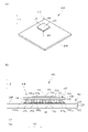
図2(a)は、第1実施形態に係る処理モジュール300の斜視図である。図2(b)は、処理モジュール300のIIB-IIB断面の模式図である。図2(b)には、図2(a)に示す処理モジュール300をプリント配線板200の実装面に垂直なZ方向に見たとき、即ち処理モジュール300を平面視したときの半導体装置100の中心C0を通る直線L1で切断したときの断面を模式的に図示している。半導体装置100は、Z方向に見て、矩形形状である。直線L1は、半導体装置100の2つの対角を通過する直線でもある。図3(a)は、第1実施形態に係る半導体装置100の平面図である。図3(b)は、第1実施形態に係るプリント配線板200の平面図である。直線L1の延びる方向、即ち直線L1に沿う方向をA1方向とし、A1方向に直交する方向をA2方向とする。以下、図2(a)、図2(b)、図3(a)、及び図3(b)を参照しながら説明する。
FIG. 2A is a perspective view of the
半導体装置100は、エリアアレイの半導体パッケージであり、第1実施形態では、BGA(Ball Grid Array)の半導体パッケージである。なお、半導体装置100は、LGA(Land Grid Array)の半導体パッケージであってもよい。半導体装置100は、半導体素子101と、パッケージ基板102と、を有する。パッケージ基板102は、リジッド基板である。
The
半導体素子101は、パッケージ基板102に実装されている。パッケージ基板102は、絶縁基板120を有する。絶縁基板120は、主面121と、主面121とは反対側の主面122と、を有する。絶縁基板120の材質は、例えばアルミナ等のセラミックである。半導体素子101は、例えば半導体チップであり、フェイスアップ又はフェイスダウン、第1実施形態ではフェイスダウンで絶縁基板120の主面121に実装されている。絶縁基板120の主面121には、半導体素子101を封止する封止樹脂106が設けられている。パッケージ基板102は、絶縁基板120の主面122に配置された複数のランド130を有する。複数のランド130の配列パターンは、格子状、即ちマトリックス状である。なお、複数のランド130の配列パターンは、これに限らず、例えば千鳥状であってもよい。ランド130は、導電性を有する金属材料、例えば銅又は金で形成された端子であり、例えば信号端子、電源端子、グラウンド端子、又はダミー端子である。Z方向に見て、ランド130は、円形状である。主面122上には、ソルダーレジスト108が設けられている。ソルダーレジスト108は、ソルダーレジスト材で構成された膜である。複数のランド130の各々の一部は、ソルダーレジスト108に形成された開口部により露出させられている。ランド130は、SMD(Solder Mask Defined)又はNSMD(Non-Solder Mask Defined)のいずれのランドであってもよいが、SMDのランドが好ましく、第1実施形態ではSMDのランドである。よって、各ランド130において外周縁全体が、ソルダーレジスト108で覆われている。そして、各ランド130においてはんだ接合に用いられる部分が、ソルダーレジスト108に形成された開口部により露出させられている。開口部は、平面視して円形状である。なお、図示は省略するが、半導体素子101の上面に放熱板が配置されていてもよい。
The
プリント配線板200は、絶縁基板220を有する。絶縁基板220は、主面221と、主面221とは反対側の主面222とを有する。なお、Z方向は、主面121,122,221,222に垂直な方向でもある。プリント配線板200は、絶縁基板220の主面221に配置された、ランド130と同じ数の複数のランド230を有する。複数のランド230の配列パターンは、複数のランド130の配列パターンと同じである。ランド230は、導電性を有する金属材料、例えば銅又は金で形成された端子であり、例えば信号端子、電源端子、グラウンド端子、又はダミー端子である。絶縁基板220の材質は、エポキシ樹脂等の絶縁材料である。
The printed
プリント配線板200は、ソルダーレジスト208を有する。ソルダーレジスト208は、ソルダーレジスト材で構成された膜である。ソルダーレジスト208は、主面221上に設けられている。各ランド230の一部は、ソルダーレジスト208により覆われている。各ランド230においてはんだ接合に用いられる部分は、ソルダーレジスト208に形成された開口部により露出させられている。
The printed
図3(b)には、半導体装置100が実装される実装領域R100を破線で図示している。図4(a)は、プリント配線板200において図3(b)に示す実装領域R100の部分を拡大した平面図である。図4(b)は、図4(a)からソルダーレジスト208を除いた平面図である。
In FIG. 3B, the mounting area R100 on which the
実装領域R100とは、プリント配線板200に半導体装置100が実装されたとしたときの半導体装置100を、プリント配線板200にZ方向に投影した領域である。したがって、Z方向に見たとき、実装領域R100は、半導体装置100と同じ形状かつ同じ大きさである。よって、Z方向に見たとき、実装領域R100は、半導体装置100と同じ矩形形状である。
The mounting area R100 is an area in which the
ランド130とランド230とは、Z方向において互いに対向し、はんだで形成された図2(b)のはんだ接合部190で接合されている。はんだ接合部190により、ランド130とランド230とは、電気的及び機械的に接続されている。はんだ接合部190は、ランド130と同じ数、即ちランド230と同じ数、存在する。
The
図3(a)に示すように、Z方向に見て、複数のランド130のうち、外側のランドをランド1301とする。つまり、ランド1301は、Z方向に見て、複数のランド130のうち、最も外側に位置し、半導体装置100の外周縁に沿って配置されたランドである。また、Z方向に見て、ランド1301の中でも、半導体装置100の角部に位置するランドをランド13011とする。半導体装置100の角部は、4つ存在するため、ランド13011は4つある。Z方向に見て、複数のランド130のうち、内側に位置するランドをランド1302とする。
As shown in FIG. 3A, when viewed in the Z direction, the outer land of the plurality of lands 130 is referred to as
図3(b)に示すように、Z方向に見て、複数のランド230のうち、外側のランドをランド2301とする。つまり、ランド2301は、Z方向に見て、複数のランド230のうち、最も外側に位置し、図2(a)の半導体装置100の外周縁に沿って配置されたランドである。また、ランド2301の中でも、Z方向に見て、半導体装置100の角部に位置するランドをランド23011とする。半導体装置100の角部は、4つ存在するため、ランド23011は4つある。Z方向に見て、複数のランド230のうち、内側に位置するランドをランド2302とする。なお、Z方向に見て、ランド2301は、実装領域R100の外周縁に沿って配置されたランドでもある。また、Z方向に見て、ランド23011は、実装領域R100の角部に位置するランドでもある。
As shown in FIG. 3B, when viewed in the Z direction, the outer land of the plurality of
図2(b)に示すように、ランド13011とランド23011とは、Z方向において互いに対向している。ランド1302とランド2302とは、Z方向において互いに対向している。複数のはんだ接合部190のうち、ランド13011とランド23011とを接合するはんだ接合部を、はんだ接合部19011とする。複数のはんだ接合部190のうち、ランド1302とランド2302とを接合するはんだ接合部をはんだ接合部1902とする。ランド23011は、第1ランドである。ランド2302は、第2ランドである。ランド13011は、第3ランドである。ランド1302は、第4ランドである。
As shown in FIG. 2B, the
半導体装置100の角部に位置するはんだ接合部19011には、はんだ接合部1902よりも強度が求められる。はんだ接合部19011において接合強度を確保する観点から、はんだ接合部19011の量は、はんだ接合部1902の量よりも多い。そして、図4(a)に示すように、Z方向に見て、ランド23011においてソルダーレジスト208と重ならない面の面積S1が、ランド2302においてソルダーレジスト208と重ならない面の面積S2よりも広い。
The solder
図1に示すデジタルカメラ600は、モバイル機器であり、ユーザに携帯される。したがって、ユーザが誤ってデジタルカメラ600を落下させてしまうことがある。このような場合、処理モジュール300に落下の衝撃が加わる。処理モジュール300において、複数のランド230のうち、特にランド2301に落下の衝撃が加わる。ランド2301の中でも特にランド23011に落下の衝撃が集中しやすい。
The
落下の衝撃によるランド23011の剥離を防止するため、ランド23011を単純にSMDのランドとする、つまりランド23011の外周縁全体をソルダーレジスト208で覆うことも考えられる。しかし、仮にランド23011を単純なSMDのランドとすると、以下の問題が生じることを本発明者は突き止めた。
In order to prevent the
ユーザがデジタルカメラ600を使用することで、半導体装置100が動作して発熱する。半導体装置100が発熱すると、半導体装置100が線膨張係数に応じて膨張する。よって、複数のはんだ接合部190のうち、ランド1301とランド2301とを接合するはんだ接合部に特に熱応力が生じる。図2(b)においては、半導体装置100は、プリント配線板200に対して相対的にA1方向に膨張する。したがって、半導体装置100の動作により、ランド1301とランド2301とを接合するはんだ接合部の中でも、特に角部に位置するはんだ接合部19011に熱応力が集中しやすい。
When the user uses the
仮にランド23011を単純なSMDのランドとすると、ランド23011に接するはんだ接合部19011が、ソルダーレジスト208においてランド23011を露出させる開口部を画成する壁の縁に接触することになる。半導体装置100がA1方向に加熱による膨張及び冷却による収縮を繰り返すことで、はんだ接合部19011が、開口部を画成する壁の縁のうちA1方向の端部に接する部分から剥離又は破断することを突き止めた。
Assuming that the
第1実施形態では、ランド23011の一部は、複数のランド230のうちランド23011以外の他のランドとは異なる覆われ方でソルダーレジスト208に覆われている。
In the first embodiment, a part of the
なお、他のランド、例えばランド2302は、SMDのランドである。よって、ランド2302は、その外周縁全体がソルダーレジスト208で覆われている。なお、図4(a)では、1つのランド2302において、ソルダーレジスト208と重なる部分を破線で図示している。この1つのランド2302を除く他のランドにおいて、ソルダーレジスト208と重なる部分の図示、即ち破線の図示は省略する。
The other land, for example,
他のランドの形状は、Z方向に見て円形である。また、他のランドにおいて、ソルダーレジスト208の開口部から露出させられている部分、即ちソルダーレジスト208と重ならない部分が、Z方向に見て円形である。 The shape of the other lands is circular when viewed in the Z direction. Further, in other lands, the portion exposed from the opening of the solder resist 208, that is, the portion that does not overlap with the solder resist 208 is circular when viewed in the Z direction.
図4(a)及び図4(b)には、半導体装置100、即ち実装領域R100の中心C0を通る直線L1と、直線L1と直交する直線L2とを一点鎖線で図示している。直線L1は、実装領域R100の2つの対角を通る直線でもある。直線L1の延びる第1方向がA1方向、直線L2の延びる第2方向がA2方向である。図4(a)及び図4(b)中、直線L1に沿って配置される7つのランド230のうち、ランド23011は、A1方向の最も外側に位置するランドであり、ランド2302は、2つのランド23011の間のA1方向の内側に位置するランドである。
In FIGS. 4A and 4B, a straight line L1 passing through the center C0 of the
図4(a)及び図4(b)に示す4つのランド23011は、同じ構成であるため、4つのランド23011うち、左上のランド23011に着目して説明する。図5(a)は、1つのランド23011を拡大した平面図、具体的には、図4(a)に示す4つのランド23011のうちの左上のランド23011を拡大した平面図である。なお、図5(a)には、ランド13011において、図3(a)のソルダーレジスト108と重ならない面の部分、即ちソルダーレジスト108の開口部から露出させられた部分の外周縁を、破線の円で図示している。
Since the four
ソルダーレジスト208は、開口部H1を画成する側壁2080を有する。開口部H1は、Z方向に見て、A1方向を長径とし、A2方向を短径とする楕円形状である。開口部H1により、ランド23011の大部分が露出させられている。
The solder resist 208 has a
ランド23011は、Z方向に見て、A1方向において互いに対向する一対の端部241,242と、A2方向において互いに対向する一対の端部243,244と、を有する。一対の端部241,242のうち一方の端部241が第1端部であり、他方の端部242が第2端部である。なお、端部241は、図4(a)に示す中心C0から遠い側の端部であり、端部242は、中心C0に近い側の端部である。一対の端部243,244のうち一方の端部243が第3端部であり、他方の端部244が第4端部である。Z方向に見て、一対の端部241,242は、ソルダーレジスト208と重ならず、一対の端部243,244は、ソルダーレジスト208と重なっている。
The
図5(b)は、処理モジュール300のVB-VB断面図である。図5(c)は、処理モジュール300のVC-VC断面図である。図5(b)に示すように、一対の端部243,244がソルダーレジスト208で覆われているので、ソルダーレジスト208によってランド23011が絶縁基板220から剥離するのが防止される。
FIG. 5B is a cross-sectional view taken along the line VB-VB of the
また、図5(c)に示すように、一対の端部241,242がソルダーレジスト208から露出しているので、はんだ接合部19011は、図5(a)の側壁2080のうち、A1方向の両端部2081,2082と接触しない。これにより、はんだ接合部19011に、半導体装置100の熱変形による熱応力が局所的に集中して発生するのを防止することができ、はんだ接合部19011が剥離及び破断するのを防止することができる。
Further, as shown in FIG. 5 (c), since the pair of end portions 241,242 are exposed from the solder resist 208, the solder
第1実施形態では、ランド23011は、図5(a)に示すようにランド本体231を有する。ランド本体231は、Z方向に見て、A1方向を長径とし、A2方向を短径とする、ソルダーレジスト208の開口部H1よりも小さい楕円形状である。ランド本体231は、A1方向の長さが、A2方向の長さよりも長い。ランド本体231は、一対の端部241,242を含んでいる。ランド23011は、ランド本体231からA2方向に延びる第1突出部である突出部232と、ランド本体231からA2方向であって突出部232とは反対方向に延びる第2突出部である突出部233と、を有する。突出部232は、端部243を含んでおり、突出部233は、端部244を含んでいる。突出部232のA2方向の先端部分が端部243であり、突出部233のA2方向の先端部分が端部244である。突出部232,233は、Z方向に見て、矩形形状である。突出部232,233のA1方向の幅は、ランド本体231のA1方向の長さの半分以下である。
In the first embodiment, the
第1実施形態では、Z方向に見て、突出部232の先端部分がソルダーレジスト208と重なり、残りの部分がソルダーレジスト208と重なっていない。同様に、Z方向に見て、突出部233の先端部分がソルダーレジスト208と重なり、残りの部分がソルダーレジスト208と重なっていない。また、Z方向に見て、ランド本体231の全部が、ソルダーレジスト208と重なっていない。
In the first embodiment, when viewed in the Z direction, the tip portion of the
突出部232,233のA1方向の幅は、A2方向に亘って同じでもよいし、ランド本体231からA2方向に遠ざかるに連れて徐々に細くなる又は太くなるようにしてもよい。突出部232,233のA1方向の最大幅は、ランド本体231のA1方向の長さ以下であればよい。突出部232,233のA1方向の幅が広いほど、ソルダーレジスト208で抑え込まれる領域が増加し、ランド23011の剥離が効果的に防止される。このような観点から、突出部232,233のA1方向の幅は、50μm以上であるのが好ましい。
The widths of the
突出部232,233のA2方向の長さは、少なくとも突出部232,233の先端がソルダーレジスト208の下に位置していればよく、プリント配線板200における他の配線と干渉しないように設定される。ランド23011の剥離を効果的に防止する観点から、突出部232,233において、ソルダーレジスト208と重なる部分のA2方向の長さは、25μm以上であるのが好ましい。
The length of the
ところで、処理モジュール300の製造過程において、半導体装置100とプリント配線板200とをはんだ接合する際に、半導体装置100とプリント配線板200とは、リフロー加熱炉に搬送されて、はんだの融点以上の温度の雰囲気に晒される。半導体装置100は、プリント配線板200の上に載置されているが、プリント配線板200に対して上に凸形状に熱変形する。即ち、半導体装置100の中央部がプリント配線板200から遠ざかり、半導体装置100の角部がプリント配線板200に近づくように熱変形する。
By the way, in the manufacturing process of the
一方、半導体装置100とプリント配線板200との間のはんだを融点以上に加熱して溶融させると、溶融はんだは、半導体装置100のランド130とプリント配線板200のランド230とに挟まれながら濡れ広がろうとする。なお、図2(b)に示すように、ランド1302とランド2302とは、ランド1302の中心とランド2302の中心とが一致するように、Z方向において互いに対向している。
On the other hand, when the solder between the
図5(a)に示すように、Z方向において、ランド13011とランド23011とは互いに対向している。第1実施形態では、ランド23011のA1方向の中心C1は、ランド13011のA1方向の中心C2に対して、半導体装置100の中心C0から遠ざかるA11方向にずれている。これにより、ランド23011上において、溶融はんだは、A1方向の外側、即ちA11方向に濡れ広がって、横方向に膨らみにくい状態となり、はんだ接合部19011は、ランド23011の端部241上においてフィレット形状となる。これにより、はんだ接合部19011は、接合強度を確保しつつ、周辺のはんだ接合部とショートするのが防止される。
As shown in FIG. 5A, the
また、図5(a)に示すように、Z方向に見て、ランド23011においてソルダーレジスト208と重ならない面の面積S1が、ランド13011において図5(b)のソルダーレジスト108と重ならない面の面積S3よりも広い。つまり、Z方向に見て、ランド13011においてソルダーレジスト108と重ならない部分の全部が、ランド23011においてソルダーレジスト208と重ならない部分と重なる。これにより、図5(c)に示すように、Z方向に見て、ランド23011の端部241は、ランド13011においてソルダーレジスト108と重ならない部分よりもA11方向に突出している。したがって、製造過程において溶融はんだが端部241まで濡れ広がることで、はんだ接合部19011が横方向に膨らむのを効果的に防止することができ、周辺のはんだ接合部とショートするのが効果的に防止される。また、ランド本体231のA1方向の長さが長いほど、はんだ接合部19011が周辺のはんだ接合部とショートするのが効果的に防止される。
Further, as shown in FIG. 5 (a), when viewed in the Z direction, the area S1 of the surface that does not overlap with the solder resist 208 at the
以上、第1実施形態によれば、ランド23011の端部241,242をNSMD構造にすることにより、はんだ接合部19011がランド23011から剥離したり、破断したりするのを防止することができる。さらに、端部243,244をSMD構造にすることにより、デジタルカメラ600の落下等の衝撃が処理モジュール300に加わったときに、ランド23011が剥離するのを防止することができる。これにより、処理モジュール300の信頼性が向上する。
As described above, according to the first embodiment, by forming the
[変形例]
第1実施形態で説明したランド23011の変形例を図6に示す。図6は、変形例のランド23011の平面図である。第1実施形態では、図5(a)に示すように、突出部232,233のA1方向の幅が、ランド本体231のA1方向の長さの半分以下である。しかし、突出部232,233のA1方向の幅は、これに限定するものではない。図6に示すように、突出部232,233のA1方向の幅が、ランド本体231のA1方向の長さの半分よりも広くてもよい。
[Modification example]
FIG. 6 shows a modified example of the
[第2実施形態]
第2実施形態について説明する。図7は、第2実施形態に係るプリント配線板200Aにおいて、半導体装置が実装される実装領域R100の部分を拡大した平面図である。第2実施形態のプリント配線板200Aは、第1実施形態と同様に配列された、複数のランド230を有する。Z方向に見て、複数のランド230のうち、半導体装置の角部に位置する、第1ランドであるランド230A11が、第1実施形態で説明したランド23011と異なる。すなわち、第2実施形態では、第1実施形態で説明した図4(a)に示すランド23011を、図7に示すランド230A11に置き換えたものである。また、プリント配線板200Aは、ソルダーレジスト208Aを有する。ソルダーレジスト208Aは、第1実施形態のソルダーレジスト208と同じ材料であるが、ランド230A11を露出させるための開口部の形状が、第1実施形態と異なる。第2実施形態において、それ以外の構成については、第1実施形態と同様であるため、同一符号を付して説明を省略する。
[Second Embodiment]
The second embodiment will be described. FIG. 7 is an enlarged plan view of a portion of the mounting region R100 on which the semiconductor device is mounted in the printed
図7に示すように、プリント配線板200Aは、半導体装置、即ち実装領域R100の角部に位置する4つのランド230A11を有する。4つのランド230A11は同様の構成である。
As shown in FIG. 7, the printed
図8(a)は、図7に示す4つのランド230A11のうち、左上のランド230A11を拡大した平面図である。図8(b)は、第2実施形態に係る処理モジュール300AのVIIIB-VIIIB断面図である。なお、図8(a)には、第1実施形態と同様、ランド13011において、図8(b)のソルダーレジスト108と重ならない面の部分、即ちソルダーレジスト108の開口部から露出させられた部分の外周縁を、破線の円で図示している。
FIG. 8A is an enlarged plan view of the upper left land 230A 11 among the four lands 230A 11 shown in FIG. 7. FIG. 8B is a sectional view taken along line VIIIB-VIIIB of the
電子機器に搭載される半導体モジュールの一例である、図8(b)に示す第2実施形態の処理モジュール300Aは、半導体装置100と、上述のプリント配線板200Aとを有する。半導体装置100は、プリント配線板200Aに実装されている。プリント配線板200Aは、第1実施形態と同様、絶縁基板220を有する。ランド13011とランド230A11とは、はんだ接合部190A11で接合されている。
The
第1実施形態と同様、図7に示すように、ランド230A11は、ランド2302よりも大きく形成されている。すなわち、Z方向に見て、ランド230A11においてソルダーレジスト208Aと重ならない面の面積S1が、ランド2302においてソルダーレジスト208Aと重ならない面の面積S2よりも広い。これにより、半導体装置の角部における図8(b)のはんだ接合部190A11の強度を確保することができる。
Similar to the first embodiment, as shown in FIG. 7, the land 230A 11 is formed larger than the
第2実施形態では、ランド230A11の一部は、複数のランド230のうちランド230A11以外の他のランドとは異なる覆われ方でソルダーレジスト208Aに覆われている。なお、他のランド、例えばランド2302は、第1実施形態で説明した通り、SMDのランドである。
In the second embodiment, a part of the land 230A 11 is covered with the solder resist 208A in a manner different from that of the other lands other than the land 230A 11 among the plurality of
図8(a)に示すように、ソルダーレジスト208Aは、開口部H2を画成する側壁2080Aを有する。開口部H2により、ランド230A11の大部分が露出させられている。
As shown in FIG. 8A, the solder resist 208A has a
ランド230A11は、Z方向に見て、A1方向において互いに対向する一対の端部241A,242Aと、A2方向において互いに対向する一対の端部243A,244Aと、を有する。一対の端部241A,242Aのうち一方の端部241Aが第1端部であり、他方の端部242Aが第2端部である。なお、端部241Aは、図7に示す中心C0から遠い側の端部であり、端部242Aは、中心C0に近い側の端部である。一対の端部243A,244Aのうち一方の端部243Aが第3端部であり、他方の端部244Aが第4端部である。Z方向に見て、一対の端部241A,242Aは、ソルダーレジスト208Aと重ならず、一対の端部243A,244Aは、ソルダーレジスト208Aと重なっている。
The land 230A 11 has a pair of
図8(a)に示すように、一対の端部243A,244Aがソルダーレジスト208Aで覆われているので、ソルダーレジスト208Aによってランド230A11がプリント配線板200Aの図8(b)に示す絶縁基板220から剥離するのが防止される。
As shown in FIG. 8A, since the pair of
また、図8(b)に示すように、一対の端部241A,242Aがソルダーレジスト208Aから露出している。したがって、ランド13011とランド230A11とを接合するはんだ接合部190A11は、図8(a)の側壁2080Aのうち、A1方向の両端部2081A,2082Aと接触しない。これにより、はんだ接合部190A11に、半導体装置100の熱変形による熱応力が局所的に集中して発生するのを防止することができ、はんだ接合部190A11が剥離及び破断するのを防止することができる。
Further, as shown in FIG. 8B, the pair of
第2実施形態では、ランド230A11は、図8(a)に示すようにランド本体231Aを有する。ランド本体231Aは、Z方向に見て、ソルダーレジスト208Aの開口部H2よりも小さい形状である。ランド本体231AのA1方向の長さは、ランド本体231AのA2方向の長さよりも長い。ランド本体231Aは、一対の端部241A,242Aを含んでいる。なお、ランド230A11のA1方向の中心と、ランド本体231AのA1方向の中心とは同一であるため、これらを中心CAとする。
In the second embodiment, the land 230A 11 has a
ランド230A11は、ランド本体231AからA2方向に延びる第1突出部である突出部232Aと、ランド本体231AからA2方向であって突出部232Aとは反対方向に延びる第2突出部である突出部233Aと、を有する。突出部232Aは、端部243Aを含んでおり、突出部233Aは、端部244Aを含んでいる。突出部232A,233Aは、Z方向に見て、矩形形状である。突出部232AのA2方向の先端部分が端部243Aであり、突出部233AのA2方向の先端部分が端部244Aである。
The land 230A 11 has a
第2実施形態では、Z方向に見て、突出部232Aの先端部分がソルダーレジスト208Aと重なり、残りの部分がソルダーレジスト208Aと重なっていない。同様に、Z方向に見て、突出部233Aの先端部分がソルダーレジスト208Aと重なり、残りの部分がソルダーレジスト208Aと重なっていない。また、Z方向に見て、ランド本体231Aの全部が、ソルダーレジスト208Aと重なっていない。
In the second embodiment, when viewed in the Z direction, the tip portion of the protruding
図8(a)に示すように、Z方向において、ランド13011と、ランド230A11とは、互いに対向している。第2実施形態では、第1実施形態と同様、ランド230A11のA1方向の中心CAは、ランド13011のA1方向の中心C2に対して、図7の中心C0から遠ざかるA11方向にずれている。これにより、ランド230A11に接するはんだ接合部190A11は、接合強度を確保しつつ、周辺のはんだ接合部とショートするのが防止される。
As shown in FIG. 8A, the
また、図8(a)に示すように、Z方向に見て、ランド230A11においてソルダーレジスト208Aと重ならない面の面積S1が、ランド13011において図8(b)のソルダーレジスト108と重ならない面の面積S3よりも広い。つまり、Z方向に見て、ランド13011においてソルダーレジスト108と重ならない部分の全部が、ランド230A11においてソルダーレジスト208Aと重ならない部分と重なる。これにより、図8(b)に示すように、Z方向に見て、ランド230A11の端部241Aは、ランド13011においてソルダーレジスト108と重ならない部分よりもA11方向に突出している。したがって、製造過程において溶融はんだが端部241Aまで濡れ広がることで、はんだ接合部190A11が横方向に膨らむのを効果的に防止することができ、周辺のはんだ接合部とショートするのが効果的に防止される。また、ランド本体231AのA1方向の長さが長いほど、はんだ接合部190A11が周辺のはんだ接合部とショートするのが効果的に防止される。
Further, as shown in FIG. 8 (a), when viewed in the Z direction, the area S1 of the surface that does not overlap with the solder resist 208A in the land 230A 11 does not overlap with the solder resist 108 in FIG. 8 (b) in the
図8(a)に示すように、Z方向に見て、ランド本体231Aは、A1方向の外側に向かって末広がりの形状である。即ち、Z方向に見て、ランド本体231Aは、図7の中心C0から遠ざかるA11方向に向かって末広がりの形状である。Z方向に見て、ランド本体231Aは、半円形状の部分231A-1と、部分231A-1に対してA11方向の側に配置された台形形状の部分231A-2とで構成される。部分231A-1の直径は、ランド13011の直径と同程度である。端部241Aは、台形状である部分231A-2の長辺側の端部である。部分231A-2の短辺側が、部分231A-1に接続されている。端部241AのA2方向の長さは、ランド13011の直径よりも長い。
As shown in FIG. 8A, the
ランド本体231Aが末広がりの形状であるため、処理モジュール300Aの製造過程において、溶融はんだは、端部241Aの側に濡れ広がりやすい。これにより、図8(b)に示すように、はんだ接合部190A11は、端部241A上においてフィレット形状となる。これにより、はんだ接合部190A11におけるA11方向の膨らみを更に低減させることができ、はんだ接合部190A11が周辺のはんだ接合部とショートするのが効果的に防止される。
Since the
ランドは、図7の中心C0から遠い側のA1方向の端部から剥離しやすい。第2実施形態では、Z方向に見て、突出部232A,233Aは、ランド本体231AのA1方向の中心CAよりも、図7の中心C0から遠い位置に配置されている。突出部232A,233AのA1方向の中心をCBとすると、中心CBは、中心CAよりも図7の中心C0から遠い位置にある。これにより、ランド230A11の剥離を効果的に抑制することができる。
The land is easily peeled off from the end in the A1 direction on the side far from the center C0 in FIG. 7. In the second embodiment, the
以上、第2実施形態によれば、ランド230A11の端部241A,242AをNSMD構造にすることにより、はんだ接合部190A11がランド230A11から剥離したり、破断したりするのを防止することができる。さらに、端部243A,244AをSMD構造にすることにより、デジタルカメラの落下等の衝撃が処理モジュール300Aに加わったときに、ランド230A11が剥離するのを防止することができる。これにより、処理モジュール300Aの信頼性が向上する。
As described above, according to the second embodiment, by forming the
[第3実施形態]
第3実施形態について説明する。図9(a)は、第3実施形態に係るランド230B11の平面図である。図9(b)は、第3実施形態に係る処理モジュール300BのIXB-IXB断面図である。第3実施形態では、第1ランドであるランド230B11が第2実施形態で説明したランド230A11と異なる。第3実施形態において、それ以外の構成については、第2実施形態と同様であるため、同一符号を付して説明を省略する。なお、ソルダーレジストの開口部の形状は、第2実施形態と同様である。
[Third Embodiment]
A third embodiment will be described. FIG. 9A is a plan view of the land 230B 11 according to the third embodiment. FIG. 9B is a sectional view taken along line IXB-IXB of the
電子機器に搭載される半導体モジュールの一例である、図9(b)に示す第3実施形態の処理モジュール300Bは、半導体装置100と、プリント配線板200Bとを有する。半導体装置100は、プリント配線板200Bに実装されている。プリント配線板200Bは、ランド230B11と、第2実施形態と同様、絶縁基板220及びソルダーレジスト208Aと、を有する。半導体装置100のランド13011とプリント配線板200Bのランド230B11とは、はんだ接合部190B11で接合されている。
The
ランド230B11は、互いに独立した、つまり互いに離間した2つのランド部231B,232Bからなる。なお、2つのランド部231B,232Bは、同じ1つのはんだ接合部190B11で、ランド13011に電気的に接続されている。
The lands 230B 11 are composed of two
ランド230B11は、主ランド部231Bを有する。また、ランド230B11は主ランド部231Bと独立して設けられた副ランド部232Bを有する。副ランド部232Bは、Z方向に見て、主ランド部231Bに対してA1方向の外側の位置、即ち、半導体装置100の中心からA11方向に遠ざかる位置に配置されている。
The land 230B 11 has a
Z方向に見て、主ランド部231Bは、全部がソルダーレジスト208Aと重ならない。Z方向に見て、副ランド部232Bは、矩形形状に形成されており、A2方向の長さが、A1方向の長さよりも長い。Z方向に見て、副ランド部232Bは、A2方向の一対の端部243B,244Bと、A2方向の中央部245Bと、を含む。Z方向に見て、中央部245Bがソルダーレジスト208Aと重ならず、一対の端部243B,244Bがソルダーレジスト208Aと重なる。
When viewed in the Z direction, the
副ランド部232Bの一対の端部243B,244Bがソルダーレジスト208Aで覆われているので、ソルダーレジスト208Aによってランド230B11がプリント配線板200Bの絶縁基板220から剥離するのが防止される。
Since the pair of
また、主ランド部231Bの全部及び副ランド部232Bの中央部245Bが、ソルダーレジスト208Aから露出している。したがって、はんだ接合部190B11は、ソルダーレジスト208Aにおける側壁2080Aの両端部2081A,2082Aと接触しない。これにより、はんだ接合部190B11に、半導体装置100の熱変形による熱応力が局所的に集中して発生するのを防止することができ、はんだ接合部190B11が剥離及び破断するのを防止することができる。これにより、処理モジュール300Bの信頼性が向上する。
Further, the entire
[第4実施形態]
第4実施形態について説明する。図10(a)は、第4実施形態に係るランド230C11の平面図である。図10(b)は、第4実施形態に係る処理モジュール300CのXB-XB断面図である。第4実施形態では、第1ランドであるランド230C11が第3実施形態で説明したランド230B11と異なる。また、ソルダーレジストの開口部の形状が異なる。第4実施形態において、それ以外の構成については、第3実施形態と同様であるため、同一符号を付して説明を省略する。
[Fourth Embodiment]
A fourth embodiment will be described. FIG. 10A is a plan view of the land 230C 11 according to the fourth embodiment. FIG. 10B is a cross-sectional view taken along the line XB-XB of the
電子機器に搭載される半導体モジュールの一例である、図10(b)に示す第4実施形態の処理モジュール300Cは、半導体装置100と、プリント配線板200Cとを有する。半導体装置100は、プリント配線板200Cに実装されている。プリント配線板200Cは、ランド230C11と、絶縁基板220と、ソルダーレジスト208Cと、を有する。半導体装置100のランド13011とプリント配線板200Cのランド230C11とは、はんだ接合部190C11で接合されている。
The
図10(a)に示すように、ソルダーレジスト208Cは、開口部H3を画成する側壁2080Cを有する。開口部H3により、ランド230C11の大部分が露出させられている。
As shown in FIG. 10 (a), the solder resist 208C has a
ランド230C11は、Z方向に見て、半導体装置100の中心を通る直線L1の延びるA1方向において互いに対向する、第1端部である端部241C及び第2端部である端部242Cを有する。また、ランド230C11は、Z方向に見て、直線L1と直交する直線L2の延びる方向、即ちA1方向と直交するA2方向において互いに対向する、第3端部である端部243C及び第4端部である端部244Cを有する。
The land 230C 11 has an
Z方向に見て、ランド230C11の端部241Cと端部242Cは、ソルダーレジスト208Cと重なっていない。Z方向に見て、ランド230C11の端部243Cと端部244Cは、ソルダーレジスト208Cと重なっている。一対の端部243C,244Cがソルダーレジスト208Cで覆われているので、ソルダーレジスト208Cによってランド230C11がプリント配線板200Cの絶縁基板220から剥離するのが防止される。
When viewed in the Z direction, the
また、ランド230C11の端部241Cと端部242Cが、ソルダーレジスト208Cから露出している。したがって、はんだ接合部190C11は、ソルダーレジスト208Cにおける側壁2080CのA1方向の両端部2081C,2082Cと接触しない。これにより、はんだ接合部190C11に、半導体装置100の熱変形による熱応力が局所的に集中して発生するのを防止することができ、はんだ接合部190C11が剥離及び破断するのを防止することができる。これにより、処理モジュール300Cの信頼性が向上する。
Further, the
[実施例]
第1実施形態に対応する実施例1の処理モジュール300、第2実施形態に対応する実施例2の処理モジュール300A、比較例1の処理モジュールを用意し、実験を行った。図11は、実験結果を示すグラフである。図11には、説明の便宜上、比較例1のランド230X11、実施例1のランド23011、実施例2のランド230A11を図示している。図11に示す縦軸は、落下衝撃時にランド230X11,23011,230A11の外側の端部241X,241,241Aに掛かるモーメントである。
[Example]
An experiment was conducted by preparing the
実験結果を説明する前に、まず用意した実施例1の処理モジュール300、実施例2の処理モジュール300A、比較例1の処理モジュールについて説明する。なお、実施例1については、図2(a)、図2(b)、図3(a)、図3(b)、図4(a)、図4(b)、図5(a)、図5(b)、図5(c)を参照しながら説明する。また、実施例2については、図7、図8(a)、図8(b)を参照しながら説明する。
Before explaining the experimental results, first, the
(実施例1)
用意した実施例1の処理モジュール300の構成は、以下の通りである。半導体装置100は、BGAの半導体パッケージであり、半導体装置100の外形サイズは、18(mm)×18(mm)であった。各ランド130は、φ0.22(mm)であった。複数のランド130は、千鳥状に配置され、ピッチは0.4(mm)であった。各ランド130の材質はCuであった。端子数(ランド数)は1860個であった。はんだ接合部190の合金組成は、Sn-3.0mass%Ag-0.5mass%Cuであった。
(Example 1)
The configuration of the
プリント配線板200の外形サイズは、50(mm)×50(mm)であった。プリント配線板200の絶縁基板220の材質は、FR-4であった。ランド230の材質はCuであった。ソルダーレジスト208の厚みは、約25(μm)であった。開口部H1は、長径570(μm)、短径340(μm)の楕円形状であった。ランド23011のランド本体231は、長径470(μm)、短径240(μm)の楕円形状であった。一対の突出部232,233における一対の端部243,244のA2方向の距離は440(μm)であった。各突出部232,233のA1方向の幅は75(μm)であった。
The external size of the printed
(実施例2)
用意した実施例2の処理モジュール300Aの構成は、以下の通りである。実施例2の半導体装置100は、実施例1と同様のものとした。実施例2のプリント配線板200Aにおいて、ランド230A11及び開口部H2以外は、実施例1のプリント配線板200と同様とした。
(Example 2)
The configuration of the
開口部H2は、ランド13011の中心と一致する半円形状の第1開口領域と、第1開口領域のA11方向の側に形成された台形形状の第2開口領域を有している。第1開口領域は、半径170(μm)の半円形状であった。第2開口領域は、短辺340(μm)、長辺440(μm)、長さ400(μm)の台形形状であった。
The opening H2 has a semicircular first opening region that coincides with the center of the
ランド230A11は、半円形状の部分231A-1と、台形形状の部分231A-2とを有している。部分231A-1は、半径120(μm)の半円形状であった。部分231A-2は、短辺240(μm)、長辺340(μm)、長さ350(μm)の台形形状であった。
The land 230A 11 has a
一対の突出部232A,233Aにおける一対の端部243A,244AのA2方向の距離は540(μm)であった。各突出部232A,233AのA1方向の幅は75(μm)であった。各突出部232A,233Aは、端部241AからA11方向と反対方向に75(μm)入り込んだ位置に配置されていた。
The distance between the pair of
(比較例1)
以下、比較例1の処理モジュールにおいて、実施例1の処理モジュールと異なる点についてのみ説明する。比較例1のランド230X11では、幅100(μm)の突出部232Xを、楕円形状のランド本体231の中央部から、半導体装置の中心側に260(μm)ずらした位置に配置した構成とした。よって、比較例1のランド230X11において、半導体装置の中心に近い側の端部は、SMD構造である。
(Comparative Example 1)
Hereinafter, only the differences between the processing module of Comparative Example 1 and the processing module of Example 1 will be described. In the land 230X 11 of Comparative Example 1, the protruding
ところで、半導体装置とプリント配線板との曲げ剛性の差により、振動による撓みが異なることで、電子機器の落下時の衝撃によって、プリント配線板のランドを剥離させようとする応力が生じる。この時、半導体装置の最外部からランドを剥離させようとする応力が発生するため、ランドの剥離を抑制するためには、ランドにおいてSMD構造とする位置が重要となる。最外部のランドを剥離させようとする応力は、プリント配線板の撓みによる力と、ランドの外側の端部から突出部までの距離との積であるモーメント(力)で考えることができる。プリント配線板の撓みによる力は、落下方向、速度、半導体装置の全体構造、プリント配線板の全体構造等で決まる数値であり、プリント配線板のランドの構造には依存しにくい。ランドの構造で落下衝撃に対してランドの剥離を抑制するには、SMD構造の位置、すなわち突出部の位置が重要となる。ランドの外側の端部と突出部との距離が短いほど、ランドを剥離させようとするモーメントは小さくなる。 By the way, due to the difference in flexural rigidity between the semiconductor device and the printed wiring board, the bending due to vibration is different, so that the impact when the electronic device is dropped causes a stress to peel off the land of the printed wiring board. At this time, since stress is generated to peel off the land from the outermost side of the semiconductor device, the position of the land having the SMD structure is important in order to suppress the peeling of the land. The stress for peeling the outermost land can be considered as a moment (force) which is the product of the force due to the bending of the printed wiring board and the distance from the outer end of the land to the protrusion. The force due to the bending of the printed wiring board is a numerical value determined by the drop direction, the speed, the overall structure of the semiconductor device, the overall structure of the printed wiring board, etc., and is less dependent on the land structure of the printed wiring board. In order to suppress the peeling of the land against a drop impact in the structure of the land, the position of the SMD structure, that is, the position of the protruding portion is important. The shorter the distance between the outer edge of the land and the protrusion, the smaller the moment at which the land is to be peeled off.
図11に示す実験結果から、比較例1と実施例1,2とでは、実施例1,2の方がランドの外側の端部にかかるモーメントが小さくなることが分かる。また、実施例1と実施例2とでは、実施例2の方がランドの外側の端部にかかるモーメントが小さくなることがわかる。以上、実施例1及び実施例2によれば、落下衝撃に対してランドが剥離するのを抑制することができる。 From the experimental results shown in FIG. 11, it can be seen that in Comparative Example 1 and Examples 1 and 2, the moment applied to the outer end of the land is smaller in Examples 1 and 2. Further, in Example 1 and Example 2, it can be seen that the moment applied to the outer end of the land is smaller in Example 2. As described above, according to the first and second embodiments, it is possible to suppress the land from peeling due to the drop impact.
ところで、ランドの外周縁全体をSMD構造とした場合、使用環境下において、はんだにかかる熱応力は、半導体装置の中心を通る直線の方向の2つの端部に集中され、その2か所を起点としてはんだに亀裂が進展し、破断となる。2つの端部の一方をSMD構造とし、他方をNSMD構造とした場合であっても、SMD構造の箇所を起点として、亀裂が進展していく。 By the way, when the entire outer peripheral edge of the land has an SMD structure, the thermal stress applied to the solder is concentrated on two ends in the direction of the straight line passing through the center of the semiconductor device under the usage environment, and the starting points are the two ends. As a result, cracks develop in the solder, resulting in breakage. Even when one of the two ends has an SMD structure and the other has an NSMD structure, the crack grows from the location of the SMD structure as a starting point.
図12は、実施例2と比較例2の実験結果を示す図である。比較例2では、実施例2のランドを半導体装置の中心から遠ざかる方向に延ばした形状としたものであり、ランドの端部241Aがソルダーレジストに覆われている。即ち、実施例2のランドの端部241Aは、NSMD構造であり、比較例2のランドの端部241Aは、SMD構造である。なお、実施例2及び比較例2のランドの端部242Aは、いずれもNSMD構造である。図12には、使用環境下においてはんだの端部241Aにかかるクリープひずみのコンター図を、NSMD構造及びSMD構造のそれぞれの場合のXII-XII断面について図示している。
FIG. 12 is a diagram showing the experimental results of Example 2 and Comparative Example 2. In Comparative Example 2, the land of Example 2 has a shape extended in a direction away from the center of the semiconductor device, and the
SMD構造では、はんだにかかるクリープひずみεcrは、はんだとソルダーレジストとの界面において高くなっている。このことから、はんだにおいて亀裂が発生しやすい箇所に応力が集中していることが分かる。NSMD構造では、はんだとソルダーレジストとの界面が存在せず、はんだにかかるクリープひずみεcrが全体的に低い。このことから、はんだにおいて亀裂が発生しやすい箇所に応力が集中していないことが分かる。実施例2によれば、2つの端部241A,242AをNSMD構造にしたことから、通常の使用環境下において、はんだ接合の信頼性が向上する。
In the SMD structure, the creep strain ε cr applied to the solder is high at the interface between the solder and the solder resist. From this, it can be seen that the stress is concentrated in the places where cracks are likely to occur in the solder. In the NSMD structure, there is no interface between the solder and the solder resist, and the creep strain ε cr applied to the solder is generally low. From this, it can be seen that the stress is not concentrated in the places where cracks are likely to occur in the solder. According to the second embodiment, since the two
なお、本発明は、以上説明した実施形態に限定されるものではなく、本発明の技術的思想内で多くの変形が可能である。また、実施形態に記載された効果は、本発明から生じる最も好適な効果を列挙したに過ぎず、本発明による効果は、実施形態に記載されたものに限定されない。 The present invention is not limited to the embodiments described above, and many modifications can be made within the technical idea of the present invention. Moreover, the effects described in the embodiments are merely a list of the most suitable effects resulting from the present invention, and the effects according to the present invention are not limited to those described in the embodiments.
上述の実施形態では、平面視して、プリント配線板に含まれる、半導体装置の角部に位置するランドの構造について説明したが、角部のランドに限定するものではない。例えば図4(a)に示す外側に位置するランド2301のうち、角部に位置するランド23011以外のランドについても、ランド23011と同様の構成にしてもよい。また、例えば図7に示す外側に位置するランド2301のうち、角部に位置するランド230A11以外のランドについても、ランド230A11と同様の構成にしてもよい。
In the above-described embodiment, the structure of the land located at the corner of the semiconductor device included in the printed wiring board has been described in a plan view, but the structure is not limited to the land at the corner. For example, among the
また、上述の実施形態では、半導体モジュールが処理モジュールである場合について説明したが、これに限定するものではない。例えば半導体モジュールが図1のセンサモジュール900であってもよい。
Further, in the above-described embodiment, the case where the semiconductor module is a processing module has been described, but the present invention is not limited to this. For example, the semiconductor module may be the
また、上述の実施形態では、4つの角部に位置するランドの全てが、SMD構造とNSMD構造との組み合わせで構成される場合について説明したが、これに限定するものではない。4つのランドの全てが上述の構成であるのが好ましいが、4つのランドの少なくとも1つが上述の構成であってもよい。 Further, in the above-described embodiment, the case where all the lands located at the four corners are composed of a combination of the SMD structure and the NSMD structure has been described, but the present invention is not limited to this. It is preferable that all four lands have the above-described configuration, but at least one of the four lands may have the above-mentioned configuration.
100…半導体装置、200…プリント配線板、208…ソルダーレジスト、220…絶縁基板、221…主面、230…ランド、23011…ランド(第1ランド)、241…端部(第1端部)、242…端部(第2端部)、243…端部(第3端部)、 244…端部(第4端部)、300…処理モジュール(半導体モジュール)、600…デジタルカメラ、C0…中心、L1…直線、R100…実装領域 100 ... semiconductor device, 200 ... printed wiring board, 208 ... solder resist, 220 ... insulating substrate, 221 ... main surface, 230 ... land, 230 11 ... land (first land), 241 ... end (first end) 242 ... end (second end), 243 ... end (third end), 244 ... end (fourth end), 300 ... processing module (semiconductor module), 600 ... digital camera, C0 ... Center, L1 ... straight line, R100 ... mounting area
Claims (13)
前記プリント配線板に実装された半導体装置と、を備え、
前記プリント配線板は、
絶縁基板と、
前記絶縁基板の主面に配置され、前記半導体装置にはんだで接合された第1ランド及び第2ランドと、
前記絶縁基板の主面に配置されたソルダーレジストと、を有し、
平面視して、前記第1ランドは、前記第2ランドよりも前記絶縁基板の外周縁の近くに位置し、前記第1ランドと前記半導体装置の中心を通る直線の延びる第1方向において前記第1ランドの一方の端に位置する第1端部と、前記第1方向において前記第1ランドの他方の端に位置する第2端部と、前記第1方向と直交する第2方向において前記第1ランドの一方の端に位置する第3端部と、前記第2方向において前記第1ランドの他方の端に位置する第4端部と、を有し、
前記平面視して、前記第1端部及び前記第2端部は、前記ソルダーレジストと重ならず、前記第3端部及び前記第4端部は、前記ソルダーレジストと重なっており、
前記平面視して、前記第1ランドにおいて前記ソルダーレジストと重ならない面の面積が、前記第2ランドにおいて前記ソルダーレジストと重ならない面の面積よりも広いことを特徴とする半導体モジュール。 Printed wiring board and
The semiconductor device mounted on the printed wiring board is provided.
The printed wiring board is
Insulated board and
The first land and the second land, which are arranged on the main surface of the insulating substrate and bonded to the semiconductor device by solder,
With a solder resist arranged on the main surface of the insulating substrate,
In a plan view, the first land is located closer to the outer peripheral edge of the insulating substrate than the second land, and the first land extends in a first direction extending a straight line passing through the center of the first land and the semiconductor device. The first end located at one end of one land, the second end located at the other end of the first land in the first direction, and the second in a second direction orthogonal to the first direction. It has a third end located at one end of one land and a fourth end located at the other end of the first land in the second direction.
In the plan view, the first end portion and the second end portion do not overlap with the solder resist, and the third end portion and the fourth end portion overlap with the solder resist.
The semiconductor module is characterized in that the area of the surface of the first land that does not overlap with the solder resist is larger than the area of the surface of the second land that does not overlap with the solder resist.
前記プリント配線板に実装された半導体装置と、を備え、
前記プリント配線板は、
絶縁基板と、
前記絶縁基板の主面に配置され、前記半導体装置にはんだで接合された第1ランド及び第2ランドと、
前記絶縁基板の主面に配置されたソルダーレジストと、を有し、
平面視して、前記第1ランドは、前記第2ランドよりも前記絶縁基板の外周縁の近くに位置し、前記第1ランドと前記半導体装置の中心を通る直線の延びる第1方向において前記第1ランドの一方の端に位置する第1端部と、前記第1方向において前記第1ランドの他方の端に位置する第2端部と、前記第1方向と直交する第2方向において前記第1ランドの一方の端に位置する第3端部と、前記第2方向において前記第1ランドの他方の端に位置する第4端部と、を有し、
前記平面視して、前記第1端部及び前記第2端部は、前記ソルダーレジストと重ならず、前記第3端部及び前記第4端部は、前記ソルダーレジストと重なっており、
前記第1ランドは、ランド本体と、前記ランド本体から前記第2方向に延びる、前記第3端部を含む第1突出部及び前記第4端部を含む第2突出部と、を有することを特徴とする半導体モジュール。 Printed wiring board and
The semiconductor device mounted on the printed wiring board is provided.
The printed wiring board is
Insulated board and
The first land and the second land, which are arranged on the main surface of the insulating substrate and bonded to the semiconductor device by solder,
With a solder resist arranged on the main surface of the insulating substrate,
In a plan view, the first land is located closer to the outer peripheral edge of the insulating substrate than the second land, and the first land extends in a first direction extending a straight line passing through the center of the first land and the semiconductor device. The first end located at one end of one land, the second end located at the other end of the first land in the first direction, and the second in a second direction orthogonal to the first direction. It has a third end located at one end of one land and a fourth end located at the other end of the first land in the second direction.
In the plan view, the first end portion and the second end portion do not overlap with the solder resist, and the third end portion and the fourth end portion overlap with the solder resist.
The first land has a land body and a first protrusion including the third end and a second protrusion including the fourth end extending from the land body in the second direction. A featured semiconductor module.
前記平面視して、前記第1方向において、前記第1ランドの中心が、前記第3ランドの中心よりも、前記半導体装置の中心から遠い側に位置していることを特徴とする請求項1乃至6のいずれか1項に記載の半導体モジュール。 The semiconductor device has a third land that is soldered to the first land.
The first aspect of the present invention is characterized in that, in the first direction, the center of the first land is located farther from the center of the semiconductor device than the center of the third land. 6. The semiconductor module according to any one of 6.
前記プリント配線板に実装された半導体装置と、を備え、
前記プリント配線板は、
絶縁基板と、
前記絶縁基板の主面に配置され、前記半導体装置にはんだで接合された第1ランド及び第2ランドと、
前記絶縁基板の主面に配置されたソルダーレジストと、を有し、
平面視して、前記第1ランドは、前記第2ランドよりも前記絶縁基板の外周縁の近くに位置し、主ランド部と、前記主ランド部と独立して設けられた副ランド部と、を有し、
前記平面視して、前記第1ランドと前記半導体装置の中心を通る直線の延びる第1方向において、前記主ランド部は前記副ランド部よりも前記半導体装置の中心に近くに位置し、
前記平面視して、前記主ランド部は、前記ソルダーレジストと重ならず、
前記平面視して、前記副ランド部は、前記第1方向と直交する第2方向において、中央部が前記ソルダーレジストと重ならず、前記中央部を挟んで位置する両側の端部が前記ソルダーレジストと重なることを特徴とする半導体モジュール。 Printed wiring board and
The semiconductor device mounted on the printed wiring board is provided.
The printed wiring board is
Insulated board and
The first land and the second land, which are arranged on the main surface of the insulating substrate and bonded to the semiconductor device by solder,
With a solder resist arranged on the main surface of the insulating substrate,
In a plan view, the first land is located closer to the outer peripheral edge of the insulating substrate than the second land, and has a main land portion and a sub land portion provided independently of the main land portion. Have,
In the plan view, the main land portion is located closer to the center of the semiconductor device than the sub land portion in the first direction in which a straight line passing through the center of the first land and the semiconductor device extends.
In the plan view, the main land portion does not overlap with the solder resist, and the main land portion does not overlap with the solder resist.
In the plan view, the central portion of the sub-land portion does not overlap with the solder resist in the second direction orthogonal to the first direction, and the end portions on both sides of the central portion are located on both sides of the solder resist. A semiconductor module characterized by overlapping with a resist.
前記筐体の内部に配置された、請求項1乃至9のいずれか1項に記載の半導体モジュールと、を備えたことを特徴とする電子機器。 With the housing
An electronic device comprising the semiconductor module according to any one of claims 1 to 9, which is arranged inside the housing.
絶縁基板と、
前記絶縁基板の主面に配置され、前記半導体装置にはんだで接合される第1ランド及び第2ランドと、
前記絶縁基板の主面に配置されたソルダーレジストと、を有し、
平面視して、前記第1ランドは、前記第2ランドよりも前記絶縁基板の外周縁の近くに位置し、前記第1ランドと前記半導体装置が実装される実装領域の中心を通過する直線の延びる第1方向において前記第1ランドの一方の端に位置する第1端部と、前記第1方向において前記第1ランドの他方の端に位置する第2端部と、前記第1方向と直交する第2方向において前記第1ランドの一方の端に位置する第3端部と、前記第2方向において前記第1ランドの他方の端に位置する第4端部と、を有し、
前記平面視して、前記第1端部及び前記第2端部は、前記ソルダーレジストと重ならず、前記第3端部及び前記第4端部は、前記ソルダーレジストと重なっており、
前記平面視して、前記第1ランドにおいて前記ソルダーレジストと重ならない面の面積が、前記第2ランドにおいて前記ソルダーレジストと重ならない面の面積よりも広いことを特徴とするプリント配線板。 In a printed wiring board on which a semiconductor device is mounted
Insulated board and
The first land and the second land, which are arranged on the main surface of the insulating substrate and bonded to the semiconductor device by solder,
With a solder resist arranged on the main surface of the insulating substrate,
In a plan view, the first land is located closer to the outer peripheral edge of the insulating substrate than the second land, and is a straight line passing through the center of the mounting region in which the first land and the semiconductor device are mounted. The first end located at one end of the first land in the extending first direction and the second end located at the other end of the first land in the first direction are orthogonal to the first direction. It has a third end located at one end of the first land in the second direction and a fourth end located at the other end of the first land in the second direction.
In the plan view, the first end portion and the second end portion do not overlap with the solder resist, and the third end portion and the fourth end portion overlap with the solder resist.
A printed wiring board, characterized in that, in the plan view, the area of the surface of the first land that does not overlap with the solder resist is larger than the area of the surface of the second land that does not overlap with the solder resist.
絶縁基板と、
前記絶縁基板の主面に配置され、前記半導体装置にはんだで接合される第1ランド及び第2ランドと、
前記絶縁基板の主面に配置されたソルダーレジストと、を有し、
平面視して、前記第1ランドは、前記第2ランドよりも前記絶縁基板の外周縁の近くに位置し、前記第1ランドと前記半導体装置が実装される実装領域の中心を通過する直線の延びる第1方向において前記第1ランドの一方の端に位置する第1端部と、前記第1方向において前記第1ランドの他方の端に位置する第2端部と、前記第1方向と直交する第2方向において前記第1ランドの一方の端に位置する第3端部と、前記第2方向において前記第1ランドの他方の端に位置する第4端部と、を有し、
前記平面視して、前記第1端部及び前記第2端部は、前記ソルダーレジストと重ならず、前記第3端部及び前記第4端部は、前記ソルダーレジストと重なっており、
前記第1ランドは、ランド本体と、前記ランド本体から前記第2方向に延びる、前記第3端部を含む第1突出部及び前記第4端部を含む第2突出部と、を有することを特徴とするプリント配線板。 In a printed wiring board on which a semiconductor device is mounted
Insulated board and
The first land and the second land, which are arranged on the main surface of the insulating substrate and bonded to the semiconductor device by solder,
With a solder resist arranged on the main surface of the insulating substrate,
In a plan view, the first land is located closer to the outer peripheral edge of the insulating substrate than the second land, and is a straight line passing through the center of the mounting region in which the first land and the semiconductor device are mounted. The first end located at one end of the first land in the extending first direction and the second end located at the other end of the first land in the first direction are orthogonal to the first direction. It has a third end located at one end of the first land in the second direction and a fourth end located at the other end of the first land in the second direction.
In the plan view, the first end portion and the second end portion do not overlap with the solder resist, and the third end portion and the fourth end portion overlap with the solder resist.
The first land has a land body and a first protrusion including the third end and a second protrusion including the fourth end extending from the land body in the second direction. Characterized printed wiring board.
絶縁基板と、
前記絶縁基板の主面に配置され、前記半導体装置にはんだで接合される第1ランド及び第2ランドと、
前記絶縁基板の主面に配置されたソルダーレジストと、を有し、
平面視して、前記第1ランドは、前記第2ランドよりも前記絶縁基板の外周縁の近くに位置し、主ランド部と、前記主ランド部と独立して設けられた副ランド部と、を有し、
前記平面視して、前記第1ランドと前記半導体装置が実装される実装領域の中心を通る直線の延びる第1方向において、前記主ランド部は前記副ランド部よりも前記半導体装置の中心に近くに位置し、
前記平面視して、前記主ランド部は、前記ソルダーレジストと重ならず、
前記平面視して、前記副ランド部は、前記第1方向と直交する第2方向において、中央部が前記ソルダーレジストと重ならず、前記中央部を挟んで位置する両側の端部が前記ソルダーレジストと重なることを特徴とするプリント配線板。 In a printed wiring board on which a semiconductor device is mounted
Insulated board and
The first land and the second land, which are arranged on the main surface of the insulating substrate and bonded to the semiconductor device by solder,
With a solder resist arranged on the main surface of the insulating substrate,
In a plan view, the first land is located closer to the outer peripheral edge of the insulating substrate than the second land, and has a main land portion and a sub land portion provided independently of the main land portion. Have,
In the plan view, the main land portion is closer to the center of the semiconductor device than the sub land portion in the first direction in which a straight line passing through the center of the mounting region where the first land and the semiconductor device are mounted extends. Located in
In the plan view, the main land portion does not overlap with the solder resist, and the main land portion does not overlap with the solder resist.
In the plan view, in the second direction orthogonal to the first direction, the central portion of the sub-land portion does not overlap with the solder resist, and the end portions on both sides of the central portion are located on both sides of the solder resist. A printed wiring board characterized by overlapping with a resist.
Priority Applications (3)
| Application Number | Priority Date | Filing Date | Title |
|---|---|---|---|
| JP2019117123A JP7080852B2 (en) | 2019-06-25 | 2019-06-25 | Semiconductor modules, electronic devices, and printed wiring boards |
| US16/901,117 US11309235B2 (en) | 2019-06-25 | 2020-06-15 | Semiconductor module, electronic device, and printed wiring board |
| CN202010563479.5A CN112135418A (en) | 2019-06-25 | 2020-06-19 | Semiconductor module, electronic device, and printed wiring board |
Applications Claiming Priority (1)
| Application Number | Priority Date | Filing Date | Title |
|---|---|---|---|
| JP2019117123A JP7080852B2 (en) | 2019-06-25 | 2019-06-25 | Semiconductor modules, electronic devices, and printed wiring boards |
Publications (3)
| Publication Number | Publication Date |
|---|---|
| JP2021005586A JP2021005586A (en) | 2021-01-14 |
| JP2021005586A5 JP2021005586A5 (en) | 2021-09-09 |
| JP7080852B2 true JP7080852B2 (en) | 2022-06-06 |
Family
ID=73850874
Family Applications (1)
| Application Number | Title | Priority Date | Filing Date |
|---|---|---|---|
| JP2019117123A Active JP7080852B2 (en) | 2019-06-25 | 2019-06-25 | Semiconductor modules, electronic devices, and printed wiring boards |
Country Status (3)
| Country | Link |
|---|---|
| US (1) | US11309235B2 (en) |
| JP (1) | JP7080852B2 (en) |
| CN (1) | CN112135418A (en) |
Families Citing this family (1)
| Publication number | Priority date | Publication date | Assignee | Title |
|---|---|---|---|---|
| US11818844B2 (en) * | 2021-05-31 | 2023-11-14 | Canon Kabushiki Kaisha | Semiconductor module and electronic apparatus |
Citations (1)
| Publication number | Priority date | Publication date | Assignee | Title |
|---|---|---|---|---|
| JP2003008191A (en) | 2001-06-21 | 2003-01-10 | Toshiba Corp | Wiring board device |
Family Cites Families (9)
| Publication number | Priority date | Publication date | Assignee | Title |
|---|---|---|---|---|
| US6449836B1 (en) * | 1999-07-30 | 2002-09-17 | Denso Corporation | Method for interconnecting printed circuit boards and interconnection structure |
| US7183652B2 (en) * | 2005-04-27 | 2007-02-27 | Infineon Technologies Ag | Electronic component and electronic configuration |
| JP2006344824A (en) * | 2005-06-09 | 2006-12-21 | Nec Electronics Corp | Semiconductor device and method for manufacturing semiconductor device |
| JP5107959B2 (en) | 2009-04-09 | 2012-12-26 | ルネサスエレクトロニクス株式会社 | substrate |
| JP2011029287A (en) * | 2009-07-22 | 2011-02-10 | Renesas Electronics Corp | Printed wiring board, semiconductor device, and method for manufacturing the printed wiring board |
| US9474166B2 (en) * | 2012-12-21 | 2016-10-18 | Canon Kabushiki Kaisha | Printed wiring board, printed circuit board, and method for manufacturing printed circuit board |
| US9237647B2 (en) * | 2013-09-12 | 2016-01-12 | Taiwan Semiconductor Manufacturing Company, Ltd. | Package-on-package structure with through molding via |
| JP6230520B2 (en) * | 2014-10-29 | 2017-11-15 | キヤノン株式会社 | Printed circuit board and electronic device |
| JP6750872B2 (en) * | 2016-09-01 | 2020-09-02 | キヤノン株式会社 | Printed wiring boards, printed circuit boards and electronic equipment |
-
2019
- 2019-06-25 JP JP2019117123A patent/JP7080852B2/en active Active
-
2020
- 2020-06-15 US US16/901,117 patent/US11309235B2/en active Active
- 2020-06-19 CN CN202010563479.5A patent/CN112135418A/en active Pending
Patent Citations (1)
| Publication number | Priority date | Publication date | Assignee | Title |
|---|---|---|---|---|
| JP2003008191A (en) | 2001-06-21 | 2003-01-10 | Toshiba Corp | Wiring board device |
Also Published As
| Publication number | Publication date |
|---|---|
| US11309235B2 (en) | 2022-04-19 |
| CN112135418A (en) | 2020-12-25 |
| US20200411424A1 (en) | 2020-12-31 |
| JP2021005586A (en) | 2021-01-14 |
Similar Documents
| Publication | Publication Date | Title |
|---|---|---|
| KR0141067B1 (en) | Electronic package with a thermally conductive support member having a thin circuitized substrate | |
| JP6415111B2 (en) | Printed circuit board, semiconductor device bonding structure, and printed circuit board manufacturing method | |
| JP4349988B2 (en) | Semiconductor package having improved solder ball land structure | |
| CN107872922B (en) | Printed circuit board, electronic device, and method for manufacturing printed circuit board | |
| US6448504B1 (en) | Printed circuit board and semiconductor package using the same | |
| CA2273754A1 (en) | Enhanced mounting pads for printed circuit boards | |
| JP2005109187A (en) | Flip chip packaging circuit board and its manufacturing method, and integrated circuit device | |
| JP2007048976A (en) | Printed circuit board and electronic instrument equipped therewith | |
| JP7080852B2 (en) | Semiconductor modules, electronic devices, and printed wiring boards | |
| JP2907168B2 (en) | Semiconductor device and bonding structure of semiconductor device and substrate | |
| JP2018137276A (en) | Printed circuit board and manufacturing method thereof, and electronic device | |
| KR20130034310A (en) | Printed circuit board assembly | |
| JP5159750B2 (en) | Solder balls and semiconductor packages | |
| JP2005340448A (en) | Semiconductor device, its manufacturing method, circuit board, and electronic apparatus | |
| JP4086123B2 (en) | Semiconductor device | |
| JP2007158024A (en) | Bga-type semiconductor device and its manufacturing method | |
| JP7362286B2 (en) | Printed circuit board manufacturing method, printed circuit board, and electronic equipment | |
| JP2006216842A (en) | Memory card and printed wiring board | |
| JP6929658B2 (en) | How to make printed circuit boards, printed circuit boards, and electronic devices | |
| JP2016162813A (en) | Printed circuit board and soldering method | |
| JP2011066122A (en) | Circuit board | |
| JPH10150065A (en) | Chip-size package | |
| JP2009123781A (en) | Circuit module | |
| JPH1187906A (en) | Semiconductor device and packaging method therefor | |
| JP2004146476A (en) | Structure of printed circuit board and piezoelectric oscillator using the same |
Legal Events
| Date | Code | Title | Description |
|---|---|---|---|
| RD02 | Notification of acceptance of power of attorney |
Free format text: JAPANESE INTERMEDIATE CODE: A7422 Effective date: 20200206 |
|
| RD04 | Notification of resignation of power of attorney |
Free format text: JAPANESE INTERMEDIATE CODE: A7424 Effective date: 20200207 |
|
| A521 | Request for written amendment filed |
Free format text: JAPANESE INTERMEDIATE CODE: A523 Effective date: 20210730 |
|
| A621 | Written request for application examination |
Free format text: JAPANESE INTERMEDIATE CODE: A621 Effective date: 20210730 |
|
| A871 | Explanation of circumstances concerning accelerated examination |
Free format text: JAPANESE INTERMEDIATE CODE: A871 Effective date: 20210730 |
|
| A131 | Notification of reasons for refusal |
Free format text: JAPANESE INTERMEDIATE CODE: A131 Effective date: 20211026 |
|
| A521 | Request for written amendment filed |
Free format text: JAPANESE INTERMEDIATE CODE: A523 Effective date: 20211221 |
|
| A131 | Notification of reasons for refusal |
Free format text: JAPANESE INTERMEDIATE CODE: A131 Effective date: 20220111 |
|
| A521 | Request for written amendment filed |
Free format text: JAPANESE INTERMEDIATE CODE: A523 Effective date: 20220303 |
|
| TRDD | Decision of grant or rejection written | ||
| A01 | Written decision to grant a patent or to grant a registration (utility model) |
Free format text: JAPANESE INTERMEDIATE CODE: A01 Effective date: 20220426 |
|
| A61 | First payment of annual fees (during grant procedure) |
Free format text: JAPANESE INTERMEDIATE CODE: A61 Effective date: 20220525 |
|
| R151 | Written notification of patent or utility model registration |
Ref document number: 7080852 Country of ref document: JP Free format text: JAPANESE INTERMEDIATE CODE: R151 |