JP7073687B2 - Pachinko machine - Google Patents
Pachinko machine Download PDFInfo
- Publication number
- JP7073687B2 JP7073687B2 JP2017228437A JP2017228437A JP7073687B2 JP 7073687 B2 JP7073687 B2 JP 7073687B2 JP 2017228437 A JP2017228437 A JP 2017228437A JP 2017228437 A JP2017228437 A JP 2017228437A JP 7073687 B2 JP7073687 B2 JP 7073687B2
- Authority
- JP
- Japan
- Prior art keywords
- opening
- game
- game ball
- winning
- ball
- Prior art date
- Legal status (The legal status is an assumption and is not a legal conclusion. Google has not performed a legal analysis and makes no representation as to the accuracy of the status listed.)
- Active
Links
Images


Classifications
-
- Y—GENERAL TAGGING OF NEW TECHNOLOGICAL DEVELOPMENTS; GENERAL TAGGING OF CROSS-SECTIONAL TECHNOLOGIES SPANNING OVER SEVERAL SECTIONS OF THE IPC; TECHNICAL SUBJECTS COVERED BY FORMER USPC CROSS-REFERENCE ART COLLECTIONS [XRACs] AND DIGESTS
- Y02—TECHNOLOGIES OR APPLICATIONS FOR MITIGATION OR ADAPTATION AGAINST CLIMATE CHANGE
- Y02E—REDUCTION OF GREENHOUSE GAS [GHG] EMISSIONS, RELATED TO ENERGY GENERATION, TRANSMISSION OR DISTRIBUTION
- Y02E60/00—Enabling technologies; Technologies with a potential or indirect contribution to GHG emissions mitigation
- Y02E60/10—Energy storage using batteries
Landscapes
- Pinball Game Machines (AREA)
Description
本発明は遊技機に関するものである。 The present invention relates to a gaming machine.
パチンコ機等の遊技機には、遊技領域に設けられた入球手段又は入球部への遊技球の入球に基づいて、例えば遊技球の払い出し等の特典を付与するものが知られている(例えば特許文献1参照)。 It is known that a game machine such as a pachinko machine grants a privilege such as paying out a game ball based on a ball entry means provided in the game area or a game ball entering the ball entry portion. (See, for example, Patent Document 1).
ここで、遊技機においては遊技への注目度を高める工夫が望まれている。 Here, in a gaming machine, a device for increasing the degree of attention to a game is desired.
本発明は、上記例示した事情等に鑑みてなされたものであり、遊技への注目度を高めることが可能な遊技機を提供することを目的とするものである。 The present invention has been made in view of the above-exemplified circumstances and the like, and an object of the present invention is to provide a gaming machine capable of increasing the degree of attention to gaming.
本発明は、
所定の発射操作に基づいて遊技球を発射可能な発射手段と、
遊技球が入球可能な第1入球手段及び第2入球手段と、
前記第1入球手段に遊技球が入球不能又は入球しにくい第1状態と、前記第1入球手段に遊技球が入球可能又は前記第1状態よりも入球しやすい第2状態とに切り替わり可能な可動体と、
所定の場合に、前記可動体を前記第1状態から前記第2状態とし、その後、前記第1状態とする切替制御を実行する切替制御手段と、
を備え、
前記可動体が少なくとも前記第1状態である状況で遊技球を受けることが可能な球受け手段を有しており、
前記球受け手段よりも下方の所定領域に前記第2入球手段が配置されており、
前記可動体が前記第1状態である状況で前記第2入球手段への遊技球の入球が規制され得るように構成されており、
前記球受け手段に所定の遊技球が受けられている状況で前記可動体が前記第1状態から前記第2状態に切り替えられた場合に前記球受け手段における前記所定の遊技球が前記球受け手段よりも下方に流下し得るように構成されており、
前記球受け手段よりも下方に流下した前記所定の遊技球が前記第2入球手段に入球可能であることを特徴とする。
The present invention
A launching means that can launch a game ball based on a predetermined launch operation,
The first and second ball entry means on which the game ball can enter, and the second ball entry means ,
The first state in which the game ball cannot enter or is difficult to enter into the first ball entry means , and the second state in which the game ball can enter into the first entry means or is easier to enter than the first state. Movable body that can be switched to and
A switching control means for executing switching control in which the movable body is changed from the first state to the second state and then changed to the first state in a predetermined case.
Equipped with
It has a ball receiving means capable of receiving a game ball in a situation where the movable body is at least in the first state.
The second ball entry means is arranged in a predetermined area below the ball receiving means.
It is configured so that the entry of the game ball into the second entry means can be restricted in the situation where the movable body is in the first state.
When the movable body is switched from the first state to the second state in a situation where the ball receiving means receives the predetermined game ball, the predetermined game ball in the ball receiving means is the ball receiving means. It is configured so that it can flow downwards.
The predetermined game ball that has flowed down below the ball receiving means can enter the second ball entering means .
本発明によれば、遊技への注目度を高めることが可能となる。 According to the present invention, it is possible to increase the degree of attention to the game.
<第1の実施形態>
以下、遊技機の一種であるパチンコ遊技機(以下、「パチンコ機」という)の第1の実施形態を、図面に基づいて説明する。図1はパチンコ機10の正面図、図2及び図3はパチンコ機10の主要な構成を展開して示す斜視図である。なお、図2では便宜上パチンコ機10の遊技領域内の構成を省略している。
<First Embodiment>
Hereinafter, a first embodiment of a pachinko gaming machine (hereinafter referred to as “pachinko machine”), which is a kind of gaming machine, will be described with reference to the drawings. FIG. 1 is a front view of the
パチンコ機10は、当該パチンコ機10の外殻を形成する外枠11と、この外枠11に対して前方に回動可能に取り付けられた遊技機本体12とを有する。遊技機本体12は、内枠13と、その内枠13の前方に配置される前扉枠14と、内枠13の後方に配置される裏パックユニット15とを備えている。
The
図2に示すように、遊技機本体12のうち内枠13が、左右両側部のうち一方を支持側として外枠11に回動可能に支持されている。また、内枠13には、前扉枠14が回動可能に支持されており、左右両側部のうち一方を支持側として前方へ回動可能とされている。また、内枠13には、裏パックユニット15が回動可能に支持されており、左右両側部のうち一方を支持側として後方へ回動可能とされている。
As shown in FIG. 2, the
なお、遊技機本体12には、その回動先端部に施錠装置16が設けられており、遊技機本体12を外枠11に対して開放不能に施錠状態とする機能を有しているとともに、前扉枠14を内枠13に対して開放不能に施錠状態とする機能を有している。これらの各施錠状態は、パチンコ機10前面にて露出させて設けられたシリンダ錠17に対して解錠キーを用いて解錠操作を行うことにより、それぞれ解除される。
The gaming machine
内枠13の前面側全体を覆うようにして設けられた前扉枠14には、後述する遊技領域のほぼ全域を前方から視認することができるようにした窓部61が形成されている。窓部61は、略楕円形状をなし、窓パネル62が嵌め込まれている。窓パネル62は、ガラスによって無色透明に形成されているが、これに限定されることはなく合成樹脂によって無色透明に形成されていてもよい。
The
窓部61の周囲には、各種ランプ部等の発光手段が設けられている。当該各種ランプ部の一部として表示発光部63が窓部61の上方に設けられている。また、表示発光部63の左右両側には、遊技状況に応じた効果音などが出力されるスピーカ部64が設けられている。
Light emitting means such as various lamp portions are provided around the
前扉枠14における窓部61の下方には、手前側へ膨出した上側膨出部65と下側膨出部66とが上下に並設されている。上側膨出部65内側には上方に開口した上皿71が設けられており、下側膨出部66内側には同じく上方に開口した下皿72が設けられている。上皿71は、裏パックユニット15に設けられた払出装置96より払い出された遊技球を一旦貯留し、一列に整列させながら遊技球発射機構53側へ導くための機能を有する。また、下皿72は、上皿71内にて余剰となった遊技球を貯留する機能を有する。
Below the
前扉枠14において下皿72の右方には、発射ハンドル60が設けられている。発射ハンドル60が操作されることにより、内枠13において遊技領域PEの下方に設けられた遊技球発射機構53から遊技領域PEに向けて遊技球が発射される。この場合、発射ハンドル60の回転操作量を変更することで、遊技領域PEに向けて発射される遊技球の発射強度、すなわち発射の勢いが変更される。
A firing handle 60 is provided on the right side of the
遊技領域PEは、内枠13に搭載された遊技盤24に形成されている。以下、遊技盤24の構成を図4に基づいて説明する。図4は遊技盤24の正面図である。
The game area PE is formed on the
遊技盤24は板状をなしており、その表面(前面)には、内レール部51と外レール部52とが取り付けられている。これら内レール部51及び外レール部52によって区画されるようにして遊技領域PEが形成されている。また、これら内レール部51及び外レール部52により遊技領域PEへの遊技球の誘導レール54が構成され、遊技者が発射ハンドル60を回転操作したことにより遊技球発射機構53から発射された遊技球は上記誘導レール54によって遊技領域PEの上部に案内される。
The
誘導レール54は、その出口部分が遊技領域PEの一方の側部において遊技領域PEの上部中央を向くようにして形成されている。そのため、遊技者による発射ハンドル60の回転操作量が大きくなるにしたがって、遊技領域PEの上部における遊技球の到達位置は、誘導レール54の出口部分が形成された側部の側からその反対側の側部の側へとシフトしていく。なお、誘導レール54の出口部分は、遊技領域PEの左側の側部に設けられている。
The
遊技盤24において遊技領域PEとして区画される範囲には、ルータ加工が施されることによって前後方向に貫通する大小複数の開口部が形成されている。各開口部には一般入賞口31(図5参照),上作動口(第1始動入球部)33,下作動口(第2始動入球部)34,可変入賞装置201、スルーゲート35、可変表示ユニット36、メイン表示部43及び役物用表示部44等がそれぞれ設けられている。
In the range defined as the game area PE in the
一般入賞口31、上作動口33、下作動口34、スルーゲート35及び可変入賞装置201への入球が発生すると、それぞれ対応させて設けられている検知センサ(一般入賞口用入賞センサ31e、上作動口用入賞センサ33b、下作動口用入賞センサ34c、スルー用入賞センサ35a、大入賞口用入賞センサ202a)により検知される。そして、一般入賞口31、上作動口33、下作動口34及び可変入賞装置201への入球が検知されると、所定数の賞球の払い出しが実行される。この場合、上作動口33への入球が検知された場合には3個の賞球の払い出しが実行され、下作動口34への入球が検知された場合には2個の賞球の払い出しが実行され、一般入賞口31への入球が検知された場合には10個の賞球の払い出しが実行され、可変入賞装置201への入球が検知された場合には15個の賞球の払い出しが実行される。
When a ball enters the general winning
なお、これら賞球の個数は任意であり、例えば上作動口33に係る賞球個数よりも下作動口34に係る賞球個数を多くしてもよいし、両作動口33,34の賞球個数が同じであってもよい。また、可変入賞装置201に係る賞球個数を作動口33,34に係る賞球個数よりも少なくしてもよいし、両作動口33,34の賞球個数と同じであってもよい。但し、可変入賞装置201へ入賞することの優位性を保つためには、可変入賞装置201に係る賞球個数が作動口33,34に係る賞球個数よりも多いほうが好ましい。その他、一般入賞口31に係る賞球個数を可変入賞装置201に係る賞球個数と同じ又はそれよりも多くしてもよい。後述するように、一般入賞口31は、遊技の中核をなす大当たり抽選を行わせる遊技や大当たり中の遊技とは関係のない入球部であるところ、一般入賞口31への入球に基づく賞球はこの中核をなす遊技を行ううえでの補助的な役割をなすといえる。その点、一般入賞口31に係る賞球個数が多いほど(又は一般入賞口31への入球が発生し易い構成であるほど)、大当たり抽選を行わせる遊技等を行ううえで持ち球の減りを少なくする又はトータル的に得られる賞球を多くすることが可能となる。
The number of these prize balls is arbitrary, and for example, the number of prize balls related to the
その他に、遊技盤24にはアウト口が設けられており、各種入賞口等に入らなかった遊技球はアウト口を通って遊技領域PEから排出される。また、遊技盤24には、遊技球の落下方向を適宜分散、調整等するために多数の遊技釘38が植設されていると共に、風車等の各種部材(役物)が配設されている。
In addition, the
ここで、入球とは、所定の開口部を遊技球が通過することを意味し、開口部を通過した後に遊技領域PEから排出される態様だけでなく、開口部を通過した後に遊技領域PEから排出されずに当該遊技領域PEの流下を継続する態様も含まれる。但し、以下の説明では、アウト口への遊技球の入球と明確に区別するために、一般入賞口31、上作動口33、下作動口34、スルーゲート35又は可変入賞装置201への遊技球の入球を、入賞とも表現する。なお、一般入賞口31、上作動口33、下作動口34、スルーゲート35及び可変入賞装置201のうち、スルーゲート35は、入賞した遊技球を再び遊技領域PEを戻すように構成されている一方、他の入賞部31,33,34,201は、入賞した遊技球を遊技盤24の背面側に導き、遊技領域PEに戻さない(他の入賞部やアウト口に再度入らない)ように構成されている。
Here, the entry ball means that the game ball passes through the predetermined opening, and not only the mode in which the game ball is discharged from the game area PE after passing through the opening, but also the game area PE after passing through the opening. It also includes a mode in which the flow of the game area PE is continued without being discharged from the game area PE. However, in the following description, in order to clearly distinguish from the entry of the game ball into the out opening, the game to the general winning
遊技領域PEの中央部を含むようにして可変表示ユニット36が設けられている。当該可変表示ユニット36の周縁部が遊技盤24の表面よりもパチンコ機10前方に突出していることに起因して、遊技球が流下可能な領域が複数に区画されている。
The
具体的には、遊技領域PEにおいて可変表示ユニット36の所定の高さ位置よりも上方の領域である上側領域PE1と、当該上側領域PE1に対してその下方にて連続し可変表示ユニット36よりも左方の領域である左側領域PE2と、上側領域PE1に対してその下方にて連続し可変表示ユニット36よりも右方の領域である右側領域PE3と、左側領域PE2及び右側領域PE3のそれぞれに対してその下方にて連続し可変表示ユニット36よりも下方の領域である下側領域PE4と、に区画されている。
Specifically, the upper region PE1 which is a region above the predetermined height position of the
これら各領域PE1~PE4のうちのどの領域を遊技領域が流下(通過)するかは、発射ハンドル60の回動操作量、すなわち、遊技球の発射勢によって規定される。具体的には、遊技者が第1発射操作として所定回動量以上であって基準回動量未満である第1範囲の回動操作量で、発射ハンドル60の回動操作を行った場合、発射された遊技球は、上側領域PE1において横方向の中央位置よりも左方に打ち出されやすくなる。この場合、遊技球は上側領域PE1→左側領域PE2→下側領域PE4の順で遊技領域PEを流下することとなる。
Which region of each of these regions PE1 to PE4 the gaming region flows down (passes) is defined by the amount of rotation operation of the
一方、遊技者が第2発射操作として基準回動量以上である第2範囲の回動操作量で発射ハンドル60の回動操作を行った場合、発射された遊技球は、上側領域PE1において横方向の中央位置よりも右方に打ち出されやすくなる。この場合、遊技球は上側領域PE1→右側領域PE3→下側領域PE4の順で流下することとなる。つまり、発射ハンドル60の回動操作量を調整することで、遊技球が左側領域PE2を流下する左ルートで遊技するのか、それとも、遊技球が右側領域PE3を流下する右ルートで遊技するのかを、遊技者が選択することが可能となっている。
On the other hand, when the player performs the rotation operation of the launch handle 60 with the rotation operation amount in the second range which is equal to or larger than the reference rotation amount as the second launch operation, the launched game ball is laterally oriented in the upper region PE1. It is easier to launch to the right than the center position of. In this case, the game ball flows down in the order of the upper region PE1 → the right region PE3 → the lower region PE4. That is, by adjusting the amount of rotation of the
なお、基準回動量とは、左側領域PE2を遊技球が流下する割合と、右側領域PE3を遊技球が流下する割合とが同一又は略同一となる回動操作量であり、また、所定回動量とは、発射された遊技球が誘導レール54を通過して遊技領域PEに進入可能となる回動操作量である。第1範囲の回動操作量では、左側領域PE2を遊技球が流下する割合が高くなり、第2範囲の回動操作量では、右側領域PE3を遊技球が流下する割合が高くなる。
The reference rotation amount is a rotation operation amount at which the ratio of the game ball flowing down the left side region PE2 and the ratio of the game ball flowing down the right side region PE3 are the same or substantially the same, and the predetermined rotation amount. Is the amount of rotation operation that enables the launched game ball to pass through the
上作動口33及び下作動口34は、作動口装置としてユニット化されて遊技盤24に設置されている。上作動口33及び下作動口34はともに上向きに開放されている。また、上作動口33が上方となるようにして両作動口33,34は上下方向、詳細には鉛直方向に並んでいる。これら上作動口33及び下作動口34へは、遊技者が上記第1発射操作及び第2発射操作のいずれを行っている場合であっても遊技球が到達可能となっている。下作動口34には、左右一対の可動片よりなるガイド片(サポート片)としての電動役物34aが設けられている。
The
電動役物34aは、下作動口34への入球を許容する開放状態(サポート状態又はガイド状態)と、当該下作動口34への入球を上記開放状態よりも困難又は不可とする閉鎖状態(非サポート状態又は非ガイド状態)とに切替可能に構成されている。ここで、電動役物34aについて補足説明する。
The
上作動口33を構成する作動口ケース33aは、手前側に張り出すとともに正面から見て略台形状をなしており、上辺長<下辺長となっている。このとき、作動口ケース33aの上辺長(すなわち上作動口33の左右幅)は、遊技球の直径よりも僅かに大きい長さとされ、下辺長は、電動役物34aが閉鎖状態にある場合において左右の電動役物34a間の距離よりも大きい長さとされている。また、電動役物34aが閉鎖状態にある場合には作動口ケース33aと電動役物34aの上端部との間隔が遊技球の直径よりも僅かに短くなるよう両作動口33,34の設置間隔が調整されている。
The operating
上記構成によれば、電動役物34aの閉鎖状態では遊技球が下作動口34に入賞できず、電動役物34aが開放されることで下作動口34への入賞が可能となる。特にこのとき、電動役物34aが閉鎖状態から開放状態に移行する動作途中では、上記のとおり上作動口33の作動口ケース33aが略台形状をなしておりそれが障害となることから、電動役物34aが十分に開放されるまでは下作動口34への遊技球の入賞が不可能となり、電動役物34aのほぼ全開状態でのみ入賞が可能となっている。つまり、上方から落下してきた遊技球は作動口ケース33aの側面に当たって外側に弾かれ、下作動口34に直接入賞することはない。これにより、電動役物34aが極短時間で開放される場合には下作動口34への入賞が極めて困難となり、電動役物34aの開放状態が継続される場合にのみ下作動口34への入賞が容易となる。
According to the above configuration, the game ball cannot win the
なお、上作動口33の作動口ケース33aを上記の如く略台形状とする構成以外にも、上作動口33の作動口ケース33aを上部幅狭、下部幅広の2段構成としたり、作動口ケース33aの斜め下方に障害釘を植設したりしてもよい。
In addition to the configuration in which the
可変入賞装置201は、遊技盤24において下側領域PE4に設置されており、より詳しくは、遊技領域PEの最下部において左右方向の中央部に設置されている。可変入賞装置201は、遊技盤24の背面側へと通じる大入賞口202(図7(b)参照)を備えているとともに、当該大入賞口202を開閉する開閉扉203を備えている。開閉扉203は、通常は遊技球が入賞できない又は入賞しにくい閉鎖状態になっており、内部抽選において開閉実行モード(開閉実行状態)への移行に当選した場合に遊技球が入賞しやすい所定の開放状態に切り換えられるようになっている。
The
ここで、開閉実行モードとは、大当たり当選又は特別外れ当選となった場合に移行することとなるモードである。当該開閉実行モードについては、後に詳細に説明する。可変入賞装置201の開放態様としては、所定時間(例えば30sec)の経過又は所定個数(例えば10個)の入賞を1ラウンドとして、複数ラウンド(例えば15ラウンド)を上限として可変入賞装置201が繰り返し開放される態様がある。
Here, the open / close execution mode is a mode in which the transition is made when a big hit or a special loss is won. The open / close execution mode will be described in detail later. As an opening mode of the
上記可変入賞装置201を挟むようにして下側領域PE4の左右両側部には、流路形成部131,161が設置されている。左側流路形成部131は、左側領域PE2を通った遊技球が流下可能となる遊技球流路を形成するものであり、右側流路形成部161は、右側領域PE3を通った遊技球が流下可能となる遊技球流路を形成するものである。これら流路形成部131,161は、左側領域PE2及び右側領域PE3の各領域を流下した遊技球をそれぞれ可変入賞装置201に導くように構成され、無色透明又は有色透明な合成樹脂によって形成されている。
Flow
流路形成部131,161はいずれも遊技盤24の前面から遊技機前方に突出しており、その前面は、前扉枠14に設けられた窓パネル62と対向している。各流路形成部131,161の前面と窓パネル62との間の距離は、遊技球1個分よりも狭くなっており、流路形成部131,161の前方を遊技球が通過できない構成となっている。このため、各流路形成部131,161により、遊技領域PEにおける一部の外縁(詳しくは、遊技領域PEの左下部及び右下部の外縁)が区画形成されるものとなっている。なお、各流路形成部131,161の前面部には所定の造形や着色がなされており、装飾が施されている。
Both the flow
右側流路形成部161には、メイン表示部43及び役物用表示部44が設けられている。メイン表示部43及び役物用表示部44は、右側流路形成部161の前面から露出するようにして設けられている。つまり、メイン表示部43及び役物用表示部44は、前扉枠14の窓パネル62を通じてパチンコ機10前方から視認可能となっているとともに、これら両表示部43,44の前方を遊技球が落下していくのが防止されている。
The right flow
メイン表示部43には、内部抽選の結果として開閉実行モードとなった場合(又は開閉実行モードとなる場合)において、その開閉実行モードにおけるラウンドの回数を明示するためのラウンド表示部RSと、上作動口33への入賞に基づいて行われた内部抽選の結果を明示するための第1結果表示部ASと、下作動口34への入賞に基づいて行われた内部抽選の結果を明示するための第2結果表示部BSとが設定されている。
The
ラウンド表示部RSでは、開閉実行モードの開始に際してラウンド回数の表示が開始され、開閉実行モードの終了に際して当該表示が終了される。 The round display unit RS starts displaying the number of rounds at the start of the open / close execution mode, and ends the display at the end of the open / close execution mode.
第1結果表示部ASでは、上作動口33への入賞をトリガとして絵柄の変動表示が行われ、その変動表示の停止結果として、上作動口33への入賞に基づいて行われた内部抽選の結果が表示によって明示される。上作動口33への入賞に基づく内部抽選の結果が開閉実行モードへの移行に対応した当選結果であった場合には、第1結果表示部ASにて所定の停止結果が表示されて変動表示が停止された後に、開閉実行モードへ移行する。
In the first result display unit AS, the variation display of the pattern is performed triggered by the winning of the
第2結果表示部BSでは、下作動口34への入賞をトリガとして絵柄の変動表示が行われ、その変動表示の停止結果として、下作動口34への入賞に基づいて行われた内部抽選の結果が表示によって明示される。下作動口34への入賞に基づく内部抽選の結果が開閉実行モードへの移行に対応した当選結果であった場合には、第2結果表示部BSにて所定の停止結果が表示されて変動表示が停止された後に、開閉実行モードへ移行する。
In the second result display unit BS, the variation display of the pattern is performed triggered by the winning of the
ここで、いずれかの作動口33,34への入賞に基づいて、対応する結果表示部AS,BSにて変動表示が開始され、所定の停止結果を表示し上記変動表示が停止されるまでが遊技回の1回に相当する。但し、遊技回の1回は、上記の内容に限定されることはなく、例えば、単一の結果表示部が設けられ、いずれの作動口33,34への入賞が発生したとしてもその単一の結果表示部にて変動表示が行われる構成においては、当該単一の結果表示部にて変動表示が開始され、所定の停止結果を表示した状態で上記変動表示が停止されるまでを遊技回の1回とする。
Here, based on the winning of any of the operating
役物用表示部44は、スルーゲート35への入賞に基づいて行われた内部抽選の結果を明示するための表示部である。この場合、役物用表示部44では、スルーゲート35への入賞をトリガとして絵柄の変動表示が行われ、その変動表示の停止結果として、スルーゲート35への入賞に基づいて行われた内部抽選の結果が表示によって明示される。スルーゲート35への入賞に基づく内部抽選の結果が電役開放状態への移行に対応した当選結果であった場合には、役物用表示部44にて所定の停止結果が表示されて変動表示が停止された後に、電役開放状態へ移行する。電役開放状態では、下作動口34に設けられた電動役物34aが所定の態様で開放状態となる。
The
なお、メイン表示部43及び役物用表示部44は、複数のセグメントを有するセグメント表示装置により構成されているが、これに限定されることはなく、液晶表示装置など他の表示装置を用いてもよい。
The
可変表示ユニット36には、絵柄の一種である図柄を変動表示(又は、可変表示若しくは切換表示)する図柄表示装置41が設けられている。また、可変表示ユニット36には、図柄表示装置41を囲むようにしてセンターフレーム42が配設されている。このセンターフレーム42は、その上部がパチンコ機10前方に延出している。これにより、図柄表示装置41の表示画面の前方を遊技球が落下していくのが防止されており、遊技球の落下により表示画面の視認性が低下するといった不都合が生じない構成となっている。
The
図柄表示装置41は、液晶ディスプレイを備えた液晶表示装置として構成されており、後述する表示制御装置により表示内容が制御される。なお、図柄表示装置41は、液晶表示装置であることに限定されることはなく、プラズマディスプレイ装置、有機EL表示装置又はCRTといった他の表示装置であってもよい。
The
図柄表示装置41には、例えば上、中及び下に並べて図柄が表示され、これらの図柄が左右方向にスクロールされるようにして変動表示されるようになっている。この場合、図柄表示装置41における変動表示は、上作動口33又は下作動口34への入賞に基づいて開始される。すなわち、メイン表示部43において変動表示が行われる場合には、それに合わせて図柄表示装置41において変動表示が行われる。そして、例えば、開閉実行モードとして可変入賞装置201の大入賞口202の開放が15回行われることとなる15ラウンド対応の開閉実行モードに移行する遊技回には、図柄表示装置41では予め設定されている有効ライン上に所定の組み合わせの図柄が停止表示される。
On the
センターフレーム42の前面側における左上部分には、第1結果表示部AS及び図柄表示装置41に対応した第1保留発光部45が設けられている。遊技球が上作動口33に入賞した個数は最大4個まで保留され、第1保留発光部45の点灯によってその保留個数が表示されるようになっている。また、センターフレーム42の前面側における右上部分には、第2結果表示部BS及び図柄表示装置41に対応した第2保留発光部46が設けられている。遊技球が下作動口34に入賞した個数は最大4個まで保留され、第2保留発光部46の点灯によってその保留個数が表示されるようになっている。上述したように、センターフレーム42の上部がパチンコ機10前方に延出していることにより、第1保留発光部45及び第2保留発光部46の視認性が遊技球の落下により阻害されない構成となっている。
A first reserved
センターフレーム42の下部には、役物用表示部44に対応した第3保留発光部47が設けられている。遊技球がスルーゲート35を通過した回数は最大4回まで保留され、第3保留発光部47の点灯によってその保留個数が表示されるようになっている。なお、各保留発光部45~47が図柄表示装置41の一部で表示される構成等であってもよい。
At the lower part of the
次に、遊技機本体12の背面側の構成について説明する。
Next, the configuration of the back side of the gaming machine
図3に示すように、内枠13(具体的には、遊技盤24)の背面には、主制御装置81及び演出制御装置82が搭載されている。
As shown in FIG. 3, a
主制御装置81は、遊技の主たる制御を司る機能(主制御回路)と、電源を監視する機能(停電監視回路)とを有する主制御基板を具備しており、当該主制御基板が透明樹脂材料等よりなる基板ボックス83に収容されて構成されている。基板ボックス83は、略直方体形状のボックスベース(表ケース体)とこのボックスベースの開口部を覆うボックスカバー(裏ケース体)とを備えている。これらボックスベースとボックスカバーとは分離阻止手段(又は、結合手段)としてのボックス結合部85によって分離不能に連結され、これにより基板ボックス83が封印されている。そして、これらボックス結合部85によって分離不能に連結されていることで、基板ボックス83の内部空間の開放に際しては当該基板ボックス83の破壊又は一部の切除を要する構成となっている。ボックス結合部85は、基板ボックス83の長辺部に複数設けられ、そのうち少なくとも一つが用いられて結合処理が行われる。
The
ボックス結合部85はボックスベースとボックスカバーとを開放不能に結合する構成であれば任意の構成が適用できるが、ボックス結合部85を構成する長孔に係止爪を挿入することでボックスベースとボックスカバーとが開放不能に結合されるようになっている。ボックス結合部85による結合処理は、その結合後の不正な開放を防止し、また万一不正開放が行われてもそのような事態を早期に且つ容易に発見可能とするものであって、一旦開放した後でも再度開放処理を行うこと自体は可能である。すなわち、複数のボックス結合部85のうち、少なくとも一つの長孔に係止爪を挿入することにより結合処理が行われる。そして、収容した主制御基板の不具合発生の際や主制御基板の検査の際など基板ボックス83を開放する場合には、係止爪が挿入されたボックス結合部85と他のボックス結合部85との連結部分やボックス本体との連結部分を切断する。これにより、基板ボックス83のボックスベースとボックスカバーとが分離され、内部の主制御基板を取り出すことができる。その後、再度結合処理する場合は他のボックス結合部85の長孔に係止爪を挿入する。基板ボックス83の開放を行った旨の履歴を当該基板ボックス83に残しておけば、基板ボックス83を見ることで不正な開放が行われた旨が容易に発見できる。
Any configuration can be applied to the box
基板ボックス83一方の短辺部には、その側方に突出するようにして複数の結合片86が設けられている。これら結合片86は、主制御装置81の取付台に形成された複数の被結合片87と1対1で対応しており、結合片86と被結合片87とにより基板ボックス83と取付台との間で結合処理が行われる。
A plurality of
なお、上記基板ボックス83の不正な開放を発見するための痕跡手段として、封印シールをボックスベースとボックスカバーとの境界を跨ぐようにして貼り付ける構成としてもよい。この場合、封印シールをその貼付箇所から剥がした場合には、当該封印シールの接着剤層が基板ボックス83側に残り、その痕跡が残ることとなる。さらには、当該封印シールに所定周波数の呼び出し波に対して識別情報を含む応答波を発信するICタグを設け、封印シールを剥がした場合には、当該ICタグのアンテナが切断されて、上記応答波の発信が不可となる構成としてもよい。
As a trace means for detecting the unauthorized opening of the
演出制御装置82は、主制御装置81からの指示に従い音声やランプ表示、及び図示しない表示制御装置の制御を司る演出制御基板を具備しており、演出制御基板が透明樹脂材料等よりなる基板ボックス84に収容されて構成されている。
The
裏パックユニット15は、図3に示すように、裏パック91を備えており、当該裏パック91に対して、払出機構部92及び制御装置集合ユニット93が取り付けられている。なお、裏パック91は透明性を有する合成樹脂により形成されており、主制御装置81や演出制御装置82などを後方から覆うように、後方に突出し略直方体形状をなす保護カバー部94を有している。
As shown in FIG. 3, the
払出機構部92は、保護カバー部94を迂回するようにして配設されており、遊技場の島設備から供給される遊技球が逐次補給されるタンク95と、当該タンク95に貯留された遊技球を払い出すための払出装置96と、を備えている。払出装置96より払い出された遊技球は、当該払出装置96の下流側に設けられた図示しない払出通路を通じて、上皿71又は下皿72に排出される。また、払出機構部92には、例えば交流24ボルトの主電源が供給されるとともに、電源のON操作及びOFF操作を行うための電源スイッチが設けられた裏パック基板が搭載されている。
The
また、裏パック91には、裏パックユニット15の回動軸側であって上縁側に外部出力端子99が設けられている。外部出力端子99には、タンク95などで遊技球が不足した場合に信号出力するための出力端子、所定個数の賞球を払い出す毎に信号出力するための出力端子、所定個数の遊技球を貸し出す毎に信号出力するための出力端子、遊技機本体12の開放時に信号出力するための出力端子、前扉枠14の開放時に信号出力するための出力端子、及び開閉実行モードなどの状態移行に際して(又は、状態に移行している間)信号出力するための出力端子が設けられている。そして、これらの出力端子を通じて、遊技ホール側の管理制御装置に対して枠側の状態に関する信号が出力される。なお、所定個数の遊技球を貸し出す毎に信号出力するための出力端子はいわゆる現金機においては不要である。
Further, the
制御装置集合ユニット93は、払出制御装置97と電源及び発射制御装置98とを備えている。これら払出制御装置97と電源及び発射制御装置98とは、払出制御装置97がパチンコ機10後方となるように前後に重ねて配置されている。
The control device
払出制御装置97は、払出装置96を制御する払出制御基板が基板ボックス内に収容されて構成されている。この場合、当該払出制御装置97の基板ボックスに対して、主制御装置81の基板ボックス83と同様の不正抑制手段を適用してもよい。
The
電源及び発射制御装置98は、電源及び発射制御基板が基板ボックス内に収容されて構成されており、当該基板により、各種制御装置等で要する所定の電力が生成されて出力され、さらに遊技者による発射ハンドル60の操作に伴う遊技球の打ち出しの制御が行われる。また、本パチンコ機10は各種データの記憶保持機能を有しており、万一停電が発生した際でも停電時の状態を保持し、停電からの復帰の際には停電時の状態に復帰できるようになっている。
The power supply and
<流路形成部131,161及び可変入賞装置201>
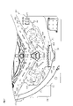
本実施の形態においては、流路形成部131,161、可変入賞装置201及びそれに関連する構成が特徴的となっている。そこで以下、図5~図7を参照して流路形成部131,161、可変入賞装置201及びそれに関連する構成について補足説明する。図5は、可変入賞装置201及びその周辺構成を拡大して示す図4の部分拡大図、図6の(a)は可変入賞装置201の正面図、(b),(c)は可変入賞装置201の断面図、図7は可変入賞装置201及びその周辺構成の斜視図である。
<Flower
In the present embodiment, the flow
先ず、図5を参照しながら左側流路形成部131について説明する。左側流路形成部131は、下側領域PE4の左部において内レール部51に沿って配設されている。既に説明したように、左側流路形成部131は、遊技盤24の前面から前方に突出しているとともに、左側流路形成部131の前方を遊技球が流下できない構成となっている。左側流路形成部131の上面部132は、遊技球が転動可能な転動面となっており、遊技球を下側領域PE4の左右中央側に導く流路を形成している。
First, the left side flow
上面部132は上下方向に段差をもって形成され、上流側の第1傾斜部133と、下流側の第2傾斜部136とに分かれている。第1傾斜部133は、正面視において右側に下る傾斜状をなしており、左側領域PE2を流下した遊技球を左側遊技釘群134に向けて導出する左側第1流路を形成している。左側遊技釘群134は、第1傾斜部133と、可変入賞装置201の上方に配置された下作動口34との間において、略直線状に配列された複数の遊技釘38から構成されており、第1傾斜部133からの遊技球を下作動口34に案内可能な案内路を形成している。
The
第1傾斜部133と左側遊技釘群134との間、及び左側遊技釘群134の途中位置には、1個の遊技球が通過可能な隙間135が形成されており、これらの隙間135を介して遊技球が落下可能となっている。隙間135の下方には、上方に開口する一般入賞口31a,31bが配置されており、これら一般入賞口31a,31bには遊技球が1個ずつ入賞可能となっている。隙間135と一般入賞口31a,31bとの間には複数の遊技釘38が配置されており、これらの遊技釘38により、隙間135から落下した遊技球がランダムに振り分けられる。このため、隙間135から落下した遊技球が一般入賞口31a,31bに入賞する場合もあれば、入賞しない場合もある。なお、本実施の形態では、2個の一般入賞口31を配置しているが、一般入賞口31の数は任意であり、1個であってもよいし、3個以上であってもよい。
A
第2傾斜部136は正面視において右側に下る傾斜状をなしており、その最下流部(終端部)が可変入賞装置201に向けて開放されている。第2傾斜部136は、一般入賞口31a,31bの下方に配置されており、一般入賞口31a,31bに入賞しなかった遊技球を可変入賞装置201に向けて導出する左側第2流路を形成している。
The second
第2傾斜部136と第1傾斜部133との間には、上記段差を形成し、両傾斜部133,136を繋ぐ第1縦壁部137が形成されている。第1縦壁部137は上下方向に延びており、第1縦壁部137と一般入賞口31aとの間には、1個の遊技球が通過可能な左側第3流路が形成されている。このため、隙間135から落下した遊技球が一般入賞口31aの左側を抜けた場合、当該遊技球は上記第3流路を通って第2傾斜部136に至ることが可能となっている。
The step is formed between the second
本実施の形態において第2傾斜部136は、第1縦壁部137の下端部と連続し、且つ第1縦壁部137との接続部から最下流部(可変入賞装置201側の端部)までの間においてアウト口等の遊技球の抜け道が存在しない構成となっている。このため、左側第3流路を通過した遊技球及び第2傾斜部136上に落下した遊技球は全て可変入賞装置201側に導出されるものとなっている。なお、第1傾斜部133及び第2傾斜部136における遊技球の転動面は凹凸のない平面状とされ、遊技球のスムーズな転動(流下)が可能となっている。
In the present embodiment, the second
また、下作動口34と可変入賞装置201との間の領域PE4aや、左側遊技釘群134と可変入賞装置201との間の領域PE4bには、複数の遊技釘38が配置されており、これら遊技釘38は上記領域PE4a,PE4bに流入した遊技球を可変入賞装置201に導くようにレイアウトされている。このため、上作動口33や下作動口34の脇を抜けて流下する遊技球や、隙間135から落下し領域PE4bに流れ込んだ遊技球は、いずれも可変入賞装置201側に流下する。なお、領域PE4a,PE4bの遊技球が可変入賞装置201に向けて流下するものであれば、これらの領域における遊技釘38を省略したり、遊技釘38に代えて合成樹脂製の通路部材(案内部材)を設けたりしてもよい。
Further, a plurality of game nails 38 are arranged in the area PE4a between the
第2傾斜部136の最下流部には、下方(内レール部51)に向けて延びる第2縦壁部138が設けられている。第2縦壁部138の上部には、遊技球が入球可能なアウト口141が設けられており、アウト口141に入球した遊技球は、遊技盤24の背面側に導かれ、遊技領域PEから排出される。アウト口141は遊技機横方向(右方)に開口しており、その大きさは1個の遊技球が通過可能な大きさとなっている。
A second
アウト口141及びその周辺部における左側流路形成部131の前面部、すなわち、左側流路形成部131の前面部において、少なくとも、アウト口141及びアウト口141に入球した遊技球を遊技盤24の背面側に導く誘導通路に対し遊技機前方から重なる部分には、メッキやシールなどにより所定の装飾が施され、着色がなされている。一方、遊技球の転動面となる第2傾斜部136にはそのような着色がなく、上記部分は、第2傾斜部136よりも光透過率が低くなっている。これにより、遊技機前方からの正面視においてアウト口141の開口部やアウト口141に入球した遊技球の流れが視認不能又は視認困難となっている。すなわち、アウト口141はその視認性が他の入球部(例えば可変入賞装置201)よりも低く、目立ちにくい構成となっている。
At least in the front portion of the left side flow
その際、アウト口141の存在を遊技者やホール従業員等が把握できるように、アウト口141及びその周辺部における左側流路形成部131の前面に、アウト口141を示唆又は明示する表示(例えば「OUT」)を設けてもよい。なお、上記部分を着色する構成に代えて、当該部分を不透明な材料や第2傾斜部136よりも光透過率が低い材料で形成することで、アウト口141の視認性を低下させる構成としてもよい。
At that time, a display suggesting or clearly indicating the
ちなみに、左側流路形成部131自体は、既に説明したように、透明な合成樹脂により形成されており、透光性を有している。よって、遊技機前方や遊技機側方(上下や左右)に向けて光を発することが可能な複数の発光素子が搭載された発光基板を、左側流路形成部131の後方に配置することで、例えば第2傾斜部136を明るく照らすなどの発光演出を行うことが可能となっている。
Incidentally, the left flow
次に、右側流路形成部161について説明する。右側流路形成部161の上面部162は、遊技球が転動可能な転動面となっており、遊技球を下側領域PE4の左右中央側に導く流路を形成している。右側流路形成部161の上面部162は、左側流路形成部131の上面部132と左右対称になっており、第1傾斜部163、第2傾斜部166及び第1縦壁部167を有している。
Next, the right side flow
第1傾斜部163は、正面視において左側に下る傾斜状をなしており、右側領域PE3を流下した遊技球を右側遊技釘群164に向けて導出する右側第1流路を形成している。右側遊技釘群164は遊技球を下作動口34に案内可能な案内路を形成するものであり、第1傾斜部163と右側遊技釘群164との間、及び右側遊技釘群164の途中位置には、1個の遊技球が通過可能な隙間165が形成されている。また、隙間165の下方には、上方に開口する一般入賞口31c,31dが配置されており、隙間165から落下した遊技球が一般入賞口31c,31dに入賞可能となっている。
The first
第2傾斜部166は、正面視において左側に下る傾斜状をなしており、遊技球を可変入賞装置201に向けて導出する右側第2流路を形成している。第2傾斜部166は、一般入賞口31c,31dの下方に配置されており、一般入賞口31c,31dに入賞しなかった遊技球を可変入賞装置201に導出するものとなっている。第1縦壁部167は、第1傾斜部163と第2傾斜部166と繋ぐものであり、一般入賞口31dとの間に、1個の遊技球が通過可能な右側第3流路を形成している。
The second
本実施の形態において第2傾斜部166は、第1縦壁部167の下端部と連続し、且つ第1縦壁部167との接続部から終端部(可変入賞装置201側の端部)までの間においてアウト口等の遊技球の抜け道が存在しない構成となっている。このため、右側第3流路を通過した遊技球及び第2傾斜部166上に落下した遊技球は全て可変入賞装置201側に導出されるものとなっている。なお、第1傾斜部163及び第2傾斜部166における遊技球の転動面は凹凸のない平面状とされ、遊技球のスムーズな転動(流下)が可能となっている。
In the present embodiment, the second
右側遊技釘群164と可変入賞装置201との間の領域PE4cには、領域PE4cに流入した遊技球を可変入賞装置201に導く複数の遊技釘38が設けられており、隙間165から落下し領域PE4cに流れ込んだ遊技球は、いずれも可変入賞装置201に向けて流下する。なお、領域PE4cの遊技球が可変入賞装置201に向けて流下するものであれば、領域PE4cにおける遊技釘38を省略したり、遊技釘38に代えて合成樹脂製の通路部材(案内部材)を設けたりしてもよい。
In the area PE4c between the right side
第2傾斜部166の最下流部には、下方(内レール部51)に向けて延びる第2縦壁部168が設けられている。第2縦壁部168の上部には、遊技領域PEから遊技球を排出させるアウト口171が設けられている。アウト口171は、遊技機横方向(左方)に開口しており、その大きさは1個の遊技球が通過可能な大きさとなっている。アウト口171の高さ位置は、左側流路形成部131のアウト口141と同一となっており、可変入賞装置201を挟んでアウト口141,171が相対向している。また、アウト口171は、アウト口141の場合と同様、アウト口171及びその周辺部における右側流路形成部161の前面が不透明化されることで、遊技機前方からの視認性が他の入球部よりも低くなっている。ちなみに本実施の形態では、アウト口141,171以外のアウト口は設けられていない。
A second
次に、可変入賞装置201について説明する。図6(a)に示すように、遊技盤24において最下部となる位置には、遊技盤24を厚さ方向に貫通する開口部207が設けられている。可変入賞装置201は板状のベース体211を備えており、ベース体211を上記開口部207に嵌め込むことで、遊技盤24に取り付けられている。
Next, the
ベース体211の前面部211aと窓パネル62との間の距離は、遊技球の直径よりも大きくなっており、前面部211aの前方には、遊技球が通過可能な通路部208が形成されている。通路部208は、流路形成部131,161の各第2縦壁部138,168からなる側壁部213と、内レール部51からなる底部214とを備えて構成されており、通路部208の上部には大入賞口202が形成されている(図7(b)参照)。大入賞口202は、上方に開口しており、平面視において左右に延びる横長の長方形状をなしている。大入賞口202の大きさ(幅寸法)は、複数個の遊技球が同時に通過可能な大きさとなっている。
The distance between the
通路部208の下部中央には、ベース体211を厚み方向に貫通する貫通孔222が形成されている。貫通孔222は、正面視において横長の略楕円形状をなしており、複数個の遊技球が同時に通過可能な大きさを有している。図6(b)に示すように、ベース体211の背面側には球通路221が設けられており、球通路221は貫通孔222を通じて通路部208と連通している。球通路221は後方に延びており、球通路221に到達した遊技球は通路底面221aに沿って後方に誘導される。その途中位置には、大入賞口202に入賞した遊技球を検知する大入賞口用入賞センサ202aが配置されている。大入賞口用入賞センサ202aは主制御装置81に電気的に接続されており、大入賞口用入賞センサ202aの検知領域を遊技球が通過した場合に所定の検知情報(検知信号)が主制御装置81に入力される。主制御装置81ではこの検知情報に基づいて大入賞口202への入賞の有無を判定する。
A through
上記大入賞口202を覆うようにして、開閉扉203としての板状のシャッタ216が配設されている。シャッタ216は、前後方向へのスライド移動が可能に構成されており、ベース体211の前面部211a(遊技盤24の前面)から遊技機前方に突出する突出位置と、突出位置から後方に退避し、遊技機前方への突出が抑えられた退避位置とに変位可能となっている。
A plate-shaped
シャッタ216が退避位置に位置する場合には、図7(b)に示すように、通路部208の上部において遊技球を大入賞口202へ受入可能な受入領域RAが形成される。受入領域RAは平面視で大入賞口202と同位置で且つ同一の形状及び大きさを有しており、受入領域RAが形成されることで大入賞口202への遊技球の入賞が許容される。なお、退避位置では、シャッタ216の前端部がベース体211の前面部211aと面一又は前面部211aよりも遊技機背面側に位置するようになっている。これにより、退避位置にあるシャッタ216の前方を遊技球が通過可能であるだけでなく、ベース体211とシャッタ216との境界に遊技球が引っ掛かることが抑制され、遊技球の円滑な流れが確保されている。
When the
一方、シャッタ216が突出位置に位置する場合には、図7(a)に示すように、シャッタ216により大入賞口202が上方から覆われることで、受入領域RAが消失する。これにより、可変入賞装置201が閉鎖状態となり、大入賞口202への遊技球の入賞が規制される。なお、閉鎖状態である場合に必ずしも大入賞口202に遊技球が入賞できない構成とする必要はなく、開放状態に比べて入賞しにくい範囲で入賞可能となる構成であってもよい。要は、開放状態と閉鎖状態とで大入賞口202への入賞しやすさが相違すれば足り、閉鎖や開放の度合は任意である。
On the other hand, when the
ここで、図6(a)に示すように、シャッタ216の左右端部216a,216bの高さ位置は、各流路形成部131,161の第2傾斜部136,166から、少なくとも遊技球1個分の大きさだけ下方に下がった位置に設定されている。換言すれば、シャッタ216の左右両側には、シャッタ216の左右端部216a,216bが第2傾斜部136,166よりも遊技球の直径以上低くなるようにして、段差部204が形成されている。これらの段差部204には、上記アウト口141,171がシャッタ216側に開口する態様で配置されている。このため、突出位置に位置するシャッタ216の上を遊技球が転動した場合には、当該遊技球はシャッタ216によってアウト口141,171へと導かれる。
Here, as shown in FIG. 6A, the height positions of the left and
シャッタ216には、遊技球をアウト口141,171に案内する案内機能が付与されている。具体的には、図7(a)に示すように、シャッタ216の上面部において左側には、アウト口141に向けて下り傾斜となる第1シャッタ傾斜部217が設けられ、上記上面部において右側には、アウト口171に向けて下り傾斜となる第2シャッタ傾斜部218が設けられている。これら各傾斜部217,218は左右対称になっており、シャッタ216の上面部に到達した遊技球は、上記各傾斜部217,218によりアウト口141,171へと案内される。なお、必ずしもシャッタ216全体を傾斜させる必要はなく、少なくともその上面部が傾斜していれば足りる。
The
シャッタ216は左右方向に延びており、詳しくは、その左右端部216a,216bが各流路形成部131,161の第2縦壁部138,168の近傍に位置している。シャッタ216の左右端部216a,216bと各アウト口141,171との間隔は、遊技球の直径未満となっており、突出位置に位置するシャッタ216と各アウト口141,171との間から遊技球が落下しないようになっている。このため、シャッタ216によりアウト口141,171に向けて案内された遊技球は、案内途中でシャッタ216が退避位置に変位しない限り、全てアウト口141,171に入球する。
The
なお、シャッタ216が退避位置に位置する場合は、遊技球同士の接触により遊技球の流下方向が変化するなどの事象が生じた場合を除き、原則としてアウト口141,171には遊技球が入球しない。
When the
図6(b),(c)に示すように、ベース体211の背面側にはシャッタ216を駆動する可変入賞駆動部219が取り付けられている。可変入賞駆動部219は、駆動源としてのソレノイドと、当該ソレノイドからの駆動力をシャッタ216に伝達する駆動力伝達手段としてのリンク機構とを有している。ソレノイドは主制御装置81に電気的に接続されており、主制御装置81からの駆動信号に基づいて駆動する。ソレノイドが駆動することで、シャッタ216が突出位置から退避位置に後退し、可変入賞装置201が閉鎖状態から開放状態に切り換わる。主制御装置81からの駆動信号の出力が停止すると、付勢手段(ばね等)の付勢力によってシャッタ216が退避位置から突出位置に前進し、可変入賞装置201が開放状態から閉鎖状態に切り替わる。
As shown in FIGS. 6 (b) and 6 (c), a variable winning
<パチンコ機10の電気的構成>
次に、パチンコ機10の電気的構成について、図8のブロック図に基づいて説明する。
<Electrical configuration of
Next, the electrical configuration of the
主制御基板111には、MPU112が搭載されている。MPU112には、当該MPU112により実行される各種の制御プログラムや固定値データを記憶したROM113と、そのROM113内に記憶される制御プログラムの実行に際して各種のデータ等を一時的に記憶するためのメモリであるRAM114と、割込回路、タイマ回路、データ入出力回路、乱数発生器としての各種カウンタ回路などが内蔵されている。なお、MPU112に対してROM113及びRAM114が1チップ化されていることは必須の構成ではなく、それぞれが個別にチップ化された構成としてもよい。これは主制御装置81以外の制御装置のMPUについても同様である。
The
MPU112には、入力ポート及び出力ポートがそれぞれ設けられている。MPU112の入力側には、主制御装置81に設けられた停電監視基板115及び払出制御装置97が接続されている。この場合に、停電監視基板115には動作電力を供給する機能を有する電源及び発射制御装置98が接続されており、MPU112には停電監視基板115を介して電力が供給される。
The
また、MPU112の入力側には、各種センサが接続されている。各種センサには、一般入賞口31、上作動口33、下作動口34、スルーゲート35、可変入賞装置201への入賞を検知する一般入賞口用入賞センサ31e、上作動口用入賞センサ33b、下作動口用入賞センサ34c、スルー用入賞センサ35a、大入賞口用入賞センサ202a等が設けられている。MPU112では、これら各種センサ31e,33b,34c,35a,202aの検知結果に基づいて、各入球部への入賞判定(入球判定)等を行う。また、MPU112では、上作動口33及び下作動口34への入賞に基づいて大当たり発生抽選を実行するとともに、スルーゲート35への入賞に基づいてサポート発生抽選を実行する。
Further, various sensors are connected to the input side of the
MPU112の出力側には、停電監視基板115、払出制御装置97及び演出制御装置82等が接続されている。払出制御装置97には、例えば、賞球が払い出されることに対応する賞球対応入球部への入賞判定結果に基づいて賞球コマンドが出力される。
A power
演出制御装置82には、演出用の各種コマンドが出力される。これら各種コマンドの詳細については、後に説明する。ちなみに、演出制御装置82は、信号線の両端にコネクタが設けられたコネクタユニット(接続ユニット)を介して主制御装置81と電気的に接続されている。
Various commands for staging are output to the
また、MPU112の出力側には各種駆動部として、電動役物駆動部34b、可変入賞駆動部219が接続されている。主制御基板111には各種ドライバ回路が設けられており、当該ドライバ回路を通じてMPU112は各種駆動部の駆動制御を実行する。具体的には、開閉実行モードへの移行が発生すると、大入賞口202が開閉されるように、MPU112において可変入賞駆動部219の駆動制御が実行される。また、電動役物34aの開放状態当選となった場合には、電動役物34aが開閉されるように、MPU112において電動役物駆動部34bの駆動制御が実行される。また、各遊技回に際しては、MPU112においてメイン表示部43における第1結果表示部AS又は第2結果表示部BSの表示制御が実行されるとともに、可変入賞装置201の開閉実行モードに際してはメイン表示部43におけるラウンド表示部RSの表示制御が実行される。そして、電動役物34aを開放状態とするか否かの抽選結果を明示する場合に、MPU112において役物用表示部44の表示制御が実行される。
Further, an electric
さらには、MPU112の出力側に外部出力端子99が接続されており、この外部出力端子99を通じて遊技ホール側の管理制御装置(ホールコンピュータHC)に対して各種入球部への入球情報や大当たり等の抽選結果に関する情報が出力される。これにより、ホールコンピュータHCにてパチンコ機10の状態等を把握することが可能となっている。
Furthermore, an
停電監視基板115は、主制御基板111と電源及び発射制御装置98とを中継し、また電源及び発射制御装置98から出力される直流安定24ボルトの電圧を監視する。払出制御装置97は、主制御装置81から入力した賞球コマンドに基づいて、払出装置96により賞球や貸し球の払出制御を行うものである。
The power
電源及び発射制御装置98は、例えば、遊技場等における商用電源(外部電源)に接続されている。そして、その商用電源から供給される外部電力に基づいて主制御基板111や払出制御装置97等に対して各々に必要な動作電力を生成するとともに、その生成した動作電力を供給する。ちなみに、電源及び発射制御装置98にはバックアップ用コンデンサなどの電断時用電源部が設けられており、パチンコ機10の電源がOFF状態の場合であっても当該電断時用電源部から主制御装置81のRAM114に記憶保持用の電力が供給される。
The power supply and the
また、電源及び発射制御装置98は遊技球発射機構53の発射制御を担うものであり、遊技球発射機構53は所定の発射条件が整っている場合に駆動される。この場合、遊技球発射機構53は、遊技盤24の誘導レール54に向けて延びる発射レールと、上皿71に貯留されている遊技球を発射レール上に供給する球送り装置と、発射レール上に供給された遊技球を誘導レール54に向けて発射させる電動アクチュエータであるソレノイドと、を備えており、当該ソレノイドに対して電源及び発射制御装置98から駆動信号が供給されることで遊技球が発射される。
Further, the power supply and the
演出制御装置82は、主制御装置81から入力した各種コマンドに基づいて、可変表示ユニット36に設けられた各保留発光部45~47及び前扉枠14に設けられた表示発光部63やスピーカ部64を駆動制御するとともに、表示制御装置212を制御するものである。
The
演出制御装置82に設けられた演出制御基板241には、MPU242が搭載されている。MPU242には、当該MPU242により実行される各種の制御プログラムや固定値データを記憶したROM243と、そのROM243内に記憶される制御プログラムの実行に際して各種のデータ等を一時的に記憶するためのメモリであるRAM244と、割込回路、タイマ回路、データ入出力回路などが内蔵されている。
The
MPU242には、入力ポート及び出力ポートがそれぞれ設けられている。MPU242の入力側には主制御装置81が接続されている。主制御装置81からは、シフトコマンドや保留コマンドといった保留表示制御用コマンド(保留表示制御用情報)を受信する。また、変動用コマンド、種別コマンド、変動終了コマンドといった遊技回制御用コマンド(遊技回制御用情報)を受信する。また、開放コマンド、閉鎖コマンド、オープニングコマンド、エンディングコマンドといった開閉実行モード用コマンド(開閉実行モード用情報)を受信する。
The
MPU242は、主制御装置81から受信する各種コマンドに基づいて、各種演出を実行するための処理を行う。受信したコマンドは、MPU242のRAM244に設けられたコマンド格納エリアに格納される。そして、その格納されたコマンドを解析等する処理を行い、各種演出を実行する。MPU242のROM243には各種テーブル記憶エリアが設けられており、また、MPU242のRAM244には各種フラグ格納エリアや各種カウンタエリアが設けられており、各種演出を実行する場合、これらのエリアを用いた処理を行うことが可能となっている。
The
MPU242の出力側には、可変表示ユニット36に設けられた各保留発光部45~47及び前扉枠14に設けられた表示発光部63やスピーカ部64が接続されているとともに、表示制御装置212が接続されている。
On the output side of the
表示制御装置212は、プログラムROM273及びワークRAM274が複合的にチップ化されたMPU272と、ビデオディスプレイプロセッサ(VDP)275と、キャラクタROM276と、ビデオRAM277とがそれぞれ搭載された表示制御基板271を備えている。
The
MPU272は、演出制御装置82から、保留表示制御を行うための保留表示制御用コマンド(保留表示制御用情報)、図柄の変動表示を行うための遊技回制御用コマンド(遊技回制御用情報)、開閉実行モード中の動画表示を行うための開閉実行モード用コマンド(開閉実行モード用情報)などを受信する。そして、それら受信したコマンドを解析し又は受信したコマンドに基づき所定の演算処理を行ってVDP275の制御(具体的にはVDP275に対する内部コマンドの生成)を実施する。
From the
プログラムROM273は、MPU272により実行される各種の制御プログラムや固定値データを記憶するためのメモリであり、背景画像用のJPEG形式画像データも併せて記憶保持されている。
The program ROM 273 is a memory for storing various control programs executed by the
ワークRAM274は、MPU272による各種プログラムの実行時に使用されるワークデータやフラグ等を一時的に記憶するためのメモリである。これらワークデータやフラグ等はワークRAM274の各エリアに記憶される。
The
VDP275は、図柄表示装置41に組み込まれた液晶表示部ドライバとしての画像処理デバイスを直接操作する一種の描画回路である。VDP275はICチップ化されているため「描画チップ」とも呼ばれ、その実体は、描画処理専用のファームウェアを内蔵したマイコンチップとでも言うべきものである。VDP275は、MPU272、ビデオRAM277等のそれぞれのタイミングを調整してデータの読み書きに介在するとともに、ビデオRAM277に記憶させる画像データを、キャラクタROM276から所定のタイミングで読み出して図柄表示装置41に表示させる。
The VDP275 is a kind of drawing circuit that directly operates an image processing device as a liquid crystal display driver built in the
キャラクタROM276は、図柄表示装置41に表示される図柄などのキャラクタデータを記憶するための画像データライブラリとしての役割を担うものである。このキャラクタROM276には、各種の表示図柄のビットマップ形式画像データ、ビットマップ画像の各ドットでの表現色を決定する際に参照する色パレットテーブル等が保持されている。
The character ROM 276 plays a role as an image data library for storing character data such as a symbol displayed on the
なお、キャラクタROM276を複数設け、各キャラクタROM276に分担して画像データ等を記憶させておくことも可能である。また、前記プログラムROM273に記憶した背景画像用のJPEG形式画像データをキャラクタROM276に記憶する構成とすることも可能である。 It is also possible to provide a plurality of character ROMs 276 and store image data and the like in each character ROM 276. Further, it is also possible to store the JPEG format image data for the background image stored in the program ROM 273 in the character ROM 276.
ビデオRAM277は、図柄表示装置41に表示させる表示データを記憶するためのメモリであり、ビデオRAM277の内容を書き替えることにより図柄表示装置41の表示内容が変更される。
The video RAM 277 is a memory for storing display data to be displayed on the
ここで、図柄表示装置41の表示内容について図9及び図10に基づいて説明する。図9は図柄表示装置41にて変動表示される図柄を個々に示す図であり、図10は図柄表示装置41の表示画面Gを示す図である。
Here, the display contents of the
図9(a)~(j)に示すように、絵柄の一種である図柄は、「1」~「9」の数字が各々付された9種類の主図柄と、貝形状の絵図柄からなる副図柄とにより構成されている。より詳しくは、タコ等の9種類のキャラクタ図柄に「1」~「9」の数字がそれぞれ付されて主図柄が構成されている。 As shown in FIGS. 9 (a) to 9 (j), a pattern which is a kind of a pattern consists of nine main patterns with numbers "1" to "9" and a shell-shaped pattern. It is composed of sub-designs. More specifically, nine types of character symbols such as an octopus are assigned numbers "1" to "9" to form a main symbol.
図10(a)に示すように、図柄表示装置41の表示画面Gには、上段・中段・下段の3つの図柄列Z1,Z2,Z3が設定されている。各図柄列Z1~Z3は、主図柄と副図柄が所定の順序で配列されて構成されている。詳細には、上図柄列Z1には、「1」~「9」の9種類の主図柄が数字の降順に配列されると共に、各主図柄の間に副図柄が1つずつ配されている。下図柄列Z3には、「1」~「9」の9種類の主図柄が数字の昇順に配列されると共に、各主図柄の間に副図柄が1つずつ配されている。つまり、上図柄列Z1と下図柄列Z3は18個の図柄により構成されている。これに対し、中図柄列Z2には、数字の昇順に「1」~「9」の9種類の主図柄が配列された上で「9」の主図柄と「1」の主図柄との間に「4」の主図柄が付加的に配列され、これら各主図柄の間に副図柄が1つずつ配されている。つまり、中図柄列Z2に限っては、10個の主図柄が配されて20個の図柄により構成されている。そして、表示画面Gでは、これら各図柄列Z1~Z3の図柄が周期性をもって所定の向きにスクロールするように変動表示される。また、図10(b)に示すように、表示画面Gは、図柄列毎に3個の図柄が停止表示されるようになっており、結果として3×3の計9個の図柄が停止表示されるようになっている。
As shown in FIG. 10A, three symbol rows Z1, Z2, and Z3 of an upper row, a middle row, and a lower row are set on the display screen G of the
また、表示画面Gには、5つの有効ライン、すなわち左ラインL1、中ラインL2、右ラインL3、右下がりラインL4、右上がりラインL5が設定されている。そして、上図柄列Z1→下図柄列Z3→中図柄列Z2の順に変動表示が停止し、いずれかの有効ラインに同一の数字が付された図柄の組合せが形成された状態で全図柄列Z1~Z3の変動表示が終了すれば、大当たり結果の発生として大当たり動画が表示されるようになっている。 Further, five effective lines, that is, a left line L1, a middle line L2, a right line L3, a right-down line L4, and a right-up line L5 are set on the display screen G. Then, the variable display is stopped in the order of the upper symbol row Z1 → the lower symbol row Z3 → the middle symbol row Z2, and all the symbol rows Z1 are formed in a state where a combination of symbols with the same number is formed on any of the effective lines. When the variable display of ~ Z3 is completed, the jackpot moving image is displayed as the occurrence of the jackpot result.
本パチンコ機10では、奇数番号(1,3,5,7,9)が付された主図柄は「特定図柄」に相当し、確変大当たり結果が発生する場合には、同一の特定図柄の組合せが停止表示される。また、偶数番号(2,4,6,8)が付された主図柄は「非特定図柄」に相当し、通常大当たり結果が発生する場合には、同一の非特定図柄の組合せが停止表示される。
In this
なお、図柄表示装置41における図柄の変動表示の態様は上記のものに限定されることはなく任意であり、図柄列の数、図柄列における図柄の変動表示の方向、各図柄列の図柄数などは適宜変更可能である。
The mode of variable display of symbols in the
表示画面Gの下部における左側には、第1保留表示領域Gaが設定されており、表示画面Gの下部における右側には、第2保留表示領域Gbが設定されている。 The first reserved display area Ga is set on the left side at the lower part of the display screen G, and the second reserved display area Gb is set on the right side at the lower part of the display screen G.
第1保留表示領域(非優先側保留表示領域)Gaは、遊技球が上作動口33に入賞した場合の最大保留個数と同一の数の単位保留表示領域Ga1~Ga4が左右方向に並設されるように区画表示されている。具体的には、遊技球が上作動口33に入賞した場合の最大保留個数は4個であり、これに対応させて第1保留表示領域Gaには、第1単位保留表示領域Ga1、第2単位保留表示領域Ga2、第3単位保留表示領域Ga3、第4単位保留表示領域Ga4が設定されている。
In the first hold display area (non-priority side hold display area) Ga, the same number of unit hold display areas Ga1 to Ga4 as the maximum number of holds when the game ball wins the
例えば、遊技球が上作動口33に入賞した場合の保留個数が1個の場合には、第1単位保留表示領域Ga1のみにて所定の保留用画像が表示され、遊技球が上作動口33に入賞した場合の保留個数が4個の場合には、第1単位保留表示領域Ga1~第4単位保留表示領域Ga4の全てにおいて所定の保留用画像が表示される。
For example, when the number of holdings when the game ball wins in the
また、第2保留表示領域(優先側保留表示領域)Gbは、遊技球が下作動口34に入賞した場合の最大保留個数と同一の数の単位保留表示領域Gb1~Gb4が左右方向に並設されるように区画表示されている。具体的には、遊技球が下作動口34に入賞した場合の最大保留個数は4個であり、これに対応させて第2保留表示領域Gbには、第1単位保留表示領域Gb1、第2単位保留表示領域Gb2、第3単位保留表示領域Gb3、第4単位保留表示領域Gb4が設定されている。
Further, in the second hold display area (priority side hold display area) Gb, the same number of unit hold display areas Gb1 to Gb4 as the maximum number of holds when the game ball wins the
例えば、遊技球が下作動口34に入賞した場合の保留個数が1個の場合には、第1単位保留表示領域Gb1のみにて保留用画像が表示され、遊技球が下作動口34に入賞した場合の保留個数が4個の場合には、第1単位保留表示領域Gb1~第4単位保留表示領域Gb4の全てにおいて保留用画像が表示される。
For example, when the number of holdings when the game ball wins in the
<主制御装置81のMPU112にて各種抽選を行うための電気的構成>
次に、主制御装置81のMPU112にて各種抽選を行うための電気的な構成について図11を用いて説明する。
<Electrical configuration for performing various lottery with
Next, an electrical configuration for performing various lottery with the
MPU112は遊技に際し各種カウンタ情報を用いて、大当たり発生抽選、メイン表示部43の表示の設定、図柄表示装置41の演出内容の設定、役物用表示部44の表示の設定などを行うこととしており、具体的には、図11に示すように、大当たり発生の抽選に使用する大当たり乱数カウンタC1と、大当たり種別を判定する際に使用する大当たり種別カウンタC2と、図柄表示装置41が外れ変動する際のリーチ発生抽選に使用するリーチ乱数カウンタC3と、大当たり乱数カウンタC1の初期値設定に使用する乱数初期値カウンタCINIと、メイン表示部43及び図柄表示装置41における変動表示時間を決定する変動種別カウンタCSと、を用いることとしている。さらに、下作動口34の電動役物34aを電役開放状態とするか否かの抽選に使用する電動役物開放カウンタC4を用いることとしている。
The
各カウンタC1,C2,C3,CINI,CS,C4は、その更新の都度前回値に1が加算され、最大値に達した後0に戻るループカウンタとなっている。各カウンタは短時間間隔で更新され、その更新値がRAM114の所定領域に設定された抽選カウンタ用バッファ114aに適宜格納される。抽選カウンタ用バッファ114aにおいて、大当たり乱数カウンタC1、大当たり種別カウンタC2、リーチ乱数カウンタC3及び変動種別カウンタCSに対応した情報は、上作動口33又は下作動口34への入賞が発生した場合に、取得情報記憶手段としての保留球格納エリア114bに格納される。
Each of the counters C1, C2, C3, CINI, CS, and C4 is a loop counter in which 1 is added to the previous value each time the counter is updated, and the counter returns to 0 after reaching the maximum value. Each counter is updated at short intervals, and the updated value is appropriately stored in the
保留球格納エリア114bは、第1結果表示部用保留エリアRa及び第2結果表示部用保留エリアRbからなる保留エリアREと、実行エリアAEとを備えている。保留エリアRa,Rbは、それぞれ、第1エリア、第2エリア、第3エリア、第4エリアを備えており、上作動口33又は下作動口34への入賞履歴に合わせて、抽選カウンタ用バッファ114aに格納されている大当たり乱数カウンタC1、大当たり種別カウンタC2、リーチ乱数カウンタC3及び変動種別カウンタCSの各数値情報が保留情報として、いずれかのエリアに格納される。なお、当該保留情報が特別情報に相当する。
The holding
この場合、第1エリア~第4エリアには、上作動口33又は下作動口34への入賞が複数回連続して発生した場合に、第1エリア→第2エリア→第3エリア→第4エリアの順に各数値情報が時系列的に格納されていく。このようにそれぞれ4つのエリアが設けられていることにより、上作動口33又は下作動口34への遊技球の入賞履歴がそれぞれ最大4個まで保留記憶されるようになっている。また、保留球格納エリア114bには総保留数記憶領域が設けられており、当該総保留数記憶領域には上作動口33又は下作動口34への入賞履歴を保留記憶している数を特定するための情報が格納される。
In this case, in the first area to the fourth area, when the
なお、保留記憶可能な数は、4個に限定されることはなく任意であり、2個、3個又は5個以上といったように他の複数であってもよく、単数であってもよい。 The number that can be stored on hold is not limited to four, and may be any other, such as two, three, or five or more, or may be a single number.
実行エリアAEは、メイン表示部43の変動表示を開始する際に、保留エリアREの第1エリアに格納された各値を移動させるためのエリアであり、1遊技回の開始に際しては実行エリアAEに記憶されている各種数値情報に基づいて、当否判定などが行われる。
The execution area AE is an area for moving each value stored in the first area of the hold area RE when starting the variable display of the
各カウンタについて詳しくは、大当たり乱数カウンタC1は、例えば0~599の範囲内で順に1ずつ加算され、最大値(つまり599)に達した後0に戻る構成となっている。大当たり乱数カウンタC1が1周した場合、その時点の乱数初期値カウンタCINIの値が当該大当たり乱数カウンタC1の初期値として読み込まれる。なお、乱数初期値カウンタCINIは、大当たり乱数カウンタC1と同様のループカウンタである(値=0~599)。大当たり乱数カウンタC1は定期的に更新され、遊技球が上作動口33又は下作動口34に入賞したタイミングでRAM114の保留球格納エリア114bに格納される。より詳しくは、上作動口33に遊技球が入賞したタイミングでRAM114の第1結果表示部用保留エリアRaに格納され、下作動口34に遊技球が入賞したタイミングでRAM114の第2結果表示部用保留エリアRbに格納される。
More specifically, the jackpot random number counter C1 is configured to be incremented by 1 in order within the range of, for example, 0 to 599, reach the maximum value (that is, 599), and then return to 0. When the jackpot random number counter C1 makes one round, the value of the random number initial value counter CINI at that time is read as the initial value of the jackpot random number counter C1. The random number initial value counter CINI is a loop counter similar to the jackpot random number counter C1 (value = 0 to 599). The jackpot random number counter C1 is periodically updated and stored in the reserved
大当たり当選となる乱数の値は、ROM113における当否情報群記憶手段としての当否テーブル記憶エリア113aに当否テーブル(当否情報群)として記憶されている。当否テーブルとしては、低確率モード用の当否テーブル(低確率用当否情報群)と、高確率モード用の当否テーブル(高確率用当否情報群)とが設定されている。つまり、本パチンコ機10は、当否抽選手段における抽選モードとして、低確率モード(低確率状態)と高確率モード(高確率状態)とが設定されている。各当否テーブルでは、低確率モード用の当否テーブルよりも高確率モード用の当否テーブルの方が大当たり当選となる確率が高くなるように乱数の値が設定されている。
The value of the random number that wins the big hit is stored as a hit / miss table (hit / miss information group) in the hit / miss
また、各抽選モードにおいて、大当たり当選となる乱数の値以外は、抽選結果が外れ結果となる。 Further, in each lottery mode, the lottery result is out of order except for the value of the random number that is the big hit.
大当たり種別カウンタC2は、0~29の範囲内で順に1ずつ加算され、最大値(つまり29)に達した後0に戻る構成となっている。ここで、本実施の形態では、複数の大当たり結果が設定されている。これら複数の大当たり結果は、(1)開閉実行モード終了後の当否抽選手段における抽選モード、(2)開閉実行モード終了後の下作動口34の電動役物34aにおけるサポートモード、という2つの条件に差異を設けることで設定されている。
The jackpot type counter C2 is configured to be incremented by 1 in order within the range of 0 to 29, reach the maximum value (that is, 29), and then return to 0. Here, in the present embodiment, a plurality of jackpot results are set. These multiple jackpot results are subject to two conditions: (1) a lottery mode in the winning / failing lottery means after the opening / closing execution mode ends, and (2) a support mode in the
下作動口34の電動役物34aにおけるサポートモードとしては、遊技領域PEに対して同様の態様で遊技球の発射が継続されている状況で比較した場合に、下作動口34の電動役物34aが単位時間当たりに開放状態となる頻度が相対的に高低となるように、低頻度サポートモード(低頻度サポート状態又は低頻度ガイド状態)と高頻度サポートモード(高頻度サポート状態又は高頻度ガイド状態)とが設定されている。
As the support mode in the
具体的には、低頻度サポートモードと高頻度サポートモードとでは、電動役物開放カウンタC4を用いた電動役物開放抽選における電役開放状態当選となる確率は同一(例えば、共に1/2)となっているが、高頻度サポートモードでは低頻度サポートモードよりも、電役開放状態当選となった際に電動役物34aが開放状態となる回数が多く設定されており、さらに1回の開放時間が長く設定されている。この場合、高頻度サポートモードにおいて電役開放状態当選となり電動役物34aの開放状態が複数回発生する場合において、1回の開放状態が終了してから次の開放状態が開始されるまでの閉鎖時間は、1回の開放時間よりも短く設定されている。さらにまた、高頻度サポートモードでは低頻度サポートモードよりも、1回の電動役物開放抽選が行われてから次の電動役物開放抽選が行われる上で最低限確保される確保時間が短く設定されている。
Specifically, in the low-frequency support mode and the high-frequency support mode, the probability of winning the electric role open state in the electric accessory open lottery using the electric accessory release counter C4 is the same (for example, both are 1/2). However, in the high-frequency support mode, the number of times the
上記のように高頻度サポートモードでは、低頻度サポートモードよりも下作動口34への入賞が発生する確率が高くなる。換言すれば、低頻度サポートモードでは、下作動口34よりも上作動口33への入賞が発生する確率が高くなるが、高頻度サポートモードでは、上作動口33よりも下作動口34への入賞が発生する確率が高くなる。そして、下作動口34への入賞が発生した場合には、所定個数の遊技球の払出が実行されるため、高頻度サポートモードでは、遊技者は持ち球をあまり減らさないようにしながら遊技を行うことができる。
As described above, in the high frequency support mode, the probability that the
なお、高頻度サポートモードを低頻度サポートモードよりも単位時間当たりに電役開放状態となる頻度を高くする上での構成は、上記のものに限定されることはなく、例えば電動役物開放抽選における電役開放状態当選となる確率を高くする構成としてもよい。さらには、回数、開放時間及び当選確率のうち、いずれか1条件又は任意の組合せの条件を相違させることで、高頻度サポートモードと低頻度サポートモードとの設定を行う構成としてもよい。 The configuration for increasing the frequency of the high-frequency support mode to be in the electric service open state per unit time is not limited to the above, for example, the electric accessory open lottery. It may be configured to increase the probability of winning the electric service open state in. Further, the high-frequency support mode and the low-frequency support mode may be set by differentiating any one of the conditions of the number of times, the opening time, and the winning probability, or any combination of the conditions.
大当たり種別カウンタC2は定期的に更新され、遊技球が上作動口33又は下作動口34に入賞したタイミングでRAM114の保留球格納エリア114bに格納される。より詳しくは、上作動口33に遊技球が入賞したタイミングでRAM114の第1結果表示部用保留エリアRaに格納され、下作動口34に遊技球が入賞したタイミングでRAM114の第2結果表示部用保留エリアRbに格納される。
The jackpot type counter C2 is periodically updated and stored in the reserved
大当たり種別カウンタC2に対する遊技結果の振分先は、ROM113における振分情報群記憶手段としての振分テーブル記憶エリア113bに振分テーブル(振分情報群)として記憶されている。
The distribution destination of the game result for the jackpot type counter C2 is stored as a distribution table (distribution information group) in the distribution
本実施形態では大当たり結果の種類として、通常大当たり結果と確変大当たり結果とが設定されている。通常大当たり結果は、開閉実行モードの終了後には、当否抽選モードが低確率モードとなるとともに、サポートモードが低頻度サポートモードとなる大当たり結果である。 In the present embodiment, a normal jackpot result and a probabilistic jackpot result are set as the types of jackpot results. The normal jackpot result is a jackpot result in which the winning / failing lottery mode becomes the low probability mode and the support mode becomes the low frequency support mode after the opening / closing execution mode ends.
確変大当たり結果は、開閉実行モードの終了後には、当否抽選モードが高確率モードとなるとともに、サポートモードが高頻度サポートモードとなる大当たり結果である。当該高頻度サポートモードは、当否抽選における抽選結果が大当たり状態当選となり、それによる大当たり状態に移行するまで継続する。 The probability variation jackpot result is a jackpot result in which the winning / failing lottery mode becomes the high probability mode and the support mode becomes the high frequency support mode after the end of the open / close execution mode. The high-frequency support mode continues until the lottery result in the winning / losing lottery becomes a big hit state and the state shifts to the big hit state.
リーチ乱数カウンタC3は、例えば0~238の範囲内で順に1ずつ加算され、最大値(つまり238)に達した後0に戻る構成となっている。リーチ乱数カウンタC3は定期的に更新され、遊技球が上作動口33又は下作動口34に入賞したタイミングでRAM114の保留球格納エリア114bに格納される。より詳しくは、上作動口33に遊技球が入賞したタイミングでRAM114の第1結果表示部用保留エリアRaに格納され、下作動口34に遊技球が入賞したタイミングでRAM114の第2結果表示部用保留エリアRbに格納される。そして、ROM113のリーチ用テーブル記憶エリアに記憶されたリーチ用テーブルに基づいてリーチを発生させるか否かを決定することとしている。但し、開閉実行モードに移行する遊技回においては、MPU112では、リーチ乱数カウンタC3の値に関係なくリーチ発生の決定を行う。なお、リーチ表示の発生に対応したリーチ乱数カウンタC3の数は、各遊技状態において同一となっているが、遊技状態に応じて各々個別に設定されるものであってもよい。例えば、サポートモードが高頻度サポートモードである場合の方が、低頻度サポートモードよりも、リーチ表示の発生に対応したリーチ乱数カウンタC3の数が多く設定された構成としてもよい。
The reach random number counter C3 is configured to be incremented by 1 in order within the range of, for example, 0 to 238, reach the maximum value (that is, 238), and then return to 0. The reach random number counter C3 is periodically updated and stored in the reserved
ここで、リーチ表示(リーチ状態)とは、図柄(絵柄)の変動表示(又は可変表示)を行うことが可能な図柄表示装置41を備え、可変入賞装置201の開閉実行モードとなる遊技回では変動表示後の停止表示結果が特別表示結果となる遊技機において、図柄表示装置41における図柄(絵柄)の変動表示(又は可変表示)が開始されてから停止表示結果が導出表示される前段階で、前記特別表示結果となり易い変動表示状態であると遊技者に思わせるための表示状態をいう。
Here, the reach display (reach state) is provided with a
換言すれば、図柄表示装置41の表示画面に表示される複数の図柄列のうち一部の図柄列について図柄を停止表示させることで、開閉実行モードの発生に対応した大当たり図柄の組合せが成立する可能性があるリーチ図柄の組合せを表示し、その状態で残りの図柄列において図柄の変動表示を行う表示状態のことである。
In other words, by stopping and displaying some of the symbols among the plurality of symbols displayed on the display screen of the
より具体的には、図柄の変動表示を終了させる前段階として、図柄表示装置41の表示画面内の予め設定された有効ライン上に、開閉実行モードの発生に対応した大当たり図柄の組合せが成立する可能性のあるリーチ図柄の組合せを停止表示させることによりリーチラインを形成させ、当該リーチラインが形成されている状況下において最終停止図柄列により図柄の変動表示を行うことである。
More specifically, as a pre-stage for ending the variable display of the symbol, a combination of jackpot symbols corresponding to the occurrence of the open / close execution mode is established on the preset effective line in the display screen of the
図10の表示内容について具体的に説明すると、先ず全図柄列Z1~Z3について高速変動表示が開始される。この場合、どの図柄が表示されているかは認識できない又は困難となっている。その後、上図柄列Z1の変動表示態様が、高速変動表示から、遊技者が表示されている図柄を認識することが容易な又はできる低速変動表示に切り換わる。そして、上図柄列Z1の変動表示が終了するとともに、下図柄列Z3の変動表示態様が高速変動表示から低速変動表示に切り換わる。その後、下図柄列Z3の変動表示が終了する。この場合、いずれかの有効ラインL1~L5に同一の数字が付された主図柄が停止表示されることでリーチラインが形成される。そして、中図柄列Z2の変動表示が高速変動表示から低速変動表示に切り換わり、開閉実行モードが発生する場合には、リーチラインを形成している主図柄と同一の数字が付された主図柄がリーチライン上に停止表示されるようにして中段の図柄列Z2における図柄の変動表示が終了される。 To specifically explain the display contents of FIG. 10, first, high-speed fluctuation display is started for all the symbol rows Z1 to Z3. In this case, it is difficult or impossible to recognize which symbol is displayed. After that, the variation display mode of the upper symbol sequence Z1 is switched from the high-speed variation display to the low-speed variation display in which the player can easily or can recognize the symbol displayed. Then, when the variation display of the upper symbol sequence Z1 is completed, the variation display mode of the lower symbol sequence Z3 is switched from the high-speed variation display to the low-speed variation display. After that, the variable display of the lower symbol column Z3 ends. In this case, the reach line is formed by stopping and displaying the main symbols with the same numbers on any of the effective lines L1 to L5. Then, when the fluctuation display of the middle symbol row Z2 is switched from the high-speed fluctuation display to the low-speed fluctuation display and the open / close execution mode is generated, the main symbol with the same number as the main symbol forming the reach line is attached. Is stopped and displayed on the reach line, and the variation display of the symbol in the symbol row Z2 in the middle row is terminated.
また、リーチ表示には、上記のようにリーチ図柄の組合せを表示した状態で、残りの図柄列において図柄の変動表示を行うとともに、その背景画面において所定のキャラクタなどを動画として表示することによりリーチ演出を行うものや、リーチ図柄の組合せを縮小表示させる又は非表示とした上で、表示画面の略全体において所定のキャラクタなどを動画として表示することによりリーチ演出を行うものが含まれる。また、リーチ表示が行われている場合又はリーチ表示の前に所定のキャラクタといった所定画像を用いた予告表示を行うか否かの決定を、リーチ乱数カウンタC3やその他のカウンタを用いて行うようにしてもよい。 Further, in the reach display, in the state where the combination of the reach symbols is displayed as described above, the variable display of the symbols is performed in the remaining symbol rows, and a predetermined character or the like is displayed as a moving image on the background screen to reach the reach. It includes those that perform an effect and those that perform a reach effect by displaying a predetermined character or the like as a moving image on substantially the entire display screen after reducing or hiding the combination of reach symbols. Further, when the reach display is performed or before the reach display, it is determined whether or not to perform the advance notice display using a predetermined image such as a predetermined character by using the reach random number counter C3 or another counter. You may.
変動種別カウンタCSは、例えば0~198の範囲内で順に1ずつ加算され、最大値(つまり198)に達した後0に戻る構成となっている。変動種別カウンタCSは、メイン表示部43の第1結果表示部AS及び第2結果表示部BSにおける変動表示時間と、図柄表示装置41における図柄の変動表示時間と、をMPU112において決定する上で用いられる。変動種別カウンタCSは、後述する通常処理が1回実行される毎に1回更新され、当該通常処理内の残余時間内でも繰り返し更新される。そして、変動種別カウンタCSは、遊技球が上作動口33又は下作動口34に入賞したタイミングでRAM114の保留球格納エリア114bに格納される。より詳しくは、上作動口33に遊技球が入賞したタイミングでRAM114の第1結果表示部用保留エリアRaに格納され、下作動口34に遊技球が入賞したタイミングでRAM114の第2結果表示部用保留エリアRbに格納される。
The variation type counter CS is configured to be incremented by 1 in order within the range of 0 to 198, and returns to 0 after reaching the maximum value (that is, 198). The variation type counter CS is used in the
電動役物開放カウンタC4は、例えば、0~250の範囲内で順に1ずつ加算され、最大値(つまり250)に達した後0に戻る構成となっている。電動役物開放カウンタC4は定期的に更新され、スルーゲート35に遊技球が入賞したタイミングでRAM114の電役保留エリア114cに格納される。そして、所定のタイミングにおいて、その格納された電動役物開放カウンタC4の値によって電動役物34aを開放状態に制御するか否かの抽選が行われる。例えば、C4=0~190であれば、電動役物34aを開放状態に制御し、C4=191~250であれば、電動役物34aを開放状態に制御しない。
The electric accessory opening counter C4 is configured to, for example, add 1 in order within the range of 0 to 250, reach the maximum value (that is, 250), and then return to 0. The electric accessory opening counter C4 is periodically updated and stored in the electric
MPU112では、実行エリアAEに格納されている変動種別カウンタCSの値を用いて、第1結果表示部AS及び第2結果表示部BSにおける変動表示時間が決定されるが、その決定に際してはROM113の変動表示時間テーブル記憶エリア113cが用いられる。また、MPU112では、実行エリアAEに格納されている大当たり乱数カウンタC1の値及び大当たり種別カウンタC2の値を用いて、第1結果表示部AS及び第2結果表示部BSにおける停止結果が決定されるが、その決定に際してはROM113の停止結果テーブル記憶エリアが用いられる。
In the
<主制御装置81にて実行される各種処理について>
次に、主制御装置81内のMPU112にて遊技を進行させるために実行されるタイマ割込み処理及び通常処理を説明する。なお、MPU112では、タイマ割込み処理及び通常処理の他に、電源投入に伴い起動されるメイン処理及びNMI端子(ノンマスカブル端子)への停電信号の入力により起動されるNMI割込み処理が実行されるが、これらの処理については説明を省略する。
<About various processes executed by the
Next, timer interrupt processing and normal processing executed for advancing the game by the
<タイマ割込み処理>
先ず、タイマ割込み処理について、図12のフローチャートを参照しながら説明する。本処理はMPU112により定期的に(例えば2msec周期で)起動される。
<Timer interrupt processing>
First, the timer interrupt processing will be described with reference to the flowchart of FIG. This process is periodically activated by the MPU 112 (for example, at a cycle of 2 msec).
ステップS101では、各種検知センサの読み込み処理を実行する。当該読み込み処理では、各種検知センサ31e,33b,34c,35a,202aの状態を読み込み、これら各種検知センサ31e,33b,34c,35a,202aの状態を判定して検知情報を保存する処理を実行する。また、賞球の発生に対応した各種検知センサ31e,33b,34c,202aにおいて遊技球の入賞が検知されている場合には、払出制御装置97に対して賞球の払い出し指示を行うための賞球コマンドを設定する。例えば、大入賞口用入賞センサ202aによって可変入賞装置201への入賞が検知されている場合には、対応する賞球個数である15個の賞球を指示するための賞球コマンドを設定する。続くステップS102では、乱数初期値カウンタCINIの更新を実行する。
In step S101, reading processing of various detection sensors is executed. In the reading process, the states of the
続くステップS103では、大当たり乱数カウンタC1、大当たり種別カウンタC2、リーチ乱数カウンタC3及び電動役物開放カウンタC4の更新を実行する。具体的には、大当たり乱数カウンタC1、大当たり種別カウンタC2、リーチ乱数カウンタC3及び電動役物開放カウンタC4をそれぞれ1加算するとともに、それらのカウンタ値が最大値に達した際それぞれ0にクリアする。そして、各カウンタC1,C2,C3,C4の更新値を、RAM114の該当するバッファ領域に格納する。
In the following step S103, the jackpot random number counter C1, the jackpot type counter C2, the reach random number counter C3, and the electric accessory release counter C4 are updated. Specifically, the jackpot random number counter C1, the jackpot type counter C2, the reach random number counter C3, and the electric accessory release counter C4 are each incremented by 1, and when the counter values reach the maximum value, they are cleared to 0, respectively. Then, the updated values of the counters C1, C2, C3, and C4 are stored in the corresponding buffer area of the
続くステップS104ではスルーゲート35への入賞に伴うスルー用の入賞処理を実行する。スルー用の入賞処理では、スルーゲート35への入賞が発生していた場合には、電役保留エリア114cに記憶されている役物保留記憶数が上限数(例えば、「4」)未満であることを条件として、前記ステップS103にて更新した電動役物開放カウンタC4の値を電役保留エリア114cに格納する。また、演出制御装置82に対して、役物保留記憶数と対応する第3保留発光部47を点灯させるための処理を実行する。
In the following step S104, a winning process for passing through is executed in association with winning the winning through the through
その後、ステップS105にて作動口用の入賞処理を実行した後に、本タイマ割込み処理を終了する。作動口用の入賞処理では、各作動口33,34のいずれかに遊技球が入賞したことに基づいて、その入賞に基づいて遊技球を払い出させる賞球コマンドを設定するとともに、大当たり乱数カウンタC1、大当たり種別カウンタC2、リーチ乱数カウンタC3及び変動種別カウンタCSの各値を格納する情報取得処理を行う。
Then, after the winning process for the operating port is executed in step S105, the timer interrupt process is terminated. In the winning process for the operating port, based on the winning of the game ball in any of the operating
情報取得処理では、遊技球が上作動口33に入賞(始動入賞)したか否かを判定する。上作動口33に入賞している場合には、第1結果表示部用保留エリアRaに記憶されている保留情報の数を把握し、その把握した数を第1始動保留記憶数RaNとしてセットする。一方、遊技球が上作動口33に入賞していない場合には、遊技球が下作動口34に入賞(始動入賞)したか否かを判定する。下作動口34に入賞している場合には、第2結果表示部用保留エリアRbに記憶されている保留情報の数を把握し、その把握した数を第2始動保留記憶数RbNとしてセットする。そしてこれらセットした始動保留記憶数N(RaN又はRbN)が上限値(本実施形態では4)未満であるか否かを判定する。始動保留記憶数Nが上限値未満である場合には、対応する結果表示部用保留エリアの始動保留記憶数Nを1増加するように更新する。そして第1始動保留記憶数RaNがセットされている場合には、大当たり乱数カウンタC1、大当たり種別カウンタC2、リーチ乱数カウンタC3及び変動種別カウンタCSの各値を、第1結果表示部用保留エリアRaの空き記憶エリアのうち最初の記憶エリアに格納し、第2始動保留記憶数RbNがセットされている場合には、大当たり乱数カウンタC1、大当たり種別カウンタC2、リーチ乱数カウンタC3及び変動種別カウンタCSの各値を、第2結果表示部用保留エリアRbの空き記憶エリアのうち最初の記憶エリアに格納する。その後、演出制御装置82に対して、始動保留記憶数と対応する第1保留発光部45又は第2保留発光部46を点灯させるための処理を実行する。
In the information acquisition process, it is determined whether or not the game ball has won a prize (starting prize) in the
<通常処理>
次に、通常処理の流れを図13のフローチャートを参照しながら説明する。通常処理は電源投入に伴い起動されるメイン処理が実行された後に開始される処理であり、通常処理では遊技の主要な処理が実行される。その概要として、ステップS201~S206の処理が4msec周期の定期処理として実行され、その残余時間でステップS209,S210のカウンタ更新処理が実行される構成となっている。
<Normal processing>
Next, the flow of normal processing will be described with reference to the flowchart of FIG. The normal process is a process that is started after the main process that is started when the power is turned on is executed, and in the normal process, the main process of the game is executed. As an outline, the processes of steps S201 to S206 are executed as periodic processes having a cycle of 4 msec, and the counter update processes of steps S209 and S210 are executed in the remaining time.
通常処理においては先ず、ステップS201にて外部信号出力処理を実行する。ステップS201の外部信号出力処理では、タイマ割込み処理又は前回の通常処理で設定したコマンド等の出力データをサブ側の各制御装置に送信する。具体的には、賞球コマンドの有無を判定し、賞球コマンドが設定されていればそれを払出制御装置97に対して送信する。また、演出用コマンドが設定されている場合にはそれを演出制御装置82に対して送信する。
In the normal processing, first, the external signal output processing is executed in step S201. In the external signal output processing in step S201, output data such as a command set in the timer interrupt processing or the previous normal processing is transmitted to each control device on the sub side. Specifically, the presence or absence of the prize ball command is determined, and if the prize ball command is set, it is transmitted to the
次に、ステップS202では、変動種別カウンタCSの更新を実行する。具体的には、変動種別カウンタCSを1インクリメントするとともに、カウンタ値が最大値に達した際にはカウンタ値を0にクリアする。そして、変動種別カウンタCSの更新値を、RAM114の該当するバッファ領域に格納する。
Next, in step S202, the variation type counter CS is updated. Specifically, the fluctuation type counter CS is incremented by 1, and when the counter value reaches the maximum value, the counter value is cleared to 0. Then, the update value of the variation type counter CS is stored in the corresponding buffer area of the
続くステップS203では、各遊技回の遊技を進行させるための遊技回制御処理を実行する。この遊技回制御処理では、大当たり等の当否判定及び大当たり種別の振分判定を行うとともに、図柄表示装置41による図柄の変動表示の設定、メイン表示部43における変動表示の設定等を行う。
In the following step S203, a game time control process for advancing the game of each game time is executed. In this game round control process, a hit / fail judgment such as a big hit and a distribution judgment of a big hit type are performed, and a variation display of a symbol is set by the
ステップS203の遊技回制御処理を実行した後は、ステップS204に進み、遊技状態移行処理を実行する。この遊技状態移行処理により、遊技状態が開閉実行モード等に移行する。なお、ステップS203の遊技回制御処理及びステップS204の遊技状態移行処理についての詳細は後述する。 After executing the game times control process in step S203, the process proceeds to step S204 to execute the game state transition process. By this game state transition process, the game state shifts to the open / close execution mode or the like. The details of the game times control process in step S203 and the game state transition process in step S204 will be described later.
続くステップS205では、下作動口34に設けられた電動役物34aを駆動制御するための電役サポート用処理を実行する。この電役サポート用処理では、RAM114の電役保留エリア114cに格納されている電動役物開放カウンタC4から取得した数値情報を用いて電動役物34aを開放状態とするか否かの電役開放抽選を行うとともに、電役開放状態当選となった場合には電動役物34aの開閉処理を実行する。また、電役開放抽選の抽選結果を教示するように、役物用表示部44の表示制御などを行う。
In the following step S205, an electric service support process for driving and controlling the
その後、ステップS206では、遊技球発射制御処理を実行する。遊技球発射制御処理では、電源及び発射制御装置98から発射許可信号を入力していることを条件として、所定期間(例えば、0.6sec)に1回、遊技球発射機構53のソレノイドを励磁する。これにより、遊技球が遊技領域に向けて打ち出される。
After that, in step S206, the game ball launch control process is executed. In the game ball launch control process, the solenoid of the game
続くステップS207では、RAM114に停電フラグがセットされているか否かを判定する。停電フラグは、停電監視基板115において停電の発生が確認され当該停電監視基板115からMPU112のNMI端子に停電信号が入力されることによりセットされ、次回のメイン処理にて消去されるフラグである。
In the following step S207, it is determined whether or not the power failure flag is set in the
停電フラグがセットされていない場合は、繰り返し実行される複数の処理の最後の処理が終了したこととなるので、ステップS208にて次の通常処理の実行タイミングに至ったか否か、すなわち今回の通常処理の開始から所定時間(本実施の形態では4msec)が経過したか否かを判定する。そして、次の通常処理の実行タイミングに至るまでの残余時間内において、乱数初期値カウンタCINI及び変動種別カウンタCSの更新を繰り返し実行する。 If the power failure flag is not set, it means that the last process of the plurality of processes to be repeatedly executed has been completed. Therefore, whether or not the execution timing of the next normal process has been reached in step S208, that is, the normal process of this time. It is determined whether or not a predetermined time (4 msec in the present embodiment) has elapsed from the start of the process. Then, the random number initial value counter CINI and the variation type counter CS are repeatedly updated within the remaining time until the execution timing of the next normal process is reached.
つまり、ステップS209では、乱数初期値カウンタCINIの更新を実行する。具体的には、乱数初期値カウンタCINIを1加算するとともに、そのカウンタ値が最大値に達した際0にクリアする。そして、乱数初期値カウンタCINIの更新値を、RAM114の該当するエリアに格納する。また、ステップS210では、変動種別カウンタCSの更新を実行する。具体的には、変動種別カウンタCSを1加算するとともに、それらのカウンタ値が最大値に達した際0にクリアする。そして、変動種別カウンタCSの更新値を、RAM114の該当するエリアに格納する。
That is, in step S209, the random number initial value counter CINI is updated. Specifically, the random number initial value counter CINI is added by 1, and when the counter value reaches the maximum value, it is cleared to 0. Then, the updated value of the random number initial value counter CINI is stored in the corresponding area of the
ここで、ステップS201~S206の各処理の実行時間は遊技の状態に応じて変化するため、次の通常処理の実行タイミングに至るまでの残余時間は一定でなく変動する。故に、かかる残余時間を使用して乱数初期値カウンタCINIの更新を繰り返し実行することにより、乱数初期値カウンタCINI(すなわち、大当たり乱数カウンタC1の初期値)をランダムに更新することができ、同様に変動種別カウンタCSについてもランダムに更新することができる。 Here, since the execution time of each process of steps S201 to S206 changes according to the state of the game, the remaining time until the execution timing of the next normal process is not constant and fluctuates. Therefore, by repeatedly updating the random number initial value counter CINI using the remaining time, the random number initial value counter CINI (that is, the initial value of the jackpot random number counter C1) can be updated at random, and similarly. The variation type counter CS can also be updated at random.
一方、ステップS207にて、停電フラグがセットされていると判定した場合は、電源遮断が発生したことになるので、ステップS211以降の電断時処理を実行する。つまり、ステップS211では、タイマ割込み処理の発生を禁止し、その後、ステップS212にてRAM判定値を算出、保存し、ステップS213にてRAM114のアクセスを禁止した後に、電源が完全に遮断して処理が実行できなくなるまで無限ループを継続する。
On the other hand, if it is determined in step S207 that the power failure flag is set, it means that the power is cut off, so the power failure processing after step S211 is executed. That is, in step S211, the occurrence of timer interrupt processing is prohibited, then the RAM determination value is calculated and saved in step S212, access to the
<遊技回制御処理>
次に、ステップS203の遊技回制御処理を図14のフローチャートを参照して説明する。
<Game times control process>
Next, the game times control process in step S203 will be described with reference to the flowchart of FIG.
遊技回制御処理では、先ずステップS301にて、開閉実行モード中か否かを判定する。具体的には、RAM114の各種フラグ格納エリア114eに開閉実行モードフラグが格納(記憶)されているか否かを判定する。当該開閉実行モードフラグは、後述する遊技状態移行処理にて遊技状態を開閉実行モードに移行させる場合に格納され、同じく遊技状態移行処理にて開閉実行モードを終了させる場合に消去される。
In the game times control process, first, in step S301, it is determined whether or not the open / close execution mode is in progress. Specifically, it is determined whether or not the open / close execution mode flag is stored (stored) in the various flag storage areas 114e of the
開閉実行モード中である場合には、ステップS302以降の処理、すなわちステップS303~ステップS305の遊技回開始用処理及びステップS306~ステップS309の遊技回進行用処理のいずれも実行することなく、本遊技回制御処理を終了する。つまり、開閉実行モード中である場合には、作動口33,34への入賞が発生しているか否かに関係なく、遊技回が開始されることはない。
When the open / close execution mode is in progress, the main game is performed without executing any of the processes after step S302, that is, the game round start process of steps S303 to S305 and the game round progress process of steps S306 to S309. Ends the control process. That is, in the open / close execution mode, the game round is not started regardless of whether or not the operating
開閉実行モード中でない場合には、ステップS302にて、メイン表示部43が変動表示中であるか否かを判定する。具体的には、第1結果表示部AS又は第2結果表示部BSのいずれか一方が変動表示中であるか否かを判定する。なお、この判定は、RAM114の各種フラグ格納エリア114eに変動表示中フラグが格納されているか否かを判定することにより行う。変動表示中フラグは、第1結果表示部AS又は第2結果表示部BSのいずれか一方について変動表示を開始させる場合に格納され、その変動表示が終了する場合に消去される。
If it is not in the open / close execution mode, it is determined in step S302 whether or not the
メイン表示部43が変動表示中でない場合には、ステップS303~ステップS305の遊技回開始用処理に進む。遊技回開始用処理では、先ずステップS303にて、第1結果表示部AS及び第2結果表示部BSの始動保留記憶数の合計である共通保留数CRNが「0」か否かを判定する。共通保留数CRNが「0」である場合とは、上作動口33及び下作動口34のいずれについても始動保留記憶数RaN,RbNが「0」であることを意味する。したがって、そのまま遊技回制御処理を終了する。
If the
共通保留数CRNが「0」でない場合には、ステップS304にて第1結果表示部用保留エリアRa又は第2結果表示部用保留エリアRbに記憶されているデータを変動表示用に設定するためのデータ設定処理を実行し、さらにステップS305にてメイン表示部43における変動表示及び図柄表示装置41における変動表示を開始させるための変動開始処理を実行した後に、本遊技回制御処理を終了する。変動開始処理では、データ設定処理にて設定されたデータ(保留情報)に基づいて当否抽選を実行するとともに、当該当否抽選の結果に対応する停止結果で遊技回が終了するように、停止結果の設定を行う。また、今回実行する遊技回の変動表示時間を変動種別カウンタCS等に基づいて設定する。また、変動開始処理では、今回実行する遊技回に対応する演出が行われるように、遊技結果の情報が含まれる変動用コマンドや変動表示時間の情報が含まれる種別コマンドを、演出制御装置82へ出力設定する。変動用コマンドや種別コマンドは、通常処理(図13)におけるステップS201にて、演出制御装置82に送信される。演出制御装置82では、受信したコマンドをその情報形態を維持したまま表示制御装置212に送信する。表示制御装置212では、当該コマンドを受信することにより、その遊技回の演出を開始するように図柄表示装置41等の表示制御を実行する。
If the common hold number CRN is not "0", the data stored in the hold area Ra for the first result display unit or the hold area Rb for the second result display unit is set for variable display in step S304. After executing the data setting process of the above, and further executing the variation start process for starting the variation display in the
メイン表示部43が変動表示中である場合には、ステップS306~ステップS309の遊技回進行用処理を実行する。遊技回進行用処理では、先ずステップS306にて、今回の遊技回の変動表示時間が経過したか否かを判定する。具体的には、RAM114の変動表示時間カウンタエリアに格納されている変動表示時間情報の値が「0」となったか否かを判定する。当該変動表示時間情報の値は、遊技回の開始に際して変動開始処理においてセットされる。また、このセットされた変動表示時間情報の値は、タイマ割込み処理(図12)が起動される度に、1ディクリメントされる。
When the
変動表示時間が経過していない場合には、ステップS307にて変動表示用処理を実行する。変動表示用処理では、今回の遊技回に係る結果表示部において各表示用セグメントが所定の順番で点灯及び消灯されていくように当該結果表示部を表示制御(各表示用セグメントの発光制御)し、本遊技回制御処理を終了する。 If the variation display time has not elapsed, the variation display process is executed in step S307. In the variable display processing, the result display unit is displayed and controlled (light emission control of each display segment) so that each display segment is turned on and off in a predetermined order in the result display unit related to the current game round. , The game round control process is terminated.
変動表示時間が経過している場合には、ステップS308にて変動終了処理を実行する。変動終了処理では、変動開始処理の当否抽選の結果に基づいて設定された情報を特定し、その情報に対応した絵柄がメイン表示部43にて停止表示されるように当該メイン表示部43を制御する。
If the variation display time has elapsed, the variation end processing is executed in step S308. In the variation end processing, the information set based on the result of the winning / failing lottery of the variation start processing is specified, and the
続くステップS309では、変動終了コマンドを設定する。その後、本遊技回制御処理を終了する。ステップS309にて設定された変動終了コマンドは、通常処理(図13)におけるステップS201にて、演出制御装置82に送信される。演出制御装置82では、受信した変動終了コマンドをその情報形態を維持したまま表示制御装置212に送信する。表示制御装置212では、当該変動終了コマンドを受信することにより、その遊技回における最終停止図柄の組合せを確定表示(最終停止表示)させる。
In the following step S309, a variable end command is set. After that, the game round control process is terminated. The variation end command set in step S309 is transmitted to the
<遊技状態移行処理>
次に、通常処理(図13)における、ステップS204の遊技状態移行処理について、図15~図16のフローチャート等を参照しながら説明する。
<Game state transition process>
Next, the game state transition process of step S204 in the normal process (FIG. 13) will be described with reference to the flowcharts of FIGS. 15 to 16.
先ず、ステップS401では、開閉実行モード中か否かを判定する。開閉実行モード中でない場合にはステップS402に進み、1の遊技回の第1結果表示部AS又は第2結果表示部BSにおける絵柄の変動表示が終了したタイミングか否かを判定する。変動表示が終了したタイミングでない場合には、そのまま本遊技状態移行処理を終了する。 First, in step S401, it is determined whether or not the open / close execution mode is in progress. If it is not in the open / close execution mode, the process proceeds to step S402, and it is determined whether or not it is the timing at which the variation display of the pattern on the first result display unit AS or the second result display unit BS of one game round is completed. If it is not the timing when the variation display is finished, the game state transition process is finished as it is.
変動表示が終了したタイミングである場合には、ステップS403にて、今回の遊技回の遊技結果が開閉実行モードへの移行に対応したものであるか否かを判定する。開閉実行モードへの移行に対応したものではない場合には、そのまま本遊技状態移行処理を終了する。 When the variation display is finished, in step S403, it is determined whether or not the game result of the current game times corresponds to the transition to the open / close execution mode. If it does not correspond to the transition to the open / close execution mode, the game state transition process is terminated as it is.
開閉実行モードの移行に対応したものである場合には、ステップS404にて開閉実行モードの開始処理を実行する。当該開始処理では、開閉実行モードの開始前において可変入賞装置201が閉鎖状態であることをチェックしたりする。また、開閉実行モードの開始処理では、開閉実行モードの開始に際して可変入賞装置201の開放を開始することなく待機するためのオープニング期間の設定処理を実行する。オープニング期間の設定処理では、RAM114の各種カウンタエリア114dに設けられたタイマカウンタTに、ROM113に予め記憶されているオープニング用の待機時間情報をセットする。タイマカウンタTの値は、所定周期(例えば2msec周期、タイマ割込み処理が起動される都度)で1ディクリメントされる。
If it corresponds to the transition of the open / close execution mode, the start processing of the open / close execution mode is executed in step S404. In the start process, it is checked that the
続くステップS405では、ラウンド表示の開始処理として、メイン表示部43におけるラウンド表示部RSにて今回実行する開閉実行モードのラウンド数(本実施形態ではいずれの大当たり結果でも「15」)が表示されるように制御する。 In the following step S405, the number of rounds in the open / close execution mode to be executed this time on the round display unit RS in the main display unit 43 (“15” in any jackpot result in this embodiment) is displayed as the start processing of the round display. To control.
続くステップS406では、オープニングコマンドを設定する。この設定されたオープニングコマンドは、通常処理(図13)におけるステップS201にて、演出制御装置82に送信される。演出制御装置82では、受信したオープニングコマンドに基づいて、開閉実行モードに対応した演出の内容を決定し、その決定した演出の内容が実行されるように各種機器を制御する。この演出の内容としては、図柄表示装置41における表示態様が含まれており、この決定された表示態様は演出制御装置82から表示制御装置212に表示内容コマンドとして出力される。表示制御装置212では、演出制御装置82から受信した表示内容コマンドに基づいて、今回の開閉実行モードに対応した表示(例えば、動画表示)が行われるように図柄表示装置41を表示制御する。
In the following step S406, an opening command is set. This set opening command is transmitted to the
そして、ステップS407にて、外部信号設定処理を実行した後に、本遊技状態移行処理を終了する。外部信号設定処理では、外部出力端子99に設けられた大当たり信号用の出力端子の信号出力状態を大当たり信号出力状態とする。これにより、大当たり信号用の出力端子が遊技ホール側の管理制御装置に接続されている場合には、当該管理制御装置に大当たり信号が出力され、当該管理制御装置においてパチンコ機10にて大当たりが発生したことを把握することができる。
Then, in step S407, after executing the external signal setting process, the game state transition process is terminated. In the external signal setting process, the signal output state of the output terminal for the jackpot signal provided in the
一方、開閉実行モード中である場合には、ステップS401にて肯定判定をし、ステップS408に進む。ステップS408では、オープニング用の待機時間が経過したか否かを判定する。オープニング用の待機時間が経過していない場合には、そのまま本遊技状態移行処理を終了する。オープニング用の待機時間が経過している場合には、ステップS409にて大入賞口開閉処理を実行する。ここで、大入賞口開閉処理について、図16のフローチャートを参照しながら説明する。 On the other hand, if the open / close execution mode is in progress, an affirmative determination is made in step S401, and the process proceeds to step S408. In step S408, it is determined whether or not the waiting time for opening has elapsed. If the waiting time for the opening has not elapsed, the game state transition process is terminated as it is. If the waiting time for the opening has elapsed, the large winning opening opening / closing process is executed in step S409. Here, the large winning opening opening / closing process will be described with reference to the flowchart of FIG.
先ず、ステップS501にて、可変入賞装置201が開放状態であり大入賞口202が開放されているか否かを判定する。具体的には、可変入賞駆動部219の駆動状態に基づいてかかる判定を行う。大入賞口202が開放されていない場合には、ステップS502にてラウンドカウンタRCの値が「0」か否かを判定すると共に、ステップS503にてタイマカウンタTの値が「0」か否かを判定する。
First, in step S501, it is determined whether or not the
ラウンドカウンタRCの値が「0」である場合又はタイマカウンタTの値が「0」でない場合には、そのまま本大入賞口開閉処理を終了する。一方、ラウンドカウンタRCの値が「0」でなく且つタイマカウンタTの値が「0」である場合には、ステップS504に進み、可変入賞装置201を開放状態とすべく可変入賞駆動部219を駆動状態とする。
If the value of the round counter RC is "0" or the value of the timer counter T is not "0", the opening / closing process of the main winning opening is terminated as it is. On the other hand, when the value of the round counter RC is not "0" and the value of the timer counter T is "0", the process proceeds to step S504, and the variable winning
続くステップS505では、ラウンドの開放時間の設定処理を実行する。開放時間の設定処理では、タイマカウンタTにラウンドの上限開放時間(上限開放期間)に相当する「15000」(30sec)を入力する。 In the following step S505, the round opening time setting process is executed. In the opening time setting process, "15000" (30 sec) corresponding to the upper limit opening time (upper limit opening period) of the round is input to the timer counter T.
続くステップS506では、各ラウンドの上限入賞個数の設定処理を行う。各ラウンドの上限入賞個数の設定処理では、RAM114の各種カウンタエリア114dに設けられた入賞カウンタPCに上限入賞個数に相当する「10」を入力する処理を行う。
In the following step S506, the processing for setting the maximum number of winnings in each round is performed. In the process of setting the maximum number of winnings in each round, a process of inputting "10" corresponding to the maximum number of winnings is performed in the winning counter PC provided in
そして、ステップS507にて、開放コマンドを設定し、本開閉処理を終了する。この設定された開放コマンドは、通常処理(図13)におけるステップS201にて、演出制御装置82に送信される。演出制御装置82では、受信した開放コマンドに基づいて、各ラウンドに対応した演出の内容を決定し、その決定した演出の内容が実行されるように各種機器を制御する。
Then, in step S507, the release command is set, and the main opening / closing process is completed. This set release command is transmitted to the
また、ステップS501にて可変入賞装置201が開放状態である場合にはステップS508に進み、タイマカウンタTの値が「0」か否かを判定する。タイマカウンタTの値が「0」でない場合、ステップS509にて可変入賞装置201に遊技球が入賞したか否かを、大入賞口用入賞センサ202aの検知状態により判定する。入賞が発生していない場合には、そのまま本開閉処理を終了する。一方、入賞が発生している場合には、ステップS510にて入賞カウンタPCの値を1ディクリメントした後にステップS511にて入賞カウンタPCの値が「0」か否かを判定し、「0」でない場合にはそのまま本開閉処理を終了する。
If the
ステップS508にてタイマカウンタTの値が「0」であり上限開放時間が経過した場合、又はステップS511にて入賞カウンタPCの値が「0」であり上限入賞個数の入賞が発生した場合には、ラウンドの終了条件が成立したことを意味する。かかる場合にはステップS512にて可変入賞装置201を閉鎖すべく可変入賞駆動部219を非駆動状態とする。
When the value of the timer counter T is "0" in step S508 and the upper limit opening time has elapsed, or when the value of the winning counter PC is "0" in step S511 and the upper limit winning number is won. , Means that the end condition of the round has been met. In such a case, the variable winning
続くステップS513ではラウンドカウンタRCの値を1ディクリメントしてラウンドカウンタRCの更新処理を実行する。続く、ステップS514では、ラウンドカウンタRCの値が「0」か否かを判定する。 In the following step S513, the value of the round counter RC is decremented by 1 and the round counter RC is updated. Following step S514, it is determined whether or not the value of the round counter RC is "0".
ラウンドカウンタRCの値が「0」でない場合には、ステップS515にてラウンドとラウンドとの間、すなわち可変入賞装置201を開放状態から閉鎖状態としてから、再び開放状態とするまでの閉鎖時間の設定処理を実行する。閉鎖時間の設定処理では、タイマカウンタTにラウンドとラウンドとの間の待機時間(インターバル)に相当する「2000」(4sec)を入力する処理を行う。
If the value of the round counter RC is not "0", the closing time between the rounds, that is, from the open state to the closed state of the
その後、ステップS516にて閉鎖コマンドを設定し、本開閉処理を終了する。閉鎖コマンドは、通常処理(図13)におけるステップS201にて、演出制御装置82に送信される。演出制御装置82では、受信した閉鎖コマンドに基づいて、ラウンド遊技のインターバルに対応した演出の内容を決定し、その決定した演出の内容が実行されるように各種機器を制御する。
After that, the closing command is set in step S516, and the main opening / closing process is completed. The closing command is transmitted to the
ステップS514にて、ラウンドカウンタRCの値が「0」であると判定した場合には、ステップS517にて、エンディングの開始処理を実行する。当該開始処理では、開閉実行モードのエンディング用に次の遊技回を開始することなく待機するためのエンディング用待機時間を設定する。具体的には、タイマカウンタTに、ROM113に予め記憶されているエンディング用の待機時間情報をセットする。本実施形態では、エンディング用待機時間は5secとなるように設定されており、ステップS517では、タイマカウンタTに「2500」を入力する処理を行う。
If it is determined in step S514 that the value of the round counter RC is "0", the ending start process is executed in step S517. In the start process, an ending waiting time for waiting without starting the next game round for the ending of the open / close execution mode is set. Specifically, the timer counter T is set with the waiting time information for the ending stored in advance in the
その後、ステップS518にて、エンディングコマンドを設定した後に、本開閉処理を終了する。エンディングコマンドは、通常処理(図13)におけるステップS201にて、演出制御装置82に送信される。演出制御装置82では、受信したエンディングコマンドに基づいて、開閉実行モードの終了に対応した演出の内容を決定し、その決定した演出の内容が実行されるように各種機器を制御する。
Then, in step S518, after setting the ending command, the main opening / closing process is terminated. The ending command is transmitted to the
遊技状態移行処理(図15)の説明に戻り、ステップS409にて大入賞口開閉処理を実行した後は、ステップS410にてラウンドカウンタRCが「0」か否かを判定する。ラウンドカウンタRCの値が「0」でない場合には、そのまま本遊技状態移行処理を終了する。一方、ラウンドカウンタRCの値が「0」である場合には、ステップS411にてエンディング用の待機時間が終了したか否かをタイマカウンタTにより判定する。エンディング用の待機時間が終了していない場合には、そのまま本遊技状態移行処理を終了する。一方、エンディング用の待機時間が終了している場合には、ステップS412にて開閉実行モード終了時の移行処理を実行する。 Returning to the description of the game state transition process (FIG. 15), after executing the large winning opening opening / closing process in step S409, it is determined in step S410 whether or not the round counter RC is “0”. If the value of the round counter RC is not "0", the game state transition process is terminated as it is. On the other hand, when the value of the round counter RC is "0", the timer counter T determines whether or not the waiting time for the ending has ended in step S411. If the waiting time for the ending has not ended, the game state transition process ends as it is. On the other hand, when the waiting time for the ending has ended, the transition process at the end of the open / close execution mode is executed in step S412.
開閉実行モード終了時の移行処理では、開閉実行モード後の当否抽選モード及びサポートモードの設定を行う。具体的には、今回の開閉実行モードの契機が確変大当たり結果であった場合には、開閉実行モード終了後は高確率モード且つ高頻度サポートモードの遊技状態に移行し、通常大当たり結果となっている場合には、開閉実行モード終了後は低確率モード且つ回数限定の低頻度サポートモードの遊技状態に移行する。 In the transition process at the end of the open / close execution mode, the winning / failing lottery mode and the support mode after the open / close execution mode are set. Specifically, if the trigger of the opening / closing execution mode this time is a probability change jackpot result, after the opening / closing execution mode ends, the game state shifts to the high probability mode and the high frequency support mode, and the normal jackpot result is obtained. If so, after the opening / closing execution mode ends, the game state shifts to the low probability mode and the low frequency support mode with a limited number of times.
そして、ステップS413にてラウンド表示部RSの表示を終了するための処理を実行し、ステップS414にて開閉実行モードの終了処理を実行してから、本遊技状態移行処理を終了する。開閉実行モードの終了処理では、開閉実行モードへの移行や開閉実行モード中に使用した各種カウンタやフラグの消去を行う。 Then, in step S413, the process for ending the display of the round display unit RS is executed, and in step S414, the end process of the open / close execution mode is executed, and then the game state transition process is ended. In the end processing of the open / close execution mode, the transition to the open / close execution mode and the deletion of various counters and flags used in the open / close execution mode are performed.
<遊技の流れについて>
次に、通常遊技状態(開閉実行モードではない遊技状態)及び開閉実行モードでのそれぞれの遊技の流れについて、図17及び図18を参照しながら説明する。図17は通常遊技状態での遊技の流れを説明するための説明図、図18は開閉実行モードでの遊技の流れを説明するための説明図である。
<About the flow of the game>
Next, the flow of each game in the normal game state (game state other than the open / close execution mode) and the open / close execution mode will be described with reference to FIGS. 17 and 18. FIG. 17 is an explanatory diagram for explaining the flow of the game in the normal game state, and FIG. 18 is an explanatory diagram for explaining the flow of the game in the open / close execution mode.
先ずは、図17を参照しながら通常遊技状態での遊技の流れについて説明する。左側領域PE2(図4参照)を流下した遊技球が左側流路形成部131に到達すると、その遊技球は、左側流路形成部131の第1傾斜部133に沿って下り、左側遊技釘群134に向けて導出される。そして、第1傾斜部133と左側遊技釘群134との間の隙間135を遊技球が飛び越えた場合は、その遊技球は左側遊技釘群134により下作動口34に向けて案内される。遊技球が左側遊技釘群134を渡り切った場合、電動役物34aが開放状態となっていれば、下作動口34に遊技球が入賞し、電動役物34aが閉鎖状態となっていれば、遊技球は下作動口34に入賞することなく可変入賞装置201に向けて落下する。
First, the flow of the game in the normal game state will be described with reference to FIG. When the game ball flowing down the left side region PE2 (see FIG. 4) reaches the left side flow
一方、第1傾斜部133と左側遊技釘群134との間の隙間135や、左側遊技釘群134の途中位置に設けられた隙間135から遊技球が落下した場合は、その遊技球は一般入賞口31a,31b又は一般入賞口31a,31bの上方に導かれる。そして、遊技球が一般入賞口31a,31bに入賞した場合は、その入賞が一般入賞口用入賞センサ31eにより検知され、所定数(例えば10個)の遊技球が払い出される。これに対し、隙間135から落下した遊技球が一般入賞口31a,31bに入賞しなかった場合は、当該遊技球は、第1縦壁部137と一般入賞口31aとの間に形成された左側第3流路を通過したり、一般入賞口31aと一般入賞口31bとの間を通り抜けたりすることで、左側流路形成部131の第2傾斜部136上に落下する。
On the other hand, if the game ball falls from the
既に説明したように、第2傾斜部136は、第1縦壁部137との接続部から終端部(可変入賞装置201側の端部)までの間においてアウト口等の遊技球の抜け道が存在しない構成となっているため、第2傾斜部136上に落下した遊技球は全て可変入賞装置201側に導出される。そして、可変入賞装置201側に導出された遊技球は、突出位置に位置し大入賞口202を閉鎖している状態のシャッタ216の上面上に落下し、シャッタ216に設けられた各傾斜部217,218によりアウト口141,171に案内される。ここで、シャッタ216の左右端部216a,216bと左側流路形成部131の第2縦壁部138,168との間隔は遊技球の直径未満となっているため、シャッタ216上を転動する遊技球は、シャッタ216と第2縦壁部138,168との間から落下することがなく、いずれもアウト口141,171に入球する。
As described above, the second
また、左側遊技釘群134と可変入賞装置201との間の領域PE4bには、領域PE4bに流入した遊技球を可変入賞装置201に導くようにして遊技釘38が配列されている。このため、隙間135を抜けた遊技球が第2傾斜部136に至らない場合でも、その遊技球は可変入賞装置201に導出され、シャッタ216上に落下する。そして、上記の場合と同様、シャッタ216上を転動してアウト口141,171に案内される。
Further, in the area PE4b between the left side game nail group 134 and the
遊技球が右側領域PE3(図4参照)を流下するように打ち出され、右側領域PE3を流下した遊技球が右側流路形成部161に到達した場合は、その遊技球は、右側流路形成部161の第1傾斜部163により右側遊技釘群164に向けて導出される。この場合も、遊技球が右側遊技釘群164に届かなかった場合や、右側遊技釘群164の途中位置に設けられた隙間165から落下した場合は、当該遊技球が一般入賞口31c,31d又は一般入賞口31c,31dの上方に導かれる。
When the game ball is launched so as to flow down the right side area PE3 (see FIG. 4) and the game ball that has flowed down the right side area PE3 reaches the right side flow
そして、一般入賞口31c,31dに入賞しなかった遊技球は、第1縦壁部167と一般入賞口31dとの間に形成された右側第3流路を通過したり、一般入賞口31cと一般入賞口31dとの間を通り抜けたりすることで、右側流路形成部161の第2傾斜部166上に落下する。第2傾斜部166においても、第1縦壁部167との接続部から終端部(可変入賞装置201側の端部)までの間においてアウト口等の遊技球の抜け道が存在しないため、第2傾斜部166上に落下した遊技球は全て可変入賞装置201側に導出され、シャッタ216の上面上に落下する。
Then, the game ball that did not win in the general winning
また、右側遊技釘群164と可変入賞装置201との間の領域PE4cに遊技球が流れ込んだ場合でも、領域PE4cに配列された遊技釘38により可変入賞装置201側に導出され、シャッタ216の上面上に落下する。さらに、上作動口33及び下作動口34の近傍にまで到達したものの、これら作動口33,34のいずれに入賞せず、領域PE4aに流れ込んだ遊技球についても可変入賞装置201側に導出され、シャッタ216の上面上に落下する。
Further, even when the game ball flows into the area PE4c between the right side
このように、本実施の形態では、遊技球が左側領域PE2及び右側領域PE3のいずれを通過した場合でも、上作動口33、下作動口34及び一般入賞口31a~31dに入賞しなかった遊技球の全てが可変入賞装置201の配置領域に集約される。集約された遊技球は、シャッタ216が突出位置にあり可変入賞装置201が閉鎖状態である場合には、シャッタ216上に落下した後、シャッタ216によってアウト口141,171に導かれる。
As described above, in the present embodiment, the game in which the
次に、図18を参照しながら開閉実行モードでの遊技の流れについて説明する。なお、左側領域PE2及び右側領域PE3を流下した遊技球が、可変入賞装置201の配置領域に集約されるまでの流れについては、通常遊技状態の場合と同様であるため、説明を省略する。
Next, the flow of the game in the open / close execution mode will be described with reference to FIG. The flow until the game balls flowing down the left side region PE2 and the right side region PE3 are aggregated in the arrangement area of the
既に説明したように、開閉実行モードに移行した場合には、可変入賞装置201を閉鎖状態から開放状態とし、その後、開放状態から閉鎖状態とする切替制御(開閉制御)が少なくとも1回(本実施の形態では15回)行われる。可変入賞装置201の開放状態では、シャッタ216が退避位置に位置することで、遊技球を大入賞口202へ受入可能な受入領域RA(図7(b)参照)が形成され、大入賞口202への遊技球の入賞が許容される。一方、閉鎖状態では、シャッタ216が突出位置に位置することで受入領域RAが消失し、大入賞口202への遊技球の入賞が規制される。
As described above, when the mode shifts to the open / close execution mode, the
このような構成の下、本実施の形態では、各流路形成部131,161の第2傾斜部136,166や、領域PE4a~PE4cに流下した遊技球を、受入領域RAが形成される領域に集約させるように構成されている。このため、シャッタ216が退避位置にある状況(可変入賞装置201が開放状態にある状況)で、遊技球が受入領域RAの形成領域に到達した場合には、それら遊技球は全て受入領域RAに流入し、大入賞口202に入賞する(通路部208に流入する)。これにより、アウト球の発生が抑制され、遊技球を効率良く可変入賞装置201に入賞させることが可能になる。
Under such a configuration, in the present embodiment, the second
一方、シャッタ216が突出位置にある状況(可変入賞装置201が閉鎖状態にある状況)で、遊技球が受入領域RAの形成領域に到達した場合には、通常遊技状態の場合と同じく遊技球はシャッタ216上に落下し、アウト口141,171へと案内される。
On the other hand, when the
以上詳述した本実施の形態によれば、以下の優れた効果を奏する。 According to the present embodiment described in detail above, the following excellent effects are obtained.
遊技領域PEを流下する遊技球のうち、可変入賞装置201よりも上流側の他の入球部(上作動口33、下作動口34、一般入賞口31a~31d)に入賞しなかった遊技球の全てを所定領域(受入領域RAが形成される領域)に導出する構成とした。この場合、所定領域に集まる遊技球の流れを遊技者が見ることによって、可変入賞装置201が開放状態に切り替えられた場合に、可変入賞装置201に効率良く遊技球を入賞させられそうな印象を与えることが可能になる。
Among the game balls flowing down the game area PE, the game balls that did not win in the other winning portions (
しかも、左側流路形成部131及び右側流路形成部161を設け、左側領域PE2及び右側領域PE3のいずれの領域を遊技球が流下しようとも、上記のような所定領域への導出が行われる構成としたことで、所定領域に集まる遊技球の流れを、右打ち時等の特殊な遊技状態に限らず、日常的に発生させることができる。すなわち、上記流れを遊技者が常時見ることで、可変入賞装置201に効率良く入賞させられそうな意識付けが促進され、開閉実行モードを発生させる楽しみを増強することが可能になる。
Moreover, the left side flow
加えて、本実施の形態では、可変入賞装置201が閉鎖状態である場合に、所定領域に導出された遊技球をアウト口141,171に導くように構成されている。この場合、通常遊技状態において所定領域に集約された遊技球を適宜遊技領域PE外へ逃がすことができる。これにより、所定領域に遊技球が留まることが抑制され、所定領域及びその周辺領域での球詰まりが抑制される。例えばこれらの領域で球詰まりが頻発すると、遊技ホールの係員によって球詰まりを解消してもらう機会が増大して遊技者が煩わしく感じたり、設計意図に反した遊技球の流れが構築されたりする不都合が懸念されるが、本実施の形態によればそのような不都合の発生を好適に抑制することが可能になる。
In addition, in the present embodiment, when the
遊技盤24の左右に左側流路形成部131及び右側流路形成部161を設け、これら流路形成部131,161の間に可変入賞装置201を配置する構成とした。この場合、遊技球を集約させる所定領域を流路形成部131,161の間に設定することができ、下側領域PE4の左右中央部に遊技球を寄せることが可能になる。これにより、例えば、所定領域を遊技盤24の左隅部や右隅部に設定した場合に比べ、所定領域に集まる遊技球の流れを、遊技者の目に付きやすい箇所に構築することが可能になる。また、流路形成部131,161の間に可変入賞装置201が位置することで、三者の位置関係より、遊技者が実際に遊技球の流れを見なくても可変入賞装置201に遊技球が集まりやすい印象を与えることができ、遊技意欲を好適に喚起することが可能になる。
The left side flow
各流路形成部131,161において第1傾斜部133,163を設け、一般入賞口31a~31dの上方に遊技球を導出し、その後、一般入賞口31a~31dに入賞しなかった遊技球を可変入賞装置201に導く構成とした。例えば、可変入賞装置201に対してあまりも効率良く遊技球が入賞する構成であると、入賞に対する遊技機内部での処理負荷が増大し、遊技機の運用に支障を来たすおそれがある。この点、本構成では、一般入賞口31a~31dに寄せてから可変入賞装置201に寄せるように遊技球の流れを構築することで、可変入賞装置201に到達する遊技球の数を減らし、可変入賞装置201への入賞数が過大となることを抑制できる。その際、一般入賞口31a~31dを活用する構成としたため、遊技球の払い出しを行いながら可変入賞装置201への入賞頻度を低減することができる。このため、例えば遊技球をアウト口に導くなどして可変入賞装置201への入賞頻度を減らす場合に比べ、遊技者の理解が得られやすくなり、遊技意欲の低下を抑制することが可能になる。
First
シャッタ216の側方にアウト口141,171を配置する構成とした。この場合、突出位置にあるシャッタ216上での遊技球の流れを利用して遊技球をアウト口141,171に導くことができ、シャッタ216をアウト口141,171への案内通路として活用可能になる。しかも、シャッタ216とアウト口141,171との間隔を遊技球の直径未満としたため、シャッタ216とアウト口141,171との間から遊技球が下方に落下することが回避される。その結果、シャッタ216からの遊技球をアウト口141,171に案内するための別途の案内路が不要となり、アウト口141,171への遊技球案内路をシンプル化することができる。
Out
<第1の実施の形態の変形例1>
本変形例では、各流路形成部131,161における第2傾斜部136,166及び可変入賞装置201の構成が上記第1の実施の形態と異なっている。以下、本変形例に係る第2傾斜部136,166及び可変入賞装置201の構成について図19及び図20に参照しながら説明する。なお、これらの図において上記第1の実施の形態と同様の構成については同一の符号を付し、その説明を省略する。
<
In this modification, the configurations of the second
図19に示すように、本変形例において第2傾斜部136,166には、アウト口231,232が設けられている。各アウト口231,232は上方に開口しており、1個の遊技球が通過可能となっている。
As shown in FIG. 19, in this modification, the second
アウト口231,232は、第2傾斜部136,166における遊技球の転動面の途中位置に設けられており、具体的には、第2傾斜部136,166の最上流部、すなわち、第1縦壁部137,167側の端部に設けられている。このため、アウト口141,171に対しては、第1縦壁部137,167と一般入賞口31a,31dとの間に形成された各第3流路を通過した遊技球が入球可能となる。ちなみに、遊技領域PEを流下する遊技球のうち第3流路に流入する遊技球の割合は僅かであるため、本変形例では、作動口33,34及び一般入賞口31a~31dに入賞しなかった遊技球の略全て(ほとんど)が可変入賞装置201の配置領域に導出されるものとなる。
The out
このように、第2傾斜部136,166の途中位置にアウト口231,232を設けたことで、遊技球を可変入賞装置201に向けて導出する過程で遊技球が遊技領域PEから排出され得るものとなる。このため、一律に遊技球が可変入賞装置201に向けて導出される上記第1の実施の形態に比べ、遊技球の行方を予測しにくくなり、遊技球の流れに対する注目度を向上させることが可能になる。
As described above, by providing the
なお、上記変形例においては、アウト口231,232を第2傾斜部136,166の最上流部に設けたが、アウト口231,232の配置箇所はこれに限定されるものではなく、例えば、第2傾斜部136,166の最上流部と最下流部との間の中間位置に設けることも可能である。ちなみに、アウト口231,232を第2傾斜部136,166の最下流部に近づけるほど、アウト口231,232への遊技球の入球率を高めることができる。すなわち、アウト口231,232を可変入賞装置201への遊技球の到達率を調整する調整手段として活用することができる。
In the above modification, the
また、上記変形例では、左側流路形成部131の第2傾斜部136と、右側流路形成部161の第2傾斜部166とのそれぞれにアウト口を設けたが、それら第2傾斜部136,166の一方のみにアウト口を設ける構成としてもよい。さらにまた、各流路形成部131,161又はいずれかの流路形成部の第1傾斜部133,163に上方に開口するアウト口を設けたり、第1縦壁部137,167に側方(下側領域PE4の左右中央側)に開口するアウト口を設けたりしてもよい。
Further, in the above modification, out ports are provided in each of the second
次に、本変形例に係る可変入賞装置201について説明する。図20に示すように、本変形例に係る可変入賞装置201はシャッタ216の構成が特徴的となっている。
Next, the
本変形例において可変入賞装置201には、遊技球がシャッタ216上を移動する場合に、その移動速度を低減するための減速手段が設けられている。具体的には、シャッタ216の上面部216cにおいて、遊技球の移動方向と交差する方向に延びる複数の凸条部215を備えている。各凸条部215は、シャッタ216の上面部216cから上方に突出しており、上方に凸となる半円状断面を有する柱状をなしている。これら凸条部215は、シャッタ216上での遊技球の移動方向(遊技機左右方向)に並ぶようにして配列されており、それぞれ所定の間隔を隔てて配置されている。
In this modification, the
このような減速手段を備えることで、シャッタ216の上面部216cに遊技球が載った場合に、アウト口141,171へ向かって移動する遊技球が減速され、シャッタ216上での遊技球の滞在期間が長期化される。その結果、ラウンド遊技とラウンド遊技との間の待機期間(可変入賞装置201が閉鎖状態となっている期間)において遊技球がシャッタ216に到達した場合に、当該遊技球がシャッタ216を渡り切る前に次のラウンド遊技が開始される(可変入賞装置201が開放状態に切り替えられる)確率が高まる。すなわち、可変入賞装置201が開放状態となっているタイミングで可変入賞装置201に到達した遊技球だけでなく、待機期間中に可変入賞装置201に到達した遊技球についても大入賞口202への入賞が可能となり、さらに効率の良い入賞を期待できるものとなる。なお、凸条部215は、シャッタ216上での遊技球の流れを阻害するように機能することから、阻害部又は障害部ということもできる。
By providing such a deceleration means, when the game ball is placed on the
<第2の実施の形態>
本実施の形態では可変入賞装置及びその周辺構成が上記第1の実施の形態と異なっている。以下、本実施の形態に係る可変入賞装置301及びその周辺構成について図21及び図22を参照しながら説明する。図21の(a)は可変入賞装置301及びその周辺構成の正面図、(b),(c)は可変入賞装置301の断面図、図22の(a)は可変入賞装置301及びその周辺構成の斜視図、(b)は開閉扉305の後面部305cを示す平面図である。なお、これらの図において上記第1の実施の形態と同様の構成については同一の符号を付し、その説明を省略する。
<Second embodiment>
In the present embodiment, the variable winning device and its peripheral configuration are different from those in the first embodiment. Hereinafter, the
本実施の形態において可変入賞装置301の大入賞口302は、図21(a)に示すように、前方に向けて開口する正面視横長長方形状の開口として形成されている。大入賞口302の大きさ(幅寸法)は、遊技機正面から見て遊技球2個分よりも大きく、複数個の遊技球が同時に通過可能な大きさとなっている。図21(c)に示すように、大入賞口302の後方には、大入賞口302に入った遊技球を遊技盤24の背面側に案内した後、下方へ誘導する球通路303が形成されている。球通路303の途中位置には、大入賞口302に入賞した遊技球を検知する大入賞口用入賞センサ302aが配置されている。
In the present embodiment, the large winning
可変入賞装置201には、上記大入賞口302に対応するようにして板状の開閉扉305が設けられている。開閉扉305は、大入賞口302の下端部に設けられた回転軸を中心として前後方向に回動可能となっている。この前後回動により、遊技盤24の前面から前方に突出し大入賞口302を開放する突出位置(開放位置)と、遊技盤24の前面からの突出が抑えられ大入賞口302を覆う退避位置(閉鎖位置)とに変位可能となっている。
The
図21(b)に示すように、開閉扉305が退避位置に位置する場合は、開閉扉305により大入賞口302が前方から覆われることで、大入賞口302への遊技球の入賞が規制され、大入賞口302を閉鎖する閉鎖状態となる。その際、開閉扉305の前面部305bは、遊技盤24の前面(可変入賞装置301のベース体311の前面部311a)と面一又は遊技盤24の前面よりも遊技機背面側に位置するようになっている。この状態から開閉扉305が前方回動して突出位置に変位すると、大入賞口302の前方において、遊技球を受入可能な受入領域RAが形成される。受入領域RAは正面視で大入賞口302と同一の形状及び大きさを有し、受入領域RAが形成されることで大入賞口302への遊技球の入賞が許容される。これにより、大入賞口302を開放する開放状態となる。
As shown in FIG. 21B, when the opening /
図21(a)に示すように、開閉扉305の高さ位置は、開閉扉305と各流路形成部131,161に形成されたアウト口141,171とが横並びとなるように設定されている。詳しくは、開閉扉305が突出位置に位置する場合に、開閉扉305の後面部(球受け部)305cが、各流路形成部131,161の第2傾斜部136,166から、少なくとも1個分の大きさだけ下方に下がった位置となるように設定されている。換言すれば、開閉扉305の後面部305cと第2傾斜部136,166との間には、開閉扉305の後面部305cが第2傾斜部136,166よりも遊技球の直径以上低くなる段差部が形成されており、この段差部にアウト口141,171が配置される態様となっている。このような構成であることにより、開閉扉305が突出位置に位置する場合に、開閉扉305上を移動する遊技球の一部がアウト口141,171に入球するようになっている。
As shown in FIG. 21A, the height position of the opening /
なお、アウト口141,171は、上記第1の実施の形態と同様、開閉扉305側に開口しており、その大きさは1個の遊技球が通過可能な大きさとなっている。また、アウト口141,171及びその周辺部における流路形成部131,161の前面は不透明化されており、後述する下側アウト口321よりも遊技機正面からの視認性が低くなっている。
The out
図22(b)に示すように、開閉扉305の後面部305cには突起部325が設けられている。突起部325は、上記後面部305cから上方に突出しており、開閉扉305上を移動する遊技球のアウト口141,171への到達しやすさを調整するためのものである。すなわち、突起部325を高くしたり、その数を多くしたりするほど、遊技球がアウト口141,171に到達しにくくなり、遊技機設計時においてそれらを調整することで、アウト口141,171への遊技球の逃がしやすさ、すなわち、大入賞口302への遊技球の入賞率を調整することが可能になる。
As shown in FIG. 22B, a
本実施の形態では突起部325を開閉扉305の前端部305fに寄せて配置しているため、遊技ホールへのパチンコ機10の設置時における所謂寝かせによっても、アウト口141,171への遊技球の到達しやすさを調整できるものとなっている。すなわち、パチンコ機10の寝かせ(前傾度合)を大きくすることで、遊技球が開閉扉305の前端部305f側を通りやすくなり、突起部325に影響されやすくなる。なお、本実施の形態では、突起部325を開閉扉305の左右両側に配置しているが、左右いずれかのみに配置してもよい。また、突起部325の数は任意であり、1個であってもよいし、3個以上であってもよい。
In the present embodiment, since the
図21(a)に示すように、開閉扉305は左右方向に延びており、詳しくは、その左右端部305d,305e(図22(b)参照)が各流路形成部131,161の第2縦壁部138,168の近傍に位置している。開閉扉305の左右端部305d,305eと各アウト口141,171との間隔は、遊技球の直径未満となっており、突出位置に位置する開閉扉305と各アウト口141,171との間から遊技球が落下しないようになっている。
As shown in FIG. 21A, the opening /
図21(b)に示すように、ベース体311の背面側には開閉扉305を駆動する可変入賞駆動部219が取り付けられている。可変入賞駆動部219は、駆動源としてのソレノイドと、当該ソレノイドからの駆動力を開閉扉305に伝達する駆動力伝達手段としてのリンク機構とを有している。ソレノイドは主制御装置81に電気的に接続されており、主制御装置81からの駆動信号に基づいて駆動する。ソレノイドが駆動することで、開閉扉305が退避位置から突出位置に回動し、可変入賞装置301が閉鎖状態から開放状態に切り替わる。主制御装置81からの駆動信号の出力が停止すると、付勢手段(ばね等)の付勢力によって開閉扉305が突出位置から退避位置に復帰し、可変入賞装置301が開放状態から閉鎖状態に切り替わる。
As shown in FIG. 21B, a variable winning
図21(a)に示すように、可変入賞装置301の下方には下側アウト口321が配置されている。下側アウト口321は前方に向けて開口し、正面視横長の略楕円形状をなしている。下側アウト口321の大きさ(幅寸法)は、遊技機正面から見て遊技球2個分よりも大きく、複数個の遊技球が同時に通過可能な大きさとなっている。下側アウト口321の後方には、下側アウト口321に入った遊技球を遊技盤24の背面側に案内する球通路322が形成されている。なお、本実施の形態では、下側アウト口321に対応する球通路322と、大入賞口302に対応する球通路303とを合流させているが、これらの球通路322,303が合流しない構成としてもよい。
As shown in FIG. 21A, a lower out
<遊技の流れについて>
次に、通常遊技状態及び開閉実行モードでのそれぞれの遊技の流れについて、図23を参照しながら説明する。図23の(a)は通常遊技状態での遊技の流れを説明するための説明図、(b)は開閉実行モードでの遊技の流れを説明するための説明図である。なお、通常遊技状態及び開閉実行モードのいずれにおいても、左側領域PE2及び右側領域PE3を流下した遊技球が、可変入賞装置301の配置領域に集約されるまでの流れについては、図18を参照して説明した上記第1の実施の形態の場合と同様であるため、説明を省略する。
<About the flow of the game>
Next, the flow of each game in the normal game state and the open / close execution mode will be described with reference to FIG. 23. FIG. 23A is an explanatory diagram for explaining the flow of the game in the normal gaming state, and FIG. 23B is an explanatory diagram for explaining the flow of the game in the open / close execution mode. In both the normal game state and the open / close execution mode, refer to FIG. 18 for the flow until the game balls flowing down the left side region PE2 and the right side region PE3 are concentrated in the arrangement area of the
先ずは、図23(a)を参照しながら通常遊技状態での遊技の流れを説明する。通常遊技状態では、開閉実行モードが実行されず、可変入賞装置301が閉鎖状態とされ続ける。このような状態において、各流路形成部131,161の第2傾斜部136,166や領域PE4a~PE4cを経由した遊技球が可変入賞装置301側に導出されると、それらの遊技球はいずれも開閉扉305の前方を通過し、下側アウト口321に向けて流下する。すなわち、通常遊技状態において可変入賞装置301の配置領域に集約された遊技球は、全て下側アウト口321に入り、遊技領域PEから排出される。
First, the flow of the game in the normal game state will be described with reference to FIG. 23 (a). In the normal game state, the open / close execution mode is not executed, and the
次に、図23(b)を参照しながら開閉実行モードでの遊技の流れについて説明する。既に説明したように、開閉実行モードに移行した場合には、可変入賞装置301を閉鎖状態から開放状態とし、その後、開放状態から閉鎖状態とする切替制御が少なくとも1回(本実施の形態では1回)行われるラウンド遊技が実行され、また、開閉実行モードではこのようなラウンド遊技が複数回(本実施の形態では15回)に亘って行われる。可変入賞装置301の開放状態では、開閉扉305が突出位置に位置することで、遊技球を大入賞口302へ受入可能な受入領域RA(図21(c)参照)が形成され、大入賞口302への遊技球の入賞が許容される。一方、閉鎖状態では、開閉扉305が退避位置に位置することで受入領域RAが消失し、大入賞口302への遊技球の入賞が規制される。
Next, the flow of the game in the open / close execution mode will be described with reference to FIG. 23 (b). As described above, when the mode shifts to the open / close execution mode, the
そして、遊技領域PEにおいては、上記第1の実施の形態の場合と同様、遊技球を受入領域RAが形成される領域に集約させるように構成されている。このため、開閉扉305が突出位置にあり可変入賞装置301が開放状態にある状況下において、遊技球が受入領域RAの形成領域に到達した場合には、それら遊技球は全て受入領域RAに流入する。こうして受入領域RAに流入した遊技球は、開閉扉305の後面部305c上に落下した後、後面部305c上を後方に進んで大入賞口302に入賞する。また、一部の遊技球は、開閉扉305の後面部305c上を左右方向に移動する。そして、突起部325を乗り越えた場合は、アウト口141,171に入球し、遊技領域PEから排出される。既に説明したように、大入賞口302に遊技球が入賞した場合には、所定数(例えば15個)の遊技球の払い出しが行われるが、アウト口141,171に遊技球が入球した場合には遊技球の払い出しは行われない。
Then, in the game area PE, as in the case of the first embodiment, the game balls are configured to be concentrated in the area where the receiving area RA is formed. Therefore, when the opening /
一方、開閉扉305が退避位置にあり可変入賞装置301が閉鎖状態にある状況下において遊技球が受入領域RAの形成領域に到達した場合には、通常遊技状態の場合と同様、遊技球は開閉扉305の前方を通過し、下側アウト口321に入球する。
On the other hand, when the opening /
以上詳述した本実施の形態によれば、以下の優れた効果を奏する。 According to the present embodiment described in detail above, the following excellent effects are obtained.
可変入賞装置301よりも上流側の他の入球部(上作動口33、下作動口34、一般入賞口31a~31d)に入賞しなかった遊技球の全てを所定領域(受入領域RAが形成される領域)に導出する構成としたため、上記第1の実施の形態と同様の効果が得られる。
All of the game balls that did not win in the other winning portions (
下側アウト口321とアウト口141,171とを設け、可変入賞装置301が閉鎖状態である場合には遊技球が下側アウト口321に入球し、可変入賞装置301が開放状態である場合にはアウト口141,171に入球する構成とした。これにより、次の効果が期待される。
When the lower out
あまりにも効率良く遊技球が可変入賞装置301に入賞すると、遊技者側に偏重して有利となり、遊技ホールでの運用に支障を来す場合がある。遊技機の設計段階においてそのような不都合が見込まれる場合には、遊技球の流下経路を見直し、可変入賞装置301への入賞率を調整することがある。この場合において、露骨に遊技球をアウト口側に導き、可変入賞装置301への遊技球の入賞率を低下させると、遊技意欲の低下を招くおそれがあり、望ましくない。
If the game ball wins the
この点、本実施の形態では、遊技球を排出するアウト口を可変入賞装置301の動作状態に応じて切り替える構成とすることで、上記課題に対処している。すなわち、可変入賞装置301が閉鎖状態である場合には遊技球が下側アウト口321に入球するため、開閉実行モードが実行されない遊技状態では遊技球が下側アウト口321を通じて排出される。遊技においては、開閉実行モードが行われる期間よりも行われない期間の方が長く支配的になりやすいため、下側アウト口321を通じて遊技球が排出される様子を遊技者が日常的に見ることで、下側アウト口321が遊技球の排出口であり、下側アウト口321に入球する遊技球がアウト球になるとの意識付けが促進される。その上で、可変入賞装置301が開放状態である場合には、下側アウト口321ではなく、それとは別のアウト口141,171を通じて遊技球が排出されるように構成している。下側アウト口321がアウト口であるとの先入観があることで、アウト口141,171に遊技球を入球させても遊技者がこれを遊技球の排出と認識することが抑制される。このため、排出を目立ちにくくしながら、開放状態にある可変入賞装置301に入賞しなかった遊技球を排出することができる。これにより、遊技意欲の低下を抑制しつつ、可変入賞装置301への遊技球の入賞率を調整することが可能になる。
In this respect, in the present embodiment, the above-mentioned problems are dealt with by configuring the out port for discharging the game ball to be switched according to the operating state of the
しかも、本実施の形態では、アウト口141,171へは突出位置にある開閉扉305を経由して入球する構成となっているため、可変入賞装置301の配置領域に遊技球を集約させる遊技球の流れを維持することもできる。このため、遊技球が可変入賞装置301に寄りやすいとの印象を与えながら、可変入賞装置301への遊技球の入賞率を調整することができる。
Moreover, in the present embodiment, since the ball is entered into the
アウト口141,171の正面視(遊技機前方からの正面視)からの視認性を下側アウト口321のそれよりも低くなる構成とした。この場合、下側アウト口321に比べてアウト口141,171の存在感が希薄化され、アウト口141,171への遊技者の注目度が高まることが抑制される。これにより、アウト口141,171を通じた遊技球の排出を一層目立ちにくくすることができる。
The visibility of the
なお、下側アウト口321を強調しつつ、アウト口141,171の存在感を希薄化する上では、アウト口であることを示唆又は明示する表示(例えば「OUT」)を、例えば、下側アウト口321の側方など下側アウト口321の周囲に設けたり、下側アウト口321前方に装飾体を配置する場合にはその装飾体に設けたりするなど、上記表示を下側アウト口321に対応して設ける一方、アウト口141,171に対してはそのような表示を設けない構成としたり、上記表示を下側アウト口321のものよりも目立ちにくく行う(例えば、表示を小さくしたり、薄くしたりするなど)構成としてもよい。
In addition, in order to dilute the presence of the
アウト口141,171を下側アウト口321よりも上流側に配置した。遊技機においてはアウト口を遊技領域PEの最下部(最下流部)に配置する場合が多く、遊技者がそのような先入観を抱いて遊技するケースも少なくないと想定される。本構成はこれを利用したものであり、下側アウト口321よりもアウト口141,171を上流側に配置することで、遊技者が一見してアウト口141,171をアウト口として認識することを抑制可能となる。
The out
アウト口141,171を開閉扉305に隣接して配置した。開閉扉305が突出位置にある場合において、開閉扉305の後面部305c上を移動する遊技球が開閉扉305を通過した場合に、当該遊技球を迅速にアウト口141,171に入球させることができる。その結果、開閉扉305を通過してからアウト口141,171に至るまでの遊技球の流れを遊技者が認識しにくくなり、アウト口141,171への遊技球の入球が一層目立ちにくくなる。また、アウト口141,171と開閉扉305とを隣接させることで、開閉扉305と大入賞口302との距離を短くすることができる。これにより、あたかも大入賞口302に遊技球が入賞しているかの如く見せながら、アウト口141,171に入球させることができ、排出をより目立ちにくくすることが可能になる。
Out
アウト口141,171と開閉扉305との間隔を遊技球の直径未満とした。例えば、アウト口141,171と開閉扉305との間から遊技球が落下する構成であると、開閉扉305から遊技球がこぼれ落ちる様子を遊技者が視認する結果、遊技球がこぼれやすい印象を抱きやすくなるおそれがある。この点、本構成では、アウト口141,171と開閉扉305との間から遊技球が落下することが回避されるため、遊技者に対し遊技球がこぼれやすい印象を与えにくくすることができ、遊技意欲の低下を好適に抑制可能となる。
The distance between the
なお、上記実施の形態では、開放状態である場合に遊技球が下側アウト口321に入球できない構成としたが、閉鎖状態である場合に比べて入球しにくい範囲で入球可能となる構成としてもよい。また、閉鎖状態である場合に基本的に遊技球がアウト口141,171に入球しない構成としたが、開放状態である場合に比べて入球しにくい範囲で入球可能となる構成としてもよい。
In the above embodiment, the game ball cannot enter the lower out
<第3の実施の形態>
本実施の形態では可変入賞装置及びその周辺構成が上記各実施の形態と異なっている。以下、本実施の形態に係る可変入賞装置401及びその周辺構成について図24~図26を参照しながら説明する。図24の(a)は可変入賞装置401及びその周辺構成の正面図、(b)はその断面図、図25の(a)は可変入賞装置401の断面図、(b)は開閉部材431及びその周辺構成の平面図、図26は可変入賞装置401及びその周辺構成の斜視図である。なお、これらの図において上記各実施の形態と同様の構成については同一の符号を付し、その説明を省略する。また、図24(b)及び図25(a)においては便宜上左側流路形成部131の図示を省略している。
<Third embodiment>
In this embodiment, the variable winning device and its peripheral configuration are different from those in each of the above embodiments. Hereinafter, the
図24(a)に示すように、可変入賞装置401は、板状のベース体411を備えており、当該ベース体411が遊技盤24の最下部に形成された開口部に嵌め込まれることで、遊技盤24に取り付けられている。図24(b)に示すように、ベース体411の前面部411aと窓パネル62との間の距離は、遊技球の直径よりも大きくなっており、前面部411aの前方を遊技球が通過可能となっている。
As shown in FIG. 24A, the
図24(a)、(b)に示すように、ベース体411の上部には、遊技機前方に向けて開口するようにして第1入賞口部403が形成されている。第1入賞口部403は、正面視横長の長方形状をなしており、その大きさ(幅寸法)は、遊技機正面から見て遊技球2個分よりも大きく、複数個の遊技球が同時に通過可能となっている。
As shown in FIGS. 24A and 24B, a first winning
第1入賞口部403の後方には、図25(a)に示すように、第1入賞口部403に入った遊技球を遊技盤24の背面側に案内した後、下方へ誘導する第1球通路405が形成されている。第1球通路405の途中位置には、第1入賞口部403に入賞した遊技球を検知する第1大入賞口用入賞センサ403aが配置されている。
Behind the first winning
図24(b)に示すように、第1入賞口部403の下方においてベース体411の前方には、遊技球が通過可能な通路部408が形成されている。通路部408の底部は内レール部51によって区画されており、通路部408の左右両側にはアウト口441,442が配置されている(図24(a)、図26(a)参照)。これらアウト口441,442は、各流路形成部131,161の第2縦壁部138,168においてアウト口141,171の下方に設けられ、いずれも通路部408側を向くように側方に開口している。
As shown in FIG. 24B, a
通路部408の下部中央には、ベース体411を厚み方向に貫通するようにして第2入賞口部404が形成されている。第2入賞口部404は、前方に開口する正面視横長の略楕円形状の開口として形成されており、その大きさ(幅寸法)は、遊技機正面から見て遊技球2個分よりも大きく、複数個の遊技球が同時に通過可能となっている。
At the center of the lower part of the
図25(a)に示すように、ベース体411の背面側には、第2入賞口部404と連通するようにして第2球通路421が設けられている。第2球通路421は後方に延びており、第2入賞口部404に入賞した遊技球は、第2球通路421に流入した後、通路底面421aに沿って後方に誘導される。第2球通路421の途中位置には、第2入賞口部404に入賞した遊技球を検知する第2大入賞口用入賞センサ404aが配置されている。
As shown in FIG. 25A, a
このように、本実施の形態の可変入賞装置401では、遊技球が入賞可能な入賞口として2つの入賞口部403,404を備えており、これら入賞口部403,404によって大入賞口402が構成されている。なお、第1大入賞口用入賞センサ403a及び第2大入賞口用入賞センサ404aは、主制御装置81に電気的に接続されており、各大入賞口用入賞センサ403a,404aの検知領域を遊技球が通過した場合に所定の検知情報(検知信号)が主制御装置81に入力される構成となっている。主制御装置81ではこの検知情報に基づいて大入賞口402への入賞の有無を判定する。
As described above, in the
図26(a)、(b)に示すように、可変入賞装置401には、上記第1入賞口部403及び第2入賞口部404に対応するようにして開閉部材431が設けられている。
As shown in FIGS. 26A and 26B, the
開閉部材431は、第1入賞口部403を開閉する第1開閉板432を備えており、第1入賞口部403の下端部に設けられた回転軸を中心として前後方向に回動可能となっている。この前後回動により、第1開閉板432が遊技盤24の前面(ベース体411の前面部411a)から前方に突出する突出位置(図25(a)及び図26(b)参照)と、遊技盤24の前面からの突出が抑えられた退避位置(図24(b)及び図26(a)参照)とに変位可能となっている。
The opening / closing
第1開閉板432が退避位置に位置する場合は、第1開閉板432により第1入賞口部403が前方から覆われることで、第1入賞口部403への遊技球の入賞が規制され、第1入賞口部403を閉鎖する閉鎖状態となる。その際、第1開閉板432の前面部432bは、遊技盤24の前面と面一又は遊技盤24の前面よりも遊技機背面側に位置するようになっている。この状態から開閉部材431が前方に回動し、第1開閉板432が突出位置に位置すると、第1入賞口部403への遊技球の入賞が許容され、第1入賞口部403を開放する開放状態となる。なお、閉鎖状態である場合に必ずしも第1入賞口部403に遊技球が入賞できない構成とする必要はなく、開放状態に比べて入賞しにくい範囲で入賞可能となる構成であってもよい。
When the first opening /
図26(a)に示すように、第1開閉板432の前面部432bには、第2入賞口部404を開閉する第2開閉板433が設けられている。第2開閉板433は、第1開閉板432が退避位置にある場合において、第1開閉板432の前面部432bから遊技機前方に突出するように形成されている。第2開閉板433の奥行寸法(第1開閉板432からの前方突出量)は遊技球の直径以上となっており、第2開閉板433上に遊技球が載ることが可能となっている。
As shown in FIG. 26 (a), the
第2開閉板433は第1開閉板432と一体化されており、開閉部材431の回動に伴って前後回動するように構成されている。この前後回動により、第2開閉板433が遊技盤24の前面(ベース体411の前面部411a)から前方に突出し、その上面部433bが上方を向く突出位置(図24(b)及び図26(a)参照)と、第2開閉板433の突出が抑えられ、上記上面部433bが前傾する退避位置(図25(a)及び図26(b)参照)とに変位可能となっている。
The second opening /
第2開閉板433は左右方向に延びており、詳しくは、その左右端部が各流路形成部131,161の第2縦壁部138,168の近傍に位置している。また、第2開閉板433の奥行寸法(第1開閉板432からの突出長)は、図24(b)に示すように、突出位置において第2開閉板433の前端部433aと窓パネル62との間隔(距離)D1が遊技球の直径未満となるように設定されている。このため、第2開閉板433が突出位置に位置し、第2開閉板433により通路部408が上方から覆われる場合には、第2開閉板433の前方及び側方のいずれからも遊技球が通路部408に流入できず、通路部408への遊技球の流入が規制される。これにより、第2入賞口部404への遊技球の入賞が規制され、第2入賞口部404を閉鎖する閉鎖状態となる。なお、閉鎖状態である場合に必ずしも第2入賞口部404に遊技球が入賞できない構成とする必要はなく、開放状態に比べて入賞しにくい範囲で入賞可能となる構成であってもよい。
The second opening /
また、第2開閉板433が突出位置にある場合には、第2開閉板433が遊技機前方へ突出していることで、遊技球を第2開閉板433の上面部433bに受けることが可能となっている。すなわち、第2開閉板433は、第2入賞口部404を開閉する開閉部としてだけでなく、遊技球を受ける球受け部としても機能する。第2開閉板433の上面部433bに受けられた遊技球は、図26(a),(b)に示すように、第2開閉板433が突出位置から退避位置に変位する過程で上記上面部433bから下方に落下する。これにより、遊技球が通路部408に流入し、第2入賞口部404への入賞が可能となる。第2開閉板433の上面部433bには複数の凸条部215(減速手段)が設けられ、第2開閉板433上での遊技球の滞在期間が長期化されている。
Further, when the second opening /
図25(a)に示すように、第2開閉板433が退避位置に位置する場合、第1開閉板432が突出位置に位置するものとなるが、その際、本実施の形態では、第1開閉板432の上端部432aと窓パネル62との距離D2が遊技球の直径以上となり、第1開閉板432の前方を遊技球が通過可能となっている。その際、第2開閉板433においては、図25(b)に示すように、その中央部433cが第1開閉板432よりも前方に突出し、窓パネル62との間隔が狭くなるが、左右両側の部分は第1開閉板432よりも後方に位置する。これらの部分において窓パネル62との間隔が遊技球の直径よりも大きくなり、第1開閉板432の前方を通過した遊技球は当該部分を通って通路部408に流入する。
As shown in FIG. 25 (a), when the second opening /
このように、第2開閉板433の突出位置から退避位置への切り替え時、及び第2開閉板433が退避位置に維持される期間において、第2入賞口部404への遊技球の入賞が許容され、第2入賞口部404を開放する開放状態となる。但し、第2開閉板433からの落下による第2入賞口部404への入賞は、第2開閉板433の突出位置から退避位置への切り替え時にしか発生しないことに加え、退避位置への維持期間において第2入賞口部404への入賞が発生するのは、遊技球が窓パネル62の近傍を通る場合に限られる。このため、第2入賞口部404への遊技球の入賞確率は第1入賞口部403への入賞確率よりも低くなっている。
In this way, when switching from the protruding position of the second opening /
ここで、第2開閉板433は、図24(a)に示すように、正面視山型形状をなしており、上記第1の実施の形態に係るシャッタ216と同様、上面部433bに受けた遊技球をアウト口141,171に導くことが可能となっている。アウト口141,171に対する第2開閉板433の高さ位置や、アウト口141,171と第2開閉板433との間隔など、両者の位置関係については、上記第1の実施の形態に係るシャッタ216及びアウト口141,171の場合と同様であるため、説明を省略する。
Here, as shown in FIG. 24A, the second opening /
図24(b)に示すように、ベース体411の背面側には開閉部材431を駆動する可変入賞駆動部419が取り付けられている。可変入賞駆動部419は、駆動源としてのソレノイドと、当該ソレノイドからの駆動力を開閉部材431に伝達する駆動力伝達手段としてのリンク機構とを有している。ソレノイドは主制御装置81に電気的に接続されており、主制御装置81からの駆動信号に基づいて駆動する。ソレノイドが駆動することで、第1開閉板432を退避位置とし且つ第2開閉板433を突出位置とする状態から、第1開閉板432を退避位置とし且つ第2開閉板433を退避位置とする状態に開閉部材431が回動し、各入賞口部403,404(大入賞口402)を閉鎖する閉鎖状態からそれらを開放する開放状態に切り替わる。主制御装置81からの駆動信号の出力が停止すると、付勢手段(ばね等)の付勢力によって、第1開閉板432を退避位置とし且つ第2開閉板433を突出位置とする状態に開閉部材431が復帰し、開放状態から閉鎖状態に切り替わる。
As shown in FIG. 24B, a variable winning
なお、本実施の形態では、通路部408に流入した遊技球の一部がアウト口441,442を通じて排出され得るため、通路部408の下部中央に設けた貫通孔が第2入賞口部404として機能するが、図27に示すように、アウト口441,442を省略し、第2入賞口部404が上方に開口する構成としてもよい。なお、図27では第2入賞口部404を分かりやすくするため、第2開閉板433の図示を省略している。
In the present embodiment, since a part of the game ball that has flowed into the
次に、本実施の形態に係る大当たり種別の振分について図28を参照しながら説明する。図28は振分テーブルを説明するための説明図である。なお、振分テーブルは、大当たり種別カウンタC2の値に基づいて大当たり結果の種別を振り分けるためのテーブルであり、ROM113の振分テーブル記憶エリア113b(図8参照)に記憶されている。
Next, the distribution of the jackpot type according to the present embodiment will be described with reference to FIG. 28. FIG. 28 is an explanatory diagram for explaining the distribution table. The distribution table is a table for distributing the types of jackpot results based on the value of the jackpot type counter C2, and is stored in the distribution
図28に示すように、本実施の形態において振分テーブルには、大当たり結果の種別として、明示15R確変大当たり結果(明示高確率対応遊技結果)と、非明示15R確変大当たり結果(非明示高確率対応遊技結果又は潜伏確変状態となる結果)と、15R通常大当たり結果とが設定されている。 As shown in FIG. 28, in the distribution table in the present embodiment, the types of the jackpot result are the explicit 15R probability variation jackpot result (explicit high probability corresponding game result) and the unspecified 15R probability variation jackpot result (unspecified high probability). The corresponding game result or the result of the latent probability change state) and the 15R normal jackpot result are set.
明示15R確変大当たり結果は、開閉実行モードの終了後に、当否抽選モードが高確率モードとなるとともに、サポートモードが高頻度サポートモードとなる大当たり結果である。当該高頻度サポートモードは、当否抽選における抽選結果が大当たり状態当選となり、それによる開閉実行モードに移行するまで継続する。非明示15R確変大当たり結果は、開閉実行モードの終了後に、当否抽選モードが高確率モードとなるとともに、サポートモードが低頻度サポートモードとなる大当たり結果である。15R通常大当たり結果は、開閉実行モードの終了後に、当否抽選モードが低確率モードとなるとともに、サポートモードが低頻度サポートモードとなる大当たり結果である。 The explicit 15R probability variation jackpot result is a jackpot result in which the winning / failing lottery mode becomes the high probability mode and the support mode becomes the high frequency support mode after the end of the open / close execution mode. The high-frequency support mode continues until the lottery result in the winning / losing lottery becomes a big hit state winning and the mode shifts to the opening / closing execution mode. The unspecified 15R probability variation jackpot result is a jackpot result in which the winning / failing lottery mode becomes the high probability mode and the support mode becomes the low frequency support mode after the end of the open / close execution mode. The 15R normal jackpot result is a jackpot result in which the winning / failing lottery mode becomes the low probability mode and the support mode becomes the low frequency support mode after the opening / closing execution mode ends.
非明示15R確変大当たり結果では、開閉実行モードの終了後において、当否抽選モードが高確率モードに移行するものの、15R通常大当たり結果の場合と同様にサポートモードが低頻度サポートモードとなる。そうすると、遊技状態として、電動役物34aのサポートモードが低頻度サポートモードで共通しているにも関わらず、当否抽選モードが高確率モードとなる遊技状態を作り出すことができる。これにより、非明示15R確変大当たり結果と15R通常大当たり結果とを遊技者が識別不能又は識別困難とすることができ、当否抽選モードが高確率モード又は低確率モードのいずれであるかを予測する面白みを付与することが可能になる。
In the unspecified 15R probability variation jackpot result, the winning / failing lottery mode shifts to the high probability mode after the end of the open / close execution mode, but the support mode becomes the low frequency support mode as in the case of the 15R normal jackpot result. Then, as a gaming state, it is possible to create a gaming state in which the winning / failing lottery mode becomes the high probability mode even though the support mode of the
図28に示す振分テーブルでは、大当たり種別カウンタC2の「0~29」の値のうち、「0~9」が明示15R確変大当たり結果に対応し、「10~19」が非明示15R確変大当たり結果に対応し、「20~29」が15R通常大当たり結果に対応しているが、これらの数値の振分は任意である。 In the distribution table shown in FIG. 28, among the values of "0 to 29" of the jackpot type counter C2, "0 to 9" corresponds to the explicit 15R probability variation jackpot result, and "10 to 19" corresponds to the unspecified 15R probability variation jackpot. Corresponding to the result, "20-29" corresponds to the 15R normal jackpot result, but the distribution of these numerical values is arbitrary.
次に、本実施の形態にて、主制御装置81のMPU112にて実行される各制御処理について説明する。
Next, in the present embodiment, each control process executed by the
図29は変動開始処理を示すフローチャートである。本処理は遊技回制御処理(図14)のステップS305にて実行されるものである。 FIG. 29 is a flowchart showing the fluctuation start process. This process is executed in step S305 of the game turn control process (FIG. 14).
変動開始処理では、先ずステップS701にて、今回の変動開始処理にて参照した保留情報が大当たり当選に対応しているか否かを判定するための当否判定処理を実行する。具体的には、実行エリアAEに格納された情報のうち大当たり判定用の情報、すなわち大当たり乱数カウンタC1によって更新された情報から取得した情報を把握する。そして、当否抽選モードが低確率モードである場合には、ROM113の当否テーブル記憶エリア113aに記憶された低確率モード用の当否テーブルを参照して、上記把握した情報が大当たり当選に対応した情報に含まれているかを特定し、当否抽選モードが高確率モードである場合には、ROM113の当否テーブル記憶エリア113aに記憶された高確率モード用の当否テーブルを参照して、上記把握した情報が大当たり当選に対応した情報に含まれているかを特定する。
In the variation start process, first, in step S701, a win / fail determination process for determining whether or not the reserved information referred to in the current variation start process corresponds to the jackpot winning is executed. Specifically, among the information stored in the execution area AE, the information for determining the jackpot, that is, the information acquired from the information updated by the jackpot random number counter C1 is grasped. Then, when the winning / failing lottery mode is the low probability mode, the winning / failing table for the low probability mode stored in the winning / failing
続くステップS702では、ステップS701における当否判定処理の結果が大当たり当選に対応した結果であるか否かを判定する。大当たり当選に対応した結果である場合には、ステップS703にて種別判定処理を実行する。 In the following step S702, it is determined whether or not the result of the winning / failing determination process in step S701 is the result corresponding to the jackpot winning. If the result corresponds to the jackpot winning, the type determination process is executed in step S703.
種別判定処理では、実行エリアAEに格納された情報のうち種別判定用の情報、すなわち大当たり種別カウンタC2によって更新された情報から取得した情報を把握する。また、ROM113の振分テーブル記憶エリア113bに記憶された振分テーブル(図28)を参照して、上記把握した種別判定用の情報が確変大当たり結果に対応した情報に含まれているかを特定する。
In the type determination process, among the information stored in the execution area AE, the information for type determination, that is, the information acquired from the information updated by the jackpot type counter C2 is grasped. Further, with reference to the distribution table (FIG. 28) stored in the distribution
続くステップS704では、ステップS703における種別判定処理において特定した情報に基づいて今回の大当たり当選の種別が確変大当たり結果であるか否かを判定する。確変大当たり結果である場合には、ステップS705にて確変大当たり用の停止結果設定処理を実行し、確変大当たり結果でない場合には、ステップS706にて通常大当たり用の停止結果設定処理を実行する。また、ステップS702にて大当たり当選ではないと判定した場合には、ステップS707にて外れ時用の停止結果設定処理を実行する。 In the following step S704, it is determined whether or not the type of the current jackpot winning is a probabilistic jackpot result based on the information specified in the type determination process in step S703. If it is a probability variation jackpot result, the stop result setting process for the probability variation jackpot is executed in step S705, and if it is not the probability variation jackpot result, the stop result setting process for the normal jackpot is executed in step S706. Further, if it is determined in step S702 that the jackpot is not won, the stop result setting process for the time of loss is executed in step S707.
ステップS705~ステップS707の各停止結果設定処理では、メイン表示部43に最終的に停止表示させる絵柄の態様の情報を、ROM113の停止結果テーブル記憶エリアに記憶されている停止結果テーブルを参照して特定し、その特定した情報をRAM114に記憶する。また、ステップS705及びステップS706では、今回の遊技回の当否判定結果が、大当たり結果であることをMPU112にて特定するための情報(明示15R確変大当たりフラグ、非明示15R確変大当たりフラグ、15R通常大当たりフラグ)をRAM114の各種フラグ格納エリア114eに格納する。
In each stop result setting process of steps S705 to S707, information on the mode of the pattern to be finally stopped and displayed on the
ステップS705~ステップS707のいずれかの処理を実行した後は、ステップS708にて、変動表示を行う変動表示時間の設定処理を実行する。続くステップS709では、変動用コマンド及び種別コマンドを設定する。変動用コマンドには、大当たりの有無、リーチ発生の有無の情報、変動表示時間の情報が含まれる。また、種別コマンドには、遊技結果の情報が含まれる。つまり、種別コマンドには、遊技結果の情報として、明示15R確変大当たり結果の情報、非明示15R確変大当たりの情報、15R通常大当たり結果の情報、外れ結果の情報などが含まれる。 After executing any of the processes of steps S705 to S707, in step S708, the variable display time setting process for displaying the variable is executed. In the following step S709, a variable command and a type command are set. The fluctuation command includes information on whether or not there is a big hit, information on whether or not reach has occurred, and information on the fluctuation display time. In addition, the type command includes information on the game result. That is, the type command includes information on the explicit 15R probability variation jackpot result, information on the unspecified 15R probability variation jackpot, information on the 15R normal jackpot result, information on the deviation result, and the like as information on the game result.
ステップS709にて設定された変動用コマンド及び種別コマンドは、通常処理(図13)におけるステップS201にて、演出制御装置82に送信される。演出制御装置82では、上記変動用コマンド及び種別コマンドをその情報形態を維持したまま表示制御装置212に送信する。表示制御装置212では、受信した変動用コマンド及び種別コマンドに基づいて、その遊技回における図柄表示装置41での変動表示パターンを把握し、その把握した変動表示パターンが実行されるように図柄表示装置41を表示制御する。その後、ステップS710にてメイン表示部43において絵柄の変動表示を開始させた後に、本変動開始処理を終了する。
The variation command and the type command set in step S709 are transmitted to the
図30は、本実施の形態における大入賞口開閉処理を示すフローチャートである。ここで、図30に示すステップS801,S802の処理は、図16の大入賞口開閉処理におけるステップS509とステップS510との間にて実行されるものである。なお、ステップS509は、大入賞口用入賞センサ403a,404aの検知状態に基づいて可変入賞装置401に遊技球が入賞したか否かを判定するものであり、ステップS510は入賞カウンタPCの値を更新する処理である。
FIG. 30 is a flowchart showing a large winning opening opening / closing process according to the present embodiment. Here, the processes of steps S801 and S802 shown in FIG. 30 are executed between steps S509 and S510 in the large winning opening opening / closing process of FIG. In step S509, it is determined whether or not a game ball has won a prize in the
ステップS509で肯定判定した場合、すなわち、可変入賞装置401への遊技球の入賞を検知した場合には、ステップS801において、当該入賞の検知が第2大入賞口用入賞センサ404aにより遊技球が検知されたものであるか否かを判定する。判定の結果、第2大入賞口用入賞センサ404aにより遊技球が検知されたものである場合は、ステップS802にて、第2大入賞口用入賞センサ404bにより遊技球が検知されたこと、すなわち、第2入賞口部404に遊技球が入賞したことを示す第2入賞口部コマンドを設定する。ステップS802で設定された第2入賞口部コマンドは、通常処理(図13)におけるステップS201の外部出力処理にて演出制御装置82に出力される。
When an affirmative judgment is made in step S509, that is, when the winning of the game ball to the
ステップS802の実行後又はステップS801で否定判定した場合は、ステップS510に進み、入賞カウンタPCの値を1ディクリメントする。 After the execution of step S802 or when a negative determination is made in step S801, the process proceeds to step S510, and the value of the winning counter PC is decremented by 1.
このように本実施の形態では、可変入賞装置401(大入賞口402)への遊技球の入賞が検知された場合に、それが第2入賞口部404への入賞であるかを判別するようにしている。但し、入賞カウンタPCの更新は、大入賞口402への入賞を単位とし、第1入賞口部403及び第2入賞口部404の区別なく更新するようになっている。このため、それら各入賞口部403,404への入賞個数の合計が予め定めた所定の上限個数(例えば10個。図16のステップS506を参照)となった場合には、可変入賞装置401が開放状態から閉鎖状態へと切り替えられる。
As described above, in the present embodiment, when the winning of the game ball to the variable winning device 401 (large winning opening 402) is detected, it is determined whether or not the winning is to the second winning
<告知演出制御処理>
次に、演出制御装置82のMPU242によって実行される告知演出制御処理について、図31を参照しながら説明する。図31は告知演出制御処理を示すフローチャートである。
<Notification effect control process>
Next, the notification effect control process executed by the
告知演出制御処理は、開閉実行モードの実行中において告知演出を行うための処理であり、所定の周期(例えば2msec)ごとに起動される。告知演出制御処理では、予め定められた告知演出の実行条件が成立したか否かを判定し、成立したと判定した場合に、図柄表示装置41にて告知演出が実行されるように制御する。
The notification effect control process is a process for performing a notification effect while the open / close execution mode is being executed, and is activated every predetermined cycle (for example, 2 msec). In the notification effect control process, it is determined whether or not the predetermined notification effect execution condition is satisfied, and if it is determined that the condition is satisfied, the
具体的には、先ずステップS901において、開閉実行モードの実行中であるか否かを判定する。この判定は、主制御装置81からのオープニングコマンドを受信済みであるか否かに基づいて行う。開閉実行モード中でないと判定した場合は本告知演出制御処理を終了する一方、開閉実行モード中であると判定した場合は、ステップS902にて、今回の大当たり結果が非明示確変大当たり結果又は通常大当たり結果であるか否かを判定する。この判定は主制御装置81からの種別コマンドに基づいて行う。
Specifically, first, in step S901, it is determined whether or not the open / close execution mode is being executed. This determination is made based on whether or not the opening command from the
判定の結果、今回の大当たり結果が非明示確変大当たり結果及び通常大当たり結果のいずれでもない、すなわち、明示確変大当たり結果である場合は本告知演出制御処理を終了する。これに対し、今回の大当たり結果が非明示確変大当たり結果及び通常大当たり結果のいずれかであると判定した場合は、ステップS903に進み、オープニング期間中であるか否かを判定する。オープニング期間中であると判定した場合には、ステップS904にて導入演出設定処理を実行する。 As a result of the determination, if the current jackpot result is neither an unspecified probability variation jackpot result nor a normal jackpot result, that is, an explicit probability variation jackpot result, the present notification effect control process is terminated. On the other hand, if it is determined that the current jackpot result is either an unspecified probability variable jackpot result or a normal jackpot result, the process proceeds to step S903, and it is determined whether or not the opening period is in progress. If it is determined that the opening period is in progress, the introduction effect setting process is executed in step S904.
ここで、図32(a)を参照して導入演出について説明する。導入演出は、図柄表示装置41の表示画面Gにて実行される遊技演出であり、開閉実行モードが終了した後の遊技状態(抽選モード)が高確率モード及び低確率モードのいずれとなるかを明示する告知演出の事前演出として実行されるものである。導入演出では、「?」の表示がなされた卵画像461と、剣を持った戦士キャラクタ画像462とが表示される。図示を省略しているが、「第2入賞口部404に20個以上の遊技球を入賞させたらイイことがあるかも・・・」などの文字表示も行われる。
Here, the introduction effect will be described with reference to FIG. 32 (a). The introduction effect is a game effect executed on the display screen G of the
また、導入演出では、大当たり結果となった遊技回において有効ラインL1~L5に停止表示された主図柄を示す大当たり図柄画像463が表示される。本実施の形態において非明示確変大当たり結果である場合は、通常大当たり結果である場合と同様に、有効ラインL1~L5のいずれかに同一の偶数図柄が停止表示されるように構成されている。このため、確変大当たり結果であるか、それとも通常大当たり結果であるかを、有効ラインL1~L5上の停止結果から遊技者が識別できないようになっている。
Further, in the introduction effect, the
さらに、導入演出では、第2入賞口部404への入賞個数を示すカウント画像464が表示される。本実施の形態において第2入賞口部404への入賞が検知された場合、戦士キャラクタ画像462が卵画像461に向けて剣を振り下ろす表示が行われるとともに、カウント画像464に表示された数値がカウントアップされる。これらの表示が、第2入賞口部404への入賞が発生したことに対応する報知となる。
Further, in the introduction effect, a
図31の告知演出制御処理の説明に戻り、ステップS904(導入演出設定処理)では、上記図32(a)の導出演出が図柄表示装置41の表示画面Gにて行われるように、表示制御装置212への出力コマンドを設定する。表示制御装置212では当該コマンドに基づいて図柄表示装置41を表示制御する。
Returning to the description of the notification effect control process of FIG. 31, in step S904 (introduction effect setting process), the display control device is such that the derivation effect of FIG. 32 (a) is performed on the display screen G of the
ステップS904の実行後又はステップS903で否定判定した場合は、ステップS905にて、後述する告知演出又は終了演出を実行済みであるか否かを判定する。それらの演出を実行済みである場合は本告知演出制御処理を終了する一方、実行済みでない場合は、ステップS906にて主制御装置81からの第2入賞口部コマンドを受信しているか否かを判定する。第2入賞口部コマンドは、主制御装置81において第2入賞口部404への遊技球の入賞が検知された場合に出力されるものであり、第2入賞口部コマンドを受信している場合はステップS907にて、第2入賞カウンタSPCの値を1インクリメントして更新する。第2入賞カウンタSPCは、演出制御装置82において第2入賞口部404への遊技球の入賞個数を管理するためのものであり、RAM244に格納される。また、ステップS907では、上述したカウント画像464の表示を更新するように、表示制御装置212への出力コマンドを設定する。
After the execution of step S904 or when a negative determination is made in step S903, it is determined in step S905 whether or not the notification effect or the end effect described later has been executed. If those effects have been executed, the present notification effect control process is terminated. If the effects have not been executed, it is determined in step S906 whether or not the second winning opening command from the
ステップS907の実行後又はステップS906で否定判定した場合(新たな第2入賞口部コマンドを受信していない場合)は、ステップS908に進み、第2入賞カウンタSPCの値が所定数(例えば20)以上であるか否かを判定する。第2入賞カウンタSPCの値が所定数以上であると判定した場合は、ステップS909にて告知演出設定処理を実行する。 After the execution of step S907 or when a negative determination is made in step S906 (when a new second winning opening command has not been received), the process proceeds to step S908, and the value of the second winning counter SPC is a predetermined number (for example, 20). It is determined whether or not it is the above. If it is determined that the value of the second winning counter SPC is equal to or greater than a predetermined number, the notification effect setting process is executed in step S909.
ここで、図32(b)、(c)を参照しながら告知演出について説明する。告知演出は、開閉実行モードが終了した後の抽選モードが高確率モードであるか否かを告知(明示)する遊技演出である。大当たり結果が非明示確変大当たり結果である場合、すなわち、開閉実行モードが終了した後の抽選モードが高確率モードとなる場合は、図32(b)に示すように、割れた卵の中から「確変」の文字が現れる画像465が表示されるとともに、喜んでいる様子の戦士キャラクタ画像462が表示される。一方、大当たり結果が通常大当たり結果である場合、すなわち、開閉実行モードが終了した後の抽選モードが低確率モードとなる場合は、図32(c)に示すように、割れた卵の中から「通常」の文字が現れる画像466が表示されるとともに、立ち尽くす様子の戦士キャラクタ画像462が表示される。これらの表示を見ることで、遊技者は、開閉実行モードの終了後の抽選モードが高確率モードとなるか、それとも低確率モードとなるかを明確に知ることができる。
Here, the notification effect will be described with reference to FIGS. 32 (b) and 32 (c). The notification effect is a game effect that announces (clarifies) whether or not the lottery mode after the opening / closing execution mode is finished is the high probability mode. When the jackpot result is an unspecified probability variation jackpot result, that is, when the lottery mode after the opening / closing execution mode ends is the high probability mode, as shown in FIG. 32 (b), " An
図31の告知演出制御処理の説明に戻り、ステップS909(告知演出設定処理)では、大当たり結果の種類に応じて図32(b)又は図32(c)の告知演出が図柄表示装置41の表示画面Gにて行われるように、表示制御装置212への出力コマンドを設定する。
Returning to the description of the notification effect control process of FIG. 31, in step S909 (notification effect setting process), the notification effect of FIG. 32 (b) or FIG. 32 (c) is displayed on the
一方、ステップS908で否定判定した場合、すなわち、第2入賞カウンタSPCの値が所定数未満である場合は、ステップS910に進み、現在のラウンド遊技が所定ラウンド数目(例えば10R目)のラウンド遊技であるか否かを判定する。所定ラウンド数目でないと判定した場合は本告知演出制御処理を終了する一方、所定ラウンド数目であると判定した場合は、ステップS911にて終了演出設定処理を実行する。 On the other hand, if a negative determination is made in step S908, that is, if the value of the second winning counter SPC is less than a predetermined number, the process proceeds to step S910, and the current round game is the round game of the predetermined number of rounds (for example, the 10Rth). Determine if it exists. If it is determined that the number of rounds is not the predetermined number, the notification effect control process is terminated. On the other hand, if it is determined that the number of rounds is not the predetermined number, the end effect setting process is executed in step S911.
終了演出では、図32(d)に示すように、割れていない状態の卵画像461を表示するとともに、うなだれた様子の戦士キャラクタ画像462を表示する。この場合、卵画像461には「?」の表示を付し、開閉実行モードが終了した後の抽選モードが高確率モードとなるか、それとも低確率モードとなるかを遊技者が識別できないようにする。この場合、遊技者は、開閉実行モードの終了後、高確率モードであるのか否かが不確定のまま、遊技を進めることになる。図31のステップS911では、上記終了演出が図柄表示装置41の表示画面Gにて行われるように、表示制御装置212への出力コマンドを設定する。
In the end effect, as shown in FIG. 32 (d), the
このように本実施の形態では、所定ラウンド数目のラウンド遊技が終了するまでに、第2入賞口部404への遊技球の入賞個数が所定数に達しなかった場合は、時間切れであるとして終了演出を表示するように構成されている。このため、第2入賞口部404への入賞が速やかに達成されることを遊技者が強く望むようになり、焦燥感や緊張感が好適に喚起される。これにより、漠然と開閉実行モードを消化するに過ぎない場合に比べ、遊技を盛り上げることが可能になる。
As described above, in the present embodiment, if the number of winning balls to the second winning
ステップS909又はステップS911の実行後は、ステップS912にて第2入賞カウンタSPCの値に「0」を入力してクリアする。その後、本告知演出制御処理を終了する。 After the execution of step S909 or step S911, "0" is input to the value of the second winning counter SPC in step S912 to clear the process. After that, the present notification effect control process is terminated.
<遊技の流れについて>
次に、通常遊技状態及び開閉実行モードでのそれぞれの遊技の流れについて説明する。なお、通常遊技状態及び開閉実行モードのいずれにおいても、左側領域PE2及び右側領域PE3を流下した遊技球が、可変入賞装置301の配置領域に集約されるまでの流れについては、図18を参照して説明した上記第1の実施の形態の場合と同様であるため、説明を省略する。
<About the flow of the game>
Next, the flow of each game in the normal game state and the open / close execution mode will be described. In both the normal game state and the open / close execution mode, refer to FIG. 18 for the flow until the game balls flowing down the left side region PE2 and the right side region PE3 are concentrated in the arrangement area of the
先ずは通常遊技状態での遊技の流れについて図26(a)を参照しながら説明する。通常遊技状態では、開閉実行モードが実行されず、可変入賞装置401が閉鎖状態とされ続ける。この場合における閉鎖状態とは、第1開閉板432が第1入賞口部403を閉鎖し、第2開閉板433が第2入賞口部404を閉鎖するように、開閉部材431の回動位置が設定された状態である。この状態においては、既に説明したように、第2開閉板433が球受け部として機能し、遊技領域PEを流下する遊技球を受けることが可能となる。そして、第2開閉板433に受けられた遊技球は、第2開閉板433によりアウト口141,171側に案内され、アウト口141,171に入球する。すなわち、通常遊技状態において可変入賞装置401の配置領域に集約された遊技球は、左右のアウト口141,171のいずれかに入り、遊技領域PEから排出される。
First, the flow of the game in the normal game state will be described with reference to FIG. 26 (a). In the normal game state, the open / close execution mode is not executed, and the
次に、図33を参照しながら開閉実行モードでの遊技の流れについて説明する。なお、図33において「到達球」は、可変入賞装置401の配置領域に到達した遊技球を意味するものである。
Next, the flow of the game in the open / close execution mode will be described with reference to FIG. 33. In FIG. 33, the “reaching ball” means a game ball that has reached the arrangement area of the
開閉実行モードに移行した場合には、可変入賞装置401を閉鎖状態から開放状態とし、その後、閉鎖状態に切り替える切替制御が少なくとも1回(本実施の形態では1回)行われるラウンド遊技が実行され、また、開閉実行モードではこのようなラウンド遊技が複数回(本実施の形態では15回)に亘って行われる。
When the mode shifts to the open / close execution mode, a round game is executed in which the
可変入賞装置401の開放状態では、開閉部材431が前方に回動していることで(図26(b)参照)、第1入賞口部403及び第2入賞口部404がそれぞれ開放され、各入賞口部403,404への遊技球の入賞が許容される。このため、可変入賞装置401が開放状態にあるタイミングで可変入賞装置401の配置領域に到達した遊技球は、第1入賞口部403及び第2入賞口部404のいずれかに入賞する(図33のタイミングt1~t4)。この場合、第2入賞口部404への遊技球の入賞確率が第1入賞口部403への入賞確率よりも低くなっていることは前述したとおりである。
In the open state of the
可変入賞装置401が閉鎖状態にある場合には、第1入賞口部403及び第2入賞口部404の両方が閉鎖される一方、第2開閉板433が球受け部として機能とする。つまり、前後のラウンド遊技間に設定される待機期間(可変入賞装置401を閉鎖状態として次のラウンド遊技の開始を待機する期間)であるタイミングで可変入賞装置401の配置領域に到達した遊技球は、第2開閉板433の上面部433b上に落下する。そして、その遊技球がアウト口141,171に到達する前、すなわち、第2開閉板433の上面部433b上に存在する状況下で次回のラウンド遊技が開始された場合(可変入賞装置401が再び開放状態に切り替えられた場合)は、当該遊技球が下方に落下することで、第2入賞口部404に入賞する(図33のタイミングt5,t6)。
When the
なお、次回のラウンド遊技が開始される前に第2開閉板433上の遊技球がアウト口141,171に到達した場合は、その遊技球は第2入賞口部404に入賞することなく、アウト口141,171を通じて遊技領域PEから排出される。この点、本実施の形態では、第2開閉板433に減速手段としての凸条部215が設けられており、第2開閉板433上での遊技球の滞在期間が長期化されている。すなわち、待機期間中に可変入賞装置401の配置領域に到達した遊技球が第2入賞口部404に入賞しやすくなるように優遇されている。
If the game ball on the second opening /
上記では、ラウンド間の待機期間中を対象に説明したが、初回ラウンドの実行前における閉鎖期間(初回ラウンドの開始直前において可変入賞装置401を閉鎖状態としている期間)中に可変入賞装置401の配置領域に到達した遊技球についても同様である。すなわち、当該遊技球が第2開閉板433上に存在している状況下で初回のラウンド遊技が開始された場合には、当該遊技球は第2入賞口部404に入賞するものとなる。
In the above, the explanation was given for the waiting period between rounds, but the
このように本実施の形態では、可変入賞装置401が開放状態の場合に限らず、閉鎖状態にある場合に可変入賞装置401の配置領域に到達した遊技球についても、可変入賞装置401への入賞が可能となる。そして、10ラウンド目のラウンド遊技が終了するまでに第2入賞口部404への入賞数が20個以上となった場合には、図柄表示装置41の表示画面Gにおいて告知演出(図32)が実行され、開閉実行モード終了後の抽選モード(遊技状態)に対応した報知が行われる。
As described above, in the present embodiment, not only when the
以上詳述した本実施の形態によれば、以下の優れた効果を奏する。 According to the present embodiment described in detail above, the following excellent effects are obtained.
開閉部材431に第2開閉板433を設け、可変入賞装置401が閉鎖状態である場合に第2開閉板433を球受け部として機能させ、さらに、閉鎖状態から開放状態に切り替わることに基づいて第2開閉板433に受けられた遊技球が第2入賞口部404に入賞可能となる構成とした。
A second opening /
開閉実行モードが実行される場合、効率の良い大入賞口への入賞が達成され、無駄な遊技球の消費を抑えられることが、遊技者にとって望ましいものとなる。このため、遊技者によっては、大入賞口への入賞が生じにくいタイミングでの遊技球の発射を控えるなど、所謂止め打ちを行う場合がある。しかしながら、このような技術介入が過剰に行われると、遊技の公平性が阻害され、望ましくない。 When the open / close execution mode is executed, it is desirable for the player to achieve efficient winning of the large winning opening and to suppress unnecessary consumption of the game ball. For this reason, depending on the player, a so-called stoppage may be performed, such as refraining from launching a game ball at a timing at which a prize is unlikely to occur in the large winning opening. However, excessive technical intervention is not desirable because it impairs the fairness of the game.
この点、本実施の形態の構成によれば、第1入賞口部403の入賞が生じにくいタイミングで発射された遊技球であっても、第2開閉板433(球受け部)を介して第2入賞口部404に入賞させることが可能となる。これにより、無駄球の発生を抑制しながら効率的に特典を得ることが可能になり、遊技者のニーズに適った構成とできる。そればかりか、止め打ちの横行を抑制することもでき、遊技の公平性を担保する上でも有利となる。
In this respect, according to the configuration of the present embodiment, even if the game ball is launched at a timing at which the winning of the first winning
しかも、第2開閉板433に受けられた遊技球が第1入賞口部403ではなく、第2入賞口部404に入賞可能な構成となっている。例えば、第2開閉板433から落下する遊技球を第1入賞口部403に入賞させる構成であると、第1入賞口部403の開放により入賞する遊技球と入賞先が同じとなるため、パチンコ機10において、いずれのルートで入賞した遊技球なのかを識別することが困難化するおそれがある。この点、本実施の形態では、第2開閉板433からの落下により入賞する場合と、落下を介さずに入賞する場合とで遊技球の入賞先が相違するため、パチンコ機10において、いずれのルートで入賞したのかを容易に識別可能となる。このため、前者の場合を後者の場合よりも簡単に有利化することができ、第2開閉板433からの落下を通じた入賞への特別感を喚起する上で有利な構成とできる。
Moreover, the game ball received by the second opening /
また、例えば第2開閉板433(球受け部)に受けた遊技球を第1入賞口部403に入賞させる構成では、球受け部を通じて第1入賞口部403へ向かう遊技球と、球受け部を介さずに直接第1入賞口部403へ向かう遊技球とが干渉し、それぞれの入賞が阻害される懸念が生じる。この点、本構成では、球受け部を介する入賞口部と、介さない入賞口部とが別れていることで、そのような不都合の発生を好適に抑制することができる。
Further, for example, in the configuration in which the game ball received by the second opening / closing plate 433 (ball receiving portion) is awarded to the first winning
第2開閉板433に受けた遊技球を下方に落下させることで、第2入賞口部404に入賞させる構成とした。この場合、第2開閉板433上の遊技球を開閉部材431の前方回動を利用して第2入賞口部404に導くことができ、構成を簡単化することが可能になる。また、閉鎖状態から開放状態への切り替えによって、第2開閉板433に受けられた遊技球の第2入賞口部404への入賞とともに、第2開閉板433における球受け状態のリセット化を図ることができる。これにより、可変入賞装置401を開放状態から閉鎖状態に復帰させた場合に、第2開閉板433上に遊技球が残存しない状態で新たな球受けを開始することが可能になる。
By dropping the game ball received by the second opening /
さらに、第2入賞口部404を第2開閉板433の下方に配置し、上方に開口する構成とした。この場合、第2開閉板433から落下した遊技球を第2入賞口部404に入賞させやすくすることができる。しかも、第2開閉板433から第2入賞口部404への遊技球の通路を簡単化することでき、当該通路が複雑化する場合に比べて遊技領域PEにおける上記通路の占有領域を小さく抑えることが可能になる。すなわち、遊技領域PEが限られている遊技機において最適な構成とすることができる。
Further, the second winning
開閉部材431が前方回動して可変入賞装置401を開放状態とする場合に、第1開閉板432と窓パネル62との距離D2が遊技球の直径以上となる構成とした。この場合、第1開閉板432の前方を遊技球が通過して第2入賞口部404に入賞可能となる。すなわち、第1入賞口部403及び第2入賞口部404へのダブル入賞を期待することができ、一の入賞口部に遊技球が入る否かだけの画一的な遊技と比べ、興趣性を向上させることが可能になる。
When the opening / closing
第2開閉板433に受けた遊技球をアウト口141,171に導出する構成とした。この場合、開閉実行モードが実行されず、可変入賞装置401が閉鎖状態とされ続ける場合に、第2開閉板433に受けた遊技球をアウト口141,171へと導き、遊技領域PEから適宜排出することができる。これにより、第2開閉板433上に遊技球が留まることが抑制され、第2開閉板433及びその周辺領域での球詰まりが抑制される。
The game ball received by the second opening /
さらに、アウト口141,171を開閉部材431の側方に隣接して配置する構成とした。この場合、第2開閉板433からアウト口141,171への遊技球の導出を容易化することができる。また、第2開閉板433とアウト口141,171との距離が近くなるため、第2開閉板433上に遊技球が残存しているか、それともアウト口141,171に入球済みであるかを、視線移動を伴わずに目視確認することができ、注目箇所の集約化を図ることが可能になる。これにより、様々な箇所の視認が求められる場合に比べて注意力の散漫化が抑制され、遊技者が遊技に集中しやすい構成とすることができる。
Further, the
加えて、アウト口141,171が開閉部材431側に開口する構成とした。この場合、第2開閉板433上を移動する遊技球の勢いを利用してスムーズにアウト口141,171へと入球させることができ、第2開閉板433上で遊技球の流れが停滞することを抑制可能になる。また、遊技球の移動方向を変えずにそのままアウト口141,171に入球させることができるため、アウト口141,171への遊技球の導出構造を簡単化することができる。
In addition, the
第2入賞口部404への所定個数の入賞が検知された場合に、確変大当たり結果であるか、それとも通常大当たり結果であるかを報知する告知演出を実行する構成とし、第1入賞口部403に入賞するよりも第2入賞口部404に入賞する方が遊技者にとって有利となる構成とした。この場合、第2開閉板433により遊技球を受けて無駄球の発生を抑制するだけではなく、第1入賞口部403及び第2入賞口部404のどちらに遊技球が入賞するかによって、その後の遊技の展開を異ならせることができる(高確率モードであるか否かを知った状態で遊技を進めるか、それとも不確定のまま遊技を進めるか)。すなわち、どちらの入賞口部403,404に入賞するかが遊技者にとって大きな関心事項となり、遊技への注目度を好適に高めることが可能になる。
When a predetermined number of winnings to the second winning
なお、本実施の形態における第1開閉板432及び第2開閉板433の関係を換言すると、第1開閉板432は、第2開閉板433の上面部433bにおいて、開閉部材431が閉鎖状態にある場合に上方に起立又は突出し、且つ上記上面部433bの通路方向(アウト口141,171に向かう方向)に延びているとも言える。この場合、開閉部材431が回動することで、上面部433b上の遊技球を落下させて開閉部材431の下方に流下させつつ、第1開閉板432により、新たな遊技球が開閉部材431の流入することを抑制できる。これにより、開閉部材431の下方に遊技球が流下する機会を制限し、遊技球が落下した場合の嬉しさを増大させることができる。
In other words, the relationship between the first opening /
また、第1開閉板432は、第2開閉板433の上面部433bの回動先端部から遊技球の直径以上離間して配置されており、より詳しくは、上面部433bにおいて回動先端とは反対側の端部に配置されている。このため、開閉部材431が閉鎖位置(図24(b))にある場合に上面部433bにおいて第1開閉板432の前方に遊技球が載ることができ、開閉部材431が前方回動した場合(図25(a)の開放位置に位置する場合)に、上面部433bからの遊技球の落下が第1開閉板432により阻害されることを抑制できる。すなわち、上面部433bに受けた遊技球を落下させる機能と、それ以上の遊技球の落下を抑止する機能とを良好に両立することができる。
Further, the first opening /
さらにまた、第1開閉板432は、上面部433bの通路方向における全長に亘って延在している。この場合、開閉部材431が開放位置に位置する場合に、遊技球が第1開閉板432の横を抜けて通路部408に流入することを抑制できる。
Furthermore, the first opening /
なお、開閉部材431が開放位置にある場合に第1開閉板432上に遊技球が載り、その状態で開閉部材431が閉鎖位置に復帰すると、遊技球が載ったままの状態で第1開閉板432が後方回動する場合があり得る。この場合、第1開閉板432と第1開閉板432後方の物体との間に遊技球が挟まり、球噛みが生じるおそれがある。この点、上記構成では、第1開閉板432の後方に1個以上の遊技球を収容可能な空間部(第1入賞口部403及び第1球通路405)が設けられているため、球噛みの発生を抑制することが可能になる。
When the opening / closing
<第3の実施の形態の変形例1>
本変形例では、開閉部材431の構成が上記第3の実施の形態と異なっており、具体的には、開閉部材431が開放位置に位置する場合の窓パネル62との隙間寸法が上記第3の実施の形態の場合よりも狭くなっている。以下、本変形例について図34を参照しながら説明する。図34は開放状態にある可変入賞装置401の断面図である。なお、この図において上記第3の実施の形態と同様の構成については同一の符号を付し、その説明を省略する。
<
In this modification, the configuration of the opening / closing
本変形例では、閉鎖位置(図24(b))から開閉部材431が前方回動して開放位置に変位した場合に、第1開閉板432の上端部432aと窓パネル62との距離D2が遊技球の直径未満となるように、第1開閉板432の奥行き寸法が設定されている。このため、遊技球は、第1開閉板432(開閉部材431)の前方を通過することができず、開閉部材431下方の通路部408に流入しないものとなっている。
In this modification, when the opening / closing
このように、本変形例では、第1入賞口部403を開放させる回動位置まで開閉部材431が前方回動しても、第2入賞口部404が開放されず、第1入賞口部403のみが開放される構成となっている。この場合、第2入賞口部404への入賞機会を閉鎖状態から開放状態への切り替え時のみに制限することができ、第2開閉板433から遊技球を落下させて第2入賞口部404に入賞させる遊技を際立たせることが可能になる。
As described above, in this modification, even if the opening / closing
<第4の実施の形態>
本実施の形態では、開閉部材431の動作態様が上記第3の実施の形態と異なっている。以下、本実施の形態について図35~図37を参照しながら説明する。図35は閉鎖状態での可変入賞装置401の断面図、図36の(a)は開放状態Aでの可変入賞装置401の断面図、(b)はその平面図、図37は開放状態Bでの可変入賞装置401の断面図である。なお、これらの図において上記第3の実施の形態と同様の構成については同一の符号を付し、その説明を省略する。
<Fourth Embodiment>
In the present embodiment, the operation mode of the opening / closing
本実施の形態の可変入賞装置401では、開放状態として2つの開放状態を含んでいる。具体的には、第2入賞口部404を開放状態とする開放状態A(図36)と、第1入賞口部403を開放状態とする開放状態B(図37)とである。これら各開放状態A,Bは、可変入賞装置401における開閉部材431の回動量(回動角)を調整することで実現される。開放状態A,B以外の状態として、第1入賞口部403及び第2入賞口部404の両方を閉鎖状態とする閉鎖状態(図35)を取り得るが、この閉鎖状態については上記第3の実施の形態に係る閉鎖状態(図24(b))と同様であるため、説明を省略する。なお、図35に示す閉鎖状態において、第2開閉板433の前端部433aと窓パネル62との距離D1は遊技球の直径未満となっている。
The
図36(a)、(b)に示すように、開放状態Aは、閉鎖状態からの遊技機前方への開閉部材431の回動量を第1回動量とすることで、第2入賞口部404への遊技球の入賞を許容しつつ、第1入賞口部403への遊技球の入賞を許容しないものである。すなわち、第1回動量は、第1入賞口部403の開口度合を第1入賞口部403に遊技球が入賞し得ない範囲内で抑えつつ、第1開閉板432の上端部432aと窓パネル62との距離D3、及び第2開閉板433の左右端部433d,433eと窓パネル62との距離D4が遊技球の直径以上となるように、開閉部材431を回動させるものである。上記距離D3,D4が遊技球の直径以上となることで、先ず、開閉部材431の上方から流下する遊技球が第1開閉板432の前方を通過して第2開閉板433の上面部433bに載るようになる。上面部433bに載った遊技球は、上面部433bの傾斜に沿って左側端部433d又は右側端部433eに向けて移動し、それら端部433d,433eの前方領域を通じて開閉部材431の下方に落下する。このようにして遊技球が通過可能な球通路471が形成され、第2入賞口部404に遊技球が入賞可能となる。
As shown in FIGS. 36 (a) and 36 (b), in the open state A, the amount of rotation of the opening / closing
また、閉鎖状態から開放状態Aへの切り替わり直前において第2開閉板433上に遊技球が載っていた場合には、開放状態Aへの切り替わり過程で遊技球が第2開閉板433から下方に落下し、第2入賞口部404に入賞可能となる。
If the game ball is placed on the second opening /
図37(a)に示すように、開放状態Bは、閉鎖状態からの遊技機前方への開閉部材431の回動量を上記第1回動量よりも大きい第2回動量とすることで、第1入賞口部403への入賞を許容しつつ、第2入賞口部404への遊技球の入賞を許容しないものである。すなわち、第2回動量は、第1入賞口部403への遊技球の入賞が許容される程度に第1開閉板432が第1入賞口部403を開放しつつ、第2入賞口部404へと繋がる通路部408(図24(b)参照)が第1開閉板432により上方から覆われるように、開閉部材431を回動させるものである。本実施の形態において第1開閉板432は、開放状態Bとなる回動位置まで開閉部材431が回動した場合に、第1開閉板432の上端部432aと窓パネル62との距離D5が遊技球の直径未満となるように、その寸法が設定されている。
As shown in FIG. 37 (a), in the open state B, the rotation amount of the opening / closing
ここで、第2回動量は、閉鎖状態からの開閉部材431の前方回動量を第1回動量よりも大きくするものであるため、閉鎖状態から開放状態Bへの切り替わりは、開放状態Aを経由して行われるものとなっている。その際、開放状態Aとなる期間は、開放状態Bとなる期間(開放状態Bに維持される期間)よりも短くなるように構成されている。
Here, since the second rotation amount makes the forward rotation amount of the opening / closing
また、図37(b)に示すように、閉鎖状態から開放状態Bへの切り替わり直前において第2開閉板433上に遊技球が載っていた場合には、開放状態Bへの切り替わり過程で遊技球が下方に落下し、第2入賞口部404に入賞可能となる。すなわち、可変入賞装置401が開放状態Bにある状況下では第2入賞口部404への入賞が許容されないが、開放状態Bへの切り替え時には第2入賞口部404への入賞が許容される。
Further, as shown in FIG. 37 (b), when the game ball is placed on the second opening /
本実施の形態において可変入賞駆動部419は、駆動源としてステッピングモータを備えている。ステッピングモータは主制御装置81に電気的に接続されており、主制御装置81からの駆動信号に基づいて駆動する。具体的には、主制御装置81から第1駆動信号が出力された場合に、可変入賞装置401が開放状態Aとなるように開閉部材431を回動させ、主制御装置81から第2駆動信号が出力された場合に、可変入賞装置401が開放状態Bとなるように開閉部材431を回動させる。また、主制御装置81から復帰信号が出力された場合には、可変入賞装置401が閉鎖状態となるように開閉部材431を回動させる。
In the present embodiment, the variable winning
次に、本実施の形態に係る大当たり種別の振分について図38(a)を参照しながら説明する。図38(a)は振分テーブルを説明するための説明図である。 Next, the distribution of the jackpot type according to the present embodiment will be described with reference to FIG. 38 (a). FIG. 38A is an explanatory diagram for explaining the distribution table.
本実施の形態の振分テーブルでは、非明示15R確変大当たり結果に対応するものとして非明示15R確変大当たり結果A及び非明示15R確変大当たり結果Bの2種類が設定されている。また、15R通常大当たり結果に対応するものとして通常大当たり結果A及び通常大当たり結果Bの2種類が設定されている。 In the distribution table of the present embodiment, two types, an unspecified 15R probability variation jackpot result A and an unspecified 15R probability variation jackpot result B, are set as corresponding to the unspecified 15R probability variation jackpot result. Further, two types, a normal jackpot result A and a normal jackpot result B, are set as corresponding to the 15R normal jackpot result.
大当たり種別が非明示15R確変大当たり結果Aになった場合と、非明示15R確変大当たり結果Bになった場合とでは、メイン表示部43に停止表示される図柄は相違するものとなるが、図柄表示装置41には同一の図柄組み合わせが停止表示される場合が生じるようになっている(例えば「444」の図柄組み合わせは、非明示15R確変大当たり結果Aと非明示15R確変大当たり結果Bとの両方で表示され得る)。これにより、図柄表示装置41に停止表示される図柄組み合わせからどちらの大当たり結果であるかが識別不能又は識別困難とされ、遊技者が大当たり種別を容易に把握できることが抑制されている。通常大当たり結果A,Bについても同様であり、メイン表示部43に停止表示される図柄は相違するものとなるが、図柄表示装置41には同一の図柄組み合わせが停止表示される場合が生じるようになっている。
The symbol displayed on the
なお、明示15R確変大当たり結果については上記第3の実施の形態の振分テーブル(図28)と同様である。 The explicit 15R probability variation jackpot result is the same as the distribution table (FIG. 28) of the third embodiment.
次に、大当たり種別と可変入賞装置401の開放状態との関係について図38(b)を参照しながら説明する。図38(b)はそれらの対応関係を説明するための説明図である。
Next, the relationship between the jackpot type and the open state of the
大当たり種別が非明示15R確変大当たり結果A又は15R通常大当たり結果Aとなった場合には、それらの大当たり結果に対応する開閉実行モードにおいて、可変入賞装置401が開放状態Aで開放される。開放状態Aは、第2入賞口部404を開放状態とするものであるところ、第2入賞口部404に遊技球が入賞した場合には、上記第3の実施の形態の場合と同様、第2大入賞口用入賞センサ404aによってそれが検知される。そして、開閉実行モードの実行中において、第2入賞口部404への所定個数以上の遊技球の入賞が検知された場合には、図32(b),(c)に示す告知演出が実行され、開閉実行モードが終了した後の抽選モードが報知される。これにより、遊技者は、開閉実行モードの終了後の抽選モードが高確率モードとなるか、それとも低確率モードとなるかを明確に知ることができる。
When the jackpot type is an unspecified 15R probability variable jackpot result A or a 15R normal jackpot result A, the
一方、大当たり種別が非明示15R確変大当たり結果B又は15R通常大当たり結果Bとなった場合には、それらの大当たり結果に対応する開閉実行モードにおいて、可変入賞装置401が開放状態Bで開放される。閉鎖状態から開放状態Bへの切り替え時において第2入賞口部404への入賞が見込めるとは言え、開放状態Bへの移行後は第2入賞口部404への入賞が許容されなくなるため、開放状態Aに比べると第2入賞口部404への入賞が発生しにくくなっている。このため、大当たり種別が非明示15R確変大当たり結果B又は15R通常大当たり結果Bとなった場合には、図32(d)に示す終了演出が実行されやすくなり、抽選モードが高確率モードであるか否かを遊技者が明確に把握できないまま、開閉実行モード終了後の遊技に進む可能性が高まる。
On the other hand, when the jackpot type is an unspecified 15R probability variable jackpot result B or a 15R normal jackpot result B, the
このように本実施の形態では、開閉実行モード終了後の抽選モードを知ることができる確率が高まる分、開放状態Bよりも開放状態Aの方が有利となっている。このため、可変入賞装置401が開放状態Aで開放されることを期待して遊技する面白みが付与され、遊技への注目度が好適に高まる。
As described above, in the present embodiment, the open state A is more advantageous than the open state B because the probability that the lottery mode after the end of the open / close execution mode is known increases. For this reason, the fun of playing the game with the expectation that the
なお、図38(b)に示す開放状態は、開閉実行モードにて実行される全てのラウンド遊技を対象としてもよいし、一部のラウンド遊技を対象としてもよい。例えば、大当たり種別が非明示15R確変大当たり結果B又は15R通常大当たり結果Bとなった場合には、開閉実行モード中の全ラウンド遊技において可変入賞装置401を開放状態Bで開放し、非明示15R確変大当たり結果A又は15R通常大当たり結果Aとなった場合には、1ラウンド目から10ラウンド目までのラウンド遊技で可変入賞装置401を開放状態Aで開放し、残りのラウンド遊技は開放状態Bで開放する態様とすることができる。
The open state shown in FIG. 38B may target all round games executed in the open / close execution mode, or may target some round games. For example, when the jackpot type is unspecified 15R probability variation jackpot result B or 15R normal jackpot result B, the
以上詳述した本実施の形態によれば、以下の優れた効果を奏する。 According to the present embodiment described in detail above, the following excellent effects are obtained.
開放状態に複数の状態を有し、第1入賞口部403及び第2入賞口部404の両方を閉鎖する閉鎖状態と、第2入賞口部404を開放状態とする開放状態Aと、第1入賞口部403を開放状態とする開放状態Bとに切り替わり可能な構成とした。これにより、一の入賞口に遊技球が入る否かだけの画一的な遊技と比べ、遊技球の入賞態様を多様化することができ、興趣性を向上させることが可能になる。しかも、そのような切り替えが一の開閉部材431によって実現されるため、開閉部材431が動作する場合に、開放状態に切り替わる入賞口部が一義的に定まらず、いずれの入賞口部403,404が開放状態となるかを予測する面白みを付与することができる。加えて、第1入賞口部403に遊技球が入賞するよりも第2入賞口部404に遊技球が入賞する方が遊技者にとって有利となっているため、開放状態A,Bのいずれとなるかが遊技者にとって大きな関心事項となる。これにより、開閉部材431の挙動に遊技者がより強い関心を寄せることが期待され、遊技への注目度を好適に高めることが可能になる。
There are a plurality of open states, a closed state in which both the first winning
可変入賞装置401が閉鎖状態から開放状態Bに切り替わる場合に開放状態Aを経由する構成とした。この場合、開放状態Bに切り替わる途中までの開閉部材431の挙動を、閉鎖状態から開放状態Aに切り替える場合の開閉部材431の挙動と一致させることができる。この際、開閉部材431の挙動が一致する期間では、開放状態A,Bのいずれとなるのかが遊技者から見て定まらないものとなる。これにより、開放状態となる入賞口部403,404が開閉部材431の挙動から早期に判明する事態が回避され、いずれの入賞口部403,404が開放状態となるかを予測する面白みを増強することができる。
When the
開放状態Aを経由して開放状態Bに切り替わる場合に、開放状態Aとなる期間が開放状態Bとなる期間よりも短くなる構成とした。例えば、開放状態Aとなる期間が開放状態Bとなる期間よりも長くなる構成であると、第2入賞口部404への遊技球の入賞が生じやすくなる。その結果、開放状態Bとの違いが曖昧化し、開放状態Bを設けた意義が損なわれるおそれがある。この点、本構成によれば、開放状態Aを経由させる構成でありながらも第2入賞口部404への遊技球の入賞確率を低く抑えることができ、開放状態Bとの適切な差別化が可能になる。
When switching to the open state B via the open state A, the period of the open state A is shorter than the period of the open state B. For example, if the period in which the open state A is set is longer than the period in which the open state B is set, the game ball is likely to win a prize in the second winning
<第4の実施の形態の変形例1>
本変形例では、一のラウンド遊技の中で可変入賞装置401の開放状態を変化させる点で上記第4の実施の形態と異なっている。以下、本変形例について図39(a)を参照しながら説明する。図39(a)は一のラウンド遊技中における可変入賞装置401の開閉パターンを説明するための説明図である。
<
This modification is different from the fourth embodiment in that the open state of the
本変形例では、一のラウンド遊技が開始される場合に、先ず可変入賞装置401を閉鎖状態から、第2入賞口部404を開放状態とする開放状態A(図36参照)に切り替える。そして、当該一のラウンド遊技の途中で可変入賞装置401を開放状態Aから、第1入賞口部403を開放状態とする開放状態B(図37参照)に切り替える。その後、ラウンド遊技の終了条件(可変入賞装置401への遊技球の入賞個数が所定の上限個数に達すること又は開放期間が所定の上限期間に達すること)が成立することに基づいて、可変入賞装置401を開放状態Bから閉鎖状態に切り替え、ラウンド遊技が終了する。
In this modification, when one round game is started, the
このように可変入賞装置401の開放状態がラウンド遊技の途中で変化するため、開閉部材431の挙動を遊技者が注意深く見ることが期待され、遊技への注目度を好適に高めることが可能になる。加えて、可変入賞装置401が開くか否かだけの従来の遊技機に比べ、遊技球の流れや可変入賞装置401への入賞態様を多様化させることができ、興趣性を向上させることが可能になる。
Since the open state of the
上記の場合における開放状態Aから開放状態Bへの切り替えは、開放状態Aの維持期間(第2入賞口部404を開放状態とし続ける期間)がある程度確保されるものであれば任意であるが、例えば、可変入賞装置401への遊技球の入賞個数が上限個数よりも少ない所定数に達したことに基づいて行ったり、開放状態Aの実行期間(第2入賞口部404を開放状態とする期間)が上限期間よりも短い所定期間に達したことに基づいて行ったり、それらの両方が成立することに基づいて行ったりすることができる。
Switching from the open state A to the open state B in the above case is arbitrary as long as the maintenance period of the open state A (the period during which the second winning
また、開放状態Aから開放状態Bへの切り替えに際しては、可変入賞装置401を閉鎖状態に戻すことなく開放状態Aから開放状態Bに移行させるようにする。この場合、可変入賞装置401を閉鎖状態に戻してから開放状態Bに移行させる場合に比べ、開放状態Bに至るまでの開閉部材431の回動量を少なくすることができ、迅速な状態切替が可能になる。また、閉鎖状態を介在させないことで、無駄球の発生(遊技球がアウト口141,171に入球する事象の発生)が抑制され、可変入賞装置401に効率良く遊技球を入賞させることが可能になる。
Further, when switching from the open state A to the open state B, the
なお、開放状態の変化は、必ずしも開閉実行モードにおける全てのラウンド遊技で行う必要はなく、例えば、図39(b)に示すように、一部のラウンド遊技でのみ行う構成としてもよい。すなわち、開放状態の変化は、開閉実行モードにおける少なくとも一部のラウンド遊技で行われる構成であればよい。 It should be noted that the change in the open state does not necessarily have to be performed in all round games in the open / close execution mode, and may be configured to be performed only in some round games, for example, as shown in FIG. 39 (b). That is, the change in the open state may be a configuration that is performed in at least a part of the round games in the open / close execution mode.
また、図39(c)に示すように、複数のラウンド遊技で可変入賞装置401の開放状態を変化させる場合に、開放状態の変化パターンを異ならせるようにしてもよい。この場合、開放状態の変化の仕方がラウンドによって異なるものとなり、可変入賞装置401への遊技球の入賞態様を多様化する上で有効となる。
Further, as shown in FIG. 39 (c), when the open state of the
<第4の実施の形態の変形例2>
本変形例では、ラウンド単位で可変入賞装置401の開放状態を変化させる点で上記第4の実施の形態及びその変形例1と異なっている。以下、本変形例について図40を参照しながら説明する。図40は各ラウンドと可変入賞装置401の開閉パターンとの関係を説明するための説明図である。
<
This modification is different from the fourth embodiment and the first modification thereof in that the open state of the
開閉実行モードが実行される場合、1ラウンド目のラウンド遊技では可変入賞装置401が開放状態Aで開放され、2ラウンド目のラウンド遊技では、1ラウンド目の場合とは異なり開放状態Bで開放される。また、3ラウンド目のラウンド遊技では可変入賞装置401が開放状態Aで開放され、4ラウンド目のラウンド遊技では、3ラウンド目の場合と同様、開放状態Aで開放される。
When the open / close execution mode is executed, the
このようにラウンドによって可変入賞装置401の開放状態が異なったものとなるため、可変入賞装置401への遊技球の入賞態様がラウンドに応じて相違するものとなる。これにより、開閉実行モードが進むことに応じて同じようなラウンド遊技が繰り返されるだけの場合に比べ、ラウンド遊技の楽しみ方を多様化することができ、興趣性を向上させることが可能になる。
In this way, the open state of the
上記の場合において、1ラウンド目から2ラウンド目への切り替わりに際しては、可変入賞装置401を閉鎖状態に戻すことなく開放状態Aから開放状態Bに移行させるようにする。すなわち、2ラウンド目のラウンド遊技は、第1入賞口部403を開放状態とするものであるため、その事前状態として第1入賞口部403の閉鎖状態が求められるが、本変形例では、1ラウンド目のラウンド遊技にて実施される開放状態Aによりそれが果たされているとみなし(開放状態Aでは第1入賞口部403が閉鎖状態となる(図36参照))、閉鎖状態に復帰させずに開放状態Bに移行させる。
In the above case, when switching from the first round to the second round, the
この場合、可変入賞装置401を閉鎖状態に戻してから開放状態Bに移行させる場合に比べ、開放状態Bに至るまでの開閉部材431の回動量を少なくすることができ、迅速な状態切替が可能になる。また、1ラウンド目の開放状態Aにより、2ラウンド目を開始する直前の待機期間(第1入賞口部403を閉鎖状態として2ラウンド目のラウンド遊技の開始を待機する期間)が兼用されるため、1ラウンド目から途切れなく2ラウンド目に移行させる、又は1ラウンド目の終了後、瞬時に2ラウンド目を開始することができ、実質的な待機期間を無くす又は極めて短いものとすることができる。
In this case, the amount of rotation of the opening / closing
これらにより、無駄球の発生(遊技球がアウト口141,171に入球する事象の発生)を抑制することができ、可変入賞装置401への効率的な入賞を促進することが可能になる。加えて、開閉実行モードをテンポよく進行させることができ、遊技を行う際の時間効率を向上させることが可能になる。
As a result, it is possible to suppress the occurrence of waste balls (occurrence of an event in which a game ball enters the
また、2ラウンド目から3ラウンド目の切り替えに際しても、可変入賞装置401を閉鎖状態に戻すことなく開放状態Bから開放状態Aに移行させるようにする。これにより、上記の場合と同様の効果を期待することができる。
Further, even when switching from the second round to the third round, the
<第4の実施の形態の変形例3>
本変形例では、閉鎖状態からの開閉部材431の回動方向を切り替えることで開放状態A,Bの切り替えを行う点で上記第4の実施の形態の変形例1,2と異なっている。以下、本変形例について図41及び図42を参照しながら説明する。図41は本変形例に係る開閉部材431の斜視図、図42は開閉部材431の動作態様を説明するための説明図である。なお、これらの図において上記各実施の形態と同様の構成については同一の符号を付し、その説明を省略する。
<
This modification is different from the
図41に示すように、本変形例では、開閉部材431の第2開閉板483は平板状をなしている。すなわち、第2開閉板483は、遊技機前方からの正面視において、その上面部483bが左右方向に直線状(略水平)に延びるように構成されている。第2開閉板483は、第2入賞口部404へと繋がる通路部408(図24(b)参照)を上方から覆い、当該通路部408を閉鎖することが可能な大きさとなっている。
As shown in FIG. 41, in this modification, the second opening /
開閉部材431は、第1開閉板432の下端部に設けられた回動軸部431aを中心として前後方向に回動可能となっており、この前後回動に伴い第1開閉板432及び第2開閉板483が一体的に回動するようになっている。なお、図示を省略しているが、遊技盤24には他の実施の形態と同様に流路形成部131,161が設けられ、開閉部材431の左右両側にはアウト口141,171が配置されている。
The opening / closing
次に、開閉部材431の動作態様について図42を参照して説明する。本変形例においても、開放状態には、第2入賞口部404を開放状態とする開放状態Aと、第1入賞口部403を開放状態とする開放状態Bとが含まれており、閉鎖状態と開放状態Aと開放状態Bとの切り替えが可能となっている。
Next, the operation mode of the opening / closing
閉鎖状態は、図42(a)に示すように、第1開閉板432が第1入賞口部403を前方から覆い、且つ、第2開閉板483が通路部408を上方から覆う状態である。これにより、第1入賞口部403及び第2入賞口部404への遊技球の入賞が許容されないものとなり、両入賞口部403,404が閉鎖される。閉鎖状態では、第2開閉板483が前方に突出することで、上方から流下する遊技球を第2開閉板483の上面部483bに受けることが可能となっている。上面部483bに受けられた遊技球は、上面部483bに沿って移動することで左右方向に移動し、アウト口141,171へと導かれる。
In the closed state, as shown in FIG. 42 (a), the first opening /
図42(b)に示すように、上記閉鎖状態から開閉部材431が前方に回動すると、開放状態Bとなる。開放状態Bでは、第1開閉板432が前方に倒れることで第1入賞口部403が開放状態となり、第1入賞口部403への遊技球の入賞が許容される。また、前方に倒れた第1開閉板432が通路部408を上方から覆うことで、第2入賞口部404が閉鎖状態とされる。
As shown in FIG. 42 (b), when the opening / closing
閉鎖状態から開放状態Bへの切り替えに際して第2開閉板483の上面部483b上に遊技球が存在していた場合には、開閉部材431の前方回動に伴う第2開閉板483の下方回動により、当該遊技球が下方に落下し、第2入賞口部404に入賞可能となる。すなわち、第2開閉板483上の遊技球は、開放状態Bに切り替えられた場合に開放状態となる側の入賞口部(第1入賞口部403)とは反対側の入賞口部(第2入賞口部404)に入賞可能となる。また、このような入賞は、開放状態Bへの切り替えが完了した後は許容されず、切り替え過程でのみ許容される限定的なものとなる。
When the game ball is present on the
図42(c)に示すように、上記閉鎖状態から開閉部材431が後方に回動すると、開放状態Aとなる。開放状態Aでは、第2開閉板483が起立姿勢となることで通路部408が上方に開口され、第2入賞口部404への遊技球の入賞が許容される。また、起立した第2開閉板483が第1入賞口部403を前方から覆うことで、第1入賞口部403が閉鎖状態とされる。
As shown in FIG. 42 (c), when the opening / closing
閉鎖状態から開放状態Aへの切り替えに際して第2開閉板483の上面部483b上に遊技球が存在していた場合には、第2開閉板483が第1入賞口部403に向けて回動することで、当該遊技球が第1入賞口部403に導かれ、第1入賞口部403に入賞可能となる。このような入賞は、開放状態Aへの切り替えが完了した後は許容されず、切り替え過程でのみ許容される限定的なものとなる。
When the game ball is present on the
なお、本変形例において第2開閉板483を平板状としたのは、第2開閉板483上の遊技球を第1入賞口部403側に誘導する際に、当該遊技球が第2開閉板483の左右端部側に移動して第2開閉板483からこぼれ落ちることを抑制するものであるが、このようなこぼれ落ちが生じない又は生じにくい範囲内であれば、上記第4の実施の形態と同様にアウト口141,171に向けて傾斜する構成としてもよい。
In this modification, the second opening /
以上のように本変形例においては、開閉部材431が前方回動すると開放状態Bとなり、後方回動すると開放状態Aとなる構成としたため、開閉部材431が動作する方向への遊技者の関心が高まり、開閉部材431の挙動を遊技者が注視することが期待される。よって、遊技への注目度を好適に高めることが可能になる。また、開放状態A,Bのいずれであるかが開閉部材431の動作方向に対応付けられるため、いずれの状態であるかを遊技者が直感的に把握しやすくなり、遊びやすさが向上する。
As described above, in this modification, the opening / closing
なお、上記変形例では、開放状態Aへの切り替えが完了した場合に第1入賞口部403への遊技球の入賞が不可能となる構成としたが、これに限定されるものではなく、第2入賞口部404に比べて入賞しにくい範囲で入賞可能とある構成であってもよい。同様に、開放状態Bへの切り替えが完了した場合においても、第2入賞口部404への遊技球の入賞が不可能となる構成に限定されるものではなく、第1入賞口部403に比べて入賞にくい範囲で入賞可能となる構成であってもよい。
In the above modified example, when the switching to the open state A is completed, the game ball cannot be won in the first winning
<第4の実施の形態の変形例4>
本変形例は、上記第4の実施の形態の変形例3をベースとし、開閉実行モード中における開放状態A,Bへの切替態様を工夫したものとなっている。以下、本変形例について図43(a)を参照しながら説明する。図43の(a)は大当たり種別と各ラウンドの開放状態との関係を説明するための説明図、(b)は大当たり種別と開閉実行モードにおける開放状態Aへの切替回数との関係を説明するための説明図である。
<Variation Example 4 of the Fourth Embodiment>
This modification is based on the
本変形例では、第2入賞口部404への遊技球の入賞が発生しても図32に示す告知演出は実行されず(もちろん導入演出及び終了演出も実行されない)、開閉実行モードの実行中において図柄表示装置41の表示画面Gに表示される演出画像からは、開閉実行モードが終了した後の抽選モードが低確率モード及び高確率モードのいずれになるかを識別不能又は識別困難な構成となっている。また、一のラウンド遊技において開閉部材431が開放状態A,Bのいずれかに切り替えられた場合に、その状態が当該ラウンド遊技の終了まで継続される構成となっている。さらに、本変形例における大当たり種別には、第3の実施の形態の変形例1の場合と同様に、明示15R確変大当たり結果と非明示15R確変大当たり結果と15R通常大当たり結果とが設定されている(図28参照)。
In this modification, even if a game ball is won in the second winning
図43(a)に示すように、大当たり種別が非明示15R確変大当たり結果に振り分けられた場合の開閉実行モードでは、1ラウンド目~4ラウンド目、10ラウンド目~15ラウンド目のラウンド遊技において、開閉部材431が前方回動されて開放状態Bとされ、5ラウンド目~9ラウンド目のラウンド遊技において、開閉部材431が後方回動されて開放状態Aとされる。一方、大当たり種別が15R通常大当たり結果に振り分けられた場合の開閉実行モードでは、1ラウンド目、3ラウンド目、5ラウンド目、7ラウンド目~15ラウンド目のラウンド遊技において、開閉部材431が前方回動されて開放状態Bとされ、2ラウンド目、4ラウンド目、6ラウンド目のラウンド遊技において、開閉部材431が後方回動されて開放状態Aとされる。
As shown in FIG. 43 (a), in the open / close execution mode when the jackpot type is assigned to the unspecified 15R probability variation jackpot result, in the round game of the first round to the fourth round, the tenth round to the fifteenth round, The opening / closing
すなわち、大当たり種別が非明示15R確変大当たり結果に振り分けられた場合と、15R通常大当たり結果に振り分けられた場合とでは、可変入賞装置401が開放状態Aに切り替えられる回数が相違するものとなっており、詳しくは、前者の場合には開放状態Aへの切替回数が所定回数(本変形例では4回)よりも多くなり、後者の場合には開放状態Aへの切替回数が所定回数以下となるように構成されている。
That is, the number of times the
このような制御は、例えば、主制御装置81が、取得された大当たり種別カウンタC2の値や大当たり種別の振分結果を示すフラグ等の大当たり種別の振分結果に関する情報に基づいて、各ラウンドの開閉部材431の開放態様を設定することで実現される。
Such control is performed in each round based on, for example, information on the distribution result of the jackpot type such as the acquired value of the jackpot type counter C2 and the flag indicating the distribution result of the jackpot type by the
以上のような構成であることにより、開放状態Aへの切替回数(開閉部材431の挙動)から開閉実行モードが終了した後の抽選モードを推測する面白みを付与することができる。これにより、開閉部材431の挙動に対する遊技者の関心を大きく高めることができ、遊技への注目度を好適に向上させることが可能になる。
With the above configuration, it is possible to add fun to guess the lottery mode after the opening / closing execution mode is completed from the number of times of switching to the open state A (behavior of the opening / closing member 431). As a result, the player's interest in the behavior of the opening / closing
なお、本変形例では、大当たり種別と開放状態Aへの切替回数とを1対1で対応させたが、図44に示すように、大当たり種別が非明示15R確変大当たり結果に振り分けられた場合には、開放状態Aへの切替回数が所定回数よりも多くなる場合が生じやすくなり、通常15R大当たり結果に振り分けられた場合には、開放状態Aへの切替回数が所定回数以下となる場合が生じやすくなる構成であってもよい。 In this modification, the jackpot type and the number of times of switching to the open state A are associated with each other on a one-to-one basis, but as shown in FIG. 44, when the jackpot type is assigned to the unspecified 15R probability variation jackpot result. Is likely to occur when the number of switching to the open state A is larger than the predetermined number, and when the result is normally distributed to the 15R jackpot result, the number of switching to the open state A may be less than the predetermined number. The configuration may be easy.
また、大当たり種別が非明示15R確変大当たり結果に振り分けられた場合には、開放状態Bへの切替回数が所定回数よりも多くなり、通常15R大当たり結果に振り分けられた場合には、開放状態Bへの切替回数が所定回数以下となる構成であってもよい。 Further, when the jackpot type is distributed to the unspecified 15R probability variation jackpot result, the number of switching to the open state B becomes larger than the predetermined number, and when the jackpot type is normally distributed to the 15R jackpot result, the open state B is reached. The number of times of switching may be less than or equal to a predetermined number of times.
さらに、本変形例では、説明の便宜上、一のラウンド遊技において開閉部材431が開放状態A,Bのいずれかに切り替えられた場合に、その状態が当該ラウンド遊技の終了まで継続される構成としたが、上記第4の実施の形態の変形例1のように、一のラウンド遊技の中で開閉部材431の開放態様が変化する構成としてもよい。この場合、非明示15R確変大当たり結果に振り分けられた場合と、15R通常大当たり結果に振り分けられた場合とで、開閉実行モード中の開放状態Aへの切替回数(総数)が異なるものとしてもよいし、開放状態Aへの切替を含むラウンド数が異なるものとしてもよい。
Further, in this modification, for convenience of explanation, when the opening / closing
<第4の実施の形態の変形例5>
本変形例は、所定ラウンド目のラウンド遊技を対象とし、大当たり種別が非明示15R確変大当たり結果に振り分けられた場合と、15R通常大当たり結果に振り分けられた場合とで、可変入賞装置401の開放状態を相違させる点で、上記変形例4と異なっている。以下、本変形例について図45(a)を参照しながら説明する。図45(a)は、大当たり種別と15ラウンド目の開放状態との関係を説明するための説明図である。
<Variation Example 5 of the Fourth Embodiment>
This modification is targeted at the round game of the predetermined round, and the
本変形例において大当たり種別が非明示15R確変大当たり結果に振り分けられた場合の開閉実行モードでは、15ラウンド目のラウンド遊技において開閉部材431が後方回動されて開放状態Aとされる。一方、大当たり種別が15R通常大当たり結果に振り分けられた場合の開閉実行モードでは、15ラウンド目のラウンド遊技において開閉部材431が前方回動されて開放状態Bとされる。なお、非明示15R確変大当たり結果及び15R通常大当たり結果のいずれの場合も、15ラウンド目以外のラウンド遊技では開閉部材431が前方回動されて開放状態Bとされる。
In the opening / closing execution mode when the jackpot type is assigned to the unspecified 15R probability variation jackpot result in this modification, the opening / closing
このような構成であることにより、15ラウンド目における可変入賞装置401の開放状態から開閉実行モードが終了した後の抽選モードを推測する面白みを付与することができる。これにより、上記変形例4の場合と同様、開閉部材431の挙動に対する遊技者の関心を大きく高めることができ、遊技への注目度を好適に向上させることが可能になる。加えて、所定ラウンドでの開閉部材431の挙動に注目していれば足りるため、開閉実行モードにおいて行われる全てのラウンド遊技を対象とする場合に比べ、遊技者への負荷を軽くすることができる。
With such a configuration, it is possible to add fun to guess the lottery mode after the opening / closing execution mode is completed from the open state of the
なお、本変形例では、所定ラウンドを15ラウンド目(最終ラウンド)としたが、これに限定されるものではなく、任意のラウンドとすることができる。但し、通常大当たり結果であった場合に、それを開閉実行モードの比較的に早い段階で遊技者が推測できてしまうと、落胆して残りの開閉実行モードを十分に楽しめなくなるおそれがあるため、所定ラウンドは開閉実行モード終盤のラウンド遊技(最終ラウンド又はその1つ前のラウンド遊技)とすることが好ましい。 In this modification, the predetermined round is the 15th round (final round), but the present invention is not limited to this, and any round can be used. However, if the result is usually a big hit and the player can guess it at a relatively early stage of the open / close execution mode, he / she may be disappointed and cannot fully enjoy the remaining open / close execution modes. The predetermined round is preferably a round game at the end of the open / close execution mode (the final round or the round game immediately before it).
また、本変形例では、所定ラウンドを一のラウンド遊技としたが、複数のラウンド遊技から構成されるものとしてもよい。さらに、図45(b)の場合のように、大当たり種別と所定ラウンドでの開放態様(開放状態A,Bのどちらとするか)とを1対1で対応させず、大当たり種別が非明示15R確変大当たり結果に振り分けられた場合に、15R通常大当たり結果に振り分けられた場合よりも、所定のラウンド遊技において可変入賞装置401が開放状態Aとされやすくなる構成としてもよい。
Further, in this modification, the predetermined round is regarded as one round game, but it may be composed of a plurality of round games. Further, as in the case of FIG. 45 (b), there is no one-to-one correspondence between the jackpot type and the opening mode (whether the open state A or B is used) in the predetermined round, and the jackpot type is not specified 15R. In the case of being distributed to the probabilistic jackpot result, the
<第5の実施の形態>
本実施の形態では、上記第4の実施の形態に係る可変入賞装置401を複数の可変入賞装置が一体化された可変入賞ユニットとして構成する点で異なっている。以下、本実施の形態について図46及び図47を参照しながら説明する。図46の(a)は可変入賞ユニット501及びその周辺構成の正面図、図46の(b)及び図47は可変入賞ユニット501の断面図である。なお、これらの図において上記各実施の形態と同様の構成については同一の符号を付し、その説明を省略する。
<Fifth Embodiment>
The present embodiment is different in that the
図46(a)に示すように、可変入賞ユニット501は、上記第4の実施の形態に係る可変入賞装置401と同様のベース体411を備えている。ベース体411の上部には、前方に開口する上側大入賞口505が形成され、ベース体411の下部には、前方に開口する下側大入賞口506が形成されている。これら上側大入賞口505及び下側大入賞口506は、上記第4の実施の形態に係る第1入賞口部403及び第2入賞口部404と同様の構成を有するものであり、開閉部材431によって開閉される。つまり、上側大入賞口505と開閉部材431とによって上側可変入賞装置502が構成されるとともに、下側大入賞口506と開閉部材431とによって下側可変入賞装置503が構成されている。
As shown in FIG. 46 (a), the variable winning
上側大入賞口505及び下側大入賞口506を開閉するための具体的な開閉部材431の動作は、上記第4の実施の形態において第1入賞口部403及び第2入賞口部404を開閉する場合と同様であり、図46(b)及び図47(a)、(b)に示すように、両大入賞口505,506を閉鎖する閉鎖状態と、下側大入賞口506を開放する開放状態Aと、上側大入賞口505を開放する開放状態Bとに切り替えが可能となっている。
The specific operation of the opening / closing
図47(b)に示す開放状態Bにおいて、遊技球が上側大入賞口505に入賞すると、上側大入賞口505後方の第1球通路405に設けられた第1大入賞口用入賞センサ403aによってそれが検知される。このようにして上側大入賞口505への遊技球の入賞が検知された場合には、払出制御装置97から第1個数(例えば10個)の遊技球が払い出される。
When the game ball wins the upper prize opening 505 in the open state B shown in FIG. 47 (b), the
一方、図47(a)に示す開放状態Aにおいて、遊技球が下側大入賞口506に入賞すると、下側大入賞口506後方の第2球通路421に設けられた第2大入賞口用入賞センサ404aによってそれが検知される。このようにして下側大入賞口506への遊技球の入賞が検知された場合には、第1個数よりも多い第2個数(例えば15個)の遊技球が払出制御装置97から払い出される。すなわち、本実施の形態では、下側大入賞口506に遊技球を入賞させることで多くの賞球を獲得できるものとなっており、下側大入賞口506に入賞させる方が上側大入賞口505に入賞させるよりも遊技者にとって有利となっている。
On the other hand, in the open state A shown in FIG. 47 (a), when the game ball wins the lower
また、閉鎖状態から開放状態A,Bへの切り替わり直前において第2開閉板433上に遊技球が載っていた場合には、開放状態A,Bへの切り替わり過程で遊技球が下方に落下し、下側大入賞口506に入賞可能となる。このため、開閉実行モードにおいて、先のラウンド遊技と次のラウンド遊技との間の待機期間(閉鎖状態にある期間)中に可変入賞ユニット501へ到達した遊技球を、下側大入賞口506に入賞させることが可能になる。
Further, if the game ball is placed on the second opening /
ちなみに、先のラウンド遊技で開放状態Aとし、その次のラウンド遊技で開放状態Bとする場合は、上記第4の実施の形態の変形例2(図40)の場合と同様に、閉鎖状態に戻すことなく開放状態Aから開放状態Bに移行させるようにしてもよい。これにより、先のラウンドから途切れなく次のラウンドに移行させる、又は先のラウンドの終了後、瞬時に次のラウンド目を開始することができ、実質的な待機期間を無くす又は極めて短いものとすることができる。 By the way, when the open state A is set in the previous round game and the open state B is set in the next round game, the closed state is set as in the case of the modification 2 (FIG. 40) of the fourth embodiment. It may be possible to shift from the open state A to the open state B without returning. This allows the transition from the previous round to the next round without interruption, or the start of the next round instantly after the end of the previous round, eliminating or making the waiting period substantially shorter. be able to.
本変形例では上側可変入賞装置502と下側可変入賞装置503とが各別の可変入賞装置として扱われるため、例えば、開放状態B(上側大入賞口505を開放とする状態)の態様でラウンド遊技が行われた場合、そのラウンド遊技は、上側大入賞口505への遊技球の入賞個数が所定の上限個数(例えば10個)となること、又は、開放状態Bの継続期間が所定の上限期間(例えば30sec)となることに基づいて終了する。同様に、開放状態A(下側大入賞口506を開放とする状態)の態様でラウンド遊技が行われた場合も、上側大入賞口505への遊技球の入賞個数が上記所定の上限個数となること、又は、開放状態Bの継続期間が上記所定の上限期間となることに基づいて、そのラウンド遊技が終了する。
In this modification, the upper variable winning
なお、本変形例において下側大入賞口506への遊技球の入賞に基づく告知演出(図32)は行ってもよいし、行わなくてもよい。
In this modification, the notification effect (FIG. 32) based on the winning of the game ball to the lower
<第5の実施の形態の変形例1>
本変形例は、図47(a)に示す開放状態A(下側大入賞口506を開放とする状態)を備えない点で上記第5の実施の形態と異なっている。本変形例では、開放状態が開放状態B(上側大入賞口505を開放とする状態)のみになっており、閉鎖状態(図46(b))と開放状態Bとの二態様の間で切り替えられる構成となっている。すなわち、上記第3の実施の形態の変形例1(図34)の場合と同様、下側大入賞口506への遊技球の入賞機会は開放状態Bへの切り替え時のみに制限されている。これにより、上記切り替え時において第2開閉板433上の遊技球の個数が多いほど遊技者にとって有利となる遊技性を強調することができる。
<
This modification is different from the fifth embodiment in that it does not have the open state A (the state in which the lower
<第6の実施の形態>
本実施の形態は、上記第3の実施の形態をベースとし、閉鎖状態における球受けの構成を工夫したものとなっている。以下、本実施の形態について図48及び図49を参照しながら説明する。図48の(a)、(b)は本実施の形態に係る開閉部材631の斜視図、図49は側面図である。なお、これらの図において上記各実施の形態と同様の構成については同一の符号を付し、その説明を省略する。但し、本実施の形態では、第2入賞口部404への遊技球の入賞が行われても告知演出は実行されず、遊技球の払い出し個数も第1入賞口部403に遊技球が入賞した場合と同数となっている。すなわち、第1入賞口部403への入賞時と第2入賞口部404への入賞時とで遊技者にとっての有利度合が同等となっている。
<Sixth Embodiment>
This embodiment is based on the above-mentioned third embodiment, and the configuration of the ball receiver in the closed state is devised. Hereinafter, the present embodiment will be described with reference to FIGS. 48 and 49. (A) and (b) of FIG. 48 are perspective views of the opening / closing
図48(a)に示すように、本実施の形態の開閉部材631は、長板状の可動板651を備えている。可動板651は、第1開閉板432及び第2開閉板433と同様に遊技機左右方向を長手方向として配置され、開閉部材631の回動方向において第1開閉板432と第2開閉板433との間に配設されている。可動板651の一方の長辺部652には、可動板651の長手方向に延びる図示しない円柱状の軸部が設けられ、当該軸部は、第2開閉板433の上面部433bに設けられた軸受け部653に回動可能に連結されている。すなわち、可動板651は、図49に示すように、開閉部材431の回動軸と同一方向に延びる回動軸を中心として第1開閉板432と第2開閉板433との間を回動可能な構成となっている。これにより、可動板651は、第1開閉板432の前面部432bに対して前方から重なる状態(図48(a))と、第2開閉板433の上面部433bに対して上方から重なる状態(図48(b))とに切り替わり可能となっている。可動板651は、図48(b)に示すように、第2開閉板433の上面部433bの略全面を覆うことが可能な大きさを有している。なお、本実施の形態では、可動板651を駆動するためのソレノイド等の駆動源は設けられていない。
As shown in FIG. 48 (a), the opening / closing
本実施の形態では、第1入賞口部403及び第2入賞口部404を閉鎖する閉鎖状態として、図48(a)に示す閉鎖状態Aと、図48(b)に示す閉鎖状態Bとを有している。これら閉鎖状態A,Bは、第2開閉板433に対して可動板651が上方から重なるか否かが相違するものであり、具体的には、第2開閉板433に可動板651が重ならない場合が閉鎖状態Aとなり、重なる場合が閉鎖状態Bとなる。
In the present embodiment, as the closed state in which the first winning
図48(a)に示すように、閉鎖状態Aでは、可動板651が起立状態となっていることで、可動板651において第2開閉板433側に位置する第1面部654が前方に露出し、且つ、第2開閉板433の上面部433bが上方に露出する状態となる。この場合、可動板651の第1面部654は、ベース体411の前面部411a(遊技盤24の前面。図24(b)参照)と面一又は前面部411aよりも遊技機背面側に位置しており、第1面部654の前方を遊技球が通過可能となっている。
As shown in FIG. 48 (a), in the closed state A, the
よって、上記の場合は、第2開閉板433の上面部433bが球受け部として機能する第1態様となる。第2開閉板433の上面部433bは滑らかな平面状をなしており、当該上面部433b上を遊技球が移動する場合に引っかかり等が生じにくくなっている。また、可動板651の第1面部654においても滑らかな平面状となっており、これによっても遊技球の引っ掛かり等が抑制されている。
Therefore, in the above case, the
なお、可動板651の回動先端側の面部655には、当該面部655から可動板651の回動半径方向に突出するようにして係合部656が設けられている。この係合部656は、可動板651が起立姿勢となった場合に、可変入賞装置401のベース体411側に設けられた被係合部657(図49参照)と係合するようになっており、これにより、可動板651を起立姿勢に保持可能となっている。
The
図48(b)に示すように、閉鎖状態Bでは、可動板651が第2開閉板433側に倒れていることで、第1開閉板432の前面部432bが前方に露出し、且つ、第2開閉板433において第1開閉板432側に位置する第2面部658が上方に露出する状態となる。この場合は、可動板651の第2面部658が球受け部として機能する第2態様となる。可動板651の第2面部658には、可動板651の長手方向と交差する方向に延びる複数の凸条部660が設けられており、これら凸条部660は、他の実施の形態に係る凸条部215と同様、減速手段として機能する。すなわち、第2面部658上に遊技球が載った場合には、アウト口141,171へ向かう方向の遊技球の移動が凸条部660により阻害され、遊技球が減速される。
As shown in FIG. 48 (b), in the closed state B, the
なお、第1開閉板432の前面部432bには、凸条部660に対応するようにして複数の溝部661が設けられている。これら溝部661には、開閉部材631が閉鎖状態Aとなった場合に各凸条部660を収容することが可能となっている。
The
次に、通常遊技状態及び開閉実行モードでの開閉部材631の動作態様について説明する。なお、図示を省略しているが、本実施の形態においても遊技盤24には流路形成部131,161(図5参照)が設けられており、遊技領域PEを流下する遊技球は可変入賞装置401の配置領域に集約される。
Next, the operation mode of the opening / closing
先ずは、図48(a)及び図49を参照しながら通常遊技状態の場合について説明する。通常遊技状態である場合には、開閉部材631の状態が第1入賞口部403及び第2入賞口部404を閉鎖する閉鎖状態に維持される。この場合、可動板651は、係合部656と被係合部657との係合により起立姿勢に保持され、開閉部材631が閉鎖状態Aとされる。この閉鎖状態Aの下では、第2開閉板433の上面部483bが球受け部として機能するため、遊技領域PEにおいて可変入賞装置401の配置領域に集約された遊技球は、第2開閉板433の上面部483bに落下し、上面部483b上を転動する。既に説明したように、上面部483bは滑らかな平面状となっているため、遊技球は上面部483b上をスムーズに移動し、開閉部材431の左右両側に配置されたアウト口141,171へと速やかに誘導される。
First, a case of a normal gaming state will be described with reference to FIGS. 48 (a) and 49. In the normal gaming state, the state of the opening / closing
次に、図50を参照しながら開閉実行モードが実行される場合について説明する。図50は開閉実行モードでの開閉部材631の動作態様を説明するための説明図である。ここでは、便宜上、一のラウンド遊技における可変入賞装置401の開放回数は1回であるとする。
Next, a case where the open / close execution mode is executed will be described with reference to FIG. FIG. 50 is an explanatory diagram for explaining an operation mode of the opening / closing
1ラウンド目のラウンド遊技では、先ず、上で述べた閉鎖状態Aから開閉部材631が前方回動され、第1入賞口部403が開放状態とされる(図50(a)、(b))。このとき、第1開閉板432が可動板651を後方から押圧することで、被係合部657に対する係合部656の係合が解除され、可動板651が開閉部材631とともに前方回動する。その後、第1開閉板432が開放位置まで回動すると、可動板651が自重によって下方へ回動する。これにより、可動板651が第1開閉板432から離間し、第2開閉板433に当接した状態となる。
In the first round game, first, the opening / closing
その後、ラウンド遊技の終了条件(可変入賞装置401への遊技球の入賞個数が所定の上限個数に達すること又は開放期間が所定の上限期間に達すること)が成立すると、開閉部材631が上記の場合とは逆方向に回動されて閉鎖状態に復帰する(図50(c))。その際、可動板651は、第2開閉板433に寄り掛かるようにして開閉部材631とともに回動する。その結果、閉鎖状態への復帰時点では、可動板651が第2開閉板433に上方から重なった状態となり、開閉部材631の閉鎖状態が閉鎖状態Bに切り替わる。
After that, when the end condition of the round game (the number of winning balls to the
閉鎖状態Bでは、可動板651の第2面部658が球受け部として機能するため、遊技領域PEにおいて可変入賞装置401の配置領域に集約された遊技球は、可動板651の第2面部658に落下し、第2面部658上を転動する。既に説明したように、第2面部658には減速手段としての凸条部660が設けられているため、第2面部658上を移動する遊技球は、凸条部660によりその移動速度が減速される。このため、閉鎖状態Aの場合よりも遊技球がアウト口141,171に到達するまでの時間が長くなり、開閉部材631上での滞在期間が長期化される。
In the closed state B, the
そして、2ラウンド目のラウンド遊技が開始されると、再び開閉部材631が前方回動され、閉鎖状態から開放状態に切り替えられる(図50(d))。これに伴い、可動板651上にある遊技球が下方に落下し、第2入賞口部404に入賞する。上述のように、2ラウンド目の直前の待機期間では閉鎖状態Bとなっており、開閉部材631(可動板651)上での遊技球の滞在期間が長期化されている。このため、球受け部上の遊技球がアウト口141,171に到達するよりも早く開閉部材631が開放状態に切り替わる確率が高まり、第2入賞口部404への遊技球の入賞確率が高まる。つまり、閉鎖状態Bは、閉鎖状態Aよりも遊技者にとって有利な態様となる。
Then, when the second round game is started, the opening / closing
その後、ラウンド遊技の終了条件が成立すると、再び開閉部材631が逆方向に回動されて閉鎖状態に復帰する(図50(e))。この場合も1ラウンド目の終了時の場合と同様に閉鎖状態Bとなり、開閉部材631(可動板651)上での遊技球の滞在期間が長期化される。以後、14ラウンド目の終了まで同様の処理が繰り返される。
After that, when the end condition of the round game is satisfied, the opening / closing
15ラウンド目のラウンド遊技が開始されると、開閉部材631は、閉鎖状態B(図50(e))から後方に回動される(図50(f))。これにより、第2開閉板433によって第1入賞口部403が閉鎖されるとともに、第2入賞口部404が開放される。この場合、後方回動の開始時において可動板651の第2面部658に載っていた遊技球は、第1入賞口部403に入賞する。また、開閉部材631の後方回動に伴い、可動板651が後方に倒れて第1開閉板432側に回動する。その後、ラウンド遊技の終了条件が成立すると、開閉部材631が図50(f)の状態から前方回動し、閉鎖状態に復帰する(図50(g))。この場合、可動板651は、第1開閉板432に寄り掛かるようにして第1開閉板432とともに起き上がり、これにより、閉鎖状態Aへの切り替えがなされる。
When the fifteenth round game is started, the opening / closing
以上詳述した本実施の形態によれば、以下の優れた効果を奏する。 According to the present embodiment described in detail above, the following excellent effects are obtained.
第2開閉板433の上面部433bが球受け部として機能する場合(閉鎖状態A)と、可動板651の第2面部658が球受け部として機能する場合(閉鎖状態B)との切り替えを可能とし、球受け部における遊技球の所定方向(アウト口141,171へ向かう方向)への移動しやすさを変化させることが可能な構成とした。
It is possible to switch between the case where the
開閉実行モードにおいて大入賞口402への遊技球の入賞効率を高める(アウト球を少なく抑える)上では、球受け部を通過する遊技球の移動速度を低下させ、球受け部上に遊技球が滞在する期間を長くすることが望ましい。しかしながら、球受け部を遊技球を大きく減速させる構造としてしまうと、その作用は通常遊技状態でも発揮されるため、通常遊技状態において球受け部上での遊技球の流れが停滞し、球受け部やその周辺領域での球詰まりを招くおそれがある。このため、減速の程度を少なく抑えたり、通常遊技状態では遊技球が球受け部上を通らない構成としたりする必要が生じ、遊技機設計を行う上で制約となる。 In order to improve the winning efficiency of the game ball to the large winning opening 402 (reduce the number of out balls) in the open / close execution mode, the moving speed of the game ball passing through the ball receiving portion is reduced, and the game ball is placed on the ball receiving portion. It is desirable to stay longer. However, if the ball receiving portion has a structure that greatly decelerates the game ball, its action is exhibited even in the normal gaming state, so that the flow of the game ball on the ball receiving portion is stagnant in the normal gaming state, and the ball receiving portion There is a risk of ball jamming in and around it. For this reason, it is necessary to suppress the degree of deceleration to a small extent, or to configure the gaming ball so that it does not pass over the ball receiving portion in the normal gaming state, which is a limitation in designing the gaming machine.
この点、本実施の形態では、閉鎖状態Aと閉鎖状態Bとの切り替えにより、球受け部上での遊技球の移動しやすさを変更することができ、上記制約を緩和することができる。これにより、開閉実行モードにおいては、球受け部上での遊技球の流れを停滞させる一方、通常遊技状態においては、球受け部上での遊技球の流れを円滑化することができる。よって、通常遊技状態に影響が及ぶことを回避しながら、開閉実行モードにおいて大入賞口402への遊技球の入賞効率を高めることが可能になる。
In this respect, in the present embodiment, the ease of movement of the game ball on the ball receiving portion can be changed by switching between the closed state A and the closed state B, and the above restriction can be relaxed. As a result, in the open / close execution mode, the flow of the game ball on the ball receiving portion is stagnant, while in the normal gaming state, the flow of the game ball on the ball receiving portion can be smoothed. Therefore, it is possible to improve the winning efficiency of the game ball to the large winning
第1開閉板432と第2開閉板433との間に可動板651を回動可能な状態で配置し、開閉部材631の回動方向の切り替えに機械的に連動して球受け部の態様が切り替わる構成とした。この場合、開閉部材631の切替制御(可変入賞装置401の開閉制御)と球受け部の切替制御とをまとめて行うことができる。これにより、それらの切替制御を各別に行う場合に比べて制御処理を簡単化することができ、主制御装置81の処理負荷を軽減することが可能になる。なお、「機械的に連動」とは、電動アクチュエータが介在することなく連動することをいう。
The
閉鎖状態から開放状態への移行態様として開閉部材631の前方回動と後方回動とを設け、開閉部材631が前方回動する場合には閉鎖状態Bとなり、後方回動する場合には閉鎖状態Aとなる構成とした。この場合、開閉部材631の回動方向と閉鎖状態の態様とが対応するため、閉鎖状態A,Bのいずれとなるかに関心がある遊技者は、開閉部材631の動きに注視すると考えられ、遊技への注目度を好適に高めることが可能になる。また、開閉制御の各回において前方回動及び後方回動のいずれとするかを制御することで、閉鎖状態A,Bのいずれとするかを制御することができる。これにより、例えば開閉制御の都度、閉鎖状態A,Bが交互に切り替わるなど閉鎖状態の切替パターンが画一化することを抑制し、状態切替のパターンを多様化することが可能になる。さらに、開閉実行モードの最終ラウンドでは開閉部材631を後方回動させることで、閉鎖状態Aに戻した状態で開閉実行モード終了後の通常遊技状態を開始させることができる。これにより、通常遊技状態において遊技球が球受け部を通過しにくくなり、球詰まり等が誘発される不都合を抑制可能となる。
As a mode of transition from the closed state to the open state, forward rotation and backward rotation of the opening / closing
なお、上記実施の形態においては、15ラウンド目(最終ラウンド)のみ閉鎖状態Aとし、それ以外のラウンドを全て閉鎖状態Bとするが、15ラウンド目以外のラウンドでも閉鎖状態Aとする構成としてもよい。この場合、閉鎖状態B(又は閉鎖状態A)となるラウンドを多様化すべく、大当たり種別の振分結果として複数の大当たり結果を設け、大当たり結果によって閉鎖状態B(又は閉鎖状態A)となるラウンドが変化する構成とするとよい。例えば、大当たり結果Aの場合には、1ラウンド目~14ラウンド目の各回において閉鎖状態Bとなり(15ラウンド目のみ開放状態Aとなる)、大当たり結果Bの場合には、1ラウンド目~10ラウンド目の各回において閉鎖状態Bとなり(残りのラウンドは閉鎖状態Aとなる)、大当たり結果Cの場合には、全てのラウンドにおいて閉鎖状態Aとなるようにすることができる。このような構成により、閉鎖状態Aとなるラウンド(開閉部材631が後方回動するラウンド)の事前把握が困難化し、開閉部材631の動きに対する関心を一層高めることができるし、遊技の単調化を抑制する上でも有効となる。
In the above embodiment, only the 15th round (final round) is in the closed state A, and all the other rounds are in the closed state B, but the rounds other than the 15th round are also in the closed state A. good. In this case, in order to diversify the rounds in the closed state B (or closed state A), a plurality of jackpot results are provided as the distribution results of the jackpot types, and the rounds in the closed state B (or closed state A) are set according to the jackpot results. The configuration should change. For example, in the case of the jackpot result A, the closed state B is set in each round from the 1st round to the 14th round (only the 15th round is the open state A), and in the case of the jackpot result B, the 1st round to the 10th round. It can be closed state B in each round (the remaining rounds are closed state A), and in the case of jackpot result C, it can be closed state A in all rounds. With such a configuration, it becomes difficult to grasp in advance the round in the closed state A (the round in which the opening / closing
また、開閉実行モードの終了後の抽選モードが高確率モードとなる場合と、低確率モードになる場合とで、開閉実行モードにおける閉鎖状態の態様を相違させ、これによって、抽選モードを示唆する構成としてもよい。この場合、開閉実行モードにおける所定のラウンドでの閉鎖状態を、開閉実行モードの終了後の抽選モードが高確率モードとなる場合と、低確率モードになる場合とで相違させるとよい。これにより、大入賞口402への入賞が発生しやすい閉鎖状態Bとなるか否かを楽しむだけでなく、いずれの閉鎖状態となるかに基づいて開閉実行モードの終了後の抽選モードを予測する楽しみを付与することができる。この場合、大当たり結果となる遊技回や開閉実行モードにおいて、図柄表示装置41の表示画面Gやスピーカでの、開閉実行モードが終了した後の抽選モードを示唆又は明示する報知は行わない構成とするとよい。なお、報知を行う場合は、大当たり結果となる遊技回も含めて開閉実行モードにおける上記所定のラウンドが終了するまでは行わず、当該ラウンドの次に実行されるラウンドの開始以後に行うとよい。また、抽選モードに代えて、開閉実行モードの終了後のサポートモードを示唆する構成としてもよい。
Further, the mode of the closed state in the open / close execution mode is different depending on whether the lottery mode after the end of the open / close execution mode is the high probability mode or the low probability mode, thereby suggesting the lottery mode. May be. In this case, the closed state in the predetermined round in the open / close execution mode may be different between the case where the lottery mode after the end of the open / close execution mode becomes the high probability mode and the case where the open / close execution mode becomes the low probability mode. As a result, not only is it enjoyed whether or not the closed state B is likely to win a prize in the large winning
<第6の実施の形態の変形例1>
本変形例では、開閉部材の構成が上記第6の実施の形態と異なっており、具体的には、上記第1の実施の形態をベースとしている点で異なっている。本変形例について図51~図53を参照しながら説明する。図51の(a)は本変形に係る可変入賞装置201及びその周辺構成の正面図、(b)は開閉部材731の斜視図、図52及び図53は、図51(a)のA-A線断面に相当する可変入賞装置401の断面図である。なお、これらの図において上記各実施の形態と同様の構成については同一の符号を付し、その説明を省略する。
<
In this modification, the configuration of the opening / closing member is different from that of the sixth embodiment, and specifically, it is different in that it is based on the first embodiment. This modification will be described with reference to FIGS. 51 to 53. 51 (a) is a front view of the
図51及び図52に示すように、本変形例に係る開閉部材731は、大入賞口202(図7(b)参照)を覆うようにして板状のシャッタ部732を備えている。シャッタ部732の上面部732aは、上記第6の実施の形態に係る第2開閉板433の上面部433bと同様、滑らかな平面状になっている。開閉部材731は、前後方向へのスライド移動が可能に構成されており、ベース体211の前面部211a(遊技盤24の前面)から遊技機前方に突出する突出位置と、突出位置から後方に退避し、遊技機前方への突出が抑えられた退避位置とに変位可能となっている。
As shown in FIGS. 51 and 52, the opening / closing
図51(b)に示すように、シャッタ部732の上面部732aには、上方に起立するようして支持部734が設けられている。支持部734は、シャッタ部732の後端部732b寄りに配置されており、その前面部734aには、前方に延出する複数の延出部735が設けられている。これら延出部735の前後方向の長さ寸法は等しくなっており、いずれもその前端部735aがシャッタ部732の前端部732cよりも後方に位置している。図51(a)に示すように、各延出部735は、遊技機前方からの正面視において縦長の長方形状をなしており、等間隔で配列されている。一方、ベース体211には、上記延出部735に対応するようにして複数のスリット部737が形成されている。各スリット部737はベース体211を厚み方向に貫通しており、各スリット部737には、ベース体211の後方から各延出部735を挿通可能となっている。
As shown in FIG. 51 (b), a
本変形例では、大入賞口202を閉鎖する閉鎖状態として、図52(a)に示す閉鎖状態Aと、図52(b)に示す閉鎖状態Bとを有している。これら閉鎖状態A,Bは、退避位置からの開閉部材731の前方へのスライド量(移動距離)が相違するものであり、具体的には、閉鎖状態Bの方が閉鎖状態Aよりもスライド量が大きくなっている。
In this modification, the closed state A shown in FIG. 52 (a) and the closed state B shown in FIG. 52 (b) are provided as the closed state in which the large winning
図52(a)に示す閉鎖状態Aでは、各延出部735の前端部735aが、ベース体211の前面部211a(遊技盤24の前面)と面一又は前面部211aよりも若干遊技機背面側に位置するものとなっている。このため、閉鎖状態Aでは、シャッタ部732の上面部732a上を移動する遊技球の流れが延出部735により妨げられない又は妨げられにくくなる。また、既に説明したように、シャッタ部732の上面部732aは滑らかな平面状となっているため、遊技球は上面部732a上をスムーズに移動し、開閉部材731の左右両側に配置されたアウト口141,171へと速やかに誘導される。
In the closed state A shown in FIG. 52 (a), the
一方、図52(b)に示す閉鎖状態Bでは、各延出部735の前端部735aが、ベース体211の前面部211a(遊技盤24の前面)よりも前方に突出する。このため、閉鎖状態Bでは、各延出部735がシャッタ部732の上面部732a上を移動する遊技球の流れを阻害する阻害部又は障害部として機能し、これら延出部735により遊技球が減速される。このため、閉鎖状態Aの場合よりも遊技球がアウト口141,171に到達するまでの時間が長くなり、開閉部材731上での滞在期間が長期化される。
On the other hand, in the closed state B shown in FIG. 52B, the
本変形例においても、通常遊技状態では開閉部材731が閉鎖状態Aに維持され、可変入賞装置401の配置領域に集約された遊技球がアウト口141,171へと速やかに誘導される。一方、開閉実行モードでは1ラウンド目~14ラウンド目の各待機期間において、閉鎖状態Bとされ、開閉部材731上での遊技球の滞在期間が長期化される。そして、次のラウンドの開始時において開閉部材731上に存在する遊技球は、図53に示すように、開閉部材731が退避位置に後退することに伴って下方に落下し、大入賞口202に入賞する。その後、15ラウンド目のラウンド遊技が終了する場合には、開閉部材731の閉鎖状態が閉鎖状態Aに切り替えられる。
Also in this modification, the opening / closing
このように、本変形例においても、球受け部における遊技球の所定方向(アウト口141,171へ向かう方向)への移動しやすさを変更することができる。これにより、開閉実行モードにおいては、球受け部上での遊技球の流れを停滞させる一方、通常遊技状態においては、球受け部上での遊技球の流れを円滑化することができる。よって、通常遊技状態に影響が及ぶことを回避しながら、開閉実行モードにおいて大入賞口202への遊技球の入賞効率を高めることが可能になる。
As described above, also in this modification, the ease of movement of the game ball in the ball receiving portion in a predetermined direction (direction toward the
なお、上記構成では、延出部735を出没させることで開放状態A,Bの切り替えを行う構成としたが、閉鎖状態Aである場合に、開放状態Bの場合よりも少ない突出量において延出部735の前端部735aをベース体211から前方に突出させてもよい。
In the above configuration, the open state A and B are switched by infesting the
また、上記構成では、15ラウンド目(最終ラウンド)のみ閉鎖状態Aとし、それ以外のラウンドを全て閉鎖状態Bとするが、15ラウンド目以外のラウンドでも閉鎖状態Aとする構成としてもよい。また、開閉実行モードの終了後の抽選モードが高確率モードとなる場合と、低確率モードになる場合とで、閉鎖状態B(又は閉鎖状態A)となるラウンドを相違させ、これによって、抽選モードを示唆する構成としてもよい。 Further, in the above configuration, only the 15th round (final round) is set to the closed state A, and all the other rounds are set to the closed state B, but the rounds other than the 15th round may also be set to the closed state A. Further, the round in which the closed state B (or the closed state A) is set is different depending on whether the lottery mode after the end of the open / close execution mode is the high probability mode or the low probability mode. It may be a configuration suggesting.
<第7の実施の形態>
本実施の形態は、上記第3の実施の形態をベースとし、第2入賞口部404に代えて第3作動口803を備えた点で、上記各実施の形態と異なっている。以下、本実施の形態について図54を参照しながら説明する。図54の(a)は、本実施の形態に係る入賞ユニット801及びその周辺構成の正面図、(b)は(a)のB-B線断面図である。なお、この図において上記各実施の形態と同様の構成については同一の符号を付し、その説明を省略する。
<7th embodiment>
The present embodiment is different from each of the above-described embodiments in that the
図54(a)に示すように、本実施の形態に係るパチンコ機10は、可変入賞装置802と第3作動口803とが一体化された入賞ユニット801を備えている。入賞ユニット801は、遊技盤24に嵌め込まれるベース体811を備えており、ベース体811の上部には可変入賞装置802が配置されている。可変入賞装置802は、第1入賞口部403と、第1入賞口部403を開閉する開閉部材431と、第1入賞口部403に入賞した遊技球を誘導・検知するための裏構造(第1球通路405及び第1大入賞口用入賞センサ403a)とから構成されている。
As shown in FIG. 54 (a), the
ベース体811の下部(可変入賞装置802の下方)には第3作動口803が配置されている。第3作動口803は前方に開口しており、その大きさは複数個の遊技球が同時に通過可能な大きさとなっている。図54(b)に示すように、ベース体811の背面側には、第3作動口803と連通するようにして球通路821が設けられている。球通路821は後方に延びており、第3作動口803に入賞した遊技球は、第2球通路421に流入した後、通路底面821aに沿って後方に誘導される。その途中位置には、第3作動口803に入賞した遊技球を検知する第3作動口用入賞センサ803aが配置されている。第3作動口用入賞センサ803aは主制御装置81に電気的に接続されており、主制御装置81は、第3作動口用入賞センサ803aから出力される検知情報に基づいて第3作動口803への入賞の有無を判定する。
A
主制御装置81にて第3作動口803への入賞が特定された場合、当該入賞が特定されたタイミングで各数値情報(大当たり乱数カウンタC1、大当たり種別カウンタC2、リーチ乱数カウンタC3及び変動種別カウンタCS)が取得され、RAM114の保留球格納エリア114bに設けられた第2結果表示部用保留エリアRbに保留情報として格納される。すなわち、第3作動口803は、下作動口34と同様、第2結果表示部BSに変動・停止表示される絵柄に対応したものとなっている。以下においては、下作動口34又は第3作動口803への入賞を契機に第2結果表示部BSにて変動表示される絵柄を、上作動口33への入賞を契機に第1結果表示部ASにて変動表示される絵柄と区別すべく、前者を第2特図といい、後者を第1特図ということがある。
When a prize is specified for the
また、第3作動口803への入賞が特定された場合には、払出制御装置97に賞球コマンドが出力され、例えば、下作動口34への入賞が発生した場合と同じく2個の賞球の払い出しが実行される。
Further, when a prize is specified for the
図54(a)に示すように、ベース体811の下部において第3作動口803の左右両側には、通路部408に流入した遊技球の一部を排出するためのアウト口806が設けられている。アウト口806は前方に開口しており、その大きさは1個の遊技球が通過可能な大きさとなっている。
As shown in FIG. 54 (a), out
次に、本実施の形態に係る大当たり種別の振分について図55を参照しながら説明する。図55の(a)は上作動口33用(第1特図側)の振分テーブルを説明するための説明図、(b)は下作動口34又は第3作動口803用(第2特図側)の振分テーブルを説明するための説明図である。
Next, the distribution of the jackpot type according to the present embodiment will be described with reference to FIG. 55. FIG. 55 (a) is an explanatory diagram for explaining the distribution table for the upper operating port 33 (first special drawing side), and (b) is for the
上作動口33への入賞に基づいて大当たり結果となった場合には、図55(a)に示す第1振分テーブルを用いて大当たり結果の種別が振り分けられる。第1振分テーブルでは、大当たり結果の種別として5R確変大当たり結果と5R通常大当たり結果とが設定されている。これらはいずれも実行されるラウンド数が5となるものである。
When the jackpot result is obtained based on the winning of the
下作動口34又は第3作動口803への入賞に基づいて大当たり結果となった場合には、図55(b)に示す第2振分テーブルを用いて大当たり結果の種別が振り分けられる。第2振分テーブルでは、大当たり結果の種別として15R確変大当たり結果と15R通常大当たり結果とが設定されている。これらはいずれも実行されるラウンド数が15となるものである。
When the jackpot result is obtained based on the winning of the
このように、上作動口33への入賞に基づいて大当たり結果となるよりも、下作動口34又は第3作動口803への入賞に基づいて大当たり結果となる方が、開閉実行モードにて実行されるラウンド数が多くなりやすく、より多くの賞球が見込まれるものとなっている。すなわち、遊技者にとっては、第1特図側で抽選を受けるよりも第2特図側で抽選を受ける方が有利となっている。
In this way, the jackpot result based on the winning of the
ちなみに、開閉実行モードにおいては、第1特図及び第2特図のいずれであるかにかかわらず、抽選モードが低確率モードとなり、サポートモードが低頻度サポートモードとなるように構成されている。また、開閉実行モードの実行中は、第1特図及び第2特図のいずれについても絵柄の変動表示が実行されない構成となっている(図14のステップS301参照)。 Incidentally, in the open / close execution mode, the lottery mode is set to the low probability mode and the support mode is configured to be the low frequency support mode regardless of which of the first special figure and the second special figure. Further, during the execution of the open / close execution mode, the variable display of the pattern is not executed for any of the first special figure and the second special figure (see step S301 in FIG. 14).
ここで、本実施の形態におけるデータ設定処理について説明する。この処理は遊技回制御処理(図14)のステップS304にて行われるものであり、主制御装置81のMPU112にて実行されるものである。
Here, the data setting process in the present embodiment will be described. This process is performed in step S304 of the game times control process (FIG. 14), and is executed by the
データ設定処理では先ず第2結果表示部用保留エリアRbに保留記憶されている第2始動保留記憶数RbNが「0」か否かを判定する。第2始動保留記憶数RbNが「0」である場合には第1結果表示部AS用のデータ設定処理を実行し、第2始動保留記憶数RbNが「0」でない場合には第2結果表示部BS用のデータ設定処理を実行する。 In the data setting process, first, it is determined whether or not the second start hold storage number RbN stored in the hold area Rb for the second result display unit is "0". When the second start hold storage number RbN is "0", the data setting process for the first result display unit AS is executed, and when the second start hold storage number RbN is not "0", the second result display is performed. The data setting process for the part BS is executed.
第1結果表示部AS用のデータ設定処理では、第1結果表示部用保留エリアRaの第1始動保留記憶数RaNを1ディクリメントし、第1結果表示部用保留エリアRaの第1エリアに格納されたデータを実行エリアAEに移動する。その後、第1結果表示部用保留エリアRaの第1エリア~第4エリアに格納されたデータを下位エリア側に順にシフトさせる処理を実行する。 In the data setting process for the first result display unit AS, the first start hold storage number RaN of the hold area Ra for the first result display unit is decremented by 1, and the first area of the hold area Ra for the first result display unit Ra is decremented. Move the stored data to the execution area AE. After that, the process of sequentially shifting the data stored in the first area to the fourth area of the hold area Ra for the first result display unit to the lower area side is executed.
また、第2結果表示部BS用のデータ設定処理においても、第2結果表示部用保留エリアRbの第2始動保留記憶数RbNの1ディクリメント、及び、第2結果表示部用保留エリアRbの第1エリアに格納されたデータの実行エリアAEへの移動処理を実行するとともに、第2結果表示部用保留エリアRbの第1エリア~第4エリアに格納されたデータのシフト処理を実行する。 Further, also in the data setting process for the second result display unit BS, one decrement of the second start hold storage number RbN of the second result display unit hold area Rb and the second result display unit hold area Rb. The data stored in the first area is moved to the execution area AE, and the data stored in the first to fourth areas of the hold area Rb for the second result display unit Rb is shifted.
このように本実施の形態では、第1結果表示部用保留エリアRa及び第2結果表示部用保留エリアRb(図11)の両方に保留情報が記憶されている場合には、第2結果表示部用保留エリアRbに記憶された保留情報(下作動口34又は第3作動口803への入賞に対応して記憶された保留情報)に基づく抽選処理、すなわち、第2特図側の抽選処理が優先して実行される。
As described above, in the present embodiment, when the hold information is stored in both the hold area Ra for the first result display unit and the hold area Rb (FIG. 11) for the second result display unit, the second result display is performed. Lottery processing based on the holding information stored in the holding area Rb for the part (holding information stored corresponding to the winning of the
<遊技の流れについて>
次に、通常遊技状態及び開閉実行モードでのそれぞれの遊技の流れについて図54を参照しながら説明する。なお、通常遊技状態及び開閉実行モードのいずれにおいても、左側領域PE2及び右側領域PE3を流下した遊技球が、可変入賞装置301の配置領域に集約されるまでの流れについては、図18を参照して説明した上記第1の実施の形態の場合と同様であるため、説明を省略する。
<About the flow of the game>
Next, the flow of each game in the normal game state and the open / close execution mode will be described with reference to FIG. 54. In both the normal game state and the open / close execution mode, refer to FIG. 18 for the flow until the game balls flowing down the left side region PE2 and the right side region PE3 are concentrated in the arrangement area of the
通常遊技状態では、可変入賞装置802の開閉制御が実行されず、開閉部材431が第1入賞口部403を閉鎖する閉鎖位置に維持される(図54(a)、(b))。この場合、遊技球は開閉部材431の第2開閉板433の前方を通過することができず、第2開閉板433下方の通路部408への流入が不可能となる。このため、第3作動口803への入賞は発生しない。
In the normal gaming state, the opening / closing control of the
ちなみに、スルーゲート35(図4)への遊技球の通過に基づく電役開放抽選により開放結果となった場合には、下作動口34に対応して設けられた電動役物34aが開放状態となり、下作動口34に遊技球が入賞可能となる。このことは、サポートモードが低頻度サポートモード及び高頻度サポートモードのいずれにおいても同様であり、これにより、通常遊技状態において第2特図側の抽選処理を受ける機会が確保されている。なお、高頻度サポートモードである場合の方が低頻度サポートモードである場合よりも下作動口34への入賞が発生する確率が高くなることは既に述べたとおりである。
By the way, when the opening result is obtained by the electric combination opening lottery based on the passage of the game ball to the through gate 35 (FIG. 4), the
一方、開閉実行モードに移行した場合には、可変入賞装置802を閉鎖状態から開放状態とし、その後、開放状態から閉鎖状態とする切替制御(開閉制御)が少なくとも1回行われる。切替制御にあたっては、開閉部材431が上記閉鎖位置から前方回動することで、第1入賞口部403が閉鎖状態から開放状態に切り替わり、第1入賞口部403への遊技球の入賞が可能となる。この際、切替の直前において第2開閉板433上に遊技球が載っていた場合には、開閉部材431の前方回動に伴い当該遊技球が第2開閉板433から下方に落下する。これにより、通路部408に遊技球が流入し、第3作動口803への入賞が可能になる。
On the other hand, when the mode shifts to the open / close execution mode, the
ちなみに第3作動口803の左右両側にはアウト口806が設けられているため、通路部408の流入した遊技球の一部を第3作動口803に入賞させないようにすることができる。これにより、通路部408に流入した遊技球が常に第3作動口803に入賞することが回避され、第2開閉板433から落下した遊技球の行方に対する遊技者の関心を持続させることが可能になる。なお、アウト口806は必ずしも第3作動口803の両側に設ける必要はなく、片側のみに設けてもよい。
By the way, since the
以上詳述した本実施の形態によれば、以下の優れた効果を奏する。 According to the present embodiment described in detail above, the following excellent effects are obtained.
遊技者に有利な第2特図に対応する第3作動口803を設け、開閉実行モードにおいて第3作動口803への入賞が発生し得る構成とした。この場合、遊技者は、遊技状態が開閉実行モードに移行することで、可変入賞装置802への入賞に基づく多量の賞球を得るだけでなく、その後の遊技において第2特図側の当否抽選(有利な側の抽選)を受ける権利を獲得することが可能になる。一方で、通常遊技状態においては第3作動口803への入賞が発生しない構成としたことで、遊技者にとって過度に有利な条件で遊技が行われることを抑制できる。このように本実施の形態によれば、通常遊技状態に影響が及ぶことを回避しつつ、開閉実行モードに付加価値を付与し、開閉実行モードの魅力を向上させることが可能になる。
A
また、本実施の形態は、通常遊技状態(時短中や確変中等のようにサポートモードが高頻度サポートモードになっている場合を除く)において第2特図側の作動口への入賞が生じにくい構成とされた遊技機に対しても有効である。すなわち、このような遊技機では、第1特図側に保留があり且つ第2特図側には保留がない状態で開閉実行モードが開始され、その状態で開閉実行モードが終了することが起こり得る。この場合、開閉実行モード終了後のサポートモードが高頻度サポートモードに移行しても、開閉実行モード終了後の遊技では最初に第1特図側の当否抽選(不利な側の抽選)が行われることになり、遊技者に不快感を与えることになりかねない。この点、本実施の形態によれば、仮に第1特図側に保留があり且つ第2特図側には保留がない状態で開閉実行モードが開始されたとしても、開閉実行モードの実行中に第3作動口803への入賞が生じることで、第2特図側の保留を補充することができる。これにより、最初に第2特図側の抽選処理が行われやすくし、遊びやすさを向上させることが可能になる。
Further, in the present embodiment, it is difficult for a prize to be awarded to the operating port on the second special drawing side in a normal gaming state (except when the support mode is set to the high frequency support mode such as during a time reduction or a probability change). It is also effective for the configured gaming machines. That is, in such a gaming machine, the open / close execution mode may be started in a state where the first special figure side has a hold and the second special figure side has no hold, and the open / close execution mode may end in that state. obtain. In this case, even if the support mode after the end of the open / close execution mode shifts to the high frequency support mode, the winning / fail lottery on the first special figure side (lottery on the disadvantageous side) is first performed in the game after the end of the open / close execution mode. As a result, the player may feel uncomfortable. In this regard, according to the present embodiment, even if the opening / closing execution mode is started in a state where the first special drawing side has a hold and the second special drawing side has no hold, the opening / closing execution mode is being executed. By winning a prize in the
第3作動口803を可変入賞装置802よりも下流側に配置する構成とした。例えば、第3作動口803が可変入賞装置802の上流側に位置する構成であると、第3作動口803への入賞によって遊技球が可変入賞装置802に到達しなくなり、結果的に可変入賞装置802への入賞が阻害されるおそれがある。この点、本実施の形態では、第3作動口803が可変入賞装置802の下流側に位置するため、第3作動口803への入賞によって可変入賞装置802への入賞が阻害されることが抑制される。これにより、可変入賞装置802への遊技球の入賞状況に影響が及ぶことを抑制しながら、開閉実行モードにおいて第3作動口803への入賞を生じさせることが可能になる。
The
下作動口34を可変入賞装置802(第2開閉板433)よりも上流側に配置する構成とした。この構成によれば、第2開閉板433により遊技球の流れを規制することに伴い、下作動口34への遊技球の入賞までもが規制されてしまう不都合の発生を抑制できる。これにより、下作動口34への遊技球の入賞状況に影響が及ぶことを抑制しながら、第3作動口803への入賞が生じないように制限することが可能になる。
The lower working
なお、上記実施の形態においては、通常遊技状態において第3作動口803に遊技球が入賞できない構成としたが、開閉実行モードである場合よりも入賞しにくい範囲で入賞可能となる構成としてもよい。このような構成としては、例えば、第2開閉板433の前端部433aと窓パネル62との距離D1を遊技球の直径以上とし、遊技球が窓パネル62の近傍を通る場合に第3作動口803への入賞が可能となる構成としたり、遊技領域PEを流下する遊技球の一部が第2開閉板433を介さずに通路部408又は第3作動口803に直接導出され得る構成としたりすることが考えられる。
In the above embodiment, the game ball cannot be won in the
<他の実施の形態>
なお、上述した各実施の形態の記載内容に限定されず例えば次のように実施してもよい。ちなみに、以下の各構成を個別に上記各実施の形態に対して適用してもよく、一部又は全部を組み合わせて上記各実施の形態に対して適用してもよい。また、上記各実施形態に示した各種構成の全て又は一部を任意に組み合わせることも可能である。この場合、組み合わせの対象となる各構成の技術的意義(発揮される効果)が担保されることが好ましい。実施形態の組み合わせからなる新たな構成に対して以下の各構成を個別に適用してもよく、一部又は全部を組み合わせて適用することも可能である。
<Other embodiments>
The content is not limited to the description of each of the above-described embodiments, and may be carried out as follows, for example. Incidentally, each of the following configurations may be individually applied to each of the above embodiments, or may be partially or wholly combined and applied to each of the above embodiments. Further, it is also possible to arbitrarily combine all or a part of the various configurations shown in the above embodiments. In this case, it is preferable that the technical significance (effect to be exerted) of each configuration to be combined is guaranteed. Each of the following configurations may be applied individually to a new configuration consisting of a combination of embodiments, or a part or all of them may be applied in combination.
(1)上記各実施の形態では、シャッタの前後方向への進退又は開閉部材の前後回動により大入賞口を開閉するタイプの可変入賞装置を例示したが、横開きタイプの可変入賞装置としてもよい。なお、横開きタイプの可変入賞装置としては、遊技盤24の前面から前方に突出し、入球部としての開口を有する突出部と、入球部に対応して設けられ、遊技盤24に交差する方向の軸線を中心として回動する可動体としての可動羽根と、を備え、可動羽根が回動することで上記開口の開口度合を変化させ、開放状態(入球部に遊技球が入球可能又は入球しやすい第1状態)と、閉鎖状態(入球部に遊技球が入球不能又は第1状態よりも入球しにくい第2状態)とに切り換わるものが挙げられる。
(1) In each of the above embodiments, a variable winning device of a type that opens and closes the large winning opening by advancing and retreating the shutter in the front-rear direction or rotating the opening / closing member back and forth is exemplified, but it can also be a side-opening type variable winning device. good. The side-opening type variable winning device is provided with a protruding portion that protrudes forward from the front surface of the
(2)上記第1の実施の形態におけるシャッタ216や第3の実施の形態における第2開閉板433において、アウト口141,171への遊技球の案内手段を備えるべく左右対称の山型形状としたが、案内機能が果たされるものであればこれに限定されるものではない。例えば一方向のみに傾斜する構成(図56(a))であってもよいし、左右の傾斜が非対称の構成(図56(b))であってもよいし、台形状等の非傾斜部を含む構成であってもよい。図56(a)、(b)の場合にあっては、シャッタ216に対して遊技球を矢印A方向に進入させる場合(例えば左打ちする場合)と、矢印B方向に進入させる場合(例えば右打ちする場合)とで、シャッタ216上の遊技球がアウト口171に到達するまでの所要期間が相違するものとなり、有利度合に差異を設けることが可能になる。
(2) The
また、減速手段としての凸条部215の数や間隔、高さ、形状等をシャッタ216や第2開閉板433の左右で異ならせることで、減速度合が左右で異なる構成としてもよい。
Further, by making the number, spacing, height, shape, etc. of the
(3)上記第1の実施の形態におけるシャッタ216や第3の実施の形態における第2開閉板433について、アウト口141,171に向けて下る傾斜を有する構成としたが、上記第4の実施の形態における第2開閉板433のように、平板状としてもよい。また、上記第4の実施の形態における第2開閉板433、第6の実施の形態における可動板651及び第2開閉板433、第7の実施の形態におけるシャッタ部732を平板状としたが、上記第1の実施の形態におけるシャッタ216のように、アウト口141,171に向けて下る傾斜を有する構成としてもよい。この場合、図56(a)、(b)等のように構成することもできる。
(3) The
(4)上記各実施の形態では、アウト口141,171が可変入賞装置側に開口する構成としたが、上方や前方に開口する構成としてもよい。とくに前方に開口する構成の場合は、遊技機前方からの正面視において遊技球がアウト口に入って奥側に流れていく様子を目視しやすくなり、遊技領域PEから遊技球が排出されたことを遊技者が認識しやすくなることが期待される。
(4) In each of the above embodiments, the
(5)上記各実施の形態では、流路形成部131、161の前面部において、アウト口141,171及びアウト口141,171に入球した遊技球を遊技盤24の背面側に導く誘導通路と重なる部分を不透明化し、アウト口141,171の開口部やアウト口141,171に入球した遊技球の流れを遊技機前方から視認不能又は視認困難としたが、上記部分が透明性を有するものとし、アウト口141,171の開口部等が遊技機前方から視認可能又は視認容易となる構成としてもよい。
(5) In each of the above embodiments, in the front portions of the flow
(6)上記各実施の形態では、作動口33,34への入賞に基づいて保留情報が取得され、それぞれ所定数(4個)を上限として保留情報が記憶される構成としたが、保留情報が記憶されない構成としてもよい。このようにすれば、構成の簡素化を図ることができる。このことは、スルーゲート35への入賞についても同様である。
(6) In each of the above embodiments, the hold information is acquired based on the winning of the operating
(7)上記各実施の形態では、上作動口33への入賞に基づく保留情報が4個を上限として記憶される構成としたが、4個未満であってもよいし、5個以上であってもよい。また、下作動口34及びスルーゲート35への各入賞に基づく保留情報の上限記憶数についても、4個未満であってもよいし、5個以上であってもよい。また、各作動口33,34及びスルーゲート35への入賞に基づく保留情報の上限記憶数が相違する構成としてもよい。
(7) In each of the above embodiments, the hold information based on the winning of the
(8)上記各実施の形態では、遊技球が左側領域PE2及び右側領域PE3のどちらを流下しても(遊技球の発射勢にかかわらず)、遊技球を可変入賞装置に導出する構成としたが、遊技球が左側領域PE2又は右側領域PE3のいずれかを流下する場合に限り、可変入賞装置に導く構成としてもよい。 (8) In each of the above embodiments, the game ball is led out to the variable winning device regardless of whether the game ball flows down the left side area PE2 or the right side area PE3 (regardless of the launching force of the game ball). However, only when the game ball flows down either the left side region PE2 or the right side region PE3, it may be configured to lead to the variable winning device.
(9)上記第3~第7の実施の形態では、減速手段としての凸条部を開閉部材(球受け部)に設けたが、例えばベース体の前面部(遊技盤24の前面)など、他の箇所に設けてもよい。また、凸条部により段差を生じさせることで遊技球を減速させ、開閉部材上での遊技球の滞在期間を長くする構成としたが、非直線的な通路形状(例えばつづら折り状の通路形状)とすることで、滞在期間を長くする構成としてもよい。 (9) In the third to seventh embodiments, the convex portion as a deceleration means is provided on the opening / closing member (ball receiving portion), but for example, the front portion of the base body (front surface of the game board 24) may be used. It may be provided in other places. In addition, the game ball is decelerated by creating a step by the convex portion to extend the staying period of the game ball on the opening / closing member, but a non-linear passage shape (for example, a zigzag-shaped passage shape) is used. By doing so, the staying period may be extended.
(10)上記各実施の形態では、「可変入球手段」として大当たり結果となった場合に開閉される可変入賞装置を備えるが、「可変入球手段」はこれに限定されるものではなく、例えば、電役開放抽選の結果に基づいて開閉される可変作動口(電動役物34a及び下作動口34)であってもよい。このことは、「可動体」及び当該可動体により開閉される「入球部」についても同様であり、それぞれ電動役物34a及び下作動口34が対応するものであってもよい。ちなみに、電動役物34aにより開閉される作動口は、必ずしも「下」側である必要はなく、その配置箇所は任意である。
(10) In each of the above embodiments, the "variable ball entry means" includes a variable winning device that is opened and closed when a big hit result is obtained, but the "variable ball entry means" is not limited to this. For example, it may be a variable operating port (
(11)上記第2の実施の形態において、可変入賞装置301が閉鎖状態である場合にアウト口141,171に対向し、アウト口141,171の開口を覆って遮蔽する遮蔽手段を設けてもよい。これにより、アウト口141,171をより目立ちにくくすることができ、その存在感を一層希薄化することができる。遮蔽手段は開閉扉305に設ける(より具体的には、開閉扉305の前面部305bから前方に突出するようにして設ける)とよい。この場合、開閉扉305の開閉動作に連動して、遮蔽手段がアウト口141,171を遮蔽する状態(アウト口141,171に対向する状態)と、それが解除される状態(アウト口141,171に対向しない状態)とを切り替えることができる。
(11) In the second embodiment, when the
(12)上記第2の実施の形態においてアウト口141,171を省略してもよい。これにより、可変入賞装置301の配置領域に集約された遊技球の全てを可変入賞装置301に入賞させることが可能になる。
(12) Out
(13)上記第3~第7の実施形態では、球受け部(又は球受け手段)が開閉部材(可動体)と一体に設けられていたが、これらを別体とし、離間して配置する構成としてもよい。この場合、可動体の動きを球受け部に伝達するリンク機構等の伝達手段を備え、可動体に機械的に連動して球受け部が球受け状態と遊技球を落下させる落下状態とに切り替わる構成としてもよい。また、球受け部を駆動する球受け用駆動手段を備え、可動体が閉鎖状態から開放状態に切り替わることに合わせ、球受け部が球受け状態から落下状態に切り替わるように上記球受け用駆動手段を制御する構成としてもよい。後者の場合における球受け用駆動手段の制御は、可動体の制御との連携(同期)が簡単化することから主制御装置81が行う構成とするとよい。なお、上記第5の実施の形態のように上側可変入賞装置502と下側可変入賞装置503とを備える場合には、それら可変入賞装置502,503用として2つの駆動部を設け、それらの一方を開閉部材431を駆動する駆動部に用い、他方を球受け部を駆動する駆動部に用いる構成としてもよい。
(13) In the third to seventh embodiments, the ball receiving portion (or the ball receiving means) is provided integrally with the opening / closing member (movable body), but these are separated and arranged separately. It may be configured. In this case, a transmission means such as a link mechanism for transmitting the movement of the movable body to the ball receiving portion is provided, and the ball receiving portion is mechanically interlocked with the movable body to switch between a ball receiving state and a falling state in which the game ball is dropped. It may be configured. Further, a ball receiving drive means for driving the ball receiving portion is provided, and the ball receiving driving means is provided so that the ball receiving portion switches from the ball receiving state to the falling state in accordance with the switching of the movable body from the closed state to the open state. It may be configured to control. In the latter case, the control of the ball receiving drive means may be configured by the
(14)上記第3の実施の形態では、第2入賞口部404が第1入賞口部403よりも遊技者にとって有利となる構成としたが、第1入賞口部403が第2入賞口部404よりも有利となる構成としてもよい。また、第1入賞口部403及び第2入賞口部404で有利度合に差異を設けない構成としてもよい。この場合、第1入賞口部403への遊技球の入賞を検知する検知手段(センサ)と、第2入賞口部404への遊技球の入賞を検知する検知手段とを共通化し、一の検知手段によって構成してもよい。この場合の検知手段は、第1球通路405及び第2球通路421の合流部又はそれよりも下流側に設けるとよい。
(14) In the third embodiment described above, the second winning
(15)上記第3の実施の形態において、長さの異なる複数の待機期間(ラウンドインターバル期間)を有し、例えば、ラウンド間の待機期間が相対的に長くなる長期間態様と、相対的に短くなる(長期間態様よりも短くなる)短期間態様とを設定可能な構成としてもよい。待機期間を短期態様とした場合、長期間態様の場合に比べ、球受け部上の遊技球がアウト口141,171に到達する前に次のラウンドが開始される(開放状態に切り替えられる)確率が高くなり、第2入賞口部404への遊技球の入賞確率が高まる。すなわち、待機期間の長短によって第2入賞口部404への入賞しやすさに差異を設けることができる。
(15) In the third embodiment, for example, a long-term mode in which a plurality of waiting periods (round interval periods) having different lengths are provided and the waiting period between rounds is relatively long, and relatively It may be configured so that a short-term mode that becomes shorter (shorter than the long-term mode) can be set. When the waiting period is set to the short-term mode, the probability that the next round is started (switched to the open state) before the game ball on the ball receiving portion reaches the
このような構成としては、例えば確変大当たりか否かや、いずれの作動口への入賞によって大当たりとなったか(第1特図及び第2特図のいずれで大当たりとなったか)、大当たりとなったときの遊技状態(高確率モード中であるか否かや、高頻度サポートモード中であるか否かなど)などによって、開閉実行モードでの待機期間に長短が生じる構成とすることができる。具体的には、例えば、通常大当たり結果である場合は、一又は複数のラウンドからなる所定ラウンドの待機期間が長期間態様となる開閉実行モードに移行する一方、確変大当たり結果である場合は、所定ラウンドの待機期間が短期間態様となる開閉実行モードに移行する構成が考えられる。なお、待機期間の設定処理は、大入賞口開閉処理(図16)のステップS515で行うことができる。また、上記第4~第7の実施の形態においても長さの異なる複数の待機期間を設けてもよい。 As such a configuration, for example, whether or not it is a probabilistic big hit, which operating port wins a big hit (whether it is a big hit in the first special figure or the second special figure), or a big hit. Depending on the game state (whether or not the player is in the high-probability mode, whether or not the player is in the high-frequency support mode, etc.), the waiting period in the open / close execution mode can be long or short. Specifically, for example, in the case of a normal jackpot result, the waiting period of a predetermined round consisting of one or a plurality of rounds shifts to a long-term opening / closing execution mode, while in the case of a probabilistic jackpot result, a predetermined It is conceivable to shift to the open / close execution mode in which the waiting period of the round is a short-term mode. The waiting period setting process can be performed in step S515 of the large winning opening opening / closing process (FIG. 16). Further, also in the fourth to seventh embodiments, a plurality of waiting periods having different lengths may be provided.
(16)上記第3の実施の形態において、可変入賞装置401とは別に、球受け部(又は球受け手段)及び第2入球部を備えない一般的な可変入賞装置(第2可変入賞装置)を設けてもよい。この場合、大当たり種別の振分結果(作動口33,34への入賞に基づく抽選処理の結果)が第1結果であった場合には可変入賞装置401を開閉する開閉実行モードに移行し、上記振分結果が第1結果とは異なる第2結果であった場合には第2可変入賞装置を開閉する開閉実行モードに移行する構成とするとよい。いずれの可変入賞装置が開閉されるかによって遊技者にとっての有利度合に差異を設けることができ、興趣性が向上する。なお、上記第4~第7の実施の形態においても同様である。
(16) In the third embodiment, a general variable winning device (second variable winning device) that does not have a ball receiving portion (or ball receiving means) and a second ball receiving portion in addition to the variable winning device 401. ) May be provided. In this case, if the distribution result of the jackpot type (result of the lottery process based on the winning of the operating
(17)上記第3の実施の形態において、一のラウンド遊技において開閉制御(可変入賞装置を閉鎖状態から開放状態とし、その後、閉鎖状態する制御)を複数回にわたって行う構成としてもよい。開閉制御を1回のみ実行する場合に比べ、第2入賞口部404に遊技球が入賞する頻度が高まり、第2入賞口部404への入賞機会を拡充化する上で好ましい。この場合、開閉制御間の待機期間(可変入賞装置を閉鎖状態として次の開閉制御の開始を待機する期間)において遊技球が第2開閉板433に到達する時間的猶予を確保する上では、上記待機期間を遊技球の発射周期(0.6sec)よりも長くするとよい。
(17) In the third embodiment, the open / close control (control to change the variable winning device from the closed state to the open state and then to the closed state) may be performed a plurality of times in one round game. Compared with the case where the opening / closing control is executed only once, the frequency of winning the game ball in the second winning
さらに、複数回の開閉制御を実行可能なラウンド遊技と、開閉制御を1回のみ実行可能なラウンド遊技とが設定される構成としてもよい。この場合、前者のラウンド遊技と後者のラウンド遊技とで第2入賞口部404への入賞頻度を異ならせることができ、とくに上記第3の実施の形態のように、第2入賞口部404が有利な入賞口として機能する構成の下では、前者のラウンド遊技を後者のラウンド遊技よりも遊技者にとって有利なものとすることができる。
Further, a round game in which the opening / closing control can be executed a plurality of times and a round game in which the opening / closing control can be executed only once may be set. In this case, the frequency of winning the second winning
複数回の開閉制御を実行する場合における各回の開放期間の上限は、1回の開閉制御を実行する場合の開放期間の上限よりも短くすること(換言すれば、複数回の開閉制御を実行する場合は短期間開放を複数回実行し、1回の開閉制御を実行する場合は長期間開放を実行すること)が好ましい。このような構成とすることで、複数回の開閉制御が実行可能なラウンド遊技であるにもかかわらず、初回の開放で可変入賞装置401への遊技球の入賞個数が上限個数に達し、2回目の開放が行われなくなる事態の発生が抑制される。そのような意味では、少なくとも初回開放の開放期間の上限が、1回の開閉制御を実行する場合の開放期間の上限よりも短いものであればよい。
The upper limit of the open period when executing the open / close control multiple times should be shorter than the upper limit of the open period when the open / close control is executed once (in other words, the open / close control is executed multiple times. In this case, it is preferable to execute short-term opening a plurality of times, and to execute one opening / closing control, execute long-term opening). With such a configuration, the number of winning balls to the
(18)上記第3の実施の形態では、図柄表示装置41の表示画面G上に所定の演出画像を表示させて告知演出(図32(b)、(c))を行う構成としたが、告知演出は、LED等の発光手段を用いた発光演出であってもよいし、可動演出用の装飾可動体(可動役物)を用いた役物演出であってもよい。さらに、必ずしも視覚的なものである必要はなく、例えば、効果音を用いた聴覚的なものであってもよい。また、図柄表示装置41とは別に他の表示装置を設け、当該表示装置の表示画面に告知演出を表示する構成としてもよい。これらのことは、図32(a)の導入演出や図32(d)の終了演出についても同様である。
(18) In the third embodiment described above, a predetermined effect image is displayed on the display screen G of the
(19)上記第3の実施の形態では、告知演出において開閉実行モード終了後の遊技状態を明示する構成としたが、示唆する構成としてもよい。 (19) In the third embodiment described above, the game state after the end of the open / close execution mode is clearly indicated in the notification effect, but it may be suggested.
(20)上記第3の実施の形態では、第2入賞口部404への遊技球の入賞に基づく特定報知として、開閉実行モード終了後の抽選モードの告知演出を行う構成としたが、特定報知の形態はこれに限定されるものではない。例えば、開閉実行モード終了後のサポートモードを示唆又は明示するものであってもよいし、第2入賞口部404への遊技球の入賞が発生したこと又は入賞個数が所定数に達したことに基づいて背景画像等の演出表示が変化したり、特殊な演出画像が表示されたりするものであってもよい。
(20) In the third embodiment described above, as the specific notification based on the winning of the game ball to the second winning
また、第1入賞口部403への遊技球の入賞に基づいて第1報知を行い、第2入賞口部404への遊技球の入賞に基づいて第1報知とは異なる第2報知を行う構成としてもよい。両入賞口部403,404の距離が近い場合、遊技球がいずれの入賞口部に入賞したのかを遊技者が明確に識別できないことが起こり得るが、上記構成とすることで、そのような不都合の発生を抑制することができる。なお、この場合の報知は上記(18)の場合と同様、必ずしも視覚的なものである必要はなく、聴覚的なものであってもよい。また、第1報知及び第2報知は同一の報知手段にて行ってよいし、異なる報知手段にて行ってもよい。
Further, the first notification is performed based on the winning of the game ball to the first winning
(21)上記第3の実施の形態では、開閉部材431が閉鎖状態から開放状態に切り替えられる場合に、球受け部(第2開閉板433)に受けられた遊技球が第2入賞口部404に入賞可能となる構成としたが、例えば、演出ボタン等の遊技者が操作可能な操作手段を遊技者が操作した場合に、球受け部に受けられた遊技球が第2入賞口部404に入賞可能となる構成としてもよい。また、球受け部に受けられた遊技球が入球可能となる入球部は、当該入球部への遊技球の入球が生じた場合に遊技球の払い出し(特典の付与)がない構成としてもよい。
(21) In the third embodiment, when the opening / closing
(22)上記第4の実施の形態では、開放状態Aと開放状態Bとからなる2種類の開放状態を備える構成としたが、3種類以上の開放状態を備える構成としてもよい。 (22) In the fourth embodiment, the configuration includes two types of open states including the open state A and the open state B, but the configuration may include three or more types of open states.
(23)上記第4の実施の形態において、開放状態Bが開放状態Aよりも有利(第1入賞口部403が第2入賞口部404よりも有利)な構成としてもよく、この場合、開閉部材431の動作量が大きい側の開放状態の方が有利となる構成とできる。
(23) In the fourth embodiment, the open state B may be configured to be more advantageous than the open state A (the first winning
(24)上記第4の実施の形態の変形例1,2において、可変入賞装置401が開放状態Aから開放状態Bに切り替わるまでの途中期間で、第1入賞口部403及び第2入賞口部404の両方が開放状態となる構成とし、開放状態Aとなる期間と開放状態Bとなる期間とが重複する構成としてもよい。この場合、単に開放状態Aから開放状態Bへの切り替わりが行われる場合に比べて、第1入賞口部403及び第2入賞口部404への遊技球の入賞態様を複雑化することができ、興趣性が向上する。なお、このことは、可変入賞装置401が開放状態Bから開放状態Aに切り替わる場合についても同様である。また、上記重複期間以外の期間においても、第1入賞口部403及び第2入賞口部404の両方を開放状態とする状態が生じる構成としてもよい。
(24) In the modified examples 1 and 2 of the fourth embodiment, the first winning
(25)上記第4の実施の形態において、閉鎖状態から開放状態Aへの切り替えが開始される場合、閉鎖状態から開放状態Bへの切り替えが開始される場合のそれぞれにおいて所定報知を行うとともに、当該所定報知では開放状態A,Bのいずれとなるかの示唆又は明示を行わない構成としてもよい。この場合、遊技者を可変入賞装置401に注目させた上で、いずれの開放状態となるのかを予測する遊技を楽しませることができる。
(25) In the fourth embodiment, when the switching from the closed state to the open state A is started and the switching from the closed state to the open state B is started, predetermined notification is given and predetermined notification is given. The predetermined notification may be configured so as not to suggest or clearly indicate which of the open states A and B will be. In this case, it is possible to entertain the game in which the player is focused on the
(26)上記第4の実施の形態では、主制御装置81により可変入賞駆動部419を制御し、可変入賞駆動部419により開閉部材431を駆動する構成としたが、可変入賞駆動部419を省略し、開閉部材431に接触する遊技球の重みにより開閉部材431が回動する構成としてもよい。
(26) In the fourth embodiment, the variable winning
(27)上記第4の実施の形態では、開閉部材431が回動する構成としたが、直線移動する構成としてもよい。このような構成としては、例えば図56(c)に示すように、左右に並設され、それぞれ上方に開口する第1入球部853及び第2入球部854と、それら入球部853,854を上方から覆うことが可能に配置され、入球部853,854の並び方向に往復移動が可能な構成とされた開閉部材855とを備え、開閉部材855の移動方向を切り替えることで、開放状態する入球部を切り替える構成などが考えられる。
(27) In the fourth embodiment, the opening / closing
(28)上記第6の実施の形態では、閉鎖状態Aと閉鎖状態Bとからなる2種類の閉鎖状態を備える構成としたが、3種類以上の閉鎖状態を備える構成としてもよい。 (28) In the sixth embodiment, the configuration includes two types of closed states including the closed state A and the closed state B, but the configuration may include three or more types of closed states.
(29)上記第6の実施の形態では、開閉部材631の動きに機械的に連動して可動板651が動作する構成としたが、可動板651を駆動する可動板用駆動手段を備え、開閉部材631とは別に駆動制御される構成としてもよい。この場合、開閉実行モードの開始タイミングやラウンド遊技の終了タイミング(ラウンド間の待機期間の開始タイミング)に合わせて可動板651を動作させるように、上記可動板用駆動手段を制御するとよい。この場合における可動板用駆動手段の制御は、開閉部材631の制御との連携(同期)が簡単化することから主制御装置81が行うとよい。
(29) In the sixth embodiment, the
(30)上記第7の実施の形態では、開閉実行モードにて実行されるラウンド数に差異を設けることで、第1特図よりも第2特図が有利となる構成としたが、これに代えて又は加えて、開閉実行モード終了後のサポートモードが高頻度サポートモードに移行するか否かや、高頻度サポートモードが継続する遊技回数に差異を設けることなどにより、有利度合に差異が生じる構成としてもよい。 (30) In the seventh embodiment, the second special figure is more advantageous than the first special figure by providing a difference in the number of rounds executed in the open / close execution mode. Instead or in addition, there is a difference in the degree of advantage depending on whether or not the support mode after the end of the open / close execution mode shifts to the high frequency support mode, and the number of games in which the high frequency support mode continues is different. It may be configured.
(31)上記第7の実施の形態では、第3作動口803に遊技球が入賞した場合の賞球数を下作動口34への入賞が発生した場合と同数としたが、第3作動口803への入賞が生じた場合の賞球数は任意であり、下作動口34への入賞が生じた場合よりも多くしてもよい。この場合、第3作動口803の特別感を高められるほか、開閉実行モードで獲得可能な遊技球をより多く上積みすることができ、開閉実行モードの魅力を向上させることにも繋がる。また、第3作動口803に遊技球が入賞した場合の賞球数を下作動口34への入賞が発生した場合よりも少なくしたり、遊技球の払い出しを行わなかったりする構成としてもよい。この場合、開閉実行モードで獲得可能な総賞球数が過大となることを抑制し、遊技者有利となり過ぎることを回避できる。なお、いずれの場合においても可変入賞装置802の優位性を確保すべく、可変入賞装置802への入賞が生じた場合の賞球数(本実施の形態では15個)よりも少なくすることが好ましい。
(31) In the seventh embodiment, the number of prize balls when the game ball wins in the
(32)上記第1の実施の形態において、左側流路形成部131、右側流路形成部161を図57のように構成してもよい。図57の(a)は各流路形成部131,161の変形例を示す正面図、(b)は(a)の平面図である。なお、右側流路形成部161は左側流路形成部131と左右対称の構成であるため、ここでは、左側流路形成部131を例にとって説明する。
(32) In the first embodiment, the left side flow
左側流路形成部131は、上記第1の実施の形態の場合と同様に、透明な合成樹脂により形成されており、第2縦壁部138(左側流路形成部131の側面部)には、アウト口141が開口している。図57(b)に示すように、アウト口141は、遊技機横方向(右方、矢印C方向)に開口する開口部141aと、開口部141aに入球した遊技球を遊技機横方向(左方)に案内した後、遊技機後方へと案内する案内通路部141bとを備えている。案内通路部141bにおいて遊技球を遊技機横方向に案内する部分は、少なくとも遊技球の1個分の長さを有している。
The left side flow
本変形例において第2縦壁部138は、平面視において傾斜している。具体的には、第2縦壁部138の前端部138aが後端部138bよりも開口部141aの開口方向側(右方)に位置するように、開口方向に対して斜めに交差している。このため、アウト口141の開口部141a(開口面)においても第2縦壁部138に沿って傾斜するものとなっている。
In this modification, the second
例えば、上記第1の実施の形態のように、第2縦壁部138が前後方向に延びる(遊技盤24の前面に直交する)構成であると、遊技機前方からの正面視に対してはアウト口141の開口部を見えにくくすることができるものの、斜めに覗き込んだ場合に、開口部が簡単に見えるおそれがある。この点、本変形例によれば、開口部141aが傾斜していることで、遊技機前方から斜めに覗き込んだ場合でも、開口部141aを視認しにくくなり、アウト口141の視認性を一層低下させることができる。
For example, if the second
また、本変形例では、左側流路形成部131の前面部131aのうち、少なくとも遊技機前方からの正面視において開口部141aの前方に位置する領域131b(図58(a)参照)と、案内通路部141bの前方に位置する領域131cとには、メッキやシールなどにより所定の装飾が施され、着色がなされている。一方、遊技球の転動面となる第2傾斜部136にはそのような着色がなく、各領域131b,131cの光透過率は第2傾斜部136よりも低くなっている。これにより、前面部131aを通じて開口部141aや案内通路部141bが透けて見えることが抑制され、アウト口141が目立ちにくくなっている。
Further, in this modification, of the front surface portion 131a of the left side flow
なお、領域131b,131cを着色する構成に代えて、各領域131b,131cを不透明な材料や第2傾斜部136よりも光透過率が低い材料で形成することで、アウト口141の視認性を低下させる構成としてもよい。また、領域131b,131cのいずれか一方のみ着色したり、不透明な材料で形成したりする構成としてもよい。この場合でも、それら領域131b,131cの両方の光透過率が高い場合よりもアウト口141を目立ちにくくできる。
Instead of coloring the regions 131b and 131c, the regions 131b and 131c are formed of an opaque material or a material having a lower light transmittance than the second
さらに、本変形例では、図57(b)に示すように、左側流路形成部131の前面部131aにおいてシャッタ216側の端部には、張出部951が一体形成されている。張出部951は、アウト口141の開口部141aよりも遊技機前方に位置しており、第2傾斜部136(開口部141a)よりもシャッタ216側に張り出している。張出部951の前面部は、領域131b,131cと同様に、着色(装飾)が施されたり、不透明な材料で形成されたりすることで、透けにくい又は透けない構成となっている。このため、遊技機前方からの正面視だけでなく斜めに見た場合でも、張出部951によって開口部141aが遮蔽され、開口部141aを視認しづらくなっている。これにより、アウト口141の視認性がさらに低下し、アウト口141を一層目立ちにくくすることができる。
Further, in this modification, as shown in FIG. 57B, an overhanging
なお、張出部951は、左側流路形成部131側の張出部951と、右側流路形成部161側の張出部951とがシャッタ216の前方で連続するものであってもよい。また、上記構成では、第2縦壁部138を傾斜させた上で張出部951を設けるが、図58(b)に示すように、第2縦壁部138を傾斜させないで張出部951を設けてもよい。さらに、図58(c)に示すように、第2縦壁部138を傾斜させるのみで張出部951を設けない構成としてもよい。
In the overhanging
なお、図57及び図58に示す上記構成は、第1の実施の形態に限らず、第2~第7の実施の形態にも適用することが可能である。 The above configuration shown in FIGS. 57 and 58 can be applied not only to the first embodiment but also to the second to seventh embodiments.
(33)図59に示すように、球受け部912が設けられた開閉部材911により大入賞口902を開閉する可変入賞装置901を、下作動口34及び電動役物34aの上方に配置する構成としてもよい。この場合、可変入賞装置901が開放状態又は閉鎖状態である状況では、電動役物34aが開放状態とされると、側方から下作動口34に遊技球が入賞可能又は入賞しやすくなり、電動役物34aが閉鎖状態とされると、下作動口34に遊技球が入賞不可又は入賞しにくくなる一方(図57(a))、可変入賞装置901が閉鎖状態から開放状態に切り替わる過程では、遊技球が球受け部912から落下することにより、上方からも下作動口34に入賞可能となる構成とするとよい(図57(b))。上記構成によれば、可変入賞装置901の状態によって、下作動口34への入賞の発生しやすさだけでなく、下作動口34への遊技球の入賞態様を変化させることもできる。これにより、遊技の多様性が高められ、興趣性が向上する。
(33) As shown in FIG. 59, a
(34)上記各実施の形態とは異なる他のタイプのパチンコ機等、例えば特別装置の特定領域に遊技球が入ると電動役物が所定回数開放するパチンコ機や、特別装置の特定領域に遊技球が入ると権利が発生して大当たりとなるパチンコ機、他の役物を備えたパチンコ機、アレンジボール機、雀球等の遊技機にも本発明を適用できる。 (34) Other types of pachinko machines different from the above embodiments, for example, a pachinko machine in which the electric accessory is opened a predetermined number of times when a game ball enters a specific area of the special device, or a game in a specific area of the special device. The present invention can also be applied to a pachinko machine in which a right is generated when a ball enters and becomes a big hit, a pachinko machine equipped with other accessories, an arrange ball machine, a game machine such as a sparrow ball, and the like.
また、弾球式でない遊技機、例えば、複数種の図柄が周方向に付された複数のリールを備え、メダルの投入及びスタートレバーの操作によりリールの回転を開始し、ストップスイッチが操作されるか所定時間が経過することでリールが停止した後に、表示窓から視認できる有効ライン上に特定図柄又は特定図柄の組み合わせが成立していた場合にはメダルの払い出し等といった特典を遊技者に付与するスロットマシンにも本発明を適用できる。 In addition, a non-bullet type gaming machine, for example, a plurality of reels having a plurality of types of symbols attached in the circumferential direction is provided, the reels are started to rotate by inserting medals and operating the start lever, and the stop switch is operated. Or, after the reel has stopped after a predetermined time has elapsed, if a specific symbol or a combination of specific symbols is established on the effective line that can be seen from the display window, a privilege such as paying out a medal is given to the player. The present invention can also be applied to slot machines.
更には、取込装置を備え、貯留部に貯留されている所定数の遊技球が取込装置により取り込まれた後にスタートレバーが操作されることによりリールの回転を開始する、パチンコ機とスロットマシンとが融合された遊技機にも本発明を適用できる。 Further, a pachinko machine and a slot machine equipped with a take-in device, in which a predetermined number of game balls stored in the storage unit are taken in by the take-in device and then the start lever is operated to start the rotation of the reel. The present invention can also be applied to a gaming machine in which and is fused.
<上記実施の形態から抽出される発明群について>
以下、上述した各実施の形態から抽出される発明群の特徴について、必要に応じて効果等を示しつつ説明する。なお以下においては、理解の容易のため、上記各実施の形態において対応する構成を括弧書き等で適宜示すが、この括弧書き等で示した具体的構成に限定されるものではない。
<About the invention group extracted from the above-described embodiment>
Hereinafter, the characteristics of the invention group extracted from each of the above-described embodiments will be described while showing the effects and the like as necessary. In the following, for the sake of easy understanding, the corresponding configurations in each of the above embodiments are appropriately shown in parentheses or the like, but the present invention is not limited to the specific configurations shown in the parentheses or the like.
なお、下記の各特徴に記載された発明は、「パチンコ機等の遊技機には、遊技領域に設けられた入球手段又は入球部への遊技球の入球に基づいて、例えば遊技球の払い出し等の特典を付与するものが知られている(例えば特開2005-074175号公報参照)。」という背景技術について、「ここで、遊技機においては遊技への注目度を高める工夫が望まれている。」という発明が解決しようとする課題をもってなされたものである。 In addition, the invention described in each of the following features states, "For a gaming machine such as a pachinko machine, for example, a gaming ball is based on the entry means provided in the gaming area or the entry of the gaming ball into the entry portion. Regarding the background technique of "It is known to give benefits such as payout of pachinko machines (see, for example, Japanese Patent Application Laid-Open No. 2005-0745)." It was made with the problem that the invention "is rare."
<特徴A群>
特徴A1.所定の発射操作に基づいて遊技領域へ遊技球を発射可能な発射手段(遊技球発射機構53)と、
前記遊技領域に設けられ、遊技球が入球可能又は入球しやすい第1状態(開放状態)と、遊技球が入球不能又は前記第1状態よりも入球しにくい第2状態(閉鎖状態)と、に切り替わり可能な可変入球手段(可変入賞装置201,301,401,502,802)と、
予め定められた特定契機に基づいて、前記可変入球手段を前記第2状態から前記第1状態とし、その後、前記第2状態とする可変入球制御を実行する可変入球制御手段(主制御装置81による大入賞口開閉処理を実行する機能)と、
前記可変入球手段への遊技球の入球に基づいて遊技者に特典を付与可能な特典付与手段(払出制御装置97)と、
前記遊技領域を流下する遊技球のうち、前記可変入球手段よりも上流側の他の入球部(上作動口33、下作動口34、一般入賞口31a~31d)に入球しなかった遊技球の全て又は略全てを、前記発射手段における遊技球の発射勢にかかわらず、前記他の入球部よりも下流側の所定領域に導出することが可能な導出手段(左側流路形成部131の第2傾斜部136、右側流路形成部161の第2傾斜部166、領域PE4a~PE4cにおける遊技球の案内構造)と、
前記遊技領域に設けられ、遊技球を前記遊技領域から排出することが可能な排出部(アウト口141,171)と、
を備え、
前記可変入球手段が前記第1状態である場合に、前記所定領域に導出された遊技球が前記可変入球手段に入球可能となり、前記可変入球手段が前記第2状態である場合に、前記所定領域に導出された遊技球が前記排出部に入球可能となるように構成されていることを特徴とする遊技機。
<Characteristic A group>
Features A1. A launching means (game ball launching mechanism 53) capable of launching a game ball into a game area based on a predetermined launch operation, and
A first state (open state) in which the game ball can enter or is easy to enter, and a second state (closed state) in which the game ball cannot enter or is harder to enter than the first state. ), And variable ball entry means (variable winning
A variable ball entry control means (main control) that executes variable ball entry control in which the variable ball entry means is changed from the second state to the first state and then changed to the second state based on a predetermined specific opportunity. Function to execute the opening and closing process of the big winning opening by the device 81) and
A privilege giving means (payout control device 97) capable of giving a privilege to a player based on the entry of a game ball into the variable entry means, and
Among the game balls flowing down the game area, the ball did not enter the other entry portions (
Discharge sections (out
Equipped with
When the variable ball entry means is in the first state, the gaming ball derived to the predetermined area can enter the variable ball entry means, and the variable ball entry means is in the second state. , A gaming machine characterized in that a gaming ball led out to the predetermined region is configured to be able to enter the discharging portion.
可変入球制御が行われる場合、効率の良い可変入球手段への入球が達成され、無駄な遊技球の消費を抑えられることが、遊技者にとって望ましいものとなる。この点、上記構成では、遊技領域を流下する遊技球のうち、可変入球手段よりも上流側の他の入球部に入球しなかった遊技球の全て又は略全てを、他の入球部よりも下流側の所定領域に導出する構成とし、その上で、可変入球手段が第1状態である場合には、所定領域に導出された遊技球が可変入球手段に入球可能となる構成となっている。この場合、所定領域に集まる遊技球の流れを遊技者が見ることによって、可変入球手段が第1状態に切り替えられた場合に、可変入球手段に効率良く遊技球を入球させられそうな印象を与えることが可能になる。 When variable ball entry control is performed, it is desirable for the player to achieve efficient ball entry into the variable ball entry means and suppress unnecessary consumption of the game ball. In this respect, in the above configuration, among the game balls flowing down the game area, all or substantially all of the game balls that did not enter the other entry portions on the upstream side of the variable entry means are entered into other balls. It is configured to be derived to a predetermined area on the downstream side of the unit, and when the variable ball entry means is in the first state, the game ball derived to the predetermined area can enter the variable ball entry means. It has a structure of. In this case, when the player sees the flow of the game balls gathering in the predetermined area and the variable ball entry means is switched to the first state, it is likely that the variable ball entry means can efficiently enter the game balls. It becomes possible to give an impression.
しかも、発射手段における遊技球の発射勢にかかわらず、上記のような所定領域への導出が行われる構成としたことで、遊技球が所定領域に集まる遊技球の流れを、特殊な遊技状態に限らず日常的に発生させることができる。すなわち、上記流れを遊技者が常時見ることで、可変入球手段に効率良く遊技球を入球させ得る意識付けが促進され、可変入球制御を発生させる楽しみを増強することが可能になる。 Moreover, regardless of the launching force of the game ball in the launching means, the above-mentioned derivation to the predetermined area is performed, so that the flow of the game ball in which the game ball gathers in the predetermined area is put into a special game state. Not limited to it, it can be generated on a daily basis. That is, when the player constantly watches the above flow, the awareness that the game ball can be efficiently entered into the variable entry means is promoted, and it becomes possible to enhance the enjoyment of generating the variable entry control.
さらに、上記構成では、可変入球手段が第2状態である場合に、所定領域に導出された遊技球が排出部に入球可能となるように構成されている。この場合、可変入球制御が行われない通常の遊技状態において、所定領域に集約された遊技球を遊技領域外に逃がすことができ、所定領域の遊技球により、遊技の進行や可変入球手段の第1状態への切り替え動作が妨げられる不都合を抑制することが可能になる。 Further, in the above configuration, when the variable ball entry means is in the second state, the game ball led out to the predetermined region can enter the discharge unit. In this case, in a normal game state in which variable ball entry control is not performed, the game balls gathered in the predetermined area can be escaped to the outside of the game area, and the game progresses and the variable ball entry means by the game ball in the predetermined area. It is possible to suppress the inconvenience that the switching operation to the first state is hindered.
特徴A2.前記遊技領域が形成された遊技盤(遊技盤24)を備え、
前記他の入球部は、前記可変入球手段よりも上流側に位置するものであって、入球した遊技球を前記遊技盤の背面側に導くように構成された全ての入球部(上作動口33、下作動口34、一般入賞口31a~31d)であることを特徴とする特徴A1に記載の遊技機。
Feature A2. A game board (game board 24) in which the game area is formed is provided.
The other entry portions are located on the upstream side of the variable entry means, and all entry portions configured to guide the entered game ball to the back side of the game board (the other entry portions). The gaming machine according to feature A1, which has an
上記構成によれば、可変入球手段以外の入球部に遊技球が入球した場合を除き、発射された遊技球の全て又は略全てを所定領域に導出することができ、可変入球手段に効率良く遊技球を入球させることが可能な構成を好適に実現することができる。 According to the above configuration, all or substantially all of the launched game balls can be derived to a predetermined area except when the game ball enters a ball entry portion other than the variable ball entry means, and the variable ball entry means can be used. It is possible to preferably realize a configuration in which a game ball can be efficiently inserted into the ball.
特徴A3.前記遊技領域において上方及び正面視で左右両側を遊技球が通過可能となるように設置され、絵柄が変動表示される絵柄表示手段(図柄表示装置41)を備え、
前記導出手段は、
前記左右両側のうち左側を流下する遊技球を前記所定領域に導出することが可能な左側導出手段(左側流路形成部131の第2傾斜部136)と、
前記左右両側のうち右側を流下する遊技球を前記所定領域に導出することが可能な右側導出手段(右側流路形成部161の第2傾斜部166)と、
を備え、
前記左側導出手段と前記右側導出手段とが前記所定領域を挟むようにして配置されていることを特徴とする特徴A1又はA2に記載の遊技機。
Feature A3. The game area is provided with a pattern display means (design display device 41) that is installed so that the game ball can pass on both the left and right sides in the upper direction and in front view, and the pattern is variablely displayed.
The derivation means
A left side lead-out means (second
A right-side lead-out means (second
Equipped with
The gaming machine according to feature A1 or A2, wherein the left side derivation means and the right side derivation means are arranged so as to sandwich the predetermined area.
上記構成によれば、遊技球が左側領域を流下するように発射された場合には、左側導出手段により遊技球を所定領域に導出することができ、遊技球が右側領域を流下するように発射された場合には、右側導出手段により遊技球を所定領域に導出することができる。すなわち、遊技球がいずれの領域を流下しようとも所定領域に導くことができ、遊技球の発射勢にかかわらず遊技球を所定領域に導出する構成を好適に実現することが可能になる。さらに、左側導出手段と右側導出手段との間に所定領域が位置するため、遊技球を遊技領域の左右方向中央部に寄せるようにして所定領域に導出することができる。これにより、所定領域に集まる遊技球の流れを、遊技者の目に付きやすい箇所に構築することができ、特徴A1の効果を好適に発揮することが可能になる。 According to the above configuration, when the game ball is launched so as to flow down the left side region, the game ball can be led out to a predetermined region by the left side derivation means, and the game ball is launched so as to flow down the right side region. If so, the game ball can be derived to a predetermined area by the right side extraction means. That is, it is possible to guide the game ball to a predetermined area regardless of which area the game ball flows down, and it is possible to preferably realize a configuration in which the game ball is led out to the predetermined area regardless of the launching force of the game ball. Further, since the predetermined area is located between the left side derivation means and the right side derivation means, the game ball can be led out to the predetermined area so as to be closer to the central portion in the left-right direction of the game area. As a result, the flow of the game balls gathering in the predetermined area can be constructed in a place easily noticed by the player, and the effect of the feature A1 can be suitably exhibited.
なお、上記特徴A3において「前記所定領域を挟むようにして配置されている」を「前記所定領域を挟むようにして対向配置されている」と言い換えてもよい。また、「前記所定領域が前記絵柄表示手段の下方において前記遊技領域の左右方向中央部に位置するように、前記左側導出手段及び前記右側導出手段が構成されている」という特徴をさらに備えていてもよい。 In the feature A3, "arranged so as to sandwich the predetermined area" may be rephrased as "arranged so as to sandwich the predetermined area". Further, it further has the feature that "the left side derivation means and the right side derivation means are configured so that the predetermined area is located in the central portion in the left-right direction of the game area below the pattern display means". May be good.
特徴A4.前記左側導出手段と前記右側導出手段との間に前記可変入球手段が配置されていることを特徴とする特徴A3に記載の遊技機。 Feature A4. The gaming machine according to feature A3, wherein the variable ball entry means is arranged between the left side derivation means and the right side derivation means.
上記構成によれば、遊技者が実際に遊技球の流れを見なくても、左側導出手段、右側導出手段及び可変入球手段の位置関係から可変入球手段に遊技球が集まりやすい印象を与えることができ、遊技意欲を好適に喚起することが可能になる。 According to the above configuration, even if the player does not actually see the flow of the game ball, the game ball is easily gathered in the variable ball entry means due to the positional relationship between the left side lead-out means, the right side lead-out means and the variable ball entry means. It becomes possible to arouse the motivation to play.
特徴A5.前記他の入球部には所定入球部(一般入賞口31a~31d)が含まれており、
前記特典付与手段は、前記所定入球部への遊技球の入球に基づいて遊技者に特典を付与可能な構成であり、
前記遊技領域において遊技球を前記所定入球部又は前記所定入球部の上方に導出することが可能な第1導出部(左側流路形成部131の第1傾斜部133、右側流路形成部161の第1傾斜部163)を備え、
前記導出手段は、前記第1導出部により導出された後、前記所定入球部に入球しなかった遊技球を、前記所定領域に導出することが可能な第2導出部(左側流路形成部131の第2傾斜部136、右側流路形成部161の第2傾斜部166)を備えていることを特徴とする特徴A1乃至A4のいずれかに記載の遊技機。
Feature A5. The other ball entry sections include predetermined ball entry sections (general winning openings 31a to 31d).
The privilege granting means has a configuration in which a privilege can be granted to a player based on the entry of a game ball into the predetermined entry portion.
In the game area, a first lead-out portion (first
The derivation means is a second derivation unit (left side flow path formation) capable of deriving a game ball that has not entered the predetermined entry unit after being derived by the first derivation unit to the predetermined region. The gaming machine according to any one of the features A1 to A4, characterized in that the second inclined portion 136) of the
例えば、可変入球手段に対してあまりも効率良く遊技球が入球する構成であると、入球に対する遊技機内部での処理負荷が増大し、遊技機の運用に支障を来たすおそれがある。この点、本構成では、第1導出部により遊技球を一旦所定入球部に向けて導出し、所定入球部に入球しなかった遊技球を第2導出部により所定領域に導くように構成されている。この場合、遊技球が所定入球部に入球する機会が増加することで、可変入球手段への遊技球の入球頻度を低下させることができ、処理負荷を軽減することが可能になる。その際、所定入球部への遊技球の入球に基づいて特典を付与する構成としたため、所定入球部に遊技球が入球した結果、可変入球手段に入球しなくなる場合であっても、遊技者が特典を獲得することができる。このため、例えば、遊技球を排出部に導くなどして可変入球手段に向かう遊技球を間引く場合に比べ、遊技者の理解が得られやすくなり、遊技意欲の低下を抑制することが可能になる。 For example, if the pachinko ball is configured to enter the ball too efficiently with respect to the variable ball entry means, the processing load inside the gaming machine for entering the ball increases, which may hinder the operation of the gaming machine. In this respect, in this configuration, the game ball is once led out toward the predetermined ball entry section by the first lead-out unit, and the game ball that has not entered the predetermined ball entry section is guided to the predetermined area by the second lead-out section. It is configured. In this case, by increasing the chance that the game ball enters the predetermined ball entry portion, the frequency of the game ball entering the variable ball entry means can be reduced, and the processing load can be reduced. .. At that time, since the privilege is given based on the entry of the game ball into the predetermined entry section, as a result of the game ball entering the predetermined entry section, the variable entry means may not be entered. However, the player can get the privilege. For this reason, for example, as compared with the case of thinning out the game balls toward the variable ball entry means by guiding the game balls to the discharge portion, it becomes easier for the player to understand and it is possible to suppress a decrease in the game motivation. Become.
特徴A6.前記所定入球部に遊技球が入球した場合の方が前記可変入球手段に遊技球が入球した場合よりも遊技者にとって有利度合が低い構成であることを特徴とする特徴A5に記載の遊技機。 Feature A6. The feature A5 is characterized in that the case where the game ball enters the predetermined ball entry portion has a lower advantage for the player than the case where the game ball enters the variable ball entry means. Pachinko machine.
上記構成によれば、可変入球手段に入球させるよりも所定入球部に入球させる方が遊技者にとって有利となることを抑制し、可変入球手段に遊技球を入球させる楽しみを好適に担保することが可能になる。 According to the above configuration, it is suppressed that it is more advantageous for the player to enter the ball into the predetermined entry portion than to enter the variable entry means, and the enjoyment of entering the game ball into the variable entry means can be enjoyed. It becomes possible to collateralize it suitably.
特徴A7.前記所定入球部は、前記第1状態にある前記可変入球手段よりも遊技球が入球しにくい構成であることを特徴とする特徴A5又はA6に記載の遊技機。 Feature A7. The gaming machine according to feature A5 or A6, wherein the predetermined ball-entry portion has a configuration in which a gaming ball is more difficult to enter than the variable ball-entry means in the first state.
上記構成によれば、可変入球手段に向かう遊技球が所定入球部により過剰に間引かれることを抑制し、可変入球手段への入球を楽しむ機会を適切に確保することが可能になる。 According to the above configuration, it is possible to prevent the game ball heading for the variable ball entry means from being excessively thinned out by the predetermined ball entry portion, and to appropriately secure an opportunity to enjoy the ball entering the variable ball entry means. Become.
なお、上記特徴A7は「前記所定入球部の開口部の大きさが、前記第1状態にある前記可変入球手段の開口部の大きさよりも小さいことを特徴とする」や「前記所定入球部の開口度合いが前記第1状態にある前記可変入球手段の開口度合いよりも小さいことを特徴とする」と言い換えることができる。 The feature A7 is characterized in that "the size of the opening of the predetermined ball entry portion is smaller than the size of the opening of the variable ball entry means in the first state" and "the predetermined entry". It is characterized in that the opening degree of the ball portion is smaller than the opening degree of the variable ball entering means in the first state. "
特徴A8.前記導出手段は、遊技球の導出方向に沿って延びる通路状をなし遊技球が転動可能な平面部(第2傾斜部136,166の上面)を備え、前記平面部により遊技球を前記所定領域に導出可能な構成であることを特徴とする特徴A1乃至A7のいずれかに記載の遊技機。
Feature A8. The derivation means has a flat surface portion (upper surface of the second
上記構成によれば、遊技釘により導出手段を構成する場合に比べ、所定領域に向けて遊技球をスムーズに導出することが可能になる。また、いわゆる釘曲げにより遊技球が所定領域へ適切に導出されなくなる不都合を抑制することができ、遊技の公平性を担保する上で好ましい態様とできる。 According to the above configuration, it is possible to smoothly derive the game ball toward a predetermined area as compared with the case where the derivation means is configured by the game nail. In addition, it is possible to suppress the inconvenience that the game ball is not properly derived to a predetermined area due to so-called nail bending, which is a preferable mode for ensuring the fairness of the game.
特徴A9.前記可変入球手段が前記第1状態である場合に、前記所定領域に導出された遊技球の全て又は略全てが前記可変入球手段に入球可能となる構成であることを特徴とする特徴A1乃至A8のいずれかに記載の遊技機。 Feature A9. When the variable ball entry means is in the first state, all or substantially all of the game balls derived to the predetermined area can enter the variable ball entry means. The gaming machine according to any one of A1 to A8.
上記構成によれば、より効率良く遊技球を可変入球手段に入球させることができる。また、そのような入球を遊技球の発射勢にかかわらず実現することができ、遊技者の技量を問わず可変入球手段への入球効率を高めることが可能になる。 According to the above configuration, it is possible to more efficiently enter the game ball into the variable ball entry means. In addition, such entry can be realized regardless of the launching force of the game ball, and it becomes possible to improve the efficiency of entry into the variable entry means regardless of the skill of the player.
特徴A10.前記可変入球手段は、前記第2状態から前記第1状態に切り換えられた場合に、所定の受入領域(受入領域RA)を前記遊技領域に形成し、前記所定の受入領域に流入した遊技球を受け入れるように構成されており、
前記所定の受入領域が形成される領域に前記所定領域が含まれることを特徴とする特徴A1乃至A9のいずれかに記載の遊技機。
Feature A10. The variable ball-entry means forms a predetermined receiving area (accepting area RA) in the gaming area when the second state is switched to the first state, and the game ball flowing into the predetermined receiving area. Is configured to accept
The gaming machine according to any one of features A1 to A9, wherein the predetermined region is included in the region where the predetermined receiving region is formed.
上記構成によれば、導出手段により遊技球が導出される所定領域が、所定の受入領域が形成される領域に含まれるため、可変入球手段が第1状態となり受入領域が形成された場合、受入領域の中に遊技球が導出される。このため、可変入球手段が第1状態であるタイミングで所定領域に導出された遊技球の全て又は略全てを可変入球手段に入球させることができ、一層効率の良い入球を実現することが可能になる。 According to the above configuration, since the predetermined region from which the game ball is derived by the derivation means is included in the region where the predetermined receiving region is formed, when the variable receiving means is in the first state and the receiving region is formed, A game ball is derived in the receiving area. Therefore, all or substantially all of the game balls derived to the predetermined region can be entered into the variable entry means at the timing when the variable entry means is in the first state, and more efficient entry can be realized. Will be possible.
特徴A11.前記可変入球手段は、所定の第1位置(退避位置)と、前記第1位置よりも遊技機前方に突出した第2位置(突出位置)とに変位可能なシャッタ(シャッタ216)を備え、前記シャッタが前記第1位置にある場合に前記第1状態となり、前記シャッタが前記第2位置にある場合に前記第2状態となるように構成されていることを特徴とする特徴A1乃至A10のいずれかに記載の遊技機。 Feature A11. The variable ball entry means includes a shutter (shutter 216) that can be displaced to a predetermined first position (retracted position) and a second position (protruding position) that protrudes in front of the gaming machine from the first position. The features A1 to A10 are configured to be in the first state when the shutter is in the first position and in the second state when the shutter is in the second position. The gaming machine described in either.
上記構成によれば、シャッタが第1位置にある場合には、所定領域に導出された遊技球がシャッタの前方を通過して可変入球手段に入球可能となる一方、シャッタが第2位置にある場合には、上記遊技球がシャッタ上を移動(転動)した後、排出部に入球可能となり、遊技球を可変入球手段と排出部とに振り分ける上で実用上好ましい態様とすることができる。 According to the above configuration, when the shutter is in the first position, the game ball led out to the predetermined area passes in front of the shutter and can enter the variable ball entry means, while the shutter is in the second position. In the case of, the game ball moves (rolls) on the shutter and then can enter the ejection section, which is a practically preferable mode for distributing the game ball between the variable entry means and the ejection section. be able to.
特徴A12.前記シャッタが少なくとも前記第2位置にある場合に、遊技球が前記シャッタ上を前記シャッタの側方に向けて移動可能となっており、
前記排出部が前記シャッタの側方に配置されていることを特徴とする特徴A11に記載の遊技機。
Feature A12. When the shutter is at least in the second position, the game ball can move on the shutter toward the side of the shutter.
The gaming machine according to feature A11, wherein the discharging portion is arranged on the side of the shutter.
上記構成によれば、シャッタ上での遊技球の流れを利用して遊技球を排出部に導くことができ、排出部への遊技球通路としてもシャッタを活用することが可能となる。これにより、排出部への遊技球の導出と可変入球手段への遊技球の入球しやすさの切り替えとを一の部材で賄うことができ、部品点数の削減を図ることが可能になる。 According to the above configuration, the game ball can be guided to the discharge portion by using the flow of the game ball on the shutter, and the shutter can also be used as a game ball passage to the discharge portion. As a result, it is possible to cover the derivation of the game ball to the discharge part and the switching of the ease of entering the game ball to the variable ball entry means with one member, and it is possible to reduce the number of parts. ..
特徴A13.前記シャッタと前記排出部との間隔が遊技球の直径未満であることを特徴とする特徴A12に記載の遊技機。 Feature A13. The gaming machine according to feature A12, wherein the distance between the shutter and the discharging portion is smaller than the diameter of the gaming ball.
上記構成によれば、シャッタと排出部との間から遊技球が下方に落下することが回避され、シャッタからの遊技球を排出部に導くための別途の導出路を不要化することができる。その結果、排出部に遊技球を導く構成がシンプルなものとなり、遊技領域が限られている遊技機において最適な構成とすることができる。 According to the above configuration, it is possible to prevent the game ball from falling downward from between the shutter and the discharge unit, and it is possible to eliminate the need for a separate lead-out path for guiding the game ball from the shutter to the discharge unit. As a result, the configuration for guiding the gaming ball to the discharging unit becomes simple, and the optimum configuration can be achieved in a gaming machine in which the gaming area is limited.
特徴A14.前記排出部が前記シャッタ側に開口していることを特徴とする特徴A12又はA13に記載の遊技機。 Feature A14. The gaming machine according to feature A12 or A13, wherein the discharging portion is open to the shutter side.
上記構成によれば、シャッタ上を移動する遊技球の勢いを利用してスムーズに排出部へと入球させることができ、シャッタ上で遊技球の流れが停滞することを抑制可能になる。また、遊技球の移動方向を変えずにそのまま排出部に入球させることができるため、シャッタから排出部に至るまでの遊技球通路を簡単な構成とすることができる。 According to the above configuration, the ball can be smoothly entered into the discharge portion by utilizing the momentum of the game ball moving on the shutter, and it is possible to suppress the flow of the game ball from stagnation on the shutter. Further, since the ball can be directly entered into the discharge portion without changing the moving direction of the game ball, the game ball passage from the shutter to the discharge portion can be easily configured.
特徴A15.前記シャッタは、前記シャッタ上の遊技球を前記排出部に案内可能な案内部(第1シャッタ傾斜部217、第2シャッタ傾斜部218)を備えていることを特徴とする特徴A12乃至A14のいずれかに記載の遊技機。
Feature A15. Any of the features A12 to A14, wherein the shutter includes a guide portion (first shutter inclined
上記構成によれば、シャッタ上の遊技球を円滑に排出部に導くことができ、シャッタ上で遊技球の流れが滞ることを抑制可能となる。 According to the above configuration, the game ball on the shutter can be smoothly guided to the discharge portion, and it is possible to suppress the flow of the game ball on the shutter from being stagnant.
なお、本特徴は「前記シャッタは、前記排出部に向けて下り傾斜となる傾斜部(第1シャッタ傾斜部217、第2シャッタ傾斜部218)を備え、前記傾斜部により遊技球を前記排出部に案内可能な構成とされていることを特徴とする」と言い換えることもできる。
It should be noted that the present feature is "the shutter is provided with an inclined portion (first shutter inclined
特徴A16.前記シャッタが少なくとも前記第2位置にある場合に、前記シャッタ上を遊技球が移動可能となっており、
前記シャッタ上を移動する遊技球を減速させることが可能な減速手段(凸条部215)を備えていることを特徴とする特徴A11乃至A14のいずれかに記載の遊技機。
Feature A16. When the shutter is at least in the second position, the game ball can move on the shutter.
The gaming machine according to any one of features A11 to A14, which comprises a deceleration means (convex portion 215) capable of decelerating a gaming ball moving on the shutter.
上記構成によれば、減速手段がない場合に比べてシャッタ上での遊技球の滞在期間を長期化できる。これにより、当該遊技球がシャッタを渡り切る前にシャッタが第2位置から第1位置に切り替わる確率が高まり、シャッタ上の遊技球が可変入球手段に入球する確率を高めることが可能になる。すなわち、シャッタが第2位置にある状況下で所定領域に到達した遊技球についても可変入球手段への入球を期待できるものとなり、さらに効率の良い可変入球手段への入球が達成される。 According to the above configuration, the staying period of the game ball on the shutter can be extended as compared with the case where there is no deceleration means. As a result, the probability that the shutter switches from the second position to the first position before the game ball crosses the shutter increases, and the probability that the game ball on the shutter enters the variable ball entry means can be increased. .. That is, even a game ball that has reached a predetermined area when the shutter is in the second position can be expected to enter the variable ball entry means, and more efficient entry into the variable ball entry means is achieved. To.
特徴A17.前記可変入球手段は、所定の第1位置(退避位置)と、前記第1位置よりも遊技機前方に突出した第2位置(突出位置)とに変位可能な開閉体(開閉扉305)を備え、
前記開閉体は、前記第1位置から遊技機前方に回動することで前記第2位置に変位可能となっており、
前記可変入球手段は、前記開閉体が前記第1位置にある場合に前記第2状態となり、前記開閉体が前記第2位置にある場合に前記第1状態となるように構成されていることを特徴とする特徴A1乃至A10のいずれかに記載の遊技機。
Feature A17. The variable ball entry means has an opening / closing body (opening / closing door 305) that can be displaced to a predetermined first position (retracted position) and a second position (protruding position) protruding in front of the gaming machine from the first position. Prepare,
The opening / closing body can be displaced to the second position by rotating from the first position to the front of the gaming machine.
The variable ball entry means is configured to be in the second state when the opening / closing body is in the first position, and to be in the first state when the opening / closing body is in the second position. The gaming machine according to any one of the features A1 to A10.
上記構成によれば、開閉体が第1位置にある場合には、所定領域に導出された遊技球が開閉体の前方を通過して排出部に入球可能となる一方、開閉体が第2位置にある場合には、上記遊技球が開閉体により拾われて可変入球手段に入球可能となり、遊技球を可変入球手段と排出部とに振り分ける上で実用上好ましい態様とすることができる。 According to the above configuration, when the opening / closing body is in the first position, the game ball led out to the predetermined area can pass in front of the opening / closing body and enter the discharge portion, while the opening / closing body is the second. When it is in the position, the game ball is picked up by the opening / closing body and can enter the variable ball entry means, which is a practically preferable mode for distributing the game ball into the variable ball entry means and the discharge portion. can.
特徴A18.前記第1位置にある前記開閉体の前方を遊技球が流下可能となっており、
前記開閉体の下方に前記排出部が配置されていることを特徴とする特徴A17に記載の遊技機。
Feature A18. A game ball can flow down in front of the opening / closing body at the first position.
The gaming machine according to feature A17, wherein the discharging portion is arranged below the opening / closing body.
上記構成によれば、開閉体の下方に排出部が位置することで、第1位置にある開閉体の前方を通り過ぎる遊技球を排出部に自然と導くことができる。これにより、可変入球手段が第2状態である状況下で所定領域に到達した遊技球を、比較的簡単な構成により排出部に導くことが可能になる。 According to the above configuration, by locating the discharging portion below the opening / closing body, the game ball passing in front of the opening / closing body at the first position can be naturally guided to the discharging portion. This makes it possible to guide the game ball that has reached the predetermined region to the discharge unit with a relatively simple configuration under the situation that the variable ball entry means is in the second state.
なお、本特徴において「前記開閉体の前方」を「遊技機前方からの正面視における前記開閉体の手前側」と言い換えてもよい。以下の各特徴においても同様に、「前方」を「遊技機前方からの正面視における手前側」と適宜言い換えることができる。 In this feature, "the front of the opening / closing body" may be paraphrased as "the front side of the opening / closing body in the front view from the front of the gaming machine". Similarly, in each of the following features, "front" can be appropriately paraphrased as "front side in front view from the front of the gaming machine".
特徴A19.前記排出部としての第1排出部と、
前記開閉体の側方に配置され、遊技球を前記遊技領域から排出することが可能な第2排出部(アウト口141,171)と、
を備えていることを特徴とする特徴A18に記載の遊技機。
Feature A19. The first discharge part as the discharge part and
A second discharge unit (out
The gaming machine according to the feature A18, which is characterized by the above.
上記構成によれば、開閉体が第2位置にある場合において、開閉体からこぼれた遊技球を第2排出部を通じて遊技領域から排出することができ、可変入球手段及びその周辺部で遊技球の流れが停滞することを抑制可能となる。 According to the above configuration, when the open / close body is in the second position, the game ball spilled from the open / close body can be discharged from the game area through the second discharge portion, and the game ball can be discharged from the variable ball entry means and its peripheral portion. It is possible to suppress the stagnation of the flow of.
特徴A20.所定の発射操作に基づいて遊技領域へ遊技球を発射可能な発射手段(遊技球発射機構53)と、
前記遊技領域に設けられ、遊技球が入球可能又は入球しやすい第1状態(開放状態)と、遊技球が入球不能又は前記第1状態よりも入球しにくい第2状態(閉鎖状態)と、に切り替わり可能な可変入球手段(可変入賞装置201,301,401,502,802)と、
予め定められた特定契機に基づいて、前記可変入球手段を前記第2状態から前記第1状態とし、その後、前記第2状態とする可変入球制御を実行する可変入球制御手段(主制御装置81による大入賞口開閉処理を実行する機能)と、
前記可変入球手段への遊技球の入球に基づいて遊技者に特典を付与可能な特典付与手段(払出制御装置97)と、
前記遊技領域を流下する遊技球のうち、前記可変入球手段よりも上流側の他の入球部(上作動口33、下作動口34、一般入賞口31a~31d)に入球しなかった遊技球の全て又は略全てを、前記他の入球部よりも下流側の所定領域に導出することが可能な導出手段(左側流路形成部131の第2傾斜部136、右側流路形成部161の第2傾斜部166、領域PE4a~PE4cにおける遊技球の案内構造)と、
前記遊技領域に設けられ、遊技球を前記遊技領域から排出することが可能な排出部(アウト口141,171)と、
を備え、
前記可変入球手段が前記第1状態である場合に、前記所定領域に導出された遊技球が前記可変入球手段に入球可能となり、前記可変入球手段が前記第2状態である場合に、前記所定領域に導出された遊技球が前記排出部に入球可能となるように構成されていることを特徴とする遊技機。
Feature A20. A launching means (game ball launching mechanism 53) capable of launching a game ball into a game area based on a predetermined launch operation, and
A first state (open state) in which the game ball can enter or is easy to enter, and a second state (closed state) in which the game ball cannot enter or is harder to enter than the first state. ), And variable ball entry means (variable winning
A variable ball entry control means (main control) that executes variable ball entry control in which the variable ball entry means is changed from the second state to the first state and then changed to the second state based on a predetermined specific opportunity. Function to execute the opening and closing process of the big winning opening by the device 81) and
A privilege giving means (payout control device 97) capable of giving a privilege to a player based on the entry of a game ball into the variable entry means, and
Among the game balls flowing down the game area, the ball did not enter the other entry portions (
Discharge sections (out
Equipped with
When the variable ball entry means is in the first state, the gaming ball derived to the predetermined area can enter the variable ball entry means, and the variable ball entry means is in the second state. , A gaming machine characterized in that a gaming ball led out to the predetermined region is configured to be able to enter the discharging portion.
上記構成では、遊技領域を流下する遊技球のうち、可変入球手段よりも上流側の他の入球部に入球しなかった遊技球の全て又は略全てを、他の入球部よりも下流側の所定領域に導出する構成とし、その上で、可変入球手段が第1状態である場合には、所定領域に導出された遊技球が可変入球手段に入球可能となる構成となっている。この場合、遊技球が所定領域に集まる遊技球の流れを遊技者が見ることによって、可変入球手段が第1状態に切り替えられた場合に、可変入球手段に効率良く遊技球を入球できそうな印象を与えることが可能になる。さらに、本構成では、可変入球手段が第2状態である場合に、所定領域に導出された遊技球が排出部に入球可能となるように構成されている。この場合、可変入球制御が行われない通常の遊技状態において、所定領域に集約された遊技球を遊技領域外に逃がすことができ、所定領域の遊技球により、遊技の進行や可変入球手段の第1状態への切り替え動作が妨げられる不都合を抑制することが可能になる。 In the above configuration, among the game balls flowing down the game area, all or substantially all of the game balls that did not enter the other entry portions on the upstream side of the variable entry means are more than the other entry portions. The configuration is such that the ball is led out to a predetermined area on the downstream side, and when the variable ball entry means is in the first state, the game ball derived to the predetermined area can enter the variable ball entry means. It has become. In this case, by allowing the player to see the flow of the game balls in which the game balls gather in a predetermined area, when the variable ball entry means is switched to the first state, the game balls can be efficiently entered into the variable ball entry means. It is possible to give such an impression. Further, in this configuration, when the variable ball entry means is in the second state, the game ball led out to the predetermined region can enter the discharge unit. In this case, in a normal game state in which variable ball entry control is not performed, the game balls gathered in the predetermined area can be escaped to the outside of the game area, and the game progresses and the variable ball entry means by the game ball in the predetermined area. It is possible to suppress the inconvenience that the switching operation to the first state is hindered.
なお、本特徴に対して上記特徴A1~A19のいずれかに記載の各構成を適用してもよい。この場合、各構成を適用したことによる更なる効果を奏することができる。 In addition, each configuration described in any one of the above-mentioned features A1 to A19 may be applied to this feature. In this case, further effects can be obtained by applying each configuration.
なお、上記特徴A1乃至A20の各構成に対して、特徴B1乃至B13、特徴C1乃至C19、特徴D1乃至D14、特徴E1乃至E16、特徴F1乃至F12、特徴G1乃至G11、特徴H1乃至H7のいずれか1の構成にて示した技術的思想をそれぞれ個別に適用することも可能であるし、それぞれの技術的思想を組み合わせて適用することも可能である。各技術的思想を組み合わせて適用する場合、特徴群を跨いで組み合わせることも可能である。 For each configuration of the above features A1 to A20, any of features B1 to B13, features C1 to C19, features D1 to D14, features E1 to E16, features F1 to F12, features G1 to G11, and features H1 to H7. It is possible to apply each of the technical ideas shown in the configuration of 1 or 1 individually, or it is also possible to apply each of the technical ideas in combination. When applying each technical idea in combination, it is also possible to combine them across feature groups.
<特徴B群>
特徴B1.所定の発射操作に基づいて遊技領域へ遊技球を発射可能な発射手段(遊技球発射機構53)と、
前記遊技領域に設けられ、遊技球が入球可能又は入球しやすい第1状態(開放状態)と、遊技球が入球不能又は前記第1状態よりも入球しにくい第2状態(閉鎖状態)と、に切り替わり可能な可変入球手段(可変入賞装置301)と、
予め定められた特定契機に基づいて、前記可変入球手段を前記第2状態から前記第1状態とし、その後、前記第2状態とする可変入球制御を実行する可変入球制御手段(主制御装置81による大入賞口開閉処理を実行する機能)と、
前記可変入球手段への遊技球の入球に基づいて遊技者に特典を付与可能な特典付与手段(払出制御装置97)と、
前記遊技領域に設けられ、遊技球を前記遊技領域から排出することが可能な第1排出部(アウト口141,171)及び第2排出部(下側アウト口321)と、
を備え、
前記可変入球手段が前記第2状態である場合に、遊技球が前記第1排出部よりも前記第2排出部に入球しやすく、前記可変入球手段が前記第1状態である場合に、遊技球が前記第2排出部よりも前記第1排出部に入球しやすいように構成されていることを特徴とする遊技機。
<Characteristic B group>
Feature B1. A launching means (game ball launching mechanism 53) capable of launching a game ball into a game area based on a predetermined launch operation, and
A first state (open state) in which the game ball can enter or is easy to enter, and a second state (closed state) in which the game ball cannot enter or is harder to enter than the first state. ), And a variable ball entry means (variable winning device 301) that can be switched to
A variable ball entry control means (main control) that executes variable ball entry control in which the variable ball entry means is changed from the second state to the first state and then changed to the second state based on a predetermined specific opportunity. Function to execute the opening and closing process of the big winning opening by the device 81) and
A privilege giving means (payout control device 97) capable of giving a privilege to a player based on the entry of a game ball into the variable entry means, and
A first discharge unit (out
Equipped with
When the variable ball entry means is in the second state, the gaming ball is more likely to enter the second discharge section than the first discharge section, and the variable ball entry means is in the first state. , A gaming machine characterized in that the gaming ball is configured to be easier to enter the first discharging portion than the second discharging portion.
上記構成では、可変入球手段が第2状態である場合には、遊技球が第1排出部よりも第2排出部に入球しやすいため、可変入球制御が実行されない遊技状態では、遊技球が第2排出部を通じて排出されやすくなる。遊技においては、可変入球制御が行われる期間よりも行われない期間の方が長く支配的になりやすいため、第2排出部を通じて遊技球が排出される様子を遊技者が日常的に見ることで、第2排出部が遊技球の排出口であり、第2排出部に入球する遊技球が排出球(アウト球)になるとの意識付けが促進される。その上で、可変入球手段が第1状態である場合には、第2排出部ではなく、それとは別の第1排出部を通じて遊技球が排出されやすくなる構成となっている。第2排出部が排出口であるとの先入観があることで、第1排出部に遊技球を入球させても遊技者がこれを遊技球の排出と認識することが抑制される。このため、排出を目立ちにくくしながら、第2状態にある可変入球手段に入球しなかった遊技球を排出することができる。これにより、遊技意欲の低下を抑制しつつ、可変入球手段への遊技球の入球度合を調整することが可能になる。 In the above configuration, when the variable ball entry means is in the second state, the game ball is more likely to enter the second discharge section than the first discharge section. Therefore, in the game state in which the variable ball entry control is not executed, the game is played. The ball is easily discharged through the second discharge unit. In the game, the period in which the variable ball entry control is not performed is longer and more likely to be dominant than the period in which the variable ball entry control is performed. Therefore, the awareness that the second discharging unit is the discharging port of the game ball and the game ball entering the second discharging unit becomes the discharging ball (out ball) is promoted. On top of that, when the variable ball entry means is in the first state, the game ball is easily discharged through a first discharge unit other than the second discharge unit. Since there is a prejudice that the second discharge unit is the discharge port, even if the game ball is inserted into the first discharge unit, the player is prevented from recognizing this as the discharge of the game ball. Therefore, it is possible to eject the game ball that has not entered the variable ball entry means in the second state while making the ejection inconspicuous. This makes it possible to adjust the degree of entry of the game ball into the variable entry means while suppressing a decrease in the motivation for the game.
特徴B2.前記可変入球手段が前記第1状態である場合に、遊技球が前記第1排出部に入球可能で且つ前記第2排出部に入球不能な構成となっていることを特徴とする特徴B1に記載の遊技機。 Feature B2. When the variable ball entry means is in the first state, the gaming ball is configured to be able to enter the first discharge section and not to enter the second discharge section. The gaming machine described in B1.
上記構成によれば、可変入球手段が第1状態である場合に第2排出部を通じた遊技球の排出が発生しないため、遊技球が排出された印象を一層与えにくくしながら可変入球手段への遊技球の入球度合を調整することが可能になる。 According to the above configuration, when the variable ball entry means is in the first state, the game ball is not discharged through the second discharge unit, so that the variable ball entry means is made more difficult to give the impression that the game ball is discharged. It becomes possible to adjust the degree of entry of the game ball into.
特徴B3.前記可変入球手段が前記第2状態である場合に、遊技球が前記第2排出部に入球可能で且つ前記第1排出部に入球不能な構成となっていることを特徴とする特徴B1又はB2に記載の遊技機。 Feature B3. When the variable ball entry means is in the second state, the gaming ball is configured to be able to enter the second discharge section and not to enter the first discharge section. The gaming machine according to B1 or B2.
上記構成によれば、可変入球手段が第2状態である場合に、第2排出部の存在をより強調することができ、第2排出部に遊技球が入球することで遊技領域から排出されるとの認識を一層促進することが可能になる。これにより、第1排出部を通じて排出された遊技球をより目立ちにくくすることができ、特徴B1の効果を強化することが可能になる。 According to the above configuration, when the variable ball entry means is in the second state, the existence of the second ejection portion can be further emphasized, and the game ball enters the second ejection portion and is ejected from the game area. It will be possible to further promote the recognition that it will be done. As a result, the game ball discharged through the first discharging unit can be made less noticeable, and the effect of the feature B1 can be enhanced.
特徴B4.前記第1排出部は、前記第2排出部よりも遊技機正面からの視認性が低くなっていることを特徴とする特徴B1乃至B3のいずれかに記載の遊技機。 Feature B4. The gaming machine according to any one of features B1 to B3, wherein the first discharging unit has a lower visibility from the front of the gaming machine than the second discharging unit.
上記構成によれば、第2排出部に比べて第1排出部の存在感が希薄化され、第1排出部への遊技者の注目度が高まることが抑制される。これにより、第1排出部を通じた遊技球の排出が一層目立ちにくくなり、特徴B1の効果を強化することが可能になる。 According to the above configuration, the presence of the first discharge unit is diluted as compared with the second discharge unit, and it is suppressed that the player's attention to the first discharge unit is increased. As a result, the discharge of the game ball through the first discharge unit becomes less noticeable, and the effect of the feature B1 can be enhanced.
特徴B5.前記第2排出部が遊技機前方に開口し、前記第1排出部が遊技機前方とは異なる方向に開口していることを特徴とする特徴B4に記載の遊技機。 Feature B5. The gaming machine according to feature B4, wherein the second discharging portion is opened in front of the gaming machine, and the first discharging portion is opened in a direction different from that in front of the gaming machine.
上記構成によれば、上記特徴B4の構成を具現化する上で実用上好ましい態様とすることができる。すなわち、遊技機正面からの第2排出部の視認性が高まることで、遊技者に対して第2排出部の存在を好適にアピールすることができる一方、第1排出部については遊技機正面からの視認性を低下させることができ、目立ちにくくすることが可能になる。 According to the above configuration, it can be a practically preferable embodiment in embodying the configuration of the above feature B4. That is, by increasing the visibility of the second discharging portion from the front of the gaming machine, the existence of the second discharging portion can be suitably appealed to the player, while the first discharging portion is from the front of the gaming machine. It is possible to reduce the visibility of the slingshot and make it less noticeable.
なお、本特徴において「その前面に前記遊技領域が形成された遊技盤(遊技盤24)」を備えた上で、「遊技機前方とは異なる方向」を「前記遊技盤の前面に沿った方向」や「前記遊技盤の前面と平行な方向」と言い換えてもよい。 In this feature, "a game board (game board 24) in which the game area is formed on the front surface thereof" is provided, and "a direction different from the front of the game machine" is set to "a direction along the front surface of the game board". Or "direction parallel to the front surface of the game board".
特徴B6.各前記排出部は遊技球が通過可能な開口部を備え、
前記第1排出部の開口部が前記第2排出部の開口部よりも小さいことを特徴とする特徴B1乃至B5のいずれかに記載の遊技機。
Feature B6. Each of the discharge portions has an opening through which a game ball can pass.
The gaming machine according to any one of features B1 to B5, wherein the opening of the first discharging portion is smaller than the opening of the second discharging portion.
上記構成によれば、第2排出部の開口部に比べて第1排出部の開口部を目立ちにくくすることができ、遊技者が第1排出部の存在に気付きにくくできる。仮に遊技者が第1排出部の存在に気付いたとしても、開口部が小さくなっていることで、遊技球が入球しやすい印象を抱くことが抑制される。これにより、第1排出部の存在を気にする遊技者の不安感を軽減し、遊技意欲の低下を好適に抑制することが可能になる。 According to the above configuration, the opening of the first discharge portion can be made less noticeable than the opening of the second discharge portion, and the player can be less likely to notice the existence of the first discharge portion. Even if the player notices the existence of the first discharge portion, the small opening suppresses the impression that the game ball is easy to enter. As a result, it is possible to reduce the anxiety of the player who is concerned about the existence of the first discharging unit, and to suitably suppress the decrease in the motivation for playing.
なお、本特徴において「開口部」を「開口幅」と言い換えてもよい。また、本特徴において「各前記排出部は遊技球が通過可能な開口部」を「各前記排出部は前記遊技領域を流下する遊技球が通過可能な開口部」と言い換えてもよい。 In this feature, the "opening" may be paraphrased as the "opening width". Further, in this feature, "each of the discharging portions is an opening through which a game ball can pass" may be rephrased as "each of the discharging portions is an opening through which a game ball flowing down the game area can pass".
特徴B7.前記第2排出部の開口部は複数個の遊技球が通過可能とされ、前記第1排出部の開口部は1個の遊技球が通過可能とされていることを特徴とする特徴B6に記載の遊技機。 Feature B7. Described in Feature B6, wherein a plurality of game balls can pass through the opening of the second discharge portion, and one game ball can pass through the opening of the first discharge portion. Gaming machine.
上記構成では、第2排出部に対して複数個の遊技球が同時に入球可能となっていることで、可変入球制御が行われない通常の遊技状態では、遊技領域内の遊技球をスムーズに排出し、遊技領域の中で遊技球が停滞することを抑制可能となる。一方、第1排出部の開口部については遊技球の受け入れが可能な必要最小限の大きさに留めることで、遊技球の排出を目立ちにくくしながらも、可変入球手段に入球しない遊技球を適宜に排出することができる。 In the above configuration, since a plurality of game balls can enter the second ejection unit at the same time, the game balls in the game area can be smoothly entered in a normal game state in which the variable entry control is not performed. It is possible to suppress the stagnation of the game ball in the game area. On the other hand, by keeping the opening of the first discharge portion to the minimum size that can accept the game ball, the discharge of the game ball is made inconspicuous, but the game ball does not enter the variable ball entry means. Can be discharged as appropriate.
特徴B8.前記第1排出部が前記第2排出部よりも上流側に配置されていることを特徴とする特徴B1乃至B7のいずれかに記載の遊技機。 Feature B8. The gaming machine according to any one of features B1 to B7, wherein the first discharging unit is arranged on the upstream side of the second discharging unit.
遊技機においては排出部を遊技領域の最下部(最下流部)に配置する場合が多く、遊技者がそのような先入観を抱いて遊技するケースも少なくないと想定される。本特徴はこれを利用したものであり、可変入球手段が第1状態である場合に機能させる第1排出部を、通常の遊技状態において機能させる第2排出部よりも上流側に配置することで、遊技者が第1排出部を一見して排出口と認識して遊技意欲が低下することを抑制可能となる。 In a gaming machine, the discharging portion is often arranged at the bottom (downstream portion) of the gaming area, and it is assumed that there are many cases where the player plays with such a prejudice. This feature utilizes this, and the first discharge unit that functions when the variable ball entry means is in the first state is arranged on the upstream side of the second discharge unit that functions in the normal gaming state. Therefore, it is possible to prevent the player from declining the motivation to play the game by recognizing the first discharge unit as a discharge port at first glance.
特徴B9.前記可変入球手段は、
所定の入球部(大入賞口302)と、
前記所定の入球部を開閉可能な開閉体(開閉扉305)と、
を備え、
前記開閉体は、所定の第1位置(退避位置)から遊技機前方に回動することで、前記第1位置よりも遊技機前方に突出した第2位置(突出位置)に変位可能となっており、
前記可変入球手段は、前記開閉体が前記第1位置にある場合に前記第2状態となり、前記開閉体が前記第2位置にある場合に前記第1状態となるように構成されており、
前記第1位置にある前記開閉体の前方を遊技球が流下可能となっており、
前記第1排出部は、前記開閉体の側方に配置されていることを特徴とする特徴B1乃至B8のいずれかに記載の遊技機。
Feature B9. The variable ball entry means
The designated entry section (large winning opening 302) and
An opening / closing body (opening / closing door 305) that can open / close the predetermined ball entry portion,
Equipped with
By rotating the opening / closing body forward from the predetermined first position (evacuation position), the opening / closing body can be displaced to a second position (protruding position) protruding forward from the first position. Cage,
The variable ball entry means is configured to be in the second state when the opening / closing body is in the first position, and to be in the first state when the opening / closing body is in the second position.
A game ball can flow down in front of the opening / closing body at the first position.
The gaming machine according to any one of features B1 to B8, wherein the first discharging unit is arranged on the side of the opening / closing body.
上記構成では、開閉体が第2位置にある場合には、開閉体により受けられた遊技球が開閉体に沿って移動することで、遊技球を第1排出部側に誘導することができる一方、開閉体が第1位置にある場合には、遊技球が開閉体の前方を通り過ぎることで、開閉体による第1排出部側への誘導がなされないようにすることができる。すなわち、可変入球制御の実行に伴って遊技球を第1排出部と第2排出部とに振り分けることができ、比較的簡単な構成により、上記特徴B1の構成を実現することが可能となる。 In the above configuration, when the opening / closing body is in the second position, the game ball received by the opening / closing body moves along the opening / closing body, so that the game ball can be guided to the first discharge portion side. When the opening / closing body is in the first position, the game ball may pass in front of the opening / closing body so that the opening / closing body is not guided to the first discharging portion side. That is, the game ball can be distributed to the first discharge unit and the second discharge unit along with the execution of the variable ball entry control, and the configuration of the above-mentioned feature B1 can be realized by a relatively simple configuration. ..
特徴B10.前記第1排出部は前記開閉体に隣接して配置されていることを特徴とする特徴B9に記載の遊技機。 Feature B10. The gaming machine according to feature B9, wherein the first discharging unit is arranged adjacent to the opening / closing body.
上記構成によれば、第1排出部と開閉体とが隣接しているため、開閉体が第2位置にある場合において、開閉体上を移動する遊技球が開閉体を通過した場合に、当該遊技球を迅速に第1排出部に入球させることができる。その結果、開閉体を通過してから第1排出部に至るまでの遊技球の流れを遊技者が認識しにくくなり、第1排出部への遊技球の入球が一層目立ちにくくなる。また、第1排出部と開閉体とを隣接させることで、第1排出部と所定の入球部との距離を短くすることができる。これにより、あたかも所定の入球部に入球しているかの如く見せながら、第1排出部に入球させることができ、排出をより目立ちにくくすることが可能になる。 According to the above configuration, since the first discharging portion and the opening / closing body are adjacent to each other, when the opening / closing body is in the second position and the game ball moving on the opening / closing body passes through the opening / closing body, the said The game ball can be quickly entered into the first discharging unit. As a result, it becomes difficult for the player to recognize the flow of the game ball from passing through the opening / closing body to the first discharge portion, and the entry of the game ball into the first discharge portion becomes more inconspicuous. Further, by adjoining the first discharging portion and the opening / closing body, the distance between the first discharging portion and the predetermined ball entry portion can be shortened. As a result, it is possible to make the ball enter the first discharge portion while making it appear as if the ball has entered the predetermined entry portion, and it becomes possible to make the discharge less noticeable.
なお、本特徴において「前記開閉体に隣接して配置されている」を「遊技機前方からの正面視において前記開閉体に隣接して配置されている」と言い換えてもよい。 In this feature, "arranged adjacent to the opening / closing body" may be rephrased as "arranged adjacent to the opening / closing body in front view from the front of the gaming machine".
特徴B11.前記第1排出部と前記開閉体との間隔が遊技球の直径未満であることを特徴とする特徴B9又はB10に記載の遊技機。 Feature B11. The gaming machine according to feature B9 or B10, wherein the distance between the first discharging portion and the opening / closing body is smaller than the diameter of the gaming ball.
例えば、第1排出部と開閉体との間から遊技球が落下する構成であると、開閉体から遊技球がこぼれ落ちる様子を遊技者が視認する結果、遊技球がこぼれやすい印象を抱きやすくなるおそれがある。この点、本構成では、第1排出部と開閉体との間から遊技球が落下することが回避されるため、遊技者に対し遊技球がこぼれやすい印象を与えにくくすることができ、遊技意欲の低下を好適に抑制可能となる。 For example, if the game ball falls from between the first discharging unit and the opening / closing body, the player can visually recognize how the game ball spills from the opening / closing body, and as a result, the game ball tends to have an impression of spilling. There is a risk. In this respect, in this configuration, since the game ball is prevented from falling between the first discharging portion and the opening / closing body, it is possible to make it difficult for the player to give the impression that the game ball is likely to spill, and the player is motivated to play the game. Can be suitably suppressed.
特徴B12.前記開閉体は、当該開閉体が前記第2位置にある場合に、前記遊技領域を流下する遊技球を受けることが可能な球受け部(開閉扉305の後面部305c)を備え、
前記球受け部上にある遊技球の前記第1排出部側への流れを阻害することが可能な阻害手段(突起部325)を備えていることを特徴とする特徴B9乃至B11のいずれかに記載の遊技機。
Feature B12. The opening / closing body includes a ball receiving portion (
One of the features B9 to B11, which comprises an obstructing means (projection portion 325) capable of obstructing the flow of the game ball on the ball receiving portion to the first discharging portion side. The described gaming machine.
上記構成によれば、例えば遊技機の設計時において阻害手段による阻害の程度を調整することで、第1排出部への遊技球の入球しやすさを調整することができ、延いては、可変入球手段(所定の入球部)への遊技球の入球しやすさを調整することが可能になる。 According to the above configuration, for example, by adjusting the degree of inhibition by the obstructing means at the time of designing the gaming machine, it is possible to adjust the ease of entering the gaming ball into the first discharging unit, and by extension, It becomes possible to adjust the ease of entering a game ball into a variable ball entry means (predetermined entry portion).
なお、本特徴において「前記球受け部上にある遊技球の前記第1排出部側への流れを阻害することが可能な阻害手段」を「前記球受け部上にある遊技球の前記第1排出部側への移動しやすさを調整可能な調整手段」や「前記球受け部上の遊技球を前記第1排出部側と前記所定の入球部側とに振り分け可能な振分手段」と言い換えてもよい。 In this feature, "inhibiting means capable of inhibiting the flow of the game ball on the ball receiving portion to the first discharging portion side" is referred to as "the first of the gaming balls on the ball receiving portion". "Adjusting means that can adjust the ease of movement to the discharging part" and "Distributing means that can distribute the game ball on the ball receiving part to the first discharging part side and the predetermined ball receiving part side" It may be paraphrased as.
特徴B13.前記第2排出部が前記開閉体の下方に配置されていることを特徴とする特徴B9乃至B12のいずれかに記載の遊技機。 Feature B13. The gaming machine according to any one of features B9 to B12, wherein the second discharging portion is arranged below the opening / closing body.
上記構成によれば、開閉体の下方に第2排出部が位置することで、第1位置にある開閉体の前方を通り過ぎる遊技球を第2排出部に自然と導くことができる。これにより、可変入球手段が第2状態にある場合に遊技球が第2排出部に入球しやすい構成を、比較的簡単な構成により実現することが可能になる。 According to the above configuration, by locating the second discharging portion below the opening / closing body, the game ball passing in front of the opening / closing body at the first position can be naturally guided to the second discharging portion. As a result, it is possible to realize a configuration in which the game ball can easily enter the second ejection unit when the variable ball entry means is in the second state, with a relatively simple configuration.
なお、上記特徴B1乃至B13の各構成に対して、特徴A1乃至A20、特徴C1乃至C19、特徴D1乃至D14、特徴E1乃至E16、特徴F1乃至F12、特徴G1乃至G11、特徴H1乃至H7のいずれか1の構成にて示した技術的思想をそれぞれ個別に適用することも可能であるし、それぞれの技術的思想を組み合わせて適用することも可能である。各技術的思想を組み合わせて適用する場合、特徴群を跨いで組み合わせることも可能である。 For each configuration of the features B1 to B13, any of features A1 to A20, features C1 to C19, features D1 to D14, features E1 to E16, features F1 to F12, features G1 to G11, and features H1 to H7. It is possible to apply each of the technical ideas shown in the configuration of 1 or 1 individually, or it is also possible to apply each of the technical ideas in combination. When applying each technical idea in combination, it is also possible to combine them across feature groups.
<特徴C群>
特徴C1.所定の発射操作に基づいて遊技領域へ遊技球を発射可能な発射手段(遊技球発射機構53)と、
前記遊技領域に設けられ、遊技球が入球可能な第1入球部(第1入賞口部403)及び第2入球部(第2入賞口部404)と、
前記第1入球部に遊技球が入球不能又は入球しにくい第1状態(閉鎖状態)と、前記第1入球部に遊技球が入球可能又は前記第1状態よりも入球しやすい第2状態(開放状態)とに切り替わり可能な可動体(開閉部材431)と、
予め定められた契機に基づいて、前記可動体を前記第1状態から前記第2状態とし、その後、前記第1状態とする切替制御を実行する切替制御手段(主制御装置81による大入賞口開閉処理を実行する機能)と、
前記第1入球部及び前記第2入球部の各入球部への遊技球の入球に基づいて遊技者に特典を付与可能な特典付与手段(払出制御装置97)と、
を備え、
前記可動体が少なくとも前記第1状態にある状況で、前記遊技領域を流下する遊技球を受けることが可能な球受け部(第2開閉板433)が設けられており、
前記可動体が前記第1状態から前記第2状態に切り替わる場合に、前記球受け部に受けられた遊技球が前記第2入球部に入球可能となるように構成されていることを特徴とする遊技機。
<Characteristic C group>
Features C1. A launching means (game ball launching mechanism 53) capable of launching a game ball into a game area based on a predetermined launch operation, and
A first entry section (first winning opening section 403) and a second entry section (second winning opening section 404) provided in the game area and capable of entering a game ball,
The first state (closed state) in which the game ball cannot or is difficult to enter the first ball entry portion, and the game ball can enter the first ball entry portion or enters the ball more than the first state. A movable body (opening / closing member 431) that can be easily switched to the second state (open state),
A switching control means (opening / closing of a large winning opening by the main control device 81) for executing switching control for changing the movable body from the first state to the second state and then changing to the first state based on a predetermined opportunity. Function to execute processing) and
A privilege granting means (payout control device 97) capable of granting a privilege to a player based on the entry of a game ball into each entry portion of the first entry portion and the second entry portion.
Equipped with
A ball receiving portion (second opening / closing plate 433) capable of receiving a game ball flowing down the game area is provided in a situation where the movable body is at least in the first state.
When the movable body switches from the first state to the second state, the game ball received by the ball receiving portion is configured to be able to enter the second entering portion. A gaming machine.
切替制御が行われる場合、効率の良い第1入球部への入球が達成され、無駄な遊技球の消費を抑えられることが、遊技者にとって望ましいものとなる。このため、遊技者によっては、第1入球部への入球が生じにくいタイミングでの遊技球の発射を控えるなど、所謂止め打ちを行う場合がある。しかしながら、このような技術介入が過剰に行われると、遊技の公平性が阻害され、望ましくない。 When the switching control is performed, it is desirable for the player to achieve efficient entry into the first ball entry section and suppress unnecessary consumption of the game ball. For this reason, depending on the player, a so-called stop hit may be performed, such as refraining from launching the game ball at a timing at which it is difficult for the ball to enter the first ball entry portion. However, excessive technical intervention is not desirable because it impairs the fairness of the game.
この点、上記構成では、第1入球部に入球不能又は入球しにくい第1状態にある状況において、遊技領域上の遊技球を受けることが可能な球受け部を設け、第1状態から第1入球部に入球可能又は入球しやすい第2状態に切り替わることに基づいて、球受け部に受けられた遊技球が第2入球部に入球可能となる構成となっている。この場合、第1入球部の入球が生じにくいタイミングで発射された遊技球であっても、球受け部を介して第2入球部に入球させることが可能となる。これにより、無駄球の発生を抑制しながら効率的に特典を得ることが可能になり、遊技者のニーズに適った構成とできる。そればかりか、止め打ちの横行を抑制することもでき、遊技の公平性を担保する上でも有利となる。 In this respect, in the above configuration, a ball receiving portion capable of receiving a game ball on the game area is provided in the first state where the ball cannot be entered or is difficult to enter, and the first state is provided. Based on the switch to the second state where the ball can enter the first ball entry section or is easy to enter, the game ball received by the ball receiving section can enter the second ball entry section. There is. In this case, even a game ball launched at a timing at which the first ball entry portion is unlikely to enter can be entered into the second entry section via the ball receiving portion. As a result, it becomes possible to efficiently obtain the privilege while suppressing the generation of waste balls, and the configuration can be configured to meet the needs of the player. Not only that, it is also possible to suppress the rampant strikes, which is advantageous in ensuring the fairness of the game.
しかも、上記構成では、球受け部に受けられた遊技球が第1入球部ではなく、第2入球部に入球可能な構成となっている。例えば、球受け部に受けられた遊技球が第1入球部に入球する構成であると、可動体が第1状態にあることに起因して入球する場合(球受け部を介さないで入球する場合)と遊技球の入球先が同一となるため、遊技機において、いずれのルートで入球したのかを識別することが困難となるおそれがある。この点、本構成では、球受け部を介して入球する場合と、介さないで入球する場合とで遊技球の入球先が相違するため、遊技機において、いずれのルートで入球したのかを簡単に識別可能となる。このため、例えば前者の場合と後者の場合とで有利度合に差異を設けるなどして差別化することが容易となり、球受け部を介した入球への特別感を喚起する上で有利な構成とすることができる。また、例えば球受け部に受けた遊技球を第1入球部(可動体により開閉される入球部)に入球させる構成では、球受け部を通じて第1入球部へ向かう遊技球と、球受け部を介さずに直接第1入球部へ向かう遊技球とが干渉し、それぞれの入球が阻害される懸念が生じる。この点、本構成では、球受け部を介する入球部と、介さない入球部とが別れていることで、そのような不都合の発生を好適に抑制することができる。 Moreover, in the above configuration, the game ball received by the ball receiving portion can enter the second entry portion instead of the first entry portion. For example, if the game ball received by the ball receiving portion is configured to enter the first ball receiving portion, the ball enters due to the movable body being in the first state (not via the ball receiving portion). Since the entry destination of the game ball is the same as that of the ball entering in (when entering the ball in), it may be difficult for the gaming machine to identify which route the ball entered. In this respect, in this configuration, since the entry destination of the game ball is different depending on whether the ball is entered through the ball receiving portion or without the ball receiving portion, the ball is entered by any route in the gaming machine. Can be easily identified. For this reason, for example, it becomes easy to differentiate between the former case and the latter case by providing a difference in the degree of advantage, which is advantageous in evoking a special feeling for entering the ball through the ball receiving portion. Can be. Further, for example, in the configuration in which the game ball received by the ball receiving portion is inserted into the first entry portion (the entry portion opened and closed by the movable body), the game ball heading toward the first entry portion through the ball receiving portion and the game ball. There is a concern that the game balls heading directly to the first ball entry section will interfere with each other without passing through the ball receiving section, and each ball entry will be hindered. In this respect, in the present configuration, the occurrence of such an inconvenience can be suitably suppressed by separating the ball-entry portion via the ball receiving portion and the ball-entry portion not intervening.
特徴C2.前記可動体が前記第1状態である場合に、前記第2入球部への遊技球の入球を許容しない構成であることを特徴とする特徴C1に記載の遊技機。 Feature C2. The gaming machine according to feature C1, wherein the movable body is configured not to allow the gaming ball to enter the second entry portion when the movable body is in the first state.
上記構成によれば、可動体が第1状態にある期間において可動体上に遊技球を載せ(又は溜め)、それを第2状態への切り替え時に第2入球部に向けて放出するという遊技を確立することができ、これまでにない斬新な遊技性を提供可能となる。これにより、遊技者に新鮮な印象を与え、遊技意欲を好適に高めることが可能になる。 According to the above configuration, a game in which a game ball is placed (or stored) on the movable body while the movable body is in the first state, and the game ball is released toward the second ball entry portion when switching to the second state. Can be established, and it will be possible to provide unprecedented novel playability. This gives the player a fresh impression and makes it possible to suitably increase the motivation to play.
特徴C3.前記可動体が前記第2状態である場合に、前記第2入球部への遊技球の入球を許容しない構成であることを特徴とする特徴C1又はC2に記載の遊技機。 Feature C3. The gaming machine according to feature C1 or C2, wherein the movable body has a configuration that does not allow the gaming ball to enter the second entry portion when the movable body is in the second state.
上記構成によれば、第1入球部に入球可能又は入球しやすい第2状態である場合に、第2入球部への入球が発生しない構成であるため、遊技者が第2入球部を気にすることなく第1入球部への入球が生じるか否かに集中することができる。すなわち、可動体を第1状態と第2状態とに切り替える切替制御本来の遊技に影響が及ぶことを抑制しながら、第2入球部に遊技球を入球させる新たな遊技を追加することが可能になる。なお、本特徴を特徴C2に適用した場合は、第2入球部への遊技球の入球機会を第1状態から第2状態への切り替え時に限定することができ、第2入球部への入球が発生した場合の喜びや驚きを増大させる上で有利となる。 According to the above configuration, when the ball can enter the first ball entry portion or is in the second state where it is easy to enter the ball, the player does not enter the second ball entry portion. It is possible to concentrate on whether or not the ball enters the first ball entry section without worrying about the ball entry section. That is, it is possible to add a new game in which the game ball is inserted into the second entry portion while suppressing the influence of the original game of the switching control for switching the movable body between the first state and the second state. It will be possible. When this feature is applied to feature C2, the opportunity for the game ball to enter the second entry section can be limited when switching from the first state to the second state, and the second entry section can be reached. It is advantageous in increasing the joy and surprise when a ball enters.
特徴C4.前記可動体が前記第2状態である場合に、前記第2入球部への遊技球の入球を許容する構成とされていることを特徴とする特徴C1又はC2に記載の遊技機。 Feature C4. The gaming machine according to feature C1 or C2, characterized in that the movable body is configured to allow the gaming ball to enter the second entry portion when the movable body is in the second state.
上記構成によれば、可動体が第2状態である場合に、第1入球部だけでなく、第2入球部に遊技球が入球するかを楽しむことができる。すなわち、どちらの入球部に遊技球が入球するかの面白みを付与することができ、一の入球部に遊技球が入る否かだけの画一的な遊技と比べ、興趣性を向上させることが可能になる。 According to the above configuration, when the movable body is in the second state, it is possible to enjoy whether the game ball enters not only the first entry portion but also the second entry portion. In other words, it is possible to give fun to which entry part the game ball enters, and it is more interesting than a uniform game in which only one entry section contains the game ball. It will be possible to make it.
特徴C5.前記可動体が前記第1状態から前記第2状態に切り替わる場合に、前記球受け部に受けられた遊技球を下方に落下させるように構成されており、
前記落下した遊技球が前記第2入球部に入球可能となっていることを特徴とする特徴C1乃至C4のいずれかに記載の遊技機。
Feature C5. When the movable body switches from the first state to the second state, the game ball received by the ball receiving portion is configured to drop downward.
The gaming machine according to any one of features C1 to C4, wherein the dropped gaming ball can enter the second entry portion.
上記構成によれば、第1状態から第2状態への切り替えによって、球受け部に受けられた遊技球の第2入球部への入球とともに、球受け部における球受け状態のリセット化を図ることができる。これにより、可動体を第1状態に復帰させた場合に、球受け部上に遊技球が残存しない状態で新たな球受けを開始させることが可能になる。 According to the above configuration, by switching from the first state to the second state, the game ball received by the ball receiving portion enters the second entering portion and the ball receiving state in the ball receiving portion is reset. Can be planned. As a result, when the movable body is returned to the first state, it becomes possible to start a new ball receiving with no game ball remaining on the ball receiving portion.
特徴C6.前記第2入球部は、前記球受け部の下方に配置され、上方に開口していることを特徴とする特徴C5に記載の遊技機。 Feature C6. The gaming machine according to feature C5, wherein the second ball entry portion is arranged below the ball receiving portion and is open upward.
上記構成によれば、球受け部から落下した遊技球を第2入球部に入球させやすくすることができる。しかも、球受け部から第2入球部への遊技球の通路を簡単化することができ、当該通路が複雑化する場合に比べて遊技領域における上記通路の占有領域を小さく抑えることが可能になる。すなわち、遊技領域が限られている遊技機において最適な構成とすることができる。 According to the above configuration, it is possible to make it easier for a game ball that has fallen from a ball receiving portion to enter the second entry portion. Moreover, the passage of the game ball from the ball receiving portion to the second entry portion can be simplified, and the occupied area of the passage in the game area can be suppressed to be smaller than in the case where the passage is complicated. Become. That is, it is possible to make an optimum configuration in a gaming machine having a limited gaming area.
特徴C7.前記可動体は、所定方向(遊技前後方向)に回動可能となっており、前記回動により前記第1状態から前記第2状態への切り替わりが行われる構成であることを特徴とする特徴C5又はC6に記載の遊技機。 Feature C7. The movable body is rotatable in a predetermined direction (front-back direction of the game), and is characterized in that the rotation causes the switching from the first state to the second state. Or the gaming machine according to C6.
上記構成によれば、可動体の回動を利用して球受け部に受けた遊技球を落下させることができ、比較的簡単な構成により上記特徴C5又はC6の構成を実現することが可能になる。 According to the above configuration, the game ball received by the ball receiving portion can be dropped by using the rotation of the movable body, and the configuration of the above features C5 or C6 can be realized by a relatively simple configuration. Become.
特徴C8.前記可動体は、前記第1入球部を開閉可能な開閉部(第1開閉板432)を備え、
前記開閉部により前記第1入球部が前記第1状態とされている場合に、前記球受け部が前記開閉部よりも遊技機前方に突出する構成であることを特徴とする特徴C7に記載の遊技機。
Feature C8. The movable body includes an opening / closing portion (first opening / closing plate 432) capable of opening / closing the first ball entry portion.
Described in feature C7, the ball receiving portion is configured to project forward of the gaming machine from the opening / closing portion when the first ball entering portion is in the first state by the opening / closing portion. Pachinko machine.
上記構成によれば、開閉部により第1入球部への遊技球を入球を規制しながら、球受け部に遊技球を受けることが可能になる。これにより、例えば球受け部への接触により遊技球が跳ね返るなどして、第1状態であるにもかかわらず第1入球部に入球する不都合を好適に抑制可能となる。 According to the above configuration, it is possible to receive the game ball in the ball receiving portion while restricting the entry of the game ball into the first ball entry portion by the opening / closing portion. As a result, for example, the game ball bounces off due to contact with the ball receiving portion, and it is possible to suitably suppress the inconvenience of entering the first ball entry portion even though it is in the first state.
特徴C9.前記可動体は、遊技機前方への前記回動により前記第1状態から前記第2状態への切り替わりが行われるように構成されており、
前記可動体の前方には、前記可動体から離間して所定の遊技部品(窓パネル62)が配置されており、
前記可動体は、前記第1入球部を開閉可能な開閉部(第1開閉板432)を備え、前記開閉部により前記第1入球部が前記第2状態とされている場合に、前記開閉部の前記遊技部品側の端部と前記遊技部品との距離(距離D2)が遊技球の直径未満となるように構成されていることを特徴とする特徴C7又はC8に記載の遊技機。
Feature C9. The movable body is configured to switch from the first state to the second state by the rotation to the front of the gaming machine.
A predetermined game component (window panel 62) is arranged in front of the movable body at a distance from the movable body.
The movable body includes an opening / closing portion (first opening / closing plate 432) capable of opening / closing the first ball entry portion, and the opening / closing portion causes the first ball entry portion to be in the second state. The gaming machine according to feature C7 or C8, wherein the distance (distance D2) between the end of the opening / closing portion on the gaming component side and the gaming component is smaller than the diameter of the gaming ball.
上記構成によれば、開閉部により第1入球部が第2状態とされている場合に、遊技球が開閉部の前方を通過して可動体の下方に移動することを防止できる。すなわち、第1入球部に入球可能又は入球しやすい第2状態である場合に、第2入球部への入球が発生しない構成となり、遊技者が第2入球部を気にすることなく第1入球部への入球が生じるか否かに集中することができる。すなわち、可動体を第1状態と第2状態とに切り替える切替制御本来の遊技に影響が及ぶことを抑制しながら、第2入球部に遊技球を入球させる新たな遊技を追加することが可能になる。 According to the above configuration, when the first ball entry portion is in the second state by the opening / closing portion, it is possible to prevent the game ball from passing in front of the opening / closing portion and moving below the movable body. That is, when the ball can enter the first ball entry portion or is in the second state where it is easy to enter the ball, the ball does not enter the second entry section, and the player cares about the second entry section. It is possible to concentrate on whether or not a ball enters the first ball entry portion without doing so. That is, it is possible to add a new game in which the game ball is inserted into the second entry portion while suppressing the influence of the original game of the switching control for switching the movable body between the first state and the second state. It will be possible.
特徴C10.前記可動体は、遊技機前方への前記回動により前記第1状態から前記第2状態への切り替わりが行われるように構成されており、
前記可動体の前方には、前記可動体から離間して所定の遊技部品(窓パネル62)が配置されており、
前記可動体は、前記第1入球部を開閉可能な開閉部(第1開閉板432)を備え、前記開閉部により前記第1入球部が前記第2状態とされている場合に、前記開閉部の前記遊技部品側の端部と前記遊技部品との距離(距離D2)が遊技球の直径以上となるように構成されていることを特徴とする特徴C7又はC8に記載の遊技機。
Feature C10. The movable body is configured to switch from the first state to the second state by the rotation to the front of the gaming machine.
A predetermined game component (window panel 62) is arranged in front of the movable body at a distance from the movable body.
The movable body includes an opening / closing portion (first opening / closing plate 432) capable of opening / closing the first ball entry portion, and the opening / closing portion causes the first ball entry portion to be in the second state. The gaming machine according to feature C7 or C8, wherein the distance (distance D2) between the end portion of the opening / closing portion on the gaming component side and the gaming component is configured to be equal to or larger than the diameter of the gaming ball.
上記構成によれば、開閉部により第1入球部が第2状態とされている場合に、遊技球が開閉部の前方を通過して可動体の下方に移動することが可能になる。すなわち、第1入球部に入球可能又は入球しやすい第2状態である場合に、第2入球部への入球も生じ得るものとなっており、どちらの入球部に遊技球が入球するかの面白みを付与することができる。これにより、一の入球部に遊技球が入る否かだけの画一的な遊技と比べ、興趣性を向上させることが可能になる。 According to the above configuration, when the first ball entry portion is in the second state by the opening / closing portion, the game ball can pass in front of the opening / closing portion and move below the movable body. That is, in the second state where it is possible or easy to enter the first ball entry section, the ball can enter the second entry section, and the game ball can enter either entry section. It is possible to give the fun of whether or not the ball enters. As a result, it is possible to improve the fun of the game as compared with a uniform game in which only one game ball is inserted or not.
特徴C11.前記遊技領域に設けられ、遊技球を前記遊技領域から排出することが可能な排出部(アウト口141,171)と、
前記球受け部に受けられた遊技球を前記排出部側に導出することが可能な導出手段(第2開閉板433の上面部433b)とを備えていることを特徴とする特徴C1乃至C10のいずれかに記載の遊技機。
Feature C11. Discharge sections (out
The features C1 to C10 are provided with a take-out means (
上記構成によれば、切替制御が実行されず可動体が第1状態に常態化される場合、すなわち、球受け部が長期に亘って球受け状態とされ続ける場合に、球受け部に受けた遊技球を排出部へと導き、遊技領域から適宜に排出することができる。これにより、球受け部上に遊技球が留まることが抑制され、球受け部及びその周辺領域での球詰まりが抑制される。例えばこれらの領域で球詰まりが頻発すると、遊技場の従業員によって球詰まりを解消してもらう機会が増大して遊技者が煩わしく感じたり、設計意図に反した遊技球の流れが構築されたりする不都合が懸念されるが、本構成によれば、そのような不都合の発生を好適に抑制することが可能になる。 According to the above configuration, when the switching control is not executed and the movable body is normalized to the first state, that is, when the ball receiving portion continues to be in the ball receiving state for a long period of time, the ball receiving portion receives the ball receiving portion. The game ball can be guided to the discharge unit and appropriately discharged from the game area. As a result, the game ball is suppressed from staying on the ball receiving portion, and the ball clogging in the ball receiving portion and its peripheral region is suppressed. For example, if ball jams occur frequently in these areas, the chances of having the game field employees clear the ball jams increase, which makes the player feel annoyed or builds a flow of game balls contrary to the design intention. Although there are concerns about inconvenience, according to this configuration, it is possible to suitably suppress the occurrence of such inconvenience.
特徴C12.前記導出手段は、前記球受け部に受けられた遊技球を当該球受け部の側方側に向けて導出することが可能となっており、
前記排出部は、前記球受け部の側方において前記球受け部に隣接して配置されていることを特徴とする特徴C11に記載の遊技機。
Feature C12. The derivation means can derive the game ball received by the ball receiving portion toward the side of the ball receiving portion.
The gaming machine according to feature C11, wherein the discharging portion is arranged adjacent to the ball receiving portion on the side of the ball receiving portion.
上記構成によれば、球受け部から排出部への遊技球の導出を容易化することができる。また、球受け部と排出部との距離が近くなるため、球受け部上に遊技球が残存しているか、それとも排出部に入球済みであるかを、視線移動を伴わずに目視確認することができ、注目箇所の集約化を図ることが可能になる。これにより、様々な箇所を視認する必要がある場合に比べて注意力が散漫化することが抑制され、遊技者が遊技に集中しやすい構成とすることができる。 According to the above configuration, it is possible to facilitate the derivation of the game ball from the ball receiving portion to the discharging portion. In addition, since the distance between the ball receiving part and the discharging part becomes short, it is visually confirmed whether the game ball remains on the ball receiving part or whether the ball has already entered the discharging part without moving the line of sight. It is possible to consolidate the points of interest. As a result, it is possible to suppress the distraction of attention as compared with the case where it is necessary to visually recognize various parts, and it is possible to make the configuration so that the player can easily concentrate on the game.
特徴C13.前記排出部は前記球受け部側に開口していることを特徴とする特徴C12に記載の遊技機。 Feature C13. The gaming machine according to feature C12, wherein the discharging portion is open to the ball receiving portion side.
上記構成によれば、球受け部上を移動する遊技球の勢いを利用してスムーズに排出部へと入球させることができ、球受け部上で遊技球の流れが停滞することを抑制可能になる。また、遊技球の移動方向を変えずにそのまま排出部に入球させることができるため、排出部への遊技球の導出構造を簡単化することができる。 According to the above configuration, it is possible to smoothly enter the ejection part by using the momentum of the game ball moving on the ball receiving part, and it is possible to suppress the flow of the game ball from stagnation on the ball receiving part. become. Further, since the ball can be directly entered into the discharge portion without changing the moving direction of the game ball, the structure for deriving the game ball to the discharge portion can be simplified.
特徴C14.前記可動体が前記第1状態にある場合に、前記球受け部上を遊技球が移動可能となっており、
前記球受け部上を移動する遊技球を減速させることが可能な減速手段(凸条部215)を備えていることを特徴とする特徴C1乃至C13のいずれかに記載の遊技機。
Feature C14. When the movable body is in the first state, the game ball can move on the ball receiving portion.
The gaming machine according to any one of features C1 to C13, which comprises a deceleration means (convex portion 215) capable of decelerating a gaming ball moving on the ball receiving portion.
上記構成によれば、減速手段がない場合に比べて球受け部上での遊技球の滞在期間を長期化することができ、遊技球が球受け部を通り過ぎる前に第1状態から第2状態への切り替えが実施される確率を高めることができる。これにより、球受け部に受けた遊技球を第2入球部に入球させやすくすることができ、遊技意欲を好適に喚起することが可能になる。 According to the above configuration, the staying period of the game ball on the ball receiving portion can be extended as compared with the case where there is no deceleration means, and the first state to the second state before the game ball passes through the ball receiving portion. The probability that a switch to will be implemented can be increased. As a result, it is possible to make it easier for the game ball received by the ball receiving portion to enter the second ball entering portion, and it is possible to appropriately arouse the motivation for playing.
特徴C15.前記第1入球部に遊技球が入球した場合と前記第2入球部に入球した場合とで遊技者にとっての有利度合を異ならせる手段(演出制御装置82により告知演出制御処理を実行する機能)を備えていることを特徴とする特徴C1乃至C14のいずれかに記載の遊技機。
Feature C15. Means for differentiating the degree of advantage for the player between the case where the game ball enters the first ball entry section and the case where the game ball enters the second ball entry section (the
上記構成によれば、遊技球を第1入球部又は第2入球部に入球させて遊技球の排出を回避するだけの遊技ではなく、第1入球部及び第2入球部のどちらに遊技球が入るかによって価値を異ならせることができる。このため、いずれの入球部に遊技球が入るかが遊技者にとって大きな関心事項となり、遊技への注目度を好適に高めることが可能になる。 According to the above configuration, it is not only a game in which a game ball is entered into a first entry section or a second entry section to avoid ejection of the game ball, but also a first entry section and a second entry section. The value can be different depending on which one the game ball enters. For this reason, which entry portion the game ball enters is of great concern to the player, and it is possible to suitably increase the degree of attention to the game.
特徴C16.前記第1入球部に遊技球が入球した場合よりも前記第2入球部に入球した場合の方が遊技者にとって有利となるようにする手段(演出制御装置82による告知演出制御処理を実行する機能)を備えていることを特徴とする特徴C1乃至C15のいずれかに記載の遊技機。 Feature C16. Means for making it more advantageous for the player when the game ball enters the second ball entry section than when the game ball enters the first ball entry section (notification effect control process by the effect control device 82). The gaming machine according to any one of the features C1 to C15, which is characterized by having a function of executing the above.
上記構成によれば、第2入球部に遊技球が入球した場合に、第1入球部に入球した場合よりも有利となるため、第2入球部への入球を実現させた場合の嬉しさを増大させることができる。これにより、いずれの入球部に遊技球が入るかへの関心を格段に向上させることができ、遊技への注目度を好適に高めることが可能になる。 According to the above configuration, when the game ball enters the second entry section, it is more advantageous than the case where the game ball enters the first entry section, so that the entry into the second entry section is realized. You can increase the joy of doing so. As a result, it is possible to significantly increase the interest in which entry portion the game ball enters, and it is possible to suitably increase the degree of attention to the game.
特徴C17.前記特典付与手段は、
前記第1入球部への遊技球の入球に基づいて遊技者に第1特典(所定個数の遊技球の払い出し)を付与可能な第1特典付与手段と、
前記第2入球部への遊技球の入球に基づいて前記第1特典よりも遊技者に有利な第2特典(所定個数の遊技球の払い出しと告知演出との組み合わせ、所定個数よりも多くの遊技球の払い出し)を付与可能な第2特典付与手段と、
を備えていることを特徴とする特徴C16に記載の遊技機。
Feature C17. The privilege granting means
A first privilege granting means capable of granting a first privilege (payout of a predetermined number of game balls) to a player based on the entry of a game ball into the first ball entry portion.
A second privilege that is more advantageous to the player than the first privilege based on the entry of the game ball into the second entry portion (combination of payout of a predetermined number of game balls and a notification effect, more than the predetermined number). 2nd privilege granting means that can grant)
The gaming machine according to the feature C16, which is characterized in that it is provided with.
上記構成によれば、第2入球部に遊技球が入球した場合に、第1入球部への入球に基づいて付与される第1特典よりも有利な第2特典が付与されるため、第2入球部への入球を実現させた場合の嬉しさを増大させることができる。これにより、いずれの入球部に遊技球が入るかへの関心を格段に向上させることができ、遊技への注目度を好適に高めることが可能になる。 According to the above configuration, when a game ball enters the second entry section, a second benefit that is more advantageous than the first benefit granted based on the entry into the first entry section is granted. Therefore, it is possible to increase the joy when the ball enters the second ball entry portion. As a result, it is possible to significantly increase the interest in which entry portion the game ball enters, and it is possible to suitably increase the degree of attention to the game.
なお、上記特徴C16又はC17に対して上記特徴C2又はC3の構成を適用すると、第2入球部への入球機会が限定的となり、遊技を盛り上げる上で有効となる。 If the configuration of the feature C2 or C3 is applied to the feature C16 or C17, the opportunity to enter the second ball entry portion is limited, which is effective in enlivening the game.
特徴C18.所定の条件(大当たり結果となること)により、前記切替制御を複数回実行することが可能な特別遊技状態に移行させる遊技状態移行手段(主制御装置81による遊技状態移行処理を実行する機能)を備えていることを特徴とする特徴C1乃至C17のいずれかに記載の遊技機。 Feature C18. A game state transition means (a function of executing a game state transition process by the main control device 81) for transitioning to a special gaming state in which the switching control can be executed a plurality of times under a predetermined condition (resulting in a big hit). The gaming machine according to any one of features C1 to C17, characterized in that it is provided.
上記構成によれば、前後の切替制御間に生じる待機期間(第1入球部を第1状態とした状態で次の切替制御の開始を待機する期間)において球受け部に受けられた遊技球を第2入球部に入球させることが可能になる。これにより、特別遊技状態において無駄球の発生を抑制し、効率良く特典を得ることが可能な遊技機を提供することが可能になる。 According to the above configuration, the game ball received by the ball receiving unit during the waiting period (the period of waiting for the start of the next switching control with the first ball entering unit in the first state) that occurs between the front and rear switching controls. Can be entered into the second entry portion. This makes it possible to provide a gaming machine capable of suppressing the generation of wasted balls in a special gaming state and efficiently obtaining benefits.
特徴C19.所定の発射操作に基づいて遊技領域へ遊技球を発射可能な発射手段(遊技球発射機構53)と、
前記遊技領域に設けられ、遊技球が入球可能な第1入球部(第1入賞口部403)及び第2入球部(第2入賞口部404)と、
前記第1入球部に遊技球が入球不能又は入球しにくい第1状態(閉鎖状態)と、前記第1入球部に遊技球が入球可能又は前記第1状態よりも入球しやすい第2状態(開放状態)とに切り替わり可能な可動体(開閉部材431)と、
予め定められた契機に基づいて、前記可動体を前記第1状態から前記第2状態とし、その後、前記第1状態とする切替制御を実行する切替制御手段(主制御装置81による大入賞口開閉処理を実行する機能)と、
前記第1入球部への遊技球の入球に基づいて遊技者に特典を付与可能な特典付与手段(払出制御装置97)と、
を備え、
前記可動体が少なくとも前記第1状態にある状況で、前記遊技領域を流下する遊技球を受けることが可能な球受け部(第2開閉板433)が設けられており、
所定の条件により、前記球受け部に受けられた遊技球が前記第2入球部に入球可能となるように構成されていることを特徴とする遊技機。
Feature C19. A launching means (game ball launching mechanism 53) capable of launching a game ball into a game area based on a predetermined launch operation, and
A first entry section (first winning opening section 403) and a second entry section (second winning opening section 404) provided in the game area and capable of entering a game ball,
The first state (closed state) in which the game ball cannot or is difficult to enter the first ball entry portion, and the game ball can enter the first ball entry portion or enters the ball more than the first state. A movable body (opening / closing member 431) that can be easily switched to the second state (open state),
A switching control means (opening / closing of a large winning opening by the main control device 81) for executing switching control for changing the movable body from the first state to the second state and then changing to the first state based on a predetermined opportunity. Function to execute processing) and
A privilege granting means (payout control device 97) capable of granting a privilege to a player based on the entry of a game ball into the first entry unit, and
Equipped with
A ball receiving portion (second opening / closing plate 433) capable of receiving a game ball flowing down the game area is provided in a situation where the movable body is at least in the first state.
A gaming machine characterized in that a gaming ball received by the ball receiving portion is configured to be able to enter the second entering portion under a predetermined condition.
切替制御が行われる場合、効率の良い第1入球部への入球が達成され、無駄な遊技球の消費を抑えられることが、遊技者にとって望ましいものとなる。このため、遊技者によっては、第1入球部への入球が生じにくいタイミングでの遊技球の発射を控えるなど、所謂止め打ちを行う場合がある。しかしながら、このような技術介入が過剰に行われると、遊技の公平性が阻害され、望ましくない。 When the switching control is performed, it is desirable for the player to achieve efficient entry into the first ball entry section and suppress unnecessary consumption of the game ball. For this reason, depending on the player, a so-called stop hit may be performed, such as refraining from launching the game ball at a timing at which it is difficult for the ball to enter the first ball entry portion. However, excessive technical intervention is not desirable because it impairs the fairness of the game.
この点、上記構成では、第1入球部に入球不能又は入球しにくい第1状態にある状況において、遊技領域上の遊技球を受けることが可能な球受け部を設け、球受け部に受けられた遊技球が第2入球部に入球可能となる構成となっている。この場合、第1入球部の入球が生じにくいタイミングで発射された遊技球であっても、球受け部を介して第2入球部に入球させることが可能となる。これにより、無駄球の発生を抑制しながら効率的に特典を得ることが可能になり、遊技者のニーズに適った構成とできる。そればかりか、止め打ちの横行を抑制することもでき、遊技の公平性を担保する上で有利となる。 In this respect, in the above configuration, the ball receiving portion is provided so that the ball receiving portion can receive the game ball on the game area in the first state where the ball cannot be entered or is difficult to enter in the first ball receiving portion. The game ball received by the player can enter the second ball entry section. In this case, even a game ball launched at a timing at which the first ball entry portion is unlikely to enter can be entered into the second entry section via the ball receiving portion. As a result, it becomes possible to efficiently obtain the privilege while suppressing the generation of waste balls, and the configuration can be configured to meet the needs of the player. Not only that, it is also possible to suppress the rampant strikes, which is advantageous in ensuring the fairness of the game.
しかも、上記構成では、球受け部に受けられた遊技球が第1入球部ではなく、第2入球部に入球可能な構成となっている。例えば、球受け部に受けられた遊技球が第1入球部に入球する構成であると、可動体が第1状態にあることに起因して入球する場合(球受け部を介さないで入球する場合)と遊技球の入球先が同一となるため、遊技機において、いずれのルートで入球したのかを識別することが困難となるおそれがある。この点、本構成では、球受け部を介して入球する場合と、介さないで入球する場合とで遊技球の入球先が相違するため、遊技機において、いずれのルートで入球したのかを簡単に識別可能となる。このため、例えば前者の場合と後者の場合とで有利度合に差異を設けるなどして差別化することが容易となり、球受け部を介した入球への特別感を喚起する上で有利な構成とすることができる。また、例えば球受け部に受けた遊技球を第1入球部(可動体により開閉される入球部)に入球させる構成では、球受け部を通じて第1入球部へ向かう遊技球と、球受け部を介さずに直接第1入球部へ向かう遊技球とが干渉し、それぞれの入球が阻害される懸念があるが、本構成では、球受け部を介する入球部と、介さない入球部とが別れていることで、そのような不都合の発生が好適に抑制される。 Moreover, in the above configuration, the game ball received by the ball receiving portion can enter the second entry portion instead of the first entry portion. For example, if the game ball received by the ball receiving portion is configured to enter the first ball receiving portion, the ball enters due to the movable body being in the first state (not via the ball receiving portion). Since the entry destination of the game ball is the same as that of the ball entering in (when entering the ball in), it may be difficult for the gaming machine to identify which route the ball entered. In this respect, in this configuration, since the entry destination of the game ball is different depending on whether the ball is entered through the ball receiving portion or without the ball receiving portion, the ball is entered by any route in the gaming machine. Can be easily identified. For this reason, for example, it becomes easy to differentiate between the former case and the latter case by providing a difference in the degree of advantage, which is advantageous in evoking a special feeling for entering the ball through the ball receiving portion. Can be. Further, for example, in a configuration in which a game ball received by a ball receiving portion is inserted into a first entry portion (an entry portion opened and closed by a movable body), a game ball heading toward the first entry portion through the ball receiving portion and a game ball. There is a concern that the game balls heading directly to the first ball receiving part will interfere with each other without going through the ball receiving part, and each ball will be hindered. By separating from the ball entry portion, the occurrence of such inconvenience is suitably suppressed.
なお、本特徴に対して上記特徴C1~C18のいずれかに記載の各構成を適用してもよい。この場合、各構成を適用したことによる更なる効果を奏することができる。 In addition, each configuration described in any one of the above-mentioned features C1 to C18 may be applied to this feature. In this case, further effects can be obtained by applying each configuration.
なお、上記特徴C1乃至C19の各構成に対して、特徴A1乃至A20、特徴B1乃至B13、特徴D1乃至D14、特徴E1乃至E16、特徴F1乃至F12、特徴G1乃至G11、特徴H1乃至H7のいずれか1の構成にて示した技術的思想をそれぞれ個別に適用することも可能であるし、それぞれの技術的思想を組み合わせて適用することも可能である。各技術的思想を組み合わせて適用する場合、特徴群を跨いで組み合わせることも可能である。 For each configuration of the above features C1 to C19, any of features A1 to A20, features B1 to B13, features D1 to D14, features E1 to E16, features F1 to F12, features G1 to G11, and features H1 to H7. It is possible to apply each of the technical ideas shown in the configuration of 1 or 1 individually, or it is also possible to apply each of the technical ideas in combination. When applying each technical idea in combination, it is also possible to combine them across feature groups.
<特徴D群>
特徴D1.所定の発射操作に基づいて遊技領域へ遊技球を発射可能な発射手段(遊技球発射機構53)と、
前記遊技領域に設けられ、遊技球が入球可能な入球部(大入賞口202、大入賞口302、第2入賞口部404)と、
前記入球部への遊技球の入球に基づいて遊技者に特典を付与可能な特典付与手段(払出制御装置97)と、
前記遊技領域に設けられ、遊技球を前記遊技領域から排出することが可能な排出部(アウト口141,171)と、
を備え、
前記排出部は、遊技機前方からの正面視において遊技機横方向に開口するように構成されていることを特徴とする遊技機。
<Characteristic D group>
Feature D1. A launching means (game ball launching mechanism 53) capable of launching a game ball into a game area based on a predetermined launch operation, and
A ball entry section (large winning
A privilege granting means (payout control device 97) capable of granting a privilege to a player based on the entry of a game ball into the ball entry portion, and
Discharge sections (out
Equipped with
The discharging portion is configured to open in the lateral direction of the gaming machine when viewed from the front of the gaming machine.
上記構成では、排出部を遊技機横方向に開口する構成としたため、遊技機前方からの正面視だけでなく、遊技機前方から見下ろした場合にも、排出部の開口部を視認しづらくすることができる。これにより、遊技球の排出を目立ちにくくしながら、遊技球を遊技領域から排出することが可能になる。 In the above configuration, since the discharging portion is opened in the lateral direction of the gaming machine, it is difficult to visually recognize the opening of the discharging portion not only when viewed from the front of the gaming machine but also when looking down from the front of the gaming machine. Can be done. This makes it possible to eject the game ball from the game area while making the discharge of the game ball inconspicuous.
特徴D2.その前面に前記遊技領域が形成された遊技盤(遊技盤24)と、
前記遊技盤の前面よりも遊技機前方に突出する突出部(左側流路形成部131、右側流路形成部161)と、
を備え、
前記排出部は、遊技機横方向に開口するようにして前記突出部に設けられていることを特徴とする特徴D1に記載の遊技機。
Feature D2. A game board (game board 24) in which the game area is formed on the front surface thereof,
Protruding portions (left side flow
Equipped with
The gaming machine according to feature D1, wherein the discharging portion is provided in the protruding portion so as to open in the lateral direction of the gaming machine.
上記構成によれば、遊技盤の前面よりも前方において、遊技機横方向に開口するように排出部が形成されるため、排出部を目立ちにくくしながらも、遊技盤の前面(遊技領域)を流下する遊技球を良好に排出部へと受け入れることができ、上記特徴D1の構成を実現する上で実用上好ましい態様とすることができる。 According to the above configuration, since the discharging portion is formed so as to open in the lateral direction of the gaming machine in front of the front surface of the gaming board, the front surface (gaming area) of the gaming board is formed while making the discharging portion inconspicuous. The flowing game ball can be satisfactorily received into the discharge portion, and it can be a practically preferable embodiment in realizing the configuration of the above-mentioned feature D1.
特徴D3.前記排出部は、前記突出部の側面部(第2縦壁部138,168)において開口するように構成されており、
前記突出部には、前記排出部の開口部よりも遊技機前方に配置され、遊技機上方から見て前記側面部よりも前記開口部の開口方向に張り出す張出手段(張出部951)が設けられていることを特徴とする特徴D2に記載の遊技機。
Feature D3. The discharge portion is configured to open at a side surface portion (second
The protruding portion is arranged in front of the gaming machine from the opening of the discharging portion, and projects from the side surface portion in the opening direction of the opening when viewed from above the gaming machine (overhanging portion 951). The gaming machine according to feature D2, characterized in that the machine is provided with.
上記構成では、排出部の開口部よりも遊技機前方に配置され、当該開口部よりも開口方向に張り出すようにして張出手段が設けられるため、遊技機前方からの正面視だけでなく斜めに見た場合でも、張出手段によって開口部が遮蔽され、開口部を視認しづらくすることができる。これにより、排出部の視認性がさらに低下し、排出部を一層目立ちにくくすることが可能になる。 In the above configuration, since the pachinko machine is arranged in front of the opening of the discharging portion and the overhanging means is provided so as to project in the opening direction from the opening, the pachinko machine is not only viewed from the front but also diagonally. Even when viewed in the above, the opening can be shielded by the overhanging means, making it difficult to see the opening. As a result, the visibility of the discharging portion is further lowered, and the discharging portion can be made more inconspicuous.
特徴D4.前記排出部は、前記突出部の側面部(第2縦壁部138,168)において開口するように構成されており、
前記側面部は、遊技機前方側の端部が遊技機背面側の端部よりも前記開口の開口方向側に位置するように、前記開口方向に対して傾斜する構成であることを特徴とする特徴D2又はD3に記載の遊技機。
Feature D4. The discharge portion is configured to open at a side surface portion (second
The side surface portion is characterized in that the end portion on the front side of the gaming machine is inclined with respect to the opening direction so that the end portion on the front side of the gaming machine is located on the opening direction side of the opening portion with respect to the end portion on the back surface side of the gaming machine. The gaming machine according to the feature D2 or D3.
上記構成によれば、開口部が形成される側面部が傾斜していることで、遊技機前方からの正面視だけでなく、斜めに覗き込んだ場合でも、開口部を視認しにくくなり、排出部の視認性を一層低下させることができる。 According to the above configuration, since the side surface portion on which the opening is formed is inclined, it becomes difficult to see the opening not only from the front view from the front of the gaming machine but also when looking at it at an angle, and the pachinko machine is discharged. The visibility of the portion can be further reduced.
特徴D5.前記突出部には、光透過率が相対的に高い第1領域(第2傾斜部136)と、光透過率が相対的に低い第2領域とが設けられており、
前記第2領域には、少なくとも前記排出部の開口部の遊技機前方側である領域(領域131b)が含まれることを特徴とする特徴D2乃至D4のいずれかに記載の遊技機。
Feature D5. The protruding portion is provided with a first region (second inclined portion 136) having a relatively high light transmittance and a second region having a relatively low light transmittance.
The gaming machine according to any one of features D2 to D4, wherein the second region includes at least a region (region 131b) on the front side of the gaming machine at the opening of the discharging portion.
上記構成では、突出部に光透過率が高い第1領域を設けられていることで、例えば、突出部の後方に発光手段を設けることで、例えば第1領域を明るく照らすなどの発光演出を行うことができ、突出部の見栄えを良くすることが可能になる。但し、この場合、突出部を透過して排出部の開口部が見えるようになり、排出部を目立ちにくくする上で望ましくない。この点、本構成では、光透過率が低い第2領域が設けられ、その第2領域に、少なくとも排出部の開口部の遊技機前方側である領域が含まれている。これにより、遊技機前面からの正面視において開口部が透けて見えることが抑制され、排出部をより目立ちにくくすることができる。 In the above configuration, a first region having a high light transmittance is provided in the protruding portion, and for example, by providing a light emitting means behind the protruding portion, a light emitting effect such as illuminating the first region brightly is performed. It is possible to improve the appearance of the protrusion. However, in this case, the opening of the discharge portion becomes visible through the protruding portion, which is not desirable in order to make the discharge portion inconspicuous. In this respect, in this configuration, a second region having a low light transmittance is provided, and the second region includes at least a region on the front side of the gaming machine of the opening of the discharging portion. As a result, it is possible to prevent the opening from being seen through when viewed from the front of the gaming machine, and the discharging portion can be made less noticeable.
なお、本特徴を上記特徴D4に適用した場合には特に有益となる。すなわち、上記特徴D4のように開口部が傾斜する構成では、遊技機前方からの正面視における開口部の投影面積が大きくなりがちとなる。このため、突出部を透過して開口部が見える構成であると、開口部が目立ちやすく、遊技者が排出部の存在に気付きやすくなる。このような構成に対し、本特徴を適用することで、開口部を視認しづらくすることができ、排出部(開口部)が目立つことを好適に抑制可能になる。 It is particularly beneficial when this feature is applied to the feature D4. That is, in the configuration in which the opening is inclined as in the above feature D4, the projected area of the opening tends to be large in the front view from the front of the gaming machine. Therefore, if the structure is such that the opening can be seen through the protruding portion, the opening is easily conspicuous, and the player can easily notice the existence of the discharging portion. By applying this feature to such a configuration, it is possible to make the opening difficult to see, and it is possible to suitably suppress the discharge portion (opening) from being conspicuous.
特徴D6.前記突出部の側面部(第2縦壁部138,168)において前記排出部が開口するように構成されており、
前記排出部は、前記開口に入球した遊技球を遊技機横方向に案内する案内通路部(案内通路部141b)を備え、
前記突出部には、光透過率が相対的に高い第1領域(第2傾斜部136)と、光透過率が相対的に低い第2領域とが設けられており、
前記第2領域には、少なくとも前記案内通路部の遊技機前方側である領域(領域131c)が含まれることを特徴とする特徴D2乃至D5のいずれかに記載の遊技機。
Feature D6. The discharge portion is configured to open at the side surface portion (second
The discharge unit includes a guide passage unit (guide
The protruding portion is provided with a first region (second inclined portion 136) having a relatively high light transmittance and a second region having a relatively low light transmittance.
The gaming machine according to any one of features D2 to D5, wherein the second region includes at least a region (region 131c) on the front side of the gaming machine in the guide passage portion.
上記構成では、突出部に光透過率が高い第1領域を設けられていることで、例えば、突出部の後方に発光手段を設けることで、例えば第1領域を明るく照らすなどの発光演出を行うことができ、突出部の見栄えを良くすることが可能になる。但し、この場合、案内通路部や当該通路部内を移動する遊技球が突出部を透過して見えるようになり、排出部を目立ちにくくする上で望ましくない。この点、本構成では、光透過率が低い第2領域が設けられ、その第2領域に、少なくとも案内通路の前方に位置する領域が含まれている。これにより、遊技機前面からの正面視において案内通路部や当該通路部内を移動する遊技球が透けて見えることが抑制され、排出部をより目立ちにくくすることができる。 In the above configuration, a first region having a high light transmittance is provided in the protruding portion, and for example, by providing a light emitting means behind the protruding portion, a light emitting effect such as illuminating the first region brightly is performed. It is possible to improve the appearance of the protrusion. However, in this case, the guide passage portion and the game ball moving in the passage portion can be seen through the protruding portion, which is not desirable in order to make the discharge portion inconspicuous. In this respect, in this configuration, a second region having a low light transmittance is provided, and the second region includes at least a region located in front of the guide passage. As a result, it is possible to prevent the guide passage portion and the game ball moving in the passage portion from being seen through when viewed from the front of the gaming machine, and the discharge portion can be made less noticeable.
なお、本特徴を上記特徴D5に適用する場合には、「第1領域」及び「第2領域」をそれぞれ「前記第1領域」及び「前記第2領域」と言い換えることができる。 When this feature is applied to the feature D5, the "first region" and the "second region" can be paraphrased as "the first region" and "the second region", respectively.
特徴D7.前記入球部及び前記排出部は遊技球が通過可能な開口部をそれぞれ備え、
前記入球部よりも前記排出部の方が開口部が小さい構成であることを特徴とする特徴D1乃至D6のいずれかに記載の遊技機。
Feature D7. The ball entry section and the ejection section each have an opening through which a game ball can pass.
The gaming machine according to any one of features D1 to D6, wherein the discharge portion has a smaller opening than the ball entry portion.
上記構成によれば、排出部を入球部よりも目立ちにくくすることができ、遊技者が排出部の存在に気付きにくくすることができる。 According to the above configuration, the discharging portion can be made less noticeable than the ball entry portion, and the player can be less likely to notice the presence of the discharging portion.
なお、本特徴において「開口部」を「開口幅」と言い換えてもよい。また、本特徴において「前記入球部及び前記排出部は遊技球が通過可能な開口部」を「前記入球部及び前記排出部は、前記遊技領域を流下する遊技球が通過可能な開口部」と言い換えてもよい。 In this feature, the "opening" may be paraphrased as the "opening width". Further, in the present feature, "the entrance portion and the discharge portion are openings through which a game ball can pass", and "the entry portion and the discharge portion are openings through which a game ball flowing down the game area can pass". It may be paraphrased.
特徴D8.前記入球部に遊技球が入球可能又は入球しやすい第1状態(開放状態)と、前記入球部に遊技球が入球不能又は前記第1状態よりも入球しにくい第2状態(閉鎖状態)と、に切り替わり可能な可動体(シャッタ216、開閉扉305、第2開閉板433)と、
予め定められた契機に基づいて、前記可動体を前記第2状態から前記第1状態とし、その後、前記第2状態とする切替制御を実行する切替制御手段(主制御装置81による大入賞口開閉処理を実行する機能)と、
前記排出部は、遊技機前方からの正面視において前記可動体の側方に配置され、前記可動体側に開口するように構成されていることを特徴とする特徴D1乃至D7のいずれかに記載の遊技機。
Feature D8. The first state (open state) in which the game ball can or is easy to enter the ball entry portion, and the second state in which the game ball cannot enter the ball entry portion or is harder to enter than the first state. (Closed state), movable body (shutter 216, opening / closing
A switching control means (opening / closing of a large winning opening by the main control device 81) for executing switching control for changing the movable body from the second state to the first state and then changing to the second state based on a predetermined opportunity. Function to execute processing) and
The discharge unit is described in any one of the features D1 to D7, which is arranged on the side of the movable body in a front view from the front of the gaming machine and is configured to open to the movable body side. Gaming machine.
上記構成では、排出部を可動体の側方に配置し、当該排出部が可動体側に開口する構成としたため、遊技機前方からの正面視だけでなく、遊技機前方から見下ろした場合にも、排出部の視認性を低下させることができる。また、上記構成では、可動体の側方に向けて流れる遊技球の勢いを利用して遊技球をスムーズに排出部へと入球させることができるため、排出部の周辺で遊技球の流れが停滞したり、球詰まりが発生したりするなどして目立つことが抑制される。以上より、遊技球の排出を目立ちにくくしながら、遊技球を遊技領域から排出することが可能になる。 In the above configuration, since the discharging portion is arranged on the side of the movable body and the discharging portion opens on the movable body side, not only when viewed from the front of the gaming machine but also when looking down from the front of the gaming machine. The visibility of the discharge portion can be reduced. Further, in the above configuration, since the game ball can be smoothly entered into the discharge portion by using the momentum of the game ball flowing toward the side of the movable body, the flow of the game ball flows around the discharge portion. It is suppressed from being conspicuous due to stagnation or clogging of the ball. From the above, it becomes possible to discharge the game ball from the game area while making the discharge of the game ball inconspicuous.
特徴D9.前記可動体は、所定の第1位置(退避位置)と、前記第1位置よりも遊技機前方に突出した第2位置(突出位置)とに変位可能な構成であり、前記第2位置にある場合に、前記遊技領域を流下する遊技球を受けることが可能となっており、
前記可動体に受けられた遊技球を前記排出部側に導出することが可能な導出手段(第1シャッタ傾斜部217、第2シャッタ傾斜部218)を備えていることを特徴とする特徴D8に記載の遊技機。
Feature D9. The movable body has a configuration that can be displaced to a predetermined first position (retracted position) and a second position (protruding position) that protrudes in front of the gaming machine from the first position, and is in the second position. In some cases, it is possible to receive a game ball flowing down the game area.
The feature D8 is provided with a lead-out means (first
上記構成によれば、可動体上に遊技球が留まることが抑制され、可動体及びその周辺領域での球詰まりが抑制される。例えばこれらの領域で球詰まりが頻発すると、遊技場の従業員によって球詰まりを解消してもらう機会が増大して遊技者が煩わしく感じたり、設計意図に反した遊技球の流れが構築されたりする不都合が懸念されるが、本構成によれば、そのような不都合の発生を好適に抑制することが可能になる。 According to the above configuration, the game ball is suppressed from staying on the movable body, and the ball clogging in the movable body and the peripheral region thereof is suppressed. For example, if ball jams occur frequently in these areas, the chances of having the game field employees clear the ball jams increase, which makes the player feel annoyed or builds a flow of game balls contrary to the design intention. Although there are concerns about inconvenience, according to this configuration, it is possible to suitably suppress the occurrence of such inconvenience.
特徴D10.前記可動体は、前記第1位置にある場合に前記第1状態となり、前記第2位置にある場合に前記第2状態となるように構成されていることを特徴とする特徴D9に記載の遊技機。 Feature D10. The game according to feature D9, wherein the movable body is configured to be in the first state when it is in the first position and to be in the second state when it is in the second position. Machine.
上記構成によれば、切替制御が実行されず可動体が第1状態に常態化される場合、すなわち、可動体が長期に亘って球受け状態とされ続ける場合に、可動体に受けた遊技球を排出部へと導き、遊技領域から適宜に排出することができる。 According to the above configuration, when the switching control is not executed and the movable body is normalized to the first state, that is, when the movable body is kept in the ball receiving state for a long period of time, the game ball received by the movable body. Can be guided to the discharge unit and appropriately discharged from the game area.
特徴D11.前記可動体は、前記第1位置にある場合に前記第2状態となり、前記第2位置にある場合に前記第1状態となるように構成されていることを特徴とする特徴D9に記載の遊技機。 Feature D11. The game according to feature D9, wherein the movable body is configured to be in the second state when it is in the first position and to be in the first state when it is in the second position. Machine.
上記構成によれば、第1状態(入球部に入球可能又は入球しやすい状態)にある状況下で入球部に入球しなかった遊技球を排出部へと導き、遊技領域から適宜に排出することができる。この場合において排出部が目立ちにくくなっていることから、排出が強調されることを抑制しつつ、入球部に入球しなかった遊技球を排出することができる。これにより、遊技意欲の低下を抑制しながら、入球部への遊技球の入球度合を調整することが可能になる。 According to the above configuration, the game ball that did not enter the ball entry section is guided to the discharge section under the condition of the first state (the state where the ball can enter the ball entry section or is easy to enter), and the game ball is guided from the game area to the discharge section. It can be discharged as appropriate. In this case, since the discharge portion is less noticeable, it is possible to discharge the game ball that did not enter the ball entry portion while suppressing the emphasis on the discharge. This makes it possible to adjust the degree of entry of the game ball into the entry portion while suppressing a decrease in the motivation for the game.
特徴D12.前記排出部は前記可動体に隣接して配置されていることを特徴とする特徴D8乃至D11のいずれかに記載の遊技機。 Feature D12. The gaming machine according to any one of features D8 to D11, wherein the discharging portion is arranged adjacent to the movable body.
上記構成によれば、可動体(入球部)と排出部とが近くなるため、遊技球が入球部及び排出部のいずれに入球したのかを視線移動を伴わずに目視確認することができ、注目箇所の集約化を図ることが可能になる。これにより、様々な箇所の視認を求められる場合に比べて注意力が散漫化することが抑制され、遊技者が遊技に集中しやすい構成とすることができる。 According to the above configuration, since the movable body (ball entry part) and the discharge part are close to each other, it is possible to visually confirm whether the game ball has entered the ball entry part or the discharge part without moving the line of sight. It is possible to consolidate the points of interest. As a result, it is possible to suppress the distraction of attention as compared with the case where the visual recognition of various parts is required, and the player can easily concentrate on the game.
なお、本特徴を上記特徴D11に適用した場合には、排出部と入球部とが近くなることで、あたかも遊技球が入球部に入球しているかの如く見せながら、排出部に入球させることができ、排出をより目立ちにくくできるという効果が期待される。 When this feature is applied to the above feature D11, the discharge part and the ball entry part are brought close to each other, so that the game ball enters the discharge part while making it appear as if the game ball has entered the ball entry part. It is expected to have the effect of making the ball ball and making the discharge less noticeable.
特徴D13.前記排出部と前記可動体との間隔が遊技球の直径未満であることを特徴とする特徴D12に記載の遊技機。 Feature D13. The gaming machine according to feature D12, wherein the distance between the discharging portion and the movable body is smaller than the diameter of the gaming ball.
上記構成によれば、可動体と排出部との間から遊技球が下方に落下することが回避され、可動体からの遊技球を排出部に案内するための別途の案内路を不要化することができる。その結果、排出部に遊技球を導く構成がシンプルなものとなり、遊技領域が限られている遊技機において最適な構成とすることができる。 According to the above configuration, it is possible to prevent the game ball from falling downward from between the movable body and the discharging unit, and to eliminate the need for a separate guide path for guiding the game ball from the movable body to the discharging unit. Can be done. As a result, the configuration for guiding the gaming ball to the discharging unit becomes simple, and the optimum configuration can be achieved in a gaming machine in which the gaming area is limited.
なお、本特徴を上記特徴D11に適用した場合には、「例えば、可動体と排出部との間から遊技球が落下する構成であると、可動体から遊技球がこぼれ落ちる様子を遊技者が視認する結果、遊技球がこぼれやすい印象を抱きやすくなるおそれがある。この点、本構成では、可動体と排出部との間から遊技球が落下することが回避されるため、遊技者に対し遊技球がこぼれやすい印象を与えにくくでき、遊技意欲の低下を好適に抑制することが可能になる。」という効果が期待される。 When this feature is applied to the above feature D11, "For example, if the game ball is configured to fall between the movable body and the discharging portion, the player can see how the game ball spills from the movable body. As a result of visual recognition, it may be easy to give the impression that the game ball is likely to spill. In this respect, in this configuration, the game ball is prevented from falling between the movable body and the discharging portion, so that the player can see it. It is possible to make it difficult for the game ball to give an impression that it is easy to spill, and it is possible to suitably suppress a decrease in the motivation to play. "
特徴D14.所定の発射操作に基づいて遊技領域へ遊技球を発射可能な発射手段(遊技球発射機構53)と、
前記遊技領域に設けられ、遊技球が入球可能な第1入球部(大入賞口202、大入賞口302、第2入賞口部404)及び第2入球部(アウト口141,171)と、
前記第1入球部に遊技球が入球可能又は入球しやすい第1状態(開放状態)と、前記第1入球部に遊技球が入球不能又は前記第1状態よりも入球しにくい第2状態(閉鎖状態)と、に切り替わり可能な可動体(シャッタ216、開閉扉305、第2開閉板433)と、
予め定められた契機に基づいて、前記可動体を前記第2状態から前記第1状態とし、その後、前記第2状態とする切替制御を実行する切替制御手段(主制御装置81による大入賞口開閉処理を実行する機能)と、
前記第1入球部への遊技球の入球に基づいて遊技者に特典を付与可能な特典付与手段(払出制御装置97)と、
を備え、
前記第2入球部は、遊技機前方からの正面視において前記可動体の側方に配置され、前記可動体側に開口するように構成されていることを特徴とする遊技機。
Feature D14. A launching means (game ball launching mechanism 53) capable of launching a game ball into a game area based on a predetermined launch operation, and
The first entry section (large winning
The first state (open state) in which the game ball can enter or is easy to enter in the first entry portion, and the game ball cannot enter the first entry portion or enters the ball more than in the first state. A movable body (
A switching control means (opening / closing of a large winning opening by the main control device 81) for executing switching control for changing the movable body from the second state to the first state and then changing to the second state based on a predetermined opportunity. Function to execute processing) and
A privilege granting means (payout control device 97) capable of granting a privilege to a player based on the entry of a game ball into the first entry unit, and
Equipped with
The second ball entry portion is arranged on the side of the movable body when viewed from the front of the game machine, and is configured to open to the movable body side.
上記構成では、第2入球部を可動体の側方に配置し、当該第2入球部が可動体側に開口する構成としたため、遊技機前方からの正面視だけでなく、遊技機前方から見下ろした場合にも、第2入球部の視認性を低下させることができる。また、上記構成では、可動体の側方に向けて流れる遊技球の勢いを利用して遊技球をスムーズに第2入球部へと入球させることができるため、第2入球部の周辺で遊技球の流れが停滞したり、球詰まりが発生したりするなどして目立つことが抑制される。以上より、目立ちにくくしながら第2入球部に遊技球を入球させることが可能になる。 In the above configuration, since the second ball entry portion is arranged on the side of the movable body and the second ball entry portion opens on the movable body side, not only the front view from the front of the gaming machine but also from the front of the gaming machine. Even when looking down, the visibility of the second ball entry portion can be reduced. Further, in the above configuration, since the game ball can be smoothly entered into the second entry portion by using the momentum of the game ball flowing toward the side of the movable body, the periphery of the second entry portion. The flow of the game ball is stagnant, the ball is clogged, and so on. From the above, it is possible to allow the game ball to enter the second entry portion while making it inconspicuous.
なお、本特徴に対して上記特徴D1~D13のいずれかに記載の各構成を適用してもよい。この場合、各構成を適用したことによる更なる効果を奏することができる。 In addition, each configuration described in any of the above features D1 to D13 may be applied to this feature. In this case, further effects can be obtained by applying each configuration.
なお、上記特徴D1乃至D14の各構成に対して、特徴A1乃至A20、特徴B1乃至B13、特徴C1乃至C19、特徴E1乃至E16、特徴F1乃至F12、特徴G1乃至G11、特徴H1乃至H7のいずれか1の構成にて示した技術的思想をそれぞれ個別に適用することも可能であるし、それぞれの技術的思想を組み合わせて適用することも可能である。各技術的思想を組み合わせて適用する場合、特徴群を跨いで組み合わせることも可能である。 For each configuration of the above features D1 to D14, any of features A1 to A20, features B1 to B13, features C1 to C19, features E1 to E16, features F1 to F12, features G1 to G11, and features H1 to H7. It is possible to apply each of the technical ideas shown in the configuration of 1 or 1 individually, or it is also possible to apply each of the technical ideas in combination. When applying each technical idea in combination, it is also possible to combine them across feature groups.
<特徴E群>
特徴E1.所定の発射操作に基づいて遊技領域へ遊技球を発射可能な発射手段(遊技球発射機構53)と、
前記遊技領域に設けられ、遊技球が入球可能な第1入球部(第2入賞口部404、下側大入賞口506)と、
前記遊技領域に設けられ、遊技球が入球可能な第2入球部(第1入賞口部403、上側大入賞口505)と、
前記第1入球部及び前記第2入球部の各入球部への遊技球の入球に基づいて遊技者に特典を付与可能な特典付与手段(払出制御装置97)と、
前記第1入球部及び前記第2入球部に対応して設けられ、前記第1入球部及び前記第2入球部を閉状態とする第1状態(閉鎖状態)と、前記第1入球部を開状態とする第2状態(開放状態A)と、前記第2入球部を開状態とする第3状態(開放状態B)とに切り替わり可能な可動体(開閉部材431)と、
前記可動体を切替制御する切替制御手段(主制御装置81による大入賞口開閉処理を実行する機能)と、
を備えていることを特徴とする遊技機。
<Characteristic E group>
Features E1. A launching means (game ball launching mechanism 53) capable of launching a game ball into a game area based on a predetermined launch operation, and
A first ball entry section (second winning
A second ball entry portion (first winning
A privilege granting means (payout control device 97) capable of granting a privilege to a player based on the entry of a game ball into each entry portion of the first entry portion and the second entry portion.
A first state (closed state) in which the first ball entry portion and the second ball entry section are closed, which are provided corresponding to the first ball entry section and the second ball entry section, and the first state. A movable body (opening / closing member 431) that can be switched between a second state (open state A) in which the ball entry portion is in the open state and a third state (open state B) in which the second ball entry portion is in the open state. ,
A switching control means (a function of executing a large winning opening opening / closing process by the main control device 81) for switching and controlling the movable body, and
A gaming machine characterized by being equipped with.
上記構成では、第1入球部及び第2入球部の両方を閉状態とする第1状態と、第1入球部を開状態とする第2状態と、第2入球部を開状態とする第3状態とに切り替え可能な構成となっている。このため、一の入球部に遊技球が入る否かだけの画一的な遊技と比べ、遊技球の入球態様を多様化することができ、興趣性を向上させることが可能になる。しかも、そのような切り替えが一の可動体によって実現されるため、可動体の動作が開始された場合に、第1入球部が開状態となる可能性と第2入球部が開状態となる可能性との両方を生じさせることができる。これにより、いずれの入球部が開状態となるかを予測する面白みを付与することができ、遊技への注目度を好適に高めることが可能になる。 In the above configuration, the first state in which both the first and second ball entry portions are closed, the second state in which the first ball entry section is open, and the second ball entry section are open. The configuration is such that it can be switched to the third state. For this reason, it is possible to diversify the entry mode of the game ball and improve the interest of the game, as compared with a uniform game in which only one entry portion contains the game ball. Moreover, since such switching is realized by one movable body, there is a possibility that the first ball entry portion will be in the open state and the second ball entry section will be in the open state when the movement of the movable body is started. Can give rise to both the possibility of becoming. As a result, it is possible to add fun to predict which entry portion will be in the open state, and it is possible to suitably increase the degree of attention to the game.
特徴E2.前記切替制御手段は、前記可動体が前記第1状態から前記第3状態に切り替わる場合に前記第2状態を経由するようにする手段(開放状態Bを経由して開放状態Aに切り替える機能)を備えていることを特徴とする特徴E1に記載の遊技機。 Feature E2. The switching control means provides means for allowing the movable body to pass through the second state when the movable body switches from the first state to the third state (a function of switching to the open state A via the open state B). The gaming machine according to feature E1, which is characterized by being provided.
上記構成では、可動体が第1状態から第3状態に切り替わる場合に、その途中までの可動体の挙動を、第1状態から第2状態に切り替わる場合の挙動と一致させることができる。可動体の挙動が一致する期間では、遊技者から見て第2状態及び第3状態のいずれとなるのかが定まらないため、可動体の挙動から早期に開状態となる側の入球部が判明することが回避され、いずれの入球部が開状態となるのかを予測する面白みを担保する上で有利となる。 In the above configuration, when the movable body is switched from the first state to the third state, the behavior of the movable body up to the middle can be matched with the behavior when the movable body is switched from the first state to the second state. During the period when the behavior of the movable body matches, it is not determined from the player's point of view whether it will be in the second state or the third state. This is avoided, and it is advantageous in ensuring the fun of predicting which ball entry portion will be in the open state.
なお、本特徴は「前記切替制御手段は、前記可動体を前記第2状態に切り替える第1手段と、前記可動体を前記第3状態に切り替える第2手段と、を備え、前記第2手段により前記可動体を前記第3状態に切り替える場合に前記第2状態を経由することが可能な構成であることを特徴とする」と言い換えることもできる。 It should be noted that the present feature is "the switching control means includes a first means for switching the movable body to the second state and a second means for switching the movable body to the third state, and the second means is used. It is characterized in that it is possible to pass through the second state when the movable body is switched to the third state. "
特徴E3.前記切替制御手段は、前記可動体が前記第2状態を経由して前記第3状態に切り替わる場合に、前記第2状態となる期間が前記第3状態となる期間よりも短くなるようにする手段を備えていることを特徴とする特徴E2に記載の遊技機。 Feature E3. The switching control means is a means for making the period of the second state shorter than the period of the third state when the movable body switches to the third state via the second state. The gaming machine according to the feature E2, which is characterized by having.
例えば、可動体が第2状態を経由して第3状態に切り替わる場合に、第2状態となる期間が第3状態となる期間よりも長くなる構成であると、第1入球部への入球が生じやすくなり、可動体が第2状態に切り替わる場合との違いが曖昧化するおそれがある。この点、本構成によれば、第2状態を経由させる構成でありながらも第1入球部への遊技球の入球確率を低く抑えることができ、可動体が第2状態に切り替わる場合との適切な差別化が可能になる。 For example, when the movable body switches to the third state via the second state, if the period of the second state is longer than the period of the third state, the movable body enters the first ball entry portion. The sphere is likely to occur, and the difference from the case where the movable body switches to the second state may be ambiguous. In this respect, according to this configuration, the probability of the game ball entering the first ball entry portion can be suppressed to a low level even though the configuration is such that the second state is passed through, and the movable body is switched to the second state. Appropriate differentiation is possible.
特徴E4.前記可動体が前記第2状態にある場合に前記第2入球部が閉状態となる構成であり、
前記切替制御手段は、
前記可動体を前記第2状態に切り替える第1手段(開閉部材431を開放状態Aに切り替える機能)と、
前記可動体を前記第3状態に切り替える第2手段(開閉部材431を開放状態Bに切り替える機能)と、
を備え、
前記第1手段により前記可動体を前記第2状態に切り替えた後、前記第2手段により前記可動体を前記第3状態に切り替える場合に、前記可動体を前記第1状態に切り替えることなく前記第3状態に切り替えることが可能な構成であることを特徴とする特徴E1乃至E3のいずれかに記載の遊技機。
Feature E4. When the movable body is in the second state, the second ball entry portion is closed.
The switching control means is
A first means for switching the movable body to the second state (a function of switching the opening /
A second means for switching the movable body to the third state (a function of switching the opening /
Equipped with
When the movable body is switched to the second state by the first means and then the movable body is switched to the third state by the second means, the movable body is not switched to the first state. The gaming machine according to any one of features E1 to E3, which is characterized in that it has a configuration capable of switching to three states.
上記構成によれば、可動体を第2状態とした後、第1状態に復帰させることなく第3状態へと移行する構成としたため、第3状態への切り替わりに要する期間を短縮することができ、迅速な状態切替が可能になる。また、第1入球部及び第2入球部の両方を閉状態とする第1状態を第2状態と第3状態との間に介在させないことで、遊技球が第1入球部及び第2入球部のいずれにも入球しない事象の発生が抑制され、効率の良い入球(特典獲得)を実現することが可能になる。 According to the above configuration, after the movable body is in the second state, it is configured to shift to the third state without returning to the first state, so that the period required for switching to the third state can be shortened. , Quick state switching is possible. Further, by not interposing the first state in which both the first ball entry part and the second ball entry part are closed between the second state and the third state, the game ball can be placed in the first ball entry part and the first ball entry part. It is possible to suppress the occurrence of an event in which the ball does not enter any of the two entry sections, and to realize efficient entry (privilege acquisition).
特徴E5.所定の条件(大当たり結果となること)により、前記切替制御が行われるラウンド遊技を複数回実行することが可能な特別遊技状態(開閉実行モード)に移行させる遊技状態移行手段(主制御装置81による遊技状態移行処理を実行する機能)を備え、
前記特別遊技状態において、先のラウンド遊技で前記第1手段により前記可動体を前記第2状態に切り替えた後、後のラウンド遊技で前記第2手段により前記可動体を前記第3状態に切り替える場合に、前記可動体を前記第1状態に切り替えることなく前記第3状態に切り替えることが可能な構成であることを特徴とする特徴E4に記載の遊技機。
Feature E5. A game state transition means (by the main control device 81) for shifting to a special game state (open / close execution mode) capable of executing the round game in which the switching control is performed a plurality of times under a predetermined condition (a result of a big hit). Equipped with a function to execute the game state transition process)
In the special gaming state, when the movable body is switched to the second state by the first means in the previous round game, and then the movable body is switched to the third state by the second means in the later round game. The gaming machine according to feature E4, wherein the movable body can be switched to the third state without switching to the first state.
上記構成によれば、先のラウンド遊技と後のラウンド遊技との間の待機期間を無くす又は極めて短くすることができる。これにより、遊技球が第1入球部及び第2入球部のいずれにも入球しない事象の発生を抑制することができ、効率の良い入球(特典獲得)を促進することが可能になる。加えて、特別遊技状態をテンポよく進行させることができ、遊技を行う際の時間効率を向上させることが可能になる。なお、本特徴において「後のラウンド遊技」を「次のラウンド遊技」と言い換えてもよい。 According to the above configuration, the waiting period between the first round game and the later round game can be eliminated or extremely shortened. As a result, it is possible to suppress the occurrence of an event in which the game ball does not enter either the first entry section or the second entry section, and it is possible to promote efficient entry (privilege acquisition). Become. In addition, the special game state can be advanced at a good tempo, and the time efficiency when playing the game can be improved. In this feature, the "later round game" may be paraphrased as the "next round game".
特徴E6.所定の条件(大当たり結果となること)により、前記切替制御が行われるラウンド遊技を複数回実行することが可能な特別遊技状態(開閉実行モード)に移行させる遊技状態移行手段(主制御装置81による遊技状態移行処理を実行する機能)を備え、
前記切替制御手段は、
前記可動体を前記第2状態に切り替える第1切替制御を行う第1手段(開閉部材431を開放状態Aに切り替える機能)と、
前記可動体を前記第3状態に切り替える第2切替制御を行う第2手段(開閉部材431を開放状態Bに切り替える機能)と、
を備え、
一の前記ラウンド遊技において前記第1切替制御と前記第2切替制御とを実行することが可能な構成であることを特徴とする特徴E1乃至E5のいずれかに記載の遊技機。
Feature E6. A game state transition means (by the main control device 81) for shifting to a special game state (open / close execution mode) capable of executing the round game in which the switching control is performed a plurality of times under a predetermined condition (a result of a big hit). Equipped with a function to execute the game state transition process)
The switching control means is
A first means (a function of switching the opening / closing
A second means (a function of switching the opening / closing
Equipped with
The gaming machine according to any one of the features E1 to E5, characterized in that the first switching control and the second switching control can be executed in the round game.
上記構成によれば、一のラウンド遊技の中で入球しやすい入球部が変化するため、可動体の挙動を遊技者が注意深く見ることが期待され、遊技への注目度を好適に高めることが可能になる。加えて、一の入球部に遊技球が入る否かだけの画一的な遊技と比べ、遊技球の流れや入球態様を多様化させることができ、興趣性を向上させることが可能になる。 According to the above configuration, since the ball entry portion that is easy to enter changes in one round game, it is expected that the player carefully observes the behavior of the movable body, and the degree of attention to the game is suitably increased. Will be possible. In addition, it is possible to diversify the flow of the game ball and the mode of entering the ball, and to improve the fun of the game, as compared with the uniform game in which only the game ball enters one entry section. Become.
なお、本特徴を「所定の条件(大当たり結果となること)により、前記切替制御が行われるラウンド遊技を複数回実行することが可能な特別遊技状態(開閉実行モード)に移行させる遊技状態移行手段(主制御装置81による遊技状態移行処理を実行する機能)を備え、一の前記ラウンド遊技において、前記可動体の前記第2状態への切り替えと、前記可動体の前記第3状態への切り替えとを実行することが可能な構成であることを特徴とする」と言い換えてもよい。 It should be noted that the game state transition means for shifting this feature to a special game state (open / close execution mode) in which the round game in which the switching control is performed can be executed a plurality of times under a predetermined condition (a result of a big hit). (A function to execute a game state transition process by the main control device 81), in one round game, switching of the movable body to the second state and switching of the movable body to the third state. It is characterized by having a configuration capable of executing. "
特徴E7.前記可動体は、前記第1入球部及び前記第2入球部を開状態とする第4状態に切り替わり可能になっていることを特徴とする特徴E1乃至E6のいずれかに記載の遊技機。 Feature E7. The gaming machine according to any one of features E1 to E6, wherein the movable body can be switched to a fourth state in which the first ball entry portion and the second ball entry portion are in an open state. ..
上記構成では、第1入球部及び第2入球部の両方への入球が可能となる第4状態が存在する。第2状態及び第3状態では、可動体の状態からどちらの入球部に遊技球が入球するのかを遊技者がある程度予測可能となるが、第4状態ではそのような予測が困難化する。このような状態が可動体の切替態様に含まれていることで、遊技球の流れ(行方)に対する遊技者の関心が一層高まることが期待され、遊技への注目度を好適に高めることが可能になる。 In the above configuration, there is a fourth state in which the ball can enter both the first ball entry section and the second ball entry section. In the second and third states, the player can predict to some extent which entry portion the game ball will enter from the state of the movable body, but in the fourth state, such prediction becomes difficult. .. By including such a state in the switching mode of the movable body, it is expected that the player's interest in the flow (whereabouts) of the game ball will be further increased, and the degree of attention to the game can be suitably increased. become.
特徴E8.前記可動体が前記第2状態から前記第3状態に切り替わる場合に、前記可動体が前記第2状態となる期間と前記可動体が前記第3状態となる期間とが重複可能な構成であり、少なくとも前記重複の期間において前記可動体が前記第4状態となる構成であることを特徴とする特徴E7に記載の遊技機。 Feature E8. When the movable body switches from the second state to the third state, the period in which the movable body is in the second state and the period in which the movable body is in the third state can overlap. The gaming machine according to feature E7, wherein the movable body is in the fourth state at least during the overlapping period.
上記構成によれば、第2状態から第3状態への切り替わり途中で第4状態を発生させることができ、単に第2状態から第3状態への切り替わりだけが行われる場合に比べて、第1入球部及び第2入球部の遊技球の入球態様を複雑化することができ、興趣性が向上する。 According to the above configuration, the fourth state can be generated during the switching from the second state to the third state, and the first state is compared with the case where only the switching from the second state to the third state is performed. It is possible to complicate the entry mode of the game ball of the entry section and the second entry section, and the interest is improved.
特徴E9.前記可動体は、所定位置にて前記第1状態となるように前記第1入球部及び前記第2入球部に対して設けられており、
前記可動体が前記所定位置から第1方向に変位すると前記第2状態となる一方、前記可動体が前記所定位置から前記第1方向とは異なる第2方向に変位すると前記第3状態となるように構成されていることを特徴とする特徴E1に記載の遊技機。
Feature E9. The movable body is provided with respect to the first ball entry portion and the second ball entry portion so as to be in the first state at a predetermined position.
When the movable body is displaced from the predetermined position in the first direction, the second state is obtained, while when the movable body is displaced from the predetermined position in a second direction different from the first direction, the third state is obtained. The gaming machine according to feature E1, which is characterized in that it is configured in.
上記構成によれば、所定位置からの可動体の変位方向によっていずれの入球部が開状態となるかが変化するため、可動体がどの方向に変位するかへの遊技者の関心が高まると考えられる。よって、可動体の挙動を遊技者が注視することが期待され、遊技への注目度を好適に高めることが可能になる。 According to the above configuration, which entry portion is in the open state changes depending on the displacement direction of the movable body from a predetermined position, so that the player's interest in the direction in which the movable body is displaced increases. Conceivable. Therefore, it is expected that the player pays close attention to the behavior of the movable body, and it becomes possible to suitably increase the degree of attention to the game.
なお、本特徴において「第1方向」及び「第2方向」をそれぞれ「第1の向き」及び「第2の向き」、「第1進行方向」及び「第2進行方向」、又は「第1側」及び「第2側」と言い換えてもよい。 In this feature, the "first direction" and "second direction" are referred to as "first direction" and "second direction", "first direction of travel" and "second direction of travel", or "first direction", respectively. It may be paraphrased as "side" and "second side".
特徴E10.前記第2方向が前記第1方向とは反対側の方向であることを特徴とする特徴E9に記載の遊技機。 Feature E10. The gaming machine according to feature E9, wherein the second direction is a direction opposite to the first direction.
上記構成によれば、可動体を往復動が可能な構成とすることで、第1状態から第2状態及び第1状態から第3状態への各切り替わりを実現することができ、構成の簡単化を図ることが可能になる。また、第2状態となる変位方向と、第3状態となる変位方向とが逆方向であることで、遊技者から見て可動体の変位方向の違いが分かりやすくなるという利点もある。 According to the above configuration, by making the movable body reciprocating, it is possible to realize each switching from the first state to the second state and from the first state to the third state, and the configuration is simplified. It becomes possible to plan. Further, since the displacement direction in the second state and the displacement direction in the third state are opposite to each other, there is an advantage that the difference in the displacement direction of the movable body can be easily understood from the player's point of view.
特徴E11.前記第1入球部に遊技球が入球した場合と前記第2入球部に入球した場合とで遊技者にとっての有利度合を異ならせる手段(演出制御装置82により告知演出制御処理を実行する機能、上側大入賞口505に遊技球が入賞した場合と下側大入賞口506に遊技球が入賞した場合とで遊技球の払い出し個数を異ならせる機能)を備えていることを特徴とする特徴E1乃至E10のいずれかに記載の遊技機。
Feature E11. Means for differentiating the degree of advantage for the player between the case where the game ball enters the first ball entry section and the case where the game ball enters the second ball entry section (the
上記構成によれば、遊技球が入球しやすい入球部が切り替わるに留まらず、第1入球部及び第2入球部のいずれに遊技球が入るかによって遊技者の嬉しさを異ならせることができる。このため、可動体の挙動等を遊技者が一層注視するだけでなく、開状態となる入球部を予測する面白みが増すことが期待される。 According to the above configuration, not only the entry part where the game ball is easy to enter is switched, but also the joy of the player is different depending on whether the game ball enters the first entry part or the second entry part. be able to. Therefore, it is expected that not only the player pays more attention to the behavior of the movable body, but also the fun of predicting the ball entry portion to be in the open state increases.
特徴E12.前記第2入球部に遊技球が入球した場合よりも前記第1入球部に入球した場合の方が遊技者にとって有利となるようにする手段(演出制御装置82による告知演出制御処理を実行する機能、下側大入賞口506に遊技球が入賞した場合に上側大入賞口505に遊技球が入賞した場合よりも多くの遊技球を払い出す機能)を備えていることを特徴とする特徴E11に記載の遊技機。
Feature E12. Means for making the player more advantageous when the game ball enters the first ball entry section than when the game ball enters the second ball entry section (notification effect control process by the effect control device 82). It is characterized by having a function to execute, and a function to pay out more game balls when a game ball wins in the lower
上記構成によれば、第1入球部に遊技球が入球した場合に、第2入球部に入球した場合よりも有利となるため、第1入球部への入球を実現させた場合の嬉しさを増大させることができる。これにより、いずれの入球部に遊技球が入るかへの関心を格段に向上させることができ、遊技への注目度を好適に高めることが可能になる。 According to the above configuration, when the game ball enters the first entry section, it is more advantageous than the case where the game ball enters the second entry section, so that the entry into the first entry section is realized. You can increase the joy of doing so. As a result, it is possible to significantly increase the interest in which entry portion the game ball enters, and it is possible to suitably increase the degree of attention to the game.
特徴E13.前記特典付与手段は、
前記第2入球部への遊技球の入球に基づいて遊技者に第1特典を付与可能な第1特典付与手段と、
前記第1入球部への遊技球の入球に基づいて前記第1特典よりも遊技者に有利な第2特典を付与可能な第2特典付与手段と、
を備えていることを特徴とする特徴E12に記載の遊技機。
Feature E13. The privilege granting means
A first privilege granting means capable of granting a first privilege to a player based on the entry of a game ball into the second entry portion,
A second privilege granting means capable of granting a second privilege that is more advantageous to the player than the first privilege based on the entry of the game ball into the first ball entry portion.
The gaming machine according to the feature E12, characterized in that the machine is equipped with.
上記構成によれば、第1入球部に遊技球が入球した場合に、第2入球部への入球に基づいて付与される第1特典よりも有利な第2特典が付与されるため、第1入球部への入球を実現させた場合の嬉しさを増大させることができる。これにより、いずれの入球部に遊技球が入るかへの関心を格段に向上させることができ、遊技への注目度を好適に高めることが可能になる。 According to the above configuration, when a game ball enters the first ball entry section, a second benefit that is more advantageous than the first benefit granted based on the entry into the second entry section is granted. Therefore, it is possible to increase the joy when the ball enters the first ball entry portion. As a result, it is possible to significantly increase the interest in which entry portion the game ball enters, and it is possible to suitably increase the degree of attention to the game.
特徴E14.予め定められた特定契機(大当たり結果)に基づいて、前記第2状態及び前記第3状態の少なくとも一方を生じさせる特別遊技状態(開閉実行モード)に移行させる特別遊技状態移行手段(主制御装置81による遊技状態移行処理を実行する機能)と、
所定の遊技結果の場合(大当たり種別が15R通常大当たり結果に振り分けられた場合)に、前記特別遊技状態の終了後の遊技状態が第1遊技状態(低確率モード)となるようにし、前記所定の遊技結果とは異なる遊技結果の場合(大当たり種別が非明示確変15R大当たり結果に振り分けられた場合)に、前記特別遊技状態の終了後の遊技状態が前記第1遊技状態とは異なる第2遊技状態となるようにする状態用手段(主制御装置81による開閉実行モード終了時の移行処理(ステップS412)を実行する機能)と、
を備え、
前記切替制御手段は、前記状態用手段により前記特別遊技状態の終了後の遊技状態が前記第1遊技状態とされる場合に、前記特別遊技状態において前記第2状態となる回数又は前記第3状態となる回数が所定回数よりも多くなる確率が、前記状態用手段により前記特別遊技状態の終了後の遊技状態が前記第2遊技状態とされる場合とは異なるように、前記切替制御を実行する手段を備えていることを特徴とする特徴E1乃至E13のいずれかに記載の遊技機。
Feature E14. A special game state transition means (main control device 81) that shifts to a special game state (open / close execution mode) that causes at least one of the second state and the third state based on a predetermined specific trigger (big hit result). (Function to execute the game state transition process) and
In the case of a predetermined game result (when the jackpot type is divided into 15R normal jackpot results), the gaming state after the end of the special gaming state is set to the first gaming state (low probability mode), and the predetermined game state is set. In the case of a game result different from the game result (when the jackpot type is assigned to the
Equipped with
The switching control means is the number of times the special gaming state is changed to the second state or the third state when the gaming state after the end of the special gaming state is set to the first gaming state by the state means. The switching control is executed so that the probability that the number of times becomes larger than the predetermined number of times is different from the case where the gaming state after the end of the special gaming state is set to the second gaming state by the state means. The gaming machine according to any one of the features E1 to E13, which comprises means.
上記構成によれば、特別遊技状態において可動体が第2状態となる回数又は第3状態となる回数から特別遊技状態の終了後の遊技状態を推測する面白みを付与することができる。その結果、可動体の挙動に対する遊技者の関心が大きく高まり、遊技への注目度を好適に向上させることが可能になる。なお、本特徴において「確率」は0%を含み、また「所定回数」は0回を含むものである。 According to the above configuration, it is possible to add fun to guess the gaming state after the end of the special gaming state from the number of times the movable body is in the second state or the number of times in the third state in the special gaming state. As a result, the player's interest in the behavior of the movable body is greatly increased, and the degree of attention to the game can be suitably improved. In this feature, the "probability" includes 0%, and the "predetermined number of times" includes 0 times.
特徴E15.予め定められた特定契機(大当たり結果となること)に基づいてラウンド遊技を複数回実行することが可能な特別遊技状態(開閉実行モード)に移行させる特別遊技状態移行手段(主制御装置81による遊技状態移行処理を実行する機能)と、
所定の遊技結果の場合(大当たり種別が15R通常大当たり結果に振り分けられた場合)に、前記特別遊技状態の終了後の遊技状態が第1遊技状態(低確率モード)となるようにし、前記所定の遊技結果とは異なる遊技結果の場合(大当たり種別が非明示確変15R大当たり結果に振り分けられた場合)に、前記特別遊技状態の終了後の遊技状態が前記第1遊技状態とは異なる第2遊技状態となるようにする状態用手段(主制御装置81による開閉実行モード終了時の移行処理(ステップS412)を実行する機能)と、
を備え、
前記切替制御手段は、前記状態用手段により前記特別遊技状態の終了後の遊技状態が前記第1遊技状態とされる場合に、前記特別遊技状態における所定のラウンド遊技にて前記第2状態となる確率又は前記第3状態となる確率が、前記状態用手段により前記特別遊技状態の終了後の遊技状態が前記第2遊技状態とされる場合とは異なるように、前記切替制御を実行する手段を備えていることを特徴とする特徴E1乃至E13のいずれかに記載の遊技機。
Feature E15. A special game state transition means (game by the main control device 81) for shifting to a special game state (open / close execution mode) in which a round game can be executed multiple times based on a predetermined specific opportunity (a result of a big hit). Function to execute state transition processing) and
In the case of a predetermined game result (when the jackpot type is divided into 15R normal jackpot results), the gaming state after the end of the special gaming state is set to the first gaming state (low probability mode), and the predetermined game state is set. In the case of a game result different from the game result (when the jackpot type is assigned to the
Equipped with
When the gaming state after the end of the special gaming state is set to the first gaming state by the state means, the switching control means becomes the second state in a predetermined round game in the special gaming state. A means for executing the switching control so that the probability or the probability of becoming the third state is different from the case where the gaming state after the end of the special gaming state is set to the second gaming state by the state means. The gaming machine according to any one of the features E1 to E13, which is characterized by being provided.
上記構成によれば、所定のラウンド遊技での可動体の状態から特別遊技状態の終了後の遊技状態を推測する面白みを付与することができる。その結果、可動体の挙動に対する遊技者の関心が大きく高まり、遊技への注目度を好適に向上させることが可能になる。また、所定のラウンド遊技での可動体の挙動に注目していれば足りるため、特別遊技状態において行われる全てのラウンド遊技を対象とする場合や注目すべきラウンド遊技が定まらない場合に比べ、遊技者への負荷を軽くすることができる。なお、本特徴において「確率」は0%を含むものである。 According to the above configuration, it is possible to add fun to guess the game state after the end of the special game state from the state of the movable body in the predetermined round game. As a result, the player's interest in the behavior of the movable body is greatly increased, and the degree of attention to the game can be suitably improved. In addition, since it is sufficient to pay attention to the behavior of the movable body in the predetermined round game, the game is compared with the case where all the round games performed in the special game state are targeted or the round game to be noted is not determined. The load on the person can be reduced. In this feature, the "probability" includes 0%.
特徴E16.所定の発射操作に基づいて遊技領域へ遊技球を発射可能な発射手段(遊技球発射機構53)と、
前記遊技領域に設けられ、遊技球が入球可能な第1入球部(第2入賞口部404、下側大入賞口506)と、
前記遊技領域に設けられ、遊技球が入球可能な第2入球部(第1入賞口部403、上側大入賞口505)と、
前記第1入球部及び前記第2入球部に対応して設けられ、前記第1入球部及び前記第2入球部を開閉可能な一の開閉手段(開閉部材431)と、
予め定められた所定の動作態様にて前記開閉手段が動作するように制御する開閉制御手段(主制御装置81による大入賞口開閉処理を実行する機能)と、
前記第1入球部に遊技球が入球した場合と前記第2入球部に入球した場合とで遊技者にとっての有利度合を異ならせる手段(第2入賞口部404への遊技球の入賞に基づいて告知演出を実行する機能、上側大入賞口505に遊技球が入賞した場合と下側大入賞口506に遊技球が入賞した場合とで遊技球の払い出し個数を異ならせる機能)と、
を備えていることを特徴とする遊技機。
Feature E16. A launching means (game ball launching mechanism 53) capable of launching a game ball into a game area based on a predetermined launch operation, and
A first ball entry section (second winning
A second ball entry portion (first winning
A single opening / closing means (opening / closing member 431) provided corresponding to the first ball entry section and the second ball entry section and capable of opening / closing the first ball entry section and the second ball entry section.
An opening / closing control means (a function of executing a large winning opening opening / closing process by the main control device 81) for controlling the opening / closing means to operate in a predetermined operation mode, and
Means for making the degree of advantage for the player different between the case where the game ball enters the first entry portion and the case where the game ball enters the second entry portion (the means for the game ball to the second winning opening portion 404). A function to execute a notification effect based on a prize, a function to make the number of game balls paid out different depending on whether a game ball wins in the upper
A gaming machine characterized by being equipped with.
上記構成によれば、第1入球部及び第2入球部の開閉状態の切り替えが一の開閉手段によって実現される。すなわち、入球部と開閉手段とが多対1で対応するため、開閉手段が動作する場合に、開状態に切り替わる入球部が一義的に定まらず、いずれの入球部が開状態となるかを予測する面白みを付与することができる。しかも、第1入球部への入球と第2入球部への入球とでは遊技者にとっての有利度合が異なるため、いずれの入球部が開状態となるかが遊技者にとって大きな関心事項となる。これにより、開閉手段の挙動に遊技者がより強い関心を寄せることが期待され、遊技への注目度を好適に高めることが可能になる。 According to the above configuration, switching of the open / closed state of the first ball entry portion and the second ball entry portion is realized by one opening / closing means. That is, since the ball entry portion and the opening / closing means have a many-to-one correspondence, when the opening / closing means operates, the ball entry portion that switches to the open state is not uniquely determined, and any of the ball entry portions is in the open state. It is possible to give fun to predict whether or not. Moreover, since the degree of advantage for the player differs between the entry into the first entry section and the entry into the second entry section, it is of great interest to the player which entry section is in the open state. It becomes a matter. As a result, it is expected that the player will be more interested in the behavior of the opening / closing means, and it will be possible to suitably increase the degree of attention to the game.
なお、本特徴に対して上記特徴E1~E15のいずれかに記載の各構成を適用してもよい。この場合、各構成を適用したことによる更なる効果を奏することができる。 In addition, each configuration described in any one of the above-mentioned features E1 to E15 may be applied to this feature. In this case, further effects can be obtained by applying each configuration.
なお、上記特徴E1乃至E16の各構成に対して、特徴A1乃至A20、特徴B1乃至B13、特徴C1乃至C19、特徴D1乃至D14、特徴F1乃至F12、特徴G1乃至G11、特徴H1乃至H7のいずれか1の構成にて示した技術的思想をそれぞれ個別に適用することも可能であるし、それぞれの技術的思想を組み合わせて適用することも可能である。各技術的思想を組み合わせて適用する場合、特徴群を跨いで組み合わせることも可能である。 For each configuration of the above features E1 to E16, any of features A1 to A20, features B1 to B13, features C1 to C19, features D1 to D14, features F1 to F12, features G1 to G11, and features H1 to H7. It is possible to apply each of the technical ideas shown in the configuration of 1 or 1 individually, or it is also possible to apply each of the technical ideas in combination. When applying each technical idea in combination, it is also possible to combine them across feature groups.
<特徴F群>
特徴F1.所定の発射操作に基づいて遊技領域へ遊技球を発射可能な発射手段(遊技球発射機構53)と、
前記遊技領域に設けられ、遊技球が入球可能な入球部(第1入賞口部403、大入賞口202)と、
前記入球部に対応して設けられ、前記入球部に遊技球が入球可能又は入球しやすい開状態(開放状態)と、前記入球部に遊技球が入球不能又は前記開状態よりも入球しにくい閉状態(閉鎖状態)とに切り替わり可能な可動体(開閉部材631、731)と、
予め定められた特定契機に基づいて、前記可動体を前記閉状態から前記開状態とし、その後、前記閉状態とする切替制御を実行する切替制御手段(主制御装置81による大入賞口開閉処理を実行する機能)と、
前記入球部への遊技球の入球に基づいて遊技者に特典を付与可能な特典付与手段(払出制御装置97)と、
を備え、
前記可動体が少なくとも前記閉状態にある状況で、前記遊技領域を流下する遊技球を受けることが可能な球受け部(可動板651の第2面部658、シャッタ部732の上面部732a)が設けられており、
前記球受け部は、当該球受け部に受けた遊技球を所定方向(アウト口141,171に向かう方向)に移動させることが可能な構成となっており、
前記球受け部における遊技球の前記所定方向への移動しやすさを変化させることが可能な可変化手段(閉鎖状態Aと閉鎖状態Bとに切り替える機能)を備えていることを特徴とする遊技機。
<Characteristic F group>
Features F1. A launching means (game ball launching mechanism 53) capable of launching a game ball into a game area based on a predetermined launch operation, and
A ball entry portion (first winning
An open state (open state) in which a game ball can or easily enters the ball entry portion, which is provided corresponding to the entry portion, and an open state in which the game ball cannot enter the ball entry portion or the open state. Movable bodies (opening and closing
A switching control means (a large winning opening opening / closing process by the main control device 81) for executing a switching control of changing the movable body from the closed state to the open state and then changing the movable body to the closed state based on a predetermined specific trigger. Function to execute) and
A privilege granting means (payout control device 97) capable of granting a privilege to a player based on the entry of a game ball into the ball entry portion, and
Equipped with
A ball receiving portion (
The ball receiving portion has a configuration capable of moving the game ball received by the ball receiving portion in a predetermined direction (direction toward the
A game characterized by having a variable means (a function of switching between a closed state A and a closed state B) capable of changing the ease of movement of a game ball in the ball receiving portion in the predetermined direction. Machine.
上記構成では、入球部への遊技球の入球に基づいて遊技球に特典が付与されることから、遊技者は、可動体が開状態とされている場合において、入球部に遊技球が入球するか否かを楽しむことができる。加えて、上記構成では、可動体が閉状態にある状況で遊技球を受けることが可能な球受け部を有し、当該球受け部上での遊技球の所定方向への移動しやすさを変化させることが可能となっている。このため、可動体が閉状態である場合に球受け部上での遊技球の流れ方が多様化され、遊技球の動きに変化をもたらすことができる。これにより、可動体が開状態である場合に限らず、閉状態である場合にも遊技球の挙動に対して遊技者の関心を集めることができ、遊技への注目度を好適に高めることが可能になる。 In the above configuration, since the privilege is given to the game ball based on the entry of the game ball into the entry section, the player can use the game ball in the entry section when the movable body is in the open state. You can enjoy whether or not the ball enters. In addition, in the above configuration, the ball receiving portion capable of receiving the game ball in the closed state of the movable body is provided, and the ease of movement of the game ball in the predetermined direction on the ball receiving portion is made. It is possible to change. Therefore, when the movable body is in the closed state, the flow of the game ball on the ball receiving portion is diversified, and the movement of the game ball can be changed. As a result, the player's attention can be attracted to the behavior of the game ball not only when the movable body is in the open state but also when the movable body is in the closed state, and the degree of attention to the game can be suitably increased. It will be possible.
また、本構成では、球受け部上での遊技球の所定方向への移動しやすさを可変化できることで、遊技設計の幅が広がるという利点もある。すなわち、遊技機の設計上、例えばある状況下において球受け部上を遊技球が移動しにくいことが望ましい場合に、球受け部を遊技球が移動しにくい構造としてしまうと、その作用が遊技全般において発揮されるものとなり、別の状況に対して影響が及ぶおそれが生じる。この点、本構成によれば、同じ閉状態であっても状況に応じた移動しやすさの使い分けが可能となり、遊技設計上の制約を緩和することができる。これにより、より興趣性に富んだ遊技機の実現を促進することができる。 Further, this configuration has an advantage that the range of game design can be expanded by making it possible to change the ease of moving the game ball in a predetermined direction on the ball receiving portion. That is, in the design of the gaming machine, for example, when it is desirable that the gaming ball is difficult to move on the ball receiving portion under a certain situation, if the ball receiving portion has a structure in which the gaming ball is difficult to move, the action is the whole game. It will be exhibited in the above, and there is a risk that it will affect other situations. In this respect, according to this configuration, it is possible to properly use the ease of movement according to the situation even in the same closed state, and it is possible to relax the restrictions on the game design. As a result, it is possible to promote the realization of a more entertaining gaming machine.
特徴F2.前記可動体が前記閉状態から前記開状態に切り替わる場合に、前記球受け部に受けられた遊技球が前記入球部に入球可能となる構成であることを特徴とする特徴F1に記載の遊技機。 Feature F2. The feature F1 is described in the feature F1 which is characterized in that when the movable body switches from the closed state to the open state, the gaming ball received by the ball receiving portion can enter the ball entering portion. Gaming machine.
上記構成では、可動体において閉状態から開状態への切り替えが行われる際、球受け部上に遊技球が載っていることで、当該遊技球が入球部に入球可能となる。この場合、閉状態の下で球受け部に受けられた遊技球は、球受け部上での滞在期間が長いほど入球部への入球確率が高くなる。このため、球受け部上での遊技球の所定方向への移動しやすさ、すなわち、球受け部の通過しやすさを変化させることで、例えば、球受け部に受けられた遊技球が入球部に入球しやすい特殊な状態をそうではない状態とは別に作り出すことができ、興趣性を向上させることが可能になる。 In the above configuration, when the movable body is switched from the closed state to the open state, the game ball is placed on the ball receiving portion, so that the game ball can enter the ball entry portion. In this case, the game ball received by the ball receiving portion under the closed state has a higher probability of entering the ball receiving portion as the staying period on the ball receiving portion is longer. Therefore, by changing the ease of moving the game ball in a predetermined direction on the ball receiving portion, that is, the ease of passing through the ball receiving portion, for example, the game ball received by the ball receiving portion can be inserted. It is possible to create a special state in which it is easy to enter the ball part separately from the state in which it is not, and it is possible to improve the interest.
特徴F3.前記入球部としての第1入球部と、
前記遊技領域に設けられ、遊技球が入球可能な第2入球部(第2入賞口部404)と、
を備え、
前記特典付与手段は、前記第2入球部への遊技球の入球に基づいて遊技者に特典を付与可能な手段(第2入賞口部404への遊技球の入賞に基づいて賞球の払い出しを行う機能)を備え、
前記可動体が前記開状態から前記閉状態に切り替わる場合に、前記球受け部に受けられた遊技球が前記第2入球部に入球可能となる構成であることを特徴とする特徴F1に記載の遊技機。
Feature F3. The first ball entry part as the ball entry part and
A second ball entry section (second winning opening section 404) provided in the game area and capable of entering a game ball,
Equipped with
The privilege granting means is a means capable of granting a privilege to the player based on the entry of the game ball into the second entry portion (a prize ball based on the winning of the game ball to the second prize opening portion 404). Equipped with a function to pay out)
The feature F1 is characterized in that when the movable body is switched from the open state to the closed state, the gaming ball received by the ball receiving portion can enter the second entering portion. The described gaming machine.
上記構成によれば、上記特徴F2と同様の効果を奏することができる。加えて、上記構成では、球受け部に受けられた遊技球が第1入球部ではなく、第2入球部に入球可能な構成となっている。例えば、球受け部に受けられた遊技球が第1入球部に入球する構成であると、可動体が第1状態にあることに起因して入球する場合(球受け部を介さないで入球する場合)と遊技球の入球先が同一となるため、遊技機において、いずれのルートで入球したのかを識別することが困難となるおそれがある。この点、本構成では、球受け部を介して入球する場合と、介さないで入球する場合とで遊技球の入球先が相違するため、遊技機において、いずれのルートで入球したのかを簡単に識別可能となる。このため、例えば前者の場合と後者の場合とで有利度合に差異を設けるなどして差別化することが容易となり、球受け部を介した入球への特別感を喚起する上で有利な構成とすることができる。 According to the above configuration, the same effect as that of the above feature F2 can be obtained. In addition, in the above configuration, the game ball received by the ball receiving portion can enter the second entry portion instead of the first entry portion. For example, if the game ball received by the ball receiving portion is configured to enter the first ball receiving portion, the ball enters due to the movable body being in the first state (not via the ball receiving portion). Since the entry destination of the game ball is the same as that of the ball entering in (when entering the ball in), it may be difficult for the gaming machine to identify which route the ball entered. In this respect, in this configuration, since the entry destination of the game ball is different depending on whether the ball is entered through the ball receiving portion or without the ball receiving portion, the ball is entered by any route in the gaming machine. Can be easily identified. For this reason, for example, it becomes easy to differentiate between the former case and the latter case by providing a difference in the degree of advantage, which is advantageous in evoking a special feeling for entering the ball through the ball receiving portion. Can be.
特徴F4.遊技状態として、前記切替制御が実行される第1遊技状態(開閉実行モード)と、前記切替制御が実行されない第2遊技状態(通常遊技状態)とを有しており、
前記可変化手段は、
前記球受け部における遊技球の前記所定方向への移動しやすさを、遊技球が相対的に移動しやすい第1状態(閉鎖状態A)と、遊技球が相対的に移動しにくい第2状態(閉鎖状態B)とに切り替え可能となっており、
前記第1遊技状態の少なくとも一部の期間で前記第2状態となるようにする状態変更手段(開閉実行モードの少なくとも一のラウンド遊技で閉鎖状態Bとする機能)を備えていることを特徴とする特徴F2又はF3に記載の遊技機。
Features F4. The game state has a first game state (open / close execution mode) in which the switching control is executed and a second game state (normal game state) in which the switching control is not executed.
The variable means is
The ease of movement of the game ball in the predetermined direction in the ball receiving portion is determined by the first state (closed state A) in which the game ball is relatively easy to move and the second state in which the game ball is relatively difficult to move. It is possible to switch to (closed state B),
It is characterized by having a state changing means (a function of setting the closed state B in at least one round game of the opening / closing execution mode) so as to be in the second state for at least a part of the period of the first gaming state. Features The gaming machine according to F2 or F3.
上記構成によれば、切替制御が行われる第1遊技状態において、球受け部上での遊技球の滞在期間が長期化される結果、球受け部を介した入球が第1遊技状態の下で発生しやすくなる。これにより、興趣性が高められ、遊技意欲を好適に喚起することが可能になる。 According to the above configuration, in the first game state in which switching control is performed, the staying period of the game ball on the ball receiving portion is prolonged, and as a result, the ball entering through the ball receiving portion is under the first gaming state. It is more likely to occur in. As a result, the interest is enhanced and it becomes possible to appropriately arouse the motivation to play.
なお、本特徴において「遊技状態として、前記切替制御が実行される第1遊技状態(開閉実行モード)と、前記切替制御が実行されない第2遊技状態(通常遊技状態)とを有しており」を「通常遊技状態よりも遊技者に有利な特別遊技状態を発生させるか否かの抽選を行う抽選手段(主制御装置81による当否抽選を実行する機能)と、前記抽選手段の抽選結果が前記特別遊技状態の発生に対応した結果となった場合に、遊技状態を前記特別遊技状態に移行させる遊技状態移行手段(主制御装置81による遊技状態移行処理を実行する機能)と、を備え、遊技状態が前記特別遊技状態に移行した場合に、前記切替制御手段により前記切替制御が実行される構成であり」と言い換えた上で、「第1遊技状態」及び「第2遊技状態」をそれぞれ「特別遊技状態」及び「通常遊技状態」と言い換えてもよい。また、「前記切替制御が実行される」を「前記切替制御が複数回実行される」と言い換えてもよい。 In this feature, "the game state has a first game state (open / close execution mode) in which the switching control is executed and a second game state (normal game state) in which the switching control is not executed." "A lottery means (a function of executing a winning / failing lottery by the main control device 81) for performing a lottery to determine whether or not to generate a special gaming state more advantageous to the player than the normal gaming state, and the lottery result of the lottery means are described above. A game is provided with a game state transition means (a function of executing a game state transition process by the main control device 81) for shifting the game state to the special game state when the result corresponds to the occurrence of the special game state. When the state shifts to the special gaming state, the switching control is executed by the switching control means. ”In other words, the“ first gaming state ”and the“ second gaming state ”are“ It may be paraphrased as "special game state" and "normal game state". Further, "the switching control is executed" may be rephrased as "the switching control is executed a plurality of times".
特徴F5.前記状態変更手段は、前記第2遊技状態である場合に前記第1状態となるようにすることを特徴とする特徴F4に記載の遊技機。 Feature F5. The gaming machine according to feature F4, wherein the state changing means is set to the first state when the second gaming state is reached.
上記構成によれば、切替制御が実行されない第2遊技状態の下では、球受け部上での遊技球の流れが円滑化され、球受け部及びその周辺領域での球詰まりが抑制される。これにより、第2遊技状態に影響が及ぶことを回避しながら、第1遊技状態において球受け部を介した入球が生じやすくなるようにすることができる。 According to the above configuration, under the second gaming state in which the switching control is not executed, the flow of the game ball on the ball receiving portion is smoothed, and the ball clogging in the ball receiving portion and its peripheral region is suppressed. Thereby, it is possible to make it easy for the ball to enter through the ball receiving portion in the first gaming state while avoiding the influence on the second gaming state.
特徴F6.前記遊技領域に設けられ、前記所定方向への移動により前記球受け部を通過した遊技球を前記遊技領域から排出することが可能な排出部(アウト口141,171)を備えていることを特徴とする特徴F5に記載の遊技機。
Feature F6. It is characterized by being provided in the game area and provided with a discharge unit (out
第2遊技状態においては、切替制御が実行されないことに加え、球受け部での遊技球の流れが円滑化されるため、次から次へと遊技球が球受け部を通過し、球受け部の下流側に遊技球が溜まりやすくなる。この点、本構成では、球受け部を通過した遊技球を適宜遊技領域から排出できるため、球受け部の下流側に遊技球が溜まり、遊技球の流れが停滞したり、球詰まりが発生したりすることを抑制可能となる。 In the second game state, in addition to the switching control not being executed, the flow of the game ball in the ball receiving part is smoothed, so that the game balls pass through the ball receiving part one after another and the ball receiving part. It becomes easy for game balls to collect on the downstream side of. In this respect, in this configuration, since the game ball that has passed through the ball receiving portion can be appropriately discharged from the game area, the game ball accumulates on the downstream side of the ball receiving portion, the flow of the game ball is stagnant, or the ball is clogged. It is possible to suppress such things.
特徴F7.前記状態変更手段は、前記切替制御が実行されることに対応して前記第2状態への切り替えを実行する構成であることを特徴とする特徴F4乃至F6のいずれかに記載の遊技機。 Feature F7. The gaming machine according to any one of features F4 to F6, wherein the state changing means is configured to execute switching to the second state in response to execution of the switching control.
上記構成によれば、切替制御が行われることで第2状態に切り替わり、第1遊技状態において第2状態とする上で適した構成とすることができる。なお、本特徴において「前記切替制御が実行されない場合はその直前の状態を維持する」という構成をさらに限定してもよい。 According to the above configuration, it is possible to switch to the second state by performing the switching control, and to have a configuration suitable for setting the second state in the first gaming state. In this feature, the configuration of "maintaining the state immediately before the switching control when the switching control is not executed" may be further limited.
特徴F8.前記切替制御として、予め定められた所定の態様(図49(a)~(e)の態様、図52(a)の態様)で前記切替制御が行われる第1切替制御と、前記所定の態様とは異なる態様(図49(e)~図49(g)の態様、図52(b)の態様)で前記切替制御が行われる第2切替制御とを有しており、
前記状態変更手段は、前記第1切替制御が実行される場合に前記第2状態となり、前記第2切替制御が実行される場合に前記第1状態となるようにする手段を備えていることを特徴とする特徴F4乃至F7のいずれかに記載の遊技機。
Feature F8. As the switching control, the first switching control in which the switching control is performed in a predetermined predetermined mode (the mode of FIGS. 49 (a) to (e) and the mode of FIG. 52 (a)) and the predetermined mode. It has a second switching control in which the switching control is performed in a mode different from that (a mode of FIGS. 49 (e) to 49 (g), a mode of FIG. 52 (b)).
The state changing means is provided with means for making the second state when the first switching control is executed and the first state when the second switching control is executed. Characteristic Feature The gaming machine according to any one of F4 to F7.
上記構成によれば、可動体の切替制御の態様と球受け部の状態とが対応するため、第1状態及び第2状態のいずれとなるかに関心がある遊技者は、可動体の動きを注視すると考えられ、遊技への注目度を好適に高めることが可能になる。また、第1遊技状態において切替制御が複数回実行される場合に、切替制御の各回において第1切替制御及び第2切替制御のいずれとするかを制御することで、第1状態及び第2状態のいずれとするかを制御することができ、状態切替のパターンを多様化することが可能になる。さらに、第1遊技状態における最終の切替制御を第2切替制御とすることで、第1状態に戻した状態で第2遊技状態を開始させることができる。これにより、第2遊技状態において遊技球が球受け部を通過しにくくなり、球詰まり等が誘発される不都合を抑制可能となる。 According to the above configuration, since the mode of switching control of the movable body and the state of the ball receiving portion correspond to each other, the player who is interested in which of the first state and the second state is to move the movable body. It is considered to be watched, and it becomes possible to suitably increase the degree of attention to the game. Further, when the switching control is executed a plurality of times in the first gaming state, the first state and the second state are controlled by controlling which of the first switching control and the second switching control is performed in each switching control. It is possible to control which of these is used, and it is possible to diversify the pattern of state switching. Further, by setting the final switching control in the first gaming state to the second switching control, the second gaming state can be started in the state of returning to the first state. As a result, it becomes difficult for the game ball to pass through the ball receiving portion in the second game state, and it is possible to suppress the inconvenience of inducing ball clogging or the like.
特徴F9.前記可動体の一部をなし又は前記可動体の動力を受けて、第1位置(図48(a)の閉鎖状態Aの位置、図52(a)の閉鎖状態Aの位置)と、前記第1位置とは異なる第2位置(図48(b)の閉鎖状態Bの位置、図52(b)の閉鎖状態Bの位置)とに動作可能な特定体(可動板651、延出部735)を備え、
前記特定体が前記第1位置に配置されることで前記第1状態となり、前記特定体が前記第2位置に配置されることで前記第2状態となることを特徴とする特徴F4乃至F8のいずれかに記載の遊技機。
Features F9. The first position (the position of the closed state A in FIG. 48 (a), the position of the closed state A in FIG. 52 (a)) and the first position (the position of the closed state A in FIG. 48 (a)) forming a part of the movable body or receiving the power of the movable body. A specific body (
The features F4 to F8 characterized in that the specific body is placed in the first position to be in the first state, and the specific body is placed in the second position to be in the second state. The gaming machine described in either.
上記構成によれば、可動体の動きに連動して動作する特定体を備え、当該特定体の位置変位により球受け部での遊技球の所定方向への移動しやすさを変更できるため、特殊な制御や球受け部のための専用駆動部を不要化することができる。 According to the above configuration, a specific body that operates in conjunction with the movement of the movable body is provided, and the ease of movement of the game ball in the predetermined direction at the ball receiving portion can be changed by the positional displacement of the specific body. It is possible to eliminate the need for a dedicated drive unit for various controls and ball receiving units.
特徴F10.前記球受け部は、遊技球の前記所定方向への移動しやすさが異なる第1球受け面(第2開閉板433の上面部433b)と第2球受け面(可動板651の第2面部658)とを有しており、前記第2球受け面は、前記第1球受け面よりも遊技球が前記所定方向に移動しにくい構成となっており、
前記第1状態は前記第1球受け面にて遊技球を受けるものであり、前記第2状態は前記第2球受け面にて遊技球を受けるものであることを特徴とする特徴F4乃至F8のいずれかに記載の遊技機。
Feature F10. The ball receiving portion has a first ball receiving surface (
The first state is to receive a game ball on the first ball receiving surface, and the second state is to receive a game ball on the second ball receiving surface. Features F4 to F8. The gaming machine described in any of.
上記構成によれば、球受け面の切替により第1状態及び第2状態の切替を実現することができ、上記特徴F4乃至F8のいずれかの構成を実現する上で実用上好ましい態様とすることができる。また、このような面切り替えによって状態が変わることで、第1状態及び第2状態のいずれにあるかを遊技者が認識しやすくすることができる。 According to the above configuration, switching between the first state and the second state can be realized by switching the ball receiving surface, which is a practically preferable embodiment for realizing the configuration of any of the above features F4 to F8. Can be done. Further, by changing the state by such surface switching, it is possible to make it easier for the player to recognize which of the first state and the second state is.
特徴F11.所定の発射操作に基づいて遊技領域へ遊技球を発射可能な発射手段(遊技球発射機構53)と、
前記遊技領域に設けられ、遊技球が入球可能な入球部(第1入賞口部403、大入賞口202)と、
前記入球部に対応して設けられ、前記入球部に遊技球が入球可能又は入球しやすい開状態(開放状態)と、前記入球部に遊技球が入球不能又は前記開状態よりも入球しにくい閉状態(閉鎖状態)とに切り替わり可能な可動体(開閉部材631、731)と、
予め定められた特定契機に基づいて、前記可動体を前記閉状態から前記開状態とし、その後、前記閉状態とする切替制御を実行する切替制御手段(主制御装置81による大入賞口開閉処理を実行する機能)と、
前記入球部への遊技球の入球に基づいて遊技者に特典を付与可能な特典付与手段(払出制御装置97)と、
前記可動体の一部をなし又は前記可動体の動力を受けて、第1位置(図48(a)の閉鎖状態Aの位置、図52(a)の閉鎖状態Aの位置)と、前記第1位置とは異なる第2位置(図48(b)の閉鎖状態Bの位置、図52(b)の閉鎖状態Bの位置)とに動作可能な特定体(可動板651、延出部735)と、
前記可動体が少なくとも前記閉状態にある状況で、前記遊技領域を流下する遊技球を受けることが可能であって、受けた遊技球の所定方向への移動しやすさが異なる第1状態と第2状態とに切り替わり可能な球受け部(可動板651の第2面部658、シャッタ部732の上面部732a)と、
を備え、
前記球受け部は、前記特定体が前記第1位置に配置されることで前記第1状態となり、前記特定体が前記第2位置に配置されることで前記第2状態となることを特徴とする遊技機。
Features F11. A launching means (game ball launching mechanism 53) capable of launching a game ball into a game area based on a predetermined launch operation, and
A ball entry portion (first winning
An open state (open state) in which a game ball can or easily enters the ball entry portion, which is provided corresponding to the entry portion, and an open state in which the game ball cannot enter the ball entry portion or the open state. Movable bodies (opening and closing
A switching control means (a large winning opening opening / closing process by the main control device 81) for executing a switching control of changing the movable body from the closed state to the open state and then changing the movable body to the closed state based on a predetermined specific trigger. Function to execute) and
A privilege granting means (payout control device 97) capable of granting a privilege to a player based on the entry of a game ball into the ball entry portion, and
The first position (the position of the closed state A in FIG. 48 (a), the position of the closed state A in FIG. 52 (a)) and the first position (the position of the closed state A in FIG. 48 (a)) forming a part of the movable body or receiving the power of the movable body. A specific body (
In a situation where the movable body is at least in the closed state, it is possible to receive a game ball flowing down the game area, and the ease of movement of the received game ball in a predetermined direction is different from the first state and the first state. A ball receiving portion that can be switched between the two states (
Equipped with
The ball receiving portion is characterized in that the specific body is placed in the first position to be in the first state, and the specific body is placed in the second position to be in the second state. A game machine to play.
上記構成によれば、上記特徴A1と同様の効果が得られる。加えて、可動体の動きに連動して動作する特定体を備え、当該特定体の位置変位により球受け部での遊技球の所定方向への移動しやすさを変更できるため、特殊な制御や球受け部のための専用駆動部を不要化することができる。 According to the above configuration, the same effect as that of the above feature A1 can be obtained. In addition, it is equipped with a specific body that operates in conjunction with the movement of the movable body, and the ease of movement of the game ball in the predetermined direction at the ball receiving portion can be changed by the positional displacement of the specific body. It is possible to eliminate the need for a dedicated drive unit for the ball receiving unit.
なお、本特徴に対して上記特徴F1~F10のいずれかに記載の各構成を適用してもよい。この場合、各構成を適用したことによる更なる効果を奏することができる。 In addition, each configuration described in any one of the above-mentioned features F1 to F10 may be applied to this feature. In this case, further effects can be obtained by applying each configuration.
特徴F12.所定の発射操作に基づいて遊技領域へ遊技球を発射可能な発射手段(遊技球発射機構53)と、
前記遊技領域に設けられ、遊技球が入球可能又は入球しやすい開状態(開放状態)と、遊技球が入球不能又は前記開状態よりも入球しにくい閉状態(閉鎖状態)と、に切り替わり可能な可変入球手段(可変入賞装置201、401)と、
予め定められた特定契機に基づいて、前記可変入球手段を前記閉状態から前記開状態とし、その後、前記閉状態とする可変入球制御を実行する可変入球制御手段(主制御装置81による大入賞口開閉処理を実行する機能)と、
前記可変入球手段への遊技球の入球に基づいて遊技者に特典を付与可能な特典付与手段(払出制御装置97)と、
を備え、
前記可変入球手段は、前記閉状態の態様が、予め定められた第1態様(閉鎖状態A)と、前記第1態様とは異なる第2態様(閉鎖状態B)とを含む複数の態様に切り替わり可能となっており、
前記可変入球制御手段は、前記可変入球手段を前記開状態から前記閉状態とする場合に、前記可変入球手段の前記閉状態の態様を前記複数の態様のうちいずれかの態様とする態様制御手段(閉鎖状態Aと閉鎖状態Bとに切り替える機能)を備え、
前記可変入球手段の前記閉状態の態様が前記第1態様である場合と前記第2態様である場合とで遊技者にとっての有利度合が異なることを特徴とする遊技機。
Feature F12. A launching means (game ball launching mechanism 53) capable of launching a game ball into a game area based on a predetermined launch operation, and
An open state (open state) in which the game ball can enter or is easy to enter, and a closed state (closed state) in which the game ball cannot enter or is harder to enter than the open state, which are provided in the game area. Variable ball entry means (variable winning
The variable ball entry control means (by the main control device 81) that executes the variable ball entry control that changes the variable ball entry means from the closed state to the open state and then changes the ball entry control to the closed state based on a predetermined specific trigger. Function to execute the opening and closing process of the big prize opening) and
A privilege giving means (payout control device 97) capable of giving a privilege to a player based on the entry of a game ball into the variable entry means, and
Equipped with
The variable ball entry means has a plurality of modes in which the closed state includes a predetermined first mode (closed state A) and a second mode different from the first mode (closed state B). It is possible to switch,
When the variable ball entry means is changed from the open state to the closed state, the variable ball entry control means sets the closed state of the variable ball entry means to any one of the plurality of modes. Equipped with mode control means (function to switch between closed state A and closed state B)
A gaming machine characterized in that the degree of advantage for a player differs depending on whether the closed state of the variable ball-entry means is the first aspect or the second aspect.
上記構成によれば、閉状態の態様として、第1態様と第2態様とを含む複数の態様を有しており、可変入球手段が閉状態とされる場合にそれら複数の態様のいずれかとされる。これにより、可変入球手段がいずれの態様で閉状態とされるかを楽しむ面白みを付与することができ、単に可変入球手段が開閉されるだけの画一的な遊技に比べて興趣性を向上させることが可能になる。しかも、閉鎖状態が第1態様である場合と第2態様である場合とで遊技者にとっての有利度合が異なるため、可変入球手段がいずれの態様で閉状態とされるかに強い関心を抱かせることができ、遊技への注目度を高めることが可能になる。 According to the above configuration, the closed state has a plurality of modes including the first mode and the second mode, and when the variable ball entry means is closed, any one of the plurality of modes is used. Will be done. As a result, it is possible to add fun to enjoy in which mode the variable ball entry means is closed, and it is more interesting than a uniform game in which the variable ball entry means is simply opened and closed. It will be possible to improve. Moreover, since the degree of advantage for the player differs depending on whether the closed state is the first mode or the second mode, there is a strong interest in which mode the variable ball entry means is closed. It can be turned away, and it becomes possible to increase the degree of attention to the game.
なお、本特徴に対して上記特徴F1~F11のいずれかに記載の各構成を適用してもよい。この場合、各構成を適用したことによる更なる効果を奏することができる。 In addition, each configuration described in any one of the above-mentioned features F1 to F11 may be applied to this feature. In this case, further effects can be obtained by applying each configuration.
なお、上記特徴F1乃至F12の各構成に対して、特徴A1乃至A20、特徴B1乃至B13、特徴C1乃至C19、特徴D1乃至D14、特徴E1乃至E16、特徴G1乃至G11、特徴H1乃至H7のいずれか1の構成にて示した技術的思想をそれぞれ個別に適用することも可能であるし、それぞれの技術的思想を組み合わせて適用することも可能である。各技術的思想を組み合わせて適用する場合、特徴群を跨いで組み合わせることも可能である。 For each configuration of the above features F1 to F12, any of features A1 to A20, features B1 to B13, features C1 to C19, features D1 to D14, features E1 to E16, features G1 to G11, and features H1 to H7. It is possible to apply each of the technical ideas shown in the configuration of 1 or 1 individually, or it is also possible to apply each of the technical ideas in combination. When applying each technical idea in combination, it is also possible to combine them across feature groups.
<特徴G群>
特徴G1.所定の発射操作に基づいて遊技領域へ遊技球を発射可能な発射手段(遊技球発射機構53)と、
前記遊技領域に設けられ、遊技球の通路部を形成可能な通路形成体(開閉部材431)と、
を備え、
前記通路形成体は、当該通路形成体の所定面(第2開閉板483の上面部483b)が上方を向き、前記所定面が前記通路部の床部を構成する第1位置(図42(a)の閉鎖状態となる開閉部材431の回動位置)と、前記床部上の遊技球を下方に落下させることが可能な第2位置(図42(b)の開放状態Bとなる開閉部材431の回動位置)とに回動可能となっており、
前記通路形成体の前記所定面には、前記通路形成体が前記第1位置にある場合に上方に起立し、且つ前記通路形成体の通路方向に延在する起立部(第1開閉板432)が設けられていることを特徴とする遊技機。
<Characteristic G group>
Features G1. A launching means (game ball launching mechanism 53) capable of launching a game ball into a game area based on a predetermined launch operation, and
A passage forming body (opening / closing member 431) provided in the game area and capable of forming a passage portion of the game ball, and
Equipped with
In the passage forming body, a predetermined surface (
On the predetermined surface of the passage forming body, an upright portion (first opening / closing plate 432) that stands upward when the passage forming body is in the first position and extends in the passage direction of the passage forming body. A gaming machine characterized by being provided with.
上記構成によれば、通路形成体が回動することで、通路部上の遊技球を落下させて通路形成体の下方に流下させつつ、起立部により、新たな遊技球が通路形成体の下方に流入することを抑制できる。これにより、通路形成体の下方に遊技球が流下する機会を制限し、遊技球が落下した場合の嬉しさを増大させることができる。これにより、遊技への注目度を高めることが可能になる。 According to the above configuration, the rotation of the passage forming body causes the game ball on the passage portion to fall and flow down below the passage forming body, while the standing portion causes a new game ball to move below the passage forming body. It is possible to suppress the inflow to. As a result, the opportunity for the game ball to flow down below the passage forming body can be limited, and the joy when the game ball falls can be increased. This makes it possible to increase the degree of attention to the game.
特徴G2.前記起立部は、前記所定面の回動先端部から遊技球の直径以上離間していることを特徴とする特徴G1に記載の遊技機。 Feature G2. The gaming machine according to feature G1, wherein the standing portion is separated from the rotating tip portion of the predetermined surface by a diameter of a gaming ball or more.
上記構成によれば、通路形成体が第1位置にある場合に所定面において起立部の前方に遊技球が載ることができ、通路形成体が第2位置に回動した場合に、所定面からの遊技球の落下が起立部により阻害されることを抑制できる。すなわち、所定面に受けた遊技球を落下させる機能と、それ以上の遊技球の落下を抑止する機能とを良好に両立することができる。 According to the above configuration, when the passage forming body is in the first position, the game ball can be placed in front of the standing portion on the predetermined surface, and when the passage forming body is rotated to the second position, from the predetermined surface. It is possible to prevent the falling of the game ball from being hindered by the standing portion. That is, it is possible to achieve both the function of dropping the game ball received on the predetermined surface and the function of suppressing the further fall of the game ball.
特徴G3.前記起立部は、前記所定面において回動先端とは反対側の端部に設けられていることを特徴とする特徴G2に記載の遊技機。 Feature G3. The gaming machine according to feature G2, wherein the upright portion is provided at an end portion of the predetermined surface opposite to the rotating tip.
上記構成によれば、上記特徴G2の効果を高めることができ、特徴G2の構成を実現する上で最適な構成とすることができる。 According to the above configuration, the effect of the feature G2 can be enhanced, and the optimum configuration can be used to realize the configuration of the feature G2.
特徴G4.前記起立部は、前記所定面の前記通路方向における全長に亘って延在していることを特徴とする特徴G1乃至G3のいずれかに記載の遊技機。 Features G4. The gaming machine according to any one of features G1 to G3, wherein the upright portion extends over the entire length of the predetermined surface in the passage direction.
上記構成によれば、通路形成体が第2位置にある場合に、遊技球が起立部の脇を抜けて通路形成体の下方に流入することを抑制でき、通路形成体下方への遊技球の流入機会を制限する上で好ましい態様とすることができる。 According to the above configuration, when the passage forming body is in the second position, it is possible to prevent the game ball from passing through the side of the standing portion and flowing into the lower part of the passage forming body, and the gaming ball below the passage forming body can be suppressed. It can be a preferred embodiment in limiting the inflow opportunity.
特徴G5.前記通路形成体が前記第1位置にある状況で前記起立部の遊技機後方側には所定の空間部(第1入賞口部403及び第1球通路405)が設けられていることを特徴とする特徴G1乃至G4のいずれかに記載の遊技機。
Feature G5. In a situation where the passage forming body is in the first position, a predetermined space portion (first winning
通路形成体が第2位置にある場合に起立部上に遊技球が載り、その状態で通路形成体が第1位置に回動すると、起立部と起立部後方の物体との間に遊技球が挟まり、球噛みが生じるおそれがある。この点、本構成では起立部の後方に空間部が設けられるため、起立部上の遊技球を空間部に逃がすことができ、球噛みの発生を抑制することが可能になる。 When the passage forming body is in the second position, the game ball is placed on the standing portion, and when the passage forming body rotates to the first position in that state, the game ball is placed between the standing portion and the object behind the standing portion. There is a risk of pinching and ball biting. In this respect, in this configuration, since the space portion is provided behind the standing portion, the game ball on the standing portion can be released to the space portion, and the occurrence of ball biting can be suppressed.
特徴G6.前記空間部は、1個以上の遊技球を収容可能であることを特徴とする特徴G5に記載の遊技機。 Feature G6. The gaming machine according to feature G5, wherein the space portion can accommodate one or more gaming balls.
上記構成によれば、球噛みの発生を好適に抑制することが可能になる。 According to the above configuration, it is possible to suitably suppress the occurrence of ball biting.
特徴G7.前記空間部に入った遊技球を他の領域に誘導することが可能な誘導手段(第1球通路405)を備えていることを特徴とする特徴G6に記載の遊技機。 Feature G7. The gaming machine according to feature G6, which comprises a guiding means (first ball passage 405) capable of guiding the gaming ball that has entered the space to another region.
上記構成によれば、空間部の中で遊技球が溜まることを抑制でき、球噛みの発生を一層好適に抑制することが可能になる。 According to the above configuration, it is possible to suppress the accumulation of game balls in the space portion, and it is possible to more preferably suppress the occurrence of ball biting.
特徴G8.前記遊技領域に設けられ、遊技球が入球可能な第1入球部(アウト口141,171)及び第2入球部(第2入賞口部404)を備え、
前記通路部を通過した遊技球が前記第1入球部に入球可能となる一方、前記通路部から落下した遊技球が前記第2入球部に入球可能となる構成であり、
前記第1入球部に遊技球が入球した場合よりも前記第2入球部に遊技球が入球した場合の方が遊技者にとって有利となる構成であることを特徴とする特徴G1乃至G7のいずれかに記載の遊技機。
Feature G8. It is provided in the game area and includes a first entry portion (out
The game ball that has passed through the passage portion can enter the first entry portion, while the game ball that has fallen from the passage portion can enter the second entry portion.
The features G1 to the feature G1 to be characterized in that the case where the game ball enters the second entry portion is more advantageous to the player than the case where the game ball enters the first entry portion. The gaming machine described in any of G7.
上記構成によれば、遊技球が通路部を渡り切るよりもその途中で落下する方が遊技者にとって有利となるため、遊技球が通路部を移動している間に通路形成体の回動が発生することへの期待感を好適に煽ることができる。また、遊技球や通路形成体の挙動に遊技者がより強い関心を寄せることが想定され、遊技への注目度を高めることが可能になる。 According to the above configuration, it is more advantageous for the player to drop the game ball on the way than to cross the passage part, so that the rotation of the passage forming body is performed while the game ball is moving in the passage part. It is possible to suitably arouse the expectation that it will occur. In addition, it is assumed that the player will be more interested in the behavior of the game ball and the passage forming body, and it will be possible to increase the degree of attention to the game.
特徴G9.前記第2入球部への遊技球の入球に基づいて特典が付与可能である一方、前記第1入球部への遊技球の入球に基づく特典付与の契機がない構成であることを特徴とする特徴G8に記載の遊技機。 Feature G9. While the privilege can be given based on the entry of the game ball into the second entry section, the configuration is such that there is no opportunity to give the privilege based on the entry of the game ball into the first entry section. The gaming machine according to the feature G8.
上記構成によれば、特典付与の有無によって第1入球部と第2入球部とが差別化されるため、遊技球が通路部から落下することへの期待感をより強く喚起することができ、上記特徴G2の効果を増強することが可能になる。 According to the above configuration, since the first ball entry section and the second entry section are differentiated depending on whether or not the privilege is given, it is possible to further arouse the expectation that the game ball will fall from the passage section. It is possible to enhance the effect of the above-mentioned feature G2.
特徴G10.前記通路形成体が前記第1位置にある場合には、前記通路形成体の下方への遊技球流路(通路部408)を前記通路部が上方から覆う一方、前記通路形成体が前記第2位置にある場合には、前記遊技球流路を前記起立部が上方から覆う構成であることを特徴とする特徴G1乃至G9のいずれかに記載の遊技機。 Feature G10. When the passage forming body is in the first position, the passage portion covers the game ball flow path (passage portion 408) downward of the passage forming body from above, while the passage forming body covers the second passage forming body. The gaming machine according to any one of the features G1 to G9, characterized in that the standing portion covers the gaming ball flow path from above when the game ball is in a position.
上記構成によれば、通路形成体が第1位置及び第2位置のいずれにある場合も、通路形成体の下方への遊技球流路が上方から覆われるため、上記第1位置及び第2位置の双方で遊技球流路への遊技球の流入を規制することができる。これにより、遊技球流路への遊技球の流入機会が通路形成体が第1位置から第2位置に回動する過程(第1位置から第2位置への切り替え時)に制限され、遊技球が遊技球流路に流入した際の嬉しさを増大させることができる。 According to the above configuration, regardless of whether the passage forming body is in the first position or the second position, the game ball flow path downward of the passage forming body is covered from above, so that the first position and the second position are covered. Both of these can regulate the inflow of the game ball into the game ball flow path. As a result, the opportunity for the game ball to flow into the game ball flow path is limited to the process in which the passage forming body rotates from the first position to the second position (when switching from the first position to the second position), and the game ball. Can increase the joy when the ball flows into the game ball flow path.
特徴G11.所定の発射操作に基づいて遊技領域へ遊技球を発射可能な発射手段(遊技球発射機構53)と、
前記遊技領域に設けられ、遊技球の通路部を形成可能な通路形成体(開閉部材431)と、
を備え、
前記通路形成体は、当該通路形成体の所定面(第2開閉板483の上面部483b)が上方を向き、前記所定面が前記通路部の床部を構成する第1位置(図42(a)の閉鎖状態となる開閉部材431の回動位置)と、前記床部上の遊技球を下方に落下させることが可能な第2位置(図42(b)の開放状態Bとなる開閉部材431の回動位置)とに回動可能となっており、
前記通路形成体の前記所定面には、前記通路形成体が前記第1位置にある場合に上方に突出する突出部(第1開閉板432)が設けられており、
前記突出部は、前記所定面において前記通路形成体の回動先端とは反対側の端部に設けられていることを特徴とする遊技機。
Feature G11. A launching means (game ball launching mechanism 53) capable of launching a game ball into a game area based on a predetermined launch operation, and
A passage forming body (opening / closing member 431) provided in the game area and capable of forming a passage portion of the game ball, and
Equipped with
In the passage forming body, a predetermined surface (
A protruding portion (first opening / closing plate 432) that protrudes upward when the passage forming body is in the first position is provided on the predetermined surface of the passage forming body.
A gaming machine characterized in that the protruding portion is provided at an end portion of the predetermined surface opposite to the rotating tip of the passage forming body.
上記構成によれば、通路形成体が回動することで、通路部上の遊技球を落下させて通路形成体の下方に流下させつつ、突出部により、新たな遊技球が通路形成体の下方に流入することを抑制できる。これにより、通路形成体の下方に遊技球が流下する機会を制限し、遊技球が落下した場合の嬉しさを増大させることができる。これにより、遊技への注目度を高めることが可能になる。 According to the above configuration, the rotation of the passage forming body causes the game ball on the passage portion to fall and flow down below the passage forming body, while the protruding portion causes a new game ball to move below the passage forming body. It is possible to suppress the inflow to. As a result, the opportunity for the game ball to flow down below the passage forming body can be limited, and the joy when the game ball falls can be increased. This makes it possible to increase the degree of attention to the game.
なお、本特徴に対して上記特徴G1~G10のいずれかに記載の各構成を適用してもよい。この場合、各構成を適用したことによる更なる効果を奏することができる。 In addition, each configuration described in any one of the above-mentioned features G1 to G10 may be applied to this feature. In this case, further effects can be obtained by applying each configuration.
なお、上記特徴G1乃至G11の各構成に対して、特徴A1乃至A20、特徴B1乃至B13、特徴C1乃至C19、特徴D1乃至D14、特徴E1乃至E16、特徴F1乃至F12、特徴H1乃至H7のいずれか1の構成にて示した技術的思想をそれぞれ個別に適用することも可能であるし、それぞれの技術的思想を組み合わせて適用することも可能である。各技術的思想を組み合わせて適用する場合、特徴群を跨いで組み合わせることも可能である。 For each configuration of the above features G1 to G11, any of features A1 to A20, features B1 to B13, features C1 to C19, features D1 to D14, features E1 to E16, features F1 to F12, and features H1 to H7. It is possible to apply each of the technical ideas shown in the configuration of 1 or 1 individually, or it is also possible to apply each of the technical ideas in combination. When applying each technical idea in combination, it is also possible to combine them across feature groups.
<特徴H群>
特徴H1.所定の発射操作に基づいて遊技領域へ遊技球を発射可能な発射手段(遊技球発射機構53)と、
前記遊技領域に設けられた第1始動入球部(上作動口33)及び第2始動入球部(第3作動口803)と、
前記第1始動入球部への遊技球の入球に基づいて特別情報を取得する第1情報取得手段(主制御装置81による上作動口33用の入賞処理を実行する機能)と、
前記第1情報取得手段の取得した特別情報が付与情報に対応しているか否かの第1付与判定を行う第1付与判定手段(主制御装置81による上作動口33用の当否判定処理を実行する機能)と、
前記第2始動入球部への遊技球の入球に基づいて特別情報を取得する第2情報取得手段(主制御装置81による第3作動口803用の入賞処理を実行する機能)と、
前記第2情報取得手段の取得した特別情報を予め定められた所定数を上限として記憶する第2取得情報記憶手段(保留球格納エリア114bの第2結果表示部用保留エリアRb)と、
前記第2情報取得手段に記憶されている特別情報が付与情報に対応しているか否かの第2付与判定を行い、前記第2情報取得手段に複数の特別情報が記憶されている場合にはそれら複数の特別情報に対して前記第2付与判定を順次行う第2付与判定手段(主制御装置81による第3作動口803用の当否判定処理を実行する機能)と、
を備え、前記第1付与判定手段又は前記第2付与判定手段による判定結果が付与情報に対応しているとする付与対応結果となった場合に、通常遊技状態よりも遊技者にとって有利な特別遊技状態に移行するように構成された遊技機であって、
前記遊技領域に設けられ、遊技球が入球可能又は入球しやすい開状態(開状態)と、遊技球が入球不能又は前記開状態よりも入球しにくい閉状態(閉状態)と、に切り替わり可能な可変入球手段(可変入賞装置802)と、
前記可変入球手段への遊技球の入球に基づいて遊技者に特典を付与可能な特典付与手段(払出制御装置97)と、
を備え、
遊技状態が前記特別遊技状態に移行した場合に、前記可変入球手段を前記閉状態から前記開状態とし、その後、前記閉状態とする可変入球制御を実行する構成であり、
前記第1付与判定よりも前記第2付与判定の方が遊技者にとって有利となるように設定されており、
前記特別遊技状態である場合に前記第2始動入球部に遊技球が入球可能又は入球しやすい第1状態となり、前記通常遊技状態である場合に前記第2始動入球部に遊技球が入球不可又は前記第1状態よりも入球しにくい第2状態となるようにする特定手段(第2開閉板433)を備えていることを特徴とする遊技機。
<Characteristic H group>
Features H1. A launching means (game ball launching mechanism 53) capable of launching a game ball into a game area based on a predetermined launch operation, and
The first starting ball entry portion (upper operating port 33) and the second starting ball entering portion (third operating port 803) provided in the game area,
A first information acquisition means (a function of executing a winning process for the
The first grant determination means (execution of the hit / fail determination process for the
A second information acquisition means (a function of executing a winning process for the
A second acquisition information storage means (holding area Rb for the second result display unit of the holding
A second grant determination is made as to whether or not the special information stored in the second information acquisition means corresponds to the grant information, and when a plurality of special information is stored in the second information acquisition means. A second grant determination means (a function of the
A special game that is more advantageous to the player than the normal gaming state when the determination result by the first grant determination means or the second grant determination means corresponds to the grant information. A gaming machine configured to transition to a state,
An open state (open state) in which the game ball can enter or is easy to enter, and a closed state (closed state) in which the game ball cannot enter or is harder to enter than the open state, which are provided in the game area. Variable ball entry means (variable winning device 802) that can be switched to
A privilege giving means (payout control device 97) capable of giving a privilege to a player based on the entry of a game ball into the variable entry means, and
Equipped with
When the gaming state shifts to the special gaming state, the variable ball entry means is changed from the closed state to the open state, and then the variable ball entry control to be changed to the closed state is executed.
The second grant determination is set to be more advantageous to the player than the first grant determination.
In the special gaming state, the game ball can enter the second starting ball entering portion or is easily entered in the first state, and in the normal gaming state, the gaming ball enters the second starting ball entering portion. The gaming machine is characterized by comprising a specific means (second opening / closing plate 433) for making it impossible to enter a ball or to enter a second state in which it is more difficult to enter the ball than the first state.
上記構成によれば、遊技者に有利な第2付与判定に対応する第2始動入球部への入球が、可変入球制御が実行される特別遊技状態において生じる又は生じやすい構成であるため、遊技者は、遊技状態が特別遊技状態に移行することで、可変入球手段への入球による特典付与を得るだけでなく、その後の遊技において有利な側の第2付与判定を受ける権利を獲得することが可能になる。一方で、通常遊技状態においては第2始動入球部への入球が生じない又は生じにくい構成であるため、遊技者にとって過度に有利な条件で遊技が行われることを抑制できる。このように本構成によれば、通常遊技状態に影響が及ぶことを回避しつつ、特別遊技状態に付加価値を付与し、特別遊技状態の魅力を向上させることが可能になる。 According to the above configuration, the ball entering the second starting ball entry portion corresponding to the second grant determination advantageous to the player is likely to occur or occur in the special gaming state in which the variable ball entry control is executed. , The player has the right not only to obtain the privilege grant by entering the variable ball entry means by shifting the gaming state to the special gaming state, but also to receive the second grant judgment on the advantageous side in the subsequent game. It will be possible to acquire. On the other hand, in the normal game state, the ball does not or is unlikely to enter the second starting ball entry portion, so that it is possible to suppress the game from being performed under conditions that are excessively advantageous for the player. As described above, according to this configuration, it is possible to add value to the special gaming state and improve the attractiveness of the special gaming state while avoiding the influence on the normal gaming state.
特徴H2.前記第1情報取得手段の取得した特別情報を予め定められた第1所定数を上限として記憶する第1取得情報記憶手段(保留球格納エリア114bの第1結果表示部用保留エリアRa)を備え、
前記第1付与判定手段は、前記第1情報取得手段に記憶されている特別情報に基づいて前記第1付与判定を行う構成であり、
前記第1始動入球部への遊技球の入球に基づいて取得される特別情報についての前記第1付与判定よりも、前記第2始動入球部への遊技球の入球に基づいて取得される特別情報についての前記第2付与判定を優先して実行することが可能な優先手段(主制御装置81によるデータ設定処理を実行する機能)を備えていることを特徴とする特徴H1に記載の遊技機。
Feature H2. It is provided with a first acquisition information storage means (holding area Ra for the first result display unit of the holding
The first grant determination means has a configuration in which the first grant determination is performed based on the special information stored in the first information acquisition means.
Obtained based on the entry of the game ball into the second start entry section rather than the first grant determination regarding the special information acquired based on the entry of the game ball into the first start entry section. Described in feature H1 characterized by having a priority means (a function of executing data setting processing by the main control device 81) capable of preferentially executing the second grant determination for the special information to be performed. Gaming machine.
上記構成によれば、第2付与判定が第1付与判定よりも優先して行われるため、特別遊技状態の終了時において、第1始動入球部への入球に対応する特別情報と、第2始動入球部への入球に対応する特別情報との両方が記憶されていたとしても、有利な側の第2付与判定が優先的に行われる。これにより、特別遊技状態において第2始動入球部に入球させたにもかかわらず、その終了後の遊技において第2付与判定よりも先に不利な側の第1付与判定が行われることが抑制される。なお、本特徴を上記特徴H1に適用する場合には、第2取得情報記憶手段における「所定数」を「第2所定数」と言い換えることができる。 According to the above configuration, since the second grant determination is prioritized over the first grant determination, the special information corresponding to the entry into the first starting entry section at the end of the special gaming state and the first 2 Even if both the special information corresponding to the entry into the starting ball entry portion is stored, the second grant determination on the advantageous side is preferentially performed. As a result, even though the ball is entered into the second starting ball entry portion in the special game state, the first grant determination on the disadvantageous side may be performed before the second grant determination in the game after the end. It is suppressed. When this feature is applied to the feature H1, the "predetermined number" in the second acquired information storage means can be paraphrased as the "second predetermined number".
特徴H3.前記第2始動入球部は、前記遊技領域において前記可変入球手段よりも下流側に設けられることを特徴とする特徴H1又はH2に記載の遊技機。 Feature H3. The gaming machine according to feature H1 or H2, wherein the second starting ball entry portion is provided on the downstream side of the variable ball entry means in the gaming area.
例えば、第2始動入球部が可変入球手段の上流側に存在する構成であると、第2始動入球部への入球によって遊技球が可変入球手段に到達しなくなり、結果的に可変入球手段への入球が阻害されるおそれがある。この点、上記構成では、第2始動入球部が可変入球手段の下流側に位置するため、可変入球手段に入球しなかった遊技球が第2始動入球部に入球するものとなり、第2始動入球部への入球によって可変入球手段への入球が阻害されることが抑制される。これにより、可変入球手段への入球状況に影響が及ぶことを抑制しながら、特別遊技状態において第2始動入球部への入球を生じさせる又はさせやすくすることが可能になる。 For example, if the second starting ball entry portion is present on the upstream side of the variable entry means, the game ball does not reach the variable entry means due to the entry into the second start entry portion, and as a result, the game ball does not reach the variable entry means. There is a risk that entry into the variable entry means will be hindered. In this regard, in the above configuration, since the second starting ball entry portion is located on the downstream side of the variable entry means, the game ball that did not enter the variable entry means enters the second start entry portion. Therefore, it is possible to prevent the ball from entering the variable ball entry means from being hindered by the ball entering the second starting ball entry portion. This makes it possible to cause or facilitate the entry of the ball into the second starting entry section in the special gaming state while suppressing the influence of the entry situation into the variable entry means.
特徴H4.前記特定手段は、前記通常遊技状態である場合に遊技球が特定領域(可変入賞装置802の下方領域)に流入することを規制し、前記特別遊技状態である場合に遊技球が前記特定領域に流入することを許容する手段(第2開閉板433)を備え、
前記特定領域に流入した遊技球が前記第2始動入球部に入球可能となる構成であることを特徴とする特徴H1乃至H3のいずれかに記載の遊技機。
Features H4. The specific means restricts the game ball from flowing into the specific area (lower region of the variable winning device 802) in the normal gaming state, and the game ball enters the specific region in the special gaming state. A means for allowing inflow (second opening / closing plate 433) is provided.
The gaming machine according to any one of the features H1 to H3, characterized in that the gaming ball that has flowed into the specific region can enter the second starting ball entry portion.
上記構成によれば、遊技状態に応じて特定領域への遊技球の流入を許容するか否かを切り替えるという比較的簡単な構成により、特別遊技状態である場合に第1状態となり、通常遊技状態である場合に第2状態となる構成を実現することができ、上記特徴H1の構成を実現する上で実用上好ましい態様とすることができる。 According to the above configuration, a relatively simple configuration of switching whether or not to allow the inflow of the game ball to the specific area according to the game state causes the first state in the special game state, and the normal game state. In this case, the configuration in the second state can be realized, and it can be a practically preferable embodiment in realizing the configuration of the above-mentioned feature H1.
特徴H5.前記遊技領域に設けられ、前記第1始動入球部及び前記第2始動入球部とは異なる第3始動入球部(下作動口34)と、
前記第3始動入球部に遊技球を受入可能又は受け入れやすい第1態様(電動役物34aの開放状態)と、前記第3始動入球部に遊技球を受入不可又は前記第1態様よりも受け入れにくい第2態様(電動役物34aの閉鎖状態)とに切り替わり可能な受入手段(電動役物34a)と、
前記受入手段を前記第2態様から前記第1態様とし、その後、前記第2態様とする受入制御を実行する受入制御手段(主制御装置81による電役サポート用処理を実行する機能)と、
前記遊技領域に設けられ、遊技球が通過可能な通過部(スルーゲート35)と、
前記通過部を遊技球が通過したことに基づいて受入用情報を取得する受入情報取得手段(主制御装置81によるスルー用の入賞処理を実行する機能)と、
前記受入情報取得手段により取得された受入用情報に基づいて、前記受入制御手段により前記受入制御を実行するか否かの受入判定を行う受入判定手段(主制御装置81による電役開放抽選を行う機能)と、
を備え、
前記第2情報取得手段は、前記第2始動入球部及び前記第3始動入球部の各始動入球部への遊技球の入球に基づいて特別情報を取得する構成であることを特徴とする特徴H1乃至H4のいずれかに記載の遊技機。
Feature H5. A third starting ball entering portion (lower operating port 34) provided in the game area and different from the first starting ball entering portion and the second starting ball entering portion.
The first aspect (open state of the
The receiving means is changed from the second aspect to the first aspect, and then the acceptance control means (a function of executing the electric service support process by the main control device 81) for executing the acceptance control according to the second aspect, and
A passing portion (through gate 35) provided in the game area and through which a game ball can pass,
Acceptance information acquisition means (a function of executing a winning process for through by the main control device 81) to acquire acceptance information based on the passage of the game ball through the passing portion, and
Based on the acceptance information acquired by the acceptance information acquisition means, the acceptance determination means (
Equipped with
The second information acquisition means is characterized in that it acquires special information based on the entry of a gaming ball into each starting entry section of the second starting entry section and the third starting entry section. The gaming machine according to any one of the features H1 to H4.
上記構成によれば、第2始動入球部とは別に、第2付与判定に対応する第3始動入球部を備えるため、通常遊技状態において第2付与判定を受ける機会を確保することが可能になる。しかも、通過部への遊技球の通過に基づき行われる受入用判定が所定結果となり、受入手段が第1態様に切り替えられると、第3始動入球部に遊技球が入球可能又は入球しやすくなる構成であるため、通常遊技状態において第3始動入球部への入球頻度が過剰に高くなることが抑制される。これにより、遊技者にとって過度に有利化されることが抑制されるとともに、第2始動入球部を設けた意義が薄れてしまうことが抑制される。 According to the above configuration, since the third start ball entry unit corresponding to the second grant determination is provided in addition to the second start ball entry unit, it is possible to secure an opportunity to receive the second grant determination in the normal gaming state. become. Moreover, when the acceptance determination made based on the passage of the game ball to the passing portion has a predetermined result and the receiving means is switched to the first aspect, the game ball can or enters the third starting ball entry section. Since the configuration is easy, it is possible to prevent the frequency of entering the third starting ball from becoming excessively high in the normal gaming state. As a result, it is suppressed that the player is excessively advantageous, and the significance of providing the second starting ball entry portion is suppressed.
特徴H6.前記特定手段は、前記通常遊技状態である場合に遊技球が特定領域(可変入賞装置802の下方領域)に流入することを規制し、前記特別遊技状態である場合に遊技球が前記特定領域に流入することを許容する手段(第2開閉板433)を備え、
前記特定領域に流入した遊技球が前記第2始動入球部に入球可能となる構成であり、
前記第3始動入球部は、前記遊技領域において前記特定領域よりも上流側に配置されていることを特徴とする特徴H5に記載の遊技機。
Feature H6. The specific means restricts the game ball from flowing into the specific area (lower region of the variable winning device 802) in the normal gaming state, and the game ball enters the specific region in the special gaming state. A means for allowing inflow (second opening / closing plate 433) is provided.
The game ball that has flowed into the specific area can enter the second starting ball entry portion.
The gaming machine according to feature H5, wherein the third starting ball entry portion is arranged on the upstream side of the specific region in the gaming region.
上記構成によれば、特定領域への遊技球の流入を規制することに伴い、第3始動入球部への遊技球の入球までもが規制されてしまう不都合の発生を抑制できる。これにより、第3始動入球部への遊技球の入球状況に影響が及ぶことを抑制しながら、第2始動入球部に遊技球が入球しない又はしくにいようにすることが可能になる。 According to the above configuration, it is possible to suppress the occurrence of the inconvenience that the inflow of the game ball into the specific area is restricted and even the entry of the game ball into the third starting ball entry portion is restricted. This makes it possible to prevent the game ball from entering the second starting ball entry section while suppressing the influence of the ball entry status of the game ball into the third starting ball entry section. become.
特徴H7.前記特定手段は、前記可変入球手段が前記閉状態である場合に遊技球を受けることが可能な球受け手段(第2開閉板433)を備え、
前記球受け手段は、前記可変入球手段が前記閉状態である場合に当該球受け手段の下方に遊技球が流入することを規制し、前記可変入球手段が前記閉状態から前記開状態に切り替えられることに基づいて、当該球受け手段から遊技球を下方に落下させることが可能な構成であり、
前記球受け手段の下方に流入した遊技球が前記第2始動入球部に入球可能となる構成であることを特徴とする特徴H1乃至H6のいずれかに記載の遊技機。
Feature H7. The specific means includes a ball receiving means (second opening / closing plate 433) capable of receiving a game ball when the variable ball entering means is in the closed state.
The ball receiving means regulates the inflow of game balls below the ball receiving means when the variable ball receiving means is in the closed state, and the variable ball entering means changes from the closed state to the open state. Based on the fact that it can be switched, the game ball can be dropped downward from the ball receiving means.
The gaming machine according to any one of the features H1 to H6, characterized in that the gaming ball flowing into the lower part of the ball receiving means can enter the second starting ball entry portion.
上記構成によれば、特別遊技状態への移行に伴い可変入球手段を開閉することで、特別遊技状態である場合に第1状態となり、通常遊技状態である場合に第2状態となる切り替えを実現することができ、上記特徴H1の構成を実現する上で実用上好ましい態様とすることができる。 According to the above configuration, by opening and closing the variable ball entry means with the transition to the special gaming state, switching to the first state in the special gaming state and the second state in the normal gaming state can be performed. It can be realized, and it can be a practically preferable embodiment in realizing the configuration of the above-mentioned feature H1.
なお、上記特徴H1乃至H7の各構成に対して、特徴A1乃至A20、特徴B1乃至B13、特徴C1乃至C19、特徴D1乃至D14、特徴E1乃至E16、特徴F1乃至F12、特徴G1乃至G11のいずれか1の構成にて示した技術的思想をそれぞれ個別に適用することも可能であるし、それぞれの技術的思想を組み合わせて適用することも可能である。各技術的思想を組み合わせて適用する場合、特徴群を跨いで組み合わせることも可能である。 For each configuration of the above features H1 to H7, any of features A1 to A20, features B1 to B13, features C1 to C19, features D1 to D14, features E1 to E16, features F1 to F12, and features G1 to G11. It is possible to apply each of the technical ideas shown in the configuration of 1 or 1 individually, or it is also possible to apply each of the technical ideas in combination. When applying each technical idea in combination, it is also possible to combine them across feature groups.
なお、上述した各特徴A~H群の各発明に示した技術的思想を、各特徴A~H群の各発明に対して互いに適用してもよく、一部又は全部を組み合わせ各特徴A~H群の各発明に対して適用してもよい。また、各特徴A~H群の各発明に示した各種構成の全て又は一部を任意に組み合わせることも可能である。 In addition, the technical idea shown in each invention of each feature A to H group described above may be applied to each invention of each feature A to H group to each other, and some or all of them may be combined and each feature A to each feature A to H. It may be applied to each invention of group H. Further, it is also possible to arbitrarily combine all or a part of the various configurations shown in each invention of each feature group A to H.
以下に、以上の各特徴を適用し得る遊技機の基本構成を示す。 The basic configuration of the gaming machine to which each of the above features can be applied is shown below.
パチンコ遊技機:遊技者が操作する操作手段と、その操作手段の操作に基づいて遊技球を発射する遊技球発射手段と、その発射された遊技球を所定の遊技領域に導く球通路と、遊技領域内に配置された各遊技部品とを備え、それら各遊技部品のうち所定の通過部を遊技球が通過した場合に遊技者に特典を付与する遊技機。 Pachinko gaming machine: An operating means operated by a player, a game ball launching means for launching a game ball based on the operation of the operating means, a ball passage for guiding the launched game ball to a predetermined game area, and a game. A gaming machine that includes each gaming component arranged in an area and grants a privilege to a player when a gaming ball passes through a predetermined passing portion of each gaming component.
スロットマシン等の回胴式遊技機:複数の図柄からなる図柄列を変動表示した後に図柄列を最終停止表示する可変表示手段を備え、始動用操作手段の操作に起因して図柄の変動が開始され、停止用操作手段の操作に起因して又は所定時間経過することにより図柄の変動が停止され、その停止時の最終停止図柄が特定図柄であることを必要条件として遊技者に有利な特別遊技状態(ボーナスゲーム等)を発生させるようにした遊技機。 Revolving gaming machine such as a slot machine: Equipped with a variable display means that displays a variable display of a symbol sequence consisting of a plurality of symbols and then displays the final stop display of the symbol sequence, and the symbol variation starts due to the operation of the starting operation means. This is a special game that is advantageous to the player on the condition that the fluctuation of the symbol is stopped due to the operation of the stop operation means or after a predetermined time has elapsed, and the final stop symbol at the time of the stop is a specific symbol. A gaming machine that generates a state (bonus game, etc.).
球使用ベルト式遊技機(球使用回胴式遊技機):複数の図柄からなる図柄列を変動表示した後に図柄列を最終停止表示する可変表示手段を備え、始動用操作手段の操作に起因して図柄の変動が開始され、停止用操作手段の操作に起因して又は所定時間経過することにより図柄の変動が停止され、その停止時の最終停止図柄が特定図柄であることを必要条件として遊技者に有利な特別遊技状態(ボーナスゲーム等)を発生させるようにし、さらに、球受皿を設けてその球受皿から遊技球を取り込む投入処理を行う投入装置と、前記球受皿に遊技球の払出を行う払出装置とを備え、投入装置により遊技球が投入されることにより前記始動用操作手段の操作が有効となるように構成した遊技機。 Ball-using belt-type gaming machine (ball-using spinning-type gaming machine): Equipped with a variable display means that displays a variable display of a symbol sequence consisting of a plurality of symbols and then displays the final stop display of the symbol sequence, which is caused by the operation of the starting operation means. The game starts with the fluctuation of the symbol, and the fluctuation of the symbol is stopped due to the operation of the stopping operation means or after a predetermined time elapses, and the final stop symbol at the time of the stop is a specific symbol. A throwing device that generates a special game state (bonus game, etc.) that is advantageous to the player, and further provides a ball tray to perform a throwing process of taking in the game ball from the ball tray, and paying out the game ball to the ball tray. A gaming machine provided with a payout device to be performed, and configured so that the operation of the starting operation means becomes effective when the game ball is thrown by the throwing device.
10…パチンコ機、31…一般入賞口、33…上作動口、34…下作動口、97…払出制御装置、131…左側流路形成部、133…第1傾斜部、136…第2傾斜部、141…アウト口、161…右側流路形成部、163…第1傾斜部、166…第2傾斜部、171…アウト口、201,301,401,501,802…可変入賞装置、321…下側アウト口、403…第1入賞口部、404…第2入賞口部、431,631,731…開閉部材、432…第1開閉板、433…第2開閉板、651…可動板、732…シャッタ部、735…延出部、803…第3作動口。 10 ... Pachinko machine, 31 ... General winning port, 33 ... Upper operating port, 34 ... Lower operating port, 97 ... Payout control device, 131 ... Left flow path forming part, 133 ... First inclined part, 136 ... Second inclined part , 141 ... Out port, 161 ... Right side flow path forming part, 163 ... First inclined part, 166 ... Second inclined part, 171 ... Out port, 201, 301, 401, 501, 802 ... Variable winning device, 321 ... Bottom Side out opening, 403 ... 1st winning opening, 404 ... 2nd winning opening, 431, 631, 731 ... Opening / closing member, 432 ... 1st opening / closing plate, 433 ... 2nd opening / closing plate, 651 ... Movable plate, 732 ... Shutter part, 735 ... Extension part, 803 ... Third actuating port.
Claims (1)
遊技球が入球可能な第1入球手段及び第2入球手段と、
前記第1入球手段に遊技球が入球不能又は入球しにくい第1状態と、前記第1入球手段に遊技球が入球可能又は前記第1状態よりも入球しやすい第2状態とに切り替わり可能な可動体と、
所定の場合に、前記可動体を前記第1状態から前記第2状態とし、その後、前記第1状態とする切替制御を実行する切替制御手段と、
を備え、
前記可動体が少なくとも前記第1状態である状況で遊技球を受けることが可能な球受け手段を有しており、
前記球受け手段よりも下方の所定領域に前記第2入球手段が配置されており、
前記可動体が前記第1状態である状況で前記第2入球手段への遊技球の入球が規制され得るように構成されており、
前記球受け手段に所定の遊技球が受けられている状況で前記可動体が前記第1状態から前記第2状態に切り替えられた場合に前記球受け手段における前記所定の遊技球が前記球受け手段よりも下方に流下し得るように構成されており、
前記球受け手段よりも下方に流下した前記所定の遊技球が前記第2入球手段に入球可能であることを特徴とする遊技機。 A launching means that can launch a game ball based on a predetermined launch operation,
The first and second ball entry means on which the game ball can enter, and the second ball entry means ,
The first state in which the game ball cannot enter or is difficult to enter into the first ball entry means , and the second state in which the game ball can enter into the first entry means or is easier to enter than the first state. Movable body that can be switched to and
A switching control means for executing switching control in which the movable body is changed from the first state to the second state and then changed to the first state in a predetermined case.
Equipped with
It has a ball receiving means capable of receiving a game ball in a situation where the movable body is at least in the first state.
The second ball entry means is arranged in a predetermined area below the ball receiving means.
It is configured so that the entry of the game ball into the second entry means can be restricted in the situation where the movable body is in the first state.
When the movable body is switched from the first state to the second state in a situation where the ball receiving means receives the predetermined game ball, the predetermined game ball in the ball receiving means is the ball receiving means. It is configured so that it can flow downwards.
A gaming machine characterized in that the predetermined gaming ball that has flowed down below the ball receiving means can enter the second ball entering means .
Priority Applications (2)
| Application Number | Priority Date | Filing Date | Title |
|---|---|---|---|
| JP2017228437A JP7073687B2 (en) | 2017-11-28 | 2017-11-28 | Pachinko machine |
| JP2022077893A JP2022097633A (en) | 2017-11-28 | 2022-05-11 | Game machine |
Applications Claiming Priority (1)
| Application Number | Priority Date | Filing Date | Title |
|---|---|---|---|
| JP2017228437A JP7073687B2 (en) | 2017-11-28 | 2017-11-28 | Pachinko machine |
Related Child Applications (1)
| Application Number | Title | Priority Date | Filing Date |
|---|---|---|---|
| JP2022077893A Division JP2022097633A (en) | 2017-11-28 | 2022-05-11 | Game machine |
Publications (3)
| Publication Number | Publication Date |
|---|---|
| JP2019097617A JP2019097617A (en) | 2019-06-24 |
| JP2019097617A5 JP2019097617A5 (en) | 2021-07-26 |
| JP7073687B2 true JP7073687B2 (en) | 2022-05-24 |
Family
ID=66974473
Family Applications (2)
| Application Number | Title | Priority Date | Filing Date |
|---|---|---|---|
| JP2017228437A Active JP7073687B2 (en) | 2017-11-28 | 2017-11-28 | Pachinko machine |
| JP2022077893A Withdrawn JP2022097633A (en) | 2017-11-28 | 2022-05-11 | Game machine |
Family Applications After (1)
| Application Number | Title | Priority Date | Filing Date |
|---|---|---|---|
| JP2022077893A Withdrawn JP2022097633A (en) | 2017-11-28 | 2022-05-11 | Game machine |
Country Status (1)
| Country | Link |
|---|---|
| JP (2) | JP7073687B2 (en) |
Cited By (2)
| Publication number | Priority date | Publication date | Assignee | Title |
|---|---|---|---|---|
| JP2022097634A (en) * | 2017-11-28 | 2022-06-30 | 株式会社三洋物産 | Game machine |
| JP2022118258A (en) * | 2017-11-28 | 2022-08-12 | 株式会社三洋物産 | game machine |
Citations (3)
| Publication number | Priority date | Publication date | Assignee | Title |
|---|---|---|---|---|
| JP2007236791A (en) | 2006-03-10 | 2007-09-20 | Samii Kk | Pachinko game machine |
| JP2010082129A (en) | 2008-09-30 | 2010-04-15 | Kyoraku Sangyo Kk | Pachinko game machine |
| JP2013252293A (en) | 2012-06-07 | 2013-12-19 | Taiyo Elec Co Ltd | Game machine |
Family Cites Families (2)
| Publication number | Priority date | Publication date | Assignee | Title |
|---|---|---|---|---|
| JP2022077894A (en) * | 2020-11-12 | 2022-05-24 | 株式会社ジェイテクト | Control device |
| JP2022102601A (en) * | 2020-12-25 | 2022-07-07 | 京セラ株式会社 | Support mechanism and telescope support device |
-
2017
- 2017-11-28 JP JP2017228437A patent/JP7073687B2/en active Active
-
2022
- 2022-05-11 JP JP2022077893A patent/JP2022097633A/en not_active Withdrawn
Patent Citations (3)
| Publication number | Priority date | Publication date | Assignee | Title |
|---|---|---|---|---|
| JP2007236791A (en) | 2006-03-10 | 2007-09-20 | Samii Kk | Pachinko game machine |
| JP2010082129A (en) | 2008-09-30 | 2010-04-15 | Kyoraku Sangyo Kk | Pachinko game machine |
| JP2013252293A (en) | 2012-06-07 | 2013-12-19 | Taiyo Elec Co Ltd | Game machine |
Cited By (4)
| Publication number | Priority date | Publication date | Assignee | Title |
|---|---|---|---|---|
| JP2022097634A (en) * | 2017-11-28 | 2022-06-30 | 株式会社三洋物産 | Game machine |
| JP2022118258A (en) * | 2017-11-28 | 2022-08-12 | 株式会社三洋物産 | game machine |
| JP7435664B2 (en) | 2017-11-28 | 2024-02-21 | 株式会社三洋物産 | gaming machine |
| JP7435657B2 (en) | 2017-11-28 | 2024-02-21 | 株式会社三洋物産 | gaming machine |
Also Published As
| Publication number | Publication date |
|---|---|
| JP2019097617A (en) | 2019-06-24 |
| JP2022097633A (en) | 2022-06-30 |
Similar Documents
| Publication | Publication Date | Title |
|---|---|---|
| JP2022097633A (en) | Game machine | |
| JP2022132519A (en) | game machine | |
| JP7384307B2 (en) | gaming machine | |
| JP7355207B2 (en) | gaming machine | |
| JP2022132520A (en) | game machine | |
| JP2022145963A (en) | game machine | |
| JP2022069666A (en) | Game machine | |
| JP2022097634A (en) | Game machine | |
| JP7435664B2 (en) | gaming machine | |
| JP7371750B2 (en) | gaming machine | |
| JP7176181B2 (en) | game machine | |
| JP7176182B2 (en) | game machine | |
| JP7176183B2 (en) | game machine | |
| JP2020151394A (en) | Game machine | |
| JP2020151398A (en) | Game machine | |
| JP2020151401A (en) | Game machine | |
| JP2020151396A (en) | Game machine | |
| JP7568044B2 (en) | Gaming Machines | |
| JP7355206B2 (en) | gaming machine | |
| JP2020151399A (en) | Game machine | |
| JP2020151393A (en) | Game machine | |
| JP2020151395A (en) | Game machine | |
| JP2020151400A (en) | Game machine | |
| JP2023010927A (en) | game machine | |
| JP2017209248A (en) | Game machine |
Legal Events
| Date | Code | Title | Description |
|---|---|---|---|
| A621 | Written request for application examination |
Free format text: JAPANESE INTERMEDIATE CODE: A621 Effective date: 20201117 |
|
| A521 | Request for written amendment filed |
Free format text: JAPANESE INTERMEDIATE CODE: A523 Effective date: 20210604 |
|
| A977 | Report on retrieval |
Free format text: JAPANESE INTERMEDIATE CODE: A971007 Effective date: 20210915 |
|
| A131 | Notification of reasons for refusal |
Free format text: JAPANESE INTERMEDIATE CODE: A131 Effective date: 20210928 |
|
| A521 | Request for written amendment filed |
Free format text: JAPANESE INTERMEDIATE CODE: A523 Effective date: 20211125 |
|
| TRDD | Decision of grant or rejection written | ||
| A01 | Written decision to grant a patent or to grant a registration (utility model) |
Free format text: JAPANESE INTERMEDIATE CODE: A01 Effective date: 20220412 |
|
| A61 | First payment of annual fees (during grant procedure) |
Free format text: JAPANESE INTERMEDIATE CODE: A61 Effective date: 20220425 |
|
| R150 | Certificate of patent or registration of utility model |
Ref document number: 7073687 Country of ref document: JP Free format text: JAPANESE INTERMEDIATE CODE: R150 |