JP7073182B2 - Imaging device - Google Patents
Imaging device Download PDFInfo
- Publication number
- JP7073182B2 JP7073182B2 JP2018084280A JP2018084280A JP7073182B2 JP 7073182 B2 JP7073182 B2 JP 7073182B2 JP 2018084280 A JP2018084280 A JP 2018084280A JP 2018084280 A JP2018084280 A JP 2018084280A JP 7073182 B2 JP7073182 B2 JP 7073182B2
- Authority
- JP
- Japan
- Prior art keywords
- housing
- wireless module
- wireless
- antenna
- main body
- Prior art date
- Legal status (The legal status is an assumption and is not a legal conclusion. Google has not performed a legal analysis and makes no representation as to the accuracy of the status listed.)
- Active
Links
Images


Classifications
-
- H—ELECTRICITY
- H01—ELECTRIC ELEMENTS
- H01Q—ANTENNAS, i.e. RADIO AERIALS
- H01Q1/00—Details of, or arrangements associated with, antennas
- H01Q1/12—Supports; Mounting means
- H01Q1/22—Supports; Mounting means by structural association with other equipment or articles
- H01Q1/2291—Supports; Mounting means by structural association with other equipment or articles used in bluetooth or WI-FI devices of Wireless Local Area Networks [WLAN]
-
- H—ELECTRICITY
- H01—ELECTRIC ELEMENTS
- H01Q—ANTENNAS, i.e. RADIO AERIALS
- H01Q1/00—Details of, or arrangements associated with, antennas
- H01Q1/12—Supports; Mounting means
- H01Q1/22—Supports; Mounting means by structural association with other equipment or articles
-
- H—ELECTRICITY
- H01—ELECTRIC ELEMENTS
- H01Q—ANTENNAS, i.e. RADIO AERIALS
- H01Q1/00—Details of, or arrangements associated with, antennas
- H01Q1/12—Supports; Mounting means
- H01Q1/22—Supports; Mounting means by structural association with other equipment or articles
- H01Q1/24—Supports; Mounting means by structural association with other equipment or articles with receiving set
- H01Q1/241—Supports; Mounting means by structural association with other equipment or articles with receiving set used in mobile communications, e.g. GSM
- H01Q1/242—Supports; Mounting means by structural association with other equipment or articles with receiving set used in mobile communications, e.g. GSM specially adapted for hand-held use
- H01Q1/243—Supports; Mounting means by structural association with other equipment or articles with receiving set used in mobile communications, e.g. GSM specially adapted for hand-held use with built-in antennas
-
- H—ELECTRICITY
- H01—ELECTRIC ELEMENTS
- H01Q—ANTENNAS, i.e. RADIO AERIALS
- H01Q1/00—Details of, or arrangements associated with, antennas
- H01Q1/36—Structural form of radiating elements, e.g. cone, spiral, umbrella; Particular materials used therewith
-
- H—ELECTRICITY
- H01—ELECTRIC ELEMENTS
- H01Q—ANTENNAS, i.e. RADIO AERIALS
- H01Q1/00—Details of, or arrangements associated with, antennas
- H01Q1/36—Structural form of radiating elements, e.g. cone, spiral, umbrella; Particular materials used therewith
- H01Q1/38—Structural form of radiating elements, e.g. cone, spiral, umbrella; Particular materials used therewith formed by a conductive layer on an insulating support
-
- H—ELECTRICITY
- H01—ELECTRIC ELEMENTS
- H01Q—ANTENNAS, i.e. RADIO AERIALS
- H01Q1/00—Details of, or arrangements associated with, antennas
- H01Q1/42—Housings not intimately mechanically associated with radiating elements, e.g. radome
-
- H—ELECTRICITY
- H01—ELECTRIC ELEMENTS
- H01Q—ANTENNAS, i.e. RADIO AERIALS
- H01Q1/00—Details of, or arrangements associated with, antennas
- H01Q1/44—Details of, or arrangements associated with, antennas using equipment having another main function to serve additionally as an antenna, e.g. means for giving an antenna an aesthetic aspect
-
- H—ELECTRICITY
- H01—ELECTRIC ELEMENTS
- H01Q—ANTENNAS, i.e. RADIO AERIALS
- H01Q9/00—Electrically-short antennas having dimensions not more than twice the operating wavelength and consisting of conductive active radiating elements
- H01Q9/04—Resonant antennas
- H01Q9/30—Resonant antennas with feed to end of elongated active element, e.g. unipole
-
- H—ELECTRICITY
- H04—ELECTRIC COMMUNICATION TECHNIQUE
- H04N—PICTORIAL COMMUNICATION, e.g. TELEVISION
- H04N23/00—Cameras or camera modules comprising electronic image sensors; Control thereof
- H04N23/50—Constructional details
- H04N23/51—Housings
-
- H—ELECTRICITY
- H04—ELECTRIC COMMUNICATION TECHNIQUE
- H04N—PICTORIAL COMMUNICATION, e.g. TELEVISION
- H04N23/00—Cameras or camera modules comprising electronic image sensors; Control thereof
- H04N23/50—Constructional details
- H04N23/52—Elements optimising image sensor operation, e.g. for electromagnetic interference [EMI] protection or temperature control by heat transfer or cooling elements
-
- H—ELECTRICITY
- H04—ELECTRIC COMMUNICATION TECHNIQUE
- H04N—PICTORIAL COMMUNICATION, e.g. TELEVISION
- H04N23/00—Cameras or camera modules comprising electronic image sensors; Control thereof
- H04N23/50—Constructional details
- H04N23/53—Constructional details of electronic viewfinders, e.g. rotatable or detachable
-
- H—ELECTRICITY
- H04—ELECTRIC COMMUNICATION TECHNIQUE
- H04N—PICTORIAL COMMUNICATION, e.g. TELEVISION
- H04N23/00—Cameras or camera modules comprising electronic image sensors; Control thereof
- H04N23/50—Constructional details
- H04N23/54—Mounting of pick-up tubes, electronic image sensors, deviation or focusing coils
-
- H—ELECTRICITY
- H05—ELECTRIC TECHNIQUES NOT OTHERWISE PROVIDED FOR
- H05K—PRINTED CIRCUITS; CASINGS OR CONSTRUCTIONAL DETAILS OF ELECTRIC APPARATUS; MANUFACTURE OF ASSEMBLAGES OF ELECTRICAL COMPONENTS
- H05K1/00—Printed circuits
- H05K1/02—Details
- H05K1/0201—Thermal arrangements, e.g. for cooling, heating or preventing overheating
- H05K1/0203—Cooling of mounted components
-
- H—ELECTRICITY
- H05—ELECTRIC TECHNIQUES NOT OTHERWISE PROVIDED FOR
- H05K—PRINTED CIRCUITS; CASINGS OR CONSTRUCTIONAL DETAILS OF ELECTRIC APPARATUS; MANUFACTURE OF ASSEMBLAGES OF ELECTRICAL COMPONENTS
- H05K7/00—Constructional details common to different types of electric apparatus
- H05K7/20—Modifications to facilitate cooling, ventilating, or heating
- H05K7/2039—Modifications to facilitate cooling, ventilating, or heating characterised by the heat transfer by conduction from the heat generating element to a dissipating body
-
- H—ELECTRICITY
- H05—ELECTRIC TECHNIQUES NOT OTHERWISE PROVIDED FOR
- H05K—PRINTED CIRCUITS; CASINGS OR CONSTRUCTIONAL DETAILS OF ELECTRIC APPARATUS; MANUFACTURE OF ASSEMBLAGES OF ELECTRICAL COMPONENTS
- H05K7/00—Constructional details common to different types of electric apparatus
- H05K7/20—Modifications to facilitate cooling, ventilating, or heating
- H05K7/20954—Modifications to facilitate cooling, ventilating, or heating for display panels
- H05K7/20963—Heat transfer by conduction from internal heat source to heat radiating structure
-
- H—ELECTRICITY
- H04—ELECTRIC COMMUNICATION TECHNIQUE
- H04N—PICTORIAL COMMUNICATION, e.g. TELEVISION
- H04N21/00—Selective content distribution, e.g. interactive television or video on demand [VOD]
- H04N21/40—Client devices specifically adapted for the reception of or interaction with content, e.g. set-top-box [STB]; Operations thereof
- H04N21/45—Management operations performed by the client for facilitating the reception of or the interaction with the content or administrating data related to the end-user or to the client device itself, e.g. learning user preferences for recommending movies, resolving scheduling conflicts
- H04N21/462—Content or additional data management, e.g. creating a master electronic program guide from data received from the Internet and a Head-end, controlling the complexity of a video stream by scaling the resolution or bit-rate based on the client capabilities
- H04N21/4622—Retrieving content or additional data from different sources, e.g. from a broadcast channel and the Internet
-
- H—ELECTRICITY
- H04—ELECTRIC COMMUNICATION TECHNIQUE
- H04N—PICTORIAL COMMUNICATION, e.g. TELEVISION
- H04N21/00—Selective content distribution, e.g. interactive television or video on demand [VOD]
- H04N21/40—Client devices specifically adapted for the reception of or interaction with content, e.g. set-top-box [STB]; Operations thereof
- H04N21/47—End-user applications
- H04N21/478—Supplemental services, e.g. displaying phone caller identification, shopping application
Description
本発明は、例えばデジタルカメラやデジタルビデオカメラ等の撮像装置に関し、特に無線通信手段と電子ビューファインダが搭載された撮像装置に関する。 The present invention relates to an image pickup device such as a digital camera or a digital video camera, and more particularly to an image pickup device equipped with a wireless communication means and an electronic viewfinder.
デジタルカメラ等の撮像装置では、外部装置との通信を可能とする無線通信機能を搭載したものがある。無線の通信感度を安定化させるためには、アンテナを撮像装置の外観面の近くに配置し、かつユーザが撮像装置を使用する際に、ユーザの手や頭等でアンテナを隠さない位置に配置する必要がある。例えば、特許文献1では、ペンタプリズムを有する光学ファインダを設けた撮像装置に関する無線通信手段の配置構成において、アンテナをカメラ上面のペンタダハ面に配置する技術が提案されている。 Some imaging devices such as digital cameras are equipped with a wireless communication function that enables communication with an external device. In order to stabilize the wireless communication sensitivity, the antenna is placed near the external surface of the image pickup device, and when the user uses the image pickup device, the antenna is placed in a position where the antenna is not hidden by the user's hand or head. There is a need to. For example, Patent Document 1 proposes a technique of arranging an antenna on a pentadach surface on the upper surface of a camera in an arrangement configuration of a wireless communication means for an image pickup apparatus provided with an optical finder having a pentaprism.
しかしながら、上記特許文献1では、例えば電子ビューファインダを設けた場合、共に発熱源である無線アンテナと電子ビューファインダを近接配置すると、熱的に接続される筐体等の温度が高くなってしまう。また、無線アンテナは、受信性能上、周辺の電気部品や静電気などのノイズを受けやすく、グランド(GND)として電気的に接続する筐体等は大きな導電体である必要がある。しかしながら、上記のように電子ビューファインダと同様の筐体等に無線アンテナを接続すると放熱の問題があるため、容易に大きな金属筐体に無線アンテナを接続することが難しい。 However, in Patent Document 1, for example, when an electronic viewfinder is provided, if the wireless antenna and the electronic viewfinder, both of which are heat sources, are arranged close to each other, the temperature of the thermally connected housing or the like becomes high. Further, in terms of reception performance, the wireless antenna is susceptible to noise such as peripheral electrical components and static electricity, and the housing or the like electrically connected as a ground (GND) needs to be a large conductor. However, it is difficult to easily connect the wireless antenna to a large metal housing because there is a problem of heat dissipation when the wireless antenna is connected to a housing or the like similar to the electronic viewfinder as described above.
また、特に軽量化のために外装を樹脂等の導電率が低い材質にして、無線アンテナを外装に接続した場合、無線通信手段のグランドが不安定になり、良好な無線性能を確保できない可能性がある。 In addition, if the exterior is made of a material with low conductivity such as resin for weight reduction and the wireless antenna is connected to the exterior, the ground of the wireless communication means may become unstable and good wireless performance may not be ensured. There is.
そこで、本発明の目的は、電子ビューファインダを搭載する撮像装置で筐体が熱くなることを抑制し、かつ電気ノイズを抑制して省スペースで無線アンテナを配置することができる撮像装置を提供することにある。 Therefore, an object of the present invention is to provide an image pickup device equipped with an electronic viewfinder, which suppresses the housing from becoming hot, suppresses electrical noise, and can arrange a wireless antenna in a space-saving manner. There is something in it.
上記目的を達成するために、本発明の撮像装置は、撮像手段と、前記撮像手段により撮像された被写体の画像を表示する表示部を有する電子ビューファインダと、無線通信が可能なアンテナ、通信制御部及び接続端子を有する無線通信手段と、前記無線通信手段が熱的に接続される第1の筐体と、前記第1の筐体とは異なる、前記電子ビューファインダが熱的に接続される第2の筐体と、を備え、前記第1の筐体は、撮像装置の上面を覆う金属製のカバーであり、前記第2の筐体は、金属製の本体シャーシであり、前記第1の筐体と前記第2の筐体は電気的に導通するように接続され、前記通信制御部と前記接続端子は、前記第1の筐体の内面側に配置されるとともに前記接続端子が前記電子ビューファインダの上面に重畳して配置され、前記アンテナは、前記第1の筐体から突出して配置されることを特徴とする。 In order to achieve the above object, the image pickup apparatus of the present invention includes an image pickup means, an electronic viewfinder having a display unit for displaying an image of a subject captured by the image pickup means, an antenna capable of wireless communication , and communication control. A wireless communication means having a unit and a connection terminal, a first housing to which the wireless communication means is thermally connected, and an electronic viewfinder different from the first housing are thermally connected. The first housing is a metal cover that covers the upper surface of the image pickup apparatus, and the second housing is a metal main body chassis. The housing 1 and the second housing are connected so as to be electrically conductive, the communication control unit and the connection terminal are arranged on the inner surface side of the first housing, and the connection terminal is provided. The antenna is arranged so as to be superimposed on the upper surface of the electronic view finder, and the antenna is arranged so as to project from the first housing .
本発明によれば、電子ビューファインダを搭載する撮像装置で筐体が熱くなることを抑制し、かつ電気ノイズを抑制して省スペースで無線アンテナを配置することができる撮像装置を提供することができる。 According to the present invention, it is possible to provide an image pickup device equipped with an electronic viewfinder, which suppresses the housing from becoming hot and suppresses electrical noise so that a wireless antenna can be arranged in a small space. can.
以下、図面を参照して、本発明の実施形態を説明する。 Hereinafter, embodiments of the present invention will be described with reference to the drawings.
(第1の実施形態)
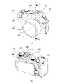
図1(a)は本発明の撮像装置の第1の実施形態に係るデジタルカメラの正面斜視図、図1(b)は図1(a)に示すデジタルカメラの背面斜視図である。
(First Embodiment)
1 (a) is a front perspective view of the digital camera according to the first embodiment of the image pickup apparatus of the present invention, and FIG. 1 (b) is a rear perspective view of the digital camera shown in FIG. 1 (a).
本実施形態のデジタルカメラは、図1に示すように、カメラ本体101の正面側には、レンズ鏡筒201が装着され、かかる装着状態においては、マウント接点群(不図示)を介してカメラ本体101とレンズ鏡筒201とは電気的に接続される。カメラ本体101の上面は、上面カバー301により覆われている。上面カバー301は、導電樹脂などの導電部材で形成され、不要ノイズの放射や、外来ノイズによるカメラ本体101への影響を抑制する。上面カバー301は、本発明の第2の筐体の一例に相当する。
In the digital camera of the present embodiment, as shown in FIG. 1, a
アンテナカバー302は、後述する無線モジュール501を覆う。アンテナカバー302は、ポリカーボネート等の非導電部材で形成されている。これにより、無線電波を透過し、無線通信ネットワークに接続された外部装置(例えばパーソナルコンピュータ)と無線モジュール501との通信を可能とする。アクセサリシュー303は、ストロボ装置等の撮影に使用するアクセサリーをカメラ本体101に取り付ける部分である。
The
グリップ130は、ユーザが手でカメラ本体101を保持する把持部である。操作ボタン120は、撮影動作を開始させるために、ユーザにより押圧操作される。電子ビューファインダ(以下、EVFという。)401は、ユーザが被写体像を観察するための表示部である。
The
図2は、図1に示すデジタルカメラのシステム構成を示すブロック図である。図2において、CPU(中央演算処理装置)102は、カメラ本体101全体の制御を司り、各要素に対して様々な処理や指示を実行する。主基板150は、CPU102等を構成するための様々な部品が実装されている。電源114は、カメラ本体101内の回路各部に電力を供給する。
FIG. 2 is a block diagram showing a system configuration of the digital camera shown in FIG. In FIG. 2, the CPU (Central Processing Unit) 102 controls the
撮像センサ110は、CCDセンサやCMOSセンサ等により構成され、レンズ鏡筒201の撮影光学系を介して取り込まれた被写体の光学像を画像信号に変換する。撮像センサ110により得られた画像信号は、画像処理部111によって画像データに変換され、CPU102に出力される。
The
レンズ鏡筒201は、フォーカスレンズ202等の複数のレンズ、及び絞り(不図示)等で構成されている。光学系制御部203は、CPU102からマウント接点群を介して入力された信号に基づいて、フォーカスレンズ202と絞りを駆動し、レンズ鏡筒201の焦点とカメラ本体101内に入射する光量を調節する。
The
レンズ鏡筒201と撮像センサ110の間には、撮像センサ110の露光時間を調整するシャッタ112が配置されている。シャッタ制御部113は、CPU102から入力された信号に基づいて、シャッタ112を駆動する。撮影ボタン120は、ユーザにより押圧操作されると、操作検出部121がそれを検知して検知信号をCPU102に出力し、撮影が開始される。
A
EVF401は、有機ELパネル等の表示パネル402を有し、表示制御部140は、撮影情報や撮像センサ110から取得した画像を表示パネル402に表示する。無線モジュール501は、外部装置に無線通信で画像の転送等を行うことができる。無線モジュール501は、本発明の無線通信手段の一例に相当する。
The EVF 401 has a
次に、図3及び図4を参照して、EVF401で発生した熱をカメラ本体101内部に拡散させる方法について説明する。図3(a)はEVF401の背面分解斜視図、図3(b)はEVF401の正面分解斜視図である。
Next, a method of diffusing the heat generated in the EVF 401 inside the
図3に示すように、表示パネル402には、FPC等の接続部材403が接着されており、接続部材403は、主基板150に実装されたコネクタ(不図示)に接続される。EVFホルダ404には、不図示の光学レンズが収納され、ユーザは表示パネル402の正面の画像表示部402aに表示される画像を光学レンズを介して観察することができる。EVFホルダ404には、表示パネル402を収納して保持する収納部404aが設けられている。
As shown in FIG. 3, a connecting
表示パネル402は、自己発熱が高く長時間連続で使用すると、動作保証温度を超えてしまう可能性があるため、放熱構造を設ける必要がある。そのため、表示パネル402の背面402bには、熱伝導率が高い金属板等で形成される第1の放熱部材406が弾性部材405を介して接続される。
Since the
表示パネル402の背面402bと第1の放熱部材406で弾性部材405を挟むことで、表示パネル402と第1の放熱部材406の間に熱伝導率が低い空気層が無くなる。これにより、表示パネル402で生じた熱を第1の放熱部材406に拡散しやすくすることができるため、弾性部材405は、熱伝導率が高い材質であることが好ましい。第1の放熱部材406は、ビス601a,601bによってEVFホルダ404に締結される。
By sandwiching the
図4は、上面カバー301とEVF401との接続を説明する分解斜視図である。図4において、第2の放熱部材304は、熱伝導率が高い金属板等で形成され、ビス602a,602bによって上面カバー301に締結される。EVF401は、ビス603a,603bによって上面カバー301に締結される。
FIG. 4 is an exploded perspective view illustrating the connection between the
このとき、上面カバー301とEVF401の間に第2の放熱部材304が配置され、第2の放熱部材304は、第1の放熱部材406と当接する。これにより、表示パネル402で生じた熱を弾性部材405、第1の放熱部材406及び第2の放熱部材304を介して上面カバー301に拡散することができる。
At this time, the second
ユーザがカメラ本体101を使用する際、図5に示すようにデジタルカメラを把持するため、ユーザが把持しない上面カバー301側に熱を拡散することで、表示パネル402で生じた熱を放熱しやすくなり、放熱効率を高めることができる。
When the user uses the
次に、図6及び図7を参照して、無線モジュール501からの熱をカメラ本体101内部で拡散させるための方法について説明する。図6(a)は無線モジュール501の正面斜視図、図6(b)は無線モジュール501の背面斜視図である。なお、無線モジュール501は、WiFiモジュール、BLUETOOTH(登録商標)、GPS(GLOBAL POSITIONING SYSTEM)等のいずれの形態を採用しても良い。
Next, with reference to FIGS. 6 and 7, a method for diffusing the heat from the
図6に示すアンテナ502は、無線基板503の表面上に銅箔パターンで形成された、マイクロストリップアンテナである。無線IC504は、無線基板503に実装され、アンテナ502を介して外部装置から変調信号を受信したとき、復調信号に変換し、無線IC504から外部装置にデータを送信する際には、変調信号に変換し、送信する。コネクタ505は、無線基板503に実装され、FPC等の接続部材506を介して、無線モジュール501を主基板150に接続する。GND接地部(金属材料で形成されるグランド部)507は、無線基板503の表面に形成されるレジスト膜が除去されて導電パターンが露出しており、金めっき処理および防錆処理が施されている。
The
図7は、無線モジュール501の周辺の分解斜視図である。図7に示す本体構造体103はマグネシウム合金等の金属によって形成され、カメラ本体101の骨格となる。本体構造体103は、本発明の第1の筐体の一例に相当する。
FIG. 7 is an exploded perspective view of the periphery of the
無線モジュール501は、ビス604によって本体構造体103に締結され、無線モジュール501のGND接地部507は、本体構造体103の当接部103aと当接する。無線モジュール501は、自己発熱が高く長時間連続で使用すると、デバイスの動作保証温度を超えてしまう可能性がある。そのため、熱伝導率が高い金属の本体構造体103と無線モジュール501を締結することで、無線モジュール501で生じた熱をカメラ本体101全体に拡散することができる。
The
無線モジュール501は、EVF401よりも消費電力が大きいため、発熱量が多い。そのため、EVF401が接続される第2の放熱部材304よりも表面積が大きい本体構造体103に無線モジュール501を接続することで、優先的に無線モジュール501の熱を放熱し、動作保証温度を超えないようにすることが可能である。
Since the
また、無線モジュール501は、強い電界および磁界が発生しやすいため、周辺の導電部材や他の回路による電気ノイズの影響を受けやすい。そのため、導電率が高い金属の本体構造体103と、GND接地部507を当接させることにより、無線モジュール501のグランド接続を強固にし、無線性能を確保することができる。
Further, since the
一方、EVF401は、無線モジュール501よりも周辺の導電部材や他の回路基板の影響を受けにくい。そのため、EVF401が接続される第2の放熱部材304よりも体積が大きい本体構造体103に無線モジュール501を接続することで、優先的に無線モジュール501のグランド接続を強固にすることができる。
On the other hand, the
無線モジュール501は、接続部材506を介して主基板150に実装されているコネクタ152に接続される。主基板150のGND接地部(金属材料で形成されるグランド部)151a~151dは、主基板150の表面に形成されるレジスト膜が除去され、導電パターンが露出しており、金めっき処理および防錆処理が施されている。
The
主基板150は、ビス605a~605dによって本体構造体103に締結され、主基板150のGND接地部151a~151dと本体構造体103は当接する。これにより、無線モジュール501のGND接地部507と主基板150のGND接地部151a~151dは、いずれも本体構造体103に接続されるため、無線モジュール501の電位を主基板150と同電位にすることができる。その結果、無線モジュール501のグランドとCPU102のグランドを強固に接続することができ、無線性能を確保することが可能である。
The
このとき、無線モジュール501のアンテナ502は、本体構造体103の当接部の端103bに重ならないように配置する。アンテナ502を導電部材である本体構造体103から遠ざけることで、無線性能の著しい低下を抑えることが可能である。
At this time, the
このように、無線モジュール501を本体構造体103に締結することで、無線モジュール501の熱対策、及び無線性能を確保することが可能である。また、本体構造体103のみで無線モジュール501の固定、熱対策、グランド強化を行うことができるため、部品点数を抑えることができる。
By fastening the
図8は、本体構造体103と上面カバー301の接続を説明する分解斜視図である。図8に示すように、アンテナカバー302は、ビス606a~606dによって上面カバー301に締結される。上面カバー301は、ビス607によって上面カバー301の締結部301aと本体構造体103の締結部103cに締結される。上面カバー301は、導電部材なので、上面及び正面(レンズ鏡筒201側)から見て、無線モジュール501のアンテナ502に上面カバー301が投影上に重ならないようにすることで、無線性能を確保することができる。
FIG. 8 is an exploded perspective view illustrating the connection between the
図8において、光軸方向をZ軸、上下方向をY軸とし、Y、Z軸と垂直な方向をX軸とすると、無線モジュール501の放熱経路となる本体構造体103は、光軸中心に対し、X軸方向のプラス側で上面カバー301の締結部301aと締結される。一方、EVF401については、図4に示すように、EVF401の放熱経路となる第2の放熱部材304は、光軸中心に対し、X軸方向のマイナス側(グリップ130側)で上面カバー301と締結される。これにより、EVF401と無線モジュール501の放熱経路を、光軸中心に対し、X軸方向で遠ざけることができ、それぞれの放熱効果を高めることが可能である。
In FIG. 8, when the optical axis direction is the Z axis, the vertical direction is the Y axis, and the direction perpendicular to the Y and Z axes is the X axis, the
図9は、図1(a)のA-A線断面図である。図9に示すように、EVF401の前面(図の左面)に重畳するように無線モジュール501を配置し、無線モジュール501をアクセサリシュー303の天面303aより本体構造体103側に配置する。これにより、カメラ本体101を大型化することなく、無線モジュール501を配置することができる。
FIG. 9 is a cross-sectional view taken along the line AA of FIG. 1 (a). As shown in FIG. 9, the
本実施形態では、無線モジュール501をEVF401の前面に配置しているが、アクセサリシュー303の天面303aより本体構造体103側、かつ上面から見てアクセサリシュー303と重畳しなければ、EVF401の上面に重畳して配置してもよい。
In the present embodiment, the
また、無線モジュール501をEVF401に対し、本体構造体103を挟んで反対側に配置することで、無線モジュール501は導電部材の本体構造体103より非導電部材のアンテナカバー302側に配置されるため、無線性能を確保することができる。
Further, by arranging the
以上説明したように、本実施形態では、EVF401を搭載するデジタルカメラで筐体が熱くなることを抑制し、かつ電気ノイズを抑制し省スペースで無線モジュール501のアンテナ502を配置することができる
(第2の実施形態)
次に、図10乃至図12を参照して、本発明の撮像装置の第2の実施形態に係るデジタルカメラについて説明する。本実施形態では、上記第1の実施形態に対して重複する部分については、各図に同一符号を付し、主に相違点について説明する。上記第1の実施形態では、上面カバー301の材質が金属に比べ熱伝導率と導電性が低い樹脂の場合を例示したが、本実施形態では、上面カバー701の材質が金属製の場合を例に採る。
As described above, in the present embodiment, it is possible to suppress the housing from becoming hot in the digital camera equipped with the
Next, the digital camera according to the second embodiment of the image pickup apparatus of the present invention will be described with reference to FIGS. 10 to 12. In the present embodiment, the same reference numerals are given to the parts that overlap with the first embodiment, and the differences will be mainly described. In the first embodiment, the case where the material of the
図10は、金属製の上面カバー701と無線モジュール501の関係を説明する分解斜視図である。上面カバー701は、たとえばマグネシウム合金などの熱伝導率の高い金属材料で形成される。上面カバー701は、本発明の第1の筐体の一例に相当する。無線モジュール501は、熱伝導率が高い金属板等で形成される金属部材702にビス703で締結されている。金属部材702は、ビス704aで上面カバー701の体積が大きい光軸に対して撮影ボタン120側(図の左側)に直接接続され、無線モジュール501を上面カバー701に優先的にグランド接続する。これにより、無線モジュール501のグランド接続を強固することができる。
FIG. 10 is an exploded perspective view illustrating the relationship between the metal
このように、本実施形態では、無線モジュール501の熱を上面カバー701の体積が大きい側へ拡散させる。このため、金属部材702は、モールド部材706にビス705で締結され、モールド部材706を介して上面カバー701の体積が小さい光軸に対して撮影ボタン120とは反対側にビス707a~707cで締結される。非導電樹脂で形成されるアンテナカバー302は、上面カバー701にビス704a~704dで締結される。
As described above, in the present embodiment, the heat of the
図11は、本体構造体103とEVF401と上面カバー701との接続を説明する分解斜視図である。図11に示すように、上面カバー701は、ビス708a~708dで本体構造体103に締結されて電気的に導通し、グランド接続される。EVF401は、高い熱伝導性を有する弾性部材405を介して本体構造体103に熱的に接続され、発生した熱が放熱される。
FIG. 11 is an exploded perspective view illustrating the connection between the
本実施形態では、上記第1の実施形態の第1の放熱部材406は不要であり、本体構造体(本体シャーシ)103が本発明の第2の筐体の一例に相当し、優先的に本体構造体103に放熱して熱を拡散することができる。EVF401は、発熱しないEVFホルダ404が上面カバー701の背面部701aにビス710a~710cで締結される。
In the present embodiment, the first
図12(a)は無線モジュール501の周辺の要部断面図、図12(b)は図12(a)の状態から非導電樹脂のアンテナカバー302を取り外した状態を示す要部断面図である。
FIG. 12 (a) is a cross-sectional view of a main part around the
図12を参照して、無線モジュール501の発熱しないコネクタ(接続端子)505をEVF401の上面に重畳するように配置し、無線モジュール501の発熱する無線IC(通信制御部)504を上面カバー701のアクセサリシュー303の内面側に配置する。また、上述したように、EVF401の熱は、弾性部材405を介して本体構造体103に放熱され、かつ無線モジュール501とEVF401の間に無線モジュール501が固定される金属部材702が配置される。
With reference to FIG. 12, the connector (connection terminal) 505 that does not generate heat of the
これにより、無線モジュール501の熱を優先的に上面カバー701に放熱しつつ、カメラ本体101を大型化することなく、無線モジュール501をEVF401に近接して配置することができる。また、無線モジュール501のアンテナ502は、図12(b)に示すように、金属材料である上面カバー701と本体構造体103の外側に突出配置されるため、アンテナ性能を確保することができる。その他の構成、及び作用効果は、上記第1の実施形態と同様である。
As a result, the
なお、本発明の構成は、上記各実施形態に例示したものに限定されるものではなく、材質、形状、寸法、形態、数、配置箇所等は、本発明の要旨を逸脱しない範囲において適宜変更可能である。 The configuration of the present invention is not limited to those exemplified in each of the above embodiments, and the material, shape, dimensions, form, number, arrangement location, etc. are appropriately changed as long as the gist of the present invention is not deviated. It is possible.
101 カメラ本体
103 本体構造体
110 撮像センサ
301 上面カバー
401 EVF
501 無線モジュール
502 アンテナ
501
Claims (3)
前記撮像手段により撮像された被写体の画像を表示する表示部を有する電子ビューファインダと、
無線通信が可能なアンテナ、通信制御部及び接続端子を有する無線通信手段と、
前記無線通信手段が熱的に接続される第1の筐体と、
前記第1の筐体とは異なる、前記電子ビューファインダが熱的に接続される第2の筐体と、を備え、
前記第1の筐体は、撮像装置の上面を覆う金属製のカバーであり、前記第2の筐体は、金属製の本体シャーシであり、前記第1の筐体と前記第2の筐体は電気的に導通するように接続され、
前記通信制御部と前記接続端子は、前記第1の筐体の内面側に配置されるとともに前記接続端子が前記電子ビューファインダの上面に重畳して配置され、前記アンテナは、前記第1の筐体から突出して配置されることを特徴とする撮像装置。 Imaging means and
An electronic viewfinder having a display unit for displaying an image of a subject captured by the imaging means, and an electronic viewfinder.
A wireless communication means having an antenna capable of wireless communication, a communication control unit, and a connection terminal,
The first housing to which the wireless communication means is thermally connected and
A second housing, which is different from the first housing and to which the electronic viewfinder is thermally connected, is provided.
The first housing is a metal cover that covers the upper surface of the image pickup apparatus, and the second housing is a metal main body chassis, that is, the first housing and the second housing. Are connected to be electrically conductive and
The communication control unit and the connection terminal are arranged on the inner surface side of the first housing, and the connection terminal is arranged so as to be superimposed on the upper surface of the electronic viewfinder, and the antenna is the first housing. An image pickup device characterized in that it is arranged so as to project from the body.
Priority Applications (3)
| Application Number | Priority Date | Filing Date | Title |
|---|---|---|---|
| JP2018084280A JP7073182B2 (en) | 2018-04-25 | 2018-04-25 | Imaging device |
| US16/388,941 US10951796B2 (en) | 2018-04-25 | 2019-04-19 | Image pickup apparatus including thermally isolated radio antenna and thermally isolated electronic viewfinder |
| CN201910335206.2A CN110401785B (en) | 2018-04-25 | 2019-04-24 | Image pickup apparatus including radio antenna |
Applications Claiming Priority (1)
| Application Number | Priority Date | Filing Date | Title |
|---|---|---|---|
| JP2018084280A JP7073182B2 (en) | 2018-04-25 | 2018-04-25 | Imaging device |
Publications (3)
| Publication Number | Publication Date |
|---|---|
| JP2019191374A JP2019191374A (en) | 2019-10-31 |
| JP2019191374A5 JP2019191374A5 (en) | 2021-05-13 |
| JP7073182B2 true JP7073182B2 (en) | 2022-05-23 |
Family
ID=68291720
Family Applications (1)
| Application Number | Title | Priority Date | Filing Date |
|---|---|---|---|
| JP2018084280A Active JP7073182B2 (en) | 2018-04-25 | 2018-04-25 | Imaging device |
Country Status (3)
| Country | Link |
|---|---|
| US (1) | US10951796B2 (en) |
| JP (1) | JP7073182B2 (en) |
| CN (1) | CN110401785B (en) |
Families Citing this family (7)
| Publication number | Priority date | Publication date | Assignee | Title |
|---|---|---|---|---|
| JP7395343B2 (en) * | 2019-12-25 | 2023-12-11 | キヤノン株式会社 | Imaging device |
| JPWO2021181926A1 (en) * | 2020-03-13 | 2021-09-16 | ||
| JP7414628B2 (en) * | 2020-04-22 | 2024-01-16 | キヤノン株式会社 | Imaging device |
| JP7443146B2 (en) | 2020-04-27 | 2024-03-05 | キヤノン株式会社 | Imaging device |
| JP2022124751A (en) * | 2021-02-16 | 2022-08-26 | キヤノン株式会社 | Electronic apparatus and external unit |
| CN113315893B (en) * | 2021-05-17 | 2023-10-27 | 杭州海康威视数字技术股份有限公司 | Video camera and video apparatus |
| JP2023021774A (en) * | 2021-08-02 | 2023-02-14 | パナソニックIpマネジメント株式会社 | Imaging apparatus |
Citations (3)
| Publication number | Priority date | Publication date | Assignee | Title |
|---|---|---|---|---|
| JP2004104168A (en) | 2002-09-04 | 2004-04-02 | Canon Inc | Imaging apparatus and imaging system |
| JP2015012476A (en) | 2013-06-28 | 2015-01-19 | 株式会社ニコン | Display device, electronic view finder, and camera |
| JP2017111218A (en) | 2015-12-15 | 2017-06-22 | キヤノン株式会社 | Imaging device |
Family Cites Families (20)
| Publication number | Priority date | Publication date | Assignee | Title |
|---|---|---|---|---|
| JP4633605B2 (en) * | 2005-01-31 | 2011-02-16 | 富士通コンポーネント株式会社 | ANTENNA DEVICE AND ELECTRONIC DEVICE, ELECTRONIC CAMERA, ELECTRONIC CAMERA LIGHT EMITTING DEVICE, AND PERIPHERAL DEVICE |
| WO2008023894A1 (en) * | 2006-08-22 | 2008-02-28 | Lg Innotek Co., Ltd | Camera module |
| SE535818C2 (en) * | 2011-05-26 | 2013-01-02 | Stanley Wissmar | A mobile wristwatch comprising several electrical and micromechanical components that act as a central unit for a variety of tasks |
| JP5221824B1 (en) * | 2011-07-01 | 2013-06-26 | パナソニック株式会社 | Imaging device |
| US8712233B2 (en) * | 2012-02-24 | 2014-04-29 | Apple Inc. | Electronic device assemblies |
| CN103337223B (en) * | 2013-05-02 | 2016-02-03 | 友达光电股份有限公司 | Display module, electronic installation and be applied to the method for display module |
| JP6147076B2 (en) | 2013-05-09 | 2017-06-14 | オリンパス株式会社 | Imaging apparatus, imaging method, and program |
| US9432561B2 (en) * | 2013-08-13 | 2016-08-30 | Gopro, Inc. | Camera heat sink |
| US20150195442A1 (en) * | 2014-01-03 | 2015-07-09 | Lyve Minds, Inc. | Modular camera core control |
| KR102152924B1 (en) * | 2014-05-28 | 2020-09-07 | 삼성전자주식회사 | Antenna by Using Conductor and Device |
| KR101707662B1 (en) * | 2014-07-08 | 2017-02-21 | 주식회사 케이엠더블유 | LED lighting device with camera |
| US9661197B2 (en) * | 2014-10-22 | 2017-05-23 | Gopro, Inc. | Quick-release ball-and-socket joint camera mount |
| CN204697157U (en) * | 2015-06-16 | 2015-10-07 | 成都西可科技有限公司 | A kind of radiator structure of moving camera |
| US9674986B2 (en) * | 2015-08-03 | 2017-06-06 | Apple Inc. | Parallel heat spreader |
| US10133158B2 (en) * | 2016-10-17 | 2018-11-20 | Panasonic Intellectual Property Management Co., Ltd. | Imaging device |
| KR102269525B1 (en) * | 2017-03-13 | 2021-06-28 | 삼성전자주식회사 | electronic device of slim type and manufacturing method thereof |
| KR102265616B1 (en) * | 2017-04-26 | 2021-06-16 | 삼성전자 주식회사 | Antenna apparatus and electronic device including the same |
| CN107135346B (en) * | 2017-06-30 | 2023-03-24 | 深圳市欢太科技有限公司 | Imaging device assembly and electronic device |
| US10141625B1 (en) * | 2017-07-13 | 2018-11-27 | Lg Electronics Inc. | Mobile terminal |
| US10581153B2 (en) * | 2017-09-11 | 2020-03-03 | Apple Inc. | Electronic device antennas including conductive display structures |
-
2018
- 2018-04-25 JP JP2018084280A patent/JP7073182B2/en active Active
-
2019
- 2019-04-19 US US16/388,941 patent/US10951796B2/en active Active
- 2019-04-24 CN CN201910335206.2A patent/CN110401785B/en active Active
Patent Citations (3)
| Publication number | Priority date | Publication date | Assignee | Title |
|---|---|---|---|---|
| JP2004104168A (en) | 2002-09-04 | 2004-04-02 | Canon Inc | Imaging apparatus and imaging system |
| JP2015012476A (en) | 2013-06-28 | 2015-01-19 | 株式会社ニコン | Display device, electronic view finder, and camera |
| JP2017111218A (en) | 2015-12-15 | 2017-06-22 | キヤノン株式会社 | Imaging device |
Also Published As
| Publication number | Publication date |
|---|---|
| CN110401785A (en) | 2019-11-01 |
| JP2019191374A (en) | 2019-10-31 |
| CN110401785B (en) | 2021-09-21 |
| US10951796B2 (en) | 2021-03-16 |
| US20190335075A1 (en) | 2019-10-31 |
Similar Documents
| Publication | Publication Date | Title |
|---|---|---|
| JP7073182B2 (en) | Imaging device | |
| US10133158B2 (en) | Imaging device | |
| JP4083521B2 (en) | Imaging device | |
| JP2007049369A (en) | Holding structure of image sensor package, and lens unit | |
| JP6529276B2 (en) | Imaging device | |
| US9986137B2 (en) | Image pickup apparatus | |
| JP2006086752A (en) | Lens interchangeable camera integral with imaging element and interchangeable lens unit integral with imaging element | |
| US8736754B2 (en) | Imaging device | |
| JP5273296B2 (en) | Digital camera | |
| JP2007060237A (en) | Camera having wireless communication function | |
| JP2016019005A (en) | Imaging device | |
| JP6949686B2 (en) | Imaging device | |
| US8970752B2 (en) | Imaging device | |
| JP6861334B2 (en) | Imaging device | |
| JP5925053B2 (en) | Imaging device | |
| JP2010226227A (en) | Imaging apparatus | |
| JP2011146856A (en) | Imaging apparatus | |
| JP2009017464A (en) | Camera module and imaging unit | |
| JP2017199988A (en) | Shield case fixing method | |
| JP2002072341A (en) | Heat dissipating device | |
| JP2010239581A (en) | Imaging apparatus | |
| JP6471607B2 (en) | Electronics | |
| JP5092497B2 (en) | Digital camera with built-in projector and projector device | |
| JP2015004828A (en) | Imaging apparatus | |
| JP5805114B2 (en) | Imaging apparatus and electronic apparatus |
Legal Events
| Date | Code | Title | Description |
|---|---|---|---|
| A521 | Request for written amendment filed |
Free format text: JAPANESE INTERMEDIATE CODE: A523 Effective date: 20210330 |
|
| A621 | Written request for application examination |
Free format text: JAPANESE INTERMEDIATE CODE: A621 Effective date: 20210330 |
|
| A977 | Report on retrieval |
Free format text: JAPANESE INTERMEDIATE CODE: A971007 Effective date: 20211216 |
|
| A131 | Notification of reasons for refusal |
Free format text: JAPANESE INTERMEDIATE CODE: A131 Effective date: 20220111 |
|
| A521 | Request for written amendment filed |
Free format text: JAPANESE INTERMEDIATE CODE: A523 Effective date: 20220308 |
|
| TRDD | Decision of grant or rejection written | ||
| A01 | Written decision to grant a patent or to grant a registration (utility model) |
Free format text: JAPANESE INTERMEDIATE CODE: A01 Effective date: 20220412 |
|
| A61 | First payment of annual fees (during grant procedure) |
Free format text: JAPANESE INTERMEDIATE CODE: A61 Effective date: 20220511 |
|
| R151 | Written notification of patent or utility model registration |
Ref document number: 7073182 Country of ref document: JP Free format text: JAPANESE INTERMEDIATE CODE: R151 |