JP7071309B2 - Cartridge and image forming equipment - Google Patents

Cartridge and image forming equipment Download PDF

Info

Publication number
JP7071309B2
JP7071309B2 JP2019086876A JP2019086876A JP7071309B2 JP 7071309 B2 JP7071309 B2 JP 7071309B2 JP 2019086876 A JP2019086876 A JP 2019086876A JP 2019086876 A JP2019086876 A JP 2019086876A JP 7071309 B2 JP7071309 B2 JP 7071309B2
Authority
JP
Japan
Prior art keywords
developing
main body
unit
drum
cartridge
Prior art date
Legal status (The legal status is an assumption and is not a legal conclusion. Google has not performed a legal analysis and makes no representation as to the accuracy of the status listed.)
Active
Application number
JP2019086876A
Other languages
Japanese (ja)
Other versions
JP2020183983A (en
JP2020183983A5 (en
Inventor
範行 小松
磨佐基 尾島
大輔 阿部
友紀 森
忠之 津田
哲哉 沼田
直哉 浅沼
Current Assignee (The listed assignees may be inaccurate. Google has not performed a legal analysis and makes no representation or warranty as to the accuracy of the list.)
Canon Inc
Original Assignee
Canon Inc
Priority date (The priority date is an assumption and is not a legal conclusion. Google has not performed a legal analysis and makes no representation as to the accuracy of the date listed.)
Filing date
Publication date
Family has litigation
First worldwide family litigation filed litigation Critical https://patents.darts-ip.com/?family=72916741&utm_source=google_patent&utm_medium=platform_link&utm_campaign=public_patent_search&patent=JP7071309(B2) "Global patent litigation dataset” by Darts-ip is licensed under a Creative Commons Attribution 4.0 International License.
Application filed by Canon Inc filed Critical Canon Inc
Priority to JP2019086876A priority Critical patent/JP7071309B2/en
Priority to US16/853,212 priority patent/US11209773B2/en
Publication of JP2020183983A publication Critical patent/JP2020183983A/en
Priority to US17/531,080 priority patent/US11733644B2/en
Publication of JP2020183983A5 publication Critical patent/JP2020183983A5/ja
Priority to JP2022073383A priority patent/JP7362829B2/en
Publication of JP7071309B2 publication Critical patent/JP7071309B2/en
Application granted granted Critical
Priority to US18/347,847 priority patent/US20230350339A1/en
Priority to JP2023129116A priority patent/JP7408876B2/en
Priority to JP2023213588A priority patent/JP2024019611A/en
Active legal-status Critical Current
Anticipated expiration legal-status Critical

Links

Images

Classifications

    • GPHYSICS
    • G03PHOTOGRAPHY; CINEMATOGRAPHY; ANALOGOUS TECHNIQUES USING WAVES OTHER THAN OPTICAL WAVES; ELECTROGRAPHY; HOLOGRAPHY
    • G03GELECTROGRAPHY; ELECTROPHOTOGRAPHY; MAGNETOGRAPHY
    • G03G21/00Arrangements not provided for by groups G03G13/00 - G03G19/00, e.g. cleaning, elimination of residual charge
    • G03G21/16Mechanical means for facilitating the maintenance of the apparatus, e.g. modular arrangements
    • G03G21/18Mechanical means for facilitating the maintenance of the apparatus, e.g. modular arrangements using a processing cartridge, whereby the process cartridge comprises at least two image processing means in a single unit
    • G03G21/1803Arrangements or disposition of the complete process cartridge or parts thereof
    • G03G21/1814Details of parts of process cartridge, e.g. for charging, transfer, cleaning, developing
    • GPHYSICS
    • G03PHOTOGRAPHY; CINEMATOGRAPHY; ANALOGOUS TECHNIQUES USING WAVES OTHER THAN OPTICAL WAVES; ELECTROGRAPHY; HOLOGRAPHY
    • G03GELECTROGRAPHY; ELECTROPHOTOGRAPHY; MAGNETOGRAPHY
    • G03G21/00Arrangements not provided for by groups G03G13/00 - G03G19/00, e.g. cleaning, elimination of residual charge
    • G03G21/0005Arrangements not provided for by groups G03G13/00 - G03G19/00, e.g. cleaning, elimination of residual charge for removing solid developer or debris from the electrographic recording medium
    • GPHYSICS
    • G03PHOTOGRAPHY; CINEMATOGRAPHY; ANALOGOUS TECHNIQUES USING WAVES OTHER THAN OPTICAL WAVES; ELECTROGRAPHY; HOLOGRAPHY
    • G03GELECTROGRAPHY; ELECTROPHOTOGRAPHY; MAGNETOGRAPHY
    • G03G21/00Arrangements not provided for by groups G03G13/00 - G03G19/00, e.g. cleaning, elimination of residual charge
    • G03G21/10Collecting or recycling waste developer
    • GPHYSICS
    • G03PHOTOGRAPHY; CINEMATOGRAPHY; ANALOGOUS TECHNIQUES USING WAVES OTHER THAN OPTICAL WAVES; ELECTROGRAPHY; HOLOGRAPHY
    • G03GELECTROGRAPHY; ELECTROPHOTOGRAPHY; MAGNETOGRAPHY
    • G03G21/00Arrangements not provided for by groups G03G13/00 - G03G19/00, e.g. cleaning, elimination of residual charge
    • G03G21/16Mechanical means for facilitating the maintenance of the apparatus, e.g. modular arrangements
    • G03G21/1661Mechanical means for facilitating the maintenance of the apparatus, e.g. modular arrangements means for handling parts of the apparatus in the apparatus
    • G03G21/1671Mechanical means for facilitating the maintenance of the apparatus, e.g. modular arrangements means for handling parts of the apparatus in the apparatus for the photosensitive element
    • GPHYSICS
    • G03PHOTOGRAPHY; CINEMATOGRAPHY; ANALOGOUS TECHNIQUES USING WAVES OTHER THAN OPTICAL WAVES; ELECTROGRAPHY; HOLOGRAPHY
    • G03GELECTROGRAPHY; ELECTROPHOTOGRAPHY; MAGNETOGRAPHY
    • G03G21/00Arrangements not provided for by groups G03G13/00 - G03G19/00, e.g. cleaning, elimination of residual charge
    • G03G21/16Mechanical means for facilitating the maintenance of the apparatus, e.g. modular arrangements
    • G03G21/18Mechanical means for facilitating the maintenance of the apparatus, e.g. modular arrangements using a processing cartridge, whereby the process cartridge comprises at least two image processing means in a single unit
    • G03G21/1803Arrangements or disposition of the complete process cartridge or parts thereof
    • G03G21/1817Arrangements or disposition of the complete process cartridge or parts thereof having a submodular arrangement
    • G03G21/1821Arrangements or disposition of the complete process cartridge or parts thereof having a submodular arrangement means for connecting the different parts of the process cartridge, e.g. attachment, positioning of parts with each other, pressure/distance regulation
    • GPHYSICS
    • G03PHOTOGRAPHY; CINEMATOGRAPHY; ANALOGOUS TECHNIQUES USING WAVES OTHER THAN OPTICAL WAVES; ELECTROGRAPHY; HOLOGRAPHY
    • G03GELECTROGRAPHY; ELECTROPHOTOGRAPHY; MAGNETOGRAPHY
    • G03G21/00Arrangements not provided for by groups G03G13/00 - G03G19/00, e.g. cleaning, elimination of residual charge
    • G03G21/16Mechanical means for facilitating the maintenance of the apparatus, e.g. modular arrangements
    • G03G21/18Mechanical means for facilitating the maintenance of the apparatus, e.g. modular arrangements using a processing cartridge, whereby the process cartridge comprises at least two image processing means in a single unit
    • G03G21/1839Means for handling the process cartridge in the apparatus body
    • G03G21/1842Means for handling the process cartridge in the apparatus body for guiding and mounting the process cartridge, positioning, alignment, locks
    • G03G21/1853Means for handling the process cartridge in the apparatus body for guiding and mounting the process cartridge, positioning, alignment, locks the process cartridge being mounted perpendicular to the axis of the photosensitive member
    • GPHYSICS
    • G03PHOTOGRAPHY; CINEMATOGRAPHY; ANALOGOUS TECHNIQUES USING WAVES OTHER THAN OPTICAL WAVES; ELECTROGRAPHY; HOLOGRAPHY
    • G03GELECTROGRAPHY; ELECTROPHOTOGRAPHY; MAGNETOGRAPHY
    • G03G21/00Arrangements not provided for by groups G03G13/00 - G03G19/00, e.g. cleaning, elimination of residual charge
    • G03G21/16Mechanical means for facilitating the maintenance of the apparatus, e.g. modular arrangements
    • G03G21/18Mechanical means for facilitating the maintenance of the apparatus, e.g. modular arrangements using a processing cartridge, whereby the process cartridge comprises at least two image processing means in a single unit
    • G03G21/1839Means for handling the process cartridge in the apparatus body
    • G03G21/1857Means for handling the process cartridge in the apparatus body for transmitting mechanical drive power to the process cartridge, drive mechanisms, gears, couplings, braking mechanisms
    • G03G21/1864Means for handling the process cartridge in the apparatus body for transmitting mechanical drive power to the process cartridge, drive mechanisms, gears, couplings, braking mechanisms associated with a positioning function
    • GPHYSICS
    • G03PHOTOGRAPHY; CINEMATOGRAPHY; ANALOGOUS TECHNIQUES USING WAVES OTHER THAN OPTICAL WAVES; ELECTROGRAPHY; HOLOGRAPHY
    • G03GELECTROGRAPHY; ELECTROPHOTOGRAPHY; MAGNETOGRAPHY
    • G03G21/00Arrangements not provided for by groups G03G13/00 - G03G19/00, e.g. cleaning, elimination of residual charge
    • G03G21/16Mechanical means for facilitating the maintenance of the apparatus, e.g. modular arrangements
    • G03G21/18Mechanical means for facilitating the maintenance of the apparatus, e.g. modular arrangements using a processing cartridge, whereby the process cartridge comprises at least two image processing means in a single unit
    • G03G21/1875Mechanical means for facilitating the maintenance of the apparatus, e.g. modular arrangements using a processing cartridge, whereby the process cartridge comprises at least two image processing means in a single unit provided with identifying means or means for storing process- or use parameters, e.g. lifetime of the cartridge
    • G03G21/1878Electronically readable memory

Description

本発明は、ドラムユニットに対して現像ユニットが着脱可能に構成されたカートリッジ及び画像形成装置に関する。 The present invention relates to a cartridge and an image forming apparatus in which a developing unit is detachably configured with respect to a drum unit.

従来、メモリ手段を有する現像カートリッジを感光体カートリッジに対して着脱可能に設けられたプロセスカートリッジが提案されている(特許文献1参照)。この感光体カートリッジには、装置本体側の電気接点部と電気的に接続する第一の電気接点部と、上記メモリ手段と電気的に接続する第二の電気接点部と、が設けられている。そして、メモリ手段は、これら第一及び第二の電気接点部を介して、装置本体側に設けられた制御部と通信するように構成されている。 Conventionally, a process cartridge in which a developing cartridge having a memory means is detachably provided with respect to a photoconductor cartridge has been proposed (see Patent Document 1). The photoconductor cartridge is provided with a first electrical contact portion that is electrically connected to the electrical contact portion on the device main body side and a second electrical contact portion that is electrically connected to the memory means. .. The memory means is configured to communicate with the control unit provided on the main body side of the device via the first and second electric contact units.

特開2016-224221号公報Japanese Unexamined Patent Publication No. 2016-224221

上記特許文献1記載のように、感光体カートリッジのフレームに対して着脱可能な現像カートリッジにメモリ手段を備えている場合、このメモリ手段を装置本体側の電気接点部に直接接触させる構成が考えられる。この場合、フレームにメモリを露出させるための孔を設ける必要がある。 As described in Patent Document 1, when the developing cartridge that can be attached to and detached from the frame of the photoconductor cartridge is provided with a memory means, a configuration is conceivable in which the memory means is brought into direct contact with the electric contact portion on the device main body side. .. In this case, it is necessary to provide a hole in the frame for exposing the memory.

しかしながら、フレームに孔を設けることでフレームの強度が低下するという課題がある。 However, there is a problem that the strength of the frame is lowered by providing the holes in the frame.

そこで、本発明は、メモリ手段を露出させるための孔を有するフレームの強度低下を抑制する構成を備えるカートリッジ及び画像形成装置を提供することを目的とする。 Therefore, an object of the present invention is to provide a cartridge and an image forming apparatus having a structure for suppressing a decrease in strength of a frame having a hole for exposing a memory means.

本発明の一態様は、画像形成装置の装置本体に着脱可能なカートリッジであって、トナーを収容可能なトナー収容部が設けられた現像フレームと、第1方向に延びる回転軸線を中心に回転可能な現像ローラと、前記第1方向において前記現像フレームの第1端部の側に位置する第1電極当接面を有する現像メモリと、を有する現像ユニットと、感光ドラムと、前記感光ドラムを支持するドラムフレームと、前記第1方向において前記現像フレームの前記第1端部と同じ側にある前記ドラムフレームの第2端部の側に位置する第2電極当接面を有するドラムメモリと、を有し、前記現像ユニットが着脱可能なドラムユニットと、を備え、前記現像ユニットが前記ドラムユニットに装着された装着状態において、 前記第1電極当接面は、前記第1方向と交差する第2方向において、前記現像ローラと前記第2電極当接面の間に位置し、前記第1電極当接面及び前記第2電極当接面は、前記第1方向と前記第2方向の双方に交差する第3方向を向いていることを特徴とするカートリッジである。
また、本発明の他の一態様は、カートリッジと、前記カートリッジが着脱可能な装置本体と、を備える画像形成装置であって、前記カートリッジは、現像ユニットと、前記現像ユニットが着脱可能なドラムユニットと、を有し、前記現像ユニットは、トナーを収容可能なトナー収容部が設けられた現像フレームと、第1方向に延びる回転軸線を中心に回転可能な現像ローラと、前記第1方向における前記現像フレームの第1端部の側に位置する第1カートリッジ電極当接面を有する現像メモリと、を有し、前記ドラムユニットは、感光ドラムと、前記感光ドラムを支持するドラムフレームと、前記第1方向において前記現像フレームの前記第1端部と同じ側にある前記ドラムフレームの第2端部の側に位置する第2カートリッジ電極当接面を有するドラムメモリと、を有し、前記第1カートリッジ電極当接面は、前記第1方向と交差する第2方向において、前記現像ローラと前記第2カートリッジ電極当接面の間に位置し、前記装置本体は、前記第1方向と前記第2方向との双方に交差する第3方向を向いた第1本体電極当接面を有する第1本体電気接点と、前記第3方向を向いた第2本体電極当接面を有する第2本体電気接点と、を有し、前記現像ユニットが前記ドラムユニットに装着された前記カートリッジが前記装置本体に装着された装着状態において、前記第1カートリッジ電極当接面及び前記第2カートリッジ電極当接面はそれぞれ、第1本体電極当接面及び第2本体電極当接面と当接するように構成されていることを特徴とする画像形成装置である。
One aspect of the present invention is a cartridge that can be attached to and detached from the main body of the image forming apparatus, and can be rotated around a developing frame provided with a toner accommodating portion capable of accommodating toner and a rotation axis extending in the first direction. A developing unit having a developing roller and a developing memory having a first electrode contact surface located on the side of the first end of the developing frame in the first direction, a photosensitive drum, and the photosensitive drum are supported. A drum frame to be held, a drum memory having a second electrode contact surface located on the side of the second end of the drum frame on the same side as the first end of the developing frame in the first direction, and a drum memory. The first electrode contact surface is in a second direction intersecting the first direction in a mounted state in which the developing unit is attached to the drum unit . Located between the developing roller and the second electrode contact surface, the first electrode contact surface and the second electrode contact surface intersect both the first direction and the second direction. It is a cartridge characterized in that it faces the third direction .
Further, another aspect of the present invention is an image forming apparatus including a cartridge and a device main body to which the cartridge can be attached and detached, wherein the cartridge includes a development unit and a drum unit to which the development unit can be attached and detached. The development unit includes a development frame provided with a toner accommodating portion capable of accommodating toner, a development roller rotatable about a rotation axis extending in the first direction, and the development in the first direction. It has a developing memory having a first cartridge electrode contact surface located on the side of the first end of the frame, and the drum unit includes a photosensitive drum, a drum frame that supports the photosensitive drum, and the first direction. The first cartridge electrode has a drum memory having a second cartridge electrode contact surface located on the same side as the first end portion of the development frame and on the side of the second end portion of the drum frame. The contact surface is located between the development roller and the second cartridge electrode contact surface in the second direction intersecting the first direction, and the apparatus main body is in the first direction and the second direction. A first main body electrical contact having a first main body electrode contact surface facing the third direction and a second main body electric contact having a second main body electrode contact surface facing the third direction. The first cartridge electrode contact surface and the second cartridge electrode contact surface are each in a mounted state in which the development unit is mounted on the drum unit and the cartridge is mounted on the apparatus main body. It is an image forming apparatus characterized in that it is configured to be in contact with the main body electrode contact surface and the second main body electrode contact surface.

本発明によると、感光ドラムの回転軸線方向において、メモリをフレームから露出させるための露出孔に対して凹部が隣接して設けられている。このため、ドラムユニットの露出孔周辺のフレーム強度を上げることができる。 According to the present invention, a recess is provided adjacent to an exposed hole for exposing the memory from the frame in the direction of the rotation axis of the photosensitive drum. Therefore, the frame strength around the exposed hole of the drum unit can be increased.

第1の実施の形態に係るプリンタを示す全体概略図。The whole schematic diagram which shows the printer which concerns on 1st Embodiment. ドラムユニット及び現像ユニットを示す斜視図。The perspective view which shows the drum unit and the developing unit. 現像ユニットを示す斜視図。The perspective view which shows the developing unit. 図3の4-4断面を示す断面図。FIG. 6 is a cross-sectional view showing a 4-4 cross section of FIG. 現像ユニットを示す分解斜視図。An exploded perspective view showing a developing unit. 現像ユニットを示す平面図。Top view showing the developing unit. (a)は未使用の現像ユニットを示す側面図。(b)は既に使用された現像ユニットを示す側面図。(A) is a side view showing an unused developing unit. (B) is a side view showing a developing unit that has already been used. 現像ユニットを示す底面図。Bottom view showing the developing unit. プロセスカートリッジを示す断面図。Sectional drawing which shows the process cartridge. プロセスカートリッジを示す斜視図。The perspective view which shows the process cartridge. プロセスカートリッジを示す斜視図。The perspective view which shows the process cartridge. ドラムユニット及び現像ユニットを示す平面図。The plan view which shows the drum unit and the developing unit. (a)は押圧部材及びリフト部材を示し、リフト部材を破線で表示した平面図。(b)は押圧部材及びリフト部材を示し、リフト部材を実線で表示した平面図。(A) is a plan view showing a pressing member and a lifting member, and the lifting member is shown by a broken line. (B) shows a pressing member and a lifting member, and is a plan view showing the lifting member by a solid line. (a)はドラムユニットの底面図。b)ドラムユニットの後部左端側を示す拡大図。(A) is a bottom view of the drum unit. b) An enlarged view showing the rear left end side of the drum unit. 押圧部材及びリフト部材を示す斜視図。The perspective view which shows the pressing member and the lifting member. (a)はドラムユニットに現像ユニットが装着された状態を示す断面図。(b)はリフト部材によってリフトアップ状態となった現像ユニットを示す断面図。(A) is a cross-sectional view showing a state in which a developing unit is mounted on a drum unit. (B) is a cross-sectional view showing a developing unit in a lift-up state due to a lift member. (a)はドラムユニットの後部左端側を示す拡大図。(b)は捕集凹部の断面図。(A) is an enlarged view showing the rear left end side of the drum unit. (B) is a cross-sectional view of the collection recess. 第2の実施の形態に係るプロセスカートリッジを示す斜視図。The perspective view which shows the process cartridge which concerns on 2nd Embodiment. プロセスカートリッジを示す斜視図。The perspective view which shows the process cartridge. プロセスカートリッジの底面図。Bottom view of the process cartridge. ドラムユニットの斜視図。Perspective view of the drum unit. ドラムユニットの後部左端側を示す拡大図。An enlarged view showing the rear left end side of the drum unit. ドラムユニットの後部左端側を示す平面図。The plan view which shows the rear left end side of a drum unit. ドラムユニットの後部左端側を示す平面図。The plan view which shows the rear left end side of a drum unit. 第3の実施の形態に係るプロセスカートリッジを示す底面図。The bottom view which shows the process cartridge which concerns on 3rd Embodiment. (a)は装置本体側の電極ユニットを示す模式図。(b)は装置本体側の電極ユニットを示す断面図。(A) is a schematic diagram showing an electrode unit on the device main body side. (B) is a cross-sectional view showing an electrode unit on the device main body side. (a)は現像ユニットがドラムユニットの装着方向へと移動している際の電極ユニットを示す断面図。(b)は現像ユニットがドラムユニットへと装着された状態の電極ユニットを示す断面図。(A) is a cross-sectional view showing an electrode unit when the developing unit is moving in the mounting direction of the drum unit. (B) is a cross-sectional view showing an electrode unit in a state where the developing unit is mounted on the drum unit. (a)は第4の実施の形態に係るドラムユニットを示す斜視図。(b)は(a)のドラムユニットを下方側から視た斜視図。(A) is a perspective view showing a drum unit according to a fourth embodiment. (B) is a perspective view of the drum unit of (a) as viewed from below. (a)は現像ユニットの斜視図。(b)は現像ユニットを下方側から視た斜視図。(A) is a perspective view of the developing unit. (B) is a perspective view of the developing unit as viewed from below. (a)はプロセスカートリッジを示す斜視図。(b)はプロセスカートリッジの断面図。(A) is a perspective view showing a process cartridge. (B) is a cross-sectional view of the process cartridge. プリンタを示す全体概略図。Overall schematic showing the printer. (a)は第5の実施の形態に係るドラムユニットを示す斜視図。(b)は(a)のドラムユニットを下方側から視た斜視図。(A) is a perspective view showing a drum unit according to a fifth embodiment. (B) is a perspective view of the drum unit of (a) as viewed from below. (a)は現像ユニットの斜視図。(b)は現像ユニットを下方側から視た斜視図。(A) is a perspective view of the developing unit. (B) is a perspective view of the developing unit as viewed from below. (a)はプロセスカートリッジを示す斜視図。(b)はプロセスカートリッジの断面図。(A) is a perspective view showing a process cartridge. (B) is a cross-sectional view of the process cartridge. 第6の実施の形態に係るプロセスカートリッジを示す断面図。The cross-sectional view which shows the process cartridge which concerns on 6th Embodiment. プロセスカートリッジが装置本体に装着された状態を示す模式図。The schematic diagram which shows the state which the process cartridge is attached to the apparatus main body. (a)はプロセスカートリッジを示す斜視図。(b)は(a)に示すプロセスカートリッジの後部左端側を示す拡大図。(A) is a perspective view showing a process cartridge. (B) is an enlarged view showing the rear left end side of the process cartridge shown in (a). (a)は現像ユニットを示す斜視図。(b)は(a)に示す現像ユニットの後部左端側を示す拡大図。(A) is a perspective view showing a developing unit. (B) is an enlarged view showing the rear left end side of the developing unit shown in (a). (a)はドラムユニットを示す斜視図。(b)は(a)に示すドラムユニットの後部左端側を示す拡大図。(A) is a perspective view showing a drum unit. (B) is an enlarged view showing the rear left end side of the drum unit shown in (a). (a)は装置本体の左方側のガイド構成を示す模式図。(b)はプロセスカートリッジの左方側を示す斜視図。(A) is a schematic diagram showing a guide configuration on the left side of the main body of the apparatus. (B) is a perspective view showing the left side of the process cartridge. (a)は装置本体の右方側のガイド構成を示す模式図。(b)はプロセスカートリッジの右方側を示す斜視図。(A) is a schematic diagram showing a guide configuration on the right side of the main body of the apparatus. (B) is a perspective view showing the right side of the process cartridge. 第1感光ドラムギヤの噛合構造を説明するための説明図。Explanatory drawing for demonstrating the meshing structure of the 1st photosensitive drum gear. 第1感光ドラムギヤによって生じるスラスト力の作用を説明するための説明図。The explanatory view for demonstrating the action of the thrust force generated by the 1st photosensitive drum gear. (a)は第7の実施の形態に係るドラムユニットを示す斜視図。(b)は(a)のドラムユニットの感光ドラム周りの構造を示す拡大図。(A) is a perspective view showing a drum unit according to a seventh embodiment. (B) is an enlarged view showing the structure around the photosensitive drum of the drum unit of (a). 感光ドラム周りの動力伝達構造を説明する組立図。An assembly drawing illustrating the power transmission structure around the photosensitive drum. (a)は第8の実施の形態に係るプロセスカートリッジを示す斜視図。(b)はプロセスカートリッジが装置本体に装着された状態を示す模式図。(A) is a perspective view which shows the process cartridge which concerns on 8th Embodiment. (B) is a schematic diagram showing a state in which the process cartridge is mounted on the main body of the apparatus. (a)は第9の実施の形態に係るプロセスカートリッジを下方側から視た場合の斜視図。(b)はドラムユニットメモリとガイドとの関係を説明する説明図。(A) is a perspective view of the process cartridge according to the ninth embodiment when viewed from below. (B) is an explanatory diagram illustrating the relationship between the drum unit memory and the guide. (a)は第10の実施の形態に係るプロセスカートリッジを示す斜視図。(b)はプロセスカートリッジの側面図。(A) is a perspective view showing the process cartridge according to the tenth embodiment. (B) is a side view of the process cartridge. (a)はドアが開かれた状態におけるプロセスカートリッジを示す模式図。(b)はドアが閉じられた状態におけるプロセスカートリッジを示す模式図。(A) is a schematic diagram showing a process cartridge with the door open. (B) is a schematic diagram showing a process cartridge in a state where the door is closed. (a)はプロセスカートリッジの左端側を下方から視た斜視図。(b)はプロセスカートリッジの底面図。(A) is a perspective view of the left end side of the process cartridge as viewed from below. (B) is a bottom view of the process cartridge. (a)は変形例に係るプロセスカートリッジの左端側を下方から視た斜視図。(b)はプロセスカートリッジの底面図。(A) is a perspective view of the left end side of the process cartridge according to the modified example as viewed from below. (B) is a bottom view of the process cartridge. (a)は変形例に係るプロセスカートリッジの左端側を下方から視た斜視図。(b)はプロセスカートリッジの底面図。(A) is a perspective view of the left end side of the process cartridge according to the modified example as viewed from below. (B) is a bottom view of the process cartridge. (a)は変形例に係るプロセスカートリッジの左端側を下方から視た斜視図。(b)はプロセスカートリッジの底面図。(A) is a perspective view of the left end side of the process cartridge according to the modified example as viewed from below. (B) is a bottom view of the process cartridge. 第11の実施の形態に係る現像ユニットの斜視図。The perspective view of the development unit which concerns on 11th Embodiment. プロセスカートリッジを示す斜視図。The perspective view which shows the process cartridge. 第12の実施の形態に係るプロセスカートリッジを示す断面図。The cross-sectional view which shows the process cartridge which concerns on 12th Embodiment.

<第1の実施の形態>
[全体構成]
まず、本発明の第1の実施の形態について説明する。以下の説明では、プリンタ1を使用するユーザを基準にした方向を定義している。つまり、プリンタ1の正面側を「前」、背面側を「後」、上面(天面)側を「上」、下面(底面)側を「下」としている。またプリンタ1を正面側から見た時の画像形成装置の左側を「左」、右側を「右」とする。後述するプロセスカートリッジについても、プリンタ1に装着された状態と同じ姿勢であるものとしてプリンタ1と同様に方向を定義している。各図面における各方向は図面に記される矢印によって定義されている。例えば、図1において、紙面左側が前側となっている。また、上下方向は鉛直方向と平行で、左右方向及び前後方向は水平方向と平行である。左右方向は感光ドラム61の回転軸線方向、及び現像ローラ71の回転軸線方向とそれぞれ平行である。
<First Embodiment>
[overall structure]
First, the first embodiment of the present invention will be described. In the following description, the direction with respect to the user who uses the printer 1 is defined. That is, the front side of the printer 1 is "front", the back side is "rear", the upper surface (top surface) side is "upper", and the lower surface (bottom surface) side is "lower". Further, the left side of the image forming apparatus when the printer 1 is viewed from the front side is referred to as "left", and the right side is referred to as "right". The direction of the process cartridge, which will be described later, is defined in the same manner as in the printer 1 assuming that the process cartridge has the same posture as that in the state of being mounted on the printer 1. Each direction in each drawing is defined by an arrow on the drawing. For example, in FIG. 1, the left side of the paper is the front side. The vertical direction is parallel to the vertical direction, and the horizontal direction and the front-back direction are parallel to the horizontal direction. The left-right direction is parallel to the rotation axis direction of the photosensitive drum 61 and the rotation axis direction of the developing roller 71, respectively.

第1の実施の形態に係る画像形成装置としてのプリンタ1は、電子写真方式のレーザビームプリンタである。プリンタ1は、図1に示すように、カセット31内に収容されたシートSを供給するシート給送部3と、シートSにトナー像を形成する画像形成部9と、トナー像をシートSに定着させる定着装置8と、排出ローラ対25と、を有している。 The printer 1 as the image forming apparatus according to the first embodiment is an electrophotographic laser beam printer. As shown in FIG. 1, the printer 1 has a sheet feeding unit 3 for supplying a sheet S housed in a cassette 31, an image forming unit 9 for forming a toner image on the sheet S, and a toner image on the sheet S. It has a fixing device 8 for fixing and a discharge roller pair 25.

シート給送部3は、カセット31と、カセット31に収容された最上位のシートSを給送するピックアップローラ33と、ピックアップローラ33によって給送されたシートSを1枚ずつに分離する分離ローラ対32と、を有している。 The sheet feeding unit 3 is a separation roller that separates the cassette 31, the pickup roller 33 that feeds the uppermost sheet S housed in the cassette 31, and the sheet S fed by the pickup roller 33 into one sheet at a time. It has a pair of 32.

画像形成部9は、プリンタ1の装置本体2に設けられる露光装置4と、装置本体2に対して矢印S1方向に挿入され、矢印S2方向に取り外されるプロセスカートリッジ5と、を有している。露光装置4は、図示しないレーザ発光部、ポリゴンミラー、レンズ及び反射鏡等を有している。この露光装置4では、レーザ発光部から出射される画像データに基づくレーザ光が、プロセスカートリッジ5の感光ドラム61の表面で高速走査されることで、感光ドラム61の表面を露光する。 The image forming unit 9 has an exposure apparatus 4 provided in the apparatus main body 2 of the printer 1, and a process cartridge 5 that is inserted into the apparatus main body 2 in the direction of arrow S1 and removed in the direction of arrow S2. The exposure apparatus 4 includes a laser emitting unit (not shown), a polygon mirror, a lens, a reflecting mirror, and the like. In this exposure apparatus 4, the laser beam based on the image data emitted from the laser light emitting unit is scanned at high speed on the surface of the photosensitive drum 61 of the process cartridge 5, thereby exposing the surface of the photosensitive drum 61.

プロセスカートリッジ5は、露光装置4の下方に配置されており、装置本体2のドア21が開かれた状態で、装置本体2に対して挿抜される。プロセスカートリッジ5は、主にドラムユニット6及び現像ユニット7を有しており、ドラムユニット6は、感光ドラム61、帯電ローラ62、転写ローラ63、クリーニングブレード64等を有している。感光ドラム61及び転写ローラ63は、転写ニップN1を形成している。現像ユニット7は、現像ローラ71と、供給ローラ72と、ブレード73と、トナーを含む現像剤を収容するトナー収容部74と、トナー収容部74内に設けられる第1アジテータ75A及び第2アジテータ75Bと、を有している。 The process cartridge 5 is arranged below the exposure apparatus 4, and is inserted and removed from the apparatus main body 2 with the door 21 of the apparatus main body 2 opened. The process cartridge 5 mainly has a drum unit 6 and a developing unit 7, and the drum unit 6 has a photosensitive drum 61, a charging roller 62, a transfer roller 63, a cleaning blade 64, and the like. The photosensitive drum 61 and the transfer roller 63 form a transfer nip N1. The developing unit 7 includes a developing roller 71, a supply roller 72, a blade 73, a toner accommodating portion 74 for accommodating a developer containing toner, and a first agitator 75A and a second agitator 75B provided in the toner accommodating portion 74. And have.

トナー収容部74内の現像剤は、第2アジテータ75B及び第1アジテータ75Aによって撹拌された後、供給ローラ72によって現像ローラ71に供給される。供給ローラ72によって現像ローラ71に供給された現像剤は、現像ローラ71とブレード73との隙間を通過することで、現像ローラ71に一定の層厚で担持される。定着装置8は、プロセスカートリッジ5の後方に配置されており、加圧ローラ91及び加熱ローラ92を有している。加熱ローラ92は、セラミックヒータ等の熱源を内蔵している。 The developer in the toner accommodating portion 74 is agitated by the second agitator 75B and the first agitator 75A, and then supplied to the developing roller 71 by the supply roller 72. The developer supplied to the developing roller 71 by the feeding roller 72 passes through the gap between the developing roller 71 and the blade 73, and is supported on the developing roller 71 with a constant layer thickness. The fixing device 8 is arranged behind the process cartridge 5 and has a pressurizing roller 91 and a heating roller 92. The heating roller 92 has a built-in heat source such as a ceramic heater.

プリンタ1に画像形成の指令が出力されると、プリンタ1に接続された外部のコンピュータやオプションとして接続される画像読取装置等から入力された画像情報に基づいて、画像形成部9による画像形成プロセスが開始される。露光装置4は、入力された画像情報に基づいて、感光ドラム61に向けてレーザ光を照射する。このとき感光ドラム61は、帯電器としての帯電ローラ62により予め帯電されており、レーザ光が照射されることで感光ドラム61上に静電潜像が形成される。その後、現像ローラ71によりこの静電潜像が現像され、感光ドラム61上にトナー像が形成される。 When an image formation command is output to the printer 1, an image formation process by the image forming unit 9 is performed based on image information input from an external computer connected to the printer 1, an image reading device connected as an option, or the like. Is started. The exposure apparatus 4 irradiates the photosensitive drum 61 with a laser beam based on the input image information. At this time, the photosensitive drum 61 is precharged by a charging roller 62 as a charging device, and an electrostatic latent image is formed on the photosensitive drum 61 by being irradiated with laser light. After that, the electrostatic latent image is developed by the developing roller 71, and a toner image is formed on the photosensitive drum 61.

上述の画像形成プロセスに並行して、カセット31に積載されたシートSがピックアップローラ33によって送り出される。ピックアップローラ33によって給送されたシートSは、分離ローラ対32によって1枚ずつに分離され、転写ニップN1に搬送される。転写ニップN1において、転写ローラ63に転写バイアスが印加されることで、感光ドラム61上に形成されたトナー像がシートSに転写される。転写ニップN1においてトナー像が転写されたシートSは、加圧ローラ91及び加熱ローラ92によって形成される定着ニップN2によって加熱・加圧処理され、トナー像が定着される。そして、トナー像が定着されたシートSは、排出ローラ対25によって排出トレイ22に排出される。 In parallel with the image forming process described above, the sheet S loaded on the cassette 31 is sent out by the pickup roller 33. The sheets S fed by the pickup rollers 33 are separated one by one by the separation roller pair 32 and conveyed to the transfer nip N1. When the transfer bias is applied to the transfer roller 63 in the transfer nip N1, the toner image formed on the photosensitive drum 61 is transferred to the sheet S. The sheet S on which the toner image is transferred in the transfer nip N1 is heated and pressure-treated by the fixing nip N2 formed by the pressure roller 91 and the heating roller 92, and the toner image is fixed. Then, the sheet S on which the toner image is fixed is discharged to the discharge tray 22 by the discharge roller pair 25.

[プロセスカートリッジ]
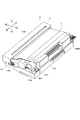
図2に示すように、プロセスカートリッジ5は、ドラムユニット6と、ドラムユニット6に着脱可能に支持される現像ユニット7と、を有している。現像ユニット7は、ユーザによって把持部701を把持された状態で、ドラムユニット6に対して装着方向ADに装着される。
[Process cartridge]
As shown in FIG. 2, the process cartridge 5 has a drum unit 6 and a developing unit 7 detachably supported by the drum unit 6. The developing unit 7 is mounted in the mounting direction AD with respect to the drum unit 6 in a state where the grip portion 701 is gripped by the user.

[現像ユニット]
現像ユニット7は、図3乃至5に示すように、筐体700と、現像ローラ71と、供給ローラ72と、第1アジテータ75Aと、第2アジテータ75Bと、駆動列720と、サイドホルダ719と、を有している。筐体700は、現像ローラ71、供給ローラ72、第1アジテータ75A及び第2アジテータ75Bの両端をそれぞれ回転可能に支持する左側壁704及び右側壁705と、筐体700の手前側に設けられユーザに把持される把持部701と、を有している。サイドホルダ719は、駆動列720を覆って左側壁704に支持される。以下、現像ローラ71の回転軸線方向を軸方向と称して説明する。
[Development unit]
As shown in FIGS. 3 to 5, the developing unit 7 includes a housing 700, a developing roller 71, a supply roller 72, a first agitator 75A, a second agitator 75B, a drive train 720, and a side holder 719. ,have. The housing 700 is provided on the front side of the housing 700, the left side wall 704 and the right side wall 705 that rotatably support both ends of the developing roller 71, the supply roller 72, the first agitator 75A, and the second agitator 75B, respectively. It has a gripping portion 701 that is gripped on the surface. The side holder 719 covers the drive train 720 and is supported by the left wall 704. Hereinafter, the rotation axis direction of the developing roller 71 will be referred to as an axial direction.

第1アジテータ75Aは、撹拌棒78A及び撹拌シート79Aを有しており、これら撹拌棒78A及び撹拌シート79Aによってトナー収容部74内の現像剤を撹拌する。また、第2アジテータ75Bも、同様に、撹拌棒78B及び撹拌シート79Bを有しており、これら撹拌棒78B及び撹拌シート79Bによって、トナー収容部74内の現像剤を撹拌する。供給ローラ72には、撹拌シート79Aによって現像剤が供給される。 The first agitator 75A has a stirring rod 78A and a stirring sheet 79A, and the developer in the toner accommodating portion 74 is stirred by the stirring rod 78A and the stirring sheet 79A. Similarly, the second agitator 75B also has a stirring rod 78B and a stirring sheet 79B, and the developing agent in the toner accommodating portion 74 is stirred by the stirring rod 78B and the stirring sheet 79B. The developer is supplied to the supply roller 72 by the stirring sheet 79A.

現像ローラ71は、サイドホルダ719に設けられる軸受746Aと、筐体700の右側壁705に取り付けられる軸受746Bとに回転可能に支持される。図3に示すように、現像ユニット7は、軸受746Bの近傍に配置される第1接点720A及び第2接点720Bを有している。第1接点720Aは、現像ローラ71に電気的に接続され、現像ローラ71に印加される電圧が装置本体2から供給される。第2接点720Bは、供給ローラ72に電気的に接続され、供給ローラ72に印加される電圧が装置本体2から供給される。これら第1接点720A及び第2接点720Bは、装置本体2に設けられた不図示の電力供給接点と接触可能である。 The developing roller 71 is rotatably supported by a bearing 746A provided on the side holder 719 and a bearing 746B attached to the right side wall 705 of the housing 700. As shown in FIG. 3, the developing unit 7 has a first contact 720A and a second contact 720B arranged in the vicinity of the bearing 746B. The first contact 720A is electrically connected to the developing roller 71, and the voltage applied to the developing roller 71 is supplied from the apparatus main body 2. The second contact 720B is electrically connected to the supply roller 72, and the voltage applied to the supply roller 72 is supplied from the device main body 2. The first contact 720A and the second contact 720B can come into contact with a power supply contact (not shown) provided in the apparatus main body 2.

図5及び図6に示すように、現像ユニット7の左側に設けられる駆動列720は、現像カップリング710と、供給ローラギヤ712と、現像ローラギヤ711と、第1アジテータギヤ713と、第2アジテータギヤ714と、を有している。また、駆動列720は、アイドルギヤ715A,715B,715Cを有している。 As shown in FIGS. 5 and 6, the drive train 720 provided on the left side of the developing unit 7 includes a developing coupling 710, a supply roller gear 712, a developing roller gear 711, a first agitator gear 713, and a second agitator gear. It has 714 and. Further, the drive train 720 has idle gears 715A, 715B and 715C.

現像カップリング710は、現像ユニット7の左側壁704に回転可能に支持されており、装置本体2に設けられたドア21(図1参照)が閉じられる動作に連動して、装置本体2に設けられた不図示の駆動伝達部材が現像カップリング710に係合する。逆に、ドア21が開かれる動作に連動して、駆動伝達部材は現像カップリング710から離間する。駆動伝達部材は、現像カップリング710の所定範囲内での位置ずれを許容して、現像カップリング710に駆動力を伝達することができる構成となっている。また、現像カップリング710、現像ローラギヤ711及び供給ローラギヤ712は、サイドホルダ719によって軸方向の移動を規制されている。 The development coupling 710 is rotatably supported by the left wall 704 of the development unit 7, and is provided on the apparatus main body 2 in conjunction with the operation of closing the door 21 (see FIG. 1) provided on the apparatus main body 2. A drive transmission member (not shown) is engaged with the developing coupling 710. On the contrary, the drive transmission member is separated from the developing coupling 710 in conjunction with the operation of opening the door 21. The drive transmission member is configured to allow the position shift of the development coupling 710 within a predetermined range and transmit the drive force to the development coupling 710. Further, the development coupling 710, the development roller gear 711, and the supply roller gear 712 are restricted from moving in the axial direction by the side holder 719.

ドア21が閉じられた後、装置本体2が動作すると、駆動伝達部材から現像カップリング710に駆動力が伝達され、現像カップリング710の周面に設けられたギヤ710aが回転する。ギヤ710aは、現像ローラギヤ711と、供給ローラ72の端部に設けられる供給ローラギヤ712と、に噛合しており、このギヤ710aが回転することで、現像ローラ71及び供給ローラ72が回転する。 When the apparatus main body 2 operates after the door 21 is closed, the driving force is transmitted from the drive transmission member to the developing coupling 710, and the gear 710a provided on the peripheral surface of the developing coupling 710 rotates. The gear 710a meshes with the developing roller gear 711 and the supply roller gear 712 provided at the end of the supply roller 72, and the rotation of the gear 710a causes the developing roller 71 and the supply roller 72 to rotate.

また、現像カップリング710のギヤ710aは、第1アジテータギヤ713と噛合するアイドルギヤ715Aと噛合しており、第1アジテータギヤ713が回転することで、第1アジテータ75Aが回転する。第1アジテータ75Aと同軸に設けられるアイドルギヤ715Bは、第2アジテータギヤ714と噛合するアイドルギヤ715Cと噛合しており、第2アジテータギヤ714が回転することで、第2アジテータ75Bが回転する。 Further, the gear 710a of the developing coupling 710 meshes with the idle gear 715A that meshes with the first agitator gear 713, and the rotation of the first agitator gear 713 causes the first agitator 75A to rotate. The idle gear 715B provided coaxially with the first agitator 75A meshes with the idle gear 715C that meshes with the second agitator gear 714, and the rotation of the second agitator gear 714 causes the second agitator 75B to rotate.

更に、図5乃至図7(b)に示すように、第2アジテータギヤ714は、検知ギヤ81のギヤ部82に噛合可能に構成されている。検知ギヤ81には、回転中心から所定距離だけ離れた位置に配置され軸方向に延びる検知突起83が設けられており、検知突起83は、サイドホルダ719の検知部80の孔84に貫通している。孔84は、周方向に長い長孔形状である。装置本体2には、検知突起83の位置を検知する不図示の検知機構が設けられており、これにより現像ユニット7が未使用の物であるか、既に使用されたものかを判定することができる。 Further, as shown in FIGS. 5 to 7 (b), the second agitator gear 714 is configured to be meshable with the gear portion 82 of the detection gear 81. The detection gear 81 is provided with a detection protrusion 83 that is arranged at a position separated from the center of rotation by a predetermined distance and extends in the axial direction, and the detection protrusion 83 penetrates through the hole 84 of the detection unit 80 of the side holder 719. There is. The hole 84 has an elongated hole shape that is long in the circumferential direction. The apparatus main body 2 is provided with a detection mechanism (not shown) that detects the position of the detection protrusion 83, whereby it is possible to determine whether the developing unit 7 is an unused one or an already used one. can.

図7(a)は、未使用の現像ユニット7を示す側面図であり、図7(b)は、既に使用された現像ユニット7を示す側面図である。検知ギヤ81は、欠歯ギヤであり、ギヤ部82と、非ギヤ部82aと、を有している。図7(a)に示すように、未使用の現像ユニット7の第2アジテータギヤ714は、検知ギヤ81のギヤ部82に噛合している。この時、検知突起83は、上方前側に位置している。 FIG. 7A is a side view showing an unused developing unit 7, and FIG. 7B is a side view showing a developing unit 7 that has already been used. The detection gear 81 is a missing tooth gear and has a gear portion 82 and a non-gear portion 82a. As shown in FIG. 7A, the second agitator gear 714 of the unused developing unit 7 meshes with the gear portion 82 of the detection gear 81. At this time, the detection protrusion 83 is located on the upper front side.

そして、現像ユニット7が使用されて第2アジテータギヤ714が矢印R3方向に回転すると、第2アジテータギヤ714に噛合する検知ギヤ81が矢印R4方向に回転する。そして、図7(b)に示すように、検知ギヤ81のギヤ部82が第2アジテータギヤ714と噛合しなくなると、検知ギヤ81は停止する。この時、検知突起83は、上方後側に位置している。 Then, when the developing unit 7 is used and the second agitator gear 714 rotates in the direction of arrow R3, the detection gear 81 that meshes with the second agitator gear 714 rotates in the direction of arrow R4. Then, as shown in FIG. 7B, when the gear portion 82 of the detection gear 81 does not mesh with the second agitator gear 714, the detection gear 81 stops. At this time, the detection protrusion 83 is located on the upper rear side.

このように、現像ユニット7が使用されることで、検知部80の孔84の範囲内で、検知突起83が回動し、検知突起83の位置を装置本体2に設けられた検知機構が検知する。これにより現像ユニット7が未使用の物であるか、既に使用されたものかを判定することができる。 In this way, by using the developing unit 7, the detection protrusion 83 rotates within the range of the hole 84 of the detection unit 80, and the position of the detection protrusion 83 is detected by the detection mechanism provided in the apparatus main body 2. do. This makes it possible to determine whether the developing unit 7 is an unused one or one that has already been used.

更に、図8に示すように、現像ユニット7の底面には、下方に突出する左右1対のリブ718,718と、底面の左側に位置するメモリ85及び位置決め突起86と、が設けられている。より具体的には、メモリ85及び位置決め突起86は、現像ユニット7のサイドホルダ719の底面に設けられている。メモリ85は、残トナー量に関する情報など現像ユニット7に関する情報を記憶している不図示のメモリチップと、メモリチップと導通しているメモリ電極85aと、を有している。メモリ電極85aは、装置本体2に設けられた不図示の電極と接触し、メモリチップと装置本体2の制御部との通信を行う。現像ローラ71の回転軸線方向において、現像カップリング710とメモリ85は、現像ローラ71の中心に対して同じ側に配置されている。 Further, as shown in FIG. 8, the bottom surface of the developing unit 7 is provided with a pair of left and right ribs 718 and 718 protruding downward, and a memory 85 and a positioning protrusion 86 located on the left side of the bottom surface. .. More specifically, the memory 85 and the positioning protrusion 86 are provided on the bottom surface of the side holder 719 of the developing unit 7. The memory 85 has a memory chip (not shown) that stores information about the developing unit 7, such as information about the amount of remaining toner, and a memory electrode 85a that is conductive to the memory chip. The memory electrode 85a comes into contact with an electrode (not shown) provided on the device main body 2 and communicates between the memory chip and the control unit of the device main body 2. In the direction of the rotation axis of the developing roller 71, the developing coupling 710 and the memory 85 are arranged on the same side with respect to the center of the developing roller 71.

[ドラムユニット]
次に、ドラムユニット6の詳細構成について説明する。ドラムユニット6は、図2及び図9乃至図11に示すように、フレーム610と、フレーム610の後方に回転可能に支持される感光ドラム61と、を主に有している。フレーム610は、底部614の左右端部において、一対の左側壁611及び右側壁612が左右方向に対向するように立設されていると共に、前端部ではユーザが把持する把持部617が設けられた前端壁613が立設している。
[Drum unit]
Next, the detailed configuration of the drum unit 6 will be described. As shown in FIGS. 2 and 9 to 11, the drum unit 6 mainly includes a frame 610 and a photosensitive drum 61 rotatably supported behind the frame 610. The frame 610 is erected at the left and right ends of the bottom 614 so that the pair of left side walls 611 and the right side wall 612 face each other in the left-right direction, and the front end is provided with a grip portion 617 to be gripped by the user. The front end wall 613 is erected.

フレーム610は、その後方側では、上記左右の側壁611,612に感光ドラム61が回転可能に支持されていると共に、この感光ドラム61の周りを覆うように構成されている。また、感光ドラム61上方において、フレーム610は、レーザ通過孔616が形成されており、このレーザ通過孔616を介して露光装置4から出射されたレーザ光が感光ドラム61の表面を照射可能となっている。 On the rear side of the frame 610, the photosensitive drum 61 is rotatably supported by the left and right side walls 611 and 612, and is configured to cover the periphery of the photosensitive drum 61. Further, above the photosensitive drum 61, a laser passage hole 616 is formed in the frame 610, and the laser light emitted from the exposure apparatus 4 through the laser passage hole 616 can irradiate the surface of the photosensitive drum 61. ing.

一方で、フレーム610は、この感光ドラム61の前方側において、上方に開放されて構成されており、現像ユニット7を装着する装着部615が形成されている。より詳しくは、感光ドラム61の前方側において、壁部611,612,613,614に囲まれた空間が上記現像ユニット7を装着する装着部615となっている。 On the other hand, the frame 610 is configured to be open upward on the front side of the photosensitive drum 61, and a mounting portion 615 for mounting the developing unit 7 is formed. More specifically, on the front side of the photosensitive drum 61, the space surrounded by the wall portions 611, 612, 613, 614 is the mounting portion 615 on which the developing unit 7 is mounted.

ここで、図9に示すように、装着部615において、底部614は、感光ドラム61に近い後方側底部614Rよりも前方側底部614Fが一段、低くなるように構成されている。前方側底部614Fは、装着部615において、現像ユニット7のトナー収容部74が収容される空間部を形成しており、現像ユニット7の底面と対向するその上面には、左右一対の突起部643,643が形成されている。 Here, as shown in FIG. 9, in the mounting portion 615, the bottom portion 614 is configured such that the front side bottom portion 614F is one step lower than the rear side bottom portion 614R near the photosensitive drum 61. The front bottom portion 614F forms a space portion in the mounting portion 615 in which the toner accommodating portion 74 of the developing unit 7 is accommodated, and a pair of left and right protrusions 643 are formed on the upper surface facing the bottom surface of the developing unit 7. , 643 are formed.

一方で、前方側底部614Fよりも感光ドラム61に近い後方側底部614Rは、装着部615において、現像ローラ71及び供給ローラ72が収容される空間部を形成している。このように構成されているため、現像ユニット7は、ドラムユニット6に装着されると、前方側から感光ドラム61の存在する後方側に向かって下方傾斜した状態となる。また、前方側底部614Fとの間に空間が形成され、筐体700の内、トナー収容部74を形成する部分が下方へと突出して、内部のトナー収容容量を大きくできるようになっている。 On the other hand, the rear side bottom portion 614R, which is closer to the photosensitive drum 61 than the front side bottom portion 614F, forms a space portion in the mounting portion 615 in which the developing roller 71 and the supply roller 72 are accommodated. Because of this configuration, when the developing unit 7 is mounted on the drum unit 6, it is tilted downward from the front side toward the rear side where the photosensitive drum 61 is present. Further, a space is formed between the front side bottom portion 614F and the portion of the housing 700 that forms the toner accommodating portion 74 protrudes downward so that the internal toner accommodating capacity can be increased.

なお、フレーム610の後方側において、左側壁611の外面には、軸方向外側に突出する第1位置決め突起660及び第1ガイドリブ662が設けられており、第1位置決め突起660は、第1ガイドリブ662よりも後方に配置されている。同様にして、フレーム610の右側壁612の外面には、軸方向外側に突出する第2位置決め突起661及び第2ガイドリブ663が設けられており、第2位置決め突起661は、第2ガイドリブ663よりも後方に配置されている。第1位置決め突起660及び第2位置決め突起661は、円筒形状に形成され、第1ガイドリブ662及び第2ガイドリブ663は、前後方向に沿った方向に延在している。これら第1位置決め突起660、第2位置決め突起661、第1ガイドリブ662及び第2ガイドリブ663は、プロセスカートリッジ5が装置本体2に装着される際に、装置本体2に設けられた不図示のガイド部に案内される。そして、プロセスカートリッジ5を装着位置まで導く。 On the rear side of the frame 610, the outer surface of the left side wall 611 is provided with a first positioning protrusion 660 and a first guide rib 662 projecting outward in the axial direction, and the first positioning protrusion 660 is a first guide rib 662. It is located behind. Similarly, a second positioning protrusion 661 and a second guide rib 663 projecting outward in the axial direction are provided on the outer surface of the right side wall 612 of the frame 610, and the second positioning protrusion 661 is more than the second guide rib 663. It is located behind. The first positioning protrusion 660 and the second positioning protrusion 661 are formed in a cylindrical shape, and the first guide rib 662 and the second guide rib 663 extend in a direction along the front-rear direction. The first positioning protrusion 660, the second positioning protrusion 661, the first guide rib 662, and the second guide rib 663 are guide portions (not shown) provided on the device main body 2 when the process cartridge 5 is mounted on the device main body 2. Will be guided to. Then, the process cartridge 5 is guided to the mounting position.

ところで、現像ユニット7に収容されるトナー量から決まる現像ユニット7の寿命は、感光ドラム61の感光層の厚みから決まるドラムユニット6の寿命に比べて短く設定されている。従って、寿命に到達した現像ユニット7だけをドラムユニット6とは別に交換することがコスト上望ましい。現像ユニット7のみを交換する場合は、ドア21を開いて装置本体2内からプロセスカートリッジ5を取り出した後、ドラムユニット6から現像ユニット7だけを取り外す。そして、新しい現像ユニット7を図2の装着方向ADに挿入し、現像ユニット7をドラムユニット6に組み付ける。 By the way, the life of the developing unit 7 determined by the amount of toner contained in the developing unit 7 is set shorter than the life of the drum unit 6 determined by the thickness of the photosensitive layer of the photosensitive drum 61. Therefore, it is desirable in terms of cost to replace only the developing unit 7 that has reached the end of its life separately from the drum unit 6. When replacing only the developing unit 7, the door 21 is opened, the process cartridge 5 is taken out from the inside of the apparatus main body 2, and then only the developing unit 7 is removed from the drum unit 6. Then, a new developing unit 7 is inserted into the mounting direction AD of FIG. 2, and the developing unit 7 is assembled to the drum unit 6.

ついで、上記現像ユニット7がドラムユニット6に組み付けられる際における現像ユニット7のドラムユニット6に対する位置決め構成について説明をする。まずは、現像ユニット7のドラムユニット6に対する前後方向の位置決めについて説明をする。図2、図10及び図11に示すように、フレーム610の左側壁611及び右側壁612には、受け部641,641がそれぞれ形成されており、受け部641は、現像ユニット7の軸受746A,746Bに当接可能に構成されている。受け部641は、前方が開放された略U字状に形成されており、前後方向に延びる下面641aと鉛直方向に延びる突き当たり面641bとを有している(図10参照)。 Next, a positioning configuration of the developing unit 7 with respect to the drum unit 6 when the developing unit 7 is assembled to the drum unit 6 will be described. First, the positioning of the developing unit 7 with respect to the drum unit 6 in the front-rear direction will be described. As shown in FIGS. 2, 10 and 11, receiving portions 641 and 641 are formed on the left side wall 611 and the right side wall 612 of the frame 610, respectively, and the receiving portions 641 are the bearings 746A of the developing unit 7. It is configured so that it can come into contact with the 746B. The receiving portion 641 is formed in a substantially U shape with the front open, and has a lower surface 641a extending in the front-rear direction and an abutting surface 641b extending in the vertical direction (see FIG. 10).

また、図12乃至図13(b)に示すように、ドラムユニット6のフレーム610の前部には、一対の押圧部材640,640が設けられている。押圧部材640は、付勢バネ644によって前方に付勢されており、現像ユニット7がドラムユニット6に装着された状態で、現像ユニット7の筐体700に設けられた一対の被押圧リブ716を押圧する。 Further, as shown in FIGS. 12 to 13 (b), a pair of pressing members 640, 640 are provided on the front portion of the frame 610 of the drum unit 6. The pressing member 640 is urged forward by an urging spring 644, and with the developing unit 7 mounted on the drum unit 6, presses a pair of pressed ribs 716 provided in the housing 700 of the developing unit 7. do.

なお、左右1対の被押圧リブ716は、図12に示すように、右側に配置された被押圧リブ716の方が左側に配置された被押圧リブ716よりも後方に配置されるように設けられている。これは、図13(a)及び図13(b)に示すように、後述するリフト部材642が左右方向において右側の被押圧リブ716に重なるように配置され、回動操作されるリフト部材642と右側の被押圧リブ716とが干渉しないようにするためである。このように構成することで、リフト部材642の後方への突出量を抑え、プロセスカートリッジ5を小型に構成することができる。 As shown in FIG. 12, the pair of left and right pressed ribs 716 are provided so that the pressed ribs 716 arranged on the right side are arranged behind the pressed ribs 716 arranged on the left side. Has been done. As shown in FIGS. 13 (a) and 13 (b), the lift member 642 described later is arranged so as to overlap the pressed rib 716 on the right side in the left-right direction, and is rotated with the lift member 642. This is to prevent interference with the pressed rib 716 on the right side. With such a configuration, the amount of protrusion of the lift member 642 to the rear can be suppressed, and the process cartridge 5 can be configured in a small size.

このように構成されているため、現像ユニット7が図2に示すようにドラムユニット6に対して装着方向ADに装着される際には、現像ユニット7の軸受746A,746Bが受け部641の下面641aに案内される。そして、更に現像ユニット7がドラムユニット6に装着されると、軸受746A,746Bが受け部641の突き当たり面641bに突き当たる。 Because of this configuration, when the developing unit 7 is mounted in the mounting direction AD with respect to the drum unit 6 as shown in FIG. 2, the bearings 746A and 746B of the developing unit 7 are mounted on the lower surface 641a of the receiving portion 641. Will be guided to. When the developing unit 7 is further mounted on the drum unit 6, the bearings 746A and 746B abut against the abutting surface 641b of the receiving portion 641.

この状態で、ユーザが現像ユニット7の把持部701から手を離すと、現像ユニット7は、ドラムユニット6の底部614に形成された突起部643,643によって支持されると共に、押圧部材640によって前方に押圧される。押圧部材640を押圧する付勢バネ644の付勢力により、現像ユニット7の軸受746A,746Bは、突き当たり面641bに対して押し付けられ、現像ユニット7は、ドラムユニット6に対して前後方向に位置決めされる。また、付勢バネ644の付勢力により、上記現像ユニット7の現像ローラ71が感光ドラム61に押し付けられる。 In this state, when the user releases the grip portion 701 of the developing unit 7, the developing unit 7 is supported by the protrusions 643 and 643 formed on the bottom portion 614 of the drum unit 6, and is supported forward by the pressing member 640. Pressed. The bearings 746A and 746B of the developing unit 7 are pressed against the abutting surface 641b by the urging force of the urging spring 644 that presses the pressing member 640, and the developing unit 7 is positioned in the front-rear direction with respect to the drum unit 6. .. Further, the developing roller 71 of the developing unit 7 is pressed against the photosensitive drum 61 by the urging force of the urging spring 644.

ついで、現像ユニット7の左右方向(感光ドラム61の回転軸線方向)のドラムユニット6に対する位置決め機構について説明をする。図12、図14(a)及び図14(b)に示すように、フレーム610の底部614の内、後方側底部614Rには、シートが転写ニップN1に搬送される際に通過するシート通過孔618と、端部貫通孔68とが穿設されている。 Next, a positioning mechanism for the drum unit 6 in the left-right direction of the developing unit 7 (direction of the rotation axis of the photosensitive drum 61) will be described. As shown in FIGS. 12, 14 (a) and 14 (b), in the bottom portion 614 of the frame 610, the rear side bottom portion 614R has a sheet passage hole through which the sheet is conveyed to the transfer nip N1. A 618 and an end through hole 68 are bored.

上記端部貫通孔68は、感光ドラム61の回転軸線方向一方側の端部(本実施の形態では左方側)に設けられており、電極露出孔68aと、位置決め孔68bと、によって形成されている。なお、感光ドラム61の左端部には第1感光ドラムギヤ65及び第2感光ドラムギヤ66が設けられ、転写ローラ63の左端部には第2感光ドラムギヤ66と噛合する転写ギヤ67が設けられている。ドラムユニット6を含むプロセスカートリッジ5が装置本体2に装着されると、装置本体2に設けられた駆動ギヤが第1感光ドラムギヤ65に噛合する。この状態で駆動ギヤが回転すると、駆動ギヤによって第1感光ドラムギヤ65が回転し、第1感光ドラムギヤ65と一体に感光ドラム61及び第2感光ドラムギヤ66が回転する。そして、第2感光ドラムギヤ66の回転が転写ギヤ67に伝達され、転写ギヤ67と一体に転写ローラ63が回転する。 The end through hole 68 is provided at one end of the photosensitive drum 61 on one side in the rotation axis direction (left side in the present embodiment), and is formed by an electrode exposed hole 68a and a positioning hole 68b. ing. A first photosensitive drum gear 65 and a second photosensitive drum gear 66 are provided at the left end of the photosensitive drum 61, and a transfer gear 67 that meshes with the second photosensitive drum gear 66 is provided at the left end of the transfer roller 63. When the process cartridge 5 including the drum unit 6 is mounted on the apparatus main body 2, the drive gear provided on the apparatus main body 2 meshes with the first photosensitive drum gear 65. When the drive gear rotates in this state, the first photosensitive drum gear 65 is rotated by the drive gear, and the photosensitive drum 61 and the second photosensitive drum gear 66 are rotated integrally with the first photosensitive drum gear 65. Then, the rotation of the second photosensitive drum gear 66 is transmitted to the transfer gear 67, and the transfer roller 63 rotates integrally with the transfer gear 67.

電極露出孔68aは、現像ユニット7がドラムユニット6に装着された状態で、メモリ電極85aをドラムユニット6の下方に露出させ、メモリ電極85aが装置本体2に設けられた不図示の電極と接触可能となるように構成されている。位置決め孔68bは、電極露出孔68aの後方側にて電極露出孔68aと連続して形成されており、電極露出孔68aよりも左右方向において小さな寸法のスリット状の孔となっている。この位置決め孔68bには、現像ユニット7がドラムユニット6に装着された状態で、位置決め突起86が係合し、この位置決め突起86が係合することによって、現像ユニット7の左右方向の位置が位置決めされる。 The electrode exposed holes 68a expose the memory electrode 85a below the drum unit 6 with the developing unit 7 mounted on the drum unit 6, so that the memory electrode 85a can come into contact with an electrode (not shown) provided in the apparatus main body 2. It is configured to be. The positioning hole 68b is formed continuously with the electrode exposed hole 68a on the rear side of the electrode exposed hole 68a, and is a slit-shaped hole having a smaller dimension in the left-right direction than the electrode exposed hole 68a. With the developing unit 7 mounted on the drum unit 6, the positioning projection 86 is engaged with the positioning hole 68b, and the positioning projection 86 is engaged to position the position of the developing unit 7 in the left-right direction. To.

なお、電極露出孔68aと位置決め孔68bとの接続部分は、位置決め突起86を位置決め孔68bに案内するように、位置決め孔68bに近づくほど、幅狭いとなるテーパー面681により形成されている。また、上述したように位置決め突起86及び位置決め孔68bは、それぞれメモリ電極85a及び電極露出孔68aよりも装着方向ADにおける下流側に設けられている。このため、現像ユニット7をドラムユニット6に装着する際に、メモリ電極85aをドラムユニット6に接触させることがない。よって、現像ユニット7をドラムユニット6に装着する際のユーザビリティを向上すると共に、メモリ電極85aの破損を低減することができる。また、電極露出孔68aが位置決め孔68bと近接して配設されているため、メモリ電極85aと電極露出孔68aとの位置決め精度が高まる。加えて、電極露出孔68aを介して位置決め突起86を位置決め孔68bに案内して容易に係合させることができる。 The connection portion between the electrode exposed hole 68a and the positioning hole 68b is formed by a tapered surface 681 that becomes narrower as it approaches the positioning hole 68b so as to guide the positioning projection 86 to the positioning hole 68b. Further, as described above, the positioning protrusion 86 and the positioning hole 68b are provided on the downstream side in the mounting direction AD from the memory electrode 85a and the electrode exposed hole 68a, respectively. Therefore, when the developing unit 7 is mounted on the drum unit 6, the memory electrode 85a does not come into contact with the drum unit 6. Therefore, usability when the developing unit 7 is mounted on the drum unit 6 can be improved, and damage to the memory electrode 85a can be reduced. Further, since the electrode exposed holes 68a are arranged close to the positioning holes 68b, the positioning accuracy between the memory electrodes 85a and the electrode exposed holes 68a is improved. In addition, the positioning projection 86 can be guided to the positioning hole 68b via the electrode exposed hole 68a and easily engaged with the positioning protrusion 86.

[現像ユニットの取外し構成]
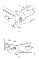
次に、現像ユニット7をドラムユニット6から取り外すための構成について説明する。なお、図13(a)においては、図13(b)に示すリフト部材642を破線で透かして表現している。図13(a)及び図13(b)に示すように、ドラムユニット6の前端部かつ右端部には、リフト部材642が設けられている。このリフト部材642は、図15に示すように、ドラムユニット6の右側壁612に対して回転軸線642Xを中心に回転可能に支持されている。回転軸線642Xは、感光ドラム61及び現像ローラ71の回転軸線方向と平行に延びている。リフト部材642は、圧縮バネ650によって矢印R1方向に回転するように付勢されており、リフト部材642の一端部に設けられた操作部642Aを下方に押し操作することで、圧縮バネ650の付勢力に抗して矢印R2方向に回転される。
[Removal configuration of developing unit]
Next, a configuration for removing the developing unit 7 from the drum unit 6 will be described. In FIG. 13 (a), the lift member 642 shown in FIG. 13 (b) is represented by a broken line. As shown in FIGS. 13 (a) and 13 (b), a lift member 642 is provided at the front end portion and the right end portion of the drum unit 6. As shown in FIG. 15, the lift member 642 is rotatably supported about the rotation axis 642X with respect to the right side wall 612 of the drum unit 6. The rotation axis 642X extends parallel to the rotation axis direction of the photosensitive drum 61 and the developing roller 71. The lift member 642 is urged to rotate in the arrow R1 direction by the compression spring 650, and the compression spring 650 is attached by pushing the operation portion 642A provided at one end of the lift member 642 downward. It is rotated in the direction of arrow R2 against the force.

現像ユニット7の右側壁705には、右方に突出する円筒形状の突出部751が設けられており、リフト部材642の他端部には、突出部751に当接可能な当接部642Bが設けられている。当接部642Bは、回転軸線642Xを挟んで操作部642Aとは反対側に設けられている。 The right side wall 705 of the developing unit 7 is provided with a cylindrical protrusion 751 protruding to the right, and the other end of the lift member 642 has an abutting portion 642B capable of contacting the protrusion 751. It is provided. The contact portion 642B is provided on the side opposite to the operation portion 642A with the rotation axis 642X interposed therebetween.

ところで、図15乃至図16(b)に示すように、押圧部材640は、押圧部材640の前面に設けられ鉛直方向に延びる押圧面640aと、押圧面640aの上端から後方に上り傾斜する傾斜面640bと、をそれぞれ有している。現像ユニット7の被押圧部716は、押圧面640aによって前方に押圧される被押圧面716aと、被押圧面716aの下端から前方に下り傾斜する傾斜面716bと、を有している。 By the way, as shown in FIGS. 15 to 16B, the pressing member 640 has a pressing surface 640a provided on the front surface of the pressing member 640 and extending in the vertical direction, and an inclined surface that is inclined backward from the upper end of the pressing surface 640a. It has 640b and each. The pressed portion 716 of the developing unit 7 has a pressed surface 716a that is pressed forward by the pressing surface 640a, and an inclined surface 716b that is inclined forward from the lower end of the pressed surface 716a.

図16(a)に示すように、現像ユニット7がドラムユニット6に装着されている状態では、付勢バネ644によって付勢される押圧部材640の押圧面640aは、現像ユニット7の被押圧部716の被押圧面716aを押圧している。この時、これら押圧面640a及び被押圧面716aは、略鉛直方向に延びており、付勢バネ644の付勢力は、被押圧面716aに対して垂直に作用し、現像ユニット7は前方向に付勢される。これにより、現像ユニット7は、ドラムユニット6に対して離脱しないように装着位置でロックされている。 As shown in FIG. 16A, when the developing unit 7 is mounted on the drum unit 6, the pressing surface 640a of the pressing member 640 urged by the urging spring 644 is the pressed portion 716 of the developing unit 7. Is pressing the pressed surface 716a. At this time, the pressing surface 640a and the pressed surface 716a extend substantially in the vertical direction, the urging force of the urging spring 644 acts perpendicularly to the pressed surface 716a, and the developing unit 7 moves forward. Be urged. As a result, the developing unit 7 is locked at the mounting position so as not to be detached from the drum unit 6.

図15に示すように、リフト部材642の操作部642Aが下方に押圧されると、リフト部材642が矢印R2方向に回転し、リフト部材642の当接部642Bが現像ユニット7の突出部751を上方に押し上げる。これにより、図16(b)に示すように、ドラムユニット6に装着された現像ユニット7の手前側が上方に回動し、現像ユニット7は、装着位置から離脱方向LDに回動する。これにより、現像ユニット7の被押圧面716aは、押圧面640aから上方に離間し、現像ユニット7の傾斜面716bが押圧部材640の傾斜面640bに乗り上げる。 As shown in FIG. 15, when the operation portion 642A of the lift member 642 is pressed downward, the lift member 642 rotates in the direction of arrow R2, and the contact portion 642B of the lift member 642 pushes the protruding portion 751 of the developing unit 7. Push it up. As a result, as shown in FIG. 16B, the front side of the developing unit 7 mounted on the drum unit 6 rotates upward, and the developing unit 7 rotates from the mounting position in the detaching direction LD. As a result, the pressed surface 716a of the developing unit 7 is separated upward from the pressing surface 640a, and the inclined surface 716b of the developing unit 7 rides on the inclined surface 640b of the pressing member 640.

この時、現像ユニット7の軸受746A,746Bは、受け部641,641に支持された状態である。この時の現像ユニット7の状態をリフトアップ状態と呼称する。現像ユニット7がリフトアップ状態にある際に、傾斜面640b,716bは、押圧部材640の付勢方向である前方向に対して傾斜している。すなわち、リフト部材642によって現像ユニット7が離脱方向LDに回動すると、現像ユニット7の被押圧面716aが押圧面640aから上方に離間する。すると、付勢バネ644によって前方に付勢された押圧部材640の傾斜面640bによって、現像ユニット7の傾斜面716bが上方に持ち上げられ、現像ユニット7は、付勢バネ644の付勢力によって更に離脱方向LDに回動する。このため、現像ユニット7をリフトアップ状態にするための操作力を低減できる。 At this time, the bearings 746A and 746B of the developing unit 7 are in a state of being supported by the receiving portions 641 and 641. The state of the developing unit 7 at this time is referred to as a lift-up state. When the developing unit 7 is in the lift-up state, the inclined surfaces 640b and 716b are inclined with respect to the forward direction, which is the urging direction of the pressing member 640. That is, when the developing unit 7 is rotated in the detaching direction LD by the lift member 642, the pressed surface 716a of the developing unit 7 is separated upward from the pressing surface 640a. Then, the inclined surface 716b of the developing unit 7 is lifted upward by the inclined surface 640b of the pressing member 640 urged forward by the urging spring 644, and the developing unit 7 is further separated by the urging force of the urging spring 644. Rotate in the direction LD. Therefore, the operating force for bringing the developing unit 7 into the lift-up state can be reduced.

現像ユニット7がリフトアップ状態となっている際には、付勢バネ644の前方向の付勢力のほとんどは、傾斜面640b,716bによって略上方への力として変換されているため、現像ユニット7はドラムユニット6に対してロックされていない。このため、ユーザは、現像ユニット7の把持部701を持ち上げるだけで、他の部材を移動させるなどすることなく、現像ユニット7をドラムユニット6から取り外すことができる。このようにして、ユーザは、ドラムユニット6から現像ユニット7を取り外して、新品の現像ユニット7をドラムユニット6へ装着することができる。 When the developing unit 7 is in the lift-up state, most of the forward urging force of the urging spring 644 is converted as a substantially upward force by the inclined surfaces 640b and 716b, so that the developing unit 7 Is not locked to the drum unit 6. Therefore, the user can remove the developing unit 7 from the drum unit 6 simply by lifting the grip portion 701 of the developing unit 7 without moving other members. In this way, the user can remove the developing unit 7 from the drum unit 6 and attach a new developing unit 7 to the drum unit 6.

[捕集凹部]
ついで、図17(a)及び図17(b)に基づいて、捕集凹部800及びシート部材810の構成について説明をする。図17(a)に示すように、ドラムユニット6のフレーム610は、感光ドラム61の回転軸線方向の一端側(本実施の形態では左方側)において、端部貫通孔68とシート通過孔618との間に架橋部619が設けられている。この架橋部619には、捕集凹部800が設けられていると共に、捕集凹部800の感光ドラム61側の端部には、クリーニング部材としてのシート部材810が設けられている。
[Collecting recess]
Next, the configurations of the collection recess 800 and the sheet member 810 will be described with reference to FIGS. 17 (a) and 17 (b). As shown in FIG. 17A, the frame 610 of the drum unit 6 has an end through hole 68 and a sheet passing hole 618 on one end side (left side in the present embodiment) of the photosensitive drum 61 in the rotation axis direction. A cross-linking portion 619 is provided between the two. The cross-linked portion 619 is provided with a collection recess 800, and a sheet member 810 as a cleaning member is provided at the end of the collection recess 800 on the photosensitive drum 61 side.

このシート部材810は、フレーム610から感光ドラム61に向かって立設しており、その先端部810aが感光ドラム61に当接するようになっている。より詳しくは、シート部材810は、感光ドラム61の画像形成領域から軸方向外側に外れた端部部分において、感光ドラム61と当接しており、画像形成時に感光ドラム61の表面に付着した不要なトナーや紙粉等の異物を先端部810aで掻き落としている。 The sheet member 810 is erected from the frame 610 toward the photosensitive drum 61, and its tip portion 810a comes into contact with the photosensitive drum 61. More specifically, the sheet member 810 is in contact with the photosensitive drum 61 at an end portion axially outward from the image forming region of the photosensitive drum 61, and is unnecessary attached to the surface of the photosensitive drum 61 during image formation. Foreign matter such as toner and paper dust is scraped off by the tip portion 810a.

また、上記捕集凹部800は、上記感光ドラム61の回転軸線方向と直交する直交方向(前後方向)において、シート部材810の前方側でかつ、シート部材810の先端部810aの下方に位置している。上記シート部材810の先端部810aは、感光ドラム61の回転方向に対して対向する形で感光ドラム61の表面と当接するため、シート部材810にて掻き落とされた異物は、捕集凹部800内に落ちて捕集される。 Further, the collection recess 800 is located on the front side of the seat member 810 and below the tip portion 810a of the seat member 810 in the orthogonal direction (front-back direction) orthogonal to the rotation axis direction of the photosensitive drum 61. There is. Since the tip portion 810a of the sheet member 810 abuts on the surface of the photosensitive drum 61 so as to face the rotation direction of the photosensitive drum 61, foreign matter scraped off by the sheet member 810 is contained in the collection recess 800. It falls to and is collected.

加えて、このような捕集凹部800が、ドラムユニット6のフレーム610の中でも、端部貫通孔68及びシート通過孔618に挟まれて強度が低下する架橋部619に設けられているため、フレーム610の強度を向上させることができる。即ち、捕集凹部800は、感光ドラム61の回転軸線方向から視て直交方向において、電極露出孔68a、位置決め孔68b及びシート通過孔618と重なる位置において、これらの孔68a,68b,618に隣接して設けられている。 In addition, since such a collecting recess 800 is provided in the frame 610 of the drum unit 6 in the cross-linked portion 619 which is sandwiched between the end through hole 68 and the sheet passing hole 618 and whose strength is reduced, the frame 610 is provided. Strength can be improved. That is, the collection recess 800 is adjacent to the holes 68a, 68b, 618 at positions overlapping the electrode exposed holes 68a, the positioning holes 68b, and the sheet passing holes 618 in the orthogonal direction when viewed from the rotation axis direction of the photosensitive drum 61. It is provided.

このため、捕集凹部800が架橋部619を補強するリブとしても働き、架橋部619におけるフレーム610の強度を向上させている。特に、この捕集凹部800は、図17(b)に示すように、その深さ(底部の上面の位置)D2が位置決め孔68bの深さD1よりも深くなっており(D2>D1)、補強効果が大きくなるように構成されている。従って、上記位置決め孔68b周囲のフレーム610の強度が向上し、これにより、フレーム610の歪みも少なくなるため、現像ユニット7の左右方向の位置決め精度を向上させることができる。 Therefore, the collection recess 800 also functions as a rib for reinforcing the cross-linked portion 619, improving the strength of the frame 610 in the cross-linked portion 619. In particular, as shown in FIG. 17 (b), the depth (position of the upper surface of the bottom surface) D2 of the collection recess 800 is deeper than the depth D1 of the positioning hole 68b (D2> D1). It is configured to have a large reinforcing effect. Therefore, the strength of the frame 610 around the positioning hole 68b is improved, and the distortion of the frame 610 is also reduced, so that the positioning accuracy of the developing unit 7 in the left-right direction can be improved.

なお、図2に示すように、ドラムユニット6のフレーム610は、感光ドラム61の回転軸線方向の他端側(本実施の形態では右方側)においても、上記捕集凹部800と同様にボックス状の捕集凹部830と、シート部材840と、が設けられている。このシート部材840は、フレーム610から感光ドラム61に向かって立設しており、その先端部が感光ドラム61に当接するようになっている。より詳しくは、シート部材840は、感光ドラム61の画像形成領域から軸方向外側に外れた端部部分において、感光ドラム61と当接しており、画像形成時に感光ドラム61の表面に付着した不要なトナーや紙粉等の異物をその先端部で掻き落としている。 As shown in FIG. 2, the frame 610 of the drum unit 6 has a box shape on the other end side (right side in the present embodiment) of the photosensitive drum 61 in the rotation axis direction as well as the collection recess 800. The collection recess 830 and the seat member 840 are provided. The sheet member 840 is erected from the frame 610 toward the photosensitive drum 61, and its tip end abuts on the photosensitive drum 61. More specifically, the sheet member 840 is in contact with the photosensitive drum 61 at an end portion axially outward from the image forming region of the photosensitive drum 61, and is unnecessary attached to the surface of the photosensitive drum 61 during image formation. Foreign matter such as toner and paper dust is scraped off at the tip.

また、上記捕集凹部830は、上記感光ドラム61の回転軸線方向と直交する直交方向において、シート部材840の前方側に位置しているため、このシート部材840にて掻き落とされた異物が、捕集凹部830内に落ちて捕集されるようになっている。 Further, since the collection recess 830 is located on the front side of the sheet member 840 in the orthogonal direction orthogonal to the rotation axis direction of the photosensitive drum 61, foreign matter scraped off by the sheet member 840 can be removed. It falls into the collection recess 830 and is collected.

[第1の実施の形態のまとめ]
上述したように、画像形成装置(1)の装置本体(2)に着脱可能なカートリッジ(5)であって、
感光ドラム(61)と、前記感光ドラム(61)を回転可能に支持するフレーム(610)と、を有するドラムユニット(6)と、
前記感光ドラム(61)にトナーを供給する現像ローラ(71)と、情報を記憶するためのメモリ(85)と、を備え、前記ドラムユニット(6)に着脱可能に構成された現像ユニット(7)と、を備え、
前記ドラムユニット(6)は、回転軸線方向における前記感光ドラム(61)の端部に接触して前記感光ドラム(61)をクリーニングするクリーニング部材(810)を有し、
前記フレーム(610)は、前記メモリ(85)を前記フレーム(610)から露出させるための露出孔(68a)と、前記感光ドラム(61)の回転軸線方向において前記露出孔(68a)と隣接する凹部(800)と、を有し、
前記凹部(800)は、前記回転軸線方向に直交する方向から視たときに前記クリーニング部材(810)と前記回転軸線方向に少なくとも一部が重なるように設けられ、かつ、前記クリーニング部材(810)から離れる方向に凹んでいる。
[Summary of the first embodiment]
As described above, it is a cartridge (5) that can be attached to and detached from the apparatus main body (2) of the image forming apparatus (1).
A drum unit (6) having a photosensitive drum (61) and a frame (610) that rotatably supports the photosensitive drum (61).
A developing unit (7) provided with a developing roller (71) for supplying toner to the photosensitive drum (61) and a memory (85) for storing information, and which is detachably configured on the drum unit (6). And with
The drum unit (6) has a cleaning member (810) that comes into contact with the end portion of the photosensitive drum (61) in the direction of the rotation axis to clean the photosensitive drum (61).
The frame (610) is adjacent to the exposed hole (68a) for exposing the memory (85) from the frame (610) and the exposed hole (68a) in the rotation axis direction of the photosensitive drum (61). With a recess (800),
The recess (800) is provided so that at least a part of the cleaning member (810) overlaps the cleaning member (810) when viewed from a direction orthogonal to the rotation axis direction, and the cleaning member (810) is provided. It is dented in the direction away from.

上述したように、ドラムユニット6のフレーム610は、感光ドラム61の回転軸線方向において露出孔68aに隣接して凹部800を設けている。このため、露出孔68aを形成したとしても、ドラムユニット6のフレーム610の強度を向上させることができる。また、上記凹部800がクリーニング部材810と感光ドラム61の回転軸線方向に直交する方向から視たときに、回転軸線方向に少なくとも一部が重なるように設けられている。このため、凹部800によってクリーニング部材810によって掻き取られた余分なトナーや紙粉等の異物を捕集することができる。 As described above, the frame 610 of the drum unit 6 is provided with a recess 800 adjacent to the exposed hole 68a in the direction of the rotation axis of the photosensitive drum 61. Therefore, even if the exposed holes 68a are formed, the strength of the frame 610 of the drum unit 6 can be improved. Further, the recess 800 is provided so that at least a part of the recess 800 overlaps in the rotation axis direction when viewed from a direction orthogonal to the rotation axis direction of the cleaning member 810 and the photosensitive drum 61. Therefore, foreign matter such as excess toner and paper dust scraped off by the cleaning member 810 can be collected by the recess 800.

また、
前記現像ユニット(7)は、前記ドラムユニット(6)に向けて延びる突起(86)を有し、
前記フレーム(610)は、前記現像ユニット(7)の前記ドラムユニット(6)に対する前記回転軸線方向の位置が決まるように前記突起(86)と係合する位置決め孔(68b)を有し、
前記凹部(800)は、前記回転軸線方向において前記位置決め孔(68b)と隣接している。このように、凹部800が位置決め孔68bと回転軸線方向において隣接して配設されているため、位置決め孔68bの周囲のフレーム610の強度を高めることができる。そして、これにより、位置決め孔68bの周囲でフレームが歪むことが抑制され、高い精度で現像ユニット7をドラムユニット6に対して位置決めすることができる。
also,
The developing unit (7) has a protrusion (86) extending toward the drum unit (6).
The frame (610) has a positioning hole (68b) that engages with the protrusion (86) so that the position of the developing unit (7) in the rotation axis direction with respect to the drum unit (6) is determined.
The recess (800) is adjacent to the positioning hole (68b) in the direction of the rotation axis. In this way, since the recess 800 is arranged adjacent to the positioning hole 68b in the direction of the rotation axis, the strength of the frame 610 around the positioning hole 68b can be increased. As a result, the frame is suppressed from being distorted around the positioning hole 68b, and the developing unit 7 can be positioned with respect to the drum unit 6 with high accuracy.

前記位置決め孔(68b)は、前記回転軸線方向に直交する方向において前記露出孔(68a)と前記感光ドラム(61)との間にあって、前記露出孔(68a)と連通している。これにより、露出孔68aが位置決め孔68bに対して近接して配置され、露出孔68bとメモリ85とを高精度で位置決めすることができる。 The positioning hole (68b) is located between the exposed hole (68a) and the photosensitive drum (61) in a direction orthogonal to the rotation axis direction, and communicates with the exposed hole (68a). As a result, the exposed hole 68a is arranged close to the positioning hole 68b, and the exposed hole 68b and the memory 85 can be positioned with high accuracy.

上述したように、本実施の形態においてプロセスカートリッジ(5)は、
感光ドラム(61)を備えたドラムユニット(6)と、
前記感光ドラム(61)に対してトナーを供給してトナー像を現像する現像ローラ(71)を備え、前記ドラムユニット(6)に対して着脱可能に構成された現像ユニット(7)と、を備え、
前記現像ユニット(7)は、
前記現像ユニット(7)の情報を記憶するメモリ(85)と、
前記感光ドラム(61)の回転軸線方向における前記現像ユニット(7)の前記ドラムユニット(6)に対する位置を位置決めする位置決め突起(86)と、を備え、
前記ドラムユニット(6)は、前記感光ドラム(61)の回転軸線方向の一端側において、前記位置決め突起(86)が係合する位置決め孔(68b)及び凹部(800)を有するフレーム(610)を備え、
前記凹部(800)は、前記感光ドラム(61)の回転軸線方向から視て、前記回転軸線方向と直交する方向において、前記位置決め孔(68b)と重なる位置に配設されている。
As described above, in the present embodiment, the process cartridge (5) is
A drum unit (6) equipped with a photosensitive drum (61) and
A developing roller (71) that supplies toner to the photosensitive drum (61) to develop a toner image is provided, and a developing unit (7) that is detachably configured with respect to the drum unit (6) is provided. ,
The developing unit (7) is
A memory (85) for storing information of the developing unit (7) and
A positioning projection (86) for positioning the position of the developing unit (7) with respect to the drum unit (6) in the rotation axis direction of the photosensitive drum (61) is provided.
The drum unit (6) includes a frame (610) having a positioning hole (68b) and a recess (800) with which the positioning projection (86) is engaged on one end side of the photosensitive drum (61) in the rotation axis direction. ,
The recess (800) is arranged at a position overlapping the positioning hole (68b) in a direction orthogonal to the rotation axis direction when viewed from the rotation axis direction of the photosensitive drum (61).

このように、凹部800が感光ドラム61の回転軸線方向から視て、回転軸線方向と直交する方向において、位置決め孔68bと重なる位置に配設されていると、ドラムユニット6の位置決め孔68b周辺の強度が上がる。そして、これにより、現像ユニット7の位置決め突起86と、ドラムユニット6の位置決め孔68bによる両ユニットの左右方向の位置決め精度を向上させることができる。また、この結果として、現像ユニット7のメモリ電極85aを装置本体2側の電極に対して高い精度で当接させることができる。 As described above, when the recess 800 is arranged at a position overlapping the positioning hole 68b in the direction orthogonal to the rotation axis direction when viewed from the rotation axis direction of the photosensitive drum 61, the strength around the positioning hole 68b of the drum unit 6 is obtained. Goes up. As a result, the positioning accuracy of both units in the left-right direction can be improved by the positioning protrusion 86 of the developing unit 7 and the positioning hole 68b of the drum unit 6. Further, as a result, the memory electrode 85a of the developing unit 7 can be brought into contact with the electrode on the device main body 2 side with high accuracy.

更に、前記凹部(800)の深さ(D2)は、前記位置決め孔(68b)の深さ(D1)よりも深くなるように構成されている(D2>D1)。このため、上述した凹部800によるフレーム610の補強効果を大きくすることができる。 Further, the depth (D2) of the recess (800) is configured to be deeper than the depth (D1) of the positioning hole (68b) (D2> D1). Therefore, the reinforcing effect of the frame 610 by the recess 800 described above can be enhanced.

また、前記ドラムユニット(6)は、前記感光ドラム(61)に対して先端部(810a)が当接するクリーニング部材(810)を備え、
前記凹部(800)は、前記回転軸線方向と直交する方向から視て、前記感光ドラム(61)の回転軸線方向において、前記クリーニング部材(810)と重なる位置に配設されている。このため、クリーニング部材810によって感光ドラム61の表面から掻き取った余分なトナーや、紙粉などの異物を凹部800によって捕集することができ、散らばることを防止することができる。その結果として、異物によってプロセスカートリッジ5の汚染や、異物のシートSへの落下による画像不良が発生することを防止することができる。加えて、凹部800をドラムユニット6のフレーム610の補強と、異物の捕集との両方に用いることによって、凹部800とは別に異物捕集用の構成を設けることが不要となり、カートリッジの小型化及び構成をシンプルにすることができる。
Further, the drum unit (6) includes a cleaning member (810) in which the tip end portion (810a) abuts on the photosensitive drum (61).
The recess (800) is arranged at a position overlapping the cleaning member (810) in the rotation axis direction of the photosensitive drum (61) when viewed from a direction orthogonal to the rotation axis direction. Therefore, excess toner scraped from the surface of the photosensitive drum 61 by the cleaning member 810 and foreign matter such as paper dust can be collected by the recess 800 and can be prevented from being scattered. As a result, it is possible to prevent the process cartridge 5 from being contaminated by foreign matter and image defects due to the foreign matter falling onto the sheet S. In addition, by using the recess 800 for both the reinforcement of the frame 610 of the drum unit 6 and the collection of foreign matter, it becomes unnecessary to provide a configuration for collecting foreign matter separately from the recess 800, and the size of the cartridge can be reduced. The configuration can be simplified.

更に、前記ドラムユニット(6)のフレーム(610)は、前記メモリ(85)の電極(85a)を露出させる電極露出孔(68a)を有し、
前記位置決め孔(68b)は、前記現像ユニット(7)の前記ドラムユニット(6)に対する装着方向において、前記電極露出孔(68a)よりも下流側に位置し、かつ、前記位置決め孔(68b)と連通するように形成されている。このため、現像ユニット7をドラムユニット6に装着する際に、電極露出孔68aを介して位置決め突起86を位置決め孔68bへと案内することができる。また、電極露出孔68aが位置決め孔68bに近接して配置されているため、メモリ電極85aを高い精度で位置決めすることができる。
Further, the frame (610) of the drum unit (6) has an electrode exposed hole (68a) for exposing the electrode (85a) of the memory (85).
The positioning hole (68b) is located downstream of the electrode exposed hole (68a) in the mounting direction of the developing unit (7) with respect to the drum unit (6), and communicates with the positioning hole (68b). It is formed to do. Therefore, when the developing unit 7 is mounted on the drum unit 6, the positioning projection 86 can be guided to the positioning hole 68b via the electrode exposed hole 68a. Further, since the electrode exposed holes 68a are arranged close to the positioning holes 68b, the memory electrodes 85a can be positioned with high accuracy.

<第2の実施の形態>
ついで、第2の実施の形態に係るプロセスカートリッジ5の構成について、図18から図24に基づいて説明をする。なお、以下の説明については、第1の実施の形態と異なる部分についてのみ説明し、その他の部分については、同様の名称/符号を付すことによって、その説明を省略する。
<Second embodiment>
Next, the configuration of the process cartridge 5 according to the second embodiment will be described with reference to FIGS. 18 to 24. In the following description, only the parts different from those of the first embodiment will be described, and the description of the other parts will be omitted by giving the same names / reference numerals.

図18~図20は、ドラムユニット6に対して現像ユニット7が装着された状態を示している。この装着状態において、現像ユニット7は、上述したように、軸受746A,746Bがドラムユニット6Aの受け部(溝部)641,641に係合することによって、ドラムユニット6に対する前後方向の位置決めが行われている。即ち、この状態において、上記軸受746A,746Bは、被位置決め部としての被位置決め突起となっており、これら軸受746A,746Bは、現像ユニット7の後方側に位置している。 18 to 20 show a state in which the developing unit 7 is attached to the drum unit 6. In this mounted state, as described above, the developing unit 7 is positioned in the front-rear direction with respect to the drum unit 6 by engaging the bearings 746A and 746B with the receiving portions (groove portions) 641 and 641 of the drum unit 6A. .. That is, in this state, the bearings 746A and 746B are positioned projections as positioned portions, and these bearings 746A and 746B are located on the rear side of the developing unit 7.

また、現像ユニット7は、長手方向(感光ドラム61の軸線方向)については、位置決め突起86がドラムユニット6の位置決め孔68bに係合することによって位置決めされており、上記位置決め突起86も現像ユニット7の後方側に設けられている。加えて、現像ユニット7の後方側には、現像ユニット7の情報を記録するメモリ85が設けられている。 Further, the developing unit 7 is positioned in the longitudinal direction (the axial direction of the photosensitive drum 61) by engaging the positioning projection 86 with the positioning hole 68b of the drum unit 6, and the positioning projection 86 is also positioned in the developing unit 7. It is provided on the rear side. In addition, a memory 85 for recording the information of the developing unit 7 is provided on the rear side of the developing unit 7.

このように、現像ユニット7は、現像ユニット7のドラムユニット6に対する相対位置を位置決めする位置決め部746A,746B,86を感光ドラム61に近い後方側に配設している。そして、これにより、感光ドラム61に対する現像ローラ71の位置決め精度を向上させている。また、現像ユニット7は、メモリ85をこれら位置決め部746A,746B,86に近くに配設することによって、このメモリ85のドラムユニット6及び装置本体2に対する位置決め精度について向上させている。 As described above, the developing unit 7 arranges the positioning portions 746A, 746B, 86 for positioning the relative position of the developing unit 7 with respect to the drum unit 6 on the rear side close to the photosensitive drum 61. As a result, the positioning accuracy of the developing roller 71 with respect to the photosensitive drum 61 is improved. Further, the developing unit 7 arranges the memory 85 close to these positioning portions 746A, 746B, 86, thereby improving the positioning accuracy of the memory 85 with respect to the drum unit 6 and the apparatus main body 2.

ところで、上記現像ユニット7は、現像ユニット7がドラムユニット6に対して位置決めされ、しっかりと、現像ローラ71が感光ドラム61に対して当接するように、押圧部材640L,640Rによって感光ドラム61に向かって押圧されている。より具体的には、現像ユニット7は、前端部においてその長手方向両端部に被押圧部716,716がそれぞれ設けられており、これら被押圧部716,716が対応する押圧部材640L,640Rによって押圧されている。ここで、上記押圧部材640L,640Rが現像ユニット7を押圧するため、ドラムユニット6のフレーム610の後方側には、感光ドラム61及び軸受746A,746Bを介して、押圧部材640L,640Rからの押圧力が掛かる。また、フレーム610の前端壁613に対しては、付勢バネ644,644を介して上記押圧力の反力が作用する。このため、フレーム610の底部614には、上述した押圧力及び反力によって、前後方向に張力が発生する。 By the way, in the developing unit 7, the developing unit 7 is positioned with respect to the drum unit 6 and the developing roller 71 is firmly in contact with the photosensitive drum 61 by the pressing members 640L and 640R toward the photosensitive drum 61. It is being pressed. More specifically, the developing unit 7 is provided with pressed portions 716 and 716 at both ends in the longitudinal direction at the front end portions thereof, and these pressed portions 716 and 716 are pressed by the corresponding pressing members 640L and 640R. Has been done. Here, since the pressing members 640L and 640R press the developing unit 7, the pressing force from the pressing members 640L and 640R is placed on the rear side of the frame 610 of the drum unit 6 via the photosensitive drum 61 and the bearings 746A and 746B. Is hung. Further, the reaction force of the pressing force acts on the front end wall 613 of the frame 610 via the urging springs 644 and 644. Therefore, tension is generated in the bottom portion 614 of the frame 610 in the front-rear direction due to the above-mentioned pressing force and reaction force.

しかしながら、図21に示すように、底部614には、その後方側において、位置決め孔68bや、メモリ85の電極85aを露出させるための貫通孔である電極露出孔68aが設けられている。また、感光ドラム61と現像ローラ71との間の転写ニップN1にシートを供給するためのシート通過孔618が、これら位置決め孔68b及び電極露出孔68aと、感光ドラム61の回転軸線方向から視て回転軸線方向と直交する方向に重なっている。 However, as shown in FIG. 21, the bottom portion 614 is provided with a positioning hole 68b and an electrode exposed hole 68a which is a through hole for exposing the electrode 85a of the memory 85 on the rear side thereof. Further, the sheet passing hole 618 for supplying the sheet to the transfer nip N1 between the photosensitive drum 61 and the developing roller 71 is viewed from the positioning holes 68b and the electrode exposed holes 68a and the direction of the rotation axis of the photosensitive drum 61. It overlaps in the direction orthogonal to the direction of the rotation axis.

このような孔部68a,68b,610bが形成されると、ドラムユニット6のフレーム610の強度は低下してしまう。しかしながら、上述した張力によって、このフレーム610の変形してしまうと、押圧力が低下して現像ローラ71と感光ドラム61の当接状態が不安定になる虞がある。以下、ドラムユニット6のフレーム610の変形を抑制するための構成について説明をする。 When such holes 68a, 68b, 610b are formed, the strength of the frame 610 of the drum unit 6 is lowered. However, if the frame 610 is deformed by the above-mentioned tension, the pressing force may decrease and the contact state between the developing roller 71 and the photosensitive drum 61 may become unstable. Hereinafter, a configuration for suppressing deformation of the frame 610 of the drum unit 6 will be described.

図22に示すように、ドラムユニット6のフレーム610は、電極露出孔68a及び位置決め孔68bとシート通過孔618との間の架橋部619に捕集凹部800を設けており、この架橋部619の強度を補強している。また、本実施の形態においては、この架橋部619に対して、上記捕集凹部800とは別に補強用の凹部820を設けている。 As shown in FIG. 22, the frame 610 of the drum unit 6 is provided with a collection recess 800 in the cross-linking portion 619 between the electrode exposed hole 68a and the positioning hole 68b and the sheet passage hole 618, and the strength of the cross-linking portion 619 is provided. Is being reinforced. Further, in the present embodiment, the cross-linking portion 619 is provided with a recess 820 for reinforcement in addition to the collection recess 800.

より詳しくは、この補強用の凹部(以下、補強凹部という)820は、下方に窪んだボックス状の凹部であり、前後及び左右に拡がる底面(第1壁面)821を備えている。また、底面821から左右方向に間隔を空けて対向するように立設された左右の壁面(第2及び第2壁面)822,823と、底面821から前後方向に間隔を空けて対向するように立設された前後の壁面(第4及び第5壁面)824,825と、を備えている。 More specifically, the reinforcing recess (hereinafter referred to as a reinforcing recess) 820 is a box-shaped recess recessed downward, and has a bottom surface (first wall surface) 821 that extends back and forth and left and right. Further, the left and right wall surfaces (second and second wall surfaces) 822 and 823 erected so as to face each other with a space between the bottom surface 821 in the left-right direction and the left and right wall surfaces (second and second wall surfaces) 822 and 823 are opposed to each other with a space between the bottom surface 821 in the front-rear direction. The front and rear wall surfaces (fourth and fifth wall surfaces) 824 and 825 are provided.

上記補強凹部820は、捕集凹部800の前方に所定間隔を存して設けられている。より詳しくは、図23に示すように、補強凹部820は、感光ドラム61の回転軸線方向から視て回転軸線方向と直交する前後方向において、電極露出孔68a及びシート通過孔618と重なるように配設されている。即ち、前後方向において、シート通過孔618が形成されている範囲X1内に端部貫通孔68の形成範囲X2が含まれている。また、これら形成範囲X1及びX2の範囲内に、捕集凹部800及び補強凹部820の形成範囲の少なくとも一部が重なっている。 The reinforcing recesses 820 are provided in front of the collecting recesses 800 at predetermined intervals. More specifically, as shown in FIG. 23, the reinforcing recess 820 is arranged so as to overlap the electrode exposed hole 68a and the sheet passing hole 618 in the front-rear direction orthogonal to the rotation axis direction when viewed from the rotation axis direction of the photosensitive drum 61. It is set up. That is, in the front-rear direction, the formation range X2 of the end through hole 68 is included in the range X1 in which the sheet passage hole 618 is formed. Further, at least a part of the forming range of the collecting recess 800 and the reinforcing recess 820 overlaps within the forming ranges X1 and X2.

ところで、上述したフレーム610に掛かる張力は、感光ドラム61の回転軸線方向において、押圧部材640L,640Rと重なる位置にて大きくなる。ここで、本実施の形態では、図24に示すように、押圧部材640Lを回転軸線方向と直交する方向から視て、回転軸線方向において、電極露出孔68aよりも内側となるように配設している。また、押圧部材640Lを、回転軸線方向から視て回転軸線方向と直交する方向において、上記架橋部619と重なる位置に配設している。即ち、左右方向(回転軸線方向)の押圧部材640Lの押圧範囲Y1と、端部貫通孔68の左右方向の形成範囲Y3とが重ならず、この押圧範囲Y1は架橋部619の左右方向の形成範囲Y2と一部が重なるようになっている。また、上記押圧範囲Y1は、シート通過孔618と回転軸線方向から視て回転軸線方向と直交する方向において一部、重なっている。 By the way, the tension applied to the frame 610 described above increases at a position overlapping with the pressing members 640L and 640R in the rotation axis direction of the photosensitive drum 61. Here, in the present embodiment, as shown in FIG. 24, the pressing member 640L is arranged so as to be inside the electrode exposed hole 68a in the rotation axis direction when viewed from a direction orthogonal to the rotation axis direction. ing. Further, the pressing member 640L is arranged at a position overlapping with the bridge portion 619 in a direction orthogonal to the rotation axis direction when viewed from the rotation axis direction. That is, the pressing range Y1 of the pressing member 640L in the left-right direction (rotation axis direction) and the forming range Y3 in the left-right direction of the end through hole 68 do not overlap, and this pressing range Y1 is formed in the left-right direction of the bridge portion 619. A part of the range Y2 overlaps. Further, the pressing range Y1 partially overlaps with the sheet passing hole 618 in a direction orthogonal to the rotation axis direction when viewed from the rotation axis direction.

このように、本実施の形態では、回転軸線方向から視て回転軸線方向と直交する方向において、押圧部材640を、電極露出孔68aとは重ならずに架橋部619と重なる範囲に配置している。これにより、上記張力を補強凹部820及び捕集凹部800が設けられて補強された架橋部619が存在する位置にて受けることができる。 As described above, in the present embodiment, the pressing member 640 is arranged in a range that does not overlap with the electrode exposed hole 68a but overlaps with the bridge portion 619 in the direction orthogonal to the rotation axis direction when viewed from the rotation axis direction. There is. As a result, the tension can be received at the position where the cross-linking portion 619 reinforced by providing the reinforcing recess 820 and the collecting recess 800 is present.

[第2の実施の形態のまとめ]
本実施の形態に係るプロセスカートリッジ(5)は、
感光ドラム(61)を備えたドラムユニット(6)と、
前記感光ドラム(61)に対してトナーを供給してトナー像を現像する現像ローラ(71)を備え、前記ドラムユニット(6)に対して着脱可能に構成された現像ユニット(7)と、を備え、
前記現像ユニット(7)は、
前記現像ユニット(7)の情報を記憶するメモリ(85)と、
前記感光ドラム(61)の回転軸線方向における前記現像ユニット(7)の前記ドラムユニット(6)に対する位置を位置決めする位置決め突起(86)と、を備え、
前記ドラムユニット(6)は、
前記現像ユニット(7)を前記感光ドラム(61)に向かって押圧する押圧部材(640L)と、
前記感光ドラム(61)の回転軸線方向の一端側において、前記位置決め突起(86)が係合する位置決め孔(68b)と、前記メモリ(85)の電極(85a)を露出させる電極露出孔(68a)と、を有するフレーム(610)と、を備え、
前記電極露出孔(68a)は、前記回転軸線方向と直交する方向から視て前記感光ドラム(61)の回転軸線方向において、前記押圧部材(640L)よりも外側に位置している。
[Summary of the second embodiment]
The process cartridge (5) according to the present embodiment is
A drum unit (6) equipped with a photosensitive drum (61) and
A developing roller (71) that supplies toner to the photosensitive drum (61) to develop a toner image is provided, and a developing unit (7) that is detachably configured with respect to the drum unit (6) is provided. ,
The developing unit (7) is
A memory (85) for storing information of the developing unit (7) and
A positioning projection (86) for positioning the position of the developing unit (7) with respect to the drum unit (6) in the rotation axis direction of the photosensitive drum (61) is provided.
The drum unit (6) is
A pressing member (640L) that presses the developing unit (7) toward the photosensitive drum (61), and
On one end side of the photosensitive drum (61) in the direction of the rotation axis, the positioning hole (68b) with which the positioning projection (86) is engaged and the electrode exposed hole (68a) for exposing the electrode (85a) of the memory (85) are exposed. ), And a frame (610) with.
The electrode exposed hole (68a) is located outside the pressing member (640L) in the rotation axis direction of the photosensitive drum (61) when viewed from a direction orthogonal to the rotation axis direction.

このように、メモリ電極85aを露出させる電極露出孔68aを感光ドラム61の回転軸線方向において、押圧部材640よりも外側に配設している。このため、押圧部材640の押圧力によるドラムユニット6のフレーム610の変形を抑制し、現像ユニット7の現像ローラ71を安定して感光ドラム61に向かって押圧することができる。そして、現像ローラ71を感光ドラム61に安定的に当接させ、画像不良の発生を防止することができる。また、上記電極露出孔68aを現像ユニット7の位置決め部の近くに配置することにより、メモリ85のドラムユニット6および装置本体2に対する位置決め精度を向上させることができる。加えて、メモリ85の位置決め精度向上により、装置本体2の制御部との情報通信の安定性向上させることができる。 In this way, the electrode exposed holes 68a that expose the memory electrodes 85a are arranged outside the pressing member 640 in the direction of the rotation axis of the photosensitive drum 61. Therefore, the deformation of the frame 610 of the drum unit 6 due to the pressing force of the pressing member 640 can be suppressed, and the developing roller 71 of the developing unit 7 can be stably pressed toward the photosensitive drum 61. Then, the developing roller 71 can be stably brought into contact with the photosensitive drum 61 to prevent the occurrence of image defects. Further, by arranging the electrode exposed holes 68a near the positioning portion of the developing unit 7, the positioning accuracy of the memory 85 with respect to the drum unit 6 and the apparatus main body 2 can be improved. In addition, by improving the positioning accuracy of the memory 85, it is possible to improve the stability of information communication with the control unit of the apparatus main body 2.

特に、前記ドラムユニット(6)のフレーム(610)は、シートが前記感光ドラム(61)に向かって通過するシート通過孔(610b)と、前記回転軸線方向において、前記露出孔(68a)と前記シート通過孔(618)との間に位置する架橋部(619)と、を有し、
前記押圧部材(640L)は、前記回転軸線方向と直交する方向から視て前記感光ドラム(61)の回転軸線方向において、前記架橋部(619)と重なる位置に配設されている。このため、ドラムユニット6のフレーム610に発生する張力を架橋部619によって受けることができ、フレーム610の変形を効果的に抑制することができる。
In particular, the frame (610) of the drum unit (6) has a sheet passing hole (610b) through which the sheet passes toward the photosensitive drum (61), and the exposed hole (68a) and the sheet in the direction of the rotation axis. It has a cross-linking portion (619) located between the passage hole (618) and
The pressing member (640L) is arranged at a position overlapping the crosslinked portion (619) in the rotation axis direction of the photosensitive drum (61) when viewed from a direction orthogonal to the rotation axis direction. Therefore, the tension generated in the frame 610 of the drum unit 6 can be received by the cross-linking portion 619, and the deformation of the frame 610 can be effectively suppressed.

加えて、前記架橋部(619)には、凹部(820)が形成されている。このように、補強用の凹部820を設けることによって、上記張力が作用する架橋部619の強度を向上し、ドラムユニット6のフレーム610の強度を向上させることができる。 In addition, a recess (820) is formed in the crosslinked portion (619). By providing the reinforcing recess 820 in this way, the strength of the cross-linked portion 619 on which the tension acts can be improved, and the strength of the frame 610 of the drum unit 6 can be improved.

<第3の実施の形態>
ついで、第3の実施の形態に係るプロセスカートリッジ5の構成について、図25から図27に基づいて説明をする。なお、以下の説明については、第1の実施の形態と異なる部分についてのみ説明し、その他の部分については、同様の名称/符号を付すことによって、その説明を省略する。
<Third embodiment>
Next, the configuration of the process cartridge 5 according to the third embodiment will be described with reference to FIGS. 25 to 27. In the following description, only the parts different from those of the first embodiment will be described, and the description of the other parts will be omitted by giving the same names / reference numerals.

図25は、現像ユニット7がドラムユニット6に対して装着された状態のプロセスカートリッジ5のメモリ85周りの構造を示す図である。図26に示すように、本実施の形態において、現像ユニット7の位置決め突起86aは、その先端が段状に形成されており、プロセスカートリッジ5の装着方向における上流側の端部が下方への突出量が大きい突出部861となっている。また、この突出部861のプロセスカートリッジ5の装着方向下流側には、上述した突出部861よりも突出量が少ないギャップ保持部862が形成されている。 FIG. 25 is a diagram showing a structure around the memory 85 of the process cartridge 5 in a state where the developing unit 7 is mounted on the drum unit 6. As shown in FIG. 26, in the present embodiment, the tip of the positioning protrusion 86a of the developing unit 7 is formed in a stepped shape, and the upstream end portion in the mounting direction of the process cartridge 5 projects downward. The protrusion 861 has a large amount. Further, a gap holding portion 862 having a smaller protrusion amount than the above-mentioned protrusion 861 is formed on the downstream side of the protrusion 861 in the mounting direction of the process cartridge 5.

更に、プロセスカートリッジ5(ドラムユニット6)の底面には、上記位置決め突起86よりもプロセスカートリッジ5の装着方向上流側にラフガイド497,497が形成されている。ラフガイド497,497は、感光ドラム61の回転軸線方向に所定間隔を存して配置された一対の板状のガイド部材によって形成されており、これら対向したガイド部材は上記装着方向に並行に延設されている。 Further, on the bottom surface of the process cartridge 5 (drum unit 6), rough guides 497 and 497 are formed on the upstream side in the mounting direction of the process cartridge 5 with respect to the positioning protrusion 86. The rough guides 497 and 497 are formed by a pair of plate-shaped guide members arranged at predetermined intervals in the rotation axis direction of the photosensitive drum 61, and these facing guide members extend in parallel in the mounting direction. It is set up.

一方で、図26(a)及び図26(b)に示すように、現像ユニット7のメモリ85の電極85aが当接するプリンタ1の装置本体2側の電極ユニット490は、電極ホルダ493内に電極部としての電極基板492が収められている。これら電極ホルダ493と、電極基板492との間には、所定のクリアランスが設けられており、電極基板492は弾性体494によって支持されている。この弾性体494は、ウレタンフォームのような多孔質弾性体や、金属バネなどによって構成され、電極基板492に設けられた装置本体2側の電極491は、前後左右方向に上記クリアランスの範囲内で移動できるフローティング構成によって支持している。なお、装置本体側電極491には画像形成装置1内の制御部(図示せず)に繋がるケーブル496が接続されており、電極基板492が多少移動しても制御部への導通が保たれるようになっている。 On the other hand, as shown in FIGS. 26A and 26B, the electrode unit 490 on the device main body 2 side of the printer 1 with which the electrode 85a of the memory 85 of the developing unit 7 abuts is an electrode in the electrode holder 493. The electrode substrate 492 as a part is housed. A predetermined clearance is provided between the electrode holder 493 and the electrode substrate 492, and the electrode substrate 492 is supported by the elastic body 494. The elastic body 494 is composed of a porous elastic body such as urethane foam, a metal spring, or the like, and the electrode 491 on the device main body 2 side provided on the electrode substrate 492 is within the above clearance in the front-back and left-right directions. It is supported by a movable floating configuration. A cable 496 connected to a control unit (not shown) in the image forming apparatus 1 is connected to the electrode 491 on the main body side of the apparatus, and continuity to the control unit is maintained even if the electrode substrate 492 moves a little. It has become like.

また、上記電極基板492には、上述した現像ユニット7の位置決め突起86aの突出部861が係合するガイド溝495が設けられている。即ち、本実施の形態において、上記突出部861が被係合部としてのガイド溝495に係合する係合部となっている。図27(a)に示すように、プロセスカートリッジ5がプリンタ1の装置本体2に装着される場合、ラフガイド497,497の間に電極ホルダ493を挟み込むようにプロセスカートリッジ5を位置決めして、装着方向(図中矢印方向)へと移動させる。ラフガイド497,497に案内されたプロセスカートリッジ5は、位置決め突起86aの突出部861が装置本体側電極491に対して若干の距離が保たれた状態で移動をする。そして、図27(b)に示すように、装着位置直前でプロセスカートリッジ5が下方に下がり、位置決め突起86aの突出部861が電極基板492のガイド溝495に挿入される。 Further, the electrode substrate 492 is provided with a guide groove 495 in which the protruding portion 861 of the positioning projection 86a of the developing unit 7 is engaged. That is, in the present embodiment, the protruding portion 861 is an engaging portion that engages with the guide groove 495 as the engaged portion. As shown in FIG. 27A, when the process cartridge 5 is mounted on the apparatus main body 2 of the printer 1, the process cartridge 5 is positioned and mounted so as to sandwich the electrode holder 493 between the rough guides 497 and 497. Move in the direction (arrow direction in the figure). The process cartridge 5 guided by the rough guides 497 and 497 moves in a state where the protruding portion 861 of the positioning protrusion 86a is maintained at a slight distance from the device main body side electrode 491. Then, as shown in FIG. 27B, the process cartridge 5 is lowered immediately before the mounting position, and the protruding portion 861 of the positioning protrusion 86a is inserted into the guide groove 495 of the electrode substrate 492.

この時、プロセスカートリッジ5の姿勢がプリンタ1の装置本体2に対する適正な装着位置に対して、若干ながら前後左右に捩れていても、電極基板492が突出部861及びガイド溝495を通じてプロセスカートリッジ5に倣うように姿勢を変える。そして、姿勢を変えた状態で装置本体側電極491とメモリ電極85aが接触し、更にプロセスカートリッジ5が適正な装着位置まで押し込まれ装着が完了する。 At this time, even if the posture of the process cartridge 5 is slightly twisted back and forth and left and right with respect to the proper mounting position of the printer 1 with respect to the apparatus main body 2, the electrode substrate 492 is attached to the process cartridge 5 through the protrusion 861 and the guide groove 495. Change your posture to imitate. Then, the device main body side electrode 491 and the memory electrode 85a come into contact with each other in a state where the posture is changed, and the process cartridge 5 is further pushed to an appropriate mounting position to complete the mounting.

なお、装置本体側電極491とメモリ電極85aとの間の距離は、位置決め突起86aのギャップ保持部862が電極基板492に直接接触し、電極基板492を下方に押し込むことで適正な距離に保持されている。また、このギャップ保持部862によって装置本体側電極491とメモリ電極85aとの間の距離が適正に保持される。このため、装置本体側電極がプロセスカートリッジ5の装着時に潰れてしまうことが防止されていると共に、装置本体側電極に加わる圧力が適正に保たれている。 The distance between the device main body side electrode 491 and the memory electrode 85a is maintained at an appropriate distance by the gap holding portion 862 of the positioning projection 86a directly in contact with the electrode substrate 492 and pushing the electrode substrate 492 downward. ing. Further, the gap holding portion 862 properly holds the distance between the device main body side electrode 491 and the memory electrode 85a. Therefore, it is prevented that the electrode on the main body side of the device is crushed when the process cartridge 5 is mounted, and the pressure applied to the electrode on the main body side of the device is properly maintained.

また、プロセスカートリッジ5が装着位置まで押し込まれる際、プロセスカートリッジ5はその捩れが解消されるように動くが、電極基板492がプロセスカートリッジ5に連動して姿勢を変える。このため、装置本体側電極491とメモリ電極85aとが相対的に動くことは抑制され、装置本体側電極491に加わるストレスが軽減されている。 Further, when the process cartridge 5 is pushed to the mounting position, the process cartridge 5 moves so as to eliminate the twist, but the electrode substrate 492 changes its posture in conjunction with the process cartridge 5. Therefore, the relative movement of the device main body side electrode 491 and the memory electrode 85a is suppressed, and the stress applied to the device main body side electrode 491 is reduced.

[第3の実施の形態のまとめ]
本実施の形態に係るプロセスカートリッジ(5)は、画像形成装置(1)に着脱可能なプロセスカートリッジ(5)であって、
感光ドラム(61)を備えたドラムユニット(6)と、
前記感光ドラム(61)に対してトナーを供給してトナー像を現像する現像ローラ(71)を備え、前記ドラムユニット(6)に対して着脱可能に構成された現像ユニット(7)と、を備え、
前記現像ユニット(7)は、
前記現像ユニット(7)の情報を記憶するメモリ(85)と、
前記感光ドラム(61)の回転軸線方向における前記現像ユニット(7)の前記ドラムユニット(6)に対する位置を位置決めする位置決め突起(86a)と、を備え、
前記メモリ(85)の電極(85a)は、前記画像形成装置(1)の装置本体側に設けられた電極(491)と当接すると共に、前記装置本体側の電極(491)が設けられた電極部(492)は、前記電極(491)の位置が移動可能なフローティング構成によって保持されており、
前記現像ユニット(7)の位置決め突起(86a)は、前記電極部(492)と係合する係合部(861)を有している。
[Summary of the third embodiment]
The process cartridge (5) according to the present embodiment is a process cartridge (5) that can be attached to and detached from the image forming apparatus (1).
A drum unit (6) equipped with a photosensitive drum (61) and
A developing roller (71) that supplies toner to the photosensitive drum (61) to develop a toner image is provided, and a developing unit (7) that is detachably configured with respect to the drum unit (6) is provided. ,
The developing unit (7) is
A memory (85) for storing information of the developing unit (7) and
A positioning projection (86a) for positioning the position of the developing unit (7) with respect to the drum unit (6) in the rotation axis direction of the photosensitive drum (61) is provided.
The electrode (85a) of the memory (85) comes into contact with the electrode (491) provided on the device main body side of the image forming apparatus (1), and the electrode (491) provided on the device main body side is provided. The portion (492) is held by a floating configuration in which the position of the electrode (491) can be moved.
The positioning projection (86a) of the developing unit (7) has an engaging portion (861) that engages with the electrode portion (492).

このように、電極部492がプロセスカートリッジ5に連動して姿勢を変えるフローティング構成となっていると、メモリ電極85aを確実に装置本体側電極491に当接させることができる。このため、メモリ85(もしくはそのメモリ電極85a)を小型化することが可能となる。また、本実施の形態では、現像ユニット7とドラムユニット6の係合を担う位置決め突起86aを、画像形成装置1のフローティング構成の電極部492との位置決め部材と兼用させている。これにより、プロセスカートリッジ5のより安定した導通環境を確保し、電極の損傷を防止することができる。 As described above, when the electrode portion 492 has a floating configuration that changes its posture in conjunction with the process cartridge 5, the memory electrode 85a can be reliably brought into contact with the device main body side electrode 491. Therefore, the memory 85 (or its memory electrode 85a) can be miniaturized. Further, in the present embodiment, the positioning projection 86a responsible for engaging the developing unit 7 and the drum unit 6 is also used as a positioning member for the electrode portion 492 of the floating configuration of the image forming apparatus 1. This makes it possible to secure a more stable conduction environment of the process cartridge 5 and prevent damage to the electrodes.

また、前記位置決め突起(86a)は、前記電極部(492)と当接して、前記メモリ(85)の電極(85a)と前記装置本体側の電極(491)との間の距離を所定の距離に保持するギャップ保持部(862)を備えている。このように、ギャップ保持部862によって電極間の間隔を確保することによって、電極を保護することができると共に、電極間の当接圧を適正に保つことができる。 Further, the positioning projection (86a) abuts on the electrode portion (492), and the distance between the electrode (85a) of the memory (85) and the electrode (491) on the device main body side is set to a predetermined distance. It is provided with a gap holding portion (862) for holding the gap. In this way, by securing the space between the electrodes by the gap holding portion 862, the electrodes can be protected and the contact pressure between the electrodes can be properly maintained.

前記現像ユニット(7)は、前記電極部(492)を収容する電極ホルダ(493)と干渉し、前記位置決め突起(86a)の係合部(861)を前記電極部(492)へと案内するラフガイド(497)を備えている。これにより、簡単に素早く、位置決め突起86aの係合部861を電極部492へと案内することができる。 The developing unit (7) interferes with the electrode holder (494) accommodating the electrode portion (492) and guides the engaging portion (861) of the positioning projection (86a) to the electrode portion (492). It is equipped with a rough guide (497). Thereby, the engaging portion 861 of the positioning projection 86a can be easily and quickly guided to the electrode portion 492.

なお、本実施の形態では、現像ユニット7に位置決め突起86aを、電極部492にガイド溝495を備えた例を説明した。しかしながら、これに限らず、現像ユニット7にガイド溝を、電極部492に位置決め突起を備えた構成であっても、メモリ電極85aの位置を正確に装置本体側電極491に当接させることができる。 In this embodiment, an example in which the developing unit 7 is provided with the positioning projection 86a and the electrode portion 492 is provided with the guide groove 495 has been described. However, the present invention is not limited to this, and even if the developing unit 7 is provided with a guide groove and the electrode portion 492 is provided with a positioning projection, the position of the memory electrode 85a can be accurately brought into contact with the device main body side electrode 491. ..

<第4の実施の形態>
ついで、第4の実施の形態に係るプロセスカートリッジ5の構成について、図28から図31に基づいて説明をする。なお、以下の説明については、第1の実施の形態と異なる部分についてのみ説明し、その他の部分については、同様の名称/符号を付すことによって、その説明を省略する。
<Fourth Embodiment>
Next, the configuration of the process cartridge 5 according to the fourth embodiment will be described with reference to FIGS. 28 to 31. In the following description, only the parts different from those of the first embodiment will be described, and the description of the other parts will be omitted by giving the same names / reference numerals.

図28(a)及び図28(b)に示すように、ドラムユニット6のフレーム610aは、底部614aの内、前方側の前方側底部614Faに開口部6141が設けられている。この開口部6141には、図30(a)及び図30(b)に示すように現像ユニット7の筐体700aの底面が嵌まるようになっている。 As shown in FIGS. 28A and 28B, the frame 610a of the drum unit 6 is provided with an opening 6141 in the front bottom portion 614F on the front side of the bottom portion 614a. As shown in FIGS. 30A and 30B, the bottom surface of the housing 700a of the developing unit 7 is fitted into the opening 6141.

より詳しくは、図29(a)乃至図30(b)に示すように、ドラムユニット6のフレーム610aに開口部6141が形成されたため、現像ユニット7の筐体700aはトナー収容部74の容積が大きくなるように構成されている。即ち、筐体700aは、トナー収容部74の内、第2アジテータ75Bが設けられる前方側の収容部分を形成する底部700a1が下方に大きく突出している。 More specifically, as shown in FIGS. 29A to 30B, since the opening 6141 is formed in the frame 610a of the drum unit 6, the housing 700a of the developing unit 7 has a large volume of the toner accommodating portion 74. It is configured to be. That is, in the housing 700a, of the toner accommodating portion 74, the bottom portion 700a1 forming the accommodating portion on the front side where the second agitator 75B is provided projects greatly downward.

このため、図30(b)に示すように、開口部6141に底部700a1が侵入した状態において、この底部700a1の下面(底面)の下端部700a11は、前方側底部614Faの上面614Fa1よりも下方に位置している。 Therefore, as shown in FIG. 30B, when the bottom portion 700a1 has penetrated into the opening 6141, the lower end portion 700a11 of the lower surface (bottom surface) of the bottom portion 700a1 is below the upper surface 614Fa1 of the front side bottom portion 614Fa. positioned.

また、底部700a1の下方への突出量を稼ぐために、本実施の形態では、前方側底部614Faの上面614Fa1に形成される突起部643a,643aが、開口部6141よりも前方側に設けられている。加えて、突起部643a,643aが支持する現像ユニット7のリブ718aについても、上記下端部700a11よりも前方側に設けられている。 Further, in order to increase the amount of protrusion of the bottom portion 700a1 downward, in the present embodiment, the protrusions 643a and 643a formed on the upper surface 614Fa1 of the front side bottom portion 614F are provided on the front side of the opening 6141. There is. In addition, the rib 718a of the developing unit 7 supported by the protrusions 643a and 643a is also provided on the front side of the lower end portion 700a11.

更に、本実施の形態では、図30(a)及び図30(b)に示すように、ドラムユニット6のフレーム610aは、前方側底部614Faの下面614Fa2側に搬送ローラ(搬送部材)521が取り付けられている。この搬送ローラ521は、より詳しくは、開口部6141よりも後方側に位置しており、図31に示すように、プロセスカートリッジ5が装置本体2に装着された状態で、搬送ローラ対520の一方側(本実施の形態では上方側)の搬送ローラとなっている。なおこの搬送ローラ対520は、カセット31から転写ニップN1の間のシート搬送路上に配設された搬送ローラ対である。また、上記搬送ローラ521の両端には、抜け止めキャップが取り付けられており、フレーム610aから抜けないように保持されている。 Further, in the present embodiment, as shown in FIGS. 30A and 30B, the frame 610a of the drum unit 6 has a transport roller (transport member) 521 attached to the lower surface 614Fa2 side of the front bottom portion 614F. ing. More specifically, the transfer roller 521 is located on the rear side of the opening 6141, and as shown in FIG. 31, one of the transfer rollers 520 is in a state where the process cartridge 5 is mounted on the apparatus main body 2. It is a transport roller on the side (upper side in this embodiment). The transfer roller pair 520 is a transfer roller pair arranged on the sheet transfer path between the cassette 31 and the transfer nip N1. Further, retaining caps are attached to both ends of the transport roller 521 so that they are held so as not to come off from the frame 610a.

[第4の実施の形態のまとめ]
本実施の形態のプロセスカートリッジ(5)は、
現像ローラ(71)を備えた現像ユニット(7)と、
前記現像ローラ(71)によって表面にトナー像が現像される感光ドラム(61)と、前記現像ユニット(7)が着脱可能に装着されるフレーム(610a)と、を備えたドラムユニット(6)と、を備え、
前記フレーム(610a)は、前記現像ユニット(7)を支持する底部(614Fa)に、前記現像ユニット(7)が装着された状態において前記現像ユニット(7)の一部が入り込む開口(6041)が形成されており、前記現像ユニット(7)の一部(700a11)は、前記感光ドラム(61)の回転軸線方向から視て、前記底部(614Fa)の前記現像ユニット(7)と対向する側の面(614Fa1)よりも下方に位置している。
[Summary of Fourth Embodiment]
The process cartridge (5) of the present embodiment is
A developing unit (7) equipped with a developing roller (71) and
A drum unit (6) including a photosensitive drum (61) on which a toner image is developed on the surface by the developing roller (71), a frame (610a) to which the developing unit (7) is detachably mounted, and a drum unit (6). Equipped with
The frame (610a) has an opening (6041) into which a part of the developing unit (7) enters in a state where the developing unit (7) is mounted on the bottom portion (614Fa) supporting the developing unit (7). A part (700a11) of the developing unit (7) is formed, and the part (700a11) of the developing unit (7) is on the side of the bottom portion (614Fa) facing the developing unit (7) when viewed from the rotation axis direction of the photosensitive drum (61). It is located below the surface (614Fa1).

これにより、現像ユニット7の底部700a1を拡大して、より多くのトナーを収容でき、トナーの収容容量の大きな現像ユニット7を提供することができる。 As a result, the bottom 700a1 of the developing unit 7 can be expanded to accommodate more toner, and the developing unit 7 having a large toner accommodating capacity can be provided.

また、前記ドラムユニット(6)は、前記フレーム(610a)の前記底部(614Fa)を挟んで前記現像ユニット(7)とは反対側において、回転可能に支持されたローラ(521)を備えている。現像ユニット7の底部700a1は搬送部材としてのローラ521よりも前方に位置しているため、ドラムユニット6の開口部6041より下方に突出しても、装置本体2の通紙に影響を与えることが無い。また、搬送部材521をドラムユニット6に設けることで、装置本体2を小型化することができる。 Further, the drum unit (6) includes a roller (521) rotatably supported on the side opposite to the developing unit (7) with the bottom portion (614 Fa) of the frame (610a) interposed therebetween. Since the bottom portion 700a1 of the developing unit 7 is located in front of the roller 521 as a transport member, even if it protrudes downward from the opening 6041 of the drum unit 6, it does not affect the paper passage of the apparatus main body 2. Further, by providing the transport member 521 in the drum unit 6, the apparatus main body 2 can be miniaturized.

<第5の実施の形態>
ついで、第5の実施の形態に係るプロセスカートリッジ5の構成について、図32(a)から図34(b)に基づいて説明をする。なお、以下の説明については、第4の実施の形態と異なる部分についてのみ説明し、その他の部分については、同様の名称/符号を付すことによって、その説明を省略する。
<Fifth Embodiment>
Next, the configuration of the process cartridge 5 according to the fifth embodiment will be described with reference to FIGS. 32 (a) to 34 (b). In the following description, only the parts different from those of the fourth embodiment will be described, and the description of the other parts will be omitted by giving the same names / reference numerals.

図32(a)から図34(b)に示すように、本実施の形態においては、ドラムユニット6のフレーム610bは、現像ユニット7の筐体700bの底部700b1が嵌まる開口部6142が前端壁613aまで拡大されて形成されている。より詳しくは、開口部6142は、現像ユニット7の底部700b1が嵌まる嵌合部6142aと、この嵌合部6142aを前方側に開放する開放部6142bとによって構成されている。 As shown in FIGS. 32 (a) to 34 (b), in the present embodiment, in the frame 610b of the drum unit 6, the opening 6142 into which the bottom portion 700b1 of the housing 700b of the developing unit 7 is fitted is the front end wall 613a. It is enlarged and formed. More specifically, the opening 6142 is composed of a fitting portion 6142a into which the bottom portion 700b1 of the developing unit 7 is fitted, and an opening portion 6142b that opens the fitting portion 6142a to the front side.

上記開放部6142bは、感光ドラム61の回転軸線方向において、嵌合部6142aよりも若干幅狭に形成されていると共に、嵌合部6142aから前方側へと延設されている。このため、嵌合部6142aの前方側において、前方側底部614Fb及び前端壁613aは、上記嵌合部6142aを開放する形で中央部分が切り欠かれている。なお、開放部6142bによって切り欠かれずに残った左右の前方側底部614Fb及び前端壁613aには、押圧部材640,640及び突起部643a,643aが形成されている。 The open portion 6142b is formed to be slightly narrower than the fitting portion 6142a in the direction of the rotation axis of the photosensitive drum 61, and extends forward from the fitting portion 6142a. Therefore, on the front side of the fitting portion 6142a, the central portion of the front bottom portion 614Fb and the front end wall 613a is cut out so as to open the fitting portion 6142a. Pressing members 640, 640 and protrusions 643a, 643a are formed on the left and right front bottom portions 614Fb and the front end wall 613a that remain without being cut out by the opening portion 6142b.

[第5の実施の形態のまとめ]
本実施の形態のプロセスカートリッジ(5)は、
現像ローラ(71)を備えた現像ユニット(7)と、
前記現像ローラ(71)によって表面にトナー像が現像される感光ドラム(61)と、前記現像ユニット(7)が着脱可能に装着されるフレーム(610b)と、を備えたドラムユニット(6)と、を備え、
前記フレーム(610b)は、前記現像ユニット(7)を支持する底部(614Fb)に、前記現像ユニット(7)が装着された状態において前記現像ユニット(7)の一部が入り込む開口(6142)が形成されており、
前記開口(6242)は、前記現像ローラ(61)とは反対側の端部が開放されて形成されており、
前記現像ユニット(7)の一部(700b11)は、前記感光ドラムの回転軸線方向から視て、前記底部(614Fb)の前記現像ユニットと対向する側の面(614Fb1)よりも下方に位置している。
[Summary of the fifth embodiment]
The process cartridge (5) of the present embodiment is
A developing unit (7) equipped with a developing roller (71) and
A drum unit (6) including a photosensitive drum (61) on which a toner image is developed on the surface by the developing roller (71), a frame (610b) to which the developing unit (7) is detachably mounted, and a drum unit (6). Equipped with
The frame (610b) has an opening (6142) into which a part of the developing unit (7) enters in a state where the developing unit (7) is mounted on the bottom portion (614Fb) supporting the developing unit (7). Is formed and
The opening (6242) is formed by opening the end on the side opposite to the developing roller (61).
A part (700b11) of the developing unit (7) is located below the surface (614Fb1) of the bottom portion (614Fb) facing the developing unit when viewed from the rotation axis direction of the photosensitive drum. There is.

このように、感光ドラム61の軸線と直交する方向から見ると、現像ユニット7の下面(底面)700b1の下端部700b11が、ドラムユニット6のフレーム610bの底部614Fbの上面614Fb1よりも下側に突出している。また、上記開口部6242の感光ドラム61と反対側の端部が開放されているため、現像ユニット7の筐体700の前端部を前端壁613aより前方に拡大することができる。こうすることにより、より多くのトナーを収容でき、容量の大きな現像ユニット7を提供することができる。 As described above, when viewed from the direction orthogonal to the axis of the photosensitive drum 61, the lower end portion 700b11 of the lower surface (bottom surface) 700b1 of the developing unit 7 projects below the upper surface 614Fb1 of the bottom portion 614Fb of the frame 610b of the drum unit 6. There is. Further, since the end portion of the opening portion 6242 opposite to the photosensitive drum 61 is open, the front end portion of the housing 700 of the developing unit 7 can be expanded forward from the front end wall 613a. By doing so, it is possible to accommodate a larger amount of toner and provide a developing unit 7 having a large capacity.

なお、本実施の形態では、前端壁613aの中央部が切り欠かれ、ドラムユニット6側にユーザが把持する把持部が設けられていないが、プロセスカートリッジ5を装置本体2に装着する際には、現像ユニット7の把持部701が把持される。 In the present embodiment, the central portion of the front end wall 613a is cut out, and the grip portion to be gripped by the user is not provided on the drum unit 6 side. However, when the process cartridge 5 is mounted on the apparatus main body 2, the process cartridge 5 is not provided. The grip portion 701 of the developing unit 7 is gripped.

<第6の実施の形態>
ついで、第6の実施の形態に係るプロセスカートリッジ5の構成について、図35から図43に基づいて説明をする。なお、以下の説明については、第4の実施の形態と異なる部分についてのみ説明し、その他の部分については、同様の名称/符号を付すことによって、その説明を省略する。
<Sixth Embodiment>
Next, the configuration of the process cartridge 5 according to the sixth embodiment will be described with reference to FIGS. 35 to 43. In the following description, only the parts different from those of the fourth embodiment will be described, and the description of the other parts will be omitted by giving the same names / reference numerals.

図35及び図36に示すように、本実施の形態のプロセスカートリッジ5では、現像ユニット7のみならず、ドラムユニット6に対してもドラムユニット6の情報を記憶するメモリ630が設けられている。同様に、装置本体2側にも、このメモリ630の電極630aと当接する本体側の電極252が設けられている。なお、以下の説明において、現像ユニット7のメモリ85を現像メモリと呼び、ドラムユニット6のメモリ630をドラムユニットメモリと呼ぶ。また、現像メモリ85の電極(電気接点)85aと当接する装置本体側の電極(電気接点)491を第1本体側電極、ドラムユニットメモリ630の電極(電気接点)630aと当接する電極(電気接点)を第2本体側電極500と呼ぶものとする。 As shown in FIGS. 35 and 36, in the process cartridge 5 of the present embodiment, not only the developing unit 7 but also the drum unit 6 is provided with a memory 630 for storing the information of the drum unit 6. Similarly, on the device main body 2 side, an electrode 252 on the main body side that comes into contact with the electrode 630a of the memory 630 is provided. In the following description, the memory 85 of the developing unit 7 is referred to as a developing memory, and the memory 630 of the drum unit 6 is referred to as a drum unit memory. Further, the electrode (electrical contact) 491 on the device main body side that comes into contact with the electrode (electrical contact) 85a of the development memory 85 is the electrode on the first main body side, and the electrode (electrical contact) that comes into contact with the electrode (electrical contact) 630a of the drum unit memory 630. Is referred to as a second main body side electrode 500.

上記ドラムユニットメモリ630には、感光ドラム61の交換に関する情報(例えば、積算回転数や積算時間)が記憶されている。このドラムユニットメモリ630は、ドラムユニット6のフレーム610の内、後端部にて立設された後端壁620に対して、接着、溶着、熱カシメ、圧入、挟み込みなどの手段により固定されている。このため、ドラムユニットメモリ630の電極630aは、後方側を向いて露出しており、プロセスカートリッジ5が装置本体2に取り付けられることによって、第2本体側電極500と当接するようになっている。なお、上記ドラムユニットメモリ630の電極630aは、後端壁620に形成された開口を介して後方側に露出するようにしても良い。 Information regarding replacement of the photosensitive drum 61 (for example, integrated rotation speed and integrated time) is stored in the drum unit memory 630. The drum unit memory 630 is fixed to the rear end wall 620 erected at the rear end of the frame 610 of the drum unit 6 by means such as adhesion, welding, heat caulking, press fitting, and pinching. Therefore, the electrode 630a of the drum unit memory 630 is exposed toward the rear side, and the process cartridge 5 is attached to the apparatus main body 2 so as to come into contact with the second main body side electrode 500. The electrode 630a of the drum unit memory 630 may be exposed to the rear side through an opening formed in the rear end wall 620.

ところで、図36から図39(b)に示すように、感光ドラム61を回転駆動させる上述した第1感光ドラムギヤ65(第1の実施形態の図14も合わせて参照)は、フレーム610の後端部分が一部、開口して露出するようになっている。そして、この開口部分6101において、装置本体2側の駆動ギヤ510と噛合するようになっている。 By the way, as shown in FIGS. 36 to 39 (b), the above-mentioned first photosensitive drum gear 65 (see also FIG. 14 of the first embodiment) for rotationally driving the photosensitive drum 61 is the rear end of the frame 610. A part of the part is open and exposed. The opening portion 6101 meshes with the drive gear 510 on the device main body 2 side.

図40(a)は、装置本体2の内側を右側から左側へ向けて見た斜視図である。上記駆動ギヤ510は、装置本体2のプロセスカートリッジ5の装着空間において、左奥側に位置している。また、装置本体2の奥側壁部の左側には第2本体側電極500が、下方左側には、第1本体側電極491が設けられている。 FIG. 40A is a perspective view of the inside of the apparatus main body 2 as viewed from the right side to the left side. The drive gear 510 is located on the left back side in the mounting space of the process cartridge 5 of the apparatus main body 2. Further, a second main body side electrode 500 is provided on the left side of the back side wall portion of the apparatus main body 2, and a first main body side electrode 491 is provided on the lower left side.

更に、装置本体2の左側壁部には左側本体ガイド254が設けられており、この左側本体ガイド254は、第1ガイド部254aと、第2ガイド部254bと、本体側駆動カップリング255と、凸部254cと、を備えている。この第1ガイド部254aは、ドラムユニット6の左側壁611に設けられた第1位置決め突起660を案内し、第2ガイド部254bは、第1ガイドリブ662を案内する(図40(b)も併せて参照)。また、本体側駆動カップリング255は、現像カップリング710と係合して駆動させる。 Further, a left side main body guide 254 is provided on the left side wall portion of the apparatus main body 2, and the left side main body guide 254 includes a first guide portion 254a, a second guide portion 254b, and a main body side drive coupling 255. It is provided with a convex portion 254c. The first guide portion 254a guides the first positioning protrusion 660 provided on the left side wall 611 of the drum unit 6, and the second guide portion 254b guides the first guide rib 662 (also including FIG. 40B). reference). Further, the main body side drive coupling 255 engages with the development coupling 710 to drive the coupling.

なお、図41(a)に示すように、装置本体2の右側壁部にも右側本体ガイド253が設けられている。この右側本体ガイド253は、第3ガイド部253aと第4ガイド部253bを備えている。第3ガイド部253aは、ドラムユニット6の右側壁612に設けられた第2位置決め突起661を案内し、第4ガイド部253bは、第2ガイドリブ663を案内する(図41(b)も併せて参照)。 As shown in FIG. 41 (a), the right side main body guide 253 is also provided on the right side wall portion of the apparatus main body 2. The right side main body guide 253 includes a third guide portion 253a and a fourth guide portion 253b. The third guide portion 253a guides the second positioning protrusion 661 provided on the right side wall 612 of the drum unit 6, and the fourth guide portion 253b guides the second guide rib 663 (see also FIG. 41 (b)). ).

ついで、駆動ギヤ510及び第1感光ドラムギヤ65との噛合と電極の接触との関係を説明する。図42に示すように、第1感光ドラムギヤ65はフレーム610の開口6101を介して露出している。この開口6101は、感光ドラム61の回転軸線方向から視て、回転軸線方向と直交する方向において、現像メモリ85の電極85a及びドラムユニットメモリ630の電極630aと重なっている。なお、図中の寸法W1で示す領域範囲が、開口6101の回転軸線方向における存在範囲である。 Next, the relationship between the meshing with the drive gear 510 and the first photosensitive drum gear 65 and the contact with the electrodes will be described. As shown in FIG. 42, the first photosensitive drum gear 65 is exposed through the opening 6101 of the frame 610. The opening 6101 overlaps the electrode 85a of the developing memory 85 and the electrode 630a of the drum unit memory 630 in the direction orthogonal to the rotation axis direction when viewed from the rotation axis direction of the photosensitive drum 61. The region range indicated by the dimension W1 in the figure is the existence range in the rotation axis direction of the opening 6101.

ここで、第1感光ドラムギヤ65は、ねじれ方向が右のハスバギヤによって構成されている。なお、本実施の形態において、ねじれ方向が右のハスバギヤとは回転軸線を天地に向けて正面から見た時に、右上がりとなる方向を言うものとする。また、同様に、第1感光ドラムギヤ65が噛合する装置本体2側の駆動ギヤ510も対応するハスバギヤによって形成されている。そして、この駆動ギヤ510から駆動を受け、感光ドラム61の回転方向である矢印Rに第1感光ドラムギヤ65が回転すると、ハスバギヤによって生じるスラスト力で、第1感光ドラムギヤ65は矢印XX方向に移動するような力を受ける。 Here, the first photosensitive drum gear 65 is composed of a hasba gear whose twisting direction is right. In the present embodiment, the Hasba gear whose twisting direction is right is the direction in which the rotation axis is upward to the right when viewed from the front with the rotation axis facing the top and bottom. Similarly, the drive gear 510 on the device main body 2 side to which the first photosensitive drum gear 65 meshes is also formed by the corresponding hasba gear. Then, when the first photosensitive drum gear 65 is driven by the drive gear 510 and rotates in the arrow R which is the rotation direction of the photosensitive drum 61, the first photosensitive drum gear 65 moves in the arrow XX direction due to the thrust force generated by the hasba gear. Receive such power.

すると、第1感光ドラムギヤ65の端面65cは、ドラムユニット6のフレーム610の内側端面610iと当接し、これにより、第1感光ドラムギヤ65がフレーム610に対して相対的に位置決めされる。また、この場合、ドラムユニット6のフレーム610は、上記第1感光ドラムギヤ65の端面65cによって矢印XX方向に押圧される。このため、その結果、図40(b)に示すドラムユニット6のフレーム610の被当接面610gが図40(a)の凸部254cと当接する。そして、これにより、装置本体2とプロセスカートリッジ5との回転軸線方向(左右方向)の位置が位置決めされる。 Then, the end surface 65c of the first photosensitive drum gear 65 comes into contact with the inner end surface 610i of the frame 610 of the drum unit 6, whereby the first photosensitive drum gear 65 is positioned relative to the frame 610. Further, in this case, the frame 610 of the drum unit 6 is pressed in the arrow XX direction by the end surface 65c of the first photosensitive drum gear 65. Therefore, as a result, the contacted surface 610 g of the frame 610 of the drum unit 6 shown in FIG. 40 (b) comes into contact with the convex portion 254 c of FIG. 40 (a). As a result, the positions of the apparatus main body 2 and the process cartridge 5 in the rotation axis direction (left-right direction) are positioned.

このように、プロセスカートリッジ5の回転軸線方向の位置が高精度に位置決めされると、現像メモリ85の電極85aと第1本体側電極491、ドラムユニットメモリ630の電極630aと第2本体側電極500も高精度に位置決めされる。また、このように各電極の回転軸線方向の位置決め精度が高い場合、図42に示すように、電極85a及び電極630aの回転軸線方向の幅を狭く形成することができる。例えば、本実施の形態では、回転軸線方向の幅をL1、回転軸線方向と直交する方向の幅をL2とした場合、L1<L2の関係が成り立つ長方形によって、電極85a及び電極630aが形成されている。電極85a及び電極630aは、金メッキなどの希少金属のメッキが施されているため、回転軸線方向の幅を狭くすることができる分、コストダウンをすることができる。 When the position of the process cartridge 5 in the rotation axis direction is positioned with high accuracy, the electrodes 85a and the first main body side electrode 491 of the developing memory 85, the electrodes 630a and the second main body side electrode 500 of the drum unit memory 630 are also positioned. Positioned with high accuracy. Further, when the positioning accuracy of each electrode in the rotation axis direction is high as described above, the width of the electrode 85a and the electrode 630a in the rotation axis direction can be narrowed as shown in FIG. 42. For example, in the present embodiment, when the width in the rotation axis direction is L1 and the width in the direction orthogonal to the rotation axis direction is L2, the electrodes 85a and 630a are formed by the rectangles in which the relationship L1 <L2 holds. There is. Since the electrode 85a and the electrode 630a are plated with a rare metal such as gold plating, the width in the rotation axis direction can be narrowed, so that the cost can be reduced.

[第6の実施の形態のまとめ]
本実施形態に係るプロセスカートリッジ(5)は、
感光ドラム(61)を備えたドラムユニット(6)と、
前記感光ドラム(61)に対してトナーを供給してトナー像を現像する現像ローラ(71)を備え、前記ドラムユニット(6)に対して着脱可能に構成された現像ユニット(7)と、を備え、
前記現像ユニット(7)は、
前記現像ユニット(7)の情報を記憶する第1メモリ(85)を備え、
前記ドラムユニット(6)は、
前記ドラムユニット(6)の情報を記憶する第2メモリ(630)と、
装置本体側のギヤ(510)と噛合して前記感光ドラム(61)を駆動する感光ドラムギヤ(65)と、を備え、
前記感光ドラムギヤ(65)は、ハスバギヤである。
[Summary of the sixth embodiment]
The process cartridge (5) according to this embodiment is
A drum unit (6) equipped with a photosensitive drum (61) and
A developing roller (71) that supplies toner to the photosensitive drum (61) to develop a toner image is provided, and a developing unit (7) that is detachably configured with respect to the drum unit (6) is provided. ,
The developing unit (7) is
A first memory (85) for storing the information of the developing unit (7) is provided.
The drum unit (6) is
A second memory (630) for storing information on the drum unit (6), and
A photosensitive drum gear (65) that meshes with a gear (510) on the device main body side to drive the photosensitive drum (61) is provided.
The photosensitive drum gear (65) is a hasba gear.

このように、感光ドラムギヤ65をハスバギヤによって構成しているため、この感光ドラムギヤ65が受けるスラスト力によって、感光ドラム61の回転軸線方向における装置本体2に対するプロセスカートリッジ5の位置決めを高精度に行うことができる。このため、上記第1及び第2メモリ85,630の装置本体側の電極に対する位置決めも高精度なものとなる。 As described above, since the photosensitive drum gear 65 is composed of the hasba gear, the thrust force received by the photosensitive drum gear 65 enables the process cartridge 5 to be positioned with high accuracy with respect to the apparatus main body 2 in the direction of the rotation axis of the photosensitive drum 61. can. Therefore, the positioning of the first and second memories 85 and 630 with respect to the electrodes on the device main body side is also highly accurate.

また、前記感光ドラムギヤ(65)は、前記装置本体側のギヤ(510)から前記感光ドラム(61)の回転軸線方向一方側に向けた力を受けるように構成されており、
前記第1及び第2メモリ(85,630)は、プロセスカートリッジ(5)の前記感光ドラム(61)の回転軸線方向一方側に配設されている。このように、第1及び第2メモリ85,630をプロセスカートリッジ5の位置決めされる側に寄せることによって、より高精度に第1及び第2メモリ85,630を装置本体側の電極に対して位置決めすることができる。
Further, the photosensitive drum gear (65) is configured to receive a force from the gear (510) on the main body side of the apparatus toward one side in the rotation axis direction of the photosensitive drum (61).
The first and second memories (85,630) are arranged on one side of the process cartridge (5) in the rotation axis direction of the photosensitive drum (61). In this way, by moving the first and second memories 85 and 630 toward the positioning side of the process cartridge 5, the first and second memories 85 and 630 are positioned with respect to the electrodes on the apparatus main body side with higher accuracy. can do.

<第7の実施形態>
ついで、第7の実施の形態に係るプロセスカートリッジ5の構成について、図44(a)から図45に基づいて説明をする。なお、以下の説明については、第6の実施の形態と異なる部分についてのみ説明し、その他の部分については、同様の名称/符号を付すことによって、その説明を省略する。
<7th Embodiment>
Next, the configuration of the process cartridge 5 according to the seventh embodiment will be described with reference to FIGS. 44 (a) to 45. In the following description, only the parts different from those of the sixth embodiment will be described, and the description of the other parts will be omitted by giving the same names / reference numerals.

上述した第1乃至6の実施の形態においては、感光ドラム61にクリーニングブレード64が当接される構成を説明してきた。本実施の形態では、クリーニング部材として、クリーニングブレードを用いない構成のプロセスカートリッジ5について説明をする。図44(a)及び図44(b)に示すように、ドラムユニット6は、帯電ローラ62の上流側でかつ転写ローラ63の下流側において紙粉取りローラ690が感光ドラム61に当接されている。また、この紙粉取りローラ690には、ローラクリーナ691が当接している。 In the above-described first to sixth embodiments, the configuration in which the cleaning blade 64 is brought into contact with the photosensitive drum 61 has been described. In the present embodiment, a process cartridge 5 having a configuration that does not use a cleaning blade as a cleaning member will be described. As shown in FIGS. 44 (a) and 44 (b), in the drum unit 6, the paper dust removing roller 690 is in contact with the photosensitive drum 61 on the upstream side of the charging roller 62 and on the downstream side of the transfer roller 63. .. Further, the roller cleaner 691 is in contact with the paper dust removing roller 690.

上記帯電ローラ62は軸受62aに回転可能に支持されると共に、この軸受62aはバネ62bにより感光ドラム61に向けて付勢されている。また、紙粉取りローラ690とローラクリーナ691は軸受693に回転可能に支持される。軸受693はバネ694によって、感光ドラム61に向けて付勢されている。 The charging roller 62 is rotatably supported by the bearing 62a, and the bearing 62a is urged toward the photosensitive drum 61 by a spring 62b. Further, the paper dust removing roller 690 and the roller cleaner 691 are rotatably supported by the bearing 693. The bearing 693 is urged toward the photosensitive drum 61 by a spring 694.

図45は紙粉取りローラ690とローラクリーナ691と転写ローラ63の駆動列を示す分解斜視図である。駆動列は、第1感光ドラムギヤ65と噛み合う伝達ギヤ900から順に、ローラクリーナ外側ギヤ901、中間体902、ローラクリーナ内側ギヤ903、紙粉取りローラギヤ904が連結して構成される。ローラクリーナ外側ギヤ901はローラクリーナ691の金属軸の端部に相対回転不能に取り付けられている。紙粉取りローラギヤ904は紙粉取りローラ690の金属軸の端部に相対回転不能に取り付けられている。ローラクリーナ外側ギヤ901、中間体902、ローラクリーナ内側ギヤ903はオルダムカップリングを構成する。これにより、紙粉取りローラ690とローラクリーナ691がフレーム610に対して相対的に移動した場合でも、駆動連結状態が保たれる。 FIG. 45 is an exploded perspective view showing the drive trains of the paper dust removing roller 690, the roller cleaner 691, and the transfer roller 63. The drive train is configured by connecting the roller cleaner outer gear 901, the intermediate body 902, the roller cleaner inner gear 903, and the paper dust removing roller gear 904 in order from the transmission gear 900 that meshes with the first photosensitive drum gear 65. The roller cleaner outer gear 901 is attached to the end of the metal shaft of the roller cleaner 691 so as not to rotate relative to each other. The paper dust removing roller gear 904 is attached to the end of the metal shaft of the paper dust removing roller 690 so as not to rotate relative to each other. The roller cleaner outer gear 901, the intermediate body 902, and the roller cleaner inner gear 903 form an old dam coupling. As a result, even when the paper dust removing roller 690 and the roller cleaner 691 move relative to the frame 610, the drive connection state is maintained.

また、第1感光ドラムギヤ65の回転軸線方向内側には上述したように第2感光ドラムギヤ66が設けられており、第1感光ドラムギヤ65の駆動力が伝達されるようになっている。転写ローラ63の端部には転写ギヤ67が設けられており、この転写ギヤ67は、第2感光ドラムギヤ66と噛合して回転駆動する。 Further, as described above, the second photosensitive drum gear 66 is provided inside the first photosensitive drum gear 65 in the direction of the rotation axis, and the driving force of the first photosensitive drum gear 65 is transmitted. A transfer gear 67 is provided at the end of the transfer roller 63, and the transfer gear 67 meshes with the second photosensitive drum gear 66 and is rotationally driven.

なお、第1感光ドラムギヤ65と第2感光ドラムギヤ66とは、一体的でも別体に分かれていてもどちらでも良い。別体の場合は、第1感光ドラムギヤ65と第2感光ドラムギヤ66とは凹凸が係合する構成で駆動が伝えられる。 The first photosensitive drum gear 65 and the second photosensitive drum gear 66 may be integrated or separated. In the case of a separate body, the drive is transmitted by the configuration in which the first photosensitive drum gear 65 and the second photosensitive drum gear 66 are engaged with each other.

[第7の実施の形態のまとめ]
本実施の形態のドラムユニット6においては、感光ドラム61の回転に対するブレーキとして作用するのは、紙粉取りローラ690、ローラクリーナ691、帯電ローラ62、転写ローラ63である。感光ドラム61の回転に対するブレーキ力が大きいほど、ハスバギヤである第1感光ドラムギヤ65のスラスト力も大きくなる。それにより、プロセスカートリッジ5が感光ドラム61の回転軸方向に移動され易くなり、プロセスカートリッジ5と装置本体2の感光ドラム61の回転軸方向の位置決めがより確実に行われる。
[Summary of the seventh embodiment]
In the drum unit 6 of the present embodiment, the paper dust removing roller 690, the roller cleaner 691, the charging roller 62, and the transfer roller 63 act as a brake against the rotation of the photosensitive drum 61. The greater the braking force with respect to the rotation of the photosensitive drum 61, the greater the thrust force of the first photosensitive drum gear 65, which is a hasba gear. As a result, the process cartridge 5 is easily moved in the rotation axis direction of the photosensitive drum 61, and the process cartridge 5 and the photosensitive drum 61 of the apparatus main body 2 are more reliably positioned in the rotation axis direction.

本実施の形態においては、紙粉取りローラ690、帯電ローラ62、転写ローラ63が感光ドラムに接触する接触部材である。また、これに加えて、クリーニングブレードを接触部材として更に設けても良い。接触部材は感光ドラム61の回転に対するブレーキとして作用するものであれば、上記で示した形態以外でも良い。 In the present embodiment, the paper dust removing roller 690, the charging roller 62, and the transfer roller 63 are contact members that come into contact with the photosensitive drum. In addition to this, a cleaning blade may be further provided as a contact member. The contact member may have a form other than that shown above as long as it acts as a brake against the rotation of the photosensitive drum 61.

<第8の実施の形態>
ついで、第8の実施の形態に係るプロセスカートリッジ5の構成について、図46(a)及び図46(b)に基づいて説明をする。なお、以下の説明については、第6の実施の形態と異なる部分についてのみ説明し、その他の部分については、同様の名称/符号を付すことによって、その説明を省略する。
<8th embodiment>
Next, the configuration of the process cartridge 5 according to the eighth embodiment will be described with reference to FIGS. 46 (a) and 46 (b). In the following description, only the parts different from those of the sixth embodiment will be described, and the description of the other parts will be omitted by giving the same names / reference numerals.

図46(a)及び図46(b)に示すように、本実施の形態において、ドラムユニットメモリ6301は、ドラムユニット6のフレーム610の後方側にて感光ドラム61を覆うカバー部分の上面610Uに設けられている。より具体的には、ドラムユニットメモリ6301は、前後方向において後方側から、ドラムユニットメモリ6301、第1位置決め突起660、被当接面610g、現像メモリ85の順で並ぶように配設されている。また、ドラムユニットメモリ6301に対応して、装置本体2側の第2本体側電極500aも下方に向けて突出するように設けられている。このため、ドラムユニットメモリ6301の電極6301aが第2本体側電極500aから押圧される方向は、プロセスカートリッジ5の装着方向S1と実質的に直交する方向となっている。 As shown in FIGS. 46A and 46B, in the present embodiment, the drum unit memory 6301 is provided on the upper surface 610U of the cover portion covering the photosensitive drum 61 on the rear side of the frame 610 of the drum unit 6. ing. More specifically, the drum unit memory 6301 is arranged so as to be arranged in the order of the drum unit memory 6301, the first positioning projection 660, the contacted surface 610 g, and the developing memory 85 from the rear side in the front-rear direction. Further, corresponding to the drum unit memory 6301, the second main body side electrode 500a on the device main body 2 side is also provided so as to project downward. Therefore, the direction in which the electrode 6301a of the drum unit memory 6301 is pressed from the second main body side electrode 500a is a direction substantially orthogonal to the mounting direction S1 of the process cartridge 5.

[第8の実施の形態のまとめ]
このように、本実施の形態では、ドラムユニットメモリ6301の電極6301aが第2本体側電極500aによって押圧される方向を、装着方向S1と交差する方向としている。このため、第2本体側電極500aからプロセスカートリッジ5が装置本体2から抜ける方向に受ける力が減少する。従って、プロセスカートリッジ5の装置本体2内での位置決め精度を悪化させる要因を減らし、装置本体2に対するプロセスカートリッジ5の位置決め精度を向上させる事ができる。
[Summary of the eighth embodiment]
As described above, in the present embodiment, the direction in which the electrode 6301a of the drum unit memory 6301 is pressed by the second main body side electrode 500a is the direction intersecting the mounting direction S1. Therefore, the force that the process cartridge 5 receives from the second main body side electrode 500a in the direction of coming out of the apparatus main body 2 is reduced. Therefore, it is possible to reduce the factors that deteriorate the positioning accuracy of the process cartridge 5 in the apparatus main body 2 and improve the positioning accuracy of the process cartridge 5 with respect to the apparatus main body 2.

<第9の実施の形態>
ついで、第9の実施の形態に係るプロセスカートリッジ5の構成について、図47(a)及び図47(b)に基づいて説明をする。なお、以下の説明については、第8の実施の形態と異なる部分についてのみ説明し、その他の部分については、同様の符号を付すことによって、その説明を省略する。
<9th embodiment>
Next, the configuration of the process cartridge 5 according to the ninth embodiment will be described with reference to FIGS. 47 (a) and 47 (b). In the following description, only the parts different from those of the eighth embodiment will be described, and the description of the other parts will be omitted by adding the same reference numerals.

図47(a)及び図47(b)に示すように、本実施の形態では、ドラムユニット6の情報を記憶するドラムユニットメモリ6302が、ドラムユニット6のフレーム610の左後下側に備えられている。即ち、ドラムユニットメモリ6302は、フレーム610の前方側底部614Fの下面に取り付けられており、下方に向けてその電極6302aが露出している。即ち、ドラムユニットメモリ6302は、第2ガイド部254bに支持される第1ガイドリブ662の下面(突き当て面)側に配置されている。また、これに対応して、装置本体2側の第2本体側電極500bも装置本体2のから上方に向けて突出するようになっている。 As shown in FIGS. 47 (a) and 47 (b), in the present embodiment, the drum unit memory 6302 for storing the information of the drum unit 6 is provided on the lower left rear side of the frame 610 of the drum unit 6. That is, the drum unit memory 6302 is attached to the lower surface of the front bottom portion 614F of the frame 610, and its electrode 6302a is exposed downward. That is, the drum unit memory 6302 is arranged on the lower surface (butting surface) side of the first guide rib 662 supported by the second guide portion 254b. Correspondingly, the second main body side electrode 500b on the device main body 2 side also protrudes upward from the device main body 2.

[第9の実施の形態のまとめ]
このように、本実施の形態では、ドラムユニットメモリ6302の電極6302aが第2本体側電極500bによって押圧される方向を、装着方向S1と交差する方向としている。このため、この押圧力により、プロセスカートリッジ5が装置本体2から抜ける方向に受ける力が減少する。従って、プロセスカートリッジ5の装置本体2内での位置決め精度を悪化させる要因を減らし、装置本体2に対するプロセスカートリッジ5の位置決め精度を向上させる事ができる。
[Summary of the ninth embodiment]
As described above, in the present embodiment, the direction in which the electrode 6302a of the drum unit memory 6302 is pressed by the second main body side electrode 500b is the direction intersecting the mounting direction S1. Therefore, due to this pressing force, the force that the process cartridge 5 receives in the direction of coming out of the apparatus main body 2 is reduced. Therefore, it is possible to reduce the factors that deteriorate the positioning accuracy of the process cartridge 5 in the apparatus main body 2 and improve the positioning accuracy of the process cartridge 5 with respect to the apparatus main body 2.

また、ドラムユニットメモリ6302を、第1ガイドリブ662の突き当て面側に配置することによって、ドラムユニットメモリ6302が第2本体側電極500bに近づきすぎることを防止することができる。これにより、ドラムユニットメモリ6302の上下方向の位置が安定し、電極の当接圧のばらつきを低減することができる。 Further, by arranging the drum unit memory 6302 on the abutting surface side of the first guide rib 662, it is possible to prevent the drum unit memory 6302 from getting too close to the second main body side electrode 500b. As a result, the vertical position of the drum unit memory 6302 is stabilized, and variations in the contact pressure of the electrodes can be reduced.

<第10の実施の形態>
ついで、第10の実施の形態に係るプロセスカートリッジ5の構成について、図48(a)から図53(b)に基づいて説明をする。なお、以下の説明については、第8の実施の形態と異なる部分についてのみ説明し、その他の部分については、同様の名称/符号を付すことによって、その説明を省略する。
<10th embodiment>
Next, the configuration of the process cartridge 5 according to the tenth embodiment will be described with reference to FIGS. 48 (a) to 53 (b). In the following description, only the parts different from those of the eighth embodiment will be described, and the description of the other parts will be omitted by giving the same names / reference numerals.

図48(a)及び図48(b)に示すように、本実施の形態では、ドラムユニット6の情報を記憶するドラムユニットメモリ6303が、ドラムユニット6のフレーム610の前端壁613に備えられている。このため、ドラムユニットメモリ6303の電極6303aは、前方に向かって突出して露出している。 As shown in FIGS. 48 (a) and 48 (b), in the present embodiment, the drum unit memory 6303 for storing the information of the drum unit 6 is provided on the front end wall 613 of the frame 610 of the drum unit 6. Therefore, the electrode 6303a of the drum unit memory 6303 projects forward and is exposed.

また、これに対応して、図49(a)に示すように、装置本体2側の第2本体側電極500cは、開閉部材としての本体ドア21aの内壁に取り付けられている。この本体ドア21aは、回転中心として回動軸21cを中心として回動可能に構成されており、図49(a)のように開状態の場合、第2本体側電極500cとドラムユニットメモリ6303の電極6303aとは離間している。また、図49(b)のように閉状態となると、第2本体側電極500cがドラムユニットメモリ6303の電極6303aと当接する。 Correspondingly, as shown in FIG. 49A, the second main body side electrode 500c on the device main body 2 side is attached to the inner wall of the main body door 21a as an opening / closing member. The main body door 21a is configured to be rotatable around a rotation shaft 21c as a rotation center, and when in the open state as shown in FIG. 49 (a), the second main body side electrode 500c and the electrode of the drum unit memory 6303 It is separated from 6303a. Further, in the closed state as shown in FIG. 49B, the second main body side electrode 500c comes into contact with the electrode 6303a of the drum unit memory 6303.

上記閉状態では、2本体側電極500cは電極の当接圧によってプロセスカートリッジ5を後側に押し込む方向に付勢する。このため、第1位置決め突起660が第1ガイド部254aの後側面に当接する方向へと押し付けられ、装置本体2に対するプロセスカートリッジ5の相対位置を安定させることができる。 In the closed state, the two main body side electrodes 500c are urged in the direction of pushing the process cartridge 5 to the rear side by the contact pressure of the electrodes. Therefore, the first positioning protrusion 660 is pressed in the direction of contacting the rear side surface of the first guide portion 254a, and the relative position of the process cartridge 5 with respect to the apparatus main body 2 can be stabilized.

また、図50(a)及び図50(b)に示すように、現像メモリ851は、以下のように配置されている。即ち、本実施の形態において、シート通過孔618は、その入口部分がシートを上記シート通過孔618に案内するように広がって形成されている。より詳しくは、この入口部分は、前後方向に対して幅の狭い縁部618a(2点鎖線で示す)と、前後方向に対して幅の広い縁部618b(2点鎖線で示す)とを有している。そして、前後方向において、位置決め孔68b1の一部と電極露出孔68aが縁部618aよりも前方側となるように現像メモリ851が配設されている。 Further, as shown in FIGS. 50 (a) and 50 (b), the developing memory 851 is arranged as follows. That is, in the present embodiment, the sheet passing hole 618 is formed so that the inlet portion thereof is widened so as to guide the sheet to the sheet passing hole 618. More specifically, this inlet portion has an edge portion 618a (indicated by a two-dot chain line) narrow in the anteroposterior direction and an edge portion 618b (indicated by a two-dot chain line) wide in the anteroposterior direction. are doing. The developing memory 851 is arranged so that a part of the positioning hole 68b1 and the electrode exposed hole 68a are on the front side of the edge portion 618a in the front-rear direction.

このようにすることにより、感光ドラム61の回転軸線方向から視て、回転軸線方向と直交する方向において、位置決め孔68b1及び電極露出孔68a1を、シート通過孔618から前方側にずらすことができる。これにより、位置決め孔68b1及び電極露出孔68a1と、シート通過孔618との距離を離すことができ、ドラムユニット6のフレーム610の強度を向上させることができる。 By doing so, the positioning hole 68b1 and the electrode exposed hole 68a1 can be displaced forward from the sheet passing hole 618 in the direction orthogonal to the rotation axis direction when viewed from the rotation axis direction of the photosensitive drum 61. As a result, the distance between the positioning hole 68b1 and the electrode exposed hole 68a1 and the sheet passing hole 618 can be increased, and the strength of the frame 610 of the drum unit 6 can be improved.

また、例えば、図51(a)及び図51(b)に示すように、位置決め孔68b2及び電極露出孔68a2を別体の孔部とし、これら位置決め孔68b2及び電極露出孔68a2を感光ドラム61の回転軸線方向に並設するようにしても良い。この場合も、上記位置決め孔68b2及び電極露出孔68a2は、縁部618aよりも、前方側にずらして配置することによって、位置決め孔68b2及び電極露出孔68a2と、シート通過孔618との距離を離すことができる。 Further, for example, as shown in FIGS. 51 (a) and 51 (b), the positioning hole 68b2 and the electrode exposed hole 68a2 are separate holes, and the positioning hole 68b2 and the electrode exposed hole 68a2 are used in the photosensitive drum 61. It may be arranged side by side in the direction of the rotation axis. Also in this case, the positioning hole 68b2 and the electrode exposed hole 68a2 are arranged so as to be offset to the front side from the edge portion 618a so that the positioning hole 68b2 and the electrode exposed hole 68a2 are separated from each other by the sheet passage hole 618. be able to.

また、位置決め孔68b2及び電極露出孔68a2を独立した孔部とすることによって、位置決め孔68b2と電極露出孔68a2との間に孔の前縁と後縁を繋ぐ仕切り部(架橋部)6191が形成される。このため、それぞれの開口部の面積を減らすことができ、ドラムユニット6のフレーム610の強度を向上させることができる。 Further, by making the positioning hole 68b2 and the electrode exposed hole 68a2 independent holes, a partition portion (bridge portion) 6191 connecting the leading edge and the trailing edge of the hole is formed between the positioning hole 68b2 and the electrode exposed hole 68a2. Will be done. Therefore, the area of each opening can be reduced, and the strength of the frame 610 of the drum unit 6 can be improved.

更に、図52(a)及び図52(b)に示すように、位置決め孔68b3と電極露出孔68a3とを別体に形成し、前後方向において、位置決め孔68b3を縁部618aの前方側、電極露出孔68a3を縁部618aの後方側に配設するようにしても良い。この場合、位置決め孔68b3と電極露出孔68a3とは、感光ドラム61の回転軸線方向と直交する方向から視て、回転軸線方向に重ならないように配設されている。即ち、仕切部6192によって位置決め孔68b3と電極露出孔68a3とが別体に分けられており、これにより、それぞれの開口部の面積を減らすことができ、ドラムユニット6のフレーム610の強度を向上させることができる。 Further, as shown in FIGS. 52 (a) and 52 (b), the positioning hole 68b3 and the electrode exposed hole 68a3 are formed separately, and the positioning hole 68b3 is formed on the front side of the edge portion 618a and the electrode in the front-rear direction. The exposed holes 68a3 may be arranged on the rear side of the edge portion 618a. In this case, the positioning holes 68b3 and the electrode exposed holes 68a3 are arranged so as not to overlap each other in the rotation axis direction when viewed from a direction orthogonal to the rotation axis direction of the photosensitive drum 61. That is, the positioning hole 68b3 and the electrode exposed hole 68a3 are separated by the partition portion 6192, whereby the area of each opening can be reduced and the strength of the frame 610 of the drum unit 6 can be improved. Can be done.

また、図53(a)及び図53(b)のように、位置決め孔68b3と電極露出孔68a3とを別体に形成する。そして、これら位置決め孔68b3と電極露出孔68a3とシート通過孔618とを、感光ドラムの回転軸線方向と直交する方向から視て、回転軸線方向に重なるように配設しても良い。この場合においても、仕切部6193によって位置決め孔68b3と電極露出孔68a3とが別体に分かれており、これにより、それぞれの開口部の面積を減らすことができ、ドラムユニット6のフレーム610の強度を向上させることができる。 Further, as shown in FIGS. 53 (a) and 53 (b), the positioning hole 68b3 and the electrode exposed hole 68a3 are formed separately. Then, the positioning hole 68b3, the electrode exposed hole 68a3, and the sheet passing hole 618 may be arranged so as to overlap each other in the rotation axis direction when viewed from a direction orthogonal to the rotation axis direction of the photosensitive drum. Also in this case, the positioning hole 68b3 and the electrode exposed hole 68a3 are separated by the partition portion 6193, whereby the area of each opening can be reduced and the strength of the frame 610 of the drum unit 6 is improved. Can be made to.

[第10の実施の形態のまとめ]
このように、ドラムユニットメモリ6303をフレーム610の前端壁613に設けることによって、第2本体側電極500cは電極の当接圧によってプロセスカートリッジ5を後側に押し込む方向に付勢することができる。このため、装置本体2に対するプロセスカートリッジ5の相対位置を安定させることができる。その結果として、ドラムユニットメモリ6303及び現像メモリ851の電極と装置本体側の電極との位置合わせの精度が向上する。
[Summary of the tenth embodiment]
By providing the drum unit memory 6303 on the front end wall 613 of the frame 610 in this way, the second main body side electrode 500c can be urged in the direction of pushing the process cartridge 5 to the rear side by the contact pressure of the electrodes. Therefore, the relative position of the process cartridge 5 with respect to the apparatus main body 2 can be stabilized. As a result, the accuracy of alignment between the electrodes of the drum unit memory 6303 and the developing memory 851 and the electrodes on the main body side of the apparatus is improved.

<第11の実施の形態>
ついで、第11の実施の形態に係るプロセスカートリッジ5の構成について、図54及び図55に基づいて説明をする。なお、以下の説明については、第1の実施の形態と異なる部分についてのみ説明し、その他の部分については、同様の名称/符号を付すことによって、その説明を省略する。
<11th embodiment>
Next, the configuration of the process cartridge 5 according to the eleventh embodiment will be described with reference to FIGS. 54 and 55. In the following description, only the parts different from those of the first embodiment will be described, and the description of the other parts will be omitted by giving the same names / reference numerals.

図54に示すように、本実施の形態では、現像ユニット7の左側の被押圧リブ716Lをサイドホルダ719aの前端部に形成している。また、これに合わせて、図55に示すように、左側の押圧部640L1も左方側に位置をずらして配設されている。 As shown in FIG. 54, in the present embodiment, the pressed rib 716L on the left side of the developing unit 7 is formed at the front end portion of the side holder 719a. Further, in accordance with this, as shown in FIG. 55, the pressing portion 640L1 on the left side is also arranged so as to be displaced to the left side.

[第11の実施の形態のまとめ]
このようにすることによって、現像ユニット7の筐体700を前方側に拡大し、トナー収容部74の容積を増やし、トナー収容量を増やすことができる。
[Summary of the eleventh embodiment]
By doing so, the housing 700 of the developing unit 7 can be expanded to the front side, the volume of the toner accommodating portion 74 can be increased, and the toner accommodating capacity can be increased.

<第12の実施の形態>
ついで、第12の実施の形態に係るプロセスカートリッジ5の構成について、図54及び図55に基づいて説明をする。なお、以下の説明については、第1の実施の形態と異なる部分についてのみ説明し、その他の部分については、同様の名称/符号を付すことによって、その説明を省略する。
<12th embodiment>
Next, the configuration of the process cartridge 5 according to the twelfth embodiment will be described with reference to FIGS. 54 and 55. In the following description, only the parts different from those of the first embodiment will be described, and the description of the other parts will be omitted by giving the same names / reference numerals.

図56に示すように、本実施の形態において、ドラムユニット6は、感光ドラム61の周りにコロナ帯電器910と、前露光部920と、回収ローラ930と、を備えている。コロナ帯電器910は、非接触で感光ドラム61の表面を帯電する帯電ユニットである。また、前露光部920は光源としての発光ダイオードと、導光部材としてのライトガイドとを備え、発光ダイオードから出射された光をライトガイドで導き、感光ドラム61の表面に光を照射する。発光ダイオードに供給される電流は、装置本体2から供給される。前露光部920の光の照射により感光ドラム61の表面が除電される。また、回収ローラ930には装置本体2から所定の電圧が印加され、感光ドラム61の表面に付着した紙粉やゴミなどの異物やトナーを回収する。 As shown in FIG. 56, in the present embodiment, the drum unit 6 includes a corona charger 910, a pre-exposure unit 920, and a recovery roller 930 around the photosensitive drum 61. The corona charger 910 is a charging unit that charges the surface of the photosensitive drum 61 in a non-contact manner. Further, the pre-exposed unit 920 includes a light emitting diode as a light source and a light guide as a light guide member, guides the light emitted from the light emitting diode by the light guide, and irradiates the surface of the photosensitive drum 61 with light. The current supplied to the light emitting diode is supplied from the device main body 2. The surface of the photosensitive drum 61 is statically eliminated by irradiation with light from the pre-exposed unit 920. Further, a predetermined voltage is applied to the recovery roller 930 from the main body 2 of the apparatus to recover foreign substances such as paper dust and dust and toner adhering to the surface of the photosensitive drum 61.

感光ドラム61の周りには、画像形成中の回転方向(矢印61a)に関して、転写ローラ63、前露光部920、回収ローラ930、コロナ帯電器910、現像ローラ71が、この順序で上流から下流に向って並んで配置されている。 Around the photosensitive drum 61, a transfer roller 63, a pre-exposure unit 920, a recovery roller 930, a corona charger 910, and a developing roller 71 are arranged from upstream to downstream in this order with respect to the rotation direction (arrow 61a) during image formation. They are arranged side by side facing each other.

[第12の実施の形態のまとめ]
このように、ドラムユニット6は、コロナ帯電器910や前露光部920などを備えても構成されても良い。なお、上述した実施の形態に記載された発明は、そのように組み合わされても良い。また上述した実施の形態では現像ローラ71は感光ドラム61に接触していたが、現像ローラ71が感光ドラム61に微小隙間をあけて対向するように押圧され、この微小隙間を介してトナーが感光ドラム61に現像される構成としても良い。
[Summary of the twelfth embodiment]
As described above, the drum unit 6 may be provided with or configured with a corona charger 910, a pre-exposure unit 920, and the like. The inventions described in the above-described embodiments may be combined in this way. Further, in the above-described embodiment, the developing roller 71 is in contact with the photosensitive drum 61, but the developing roller 71 is pressed against the photosensitive drum 61 with a minute gap so as to face the photosensitive drum 61, and the toner is exposed through the minute gap. It may be configured to be developed on the drum 61.

更に、上述した実施の形態では、電子写真方式のプリンタ1を例に取って説明をしたが、本発明はこれに限定されない。例えば、ノズルからインク液を吐出させることでシートに画像を形成するインクジェット方式の画像形成装置にも本発明を適用しても良い。 Further, in the above-described embodiment, the electrophotographic printer 1 has been described as an example, but the present invention is not limited thereto. For example, the present invention may be applied to an inkjet type image forming apparatus that forms an image on a sheet by ejecting an ink liquid from a nozzle.

5:カートリッジ(プロセスカートリッジ)/6:ドラムユニット/7:現像ユニット/61:感光ドラム/68a:露出孔(電極露出孔)/71:現像ローラ/85:メモリ/800:凹部(捕集凹部)/810:クリーニング部材(シート部材)/610:フレーム 5: Cartridge (process cartridge) / 6: Drum unit / 7: Development unit / 61: Photosensitive drum / 68a: Exposed hole (electrode exposed hole) / 71: Development roller / 85: Memory / 800: Recess (collection recess) / 810: Cleaning member (seat member) / 610: Frame

Claims (12)

画像形成装置の装置本体に着脱可能なカートリッジであって、
トナーを収容可能なトナー収容部が設けられた現像フレームと、第1方向に延びる回転軸線を中心に回転可能な現像ローラと、前記第1方向において前記現像フレームの第1端部の側に位置する第1電極当接面を有する現像メモリと、を有する現像ユニットと、
感光ドラムと、前記感光ドラムを支持するドラムフレームと、前記第1方向において前記現像フレームの前記第1端部と同じ側にある前記ドラムフレームの第2端部の側に位置する第2電極当接面を有するドラムメモリと、を有し、前記現像ユニットが着脱可能なドラムユニットと、を備え、
前記現像ユニットが前記ドラムユニットに装着された装着状態において、
前記第1電極当接面は、前記第1方向と交差する第2方向において、前記現像ローラと前記第2電極当接面の間に位置し、
前記第1電極当接面及び前記第2電極当接面は、前記第1方向と前記第2方向の双方に交差する第3方向を向いていることを特徴とするカートリッジ。
A cartridge that can be attached to and detached from the main body of the image forming device.
A developing frame provided with a toner accommodating portion capable of accommodating toner, a developing roller rotatable about a rotation axis extending in the first direction, and a position on the side of the first end portion of the developing frame in the first direction. A developing memory having a first electrode contact surface, and a developing unit having a first electrode contact surface.
The photosensitive drum, the drum frame that supports the photosensitive drum, and the second electrode located on the side of the second end portion of the drum frame that is on the same side as the first end portion of the developing frame in the first direction. A drum memory having a contact surface, and a drum unit to which the developing unit can be attached and detached are provided.
In the mounted state in which the developing unit is mounted on the drum unit,
The first electrode contact surface is located between the developing roller and the second electrode contact surface in the second direction intersecting the first direction.
A cartridge characterized in that the first electrode contact surface and the second electrode contact surface face a third direction intersecting both the first direction and the second direction .
前記装着状態において、前記第1電極当接面は、前記第3方向において、前記現像ローラと前記第2電極当接面との間に位置する
ことを特徴とする請求項1記載のカートリッジ。
The cartridge according to claim 1 , wherein the first electrode contact surface is located between the developing roller and the second electrode contact surface in the third direction in the mounted state .
前記現像ユニットは、前記現像ローラを回転させるための駆動力を前記装置本体から受けるための現像カップリングを有し、
前記現像カップリングは、 前記第1方向における前記現像フレームの前記第1端部の側に位置することを特徴とする請求項1又は2に記載のカートリッジ。
The developing unit has a developing coupling for receiving a driving force for rotating the developing roller from the main body of the apparatus.
The cartridge according to claim 1 or 2, wherein the development coupling is located on the side of the first end portion of the development frame in the first direction .
前記装着状態において、前記第1電極当接面は、前記第3方向において、前記現像カップリングと前記第2電極当接面との間に位置することを特徴とする請求項3に記載のカートリッジ。 The cartridge according to claim 3 , wherein in the mounted state, the first electrode contact surface is located between the development coupling and the second electrode contact surface in the third direction. .. 前記ドラムフレームは、前記カートリッジが前記装置本体に装着される時に前記装置本体にガイドされるように構成された被ガイド部であって、前記第1方向における前記第2端部の側の端面から突出する被ガイド部を有し、
前記装着状態において、 前記被ガイド部は、前記第2方向において、前記現像ローラと前記第2電極当接面の間に位置することを特徴とする請求項1乃至4のいずれか1項記載のカートリッジ。
The drum frame is a guided portion configured to be guided by the apparatus main body when the cartridge is mounted on the apparatus main body, and is from an end surface on the side of the second end portion in the first direction. It has a protruding guided portion and has a protruding guided portion.
The one according to any one of claims 1 to 4 , wherein the guided portion is located between the developing roller and the second electrode contact surface in the second direction in the mounted state. cartridge.
前記現像ユニットは、前記第2方向において、前記現像フレームの一端部に前記現像ローラを有し、前記現像フレームの他端部に把持部を有し、
前記装着状態において、前記第2電極当接面は、前記第2方向において、前記現像ローラよりも前記把持部に近い位置にあることを特徴とする請求項1乃至5のいずれか1項に記載のカートリッジ。
The developing unit has the developing roller at one end of the developing frame and the gripping portion at the other end of the developing frame in the second direction.
The aspect according to any one of claims 1 to 5 , wherein the second electrode contact surface is located closer to the grip portion than the developing roller in the second direction in the mounted state. Cartridge.
カートリッジと、前記カートリッジが着脱可能な装置本体と、を備える画像形成装置であって、 An image forming apparatus including a cartridge and a device body to which the cartridge can be attached and detached.
前記カートリッジは、現像ユニットと、前記現像ユニットが着脱可能なドラムユニットと、を有し、 The cartridge has a developing unit and a drum unit to which the developing unit can be attached and detached.
前記現像ユニットは、トナーを収容可能なトナー収容部が設けられた現像フレームと、第1方向に延びる回転軸線を中心に回転可能な現像ローラと、前記第1方向における前記現像フレームの第1端部の側に位置する第1カートリッジ電極当接面を有する現像メモリと、を有し、 The developing unit includes a developing frame provided with a toner accommodating portion capable of accommodating toner, a developing roller rotatable about a rotation axis extending in a first direction, and a first end of the developing frame in the first direction. It has a developing memory having a first cartridge electrode contact surface located on the side of the portion, and has.
前記ドラムユニットは、感光ドラムと、前記感光ドラムを支持するドラムフレームと、前記第1方向において前記現像フレームの前記第1端部と同じ側にある前記ドラムフレームの第2端部の側に位置する第2カートリッジ電極当接面を有するドラムメモリと、を有し、 The drum unit is located on the side of the photosensitive drum, the drum frame that supports the photosensitive drum, and the second end portion of the drum frame that is on the same side as the first end portion of the developing frame in the first direction. A drum memory having a second cartridge electrode contact surface, and
前記第1カートリッジ電極当接面は、前記第1方向と交差する第2方向において、前記現像ローラと前記第2カートリッジ電極当接面の間に位置し、 The first cartridge electrode contact surface is located between the developing roller and the second cartridge electrode contact surface in the second direction intersecting the first direction.
前記装置本体は、前記第1方向と前記第2方向との双方に交差する第3方向を向いた第1本体電極当接面を有する第1本体電気接点と、前記第3方向を向いた第2本体電極当接面を有する第2本体電気接点と、を有し、 The device main body has a first main body electrical contact having a first main body electrode contact surface facing the third direction intersecting both the first direction and the second direction, and a third main body facing the third direction. It has a second main body electrical contact having a two main body electrode contact surface, and has.
前記現像ユニットが前記ドラムユニットに装着された前記カートリッジが前記装置本体に装着された装着状態において、前記第1カートリッジ電極当接面及び前記第2カートリッジ電極当接面はそれぞれ、第1本体電極当接面及び第2本体電極当接面と当接するように構成されていることを特徴とする画像形成装置。 In a mounted state in which the developing unit is mounted on the drum unit and the cartridge is mounted on the apparatus main body, the first cartridge electrode contact surface and the second cartridge electrode contact surface are in contact with the first main body electrode, respectively. An image forming apparatus characterized in that it is configured to abut on a surface and an electrode contact surface of a second main body.
前記装着状態において、前記第1カートリッジ電極当接面は、前記第3方向において、前記現像ローラと前記第2カートリッジ電極当接面との間に位置することを特徴とする請求項7に記載の画像形成装置。 The seventh aspect of claim 7 , wherein the first cartridge electrode contact surface is located between the developing roller and the second cartridge electrode contact surface in the third direction in the mounted state. Image forming device. 前記装置本体は、本体側駆動カップリングを有し、 The main body of the device has a main body side drive coupling.
前記現像ユニットは、前記本体側駆動カップリングと係合し、前記現像ローラを回転させるための駆動力を受けるための現像カップリングを有し、 The developing unit has a developing coupling for engaging with the main body side driving coupling and receiving a driving force for rotating the developing roller.
前記現像カップリングは、 前記第1方向における前記現像フレームの前記第1端部の側に位置することを特徴とする請求項7又は8に記載の画像形成装置。 The image forming apparatus according to claim 7 or 8, wherein the development coupling is located on the side of the first end portion of the development frame in the first direction.
前記装着状態において、前記第1カートリッジ電極当接面は、前記第3方向において、前記現像カップリングと前記第2カートリッジ電極当接面との間に位置することを特徴とする請求項9に記載の画像形成装置。 The ninth aspect of the present invention is characterized in that, in the mounted state, the first cartridge electrode contact surface is located between the development coupling and the second cartridge electrode contact surface in the third direction. Image forming device. 前記装置本体は、ガイド部を有し、 The main body of the device has a guide portion and has a guide portion.
前記ドラムフレームは、前記カートリッジが前記装置本体に装着される時に前記ガイド部にガイドされる被ガイド部であって、前記第1方向における前記第2端部の側の端面から突出する被ガイド部を有し、 The drum frame is a guided portion that is guided by the guide portion when the cartridge is mounted on the apparatus main body, and is a guided portion that protrudes from an end surface on the side of the second end portion in the first direction. Have,
前記装着状態において、前記被ガイド部は、前記第2方向において、前記現像ローラと前記第2カートリッジ電極当接面の間に位置することを特徴とする請求項7乃至10のいずれか1項に記載の画像形成装置。 According to any one of claims 7 to 10, the guided portion is located between the developing roller and the second cartridge electrode contact surface in the second direction in the mounted state. The image forming apparatus described.
前記現像ユニットは、前記第2方向において、前記現像フレームの一端部に前記現像ローラを有し、前記現像フレームの他端部に把持部を有し、 The developing unit has the developing roller at one end of the developing frame and the gripping portion at the other end of the developing frame in the second direction.
前記装着状態において、前記第2カートリッジ電極当接面は、前記第2方向において、前記現像ローラよりも前記把持部に近い位置にあることを特徴とする請求項7乃至11のいずれか1項に記載の画像形成装置。 The aspect according to any one of claims 7 to 11, wherein in the mounted state, the second cartridge electrode contact surface is located closer to the grip portion than the developing roller in the second direction. The image forming apparatus described.
JP2019086876A 2019-04-26 2019-04-26 Cartridge and image forming equipment Active JP7071309B2 (en)

Priority Applications (7)

Application Number Priority Date Filing Date Title
JP2019086876A JP7071309B2 (en) 2019-04-26 2019-04-26 Cartridge and image forming equipment
US16/853,212 US11209773B2 (en) 2019-04-26 2020-04-20 Cartridge and image forming apparatus
US17/531,080 US11733644B2 (en) 2019-04-26 2021-11-19 Cartridge and image forming apparatus
JP2022073383A JP7362829B2 (en) 2019-04-26 2022-04-27 Cartridge and image forming device
US18/347,847 US20230350339A1 (en) 2019-04-26 2023-07-06 Cartridge and image forming apparatus
JP2023129116A JP7408876B2 (en) 2019-04-26 2023-08-08 process cartridge
JP2023213588A JP2024019611A (en) 2019-04-26 2023-12-19 process cartridge

Applications Claiming Priority (1)

Application Number Priority Date Filing Date Title
JP2019086876A JP7071309B2 (en) 2019-04-26 2019-04-26 Cartridge and image forming equipment

Related Child Applications (1)

Application Number Title Priority Date Filing Date
JP2022073383A Division JP7362829B2 (en) 2019-04-26 2022-04-27 Cartridge and image forming device

Publications (3)

Publication Number Publication Date
JP2020183983A JP2020183983A (en) 2020-11-12
JP2020183983A5 JP2020183983A5 (en) 2022-03-08
JP7071309B2 true JP7071309B2 (en) 2022-05-18

Family

ID=72916741

Family Applications (4)

Application Number Title Priority Date Filing Date
JP2019086876A Active JP7071309B2 (en) 2019-04-26 2019-04-26 Cartridge and image forming equipment
JP2022073383A Active JP7362829B2 (en) 2019-04-26 2022-04-27 Cartridge and image forming device
JP2023129116A Active JP7408876B2 (en) 2019-04-26 2023-08-08 process cartridge
JP2023213588A Pending JP2024019611A (en) 2019-04-26 2023-12-19 process cartridge

Family Applications After (3)

Application Number Title Priority Date Filing Date
JP2022073383A Active JP7362829B2 (en) 2019-04-26 2022-04-27 Cartridge and image forming device
JP2023129116A Active JP7408876B2 (en) 2019-04-26 2023-08-08 process cartridge
JP2023213588A Pending JP2024019611A (en) 2019-04-26 2023-12-19 process cartridge

Country Status (2)

Country Link
US (3) US11209773B2 (en)
JP (4) JP7071309B2 (en)

Families Citing this family (2)

* Cited by examiner, † Cited by third party
Publication number Priority date Publication date Assignee Title
JP7224904B2 (en) * 2018-12-26 2023-02-20 キヤノン株式会社 Cartridges used in image forming devices
JP7071309B2 (en) 2019-04-26 2022-05-18 キヤノン株式会社 Cartridge and image forming equipment

Citations (4)

* Cited by examiner, † Cited by third party
Publication number Priority date Publication date Assignee Title
JP3246571B2 (en) 1993-02-15 2002-01-15 東洋紡績株式会社 pulp
JP2003330335A (en) 2002-05-17 2003-11-19 Canon Inc Information recording medium, unit, process cartridge, development cartridge and electrophotographic image forming device
US7171137B2 (en) 2003-10-30 2007-01-30 Samsung Electronics Co., Ltd. Developing apparatus and image forming equipment and method thereof
JP2019117343A (en) 2017-12-27 2019-07-18 ブラザー工業株式会社 Image forming apparatus

Family Cites Families (17)

* Cited by examiner, † Cited by third party
Publication number Priority date Publication date Assignee Title
JPH03246571A (en) * 1990-12-13 1991-11-01 Konica Corp Developing device provided with cleaning means
JP2007171799A (en) 2005-12-26 2007-07-05 Fuji Xerox Co Ltd Image forming apparatus, image forming unit, method of replacing image forming unit, and method for manufacturing image forming unit
JP4862701B2 (en) 2007-03-12 2012-01-25 ブラザー工業株式会社 Developer cartridge
JP5929415B2 (en) 2012-03-29 2016-06-08 ブラザー工業株式会社 Image forming apparatus
JP2016071249A (en) 2014-09-30 2016-05-09 株式会社リコー Image forming apparatus
JP6581797B2 (en) * 2015-04-03 2019-09-25 シャープ株式会社 Cartridge and image forming apparatus
JP6590534B2 (en) 2015-05-29 2019-10-16 キヤノン株式会社 Process cartridge and image forming apparatus
JP6693302B2 (en) 2016-06-30 2020-05-13 ブラザー工業株式会社 Developer cartridge
US10126704B2 (en) * 2016-10-14 2018-11-13 Brother Kogyo Kabushiki Kaisha Drum cartridge and developing cartridge capable of suppressing variation in position of electrical contact surface
JP6880712B2 (en) 2016-10-14 2021-06-02 ブラザー工業株式会社 Drum cartridge and development cartridge
JP6878863B2 (en) 2016-12-12 2021-06-02 ブラザー工業株式会社 The main body of the image forming device
JP6922265B2 (en) 2017-03-07 2021-08-18 ブラザー工業株式会社 Drum cartridge and process cartridge
JP7062875B2 (en) 2017-03-07 2022-05-09 ブラザー工業株式会社 Drum cartridges and process cartridges
JP2018200450A (en) 2017-05-30 2018-12-20 ブラザー工業株式会社 Image forming apparatus
JP2020052333A (en) * 2018-09-28 2020-04-02 ブラザー工業株式会社 Image forming apparatus
JP7305417B2 (en) 2019-04-25 2023-07-10 キヤノン株式会社 Process cartridge and image forming apparatus
JP7071309B2 (en) 2019-04-26 2022-05-18 キヤノン株式会社 Cartridge and image forming equipment

Patent Citations (4)

* Cited by examiner, † Cited by third party
Publication number Priority date Publication date Assignee Title
JP3246571B2 (en) 1993-02-15 2002-01-15 東洋紡績株式会社 pulp
JP2003330335A (en) 2002-05-17 2003-11-19 Canon Inc Information recording medium, unit, process cartridge, development cartridge and electrophotographic image forming device
US7171137B2 (en) 2003-10-30 2007-01-30 Samsung Electronics Co., Ltd. Developing apparatus and image forming equipment and method thereof
JP2019117343A (en) 2017-12-27 2019-07-18 ブラザー工業株式会社 Image forming apparatus

Also Published As

Publication number Publication date
JP2020183983A (en) 2020-11-12
US20230350339A1 (en) 2023-11-02
US11733644B2 (en) 2023-08-22
US11209773B2 (en) 2021-12-28
JP7408876B2 (en) 2024-01-05
JP7362829B2 (en) 2023-10-17
JP2024019611A (en) 2024-02-09
JP2022093491A (en) 2022-06-23
JP2023138665A (en) 2023-10-02
US20220075313A1 (en) 2022-03-10
US20200341428A1 (en) 2020-10-29

Similar Documents

Publication Publication Date Title
JP4886182B2 (en) Cartridge, process cartridge, and electrophotographic image forming apparatus
JP7408876B2 (en) process cartridge
US6823160B2 (en) Developing device and image forming apparatus having a gear holder
JP4110144B2 (en) Electrophotographic image forming apparatus
JP3797295B2 (en) Detachable member, developing device, process device, and image forming apparatus
JP4544180B2 (en) Image forming apparatus
JP4274220B2 (en) Image forming apparatus
JP7305417B2 (en) Process cartridge and image forming apparatus
JP2021114003A (en) Process cartridge, photoreceptor unit, and development unit
JP5831048B2 (en) Image forming apparatus
JP4265584B2 (en) Image forming apparatus, process unit, and developing cartridge
JP2007199675A (en) Image forming apparatus
JP2009244555A (en) Developing cartridge
JP2009210630A (en) Tandem type photoreceptor unit and image forming apparatus
JP4821787B2 (en) Tandem type photoreceptor unit and image forming apparatus
CN104950646B (en) Image forming apparatus
JP2008203741A (en) Image forming apparatus
JP4915425B2 (en) Image forming apparatus
JP4483805B2 (en) Developing cartridge and image forming apparatus
JP2021196494A (en) Image forming apparatus and cartridge
JP3968664B2 (en) Sheet material supply apparatus, image forming apparatus, and storage cassette
US20190121277A1 (en) Replaceable unit having a media feed roll assembly for an electrophotographic image forming device
JP7455577B2 (en) process cartridge
US10444661B2 (en) Toner cartridge having a biasing assembly for biasing a media feed roll in an electrophotographic image forming device
US10185247B1 (en) Toner cartridge having a media feed roll assembly

Legal Events

Date Code Title Description
RD02 Notification of acceptance of power of attorney

Free format text: JAPANESE INTERMEDIATE CODE: A7422

Effective date: 20200206

RD04 Notification of resignation of power of attorney

Free format text: JAPANESE INTERMEDIATE CODE: A7424

Effective date: 20200207

A521 Request for written amendment filed

Free format text: JAPANESE INTERMEDIATE CODE: A523

Effective date: 20220225

A621 Written request for application examination

Free format text: JAPANESE INTERMEDIATE CODE: A621

Effective date: 20220225

A871 Explanation of circumstances concerning accelerated examination

Free format text: JAPANESE INTERMEDIATE CODE: A871

Effective date: 20220225

TRDD Decision of grant or rejection written
A01 Written decision to grant a patent or to grant a registration (utility model)

Free format text: JAPANESE INTERMEDIATE CODE: A01

Effective date: 20220405

A61 First payment of annual fees (during grant procedure)

Free format text: JAPANESE INTERMEDIATE CODE: A61

Effective date: 20220506

R151 Written notification of patent or utility model registration

Ref document number: 7071309

Country of ref document: JP

Free format text: JAPANESE INTERMEDIATE CODE: R151

R157 Certificate of patent or utility model (correction)

Free format text: JAPANESE INTERMEDIATE CODE: R157