JP7224904B2 - Cartridges used in image forming devices - Google Patents
Cartridges used in image forming devices Download PDFInfo
- Publication number
- JP7224904B2 JP7224904B2 JP2018242687A JP2018242687A JP7224904B2 JP 7224904 B2 JP7224904 B2 JP 7224904B2 JP 2018242687 A JP2018242687 A JP 2018242687A JP 2018242687 A JP2018242687 A JP 2018242687A JP 7224904 B2 JP7224904 B2 JP 7224904B2
- Authority
- JP
- Japan
- Prior art keywords
- toner
- photosensitive drum
- unit
- cartridge
- memory
- Prior art date
- Legal status (The legal status is an assumption and is not a legal conclusion. Google has not performed a legal analysis and makes no representation as to the accuracy of the status listed.)
- Active
Links
Images


Classifications
-
- G—PHYSICS
- G03—PHOTOGRAPHY; CINEMATOGRAPHY; ANALOGOUS TECHNIQUES USING WAVES OTHER THAN OPTICAL WAVES; ELECTROGRAPHY; HOLOGRAPHY
- G03G—ELECTROGRAPHY; ELECTROPHOTOGRAPHY; MAGNETOGRAPHY
- G03G21/00—Arrangements not provided for by groups G03G13/00 - G03G19/00, e.g. cleaning, elimination of residual charge
- G03G21/16—Mechanical means for facilitating the maintenance of the apparatus, e.g. modular arrangements
- G03G21/18—Mechanical means for facilitating the maintenance of the apparatus, e.g. modular arrangements using a processing cartridge, whereby the process cartridge comprises at least two image processing means in a single unit
- G03G21/1803—Arrangements or disposition of the complete process cartridge or parts thereof
-
- G—PHYSICS
- G03—PHOTOGRAPHY; CINEMATOGRAPHY; ANALOGOUS TECHNIQUES USING WAVES OTHER THAN OPTICAL WAVES; ELECTROGRAPHY; HOLOGRAPHY
- G03G—ELECTROGRAPHY; ELECTROPHOTOGRAPHY; MAGNETOGRAPHY
- G03G15/00—Apparatus for electrographic processes using a charge pattern
- G03G15/06—Apparatus for electrographic processes using a charge pattern for developing
- G03G15/08—Apparatus for electrographic processes using a charge pattern for developing using a solid developer, e.g. powder developer
- G03G15/0806—Apparatus for electrographic processes using a charge pattern for developing using a solid developer, e.g. powder developer on a donor element, e.g. belt, roller
- G03G15/0808—Apparatus for electrographic processes using a charge pattern for developing using a solid developer, e.g. powder developer on a donor element, e.g. belt, roller characterised by the developer supplying means, e.g. structure of developer supply roller
-
- G—PHYSICS
- G03—PHOTOGRAPHY; CINEMATOGRAPHY; ANALOGOUS TECHNIQUES USING WAVES OTHER THAN OPTICAL WAVES; ELECTROGRAPHY; HOLOGRAPHY
- G03G—ELECTROGRAPHY; ELECTROPHOTOGRAPHY; MAGNETOGRAPHY
- G03G15/00—Apparatus for electrographic processes using a charge pattern
- G03G15/06—Apparatus for electrographic processes using a charge pattern for developing
- G03G15/08—Apparatus for electrographic processes using a charge pattern for developing using a solid developer, e.g. powder developer
- G03G15/0822—Arrangements for preparing, mixing, supplying or dispensing developer
- G03G15/0877—Arrangements for metering and dispensing developer from a developer cartridge into the development unit
-
- G—PHYSICS
- G03—PHOTOGRAPHY; CINEMATOGRAPHY; ANALOGOUS TECHNIQUES USING WAVES OTHER THAN OPTICAL WAVES; ELECTROGRAPHY; HOLOGRAPHY
- G03G—ELECTROGRAPHY; ELECTROPHOTOGRAPHY; MAGNETOGRAPHY
- G03G15/00—Apparatus for electrographic processes using a charge pattern
- G03G15/06—Apparatus for electrographic processes using a charge pattern for developing
- G03G15/08—Apparatus for electrographic processes using a charge pattern for developing using a solid developer, e.g. powder developer
- G03G15/0822—Arrangements for preparing, mixing, supplying or dispensing developer
- G03G15/0887—Arrangements for conveying and conditioning developer in the developing unit, e.g. agitating, removing impurities or humidity
-
- G—PHYSICS
- G03—PHOTOGRAPHY; CINEMATOGRAPHY; ANALOGOUS TECHNIQUES USING WAVES OTHER THAN OPTICAL WAVES; ELECTROGRAPHY; HOLOGRAPHY
- G03G—ELECTROGRAPHY; ELECTROPHOTOGRAPHY; MAGNETOGRAPHY
- G03G21/00—Arrangements not provided for by groups G03G13/00 - G03G19/00, e.g. cleaning, elimination of residual charge
- G03G21/16—Mechanical means for facilitating the maintenance of the apparatus, e.g. modular arrangements
- G03G21/1661—Mechanical means for facilitating the maintenance of the apparatus, e.g. modular arrangements means for handling parts of the apparatus in the apparatus
- G03G21/1671—Mechanical means for facilitating the maintenance of the apparatus, e.g. modular arrangements means for handling parts of the apparatus in the apparatus for the photosensitive element
-
- G—PHYSICS
- G03—PHOTOGRAPHY; CINEMATOGRAPHY; ANALOGOUS TECHNIQUES USING WAVES OTHER THAN OPTICAL WAVES; ELECTROGRAPHY; HOLOGRAPHY
- G03G—ELECTROGRAPHY; ELECTROPHOTOGRAPHY; MAGNETOGRAPHY
- G03G21/00—Arrangements not provided for by groups G03G13/00 - G03G19/00, e.g. cleaning, elimination of residual charge
- G03G21/16—Mechanical means for facilitating the maintenance of the apparatus, e.g. modular arrangements
- G03G21/1661—Mechanical means for facilitating the maintenance of the apparatus, e.g. modular arrangements means for handling parts of the apparatus in the apparatus
- G03G21/1676—Mechanical means for facilitating the maintenance of the apparatus, e.g. modular arrangements means for handling parts of the apparatus in the apparatus for the developer unit
-
- G—PHYSICS
- G03—PHOTOGRAPHY; CINEMATOGRAPHY; ANALOGOUS TECHNIQUES USING WAVES OTHER THAN OPTICAL WAVES; ELECTROGRAPHY; HOLOGRAPHY
- G03G—ELECTROGRAPHY; ELECTROPHOTOGRAPHY; MAGNETOGRAPHY
- G03G21/00—Arrangements not provided for by groups G03G13/00 - G03G19/00, e.g. cleaning, elimination of residual charge
- G03G21/16—Mechanical means for facilitating the maintenance of the apparatus, e.g. modular arrangements
- G03G21/18—Mechanical means for facilitating the maintenance of the apparatus, e.g. modular arrangements using a processing cartridge, whereby the process cartridge comprises at least two image processing means in a single unit
- G03G21/1803—Arrangements or disposition of the complete process cartridge or parts thereof
- G03G21/1814—Details of parts of process cartridge, e.g. for charging, transfer, cleaning, developing
-
- G—PHYSICS
- G03—PHOTOGRAPHY; CINEMATOGRAPHY; ANALOGOUS TECHNIQUES USING WAVES OTHER THAN OPTICAL WAVES; ELECTROGRAPHY; HOLOGRAPHY
- G03G—ELECTROGRAPHY; ELECTROPHOTOGRAPHY; MAGNETOGRAPHY
- G03G21/00—Arrangements not provided for by groups G03G13/00 - G03G19/00, e.g. cleaning, elimination of residual charge
- G03G21/16—Mechanical means for facilitating the maintenance of the apparatus, e.g. modular arrangements
- G03G21/18—Mechanical means for facilitating the maintenance of the apparatus, e.g. modular arrangements using a processing cartridge, whereby the process cartridge comprises at least two image processing means in a single unit
- G03G21/1875—Mechanical means for facilitating the maintenance of the apparatus, e.g. modular arrangements using a processing cartridge, whereby the process cartridge comprises at least two image processing means in a single unit provided with identifying means or means for storing process- or use parameters, e.g. lifetime of the cartridge
- G03G21/1878—Electronically readable memory
- G03G21/1882—Electronically readable memory details of the communication with memory, e.g. wireless communication, protocols
- G03G21/1885—Electronically readable memory details of the communication with memory, e.g. wireless communication, protocols position of the memory; memory housings; electrodes
Description
電子写真方式の画像形成装置に着脱可能であるカートリッジに関する。 The present invention relates to a cartridge that is attachable to and detachable from an electrophotographic image forming apparatus.
電子写真方式の画像形成装置(レーザビームプリンタ、LEDプリンタ、複写機等)において、画像形成装置の一部の部品をカートリッジ化して交換できるようにした構成が広く採用されている。特許文献1には、感光ドラムを有する感光体ユニットに現像ユニットが設けられ、現像ユニットに対してトナーを収容するトナー容器が着脱可能であるカートリッジが開示されている。 2. Description of the Related Art In electrophotographic image forming apparatuses (laser beam printers, LED printers, copiers, etc.), a configuration in which some parts of the image forming apparatus are made into cartridges so that they can be replaced is widely adopted. Japanese Unexamined Patent Application Publication No. 2002-100001 discloses a cartridge in which a developing unit is provided in a photosensitive unit having a photosensitive drum, and a toner container containing toner is detachably attached to the developing unit.
特許文献1のように、トナー容器を現像ユニットに対して着脱可能に構成したカートリッジの場合、トナー容器を現像ユニットに着脱する動作によってトナーが飛散する場合がある。一方、カートリッジに関する情報を記憶したメモリをカートリッジに設けて、画像形成装置がそのメモリに記憶された情報に基づいて画像形成プロセスに関する制御を行う場合がある。特許文献1のカートリッジにメモリを設ける場合、メモリが飛散トナーで汚れて装置本体でカートリッジに設けられたメモリの情報が読み取れなくなるという課題が考えられる。
In the case of a cartridge in which a toner container is detachable from a developing unit, as in Japanese Patent Application Laid-Open No. 2002-200010, toner may scatter when the toner container is attached to or detached from the developing unit. On the other hand, there is a case where the cartridge is provided with a memory that stores information about the cartridge, and the image forming apparatus controls the image forming process based on the information stored in the memory. In the case of providing a memory in the cartridge of
上記課題を解決するための実施態様の一つは、画像形成装置の装置本体に対し着脱可能に構成されたカートリッジであって、感光ドラムと、回転軸線を中心に前記感光ドラムを回転可能に支持する第1枠体と、を有する第1ユニットであって、前記回転軸線の方向に交差する方向に関し一端部に前記感光ドラムを支持し、他端部に把持部を有する第1ユニットと、前記感光ドラムにトナーを供給する現像ローラと、前記現像ローラに担持させるための前記トナーを収容し且つトナー受入口を有するトナー収容部を含む第2枠体と、を有し、前記第1ユニットに装着されている第2ユニットであって、前記交差する方向に関し前記感光ドラムと前記把持部との間に装着されている第2ユニットと、前記第2ユニットに対して着脱可能に構成され、前記トナーを収容するトナー容器であって、前記トナー受入口を介して前記トナー収容部に前記トナーを排出するためのトナー排出口を有するトナー容器と、
情報を記憶するためのメモリと、を備え、前記トナー収容部は、前記回転軸線の方向に関し、第1端部と、前記第1端部と反対側の第2端部と、を有し、前記トナー受入口は、前記トナー収容部の前記第1端部であって、前記交差する方向において前記感光ドラムよりも前記把持部に近い位置に設けられ、前記メモリは、前記トナー収容部の前記第2端部と同じ側にある前記カートリッジの端部であって、前記交差する方向において前記把持部よりも前記感光ドラムに近い位置に設けられている。
One of the embodiments for solving the above-mentioned problems is a cartridge that is detachably attached to an apparatus main body of an image forming apparatus, and includes a photosensitive drum and a photosensitive drum that is rotatably supported about a rotation axis. a first unit supporting the photosensitive drum at one end in a direction intersecting the direction of the rotation axis and having a grip portion at the other end; a developing roller that supplies toner to a photosensitive drum; and a second frame that contains the toner to be carried on the developing roller and that includes a toner containing portion having a toner receiving opening; a second unit mounted between the photosensitive drum and the gripping portion in the intersecting direction; a toner container for containing toner, the toner container having a toner discharge port for discharging the toner into the toner containing portion through the toner receiving port;
a memory for storing information, wherein the toner container has a first end and a second end opposite to the first end with respect to the direction of the rotation axis; The toner receiving port is provided at the first end portion of the toner containing portion and at a position closer to the holding portion than the photosensitive drum in the intersecting direction, and the memory is provided in the toner containing portion. The end of the cartridge on the same side as the second end and located closer to the photosensitive drum than the grip portion in the crossing direction .
トナー容器が現像ユニットに対して着脱可能であり、情報を記憶するためのメモリを有するカートリッジにおいて、メモリがトナーで汚れることを抑制することができる。 In a cartridge in which a toner container is detachable from a developing unit and has a memory for storing information, it is possible to prevent the memory from being soiled with toner.
〔実施例1〕
本発明の実施例1について、適宜図面を参照しながら詳細に説明する。以下の説明において、画像形成装置1を使用するユーザを基準にした方向を定義している。つまり、画像形成装置1の正面側を「前」、背面側を「後」、上面(天面)側を「上」、下面(底面)側を「下」としている。また画像形成装置1を正面側から見た時の画像形成装置1の左側を「左」、右側を「右」とする。プロセスカートッジ5およびトナー容器9についても、画像形成装置1に装着された状態と同じ姿勢であるものとして画像形成装置1と同様に方向を定義している。各図面における各方向は図面に記される矢印によって定義されている。この矢印で示される前後方向、上下方向、左右方向は互いに直交する方向である。これらの方向は全ての図面で同じ方向を示している。上下方向は鉛直方向と平行で、左右方向及び前後方向は水平方向と平行である。また、左右方向は感光ドラム61の回転軸線方向、及び、現像ローラ71の回転軸線方向とそれぞれ平行である。また、現像ユニット7を感光体ユニット6に装着して一体化したものをプロセスカートッジ5と称す。このプロセスカートリッジ5を装置本体2に装着する際の挿入方向(装着方向)S1及び取り外し方向S2は、前後方向と平行であり、左右方向と上下方向とに直交する。また、プロセスカートリッジ5には、現像ユニット7へトナーを供給するためのトナー容器9が着脱可能に設けられる。プロセスカートリッジ5にトナー容器9を装着して一体化したものをカートリッジ10と称する。
[Example 1]
<画像形成装置の全体構成>
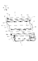
図1は、カートリッジ10が装着された画像形成装置1の断面図であり、その断面は上下方向及び前後方向に平行である。図1に示すように、画像形成装置1は、装置本体2内に用紙S(記録材)を供給するための給紙部3と、露光装置4と、用紙S上にトナー像を転写するカートリッジ10と、用紙S上に転写されたトナー像を熱定着する定着装置8を主に備えている。
<Overall Configuration of Image Forming Apparatus>
FIG. 1 is a cross-sectional view of the
給紙部3は、装置本体2内の下部に設けられ、給紙トレイ31と、給紙機構32とを主に備えている。給紙トレイ31に収容された用紙Sは、給紙機構32によってカートリッジ10(感光ドラム61と転写ローラ63との間)に向けて供給される。
The
露光装置4は、装置本体2内の上部に配置され、図示しないレーザ発光部や、符号を省略して示すポリゴンミラー、レンズ、反射鏡などを備えている。この露光装置4では、レーザ発光部から出射される画像データに基づくレーザ光が、感光ドラム61の表面で高速走査されることで、感光ドラム61の表面を露光する。
The
カートリッジ10は、露光装置4の下方に配置されている。装置本体2に設けられたドア(開閉部材)21を開いたとき(図1に二点鎖線で記載)にできる開口から装置本体2の収容部23に挿入方向S1で挿入され、装置本体2に装着される構成となっている。カートリッジ10を装置本体2から取り外す際は取り外し方向S2にカートリッジ10を移動させて取り出す。
The
このカートリッジ10はプロセスカートリッジ5とトナー容器9からなり、プロセスカートリッジ5は、主に感光体ユニット6と現像ユニット7を備えている。感光体ユニット6は、感光ドラム61と、コロナ帯電器68と、前露光部69と、回収ローラ62と、転写ローラ63とを主に備えている。現像ユニット7は、感光体ユニット6に対して着脱可能に装着される構成となっている。現像ユニット7は、現像ローラ71と、供給ローラ72と、層厚規制ブレード73と、トナーを収容するトナー収容部74と、トナー収容部74内に設けられる第1アジテータ75Aとを主に備えている。
This
<画像形成プロセス>
次にこのプロセスカートリッジ5を用いた画像形成プロセスについて説明する。図5はプロセスカートリッジ5の断面図である。感光ドラム61は、画像形成プロセス実行中に回転駆動されている。最初にコロナ帯電器68(帯電部材)により感光ドラム61の表面が一様に帯電され、その後、露光装置4(図1)から発せられる画像データに対応したレーザ光で露光されることで、感光ドラム61上に画像データに対応する静電潜像が形成される。
<Image forming process>
Next, an image forming process using this
一方で、トナー収容部74内のトナーは、第1アジテータ75Aで撹拌された後、供給ローラ72を介して現像ローラ71に供給される。そして、現像ローラ71に供給されたトナーは、現像ローラ71と層厚規制ブレード73の間に進入して一定厚さの薄層として現像ローラ71上に担持される。
On the other hand, the toner in the
現像ローラ71上に担持されたトナーは、感光ドラム61上に形成された静電潜像に供給される。これにより、静電潜像にトナーが付着して可視像化され、感光ドラム61上にトナー像が形成される。その後、感光ドラム61と転写ローラ63の間に用紙Sが搬送され、感光ドラム61上のトナー像が用紙S上に転写される。
The toner carried on the developing
次に、図1に示すように、定着装置8は、プロセスカートリッジ5の後方に配置され、加熱ローラ81と加圧ローラ82とを主に備えている。トナー像が転写された用紙Sはこの定着装置8を通過し、その際に、用紙Sが加熱ローラ81と加圧ローラ82との間で加熱及び加圧され、トナー像が用紙S上に定着させられる。定着装置8を通過した用紙Sは、排紙トレイ22上に排出される。
Next, as shown in FIG. 1, the fixing
図5を用いて上述したコロナ帯電器68は、非接触で感光ドラム61の表面を帯電する帯電ユニットである。前露光部69は光源としての発光ダイオードと導光部材としてのライトガイドを備え、発光ダイオードから出射された光をライトガイドで導き、感光ドラム61の表面に光を照射する。発光ダイオードに供給される電流は、装置本体2から供給される。前露光部69の光の照射により感光ドラム61の表面が除電される。また、回収ローラ62には装置本体2から所定の電圧が印加され、感光ドラム61の表面に付着した紙粉やゴミなどの異物やトナーを回収する。
The corona charger 68 described above with reference to FIG. 5 is a charging unit that charges the surface of the
<プロセスカートリッジ>
次にプロセスカートリッジ5の各ユニットについて説明する。前述のように、プロセスカートリッジ5は、感光体ユニット6(第1ユニット)と現像ユニット7(第2ユニット)を備えている。
<Process cartridge>
Next, each unit of the
<現像ユニット>
まず、現像ユニット7の構成について説明する。図2は、現像ユニット7の断面図であり、図3のA-A断面での断面図である。なおA-A断面は上下方向及び前後方向に平行である。図3は現像ユニット7の斜視図である。図4は、現像ユニット7の分解斜視図である。図6は、現像ユニット7の上視図であり、説明のため筐体700の天面を取り除いた状態を示している。図11は、現像ユニット7を下方から見た斜視図である。
<developing unit>
First, the configuration of the developing
現像ユニット7は、図2に示すように、筐体700の後方の一端に現像ローラ71が回転可能に支持されている。以降、現像ユニット7の構成に関して、現像ローラ71の回転軸線方向を軸方向と称して説明する。
As shown in FIG. 2, the developing
図4、図6に示すように、現像ローラ71、供給ローラ72、第1アジテータ(第1撹拌部材)75Aは、それぞれその両端を筐体700(第2枠体)の左側壁704と右側壁705に回転可能に支持されている。また、筐体700の左側壁704よりも左側には、現像カップリング710、現像ローラギア711、供給ローラギア712、第1アジテータギア713、アイドルギア715A、715Bが設けられている。現像ローラギア711は現像ローラ71の端部に固定され、供給ローラギア712は供給ローラ72の端部に固定されている。また、第1アジテータギア713は第1アジテータ75Aの撹拌棒78A(図5参照)の端部に固定されている。
As shown in FIGS. 4 and 6, the developing
また、現像ユニット7には、トナーを供給するためのトナー容器9が装着可能である。トナー収容部74は、現像ローラ71に担持させるトナーを収容し、トナー容器9により供給されたトナーを受け入れるためのトナー受入部770を有する。さらにトナー容器9を保持およびリフトアップするためのリフト機構760も備えている。
A
図3に示すように、現像ユニット7には、現像ローラ71に電気的に接続され、現像ローラ71に印加される電圧が供給される第1電気接点720Aが設けられる。また、供給ローラ72に電気的に接続され、供給ローラ72に印加される電圧が供給される第2接点720Bが設けられている。これらの電気接点が装置本体2に設けられた不図示の電力供給接点と接触することで、現像ローラ71、供給ローラ72に電力を供給する。
As shown in FIG. 3 , the developing
続いて、現像ユニット7の駆動構成について図4を用いて説明する。装置本体2に設けられたドア21(図1)を閉じる動作に連動して、装置本体2に設けられた不図示の現像駆動伝達部材が、現像カップリング710に係合するための位置へ移動する。逆にドア21(図1)を開く動作に連動して、現像駆動伝達部材(不図示)は、現像カップリング710との係合を解除する位置へ移動する。
Next, the driving structure of the developing
ドア21(図1)を閉めた後、装置本体2が動作すると、現像駆動伝達部材(不図示)から駆動力受部材としての現像カップリング710に駆動力が伝達(入力)される。次に、現像カップリング710の周面に設けられたギアから現像ローラギア711を介して現像ローラ71が、供給ローラギア712を介して供給ローラ72が回転可能となる。現像駆動伝達部材(不図示)は、現像カップリング710の所定範囲内での位置ずれを許容して、現像カップリング710に駆動力を伝達することができる構成となっている。現像カップリング710、現像ローラギア711、供給ローラギア712は、筐体700に取り付けられたサイドホルダ719によって、軸方向の移動を規制されている。
When the apparatus
図5に示すように、現像ユニット7は、第1アジテータ75Aを採用し、トナー収容部74内のトナーを撹拌し、最後まで使い切れるようにしている。第1アジテータ75Aは、撹拌棒78Aと撹拌シート79Aを備える。また、第1アジテータ75Aは、現像カップリング710からアイドルギア715Aを介して、第1アジテータギア713で駆動力を受けて回転可能に構成されている(図6参照)。トナー収容部74内の第1アジテータ75Aの近くにあるトナーは、第1アジテータ75Aで撹拌された後、供給ローラ72側へ供給され、更に供給ローラ72によって現像ローラ71に供給される。
As shown in FIG. 5, the developing
<感光体ユニット>
次に、感光体ユニット6の詳細構成について説明する。図7は、プロセスカートリッジ5の斜視図である。図8は、感光体ユニット6の部分斜視図である。図9は、現像ユニット7と感光体ユニット6の斜視図である。図10は、感光体ユニット6と現像ユニット7と現像ローラ71の左右方向の配置関係を示す上視図である。
<Photoconductor unit>
Next, the detailed configuration of the photoreceptor unit 6 will be described. 7 is a perspective view of the
感光体ユニット6は、図9に示すように、一対の左側壁611と右側壁612を有するフレーム610(第1枠体)と、フレーム610に回転可能に支持された感光ドラム61と、備える。感光ドラム61の軸線方向に交差する前後方向において、フレーム610の後方の一端部に感光ドラム61が支持され、前方の他端部に把持部617が設けられている。前後方向において、感光ドラム61と把持部617との間に現像ユニット7が装着可能な装着部615が設けられている。また、フレーム610には、現像ローラ71が感光ドラム61に接触するように現像ユニット7を押圧する押圧部材640が設けられている。
As shown in FIG. 9 , the photosensitive unit 6 includes a frame 610 (first frame) having a pair of
そして、図7に示すように、左右方向において左側壁611と右側壁612の間に装着部615に装着された現像ユニット7のトナー収容部74が配置される。
As shown in FIG. 7, the
図9に示すように、フレーム610の左側壁611、右側壁612には、感光ドラム61よりも前方に現像ローラ71の回転軸受け部材746A、及び746B(図7)を受ける受け部641が形成されている。受け部641は、前側が開放された略U字の凹部であり、現像ローラ71の回転軸(不図示)がその中に挿入される。受け部641は、現像ユニット7を感光体ユニット6に支持する。
As shown in FIG. 9, the
また、図10に示すように、フレーム610の底面613の左右方向で両端部に上方向に突出した突起部643を設けている。この突起部643は、図11に示す、現像ユニット7の筐体700の底部に設けられたボス718に当接することで現像ユニット7を支持している。
Further, as shown in FIG. 10,
また、本実施形態の構成においては、図7に示すように、感光体ユニット6に現像ユニット7を装着した状態において、現像ユニット7の取り外しができないようにする押え部材650が設けられている。
Further, in the configuration of this embodiment, as shown in FIG. 7, a pressing
図9に示すように、押圧部材640は、フレーム610の前方の左右方向に関して両端部に設けられ、付勢部材としての圧縮バネ640A(図10)により前から後へ向かう方向へ付勢されている。このため、圧縮バネ640A(図10)の付勢力により、押圧部材640は現像ユニット7の筐体700に設けられているボス718(図11)をそれぞれ押圧する。押圧部材640によって現像ユニット7を押圧することで、現像ローラ71を感光ドラム61に向けて付勢する。
As shown in FIG. 9, the
また、図8に示すように、感光ドラム61の左端部には感光体ギア(第1ギア)65と転写ギア(第2ギア)66が固定され、感光ドラム61と一体的に回転する構成となっている。プロセスカートリッジ5が装置本体2に装着されると、装置本体2の駆動ギア(不図示)と感光体ギア65とが噛合うことで、感光ドラム61及び転写ギア66に駆動力が伝達されて回転可能な状態となる。更に転写ギア66は転写ローラ63の左端部に固定された転写ローラギア(第3ギア)67(図1)に噛み合っており、転写ローラ63も回転可能な状態となる。
Further, as shown in FIG. 8, a photoreceptor gear (first gear) 65 and a transfer gear (second gear) 66 are fixed to the left end of the
<トナー容器>
次に、トナー容器9の構成について説明する。図12はトナー容器9の分解斜視図であり、図13はトナー容器9を下方から見た斜視図である。また、図14はトナー容器9の断面図である。
<Toner container>
Next, the configuration of the
トナー容器9は、図12に示すように、容器部材911と、底部材912と、TサイドホルダL92と、TサイドホルダR93と、排出口形成部材94と、排出側シャッター95と、搬送スクリュー96と、第2アジテータ97とを主に備える。また、駆動を伝達するために、搬送スクリューギア980と、Tアイドルギア981と、第2アジテータギア982とを備えている。
As shown in FIG. 12, the
図13に示すように、容器部材911と底部材912によりトナー容器910を形成し、内部にトナーを収容している。トナー容器910の長手方向の一端部には、排出口形成部材94が固定されている。排出口形成部材94は、外周部に排出口形成面94Cを有し、排出口形成面94Cにはトナーを外部へ排出するための排出口94A(トナー排出口)が形成される。
As shown in FIG. 13, a
また図14に示すように、搬送スクリュー96と第2アジテータ97はトナー容器910の内部に回転可能に設けられている。搬送スクリュー96と第2アジテータ97は、トナー容器910の外部に設けられた搬送スクリューギア980と第2アジテータギア982により駆動力を伝達されることでそれぞれ回転する(図12参照)。第2アジテータ97は、第1アジテータ75Aと同様に、第2撹拌棒98と第2撹拌シート99により構成されている。トナー容器910の内部に収容されたトナーは、第2アジテータ97により搬送スクリュー96に向けて撹拌および搬送され、次に搬送スクリュー96により図13に示す排出口94Aへ向けて搬送され、排出口94Aから排出される。
Further, as shown in FIG. 14, the conveying
図12に示すように、排出口形成部材94の内部には、排出口94Aを開閉できるように構成された排出側シャッター95(第2シャッター)が回転可能に設けられている。排出側シャッター95はトナー通過穴95Aおよび閉鎖部95Bが設けられており、このトナー通過穴95Aと排出口94Aが一致している場合にトナーが排出可能となる。一方で、閉鎖部95Bが排出口94Aと対向している場合にはトナーの排出を禁止し、運搬時などに内部のトナーが漏出することを防止している。
As shown in FIG. 12, inside the discharge
<トナー容器の支持構成>
次に、トナー容器9の支持構成について説明する。図15はトナー容器9とプロセスカートリッジ5の斜視図であり、(a)はトナー容器9の装着前の状態を、(b)はトナー容器9の装着過程の状態を、(c)はトナー容器9の装着完了の状態を示している。図15に示すように、トナー容器9は現像ユニット7に対して着脱可能な構成となっている。まず、トナー容器9の容器部材911には第2ユニット把持部としての把手部911Aが備えられている。トナー容器9の長手方向の両端部には、TサイドホルダL92およびTサイドホルダR93が固定されている。Tサイドホルダ92およびTサイドホルダ93は、現像ユニット7に支持されるための被支持突起92A(第1被支持部)および被支持突起93A(第2被支持部)をそれぞれ備えている。また、現像ユニット7には、被支持突起92Aおよび被支持突起93Aを支持するための、支持部730(第1支持部)および支持部731(第2支持部)が設けられている。
<Support Structure of Toner Container>
Next, the structure for supporting the
トナー容器9を現像ユニット7に装着する際は、図15(a)に示すように、現像ユニット7に対して上方から、把手部911Aを把持しながらトナー容器9を矢印S3方向へ移動させる。矢印S3方向へ移動されたトナー容器9は、図15(b)に示すように、被支持突起92Aおよび被支持突起93Aが支持部730および支持部731に仮支持された状態となる。この状態のカートリッジの姿勢を第1の姿勢とする。このトナー容器9が第1の姿勢にある状態からトナー容器9を被支持突起92Aおよび被支持突起93Aの中心の周りに回転させることで、図15(c)に示すように装着が完了する。このトナー容器9が現像ユニット7に装着完了した時のトナー容器9の姿勢を第2の姿勢とする。また、装着完了状態において、トナー容器9の搬送スクリューギア980が現像ユニット7のアイドルギア715Bと噛合うことができる。これにより、現像ユニット7の駆動力をトナー容器9へと伝達している。トナー容器9に収納されるトナー量から決まるトナー容器9の寿命は、感光ドラム61の寿命および現像ローラ71の寿命から決まるプロセスカートリッジ5の寿命に比べて短く設定されている。従って、寿命に到達したトナー容器9だけをプロセスカートリッジ5とは別に交換する必要がある。この場合に、ドア21(図1)を開くだけでトナー容器9の交換が可能となっており、ユーザはプロセスカートリッジ5を装置本体2内から取り出すことなく交換作業を行うことができる。
When attaching the
<受入側シャッター>
次に、受入側シャッター(第1シャッタ)の開閉動作について説明する。図16は現像ユニット7の受入側シャッターの開閉動作を示した図であり、(a)は受入側シャッターが閉じた状態を、(b)は受入側シャッターが開いた状態を表している。
<Receiving side shutter>
Next, the opening/closing operation of the receiving side shutter (first shutter) will be described. 16A and 16B are diagrams showing the opening and closing operation of the receiving side shutter of the developing
まず図4に示すように、現像ユニット7のトナー受入部770は、筐体700の上面に設けられたトナー受入口771、受入側シャッターシール772、受入側シャッター773、受入口カバー774、連結シール775により構成される。各部品にはそれぞれ穴部772A、773A、774A、775Aが設けられている。受入側シャッターシール772、受入口カバー774、連結シール775の穴部772A、774A、775Aはトナー受入口771と一致した状態で組み付けられている。また、受入側シャッター773は穴部773Aのほかに遮蔽部773Bを備え、スライド移動が可能な状態で組み付けられている。このスライド移動によってトナー受入口771の開閉を行う。
First, as shown in FIG. 4, the
受入側シャッター773の開閉動作は、図16に示すように、トナー容器9の着脱動作に連動して行われる。ここで、トナー容器9の排出口形成部材94の外周面には、駆動突起群94Bが配置されている。また、受入側シャッター773には被駆動突起群773Cが配置されている。
The opening/closing operation of the receiving
前述した通り、トナー容器9は現像ユニット7への装着過程において、回動動作を行うことで装着完了状態へと移行する。図16(a)は装着過程において回動動作を行う前の状態であり、この状態では受入側シャッター773の遮蔽部773Bがトナー受入口771と対向しており、トナー受入口771が閉じられた状態となっている。このとき、駆動突起群94Bと被駆動突起群773Cは係合した状態となっている。
As described above, the
続いて、トナー容器9を回動させて装着完了状態となっているのが図16(b)である。このとき、駆動突起群94Bと被駆動突起群773Cが係合を維持した状態でトナー容器9の回動動作を行うため、トナー容器9の回動動作に連動して受入側シャッター773がスライド移動する。これにより、受入側シャッター773の穴部773Aとトナー受入口771の位置が一致し、トナー受入口771が開かれた状態となる。
Next, FIG. 16B shows a state in which the
トナー容器9が現像ユニット7から離脱する際も同様に、トナー容器9の回動動作に連動して受入側シャッター773がスライド移動し、トナー受入口771が閉じた状態となる。
Similarly, when the
以上のように、現像ユニット7にトナー容器9が装着された状態においては、トナー受入口771が開いた状態となり、現像ユニット7の内部へのトナーの受入が可能となる。一方で、現像ユニット7にトナー容器9が装着されていない状態においては、トナー受入口771が閉じた状態となり、現像ユニット7の内部への異物の混入や、外部へのトナーの漏出を防止している。
As described above, when the
<排出側シャッター>
次に、排出側シャッター95の開閉動作について説明する。図17はトナー容器9の排出側シャッター95の開閉動作を示した図であり、(a)は排出側シャッター95が閉じた状態を、(b)は排出側シャッター95が開いた状態を表している。
<Exit shutter>
Next, the opening/closing operation of the
前述の通り、図12で示した排出口形成部材94の排出口94Aと、排出側シャッター95のトナー通過穴95Aの位置が一致している場合に排出口94Aが開いた状態となる。また、排出側シャッター95の閉鎖部95Bが排出口94Aと対向している場合には排出口94Aが閉じた状態となる。排出側シャッター95の開閉動作も、前述した受入側シャッター773の開閉動作と同様に、トナー容器9の装着・離脱時の回動動作に連動して行われる。
As described above, when the
図17に示すように、排出側シャッター95には被係止突起95Cが設けられており、被支持突起R93Aの半径方向内側に配置されている。また、現像ユニット7の支持部R731には係止部731Aおよび切欠部731Bが設けられている。
As shown in FIG. 17, the ejection-
図17(a)はトナー容器9の装着過程において回動動作を行う前の状態であり、この状態では排出側シャッター95の閉鎖部95B(図12)と排出口94A(図12)が対向しているため、排出口94A(図12)は閉じられた状態となっている。このとき、被係止突起95Cは係止部731Aに挟まれた状態となり、排出側シャッター95の現像ユニット7に対する回動動作を禁止された状態となる。
17(a) shows the state before the rotation operation is performed in the mounting process of the
続いて、トナー容器9を回動させて装着完了状態となっているのが図17(b)である。このとき、排出側シャッター95の回動動作が禁止されている状態でトナー容器9を現像ユニット7に対して回動させることとなる。ここで、被支持突起R93Aは切欠部731Bに入り込むことができるため、トナー容器9の、排出側シャッター95以外の回動が阻害されることはない。
Next, FIG. 17B shows a state in which the
以上より、トナー容器9の装着過程における回動動作により、相対的に、トナー容器9の内部で排出側シャッター95が回動することとなる。これにより排出側シャッター95のトナー通過穴95A(図12)と排出口94A(図12)の位置が一致し、排出口94A(図12)が開かれた状態となる。
As described above, the discharge-
トナー容器9が現像ユニット7から離脱する際も同様に、トナー容器9の回動動作に連動して排出側シャッター95が回動し、排出口94A(図12)が閉じられた状態となる。
Similarly, when the
<トナー容器のリフト機構>
続いて、トナー容器9のリフト機構760について説明する。図18はトナー容器9を装着する過程でのリフト機構760の動きを示しており、(a)はトナー容器9が装着過程でリフト機構760に載った状態を示している。(b)はトナー容器9が装着過程でリフト機構760を開く状態を示している。(c)はトナー容器9が装着完了した状態を示している。
<Toner container lift mechanism>
Next, the
図19は装着状態のトナー容器9をリフト機構760によりリフトアップ状態に移行する動きを示している。(a)はトナー容器9が装着完了した状態を示している。(b)はリフト機構760によりトナー容器9をリフトアップする様子を示している。(c)はトナー容器9がリフトアップ状態になった様子を示している。なお、図19は説明のために現像ユニット7のサイドホルダ719を省略している。
FIG. 19 shows the movement of the
図19に示すように、トナー容器9のTサイドホルダL92には突出部92Bが設けられており、突出部92Bは当接面92C、保持面92D、受け面92Eを備えている。また、図5に示すように、リフト機構760は現像ユニット7のサイドホルダ719に設けられたボス719A、リフト部材761、ねじりコイルばね762からなる。リフト部材761とねじりコイルばね762はボス719Aに取り付けられており、ボス719Aを中心として回動可能となっている。リフト部材761は当接部761A、操作部761B、持上部761Cを有する。また、リフト部材761はねじりコイルばね762によって、矢印R1方向に付勢されている。
As shown in FIG. 19, the T side holder L92 of the
まず、トナー容器9の装着過程におけるリフト機構760の動きについて図18を用いて説明する。
First, the movement of the
トナー容器9の装着過程で回動動作をしていくと、図18(a)に示すように、当接面92Cと当接部761Aが当接し、トナー容器9はリフト機構760に載った状態となる。次に、さらにトナー容器9の回動動作を続けると、図18(b)に示すように、当接面92Cに押されることによってリフト部材761が矢印R2方向に回動し、トナー容器9の回動動作を許容する。そして、さらに回動動作を続けトナー容器9の装着が完了すると、図18(c)に示すように、当接部761Aは当接面92Cから脱落し、保持面92Dと接触することとなる。これにより、リフト部材761によりトナー容器9を装着完了状態に保持しておくことができる。
As the
次に、トナー容器9を装着完了状態からリフトアップ状態に移行させる動きについて図19を用いて説明する。図19(a)に示すように、トナー容器9の装着完了状態においてはリフト部材761の当接部761Aは保持面92Dと当接しており、トナー容器9を取り外すことはできない。トナー容器9を取り外すためには、図19(b)に示すように、リフト部材761の操作部761Bを操作して、リフト部材761を矢印R2方向に回動させる。これにより、リフト部材761の持上部761Cが受け面92Eと当接し、トナー容器9を回動させることができる。その後操作部761Bを開放すると、図19(c)に示すように、リフト部材761はねじりコイルばね762の付勢力により矢印R1方向に回動する。当接面92Cと当接部761Bが当接した状態となり、トナー容器9がリフト機構760に載ったリフトアップ状態となる。これにより、トナー容器9を取り外すことが可能となる。
Next, the movement of shifting the
<メモリタグの配置>
次に、実施例1における、記憶部材としてのメモリタグ500(メモリ)の配置について説明する。
<Arrangement of memory tags>
Next, the arrangement of the memory tag 500 (memory) as a storage member in the first embodiment will be described.
図15に示すように、プロセスカートリッジ5はメモリタグ500を備えており、メモリタグ500は情報伝達接点500Aを有する。メモリタグ500は様々な情報の記憶・伝達が可能であり、装置本体2のタグ接点(不図示)と情報伝達接点500Aが電気的に接触することにより、情報の伝達を行う。
As shown in FIG. 15, the
メモリタグ500の情報伝達接点500Aが汚れると、装置本体2のタグ接点(不図示)との電気的な接触不良が発生し、情報伝達不良が発生する可能性が高くなるため、メモリタグ500は極力汚れ難い位置に配置するのが望ましい。また、現像ユニット7のトナー受入口771(図5)およびトナー容器9の排出口94Aの周辺は、トナー容器9をプロセスカートリッジ5に装着・離脱する動作の間にトナーが飛散しやすい箇所である。
If the
ここで、図7においてトナー収容部74は、感光体ドラム61の軸線方向において、右側の端部R(第1端部)と、それと反対側の端部である左側の端部L(第2端部)と、を有する。トナー受入口771(図7)および排出口94Aは、トナー収容部74の端部Rに設けられている。一方で、メモリタグ500は、感光ドラム61の軸線方向において、トナー収容部74の端部Lと同じ側のプロセスカートリッジ5の端部に設けられている。
Here, in FIG. 7, the
すなわち、感光ドラム61の軸線方向において、メモリタグ500はトナー受入口771(図7)および排出口94Aから離れた位置に配置されている。これは、トナー容器9を現像ユニット7に着脱する動作で飛散した飛散トナーがメモリタグ500に付着することを抑制するためである。
That is, in the axial direction of the
メモリタグ500のプロセスカートリッジ5における具体的な配置について説明する。
A specific arrangement of the
本実施例においては、図7及び図8に示すように、フレーム610の上側の面に保持される構成とした。図5に示すように、トナー受入口771は前後方向において感光体ドラム61よりも把持部617に近い位置に設けられ、メモリタグ500は把持部617よりも感光体ドラム61に近い位置に設けられている。メモリタグ500を前後方向においてもトナー受入口771から離れた位置に配置することにより、飛散トナーが付着し難い構成にしている。更に、メモリタグ500を前後方向において把持部617から離れた位置に配置することによってメモリタグ500にユーザが触れにくいようにしている。図5及び図9に示すように、メモリタグ500は、上下方向(第2方向)に見た場合に、感光体ドラム61及び帯電部材68とオーバラップする位置に設けられている。メモリタグ500は、感光体ドラム61とメモリタグ500との間に帯電部材68があるように設けられている。また、図5に示すように、メモリタグ500は、上下方向において、トナー受入口771に対して転写ローラ63から感光体ドラム61に向かう方向(下側から上側に向かう方向)に離れた位置に設けられている。メモリタグ500は、上下方向において、感光体ドラム61を挟んで転写ローラ63と反対側に設けられている。
In this embodiment, as shown in FIGS. 7 and 8, it is configured to be held on the upper surface of the
このようにメモリタグ500の配置を工夫することにより、トナー容器9を現像ユニット7に着脱する動作で飛散した飛散トナーがメモリタグ500に付着することを抑制することができる。
By devising the arrangement of the
〈変形例〉
メモリタグ500は、左右方向(感光ドラムの軸線方向)において、トナー収容部74の端部Lと同じ側のプロセスカートリッジ5の端部に設けられていれば、本実施例の位置に限定されない。本実施例の変形例1及び2の構成を図25(a)及び(b)に示す。図25(a)は、メモリタグ500をフレーム610の現像ユニット7が装着される側の面(底面613)と反対側の面に設けた構成である。図25(b)は、フレーム610は、現像ユニット7の筐体700と対向する面に開口部を有し、メモリ500は開口部から露出している筐体700の領域に設けられている。トナー受入口771が設けられている面と反対側の面は飛散トナーの影響を受け難い。
<Modification>
The
また、本実施例の変形例3の構成を図26に示す。メモリタグ500は、フレーム610のトナー収容部74の端部Lと同じ側の側面に設けられている。変形例3の構成は、感光体ドラム61の軸線方向においてトナー受入口771からの距離を最も長く確保することができる。
FIG. 26 shows the configuration of
尚、ここで述べた上下方向とは、前後方向(第1方向)と左右方向(感光ドラム61の軸線方向)との双方に交差する方向である。 The vertical direction mentioned here is a direction intersecting both the front-rear direction (first direction) and the left-right direction (the axial direction of the photosensitive drum 61).
変形例1、2、及び3についても、トナー容器9を現像ユニット7に着脱する動作で飛散した飛散トナーがメモリタグ500に付着することを抑制するという効果を奏する。
〔実施例2〕
次に実施例2について説明する。ここでは、実施例1と異なる部分についてのみ説明する。それ以外の部分については実施例1と同様であり、説明は省略する。
[Example 2]
Next, Example 2 will be described. Here, only parts different from the first embodiment will be described. Other parts are the same as those of the first embodiment, and the description thereof is omitted.
<メモリタグの配置>
実施例2におけるメモリタグ500の配置について説明する。図20は実施例2におけるカートリッジ10の斜視図である。図21は図20のB-B断面におけるカートリッジ10の断面図である。
<Arrangement of memory tags>
Arrangement of the
図15を用いて前述したように、ユーザは把手部911Aを把持しながらトナー容器9の交換作業を行う。このとき、ユーザは前後方向において前側から作業を行うため、把手部911Aの視認性や操作性の観点から、把手部911Aはトナー容器9の前側に配置することが一般的である。そして、このようなトナー容器9の交換作業を行う際にトナー容器9が通過する領域は、トナー容器9の装着完了位置よりも前側になると考えられる。したがって、トナー容器9の交換作業によるトナー飛散は、トナー受入口771(図5)および排出口94Aよりも前後方向において前側に集中する。
As described above with reference to FIG. 15, the user replaces the
ここで、図20に示すように、メモリタグ500は左右方向において、トナー受入口771および排出口94A(不図示)と同様に現像ローラ71(図4)の軸線方向の一端側の端部に設けられている。ただし、図21に示すように、メモリタグ500は前後方向においてトナー受入口771を境界としてトナー容器9の把手部911Aとは反対側に配置されている。
Here, as shown in FIG. 20, the
これにより、現像ローラ71(図4)の軸線方向においてメモリタグ500とトナー受入口771および排出口94Aが近くに配置されているが、トナー容器9の交換作業を行う際に飛散したトナーがメモリタグ500に付着し難い構成となっている。
As a result, the
〔実施例3〕
次に実施例3について説明する。ここでも、実施例1と異なる部分についてのみ説明する。それ以外の部分については実施例1と同様であり、説明は省略する。
[Example 3]
Next, Example 3 will be described. Also here, only parts different from the first embodiment will be described. Other parts are the same as those of the first embodiment, and the description thereof is omitted.
<メモリタグの配置>
実施例3におけるメモリタグ500の配置について説明する。図22は実施例3におけるカートリッジ10の斜視図である。
<Arrangement of memory tags>
Arrangement of the
図22に示すように、トナー受入口771よりも現像ローラ71(図4)の軸線方向の外側には壁部774Bが設けられている。また、メモリタグ500は壁部774Bよりもさらに、現像ローラ71(図4)の軸線方向の外側に設けられている。すなわち、トナー受入口771とメモリタグ500の間に壁部774Bが配置されている。
As shown in FIG. 22, a
これにより、トナー容器9の交換作業により飛散するトナーがメモリタグ500へ付着することを、壁部774Bにより遮ることが可能である。
As a result, the
〔実施例4〕
次に実施例4について説明する。ここでも、実施例1と異なる部分についてのみ説明する。それ以外の部分については実施例1と同様であり、説明は省略する。
[Example 4]
Next, Example 4 will be described. Also here, only parts different from the first embodiment will be described. Other parts are the same as those of the first embodiment, and the description thereof is omitted.
<メモリタグの配置>
実施例4におけるメモリタグ500の配置について説明する。図23は実施例4におけるカートリッジ10の下方からみた斜視図である。また、図24は図23におけるC-C断面におけるカートリッジ10の断面図である。
<Arrangement of memory tags>
Arrangement of the
図24に示すように、受入口カバー774はトナー容器9の排出口形成面94Cと対向する対向面774Cを備えている。ここで、メモリタグ500は、対向面774Cを境界として、排出口形成面94Cとは反対側に設けられている。これにより、トナー容器9の交換作業により飛散するトナーは、対向面774Cにより遮られるため、メモリタグ500が汚れることを防止することができる。
As shown in FIG. 24, the receiving
1 画像形成装置
2 装置本体
5 プロセスカートリッジ
6 感光体ユニット
7 現像ユニット
9 トナー容器
10 カートリッジ
61 感光ドラム
63 転写ローラ
68 コロナ帯電器
71 現像ローラ
74 トナー収容部
94A トナー排出口
95 排出側シャッター
500 メモリタグ
610 フレーム
700 筐体
771 トナー受入口
910 トナー容器
REFERENCE SIGNS
Claims (10)
感光ドラムと、回転軸線を中心に前記感光ドラムを回転可能に支持する第1枠体と、を有する第1ユニットであって、前記回転軸線の方向に交差する方向に関し一端部に前記感光ドラムを支持し、他端部に把持部を有する第1ユニットと、
前記感光ドラムにトナーを供給する現像ローラと、前記現像ローラに担持させるための前記トナーを収容し且つトナー受入口を有するトナー収容部を含む第2枠体と、を有し、前記第1ユニットに装着されている第2ユニットであって、前記交差する方向に関し前記感光ドラムと前記把持部との間に装着されている第2ユニットと、
前記第2ユニットに対して着脱可能に構成され、前記トナーを収容するトナー容器であって、前記トナー受入口を介して前記トナー収容部に前記トナーを排出するためのトナー排出口を有するトナー容器と、
情報を記憶するためのメモリと、
を備え、
前記トナー収容部は、前記回転軸線の方向に関し、第1端部と、前記第1端部と反対側の第2端部と、を有し、
前記トナー受入口は、前記トナー収容部の前記第1端部であって、前記交差する方向において前記感光ドラムよりも前記把持部に近い位置に設けられ、
前記メモリは、前記トナー収容部の前記第2端部と同じ側にある前記カートリッジの端部であって、前記交差する方向において前記把持部よりも前記感光ドラムに近い位置に設けられている、
ことを特徴とするカートリッジ。 A cartridge configured to be detachable from an apparatus main body of an image forming apparatus,
A first unit having a photosensitive drum and a first frame rotatably supporting the photosensitive drum about a rotation axis , wherein the photosensitive drum is mounted at one end in a direction intersecting the rotation axis. a first unit that supports and has a grip on the other end ;
a developing roller that supplies toner to the photosensitive drum; and a second frame that contains the toner to be carried on the developing roller and that includes a toner containing portion having a toner receiving opening; a second unit attached to the intersecting direction, the second unit attached between the photosensitive drum and the gripping portion ;
A toner container configured to be detachable from the second unit and containing the toner, the toner container having a toner discharge port for discharging the toner into the toner containing portion through the toner receiving port. and,
a memory for storing information;
with
The toner containing portion has a first end and a second end opposite to the first end with respect to the direction of the rotation axis,
The toner receiving port is provided at the first end of the toner containing portion and at a position closer to the gripping portion than the photosensitive drum in the intersecting direction,
The memory is provided at an end portion of the cartridge on the same side as the second end portion of the toner containing portion and at a position closer to the photosensitive drum than the grip portion in the intersecting direction .
A cartridge characterized by:
感光ドラムと、前記感光ドラムを帯電させる帯電部材と、回転軸線を中心に前記感光ドラムを回転可能に支持する第1枠体と、を有する第1ユニットであって、前記回転軸線の方向に交差する方向に関し一端部に前記感光ドラムを支持し、他端部に把持部を有する第1ユニットと、
前記感光ドラムにトナーを供給する現像ローラと、前記現像ローラに担持させるための前記トナーを収容し且つトナー受入口を有するトナー収容部を含む第2枠体と、を有し、前記第1ユニットに装着されている第2ユニットであって、前記交差する方向に関し前記感光ドラムと前記把持部との間に装着されている第2ユニットと、
前記第2ユニットに対して着脱可能に構成され、前記トナーを収容するトナー容器であって、前記トナー受入口を介して前記トナー収容部に前記トナーを排出するためのトナー排出口を有するトナー容器と、
情報を記憶するためのメモリと、
を備え、
前記トナー収容部は、前記回転軸線の方向に関し、第1端部と、前記第1端部と反対側の第2端部と、を有し、
前記トナー受入口は、前記トナー収容部の前記第1端部に設けられ、
前記メモリは、
前記トナー収容部の前記第2端部と同じ側にある前記カートリッジの端部に設けられ、
前記交差する方向を第1方向とした場合、前記第1方向と前記回転軸線の方向との双方に交差する第2方向に見た場合に、前記帯電部材とオーバラップしている、
ことを特徴とするカートリッジ。 A cartridge configured to be detachable from an apparatus main body of an image forming apparatus,
A first unit having a photosensitive drum, a charging member that charges the photosensitive drum, and a first frame that rotatably supports the photosensitive drum about a rotation axis, the first unit intersecting with the rotation axis. a first unit that supports the photosensitive drum at one end and has a grip at the other end;
a developing roller that supplies toner to the photosensitive drum; and a second frame that contains the toner to be carried on the developing roller and that includes a toner containing portion having a toner receiving opening; a second unit attached to the intersecting direction, the second unit attached between the photosensitive drum and the gripping portion;
A toner container configured to be detachable from the second unit and containing the toner, the toner container having a toner discharge port for discharging the toner into the toner containing portion through the toner receiving port. and,
a memory for storing information;
with
The toner containing portion has a first end and a second end opposite to the first end with respect to the direction of the rotation axis,
The toner receiving port is provided at the first end of the toner containing portion,
The memory is
provided at an end of the cartridge on the same side as the second end of the toner containing portion;
When the intersecting direction is defined as a first direction, the charging member overlaps with the charging member when viewed in a second direction intersecting both the first direction and the direction of the rotation axis .
A cartridge characterized by:
感光ドラムと、回転軸線を中心に前記感光ドラムを回転可能に支持する第1枠体と、を有する第1ユニットであって、前記回転軸線の方向に交差する方向に関し一端部に前記感光ドラムを支持し、他端部に把持部を有する第1ユニットと、
前記感光ドラムにトナーを供給する現像ローラと、前記現像ローラに担持させるための前記トナーを収容し且つトナー受入口を有するトナー収容部を含む第2枠体と、を有し、前記第1ユニットに装着されている第2ユニットであって、前記交差する方向に関し前記感光ドラムと前記把持部との間に装着されている第2ユニットと、
前記第2ユニットに対して着脱可能に構成され、前記トナーを収容するトナー容器であって、前記トナー受入口を介して前記トナー収容部に前記トナーを排出するためのトナー排出口を有するトナー容器と、
情報を記憶するためのメモリと、
を備え、
前記トナー収容部は、前記回転軸線の方向に関し、第1端部と、前記第1端部と反対側の第2端部と、を有し、
前記トナー受入口は、前記トナー収容部の前記第1端部に設けられ、
前記メモリは、
前記トナー収容部の前記第2端部と同じ側にある前記カートリッジの端部に設けられ、
前記交差する方向を第1方向とした場合、前記第1方向と前記回転軸線の方向との双方に交差する第2方向に見た場合に、前記感光ドラムとオーバラップしている、
ことを特徴とするカートリッジ。 A cartridge configured to be detachable from an apparatus main body of an image forming apparatus,
A first unit having a photosensitive drum and a first frame rotatably supporting the photosensitive drum about a rotation axis, wherein the photosensitive drum is mounted at one end in a direction intersecting the rotation axis. a first unit that supports and has a grip on the other end;
a developing roller that supplies toner to the photosensitive drum; and a second frame that contains the toner to be carried on the developing roller and that includes a toner containing portion having a toner receiving opening; a second unit attached to the intersecting direction, the second unit attached between the photosensitive drum and the gripping portion;
A toner container configured to be detachable from the second unit and containing the toner, the toner container having a toner discharge port for discharging the toner into the toner containing portion through the toner receiving port. and,
a memory for storing information;
with
The toner containing portion has a first end and a second end opposite to the first end with respect to the direction of the rotation axis,
The toner receiving port is provided at the first end of the toner containing portion,
The memory is
provided at an end of the cartridge on the same side as the second end of the toner containing portion;
When the intersecting direction is defined as a first direction, the photosensitive drum overlaps when viewed in a second direction intersecting both the first direction and the direction of the rotation axis ,
A cartridge characterized by:
感光ドラムと、前記感光ドラムから記録材へ画像を転写するための転写ローラと、回転軸線を中心に前記感光ドラムを回転可能に支持する第1枠体と、を有する第1ユニットであって、前記回転軸線の方向に交差する方向に関し一端部に前記感光ドラムを支持し、他端部に把持部を有する第1ユニットと、
前記感光ドラムにトナーを供給する現像ローラと、前記現像ローラに担持させるための前記トナーを収容し且つトナー受入口を有するトナー収容部を含む第2枠体と、を有し、前記第1ユニットに装着されている第2ユニットであって、前記交差する方向に関し前記感光ドラムと前記把持部との間に装着されている第2ユニットと、
前記第2ユニットに対して着脱可能に構成され、前記トナーを収容するトナー容器であって、前記トナー受入口を介して前記トナー収容部に前記トナーを排出するためのトナー排出口を有するトナー容器と、
情報を記憶するためのメモリと、
を備え、
前記トナー収容部は、前記回転軸線の方向に関し、第1端部と、前記第1端部と反対側の第2端部と、を有し、
前記トナー受入口は、前記トナー収容部の前記第1端部に設けられ、
前記メモリは、
前記トナー収容部の前記第2端部と同じ側にある前記カートリッジの端部に設けられ、
前記交差する方向を第1方向とした場合に、前記第1方向と前記回転軸線の方向との双方に交差する第2方向において、前記トナー受入口に対して前記転写ローラから前記感光ドラムに向かう方向に離れた位置に設けられている、
ことを特徴とするカートリッジ。 A cartridge configured to be detachable from an apparatus main body of an image forming apparatus,
A first unit having a photosensitive drum, a transfer roller for transferring an image from the photosensitive drum to a recording material, and a first frame supporting the photosensitive drum rotatably around a rotation axis, a first unit that supports the photosensitive drum at one end in a direction crossing the direction of the rotation axis and has a grip at the other end;
a developing roller that supplies toner to the photosensitive drum; and a second frame that contains the toner to be carried on the developing roller and that includes a toner containing portion having a toner receiving opening; a second unit attached to the intersecting direction, the second unit attached between the photosensitive drum and the gripping portion;
A toner container configured to be detachable from the second unit and containing the toner, the toner container having a toner discharge port for discharging the toner into the toner containing portion through the toner receiving port. and,
a memory for storing information;
with
The toner containing portion has a first end and a second end opposite to the first end with respect to the direction of the rotation axis,
The toner receiving port is provided at the first end of the toner containing portion,
The memory is
provided at an end of the cartridge on the same side as the second end of the toner containing portion;
In a second direction that intersects both the first direction and the direction of the rotation axis when the intersecting direction is defined as a first direction, the transfer roller is directed toward the photosensitive drum with respect to the toner receiving port. are provided in a direction away from each other ,
A cartridge characterized by:
前記メモリは、前記感光ドラムと前記メモリとの間に前記帯電部材があるように設けられていることを特徴とする請求項4又は5に記載のカートリッジ。 The first unit has a charging member that charges the photosensitive drum,
6. A cartridge according to claim 4 , wherein said memory is provided such that said charging member is between said photosensitive drum and said memory.
Priority Applications (9)
| Application Number | Priority Date | Filing Date | Title |
|---|---|---|---|
| JP2018242687A JP7224904B2 (en) | 2018-12-26 | 2018-12-26 | Cartridges used in image forming devices |
| US16/722,319 US11294299B2 (en) | 2018-12-26 | 2019-12-20 | Cartridge used in image forming apparatus |
| CN202310460812.3A CN116382053A (en) | 2018-12-26 | 2019-12-24 | Cartridge for use in image forming apparatus |
| CN202310458177.5A CN116382051A (en) | 2018-12-26 | 2019-12-24 | Cartridge for use in image forming apparatus |
| CN202310459346.7A CN116382052A (en) | 2018-12-26 | 2019-12-24 | Cartridge for use in image forming apparatus |
| CN201911341454.4A CN111381480B (en) | 2018-12-26 | 2019-12-24 | Cartridge for use in image forming apparatus |
| US17/684,973 US11709438B2 (en) | 2018-12-26 | 2022-03-02 | Cartridge used in image forming apparatus |
| JP2023003058A JP2023029599A (en) | 2018-12-26 | 2023-01-12 | Cartridge used on image forming device |
| US18/329,229 US20230314982A1 (en) | 2018-12-26 | 2023-06-05 | Cartridge used in image forming apparatus |
Applications Claiming Priority (1)
| Application Number | Priority Date | Filing Date | Title |
|---|---|---|---|
| JP2018242687A JP7224904B2 (en) | 2018-12-26 | 2018-12-26 | Cartridges used in image forming devices |
Related Child Applications (1)
| Application Number | Title | Priority Date | Filing Date |
|---|---|---|---|
| JP2023003058A Division JP2023029599A (en) | 2018-12-26 | 2023-01-12 | Cartridge used on image forming device |
Publications (2)
| Publication Number | Publication Date |
|---|---|
| JP2020106594A JP2020106594A (en) | 2020-07-09 |
| JP7224904B2 true JP7224904B2 (en) | 2023-02-20 |
Family
ID=71121735
Family Applications (2)
| Application Number | Title | Priority Date | Filing Date |
|---|---|---|---|
| JP2018242687A Active JP7224904B2 (en) | 2018-12-26 | 2018-12-26 | Cartridges used in image forming devices |
| JP2023003058A Pending JP2023029599A (en) | 2018-12-26 | 2023-01-12 | Cartridge used on image forming device |
Family Applications After (1)
| Application Number | Title | Priority Date | Filing Date |
|---|---|---|---|
| JP2023003058A Pending JP2023029599A (en) | 2018-12-26 | 2023-01-12 | Cartridge used on image forming device |
Country Status (3)
| Country | Link |
|---|---|
| US (3) | US11294299B2 (en) |
| JP (2) | JP7224904B2 (en) |
| CN (4) | CN116382053A (en) |
Families Citing this family (7)
| Publication number | Priority date | Publication date | Assignee | Title |
|---|---|---|---|---|
| JP7224904B2 (en) * | 2018-12-26 | 2023-02-20 | キヤノン株式会社 | Cartridges used in image forming devices |
| JP2021039173A (en) | 2019-08-30 | 2021-03-11 | ブラザー工業株式会社 | Drum cartridge |
| JP7472442B2 (en) | 2019-08-30 | 2024-04-23 | ブラザー工業株式会社 | Drum cartridge and image forming apparatus |
| US11314193B2 (en) * | 2019-12-25 | 2022-04-26 | Canon Kabushiki Kaisha | Foreign substance collection apparatus, process cartridge, and image forming apparatus |
| US11454901B2 (en) * | 2020-08-10 | 2022-09-27 | Jiangxi Yibo E-Tech Co. Ltd. | Developing cartridge |
| JP2022174917A (en) * | 2021-05-12 | 2022-11-25 | キヤノン株式会社 | Developer storage device, developing device, cartridge, and image forming apparatus |
| JP2023085039A (en) * | 2021-12-08 | 2023-06-20 | 沖電気工業株式会社 | Developing device and image forming apparatus |
Citations (5)
| Publication number | Priority date | Publication date | Assignee | Title |
|---|---|---|---|---|
| JP2007199505A (en) | 2006-01-27 | 2007-08-09 | Toshiba Corp | Developer supply device |
| JP2018010243A (en) | 2016-07-15 | 2018-01-18 | ブラザー工業株式会社 | Drum cartridge |
| JP2018025673A (en) | 2016-08-10 | 2018-02-15 | 京セラドキュメントソリューションズ株式会社 | Image forming apparatus |
| JP2018146829A (en) | 2017-03-07 | 2018-09-20 | ブラザー工業株式会社 | Drum cartridge and process cartridge |
| JP2018180379A (en) | 2017-04-17 | 2018-11-15 | キヤノン株式会社 | Image forming apparatus |
Family Cites Families (21)
| Publication number | Priority date | Publication date | Assignee | Title |
|---|---|---|---|---|
| KR0131958B1 (en) * | 1994-11-10 | 1998-10-01 | 김광호 | Alarm method and device of process cartridge changing time |
| JP2004126528A (en) * | 2002-08-06 | 2004-04-22 | Ricoh Co Ltd | Image forming apparatus, process cartridge used therefor, photoreceptor unit, developing unit, and method for correcting image dispacement |
| EP1821160A4 (en) * | 2004-12-09 | 2013-01-16 | Seiko Epson Corp | Development apparatus, image forming apparatus, image forming system, cartridge, development unit and photoreceptor unit |
| JP2008107698A (en) * | 2006-10-27 | 2008-05-08 | Seiko Epson Corp | Image forming apparatus and image forming method |
| JP4862701B2 (en) | 2007-03-12 | 2012-01-25 | ブラザー工業株式会社 | Developer cartridge |
| JP4985030B2 (en) * | 2007-03-29 | 2012-07-25 | ブラザー工業株式会社 | Image forming apparatus |
| US7742717B2 (en) * | 2007-09-11 | 2010-06-22 | Samsung Electronics Co., Ltd. | Developing device, memory unit thereof, and image forming apparatus |
| JP5380918B2 (en) | 2008-06-20 | 2014-01-08 | コニカミノルタ株式会社 | Image forming apparatus, image forming apparatus control method, and image forming apparatus control program |
| JP5003709B2 (en) * | 2009-03-31 | 2012-08-15 | ブラザー工業株式会社 | Image forming apparatus |
| US8532542B2 (en) * | 2009-07-23 | 2013-09-10 | Ricoh Company, Limited | Toner container and manufacturing method for toner container |
| JP5182313B2 (en) * | 2010-03-24 | 2013-04-17 | ブラザー工業株式会社 | Process cartridge |
| JP2013167685A (en) | 2012-02-14 | 2013-08-29 | Sharp Corp | Image forming apparatus |
| JP6314818B2 (en) * | 2014-12-19 | 2018-04-25 | 京セラドキュメントソリューションズ株式会社 | Toner container and image forming apparatus to which toner container is attached |
| JP6048853B2 (en) * | 2015-09-08 | 2016-12-21 | 株式会社リコー | Developer container, developing device, process unit, and image forming apparatus |
| CN205827060U (en) * | 2016-06-13 | 2016-12-21 | 江西亿铂电子科技有限公司 | A kind of Delevoping cartridge |
| JP6764816B2 (en) * | 2017-03-24 | 2020-10-07 | 株式会社沖データ | Development unit, image forming unit and image forming device |
| JP2018194660A (en) * | 2017-05-17 | 2018-12-06 | ブラザー工業株式会社 | Image forming apparatus |
| US10627780B2 (en) * | 2018-01-23 | 2020-04-21 | Canon Kabushiki Kaisha | Cartridge and image forming apparatus |
| JP7305942B2 (en) * | 2018-09-27 | 2023-07-11 | ブラザー工業株式会社 | image forming device |
| JP7224904B2 (en) * | 2018-12-26 | 2023-02-20 | キヤノン株式会社 | Cartridges used in image forming devices |
| JP7071309B2 (en) * | 2019-04-26 | 2022-05-18 | キヤノン株式会社 | Cartridge and image forming equipment |
-
2018
- 2018-12-26 JP JP2018242687A patent/JP7224904B2/en active Active
-
2019
- 2019-12-20 US US16/722,319 patent/US11294299B2/en active Active
- 2019-12-24 CN CN202310460812.3A patent/CN116382053A/en active Pending
- 2019-12-24 CN CN202310458177.5A patent/CN116382051A/en active Pending
- 2019-12-24 CN CN202310459346.7A patent/CN116382052A/en active Pending
- 2019-12-24 CN CN201911341454.4A patent/CN111381480B/en active Active
-
2022
- 2022-03-02 US US17/684,973 patent/US11709438B2/en active Active
-
2023
- 2023-01-12 JP JP2023003058A patent/JP2023029599A/en active Pending
- 2023-06-05 US US18/329,229 patent/US20230314982A1/en active Pending
Patent Citations (5)
| Publication number | Priority date | Publication date | Assignee | Title |
|---|---|---|---|---|
| JP2007199505A (en) | 2006-01-27 | 2007-08-09 | Toshiba Corp | Developer supply device |
| JP2018010243A (en) | 2016-07-15 | 2018-01-18 | ブラザー工業株式会社 | Drum cartridge |
| JP2018025673A (en) | 2016-08-10 | 2018-02-15 | 京セラドキュメントソリューションズ株式会社 | Image forming apparatus |
| JP2018146829A (en) | 2017-03-07 | 2018-09-20 | ブラザー工業株式会社 | Drum cartridge and process cartridge |
| JP2018180379A (en) | 2017-04-17 | 2018-11-15 | キヤノン株式会社 | Image forming apparatus |
Also Published As
| Publication number | Publication date |
|---|---|
| US11294299B2 (en) | 2022-04-05 |
| US20220269192A1 (en) | 2022-08-25 |
| US20230314982A1 (en) | 2023-10-05 |
| CN111381480A (en) | 2020-07-07 |
| CN116382053A (en) | 2023-07-04 |
| US20200209780A1 (en) | 2020-07-02 |
| US11709438B2 (en) | 2023-07-25 |
| CN116382052A (en) | 2023-07-04 |
| CN116382051A (en) | 2023-07-04 |
| CN111381480B (en) | 2023-05-05 |
| JP2020106594A (en) | 2020-07-09 |
| JP2023029599A (en) | 2023-03-03 |
Similar Documents
| Publication | Publication Date | Title |
|---|---|---|
| JP7224904B2 (en) | Cartridges used in image forming devices | |
| JP4882517B2 (en) | Process unit and image forming apparatus | |
| JP4635645B2 (en) | Image forming apparatus and toner cartridge | |
| JP3595798B2 (en) | Process cartridge and electrophotographic image forming apparatus | |
| EP1722279A1 (en) | Process cartridge with attachable toner cartridge exerting a pressure to urge the developing roller towards the image carrier | |
| JP4798300B2 (en) | Process cartridge and image forming apparatus | |
| JP2021114003A (en) | Process cartridge, photoreceptor unit, and development unit | |
| JP5212758B1 (en) | Developer container, developing device, process unit, and image forming apparatus | |
| JP2004077565A (en) | Attachable/detachable member, developing device, processing device and image forming apparatus | |
| JP2024040277A (en) | cartridge | |
| JP2012230372A (en) | Image forming apparatus | |
| JP4882516B2 (en) | Process unit and developer cartridge | |
| JP2022013378A (en) | Cartridge, image forming apparatus, and method for manufacturing cartridge | |
| JP4737304B2 (en) | Image forming apparatus | |
| US20220236661A1 (en) | Image forming apparatus and cartridge | |
| EP2073074B1 (en) | Developer cartridge and developing device | |
| JP2006154867A (en) | Detaching member, developing unit, process device and image forming apparatus | |
| JP7455577B2 (en) | process cartridge | |
| JP4775514B2 (en) | Image forming apparatus | |
| JP6884832B2 (en) | Photoreceptor cartridge and process cartridge | |
| JP2021107914A (en) | Cartridge unit | |
| CN113050399A (en) | Cartridge unit | |
| JP2022174917A (en) | Developer storage device, developing device, cartridge, and image forming apparatus | |
| JP2021103292A (en) | Foreign substance recovery device, process cartridge, and image forming apparatus | |
| JP2010181765A (en) | Developer container and developing device |
Legal Events
| Date | Code | Title | Description |
|---|---|---|---|
| A621 | Written request for application examination |
Free format text: JAPANESE INTERMEDIATE CODE: A621 Effective date: 20211215 |
|
| A977 | Report on retrieval |
Free format text: JAPANESE INTERMEDIATE CODE: A971007 Effective date: 20221020 |
|
| A131 | Notification of reasons for refusal |
Free format text: JAPANESE INTERMEDIATE CODE: A131 Effective date: 20221101 |
|
| A521 | Request for written amendment filed |
Free format text: JAPANESE INTERMEDIATE CODE: A523 Effective date: 20221221 |
|
| TRDD | Decision of grant or rejection written | ||
| A01 | Written decision to grant a patent or to grant a registration (utility model) |
Free format text: JAPANESE INTERMEDIATE CODE: A01 Effective date: 20230110 |
|
| A61 | First payment of annual fees (during grant procedure) |
Free format text: JAPANESE INTERMEDIATE CODE: A61 Effective date: 20230208 |
|
| R151 | Written notification of patent or utility model registration |
Ref document number: 7224904 Country of ref document: JP Free format text: JAPANESE INTERMEDIATE CODE: R151 |