JP7063809B2 - Laundry processing equipment and its water supply valve control method - Google Patents
Laundry processing equipment and its water supply valve control method Download PDFInfo
- Publication number
- JP7063809B2 JP7063809B2 JP2018534635A JP2018534635A JP7063809B2 JP 7063809 B2 JP7063809 B2 JP 7063809B2 JP 2018534635 A JP2018534635 A JP 2018534635A JP 2018534635 A JP2018534635 A JP 2018534635A JP 7063809 B2 JP7063809 B2 JP 7063809B2
- Authority
- JP
- Japan
- Prior art keywords
- water supply
- supply valve
- opened
- water
- nozzle
- Prior art date
- Legal status (The legal status is an assumption and is not a legal conclusion. Google has not performed a legal analysis and makes no representation as to the accuracy of the status listed.)
- Active
Links
Images


Classifications
-
- D—TEXTILES; PAPER
- D06—TREATMENT OF TEXTILES OR THE LIKE; LAUNDERING; FLEXIBLE MATERIALS NOT OTHERWISE PROVIDED FOR
- D06F—LAUNDERING, DRYING, IRONING, PRESSING OR FOLDING TEXTILE ARTICLES
- D06F25/00—Washing machines with receptacles, e.g. perforated, having a rotary movement, e.g. oscillatory movement, the receptacle serving both for washing and for centrifugally separating water from the laundry and having further drying means, e.g. using hot air
-
- D—TEXTILES; PAPER
- D06—TREATMENT OF TEXTILES OR THE LIKE; LAUNDERING; FLEXIBLE MATERIALS NOT OTHERWISE PROVIDED FOR
- D06F—LAUNDERING, DRYING, IRONING, PRESSING OR FOLDING TEXTILE ARTICLES
- D06F37/00—Details specific to washing machines covered by groups D06F21/00 - D06F25/00
- D06F37/02—Rotary receptacles, e.g. drums
- D06F37/04—Rotary receptacles, e.g. drums adapted for rotation or oscillation about a horizontal or inclined axis
-
- D—TEXTILES; PAPER
- D06—TREATMENT OF TEXTILES OR THE LIKE; LAUNDERING; FLEXIBLE MATERIALS NOT OTHERWISE PROVIDED FOR
- D06F—LAUNDERING, DRYING, IRONING, PRESSING OR FOLDING TEXTILE ARTICLES
- D06F39/00—Details of washing machines not specific to a single type of machines covered by groups D06F9/00 - D06F27/00
- D06F39/08—Liquid supply or discharge arrangements
- D06F39/088—Liquid supply arrangements
-
- D—TEXTILES; PAPER
- D06—TREATMENT OF TEXTILES OR THE LIKE; LAUNDERING; FLEXIBLE MATERIALS NOT OTHERWISE PROVIDED FOR
- D06F—LAUNDERING, DRYING, IRONING, PRESSING OR FOLDING TEXTILE ARTICLES
- D06F37/00—Details specific to washing machines covered by groups D06F21/00 - D06F25/00
- D06F37/20—Mountings, e.g. resilient mountings, for the rotary receptacle, motor, tub or casing; Preventing or damping vibrations
- D06F37/22—Mountings, e.g. resilient mountings, for the rotary receptacle, motor, tub or casing; Preventing or damping vibrations in machines with a receptacle rotating or oscillating about a horizontal axis
-
- D—TEXTILES; PAPER
- D06—TREATMENT OF TEXTILES OR THE LIKE; LAUNDERING; FLEXIBLE MATERIALS NOT OTHERWISE PROVIDED FOR
- D06F—LAUNDERING, DRYING, IRONING, PRESSING OR FOLDING TEXTILE ARTICLES
- D06F58/00—Domestic laundry dryers
- D06F58/20—General details of domestic laundry dryers
- D06F58/206—Heat pump arrangements
-
- D—TEXTILES; PAPER
- D06—TREATMENT OF TEXTILES OR THE LIKE; LAUNDERING; FLEXIBLE MATERIALS NOT OTHERWISE PROVIDED FOR
- D06F—LAUNDERING, DRYING, IRONING, PRESSING OR FOLDING TEXTILE ARTICLES
- D06F58/00—Domestic laundry dryers
- D06F58/20—General details of domestic laundry dryers
- D06F58/22—Lint collecting arrangements
Description
本発明は、洗濯物処理装置及びその給水弁制御方法に関する。 The present invention relates to a laundry processing device and a water supply valve control method thereof.
周知のように、洗濯物処理装置は、衣類又は洗濯物を洗濯過程及びすすぎ過程により処理(洗濯)する装置の一種である。 As is well known, a laundry processing device is a kind of device that processes (washes) clothes or laundry by a washing process and a rinsing process.
前記洗濯物とは、衣類だけでなく、布団などの寝具類、カーテン、ぬいぐるみなど、洗濯可能な物品を意味する。 The laundry means not only clothes but also bedding such as futons, curtains, stuffed animals, and other washable items.
前記洗濯物処理装置は、洗濯された衣類又は洗濯物を予め設定された速度で回転させて水分を除去する脱水機能を備える。 The laundry processing device has a dehydration function of rotating washed clothes or laundry at a preset speed to remove water.
前記洗濯物処理装置のうち一部は、洗濯機能に加え、洗濯された衣類又は洗濯物に加熱された空気を供給して乾燥させる乾燥機能を備えるように構成される。 A part of the laundry processing apparatus is configured to have a drying function of supplying heated air to the washed clothes or the laundry to dry the washed clothes or the laundry in addition to the washing function.
前記洗濯機能及び前記乾燥機能を備えた洗濯物処理装置のうち一部は、水槽と、前記水槽の空気を前記水槽の外部に取り出して処理した後に前記水槽の内部に再流入させる循環流路と、前記循環流路に備えられる乾燥モジュールとを備える。 A part of the laundry processing apparatus having the washing function and the drying function includes a water tank and a circulation flow path in which the air in the water tank is taken out of the water tank for processing and then re-flowed into the inside of the water tank. , A drying module provided in the circulation flow path.
前記乾燥モジュールのうち一部は、ヒートポンプを備えて構成される。 Some of the drying modules are configured with a heat pump.
前記循環流路には、前記水槽から取り出された空気中のリントを捕集できるように、リントフィルタが備えられる。 The circulation flow path is provided with a lint filter so that lint in the air taken out from the water tank can be collected.
前記ヒートポンプは、前記循環流路の内部に備えられて空気を冷却する蒸発器、前記空気を加熱できるように配置される凝縮器、前記凝縮器に圧縮された冷媒を供給する圧縮機、及び凝縮された冷媒を膨張させる膨張装置を備えて構成される。 The heat pump includes an evaporator provided inside the circulation flow path for cooling air, a condenser arranged so as to be able to heat the air, a compressor for supplying a compressed refrigerant to the condenser, and a condenser. It is configured with an expansion device that expands the condensed refrigerant.
前記リントフィルタ又は前記蒸発器には循環する空気中のリントを含む異物が付着する。 Foreign matter containing lint in the circulating air adheres to the lint filter or the evaporator.
前記リントフィルタ及び前記蒸発器には、水を供給して前記リントフィルタ及び前記蒸発器に付着した異物を除去するノズルがそれぞれ備えられる。 The lint filter and the evaporator are each provided with a nozzle for supplying water to remove foreign matter adhering to the lint filter and the evaporator.
前記各ノズルの給水流路には給水弁がそれぞれ備えられる。 A water supply valve is provided in the water supply flow path of each nozzle.
前記給水弁は、予め設定された回数で前記給水流路を開閉して前記リントフィルタ及び前記蒸発器に水が供給されるようにする。 The water supply valve opens and closes the water supply flow path a preset number of times so that water is supplied to the lint filter and the evaporator.
しかし、このような従来の洗濯物処理装置においては、各ノズルに水を選択的に供給するために給水弁を予め設定された回数でそれぞれ開閉するようになっており、給水弁の閉鎖時の圧力変化により給水流路に衝撃が加わる、いわゆるウォータハンマ(WATER HAMMERING)効果という水撃作用が発生するという問題がある。 However, in such a conventional laundry treatment device, the water supply valve is opened and closed a preset number of times in order to selectively supply water to each nozzle, and when the water supply valve is closed, the water supply valve is opened and closed. There is a problem that a water hammer action called the WATER HAMMERING effect, in which an impact is applied to the water supply flow path due to a pressure change, occurs.
前記給水弁の選択的な開閉により水撃作用が発生した場合、前記給水流路の強制劣化が促進されて寿命が短縮されるという問題がある。 When a water hammer action occurs due to the selective opening and closing of the water supply valve, there is a problem that forced deterioration of the water supply flow path is promoted and the life is shortened.
また、前記給水弁の閉鎖時の衝撃圧及び振動が前記給水弁の故障の原因となり、前記給水弁の寿命が短縮されることがある。 In addition, the impact pressure and vibration when the water supply valve is closed may cause a failure of the water supply valve, and the life of the water supply valve may be shortened.
さらに、前記給水弁の閉鎖時の衝撃及び/又は振動による騒音が発生することがある。 Further, noise due to impact and / or vibration when the water supply valve is closed may be generated.
そこで、本発明は、掃除のための給水時の水撃作用の発生を抑制できる洗濯物処理装置及びその給水弁制御方法を提供することを目的とする。 Therefore, an object of the present invention is to provide a laundry treatment device capable of suppressing the occurrence of water hammer during water supply for cleaning and a water supply valve control method thereof.
また、本発明は、掃除のための給水時の衝撃及び騒音の発生を抑制できる洗濯物処理装置及びその給水弁制御方法を提供することを他の目的とする。 Another object of the present invention is to provide a laundry treatment device capable of suppressing the generation of impact and noise during water supply for cleaning and a water supply valve control method thereof.
本発明は、上記目的を達成するために、水槽及び前記水槽の空気を取り出して前記水槽の外部を経由して循環させる循環流路を備えた洗濯物処理装置本体と、前記循環流路に備えられて水を噴射する複数の掃除ノズルと、一側は給水源に連結されて他側は前記複数の掃除ノズルにそれぞれ連結される複数の給水流路と、前記複数の給水流路をそれぞれ開閉する複数の給水弁と、前記複数の掃除ノズルのいずれかは開放されて前記給水源の水が連続的に流出するように、前記複数の給水弁の少なくとも1つが開放された状態で他の1つが閉鎖されるように前記複数の給水弁を順次制御する制御部とを含む、洗濯物処理装置を提供する。 In order to achieve the above object, the present invention is provided with a laundry processing apparatus main body provided with a water tank and a circulation flow path for taking out air from the water tank and circulating it via the outside of the water tank, and the circulation flow path. It opens and closes a plurality of cleaning nozzles that are sprayed with water, a plurality of water supply channels that are connected to a water supply source on one side and are connected to the plurality of cleaning nozzles on the other side, and the plurality of water supply channels. The other one with at least one of the plurality of water supply valves open so that the plurality of water supply valves and one of the plurality of cleaning nozzles are opened so that the water of the water supply source continuously flows out. Provided is a laundry processing apparatus including a control unit that sequentially controls the plurality of water supply valves so that one is closed.
一実施形態において、前記洗濯物処理装置本体は、外観を形成するキャビネットと、前記水槽の内部に回転可能に備えられる回転槽とをさらに含んでもよい。 In one embodiment, the laundry processing apparatus main body may further include a cabinet forming an appearance and a rotary tub rotatably provided inside the water tub.
前記水槽は、前記キャビネットの内部に備えられてもよい。 The water tank may be provided inside the cabinet.
一実施形態において、前記循環流路には、空気中のリントを捕集するリントフィルタ、及び空気と熱交換する熱交換器を備えたヒートポンプが備えられてもよい。 In one embodiment, the circulation flow path may be provided with a lint filter that collects lint in the air and a heat pump provided with a heat exchanger that exchanges heat with the air.
一実施形態において、前記複数の掃除ノズルは、前記リントフィルタに水を噴射するリントフィルタノズル、及び前記熱交換器に水を噴射する熱交換器ノズルを備えてもよい。 In one embodiment, the plurality of cleaning nozzles may include a lint filter nozzle that injects water into the lint filter and a heat exchanger nozzle that injects water into the heat exchanger.
一実施形態において、前記制御部は、前記リントフィルタノズル及び前記熱交換器ノズルのいずれか一方の給水弁が開放され、前記リントフィルタノズル及び前記熱交換器ノズルの他方の給水弁が開放され、次に前記リントフィルタノズル及び前記熱交換器ノズルの給水弁のうち先に開放された給水弁が閉鎖され、前記リントフィルタノズル及び前記熱交換器ノズルの給水弁のうち先に閉鎖された給水弁が開放され、その後前記リントフィルタノズル及び前記熱交換器ノズルの給水弁のうち後に開放された給水弁が閉鎖される順序で、前記リントフィルタノズル及び前記熱交換器ノズルの給水弁が予め設定された回数で開閉されるように制御するように構成されてもよい。 In one embodiment, in the control unit, one of the water supply valves of the lint filter nozzle and the heat exchanger nozzle is opened, and the other water supply valve of the lint filter nozzle and the heat exchanger nozzle is opened. Next, the water supply valve that was opened earlier among the water supply valves of the lint filter nozzle and the heat exchanger nozzle was closed, and the water supply valve that was closed earlier among the water supply valves of the lint filter nozzle and the heat exchanger nozzle was closed. Is opened, and then the water supply valves of the lint filter nozzle and the heat exchanger nozzle are preset in the order in which the later opened water supply valves of the water supply valves of the lint filter nozzle and the heat exchanger nozzle are closed. It may be configured to be controlled so as to be opened and closed by the number of times.
一実施形態において、前記制御部は、前記リントフィルタノズル及び前記熱交換器ノズルのいずれか一方の給水弁を開放し、その後先に開放された給水弁の閉鎖時点より予め設定された時間前に前記リントフィルタノズル及び前記熱交換器ノズルの他方の給水弁を開放するように構成されてもよい。 In one embodiment, the control unit opens the water supply valve of either the lint filter nozzle or the heat exchanger nozzle, and then opens the water supply valve at a preset time before the closing time of the previously opened water supply valve. The lint filter nozzle and the other water supply valve of the heat exchanger nozzle may be configured to open.
一実施形態において、前記リントフィルタノズル及び前記熱交換器ノズルのいずれか一方は、複数で構成されてもよい。 In one embodiment, either one of the lint filter nozzle and the heat exchanger nozzle may be configured by a plurality.
一実施形態において、前記洗濯物処理装置は、前記掃除ノズルの設置領域の掃除時期を検知する検知部をさらに含んでもよい。 In one embodiment, the laundry processing device may further include a detection unit that detects the cleaning time of the installation area of the cleaning nozzle.
一実施形態において、前記制御部は、前記検知部により前記掃除ノズルの設置領域の掃除時期が検知されると、前記複数の給水弁が順次開閉されるように制御するように構成されてもよい。 In one embodiment, the control unit may be configured to control the plurality of water supply valves to be sequentially opened and closed when the detection unit detects the cleaning time of the installation area of the cleaning nozzle. ..
一方、本発明の他の態様によれば、水槽及び前記水槽の空気を取り出して前記水槽の外部を経由して循環させる循環流路を備えた洗濯物処理装置本体と、前記循環流路に備えられて水を噴射する複数の掃除ノズルと、一側は給水源に連結されて他側は前記複数の掃除ノズルにそれぞれ連結される複数の給水流路と、前記複数の給水流路をそれぞれ開閉する複数の給水弁とを備えた洗濯物処理装置の給水弁制御方法であって、前記複数の給水弁の少なくとも1つを開放する段階と、前記複数の給水弁の少なくとも1つが開放された状態で閉鎖された給水弁の少なくとも1つを開放する段階と、複数の開放された給水弁のうち先に開放された給水弁を閉鎖する段階とを含む、洗濯物処理装置の給水弁制御方法を提供する。 On the other hand, according to another aspect of the present invention, the main body of the laundry processing apparatus provided with the water tank and the circulation flow path for taking out the air from the water tank and circulating the air through the outside of the water tank, and the circulation flow path. It opens and closes a plurality of cleaning nozzles that are sprayed with water, a plurality of water supply channels that are connected to a water supply source on one side and connected to the plurality of cleaning nozzles on the other side, and the plurality of water supply channels. A water supply valve control method for a laundry treatment device including a plurality of water supply valves, wherein at least one of the plurality of water supply valves is opened and at least one of the plurality of water supply valves is opened. A method for controlling a water supply valve of a laundry treatment device, which includes a stage of opening at least one of the water supply valves closed in the water supply valve and a stage of closing the water supply valve opened first among a plurality of opened water supply valves. offer.
一実施形態において、前記複数の給水弁は、予め設定された回数でそれぞれ開閉され、前記洗濯物処理装置の給水弁制御方法は、前記複数の給水弁が前記予め設定された回数でそれぞれ開閉されるように、前記複数の給水弁の少なくとも1つが開放された状態で複数の給水弁のうち閉鎖された給水弁の少なくとも1つを開放する段階、及び前記複数の開放された給水弁のうち先に開放された給水弁を閉鎖する段階を繰り返す段階をさらに含んでもよい。 In one embodiment, the plurality of water supply valves are opened and closed by a preset number of times, and the water supply valve control method of the laundry processing device is such that the plurality of water supply valves are opened and closed by the preset number of times. As such, the stage of opening at least one of the closed water supply valves among the plurality of water supply valves with at least one of the plurality of water supply valves open, and the first of the plurality of opened water supply valves. It may further include a step of repeating the step of closing the water supply valve opened to the water supply valve.
一実施形態において、前記循環流路には、空気中のリントを捕集するリントフィルタ、及び空気と熱交換する熱交換器を備えたヒートポンプが備えられ、前記掃除ノズルは、前記リントフィルタに備えられるリントフィルタノズル、及び前記熱交換器に備えられる熱交換器ノズルを含み、前記洗濯物処理装置は、前記リントフィルタ又は前記熱交換器の掃除時期を検知する検知部をさらに含み、前記洗濯物処理装置の給水弁制御方法は、前記複数の給水弁の少なくとも1つを開放する段階の前に、前記リントフィルタ又は前記熱交換器の掃除時期を検知する段階をさらに含んでもよい。 In one embodiment, the circulation flow path is provided with a lint filter that collects lint in the air and a heat pump provided with a heat exchanger that exchanges heat with the air, and the cleaning nozzle is provided in the lint filter. The lint filter nozzle and the heat exchanger nozzle provided in the heat exchanger are included, and the laundry processing device further includes a detection unit for detecting the cleaning time of the lint filter or the heat exchanger, and the laundry. The method of controlling the water supply valve of the treatment device may further include a step of detecting the cleaning time of the lint filter or the heat exchanger before the step of opening at least one of the plurality of water supply valves.
一方、本発明のさらに他の態様によれば、水槽及び前記水槽の空気を取り出して前記水槽の外部を経由して循環させる循環流路を備えた洗濯物処理装置本体と、前記循環流路に備えられるリントフィルタと、前記循環流路に備えられて熱交換する熱交換器を備えたヒートポンプと、前記リントフィルタに水を噴射するリントフィルタノズルと、前記熱交換器に水を噴射する熱交換器ノズルと、一側は給水源に連結されて他側は前記リントフィルタノズルに連結される第1給水流路と、一側は前記給水源に連結されて他側は前記熱交換器ノズルに連結される第2給水流路と、前記第1給水流路を開閉する第1給水弁と、前記第2給水流路を開閉する第2給水弁とを備えた洗濯物処理装置の給水弁制御方法であって、前記第1給水弁及び前記第2給水弁のいずれか一方を開放する段階と、前記第1給水弁及び前記第2給水弁の他方を開放する段階と、前記第1給水弁及び前記第2給水弁を開放された順序で閉鎖する段階とを含む、洗濯物処理装置の給水弁制御方法を提供する。 On the other hand, according to still another aspect of the present invention, the laundry processing apparatus main body provided with a circulation flow path for taking out the water tank and the air in the water tank and circulating the air through the outside of the water tank, and the circulation flow path. A lint filter provided, a heat pump equipped with a heat exchanger provided in the circulation flow path for heat exchange, a lint filter nozzle for injecting water into the lint filter, and heat exchange for injecting water into the heat exchanger. The vessel nozzle, one side is connected to the water supply source and the other side is connected to the lint filter nozzle, and one side is connected to the water supply source and the other side is connected to the heat exchanger nozzle. Water supply valve control of a laundry treatment device including a second water supply flow path to be connected, a first water supply valve for opening and closing the first water supply flow path, and a second water supply valve for opening and closing the second water supply flow path. The method is a step of opening one of the first water supply valve and the second water supply valve, a step of opening the other of the first water supply valve and the second water supply valve, and the first water supply valve. And a step of closing the second water supply valve in the order of opening is provided, and a water supply valve control method of a laundry processing apparatus is provided.
一実施形態において、前記第1給水弁及び前記第2給水弁は、予め設定された回数で開閉され、前記第1給水弁及び前記第2給水弁を開放された順序で閉鎖する段階において、前記第1給水弁及び前記第2給水弁は、いずれか一方が開放された状態で他方が閉鎖されるようにしてもよい。 In one embodiment, the first water supply valve and the second water supply valve are opened and closed a preset number of times, and the first water supply valve and the second water supply valve are closed in the order of opening. The first water supply valve and the second water supply valve may be closed while one of them is open.
一実施形態において、前記洗濯物処理装置は、前記リントフィルタ又は前記熱交換器の掃除時期を検知する検知部をさらに含み、前記洗濯物処理装置の給水弁制御方法は、前記第1給水弁及び前記第2給水弁のいずれか一方を開放する段階の前に、前記リントフィルタ又は前記熱交換器の掃除時期を検知する段階をさらに含んでもよい。 In one embodiment, the laundry treatment device further includes a detection unit for detecting the cleaning time of the lint filter or the heat exchanger, and the water supply valve control method of the laundry treatment device includes the first water supply valve and the first water supply valve. Prior to the step of opening any one of the second water supply valves, a step of detecting the cleaning time of the lint filter or the heat exchanger may be further included.
以上説明したように、本発明の一実施形態によれば、前記複数の掃除ノズルのいずれかは開放されて前記給水源の水が連続的に流出するように、前記複数の給水弁の少なくとも1つが開放された状態で他の1つが閉鎖されるように前記複数の給水弁を順次制御する制御部を設けることにより、掃除のための給水弁の開閉時の水撃作用の発生を抑制することができる。 As described above, according to one embodiment of the present invention, at least one of the plurality of water supply valves is provided so that any one of the plurality of cleaning nozzles is opened and the water of the water supply source continuously flows out. By providing a control unit that sequentially controls the plurality of water supply valves so that one is closed while the other is closed, it is possible to suppress the occurrence of water hammer when opening and closing the water supply valves for cleaning. Can be done.
また、水撃作用による部品損傷の発生を抑制することができ、衝撃的騒音の発生を抑制することができる。 In addition, it is possible to suppress the occurrence of damage to parts due to the water hammer action, and it is possible to suppress the generation of impact noise.
以下、添付図面を参照して、本明細書に開示された実施形態について詳細に説明する。本明細書においては、異なる実施形態であっても、同一又は類似の構成には同一又は類似の符号を付し、その説明は省略する。本明細書で用いられる単数の表現には、特に断らない限り複数の表現が含まれる。また、本明細書に開示された実施形態について説明する上で、関連する公知技術についての具体的な説明が本明細書に開示された実施形態の要旨を不明にすると判断される場合は、その詳細な説明を省略する。なお、添付図面は本明細書に開示された実施形態を容易に理解できるようにするためのものにすぎず、添付図面により本明細書に開示された技術的思想が限定されるものと解釈されてはならない。 Hereinafter, embodiments disclosed in the present specification will be described in detail with reference to the accompanying drawings. In the present specification, even in different embodiments, the same or similar configurations are designated by the same or similar reference numerals, and the description thereof will be omitted. The singular representation used herein includes multiple representations unless otherwise noted. In addition, in explaining the embodiments disclosed in the present specification, if it is determined that a specific description of the related publicly known technique makes the gist of the embodiments disclosed in the present specification unclear, the present invention thereof shall be described. A detailed description will be omitted. It should be noted that the accompanying drawings are merely intended to facilitate understanding of the embodiments disclosed in the present specification, and it is interpreted that the attached drawings limit the technical ideas disclosed in the present specification. must not.
図1、図2及び図5に示すように、本発明の一実施形態による洗濯物処理装置は、水槽130及び水槽130の空気を取り出して水槽130の外部を経由して循環させる循環流路160を備えた洗濯物処理装置本体110と、循環流路160に備えられて水を噴射する複数の掃除ノズル210と、一側は給水源240に連結されて他側は複数の掃除ノズル210にそれぞれ連結される複数の給水流路241と、複数の給水流路241をそれぞれ開閉する複数の給水弁250と、複数の掃除ノズル210のいずれかは開放されて給水源240の水が連続的に流出するように、複数の給水弁250の少なくとも1つが開放された状態で他の1つが閉鎖されるように複数の給水弁250を順次制御する制御部270(図9参照)とを備えて構成されてもよい。
As shown in FIGS. 1, 2 and 5, the laundry processing apparatus according to the embodiment of the present invention takes out the water from the
洗濯物処理装置本体110は、外観を形成するキャビネット120を備えてもよい。
The laundry processing device
キャビネット120は、略直方体状に実現されてもよい。
The
キャビネット120の内部には、水を貯蔵する水槽130が備えられてもよい。
Inside the
水槽130は、例えば、一側が開口した円筒形状を有するようにしてもよい。
The
水槽130は、例えば、前記開口がキャビネット120の前面を向くように配置されてもよい。
The
キャビネット120の前面には、水槽130の前面開口に対応する開口が形成されてもよい。
An opening corresponding to the front opening of the
キャビネット120の前面には、キャビネット120の前面開口及び水槽130の前面開口を開閉するドア125が備えられてもよい。
The front surface of the
ドア125は、キャビネット120の上下方向に配置された回動軸127を中心として左右方向に回動可能に配置されてもよい。
The
水槽130は、複数の弾性部材142及びダンパー145又はスプリングダンパー(図示せず)により支持されてもよい。
The
こうすることにより、水槽130の振動を緩和することができる。
By doing so, the vibration of the
水槽130の内部には、回転槽140が備えられてもよい。
A
回転槽140は、水槽130の後方に備えられた駆動モータ(図示せず)により回転する。
The
水槽130の外部には、水槽130の空気を取り出して循環させる循環流路160が形成されてもよい。
A
循環流路160は、例えば図3及び図4に示すように、空気が水槽130の上部後方から流出して水槽130の前方に流入するように構成されてもよい。
The
水槽130の上部後方には、空気が流出する流出部132が貫通形成されてもよい。
An
水槽130の上部前方には、空気が流入する流入部134が貫通形成されてもよい。
An
循環流路160は、例えば、流出部132に連結される連結ダクト162、連結ダクト162に連通するように連結される熱交換ダクト部164、及び熱交換ダクト部164に連通するように連結されるファンダクト部166を備えて構成されてもよい。
The
循環流路160の一側には、循環流路160の空気と熱交換するヒートポンプ180が備えられてもよい。
A
ヒートポンプ180は、例えば図5及び図6に示すように、冷媒を圧縮する圧縮機182、圧縮された冷媒を放熱する凝縮器184、冷媒に周囲の潜熱を吸収させて蒸発させる蒸発器186、並びに、冷媒を減圧及び膨張させる膨張装置(図示せず)を備えた、いわゆる蒸気圧縮式冷凍サイクル装置で構成されてもよい。
As shown in FIGS. 5 and 6, for example, the
圧縮機182は、例えば、水槽130の上側空間のうち熱交換ダクト部164の後方に配置されてもよい。
The
蒸発器186は、熱交換ダクト部164の内部に備えられてもよい。
The
凝縮器184は、熱交換ダクト部164の内部の蒸発器186の一側に備えられてもよい。
The
凝縮器184の一側には、水槽130の空気を循環させる循環ファン200が備えられてもよい。
One side of the
循環ファン200は、例えば、ファン202及びファン202を回転駆動するファン駆動モータ204を備えてもよい(図7参照)。
The
循環流路160を循環する空気の移動方向に沿って、蒸発器186は凝縮器184の上流側に配置され、循環ファン200は凝縮器184の下流側に配置されてもよい。
The
よって、水槽130の内部から流出した相対的に高温多湿の空気が蒸発器186と熱交換して冷却されることにより、空気中の水分が除去される。
Therefore, the relatively hot and humid air flowing out from the inside of the
蒸発器186を通過した相対的に低温乾燥の空気は、凝縮器184を通過して熱交換することにより相対的に高温乾燥の空気となり、水槽130の内部に流入する。
The relatively low temperature dry air that has passed through the
水槽130の流出部132には、例えば図7に示すように、空気中のリントを捕集するリントフィルタ135が備えられてもよい。
The
リントフィルタ135は、例えば、流出部132に配置されて空気の通過を許容して異物を捕集するフィルタ部材137、及び流出部132に固定されてフィルタ部材137を支持するフレーム136を備えて構成されてもよい。
The
フィルタ部材137は、例えば、所定の大きさの網目を備えるメッシュ部材で構成されてもよい。
The
一方、循環流路160には、循環流路160の内部の構成部品を掃除できるように、掃除ノズル210が備えられてもよい。
On the other hand, the
掃除ノズル210には、水を供給できるように、給水流路241が連結されてもよい。
A water
給水流路241の一側は、給水源240(例えば、上水道の水栓)に連結されてもよい。
One side of the water
給水流路241には、給水流路241を開閉する給水弁250が備えられてもよい。
The water
掃除ノズル210は、例えば、連結ダクト162に備えられてリントフィルタ135に水を噴射するリントフィルタノズル220、及び熱交換ダクト部164に備えられて熱交換器に水を噴射する熱交換器ノズル230を備えてもよい。
The cleaning
リントフィルタノズル220は、例えば図7に示すように、リントフィルタ135の上側に配置されてもよい。
The
よって、リントフィルタノズル220が水を噴射することにより、リントフィルタ135の上流側、すなわちリントフィルタ135の下側に付着したリントを容易に分離及び落下させて除去することができる。
Therefore, by injecting water from the
リントフィルタノズル220は、例えば、内部に水が移動可能なノズル本体222と、ノズル本体222に貫通形成されて水が噴射される複数のノズル孔224とを備えてもよい。
The
熱交換器ノズル230は、例えば図8に示すように、相対的にリントが多く付着する蒸発器186の前方上側に備えられてもよい。
As shown in FIG. 8, for example, the
よって、相対的にリントが多く付着する蒸発器186の前方への水噴射が容易になる。
Therefore, it becomes easy to inject water to the front of the
熱交換器ノズル230は、熱交換ダクト部164の天井に備えられてもよい。
The
熱交換器ノズル230は、循環流路160の空気の移動方向に沿って蒸発器186の上流側に配置されてもよい。
The
熱交換ダクト部164の底面は、水を収集及び排出できるように、一側に傾斜して形成されてもよい。
The bottom surface of the heat
熱交換ダクト部164の一側には、収集された水を排出できるように、排水孔165が形成されてもよい。
A
排水孔165は、例えば、水槽130の下側に設けられた排水流路に連結されてもよい。
The
キャビネット120の内部には、図6に示すように、掃除ノズル210に水を供給する給水流路241が形成されてもよい。
As shown in FIG. 6, a water
給水流路241は、例えば、リントフィルタノズル220に連結される第1給水流路242、及び熱交換器ノズル230に連結される第2給水流路244を備えてもよい。
The water
給水弁250は、例えば、第1給水流路242に連結されて第1給水流路242を開閉する第1給水弁252、及び第2給水流路244に連結されて第2給水流路244を開閉する第2給水弁254を備えてもよい。
The
一方、本発明の一実施形態による洗濯物処理装置は、例えば図9に示すように、制御プログラムを備えたマイクロプロセッサで実現される制御部270を備えて構成されてもよい。
On the other hand, the laundry processing device according to the embodiment of the present invention may be configured to include a
制御部270は、例えば、複数の掃除ノズル210のいずれかは開放されて給水源240の水が連続的に流出するように、複数の給水弁250の少なくとも1つが開放された状態で他の1つが閉鎖されるように複数の給水弁250を順次制御するように構成されてもよい。
In the
制御部270には、第1給水弁252及び第2給水弁254が制御可能にそれぞれ接続されてもよい。
The first
制御部270には、掃除ノズル210の設置領域の掃除時期を検知する検知部275が通信可能に接続されてもよい。
A
制御部270は、検知部275の前記検知の結果に基づいて、第1給水弁252及び第2給水弁254が順次開閉されるように制御することにより、それぞれリントフィルタノズル220及び熱交換器ノズル230に水を供給するように構成されてもよい。
The
制御部270は、例えば、第1給水弁252及び第2給水弁254をそれぞれ予め設定された回数(例えば、5~15回)だけ開閉するように設定されてもよい。
The
制御部270は、例えば、第1給水弁252及び第2給水弁254が同じ開放時間で開閉されるように制御するように構成されてもよい。
The
より具体的には、例えば、制御部270は、第1給水弁252及び第2給水弁254が0.5秒~3秒間開放されるように制御してもよい。
More specifically, for example, the
第1給水弁252及び第2給水弁254の開放時間及び閉鎖時間、開閉回数は適宜設定可能である。
The opening time, closing time, and number of times of opening and closing of the first
制御部270は、第1給水弁252及び第2給水弁254のいずれか一方が開放された状態で予め設定された回数だけ第1給水弁252及び第2給水弁254が順次制御されるように、第1給水弁252及び第2給水弁254の開放及び閉鎖時点を設定して制御してもよい。
The
熱交換器ノズル230及びリントフィルタノズル220に水が順次供給される場合を例に挙げてより具体的に説明する。
A case where water is sequentially supplied to the
制御部270は、図10に示すように、検知部275により掃除時期が検知されると、熱交換器ノズル230に先に給水されるように第2給水弁254を開放し(t1)、第2給水弁254が開放された状態で第1給水弁252の開放時点が到来すると、第1給水弁252を開放する(t2)。第1給水弁252が開放された直後に第2給水弁254を閉鎖し(t3)、第2給水弁254が開放された状態で第1給水弁252を開放する(t4)。
As shown in FIG. 10, the
制御部270は、第2給水弁254の最終開放時点が到来すると(tn)、第2給水弁254を開放し、第2給水弁254が開放された状態で第1給水弁252を閉鎖する。
When the final opening time of the second
制御部270は、第2給水弁254が最終的に開放された状態で第1給水弁252の最終開放時点が到来すると(tn+2)、第1給水弁252を開放する。
The
制御部270は、第1給水弁252が開放された状態で第2給水弁254の最終閉鎖時点が到来すると(tn+3)、第2給水弁254を閉鎖する。
The
制御部270は、第2給水弁254が最終的に閉鎖された状態で第1給水弁252の最終閉鎖時点が到来すると、第1給水弁252を最終的に閉鎖する(tn+4)。
When the final closing time of the first
本実施形態において、t1、t2、・・・、tn、tn+2、tn+3、tn+4とは、それぞれ第1給水弁252及び第2給水弁254のいずれか一方が開放された状態で予め定められた回数で開閉するために順次定められた第1給水弁252及び第2給水弁254の開放時点を意味する。
In the present embodiment, t1, t2, ..., Tn, tn + 2, tn + 3, and tn + 4 are a predetermined number of times in a state where either the first
前述したように、制御部270は、前記給水流路が同時に閉鎖されるのではなく順次開閉されるように第1給水弁252及び第2給水弁254を制御することにより、給水源240の急激な遮断による水撃作用の発生を抑制することができる。
As described above, the
本実施形態においては、第2給水弁254が先に開放されて第1給水弁252が後に開放される場合を例示しているが、第1給水弁252が先に開放されて第2給水弁254が後に開放されるように制御してもよい。
In the present embodiment, the case where the second
本実施形態において、第1給水弁252及び第2給水弁254のいずれか一方が開放されてから他方が開放される時点は、先に開放された給水弁の閉鎖時点の直前に設定されてもよい。
In the present embodiment, the time point at which one of the first
また、本実施形態において、第1給水弁252及び第2給水弁254のいずれか一方が開放されてから他方が開放された後に先に開放された給水弁が閉鎖される時点は、後に開放された給水弁の閉鎖時点の直後に設定されてもよい。
Further, in the present embodiment, when one of the first
本実施形態において、制御部270は、第1給水弁252及び第2給水弁254のいずれか一方が開放された状態で他方を開放し、他方が開放された直後に先に開放された給水弁を直ちに閉鎖するように制御するように構成されてもよい。
In the present embodiment, the
制御部270は、前述したように、第1給水弁252及び第2給水弁254が予め設定された回数だけ順次開放及び閉鎖されるように制御することにより、給水源240の水が連続的に流出することになり、給水流路241の急激な閉鎖による水撃作用の発生が抑制される。
As described above, the
一方、制御部270は、第1給水弁252及び第2給水弁254のいずれか一方が先に開放され、先に開放された給水弁の閉鎖時点より予め設定された時間前の時点で他方の給水弁が開放されるように制御するように構成されてもよい。
On the other hand, in the
こうすることにより、複数の掃除ノズル210(リントフィルタノズル220及び熱交換器ノズル230)の全動作時間を短縮することができる。
By doing so, the total operating time of the plurality of cleaning nozzles 210 (
より具体的には、例えば図11に示すように、制御部270は、リントフィルタノズル220に先に給水されるように第1給水弁252を先に開放し(t1)、第1給水弁252の閉鎖時点より予め設定された時間(T)前の時点で熱交換器ノズル230に給水されるように第2給水弁254を開放するように制御する(t2)。
More specifically, for example, as shown in FIG. 11, the
制御部270は、第2給水弁254が開放された状態で第1給水弁252の閉鎖時点が到来すると、第1給水弁252を閉鎖し(t3)、第2給水弁254が開放された状態で第1給水弁252の開放時点が到来すると、第1給水弁252を再び開放するように制御する(t4)。
When the closing time of the first
制御部270は、第1給水弁252が開放された状態で第2給水弁254を閉鎖する(t5)。制御部270は、第1給水弁252が開放された状態で再び第2給水弁254を開放するように制御する(t6)。
The
制御部270は、前述した過程を繰り返して、予め設定された第1給水弁252の開放時点が到来すると、第1給水弁252を開放し、第1給水弁252が開放された状態で第2給水弁254を閉鎖する。
The
制御部270は、第1給水弁252が開放された状態で第2給水弁254の開放時点が到来すると、第2給水弁254を開放し、第2給水弁254が開放された状態で第1給水弁252の最終閉鎖時点が到来すると、第1給水弁252を閉鎖する(tn+3)。
When the opening time of the second
制御部270は、第1給水弁252が閉鎖された状態で第2給水弁254の最終閉鎖時点が到来すると、第2給水弁254を閉鎖する(tn+4)。
When the final closing time of the second
本実施形態においては、第1給水弁252及び第2給水弁254のいずれか一方が開放された状態で先に開放された給水弁の閉鎖時点より予め設定された時間前の時点で他方の給水弁が開放されるように制御することにより、水撃作用の発生を抑制するだけでなく、第1給水弁252及び第2給水弁254が同時に給水動作する時間が増加し、掃除ノズル210の全動作時間、すなわち掃除時間を短縮することができる。
In the present embodiment, one of the first
以下、図12~図14を参照して、本発明の他の実施形態による洗濯物処理装置について説明する。 Hereinafter, the laundry processing apparatus according to another embodiment of the present invention will be described with reference to FIGS. 12 to 14.
本実施形態の洗濯物処理装置は、前述したように、水槽130及び水槽130の空気を取り出して水槽130の外部を経由して循環させる循環流路160を備えた洗濯物処理装置本体110と、循環流路160に備えられて水を噴射する複数の掃除ノズル210と、一側は給水源240に連結されて他側は複数の掃除ノズル210にそれぞれ連結される複数の給水流路241と、複数の給水流路241をそれぞれ開閉する複数の給水弁250と、複数の掃除ノズル210のいずれかは開放されて給水源240の水が連続的に流出するように、複数の給水弁250の少なくとも1つが開放された状態で他の1つが閉鎖されるように複数の給水弁250を順次制御する制御部270(図13参照)とを備えて構成されてもよい。
As described above, the laundry processing device of the present embodiment includes a laundry processing device
洗濯物処理装置本体110は、外観を形成するキャビネット120、及び水槽130の内部に備えられる回転槽140を備えてもよい。
The laundry processing apparatus
水槽130には空気の循環のための流入部134及び流出部132が備えられてもよい。
The
循環流路160は、流出部132に連結される連結ダクト162、連結ダクト162に連通するように連結される熱交換ダクト部164、及び熱交換ダクト部164に連通するように連結されるファンダクト部166を備えて構成されてもよい。
The
流出部132にはリントフィルタ135が備えられてもよい。
The
リントフィルタ135の上側にはリントフィルタノズル220が備えられてもよい。
A
リントフィルタノズル220には第1給水流路242が備えられ、第1給水流路242には第1給水弁252が備えられてもよい。
The
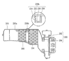
一方、本実施形態の洗濯物処理装置においては、図12に示すように、熱交換ダクト部164には複数の熱交換器ノズル230が備えられてもよい。
On the other hand, in the laundry processing apparatus of the present embodiment, as shown in FIG. 12, the heat
熱交換器ノズル230は、例えば、熱交換ダクト部164の空気の移動方向に沿って、蒸発器186の前方に配置される第1熱交換器ノズル230a、及び蒸発器186の後方に配置される第2熱交換器ノズル230bを備えてもよい。
The
第1熱交換器ノズル230a及び第2熱交換器ノズル230bには、給水源240に連結された給水流路241がそれぞれ連結され、各給水流路241には、当該給水流路241を開閉できるように第2給水弁254及び第3給水弁256がそれぞれ備えられてもよい。
A water
第1熱交換器ノズル230aは、例えば図12に示すように、蒸発器186の前方上側から蒸発器186に向かって下方に傾斜して水を噴射するように構成されてもよい。
The first
第2熱交換器ノズル230bは、例えば図13に示すように、蒸発器186の後方上側から蒸発器186に向かって前方及び前下方に傾斜して水をそれぞれ噴射するように構成されてもよい。
The second
第2熱交換器ノズル230bは、例えば、互いに離隔した垂直面232及び各垂直面232の下端を連結する水平面236を備えて断面「U」字形状を有するように構成されてもよい。
The second
第2熱交換器ノズル230bは、例えば、垂直面232のうち蒸発器186側に形成される第1ノズル孔234、及び水平面236に形成される第2ノズル孔238を備えてもよい。
The second
第1ノズル孔234は、例えば、蒸発器186の上部領域に向けて水を噴射するように構成されてもよい。
The
第2ノズル孔238は、例えば、蒸発器186の下部領域に水を噴射するように構成されてもよい。
The
第2熱交換器ノズル230bは、蒸発器186の後方から前方に水を噴射することにより、蒸発器186の前面に付着したリントを容易に除去することができる。
The second
一方、本実施形態の制御部270には、図13に示すように、リントフィルタノズル220、第1熱交換器ノズル230a及び第2熱交換器ノズル230bの給水流路をそれぞれ開閉できるように、第1給水弁252、第2給水弁254及び第3給水弁256がそれぞれ制御可能に接続されてもよい。
On the other hand, as shown in FIG. 13, the
制御部270には、リントフィルタ135の設置領域及び熱交換器の設置領域の掃除時期を検知できるように、検知部275が通信可能に接続されてもよい。
The
制御部270は、例えば、複数の掃除ノズル210(リントフィルタノズル220、第1熱交換器ノズル230a及び第2熱交換器ノズル230b)のいずれかは開放されて給水源240の水が連続的に流出するように、複数の給水弁250の少なくとも1つが開放された状態で他の1つが閉鎖されるように複数の給水弁250を順次制御するように構成されてもよい。
In the
また、制御部270は、給水弁250のうち先に開放された給水弁250の閉鎖時点より予め設定された時間前の時点で他の給水弁250が開放されるように制御するように構成されてもよい。
Further, the
より具体的には、図14に示すように、制御部270は、第1給水弁252、第2給水弁254及び第3給水弁256のうち先に第1給水弁252が開放されるようにする(t1)。
More specifically, as shown in FIG. 14, in the
制御部270は、第1給水弁252が開放された状態で、第2給水弁254が開放されるように制御する(t2)。
The
制御部270は、第2給水弁254が開放された状態で、第1給水弁252が閉鎖されるように制御する(t3)。
The
制御部270は、第2給水弁254が開放された状態で、第3給水弁256が開放されるように制御する(t4)。
The
制御部270は、第3給水弁256が開放された状態で、第2給水弁254が閉鎖されるようにする(t5)。
The
制御部270は、第3給水弁256が開放された状態で、第1給水弁252が開放されるようにする(t6)。
The
制御部270は、このような順序で第1給水弁252、第2給水弁254及び第3給水弁256が順次開閉されるようにそれぞれ制御し、第1給水弁252の予め設定された最終回の開放時点(tn)で、第3給水弁256を閉鎖する。
The
制御部270は、第1給水弁252が開放された状態で、第2給水弁254の予め設定された最終回の開放時点(tn+2)が到来すると、第2給水弁254を開放し、第2給水弁254が開放された状態で、第1給水弁252を最終的に閉鎖する(tn+3)。
The
制御部270は、第2給水弁254が開放された状態で、第3給水弁256の予め設定された回数の最終回の開放をする(tn+4)。
The
制御部270は、第3給水弁256が開放された状態で、第2給水弁254を最終的に閉鎖する(tn+5)。
The
制御部270は、第3給水弁256の最終閉鎖時点が到来すると、第3給水弁256を最終的に閉鎖する(tn+6)。
The
本実施形態において、制御部270は、第1給水弁252、第2給水弁254及び第3給水弁256を予め設定された回数でそれぞれ開閉する間、給水源240の遮断が発生しないように第1給水弁252、第2給水弁254及び第3給水弁256を順次制御することにより、水撃作用の発生を抑制することができる。
In the present embodiment, the
また、制御部270は、第1給水弁252、第2給水弁254及び第3給水弁256を予め設定された回数でそれぞれ開閉する間、前記各給水弁の閉鎖時点より予め設定された時間前の時点で後続の給水弁が開放されるように制御することにより、前記各給水弁の総動作時間を短縮して全般的な掃除時間を短縮することができる。
Further, while the
なお、本実施形態においては、制御部270が第1給水弁252、第2給水弁254及び第3給水弁256の順序で開放されるように制御する場合を例示しているが、これは一例示にすぎず、順序は給水弁250のいずれかが開放された状態で他の給水弁250を順次制御できれば適宜調整できることは言うまでもない。
In this embodiment, a case where the
また、本実施形態においては、リントフィルタ135にリントフィルタノズル220が1つ備えられ、熱交換器ノズルが複数で構成された場合を例示しているが、これは例示にすぎず、リントフィルタノズル220が複数で構成され、熱交換器ノズルが1つで構成されるようにしてもよい。
Further, in the present embodiment, a case where one
以下、図15及び図16を参照して、本発明の一実施形態による洗濯物処理装置の給水弁制御方法について説明する。 Hereinafter, the water supply valve control method of the laundry processing apparatus according to the embodiment of the present invention will be described with reference to FIGS. 15 and 16.
図15に示すように、制御部270は、検知部275により掃除時点が検知されると、第1給水弁252が開放されているか否かを確認し(S110)、第1給水弁252を開放する(S120)。
As shown in FIG. 15, when the
制御部270は、第1給水弁252が開放されると、第2給水弁254が開放されているか否かを確認し(S130)、第2給水弁254が開放されるように制御する(S140)。
When the first
制御部270は、第2給水弁254が開放された状態で、第1給水弁252が閉鎖されるように制御する(S150)。
The
こうすることにより、給水源240の水が流出し続けることになり、給水源240の急激な遮断による水撃作用の発生を抑制することができる。
By doing so, the water of the
制御部270は、第1給水弁252が閉鎖されると、第1給水弁252の閉鎖回数(N1i)をカウントする(S160)。
When the first
制御部270は、第1給水弁252の閉鎖回数(N1i)と設定回数(N1s)とを比較する(S170)。
The
制御部270は、第1給水弁252の閉鎖回数(N1i)が設定回数(N1s)より少ないと、第1給水弁252が開放されているか否かを確認し(S110)、第1給水弁252を開放する(S120)。
When the number of times the first
制御部270は、第2給水弁254が開放されているか否かを確認し(S130)、第1給水弁252が開放された状態であるので、第2給水弁254を閉鎖する(S180)。
The
制御部270は、第2給水弁254の閉鎖回数(N2i)をカウントし(S190)、第2給水弁254の閉鎖回数(N2i)と第2給水弁254の設定回数(N2s)とを比較する(S200)。
The
制御部270は、第2給水弁254の閉鎖回数(N2i)が設定回数(N2s)より少ないと、第1給水弁252が開放されているか否かを確認し(S110)、第1給水弁252が開放された状態であるので、第2給水弁254が開放されているか否かを確認し(S130)、第2給水弁254が開放されるように制御する(S140)。
When the number of times the second
制御部270は、このような過程を繰り返して、第1給水弁252及び第2給水弁254を順次開閉し、第1給水弁252の閉鎖回数(N1i)が設定回数(N1si)に到達すると(S170)、第2給水弁254を閉鎖する(S180)。
The
制御部270は、第2給水弁254の閉鎖回数(N2i)をカウントし(S190)、第2給水弁254の閉鎖回数(N2i)が設定回数(N2s)に到達すると(S200)、掃除過程を全て終了する。
The
前述したように、制御部270は、第1給水弁252及び第2給水弁254のいずれか一方が先に開放された状態で他方が開放され、先に開放された給水弁が閉鎖されるように順次制御することにより、給水源240の水が流出し続けることになり、給水源240の水の流出が急激に抑制されて発生する水撃作用の発生を抑制することができる。
As described above, in the
以下、図16を参照して、本発明の他の実施形態による洗濯物処理装置の掃除ノズル制御方法について説明する。 Hereinafter, a cleaning nozzle control method for a laundry processing apparatus according to another embodiment of the present invention will be described with reference to FIG.
制御部270は、図16に示すように、検知部275により掃除ノズル210の設置領域の掃除時期が検知されると、第1給水弁252が開放されているか否かを確認し(S210)、第1給水弁252が開放されるように制御する(S220)。
As shown in FIG. 16, the
制御部270は、第1給水弁252が開放された状態で、第2給水弁254が開放されているか否かを確認し(S230)、第2給水弁254が開放されるように制御する(S240)。
The
制御部270は、第2給水弁254が開放された状態で、先に開放された第1給水弁252が閉鎖されるように制御する(S250)。
The
制御部270は、第1給水弁252の閉鎖回数(N1i)をカウントし(S260)、第1給水弁252の閉鎖回数(N1i)が設定回数(N1s)より少ないと(S270)、第3給水弁256が開放されているか否かを確認し(S280)、第3給水弁256が開放されるように制御する(S290)。
The
制御部270は、第3給水弁256が開放された状態で、第2給水弁254を閉鎖し(S300)、第2給水弁254の閉鎖回数(N2i)をカウントする(S310)。
The
制御部270は、第2給水弁254の閉鎖回数(N2i)が設定回数(N2s)より少ないと(S320)、第1給水弁252を開放し(S330)、第1給水弁252が開放された状態で、第3給水弁256が閉鎖されるように制御する(S340)。
When the number of times the second
制御部270は、第3給水弁256の閉鎖回数(N3i)をカウントし(S350)、第3給水弁256の閉鎖回数(N3i)が設定回数(N3s)より小さいと(S360)、第1給水弁252が開放されているか否かを確認する(S210)。
The
制御部270は、第1給水弁252が開放されていると、第2給水弁254が開放されているか否かを確認し(S230)、第2給水弁254が開放されるように制御する(S240)。
When the first
制御部270は、第2給水弁254が開放された状態で、第1給水弁252を閉鎖し(S250)、第1給水弁252の閉鎖回数(N1i)をカウントする(S260)。
The
第1給水弁252の閉鎖回数(N1i)が設定回数(N1s)に到達すると(S270)、第2給水弁254が開放されているか否かを確認し(S230)、第2給水弁254が開放されていると、第3給水弁256が開放されているか否かを確認し(S280)、第3給水弁256を開放する(S290)。
When the number of times the first
制御部270は、第3給水弁256が開放された状態で、第2給水弁254を閉鎖し(S300)、第2給水弁254の閉鎖回数(N2i)をカウントする(S310)。
The
制御部270は、第2給水弁254の閉鎖回数(N2i)が設定回数(N2s)に到達すると(S320)、第3給水弁256が開放されているか否かを確認し(S290)、第3給水弁256が閉鎖されるように制御する(S340)。
When the number of times the second
制御部270は、第3給水弁256が閉鎖されると、第3給水弁256の閉鎖回数(N3i)をカウントし(S350)、第3給水弁256の閉鎖回数(N3i)が設定回数(N3s)に到達すると(S360)、掃除ノズル210の給水過程を全て終了する。
When the third
前述したように、制御部270は、第1給水弁252、第2給水弁2542及び第3給水弁256のいずれかが先に開放された状態で他の1つが開放され、先に開放された給水弁が閉鎖されるように順次制御することにより、給水源240の水が流出し続けることになり、給水源240の水の流出が急激が遮断されて発生する水撃作用の発生を抑制することができる。
As described above, in the
以上、本発明の特定の実施形態について図示して説明した。しかし、本発明はその思想又は本質的な特徴を逸脱しない範囲で様々な形態で実施できるので、上記実施形態はその詳細な説明の内容により限定されない。 The specific embodiments of the present invention have been illustrated and described above. However, since the present invention can be carried out in various forms without departing from the idea or essential features, the above-mentioned embodiment is not limited by the content of the detailed description.
また、上記詳細な説明において具体的に列挙していない実施形態であっても、請求の範囲に定義されたその技術思想の範囲内で広く解釈されるべきである。さらに、請求の範囲の技術的範囲とその均等範囲に含まれるあらゆる変更及び変形は請求の範囲に含まれるべきである。 Further, even embodiments not specifically listed in the above detailed description should be broadly interpreted within the scope of the technical idea defined in the claims. In addition, any changes or modifications contained in the technical scope of the claims and their equivalents should be included in the claims.
Claims (12)
キャビネットと、
前記キャビネットの内部に備えられる水槽と、
前記水槽の内部に回転可能に備えられる回転槽と、
前記水槽の内部の空気が外部を経由して前記水槽の内部に循環する循環流路と、
前記循環流路に備えられて水を噴射する複数の掃除ノズルと、
一側は給水源に連結され、他側は分岐されて前記複数の掃除ノズルにそれぞれ連結される複数の給水流路と、
前記複数の給水流路をそれぞれ開閉する複数の給水弁と、
前記複数の掃除ノズルのいずれかは開放されて前記給水源の水が連続的に流出するように前記複数の給水弁のいずれかを開放し、前記複数の給水弁の少なくとも1つが開放された状態で他の1つが閉鎖されるように前記複数の給水弁を順次制御する制御部と、を備えてなり、
前記制御部は、前記複数の給水弁が予め設定された回数でそれぞれ開閉されるように、前記複数の給水弁の少なくとも1つが開放された状態で他の1つが閉鎖されるように前記複数の給水弁を開閉する動作を繰り返し、
前記制御部は、前記複数の給水弁が0.5秒間~3秒間開放されるようにそれぞれ制御し、
前記給水源の水は、前記複数の給水弁のうち開放された給水弁から連続的に流出する、洗濯物処理装置。 It ’s a laundry processing device,
With a cabinet
The water tank provided inside the cabinet and
A rotary tank that is rotatably provided inside the water tank,
A circulation flow path in which the air inside the water tank circulates inside the water tank via the outside, and
A plurality of cleaning nozzles provided in the circulation flow path to inject water,
A plurality of water supply channels connected to a water supply source on one side and branched to each of the plurality of cleaning nozzles on the other side.
A plurality of water supply valves that open and close each of the plurality of water supply channels, and
A state in which any one of the plurality of cleaning nozzles is opened and one of the plurality of water supply valves is opened so that the water of the water supply source continuously flows out, and at least one of the plurality of water supply valves is opened. It is equipped with a control unit that sequentially controls the plurality of water supply valves so that the other one is closed.
The control unit has the plurality of water supply valves so that at least one of the plurality of water supply valves is opened and the other one is closed so that the plurality of water supply valves are opened and closed at a preset number of times. Repeat the operation of opening and closing the water supply valve,
The control unit controls each of the plurality of water supply valves so that they are opened for 0.5 seconds to 3 seconds .
A laundry treatment device in which water from the water supply source continuously flows out from an open water supply valve among the plurality of water supply valves .
前記複数の掃除ノズルは、前記リントフィルタに水を噴射するリントフィルタノズル、及び前記熱交換器に水を噴射する熱交換器ノズルを備えてなる、請求項1に記載の洗濯物処理装置。 The circulation flow path is provided with a lint filter that collects lint in the air and a heat pump equipped with a heat exchanger that exchanges heat with the air.
The laundry processing apparatus according to claim 1, wherein the plurality of cleaning nozzles include a lint filter nozzle that injects water into the lint filter and a heat exchanger nozzle that injects water into the heat exchanger.
前記制御部は、前記検知部により前記掃除ノズルの設置領域の掃除時期が検知されると、前記複数の給水弁が順次開閉されるように制御する、請求項1~5の何れか一項に記載の洗濯物処理装置。 It is further equipped with a detection unit that detects the cleaning time of the cleaning nozzle installation area.
The control unit controls to open and close the plurality of water supply valves in sequence when the detection unit detects the cleaning time of the installation area of the cleaning nozzle, according to any one of claims 1 to 5. The laundry processing device described.
前記洗濯物処理装置が、キャビネットと、前記キャビネットの内部に備えられる水槽と、前記水槽の内部に回転可能に備えられる回転槽と、前記水槽の内部の空気が外部を経由して前記水槽の内部に循環する循環流路と、前記循環流路に備えられて水を噴射する複数の掃除ノズルと、一側は給水源に連結され、他側は分岐されて前記複数の掃除ノズルにそれぞれ連結される複数の給水流路と、前記複数の給水流路をそれぞれ開閉する複数の給水弁と、を備えてなるものであり、
前記複数の給水弁の少なくとも1つを開放する段階と;
前記複数の給水弁の少なくとも1つが開放された状態で閉鎖された給水弁の少なくとも1つを開放する段階と;及び、
前記段階により開放された2つの給水弁のうち先に開放された給水弁を閉鎖する段階と;を含んでなり、
前記複数の給水弁は、予め設定された回数でそれぞれ開閉され、
前記複数の給水弁が前記予め設定された回数でそれぞれ開閉されるように、前記複数の給水弁の少なくとも1つを開放する段階と;
前記複数の給水弁の少なくとも1つが開放された状態で閉鎖された給水弁の少なくとも1つを開放する段階と;及び、
前記段階により開放された2つの給水弁のうち先に開放された給水弁を閉鎖する段階を前記予め設定された回数で繰り返す段階と;を更に含んでなり、
前記複数の給水弁は0.5秒間~3秒間それぞれ開放され、
前記給水源の水は、前記複数の給水弁のうち開放された給水弁から連続的に流出する、洗濯物処理装置の給水弁制御方法。 It is a water supply valve control method for laundry processing equipment.
The laundry processing device includes a cabinet, a water tank provided inside the cabinet, a rotary tank rotatably provided inside the water tank, and air inside the water tank via the outside to the inside of the water tank. One side is connected to the water supply source, and the other side is branched and connected to the plurality of cleaning nozzles. It is provided with a plurality of water supply channels and a plurality of water supply valves for opening and closing each of the plurality of water supply channels.
With the stage of opening at least one of the plurality of water supply valves;
With at least one of the plurality of water supply valves open and at least one of the closed water supply valves being opened;
Of the two water supply valves opened by the above step, the step of closing the water supply valve opened earlier;
The plurality of water supply valves are opened and closed a preset number of times, respectively.
A step of opening at least one of the plurality of water supply valves so that the plurality of water supply valves are opened and closed at a preset number of times.
With at least one of the plurality of water supply valves open and at least one of the closed water supply valves being opened;
Of the two water supply valves opened by the above step , the step of closing the previously opened water supply valve is repeated at the preset number of times ;
The plurality of water supply valves are opened for 0.5 to 3 seconds , respectively.
A method for controlling a water supply valve of a laundry treatment device, in which water from the water supply source continuously flows out from an open water supply valve among the plurality of water supply valves .
前記掃除ノズルは、前記リントフィルタに備えられるリントフィルタノズル、及び前記熱交換器に備えられる熱交換器ノズルを備えられ、
前記リントフィルタ又は前記熱交換器の掃除時期を検知する検知部を更に備えてなり、
前記複数の給水弁の少なくとも1つを開放する段階の前に、前記リントフィルタ又は前記熱交換器の掃除時期を検知する段階を更に含んでなる、請求項7又は8に記載の洗濯物処理装置の給水弁制御方法。 The circulation flow path is provided with a lint filter that collects lint in the air and a heat pump equipped with a heat exchanger that exchanges heat with the air.
The cleaning nozzle includes a lint filter nozzle provided in the lint filter and a heat exchanger nozzle provided in the heat exchanger.
Further, a detector for detecting the cleaning time of the lint filter or the heat exchanger is provided.
The laundry processing apparatus according to claim 7 or 8, further comprising a step of detecting a cleaning time of the lint filter or the heat exchanger before the step of opening at least one of the plurality of water supply valves. Water supply valve control method.
前記洗濯物処理装置が、キャビネットと、前記キャビネットの内部に備えられる水槽と、前記水槽の内部に回転可能に備えられる回転槽と、前記水槽の内部の空気が外部を経由して前記水槽の内部に循環する循環流路と、前記循環流路に備えられるリントフィルタと、前記循環流路に備えられて熱交換する熱交換器を備えたヒートポンプと、前記リントフィルタに水を噴射するリントフィルタノズルと、前記熱交換器に水を噴射する熱交換器ノズルと、一側は給水源に連結され、他側は分岐されて前記リントフィルタノズルに連結される第1給水流路と、一側は前記給水源に連結され、他側は分岐されて前記熱交換器ノズルに連結される第2給水流路と、前記第1給水流路を開閉する第1給水弁と、前記第2給水流路を開閉する第2給水弁と、を備えてなり、
前記第1給水弁及び前記第2給水弁のいずれか一方を開放する段階と;
前記第1給水弁及び前記第2給水弁のいずれか一方が開放された状態で他方を開放する段階と;
前記第1給水弁及び前記第2給水弁が開放された状態で開放された順序で前記第1給水弁及び前記第2給水弁を閉鎖する段階と;を含んでなり、
前記第1給水弁及び前記第2給水弁が予め設定された回数でそれぞれ開閉されるように、前記第1給水弁及び前記第2給水弁のいずれか一方を開放する段階と;
前記第1給水弁及び前記第2給水弁のいずれか一方が開放された状態で他方を開放する段階と;及び、
前記第1給水弁及び前記第2給水弁が開放された状態で開放された順序で前記第1給水弁及び前記第2給水弁を閉鎖する段階を前記予め設定された回数でそれぞれ開閉されるように繰り返す段階と;を更に含んでなり、
前記第1給水弁及び前記第2給水弁は、0.5秒間~3秒間それぞれ開放され、
前記給水源の水は、前記第1給水弁及び前記第2給水弁のうち開放された給水弁から連続的に流出する、洗濯物処理装置の給水弁制御方法。 It is a water supply valve control method for laundry processing equipment.
The laundry processing apparatus includes a cabinet, a water tank provided inside the cabinet, a rotary tank rotatably provided inside the water tank, and air inside the water tank via the outside to the inside of the water tank. A circulation flow path that circulates in the circulation flow path, a lint filter provided in the circulation flow path, a heat pump provided in the circulation flow path provided with a heat exchanger for heat exchange, and a lint filter nozzle that injects water into the lint filter. And the heat exchanger nozzle that injects water into the heat exchanger, the first water supply flow path that is connected to the water supply source on one side and branched to the lint filter nozzle on the other side, and one side. A second water supply flow path connected to the water supply source and branched on the other side and connected to the heat exchanger nozzle, a first water supply valve for opening and closing the first water supply flow path, and the second water supply flow path. It is equipped with a second water supply valve that opens and closes.
The stage of opening either the first water supply valve or the second water supply valve;
A stage in which one of the first water supply valve and the second water supply valve is opened and the other is opened;
It comprises the steps of closing the first water supply valve and the second water supply valve in the order in which the first water supply valve and the second water supply valve are opened in the opened state.
A step of opening either the first water supply valve or the second water supply valve so that the first water supply valve and the second water supply valve are opened and closed at a preset number of times.
A stage in which one of the first water supply valve and the second water supply valve is opened and the other is opened;
The steps of closing the first water supply valve and the second water supply valve in the order in which the first water supply valve and the second water supply valve are opened are opened and closed at the preset number of times. And so on , including more;
The first water supply valve and the second water supply valve are opened for 0.5 to 3 seconds , respectively.
A method for controlling a water supply valve of a laundry treatment device, in which water from the water supply source continuously flows out from an open water supply valve among the first water supply valve and the second water supply valve .
前記第1給水弁及び前記第2給水弁のいずれか一方を開放する段階の前に、前記リントフィルタ又は前記熱交換器の掃除時期を検知する段階を更に含んでなる、請求項10又は11に記載の洗濯物処理装置の給水弁制御方法。 It further includes a detector for detecting the cleaning time of the lint filter or the heat exchanger.
10. The claim 10 or 11, further comprising a step of detecting the cleaning time of the lint filter or the heat exchanger before the step of opening either the first water supply valve or the second water supply valve. The water supply valve control method of the laundry processing apparatus according to the above.
Applications Claiming Priority (3)
| Application Number | Priority Date | Filing Date | Title |
|---|---|---|---|
| KR10-2016-0001214 | 2016-01-05 | ||
| KR1020160001214A KR102428247B1 (en) | 2016-01-05 | 2016-01-05 | Laundry treating apparatus and control method for feed water valve thereof |
| PCT/KR2016/012815 WO2017119595A1 (en) | 2016-01-05 | 2016-11-08 | Laundry treatment apparatus and water supply valve control method therefor |
Publications (2)
| Publication Number | Publication Date |
|---|---|
| JP2019503770A JP2019503770A (en) | 2019-02-14 |
| JP7063809B2 true JP7063809B2 (en) | 2022-05-09 |
Family
ID=57708515
Family Applications (1)
| Application Number | Title | Priority Date | Filing Date |
|---|---|---|---|
| JP2018534635A Active JP7063809B2 (en) | 2016-01-05 | 2016-11-08 | Laundry processing equipment and its water supply valve control method |
Country Status (8)
| Country | Link |
|---|---|
| US (1) | US10400383B2 (en) |
| EP (1) | EP3190219B1 (en) |
| JP (1) | JP7063809B2 (en) |
| KR (1) | KR102428247B1 (en) |
| CN (1) | CN106996001B (en) |
| AU (1) | AU2016384527B2 (en) |
| RU (1) | RU2689734C1 (en) |
| WO (1) | WO2017119595A1 (en) |
Families Citing this family (3)
| Publication number | Priority date | Publication date | Assignee | Title |
|---|---|---|---|---|
| CN110468551B (en) * | 2018-05-10 | 2021-11-05 | 青岛海尔洗涤电器有限公司 | Drum washing machine and spraying control method thereof |
| KR102561544B1 (en) * | 2018-10-16 | 2023-07-28 | 엘지전자 주식회사 | Method of controlling laundry treating apparatus |
| AU2021299595A1 (en) | 2020-07-03 | 2023-02-02 | Lg Electronics Inc. | Laundry treatment machine |
Citations (2)
| Publication number | Priority date | Publication date | Assignee | Title |
|---|---|---|---|---|
| JP2006187449A (en) | 2005-01-06 | 2006-07-20 | Toshiba Corp | Washing/drying machine |
| US20110167662A1 (en) | 2008-09-11 | 2011-07-14 | BSH Bosch und Siemens Hausgeräte GmbH | Dryer having a lint filter and a cleaning device |
Family Cites Families (19)
| Publication number | Priority date | Publication date | Assignee | Title |
|---|---|---|---|---|
| JP2708636B2 (en) | 1991-01-08 | 1998-02-04 | 株式会社日立製作所 | Information processing device maintenance control method |
| JP2002143598A (en) * | 2000-11-13 | 2002-05-21 | Nippon Kentetsu Co Ltd | Water feeding valve control method for washing machine |
| KR100433034B1 (en) | 2001-09-04 | 2004-06-07 | 우성전기공업 주식회사 | Minifold for supplying water |
| JP2007306960A (en) * | 2006-05-16 | 2007-11-29 | Matsushita Electric Ind Co Ltd | Clothes dryer |
| JP2010035894A (en) * | 2008-08-07 | 2010-02-18 | Hitachi Appliances Inc | Drum washing and drying machine |
| KR101806241B1 (en) * | 2011-03-29 | 2017-12-07 | 엘지전자 주식회사 | Clothes treating apparatus with a heat exchanger cleaning means |
| US8857071B2 (en) * | 2011-03-29 | 2014-10-14 | Lg Electronics Inc. | Clothes treating apparatus having heat exchanger cleaning device |
| JP2013128527A (en) * | 2011-12-20 | 2013-07-04 | Panasonic Corp | Clothing drying machine |
| AU2013244151B2 (en) * | 2012-04-06 | 2016-04-14 | Lg Electronics Inc. | Laundry machine and method for controlling the same |
| AU2013244150B2 (en) | 2012-04-06 | 2016-02-11 | Lg Electronics Inc. | Laundry treating machine |
| EP2669417A1 (en) * | 2012-05-29 | 2013-12-04 | Electrolux Home Products Corporation N.V. | Washer-dryer machine with a heat pump |
| US20130340797A1 (en) | 2012-06-26 | 2013-12-26 | BSH Bosch und Siemens Hausgeräte GmbH | Clothes treatment appliance with transfer pipe |
| DE112012006737T5 (en) | 2012-07-24 | 2015-04-23 | Panasonic Intellectual Property Management Co., Ltd. | Washing and drying machine |
| JP6040418B2 (en) * | 2012-09-04 | 2016-12-07 | パナソニックIpマネジメント株式会社 | Clothes dryer |
| WO2014044530A1 (en) | 2012-09-24 | 2014-03-27 | Arcelik Anonim Sirketi | A laundry washing and drying machine comprising a condenser |
| KR102057859B1 (en) * | 2013-01-25 | 2019-12-20 | 엘지전자 주식회사 | Laundry Machine |
| KR101560386B1 (en) * | 2013-09-03 | 2015-10-13 | 엘지전자 주식회사 | Laundry Treating Apparatus |
| DE102014204299A1 (en) | 2014-03-10 | 2015-09-10 | BSH Bosch und Siemens Hausgeräte GmbH | Dryer with flusend depot and adaptive detection of the Flusendepot filling level and method for its operation |
| KR102151191B1 (en) | 2014-04-17 | 2020-09-02 | 엘지전자 주식회사 | Dryer for clothes |
-
2016
- 2016-01-05 KR KR1020160001214A patent/KR102428247B1/en active IP Right Grant
- 2016-11-08 WO PCT/KR2016/012815 patent/WO2017119595A1/en active Application Filing
- 2016-11-08 AU AU2016384527A patent/AU2016384527B2/en active Active
- 2016-11-08 RU RU2018128279A patent/RU2689734C1/en active
- 2016-11-08 JP JP2018534635A patent/JP7063809B2/en active Active
- 2016-12-22 US US15/388,781 patent/US10400383B2/en active Active
- 2016-12-28 CN CN201611236463.3A patent/CN106996001B/en active Active
-
2017
- 2017-01-03 EP EP17150151.3A patent/EP3190219B1/en active Active
Patent Citations (2)
| Publication number | Priority date | Publication date | Assignee | Title |
|---|---|---|---|---|
| JP2006187449A (en) | 2005-01-06 | 2006-07-20 | Toshiba Corp | Washing/drying machine |
| US20110167662A1 (en) | 2008-09-11 | 2011-07-14 | BSH Bosch und Siemens Hausgeräte GmbH | Dryer having a lint filter and a cleaning device |
Also Published As
| Publication number | Publication date |
|---|---|
| JP2019503770A (en) | 2019-02-14 |
| US20170191209A1 (en) | 2017-07-06 |
| US10400383B2 (en) | 2019-09-03 |
| CN106996001A (en) | 2017-08-01 |
| AU2016384527B2 (en) | 2019-07-04 |
| AU2016384527A1 (en) | 2018-07-12 |
| EP3190219A1 (en) | 2017-07-12 |
| EP3190219B1 (en) | 2019-01-02 |
| KR102428247B1 (en) | 2022-08-02 |
| RU2689734C1 (en) | 2019-05-28 |
| WO2017119595A1 (en) | 2017-07-13 |
| KR20170082058A (en) | 2017-07-13 |
| CN106996001B (en) | 2020-08-18 |
Similar Documents
| Publication | Publication Date | Title |
|---|---|---|
| JP7065026B2 (en) | Laundry processing device and its cleaning nozzle control method | |
| JP7063809B2 (en) | Laundry processing equipment and its water supply valve control method | |
| KR101186159B1 (en) | Clothes dry machine | |
| KR101608655B1 (en) | Fabric treating apparatus and controlling method therof | |
| KR101366273B1 (en) | Cloth treating apparatus | |
| KR20180013535A (en) | Washing drying machine having heat pump and drying operation control method thereof | |
| JP2017070710A (en) | Shoe cleaning device | |
| KR20100020788A (en) | Dish washer | |
| JP2013128527A (en) | Clothing drying machine | |
| KR20180093053A (en) | High efficiency washing dryer and control method | |
| KR101580125B1 (en) | Method for dishwasher operating for door opening protecting | |
| US11174583B2 (en) | Method of controlling laundry treating apparatus | |
| JP2020018714A (en) | Washing and drying machine | |
| JP2018110789A (en) | Washing and drying machine | |
| KR101366265B1 (en) | Laundry Treating Apparatus and the control method of the same | |
| JP6980466B2 (en) | Cooler | |
| KR20090118688A (en) | Laundry treating apparatus and steam generator assembly | |
| KR101608656B1 (en) | Fabric treating apparatus and controlling method thereof | |
| JP6946125B2 (en) | Cooler | |
| JP2020010817A (en) | Washing and drying machine | |
| KR20090050220A (en) | Cloth treating apparatus | |
| US20220380964A1 (en) | Laundry treating apparatus | |
| JP2023019539A (en) | Laundry dryer | |
| JP2022047885A (en) | Clothes dryer |
Legal Events
| Date | Code | Title | Description |
|---|---|---|---|
| A621 | Written request for application examination |
Free format text: JAPANESE INTERMEDIATE CODE: A621 Effective date: 20191030 |
|
| A131 | Notification of reasons for refusal |
Free format text: JAPANESE INTERMEDIATE CODE: A131 Effective date: 20210105 |
|
| A521 | Request for written amendment filed |
Free format text: JAPANESE INTERMEDIATE CODE: A523 Effective date: 20210402 |
|
| A02 | Decision of refusal |
Free format text: JAPANESE INTERMEDIATE CODE: A02 Effective date: 20210914 |
|
| A521 | Request for written amendment filed |
Free format text: JAPANESE INTERMEDIATE CODE: A523 Effective date: 20220112 |
|
| C60 | Trial request (containing other claim documents, opposition documents) |
Free format text: JAPANESE INTERMEDIATE CODE: C60 Effective date: 20220112 |
|
| A911 | Transfer to examiner for re-examination before appeal (zenchi) |
Free format text: JAPANESE INTERMEDIATE CODE: A911 Effective date: 20220120 |
|
| C21 | Notice of transfer of a case for reconsideration by examiners before appeal proceedings |
Free format text: JAPANESE INTERMEDIATE CODE: C21 Effective date: 20220125 |
|
| TRDD | Decision of grant or rejection written | ||
| A01 | Written decision to grant a patent or to grant a registration (utility model) |
Free format text: JAPANESE INTERMEDIATE CODE: A01 Effective date: 20220329 |
|
| A61 | First payment of annual fees (during grant procedure) |
Free format text: JAPANESE INTERMEDIATE CODE: A61 Effective date: 20220421 |
|
| R150 | Certificate of patent or registration of utility model |
Ref document number: 7063809 Country of ref document: JP Free format text: JAPANESE INTERMEDIATE CODE: R150 |