JP7063802B2 - Cylinder head cover - Google Patents
Cylinder head cover Download PDFInfo
- Publication number
- JP7063802B2 JP7063802B2 JP2018248829A JP2018248829A JP7063802B2 JP 7063802 B2 JP7063802 B2 JP 7063802B2 JP 2018248829 A JP2018248829 A JP 2018248829A JP 2018248829 A JP2018248829 A JP 2018248829A JP 7063802 B2 JP7063802 B2 JP 7063802B2
- Authority
- JP
- Japan
- Prior art keywords
- head cover
- wall
- passage
- gas
- cylinder head
- Prior art date
- Legal status (The legal status is an assumption and is not a legal conclusion. Google has not performed a legal analysis and makes no representation as to the accuracy of the status listed.)
- Active
Links
Images


Classifications
-
- F—MECHANICAL ENGINEERING; LIGHTING; HEATING; WEAPONS; BLASTING
- F01—MACHINES OR ENGINES IN GENERAL; ENGINE PLANTS IN GENERAL; STEAM ENGINES
- F01M—LUBRICATING OF MACHINES OR ENGINES IN GENERAL; LUBRICATING INTERNAL COMBUSTION ENGINES; CRANKCASE VENTILATING
- F01M13/00—Crankcase ventilating or breathing
- F01M13/04—Crankcase ventilating or breathing having means for purifying air before leaving crankcase, e.g. removing oil
- F01M13/0416—Crankcase ventilating or breathing having means for purifying air before leaving crankcase, e.g. removing oil arranged in valve-covers
-
- F—MECHANICAL ENGINEERING; LIGHTING; HEATING; WEAPONS; BLASTING
- F02—COMBUSTION ENGINES; HOT-GAS OR COMBUSTION-PRODUCT ENGINE PLANTS
- F02B—INTERNAL-COMBUSTION PISTON ENGINES; COMBUSTION ENGINES IN GENERAL
- F02B75/00—Other engines
- F02B75/16—Engines characterised by number of cylinders, e.g. single-cylinder engines
- F02B75/18—Multi-cylinder engines
- F02B75/20—Multi-cylinder engines with cylinders all in one line
-
- F—MECHANICAL ENGINEERING; LIGHTING; HEATING; WEAPONS; BLASTING
- F02—COMBUSTION ENGINES; HOT-GAS OR COMBUSTION-PRODUCT ENGINE PLANTS
- F02F—CYLINDERS, PISTONS OR CASINGS, FOR COMBUSTION ENGINES; ARRANGEMENTS OF SEALINGS IN COMBUSTION ENGINES
- F02F7/00—Casings, e.g. crankcases or frames
- F02F7/006—Camshaft or pushrod housings
-
- F—MECHANICAL ENGINEERING; LIGHTING; HEATING; WEAPONS; BLASTING
- F02—COMBUSTION ENGINES; HOT-GAS OR COMBUSTION-PRODUCT ENGINE PLANTS
- F02F—CYLINDERS, PISTONS OR CASINGS, FOR COMBUSTION ENGINES; ARRANGEMENTS OF SEALINGS IN COMBUSTION ENGINES
- F02F7/00—Casings, e.g. crankcases or frames
- F02F7/0065—Shape of casings for other machine parts and purposes, e.g. utilisation purposes, safety
- F02F7/0068—Adaptations for other accessories
-
- F—MECHANICAL ENGINEERING; LIGHTING; HEATING; WEAPONS; BLASTING
- F02—COMBUSTION ENGINES; HOT-GAS OR COMBUSTION-PRODUCT ENGINE PLANTS
- F02M—SUPPLYING COMBUSTION ENGINES IN GENERAL WITH COMBUSTIBLE MIXTURES OR CONSTITUENTS THEREOF
- F02M25/00—Engine-pertinent apparatus for adding non-fuel substances or small quantities of secondary fuel to combustion-air, main fuel or fuel-air mixture
- F02M25/06—Engine-pertinent apparatus for adding non-fuel substances or small quantities of secondary fuel to combustion-air, main fuel or fuel-air mixture adding lubricant vapours
-
- F—MECHANICAL ENGINEERING; LIGHTING; HEATING; WEAPONS; BLASTING
- F02—COMBUSTION ENGINES; HOT-GAS OR COMBUSTION-PRODUCT ENGINE PLANTS
- F02M—SUPPLYING COMBUSTION ENGINES IN GENERAL WITH COMBUSTIBLE MIXTURES OR CONSTITUENTS THEREOF
- F02M35/00—Combustion-air cleaners, air intakes, intake silencers, or induction systems specially adapted for, or arranged on, internal-combustion engines
- F02M35/10—Air intakes; Induction systems
- F02M35/10209—Fluid connections to the air intake system; their arrangement of pipes, valves or the like
- F02M35/10222—Exhaust gas recirculation [EGR]; Positive crankcase ventilation [PCV]; Additional air admission, lubricant or fuel vapour admission
-
- F—MECHANICAL ENGINEERING; LIGHTING; HEATING; WEAPONS; BLASTING
- F01—MACHINES OR ENGINES IN GENERAL; ENGINE PLANTS IN GENERAL; STEAM ENGINES
- F01M—LUBRICATING OF MACHINES OR ENGINES IN GENERAL; LUBRICATING INTERNAL COMBUSTION ENGINES; CRANKCASE VENTILATING
- F01M13/00—Crankcase ventilating or breathing
- F01M13/0011—Breather valves
- F01M2013/0027—Breather valves with a de-icing or defrosting system
-
- F—MECHANICAL ENGINEERING; LIGHTING; HEATING; WEAPONS; BLASTING
- F01—MACHINES OR ENGINES IN GENERAL; ENGINE PLANTS IN GENERAL; STEAM ENGINES
- F01M—LUBRICATING OF MACHINES OR ENGINES IN GENERAL; LUBRICATING INTERNAL COMBUSTION ENGINES; CRANKCASE VENTILATING
- F01M13/00—Crankcase ventilating or breathing
- F01M2013/0038—Layout of crankcase breathing systems
-
- Y—GENERAL TAGGING OF NEW TECHNOLOGICAL DEVELOPMENTS; GENERAL TAGGING OF CROSS-SECTIONAL TECHNOLOGIES SPANNING OVER SEVERAL SECTIONS OF THE IPC; TECHNICAL SUBJECTS COVERED BY FORMER USPC CROSS-REFERENCE ART COLLECTIONS [XRACs] AND DIGESTS
- Y02—TECHNOLOGIES OR APPLICATIONS FOR MITIGATION OR ADAPTATION AGAINST CLIMATE CHANGE
- Y02T—CLIMATE CHANGE MITIGATION TECHNOLOGIES RELATED TO TRANSPORTATION
- Y02T10/00—Road transport of goods or passengers
- Y02T10/10—Internal combustion engine [ICE] based vehicles
- Y02T10/12—Improving ICE efficiencies
Landscapes
- Engineering & Computer Science (AREA)
- Mechanical Engineering (AREA)
- General Engineering & Computer Science (AREA)
- Chemical & Material Sciences (AREA)
- Combustion & Propulsion (AREA)
- Lubrication Details And Ventilation Of Internal Combustion Engines (AREA)
- Cylinder Crankcases Of Internal Combustion Engines (AREA)
Description
本発明は、小型ディーゼルエンジンなどの主に産業用エンジンに適用されるシリンダヘッドカバーに関するものである。 The present invention relates to a cylinder head cover mainly applied to an industrial engine such as a small diesel engine.
産業用ディーゼルエンジンなどにおいては、ブローバイガスをシリンダヘッドカバーの内部を通してから吸気経路に戻す構造のブローバイガス還流装置を備えることが一般的である。 In an industrial diesel engine or the like, it is common to provide a blow-by gas recirculation device having a structure in which blow-by gas is returned to the intake path after passing through the inside of the cylinder head cover.
その場合、シリンダヘッドカバーにおけるブローバイガスの出口に、吸気経路に繋がるチューブやダクトなどのガス管路が接続される。シリンダヘッドカバーのガス出口は、PCV弁などの調圧弁の直後に形成されることが多い。例えば、特許文献1(図2,6を参照)にて開示されるように、シリンダヘッドカバーの頂部において板金製のカバー蓋(天井壁:27)を備えた調圧弁が配置され、その調圧弁(PCVバルブ:3)の出口が、シリンダヘッドカバーのガス出口となった構造のものが知られている。 In that case, a gas pipeline such as a tube or a duct connected to the intake path is connected to the outlet of the blow-by gas in the cylinder head cover. The gas outlet of the cylinder head cover is often formed immediately after a pressure regulating valve such as a PCV valve. For example, as disclosed in Patent Document 1 (see FIGS. 2 and 6), a pressure regulating valve provided with a sheet metal cover lid (ceiling wall: 27) is arranged at the top of the cylinder head cover, and the pressure regulating valve (see FIG. 2 and 6) is provided. It is known that the outlet of the PCV valve: 3) is a gas outlet of the cylinder head cover.
クランクケース内で発生するブローバイガスを、エンジン内(吸気側)に戻すことにより、クリーンな排気ガスの実現に寄与している。シリンダヘッドカバーのガス出口から出たブローバイガスは、ゴムホースや合成樹脂ホースなどのガス管路により、吸気マニホルドや過給機の吸い込み側に戻されている。 By returning the blow-by gas generated in the crankcase to the inside of the engine (intake side), it contributes to the realization of clean exhaust gas. The blow-by gas discharged from the gas outlet of the cylinder head cover is returned to the suction side of the intake manifold or the turbocharger by a gas pipeline such as a rubber hose or a synthetic resin hose.
従来のブローバイガス還流装置における技術の問題点や改良すべき点は次のとおりである。即ち、極寒地域において、エンジン停止時にエンジン内のブローバイガス中の水分が冷やされ、エンジン内に結露が発生し、場合によっては凍結することがある。 The technical problems and points to be improved in the conventional blow-by gas recirculation device are as follows. That is, in an extremely cold region, when the engine is stopped, the water content in the blow-by gas in the engine is cooled, dew condensation occurs in the engine, and in some cases, the engine may freeze.
外気に接する面や壁を持つ部位や断面積の少ない箇所では、凍結によりガス通路が詰まるおそれもある。特に、シリンダヘッドカバーにおけるガス出口は、上方突出した構造になり易いため、過冷や凍結のリスクが高い。 There is a risk that the gas passage will be clogged due to freezing in areas with surfaces or walls that come into contact with the outside air or in areas with a small cross-sectional area. In particular, the gas outlet in the cylinder head cover tends to have a structure protruding upward, so that there is a high risk of overcooling or freezing.
本発明の目的は、構造工夫により、ブローバイガスのガス出口が冷され難いようにして、寒冷時におけるガス出口での凍結や詰まりが生じないよう、改善されたシリンダヘッドカバーを提供する点にある。 An object of the present invention is to provide an improved cylinder head cover by making it difficult for the gas outlet of blow-by gas to be cooled by devising a structure and preventing freezing or clogging at the gas outlet in cold weather.
本発明は、シリンダヘッドカバーにおいて、
クランクケースからのブローバイガスを通すガス通路と、ヘッドカバー上壁から上方突出する状態で形成されるガス出口部とを有し、
前記ガス出口部は、ブローバイガスを通す出口通路を形成すべくヘッドカバー上壁から上方に膨出した突出ケース部を備え、
前記突出ケース部から下方に突出する通路壁に、下端にガス入口開口を備える上下向き通路部及び先端に出口開口を備える横向き通路部を有して側面視が上下逆向きのL字形状を呈する前記出口通路が形成され、
前記突出ケース部と前記通路壁との間に、下方がヘッドカバー内に連通される空気層が形成されていることを特徴とする。
The present invention relates to a cylinder head cover.
It has a gas passage through which blow-by gas from the crankcase passes, and a gas outlet portion formed so as to project upward from the upper wall of the head cover.
The gas outlet portion includes a protruding case portion that bulges upward from the upper wall of the head cover so as to form an outlet passage through which blow-by gas passes.
The passage wall protruding downward from the protruding case portion has a vertical passage portion having a gas inlet opening at the lower end and a lateral passage portion having an outlet opening at the tip, and exhibits an L-shape in which the side view is upside down. The exit passage is formed
An air layer is formed between the protruding case portion and the passage wall so that the lower part communicates with the inside of the head cover .
例えば、前記突出ケース部は、ヘッドカバー上壁から立ち上がる起立壁を有しており、前記出口通路を形成するための通路壁と前記起立壁との間に前記空気層が設けられていると好都合である。そして、前記起立壁は、前記突出ケース部が裾広がり状となるように前記ヘッドカバー上壁から傾き角度を持って立ち上がる傾斜壁に形成されていればより好都合である。 For example, it is convenient that the protruding case portion has an upright wall that rises from the upper wall of the head cover, and the air layer is provided between the passage wall for forming the exit passage and the upright wall. be. It is more convenient if the upright wall is formed on an inclined wall that rises from the upper wall of the head cover at an inclination angle so that the protruding case portion has a wide hem.
また、前記起立壁は、エンジン冷却風の流れ方向で上流側に対面する状態となるように、前記突出ケース部が構成されていると好ましい。そして、シリンダヘッドカバーは、直列複数気筒の産業用ディーゼルエンジン用のものであると好都合である。 Further, it is preferable that the protruding case portion is configured such that the upright wall faces the upstream side in the flow direction of the engine cooling air. It is convenient that the cylinder head cover is for an industrial diesel engine having a plurality of cylinders in series.
本発明によれば、突出ケース部における出口通路の外側に空気層を形成したので、空気層が無い場合に比べて、断熱作用が飛躍的に向上するようになる。従って、極寒などの寒冷時でも出口通路の温度低下が抑制され、ブローバイガス中の水分が冷やされて結露が発生し、場合によっては凍結することが生じないようになる。 According to the present invention, since the air layer is formed on the outside of the outlet passage in the protruding case portion, the heat insulating effect is dramatically improved as compared with the case where there is no air layer. Therefore, even in a cold weather such as extremely cold, the temperature drop of the outlet passage is suppressed, the moisture in the blow-by gas is cooled, dew condensation occurs, and in some cases, freezing does not occur.
その結果、ガス出口部に空気層を設ける構造工夫により、突出ケース部に形成されたガス出口部におけるブローバイガスが冷され難いようになり、寒冷時におけるガス出口での凍結や詰まりが生じないよう、改善されたシリンダヘッドカバーを提供することができる。 As a result, by devising a structure that provides an air layer at the gas outlet, the blow-by gas at the gas outlet formed in the protruding case becomes difficult to cool, and freezing or clogging at the gas outlet during cold weather does not occur. , An improved cylinder head cover can be provided.
以下に、本発明によるシリンダヘッドカバーの実施の形態を、小型の産業用ディーゼルエンジンに適用した場合について、図面を参照しながら説明する。 Hereinafter, an embodiment of the cylinder head cover according to the present invention will be described with reference to the drawings when applied to a small industrial diesel engine.
図3に、産業用ディーゼルエンジンEの平面図が示され、1はエンジン冷却ファン、2はオルタネータ、3は過給機、4は排気処理装置、5はシリンダヘッド(符記省略)の上に組付けられるシリンダヘッドカバー(以下、ヘッドカバーと略称する)、6は複数のインジェクタ、7は燃料噴射用供給ポンプである。 FIG. 3 shows a plan view of the industrial diesel engine E, where 1 is an engine cooling fan, 2 is an alternator, 3 is a supercharger, 4 is an exhaust treatment device, and 5 is on a cylinder head (not shown). The cylinder head cover to be assembled (hereinafter, abbreviated as head cover), 6 is a plurality of injectors, and 7 is a fuel injection supply pump.
本エンジンEには、ブローバイガス還流装置(図示省略)が装備されており、クランクケース(図示省略)からのブローバイガスをヘッドカバー5の内部に形成されているガス通路W(図1を参照)を通し、極力オイル成分などを除いた状態で吸気通路Aに戻す構成とされている。なお、吸気通路Aの例としては、過給機3の吸気側ダクト3Aが挙げられる(図4を参照)。
The engine E is equipped with a blow-by gas recirculation device (not shown), and allows blow-by gas from the crankcase (not shown) to pass through a gas passage W (see FIG. 1) formed inside the
図3及び図4に示されるように、ヘッドカバー5は、インジェクタ装着用の4箇所の円孔5aを有する上下中間壁5Cと、前側の上壁(以下、ヘッドカバー上壁と呼ぶ)5Aと、後側の上壁5Bとを備えた無底箱状の部材である。ヘッドカバー上壁5Aの後部には、ヘッドカバー上壁5Aから上方突出する状態で形成されるガス出口部8が形成されている。ブレザ経路でもあるガス出口部8には、ブローバイガスgを吸気通路Aに戻すためのガス管路9が接続される。
As shown in FIGS. 3 and 4, the
ヘッドカバー上壁5Aの下側には、図4で示されるセパレータ(オイルセパレータ)Sが収容されている。セパレータSの平面視形状は、ヘッドカバー上壁5Aの上方突出形状に合せてその内側にピッタリと内装できるように、略横向きT字状に形成されている。セパレータSの前後及び右側のそれぞれに、ヘッドカバー5の内側にボルト止め装着するための挿通孔24が形成されている。
A separator (oil separator) S shown in FIG. 4 is housed under the head cover
セパレータSは、その下面の前端部にブローバイガスの入口、即ちセパレータ入口10が形成され、上面の後端部にブローバイガスの出口、即ちセパレータ出口11が形成されている。セパレータSの前後中間で右側の箇所に、大きく下方突出させたオイル落し部12が形成されており、また、セパレータ入口10とオイル落し部12との前後方向の間にフィルタ(図示省略)が設けられている。
The separator S has a blow-by gas inlet, that is, a
従って、クランクケースからのブローバイガスgは、ヘッドカバー5の内部の前端部から、セパレータSの下面前端部のセパレータ入口10からセパレータSの内部に入り、そこでフィルタ作用やオイル滴下作用を受けた後に、セパレータSの上面後端部のセパレータ出口11から出る、という具合に流れる。
Therefore, the blow-by gas g from the crankcase enters the inside of the separator S from the front end portion inside the
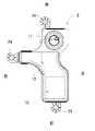
セパレータ出口11は、図1(A)に示されるように、ヘッドカバー5のガス出口部8のガス入口開口14に気密に対向配備されている。従って、セパレータ出口11から出たブローバイガスgは、ガス出口部8を通ってからガス管路9に流れて行くようになる。つまり、ヘッドカバー5の内部のガス通路Wは、そこに収容されるセパレータSの内部にも形成されている。
As shown in FIG. 1A, the
図1(A)、図2、図3に示されるように、ガス出口部8は、ブローバイガスgを通す出口通路8Aを形成すべくヘッドカバー上壁5Aから上方に膨出した突出ケース部15を備え、突出ケース部15における出口通路8Aの外側に空気層16が形成されている。なお、図1(A)において、5Dはヘッドカバー前壁である。
As shown in FIGS. 1A, 2 and 3, the
突出ケース部15は、頂壁15A、前側の起立壁17、後壁19、左側の取出し壁20、及び右側の右側壁21を有している。起立壁17、後壁19、及び取出し壁20は傾斜角度の付いた傾斜壁に形成されており、突出ケース部15は裾広がり状の外観を呈している。やや左後方に向いた外面(符記省略)を持つ取出し壁20には、前記出口通路8Aの出口開口22を備える庇壁20Aが形成されている。
The
突出ケース部15は、ヘッドカバー5の内部となる下側に突出する通路壁15Bを備えており、その通路壁15Bに、側面視が上下逆向きのL字形状を呈する出口通路8Aが形成されている。出口通路8Aは、下端にガス入口開口14を備える上下向き通路部8aと、左端(先端)に出口開口22を備える横向き通路部8bとを有する折れ曲がり通路に形成されている。起立壁17の下端部の裏側には、図1に示されるように、セパレータSと干渉しない範囲で下方突出するリブ壁23が形成されている。
The
従って、図1(A)、(B)に示されるように、ヘッドカバー上壁5Aから傾き角度θで立上る起立壁17と通路壁15Bとの間及びリブ壁23との間に跨る状態で空気層16が形成されている。また、後壁19と通路壁15Bとの間にも空気層16が形成されている。また、図4に示されるように、起立壁17は、エンジン冷却風Rの流れ方向(矢印Y方向)で上流側に対面する状態となるように、突出ケース部15が構成されている。
Therefore, as shown in FIGS. 1A and 1B, air straddles between the
以上のように構成されたヘッドカバーにより、次のとおりの作用効果が得られる。ヘッドカバー5のブレザ経路としてヘッドカバー上壁5Aから突設されたガス出口部8の下方突出する通路壁15Bの周囲に、外壁である起立壁17との間に空気層16が形成されている。そして、起立壁17は水平から角度が付いた傾斜壁とされている。
With the head cover configured as described above, the following effects can be obtained. An
つまり、従来品では1枚の壁であったところを、本発明では間に空気層16を設けた二重壁構造(通路壁15B、起立壁17)としてあるので、断熱作用が格段に向上するようになる。従って、極寒などの寒冷時でも出口通路8Aの温度低下が抑制され、ブローバイガス中の水分が冷やされて結露が発生し、場合によっては凍結することが生じないようになる。
That is, since the conventional product has a double wall structure (
また、突出ケース部15は、エンジン冷却ファン1によるエンジン冷却風Rの風下に位置し、起立壁17には直接的にエンジン冷却風Rがあたるようになる。しかしながらが、起立壁17は傾き角度θによる傾斜壁とされているので、図1(A)に矢印で示されるように、エンジン冷却風Rは滑らかに起立壁17部位を吹き去っていくようになり、エンジン冷却風Rによる冷却作用も最小限に又は大きく抑制することが可能になる。
Further, the protruding
その結果、構造工夫により、突出ケース部15に形成されたガス出口部8におけるブローバイガスgが冷され難いようになり、寒冷時におけるガス出口での凍結や詰まりが生じないよう、改善されたシリンダヘッドカバー5を提供することができる。
As a result, by devising the structure, the blow-by gas g in the
〔別実施形態〕
右側壁21も傾斜壁として、通路壁15Bとの間に空気層16が形成されるように構成してもよい。
[Another Embodiment]
The
5 シリンダヘッドカバー
5A ヘッドカバー上壁
8 ガス出口部
8A 出口通路
8a 上下向き通路部
8b 横向き通路部
14 ガス入口開口
15 突出ケース部
15B 通路壁
16 空気層
17 起立壁
22 出口開口
R エンジン冷却風
W ガス通路
θ 傾き角度
5
8a Vertical passage
8b Sideways passage
14 Gas inlet opening
15 Protruding case
15B passage wall
16
22 Exit opening
R engine cooling air W gas passage θ tilt angle
Claims (5)
前記ガス出口部は、ブローバイガスを通す出口通路を形成すべくヘッドカバー上壁から上方に膨出した突出ケース部を備え、
前記突出ケース部から下方に突出する通路壁に、下端にガス入口開口を備える上下向き通路部及び先端に出口開口を備える横向き通路部を有して側面視が上下逆向きのL字形状を呈する前記出口通路が形成され、
前記突出ケース部と前記通路壁との間に、下方がヘッドカバー内に連通される空気層が形成されているシリンダヘッドカバー。
It has a gas passage through which blow-by gas from the crankcase passes, and a gas outlet portion formed so as to project upward from the upper wall of the head cover.
The gas outlet portion includes a protruding case portion that bulges upward from the upper wall of the head cover so as to form an outlet passage through which blow-by gas passes.
The passage wall protruding downward from the protruding case portion has a vertical passage portion having a gas inlet opening at the lower end and a lateral passage portion having an outlet opening at the tip, and exhibits an L-shape in which the side view is upside down. The exit passage is formed
A cylinder head cover in which an air layer is formed below the protruding case portion and the passage wall so as to communicate with the inside of the head cover.
Priority Applications (4)
| Application Number | Priority Date | Filing Date | Title |
|---|---|---|---|
| JP2018248829A JP7063802B2 (en) | 2018-12-31 | 2018-12-31 | Cylinder head cover |
| EP19206653.8A EP3674539B1 (en) | 2018-12-31 | 2019-10-31 | Cylinder head cover |
| CN201911077839.4A CN111379610B (en) | 2018-12-31 | 2019-11-06 | Cylinder head cover |
| US16/683,394 US10941684B2 (en) | 2018-12-31 | 2019-11-14 | Cylinder head cover |
Applications Claiming Priority (1)
| Application Number | Priority Date | Filing Date | Title |
|---|---|---|---|
| JP2018248829A JP7063802B2 (en) | 2018-12-31 | 2018-12-31 | Cylinder head cover |
Publications (2)
| Publication Number | Publication Date |
|---|---|
| JP2020109265A JP2020109265A (en) | 2020-07-16 |
| JP7063802B2 true JP7063802B2 (en) | 2022-05-09 |
Family
ID=68426154
Family Applications (1)
| Application Number | Title | Priority Date | Filing Date |
|---|---|---|---|
| JP2018248829A Active JP7063802B2 (en) | 2018-12-31 | 2018-12-31 | Cylinder head cover |
Country Status (4)
| Country | Link |
|---|---|
| US (1) | US10941684B2 (en) |
| EP (1) | EP3674539B1 (en) |
| JP (1) | JP7063802B2 (en) |
| CN (1) | CN111379610B (en) |
Cited By (2)
| Publication number | Priority date | Publication date | Assignee | Title |
|---|---|---|---|---|
| KR101932647B1 (en) * | 2017-04-17 | 2018-12-26 | (주)알룩스메뉴펙처링 | filter feeding device |
| KR101932630B1 (en) * | 2017-04-17 | 2018-12-27 | (주)알룩스메뉴펙처링 | filter feeding device |
Citations (4)
| Publication number | Priority date | Publication date | Assignee | Title |
|---|---|---|---|---|
| KR100680360B1 (en) | 2005-12-19 | 2007-02-08 | 현대자동차주식회사 | Cylinder head cover structure |
| JP2009299512A (en) | 2008-06-10 | 2009-12-24 | Aichi Mach Ind Co Ltd | Blowby gas reflux structure and internal combustion engine |
| JP2012057575A (en) | 2010-09-10 | 2012-03-22 | Kubota Corp | Engine blow-by gas reflux device |
| JP2017067021A (en) | 2015-09-30 | 2017-04-06 | 株式会社クボタ | Breather device of engine |
Family Cites Families (13)
| Publication number | Priority date | Publication date | Assignee | Title |
|---|---|---|---|---|
| US3397385A (en) * | 1964-07-17 | 1968-08-13 | Alonzo R. Moeller | Vehicle course and turn timer apparatus |
| JP3317106B2 (en) * | 1995-10-17 | 2002-08-26 | 三菱自動車エンジニアリング株式会社 | Cylinder head cover |
| FR2789125B1 (en) * | 1999-01-29 | 2001-11-09 | Renault | DEVICE FOR RESPIRATING THE CRANKCASE GASES OF AN ENGINE |
| JP2001263036A (en) * | 2000-03-23 | 2001-09-26 | Tennex Corp | Blowby gas circulating device for engine |
| JP2002097920A (en) * | 2000-09-22 | 2002-04-05 | Daihatsu Motor Co Ltd | Blow-by gas extraction device for internal combustion engine |
| JP3853582B2 (en) * | 2000-08-25 | 2006-12-06 | ダイハツ工業株式会社 | Structure of cylinder head cover in internal combustion engine |
| JP3904425B2 (en) * | 2001-10-10 | 2007-04-11 | 本田技研工業株式会社 | Blow-by gas processing device for internal combustion engine |
| KR100680860B1 (en) * | 2005-08-12 | 2007-02-09 | 임정우 | Effect sound producer |
| US7594501B2 (en) * | 2006-12-22 | 2009-09-29 | Dichtungstechnik G. Bruss Gmbh & Co., Kg | Cylinder head cover for an internal combustion engine |
| DE102007046235B4 (en) * | 2006-12-22 | 2015-06-03 | Dichtungstechnik G. Bruss Gmbh & Co. Kg | Cylinder head cover for an internal combustion engine |
| JP4810522B2 (en) * | 2007-10-15 | 2011-11-09 | 愛知機械工業株式会社 | Blowby gas recirculation device for internal combustion engine |
| EP2321503B1 (en) * | 2008-06-27 | 2014-07-30 | BRP-Powertrain GmbH & Co. KG | Internal combustion engine oil tank arrangement |
| CN105332818A (en) * | 2015-12-08 | 2016-02-17 | 青岛华涛汽车模具有限公司 | Cylinder head cover integrated with air filter |
-
2018
- 2018-12-31 JP JP2018248829A patent/JP7063802B2/en active Active
-
2019
- 2019-10-31 EP EP19206653.8A patent/EP3674539B1/en active Active
- 2019-11-06 CN CN201911077839.4A patent/CN111379610B/en active Active
- 2019-11-14 US US16/683,394 patent/US10941684B2/en active Active
Patent Citations (4)
| Publication number | Priority date | Publication date | Assignee | Title |
|---|---|---|---|---|
| KR100680360B1 (en) | 2005-12-19 | 2007-02-08 | 현대자동차주식회사 | Cylinder head cover structure |
| JP2009299512A (en) | 2008-06-10 | 2009-12-24 | Aichi Mach Ind Co Ltd | Blowby gas reflux structure and internal combustion engine |
| JP2012057575A (en) | 2010-09-10 | 2012-03-22 | Kubota Corp | Engine blow-by gas reflux device |
| JP2017067021A (en) | 2015-09-30 | 2017-04-06 | 株式会社クボタ | Breather device of engine |
Cited By (2)
| Publication number | Priority date | Publication date | Assignee | Title |
|---|---|---|---|---|
| KR101932647B1 (en) * | 2017-04-17 | 2018-12-26 | (주)알룩스메뉴펙처링 | filter feeding device |
| KR101932630B1 (en) * | 2017-04-17 | 2018-12-27 | (주)알룩스메뉴펙처링 | filter feeding device |
Also Published As
| Publication number | Publication date |
|---|---|
| JP2020109265A (en) | 2020-07-16 |
| US10941684B2 (en) | 2021-03-09 |
| CN111379610B (en) | 2023-04-28 |
| CN111379610A (en) | 2020-07-07 |
| EP3674539A1 (en) | 2020-07-01 |
| EP3674539B1 (en) | 2022-05-11 |
| US20200208551A1 (en) | 2020-07-02 |
Similar Documents
| Publication | Publication Date | Title |
|---|---|---|
| JP5478399B2 (en) | Engine blow-by gas recirculation system | |
| JP7063802B2 (en) | Cylinder head cover | |
| JP2009013941A (en) | Breather device of engine | |
| US6997144B2 (en) | Cylinder head structure for an internal combustion engine | |
| JP4505971B2 (en) | Engine intake system structure | |
| JP7049987B2 (en) | Blow-by gas recirculation device and engine | |
| JP7221702B2 (en) | Blow-by gas reflux device | |
| JP7115884B2 (en) | vehicle internal combustion engine | |
| JP7103935B2 (en) | Blow-by gas recirculation device | |
| JP7103936B2 (en) | Blow-by gas recirculation device | |
| JP7103937B2 (en) | Blow-by gas recirculation device | |
| JP7109405B2 (en) | Blow-by gas reflux device | |
| JP6621713B2 (en) | Engine with oil separator | |
| JP6025582B2 (en) | Intake manifold | |
| JP4075772B2 (en) | Engine oil separator | |
| JP7157011B2 (en) | Engine with blow-by gas recirculation device | |
| JP7291642B2 (en) | Engine with blow-by gas recirculation device | |
| US10350987B2 (en) | Upper structure of vehicle engine | |
| US20190345855A1 (en) | Engine that includes blow-by-gas returning system | |
| JP7148417B2 (en) | Blow-by gas reflux device | |
| JP7092690B2 (en) | Engine with blow-by gas recirculation device | |
| JP7291644B2 (en) | Engine with blow-by gas recirculation device | |
| JP7436767B2 (en) | Blazer device and engine equipped with a blazer device | |
| JP6621712B2 (en) | Engine with blow-by gas recirculation device | |
| JP7099997B2 (en) | Engine with blow-by gas recirculation device |
Legal Events
| Date | Code | Title | Description |
|---|---|---|---|
| A621 | Written request for application examination |
Free format text: JAPANESE INTERMEDIATE CODE: A621 Effective date: 20201225 |
|
| A131 | Notification of reasons for refusal |
Free format text: JAPANESE INTERMEDIATE CODE: A131 Effective date: 20211013 |
|
| A521 | Request for written amendment filed |
Free format text: JAPANESE INTERMEDIATE CODE: A523 Effective date: 20211122 |
|
| TRDD | Decision of grant or rejection written | ||
| A01 | Written decision to grant a patent or to grant a registration (utility model) |
Free format text: JAPANESE INTERMEDIATE CODE: A01 Effective date: 20220405 |
|
| A61 | First payment of annual fees (during grant procedure) |
Free format text: JAPANESE INTERMEDIATE CODE: A61 Effective date: 20220421 |
|
| R150 | Certificate of patent or registration of utility model |
Ref document number: 7063802 Country of ref document: JP Free format text: JAPANESE INTERMEDIATE CODE: R150 |