JP7058218B2 - Tissue Engagement Devices, Systems and Methods - Google Patents
Tissue Engagement Devices, Systems and Methods Download PDFInfo
- Publication number
- JP7058218B2 JP7058218B2 JP2018526813A JP2018526813A JP7058218B2 JP 7058218 B2 JP7058218 B2 JP 7058218B2 JP 2018526813 A JP2018526813 A JP 2018526813A JP 2018526813 A JP2018526813 A JP 2018526813A JP 7058218 B2 JP7058218 B2 JP 7058218B2
- Authority
- JP
- Japan
- Prior art keywords
- actuating member
- tissue
- tissue engaging
- arms
- engaging device
- Prior art date
- Legal status (The legal status is an assumption and is not a legal conclusion. Google has not performed a legal analysis and makes no representation as to the accuracy of the status listed.)
- Active
Links
Images


Classifications
-
- A—HUMAN NECESSITIES
- A61—MEDICAL OR VETERINARY SCIENCE; HYGIENE
- A61B—DIAGNOSIS; SURGERY; IDENTIFICATION
- A61B17/00—Surgical instruments, devices or methods, e.g. tourniquets
- A61B17/02—Surgical instruments, devices or methods, e.g. tourniquets for holding wounds open; Tractors
-
- A—HUMAN NECESSITIES
- A61—MEDICAL OR VETERINARY SCIENCE; HYGIENE
- A61B—DIAGNOSIS; SURGERY; IDENTIFICATION
- A61B17/00—Surgical instruments, devices or methods, e.g. tourniquets
- A61B17/02—Surgical instruments, devices or methods, e.g. tourniquets for holding wounds open; Tractors
- A61B17/0218—Surgical instruments, devices or methods, e.g. tourniquets for holding wounds open; Tractors for minimally invasive surgery
-
- A—HUMAN NECESSITIES
- A61—MEDICAL OR VETERINARY SCIENCE; HYGIENE
- A61B—DIAGNOSIS; SURGERY; IDENTIFICATION
- A61B17/00—Surgical instruments, devices or methods, e.g. tourniquets
- A61B17/00234—Surgical instruments, devices or methods, e.g. tourniquets for minimally invasive surgery
-
- A—HUMAN NECESSITIES
- A61—MEDICAL OR VETERINARY SCIENCE; HYGIENE
- A61B—DIAGNOSIS; SURGERY; IDENTIFICATION
- A61B17/00—Surgical instruments, devices or methods, e.g. tourniquets
- A61B17/34—Trocars; Puncturing needles
- A61B17/3417—Details of tips or shafts, e.g. grooves, expandable, bendable; Multiple coaxial sliding cannulas, e.g. for dilating
- A61B17/3421—Cannulas
-
- A—HUMAN NECESSITIES
- A61—MEDICAL OR VETERINARY SCIENCE; HYGIENE
- A61B—DIAGNOSIS; SURGERY; IDENTIFICATION
- A61B17/00—Surgical instruments, devices or methods, e.g. tourniquets
- A61B17/34—Trocars; Puncturing needles
- A61B17/3478—Endoscopic needles, e.g. for infusion
-
- A—HUMAN NECESSITIES
- A61—MEDICAL OR VETERINARY SCIENCE; HYGIENE
- A61B—DIAGNOSIS; SURGERY; IDENTIFICATION
- A61B17/00—Surgical instruments, devices or methods, e.g. tourniquets
- A61B17/00234—Surgical instruments, devices or methods, e.g. tourniquets for minimally invasive surgery
- A61B2017/00238—Type of minimally invasive operation
- A61B2017/00243—Type of minimally invasive operation cardiac
- A61B2017/00247—Making holes in the wall of the heart, e.g. laser Myocardial revascularization
-
- A—HUMAN NECESSITIES
- A61—MEDICAL OR VETERINARY SCIENCE; HYGIENE
- A61B—DIAGNOSIS; SURGERY; IDENTIFICATION
- A61B17/00—Surgical instruments, devices or methods, e.g. tourniquets
- A61B17/00234—Surgical instruments, devices or methods, e.g. tourniquets for minimally invasive surgery
- A61B2017/00349—Needle-like instruments having hook or barb-like gripping means, e.g. for grasping suture or tissue
-
- A—HUMAN NECESSITIES
- A61—MEDICAL OR VETERINARY SCIENCE; HYGIENE
- A61B—DIAGNOSIS; SURGERY; IDENTIFICATION
- A61B17/00—Surgical instruments, devices or methods, e.g. tourniquets
- A61B17/02—Surgical instruments, devices or methods, e.g. tourniquets for holding wounds open; Tractors
- A61B2017/0237—Surgical instruments, devices or methods, e.g. tourniquets for holding wounds open; Tractors for heart surgery
-
- A—HUMAN NECESSITIES
- A61—MEDICAL OR VETERINARY SCIENCE; HYGIENE
- A61B—DIAGNOSIS; SURGERY; IDENTIFICATION
- A61B17/00—Surgical instruments, devices or methods, e.g. tourniquets
- A61B17/34—Trocars; Puncturing needles
- A61B2017/348—Means for supporting the trocar against the body or retaining the trocar inside the body
- A61B2017/3482—Means for supporting the trocar against the body or retaining the trocar inside the body inside
- A61B2017/3484—Anchoring means, e.g. spreading-out umbrella-like structure
- A61B2017/3488—Fixation to inner organ or inner body tissue
Description
本願は、2015年11月25日出願の米国特許仮出願第62/260,212号(名称:組織係合装置、システム及び関連方法)の利益を主張し、これら全ての内容は、参照として本明細書に組み込まれる。 This application claims the benefits of US Patent Application No. 62 / 260,212 (name: Tissue Engagement Device, System and Related Methods) filed on November 25, 2015, all of which are in reference only. Incorporated in the specification.
本開示は、全体的に、組織層下の領域へのアクセスを提供するためのシステム、装置及び方法に関する。より具体的には、本開示は、組織層下の空間にアクセスするための装置及び方法に関し、この空間は組織層と下部構造(例えば、心膜腔)との間であり得る。 The present disclosure relates to systems, devices and methods for providing access to areas below the panniculus as a whole. More specifically, the present disclosure relates to devices and methods for accessing the space beneath the panniculus, which space can be between the panniculus and the substructure (eg, the pericardial cavity).
本願明細書に記載の開示は、非限定的及び非排他的である例示的な実施形態を記載する。図に示されている、このような例示的な特定の実施形態を参照する。
組織層下の領域にアクセスするため、又はより詳細には、組織層(例えば、壁側心膜)と下部構造(例えば、心外膜)との間の空間(例えば、心膜腔又は囲心腔)にアクセスするための既知のシステム、装置及び方法には、種々の欠点がある。例えば、心臓医学の分野においては、心臓の表面又は心外膜の病気を治療するための低侵襲的治療が開発され、検討されてきた。例示的な治療は心外膜切除、左心耳を結紮、リードの配置、及び薬物送達を含む。これらの手順の重要な要素は、心膜を介した心膜腔へのアクセスを安全にし、これは、心臓を取り囲む薄い保護用多層膜である。最外層は線維性心膜であり、心膜腔に面する内部表面は、壁側層又は心膜と称する漿膜である。壁側心膜に対抗するのは、心外膜の外部表面を形成する臓側板と称する別の漿膜である。臓側板と壁側層との間の心膜腔は、潤滑を提供する漿液の薄膜である。心外膜に近接しているため、その下の心外膜、心筋(心筋組織)及び血管や神経のような他の構造を傷つけることなく非常に薄い心膜を通してアクセスポートを作ることは困難であり得る。心臓の拍動、呼吸運動、線維性心膜の外側表面上の脂肪の表面組織の存在、及び心膜の靭性は、アクセスするのを困難にする追加のいくつかの要因である。 To access the area below the panniculus, or more specifically, the space between the panniculus (eg, the wall-side pericardium) and the substructure (eg, the epicardium) (eg, the pericardial cavity or pericardium). Known systems, devices and methods for accessing the cavity) have various drawbacks. For example, in the field of cardiac medicine, minimally invasive therapies for treating diseases of the surface or epicardium of the heart have been developed and studied. Exemplary treatments include epicardial resection, ligation of the left atrial appendage, lead placement, and drug delivery. An important element of these procedures is to secure access to the pericardial cavity through the pericardium, which is a thin protective multilayer membrane that surrounds the heart. The outermost layer is the fibrous pericardium, and the inner surface facing the pericardial cavity is the mural layer or serosa, called the pericardium. Opposing the wall-side pericardium is another serosa called the visceral plate that forms the outer surface of the epicardium. The pericardial cavity between the visceral plate and the wall-side layer is a thin film of serous fluid that provides lubrication. Due to its proximity to the epicardium, it is difficult to create an access port through the very thin pericardium without damaging the underlying epicardium, myocardium (myocardial tissue) and other structures such as blood vessels and nerves. possible. The beating of the heart, respiratory movements, the presence of surface tissue of fat on the outer surface of the fibrous pericardium, and the toughness of the pericardium are several additional factors that make access difficult.
心膜腔にアクセスするための非低侵襲的な手順は、外科的な方法であると考えられ、胸腔鏡を使用して心膜に心膜窓と称する開口を作ることができる。体腔液を排出させる(心膜穿刺)以外の目的のために心膜と心外膜との間の心膜腔にアクセスする1つの確立した低侵襲的な方法は、蛍光透視法による誘導をしながら針を注意深く挿入することを含む。この手順は、長年使用されており、現在も依然として行われており、標準的な0.035インチ(8.9ミリメートル)のガイドワイヤを収容する市販のTuohy針(通常17ゲージ又は18ゲージ)を用いる。他の心外膜へのアクセス手順は、21ゲージの微小穿刺針を用いて行われ、これは非常に小さな直径であるため、意図しないで心臓を穿刺しても害がないが、硬度が低いために非常に使いづらいため、より大きく、より安定的な0.035インチ(8.9ミリメートル)のガイドワイヤに交換する必要がある。針の種類をどちらも使用するには、高度な技能や熟練を必要とし、非常に時間がかかることがあり、そのためこの手順は広く採用はされず、最新の心外膜の治療への使用に限定される。 A non-minimally invasive procedure for accessing the pericardial cavity is considered to be a surgical method, and a thoracoscope can be used to create an opening in the pericardium called the pericardial window. One established, minimally invasive method of accessing the pericardial cavity between the pericardium and the epicardium for purposes other than draining the body cavity (pericardiocentesis) is guided by fluoroscopy. Includes careful insertion of the needle while. This procedure has been used for many years and is still practiced with commercially available Tuohy needles (usually 17 gauge or 18 gauge) containing standard 0.035 inch (8.9 mm) guide wires. Use. Other epicardial access procedures are performed using a 21-gauge micropuncture needle, which has a very small diameter and is harmless to unintentionally puncture the heart, but has low hardness. Because it is very difficult to use, it needs to be replaced with a larger and more stable 0.035 inch (8.9 mm) guide wire. The use of both types of needles requires a high degree of skill and skill and can be very time consuming, so this procedure is not widely adopted and is used in modern epicardial treatments. Limited.
これら及び他の既知の装置及び手順は、本明細書の開示から明白であるように、様々な欠点がある。これらの制限は、本明細書で開示された実施形態によって改善又は排除されることが可能である。 These and other known devices and procedures have various drawbacks, as will be apparent from the disclosure herein. These restrictions can be improved or eliminated by the embodiments disclosed herein.
本開示は概して、組織係合装置、システム、及び方法に関する。特に、本明細書で開示された特定の実施形態は、2つの組織層間の空間を作るか拡大するために使用することができ、またさらに、空間にアクセスするために使用可能である。 The present disclosure generally relates to tissue engagement devices, systems, and methods. In particular, certain embodiments disclosed herein can be used to create or expand the space between two tissue layers, and can also be used to access the space.
例示のために、本開示の大部分は、心膜腔を作るか拡大し、また本空間にアクセスすることに関する。特定の装置は心膜(すなわち、壁側心膜)に係合することができ、これは心臓から引き剥がされるか、又は別の言い方をすると、下部組織(例えば、臓側心膜又は心外膜)から引き剥がされて心膜腔を広げることができ、これはまた心膜腔と称され得る。この手法で心膜腔を拡大することで、針が心膜を通って前進されて、この空間へのアクセスを提供する場合に、下部組織(例えば心外膜)を穿刺するリスクを減らすことができる。例えば、心膜液の収集、心膜の生検、診断用及び治療用薬剤の送達、導線の配置、電気生理マッピング及び/又はアブレーション、血管形成術、再狭窄の減少、冠血管ステント配置、冠血管バイパスグラフト術等のような、多くの手順はこの手法で心膜腔にアクセスを提供するという利点を受けることができる。心膜へのアクセスとの関係においては、本明細書に開示されているが、限定するものと解釈するべきではない。他の実施形態又はさらなる実施形態が他の組織層に係合し、患者の組織層間の他の空間へのアクセスを提供するために使用することができるためである。 For illustration purposes, most of this disclosure relates to creating or enlarging the pericardial cavity and also accessing the space. Certain devices can engage the pericardium (ie, the wall-side pericardium), which is stripped from the heart or, in other words, the underlying tissue (eg, visceral-side pericardium or extracardiac). It can be stripped from the pericardial cavity to widen the pericardial cavity, which can also be referred to as the pericardial cavity. Enlarging the pericardial cavity in this way can reduce the risk of puncturing underlying tissue (eg, the epicardium) when the needle is advanced through the pericardium to provide access to this space. can. For example, pericardial fluid collection, pericardial biopsy, delivery of diagnostic and therapeutic agents, lead placement, electrophysiological mapping and / or ablation, angioplasty, reduction of restenosis, coronary stent placement, coronary Many procedures, such as vascular bypass grafting, can benefit from providing access to the pericardial cavity in this manner. In relation to access to the pericardium, it is disclosed herein but should not be construed as limiting. This is because other embodiments or further embodiments can be used to engage other tissue layers and provide access to other spaces between the patient's tissue layers.
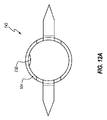
図1は、組織係合システム100の一実施形態の斜視図である。より完全に本明細書で記載されるように、組織係合システム100は組織層を係合し、組織層を貫通して組織層下の領域にアクセスを提供するために使用することができる。特定の実施形態では、比較的薄く及び/又は下部構造に密接して位置する組織層を係合して貫通するために特に好適であり得る。例えば、いくつかの実施形態は心膜を係合し、貫通するのに特に好適であり、下にある心外膜に接触したり損傷したりすることなく行うように構成することができる。様々な実施形態の他の特徴及び利点は、以下の開示から明白になるだろう。
FIG. 1 is a perspective view of an embodiment of the
図示された実施形態では、組織係合システム100は、トンネルシステム101及び組織係合システム102を含む。換言すれば、トンネルシステム101及び組織係合システム102の各々は、組織係合システム100のサブセットである。図示された実施形態では、トンネラーカニューレ110は、トンネルシステム101及び組織係合システム102の両方を共通して含む。すなわち、トンネラーカニューレ110は、トンネルシステム101とともに使用されて標的組織層への通路を通すことができ、また、その後の標的組織層を係合及び貫通する上で組織係合システム102とともにさらに使用することができる。
In the illustrated embodiment, the
トンネラーカニューレ110に加えて、トンネルシステム101は閉塞具120を含み、またトンネルシステム102は組織係合装置130を含む。図示された実施形態では、閉塞具120及び組織係合装置130の各々は、トンネラーカニューレ110に選択的に連結されるように構成される。
In addition to the
いくつかの実施形態では、組織係合システム100はキット103として設けられる。例えば、トンネラーカニューレ110、閉塞具120、及び組織係合装置130は、一組として組み立てられ、単一の滅菌包装として共に配布されることができる。他の実施形態では、キット103は閉塞具120又はトンネラーカニューレ110のうち1つ以上を除外してよい。その他の場合、トンネラーカニューレ110、閉塞具120、又は組織係合装置130のうち1つ以上は別に配布されることができる。
In some embodiments, the
図2を参照すると、トンネルシステム101はより詳細に示されている。図示された実施形態では、トンネラーカニューレ110は、カニューレ、シャフト、又は管腔112を画定する管111を含む。
With reference to FIG. 2, the
トンネラーカニューレ110は、さらに管111の近位端にコネクタ113を含むことができる。コネクタ113は、任意の好適な種類とすることができ、選択的に閉塞具120に/閉塞具120から、トンネラーカニューレ110に連結/分離するように構成されることができる。図示された実施形態では、コネクタ113は、トンネラーカニューレ110の長手方向軸に対して外側に曲がるように構成される2つの弾性プロング115a、115bを含む雌スナップ嵌め114を備える。各弾性プロング115a、115bの近位端は、閉塞具120の相補部分を係合することができる内側に向けられた隆起116を含む。図示されたスナップ嵌め114は、一対の互いに正反対のチャネル117を含む(そのうち1つのみを図2に図示)。チャネル117は、プロング115a、115bの湾曲を容易にすることができる。いくつかの実施形態では、トンネラーカニューレ110は、任意の好適な種類の1つ以上の深さマーキング118を含む。
The
図示された閉塞具120は、トンネラーカニューレ110の管腔112を実質的に充填するように寸法を合わせたロッド121を含む。例えば、ロッド121の外径は、管111の内径よりも僅かに小さく、閉塞具120を管111に容易に挿入し、また管111から取り出すことができる。一方、管111は、患者の組織(例えば、軟組織又は結合組織)中を前進するときでも管腔112を充填することにより芯が抜けるのを防止する。
The
本明細書中で用いる場合、「直径」という用語は最も広い意味で用いられ、中心点を通るあるものの片側から他側への直線の定義又はあるものの中心を通る片側から他側への距離の定義を含む。すなわち、「直径」という用語は、必ずしも円形形状を意味するものではない。図面は、管111及びロッド121のような全体的に円形又は円筒状の左右対称形を示すが、本開示は、非円形の構成を想定している。例えば、様々な実施形態は、三角形、矩形、多角形、楕円形等のような非円形断面形状を有することができる。特に明記しない限り、「直径」という用語は、文脈から明らかなように、所与の特徴又はその一部の最大直径を指す。
As used herein, the term "diameter" is used in the broadest sense to define a straight line from one side to the other through the center point or the distance from one side to the other through the center of something. Includes definition. That is, the term "diameter" does not necessarily mean a circular shape. Although the drawings show an overall circular or cylindrical symmetrical shape such as a
閉塞具120は、その遠位端に丸みをつけ得る鈍い又は尖っていない先端122を含むことができる。先端122は、閉塞具120が組織を通って容易に前進されることができるのに十分な傾斜のあるピッチ(例えば、十分に鋭いこと)を有することができる。しかし、いくつかの実施形態では、先端122は、先端122が標的組織層に押し当てられるときに標的組織層が意図せずに穿刺又は穿孔するのを防止するために十分な鈍さである。例えば、いくつかの実施形態では、先端122は、患者の組織を通って患者の心臓に向かって容易に前進され得る(例えば、約2ポンド又は約3ポンドの力を加えた場合)が、先端122が同じ力の量で心臓(例えば、心膜)と接触すると、先端122はそれによって停止し、心臓を穿刺しない。
The
閉塞具120は、トンネラーカニューレ110のコネクタ113に選択可能に連結されるように構成されたコネクタ123を含むことができる。例示のコネクタ123は、トンネラーカニューレ110の雌スナップ嵌め114に対して補完的である雄スナップ嵌め124である。スナップ嵌め124は、隆起116がカム表面125の近位端の溝126へと受け入れられるまでプロング115a、115bを広げて離す傾斜面又はカム表面125を含む。閉塞具120とトンネラーカニューレ110との間の任意の他の好適な接続インタフェースが企図される。
The
図示された実施形態では、閉塞具120は一対の互いに正反対の隆起127を含み、これはトンネル事象中にトンネルシステム101の捻りを容易に可能にする把持部として機能してよい。閉塞具120は、拡大された基部128を含むことができ、実質的に平坦であってよく、トンネル事象中にトンネルシステム101に遠位方向の力を加えることを促進し得る。
In the illustrated embodiment, the
図3を参照すると、組織係合装置130は、閉塞具120の組織係合装置と類似又は同一の連結特徴を含むことができる。例えば、図示された実施形態では、組織係合装置130は、閉塞具の類似の番号、類似の名称の機能と同じであるカム表面135及び溝136を有するコネクタ133を含む。したがって、トンネル事象後、閉塞具120は、トンネラーカニューレ110から容易に取り出され、組織係合装置130と交換することができる。
Referring to FIG. 3, the
組織係合装置130は、細長いハウジング又は管腔132を画定するシース131を含むことができる。患者に挿入される組織係合システム102の遠位部分の形状を小さくするために、シース131は管111の内径よりも僅かに小さな外径を有することができる。このような配置にすることで、シース131に容易に挿入し、管111から容易に取り外すことができ、一方、シース131内に収納された組織係合装置130の構成要素に対し大きな空間を提供する。様々な実施形態では、シース131の外径は、約0.15インチ、約0.10インチ、又は約0.09インチ(約3.8ミリメートル、約2.5ミリメートル又は約2.3ミリメートル)以下であり得る。いくつかの実施形態では、シース131の外径は約0.96インチ(約2.4ミリメートル)である。
The
シース131内に収納される構成要素用に大きな空間を提供するために狭いのに対し、シース131の側壁の厚さは、また、曲げに抵抗するのに十分な硬さ又は剛性を有するシース131を提供するように選択されてよい。様々な実施形態では、シース131の側壁の厚さは、約0.005インチ、約0.004インチ、又は約0.003インチ(約0.13ミリメートル、約0.1ミリメートル、約0.08ミリメートル)以下である。
While narrow to provide large space for the components housed within the
シース131は、任意の好適な材料から形成され得る。いくつかの実施形態では、シース131はステンレス鋼を備える。
The
組織係合装置130は、ユーザが組織係合装置130の一部を展開可能な作動インタフェース138を含むことができる作動機構137を有し得る。図示された実施形態では、さらに後述するように、作動インタフェース138は、遠位方向に押されると係合アームを作動し、又は近位方向に引っ張られると作動後に係合アームを後退することができるボタンを備える。作動機構137はさらに、アクセスアセンブリ139を含むことができ、針のようなアクセス装置を展開するために使用され得る。図示された実施形態では、アクセスアセンブリ139は、以下にさらに記載するように、針を展開するために遠位方向に押されることができ、また展開後に針を後退させるために近位方向に引っ張られることができる。
The
図4Aを参照すると、組織係合装置130の作動機構137は、内部に様々な構成要素が収納されるハウジング140を含むことができる。図示された実施形態では、ハウジング140は上部シェル141及び下部シェル142を含む。上部シェル141及び下部シェル142は、摩擦嵌め係合、スナップ嵌め係合、接着、溶接(例えば超音波溶接)等のうち1つ以上を含む、任意の好適なやり方で互いに固定されることができる。
Referring to FIG. 4A, the
本明細書で「上部」及び「下部」のような方向を示す用語は、全体的に図面に描かれた向きに対する。このような方向を示す用語は、装置又は構成要素の可能な向きを制限することを必ずしも目的とはしない。例えば、場合によっては、ユーザは、作動機構の使用中に、上部シェル141を下向きに、下部シェル142を上向きに向けることを望む場合がある。
As used herein, terms such as "top" and "bottom" refer to the orientations depicted in the drawings as a whole. The term for such orientation is not necessarily intended to limit the possible orientation of the device or component. For example, in some cases, the user may wish to have the
いくつかの実施形態では、組み立てられたハウジング140は、ユーザの手の1つ以上の巻き、握りしめ、又は握りしめた、湾曲した指の中に収まるように寸法を合わせることが可能である。例えば、組み立てられたハウジング140の外部の幅は、約1/2インチ、約5/8インチ、約3/4インチ、約1インチ、約1.5インチ(約1.3センチメートル、約1.6センチメートル、約1.9センチメートル、約2.5センチメートル、又は約3.8センチメートル)以下であることができる。いくつかの実施形態では、幅は約5/8インチである。いくつかの実施形態では、組み立てられたハウジング140の外部の長さには、1つ以上の巻き、握りしめ、又は握りしめたユーザの手の指が3本まで、又は4本まで同時に接触することができる。このような構成はユーザにハウジング140上でしっかりしたハンドルを提供することができ、係合装置130を安定し、確実に、及び/又は人間工学的に使用することができる。様々な実施形態では、組み立てられたハウジングの把持領域(例えば、図示された実施形態の実質的に平行に供給される中央部分)は、約2インチ、約2.5インチ、又は約3インチ(約5.1センチメートル、約6.4センチメートル、又は約7.6センチメートル)以下である長さを有する。いくつかの実施形態では、その長さは約2.25インチである。
In some embodiments, the assembled
さらに後述するように、作動インタフェース138は、ハウジング140に移動可能に連結されることができる。例えば、図示された実施形態では、作動インタフェース138は、遠位方向(作動のために)又は近位方向(後退のために)に選択的に動かすように構成され得る。ハウジング140に対する作動インタフェース138の位置は、使い易いように人間工学的に設計されることができる。図示された実施形態では、作動インタフェース138は、上部シェル141の上部表面の中心点を実質的に通るように構成される。作動インタフェース138は、さらに遠位及び近位の方向の各々における中心点からほぼ等距離に移動するように構成され得る。他の好適な構成も企図される。作動インタフェース138は、片手での操作に都合がいいように配置され得る。例えば、図示された実施形態では、ハウジングは、ユーザの手の多数の指で把持されることができ、作動インタフェース138は、その手の親指で制御されることができる。
Further, as will be described later, the
ハウジング140の下部シェル142はコネクタ133を画定できる。図示された実施形態では、シース131は任意の好適な手法でコネクタ133にしっかりと固定される。係合要素143は、シース131の管腔132内に受け入れられることができ、コネクタ133及び/又はシース131にしっかりと固定され得る。換言すれば、係合要素143は、シース131に対して及び/又はハウジング140に固定されることができる。図示された実施形態では、係合要素143の近位端は、シース131の近位端に取り付けられる。
The
図4Bは、さらに詳細に係合要素143の遠位部分を示す。係合要素143は、基部104を備え、本基部は係合要素143の近位部分を画定する。図示された実施形態では、基部104は実質的に管状又はカニューレ構造であり、そのため基部104もまたカニューレ基部とも称され得る。カニューレ基部104は管腔105を画定する。図示された実施形態では、基部の外径はシース131の内径よりも僅かに小さい。
FIG. 4B shows the distal portion of the
図示された実施形態では、複数の可撓性アーム108a、108bは基部104の遠位端から遠位方向に延びる。アーム108a、108bもまた、タイン又はプロングと称され得る。さらに後述するように、アーム108a、108bは、基部104に一体的に接続されてよく、いくつかの実施形態では、又は換言すれば、基部104及びアーム108a、108bは単一片の材料から一体的に形成される。例えば、アーム108a、108bは、管(図9を参照)の部分から切り取られ(例えばレーザ切断)、次に残りの突出を曲げることによって形成され得る。いくつかの実施形態では、係合要素143をシース131に挿入する前に、アーム108a、108bは、例えば、図10A及び図10Bに示されている構成のように、基部104の外周を越えて外側に横方向に延びる曲げ構成を保持し得る。
In the illustrated embodiment, the plurality of
各アーム108a、108bは、標的組織層内に埋め込まれ、標的組織層を貫通し、又は別の方法で標的組織層に取り付けられることが可能な組織係合部材109a、109bを含むことができる。組織係合部材は、各々、標的組織層へと貫通することが可能な角度のある端、スパイク、又はバーブのような尖った要素を含む。図示された実施形態では、各組織係合部材109a、109bは、それぞれのアーム108a、108bの角度のある遠位端を含む。
Each
図4Aを再度参照すると、係合装置130は、その近位端での作動インタフェース138の移動を作動部材145の遠位端へと通信する作動部材145を含むことができる。さらに後述するように、作動部材145は、係合要素143のアーム108a、108bを展開するように構成される。図4Aに図示されるようないくつかの実施形態では、作動部材145は、管又はカニューレを備える。したがって、作動部材145もまた、作動カニューレと称され得る。
Referring again to FIG. 4A, the engaging
さらに、図示された実施形態は、展開時には標的組織層を通ってアクセス開口を作るように構成される貫通部材又はアクセス装置147を含む。図示された実施形態では、アクセス装置147は針である。任意の好適な針又は他の貫通部材が使用され得る。作動部材145は、シース131の管腔132内に配置されることができ、摺動又は別の方法で内部を自由に動かすように寸法を合わせることができる。アクセス装置147は、作動部材145の管腔105内に配置されることができ、摺動又は別の方法で内部を自由に動かすように寸法を合わせることができる。
Further, the illustrated embodiment includes a penetration member or
作動機構137は、組織係合装置130の動作を拘束するように構成される多数の構成要素を含むことができる。特に、図示された実施形態では、作動機構137は、係合要素143に対して、またアクセス装置147に対しても作動部材145の移動を制御する構成要素を含む。さらに、作動機構137は、作動部材145及び係合要素143に対して、アクセス装置147の移動を制御する構成要素を含むことができる。図示された実施形態では、作動機構は、ハウジングの下部シェル142内に受け入れられるゲート144、作動部材145と連結されるシャトル146、及びアクセス装置147と連結されるハブ149を含む。これらの構成要素の各々の少なくとも一部はハウジング140内に配置される。これらの構成要素の様々な特徴及び機能は、以下の図6Aから図7Eに関連してさらに記載される。アクセスアセンブリ139は、ハブ149及びアクセス装置147を含む。作動インタフェース138、シャトル146、及び作動部材145は、本明細書において集合的に作動アセンブリ148と称され得る。
The
図5Aから図5Dは、様々な動作状態における組織係合システム102を示し、これはシステム102を使用する方法のステップに一致できる。これらの図は組み立てられた係合システム102の遠位端を示す。図6Aから図7Eに対してさらに以下に記載されるように、図5Aから図5Dに示された動作状態を達成するための例示的な実施例は図示された作動機構137を介して達成されることができる。記載された動作状態を達成するための任意の好適なシステム及び方法が企図されることを理解すべきである。
5A-5D show the
図5Aは、トンネラーカニューレ110の遠位部分内に配置された組織係合装置130の遠位部分を示す。トンネラーカニューレの管111は最も外側の管として示されている。シース131の外部表面、カニューレ基部104、作動部材145、及びアクセス装置147は破線で示されている。このビューは、入れ子式、伸縮式、又は同軸配置の管111、シース131、カニューレ基部104、作動部材145、及びアクセス装置147によって達成されるコンパクトな構成を示す。
FIG. 5A shows the distal portion of the
アーム108a、108b及び組織係合部材109a、109bもまた、図5Aにおいて識別されている。組織係合システム102のこの動作構成においては、組織係合装置130は、管111の遠位端に向かって、又は遠位端を通って遠位方向に前進されるか、もしくは管111を通って近位方向に後退される過程のいずれかにあり得る。いずれの場合も、組織係合部材109a、109bの先の尖った端は、管111の内部にもあり、換言すれば、管腔112内にある。この配置において、尖った端は、管111を通って前進するか、又は管111を通って後退する間、組織(すなわち、管111の外部の組織)に意図せずに接触できない。
The
図5Bは、トンネラーカニューレ110の管111の遠位端を通過して前進される組織係合装置130の遠位端を示す。図5Aと同様に、組織係合装置130は完全に後退されるか、未作動の状態で図示されている。完全に後退された状態では、アーム108a、108b又はアクセス装置147のどちらも展開されていない。図示された構成は、システム102が標的組織層へと前進され、かつアーム108a、108bを展開する直前の時点を表すことができる。
FIG. 5B shows the distal end of the
図示された実施形態では、アーム108a、108bの係合部材109a、109bは、組織係合装置130が完全に後退した構成にある場合にはシース131の遠位端から僅かに外部に配置される。換言すれば、係合部材109a、109bはシース131の遠位端に対して遠位方向に配置される。係合部材109a、109bの露出された先端は、シース131の遠位端が標的組織層と接触して前進されるため、接触時に標的組織層に容易に係合し得る。また、図示された実施形態では、尖った先端は僅かに遠位方向に向けられ、その結果、係合装置130がトンネラーカニューレ110を通って遠位方向に前進される際に、尖った先端と標的組織層とが初めて接触して標的組織層に尖った先端を向かわせることができる。さらに、シース131の遠位端を通過して尖った先端が僅かに露出することによって、標的組織層にシース131の遠位端を当接して接触させ、組織層は最初に係合され、またアーム108a、108bの展開が進行可能であることをユーザに対し触覚でフィードバックを提供できる。
In the illustrated embodiment, the engaging
図示された実施形態における係合部材109a、109bは長手方向に、又は遠位方向に、シース131の遠位先端を越えて延びるが、係合部材109a、109bは、やはり、延びないか、又はシース131の外周を越えて水平方向外側に大きく延びないかのいずれかである小さな形状の構成に制限される。例えば、図5Bに示した配置が端面図(近位方向)で示された場合には、図11D及び図13に示されたビューと同様に、シース131の遠位端の全周は、係合部材109a、109bが周辺を越えて水平方向外側へ延びない状況で見えるであろう。このビューにおいては、係合部材109a、109bは周辺に対し内側にある。換言すれば、シース131の外部表面は、シース131の遠位端を越えて遠位方向に突出された場合には、係合部材109a、109bの全て又はほぼ全て(例えば75%以上)は、取り囲まれるか外接するであろう。このような配置は、係合部材109a、109bとシース131の周囲外に配置された組織との間の相互作用(例えば、引っ掛け、引き裂き等)を抑制又は回避することができる。これはトンネラーカニューレ110の遠位端を越えて組織係合装置130の展開中又はトンネラーカニューレ110へと係合装置130が後退する間のいずれにおいても有用であり得る。
The engaging
アーム108a、108bの残部はシース131の管腔132内に配置される。以下でさらに説明すると、また図5Bに示すように、アーム108a、108bは、管腔132内かつ作動部材145の遠位端に対し遠位である位置で互いに交差する。
The rest of the
図5Cは、アーム108a、108bが展開された後の組織係合システム102を示す。特に、作動部材145は、アーム108a、108bが互いに交差する位置を越えて遠位方向に前進されてきて、それによってアーム108a、108bの交差を解き、図5Bに示されている非展開構造から変形させる。作動部材145は、アーム108a、108bの近位部分を作動部材147の外部表面とシース131の内部表面との間の環状領域へと押し込んだ。
FIG. 5C shows the
図示された実施形態では、アーム108a、108bは、装置130の正反対側にある(例えば、カニューレ基部104の反対側)。さらに後述するように、アーム108a、108bの展開により、実質的に対抗する方向に係合部材109a、109bを移動させる。係合部材109a、109bは、このように、内部に埋め込まれ、及び/又は実質的に対抗する方向に標的組織層に張力を加えることができる。アーム108a、108bは、シース131の周囲を越えて水平方向外側へ延びる大きな形状の構成である。
In the illustrated embodiment, the
図示された構成では組織係合装置130は、アーム108a、108bは展開されているがアクセス装置147は後退したままであるという点において、部分的に展開された状態である。アーム108a、108bを展開することにより、係合部材109a、109bを作動部材145の遠位端から外して、アクセス装置147を展開するために遮るもののない通路を提供する。換言すれば、図5Bに示された構成において、アーム108a、108bは作動部材145の遠位端を覆う。アーム108a、108bの展開は、作動部材145の遠位端の覆いを効果的に取り、アクセス装置147にアクセス路を提供する。
In the illustrated configuration, the
本発明で使用する場合、「覆う」という用語は、表面(例えば作動部材145の遠位端)に直接接触することを必要としないが、このような配置は本用語の範囲内に含まれる。「覆う」という用語は、本明細書ではより広範に使用され、直接接触することがない障害物の状況を含む。例えば、図5Bに示された配置が、斜視図よりもむしろ図13に示されたビューに類似する端面図(近位方向)で示された場合、作動部材145の遠位端における開口の大部分はアーム108a、108bによって視界が遮られるであろう。より適切に、対抗する方向、つまり、アクセス装置147の遠位端の斜視から見ると、作動部材145の遠位開口は遮られるであろう。換言すると、作動部材145の遠位開口を画定する作動部材145の内部表面が作動部材145の遠位端を越えて遠位方向に突出した場合には、アーム108a、108bはそれらによって取り囲まれるか、又は外接されるであろう。
As used in the present invention, the term "covering" does not require direct contact with a surface (eg, the distal end of the actuating member 145), but such arrangements are within the scope of the term. The term "covering" is used more broadly herein and includes the situation of obstacles that are not in direct contact. For example, if the arrangement shown in FIG. 5B is shown in an end plan (proximal direction) similar to the view shown in FIG. 13 rather than a perspective view, the large opening at the distal end of the actuating
いくつかの実施形態では、作動機構137は作動部材145を介してアーム108a、108bの展開の前にアクセス装置147が展開するのを防止できる。これは、ユーザが不意にアームを通って遠位方向にアクセス装置147を動かすことによって、アーム108a、108bを部分的に展開しないことを確実にするための安全策になり得る。すなわち、アクセス装置147の外径が作動部材145の外径よりもほんの僅かだけ小さいため、作動部材145の展開前にアクセス装置147を展開すると、係合部材109a、109bを比較的大きな形状へと水平方向外側に延びるが、場合によっては作動部材145の展開によって達成され得るような幅又は大きな形状の配置ではない。
In some embodiments, the
図5Dは、完全に展開された状態の組織係合装置130を示す。特に、係合アーム108a、108bが展開され、アクセス装置147もまた展開されている。アクセス装置147は作動部材145を通り、遠位端を越えてその遠位方向に前進してきている。
FIG. 5D shows the
いくつかの実施形態では、アクセス装置147が始めに後退されない限り、作動機構137は作動部材145が係合アーム108a、108bを後退させないように防止することができる。これは、最初にアクセス装置147を最初に後退せずに作動部材145を後退させるとアーム108a、108bを部分的に展開された状態のままにする可能性があるため、安全策としての役割をすることができる。例えば、図示された実施形態では、アクセス装置147は作動部材145の外径よりも僅かに小さい外径を有する。したがって、作動部材145がアクセス装置147が展開された状態の間に引き出された場合には、弾性アーム108a、108bは作動部材145の後退時に小さな形状の構成に戻り始めるであろうが、しかし、その代わりに、アクセス装置147の外部表面と接触するようになることにより、この構成に到達することを防止するであろう。ユーザは、作動部材145が後退したため、アーム108a、108bがこの段階で完全に後退したと考え、組織係合装置130を部分的に展開された状態のアーム108a、108bで引き出す可能性がある。この状態で組織係合装置130を遠位方向に引き出すと、場合によっては組織の下にある標的組織層及び/又は係合装置130自体を損傷する可能性がある。
In some embodiments, the
特定の実施形態では、システム102を患者から後退させる方法は、逆の順序で図5Aから図5Dに示された段階をたどることができる。例えば、図5Dに示された構成から始めると、アクセス装置147は図5Cに示された方向に後退されることができる。その後、作動部材145は図5Bに示された方向に後退されることができる。特定の実施形態では、アーム108a、108bが弾性であるため、この作動部材145の後退もまた、アーム108a、108bを図5Cの変形された状態から図5Bに示された構成へと自然に、又は自動的に戻らせるだろう。その後、組織係合装置130は図5Aに示されるように、トンネラーカニューレ110の管腔を通って引き出され得る。
In certain embodiments, the method of retracting the
図6Aから図6Gは、組織係合装置130のための作動機構137の例示的な実施形態を示す。前述のように、他の好適な機構も企図され、本開示の範囲内である。図示された作動機構137は組織係合装置130の2つの潜在的に不都合な構成を防止することができる。特に、作動機構137は作動部材145を介してアーム108a、108bの展開の前にアクセス装置147が展開するのを防止するように構成され、これにより上述したこのような構成に対する潜在的に望ましくない結果を回避できる。図示された作動機構137はさらに、作動部材145の後退及び結果として生じるアーム108a、108bの後退を防止するように構成され、これにより上述したこのような構成に対する潜在的に望ましくない結果を回避できる。図示された駆動機構137は、二重連結システムと称され得る。換言すると、作動機構137は組織係合装置130の最初の潜在的に望ましくない構成を防止するためのロックとしての役割をすることができ、さらに、組織係合装置130の第2の潜在的に望ましくない構成を防止するためのロックとしての役割をすることができる。他の実施形態では、連結装置は潜在的に望ましくない構成のうち1つのみ防止し得る。さらに他の実施形態では、作動機構137はいずれかの潜在的に望ましくない構成に対する連結装置として機能しなくてよい。
6A-6G show exemplary embodiments of
図6Aは、ハウジング140の実施形態の分解斜視図を示し、上部シェル141及び下部シェル142を含む。下部シェル142は、上述したようにその遠位端にあるコネクタ133を含むことができる。コネクタ133は、作動部材145及びアクセス装置147が展開された状態に前進又は後退された状態に後退するために中を通過できる管腔133aを画定できる。
FIG. 6A shows an exploded perspective view of an embodiment of the
図6A及び図6Bを参照すると、下部シェル142は、作動機構147の特定の構成要素又はその一部が受け入れられるキャビティ150aを画定できる。上部シェル141は、同様に、特定の構成要素又はその一部が受け入れられることが可能なキャビティ150bを画定する。上部シェル141及び下部シェル142が互いに連結されるときには、キャビティ150a、150bは単一の空間の容積を画定する。
With reference to FIGS. 6A and 6B, the
作動機構137の図示された実施形態の二重連結プロパティは、通常2つのレベル又は平面上で動作する。上位レベルは上部シェル141の下部分によって全体的に画定される。下部レベルは下部シェル142によって画定される。例えば、下部シェル142は、アクチュエータ停止部151を含み、これは下部シェル142の実質的に平坦な基部壁から上向きに延びる丸い突出である。さらに後述するように、アクチュエータ停止部151は、下部レベルにおける構成要素と相互作用するように構成される。
The duplex property of the illustrated embodiment of the
下部シェル142はさらに、さらに後述するように、ゲート144と接続するように構成される連結突出152を含む。下部シェル142の近位端は、キーイング表面153aによって画定されるキースロット領域155aを含むことができる。上部シェル141の近位端は、キーイング表面155bによって画定されるキースロット領域155bを同様に含むことができる。上部シェル141及び下部シェル142が互いに連結されるときには、キースロット領域155a、155bは、単一のキースロットを画定し、キーイング表面153a、153bは、その部分がハウジング140から遠位方向に前進されるか、又は近位方向に後退されつつ、ハブ149の固定された回転方向を維持するように協働する。
The
上部シェル141は、作動インタフェース138が前後に動かすことができる凹部156を画定する。上部シェル141は、さらに作動インタフェース138が前後に沿って動かすことができる長手方向のチャネル157を画定する。上部シェル141もまた、作動インタフェース138の一部が内部を通って前進されることができる横方向のチャネル158を含む。
The
図6Bを参照すると、上部シェル141は、さらに以下に記載するように、シャトル146の近位方向の移動を選択的に防止できる一対の停止部159a、159bを画定する。停止部159a、159bは、二重連結機構が沿って作動する上位レベル内にある。
Referring to FIG. 6B, the
図6Aを参照すると、図示された作動インタフェース138はボタン160として形成され、これはまたスライダと称され得る。図示されたボタン160はユーザの親指を介する作動に特に適しているが、他の作動把持部が可能であるがハウジング140は手の指で保持される。ボタン160は、ユーザの親指の先端を受け入れるような形状となっている近位面161を含む。近位面161は、把持部163に向かって遠位方向に上昇し、これはユーザに牽引力を提供できる。任意の好適な把持機構が企図されるが、図示された把持部は、横方向に向けられた溝を含む。遠位面162は頂点から急角度で下がる。ユーザは遠位面162の頂点及び/又は上部分を容易に把持して作動アセンブリ148を後退するために後方向の力を加える。
Referring to FIG. 6A, the illustrated
図6Cを参照すると、ボタン160は、上部シェル141の長手方向のチャネル157内を摺動するように寸法を合わせた長手方向のガイド164を含むことができる。ボタン160はさらに、ボタン160の底部表面と協働してガイド164のいずれかの側上にあるチャネル166を画定する水平方向又は横方向の棒165を含むことができる。チャネル166は、長手方向のチャネル157と接する上部シェル141の一部を受け入れることができる。
Referring to FIG. 6C, the
図6D及び図6Eは、2つの異なる動作状態におけるゲート144を示す。図6Dにおいては、ゲート144は閉鎖され、これに対して、ゲート144は図6Eにおいて開かれている。ゲート144は、下部シェル142内に配置される。したがって、ゲート144は、二重連結機構のより低いレベルで動作する。
6D and 6E show the
ゲート144は、近位方向に延びる2つの弾性アーム171a、171bを含む。基部170は、下部シェル142の連結突出152を受け入れるように寸法を合わせた開口172を画定してゲート144を下部シェル142に接続する。アーム171a、171bの遠位端は、基部170の内部表面と協働して容器173を画定する。ゲート144は下部シェル142に連結される場合、アクチュエータ停止部151は容器173内にある。
The
アーム171a、171bの略中央部分は、それぞれ内側に突出するカム表面174a、174bを含む。さらに下記に記載されているように、カム表面174a、174bは、シャトル146の一部と相互作用してゲート144を選択的に開くように構成される。
The substantially central portion of the
アーム171a、171bの近位端は、ゲート144が図6Dの閉鎖状態にあるときにハブ149の一部と当接してハブ149の遠位方向への移動を防ぐように構成される停止部175a、175bを含む。ゲート144は図6Eの開状態にあるときに、停止部175a、175bは互いに分離されて、ハブ149の一部が遠位の方向に通ることができる通路176を画定する。
The proximal ends of the
図6Fはアクチュエータ148の一部を示し、これは作動部材145及びシャトル146を含む。前述したように、アクチュエータ148は、さらに作動インタフェース138を含む。
FIG. 6F shows a portion of the
前述したように、図示された実施形態では、作動部材145は管腔180を画定するカニューレである。管腔180は、アクセス装置147が通過できるような寸法である。作動部材145の近位端は、任意の好適な手法でシャトル146の本体181に連結されることができる。
As mentioned above, in the illustrated embodiment, the actuating
シャトル146は、長手方向のチャネル183及び水平方向のチャネル187を画定するように協働する一対の上向きに突出する側壁182を含む。チャネル183、187は、ボタン160から下向きに突出する長手方向のガイド164及び横方向の棒165を受け入れるように寸法を合わせられる。
図6Aから図6C及び図6Fを参照すると、ボタン160をシャトル146及びハウジング140の上部シェル141の連結において、長手方向のガイド164及び横方向の棒165は、上部シェル141の長手方向のチャネル157及び横方向のチャネル158を通って、シャトル146の長手方向のチャネル183及び水平方向のチャネル187へと挿入される。ボタン160及びシャトル146は、摩擦嵌め、スナップ嵌め、接着等のうち1つ以上を含む任意の好適な手法で共に接続されることができる。一旦、ボタン160及びシャトル146が接続されると、ボタン160は上部シェルの長手方向のチャネル157内で前方及び後方に自由に摺動する。
Referring to FIGS. 6A-6C and 6F, in connecting the
図6Fを再度参照すると、シャトル146はさらに、ウェッジ184のような下向きの突出を含む。ウェッジ184は、連結機構の下部面上で動作するように構成される。具体的には、ウェッジ184は、ゲート144のアーム171a、171bの近位部分間に配置されることができる。ウェッジ184は、ゲート144のカム表面174a、174bと相互作用するカム表面を含み、弾性的で可撓性のアーム171a、171bを離すようにさせることができる。ウェッジ184はアクチュエータ停止部151(図6A)と相互作用してシャトルが遠位方向にあまりに遠く移動するのを防止できる。具体的には、停止部151は、作動部材145の遠位端が作動アーム108a、108b(図5Cを参照)に対して例えば、作動アーム108a、108bの組織係合部材109a、109bの僅かに近位の位置のような、所望の位置で停止するのを確実にするように配置され得る。このような位置は、例えば、作動係合部材109a、109bの標的組織層の被係合部を押すことを回避し得る。
Referring again to FIG. 6F, the
図6Fを続いて参照すると、シャトル146の図示された実施形態は、水平方向かつ近位方向突出する一対の弾性的で可撓性のあるアーム185a、185bを含む。アーム185a、185bは、その基端に停止部186a、186bを含む。アーム185a、185b及び停止部186a、186bは、連結機構の上位レベル上で動作するように配置される。具体的には、さらに以下で説明するように、アーム185a、185bは、アクチュエータ148がハブ149の一部との接触を介して作動部材145を通じてアーム108a、108bを展開すべく遠位方向に前進させるように内側に曲げてよい。しかしながら、アクセス装置147を展開するためにハブ149を遠位方向へ前進させると、アーム108a、108bは、自動的に通常の延びた状態に自動的に戻ることができ、その時点で停止部186a、186bは、上部シェル141の停止部159a、159bに係合する。図7Eに対してさらに以下に記載されるように、ハブ149が近位位置に戻って停止部186a、186bを停止部159a、159bから開放するまでシャトル146はこの位置に保持されることができる。
With reference to FIG. 6F, the illustrated embodiment of the
図6Gは、アクセスアセンブリ139を示し、これはアクセス装置147又は貫通部材及びハブ149を含む。アクセス装置147の近位端は、任意の好適な手法でハブ149の本体191に連結されることができる。アクセス装置190は、一旦、アクセス装置147が標的組織層を貫通すると、標的組織層(例えば心膜腔)下の領域との連通を確立できる管腔190を画定することができる。例えば、ガイドワイヤは、管腔190を通して送達され得る。
FIG. 6G shows
ハブ192は、下部シェル142及び上部シェル141のキーイング表面153a、153bにより画定されたキースロット内に適合するように形成されているネック192と含む。ネック192は、キーイング表面153a、153bと協働してその長手方向軸を中心とするハブ149の回転運動を防止する外側へ突出するフランジを含むことができる。
The
ハブ192は把持部197を含むことができ、ネック192の近位に配置され得る。把持部197は、ユーザがハウジング140を第1の手で保持しながら第2の手を使用するなど、ユーザによって容易に操作されるような寸法に構成されることができる。図示された実施形態では、医療用コネクタ198は、ハブ192の近位端に配置される。任意の好適な接続インタフェースは、医療用コネクタ198のために企図され、流体をアクセス装置147の遠位端によってアクセスされた領域に、又は領域から送達及び/又は回収するために、ハブ149を任意の好適な医療装置(複数可)又は装置に連結する役割をすることができる。図示された実施形態では、コネクタ198はルアー継手199を備える。
The
図6Gを続いて参照すると、ハブ149は、3つの遠位方向に突出するタイン、プロング又はアーム193、194a、194bを含む。図示された実施形態では、アーム193、194a、194bは実質的に三叉形状を形成する。中央アーム193は、外側アーム194a、194bよりも短く、またその遠位端に停止部195を含む。停止部195は、連結システムのより低いレベルで動作し、ゲート144の停止部175a、175bと相互作用するように構成される。
With reference to FIG. 6G, the
上向きの突出196a、196bは側アーム194a、194bの各々の遠位端に配置される。突出196a、196bは、連結システムの上位レベルで動作するように配置される。具体的には、突出196a、196bは、ハブ149が後退状態に近位方向に引っ張られる場合には、アーム185a、186bの近位端を内側に曲げるように構成され、それによって図7Eに関してさらに示されて記載されるように、シャトルを後退状態にまで近位移動できる。
The
図示された作動機構137の特徴のいくつかは、所与の機能を達成するための一対の要素を含む。例えば、2つのアーム185a、186aは、2つの停止部159a、159bと相互作用して、特定の条件下で作動部材145の後退を防止する。他の実施形態では、相互作用する特徴の単一セットのみが使用され得る。しかしながら、場合によっては、相互作用する特徴の冗長なセットは、システムに対し強度、安定性及び/もしくはバランスを与え、並びに/又はバックアップ又は故障として作用することができる。
Some of the features of the illustrated
図7Aから図7Eは、作動機構137の動作の様々な段階を示す。動作のこれらの段階に関する多くの詳細は、既に提供されている。図7Aから図7E及びそれに続く記載は、様々な構成要素が相互作用する(例えば二重連結機構を達成するための)手法に関してさらに明瞭にするためである。本議論は図示された作動機構137の合理的な理解を目的とするため、少なくとも図5Aから図6Gに関して記載された特定の特徴は、以下の記載において繰り返されない可能性がある。少なくとも図5Aから図6Gに関してさらに開示された詳細は、完全に本明細書に適用されるが、簡潔かつ明瞭にするために省略されるであろう。
7A-7E show various stages of operation of the
図7Aは、トンネラーカニューレ110と連結された場合の図1中の視線7A-7Aに沿った組織係合装置130の断面図であり、これはまた横断面で示されている。この図面は完全に後退した構成において、シャトル146を示している。それに対応して、図面は後退した構成における作動部材145を示す。同様に、アクセス装置147及びハブ149は後退した構成である。したがって、組織係合装置130は完全に後退した構成にある。図7Aは、図5Bに示す組織係合装置130の遠位端のビューに対応している。この動作状態においては、ゲート144は閉じられ、ハブ149の中央プロング193と相互作用して、アクセス装置147の展開を防止する。
FIG. 7A is a cross-sectional view of the
図7Bにおいて、部分的に展開された状態の組織係合装置130を示す。具体的に、シャトル146は遠位方向へ前進されてきたが、まだその最遠位の向きにまで前進されていない。すなわち、シャトル146は展開の中間段階にまで前進されてきた。ゲート144は開き始めるが、しかしまだハブ149の中央プロング193の遠位方向に通過することができるほど十分な広さで開いてはいない。
FIG. 7B shows the
図7Cは、別の部分的に展開された状態における組織係合装置130の作動機構137を示す。この状態では、シャトル146は最遠位位置に前進されて、その結果完全に展開されている。しかしながら、ハブ149及びアクセス装置147は後退された状態のままである。シャトル146が完全に遠位に移動することにより、ゲート144が開放されて通路176を作り、ここで、遠位方向においてハブ149の中央プロング193が通過できるのに十分な大きさである。図7Cは、図5Cに示す組織係合装置130の遠位端のビューに対応している。
FIG. 7C shows the
図7Dは、完全に展開された状態における組織係合装置130の作動機構137を示す。具体的には、シャトル146及び作動部材145は、その最遠位方向にあり、ハブ149は、遠位方向に移動して少なくとも部分的にアクセス装置147を展開してきた。
FIG. 7D shows the
この動作モードにおいては、ハブ149は、遠位方向及び近位方向に拘束されない手法で移動することができ、又は少なくともハウジング140の境界によって許容される範囲内では少なくとも拘束されない。拘束されていない遠位方向への移動により、ユーザは、アクセス装置147に加える力の量を選択して、アクセス装置147が組織層を通って挿入される距離(限定された範囲内で)と同様に、標的組織層を貫通することができる。
In this mode of operation, the
拘束されていない近位の運動は、場合によっては、有用な安全特徴であり得る。例えば、ユーザが組織層を通じてアクセス装置147を挿入するが、その後注意散漫になるか、又はそうでなければ意図せずにハブ149を開放した場合には、下の層は近位方向にアクセス装置147を押すなどによって損傷から保護されることができる。心膜アクセスの文脈においては、例えば、アクセス装置147の遠位先端は、施術者がハウジング140に把持部を維持するがハブ149の把持部を解放する場合、拍動する心臓により後方に容易に押されてよい。
Unrestrained proximal movement can be a useful safety feature in some cases. For example, if the user inserts the
ハブ149の移動及び遠位方向の上向きの突出196a、196bは、シャトル146のアーム185a、185bを開放して自動的に、かつ弾性的に外側に広げてハウジング140の側面に接触する。アーム185a、185bの近位端は、停止部159a、159bの遠位面と接触するようになり、これにより本構成においてシャトル146を遠位方向に移動することを防ぐ。
The movement of the
図7Eは、部分的に展開された状態の作動機構137を再度示し、ハブ149は作動部材145が後退できる構成にまで遠位方向に引き出されている。さらに、ハブ149及びその上向きの突出196a、196bの近位方向への移動は、シャトル146のアーム185a、185bを圧縮して内側に変位し、停止部159a、159bの遠位面との接触を開放する。この構成により、シャトル146が近位移動をして作動部材145を後退位置へと引き出すことができる。
FIG. 7E shows the partially unfolded
図8Aから図8Kは、標的組織層に係合し、かつ同一の下側の空間にアクセスする例示的な方法の種々の段階を示す。これらの方法の段階に関する多くの詳細は、既に提供されている。図8Aから図8K及び以下の記載は、方法に関してさらに明瞭にするためである。本議論の目的は図示された方法の段階の合理的な理解を提供するため、少なくとも図5Aから図7Eに関して記載された特定の特徴は、以下の記載において繰り返されない可能性がある。少なくとも図5Aから図7Eに関してさらに開示された詳細は、完全に本明細書で適用されるが、簡潔かつ明瞭にするために省略されるであろう。 8A-8K show the various steps of an exemplary method of engaging the target tissue layer and accessing the same underlying space. Many details regarding the stages of these methods have already been provided. 8A-8K and the following description are for further clarity regarding the method. In order to provide a reasonable understanding of the steps of the illustrated method, the particular features described with respect to at least FIGS. 5A-7E may not be repeated in the following description. Further disclosed details, at least with respect to FIGS. 5A-7E, are fully applicable herein, but will be omitted for brevity and clarity.
1つの図示された方法は、順番に示された図8Aから図8Kにおいて図示された各段階を含む。例示的な方法において、患者の心臓の心膜腔にアクセスする。図示された各方法の段階を採用せず、及び/又は追加の段階を使用するいくつかを含む、他の方法が考えられる。また、他の好適な文脈(例えば、心膜以外の標的組織層)が企図される。 One illustrated method comprises each of the steps illustrated in FIGS. 8A-8K, shown in sequence. In an exemplary method, access the pericardial space of the patient's heart. Other methods are conceivable, including some that do not employ the steps of each of the illustrated methods and / or use additional steps. Also, other suitable contexts (eg, target tissue layers other than the pericardium) are contemplated.
図8Aは、組織層下の領域にアクセスするための例示的な方法の初期段階を示す。特に、本方法は、患者Pの心臓50の心膜51と心外膜52との間の心膜腔53にアクセスするために使用される。
FIG. 8A shows the initial steps of an exemplary method for accessing the area under the panniculus. In particular, the method is used to access the
図示された方法では、滅菌包装から除去されるなどによって、トンネルアセンブリ101が提供される。いくつかの実施形態では、閉塞具120及びトンネルカニューレ110が予め組み立てられた状態で提供される。その他の場合、方法の初期段階は、閉塞具120をトンネルカニューレ110と連結して示される構成にすることを含む。
In the illustrated method, the
いくつかの実施形態では、前方アプローチはトンネリングアセンブリ101を心臓50に向かって方向づける際に使用され得る。他の実施形態では、下方又は後方アプローチが使用され、これはトンネリングアセンブリ101を横隔膜を通って通過する必要があり得る。このようなアプローチもまた横隔膜内外圧差法又は横隔膜下法と称され得る。このようなアプローチの各々は、剣状突起下法と称され得る。異なるアプローチは心臓に対して異なる結果をもたらす。さらにその他の例においては、例えば6番目と7番目の間の肋骨などの肋間法が用いられ、また心臓の異なる領域に直接のアクセスを提供し得る。場合によっては、肋間の空間によって、心尖にアクセスすることができ、それによりこのアプローチは肋間法と呼ばれる。
In some embodiments, the anterior approach can be used to orient the
前述したことを考慮すると、心臓に対するいくつかの異なるアプローチが考えられる。本明細書で開示された組織係合システム100、102及び組織係合装置130は、任意のこのような心臓に対するアプローチに特に適している。具体的には、システム100、102及び装置130は、係合、把持、引っ張り、又は別の方法で心膜51を任意の数の異なる近接角で操作するのに特に適している。例えば、組織係合装置130は、アプローチを低い角度又は急な角度で効果的に行うことができる。また、特定の実施形態は0度(例えば、完全に横方向)から90度(例えば、完全に直交する方向)のアプローチの角度で良好に機能することができる。0度のアプローチに対して、装置130の遠位端は、心膜と接触して波形、又は装置の遠位端の前に、実質的に垂直(又は上向きに延びる)組織の壁を作ることができる。この現象は、指を使って天板に一片の生地を押し付けて波形又は波の反応を生成することに似ている。局所の波又は波形は、装置130の遠位端に対し少なくとも横方向の面を作ることができ、タインが係合(例えば掴み、把持、埋め込み、引掛け、捕獲等)できる。
Considering the above, there are several different approaches to the heart. The
図8Bは、トンネルアセンブリ101が患者の皮膚55の切開56を通って前進されてきた段階を示す。閉塞具120の鈍い先端122は、患者Pの結合組織54を通って心膜51の外部表面と接触させるように押し込まれている。
FIG. 8B shows the stage in which the
図8Cは、閉塞具120が、トンネルカニューレ110から切り離され、そこから除去される段階を示す。トンネリングカニューレ110の管111の一部は、組織54に残されて心膜51へのチャネルを提供する。
FIG. 8C shows the stage at which the
図8Dは、組織係合装置130がトンネラーカニューレ110に連結される段階を示す。特に、シース131は管111を通って心膜51に向かって前進される。
FIG. 8D shows the stage in which the
図8Eは、図5B及び図7Aの段階のように、標的組織層に配置された係合アーム108a、108bの組織係合部材109a、109b(例えば、遠位先端)とともに、組織係合装置130が完全に後退した構成にある別の段階を示し、この例では、心膜51である。組織係合装置130はトンネラーカニューレ110に完全に連結されている。
FIG. 8E shows the
図8Fは、組織係合装置130が図7Bの段階のように、部分的に展開された状態にある別の段階を示し、作動部材145が組織係合部材109a、109bのアームを心膜51に埋め込むために中間位置に向かって遠位方向に前進されている。図示された実施形態では、組織係合部材109a、109bは心膜51の厚さ全体を通って心膜腔53へと通過するようには延びない。換言すれば、係合部材109a、109bは、心膜51の内側表面又は底面を通過しない。これは、心膜51に対する係合部材109a、109bの初期の低い角度によるものであり、さらに、係合部材109a、109bの各々に対する浅い展開路によるものである。「浅い展開路」は、係合部材109a、109b(例えば、遠位先端)によって追跡される路は、作動部材145の遠位端から、又はそれぞれの係合部材109a、109bの開始点からの短い長手方向の距離だけ延びることを意味する。様々な実施形態では、各係合部材109a、109bは、開始点から1、2、3又は4ミリメートル以下の最大の長手方向の距離(すなわち、長手方向又は作動部材145の長手方向軸に対して同一直線上又は平行な方向で測定した場合のみの距離)へ遠位方向に進行する。また、いくつかの実施形態では、各係合部材109a、109bによって追跡される路の全体が、長手方向ではない構成要素(例えば、完全に水平方向であってよい)を有するか、又は近位方向にのみ進行するか、又は換言すると、開始点から水平方向かつ近位方向にのみ移動する長手方向の構成要素を有し得る。
FIG. 8F shows another stage in which the
様々な実施形態では、各係合部材109a、109bは最大長を画定する。例えば、図示された実施形態では、各係合部材109a、109bの最大長さは、その遠点から主屈曲部まで(例えば、図8Fにおいて容易に明白である各アーム108a、108b内で曲がるのみ)の距離である。様々な実施形態では、各係合部材109a、109bは開始点から、係合部材109a、109bの最大長が0.25倍、0.5倍、0.75倍、1倍、1.25倍、又は1.5倍以下の最大の長手方向の距離へ遠位方向に進行する。
In various embodiments, the engaging
あるいは、各係合部材109a、109bは、標的組織層の表面を実質的に横方向の展開路をたどると言うことができる。実質的に横方向に展開した係合部材109a、109bは、組織層内の係合部材109a、109bに埋め込み、また横方向に組織層に張力をかけることができる。実質的に横方向の展開路もまた、心外膜52のような下部組織層に接触及び/又は損傷する危険性を低減させる。
Alternatively, it can be said that each of the engaging
他の実施形態では、1つ以上の係合部材109a、109bのうち少なくとも一部分は、標的組織層の厚さ全体を貫通して延びることができる。換言すれば、他の実施形態では係合部材109a、109bは、組織層の底部又は内部表面を貫通し得る。
In another embodiment, at least a portion of one or more
図8Gは、組織係合装置130が図5C及び図7Cの段階のように、さらに部分的に展開された状態にある段階を示し、作動部材145が最遠位位置に向かって前進され、さらに係合部材109a、109bを心膜51に埋め込む。図示された実施形態では、係合部材109a、109bは、隣接するアーム108a、108bの近位部分に対して約90度の角度で水平方向外側に延びる。さらに後述するように、この完全な展開された状態におけるアーム108a、108bに対する他の角度も企図される。
FIG. 8G shows the stage in which the
図8Hは、組織係合装置130が図8Gに示されたように同一の構成にあり、組織係合装置130が係合部材109a、109bの近傍にある心膜51と心外膜52との間の心膜腔53を拡大するために近位方向に引っ張られる段階を示す。このような分離事象は、係合位置で心膜51のテンティングをもたらすことがある。このテンティングは図8Hで模式的にのみ示されているが、心膜51は上向きに引き上げられるような手法で示されるように、場合によっては、テンティングは心膜腔53内の真空又は他の力から生じ得るように非常に急であり得る。
In FIG. 8H, the
図8Iは、組織係合装置130が図5Dと7Dの段階のように、完全に展開された状態に移動された段階を示し、作動部材145及びアクセス装置147の両方が遠位方向に前進されている。図示された段階では、アクセス装置147は心膜51を貫通して心膜腔53にアクセスを提供する。流体の導入又は流体の除去のための心膜腔53との連通は、医療用コネクタ198を介して達成されることができる。
FIG. 8I shows the stage in which the
図8Hを参照して説明したように、作動アーム108a、108bの近傍のテンティングは、かなり急であってよい。しかしながら、アーム108a、108b間の領域は、アーム108a、108bによってもたらされる張力により実質的に平坦であり得る。したがってアクセス装置147は張力がかかった心膜51の一部を通って容易に前進されてよく、これは隣り合うテンティングによって比較的影響を受けない。
As described with reference to FIG. 8H, the tenting in the vicinity of the actuating
具体的には、アクセス装置147の遠位端は、尖っているか、又は装置の長手方向軸に対して角度があってよい。その結果、装置147の挿入は、例えば、アーム108a、108b間の領域を通って、アーム108a、108b間に保持される領域を包囲する急勾配のテント付表面のような、先端に対してより低い角度を有する領域を通してよりも、装置の長手方向軸と実質的に直交する平坦な領域を通じたほうがはるかに容易である。このため、いくつかの実施形態では、アクセス装置147の先端がアーム108a、108bが展開された状態にあるときにアーム108a、108b間に延びるラインを通過するのを確実にすることが有用である。
Specifically, the distal end of the
図8Jは、組織係合装置130が完全に展開された状態のままであり、ガイドワイヤ200の遠位端は、アクセス装置147を通って心膜腔53へと遠位方向に前進されている段階を示す。ガイドワイヤ200は、任意の好適な寸法であり得る。様々な実施形態では、ガイドワイヤの太さは、0.035インチ(0.89ミリメートル)又は0.032インチ(0.81ミリメートル)とすることができる。
FIG. 8J shows the
図8Kは、組織係合装置130が図5C及び図7Cの段階のように、部分的に展開された状態に戻った別の段階を示し、特に、アクセス装置147は後退されている。この段階から、作動部材145は、続いて後退されてよく、装置130は次に患者Pから取り除かれることができる。ガイドワイヤ200の遠位端は、組織係合装置130が引き出されると、心膜腔53内の適所に留まることができる。アームが装置130を取り除いている間に後退された状態ではあるが、ガイドワイヤ200の位置決めは、装置130の引き抜き時に比較的影響を受けないであろう。特に、装置130が引き抜かれるとアーム108a、108bは、ガイドワイヤ200によって通過される。換言すると、アーム108a、108bが作動部材145の遠位開口を覆っていてもガイドワイヤ200は、アーム108a、108bによって画定された開口225、226を通過することができる。例えば開口225、226は、図11C及び11Dにおいて見ることができる。
FIG. 8K shows another stage in which the
図9は、その製造工程の段階中の係合要素143の実施形態を示す。図示された実施形態では、係合部材143は、単一片の材料から形成される。任意の好適な材料が企図される。材料は、本明細書に記載された特性を望ましくは呈することが可能である。いくつかの実施形態では、係合要素143は、管として形成されたステンレス鋼の単一片から形成される。
FIG. 9 shows an embodiment of the
図9に示される製造方法の段階の前に、管の一部が切断されるか、又は別の方法で取り除かれてアーム又はタイン108a、108bが形成される(タイン108bは、図9では隠れているが図10Aのような他の図で示されている)。いくつかの実施形態では、タインはレーザ切断である。タイン108a、108bは、元の管の残りの部分から遠位方向に延びることができ、これは本明細書ではカニューレ基部104とも呼ばれる。
Prior to the steps of the manufacturing method shown in FIG. 9, a portion of the tube is cut or otherwise removed to form an arm or
タイン108a、108bは、各々比較的広い基部領域210を含むことができ、これはカニューレ基部104の遠位端から遠位方向に延びることができる。様々な実施形態では、基部領域210の幅は、カニューレ基部104の直径の約2/3、約1/2、又は約1/3以下であり得る。基部領域210は、変位領域212まで傾斜した角度のあるステップを有することができる。各アームの変位領域212は、使用中の最大変位の領域である。より薄い変位領域212により、コンパクト又は小さな設計を可能にすることができる。特に、タイン108a、108bは、後退された向きで互いに交差し、展開中に互いに移動する場合には、薄い変位領域が望まれ得る。様々な実施形態では、変位領域の厚さは、カニューレ基部104の直径の約1/2、約1/3、約1/4、約1/6、約1/8以下である。
The
元の管の部分を取り除くことにより、貫通面214a、214bも得ることができる(例えば図10Aも参照)。図示された実施形態では、貫通面214a、214bは、タイン108a、108bの遠位先端の尖った端又はバーブとして形成されている。貫通面214a、214bの迎角αは、標的組織層との迅速な係合を提供するために選択することができる。様々な実施形態では、迎角αは約10度、約15度、約20度、約25度、又は約30度以下である。
図10Aは、さらに処理をした後の係合要素143の側面立面図であり、図10Bはその平面図である。図10A及び図10Bに示されている構成に至るさらなる工程の段階において、タイン108a、108bは多数の軸の周りで曲げられる。いくつかの実施形態では、主屈曲部216a、216bはタイン108a、108bの遠位端をy軸の周りで回転することによってなされる。具体的には、タイン108aはy軸の周りで第一の方向に回転され、タイン108bはy軸の周りで対抗する方向に回転される。様々な実施形態では、曲げに起因する塑性変形の角度は、約30度から約120度、約45度から約115度の範囲内であることができ、又は約45度、約60度、約90度又は約115度以下であり得る。
FIG. 10A is a side elevation view of the
主屈曲部216a、216bは、係合部材109a、109bを得ることができる。係合部材109a、109bの近位側の保持面219a、219bは、屈曲部216a、216bの塑性変形の角度に依存して、標的組織層を保持する効果において変わり得る。
The main
タイン108a、108bは回転され、z軸周りに同方向に恒久的に曲げることができる。追加的に又は代替的に、タイン108a、108bは回転され、x軸周りで対抗する方向に恒久的に曲げることができる。後者の曲げは、スプラインングと呼ばれ、追加の恒久曲げ、又は第2の曲げ218a、218b(図10)が形成されるときに、タイン108a、108bを互いに移動させることができる。
The
図10Bに示すように、いくつかの実施形態では、タイン108a、108bは、タイン108a、108bの遠位端の水平幅が、カニューレ基部104の直径よりも大きな自然な方向を画定する。その結果、タイン216a、216bは、基部104の外径を僅かにのみ超える内径を有するシース131内に受けられると、タイン108a、108bはスプリング負荷される。すなわち、タイン108a、108bは、図10A及び図10Bに示されている構成を自然に想定しようとしているが、シース131(図5Bを参照)によって妨げられている。タイン108a、108bにこのような予荷重を与えることにより、作動部材145が後退された後、タイン108a、108bは図5Bに示された拘束方向に自然に戻ることを可能にする。
As shown in FIG. 10B, in some embodiments, the
図11Aから図11Dは、図5Bに示されている配置におけるような、シース131によって提供される拘束された構成における場合の係合要素143の様々なビューを表す。明確にするために、シース131は、これらの図には示されていない。この動作状態においては、タイン108a、108bは、カニューレ基部104の遠位端の遠位の位置で互いに交差する。この1つの特定の実施形態では、タイン108a、108bは、交差点220で互いに接触する。他の実施形態は、交差点の近くで互いに交差するが、そこでは互いに接触しない。このような配置における交差点は、交差するタイン108a、108b間の最短距離の中間点であり得る。前述のように、タイン108a、108bは、ガイドワイヤが使用中に容易に通過し得る開口225、226を画定する。
11A-11D represent different views of the
上記から理解できるように、特定の実施形態では、タイン108a、108bは互いに正反対に配置されることができる。後退された状態のときには、タイン108a、108bは実質的に曲がった構成にすることができる。作動時には、シース131内に拘束されている各タイン108a、108bの近位部分は、実質的に直線にすることができる。直線にされたタインは、互いに実質的に平行に及び/又は実質的にカニューレ基部104の長手方向軸に対して平行であってよい。各タイン108a、108bの長さは、展開中にタイン108a、108bの塑性変形を防止するのに十分な長さとすることができる。タインは、展開後に展開前の状態に自動的かつ自然に戻ることができる伸縮自在の弾性的な種類で形成されている。
As can be seen from the above, in certain embodiments, the
図12A及び図12Bを参照すると、係合要素143の特定の実施形態は、センタリング用突出230を含むことができる。図示された実施形態では、センタリング用突出230は、カニューレ基部104に押し付けられた内側方向の隆起230である。他の実施形態では、センタリング用突出230は、代わりに異なる材料から形成され、カニューレ基部104の内壁にしっかりと固定される。
With reference to FIGS. 12A and 12B, certain embodiments of the
図13に示すように、センタリング用突出230は作動部材145の移動を拘束(例えば、長手方向軸に対する水平方向の移動を拘束)し、これはアクセス装置147の移動を拘束する。この配置は、アクセス装置147の遠位先端240が係合要素143に対して実質的に中央にあることを確実にすることができる。いくつかの実施形態では、アクセス装置147の作動中、遠位先端240はタイン108a、108bの遠位先端を通って延びるラインLを通過することができる。このような配置は、タイン108a、108bの間にあり、それによって張力がかかる心膜の一部を通って先端240を送達するのを助けることができる。例えば、前述したように、これにより先端240が心膜の穿刺部分の頂部で比較的平坦又は平らな領域を通過することができる。
As shown in FIG. 13, the centering
図14A及び図14Bに示されているように、いくつかの実施形態では、アクセス装置147は、中心に遠位先端240を有する針250とすることもできる。場合によっては、針250は、ベベル242(例えば、バイアス研削、ランセット研削等のうち1つ以上)で形成され、次に遠位先端240を曲げて移動し、針250の長手方向軸と並ばせる。
As shown in FIGS. 14A and 14B, in some embodiments, the
図15から図20は、多くの点で上述の組織係合システムに類似し得る組織係合システム300の別の実施形態を示す。したがって、類似の特徴は類似の参照番号で示され、先頭の桁は「3」に増加される。したがって、同様に、識別された特徴に関して上記で説明された関連する開示は、以降、繰り返さない場合がある。さらに、組織係合システム300の特定の特徴は、図面中の参照番号により示されたり、又は識別されたりしないか、又は以下に記載する明細書で議論されない可能性がある。しかし、この特徴は、他の実施形態では記載された特徴及び/又はこのような実施形態に関して記載される特徴と明白に同一であるか、又は実質的に同一である。したがって、このような特徴の関連する記載は、組織係合システム300の特徴と等しく当てはまる。上述したように、組織係合システムに関して記載したのと同様の特徴及び変形例の任意の好適な組合せは、組織係合システム300とともに採用され、またその逆もまた同様である。
15 to 20 show another embodiment of the
図17を参照すると、組織層に係合するため、また組織層下の領域内へのアクセスを提供するためのシステム300は、統合された組織係合部材308a、308bを備えるカニューレ基部又はハウジング304、ハウジング304の管腔内の組織係合部材308a、308bを作動するためのカニューレ345、またカニューレ345の管腔内の組織貫通部材347を有する組織係合要素343を含み、組織層下の領域にアクセスするのを確実にする。
Referring to FIG. 17, the
図15を参照すると、カニューレ345とハウジング304内に後退された組織貫通部材347を備えるシステム300の実施形態が示され、その結果、カニューレ345及び組織貫通部材347は組織係合部材308a、308bと接触しない。
Referring to FIG. 15, an embodiment of a
図16を参照すると、組織係合部材308a、308bが完全に展開されたハウジング304の実施形態が示されている。カニューレ345の遠位端がハウジング304の遠位端へと前進され、それによって組織係合部材308a、308bを外側に展開させる。
Referring to FIG. 16, an embodiment of a
図18を参照すると、システム300の一実施形態が示され、カニューレ345の遠位端が組織係合部材308aの近位端310aからハウジング304の遠位端へと前進され、それによって組織係合部材308aを展開する。組織係合部材308bは同様に展開される。組織貫通部材347は、ハウジング304の遠位端を越えて前進される。
Referring to FIG. 18, one embodiment of the
図19を参照すると、ハウジング304の遠位端の組織係合部材308a、308bのオフセット性を示す一実施形態の正面図が示されている。
Referring to FIG. 19, a front view of an embodiment showing the offset properties of the
図20を参照すると、組織係合部材308a、308bによる組織層51の係合、及び組織層51の下の空間内への組織貫通部材347の展開の側面図が示されている。
Referring to FIG. 20, a side view of the engagement of the
これらの図に示されているように図示されたシステム300は、細長いハウジング304を含み、これもまたカニューレと称され、近位端及び遠位端を有し得る。遠位端は、針347が図17における場合のように延ばされるときに針347の遠位先端で終端し、遠位端は、針347が図15における場合のように後退されるときにハウジング304の遠位先端で終端する。針347は、図17における場合のように患者の皮膚の中への挿入を助けるために前進されることができ、次に図15における場合のように装置300が組織層51に向かって移動されると後退されて係合され、延ばされた針によって生じ得る組織の損傷を低減する。図示された実施形態は、剣状突起下の手法を使用して心膜腔にアクセスを提供するために特に適している。図15に示された非展開の組織係合部材308a、308bは、心膜に接触するまで患者の軟組織を効果的に通過してよく、また前進されるとき、心膜又は他の組織を穿孔又は貫通するのを防ぐために十分鈍くできる。
The
ハウジング304は、任意の好適な材料から形成され得る。いくつかの実施形態では、ハウジング304は金属製であるが、これに対して、他の実施形態又はさらなる実施形態では、ハウジング304は、実質的に剛性のプラスチックで形成することができる。
The
針347は、任意の好適な材料から形成され得る。例えば、いくつかの実施形態では、針347は、ステンレス鋼から形成される。材料は、組織層を貫通するのに十分な剛性を有するように選択される。
The
カニューレ345は、任意の好適な材料から形成され得る。例えば、いくつかの実施形態では、カニューレ345は、ステンレス鋼から形成される。材料は、組織係合部材308a、308bを展開するのに十分な剛性及び強さであるように選択される。
システム300の使用中に、針347は、ハウジング304を通過して延び、所望の位置へと患者に挿入してよく、ハウジング304の近位端は患者の外側に残すことができる。一実施形態では、システムは、図15に示されているように針347を後退された位置で所望の位置に患者の切開を介して患者に挿入される。いくつかの実施形態では、システム300は、ユーザが針347及び/又はカニューレ345を展開できる近位端に1つ以上のアクチュエータを含む。任意の適切なアクチュエータの配置も可能である。他又はさらなる実施形態では、カニューレ345及びアクセス針347は、ユーザにより直接操作されると、任意のアクチュエータに依存することなくハウジング304を通して前進され得る。
During use of the
一実施形態では、システム300は、針347を展開及び/又は後退するように構成されたシステムの近位端に第1のアクチュエータを含む。任意の好適なアクチュエータの配置も検討されるが、図示されたアクチュエータは、針347の近位部分に連結されたボタン、スイッチ、つまみ、又は突出を備える。図示された実施形態では、比較的大きな環状空間のアクセス針347の外側表面と、カニューレ345の内側表面と、ハウジング304の内側表面の間に示されている。いくつかの実施形態では、この環状空間は比例してはるかに小さく、最小化され、又は実質的に除去される。例えば、ハウジング304の側壁の内側表面の少なくとも一部と、カニューレ345の外側表面の少なくとも一部分と、アクセス針347との間に滑り嵌め、動き嵌め、又は最小の間隙が提供され、システム300の全直径(例えば、断面が必ずしも円形でない最大断面幅)、より具体的には、ハウジング304の外径を所望により減少できる。このような配置もまた、システム300が患者に前進されるとハウジング304によって組織の芯抜きを低減又は回避することができる。
In one embodiment, the
図20は、患者に前進させ、組織層51に係合させているシステム300の遠位端を示す。組織層51は、引き戻され、針347は組織層41の下に作られた空間へと前進される。ガイドワイヤが組織貫通層の管腔を通って組織層下の空間へと前進されている。
FIG. 20 shows the distal end of the
図18を再度参照すると、ハウジング304に沿って延びると組織係合部材308a、308bの長さは、カニューレ345によって作動中組織係合部材308a、308bの塑性変形を防止するために十分な長さであることが好ましい。
Referring again to FIG. 18, the length of the
図19を再度参照すると、組織係合部材308a、308bの遠位端の形状は、組織層51に切り込むことができるように鋭い。図15に示されるように作動されていないときは、プロングはハウジング304の境界を越えて延びないように、組織層51を係合するのに十分に長いが、ハウジング304の直径以下である。組織層に係合するプロングは、示されているように、90度で曲げるか、又は、60度から120度の間で曲げられてよく、組織係合及び保持を可能にすることができる。プロングの鋭い先端は、示されているように、組織を係合し、保持するために中心から切断されてよく、又は様々な角度で切断されてよく、又は任意の角度で切断されてよい。プロングの形状及び鋭さは、低角度や高角度で組織層50と係合するように設計されている。これにより低近接角及び高近接角、しかし、例えば、心臓への低角度の剣状突起下のアプローチに特に適し得る特に低角度を可能にする。
Referring again to FIG. 19, the shape of the distal end of the
図15及び図19を再度参照すると、組織係合部材308a、308bは、カニューレ345によって作動中に互いに通過しないように図示されるようにオフセットであり得るか、又はオフセットでなくてよい。組織係合部材308a、308bの遠位端でのプロングの長さは、カニューレによって作動されていない場合には、ハウジング304の直径を越えて延びないように組み立てられる。
Referring again to FIGS. 15 and 19, the
本明細書に開示される任意の方法は、記載された方法を実行するために1つ以上のステップ又は動作を含む。方法のステップ及び/又は動作は、互いに交換し得る。換言すれば、実施形態の適切な作動のためにステップ又は動作の特定の順序が必要とされない限り、特定のステップ及び/又は動作の順序及び/又は使用は、修正され得る。 Any method disclosed herein comprises one or more steps or actions to perform the described method. The steps and / or operations of the method may be interchangeable with each other. In other words, the sequence and / or use of a particular step and / or action may be modified unless a particular sequence of steps or actions is required for proper operation of the embodiment.
近似値への参照は、本明細書を通して、「約」又は「およそ」という用語を使用することなどによってなされる。各々のこのような参照には、いくつかの実施形態では、値、特徴又は特性は、近似なしで特定され得ることを理解すべきである。例えば、「約」、「実質的に」、「全体的に」のような修飾が使用される場合、これらの用語は、それらの修飾がない場合の修飾語を範囲内に含む。例えば、「実質的に平坦」という用語が特徴に関して引用された場合には、さらなる実施形態では、この特徴は正確な平面方向を有することができると理解されている。 References to approximations are made throughout the specification, such as by using the terms "about" or "approximately". For each such reference, it should be understood that in some embodiments, the value, feature or property can be specified without approximation. For example, when modifiers such as "about," "substantially," and "overall" are used, these terms include modifiers in the absence of those modifiers. For example, if the term "substantially flat" is cited with respect to a feature, it is understood that in a further embodiment, the feature can have an exact planar orientation.
本明細書を通して「特定の実施形態」等の任意の参照は、実施形態に関して記載された特別の特色、構造、又は特徴が少なくとも1つの実施形態に含まれているということを意味する。したがって、本明細書に引用された引用句、その変形は、必ずしも全て同じ実施形態を参照するわけではない。 Any reference, such as "specific embodiments," throughout the specification means that the particular features, structures, or features described with respect to the embodiments are included in at least one embodiment. Therefore, the quotation quoted herein, and variations thereof, do not necessarily refer to the same embodiment.
同様に、上記の実施形態の記載において、本開示を効率化するために、単一の実施形態、図、又はそれらの記載において、様々な特徴が共にグループ化されることがあることを理解すべきである。しかしながら、本開示の方法は、請求項に記載された請求項に明示されたものよりも多くの特徴を要するという意図を反映するように解釈されるべきではない。むしろ、以下の特許請求の範囲が表すように、本発明の態様は、先に開示された任意の単一の実施形態の全ての特徴よりも少ない数の組み合わせにある。 Similarly, in the description of the above embodiments, it is understood that various features may be grouped together in a single embodiment, figure, or description thereof for the sake of efficiency of the present disclosure. Should be. However, the methods of the present disclosure should not be construed to reflect the intent that they require more features than those specified in the claims. Rather, as the claims set forth below, aspects of the invention lie in a smaller number of combinations than all features of any single embodiment disclosed above.
この書面による開示に基づく特許請求の範囲は、別々の実施形態として独自に各請求項とともに本明細書によって明示的に本明細書の開示中に組み込まれる。この開示は、それらが従属請求項とともに独立請求項の全ての順列を含む。 The scope of the claims based on this written disclosure are independently incorporated herein by the present specification together with each claim as separate embodiments. This disclosure includes all the sequences of independent claims as well as the dependent claims.
特徴又は要素に関する「第1」という用語の特許請求の範囲における記載は、必ずしも第2又は付加的な特徴又は要素の存在を意味しない。もしあれば、ミーンズ・プラス・ファンクション形式で具体的に引用される要素は、米国特許法第35条§112(f)に従って解釈されることが意図される。排他的所有権又は特権が請求される発明の実施形態は、以下のように定義される。 The claims of the term "first" with respect to a feature or element do not necessarily mean the presence of a second or additional feature or element. Elements specifically cited in the Means Plus Function format, if any, are intended to be construed in accordance with US Patent Law Article 35 § 112 (f). An embodiment of an invention for which exclusive ownership or privilege is claimed is defined as follows.
Claims (20)
シースと、
少なくともその近位部分が前記シース内にある第1のアームであって、第1の貫通面を有する前記第1のアームと、
少なくともその近位部分が前記シース内にある第2のアームであって、第2の貫通面を有する前記第2のアームと、
前記シース内の作動部材であって、後退された位置と延ばされた位置との間の前記シース内で移動するように構成された前記作動部材と、を備え、
前記作動部材は前記延ばされた位置に遠位方向に移動すると、前記作動部材の外側表面と前記シースの内側表面との間の領域へと前記第1のアームの少なくとも一部及び前記第2のアームの少なくとも一部を移動する、組織係合装置。 Tissue engagement device
Sheath and
With the first arm having at least a proximal portion thereof in the sheath and having a first through surface.
With the second arm having at least a proximal portion thereof in the sheath and having a second through surface.
The actuating member in the sheath comprising said actuating member configured to move within the sheath between a retracted position and an extended position.
When the actuating member moves distally to the extended position, at least a portion of the first arm and the second arm into the region between the outer surface of the actuating member and the inner surface of the sheath. A tissue engagement device that moves at least part of the arm .
遠位方向の長手方向の構成要素、
長手方向ではない構成要素、又は、
近位方向のみの長手方向の構成要素と、
を含む、別個の浅い展開路をたどる、請求項1から3のいずれか一項に記載の組織係合装置。 When the actuating member moves from the retracted position to the extended position, each of the first and second through surfaces is a component horizontal to the longitudinal axis of the device.
Distal longitudinal components,
Non-longitudinal components or components
Longitudinal components only proximal and
The tissue engaging device according to any one of claims 1 to 3, which follows a separate shallow deployment path, including.
The tissue engaging device comprises a connector, the closure comprises a connector, and the tunneler cannula is complementary to each of the connector of the tissue engaging device and the connector of the closure. 19. The kit of claim 19, wherein the kit has connectors that can be individually connected.
Applications Claiming Priority (3)
| Application Number | Priority Date | Filing Date | Title |
|---|---|---|---|
| US201562260212P | 2015-11-25 | 2015-11-25 | |
| US62/260,212 | 2015-11-25 | ||
| PCT/US2016/063772 WO2017091812A1 (en) | 2015-11-25 | 2016-11-25 | Tissue engagement devices, systems, and methods |
Publications (3)
| Publication Number | Publication Date |
|---|---|
| JP2018537178A JP2018537178A (en) | 2018-12-20 |
| JP2018537178A5 JP2018537178A5 (en) | 2020-01-09 |
| JP7058218B2 true JP7058218B2 (en) | 2022-04-21 |
Family
ID=58720363
Family Applications (1)
| Application Number | Title | Priority Date | Filing Date |
|---|---|---|---|
| JP2018526813A Active JP7058218B2 (en) | 2015-11-25 | 2016-11-25 | Tissue Engagement Devices, Systems and Methods |
Country Status (7)
| Country | Link |
|---|---|
| US (3) | US10631840B2 (en) |
| EP (1) | EP3380017A4 (en) |
| JP (1) | JP7058218B2 (en) |
| KR (1) | KR20180088656A (en) |
| CN (1) | CN108289659B (en) |
| BR (1) | BR112018010622B1 (en) |
| WO (1) | WO2017091812A1 (en) |
Cited By (1)
| Publication number | Priority date | Publication date | Assignee | Title |
|---|---|---|---|---|
| US11627951B2 (en) | 2015-11-25 | 2023-04-18 | Circa Scientific, Inc. | Tissue engagement devices, systems, and methods |
Families Citing this family (3)
| Publication number | Priority date | Publication date | Assignee | Title |
|---|---|---|---|---|
| WO2019072412A1 (en) * | 2017-10-12 | 2019-04-18 | Christoph Miethke Gmbh & Co Kg | Pericardium gripper and method for implanting a temporary ventricular assist device |
| JP7154521B2 (en) * | 2017-11-02 | 2022-10-18 | 学校法人大阪医科薬科大学 | local injection needle |
| US20190328420A1 (en) * | 2018-04-30 | 2019-10-31 | Sebastian Khairkhahan | Pericardial space access device and method |
Citations (5)
| Publication number | Priority date | Publication date | Assignee | Title |
|---|---|---|---|---|
| JP2002191609A (en) | 2000-10-16 | 2002-07-09 | Olympus Optical Co Ltd | Clip apparatus for anatomy |
| JP2006508781A (en) | 2002-12-05 | 2006-03-16 | アイディー エルエルシー | Tissue retractor device and method of using the same |
| US20060224165A1 (en) | 2005-03-11 | 2006-10-05 | Wilson-Cook Medical Inc. | Multi-clip device |
| JP2010099479A (en) | 2008-10-27 | 2010-05-06 | Ovesco Endoscopy Ag | Piercing tool |
| WO2014117087A1 (en) | 2013-01-25 | 2014-07-31 | Apica Cardiovascular Limited | Systems and methods for percutaneous access, stabilization and closure of organs |
Family Cites Families (244)
| Publication number | Priority date | Publication date | Assignee | Title |
|---|---|---|---|---|
| US406546A (en) | 1889-07-09 | Thirds to charles i-iaight griffen | ||
| US525076A (en) | 1894-08-28 | Ice-tongs | ||
| US919631A (en) | 1907-10-03 | 1909-04-27 | William Hansell Page | Wire staple. |
| US2033050A (en) | 1932-12-12 | 1936-03-03 | William G Pankonin | Tool for removing staples |
| US2060366A (en) | 1935-10-18 | 1936-11-10 | Carson Ray Lilly | Animal catcher |
| US2108206A (en) | 1937-03-09 | 1938-02-15 | Lillian Pearl Mecker | Tenaculum |
| US3120227A (en) | 1960-07-08 | 1964-02-04 | Jr Charles A Hunter | Method for obtaining a fetal electrocardiogram |
| US3241814A (en) | 1964-05-22 | 1966-03-22 | Foster M Forte | Upholstery staple dislodging and extracting tool |
| GB1323675A (en) | 1969-07-09 | 1973-07-18 | Nat Res Dev | Endoscopes |
| US3814104A (en) | 1971-07-05 | 1974-06-04 | W Irnich | Pacemaker-electrode |
| US4027510A (en) | 1974-05-15 | 1977-06-07 | Siegfried Hiltebrandt | Forceps |
| US4066085A (en) | 1975-01-14 | 1978-01-03 | Cordis Corporation | Contact device for muscle stimulation |
| US4144890A (en) | 1975-01-14 | 1979-03-20 | Cordis Corporation | Contact device for muscle stimulation |
| AR219066A1 (en) | 1977-02-14 | 1980-07-31 | Trabucco H | IMPROVEMENTS IN A CATETER ELECTRODE |
| AR216293A1 (en) | 1976-12-02 | 1979-12-14 | Leon De Pedro F | SELF-FIXING TOOTH ELECTRODE AND A GRIPPER FOR ITS MANEUVERING |
| US5133727A (en) | 1990-05-10 | 1992-07-28 | Symbiosis Corporation | Radial jaw biopsy forceps |
| US4164943A (en) | 1977-09-30 | 1979-08-21 | Thoratec Laboratories Corporation | Catheter anchor |
| US4222380A (en) | 1977-12-02 | 1980-09-16 | Olympus Optical Co., Ltd. | Celiac injector |
| US4281659A (en) | 1979-03-12 | 1981-08-04 | Roche Medical Electronics Inc. | Applying and securing percutaneous or transcutaneous probes to the skin especially for fetal monitoring |
| US4393872A (en) | 1980-05-27 | 1983-07-19 | Eder Instrument Co., Inc. | Aspirating surgical forceps |
| US4759348A (en) | 1981-09-28 | 1988-07-26 | Cawood Charles David | Endoscope assembly and surgical instrument for use therewith |
| US4420884A (en) | 1981-12-11 | 1983-12-20 | The Scott & Fetzer Company | Camming scissors |
| US4721116A (en) | 1985-06-04 | 1988-01-26 | Schintgen Jean Marie | Retractable needle biopsy forceps and improved control cable therefor |
| US4637538A (en) | 1985-08-12 | 1987-01-20 | Wagner Wayne M | Staple remover |
| JPH0755222B2 (en) | 1986-12-12 | 1995-06-14 | オリンパス光学工業株式会社 | Treatment tool |
| US4776567A (en) | 1987-08-04 | 1988-10-11 | Strickland Larry D | Staple removing method |
| US5033477A (en) | 1987-11-13 | 1991-07-23 | Thomas J. Fogarty | Method and apparatus for providing intrapericardial access and inserting intrapericardial electrodes |
| US4991578A (en) | 1989-04-04 | 1991-02-12 | Siemens-Pacesetter, Inc. | Method and system for implanting self-anchoring epicardial defibrillation electrodes |
| US5009643A (en) | 1989-08-09 | 1991-04-23 | Richard Wolf Medical Instruments Corp. | Self-retaining electrically insulative trocar sleeve and trocar |
| US5071428A (en) | 1989-09-08 | 1991-12-10 | Ventritex, Inc. | Method and apparatus for providing intrapericardial access and inserting intrapericardial electrodes |
| US5665100A (en) | 1989-12-05 | 1997-09-09 | Yoon; Inbae | Multifunctional instrument with interchangeable operating units for performing endoscopic procedures |
| US4995866A (en) | 1989-12-15 | 1991-02-26 | Microvena Corporation | Combined needle and dilator apparatus |
| US5345927A (en) | 1990-03-02 | 1994-09-13 | Bonutti Peter M | Arthroscopic retractors |
| US5613499A (en) | 1990-05-10 | 1997-03-25 | Symbiosis Corporation | Endoscopic biopsy forceps jaws and instruments incorporating same |
| US5171256A (en) | 1990-05-10 | 1992-12-15 | Symbiosis Corporation | Single acting disposable laparoscopic scissors |
| US5203785A (en) | 1990-05-10 | 1993-04-20 | Symbrosis Corporation | Laparoscopic hook scissors |
| US5119585A (en) | 1990-08-16 | 1992-06-09 | Camp Charles D | Fish handling tool |
| US5478347A (en) | 1990-10-05 | 1995-12-26 | United States Surgical Corporation | Endoscopic surgical instrument having curved blades |
| US5221269A (en) | 1990-10-15 | 1993-06-22 | Cook Incorporated | Guide for localizing a nonpalpable breast lesion |
| US5213570A (en) | 1990-12-14 | 1993-05-25 | Mallinckrodt Medical, Inc. | System and method for oxygenation of the pericardium |
| US5071412A (en) | 1991-03-01 | 1991-12-10 | Laparomed Corporation | Device and method for performing cholangiography |
| US5178133A (en) | 1991-03-26 | 1993-01-12 | Pena Louis T | Laparoscopic retractor and sheath |
| EP0513471A3 (en) | 1991-04-19 | 1993-02-03 | Lutz Kothe | Surgical instrument |
| US5199419A (en) | 1991-08-05 | 1993-04-06 | United States Surgical Corporation | Surgical retractor |
| US5289817A (en) | 1991-08-20 | 1994-03-01 | Linvatec Corporation | Endoscopic surgical retractor |
| US5226890A (en) | 1991-11-13 | 1993-07-13 | United States Surgical Corporation | Tissue gripping device |
| US5269754A (en) | 1992-01-31 | 1993-12-14 | Everest Medical Corporation | Laparoscopic cholangiogram device |
| US5332398A (en) | 1992-02-01 | 1994-07-26 | Board Of Regents, The University Of Texas System | Intramedullary catheter |
| US5368596A (en) | 1992-03-18 | 1994-11-29 | Burkhart; Stephen S. | Augmented awl for creating channels in human bone tissue |
| US5707362A (en) | 1992-04-15 | 1998-01-13 | Yoon; Inbae | Penetrating instrument having an expandable anchoring portion for triggering protrusion of a safety member and/or retraction of a penetrating member |
| US5318589A (en) | 1992-04-15 | 1994-06-07 | Microsurge, Inc. | Surgical instrument for endoscopic surgery |
| US5314462A (en) | 1992-05-27 | 1994-05-24 | Cardiac Pacemakers, Inc. | Positive fixation device |
| US5217464A (en) | 1992-06-01 | 1993-06-08 | Henry H. McDonald | Three bar cross action lens implantation forceps |
| US5209755A (en) | 1992-06-05 | 1993-05-11 | Stella Abrahan | Dermal exciser |
| US5407427A (en) | 1992-06-16 | 1995-04-18 | Loma Linda University Medical Center | Trocar facilitator for endoscopic surgery |
| US5443484A (en) | 1992-06-16 | 1995-08-22 | Loma Linda University Medical Center | Trocar and method for endoscopic surgery |
| US5336252A (en) | 1992-06-22 | 1994-08-09 | Cohen Donald M | System and method for implanting cardiac electrical leads |
| US5653718A (en) | 1994-05-16 | 1997-08-05 | Yoon; Inbae | Cannula anchoring system |
| US7060077B2 (en) | 1992-09-04 | 2006-06-13 | Boston Scientific Scimed, Inc. | Suturing instruments and methods of use |
| US5364408A (en) | 1992-09-04 | 1994-11-15 | Laurus Medical Corporation | Endoscopic suture system |
| US5356382A (en) | 1992-10-23 | 1994-10-18 | Applied Medical Research, Inc. | Percutaneous tract measuring and forming device |
| US5425705A (en) | 1993-02-22 | 1995-06-20 | Stanford Surgical Technologies, Inc. | Thoracoscopic devices and methods for arresting the heart |
| US5330525A (en) | 1993-04-29 | 1994-07-19 | Medtronic, Inc. | Epicardial lead having dual rotatable anchors |
| US5527321A (en) | 1993-07-14 | 1996-06-18 | United States Surgical Corporation | Instrument for closing trocar puncture wounds |
| US5556416A (en) | 1993-10-12 | 1996-09-17 | Valleylab, Inc. | Endoscopic instrument |
| US5423857A (en) | 1993-11-02 | 1995-06-13 | Ethicon, Inc. | Three piece surgical staple |
| CA2144211C (en) | 1994-03-16 | 2005-05-24 | David T. Green | Surgical instruments useful for endoscopic spinal procedures |
| US5478329A (en) | 1994-05-06 | 1995-12-26 | Ternamian; Artin M. | Trocarless rotational entry cannula |
| US5512037A (en) | 1994-05-12 | 1996-04-30 | United States Surgical Corporation | Percutaneous surgical retractor |
| WO1995035064A1 (en) | 1994-06-20 | 1995-12-28 | Slotman Gus J | Tissue spreading surgical instrument |
| US5807243A (en) | 1994-08-31 | 1998-09-15 | Heartport, Inc. | Method for isolating a surgical site |
| JP3580903B2 (en) | 1994-09-26 | 2004-10-27 | オリンパス株式会社 | Lifting equipment |
| US5496310A (en) | 1994-09-30 | 1996-03-05 | Exconde; Primo D. | Endoscopic cholangiogram guide instrument and method of use |
| US5562694A (en) | 1994-10-11 | 1996-10-08 | Lasersurge, Inc. | Morcellator |
| US5695504A (en) | 1995-02-24 | 1997-12-09 | Heartport, Inc. | Devices and methods for performing a vascular anastomosis |
| US5573546A (en) | 1995-03-07 | 1996-11-12 | Nakao; Naomi L. | Biopsy ejecting forceps |
| US5618307A (en) | 1995-04-03 | 1997-04-08 | Heartport, Inc. | Clamp assembly and method of use |
| US6589211B1 (en) | 1995-04-28 | 2003-07-08 | Macleod Cathel | Modified trocar and methods of use |
| JP3633032B2 (en) | 1995-05-26 | 2005-03-30 | 佐々木 寛 | Puncture device |
| US6132438A (en) | 1995-06-07 | 2000-10-17 | Ep Technologies, Inc. | Devices for installing stasis reducing means in body tissue |
| US5827216A (en) | 1995-06-07 | 1998-10-27 | Cormedics Corp. | Method and apparatus for accessing the pericardial space |
| US5803922A (en) | 1995-06-27 | 1998-09-08 | Christy; William J. | Endoscopic wound access, anchoring, and insufflation device and method |
| CN1204242A (en) * | 1995-10-13 | 1999-01-06 | 血管转换公司 | Method and apparatus for bypassing arterial obstructions and/or performing other transvascular procedures |
| US5755697A (en) | 1995-11-22 | 1998-05-26 | Jones; Calvin E. | Self-tunneling, self-securing percutaneous catheterization device and method of use thereof |
| US5730749A (en) * | 1995-12-15 | 1998-03-24 | Battenfield; Harold L. | Carpal tunnel surgery instruments |
| US5971960A (en) | 1996-03-12 | 1999-10-26 | Heartport, Inc. | Trocar with expandable members for retaining the trocar |
| JP3912620B2 (en) | 1996-05-10 | 2007-05-09 | カール シュトルツ ゲーエムベーハー ウント コー | Suture assist device |
| US5669885A (en) * | 1996-05-14 | 1997-09-23 | United States Surgical Corporation | Trocar assembly with spring-loaded mechanism |
| US5931810A (en) | 1996-12-05 | 1999-08-03 | Comedicus Incorporated | Method for accessing the pericardial space |
| US6206004B1 (en) | 1996-12-06 | 2001-03-27 | Comedicus Incorporated | Treatment method via the pericardial space |
| US6019780A (en) | 1996-12-17 | 2000-02-01 | Tnco, Inc. | Dual pin and groove pivot for micro-instrument |
| JPH114834A (en) | 1997-04-24 | 1999-01-12 | Asahi Optical Co Ltd | Endoscope gripping tool |
| US6200303B1 (en) | 1997-04-30 | 2001-03-13 | Beth Israel Deaconess Medical Center, Inc. | Method and kit for transvenously accessing the pericardial space via the right atrium |
| DE29713150U1 (en) | 1997-07-24 | 1997-09-25 | Wolf Gmbh Richard | Surgical instrument |
| WO1999011183A1 (en) | 1997-09-03 | 1999-03-11 | Peter Doble | Back biting surgical instrument |
| US5972013A (en) | 1997-09-19 | 1999-10-26 | Comedicus Incorporated | Direct pericardial access device with deflecting mechanism and method |
| US6592552B1 (en) | 1997-09-19 | 2003-07-15 | Cecil C. Schmidt | Direct pericardial access device and method |
| WO1999047050A2 (en) | 1998-03-20 | 1999-09-23 | Scimed Life Systems, Inc. | Endoscopic suture systems |
| US6296630B1 (en) | 1998-04-08 | 2001-10-02 | Biocardia, Inc. | Device and method to slow or stop the heart temporarily |
| US20010044619A1 (en) | 1998-04-08 | 2001-11-22 | Peter A. Altman | Cardiac drug delivery system and method for use |
| US6086606A (en) | 1998-05-06 | 2000-07-11 | Knodel; Bryan D. | Manually-operable surgical tool suitable for laparoscopic operations, readily adaptable for different functions by quick change of tissue-contacting operational elements |
| US6231518B1 (en) | 1998-05-26 | 2001-05-15 | Comedicus Incorporated | Intrapericardial electrophysiological procedures |
| JP3331172B2 (en) | 1998-06-12 | 2002-10-07 | 旭光学工業株式会社 | Endoscope foreign matter collection tool |
| US6685627B2 (en) | 1998-10-09 | 2004-02-03 | Swaminathan Jayaraman | Modification of properties and geometry of heart tissue to influence heart function |
| US6360749B1 (en) | 1998-10-09 | 2002-03-26 | Swaminathan Jayaraman | Modification of properties and geometry of heart tissue to influence heart function |
| US6099518A (en) | 1998-10-20 | 2000-08-08 | Boston Scientific Corporation | Needle herniorrhaphy devices |
| EP2106764A3 (en) | 1998-11-20 | 2009-12-23 | Intuitive Surgical, Inc. | System for performing cardiac surgery without cardioplegia |
| US6333347B1 (en) | 1999-01-29 | 2001-12-25 | Angiotech Pharmaceuticals & Advanced Research Tech | Intrapericardial delivery of anti-microtubule agents |
| US6228023B1 (en) | 1999-02-17 | 2001-05-08 | Abiomed, Inc. | Tissue pick and method for use in minimally invasive surgical procedures |
| EP1171042A1 (en) * | 1999-03-19 | 2002-01-16 | By-Pass, Inc. | Vascular surgery |
| JP3425387B2 (en) | 1999-03-29 | 2003-07-14 | 有限会社タカタデザインラボ | Fixture for goods |
| US6488689B1 (en) | 1999-05-20 | 2002-12-03 | Aaron V. Kaplan | Methods and apparatus for transpericardial left atrial appendage closure |
| US6558342B1 (en) | 1999-06-02 | 2003-05-06 | Optonol Ltd. | Flow control device, introducer and method of implanting |
| US6821285B2 (en) | 1999-06-22 | 2004-11-23 | Ndo Surgical, Inc. | Tissue reconfiguration |
| US7618426B2 (en) | 2002-12-11 | 2009-11-17 | Usgi Medical, Inc. | Apparatus and methods for forming gastrointestinal tissue approximations |
| US6569082B1 (en) | 1999-08-10 | 2003-05-27 | Origin Medsystems, Inc. | Apparatus and methods for cardiac restraint |
| US7264587B2 (en) | 1999-08-10 | 2007-09-04 | Origin Medsystems, Inc. | Endoscopic subxiphoid surgical procedures |
| US6607547B1 (en) | 1999-08-25 | 2003-08-19 | Origin Medsystems, Inc. | Longitudinal dilator and method |
| US20030187460A1 (en) | 1999-08-10 | 2003-10-02 | Chin Albert K. | Methods and apparatus for endoscopic cardiac surgery |
| US6706052B1 (en) | 1999-08-10 | 2004-03-16 | Origin Medsystems, Inc. | Longitudinal dilator and method |
| US6977080B1 (en) | 1999-08-10 | 2005-12-20 | Allergan, Inc. | Intrapericardial botulinum toxin treatment for bradycardia |
| US7398781B1 (en) | 1999-08-10 | 2008-07-15 | Maquet Cardiovascular, Llc | Method for subxiphoid endoscopic access |
| US6423051B1 (en) | 1999-09-16 | 2002-07-23 | Aaron V. Kaplan | Methods and apparatus for pericardial access |
| AU3885801A (en) | 1999-09-20 | 2001-04-24 | Stereotaxis, Inc. | Magnetically guided myocardial treatment system |
| US6613062B1 (en) | 1999-10-29 | 2003-09-02 | Medtronic, Inc. | Method and apparatus for providing intra-pericardial access |
| US7758521B2 (en) | 1999-10-29 | 2010-07-20 | Medtronic, Inc. | Methods and systems for accessing the pericardial space |
| JP3742542B2 (en) | 2000-03-10 | 2006-02-08 | ペンタックス株式会社 | Endoscope foreign matter collection tool |
| US7291597B2 (en) | 2000-04-06 | 2007-11-06 | Franco Wayne P | Growth factor therapy mobilization of stem cells into the peripheral blood |
| CA2405291A1 (en) | 2000-04-06 | 2001-10-18 | Wayne P. Franco | Methods of using growth factors for treating heart disease |
| US7166280B2 (en) | 2000-04-06 | 2007-01-23 | Franco Wayne P | Combination growth factor therapy and cell therapy for treatment of acute and chronic heart disease |
| US7288521B2 (en) | 2000-04-06 | 2007-10-30 | Franco Wayne P | Growth factor therapy mobilization of stem cells into the peripheral blood |
| US6425856B1 (en) | 2000-05-10 | 2002-07-30 | Acorn Cardiovascular, Inc. | Cardiac disease treatment and device |
| ATE401920T1 (en) | 2000-07-13 | 2008-08-15 | Abbott Cardiovascular Systems | DELIVERY SYSTEM FOR MYOCARDIAL CELLULAR MATERIAL |
| US20040167558A1 (en) | 2000-07-26 | 2004-08-26 | Igo Stephen R. | Method and apparatus for accessing the pericardial space |
| US6533762B2 (en) * | 2000-09-01 | 2003-03-18 | Angiolink Corporation | Advanced wound site management systems and methods |
| US6666861B1 (en) | 2000-10-05 | 2003-12-23 | James R. Grabek | Atrial appendage remodeling device and method |
| US6890295B2 (en) | 2002-10-31 | 2005-05-10 | Medtronic, Inc. | Anatomical space access tools and methods |
| US6786898B2 (en) * | 2003-01-15 | 2004-09-07 | Medtronic, Inc. | Methods and tools for accessing an anatomic space |
| US7037305B2 (en) | 2001-04-30 | 2006-05-02 | Ethicon, Inc. | Heart presentation device and method |
| DE10159470B4 (en) * | 2001-12-04 | 2012-12-13 | Ovesco Endoscopy Gmbh | Surgical instrument with anchor device at the head end |
| US7344545B2 (en) | 2002-01-30 | 2008-03-18 | Olympus Corporation | Endoscopic suturing system |
| US7527590B2 (en) | 2002-03-19 | 2009-05-05 | Olympus Corporation | Anastomosis system |
| US7108685B2 (en) | 2002-04-15 | 2006-09-19 | Boston Scientific Scimed, Inc. | Patch stabilization of rods for treatment of cardiac muscle |
| US7610104B2 (en) | 2002-05-10 | 2009-10-27 | Cerebral Vascular Applications, Inc. | Methods and apparatus for lead placement on a surface of the heart |
| AU2003241467A1 (en) | 2002-05-14 | 2003-12-02 | University Of Pittsburgh | Device and method of use for functional isolation of animal or human tissues |
| DE10236070B4 (en) | 2002-08-07 | 2009-10-08 | Richard Wolf Gmbh | Medical forceps |
| US20070010715A1 (en) * | 2002-09-20 | 2007-01-11 | Id, Llc | Tissue retractor and method for using the retractor |
| US7731655B2 (en) | 2002-09-20 | 2010-06-08 | Id, Llc | Tissue retractor and method for using the retractor |
| US8840547B2 (en) | 2002-09-20 | 2014-09-23 | Syntheon, Llc | Flexible, selectively rotatable tissue retractor and method for using the retractor |
| US7247134B2 (en) | 2002-11-12 | 2007-07-24 | Myocor, Inc. | Devices and methods for heart valve treatment |
| US7112219B2 (en) | 2002-11-12 | 2006-09-26 | Myocor, Inc. | Devices and methods for heart valve treatment |
| US7529583B1 (en) | 2003-01-15 | 2009-05-05 | Transoma Medical, Inc. | Therapeutic device and method using feedback from implantable pressure sensor |
| US7883500B2 (en) | 2003-03-26 | 2011-02-08 | G&L Consulting, Llc | Method and system to treat and prevent myocardial infarct expansion |
| DE10323016A1 (en) | 2003-05-15 | 2004-12-02 | Biotronik Meß- und Therapiegeräte GmbH & Co. Ingenieurbüro Berlin | Epicardium electrode |
| US7553298B2 (en) | 2003-12-19 | 2009-06-30 | Ethicon Endo-Surgery, Inc. | Implantable medical device with cover and method |
| US7794454B2 (en) | 2003-07-11 | 2010-09-14 | Medtronic Cryocath Lp | Method and device for epicardial ablation |
| US8308708B2 (en) | 2003-07-15 | 2012-11-13 | Abbott Cardiovascular Systems Inc. | Deployment system for myocardial cellular material |
| US7775989B2 (en) | 2003-09-03 | 2010-08-17 | Granit Medical Innovations, Llc | Needle biopsy forceps with integral sample ejector |
| EP1682034B1 (en) | 2003-10-09 | 2018-11-21 | Sentreheart, Inc. | Apparatus for the ligation of tissue |
| AU2004289336B2 (en) | 2003-11-12 | 2010-07-29 | Applied Medical Resources Corporation | Surgical instrument having jaw spines |
| US7186214B2 (en) | 2004-02-12 | 2007-03-06 | Medtronic, Inc. | Instruments and methods for accessing an anatomic space |
| US7620458B2 (en) | 2004-03-09 | 2009-11-17 | Mayo Foundation For Medical Education And Research | Sheath and electrical lead |
| US20050234507A1 (en) | 2004-04-16 | 2005-10-20 | Jeff Geske | Medical tool for access to internal tissue |
| WO2005113061A1 (en) | 2004-05-19 | 2005-12-01 | The Board Of Trustees, The Leland Stanford Junior University | Devices and methods for treating cardiac pathologies |
| US8992549B2 (en) | 2004-08-05 | 2015-03-31 | Teleflex Medical Incorporated | Laparoscopic port site closure tool |
| NL1027131C2 (en) | 2004-09-28 | 2006-03-29 | Cardiall B V | Implantable anchoring system. |
| US7433739B1 (en) | 2004-11-30 | 2008-10-07 | Pacesetter, Inc. | Passive fixation mechanism for epicardial sensing and stimulation lead placed through pericardial access |
| US7918865B2 (en) | 2005-04-07 | 2011-04-05 | Sentreheart, Inc. | Apparatus and method for the ligation of tissue |
| US7740627B2 (en) | 2005-04-29 | 2010-06-22 | Medtronic Cryocath Lp | Surgical method and apparatus for treating atrial fibrillation |
| US20070010793A1 (en) | 2005-06-23 | 2007-01-11 | Cardiac Pacemakers, Inc. | Method and system for accessing a pericardial space |
| US7918844B2 (en) | 2005-06-24 | 2011-04-05 | Ethicon Endo-Surgery, Inc. | Applier for implantable medical device |
| US20070060895A1 (en) | 2005-08-24 | 2007-03-15 | Sibbitt Wilmer L Jr | Vascular closure methods and apparatuses |
| US7751882B1 (en) | 2005-12-21 | 2010-07-06 | Pacesetter, Inc. | Method and system for determining lead position for optimized cardiac resynchronization therapy hemodynamics |
| US7785333B2 (en) | 2006-02-21 | 2010-08-31 | Olympus Medical Systems Corp. | Overtube and operative procedure via bodily orifice |
| US7699892B2 (en) | 2006-04-12 | 2010-04-20 | Medtronic Vascular, Inc. | Minimally invasive procedure for implanting an annuloplasty device |
| US7729783B2 (en) | 2006-04-26 | 2010-06-01 | Medtronic, Inc. | Apparatus and methods for vacuum- and mechanically-assisted fixation of medical electrical leads |
| US8244379B2 (en) | 2006-04-26 | 2012-08-14 | Medtronic, Inc. | Pericardium fixation concepts of epicardium pacing leads and tools |
| US7867228B2 (en) | 2006-04-28 | 2011-01-11 | Ethicon Endo-Surgery, Inc. | Apparatus and method for performing an endoscopic mucosal resection |
| US20070270882A1 (en) | 2006-05-19 | 2007-11-22 | Acorn Cardiovascular, Inc. | Pericardium management method for intra-pericardial surgical procedures |
| US20070288033A1 (en) * | 2006-06-09 | 2007-12-13 | Allergan, Inc. | Intragastric balloon retrieval mechanisms |
| US7783352B1 (en) | 2006-06-23 | 2010-08-24 | Pacesetter, Inc. | Optimizing anti-tachycardia pacing for terminating atrial fibrillation |
| US20080097146A1 (en) | 2006-06-29 | 2008-04-24 | Acorn Cardiovascular, Inc. | Cardiac support device with low friction delivery structures |
| WO2008134104A2 (en) | 2007-04-27 | 2008-11-06 | Cvdevices, Llc | Devices, systems, and methods for accessing the epicardial surface of the heart |
| US8328752B2 (en) | 2006-06-30 | 2012-12-11 | Cvdevices, Llc | Devices, systems, and methods for promotion of infarct healing and reinforcement of border zone |
| US7651462B2 (en) | 2006-07-17 | 2010-01-26 | Acorn Cardiovascular, Inc. | Cardiac support device delivery tool with release mechanism |
| US7641608B1 (en) | 2006-09-26 | 2010-01-05 | Acorn Cardiovascular, Inc. | Sectional cardiac support device and method of delivery |
| WO2008045333A2 (en) | 2006-10-05 | 2008-04-17 | Tyco Healthcare Group Lp | Flexible endoscopic stitching devices |
| US8147413B2 (en) | 2006-10-12 | 2012-04-03 | Innoscion, Llc | Image guided catheter having deployable balloons and pericardial access procedure |
| US8403858B2 (en) | 2006-10-12 | 2013-03-26 | Perceptive Navigation Llc | Image guided catheters and methods of use |
| US8147414B2 (en) | 2006-10-12 | 2012-04-03 | Innoscion, Llc | Image guided catheter having remotely controlled surfaces-mounted and internal ultrasound transducers |
| US7797059B1 (en) | 2006-11-15 | 2010-09-14 | Pacesetter, Inc. | System and method for lead implantation in a pericardial space |
| US9387062B2 (en) | 2007-01-31 | 2016-07-12 | Stanley Batiste | Intravenous deep vein thrombosis filter and method of filter placement |
| US8142450B2 (en) | 2007-03-13 | 2012-03-27 | Longevity Surgical, Inc. | Methods for reducing gastric volume |
| BRPI0809127B8 (en) | 2007-03-19 | 2021-06-22 | Univ Virginia Patent Foundation | devices and methods for accessing one or more locations and detecting pressure at one or more locations |
| US8092489B2 (en) | 2007-04-17 | 2012-01-10 | Usgi Medical, Inc. | Tissue grasping apparatus |
| JP5174891B2 (en) | 2007-04-27 | 2013-04-03 | シーヴィ デヴァイシズ,エルエルシー | Devices, systems, and methods for accessing the epicardial surface of the heart |
| US20080294174A1 (en) | 2007-05-21 | 2008-11-27 | Epitek, Inc. | Methods and apparatus for pericardial access |
| JP4999168B2 (en) | 2007-06-18 | 2012-08-15 | 株式会社日立製作所 | Surgical tools and surgical devices |
| US8591537B2 (en) | 2007-07-17 | 2013-11-26 | Medical College Of Georgia Research Institute, Inc. | Surgical appratus for cutting tissue |
| US20090030446A1 (en) | 2007-07-25 | 2009-01-29 | Measamer John P | Tissue Manipulator |
| US8235903B2 (en) | 2007-10-12 | 2012-08-07 | Innoscion, Llc | Remotely controlled implantable transducer and associated displays and controls |
| US8062308B2 (en) | 2007-10-23 | 2011-11-22 | Minos Medical | Devices and methods for securing tissue |
| US20090131819A1 (en) * | 2007-11-20 | 2009-05-21 | Ritchie Paul G | User Interface On Biopsy Device |
| US8255035B2 (en) | 2007-12-31 | 2012-08-28 | St. Jude Medical, Atrial Fibrillation Division, Inc. | Coated hypodermic needle |
| US20100331854A1 (en) | 2008-01-07 | 2010-12-30 | Ilan Greenberg | Device and method for performing treatment in a pericardial space |
| US8070759B2 (en) | 2008-05-30 | 2011-12-06 | Ethicon Endo-Surgery, Inc. | Surgical fastening device |
| US8155739B2 (en) | 2008-06-20 | 2012-04-10 | Pacesetter, Inc. | Cardiac resynchronization therapy optimization using mechanical dyssynchrony and shortening parameters from realtime electrode motion tracking |
| US8814778B2 (en) | 2009-06-23 | 2014-08-26 | Atricure, Inc. | Pericardial devices, systems and methods for occluding an atrial appendage |
| US20100016885A1 (en) | 2008-07-21 | 2010-01-21 | Eidenschink Tracee E J | Device to close openings in body tissue |
| US8114119B2 (en) | 2008-09-09 | 2012-02-14 | Ethicon Endo-Surgery, Inc. | Surgical grasping device |
| US8317810B2 (en) | 2008-12-29 | 2012-11-27 | St. Jude Medical, Atrial Fibrillation Division, Inc. | Tissue puncture assemblies and methods for puncturing tissue |
| DE102009014525A1 (en) | 2009-03-13 | 2010-09-16 | Karl Storz Gmbh & Co. Kg | Medical instrument for providing access for a minimally invasive procedure |
| US20100274129A1 (en) | 2009-04-24 | 2010-10-28 | Hooven Michael D | Apparatus And Methods for Separating Pericardial Tissue From The Epicardium of the Heart |
| US8690909B2 (en) | 2009-05-22 | 2014-04-08 | Charles R. Slater | Endoscopic instrument with bi-laterally widened cam-slot at end effector |
| AU2010298315A1 (en) * | 2009-09-22 | 2012-04-19 | Arstasis, Inc. | Devices, methods, and kits for forming tracts in tissue |
| US20110082339A1 (en) | 2009-10-02 | 2011-04-07 | Elliott Iii Glynn J | Method and apparatus for stabilizing an abdominal wall during a laparoscopic incision |
| EP2528511A4 (en) * | 2010-01-29 | 2014-08-27 | Med Venture Investments Llc | Methods and apparatuses for suturing of cardiac openings |
| WO2011100547A2 (en) * | 2010-02-11 | 2011-08-18 | Boston Scientific Scimed, Inc. | Automatic vascular closure deployment devices and methods |
| EP2558014A4 (en) | 2010-04-13 | 2017-11-29 | Sentreheart, Inc. | Methods and devices for treating atrial fibrillation |
| CN103096963B (en) | 2010-04-13 | 2016-02-17 | 森特里心脏股份有限公司 | The method entered for pericardium and device |
| US8346373B2 (en) | 2010-08-03 | 2013-01-01 | Medtronic, Inc. | Method and apparatus for delivering a lead to a heart |
| AU2013205892B2 (en) * | 2010-11-06 | 2016-07-07 | Mehr Medical Llc | Methods and Systems for Delivering Prostheses Using Rail Techniques |
| US8628552B2 (en) | 2011-03-16 | 2014-01-14 | Pacesetter, Inc. | Apparatus and method for accessing an intrapericardial space |
| US9119665B2 (en) | 2011-03-21 | 2015-09-01 | Covidien Lp | Thoracic access port including foldable anchor |
| JP2014527840A (en) * | 2011-06-28 | 2014-10-23 | ノヴァトラクト サージカル インコーポレーテッドNovatract Surgical, Inc. | Tissue retractor device |
| US8801680B2 (en) | 2012-03-14 | 2014-08-12 | Becton, Dickinson And Company | Angled retracting sheath for safety needle |
| US9107693B2 (en) | 2012-04-16 | 2015-08-18 | Pacesetter, Inc. | Apparatus and method for pericardial access |
| DE202013012853U1 (en) | 2012-05-17 | 2020-08-31 | Boston Scientific Scimed, Inc. | Devices for access over adjacent tissue layers |
| US9186174B2 (en) | 2012-08-22 | 2015-11-17 | Subramaniam Chitoor Krishnan | Methods and systems for accessing a pericardial space and preventing strokes arising from the left atrial appendage |
| JP2014004016A (en) | 2012-06-21 | 2014-01-16 | Olympus Corp | Access port |
| US8834506B2 (en) | 2012-09-24 | 2014-09-16 | Fawaz ALHUMAID | Method for puncturing the pericardial membrane by synchronizing needle advancement with cardiac muscle motion |
| WO2014066340A1 (en) | 2012-10-22 | 2014-05-01 | Sentreheart, Inc. | Pericardial access devices and methods |
| US9339292B2 (en) | 2013-01-16 | 2016-05-17 | Pacesetter, Inc. | Medical device for accessing space along an interior surface of an anatomic layer |
| US9078730B2 (en) * | 2013-03-08 | 2015-07-14 | Ethicon, Inc. | Surgical instrument and method for the treatment of urinary incontinence |
| US9204995B2 (en) | 2013-03-12 | 2015-12-08 | Katalyst Surgical, Llc | Membrane removing forceps |
| US20140330263A1 (en) | 2013-05-02 | 2014-11-06 | Didier De Canniere | Pericardial cutting assembly |
| US9451950B2 (en) | 2013-05-22 | 2016-09-27 | Manoj B Patel | Apparatus and method for fascial closure device for laparoscopic trocar port site and surgery |
| EP3019092B1 (en) | 2013-07-10 | 2022-08-31 | Medtronic Inc. | Helical coil mitral valve annuloplasty systems |
| US9326793B2 (en) | 2013-07-16 | 2016-05-03 | Fawaz ALHUMAID | Needle for physically separating and penetrating the pericardium |
| US10136881B2 (en) | 2014-02-11 | 2018-11-27 | Mayo Foundation For Medical Education And Research | Laparoscopic retractor devices |
| CA3191158A1 (en) | 2014-02-28 | 2015-09-03 | Atricure, Inc. | Pericardial access devices and methods |
| EP3865081A1 (en) | 2015-01-20 | 2021-08-18 | Talon Medical, LLC | Tissue engagement devices and systems |
| CN105011989B (en) * | 2015-08-14 | 2018-02-02 | 宁波胜杰康生物科技有限公司 | A kind of new lung neoplasm pilot pin |
| CN108289659B (en) | 2015-11-25 | 2022-06-28 | 爪医疗有限公司 | Tissue engagement devices, systems, and methods |
-
2016
- 2016-11-25 CN CN201680068729.XA patent/CN108289659B/en active Active
- 2016-11-25 BR BR112018010622-4A patent/BR112018010622B1/en active IP Right Grant
- 2016-11-25 EP EP16869337.2A patent/EP3380017A4/en active Pending
- 2016-11-25 KR KR1020187015280A patent/KR20180088656A/en not_active Application Discontinuation
- 2016-11-25 JP JP2018526813A patent/JP7058218B2/en active Active
- 2016-11-25 WO PCT/US2016/063772 patent/WO2017091812A1/en active Application Filing
- 2016-11-25 US US15/361,312 patent/US10631840B2/en active Active
-
2020
- 2020-04-06 US US16/841,434 patent/US11627951B2/en active Active
-
2023
- 2023-04-18 US US18/136,284 patent/US20230248343A1/en active Pending
Patent Citations (6)
| Publication number | Priority date | Publication date | Assignee | Title |
|---|---|---|---|---|
| JP2002191609A (en) | 2000-10-16 | 2002-07-09 | Olympus Optical Co Ltd | Clip apparatus for anatomy |
| JP2006508781A (en) | 2002-12-05 | 2006-03-16 | アイディー エルエルシー | Tissue retractor device and method of using the same |
| US20060224165A1 (en) | 2005-03-11 | 2006-10-05 | Wilson-Cook Medical Inc. | Multi-clip device |
| JP2008532637A (en) | 2005-03-11 | 2008-08-21 | ウィルソン−クック・メディカル・インコーポレーテッド | Multi-clip device |
| JP2010099479A (en) | 2008-10-27 | 2010-05-06 | Ovesco Endoscopy Ag | Piercing tool |
| WO2014117087A1 (en) | 2013-01-25 | 2014-07-31 | Apica Cardiovascular Limited | Systems and methods for percutaneous access, stabilization and closure of organs |
Cited By (1)
| Publication number | Priority date | Publication date | Assignee | Title |
|---|---|---|---|---|
| US11627951B2 (en) | 2015-11-25 | 2023-04-18 | Circa Scientific, Inc. | Tissue engagement devices, systems, and methods |
Also Published As
| Publication number | Publication date |
|---|---|
| US20170143322A1 (en) | 2017-05-25 |
| US20230248343A1 (en) | 2023-08-10 |
| US20200245990A1 (en) | 2020-08-06 |
| BR112018010622B1 (en) | 2023-04-11 |
| EP3380017A1 (en) | 2018-10-03 |
| BR112018010622A2 (en) | 2018-11-13 |
| KR20180088656A (en) | 2018-08-06 |
| US11627951B2 (en) | 2023-04-18 |
| CN108289659B (en) | 2022-06-28 |
| EP3380017A4 (en) | 2019-11-27 |
| WO2017091812A1 (en) | 2017-06-01 |
| CN108289659A (en) | 2018-07-17 |
| US10631840B2 (en) | 2020-04-28 |
| JP2018537178A (en) | 2018-12-20 |
Similar Documents
| Publication | Publication Date | Title |
|---|---|---|
| US20200245990A1 (en) | Tissue engagement devices, systems, and methods | |
| US20220022907A1 (en) | Tissue engagement devices, systems, and methods | |
| CA2939929C (en) | Pericardial access devices and methods | |
| JP6046181B2 (en) | Methods and devices for pericardial access | |
| KR20200014344A (en) | Catheter delivery device, system and method | |
| JP2019535457A (en) | Intraosseous access device, system, and method | |
| EP2908745A1 (en) | Pericardial access devices and methods | |
| JP2010529891A (en) | Flexible cannula or medical device conduit | |
| US20240065731A1 (en) | Catheter system for left heart access | |
| EP3787532B1 (en) | Pericardial space access device | |
| US20040087989A1 (en) | Scalpel sheath and methods for use | |
| EP3958748B1 (en) | Non-penetrating tissue separator | |
| US20200375844A1 (en) | Retina massage and smoothing device | |
| EP3294399B1 (en) | Catheter system for left heart access | |
| JP6847617B2 (en) | Medical systems and devices | |
| US20150257743A1 (en) | Pericardial access device |
Legal Events
| Date | Code | Title | Description |
|---|---|---|---|
| A521 | Request for written amendment filed |
Free format text: JAPANESE INTERMEDIATE CODE: A523 Effective date: 20191121 |
|
| A621 | Written request for application examination |
Free format text: JAPANESE INTERMEDIATE CODE: A621 Effective date: 20191121 |
|
| A977 | Report on retrieval |
Free format text: JAPANESE INTERMEDIATE CODE: A971007 Effective date: 20201116 |
|
| A131 | Notification of reasons for refusal |
Free format text: JAPANESE INTERMEDIATE CODE: A131 Effective date: 20201124 |
|
| A521 | Request for written amendment filed |
Free format text: JAPANESE INTERMEDIATE CODE: A523 Effective date: 20210224 |
|
| A131 | Notification of reasons for refusal |
Free format text: JAPANESE INTERMEDIATE CODE: A131 Effective date: 20210803 |
|
| A601 | Written request for extension of time |
Free format text: JAPANESE INTERMEDIATE CODE: A601 Effective date: 20211101 |
|
| A521 | Request for written amendment filed |
Free format text: JAPANESE INTERMEDIATE CODE: A523 Effective date: 20211129 |
|
| TRDD | Decision of grant or rejection written | ||
| A01 | Written decision to grant a patent or to grant a registration (utility model) |
Free format text: JAPANESE INTERMEDIATE CODE: A01 Effective date: 20220329 |
|
| A61 | First payment of annual fees (during grant procedure) |
Free format text: JAPANESE INTERMEDIATE CODE: A61 Effective date: 20220411 |
|
| R150 | Certificate of patent or registration of utility model |
Ref document number: 7058218 Country of ref document: JP Free format text: JAPANESE INTERMEDIATE CODE: R150 |
|
| S111 | Request for change of ownership or part of ownership |
Free format text: JAPANESE INTERMEDIATE CODE: R313113 |
|
| S531 | Written request for registration of change of domicile |
Free format text: JAPANESE INTERMEDIATE CODE: R313531 |
|
| R350 | Written notification of registration of transfer |
Free format text: JAPANESE INTERMEDIATE CODE: R350 |