JP2014527840A - Tissue retractor device - Google Patents
Tissue retractor device Download PDFInfo
- Publication number
- JP2014527840A JP2014527840A JP2014519033A JP2014519033A JP2014527840A JP 2014527840 A JP2014527840 A JP 2014527840A JP 2014519033 A JP2014519033 A JP 2014519033A JP 2014519033 A JP2014519033 A JP 2014519033A JP 2014527840 A JP2014527840 A JP 2014527840A
- Authority
- JP
- Japan
- Prior art keywords
- anchor
- tissue
- cannula
- glassper
- user interface
- Prior art date
- Legal status (The legal status is an assumption and is not a legal conclusion. Google has not performed a legal analysis and makes no representation as to the accuracy of the status listed.)
- Pending
Links
Images


Classifications
-
- A—HUMAN NECESSITIES
- A61—MEDICAL OR VETERINARY SCIENCE; HYGIENE
- A61B—DIAGNOSIS; SURGERY; IDENTIFICATION
- A61B17/00—Surgical instruments, devices or methods, e.g. tourniquets
- A61B17/02—Surgical instruments, devices or methods, e.g. tourniquets for holding wounds open; Tractors
- A61B17/0218—Surgical instruments, devices or methods, e.g. tourniquets for holding wounds open; Tractors for minimally invasive surgery
-
- A—HUMAN NECESSITIES
- A61—MEDICAL OR VETERINARY SCIENCE; HYGIENE
- A61B—DIAGNOSIS; SURGERY; IDENTIFICATION
- A61B17/00—Surgical instruments, devices or methods, e.g. tourniquets
- A61B17/02—Surgical instruments, devices or methods, e.g. tourniquets for holding wounds open; Tractors
- A61B17/0281—Abdominal wall lifters
-
- A—HUMAN NECESSITIES
- A61—MEDICAL OR VETERINARY SCIENCE; HYGIENE
- A61B—DIAGNOSIS; SURGERY; IDENTIFICATION
- A61B17/00—Surgical instruments, devices or methods, e.g. tourniquets
- A61B17/04—Surgical instruments, devices or methods, e.g. tourniquets for suturing wounds; Holders or packages for needles or suture materials
- A61B17/0401—Suture anchors, buttons or pledgets, i.e. means for attaching sutures to bone, cartilage or soft tissue; Instruments for applying or removing suture anchors
-
- A—HUMAN NECESSITIES
- A61—MEDICAL OR VETERINARY SCIENCE; HYGIENE
- A61B—DIAGNOSIS; SURGERY; IDENTIFICATION
- A61B17/00—Surgical instruments, devices or methods, e.g. tourniquets
- A61B17/08—Wound clamps or clips, i.e. not or only partly penetrating the tissue ; Devices for bringing together the edges of a wound
- A61B17/083—Clips, e.g. resilient
-
- A—HUMAN NECESSITIES
- A61—MEDICAL OR VETERINARY SCIENCE; HYGIENE
- A61B—DIAGNOSIS; SURGERY; IDENTIFICATION
- A61B17/00—Surgical instruments, devices or methods, e.g. tourniquets
- A61B17/28—Surgical forceps
- A61B17/29—Forceps for use in minimally invasive surgery
-
- A—HUMAN NECESSITIES
- A61—MEDICAL OR VETERINARY SCIENCE; HYGIENE
- A61B—DIAGNOSIS; SURGERY; IDENTIFICATION
- A61B17/00—Surgical instruments, devices or methods, e.g. tourniquets
- A61B17/50—Instruments, other than pincettes or toothpicks, for removing foreign bodies from the human body
-
- A—HUMAN NECESSITIES
- A61—MEDICAL OR VETERINARY SCIENCE; HYGIENE
- A61B—DIAGNOSIS; SURGERY; IDENTIFICATION
- A61B1/00—Instruments for performing medical examinations of the interior of cavities or tubes of the body by visual or photographical inspection, e.g. endoscopes; Illuminating arrangements therefor
- A61B1/32—Devices for opening or enlarging the visual field, e.g. of a tube of the body
-
- A—HUMAN NECESSITIES
- A61—MEDICAL OR VETERINARY SCIENCE; HYGIENE
- A61B—DIAGNOSIS; SURGERY; IDENTIFICATION
- A61B17/00—Surgical instruments, devices or methods, e.g. tourniquets
- A61B17/08—Wound clamps or clips, i.e. not or only partly penetrating the tissue ; Devices for bringing together the edges of a wound
-
- A—HUMAN NECESSITIES
- A61—MEDICAL OR VETERINARY SCIENCE; HYGIENE
- A61B—DIAGNOSIS; SURGERY; IDENTIFICATION
- A61B17/00—Surgical instruments, devices or methods, e.g. tourniquets
- A61B17/10—Surgical instruments, devices or methods, e.g. tourniquets for applying or removing wound clamps, e.g. containing only one clamp or staple; Wound clamp magazines
-
- A—HUMAN NECESSITIES
- A61—MEDICAL OR VETERINARY SCIENCE; HYGIENE
- A61B—DIAGNOSIS; SURGERY; IDENTIFICATION
- A61B17/00—Surgical instruments, devices or methods, e.g. tourniquets
- A61B17/00234—Surgical instruments, devices or methods, e.g. tourniquets for minimally invasive surgery
- A61B2017/00238—Type of minimally invasive operation
- A61B2017/00283—Type of minimally invasive operation with a device releasably connected to an inner wall of the abdomen during surgery, e.g. an illumination source
-
- A—HUMAN NECESSITIES
- A61—MEDICAL OR VETERINARY SCIENCE; HYGIENE
- A61B—DIAGNOSIS; SURGERY; IDENTIFICATION
- A61B17/00—Surgical instruments, devices or methods, e.g. tourniquets
- A61B17/00234—Surgical instruments, devices or methods, e.g. tourniquets for minimally invasive surgery
- A61B2017/00358—Snares for grasping
-
- A—HUMAN NECESSITIES
- A61—MEDICAL OR VETERINARY SCIENCE; HYGIENE
- A61B—DIAGNOSIS; SURGERY; IDENTIFICATION
- A61B17/00—Surgical instruments, devices or methods, e.g. tourniquets
- A61B2017/00831—Material properties
- A61B2017/00867—Material properties shape memory effect
-
- A—HUMAN NECESSITIES
- A61—MEDICAL OR VETERINARY SCIENCE; HYGIENE
- A61B—DIAGNOSIS; SURGERY; IDENTIFICATION
- A61B17/00—Surgical instruments, devices or methods, e.g. tourniquets
- A61B17/02—Surgical instruments, devices or methods, e.g. tourniquets for holding wounds open; Tractors
- A61B2017/0287—Surgical instruments, devices or methods, e.g. tourniquets for holding wounds open; Tractors with elastic retracting members connectable to a frame, e.g. hooked elastic wires
-
- A—HUMAN NECESSITIES
- A61—MEDICAL OR VETERINARY SCIENCE; HYGIENE
- A61B—DIAGNOSIS; SURGERY; IDENTIFICATION
- A61B17/00—Surgical instruments, devices or methods, e.g. tourniquets
- A61B17/04—Surgical instruments, devices or methods, e.g. tourniquets for suturing wounds; Holders or packages for needles or suture materials
- A61B17/0401—Suture anchors, buttons or pledgets, i.e. means for attaching sutures to bone, cartilage or soft tissue; Instruments for applying or removing suture anchors
- A61B2017/0409—Instruments for applying suture anchors
-
- A—HUMAN NECESSITIES
- A61—MEDICAL OR VETERINARY SCIENCE; HYGIENE
- A61B—DIAGNOSIS; SURGERY; IDENTIFICATION
- A61B17/00—Surgical instruments, devices or methods, e.g. tourniquets
- A61B17/04—Surgical instruments, devices or methods, e.g. tourniquets for suturing wounds; Holders or packages for needles or suture materials
- A61B17/0401—Suture anchors, buttons or pledgets, i.e. means for attaching sutures to bone, cartilage or soft tissue; Instruments for applying or removing suture anchors
- A61B2017/0414—Suture anchors, buttons or pledgets, i.e. means for attaching sutures to bone, cartilage or soft tissue; Instruments for applying or removing suture anchors having a suture-receiving opening, e.g. lateral opening
-
- A—HUMAN NECESSITIES
- A61—MEDICAL OR VETERINARY SCIENCE; HYGIENE
- A61B—DIAGNOSIS; SURGERY; IDENTIFICATION
- A61B17/00—Surgical instruments, devices or methods, e.g. tourniquets
- A61B17/04—Surgical instruments, devices or methods, e.g. tourniquets for suturing wounds; Holders or packages for needles or suture materials
- A61B17/0401—Suture anchors, buttons or pledgets, i.e. means for attaching sutures to bone, cartilage or soft tissue; Instruments for applying or removing suture anchors
- A61B2017/0427—Suture anchors, buttons or pledgets, i.e. means for attaching sutures to bone, cartilage or soft tissue; Instruments for applying or removing suture anchors having anchoring barbs or pins extending outwardly from the anchor body
- A61B2017/0437—Suture anchors, buttons or pledgets, i.e. means for attaching sutures to bone, cartilage or soft tissue; Instruments for applying or removing suture anchors having anchoring barbs or pins extending outwardly from the anchor body the barbs being resilient or spring-like
-
- A—HUMAN NECESSITIES
- A61—MEDICAL OR VETERINARY SCIENCE; HYGIENE
- A61B—DIAGNOSIS; SURGERY; IDENTIFICATION
- A61B17/00—Surgical instruments, devices or methods, e.g. tourniquets
- A61B17/04—Surgical instruments, devices or methods, e.g. tourniquets for suturing wounds; Holders or packages for needles or suture materials
- A61B17/0401—Suture anchors, buttons or pledgets, i.e. means for attaching sutures to bone, cartilage or soft tissue; Instruments for applying or removing suture anchors
- A61B2017/0438—Suture anchors, buttons or pledgets, i.e. means for attaching sutures to bone, cartilage or soft tissue; Instruments for applying or removing suture anchors slotted, i.e. having a longitudinal slot for enhancing their elasticity
-
- A—HUMAN NECESSITIES
- A61—MEDICAL OR VETERINARY SCIENCE; HYGIENE
- A61B—DIAGNOSIS; SURGERY; IDENTIFICATION
- A61B17/00—Surgical instruments, devices or methods, e.g. tourniquets
- A61B17/04—Surgical instruments, devices or methods, e.g. tourniquets for suturing wounds; Holders or packages for needles or suture materials
- A61B17/0401—Suture anchors, buttons or pledgets, i.e. means for attaching sutures to bone, cartilage or soft tissue; Instruments for applying or removing suture anchors
- A61B2017/0445—Suture anchors, buttons or pledgets, i.e. means for attaching sutures to bone, cartilage or soft tissue; Instruments for applying or removing suture anchors cannulated, e.g. with a longitudinal through-hole for passage of an instrument
-
- A—HUMAN NECESSITIES
- A61—MEDICAL OR VETERINARY SCIENCE; HYGIENE
- A61B—DIAGNOSIS; SURGERY; IDENTIFICATION
- A61B17/00—Surgical instruments, devices or methods, e.g. tourniquets
- A61B17/04—Surgical instruments, devices or methods, e.g. tourniquets for suturing wounds; Holders or packages for needles or suture materials
- A61B17/0401—Suture anchors, buttons or pledgets, i.e. means for attaching sutures to bone, cartilage or soft tissue; Instruments for applying or removing suture anchors
- A61B2017/0464—Suture anchors, buttons or pledgets, i.e. means for attaching sutures to bone, cartilage or soft tissue; Instruments for applying or removing suture anchors for soft tissue
-
- A—HUMAN NECESSITIES
- A61—MEDICAL OR VETERINARY SCIENCE; HYGIENE
- A61B—DIAGNOSIS; SURGERY; IDENTIFICATION
- A61B17/00—Surgical instruments, devices or methods, e.g. tourniquets
- A61B17/04—Surgical instruments, devices or methods, e.g. tourniquets for suturing wounds; Holders or packages for needles or suture materials
- A61B2017/0496—Surgical instruments, devices or methods, e.g. tourniquets for suturing wounds; Holders or packages for needles or suture materials for tensioning sutures
Abstract
第1の組織が引き込まれないように選択的に展開可能なアンカーと、第2の組織が引き込まれるように選択的に展開可能なグラスパーとを備えた体内手術用組織リトラクターを提供する。長軸方向に選択的に移動可能な支持体は、アンカーを通じて通り抜けることが可能であり、前記移動可能な支持体の実質的な遠位端で前記グラスパーに取り付けられる。展開ユーザーインターフェースは、可動支持体に結合可能であり、また、使用者が体外で操作可能な近位端と、前記アンカー及び前記グラスパーの双方に解放可能に取り付け可能な遠位端とを備え、体内において前記アンカーが前記第1の組織に展開され、前記グラスパーが前記第2の組織に展開されるように適合される。前記ユーザーインターフェースは、前記第1の組織中に前記アンカーを選択的に展開可能にするアンカー配置ツールを有する第1のアクチュエータと、前記グラスパーのジョーの選択的な開閉を可能にする第2のアクチュエータとを含む。【選択図】 図27AAn intracorporeal tissue retractor is provided that includes an anchor that is selectively deployable so that the first tissue is not retracted, and a grasper that is selectively deployable so that the second tissue is retracted. A support that is selectively movable in the longitudinal direction can pass through the anchor and is attached to the glass spar at a substantial distal end of the moveable support. The deployment user interface includes a proximal end that is connectable to a movable support and that can be manipulated by a user outside the body, and a distal end that is releasably attachable to both the anchor and the glassper, In the body, the anchor is deployed to the first tissue, and the grasshopper is adapted to be deployed to the second tissue. The user interface includes: a first actuator having an anchor placement tool that allows the anchor to be selectively deployed in the first tissue; and a second actuator that enables selective opening and closing of the grasper jaws. Including. [Selection] FIG. 27A
Description
2011年6月28日付の米国仮特許出願61/502,178「組織リトラクターアセンブリ」に基づく優先権が主張され、それによる開示はここに参照して組み込まれる。 Priority is claimed based on US Provisional Patent Application 61 / 502,178 “Tissue Retractor Assembly” dated June 28, 2011, the disclosure of which is incorporated herein by reference.
本発明は、組織リトラクターアセンブリに関するもので、より具体的には単孔式腹腔鏡手術のための組織リトラクターアセンブリに関するものである。 The present invention relates to a tissue retractor assembly, and more particularly to a tissue retractor assembly for single-hole laparoscopic surgery.
単孔式腹腔鏡手術は、より少ないリスク、少ない患者の外傷および/または手術時間の縮小を提供することができる外科的処置である。典型的な単孔式手術においては、単孔は臍を通じて導入されて、例えば内部器官及び/又は所望の単数又は複数の解剖学的領域へのアクセスが得られる。単孔式手術の際には、胆嚢や他の臓器をずらすことが一般的に要求される。しかしながら、単孔式手術においては、多くの場合は孔(ポート)の位置が臓器の尾側となり、追加的なリトラクション器具のアクセスが制限されてしまうため、臓器をずらして圧排又は牽引することが困難である。 Single-hole laparoscopic surgery is a surgical procedure that can provide less risk, less patient trauma, and / or reduced surgical time. In typical single-hole surgery, a single hole is introduced through the navel to provide access to, for example, internal organs and / or desired anatomical region or regions. During single-hole surgery, it is generally required to shift the gallbladder and other organs. However, in single-hole surgery, in many cases, the position of the hole (port) is on the caudal side of the organ, restricting access to additional retraction devices, so the organ can be displaced or pulled away. Is difficult.
このように、臓器リトラクションシステムの導入を促進するための追加的な腹部への切り込みを要求することのない、例えば1つ又はそれ以上の5mm(又は5mm以上)の腹腔鏡ポートを通じた低侵襲な方法を提供し得る単孔式及び少孔式手術(例えば、肥満外科手術、子宮摘出、胆嚢、虫垂、又は大腸の手術等)におけるリトラクションシステムの必要性が存在している。さらに、臓器リトラクションシステムにとっては、例えば、組織結合及び/又はリトラクションに関する、臓器損傷及び/又は穴開けのリスクを減ずる非侵襲性という要求がある。とりわけ、臓器への外傷及び/又は穴開けは、感染症(例えば、胆嚢からの胆汁の流出は腹膜腔に感染症を引き起こすことがあり、患者のリスクを高める)を引き起こす可能性があるので、そのようなリスクの低減が重要となる。さらに、単孔式又は少孔式手術用の臓器リトラクションシステムにおいては、処置中にいかに送達装置を引き抜いたり再挿入したりすることなく器官の張力又は牽引を体外で調整するかという要求がある。さらにまた、標的器官の多様な解剖学的形態を把持し得る臓器リトラクションシステムという要求がある。これら及びその他のが標的器官の様々な解剖学的なプレゼンテーションを把握することができる臓器引き戻しシステムが存在する。これらおよび他の要求は、本開示のアセンブリによって対処されるものである。 Thus, minimally invasive through, for example, one or more 5 mm (or more than 5 mm) laparoscopic ports without requiring additional abdominal incisions to facilitate the introduction of an organ retraction system There is a need for a retraction system in single and small hole surgery (eg, bariatric surgery, hysterectomy, gallbladder, appendix, or colon surgery) that can provide a simple method. Furthermore, there is a need for organ retraction systems that are non-invasive, which reduces the risk of organ damage and / or drilling, for example with respect to tissue bonding and / or retraction. Among other things, trauma and / or puncture of organs can cause infections (e.g., bile outflow from the gallbladder can cause infection in the peritoneal cavity, increasing patient risk) Such risk reduction is important. Furthermore, in single-hole or small-bore surgical organ retraction systems, there is a need for how to adjust organ tension or traction outside the body without having to withdraw or reinsert the delivery device during the procedure. . Furthermore, there is a need for an organ retraction system that can grasp various anatomical forms of a target organ. There are organ withdrawal systems that allow these and others to capture various anatomical presentations of the target organ. These and other needs are addressed by the assembly of the present disclosure.
本開示の実施例においては、特に単孔式若しくは少孔式の腹腔鏡手術又は類似の手術用に用いるのに適した組織リトラクター装置が開示されるものである。慨して述べると、開示される組織リトラクター装置は腹腔鏡手術を補助する装置で、様々な器官及び/又は構造を体内での牽引又は圧排を促進するものである。例示的実施例においては、組織リトラクターは、複数の部品により構成され、5mmの(又はより大きい)腹腔鏡孔又は同様のポート(複数のポートを含む)を通じて送達されるような寸法であって、臓器または他の解剖学的構造、例えば胆嚢、を把握及び保持する非外傷性の手段を提供するものである。 In embodiments of the present disclosure, a tissue retractor device is disclosed that is particularly suitable for use in single or small hole laparoscopic or similar procedures. In short, the disclosed tissue retractor device assists laparoscopic surgery and facilitates traction or retraction of various organs and / or structures within the body. In an exemplary embodiment, the tissue retractor is constructed of multiple parts and is sized to be delivered through a 5 mm (or larger) laparoscopic hole or similar port (including multiple ports). Providing an atraumatic means for grasping and holding organs or other anatomical structures, such as the gallbladder.
本開示の実施例においては、組織リトラクター装置が例示的に開示され、該組織リトラクターは非外傷性のグラスパーとアンカーガイド部材/スーチャーサブアセンブリ間の協同的な相互作用、例えば固定位置(例えば腹壁)に対して位置付けられ又は固定されたアンカーを通じて通過したスーチャー(医療用糸)、を介して臓器又は他の解剖学上の構造を牽引又は圧排するのに適したものである。より詳細には、開示された組織リトラクター装置は、(1)解剖学的構造(例:腹壁)に対してアンカーを配置又は固定し、(2)スーチャーを前記アンカーに(前記解剖学的構造に対して該アンカーを固定する前にも後にも)係らせ、(3)器官、組織、又は他の解剖学的構造に対して、展開可能な無傷性グラスパーを係らせ、取り付け、及び/又は固定し、(4)グラスパーに対して取り付け又は固定されたスーチャーであって、かつ前記アンカーを通じて送られたスーチャーを、操る/操作する機能を有してもよく、これにより器官/組織/解剖学的構造が、例えばスーチャーに張力をかけることにより、牽引され、動かされ、あるいは操られることを可能にするものである。注目すべきこととしては、スーチャーは、(例えばポートを通じて)腹壁を通過させられているという利点があり、さらに、一般的にスーチャーは外科医又はユーザーによってそのような外部の場所から操作される。 In an embodiment of the present disclosure, a tissue retractor device is exemplarily disclosed, the tissue retractor being capable of cooperative interaction between an atraumatic grassper and an anchor guide member / sture subassembly, eg, a fixed position (eg, It is suitable for towing or expelling an organ or other anatomical structure via a suture (medical thread) passed through an anchor positioned or fixed to the abdominal wall. More particularly, the disclosed tissue retractor device includes (1) placing or securing an anchor to an anatomical structure (eg, abdominal wall), and (2) a suture to the anchor (the anatomical structure). (3) Engage, attach and / or deploy an deployable intact glass spar to an organ, tissue, or other anatomy. (4) a suture attached to or fixed to a glass spar and may have a function of manipulating / manipulating the suture delivered through the anchor, thereby organ / tissue / anatomy The structural structure allows it to be pulled, moved or manipulated, for example by tensioning the suture. Of note, the suture is advantageous in that it is passed through the abdominal wall (eg, through a port) and, moreover, the suture is typically manipulated from such an external location by a surgeon or user.
典型的な実装例としては、組織リトラクター装置は腹壁を通して導入(例えば5mmのポート)して用いるのに適したものであって、前記リトラクター装置は軸及び遠位端を定めるカニューレを含む。グラスパー及びアンカーはカニューレの遠位端に対して着脱自在に固定される。スーチャーは、アンカーに関連したグラスパーの動き/操作のため、グラスパー及びアンカーと協調的に関連する。前記グラスパーは、カニューレから軸方向に伸びるように一般的に構成されて寸法決めされ、また、前記グラスパーは、第1及び第2の脚又はジョー(顎)を含み、これにより器官、組織及び/又は他の構造を把持する。また、前記グラスパーは、軸方向に動作可能な管状部材を含み、これにより例えば締め付け又はカム動作により該グラスパーの脚/ジョーを相互に相対的に動かす。前記管状部材は、ロック(固定)機構としての機能を有するか、あるいはロック機構と協動するものとしてもよく、前記第1及び第2の脚又はジョーをターゲット構造(例えば、器官、組織、及び/又は他の構造)に係らせて把持及び固定する際に遠位方向に前進又は押すように構成されて寸法決めされる。 In a typical implementation, the tissue retractor device is suitable for introduction (eg, a 5 mm port) through the abdominal wall, wherein the retractor device includes a cannula that defines an axis and a distal end. The grasper and anchor are removably secured to the distal end of the cannula. The suturer is cooperatively associated with the glassper and the anchor for the movement / manipulation of the glassper relative to the anchor. The grasper is generally configured and dimensioned to extend axially from the cannula, and the grasper includes first and second legs or jaws, thereby organs, tissues and / or Or grip other structures. The glassper also includes an axially movable tubular member that moves the legs / jaws of the glassper relative to each other, for example, by clamping or camming. The tubular member may function as a locking (fixing) mechanism or may cooperate with the locking mechanism to target the first and second legs or jaws to a target structure (eg, organ, tissue, and And / or other structures) configured and dimensioned to advance or push distally when grasping and securing.
アンカーは一般的に、カニューレの遠位端から展開されるように構成され寸法決められる。前記アンカーは、腹腔内の解剖学的位置/構造に対して固定されるとよく、例えば、前記アンカーは、関与する臓器、組織又は他の構造に隣接する腹壁に取り付けられてもよい。前記アンカーは、一般的には、本体(例えば円筒状の本体)と、それに対して延びる少なくとも2本の鋭い脚部によって規定される。好ましくは前記アンカーは2本より多くの脚部を含み、より好ましくは前記アンカーは4本のそのような脚部を含むものである。前記複数の鋭い脚は、前記カニューレの軸に沿って(又はそのような軸に実質的に沿って)位置付けられるよう調整されるとよく、例えば腹壁を通過する導入を促進する。典型的な実施例において、前記鋭い脚は弾性材料(例えばニチノール又はステンレス鋼)から製造され、第1と第2の位置/形態との間での弾性的に動くように形成/成形される。より具体的には、前記複数の脚は、第1の相対的に直線的で実質的に軸方向に一直線上な構造(例えば腹部への導入の間)と、第2の曲線的な構造(例えば腹腔内のカニューレを通じた展開の後)との間で動いて適切なアンカーを提供するように有意に製造されている。このように、前記少なくとも2本の脚(及び好ましくは4本の脚)は、自動的に腹壁内へと展開してもよく、例えば実質的に交差する構造又は好適実施例において外側にカーブする構造として、腹壁に対してアンカーを固定する効果を有してもよい。鋭くされた脚は組織の貫通を容易にし、好適に外側にカーブした脚の構造により、展開時には、腹壁からのアンカーの意図しない引抜の抵抗となる。本開示によると、スーチャーは、例えばカニューレを通じて腹腔に導入され得るもので、また、(1)前記アンカーの本体を通じて(又はその本体に提携する伸長部を通じて)、さらに(2)前記グラスパーの協同する側を通じて導入され得るものである。一般的には、前記スーチャーは、腹部への導入前に予め前記グラスパー及びアンカーに提携付けられる。前記スーチャーは外科医/使用者によって腹腔の外側の位置から操作し得る。また、前記スーチャーは前記アンカーを通過により、所望のレベルのテンション及び/又は方向の力が前記グラスパーに伝達される。このように、典型的な実施において、前記アンカーに対する前記グラスパーの位置は、例えば腹腔へのスーチャーの長さの追加的な導入又は腹腔からのスーチャーの長さの引戻によるスーチャーの操作を通じて、間接的に調整し得る。 The anchor is generally configured and dimensioned to be deployed from the distal end of the cannula. The anchor may be fixed relative to an anatomical location / structure within the abdominal cavity, for example, the anchor may be attached to the abdominal wall adjacent to the organ, tissue or other structure involved. The anchor is generally defined by a body (e.g., a cylindrical body) and at least two sharp legs extending thereto. Preferably, the anchor includes more than two legs, more preferably the anchor includes four such legs. The plurality of sharp legs may be adjusted to be positioned along (or substantially along) the axis of the cannula, for example, to facilitate introduction through the abdominal wall. In an exemplary embodiment, the sharp legs are made from an elastic material (eg, Nitinol or stainless steel) and are formed / shaped to move elastically between a first and second position / form. More specifically, the plurality of legs includes a first relatively straight and substantially axially straight structure (eg, during introduction to the abdomen) and a second curvilinear structure ( (E.g. after deployment through an intraperitoneal cannula) to provide a suitable anchor. Thus, the at least two legs (and preferably four legs) may automatically deploy into the abdominal wall, eg, curve outwardly in a substantially intersecting structure or preferred embodiment. As a structure, the anchor may be fixed to the abdominal wall. The sharpened legs facilitate tissue penetration and, preferably, the outwardly curved leg structure provides resistance to unintentional withdrawal of the anchor from the abdominal wall during deployment. According to the present disclosure, a suture can be introduced into the abdominal cavity, for example, through a cannula, and (1) through the anchor body (or through an extension associated with the body), and (2) co-operate with the glass spar. Can be introduced through the side. Generally, the suture is pre-associated with the grass spar and anchor prior to introduction into the abdomen. The suture can be manipulated by a surgeon / user from a position outside the abdominal cavity. The suture passes through the anchor, and a desired level of tension and / or direction force is transmitted to the glass spar. Thus, in a typical implementation, the position of the grass spar with respect to the anchor is indirectly measured, for example through manipulation of the suture by additional introduction of the length of the suture to the abdominal cavity or withdrawal of the length of the suture from the abdominal cavity. Can be adjusted.
従って、開示された組織リトラクター装置は、所望の基質、例えば腹壁に係る腹膜構造、に対する堅固なアタッチメントを提供するアンカーを含むもので、それは非ピアスアンカーでは不可能なものである。さらに、開示される組織リトラクターアセンブリは腹腔内に位置するグラスパーに力を移すように(例えば腹腔から伸びるスーチャー又はファイバーの長さの操作を通じて)用い得るものであり、これにより術者/使用者がアンカーにより定められる実質的な固定位置との関係においてグラスパーに張力をかけたり位置を決め直したりすることを可能にする。典型的な実施例において、前記スーチャー/ファイバーは低侵襲術式をもたらす及び/又はサポートするポートを通過する。開示されたアセンブリは、低侵襲のアクセスポイント(例えば5mmのポート)を通じた有意なグラスパーの導入及び操作をこのように可能とするものである。 Thus, the disclosed tissue retractor device includes an anchor that provides a firm attachment to a desired substrate, such as the peritoneal structure of the abdominal wall, which is not possible with non-piercing anchors. In addition, the disclosed tissue retractor assembly can be used to transfer force to a grasper located within the abdominal cavity (eg, through manipulation of the length of the suture or fiber extending from the abdominal cavity), thereby enabling the operator / user Makes it possible to tension or reposition the glass spar in relation to the substantially fixed position defined by the anchor. In an exemplary embodiment, the suture / fiber passes through a port that provides and / or supports a minimally invasive procedure. The disclosed assembly thus enables significant glassper introduction and manipulation through a minimally invasive access point (eg, a 5 mm port).
本開示のさらなる実施例において、グラスパーの第1及び第2の脚/ジョーは、必要な強度及び弾性を提供するステンレス鋼または他の材料から製造される。前記脚/ジョーは一般的に所望の初期形状に形成されている。前記グラスパーの第1及び第2の脚/ジョーの少なくともひとつは、さらに、組織のよりよい把持及び/又は捕捉をするため、遠位端に鋸歯を含むものとしてもよい。さらに、前記第1及び第2の脚/ジョーのひとつは、前記グラスパーが臓器、組織及び/又は他の所望の解剖学的要素を把持するのを促進するために十分に広く開いた状態となることを可能とする傾斜部又はアーチ部を定めてもよい。前記グラスパーと関連付けられたロック機構はリング状部材、又はより好ましくは細長い及び/又は短い管状部材、によって定められてもよく、前記管状部材は前記第1及び第2の脚/ジョーの近接部分を通過する又は周囲を通るように、前記グラスパーに対して遠位に押される又は前進されるように構成されて寸法決めされ、これにより前記第1及び第2の脚/ジョーが、例えばリング/管状部材を遠位に前進させることにより生じさせられるカム作用を通じて、前記組織、臓器、又は他の解剖学的構造を閉鎖して結びつけるようにする。 In a further embodiment of the present disclosure, the first and second legs / jaws of the glassper are manufactured from stainless steel or other material that provides the necessary strength and elasticity. The legs / jaws are generally formed in the desired initial shape. At least one of the first and second legs / jaws of the glassper may further include serrations at the distal end to better grasp and / or capture tissue. Further, one of the first and second legs / jaws is open wide enough to facilitate grasping the organ, tissue and / or other desired anatomical elements. An inclined portion or an arch portion may be defined that enables this. The locking mechanism associated with the glassper may be defined by a ring-shaped member, or more preferably an elongated and / or short tubular member, the tubular member defining the proximal portion of the first and second legs / jaws. Constructed and dimensioned to be pushed or advanced distally with respect to the glass spar so as to pass or pass around, whereby the first and second legs / jaws are, for example, rings / tubular The tissue, organ, or other anatomical structure is closed and associated through cam action caused by advancing the member distally.
本開示のさらなる実施例において、グラスパーの第1及び第2の脚/顎の一方又は両方の遠位端に、全体的又は一部にゴム又は他のコーティングを施して、非外傷的に組織をより把持及び保持しやすくしてもよい。 In a further embodiment of the present disclosure, the distal end of one or both of the first and second legs / jaws of the grasper may be entirely or partially coated with rubber or other coating to atraumatically tissue. It may be easier to grip and hold.
本開示のさらなる実施例において、例示的な組織リトラクター装置が開示される。前記組織リトラクター装置は、(1)格納可能な鋭いチップと格納可能な返しを伴ってアンカーを腹壁内又は他の解剖学的構造に発射し、(2)引込又は他の操作をされる臓器又は他の構造を把持するためのワイヤー構造を展開し、(3)ワイヤー構造に取り付けられるかあるいは固定され、かつ、前記アンカーを通じて送られるスーチャーの操作を支援するように適応して、これにより前記スーチャーのテンションによる前記臓器/構造の引戻又は操作を可能にする。具体的には、例示的な組織リトラクターアセンブリは、アンカーと、ワイヤー構造と、選択的にグラスパーとを、格納するか取り外し可能に固定するように構成されて寸法決めされたカニューレを含む。前記アンカーは、前記カニューレから展開されるように構成及び寸法決めされ、目標となる臓器又は他の構造に隣接する腹壁に対して、例えば体の前面に、取り付けられる。 In a further embodiment of the present disclosure, an exemplary tissue retractor device is disclosed. The tissue retractor (1) fires an anchor into the abdominal wall or other anatomical structure with a retractable sharp tip and retractable barb, and (2) an organ that is retracted or otherwise manipulated Or deploying a wire structure for gripping other structures, and (3) adapted to support manipulation of sutures attached or secured to the wire structure and routed through the anchor, thereby Allows withdrawal or manipulation of the organ / structure by the tension of the suture. In particular, an exemplary tissue retractor assembly includes a cannula configured and dimensioned to retract or releasably secure an anchor, a wire structure, and optionally a grasper. The anchor is configured and dimensioned to be deployed from the cannula and attached to the abdominal wall adjacent to the target organ or other structure, for example, on the front of the body.
前記アンカーは、外側のチューブと中心のシャフトによって定められるもので、かつ、少なくとも2つの返しを含んでもよく、返しは、中心のシャフトが軸方向に引かれたときに展開するように構成される。前記ワイヤー構造は、前記カニューレの遠位端の外に展開して放射状に広がるように構成かつ寸法決めされたコイルばねによって定められてもよく、前記ワイヤー構造は前記アンカーに対してスーチャー又は他のファイバーの長さにより固定されて調整されてもよい。本発明のさらなる実施例によると、前記ワイヤー構造は、さらに身体組織の把持を高めるためにワイヤー構造の内側表面に沿って表面の粗さ又は返しを含む。グラスパーは前記カニューレの遠位端から外側にワイヤー構造を通じて広がるように構成されて寸法決めされてもよく、このようなグラスパーは組織を掴んでそれを前記ワイヤー構造内に引き込むのに効果的である。 The anchor is defined by an outer tube and a central shaft and may include at least two barbs that are configured to deploy when the central shaft is pulled axially. . The wire structure may be defined by a coil spring configured and dimensioned to deploy out radially and expand out of the distal end of the cannula, the wire structure being a suture or other to the anchor It may be fixed and adjusted by the length of the fiber. According to a further embodiment of the invention, the wire structure further includes a surface roughness or barb along the inner surface of the wire structure to further enhance body tissue grip. A glassper may be configured and dimensioned to extend through the wire structure outwardly from the distal end of the cannula, and such a glassper is effective for grasping tissue and drawing it into the wire structure. .
開示される組織リトラクター装置は、従って、公地の医療技術及び現在の腹腔鏡技術を利用しながら、腹腔の外側の位置から送達される力を移すために用いられうるアンカーを有意に提供する。送達される力は、アンカーに対するスーチャー又はファイバーの長さの操作を通じて送達されてもよく、これにより外科医/使用者が腹腔内に位置付けられたグラスパーにテンションをかけるかあるいは操作することを可能にする。本開示によると、外科医は腹腔内の腹膜壁又は他の場所に設けられたアンカーポイントに対してグラスパーを操作し得る。 The disclosed tissue retractor device thus significantly provides an anchor that can be used to transfer forces delivered from a location outside the abdominal cavity while utilizing public medical technology and current laparoscopic techniques. . The delivered force may be delivered through manipulation of the length of the suture or fiber relative to the anchor, thereby allowing the surgeon / user to tension or manipulate the spar positioned within the abdominal cavity. . According to the present disclosure, the surgeon may manipulate the glass spar to an anchor point located in the peritoneal wall or elsewhere within the abdominal cavity.
本開示の実施例において、臓器又は他の解剖学的構造のまわりでスーチャーを展開(例えばループ法による)する機能を有する例示的な組織リトラクター装置が開示される。前記組織リトラクターアセンブリは(1)傾斜した鋭いチップを伴うアンカーを腹壁内に発射し、(2)スーチャーのループを取り付けられ、前記アンカーを通じて送達されたスーチャーを操作し、前記スーチャーのテンションにより、例えば腹壁を通過するポートを通じて臓器/構造が引き込まれることを可能とする。具体的には例示的組織リトラクターアセンブリはアンカー及びグラスパーを収納するカニューレを含む。前記グラスパーは、前記カニューレから遠位で解放され/前進されるように構成されて寸法決めされた一方通行のロッキングトグルを伴うスーチャーのループによって定められ、前記スーチャーのループは臓器又は他の解剖学的構造を把持して、臓器/構造の周囲を引き込んで締め付けるように構成されて寸法決めされる。 In an embodiment of the present disclosure, an exemplary tissue retractor device is disclosed that has the function of deploying a suture (eg, by a loop method) around an organ or other anatomical structure. The tissue retractor assembly (1) fires an anchor with a slanted sharp tip into the abdominal wall, (2) attaches a loop of sutures, manipulates the sutures delivered through the anchors, and by the tension of the sutures, For example, organs / structures can be drawn through a port through the abdominal wall. In particular, an exemplary tissue retractor assembly includes a cannula that houses an anchor and a grasper. The grasper is defined by a loop of sutures with a one-way locking toggle configured and dimensioned to be released / advanced distally from the cannula, the loops of the suture being an organ or other anatomy Configured and dimensioned to grasp the target structure and retract around the organ / structure and tighten.
本開示のさらなる実施例において、前記ループスーチャーは小さい切欠又は返しを含み、臓器に対するスーチャーのループの摩擦を高めるようにしてもよく、これによってその間からの滑り落ちの可能性を低減する。一方通行のロッキングトグルは、スーチャーのループが一方向に引き通されることが可能であるがスーチャーのループがゆるまないプラスチック成型部品により定められる。さらに、前記アンカーは実質的に対称構造により定められてもよい。 In a further embodiment of the present disclosure, the loop suture may include a small notch or barb to increase the friction of the loop of the suture against the organ, thereby reducing the likelihood of slipping between them. The one-way locking toggle is defined by a plastic molded part that allows the suture loop to be pulled in one direction but does not loosen the suture loop. Furthermore, the anchor may be defined by a substantially symmetrical structure.
前記アンカーはバックスパンと、ねじりばねと、前記バックスパンと前記ねじりばねの間の軸上の結合とにより定められてもよい。前記アンカーはさらに前記カニューレの遠位端から展開されるように構成されて寸法決めされた2本の鋭い脚を含んでもよい。前記グラスパーは そこを通過するスーチャーの長さによって前記アンカーに対して調整され、及び/又は操作されてもよい。開示された組織リトラクターアセンブリは、従って、公知の医療技術及び現在の腹腔鏡を利用しながら、臨床治療上の損傷の機会を低減しつつ腹部の組織の貫通を可能とするスプリングクリップアンカーを提供し、腹腔の外側の場所からの力を伝送するのに用いられ得る。スーチャー又はファイバーの長さは臓器グラスパーにテンションをかけられるように用いられてもよく、そのようなスーチャー/ファイバーは、例えばポートを通じてアンカーポイントを通過し、さらに最終的に腹壁を通過する。開示される送達システムは、有利には5mmのポートを介した導入を有意に容易にすることができ、記載された臨床結果を達成するために、前記グラスパーと前記アンカー両方との相互作用を可能にする。また、開示されたシステムは、送達口からのスーチャーの操作と送達とを概して容易にし、腹壁からクリップを除去することを可能にする/容易にする。 The anchor may be defined by a backspan, a torsion spring, and an on-axis connection between the backspan and the torsion spring. The anchor may further include two sharp legs configured and dimensioned to be deployed from the distal end of the cannula. The grassper may be adjusted and / or manipulated relative to the anchor by the length of the suture that passes through it. The disclosed tissue retractor assembly thus provides a spring clip anchor that allows penetration of abdominal tissue while reducing the chance of clinical treatment damage while utilizing known medical techniques and current laparoscopes And can be used to transmit forces from locations outside the abdominal cavity. The length of the suture or fiber may be used to tension the organ spar, such suture / fiber passing through the anchor point, for example through a port, and finally through the abdominal wall. The disclosed delivery system can advantageously significantly facilitate introduction through a 5 mm port, allowing interaction of both the grasspar and the anchor to achieve the described clinical results To. The disclosed system also generally facilitates manipulation and delivery of the suture from the delivery port and allows / facilitates removal of the clip from the abdominal wall.
本開示の実施例において、展開された5mmのレイニークリップ(Raney clips)を連続して射出する例示的な組織リトラクターアセンブリが開示される。前記レイニークリップは前記カニューレの端部から出るように適応され、そこで伝統的な横断方法とは反対に、軸方向に射出される。本開示によると、前記レイニークリップは非外傷性で臓器又は構造に適用することができ、第2のクリップは腹壁へのアンカーとして機能するよう適用されてもよい。スーチャーは、グラスパーに取り付けられてもよく、第2のクリップ/アンカーを通じて送達されてもよく、このようにして前記組織/構造が前記スーチャーに、例えばポートを通じて腹壁を通過したスーチャーに基づいた外部の場所からテンションをかけることにより引戻されることを可能にする。
In an embodiment of the present disclosure, an exemplary tissue retractor assembly is disclosed that sequentially fires a deployed 5 mm Raney clip. The Rainey clip is adapted to exit from the end of the cannula, where it is fired axially, as opposed to traditional traversing methods. According to the present disclosure, the Rainey clip may be atraumatic and can be applied to an organ or structure, and the second clip may be applied to function as an anchor to the abdominal wall. The suture may be attached to a glass spar and delivered through a second clip / anchor, thus externally based on the suture that the tissue / structure has passed through the abdominal wall, eg, through the port, to the suture. Allows to be pulled back from place by applying tension.
特に、例示的な実施例において、前記組織リトラクターアセンブリは第1のグラスパーと第2のグラスパーとを格納するカニューレを含んでもよい。前記第1のグラスパーは、前記カニューレの遠位端から軸方向に展開されるよう構成されて寸法決められる第1のクリップによって定められ、さらに前記カニューレからの展開の後はC字形状の構造により定められる。前記第2のグラスパーは、前記カニューレの遠位端から軸方向に展開されるよう構成されて寸法決められる第2のクリップによって定められ、さらに前記カニューレからの展開の後はC字形状の構造により定められる。前記第1のグラスパーはスーチャーの長さによって前記第2のグラスパーに対して固定されて調整されるよう有意に適応される。 In particular, in an exemplary embodiment, the tissue retractor assembly may include a cannula that houses a first and second glasspers. The first grasper is defined by a first clip configured and dimensioned to be deployed axially from the distal end of the cannula, and further after being deployed from the cannula, by a C-shaped structure. Determined. The second glassper is defined by a second clip configured and dimensioned to be axially deployed from the distal end of the cannula, and after deployment from the cannula, by a C-shaped structure Determined. The first glassper is significantly adapted to be fixed and adjusted relative to the second glassper by the length of the suture.
本開示のさらなる実施例において、前記第1のクリップと第2のクリップは金属、プラスチック、あるいは金属とプラスチックの組み合わせによるものである。前記第1のクリップ及び第2のクリップは、さらに組織のグリップを補助する前記第1のクリップ及び第2のクリップの開口先端又は内側表面の歯によって定められる。前記第1のクリップ及び第2のクリップはさらに無侵襲の組織把持の補助となるラバーコーティングを含んでもよい。 In a further embodiment of the present disclosure, the first clip and the second clip are made of metal, plastic, or a combination of metal and plastic. The first and second clips are further defined by the open tips or inner surface teeth of the first and second clips that further assist in tissue grip. The first clip and the second clip may further include a rubber coating that aids in non-invasive tissue grasping.
従って、開示された組織リトラクター装置は、同種のクリップ及び展開の技術による臓器及びアンカー両方への取付を提供する。開示されるリトラクターアセンブリは、このように、手術にとって有益である場合の複数のクリップの展開と、力を送達するのに用いられ得るアンカーと、アンカーポイントを通じた前記臓器グラスパーからテンションをかけることができるスーチャー又はファイバーの長さと、5mmのポートを通じて導入できる配送システムとを可能とするものである。開示されるシステムは、前記グラスパーと前記アンカーとの両方を腹腔内に取付/固定することが可能で、さらに、外科医/使用者が、例えば導入孔を通して腹壁を通過したスーチャーによる相互作用を通じて前記グラスパーを扱う/操作することが可能である。さらに、開示される組織リトラクターアセンブリは、要求通りに腹壁から前記クリップ/アンカーを取り外すことを可能とする。 Thus, the disclosed tissue retractor device provides attachment to both organs and anchors with the same kind of clip and deployment techniques. The disclosed retractor assembly thus tensions from the organ grasspar through an anchor point that can be used to deploy a plurality of clips, as well as deliver force when beneficial to surgery. Enabling a length of suture or fiber that can be delivered and a delivery system that can be introduced through a 5 mm port. The disclosed system is capable of attaching / fixing both the glasspar and the anchor within the abdominal cavity, and further allows the surgeon / user to interact with the glasser through interaction with a suture, for example, through the abdominal wall through the introduction hole. Can be handled / operated. In addition, the disclosed tissue retractor assembly allows the clip / anchor to be removed from the abdominal wall as required.
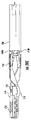
さらに、アンカーリトリーバルツールは、本発明の組織リトラクション(牽引、開創、圧排等)アセンブリの一部として検討されている。位置決めのループは前記ツールの端部から突き出て、本体内のアンカーの容易な位置決めを可能にするのに役立つ。前記位置決めループは、アンカー203に取り付けられたスーチャーの周囲をループ状に取り囲み、前記リトリーバルツールは前記スーチャーに沿って直接前記アンカーに案内される。前記リトリーバルツールの主本体の中に中心軸が配置され、その遠位端はショルダー部又はフランジに終結する傾斜部を含む。前記ショルダー部は、切り込みを入れられかつ前記アンカーの筒状体の中心に対して内側に傾斜する、柔軟な戻り止めのタブを好適に少なくともひとつ(さらに好適にはひとつ以上)伴って相互に作用する。前記中心軸の遠位端が前記アンカーの内側に入るとき、前記タブは、前記中心軸の前記ショルダー部又はフランジを下部で捕え、これによって前記シャフトの遠位端からの前記アンカーの脱落を防ぐ。
In addition, anchor retrieval tools are being considered as part of the tissue retraction (traction, retraction, retraction, etc.) assembly of the present invention. A positioning loop protrudes from the end of the tool and serves to allow easy positioning of the anchor within the body. The positioning loop surrounds a suture attached to the
本発明においては、体内手術用組織リトラクタが提供される。該組織リトラクタは、(a)引き込まれない第1の組織において選択的に展開しうるアンカーと、(b)引き込まれる第2の組織において選択的に展開しうるグラスパーと、(c) 前記グラスパーに対して可動支持部の実体的な遠位端に取り付けられ、長手方向に選択的に動くことができて、前記アンカーを通じて通り抜けることができる可動支持部と、(d)前記可動支持部に連結可能かつ使用者により体外で操作可能な近位端と、前記アンカーと前記グラスパーの両方に解放可能に取り付けた遠位端を有する展開ユーザーインターフェースとを備え、体内で前記アンカーを第1の組織中にかつ前記グラスパーを第2の組織上に展開するように適合するものである。前記アンカーが第1の組織中に展開されるとき、前記グラスパーは第2の組織上に展開し、前記可動指示部は選択的に近くに動かされ、前記第2の組織は選択的に引戻される。前記可動部が選択的に近位に動くほど、前記第2の組織がより引き込まれて、これにより前記第2の組織を動的に引き込むことが可能となる。 In the present invention, a tissue retractor for intracorporeal surgery is provided. The tissue retractor includes: (a) an anchor that can be selectively deployed in a first tissue that is not retracted; (b) a glass par that can be selectively deployed in a second tissue that is retracted; A movable support that is attached to the substantial distal end of the movable support, can be selectively moved in the longitudinal direction, and can be passed through the anchor; and (d) connectable to the movable support. And a deployment user interface having a proximal end operable by the user outside the body and a distal end releasably attached to both the anchor and the grasper, wherein the anchor is inserted into the first tissue in the body. In addition, the glass spar is adapted to be deployed on the second tissue. When the anchor is deployed into the first tissue, the glass spar is deployed onto the second tissue, the movable indicator is selectively moved closer, and the second tissue is selectively retracted. It is. The more the movable portion is selectively moved proximally, the more the second tissue is drawn, thereby allowing the second tissue to be dynamically drawn.
ある実施例において、好ましくは前記アンカーは、複数の遠位に突出する脚と実質的に近位に配置される主本体とを含む。好適には、前記アンカーの前記複数の脚は、外側に向けてカーブさせられ、弾性材料により作られる。好適には、前記ユーザーインターフェースは、さらに外側のカニューレ又はチューブと、アンカー配置ツールとを含み、前記アンカー配置ツールは前記ユーザーインターフェースの遠位端に取り付けられると共に前記外側のカニューレの遠位端の内側に相対的に引き込み可能である。前記アンカー配置ツールが前記外側カニューレ内に相対的に引き込まれる際に、前記外側カニューレは前記アンカー配置ツールに解放可能に固定された前記アンカーの複数の脚が実質的に直線状の配置となるよう促す。前記脚が実質的に直線状の配置にあるとき、前記アンカーは組織内に組織が引き込まれないように展開可能である。 In certain embodiments, preferably the anchor includes a plurality of distally projecting legs and a main body disposed substantially proximally. Preferably, the plurality of legs of the anchor are curved outward and are made of an elastic material. Preferably, the user interface further comprises an outer cannula or tube and an anchor placement tool, the anchor placement tool being attached to the distal end of the user interface and inside the distal end of the outer cannula. Can be pulled in relatively. When the anchor placement tool is relatively retracted into the outer cannula, the outer cannula is in a substantially linear arrangement of the anchor legs releasably secured to the anchor placement tool. Prompt. When the legs are in a substantially linear arrangement, the anchor is deployable so that no tissue is drawn into the tissue.
好ましくは、アンカー配置ツールは前記ユーザーインターフェイスの遠位端に取り付け可能で、前記アンカーの本体に対して解放可能に取り付け可能である。前記アンカー及び前記アンカー配置ツールの主本体のひとつはフランジを含み、また、前記アンカー及び前記アンカー配置ツールの他方の主本体は前記フランジに解放可能に固定された複数のアームを含む。好ましくは前記ユーザーインターフェースは外側カニューレと、前記外側カニューレ内に配置された中間カニューレとを含み、前記アンカー配置ツールは前記中間カニューレの遠位端に対して取り付けられる。この実施例においては、前記複数のアームが前記アンカー配置ツールに配置され、前記中間カニューレから放射状の外側方向に付勢されることが好ましく、前記中間カニューレが前記外側カニューレ内に相対的に引き込まれるとき、前記複数のアームは前記外側カニューレによって放射状の内側方向に促される。 Preferably, an anchor placement tool is attachable to the distal end of the user interface and is releasably attachable to the anchor body. One of the anchor and the main body of the anchor placement tool includes a flange, and the other main body of the anchor and the anchor placement tool includes a plurality of arms releasably secured to the flange. Preferably, the user interface includes an outer cannula and an intermediate cannula disposed within the outer cannula, and the anchor placement tool is attached to a distal end of the intermediate cannula. In this embodiment, the plurality of arms are preferably disposed on the anchor placement tool and biased radially outward from the intermediate cannula, the intermediate cannula being relatively retracted into the outer cannula. Sometimes the arms are urged radially inward by the outer cannula.
前記中間カニューレが前記外側カニューレ内に相対的に引き込まれ、かつ、前記外側カニューレが前記アンカーの複数の脚が実質的に直線状の構造に引き込まれるのを促すように、前記アンカーの複数の脚は好ましくは外側にカーブし、かつ、弾性の鋭い形状記憶材料により作られる。前記ユーザーインターフェースの近位端は好ましくは前記中間カニューレに連結された第1のアクチュエータを含み、前記第1のアクチュエータに第1の動作を作動させることで、前記中間カニューレを遠位方向に動かして前記アンカーを前記第1の組織内への配置を可能にする。好ましくは、前記第1のアクチュエータに第2の動作を作動させることで、前記中間カニューレを近位方向に動かして前記アンカーを前記第1の組織から引き戻す。 The legs of the anchor so that the intermediate cannula is relatively retracted into the outer cannula and the outer cannula encourages the legs of the anchor to be pulled into a substantially linear structure. Is preferably made of a shape memory material that curves outward and is sharp. The proximal end of the user interface preferably includes a first actuator coupled to the intermediate cannula, and actuating the first actuator to move the intermediate cannula distally. Allowing the anchor to be placed in the first tissue; Preferably, actuating a second action on the first actuator moves the intermediate cannula proximally to pull the anchor back from the first tissue.
ある実施例において、好ましくは前記アンカーの主本体は、前記ユーザーインターフェースの遠位端に取り付けられたアンカー配置ツールに解放可能に取り付け可能なショルダー部を含む。 In certain embodiments, preferably the main body of the anchor includes a shoulder that is releasably attachable to an anchor placement tool attached to the distal end of the user interface.
前記ショルダー部は溝を含み、さらに前記アンカー配置ツールは解放可能に固定可能な複数のアームを前記溝に含む。上述のように、前記ユーザーインターフェースは、外側カニューレと、前記外側カニューレ内に配置された中間カニューレとを含み、前記アンカー配置ツールは前記中間カニューレの遠位端に取り付けられる。前記アンカー配置ツールの前記複数のアームは、前記中間カニューレから放射状の外側方向に付勢され、前記中間カニューレが前記外側カニューレ内に相対的に引き込まれるとき、前記複数のアームは前記外側カニューレによって放射状の内側方向に促されて、前記アンカーの前記溝に係合する。好ましくは前記アンカーの前記主本体は、同様に前記主本体の遠位端に形成され、前記アンカーが前記第1の組織に展開する際の可動支持部を受け入れるよう調整された少なくともひとつのノッチを含む。 The shoulder portion includes a groove, and the anchor placement tool includes a plurality of releasably fixable arms in the groove. As described above, the user interface includes an outer cannula and an intermediate cannula disposed within the outer cannula, and the anchor placement tool is attached to the distal end of the intermediate cannula. The plurality of arms of the anchor placement tool are urged radially outward from the intermediate cannula such that when the intermediate cannula is relatively retracted into the outer cannula, the plurality of arms are radial by the outer cannula. To be engaged in the groove of the anchor. Preferably, the main body of the anchor is also formed at the distal end of the main body and has at least one notch adjusted to receive a movable support when the anchor is deployed in the first tissue. Including.
前記アンカーの前記弾性材料は、好ましくは様々な温度において変化しやすくしなやかであり、前記材料は室温と比較して体温においてはしなやかさが少ない。 The elastic material of the anchor is preferably flexible at various temperatures, and the material is less flexible at body temperature than at room temperature.
ある実施例において、前記グラスパーは、それぞれの遠位端で一対のジョーを形成する一対のアームを含み、前記ジョーは前記第2の組織にしっかりと取り付けられるように適合され、また、前記グラスパーは、前記ジョーを閉止位置に付勢するアームに取り付けられた付勢機構を含む。 In one embodiment, the glassper includes a pair of arms forming a pair of jaws at respective distal ends, the jaws adapted to be securely attached to the second tissue, and the glassper being And an urging mechanism attached to an arm for urging the jaw to the closed position.
好ましくは、前記グラスパーは、さらに前記可動支持部を使い捨て可能とする各アームにそれぞれ形成された一対の対応する穴を含む。前記可動支持部が選択的に近くに動くとき、追加的な力が前記グラスパーの前記穴を通じて前記可動支持部により前記ジョーに適用され、前記ジョーが前記閉止位置に徐々に閉じるようにする。 Preferably, the glass sper further includes a pair of corresponding holes respectively formed in each arm that makes the movable support portion disposable. As the movable support moves selectively close, additional force is applied to the jaws by the movable support through the holes in the glass spar, causing the jaws to gradually close to the closed position.
ある実施例において、上述のように、前記ユーザーインターフェースは外側のチューブ又はカニューレを含み、前記グラスパーは、前記外側のカニューレとの関係で少なくとも部分的に中に回収されたり外に出されたりする。前記外側のカニューレと前記グラスパーの少なくともひとつが、前記外側のカニューレと前記グラスパーの他方に対して動かされて前記グラスパーが少なくとも部分的に前記外側のカニューレ内に回収されるとき、前記外側カニューレの遠位端は前記グラスパーのアームの近位に対して進み、前記ジョーを付勢機構と逆の開口を押し進める。好ましくは、前記ユーザーインターフェースは、長手方向に移動可能な外側カニューレと、外側カニューレ内に配置されて前記グラスパーに取り付け可能な実質的に動かないグラスパー支持部とを含み、前記グラスパーは少なくとも部分的に前記外側カニューレの内に回収可能でありかつ前記外側カニューレの外に出ることができる。前記外側のカニューレが前記グラスパーに対して動いて前記グラスパーが少なくとも部分的に前記外側のカニューレ内に回収されるとき、前記外側カニューレの遠位端は前記グラスパーのアームの近位に対して進み、前記ジョーを前記付勢機構と反対の開口状態に押し進める。 In one embodiment, as described above, the user interface includes an outer tube or cannula, and the glass spar is at least partially retracted in and out with respect to the outer cannula. When at least one of the outer cannula and the glassper is moved relative to the other of the outer cannula and the glassper and the glassper is at least partially withdrawn into the outer cannula, the distal of the outer cannula The distal end is advanced relative to the proximal of the arm of the glass spar and pushes the jaw through the opening opposite the biasing mechanism. Preferably, the user interface includes a longitudinally movable outer cannula and a substantially non-moving glassper support disposed in the outer cannula and attachable to the glassper, wherein the glassper is at least partially Retrievable within the outer cannula and can exit the outer cannula. When the outer cannula moves relative to the glassper and the glassper is at least partially collected in the outer cannula, the distal end of the outer cannula advances relative to the proximal of the arm of the glassper; The jaw is pushed to the open state opposite to the biasing mechanism.
他の実施例において、前記ユーザーインターフェースは外側のカニューレは遠位縁を含み、前記グラスパーは前記外側カニューレの遠位縁に対して少なくとも部分的に隣接可能な近位端を有する。前記外側のカニューレと前記グラスパーの少なくともひとつが前記外側のカニューレと前記グラスパーの他方に対して動かされるとき、前記外側カニューレの遠位縁は前記グラスパーの近位端に対して進み、前記ジョーを付勢機構と反対の開口状態に押し進める。本実施例においては、前記ユーザーインターフェースは、遠位縁を有して長手方向に可動する外側カニューレと、前記外側カニューレに配置されて前記グラスパーに取り付け可能なグラスパー支持部とを含むことが好ましい。いずれの場合においても、前記グラスパーの近位端は好ましくは前記外側カニューレの遠位縁に対して隣接可能な外側の直径部分を含み、前記外側カニューレに対する前記グラスパーの相対的動作は、前記外側の直径部分に係る前記遠位縁の隣接により、前記ジョーを開口状態に押し進める。 In another embodiment, the user interface includes an outer cannula including a distal edge, and the grasper has a proximal end that is at least partially adjacent to the distal edge of the outer cannula. When at least one of the outer cannula and the glassper is moved relative to the other of the outer cannula and the glassper, the distal edge of the outer cannula advances relative to the proximal end of the glassper and attaches the jaws. Push to the open state opposite to the biasing mechanism. In this embodiment, it is preferable that the user interface includes an outer cannula having a distal edge and movable in a longitudinal direction, and a glass spar support portion disposed in the outer cannula and attachable to the glass spar. In any case, the proximal end of the glassper preferably includes an outer diameter portion that can be adjacent to the distal edge of the outer cannula, and the relative motion of the glassper relative to the outer cannula is determined by the outer Adjacent the distal edge on the diameter portion pushes the jaws into an open state.
本発明によると、ある実施例において、前記ユーザーインターフェースは第1のアクチュエータを含み、前記第1のアクチュエータは前記ユーザーインターフェースの近位端に配置されて前記アンカー配置ツールに機械的に連結され、前記アンカー配置ツールの長手方向の選択的動作と前記アンカーの前記第1の組織への展開とを可能にするものである。また、前記ユーザーインターフェースは、好ましくは第2のアクチュエータを含み、前記第2のアクチュエータは前記ユーザーインターフェースの近位端に配置されて前記外側カニューレ又は前記グラスパーのひとつに機械的に連結され、前記グラスパーが前記外側カニューレに対して選択的に相対的長手方向動作をして、前記グラスパーの前記ジョーを選択的に開口及び閉鎖する。 According to the present invention, in one embodiment, the user interface includes a first actuator, the first actuator is disposed at a proximal end of the user interface and mechanically coupled to the anchor placement tool, Enabling selective longitudinal movement of an anchor placement tool and deployment of the anchor to the first tissue; The user interface preferably includes a second actuator, the second actuator disposed at a proximal end of the user interface and mechanically coupled to one of the outer cannula or the glass spar, Selectively longitudinally moves relative to the outer cannula to selectively open and close the jaws of the glassper.
好ましくは、前記第2のアクチュエータは、前記外側のカニューレに機械的に連結され、前記外側カニューレは前記グラスパーに対して前記外側カニューレの選択的な長手方向動作を可能として、前記グラスパーのジョーを選択的に開口及び閉鎖する。また、好ましくは前記ユーザーインターフェースは第3のアクチュエータを含み、前記第3のアクチュエータは前記ユーザーインターフェースの近位端に配置されて前記グラスパー支持部に機械的に連結され、前記ユーザーインターフェースの前記グラスパーを自由にすると共に前記グラスパーを前記第2の組織に展開する前記グラスパー支持部の選択的な長手方向動作を可能にする。前記グラスパーの前記付勢機構は、好ましくは前記グラスパーの近位端に配置されたコイルばねを含み、また、前記グラスパー支持部は好ましくは前記グラスパー支持部の遠位端に形成されたフックを含み、前記グラスパー支持部はコイルばねを通じてフック可能である。前記フックは好ましくは前記アンカーの主本体に適合するように寸法決めされ、展開された前記アンカーの回収を容易にする。また、好ましくは前記ユーザーインターフェースは、前記第1及び/又は前記第2のアクチュエータの動作の対向性のため、実質的に動かないグリップを含む。 Preferably, the second actuator is mechanically coupled to the outer cannula, the outer cannula allowing selective longitudinal movement of the outer cannula relative to the glassper, selecting the jaws of the glassper Open and close. Preferably, the user interface includes a third actuator, and the third actuator is disposed at a proximal end of the user interface and is mechanically connected to the grasshopper support, Freely and allows selective longitudinal movement of the glassper support that deploys the glasspar into the second tissue. The biasing mechanism of the glassper preferably includes a coil spring disposed at a proximal end of the glassper, and the glassper support preferably includes a hook formed at a distal end of the glassper support. The grasshopper support portion can be hooked through a coil spring. The hook is preferably sized to fit the main body of the anchor to facilitate retrieval of the deployed anchor. Also preferably, the user interface includes a grip that does not substantially move due to the opposition of the movement of the first and / or the second actuator.
本発明は、主本体と主本体に配置される中心のシャフトを有するアンカーリトリーバルツールを任意に含み、前記中心シャフトは近位端と遠位端とを有し、前記中心シャフトの遠位端は、前記アンカーの主本体の中心に向かって切り込まれて内側方向に曲げられた柔軟な戻り止めのタブを少なくともひとつ伴って係合可能なショルダー部に終端処理を施した傾斜部を含む。前記中心シャフトの遠位端が前記アンカーの主本体の内側に入るとき、前記タブは前記中心シャフトの前記ショルダー部の下部を捕捉し、これにより前記アンカーが前記中心シャフトの遠位端から脱落するのを防ぐと共に前記アンカーの前記第1の組織からの回収を容易にする。また、前記アンカーリトリーバルツールはさらに該ツールの主本体の遠位端から突出する位置決めのループを含んでもよい。前記位置決めのループは、前記リトリーバルツールが前記可動支持部に沿って前記アンカーに直接案内可能なように、前記アンカーを通じて通り抜ける前記可動支持部の周囲にループしてもよい。前記位置決めループは好ましくは前記可動支持部の周囲の位置決めループを選択的に締め付けて調整するループ締め付け具に連結される。 The present invention optionally includes an anchor retrieval tool having a main body and a central shaft disposed on the main body, the central shaft having a proximal end and a distal end, the distal end of the central shaft being , Including a sloped portion that is terminated at a shoulder portion that is engageable with at least one flexible detent tab cut inwardly toward the center of the main body of the anchor. When the distal end of the central shaft enters inside the main body of the anchor, the tab captures the lower portion of the shoulder portion of the central shaft, thereby causing the anchor to fall off the distal end of the central shaft. And the recovery of the anchor from the first tissue is facilitated. The anchor retrieval tool may further include a positioning loop protruding from the distal end of the main body of the tool. The positioning loop may loop around the movable support passing through the anchor so that the retrieval tool can be guided directly to the anchor along the movable support. The positioning loop is preferably coupled to a loop clamp that selectively tightens and adjusts the positioning loop around the movable support.
好ましくは、上述の前記可動支持部はスーチャーを備え、前記スーチャーは近位端を有し、前記展開ユーザーインターフェースの前記近位端に配置されたリール周囲に巻かれると共に選択的にほどくことができる。好ましくは前記ユーザーインターフェースを通じて前記ユーザーインターフェースの遠位端に通り抜ける。前記ユーザーインターフェースは、好ましくは前記ユーザーインターフェースの遠位端から選択的に突出可能なワイヤー位置決めループを含み、前記ユーザーインターフェースの遠位端から突出可能な第4のアクチュエータに機械的に連結される。前記第4のアクチュエータは前記ユーザーインターフェースの近位端に配置され、前記可動支持部を捕捉すると共に前記可動支持部を前記ユーザーインターフェースに引き戻すように適応され、前記展開されたアンカーと展開されたグラスパーの位置決めを可能にする。 Preferably, the movable support described above comprises a suture, and the suture has a proximal end and can be wound and selectively unwound around a reel disposed at the proximal end of the deployment user interface. . Preferably, it passes through the user interface to the distal end of the user interface. The user interface preferably includes a wire positioning loop that is selectively projectable from a distal end of the user interface and is mechanically coupled to a fourth actuator that is projectable from the distal end of the user interface. The fourth actuator is disposed at a proximal end of the user interface and is adapted to capture the movable support and pull the movable support back to the user interface, the deployed anchor and the deployed glass spar. Enables positioning.
追加的な特徴として、本開示の組織リトラクターアセンブリの機能及び利点は後述の詳細な説明から明らかで、特に添付の図面と合わせて読むと明らかである。 As an additional feature, the function and advantages of the tissue retractor assembly of the present disclosure will be apparent from the detailed description that follows, particularly when read in conjunction with the appended drawings.
本開示の実施例においては、組織リトラクターアセンブリが開示され、これは単孔式若しくは少孔式の腹腔鏡手術又は類似の手術用の組織リトラクターを概して含むものである。具体的には、組織リトラクターアセンブリは体内で様々な臓器や組織の収縮を促進する腹腔鏡手術用補助装置である。組織リトラクターアセンブリは、一般的に複数の構成部品からなる装置の形をとり、例えば腹腔鏡又は同様のポート(例えば、5mm)を介するように、腹壁を介して送達されるような構成かつ寸法であり、また、臓器又は他の解剖学的組織/構造、たとえば、胆嚢を把持し、保持するための非侵襲手段を提供するような構成かつ寸法である。開示される組織リトラクターアセンブリ/システムの寸法の特徴は、腹腔鏡手術ツールを使用及び操作する際に通常用いられる5mmのカニューレに通して使用するように一般的に合わせられる。 In an embodiment of the present disclosure, a tissue retractor assembly is disclosed, which generally includes a single or small hole laparoscopic or similar surgical tissue retractor. Specifically, a tissue retractor assembly is an auxiliary device for laparoscopic surgery that promotes contraction of various organs and tissues in the body. The tissue retractor assembly typically takes the form of a multi-component device and is configured and dimensioned to be delivered through the abdominal wall, such as through a laparoscope or similar port (eg, 5 mm). And is configured and dimensioned to provide a non-invasive means for grasping and holding organs or other anatomical structures / structures, such as the gallbladder. The dimensional features of the disclosed tissue retractor assembly / system are generally tailored for use through a 5 mm cannula commonly used in using and operating laparoscopic surgical tools.
ここで、添付された図1〜図33を参照して説明する。これらの図はその性質上代表的なものであり、いかなる意味においても本発明の範囲を限定するものではなく、本発明の範囲は記載された請求の範囲によって定義されることを理解されたい。 Here, a description will be given with reference to FIGS. It should be understood that these drawings are representative in nature and are not intended to limit the scope of the invention in any way, which is defined by the appended claims.
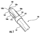
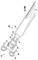
図1を参照すると、組織リトラクターアセンブリの代表的な実施形態が、組織リトラクターアセンブリ100の形態で、本開示にしたがって示される。組織リトラクターアセンブリ100は、グラスパー102とアンカー103とを収容するチューブまたはカニューレ101を含む。グラスパー102は、カニューレ101の遠位端から軸方向に延伸するように構成され、寸法合わせされる。グラスパー102は、組織を担持するための第1の脚102aと、第2の脚102bとを含む。第1の脚102aおよび第2の脚102bは、平坦な薄板金またはプラスチックから製造されてもよい。さらに、第1および第2の脚102aおよび102bは、随意にゴムで被膜されてもよく、臓器を傷つけずに把持するために有利な表面特性または形状を有する。グラスパー102はさらに、係止リング104を備える。係止リング104は、内側カニューレ(不図示)によって遠位に押されるように構成され、寸法合わせされ、臓器または組織の周囲に第1の脚102aおよび第2の脚102bを把持し、係止する。係止リング104は、短いチューブまたはリング状の部材から製造されてもよい。
With reference to FIG. 1, an exemplary embodiment of a tissue retractor assembly is shown in accordance with the present disclosure in the form of a
組織リトラクターアセンブリ100はさらに、アンカー103を含む。アンカー103はカニューレ101から展開され、臓器前の腹壁に取り付けられるように構成され、寸法合わせされる。アンカー103はさらに、円筒体105によって定められる。円筒体105は、円筒体103の軸115に沿って位置する少なくとも2本の鋭い薄い脚、106aおよび106bそれぞれに取り付けられる。少なくとも2本の鋭い薄い脚106aおよび106bは、アンカー103がカニューレ101によって展開されるとき、少なくとも2本の鋭い薄い脚106aおよび106bは予備成形された形に戻り、アンカー103の引抜力が増加するように、予備成形された形に予備成形される。
The
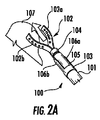
図2A〜Cを参照すると、組織リトラクターアセンブリ100がポート(不図示)に挿入された後、組織リトラクターアセンブリ100が臓器または組織107を把持する進行段階が表示される。特に図2Aを参照すると、組織リトラクターアセンブリ100は、ポートに挿入されるためにカニューレ101内に装備されていたグラスパー102と、カニューレ101の遠位端から延び出た第1の脚102aおよび第2の脚102bとを備えて表示される。ポート内に入ると、把持すべき臓器107の位置で、グラスパー102は、グラスパー102の近位端に取り付けられたフック(不図示)によってカニューレ101の遠位端からカニューレ101の外へ押し出される。一般に、臨床医は、処置中に汎用の5mmグラスパーを術野に持ち、問題の臓器の組織を管理する。図2Aに表示するように、グラスパー102の第1の脚102aおよび第2の脚102bはカニューレ101の遠位端からすでに延在しており、把持すべき臓器107を囲むために用いられる。
2A-C, after the
図2Bを参照すると、グラスパー102は把持すべき臓器107を十分に囲んで配置され、係止リング104を利用して、グラスパー102を臓器107の周囲に係止する。具体的には、係止リング104は、内側のカニューレ(不図示)によって、遠位に押される一方、内側のフックはグラスパー102を所定の位置に保持する。したがって、係止機構104は臓器107の周囲に第1の脚102aおよび第2の脚102bを締め付ける。
Referring to FIG. 2B, the
図2Cを参照すると、グラスパー102が係止されると、カニューレ101は、フックを解放するために後退され、持ち上げられる。フックが遠位に押されることで、グラスパー102はカニューレ101から展開できる。図2Cに表示するように、組織リトラクターアセンブリ100はさらにスーチャー108を含む。スーチャー108はグラスパー102を固定し、アンカー103に対してグラスパー102を調整できるようにする。具体的には、スーチャー108は第1および第2の脚102aおよび102bそれぞれの先端に取り付けられ、カニューレ101はその遠位先端からスーチャーを牽引する。
Referring to FIG. 2C, when the
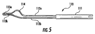
ここで図3〜6を参照すると、本発明の別の実施形態がグラスパー110として示される。グラスパー110は、臓器または組織を担持するために十分に広い開口を提供する。図3を参照すると、グラスパー110は「開口」位置で表示され、第1の脚112aおよび第2の脚112bと、係止スリーブ111とを含む。第1および第2の脚112aおよび112bは、ステンレス線製であってもよく、形に形成されてもよい。遠位端113aおよび113bは、それぞれループとして形成されることが好ましい。それによって、組織または臓器を把持するために、より広がった、したがってより安定した部分を提供できる。さらに、第1および第2の脚112aおよび112bの少なくとも1つは、表面特徴、つまり鋸歯状の縁を第1の脚113aの遠位端および/または第2の脚113bの遠位端上に有していてもよい。第1の脚112aはさらに、第1の脚113aの遠位端と係止スリーブ111の遠位端との間に曲がった部分114を含んでいてもよい。具体的には、曲がった部分114は、第1の脚112aの表面に対して上下に曲がった屈曲部を含む。曲がった屈曲部は約45°であってもよく、それによってグラスパーが適切に開口できる。さらに、図3を参照すると、図2に関連して前述した係止リングの代わりに係止スリーブ111が表示される。係止スリーブ111は好ましくは細長いチューブとして構成され、より強い係止力を提供し、摺動軸を斜めに傾けずにより容易に摺動し、近位端においてより快適な人間工学をユーザーに提供する。
With reference now to FIGS. 3-6, another embodiment of the present invention is shown as a
図4を参照すると、「開口」位置にある好ましいグラスパー110の追加の側面図が表示され、曲がった部分14をより明確に表示する。第1の脚112aおよび第2の脚112bを合わせて閉じるときに、第2の脚112bは臓器または組織をより強く、またはより安定して把持するために、真っ直ぐに形成されるか、または曲線を含有しているかのいずれかであってよい。
Referring to FIG. 4, an additional side view of the preferred
図5を参照すると、グラスパー110は「閉鎖」位置で表示される。係止スリーブ111がカニューレ101によって、第1および第2の脚113aおよび113bそれぞれの遠位端方向に、遠位に押されるにつれて、第1の脚112aおよび第2の脚112bは合わさって閉じる。
Referring to FIG. 5, the
図6を参照すると、グラスパー110は「閉鎖」位置で表示される。係止スリーブ111は、カニューレ101によって可能な限り最遠点まで遠位に押されている。係止スリーブ111が、第1および第2の脚113aおよび113bそれぞれの遠位端まで押されて閉鎖するにつれて、第1の脚112aおよび第2の脚112bは増大する力で一緒に押され、それによって臨床医は、臓器または組織を十分に担持するために、グラスパー110によって適用され得る範囲の力を得ることは、当業者には理解されるであろう。
Referring to FIG. 6, the
ここで図7を参照すると、アンカー103の代表的な実施形態が表示される。組織リトラクターアセンブリ100を用いてアンカー103を腹壁に展開する。アンカー103は、予備成形された形状記憶ニチノールステープルで製造されてもよい。ステープルは単一のワイヤー構造から形成されてもよく、チューブから切り出されてもよい。アンカー103の基礎構造は、少なくとも2本の鋭い薄い脚106aおよび106bに取り付けられた円筒体105である。脚106aおよび106bは、円筒体105の軸115に沿って位置する。少なくとも2本の鋭い薄い脚106aおよび106bは、組織を貫通できるように鋭くなっている。少なくとも2本の鋭い薄い脚106aおよび106bの予備成形の性質上、少なくとも2本の鋭い薄い脚106aおよび106bは、アンカーの引抜力を増加させるために、予備成形された形に戻ることができる。図1に表示するように、アンカー103は、最初に「D状」または特別な形状のカニューレ101上に装備される。それによって、少なくとも2本の鋭い薄い脚106aおよび106bの抑制に役立ち、アンカー103は単一のチューブによって、チューブ押出機構上で展開できる。図7を参照すると、アンカー103は「解放」位置で表示され、少なくとも2本の鋭い薄い脚106aおよび106bは円筒体106の軸115および中心に向かって折り畳まれるように予備成形される。
Referring now to FIG. 7, a representative embodiment of the
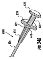
図8を参照すると、本発明のアンカー203の実施形態が表示される。図7のアンカー103とは異なり、図8のアンカー203は、少なくとも2本の(好ましくは4本の)鋭い薄い脚206a、206b、206cおよび206dを含む。脚206a、206b、206cおよび206dは、円筒体205の軸208および中心から外側に曲がるように予備成形される。図7に示すように、図8のアンカー203もまた、円筒体205をアンカー203の基礎構造として有し、円筒体205は、少なくとも2本の鋭い薄い脚206a、206b、206cおよび206dに取り付けられるか、または一体に形成される。アンカー203はまた、図9に関連してさらに後述するように、スーチャー108を誘導するために、溝またはノッチ207を円筒体205に含んでいてもよい。
Referring to FIG. 8, an embodiment of the
図9を参照すると、アンカー103または203は、カニューレ101の遠位先端を腹壁109に配置することによって取り付けられる。臨床医の手は通常は腹壁109の外側を触診し、カニューレ101は、アンカー103または203が組織109を貫通するにつれて、アンカー103または203をカニューレ101の軸方向に遠位に押し出す。アンカー103または203がカニューレ101から解放されると、少なくとも2本の鋭い薄い脚106aおよび106bまたは206a、206b、206cおよび206cは、円筒体105または205の中心に曲がり、または中心から離れて曲がり、このようにして十分な引抜力を提供するとともに、臨床医が負傷することを防止する。
Referring to FIG. 9,
図9はさらに、操作中の代表的なグラスパー102およびアンカー103を表示する。具体的には、グラスパー102は臓器107を固定し、係止機構104によって所定の位置に係止されている。さらに、アンカー103はカニューレ101から解放され、予備成形された少なくとも2本の鋭い薄い脚106aおよび106bは、十分な引抜力を提供するために予備成形された形に戻っている。グラスパー102はスーチャー108によって、アンカー103に移動可能に固定されていることに留意されたい。カニューレ101はスーチャー108を牽引するポートから後退する。スーチャー108はすべての構成部品をつなぎ、臨床医はスーチャー108の張力を高めることによって、臓器107を回収することができる。スーチャー108を、クランプまたはその他の適切な手段でポートの外側に固定することもできる。手術終了時に、グラスパー102は臓器107と共に取り出される(胆嚢摘出または類似する「摘出」手術の場合)。アンカー103は、アンカー103を5mmグラスパー(不図示)で把持して、腹壁から取り出すためにアンカー103の軸に沿って引っ張ることによって、取り出すことができる。組織リトラクターアセンブリ100の両方の部分は、ポートの挿入によって作成された腹部切開を貫通して取り出すことができる。図3から図6の好ましいグラスパー110の操作は、図9について説明した前述の操作に実質的に同様である。
FIG. 9 further displays a
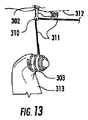
ここで図10を参照すると、本開示による代替的な組織リトラクターアセンブリ300が表示される。図10の代表的な実施形態では、組織リトラクターアセンブリ300は、カニューレ301を含む。カニューレ301は、アンカー302と、ワイヤー構造303と、グラスパー304とを収容する。アンカー302は、カニューレ301から展開され、臓器前方の腹壁に取り付けられるように構成され、寸法合わせされる。アンカー302は、外側チューブ314と、中心軸309とを含む。中心軸309はさらに、図11Bに表示する少なくとも2つの返し308aおよび308bを含む。2つの返し308aおよび308bは、中心軸309が軸方向に引っ張られるとき、外側チューブ314から展開するように構成される。さらに、アンカー302は、引込可能な鋭い先端306を含む。引込可能な鋭い先端306は、中心軸309が軸方向に引かれて、少なくとも2つの返し308aおよび308bを展開するときに、外側チューブ314内部に後退する。ワイヤー構造303は、コイルばねとして製造されてもよく、カニューレ301の遠位端から展開し、径方向に拡張するように構成され、寸法合わせされる。さらに、ワイヤー構造303は、スーチャー311の長さによって、アンカー302に固定され、アンカー302に対して調整される。最後に、グラスパー304は、カニューレ301の遠位端から延び出て、ワイヤー構造303を通って、組織313を把持し(図13に表示する)、組織313をワイヤー構造303に引き込むためにカニューレ301の遠位端内に後退するように構成され、寸法合わせされる。グラスパー304は、専門のジョー305を備える小児用グラスパーであってもよい。
Referring now to FIG. 10, an alternative
さらに図10を参照すると、組織リトラクターアセンブリ300は、腹腔鏡手術ツールの設計に一般的に用いられる5mmカニューレ301に基づく。カニューレ301は、臓器または組織313を把持するために用いるアンカー302とワイヤー構造303の両方を含有する。カニューレ301の構成部品は、アンカー302に近接し、完全に機能する3mmグラスパー304の中心で、アンカー302と同軸に配置される。カニューレ壁315によって分離されて、ワイヤー構造303は、外側カニューレ壁317に囲まれる環状リング316内に圧縮される。
Still referring to FIG. 10, the
アンカー302は、外側チューブ314と、中心軸309との2つの部品で構築されている。外側チューブ314は、アンカー302の本体と外側チューブ314の内側を形成する。中心軸309は、引込可能な鋭い先端306と、一体化された少なくとも2つの返し308aおよび308bとを含む。2つの返し308aおよび308bは、引込可能な鋭い先端306に近接するアンカー302の中心軸309を引っ張ることによって、展開することができる。アンカー302は、金属またはプラスチックで製造されてもよい。
The
図11A〜Cを参照すると、組織リトラクターアセンブリ300がSILS(単孔式腹腔鏡下手術)ポート(不図示)に挿入された後に、アンカー302を腹壁312に固定する進行段階が表示される。最初は、カニューレ301の遠位先端は腹壁312上に位置する。臨床医の手は、通常は腹壁312の外側を触診する。小児科の腹腔鏡処置で通常用いる特別設計の3mmグラスパー304を利用して、アンカー302を軸方向遠位に押し、組織312を貫通させる。次に、図11Aおよび11Bに表示するように、3mmグラスパー304を後退させて鋭い先端306を後退させ、少なくとも2つの返し308aおよび308bを展開する。具体的には、少なくとも2つの返し308aおよび308bは、アンカー302の外側チューブ314内の開口307aおよび307bを貫通して展開する。少なくとも2つの返し308aおよび308bによって、腹壁312のアンカー302の保持力は劇的に増加する。図11Cに表示するように、アンカー302はさらに、近位端に取り付けられたスーチャー311を有し、カニューレ301はスーチャー311を遠位先端から牽引する。スーチャー311は、アンカー302の中心軸309の近位端に、リング310または類似形状の構成部品によって取り付けられてもよい。
Referring to FIGS. 11A-C, an advanced stage of anchoring the
図12A〜Eを参照すると、組織リトラクターアセンブリ300がポートに挿入され、アンカー302が腹壁312に固定された後に、組織リトラクターアセンブリ300が臓器313を把持する進行段階が表示される。一般に、臨床医は、処置中に多目的の5mmグラスパー(不図示)を術野に持つ。5mmグラスパーは臓器を把持中に問題の臓器の組織を管理する。ワイヤー構造303は基本的に、特別な形状に設計されたコイルばねであり、表面粗さまたは内側のワイヤー表面に沿った返しなどの特徴を有し、臓器313の担持を強化してもよい。図12Aに表示するように、ワイヤー構造303はカニューレ301の遠位端から押し出され、より広い直径断面を実現するために径方向に拡張し、より多くの臓器313の組織を収容することができる。次に、3mmグラスパー304はカニューレ301の遠位端から延在され、ワイヤー構造303を通じて臓器313に到達し、臓器313を把持し、カニューレ301の遠位端内に後退して、臓器313の組織をワイヤー構造303内に引き込む。ワイヤー構造303はワイヤー構造303の表面と臓器313との間に生じる力によって、臓器313を担持する。図12Eを参照すると、ワイヤー構造313が臓器313の周囲に固定されると、ワイヤー構造303はスーチャー311の長さによって、アンカー302に対して固定され、調整される。具体的には、スーチャー311の長さはワイヤー構造303に取り付けられ、図11Cに表示するように、アンカー302のリング310まで延在し、カニューレ301に取り付けられる。
Referring to FIGS. 12A-E, after the
図13を参照すると、操作中の代表的なワイヤー構造303およびアンカー302が表示される。ワイヤー構造303およびアンカー302が臓器313および腹壁312それぞれに取り付けられると、カニューレ301は、スーチャー311の長さを牽引するポートから後退する。スーチャー311はすべての構成部品をつなぎ、スーチャー311の長さの張力を高めることによって、臨床医は臓器313を回収することができる。スーチャー311の長さはクランプまたはその他の適切な手段(不図示)でポートの外側に固定することもできる。手術終了時に、グラスパー303は臓器313と共に取り出される(胆嚢摘出の場合)。アンカー302の除去には、3mmグラスパー304を含有するカニューレ301の再挿入が必要となる。5mmグラスパーを用いて、アンカー302の外側チューブ314を担持しえる一方、3mmグラスパー304を用いて、アンカー302の中心軸309に取り付け、遠位に押し出して少なくとも2つの返し308aおよび308bを後退させ、それによって、アンカー302を腹壁312から取り出さすことができる。アンカー302は、カニューレ302内に後退されるか、または5mmのポートを通じて個別に取り出されてもよい。カニューレ301の構成部品は両方ともスーチャー311の長さにつながれているため、ポートの挿入によって作成された腹部切開を貫通して取り出されてもよい。
Referring to FIG. 13, a
ここで図14および図15を参照すると、本開示による代替的な組織リトラクターアセンブリ400が表示される。図15は、組織リトラクターアセンブリ400の内部構成部品をより見やすく表示するために、代替的な組織リトラクターアセンブリ400の部分図を示す。図14および図15の代表的な実施形態では、組織リトラクターアセンブリ400はカニューレ401を含む。カニューレ401はアンカー405と、グラスパー403とを収容する。グラスパー403は、一方向係止トグル402を持つスーチャー403aのループを備える。スーチャー403aのループは、カニューレ401から遠位に解放されるように構成され、寸法合わせされる。具体的には、スーチャー403aのループは、臓器406の組織を把持し、カニューレ401の遠位端内に後退し、臓器406の組織周囲を締め付けるように構成され、寸法合わせされる。アンカー405は、後部スパン412と、引張ばね409と、後部スパン412と引張ばね409との間の軸接続とを含む。アンカー405はさらに、2本の鋭い脚405aおよび405bを含む。2本の鋭い脚405aおよび405bは、カニューレ401の遠位端から展開するように構成され、寸法合わせされる。グラスパー403はスーチャー411の長さによって、アンカー405に対して固定され、調整される。
14 and 15, an alternative
さらに、図14および図15を参照すると、組織リトラクターアセンブリ400は、腹腔鏡手術ツールの設計に通常用いられる5mmカニューレ401に基づく。カニューレ401は、臓器406に取り付けるためのグラスパー403と、アンカー405と共に、それぞれを展開するためのシステムを含有する。カニューレ401の構成部品は、カニューレ401の軸に沿って、グラスパー403とアンカー405の両方と共に配置される。グラスパー403はアンカー405の下部に位置し、アンカー405は、ばねクリップとして製造されてもよい。カニューレ401はさらに、スーチャー403aのループの展開を可能にするスロットを含んでいてもよい。カニューレ401はさらに、グラスパー403およびアンカー405の送達および作動または展開を補助する機能を含む。
Still referring to FIGS. 14 and 15, the
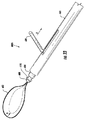
図16A〜Dを参照すると、組織リトラクターアセンブリ400がポート(不図示)に挿入された後、組織リトラクターアセンブリ400が臓器406を把持する進行段階が表示される。グラスパー403はスーチャーを用いる臓器グラスパーであり、一方向係止トグル402を備えるスーチャー403aのループを含む。一方向係止トグル402は、小型成形プラスチック部分として製造されてもよく、それによって、スーチャー403aのループを一方向に引くことができるが、スーチャー403aのループが緩まないようにする。スーチャー403aのループはまた、摩擦を大きくし、または力をより均等に分散するために、リボンまたは類似の構造であってもよい。さらに、スーチャー403aのループは表面特徴を有していてもよい。表面特徴は、つまり、スーチャー403aのループと臓器406との摩擦を大きくし、滑る可能性を低減するための直径上の小型の切り込みまたは返しである。スーチャー403aのループは、カニューレ401においてフック404によって平坦に保持される。フック404は、スーチャー403aのループ内にあり、カニューレ401内でスーチャー403aのループの張力を保持する。
Referring to FIGS. 16A-D, after the
さらに図16A〜Dを参照すると、スーチャー403aのループを臓器406に取り付けるために、カニューレ401はポートを貫通して挿入され、取付部位の近くに配置される。スーチャー403aのループは、スーチャー403aのループに緩みを作るために遠位に移動される。一般に、臨床医は、処置中に多目的用の5mmグラスパー413を術野に持つ。5mmグラスパー413は臓器406を把持中に問題の臓器406の組織を管理する。5mmグラスパー513を用いて、臓器406の組織をスーチャー403aのループを通じて引き出す。カニューレ401の送達部分は、スーチャー403aのループの自由端を一方向係止トグル402を通じて引き出し、スーチャー403aのループを臓器406の組織の周囲で締め付ける。フック404を後退させ、カニューレ401を後退することによって、一方向係止トグル402およびグラスパー403アセンブリは、カニューレ401から解放され得る。スーチャーのループの自由端、スーチャー411の長さは、アンカー405が腹壁410に取り付けられるために付着点に近づく間、カニューレ401の遠位端から抜け出して引きずられる。
Still referring to FIGS. 16A-D, to attach the loop of
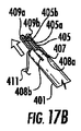
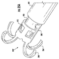
図17A〜Dを参照すると、組織リトラクターアセンブリ400がポート(不図示)に挿入され、グラスパー403が臓器406周囲に固定された後、組織リトラクターアセンブリ400がアンカー405を腹壁410に固定する進行段階が表示される。アンカー405は、ワイヤーの単一部品から構成されるワイヤー構造として製造されてもよい。ワイヤーは実体的な対称構造を有する形状であり、後部スパン412と、引張ばね409と、要素間の軸接続とからなる。アンカー405は、洗濯ばさみの一般的な構造で用いられるように、通常は閉鎖しているばねに類似する構造を有する。アンカー405はさらに、2本の鋭い脚405aおよび405bを含む。2本の鋭い脚405aおよび405bは、横断部材によって接続されておらず、組織穿刺を促進するために鋭くなっている。アンカー405は、通常は閉鎖しており、展開するためにカニューレ401内で、トレイ413または類似する構造内にある。
Referring to FIGS. 17A-D, after the
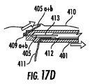
さらに図17A〜Dを参照すると、アンカー405の展開には、カニューレ401内部の装置がアンカー405を十分に遠位に押し出すことが必要である。それによってカニューレ401上の帯状の機構407がアンカー405の2本の鋭い脚405aおよび405bの下に割り込むことができる。次に、トレイ413は近位に後退し、この位置でアンカー405の2本の鋭い脚405aおよび405bは腹壁410を穿刺する。具体的には、カニューレ401は帯状の特徴407と、2つのスリット408aおよび408bとを含む。2つのスリット408aおよび408bは、アンカー405がカニューレ401の遠位端から部分的に展開されるときに、アンカー405の2本の鋭い脚405aおよび405bが内側の後退機構によって、カニューレ401の遠位端から展開できるように、寸法合わせされ、構成される。したがって、アンカー405が通常はトレイ413内で閉鎖しているのに対し、2本の鋭い脚405aおよび405bは、2つのスリット408aおよび408bを貫通して腹壁410を適切に貫通して付着するために、カニューレ401から展開することができる。
Still referring to FIGS. 17A-D, deployment of
さらに図17A〜Dを参照すると、カニューレ401の遠位先端は、腹壁410に近接して配置される。臨床医の手は通常は腹壁410の外側を触診する。臨床医は、カニューレ401およびアンカー405を近位に引っ張りながら、カニューレ401を前方に押し出す。これによって、アンカー405の2本の鋭い脚405aおよび405bは腹壁410をつかみ、貫通する。アンカー405は次に、カニューレ401を後退させ、トレイ413を遠位に押し出すことによってカニューレ401から解放される。アンカー405の閉鎖動作およびスーチャー411の長さによりもたらされる張力の方向により、アンカー405の保持力は増加し得る。
Still referring to FIGS. 17A-D, the distal tip of
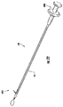
図18を参照すると、操作中の代表的なアンカー405およびグラスパー403が表示される。カニューレ401は、スーチャー311の長さを牽引するポートから後退している。スーチャー311はすべての部分をつなぎ、臨床医はスーチャー411の長さの張力を高めることによって、臓器406を回収することができる。スーチャー411の長さを、クランプまたはその他の適切な手段でポートの外側に固定することもできる。手術終了時に、グラスパー403は臓器406と共に取り出されてもよい(胆嚢摘出の場合)。図16Cに表示されるグラスパー413をさらに用いて、アンカー405の後部スパン412を担持し、挿入方向から離れるように押し出してもよい。それによって、アンカー405を簡単に取り出すことができる。通常は閉鎖しているアンカー405の性質によって、2本の鋭い脚405aおよび405bは安全に腹腔内に配置される。組織リトラクターアセンブリ400のアンカー405およびグラスパー403の両方は、どちらもスーチャーにつながれているため、ポートの挿入によって作成された腹部切開を通じて取り出されてもよい。
Referring to FIG. 18, a
ここで図19を参照すると、本開示による代替的な組織リトラクターアセンブリ500が表示される。図19の代表的な実施形態では、組織リトラクターアセンブリ500はカニューレ501を含む。カニューレ501は、第1のグラスパー502と、第2のグラスパー503とを収容する。第1のグラスパー502は、第1のクリップとして製造されてもよく、カニューレ501の遠位端から軸方向に展開するように構成され、寸法合わせされ、カニューレ501から展開後にC形の形状に画定される。第2のグラスパー503は第2のクリップとして製造されてもよく、カニューレ501の遠位端から軸方向に展開するように構成され、寸法合わせされ、カニューレ501から展開後にC形の形状に画定される。第1のグラスパー502はさらに、スーチャー504の長さによって、第2のグラスパー503に対して固定され、調整される。スーチャー504は、前もって第1および第2のグラスパー502および503の中を通り、カニューレ501内まで進んでいる。
Referring now to FIG. 19, an alternative
図19の組織リトラクターアセンブリ500は、腹腔鏡手術ツールの設計に通常用いられる5mmカニューレ501に基づく。カニューレ501は、カニューレ501の遠位先端から第1および第2のグラスパー502,503を連続して押し出すことによって、第1および第2のグラスパー502,503をそれぞれ展開する。第1および第2のグラスパー502,503は、軸方向に摺動するロッドまたはカニューレ501によって、及び、ねじまたは歯車駆動機構(不図示)によって印加される力を受けて前方に押し出される。第1および第2のグラスパー502および503は、金属、プラスチックまたは素材を組み合わせて製造されてもよく、「C」または「U」形のいずれかに形成される。この形は通常は閉鎖されている、つまり、レイニー型のクリップである。第1および第2のグラスパー502および503は、スーチャー504の長さを誘導し、または、取り付けるための第1および第2の後部スパン505および506をそれぞれ有する。第1および第2のグラスパー502および503は、組織を担持することを支援するために、追加の担持機構、つまり、歯、点、山形502a、502b、503aおよび503bを開口先端または内側表面に有していてもよい。臓器507を担持するための第1および第2のグラスパー502および503はさらに、ゴムで被膜されてもよく、臓器507を損傷せずに把持するために有利である表面機構または形状を有していてもよい。さらに、腹壁509に取り付けられる第2のグラスパー503は、腹壁509に取り付けるために、より積極的な担持機構503aおよび503b、つまり、侵襲性の高い歯または鋭い点を有していてもよい。ただし、第1のグラスパー502は臓器507を把持するために用いられ、臓器507を損傷しないように、非侵襲性の歯を担持機構502aおよび502bに有していてもよい。
The
図19を参照しつつ、さらに図20A〜Eを参照すると、組織リトラクターアセンブリ500がポート(不図示)に挿入された後、組織リトラクターアセンブリ500が第1のグラスパー502を臓器507に固定し、第2のグラスパー503を腹壁509に固定する進行段階が表示される。第1および第2のグラスパー502および503はカニューレ501内にあり、完全に開口することによってほとんど平坦となる。ポートに挿入するために、第1および第2のグラスパー502および503はカニューレ501内に装填される。ポート内部に入ると、把持すべき臓器507の部位で、第1および第2のグラスパー502および503は展開されてもよい。一般に、臨床医は処置中に、図20Aに表示する汎用の5mmグラスパー508を術野に持つ。5mmグラスパー508は問題の臓器507の組織を管理する。カニューレ501の遠位端は臓器507の近くに位置し、第1のグラスパー502は、ロッドまたは軸によって、カニューレ501から遠位に押し出される。ロッドまたは軸は、ねじまたは歯車機構(不図示)によって駆動される。第1のグラスパー502は約中間まで押し出され、それによって臨床医は第1のグラスパー502を位置決めし、次に、第1のグラスパー502が展開される。カニューレ501の形状および先端の機構は、第1のグラスパー502の展開の動的性質を管理するのに役立つ。この設計はまた、必要に応じて、複数のグラスパーを臓器507に展開する可能性も提供する(不図示)。カニューレ501はスーチャー504の長さに続いて、スーチャー504は臓器507上に位置する第1のグラスパー502につながれる。
Referring to FIG. 19 and with further reference to FIGS. 20A-E, after the
さらに図20A〜Eを参照すると、第2のグラスパー503は臓器507の隣で展開され、引き込みを可能にする。第2のグラスパー503は第1のグラスパー502と全体的に同一の形状および機能を有していてもよい。第2のグラスパー503は、不活性ガスを入れられた腹壁509を担持する機構503aおよび503bに、積極的な特徴を含んでもよい。担持機構503aおよび503bはまた、貫通機構を形成することを目的として鋭くされてもよい。カニューレ501は腹壁509まで前進して、汎用の5mmグラスパー508を用いて、腹壁509の組織を管理する。第2のグラスパー503は、臓器507に取り付けられた第1のグラスパー502と実体的に同様の方法で展開される。
Still referring to FIGS. 20A-E, the
図21を参照すると、操作中の代表的な第1のグラスパー502および第2のグラスパー503が表示される。カニューレ501はスーチャー504の長さを牽引するポートから後退する。スーチャー504は、すべての構成部品をつなぎ、臨床医はスーチャー504の長さの張力を高めることによって、臓器507を回収することができる。スーチャー504の長さを、クランプまたはその他の適切な手段でポートの外側に固定することもできる。手術終了時に、臓器507上の第1のグラスパー502は臓器507と共に取り出されてもよい(胆嚢摘出の場合)。第2のグラスパー503の形状によって、第2のグラスパー503の取り出しには特定のツールが必要となることもある。このツールはカニューレ501と一体化してもよいし、個別のツールとしてもよい。カニューレ501と一体化している場合は、ツールを挿入して第2のグラスパー503と係合させ、腹壁509の組織を損傷せずに取り出してもよい。第1および第2のグラスパー502および503の両方とも、ポートの挿入によって作成された腹部切開を貫通して取り出されてもよい。
Referring to FIG. 21, representative first and
本発明のアセンブリを利用する外科手術が終了すると、アセンブリを少なくとも部分的に除去しなければならない。生物分解性のアンカー(したがって除去の必要がない)は、本発明の範囲内にあると考えられるが、アンカー203の好ましい実施形態は、ニチノールなどの非分解性素材から製作される。そのため、手術が完了後に患者からアンカーを取り出すことが好ましい。
When a surgical procedure utilizing the assembly of the present invention is complete, the assembly must be at least partially removed. Although biodegradable anchors (and therefore need not be removed) are considered to be within the scope of the present invention, the preferred embodiment of
そのため、図22から図26に表示するように、本発明はまた、アンカーリトリーバルツール600を含んでいてもよい。リトリーバルツール600は一般に細長い形状であり、遠位端600Aと、近位端600Bとを有する。主本体601は、好ましくは実体的に管状の形状であり、手術ポートを貫通して適合するように適応される。
As such, the present invention may also include an anchor retrieval tool 600, as shown in FIGS. The retrieval tool 600 is generally elongated in shape and has a
遠位端600Aを図23に詳細に示す。位置決めループ602は遠位端600Aの最端部から突出する。位置決めループ602は線、スーチャー型の糸、またはその他の可撓性の細い素材から形成され、本体内のアンカーを容易に位置決めできるように機能する。位置決めループ602は、アンカー203に取り付けられたスーチャーの周囲にループをかける。臨床医は次に、リトリーバルツールをスーチャーに沿って、直接アンカー203まで誘導することができる。アンカー203は、たとえば腹壁に埋め込まれている。ループ602の一端または両端は、プルタブ604に取り付けられ、プルタブ604は、所望通りにスーチャーに従ってループ602の締め付けを供する。図23に示すように、プルタブ604は主本体601に沿って矢印Aの方向に引っ張られ、ループ602は主本体601内で後退し、矢印Bの方向に締まる。このように締められたループ602を図23に点線で示す。別のループで締める機構(たとえば、レバー)は本発明の範囲内であると考えられる。
The
主本体601内には軸606が配置される。軸606は、スーチャー(不図示)を収容するように適応される中空の穴607を有する。図23および24Aから最もよくわかるように、軸606の最遠位端は傾斜部608を含む。傾斜部608は、ショルダー部またはフランジ610で終端する(後で説明する)。図24Bから最もよくわかるように、軸606の近位端は、ハンドルフランジ620を含む主本体601のハンドル部分616を貫通して通過する。広い穴618はハンドル部分616内に形成され、ハンドル部分616は、軸606の幅広の近位端622を収容するように寸法合わせされる。軸606の幅広の近位端622は取っ手またはハンドル624で終端する。穴618の底619は、好ましくは、停止機構として機能し、ハンドルの過挿入を防ぎ、したがって、(患者を傷つける可能性のある)軸606の遠位端の過剰伸長を防ぐ。
A
前述の軸606の近位端および遠位端の構造によって、手術または処置が終了すると、臨床医はアンカーの位置を検出し、アンカーを患者の体から取り外すことができる。この代表的なリトリーバルツール600を用いるために、たとえば図24Aに示すわずかに修正したアンカー203’を用いていることが好ましい。アンカー203’はアンカー203に類似し、円筒体205’と、4本の脚206’とを有する。ただし、アンカー203’はまた、円筒体205’に切り込まれた少なくとも1つの、好ましくは複数の可撓性戻り止めタブ612も含む。戻り止めタブ612は本体205’の中心に向かって内側に曲がる。軸606の遠位端がアンカー203’の内側に入るとき、傾斜面608はタブ612を超えて摺動するにつれてタブ612に対して押され、タブ612を外側に曲げる。次に、図25A〜Bに示すように、軸606の狭い首部611がタブ612に実体的に隣接するとき、タブ612は元の位置/構成に跳ね返り、ショルダー部610の下部を捉える。それによってアンカー203’が軸606の遠位端から外れないようにする。図26Cに示すように、臨床医は矢印Cの方向にハンドル624を後退させると、軸606の遠位端はアンカー203’を組織から主本体601内部に引き抜き、したがって、患者から取り出す。
The structure of the proximal and distal ends of the
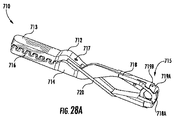
組織リトラクター装置700の好ましい実施形態は、グラスパー710と、アンカー730と、ユニバーサルユーザーインターフェース740とを含む。図27から図33において、この展開の様々な図および段階を表示する。
A preferred embodiment of the
図28A〜Bに示すように、組織グラスパー710は、回収を希望する組織または臓器に接触し、これを固定するように適応される。グラスパー710は、対向可能な上側および下側アーム712および714を含み、それぞれ遠位端713と近位端715とを含む。遠位端713の内向きの表面は、実際に組織を把持するジョー716を形成する。代表的なジョー716は、グラスパー710と回収すべき組織との間に高い摩擦係数を生じる構造である。好ましい実施形態では、ジョー716は、頂点または歯716Aと、谷716Bとを有する波状の表面を含む。図28Aに示すように、アーム712および714のうちの一方の歯716Aは、好ましくは、アーム712および714の他方の谷716Bと交互に差し込むように、かみ合って係合する。また、ジョー716は、回収すべき組織を裂いたり、またはその他の方法で損傷したりしないように略滑らかであり、鋭い縁またはぎざぎざの縁がない(つまり、歯716Aは丸められている)ことが好ましい。表面を把持する別の実施形態も考慮される。
As shown in FIGS. 28A-B, tissue spar 710 is adapted to contact and immobilize a tissue or organ desired for retrieval.
アーム712、714の近位端715は、コイルばね718および線支柱720によって接続される。ばね718は近位端715を離すように付勢し、それによって遠位端713(したがってジョー716)を合わせて閉じるように付勢する。ジョー716を開口するために、アーム712、714の近位端715に力を印加し、近位端715を合わせる。一実施形態では、これは、グラスパー710をチューブまたはカニューレ750の中に相対的に後退させることによって実現される。チューブまたはカニューレ750は、グラスパーが図28Aの閉鎖構成にあるとき、近位端715の広さより狭い内径または類似する寸法を有する。チューブ710内にグラスパーを相対的に後退させること(つまり、グラスパー710がチューブ750内に引っ張られるか、またはチューブ750がグラスパー710を覆って押し出されるかのいずれか)によって、チューブは近位端715を合わせてしっかりつかみ、それによってジョー716を開口する。
The proximal ends 715 of the
グラスパー710の好ましい実施形態では、図28A〜Dに示すように、アーム712、714の近位端715は段階的な直径を備え、それによって近位端715の一部のみがチューブ内に位置し、留まる。好ましい実施形態では、近位端715は少なくとも2つの段階を備える。つまり、外側チューブ750に適合する狭い部分719Aと、チューブ750内部には適合しない幅広のボス部719Bを備える(図28C参照)。外側チューブ750が前方に移動するとき(またはグラスパーが後方に引っ張られるとき)、ボス部719Bはコイルばね718の軸の略周囲を枢動するように、チューブの遠位縁または遠位面がボス部719Bに対して押される。その結果として、アーム712、714の近位端715は一緒に押され、遠位端713は離れるように動き、図28Dに示すように、ジョー716内に組織を把持する準備が整う。
In a preferred embodiment of the
グラスパー710が回収すべき組織に固定されるとき、従前の実施形態に関して前述したように、ユーザーは組織に取り付けられたスーチャーを引っ張る。十分な力で引っ張れば、少なくとも部分的にコイルばね718の付勢力を克服し、回収した組織上のジョー716の把持を緩めることができる。ジョーの把持力を強化するために、穴717は、アームの枢支点から離れて、アーム712および714の両方に設けられる。グラスパーおよびアンカーが取り付けられるスーチャー(不図示)は、穴717の中を通る。そのため、ジョー716内で固定された組織を回収するためにユーザーがスーチャーを引っ張ると、スーチャー上の引張力はアーム712および714に穴717を介して伝達され、ジョー716を閉鎖しようとし、それによって回収した組織をさらに固定する。ユーザーが(常識の範囲内で)強く引っ張るほど、より強い「閉鎖力」がジョー716に穴717のスーチャーを介して伝達される。
When the
組織リトラクター装置700の好ましいアンカー730を図29A〜Bに示す。アンカー730は、略近位端に切り込まれた下部または狭くなった下部を有する主本体732を含む。下部は溝734を形成する。さらに、または代替的に、主本体732は略直線状であってよく、主本体732より広い直径を有する近接するフランジ735を備える。いずれの場合であっても、アンカー固定機構(以下で説明する)は、溝734またはフランジ735のいずれかに係止する。
A
主本体732はまた、好ましくは長手方向に形成された少なくとも1つのノッチ736を含む。ノッチ736は、アンカーを通る(およびグラスパー710に取り付けられた)スーチャーまたはその他の可動支持部を収容する。それによってスーチャーの長手方向の移動は、アンカー730が展開するとき、主本体732の遠位端732Aと接触する腹壁組織をこすらない。さらに、ノッチ736によって、スーチャーが腹壁組織をこすらず、腹壁組織と遠位端732Aとの間で詰まらないため、臨床医は容易にスーチャーを移動させることができる。
The
アンカー720の遠位端は、複数の脚738を備える。好ましくは4本のこのような脚を備える。アンカー730は弾性素材からなり、好ましくはニチノールなどの形状記憶素材からなる。本質的な構成では、図29Aに示すように、脚738は主本体732から外側に曲がっている。図29Bに示すように、アンカー730が外側チューブ750などの封じ込め空間内に配置されるか、またはその内部に格納されるとき、チューブは脚738を伸ばし、それによって図29Bに示すように、脚738は実質的に真っ直ぐになる。つまり、アンカー730は、図29Bに示すように「展開の準備ができている」構成となり(つまり、外側チューブ750内部で)、図29Aの展開構成となる(つまり、腹壁に固定される)。
The distal end of
アンカー730のニチノールまたはその他の形状記憶素材は、様々な温度で様々な屈曲性質を有するように選択することができる。好ましい実施形態では、体温(約37°C)よりも室温(約20°C)でより曲げやすい製法または合金を選択する。このような事例では、脚738が腹壁に挿入される準備が整うとき、脚738は、真っ直ぐなチューブ内の構成から、より容易に伸ばされる。次に、腹壁に配置された後は、脚738の温度が約体温まで上がり、脚738は曲げにくくなる。したがって、アンカー730は、腹壁内でよりしっかりと展開され、除去を望まないときに、不注意にまたは誤って取り外されにくくなる。
The nitinol or other shape memory material of the
組織リトラクターアセンブリの構成部品のすべてはユニバーサルユーザーインターフェース740を介して、ユーザーによって制御可能である。ユニバーサルユーザーインターフェース740を、図27Aの斜視図と、明確にするために外側カバーを取り外して図27Bに表示する。一般に、インターフェース740は遠位端741Aと、近位端741Bとを有する。遠位端741Aはグラスパー710およびアンカー730と直接接触し、相互作用する。近位端741Bの拡大図を図30Aに示す。図30Bはグラスパーと接触する遠位端741A端部の拡大図であり、明確にするために取り外した状態で示される。図30Cは遠位端741Aの断面図である。
All of the components of the tissue retractor assembly are controllable by the user via the
グラスパー710の開閉はトリガー752によって制御される。トリガー752は連結部754を介して機械的に外側カニューレチューブ750に接続される。トリガー752は図30Aに示す位置にばね756によって付勢される。ユーザーがトリガー752を図30Aの矢印Aの方向に(たとえば、対向性のために取っ手744を用いて握ることによって)動かすとき、連結部754によって外側チューブ750は遠位方向(図中左側)に移動する。前述したように、外側チューブ750の遠位縁はグラスパーアーム712、714のボス部719Bに当接し、ジョー716を開口させる。トリガー752は、ばね756によって付勢されるため、ユーザーがトリガー752の担持を解放するとき、トリガー752は図30Aに示す元の位置に戻り、外側チューブ750はグラスパー710から離れて近位に移動し、コイルばね718の付勢力によってジョー716は再び閉鎖する。このように、トリガー752を握り、及び解放することによって、ユーザーはグラスパー710を回収すべき組織または臓器上に固定するために、容易に開閉することができる。
The opening and closing of the
アンカー730の展開はトリガー762の操作によって実現される。トリガー762は中間カニューレまたはチューブ760に連結部764を介して機械的に接続される。トリガー762は図30Aに示す位置にばね766によって付勢される。好ましい実施形態では、アンカー730は中間チューブ760の遠位端に後述するグリッパースリーブ770を介して固定される。ユーザーがトリガー762を図30Aの矢印Bの方向に(たとえば、取っ手744を用いて対抗するように握ることによって)動かすとき、連結部764によって中間チューブ760は遠位方向(図中左側)に移動する。最初は、アンカー730は、図30Cに示すように、外側チューブ750内に図29Bに示す真っ直ぐな脚の構成で配置される。ユーザーがトリガー762を握り込むにつれて、中間チューブ760はアンカー730を遠位に押す。脚738が外側チューブ750の遠位端から外に出るにつれて、脚738は図29Aに示す自然な曲線構成に再び曲がる。外側チューブ750の遠位端が腹壁などの組織を圧迫しているときは、脚738はその組織を貫通して引っかけ、アンカーを組織内にしっかりと固定する。アンカー730を腹壁から取り外すことが望ましいときは、アンカー730は中間チューブ760の遠位端に再び取り付けられる。アンカーの展開時に中間チューブ760はトリガー762の操作によって外側チューブ750から押し出されている。アンカーが中間チューブ760に再固定されるとき、ユーザーはトリガー762を緩め、中間チューブ760は外側チューブ750内に後退し、アンカー730を内部に引っ張る。外側チューブ750の遠位端および内面はアンカー脚738を引っ張り、伸ばして腹壁組織から取り外し、図29Bの真っ直ぐな構成にする。
The deployment of the
アンカー730を中間チューブ760に固定するため、およびアンカーを腹壁の所望の位置に配置するための好ましい構造は、グリッパースリーブ770であり、単独で図31の斜視図に示し、アセンブリ全体において図30B、30C、および27A(不鮮明)に示す。グリッパースリーブ770は相対的に短い管状構造であり、近接する主部分772を有する。主部分772は、好ましくは溶接またはその他の方法で中間チューブ760の遠位端に、またはそのうえに固定される。複数のアーム774はグリッパースリーブ770の遠位端から突出し、それぞれ内側を向くタブまたは歯776と実体的に直交するように終端する。図30Cに示すように、たとえば、歯776は、アンカー730を中間チューブ760の遠位端状に保持するために、アンカー730の溝734に(および/またはフランジ735上に)入るように構成される。アーム774は、図31に点線で示すように、好ましくは少なくとも折り曲げ点778で自然に外側に付勢される。アンカーおよびグリッパースリーブの両方が外側チューブ750内に配置されるとき、歯776は溝734のみに入る。中間チューブ760が外側チューブ750からトリガー762の操作によって押し出されるにつれて、アーム774は径方向外側に付勢し、歯776は溝734との係合から解放される。これが起きている間、アンカー730の脚738は腹壁組織に入っているため、アンカーはグリッパースリーブ770から離れ、腹壁に固定された状態を維持する。
A preferred structure for securing the
ここまで、グラスパージョー716をユーザーインターフェース740(特別な形状のトリガー752)の操作によって開閉する方法について説明してきた。グラスパーが回収すべき組織に固定されると、グラスパーは組織リトラクター装置700全体から解放されなければならない。好ましい実施形態では、図30B〜Cから最もよくわかるように、グラスパー710はユーザーインターフェース740にフック780を介して接続される。好ましくは、コイルばね718の円形部718Aは、装置700を用いる前に、最初に、フック780の遠位端に取り付けられる。グラスパージョーが回収すべき組織の周囲で開口して閉鎖すると、たとえば図27Aに示すように、グラスパー710はアクチュエータ740の遠位端741Aに固定された状態を維持する。この時点で、図30Cに示すように、フック780は完全に外側チューブ750内部にあり、コイルばね718はフック780と外側チューブ750との間にはまっている。フック780は好ましくは、内側チューブ783内に配置される(図30B〜C参照)。内側チューブ783は好ましくは、全く移動せずにフック780の配向を一定に保ち、グラスパー710の配向をアクチュエータおよびアセンブリの残りの部分に対して一定に保つ。
So far, the method of opening and closing the glass per
フック780は連結部784を介して摺動ノブ782に機械的に接続され(図27A、図32A〜C参照)、外側チューブ750内の中立位置にばね786によって付勢される。摺動ノブ782が図27Aの矢印Cが示す遠位方向に移動することによって、フック780は遠位に移動して、それによって外側チューブ750の遠位端から突出する。フック780のこの動きによって、グラスパー710はフック780と共に押し出され、グラスパー710はフック780から取り外されるように自由となり、ジョー716が組織に固定されたまま、組織に取り付けられた状態となる。ユーザーがノブ782にかけていた握力または圧力を解放すると、ばね786は外側チューブ750内部でフック780を近位に引っ張って戻す。
The
好ましくは、フック起動アセンブリはまた、フック780が外側チューブ750から偶発的に、または不注意に外に出ないように係止機構も含む。これは、グラスパー710が外側チューブ750と接触しない状態になると、ジョー716を容易に制御することができないためである。そのため、フック起動アセンブリはまた、好ましくは、連結部784およびばね789Aに接続される係止ゲート787も含む。係止ゲート787は、好ましくは係止窓788を含む。係止窓788はフック780の近位端上の対応する係止フランジ781より小さく寸法合わせされる。係止ゲート787は好ましくは、摺動ノブ782の同一の動作によって移動される。ノブ782を矢印Cに沿って遠位方向に押すことによって(図27A参照)、係止ゲート787はフック780から持ち上がり、それによって係止窓788はフック係止フランジ781から解放される。
Preferably, the hook activation assembly also includes a locking mechanism to prevent the
係止ゲート787の機能を図32A〜Cに順次に表示する。まず、図32Aでは、フック起動アセンブリは初期のニュートラルな形態にあり、係止ゲート787の係止窓788は係止フランジ781でフック780と係合している。次に、図32Bでは、摺動ノブ782は矢印Cの方向に、部分的に遠位に押されている。係止ゲート787はわずかに上昇し、係止窓788を係止フランジ781から解放する。この時点で、フック780は自由に遠位に移動できる。次に、図32Cに示すように、摺動ノブは矢印Cの方向にさらに押され、フック780はこの時点で外側チューブ750の遠位端から突出している。グラスパー710は、フック780から取り外され、回収すべき組織上の所定の位置に配置されてもよい。好ましくは、ユーザーが単に摺動ノブ782を単一の円滑な動きによって押すだけで、まず係止ゲート787が解放され、次に、フック780が遠位に移動される。ただし、連結部およびフック係止機構のその他の構成は本発明の範囲内であると考えられる。その他の構成とは、たとえば、摺動ノブ782または類似するアクチュエータと、係止ゲート787の操作を制御する個別の安全スイッチ(不図示)または類似する構造などによる2段階動作である。
The function of the locking
好ましい実施形態では、3つのばねはフックアクチュエータアセンブリのニュートラルな位置を維持するように機能する。ばね786はフック自体を近位方向後方に付勢する。ばね789Aは係止ゲート787を下方に付勢し、係止フック780のフランジ781と係合させる。ばね789B(ばね789Aに隣接し、部分的に係止ゲート787によって干渉される)は連結部784の遠位端に接続され、連結部784の遠位端を付勢する。本発明はその他の便利な付勢構成、たとえば、同一または異なる場所に、より多くまたはより少ないばねを配置するなどの構成を考慮する。
In the preferred embodiment, the three springs function to maintain the neutral position of the hook actuator assembly. The
グラスパー710が引き込むべき組織上で展開され、アンカー730が腹壁内に展開されると、実際の組織引込を実現可能な構造は、可動支持部であり、好ましくはスーチャー800(図30B参照)である。スーチャー800は好ましくは、フック780の上下いずれかで、内側チューブ783内の遠位端に配置される。スーチャー800の近位端は好ましくは、スーチャー支軸802(図32A〜C参照)の周囲に巻かれ、必要に応じてほどかれる。スーチャー800の遠位端は好ましくは、アンカー730の中を通り、グラスパー710に結ばれるか、またはその他の方法で(たとえば、コイルばね718および貫通穴717を貫通して)固定される。ユーザーアクチュエータ740が患者の体から取り出されると、臨床医はスーチャー800を単に引っ張るだけで、グラスパー710内の組織を引き込むことができる。スーチャー800は腹壁に固定されたアンカー730の中を通っているため、システムは滑車のように機能する。スーチャー800を患者から離れて近位に引っ張るほど、より多くの組織が引き込まれる。したがって、本発明によって、どれほど多く組織を引き込むかに関して動的な(つまり、可変かつリアルタイムな)選択が可能となる。
When the
手術を終了するいずれかの時点で、ユーザーは患者の体内に固定された様々な器具の回収を希望するであろう。前述した個別のアンカーリトリーバルツール600を用いることもできるが、好ましい組織リトラクター装置700では、ツール回収機構はユーザーインターフェース740に組み込まれ、一体である。
At some point in the surgery, the user may wish to retrieve various devices that are fixed in the patient's body. Although the individual anchor retrieval tool 600 described above may be used, in the preferred
具体的には、ワイヤーループ792は固定内側チューブ783内の導管790に配置されて提供される(図30B〜C参照)。ワイヤーループ792の遠位端は、ボタン794をユーザーが起動することによって、外側チューブ750の遠位端から選択的に突出可能である。ボタン794はワイヤーループ792の近位端に取り付けられる。補強構造(不図示)をワイヤーループ792の一部または全体の周囲に設けて安静を提供し、ワイヤーループ792がいずれかの方向にねじれたり、からんだりすることを防止する。ボタン794を矢印Dの方向に押圧することによって(図30A参照)、ワイヤーループ792を内側チューブ783および外側チューブ750の遠位端から直接押し出す。臨床医は次に、スーチャー800を露出したワイヤーループに通し、次に、ボタン794を解放することができる。好ましくは、ボタン794は、ばね(不図示)によって、矢印Dと反対の方向にばね付勢される。このようにして、ボタン794が解放されるとき、ワイヤーループ792は内側チューブ783内に後退し、スーチャー800をその内部に内包する。臨床医は次に、スーチャー800をアンカー730にしたがわせ、グリッパースリーブ770と共にアンカー730を回収することができる。アンカー730が回収されると、臨床医は続けてスーチャー800をグラスパー710の近位端が外側チューブ750の遠位端に当接するまで、グラスパー710にしたがわせ、グラスパージョー716を開口させて引き込まれた組織を解放する。次に、ノブ796を矢印Eの方向に近位に後退させ(図30A参照)、アセンブリ全体を患者から取り外す。
Specifically, a
手術において、組織リトラクター装置700は以下のように、図33A〜Gに表示するように用いられる(図33Aでは明確にするために外側チューブ750は取り出されている)。図33Aでは、装置700は使用前の構成である。グラスパージョー716は閉鎖し、外側チューブ750の遠位端のちょうど内側でグラスパー710はフック780に固定される。フック780は近位に付勢され、それによってグラスパー710の近位端は外側チューブ750の遠位縁に当接する。このとき好ましくは狭い部分719Aは外側チューブ750内に配置され、幅広のボス部719Bはその遠位縁に当接して配置される。スーチャー(図33Aでは不図示)はグラスパーアーム712、714の貫通穴717の中を通る。アンカー730は外側チューブ750内に、グリッパースリーブ770のアーム774の歯776を介して固定される。グリッパースリーブ770のアーム774の歯776は略全体が外側チューブ750内に含有される。ユーザーはユニバーサルユーザーインターフェース740を手で持ち、好ましくは取っ手744を手のひらでピストルのように持つ。
In surgery, the
引き込むべき組織、臓器、またはその他の身体構造を選択すると、ユーザーはグラスパー710を引き込むべき組織に、またはその近くに配置する。図30Aに示すように、好ましくは取っ手744を用いて対抗するように握ることによって、ユーザーはトリガー752を矢印Aの方向に握る。連結部754はトリガー752から外側チューブ750に力を伝達し、外側チューブ750を遠位に移動する。前述したように、また図28Cに示すように、ボス部719Bは外側チューブ750の遠位縁に当接するため、外側チューブ750の遠位方向への移動によって、チューブはボス部719Bに対して押され、図33Bに示すようにグラスパー710のジョー716が開口する(明確にするために外側チューブ750を透明にして示す)。ユーザーはグラスパージョー716を所望する組織の周囲に固定し、次に、トリガー752を解放することができる。ばね756の付勢力のおかげで、トリガー752および外側チューブ750は元の位置に戻り、およびジョー716は回収すべき組織の周囲でしっかりと閉鎖する。
Once the tissue, organ, or other body structure to be withdrawn is selected, the user places the
次に、ユーザーはグラスパー710をユーザーインターフェース740から解放しなければならない。そのためには、ユーザーは摺動ノブ782を矢印Cの方向に摺動する(図27A参照)。これによって、係止ゲート787をフック780から解放し、フック780を外側チューブ750の端部から遠位に押し出す。グラスパーのジョーが回収すべき組織に固定されているため、わずかな横方向の動作によって、グラスパーコイルばね718はフック780から解放され、図33Cに示すように、アセンブリの遠位端が構成される。
Next, the user must release the
ユーザーは次に、アンカー730を腹壁または類似する適切な解剖学的構造に展開しなければならない。組織リトラクター装置は、図33Dに示すように、外側チューブ750の遠位端を組織Tに対して押圧することによってアンカー展開を開始する。次に、ユーザーはトリガー762を矢印Bの方向に握る(図30A参照)。トリガー762は(連結部764を通じて)中間チューブ760を遠位に移動する。中間チューブ760が遠位に移動し、アンカー730が外側チューブ750の内部から離れるにつれて、脚738は組織Tにそっと穿刺し、図33Eに示すように、本来の径方向外側に曲がった構成に戻る。ユーザーがトリガー762の操作を完了すると、グリッパースリーブ770のアーム774は図33Fに示すように、自然に径方向外側に付勢される構成に戻る。その結果として、グリッパースリーブの歯776はアンカー溝734から解放され、アンカーは組織T内にしっかりと入り込んだままとなる。組織リトラクター装置700は次に、患者から後退してもよく、スーチャー800を操作して、グラスパージョー716に固定された組織を要望通り、大きくまたは小さく引き込むことができる。
The user must then deploy
手術の終わりに、ユーザーは好ましくは、アンカーおよびグラスパーを取り外すために、その位置を突き止めなければならない。まず、ボタン794を矢印Dの方向に押し(参照図30A)、それによってワイヤーループ792を導管790から延長させ、これにより外側チューブ750の外に拡張させる。スーチャー800はワイヤーループ792の中を通り、ボタン794が解放されることによって、ワイヤーループ792は後退し、スーチャー800を導管790に内包する。ユーザーインターフェース740の遠位端741は次に、患者に再挿入され、スーチャー800の遠位端にまだ取り付けられている様々な構成部品の位置を突き止める。
At the end of the operation, the user should preferably locate the anchor and glassper to remove it. First, the
スーチャー800に沿った第1の停止部はアンカー730である。図33Gに示すように、ユーザーはフック780を延長させ、フック780がアンカー730の主本体732内で適合する際に、アンカー730の回収又は検索を支援してもよい。フック780はアンカー730とユーザーインターフェース740の遠位端741との位置合わせに役立つ。その後、ユーザーはトリガー762を握り、中間チューブ760を延長させ、これによりグリッパースリーブ770を延長させる。グリッパースリーブ770が延在するにつれて、そのアーム774は径方向外側に付勢され、歯776がアンカー溝734および/またはアンカーフランジ735に入ることが可能となる。ユーザーがトリガー762を緩め、中間チューブ760が外側チューブ750内で後退すると、まず、アーム774はアンカー溝734/フランジ735の周囲をしっかり締め、次に、アンカー730を組織Tから外して近位に引っ張る。アンカー脚738は最終的に外側チューブ750内で真っ直ぐとなる。
The first stop along the suturer 800 is an
次に、ユーザーはスーチャー800をグラスパー710まで送る。ユーザーは、摺動ノブ782を矢印Cの方向に操作することによって、フック780を延在させる(図27A)。ユーザーはグラスパーコイルばね718内でフック780を固定する。次に、摺動ノブ782を解放する。ばね786はフック780を外側チューブ750内部に後退させ、グラスパー710の近位端は外側チューブ750の遠位縁に当接する。ユーザーは次に、トリガー752を握って、外側チューブ750を遠位に移動させて、それによってグラスパー710のボス部719Bに対して押圧し、ジョー716を開口し、回収した組織をジョー716から解放する。トリガー752を解放すると、ジョー716は閉鎖する。グラスパーが組織を解放し、ユーザーインターフェース740の遠位端に固定されると、装置全体が患者から解放される。
Next, the user sends the suturer 800 to the
本発明は上記の説明に限定されるものではない。たとえば、部品が所定の位置または構成に付勢されるほとんどすべての環境においてコイルばねが示されている。しかしながら、製造者に便利かつ簡便であるように、板ばねまたは任意のその他の付勢機構を使用してもよい。さらに、図は連結部の特定の構成および様々な装置およびユーザーアクチュエータの様々な可動部分間の機械的接続を表示しているが、その他の接続も考慮される。また、図27から図33の好ましい組織リトラクターアセンブリを図1から図26に表示する任意の実施形態と共に用いることもできる。さらに、前述したように、グラスパーをユーザーインターフェースに固定するフックは、好ましくはグラスパーのコイルばねを貫通して固定される。ただし、フックはグラスパーの別の構造に固定されてもよく、この目的のためにグラスパーが追加の構造を備えていてもよい。 The present invention is not limited to the above description. For example, coil springs are shown in almost all environments where parts are biased into place or configuration. However, leaf springs or any other biasing mechanism may be used as convenient and convenient for the manufacturer. Furthermore, although the figure shows the particular configuration of the linkage and the mechanical connections between the various devices and the various movable parts of the user actuator, other connections are also contemplated. The preferred tissue retractor assembly of FIGS. 27-33 can also be used with any of the embodiments shown in FIGS. 1-26. Further, as described above, the hook that secures the glassper to the user interface is preferably fixed through the coil spring of the glassper. However, the hook may be fixed to another structure of the glassper, and the glassper may be provided with an additional structure for this purpose.
本発明の一定の実施形態を記載してきたが、本発明は前述の説明または添付した代表的な図に限定されないことが理解されるべきである。むしろ、本発明の範囲は、ここに添付する請求の範囲によって画定されるもので、当業者に好まれるであろう任意の均等物を含む。 While certain embodiments of the present invention have been described, it is to be understood that the invention is not limited to the foregoing description or the attached representative figures. Rather, the scope of the present invention is defined by the claims appended hereto and includes any equivalent that would be preferred by those skilled in the art.
101 リトラクター装置
101 チューブ又はカニューレ
102,110 グラスパー
102a,112a 第1の脚
102b,112b 第2の脚
103 アンカー
104 係止リング
105 円筒体
107 臓器又は組織
108 スーチャー
110 グラスパー
111 スリーブ
113a,113b 第1及び第2の脚の遠位端
700 リトラクター装置
710 グラスパー
740 ユーザーインターフェース
752,762 トリガー
770 スリーブ
782,796 ノブ
794 ボタン
101
Claims (44)
前記外側カニューレと前記グラスパーの少なくともひとつが、前記外側カニューレと前記グラスパーの他方に対して動いて、前記グラスパーを少なくとも部分的に前記外側カニューレ内に回収される際に、前記外側カニューレの遠位端は前記グラスパーの前記複数のアームの近位端に対して進み、前記ジョーを前記付勢機構と反対の開口状態に押し進めることを特徴とする体内手術用組織リトラクター。 23. The user interface of claim 21, wherein the user interface comprises an outer cannula and the glass spar that is at least partially collected in and exited in relation to the outer cannula,
The distal end of the outer cannula when at least one of the outer cannula and the glassper moves relative to the other of the outer cannula and the glassper and the glassper is at least partially withdrawn into the outer cannula Is a tissue retractor for internal surgery, which advances with respect to the proximal ends of the plurality of arms of the glassper and pushes the jaws into an open state opposite to the biasing mechanism.
前記外側カニューレは、前記グラスパーに対して動いて、前記グラスパーを少なくとも部分的に前記外側カニューレ内に回収される際に、前記外側カニューレの遠位端は前記グラスパーの前記複数のアームの近位端に対して進み、前記ジョーを前記付勢機構と反対の開口状態に押し進めることを特徴とする体内手術用組織リトラクター。 23. The user interface of claim 21, wherein the user interface comprises a longitudinally movable outer cannula and a substantially non-moving glassper support disposed on the outer cannula and attachable to the glassper, the glassper being at least partially Collected in or out of the outer cannula,
The outer cannula moves relative to the glassper so that the distal end of the outer cannula is the proximal end of the arms of the glassper when the glassper is at least partially withdrawn into the outer cannula. The tissue retractor for in-vivo surgery is characterized in that the jaw is pushed forward to the open state opposite to the biasing mechanism.
前記外側カニューレと前記グラスパーの少なくともひとつが、前記外側カニューレと前記グラスパーの他方に対して動く際に、前記外側カニューレの前記遠位縁は前記グラスパーの近位端に対して進み、前記ジョーを前記付勢機構と反対の開口状態に押し進めることを特徴とする体内手術用組織リトラクター。 23. The user interface of claim 21, wherein the user interface comprises an outer cannula having a distal edge and the grasper having a proximal end at least partially adjoinable to the distal edge of the outer cannula,
As at least one of the outer cannula and the glassper moves relative to the other of the outer cannula and the glassper, the distal edge of the outer cannula advances relative to the proximal end of the glassper and moves the jaw through the jaws. A tissue retractor for in-vivo surgery characterized by being pushed forward in an open state opposite to the biasing mechanism.
前記外側カニューレは、前記グラスパーに対して動き、前記外側カニューレの前記遠位端は前記グラスパーの近位端に対して進み、前記ジョーを前記付勢機構と反対の開口状態に押し進めることを特徴とする体内手術用組織リトラクター。 24. The user interface of claim 21, wherein the user interface comprises a longitudinally movable outer cannula having a distal edge and a grasper support disposed on the outer cannula and attachable to the grasper, the grasper having a proximal end. And at least partially adjoining the distal edge of the outer cannula;
The outer cannula moves relative to the glassper, the distal end of the outer cannula advances relative to the proximal end of the glassper, and pushes the jaws into an open state opposite the biasing mechanism. Tissue retractor for internal surgery.
前記中心軸の前記遠位端が前記アンカーの前記主本体に入る際に、前記タブは前記中心軸の前記ショルダー部の下部を捕捉して、これにより前記アンカーが前記中心軸の前記遠位端からの脱落を防ぎ、前記第1の組織からの前記アンカーの回収又は検索を容易にすることを特徴とする体内手術用組織リトラクター。 The anchor retrieval tool of claim 1, further comprising a main body and an anchor retrieval tool having a central axis disposed on the main body, the central axis comprising a proximal end and a distal end, the distal end of the central axis Is inclined to a shoulder portion that is engageable with at least one flexible detent tab cut inwardly and angled inwardly relative to the center of the main body of the anchor Part
As the distal end of the central axis enters the main body of the anchor, the tab captures the lower portion of the shoulder portion of the central axis so that the anchor is the distal end of the central axis. A tissue retractor for in-vivo surgery that prevents dropping from the first tissue and facilitates recovery or retrieval of the anchor from the first tissue.
Applications Claiming Priority (3)
| Application Number | Priority Date | Filing Date | Title |
|---|---|---|---|
| US201161502178P | 2011-06-28 | 2011-06-28 | |
| US61/502,178 | 2011-06-28 | ||
| PCT/US2012/044683 WO2013003613A2 (en) | 2011-06-28 | 2012-06-28 | Tissue retractor assembly |
Publications (2)
| Publication Number | Publication Date |
|---|---|
| JP2014527840A true JP2014527840A (en) | 2014-10-23 |
| JP2014527840A5 JP2014527840A5 (en) | 2015-08-13 |
Family
ID=47424799
Family Applications (1)
| Application Number | Title | Priority Date | Filing Date |
|---|---|---|---|
| JP2014519033A Pending JP2014527840A (en) | 2011-06-28 | 2012-06-28 | Tissue retractor device |
Country Status (10)
| Country | Link |
|---|---|
| US (3) | US9107648B2 (en) |
| EP (1) | EP2725986A4 (en) |
| JP (1) | JP2014527840A (en) |
| KR (1) | KR20140146038A (en) |
| CN (1) | CN103619270A (en) |
| AU (1) | AU2012275259A1 (en) |
| CA (1) | CA2839282A1 (en) |
| MX (1) | MX338044B (en) |
| RU (1) | RU2585730C2 (en) |
| WO (1) | WO2013003613A2 (en) |
Cited By (1)
| Publication number | Priority date | Publication date | Assignee | Title |
|---|---|---|---|---|
| JP2020505183A (en) * | 2017-02-02 | 2020-02-20 | カンヌフロウ インコーポレイテッドCannuflow, Inc. | Systems and methods for delivery and placement of surgical implants |
Families Citing this family (43)
| Publication number | Priority date | Publication date | Assignee | Title |
|---|---|---|---|---|
| WO2009070743A1 (en) | 2007-11-26 | 2009-06-04 | Eastern Virginia Medical School | Magnaretractor system and method |
| CL2009000279A1 (en) | 2009-02-06 | 2009-08-14 | Biotech Innovations Ltda | Remote guidance and traction system for mini-invasive surgery, comprising: at least one surgical and removable endopinza with hooking means and a portion of ferro-magnaetic material, a cylindrical introduction guide, a detachment mechanism, and at least a means of remote traction with magnet. |
| KR101082762B1 (en) * | 2011-02-18 | 2011-11-10 | 이정삼 | Retractor system for laparoscopic surgery |
| EP2757963A1 (en) * | 2011-09-23 | 2014-07-30 | Surgical Perspectives SAS | Clip for organ retraction during minimally invasive surgery |
| JP2014004016A (en) * | 2012-06-21 | 2014-01-16 | Olympus Corp | Access port |
| US20140046347A1 (en) * | 2012-08-10 | 2014-02-13 | W. L. Gore & Associates, Inc. | Devices, systems and methods for engaging tissue |
| US8764769B1 (en) | 2013-03-12 | 2014-07-01 | Levita Magnetics International Corp. | Grasper with magnetically-controlled positioning |
| US10010370B2 (en) | 2013-03-14 | 2018-07-03 | Levita Magnetics International Corp. | Magnetic control assemblies and systems therefor |
| WO2014197498A1 (en) * | 2013-06-04 | 2014-12-11 | Boston Scientific Scimed, Inc. | Tissue spreader for accessing papilla, and related methods of use |
| KR101465384B1 (en) * | 2014-01-07 | 2014-11-26 | 성균관대학교산학협력단 | Surgery grasper for measuring force |
| EP3096673A4 (en) | 2014-01-21 | 2017-10-25 | Levita Magnetics International Corp. | Laparoscopic graspers and systems therefor |
| US10136881B2 (en) | 2014-02-11 | 2018-11-27 | Mayo Foundation For Medical Education And Research | Laparoscopic retractor devices |
| CN103976768B (en) * | 2014-06-03 | 2016-01-20 | 中国人民解放军第三军医大学第三附属医院 | A kind of L-type thoracoscopic operation displaying unit |
| GB2536538B (en) * | 2014-09-17 | 2018-07-18 | Cardiomech As | Anchor for implantation in body tissue |
| WO2016063679A1 (en) * | 2014-10-24 | 2016-04-28 | 株式会社カネカ | Clip device for endoscope and method for mounting clip for implanting in body |
| EP3954303A1 (en) | 2015-04-13 | 2022-02-16 | Levita Magnetics International Corp. | Grasper with magnetically-controlled positioning |
| EP3282923B1 (en) | 2015-04-13 | 2021-08-11 | Levita Magnetics International Corp. | Retractor devices |
| US10070854B2 (en) | 2015-05-14 | 2018-09-11 | Ankon Medical Technologies (Shanghai), Ltd. | Auxiliary apparatus for minimally invasive surgery and method to use the same |
| WO2016190190A1 (en) * | 2015-05-27 | 2016-12-01 | オリンパス株式会社 | Device for endoscope |
| US20190059869A1 (en) * | 2015-10-30 | 2019-02-28 | Cedars-Sinai Medical Center | Tissue retractor systems and methods |
| WO2017091812A1 (en) * | 2015-11-25 | 2017-06-01 | Talon Medical, LLC | Tissue engagement devices, systems, and methods |
| US10973506B2 (en) * | 2016-08-05 | 2021-04-13 | Boston Scientific Scimed, Inc. | Systems, devices, and related methods for retracting tissue |
| US10987120B2 (en) * | 2017-01-10 | 2021-04-27 | New Wave Endo-Surgery Inc. | Multifunction surgical instrument for use in laparoscopic surgery |
| CN107007310A (en) * | 2017-03-03 | 2017-08-04 | 重庆长麟梅捷医疗科技有限公司 | Medical operation tractor |
| US11020137B2 (en) | 2017-03-20 | 2021-06-01 | Levita Magnetics International Corp. | Directable traction systems and methods |
| JP6812578B2 (en) * | 2017-03-20 | 2021-01-13 | ボストン サイエンティフィック サイムド,インコーポレイテッドBoston Scientific Scimed,Inc. | Tissue tensioning device |
| CN110461212B (en) | 2017-03-29 | 2022-02-08 | 波士顿科学国际有限公司 | Devices and methods for tissue retraction |
| US10898192B2 (en) | 2017-06-15 | 2021-01-26 | Roberto Tapia Espriu | Adjustable pressure surgical clamp with releasable or integrated remote manipulator for laparoscopies |
| KR20220057636A (en) * | 2017-10-02 | 2022-05-09 | 보스톤 싸이엔티픽 싸이메드 인코포레이티드 | Devices and methods for tissue retraction |
| CN107693059B (en) * | 2017-11-01 | 2019-11-08 | 刘波 | A kind of operation device fixed for internal organs in Minimally Invasive Surgery |
| US11350946B2 (en) * | 2017-11-08 | 2022-06-07 | Mayo Foundation For Medical Education And Research | Systems and methods for endoscopic submucosal dissection using magnetically attachable clips |
| US10933222B2 (en) | 2017-12-05 | 2021-03-02 | Boston Scientific Scimed, Inc. | Tissue retraction system for performing minimally invasive procedures |
| CN111770733B (en) * | 2018-01-04 | 2024-04-02 | 赛格外科解决方案有限公司 | Tissue alignment for surgical closure |
| US11076843B2 (en) | 2018-01-15 | 2021-08-03 | Mariner Endosurgery Inc. | Organ retention device and system, and use of same for laparoscopic surgery |
| EP3764918B1 (en) * | 2018-03-14 | 2023-08-23 | Boston Scientific Scimed, Inc. | Tissue retraction device and delivery system |
| EP3626181A1 (en) * | 2018-09-23 | 2020-03-25 | Medtentia International Ltd Oy | A clip for fixation of a medical implant to tissue |
| WO2020092482A1 (en) | 2018-10-31 | 2020-05-07 | Boston Scientific Scimed, Inc. | Clip devices, systems, and methods for engaging tissue |
| US11497526B2 (en) | 2018-11-13 | 2022-11-15 | T & J Enterprises, Llc | Cervical tenaculum device |
| WO2020109579A1 (en) * | 2018-11-29 | 2020-06-04 | Cardiomech As | Device for heart repair |
| CN110037756A (en) * | 2019-04-30 | 2019-07-23 | 安瑞医疗器械(杭州)有限公司 | A kind of anchoring folder with connecting component |
| US11147564B2 (en) | 2019-05-14 | 2021-10-19 | Boston Scientific Scimed, Inc. | Tissue clip devices, systems, and traction methods |
| US20210205006A1 (en) * | 2020-01-07 | 2021-07-08 | Virender K. Sharma | Methods and Devices for Endoscopic Resection |
| US20220126073A1 (en) * | 2020-10-26 | 2022-04-28 | Medtronic Xomed, Inc. | System and Method for a Shunt |
Citations (3)
| Publication number | Priority date | Publication date | Assignee | Title |
|---|---|---|---|---|
| US5242456A (en) * | 1991-11-21 | 1993-09-07 | Kensey Nash Corporation | Apparatus and methods for clamping tissue and reflecting the same |
| JP2005103107A (en) * | 2003-09-30 | 2005-04-21 | Shinshu Tlo:Kk | Medical holder, and method for mounting the same in body |
| WO2009023136A2 (en) * | 2007-08-10 | 2009-02-19 | Yale University | Suspension/retraction device for surgical manipulation |
Family Cites Families (68)
| Publication number | Priority date | Publication date | Assignee | Title |
|---|---|---|---|---|
| US1741457A (en) | 1925-02-04 | 1929-12-31 | Glass Jacob | Surgical appliance |
| US2418773A (en) * | 1944-09-09 | 1947-04-08 | Henry J Kahanek | Fuse changer |
| DE2658478C2 (en) | 1976-12-23 | 1978-11-30 | Aesculap-Werke Ag Vormals Jetter & Scheerer, 7200 Tuttlingen | Vascular clips for surgical use |
| DE3139488C2 (en) | 1981-10-03 | 1984-08-16 | Aesculap-Werke Ag Vormals Jetter & Scheerer, 7200 Tuttlingen | Aneurysm clip |
| US4637395A (en) | 1983-10-04 | 1987-01-20 | Aesculap-Werke Ag | Applicator for C-shaped scalp clips |
| DE3704760C1 (en) | 1987-02-16 | 1988-03-03 | Aesculap Werke Ag | Application device for C-shaped scalp clips |
| SU1502016A1 (en) * | 1987-09-15 | 1989-08-23 | Киевский научно-исследовательский институт ортопедии | Tendoextractor |
| US4899743A (en) | 1987-12-15 | 1990-02-13 | Mitek Surgical Products, Inc. | Suture anchor installation tool |
| US5514666A (en) | 1992-01-06 | 1996-05-07 | University Of Florida | Preparation and use of a protein-enriched pectin composition |
| US5415666A (en) * | 1992-03-23 | 1995-05-16 | Advanced Surgical, Inc. | Tethered clamp retractor |
| US5411481A (en) * | 1992-04-08 | 1995-05-02 | American Cyanamid Co. | Surgical purse string suturing instrument and method |
| US5337736A (en) | 1992-09-30 | 1994-08-16 | Reddy Pratap K | Method of using a laparoscopic retractor |
| US5522844A (en) * | 1993-06-22 | 1996-06-04 | Johnson; Lanny L. | Suture anchor, suture anchor installation device and method for attaching a suture to a bone |
| US5496333A (en) * | 1993-10-20 | 1996-03-05 | Applied Medical Resources Corporation | Laparoscopic surgical clamp |
| US5466243A (en) * | 1994-02-17 | 1995-11-14 | Arthrex, Inc. | Method and apparatus for installing a suture anchor through a hollow cannulated grasper |
| DE19534322A1 (en) | 1995-09-15 | 1997-03-20 | Aesculap Ag | Surgical clip, especially a vascular clip |
| DE19534323A1 (en) | 1995-09-15 | 1997-03-20 | Aesculap Ag | Clamping ring for a surgical clip |
| US5830221A (en) | 1996-09-20 | 1998-11-03 | United States Surgical Corporation | Coil fastener applier |
| US5921996A (en) * | 1997-05-02 | 1999-07-13 | Cardio Thoracic Systems, Inc. | Surgical clamp applier/remover and detachable clamp |
| DE19752332C1 (en) | 1997-11-26 | 1999-04-08 | Aesculap Ag & Co Kg | Surgical clip applicator for blood vessels |
| DE19807354A1 (en) | 1998-02-21 | 1999-08-26 | Aesculap Ag & Co Kg | Surgical instrument for inserting tubular implant into blood vessel, especially for treatment of abdominal or thoracic aortic aneurism |
| DE19809121C1 (en) | 1998-03-04 | 1999-08-12 | Aesculap Ag & Co Kg | Organ clip for aneurysm |
| US7344547B2 (en) | 1998-09-15 | 2008-03-18 | Phavel Systems, Inc. | Laparoscopic instruments and trocar systems and related surgical method |
| US6200330B1 (en) | 1998-11-23 | 2001-03-13 | Theodore V. Benderev | Systems for securing sutures, grafts and soft tissue to bone and periosteum |
| US6210419B1 (en) | 1998-12-18 | 2001-04-03 | Aesculap Ag & Co. Kg | Surgical clip |
| DE19858581C2 (en) | 1998-12-18 | 2001-03-08 | Aesculap Ag & Co Kg | Vascular clip |
| DE19934634C1 (en) | 1999-07-23 | 2000-12-21 | Aesculap Ag & Co Kg | Surgical clip application instrument has clips in clip magazine fed forwards via reciprocating displacement plate acted on by displacement device at point at least halfway along its length |
| US6911032B2 (en) | 1999-11-18 | 2005-06-28 | Scimed Life Systems, Inc. | Apparatus and method for compressing body tissue |
| US6358196B1 (en) | 1999-12-29 | 2002-03-19 | Reiza Rayman | Magnetic retraction system for laparoscopic surgery and method of use thereof |
| DE10004264C2 (en) | 2000-02-01 | 2002-06-13 | Storz Karl Gmbh & Co Kg | Device for the intracorporeal, minimally invasive treatment of a patient |
| US6440061B1 (en) | 2000-03-24 | 2002-08-27 | Donald E. Wenner | Laparoscopic instrument system for real-time biliary exploration and stone removal |
| US7077851B2 (en) | 2000-10-17 | 2006-07-18 | Aesculap Ag & Co. Kg | Aneurysm clip |
| US7037305B2 (en) * | 2001-04-30 | 2006-05-02 | Ethicon, Inc. | Heart presentation device and method |
| CA2485461C (en) | 2002-05-17 | 2011-01-04 | Tyco Healthcare Group, Lp | Endoscopic organ retraction system and method of using the same |
| US6955673B2 (en) | 2002-08-16 | 2005-10-18 | Cryocor, Inc. | Heat transfer segment for a cryoablation catheter |
| US7727247B2 (en) * | 2002-08-21 | 2010-06-01 | Olympus Corporation | Living tissue ligation device |
| JP4147315B2 (en) | 2002-09-13 | 2008-09-10 | Hoya株式会社 | Magnetic anchor remote guidance system |
| US7070586B2 (en) | 2003-01-17 | 2006-07-04 | Applied Medical Resources Corporation | Surgical access apparatus and method |
| US20040267191A1 (en) * | 2003-03-27 | 2004-12-30 | Cierra, Inc. | Methods and apparatus for treatment of patent foramen ovale |
| US20040254427A1 (en) * | 2003-06-16 | 2004-12-16 | Lone Star Medical Products, Inc. | Surgical stay-grip assembly and method of using same |
| GB0315479D0 (en) | 2003-07-02 | 2003-08-06 | Paz Adrian | Virtual ports devices |
| US20100081875A1 (en) | 2003-07-15 | 2010-04-01 | EndoRobotics Inc. | Surgical Device For Minimal Access Surgery |
| US20050273119A1 (en) | 2003-12-09 | 2005-12-08 | Nmt Medical, Inc. | Double spiral patent foramen ovale closure clamp |
| US8562516B2 (en) | 2004-04-14 | 2013-10-22 | Usgi Medical Inc. | Methods and apparatus for obtaining endoluminal access |
| US7736378B2 (en) | 2004-05-07 | 2010-06-15 | Usgi Medical, Inc. | Apparatus and methods for positioning and securing anchors |
| US8926635B2 (en) | 2004-06-18 | 2015-01-06 | Medtronic, Inc. | Methods and devices for occlusion of an atrial appendage |
| CN2738738Y (en) * | 2004-10-21 | 2005-11-09 | 杨希中 | Automatic pull-hook device for rectal cancer |
| US20060135970A1 (en) * | 2004-11-15 | 2006-06-22 | Laurent Schaller | Catheter-based tissue remodeling devices and methods |
| US7270672B1 (en) | 2005-02-11 | 2007-09-18 | Adam Joel Singer | Rod for transferring and tightening knotted suture into patient's body |
| US7645286B2 (en) | 2005-05-20 | 2010-01-12 | Neotract, Inc. | Devices, systems and methods for retracting, lifting, compressing, supporting or repositioning tissues or anatomical structures |
| US8485970B2 (en) | 2008-09-30 | 2013-07-16 | Ethicon Endo-Surgery, Inc. | Surgical access device |
| US7691103B2 (en) | 2006-04-29 | 2010-04-06 | Board Of Regents, The University Of Texas System | Devices for use in transluminal and endoluminal surgery |
| AU2007254247B2 (en) | 2006-05-17 | 2013-09-12 | Transenterix Inc. | A surgical port system and method of performing a minimally invasive medical procedure |
| WO2008023374A2 (en) | 2006-08-23 | 2008-02-28 | Svip 2 Llc | Devices and methods for altering eating behavior |
| US8795235B2 (en) | 2006-10-06 | 2014-08-05 | Surgiquest, Inc. | Devices for and methods of performing minimally-invasive surgical procedures through a single incision |
| ES2664870T3 (en) | 2006-10-10 | 2018-04-23 | Adrian Edward Park | Adjustable line and network retractors |
| US9370368B2 (en) * | 2006-12-29 | 2016-06-21 | Ashok Kumar Jayant | Device for dispensing, looping and tying ligatures |
| US20090043246A1 (en) | 2007-08-07 | 2009-02-12 | Dominguez Guillermo Manuel | Magnetic Surgical Device to Manipulate Tissue in Laparoscopic Surgeries Performed with a Single Trocar or Via Natural Orifices |
| US8795326B2 (en) | 2007-10-05 | 2014-08-05 | Covidien Lp | Expanding seal anchor for single incision surgery |
| WO2009047707A2 (en) * | 2007-10-07 | 2009-04-16 | Ez Surgical Ltd. | Laparoscopic tissue retractor |
| US8512362B2 (en) | 2007-11-05 | 2013-08-20 | Usgi Medical Inc. | Endoscopic ligation |
| US20090131749A1 (en) | 2007-11-21 | 2009-05-21 | Board Of Regents, The University Of Texas System | Tissue removal system and method using reinforced loop |
| US20090326518A1 (en) | 2008-02-14 | 2009-12-31 | Rabin Barry H | Devices and methods for manipulating tissue |
| DE102008018158A1 (en) | 2008-04-10 | 2009-10-15 | Aesculap Ag | Ligature clip magazine and bearing body for use in this |
| WO2010042844A2 (en) | 2008-10-10 | 2010-04-15 | Surgiquest, Incorporated | Internal retraction systems and devices |
| CA2739910C (en) | 2008-10-13 | 2017-06-06 | Applied Medical Resources Corporation | Single port access system |
| US9259214B2 (en) * | 2010-05-13 | 2016-02-16 | The Board Of Trustees Of The University Of Illinois | Surgical retractor apparatus and method |
| US20130172682A1 (en) * | 2010-06-29 | 2013-07-04 | Yale University | Tissue Retractor Assembly |
-
2012
- 2012-06-28 WO PCT/US2012/044683 patent/WO2013003613A2/en active Application Filing
- 2012-06-28 US US13/536,548 patent/US9107648B2/en active Active
- 2012-06-28 JP JP2014519033A patent/JP2014527840A/en active Pending
- 2012-06-28 KR KR1020147002390A patent/KR20140146038A/en not_active Application Discontinuation
- 2012-06-28 MX MX2013015012A patent/MX338044B/en active IP Right Grant
- 2012-06-28 RU RU2014102587/14A patent/RU2585730C2/en not_active IP Right Cessation
- 2012-06-28 EP EP12803855.1A patent/EP2725986A4/en not_active Withdrawn
- 2012-06-28 AU AU2012275259A patent/AU2012275259A1/en not_active Abandoned
- 2012-06-28 CN CN201280031555.1A patent/CN103619270A/en active Pending
- 2012-06-28 CA CA2839282A patent/CA2839282A1/en not_active Abandoned
-
2014
- 2014-02-26 US US14/190,891 patent/US8852088B2/en active Active
- 2014-10-07 US US14/508,341 patent/US9241698B2/en active Active
Patent Citations (3)
| Publication number | Priority date | Publication date | Assignee | Title |
|---|---|---|---|---|
| US5242456A (en) * | 1991-11-21 | 1993-09-07 | Kensey Nash Corporation | Apparatus and methods for clamping tissue and reflecting the same |
| JP2005103107A (en) * | 2003-09-30 | 2005-04-21 | Shinshu Tlo:Kk | Medical holder, and method for mounting the same in body |
| WO2009023136A2 (en) * | 2007-08-10 | 2009-02-19 | Yale University | Suspension/retraction device for surgical manipulation |
Cited By (1)
| Publication number | Priority date | Publication date | Assignee | Title |
|---|---|---|---|---|
| JP2020505183A (en) * | 2017-02-02 | 2020-02-20 | カンヌフロウ インコーポレイテッドCannuflow, Inc. | Systems and methods for delivery and placement of surgical implants |
Also Published As
| Publication number | Publication date |
|---|---|
| US9241698B2 (en) | 2016-01-26 |
| AU2012275259A1 (en) | 2014-01-16 |
| US8852088B2 (en) | 2014-10-07 |
| EP2725986A4 (en) | 2015-06-17 |
| US20140180014A1 (en) | 2014-06-26 |
| MX2013015012A (en) | 2014-09-08 |
| US9107648B2 (en) | 2015-08-18 |
| WO2013003613A2 (en) | 2013-01-03 |
| CN103619270A (en) | 2014-03-05 |
| CA2839282A1 (en) | 2013-01-03 |
| WO2013003613A3 (en) | 2013-04-25 |
| US20130253275A1 (en) | 2013-09-26 |
| EP2725986A2 (en) | 2014-05-07 |
| KR20140146038A (en) | 2014-12-24 |
| US20150025322A1 (en) | 2015-01-22 |
| RU2014102587A (en) | 2015-08-10 |
| RU2585730C2 (en) | 2016-06-10 |
| MX338044B (en) | 2016-03-31 |
Similar Documents
| Publication | Publication Date | Title |
|---|---|---|
| JP2014527840A (en) | Tissue retractor device | |
| US8512362B2 (en) | Endoscopic ligation | |
| US7967832B2 (en) | Tying knots | |
| US20130172682A1 (en) | Tissue Retractor Assembly | |
| US7967741B2 (en) | Endoscopic guide device | |
| EP2308383B1 (en) | Internal retractor systems | |
| BR122015008496A2 (en) | ENDOSCOPIC SUTURE SYSTEM | |
| US20120022558A1 (en) | Tissue ligation devices and methods | |
| WO2006082810A1 (en) | Medical suture ligation device and medical suture ligation tool | |
| JP7141721B2 (en) | Minimally invasive tissue suturing device |
Legal Events
| Date | Code | Title | Description |
|---|---|---|---|
| A521 | Request for written amendment filed |
Free format text: JAPANESE INTERMEDIATE CODE: A523 Effective date: 20150624 |
|
| A621 | Written request for application examination |
Free format text: JAPANESE INTERMEDIATE CODE: A621 Effective date: 20150624 |
|
| A131 | Notification of reasons for refusal |
Free format text: JAPANESE INTERMEDIATE CODE: A131 Effective date: 20160614 |
|
| A02 | Decision of refusal |
Free format text: JAPANESE INTERMEDIATE CODE: A02 Effective date: 20170221 |