JP3580903B2 - Lifting equipment - Google Patents
Lifting equipment Download PDFInfo
- Publication number
- JP3580903B2 JP3580903B2 JP14739195A JP14739195A JP3580903B2 JP 3580903 B2 JP3580903 B2 JP 3580903B2 JP 14739195 A JP14739195 A JP 14739195A JP 14739195 A JP14739195 A JP 14739195A JP 3580903 B2 JP3580903 B2 JP 3580903B2
- Authority
- JP
- Japan
- Prior art keywords
- stomach
- puncture needle
- supplementary note
- sheath
- lifting device
- Prior art date
- Legal status (The legal status is an assumption and is not a legal conclusion. Google has not performed a legal analysis and makes no representation as to the accuracy of the status listed.)
- Expired - Fee Related
Links
- 210000002784 stomach Anatomy 0.000 description 81
- 210000003815 abdominal wall Anatomy 0.000 description 24
- 210000000683 abdominal cavity Anatomy 0.000 description 20
- 229920001971 elastomer Polymers 0.000 description 13
- 238000002271 resection Methods 0.000 description 11
- 230000000694 effects Effects 0.000 description 9
- 239000000463 material Substances 0.000 description 9
- 210000001519 tissue Anatomy 0.000 description 9
- 239000011810 insulating material Substances 0.000 description 7
- 230000033001 locomotion Effects 0.000 description 7
- 210000000056 organ Anatomy 0.000 description 7
- 239000011248 coating agent Substances 0.000 description 6
- 238000000576 coating method Methods 0.000 description 6
- 210000004204 blood vessel Anatomy 0.000 description 5
- 238000003780 insertion Methods 0.000 description 5
- 230000037431 insertion Effects 0.000 description 5
- 229910052751 metal Inorganic materials 0.000 description 5
- 239000002184 metal Substances 0.000 description 5
- 210000004400 mucous membrane Anatomy 0.000 description 5
- 230000002093 peripheral effect Effects 0.000 description 5
- XUIMIQQOPSSXEZ-UHFFFAOYSA-N Silicon Chemical compound [Si] XUIMIQQOPSSXEZ-UHFFFAOYSA-N 0.000 description 4
- 201000011510 cancer Diseases 0.000 description 4
- 210000001198 duodenum Anatomy 0.000 description 4
- 238000005286 illumination Methods 0.000 description 4
- 238000000034 method Methods 0.000 description 4
- 210000004877 mucosa Anatomy 0.000 description 4
- 229920003023 plastic Polymers 0.000 description 4
- 239000010703 silicon Substances 0.000 description 4
- 229910052710 silicon Inorganic materials 0.000 description 4
- 239000012780 transparent material Substances 0.000 description 4
- 206010028980 Neoplasm Diseases 0.000 description 3
- 239000004809 Teflon Substances 0.000 description 3
- 229920006362 Teflon® Polymers 0.000 description 3
- 229910052782 aluminium Inorganic materials 0.000 description 3
- XAGFODPZIPBFFR-UHFFFAOYSA-N aluminium Chemical compound [Al] XAGFODPZIPBFFR-UHFFFAOYSA-N 0.000 description 3
- 238000005452 bending Methods 0.000 description 3
- 239000004033 plastic Substances 0.000 description 3
- -1 polypropylene Polymers 0.000 description 3
- 230000001954 sterilising effect Effects 0.000 description 3
- AEMRFAOFKBGASW-UHFFFAOYSA-N Glycolic acid Chemical compound OCC(O)=O AEMRFAOFKBGASW-UHFFFAOYSA-N 0.000 description 2
- 239000004677 Nylon Substances 0.000 description 2
- 239000004698 Polyethylene Substances 0.000 description 2
- 239000004793 Polystyrene Substances 0.000 description 2
- 239000000853 adhesive Substances 0.000 description 2
- 230000001070 adhesive effect Effects 0.000 description 2
- 239000000919 ceramic Substances 0.000 description 2
- 238000010586 diagram Methods 0.000 description 2
- 238000002674 endoscopic surgery Methods 0.000 description 2
- 239000011888 foil Substances 0.000 description 2
- 239000012811 non-conductive material Substances 0.000 description 2
- 229920001778 nylon Polymers 0.000 description 2
- 229920000573 polyethylene Polymers 0.000 description 2
- 229920002223 polystyrene Polymers 0.000 description 2
- 229920002635 polyurethane Polymers 0.000 description 2
- 239000004814 polyurethane Substances 0.000 description 2
- 230000001105 regulatory effect Effects 0.000 description 2
- 229920005989 resin Polymers 0.000 description 2
- 239000011347 resin Substances 0.000 description 2
- 238000010079 rubber tapping Methods 0.000 description 2
- 238000005507 spraying Methods 0.000 description 2
- 229910001220 stainless steel Inorganic materials 0.000 description 2
- 239000010935 stainless steel Substances 0.000 description 2
- 238000004659 sterilization and disinfection Methods 0.000 description 2
- IAYPIBMASNFSPL-UHFFFAOYSA-N Ethylene oxide Chemical compound C1CO1 IAYPIBMASNFSPL-UHFFFAOYSA-N 0.000 description 1
- 108010080379 Fibrin Tissue Adhesive Proteins 0.000 description 1
- 208000031481 Pathologic Constriction Diseases 0.000 description 1
- 239000004743 Polypropylene Substances 0.000 description 1
- 229920000122 acrylonitrile butadiene styrene Polymers 0.000 description 1
- 239000004676 acrylonitrile butadiene styrene Substances 0.000 description 1
- 230000000740 bleeding effect Effects 0.000 description 1
- 210000002318 cardia Anatomy 0.000 description 1
- 238000005345 coagulation Methods 0.000 description 1
- 230000015271 coagulation Effects 0.000 description 1
- 239000004020 conductor Substances 0.000 description 1
- 238000007796 conventional method Methods 0.000 description 1
- 230000009977 dual effect Effects 0.000 description 1
- 230000002496 gastric effect Effects 0.000 description 1
- 210000004229 gastric stump Anatomy 0.000 description 1
- 239000002874 hemostatic agent Substances 0.000 description 1
- 230000000968 intestinal effect Effects 0.000 description 1
- 210000000936 intestine Anatomy 0.000 description 1
- 230000009545 invasion Effects 0.000 description 1
- 210000001630 jejunum Anatomy 0.000 description 1
- 210000002429 large intestine Anatomy 0.000 description 1
- 239000003973 paint Substances 0.000 description 1
- 230000000149 penetrating effect Effects 0.000 description 1
- 229920000747 poly(lactic acid) Polymers 0.000 description 1
- 239000004417 polycarbonate Substances 0.000 description 1
- 229920000515 polycarbonate Polymers 0.000 description 1
- 239000004626 polylactic acid Substances 0.000 description 1
- 229920001155 polypropylene Polymers 0.000 description 1
- 210000001187 pylorus Anatomy 0.000 description 1
- 238000007789 sealing Methods 0.000 description 1
- 210000000813 small intestine Anatomy 0.000 description 1
- 239000007787 solid Substances 0.000 description 1
- 230000036262 stenosis Effects 0.000 description 1
- 208000037804 stenosis Diseases 0.000 description 1
- 230000008961 swelling Effects 0.000 description 1
- 229920003002 synthetic resin Polymers 0.000 description 1
- 239000000057 synthetic resin Substances 0.000 description 1
- 238000005406 washing Methods 0.000 description 1
- XLYOFNOQVPJJNP-UHFFFAOYSA-N water Substances O XLYOFNOQVPJJNP-UHFFFAOYSA-N 0.000 description 1
Images


Classifications
-
- A—HUMAN NECESSITIES
- A61—MEDICAL OR VETERINARY SCIENCE; HYGIENE
- A61B—DIAGNOSIS; SURGERY; IDENTIFICATION
- A61B17/00—Surgical instruments, devices or methods
- A61B17/02—Surgical instruments, devices or methods for holding wounds open, e.g. retractors; Tractors
- A61B17/0218—Surgical instruments, devices or methods for holding wounds open, e.g. retractors; Tractors for minimally invasive surgery
-
- A—HUMAN NECESSITIES
- A61—MEDICAL OR VETERINARY SCIENCE; HYGIENE
- A61B—DIAGNOSIS; SURGERY; IDENTIFICATION
- A61B17/00—Surgical instruments, devices or methods
- A61B17/02—Surgical instruments, devices or methods for holding wounds open, e.g. retractors; Tractors
- A61B17/0281—Abdominal wall lifters
-
- A—HUMAN NECESSITIES
- A61—MEDICAL OR VETERINARY SCIENCE; HYGIENE
- A61B—DIAGNOSIS; SURGERY; IDENTIFICATION
- A61B18/00—Surgical instruments, devices or methods for transferring non-mechanical forms of energy to or from the body
- A61B18/04—Surgical instruments, devices or methods for transferring non-mechanical forms of energy to or from the body by heating
- A61B18/12—Surgical instruments, devices or methods for transferring non-mechanical forms of energy to or from the body by heating by passing a current through the tissue to be heated, e.g. high-frequency current
- A61B18/14—Probes or electrodes therefor
-
- A—HUMAN NECESSITIES
- A61—MEDICAL OR VETERINARY SCIENCE; HYGIENE
- A61B—DIAGNOSIS; SURGERY; IDENTIFICATION
- A61B17/00—Surgical instruments, devices or methods
- A61B17/00234—Surgical instruments, devices or methods for minimally invasive surgery
- A61B2017/00349—Needle-like instruments having hook or barb-like gripping means, e.g. for grasping suture or tissue
-
- A—HUMAN NECESSITIES
- A61—MEDICAL OR VETERINARY SCIENCE; HYGIENE
- A61B—DIAGNOSIS; SURGERY; IDENTIFICATION
- A61B17/00—Surgical instruments, devices or methods
- A61B17/00234—Surgical instruments, devices or methods for minimally invasive surgery
- A61B2017/00362—Packages or dispensers for MIS instruments
Landscapes
- Health & Medical Sciences (AREA)
- Life Sciences & Earth Sciences (AREA)
- Surgery (AREA)
- Heart & Thoracic Surgery (AREA)
- Engineering & Computer Science (AREA)
- Biomedical Technology (AREA)
- Nuclear Medicine, Radiotherapy & Molecular Imaging (AREA)
- Medical Informatics (AREA)
- Molecular Biology (AREA)
- Animal Behavior & Ethology (AREA)
- General Health & Medical Sciences (AREA)
- Public Health (AREA)
- Veterinary Medicine (AREA)
- Surgical Instruments (AREA)
- Endoscopes (AREA)
Description
【0001】
【産業上の利用分野】
この発明は、例えば、胃、腸等の臓器の内視鏡下外科手術の際に、その臓器を吊り上げる吊り上げ具に関する。
【0002】
【従来の技術】
胃、腸等の臓器の内視鏡下外科手術、例えば胃壁の一部に発生した癌細胞等の患部を切除する際に、腹壁を貫通して腹腔内に挿入した吊り上げ具によって患部周辺の胃壁を吊り上げ、この状態でトラカール等を介して腹腔内に挿入したリニアカッターにより胃壁を切除することが行われている。
【0003】
吊り上げ具としては、特開平4−226676号公報、米国特許第5112310号明細書および米国特許第5123914号明細書等で知られており、一般的に次の手順によって胃の局所を吊り上げ、胃の部分切除を行っている。
【0004】
(1) 胃内視鏡を胃内へ挿入し、内視鏡の送気手段により胃を膨らます。
(2) 腹腔鏡により胃内視鏡の照明光を腹壁側から確認し、その部分に穿刺針を腹壁、胃壁(前壁)に順に穿刺して胃内へ導入する。
【0005】
(3) あらかじめ穿刺針内にはT−ファスナーを内装してあり、このT−ファスナーを穿刺針から外し、穿刺針のみを抜去する。胃内にはT−ファスナーと糸が残る。
【0006】
(4) 腹壁側(体外)から糸を外側へ牽引する。これに先立って胃内のエアーはある程度抜いておく。胃の切除予定部が挙上される。
(5) 腹壁の他の部位から挿入留置したトラカールより、内視鏡下外科手術用リニアカッターを腹腔内へ挿入する。
(6) 挙上した胃の切除予定部を、リニアカッターのカートリッジ、アンビル間に引き込んだ後、リニアカッターを作動させ、胃を局所切除する。
【0007】
【発明が解決しようとする課題】
しかしながら、従来の技術を用いて胃の局所吊り上げを行い、胃の局所切除を行う際、前記(2) のステップにおいて、胃内へ穿刺針を穿刺する際、胃の粘膜(前壁の)を穿刺針が切りにくく、粘膜が伸びてしまう。このため、胃の前壁の粘膜がほとんど後壁の粘膜に触れるまで伸びてからようやく穿刺針が穿刺される。したがって、穿刺針が急突き出しとなり、胃の後壁側の損傷を起こす恐れがあった。
【0008】
胃の前壁については、胃内視鏡の照明光下に血管の有無を確認の上、穿刺できるが、後壁側については判らないため、血管を穿刺する恐れがある。また、後壁を貫いて胃の後ろ側の血管、臓器等を損傷する恐れがあった。
【0009】
また、上記(6) のステップにて胃を挙上する際、糸は当然ながら柔らかいため、その挙上する方向は腹壁に穿孔した位置と、胃に穿孔した2点によって決定される。したがって、リニアカッタ−のアンビルとカートリッジ間に胃の切除予定部を引き込む際、胃は糸の引っ張り具合により、この2点間を移動するのみで、あとはエンドカッターの操作によるしかなかった。このため、操作性が悪く、手術時間がかかるばかりか、希望する切除ラインを取るのが難しく、本来切除する必要のない部分までを切除してしまうという恐れがあった。
【0010】
この発明は、前記事情に着目してなされたもので、その目的とするところは、操作部材とバーを分離することが可能で、生体組織の切除片を容易に回収でき、手技が簡便になる吊り上げ具を提供することにある。
【0011】
【課題を解決するための手段】
この発明は、前記目的を達成するために、請求項1は、生体組織を牽引する操作を行う、硬性な棒状部材からなる操作部材と、前記操作部材の牽引操作により牽引されるバーと、前記操作部材と前記バーを分離可能に接続する接続部材とを備えることを特徴とする吊り上げ具にある。
請求項2は、請求項1において、前記操作部材を挿通可能な貫通孔を有し、前記貫通孔に挿入された前記操作部材を固定可能なシースとを更に備えることを特徴とする。
【0012】
【作用】
例えば、胃壁を吊り上げる場合、牽引部材を内装した穿刺針を腹壁に穿刺し、さらに確認した患部の近傍に位置する胃壁に引き続き穿刺する。この穿刺に際しては、必要に応じて高周波電流を通電することにより穿刺針の先端部に高周波電流が流れ、高周波切開を行いつつ穿刺する。
【0013】
次に、穿刺針のみを腹壁から抜去し、穿刺針によって開けられた腹壁および胃壁の孔に留置された牽引部材を牽引し、次に、腹壁から突出している牽引部材にシースを嵌合し、シースを腹腔内に挿入する。そして、シースと牽引部材との間で胃壁を挟み込んで固定する。
【0014】
【実施例】
以下、この発明の各実施例を図面に基づいて説明する。
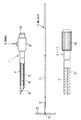
図1〜図5は第1の実施例を示し、図1は吊り上げ具を示し、図2〜図5は吊り上げ具の使用状態を示す。図1に示すように、吊り上げ具は、穿刺針1と、牽引部材2およびシース3とから構成されている。
【0015】
穿刺針1は、内腔4を有する針本体5を有しており、その先端部には生体の体壁、臓器等に穿刺できるように先端を尖らせたステンレス材料等の先端チップ6が固定されている。針本体5の外周面は熱収縮性チューブまたは絶縁塗料等の絶縁部材7によって被覆されており、針本体5および絶縁部材7は手元側本体8に接続固定されている。
【0016】
前記手元側本体8の側部には針本体5を介して先端チップ6に電気的に接続される電源コード接続ピン9が突設されており、先端チップ6に高周波電源を流せるようになっている。また、手元側本体8の基端部にはゴムキャップ10が着脱可能に設けられている。
【0017】
前記牽引部材2は、穿刺針1の内腔4に挿通可能な棒状体からなる絶縁製の操作棒11を有しており、この操作棒11の先端部にはワイヤ12を介してバー13が設けられている。このバー13は細い棒状体で、その長手方向の中間部には貫通孔14が穿設され、この貫通孔14に前記ワイヤ12が挿通されている。なお、ワイヤ12に代って生体吸収性糸で接続してもよく、また操作棒11とワイヤ12とは着脱可能な連結機構によって両者を着脱できる構成であってもよい。
【0018】
前記シース3は、硬性パイプ15と、この硬性パイプ15の基端部に回転自在に設けられた固定部材16とから構成されている。硬性パイプ15の内腔としての貫通孔17は前記牽引部材2を挿通可能であり、また固定部材16を回転することにより、貫通孔17の内径を縮径し、挿通された牽引部材2を所望位置で固定することができる。
【0019】
したがって、牽引部材2は、操作棒11とバー13とを一直線状態にすることにより、穿刺針1の内腔4およびシース3の貫通孔17に挿通可能であり、牽引部材2を穿刺針1に挿通したときには操作棒11とゴムキャップ10との間で気密が保てるようになっている。
【0020】
次に、前述のように構成された吊り下げ具の作用について説明する。
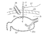
図2に示す、20は生体の腹壁であり、腹腔21の内部の胃22には内視鏡23が挿入されている。まず、内視鏡23によって胃22の内部に送気して胃22を膨らませる。一方、腹壁20にトラカール24を挿入し、このトラカール24を介して腹腔鏡25を腹腔21に挿入する。このとき、胃22の内部には内視鏡23が挿入され、その先端構成部の照明窓から照明光が胃壁22aへ照射されているため、胃壁22aを透けて内視鏡23の照明光を観察することにより、胃壁22aに発生した癌細胞等の患部26の位置を確認することができる。
【0021】
そこで、牽引部材2を内装し、電源コード接続ピン9に高周波電源コード27を接続した穿刺針1を、腹壁20に穿刺し、さらに確認した患部26の近傍に位置する胃壁22aに引き続き穿刺する。この穿刺に際しては、高周波電源コード27から高周波電流を通電することにより、電源コード接続ピン9から針本体5を介して先端チップ6に高周波電流が流れ、高周波切開を行いつつ穿刺することにより容易に穿刺できる。
【0022】
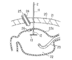
次に、図3に示すように、穿刺針1のみを腹壁20から抜去すると、穿刺針1によって開けられた腹壁20の孔に牽引部材2は留置される。この場合、牽引部材2は穿刺針1およびシース3の2倍以上の長さがあるので、シース3を挿入する時、硬性パイプ15の先端が腹壁20内へ入る前に、シース3の手元側から操作棒11が突出するので、操作棒11を腹腔21内へ落し込む恐れがない。牽引部材2のバー13が胃22の内部に入ると、バー13は貫通孔14の部分を支点として回動して安定する。この状態で、内視鏡23の吸引作用により胃22の内圧を減圧する。
【0023】
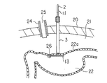
次に、図4に示すように、腹壁20から突出している牽引部材2の操作棒11にシース3の貫通孔17を嵌合し、操作棒11をガイドにしてシース3を腹腔21内に挿入する。そして、硬性パイプ15の先端面とバー13との間で胃壁22aを挟み、この状態で、固定部材16を回転すると、固定部材16により貫通孔17が縮径され、操作棒10と硬性パイプ15とが固定される。
【0024】
次に、図5に示すように、牽引部材2とシース3との組立体を術者が腹壁20の外部で操作して胃22を動かすことができる。このとき、トラカール28を介して腹腔21に挿入したアンビル29aとカートリッジ29bとからなるリニアカッター29との協同作業により胃22の切除ライン30とリニアカッター29の軸を合わせて切除する。
【0025】
切除した胃22をトラカール28より挿入した鉗子(図示しない)によって把持し、固定部材16を逆方向に回転して操作棒11をフリーにし、シース3を腹壁20から抜去する。鉗子、切除した胃片および牽引部材2をトラカール28より抜去する。なお、ワイヤ12に代って生体吸収性糸にした構成の場合には、鉗子によって切断後、切除した胃片のみを回収する。そして、残胃の切除ライン30からの出血の有無を確認し、必要に応じて高周波凝固、止血剤の散布、フィブリンのりの散布等を行う。
【0026】
また、本手術中、胃22内への送気が十二指腸へ漏れ、十二指腸、空腸が膨らんで手術を妨げることを防止するために、予め十二指腸内にバルーンを留置する、あるいは十二指腸を外側から鉗子にてクランプしてもよい。
【0027】
また、本実施例は胃について述べたが、他の管腔、例えば大腸、小腸等にも同様に適応できる。さらに、本実施例では牽引部材は1個であったが、複数個用いてもよい。1個の場合は点での吊り上げとなるが、2個の場合は線で、3個以上の場合は面での吊り上げができる。これは切除予定部位の大きさにより使い分ける。
【0028】
また、高周波を使用しない場合は、穿刺針が粘膜を穿刺する前に胃前壁側から伸びた粘膜が後壁側に接触し、その後、前壁側の粘膜が穿刺され、引き続き後壁を穿刺、場合によっては貫通して胃の向う側へ到達することもあった。この場合には予想外に臓器、血管等を損傷する恐れがあったが、前記実施例によれば、胃壁、腹壁への穿刺を高周波切開により行うために、穿刺力量が軽く、急突き出しとなることがないので、予想外に血管、臓器等を損傷する恐れがなく安全である。特に胃壁については、粘膜が伸びる前に粘膜を穿刺できる。
【0029】
図5において、シース3の硬性パイプ15は充分な強度を持っているため、胃22の方向を自由自在に3次元的に動かすことができる。このため、切除したい患部26に対して必要最少限の組織の切除を行うことができる。したがって、手術後、残胃を大きくとることができるので、胃22の機能温存ができる。
【0030】
特に胃の幽門、噴門付近については、切除量が多いと狭窄を起こす恐れがあるが、本実施例のシース3によればこの恐れが少なくなる。患部26の位置によっては胃22を挙上する際、胃22と周囲組織の癒着が邪魔をして挙上できない場合がある。この場合、腹腔21内へ挿入した鉗子や超音波吸引装置等により、癒着を剥離する必要があるが、このときにもシース3の3次元的操作により、癒着部に適度な張力(カウンタートラクション)をかけることができるので、剥離操作が簡単になる。
【0031】
図6および図7は第2の実施例を示し、第1の実施例と同一構成部分は同一番号を付して説明を省略する。図6に示すように、シース3の硬性パイプ15の先端には切欠部31が設けられているとともに、硬性パイプ15の手元側に切欠部31の弧面に対応して指標32が設けられている。
【0032】
本実施例によれば、バー13と硬性パイプ15との間で胃壁22aを挟み込んで固定部材16により操作棒11とシース3を固定する際、図7に示すように、切欠部31とバー13を固定することができ、その際、腹壁20の外部で指標32を直視にて確認することができる。
【0033】
また、牽引部材2とシース3の組立体を腹壁20の外部にて操作して胃22を動かし、リニアカッター29との協同作業により、バー13の長手軸とリニアカッター29の軸を同一平面上に位置させることにより胃22をリニアカッター29のアンビル29a、カードリッジ29b間に引き込み易くなる。
【0034】
本実施例によれば、腹腔21の外で直視下にてリニアカッター29を挿入しているトラカール28の方向へ、硬性パイプ15の指標32を向けることにより容易に上記位置関係をとることができ、手術が迅速かつ確実に行える。
【0035】
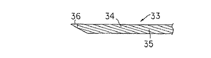
図8は第3の実施例を示し、穿刺針33の針本体34の外周面に絶縁塗装またはコーティング等により絶縁材35を設けたものである。また、第1の実施例では先端チップ6は穿刺針1の外径と同じであったが、本実施例では先端チップ36を穿刺針1の外径より小さく形成している。
【0036】
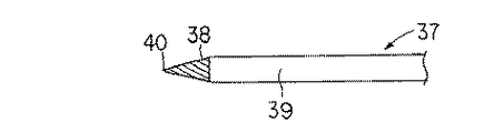
図9は第4の実施例を示し、穿刺針37を内針38と外筒39とから構成したものである。外筒39は絶縁材料によって形成されており、内針38も先端チップ40を除き、外周面が絶縁材で被覆されている。
【0037】
第3および第4の実施例によれば、胃壁への通電穿刺時、先端チップ36、40によって穿刺針33,37の外径より小さい孔を開けることができる。したがって、穿刺針33,37を抜去した後のシース3の挿入時にシース3の外周面に組織が密着し、胃の内腔を膨らませるガス等の漏れを防止できる。また、シース3を構成する硬性パイプ15の先端とバー13との間で胃壁を挟み込む際に、孔が大きいと硬性パイプ15の外径を大きくとる必要があり、侵襲が大きかったが、この点でも改善される。
【0038】
図10は第5の実施例を示し、41は牽引部材で、この第1の実施例に比較して操作棒42を短くし、操作棒42をシース3と組み合わせたときに固定部材16に相当する部分の長さとして、この操作棒42の手元側にガイドワイヤ状の操作ワイヤ43を連結したものである。
【0039】
図11は第6の実施例を示し、44は牽引部材で、第5の実施例の操作棒42を設けずに、ガイドワイヤ状の操作ワイヤ45のみで構成したものである。
本実施例によれば、組織を切除完了後、その切除片を体外へ取り出す際に操作ワイヤ43、45が柔軟であるため取り出し易いという効果がある。
【0040】
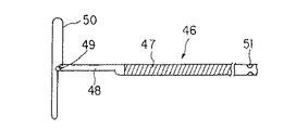
図12および図13は第7の実施例を示し、46は牽引部材で、フレキシブルコイル47とこの先端に連結された先端部材48とによって構成されている。先端部材48にはヒンジピン49によってバー50が回動自在に連結されており、またフレキシブルコイル47の手元側にはバー50の方向を指示する指標51が設けられている。本実施例によれば、シース3と組合わせることなくバー50の方向性を確認できる。
【0041】
図14〜図18は第8の実施例を示し、図14は吊り上げ具を示す。この吊り上げ具は、穿刺針61と牽引部材は62およびシース63とから構成されている。穿刺針61は内腔64を有する針本体65を有しており、この針本体65は外径が約φ2.8mmの太さを有している。針本体65の先端部は生体の体壁、臓器等に穿刺できるように先端を尖らせた先端チップ66を有している。
【0042】
針本体65の外周面は透明な熱収縮性チューブである絶縁部材67によって被覆されており、針本体65と絶縁部材67は手元側本体68に接着固定されている。
【0043】
手元側本体68はポリカーボネート、ポリスチレン等の透明度の高いプラスチック素材から作られている。図15に示すように、手元側本体68の側部には針本体65を介して先端チップ66に電気的に接続される電源コード接続ピン69が突設されており、先端チップ66に高周波通電できるようになっている。さらに、手元側本体68の側部には電源コード接続ピン69を収容する凹陥部81aを有した突部81が設けられている。そして、電源コード接続ピン69と凹陥部81aの内周壁との間にはクリアランス82があり、電源コードを取り付けても水が溜まらないよう寸法関係になっている。
【0044】
手元側本体68の基端部にはゴムキャップ70が着脱可能に設けられている。このキャップ70には蓋79が設けられ、この蓋79を装着している状態では前記穿刺針61の手元側の気密を保つことができる。なお、穿刺針61は約250mmの全長を有する。
【0045】
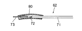
図14に示すように、前記牽引部材62は穿刺針61の内腔64に挿通可能な太さを有する操作棒71と操作棒71の先端部にワイヤ72を介してロッド73が設けられている。ロッド73の太さはφ1mm程度の細い硬性の棒状体で長さは約10〜50mmである。ロッド73の長手方向の中間部には貫通孔74が穿設され、この貫通孔74にワイヤ72が挿通されている。なお、ワイヤ72には1−0号もしくは1号の太さの縫合糸等の非伝導素材を用いている。
【0046】
牽引部材62は使用前の初期状態では図16に示すように、操作棒71とロッド74を略一直線に配置するためガイドチューブ80を操作棒71からロッド73に亘って被覆している。ガイドチューブ80には曲率半径を持った曲り癖が付いているため通常は外れないが、使用時には容易に外れる力量で装着されている。
【0047】
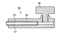
なお、操作棒71の長さは約450mmであり、太さは約φ1.5mmである。また、穿刺針61へゴムキャップ70の蓋79を外して牽引部材62を挿通したときはゴムキャップ70の内径より大きいためガイドチューブ80はゴムキャップ70へ挿通できないようになっている。また、図17に示すように、前記シース63は硬性パイプ75と手元側本体76が接着固定されたものである。このシース63の内腔77は牽引部材62の操作棒71を挿通できる径を有し、硬性パイプ75の外径は約φ3.5mmであり、穿刺針61の挿入部の外径より若干太くなっている。
【0048】
また、手元側本体76の側部にはねじにより手元側本体76と螺合する固定部材78が装着されている。固定部材78の先端は手元側本体76の内腔へ突没可能であるため、手元側本体76の内腔へ牽引部材62の操作棒71を挿通している場合は固定部材78を操作棒71へ押し当て牽引部材62とシース63を摩擦固定できるようになっている。なお、シース63の全長は約250mmである。
【0049】
次に作用について図18および図19に基づいて説明する。胃86には内視鏡87を挿入しており、腹腔84から胃86を観察できるようトラカール88を介して腹腔鏡89を導入する。そして、穿刺針61を第1の実施例と同様に患部90の近傍位置に腹壁83、胃壁85へ穿刺する。
【0050】
ゴムキャップ70の蓋79を開けてガイドチューブ80を装着した牽引部材62を操作棒71を押して穿刺針61へ挿通する。このとき、ガイドチューブ80はゴムキャップ70へ挿通できない。ロッド73、ワイヤ72、操作棒71が穿刺針61内を挿通し、ロッド73が穿刺針61の先端から突出するまで操作棒71を押す。ロッド73を胃内へ突出させた後、ガイドチューブ80と穿刺針61とを抜去する。
【0051】
次に、シース63を牽引部材62の操作棒71へ外挿し、硬性パイプ75を腹腔84内へ挿入する。硬性パイプ75の先端とロッド73の間に胃壁を挟み込む位置で手元側本体76と螺合している固定部材78を回して操作棒71の側面へ固定部材78の先端を押し付け、牽引部材62と操作棒71の両者を摩擦固定する。その他については第1の実施例と同様であり、説明を省略する。
【0052】
本実施例によれば、次のような効果が得られる。
a,電源コード接続ピンと針本体の接続を手元側本体を介して接着のみで行っているため安価である。
b,手元側本体が透明な材質であるため、電源コード接続ピンと針本体の接着状態の確認ができる。
c.ロッドと操作棒を絹糸で接続したため胃の部分切除を行った後、腹腔内で容易に絹糸の途中を鋏鉗子で切除できる。したがって、切除片を容易に回収でき、手技が簡便になる。また、絹糸のような非導電素材を用いているため、例えば操作棒に高周波処置具が接触してもロッドへは通電されず安全であり、またきれいな切除片が採れる。
d,穿刺針の手元側本体に開閉自在なゴムキャップを設けたため、穿刺針を穿刺するとき腹腔内や胃内からのガス漏れがなく手術をスムーズに進めることができる。
e,曲り癖のあるガイドチューブを使用したため安価であり、ロッドと操作棒を略直線上に配置でき、操作性が向上する。
f,シースの手元側本体に透明な素材を用いたため組立て上、硬性パイプと手元側本体の接着性を確認できる。また、術中、牽引部材の操作棒と固定部材の接触状態を確認できる。
g,牽引部材の操作棒を硬性にしたため牽引部材の穿刺針内への挿入性が向上し、また牽引部材とシースの固定も容易にできる。シースの挿入部の外径は穿刺針の挿入部の外径より大きいため腹腔内のガスが腹腔から漏れることがない。また、穿刺針で胃壁に開けた孔へシース先端が入らないためロッドと硬性パイプの間に胃壁を挟み込むことができる。したがって、シース先端が胃内に入り込み患部に接触して例えば癌等の悪性腫瘍を腹腔内に巻き散らすことがなく安全である。
h,穿刺針、シースは全長約250mmで有るため、胃の後壁へアプローチできる。
【0053】
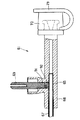
図20は第9の実施例を示し、穿刺針61の手元側本体68の側面には軸方向と垂直に内腔まで到達する孔68aが穿設されている。電源コード接続ピン69の基端部にはねじ部91を有しており、手元側本体68の孔68aの径は電源コード接続ピン69のねじ部91の谷径と略同等に形成されている。
【0054】
手元側本体68はプラスチック材料からなっており、電源コード接続ピン69をねじ込んでいくと、手元側本体68の孔68aが削られ、セルフタップねじが作られる。そして、電源コード接続ピン69の基端部を針本体65に突き当たるまでねじ込むことにより手元側本体68に対して電源コード接続ピン69を固定できる。
【0055】
作用は第8の実施例と同様であり、効果は第8の実施例の効果に加え、穿刺針の組立てが容易かつ確実にでき安価に提供できる。
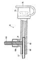
図21は第10の実施例を示し、穿刺針61において、電源コード接続ピン69と針本体65の間に金属製のコイルスプリングである弾性部材からなる導電部材92を設けた構造であり、他は第8の実施例と同様である。
【0056】
なお、導電部材92は金属製の板ばね、導電性シリコン、アルミ箔等の導電性材質からなり、多少なりとも弾性がある、もしくは容易に塑性変形するものであれば何でもよい。
【0057】
作用は第8の実施例と同様であり、効果は第8の実施例の効果に加え、導電部材を電源コード接続ピンと針本体の間に設けたため、より確実に導通でき、また経時的変化に対してもより導通を確実に確保できる。
【0058】
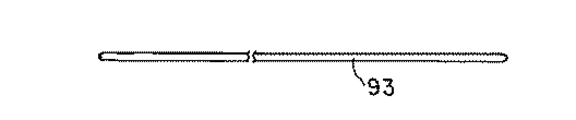
図22および図23は第11の実施例を示し、第8の実施例に、図22に示すようなプラスチックやセラミック等の絶縁材質からなる中実のガイド棒93を追加したものである。
【0059】
図23に示すように、穿刺針61を腹壁83に刺入し、穿刺針61の先端を腹腔84内まで挿入する。穿刺針61の内腔に手元側から前記ガイド棒93を挿通し、穿刺針61の先端よりガイド棒93を突出させる。ガイド棒端部94を胃壁85に押し当て、胃壁85をへこませて押し当てた位置を胃86内の内視鏡87で観察し、穿刺位置を確認する。その後、ガイド棒93に沿って穿刺針61を胃壁85へ刺入する。
【0060】
その他は、第8の実施例と同様であり、効果は第8の実施例の効果に加え、穿刺針の胃への刺入位置をガイド棒により安全確実に確認できるため穿刺針の刺入が容易となる。ガイド棒は絶縁材質からなるため穿刺針の通電刺入時にも電気的に安全である。
【0061】
図24は第12の実施例を示し、ガイド棒95はステンレス等の金属からなる硬性ロッド96を被覆チューブ97で被覆しており、両方の端面98は接着剤を充填している。したがって、全体として絶縁されている。
【0062】
作用は第11の実施例と同様であり、効果は第11の実施例の効果に加え、ガイド棒の中に硬性ロッドを挿入したため、よりガイド棒が折れや曲りに対して強く、したがって、より安全、確実に穿刺位置を確認できる。
【0063】
前述した第11の実施例の構成品である穿刺針61、牽引部材62、シース63、ゴムキャップ70、ガイド棒93を滅菌済の使い捨て処置具としてセットで梱包しようとすると、従来、全ての構成品を1つのトレーに収容する必要がある。この場合、各構成品を梱包状態で固定しなければならないため、トレーには凹凸が多くなる。したがって、トレーの形状が複雑となり、値段の高いものとなった。また、滅菌前の洗浄工程においてトレーに凹凸が多くため洗浄しにくい問題があった。
【0064】
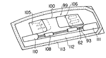
第13の実施例は前述のような問題を解決したものであり、図25および図26は第11の実施例の構成品である穿刺針61、牽引部材62、シース63、ゴムキャップ70、ガイド棒93を滅菌済の使い捨て処置具としてセットで梱包した状態を示す。
【0065】
図25に示すようにトレー99は各構成品を収容するためポリスチレン、ポリプロピレン等の樹脂もしくはボール紙等の薄板からなるトレー本体100によって形成されている。トレー本体100の幅方向の一側部には広幅部100aに、他側部には狭幅部100bに形成されている。広幅部100aの中央部を残して両端部には山折りの折曲部101によって傾斜面102が形成され、折曲部101の一方の角部にはスリット103が形成され、傾斜面102には互いに対向する複数の孔104が穿設されている。さらに、広幅部100aの長手方向の両端部には谷折りの第1と第2の折返し部105,106が設けられ、第1の折返し部105には前記スリット103に差込まれる突片107が設けられている。
【0066】
また、前記トレー本体100の狭幅部100bには長手方向に離間して2箇所に円弧状の凸条部108が形成され、この凸条部108の両端には孔109が形成されている。さらに、狭幅部100bの長手方向の両端部には谷折りの第3と第4の折返し部110,111が設けられている。
【0067】
そして、前記穿刺針61、シース63の挿入部は前記孔104に挿通することにより上下左右方向への動きが規制されている。この場合、手元側操作部、把持部の外径は孔104の径より大きいため、手元側操作部、把持部は孔104を通過できないようになっている。なお、折曲部はいくつ設けてもよい。
【0068】
穿刺針61、シース63の先端側に位置する第1の折返し部105に設けられた突片107はスリット103へ差込むことにより容易に外れないようにでき、穿刺針61の先端を保護するとともに穿刺針61、シース63の先端側への移動を規制している。また、第2の折返し部106を折返すことにより、穿刺針61、シース63の手元側操作部、把持部を覆い保護すると共に、穿刺針61、シース63の手元側への移動を規制している。また、ゴムキャップ70は穿刺針61、シース63の手元側の間に配置している。
【0069】
牽引部材62、ガイド棒93は孔109へ挿通することにより、上下左右方向への動きが規制されている。また、第3の折返し部110、第4の折返し部111を折返すことにより、牽引部材62、ガイド棒93の軸方向への移動を規制している。
【0070】
図26に示すものは、前記各構成品を収容したトレー99をピールパック112に収容し、周囲をヒートシールによってヒートシール部113を設けて密封した状態を示す。なお、ピールパック112はエチレンオキサイトガス滅菌に一般的に使用される袋である。
【0071】
なお、本実施例では大きく4つの構成品を収容しているが、さらに数多くの構成品を収容することもできる。
このように各構成品をトレー99の孔104,109へ挿通し、上下左右方向への動きを規制するとともに、ゴムキャップ70を穿刺針61、シース63の手元側の間に配置し、第1〜第4の折返し部105,106,110,111を折返し、軸方向への動きを規制している。また、各構成品を収容したトレー99をピールパック112内に入れて周囲をヒートシールしている。
【0072】
実際に本吊り上げ具を使用する場合においては、不潔領域のユーザーがトレー99のみを取り出し、清潔領域内でトレー99の第2の折返し部106、第4の折返し部111を開けて各構成品をトレー99から抜き取ることができる。
【0073】
本実施例によれば、次の効果がある。
a,トレーを薄板から製作できるため安価であり、使い捨てに好適する。
b,各構成品をトレーの孔に挿通し、トレーの両端部を折返しているため、収容物の位置決め、固定ができ、輸送中や取り出し時に各構成品が破損することがない。また、折返すことにより、穿刺針の先端の保護ができ、緩衝性も向上するため、さらに各構成品が破損することがない。
【0074】
c,各構成品を収容状態でトレーの厚さを最大限に薄くでき、ピールパック内の容積を最小限にできるため、ガス滅菌を効率よくできる。つまり、容積が小さくなるため、一度に数多く滅菌できるため安価となる。
【0075】
d,各構成品をトレーに収容しているため、実際に使用する場合、一度に全てのものを不潔領域から清潔領域へ移せるため、簡便で確実である。
前記実施態様によれば、次のような構成が得られる。
【0076】
(付記1)内腔を有する穿刺針と、この穿刺針の内腔に挿通自在で生体組織を牽引可能な牽引部材と、この牽引部材を挿通自在な内腔を有し前記牽引部材を固定可能なシースとを具備したことを特徴とする吊り上げ具。
【0077】
(付記2)前記穿刺針は、絶縁部材によって被覆された針本体の先端部に導電性の先端チップを有していることを特徴とする付記1記載の吊り上げ具。
(付記3)前記絶縁部材は、熱収縮チューブであることを特徴とする付記2記載の吊り上げ具。
(付記4)前記絶縁部材は、絶縁塗装であることを特徴とする付記2記載の吊り上げ具。
【0078】
(付記5)前記熱収縮チューブは、テフロン、シリコン、ポリウレタン、ポリエチレン等であることを特徴とする付記3記載の吊り上げ具。
(付記6)前記先端チップは、ステンレス材料で形成されていることを特徴とする付記2記載の吊り上げ具。
(付記7)前記穿刺針は、手元側に高周波電源と接続される電源コード接続ピンが設けられていることを特徴とする付記1記載の吊り上げ具。
【0079】
(付記8)前記牽引部材は、操作棒と、この操作棒の先端部に回動自在に設けられたバーとから構成されていることを特徴とする付記1記載の吊り上げ具。
(付記9)前記操作棒とバーとは、同一材料により構成されていることを特徴とする付記8記載の吊り上げ具。
(付記10)前記操作棒とバーとは、ステンレス材料により構成されていることを特徴とする付記9記載の吊り上げ具。
(付記11)前記操作棒とバーとは、合成樹脂材料により構成されていることを特徴とする付記9記載の吊り上げ具。
【0080】
(付記12)前記バーは、生体吸収性材料により構成されていることを特徴とする付記8記載の吊り上げ具。
(付記13)前記操作棒とバーとは、線状部材で接続されていることを特徴とする付記8記載の吊り上げ具。
(付記14)前記線状部材は、ワイヤであることを特徴とする付記13記載の吊り上げ具。
(付記15)前記線状部材は、絹、ナイロン、生体吸収性ポリ乳酸、グリコール酸、ポリシオキサノン等の手術用縫合糸であることを特徴とする付記13記載の吊り上げ具。
【0081】
(付記16)前記線状部材は、バーの貫通孔に挿通されていることを特徴とする付記14,15記載の吊り上げ具。
(付記17)前記シースは、内腔を有する硬性パイプと、この硬性パイプに設けられ前記内腔を縮径可能な固定部材とから構成されていることを特徴とする付記1記載の吊り上げ具。
(付記18)前記シースは、先端に切欠部を有することを特徴とする付記1記載の吊り上げ具。
【0082】
(付記19)前記シースは、切欠部の向きに対応する指標を有することを特徴とする付記18記載の吊り上げ具。
(付記20)前記指標は、シースの手元側に設けられていることを特徴とする付記19記載の吊り上げ具。
(付記21)前記穿刺針の針本体と電源コード接続ピンを接着剤のみで接続したことを特徴とする付記1記載の吊り上げ具。
(付記22)前記穿刺針の電源コード接続ピンと本体をセルフタップねじにて接続固定したことを特徴とする付記1記載の吊り上げ具。
【0083】
(付記23)前記穿刺針の本体は透明な材質を使用したことを特徴とする付記1記載の吊り上げ具。
(付記24)前記シースは内腔を有する硬性パイプと、この硬性パイプの手元側に接続した内腔を有する本体と、この本体の側面に本体と螺合し、先端が内腔へ突出可能な固定部材とからなることを特徴とする付記8記載の吊り上げ具。
(付記25)前記シースの本体は透明な材質を使用したことを特徴とする付記24記載の吊り上げ具。
(付記26)前記シースの硬性パイプの外径を穿刺針の針本体の外径より大きくしたことを特徴とする付記1記載の吊り上げ具。
【0084】
(付記27)前記穿刺針と前記シースの全長を200mm以上にしたことを特徴とする付記1記載の吊り上げ具。
(付記28)前記牽引部材の操作棒の長さを、少なくとも前記穿刺針と前記シースの全長より200mm長くしたことを特徴とする付記1記載の吊り上げ具。
(付記29)前記穿刺針へ挿通自在なガイド棒を有していることを特徴とする付記1記載の吊り上げ具。
(付記30)前記ガイド棒は、絶縁材質からなることを特徴とする付記29記載の吊り上げ具。
(付記31)前記絶縁材質は、テフロン、ナイロン、ABS等のプラスチックもしくはセラミックであることを特徴とする付記30記載の吊り上げ具。
(付記32)前記ガイド棒は、硬性線材に絶縁部材を被覆していることを特徴とする付記29記載の吊り上げ具。
(付記33)前記硬性線材は、ステンレス、アルミニウム等の金属からなることを特徴とする付記32記載の吊り上げ具。
(付記34)前記絶縁部材は、テフロン、シリコン、ポリウレタン、ポエチレン等の樹脂チューブであることを特徴とする付記32記載の吊り上げ具。
(付記35)前記絶縁部材は、絶縁塗装であることを特徴とする付記32記載の吊り上げ具。
(付記36)前記穿刺針の針本体と電源コードの間に導電部材を入れたことを付記1記載の吊り上げ具。
(付記37)前記導電部材は、弾性を有することを特徴とする付記36記載の吊り上げ具。
(付記38)前記導電部材は金属製の板ばね、コイルばね、アルミ箔、導電性シリコンデアルことを特徴とする付記36記載の吊り上げ具。
【0085】
【発明の効果】
以上説明したように、この発明によれば、生体組織を牽引する操作を行う、硬性な棒状部材からなる操作部材を備え、操作部材とバーを分離することが可能であるため、牽引の対象となっている生体組織の部分切除を行った後に接続部材により、操作部材とバーを分離でき、切除片を容易に回収でき、手技が簡便になるという効果がある。
【図面の簡単な説明】
【図1】この発明の第1の実施例を示す吊り上げ具の一部切欠した側面図。
【図2】同実施例の吊り上げ具の作用説明図。
【図3】同実施例の吊り上げ具の作用説明図。
【図4】同実施例の吊り上げ具の作用説明図。
【図5】同実施例の吊り上げ具の作用説明図。
【図6】この発明の第2の実施例を示すシースの側面図。
【図7】同実施例のシースの作用を説明するための一部切欠した側面図。
【図8】この発明の第3の実施例を示す穿刺針の側面図。
【図9】この発明の第4の実施例を示す穿刺針の側面図。
【図10】この発明の第5の実施例を示す牽引部材の側面図。
【図11】この発明の第6の実施例を示す牽引部材の側面図。
【図12】この発明の第7の実施例を示す牽引部材の側面図。
【図13】同実施例の牽引部材の側面図。
【図14】この発明の第8の実施例を示す吊り上げ具の側面図。
【図15】同実施例の穿刺針を示す一部切欠した側面図。
【図16】同実施例の牽引部材を示す側面図。
【図17】同実施例のシースを示す縦断側面図。
【図18】同実施例を示す牽引部材および穿刺針の使用状態図。
【図19】同実施例を示す牽引部材および穿刺針の使用状態図。
【図20】この発明の第9の実施例の穿刺針を示す一部切欠した側面図。
【図21】この発明の第10の実施例の穿刺針を示す一部切欠した側面図。
【図22】この発明の第11の実施例のガイド棒の側面図。
【図23】同実施例のガイド棒の使用状態図。
【図24】この発明の第12の実施例のガイド棒の縦断側面図。
【図25】この発明の第13の実施例のトレーの展開状態の斜視図。
【図26】同実施例のトレーをピールパックに収納した状態の斜視図。
【符号の説明】
1…穿刺針、2…牽引部材、3…シース。[0001]
[Industrial applications]
The present invention relates to a lifting device for lifting an organ, such as a stomach or intestine, during endoscopic surgery.
[0002]
[Prior art]
Stomach, intestinal and other organs under endoscopic surgery, for example, when removing an affected part such as a cancer cell that has occurred in a part of the stomach wall, a stomach wall around the affected part by a lifting tool inserted through the abdominal wall and inserted into the abdominal cavity. In this state, the stomach wall is excised by a linear cutter inserted into the abdominal cavity via a trocar or the like.
[0003]
The lifting device is known in Japanese Patent Application Laid-Open No. Hei 4-226676, U.S. Pat. No. 5,112,310, and U.S. Pat. No. 5,123,914. In general, a local part of the stomach is lifted by the following procedure. Partial resection is performed.
[0004]
(1) Insert the stomach endoscope into the stomach and inflate the stomach by means of the endoscope air supply.
(2) The illuminating light of the gastroscope is checked from the abdominal wall side by a laparoscope, and a puncture needle is punctured into the abdominal wall and the stomach wall (anterior wall) in that order and introduced into the stomach.
[0005]
(3) A T-fastener is previously provided inside the puncture needle, and the T-fastener is removed from the puncture needle, and only the puncture needle is removed. T-fasteners and threads remain in the stomach.
[0006]
(4) Pull the thread outward from the abdominal wall side (outside the body). Prior to this, air in the stomach should be removed to some extent. The scheduled resection of the stomach is raised.
(5) An endoscopic surgical linear cutter is inserted into the abdominal cavity from a trocar inserted and placed from another part of the abdominal wall.
(6) After the to-be-removed portion of the stomach raised is drawn between the cartridge and the anvil of the linear cutter, the linear cutter is operated to locally resect the stomach.
[0007]
[Problems to be solved by the invention]
However, when a local stomach is lifted using a conventional technique and a local resection of the stomach is performed, in the step (2), when a puncture needle is punctured into the stomach, the mucous membrane (of the anterior wall) of the stomach is removed. The puncture needle is difficult to cut and the mucous membrane is elongated. For this reason, the puncture needle is punctured only after the mucous membrane of the anterior wall of the stomach extends until it almost touches the mucous membrane of the posterior wall. Therefore, the puncture needle may suddenly protrude, possibly causing damage to the posterior wall of the stomach.
[0008]
The anterior wall of the stomach can be punctured after confirming the presence or absence of a blood vessel under the illumination light of a gastroscope, but since the posterior wall is unknown, there is a risk of puncturing the blood vessel. Further, there is a fear that blood vessels, organs, and the like behind the stomach may be damaged through the rear wall.
[0009]
Also, when raising the stomach in the step (6), the thread is naturally soft, so the raising direction is determined by the position pierced in the abdominal wall and the two points pierced in the stomach. Therefore, when the portion to be resected of the stomach is drawn between the anvil of the linear cutter and the cartridge, the stomach only moves between these two points due to the tension of the thread, and the only operation is the end cutter. For this reason, the operability is poor, it takes a long time for the operation, and it is difficult to take a desired resection line, and there is a fear that a part that does not need to be resected may be resected.
[0010]
The present invention has been made in view of the above circumstances, and the object thereof is to: The operating member and the bar can be separated, and the resected piece of the living tissue can be easily collected and the procedure is simplified. It is to provide a lifting device.
[0011]
[Means for Solving the Problems]
In order to achieve the above object, the present invention provides an operation for pulling a living tissue. Consisting of a rigid rod-shaped member An operating member and a bar towed by the towing operation of the operating member When, A lifting tool comprising: the operating member and a connecting member that connects the bar so as to be separable.
A second aspect of the present invention has a through hole according to the first aspect, through which the operation member can be inserted. The operation member inserted into the through hole can be fixed. Sheath and More It is characterized by having.
[0012]
[Action]
For example, when lifting the stomach wall, a puncture needle containing a traction member is punctured into the abdominal wall, and further punctured into the stomach wall located near the confirmed affected part. At the time of this puncture, a high-frequency current flows through the tip of the puncture needle by supplying a high-frequency current as necessary, and puncture is performed while performing high-frequency incision.
[0013]
Next, only the puncture needle is withdrawn from the abdominal wall, the traction member placed in the hole of the abdominal wall and stomach wall opened by the puncture needle is towed, and then the sheath is fitted to the traction member protruding from the abdominal wall, Insert the sheath into the abdominal cavity. Then, the stomach wall is sandwiched and fixed between the sheath and the traction member.
[0014]
【Example】
Hereinafter, embodiments of the present invention will be described with reference to the drawings.
1 to 5 show a first embodiment, FIG. 1 shows a lifting device, and FIGS. 2 to 5 show a use state of the lifting device. As shown in FIG. 1, the lifting device includes a puncture needle 1, a
[0015]
The puncture needle 1 has a needle main body 5 having a
[0016]
A power
[0017]
The
[0018]
The
[0019]
Therefore, the
[0020]
Next, the operation of the hanging device configured as described above will be described.
In FIG. 2,
[0021]
Therefore, the puncture needle 1 having the
[0022]
Next, as shown in FIG. 3, when only the puncture needle 1 is removed from the
[0023]
Next, as shown in FIG. 4, the through hole 17 of the
[0024]
Next, as shown in FIG. 5, the operator can operate the assembly of the
[0025]
The excised
[0026]
In addition, during this operation, in order to prevent the air supply into the
[0027]
Although the present embodiment has been described with reference to the stomach, the present invention can be similarly applied to other lumens, for example, the large intestine and the small intestine. Further, in the present embodiment, one traction member is used, but a plurality of traction members may be used. In the case of one piece, it can be lifted at a point, but in the case of two pieces, it can be lifted by a line, and in the case of three or more pieces, it can be lifted by a surface. This is used depending on the size of the site to be resected.
[0028]
When high frequency is not used, the mucosa extending from the anterior wall of the stomach comes into contact with the posterior wall before the puncture needle penetrates the mucous membrane, and then the mucosa on the anterior wall side is punctured, and then the posterior wall is punctured. In some cases, it penetrated to reach the other side of the stomach. In this case, there is a possibility that the organs, blood vessels, etc. may be unexpectedly damaged. However, according to the above-described embodiment, the puncture to the stomach wall and abdominal wall is performed by high-frequency incision, so that the puncture force amount is light and the protrusion is sudden. Since there is no risk, blood vessels, organs and the like are not unexpectedly damaged, so that it is safe. Particularly for the stomach wall, the mucosa can be punctured before the mucosa stretches.
[0029]
In FIG. 5, since the
[0030]
In particular, in the vicinity of the pylorus and cardia of the stomach, a large amount of resection may cause stenosis. However, according to the
[0031]
FIGS. 6 and 7 show the second embodiment. The same components as those in the first embodiment are denoted by the same reference numerals and description thereof is omitted. As shown in FIG. 6, a
[0032]
According to the present embodiment, when the operation rod 11 and the
[0033]
The
[0034]
According to the present embodiment, the above positional relationship can be easily obtained by directing the
[0035]
FIG. 8 shows a third embodiment, in which an insulating
[0036]
FIG. 9 shows a fourth embodiment, in which a
[0037]
According to the third and fourth embodiments, a hole smaller than the outer diameter of the puncture needles 33, 37 can be formed by the
[0038]
FIG. 10 shows a fifth embodiment.
[0039]
FIG. 11 shows a sixth embodiment, in which a pulling
According to the present embodiment, there is an effect that the
[0040]
12 and 13 show a seventh embodiment, in which
[0041]
14 to 18 show an eighth embodiment, and FIG. 14 shows a lifting device. This lifting device includes a
[0042]
The outer peripheral surface of the needle
[0043]
The hand side
[0044]
A
[0045]
As shown in FIG. 14, the
[0046]
In the initial state before use, the
[0047]
The length of the
[0048]
In addition, a fixing
[0049]
Next, the operation will be described with reference to FIGS. An
[0050]
The
[0051]
Next, the
[0052]
According to this embodiment, the following effects can be obtained.
a. It is inexpensive because the connection between the power cord connecting pin and the needle main body is performed only by bonding via the main body on the hand side.
b. Since the hand side main body is made of a transparent material, the state of adhesion between the power cord connecting pin and the needle main body can be checked.
c. Since the rod and the operating rod are connected by a silk thread, after a partial resection of the stomach, the middle of the silk thread can be easily removed in the abdominal cavity with scissors forceps. Therefore, the resected piece can be easily collected, and the procedure is simplified. In addition, since a non-conductive material such as silk thread is used, even if the high-frequency treatment tool comes into contact with the operation rod, for example, the rod is not energized and is safe, and a clean cut piece can be obtained.
d, since the rubber cap that can be opened and closed is provided on the proximal side body of the puncture needle, the operation can proceed smoothly without gas leakage from the abdominal cavity or stomach when puncturing the puncture needle.
e. Since the guide tube having a curl is used, it is inexpensive, and the rod and the operating rod can be arranged on a substantially straight line, so that the operability is improved.
(f) Since a transparent material is used for the proximal body of the sheath, the adhesiveness between the hard pipe and the proximal body can be confirmed upon assembly. Further, during the operation, the contact state between the operation rod of the traction member and the fixed member can be confirmed.
g. Since the operation rod of the traction member is made rigid, the insertability of the traction member into the puncture needle is improved, and the traction member and the sheath can be easily fixed. Since the outer diameter of the insertion portion of the sheath is larger than the outer diameter of the insertion portion of the puncture needle, gas in the abdominal cavity does not leak from the abdominal cavity. Further, the distal end of the sheath does not enter the hole formed in the stomach wall with the puncture needle, so that the stomach wall can be sandwiched between the rod and the hard pipe. Therefore, the sheath tip is safe because the malignant tumor such as cancer does not scatter into the abdominal cavity by the distal end of the sheath entering the stomach and contacting the affected part.
h, since the puncture needle and the sheath have a total length of about 250 mm, they can approach the posterior wall of the stomach.
[0053]
FIG. 20 shows a ninth embodiment. A hole 68a is formed in the side surface of the
[0054]
The hand-side
[0055]
The operation is the same as that of the eighth embodiment. In addition to the effects of the eighth embodiment, the puncture needle can be easily and reliably assembled and can be provided at a low cost.
FIG. 21 shows a tenth embodiment, in which a
[0056]
The
[0057]
The operation is the same as that of the eighth embodiment. The effect is the same as that of the eighth embodiment. In addition, since the conductive member is provided between the power cord connecting pin and the needle main body, the conduction can be performed more reliably, and the change over time can be prevented. On the other hand, conduction can be ensured more reliably.
[0058]
FIGS. 22 and 23 show the eleventh embodiment, in which a
[0059]
As shown in FIG. 23,
[0060]
The other points are the same as those of the eighth embodiment. In addition to the effects of the eighth embodiment, the insertion position of the puncture needle into the stomach can be confirmed securely and securely by the guide rod, so that the puncture needle can be inserted. It will be easier. Since the guide rod is made of an insulating material, it is electrically safe even when the puncture needle is inserted.
[0061]
FIG. 24 shows a twelfth embodiment, in which a
[0062]
The operation is the same as that of the eleventh embodiment. In addition to the effect of the eleventh embodiment, the rigid rod is inserted into the guide rod, so that the guide rod is more resistant to bending and bending, and therefore, more effective. The puncture position can be confirmed safely and reliably.
[0063]
When the
[0064]
The thirteenth embodiment solves the above-mentioned problem. FIGS. 25 and 26 show a
[0065]
As shown in FIG. 25, the
[0066]
In the
[0067]
The insertion portion of the
[0068]
The
[0069]
By inserting the
[0070]
FIG. 26 shows a state in which the
[0071]
In this embodiment, four components are stored. However, more components can be stored.
In this way, the components are inserted into the
[0072]
When actually using the lifting device, the user in the unclean area takes out only the
[0073]
According to this embodiment, the following effects can be obtained.
a. Since the tray can be manufactured from a thin plate, it is inexpensive and is suitable for disposable use.
b. Since each component is inserted into the hole of the tray and both ends of the tray are turned back, the contents can be positioned and fixed, and the components are not damaged during transportation or removal. In addition, by folding, the tip of the puncture needle can be protected and the cushioning property is improved, so that each component is not damaged.
[0074]
(c) Since the thickness of the tray can be reduced to the maximum while each component is stored and the volume in the peel pack can be minimized, gas sterilization can be performed efficiently. That is, since the volume is small, many can be sterilized at one time, and the cost is low.
[0075]
d. Since each component is stored in a tray, when it is actually used, all the components can be moved from the unclean area to the clean area at once, so that it is simple and reliable.
According to the embodiment, the following configuration is obtained.
[0076]
(Supplementary Note 1) A puncture needle having a lumen, a traction member that can be inserted into the lumen of the puncture needle and can pull a living tissue, and has a lumen that can insert the traction member and fix the traction member. A lifting device comprising a flexible sheath.
[0077]
(Supplementary note 2) The lifting device according to Supplementary note 1, wherein the puncture needle has a conductive tip at a distal end portion of the needle body covered with an insulating member.
(Supplementary note 3) The lifting device according to
(Supplementary note 4) The lifting device according to
[0078]
(Supplementary Note 5) The lifting device according to
(Supplementary note 6) The lifting device according to
(Supplementary note 7) The lifting device according to Supplementary note 1, wherein the puncture needle has a power cord connection pin connected to a high-frequency power supply at a hand side.
[0079]
(Supplementary Note 8) The lifting device according to Supplementary Note 1, wherein the traction member includes an operating rod and a bar rotatably provided at a tip end of the operating rod.
(Supplementary note 9) The lifting tool according to
(Supplementary note 10) The lifting device according to
(Supplementary note 11) The lifting device according to
[0080]
(Supplementary note 12) The lifting device according to
(Supplementary Note 13) The lifting device according to
(Supplementary note 14) The lifting device according to
(Supplementary note 15) The lifting device according to
[0081]
(Supplementary note 16) The lifting device according to
(Supplementary Note 17) The lifting device according to Supplementary Note 1, wherein the sheath includes a rigid pipe having a lumen and a fixing member provided in the rigid pipe and capable of reducing the diameter of the lumen.
(Supplementary note 18) The lifting device according to Supplementary note 1, wherein the sheath has a notch at a distal end.
[0082]
(Supplementary note 19) The lifting device according to supplementary note 18, wherein the sheath has an index corresponding to a direction of the notch.
(Supplementary note 20) The lifting device according to Supplementary note 19, wherein the indicator is provided on a hand side of the sheath.
(Supplementary note 21) The lifting device according to Supplementary note 1, wherein the needle main body of the puncture needle and a power cord connecting pin are connected only with an adhesive.
(Supplementary note 22) The lifting device according to supplementary note 1, wherein the power cord connection pin of the puncture needle and the main body are connected and fixed by a self-tapping screw.
[0083]
(Supplementary note 23) The lifting device according to Supplementary note 1, wherein the main body of the puncture needle uses a transparent material.
(Supplementary Note 24) The sheath is a rigid pipe having a lumen, a main body having a lumen connected to the proximal side of the rigid pipe, and screwed to the main body on a side surface of the main body, and a tip can protrude into the lumen. The lifting device according to
(Supplementary note 25) The lifting device according to
(Supplementary note 26) The lifting device according to Supplementary note 1, wherein the outer diameter of the rigid pipe of the sheath is larger than the outer diameter of the needle main body of the puncture needle.
[0084]
(Supplementary note 27) The lifting device according to supplementary note 1, wherein the total length of the puncture needle and the sheath is 200 mm or more.
(Supplementary note 28) The lifting device according to Supplementary note 1, wherein a length of the operation rod of the traction member is at least 200 mm longer than a total length of the puncture needle and the sheath.
(Supplementary note 29) The lifting device according to Supplementary note 1, further comprising a guide rod that can be inserted into the puncture needle.
(Supplementary note 30) The lifting device according to
(Supplementary note 31) The lifting device according to
(Supplementary note 32) The lifting device according to
(Supplementary note 33) The lifting device according to
(Supplementary note 34) The lifting device according to
(Supplementary note 35) The lifting device according to
(Supplementary note 36) The lifting device according to supplementary note 1, wherein a conductive member is inserted between the needle main body of the puncture needle and a power cord.
(Supplementary note 37) The lifting device according to
(Supplementary note 38) The lifting device according to
[0085]
【The invention's effect】
As described above, according to the present invention, An operation member made of a rigid rod-shaped member for performing an operation of pulling a living tissue, Since the operating member and the bar can be separated, the connecting member can be used to separate the operating member and the bar after the partial resection of the living tissue to be pulled, and the cut piece can be easily collected, This has the effect of simplifying the procedure.
[Brief description of the drawings]
FIG. 1 is a partially cutaway side view of a lifting device according to a first embodiment of the present invention.
FIG. 2 is an explanatory view of the operation of the lifting device of the embodiment.
FIG. 3 is an operation explanatory view of the lifting device of the embodiment.
FIG. 4 is an explanatory view of the operation of the lifting device of the embodiment.
FIG. 5 is an explanatory view of the operation of the lifting device of the embodiment.
FIG. 6 is a side view of a sheath showing a second embodiment of the present invention.
FIG. 7 is a partially cutaway side view for explaining the operation of the sheath of the embodiment.
FIG. 8 is a side view of a puncture needle showing a third embodiment of the present invention.
FIG. 9 is a side view of a puncture needle according to a fourth embodiment of the present invention.
FIG. 10 is a side view of a traction member showing a fifth embodiment of the present invention.
FIG. 11 is a side view of a traction member showing a sixth embodiment of the present invention.
FIG. 12 is a side view of a traction member showing a seventh embodiment of the present invention.
FIG. 13 is a side view of the traction member of the embodiment.
FIG. 14 is a side view of a lifting device according to an eighth embodiment of the present invention.
FIG. 15 is a partially cutaway side view showing the puncture needle of the embodiment.
FIG. 16 is a side view showing the traction member of the embodiment.
FIG. 17 is a longitudinal sectional side view showing the sheath of the embodiment.
FIG. 18 is a use state diagram of the traction member and the puncture needle showing the embodiment.
FIG. 19 is a use state diagram of the traction member and the puncture needle showing the embodiment.
FIG. 20 is a partially cutaway side view showing a puncture needle according to a ninth embodiment of the present invention.
FIG. 21 is a partially cutaway side view showing a puncture needle according to a tenth embodiment of the present invention.
FIG. 22 is a side view of a guide rod according to an eleventh embodiment of the present invention.
FIG. 23 is a view showing a use state of the guide rod of the embodiment.
FIG. 24 is a vertical sectional side view of a guide rod according to a twelfth embodiment of the present invention.
FIG. 25 is a perspective view of a tray according to a thirteenth embodiment of the present invention in an unfolded state.
FIG. 26 is a perspective view of a state where the tray of the embodiment is stored in a peel pack.
[Explanation of symbols]
1 puncture needle, 2 traction member, 3 sheath.
Claims (2)
前記操作部材の牽引操作により牽引されるバーと、
前記操作部材と前記バーを分離可能に接続する接続部材と
を備えることを特徴とする吊り上げ具。An operation member made of a rigid rod-shaped member for performing an operation of pulling a living tissue,
A bar towed by the towing operation of the operation member ,
A lifting tool, comprising: a connection member that detachably connects the operation member and the bar.
を更に備えることを特徴とする請求項1に記載の吊り上げ具。 A sheath having a through hole through which the operation member can be inserted, and a sheath capable of fixing the operation member inserted into the through hole ;
The lifting device according to claim 1, further comprising:
Priority Applications (2)
| Application Number | Priority Date | Filing Date | Title |
|---|---|---|---|
| JP14739195A JP3580903B2 (en) | 1994-09-26 | 1995-06-14 | Lifting equipment |
| US08/528,954 US5702352A (en) | 1994-09-26 | 1995-09-15 | Tools and method for manipulating organs in human body |
Applications Claiming Priority (3)
| Application Number | Priority Date | Filing Date | Title |
|---|---|---|---|
| JP6-229293 | 1994-09-26 | ||
| JP22929394 | 1994-09-26 | ||
| JP14739195A JP3580903B2 (en) | 1994-09-26 | 1995-06-14 | Lifting equipment |
Publications (2)
| Publication Number | Publication Date |
|---|---|
| JPH08150149A JPH08150149A (en) | 1996-06-11 |
| JP3580903B2 true JP3580903B2 (en) | 2004-10-27 |
Family
ID=26477954
Family Applications (1)
| Application Number | Title | Priority Date | Filing Date |
|---|---|---|---|
| JP14739195A Expired - Fee Related JP3580903B2 (en) | 1994-09-26 | 1995-06-14 | Lifting equipment |
Country Status (2)
| Country | Link |
|---|---|
| US (1) | US5702352A (en) |
| JP (1) | JP3580903B2 (en) |
Families Citing this family (31)
| Publication number | Priority date | Publication date | Assignee | Title |
|---|---|---|---|---|
| DE19604618A1 (en) * | 1996-02-08 | 1997-08-14 | Storz Karl Gmbh & Co | Abdominal wall lifting device for performing laparoscopic examinations |
| JPH1176247A (en) * | 1997-07-11 | 1999-03-23 | Olympus Optical Co Ltd | Surgical operation system |
| JP2002536044A (en) * | 1999-02-05 | 2002-10-29 | イーバ コーポレイション | Surgical guideline assembly and separator assembly for use during a surgical procedure |
| US6585643B2 (en) | 2001-03-22 | 2003-07-01 | Ethicon, Inc. | Heart positioning device and methods |
| US7037305B2 (en) | 2001-04-30 | 2006-05-02 | Ethicon, Inc. | Heart presentation device and method |
| US7341558B2 (en) * | 2003-09-19 | 2008-03-11 | Medcanica, Llc | Pericardial retractor |
| US20050070948A1 (en) * | 2003-09-26 | 2005-03-31 | Kirsteins Andrew E. | Subcutaneous insertion devices and methods for stimulating subcutaneous regions of patients |
| JP4573554B2 (en) * | 2004-03-30 | 2010-11-04 | オリンパス株式会社 | Endoscopic surgery system |
| JP4573555B2 (en) * | 2004-03-30 | 2010-11-04 | オリンパス株式会社 | Endoscopic surgery system |
| JP4573556B2 (en) * | 2004-03-31 | 2010-11-04 | オリンパス株式会社 | Air supply device |
| JP4624707B2 (en) * | 2004-03-31 | 2011-02-02 | オリンパス株式会社 | Endoscopic surgery system |
| US20050228312A1 (en) * | 2004-03-31 | 2005-10-13 | Vihar Surti | Biopsy needle system |
| JP2006061214A (en) * | 2004-08-24 | 2006-03-09 | Olympus Corp | Surgery system |
| JP4643246B2 (en) * | 2004-12-16 | 2011-03-02 | オリンパス株式会社 | Laparoscopic surgical system |
| JP4619855B2 (en) * | 2005-04-27 | 2011-01-26 | 日本シャーウッド株式会社 | Organ fixture and organ fixture set |
| US20070225707A1 (en) * | 2006-03-22 | 2007-09-27 | Sdgi Holdings, Inc. | Orthopedic spinal devices fabricated from two or more materials |
| US8187300B2 (en) | 2006-04-28 | 2012-05-29 | Tyco Healthcare Group Lp | Organopexy tool and organopexy kit |
| US7867253B2 (en) | 2007-08-31 | 2011-01-11 | Kimberly-Clark Worldwide, Inc. | Suture retention hub |
| US8157816B2 (en) | 2007-08-31 | 2012-04-17 | Kimberly-Clark Worldwide, Inc. | Gastropexy kit |
| US20090062742A1 (en) | 2007-08-31 | 2009-03-05 | John Anthony Rotella | Blunted Safety Needle |
| FR2942391B1 (en) * | 2009-02-25 | 2012-06-15 | Protomed | SURGICAL SPACE DEVICE AND METHOD FOR MANUFACTURING THE SAME |
| US9737289B2 (en) * | 2010-10-29 | 2017-08-22 | Vectec S.A. | Single use, disposable, tissue suspender device |
| JP5915543B2 (en) * | 2011-01-14 | 2016-05-11 | コニカミノルタ株式会社 | Diagnostic packaging |
| JP2014512867A (en) | 2011-02-09 | 2014-05-29 | シー・アール・バード・インコーポレーテッド | T-fastener suture feed system |
| US9622779B2 (en) | 2011-10-27 | 2017-04-18 | DePuy Synthes Products, Inc. | Method and devices for a sub-splenius / supra-levator scapulae surgical access technique |
| US9833228B2 (en) * | 2012-01-24 | 2017-12-05 | Cook Medical Technologies Llc | Suture and anchor engagement methods and resulting devices |
| US10098628B2 (en) | 2014-07-22 | 2018-10-16 | Cook Medical Technologies Llc | Anchor deployment system, device, and method of treatment |
| CN108289659B (en) | 2015-11-25 | 2022-06-28 | 爪医疗有限公司 | Tissue engaging devices, systems and methods |
| JP2021142051A (en) | 2020-03-11 | 2021-09-24 | 古河電気工業株式会社 | Hollow needle |
| US20210321998A1 (en) * | 2020-04-16 | 2021-10-21 | Ronney ABAZA | Surgical retractor tool for endoscopic and minimally-invasive surgeries |
| WO2025160585A1 (en) * | 2024-01-26 | 2025-07-31 | Samothrace Medical Innovations, Inc. | Devices, systems and methods for percutaneously accessing and securing internal organs or other target tissue within a patient |
Family Cites Families (10)
| Publication number | Priority date | Publication date | Assignee | Title |
|---|---|---|---|---|
| SU1319834A1 (en) * | 1985-02-28 | 1987-06-30 | Донецкий государственный медицинский институт им.М.Горького | Wound-expanding device |
| USRE34021E (en) * | 1985-11-18 | 1992-08-04 | Abbott Laboratories | Percutaneous fixation of hollow organs |
| US5123914A (en) * | 1986-05-19 | 1992-06-23 | Cook Incorporated | Visceral anchor for visceral wall mobilization |
| US5213575A (en) * | 1990-03-20 | 1993-05-25 | Scotti Daniel M | Two-piece retrievable catheter forming straight and T-shape configurations |
| US5041129A (en) * | 1990-07-02 | 1991-08-20 | Acufex Microsurgical, Inc. | Slotted suture anchor and method of anchoring a suture |
| US5074846A (en) * | 1990-09-13 | 1991-12-24 | Abbott Laboratories | Stoma creator gastrostomy device and method for placement of a feeding tube |
| US5112310A (en) * | 1991-02-06 | 1992-05-12 | Grobe James L | Apparatus and methods for percutaneous endoscopic gastrostomy |
| US5429636A (en) * | 1993-10-08 | 1995-07-04 | United States Surgical Corporation | Conductive body tissue penetrating device |
| US5456246A (en) * | 1994-02-23 | 1995-10-10 | Arthrex, Inc. | Fat pad retractor |
| US5531759A (en) * | 1994-04-29 | 1996-07-02 | Kensey Nash Corporation | System for closing a percutaneous puncture formed by a trocar to prevent tissue at the puncture from herniating |
-
1995
- 1995-06-14 JP JP14739195A patent/JP3580903B2/en not_active Expired - Fee Related
- 1995-09-15 US US08/528,954 patent/US5702352A/en not_active Expired - Lifetime
Also Published As
| Publication number | Publication date |
|---|---|
| JPH08150149A (en) | 1996-06-11 |
| US5702352A (en) | 1997-12-30 |
Similar Documents
| Publication | Publication Date | Title |
|---|---|---|
| JP3580903B2 (en) | Lifting equipment | |
| JP5042682B2 (en) | Protective needle knife | |
| JP4674975B2 (en) | Endoscope hood | |
| JP4351458B2 (en) | Endoscope insertion system | |
| US6159200A (en) | Systems, methods, and instruments for minimally invasive surgery | |
| US5925064A (en) | Fingertip-mounted minimally invasive surgical instruments and methods of use | |
| EP2172161B1 (en) | Medical instrument for endoscope | |
| JP5138270B2 (en) | Double-bending sphincterotome | |
| US20110112434A1 (en) | Kits and procedures for natural orifice translumenal endoscopic surgery | |
| US20110306829A1 (en) | Methods and apparatus for natural orifice vaginal hysterectomy | |
| US20090143794A1 (en) | Tissue resection device | |
| JP5224298B2 (en) | Lumen wall puncture overtube | |
| WO2004071284A1 (en) | Overtube, producing method and placing method of the same, and method of treating intra-abdominal cavity | |
| JPH1176403A (en) | Surgical treatment instrument | |
| WO2007037335A1 (en) | Suturing device | |
| JP2012522576A (en) | Surgical apparatus and method | |
| WO2005102179A1 (en) | Suture cutting device | |
| JPH11169342A (en) | Endoscope guide tube | |
| WO2012114569A1 (en) | Three-dimensional retractor | |
| JP5157689B2 (en) | Endoscopic surgery device | |
| JP2000037348A (en) | Endoscope for treatment | |
| JP4118354B2 (en) | Organ lifting device | |
| JP2011518026A (en) | Method and apparatus for providing direction to a surgical tool | |
| JP2003111763A (en) | Surgical device for stapling and fastening body tissues | |
| US11364071B2 (en) | Handheld dissector |
Legal Events
| Date | Code | Title | Description |
|---|---|---|---|
| A02 | Decision of refusal |
Free format text: JAPANESE INTERMEDIATE CODE: A02 Effective date: 20040316 |
|
| A521 | Written amendment |
Free format text: JAPANESE INTERMEDIATE CODE: A523 Effective date: 20040426 |
|
| A911 | Transfer to examiner for re-examination before appeal (zenchi) |
Free format text: JAPANESE INTERMEDIATE CODE: A911 Effective date: 20040531 |
|
| TRDD | Decision of grant or rejection written | ||
| A01 | Written decision to grant a patent or to grant a registration (utility model) |
Free format text: JAPANESE INTERMEDIATE CODE: A01 Effective date: 20040713 |
|
| A61 | First payment of annual fees (during grant procedure) |
Free format text: JAPANESE INTERMEDIATE CODE: A61 Effective date: 20040721 |
|
| FPAY | Renewal fee payment (event date is renewal date of database) |
Free format text: PAYMENT UNTIL: 20080730 Year of fee payment: 4 |
|
| FPAY | Renewal fee payment (event date is renewal date of database) |
Free format text: PAYMENT UNTIL: 20090730 Year of fee payment: 5 |
|
| FPAY | Renewal fee payment (event date is renewal date of database) |
Free format text: PAYMENT UNTIL: 20100730 Year of fee payment: 6 |
|
| FPAY | Renewal fee payment (event date is renewal date of database) |
Free format text: PAYMENT UNTIL: 20100730 Year of fee payment: 6 |
|
| FPAY | Renewal fee payment (event date is renewal date of database) |
Free format text: PAYMENT UNTIL: 20110730 Year of fee payment: 7 |
|
| FPAY | Renewal fee payment (event date is renewal date of database) |
Free format text: PAYMENT UNTIL: 20120730 Year of fee payment: 8 |
|
| LAPS | Cancellation because of no payment of annual fees |