JP7054211B2 - Lacrimal gland drug feeding device - Google Patents
Lacrimal gland drug feeding device Download PDFInfo
- Publication number
- JP7054211B2 JP7054211B2 JP2018560843A JP2018560843A JP7054211B2 JP 7054211 B2 JP7054211 B2 JP 7054211B2 JP 2018560843 A JP2018560843 A JP 2018560843A JP 2018560843 A JP2018560843 A JP 2018560843A JP 7054211 B2 JP7054211 B2 JP 7054211B2
- Authority
- JP
- Japan
- Prior art keywords
- drug
- container
- lumen
- feeding device
- hydrogel
- Prior art date
- Legal status (The legal status is an assumption and is not a legal conclusion. Google has not performed a legal analysis and makes no representation as to the accuracy of the status listed.)
- Active
Links
Images


Classifications
-
- A—HUMAN NECESSITIES
- A61—MEDICAL OR VETERINARY SCIENCE; HYGIENE
- A61F—FILTERS IMPLANTABLE INTO BLOOD VESSELS; PROSTHESES; DEVICES PROVIDING PATENCY TO, OR PREVENTING COLLAPSING OF, TUBULAR STRUCTURES OF THE BODY, e.g. STENTS; ORTHOPAEDIC, NURSING OR CONTRACEPTIVE DEVICES; FOMENTATION; TREATMENT OR PROTECTION OF EYES OR EARS; BANDAGES, DRESSINGS OR ABSORBENT PADS; FIRST-AID KITS
- A61F9/00—Methods or devices for treatment of the eyes; Devices for putting-in contact lenses; Devices to correct squinting; Apparatus to guide the blind; Protective devices for the eyes, carried on the body or in the hand
- A61F9/0008—Introducing ophthalmic products into the ocular cavity or retaining products therein
-
- A—HUMAN NECESSITIES
- A61—MEDICAL OR VETERINARY SCIENCE; HYGIENE
- A61K—PREPARATIONS FOR MEDICAL, DENTAL OR TOILETRY PURPOSES
- A61K9/00—Medicinal preparations characterised by special physical form
- A61K9/0012—Galenical forms characterised by the site of application
- A61K9/0048—Eye, e.g. artificial tears
- A61K9/0051—Ocular inserts, ocular implants
-
- A—HUMAN NECESSITIES
- A61—MEDICAL OR VETERINARY SCIENCE; HYGIENE
- A61P—SPECIFIC THERAPEUTIC ACTIVITY OF CHEMICAL COMPOUNDS OR MEDICINAL PREPARATIONS
- A61P27/00—Drugs for disorders of the senses
- A61P27/02—Ophthalmic agents
-
- A—HUMAN NECESSITIES
- A61—MEDICAL OR VETERINARY SCIENCE; HYGIENE
- A61K—PREPARATIONS FOR MEDICAL, DENTAL OR TOILETRY PURPOSES
- A61K45/00—Medicinal preparations containing active ingredients not provided for in groups A61K31/00 - A61K41/00
Landscapes
- Health & Medical Sciences (AREA)
- Veterinary Medicine (AREA)
- Public Health (AREA)
- General Health & Medical Sciences (AREA)
- Animal Behavior & Ethology (AREA)
- Life Sciences & Earth Sciences (AREA)
- Ophthalmology & Optometry (AREA)
- Pharmacology & Pharmacy (AREA)
- Medicinal Chemistry (AREA)
- Chemical & Material Sciences (AREA)
- Engineering & Computer Science (AREA)
- Epidemiology (AREA)
- Vascular Medicine (AREA)
- Heart & Thoracic Surgery (AREA)
- Biomedical Technology (AREA)
- General Chemical & Material Sciences (AREA)
- Bioinformatics & Cheminformatics (AREA)
- Chemical Kinetics & Catalysis (AREA)
- Nuclear Medicine, Radiotherapy & Molecular Imaging (AREA)
- Organic Chemistry (AREA)
- Prostheses (AREA)
Description
本出願は、2017年5月20日に出願された出願番号62/339,258の米国特許仮出願の優先権を主張するものであり、この米国特許仮出願は、参照することによりここに導入されるものである。
This application claims priority to the US patent provisional application of
本発明は一般に薬剤送給(デリバリ)デバイスに関するものであり、特に涙管を介して眼にドラッグを送給する埋め込み可能な(implantable )ドラッグ送給デバイスに関するものである。 The present invention generally relates to a drug delivery device, and more particularly to an implantable drug delivery device that delivers a drug to the eye via the lacrimal duct.
眼の疾患及び障害はしばしば、症状の治療のために眼に薬剤を導入することを必要とする。薬剤を送給する従来の手段には、点眼薬の使用を介するような、眼の表面に薬剤を局所使用することが含まれる。点眼薬は代表的に、規定されたスケジュールに応じて又は不快感が生じた際にユーザにより繰返し使用される。しかし、点眼薬を手で適用するには幾つかの欠点がある。ユーザは必ずしも規定されたスケジュールに従うものではない。又、ユーザが眼により適切に吸収されるよりも多量のドラッグを用いるか、又は点眼薬を眼の中に正確に入れることができない場合と関連してドラッグを無駄にするおそれもある。 Eye diseases and disorders often require the introduction of drugs into the eye for the treatment of symptoms. Conventional means of delivering the drug include topical use of the drug on the surface of the eye, such as through the use of eye drops. Eye drops are typically used repeatedly by the user according to a defined schedule or when discomfort occurs. However, there are some drawbacks to applying eye drops by hand. Users do not always follow a defined schedule. There is also the risk of wasting the drug in connection with the case where the user uses more drug than is properly absorbed by the eye or the eye drops cannot be accurately placed in the eye.
ドラッグ放出用の埋め込み可能なデバイス(インプラント)を涙点に向けて設置することにより、薬剤を手で設置する場合と関連する問題の幾つかを解決しうる。涙点プラグは、涙点内に挿入されるとともに薬剤を眼内に放出する一種の埋め込み可能なデバイスである。しかし、この種類のデバイスにも幾つかの欠点がある。この種類のデバイスは、ユーザがその眼の領域をこするか又はくしゃみをする場合に外れるおそれがある。又、この種類のデバイスは、涙腺系への涙の自然な流れを阻害するおそれがある。更に、この種類のデバイスは、僅かな量の薬剤しか保持できず、デバイスを交換する必要がある。又、この種類のデバイスは、薬剤の送給レートを均一にすることもできない。しかも、この種類のデバイスを最初に埋め込んだ際に多量の薬剤が散布され、送給レートは時間とともに小さくなる。 Placing an implantable device (implant) for drug release toward the punctum can solve some of the problems associated with manual placement of the drug. A punctal plug is a type of implantable device that is inserted into the punctum and releases the drug into the eye. However, this type of device also has some drawbacks. This type of device can come off if the user rubs or sneezes in the area of the eye. Also, this type of device can interfere with the natural flow of tears to the lacrimal gland system. Moreover, this type of device can hold only a small amount of drug and the device needs to be replaced. Also, this type of device cannot even out the delivery rate of the drug. What's more, when this type of device is first implanted, a large amount of drug is sprayed and the feed rate decreases over time.
他の種類の涙腺ドラッグ送給インプラントは、国際公開公報WO2014/113384 として公開された国際出願番号PCT/US2014/011477 [参考文献1]に記載されており、その開示内容は、参照することによりその全体が説明されているようにここに導入されるものである。しかし、このような涙腺インプラントは依然としてドラッグの送給レートを正確に制御する必要がある。 Other types of lacrimal gland drug-fed implants are described in International Application No. PCT / US2014 / 011477 [Reference 1] published as WO2014 / 113384, the disclosure of which is by reference. It is introduced here as the whole is explained. However, such lacrimal gland implants still require precise control of the drug delivery rate.
従って、薬剤を送給先に長期間一定に放出する改善したドラッグ送給インプラントを提供することが望ましい。 Therefore, it is desirable to provide an improved drug-fed implant that releases the drug to the recipient at a constant rate over a long period of time.
本発明は一般に、薬剤送給デバイスに関するものであり、特に涙管を介して眼にドラッグを送給する埋め込み可能なドラッグ送給デバイスに関するものである。 The present invention generally relates to a drug delivery device, in particular an implantable drug delivery device that delivers a drug to the eye via the lacrimal duct.
一例では、本発明は、ドラッグを保持するように構成された容器(リザーバ)であって、弛緩状態及び膨張状態間で拡張可能な当該容器と、この容器に流動的に結合されたコネクタであって、管腔がこのコネクタ内に形成されており、このコネクタ内で前記ドラッグが前記容器から前記管腔を経て送給個所に流れるように設定されている当該コネクタと、前記管腔内のヒドロゲルであって、このヒドロゲルは前記容器から前記ドラッグを吸収するとともに前記ドラッグを前記管腔から前記ドラッグの送給個所に送給するように構成されており、このヒドロゲルは前記ドラッグを第1の吸収レートで吸収する第1の区分を有している当該ヒドロゲルと、前記容器を患者の涙嚢内に送給するように前記容器に着脱自在に結合された送給ガイドとを具える涙腺ドラッグ送給デバイスを提供する。一例では、前記ヒドロゲルが前記第1の吸収レートとは異なる第2の吸収レートで前記ドラックを吸収する第2の区分を有しているようにする。一例では、前記第1の区分が第1の多孔度を有し、前記第2の区分はこの第1の多孔度とは異なる第2の多孔度を有するようにする。一例では、前記第1の吸収レート及び前記第2の吸収レートが前記多孔度により少なくとも部分的に制御され、多孔度が大きくなればなるほど吸収レートが速くなるようにする。一例では、前記第1の区分は前記容器に隣接しており、前記第2の区分は前記第1の区分に対向しており、前記第1の多孔度は前記第2の多孔度よりも大きくする。一例では、前記ヒドロゲルは、前記涙腺ドラッグ送給デバイスが埋め込まれる前には前記ドラッグがこのヒドロゲルから分離された乾燥状態と、前記涙腺ドラッグ送給デバイスが埋め込まれた後には前記ドラッグがこのヒドロゲルにより吸収された湿潤状態とを有するようにする。一例では、前記コネクタは第2の管腔を有し、前記送給ガイドがこの第2の管腔の内部に除去可能に配置されているようにする。一例では、前記送給ガイドがガイドワイヤを有しているようにする。一例では、前記ガイドワイヤがこれを貫通する開口部を有し、前記ドラッグがこの開口部を通って送給されて、前記容器を弛緩状態から膨張状態に転移させるようにした。一例では、前記涙腺ドラッグ送給デバイスが更に、前記第2の管腔内にバルブ(弁)を有し、前記涙腺ドラッグ送給デバイスが除去された際にこのバルブにより前記第2の管腔を封止するようにした。一例では、この涙腺ドラッグ送給デバイスが更に、前記コネクタに結合されたフィルタを有し、このフィルタを通して前記ドラッグを流している間このフィルタが前記ヒドロゲルを封止するようにした。一例では、前記フィルタは、外部物質が前記ヒドロゲルを汚染するのを防止するものとした。一例では、前記ドラッグが前記ヒドロゲル及びフィルタを通り抜け、このフィルタが前記ドラックの流れを少なくとも部分的に制御するようにした。一例では、前記容器が弾性であり、この容器が膨張状態にある際にこの容器が前記ドラッグに圧縮力を及ぼすようにする。一例では、前記第1の区分及び前記第2の区分は互いに同じ又はほぼ類似する化学組成を有しているようにした。一例では、前記第1の区分及び前記第2の区分は互いに異なる組成を有しているようにした。一例では、前記第1の区分を親水性とし、前記第2の区分を疎水性とした。一例では、前記管腔が近位端及び遠位端を有し、前記第1の区分対前記第2の区分の比は前記遠位端におけるよりも前記近位端において大きくする。一例では、前記第1の区分は前記近位端から前記遠位端まで延在し、前記ドラッグは前記管腔に沿って前記第1の区分を通って移すようにした。一例では、前記第1の区分は第1の厚さを有し、前記第2の区分は前記第1の厚さよりも薄い第2の厚さを有し、前記第1の区分は前記第2の区分よりも速く前記ドラッグを吸収するようにした。一例では、前記管腔は前記容器に隣接する遠位直径と前記容器とは反対側の近位直径とを有し、前記近位直径は前記遠位直径よりも小さくした。一例では、前記送給個所は、涙点及び鼻涙管のうちの少なくとも一方とした。 In one example, the invention is a container (reservoir) configured to hold a drug, the container expandable between a relaxed and inflated state, and a connector fluidly coupled to the container. A lumen is formed in the connector so that the drug is set to flow from the container through the lumen to the feeding point in the connector, and a hydrogel in the lumen. The hydrogel is configured to absorb the drug from the container and deliver the drug from the lumen to the delivery site of the drug, and the hydrogel absorbs the drug first. Lacrimal gland drug delivery with the hydrogel having a first segment of rate absorption and a delivery guide detachably coupled to the container to deliver the container into the patient's lacrimal capsule. Provide a device. In one example, the hydrogel is made to have a second category of absorbing the drug at a second absorption rate different from the first absorption rate. In one example, the first section has a first porosity, and the second section has a second porosity that is different from this first porosity. In one example, the first absorption rate and the second absorption rate are at least partially controlled by the porosity so that the higher the porosity, the faster the absorption rate. In one example, the first section is adjacent to the container, the second section faces the first section, and the first porosity is greater than the second porosity. do. In one example, the hydrogel is in a dry state in which the drug is separated from the hydrogel before the lacrimal gland drug feeding device is implanted, and after the lacrimal gland drug feeding device is implanted, the drug is subjected to the hydrogel. Have an absorbed moist state. In one example, the connector has a second lumen so that the feed guide is removably located inside the second lumen. In one example, the feed guide has a guide wire. In one example, the guide wire had an opening through which the drag was fed through the opening to cause the container to transition from a relaxed state to an inflated state. In one example, the lacrimal gland drug feeding device further has a valve in the second lumen, which valve causes the second lumen when the lacrimal gland drag feeding device is removed. I tried to seal it. In one example, the lacrimal gland drug feeding device further had a filter coupled to the connector so that the filter sealed the hydrogel while flowing the drug through the filter. In one example, the filter was intended to prevent external substances from contaminating the hydrogel. In one example, the drug passed through the hydrogel and filter, allowing the filter to at least partially control the flow of the drag. In one example, the container is elastic so that the container exerts a compressive force on the drag when it is in an inflated state. In one example, the first category and the second category were made to have the same or almost similar chemical composition to each other. In one example, the first section and the second section are made to have different compositions from each other. In one example, the first category is hydrophilic and the second category is hydrophobic. In one example, the lumen has a proximal end and a distal end, and the ratio of the first section to the second section is greater at the proximal end than at the distal end. In one example, the first section extends from the proximal end to the distal end, and the drug is transferred along the lumen through the first section. In one example, the first section has a first thickness, the second section has a second thickness thinner than the first thickness, and the first section has the second thickness. The drug was absorbed faster than the above classification. In one example, the lumen had a distal diameter adjacent to the vessel and a proximal diameter opposite to the vessel, the proximal diameter being smaller than the distal diameter. In one example, the feeding point was at least one of the punctum and the nasolacrimal duct.
一例では、本発明は、ドラッグを保持するように構成された容器であって、弛緩状態及び膨張状態間で転移することができる当該容器と、この容器に流動的に結合されたコネクタであって、このコネクタが第1の管腔、第2の管腔、近位端及び遠位端を有し、前記ドラッグが前記容器から前記第1の管腔を経て送給個所に流れるように設定されている当該コネクタと、前記第1の管腔内のヒドロゲルであって、このヒドロゲルは前記容器から前記ドラッグを吸収するとともに前記ドラッグを前記第1の管腔から前記送給個所に送給するように構成されている当該ヒドロゲルと、前記第2の管腔内にあり、前記容器を前記弛緩状態から前記膨張状態に転移させるように構成された送給ガイドであって、この送給ガイドは前記容器に着脱自在に結合されこの容器を患者の涙嚢内に配置させるようになっている当該送給ガイドと、前記第2の管腔内のバルブであって、前記送給ガイドを除去した際に前記第2の管腔を封止するとともに、前記送給ガイドを再挿入することにより前記容器を前記弛緩状態及び前記膨張状態間で再転移させるようにした当該バルブとを具える涙腺ドラッグ送給デバイスを提供する。一例では、前記送給ガイドが開口部を有し、前記ドラッグがこの開口部を通って前記容器内に送給されて前記容器を前記弛緩状態から前記膨張状態に転移させるようにした。一例では、前記ヒドロゲルは第1の吸収レートを有する第1の区分と、前記第1の吸収レートとは異なる第2の吸収レートを有する第2の区分とを具えているようにした。 In one example, the invention is a container configured to hold a drug, the container capable of transitioning between relaxed and inflated states, and a fluidly coupled connector to the container. , This connector has a first lumen, a second lumen, a proximal end and a distal end, and the drag is configured to flow from the container through the first lumen to the feeding point. The connector and the hydrogel in the first lumen, the hydrogel so as to absorb the drug from the container and deliver the drug from the first lumen to the feeding point. The hydrogel configured in the above and a feeding guide located in the second lumen and configured to transfer the container from the relaxed state to the expanded state, the feeding guide being said. The feed guide, which is detachably coupled to the container so that the container is placed in the lacrimal gland of the patient, and the valve in the second lumen, when the feed guide is removed. Lacrimal gland drug feeding with a valve that seals the second lumen and allows the container to re-transfer between the relaxed and inflated states by reinserting the feeding guide. Provide a device. In one example, the feed guide has an opening so that the drag is fed into the container through the opening to transfer the container from the relaxed state to the inflated state. In one example, the hydrogel was made to have a first category having a first absorption rate and a second category having a second absorption rate different from the first absorption rate.
一例では、ドラッグを保持するように構成された容器であって、弛緩状態及び膨張状態間で転移することができる当該容器と、この容器に流動的に結合されたコネクタであって、管腔がこのコネクタ内に形成されており、このコネクタ内で前記ドラッグが前記容器から前記管腔を経て送給個所に流れるように設定されている当該コネクタと、前記管腔内のヒドロゲルであって、このヒドロゲルは前記容器から前記ドラッグを吸収するとともに前記ドラッグを前記管腔から前記ドラッグの前記送給個所に送給するように構成されており、このヒドロゲルは前記ドラッグを第1の吸収レートで吸収する第1の区分を有している当該ヒドロゲルと、前記容器を患者の涙嚢内に送給するように前記容器に着脱自在に結合された送給ガイドとを具える涙腺ドラッグ送給デバイスを提供する。 In one example, a container configured to hold a drug, the container capable of transitioning between relaxed and inflated states, and a connector fluidly coupled to the container, the lumen of which. The connector, which is formed in the connector and is set to allow the drag to flow from the container through the lumen to the feeding point in the connector, and the hydrogel in the lumen. The hydrogel is configured to absorb the drug from the container and deliver the drug from the lumen to the delivery site of the drug, the hydrogel absorbing the drug at a first absorption rate. Provided is a lacrimal gland drug feeding device comprising the hydrogel having the first section and a feeding guide detachably coupled to the container to feed the container into the patient's lacrimal capsule. ..
他の例では、前記ヒドロゲルが前記第1の吸収レートとは異なる第2の吸収レートで前記ドラックを吸収する第2の区分を有しているようにした。前記第1の区分は第1の多孔度を有し、前記第2の区分はこの第1の多孔度とは異なる第2の多孔度を有し、前記多孔度により前記吸収レートを少なくとも部分的に制御でき、多孔度が大きくなればなるほど吸収レートが速くなるようにした。前記第1の区分は前記容器に隣接させ、前記第2の区分は前記第1の区分に対向させ、前記第1の多孔度は前記第2の多孔度よりも大きくしうるようにした。 In another example, the hydrogel was made to have a second category of absorbing the drug at a second absorption rate different from the first absorption rate. The first category has a first porosity, the second category has a second porosity different from the first porosity, and the porosity causes the absorption rate to be at least partially. The higher the porosity, the faster the absorption rate. The first section was adjacent to the container and the second section was opposed to the first section so that the first porosity could be greater than the second porosity.
他の例では、前記ヒドロゲルが、前記デバイスが埋設される前には前記ドラッグが前記ヒドロゲルから分離している乾燥状態と、前記デバイスが埋設された後には前記ドラッグが前記ヒドロゲルによって吸収される湿潤状態とを有するようにした。一例では、前記コネクタが第2の管腔を有し、前記送給ガイドがこの第2の管腔の内部に除去可能に配置されているようにした。一例では、前記送給ガイドをガイドワイヤとし、この送給ガイドはこれを貫通する開口部を有し、前記ドラッグがこの開口部を通って送給されて前記容器を弛緩状態から膨張状態に転移させるようにした。 In another example, the hydrogel is dry, with the drug separated from the hydrogel before the device is embedded, and wet, with the drug absorbed by the hydrogel after the device is embedded. Made to have a state. In one example, the connector had a second lumen and the feed guide was removably located inside the second lumen. In one example, the feed guide is a guide wire, which has an opening through which the feed is fed through the opening to transfer the container from a relaxed state to an inflated state. I tried to make it.
他の例では、涙腺ドラッグ送給デバイスが更に、前記第2の管腔内にバルブを有し、前記涙腺ドラッグ送給デバイスが除去された際にこのバルブにより前記第2の管腔を封止するようにした。他の例では、フィルタを前記コネクタに結合させ、このフィルタを通して前記ドラッグを流している間このフィルタが前記ヒドロゲルを封止するとともに、このフィルタにより外部の物質が前記ヒドロゲルを汚染するのを防止しうるようにした。一例では、前記ドラッグが前記ヒドロゲル及びフィルタを通り抜け、このフィルタが前記ドラックの流れを少なくとも部分的に制御するようにした。一例では、前記容器を弾性とし、この容器が膨張状態にある際にこの容器が前記ドラッグに圧縮力を及ぼすようにした。一例では、前記第1の区分及び前記第2の区分が互いに同じ又はほぼ類似する化学組成を有し、他の例では、前記第1の区分及び前記第2の区分が互いに異なる組成を有しているようにした。一例では、前記第1の区分を親水性とし、前記第2の区分を疎水性とした。 In another example, the lacrimal gland drug feeding device further has a valve in the second lumen, which seals the second lumen when the lacrimal gland drug feeding device is removed. I tried to do it. In another example, a filter is attached to the connector, which seals the hydrogel while flowing the drug through the filter, and the filter prevents external substances from contaminating the hydrogel. I made it possible. In one example, the drug passed through the hydrogel and filter, allowing the filter to at least partially control the flow of the drag. In one example, the container was made elastic so that the container exerted a compressive force on the drag when it was in an inflated state. In one example, the first category and the second category have the same or almost similar chemical composition to each other, and in another example, the first category and the second category have different compositions from each other. I tried to do it. In one example, the first category is hydrophilic and the second category is hydrophobic.
他の例では、前記管腔が近位端及び遠位端を有し、前記第1の区分対前記第2の区分の比は前記遠位端におけるよりも前記近位端において大きくなっているようにした。一例では、前記第1の区分が前記近位端から前記遠位端まで延在し、前記ドラッグを前記管腔に沿って前記第1の区分を通って移すようにした。一例では、前記第1の区分が第1の厚さを有し、前記第2の区分が前記第1の厚さよりも薄い第2の厚さを有し、前記第1の区分が前記第2の区分よりも速く前記ドラッグを吸収するようにした。一例では、前記管腔は前記容器に隣接する遠位直径と前記容器とは反対側の近位直径とを有し、前記近位直径は前記遠位直径よりも小さくなっているようにした。一例では、前記送給個所を、涙点及び鼻涙管のうちの少なくとも一方とした。 In another example, the lumen has a proximal end and a distal end, and the ratio of the first section to the second section is greater at the proximal end than at the distal end. I did it. In one example, the first compartment was extended from the proximal end to the distal end so that the drug was transferred along the lumen through the first compartment. In one example, the first section has a first thickness, the second section has a second thickness thinner than the first thickness, and the first section has the second thickness. The drug was absorbed faster than the above classification. In one example, the lumen had a distal diameter adjacent to the vessel and a proximal diameter opposite to the vessel so that the proximal diameter was smaller than the distal diameter. In one example, the feeding point was at least one of the punctum and the nasolacrimal duct.
他の例では、涙腺ドラッグ送給デバイスが、ドラッグを保持する容器であって、弛緩状態及び膨張状態間で転移することができる当該容器と、この容器に流動的に結合されたコネクタであって、このコネクタが第1の管腔、第2の管腔、近位端及び遠位端を有し、前記ドラッグが前記容器から前記第1の管腔を経て送給個所に流れるように設定されている当該コネクタと、前記第1の管腔内のヒドロゲルであって、このヒドロゲルは前記容器から前記ドラッグを吸収するとともに前記ドラッグを前記第1の管腔から前記送給個所に送給するように構成されている当該ヒドロゲルと、前記第2の管腔内にあり、前記容器を前記弛緩状態から前記膨張状態に転移させるように構成された送給ガイドであって、この送給ガイドは前記容器に着脱自在に結合されこの容器を患者の涙嚢内に配置させるようになっている当該送給ガイドと、前記第2の管腔内のバルブであって、前記涙腺ドラッグ送給デバイスを除去した際に前記第2の管腔を封止するとともに、前記涙腺ドラッグ送給デバイスを再挿入することにより前記容器を前記弛緩状態及び前記膨張状態間で再転移させるようにした当該バルブとを具える当該涙腺ドラッグ送給デバイスを提供する。一例では、前記送給ガイドが開口部を有し、前記ドラッグがこの開口部を通って前記容器内に送給されて前記容器を前記弛緩状態から前記膨張状態に転移させるようにする。一例では、前記ヒドロゲルは第1の吸収レートを有する第1の区分と、前記第1の吸収レートとは異なる第2の吸収レートを有する第2の区分とを具えているようにする。
[定義]
In another example, the lacrimal gland drug feeding device is a container that holds the drug and is capable of transitioning between relaxed and inflated states and a connector that is fluidly coupled to this container. , This connector has a first lumen, a second lumen, a proximal end and a distal end, and the drag is configured to flow from the container through the first lumen to the feeding point. The connector and the hydrogel in the first lumen, the hydrogel so as to absorb the drug from the container and deliver the drug from the first lumen to the feeding point. The hydrogel configured in the above and a feeding guide located in the second lumen and configured to transfer the container from the relaxed state to the expanded state, the feeding guide being said. The lacrimal gland drug feeding device, which is a feeding guide detachably coupled to and detachable from the container to allow the container to be placed in the patient's lacrimal sac, and a valve in the second lumen, has been removed. It comprises a valve that seals the second lumen and allows the container to be re-transferred between the relaxed and inflated states by reinserting the lacrimal gland drug feeding device. The lacrimal gland drug feeding device is provided. In one example, the feed guide has an opening so that the drag is fed into the container through the opening to transfer the container from the relaxed state to the inflated state. In one example, the hydrogel comprises a first category having a first absorption rate and a second category having a second absorption rate different from the first absorption rate.
[Definition]
本発明の理解を容易にするために、幾つかの用語を以下に定義する。本明細書で定義される用語は、本発明に関連する分野の当業者によって一般的に理解される意味を有するものである。本明細書中の専門用語は、本発明の特定の実施形態を説明するために使用すれるが、その使用により、特許請求の範囲に概説されていることを除いて、本発明の範囲を限定するものではない。 To facilitate understanding of the invention, some terms are defined below. The terms defined herein have meanings commonly understood by those of ordinary skill in the art in the context of the present invention. The terminology used herein is used to describe a particular embodiment of the invention, but its use limits the scope of the invention except as outlined in the claims. It's not something to do.
本明細書で用いる用語“患者”又は“被検者”は、人間、猿、牛、羊、山羊、犬、猫、マウス、ラット、モルモット又はそのトランスジェニック種などの任意の生存哺乳類生物を言及するものである。ある種の実施形態では、患者又は被検者は霊長類とする。人間の被検者の非限定的な例は、成人、未成年者、幼児及び胎児である。 As used herein, the term "patient" or "subject" refers to any living mammalian organism such as humans, monkeys, cows, sheep, goats, dogs, cats, mice, rats, guinea pigs or transgenic species thereof. It is something to do. In certain embodiments, the patient or subject is a primate. Non-limiting examples of human subjects are adults, minors, toddlers and fetuses.
本明細書で用いる“予防”又は“予防する”には、(1)疾患のおそれがある又は疾患にかかりやすい或いはこれらの双方を有するが、疾患の病変(pathology )又は症候のいずれか又は全てをまだ経験或いは示していない被験者又は患者におけるこの疾患の発症を部分的に又は完全に阻止することが含まれるか、又は(2)疾患のおそれがある又は疾患にかかりやすい或いはこれらの双方を有するが、疾患の病変又は症候のいずれか又は全てをまだ経験或いは示していない被験者又は患者におけるこの疾患の病変又は症候の発症を遅らせることが含まれるか、又はこれらの(1)及び(2)が含まれるが、これらに限定されるものではない。 As used herein, "prevention" or "prevention" includes (1) risk of disease and / or susceptibility to disease, but any or all of the pathology or symptoms of the disease. Partially or completely blocking the onset of the disease in subjects or patients who have not yet experienced or shown the disease, or (2) are at risk of or susceptible to the disease, or have both. Includes delaying the onset of the diseased lesion or symptom in a subject or patient who has not yet experienced or shown any or all of the diseased lesion or symptom, or these (1) and (2). Included, but not limited to.
本明細書で用いる用語“薬剤”又は“治療薬”は、疾患又は健康状態の症状を治療するか、又は予防或いは緩和させる如何なる化合物及び分子の双方又は何れか一方を言及するものであり、これにはドラッグ又は医薬組成物を含むがこれらに限定されるものではない。薬剤は、治療的に有効な量で又は薬学的に有効な量で送給するか又は存在すべきものとみなされるものである。 As used herein, the term "drug" or "therapeutic agent" refers to any compound and / or molecule of any compound and molecule that treats, prevents, or alleviates symptoms of a disease or health condition. Includes, but is not limited to, drugs or pharmaceutical compositions. The drug is to be delivered or considered to be in a therapeutically effective amount or in a pharmaceutically effective amount.
本明細書で用いる“治療的に有効な量”又は“薬学的に有効な量”は、疾患を治療するために被検者又は患者に投与した際に、疾患に対するこのような治療を有効にするのに、或いは疾患又は健康状態の1つ以上の症状を改善する(例えば、痛みを改善する)のに充分な量を意味するものである。 As used herein, a "therapeutically effective amount" or a "pharmaceutically effective amount", when administered to a subject or patient to treat a disease, effectively provides such treatment for the disease. It means an amount sufficient to do or to ameliorate one or more symptoms of a disease or health condition (eg, ameliorate pain).
本明細書で用いる“治療”及び“治療する”は、被検者(例えば、患者)が治療されたり、疾患が根絶されたりする場合に限定されるものではない。むしろ、治療は、症状を単に低減させるだけでもよく、他の効果の中で疾患の進行を(ある程度まで)改善させるか又は遅延させるか或いはその双方を達成させるものとすることができる。治療は、疾患又は苦痛が治癒される場合に限定されることを意図されるものではない。症状が低減されれば充分である。 As used herein, "treatment" and "treat" are not limited to cases where the subject (eg, patient) is treated or the disease is eradicated. Rather, treatment may merely reduce symptoms and, among other effects, may improve (to some extent) the progression of the disease, delay it, or achieve both. Treatment is not intended to be limited to cases where the disease or distress is cured. It is sufficient if the symptoms are reduced.
本明細書で用いる用語“医療用デバイス”、“インプラント”、“デバイス”、“医療用インプラント”、“インプラント/デバイス”等は、組織増大と、輪郭削りと、生理的機能の修復と、疾患又は外傷により損傷された組織の修復又は回復と、正常な又は損傷された又は疾患状態の臓器及び組織への治療薬の送給との何れか又は任意の組合せのような、1つ以上の治療又は予防の目的のために患者の体内に部分的に又は完全に配置するように設計した任意の物体を言及する同意義として用いている。医療用デバイスは通常、生物学的に互換性のある合成材料(例えば、医療用のステンレス鋼、ニチノール、チタン及びその他の金属や、ポリウレタン、シリコーン、PLA、PLGA、PGA、PCLのような外因性ポリマー)から構成されるが、医療用インプラントを構成するにはその他の材料を用いることもできる。本発明を任意の特定のデバイスに限定するものではないが、本発明に特に関連する特定の医療用デバイス及びインプラントには、ステント、涙点プラグ、クロフォードチューブ、カテーテル、涙管、眼またはその他のシャント及びドラッグ送給システムを含める。ある実施形態では、標準の撮像デバイスで視覚化を可能とする造影剤又は不透明材料(例えば、x線視覚化を可能にするバリウム)をデバイスに含める。 The terms "medical device", "implant", "device", "medical implant", "implant / device", etc. used herein refer to tissue growth, contouring, restoration of physiological function, and diseases. Or one or more treatments, such as repair or recovery of tissue damaged by trauma and delivery of a therapeutic agent to normal, damaged or diseased organs and tissues, or any combination. Or used interchangeably to refer to any object designed to be partially or completely placed within the patient's body for prophylactic purposes. Medical devices are usually biocompatible synthetic materials (eg, medical stainless steel, nitinol, titanium and other metals, as well as exogenous such as polyurethane, silicone, PLA, PLGA, PGA, PCL. It is composed of (polymer), but other materials can be used to construct medical implants. The invention is not limited to any particular device, but particular medical devices and implants specifically related to the invention include stents, punctal plugs, crawford tubes, catheters, nasolacrimal ducts, eyes or others. Includes shunt and drug feeding system. In certain embodiments, the device includes a contrast agent or opaque material that allows visualization with a standard imaging device (eg, barium that allows x-ray visualization).
本明細書で用いる用語“薬剤容器”は、薬剤又は治療薬を収容する任意の構造体を言及するものである。好適な実施形態では、容器は、延伸性プラスチック又はシリコーンで形成する。 As used herein, the term "drug container" refers to any structure that houses a drug or therapeutic agent. In a preferred embodiment, the container is made of stretchable plastic or silicone.
本明細書で用いる用語“近位”は、起点に向かって位置する(例えば、医師と涙腺インプラントデバイスとの間の)個所を言及するものである。 As used herein, the term "proximal" refers to a location located towards the origin (eg, between the physician and the lacrimal gland implant device).
本明細書で用いる用語“遠位”は、起点から離れて位置する(例えば、医師に対する涙線インプラントデバイスの背後の)個所を言及するものである。 As used herein, the term "distal" refers to a location (eg, behind a lacrimal gland implant device for a physician) that is located away from the origin.
本明細書で用いる用語“ヒドロゲル”は、例えば、超吸収性のポリマー、親水コロイド及び吸水性の親水性ポリマーのような吸収性又はその他の保持材料(例えば、吸収性材料)を言及するために使用している。ある例では、用語“ヒドロゲル”は、“乾燥又は無水”状態にある、より具体的には、水を含まない状態から、粒子の重量よりも少ない量の水、例えば、約5重量%より少ない量の水を含む状態までとした超吸収性のポリマー粒子を言及するものである。又、ある例では、用語“ヒドロゲル”は、このヒドロゲルが膨張性ではない場合に“乾燥又は無水”状態にある超吸収性ポリマーを言及するものであり、且つその水和状態又は膨張状態をも、より具体的には、少なくとも水中重量での吸水状態にある、例えば水中重量での数倍となったヒドロゲルをも言及するものである。ヒドロゲル材料が流体を吸収する場合、その大きさは増大するとともに、その形状は例えば、涙小管の膨大部又は涙小管の壁の少なくとも一部に対接するように変化しうる。 As used herein, the term "hydrogel" is used to refer to absorbent or other retaining materials (eg, absorbent materials) such as, for example, superabsorbent polymers, hydrophilic colloids and water-absorbent hydrophilic polymers. I'm using it. In one example, the term "hydrogel" is in a "dry or anhydrous" state, more specifically, from a water-free state to less than the weight of the particles, eg, less than about 5% by weight. It refers to superabsorbent polymer particles up to a state containing an amount of water. Also, in one example, the term "hydrogel" refers to a superabsorbent polymer that is in a "dry or anhydrous" state when the hydrogel is not swellable, and also in its hydrated or swelling state. More specifically, it also refers to hydrogels that are at least water-absorbing under water weight, for example several times the weight of water. When the hydrogel material absorbs a fluid, its size increases and its shape can change, for example, to abut the canaliculi bulge or at least a portion of the canaliculi wall.
本明細書で用いる用語“薬剤”は、医療で用いるのに適した、医療用化合物又はドラッグのような任意の活性剤を言及するものである。 As used herein, the term "drug" refers to any active agent, such as a medical compound or drug, suitable for medical use.
本明細書で用いる用語“活性剤”は、生体に影響を及ぼす任意の分子的実体を言及するものである。 As used herein, the term "activator" refers to any molecular entity that affects a living body.
本明細書で用いる用語“ポリマー”は、当該技術分野において周知のように1つ以上の反復単位を含む任意の有機高分子を言及するものである。 As used herein, the term "polymer" refers to any organic polymer containing one or more repeating units, as is well known in the art.
本明細書で用いる用語“コポリマー”は、少なくとも2種類の反復単位が含まれる任意のポリマーを言及するものである。コポリマーは、1種類の複数の反復単位を含むセグメントが存在し、これが他の種類の複数の反復単位を含むセグメントに結合されているブロックコポリマーとすることができる。 As used herein, the term "copolymer" refers to any polymer that contains at least two repetitive units. The copolymer can be a block copolymer in which a segment containing one type of multiple repeat units is present and this is bonded to a segment containing multiple other types of repeat units.
本明細書で用いる用語“親水性ポリマー”は、水により湿潤させることのできる、すなわち、防水性の表面を有していないポリマーを言及するものである。親水性ポリマーは、少量の水、例えば約0~100重量%の水を吸収することができるが、その体積は、ヒドロゲル形成ポリマーのようには著しく膨張しない。 As used herein, the term "hydrophilic polymer" refers to a polymer that can be moistened with water, i.e., does not have a waterproof surface. Hydrophilic polymers can absorb small amounts of water, such as about 0-100% by weight, but their volume does not expand significantly like hydrogel-forming polymers.
本明細書で用いる用語“埋め込まれた”は、デバイスをホスト(宿主)内に完全に又は部分的に配置することを言及するものである。デバイスの一部がホストに達するか又はホストの外側まで延在する場合には、デバイスは部分的に埋め込まれたものである。 As used herein, the term "embedded" refers to the placement of a device completely or partially within a host. If part of the device reaches the host or extends outside the host, the device is partially embedded.
本明細書で用いる用語“ステロイド”とは、4つの縮合環の形態、すなわち(下の図([化1])において環A、B及びCとして示す)3つのシクロヘキサン環と1つのシクロペンタン環(D環)との形態をとって互いに結合した20個の炭素原子より成るコアを含む如何なる有機化合物をも言及するものである。ステロイドは、この4つの環コアに結合された官能基と環の酸化状態とにより変化する。これらのステロイドの例には、食事性脂肪コレステロールと、性ホルモンエストラジオール及びテストステロンと、抗炎症ドラッグのデキサメタゾンとが含まれるが、これらに限定されるものではない。

本明細書で用いられ、通常NSAID又はNAIDと略されるが、非ステロイド性の抗炎症剤/鎮痛薬(NSAIA)又は非ステロイド性の抗炎症薬剤(NSAIM)とも称される用語“非ステロイド性の抗炎症剤”、“非ステロイド性の抗炎症ドラッグ”は、鎮痛及び解熱(熱を低下させる)効果を伴い、高投与量で抗炎症性効果を有する任意のドラッグを言及するものである。 As used herein, usually abbreviated as NSAID or NAID, the term "non-steroidal", also referred to as non-steroidal anti-inflammatory / analgesic (NSAIA) or non-steroidal anti-inflammatory drug (NSAIM). "Anti-inflammatory agents", "non-steroidal anti-inflammatory drugs" refer to any drug that has anti-inflammatory and anti-fever (reducing fever) effects and has anti-inflammatory effects at high doses.
本明細書で用いる用語“抗生物質”は、細菌、真菌又はその他の微生物の増殖を阻止するか又は抑制する任意の化合物又は薬物を言及するものである。 As used herein, the term "antibiotic" refers to any compound or drug that blocks or suppresses the growth of bacteria, fungi or other microorganisms.
本明細書で用いる用語“抗炎症剤”は、炎症を軽減させる任意の物質又は処置を言及するものである。 As used herein, the term "anti-inflammatory agent" refers to any substance or treatment that reduces inflammation.
本明細書で用いる用語“免疫抑制剤”は、免疫系の活性化を抑制又は阻止する全てのドラッグを言及するものである。 As used herein, the term "immunosuppressive agent" refers to any drug that suppresses or blocks the activation of the immune system.
本明細書で用いる用語“抗新生物剤”は、新生細胞の発生、成熟又は拡散を阻止又は抑制する全てのドラッグを言及するものである。 As used herein, the term "anti-neoplastic agent" refers to any drug that blocks or suppresses the development, maturation or diffusion of neoplastic cells.
本明細書で用いる用語“プロスタグランジン類似体”は、プロスタグランジン受容体に結合する全ての分子を言及するものである。 As used herein, the term "prostaglandin analog" refers to all molecules that bind to the prostaglandin receptor.
本明細書で用いる用語“酸化窒素”又は“一酸化窒素”は、化学式NOを有する任意の二元(binary)二原子分子を言及するものである。 As used herein, the term "nitric oxide" or "nitric oxide" refers to any binary diatomic molecule having the chemical formula NO.
本明細書で用いる用語“エンドセリン”は、種々の細胞及び組織で生成され、血管運動活性、細胞増殖及びホルモンの生成を調節する役割を演じ、且つ血管疾患の進行に関係する21個のアミノ酸残基からなる任意のタンパク質を言及するものである。例えば、エンドセリンの生物学的活性には、血管を狭窄させることと、血圧を上昇させることと、眼圧を減少させることと、神経組織を変性から防止することとを含みうるが、これらに限定されるものではない。 As used herein, the term "endothelin" is produced in a variety of cells and tissues, plays a role in regulating vasomotor activity, cell proliferation and hormone production, and is a residue of 21 amino acids involved in the progression of vascular disease. It refers to any protein consisting of a group. For example, the biological activity of endothelin can include, but is limited to, narrowing blood vessels, increasing blood pressure, reducing intraocular pressure, and preventing nervous tissue from degeneration. It is not something that will be done.
本明細書で用いる用語“コルチコステロイド”は、任意の天然に生成されたステロイドホルモン又は合成ステロイドホルモン類似体を含む化学物質の種類を言及するものである。コルチコステロイドは、ストレス応答と、免疫応答と、炎症、炭水化物代謝、タンパク質異化、血中電解質レベル及び反応(behavior)の調節とを含むがこれらに限定することのない広範な生理学的プロセスに関連する。 As used herein, the term "corticosteroid" refers to the type of chemical substance, including any naturally occurring steroid hormone or synthetic steroid hormone analog. Corticosteroids are associated with a wide range of physiological processes including, but not limited to, stress and immune responses, inflammation, carbohydrate metabolism, protein catabolism, regulation of blood electrolyte levels and behavior. do.
本明細書で用いる用語“抗体に基づく免疫抑制剤”は、免疫抑制活性を有する任意の抗体(例えば、ポリクローナル、モノクローナル、Fab 抗体等)を言及するものである。 As used herein, the term "antibody-based immunosuppressive agent" refers to any antibody having immunosuppressive activity (eg, polyclonal, monoclonal, Fab antibody, etc.).
本明細書で用いる用語“薬剤の放出”は、インプラントデバイスから生じる薬剤又はそのサブコンポーネント(副成分)の任意の存在を言及するものである。 As used herein, the term "drug release" refers to the presence of any drug or subcomponent thereof resulting from an implant device.
本明細書で用いる用語“類似体(analogue又はanalog)”は、親化合物に構造的に類似しているがその組成が僅かに異なっている(例えば、1つの原子又は官能基が異なっているか、又は付加されているか、又は除去されている)任意の化合物を言及するものである。類似体は、もとの化合物とは異なる化学的又は物理的特性を有していてもいなくてもよく、その生物学的活性及び化学的活性の双方又は何れか一方を改善させてもさせなくてもよい。例えば、類似体はより一層親水性にすることができ、又は親化合物に比べて変化した反応性を有するようにすることができる。類似体は、親化合物の化学的及び生物学的の双方又は何れか一方の活性を模倣していてもよく(即ち、類似のまたは同一の活性を有していてもよく)、又は、場合によっては、増大したもしくは減少した活性を有するようにできる。類似体は、自然に又は非自然的に生じる(例えば、組換えとした)もとの化合物の変種とすることができる。一例の類似体は、ムテイン(即ち、少なくとも1つのアミノ酸が除外されているか、又は付加されているか、又は他のアミノ酸で置換されているタンパク質類似体)である。他の種類の類似体には、化合物の異性体(鏡像異性体、ジアステレオマー等)及びその他の種類のキラル変異体や、構造異性体が含まれる。類似体は、線状化合物の分岐鎖変異体又は環状変異体とすることができる。例えば、線状化合物は、ある所望の特性を与えるために(例えば、親水性又はバイオアベイラビリティを改善するために)分岐した又は置換された類似体を有するようにしうる。 As used herein, the term "analogue or analog" is structurally similar to the parent compound but slightly different in composition (eg, one atom or functional group is different or different). It refers to any compound (or added or removed). The analog may or may not have different chemical or physical properties from the original compound and may or may not improve its biological and / or chemical activity. You may. For example, the analog can be made more hydrophilic or have altered reactivity compared to the parent compound. The analog may mimic the chemical and / or biological activity of the parent compound (ie, may have similar or identical activity), or optionally. Can have increased or decreased activity. Analogs can be variants of the original compound that occur naturally or unnaturally (eg, recombinant). One analog is a muthein (ie, a protein analog in which at least one amino acid has been excluded, added, or replaced with another amino acid). Other types of analogs include compound isomers (enantiomers, diastereomers, etc.) and other types of chiral variants, as well as structural isomers. The analog can be a branched or circular variant of the linear compound. For example, linear compounds can have forked or substituted analogs to give certain desired properties (eg, to improve hydrophilicity or bioavailability).
本明細書で用いる用語“誘導体”は、親化合物に構造的に類似しており且つ(実際に又は理論的に)その親化合物から誘導可能となっている化合物の任意の化学的又は生物学的に修飾された変形体を言及するものである。“誘導体”は、親化合物を“誘導体”発生用の出発材料としうるのに対して、親化合物を“類似体”発生用の出発材料として必ずしも使用しなくてもよいという点で“類似体”とは異なっている。類似体は、親化合物で化学的又は物理的特性が異なっているものを有することができる。例えば、誘導体は親化合物に比べてより一層親水性とすることができ、又は改変させた反応性を有するようにしうる。誘導体化(即ち修飾化)には、分子内での1つ以上の部分(moiety)の置換(例えば、官能基の変更)を含めることができる。例えば、水素をフッ素又は塩素のようなハロゲンで置換することができ、或いはヒドロキシル基(‐OH)をカルボン酸部分(‐COOH)で置換することができる。用語“誘導体”は、親化合物の複合体及びプロドラッグ(即ち、生理学的条件下でもとの化合物に変換しうる化学的に修飾された誘導体)をも含むものである。例えば、プロドラッグは活性剤の不活性形態とすることができる。生理学的条件の下では、プロドラッグを化合物の活性型に変換することができる。プロドラッグは、例えば窒素原子における1つ又は2つの水素原子を、アシル基で置換することによって形成する(アシルプロドラッグを形成する)か、又は窒素原子における1つ又は2つの水素原子をカルバメート基で置換することによって形成する(カルバメートプロドラッグを形成する)ことができる。プロドラッグに関するより一層詳細な情報は、例えば、Fleisher氏等著の文献“Advanced Drug Delivery 19 (1996) 115[参考文献2]”に開示されており、この文献の内容は参照することにより本明細書に導入されるものである。用語“誘導体”は、全ての溶媒和物、例えば水和物又は付加物(例えば、アルコールを有する付加物)と、活性代謝物と、親化合物の塩とを表すのにも使用される。調製しうる塩の種類は、化合物内の部分の性質に依存するようにしうる。例えば、酸性基、例えばカルボン酸基は、例えばアルカリ金属塩又はアルカリ土類金属塩(例えば、ナトリウム塩、カリウム塩、マグネシウム塩及びカルシウム塩や、更には生理学的に許容される第四級アンモニウムイオンを有する塩並びにアンモニア及び生理学的に許容される有機アミン、例えばトリエチルアミン、エタノールアミン又はトリス(2‐ヒドロキシエチル)アミンを有する酸付加塩)を形成することができる。塩基性基は、例えば、塩酸、硫酸又はリン酸のような無機酸を有する酸付加塩を、或いは有機カルボン酸及びスルホン酸、例えば酢酸、クエン酸、安息香酸、マレイン酸、フマル酸、酒石酸、メタンスルホン酸又はp‐トルエンスルホン酸を有する酸付加塩を形成することができる。塩基性基及び酸性基を同時に含む化合物、例えば塩基性窒素原子に加えてカルボキシル基を含む化合物は、双性イオンとして存在させることができる。塩は、当業者に既知の通常の方法によって、例えば化合物を、溶媒又は希釈剤中で無機又は有機酸或いは塩基と組み合せることによって、或いは陽イオン交換又は陰イオン交換することでその他の塩から得ることができる。 As used herein, the term "derivative" is any chemical or biological compound that is structurally similar to and (actually or theoretically) derivable from the parent compound. It refers to a variant modified to. A "derivative" is an "analog" in that the parent compound can be the starting material for the generation of the "derivative", whereas the parent compound does not necessarily have to be used as the starting material for the generation of the "analog". Is different. Analogs can have parental compounds with different chemical or physical properties. For example, the derivative can be made more hydrophilic than the parent compound or can have modified reactivity. Derivatization (ie, modification) can include substitution of one or more portions (moiety) within the molecule (eg, modification of functional groups). For example, hydrogen can be replaced with a halogen such as fluorine or chlorine, or the hydroxyl group (-OH) can be replaced with a carboxylic acid moiety (-COOH). The term "derivative" also includes complexes of parent compounds and prodrugs (ie, chemically modified derivatives that can be converted to the original compound under physiological conditions). For example, the prodrug can be an inactive form of the activator. Under physiological conditions, the prodrug can be converted to the active form of the compound. Prodrugs are formed, for example, by substituting one or two hydrogen atoms in a nitrogen atom with an acyl group (forming an acyl prodrug), or a carbamate group of one or two hydrogen atoms in a nitrogen atom. It can be formed by substituting with (forming a carbamate prodrug). More detailed information on prodrugs is disclosed, for example, in the document "Advanced Drug Delivery 19 (1996) 115 [Reference 2]" by Fleisher et al. It is introduced in the book. The term "derivative" is also used to describe all solvates, such as hydrates or adducts (eg, adducts with alcohol), active metabolites, and salts of parent compounds. The type of salt that can be prepared can be made to depend on the properties of the moieties within the compound. For example, acidic groups such as carboxylic acid groups can be, for example, alkali metal salts or alkaline earth metal salts (eg, sodium salts, potassium salts, magnesium salts and calcium salts, as well as physiologically acceptable quaternary ammonium ions. And an acid addition salt having ammonia and a physiologically acceptable organic amine such as triethylamine, ethanolamine or tris (2-hydroxyethyl) amine) can be formed. The basic group is an acid addition salt having an inorganic acid such as hydrochloric acid, sulfuric acid or phosphoric acid, or an organic carboxylic acid and a sulfonic acid such as acetic acid, citric acid, benzoic acid, maleic acid, fumaric acid, tartaric acid, etc. An acid addition salt having methanesulfonic acid or p-toluenesulfonic acid can be formed. A compound containing a basic group and an acidic group at the same time, for example, a compound containing a carboxyl group in addition to a basic nitrogen atom can be allowed to exist as zwitterion. Salts are derived from other salts by conventional methods known to those of skill in the art, for example by combining compounds with inorganic or organic acids or bases in solvents or diluents, or by cation or anion exchange. Obtainable.
本明細書で用いる用語“阻害剤”又は“アンタゴニスト”は、生物学的プロセスが生じるのを防止することと、生物学的プロセスの発生レート及び発生度の双方又は何れか一方を遅くすることとの任意の組合せを達成する任意の薬剤を言及するものである。このプロセスは瘢痕化のような一般的なものとするか、又は例えばサイトカインの放出をもたらす分子プロセスのような特定の生物学的作用を言及するものとしうる。 As used herein, the terms "inhibitor" or "antagonist" are used to prevent a biological process from occurring and to slow the rate and / or degree of occurrence of the biological process. It refers to any drug that achieves any combination of. This process may be general, such as scarring, or may refer to specific biological effects, such as molecular processes that result in the release of cytokines.
本明細書で用いる用語“アゴニスト”は、生物学的プロセス、又は生物学的プロセスの発生レート或いは発生度を促進する任意の薬剤を言及するものである。プロセスは、瘢痕化のような一般的なものであってもよく、例えばサイトカインの放出をもたらす分子プロセスのような特定の生物学的作用を言及するものとしうる。 As used herein, the term "agonist" refers to a biological process, or any agent that promotes the rate or degree of development of a biological process. The process may be general, such as scarring, and may refer to a particular biological action, such as a molecular process that results in the release of cytokines.
本明細書で用いる用語“抗微小管剤”は、例えば重合の阻止又は安定化を介して微小管の機能を損なう、任意のタンパク質、ペプチド、化学物質又はその他の分子を含むものと理解すべきである。微小管の重合を安定化させる化合物を、本明細書では“微小管安定化剤”と称するものである。特定の化合物の抗微小管活性を決定するのに、例えば、Smith 氏等著の文献“Cancer Lett. 79(2):213-219, 1994[参考文献5]”及びMooberry氏等著の文献“Cancer Lett. 96(2):261-266, 1995[参考文献3]”に記載されたアッセイを含む種々の方法を用いることができ、これらの双方の文献の内容は参照することにより本明細書に導入されるものである。 As used herein, the term "antimicrotubule" should be understood to include any protein, peptide, chemical or other molecule that impairs the function of microtubules, for example through inhibition or stabilization of polymerization. Is. A compound that stabilizes the polymerization of microtubules is referred to herein as a "microtubule stabilizer". For determining the anti-microtubule activity of a particular compound, for example, the literature "Cancer Lett. 79 (2): 213-219, 1994 [Reference 5]" by Smith et al. And the literature "Mooberry et al." Various methods can be used, including the assays described in Cancer Lett. 96 (2): 261-266, 1995 [Reference 3], the contents of both of which are hereby referenced. It is to be introduced in.
本明細書に記載されている任意の濃度範囲、パーセンテージ範囲又は比率範囲は、他に指示されない限り、その範囲内の任意の整数及び10分の1及び100分の1のようなその分数の濃度、パーセンテージ又は比率を含むものと理解すべきである。更に、ポリマーのサブユニット、寸法又は厚さのような任意の物理的特徴に関し本明細書に記載した任意の数値範囲は、他に指示されない限り、記載範囲内の任意の整数を含むものと理解すべきである。本明細書で使用する用語“約”は、±15%を意味するものである。 Any concentration range, percentage range or ratio range described herein is any integer within that range and its fractional concentration, such as one tenth and one hundredth, unless otherwise indicated. Should be understood to include, percentages or ratios. Further, any numerical range described herein with respect to any physical feature such as polymer subunits, dimensions or thickness shall be understood to include any integer within the range, unless otherwise indicated. Should. As used herein, the term "about" means ± 15%.
本明細書で用いる用語“生体材料”は、合成の又は元来天然の任意の(ドラッグ以外の)物質或いは物質の組合せであって、身体の任意の組織、器官もしくは機能を治療するか、又は増強するか、又は置換するシステムの全体として又は一部として、任意の期間に亘り使用することができるものを言及するものである。 As used herein, the term "biomaterial" is any synthetic or originally natural (other than drug) substance or combination of substances that treats or functions in any tissue, organ or function of the body. It refers to anything that can be used for any period of time, either as a whole or as part of a system that is augmented or replaced.
本明細書で用いる用語“生体適合性”は、特定の適用に当り適切なホストの反応に対し実行する材料の能力を言及するものである。 As used herein, the term "biocompatibility" refers to the ability of a material to perform on a suitable host response for a particular application.
本明細書で用いる用語“弾性限界”又は“降伏強度”は、材料が可塑的に変形し始める応力を言及するものである。降伏点の前では、材料は弾性的に変形し、加えられた応力が除去されるとその元の形状に戻る。降伏点を一旦通過すると、変形のある一部分は永久的で不可逆的なものとなる。 As used herein, the term "elastic limit" or "yield strength" refers to the stress at which a material begins to undergo plastic deformation. Before the yield point, the material elastically deforms and returns to its original shape when the applied stress is removed. Once the yield point has passed, the deformed part becomes permanent and irreversible.
本明細書で用いる用語“弾性”は、完全な回復可能性と共にそこに力が加えられると極めて大きい変形能を持つとともに、これらの力が除去されると物体がその初期形状及び寸法に戻ることを意味する完全な復元能力を有する材料を言及するものである。このような特徴は、ゴム弾性とも称されている。このような「弾性」材料の分子条件は、材料をポリマー鎖から構成する必要があるとともに、応力下で立体構造及び伸長を変化させる必要があることである。ポリマー鎖は、著しく柔軟性とする必要がある。(ガラス質、結晶質、硬質の材料を有さない(not w/ glassy, crystalline, stiff mat.))立体構造の変化にアクセスする必要がある場合、ポリマー鎖はネットワーク構造で結合させる必要がある。又、不可逆的な鎖のずれ(永久歪み)を回避する必要がある。100のモノマーのうち1つは、2つの異なる鎖を接続する必要がある。弾性ポリマーの結合(ブロックコポリマー中の共有結合、結晶子、ガラス質ドメイン)の例には、ゴム、ラテックス、合成ゴム、ネオプレン及びシリコーン等が含まれる。 The term "elasticity" as used herein has a great deal of deformability when a force is applied to it, with full recoverability, and when these forces are removed, the object returns to its initial shape and dimensions. It refers to a material that has the ability to fully restore. Such a feature is also called rubber elasticity. The molecular condition of such an "elastic" material is that the material must be composed of polymer chains and that the conformation and elongation need to be altered under stress. Polymer chains need to be significantly flexible. (Not w / glassy, crystalline, stiff mat.) If it is necessary to access changes in the three-dimensional structure, the polymer chains need to be bonded in a network structure. .. In addition, it is necessary to avoid irreversible chain displacement (permanent distortion). One of the 100 monomers needs to connect two different chains. Examples of elastic polymer bonds (covalent bonds, crystallites, vitreous domains in block copolymers) include rubbers, latexes, synthetic rubbers, neoprene and silicones.
本明細書で用いる用語“非弾性”は、力が加えられた際に変形能が低い又はない材料を言及するものである。非弾性材料は、歪み限界を超えると不可逆性の変形を被ることになる。ポリマー鎖は柔軟性ではなく、立体配座の変化に容易にアクセスするものではない。これらのポリマー鎖は不可逆的な鎖のずれ(永久歪み)を受ける可能性がある。その例には、ガラス、硬質プラスチック、非晶質ガラス質ポリマー等が含まれる。 As used herein, the term "inelastic" refers to a material that has low or no deformability when a force is applied. Non-elastic materials will undergo irreversible deformation beyond the strain limit. Polymer chains are not flexible and do not have easy access to conformational changes. These polymer chains are subject to irreversible chain misalignment (permanent strain). Examples include glass, hard plastics, amorphous vitreous polymers and the like.
本明細書で用いる用語“半弾性”は、完全な回復可能性を伴う力が加えられた際に中程度の変形能を伴う材料を言及するものであり、このことは、これらの力が除去された際に物体がその初期の形状及び寸法に戻ることを意味する。半弾性ポリマーには種々のものがある。半結晶質ポリマーの例は、リニアポリエチレン(PE)、ポリエチレンテレフタレート(PET)、ポリテトラフルオロエチレン(PTFE)又はイソタクチックポリプロピレン(PP)である。 As used herein, the term "semi-elastic" refers to materials with moderate deformability when fully recoverable forces are applied, which means that these forces are removed. It means that the object returns to its initial shape and dimensions when it is made. There are various semi-elastic polymers. Examples of semi-crystalline polymers are linear polyethylene (PE), polyethylene terephthalate (PET), polytetrafluoroethylene (PTFE) or isotactic polypropylene (PP).
本明細書で用いる用語“自己圧縮”は、材料が容器に入れられて歪むまで充填された場合に、容器内の材料を圧縮する弾性力をもたらすことを言及するものである。この自己圧縮は、流量(流速)調整ポート又は強制拡散を介して容器内の材料の容器外への排出を開始する力を生じる。 As used herein, the term "self-compressing" refers to providing an elastic force that compresses a material in a container when the material is placed in a container and filled until distorted. This self-compression produces a force that initiates the discharge of material in the vessel out of the vessel via a flow rate (flow rate) adjustment port or forced diffusion.
本明細書で用いる用語“ステント”は、疾患により誘発された限局性の流動狭窄を阻止又は解消するために、体内の自然の通路/導管内に挿入される任意の人工の「チューブ」を言及するものである。この用語は、手術のためのアクセスを可能にするために開放されたこのような自然の導管を一時的に保持するために使用されるチューブを言及することもできる。 As used herein, the term "stent" refers to any artificial "tube" that is inserted into a natural passage / conduit in the body to prevent or eliminate disease-induced localized flow stenosis. It is something to do. The term can also refer to a tube used to temporarily hold such a natural conduit that has been opened to allow access for surgery.
本明細書で用いる用語“シャント”は、2つの領域の間で流体を移すための穴又は通路を形成するために体内に挿入される任意の人工の「チューブ」を言及する。このチューブは、一時的に埋め込むものとするか又は永久的なものとすることができる。 As used herein, the term "shunt" refers to any artificial "tube" that is inserted into the body to form a hole or passage for transferring fluid between two regions. The tube can be temporary or permanent.
本明細書で用いる用語“フォーリー(Foley )型カテーテル”は、しばしば尿道を通過し膀胱に入れる可撓性チューブを言及する。このチューブは、その長さに沿って下方に走る2つの個別のチャネル又は管腔を有する。一方の管腔は、その両端が開放しており、尿を回収バッグに排出させるものである。他方の管腔は、その外側にバルブを有し、その先端がバルーンに接続されている。このバルーンは、膀胱内にある際に滅菌水又はその他の流体/気体で膨張させて滑り落ちるのを阻止するものである。 As used herein, the term "Foley catheter" often refers to a flexible tube that passes through the urethra and into the bladder. This tube has two separate channels or lumens that run downward along its length. One lumen is open at both ends and allows urine to be drained into a collection bag. The other lumen has a valve on its outside, the tip of which is connected to the balloon. This balloon prevents it from inflating and slipping off with sterile water or other fluid / gas while in the bladder.
本明細書で用いる用語“カテーテル”は、体腔、導管又は血管内に挿入しうる任意のチューブを言及する。従って、カテーテルは、流体又は気体の排出や、投与を可能にするか、又は手術器具によるアクセスを可能にする。カテーテルを挿入するプロセスはカテーテル法である。カテーテルは、ほとんどの使用に当っては、細い柔軟性のあるチューブ(“軟質”カテーテル)であるが、ある種の使用では、カテーテルをより太い、固体(“硬質”)カテーテルとする。体内に一時的に又は永久的に置かれるカテーテルは、留置カテーテルと称することができる。永久的に挿入されるカテーテルは、パームキャス(permcath(登録商標))と称することができる。 As used herein, the term "catheter" refers to any tube that can be inserted into a body cavity, conduit or blood vessel. Thus, the catheter allows drainage of fluid or gas, administration, or access by surgical instruments. The process of inserting a catheter is the catheterization method. Catheter is a thin, flexible tube (“soft” catheter) for most uses, but for some uses it is a thicker, solid (“hard”) catheter. A catheter that is temporarily or permanently placed in the body can be referred to as an indwelling catheter. Permanently inserted catheters can be referred to as palmcass (permcath®).
本明細書で用いる用語“マイクロ電気機械システム”又は“MEMS”は、極めて小型のデバイスの技術を言及する。MEMSは、分子ナノテクノロジーまたは分子エレクトロニクスの仮想ビジョンとは区別され且つ異なるものである。MEMSは、1~100マイクロメートル(すなわち、0.001~0.1mm)の大きさの構成要素から成っており、MEMSデバイスは一般に、20マイクロメートル(1メートルの20万分の1)~1ミリメートル(すなわち、0.02~1ミリメートル)の範囲の寸法を有する。これらは通常、データを処理する中央ユニット(マイクロプロセッサ)と、マイクロセンサのような周囲と相互作用する幾つかの構成要素で構成されている。 As used herein, the term "micro electromechanical system" or "MEMS" refers to the technology of very small devices. MEMS is distinct and different from the virtual vision of molecular nanotechnology or molecular electronics. MEMS consists of components sized from 1 to 100 micrometers (ie 0.001 to 0.1 mm), and MEMS devices typically have 20 micrometers (1 / 200,000 of a meter) to 1 millimeter. It has dimensions in the range (i.e., 0.02 to 1 mm). They usually consist of a central unit (microprocessor) that processes the data and several components that interact with the surroundings, such as microsensors.
本明細書で用いる用語“PLGA又はポリ乳酸・グリコール酸共重合体”は、コポリマーを言及するものであり、その生分解性及び生体適合性のために、アメリカ食品医薬品局(FDA)により療法用デバイスに対し認可されている。PLGAは、低速のドラッグ放出に関して研究されてきた[参考文献4]。 As used herein, the term "PLGA or polylactic / glycolic acid copolymer" refers to copolymers for therapeutic use by the US Food and Drug Administration (FDA) due to their biodegradability and biocompatibility. Authorized for the device. PLGA has been studied for slow drug release [Reference 4].
本明細書で用いる用語“ポリエチレングリコール”(PEGとして略記されている)は、任意のポリエーテル化合物を言及している。例えば、PEGは、その分子量に応じてポリエチレンオキシド(PEO)又はポリオキシエチレン(POE)として市販されている(Carbowax(登録商標))。 The term "polyethylene glycol" (abbreviated as PEG) as used herein refers to any polyether compound. For example, PEG is commercially available as polyethylene oxide (PEO) or polyoxyethylene (POE), depending on its molecular weight (Carbowax®).
ドラッグ送給デバイスの上述した概要及び以下の実施例の詳細な説明は、代表的な実施例の添付図面と関連させて読むことでより一層理解されるであろう。しかし、本発明は図示の厳密な構成配置及び手段に限定されないことを理解すべきである。 The above overview of the drag feeding device and the detailed description of the following embodiments will be further understood by reading in connection with the accompanying drawings of the representative embodiments. However, it should be understood that the invention is not limited to the exact configuration arrangements and means shown.
本発明は、一般に、薬剤送給デバイスに関するものであり、特に、ドラッグを、涙管を通して眼に送給するための埋め込み可能なドラッグ送給デバイスに関するものである。 The present invention generally relates to a drug delivery device, in particular an implantable drug delivery device for delivering a drug to the eye through the lacrimal duct.
全体に亘り同様な参照符号が同様な構成要素を示している図面を詳細に参照するに、本発明の第1~第8の代表的な実施例に従ってそれぞれ、一般に20、80、88、100、110、116、126及び138で表したドラッグ送給デバイスを図2~17に示している。 To refer in detail to the drawings in which similar reference numerals throughout indicate similar components, generally 20, 80, 88, 100, respectively, according to the first to eighth representative embodiments of the present invention. The drag feeding devices represented by 110, 116, 126 and 138 are shown in FIGS. 2-17.
図2及び3を参照するに、ドラッグ送給デバイス20の第1の代表的な実施例を示している。このドラッグ送給デバイス20は患者の涙点24及び涙管26を通して涙嚢28内に埋め込むことができる。一実施例では、ドラッグ送給デバイス20は、図2に最も良好に示しているように、弛緩状態40で挿入する。ドラッグ送給デバイスは、送給ガイド22を用いて挿入することができる。ある実施例では、送給ガイド22によりドラッグ送給デバイス20の容器32を弛緩状態40(図2)から膨張状態(図3)に転移させるようにする。ドラッグ送給デバイス20が埋め込まれ且つ送給ガイド22が取り外されると、フェースプレート30が涙点の開口部にとどまって眼のような送給個所に薬剤を送給するようにしうる。他の実施例では、ドラッグ送給デバイス20を鼻涙管等のような生体構造の他の部分内に埋め込むことができる。
With reference to FIGS. 2 and 3, a first representative embodiment of the
図4を参照するに、ドラッグ送給デバイス20には、容器32をフェースプレート30に流動的に接続するコネクタ34を含めることができる。一実施例では、コネクタ34は管腔を含むコネクタとする。他の実施例では、このコネクタを芯(wick)とする。一実施例では、コネクタを、管腔を含まない芯とする。容器32は、デバイスの挿入中の如何なる組織損傷をも又は埋め込まれた際のホスト個所との負の相互作用を最小化又は排除する軟質の生体適合性材料から製造することができる。一実施例では、容器32の弛緩状態での寸法を、以下に説明するようにある量のドラッグを保持するのに200%~400%に膨張しうるようにする。他の実施例では、容器の弛緩状態での寸法を、200%~1000%に膨張しうるようにする。更に他の実施例では、容器32の弛緩状態での寸法を、275%~325%に膨張しうるようにする。更に他の実施例では、容器32の弛緩状態での寸法を、300%~500%に膨張しうるようにする。例えば、容器32が約0.25~1.5mmの弛緩状態の直径Rd (図6参照)及び約3.0~6.0mmの膨張状態の直径Ed (図7参照)を有するようにしうる。容器が弛緩状態40から膨張状態42に移った際に容器32の長さも変化するようにしうる。例えば、容器32の長さは弛緩状態での5mmから膨張状態での30mmに伸長するようにしうる。容器32は涙管26を通って涙嚢28内に移すように扱うことができる。その理由は、容器32は弛緩状態で比較的小さいことによりデバイスを容易に扱うようにする為である。容器32が涙嚢28内にあると、以下で詳細に説明するように、この容器32を弛緩状態40から膨張状態42に転移させるようにすることができる。或いはまた、容器32は所望に応じ、涙管26内に配置した状態で、涙嚢28内に配置する必要がないようにしうる。図6及び7における容器32は、送給個所に(溶出、圧力誘起流、ウィッキング等を介して)薬剤を送給すべきドラッグ又は液体薬剤を保持するように構成した内部室44を有する。一実施例では、内部室44は膨張状態でドラッグを約100~41,000μL保持するようにする。他の実施例では、内部室44は膨張状態でドラッグを約300μL保持するようにする。容器32は、ドラッグと相互作用せずに且つドラッグ容器32から漏れ出ないようにする材料(例えば、シリコーン、熱可塑性エラストマー)から構成することができる。例えば、容器は90日に亘って3%未満の損失でドラッグを保持することができ、ドラッグの濃度は少なくとも5日間保つことができる。容器32に対して選択した材料は、この容器32が膨張状態42にある際にこの容器32の弾性により比較的低い平坦な圧力曲線で内部室44からドラッグを一掃する力を生ぜしめて、ドラッグの一貫した予測可能な流速(フローレート)を生ぜしめるようなバルーンの特性に類似する弾性特性を有するようにしうる。容器32の材料及び幾何学的形状は、この容器の破裂を阻止するようにするとともに、この容器32を所望に応じ再充填するようにすることもできる。
Referring to FIG. 4, the
図6及び7を参照するに、容器32は、コネクタ34を収容するように構成された開口部46を有するようにしうる。コネクタ34は開口部46を通して挿入するとともに少なくとも部分的に内部室44内に延在させ、容器32の縁(リム)48がコネクタ34におけるポート50よりも上方となるようにすることができる。一実施例では、容器32及びコネクタ34は、一体の要素として又は接着剤、溶接等を用いて互いに結合したものとして製造し、コネクタ34が開口部46を通って内部室44内に延在させる必要がないようにすることができる。他の実施例では、容器32及びコネクタ34を一体に製造するが、コネクタ34の一部は依然として容器32の内部室44内に延在するようにする。容器32を埋め込む涙嚢28又は他の個所にこの容器32を保持するのに少なくとも部分的に補助する機構(例えば、棘、スパイク、テクスチャード(textured)面)を容器32の外面52に設けることができる。
With reference to FIGS. 6 and 7, the
図4及び5を参照するに、コネクタ34は、容器32をフェースプレート30に流体接続する一般に円筒状とした部材とすることができる。このコネクタ34は、挿入中の組織の損傷を最小限にするか又は排除するために、同様に軟質で可撓性の生体適合性材料から製造することができる。このコネクタ34は、図4に示すように、第1の管腔54及び第2の管腔56を有するようにしうるが、これに代えて所望に応じ単一の管腔又は2つよりも多い管腔を有するようにすることができる。第1の管腔54は、コネクタ34の近位端58から遠位端60に向けて延在させることができるとともに、ポート50に接続して、ドラッグを容器32から、コネクタ34の近位端58に結合されたフェースプレート30に移すようにする。ポート50はコネクタ34の側壁を通って延在するように示しているが、このポートはコネクタの遠位端60上にあるようにすることもできる。ポート50は、穴、スリット弁等とすることができる。スリット弁は、容器32からの材料の一方向の流れを可能にする材料中のスリットとすることができる。他の実施例では、コネクタ34が、2つ以上のポート50又は2つ以上の第1の管腔54を有するようにする。容器32及びコネクタ34は個別の要素として図4に示しているが、これらは単一の要素として製造することができるとともに、同じ材料から製造することもできるが、コネクタは構造的に幾分異なるものとし(例えば、壁部を強化された肉厚とし)、容器32が弛緩状態から膨張状態に移った際にコネクタ34が膨張しないようにすることができる。更に他の代替例では、容器が膨張した際にコネクタ34が長手方向に膨張し、これによって、第1の管腔54を収縮させるとともに、第1の管腔54を通るドラッグの流量を制御するようにする。
With reference to FIGS. 4 and 5, the
図9を参照するに、ある実施例では、コネクタ34を通るドラッグの流量を、第1の管腔54によって少なくとも部分的に制御するようにする。例えば、管腔を大きくすればするほどコネクタを流れる流量を多くする為、第1の管腔54の寸法が流量に影響を及ぼしうる。しかし、ある実施例では、流れをより遅くすることがより望ましく、従って、第1の管腔54をより一層小さくするか、又は少なくともより小さい内径を有する管腔を採用することができる。第1の管腔54がその中にバッフル(邪魔板)又は何らかの他の構造要素を有し、ドラッグの流れを遅くするようにすることができる。例えば、ヒドロゲル62を図9に示すように第1の管腔54内に配置し、ドラッグの流れを少なくとも部分的に制御するようにすることができる。ヒドロゲル62は、容器32の圧力を用いることにより1日当り約0.1μL~約100μLの一般的に一定の流量でドラッグを一貫して送給する有効な方法を提供し、他の種類の機械的流量制限器と同様に圧力に依存させることなくドラッグをヒドロゲル62内に充填することができる。ヒドロゲル62は第1の管腔54の長さを延長させることができるか又はその一部分に沿ってのみ延在させることができる。ヒドロゲル62は第1の管腔54の断面積の全部ではないが大部分を充填し、ドラッグがヒドロゲル62を通って確実に流れるようにすることができる。ある実施例では、ヒドロゲル62の外側のドラッグの流れを考慮するように第1の管腔54内の空間の寸法を設計することができる。ヒドロゲル62は、乾燥状態にすることができるとともに、ドラッグ送給デバイス20の埋め込み処理中にドラッグのいずれをも吸収しないようにしうる。ヒドロゲル62は、デバイス20が埋め込まれ、ドラッグが容器32内に移されるとともにヒドロゲル62によって吸収された後に、湿潤状態に移行しうる。一実施例では、湿潤状態への移行は、完全に飽和して定常流動状態に達するまでに約1~48時間要する。或いはまた、ヒドロゲル62は、必要に応じて、ドラッグ送給デバイス20を埋め込む前に予め湿潤状態にしておくことができる。一実施例では、ヒドロゲル62によりドラッグを充填又は吸収して、このドラッグを送給個所に送給するようにすることができる。他の実施例では、ヒドロゲル62がドラッグを吸収せず、その代わりに、容器圧力がドラッグを送給するための駆動力である場合のドラッグの流れに対する流動抵抗を提供するだけにすることができる。ヒドロゲル62の流動抵抗は、このヒドロゲル62の化学組成、架橋結合又は幾何学的形状を変えることによって変更することができる。
Referring to FIG. 9, in one embodiment, the flow rate of drag through the
他の種類の流れ制限要素も考えられる。例えば、ドラッグの流れを制限するバルブを第1の管腔54内に配置することができる。又、第1の管腔54を封止し、この管腔54の端部に比較的小さな穴を形成してこれらの穴を通してドラッグが流れるようにすることができる。ぴったり締める“漏れのある”構成要素(例えば、ねじ付開口部で完全に封止された場合でも、ねじ接続部に沿って流れることを可能にするねじ)も使用することができる。第1の管腔54の直径を、容器内の圧力が変化するにつれて変化させて、容器内のより高い圧力が管腔の直径をより小さくするとともにより低い圧力が直径をより大きくして一貫した流量を提供するようにすることもできる。芯のような非機械的な流れ送給デバイスを採用することもできる。
Other types of flow limiting factors are also conceivable. For example, a valve that limits the flow of drag can be placed within the
図4及び9を参照するに、ある実施例では、第2の管腔56はコネクタの近位端58から遠位端60に向かって延在させ且つカニューレ66を含む送給ガイド22を収容するようにする。又、第2の管腔56がコネクタ34を完全に通って延在し、ダクト送給デバイス20の埋設に際し、カニューレ66がコネクタ34を通って容器32内に延在するようにすることができる。第2の管腔56は、以下により詳細に説明するように、送給ガイド22が除去された後に封止されるようにすることができる。
Referring to FIGS. 4 and 9, in one embodiment, the
図5及び9を参照するに、フェースプレート30は、コネクタ34の近位端58に結合させることができる。ある実施例では、コネクタ34とフェースプレート30とは一体に製造するとともに、互いに同じ又は異なる材料から形成することができる。他の実施例では、コネクタ34とフェースプレート30とを別々に製造するとともに、当業者に知られている従来の方法(例えば、接着剤、溶接、ファスナ)によって互いに結合させるようにする。フェースプレート30は単一の第1の管腔54を有し、この管腔54を通してドラッグを送給個所に送給するようにしうる。他の実施例では、フェースプレート30が、任意の個数の第1の管腔54を有するようにすることができる。更に、コネクタ34における第1の管腔54の個数を、必ずしもフェースプレート30における第1の管腔54の個数と同じにする必要はなく、フェースプレート30内にチャネル(図示せず)を形成してコネクタ34の第1の管腔54をフェースプレート30の第1の管腔に流体的に接続するようにしうる。フェースプレート30における第2の管腔56は、コネクタ34における第2の管腔56と整列させて、送給ガイド22がフェースプレート30を通ってコネクタ34内に延在するようにしうる。フェースプレート30はコネクタ34の外径よりも大きい外径を有し、ドラッグ送給デバイスを涙腺系に埋め込む際に、コネクタ34が涙管26に入るが、フェースプレート30が涙管に入ることが防止され、これによりドラッグ送給デバイス20の脱落を防止するのに役立つようにしうる。
With reference to FIGS. 5 and 9, the
図4を参照するに、送給ガイド22は、フェースプレート30及びコネクタ34を介して第2の管腔56内に挿入し、且つ容器32内に挿入しうる。送給ガイド22には、埋設に際しドラッグ送給デバイス20を剛性にするガイドワイヤを有しうるカニューレ66を設けることができる。他の実施例では、カニューレ66が、涙管26を通って涙嚢28内に導かれ、その後ドラッグ送給デバイス20がカニューレを通って埋設されるようにする可撓性カニューレ又は半可撓性カニューレ(図示せず)を有するようにする。ある実施例では、カニューレ66を導管にするとともに、ドラッグ送給デバイス20の埋設後にドラッグを容器32内に送給し、これにより容器32を弛緩状態40から膨張状態42に転移させるようにする。
With reference to FIG. 4, the
図10を参照するに、一実施例では、プラグ68をカニューレ66の端部に取り付ける。このプラグ68は、ドラッグ送給デバイス20を埋設した後に第2の管腔56を封止するような寸法及び形状とすることができる。プラグ68は、ドラッグ送給デバイス20を埋設するに際し、接着剤、ねじ接続、ボールディテント構造等を介してカニューレ66に着脱自在に結合させるとともにコネクタ34の遠位端60内に又は容器32中に配置することができる。カニューレ66を送給デバイス20から除去する際、プラグ68がフェースプレート30に隣接するまで、カニューレ66によりプラグ68を第2の管腔56に沿って引っ張ることができる。プラグ68は、遠位端60における位置を含む、所望の第2の管腔56に沿った任意の位置に配置することもできる。ドラッグは前述したように容器32内で加圧されている為、このドラッグがプラグ68に力70を及ぼすことができるとともに、第2の管腔56を有効に封止するようにプラグ68の位置を保つことができる。カニューレ66は、プラグ68が所望の位置に配置された後に、プラグ68から取り外し且つドラッグ送給デバイス20から除去することができる。
With reference to FIG. 10, in one embodiment, the plug 68 is attached to the end of the
ある実施例では、フェースプレート30の第1の管腔54内にメンブレンフィルタ64を配置する。このメンブレンフィルタ64は第1の管腔54内のヒドロゲル62を封止し、外部物質によるヒドロゲル62の汚染を防止する保護バリアを形成するようにすることができる。このメンブレンフィルタ64は第1の管腔54を通るドラッグの流れの制御を行うこともできる。例えば、このメンブレンフィルタ64の多孔度は、これによりドラッグの流れを制限するものとすることができる。又、このメンブレンフィルタ64は、フェースプレート30内にあるものとして示しているが、所望に応じ第1の管腔54内に配置することもできる。更に、所望に応じフェースプレート30の全体をメンブレンフィルタ64で形成することができる。
In one embodiment, the
図11を参照するに、全体的に80で表したドラッグ送給デバイスの第2の代表的な実施例を示している。このドラッグ送給デバイス80は、ヒドロゲル82の組成が異なることを除いて、第1の実施例のドラッグ送給デバイス20と類似させることができる。ヒドロゲル82は、容器32に隣接する第1の区分84と、この第1の区分84に対向する第2の区分86とを有するようにしうる。第1の区分84は、第2の区分86よりもドラッグの吸収を速くする組成を有するようにしうる。従って、ドラッグは第1の区分84によって迅速に吸収されるようにしうるが、第2の区分86によっては比較的遅い速度で送給しうる。この構成は、ドラッグ送給デバイス80を通るドラッグの流量を制御するのに役立つ。或いはまた、第1の区分84及び第2の区分86の組成を逆にして、第1の区分84が第2の区分86よりもゆっくりとドラッグを吸収するが、その結果としてドラッグの流量の制御は依然として同じとなるようにしうる。第1の区分84は、第2の区分86とは異なる化学組成を有するようにしうる。又、第1の区分84及び第2の区分86は互いに同じ化学組成を有するようにしうるが、第1の区分84を第2の区分86よりも密に詰め込んで、第1の区分84の多孔度が第2の区分86の多孔度とは異なるようにしうる。例えば、第1の区分84は第2の区分86よりも大きな多孔度を有することができ、多孔度をより一層大きくすることによりドラグの流速をより一層速くする。
With reference to FIG. 11, a second representative embodiment of the drag feeding device represented by 80 as a whole is shown. The
図12を参照するに、全体的に88で表したドラッグ送給デバイスの第3の代表的な実施例を示している。第1の管腔90には、第1の直径を有する第1の区分92と、第1の直径とは異なる第2の直径を有する第2の部分94とを設けることができる。第1の区分92は、第2の区分94よりも大きな直径を有するようにでき、且つヒドロゲル62により第1の区分92と第2の区分94との双方を充填しうる。第1の区分92におけるヒドロゲル62の量を増やすことにより、第1の区分92によりドラッグが第2の区分94よりも速く吸収されるようにしうる。従って、第2の区分94に対する第1の区分92の相対的な寸法は、ドラッグの流速を制御するのに役立つようにしうる。更に、第1の区分92及び第2の区分94におけるヒドロゲル62の組成は、他の実施例につき説明したように互いに同じにするか又は異なるようにすることができる。第1の区分92と第2の区分94との境界により肩部96を形成することができるが、この移行部は第1の管腔90を円錐台状とするように緩やかに変化するものとすることもできる。
With reference to FIG. 12, a third representative embodiment of the drag feeding device represented by 88 as a whole is shown. The
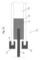
図13を参照するに、全体的に100で表したドラッグ送給デバイスの第4の代表的な実施例を示している。ドラッグ送給デバイス100は、ヒドロゲル102の組成が異なることを除いて、第1の実施例のドラッグ送給デバイス20と類似させることができる。ヒドロゲル102は、親水性部分104及び疎水性部分106を有することができる。親水性部分104及び疎水性部分106は、親水性部分104が疎水性部分106よりも速くドラッグを吸収及び送給するように、互いに異なる特性(例えば、物理的構造、化学的特性)を有するようにしうる。親水性部分104は、ドラッグが所定の経路(例えば、螺旋状、直線)に沿って親水性部分104を通って送給されるように、ほぼコネクタ34の遠位端60から近位端58まで延在するようにすることができる。親疎水性部分106に対する親水性部分104の比は、第1の管腔54の全体に亘って同じにするか、又は近位端58におけるよりも遠位端60において大きくしてドラッグが送給されるよりも一層迅速にヒドロゲルにより吸収されるようにすることができる。或いはまた、親水性部分104及び疎水性部分106は、図13に示すように均質な部分とする必要はない。その代り、ヒドロゲル102は、近位端58におけるよりも遠位端60において親水性要素の比率を大きくした不均質物質とすることができる。
With reference to FIG. 13, a fourth representative embodiment of the drag feeding device represented by 100 as a whole is shown. The
図14を参照するに、全体的に110で表したドラッグ送給デバイスの第5の代表的な実施例を示している。ドラッグ送給デバイス110は、このドラッグ送給デバイス110がドラッグ含有球112を有するとともに、如何なるヒドロゲルをも含まないことを除いて、第1の実施例のドラッグ送給デバイス20に類似しているが、所望に応じ前述したようにヒドロゲルを含めることができる。ドラッグ含有球112は、ドラッグ送給デバイス110が埋設された際に容器32内にある。ドラッグ送給デバイス110が前述したように埋設された後、送給ガイド22を介して容器内に液体(例えば、生理食塩水、液状製剤、水)が注入され、この容器においてこの液体がドラッグ含有球112を洗い流し、ドラッグ含有球112内のドラッグがコネクタ及び管腔を通して時間とともに送給され、ドラッグが送給個所に送給されるようにすることができる。
With reference to FIG. 14, a fifth representative embodiment of the drag feeding device represented by 110 as a whole is shown. The
図15を参照するに、全体的に116で表したドラッグ送給デバイスの第6の代表的な実施例を示している。ドラッグ送給デバイス116は、このドラッグ送給デバイス116がコネクタ120内に1つのみの管腔118を有することを除いて、第1の実施例のドラッグ送給デバイス20に類似している。ヒドロゲル62は、デバイス116が埋設された際には管腔118に存在させないようにしうる。その代わりに、カニューレ66がコネクタ120から取り外されると、ヒドロゲル62がカニューレ66の端部に結合されるとともに管腔118内に引き込まれるようにしうる。コネクタ120の近位端58上に接着剤122を配置し、容器(図示せず)からのドラッグによって与えられる圧力に加えて接着剤122によって、ヒドロゲル62がコネクタ120内に少なくとも部分的に固定されるようにしうる。接着剤122はフェースプレート(図示せず)をコネクタ120に固定することもできる。ヒドロゲル62は、ドラッグの流速を制御することができるとともに、管腔118を封止することもできる。
With reference to FIG. 15, a sixth representative embodiment of the drag feeding device represented by 116 as a whole is shown. The
図16を参照するに、全体的に126で表したフェースプレートの第7の代表的な実施例を示している。フェースプレート126は、このフェースプレート126がコネクタ128及びバーブ130を有するということを除いて、フェースプレート30と類似している。バーブ130は、フェースプレート126を締り嵌めによって第1の管腔54内に固定することができる。バーブ130は、このバーブ130が第1の管腔54に入り且つその中にフェースプレート126を固定する際に、このバーブ130を僅かに変形させるゴム、シリコーン等のような材料から製造することができる。フェースプレート126には、送給するドラッグを通す複数の開口部134を有する末端片132を設けることができる。このフェースプレート126には、末端片132において1つのみの開口部134を有するようにしうること勿論である。コネクタ128は、前述したように、ヒドロゲル62又はメンブレンフィルタ64を有するようにしうる。フェースプレート126は、単一の管腔を有するコネクタ34とともに使用することができ、この場合、バーブ130が管腔を封止し、ドラッグがコネクタ内のヒドロゲルを経てフェースプレートから流出する。或いはまた、フェースプレート126は、2つの管腔を有するコネクタ34とともに使用することができ、この場合、フェースプレート126は第1の管腔内に固定する。
With reference to FIG. 16, a seventh representative embodiment of the faceplate represented by 126 as a whole is shown. The
図17を参照するに、全体的に138で表したドラッグ送給デバイスの第8の代表的な実施例を示している。このドラッグ送給デバイス138は、このドラッグ送給デバイス138がプラグ68の代わりに第2の管腔56を封止するバルブ140を有するということを除いて第1の実施例のドラッグ送給デバイス20と類似している。バルブ140は、開状態142と(図17に破線で示す)閉状態144との間で移動しうる。このバルブ140によりカニューレ66を第2の管腔56内に挿入するとともに、カニューレ66を除去した際に第2の管腔56を封止するという条件で、このバルブ140を如何なる種類のバルブ(例えば、ダックビルバルブ、フラップバルブ、一方向バルブ)にもすることもできる。このバルブ140は、カニューレ66がドラッグを容器32内に送給し且つ除去した後に、第2の管腔56内のドラッグの圧力によって閉状態に固定されるようにしうる。このバルブ140は、カニューレ66を再挿入させて、容器32内に追加の量のドラッグを導入するようにすることができ、これによりドラッグ送給デバイス138を再使用しうるようにする。
With reference to FIG. 17, an eighth representative embodiment of the drag feeding device represented by 138 as a whole is shown. The
当業者によれば、本発明の広範な概念から逸脱することなく、上述した図示の代表的な実施例に変更を行うことができること明らかである。従って、本発明は、上述した図示の代表的な実施例に限定されず、特許請求の範囲によって規定した本発明の精神及び範囲内での変更に及ぶことを意図するものであること明らかである。例えば、代表的な実施例の特定の特徴は、特許請求の範囲に記載した発明の一部であっても一部でなくてもよく、開示した実施例の種々の特徴を組み合わせることができる。用語“右”、“左”、“下”及び“上”は、参照している図面の方向を示すものである。又、用語“内方に”及び“外方に”はそれぞれドラッグ送給デバイスの幾何学的中心に向かう方向及び幾何学的中心から離れる方向を参照するものである。 It will be apparent to those skilled in the art that modifications can be made to the exemplary embodiments illustrated above without departing from the broader concepts of the invention. Therefore, it is clear that the present invention is not limited to the representative examples shown in the above illustration, and is intended to extend to the spirit and scope of the present invention defined by the claims. .. For example, the specific features of the representative embodiment may or may not be part of the invention described in the claims, and various features of the disclosed examples can be combined. The terms "right", "left", "bottom" and "top" indicate the orientation of the referenced drawing. Also, the terms "inward" and "outward" refer to the direction toward the geometric center of the drag feeding device and the direction away from the geometric center, respectively.
本発明の図面及び説明の少なくとも一部は、本発明を明確に理解するのに適切な要素に焦点を当てるために簡略化したものであり、当業者が理解するところの明瞭化のために除外してある他の要素も本発明の一部を構成するものである。しかし、このような要素は当技術分野で周知であるとともに、本発明を良好に理解することを必ずしも助長するものではない為、このような要素の説明は本明細書では行わない。 At least some of the drawings and description of the invention have been simplified to focus on the elements appropriate for a clear understanding of the invention and are excluded for clarity as understood by those skilled in the art. Other elements described above also form a part of the present invention. However, such elements are not described herein because they are well known in the art and do not necessarily facilitate a good understanding of the invention.
更に、本発明の方法が本明細書で説明したステップの特定の順序に依存していない限りにおいて、これらのステップの特定の順序が特許請求の範囲を限定するものと解釈すべきではない。本発明の方法に向けた何れの請求項も、記載した順序でのステップの実行に限定されるべきではなく、当業者が容易に理解しうるように、本発明の精神及び範囲内でステップを変更したり、依然としてそのままにしたりすることができる。 Furthermore, unless the method of the invention relies on the particular order of the steps described herein, the particular order of these steps should not be construed as limiting the scope of the claims. Any claim towards the method of the invention should not be limited to performing the steps in the order described, and the steps are to be carried out within the spirit and scope of the invention so that one of ordinary skill in the art can easily understand. You can change it or leave it as it is.
[参考文献]
1.WO/2014/113384 7/24/2014 KAHOOK, M. 1/14/2014
2.FLEISHER, D. et al. (1996) “Improved oral drug delivery: solubility limitations overcome by the use of prodrugs,” Advanced Drug Delivery Reviews 19(2), 115-130.
3.MOOBERRY, S. L. et al. (1995) “Tubercidin stabilizes microtubules against vinblastine-induced depolymerization, a taxol-like effect,” Cancer Letters 96(2), 261-266.
4.RO, A. J. et al. (2012) “Morphological and degradation studies of sirolimus-containing poly(lactide-co-glycolide) discs,” Journal of Biomedical Materials Research Part B: Applied Biomaterials 100B(3), 767-777.
5.SMITH, C. D. et al (1994) “A sensitive assay for taxol and other microtubule-stabilizing agents,” Cancer Letters 79(2), 213-219.
[References]
1. 1. WO / 2014/113384 7/24/2014 KAHOOK, M. 1/14/2014
2. 2. FLEISHER, D. et al. (1996) “Improved oral drug delivery: solubility limitations overcome by the use of prodrugs,” Advanced Drug Delivery Reviews 19 (2), 115-130.
3. 3. MOOBERRY, SL et al. (1995) “Tubercidin stabilizes microtubules against vinblastine-induced depolymerization, a taxol-like effect,” Cancer Letters 96 (2), 261-266.
4. RO, AJ et al. (2012) “Morphological and degradation studies of sirolimus-containing poly (lactide-co-glycolide) discs,” Journal of Biomedical Materials Research Part B: Applied Biomaterials 100B (3), 767-777.
5. SMITH, CD et al (1994) “A sensitive assay for taxol and other microtubule-stabilizing agents,” Cancer Letters 79 (2), 213-219.
Claims (13)
前記容器に流動的に結合されたコネクタ;
前記コネクタ内に形成された管腔であって、前記ドラッグが前記容器から前記管腔を経て送給個所に流れるように設定されている前記管腔;並びに
前記管腔内のヒドロゲルであって、前記ヒドロゲルは前記容器からの前記ドラッグの送給レートを制御するとともに前記ドラッグを前記管腔から前記送給個所に送給するように構成されている前記ヒドロゲル
を具える涙腺ドラッグ送給デバイスであって、前記ヒドロゲルが、使用前には乾燥状態にあり、そして使用中に湿潤状態にあるように構成され、ここで前記デバイスの埋め込み後に、前記ドラッグが、前記容器からヒドロゲルにより吸収される、涙腺ドラッグ送給デバイス。 A container configured to hold a drug, which is expandable between relaxed and inflated states;
Connector fluidly coupled to the container;
A lumen formed in the connector, wherein the drug is set to flow from the container through the lumen to a feeding point; and a hydrogel in the lumen. The hydrogel is a lacrimal gland drug feeding device comprising the hydrogel configured to control the feeding rate of the drug from the container and feed the drug from the lumen to the feeding site. The hydrogel is configured to be dry before use and wet during use, where the drug is absorbed by the hydrogel from the container after implantation of the device, the lacrimal gland. Drag feeding device.
Applications Claiming Priority (3)
| Application Number | Priority Date | Filing Date | Title |
|---|---|---|---|
| US201662339258P | 2016-05-20 | 2016-05-20 | |
| US62/339,258 | 2016-05-20 | ||
| PCT/US2017/033277 WO2017201255A1 (en) | 2016-05-20 | 2017-05-18 | Lacrimal drug delivery device |
Publications (3)
| Publication Number | Publication Date |
|---|---|
| JP2019516496A JP2019516496A (en) | 2019-06-20 |
| JP2019516496A5 JP2019516496A5 (en) | 2020-06-25 |
| JP7054211B2 true JP7054211B2 (en) | 2022-04-13 |
Family
ID=60325609
Family Applications (1)
| Application Number | Title | Priority Date | Filing Date |
|---|---|---|---|
| JP2018560843A Active JP7054211B2 (en) | 2016-05-20 | 2017-05-18 | Lacrimal gland drug feeding device |
Country Status (6)
| Country | Link |
|---|---|
| US (2) | US11207211B2 (en) |
| EP (1) | EP3458030B1 (en) |
| JP (1) | JP7054211B2 (en) |
| AU (1) | AU2017268379A1 (en) |
| CA (1) | CA3024912A1 (en) |
| WO (1) | WO2017201255A1 (en) |
Families Citing this family (3)
| Publication number | Priority date | Publication date | Assignee | Title |
|---|---|---|---|---|
| CA2897197C (en) | 2013-01-15 | 2022-06-07 | The Regents Of The University Of Colorado, A Body Corporate | Lacrimal system drug delivery device |
| CA3006042A1 (en) | 2015-11-23 | 2017-06-01 | The Regents Of The University Of Colorado, A Body Corporate | Lacrimal system for drug delivery |
| WO2020028022A1 (en) * | 2018-08-03 | 2020-02-06 | The Johns Hopkins University | Lacrimal canalicular delivery system and methods of use |
Citations (7)
| Publication number | Priority date | Publication date | Assignee | Title |
|---|---|---|---|---|
| JP2009532133A (en) | 2006-03-31 | 2009-09-10 | キューエルティー プラグ デリバリー,インク. | Drug delivery methods, structures and compositions for the nasolacrimal system |
| JP2009544355A (en) | 2006-07-20 | 2009-12-17 | ニューロシステック コーポレイション | Devices, systems, and methods for ophthalmic drug delivery |
| WO2010092735A1 (en) | 2009-02-10 | 2010-08-19 | 千寿製薬株式会社 | Ring-shaped device |
| JP2012517330A (en) | 2009-02-12 | 2012-08-02 | インセプト エルエルシー | Drug delivery with hydrogel plugs |
| JP2013543418A (en) | 2010-10-15 | 2013-12-05 | アイサイエンス・インターベンショナル・コーポレーション | Eye access device |
| JP2015109990A (en) | 2009-12-29 | 2015-06-18 | アクラレント インコーポレイテッド | Dilating catheter |
| JP2016508064A (en) | 2013-01-15 | 2016-03-17 | ザ リージェンツ オブ ザ ユニバーシティ オブ コロラド,ア ボディー コーポレイトTHE REGENTS OF THE UNIVERSITY OF COLORADO,a body corporate | Lacrimal drug delivery device |
Family Cites Families (49)
| Publication number | Priority date | Publication date | Assignee | Title |
|---|---|---|---|---|
| US3828777A (en) | 1971-11-08 | 1974-08-13 | Alza Corp | Microporous ocular device |
| US3962414A (en) | 1972-04-27 | 1976-06-08 | Alza Corporation | Structured bioerodible drug delivery device |
| US3817248A (en) | 1972-11-06 | 1974-06-18 | Alza Corp | Self powered device for delivering beneficial agent |
| US4468816A (en) | 1983-03-08 | 1984-09-04 | Selma Kaufer | Nursing garment |
| US4658816A (en) | 1984-11-14 | 1987-04-21 | Concept Incorporated | Lighted canaliculus intubation sets |
| US4781675A (en) * | 1985-11-27 | 1988-11-01 | White Thomas C | Infusion cannula |
| DE68916960T2 (en) | 1989-05-24 | 1994-11-03 | Tsukada Medical Research Co | A BALLOON INSTRUMENT FOR CONTINUOUSLY INJECTING A MEDICAL LIQUID. |
| US5410016A (en) | 1990-10-15 | 1995-04-25 | Board Of Regents, The University Of Texas System | Photopolymerizable biodegradable hydrogels as tissue contacting materials and controlled-release carriers |
| US6524274B1 (en) | 1990-12-28 | 2003-02-25 | Scimed Life Systems, Inc. | Triggered release hydrogel drug delivery system |
| US5437625A (en) | 1992-04-06 | 1995-08-01 | Kurihashi; Katsuaki | Apparatus for intubation of lacrimal drainage pathway |
| US5318513A (en) | 1992-09-24 | 1994-06-07 | Leib Martin L | Canalicular balloon fixation stent |
| DE69529572T2 (en) | 1994-11-10 | 2003-06-18 | The University Of Kentucky Research Foundation, Lexington | IMPLANTABLE REFILLABLE DEVICE WITH CONTROLLED RELEASE FOR ADMINISTERING MEDICINAL SUBSTANCES DIRECTLY ON AN INNER PART OF THE BODY |
| FR2771297B1 (en) * | 1997-11-25 | 2000-02-11 | Pierre Andre Jacques Bige | TWO-CHANNEL PROBE FOR TREATING EYEWEEDING |
| US6196993B1 (en) | 1998-04-20 | 2001-03-06 | Eyelab Group, Llc | Ophthalmic insert and method for sustained release of medication to the eye |
| US6217896B1 (en) | 1999-04-01 | 2001-04-17 | Uab Research Foundation | Conjunctival inserts for topical delivery of medication or lubrication |
| ES2300145T3 (en) | 1999-05-21 | 2008-06-01 | Pierre Andre Jacques Bige | BICANICULAR PROBE FOR TREATMENT OF THE EYE. |
| US6344047B1 (en) | 2000-02-02 | 2002-02-05 | Eagle Vision | Instrument for inserting a punctum plug and method for manufacturing the instrument |
| JP2004517674A (en) | 2000-12-29 | 2004-06-17 | ボシュ・アンド・ロム・インコーポレイテッド | Sustained release drug delivery device |
| US6881198B2 (en) | 2001-01-09 | 2005-04-19 | J. David Brown | Glaucoma treatment device and method |
| EP2316394B1 (en) | 2001-06-12 | 2016-11-23 | The Johns Hopkins University | Reservoir device for intraocular drug delivery |
| US20050048099A1 (en) | 2003-01-09 | 2005-03-03 | Allergan, Inc. | Ocular implant made by a double extrusion process |
| US20040137059A1 (en) | 2003-01-09 | 2004-07-15 | Thierry Nivaggioli | Biodegradable ocular implant |
| US9101384B2 (en) | 2004-04-21 | 2015-08-11 | Acclarent, Inc. | Devices, systems and methods for diagnosing and treating sinusitis and other disorders of the ears, Nose and/or throat |
| CA2829533C (en) * | 2005-02-04 | 2016-08-09 | Auburn University | Contact drug delivery system |
| US7931909B2 (en) | 2005-05-10 | 2011-04-26 | Allergan, Inc. | Ocular therapy using alpha-2 adrenergic receptor compounds having enhanced anterior clearance rates |
| US9173773B2 (en) | 2006-06-21 | 2015-11-03 | Johnson & Johnson Vision Care, Inc. | Punctal plugs for the delivery of active agents |
| US20080086101A1 (en) | 2006-08-25 | 2008-04-10 | David Freilich | Ophthalmic insert |
| FR2906712A1 (en) | 2006-10-09 | 2008-04-11 | France Chirurgie Instr | MEASURE PLUG WITH SIMPLIFIED INSTALLATION. |
| UY30883A1 (en) | 2007-01-31 | 2008-05-31 | Alcon Res | PUNCTURAL PLUGS AND METHODS OF RELEASE OF THERAPEUTIC AGENTS |
| US20080199510A1 (en) | 2007-02-20 | 2008-08-21 | Xtent, Inc. | Thermo-mechanically controlled implants and methods of use |
| MX2010002616A (en) | 2007-09-07 | 2010-08-04 | Qlt Plug Delivery Inc | Drug cores for sustained release of therapeutic agents. |
| EP2865361B1 (en) | 2007-09-07 | 2019-05-22 | Mati Therapeutics Inc. | Lacrimal implants and related methods |
| CN104623741A (en) | 2008-04-30 | 2015-05-20 | 马缇医疗股份有限公司 | Composite lacrimal insert and related methods |
| TWI542338B (en) | 2008-05-07 | 2016-07-21 | 壯生和壯生視覺關懷公司 | Ophthalmic devices for the controlled release of active agents |
| US8235932B2 (en) * | 2009-01-09 | 2012-08-07 | Becker Bruce B | Side-by-side lacrimal intubation threader and method |
| US20100209477A1 (en) | 2009-01-23 | 2010-08-19 | Qlt Plug Delivery Inc. | Sustained release delivery of one or more agents |
| US8623395B2 (en) | 2010-01-29 | 2014-01-07 | Forsight Vision4, Inc. | Implantable therapeutic device |
| SG174133A1 (en) | 2009-02-23 | 2011-10-28 | Quadra Logic Tech Inc | Lacrimal implants and related methods |
| CN201469516U (en) | 2009-08-18 | 2010-05-19 | 沈素民 | Lacrimal passage expansion administration tube |
| US20110251568A1 (en) | 2010-04-08 | 2011-10-13 | Beeley Nathan R F | Punctal plugs for controlled release of therapeutic agents |
| US20110301555A1 (en) * | 2010-06-03 | 2011-12-08 | Gonzalez-Zugasti Javier P | Porous matrix drug core for lacrimal insert device |
| US20110311606A1 (en) | 2010-06-18 | 2011-12-22 | Coldren Bret A | Punctal plugs with continuous or pulsatile drug release mechanism |
| EP2654715B1 (en) * | 2010-11-24 | 2017-01-25 | Dose Medical Corporation | Drug eluting ocular implant |
| WO2012170578A1 (en) * | 2011-06-06 | 2012-12-13 | Oak Crest Institute Of Science | Drug delivery device employing wicking release window |
| US9254225B2 (en) | 2011-07-20 | 2016-02-09 | Bruce B. Becker | Punctal plug inserter and method |
| US20130220346A1 (en) | 2012-02-28 | 2013-08-29 | Victor Lust | Balloon punctal plug |
| US9265655B2 (en) | 2013-06-05 | 2016-02-23 | Enteroptyx | Punctum plug insertion device and device packaging |
| CA3006042A1 (en) * | 2015-11-23 | 2017-06-01 | The Regents Of The University Of Colorado, A Body Corporate | Lacrimal system for drug delivery |
| CN115120405A (en) * | 2016-04-20 | 2022-09-30 | 多斯医学公司 | Delivery device for bioabsorbable ocular drugs |
-
2017
- 2017-05-18 US US16/302,514 patent/US11207211B2/en active Active
- 2017-05-18 JP JP2018560843A patent/JP7054211B2/en active Active
- 2017-05-18 CA CA3024912A patent/CA3024912A1/en active Pending
- 2017-05-18 EP EP17800154.1A patent/EP3458030B1/en active Active
- 2017-05-18 AU AU2017268379A patent/AU2017268379A1/en not_active Abandoned
- 2017-05-18 WO PCT/US2017/033277 patent/WO2017201255A1/en unknown
-
2021
- 2021-11-11 US US17/524,610 patent/US12011390B2/en active Active
Patent Citations (7)
| Publication number | Priority date | Publication date | Assignee | Title |
|---|---|---|---|---|
| JP2009532133A (en) | 2006-03-31 | 2009-09-10 | キューエルティー プラグ デリバリー,インク. | Drug delivery methods, structures and compositions for the nasolacrimal system |
| JP2009544355A (en) | 2006-07-20 | 2009-12-17 | ニューロシステック コーポレイション | Devices, systems, and methods for ophthalmic drug delivery |
| WO2010092735A1 (en) | 2009-02-10 | 2010-08-19 | 千寿製薬株式会社 | Ring-shaped device |
| JP2012517330A (en) | 2009-02-12 | 2012-08-02 | インセプト エルエルシー | Drug delivery with hydrogel plugs |
| JP2015109990A (en) | 2009-12-29 | 2015-06-18 | アクラレント インコーポレイテッド | Dilating catheter |
| JP2013543418A (en) | 2010-10-15 | 2013-12-05 | アイサイエンス・インターベンショナル・コーポレーション | Eye access device |
| JP2016508064A (en) | 2013-01-15 | 2016-03-17 | ザ リージェンツ オブ ザ ユニバーシティ オブ コロラド,ア ボディー コーポレイトTHE REGENTS OF THE UNIVERSITY OF COLORADO,a body corporate | Lacrimal drug delivery device |
Also Published As
| Publication number | Publication date |
|---|---|
| EP3458030B1 (en) | 2021-05-12 |
| AU2017268379A1 (en) | 2018-12-06 |
| WO2017201255A1 (en) | 2017-11-23 |
| US12011390B2 (en) | 2024-06-18 |
| US20220062037A1 (en) | 2022-03-03 |
| EP3458030A4 (en) | 2019-11-20 |
| EP3458030A1 (en) | 2019-03-27 |
| CA3024912A1 (en) | 2017-11-23 |
| US20190274877A1 (en) | 2019-09-12 |
| US11207211B2 (en) | 2021-12-28 |
| JP2019516496A (en) | 2019-06-20 |
Similar Documents
| Publication | Publication Date | Title |
|---|---|---|
| US12011390B2 (en) | Lacrimal drug delivery device | |
| ES2950350T3 (en) | Ophthalmic delivery device | |
| CA2706384C (en) | Implantable drug delivery device and methods for treatment of the bladder and other body vesicles or lumens | |
| JP6312258B2 (en) | Device for transanal drainage of excreta from a patient's rectum and / or transanal application of inflowing fluid through a catheter-like element | |
| JP6999979B2 (en) | Lacrimal drug delivery device | |
| JP5524983B2 (en) | Implant system | |
| ES2733442T3 (en) | Device for treatment of retinal detachment and other eye diseases | |
| US20210205128A1 (en) | Methods and Systems for Treating Intracranial Hypertension and Related Indications Using An Optic Nerve Stent or Shunt | |
| US20120203160A1 (en) | Implants for reducing intraocular pressure | |
| JP2009508587A (en) | Drug delivery device and method for providing ophthalmic treatment | |
| JPH07502426A (en) | Device for deploying a removable balloon | |
| BR112016010638B1 (en) | EYE DEVICE | |
| BR112020004983A2 (en) | cannulation device for delivering an active agent that contains composition to an eye, method for treating a disease or condition by delivering a liquid or semi-solid material to the affected region, method for treating a disease or eye condition by means of injection of a solid or semi-solid material into the supracoroid space or supraciliary space and method for injecting a supracoroid material or supraciliary space by using the device in the space | |
| CN108784895A (en) | A kind of expandable stent system | |
| US10010400B2 (en) | Devices and methods for local delivery of drug to upper urinary tract | |
| JP6885609B2 (en) | Lacrimal system for drug delivery | |
| US10039631B2 (en) | Implant device for use in salivary gland duct | |
| US20210169690A1 (en) | Self-Retaining Implantable Drug Delivery Device | |
| BR102021025422A2 (en) | IMPLANT FOR TREATMENT OF OVERACTIVE BLADDER | |
| WO2024039394A1 (en) | Radiation spacer devices, delivery systems, and methods for the prevention of collateral radiation |
Legal Events
| Date | Code | Title | Description |
|---|---|---|---|
| A521 | Request for written amendment filed |
Free format text: JAPANESE INTERMEDIATE CODE: A523 Effective date: 20200515 |
|
| A621 | Written request for application examination |
Free format text: JAPANESE INTERMEDIATE CODE: A621 Effective date: 20200515 |
|
| RD03 | Notification of appointment of power of attorney |
Free format text: JAPANESE INTERMEDIATE CODE: A7423 Effective date: 20201013 |
|
| RD04 | Notification of resignation of power of attorney |
Free format text: JAPANESE INTERMEDIATE CODE: A7424 Effective date: 20201023 |
|
| A977 | Report on retrieval |
Free format text: JAPANESE INTERMEDIATE CODE: A971007 Effective date: 20210331 |
|
| A131 | Notification of reasons for refusal |
Free format text: JAPANESE INTERMEDIATE CODE: A131 Effective date: 20210413 |
|
| A601 | Written request for extension of time |
Free format text: JAPANESE INTERMEDIATE CODE: A601 Effective date: 20210712 |
|
| A521 | Request for written amendment filed |
Free format text: JAPANESE INTERMEDIATE CODE: A523 Effective date: 20211013 |
|
| A131 | Notification of reasons for refusal |
Free format text: JAPANESE INTERMEDIATE CODE: A131 Effective date: 20211130 |
|
| A521 | Request for written amendment filed |
Free format text: JAPANESE INTERMEDIATE CODE: A523 Effective date: 20220228 |
|
| TRDD | Decision of grant or rejection written | ||
| A01 | Written decision to grant a patent or to grant a registration (utility model) |
Free format text: JAPANESE INTERMEDIATE CODE: A01 Effective date: 20220315 |
|
| A61 | First payment of annual fees (during grant procedure) |
Free format text: JAPANESE INTERMEDIATE CODE: A61 Effective date: 20220325 |
|
| R150 | Certificate of patent or registration of utility model |
Ref document number: 7054211 Country of ref document: JP Free format text: JAPANESE INTERMEDIATE CODE: R150 |