EP3458030B1 - Lacrimal drug delivery device - Google Patents
Lacrimal drug delivery device Download PDFInfo
- Publication number
- EP3458030B1 EP3458030B1 EP17800154.1A EP17800154A EP3458030B1 EP 3458030 B1 EP3458030 B1 EP 3458030B1 EP 17800154 A EP17800154 A EP 17800154A EP 3458030 B1 EP3458030 B1 EP 3458030B1
- Authority
- EP
- European Patent Office
- Prior art keywords
- drug
- reservoir
- lumen
- delivery device
- hydrogel
- Prior art date
- Legal status (The legal status is an assumption and is not a legal conclusion. Google has not performed a legal analysis and makes no representation as to the accuracy of the status listed.)
- Active
Links
- 238000012377 drug delivery Methods 0.000 title claims description 79
- 239000003814 drug Substances 0.000 claims description 146
- 229940079593 drug Drugs 0.000 claims description 127
- 239000000017 hydrogel Substances 0.000 claims description 80
- 239000000126 substance Substances 0.000 claims description 23
- 238000010521 absorption reaction Methods 0.000 claims description 21
- 239000000203 mixture Substances 0.000 claims description 16
- 239000007943 implant Substances 0.000 claims description 13
- 230000002209 hydrophobic effect Effects 0.000 claims description 8
- 238000012546 transfer Methods 0.000 claims description 8
- 238000009472 formulation Methods 0.000 claims description 6
- 238000007789 sealing Methods 0.000 claims description 5
- 150000001875 compounds Chemical class 0.000 description 29
- 239000000463 material Substances 0.000 description 24
- 229920000642 polymer Polymers 0.000 description 18
- 201000010099 disease Diseases 0.000 description 14
- 208000037265 diseases, disorders, signs and symptoms Diseases 0.000 description 14
- -1 fluorine or chlorine Chemical class 0.000 description 12
- XLYOFNOQVPJJNP-UHFFFAOYSA-N water Substances O XLYOFNOQVPJJNP-UHFFFAOYSA-N 0.000 description 10
- 230000000694 effects Effects 0.000 description 9
- 230000031018 biological processes and functions Effects 0.000 description 8
- 239000012528 membrane Substances 0.000 description 7
- 238000000034 method Methods 0.000 description 7
- 229940002612 prodrug Drugs 0.000 description 7
- 239000000651 prodrug Substances 0.000 description 7
- 150000003839 salts Chemical class 0.000 description 7
- 241000083513 Punctum Species 0.000 description 6
- 239000000853 adhesive Substances 0.000 description 6
- 230000001070 adhesive effect Effects 0.000 description 6
- 230000008859 change Effects 0.000 description 6
- 210000001519 tissue Anatomy 0.000 description 6
- 239000012530 fluid Substances 0.000 description 5
- 229920001296 polysiloxane Polymers 0.000 description 5
- 230000008569 process Effects 0.000 description 5
- 208000024891 symptom Diseases 0.000 description 5
- MWUXSHHQAYIFBG-UHFFFAOYSA-N Nitric oxide Chemical compound O=[N] MWUXSHHQAYIFBG-UHFFFAOYSA-N 0.000 description 4
- 229920003171 Poly (ethylene oxide) Polymers 0.000 description 4
- 239000003795 chemical substances by application Substances 0.000 description 4
- 239000000041 non-steroidal anti-inflammatory agent Substances 0.000 description 4
- 229940021182 non-steroidal anti-inflammatory drug Drugs 0.000 description 4
- 229920001606 poly(lactic acid-co-glycolic acid) Polymers 0.000 description 4
- 229920001223 polyethylene glycol Polymers 0.000 description 4
- 102000004169 proteins and genes Human genes 0.000 description 4
- 108090000623 proteins and genes Proteins 0.000 description 4
- QTBSBXVTEAMEQO-UHFFFAOYSA-N Acetic acid Chemical compound CC(O)=O QTBSBXVTEAMEQO-UHFFFAOYSA-N 0.000 description 3
- 102000029749 Microtubule Human genes 0.000 description 3
- 108091022875 Microtubule Proteins 0.000 description 3
- ZMANZCXQSJIPKH-UHFFFAOYSA-N Triethylamine Chemical compound CCN(CC)CC ZMANZCXQSJIPKH-UHFFFAOYSA-N 0.000 description 3
- 239000002250 absorbent Substances 0.000 description 3
- 239000013543 active substance Substances 0.000 description 3
- KRKNYBCHXYNGOX-UHFFFAOYSA-N citric acid Chemical compound OC(=O)CC(O)(C(O)=O)CC(O)=O KRKNYBCHXYNGOX-UHFFFAOYSA-N 0.000 description 3
- 229920001577 copolymer Polymers 0.000 description 3
- 229920001971 elastomer Polymers 0.000 description 3
- 239000003889 eye drop Substances 0.000 description 3
- 229940012356 eye drops Drugs 0.000 description 3
- 125000000524 functional group Chemical group 0.000 description 3
- 229920001477 hydrophilic polymer Polymers 0.000 description 3
- 238000002513 implantation Methods 0.000 description 3
- 230000002427 irreversible effect Effects 0.000 description 3
- 239000007788 liquid Substances 0.000 description 3
- 210000004688 microtubule Anatomy 0.000 description 3
- 210000004083 nasolacrimal duct Anatomy 0.000 description 3
- 239000002245 particle Substances 0.000 description 3
- 230000007170 pathology Effects 0.000 description 3
- 239000005060 rubber Substances 0.000 description 3
- 150000003431 steroids Chemical class 0.000 description 3
- 229940124597 therapeutic agent Drugs 0.000 description 3
- 230000007704 transition Effects 0.000 description 3
- HZAXFHJVJLSVMW-UHFFFAOYSA-N 2-Aminoethan-1-ol Chemical compound NCCO HZAXFHJVJLSVMW-UHFFFAOYSA-N 0.000 description 2
- QGZKDVFQNNGYKY-UHFFFAOYSA-N Ammonia Chemical compound N QGZKDVFQNNGYKY-UHFFFAOYSA-N 0.000 description 2
- 108090000695 Cytokines Proteins 0.000 description 2
- 102000004127 Cytokines Human genes 0.000 description 2
- 108050009340 Endothelin Proteins 0.000 description 2
- 102000002045 Endothelin Human genes 0.000 description 2
- VZCYOOQTPOCHFL-OWOJBTEDSA-N Fumaric acid Chemical compound OC(=O)\C=C\C(O)=O VZCYOOQTPOCHFL-OWOJBTEDSA-N 0.000 description 2
- 241000282414 Homo sapiens Species 0.000 description 2
- VEXZGXHMUGYJMC-UHFFFAOYSA-N Hydrochloric acid Chemical compound Cl VEXZGXHMUGYJMC-UHFFFAOYSA-N 0.000 description 2
- 206010061218 Inflammation Diseases 0.000 description 2
- AFVFQIVMOAPDHO-UHFFFAOYSA-N Methanesulfonic acid Chemical compound CS(O)(=O)=O AFVFQIVMOAPDHO-UHFFFAOYSA-N 0.000 description 2
- 206010028980 Neoplasm Diseases 0.000 description 2
- 208000022873 Ocular disease Diseases 0.000 description 2
- NBIIXXVUZAFLBC-UHFFFAOYSA-N Phosphoric acid Chemical compound OP(O)(O)=O NBIIXXVUZAFLBC-UHFFFAOYSA-N 0.000 description 2
- 239000004698 Polyethylene Substances 0.000 description 2
- 239000004743 Polypropylene Substances 0.000 description 2
- QAOWNCQODCNURD-UHFFFAOYSA-N Sulfuric acid Chemical compound OS(O)(=O)=O QAOWNCQODCNURD-UHFFFAOYSA-N 0.000 description 2
- 239000002253 acid Substances 0.000 description 2
- 230000002378 acidificating effect Effects 0.000 description 2
- 125000002252 acyl group Chemical group 0.000 description 2
- 150000001413 amino acids Chemical class 0.000 description 2
- 239000002260 anti-inflammatory agent Substances 0.000 description 2
- 230000003110 anti-inflammatory effect Effects 0.000 description 2
- WPYMKLBDIGXBTP-UHFFFAOYSA-N benzoic acid Chemical compound OC(=O)C1=CC=CC=C1 WPYMKLBDIGXBTP-UHFFFAOYSA-N 0.000 description 2
- 239000000560 biocompatible material Substances 0.000 description 2
- 230000004071 biological effect Effects 0.000 description 2
- 229920001400 block copolymer Polymers 0.000 description 2
- 201000011510 cancer Diseases 0.000 description 2
- 125000003178 carboxy group Chemical group [H]OC(*)=O 0.000 description 2
- 150000001735 carboxylic acids Chemical group 0.000 description 2
- HVYWMOMLDIMFJA-DPAQBDIFSA-N cholesterol Chemical compound C1C=C2C[C@@H](O)CC[C@]2(C)[C@@H]2[C@@H]1[C@@H]1CC[C@H]([C@H](C)CCCC(C)C)[C@@]1(C)CC2 HVYWMOMLDIMFJA-DPAQBDIFSA-N 0.000 description 2
- 238000007906 compression Methods 0.000 description 2
- 239000003246 corticosteroid Substances 0.000 description 2
- 229960001334 corticosteroids Drugs 0.000 description 2
- 238000011161 development Methods 0.000 description 2
- 238000009826 distribution Methods 0.000 description 2
- ZUBDGKVDJUIMQQ-UBFCDGJISA-N endothelin-1 Chemical compound C([C@@H](C(=O)N[C@@H](CC(C)C)C(=O)N[C@@H](CC(O)=O)C(=O)N[C@@H]([C@@H](C)CC)C(=O)N[C@@H]([C@@H](C)CC)C(=O)N[C@@H](CC=1C2=CC=CC=C2NC=1)C(O)=O)NC(=O)[C@H]1NC(=O)[C@H](CC=2C=CC=CC=2)NC(=O)[C@@H](CC=2C=CC(O)=CC=2)NC(=O)[C@H](C(C)C)NC(=O)[C@H]2CSSC[C@@H](C(N[C@H](CO)C(=O)N[C@@H](CO)C(=O)N[C@H](CC(C)C)C(=O)N[C@@H](CCSC)C(=O)N[C@H](CC(O)=O)C(=O)N[C@@H](CCCCN)C(=O)N[C@@H](CCC(O)=O)C(=O)N2)=O)NC(=O)[C@@H](CO)NC(=O)[C@H](N)CSSC1)C1=CNC=N1 ZUBDGKVDJUIMQQ-UBFCDGJISA-N 0.000 description 2
- 239000007789 gas Substances 0.000 description 2
- 125000004435 hydrogen atom Chemical group [H]* 0.000 description 2
- 230000004054 inflammatory process Effects 0.000 description 2
- 238000003780 insertion Methods 0.000 description 2
- 230000037431 insertion Effects 0.000 description 2
- 230000000670 limiting effect Effects 0.000 description 2
- 150000007522 mineralic acids Chemical class 0.000 description 2
- 125000004433 nitrogen atom Chemical group N* 0.000 description 2
- 210000000056 organ Anatomy 0.000 description 2
- 230000036961 partial effect Effects 0.000 description 2
- 230000000704 physical effect Effects 0.000 description 2
- 230000004962 physiological condition Effects 0.000 description 2
- 239000004033 plastic Substances 0.000 description 2
- 229920003023 plastic Polymers 0.000 description 2
- 229920000573 polyethylene Polymers 0.000 description 2
- 229920000139 polyethylene terephthalate Polymers 0.000 description 2
- 239000005020 polyethylene terephthalate Substances 0.000 description 2
- 238000006116 polymerization reaction Methods 0.000 description 2
- 229920001155 polypropylene Polymers 0.000 description 2
- 229920001343 polytetrafluoroethylene Polymers 0.000 description 2
- 239000004810 polytetrafluoroethylene Substances 0.000 description 2
- 230000002265 prevention Effects 0.000 description 2
- 230000009257 reactivity Effects 0.000 description 2
- 230000037390 scarring Effects 0.000 description 2
- 239000007858 starting material Substances 0.000 description 2
- 239000003270 steroid hormone Substances 0.000 description 2
- 230000001225 therapeutic effect Effects 0.000 description 2
- 230000000451 tissue damage Effects 0.000 description 2
- 231100000827 tissue damage Toxicity 0.000 description 2
- JOXIMZWYDAKGHI-UHFFFAOYSA-N toluene-4-sulfonic acid Chemical compound CC1=CC=C(S(O)(=O)=O)C=C1 JOXIMZWYDAKGHI-UHFFFAOYSA-N 0.000 description 2
- VZCYOOQTPOCHFL-UHFFFAOYSA-N trans-butenedioic acid Natural products OC(=O)C=CC(O)=O VZCYOOQTPOCHFL-UHFFFAOYSA-N 0.000 description 2
- 238000012800 visualization Methods 0.000 description 2
- 238000003466 welding Methods 0.000 description 2
- HBAQYPYDRFILMT-UHFFFAOYSA-N 8-[3-(1-cyclopropylpyrazol-4-yl)-1H-pyrazolo[4,3-d]pyrimidin-5-yl]-3-methyl-3,8-diazabicyclo[3.2.1]octan-2-one Chemical class C1(CC1)N1N=CC(=C1)C1=NNC2=C1N=C(N=C2)N1C2C(N(CC1CC2)C)=O HBAQYPYDRFILMT-UHFFFAOYSA-N 0.000 description 1
- 241000191985 Anas superciliosa Species 0.000 description 1
- 241000894006 Bacteria Species 0.000 description 1
- 239000005711 Benzoic acid Substances 0.000 description 1
- 241000283690 Bos taurus Species 0.000 description 1
- WDPFQABQVGJEBZ-MAKOZQESSA-N Bothermon Chemical compound OC1=CC=C2[C@H]3CC[C@](C)([C@H](CC4)O)[C@@H]4[C@@H]3CCC2=C1.O=C1CC[C@]2(C)[C@H]3CC[C@](C)([C@H](CC4)O)[C@@H]4[C@@H]3CCC2=C1 WDPFQABQVGJEBZ-MAKOZQESSA-N 0.000 description 1
- 241000283707 Capra Species 0.000 description 1
- KXDHJXZQYSOELW-UHFFFAOYSA-M Carbamate Chemical compound NC([O-])=O KXDHJXZQYSOELW-UHFFFAOYSA-M 0.000 description 1
- KXDHJXZQYSOELW-UHFFFAOYSA-N Carbamic acid Chemical group NC(O)=O KXDHJXZQYSOELW-UHFFFAOYSA-N 0.000 description 1
- 241000700199 Cavia porcellus Species 0.000 description 1
- 241000282693 Cercopithecidae Species 0.000 description 1
- ZAMOUSCENKQFHK-UHFFFAOYSA-N Chlorine atom Chemical compound [Cl] ZAMOUSCENKQFHK-UHFFFAOYSA-N 0.000 description 1
- FEWJPZIEWOKRBE-JCYAYHJZSA-N Dextrotartaric acid Chemical compound OC(=O)[C@H](O)[C@@H](O)C(O)=O FEWJPZIEWOKRBE-JCYAYHJZSA-N 0.000 description 1
- 206010061818 Disease progression Diseases 0.000 description 1
- 241000282326 Felis catus Species 0.000 description 1
- PXGOKWXKJXAPGV-UHFFFAOYSA-N Fluorine Chemical compound FF PXGOKWXKJXAPGV-UHFFFAOYSA-N 0.000 description 1
- 241000233866 Fungi Species 0.000 description 1
- 241000699666 Mus <mouse, genus> Species 0.000 description 1
- 241001494479 Pecora Species 0.000 description 1
- 241000009328 Perro Species 0.000 description 1
- 239000002202 Polyethylene glycol Substances 0.000 description 1
- 229920000954 Polyglycolide Polymers 0.000 description 1
- 239000004721 Polyphenylene oxide Substances 0.000 description 1
- 241000288906 Primates Species 0.000 description 1
- OFOBLEOULBTSOW-UHFFFAOYSA-N Propanedioic acid Natural products OC(=O)CC(O)=O OFOBLEOULBTSOW-UHFFFAOYSA-N 0.000 description 1
- 102000015433 Prostaglandin Receptors Human genes 0.000 description 1
- 108010050183 Prostaglandin Receptors Proteins 0.000 description 1
- 206010037660 Pyrexia Diseases 0.000 description 1
- 241000700159 Rattus Species 0.000 description 1
- FAPWRFPIFSIZLT-UHFFFAOYSA-M Sodium chloride Chemical compound [Na+].[Cl-] FAPWRFPIFSIZLT-UHFFFAOYSA-M 0.000 description 1
- FEWJPZIEWOKRBE-UHFFFAOYSA-N Tartaric acid Natural products [H+].[H+].[O-]C(=O)C(O)C(O)C([O-])=O FEWJPZIEWOKRBE-UHFFFAOYSA-N 0.000 description 1
- RTAQQCXQSZGOHL-UHFFFAOYSA-N Titanium Chemical compound [Ti] RTAQQCXQSZGOHL-UHFFFAOYSA-N 0.000 description 1
- GSEJCLTVZPLZKY-UHFFFAOYSA-N Triethanolamine Chemical compound OCCN(CCO)CCO GSEJCLTVZPLZKY-UHFFFAOYSA-N 0.000 description 1
- 238000012382 advanced drug delivery Methods 0.000 description 1
- 239000000556 agonist Substances 0.000 description 1
- 150000001298 alcohols Chemical class 0.000 description 1
- 229910052783 alkali metal Inorganic materials 0.000 description 1
- 229910052784 alkaline earth metal Inorganic materials 0.000 description 1
- 229910000147 aluminium phosphate Inorganic materials 0.000 description 1
- 150000001412 amines Chemical class 0.000 description 1
- 125000000539 amino acid group Chemical group 0.000 description 1
- 229910021529 ammonia Inorganic materials 0.000 description 1
- 239000003708 ampul Substances 0.000 description 1
- 230000000202 analgesic effect Effects 0.000 description 1
- 229940035676 analgesics Drugs 0.000 description 1
- 210000003484 anatomy Anatomy 0.000 description 1
- 238000005349 anion exchange Methods 0.000 description 1
- 239000005557 antagonist Substances 0.000 description 1
- 239000003242 anti bacterial agent Substances 0.000 description 1
- 229940121363 anti-inflammatory agent Drugs 0.000 description 1
- 229940124599 anti-inflammatory drug Drugs 0.000 description 1
- 230000001946 anti-microtubular Effects 0.000 description 1
- 229940044684 anti-microtubule agent Drugs 0.000 description 1
- 230000001754 anti-pyretic effect Effects 0.000 description 1
- 229940088710 antibiotic agent Drugs 0.000 description 1
- 229940006138 antiglaucoma drug and miotics prostaglandin analogues Drugs 0.000 description 1
- 229940034982 antineoplastic agent Drugs 0.000 description 1
- 239000002246 antineoplastic agent Substances 0.000 description 1
- 239000002221 antipyretic Substances 0.000 description 1
- 238000003556 assay Methods 0.000 description 1
- 125000004429 atom Chemical group 0.000 description 1
- 230000003416 augmentation Effects 0.000 description 1
- 229910052788 barium Inorganic materials 0.000 description 1
- DSAJWYNOEDNPEQ-UHFFFAOYSA-N barium atom Chemical compound [Ba] DSAJWYNOEDNPEQ-UHFFFAOYSA-N 0.000 description 1
- 230000004888 barrier function Effects 0.000 description 1
- 239000002585 base Substances 0.000 description 1
- 235000010233 benzoic acid Nutrition 0.000 description 1
- 239000012620 biological material Substances 0.000 description 1
- 239000008280 blood Substances 0.000 description 1
- 210000004369 blood Anatomy 0.000 description 1
- 230000036772 blood pressure Effects 0.000 description 1
- 210000004204 blood vessel Anatomy 0.000 description 1
- 230000009172 bursting Effects 0.000 description 1
- 159000000007 calcium salts Chemical class 0.000 description 1
- 230000023852 carbohydrate metabolic process Effects 0.000 description 1
- 235000021256 carbohydrate metabolism Nutrition 0.000 description 1
- 125000004432 carbon atom Chemical group C* 0.000 description 1
- 125000002843 carboxylic acid group Chemical group 0.000 description 1
- 230000015556 catabolic process Effects 0.000 description 1
- 238000005341 cation exchange Methods 0.000 description 1
- 210000004027 cell Anatomy 0.000 description 1
- 230000004663 cell proliferation Effects 0.000 description 1
- 239000000460 chlorine Substances 0.000 description 1
- 229910052801 chlorine Inorganic materials 0.000 description 1
- 235000012000 cholesterol Nutrition 0.000 description 1
- 238000010276 construction Methods 0.000 description 1
- 238000011109 contamination Methods 0.000 description 1
- 239000002872 contrast media Substances 0.000 description 1
- 230000001276 controlling effect Effects 0.000 description 1
- 238000007796 conventional method Methods 0.000 description 1
- 238000004132 cross linking Methods 0.000 description 1
- 125000004122 cyclic group Chemical group 0.000 description 1
- 125000000113 cyclohexyl group Chemical group [H]C1([H])C([H])([H])C([H])([H])C([H])(*)C([H])([H])C1([H])[H] 0.000 description 1
- 125000001511 cyclopentyl group Chemical group [H]C1([H])C([H])([H])C([H])([H])C([H])(*)C1([H])[H] 0.000 description 1
- 230000007423 decrease Effects 0.000 description 1
- 230000003247 decreasing effect Effects 0.000 description 1
- 230000007850 degeneration Effects 0.000 description 1
- 230000001934 delay Effects 0.000 description 1
- 230000001419 dependent effect Effects 0.000 description 1
- 238000001212 derivatisation Methods 0.000 description 1
- UREBDLICKHMUKA-CXSFZGCWSA-N dexamethasone Chemical compound C1CC2=CC(=O)C=C[C@]2(C)[C@]2(F)[C@@H]1[C@@H]1C[C@@H](C)[C@@](C(=O)CO)(O)[C@@]1(C)C[C@@H]2O UREBDLICKHMUKA-CXSFZGCWSA-N 0.000 description 1
- 229960003957 dexamethasone Drugs 0.000 description 1
- 235000013367 dietary fats Nutrition 0.000 description 1
- 238000009792 diffusion process Methods 0.000 description 1
- 239000003085 diluting agent Substances 0.000 description 1
- 230000005750 disease progression Effects 0.000 description 1
- 239000006196 drop Substances 0.000 description 1
- 239000013013 elastic material Substances 0.000 description 1
- 239000003792 electrolyte Substances 0.000 description 1
- 238000010828 elution Methods 0.000 description 1
- 238000005516 engineering process Methods 0.000 description 1
- 210000003754 fetus Anatomy 0.000 description 1
- 239000011737 fluorine Substances 0.000 description 1
- 229910052731 fluorine Inorganic materials 0.000 description 1
- 239000001530 fumaric acid Substances 0.000 description 1
- 239000011521 glass Substances 0.000 description 1
- 239000003163 gonadal steroid hormone Substances 0.000 description 1
- 230000012010 growth Effects 0.000 description 1
- 229910052736 halogen Inorganic materials 0.000 description 1
- 150000002367 halogens Chemical class 0.000 description 1
- 239000005556 hormone Substances 0.000 description 1
- 229940088597 hormone Drugs 0.000 description 1
- 150000004677 hydrates Chemical class 0.000 description 1
- 239000000416 hydrocolloid Substances 0.000 description 1
- 239000001257 hydrogen Substances 0.000 description 1
- 229910052739 hydrogen Inorganic materials 0.000 description 1
- 125000002887 hydroxy group Chemical group [H]O* 0.000 description 1
- 238000003384 imaging method Methods 0.000 description 1
- 230000003832 immune regulation Effects 0.000 description 1
- 230000028993 immune response Effects 0.000 description 1
- 210000000987 immune system Anatomy 0.000 description 1
- 229960003444 immunosuppressant agent Drugs 0.000 description 1
- 230000001861 immunosuppressant effect Effects 0.000 description 1
- 239000003018 immunosuppressive agent Substances 0.000 description 1
- 239000003112 inhibitor Substances 0.000 description 1
- 230000002401 inhibitory effect Effects 0.000 description 1
- 230000005764 inhibitory process Effects 0.000 description 1
- 208000014674 injury Diseases 0.000 description 1
- 238000009434 installation Methods 0.000 description 1
- 230000003993 interaction Effects 0.000 description 1
- 229920000126 latex Polymers 0.000 description 1
- 239000004816 latex Substances 0.000 description 1
- 230000033001 locomotion Effects 0.000 description 1
- 230000007774 longterm Effects 0.000 description 1
- 229920002521 macromolecule Polymers 0.000 description 1
- 159000000003 magnesium salts Chemical class 0.000 description 1
- VZCYOOQTPOCHFL-UPHRSURJSA-N maleic acid Chemical compound OC(=O)\C=C/C(O)=O VZCYOOQTPOCHFL-UPHRSURJSA-N 0.000 description 1
- 239000011976 maleic acid Substances 0.000 description 1
- 238000004519 manufacturing process Methods 0.000 description 1
- 230000035800 maturation Effects 0.000 description 1
- 239000002207 metabolite Substances 0.000 description 1
- 229910052751 metal Inorganic materials 0.000 description 1
- 239000002184 metal Substances 0.000 description 1
- 150000002739 metals Chemical class 0.000 description 1
- 229940098779 methanesulfonic acid Drugs 0.000 description 1
- 244000005700 microbiome Species 0.000 description 1
- 230000003278 mimic effect Effects 0.000 description 1
- 230000004048 modification Effects 0.000 description 1
- 238000012986 modification Methods 0.000 description 1
- 238000005442 molecular electronic Methods 0.000 description 1
- 239000000178 monomer Substances 0.000 description 1
- 210000005170 neoplastic cell Anatomy 0.000 description 1
- 230000001537 neural effect Effects 0.000 description 1
- HLXZNVUGXRDIFK-UHFFFAOYSA-N nickel titanium Chemical compound [Ti].[Ti].[Ti].[Ti].[Ti].[Ti].[Ti].[Ti].[Ti].[Ti].[Ti].[Ni].[Ni].[Ni].[Ni].[Ni].[Ni].[Ni].[Ni].[Ni].[Ni].[Ni].[Ni].[Ni].[Ni] HLXZNVUGXRDIFK-UHFFFAOYSA-N 0.000 description 1
- 229910001000 nickel titanium Inorganic materials 0.000 description 1
- 150000007524 organic acids Chemical class 0.000 description 1
- 150000002894 organic compounds Chemical class 0.000 description 1
- 230000001151 other effect Effects 0.000 description 1
- 230000003647 oxidation Effects 0.000 description 1
- 238000007254 oxidation reaction Methods 0.000 description 1
- 239000008194 pharmaceutical composition Substances 0.000 description 1
- 230000035790 physiological processes and functions Effects 0.000 description 1
- 229920001084 poly(chloroprene) Polymers 0.000 description 1
- 229920000747 poly(lactic acid) Polymers 0.000 description 1
- 229920001610 polycaprolactone Polymers 0.000 description 1
- 229920000570 polyether Polymers 0.000 description 1
- 229920002635 polyurethane Polymers 0.000 description 1
- 239000004814 polyurethane Substances 0.000 description 1
- 159000000001 potassium salts Chemical class 0.000 description 1
- 108090000765 processed proteins & peptides Proteins 0.000 description 1
- 230000000069 prophylactic effect Effects 0.000 description 1
- 230000001681 protective effect Effects 0.000 description 1
- 230000002829 reductive effect Effects 0.000 description 1
- 230000001105 regulatory effect Effects 0.000 description 1
- 230000004044 response Effects 0.000 description 1
- 230000003938 response to stress Effects 0.000 description 1
- 230000002441 reversible effect Effects 0.000 description 1
- 238000012552 review Methods 0.000 description 1
- 239000000523 sample Substances 0.000 description 1
- 229920006395 saturated elastomer Polymers 0.000 description 1
- 229920006126 semicrystalline polymer Polymers 0.000 description 1
- 239000011780 sodium chloride Substances 0.000 description 1
- 159000000000 sodium salts Chemical class 0.000 description 1
- 239000007787 solid Substances 0.000 description 1
- 239000012453 solvate Substances 0.000 description 1
- 239000002904 solvent Substances 0.000 description 1
- 241000894007 species Species 0.000 description 1
- 230000006641 stabilisation Effects 0.000 description 1
- 238000011105 stabilization Methods 0.000 description 1
- 239000003381 stabilizer Substances 0.000 description 1
- 229910001220 stainless steel Inorganic materials 0.000 description 1
- 239000010935 stainless steel Substances 0.000 description 1
- 239000008223 sterile water Substances 0.000 description 1
- 238000006467 substitution reaction Methods 0.000 description 1
- 150000003460 sulfonic acids Chemical class 0.000 description 1
- 239000004583 superabsorbent polymers (SAPs) Substances 0.000 description 1
- 238000001356 surgical procedure Methods 0.000 description 1
- 229920003051 synthetic elastomer Polymers 0.000 description 1
- 229920002994 synthetic fiber Polymers 0.000 description 1
- 239000005061 synthetic rubber Substances 0.000 description 1
- 239000011975 tartaric acid Substances 0.000 description 1
- 235000002906 tartaric acid Nutrition 0.000 description 1
- 229920002725 thermoplastic elastomer Polymers 0.000 description 1
- 239000010936 titanium Substances 0.000 description 1
- 229910052719 titanium Inorganic materials 0.000 description 1
- 230000000699 topical effect Effects 0.000 description 1
- 230000009261 transgenic effect Effects 0.000 description 1
- 230000008733 trauma Effects 0.000 description 1
- 210000003708 urethra Anatomy 0.000 description 1
- 210000002700 urine Anatomy 0.000 description 1
- 208000019553 vascular disease Diseases 0.000 description 1
- 230000001457 vasomotor Effects 0.000 description 1
- 239000002699 waste material Substances 0.000 description 1
Images


Classifications
-
- A—HUMAN NECESSITIES
- A61—MEDICAL OR VETERINARY SCIENCE; HYGIENE
- A61F—FILTERS IMPLANTABLE INTO BLOOD VESSELS; PROSTHESES; DEVICES PROVIDING PATENCY TO, OR PREVENTING COLLAPSING OF, TUBULAR STRUCTURES OF THE BODY, e.g. STENTS; ORTHOPAEDIC, NURSING OR CONTRACEPTIVE DEVICES; FOMENTATION; TREATMENT OR PROTECTION OF EYES OR EARS; BANDAGES, DRESSINGS OR ABSORBENT PADS; FIRST-AID KITS
- A61F9/00—Methods or devices for treatment of the eyes; Devices for putting-in contact lenses; Devices to correct squinting; Apparatus to guide the blind; Protective devices for the eyes, carried on the body or in the hand
- A61F9/0008—Introducing ophthalmic products into the ocular cavity or retaining products therein
-
- A—HUMAN NECESSITIES
- A61—MEDICAL OR VETERINARY SCIENCE; HYGIENE
- A61K—PREPARATIONS FOR MEDICAL, DENTAL OR TOILETRY PURPOSES
- A61K9/00—Medicinal preparations characterised by special physical form
- A61K9/0012—Galenical forms characterised by the site of application
- A61K9/0048—Eye, e.g. artificial tears
- A61K9/0051—Ocular inserts, ocular implants
-
- A—HUMAN NECESSITIES
- A61—MEDICAL OR VETERINARY SCIENCE; HYGIENE
- A61P—SPECIFIC THERAPEUTIC ACTIVITY OF CHEMICAL COMPOUNDS OR MEDICINAL PREPARATIONS
- A61P27/00—Drugs for disorders of the senses
- A61P27/02—Ophthalmic agents
-
- A—HUMAN NECESSITIES
- A61—MEDICAL OR VETERINARY SCIENCE; HYGIENE
- A61K—PREPARATIONS FOR MEDICAL, DENTAL OR TOILETRY PURPOSES
- A61K45/00—Medicinal preparations containing active ingredients not provided for in groups A61K31/00 - A61K41/00
Definitions
- the present invention generally relates to a medicament delivery device and, more particularly, to an implantable drug delivery device for delivering a drug to the eye through the lacrimal duct.
- Ocular diseases and disorders frequently require the introduction of medicament into the eye for the treatment of symptoms.
- Conventional means for delivering the medicament include topical application of the medicament to the surface of the eye such as through the use of eye drops.
- Eye drops are typically applied repeatedly by the user either according to a defined schedule or when discomfort develops.
- There are several drawbacks with manual application of eye drops Users do not always adhere to the prescribed schedule.
- a punctal plug is one implantable device that is inserted into the punctum and releases medicament into the eye.
- the device may become dislodged if the user rubs their eye area or sneezes.
- the device may block the natural flow of tears into the lacrimal system.
- the device holds a limited volume of medicament which requires the devices to be replaced.
- the device also fails to provide an even distribution rate of the medicament. Instead, a large amount of the medicament is dispersed when the device is first implanted and the delivery rate tapers over time.
- lacrimal drug delivery implants are described in International Application No. PCT/US2014/011477 [1] and published as WO 2014113384 . However, such lacrimal implants still need to accurately control the rate of delivery of the drug.
- US-A-2015/0351961 describes an implantable lacrymal drug delivery device according to the preamble of claim 1; US 6 152 916 discloses a bicanalicular probe for the treatment of the lachrymation of the eye.
- WO-A-2017/091404 is prior art under Art. 54(3) EPC and discloses a lacrimal system for drug delivery.
- the present invention generally relates to a medicament delivery device and, more particularly, to an implantable drug delivery device for delivering a drug to the eye through the lacrimal duct.
- the present description contemplates a lacrimal drug delivery device, comprising: a reservoir configured to hold a drug, the reservoir expandable between a relaxed state and an expanded state; a connector fluidly coupled to the reservoir, a lumen formed in the connector wherein the drug is configured to flow from the reservoir to a delivery site through the lumen; a hydrogel within the lumen, the hydrogel being configured to absorb the drug from the reservoir and deliver the drug from the lumen at the drug at the delivery site, the hydrogel including a first section which absorbs the drug at a first rate of absorption; and a delivery guide detachably coupled to the reservoir to deliver the reservoir into a lacrimal sac of a patient.
- said hydrogel includes a second section which absorbs the drug at a second rate of absorption different from the first rate of absorption.
- the first section has a first porosity and the second section has a second porosity different from the first porosity.
- the first rate of absorption and the second rate of absorption are at least partially controlled by the porosity, wherein a larger porosity provides a faster rate of absorption.
- the first section is adjacent the reservoir and the second section is opposite the first section, the first porosity larger than the second porosity.
- the hydrogel includes a dry state wherein the drug is separate from the hydrogel prior to the device being implanted and a wetted state wherein the drug is absorbed by the hydrogel after the device is implanted.
- the connector includes a second lumen with the delivery guide removably positioned within the second lumen.
- the delivery guide comprises a guide wire.
- the guide wire includes an opening therethrough such that the drug is delivered through the opening to transfer the reservoir from the relaxed state to the expanded state.
- said device further comprises a valve within the second lumen which seals the second lumen when the delivery device is removed.
- said device further comprises a filter coupled to the connector, the filter sealing the hydrogel within the lumen while allowing the drug to flow through the filter.
- the filter prevents external substances from contaminating the hydrogel.
- the drug is configured to elude through the hydrogel and filter and the filter at least partially controls flow of the drug.
- the reservoir is elastic such that the reservoir exerts a compressive force on the drug when the reservoir is in the expanded state.
- the first section and the second section have the same or substantially similar chemical formulation.
- the first section and the second section have different formulations.
- the first section is hydrophilic and the second section is hydrophobic.
- the lumen includes a proximal end and a distal end and the ratio of the first section to the second section is greater at the proximal end than at the distal end.
- the first section extends from the proximal end to the distal end such that the drug is transferred along the lumen through the first section.
- the first section has a first thickness and the second section has a second thickness less than the first thickness such that the first section absorbs the drug faster than the second section.
- the lumen has a distal diameter adjacent the reservoir and a proximal diameter opposite the reservoir, wherein the proximal diameter is smaller than the distal diameter.
- the delivery site is at least one of a lacrimal punctum and nasolacrimal duct.
- the description contemplates a lacrimal drug delivery device, comprising: a reservoir configured to hold a drug, the reservoir moveable between a relaxed state and an expanded state; a connector fluidly coupled to the reservoir, the connector including a first lumen, a second lumen, a proximal end, and a distal end, the drug configured to flow from the reservoir to a delivery site through the first lumen; a hydrogel within the first lumen, the hydrogel configured to absorb the drug from the reservoir and deliver the drug from the lumen at the delivery site; a delivery guide within the second lumen and configured to transfer the reservoir between the relaxed state to the expanded state, the delivery guide detachably coupled to the reservoir to position the reservoir in a lacrimal sac of a patient; and a valve within the second lumen, the valve sealing the second lumen when the delivery guide is removed and allowing the delivery guide to be reinserted to retransfer the reservoir between the relaxed state and the expanded state.
- the delivery guide includes an opening and the drug is delivered through the opening and into the reservoir to transfer the reservoir from the relaxed state to the expanded state.
- the hydrogel includes a first section with a first rate of absorption and a second section with a second rate of absorption different than the first rate of absorption.
- a lacrimal drug delivery device including a reservoir configured to hold a drug, the reservoir moveable between a relaxed state and an expanded state; a connector fluidly coupled to the reservoir, a lumen formed in the connector wherein the drug is configured to flow from the reservoir to a delivery site through the lumen; a hydrogel within the lumen, the hydrogel being configured to absorb the drug from the reservoir and deliver the drug from the lumen at the drug delivery site, the hydrogel including a first section which absorbs the drug at a first rate of absorption; and a delivery guide detachably coupled to the reservoir to deliver the reservoir into a lacrimal sac of a patient.
- the hydrogel includes a second section which absorbs the drug at a second rate of absorption different than the first rate of absorption.
- the first section may have a first porosity and the second section may have a second porosity different from the first porosity and the rate of absorption may be at least partially controlled by the porosity, wherein a larger porosity provides a faster rate of absorption.
- the first section may be adjacent the reservoir and the second section opposite the first section and the first porosity may be larger than the second porosity.
- the hydrogel includes a dry state wherein the drug is separate from the hydrogel prior to the device being implanted and a wetted state wherein the drug is absorbed by the hydrogel after the device is implanted.
- the connector includes a second lumen with the delivery guide removably positioned within the second lumen.
- the delivery guide is a guide wire and may include an opening therethrough such that the drug is delivered through the opening to transfer the reservoir from the relaxed state to the expanded state.
- a lacrimal drug delivery device further includes a valve within the second lumen which seals the second lumen when the delivery device is removed.
- a filter is coupled to the connector to seal the hydrogel within the lumen while allowing the drug to flow through the filter and may prevent external substances from contaminating the hydrogel.
- the drug is configured to elude through the hydrogel and filter and the filter at least partially controls flow of the drug.
- the reservoir is elastic such that the reservoir exerts a compressive force on the drug when the reservoir is in the expanded state.
- the first section and the second section have the same or substantially similar chemical formulation; in another embodiment, the first section and second section have different formulations.
- the first section is hydrophilic and the second section is hydrophobic.
- the lumen includes a proximal end and a distal end and the ration of the first section to the second section is greater at the proximal end than at the distal end.
- the first section extends from the proximal end to the distal end such that the drug is transferred along the lumen through the first section.
- the first section has a first thickness and the second section has a second thickness less than the first thickness such that the first section absorbs the drug faster than the second section.
- the lumen has a distal diameter adjacent the reservoir and a proximal diameter opposite the reservoir, wherein the proximal diameter is smaller than the distal diameter.
- the delivery site is at least one of a lacrimal punctum and a nasolacrimal duct.
- a lacrimal drug delivery device comprising a reservoir to hold a drug, the reservoir moveable between a relaxed state and an expanded state; a connector fluidly coupled to the reservoir, the connector including a first lumen, a second lumen, a proximal end, and a distal end, the drug configured to flow from the reservoir to a delivery site through the first lumen; a hydrogel within the first lumen, the hydrogel configured to absorb the drug from the reservoir and deliver the drug from the lumen at the delivery site; a delivery guide within the second lumen and configured to transfer the reservoir from the relaxed state to the expanded state, the delivery guide detachably coupled to the reservoir to position the reservoir in a lacrimal sac of a patient; and a valve within the second lumen, the valve sealing the second lumen when the delivery device is removed and allowing the delivery device to be reinserted to retransfer the reservoir between the relaxed state and the expanded state.
- the delivery guide includes an opening and the drug is delivered through the opening and into the reservoir to transfer the reservoir from the relaxed state to the expanded state.
- the hydrogel includes a first section with a first rate of absorption and a second section with a second rate of absorption different than the first rate of absorption.
- the term "patient” or “subject” refers to any living mammalian organism, such as a human, monkey, cow, sheep, goat, dog, cat, mouse, rat, guinea pig, or transgenic species thereof.
- the patient or subject is a primate.
- Non-limiting examples of human subjects are adults, juveniles, infants and fetuses.
- Prevention includes, but is not limited to: (1) inhibiting the onset of a disease in a subject or patient which may be at risk and/or predisposed to the disease, wherein such inhibition may be either partial or complete, but does not yet experience or display any or all of the pathology or symptomatology of the disease, and/or (2) slowing the onset of the pathology or symptomatology of a disease in a subject or patient which may be at risk and/or predisposed to the disease but does not yet experience or display any or all of the pathology or symptomatology of the disease.
- the terms “medication” or “therapeutic agent” refer to any compound and/or molecule that treats or prevents or alleviates the symptoms of disease or condition, including, but not limited to, a drug or pharmaceutical composition. Medication is considered to be delivered or present in therapeutically effective amounts or pharmaceutically effective amounts.
- “Therapeutically effective amounts” or “pharmaceutically effective amounts”, as used herein, means that amount which, when administered to a subject or patient for treating a disease, is sufficient to effect such treatment for the disease or to ameliorate one or more symptoms of a disease or condition (e.g. ameliorate pain).
- treat and “treating” are not limited to the case where the subject (e.g. patient) is cured and the disease is eradicated. Rather, treatment may also merely reduce symptoms, improves (to some degree) and/or delays disease progression among other effects. It is not intended that treatment be limited to instances wherein a disease or affliction is cured. It is sufficient that symptoms are reduced.
- the terms “medical device,” “implant,” “device,” “medical device,” “medical implant,” “implant/device,” and the like are used synonymously to refer to any object that is designed to be placed partially or wholly within a patient's body for one or more therapeutic or prophylactic purposes such as for tissue augmentation, contouring, restoring physiological function, repairing or restoring tissues damaged by disease or trauma, and/or delivering therapeutic agents to normal, damaged or diseased organs and tissues.
- medical devices are normally composed of biologically compatible synthetic materials (e.g., medical-grade stainless steel, nitinol, titanium and other metals; exogenous polymers, such as polyurethane, silicone, PLA, PLGA, PGA, PCL), other materials may also be used in the construction of the medical implant.
- biologically compatible synthetic materials e.g., medical-grade stainless steel, nitinol, titanium and other metals; exogenous polymers, such as polyurethane, silicone, PLA, PLGA, PGA, PCL
- specific medical devices and implants that are particularly relevant to this invention include stents, punctal plugs, Crawford tubes, catheters, lacrimal tubes, ocular or other shunts, and drug delivery systems.
- the device incorporates a contrast material or opaque materials that allow for visualization with standard imaging devices (for example, barium to allow for x-ray visualization).
- the term "medication reservoir” refers to any elastic structure containing medication or therapeutic agent.
- the reservoir is made of stretchy plastics or silicones.
- proximal refers to a location situated toward a point of origin (e.g., between a physcian and a lacrimal implant device).
- distal refers to a location situated away from a point of origin (e.g., behind a lacrimal implant device relative to a physician).
- hydrogel is used to refer to an absorbing or otherwise retaining material (e.g., adsorbing material), such as super-absorbent polymers, hydrocolloids, and water-absorbent hydrophilic polymers, for example.
- adsorbing material such as super-absorbent polymers, hydrocolloids, and water-absorbent hydrophilic polymers, for example.
- the term “hydrogel” refers to super-absorbent polymer particles in a "dry or dehydrated” state, more specifically, particles containing from no water up to an amount of water less than the weight of the particles, such as less than about 5%, by weight, water.
- hydrogel refers to a super-absorbent polymer in the "dry or dehydrated” state when the hydrogel is not expandable and also refers to its hydrated or expanded state, more specifically, hydrogels that have absorbed at least their weight in water, such as several times their weight in water. As the hydrogel material absorbs fluid, it size can increase and its shape can change to bias against at least a portion of a lacrimal canaliculus ampulla or lacrimal canaliculus wall, for example.
- the term “medicament” refers to any active agent that is suitable for use in medical treatment, such as a medicinal compound or drug.
- active agent refers to any molecular entity that exerts an effect on a living organism.
- polymer refers to any organic macromolecule containing one or more repeating units, as is well known in the art.
- a "copolymer” refers to any polymer in which there are at least two types of repeating units included.
- a copolymer can be a block copolymer, in which there are segments containing multiple repeating units of one type, bonded to segments containing multiple repeating units of a second type.
- hydrophilic polymer refers to any polymer that can be wetted by water, i.e., does not have a water-repellant surface.
- a hydrophilic polymer can absorb water to a small degree, for example about 0-100 wt % of water, but does not greatly swell in volume as does a hydrogel-forming polymer.
- the terms "implanted” refers to having completely or partially placed a device within a host.
- a device is partially implanted when some of the device reaches, or extends to the outside of, a host.
- the term "steroids" refers to any organic compound that contains a core composed of twenty carbon atoms bonded together that take the form of four fused rings: three cyclohexane rings (designated as rings A, B, and C in the figure to the right) and one cyclopentane ring (the D ring).
- the steroids vary by the functional groups attached to this four-ring core and by the oxidation state of the rings. Examples of steroids include, but are not limited to, the dietary fat cholesterol, the sex hormones estradiol and testosterone, and the anti-inflammatory drug dexamethasone.
- non-steroidal anti-inflammatory agents drugs
- nonsteroidal anti-inflammatory drugs usually abbreviated to NSAIDs or NAIDs, but also referred to as nonsteroidal anti-inflammatory agents/analgesics (NSAIAs) or nonsteroidal Anti-inflammatory medicines (NSAIMs)
- NSAIAs nonsteroidal anti-inflammatory agents/analgesics
- NSAIMs nonsteroidal Anti-inflammatory medicines
- antibiotics refers to any compound or substance that kills or inhibits the growth of bacteria, fungus, or other microorganism.
- anti-inflammatory agent refers to any substance or treatment that reduces inflammation.
- immunosuppressant agents refers to all drugs that inhibit or prevent activity of the immune system.
- anti-neoplastic agents refers to all drugs that prevent or inhibit the development, maturation, or spread of neoplastic cells.
- prostaglandin analogues refers to all molecules that bind to a prostaglandin receptor.
- nitric oxide or “nitrogen monoxide” refers to any binary diatomic molecule with the chemical formula NO.
- endothelin refers to any protein that consisting of 21 amino acid residues that are produced in various cells and tissues, that play a role in regulating vasomotor activity, cell proliferation, and the production of hormones, and that have been implicated in the development of vascular disease.
- endothelin biological activity may include, but is not limited to, constrict blood vessels, raise blood pressure, decrease eye pressure, and protect neuronal tissues from degeneration.
- corticosteroids refers to a class of chemicals that includes any naturally produced steroid hormone or synthetic steroid hormone analogue. Corticosteroids are involved in a wide range of physiologic processes, including, but not limited to, stress response, immune response, and regulation of inflammation, carbohydrate metabolism, protein catabolism, blood electrolyte levels, and behavior.
- antibody-based immunosuppresants refers to any antibody (e.g., polyclonal, monoclonal, Fab etc) having an immunosuppressant activity
- release of an agent refers to any presence of the agent, or a subcomponent thereof, emanating from an implant device.
- analogue or analog refer to any chemical compound that is structurally similar to a parent compound but differs slightly in composition (e.g., one atom or functional group is different, added, or removed).
- An analogue may or may not have different chemical or physical properties than the original compound and may or may not have improved biological and/or chemical activity.
- the analogue may be more hydrophilic, or it may have altered reactivity as compared to the parent compound.
- the analogue may mimic the chemical and/or biological activity of the parent compound (i.e., it may have similar or identical activity), or, in some cases, may have increased or decreased activity.
- the analogue may be a naturally or non-naturally occurring (e.g., recombinant) variant of the original compound.
- An example of an analogue is a mutein (i.e., a protein analogue in which at least one amino acid is deleted, added, or substituted with another amino acid).
- Other types of analogues include isomers (enantiomers, diasteromers, and the like) and other types of chiral variants of a compound, as well as structural isomers.
- the analogue may be a branched or cyclic variant of a linear compound.
- a linear compound may have an analogue that is branched or otherwise substituted to impart certain desirable properties (e.g., improve hydrophilicity or bioavailability).
- the term “derivative” refers to any chemically or biologically modified version of a chemical compound that is structurally similar to a parent compound and (actually or theoretically) derivable from that parent compound.
- a “derivative” differs from an “analogue” in that a parent compound may be the starting material to generate a "derivative,” whereas the parent compound may not necessarily be used as the starting material to generate an “analogue.”
- An analogue may have different chemical or physical properties of the parent compound. For example, the derivative may be more hydrophilic or it may have altered reactivity as compared to the parent compound.
- Derivatization may involve substitution of one or more moieties within the molecule (e.g., a change in functional group).
- a hydrogen may be substituted with a halogen, such as fluorine or chlorine, or a hydroxyl group (-OH) may be replaced with a carboxylic acid moiety (-COOH).
- derivative also includes conjugates, and prodrugs of a parent compound (i.e., chemically modified derivatives that can be converted into the original compound under physiological conditions).
- the prodrug may be an inactive form of an active agent. Under physiological conditions, the prodrug may be converted into the active form of the compound.
- Prodrugs may be formed, for example, by replacing one or two hydrogen atoms on nitrogen atoms by an acyl group (acyl prodrugs) or a carbamate group (carbamate prodrugs). More detailed information relating to prodrugs is found, for example, in Fleisher et al., Advanced Drug Delivery Reviews 19 (1996) 115 [2].
- the term "derivative" is also used to describe all solvates, for example hydrates or adducts (e.g., adducts with alcohols), active metabolites, and salts of the parent compound. The type of salt that may be prepared depends on the nature of the moieties within the compound.
- acidic groups for example carboxylic acid groups
- alkali metal salts or alkaline earth metal salts e.g., sodium salts, potassium salts, magnesium salts and calcium salts
- physiologically tolerable quaternary ammonium ions and acid addition salts with ammonia and physiologically tolerable organic amines such as, for example, triethylamine, ethanolamine or tris-(2-hydroxyethyl)amine.
- Basic groups can form acid addition salts, for example with inorganic acids such as hydrochloric acid, sulfuric acid or phosphoric acid, or with organic carboxylic acids and sulfonic acids such as acetic acid, citric acid, benzoic acid, maleic acid, fumaric acid, tartaric acid, methanesulfonic acid or p-toluenesulfonic acid.
- Compounds that simultaneously contain a basic group and an acidic group for example a carboxyl group in addition to basic nitrogen atoms, can be present as zwitterions. Salts can be obtained by customary methods known to those skilled in the art, for example by combining a compound with an inorganic or organic acid or base in a solvent or diluent, or from other salts by cation exchange or anion exchange.
- the term "inhibitor” or “antagonist” refers to any agent that prevents a biological process from occurring and/or slows the rate and/or slows the degree of occurrence of a biological process.
- the process may be a general one such as scarring or refer to a specific biological action such as, for example, a molecular process resulting in release of a cytokine.
- agonist refers to any agent that stimulates a biological process or rate or degree of occurrence of a biological process.
- the process may be a general one such as scarring or refer to a specific biological action such as, for example, a molecular process resulting in release of a cytokine.
- anti-microtubule agent should be understood to include any protein, peptide, chemical, or other molecule that impairs the function of microtubules, for example, through the prevention or stabilization of polymerization.
- Compounds that stabilize polymerization of microtubules are referred to herein as "microtubule stabilizing agents.”
- a wide variety of methods may be utilized to determine the anti-microtubule activity of a particular compound, including for example, assays described by Smith et al. (Cancer Lett. 79(2):213-219, 1994 ) [5] and Mooberry et al., (Cancer Lett. 96(2):261-266, 1995 ) [3].
- any concentration ranges, percentage range, or ratio range recited herein are to be understood to include concentrations, percentages or ratios of any integer within that range and fractions thereof, such as one tenth and one hundredth of an integer, unless otherwise indicated.
- any number range recited herein relating to any physical feature, such as polymer subunits, size or thickness are to be understood to include any integer within the recited range, unless otherwise indicated.
- the terms “a” and “an” as used above and elsewhere herein refer to “one or more" of the enumerated components.
- a polymer refers to both one polymer or a mixture comprising two or more polymers.
- the term “about” means ⁇ 15%.
- biomaterial refers to any substance (other than drugs) or combination of substances synthetic or natural in origin, which can be used for any period of time, as a whole or as a part of a system which treats, augments, or replaces any tissue, organ, or function of the body.
- biocompatibility refers to the ability of a material to perform with an appropriate host response in a specific application.
- yield strength refers to the stress at which a material begins to deform plastically. Prior to the yield point the material will deform elastically and will return to its original shape when the applied stress is removed. Once the yield point is passed, some fraction of the deformation will be permanent and non-reversible.
- the term "elastic” refers to a material that with very large deformability when forces are applied on it with complete recoverability, meaning the object will return to its initial shape and size when these forces are removed. Such a feature has also been referred to as rubber elasticity.
- Molecular Requirements of such "elastic" materials Material must consist of polymer chains, Need to change conformation and extension under stress. Polymer chains must be highly flexible. Need to access conformational changes (not w/ glassy, crystalline, stiff mat.) Polymer chains must be joined in a network structure. Need to avoid irreversible chain slippage (permanent strain). One out of 100 monomers must connect two different chains. Connections (covalent bond, crystallite, glassy domain in block copolymer) Examples of elastic polymers include rubber, latex, synthetic rubbers, neoprene, silicone and the like.
- non-elastic refers to a material that with low or no deformability when forces are applied on it. Beyond the strain limit, a non-elastic material will experience irreversible deformation. Polymer chains are not flexible and do not easily access conformational changes. These may undergo irreversible chain slippage (permanent strain) Examples include glass, hard plastics, amorphous glassy polymers and the like.
- semi-elastic refers to a material that with moderate deformability when forces are applied on it with complete recoverability, meaning the object will return to its initial shape and size when these forces are removed.
- semi-crystalline polymers are linear polyethylene (PE), polyethylene terephthalate (PET), polytetrafluoroethylene (PTFE) or isotactic polypropylene (PP).
- self-compression refers to when a material is added to a reservoir and filled to distortion leading to elastic forces to compress material inside the reservoir. This self-compression provides a force to initiate distribution of the material within the reservoir out of the reservoir, either through a flow limiting port or through forced diffusion.
- the term “stent” refers to any artificial 'tube' inserted into a natural passage/conduit in the body to prevent, or counteract, a disease-induced, localized flow constriction.
- the term may also refer to a tube used to temporarily hold such a natural conduit open to allow access for surgery.
- bypass refers to any artificial 'tube' inserted into the body to create a hole or passage to allow movement of fluids between two areas. Said tube may be implanted temporarily or may be permanent.
- the term "Foley catheter” refers to a flexible tube that is often passed through the urethra and into the bladder.
- the tube has two separated channels, or lumens, running down its length.
- One lumen is open at both ends, and allows urine to drain out into a collection bag.
- the other lumen has a valve on the outside end and connects to a balloon at the tip; the balloon is inflated with sterile water, or other fluid/gas, when it lies inside the bladder, in order to stop it from slipping out.
- catheter refers to any tube that can be inserted into a body cavity, duct, or vessel. Catheters thereby allow drainage, administration of fluids or gases, or access by surgical instruments.
- the process of inserting a catheter is catheterization. In most uses, a catheter is a thin, flexible tube ("soft" catheter), though in some uses, it is a larger, solid (“hard”) catheter.
- a catheter left inside the body, either temporarily or permanently, may be referred to as an indwelling catheter.
- a permanently inserted catheter may be referred to as a permcath.
- MEMS microelectromechanical systems
- MEMS are separate and distinct from the hypothetical vision of molecular nanotechnology or molecular electronics.
- MEMS are made up of components between 1 to 100 micrometres in size (i.e. 0.001 to 0.1 mm), and MEMS devices generally range in size from 20 micrometres (20 millionths of a metre) to a millimetre (i.e. 0.02 to 1.0 mm). They usually consist of a central unit that processes data (the microprocessor) and several components that interact with the surroundings such as microsensors.
- PLGA poly(lactic-co-glycolic acid)
- FDA United States Food and Drug Administration
- polyethylene glycol refers to any polyether compound.
- PEG polyethylene glycol
- PEO polyethylene oxide
- POE polyoxyethylene
- the present invention generally relates to a medicament delivery device and, more particularly, to an implantable drug delivery device for delivering a drug to the eye through the lacrimal duct.
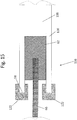
- Figs. 2-17 drug delivery devices, generally designated 20, 80, 88, 100, 110, 116, 126, and 138 in accordance with first through eighth exemplary embodiments respectively.
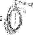
- the drug delivery device 20 may be implanted through a punctum 24 and lacrimal duct 26 of a patient, and into the lacrimal sac 28.
- the drug delivery device 20 is inserted in the relaxed state 40 as best seen in Fig. 2 .
- the drug delivery device may be inserted using a delivery guide 22.
- the delivery guide 22 moves a reservoir 32 of the drug delivery device 20 from the relaxed state 40 ( Fig. 2 ) to the expanded state ( Fig. 3 ).
- a face plate 30 may remain at the opening of the punctum to deliver medicament at a delivery site such as an eye.
- the drug delivery device 20 may be implanted into other portions of the anatomy such as the nasolacrimal duct, etc.
- the drug delivery device 20 may include a connector 34 fluidly connecting the reservoir 32 to the face plate 30.
- the connector 34 is a connector and includes a lumen.
- the connector is a wick.
- the connector is a wick and does not include a lumen.
- the reservoir 32 may be manufactured from a soft, biocompatible material that minimizes or eliminates any tissue damage during insertion of the device or negative interactions with the host site once implanted.
- the reservoir 32 is expandable to between 200% to 400% of its size in the relaxed state to hold a quantity of the drug as explained in below.
- the reservoir is expandable to between 200% to 1000% of its size in the relaxed state.
- the reservoir 32 is expandable to between 275-325% of its size in the relaxed state. In yet another embodiment, the reservoir 32 is expandable to between 300% to 500% of its size in the relaxed state.
- the reservoir 32 may have a relaxed diameter R d (see Fig. 6 ) of about 0.25-1.5 mm and an expanded diameter E d (see Fig. 7 ) of about 3.0-6.0 mm.
- the length of the reservoir 32 may also change as the reservoir moves from the relaxed state 40 to the expanded state 42. For example, the length of the reservoir 32 may expand from 5 mm in the relaxed state to about 30 mm in the expanded state.
- the reservoir 32 may be maneuvered through the lacrimal duct 26 and into the lacrimal sac 28 because the relatively smaller size in the relaxed state 40 makes the device easier to maneuver.
- the reservoir 32 may be moved from the relaxed state 40 to the expanded state 42 once it is in the lacrimal sac 28, as explained in greater detail below.
- the reservoir 32 could be positioned within the lacrimal duct 26 and need not be positioned in the lacrimal sac 28, if desired.
- the reservoir 32 in Figs. 6-7 has an internal chamber 44 configured to hold a drug or liquid medicament to be delivered at a delivery site (via elution, pressure induced flow, wicking, etc.). In one embodiment, the chamber 44 holds between about 100-41,000 ⁇ L of the drug in the expanded state.
- the chamber 44 holds about 300 ⁇ L of the drug in the expanded state.
- the reservoir 32 may be comprised of a material that does not interact with the drug and does not allow the drug to escape from the reservoir 32 (e.g. silicone, thermoplastic elastomer).
- the reservoir may retain the drug with less than 3% loss of fluid mass over 90 days and the concentration of the drug may be maintained for at least 5 days.
- the material selected for the reservoir 32 may have elastic properties similar to that of a balloon such that when the reservoir 32 is in the expanded state 42, the elasticity of the reservoir 32 provides a force to dispel the drug from the internal chamber 44 with a relatively low and flat pressure curve to provide a consistent and predictable flow rate of the drug.
- the reservoir material and geometry may also prevent bursting of the reservoir 32 and allow the reservoir 32 to be re-loaded, if desired.
- the reservoir 32 may have an opening 46 configured to receive the connector 34.
- the connector 34 may be inserted through the opening 46 and extend at least partially into the internal chamber 44 such that a rim 48 of the reservoir 32 is above a port 50 on the connector 34.
- the reservoir 32 and connector 34 may be manufactured as a monolithic element or coupled via adhesive, welding, etc. such that the connector 34 need not extend through the opening 46 and into the internal chamber 44.
- the reservoir 32 and connector 34 are manufactured monolithically but a portion of the connector 34 still extends into the chamber 44 of the reservoir 32.
- the external surface 52 of the reservoir 32 may have features (e.g. barbs, spikes, textured surface) that at least partially assist in holding the reservoir 32 within the lacrimal sac 28 or other site at which the reservoir 32 is implanted.
- the connector 34 may be a generally cylindrical member that fluidly connects the reservoir 32 to the face plate 30.
- the connector 34 may be manufactured from a similarly soft, flexible, biocompatible material to minimize or eliminate tissue damage during insertion.
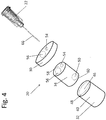
- the connector 34 may include a first lumen 54 and a second lumen 56 as shown in Fig. 4 but could alternatively include a single lumen or more than two lumens, if desired.
- the first lumen 54 may extend from a proximal end 58 toward a distal end 60 of the connector 34 and is connected to the port 50 to transfer the drug from the reservoir 32 to the face plate 30, which is coupled to the proximal end 58 of the connector 34.
- the port 50 is shown as extending through a sidewall of the connector 34, the port could also be on the distal end 60 of the connector.
- the port 50 could be a hole, slit valve, etc.
- a slit valve may be a slit in the material which allows one-way flow of material from the reservoir 32.
- the connector 34 includes more than one port 50 or more than one first lumen 54.
- the reservoir 32 and the connector 34 are shown in Fig. 4 as separate elements, they could be manufactured as a single element and even be made from the same material but the connector may be somewhat structurally different (e.g. reinforced, thicker walls) such that the connector 34 does not expand when the reservoir 32 is moved from the relaxed to the expanded state.
- the connector 34 expands lengthwise as the reservoir is expanded, thereby causing the first lumen 54 to constrict and control the flow rate of the drug through the first lumen 54.
- the rate of flow of the drug through the connector 34 is at least partially controlled by the first lumen 54.
- the size of the first lumen 54 may influence the rate of flow as a larger lumen will allow greater flow through the connector. In some embodiments, however, it is more desirable to have a slower flow and thus, a smaller first lumen 54, or at least a lumen with a smaller internal diameter, may be adopted.
- the first lumen 54 may have baffles or some other structural element within the lumen to slow the flow of the drug.
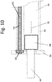
- hydrogel 62 may be placed within the first lumen 54 as shown in Fig. 9 at least partially controlling the flow of the drug.
- Hydrogel 62 may provide an effective way to consistently deliver the drug at a generally constant rate between about 0.1 ⁇ L and about 100 ⁇ L per day by utilizing the pressure of the reservoir 32 to load the drug into the hydrogel 62 without being as pressure dependent as other types of mechanical flow restrictors.
- the hydrogel 62 may extend the length of the first lumen 54 or may only extend along a portion thereof.
- the hydrogel 62 may fill a majority, if not all, of the cross sectional area of the first lumen 54 to ensure the drug flows through the hydrogel 62.
- the size of the space in the first lumen 54 may be designed to account for flow of the drug outside of the hydrogel 62.
- the hydrogel 62 may be in a dry state and not absorbed any of the drug during implantation of the drug delivery device 20.
- the hydrogel 62 may transition to a wetted state after the device 20 is implanted and the drug is transferred into the reservoir 32 and absorbed by the hydrogel 62. In one embodiment, the transition to the wetted state takes between about 1 and 48 hours to become fully saturated and reach steady state flow.
- the hydrogel 62 may be pre-wetted prior to implantation of the drug delivery device 20, if desired.
- the hydrogel 62 may load, or absorb, the drug and delivers it at a delivery site.
- the hydrogel 62 may not absorb the drug but instead merely offer a flow resistance to the flow of the drug wherein the reservoir pressure is the driving force for delivering the drug.
- the flow resistance of the hydrogel 62 may be altered by changing the chemical composition, crosslinking, or geometrical shape of the hydrogel 62.
- valves may be positioned in the first lumen 54 which restrict the flow of the drug.
- the first lumen 54 may be sealed and relatively small holes may be formed in the end of the lumen through which the drug flows.
- Tight fitting "leaky” components may also be used (e.g. a threaded screw which allows flow along the threaded connection even when fully seated in a threaded opening).
- the diameter of the first lumen 54 could also change as the pressure in the reservoir changes such that a higher pressure in the reservoir creates a smaller diameter lumen and a lower pressure creates a larger diameter to provide a consistent flow rate.
- Non-mechanical flow delivery devices such as a wick could also be adopted.
- the second lumen 56 extends from the proximal end 58 toward the distal end 60 of the connector and receives the delivery guide 22 which includes a cannula 66.
- the second lumen 56 may extend completely through the connector 34 to allow the cannula 66 to extend through the connector 34 and into the reservoir 32 during implantation of the drug delivery device 20.
- the second lumen 56 may be sealed after the delivery guide 22 is removed, as explained in greater detail below.
- the face plate 30 may be coupled to the proximal end 58 of the connector 34.
- the connector 34 and the face plate 30 are manufactured monolithically and may be made from the same or different materials.
- the connector 34 and face plate 30 are manufactured separately and joined by conventional methods known to one of ordinary skill in the art (e.g. adhesive, welding, fasteners).
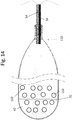
- the face plate 30 may have a single first lumen 54 through which the drug is delivered at the delivery site.
- the face plate 30 may include any number of first lumens 54.
- first lumens 54 in the connector 34 need not necessarily be equal to the number of first lumens 54 in the face plate 30 and channels (not shown) may be formed within the face plate 30 to fluidly connect the first lumens 54 of the connector 34 to those of the face plate 34.
- the second lumen 56 in the face plate 30 may align with the second lumen 56 in the connector 34 to allow the delivery guide 22 to extend through the face plate 30 and into the connector 34.
- the face plate 30 may have an outer diameter larger than that of the connector 34 such that when the drug delivery device is implanted in the lacrimal system, the connector 34 enters the lacrimal duct 26 but the face plate 30 is prevented from entering the lacrimal duct which helps prevent dislodgement of the drug delivery device 20.
- the delivery guide 22 may be inserted into the second lumen 56 through the face plate 30 and connector 34, and into the reservoir 32.
- the delivery guide 22 may include the cannula 66 which may comprise a guide wire which gives rigidity to the drug delivery device 20 as it is being implanted.
- the cannula 66 comprises a flexible cannula or a semi-flexible cannula (not shown) which is navigated through the lacrimal duct 26 and into the lacrimal sac 28 after which the drug delivery device 20 is implanted through the cannula.
- the cannula 66 is a conduit and delivers the drug into the reservoir 32 after implanting the drug delivery device 20, thereby moving the reservoir 32 from the relaxed state 40 to the expanded state 42.
- a plug 68 is attached to the end of the cannula 66.
- the plug 68 may be sized and configured to seal the second lumen 56 after the drug delivery device 20 is implanted.
- the plug 68 may be detachably coupled to the cannula 66 via adhesive, threaded connection, ball and detent structure, etc. and positioned within the distal end 60 of the connector 34 or in the reservoir 32 while the drug delivery device 20 is being implanted.
- the cannula 66 may pull the plug 68 along the second lumen 56 as the cannula 66 is removed from the delivery device 20 until the plug 68 is adjacent the face plate 30.
- the plug 68 could also be positioned at any location along the second lumen 56 desired, including at the distal end 60.
- the drug may exert a force 70 on the plug 68 because the drug is under pressure in the reservoir 32 as previously described and may maintain the position of the plug 68 to effectively seal the second lumen 56.
- the cannula 66 may be detached from the plug 68 and removed from the drug delivery device 20 after the plug 68 is positioned at the desired location.
- a membrane filter 64 is positioned within the first lumen 54 of the face plate 30.
- the membrane filter 64 may seal the hydrogel 62 within the first lumen 54 and form a protective barrier preventing contamination of the hydrogel 62 from external substances.
- the membrane filter 64 may also provide flow control of the drug through the first lumen 54.
- the porosity of the membrane filter 64 could be such that it restricts flow of the drug.
- the membrane filter 64 is shown as within the face plate 30, it could also be positioned within the first lumen 54, if desired.
- the entire face plate 30 may be formed of the membrane filter 64, if desired.
- the drug delivery device 80 may be similar to the first embodiment of the drug delivery device 20 except that the composition of the hydrogel 82 is different.
- the hydrogel 82 may include a first section 84 adjacent the reservoir 32 and a second section 86 opposite the first section 84.
- the first section 84 may have a composition which allows for faster absorption of the drug than the second section 86. Therefore, the drug may be quickly absorbed by the first section 84 but delivered by the second section 86 at a relatively slower rate. This configuration helps to control the flow rate of the drug through the drug delivery device 80.
- the composition of the first and second sections 84, 86 may be reversed such that the first section 84 absorbs the drug more slowly than the second section but the resulting control of the flow rate of the drug is still the same.
- the first section 84 may have a different chemical composition than the second section 86.
- the first and second sections 84, 86 may have the same chemical composition but the first section 84 may be more densely packed than the second section 86 such that the porosity of the first section 84 is different than the porosity of the second section 86.
- the first section 84 may have a larger porosity than the second section 86 and the larger porosity allows a faster flow rate of the drug.
- the first lumen 90 may include a first portion 92 having a first diameter and a second portion 94 having a second diameter different than the first diameter.
- the first portion 92 may have a greater diameter than the second portion 94 and the hydrogel 62 may fill both the first portion 92 and the second portion 94.
- the increased amount of hydrogel 62 in the first portion 92 may allow the drug to be absorbed faster by the first portion 92 than the second portion 94.
- the relative size of the first portion 92 to the second portion 94 may help control the rate of flow of the drug.
- composition of the hydrogel 62 in the first portion 92 and the second portion 94 may be the same or may be different from each other as described with respect to other embodiments.
- the demarcation between the first portion 92 and second portion 94 may form a shoulder 96, but the transition could also be a gradual change giving the first lumen 90 a frustoconical shape.
- the drug delivery device 100 is similar to the first embodiment of the drug delivery device 20 except that the composition of the hydrogel 102 is different.
- the hydrogel 102 may include a hydrophilic portion 104 and a hydrophobic portion 106.
- the hydrophilic and hydrophobic portions 104, 106 may have different characteristics (e.g. physical makeup, chemical properties) such that the hydrophilic portion 104 absorbs and delivers the drug faster than the hydrophobic portion 106.
- the hydrophilic portion 104 may extend substantially from the distal end 60 of the connector 34 to the proximal end 58 such that the drug is delivered through the hydrophilic portion 104 along a defined path ( e.g.
- the ratio of the hydrophilic portion 104 to the hydrophobic portion 106 may be the same throughout the first lumen 54 or may be greater at the distal end 60 than at the proximal end 58 such that the drug is absorbed by the hydrogel more quickly than it is delivered.
- the hydrophilic portion 104 and hydrophobic portion 106 need not be homogenous portions as shown in Fig. 13 .
- the hydrogel 102 may be a heterogeneous substance with the ratio of hydrophilic elements greater at the distal end 60 than at the proximal end 58.
- a fifth exemplary embodiment of the drug delivery device is similar to the first embodiment of the drug delivery device 20 except that the drug delivery device 110 includes drug containing spheres 112 and does not include any hydrogel although hydrogel as previously described could be included, if desired.
- the spheres 112 are within the reservoir 32 when the drug delivery device 110 is implanted.
- a liquid e.g. saline, liquid medicament, water
- a liquid may be injected through the delivery guide 22 and into the reservoir where it washes away the spheres 112 and the drug within the spheres 112 is delivered over time through the connector and lumen to deliver the drug at the delivery site.
- a sixth exemplary embodiment of the drug delivery device is similar to the first embodiment of the drug delivery device 20 except that the drug delivery device 116 includes only a single lumen 118 in the connector 120.
- the hydrogel 62 may not be in the lumen 118 when the device 116 is implanted. Instead, the hydrogel 62 may be coupled to the end of the cannula 66 and pulled into the lumen 118 as the cannula 66 is being removed from the connector 120.
- Adhesive 122 may be positioned on the proximal end 58 of the connector 120 such that the hydrogel 62 is at least partially secured within the connector 120 by adhesive 122 in addition to the pressure exerted by the drug from the reservoir (not shown).
- the adhesive 122 may also secure the face plate (not shown) to the connector 120.
- the hydrogel 62 may control the flow rate of the drug and also seal the lumen 118.
- a seventh exemplary embodiment of a face plate generally designated 126.
- the face plate 126 is similar to the face plate 30 except that the face plate 126 includes a connector 128 and a barb 130.
- the barb 130 may secure the face plate 126 within the first lumen 54 via an interference fit.
- the barb 130 may be manufactured from a material such as rubber, silicone, etc. that allows the barb 130 to slightly deform when it enters the first lumen 54 and secures the face plate 126 therein.
- the face plate 126 may include an end piece 132 with multiple openings 134 through which the drug is delivered. Of course, the face plate 126 may also include only a single opening 134 in the end piece 132.
- the connector 128 may include the hydrogel 62 or membrane filter 64 as previously described.
- the face plate 126 may be used with a connector 34 having a single lumen wherein the barb 130 seals the lumen and the drug flows through hydrogel within the connector and out of the face plate.
- the face plate 126 may be used with a connector 34 having two lumens wherein the face plate 126 is secured within the first lumen.
- an eighth exemplary embodiment of a drug delivery device is similar to the drug delivery device 20 of the first embodiment except that the drug delivery device 138 includes a valve 140 sealing the second lumen 56 instead of a plug 68.
- the valve 140 may be moveable between an open position 142 and a closed position 144 (shown in phantom in Fig. 17 ).
- the valve 140 may be any type of valve (e.g. duck bill valve, flap valve, one-way valve) provided that the valve 140 allows the cannula 66 to be inserted into the second lumen 56 and seals the second lumen 56 when the cannula 66 is removed.
- the valve 140 may be secured in the closed position by the pressure of the drug within the second lumen 56 after the cannula 66 delivers the drug into the reservoir 32 and is removed.
- the valve 140 may allow the cannula 66 to be reinserted to introduce an additional volume of the drug into the reservoir 32 such that the drug delivery device 138 is re-useable.
Landscapes
- Health & Medical Sciences (AREA)
- Veterinary Medicine (AREA)
- Public Health (AREA)
- General Health & Medical Sciences (AREA)
- Animal Behavior & Ethology (AREA)
- Life Sciences & Earth Sciences (AREA)
- Ophthalmology & Optometry (AREA)
- Pharmacology & Pharmacy (AREA)
- Medicinal Chemistry (AREA)
- Chemical & Material Sciences (AREA)
- Engineering & Computer Science (AREA)
- Epidemiology (AREA)
- Vascular Medicine (AREA)
- Heart & Thoracic Surgery (AREA)
- Biomedical Technology (AREA)
- General Chemical & Material Sciences (AREA)
- Bioinformatics & Cheminformatics (AREA)
- Chemical Kinetics & Catalysis (AREA)
- Nuclear Medicine, Radiotherapy & Molecular Imaging (AREA)
- Organic Chemistry (AREA)
- Prostheses (AREA)
Description
- The present invention generally relates to a medicament delivery device and, more particularly, to an implantable drug delivery device for delivering a drug to the eye through the lacrimal duct.
- Ocular diseases and disorders frequently require the introduction of medicament into the eye for the treatment of symptoms. Conventional means for delivering the medicament include topical application of the medicament to the surface of the eye such as through the use of eye drops. Eye drops are typically applied repeatedly by the user either according to a defined schedule or when discomfort develops. However, there are several drawbacks with manual application of eye drops. Users do not always adhere to the prescribed schedule. There may also be waste of the drug associated with the application as users may use a larger volume of the drug than may be absorbed by the eye in a timely manner or may not accurately place the drops inside the eye.
- Installing a drug releasing implant into the punctum can overcome some of the problems associated with manual installation of the medicament. A punctal plug is one implantable device that is inserted into the punctum and releases medicament into the eye. However, several drawbacks are associated with this type of device as well. The device may become dislodged if the user rubs their eye area or sneezes. The device may block the natural flow of tears into the lacrimal system. The device holds a limited volume of medicament which requires the devices to be replaced. The device also fails to provide an even distribution rate of the medicament. Instead, a large amount of the medicament is dispersed when the device is first implanted and the delivery rate tapers over time.
- Other types of lacrimal drug delivery implants are described in International Application No.
PCT/US2014/011477 [1] and published asWO 2014113384 . However, such lacrimal implants still need to accurately control the rate of delivery of the drug. - Therefore, it is desirable to provide an improved drug delivery implant that provides long term consistent release of medicament to the delivery site
-
US-A-2015/0351961 describes an implantable lacrymal drug delivery device according to the preamble of claim 1;US 6 152 916 discloses a bicanalicular probe for the treatment of the lachrymation of the eye.WO-A-2017/091404 is prior art under Art. 54(3) EPC and discloses a lacrimal system for drug delivery. - The present invention generally relates to a medicament delivery device and, more particularly, to an implantable drug delivery device for delivering a drug to the eye through the lacrimal duct.
- In one embodiment, the present description contemplates a lacrimal drug delivery device, comprising: a reservoir configured to hold a drug, the reservoir expandable between a relaxed state and an expanded state; a connector fluidly coupled to the reservoir, a lumen formed in the connector wherein the drug is configured to flow from the reservoir to a delivery site through the lumen; a hydrogel within the lumen, the hydrogel being configured to absorb the drug from the reservoir and deliver the drug from the lumen at the drug at the delivery site, the hydrogel including a first section which absorbs the drug at a first rate of absorption; and a delivery guide detachably coupled to the reservoir to deliver the reservoir into a lacrimal sac of a patient. In one embodiment, said hydrogel includes a second section which absorbs the drug at a second rate of absorption different from the first rate of absorption. In one embodiment, the first section has a first porosity and the second section has a second porosity different from the first porosity. In one embodiment, the first rate of absorption and the second rate of absorption are at least partially controlled by the porosity, wherein a larger porosity provides a faster rate of absorption. In one embodiment, the first section is adjacent the reservoir and the second section is opposite the first section, the first porosity larger than the second porosity. In one embodiment, the hydrogel includes a dry state wherein the drug is separate from the hydrogel prior to the device being implanted and a wetted state wherein the drug is absorbed by the hydrogel after the device is implanted. In one embodiment, the connector includes a second lumen with the delivery guide removably positioned within the second lumen. In one embodiment, the delivery guide comprises a guide wire. In one embodiment, the guide wire includes an opening therethrough such that the drug is delivered through the opening to transfer the reservoir from the relaxed state to the expanded state. In one embodiment, said device further comprises a valve within the second lumen which seals the second lumen when the delivery device is removed. In one embodiment, said device further comprises a filter coupled to the connector, the filter sealing the hydrogel within the lumen while allowing the drug to flow through the filter. In one embodiment, the filter prevents external substances from contaminating the hydrogel. In one embodiment, the drug is configured to elude through the hydrogel and filter and the filter at least partially controls flow of the drug. In one embodiment, the reservoir is elastic such that the reservoir exerts a compressive force on the drug when the reservoir is in the expanded state. In one embodiment, the first section and the second section have the same or substantially similar chemical formulation. In one embodiment, the first section and the second section have different formulations. In one embodiment, the first section is hydrophilic and the second section is hydrophobic. In one embodiment, the lumen includes a proximal end and a distal end and the ratio of the first section to the second section is greater at the proximal end than at the distal end. In one embodiment, the first section extends from the proximal end to the distal end such that the drug is transferred along the lumen through the first section. In one embodiment, the first section has a first thickness and the second section has a second thickness less than the first thickness such that the first section absorbs the drug faster than the second section. In one embodiment, the lumen has a distal diameter adjacent the reservoir and a proximal diameter opposite the reservoir, wherein the proximal diameter is smaller than the distal diameter. In one embodiment, the delivery site is at least one of a lacrimal punctum and nasolacrimal duct.
- In one embodiment, the description contemplates a lacrimal drug delivery device, comprising: a reservoir configured to hold a drug, the reservoir moveable between a relaxed state and an expanded state; a connector fluidly coupled to the reservoir, the connector including a first lumen, a second lumen, a proximal end, and a distal end, the drug configured to flow from the reservoir to a delivery site through the first lumen; a hydrogel within the first lumen, the hydrogel configured to absorb the drug from the reservoir and deliver the drug from the lumen at the delivery site; a delivery guide within the second lumen and configured to transfer the reservoir between the relaxed state to the expanded state, the delivery guide detachably coupled to the reservoir to position the reservoir in a lacrimal sac of a patient; and a valve within the second lumen, the valve sealing the second lumen when the delivery guide is removed and allowing the delivery guide to be reinserted to retransfer the reservoir between the relaxed state and the expanded state. In one embodiment, the delivery guide includes an opening and the drug is delivered through the opening and into the reservoir to transfer the reservoir from the relaxed state to the expanded state. In one embodiment, the hydrogel includes a first section with a first rate of absorption and a second section with a second rate of absorption different than the first rate of absorption.
- In one embodiment there is a lacrimal drug delivery device including a reservoir configured to hold a drug, the reservoir moveable between a relaxed state and an expanded state; a connector fluidly coupled to the reservoir, a lumen formed in the connector wherein the drug is configured to flow from the reservoir to a delivery site through the lumen; a hydrogel within the lumen, the hydrogel being configured to absorb the drug from the reservoir and deliver the drug from the lumen at the drug delivery site, the hydrogel including a first section which absorbs the drug at a first rate of absorption; and a delivery guide detachably coupled to the reservoir to deliver the reservoir into a lacrimal sac of a patient.
- In another embodiment, the hydrogel includes a second section which absorbs the drug at a second rate of absorption different than the first rate of absorption. The first section may have a first porosity and the second section may have a second porosity different from the first porosity and the rate of absorption may be at least partially controlled by the porosity, wherein a larger porosity provides a faster rate of absorption. The first section may be adjacent the reservoir and the second section opposite the first section and the first porosity may be larger than the second porosity.
- In another embodiment, the hydrogel includes a dry state wherein the drug is separate from the hydrogel prior to the device being implanted and a wetted state wherein the drug is absorbed by the hydrogel after the device is implanted. In one embodiment, the connector includes a second lumen with the delivery guide removably positioned within the second lumen. In one embodiment, the delivery guide is a guide wire and may include an opening therethrough such that the drug is delivered through the opening to transfer the reservoir from the relaxed state to the expanded state.
- In a further embodiment, a lacrimal drug delivery device further includes a valve within the second lumen which seals the second lumen when the delivery device is removed. In a further embodiment, a filter is coupled to the connector to seal the hydrogel within the lumen while allowing the drug to flow through the filter and may prevent external substances from contaminating the hydrogel. In one embodiment the drug is configured to elude through the hydrogel and filter and the filter at least partially controls flow of the drug. In one embodiment, the reservoir is elastic such that the reservoir exerts a compressive force on the drug when the reservoir is in the expanded state. In one embodiment, the first section and the second section have the same or substantially similar chemical formulation; in another embodiment, the first section and second section have different formulations. In one embodiment, the first section is hydrophilic and the second section is hydrophobic.
- In another embodiment, the lumen includes a proximal end and a distal end and the ration of the first section to the second section is greater at the proximal end than at the distal end. In one embodiment, the first section extends from the proximal end to the distal end such that the drug is transferred along the lumen through the first section. In one embodiment, the first section has a first thickness and the second section has a second thickness less than the first thickness such that the first section absorbs the drug faster than the second section. In one embodiment the lumen has a distal diameter adjacent the reservoir and a proximal diameter opposite the reservoir, wherein the proximal diameter is smaller than the distal diameter. In one embodiment the delivery site is at least one of a lacrimal punctum and a nasolacrimal duct.
- In another embodiment, there is a lacrimal drug delivery device comprising a reservoir to hold a drug, the reservoir moveable between a relaxed state and an expanded state; a connector fluidly coupled to the reservoir, the connector including a first lumen, a second lumen, a proximal end, and a distal end, the drug configured to flow from the reservoir to a delivery site through the first lumen; a hydrogel within the first lumen, the hydrogel configured to absorb the drug from the reservoir and deliver the drug from the lumen at the delivery site; a delivery guide within the second lumen and configured to transfer the reservoir from the relaxed state to the expanded state, the delivery guide detachably coupled to the reservoir to position the reservoir in a lacrimal sac of a patient; and a valve within the second lumen, the valve sealing the second lumen when the delivery device is removed and allowing the delivery device to be reinserted to retransfer the reservoir between the relaxed state and the expanded state. In one embodiment, the delivery guide includes an opening and the drug is delivered through the opening and into the reservoir to transfer the reservoir from the relaxed state to the expanded state. In one embodiment, the hydrogel includes a first section with a first rate of absorption and a second section with a second rate of absorption different than the first rate of absorption.
- To facilitate the understanding of this invention, a number of terms are defined below.
- As used herein, the term "patient" or "subject" refers to any living mammalian organism, such as a human, monkey, cow, sheep, goat, dog, cat, mouse, rat, guinea pig, or transgenic species thereof. In certain embodiments, the patient or subject is a primate. Non-limiting examples of human subjects are adults, juveniles, infants and fetuses.
- "Prevention" or "preventing" as used herein, includes, but is not limited to: (1) inhibiting the onset of a disease in a subject or patient which may be at risk and/or predisposed to the disease, wherein such inhibition may be either partial or complete, but does not yet experience or display any or all of the pathology or symptomatology of the disease, and/or (2) slowing the onset of the pathology or symptomatology of a disease in a subject or patient which may be at risk and/or predisposed to the disease but does not yet experience or display any or all of the pathology or symptomatology of the disease.
- As used herein, the terms "medication" or "therapeutic agent" refer to any compound and/or molecule that treats or prevents or alleviates the symptoms of disease or condition, including, but not limited to, a drug or pharmaceutical composition. Medication is considered to be delivered or present in therapeutically effective amounts or pharmaceutically effective amounts.
- "Therapeutically effective amounts" or "pharmaceutically effective amounts", as used herein, means that amount which, when administered to a subject or patient for treating a disease, is sufficient to effect such treatment for the disease or to ameliorate one or more symptoms of a disease or condition (e.g. ameliorate pain).
- As used herein, the terms "treat" and "treating" are not limited to the case where the subject (e.g. patient) is cured and the disease is eradicated. Rather, treatment may also merely reduce symptoms, improves (to some degree) and/or delays disease progression among other effects. It is not intended that treatment be limited to instances wherein a disease or affliction is cured. It is sufficient that symptoms are reduced.
- As used herein, the terms "medical device," "implant," "device," "medical device," "medical implant," "implant/device," and the like are used synonymously to refer to any object that is designed to be placed partially or wholly within a patient's body for one or more therapeutic or prophylactic purposes such as for tissue augmentation, contouring, restoring physiological function, repairing or restoring tissues damaged by disease or trauma, and/or delivering therapeutic agents to normal, damaged or diseased organs and tissues. While medical devices are normally composed of biologically compatible synthetic materials (e.g., medical-grade stainless steel, nitinol, titanium and other metals; exogenous polymers, such as polyurethane, silicone, PLA, PLGA, PGA, PCL), other materials may also be used in the construction of the medical implant. While not limiting the present invention to any particular device, specific medical devices and implants that are particularly relevant to this invention include stents, punctal plugs, Crawford tubes, catheters, lacrimal tubes, ocular or other shunts, and drug delivery systems. In some embodiments, the device incorporates a contrast material or opaque materials that allow for visualization with standard imaging devices (for example, barium to allow for x-ray visualization).
- As used herein, the term "medication reservoir" refers to any elastic structure containing medication or therapeutic agent. In preferred embodiments, the reservoir is made of stretchy plastics or silicones.
- As used herein, the term "proximal" refers to a location situated toward a point of origin (e.g., between a physcian and a lacrimal implant device).
- As used herein, the term "distal" refers to a location situated away from a point of origin (e.g., behind a lacrimal implant device relative to a physician).
- As used herein, the term "hydrogel" is used to refer to an absorbing or otherwise retaining material (e.g., adsorbing material), such as super-absorbent polymers, hydrocolloids, and water-absorbent hydrophilic polymers, for example. In some examples, the term "hydrogel" refers to super-absorbent polymer particles in a "dry or dehydrated" state, more specifically, particles containing from no water up to an amount of water less than the weight of the particles, such as less than about 5%, by weight, water. In some examples, the term "hydrogel" refers to a super-absorbent polymer in the "dry or dehydrated" state when the hydrogel is not expandable and also refers to its hydrated or expanded state, more specifically, hydrogels that have absorbed at least their weight in water, such as several times their weight in water. As the hydrogel material absorbs fluid, it size can increase and its shape can change to bias against at least a portion of a lacrimal canaliculus ampulla or lacrimal canaliculus wall, for example.
- As used herein, the term "medicament" refers to any active agent that is suitable for use in medical treatment, such as a medicinal compound or drug.
- As used herein, the term "active agent" refers to any molecular entity that exerts an effect on a living organism.
- As used herein, the term "polymer" refers to any organic macromolecule containing one or more repeating units, as is well known in the art.
- As used herein, a "copolymer" refers to any polymer in which there are at least two types of repeating units included. A copolymer can be a block copolymer, in which there are segments containing multiple repeating units of one type, bonded to segments containing multiple repeating units of a second type.
- As used herein, the term "hydrophilic polymer" refers to any polymer that can be wetted by water, i.e., does not have a water-repellant surface. A hydrophilic polymer can absorb water to a small degree, for example about 0-100 wt % of water, but does not greatly swell in volume as does a hydrogel-forming polymer.
- As used herein, the terms "implanted" refers to having completely or partially placed a device within a host. A device is partially implanted when some of the device reaches, or extends to the outside of, a host.
- As used herein, the term "steroids" refers to any organic compound that contains a core composed of twenty carbon atoms bonded together that take the form of four fused rings: three cyclohexane rings (designated as rings A, B, and C in the figure to the right) and one cyclopentane ring (the D ring). The steroids vary by the functional groups attached to this four-ring core and by the oxidation state of the rings. Examples of steroids include, but are not limited to, the dietary fat cholesterol, the sex hormones

- As used herein, the term "non-steroidal anti-inflammatory agents," "nonsteroidal anti-inflammatory drugs," usually abbreviated to NSAIDs or NAIDs, but also referred to as nonsteroidal anti-inflammatory agents/analgesics (NSAIAs) or nonsteroidal Anti-inflammatory medicines (NSAIMs), refers to any drug with analgesic and antipyretic (fever-reducing) effects and which have, in higher doses, anti-inflammatory effects.
- As used herein, the term "antibiotics" refers to any compound or substance that kills or inhibits the growth of bacteria, fungus, or other microorganism.
- As used herein, the term "anti-inflammatory agent" refers to any substance or treatment that reduces inflammation.
- As used herein, the term "immunosuppressant agents" refers to all drugs that inhibit or prevent activity of the immune system.
- As used herein, the term "anti-neoplastic agents" refers to all drugs that prevent or inhibit the development, maturation, or spread of neoplastic cells.
- As used herein, the term "prostaglandin analogues" refers to all molecules that bind to a prostaglandin receptor.
- As used herein, the term "nitric oxide" or "nitrogen monoxide" refers to any binary diatomic molecule with the chemical formula NO.
- As used herein, the term "endothelin" refers to any protein that consisting of 21 amino acid residues that are produced in various cells and tissues, that play a role in regulating vasomotor activity, cell proliferation, and the production of hormones, and that have been implicated in the development of vascular disease. For example, endothelin biological activity may include, but is not limited to, constrict blood vessels, raise blood pressure, decrease eye pressure, and protect neuronal tissues from degeneration.
- As used herein, the term "corticosteroids" refers to a class of chemicals that includes any naturally produced steroid hormone or synthetic steroid hormone analogue. Corticosteroids are involved in a wide range of physiologic processes, including, but not limited to, stress response, immune response, and regulation of inflammation, carbohydrate metabolism, protein catabolism, blood electrolyte levels, and behavior.
- As used herein, the term "antibody-based immunosuppresants" refers to any antibody (e.g., polyclonal, monoclonal, Fab etc) having an immunosuppressant activity
- As used herein, the term "release of an agent" refers to any presence of the agent, or a subcomponent thereof, emanating from an implant device.
- As used herein, the terms "analogue or analog" refer to any chemical compound that is structurally similar to a parent compound but differs slightly in composition (e.g., one atom or functional group is different, added, or removed). An analogue may or may not have different chemical or physical properties than the original compound and may or may not have improved biological and/or chemical activity. For example, the analogue may be more hydrophilic, or it may have altered reactivity as compared to the parent compound. The analogue may mimic the chemical and/or biological activity of the parent compound (i.e., it may have similar or identical activity), or, in some cases, may have increased or decreased activity. The analogue may be a naturally or non-naturally occurring (e.g., recombinant) variant of the original compound. An example of an analogue is a mutein (i.e., a protein analogue in which at least one amino acid is deleted, added, or substituted with another amino acid). Other types of analogues include isomers (enantiomers, diasteromers, and the like) and other types of chiral variants of a compound, as well as structural isomers. The analogue may be a branched or cyclic variant of a linear compound. For example, a linear compound may have an analogue that is branched or otherwise substituted to impart certain desirable properties (e.g., improve hydrophilicity or bioavailability).
- As used herein, the term "derivative" refers to any chemically or biologically modified version of a chemical compound that is structurally similar to a parent compound and (actually or theoretically) derivable from that parent compound. A "derivative" differs from an "analogue" in that a parent compound may be the starting material to generate a "derivative," whereas the parent compound may not necessarily be used as the starting material to generate an "analogue." An analogue may have different chemical or physical properties of the parent compound. For example, the derivative may be more hydrophilic or it may have altered reactivity as compared to the parent compound. Derivatization (i.e., modification) may involve substitution of one or more moieties within the molecule (e.g., a change in functional group). For example, a hydrogen may be substituted with a halogen, such as fluorine or chlorine, or a hydroxyl group (-OH) may be replaced with a carboxylic acid moiety (-COOH). The term "derivative" also includes conjugates, and prodrugs of a parent compound (i.e., chemically modified derivatives that can be converted into the original compound under physiological conditions). For example, the prodrug may be an inactive form of an active agent. Under physiological conditions, the prodrug may be converted into the active form of the compound. Prodrugs may be formed, for example, by replacing one or two hydrogen atoms on nitrogen atoms by an acyl group (acyl prodrugs) or a carbamate group (carbamate prodrugs). More detailed information relating to prodrugs is found, for example, in Fleisher et al., Advanced Drug Delivery Reviews 19 (1996) 115 [2]. The term "derivative" is also used to describe all solvates, for example hydrates or adducts (e.g., adducts with alcohols), active metabolites, and salts of the parent compound. The type of salt that may be prepared depends on the nature of the moieties within the compound. For example, acidic groups, for example carboxylic acid groups, can form, for example, alkali metal salts or alkaline earth metal salts (e.g., sodium salts, potassium salts, magnesium salts and calcium salts, and also salts with physiologically tolerable quaternary ammonium ions and acid addition salts with ammonia and physiologically tolerable organic amines such as, for example, triethylamine, ethanolamine or tris-(2-hydroxyethyl)amine). Basic groups can form acid addition salts, for example with inorganic acids such as hydrochloric acid, sulfuric acid or phosphoric acid, or with organic carboxylic acids and sulfonic acids such as acetic acid, citric acid, benzoic acid, maleic acid, fumaric acid, tartaric acid, methanesulfonic acid or p-toluenesulfonic acid. Compounds that simultaneously contain a basic group and an acidic group, for example a carboxyl group in addition to basic nitrogen atoms, can be present as zwitterions. Salts can be obtained by customary methods known to those skilled in the art, for example by combining a compound with an inorganic or organic acid or base in a solvent or diluent, or from other salts by cation exchange or anion exchange.
- As used herein, the term "inhibitor" or "antagonist" refers to any agent that prevents a biological process from occurring and/or slows the rate and/or slows the degree of occurrence of a biological process. The process may be a general one such as scarring or refer to a specific biological action such as, for example, a molecular process resulting in release of a cytokine.
- As used herein, the term "agonist" refers to any agent that stimulates a biological process or rate or degree of occurrence of a biological process. The process may be a general one such as scarring or refer to a specific biological action such as, for example, a molecular process resulting in release of a cytokine.
- As used herein, the term "anti-microtubule agent" should be understood to include any protein, peptide, chemical, or other molecule that impairs the function of microtubules, for example, through the prevention or stabilization of polymerization. Compounds that stabilize polymerization of microtubules are referred to herein as "microtubule stabilizing agents." A wide variety of methods may be utilized to determine the anti-microtubule activity of a particular compound, including for example, assays described by Smith et al. (Cancer Lett. 79(2):213-219, 1994) [5] and Mooberry et al., (Cancer Lett. 96(2):261-266, 1995) [3].
- Any concentration ranges, percentage range, or ratio range recited herein are to be understood to include concentrations, percentages or ratios of any integer within that range and fractions thereof, such as one tenth and one hundredth of an integer, unless otherwise indicated. In addition, any number range recited herein relating to any physical feature, such as polymer subunits, size or thickness, are to be understood to include any integer within the recited range, unless otherwise indicated. It should be understood that the terms "a" and "an" as used above and elsewhere herein refer to "one or more" of the enumerated components. For example, "a" polymer refers to both one polymer or a mixture comprising two or more polymers. As used herein, the term "about" means ±15%.
- As used herein, the term "biomaterial" refers to any substance (other than drugs) or combination of substances synthetic or natural in origin, which can be used for any period of time, as a whole or as a part of a system which treats, augments, or replaces any tissue, organ, or function of the body.
- As used herein, the term "biocompatibility" refers to the ability of a material to perform with an appropriate host response in a specific application.
- As used herein, the term "elastic limit" or "yield strength" refers to the stress at which a material begins to deform plastically. Prior to the yield point the material will deform elastically and will return to its original shape when the applied stress is removed. Once the yield point is passed, some fraction of the deformation will be permanent and non-reversible.
- As used herein, the term "elastic" refers to a material that with very large deformability when forces are applied on it with complete recoverability, meaning the object will return to its initial shape and size when these forces are removed. Such a feature has also been referred to as rubber elasticity. Molecular Requirements of such "elastic" materials: Material must consist of polymer chains, Need to change conformation and extension under stress. Polymer chains must be highly flexible. Need to access conformational changes (not w/ glassy, crystalline, stiff mat.) Polymer chains must be joined in a network structure. Need to avoid irreversible chain slippage (permanent strain). One out of 100 monomers must connect two different chains. Connections (covalent bond, crystallite, glassy domain in block copolymer) Examples of elastic polymers include rubber, latex, synthetic rubbers, neoprene, silicone and the like.
- As used herein, the term "non-elastic" refers to a material that with low or no deformability when forces are applied on it. Beyond the strain limit, a non-elastic material will experience irreversible deformation. Polymer chains are not flexible and do not easily access conformational changes. These may undergo irreversible chain slippage (permanent strain) Examples include glass, hard plastics, amorphous glassy polymers and the like..
- As used herein, the term "semi-elastic" refers to a material that with moderate deformability when forces are applied on it with complete recoverability, meaning the object will return to its initial shape and size when these forces are removed. There are a number of semi-elastic polymers. Examples of semi-crystalline polymers are linear polyethylene (PE), polyethylene terephthalate (PET), polytetrafluoroethylene (PTFE) or isotactic polypropylene (PP).
- As used herein, the term "self-compression" refers to when a material is added to a reservoir and filled to distortion leading to elastic forces to compress material inside the reservoir. This self-compression provides a force to initiate distribution of the material within the reservoir out of the reservoir, either through a flow limiting port or through forced diffusion.
- As used herein, the term "stent" refers to any artificial 'tube' inserted into a natural passage/conduit in the body to prevent, or counteract, a disease-induced, localized flow constriction. The term may also refer to a tube used to temporarily hold such a natural conduit open to allow access for surgery.
- As used herein, the term "shunt" refers to any artificial 'tube' inserted into the body to create a hole or passage to allow movement of fluids between two areas. Said tube may be implanted temporarily or may be permanent.
- As used herein, the term "Foley catheter" refers to a flexible tube that is often passed through the urethra and into the bladder. The tube has two separated channels, or lumens, running down its length. One lumen is open at both ends, and allows urine to drain out into a collection bag. The other lumen has a valve on the outside end and connects to a balloon at the tip; the balloon is inflated with sterile water, or other fluid/gas, when it lies inside the bladder, in order to stop it from slipping out.
- As used herein, the term "catheter" refers to any tube that can be inserted into a body cavity, duct, or vessel. Catheters thereby allow drainage, administration of fluids or gases, or access by surgical instruments. The process of inserting a catheter is catheterization. In most uses, a catheter is a thin, flexible tube ("soft" catheter), though in some uses, it is a larger, solid ("hard") catheter. A catheter left inside the body, either temporarily or permanently, may be referred to as an indwelling catheter. A permanently inserted catheter may be referred to as a permcath.
- As used herein, the term "microelectromechanical systems" or "MEMS" refers to technology of very small devices. MEMS are separate and distinct from the hypothetical vision of molecular nanotechnology or molecular electronics. MEMS are made up of components between 1 to 100 micrometres in size (i.e. 0.001 to 0.1 mm), and MEMS devices generally range in size from 20 micrometres (20 millionths of a metre) to a millimetre (i.e. 0.02 to 1.0 mm). They usually consist of a central unit that processes data (the microprocessor) and several components that interact with the surroundings such as microsensors.
- As used herein, the term "PLGA or poly(lactic-co-glycolic acid)" refers to a copolymer and is approved for therapeutic devices by the United States Food and Drug Administration (FDA), owing to its biodegradability and biocompatibility. PLGA has been studied for slow drug release [4].
- As used herein, the term "polyethylene glycol" (abbreviated PEG) refers to any polyether compound. For example, PEG is commercially available as polyethylene oxide (PEO) or polyoxyethylene (POE), depending on its molecular weight (Carbowax®).
- The foregoing summary, as well as the following detailed description of embodiments of the drug delivery device, will be better understood when read in conjunction with the appended drawings of an exemplary embodiment.
- In the drawings:
-
Fig. 1 is an illustration of a typical person's lacrimal system; -
Fig. 2 is a front view of a drug delivery device and delivery guide in accordance with a first exemplary embodiment being inserted into a lacrimal duct; -
Fig. 3 is a front partial sectional view of the drug delivery device and delivery guide ofFig. 2 inserted in the lacrimal duct with the reservoir in an expanded state; -
Fig. 4 is an exploded front perspective view of the drug delivery device and delivery guide ofFig. 2 ; -
Fig. 5 is an assembled front perspective view of the drug delivery device and delivery guide ofFig. 2 ; -
Fig. 6 is a front sectional view of the connector and reservoir ofFig. 2 in a relaxed state; -
Fig. 7 is a front sectional view of the connector and reservoir ofFig. 2 in an expanded state; -
Fig. 8 is a front view of the faceplate ofFig. 2 ; -
Fig. 9 is a side sectional view of the faceplate and connector ofFig. 2 ; -
Fig. 10 is a side sectional view of the faceplate and connector ofFig. 2 with a plug in the connector; -
Fig. 11 is a side sectional view of the faceplate and connector ofFig. 2 with hydrogel in the lumen in accordance with a second exemplary embodiment ; -
Fig. 12 is a side sectional view of the faceplate and connector ofFig. 2 with hydrogel in the lumen in accordance with a third exemplary embodiment ; -
Fig. 13 is a side sectional view of the faceplate and connector ofFig. 2 with hydrogel in the lumen in accordance with a fourth exemplary embodiment ; -
Fig. 14 is a side sectional view of the faceplate and connector ofFig. 2 with drug containing spheres in the reservoir in accordance with a fifth exemplary embodiment; -
Fig. 15 is a side sectional view of a connector, delivery guide, and hydrogel in accordance with a sixth exemplary embodiment; -
Fig. 16 is a front perspective view of a face plate in accordance with a seventh exemplary embodiment; and -
Fig. 17 is a front perspective view of a connector, face plate, hydrogel, and valve in accordance with an eighth exemplary embodiment. - The present invention generally relates to a medicament delivery device and, more particularly, to an implantable drug delivery device for delivering a drug to the eye through the lacrimal duct.
- Referring to the drawings in detail, wherein like reference numerals indicate like elements throughout, there is shown in
Figs. 2-17 drug delivery devices, generally designated 20, 80, 88, 100, 110, 116, 126, and 138 in accordance with first through eighth exemplary embodiments respectively. - Referring to
Figs. 2-3 , a first exemplary embodiment of thedrug delivery device 20 is shown. Thedrug delivery device 20 may be implanted through apunctum 24 andlacrimal duct 26 of a patient, and into thelacrimal sac 28. In one embodiment, thedrug delivery device 20 is inserted in therelaxed state 40 as best seen inFig. 2 . The drug delivery device may be inserted using adelivery guide 22. In some embodiments, thedelivery guide 22 moves areservoir 32 of thedrug delivery device 20 from the relaxed state 40 (Fig. 2 ) to the expanded state (Fig. 3 ). Once thedrug delivery device 20 is implanted and thedelivery guide 22 is detached, aface plate 30 may remain at the opening of the punctum to deliver medicament at a delivery site such as an eye. In other embodiments, thedrug delivery device 20 may be implanted into other portions of the anatomy such as the nasolacrimal duct, etc. - Referring to
Fig. 4 , thedrug delivery device 20 may include aconnector 34 fluidly connecting thereservoir 32 to theface plate 30. In one embodiment, theconnector 34 is a connector and includes a lumen. In another embodiment, the connector is a wick. In one embodiment, the connector is a wick and does not include a lumen. Thereservoir 32 may be manufactured from a soft, biocompatible material that minimizes or eliminates any tissue damage during insertion of the device or negative interactions with the host site once implanted. In one embodiment, thereservoir 32 is expandable to between 200% to 400% of its size in the relaxed state to hold a quantity of the drug as explained in below. In another embodiment, the reservoir is expandable to between 200% to 1000% of its size in the relaxed state. In another embodiment, thereservoir 32 is expandable to between 275-325% of its size in the relaxed state. In yet another embodiment, thereservoir 32 is expandable to between 300% to 500% of its size in the relaxed state. For example, thereservoir 32 may have a relaxed diameter Rd (seeFig. 6 ) of about 0.25-1.5 mm and an expanded diameter Ed (seeFig. 7 ) of about 3.0-6.0 mm. The length of thereservoir 32 may also change as the reservoir moves from therelaxed state 40 to the expandedstate 42. For example, the length of thereservoir 32 may expand from 5 mm in the relaxed state to about 30 mm in the expanded state. Thereservoir 32 may be maneuvered through thelacrimal duct 26 and into thelacrimal sac 28 because the relatively smaller size in therelaxed state 40 makes the device easier to maneuver. Thereservoir 32 may be moved from therelaxed state 40 to the expandedstate 42 once it is in thelacrimal sac 28, as explained in greater detail below. Alternatively, thereservoir 32 could be positioned within thelacrimal duct 26 and need not be positioned in thelacrimal sac 28, if desired. Thereservoir 32 inFigs. 6-7 has aninternal chamber 44 configured to hold a drug or liquid medicament to be delivered at a delivery site (via elution, pressure induced flow, wicking, etc.). In one embodiment, thechamber 44 holds between about 100-41,000 µL of the drug in the expanded state. In another embodiment, thechamber 44 holds about 300 µL of the drug in the expanded state. Thereservoir 32 may be comprised of a material that does not interact with the drug and does not allow the drug to escape from the reservoir 32 (e.g. silicone, thermoplastic elastomer). For example, the reservoir may retain the drug with less than 3% loss of fluid mass over 90 days and the concentration of the drug may be maintained for at least 5 days. The material selected for thereservoir 32 may have elastic properties similar to that of a balloon such that when thereservoir 32 is in the expandedstate 42, the elasticity of thereservoir 32 provides a force to dispel the drug from theinternal chamber 44 with a relatively low and flat pressure curve to provide a consistent and predictable flow rate of the drug. The reservoir material and geometry may also prevent bursting of thereservoir 32 and allow thereservoir 32 to be re-loaded, if desired. - Referring now to
Figs. 6 and 7 , thereservoir 32 may have anopening 46 configured to receive theconnector 34. Theconnector 34 may be inserted through theopening 46 and extend at least partially into theinternal chamber 44 such that arim 48 of thereservoir 32 is above aport 50 on theconnector 34. In one embodiment, thereservoir 32 andconnector 34 may be manufactured as a monolithic element or coupled via adhesive, welding, etc. such that theconnector 34 need not extend through theopening 46 and into theinternal chamber 44. In another embodiment, thereservoir 32 andconnector 34 are manufactured monolithically but a portion of theconnector 34 still extends into thechamber 44 of thereservoir 32. The external surface 52 of thereservoir 32 may have features (e.g. barbs, spikes, textured surface) that at least partially assist in holding thereservoir 32 within thelacrimal sac 28 or other site at which thereservoir 32 is implanted. - Referring to
Figs. 4-5 , theconnector 34 may be a generally cylindrical member that fluidly connects thereservoir 32 to theface plate 30. Theconnector 34 may be manufactured from a similarly soft, flexible, biocompatible material to minimize or eliminate tissue damage during insertion. Theconnector 34 may include afirst lumen 54 and asecond lumen 56 as shown inFig. 4 but could alternatively include a single lumen or more than two lumens, if desired. Thefirst lumen 54 may extend from aproximal end 58 toward adistal end 60 of theconnector 34 and is connected to theport 50 to transfer the drug from thereservoir 32 to theface plate 30, which is coupled to theproximal end 58 of theconnector 34. Although theport 50 is shown as extending through a sidewall of theconnector 34, the port could also be on thedistal end 60 of the connector. Theport 50 could be a hole, slit valve, etc. A slit valve may be a slit in the material which allows one-way flow of material from thereservoir 32. In other embodiments, theconnector 34 includes more than oneport 50 or more than onefirst lumen 54. Although thereservoir 32 and theconnector 34 are shown inFig. 4 as separate elements, they could be manufactured as a single element and even be made from the same material but the connector may be somewhat structurally different (e.g. reinforced, thicker walls) such that theconnector 34 does not expand when thereservoir 32 is moved from the relaxed to the expanded state. In yet another alternative, theconnector 34 expands lengthwise as the reservoir is expanded, thereby causing thefirst lumen 54 to constrict and control the flow rate of the drug through thefirst lumen 54. - Referring to
Fig. 9 , in some embodiments, the rate of flow of the drug through theconnector 34 is at least partially controlled by thefirst lumen 54. For example, the size of thefirst lumen 54 may influence the rate of flow as a larger lumen will allow greater flow through the connector. In some embodiments, however, it is more desirable to have a slower flow and thus, a smallerfirst lumen 54, or at least a lumen with a smaller internal diameter, may be adopted. Thefirst lumen 54 may have baffles or some other structural element within the lumen to slow the flow of the drug. For example,hydrogel 62 may be placed within thefirst lumen 54 as shown inFig. 9 at least partially controlling the flow of the drug.Hydrogel 62 may provide an effective way to consistently deliver the drug at a generally constant rate between about 0.1 µL and about 100 µL per day by utilizing the pressure of thereservoir 32 to load the drug into thehydrogel 62 without being as pressure dependent as other types of mechanical flow restrictors. Thehydrogel 62 may extend the length of thefirst lumen 54 or may only extend along a portion thereof. Thehydrogel 62 may fill a majority, if not all, of the cross sectional area of thefirst lumen 54 to ensure the drug flows through thehydrogel 62. In some embodiments, the size of the space in thefirst lumen 54 may be designed to account for flow of the drug outside of thehydrogel 62. Thehydrogel 62 may be in a dry state and not absorbed any of the drug during implantation of thedrug delivery device 20. Thehydrogel 62 may transition to a wetted state after thedevice 20 is implanted and the drug is transferred into thereservoir 32 and absorbed by thehydrogel 62. In one embodiment, the transition to the wetted state takes between about 1 and 48 hours to become fully saturated and reach steady state flow. Alternatively, thehydrogel 62 may be pre-wetted prior to implantation of thedrug delivery device 20, if desired. In one embodiment, thehydrogel 62 may load, or absorb, the drug and delivers it at a delivery site. In other embodiments, thehydrogel 62 may not absorb the drug but instead merely offer a flow resistance to the flow of the drug wherein the reservoir pressure is the driving force for delivering the drug. The flow resistance of thehydrogel 62 may be altered by changing the chemical composition, crosslinking, or geometrical shape of thehydrogel 62. - Other types of flow restricting elements are also contemplated. For example, valves may be positioned in the
first lumen 54 which restrict the flow of the drug. Thefirst lumen 54 may be sealed and relatively small holes may be formed in the end of the lumen through which the drug flows. Tight fitting "leaky" components may also be used (e.g. a threaded screw which allows flow along the threaded connection even when fully seated in a threaded opening). The diameter of thefirst lumen 54 could also change as the pressure in the reservoir changes such that a higher pressure in the reservoir creates a smaller diameter lumen and a lower pressure creates a larger diameter to provide a consistent flow rate. Non-mechanical flow delivery devices such as a wick could also be adopted. - Referring to
Figs. 4 and9 , in some embodiments, thesecond lumen 56 extends from theproximal end 58 toward thedistal end 60 of the connector and receives thedelivery guide 22 which includes acannula 66. Thesecond lumen 56 may extend completely through theconnector 34 to allow thecannula 66 to extend through theconnector 34 and into thereservoir 32 during implantation of thedrug delivery device 20. Thesecond lumen 56 may be sealed after thedelivery guide 22 is removed, as explained in greater detail below. - Referring to
Figs. 5 and9 , theface plate 30 may be coupled to theproximal end 58 of theconnector 34. In some embodiments, theconnector 34 and theface plate 30 are manufactured monolithically and may be made from the same or different materials. In other embodiments, theconnector 34 andface plate 30 are manufactured separately and joined by conventional methods known to one of ordinary skill in the art (e.g. adhesive, welding, fasteners). Theface plate 30 may have a singlefirst lumen 54 through which the drug is delivered at the delivery site. In another embodiment, theface plate 30 may include any number offirst lumens 54. Furthermore, the number offirst lumens 54 in theconnector 34 need not necessarily be equal to the number offirst lumens 54 in theface plate 30 and channels (not shown) may be formed within theface plate 30 to fluidly connect thefirst lumens 54 of theconnector 34 to those of theface plate 34. Thesecond lumen 56 in theface plate 30 may align with thesecond lumen 56 in theconnector 34 to allow thedelivery guide 22 to extend through theface plate 30 and into theconnector 34. Theface plate 30 may have an outer diameter larger than that of theconnector 34 such that when the drug delivery device is implanted in the lacrimal system, theconnector 34 enters thelacrimal duct 26 but theface plate 30 is prevented from entering the lacrimal duct which helps prevent dislodgement of thedrug delivery device 20. - Referring to
Fig. 4 , thedelivery guide 22 may be inserted into thesecond lumen 56 through theface plate 30 andconnector 34, and into thereservoir 32. Thedelivery guide 22 may include thecannula 66 which may comprise a guide wire which gives rigidity to thedrug delivery device 20 as it is being implanted. In another embodiment, thecannula 66 comprises a flexible cannula or a semi-flexible cannula (not shown) which is navigated through thelacrimal duct 26 and into thelacrimal sac 28 after which thedrug delivery device 20 is implanted through the cannula. In some embodiments, thecannula 66 is a conduit and delivers the drug into thereservoir 32 after implanting thedrug delivery device 20, thereby moving thereservoir 32 from therelaxed state 40 to the expandedstate 42. - Referring to
Fig. 10 , in one embodiment, a plug 68 is attached to the end of thecannula 66. The plug 68 may be sized and configured to seal thesecond lumen 56 after thedrug delivery device 20 is implanted. The plug 68 may be detachably coupled to thecannula 66 via adhesive, threaded connection, ball and detent structure, etc. and positioned within thedistal end 60 of theconnector 34 or in thereservoir 32 while thedrug delivery device 20 is being implanted. Thecannula 66 may pull the plug 68 along thesecond lumen 56 as thecannula 66 is removed from thedelivery device 20 until the plug 68 is adjacent theface plate 30. The plug 68 could also be positioned at any location along thesecond lumen 56 desired, including at thedistal end 60. The drug may exert aforce 70 on the plug 68 because the drug is under pressure in thereservoir 32 as previously described and may maintain the position of the plug 68 to effectively seal thesecond lumen 56. Thecannula 66 may be detached from the plug 68 and removed from thedrug delivery device 20 after the plug 68 is positioned at the desired location. - In some embodiments, a
membrane filter 64 is positioned within thefirst lumen 54 of theface plate 30. Themembrane filter 64 may seal thehydrogel 62 within thefirst lumen 54 and form a protective barrier preventing contamination of thehydrogel 62 from external substances. Themembrane filter 64 may also provide flow control of the drug through thefirst lumen 54. For example, the porosity of themembrane filter 64 could be such that it restricts flow of the drug. Although themembrane filter 64 is shown as within theface plate 30, it could also be positioned within thefirst lumen 54, if desired. Furthermore, theentire face plate 30 may be formed of themembrane filter 64, if desired. - Referring to
Fig. 11 , there is shown a second exemplary embodiment of the drug delivery device, generally designated 80. Thedrug delivery device 80 may be similar to the first embodiment of thedrug delivery device 20 except that the composition of thehydrogel 82 is different. Thehydrogel 82 may include afirst section 84 adjacent thereservoir 32 and asecond section 86 opposite thefirst section 84. Thefirst section 84 may have a composition which allows for faster absorption of the drug than thesecond section 86. Therefore, the drug may be quickly absorbed by thefirst section 84 but delivered by thesecond section 86 at a relatively slower rate. This configuration helps to control the flow rate of the drug through thedrug delivery device 80. Alternatively, the composition of the first andsecond sections first section 84 absorbs the drug more slowly than the second section but the resulting control of the flow rate of the drug is still the same. Thefirst section 84 may have a different chemical composition than thesecond section 86. The first andsecond sections first section 84 may be more densely packed than thesecond section 86 such that the porosity of thefirst section 84 is different than the porosity of thesecond section 86. For example, thefirst section 84 may have a larger porosity than thesecond section 86 and the larger porosity allows a faster flow rate of the drug. - Referring to
Fig. 12 , there is shown a third exemplary embodiment of the drug delivery device, generally designated 88. Thefirst lumen 90 may include afirst portion 92 having a first diameter and asecond portion 94 having a second diameter different than the first diameter. Thefirst portion 92 may have a greater diameter than thesecond portion 94 and thehydrogel 62 may fill both thefirst portion 92 and thesecond portion 94. The increased amount ofhydrogel 62 in thefirst portion 92 may allow the drug to be absorbed faster by thefirst portion 92 than thesecond portion 94. Thus, the relative size of thefirst portion 92 to thesecond portion 94 may help control the rate of flow of the drug. Furthermore, the composition of thehydrogel 62 in thefirst portion 92 and thesecond portion 94 may be the same or may be different from each other as described with respect to other embodiments. The demarcation between thefirst portion 92 andsecond portion 94 may form ashoulder 96, but the transition could also be a gradual change giving the first lumen 90 a frustoconical shape. - Referring to
Fig. 13 , there is shown a fourth exemplary embodiment of the drug delivery device, generally designated 100. Thedrug delivery device 100 is similar to the first embodiment of thedrug delivery device 20 except that the composition of thehydrogel 102 is different. Thehydrogel 102 may include ahydrophilic portion 104 and ahydrophobic portion 106. The hydrophilic andhydrophobic portions hydrophilic portion 104 absorbs and delivers the drug faster than thehydrophobic portion 106. Thehydrophilic portion 104 may extend substantially from thedistal end 60 of theconnector 34 to theproximal end 58 such that the drug is delivered through thehydrophilic portion 104 along a defined path (e.g. helical, straight line). The ratio of thehydrophilic portion 104 to thehydrophobic portion 106 may be the same throughout thefirst lumen 54 or may be greater at thedistal end 60 than at theproximal end 58 such that the drug is absorbed by the hydrogel more quickly than it is delivered. Alternatively, thehydrophilic portion 104 andhydrophobic portion 106 need not be homogenous portions as shown inFig. 13 . Instead, thehydrogel 102 may be a heterogeneous substance with the ratio of hydrophilic elements greater at thedistal end 60 than at theproximal end 58. - Referring to
Fig. 14 , there is shown a fifth exemplary embodiment of the drug delivery device, generally designated 110. Thedrug delivery device 110 is similar to the first embodiment of thedrug delivery device 20 except that thedrug delivery device 110 includesdrug containing spheres 112 and does not include any hydrogel although hydrogel as previously described could be included, if desired. Thespheres 112 are within thereservoir 32 when thedrug delivery device 110 is implanted. After thedrug delivery device 110 is implanted as previously described, a liquid (e.g. saline, liquid medicament, water) may be injected through thedelivery guide 22 and into the reservoir where it washes away thespheres 112 and the drug within thespheres 112 is delivered over time through the connector and lumen to deliver the drug at the delivery site. - Referring to
Fig. 15 , there is shown a sixth exemplary embodiment of the drug delivery device, generally designated 116. Thedrug delivery device 116 is similar to the first embodiment of thedrug delivery device 20 except that thedrug delivery device 116 includes only asingle lumen 118 in theconnector 120. Thehydrogel 62 may not be in thelumen 118 when thedevice 116 is implanted. Instead, thehydrogel 62 may be coupled to the end of thecannula 66 and pulled into thelumen 118 as thecannula 66 is being removed from theconnector 120. Adhesive 122 may be positioned on theproximal end 58 of theconnector 120 such that thehydrogel 62 is at least partially secured within theconnector 120 by adhesive 122 in addition to the pressure exerted by the drug from the reservoir (not shown). The adhesive 122 may also secure the face plate (not shown) to theconnector 120. Thehydrogel 62 may control the flow rate of the drug and also seal thelumen 118. - Referring to
Fig. 16 , there is shown a seventh exemplary embodiment of a face plate, generally designated 126. Theface plate 126 is similar to theface plate 30 except that theface plate 126 includes aconnector 128 and abarb 130. Thebarb 130 may secure theface plate 126 within thefirst lumen 54 via an interference fit. Thebarb 130 may be manufactured from a material such as rubber, silicone, etc. that allows thebarb 130 to slightly deform when it enters thefirst lumen 54 and secures theface plate 126 therein. Theface plate 126 may include anend piece 132 withmultiple openings 134 through which the drug is delivered. Of course, theface plate 126 may also include only asingle opening 134 in theend piece 132. Theconnector 128 may include thehydrogel 62 ormembrane filter 64 as previously described. Theface plate 126 may be used with aconnector 34 having a single lumen wherein thebarb 130 seals the lumen and the drug flows through hydrogel within the connector and out of the face plate. Alternatively, theface plate 126 may be used with aconnector 34 having two lumens wherein theface plate 126 is secured within the first lumen. - Referring to
Fig. 17 , there is shown an eighth exemplary embodiment of a drug delivery device, generally designated 138. Thedrug delivery device 138 is similar to thedrug delivery device 20 of the first embodiment except that thedrug delivery device 138 includes avalve 140 sealing thesecond lumen 56 instead of a plug 68. Thevalve 140 may be moveable between anopen position 142 and a closed position 144 (shown in phantom inFig. 17 ). Thevalve 140 may be any type of valve (e.g. duck bill valve, flap valve, one-way valve) provided that thevalve 140 allows thecannula 66 to be inserted into thesecond lumen 56 and seals thesecond lumen 56 when thecannula 66 is removed. Thevalve 140 may be secured in the closed position by the pressure of the drug within thesecond lumen 56 after thecannula 66 delivers the drug into thereservoir 32 and is removed. Thevalve 140 may allow thecannula 66 to be reinserted to introduce an additional volume of the drug into thereservoir 32 such that thedrug delivery device 138 is re-useable. - It will be appreciated by those skilled in the art that changes could be made to the exemplary embodiments shown and described above without departing from the broad inventive concepts thereof. The words "right", "left", "lower" and "upper" designate directions in the drawings to which reference is made. The words "inwardly" and "outwardly" refer to directions toward and away from, respectively, the geometric center of the drug delivery device.
- The present invention is set out in the appended claims. The embodiments, examples or aspects according to the present description which do not fall within the scope of said claims are provided for illustrative purposes only and do not form part of the present invention.
-
- 1.
WO/2014/113384 7/24/2014 KAHOOK, M. 1/14/2014 - 2. FLEISHER, D. et al. (1996) "Improved oral drug delivery: solubility limitations overcome by the use of prodrugs," Advanced Drug Delivery Reviews 19(2), 115-130.
- 3. MOOBERRY, S. L. et al. (1995) "Tubercidin stabilizes microtubules against vinblastine-induced depolymerization, a taxol-like effect," Cancer Letters 96(2), 261-266.
- 4. RO, A. J. et al. (2012) "Morphological and degradation studies of sirolimus-containing poly(lactide-co-glycolide) discs," Journal of Biomedical Materials Research Part B: Applied Biomaterials 100B(3), 767-777.
- 5. SMITH, C. D. et al. (1994) "A sensitive assay for taxol and other microtubule-stabilizing agents," Cancer Letters 79(2), 213-219.
Claims (14)
- An implantable lacrimal drug delivery device, comprising:a reservoir configured to hold a drug, the reservoir expandable between a relaxed state and an expanded state;a connector fluidly coupled to the reservoir, a lumen formed in the connector wherein the drug is configured to flow from the reservoir to a delivery site through the lumen and characterized in that the implantable lacrimal drug delivery device further comprisesa hydrogel within the lumen, the hydrogel being configured to absorb the drug from the reservoir and deliver the drug from the lumen at the drug delivery site, the hydrogel including a first section which absorbs the drug at a first rate of absorption; andin that the connector includes a second lumen adapted to removably receive a delivery guide configured to implant the reservoir into a lacrimal sac of a patient.
- The lacrimal drug delivery device of claim 1, wherein the hydrogel includes a second section which absorbs the drug at a second rate of absorption different from the first rate of absorption.
- The lacrimal drug delivery device of any preceding claim, wherein the hydrogel includes a dry state wherein the drug is separate from the hydrogel prior to the device being implanted and a wetted state wherein the drug is absorbed by the hydrogel after the device is implanted.
- The lacrimal drug delivery device of any preceding claim, further comprising a valve within the second lumen which seals the second lumen when the delivery device is removed.
- The lacrimal drug delivery device of any preceding claim, further comprising a filter coupled to the connector, the filter sealing the hydrogel within the lumen while allowing the drug to flow through the filter.
- The lacrimal drug delivery device of claim 5 wherein the filter prevents external substances from contaminating the hydrogel.
- The lacrimal drug delivery device of any preceding claim, wherein the reservoir is elastic such that the reservoir exerts a compressive force on the drug when the reservoir is in the expanded state.
- The lacrimal drug delivery device of claim 2, wherein the first section and the second section have the same or substantially similar chemical formulation.
- The lacrimal drug delivery device of claim 2, wherein the first section and the second section have different formulations.
- The lacrimal drug delivery device of claim 9 , wherein the first section is hydrophilic and the second section is hydrophobic.
- A delivery guide adapted to be removably positioned within the second lumen of the drug delivery device of claim 1 and to deliver the reservoir of said device into a lacrimal sac of a patienl
- The delivery guide according to claim 11 further comprising a guide wire.
- The delivery guide according to claim 12 wherein the guide wire includes an opening therethrough such that the drug is delivered through the opening to transfer the reservoir from the relaxed state to the expanded state.
- A lacrimal drug delivery device comprising an implantable lacrimal drug delivery device according to any of claims 1-10 and a delivery guide according to any of claims 11-13.
Applications Claiming Priority (2)
| Application Number | Priority Date | Filing Date | Title |
|---|---|---|---|
| US201662339258P | 2016-05-20 | 2016-05-20 | |
| PCT/US2017/033277 WO2017201255A1 (en) | 2016-05-20 | 2017-05-18 | Lacrimal drug delivery device |
Publications (3)
| Publication Number | Publication Date |
|---|---|
| EP3458030A1 EP3458030A1 (en) | 2019-03-27 |
| EP3458030A4 EP3458030A4 (en) | 2019-11-20 |
| EP3458030B1 true EP3458030B1 (en) | 2021-05-12 |
Family
ID=60325609
Family Applications (1)
| Application Number | Title | Priority Date | Filing Date |
|---|---|---|---|
| EP17800154.1A Active EP3458030B1 (en) | 2016-05-20 | 2017-05-18 | Lacrimal drug delivery device |
Country Status (6)
| Country | Link |
|---|---|
| US (2) | US11207211B2 (en) |
| EP (1) | EP3458030B1 (en) |
| JP (1) | JP7054211B2 (en) |
| AU (1) | AU2017268379A1 (en) |
| CA (1) | CA3024912A1 (en) |
| WO (1) | WO2017201255A1 (en) |
Families Citing this family (3)
| Publication number | Priority date | Publication date | Assignee | Title |
|---|---|---|---|---|
| CN105142710A (en) | 2013-01-15 | 2015-12-09 | 科罗拉多州立大学董事会,公司实体 | Lacrimal system drug delivery device |
| CA3006042A1 (en) | 2015-11-23 | 2017-06-01 | The Regents Of The University Of Colorado, A Body Corporate | Lacrimal system for drug delivery |
| WO2020028022A1 (en) * | 2018-08-03 | 2020-02-06 | The Johns Hopkins University | Lacrimal canalicular delivery system and methods of use |
Family Cites Families (51)
| Publication number | Priority date | Publication date | Assignee | Title |
|---|---|---|---|---|
| US3828777A (en) | 1971-11-08 | 1974-08-13 | Alza Corp | Microporous ocular device |
| US3962414A (en) | 1972-04-27 | 1976-06-08 | Alza Corporation | Structured bioerodible drug delivery device |
| US3817248A (en) | 1972-11-06 | 1974-06-18 | Alza Corp | Self powered device for delivering beneficial agent |
| US4468816A (en) * | 1983-03-08 | 1984-09-04 | Selma Kaufer | Nursing garment |
| US4658816A (en) | 1984-11-14 | 1987-04-21 | Concept Incorporated | Lighted canaliculus intubation sets |
| US4781675A (en) * | 1985-11-27 | 1988-11-01 | White Thomas C | Infusion cannula |
| US5410016A (en) | 1990-10-15 | 1995-04-25 | Board Of Regents, The University Of Texas System | Photopolymerizable biodegradable hydrogels as tissue contacting materials and controlled-release carriers |
| US6524274B1 (en) * | 1990-12-28 | 2003-02-25 | Scimed Life Systems, Inc. | Triggered release hydrogel drug delivery system |
| US5437625A (en) | 1992-04-06 | 1995-08-01 | Kurihashi; Katsuaki | Apparatus for intubation of lacrimal drainage pathway |
| US5318513A (en) | 1992-09-24 | 1994-06-07 | Leib Martin L | Canalicular balloon fixation stent |
| AU708529B2 (en) * | 1994-11-10 | 1999-08-05 | University Of Kentucky Research Foundation, The | Implantable refillable controlled release device to deliver drugs directly to an internal portion of the body |
| FR2771297B1 (en) * | 1997-11-25 | 2000-02-11 | Pierre Andre Jacques Bige | TWO-CHANNEL PROBE FOR TREATING EYEWEEDING |
| US6196993B1 (en) | 1998-04-20 | 2001-03-06 | Eyelab Group, Llc | Ophthalmic insert and method for sustained release of medication to the eye |
| US6217896B1 (en) | 1999-04-01 | 2001-04-17 | Uab Research Foundation | Conjunctival inserts for topical delivery of medication or lubrication |
| EP1185222B1 (en) | 1999-05-21 | 2008-01-09 | Pierre André Jacques Bige | Bi-canalicular probe for the treatment of lacrimation of the eye |
| WO2002056863A2 (en) | 2000-12-29 | 2002-07-25 | Bausch & Lomb Incorporated | Sustained release drug delivery devices |
| US6881198B2 (en) | 2001-01-09 | 2005-04-19 | J. David Brown | Glaucoma treatment device and method |
| US20050048099A1 (en) | 2003-01-09 | 2005-03-03 | Allergan, Inc. | Ocular implant made by a double extrusion process |
| US20040137059A1 (en) | 2003-01-09 | 2004-07-15 | Thierry Nivaggioli | Biodegradable ocular implant |
| US9101384B2 (en) | 2004-04-21 | 2015-08-11 | Acclarent, Inc. | Devices, systems and methods for diagnosing and treating sinusitis and other disorders of the ears, Nose and/or throat |
| CA2829533C (en) * | 2005-02-04 | 2016-08-09 | Auburn University | Contact drug delivery system |
| US7931909B2 (en) | 2005-05-10 | 2011-04-26 | Allergan, Inc. | Ocular therapy using alpha-2 adrenergic receptor compounds having enhanced anterior clearance rates |
| KR20110038144A (en) | 2006-03-31 | 2011-04-13 | 큐엘티 플러그 딜리버리, 인코포레이티드 | Drug delivery methods, structures, and compositions for nasolacrimal system |
| US9173773B2 (en) | 2006-06-21 | 2015-11-03 | Johnson & Johnson Vision Care, Inc. | Punctal plugs for the delivery of active agents |
| CA2657380A1 (en) | 2006-07-20 | 2008-01-24 | Neurosystec Corporation | Devices, systems and methods for ophthalmic drug delivery |
| US20080086101A1 (en) | 2006-08-25 | 2008-04-10 | David Freilich | Ophthalmic insert |
| UY30883A1 (en) | 2007-01-31 | 2008-05-31 | Alcon Res | PUNCTURAL PLUGS AND METHODS OF RELEASE OF THERAPEUTIC AGENTS |
| US20080199510A1 (en) | 2007-02-20 | 2008-08-21 | Xtent, Inc. | Thermo-mechanically controlled implants and methods of use |
| CA2698508C (en) | 2007-09-07 | 2017-06-06 | Alan R. Rapacki | Lacrimal implants and related methods |
| KR101996336B1 (en) | 2007-09-07 | 2019-07-04 | 마티 테라퓨틱스 인코포레이티드 | Drug cores for sustained release of therapeutic agents |
| US20100198191A1 (en) | 2007-12-20 | 2010-08-05 | Acclarent, Inc. | Method and system for treating target tissue within the eustachian tube |
| CA2722002C (en) | 2008-04-30 | 2018-06-19 | Qlt Plug Delivery, Inc. | Composite lacrimal insert and related methods |
| TWI542338B (en) * | 2008-05-07 | 2016-07-21 | 壯生和壯生視覺關懷公司 | Ophthalmic devices for the controlled release of active agents |
| US8235932B2 (en) * | 2009-01-09 | 2012-08-07 | Becker Bruce B | Side-by-side lacrimal intubation threader and method |
| KR20110129869A (en) | 2009-01-23 | 2011-12-02 | 큐엘티 인코포레이티드 | Sustained released delivery of one or more agents |
| US8623395B2 (en) | 2010-01-29 | 2014-01-07 | Forsight Vision4, Inc. | Implantable therapeutic device |
| WO2010092735A1 (en) | 2009-02-10 | 2010-08-19 | 千寿製薬株式会社 | Ring-shaped device |
| EP2396070A4 (en) * | 2009-02-12 | 2012-09-19 | Incept Llc | Drug delivery through hydrogel plugs |
| CN105997339B (en) | 2009-02-23 | 2018-09-04 | 马缇医疗股份有限公司 | Lacrimal implants |
| CN201469516U (en) | 2009-08-18 | 2010-05-19 | 沈素民 | Lacrimal passage expansion administration tube |
| US20110251568A1 (en) | 2010-04-08 | 2011-10-13 | Beeley Nathan R F | Punctal plugs for controlled release of therapeutic agents |
| US20110301555A1 (en) * | 2010-06-03 | 2011-12-08 | Gonzalez-Zugasti Javier P | Porous matrix drug core for lacrimal insert device |
| US20110311606A1 (en) | 2010-06-18 | 2011-12-22 | Coldren Bret A | Punctal plugs with continuous or pulsatile drug release mechanism |
| CN103327939B (en) | 2010-10-15 | 2017-05-24 | 科尼尔赛德生物医学公司 | Device for ocular access |
| US9668915B2 (en) * | 2010-11-24 | 2017-06-06 | Dose Medical Corporation | Drug eluting ocular implant |
| JP6068454B2 (en) * | 2011-06-06 | 2017-01-25 | オーク・クレスト・インスティテュート・オブ・サイエンスOak Crest Institute Of Science | Drug delivery device using wicking release window |
| US9254225B2 (en) | 2011-07-20 | 2016-02-09 | Bruce B. Becker | Punctal plug inserter and method |
| CN105142710A (en) | 2013-01-15 | 2015-12-09 | 科罗拉多州立大学董事会,公司实体 | Lacrimal system drug delivery device |
| US9265655B2 (en) | 2013-06-05 | 2016-02-23 | Enteroptyx | Punctum plug insertion device and device packaging |
| CA3006042A1 (en) * | 2015-11-23 | 2017-06-01 | The Regents Of The University Of Colorado, A Body Corporate | Lacrimal system for drug delivery |
| AU2017252294B2 (en) * | 2016-04-20 | 2021-12-02 | Dose Medical Corporation | Bioresorbable ocular drug delivery device |
-
2017
- 2017-05-18 CA CA3024912A patent/CA3024912A1/en active Pending
- 2017-05-18 US US16/302,514 patent/US11207211B2/en active Active
- 2017-05-18 JP JP2018560843A patent/JP7054211B2/en active Active
- 2017-05-18 AU AU2017268379A patent/AU2017268379A1/en not_active Abandoned
- 2017-05-18 EP EP17800154.1A patent/EP3458030B1/en active Active
- 2017-05-18 WO PCT/US2017/033277 patent/WO2017201255A1/en unknown
-
2021
- 2021-11-11 US US17/524,610 patent/US20220062037A1/en active Pending
Non-Patent Citations (1)
| Title |
|---|
| None * |
Also Published As
| Publication number | Publication date |
|---|---|
| AU2017268379A1 (en) | 2018-12-06 |
| US20190274877A1 (en) | 2019-09-12 |
| JP7054211B2 (en) | 2022-04-13 |
| JP2019516496A (en) | 2019-06-20 |
| US11207211B2 (en) | 2021-12-28 |
| EP3458030A1 (en) | 2019-03-27 |
| WO2017201255A1 (en) | 2017-11-23 |
| US20220062037A1 (en) | 2022-03-03 |
| EP3458030A4 (en) | 2019-11-20 |
| CA3024912A1 (en) | 2017-11-23 |
Similar Documents
| Publication | Publication Date | Title |
|---|---|---|
| US20220062037A1 (en) | Lacrimal drug delivery device | |
| JP6999979B2 (en) | Lacrimal drug delivery device | |
| CN107405306A (en) | Ophthalmic pharmaceutical compositions | |
| CN109640899A (en) | Ophthalmology delivery apparatus and ophthalmic pharmaceutical compositions | |
| BRPI0820800B1 (en) | IMPLANTABLE MEDICAL DEVICE FOR CONTROLLED DRUG RELEASE | |
| US20230355431A1 (en) | Ophthalmic Drug Compositions | |
| US10912673B2 (en) | Methods and systems for treating intracranial hypertension and related indications using an optic nerve stent or shunt | |
| JP6885609B2 (en) | Lacrimal system for drug delivery | |
| WO2019222121A1 (en) | Self-retaining implantable drug delivery device | |
| WO2021119353A1 (en) | Self-retaining implantable drug delivery device |
Legal Events
| Date | Code | Title | Description |
|---|---|---|---|
| STAA | Information on the status of an ep patent application or granted ep patent |
Free format text: STATUS: THE INTERNATIONAL PUBLICATION HAS BEEN MADE |
|
| PUAI | Public reference made under article 153(3) epc to a published international application that has entered the european phase |
Free format text: ORIGINAL CODE: 0009012 |
|
| STAA | Information on the status of an ep patent application or granted ep patent |
Free format text: STATUS: REQUEST FOR EXAMINATION WAS MADE |
|
| 17P | Request for examination filed |
Effective date: 20181214 |
|
| AK | Designated contracting states |
Kind code of ref document: A1 Designated state(s): AL AT BE BG CH CY CZ DE DK EE ES FI FR GB GR HR HU IE IS IT LI LT LU LV MC MK MT NL NO PL PT RO RS SE SI SK SM TR |
|
| AX | Request for extension of the european patent |
Extension state: BA ME |
|
| DAV | Request for validation of the european patent (deleted) | ||
| DAX | Request for extension of the european patent (deleted) | ||
| A4 | Supplementary search report drawn up and despatched |
Effective date: 20191023 |
|
| RIC1 | Information provided on ipc code assigned before grant |
Ipc: A61K 9/00 20060101AFI20191017BHEP Ipc: A61M 37/00 20060101ALI20191017BHEP Ipc: A61M 31/00 20060101ALI20191017BHEP Ipc: A61K 45/00 20060101ALI20191017BHEP Ipc: A61F 9/007 20060101ALI20191017BHEP Ipc: A61P 27/02 20060101ALI20191017BHEP Ipc: A61K 9/08 20060101ALI20191017BHEP Ipc: A61M 35/00 20060101ALI20191017BHEP |
|
| GRAP | Despatch of communication of intention to grant a patent |
Free format text: ORIGINAL CODE: EPIDOSNIGR1 |
|
| STAA | Information on the status of an ep patent application or granted ep patent |
Free format text: STATUS: GRANT OF PATENT IS INTENDED |
|
| INTG | Intention to grant announced |
Effective date: 20201127 |
|
| RIN1 | Information on inventor provided before grant (corrected) |
Inventor name: KAHOOK, MALIK Inventor name: SCHIEBER, ANDY Inventor name: THAI, LINDA |
|
| GRAS | Grant fee paid |
Free format text: ORIGINAL CODE: EPIDOSNIGR3 |
|
| GRAA | (expected) grant |
Free format text: ORIGINAL CODE: 0009210 |
|
| STAA | Information on the status of an ep patent application or granted ep patent |
Free format text: STATUS: THE PATENT HAS BEEN GRANTED |
|
| AK | Designated contracting states |
Kind code of ref document: B1 Designated state(s): AL AT BE BG CH CY CZ DE DK EE ES FI FR GB GR HR HU IE IS IT LI LT LU LV MC MK MT NL NO PL PT RO RS SE SI SK SM TR |
|
| REG | Reference to a national code |
Ref country code: GB Ref legal event code: FG4D |
|
| REG | Reference to a national code |
Ref country code: CH Ref legal event code: EP |
|
| REG | Reference to a national code |
Ref country code: DE Ref legal event code: R096 Ref document number: 602017038583 Country of ref document: DE |
|
| REG | Reference to a national code |
Ref country code: IE Ref legal event code: FG4D |
|
| REG | Reference to a national code |
Ref country code: AT Ref legal event code: REF Ref document number: 1391693 Country of ref document: AT Kind code of ref document: T Effective date: 20210615 |
|
| REG | Reference to a national code |
Ref country code: LT Ref legal event code: MG9D |
|
| REG | Reference to a national code |
Ref country code: AT Ref legal event code: MK05 Ref document number: 1391693 Country of ref document: AT Kind code of ref document: T Effective date: 20210512 |
|
| REG | Reference to a national code |
Ref country code: NL Ref legal event code: MP Effective date: 20210512 |
|
| PG25 | Lapsed in a contracting state [announced via postgrant information from national office to epo] |
Ref country code: HR Free format text: LAPSE BECAUSE OF FAILURE TO SUBMIT A TRANSLATION OF THE DESCRIPTION OR TO PAY THE FEE WITHIN THE PRESCRIBED TIME-LIMIT Effective date: 20210512 Ref country code: AT Free format text: LAPSE BECAUSE OF FAILURE TO SUBMIT A TRANSLATION OF THE DESCRIPTION OR TO PAY THE FEE WITHIN THE PRESCRIBED TIME-LIMIT Effective date: 20210512 Ref country code: BG Free format text: LAPSE BECAUSE OF FAILURE TO SUBMIT A TRANSLATION OF THE DESCRIPTION OR TO PAY THE FEE WITHIN THE PRESCRIBED TIME-LIMIT Effective date: 20210812 Ref country code: LT Free format text: LAPSE BECAUSE OF FAILURE TO SUBMIT A TRANSLATION OF THE DESCRIPTION OR TO PAY THE FEE WITHIN THE PRESCRIBED TIME-LIMIT Effective date: 20210512 Ref country code: FI Free format text: LAPSE BECAUSE OF FAILURE TO SUBMIT A TRANSLATION OF THE DESCRIPTION OR TO PAY THE FEE WITHIN THE PRESCRIBED TIME-LIMIT Effective date: 20210512 |
|
| PG25 | Lapsed in a contracting state [announced via postgrant information from national office to epo] |
Ref country code: SE Free format text: LAPSE BECAUSE OF FAILURE TO SUBMIT A TRANSLATION OF THE DESCRIPTION OR TO PAY THE FEE WITHIN THE PRESCRIBED TIME-LIMIT Effective date: 20210512 Ref country code: RS Free format text: LAPSE BECAUSE OF FAILURE TO SUBMIT A TRANSLATION OF THE DESCRIPTION OR TO PAY THE FEE WITHIN THE PRESCRIBED TIME-LIMIT Effective date: 20210512 Ref country code: PT Free format text: LAPSE BECAUSE OF FAILURE TO SUBMIT A TRANSLATION OF THE DESCRIPTION OR TO PAY THE FEE WITHIN THE PRESCRIBED TIME-LIMIT Effective date: 20210913 Ref country code: LV Free format text: LAPSE BECAUSE OF FAILURE TO SUBMIT A TRANSLATION OF THE DESCRIPTION OR TO PAY THE FEE WITHIN THE PRESCRIBED TIME-LIMIT Effective date: 20210512 Ref country code: NO Free format text: LAPSE BECAUSE OF FAILURE TO SUBMIT A TRANSLATION OF THE DESCRIPTION OR TO PAY THE FEE WITHIN THE PRESCRIBED TIME-LIMIT Effective date: 20210812 Ref country code: PL Free format text: LAPSE BECAUSE OF FAILURE TO SUBMIT A TRANSLATION OF THE DESCRIPTION OR TO PAY THE FEE WITHIN THE PRESCRIBED TIME-LIMIT Effective date: 20210512 Ref country code: IS Free format text: LAPSE BECAUSE OF FAILURE TO SUBMIT A TRANSLATION OF THE DESCRIPTION OR TO PAY THE FEE WITHIN THE PRESCRIBED TIME-LIMIT Effective date: 20210912 Ref country code: GR Free format text: LAPSE BECAUSE OF FAILURE TO SUBMIT A TRANSLATION OF THE DESCRIPTION OR TO PAY THE FEE WITHIN THE PRESCRIBED TIME-LIMIT Effective date: 20210813 |
|
| REG | Reference to a national code |
Ref country code: CH Ref legal event code: PL |
|
| PG25 | Lapsed in a contracting state [announced via postgrant information from national office to epo] |
Ref country code: NL Free format text: LAPSE BECAUSE OF FAILURE TO SUBMIT A TRANSLATION OF THE DESCRIPTION OR TO PAY THE FEE WITHIN THE PRESCRIBED TIME-LIMIT Effective date: 20210512 |
|
| PG25 | Lapsed in a contracting state [announced via postgrant information from national office to epo] |
Ref country code: RO Free format text: LAPSE BECAUSE OF FAILURE TO SUBMIT A TRANSLATION OF THE DESCRIPTION OR TO PAY THE FEE WITHIN THE PRESCRIBED TIME-LIMIT Effective date: 20210512 Ref country code: CZ Free format text: LAPSE BECAUSE OF FAILURE TO SUBMIT A TRANSLATION OF THE DESCRIPTION OR TO PAY THE FEE WITHIN THE PRESCRIBED TIME-LIMIT Effective date: 20210512 Ref country code: EE Free format text: LAPSE BECAUSE OF FAILURE TO SUBMIT A TRANSLATION OF THE DESCRIPTION OR TO PAY THE FEE WITHIN THE PRESCRIBED TIME-LIMIT Effective date: 20210512 Ref country code: CH Free format text: LAPSE BECAUSE OF NON-PAYMENT OF DUE FEES Effective date: 20210531 Ref country code: DK Free format text: LAPSE BECAUSE OF FAILURE TO SUBMIT A TRANSLATION OF THE DESCRIPTION OR TO PAY THE FEE WITHIN THE PRESCRIBED TIME-LIMIT Effective date: 20210512 Ref country code: LU Free format text: LAPSE BECAUSE OF NON-PAYMENT OF DUE FEES Effective date: 20210518 Ref country code: SM Free format text: LAPSE BECAUSE OF FAILURE TO SUBMIT A TRANSLATION OF THE DESCRIPTION OR TO PAY THE FEE WITHIN THE PRESCRIBED TIME-LIMIT Effective date: 20210512 Ref country code: SK Free format text: LAPSE BECAUSE OF FAILURE TO SUBMIT A TRANSLATION OF THE DESCRIPTION OR TO PAY THE FEE WITHIN THE PRESCRIBED TIME-LIMIT Effective date: 20210512 Ref country code: ES Free format text: LAPSE BECAUSE OF FAILURE TO SUBMIT A TRANSLATION OF THE DESCRIPTION OR TO PAY THE FEE WITHIN THE PRESCRIBED TIME-LIMIT Effective date: 20210512 Ref country code: LI Free format text: LAPSE BECAUSE OF NON-PAYMENT OF DUE FEES Effective date: 20210531 |
|
| REG | Reference to a national code |
Ref country code: BE Ref legal event code: MM Effective date: 20210531 |
|
| REG | Reference to a national code |
Ref country code: DE Ref legal event code: R097 Ref document number: 602017038583 Country of ref document: DE |
|
| PLBE | No opposition filed within time limit |
Free format text: ORIGINAL CODE: 0009261 |
|
| STAA | Information on the status of an ep patent application or granted ep patent |
Free format text: STATUS: NO OPPOSITION FILED WITHIN TIME LIMIT |
|
| PG25 | Lapsed in a contracting state [announced via postgrant information from national office to epo] |
Ref country code: MC Free format text: LAPSE BECAUSE OF FAILURE TO SUBMIT A TRANSLATION OF THE DESCRIPTION OR TO PAY THE FEE WITHIN THE PRESCRIBED TIME-LIMIT Effective date: 20210512 |
|
| 26N | No opposition filed |
Effective date: 20220215 |
|
| PG25 | Lapsed in a contracting state [announced via postgrant information from national office to epo] |
Ref country code: IE Free format text: LAPSE BECAUSE OF NON-PAYMENT OF DUE FEES Effective date: 20210518 |
|
| PG25 | Lapsed in a contracting state [announced via postgrant information from national office to epo] |
Ref country code: IS Free format text: LAPSE BECAUSE OF FAILURE TO SUBMIT A TRANSLATION OF THE DESCRIPTION OR TO PAY THE FEE WITHIN THE PRESCRIBED TIME-LIMIT Effective date: 20210912 Ref country code: AL Free format text: LAPSE BECAUSE OF FAILURE TO SUBMIT A TRANSLATION OF THE DESCRIPTION OR TO PAY THE FEE WITHIN THE PRESCRIBED TIME-LIMIT Effective date: 20210512 |
|
| PG25 | Lapsed in a contracting state [announced via postgrant information from national office to epo] |
Ref country code: IT Free format text: LAPSE BECAUSE OF FAILURE TO SUBMIT A TRANSLATION OF THE DESCRIPTION OR TO PAY THE FEE WITHIN THE PRESCRIBED TIME-LIMIT Effective date: 20210512 Ref country code: BE Free format text: LAPSE BECAUSE OF NON-PAYMENT OF DUE FEES Effective date: 20210531 |
|
| P01 | Opt-out of the competence of the unified patent court (upc) registered |
Effective date: 20230523 |
|
| PG25 | Lapsed in a contracting state [announced via postgrant information from national office to epo] |
Ref country code: CY Free format text: LAPSE BECAUSE OF FAILURE TO SUBMIT A TRANSLATION OF THE DESCRIPTION OR TO PAY THE FEE WITHIN THE PRESCRIBED TIME-LIMIT Effective date: 20210512 |
|
| PG25 | Lapsed in a contracting state [announced via postgrant information from national office to epo] |
Ref country code: HU Free format text: LAPSE BECAUSE OF FAILURE TO SUBMIT A TRANSLATION OF THE DESCRIPTION OR TO PAY THE FEE WITHIN THE PRESCRIBED TIME-LIMIT; INVALID AB INITIO Effective date: 20170518 |
|
| PGFP | Annual fee paid to national office [announced via postgrant information from national office to epo] |
Ref country code: FR Payment date: 20230525 Year of fee payment: 7 Ref country code: DE Payment date: 20230530 Year of fee payment: 7 |
|
| PGFP | Annual fee paid to national office [announced via postgrant information from national office to epo] |
Ref country code: GB Payment date: 20230529 Year of fee payment: 7 |