JP7051226B2 - Dehumidifying structure - Google Patents
Dehumidifying structure Download PDFInfo
- Publication number
- JP7051226B2 JP7051226B2 JP2018100748A JP2018100748A JP7051226B2 JP 7051226 B2 JP7051226 B2 JP 7051226B2 JP 2018100748 A JP2018100748 A JP 2018100748A JP 2018100748 A JP2018100748 A JP 2018100748A JP 7051226 B2 JP7051226 B2 JP 7051226B2
- Authority
- JP
- Japan
- Prior art keywords
- water
- hygroscopic agent
- moisture
- partition member
- hygroscopic
- Prior art date
- Legal status (The legal status is an assumption and is not a legal conclusion. Google has not performed a legal analysis and makes no representation as to the accuracy of the status listed.)
- Active
Links
Images


Classifications
-
- F—MECHANICAL ENGINEERING; LIGHTING; HEATING; WEAPONS; BLASTING
- F24—HEATING; RANGES; VENTILATING
- F24F—AIR-CONDITIONING; AIR-HUMIDIFICATION; VENTILATION; USE OF AIR CURRENTS FOR SCREENING
- F24F3/00—Air-conditioning systems in which conditioned primary air is supplied from one or more central stations to distributing units in the rooms or spaces where it may receive secondary treatment; Apparatus specially designed for such systems
- F24F3/12—Air-conditioning systems in which conditioned primary air is supplied from one or more central stations to distributing units in the rooms or spaces where it may receive secondary treatment; Apparatus specially designed for such systems characterised by the treatment of the air otherwise than by heating and cooling
- F24F3/14—Air-conditioning systems in which conditioned primary air is supplied from one or more central stations to distributing units in the rooms or spaces where it may receive secondary treatment; Apparatus specially designed for such systems characterised by the treatment of the air otherwise than by heating and cooling by humidification; by dehumidification
- F24F3/1411—Air-conditioning systems in which conditioned primary air is supplied from one or more central stations to distributing units in the rooms or spaces where it may receive secondary treatment; Apparatus specially designed for such systems characterised by the treatment of the air otherwise than by heating and cooling by humidification; by dehumidification by absorbing or adsorbing water, e.g. using an hygroscopic desiccant
- F24F3/1417—Air-conditioning systems in which conditioned primary air is supplied from one or more central stations to distributing units in the rooms or spaces where it may receive secondary treatment; Apparatus specially designed for such systems characterised by the treatment of the air otherwise than by heating and cooling by humidification; by dehumidification by absorbing or adsorbing water, e.g. using an hygroscopic desiccant with liquid hygroscopic desiccants
-
- F—MECHANICAL ENGINEERING; LIGHTING; HEATING; WEAPONS; BLASTING
- F24—HEATING; RANGES; VENTILATING
- F24F—AIR-CONDITIONING; AIR-HUMIDIFICATION; VENTILATION; USE OF AIR CURRENTS FOR SCREENING
- F24F3/00—Air-conditioning systems in which conditioned primary air is supplied from one or more central stations to distributing units in the rooms or spaces where it may receive secondary treatment; Apparatus specially designed for such systems
- F24F3/12—Air-conditioning systems in which conditioned primary air is supplied from one or more central stations to distributing units in the rooms or spaces where it may receive secondary treatment; Apparatus specially designed for such systems characterised by the treatment of the air otherwise than by heating and cooling
- F24F3/14—Air-conditioning systems in which conditioned primary air is supplied from one or more central stations to distributing units in the rooms or spaces where it may receive secondary treatment; Apparatus specially designed for such systems characterised by the treatment of the air otherwise than by heating and cooling by humidification; by dehumidification
- F24F3/1411—Air-conditioning systems in which conditioned primary air is supplied from one or more central stations to distributing units in the rooms or spaces where it may receive secondary treatment; Apparatus specially designed for such systems characterised by the treatment of the air otherwise than by heating and cooling by humidification; by dehumidification by absorbing or adsorbing water, e.g. using an hygroscopic desiccant
-
- B—PERFORMING OPERATIONS; TRANSPORTING
- B01—PHYSICAL OR CHEMICAL PROCESSES OR APPARATUS IN GENERAL
- B01D—SEPARATION
- B01D53/00—Separation of gases or vapours; Recovering vapours of volatile solvents from gases; Chemical or biological purification of waste gases, e.g. engine exhaust gases, smoke, fumes, flue gases, aerosols
- B01D53/26—Drying gases or vapours
- B01D53/28—Selection of materials for use as drying agents
-
- F—MECHANICAL ENGINEERING; LIGHTING; HEATING; WEAPONS; BLASTING
- F24—HEATING; RANGES; VENTILATING
- F24F—AIR-CONDITIONING; AIR-HUMIDIFICATION; VENTILATION; USE OF AIR CURRENTS FOR SCREENING
- F24F3/00—Air-conditioning systems in which conditioned primary air is supplied from one or more central stations to distributing units in the rooms or spaces where it may receive secondary treatment; Apparatus specially designed for such systems
- F24F3/12—Air-conditioning systems in which conditioned primary air is supplied from one or more central stations to distributing units in the rooms or spaces where it may receive secondary treatment; Apparatus specially designed for such systems characterised by the treatment of the air otherwise than by heating and cooling
- F24F3/14—Air-conditioning systems in which conditioned primary air is supplied from one or more central stations to distributing units in the rooms or spaces where it may receive secondary treatment; Apparatus specially designed for such systems characterised by the treatment of the air otherwise than by heating and cooling by humidification; by dehumidification
- F24F2003/1458—Air-conditioning systems in which conditioned primary air is supplied from one or more central stations to distributing units in the rooms or spaces where it may receive secondary treatment; Apparatus specially designed for such systems characterised by the treatment of the air otherwise than by heating and cooling by humidification; by dehumidification using regenerators
-
- F—MECHANICAL ENGINEERING; LIGHTING; HEATING; WEAPONS; BLASTING
- F24—HEATING; RANGES; VENTILATING
- F24F—AIR-CONDITIONING; AIR-HUMIDIFICATION; VENTILATION; USE OF AIR CURRENTS FOR SCREENING
- F24F5/00—Air-conditioning systems or apparatus not covered by F24F1/00 or F24F3/00, e.g. using solar heat or combined with household units such as an oven or water heater
- F24F5/0046—Air-conditioning systems or apparatus not covered by F24F1/00 or F24F3/00, e.g. using solar heat or combined with household units such as an oven or water heater using natural energy, e.g. solar energy, energy from the ground
- F24F2005/0064—Air-conditioning systems or apparatus not covered by F24F1/00 or F24F3/00, e.g. using solar heat or combined with household units such as an oven or water heater using natural energy, e.g. solar energy, energy from the ground using solar energy
Description
本発明は、除湿構造体に関する。 The present invention relates to a dehumidifying structure.
従来、空調用の除湿システムは、吸湿剤に吸湿させた後に温風で吸湿剤を乾燥させるものと圧縮機を利用するものとがある(例えば特許文献1,2参照)。さらには、吸湿剤に送風して吸湿させたり放湿させたりするものもある(例えば特許文献3参照)。 Conventionally, a dehumidifying system for air conditioning includes a system in which a hygroscopic agent absorbs moisture and then the hygroscopic agent is dried with warm air, and a system using a compressor (see, for example, Patent Documents 1 and 2). Further, there are some that blow air to a hygroscopic agent to absorb or release moisture (see, for example, Patent Document 3).
しかし、吸湿剤による除湿後に温風を送出するタイプは、吸湿剤が一般に相対湿度が低いときに吸湿量が少なく相対湿度が高いときに吸湿量が多いことを利用し、吸湿させた吸湿剤を温風に曝すことで相対湿度を下げて放湿させる温度スイング法が採用されている。このため、このタイプでは、必要以上に空気を温めるために多くのエネルギーを要する。 However, the type that sends out warm air after dehumidification with a hygroscopic agent takes advantage of the fact that the hygroscopic agent generally has a small amount of moisture absorption when the relative humidity is low and a large amount of moisture when the relative humidity is high. A temperature swing method is adopted in which the relative humidity is lowered and the moisture is released by exposing it to warm air. For this reason, this type requires a lot of energy to heat the air more than necessary.
また、圧縮機を利用するタイプは、湿気を含む空気を圧縮機で圧縮し、放熱後に断熱膨張させ空気温度を露点以下に下げて水蒸気を凝縮させるものであることから、空気を必要以上に冷却するために多くのエネルギーを必要としてしまう。 In addition, the type that uses a compressor compresses air containing moisture with a compressor, adiabatically expands it after heat dissipation, lowers the air temperature below the dew point, and condenses water vapor, so it cools the air more than necessary. It takes a lot of energy to do it.
さらに、吸湿剤に送風するタイプであっても、送風ファン等の駆動エネルギーを要している。 Further, even if it is a type that blows air to a hygroscopic agent, it requires driving energy of a blower fan or the like.
このため、電力を要することなく、継続的な除湿を行うことが望まれる。 Therefore, it is desirable to perform continuous dehumidification without requiring electric power.
本発明は、このような問題を解決するためになされたものであり、その目的とするところは、電力を要することなく、継続的な除湿を行うことが可能な除湿構造体を提供することにある。 The present invention has been made to solve such a problem, and an object of the present invention is to provide a dehumidifying structure capable of performing continuous dehumidification without requiring electric power. be.
本発明に係る除湿構造体は、所定温度以上で疎水性を発揮して放水し、所定温度未満で親水性を発揮して吸水する感温性を持つ吸湿剤と、吸湿剤から放水されて吸湿室に溜まった水を排水する排水機構とを備えている。吸湿剤は、太陽熱又は太陽光によって加熱された加熱体からの熱を受領可能に設けられ、排水機構は、吸湿剤から放水されて吸湿室に溜まった水が所定量以上となるときに、その水の重みを利用して開放されて排水し、所定量未満であるときに閉塞状態となる弁機構である。 The dehumidifying structure according to the present invention has a temperature-sensitive absorbent that exhibits hydrophobicity at a predetermined temperature or higher and discharges water, and exhibits hydrophilicity at a predetermined temperature or higher to absorb water, and a hygroscopic agent that discharges water from the hygroscopic agent to absorb water. It is equipped with a drainage mechanism that drains the water accumulated in the room. The hygroscopic agent is provided so as to be able to receive heat from a heating body heated by solar heat or sunlight, and a drainage mechanism is provided when the amount of water discharged from the hygroscopic agent and accumulated in the moisture absorption chamber exceeds a predetermined amount. It is a valve mechanism that uses the weight of water to open and drain water , and when the amount is less than a predetermined amount, it becomes closed .
本発明に係る除湿構造体によれば、所定温度以上で疎水性を発揮して放水し、所定温度未満で親水性を発揮して吸水する感温性を持つ吸湿剤を有し、吸湿剤は、太陽熱又は太陽光によって加熱された加熱体からの熱を受領可能に設けられている。このため、夜間においては太陽熱等を利用した加熱がなく吸湿剤は所定温度未満となって親水性を発揮し例えば室内から除湿を行う。一方、昼間においては太陽熱等を利用した加熱により吸湿剤は所定温度以上となって放水する。よって、電力を要することなく除湿と吸湿剤の再生とを行うことができる。また、吸湿剤は疎水性を発揮して放水した場合に蒸気ではなく液体のまま放水することとなる。さらに、排水機構は吸湿室に溜まった水が所定量以上となるときに、その水の重みを利用して排水することから、電力を要することなく排水することができる。従って、電力を要することなく、継続的な除湿を行うことができる。また、吸湿室に溜まった水が所定量以上となるときに開放されて排水し、所定量未満であるときに閉塞状態となる弁機構を備えるため、排水後に水が逆流して浸入してくる等が防止され、排水方向から吸湿してしまう事態を防止することができる。 According to the dehumidifying structure according to the present invention, the dehumidifying structure has a temperature-sensitive absorbent agent that exhibits hydrophobicity at a predetermined temperature or higher to discharge water and exhibits hydrophilicity at a predetermined temperature or higher to absorb water. , Solar heat or heat from a heating element heated by sunlight is provided so as to be receivable. Therefore, at night, there is no heating using solar heat or the like, and the hygroscopic agent becomes less than a predetermined temperature and exhibits hydrophilicity, for example, dehumidifying from the room. On the other hand, in the daytime, the hygroscopic agent becomes a predetermined temperature or higher due to heating using solar heat or the like, and water is discharged. Therefore, dehumidification and regeneration of the hygroscopic agent can be performed without requiring electric power. In addition, the hygroscopic agent exhibits hydrophobicity, and when the water is discharged, the water is discharged as a liquid instead of steam. Further, since the drainage mechanism drains water by utilizing the weight of the water when the amount of water accumulated in the moisture absorption chamber exceeds a predetermined amount, it can be drained without requiring electric power. Therefore, continuous dehumidification can be performed without requiring electric power. In addition, since it is equipped with a valve mechanism that is opened and drained when the amount of water accumulated in the moisture absorption chamber exceeds a predetermined amount and is closed when the amount is less than a predetermined amount, water flows back and infiltrates after drainage. Etc. are prevented, and it is possible to prevent a situation in which moisture is absorbed from the drainage direction.
以下、本発明を好適な実施形態に沿って説明する。なお、本発明は以下に示す実施形態に限られるものではなく、本発明の趣旨を逸脱しない範囲において適宜変更可能である。また、以下に示す実施形態においては、一部構成の図示や説明を省略している箇所があるが、省略された技術の詳細については、以下に説明する内容と矛盾点が発生しない範囲内において、適宜公知又は周知の技術が適用されていることはいうまでもない。 Hereinafter, the present invention will be described with reference to preferred embodiments. The present invention is not limited to the embodiments shown below, and can be appropriately modified without departing from the spirit of the present invention. Further, in the embodiments shown below, some parts of the configuration are omitted from the illustration and description, but the details of the omitted technology are within the range where there is no contradiction with the contents described below. Needless to say, publicly known or well-known techniques are applied as appropriate.
図1は、第1実施形態に係る除湿構造体を示す断面図である。図1に示すように、除湿構造体1は、例えば窓ガラスや壁材などの室内と室外とを隔てる区画部材PMに設けられるものであって、吸湿剤10と、吸湿剤収納壁20と、透湿部材30と、排水機構40とを備えている。
FIG. 1 is a cross-sectional view showing a dehumidifying structure according to the first embodiment. As shown in FIG. 1, the dehumidifying structure 1 is provided on a partition member PM that separates indoors and outdoors, such as a window glass or a wall material, and includes a
吸湿剤10は、所定温度(例えば45度)以上で疎水性を発揮して放水し、所定温度未満で親水性を発揮して吸水する感温性素材(感温性吸水高分子ゲル)によって構成されている。このような高分子としては、例えばN-イソプロピルアクリルアミド(NIPA)とソディウムアクリレート(SA)とを共重合したイオン化NIPAゲルが挙げられる。このような高分子において、上記所定温度は重合割合等によって調整することができ、例えば45度程度にすることができる。さらに、このような吸湿剤10は、疎水性を発揮した場合に吸水した水を蒸気ではなく液体として分離する。
The
吸湿剤収納壁20は、吸湿剤10が収納配置される吸湿室MRを形成するための部材であって、第1実施形態においては水分を不透過とすると共に、太陽光を吸収又は透過可能な部材によって構成されている。特に吸湿剤収納壁20が太陽光を透過可能となっている場合、吸湿剤10は太陽熱を受領可能に吸湿室MRに収納されることとなる。吸湿剤収納壁20が太陽光を吸収可能となっている場合、吸湿剤10は太陽光によって加熱された吸湿剤収納壁(加熱体)20からの熱を受領可能に吸湿室MRに収納されることとなる。この吸湿室MRは、例えば区画部材PMの上部に設けられている。吸湿室MRには、室内に連通する開口部MR1と、室外に連通する排水口MR2とが形成されている。排水口MR2は、吸湿剤10の設置箇所よりも下方となる位置に形成されている。
The hygroscopic
透湿部材30は、吸湿室MRと室内側とを接続する開口部MR1に設けられる部材である。この透湿部材30は、例えば不織布によって構成され、湿気の通過を許容すると共に開口部MR1を塞ぐものとなる。
The moisture
排水機構40は、室外に連通する排水口MR2に設けられる部材である。この排水機構40は、吸湿剤10から放水されて吸湿室MRに溜まった水を排水するものである。このような排水機構40は、吸湿剤10から放水されて吸湿室MRに溜まった水が所定量以上となるときに、その水の重みを利用して排水するものである。
The
具体的に排水機構40は、吸湿剤10から放水されて吸湿室MRに溜まった水が所定量以上となるときに開放されて排水し、吸湿室MRに溜まった水が所定量未満であるときに閉塞状態となるゴムリップシール(弁機構)によって形成されている。このゴムリップシールは、下方にだけ押し開かれる軟性体であり、押し開かれていない状態においては区画部材PMに密着状態となっている。このため、吸湿室MR内の水が所定量以上となるときに開放されて排水されるが、水が所定量未満である場合には閉塞状態(密着状態)となることから、室外側からの水の逆流等が防止されるようになっている。
Specifically, the
ここで、排水機構40は、これに限らず、吸湿剤10から放水されて吸湿室MRに溜まった水が所定量以上となるときに開放されて排水し、吸湿室MRに溜まった水が所定量未満であるときに閉塞状態となる逆止弁(弁機構)であってもよい。さらに、排水機構40は、排水トラップによって構成されてもよい。なお、排水機構40を排水トラップによって構成する場合には、排水トラップのトラップ水から発生する水蒸気が吸湿剤10に吸湿されてしまうため、弁機構であることが好ましい。
Here, the
さらに、第1実施形態において区画部材PMは太陽光日射や外気にさらされて設けられている。さらに、排水機構40は、排水した水を区画部材PMに流下させるようになっている。このため、流下した水は区画部材PM上で気化するようになっており、区画部材PMは気化熱によって冷却されることとなる。
Further, in the first embodiment, the partition member PM is provided by being exposed to sunlight or outside air. Further, the
次に、図2を参照して、第1実施形態に係る除湿構造体1の作用を説明する。図2は、第1実施形態に係る除湿構造体1の様子を示す概念図であり、(a)は吸湿状態を示し、(b)は放水状態を示している。 Next, the operation of the dehumidifying structure 1 according to the first embodiment will be described with reference to FIG. 2A and 2B are conceptual diagrams showing the state of the dehumidifying structure 1 according to the first embodiment, in which FIG. 2A shows a moisture absorption state and FIG. 2B shows a water discharge state.
まず、図2(a)に示すように、例えば夜間においては吸湿剤10が太陽熱によって加熱されることなく、所定温度未満となっているとする。このとき、吸湿剤10は親水性を発揮し透湿部材30を介して室内からの湿気を吸収する。
First, as shown in FIG. 2A, it is assumed that the
その後、例えば昼間において吸湿剤10が太陽光を吸収して加熱され、所定温度以上になったとする。この場合、図2(b)に示すように、吸湿剤10は疎水性を発揮して吸収した水を放出する。放出時において吸湿剤10は蒸気ではなく液体として水を放出する。そして、吸湿室MR内の水が所定量以上となったとすると、その重みによって排水機構40であるゴムリップシールは下方に押し開かれる(図2(b)破線参照)。これにより、吸湿室MRに溜まった水が排出されることとなる。水排出後、ゴムリップシールは再度区画部材PMに密着状態となって排水口MR2を閉塞する。
After that, for example, it is assumed that the absorbent 10 absorbs sunlight and is heated in the daytime to reach a predetermined temperature or higher. In this case, as shown in FIG. 2B, the
また、排水機構40は、区画部材PMに水を流下させるように排水する。流下する水は区画部材PM上で気化する。これにより、区画部材PMは気化熱によって冷却されることとなり、区画部材PMを冷やすことによる室内への冷房効果を発揮することもできる。
Further, the
このようにして、第1実施形態に係る除湿構造体1によれば、所定温度以上で疎水性を発揮して放水し、所定温度未満で親水性を発揮して吸水する感温性を持つ吸湿剤10を有し、吸湿剤10は、太陽熱を受領可能に設けられている。このため、夜間においては太陽熱を利用した加熱がなく吸湿剤10は所定温度未満となって親水性を発揮し例えば室内から除湿を行う。一方、昼間においては太陽熱を利用した加熱により吸湿剤10は所定温度以上となって放水する。よって、電力を要することなく除湿と吸湿剤10の再生とを行うことができる。また、吸湿剤10は疎水性を発揮して放水した場合に蒸気ではなく液体のまま放水することとなる。さらに、排水機構40は吸湿室MRに溜まった水が所定量以上となるときに、その水の重みを利用して排水することから、電力を要することなく排水することができる。従って、電力を要することなく、継続的な除湿を行うことができる。
In this way, according to the dehumidifying structure 1 according to the first embodiment, the dehumidifying structure 1 exhibits hydrophobicity at a predetermined temperature or higher to discharge water, and exhibits hydrophilicity at a predetermined temperature or lower to absorb water. The
また、吸湿室MRに溜まった水が所定量以上となるときに開放されて排水し、所定量未満であるときに閉塞状態となるゴムリップシールや逆止弁等を備えるため、排水後に水が逆流して浸入してくる等が防止され、排水方向から吸湿してしまう事態を防止することができる。 In addition, since it is equipped with a rubber lip seal, a check valve, etc. that are opened and drained when the amount of water accumulated in the moisture absorption chamber MR exceeds a predetermined amount and is closed when the amount is less than a predetermined amount, water is discharged after drainage. It is possible to prevent backflow and infiltration, and to prevent the situation where moisture is absorbed from the drainage direction.
また、吸湿室MRと室内側とを接続する開口部MR1に設けられ、湿気の通過を許容すると共に開口部MR1を塞ぐ透湿部材30をさらに備えるため、室内側からの吸湿を阻害し難く異物が吸湿室MRに侵入してしまうことを防止することができる。
Further, since the moisture
また、排水した水を区画部材PMに流下させるため、区画部材PM上で水を気化させることができ、気化熱によって区画部材PMを冷却することができる。これにより、室内側に冷房効果をもたらすことが可能となる。 Further, since the drained water flows down to the partition member PM, the water can be vaporized on the partition member PM, and the partition member PM can be cooled by the heat of vaporization. This makes it possible to bring about a cooling effect on the indoor side.
次に、本発明の第2実施形態を説明する。第2実施形態に係る除湿構造体は第1実施形態のものと同様であるが、一部構成が異なっている。なお、以下の説明において第1実施形態と同一又は同様の要素には同じ符号を付して説明を省略する。 Next, a second embodiment of the present invention will be described. The dehumidifying structure according to the second embodiment is the same as that of the first embodiment, but the structure is partially different. In the following description, the same elements as those in the first embodiment are designated by the same reference numerals, and the description thereof will be omitted.
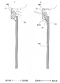
図3は、第2実施形態に係る除湿構造体の設置状態を示す斜視図であり、図4は、第2実施形態に係る除湿構造体を示す断面図である。 FIG. 3 is a perspective view showing an installed state of the dehumidifying structure according to the second embodiment, and FIG. 4 is a cross-sectional view showing the dehumidifying structure according to the second embodiment.
図3には、いわゆるサイディングボードとして用いられる区画部材(加熱体)PMが図示されている。第2実施形態に係る除湿構造体2は、図4に示すように、区画部材PMの裏面側(室内側)に設けられている。
FIG. 3 shows a partition member (heated body) PM used as a so-called siding board. As shown in FIG. 4, the
以下、特に湿度が高い夏季を想定して説明する。まず、区画部材PMは、建物の胴縁材FMに対して貼り付けられるものである。この区画部材PMは、太陽日射にさらされることから一定量の太陽熱を吸収し、日中には温度が高くなる。これによって、区画部材PMと建物の断熱壁TWとの間に形成される空気通路AR内の空気を加熱するようになっている。空気通路AR内に熱がこもると断熱壁TWも加熱され、室内に熱が貫流されることから、空気通路AR内の空気は特に夏季には上方に吹き抜けることができるように空気通路ARの下端、上端が大気に開放されている。なお、区画部材PMは、特に太陽熱の集熱性能を上げるために外表面71に太陽光選択吸収処理をしたり、更に断熱のための空気層を設けて透明部材60でカバーするなどしてもよい。
In the following, the explanation will be made assuming the summer when the humidity is particularly high. First, the partition member PM is attached to the furring strip FM of the building. Since this partition member PM is exposed to solar radiation, it absorbs a certain amount of solar heat, and the temperature rises during the day. As a result, the air in the air passage AR formed between the partition member PM and the heat insulating wall TW of the building is heated. When heat is trapped in the air passage AR, the heat insulating wall TW is also heated and the heat flows through the room. Therefore, the air in the air passage AR can be blown upward especially in the summer, so that the lower end of the air passage AR can be blown upward. , The upper end is open to the atmosphere. In addition, the partition member PM may be covered with a
ここで、第2実施形態に係る除湿構造体2は、図4に示すように区画部材PMの裏面側に設置されている。除湿構造体2は、第1実施形態と同様に、吸湿剤10と、吸湿剤収納壁20と、透湿部材30と、排水機構40とを備えている。
Here, the
なお、第2実施形態において吸湿剤収納壁20は、光透過性の部材によって構成されていなくともよい。また、第2実施形態において吸湿室MRは、開口部MR1が断熱壁TWを貫通して室内と連通している。この開口部MR1には、第1実施形態と同様に、透湿部材30が設けられるが、この透湿部材30は断熱壁TWが貫通されていることの弊害をなくすべく、断熱性が規定値以上の素材によって構成されている。
In the second embodiment, the hygroscopic
さらに、第2実施形態において排水機構40は、第1実施形態と同様にゴムリップシールによって構成されているが、水を断熱壁TW側でなく、区画部材PMの室内側板材72に流下させるようになっている。
Further, in the second embodiment, the
次に、図4を参照して、第2実施形態に係る除湿構造体2の作用を説明する。
Next, the operation of the
区画部材PMは、太陽日射にさらされることから一定量の太陽熱を吸収し、日中には温度が高くなる。特に太陽熱の集熱性能を上げるために外表面71に太陽光選択吸収処理をしたり、更に断熱のための空気層を設けて透明部材60でカバーするなどしてある場合にはさらに高温になる。よって、昼間には区画部材PMを加熱して吸湿剤10を加熱することができ、加熱によって吸湿剤10を所定温度以上とすることができる。この結果、吸湿剤10に疎水性を発揮させて放水させることができる。一方、夜間には、区画部材PMが加熱されることなく吸湿剤10を所定温度未満とすることができる。この結果、吸湿剤10に親水性を発揮させて吸湿させることができる。
Since the partition member PM is exposed to solar radiation, it absorbs a certain amount of solar heat, and the temperature rises during the day. In particular, if the
また、吸湿剤10が放水して水が所定量以上となった場合、排水機構40は水を室内側板材72に流下させる。この水は、室内側板材72を流下することで、室外まで排出される。また、流下する水は、空気通路AR内の空気によって気化させられる。
Further, when the
このようにして、第2実施形態に係る除湿構造体2によれば、第1実施形態と同様に、電力を要することなく、継続的な除湿を行うことができ、排水方向から吸湿してしまう事態を防止することができる。また、室内側からの吸湿を阻害し難く異物が吸湿室MRに侵入してしまうことを防止することができると共に、室内側に冷房効果をもたらすことが可能となる。
In this way, according to the
さらに、第2実施形態によれば、区画部材PMの室内側の面に流下させるため、排水機構40から区画部材PMに流下する排水を隠すことができ、美観の低下を抑制することができる。
Further, according to the second embodiment, since the drainage is allowed to flow down to the indoor surface of the partition member PM, the drainage flowing down from the
以上、実施形態に基づき本発明を説明したが、本発明は上記実施形態に限られるものではなく、本発明の趣旨を逸脱しない範囲で、変更を加えてもよいし、可能な範囲で適宜実施形態同士の技術を組み合わせてもよい。さらに、可能な範囲で公知又は周知の技術を組み合わせてもよい。 Although the present invention has been described above based on the embodiments, the present invention is not limited to the above embodiments, and changes may be made without departing from the spirit of the present invention, and the present invention may be appropriately implemented to the extent possible. The techniques of the forms may be combined. Further, known or well-known techniques may be combined to the extent possible.
例えば、上記実施形態において吸湿剤10は太陽光を受光して、又は太陽光により加熱された吸湿剤収納壁20や区画部材PMによって加熱されているが、これに限らず、例えば太陽光により加熱された熱媒等(加熱体)によって加熱されるようになっていてもよい。
For example, in the above embodiment, the
さらに、上記区画部材PMは窓体や壁材で構成されているが、これに限らず、室外と室内とを隔てるものであれば、例えば屋根材であってもよい。 Further, the partition member PM is composed of a window body or a wall material, but is not limited to this, and may be, for example, a roof material as long as it separates the outdoor and the indoor.
さらに、第1実施形態において流下する水は太陽光を受光して気化し、第2実施形態において流下する水は空気通路ARの空気によって気化するが、これに限らず、単に夏場の気温等によって気化するようになっていてもよい。 Further, the water flowing down in the first embodiment receives sunlight and vaporizes, and the water flowing down in the second embodiment is vaporized by the air in the air passage AR, but the present invention is not limited to this, and simply depends on the summer temperature or the like. It may be vaporized.
また、太陽光を受光して吸湿剤10を加熱する場合、効率的に吸湿剤10を所定温度以上とすべく、レンズやプリズム等の光学部材を備えるようにしてもよい。また、流下する水を気化させるためにレンズやプリズム等の光学部材を備えていてもよい。
Further, when the
1,2 :除湿構造体
10 :吸湿剤
20 :吸湿剤収納壁(加熱体)
30 :透湿部材
40 :排水機構
MR :吸湿室
MR1 :開口部
MR2 :排水口
PM :区画部材(加熱体)
1, 2,: Dehumidifying structure 10: Moisture absorbing agent 20: Moisture absorbing agent storage wall (heated body)
30: Moisture permeable member 40: Drainage mechanism MR: Moisture absorption chamber MR1: Opening MR2: Drainage port PM: Partition member (heater)
Claims (4)
前記吸湿剤が配置される吸湿室と、
前記吸湿剤から放水されて前記吸湿室に溜まった水を排水する排水機構と、を備え、
前記吸湿剤は、太陽熱又は太陽光によって加熱された加熱体からの熱を受領可能に設けられ、
前記排水機構は、前記吸湿剤から放水されて前記吸湿室に溜まった水が所定量以上となるときに、その水の重みを利用して開放されて排水し、前記所定量未満であるときに閉塞状態となる弁機構である
ことを特徴とする除湿構造体。 A temperature-sensitive absorbent that exhibits hydrophobicity at a predetermined temperature or higher and discharges water, and exhibits hydrophilicity at a temperature lower than the predetermined temperature to absorb water.
The hygroscopic chamber in which the hygroscopic agent is placed and
A drainage mechanism for draining water discharged from the hygroscopic agent and accumulated in the hygroscopic chamber is provided.
The hygroscopic agent is provided so as to be able to receive heat from a heating body heated by solar heat or sunlight.
When the amount of water discharged from the hygroscopic agent and accumulated in the hygroscopic chamber becomes a predetermined amount or more, the drainage mechanism is opened by utilizing the weight of the water to drain the water , and when the amount is less than the predetermined amount. It is a valve mechanism that becomes closed.
A dehumidifying structure characterized by that.
ことを特徴とする請求項1に記載の除湿構造体。 The dehumidifying structure according to claim 1 , further comprising a moisture-permeable member provided in an opening connecting the moisture-absorbing chamber and the indoor side to allow the passage of moisture and close the opening.
前記排水機構は、排水した水を前記区画部材に流下させる
ことを特徴とする請求項1又は請求項2のいずれかに記載の除湿構造体。 Further equipped with a partition member that separates the indoor and outdoor areas,
The dehumidifying structure according to claim 1 or 2, wherein the drainage mechanism causes the drained water to flow down to the partition member.
ことを特徴とする請求項3に記載の除湿構造体。 The dehumidifying structure according to claim 3 , wherein the drainage mechanism causes the drained water to flow down to the indoor surface of the partition member.
Priority Applications (7)
| Application Number | Priority Date | Filing Date | Title |
|---|---|---|---|
| JP2018100748A JP7051226B2 (en) | 2018-05-25 | 2018-05-25 | Dehumidifying structure |
| PCT/JP2019/015717 WO2019225193A1 (en) | 2018-05-25 | 2019-04-10 | Dehumidification structure |
| CN201980035229.XA CN112236213B (en) | 2018-05-25 | 2019-04-10 | Dehumidifying structure |
| DE112019002677.1T DE112019002677T5 (en) | 2018-05-25 | 2019-04-10 | DEHUMIDIFICATION STRUCTURE |
| GB2018512.0A GB2588318B (en) | 2018-05-25 | 2019-04-10 | Dehumidification structure |
| AU2019273951A AU2019273951B2 (en) | 2018-05-25 | 2019-04-10 | Dehumidification structure |
| US17/098,294 US11293652B2 (en) | 2018-05-25 | 2020-11-13 | Dehumidification structure |
Applications Claiming Priority (1)
| Application Number | Priority Date | Filing Date | Title |
|---|---|---|---|
| JP2018100748A JP7051226B2 (en) | 2018-05-25 | 2018-05-25 | Dehumidifying structure |
Publications (3)
| Publication Number | Publication Date |
|---|---|
| JP2019203676A JP2019203676A (en) | 2019-11-28 |
| JP2019203676A5 JP2019203676A5 (en) | 2020-01-23 |
| JP7051226B2 true JP7051226B2 (en) | 2022-04-11 |
Family
ID=68616327
Family Applications (1)
| Application Number | Title | Priority Date | Filing Date |
|---|---|---|---|
| JP2018100748A Active JP7051226B2 (en) | 2018-05-25 | 2018-05-25 | Dehumidifying structure |
Country Status (7)
| Country | Link |
|---|---|
| US (1) | US11293652B2 (en) |
| JP (1) | JP7051226B2 (en) |
| CN (1) | CN112236213B (en) |
| AU (1) | AU2019273951B2 (en) |
| DE (1) | DE112019002677T5 (en) |
| GB (1) | GB2588318B (en) |
| WO (1) | WO2019225193A1 (en) |
Families Citing this family (2)
| Publication number | Priority date | Publication date | Assignee | Title |
|---|---|---|---|---|
| CN114165769B (en) * | 2021-12-20 | 2024-03-22 | 同辉电子科技股份有限公司 | Early warning dehumidification system for wisdom lamp pole |
| CN114396666B (en) * | 2022-01-07 | 2023-06-23 | 上海交通大学 | Solar-driven indoor humidity control device |
Citations (4)
| Publication number | Priority date | Publication date | Assignee | Title |
|---|---|---|---|---|
| US20130118101A1 (en) | 2011-11-16 | 2013-05-16 | Alcoa Inc. | Floating flapper valve |
| WO2015170502A1 (en) | 2014-05-09 | 2015-11-12 | シャープ株式会社 | Cooler |
| JP2016077968A (en) | 2014-10-16 | 2016-05-16 | シャープ株式会社 | Dehumidifier |
| JP2017226276A (en) | 2016-06-21 | 2017-12-28 | カルソニックカンセイ株式会社 | Air conditioner for vehicle |
Family Cites Families (15)
| Publication number | Priority date | Publication date | Assignee | Title |
|---|---|---|---|---|
| JPS579319U (en) * | 1980-06-14 | 1982-01-18 | ||
| JPS57164238A (en) * | 1981-03-31 | 1982-10-08 | Matsushita Electric Works Ltd | Air conditioner |
| JP3022999B2 (en) | 1991-02-15 | 2000-03-21 | 大建工業株式会社 | Basement interior structure |
| JPH0647243A (en) | 1992-07-28 | 1994-02-22 | Matsushita Electric Works Ltd | Dehumidifier |
| KR101147014B1 (en) | 2004-05-26 | 2012-05-17 | 가부시키가이샤 칸쿄 | Method for extracting water from air, and device therefor |
| CN201092671Y (en) * | 2007-06-15 | 2008-07-30 | 陈卫 | Weight type floor drain |
| CN202006077U (en) * | 2010-07-27 | 2011-10-12 | 王庆森 | Gas adjustment experimental environment dehumidifier |
| JP5809904B2 (en) * | 2011-09-22 | 2015-11-11 | 中部美化企業株式会社 | Flap gate |
| CN103114645B (en) * | 2013-02-22 | 2015-01-14 | 浙江卓进电器有限公司 | Silica gel type sealing floor drain |
| CN203183894U (en) * | 2013-03-15 | 2013-09-11 | 深圳市英威腾电气股份有限公司 | Electronic equipment dehumidifier |
| JP6286735B2 (en) | 2014-09-02 | 2018-03-07 | オリオン機械株式会社 | Compressed air dehumidifier |
| MY182769A (en) * | 2014-09-05 | 2021-02-05 | Sharp Kk | Humidity controlling apparatus |
| CN104727433A (en) * | 2015-03-31 | 2015-06-24 | 董伟 | Novel deodorization floor drain core |
| CN105421574A (en) * | 2015-12-25 | 2016-03-23 | 谭文清 | Deodorant floor drain |
| CN206693366U (en) * | 2017-05-17 | 2017-12-01 | 张海波 | A kind of odour-proof floor drain |
-
2018
- 2018-05-25 JP JP2018100748A patent/JP7051226B2/en active Active
-
2019
- 2019-04-10 GB GB2018512.0A patent/GB2588318B/en active Active
- 2019-04-10 WO PCT/JP2019/015717 patent/WO2019225193A1/en active Application Filing
- 2019-04-10 AU AU2019273951A patent/AU2019273951B2/en active Active
- 2019-04-10 DE DE112019002677.1T patent/DE112019002677T5/en active Pending
- 2019-04-10 CN CN201980035229.XA patent/CN112236213B/en active Active
-
2020
- 2020-11-13 US US17/098,294 patent/US11293652B2/en active Active
Patent Citations (4)
| Publication number | Priority date | Publication date | Assignee | Title |
|---|---|---|---|---|
| US20130118101A1 (en) | 2011-11-16 | 2013-05-16 | Alcoa Inc. | Floating flapper valve |
| WO2015170502A1 (en) | 2014-05-09 | 2015-11-12 | シャープ株式会社 | Cooler |
| JP2016077968A (en) | 2014-10-16 | 2016-05-16 | シャープ株式会社 | Dehumidifier |
| JP2017226276A (en) | 2016-06-21 | 2017-12-28 | カルソニックカンセイ株式会社 | Air conditioner for vehicle |
Also Published As
| Publication number | Publication date |
|---|---|
| US11293652B2 (en) | 2022-04-05 |
| US20210063031A1 (en) | 2021-03-04 |
| DE112019002677T5 (en) | 2021-02-18 |
| AU2019273951B2 (en) | 2021-10-21 |
| JP2019203676A (en) | 2019-11-28 |
| CN112236213B (en) | 2023-03-28 |
| AU2019273951A1 (en) | 2020-12-17 |
| GB202018512D0 (en) | 2021-01-06 |
| WO2019225193A1 (en) | 2019-11-28 |
| GB2588318B (en) | 2022-08-24 |
| GB2588318A (en) | 2021-04-21 |
| CN112236213A (en) | 2021-01-15 |
Similar Documents
| Publication | Publication Date | Title |
|---|---|---|
| JP7051226B2 (en) | Dehumidifying structure | |
| CN107995944B (en) | Device and method for air conditioning a room | |
| JP2018524540A (en) | Harvesting energy from humidity fluctuations | |
| US20160010326A1 (en) | All-season non-condensing building insulation system | |
| US4051769A (en) | Solar powered method and apparatus for venting gaseous material from an enclosed space to atmosphere | |
| JP2668665B2 (en) | Solar system house | |
| JP6309087B2 (en) | Cooling system | |
| JP2019203676A5 (en) | ||
| JP3304753B2 (en) | Underground air conditioner | |
| JP2008196817A (en) | Air heat-collection type solar dehumidifying cooling system | |
| JPS6131377B2 (en) | ||
| CN209431630U (en) | Air conditioner condensate water collection arranging device and air-conditioning system including the device | |
| JPH11181901A (en) | Ventilating and heat insulating structure of building and ventilation control device used therefor | |
| JPH04288424A (en) | Air conditioner | |
| JP2585458B2 (en) | Moisture / hot air discharge and hot air circulation device and building using it | |
| JPH09292153A (en) | Air conditioning structure using underground buried facilities | |
| JPH029037Y2 (en) | ||
| JPS6216292B2 (en) | ||
| JPS6153616B2 (en) | ||
| WO2007036587A2 (en) | System for using, controlling and regulating renewable energies in self-sufficient buildings | |
| JP2002129846A (en) | Building glass structure using peltier element | |
| NL1037355C2 (en) | CLIMATIZATION DEVICE. | |
| JP4854018B2 (en) | Window structure | |
| KR20170044165A (en) | A solar collector panel and a method for operating a solar collector panel | |
| JP3281556B2 (en) | Condensation water treatment equipment generated during air conditioner operation |
Legal Events
| Date | Code | Title | Description |
|---|---|---|---|
| A521 | Request for written amendment filed |
Free format text: JAPANESE INTERMEDIATE CODE: A523 Effective date: 20191204 |
|
| A621 | Written request for application examination |
Free format text: JAPANESE INTERMEDIATE CODE: A621 Effective date: 20210416 |
|
| TRDD | Decision of grant or rejection written | ||
| A01 | Written decision to grant a patent or to grant a registration (utility model) |
Free format text: JAPANESE INTERMEDIATE CODE: A01 Effective date: 20220329 |
|
| A61 | First payment of annual fees (during grant procedure) |
Free format text: JAPANESE INTERMEDIATE CODE: A61 Effective date: 20220329 |
|
| R150 | Certificate of patent or registration of utility model |
Ref document number: 7051226 Country of ref document: JP Free format text: JAPANESE INTERMEDIATE CODE: R150 |
|
| S531 | Written request for registration of change of domicile |
Free format text: JAPANESE INTERMEDIATE CODE: R313531 |
|
| R350 | Written notification of registration of transfer |
Free format text: JAPANESE INTERMEDIATE CODE: R350 |