JP7050600B2 - Static eliminator for vehicles and vehicles - Google Patents
Static eliminator for vehicles and vehicles Download PDFInfo
- Publication number
- JP7050600B2 JP7050600B2 JP2018130179A JP2018130179A JP7050600B2 JP 7050600 B2 JP7050600 B2 JP 7050600B2 JP 2018130179 A JP2018130179 A JP 2018130179A JP 2018130179 A JP2018130179 A JP 2018130179A JP 7050600 B2 JP7050600 B2 JP 7050600B2
- Authority
- JP
- Japan
- Prior art keywords
- vehicle
- static
- static elimination
- target portion
- discharge port
- Prior art date
- Legal status (The legal status is an assumption and is not a legal conclusion. Google has not performed a legal analysis and makes no representation as to the accuracy of the status listed.)
- Active
Links
Images


Classifications
-
- B—PERFORMING OPERATIONS; TRANSPORTING
- B60—VEHICLES IN GENERAL
- B60R—VEHICLES, VEHICLE FITTINGS, OR VEHICLE PARTS, NOT OTHERWISE PROVIDED FOR
- B60R16/00—Electric or fluid circuits specially adapted for vehicles and not otherwise provided for; Arrangement of elements of electric or fluid circuits specially adapted for vehicles and not otherwise provided for
- B60R16/02—Electric or fluid circuits specially adapted for vehicles and not otherwise provided for; Arrangement of elements of electric or fluid circuits specially adapted for vehicles and not otherwise provided for electric constitutive elements
- B60R16/06—Electric or fluid circuits specially adapted for vehicles and not otherwise provided for; Arrangement of elements of electric or fluid circuits specially adapted for vehicles and not otherwise provided for electric constitutive elements for removing electrostatic charges
-
- B—PERFORMING OPERATIONS; TRANSPORTING
- B60—VEHICLES IN GENERAL
- B60K—ARRANGEMENT OR MOUNTING OF PROPULSION UNITS OR OF TRANSMISSIONS IN VEHICLES; ARRANGEMENT OR MOUNTING OF PLURAL DIVERSE PRIME-MOVERS IN VEHICLES; AUXILIARY DRIVES FOR VEHICLES; INSTRUMENTATION OR DASHBOARDS FOR VEHICLES; ARRANGEMENTS IN CONNECTION WITH COOLING, AIR INTAKE, GAS EXHAUST OR FUEL SUPPLY OF PROPULSION UNITS IN VEHICLES
- B60K13/00—Arrangement in connection with combustion air intake or gas exhaust of propulsion units
- B60K13/02—Arrangement in connection with combustion air intake or gas exhaust of propulsion units concerning intake
-
- F—MECHANICAL ENGINEERING; LIGHTING; HEATING; WEAPONS; BLASTING
- F02—COMBUSTION ENGINES; HOT-GAS OR COMBUSTION-PRODUCT ENGINE PLANTS
- F02M—SUPPLYING COMBUSTION ENGINES IN GENERAL WITH COMBUSTIBLE MIXTURES OR CONSTITUENTS THEREOF
- F02M35/00—Combustion-air cleaners, air intakes, intake silencers, or induction systems specially adapted for, or arranged on, internal-combustion engines
- F02M35/10—Air intakes; Induction systems
- F02M35/10242—Devices or means connected to or integrated into air intakes; Air intakes combined with other engine or vehicle parts
-
- H—ELECTRICITY
- H01—ELECTRIC ELEMENTS
- H01T—SPARK GAPS; OVERVOLTAGE ARRESTERS USING SPARK GAPS; SPARKING PLUGS; CORONA DEVICES; GENERATING IONS TO BE INTRODUCED INTO NON-ENCLOSED GASES
- H01T19/00—Devices providing for corona discharge
-
- H—ELECTRICITY
- H01—ELECTRIC ELEMENTS
- H01T—SPARK GAPS; OVERVOLTAGE ARRESTERS USING SPARK GAPS; SPARKING PLUGS; CORONA DEVICES; GENERATING IONS TO BE INTRODUCED INTO NON-ENCLOSED GASES
- H01T19/00—Devices providing for corona discharge
- H01T19/04—Devices providing for corona discharge having pointed electrodes
-
- H—ELECTRICITY
- H01—ELECTRIC ELEMENTS
- H01T—SPARK GAPS; OVERVOLTAGE ARRESTERS USING SPARK GAPS; SPARKING PLUGS; CORONA DEVICES; GENERATING IONS TO BE INTRODUCED INTO NON-ENCLOSED GASES
- H01T23/00—Apparatus for generating ions to be introduced into non-enclosed gases, e.g. into the atmosphere
-
- H—ELECTRICITY
- H05—ELECTRIC TECHNIQUES NOT OTHERWISE PROVIDED FOR
- H05F—STATIC ELECTRICITY; NATURALLY-OCCURRING ELECTRICITY
- H05F3/00—Carrying-off electrostatic charges
- H05F3/04—Carrying-off electrostatic charges by means of spark gaps or other discharge devices
-
- H—ELECTRICITY
- H05—ELECTRIC TECHNIQUES NOT OTHERWISE PROVIDED FOR
- H05F—STATIC ELECTRICITY; NATURALLY-OCCURRING ELECTRICITY
- H05F3/00—Carrying-off electrostatic charges
- H05F3/06—Carrying-off electrostatic charges by means of ionising radiation
Description
本発明は、車両に搭載される車両用除電装置および車両に関する。 The present invention relates to a vehicle static eliminator and a vehicle mounted on a vehicle.
従来、路面に対して絶縁状態に保持されている車体が路面を走行することを含む外部要因により、車両にプラスの静電気が帯電すること、およびこの車両に帯電したプラスの静電気が車両の運転に何らかの影響を与えることが知られている。このような車両に帯電するプラスの静電気対策の技術として、例えば、特許文献1,2がある。
Conventionally, the vehicle is charged with positive static electricity due to external factors including the fact that the vehicle body, which is kept insulated from the road surface, travels on the road surface, and the positive static electricity charged on the vehicle is used for driving the vehicle. It is known to have some effect. As a technique for taking measures against positive static electricity that charges a vehicle, for example,
特許文献1には、車両のボディ外壁における、該ボディ外壁に沿って流れる空気が該ボディ外壁から剥離し易い形状をした箇所の裏側壁面に対して、電荷制御装置よりマイナスイオンを放射することで、上記箇所のプラスの電荷を低下させる、または上記箇所をマイナスの電荷に帯電させる構成が記載されている。これによれば、車両のボディ外壁に沿って流れるプラスの電荷を持つ空気流がボディ外壁から離れることを抑制して、設計上定められた空力特性を得ることができる。
According to
また、特許文献2には、車両における駆動力発生装置の吸気通路を画定する樹脂製の吸気通路壁の外側壁面に空気イオン化自己放電式除電器を配置して、プラスに帯電した吸気通路壁における設置箇所を中心とした限られた範囲内のプラスの帯電電荷量を低下させる構成が記載されている。これによれば、吸気通路を流れるプラスに帯電した空気流が吸気通路壁から離れることを抑制して、吸入空気の吸気効率を向上させることができる。
Further, in
上述した特許文献1,2は、車両に帯電するプラスの静電気による影響を抑制するものではあるが、未だ改善の余地を有している。
Although the above-mentioned
本発明の一態様は、除電対象箇所をより効果的に除電して車両に帯電する静電気による影響をより効果的に抑制することが可能な車両用除電装置および車両を実現することを目的とする。 One aspect of the present invention is an object of the present invention to realize a vehicle static eliminator and a vehicle capable of more effectively eliminating static electricity at a portion subject to static electricity elimination and more effectively suppressing the influence of static electricity charged on the vehicle. ..
上記の課題を解決するために、本発明の一態様の車両用除電装置は、路面に対して絶縁状態に保持されている車体が走行することを含む外部要因等により、プラスの静電気に帯電する車両に搭載されて、前記車両におけるプラスに帯電した所定の除電対象箇所を除電、またはマイナスに帯電させる車両用除電装置であって、マイナスイオン発生部と、前記マイナスイオン発生部にて発生したマイナスイオンを案内して放出口より前記除電対象箇所に向けて放出するガイド装置と、を備え、前記ガイド装置は、静電気の帯電列においてマイナス側に帯電し易い樹脂から形成された、前記マイナスイオンを案内する通路を画定するガイド部材と、前記放出口を画定する部分に形成されると共に前記除電対象箇所に近接して配置され、前記ガイド部材に帯電したマイナスの電荷を前記除電対象箇所へ向けてコロナ放電させる尖端形状部と、を有することを特徴とする。 In order to solve the above problems, the vehicle static eliminator according to one aspect of the present invention is charged with positive static electricity due to an external factor including the traveling of a vehicle body maintained in an insulated state with respect to the road surface. A vehicle static eliminator that is mounted on a vehicle and that eliminates static electricity or negatively charges a predetermined positively charged static electricity elimination target portion in the vehicle, and is a negative ion generating section and a negative ion generating section. The guide device comprises a guide device that guides the ions and discharges the ions from the discharge port toward the static electricity elimination target portion, and the guide device discharges the negative ions formed from a resin that is easily charged to the negative side in the electrostatic charge train. A guide member that defines a passage to be guided and a portion that defines the discharge port and are arranged close to the static electricity elimination target location, and negative charges charged on the guide member are directed toward the static electricity elimination target location. It is characterized by having a tip-shaped portion for discharging corona.
本発明の一態様によれば、プラスに帯電した除電対象箇所をより効果的に除電することが可能となり、よって車両に帯電するプラスの静電気による影響をより効果的に抑制することができる。 According to one aspect of the present invention, it is possible to more effectively eliminate static electricity at a positively charged static electricity elimination target portion, and thus it is possible to more effectively suppress the influence of positive static electricity charged on the vehicle.
〔実施の形態1〕
本発明の実施の一形態について、詳細に説明する。
[Embodiment 1]
An embodiment of the present invention will be described in detail.
(車両用除電装置1の構成)
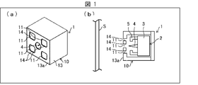
図1は、本発明の実施の形態1に係る車両用除電装置1を示すもので、(a)は外観図、(b)は概略構成を示す断面図である。なお、(b)においては、除電対象箇所Sを併せて示す。図1の(a)(b)に示すように、車両用除電装置1は、マイナスイオン発生器(マイナスイオン発生部)2と、送風装置を有さないガイド装置10とを備える。
(Configuration of vehicle static eliminator 1)
1A and 1B show a vehicle
マイナスイオン発生器2は、マイナスイオンを発生する装置であり、ハウジング3に針状の放電電極4が突設され、該放電電極4の周囲に対向電極5が設けられている。放電電極4は、対向電極5との間に電界を形成し、放電電極4の先端よりマイナスイオンが発生する。なお、図1では、放電電極4として針状電極を例示しているが、ブラシ状電極であっても、三角形状の電極であっても良い。ハウジング3の内部には放電電極4および対向電極5を制御する放電基板(不図示)が収容されている。放電基板は、後述するメイン基板30(図3参照)と接続されている。
The
ガイド装置10は、マイナスイオン発生器2にて発生したマイナスイオンを案内して放出口11より除電球対象箇所Sに向けて放出する。ガイド装置10は、ガイド部材13と尖端形状部14とを含む。
The
ガイド部材13は、マイナスイオンの通路を画定し、マイナスイオンの流れる方向の下流側に配置された前壁13aに、ガイド装置10の放出口11となる開口を複数有する。本実施の形態の構成では、ガイド部材13の開口がガイド装置10の放出口11となるため、ガイド部材13の放出口11とも表現する場合がある。なお、図1では、ガイド部材13として、立方体状の外観を呈する構成を例示しているが、円柱状や六角柱状等であってもよい。
The
ガイド部材13は、例えば、アクリルニトリルブタジエンスチレン(ABS)やポリプロピレン(PP)などの、図2に示すような帯電列においてマイナス側に帯電し易い樹脂から形成されている。図2は、代表的な材質の帯電列を示す図である。マイナス側に帯電しやすい樹脂とは、図2おいて破線で囲っているポリプロピレン(PP)から右側に位置する樹脂である。マイナスに帯電しやすい樹脂にて形成されることで、ガイド部材13はマイナスに帯電しマイナスの電荷を保持するようになる。
The
尖端形状部14は、放出口11を画定する部分に形成されると共に除電対象箇所Sに近接して配置されている。近接して配置するとは、換言すると、尖端形状部14を除電対象箇所Sに対して、ガイド部材13に帯電したマイナスの電荷が尖端形状部14よりプラスに帯電した除電対象箇所Sへ向けてコロナ放電させ得る位置に配置することである。これにより、尖端形状部14は、ガイド部材13に帯電したマイナスの電荷をプラスに帯電した除電対象箇所Sへ向けてコロナ放電させる。
The tip-
尖端形状部14は、突起や角部、突端部といった尖端を有したコロナ放電が発生しやすい形状を有している。このような形状の尖端形状部14を放出口11の周囲に形成することで、突端からガイド部材13が担持するマイナスの電荷を除電対象箇所Sに向けてコロナ放電させることができる。詳細には、除電対象箇所Sはプラスに帯電されているため、尖端形状部14を近接させることで、ガイド部材13に帯電しているマイナスの電荷が除電対象箇所Sのプラスの電荷に引き寄せられてコロナ放電が発生する。図1では、放出口11を画定する部分(放出口11の際の部分)の角が尖っており、この尖った角部が尖端形状部14となっている。
The tip-shaped
なお、図1では、ガイド部材13の内部にマイナスイオン発生器2が収容されている構成を例示しているが、マイナスイオン発生器2にて発生したマイナスイオンをガイド部材13の内部に供給できるように接続されていればよい。
Although FIG. 1 illustrates a configuration in which the
但し、送風装置を有さない構成では、放電電極4の先端から前壁13aまでの距離を短くするほど、放出口11から放出されるマイナスイオンによる除電範囲を広く確保することができる。したがって、放電電極4の先端から前壁13aまでの距離は、例えば10~30mmとすることが好ましい。
However, in a configuration without a blower, the shorter the distance from the tip of the
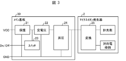
図3は、車両用除電装置1の電気的回路構成を示す回路図である。図において、保護回路21、定電圧回路22、スイッチ回路23および昇圧回路24は、メイン基板30に搭載されている。変換回路25は、前述した放電基板に搭載されている。なお、メイン基板30に変換回路25を搭載することもできる。
FIG. 3 is a circuit diagram showing an electrical circuit configuration of the
電源が投入され、オン/オフ信号がオンになると、定電圧回路22から出力される電圧が昇圧回路24を経て変換回路25に印加され、変換回路25より放電電極4および対向電極5に所定の電圧が印加され、放電電極4の先端よりマイナスイオンが発生する。
When the power is turned on and the on / off signal is turned on, the voltage output from the
なお、図3では、メイン基板30にマイナスイオン発生器2が一台接続されている構成を例示しているが、車両用除電装置1が複数台設置される場合は、メイン基板30に複数のマイナスイオン発生器2が接続される。
Note that FIG. 3 illustrates a configuration in which one
(車両用除電装置1の除電動作)
図4は、車両用除電装置1における除電動作を説明する図である。図4に示すように、放電電極4の先端よりマイナスイオン(図中の-イ)が発生すると、発生したマイナスイオンは、ガイド装置10におけるガイド部材13に案内されて放出口11に導かれ、放出口11より除電対象箇所Sに向かって放出される。放出されたマイナスイオンは、除電対象箇所Sに帯電しているプラスの電荷を中和して、除電対象箇所Sを除電する、またはマイナスの電荷に帯電させる。
(Vehicle
FIG. 4 is a diagram illustrating a static elimination operation in the vehicle
さらに、上記構成では、ガイド部材13がマイナス側に帯電しやすい樹脂より形成されているため、ガイド部材13にマイナスの電荷(図中の-)が帯電する。ガイド部材13に帯電したマイナスの電荷は、除電対象箇所Sに帯電しているプラスの電荷(図中の+)に引き寄せられ、除電対象箇所Sと近接した尖端形状部14よりコロナ放電(矢印f)が発生する。このような放電が発生することで、除電対象箇所Sの除電は、マイナスイオンのみの除電よりもさらに高められ、効果的に除電される。しかも、このような放電が発生することで、ガイド部材13の放出口11のマイナスの電荷が大幅に減少することとなり、ガイド部材13の放出口11にマイナスイオンが滞留してマイナスイオンの放出が妨げられることを是正して、マイナスイオンの放出を安定化することができる。よって除電対象箇所Sを中和除電し、マイナスの電荷に帯電させることも可能になる。
Further, in the above configuration, since the
(車両用除電装置1と除電対象箇所Sとの離間距離)
マイナスイオンの濃度は、放出口11近くで最も高く、放出口11より離れるに従い低下する。マイナスイオンによる除電能力は、放出するマイナスイオンの濃度に依存するので、放出口11を除電対象箇所Sに近づけて配置する程、効果的に除電できる。
(Distance between the vehicle
The concentration of negative ions is highest near the
また、尖端形状部14にて発生するコロナ放電も、尖端形状部14が除電対象箇所Sに近づくほど発生しやすい。そのため、尖端形状部14が形成されている放出口11を除電対象箇所Sに近づけて配置する程、効果的にコロナ放電を発生させることができる。これにより、コロナ放電による除電対象箇所Sの効果的な除電と共に、コロナ放電によるマイナスイオンの放出の妨げを是正する効果によりマイナスイオンの放出を安定化させることができる。
Further, the corona discharge generated in the tip-shaped
但し、コロナ放電には発生限界があり、放出口11の中心と除電対象箇所Sとの最短離間距離が100mmを超えると発生しなくなる。したがって、放出口11の中心と除電対象箇所Sとの最短離間距離は、コロナ放電の発生限界である100mm以下とする必要がある。ここで下記の離間距離を、放出口11の中心と除電対象箇所Sとの最短距離と定義する。後述する実施態様や図9に記載されるように、放出口11を除電対象箇所Sに対して、傾斜して配置する場合等を含む。
However, there is a limit to the occurrence of corona discharge, and it does not occur when the shortest distance between the center of the
そして、上記離間距離としては20mmとすることが最適である。上記離間距離は20mmとすることで、除電効果が最も高くなり、除電対象箇所Sのプラス電位をより大きく低下させて、ゼロ、もしくはより低いマイナス電位へと近づけることができる。 The optimum separation distance is 20 mm. By setting the separation distance to 20 mm, the static elimination effect is maximized, and the positive potential of the static elimination target portion S can be further lowered to approach zero or a lower negative potential.
除電効果は、上記離間距離20mmをピークとして20mmから離れるに従い低下する。つまり、上記離間距離が100mm以下では、コロナ放電によるマイナスイオンの放出の妨げを是正する効果(コロナ放電効果とも記載)により、20mmに近づく程にマイナスイオンの放出量が増大していき除電効果が上がる。 The static elimination effect peaks at the separation distance of 20 mm and decreases as the distance from the distance increases from 20 mm. That is, when the separation distance is 100 mm or less, the amount of negative ions released increases as the distance approaches 20 mm due to the effect of correcting the obstruction of the release of negative ions due to the corona discharge (also referred to as the corona discharge effect), and the static elimination effect is improved. Go up.
しかしながら、上記離間距離が20mmを超えて近づくと、コロナ放電効果は増大し続けるものの、除電効果は徐々に低下し始める。これは、放出口11が除電対象箇所Sに近づきすぎることに起因する。つまり、上記離間距離が20mmを超えて近づくと、マイナスイオンの放出抵抗となり放出量を減少させる。また、放出口11が除電対象箇所Sに近づきすぎることで、マイナスイオンの放出範囲(マイナスイオンが到達して作用する範囲)も減少する。
However, when the separation distance exceeds 20 mm, the corona discharge effect continues to increase, but the static elimination effect gradually begins to decrease. This is because the
したがって、上記離間距離を20mmとすることで、コロナ放電効果とマイナスイオンの放出範囲とを最適なバランスとして、最も高い除電効果を得ることができる。 Therefore, by setting the separation distance to 20 mm, the highest static elimination effect can be obtained by optimally balancing the corona discharge effect and the negative ion emission range.
また、上記離間距離としては20mmが最も好ましいことを確認しているが、上記離間距離が20(±2)mmの18~22mmの範囲であれば、上記した効果を有効に確保できることを確認している。したがって、上記離間距離は、18~22mmの範囲であれば高い除電効果を得ることができる。 Further, it has been confirmed that 20 mm is the most preferable as the separation distance, but it has been confirmed that the above effect can be effectively secured if the separation distance is in the range of 18 to 22 mm of 20 (± 2) mm. ing. Therefore, if the separation distance is in the range of 18 to 22 mm, a high static elimination effect can be obtained.
なお、本願発明者らは、離間距離20mmを超えて近づくと除電効果が徐々に低下し始める現象は、車両用除電装置1のような送風装置を備えないタイプだけでなく、後述する車両用除電装置6(図10参照)のような送風装置を備えるタイプでも共通して発生することを確認している。
In addition, the inventors of the present application have described that the phenomenon that the static elimination effect gradually starts to decrease when the distance exceeds 20 mm is not limited to the type without a blower such as the vehicle
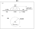
図5は、車両用除電装置1を除電対象箇所Sに対峙させて配置した場合の除電範囲を示すもので、(a)は側方より見た図、(b)は平面視した図である。図5の(a)(b)に示すように、除電範囲は、車両用除電装置1の設置箇所を中心とした円形状の限定された範囲となる。この除電範囲に含まれる除電対象箇所Sが除電される。直径100mm程度の除電範囲が確保できるように、除電対象箇所Sに対して車両用除電装置1を近接して配置することが好ましい。
5A and 5B show a static elimination range when the vehicle
(車両用除電装置1の設置例)
図6は、車両用除電装置1の車両ガラス35に対する設置例を示す図である。車両ガラス35は、例えば、フロントガラス、サイドガラス、リアガラスである。また、車両用除電装置1が設置されている設置面36は、ダッシュボード、フロントピラー、リアピラー、サイドドアの内側パネル等の板状の意匠部品である。
(Installation example of
FIG. 6 is a diagram showing an installation example of the
図6に示すように、車両用除電装置1は、車体の内側から放電電極4の先端を車両ガラス35の周縁部に向け、かつ、車両ガラス35に対して放電電極4の突出方向を傾けて設置されている。車両用除電装置1は、送風装置を備えない構成で小型ではあるが、放電電極4を車両ガラス35の正面に向けて車内に配置すると、違和感がある。これに対し、図6に示すように傾けて配置することで、車内に違和感なく設置することができる。
As shown in FIG. 6, in the vehicle
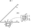
図7は、車両用除電装置1の車両ガラス35に対する別の設置例を示す図である。図7に示すように、設置面36には、車両用除電装置1の外寸に合わせた凹部36aが設けられ、車両用除電装置1は、設置面36と前壁13aとが面一にとなるように埋め込まれている。
FIG. 7 is a diagram showing another installation example of the vehicle
図8は、車両用除電装置1を設置する場所の一例を示す図である。フロントガラス37の周縁部を除電するべく、車両用除電装置1がダッシュボード38の左右の隅と、左右のフロントピラー31とにそれぞれ設置されている。また、サイドガラス39の周縁部を除電するべく、車両用除電装置1が左右のサイドドア40の内側パネル32であって、開口部40aの下端部側の走行方向前寄りに設置されている。さらに、車両用除電装置1がバックミラー41のカバー41aの内側であって、フロントガラス37の中央上部に向けて近接して設置されている。
FIG. 8 is a diagram showing an example of a place where the
また、図示してはいないが、車両用除電装置1は、上述した場所以外に、ルーフやリア窓ガラス、センターピラー、ドアハンドルの握り部、アンダーカバーの屈曲部などに設置されてもよい。
Although not shown, the vehicle
車体が走行することを含む外部要因や、車輪が絶縁体により構成されて路面に対して絶縁状態に保持されていること等により、車両はプラスの静電気に帯電する。 The vehicle is positively charged with static electricity due to external factors including the running of the vehicle body and the fact that the wheels are composed of an insulator and are maintained in an insulated state with respect to the road surface.
(除電の確認実験)
次に、車両ガラスが常に正に帯電する環境を再現し、除電効果を確認した実験について説明する。図9は、除電効果の確認実験を示すもので、(a)は、確認実験に用いた車両ガラスの形状を示す図であり、(b)は、確認実験の実験系を示す概略構成図である。
(Experiment to confirm static elimination)
Next, an experiment in which the environment in which the vehicle glass is always positively charged is reproduced and the static elimination effect is confirmed will be described. 9A and 9B show a confirmation experiment of the static elimination effect, FIG. 9A is a diagram showing the shape of the vehicle glass used in the confirmation experiment, and FIG. 9B is a schematic configuration diagram showing an experimental system of the confirmation experiment. be.
図9の(a)に示すように、車両ガラスとしては、厚みt=3mmで、上辺,下辺,高さが、600mm,800mm,465mmの台形のサイドガラス39を使用した。このようなサイドガラス39を、図9の(b)に示す実験系に設置した。実験系には、表裏の各除電スピードを測定し得るように、静電気測定器FMX-004(SIMCO製)の2つの帯電計45,45を配置した。帯電計45,45の測定位置は、サイドガラス39の周縁部である、下端から100mmとした。また、測定位置におけるサイドガラス39の表面側には、紙製ダクト43を介してプラスイオン発生器42とファン44とを配置した。
As shown in FIG. 9A, a
このような実験系を用いて、ファン44の風速を調整することで、サイドガラス39の表面および裏面が常時正の1kV~2kVに帯電する環境を作り出した。なお、プラスイオン発生器42のイオン発生量およびファン44の風速を同じとしても、サイドガラス39の種類、厚み、サイズ等により帯電量は異なり、測定箇所以外の帯電量も異なる。
By adjusting the wind speed of the
また、サイドガラス39の表面および裏面を常時、プラス1kV~プラス2kVに帯電させた状態で、プラスイオン発生器42をオフすると、自然放置で約60秒後にはサイドガラス39の帯電はほぼゼロになることを確認した(前提確認)。
Further, when the
このような前提確認のもと、サイドガラス39の表面および裏面を常時プラス1kV~プラス2kVに帯電させた状態で、車両用除電装置1をサイドガラス39の裏面から20mmの距離で、内部の放電電極4の突出方向をガラス面に対して45°傾けて設置してオンし、その時のサイドガラス39の表面,裏面の帯電量を確認した。車両用除電装置1は、図中一点鎖線で示す放電電極4の先端の延長線が、2つの帯電計45,45を結ぶ線とサイドガラス39内で交わるように設置した。
Based on such premise confirmation, with the front and back surfaces of the
サイドガラス39の表/裏面の帯電量は、約0~マイナス1.0kVに変化し、その後、車両用除電装置1をオフすると、約60秒後には初期値のプラス1kV~プラス2kVに戻った。また、サイドガラス39の表面および裏面を常時プラス1kV~プラス2kVに帯電させた状態で、プラスイオン発生器42をオフし、車両用除電装置1をオンし続けた場合は、サイドガラス39の表/裏面の帯電量は、約マイナス1kV~1.5kVに帯電することを確認した。これはつまり、除電対象箇所Sをマイナスの電荷に帯電することも可能であることを示している。
The amount of charge on the front and back surfaces of the
〔実施の形態2〕
本発明の他の実施の形態について、図10~図12に基づいて説明すれば、以下のとおりである。なお、説明の便宜上、前記実施の形態にて説明した部材と同じ機能を有する部材については、同じ符号を付記し、その説明を省略する。
[Embodiment 2]
Other embodiments of the present invention will be described below with reference to FIGS. 10 to 12. For convenience of explanation, the same reference numerals are given to the members having the same functions as the members described in the above-described embodiment, and the description thereof will be omitted.
図10は、本発明の実施の形態2に係る車両用除電装置6の概略構成を示す断面図である。図10に示すように、車両用除電装置6は、ガイド装置10に代えて送風装置17を有するガイド装置15を備える。また、ガイド装置15は、ガイド部材13に代えてガイドパイプ(ガイド部材)16を有している。
FIG. 10 is a cross-sectional view showing a schematic configuration of a vehicle
ガイドパイプ16は、一方の端部の開口に送風装置17が接続され、他方の端部の開口がマイナスイオンの放出口11となり、除電対象箇所Sに向けて配置される。送風装置17が駆動されることで、ガイドパイプ16内部を放出口11に向かって流れる気流が発生する。なお、図10では、ガイドパイプ16として二股に分岐した構成を例示しているが、3つ以上に分岐していても分岐していなくてもよい。
In the
マイナスイオン発生器2は、発生させたマイナスイオンをガイドパイプ16の内部を流れる気流に供給し得るようにガイドパイプ16に接続されている。マイナスイオン発生器2を取り付ける位置は、マイナスイオンの流れる方向において送風装置17よりも下流側であればよいが、分岐している場合は分岐箇所よりも上流側となる。
The
ガイドパイプ16もガイド部材13と同様、帯電列においてマイナス側に帯電し易い樹脂から形成されている。そして、ガイドパイプ16の放出口11を画定する部分の角が尖っており、この尖った角部が尖端形状部14となっている。
Like the
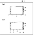
図11は、車両用除電装置6におけるガイド装置15の放出口11部分の拡大図であり、(a)は角部からなる尖端形状部14の例、(b)は尖端部からなる尖端形状部14の例を示す。図11の(a)に示すように、ガイドパイプ16における放出口11となる端部開口の端面の角部を尖らせることで、尖端形状部14が形成されている。また、図11の(b)に示すように、ガイドパイプ16における放出口11となる端部開口の端面に多数の尖端部を設けることで、尖端形状部14を形成してもよい。なお、図11の(a)(b)においては図示していないが、尖端形状部14は除電対象箇所Sと近接して設置されている。
11A and 11B are enlarged views of the
このような構成の車両用除電装置6においては、マイナスイオン発生器2より発生したマイナスイオンは、送風装置17にて発生される気流によってガイドパイプ16内部を放出口11に向かって案内され、放出口11から除電対象箇所Sに向かって放出される。
In the vehicle
さらに、ガイドパイプ16のマイナスに帯電した電荷は、プラスに帯電した除電対象箇所Sに向けてコロナ放電されることにより、ガイドパイプ16の放出口11のマイナスの電荷が大幅に減少する。これにより、送風装置17で送風されるマイナスイオンをガイドパイプ16内部に滞留させることなく、効率良く放出口11へ導き、マイナスイオンを安定放出することができる。図10のガイドパイプ16の例では、マイナスイオンは途中二手に分かれ、2箇所の除電対象箇所Sに向かって放出される。
Further, the negatively charged charge of the
図12は、車両用除電装置6の設置例を示す図である。図12に示すように、車両用除電装置6は、2つある放出口11のうち、1つをダッシュボード38よりフロントガラス37の周縁部に向け、もう1つをサイドドア40の内側パネル32よりサイドガラス39の周縁部に向けて配置されている。なお、ガイドパイプ16を3つに分岐して、3つめの放出口11をフロントピラー31よりフロントガラス37の周縁部に向けて設置してもよい。
FIG. 12 is a diagram showing an installation example of the
なお、図12においては、説明の便宜状、車両用除電装置6をダッシュボード38およびサイドドア40の内側パネル32に隠すことなく示している。しかしながら、実際には、車両用除電装置6は、ダッシュボード38およびサイドドア40の内側パネル32の内側に埋め込まれていて、放出口11の有る部分のみがダッシュボード38およびサイドドア40の内側パネル32に形成された開口より露出する形となる。なお、図12では、車両用除電装置6を助手席側に配置した構成しか図示していないが、運転席側にも同様に配置することができる。
In FIG. 12, for convenience of explanation, the vehicle
上記のように、送風装置を備えたガイド装置15とすることで、発生したマイナスイオンをガイドパイプ16内部に滞留させることなく、効率良く放出口11へ導いて放出することができる。
As described above, by using the
また、尖端形状部14にて発生するコロナ放電も、尖端形状部14が除電対象箇所Sに近づくほど発生しやすい。そのため、尖端形状部14が形成されている放出口11を除電対象箇所Sに近づけて配置する程、効果的にコロナ放電を発生させることができる。これにより、コロナ放電による除電対象箇所Sの効果的な除電と共に、コロナ放電によるマイナスイオンの放出の妨げを是正する効果によりマイナスイオンの放出を安定化させることができる。
Further, the corona discharge generated in the tip-shaped
以上のことから、尖端形状部14が設けられている放出口11の中心と除電対象箇所Sとの最短距離(離間距離)は、100mm以下とすることが好ましく、より好ましくは20mmとすることである。
From the above, the shortest distance (separation distance) between the center of the
〔実施の形態3〕
本発明の他の実施の形態について、図13、図14に基づいて説明すれば、以下のとおりである。なお、説明の便宜上、前記実施の形態にて説明した部材と同じ機能を有する部材については、同じ符号を付記し、その説明を省略する。
[Embodiment 3]
The other embodiments of the present invention will be described below with reference to FIGS. 13 and 14. For convenience of explanation, the same reference numerals are given to the members having the same functions as the members described in the above-described embodiment, and the description thereof will be omitted.
図13は、本発明の実施の形態3に係る車両用除電装置7の概略構成を示す断面図である。図14は、車両用除電装置7におけるガイド装置18の放出口11部分の拡大図である。
FIG. 13 is a cross-sectional view showing a schematic configuration of a vehicle
図13に示すように、車両用除電装置7は、実施の形態2に係る車両用除電装置6におけるガイドパイプ16の放出口11を有する一端部側に静電誘導部材19を備える構成である。つまり、車両用除電装置7は、ガイド装置15に代えて、静電誘導部材19を有するガイド装置18を備える。
As shown in FIG. 13, the vehicle
図13では、静電誘導部材19を導電性金属薄板リング形状(例えば、アルミ製円筒)とし、ガイドパイプ16に接触している構成を例示しているが、ガイドパイプ16に帯電したマイナスの電荷が静電誘導部材19に移動可能な距離であれば、非接触であってもよい。また、図14に示すように、ガイドパイプ16の一端部の開口が、ガイド装置18の放出口11となり、尖端形状部14が形成され、静電誘導部材19の位置は、ガイドパイプ16の一端部の開口よりもマイナスイオンの流れる方向における上流側となる。
FIG. 13 illustrates a configuration in which the
上記構成によれば、静電誘導部材19における、ガイドパイプ16と接触あるいは非接触で対峙している内側面には、ガイドパイプ16の帯電極性とは逆のプラスの電荷が引き寄せられる。ガイドパイプ16を流れるマイナスイオンは、静電誘導部材19が配置されている放出口11側に引き寄せられる。その結果、送風装置17による作用と同様に、マイナスイオンを滞留させることなく、効率良く放出口11へ導いて放出することができる。
According to the above configuration, a positive charge opposite to the charging polarity of the
なお、ここでは、送風装置17を組み合わせて備える構成を例示したが、送風装置17を有しない実施の形態の1のガイド装置10のガイド部材13の放出口11に静電誘導部材19を備える構成としてもよい。
Although the configuration in which the
このように、静電誘導部材19の配置位置は、ガイドパイプ16における放出口11のある一端部に近い程よく、引かれたマイナスイオンを滞留されることなく勢いをつけて放出することができる。このような静電誘導部材19は、上述したように、例えば、導電性金属薄板リングで形成することができる。この導電性金属薄板リングで形成した静電誘導部材19は、ガイドパイプ16における放出口11のある一端部に、一体成型する、あるいは該一端部に圧入する、あるいは該一端部に導電性接着剤等で接着するなどの手法で取り付けることができる。アルミ粘着テープを該一端部に巻きつけるなどの手法で作成してもよい。
As described above, the position of the
また、静電誘導部材19は、ガイドパイプ16の放出口11側に塗布された導電性を有する塗料(放電塗料)の塗膜にて形成され、該塗膜に形成された尖端形状にてコロナ放電させる尖端形状部14が形成されている構成としてもよい。導電性を有する塗料としては、例えば、メタリック塗料やカーボン塗料等を用いることができる。
Further, the
これ以降、導電性金属薄板リングの形状とした静電誘導部材19を導電性金属薄板リング19と称する。
Hereinafter, the
〔実施の形態4〕
本発明の他の実施の形態について、図15、図16に基づいて説明すれば、以下のとおりである。なお、説明の便宜上、前記実施の形態にて説明した部材と同じ機能を有する部材については、同じ符号を付記し、その説明を省略する。
[Embodiment 4]
The other embodiments of the present invention will be described below with reference to FIGS. 15 and 16. For convenience of explanation, the same reference numerals are given to the members having the same functions as the members described in the above-described embodiment, and the description thereof will be omitted.
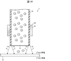
図15は、本発明の実施の形態4に係る車両用除電装置8におけるガイド装置20の放出口11部分の拡大図である。図15に示すように、導電性金属薄板リング19は、ガイドパイプ16の一端部の開口よりも除電対象箇所S側に突出している。そのため、導電性金属薄板リング19のこの突出した端部がガイド装置20の放出口11となっている。尖端形状部14は、導電性金属薄板リング19のこの突出した端部に形成されており、除電対象箇所Sに近接して配置されている。
FIG. 15 is an enlarged view of the
ガイドパイプ16のマイナスの電荷が導電性金属薄板リング19に導電し、この導電性金属薄板リング19の尖端形状部14から、プラスに帯電した除電対象箇所Sに向けて、コロナ放電が容易に行われる。その結果、ガイドパイプ16を流れるマイナスイオンが滞留することなく、さらに効率良く、マイナスイオンが安定して放出されるようになる。
The negative charge of the
<変形例>
図16は、車両用除電装置8の変形例を示すもので、ガイド装置20’の放出口11部分の拡大図である。図16に示すように、導電性金属薄板リング19は、ガイドパイプ16の一端部の開口と面一に形成されている。そのため、ガイドパイプ16の一端部の開口と面一に形成されている導電性金属薄板リング19の端部にもコロナ放電させる尖端形状部14が形成される。そして、この尖端形状部14は前記除電対象箇所Sに近接しているため、ガイドパイプ16の開口である放出口11及び導電性金属薄板リング19の尖端形状部14から、プラスに帯電した除電対象箇所Sに向けて、コロナ放電が容易に行われる。その結果、ガイドパイプ16を流れるマイナスイオンが滞留することなく、さらに効率良く、マイナスイオンが安定して放出されるようになる。
<Modification example>
FIG. 16 shows a modified example of the
〔実施の形態5〕
本発明の他の実施の形態について、図17に基づいて説明すれば、以下のとおりである。なお、説明の便宜上、前記実施の形態にて説明した部材と同じ機能を有する部材については、同じ符号を付記し、その説明を省略する。
[Embodiment 5]
The other embodiments of the present invention will be described below with reference to FIG. For convenience of explanation, the same reference numerals are given to the members having the same functions as the members described in the above-described embodiment, and the description thereof will be omitted.
図17は、本発明の実施の形態5に係る車両用除電装置9の概略構成と車両ガラス35に対する設置例を示す図である。図17に示すように、車両用除電装置9は、実施の形態1に係る車両用除電装置1において、ガイド部材13の放出口11を有する一端部側に導電性金属薄板リング19を備える構成である。車両用除電装置9において導電性金属薄板リング19は、ガイド部材13の出口を除電対象箇所Sに延長させる延長ガイド部材としての機能を兼ねている。この場合も、導電性金属薄板リング19は、ガイド部材13の前壁13aよりも除電対象箇所S側に突出しているため、導電性金属薄板リング19のこの突出した端部がガイド装置の放出口11となり、コロナ放電させる尖端形状部14が形成されている。
FIG. 17 is a diagram showing a schematic configuration of the vehicle static elimination device 9 according to the fifth embodiment of the present invention and an installation example on the
このような構成とすることで、車両用除電装置9の放出口11を、除電対象箇所Sに対し容易に近づけることができる。つまり、導電性金属薄板リング19以外の構造は共通化し、除電対象箇所Sまでの距離に合わせて導電性金属薄板リング19の長さを調整することで、コロナ放電が容易に行われるようになり、効果的な除電を行いつつ、コストの削減も図れる。
With such a configuration, the
〔発明の前提事項および好適な除電対象箇所〕
図18は、本発明で対象とすることができる車両の一例を示す図である。図18に示す車両61は、車輪62がゴムなどの絶縁体(または、電気伝導率が小さい材料)により構成されており、車体63と路面とが絶縁状態に保持されている。この車両61が走行する際には、走行風や吸排気管内を流動する空気流などと車体63との摩擦などに伴う電気的な作用によってプラスの静電気が生じて、車体63に帯電する。また、エンジンやモータなどの動力源あるいは変速機もしくはサスペンションなどが駆動すると、それらの装置を構成する複数の部材が摺動し、その摺動に伴う電気的な作用によってプラスの静電気が生じて、車体63に帯電する。さらに、ゴムで構成された車輪62と路面との摩擦や、車輪62が回転して路面に接触していた面が、路面から離れることなどによる電気的な作用によりプラスの静電気が生じて、車体63に帯電する。あるいは、車両61に搭載された電気機器や車両61の外部の送電線などの電気機器の電気を要因としてプラスの静電気が帯電する場合がある。
[Premises of the invention and suitable locations for static elimination]
FIG. 18 is a diagram showing an example of a vehicle that can be a target in the present invention. In the
その結果、そのプラスの静電気は、電気伝導率が小さい樹脂パネルやガラスや、電気伝導率が比較的高い金属材料によって構成された車体のボディ壁やパネルにも帯電する。さらに、駆動力発生装置の吸気装置の吸入通路を画定する吸気通路壁は樹脂材料から構成されているため、プラスに帯電しやすい。 As a result, the positive static electricity is also charged on the body wall and panel of the vehicle body made of a resin panel or glass having a low electric conductivity or a metal material having a relatively high electric conductivity. Further, since the intake passage wall defining the intake passage of the intake device of the driving force generator is made of a resin material, it is likely to be positively charged.
空気は、通常、プラスの電荷を帯びているため、車体63にプラスの静電気が帯電すると、空気との間で斥力(反発力)が生じる。駆動力発生装置の吸気装置の吸入通路にプラスの静電気が帯電しても同様に、吸気された空気との間で斥力(反発力)が生じる。
Since air is usually positively charged, when the
図19は、車体モデルをプラスの電荷で帯電させた状態と、車体モデルを帯電させていない状態との、車体モデルの表面に垂直な方向での流速分布を測定した結果を示すグラフである。なお、図19における縦軸は、モデル表面からの距離を示し、横軸は、車体モデルに吹き付けた空気の流速U∞に対する、車体モデルからの距離毎に測定した流速Uの割合(U/U∞)を示している。また、車体モデルをプラスの電荷で帯電させた状態で測定した結果を正方形でプロットし、車体モデルを帯電させていない状態で測定した結果を菱形でプロットしている。 FIG. 19 is a graph showing the results of measuring the flow velocity distribution in the direction perpendicular to the surface of the vehicle body model, in the state where the vehicle body model is charged with a positive charge and in the state where the vehicle body model is not charged. The vertical axis in FIG. 19 indicates the distance from the model surface, and the horizontal axis is the ratio of the flow velocity U measured for each distance from the vehicle body model to the flow velocity U∞ of the air blown to the vehicle body model (U / U). ∞) is shown. In addition, the results measured with the vehicle body model charged with a positive charge are plotted in squares, and the results measured with the vehicle body model uncharged are plotted with diamonds.
図19に示すように、車体モデルをプラスの電荷で帯電させた場合における境界層厚さ(U/U∞がほぼ「1」になる際の車体モデル表面からの距離)が、車体モデルをプラスの電荷で帯電させていない場合における境界層厚さよりも大きくなっている。これは、車体モデルをプラスの電荷で帯電させた場合には、車体モデルをプラスの電荷で帯電させていない場合に比べて剥離が大きくなることを意味する。上述したように空気流は、通常、プラスの電荷を帯びているので、車体モデルに帯電したプラスの電荷と空気流のプラスの電荷とによって斥力が生じ、その結果、車体モデルの表面からの空気流の剥離が助長されたものと考えられる。 As shown in FIG. 19, the boundary layer thickness (distance from the vehicle body model surface when U / U∞ becomes almost "1") when the vehicle body model is charged with a positive charge adds to the vehicle body model. It is larger than the boundary layer thickness when it is not charged with the electric charge of. This means that when the vehicle body model is charged with a positive charge, the peeling is larger than when the vehicle body model is not charged with a positive charge. As mentioned above, the airflow is usually positively charged, so the positive charge on the vehicle body model and the positive charge on the airflow create a repulsive force, resulting in air from the surface of the vehicle body model. It is probable that the separation of the flow was promoted.
また、駆動力発生装置の吸気装置の吸入通路を画定する吸気通路壁においても、吸気通路壁を表面にプラスの電荷が帯電している場合と帯電していない場合とで、図19と同様の結果が得られる。 Further, also in the intake passage wall defining the intake passage of the intake device of the driving force generator, the same as in FIG. 19 depending on whether the surface of the intake passage wall is positively charged or not charged. The result is obtained.
したがって、このような車体(車両)ボディ外壁表面に沿って流れる空気が剥離しやすい箇所や、駆動力発生装置の吸入された空気が吸気通路壁の壁面から剥離しやすい箇所を除電することで、プラスに静電気による影響を効果的に抑えることができる。 Therefore, by eliminating static electricity at such locations where the air flowing along the surface of the outer wall of the vehicle body (vehicle) is likely to separate, and where the air sucked by the driving force generator is likely to separate from the wall surface of the intake passage wall. Plus, the effects of static electricity can be effectively suppressed.
車体63の表面から離れた流れに変化しやすい箇所は、例えば以下のような箇所である。車体63を前方から見た場合に、車体63の外面が車体63の内側に屈曲する箇所で空気流の剥離が主に生じる。より具体的には、車体63の左右両側では、車幅が狭くなるように屈曲する箇所であり、またボンネットやルーフでは高さが低くなるように屈曲する箇所であり、さらにアンダーカバーなどの車体下面に露出している部分では、車高が車両後方に向けて次第に低くなっている箇所から水平に変化するように屈曲する箇所、あるいは車両後方に向けて水平であった箇所から車高が次第に高くなるように屈曲する箇所などである。さらに、車体63の外部に部分的に突出している箇所や段差のある箇所などで空気流の剥離が生じやすい。したがって、車体63の表面から空気流が剥離する場合には、上述したように箇所で、空気流が車体63の表面から離れた流れに変化し始める。
The places that are likely to change to a flow away from the surface of the
〔まとめ〕
車体ボディであれば、ボディ外壁に沿って流れる空気が剥離し易い形状をした箇所の当該ボディ外壁の裏側壁面を除電対象箇所Sとして除電、またはマイナスの電荷に帯電することで、前記空気流が前記車体のボディ外壁表面から離れることを効果的に抑制することができる。
〔summary〕
In the case of a vehicle body, the air flow is generated by eliminating static electricity or charging a negative charge with the back side wall surface of the outer wall of the body having a shape in which the air flowing along the outer wall of the body is easily separated. It is possible to effectively suppress the separation from the body outer wall surface of the vehicle body.
また、駆動力発生装置の吸気通路壁であれば、樹脂製の吸気通路壁における吸入空気が剥離し易い形状をした箇所の外側壁面を除電対象箇所Sとして除電することで、吸入した空気の空気流が吸気通路壁の内面から離れることを効果的に抑制することができ、吸入空気の吸気効率を向上させることができる。例えば、図20の(a)(b)は、車両の駆動力発生装置の吸気装置の一部であるエアクリーナへの吸入空気導入管66と、その近傍に近接して配置された図1に示す車両用除電装置1とを示す説明図である。図20の(a)(b)において、吸入した空気の空気流が吸入空気導入管66の吸気通路壁の内面から離れる箇所に楕円(一点鎖線)を付している。その楕円付近の吸気通路外壁に向けて、マイナスイオンを放出できる様に車両除電装置1を近接して配置している。なお、図20の(a)(b)においては、吸入空気導入管66については斜視図で示しているが、車両除電装置1については便宜上、断面図にて示している。
Further, in the case of the intake passage wall of the driving force generator, the air of the sucked air is removed by statically eliminating the outer wall surface of the portion of the resin intake passage wall having a shape in which the intake air is easily separated as the static elimination target portion S. It is possible to effectively suppress the flow from moving away from the inner surface of the intake passage wall, and it is possible to improve the intake efficiency of the intake air. For example, FIGS. 20A and 20B show an intake
なお、上述した車両用除電装置1,6~9を搭載する車両として、図18にて車輪62がゴムなどの絶縁体により構成されており、車体63と路面とが絶縁状態に保持されているものを例示しているが、車両は鉄輪がレール上を走行する列車であってもよく、要は車体が走行することを含む外部要因等により、プラスの静電気に帯電する車両が含まれることは言うまでもない。
In addition, as a vehicle equipped with the above-mentioned static eliminator for
〔まとめ〕
本発明の態様1に係る車両用除電装置は、路面に対して絶縁状態に保持されている車体が走行することを含む外部要因等により、プラスの静電気に帯電する車両に搭載されて、前記車両におけるプラスに帯電した所定の除電対象箇所を除電する、またはマイナスに帯電させる車両用除電装置であって、マイナスイオン発生部と、前記マイナスイオン発生部にて発生したマイナスイオンを案内して放出口より前記除電対象箇所に向けて放出するガイド装置と、を備え、前記ガイド装置は、静電気の帯電列においてマイナス側に帯電し易い樹脂から形成された、前記マイナスイオンを案内する通路を画定するガイド部材と、前記放出口を画定する部分に形成されると共に前記除電対象箇所に近接して配置され、前記ガイド部材に帯電したマイナスの電荷を前記除電対象箇所へ向けてコロナ放電させる尖端形状部と、を有することを特徴とする。
〔summary〕
The vehicle static eliminator according to the first aspect of the present invention is mounted on a vehicle charged with positive static electricity due to an external factor including the traveling of a vehicle body maintained in an insulated state with respect to the road surface, and the vehicle. This is a vehicle static eliminator that removes static electricity from a predetermined positively charged static electricity removal target location or negatively charges it, and guides the negative ion generation part and the negative ion generated in the negative ion generation part to the discharge port. The guide device includes a guide device that discharges the negative ions toward the static electricity elimination target portion, and the guide device defines a passage for guiding the negative ions, which is formed of a resin that is easily charged to the negative side in the electrostatic charge train. A member and a tip-shaped portion formed in a portion defining the discharge port and arranged close to the static electricity elimination target portion to corona discharge the negative charge charged on the guide member toward the static electricity elimination target portion. It is characterized by having.
本発明の態様2に係る車両用除電装置は、さらに、態様1において、前記除電対象箇所は、前記車両のボディ外壁における、当該ボディ外壁の表面に沿って流れる空気が前記表面より剥離し易い形状をした箇所の裏側壁面である構成とすることもできる。 Further, in the vehicle static elimination device according to the second aspect of the present invention, in the first aspect, the static elimination target portion has a shape in the outer wall of the body of the vehicle, in which air flowing along the surface of the outer wall of the body is easily separated from the surface. It is also possible to configure it as the back side wall surface of the marked portion.
本発明の態様3に係る車両用除電装置は、さらに、態様1において、前記除電対象箇所は、前記車両の駆動力発生装置の樹脂製の吸気通路壁における、吸入空気が剥離し易い形状をした箇所の外側壁面である構成とすることもできる。 Further, in the vehicle static elimination device according to the third aspect of the present invention, in the first aspect, the static elimination target portion has a shape in which the intake air is easily separated from the resin intake passage wall of the driving force generator of the vehicle. It can also be configured to be the outer wall surface of the location.
本発明の態様4に係る車両用除電装置は、さらに、態様1から3のいずれかにおいて、前記ガイド装置は、前記マイナスイオンを前記放出口へ送り出す送風装置を含む構成とすることもできる。 The vehicle static eliminator according to the fourth aspect of the present invention may further have a configuration in any one of the first to third aspects, wherein the guide device includes a blower device that sends out the negative ions to the discharge port.
本発明の態様5に係る車両用除電装置は、さらに、態様1から4のいずれかにおいて、前記ガイド装置は、前記ガイド部材における前記マイナスイオンの出口側に配置された静電誘導部材を含む構成とすることもできる。
The vehicle static eliminator according to
本発明の態様6に係る車両用除電装置は、さらに、態様5において、前記静電誘導部材は、前記除電対象箇所側の端部が前記ガイド部材の前記出口と少なくとも同一、もしくは前記除電対象箇所側に位置すると共に、前記除電対象箇所側の端部に前記コロナ放電させる尖端形状部が形成されている構成とすることもできる。 In the vehicle static eliminator according to the sixth aspect of the present invention, further, in the fifth aspect, the electrostatic induction member has an end portion on the static electricity elimination target portion side that is at least the same as the outlet of the guide member, or the static electricity elimination target portion. In addition to being located on the side, it is also possible to have a configuration in which a tip-shaped portion for discharging the corona is formed at the end portion on the side of the static electricity elimination target portion.
本発明の態様7に係る車両用除電装置は、さらに、態様5又は6において、前記静電誘導部材は、導電性金属薄板リングで形成され、前記ガイド部材の前記出口側に一体成型されている、もしくは前記ガイド部材の前記出口側に圧入されている、もしくは前記ガイド部材の前記出口側に接着されている構成とすることもできる。 Further, in the vehicle static elimination device according to the seventh aspect of the present invention, in the fifth or sixth aspect, the electrostatic induction member is formed of a conductive metal thin plate ring and integrally molded on the outlet side of the guide member. Alternatively, it may be configured to be press-fitted to the outlet side of the guide member or adhered to the outlet side of the guide member.
本発明の態様8に係る車両用除電装置は、さらに、態様5において、前記導電性金属薄板リングは、前記ガイド部材の前記出口を前記除電対象箇所に延長させる延長ガイド部材としての機能を兼ねる構成とすることもできる。 In the vehicle static elimination device according to the eighth aspect of the present invention, in the fifth aspect, the conductive metal thin plate ring also functions as an extension guide member for extending the outlet of the guide member to the static elimination target portion. It can also be.
本発明の態様9に係る車両用除電装置は、さらに、態様6において、前記静電誘導部材は、前記ガイド部材の前記出口側に塗布された導電性を有する塗料の塗膜にて形成され、該塗膜に形成された尖端形状にて前記コロナ放電させる尖端形状部が形成されている構成とすることもできる。 In the vehicle static eliminator according to the ninth aspect of the present invention, in the sixth aspect, the electrostatic induction member is formed of a coating film of a conductive paint applied to the outlet side of the guide member. The tip shape formed on the coating film may be configured to form the tip-shaped portion for discharging the corona.
本発明の態様10に係る車両用除電装置は、さらに、態様1から9のいずれかにおいて、前記ガイド装置における前記放出口の中心と前記除電対象箇所との間の最短距離が100mm以下である構成とすることもできる。
Further, in any one of
換言すると、本発明の態様10に係る車両用除電装置は、さらに、態様1から9のいずれかにおいて、前記ガイド装置における前記放出口の中心と最短距離が100mm離れた前記除電対象箇所に対して前記コロナ放電を生じる構成とすることもできる。 In other words, the vehicle static eliminator according to the tenth aspect of the present invention further, in any one of the first to ninth aspects, with respect to the static elimination target portion having the shortest distance of 100 mm from the center of the discharge port in the guide device. It can also be configured to generate the corona discharge.
本発明の態様11に係る車両用除電装置は、さらに、態様10において、前記ガイド装置における前記放出口の中心と前記除電対象箇所との間の最短距離が20mmである構成とすることもできる。 Further, in the tenth aspect of the vehicle static elimination device according to the eleventh aspect of the present invention, the shortest distance between the center of the discharge port in the guide device and the static elimination target portion may be 20 mm.
換言すると、本発明の態様11に係る車両用除電装置は、さらに、態様10において、前記ガイド装置における前記放出口の中心と最短距離が20mm離れた前記除電対象箇所に対する除電効果がピークになる構成とすることもできる。 In other words, the vehicle static eliminator according to the eleventh aspect of the present invention further has a configuration in which the static elimination effect peaks at the static elimination target portion having a shortest distance of 20 mm from the center of the discharge port in the guide device. It can also be.
本発明の態様12に係る車両は、さらに、態様1から11のいずれかの車両用除電装置を搭載したことを特徴とする。 The vehicle according to the 12th aspect of the present invention is further characterized by being equipped with the static elimination device for a vehicle according to any one of the 1st to 11th aspects.
本発明は上述した各実施形態に限定されるものではなく、請求項に示した範囲で種々の変更が可能であり、異なる実施形態にそれぞれ開示された技術的手段を適宜組み合わせて得られる実施形態についても本発明の技術的範囲に含まれる。さらに、各実施形態にそれぞれ開示された技術的手段を組み合わせることにより、新しい技術的特徴を形成することができる。 The present invention is not limited to the above-described embodiments, and various modifications can be made within the scope of the claims, and the embodiments obtained by appropriately combining the technical means disclosed in the different embodiments. Is also included in the technical scope of the present invention. Further, by combining the technical means disclosed in each embodiment, new technical features can be formed.
1、6、7、8、9 車両用除電装置
2 マイナスイオン発生器(マイナスイオン発生部)
10、15、18、20、20’ ガイド装置
11 放出口
13 ガイド部材
14 尖端形状部
16 ガイドパイプ(ガイド部材)
17 送風装置
19 静電誘導部材、導電性金属薄板リング
31 フロントピラー
32 内側パネル
35 車両ガラス
36 設置面
36a 凹部
37 フロントガラス
38 ダッシュボード
39 サイドガラス
40 サイドドア
61 車両
62 車輪
63 車体
66 吸入空気導入管
S 除電対象箇所
1, 6, 7, 8, 9 Vehicle
10, 15, 18, 20,
17
Claims (11)
マイナスイオン発生部と、
前記マイナスイオン発生部にて発生したマイナスイオンを案内して放出口より前記除電対象箇所に向けて放出するガイド装置と、を備え、
前記ガイド装置は、
静電気の帯電列においてマイナス側に帯電し易い樹脂から形成された、前記マイナスイオンを案内する通路を画定するガイド部材と、
前記放出口を画定する部分に形成されると共に前記除電対象箇所に近接して配置され、前記ガイド部材に帯電したマイナスの電荷を前記除電対象箇所へ向けてコロナ放電させる尖端形状部と、を有することを特徴とする車両用除電装置。 It is mounted on a vehicle that is charged with positive static electricity due to external factors such as running of a vehicle body that is kept insulated from the road surface, and eliminates static electricity at a predetermined positively charged location in the vehicle. , Or a static eliminator for vehicles that charges negatively.
Negative ion generator and
A guide device for guiding the negative ions generated in the negative ion generating portion and discharging the negative ions from the discharge port toward the static elimination target portion is provided.
The guide device is
A guide member that defines a passage that guides the negative ions, which is formed of a resin that is easily charged to the negative side in the electrostatic charge train, and
It has a tip-shaped portion formed in a portion defining the discharge port and arranged close to the static elimination target portion to corona discharge the negative charge charged on the guide member toward the static elimination target portion. A vehicle static eliminator that is characterized by this.
Priority Applications (4)
| Application Number | Priority Date | Filing Date | Title |
|---|---|---|---|
| JP2018130179A JP7050600B2 (en) | 2018-07-09 | 2018-07-09 | Static eliminator for vehicles and vehicles |
| EP19183966.1A EP3594069B1 (en) | 2018-07-09 | 2019-07-02 | Vehicular static eliminating device and vehicle |
| US16/504,369 US10988093B2 (en) | 2018-07-09 | 2019-07-08 | Vehicular static eliminating device and vehicle |
| CN201910609487.6A CN110696758A (en) | 2018-07-09 | 2019-07-08 | Static eliminator for vehicle and vehicle |
Applications Claiming Priority (1)
| Application Number | Priority Date | Filing Date | Title |
|---|---|---|---|
| JP2018130179A JP7050600B2 (en) | 2018-07-09 | 2018-07-09 | Static eliminator for vehicles and vehicles |
Publications (2)
| Publication Number | Publication Date |
|---|---|
| JP2020009643A JP2020009643A (en) | 2020-01-16 |
| JP7050600B2 true JP7050600B2 (en) | 2022-04-08 |
Family
ID=67184782
Family Applications (1)
| Application Number | Title | Priority Date | Filing Date |
|---|---|---|---|
| JP2018130179A Active JP7050600B2 (en) | 2018-07-09 | 2018-07-09 | Static eliminator for vehicles and vehicles |
Country Status (4)
| Country | Link |
|---|---|
| US (1) | US10988093B2 (en) |
| EP (1) | EP3594069B1 (en) |
| JP (1) | JP7050600B2 (en) |
| CN (1) | CN110696758A (en) |
Families Citing this family (1)
| Publication number | Priority date | Publication date | Assignee | Title |
|---|---|---|---|---|
| JP2023166094A (en) * | 2022-05-09 | 2023-11-21 | トヨタ自動車株式会社 | vehicle |
Citations (2)
| Publication number | Priority date | Publication date | Assignee | Title |
|---|---|---|---|---|
| JP2004079471A (en) | 2002-08-22 | 2004-03-11 | Denso Corp | Negative ion generating device |
| WO2015064195A1 (en) | 2013-10-30 | 2015-05-07 | トヨタ自動車株式会社 | Vehicle, and method of manufacturing same |
Family Cites Families (11)
| Publication number | Priority date | Publication date | Assignee | Title |
|---|---|---|---|---|
| JPS5552932A (en) | 1978-10-16 | 1980-04-17 | Toshiba Corp | Head for sludge concentration meter |
| JPS5675222A (en) | 1979-11-21 | 1981-06-22 | Yamaha Motor Co Ltd | Vehicle start safety device |
| TW332802B (en) * | 1992-06-04 | 1998-06-01 | Nippon Denso Co | The air purifier |
| US20090001787A1 (en) * | 2007-06-26 | 2009-01-01 | Gm Global Technology Operations, Inc. | Ionized Air System and Method for Dissipating an Electrostatic Charge in a Vehicle |
| JP2010076589A (en) * | 2008-09-25 | 2010-04-08 | Panasonic Electric Works Co Ltd | Antistatic system for vehicle |
| JP5111648B1 (en) * | 2011-08-31 | 2013-01-09 | シャープ株式会社 | Ion generator |
| JP6128093B2 (en) * | 2014-10-16 | 2017-05-17 | トヨタ自動車株式会社 | Vehicle intake system |
| JP6217675B2 (en) | 2015-03-13 | 2017-10-25 | トヨタ自動車株式会社 | vehicle |
| JP6344292B2 (en) * | 2015-04-03 | 2018-06-20 | トヨタ自動車株式会社 | vehicle |
| EP3193417A1 (en) * | 2016-01-12 | 2017-07-19 | Naturion Pte. Ltd. | Ion generator device |
| CN105781947B (en) * | 2016-03-06 | 2019-08-27 | 淄博环能海臣环保技术服务有限公司 | A kind of plasma air purifying is without leaf electric fan |
-
2018
- 2018-07-09 JP JP2018130179A patent/JP7050600B2/en active Active
-
2019
- 2019-07-02 EP EP19183966.1A patent/EP3594069B1/en active Active
- 2019-07-08 CN CN201910609487.6A patent/CN110696758A/en active Pending
- 2019-07-08 US US16/504,369 patent/US10988093B2/en active Active
Patent Citations (2)
| Publication number | Priority date | Publication date | Assignee | Title |
|---|---|---|---|---|
| JP2004079471A (en) | 2002-08-22 | 2004-03-11 | Denso Corp | Negative ion generating device |
| WO2015064195A1 (en) | 2013-10-30 | 2015-05-07 | トヨタ自動車株式会社 | Vehicle, and method of manufacturing same |
Also Published As
| Publication number | Publication date |
|---|---|
| JP2020009643A (en) | 2020-01-16 |
| CN110696758A (en) | 2020-01-17 |
| US20200010036A1 (en) | 2020-01-09 |
| EP3594069A1 (en) | 2020-01-15 |
| US10988093B2 (en) | 2021-04-27 |
| EP3594069B1 (en) | 2020-11-11 |
Similar Documents
| Publication | Publication Date | Title |
|---|---|---|
| KR101822988B1 (en) | Vehicle and manufacturing method thereof | |
| KR101914880B1 (en) | Intake system of vehicle | |
| JP6217675B2 (en) | vehicle | |
| KR101777013B1 (en) | Intake device for vehicle | |
| JP2016117388A (en) | Cooling device for vehicle | |
| JP7050600B2 (en) | Static eliminator for vehicles and vehicles | |
| JP6344292B2 (en) | vehicle | |
| CN107539249B (en) | Vehicle and method for manufacturing same | |
| CN107539248B (en) | Vehicle and manufacturing method for vehicle | |
| US11447083B2 (en) | Vehicle and electrostatic elimination component | |
| JP6848945B2 (en) | Static eliminator | |
| JP2019192568A (en) | Static eliminator for vehicle | |
| CN112389356A (en) | Static elimination equipment for vehicle and vehicle |
Legal Events
| Date | Code | Title | Description |
|---|---|---|---|
| A621 | Written request for application examination |
Free format text: JAPANESE INTERMEDIATE CODE: A621 Effective date: 20210413 |
|
| A977 | Report on retrieval |
Free format text: JAPANESE INTERMEDIATE CODE: A971007 Effective date: 20211224 |
|
| A131 | Notification of reasons for refusal |
Free format text: JAPANESE INTERMEDIATE CODE: A131 Effective date: 20220111 |
|
| A521 | Request for written amendment filed |
Free format text: JAPANESE INTERMEDIATE CODE: A523 Effective date: 20220307 |
|
| TRDD | Decision of grant or rejection written | ||
| A01 | Written decision to grant a patent or to grant a registration (utility model) |
Free format text: JAPANESE INTERMEDIATE CODE: A01 Effective date: 20220322 |
|
| A61 | First payment of annual fees (during grant procedure) |
Free format text: JAPANESE INTERMEDIATE CODE: A61 Effective date: 20220329 |
|
| R150 | Certificate of patent or registration of utility model |
Ref document number: 7050600 Country of ref document: JP Free format text: JAPANESE INTERMEDIATE CODE: R150 |