JP2019192568A - Static eliminator for vehicle - Google Patents
Static eliminator for vehicle Download PDFInfo
- Publication number
- JP2019192568A JP2019192568A JP2018086301A JP2018086301A JP2019192568A JP 2019192568 A JP2019192568 A JP 2019192568A JP 2018086301 A JP2018086301 A JP 2018086301A JP 2018086301 A JP2018086301 A JP 2018086301A JP 2019192568 A JP2019192568 A JP 2019192568A
- Authority
- JP
- Japan
- Prior art keywords
- vehicle
- tape
- adhesive tape
- static eliminator
- vehicle body
- Prior art date
- Legal status (The legal status is an assumption and is not a legal conclusion. Google has not performed a legal analysis and makes no representation as to the accuracy of the status listed.)
- Pending
Links
Images


Landscapes
- Elimination Of Static Electricity (AREA)
Abstract
Description
この発明は、車両における静電気を除電する除電器に関するものである。 The present invention relates to a static eliminator that neutralizes static electricity in a vehicle.
車両および空気は共に正に帯電することが知られており、走行時に車両およびその周囲を流れる空気流が共に正に帯電すると、それらの間の斥力によって車両表面から空気流が剥離する可能性がある。車体が帯びている正の極性の静電気を除電して上述した空気流の剥離を抑制する除電器の一例が特許文献1に記載されている。その除電器は、車体の周囲を流れる空気流が、車体表面に沿う流れから、車体表面から離れた流れに変化し始める箇所のうち、空気流の剥離を抑制することによって車両の操縦安定性を良好にすることのできる特定部位に設けられている。除電器は、金、銀、銅、アルミニウムなどの金属材料や導電性高分子、導電性プラスチックなどによって構成された導電性のシートを、導電性の粘着剤を介して特定部位に貼り付けて構成されている。また、その外縁部は自己放電を生じやすくするために鋭利もしくは尖って形成されている。除電器は導電性を有しているため、走行時に車体が正に帯電すると、車体と同様に正に帯電する。また、除電器の外縁部は尖っているため、その外縁部に電荷が集中してその周囲に負の極性の空気イオンが引き寄せられる。また、コロナ放電によって負の極性の空気イオンが生じ、その負の極性の空気イオンによって除電器の周囲における車体の正の極性の静電気が中和除電されてその電位が低下させられ、斥力が小さくなる。それらの結果、除電器の周囲に空気流が引き寄せられるから、空気流の剥離を抑制して車体の操縦安定性を向上することができる、とされている。
It is known that both the vehicle and the air are positively charged, and if the air flow flowing around the vehicle and its surroundings is positively charged during traveling, the repulsive force between them may cause the air flow to separate from the vehicle surface. is there.
特許文献1に記載された除電器を構成している、導電性のある各種の材料は、従来一般的に用いられる導電性のない合成樹脂材料と比較して高価であり、特許文献1に記載された構成では、材料コストや製造コストを抑制する点で未だ、改良の余地があった。なお、特許文献1に記載された除電器を車体表面に貼ると、外観の見栄えを損なう可能性があり、この点でも未だ、改良の余地があった。
Various electrically conductive materials constituting the static eliminator described in
この発明は上記の技術的課題に着目して成されたものであり、車体における静電気を十分に中和除電することができると共に、材料コストや製造コストを低減することができ、しかも、外観の見栄えを良好に維持することのできる車両の除電器を提供することを目的とするものである。 The present invention has been made paying attention to the above technical problem, and can sufficiently neutralize and neutralize static electricity in the vehicle body, reduce the material cost and the manufacturing cost, and further improve the appearance. An object of the present invention is to provide a static eliminator for a vehicle that can maintain a good appearance.
上記の目的を達成するために、この発明は、路面に対して絶縁状態になっている車両における、前記車両の走行による要因と、前記車両の走行による要因以外の他の要因とのうち、少なくとも一方の要因によって正の極性の静電気を帯びる少なくとも一つの特定部位に設けられていて、自己放電によって負の極性の空気イオンを生じさせ、前記負の極性の空気イオンによって前記特定部位の正の電位を中和除電して低下させるように構成された前記車両の除電器において、前記特定部位に粘着剤を介して貼付される樹脂テープを備え、前記粘着剤の表面抵抗値は、1×10¹⁰(Ω)から1×10¹¹(Ω)であり、前記樹脂テープは、前記特定部位と比較して前記特定部位とは反対の負の極性の静電気を帯びやすい合成樹脂材料によって形成され、前記樹脂テープの表面積は、前記負の極性の空気イオンによって前記特定部位の正の電位を中和除電して低下させる放電特性が同じであるアルミニウム粘着テープと同じ表面積であって、前記樹脂テープの周縁部と前記アルミニウム粘着テープの周縁部とのそれぞれは、前記自己放電を生じさせるように鋭利もしくは尖って形成され、前記樹脂テープの周縁部の長さは、前記アルミニウム粘着テープの周縁部の長さの3倍から5倍であることを特徴とするものである。 In order to achieve the above object, the present invention provides at least one of a factor caused by running of the vehicle and a factor other than a factor caused by running of the vehicle in a vehicle that is insulated from a road surface. It is provided in at least one specific part having positive polarity static electricity due to one factor, and negative polarity air ions are generated by self-discharge, and the positive potential of the specific part is generated by the negative polarity air ions. The static eliminator of the vehicle configured to reduce the neutralization and neutralization is provided with a resin tape attached to the specific part via an adhesive, and the surface resistance value of the adhesive is 1 × 10 10. is from (Ω) 1 × 10 11 ( Ω), said resin tape, it forms the negative polarity static electricity charged easy synthetic resin material of the opposite to the specific site as compared to the specific site The surface area of the resin tape is the same as that of an aluminum adhesive tape having the same discharge characteristics that neutralize and remove the positive potential of the specific part by the negative polarity air ions, and the resin tape has the same surface area. Each of the peripheral edge of the tape and the peripheral edge of the aluminum adhesive tape is sharp or pointed so as to cause the self-discharge, and the length of the peripheral edge of the resin tape is the peripheral edge of the aluminum adhesive tape. It is characterized in that it is 3 to 5 times the length of.
この発明によれば、車両には、車両の走行による要因と、前記車両の走行による要因以外の他の要因とのうち、少なくとも一方の要因によって正の極性の静電気を帯びる特定部位があり、特定部位のうちの少なくとも一つの特定部位にこの発明の除電器が設けられる。上記の特定部位としては、例えば、車体の周囲を流れる空気流が車体の表面に沿う流れから車体の表面から離れた流れに変化し始める箇所を挙げることができる。この発明では、上記の特定部位に、自己放電により負の極性の空気イオンを生じさせ、その負の極性の静電気によって特定部位およびその周囲の正の電位を中和除電して低下させる樹脂テープが粘着剤を介して除電器として設けられている。樹脂テープは、特定部位と比較して負の極性の静電気を帯びやすい合成樹脂材料によって形成され、粘着剤の表面抵抗値は1×1010(Ω)から1×1011(Ω)の範囲に設定されている。また、樹脂テープは、金属材料や導電性を有する合成樹脂材料などを備えていないため、そのような導電性のある材料を有するテープと比較して、低コストであり、したがって、除電器の材料コストや製造コストを低減することができる。また、この発明では、樹脂テープの表面積は、自己放電による負の空気イオンによって特定部位およびその周囲の正の電位を中和除電して低下させる、いわゆる放電特性が同じであるアルミニウム粘着テープの表面積と同じに設定されている。また、樹脂テープの周縁部の長さはアルミニウム粘着テープの周縁部の長さの3倍から5倍に設定されている。つまり、樹脂テープにおける負の極性の静電気と正の極性の静電気を帯びる空気とが接触したり、自己放電を生じたりする箇所あるいは長さが可及的に長くなっている。そのため、アルミニウム粘着テープと比較して樹脂テープの電気抵抗が大きく電気が流れにくいとしても、車両の走行に伴って樹脂テープが負の極性の静電気を帯び、また、その電位が増大すると、樹脂テープの周囲に正に帯電している空気イオンを含む空気流をクーロン力によって引き寄せることができる。なお、このようにクーロン力によって車体表面に空気流を引き寄せる場合には、特定部位の表面に樹脂テープを貼ることが好ましい。また、自己放電を生じると、それによって生じた負の極性の空気イオンによって特定部位の周囲の正の電位が中和除電されて低下させられる。その結果、車体と空気流との間の斥力(反発力)が低下させられる。このようにして、この発明では、車体の表面近傍から空気流が剥離することを抑制できる。そして、車体の表面に作用する空圧が想定を超えて変化したり、それに伴って車体の空力特性が悪化したりすることを抑制することができるので、操縦安定性などの走行性能が低下することを抑制することができる。さらに、樹脂テープは合成樹脂材料によって形成されるから、色彩や形状などのデザイン、材料などの選択の自由度が大きい。そのため、車体表面に除電器として貼付するとしても、車両の見栄えを良好に維持したり、あるいは見栄えを損なうことを抑制したりできる。 According to the present invention, the vehicle has a specific portion that is charged with static electricity having a positive polarity due to at least one of a factor caused by traveling of the vehicle and a factor other than the factor caused by traveling of the vehicle. The static eliminator of this invention is provided in at least one specific part of the parts. Examples of the specific part include a part where the airflow flowing around the vehicle body starts to change from a flow along the surface of the vehicle body to a flow away from the surface of the vehicle body. According to the present invention, there is provided a resin tape that generates negative polarity air ions by self-discharge in the above-mentioned specific portion and neutralizes and reduces the positive potential around the specific portion and its surroundings by the negative polarity static electricity. It is provided as a static eliminator via an adhesive. The resin tape is formed of a synthetic resin material that is easily charged with negative polarity compared to a specific portion, and the surface resistance value of the adhesive is in the range of 1 × 10 10 (Ω) to 1 × 10 11 (Ω). Is set. In addition, since the resin tape does not include a metal material or a conductive synthetic resin material, the cost of the resin tape is lower than that of a tape having such a conductive material. Costs and manufacturing costs can be reduced. In the present invention, the surface area of the resin adhesive tape is the same as the surface area of the aluminum adhesive tape having the same so-called discharge characteristics that reduces the negative potential by neutralizing and removing the positive potential around the specific portion by negative air ions due to self-discharge. Is set to the same. Moreover, the length of the peripheral part of the resin tape is set to 3 to 5 times the length of the peripheral part of the aluminum adhesive tape. That is, the portion or length of the resin tape where negatively charged static electricity and positively charged static electricity are in contact with each other or self-discharge occurs is as long as possible. Therefore, even if the electrical resistance of the resin tape is large compared to the aluminum adhesive tape and it is difficult for electricity to flow, the resin tape becomes negatively charged as the vehicle travels, and if the potential increases, the resin tape An air flow containing positively charged air ions can be attracted by the Coulomb force. In addition, when attracting | sucking an air flow to the vehicle body surface by a Coulomb force in this way, it is preferable to affix a resin tape on the surface of a specific part. Further, when self-discharge occurs, the positive potential around the specific portion is neutralized and eliminated by the negative polarity air ions generated thereby, and is lowered. As a result, the repulsive force (repulsive force) between the vehicle body and the airflow is reduced. Thus, in this invention, it can suppress that an air flow peels from the surface vicinity of a vehicle body. And since it can suppress that the air pressure which acts on the surface of a vehicle body changes beyond assumption, and the aerodynamic characteristic of a vehicle body deteriorates in connection with it, driving performance, such as steering stability, falls. This can be suppressed. Furthermore, since the resin tape is formed of a synthetic resin material, the degree of freedom in selecting the design and material such as color and shape is great. Therefore, even if it is attached to the surface of the vehicle body as a static eliminator, the appearance of the vehicle can be maintained satisfactorily or the appearance can be prevented from being impaired.
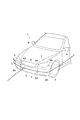
次に、この発明の実施形態を具体的に説明する。図1は、この発明の実施形態における車両の前半部分を示す斜視図である。図1に示す車両1の骨格を成す車体は、例えば、設計上、定めた剛性の図示しない鋼板に、合成樹脂材料により形成された図示しないカバー部材を取り付け、そのカバー部材の表面に図示しないガラス製のコーティングを付して構成される。その車体が、ゴムなどの金属材料と比較して電気抵抗の大きい材料によって構成されたタイヤ2を介して路面に接している。したがって、路面と車体とは、それらの間で電気がほとんど流れない絶縁状態となっており、車体の表面と空気との摩擦、あるいは、走行時に路面に対してタイヤ2の外表面が繰り返し接触および離隔するなどの内的要因や、雷雲あるいは送電線などの外的要因などによって車体に静電気が生じた場合には、その静電気は路面に流れることなく、車体に溜まる。なお、上述した内的要因が、この発明の実施形態における車両の走行による要因に相当し、上述した外的要因が、この発明の実施形態における車両の走行による要因以外の他の要因に相当している。
Next, an embodiment of the present invention will be specifically described. FIG. 1 is a perspective view showing a front half portion of a vehicle according to an embodiment of the present invention. The vehicle body constituting the skeleton of the
また、車両1は複数の内外装部品を備えており、それらの内外装部品には、軽量化や加工性などの観点から、合成樹脂材料が多く用いられている。そのため、内外装部品は、上述した内的要因や外的要因などによって静電気を帯びやすく、また、合成樹脂材料の電気抵抗が金属材料の電気抵抗と比較して大きいことが要因となって帯電量が多くなる。なお、上記の内外装部品としては、バンパカバー3、ドアミラー4、ヘッドランプ5、ドアノブ(図示せず)、テールランプ(図示せず)、アンテナフィン(図示せず)、樹脂製サイドドア(図示せず)、樹脂製バックドア(図示せず)、天井カバー(図示せず)、ステアリングホイールにおける樹脂製のコラムカバー(それぞれ図示せず)等を挙げることができる。
Further, the
上述した車体や各種の内外装部品、空気などは、従来一般的に、全体として正の極性の静電気を帯びやすいことが知られている。そのため、内的要因や外的要因などによって車体や内外装部品が共に正の極性の静電気を帯びると、車体や内外装部品と、車体の表面に沿った空気の流れ(以下、空気流と記す。)とが互いに反発し合い、すなわち車体や内外装部品の正電荷と空気流の正電荷とによって斥力が生じ、その斥力によって車体や内外装部品から空気流が剥離する可能性がある。なお、正の極性の静電気を帯びる車体や内外装部品、および、正の極性の静電気を帯びることによって空気流の変化が生じる箇所などがこの発明の実施形態における特定部位に相当している。 It is known that the above-described vehicle body, various interior / exterior parts, air, and the like are generally easily charged with positive polarity as a whole. Therefore, if both the vehicle body and interior / exterior parts are charged with positive polarity due to internal factors or external factors, the flow of air along the surface of the vehicle body / interior / exterior parts and the vehicle body (hereinafter referred to as air flow). Repel each other, that is, a repulsive force is generated by the positive charge of the vehicle body and the interior and exterior parts and the positive charge of the air flow, and the repulsive force may cause the air flow to peel from the vehicle body and the interior and exterior components. It should be noted that the vehicle body and interior / exterior parts that are charged with positive polarity static electricity, and the location where air flow changes due to the positive polarity static electricity correspond to specific portions in the embodiment of the present invention.
ここで、「空気流が剥離する」とは、車体の表面に沿った空気流が車体の表面から離れるように変化することであり、上述した特定部位のうち、そのような空気流の変化が生じる特定部位は、具体的には、車体を前方から見た場合に、車体の外面が車体の内側に屈曲する箇所である。例えば、車体の左右両側では、車幅が狭くなるように屈曲する箇所であり、バンパカバー3では、車両後方に向けてバンパカバー3が屈曲する箇所である。ボンネットやルーフでは、それらの高さが低くなるように屈曲する箇所である。アンダーカバーなどの車体下面に露出している部分では、それらの高さが車両後方に向けて次第に低くなっている箇所から水平に変化するように屈曲する箇所、あるいは車両後方に向けて水平であった箇所から高さが次第に高くなるように屈曲する箇所などである。また、車体の外側に突出しているドアミラー4やアンテナフィン、あるいは段差のある箇所なども、空気流の剥離が生じる特定部位に相当する。
Here, “the air flow is separated” means that the air flow along the surface of the vehicle body changes so as to be away from the surface of the vehicle body. Specifically, the generated specific portion is a portion where the outer surface of the vehicle body is bent inward of the vehicle body when the vehicle body is viewed from the front. For example, the left and right sides of the vehicle body are places where the vehicle width is narrowed, and the
図1に示す例では、車幅方向でバンパカバー3の両端部やその付近が特定部位となっている。その特定部位の裏面であって、かつ、空気流に曝される箇所に、当該特定部位およびその周囲での空気流の剥離を抑制する、この発明の実施形態に係る除電器6が設けられている。つまり除電器6は、車幅方向での中央部を中心としてほぼ左右対称に設けられ、かつ、車両1の内側に露出している。なお、バンパカバー3を構成する合成樹脂材料としては、アクリロニトリル、ブタジエン、スチレン共重合合成樹脂(ABS樹脂)などを挙げることができる。
In the example shown in FIG. 1, both end portions of the
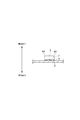
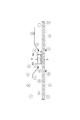
図2に、図1に示す除電器6の断面図を示してある。図2に示すように、除電器6は合成樹脂材料によって構成された樹脂テープ7を備え、その樹脂テープ7が粘着剤8を介してバンパカバー3に貼付されている。樹脂テープ7を構成する合成樹脂材料としては、ポリプロピレン樹脂、ポリエステル樹脂、アクリル樹脂、ポリエチレン樹脂、セロファン(登録商標)、ポリ塩化ビニル、テフロン(登録商標)などを挙げることができる。すなわち、樹脂テープ7は、図3に示す帯電列上で、上述した車体や特定部位、特許文献1に記載された除電器を構成するアルミニウムなどの金属材料よりも負の極性の静電気を帯びやすい合成樹脂材料によって構成されている。なお、この発明の実施形態における除電器6を構成することのできる合成樹脂材料を図3に点線で囲って示してある。
FIG. 2 is a sectional view of the
一方、粘着剤8は、正の極性の静電気を帯びるバンパカバー3に負の極性の静電気を帯びる樹脂テープ7を貼り付けるものであり、従来知られた非導電性の粘着剤によって構成されている。粘着剤8の表面抵抗値は1×10¹⁰(Ω)から1×10¹¹(Ω)の範囲に設定されており、そのため、粘着剤8は、バンパカバー3に対してほぼ絶縁した状態で樹脂テープ7を接着する。このように除電器は、非導電性の合成樹脂材料と非導電性の粘着剤とからなる粘着テープであり、したがって、除電器6としては例えば、従来知られたポリ塩化ビニルテープを用いることができる。なお、以下の説明では、除電器6を単にビニルテープ6と記す。
On the other hand, the adhesive 8 is one in which a resin tape 7 having negative polarity static electricity is attached to the
また、ここに示す例では、ビニルテープ6の周縁部6Aは鋭利もしくは尖って形成されている。これは、ビニルテープ6が静電気を帯びた場合に、自己放電つまりコロナ放電を生じやすくするためである。図4の(A)に示す例では、長方形状のビニルテープ6に互いに平行な複数のスリットが形成され、四つの辺のそれぞれが鋭く切り立って形成されると共に、各スリットの周縁部も鋭く切り立って形成される。こうすることによってビニルテープ6が静電気を帯びた場合に、その電荷が周縁部6Aに集中してコロナ放電が生じやすくなる。なお、周縁部6Aのそれぞれが鋸歯状に形成されていてもよく、このような構成であっても、ビニルテープ6の周縁部6Aの長さを可及的に長くすることができる。また、四つの角部のそれぞれが鋭く尖って形成されていてもよい。更に、図4の(B)に示すように、長方形状のビニルテープ6に互いに平行な複数の細溝を形成し、その細溝の周縁部6Aを鋭く切り立たせ、あるいは、鋸歯状に形成してもよい。要は、この発明の実施形態では、除電器としてビニルテープ6を用いる場合には、ビニルテープ6にスリットや細溝を形成したり、周縁部6Aを鋸歯状に形成したりすることによって表面積に対して周縁部6Aが可及的に長く形成されていればよい。
In the example shown here, the
特定部位に貼付するビニルテープ6の表面積や周縁部6Aの長さについて説明する。先ず、特定部位に貼り付けかつ自己放電を生じさせることによって前記特定部位およびその周囲における正の極性の静電気が中和除電されて車両1の操縦安定性が良好になるアルミニウム粘着テープの表面積および周縁部の長さを求める。そのアルミニウム粘着テープとしては、特許文献1に記載のあるアルミニウム粘着テープを採用することができる。例えば、車両1を所定距離、走行させて車体を帯電させ、その帯電している車体の特定部位にアルミニウム粘着テープを貼付する。当該アルミニウム粘着テープの表面積、周縁部の長さは予め設定されている。そして、再び、車両1を走行させ、アルミニウム粘着テープでの自己放電によって前記特定部位およびその周囲における正の極性の静電気が中和除電されて車両1の操縦安定性が良好になるか否かを運転者による官能試験によって評価する。この走行実験を、アルミニウム粘着テープの表面積および周縁部の長さを変えて繰り返し行って操縦安定性が良好になるアルミニウム粘着テープの表面積および周縁部の長さを求めた。
The surface area of the
次いで、操縦安定性が良好になったと評価されたアルミニウム粘着テープの表面積および周縁部の長さを基準値として採用し、上記と同様にして帯電させた車両1の特定部位に、アルミニウム粘着テープに替えてビニルテープ6を貼付した。そのビニルテープ6の表面積はアルミニウム粘着テープの表面積と同じに設定してあり、ビニルテープ6の周縁部6Aの長さのみ、変更した。なお、ビニルテープ6にスリットや細溝を形成したり、周縁部6Aを鋸歯状に形成したりすることによって、周縁部6Aの全長を長くすることができる。そして、上記と同様にして再度、車両1を走行させ、ビニルテープ6での自己放電によって前記特定部位およびその周囲における正の極性の静電気が中和除電されて車両1の操縦安定性が良好になるか否かを運転者による官能試験によって評価した。この走行実験を、特定部位に貼付するビニルテープ6の周縁部6Aの長さのみを変更して繰り返し行い、自己放電によって特定部位およびその周囲における正の極性の静電気が中和除電されて車両1の操縦安定性が良好になる、ビニルテープ6の周縁部6Aの長さを求めた。つまり、特定部位にアルミニウム粘着テープを貼付した場合と同じ放電特性を得ることができるビニルテープ6の周縁部6Aの長さを求めた。
Next, the surface area and the length of the peripheral portion of the aluminum adhesive tape evaluated to have improved steering stability are adopted as reference values, and the aluminum adhesive tape is applied to a specific portion of the
その結果、ビニルテープ6の周縁部6Aの長さをアルミニウム粘着テープの少なくとも3倍に設定すると、アルミニウム粘着テープと放電特性が同じになり、車両1の操縦安定性が良好になることが認められた。また、ビニルテープ6の周縁部6Aの長さがアルミニウム粘着テープの5倍以上になると、操縦安定性の低下が認められた。これは、ビニルテープ6の周縁部6Aの長さが過大になると、それに伴ってコロナ放電による静電気の放電量も増大し、その結果、車体の静電気の電位が大きく低下して一時的にコロナ放電が生じなくなるためであると思われる。つまり、車体と空気流との間にクーロン力が生じている状態と、そのようなクーロン力が生じていない状態とが交互に生じ、空力特性が断続的に変化するためであると思われる。そのため、ビニルテープ6の周縁部6Aの長さの最大値はアルミニウム粘着テープの5倍に設定した。なお、この発明の実施形態で「放電特性が同じ」とは、特定部位にビニルテープ6を貼付した場合であっても、特定部位にアルミニウム粘着テープを貼付した場合と同様に、自己放電が生じ、それによって生じた負の極性の空気イオンによって特定部位およびその周囲における正の極性の静電気が中和除電されて操縦安定性が良好になることを意味する。
As a result, it is recognized that when the length of the
次に、上述した走行実験について具体的に説明する。
(第1性能試験)
(比較例1)
ハッチバックタイプの第1試験車両を用意し、約30Km走行して車体を帯電させた。次いで、車体における予め定めた特定部位に、周縁部を鋭く切り立たせた所定長さのアルミニウム粘着テープを貼り付けた。このアルミニウム粘着テープが除電器として機能する。その後、再度、第1試験車両を走行させた。そして、特定部位にアルミニウム粘着テープを貼り付けることによって、第1試験車両の操作性や操縦安定性が良好になるか否かを、運転者による官能試験によって評価した。このような走行実験を特定部位に貼り付けるアルミニウム粘着テープの表面積および周縁部の長さを変えて、複数回行って、第1試験車両の操作性や操縦安定性が良好になるアルミニウム粘着テープの表面積および周縁部の長さを求めた。その結果、特定部位に厚さ50μm、周縁部の長さが25mmのアルミニウム粘着テープを貼り付けて走行すると、アルミニウム粘着テープを貼り付けていない場合に比較して、第1試験車両の加速操作や減速操作、操舵操作などに対する車両1の加速や減速、旋回が良好になった。つまり、操作性や操縦安定性が良好になった。なお、下記の各実験例では、比較例1で操作性や操縦安定性が良好になったアルミニウム粘着テープの表面積と同じ表面積のビニルテープ6を特定部位に貼り付け、その特定部位に貼り付けるビニルテープ6の周縁部6Aの長さを変更して上述した走行実験を行った。第1性能試験を行った日の気温は約20°、天候は晴れであった。
Next, the travel experiment described above will be specifically described.
(First performance test)
(Comparative Example 1)
A hatchback type first test vehicle was prepared, and the vehicle body was charged after traveling about 30 km. Next, an aluminum adhesive tape having a predetermined length with the peripheral edge sharply cut was affixed to a predetermined specific part of the vehicle body. This aluminum adhesive tape functions as a static eliminator. Thereafter, the first test vehicle was run again. And it was evaluated by the sensory test by a driver | operator whether the operativity and steering stability of a 1st test vehicle became favorable by sticking an aluminum adhesive tape to a specific site | part. By changing the surface area of the aluminum adhesive tape and the length of the peripheral edge of the aluminum adhesive tape to be applied to a specific part, such a running experiment is performed a plurality of times, and the operability and steering stability of the first test vehicle is improved. The surface area and peripheral edge length were determined. As a result, when an aluminum adhesive tape having a thickness of 50 μm and a peripheral edge length of 25 mm is applied to a specific part and traveling, the acceleration operation of the first test vehicle is compared with the case where the aluminum adhesive tape is not attached. The acceleration, deceleration, and turning of the
(実験例1)
比較例1のアルミニウム粘着テープに替えて、厚さが50μm、周縁部6Aの合計長さが25mmのビニルテープ6を除電器として予め定めた特定部位に貼り付けた以外は、上述した比較例1と同様に走行実験を行った。そして、第1試験車両の操作性や操縦安定性を、運転者による官能試験によって評価した。なお、アルミニウム粘着テープの表面積とビニルテープ6の表面積とは、それぞれ同じ表面積に設定した。
(Experimental example 1)
Comparative Example 1 described above, except that instead of the aluminum adhesive tape of Comparative Example 1, a
(実験例2)
比較例1のアルミニウム粘着テープに替えて、厚さが50μm、周縁部6Aの合計長さが110mmのビニルテープ6を除電器として予め定めた特定部位に貼り付けた以外は、上述した比較例1と同様に走行実験を行った。そして、第1試験車両の操作性や操縦安定性を、運転者による官能試験によって評価した。なお、周縁部6Aの合計長さは、ビニルテープ6の周縁部6Aを鋸歯状に形成して調整してもよく、あるいは、図4の(A)や図4の(B)に示すように、ビニルテープ6にスリットや細溝を形成して調整してもよい。また、アルミニウム粘着テープの表面積とビニルテープ6の表面積とは、それぞれ同じ表面積に設定した。
(Experimental example 2)
Comparative Example 1 described above, except that instead of the aluminum adhesive tape of Comparative Example 1, a
(第1性能試験の評価)
(比較例1)
特定部位にアルミニウム粘着テープを貼り付けて走行すると、操作性や操縦安定性が良好になった理由について検討する。アルミニウムなどの金属材料は図3に示すように、ビニルテープ6などの合成樹脂材料よりも正の極性の静電気を帯びやすいため、アルミニウム粘着テープは車体と同様に正の極性の静電気を帯びる。その電荷がアルミニウム粘着テープの周縁部に集中する。
(Evaluation of the first performance test)
(Comparative Example 1)
The reason why the operability and the handling stability are improved when the aluminum adhesive tape is applied to a specific part is examined. As shown in FIG. 3, a metal material such as aluminum is more likely to be charged with a positive polarity than a synthetic resin material such as
このようにして、アルミニウム粘着テープの周縁部に電荷つまり正の極性の静電気が集中すると、それらの周囲に負の極性の空気イオン(マイナスイオン)がクーロン力によって引き寄せられる。周縁部に電荷が更に集中すると、ついにはコロナ放電が生じる。言い換えれば、比較例1では、アルミニウム粘着テープに対して特定部位やその周囲から正の極性の静電気が常に供給され、その静電気を消費するように持続的にコロナ放電が生じる。そして、コロナ放電によって新たに生じた負の極性の空気イオンや上記のクーロン力によって引き寄せられたマイナスイオンなどによって特定部位やその周囲、具体的には、特定部位を中心として直径約100mmの範囲において、正の極性の静電気が中和除電される。こうして特定部位やその周囲の正の極性の静電気の電位(V)が低下する。その結果、車体と空気流との間の斥力が低減する。このようなコロナ放電を伴う空気イオンの引き寄せや斥力の低下などによって、特定部位やその周囲における車体表面からの空気流の剥離が抑制される。そして、特定部位やその周囲での空気の乱流や空圧の変動などが抑制される。つまり、空気流は乱れることなく、図1に矢印Aで示すように、車体の表面に沿って円滑に流れる。その結果、設計したとおり、もしくは設計に近い空力特性が得られ、操作性や操縦安定性が良好になったと思われる。なお、車体の帯電は、第1試験車両が走行することによって生じ、この発明の実施形態に係る除電器は、車体や特定部位が帯びる静電気によって動作するから、低速走行から高速走行までの全速度範囲に亘って走行特性が良好になる。 In this way, when charge, that is, positive polarity static electricity concentrates on the peripheral edge of the aluminum adhesive tape, negative polarity air ions (minus ions) are attracted to the periphery by the Coulomb force. When the charges are further concentrated on the peripheral edge, corona discharge finally occurs. In other words, in Comparative Example 1, positive polarity static electricity is always supplied to the aluminum adhesive tape from the specific portion and its surroundings, and corona discharge is continuously generated so that the static electricity is consumed. Then, in a specific part and its surroundings, specifically, in a range of about 100 mm in diameter around the specific part by negative polarity air ions newly generated by corona discharge or negative ions attracted by the above-mentioned Coulomb force. The static electricity of positive polarity is neutralized and neutralized. In this way, the electrostatic potential (V) of positive polarity around the specific part and its surroundings is lowered. As a result, the repulsive force between the vehicle body and the airflow is reduced. The separation of the air flow from the surface of the vehicle body at the specific site and its surroundings is suppressed by attracting air ions accompanying such corona discharge and reducing the repulsive force. And the turbulent flow of the air in the specific part and its periphery, the fluctuation | variation of air pressure, etc. are suppressed. That is, the air flow is smoothly disturbed along the surface of the vehicle body as indicated by the arrow A in FIG. 1 without being disturbed. As a result, it seems that aerodynamic characteristics as designed or close to the design were obtained, and operability and steering stability were improved. The charging of the vehicle body is caused by the traveling of the first test vehicle, and the static eliminator according to the embodiment of the present invention is operated by static electricity charged to the vehicle body or a specific part. The running characteristics are good over the range.
(実験例1)
これに対して、実験例1では、比較例1によるような操作性や操縦安定性は得られなかった。その理由について検討する。実験例1では、第1試験車両の走行に伴う空気との摩擦によってビニルテープ6は負の極性の静電気を帯びる。そのビニルテープ6は従来一般的に、アルミニウム粘着テープと比較して電気抵抗が大きく電気が流れにくい。そのために、周縁部6Aを鋭く切り立たせて形成したとしても、アルミニウム粘着テープと比較して、その周縁部6Aに電荷が集中したり、コロナ放電が生じたりしにくいと思われる。その結果、正の極性の空気流を引き寄せにくく、また、正の極性の静電気を中和除電したりする負の極性の空気イオンの発生量が少なくなる。つまり、比較例1と同様の作用・効果を得るためには、周縁部6Aの長さが短く、そのために、比較例1によるような操作性や操縦安定性は得られなかったと思われる。
(Experimental example 1)
On the other hand, in Experimental Example 1, the operability and steering stability as in Comparative Example 1 were not obtained. Consider why. In Experimental Example 1, the
(実験例2)
実験例2では、比較例1とほぼ同様に、第1試験車両の操作性や操縦安定性が良好になった。その理由について検討する。実験例2でのビニルテープ6の周縁部6Aの合計長さは、比較例1のアルミニウム粘着テープの周縁部の長さや、実験例1でのビニルテープ6の周縁部6Aの合計長さの約4.4倍となっている。つまり、電荷が集中していて空気流と接触したり、コロナ放電が生じたりする周縁部6Aの合計長さが可及的に長く設定されている。そのため、比較例1と同様の作用・効果を得ることができたと思われる。具体的には、第1試験車両の走行に伴う空気との摩擦によってビニルテープ6が負の極性の静電気を帯びると、その静電気はビニルテープ6やその周縁部6Aに集中する。そして、その周囲に比較例1とは反対に、図5に示すように、正の極性の空気イオンが引き寄せられる。また、周縁部6Aでコロナ放電が生じると、図6に示すように、比較例1と同様に、負の極性の空気イオンが生じる。そして、コロナ放電によって生じた負の極性の空気イオンや、空気中のマイナスイオンなどによって特定部位やその周囲の正の極性の静電気が中和除電される。こうして特定部位の電位が低下すると、電位の低くなった特定部位に対してその周囲から高い電位の静電気が供給され、持続的にコロナ放電が生じる。したがって、実験例2の構成であっても、比較例1と同様に、コロナ放電を伴う空気イオンの引き寄せや斥力の低下などによって、特定部位やその周囲における車体表面からの空気流の剥離を抑制できたと思われる。その結果、比較例1とほぼ同様の作用・効果を得ることができたと思われる。
(Experimental example 2)
In Experimental Example 2, the operability and steering stability of the first test vehicle were improved in substantially the same manner as Comparative Example 1. Consider why. The total length of the
(第2性能試験)
(比較例2)
セダンタイプの第2試験車両を用意し、上述した比較例1と同様にして、第2試験車両の操作性や操縦安定性が良好になるアルミニウム粘着テープの周縁部の長さを求めた。その結果、特定部位に厚さが50μm、周縁部の長さが190mmのアルミニウム粘着テープを粘着剤を介して貼り付けて走行すると、アルミニウム粘着テープを貼り付けていない場合に比較して、第2試験車両の加速操作や減速操作、操舵操作などに対する車両の加速や減速、旋回が良好になった。つまり、操作性や操縦安定性が良好になった。なお、下記の各実験例では、比較例2で操作性や操縦安定性が良好になったアルミニウム粘着テープの表面積と同じ表面積のビニルテープ6を特定部位に貼り付け、その特定部位に貼り付けたビニルテープ6の周縁部6Aの合計長さのみを変更して上述した走行実験を行った。第2性能試験を行った日の気温は約26°、天候は晴れであった。
(Second performance test)
(Comparative Example 2)
A sedan-type second test vehicle was prepared, and the length of the peripheral portion of the aluminum adhesive tape that improved the operability and steering stability of the second test vehicle was determined in the same manner as in Comparative Example 1 described above. As a result, when an aluminum adhesive tape having a thickness of 50 μm and a peripheral edge length of 190 mm is attached to the specific part via an adhesive, the second part is compared with the case where the aluminum adhesive tape is not attached. The acceleration, deceleration, and turning of the vehicle in response to the acceleration, deceleration, and steering operations of the test vehicle were improved. In other words, operability and handling stability were improved. In each of the following experimental examples,
(実験例3)
比較例2のアルミニウム粘着テープに替えて、厚さが50μm、周縁部6Aの合計長さが190mmのビニルテープ6を除電器として予め定めた特定部位に貼り付けた以外は、上述した比較例2と同様に走行実験を行った。そして、第2試験車両の操作性や操縦安定性を、運転者による官能試験によって評価した。なお、アルミニウム粘着テープの表面積とビニルテープ6の表面積とは、それぞれ同じ表面積に設定した。
(Experimental example 3)
In place of the aluminum adhesive tape of Comparative Example 2, Comparative Example 2 described above except that a
(実験例4)
比較例2のアルミニウム粘着テープに替えて、厚さが50μm、周縁部6Aの合計長さが550mmのビニルテープ6を除電器として予め定めた特定部位に貼り付けた以外は、上述した比較例2と同様に走行実験を行った。そして、第2試験車両の操作性や操縦安定性を、運転者による官能試験によって評価した。なお、周縁部6Aの合計長さは、上述した図4の(A)や図4の(B)に示すように、スリットや細溝を形成して調整した。また、アルミニウム粘着テープの表面積とビニルテープ6の表面積とは、それぞれ同じ表面積に設定した。
(Experimental example 4)
Comparative Example 2 described above, except that instead of the aluminum adhesive tape of Comparative Example 2, a
(第2性能試験の評価)
(比較例2)
特定部位にアルミニウム粘着テープを貼り付けて走行すると、アルミニウム粘着テープを貼り付けていない場合に比較して、第2試験車両の操作性や操舵安定性などが良好になった。これは、比較例1と同様の原理によって、第2試験車両の操作性や操縦安定性が良好になったと思われる。
(Evaluation of second performance test)
(Comparative Example 2)
When the aluminum adhesive tape was applied to the specific part and the vehicle was running, the operability and steering stability of the second test vehicle were improved as compared with the case where the aluminum adhesive tape was not applied. This seems to have improved the operability and steering stability of the second test vehicle by the same principle as in Comparative Example 1.
(実験例3)
これに対して、実験例3では、比較例2によるような操作性や操縦安定性は得られなかった。これは、実験例1と同様の原理により、つまり、比較例2と同様の作用・効果を得るためには、ビニルテープ6の周縁部6Aの合計長さが短く、そのために、比較例2によるような操作性や操縦安定性は得られなかったと思われる。
(Experimental example 3)
On the other hand, in the experimental example 3, the operability and the steering stability as in the comparative example 2 were not obtained. This is because the total length of the
(実験例4)
一方、実験例4では、比較例2とほぼ同様に、第2試験車両の操作性や操縦安定性が良好になった。実験例4でのビニルテープ6の周縁部6Aの合計長さは、比較例2のアルミニウム粘着テープの周縁部の長さや、実験例3でのビニルテープ6の周縁部6Aの合計長さの約2.9倍となっている。すなわち、実験例2と同様の原理により、比較例2と同様の作用・効果を得ることができたと思われる。
(Experimental example 4)
On the other hand, in Experimental Example 4, as in Comparative Example 2, the operability and steering stability of the second test vehicle were improved. The total length of the
このように、この発明の実施形態によれば、上述した操縦安定性が良好になるアルミニウム粘着テープと同じ表面積であって、かつ、ビニルテープ6の周縁部6Aの長さをアルミニウム粘着テープの周縁部の長さの少なくとも3倍に設定すると、特定部位にアルミニウム粘着テープを貼り付けた場合と同様の放電特性を得ることができる。そのビニルテープ6は、導電性のある材料を備えない分、アルミニウム粘着テープと比較して低コストであるから、除電器の材料コストや製造コストを可及的に低く抑えることができる。
Thus, according to the embodiment of the present invention, the same surface area as that of the aluminum adhesive tape that improves the steering stability described above, and the length of the
なお、ビニルテープ6の周縁部6Aの長さをアルミニウム粘着テープの周縁部の長さの5倍以上に設定した場合には、実験例2や実験例4と比較して、第1試験車両や第2試験車両の操作性や操縦安定性の低下が認められた。これは、ビニルテープ6の周縁部6Aの長さが過大になると、それに伴ってコロナ放電による車体の静電気の放電量も増大し、その結果、車体の静電気の電位が大きく低下して一時的にコロナ放電が生じなくなるためであると思われる。つまり、コロナ放電が断続的に生じる状態となる。このような状態では、車体と空気流との間にクーロン力が生じている状態と、そのようなクーロン力が生じていない状態とが交互に生じ、その結果、車両1の空力特性が断続的に変化するためであると思われる。そのため、上述したビニルテープ6の周縁部6A材の合計長さは、アルミニウム粘着テープの周縁部の長さのほぼ5倍までにすることが好ましい。
In addition, when the length of the
この発明は上述した実施形態に限定されないのであって、特許を請求している範囲で適宜に変更して実施することができる。例えば、この発明は、路面に対して絶縁状態になっている車両における、前記車両の走行による要因と、前記車両の走行による要因以外の他の要因とのうち、少なくとも一方の要因によって正の極性の静電気を帯びる少なくとも一つの特定部位に設けられていて、自己放電によって負の極性の空気イオンを生じさせ、前記負の極性の空気イオンによって前記特定部位の正の電位を中和除電して低下させるように構成された前記車両の除電方法あるいは前記車両の除電器の製造方法において、前記特定部位に設けられることによって前記車両の操縦安定性を良好にすることのできるアルミニウム粘着テープの表面積および周縁部の長さを求め、前記特定部位よりも負の極性の静電気を帯びやすい合成樹脂材料によって形成されていて前記アルミニウム粘着テープと同じ表面積であって、かつ、周縁部の長さが前記アルミニウム粘着テープの3倍から5倍である樹脂テープを形成し、表面抵抗値が1×10¹⁰(Ω)から1×10¹¹(Ω)である粘着剤を介して前記特定部位に前記樹脂テープが設けられることを特徴とする車両の除電方法あるいは前記車両の除電器の製造方法と言うことができる。 The present invention is not limited to the above-described embodiments, and can be implemented with appropriate modifications within the scope of claims. For example, according to the present invention, in a vehicle that is in an insulated state with respect to a road surface, positive polarity is caused by at least one of a factor due to travel of the vehicle and a factor other than a factor due to travel of the vehicle. It is provided in at least one specific part that is charged with static electricity, and negative polarity air ions are generated by self-discharge, and the positive potential of the specific part is neutralized and eliminated by the negative polarity air ions. A surface area and a peripheral edge of an aluminum adhesive tape capable of improving the steering stability of the vehicle by being provided at the specific part in the vehicle static eliminator or the vehicle static eliminator manufacturing method The length of the part is determined, and the aluminum is formed of a synthetic resin material that is more negatively charged with static electricity than the specific part. A same surface area as um adhesive tape, and, to form a resin tape length of the peripheral portion is three to five times of the aluminum adhesive tape, the surface resistivity of 1 × from 1 × 10 10 (Ω) It can be said that the resin tape is provided at the specific part via an adhesive having a resistance of 10 11 (Ω), or a method of manufacturing a vehicle static eliminator.
なお、特定部位の裏面に替えて特定部位の表面にビニルテープ6を貼ると、空気流と車体表面との間に直接的にクーロン力が働くため、クーロン力による空気流の引き寄せを効果的に生じさせるには好ましい。一方で、裏面に貼ったとしても、上述したように、コロナ放電による特定部位の除電は特定部位を中心とした所定の範囲におよび、その結果、空気流と車体表面との間の斥力が小さくなるから、結局、車体表面に貼った場合とほぼ同様の作用・効果を得ることができる。また、特定部位は、上述したバンパカバー3における両端部以外にも複数あり、この発明の実施形態に係る除電器を取り付ける箇所、つまり、除電器を取り付けることによって空気流の剥離を抑制することのできる複数の特定部位の例が特許文献1に記載されている。すなわち、小型ハッチバックタイプの車両においては、その車体の上面から空気流が剥離することを抑制するように、エンジンフードの前端部、エンジンフードの後端部、フロントガラスの下端部、フロントガラスの上端部、天井の前端部、天井の前部、天井の後部、ルーフスポイラーなどに除電器を配置する。また、ワイパーが車両の外表面に露出している場合には、ワイパーに空気流が衝突して空気流が剥離する可能性があるので、ワイパーのブレードおよびアームに除電器を配置する。なお、エンジンフードや天井における車幅方向での中央部分や、その中央部分を挟んで両側に所定の間隔を空けて除電器を複数配置する。または、中央部分に加えて左右均等に除電器を複数配置して、車幅方向の全幅に亘って空気流の剥離を抑制することが好ましい。
In addition, when the
また、除電器は、少なからず厚みがあるため、空気流に曝されると、除電器の近傍で空気流が乱れる可能性がある。そのため、例えば、エンジンフードの後端部における裏面や、フロントガラスの外表面であってかつエンジンフードより下側の箇所など、車体表面を流動する空気流に直接、曝されない位置に除電器を配置することが好ましい。また、セダンタイプの車両において、リアガラスとラゲージドアとの間に隙間があり、そのリアガラスからの空気流の剥離を抑制する場合には、車両の上下方向でリアガラスの外表面であって、ラゲージドアより下側の箇所に除電器を配置することが好ましい。 In addition, since the static eliminator has a certain thickness, when exposed to an air flow, the air flow may be disturbed in the vicinity of the static eliminator. Therefore, for example, the static eliminator is placed at a position where it is not directly exposed to the airflow that flows on the vehicle body surface, such as the rear surface of the rear end of the engine hood, or the outer surface of the windshield and below the engine hood. It is preferable to do. In a sedan type vehicle, there is a gap between the rear glass and the luggage door. It is preferable to dispose a static eliminator at the location on the side.
そしてハッチバックタイプの車両において、リアスポイラーやリアバックドアガラスからの空気流の剥離を抑制する場合には、リアスポイラーの上面もしくは下面に除電器を配置することが好ましい。また、リアバックドアガラスの外表面における上部に除電器を配置することが好ましい。なお、ワンボックスタイプの車両においても、リアスポイラーやリアバックドアガラスからの空気流の剥離を抑制する場合には、リアスポイラーの上面もしくは下面、および、リアバックドアガラスの外表面における上部に除電器を配置することが好ましい。 In a hatchback type vehicle, in order to suppress separation of the air flow from the rear spoiler or the rear back door glass, it is preferable to dispose a static eliminator on the upper surface or the lower surface of the rear spoiler. Moreover, it is preferable to arrange a static eliminator on the upper part of the outer surface of the rear back door glass. Even in a one-box type vehicle, when the separation of the air flow from the rear spoiler or rear back door glass is to be suppressed, the upper or lower surface of the rear spoiler and the upper part of the outer surface of the rear back door glass are removed. It is preferable to arrange an electric appliance.
また、燃料タンクが車両の下面に露出していて走行風に曝されている場合には、車両の前後方向で燃料タンクの前方部および後方部に除電器を配置する。さらに、アンダーカバーにおいては、車両1の上下方向で屈曲する箇所に除電器を配置する。アンダーカバーにリアディフューザが設けられている場合における除電器の取り付け位置について説明すると、リアデュフューザは、車体の下面を介して車体の後方側に流動する空気流の流速を増大させるために、その後方側が鉛直方向で上側に向けて傾斜して形成されている。つまり、屈曲している。そのため、リアデュフューザの屈曲点またはその近傍に除電器を配置する。また、フェンダライナにおけるフェンダーハウス側とは反対側の面に除電器を配置すると、前輪に制動力を作用させるブレーキを冷却するためにフェンダーハウスに取り込まれた空気が、車幅方向で外側に吸引されにくくなる事態が生じることを抑制することができる。すなわち、フェンダーハウス内の空気流の流速が低下することを抑制することができる。さらに、運転者によって操作されるステアリングホイールのシャフトを覆っている樹脂製のコラムカバーに除電器を設けてもよい。この場合には、静電気によるグリースの粘性の増大を抑制してステアリングホイールの回動を滑らかにすることができる。
In addition, when the fuel tank is exposed on the lower surface of the vehicle and exposed to traveling wind, a static eliminator is disposed in the front and rear portions of the fuel tank in the front-rear direction of the vehicle. Further, in the under cover, a static eliminator is disposed at a location where the
そして、この発明の実施形態に係る除電器として機能するビニルテープ6は上述したように、合成樹脂材料によって形成されているから、色彩や形状の設計の自由度が大きく、また、透明や半透明にすることができる。例えば、ビニルテープ6を透明や半透明にした場合には、ビニルテープ6の裏面に文字や図形などの所定の意匠を、金や銅などの導電性金属粉などを用いて印刷することができる。こうすることにより、ビニルテープ6が帯電した場合には自己放電を行う面積を確保できると共に、ビニルテープ6が透明あるいは半透明であるから、例えば、前席におけるサイド窓ガラスにビニルテープ6を貼付することができ、サイド窓ガラスからの空気流の剥離を抑制することができる。具体的には、サイド窓ガラスが最も上昇したときに、戸袋の外にビニルテープ6が位置するように、車両1の上下方向でサイド窓ガラスの上部または下部にビニルテープ6を貼付する。なお、可視光線透過率は70%以上に設定する。また、サイド窓ガラスの車室内側にビニルテープ6を貼付すると、車室の外側に貼付する場合と比較して、外部の塵埃による汚れや傷を抑制することができる。そのため、サイド窓ガラスの車室内側にビニルテープ6を貼付することが好ましい。なお、導電性金属粉を用いた意匠部分の表面に上述したスリットや細溝を形成したり、輪郭部や周縁部を鋸歯状に形成したりしてもよい。
Since the
また、上述した構成のビニルテープ6は車体表面にも貼付することができる。例えば、車幅方向でフロントバンパーの両側面であってかつ外表面に、上述した文字や図形などの意匠部分と同じ形状を成すビニルテープ6を貼付する。このような場合であっても、意匠部分の表面積つまりビニルテープ6の表面積を、これと放電特性が同じであるアルミニウム粘着テープの表面積と同じに設定する。そして、意匠部分の輪郭部あるいは周縁部の長さをアルミニウム粘着テープの周縁部の長さの3倍から5倍に設定する。なお、意匠部分に上述したスリットや細溝を形成したり、輪郭部や周縁部を鋸歯状に形成したりして輪郭部や周縁部の全長を調整する。また、意匠の輪郭部あるいは周縁部を鋭く切り立たせる。こうすることにより、車両1の見栄えを良好に維持しながら空気流の剥離を抑制することができる。
Further, the
そして、車両における各種の部材は、フレームに固定されており、そのフレームは、バッテリのアース部(マイナス端子部)と電気的に接続されている。したがって、バッテリのマイナス端子すなわちマイナスターミナルやアース線に除電器としてビニルテープ6を巻き付けると、フレームの電位を低下させて上述した各種の部材に帯電する正の極性の静電気の電位を低下することができる。
Various members in the vehicle are fixed to a frame, and the frame is electrically connected to a ground portion (minus terminal portion) of the battery. Therefore, when the
1…車両、 2…タイヤ、 3…バンパカバー(特定部位)、 6…ビニルテープ(除電器)、 7…樹脂テープ、 8…粘着剤。
DESCRIPTION OF
Claims (1)
前記特定部位に粘着剤を介して貼付される樹脂テープを備え、
前記粘着剤の表面抵抗値は、1×10¹⁰(Ω)から1×10¹¹(Ω)であり、
前記樹脂テープは、前記特定部位と比較して前記特定部位とは反対の負の極性の静電気を帯びやすい合成樹脂材料によって形成され、
前記樹脂テープの表面積は、前記負の極性の空気イオンによって前記特定部位の正の電位を中和除電して低下させる放電特性が同じであるアルミニウム粘着テープと同じ表面積であって、
前記樹脂テープの周縁部と前記アルミニウム粘着テープの周縁部とのそれぞれは、前記自己放電を生じさせるように鋭利もしくは尖って形成され、
前記樹脂テープの周縁部の長さは、前記アルミニウム粘着テープの周縁部の長さの3倍から5倍である
ことを特徴とする車両の除電器。 In a vehicle that is insulated from the road surface, at least one of the factors caused by traveling of the vehicle and other factors other than the factors caused by traveling of the vehicle is charged with positive polarity static electricity. It is provided at two specific parts, and is configured to generate air ions of negative polarity by self-discharge, and to neutralize and lower the positive potential of the specific parts by the negative polarity air ions. In the static eliminator of the vehicle,
Comprising a resin tape attached to the specific part via an adhesive;
The surface resistance value of the pressure-sensitive adhesive is 1 × 10 10 (Ω) to 1 × 10 11 (Ω),
The resin tape is formed of a synthetic resin material that is easily charged with a negative polarity opposite to the specific part compared to the specific part,
The surface area of the resin tape is the same surface area as the aluminum adhesive tape having the same discharge characteristics to neutralize and remove the positive potential of the specific part by the negative polarity air ions,
Each of the peripheral portion of the resin tape and the peripheral portion of the aluminum adhesive tape is formed sharp or pointed so as to cause the self-discharge,
The length of the peripheral portion of the resin tape is 3 to 5 times the length of the peripheral portion of the aluminum adhesive tape.
Priority Applications (1)
| Application Number | Priority Date | Filing Date | Title |
|---|---|---|---|
| JP2018086301A JP2019192568A (en) | 2018-04-27 | 2018-04-27 | Static eliminator for vehicle |
Applications Claiming Priority (1)
| Application Number | Priority Date | Filing Date | Title |
|---|---|---|---|
| JP2018086301A JP2019192568A (en) | 2018-04-27 | 2018-04-27 | Static eliminator for vehicle |
Publications (1)
| Publication Number | Publication Date |
|---|---|
| JP2019192568A true JP2019192568A (en) | 2019-10-31 |
Family
ID=68390795
Family Applications (1)
| Application Number | Title | Priority Date | Filing Date |
|---|---|---|---|
| JP2018086301A Pending JP2019192568A (en) | 2018-04-27 | 2018-04-27 | Static eliminator for vehicle |
Country Status (1)
| Country | Link |
|---|---|
| JP (1) | JP2019192568A (en) |
Cited By (1)
| Publication number | Priority date | Publication date | Assignee | Title |
|---|---|---|---|---|
| EP3967557A1 (en) | 2020-09-10 | 2022-03-16 | Toyota Jidosha Kabushiki Kaisha | Vehicle and electrostatic elimination component |
-
2018
- 2018-04-27 JP JP2018086301A patent/JP2019192568A/en active Pending
Cited By (4)
| Publication number | Priority date | Publication date | Assignee | Title |
|---|---|---|---|---|
| EP3967557A1 (en) | 2020-09-10 | 2022-03-16 | Toyota Jidosha Kabushiki Kaisha | Vehicle and electrostatic elimination component |
| JP2022046043A (en) * | 2020-09-10 | 2022-03-23 | トヨタ自動車株式会社 | Vehicle and destatization component |
| US11447083B2 (en) | 2020-09-10 | 2022-09-20 | Toyota Jidosha Kabushiki Kaisha | Vehicle and electrostatic elimination component |
| JP7367642B2 (en) | 2020-09-10 | 2023-10-24 | トヨタ自動車株式会社 | Vehicles and static elimination parts |
Similar Documents
| Publication | Publication Date | Title |
|---|---|---|
| JP6168157B2 (en) | Vehicle and manufacturing method thereof | |
| JP7172102B2 (en) | vehicle | |
| JP6217675B2 (en) | vehicle | |
| US10501034B2 (en) | Vehicle | |
| JP6344292B2 (en) | vehicle | |
| WO2019117051A1 (en) | Adhesive sheet-shaped member for airflow and travel vehicle using same | |
| JP2019192568A (en) | Static eliminator for vehicle | |
| US20180297420A1 (en) | Neutralization device for vehiicles | |
| US11447083B2 (en) | Vehicle and electrostatic elimination component | |
| JP7050600B2 (en) | Static eliminator for vehicles and vehicles | |
| JP6848945B2 (en) | Static eliminator | |
| JP2022046037A (en) | vehicle |