JP7050488B2 - Ophthalmologic imaging equipment, its control method, programs, and recording media - Google Patents
Ophthalmologic imaging equipment, its control method, programs, and recording media Download PDFInfo
- Publication number
- JP7050488B2 JP7050488B2 JP2017253043A JP2017253043A JP7050488B2 JP 7050488 B2 JP7050488 B2 JP 7050488B2 JP 2017253043 A JP2017253043 A JP 2017253043A JP 2017253043 A JP2017253043 A JP 2017253043A JP 7050488 B2 JP7050488 B2 JP 7050488B2
- Authority
- JP
- Japan
- Prior art keywords
- fixative
- image
- fundus
- eye
- inspected
- Prior art date
- Legal status (The legal status is an assumption and is not a legal conclusion. Google has not performed a legal analysis and makes no representation as to the accuracy of the status listed.)
- Active
Links
Images


Landscapes
- Eye Examination Apparatus (AREA)
Description
本発明は、眼科撮影装置、その制御方法、プログラム、及び記録媒体に関する。 The present invention relates to an ophthalmologic imaging apparatus, a control method thereof, a program, and a recording medium.
眼科分野において画像診断は重要な位置を占める。近年では光コヒーレンストモグラフィ(OCT)の活用が進んでいる。OCTは、被検眼のBスキャン画像や3次元画像の取得だけでなく、Cスキャン画像やシャドウグラムなどの正面画像(en-face画像)の取得にも利用されるようになってきている。 Diagnostic imaging occupies an important position in the field of ophthalmology. In recent years, the use of optical coherence tomography (OCT) has been advancing. OCT has come to be used not only for acquiring B-scan images and three-dimensional images of the eye to be inspected, but also for acquiring front images (en-face images) such as C-scan images and shadowgrams.
また、被検眼の特定部位を強調した画像を取得するモダリティも実用化されている。例えば、網膜血管や脈絡膜血管が強調された画像を形成するOCT血管造影(OCT-Angiography)が注目を集めている(例えば、特許文献1を参照)。一般に、スキャン部位の組織(構造)は時間的に不変であるが、血管内部の血流部分は時間的に変化する。OCT血管造影では、このような時間的変化が存在する部分(血流信号)を強調して画像を形成する。なお、OCT血管造影は、OCTモーションコントラスト撮影(motion contrast imaging)などとも呼ばれる。また、OCT血管造影により取得される画像は、血管造影画像、アンジオグラム、モーションコントラスト画像などと呼ばれる。 In addition, a modality for acquiring an image emphasizing a specific part of the eye to be inspected has also been put into practical use. For example, OCT-Angiography, which forms an image in which retinal blood vessels and choroidal blood vessels are emphasized, is attracting attention (see, for example, Patent Document 1). Generally, the tissue (structure) of the scan site does not change with time, but the blood flow portion inside the blood vessel changes with time. In OCT angiography, an image is formed by emphasizing a portion (blood flow signal) in which such a temporal change exists. In addition, OCT angiography is also called OCT motion contrast imaging (motion contrast imaging) or the like. The images acquired by OCT angiography are called angiographic images, angiograms, motion contrast images, and the like.
典型的な従来のOCT血管造影では、既定サイズ(例えば、9mm×9mm)の3次元スキャンが適用され、眼底血管の3次元的分布を表現した画像が得られる。一方、より広範囲の血管造影画像を取得することが望まれている。眼底の広い範囲のOCTデータを取得するための技術としてパノラマ撮影が知られている(例えば、特許文献2を参照)。 In a typical conventional OCT angiography, a 3D scan of a predetermined size (eg, 9 mm x 9 mm) is applied to obtain an image representing the 3D distribution of the fundus blood vessels. On the other hand, it is desired to acquire a wider range of angiographic images. Panorama imaging is known as a technique for acquiring OCT data over a wide range of the fundus (see, for example, Patent Document 2).
パノラマ撮影は、異なる複数の領域に3次元スキャンをそれぞれ適用し、それにより得られた複数の3次元画像を合成して広域画像を構築する画像化手法である。互いに隣接する領域には重複領域が設定され、この重複領域を基準として隣接する画像の間の相対位置が決定される。また、異なる複数の領域に対する順次的な3次元スキャンは、典型的には、固視位置の移動によって実現される。パノラマ撮影によって取得された広域画像は、パノラマ画像、モザイク画像などと呼ばれる。 Panorama photography is an imaging method in which a three-dimensional scan is applied to a plurality of different areas, and a plurality of three-dimensional images obtained by the three-dimensional scan are combined to construct a wide-area image. An overlapping area is set in the area adjacent to each other, and the relative position between the adjacent images is determined with respect to this overlapping area. Also, sequential 3D scans on different regions are typically achieved by moving the fixative position. Wide-area images acquired by panoramic photography are called panoramic images, mosaic images, and the like.
ところで、眼球のサイズや特性には個人差があり、例えば眼軸長や視度(眼屈折力)は個々人で異なる。前述したように既定サイズの3次元スキャンを適用する場合であっても、実際にスキャンされる眼底の範囲は眼軸長や視度によって変化する。 By the way, there are individual differences in the size and characteristics of the eyeball, for example, the axial length and diopter (refractive power of the eye) differ from person to person. As described above, even when a three-dimensional scan of a predetermined size is applied, the range of the fundus actually scanned varies depending on the axial length and diopter.
例えば、図1に示すように、眼軸長L1の被検眼E1と眼軸長L2(>L1)の被検眼E2に対してOCT測定光が同じ角度θで入射した場合、被検眼E1の眼底における測定光の投射位置の高さY1よりも、被検眼E2の眼底における測定光の投射位置の高さY2の方が大きくなる(Y2>Y1)。すなわち、眼軸長が長いほど、眼底における測定光の投射位置の高さが大きくなる。一方、OCTスキャンのサイズは、測定光の最大偏向角で定義される。したがって、OCTスキャンのサイズの条件が同じであっても、実際にスキャンされる眼底の範囲は、眼軸長の値に応じて変化してしまう。視度についても同様である。 For example, as shown in FIG. 1, when the OCT measurement light is incident on the eye E1 having an axial length L1 and the eye E2 having an axial length L2 (> L1) at the same angle θ, the fundus of the eye E1 is examined. The height Y2 of the projection position of the measurement light on the fundus of the eye E2 to be inspected is larger than the height Y1 of the projection position of the measurement light in (Y2> Y1). That is, the longer the axial length, the higher the height of the projection position of the measured light on the fundus. On the other hand, the size of the OCT scan is defined by the maximum deflection angle of the measurement light. Therefore, even if the size conditions of the OCT scan are the same, the range of the fundus actually scanned changes according to the value of the axial length. The same applies to diopter.
このように実際のスキャン範囲が眼球パラメータに影響を受けるため、パノラマ撮影における重複領域の大きさも眼球パラメータに応じて変化する。例えば、被検眼の眼軸長が長い場合には実際のスキャン範囲が広くなるため、重複領域も広くなる。重複領域が必要以上に広くなると、モザイク画像により実際に描出される範囲が狭くなり、パノラマ撮影の効率が低下する。 Since the actual scan range is affected by the eyeball parameters in this way, the size of the overlapping area in panoramic photography also changes according to the eyeball parameters. For example, when the axial length of the eye to be inspected is long, the actual scan range is widened, so that the overlapping area is also widened. If the overlapping area becomes wider than necessary, the range actually drawn by the mosaic image becomes narrow, and the efficiency of panoramic photography decreases.
逆に、被検眼の眼軸長が短い場合には実際のスキャン範囲が狭くなるため、重複領域も狭くなり、場合によっては重複領域が無くなる。重複領域が狭くなると、隣接する画像の間の相対位置を十分な精度で求められないおそれがある。また、重複領域が存在しない場合には、隣接する画像の間の相対位置を決定することができず、モザイク画像を構築することができない。 On the contrary, when the axial length of the eye to be inspected is short, the actual scan range is narrowed, so that the overlapping area is also narrowed, and in some cases, the overlapping area disappears. If the overlapping area becomes narrow, the relative position between adjacent images may not be obtained with sufficient accuracy. Further, when the overlapping area does not exist, the relative position between the adjacent images cannot be determined, and the mosaic image cannot be constructed.
また、モザイク画像の中心領域に描出したい注目部位(例えば、黄斑中心)が、そのように配置されない事態も生じ得る。 In addition, the region of interest (for example, the center of the macula) to be drawn in the central region of the mosaic image may not be arranged in such a situation.
本発明の目的は、OCTを用いてモザイク画像を取得するための複数の固視位置の設定を、眼球のサイズや特性の個人差にかかわらず好適に行うことを可能とする技術を提供することにある。 An object of the present invention is to provide a technique capable of appropriately setting a plurality of fixative positions for acquiring a mosaic image using OCT regardless of individual differences in the size and characteristics of the eyeball. It is in.
実施形態の第1の態様は、固視系と、撮影部と、制御部と、固視位置設定部と、OCT画像取得部と、画像処理部とを含む眼科撮影装置である。固視系は、被検眼に固視標を提示する。撮影部は、被検眼の眼底を撮影する。制御部は、所定の固視位置に対応する固視標を被検眼に提示しつつ眼底の正面画像を取得するように固視系及び撮影部を制御する眼底撮影制御を実行する。固視位置設定部は、眼底撮影制御により取得された正面画像に基づいて、1以上の固視位置を設定する。OCT画像取得部は、眼底に光コヒーレンストモグラフィ(OCT)を適用して画像を取得する。画像取得部は、OCT画像取得部により取得された画像を処理する。制御部は、固視位置設定部により設定された1以上の固視位置を含む2以上の固視位置に対応する2以上の固視標を順次に被検眼に提示するように固視系を制御し、且つ、これら2以上の固視標のそれぞれが被検眼に提示されているときに眼底の3次元画像を取得するようにOCT画像取得部を制御するOCT制御を実行する。画像処理部は、OCT制御により取得された2以上の固視位置に対応する2以上の3次元画像の合成画像を形成する合成処理部を含む。 The first aspect of the embodiment is an ophthalmologic imaging apparatus including a fixative system, an imaging unit, a control unit, a fixative position setting unit, an OCT image acquisition unit, and an image processing unit. The fixative system presents a fixative to the eye to be inspected. The photographing unit photographs the fundus of the eye to be inspected. The control unit executes fundus photography control that controls the fixative system and the imaging unit so as to acquire a frontal image of the fundus while presenting a fixative target corresponding to a predetermined fixation position to the eye to be inspected. The fixative position setting unit sets one or more fixative positions based on the front image acquired by the fundus photography control. The OCT image acquisition unit applies optical coherence tomography (OCT) to the fundus to acquire an image. The image acquisition unit processes the image acquired by the OCT image acquisition unit. The control unit sets the fixative system so as to sequentially present two or more fixative targets corresponding to two or more fixative positions including one or more fixative positions set by the fixative position setting unit to the eye to be inspected. OCT control is performed to control and control the OCT image acquisition unit so as to acquire a three-dimensional image of the fundus when each of these two or more fixative targets is presented to the eye to be inspected. The image processing unit includes a composition processing unit that forms a composite image of two or more three-dimensional images corresponding to two or more fixation positions acquired by OCT control.
実施形態の第2の態様は、第1の態様の眼科撮影装置であって、固視位置設定部は、眼底撮影制御により取得された正面画像と、眼底撮影制御における撮影領域とOCT制御における3次元スキャン領域との間の位置関係とに基づいて、1以上の固視位置を設定する。 The second aspect of the embodiment is the ophthalmologic imaging apparatus of the first aspect, and the fixative position setting unit includes a front image acquired by fundus photography control, an imaging area in fundus photography control, and 3 in OCT control. One or more fixative positions are set based on the positional relationship with the dimensional scan area.
実施形態の第3の態様は、第2の態様の眼科撮影装置であって、制御部は、眼底撮影制御において、第1の固視位置に対応する第1の固視標を被検眼に提示しつつ眼底の第1の正面画像を取得するように固視系及び撮影部を制御する第1の制御と、第2の固視位置に対応する第2の固視標を被検眼に提示しつつ眼底の第2の正面画像を取得するように固視系及び撮影部を制御する第2の制御とを実行し、固視位置設定部は、第1の正面画像と第2の正面画像とに基づいて、1以上の固視位置を設定する。 The third aspect of the embodiment is the ophthalmologic imaging apparatus of the second aspect, and the control unit presents the first fixative target corresponding to the first fixative position to the eye to be inspected in the fundus imaging control. While doing so, the subject is presented with a first control that controls the fixative system and the imaging unit so as to acquire a first frontal image of the fundus, and a second fixative that corresponds to the second fixative position. While performing a second control that controls the fixative system and the imaging unit so as to acquire a second frontal image of the fundus, the fixative position setting unit includes the first frontal image and the second frontal image. To set one or more fixative positions based on.
実施形態の第4の態様は、第3の態様の眼科撮影装置であって、固視位置設定部は、第1の正面画像と第2の正面画像との間の重複領域を特定し、この重複領域に基づいて1以上の固視位置を設定する。 A fourth aspect of the embodiment is the ophthalmologic imaging apparatus of the third aspect, wherein the fixative position setting unit identifies an overlapping region between the first front image and the second front image, and the fixation position setting unit identifies the overlapping region. One or more fixative positions are set based on the overlapping area.
実施形態の第5の態様は、第4の態様の眼科撮影装置であって、固視位置設定部は、重複領域の寸法を算出し、この寸法に基づいて1以上の固視位置を設定する。 A fifth aspect of the embodiment is the ophthalmologic imaging device of the fourth aspect, in which the fixative position setting unit calculates the dimension of the overlapping region and sets one or more fixative positions based on the dimension. ..
実施形態の第6の態様は、第5の態様の眼科撮影装置であって、固視位置設定部は、重複領域の寸法が既定値に略等しくなるように1以上の固視位置を設定する。 A sixth aspect of the embodiment is the ophthalmologic imaging apparatus of the fifth aspect, in which the fixative position setting unit sets one or more fixative positions so that the dimensions of the overlapping region are substantially equal to the default value. ..
実施形態の第7の態様は、第3~第6の態様のいずれかの眼科撮影装置であって、第1の固視位置は、眼底の所定部位を中心とする正面画像を取得するための既定の固視位置であり、第2の固視位置は、標準的な眼の眼底において所定部位から所定方向に所定距離だけ離れた位置を中心とする正面画像を取得するための既定の固視位置である。 A seventh aspect of the embodiment is the ophthalmologic imaging apparatus according to any one of the third to sixth aspects, wherein the first fixation position is for acquiring a frontal image centered on a predetermined portion of the fundus. The default fixative position, the second fixative position, is the default fixative position for acquiring a frontal image centered on a position separated by a predetermined distance in a predetermined direction from a predetermined site in the fundus of a standard eye. The position.
実施形態の第8の態様は、第7の態様の眼科撮影装置であって、第1の制御及び第2の制御の前に、制御部は、第1の固視標を被検眼に提示しつつ眼底の予備的正面画像を取得するように固視系及び撮影部を制御する予備的制御を実行し、画像処理部は、この予備的正面画像の中心位置に対する眼底の所定部位の画像の偏位を算出し、固視位置設定部は、この偏位に基づいて第1の固視位置及び第2の固視位置のそれぞれを補正し、制御部は、補正された第1の固視位置を適用して第1の制御を実行し、且つ、補正された第2の固視位置を適用して第2の制御を実行する。 Eighth aspect of the embodiment is the ophthalmologic imaging device of the seventh aspect, in which the control unit presents the first fixative to the eye to be inspected prior to the first control and the second control. While performing preliminary control to control the fixative system and the imaging unit to acquire a preliminary frontal image of the fundus, the image processing unit biases the image of a predetermined portion of the fundus with respect to the center position of the preliminary frontal image. The position is calculated, the fixation position setting unit corrects each of the first fixation position and the second fixation position based on this deviation, and the control unit corrects the corrected first fixation position. Is applied to execute the first control, and the corrected second fixation position is applied to execute the second control.
実施形態の第9の態様は、第3~第8の態様のいずれかの眼科撮影装置であって、固視位置設定部は、第1の正面画像と第2の正面画像とに基づいて第1の固視位置に対する第2の固視位置の偏位を補正することにより1以上の固視位置を設定する。 A ninth aspect of the embodiment is the ophthalmologic imaging apparatus according to any one of the third to eighth aspects, wherein the fixative position setting unit is based on a first front image and a second front image. One or more fixative positions are set by correcting the deviation of the second fixative position with respect to the one fixative position.
実施形態の第10の態様は、第1~第9の態様のいずれかの眼科撮影装置であって、制御部は、OCT制御において、眼底の3次元血管造影画像を取得するように画像取得部を制御する。 The tenth aspect of the embodiment is the ophthalmologic imaging apparatus according to any one of the first to ninth aspects, and the control unit is an image acquisition unit so as to acquire a three-dimensional angiographic image of the fundus in OCT control. To control.
実施形態の第11の態様は、被検眼の眼底に対して撮影及び光コヒーレンストモグラフィ(OCT)を適用することが可能な眼科撮影装置を制御する方法であって、撮影ステップと、固視位置設定ステップと、OCTステップと、合成ステップとを含む。撮影ステップは、所定の固視位置に対応する固視標を被検眼に提示しつつ眼底に撮影を適用して正面画像を取得する。固視位置設定ステップは、撮影ステップで取得された正面画像に基づいて、1以上の固視位置を設定する。OCTステップは、固視位置設定ステップで設定された1以上の固視位置を含む2以上の固視位置に対応する2以上の固視標を順次に被検眼に提示し、且つ、2以上の固視標のそれぞれが被検眼に提示されているときに眼底にOCTを適用して3次元画像を取得する。合成ステップは、OCTステップで取得された2以上の固視位置に対応する2以上の3次元画像の合成画像を形成する。 The eleventh aspect of the embodiment is a method of controlling an ophthalmologic imaging apparatus capable of applying imaging and optical coherence tomography (OCT) to the fundus of the eye to be inspected, and a imaging step and a fixative position. It includes a setting step, an OCT step, and a synthesis step. In the imaging step, a front image is acquired by applying imaging to the fundus while presenting a fixative target corresponding to a predetermined fixation position to the eye to be inspected. The fixative position setting step sets one or more fixative positions based on the front image acquired in the photographing step. The OCT step sequentially presents two or more fixation targets corresponding to two or more fixation positions including one or more fixation positions set in the fixation position setting step to the eye to be inspected, and two or more fixation targets. When each of the fixatives is presented to the eye to be inspected, OCT is applied to the fundus to acquire a three-dimensional image. The compositing step forms a composite image of two or more three-dimensional images corresponding to the two or more fixative positions acquired in the OCT step.
実施形態の第12の態様は、被検眼の眼底に対して撮影及び光コヒーレンストモグラフィ(OCT)を適用することが可能な眼科撮影装置に第11の態様の制御方法を実行させるプログラムである。 A twelfth aspect of the embodiment is a program for causing an ophthalmologic imaging apparatus capable of applying imaging and optical coherence tomography (OCT) to the fundus of the eye to be examined to execute the control method of the eleventh aspect.
実施形態の第13の態様は、第12の態様のプログラムを記録したコンピュータ可読な非一時的記録媒体である。 A thirteenth aspect of the embodiment is a computer-readable non-temporary recording medium on which the program of the twelfth aspect is recorded.
実施形態によれば、OCTを用いてモザイク画像を取得するための複数の固視位置の設定を、眼球のサイズや特性の個人差にかかわらず好適に行うことが可能である。 According to the embodiment, it is possible to suitably set a plurality of fixative positions for acquiring a mosaic image using OCT regardless of individual differences in the size and characteristics of the eyeball.
例示的な実施形態に係る眼科撮影装置、その制御方法、プログラム、及び記録媒体について、図面を参照しながら詳細に説明する。実施形態の眼科撮影装置は、光コヒーレンストモグラフィ(OCT)を実行する機能を備えた眼科装置である。実施形態の眼科撮影装置は、眼底のOCT血管造影を実行可能であってよい。 An ophthalmologic imaging apparatus according to an exemplary embodiment, a control method thereof, a program, and a recording medium will be described in detail with reference to the drawings. The ophthalmologic imaging apparatus of the embodiment is an ophthalmologic apparatus having a function of performing optical coherence tomography (OCT). The ophthalmologic imaging apparatus of the embodiment may be capable of performing OCT angiography of the fundus.
以下、スウェプトソースOCTと眼底カメラとを組み合わせた眼科撮影装置について説明するが、実施形態はこれに限定されない。OCTの種別はスウェプトソースOCTには限定されず、例えばスペクトラルドメインOCTであってもよい。 Hereinafter, an ophthalmologic imaging device in which a swept source OCT and a fundus camera are combined will be described, but the embodiment is not limited to this. The type of OCT is not limited to swept source OCT, and may be, for example, spectral domain OCT.
スウェプトソースOCTは、波長可変光源(波長掃引光源)からの光を測定光と参照光とに分割し、被検物からの測定光の戻り光を参照光と重ね合わせて干渉光を生成し、この干渉光をバランスドフォトダイオード等で検出し、波長の掃引及び測定光のスキャンに応じて収集された検出データにフーリエ変換等を施して画像を形成する手法である。 The swept source OCT divides the light from the variable wavelength light source (wavelength sweep light source) into the measurement light and the reference light, and superimposes the return light of the measurement light from the subject with the reference light to generate interference light. This is a method in which this interference light is detected by a balanced photodiode or the like, and the detection data collected according to the sweep of the wavelength and the scan of the measurement light is subjected to Fourier transform or the like to form an image.
スペクトラルドメインOCTは、低コヒーレンス光源からの光を測定光と参照光とに分割し、被検物からの測定光の戻り光を参照光と重ね合わせて干渉光を生成し、この干渉光のスペクトル分布を分光器で検出し、検出されたスペクトル分布にフーリエ変換等を施して画像を形成する手法である。 Spectral domain OCT divides the light from the low coherence light source into measurement light and reference light, and superimposes the return light of the measurement light from the subject with the reference light to generate interference light, and the spectrum of this interference light. This is a method in which the distribution is detected by a spectroscope and the detected spectral distribution is subjected to Fourier transform or the like to form an image.
このように、スウェプトソースOCTは時分割でスペクトル分布を取得するOCT手法であり、スペクトラルドメインOCTは空間分割でスペクトル分布を取得するOCT手法である。なお、実施形態に利用することが可能なOCT手法はこれらに限定されず、これらと異なる任意のOCT手法(例えば、タイムドメインOCT)を利用した実施形態を採用することも可能である。 As described above, the swept source OCT is an OCT method for acquiring a spectral distribution by time division, and the spectral domain OCT is an OCT method for acquiring a spectral distribution by spatial division. The OCT method that can be used in the embodiment is not limited to these, and an embodiment using an arbitrary OCT method (for example, time domain OCT) different from these can also be adopted.
実施形態に係る眼科撮影装置は、被検眼の眼底を撮影して正面画像を取得する機能を備えている。眼底撮影に使用可能な眼科モダリティの例として、以下に説明する眼底カメラに加え、走査型レーザー検眼鏡(SLO)、スリットランプ顕微鏡、手術用顕微鏡などがある。なお、実施形態に利用可能な眼科モダリティはこれらに限定されず、また、眼科以外のモダリティを利用した実施形態を採用することも可能である。 The ophthalmologic imaging apparatus according to the embodiment has a function of photographing the fundus of the eye to be inspected and acquiring a frontal image. Examples of ophthalmologic modalities that can be used for fundus photography include a scanning laser ophthalmoscope (SLO), a slit lamp microscope, a surgical microscope, and the like, in addition to the fundus camera described below. The ophthalmic modality that can be used in the embodiment is not limited to these, and it is also possible to adopt an embodiment using a modality other than ophthalmology.
本明細書においては、特に言及しない限り、「画像データ」と、それに基づく「画像」とを区別しない。また、特に言及しない限り、被検眼の部位又は組織と、それを表す画像とを区別しない。 In the present specification, unless otherwise specified, "image data" and "image" based on the "image data" are not distinguished. In addition, unless otherwise specified, the site or tissue of the eye to be inspected is not distinguished from the image showing it.
〈構成〉
図2に示す例示的な眼科撮影装置1は、眼底カメラユニット2、OCTユニット100、及び演算制御ユニット200を含む。眼底カメラユニット2には、被検眼Eの正面画像を取得するための光学系や機構と、OCTを実行するための光学系や機構とが設けられている。OCTユニット100には、OCTを実行するための光学系や機構が設けられている。演算制御ユニット200は、各種の処理(演算、制御等)を実行するように構成された1以上のプロセッサを含む。これらに加え、被検者の顔を支持するための部材(顎受け、額当て等)や、OCTが適用される部位を切り替えるためのレンズユニット(例えば、前眼部OCT用アタッチメント)等の任意の要素やユニットが眼科撮影装置1に設けられてもよい。
<Constitution>
The exemplary
本明細書において「プロセッサ」は、例えば、CPU(Central Processing Unit)、GPU(Graphics Processing Unit)、ASIC(Application Specific Integrated Circuit)、プログラマブル論理デバイス(例えば、SPLD(Simple Programmable Logic Device)、CPLD(Complex Programmable Logic Device)、FPGA(Field Programmable Gate Array))等の回路を意味する。プロセッサは、例えば、記憶回路や記憶装置に格納されているプログラムを読み出し実行することで、実施形態に係る機能を実現する。 In the present specification, the "processor" is, for example, a CPU (Central Processing Unit), a GPU (Graphics Processing Unit), an ASIC (Application Specific Integrated Circuit), a programmable logic device (for example, a SPLD (Simple It means a circuit such as Programmable Logic Device), FPGA (Field Programgable Gate Array)). The processor realizes the function according to the embodiment by reading and executing a program stored in a storage circuit or a storage device, for example.
〈眼底カメラユニット2〉
眼底カメラユニット2には、被検眼Eの眼底Efを撮影するための光学系が設けられている。取得される眼底Efのデジタル画像(眼底像、眼底写真等と呼ばれる)は、一般に、観察画像、撮影画像等の正面画像である。観察画像は、近赤外光を用いた動画撮影により得られる。撮影画像は、可視領域のフラッシュ光を用いた静止画像である。
<
The
眼底カメラユニット2は、照明光学系10と撮影光学系30とを含む。照明光学系10は、被検眼Eに照明光を照射する。撮影光学系30は、被検眼Eに照射された照明光の戻り光を検出する。OCTユニット100からの測定光は、眼底カメラユニット2内の光路を通じて被検眼Eに導かれる。被検眼E(例えば、眼底Ef)に投射された測定光の戻り光は、眼底カメラユニット2内の同じ光路を通じてOCTユニット100に導かれる。
The
照明光学系10の観察光源11から出力された光(観察照明光)は、凹面鏡12により反射され、集光レンズ13を経由し、可視カットフィルタ14を透過して近赤外光となる。更に、観察照明光は、撮影光源15の近傍にて一旦集束し、ミラー16により反射され、リレーレンズ系17、リレーレンズ18、絞り19、及びリレーレンズ系20を経由して孔開きミラー21に導かれる。そして、観察照明光は、孔開きミラー21の周辺部(孔部の周囲の領域)にて反射され、ダイクロイックミラー46を透過し、対物レンズ22により屈折されて被検眼E(眼底Ef)を照明する。観察照明光の被検眼Eからの戻り光は、対物レンズ22により屈折され、ダイクロイックミラー46を透過し、孔開きミラー21の中心領域に形成された孔部を通過し、ダイクロイックミラー55を透過し、撮影合焦レンズ31を経由し、ミラー32により反射される。更に、この戻り光は、ハーフミラー33Aを透過し、ダイクロイックミラー33により反射され、結像レンズ34によりイメージセンサ35の受光面に結像される。イメージセンサ35は、所定のフレームレートで戻り光を検出する。なお、撮影光学系30のフォーカスは、眼底Ef又は前眼部に合致するように調整される。
The light output from the observation
撮影光源15から出力された光(撮影照明光)は、観察照明光と同様の経路を通って眼底Efに照射される。被検眼Eからの撮影照明光の戻り光は、観察照明光の戻り光と同じ経路を通ってダイクロイックミラー33まで導かれ、ダイクロイックミラー33を透過し、ミラー36により反射され、結像レンズ37によりイメージセンサ38の受光面に結像される。
The light output from the photographing light source 15 (photographing illumination light) is applied to the fundus Ef through the same path as the observation illumination light. The return light of the photographing illumination light from the eye E to be examined is guided to the
液晶ディスプレイ(LCD)39は固視標(固視標画像)を表示する。LCD39から出力された光束は、その一部がハーフミラー33Aに反射され、ミラー32に反射され、撮影合焦レンズ31及びダイクロイックミラー55を経由し、孔開きミラー21の孔部を通過する。孔開きミラー21の孔部を通過した光束は、ダイクロイックミラー46を透過し、対物レンズ22により屈折されて眼底Efに投射される。固視標は、典型的には、視線の誘導及び固定に利用される。被検眼Eの視線が誘導(及び固定)される方向、つまり被検眼Eの固視が促される方向は、固視位置と呼ばれる。
The liquid crystal display (LCD) 39 displays a fixative (fixation target image). A part of the light flux output from the
LCD39の画面上における固視標画像の表示位置を変更することにより、固視標による被検眼Eの固視位置を変更することができる。固視位置の例として、黄斑を中心とする画像を取得するための固視位置や、視神経乳頭を中心とする画像を取得するための固視位置や、黄斑と視神経乳頭との間の位置(眼底中心)を中心とする画像を取得するための固視位置や、黄斑から大きく離れた部位(眼底周辺部)の画像を取得するための固視位置などがある。
By changing the display position of the fixative image on the screen of the
このような典型的な固視位置の少なくとも1つを指定するためのグラフィカルユーザーインターフェース(GUI)等を設けることができる。また、固視位置(固視標の表示位置)をマニュアルで移動するためのGUI等を設けることができる。また、固視位置を自動で設定する構成を適用することも可能である。 A graphical user interface (GUI) or the like for designating at least one of such typical fixative positions can be provided. Further, a GUI or the like for manually moving the fixative position (display position of the fixative target) can be provided. It is also possible to apply a configuration that automatically sets the fixative position.
固視位置の変更が可能な固視標を被検眼Eに提示するための構成は、LCD等の表示デバイスには限定されない。例えば、複数の発光部(発光ダイオード等)がマトリクス状に配列されたデバイス(固視マトリクス)を、表示デバイスの代わりに採用することができる。この場合、複数の発光部を選択的に点灯させることにより、固視標による被検眼Eの固視位置を変更することができる。他の例として、移動可能な1以上の発光部を備えたデバイスによって、固視位置の変更が可能な固視標を生成することができる。 The configuration for presenting a fixative target whose fixation position can be changed to the eye E to be inspected is not limited to a display device such as an LCD. For example, a device (fixation matrix) in which a plurality of light emitting units (light emitting diodes and the like) are arranged in a matrix can be adopted instead of the display device. In this case, the fixation position of the eye E to be inspected by the fixation target can be changed by selectively lighting the plurality of light emitting units. As another example, a device with one or more movable light emitting units can generate a fixative that can change the fixative position.
アライメント光学系50は、被検眼Eに対する光学系のアライメントに用いられるアライメント指標を生成する。発光ダイオード(LED)51から出力されたアライメント光は、絞り52、絞り53、及びリレーレンズ54を経由し、ダイクロイックミラー55により反射され、孔開きミラー21の孔部を通過し、ダイクロイックミラー46を透過し、対物レンズ22を介して被検眼Eに投射される。アライメント光の被検眼Eからの戻り光(角膜反射光等)は、観察照明光の戻り光と同じ経路を通ってイメージセンサ35に導かれる。その受光像(アライメント指標像)に基づいてマニュアルアライメントやオートアライメントを実行することができる。
The alignment
フォーカス光学系60は、被検眼Eに対するフォーカス調整に用いられるスプリット指標を生成する。撮影光学系30の光路(撮影光路)に沿った撮影合焦レンズ31の移動に連動して、フォーカス光学系60は照明光学系10の光路(照明光路)に沿って移動される。反射棒67は、照明光路に対して挿脱される。フォーカス調整を行う際には、反射棒67の反射面が照明光路に傾斜配置される。LED61から出力されたフォーカス光は、リレーレンズ62を通過し、スプリット指標板63により2つの光束に分離され、二孔絞り64を通過し、ミラー65により反射され、集光レンズ66により反射棒67の反射面に一旦結像されて反射される。更に、フォーカス光は、リレーレンズ20を経由し、孔開きミラー21に反射され、ダイクロイックミラー46を透過し、対物レンズ22を介して被検眼Eに投射される。フォーカス光の被検眼Eからの戻り光(眼底反射光等)は、アライメント光の戻り光と同じ経路を通ってイメージセンサ35に導かれる。その受光像(スプリット指標像)に基づいてマニュアルフォーカシングやオートフォーカシングを実行できる。
The focus
孔開きミラー21とダイクロイックミラー55との間の撮影光路に、視度補正レンズ70及び71を選択的に挿入することができる。視度補正レンズ70は、強度遠視を補正するためのプラスレンズ(凸レンズ)である。視度補正レンズ71は、強度近視を補正するためのマイナスレンズ(凹レンズ)である。
The
ダイクロイックミラー46は、眼底撮影用光路とOCT用光路(測定アーム)とを合成する。ダイクロイックミラー46は、OCTに用いられる波長帯の光を反射し、眼底撮影用の光を透過させる。測定アームには、OCTユニット100側から順に、コリメータレンズユニット40、リトロリフレクタ41、分散補償部材42、OCT合焦レンズ43、光スキャナ44、及びリレーレンズ45が設けられている。
The
リトロリフレクタ41は、図2に示す矢印の方向に移動可能とされ、それにより測定アームの長さが変更される。測定アーム長の変更は、例えば、眼軸長に応じた光路長補正や、干渉状態の調整などに利用される。
The
分散補償部材42は、参照アームに配置された分散補償部材113(後述)とともに、測定光LSの分散特性と参照光LRの分散特性とを合わせるよう作用する。
The
OCT合焦レンズ43は、測定アームのフォーカス調整を行うために測定アームに沿って移動される。なお、撮影合焦レンズ31の移動、フォーカス光学系60の移動、及びOCT合焦レンズ43の移動を連係的に制御することができる。
The
光スキャナ44は、実質的に、被検眼Eの瞳孔と光学的に共役な位置に配置される。光スキャナ44は、測定アームにより導かれる測定光LSを偏向する。光スキャナ44は、例えば、2次元走査が可能なガルバノスキャナである。典型的には、光スキャナ44は、測定光を±x方向に偏向するための1次元スキャナ(x-スキャナ)と、測定光を±y方向に偏向するための1次元スキャナ(y-スキャナ)とを含む。この場合、例えば、これら1次元スキャナのいずれか一方が瞳孔と光学的に共役な位置に配置されるか、或いは、瞳孔と光学的に共役な位置がこれら1次元スキャナの間に配置される。
The
〈OCTユニット100〉
図3に示す例示的なOCTユニット100には、スウェプトソースOCTを実行するための光学系が設けられている。この光学系は干渉光学系を含む。この干渉光学系は、波長可変光源からの光を測定光と参照光とに分割し、被検眼Eに投射された測定光の戻り光と参照光路を経由した参照光とを重ね合わせて干渉光を生成し、この干渉光を検出する。干渉光の検出により得られたデータ(検出信号)は、干渉光のスペクトルを表す信号であり、演算制御ユニット200に送られる。
<
The
光源ユニット101は、例えば、出射光の波長を高速で変化させる近赤外波長可変レーザーを含む。光源ユニット101から出力された光L0は、光ファイバ102により偏波コントローラ103に導かれてその偏光状態が調整される。更に、光L0は、光ファイバ104によりファイバカプラ105に導かれて測定光LSと参照光LRとに分割される。測定光LSの光路は測定アームなどと呼ばれ、参照光LRの光路は参照アームなどと呼ばれる。
The
ファイバカプラ105により生成された参照光LRは、光ファイバ110によりコリメータ111に導かれて平行光束に変換され、光路長補正部材112及び分散補償部材113を経由し、リトロリフレクタ114に導かれる。光路長補正部材112は、参照光LRの光路長と測定光LSの光路長とを合わせるよう作用する。分散補償部材113は、測定アームに配置された分散補償部材42とともに、参照光LRと測定光LSとの間の分散特性を合わせるよう作用する。リトロリフレクタ114は、これに入射する参照光LRの光路に沿って移動可能であり、それにより参照アームの長さが変更される。参照アーム長の変更は、例えば、眼軸長に応じた光路長補正や、干渉状態の調整などに利用される。
The reference optical LR generated by the
リトロリフレクタ114を経由した参照光LRは、分散補償部材113及び光路長補正部材112を経由し、コリメータ116によって平行光束から集束光束に変換され、光ファイバ117に入射する。光ファイバ117に入射した参照光LRは、偏波コントローラ118に導かれてその偏光状態が調整され、光ファイバ119を通じてアッテネータ120に導かれてその光量が調整され、光ファイバ121を通じてファイバカプラ122に導かれる。
The reference optical LR via the
一方、ファイバカプラ105により生成された測定光LSは、光ファイバ127を通じてコリメータレンズユニット40に導かれて平行光束に変換され、リトロリフレクタ41、分散補償部材42、OCT合焦レンズ43、光スキャナ44、及びリレーレンズ45を経由し、ダイクロイックミラー46により反射され、対物レンズ22により屈折されて被検眼Eに投射される。測定光LSは、被検眼Eの様々な深さ位置において散乱・反射される。測定光LSの被検眼Eからの戻り光は、測定アームを逆向きに進行してファイバカプラ105に導かれ、光ファイバ128を経由してファイバカプラ122に到達する。
On the other hand, the measurement light LS generated by the
ファイバカプラ122は、光ファイバ128を介して入射された測定光LSと、光ファイバ121を介して入射された参照光LRとを重ね合わせて干渉光を生成する。ファイバカプラ122は、生成された干渉光を所定の分岐比(例えば1:1)で分岐することで一対の干渉光LCを生成する。一対の干渉光LCは、それぞれ光ファイバ123及び124を通じて検出器125に導かれる。
The
検出器125は、例えばバランスドフォトダイオードを含む。バランスドフォトダイオードは、一対の干渉光LCをそれぞれ検出する一対のフォトディテクタを含み、これらにより得られた一対の検出信号の差分を出力する。検出器125は、この出力(差分信号等の検出信号)をデータ収集システム(DAQ)130に送る。
The
データ収集システム130には、光源ユニット101からクロックKCが供給される。クロックKCは、光源ユニット101において、波長可変光源により所定の波長範囲内で掃引される各波長の出力タイミングに同期して生成される。光源ユニット101は、例えば、各出力波長の光L0を分岐して2つの分岐光を生成し、これら分岐光の一方を光学的に遅延させ、これら分岐光を合成し、得られた合成光を検出し、その検出信号に基づいてクロックKCを生成する。データ収集システム130は、検出器125から入力される検出信号(差分信号)のサンプリングをクロックKCに基づいて実行する。データ収集システム130は、このサンプリングで得られたデータを演算制御ユニット200に送る。
A clock KC is supplied to the
本例では、測定アーム長を変更するための要素(例えば、リトロリフレクタ41)と、参照アーム長を変更するための要素(例えば、リトロリフレクタ114、又は参照ミラー)との双方が設けられているが、これら要素のうちの一方のみが設けられていてもよい。また、測定アーム長と参照アーム長との間の差(光路長差)を変更するための要素はこれらに限定されず、任意の要素(光学部材、機構など)を採用することが可能である。
In this example, both an element for changing the measurement arm length (for example, the retroreflector 41) and an element for changing the reference arm length (for example, the
〈演算制御ユニット200〉
演算制御ユニット200は、眼底カメラユニット2、表示装置3及びOCTユニット100の各部を制御する。また、演算制御ユニット200は、各種の演算処理を実行する。例えば、演算制御ユニット200は、一連の波長走査毎に(Aライン毎に)、データ収集システム130により得られたサンプリングデータ群に基づくスペクトル分布にフーリエ変換等の信号処理を施すことにより、各Aラインにおける反射強度プロファイルを形成する。更に、演算制御ユニット200は、各Aラインの反射強度プロファイルを画像化することにより画像データを形成する。そのための演算処理は、従来のスウェプトソースOCTと同様である。
<
The
演算制御ユニット200は、例えば、プロセッサ、RAM(Random Access Memory)、ROM(Read Only Memory)、ハードディスクドライブ、通信インターフェイスなどを含む。ハードディスクドライブ等の記憶装置には各種のコンピュータプログラムが格納されている。演算制御ユニット200は、操作デバイス、入力デバイス、表示デバイスなどを含んでいてもよい。
The
〈制御系〉
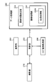
眼科撮影装置1の制御系(処理系)の構成の例を図4及び図5に示す。制御部210、画像形成部220及びデータ処理部230は、例えば演算制御ユニット200に設けられる。
<Control system>
4 and 5 show an example of the configuration of the control system (processing system) of the
〈制御部210〉
制御部210は、プロセッサを含み、眼科撮影装置1の各部を制御する。制御部210は、主制御部211と記憶部212とを含む。
<
The
〈主制御部211〉
主制御部211は、プロセッサを含み、眼科撮影装置1の各要素(図2~図5に示された要素を含む)を制御する。主制御部211は、回路を含むハードウェアと、制御ソフトウェアとの協働により実現される。
<
The
撮影光路に配置された撮影合焦レンズ31と照明光路に配置されたフォーカス光学系60とは、主制御部211の制御の下に、図示しない撮影合焦駆動部によって移動される。測定アームに設けられたリトロリフレクタ41は、主制御部211の制御の下に、リトロリフレクタ(RR)駆動部41Aによって移動される。測定アームに配置されたOCT合焦レンズ43は、主制御部211の制御の下に、OCT合焦駆動部43Aによって移動される。測定アームに設けられた光スキャナ44は、主制御部211の制御の下に動作する。参照アームに配置されたリトロリフレクタ114は、主制御部211の制御の下に、リトロリフレクタ(RR)駆動部114Aによって移動される。これら駆動部のそれぞれは、主制御部211の制御の下に動作するパルスモータ等のアクチュエータを含む。
The photographing focusing
移動機構150は、例えば、少なくとも眼底カメラユニット2を3次元的に移動する。典型的な例において、移動機構150は、±x方向(左右方向)に移動可能なxステージと、xステージを移動するx移動機構と、±y方向(上下方向)に移動可能なyステージと、yステージを移動するy移動機構と、±z方向(奥行き方向)に移動可能なzステージと、zステージを移動するz移動機構とを含む。これら移動機構のそれぞれは、主制御部211の制御の下に動作するパルスモータ等のアクチュエータを含む。
The moving
〈記憶部212〉
記憶部212は各種のデータを記憶する。記憶部212に記憶されるデータとしては、例えば、OCT画像の画像データ、眼底像の画像データ、被検眼情報などがある。被検眼情報は、患者IDや氏名などの被検者情報や、左眼/右眼の識別情報や、電子カルテ情報などを含む。
<
The
記憶部212は、眼底撮影における画像化範囲(眼底撮影領域)と、3次元OCTスキャンが適用される範囲(3次元スキャン領域)との間の位置関係を示す位置関係情報を記憶してもよい。眼底撮影領域は、例えば、眼科撮影装置1の眼底撮影機能により正面画像として描出される領域の特徴(例えば、形状、寸法)によって定義されてよい。また、3次元スキャン領域は、例えば、眼科撮影装置1のOCT機能により3次元画像として描出される領域の特徴(例えば、形状、寸法)によって定義されてよい。
The
ここで、3次元画像として描出される領域の特徴は、この3次元画像のレンダリング画像として描出される領域の特徴であってもよい。その具体例として、3次元画像として描出される領域の特徴は、3次元画像をz方向に投影して得られるプロジェクション画像に描出される領域の特徴、又は、3次元画像の一部をz方向に投影して得られるシャドウグラムに描出される領域の特徴であってよい(例えば、2次元的形状、面積、周長、径)。 Here, the feature of the region drawn as a three-dimensional image may be the feature of the region drawn as a rendered image of this three-dimensional image. As a specific example, the feature of the region drawn as a three-dimensional image is the feature of the region drawn in the projection image obtained by projecting the three-dimensional image in the z direction, or a part of the three-dimensional image is drawn in the z direction. It may be a feature of the region depicted in the shadowgram obtained by projecting onto (eg, two-dimensional shape, area, perimeter, diameter).
プロジェクション画像やシャドウグラムは正面画像であり、眼底撮影機能により得られる正面画像と同じ2次元座標系(xy座標系)で定義することが可能である。このような2次元画像ではなく3次元画像が考慮される場合には、眼底撮影機能により得られる正面画像の定義座標系(xy座標系)を3次元画像の定義座標系(xyz座標系)に埋め込むことが可能である。 The projection image and the shadow gram are front images, and can be defined in the same two-dimensional coordinate system (xy coordinate system) as the front image obtained by the fundus photography function. When a three-dimensional image is considered instead of such a two-dimensional image, the defined coordinate system (xy coordinate system) of the front image obtained by the fundus imaging function is changed to the defined coordinate system (xyz coordinate system) of the three-dimensional image. It can be embedded.
本実施形態では、前述したように、眼底撮影用光路とOCT用光路(測定アーム)とはダイクロイックミラー46によって結合されている。より具体的には、ダイクロイックミラー46は、眼底撮影用光路と測定アームとを互いに同軸に結合している。すなわち、ダイクロイックミラー46は、眼底撮影用光路の光軸と測定アームの光軸とが交差するように、眼底撮影用光路と測定アームとを結合している。
In the present embodiment, as described above, the fundus photography optical path and the OCT optical path (measurement arm) are connected by the
更に、前述したように、OCTスキャンの寸法は、測定光の最大偏向角で定義される。よって、本実施形態において、3次元スキャン領域は、光スキャナ44による測定光LSの最大偏向角(x方向の最大偏向角及びy方向の最大偏向角)で定義される。
Further, as described above, the dimensions of the OCT scan are defined by the maximum deflection angle of the measurement light. Therefore, in the present embodiment, the three-dimensional scan region is defined by the maximum deflection angle (maximum deflection angle in the x direction and maximum deflection angle in the y direction) of the light LS measured by the
また、本実施形態では、典型的な眼底カメラと同様に、眼底撮影領域の輪郭を定義するための光学部材(撮影野絞り)が配置されるか、或いは、眼底撮影領域の輪郭を定義するためにイメージセンサ35、38に対してデジタル絞りが設定される。
Further, in the present embodiment, similarly to a typical fundus camera, an optical member (shooting field diaphragm) for defining the contour of the fundus photography area is arranged, or the contour of the fundus photography area is defined. A digital aperture is set for the
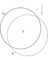
眼底撮影領域と3次元スキャン領域との位置関係の例を、図6を参照して説明する。符号300は対物レンズ22の光軸(対物光軸)300を示し、符号310は眼底撮影領域(その輪郭)を示し、符号320は3次元スキャン領域(その輪郭)を示す。眼底撮影領域310は円形であり、その中心が対物光軸300に配置されている。3次元スキャン領域320は正方形であり、その中心が対物光軸300に配置されている。すなわち、本例では、眼底撮影領域310と3次元スキャン領域320とが互いに同軸に配置されている。また、眼底撮影領域310は3次元スキャン領域320を真に含む。
An example of the positional relationship between the fundus photography area and the three-dimensional scan area will be described with reference to FIG.
眼底撮影領域310の形状及び/又は寸法は、固定的であってもよいし、可変であってもよい。眼底撮影領域310の形状及び/又は寸法の変更は、例えば、撮影野絞りの選択、撮影野絞りの開口寸法の制御、又は、デジタル絞りの制御によって実現することが可能である。
The shape and / or size of the
3次元スキャン領域320の形状及び/又は寸法は、固定的であってもよいし、可変であってもよい。3次元スキャン領域320の形状及び/又は寸法の変更は、例えば、光スキャナ44の制御(例えば、最大偏向角の制御、x-スキャナの制御、y-スキャナの制御、x-スキャナとy-スキャナとの連係的制御)によって実現することが可能である。
The shape and / or dimensions of the three-
眼底撮影領域310と3次元スキャン領域320との間の相対位置は、固定的であってもよいし、可変であってもよい。眼底撮影領域310と3次元スキャン領域320との間の相対位置の変更は、例えば、以下の制御のうちの1つ又は2つ以上の組み合わせによってすることが可能である:眼底撮影領域310の形状及び/寸法の変更;眼底撮影領域310の位置の変更;3次元スキャン領域320の形状及び/又は寸法の変更;3次元スキャン領域320の位置の変更。ここで、眼底撮影領域310の位置の変更は、例えば、撮影野絞りの選択、撮影野絞りの開口位置の制御、又は、デジタル絞りの制御によって実現することが可能である。また、3次元スキャン領域320の位置の変更は、例えば、光スキャナ44の制御によって実現することが可能である。
The relative position between the
眼底撮影領域310と3次元スキャン領域320とが互いに非同軸に配置されている場合、例えば、眼底撮影領域310の中心と3次元スキャン領域320の中心との間の相対変位、及び/又は、眼底撮影領域310の輪郭と3次元スキャン領域320の輪郭との間の相対位置によって、眼底撮影領域310と3次元スキャン領域320との間の相対位置を事前に又は随時に決定することが可能である。
When the
本実施形態では、上記した例のいずれかにしたがって求められた眼底撮影領域310と3次元スキャン領域320との間の位置関係が、事前に又は随時に、位置関係情報として記憶部212に格納される。このような位置関係情報は、例えば、図6に例示するような眼底撮影領域310と3次元スキャン領域320との間の相対位置情報、眼底撮影領域310に関する設定情報及び/又は制御情報、並びに、3次元スキャン領域320に関する設定情報及び/又は制御情報のうち、少なくとも1つを含んでいてよい。
In the present embodiment, the positional relationship between the
〈画像形成部220〉
画像形成部220は、データ収集システム130により収集されたデータに基づいて画像データを形成する。画像形成部220は、プロセッサを含む。画像形成部220は、回路を含むハードウェアと、画像形成ソフトウェアとの協働により実現される。
<
The
画像形成部220は、データ収集システム130により収集されたデータに基づいて断面像データを形成する。この処理には、従来のスウェプトソースOCTと同様に、ノイズ除去(ノイズ低減)、フィルタ処理、高速フーリエ変換(FFT)などの信号処理が含まれる。
The
画像形成部220により形成される画像データは、OCTスキャンが適用されたエリアに配列された複数のAライン(z方向に沿うスキャンライン)における反射強度プロファイルを画像化することによって形成された一群の画像データ(一群のAスキャン画像データ)を含むデータセットである。
The image data formed by the
画像形成部220により形成される画像データは、例えば、1以上のBスキャン画像データ、又は、複数のBスキャン画像データを単一の3次元座標系に埋め込んで形成されたスタックデータなどである。画像形成部220は、スタックデータにボクセル化処理を施してボリュームデータ(ボクセルデータ)を形成することも可能である。スタックデータ及びボリュームデータは、3次元座標系により表現された3次元画像データの典型的な例である。
The image data formed by the
OCT血管造影が実施される場合、主制御部211は、眼底Efの同じ領域を所定回数だけ繰り返しスキャンする。画像形成部220は、この繰り返しスキャンにおいてデータ収集システム130により収集されたデータセットに基づいて、モーションコントラスト画像を形成することができる。このモーションコントラスト画像は、眼底Efの血流に起因する干渉信号の時間的変化を強調して画像化した血管造影画像である。典型的には、眼底Efの3次元領域に対してOCT血管造影が適用され、眼底Efの血管の3次元的な分布を表す画像が得られる。
When OCT angiography is performed, the
画像形成部220は、3次元画像データを加工することができる。例えば、画像形成部220は、3次元画像データにレンダリングを適用して新たな画像データを構築することができる。レンダリングの手法としては、ボリュームレンダリング、最大値投影(MIP)、最小値投影(MinIP)、サーフェスレンダリング、多断面再構成(MPR)などがある。また、画像形成部220は、3次元画像データをz方向(Aライン方向、深さ方向)に投影してプロジェクションデータを構築することができる。また、画像形成部220は、3次元画像データの一部をz方向に投影してシャドウグラムを構築することができる。なお、シャドウグラムを構築するために投影される3次元画像データの一部は、例えば、後述のセグメンテーションを利用して設定される。
The
OCT血管造影が実施された場合、画像形成部220は、3次元血管造影画像データから、任意の2次元血管造影画像データ及び/又は任意の擬似的3次元血管造影画像データを構築することが可能である。例えば、画像形成部220は、3次元血管造影画像データに多断面再構成を適用することにより、眼底Efの任意の断面を表す2次元血管造影画像データを構築することができる。また、3次元血管造影画像データ又はその一部をz方向に投影して正面血管造影画像データを構築することが可能である。
When OCT angiography is performed, the
〈データ処理部230〉
データ処理部230は、各種のデータ処理を実行する。例えば、データ処理部230は、OCT画像データに画像処理や解析処理を適用することや、観察画像データ又は撮影画像データに画像処理や解析処理を適用することが可能である。データ処理部230は、例えば、プロセッサ及び専用回路基板の少なくともいずれかを含む。
<
The
例示的なデータ処理部230の構成を図5に示す。本例のデータ処理部230は、固視位置設定部231と画像処理部232とを含む。なお、固視系250は、被検眼Eに固視標を提示するように構成される。本例の固視系250は、LCD39と、LCD39から出力された光束を眼底Efに投射するための光学系とを含む。また、OCT画像取得部260は、被検眼Eの眼底EfにOCTを適用して画像を取得するように構成される。本例のOCT画像取得部260は、眼底カメラユニット2に設けられた測定アームを構成する要素群と、OCTユニット100に設けられた要素群と、画像形成部220とを含む。また、撮影部270は、眼底Efを撮影するように構成される。本例の撮影部270は、照明光学系10と撮影光学系30とを含む。
The configuration of the exemplary
〈固視位置設定部231〉
固視位置設定部231は、眼底EfにOCTを適用するための固視位置を設定する。特に、固視位置設定部231は、撮影部270により取得された眼底Efの正面画像に基づいて、眼底Efにパノラマ撮影(パノラマOCT)を適用するための固視位置を設定することが可能である。本例の固視位置設定部231が実行可能な処理については後述する。
<Fixation
The fixative
〈画像処理部232〉
画像処理部232は、OCT画像取得部260により取得されたOCT画像を処理する。例えば、画像処理部232は、2次元断面像データ又は3次元画像データにセグメンテーションを適用することができる。セグメンテーションは、画像中の部分領域を特定する処理である。典型的には、セグメンテーションは、眼底Efの所定組織に相当する画像領域を特定するために利用される。
<
The
前述したように、画像形成部220は、セグメンテーションで特定された画像領域をz方向に投影してシャドウグラム(正面血管造影画像データ等)を構築することができる。シャドウグラムの例として、眼底Efの任意の深さ領域(例えば、網膜浅部、網膜深部、脈絡膜毛細血管板、強膜など)に対応するシャドウグラムや、任意の組織(例えば、内境界膜、神経線維層、神経節細胞層、内網状層、内顆粒層、外網状層、外顆粒層、外境界膜、網膜色素上皮、ブルッフ膜、脈絡膜、脈絡膜強膜境界、強膜、これらのいずれかの一部、これらの少なくとも2以上の組み合わせなど)に対応するシャドウグラムなどがある。
As described above, the
画像処理部232は、撮影部270により取得された画像(観察画像、撮影画像等)を処理することや、他の眼科撮影装置により取得された画像を処理することが可能であってもよい。例えば、画像処理部232は、撮影部270により取得された眼底Efの正面画像を解析して、眼底Efの所定部位(黄斑、視神経乳頭等)に相当する画像領域を特定することや、眼底Efの所定部位の輪郭に相当する画像領域を特定することや、眼底Efの所定位置(黄斑中心、乳頭中心等)に相当する画素を特定することが可能である。この処理は、画素値に関する閾値処理、エッジ検出、テンプレートマッチング等を含んでいてよい。
The
画像処理部232は、画像処理プロセッサや画像解析プロセッサを含む。画像処理プロセッサは、回路を含むハードウェアと、画像処理ソフトウェアとの協働により実現される。また、画像解析プロセッサは、回路を含むハードウェアと、画像解析ソフトウェアとの協働により実現される。
The
本例の画像処理部232が実行可能な処理については後述する。
The processing that can be executed by the
〈合成処理部2321〉
画像処理部232は合成処理部2321を含む。合成処理部2321は、パノラマ撮影において互いに異なる2以上の固視位置に対応して取得された2以上の3次元画像の合成画像を形成する。本例の合成処理部2321が実行可能な処理については後述する。
<
The
〈ユーザインターフェイス240〉
ユーザインターフェイス240は表示部241と操作部242とを含む。表示部241は表示装置3を含む。操作部242は各種の操作デバイスや入力デバイスを含む。ユーザインターフェイス240は、例えばタッチパネルのような表示機能と操作機能とが一体となったデバイスを含んでいてもよい。ユーザインターフェイス240の少なくとも一部を含まない実施形態を構築することも可能である。例えば、表示デバイスは、眼科撮影装置に接続された外部装置であってよい。
<
The
〈パノラマ撮影について〉
本例において実行可能なパノラマ撮影について説明する。本例では、撮影部270により取得された眼底Efの正面画像を利用して、パノラマ撮影のための固視位置が設定される。この予備的な眼底撮影は、例えば、パノラマ撮影の中心位置を設定するための第1の予備的眼底撮影と、パノラマ撮影で実施される複数のOCTのための複数の固視位置を設定するための第2の予備的眼底撮影とを含む。なお、第1の予備的眼底撮影の実行は任意的である。第1の予備的眼底撮影を経ずに第2の予備的眼底撮影を実行するようにしてもよい。
<About panoramic shooting>
The panoramic photography that can be performed in this example will be described. In this example, the fixative position for panoramic photography is set by using the front image of the fundus Ef acquired by the photographing
〈第1の予備的眼底撮影等について〉
第1の予備的眼底撮影の例を説明する。第1の予備的眼底撮影において、主制御部211は、眼底Efの所定部位を中心とする正面画像を取得するための第1の固視標を被検眼Eに提示しつつ眼底Efの正面画像(予備的正面画像と呼ぶ)を取得するように固視系250及び撮影部270を制御する。本例では、この所定部位(つまり、第1の固視位置)の典型例として黄斑(黄斑中心、中心窩)を採用するが、眼底の他の部位(例えば、視神経乳頭又は眼底中心)が所定部位であってもよい。
<About the first preliminary fundus photography, etc.>
An example of the first preliminary fundus photography will be described. In the first preliminary fundus photography, the
画像処理部232は、予備的正面画像の中心位置に対する眼底Efの所定部位の画像の偏位を算出する。
The
例えば、画像処理部232は、まず、予備的正面画像を解析して黄斑中心に相当する画素の座標を求める。続いて、画像処理部232は、特定された黄斑中心の座標と、予備的正面画像の中心位置の座標との間の差を求める。黄斑中心の座標と予備的正面画像の中心位置の座標との間の差は、第1の予備的眼底撮影で適用された眼底撮影領域(撮影野)の中心位置に対する実際の黄斑中心の偏位に相当する。
For example, the
画像処理部232により求められた偏位に基づいて、固視位置設定部231は、第1の固視位置を補正することができる。例えば、固視位置設定部231は、画像処理部232により求められた偏位がキャンセルされるように(つまり、当該偏位がゼロになるように)第1の固視位置を補正する。それにより、眼底撮影領域の中心位置(パノラマ撮影の中心位置)が第1の固視位置に対応する部位(黄斑中心)に略一致される。
The fixative
更に、固視位置設定部231は、既定の第2の固視位置を補正することができる。具体例として、固視位置設定部231は、第1の固視位置と第2の固視位置との間の相対位置が維持されるように、第1の固視位置の補正量と同じ補正量を第2の固視位置に適用する。つまり、固視位置設定部231は、画像処理部232により求められた偏位(ベクトル)の逆ベクトルに相当する補正量を第2の固視位置に適用する。
Further, the fixative
主制御部211は、固視位置設定部231により補正された第1の固視位置及び第2の固視位置を適用して第2の予備的眼底撮影を実行することが可能である。
The
〈第2の予備的眼底撮影等について〉
第2の予備的眼底撮影の例を説明する。第2の予備的眼底撮影において、主制御部211は、第1の制御と、第2の制御とを実行する。第1の制御において、主制御部211は、第1の固視位置に対応する第1の固視標を被検眼Eに提示しつつ眼底Efの正面画像(第1の正面画像と呼ぶ)を取得するように固視系250及び撮影部270を制御する。同様に、第2の制御において、主制御部211は、第2の固視位置に対応する第2の固視標を被検眼Eに提示しつつ眼底Efの正面画像(第2の正面画像と呼ぶ)を取得するように固視系250及び撮影部270を制御する。
<About the second preliminary fundus photography, etc.>
An example of the second preliminary fundus photography will be described. In the second preliminary fundus photography, the
第1の制御において、主制御部211は、例えば、第1の固視位置に対応するLCD39の表示位置(ピクセル)に固視標を表示するように固視系250を制御し、且つ、その状態で眼底Efの撮影を行うように撮影部270を制御する。それにより、第1の固視位置に対応する第1の正面画像が得られる。
In the first control, the
同様に、第2の制御において、主制御部211は、例えば、第2の固視位置に対応するLCD39の表示位置(ピクセル)に固視標を表示するように固視系250を制御し、且つ、その状態で眼底Efの撮影を行うように撮影部270を制御する。それにより、第2の固視位置に対応する第2の正面画像が得られる。
Similarly, in the second control, the
ここで、第1の固視位置は、眼底の所定部位を中心とする正面画像を取得するための既定の固視位置であり、例えば、前述したように、黄斑を中心とする正面画像を取得するための固視位置であってよい。また、第2の固視位置は、例えば、標準的な眼の眼底において当該所定部位から所定方向に所定距離だけ離れた位置を中心とする正面画像を取得するための既定の固視位置であってよい。 Here, the first fixative position is a default fixative position for acquiring a frontal image centered on a predetermined portion of the fundus, and for example, as described above, a frontal image centered on the macula is acquired. It may be a fixative position to do so. Further, the second fixative position is, for example, a default fixative position for acquiring a frontal image centered on a position separated by a predetermined distance in a predetermined direction from the predetermined portion in the fundus of a standard eye. It's okay.
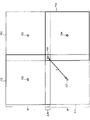
第1の固視位置及び第2の固視位置の例を図7に示す。符号411は、第1の固視位置(黄斑中心)に対応する第1の固視標(黄斑用固視標)を示す。符号412は、第1の固視位置を中心とする眼底撮影領域(黄斑用撮影範囲)を示す。符号413は、第1の固視位置を中心とする3次元スキャン領域(黄斑用スキャン範囲)を示す。本例において、黄斑用撮影範囲412と黄斑用スキャン範囲413との位置関係は、記憶部212に記憶されている位置関係情報に相当する(図6を参照)。
An example of the first fixative position and the second fixative position is shown in FIG.
また、符号421は、第2の固視位置(黄斑中心から左下方向に所定距離だけ離れた位置)に対応する第2の固視標(周辺用固視標)を示す。符号422は、第2の固視位置を中心とする眼底撮影領域(周辺用撮影範囲)を示す。符号423は、第2の固視位置を中心とする3次元スキャン領域(周辺用スキャン範囲)を示す。本例において、周辺用撮影範囲422と周辺用スキャン範囲423との位置関係は、黄斑用撮影範囲412と黄斑用スキャン範囲413との位置関係と同じく、記憶部212に記憶されている位置関係情報に相当する。
Further,
図7において、符号432は、黄斑用撮影範囲412と周辺用撮影範囲422との重複領域(重複撮影範囲)を示し、符号433は、黄斑用スキャン範囲413と周辺用スキャン範囲423との重複領域(重複スキャン範囲)を示す。前述したように、黄斑用撮影範囲412と黄斑用スキャン範囲413との位置関係は位置関係情報に相当するので、この位置関係は実質的に固定的である。同様に、周辺用撮影範囲422と周辺用スキャン範囲423との位置関係は位置関係情報に相当するので、この位置関係も実質的に固定的である。したがって、重複撮影範囲432及び重複スキャン範囲433の一方が決定されれば、他方も決定される。
In FIG. 7,
図7に示すように、第1の固視位置(黄斑用固視標411)の左下に第2の固視位置(周辺用固視標421)が配置されているとする。被検眼Eが標準的な眼である場合、図7に示すように、重複スキャン範囲433の右上隅に黄斑用固視標411が配置され、左下隅に周辺用固視標421が配置される。すなわち、被検眼Eが標準的な眼である場合にこのような配置が実現されるように、第1の固視位置(黄斑用固視標411)と第2の固視位置(周辺用固視標421)との位置関係が予め設定される。典型的には、被検眼Eが標準的な眼である場合、右上隅の所定の許容範囲に黄斑用固視標411が配置され、且つ、左下隅の所定の許容範囲に周辺用固視標421が配置されるような寸法を有する重複スキャン範囲433が得られる。前述したように、重複撮影範囲432と重複スキャン範囲433との間には一定の関係が存在するので、被検眼Eが標準的な眼である場合に得られる重複スキャン範囲433の寸法を予め決定することが可能である。
As shown in FIG. 7, it is assumed that the second fixative position (peripheral fixative 421) is arranged at the lower left of the first fixative position (macula fixative 411). When the eye to be inspected E is a standard eye, the
ここで、標準的な眼とは、典型的には、眼軸長が標準的範囲に属する眼(例えば、長眼軸長眼でも短眼軸長眼でもない眼)、及び/又は、視度が標準的範囲に属する眼(例えば、近視眼でも遠視眼でもない眼)である。 Here, the standard eye is typically an eye whose axial length belongs to the standard range (for example, an eye that is neither long-axis long eye nor short-axis long eye) and / or diopter. Is an eye that belongs to the standard range (eg, an eye that is neither myopic nor distant).
これに対し、例えば被検眼Eの眼軸長が標準よりも短い場合には、黄斑用撮影範囲の寸法が、標準的な眼の場合の黄斑用撮影範囲412の寸法よりも小さくなり、且つ、周辺用撮影範囲の寸法も標準的な眼の場合の周辺用撮影範囲422よりも小さくなる。したがって、被検眼Eの眼軸長が標準よりも短い場合の重複撮影範囲の寸法は、標準的な眼の場合の重複撮影範囲432と比較して小さくなる。この場合、重複スキャン範囲の右上隅の所定の許容範囲に黄斑用固視標411が配置されず、及び/又は、左下隅の所定の許容範囲に周辺用固視標421が配置されない。
On the other hand, for example, when the axial length of the eye E to be inspected is shorter than the standard, the size of the macula imaging range is smaller than the dimension of the
逆に、被検眼Eの眼軸長が標準よりも長い場合には、黄斑用撮影範囲の寸法が、標準的な眼の場合の黄斑用撮影範囲412の寸法よりも大きくなり、且つ、周辺用撮影範囲の寸法も標準的な眼の場合の周辺用撮影範囲422よりも大きくなる。したがって、被検眼Eの眼軸長が標準よりも長い場合の重複撮影範囲の寸法は、標準的な眼の場合の重複撮影範囲432と比較して大きくなる。この場合においても、重複スキャン範囲の右上隅の所定の許容範囲に黄斑用固視標411が配置されず、及び/又は、左下隅の所定の許容範囲に周辺用固視標421が配置されない。
On the contrary, when the axial length of the eye E to be inspected is longer than the standard, the size of the macula imaging range is larger than the dimension of the
このように、被検眼Eの眼軸長の値に応じて、第1の正面画像と第2の正面画像との重複領域の寸法が変化する。より具体的には、被検眼Eの眼軸長が短いほど重複領域の寸法は小さくなり、被検眼Eの眼軸長が長いほど重複領域の寸法は大きくなる。なお、視度等の眼球パラメータについても同様である。本実施形態では、このような関係を利用してパノラマ撮影のための複数の固視標を設定することができる。 In this way, the dimension of the overlapping region between the first front image and the second front image changes according to the value of the axial length of the eye E to be inspected. More specifically, the shorter the axial length of the eye E to be inspected, the smaller the dimension of the overlapping region, and the longer the axial length of the eye E to be inspected, the larger the dimension of the overlapping region. The same applies to eyeball parameters such as diopter. In the present embodiment, a plurality of fixatives for panoramic photography can be set by utilizing such a relationship.
より一般に、本実施形態の固視位置設定部231は、第1の正面画像と第2の正面画像とに基づいて、パノラマ撮影のための固視位置を設定することが可能である。
More generally, the fixation
一例において、固視位置設定部231は、第1の正面画像と第2の正面画像との間の重複領域を特定することができる。この処理は、例えば、第1の正面画像中の第1の部分領域及び第2の正面画像中の第2の部分領域であって、一致の程度(画像相関等)が高い第1の部分領域及び第2の部分領域を特定することによって実現される。本例では、更に、固視位置設定部231は、特定された重複領域に基づいて、パノラマ撮影のための固視位置を設定することができる。
In one example, the fixative
例えば、固視位置設定部231は、第1の正面画像と第2の正面画像との間の重複領域の寸法を算出し、この寸法に基づいてパノラマ撮影のための固視位置を設定してもよい。ここで、重複領域の寸法を示すパラメータは、x方向における長さ、y方向における長さ、周長、面積などのうちの少なくとも1つを含んでいてよい。
For example, the fixative
例えば、固視位置設定部231は、第1の正面画像と第2の正面画像との間の重複領域の寸法が既定値に略等しくなるように(又は、既定の許容範囲に含まれるように)パノラマ撮影のための固視位置を設定してもよい。この既定値(又は、許容範囲)は、例えば、被検眼Eが標準的な眼である場合に得られるべき重複領域の寸法(又は、寸法の値の許容範囲)を示す。
For example, the fixative
また、固視位置設定部231は、第1の正面画像と第2の正面画像とに基づいて第1の固視位置に対する第2の固視位置の偏位を補正することにより、パノラマ撮影のための固視位置を設定してもよい。典型的には、第1の固視位置が黄斑に対応する場合において、第2の予備的眼底撮影における第1の固視位置に対する第2の固視位置の偏位を、第1の正面画像と第2の正面画像とに基づき補正することにより、第2の固視位置の近傍に位置する周辺固視位置をパノラマ撮影のための固視位置の1つとして設定することができる。
Further, the fixation
〈動作〉
本実施形態に係る眼科撮影装置1の動作について説明する。眼科撮影装置1の動作の例を図8に示す。なお、患者情報入力、アライメント、フォーカス調整など、眼底撮影のための一般的な準備処理は既に完了しているとする。また、干渉感度調整、z位置調整など、OCTのための一般的な準備処理は任意のタイミングで実行されるものとする。
<motion>
The operation of the
(S1:第1の予備的眼底撮影を実行)
まず、眼科撮影装置1は、前述した第1の予備的眼底撮影を実行する。第1の予備的眼底撮影は、パノラマ撮影の中心位置を設定するために行われる。本例の第1の予備的眼底撮影では、主制御部211が、デフォルトの黄斑用固視標を被検眼Eに提示するように固視系250を制御し、且つ、この黄斑用固視標が提示されている被検眼Eの眼底Efを撮影するように撮影部270を制御する。それにより、予備的正面画像が得られる。
(S1: Perform the first preliminary fundus photography)
First, the
ここで、デフォルトの黄斑用固視標は、典型的には、LCD39の表示画面の中心位置(つまり、ハーフミラー33Aにより分岐された光路の光軸上の位置)に表示された可視輝点である。ただし、デフォルトの黄斑用固視標はこれに限定されない。
Here, the default macula fixative is typically the visible light spot displayed at the center position of the LCD39 display screen (ie, the position on the optical axis of the optical path branched by the
(S2:パノラマ撮影の中心位置を設定)
主制御部211は、ステップS1の第1の予備的眼底撮影で取得された予備的正面画像をデータ処理部230に送る。画像処理部232は、予備的正面画像の中心位置に対する眼底Efの黄斑の画像の偏位を算出する。
(S2: Set the center position of panoramic shooting)
The
ここで、図9Aを参照する。符号500は、予備的正面画像を示す。予備的正面画像500の輪郭は円形である。符号501は、予備的正面画像500の中心位置(xy面における中心位置)を示す。符号502は、予備的正面画像に描出された黄斑(黄斑中心)の位置を示す。符号503は、予備的正面画像500の中心位置501に対する黄斑中心502の偏位を示す。本例では、画像処理部232は、予備的正面画像500を解析することで、その中心位置501に対する黄斑中心502の偏位503を算出する。
Here, reference is made to FIG. 9A.
固視位置設定部231は、算出された偏位503に基づいて、デフォルトの黄斑用固視標に対応する固視位置(つまり、LCD39の表示画面における可視輝点の表示位置)を補正する。補正された黄斑用固視標に対応する眼底Efの位置(黄斑)が、パノラマ撮影の中心位置に設定される。すなわち、偏位503が表すベクトルの逆ベクトルに相当する方向及び距離の平行移動をデフォルトの黄斑用固視標に適用することで、図9Bに示すように、(仮想的な)正面画像550の中心位置に黄斑中心551が描出されるようにデフォルトの黄斑用固視標の位置が補正される。更に、固視位置設定部231は、デフォルトの周辺固視位置(第2の固視位置)についても同様の補正を行う。
The fixative
(S3:第2の予備的眼底撮影を開始)
パノラマ撮影の中心位置の設定(黄斑用固視標の位置補正、更には、周辺用固視標の位置補正)が完了すると、処理は第2の予備的眼底撮影に移行する。本例の第2の予備的眼底撮影では、ステップS2で補正された第1の固視位置を適用して前述の第1の制御が実行され、且つ、ステップS2で補正された第2の固視位置を適用して前述の第2の制御が実行される。
(S3: Start the second preliminary fundus photography)
When the setting of the center position of the panoramic photography (position correction of the macula fixative and further, position correction of the peripheral fixative) is completed, the process shifts to the second preliminary fundus photography. In the second preliminary fundus photography of this example, the above-mentioned first control is executed by applying the first fixative position corrected in step S2, and the second fixative position corrected in step S2 is performed. The above-mentioned second control is executed by applying the visual position.
(S4:第1の制御を実行して第1の正面画像を取得)
第1の制御において、主制御部211は、ステップS2で補正された第1の固視位置に対応する第1の固視標を被検眼Eに提示しつつ眼底Efの第1の正面画像を取得するように固視系250及び撮影部270を制御する。
(S4: Execute the first control to acquire the first front image)
In the first control, the
本例では、主制御部211は、ステップS2で補正された黄斑用固視標の固視位置に対応するLCD39の表示画面の位置(ピクセル)に可視輝点を表示させる。更に、主制御部211は、眼底Efを撮影して第1の正面画像を取得するように撮影部270を制御する。
In this example, the
(S5:第2の制御を実行して第2の正面画像を取得)
ステップS4における第1の制御の完了後、処理は第2の制御に移行する。第2の制御において、主制御部211は、ステップS2で補正された第2の固視位置に対応する第2の固視標を被検眼Eに提示しつつ眼底Efの第2の正面画像を取得するように固視系250及び撮影部270を制御する。
(S5: Execute the second control to acquire the second front image)
After the completion of the first control in step S4, the process shifts to the second control. In the second control, the
本例では、主制御部211は、ステップS2で補正された周辺用固視標の固視位置に対応するLCD39の表示画面の位置(ピクセル)に可視輝点を表示させる。更に、主制御部211は、眼底Efを撮影して第2の正面画像を取得するように撮影部270を制御する。
In this example, the
なお、本例では、第1の制御の後に第2の制御を実行しているが、これとは逆に、第2の制御の後に第1の制御を実行するようにしてもよい。 In this example, the second control is executed after the first control, but conversely, the first control may be executed after the second control.
(S6:パノラマ撮影のための複数の固視位置を設定)
第1の制御及び第2の制御が完了したら、処理は、パノラマ撮影のための固視位置の設定に移行する。固視位置設定部231は、ステップS4で取得された第1の正面画像と、ステップS5で取得された第2の正面画像とに基づいて、パノラマ撮影のための複数の固視位置を設定する。
(S6: Set multiple fixative positions for panoramic shooting)
After the first control and the second control are completed, the process shifts to the setting of the fixation position for panoramic photography. The fixative
例えば、図10Aに示す第1の正面画像601と第2の正面画像602とが取得されたとする。第1の正面画像601及び第2の正面画像602は、それぞれ、予備的正面画像500と同様の形状及び寸法を有するものとする。
For example, it is assumed that the first
固視位置設定部231は、まず、第1の正面画像601と第2の正面画像602との間の重複領域603を特定する(図10Bを参照)。
The fixative
次に、固視位置設定部231は、特定された重複領域603の寸法を算出する。本例では、固視位置設定部231は、重複領域603のx方向における長さRx(mm)とy方向における長さRy(mm)とを、重複領域603の寸法として算出するものとする。
Next, the fixative
続いて、固視位置設定部231は、算出された重複領域603の寸法Rx(mm)及びRy(mm)に基づいて、パノラマ撮影のための複数の固視位置を設定する。例えば、固視位置設定部231は、ステップS2で補正された周辺用固視標の固視位置を、重複領域603の寸法Rx(mm)及びRy(mm)が既定値に略等しくなるように更に補正する。換言すると、固視位置設定部231は、ステップS2で補正された周辺用固視標(可視輝点)の表示位置(LCD39の表示画面のピクセル位置)を、重複領域603の寸法Rx(mm)及びRy(mm)が既定値に略等しくなるように変更する。
Subsequently, the fixative
もし被検眼Eが標準的な眼である場合、重複領域603の寸法Rx(mm)及びRy(mm)は共に既定値に略等しくなる。一方、被検眼Eが標準的な眼でない場合には、重複領域503の寸法Rx及びRyの少なくとも一方が既定値と実質的に異なる。
If the eye to be inspected E is a standard eye, the dimensions Rx (mm) and Ry (mm) of the
ここで、「寸法が既定値に略等しい」とは、例えば、予め設定された許容誤差(既定値に対する誤差)の範囲に寸法が含まれる場合を意味する。また、「寸法が既定値と実質的に異なる」とは、例えば、予め設定された許容誤差(既定値に対する誤差)の範囲に寸法が含まれない場合を意味する。 Here, "the dimension is substantially equal to the default value" means, for example, the case where the dimension is included in the range of the preset tolerance (error with respect to the default value). Further, "the dimension is substantially different from the default value" means, for example, the case where the dimension is not included in the range of the preset tolerance (error with respect to the default value).
このように、重複領域603の寸法Rx(mm)及びRy(mm)と、既定値との差分の原因は、眼軸長、視度等の眼球パラメータの値の相違に起因する固視位置の変位にある。本例では、このような固視位置の変位を補正することで、パノラマ撮影のための周辺固視位置の最適化を図る。
As described above, the cause of the difference between the dimensions Rx (mm) and Ry (mm) of the
例えば、固視位置設定部231は、重複領域603の寸法Rx(mm)及びRy(mm)のそれぞれと、既定値Q(mm)との差分(Q-Rx、Q-Ry)を算出する。また、黄斑用固視標の表示位置と、その左下に位置する周辺用固視標の表示位置との間の変位が、x方向においてDx(ピクセル、ドット)、y方向においてDy(ピクセル、ドット)であるとする(ここで、Dx=Dyであってよい)。そうすると、([Q-Rx]/Dx、[Q-Ry]/Dy)に対応するドット数だけ周辺用固視標の表示位置を移動させればよい。固視位置設定部231は、このような演算を行うことが可能である。
For example, the fixative
このように、固視位置設定部231は、黄斑撮影用固視位置に対して左下に位置する周辺固視位置を設定することができる。この結果を利用して、他の周辺固視位置を設定することが可能である。
In this way, the fixation
例えば、図11に示すように、黄斑700(黄斑撮影用固視位置)の左下に位置する第1の周辺固視位置701が、上記の要領で設定されたとする。第1の周辺固視位置701は、黄斑700から左下方向に距離Tだけ離れた位置に設定されている。この場合、固視位置設定部231は、(1)黄斑700から左上方向に距離Tだけ離れた位置に第2の周辺固視位置702を設定し、(2)黄斑700から右上方向に距離Tだけ離れた位置に第3の周辺固視位置703を設定し、(3)黄斑700から右下方向に距離Tだけ離れた位置に第4の周辺固視位置704を設定することができる。
For example, as shown in FIG. 11, it is assumed that the first
なお、複数の周辺固視位置の個数は4つに限定されず、また、複数の周辺固視位置の配列は図11に示す配列に限定されない。一般に、予め設定された複数の周辺固視位置の配列(例えば、デフォルトの配列、ユーザ又は眼科撮影装置1により指定された配列)に応じて、複数の周辺固視位置を設定(補正)することが可能である。 The number of the plurality of peripheral fixation positions is not limited to four, and the arrangement of the plurality of peripheral fixation positions is not limited to the arrangement shown in FIG. In general, setting (correcting) a plurality of peripheral fixation positions according to a preset arrangement of a plurality of peripheral fixation positions (for example, a default arrangement, an arrangement specified by a user or an ophthalmologic imaging device 1). Is possible.
(S7:パノラマ撮影を実行して複数の3次元画像を取得)
主制御部211は、ステップS6で設定された複数の(周辺)固視位置に対応する複数の固視標を順次に被検眼Eに提示するように固視系250を制御し、且つ、これらの固視標のそれぞれが被検眼Eに提示されているときに眼底Efの3次元画像を取得するようにOCT画像取得部260を制御する。
(S7: Perform panoramic shooting to acquire multiple 3D images)
The
一例として、図11に示す4つの周辺固視位置701~704がパノラマ撮影に適用される場合について説明する。
As an example, a case where the four
まず、主制御部211は、第1の周辺固視位置701に対応する第1の周辺用固視標を提示するように固視系250を制御し、更に、第1の周辺用固視標が提示された状態で3次元スキャンを実行するようにOCT画像取得部260を制御する。それにより、図11に示す第1の周辺スキャン範囲711に対応する第1の周辺3次元画像が取得される。第1の周辺3次元画像(第1の周辺スキャン範囲)の寸法は、x方向の長さ及びy方向の長さが共にW(mm)である。
First, the
次に、主制御部211は、第2の周辺固視位置702に対応する第2の周辺用固視標を提示するように固視系250を制御し、更に、第2の周辺用固視標が提示された状態で3次元スキャンを実行するようにOCT画像取得部260を制御する。それにより、図11に示す第2の周辺スキャン範囲712に対応する第2の周辺3次元画像が取得される。第2の周辺3次元画像(第2の周辺スキャン範囲)の寸法は、x方向の長さ及びy方向の長さが共にW(mm)である。
Next, the
続いて、主制御部211は、第3の周辺固視位置703に対応する第3の周辺用固視標を提示するように固視系250を制御し、更に、第3の周辺用固視標が提示された状態で3次元スキャンを実行するようにOCT画像取得部260を制御する。それにより、図11に示す第3の周辺スキャン範囲713に対応する第3の周辺3次元画像が取得される。第3の周辺3次元画像(第3の周辺スキャン範囲)の寸法は、x方向の長さ及びy方向の長さが共にW(mm)である。
Subsequently, the
最後に、主制御部211は、第4の周辺固視位置704に対応する第4の周辺用固視標を提示するように固視系250を制御し、更に、第4の周辺用固視標が提示された状態で3次元スキャンを実行するようにOCT画像取得部260を制御する。それにより、図11に示す第4の周辺スキャン範囲714に対応する第4の周辺3次元画像が取得される。第4の周辺3次元画像(第4の周辺スキャン範囲)の寸法は、x方向の長さ及びy方向の長さが共にW(mm)である。
Finally, the
また、互いに隣接する2つの周辺3次元画像は、これらを合成するために好適な幅の重複領域(のりしろ)を持つ。例えば、図11に示す例では、第1の周辺スキャン範囲と第2の周辺スキャン範囲とは幅ΔWの重複領域を有し、第2の周辺スキャン範囲と第3の周辺スキャン範囲とは幅ΔWの重複領域を有し、第3の周辺スキャン範囲と第4の周辺スキャン範囲とは幅ΔWの重複領域を有し、第4の周辺スキャン範囲と第1の周辺スキャン範囲とは幅ΔWの重複領域を有する。 Further, the two peripheral three-dimensional images adjacent to each other have an overlapping region (margin) having a width suitable for synthesizing them. For example, in the example shown in FIG. 11, the first peripheral scan range and the second peripheral scan range have an overlapping region having a width ΔW, and the second peripheral scan range and the third peripheral scan range have a width ΔW. The third peripheral scan range and the fourth peripheral scan range have an overlapping area with a width ΔW, and the fourth peripheral scan range and the first peripheral scan range have an overlapping width ΔW. Has an area.
(S8:合成画像を形成)
合成処理部2321は、ステップS7で取得された複数の3次元画像の合成画像(モザイク画像)を形成する。一例として、図11に示す例では、合成処理部2321は、第1~第4の周辺3次元画像を合成して単一の3次元画像を形成する。なお、ステップS7で取得された複数の3次元画像のうちの任意の2以上の3次元画像を合成することも可能である。
(S8: Form a composite image)
The
複数の3次元画像を合成する処理は、例えば、従来の画像合成技術と同様に、画像相関等を用いた重複領域同士のマッチングと、このマッチングの結果を利用した周辺3次元画像同士の位置決めと、これら周辺3次元画像との合成処理とを含む。 The process of synthesizing a plurality of 3D images is, for example, matching of overlapping regions using image correlation and the like, and positioning of peripheral 3D images using the result of this matching, as in the conventional image synthesizing technique. , Includes a compositing process with these peripheral three-dimensional images.
(S9:合成画像を表示・保存)
主制御部211は、ステップS8で形成された合成画像を表示部241に表示させることができる。また、主制御部211は、記憶部212に合成画像を保存することや、外部装置に合成画像を送信するための制御を行うことや、記録媒体に合成画像を記録するための制御を行うことが可能である。
(S9: Display / save composite image)
The
また、主制御部211は、ステップS7で形成された複数の3次元画像の一部又は全部を表示部241に表示させることが可能である。以上で、本例に係る処理は終了となる。
Further, the
〈変形例〉
以上に説明した動作例では、第1の予備的眼底撮影を行った後に、第1の制御と第2の制御とを含む第2の予備的眼底撮影を行っている。しかし、第2の予備的眼底撮影の第1の制御を省略することが可能である。
<Modification example>
In the operation example described above, after the first preliminary fundus photography is performed, the second preliminary fundus photography including the first control and the second control is performed. However, it is possible to omit the first control of the second preliminary fundus photography.
例えば、第1の予備的眼底撮影によって取得された予備的正面画像と前述した偏位503とを、第1の制御で取得される第1の正面画像の代わりに用いることが可能である。すなわち、第1の予備的眼底撮影と、第2の予備的眼底撮影の第1の制御では、共通の第1の固視位置が適用されるため、第1の予備的眼底撮影で得られた予備的正面画像の位置を変位503に基づきシフトさせた正面画像を、第1の制御で得られる第1の正面画像の代わりに用いることができる。
For example, the preliminary front image acquired by the first preliminary fundus photography and the
〈作用・効果〉
本実施形態に係る眼科撮影装置1の作用及び効果について説明する。
<Action / effect>
The operation and effect of the
本実施形態に係る眼科撮影装置(1)は、固視系(250)と、撮影部(270)と、制御部(主制御部211)と、固視位置設定部(231)と、OCT画像取得部(260)と、画像処理部(232)とを含む。 The ophthalmologic imaging apparatus (1) according to the present embodiment includes a fixative system (250), an imaging unit (270), a control unit (main control unit 211), a fixative position setting unit (231), and an OCT image. It includes an acquisition unit (260) and an image processing unit (232).
固視系(250)は、被検眼(E)に固視標を提示する。撮影部(270)は、被検眼(E)の眼底(Ef)を撮影する。 The fixative system (250) presents a fixative to the eye to be inspected (E). The photographing unit (270) photographs the fundus (Ef) of the eye to be inspected (E).
制御部(211)は、所定の固視位置に対応する固視標を被検眼(E)に提示しつつ眼底(Ef)の正面画像を取得するように固視系(250)及び撮影部(270)を制御する。この制御を眼底撮影制御と呼ぶ。 The control unit (211) presents a fixative target corresponding to a predetermined fixation position to the eye to be inspected (E), and acquires a front image of the fundus (Ef). 270) is controlled. This control is called fundus photography control.
固視位置設定部(231)は、眼底撮影制御により取得された正面画像に基づいて、パノラマ撮影のための1以上の固視位置(少なくとも第1の周辺固視位置701)を設定する。なお、固視位置設定部(231)は、パノラマ撮影のための2以上の固視位置(例えば、第1の周辺固視位置701と、第2~第4の周辺固視位置702~704のいずれか1以上とを含む、2以上の周辺固視位置)を設定することも可能である。また、パノラマ撮影のための1以上の固視位置のうちの少なくとも1つをユーザが設定又は補正できるように構成してもよい。
The fixation position setting unit (231) sets one or more fixation positions (at least the first peripheral fixation position 701) for panoramic photography based on the front image acquired by the fundus photography control. The fixation position setting unit (231) has two or more fixation positions for panoramic photography (for example, a first
また、固視位置設定部(231)は、眼底撮影制御により取得された正面画像と、眼底撮影制御における撮影領域(眼底撮影領域310)とパノラマ撮影のためのOCT制御における3次元スキャン領域(320)との間の位置関係(位置関係情報)とに基づいて、パノラマ撮影のための1以上の固視位置を設定するように構成されていてよい。 Further, the fixative position setting unit (231) includes a front image acquired by fundus photography control, a photographing area (fundus photography area 310) in fundus photography control, and a three-dimensional scan area (320) in OCT control for panoramic photography. ) And one or more fixation positions for panoramic photography may be set based on the positional relationship (positional relationship information).
OCT画像取得部(260)は、眼底(Ef)に光コヒーレンストモグラフィ(OCT)を適用して画像を取得する。 The OCT image acquisition unit (260) applies optical coherence tomography (OCT) to the fundus (Ef) to acquire an image.
画像処理部(232)は、OCT画像取得部(260)により取得された画像を処理する。画像処理部(232)は、合成処理部(2321)を含む。 The image processing unit (232) processes the image acquired by the OCT image acquisition unit (260). The image processing unit (232) includes a composition processing unit (2321).
制御部(211)は、OCT制御(パノラマ撮影)として、固視位置設定部(231)により設定された1以上の固視位置を含む2以上の固視位置(第1~第4の周辺固視位置701~704)に対応する2以上の固視標(第1~第4の周辺用固視標)を順次に被検眼(E)に提示するように固視系(250)を制御し、且つ、2以上の固視標(第1~第4の周辺用固視標)のそれぞれが被検眼(E)に提示されているときに眼底(Ef)の3次元画像を取得するようにOCT画像取得部(260)を制御する。
The control unit (211) has two or more fixation positions (first to fourth peripheral fixation) including one or more fixation positions set by the fixation position setting unit (231) as OCT control (panoramic photography). The fixative system (250) is controlled so that two or more fixatives (first to fourth peripheral fixatives) corresponding to the
合成処理部(2321)は、OCT制御により取得された2以上の固視位置(第1~第4の周辺固視位置701~704)に対応する2以上の3次元画像(第1~第4の周辺3次元画像)の合成画像(モザイク画像)を形成する。
The synthesis processing unit (2321) has two or more three-dimensional images (first to fourth) corresponding to two or more fixation positions (first to fourth
このような実施形態によれば、眼底撮影制御を実際に行うことでパノラマ撮影のための複数の固視位置を設定することができる。それにより、眼軸長等の眼球サイズ情報や視度等の眼球特性情報などの個人差にかかわらず、OCTを用いてモザイク画像を取得するための複数の固視位置の設定を好適に行うことが可能となる。 According to such an embodiment, it is possible to set a plurality of fixative positions for panoramic photography by actually performing fundus photography control. Thereby, regardless of individual differences such as eyeball size information such as axial length and eyeball characteristic information such as diopter, it is preferable to set a plurality of fixative positions for acquiring a mosaic image using OCT. Is possible.
眼底撮影制御において、制御部(211)は、第1の制御(第2の予備的眼底撮影における第1の制御)と、第2の制御(第2の予備的眼底撮影における第2の制御)とを実行してもよい。 In the fundus photography control, the control unit (211) has a first control (first control in the second preliminary fundus photography) and a second control (second control in the second preliminary fundus photography). And may be executed.
第1の制御として、制御部(211)は、第1の固視位置に対応する第1の固視標を被検眼(E)に提示しつつ眼底(Ef)の第1の正面画像(601)を取得するように固視系(250)及び撮影部(270)を制御する。 As the first control, the control unit (211) presents the first fixative target corresponding to the first fixative position to the eye to be inspected (E), and the first front image (601) of the fundus (Ef). ) Is controlled by the fixative system (250) and the photographing unit (270).
第2の制御として、制御部(211)は、第2の固視位置に対応する第2の固視標を被検眼(E)に提示しつつ眼底(Ef)の第2の正面画像(602)を取得するように固視系(250)及び撮影部(270)を制御する。 As a second control, the control unit (211) presents the second fixative target corresponding to the second fixative position to the eye to be inspected (E), and the second front image (602) of the fundus (Ef). ) Is controlled by the fixative system (250) and the photographing unit (270).
第1の制御及び第2の制御が実行された場合、固視位置設定部(231)は、第1の正面画像(601)と第2の正面画像(602)とに基づいて、パノラマ撮影のための1以上の固視位置(少なくとも第1の周辺固視位置701)を設定することができる。 When the first control and the second control are executed, the fixative position setting unit (231) takes a panoramic image based on the first front image (601) and the second front image (602). One or more fixation positions (at least the first peripheral fixation position 701) can be set for this purpose.
このような構成によれば、異なる2つ(以上)の固視位置に対応する2つ(以上)の正面画像を実際に取得し、これら正面画像を利用してパノラマ撮影のための複数の固視位置を設定することができる。それにより、例えば撮影部(270)が広角撮影や超広角撮影を行えない場合であっても、眼底の広い範囲にわたるパノラマ撮影のための複数の固視位置を、眼球サイズや眼球特性の個人差にかかわらずに設定することが可能になる。 According to such a configuration, two (or more) front images corresponding to two different (or more) fixation positions are actually acquired, and a plurality of fixations for panoramic shooting are performed using these front images. The visual position can be set. As a result, for example, even when the photographing unit (270) cannot perform wide-angle photography or ultra-wide-angle photography, multiple fixation positions for panoramic photography over a wide range of the fundus can be determined by individual differences in eyeball size and eyeball characteristics. It is possible to set regardless of.
なお、撮影部(270)が広角撮影(超広角撮影)を実行可能である場合には、例えば、制御部(211)は、眼底撮影制御として、単一の所定の固視位置に対応する固視標を被検眼(E)に提示しつつ広角撮影を実行して眼底(Ef)の広角正面画像を取得するように固視系(250)及び撮影部(270)を制御することができる。固視位置設定部(231)は、この広角正面画像に基づいて、パノラマ撮影のための1以上の固視位置を設定することが可能である。 When the imaging unit (270) is capable of performing wide-angle imaging (ultra-wide-angle imaging), for example, the control unit (211) controls the fundus photography to correspond to a single predetermined fixation position. The fixative system (250) and the imaging unit (270) can be controlled so as to perform wide-angle photography while presenting the optotype to the eye to be inspected (E) and acquire a wide-angle frontal image of the fundus (Ef). The fixative position setting unit (231) can set one or more fixative positions for panoramic photography based on this wide-angle front image.
第1の制御及び第2の制御が実行された場合において、固視位置設定部(231)は、第1の正面画像(601)と第2の正面画像(602)との間の重複領域(603)を特定し、この重複領域(603)に基づいてパノラマ撮影のための1以上の固視位置を設定することができる。 When the first control and the second control are executed, the fixative position setting unit (231) has an overlapping region (602) between the first front image (601) and the second front image (602). 603) can be identified and one or more fixative positions for panoramic photography can be set based on this overlapping region (603).
このような構成によれば、このような構成によれば、第1の正面画像と第2の正面画像との重複状態に基づいて、パノラマ撮影のために好適な固視位置を設定することが可能である。 According to such a configuration, according to such a configuration, it is possible to set a suitable fixative position for panoramic photography based on the overlapping state of the first front image and the second front image. It is possible.
第1の正面画像(601)と第2の正面画像(602)との間の重複領域(603)が特定された場合において、固視位置設定部(231)は、重複領域(603)の寸法を算出し、この寸法に基づいてパノラマ撮影のための1以上の固視位置を設定することができる。 When the overlapping region (603) between the first front image (601) and the second front image (602) is specified, the fixative position setting unit (231) has the dimensions of the overlapping region (603). And one or more fixative positions for panoramic photography can be set based on this dimension.
このような構成によれば、第1の正面画像と第2の正面画像との重複の程度に基づいて、パノラマ撮影のために好適な固視位置を設定することが可能である。 With such a configuration, it is possible to set a suitable fixative position for panoramic photography based on the degree of overlap between the first front image and the second front image.
眼底撮影制御において第1の制御及び第2の制御が実行された場合、固視位置設定部(231)は、重複領域(603)の寸法が既定値に略等しくなるようにパノラマ撮影のための1以上の固視位置を設定することができる。この既定値は、例えば、被検眼(E)が標準的な眼である場合に得られるべき重複領域の寸法(寸法の値の許容範囲)を示す。 When the first control and the second control are executed in the fundus photography control, the fixative position setting unit (231) is used for panoramic photography so that the dimensions of the overlapping region (603) are substantially equal to the default values. One or more fixative positions can be set. This default value indicates, for example, the dimension of the overlapping region (the allowable range of the dimension value) that should be obtained when the eye to be inspected (E) is a standard eye.
このような構成によれば、パノラマ撮影で得られる複数の3次元画像(第1~第4の周辺3次元画像)がパノラマ合成に好適な重複領域を有するように、パノラマ撮影のための固視位置を設定することが可能である。 According to such a configuration, fixation for panoramic photography is performed so that a plurality of three-dimensional images (first to fourth peripheral three-dimensional images) obtained by panoramic photography have overlapping regions suitable for panoramic composition. It is possible to set the position.
眼底撮影制御において第1の制御及び第2の制御が実行される場合、第1の固視位置は、眼底の所定部位を中心とする正面画像を取得するための既定の固視位置であってよい。更に、第2の固視位置は、標準的な眼の眼底において当該所定部位から所定方向に所定距離だけ離れた位置を中心とする正面画像を取得するための既定の固視位置であってよい。 When the first control and the second control are executed in the fundus photography control, the first fixative position is a default fixative position for acquiring a frontal image centered on a predetermined part of the fundus. good. Further, the second fixative position may be a default fixative position for acquiring a frontal image centered on a position separated by a predetermined distance in a predetermined direction from the predetermined portion in the fundus of a standard eye. ..
このような構成によれば、標準的な眼に対するパノラマ撮影を好適に行えるように予め設定された第1の固視位置及び第2の固視位置を適用して、被検眼(E)のパノラマ撮影のための固視位置を設定することが可能である。 According to such a configuration, the panorama of the eye to be inspected (E) is applied by applying the first fixation position and the second fixation position preset so that panoramic photography for a standard eye can be suitably performed. It is possible to set the fixative position for shooting.
第1の制御及び第2の制御の前に、制御部(211)は、第1の固視位置に対応する第1の固視標を被検眼(E)に提示しつつ眼底(Ef)の予備的正面画像(500)を取得するように固視系(250)及び撮影部(270)を制御する予備的制御(第1の予備的眼底撮影)を実行してもよい。 Prior to the first control and the second control, the control unit (211) presents the first fixative target corresponding to the first fixative position to the eye to be inspected (E) and the fundus (Ef). Preliminary control (first preliminary fundus photography) may be performed to control the fixative system (250) and the imaging unit (270) to acquire the preliminary frontal image (500).
予備的制御が実行された場合、画像処理部(232)は、予備的正面画像(500)の中心位置(501)に対する眼底(Ef)の所定部位の画像の偏位(503)を算出することができる。更に、固視位置設定部(231)は、この偏位(503)に基づいて、第1の固視位置及び第2の固視位置のそれぞれを補正することができる。加えて、制御部(211)は、補正された第1の固視位置を適用して第1の制御を実行することができ、且つ、補正された第2の固視位置を適用して第2の制御を実行することができる。 When the preliminary control is executed, the image processing unit (232) calculates the deviation (503) of the image of the predetermined portion of the fundus (Ef) with respect to the central position (501) of the preliminary front image (500). Can be done. Further, the fixative position setting unit (231) can correct each of the first fixative position and the second fixative position based on this deviation (503). In addition, the control unit (211) can apply the corrected first fixation position to execute the first control, and apply the corrected second fixation position to perform the first control. The control of 2 can be executed.
このような構成によれば、第1の予備的眼底撮影で得られた予備的正面画像を利用してそれぞれ補正された第1の固視位置と第2の固視位置とを適用して第2の予備的眼底撮影(第1の制御及び第2の制御)を実行することができる。それにより、被検眼の眼球パラメータの個人差にかかわらず、眼底の所定部位に第1の固視位置を対応させることが可能となり、更に、眼底の所定部位から所定方向に所定距離だけ離れた位置に第2の固視位置を対応させることが可能となる。 According to such a configuration, the first fixation position and the second fixation position corrected by using the preliminary front image obtained in the first preliminary fundus photography are applied to the second. 2 preliminary fundus photography (first control and second control) can be performed. As a result, regardless of individual differences in the eyeball parameters of the eye to be inspected, it is possible to make the first fixation position correspond to a predetermined part of the fundus, and further, a position separated from the predetermined part of the fundus by a predetermined distance in a predetermined direction. It becomes possible to correspond to the second fixation position.
眼底撮影制御において第1の制御及び第2の制御が実行された場合、固視位置設定部(231)は、第1の制御で取得された第1の正面画像(601)と第2の制御で取得された第2の正面画像(602)とに基づいて第1の固視位置に対する第2の固視位置の偏位を補正することによって、パノラマ撮影のための1以上の固視位置を設定することができる。 When the first control and the second control are executed in the fundus photography control, the fixative position setting unit (231) has the first front image (601) and the second control acquired by the first control. By correcting the deviation of the second fixative position with respect to the first fixative position based on the second front image (602) obtained in, one or more fixative positions for panoramic photography can be obtained. Can be set.
このような構成によれば、第1の固視位置に対する第2の固視位置の相対位置を好適に補正することが可能である。 With such a configuration, it is possible to suitably correct the relative position of the second fixative position with respect to the first fixative position.
眼底撮影制御において第1の制御及び第2の制御が実行される場合、第1の固視位置は、黄斑を中心とする正面画像を取得するための既定の固視位置(黄斑撮影用固視位置)であってよく、第2の固視位置は、標準的な眼の眼底において黄斑から所定方向に所定距離だけ離れた位置を中心とする3次元画像を取得するための既定の固視位置(周辺固視位置)であってよい。更に、固視位置設定部(231)は、第1の正面画像(601)と第2の正面画像(602)とに基づいて第1の固視位置(黄斑撮影用固視位置)に対する第2の固視位置(周辺固視位置)の偏位を補正することにより、眼底(Ef)において黄斑から第1の方向に第1の距離だけ離れた位置に対応する第1の固視位置(黄斑から左下方向に距離Tだけ離れた位置に対応する第1の周辺固視位置701)を設定し、第1の方向(左下方向)とは反対の第2の方向(右上方向)に黄斑から第1の距離(距離T)だけ離れた位置に対応する第2の固視位置(第3の周辺固視位置703)を設定し、第1の方向(左下方向)に直交する第3の方向(左上方向)に黄斑から第1の距離(距離T)だけ離れた位置に第3の固視位置(第2の周辺固視位置702)を設定し、第3の方向(左上方向)とは反対の第4の方向(右下方向)に黄斑から第1の距離(距離T)だけ離れた位置に対応する第4の固視位置(第4の周辺固視位置704)を設定してもよい。加えて、制御部(211)は、第1、第2、第3及び第4の固視位置を含む複数の固視位置(第1~第4の周辺固視位置701~704)に基づいてOCT制御(パノラマ撮影)を実行してもよい。
When the first control and the second control are executed in the fundus imaging control, the first fixation position is the default fixation position for acquiring a frontal image centered on the macula (fixation for macula imaging). Position), and the second fixative position is the default fixative position for acquiring a three-dimensional image centered on a position separated by a predetermined distance from the macula in a predetermined direction in the base of the standard eye. It may be (peripheral fixative position). Further, the fixative position setting unit (231) is based on the first front image (601) and the second front image (602), and the second fixation position (fixation position for yellow spot imaging) is the second. By correcting the deviation of the fixation position (peripheral fixation position) of, the first fixation position (yellow spot) corresponding to the position in the fundus (Ef) separated from the yellow spot by the first distance in the first direction. Set the first peripheral fixative position 701) corresponding to a position separated by a distance T in the lower left direction from the yellow spot in the second direction (upper right direction) opposite to the first direction (lower left direction). A second fixation position (third peripheral fixation position 703) corresponding to a position separated by one distance (distance T) is set, and a third direction (lower left direction) orthogonal to the first direction (lower left direction) is set. A third fixation position (second peripheral fixation position 702) is set at a
このような構成によれば、パノラマ撮影のための複数の固視位置の設定を自動で且つ好適に行うことが可能である。 With such a configuration, it is possible to automatically and suitably set a plurality of fixation positions for panoramic photography.
本実施形態において、制御部(211)は、OCT制御(パノラマ撮影)において、眼底(Ef)の3次元血管造影画像を取得するようにOCT画像取得部(260)を制御してもよい。 In the present embodiment, the control unit (211) may control the OCT image acquisition unit (260) so as to acquire a three-dimensional angiographic image of the fundus (Ef) in the OCT control (panoramic photography).
このような構成によれば、眼底の広い範囲にわたる3次元血管造影画像(モザイク画像)を好適に取得することが可能である。 With such a configuration, it is possible to suitably acquire a three-dimensional angiographic image (mosaic image) over a wide range of the fundus.
本実施形態に係る眼科撮影装置の制御方法は、被検眼の眼底に対して撮影及び光コヒーレンストモグラフィ(OCT)を適用することが可能な眼科撮影装置を制御する方法であって、撮影ステップと、固視位置設定ステップと、OCTステップと、合成ステップとを含む。 The control method of the ophthalmologic imaging device according to the present embodiment is a method of controlling an ophthalmologic imaging device capable of applying imaging and optical coherence tomography (OCT) to the fundus of the eye to be inspected, and the imaging step. , Includes a fixative position setting step, an OCT step, and a synthesis step.
撮影ステップは、所定の固視位置に対応する固視標を被検眼(E)に提示しつつ眼底(Ef)に撮影を適用して正面画像を取得する。撮影ステップは、本実施形態において説明された第2の予備的眼底撮影に関する任意の処理を含んでいてもよい。 In the imaging step, while presenting a fixative target corresponding to a predetermined fixation position to the eye to be inspected (E), imaging is applied to the fundus (Ef) to acquire a frontal image. The imaging step may include any process relating to the second preliminary fundus imaging described in this embodiment.
固視位置設定ステップは、撮影ステップで取得された正面画像に基づいて、パノラマ撮影のための1以上の固視位置を設定する。固視位置設定ステップは、本実施形態において説明された固視位置設定に関する任意の処理を含んでいてもよい。 The fixative position setting step sets one or more fixative positions for panoramic shooting based on the front image acquired in the shooting step. The fixative position setting step may include any process related to the fixative position setting described in the present embodiment.
OCTステップは、固視位置設定ステップで設定された1以上の固視位置を含む2以上の固視位置に対応する2以上の固視標を順次に被検眼(E)に提示させ、且つ、これら2以上の固視標のそれぞれが被検眼(E)に提示されているときに眼底(Ef)の3次元画像を取得するようにOCTを実行させる。OCTステップは、本実施形態において説明されたパノラマ撮影に関する任意の処理を含んでいてもよい。 In the OCT step, two or more fixation targets corresponding to two or more fixation positions including one or more fixation positions set in the fixation position setting step are sequentially presented to the eye to be inspected (E), and OCT is performed to acquire a three-dimensional image of the fundus (Ef) when each of these two or more fixative targets is presented to the eye to be inspected (E). The OCT step may include any processing related to panoramic photography described in the present embodiment.
合成ステップは、OCTステップで取得された2以上の固視位置に対応する2以上の3次元画像の合成画像(モザイク画像)を形成する。合成ステップは、本実施形態において説明された画像合成に関する任意の処理を含んでいてもよい。 The compositing step forms a composite image (mosaic image) of two or more three-dimensional images corresponding to the two or more fixative positions acquired in the OCT step. The compositing step may include any process relating to image compositing described in this embodiment.
このような制御方法を本実施形態に係る眼科撮影装置に実行させるプログラムを作成することが可能である。また、このようなプログラムを記録したコンピュータ可読な非一時的記録媒体を作成することが可能である。この非一時的記録媒体は任意の形態であってよく、その例として、磁気ディスク、光ディスク、光磁気ディスク、半導体メモリなどがある。 It is possible to create a program that causes the ophthalmologic imaging apparatus according to the present embodiment to execute such a control method. It is also possible to create a computer-readable non-temporary recording medium on which such a program is recorded. This non-temporary recording medium may be in any form, and examples thereof include a magnetic disk, an optical disk, a magneto-optical disk, and a semiconductor memory.
以上に説明した実施形態は本発明の一例に過ぎない。本発明を実施しようとする者は、本発明の要旨の範囲内における変形(省略、置換、付加等)を任意に施すことが可能である。 The embodiments described above are merely examples of the present invention. A person who intends to carry out the present invention can arbitrarily make modifications (omission, substitution, addition, etc.) within the scope of the gist of the present invention.
1 眼科撮影装置
210 制御部
211 主制御部
230 データ処理部
231 固視位置設定部
232 画像処理部
2321 合成処理部
250 固視系
260 OCT画像取得部
270 撮影部
1
Claims (11)
前記被検眼の眼底を撮影する撮影部と、
所定の固視位置に対応する固視標を前記被検眼に提示しつつ前記眼底の正面画像を取得するように前記固視系及び前記撮影部を制御する眼底撮影制御を実行する制御部と、
前記眼底撮影制御により取得された前記正面画像に基づいて、1以上の固視位置を設定する固視位置設定部と、
前記眼底に光コヒーレンストモグラフィ(OCT)を適用して画像を取得するOCT画像取得部と、
前記OCT画像取得部により取得された画像を処理する画像処理部と
を含み、
前記制御部は、前記固視位置設定部により設定された前記1以上の固視位置を含む2以上の固視位置に対応する2以上の固視標を順次に前記被検眼に提示するように前記固視系を制御し、且つ、前記2以上の固視標のそれぞれが前記被検眼に提示されているときに前記眼底の3次元画像を取得するように前記OCT画像取得部を制御するOCT制御を実行し、
前記画像処理部は、前記OCT制御により取得された前記2以上の固視位置に対応する2以上の3次元画像の合成画像を形成する合成処理部を含み、
前記固視位置設定部は、前記眼底撮影制御により取得された前記正面画像と、前記眼底撮影制御における撮影領域と前記OCT制御における3次元スキャン領域との間の位置関係とに基づいて、前記1以上の固視位置の設定を実行し、
前記制御部は、前記眼底撮影制御において、第1の固視位置に対応する第1の固視標を前記被検眼に提示しつつ前記眼底の第1の正面画像を取得するように前記固視系及び前記撮影部を制御する第1の制御と、第2の固視位置に対応する第2の固視標を前記被検眼に提示しつつ前記眼底の第2の正面画像を取得するように前記固視系及び前記撮影部を制御する第2の制御とを実行し、
前記固視位置設定部は、前記第1の正面画像と前記第2の正面画像とに基づいて、前記1以上の固視位置の設定を実行し、
前記固視位置設定部は、
前記第1の正面画像と前記第2の正面画像との間の重複領域を特定し、
前記重複領域に基づいて前記1以上の固視位置を設定する
ことを特徴とする眼科撮影装置。 A fixative system that presents a fixative to the eye to be inspected,
An imaging unit that photographs the fundus of the eye to be inspected,
A control unit that executes fundus photography control that controls the fixation system and the imaging unit so as to acquire a frontal image of the fundus while presenting a fixation target corresponding to a predetermined fixation position to the eye to be inspected.
A fixative position setting unit that sets one or more fixative positions based on the front image acquired by the fundus photography control.
An OCT image acquisition unit that acquires an image by applying optical coherence tomography (OCT) to the fundus, and
Including an image processing unit that processes an image acquired by the OCT image acquisition unit.
The control unit sequentially presents two or more fixative targets corresponding to the two or more fixative positions including the one or more fixative positions set by the fixative position setting unit to the eye to be inspected. An OCT that controls the fixative system and controls the OCT image acquisition unit so as to acquire a three-dimensional image of the fundus when each of the two or more fixative targets is presented to the eye to be inspected. Take control and
The image processing unit includes a composition processing unit that forms a composite image of two or more three-dimensional images corresponding to the two or more fixation positions acquired by the OCT control.
The fixative position setting unit is based on the positional relationship between the front image acquired by the fundus photography control, the image pickup area in the fundus photography control, and the three-dimensional scan area in the OCT control. After setting the above fixation position,
In the fundus photography control, the control unit presents the first fixative target corresponding to the first fixative position to the eye to be inspected and acquires the first front image of the fundus. To acquire a second frontal image of the fundus while presenting the first control for controlling the system and the photographing unit and the second fixative target corresponding to the second fixative position to the eye to be inspected. The second control that controls the fixative system and the imaging unit is executed.
The fixative position setting unit executes the setting of the one or more fixative positions based on the first front image and the second front image.
The fixative position setting unit is
An overlapping region between the first front image and the second front image was identified.
Set the fixative position of 1 or more based on the overlapping region.
An ophthalmologic imaging device characterized by this.
前記重複領域の寸法を算出し、Calculate the dimensions of the overlapping area and
前記寸法に基づいて前記1以上の固視位置を設定するSet the fixative position of 1 or more based on the dimensions.
ことを特徴とする請求項1に記載の眼科撮影装置。The ophthalmologic photographing apparatus according to claim 1.
ことを特徴とする請求項2に記載の眼科撮影装置。The ophthalmologic photographing apparatus according to claim 2.
前記被検眼の眼底を撮影する撮影部と、An imaging unit that photographs the fundus of the eye to be inspected,
所定の固視位置に対応する固視標を前記被検眼に提示しつつ前記眼底の正面画像を取得するように前記固視系及び前記撮影部を制御する眼底撮影制御を実行する制御部と、A control unit that executes fundus photography control that controls the fixation system and the imaging unit so as to acquire a frontal image of the fundus while presenting a fixation target corresponding to a predetermined fixation position to the eye to be inspected.
前記眼底撮影制御により取得された前記正面画像に基づいて、1以上の固視位置を設定する固視位置設定部と、A fixative position setting unit that sets one or more fixative positions based on the front image acquired by the fundus photography control.
前記眼底に光コヒーレンストモグラフィ(OCT)を適用して画像を取得するOCT画像取得部と、An OCT image acquisition unit that acquires an image by applying optical coherence tomography (OCT) to the fundus, and
前記OCT画像取得部により取得された画像を処理する画像処理部とWith an image processing unit that processes the image acquired by the OCT image acquisition unit
を含み、Including
前記制御部は、前記固視位置設定部により設定された前記1以上の固視位置を含む2以上の固視位置に対応する2以上の固視標を順次に前記被検眼に提示するように前記固視系を制御し、且つ、前記2以上の固視標のそれぞれが前記被検眼に提示されているときに前記眼底の3次元画像を取得するように前記OCT画像取得部を制御するOCT制御を実行し、The control unit sequentially presents two or more fixative targets corresponding to the two or more fixative positions including the one or more fixative positions set by the fixative position setting unit to the eye to be inspected. An OCT that controls the fixative system and controls the OCT image acquisition unit so as to acquire a three-dimensional image of the fundus when each of the two or more fixative targets is presented to the eye to be inspected. Take control and
前記画像処理部は、前記OCT制御により取得された前記2以上の固視位置に対応する2以上の3次元画像の合成画像を形成する合成処理部を含み、The image processing unit includes a composition processing unit that forms a composite image of two or more three-dimensional images corresponding to the two or more fixation positions acquired by the OCT control.
前記固視位置設定部は、前記眼底撮影制御により取得された前記正面画像と、前記眼底撮影制御における撮影領域と前記OCT制御における3次元スキャン領域との間の位置関係とに基づいて、前記1以上の固視位置の設定を実行し、The fixative position setting unit is based on the positional relationship between the front image acquired by the fundus photography control, the image pickup area in the fundus photography control, and the three-dimensional scan area in the OCT control. After setting the above fixation position,
前記制御部は、前記眼底撮影制御において、第1の固視位置に対応する第1の固視標を前記被検眼に提示しつつ前記眼底の第1の正面画像を取得するように前記固視系及び前記撮影部を制御する第1の制御と、第2の固視位置に対応する第2の固視標を前記被検眼に提示しつつ前記眼底の第2の正面画像を取得するように前記固視系及び前記撮影部を制御する第2の制御とを実行し、In the fundus photography control, the control unit presents the first fixative target corresponding to the first fixative position to the eye to be inspected and acquires the first front image of the fundus. To acquire a second frontal image of the fundus while presenting the first control for controlling the system and the photographing unit and the second fixative target corresponding to the second fixative position to the eye to be inspected. The second control that controls the fixative system and the imaging unit is executed.
前記固視位置設定部は、前記第1の正面画像と前記第2の正面画像とに基づいて、前記1以上の固視位置の設定を実行し、The fixative position setting unit executes the setting of the one or more fixative positions based on the first front image and the second front image.
前記第1の固視位置は、眼底の所定部位を中心とする正面画像を取得するための既定の固視位置であり、The first fixative position is a default fixative position for acquiring a frontal image centered on a predetermined portion of the fundus.
前記第2の固視位置は、標準的な眼の眼底において前記所定部位から所定方向に所定距離だけ離れた位置を中心とする正面画像を取得するための既定の固視位置であるThe second fixative position is a default fixative position for acquiring a frontal image centered on a position separated by a predetermined distance in a predetermined direction from the predetermined portion in the fundus of a standard eye.
ことを特徴とする眼科撮影装置。An ophthalmologic imaging device characterized by this.
前記画像処理部は、前記予備的正面画像の中心位置に対する前記眼底の前記所定部位の画像の偏位を算出し、The image processing unit calculates the deviation of the image of the predetermined portion of the fundus with respect to the center position of the preliminary front image, and calculates the deviation.
前記固視位置設定部は、前記偏位に基づいて前記第1の固視位置及び前記第2の固視位置のそれぞれを補正し、The fixative position setting unit corrects each of the first fixative position and the second fixative position based on the deviation.
前記制御部は、The control unit
補正された前記第1の固視位置を適用して前記第1の制御を実行し、Applying the corrected first fixation position to perform the first control,
補正された前記第2の固視位置を適用して前記第2の制御を実行するThe corrected second fixation position is applied to perform the second control.
ことを特徴とする請求項4に記載の眼科撮影装置。The ophthalmologic photographing apparatus according to claim 4.
前記被検眼の眼底を撮影する撮影部と、An imaging unit that photographs the fundus of the eye to be inspected,
所定の固視位置に対応する固視標を前記被検眼に提示しつつ前記眼底の正面画像を取得するように前記固視系及び前記撮影部を制御する眼底撮影制御を実行する制御部と、A control unit that executes fundus photography control that controls the fixation system and the imaging unit so as to acquire a frontal image of the fundus while presenting a fixation target corresponding to a predetermined fixation position to the eye to be inspected.
前記眼底撮影制御により取得された前記正面画像に基づいて、1以上の固視位置を設定する固視位置設定部と、A fixative position setting unit that sets one or more fixative positions based on the front image acquired by the fundus photography control.
前記眼底に光コヒーレンストモグラフィ(OCT)を適用して画像を取得するOCT画像取得部と、An OCT image acquisition unit that acquires an image by applying optical coherence tomography (OCT) to the fundus, and
前記OCT画像取得部により取得された画像を処理する画像処理部とWith an image processing unit that processes the image acquired by the OCT image acquisition unit
を含み、Including
前記制御部は、前記固視位置設定部により設定された前記1以上の固視位置を含む2以上の固視位置に対応する2以上の固視標を順次に前記被検眼に提示するように前記固視系を制御し、且つ、前記2以上の固視標のそれぞれが前記被検眼に提示されているときに前記眼底の3次元画像を取得するように前記OCT画像取得部を制御するOCT制御を実行し、The control unit sequentially presents two or more fixative targets corresponding to the two or more fixative positions including the one or more fixative positions set by the fixative position setting unit to the eye to be inspected. An OCT that controls the fixative system and controls the OCT image acquisition unit so as to acquire a three-dimensional image of the fundus when each of the two or more fixative targets is presented to the eye to be inspected. Take control and
前記画像処理部は、前記OCT制御により取得された前記2以上の固視位置に対応する2以上の3次元画像の合成画像を形成する合成処理部を含み、The image processing unit includes a composition processing unit that forms a composite image of two or more three-dimensional images corresponding to the two or more fixation positions acquired by the OCT control.
前記固視位置設定部は、前記眼底撮影制御により取得された前記正面画像と、前記眼底撮影制御における撮影領域と前記OCT制御における3次元スキャン領域との間の位置関係とに基づいて、前記1以上の固視位置の設定を実行し、The fixative position setting unit is based on the positional relationship between the front image acquired by the fundus photography control, the image pickup area in the fundus photography control, and the three-dimensional scan area in the OCT control. After setting the above fixation position,
前記制御部は、前記眼底撮影制御において、第1の固視位置に対応する第1の固視標を前記被検眼に提示しつつ前記眼底の第1の正面画像を取得するように前記固視系及び前記撮影部を制御する第1の制御と、第2の固視位置に対応する第2の固視標を前記被検眼に提示しつつ前記眼底の第2の正面画像を取得するように前記固視系及び前記撮影部を制御する第2の制御とを実行し、In the fundus photography control, the control unit presents the first fixative target corresponding to the first fixative position to the eye to be inspected and acquires the first front image of the fundus. To acquire a second frontal image of the fundus while presenting the first control for controlling the system and the photographing unit and the second fixative target corresponding to the second fixative position to the eye to be inspected. The second control that controls the fixative system and the imaging unit is executed.
前記固視位置設定部は、前記第1の正面画像と前記第2の正面画像とに基づいて、前記1以上の固視位置の設定を実行し、The fixative position setting unit executes the setting of the one or more fixative positions based on the first front image and the second front image.
前記固視位置設定部は、前記第1の正面画像と前記第2の正面画像とに基づいて前記第1の固視位置に対する前記第2の固視位置の偏位を補正することにより前記1以上の固視位置を設定するThe fixation position setting unit corrects the deviation of the second fixation position with respect to the first fixation position based on the first front image and the second front image. Set the above fixative position
ことを特徴とする眼科撮影装置。An ophthalmologic imaging device characterized by this.
所定の固視位置に対応する固視標を前記被検眼に提示しつつ前記眼底に撮影を適用して正面画像を取得する撮影ステップと、An imaging step of applying imaging to the fundus to acquire a frontal image while presenting a fixative target corresponding to a predetermined fixation position to the eye to be inspected.
前記撮影ステップで取得された前記正面画像に基づいて、1以上の固視位置を設定する固視位置設定ステップと、A fixative position setting step for setting one or more fixative positions based on the front image acquired in the shooting step, and a fixative position setting step.
前記固視位置設定ステップで設定された前記1以上の固視位置を含む2以上の固視位置に対応する2以上の固視標を順次に前記被検眼に提示し、且つ、前記2以上の固視標のそれぞれが前記被検眼に提示されているときに前記眼底にOCTを適用して3次元画像を取得するOCTステップと、Two or more fixative targets corresponding to two or more fixative positions including the one or more fixative positions set in the fixative position setting step are sequentially presented to the eye to be inspected, and the two or more fixative targets are presented to the eye to be inspected. An OCT step of applying OCT to the fundus to acquire a three-dimensional image when each of the fixatives is presented to the eye to be inspected.
前記OCTステップで取得された前記2以上の固視位置に対応する2以上の3次元画像の合成画像を形成する合成ステップとWith the compositing step of forming a composite image of two or more three-dimensional images corresponding to the two or more fixation positions acquired in the OCT step.
を含み、Including
前記固視位置設定ステップは、前記撮影ステップで取得された前記正面画像と、前記撮影ステップにおける撮影領域と前記OCTステップにおける3次元スキャン領域との間の位置関係とに基づいて、前記1以上の固視位置の設定を実行し、The fixative position setting step is one or more based on the positional relationship between the front image acquired in the imaging step, the imaging region in the imaging step, and the three-dimensional scanning region in the OCT step. Perform the fixative position setting and
前記撮影ステップは、第1の固視位置に対応する第1の固視標を前記被検眼に提示しつつ前記眼底の第1の正面画像を取得する第1の撮影ステップと、第2の固視位置に対応する第2の固視標を前記被検眼に提示しつつ前記眼底の第2の正面画像を取得する第2の撮影ステップとを含み、The imaging step includes a first imaging step of acquiring a first frontal image of the fundus while presenting a first fixation target corresponding to the first fixation position to the eye to be inspected, and a second fixation. Including a second imaging step of acquiring a second frontal image of the fundus while presenting a second fixative target corresponding to the visual position to the eye to be inspected.
前記固視位置設定ステップは、前記第1の正面画像と前記第2の正面画像とに基づいて、前記1以上の固視位置の設定を実行し、The fixative position setting step executes the setting of the one or more fixative positions based on the first front image and the second front image.
前記固視位置設定ステップは、前記第1の正面画像と前記第2の正面画像との間の重複領域を特定するステップと、前記重複領域に基づいて前記1以上の固視位置を設定するステップとを含むThe fixative position setting step includes a step of specifying an overlapping region between the first front image and the second front image, and a step of setting one or more fixative positions based on the overlapping region. And including
ことを特徴とする眼科撮影装置の制御方法。A control method for an ophthalmologic imaging device, characterized in that.
所定の固視位置に対応する固視標を前記被検眼に提示しつつ前記眼底に撮影を適用して正面画像を取得する撮影ステップと、An imaging step of applying imaging to the fundus to acquire a frontal image while presenting a fixative target corresponding to a predetermined fixation position to the eye to be inspected.
前記撮影ステップで取得された前記正面画像に基づいて、1以上の固視位置を設定する固視位置設定ステップと、A fixative position setting step for setting one or more fixative positions based on the front image acquired in the shooting step, and a fixative position setting step.
前記固視位置設定ステップで設定された前記1以上の固視位置を含む2以上の固視位置に対応する2以上の固視標を順次に前記被検眼に提示し、且つ、前記2以上の固視標のそれぞれが前記被検眼に提示されているときに前記眼底にOCTを適用して3次元画像を取得するOCTステップと、Two or more fixative targets corresponding to two or more fixative positions including the one or more fixative positions set in the fixative position setting step are sequentially presented to the eye to be inspected, and the two or more fixative targets are presented to the eye to be inspected. An OCT step of applying OCT to the fundus to acquire a three-dimensional image when each of the fixatives is presented to the eye to be inspected.
前記OCTステップで取得された前記2以上の固視位置に対応する2以上の3次元画像の合成画像を形成する合成ステップとWith the compositing step of forming a composite image of two or more three-dimensional images corresponding to the two or more fixation positions acquired in the OCT step.
を含み、Including
前記固視位置設定ステップは、前記撮影ステップで取得された前記正面画像と、前記撮影ステップにおける撮影領域と前記OCTステップにおける3次元スキャン領域との間の位置関係とに基づいて、前記1以上の固視位置の設定を実行し、The fixative position setting step is one or more based on the positional relationship between the front image acquired in the imaging step, the imaging region in the imaging step, and the three-dimensional scanning region in the OCT step. Perform the fixative position setting and
前記撮影ステップは、第1の固視位置に対応する第1の固視標を前記被検眼に提示しつつ前記眼底の第1の正面画像を取得する第1の撮影ステップと、第2の固視位置に対応する第2の固視標を前記被検眼に提示しつつ前記眼底の第2の正面画像を取得する第2の撮影ステップとを含み、The imaging step includes a first imaging step of acquiring a first frontal image of the fundus while presenting a first fixation target corresponding to the first fixation position to the eye to be inspected, and a second fixation. Including a second imaging step of acquiring a second frontal image of the fundus while presenting a second fixative target corresponding to the visual position to the eye to be inspected.
前記固視位置設定ステップは、前記第1の正面画像と前記第2の正面画像とに基づいて、前記1以上の固視位置の設定を実行し、The fixative position setting step executes the setting of the one or more fixative positions based on the first front image and the second front image.
前記第1の固視位置は、眼底の所定部位を中心とする正面画像を取得するための既定の固視位置であり、The first fixative position is a default fixative position for acquiring a frontal image centered on a predetermined portion of the fundus.
前記第2の固視位置は、標準的な眼の眼底において前記所定部位から所定方向に所定距離だけ離れた位置を中心とする正面画像を取得するための既定の固視位置であるThe second fixative position is a default fixative position for acquiring a frontal image centered on a position separated by a predetermined distance in a predetermined direction from the predetermined portion in the fundus of a standard eye.
ことを特徴とする眼科撮影装置の制御方法。A control method for an ophthalmologic imaging device, characterized in that.
所定の固視位置に対応する固視標を前記被検眼に提示しつつ前記眼底に撮影を適用して正面画像を取得する撮影ステップと、An imaging step of applying imaging to the fundus to acquire a frontal image while presenting a fixative target corresponding to a predetermined fixation position to the eye to be inspected.
前記撮影ステップで取得された前記正面画像に基づいて、1以上の固視位置を設定する固視位置設定ステップと、A fixative position setting step for setting one or more fixative positions based on the front image acquired in the shooting step, and a fixative position setting step.
前記固視位置設定ステップで設定された前記1以上の固視位置を含む2以上の固視位置に対応する2以上の固視標を順次に前記被検眼に提示し、且つ、前記2以上の固視標のそれぞれが前記被検眼に提示されているときに前記眼底にOCTを適用して3次元画像を取得するOCTステップと、Two or more fixative targets corresponding to two or more fixative positions including the one or more fixative positions set in the fixative position setting step are sequentially presented to the eye to be inspected, and the two or more fixative targets are presented to the eye to be inspected. An OCT step of applying OCT to the fundus to acquire a three-dimensional image when each of the fixatives is presented to the eye to be inspected.
前記OCTステップで取得された前記2以上の固視位置に対応する2以上の3次元画像の合成画像を形成する合成ステップとWith the compositing step of forming a composite image of two or more three-dimensional images corresponding to the two or more fixation positions acquired in the OCT step.
を含み、Including
前記固視位置設定ステップは、前記撮影ステップで取得された前記正面画像と、前記撮影ステップにおける撮影領域と前記OCTステップにおける3次元スキャン領域との間の位置関係とに基づいて、前記1以上の固視位置の設定を実行し、The fixative position setting step is one or more based on the positional relationship between the front image acquired in the imaging step, the imaging region in the imaging step, and the three-dimensional scanning region in the OCT step. Perform the fixative position setting and
前記撮影ステップは、第1の固視位置に対応する第1の固視標を前記被検眼に提示しつつ前記眼底の第1の正面画像を取得する第1の撮影ステップと、第2の固視位置に対応する第2の固視標を前記被検眼に提示しつつ前記眼底の第2の正面画像を取得する第2の撮影ステップとを含み、The imaging step includes a first imaging step of acquiring a first frontal image of the fundus while presenting a first fixation target corresponding to the first fixation position to the eye to be inspected, and a second fixation. Including a second imaging step of acquiring a second frontal image of the fundus while presenting a second fixative target corresponding to the visual position to the eye to be inspected.
前記固視位置設定ステップは、前記第1の正面画像と前記第2の正面画像とに基づいて、前記1以上の固視位置の設定を実行し、The fixative position setting step executes the setting of the one or more fixative positions based on the first front image and the second front image.
前記固視位置設定ステップは、前記第1の正面画像と前記第2の正面画像とに基づいて前記第1の固視位置に対する前記第2の固視位置の偏位を補正することにより前記1以上の固視位置を設定するThe fixative position setting step corrects the deviation of the second fixation position with respect to the first fixation position based on the first front image and the second front image. Set the above fixative position
ことを特徴とする眼科撮影装置の制御方法。A control method for an ophthalmologic imaging device, characterized in that.
Priority Applications (2)
| Application Number | Priority Date | Filing Date | Title |
|---|---|---|---|
| JP2017253043A JP7050488B2 (en) | 2017-12-28 | 2017-12-28 | Ophthalmologic imaging equipment, its control method, programs, and recording media |
| JP2021202146A JP7134324B2 (en) | 2017-12-28 | 2021-12-14 | OPHTHALMIC PHOTOGRAPHIC APPARATUS, CONTROL METHOD, PROGRAM, AND RECORDING MEDIUM THEREOF |
Applications Claiming Priority (1)
| Application Number | Priority Date | Filing Date | Title |
|---|---|---|---|
| JP2017253043A JP7050488B2 (en) | 2017-12-28 | 2017-12-28 | Ophthalmologic imaging equipment, its control method, programs, and recording media |
Related Child Applications (1)
| Application Number | Title | Priority Date | Filing Date |
|---|---|---|---|
| JP2021202146A Division JP7134324B2 (en) | 2017-12-28 | 2021-12-14 | OPHTHALMIC PHOTOGRAPHIC APPARATUS, CONTROL METHOD, PROGRAM, AND RECORDING MEDIUM THEREOF |
Publications (2)
| Publication Number | Publication Date |
|---|---|
| JP2019118421A JP2019118421A (en) | 2019-07-22 |
| JP7050488B2 true JP7050488B2 (en) | 2022-04-08 |
Family
ID=67305672
Family Applications (1)
| Application Number | Title | Priority Date | Filing Date |
|---|---|---|---|
| JP2017253043A Active JP7050488B2 (en) | 2017-12-28 | 2017-12-28 | Ophthalmologic imaging equipment, its control method, programs, and recording media |
Country Status (1)
| Country | Link |
|---|---|
| JP (1) | JP7050488B2 (en) |
Families Citing this family (1)
| Publication number | Priority date | Publication date | Assignee | Title |
|---|---|---|---|---|
| WO2021074960A1 (en) * | 2019-10-15 | 2021-04-22 | 株式会社ニコン | Image processing method, image processing device, and image processing program |
Citations (5)
| Publication number | Priority date | Publication date | Assignee | Title |
|---|---|---|---|---|
| JP2009183332A (en) | 2008-02-04 | 2009-08-20 | Topcon Corp | Fundus observation apparatus, fundus image processing apparatus, and program |
| WO2011145182A1 (en) | 2010-05-19 | 2011-11-24 | 興和株式会社 | Optical coherence tomography device |
| JP2012115578A (en) | 2010-12-02 | 2012-06-21 | Nidek Co Ltd | Ophthalmologic photographing apparatus |
| US20160227999A1 (en) | 2015-02-05 | 2016-08-11 | Carl Zeiss Meditec, Inc. | Acquisition and analysis techniques for improved outcomes in optical coherence tomography angiography |
| JP2017047113A (en) | 2015-09-04 | 2017-03-09 | 株式会社ニデック | Ophthalmic imaging apparatus and ophthalmic imaging program |
-
2017
- 2017-12-28 JP JP2017253043A patent/JP7050488B2/en active Active
Patent Citations (5)
| Publication number | Priority date | Publication date | Assignee | Title |
|---|---|---|---|---|
| JP2009183332A (en) | 2008-02-04 | 2009-08-20 | Topcon Corp | Fundus observation apparatus, fundus image processing apparatus, and program |
| WO2011145182A1 (en) | 2010-05-19 | 2011-11-24 | 興和株式会社 | Optical coherence tomography device |
| JP2012115578A (en) | 2010-12-02 | 2012-06-21 | Nidek Co Ltd | Ophthalmologic photographing apparatus |
| US20160227999A1 (en) | 2015-02-05 | 2016-08-11 | Carl Zeiss Meditec, Inc. | Acquisition and analysis techniques for improved outcomes in optical coherence tomography angiography |
| JP2017047113A (en) | 2015-09-04 | 2017-03-09 | 株式会社ニデック | Ophthalmic imaging apparatus and ophthalmic imaging program |
Also Published As
| Publication number | Publication date |
|---|---|
| JP2019118421A (en) | 2019-07-22 |
Similar Documents
| Publication | Publication Date | Title |
|---|---|---|
| JP2023126361A (en) | Ophthalmologic apparatus, control method of the same, program and recording medium | |
| JP7736870B2 (en) | Ophthalmic imaging equipment | |
| JP7134324B2 (en) | OPHTHALMIC PHOTOGRAPHIC APPARATUS, CONTROL METHOD, PROGRAM, AND RECORDING MEDIUM THEREOF | |
| JP2022040372A (en) | Ophthalmic equipment | |
| JP7378557B2 (en) | Ophthalmologic imaging device, its control method, program, and recording medium | |
| JP7090438B2 (en) | Ophthalmologic imaging equipment, its control method, programs, and recording media | |
| JP2022075772A (en) | Ophthalmologic apparatus | |
| JP2022186845A (en) | Ophthalmologic imaging device | |
| JP7181135B2 (en) | ophthalmic equipment | |
| US11311189B2 (en) | Ophthalmic imaging apparatus, controlling method thereof, ophthalmic imaging method, and recording medium | |
| JP7050488B2 (en) | Ophthalmologic imaging equipment, its control method, programs, and recording media | |
| JP2023165810A (en) | Ophthalmologic apparatus | |
| JP6942627B2 (en) | Ophthalmologic imaging equipment, its control method, programs, and recording media | |
| JP2022051943A (en) | Ophthalmic devices, their control methods, programs, and recording media | |
| JP7325675B2 (en) | ophthalmic imaging equipment | |
| JP7043302B2 (en) | Ophthalmic devices, their control methods, programs, and recording media | |
| JP6942626B2 (en) | Ophthalmologic imaging equipment, its control method, programs, and recording media | |
| JP6954831B2 (en) | Ophthalmologic imaging equipment, its control method, programs, and recording media | |
| JP7288110B2 (en) | ophthalmic equipment | |
| JP7236832B2 (en) | OPHTHALMIC PHOTOGRAPHIC APPARATUS, CONTROL METHOD, PROGRAM, AND RECORDING MEDIUM THEREOF | |
| JP6959158B2 (en) | Ophthalmic equipment | |
| JP7281906B2 (en) | Ophthalmic device, its control method, program, and recording medium | |
| JP2022162128A (en) | ophthalmic equipment |
Legal Events
| Date | Code | Title | Description |
|---|---|---|---|
| A621 | Written request for application examination |
Free format text: JAPANESE INTERMEDIATE CODE: A621 Effective date: 20201217 |
|
| A977 | Report on retrieval |
Free format text: JAPANESE INTERMEDIATE CODE: A971007 Effective date: 20210831 |
|
| A131 | Notification of reasons for refusal |
Free format text: JAPANESE INTERMEDIATE CODE: A131 Effective date: 20210907 |
|
| A601 | Written request for extension of time |
Free format text: JAPANESE INTERMEDIATE CODE: A601 Effective date: 20211101 |
|
| A521 | Request for written amendment filed |
Free format text: JAPANESE INTERMEDIATE CODE: A523 Effective date: 20211214 |
|
| TRDD | Decision of grant or rejection written | ||
| A01 | Written decision to grant a patent or to grant a registration (utility model) |
Free format text: JAPANESE INTERMEDIATE CODE: A01 Effective date: 20220308 |
|
| A61 | First payment of annual fees (during grant procedure) |
Free format text: JAPANESE INTERMEDIATE CODE: A61 Effective date: 20220329 |
|
| R150 | Certificate of patent or registration of utility model |
Ref document number: 7050488 Country of ref document: JP Free format text: JAPANESE INTERMEDIATE CODE: R150 |
|
| R250 | Receipt of annual fees |
Free format text: JAPANESE INTERMEDIATE CODE: R250 |
|
| R250 | Receipt of annual fees |
Free format text: JAPANESE INTERMEDIATE CODE: R250 |