JP7048001B2 - Battery status estimator - Google Patents
Battery status estimator Download PDFInfo
- Publication number
- JP7048001B2 JP7048001B2 JP2021505817A JP2021505817A JP7048001B2 JP 7048001 B2 JP7048001 B2 JP 7048001B2 JP 2021505817 A JP2021505817 A JP 2021505817A JP 2021505817 A JP2021505817 A JP 2021505817A JP 7048001 B2 JP7048001 B2 JP 7048001B2
- Authority
- JP
- Japan
- Prior art keywords
- voltage
- battery cell
- resistance
- degeneration
- control unit
- Prior art date
- Legal status (The legal status is an assumption and is not a legal conclusion. Google has not performed a legal analysis and makes no representation as to the accuracy of the status listed.)
- Active
Links
Images


Classifications
-
- G—PHYSICS
- G01—MEASURING; TESTING
- G01R—MEASURING ELECTRIC VARIABLES; MEASURING MAGNETIC VARIABLES
- G01R31/00—Arrangements for testing electric properties; Arrangements for locating electric faults; Arrangements for electrical testing characterised by what is being tested not provided for elsewhere
- G01R31/36—Arrangements for testing, measuring or monitoring the electrical condition of accumulators or electric batteries, e.g. capacity or state of charge [SoC]
- G01R31/389—Measuring internal impedance, internal conductance or related variables
-
- G—PHYSICS
- G01—MEASURING; TESTING
- G01R—MEASURING ELECTRIC VARIABLES; MEASURING MAGNETIC VARIABLES
- G01R31/00—Arrangements for testing electric properties; Arrangements for locating electric faults; Arrangements for electrical testing characterised by what is being tested not provided for elsewhere
- G01R31/36—Arrangements for testing, measuring or monitoring the electrical condition of accumulators or electric batteries, e.g. capacity or state of charge [SoC]
- G01R31/392—Determining battery ageing or deterioration, e.g. state of health
-
- G—PHYSICS
- G01—MEASURING; TESTING
- G01R—MEASURING ELECTRIC VARIABLES; MEASURING MAGNETIC VARIABLES
- G01R19/00—Arrangements for measuring currents or voltages or for indicating presence or sign thereof
- G01R19/12—Measuring rate of change
-
- G—PHYSICS
- G01—MEASURING; TESTING
- G01R—MEASURING ELECTRIC VARIABLES; MEASURING MAGNETIC VARIABLES
- G01R31/00—Arrangements for testing electric properties; Arrangements for locating electric faults; Arrangements for electrical testing characterised by what is being tested not provided for elsewhere
- G01R31/36—Arrangements for testing, measuring or monitoring the electrical condition of accumulators or electric batteries, e.g. capacity or state of charge [SoC]
- G01R31/3644—Constructional arrangements
- G01R31/3648—Constructional arrangements comprising digital calculation means, e.g. for performing an algorithm
-
- G—PHYSICS
- G01—MEASURING; TESTING
- G01R—MEASURING ELECTRIC VARIABLES; MEASURING MAGNETIC VARIABLES
- G01R31/00—Arrangements for testing electric properties; Arrangements for locating electric faults; Arrangements for electrical testing characterised by what is being tested not provided for elsewhere
- G01R31/36—Arrangements for testing, measuring or monitoring the electrical condition of accumulators or electric batteries, e.g. capacity or state of charge [SoC]
- G01R31/382—Arrangements for monitoring battery or accumulator variables, e.g. SoC
- G01R31/3835—Arrangements for monitoring battery or accumulator variables, e.g. SoC involving only voltage measurements
-
- G—PHYSICS
- G01—MEASURING; TESTING
- G01R—MEASURING ELECTRIC VARIABLES; MEASURING MAGNETIC VARIABLES
- G01R31/00—Arrangements for testing electric properties; Arrangements for locating electric faults; Arrangements for electrical testing characterised by what is being tested not provided for elsewhere
- G01R31/36—Arrangements for testing, measuring or monitoring the electrical condition of accumulators or electric batteries, e.g. capacity or state of charge [SoC]
- G01R31/396—Acquisition or processing of data for testing or for monitoring individual cells or groups of cells within a battery
-
- H—ELECTRICITY
- H02—GENERATION; CONVERSION OR DISTRIBUTION OF ELECTRIC POWER
- H02J—CIRCUIT ARRANGEMENTS OR SYSTEMS FOR SUPPLYING OR DISTRIBUTING ELECTRIC POWER; SYSTEMS FOR STORING ELECTRIC ENERGY
- H02J7/00—Circuit arrangements for charging or depolarising batteries or for supplying loads from batteries
- H02J7/0013—Circuit arrangements for charging or depolarising batteries or for supplying loads from batteries acting upon several batteries simultaneously or sequentially
-
- H—ELECTRICITY
- H02—GENERATION; CONVERSION OR DISTRIBUTION OF ELECTRIC POWER
- H02J—CIRCUIT ARRANGEMENTS OR SYSTEMS FOR SUPPLYING OR DISTRIBUTING ELECTRIC POWER; SYSTEMS FOR STORING ELECTRIC ENERGY
- H02J7/00—Circuit arrangements for charging or depolarising batteries or for supplying loads from batteries
- H02J7/0047—Circuit arrangements for charging or depolarising batteries or for supplying loads from batteries with monitoring or indicating devices or circuits
- H02J7/0048—Detection of remaining charge capacity or state of charge [SOC]
-
- H—ELECTRICITY
- H02—GENERATION; CONVERSION OR DISTRIBUTION OF ELECTRIC POWER
- H02J—CIRCUIT ARRANGEMENTS OR SYSTEMS FOR SUPPLYING OR DISTRIBUTING ELECTRIC POWER; SYSTEMS FOR STORING ELECTRIC ENERGY
- H02J7/00—Circuit arrangements for charging or depolarising batteries or for supplying loads from batteries
- H02J7/007—Regulation of charging or discharging current or voltage
- H02J7/00712—Regulation of charging or discharging current or voltage the cycle being controlled or terminated in response to electric parameters
- H02J7/007182—Regulation of charging or discharging current or voltage the cycle being controlled or terminated in response to electric parameters in response to battery voltage
-
- H—ELECTRICITY
- H02—GENERATION; CONVERSION OR DISTRIBUTION OF ELECTRIC POWER
- H02J—CIRCUIT ARRANGEMENTS OR SYSTEMS FOR SUPPLYING OR DISTRIBUTING ELECTRIC POWER; SYSTEMS FOR STORING ELECTRIC ENERGY
- H02J7/00—Circuit arrangements for charging or depolarising batteries or for supplying loads from batteries
- H02J7/007—Regulation of charging or discharging current or voltage
- H02J7/007188—Regulation of charging or discharging current or voltage the charge cycle being controlled or terminated in response to non-electric parameters
-
- Y—GENERAL TAGGING OF NEW TECHNOLOGICAL DEVELOPMENTS; GENERAL TAGGING OF CROSS-SECTIONAL TECHNOLOGIES SPANNING OVER SEVERAL SECTIONS OF THE IPC; TECHNICAL SUBJECTS COVERED BY FORMER USPC CROSS-REFERENCE ART COLLECTIONS [XRACs] AND DIGESTS
- Y02—TECHNOLOGIES OR APPLICATIONS FOR MITIGATION OR ADAPTATION AGAINST CLIMATE CHANGE
- Y02E—REDUCTION OF GREENHOUSE GAS [GHG] EMISSIONS, RELATED TO ENERGY GENERATION, TRANSMISSION OR DISTRIBUTION
- Y02E60/00—Enabling technologies; Technologies with a potential or indirect contribution to GHG emissions mitigation
- Y02E60/10—Energy storage using batteries
-
- Y—GENERAL TAGGING OF NEW TECHNOLOGICAL DEVELOPMENTS; GENERAL TAGGING OF CROSS-SECTIONAL TECHNOLOGIES SPANNING OVER SEVERAL SECTIONS OF THE IPC; TECHNICAL SUBJECTS COVERED BY FORMER USPC CROSS-REFERENCE ART COLLECTIONS [XRACs] AND DIGESTS
- Y02—TECHNOLOGIES OR APPLICATIONS FOR MITIGATION OR ADAPTATION AGAINST CLIMATE CHANGE
- Y02T—CLIMATE CHANGE MITIGATION TECHNOLOGIES RELATED TO TRANSPORTATION
- Y02T10/00—Road transport of goods or passengers
- Y02T10/60—Other road transportation technologies with climate change mitigation effect
- Y02T10/70—Energy storage systems for electromobility, e.g. batteries
Description
本発明は、バッテリー状態推定装置に関し、より詳しくは、バッテリーセルの退化加速如何及び退化加速程度を判断するバッテリー状態推定装置に関する。 The present invention relates to a battery state estimation device, and more particularly to a battery state estimation device for determining whether or not the battery cell is degenerated and accelerated.
本出願は、2019年3月18日出願の韓国特許出願第10-2019-0030708号に基づく優先権を主張し、当該出願の明細書及び図面に開示された内容は、すべて本出願に組み込まれる。 This application claims priority based on Korean Patent Application No. 10-2019-0030708 filed on March 18, 2019, and all the contents disclosed in the specification and drawings of the application are incorporated into this application. ..
近年、ノートパソコン、ビデオカメラ、携帯電話などのような携帯用電子製品の需要が急激に伸び、電気自動車、エネルギー貯蔵用蓄電池、ロボット、衛星などの開発が本格化するにつれて、繰り返して充放電可能な高性能バッテリーに対する研究が活発に行われている。 In recent years, the demand for portable electronic products such as laptop computers, video cameras, and mobile phones has grown rapidly, and as the development of electric vehicles, storage batteries for energy storage, robots, satellites, etc. has begun in earnest, it can be repeatedly charged and discharged. Active research is being conducted on high-performance batteries.
現在、ニッケルカドミウム電池、ニッケル水素電池、ニッケル亜鉛電池、リチウムバッテリーなどのバッテリーが商用化し ているが、なかでもリチウムバッテリーは、ニッケル系列のバッテリーに比べてメモリ効果が殆ど起きず充放電が自在であって、自己放電率が非常に低くてエネルギー密度が高いという長所から脚光を浴びている。 Currently, batteries such as nickel-cadmium batteries, nickel-hydrogen batteries, nickel-zinc batteries, and lithium batteries are commercially available. Among them, lithium batteries have almost no memory effect compared to nickel-series batteries and can be charged and discharged freely. Therefore, it is in the limelight because of its extremely low self-discharge rate and high energy density.
二次電池の適用範囲はさらに拡がり、スマートフォンを含む小型携帯装置は勿論、ハイブリッド自動車を含む電気自動車や電力貯蔵装置のような中大型装置にも二次電池が広く用いられている。 The range of application of secondary batteries has further expanded, and secondary batteries are widely used not only in small portable devices including smartphones, but also in medium- and large-sized devices such as electric vehicles including hybrid vehicles and power storage devices.
このような二次電池の場合、使用期間が経過するにつれて初期よりも性能が退化する。そして、このような二次電池の性能退化の程度を推定することを二次電池のSOH(State of Health)推定と称し、二次電池のSOHは二次電池の交替時期を決定する際に重要な要素である。 In the case of such a secondary battery, the performance deteriorates as the usage period elapses from the initial stage. Estimating the degree of performance degradation of the secondary battery is called SOH (State of Health) estimation of the secondary battery, and the SOH of the secondary battery is important when determining the replacement time of the secondary battery. Element.
従来、バッテリーの開放回路電圧(Open Circuit Voltage、OCV)を測定し、バッテリーが完全充電される時点までバッテリーに流れ込む電流を積算し、積算された電流量と測定されたOCV値を通じてバッテリーに充電された完全充電容量を計算する装置及び方法が開示されている(特許文献1)。 Conventionally, the open circuit voltage (Open Circuit Voltage, OCV) of the battery is measured, the current flowing into the battery is integrated until the battery is fully charged, and the battery is charged through the integrated current amount and the measured OCV value. A device and a method for calculating the full charge capacity are disclosed (Patent Document 1).
ただし、特許文献1は、バッテリーの完全充電容量の損失を測定することで、事後的にバッテリーの退化程度を示す退化度を判断する構成を開示しているだけで、現在のバッテリー退化進行速度などバッテリー退化に関連するより具体的な情報を提供していない。すなわち、特許文献1は、バッテリーの現在または過去状態を判断可能な情報であるバッテリー退化度を提供しているだけで、例えば、バッテリーの予測退化速度または予測寿命などのように未来時点におけるバッテリーの状態を判断するための具体的な情報は全く提供しないという問題がある。 However, Patent Document 1 only discloses a configuration for determining the degree of degeneration, which indicates the degree of battery degeneration after the fact, by measuring the loss of the fully charged capacity of the battery, and the current battery degeneration progress speed, etc. It does not provide more specific information related to battery degeneration. That is, Patent Document 1 only provides the degree of battery degeneration, which is information that can determine the current or past state of the battery. There is a problem that it does not provide any specific information for judging the state.
本発明は、上記問題点に鑑みてなされたものであり、バッテリーセルの退化についてより具体的な情報を提供することができるバッテリー状態推定装置を提供することを目的とする。 The present invention has been made in view of the above problems, and an object of the present invention is to provide a battery state estimation device capable of providing more specific information on the degeneration of a battery cell.
本発明の他の目的及び長所は、下記の説明によって理解でき、本発明の実施形態によってより明らかに分かるであろう。また、本発明の目的及び長所は、特許請求の範囲に示される手段及びその組合せによって実現することができる。 Other objects and advantages of the invention can be understood by the following description and will be more apparent by embodiments of the invention. In addition, the objects and advantages of the present invention can be realized by means and combinations thereof shown in the claims.
本発明の一態様によるバッテリー状態推定装置は、バッテリーセルの電圧を測定し、測定された電圧が基準放電電圧に到達する度にバッテリーセルの開放回路電圧を測定するように構成された電圧測定部と、電圧測定部によって測定された開放回路電圧を受信し、受信した開放回路電圧を予め保存された基準電圧と比較して電圧変動率を算出し、算出された電圧変動率及び予め保存された電圧変動率データに基づいて電圧増減パターンを決定し、決定された電圧増減パターンに応じてバッテリーセルの退化加速程度を判断するように構成された制御部と、を含む。 The battery state estimation device according to one aspect of the present invention is a voltage measuring unit configured to measure the voltage of the battery cell and measure the open circuit voltage of the battery cell each time the measured voltage reaches the reference discharge voltage. The open circuit voltage measured by the voltage measuring unit is received, the received open circuit voltage is compared with the pre-stored reference voltage to calculate the voltage fluctuation rate, and the calculated voltage fluctuation rate and the pre-stored voltage fluctuation rate are calculated. It includes a control unit configured to determine a voltage increase / decrease pattern based on voltage fluctuation rate data and determine the degree of degeneration acceleration of the battery cell according to the determined voltage increase / decrease pattern.
予め保存された基準電圧は、所定のサイクル時点でバッテリーセルが放電してバッテリーセルの電圧が基準放電電圧に到達したときの開放回路電圧を含むように構成され得る。 The pre-stored reference voltage may be configured to include an open circuit voltage when the battery cell is discharged at a predetermined cycle and the battery cell voltage reaches the reference discharge voltage.
予め保存された電圧変動率データは、電圧測定部によって開放回路電圧が測定される度に制御部によって算出された過去の電圧変動率を含むように構成され得る。 The pre-stored voltage volatility data may be configured to include past voltage volatility calculated by the control unit each time the open circuit voltage is measured by the voltage measuring unit.
制御部は、予め保存された電圧変動率データのうちバッテリーセルの現在サイクルから所定のサイクル数以内に含まれた複数の電圧変動率と算出された電圧変動率との間の電圧変化率を算出し、算出された電圧変化率に基づいて電圧増減パターンを決定するように構成され得る。 The control unit calculates the voltage change rate between a plurality of voltage fluctuation rates included within a predetermined number of cycles from the current cycle of the battery cell and the calculated voltage fluctuation rate among the voltage fluctuation rate data stored in advance. It may be configured to determine the voltage increase / decrease pattern based on the calculated voltage change rate.
制御部は、電圧増減パターンが電圧増加パターンと決定された場合、算出された電圧変化率に基づいてバッテリーセルの退化加速程度を加速退化または線形退化と判断するように構成され得る。 When the voltage increase / decrease pattern is determined to be the voltage increase pattern, the control unit may be configured to determine the degree of degeneration acceleration of the battery cell as accelerated degeneration or linear degeneration based on the calculated voltage change rate.
制御部は、電圧増減パターンが電圧減少パターンと決定された場合、バッテリーセルの退化加速程度を減速退化と判断するように構成され得る。 When the voltage increase / decrease pattern is determined to be the voltage decrease pattern, the control unit may be configured to determine the degree of degeneration acceleration of the battery cell as deceleration degeneration.
制御部は、算出された電圧変化率が既に設定された基準電圧変化率以上である場合、バッテリーセルの退化加速程度を加速退化と判断し、算出された電圧変化率が既に設定された基準電圧変化率未満である場合、バッテリーセルの退化加速程度を線形退化と判断するように構成され得る。 When the calculated voltage change rate is equal to or higher than the already set reference voltage change rate, the control unit determines that the degree of degeneration acceleration of the battery cell is accelerated degeneration, and the calculated voltage change rate is the already set reference voltage. If it is less than the rate of change, it may be configured to determine the degree of acceleration of battery cell degeneration as linear degeneration.
制御部は、算出された電圧変動率が既に設定された電圧下限値を超え、且つ、既に設定された電圧上限値未満である場合、電圧増減パターンを決定するように構成され得る。 The control unit may be configured to determine a voltage increase / decrease pattern when the calculated voltage volatility exceeds the already set voltage lower limit value and is less than the already set voltage upper limit value.
制御部は、開放回路電圧及び予め保存された基準抵抗に基づいて抵抗変動率を算出し、算出された抵抗変動率及び予め保存された抵抗変動率データに基づいて抵抗増減パターンを決定し、決定された電圧増減パターン及び抵抗増減パターンに応じてバッテリーセルの退化加速程度を判断するように構成され得る。 The control unit calculates the resistance fluctuation rate based on the open circuit voltage and the pre-stored reference resistance, and determines and determines the resistance increase / decrease pattern based on the calculated resistance fluctuation rate and the pre-stored resistance fluctuation rate data. It may be configured to determine the degree of acceleration of degeneration of the battery cell according to the voltage increase / decrease pattern and the resistance increase / decrease pattern.
予め保存された基準抵抗は、予め保存された基準電圧に基づいて算出された基準抵抗を含むように構成され得る。 The pre-stored reference resistance may be configured to include a reference resistance calculated based on the pre-stored reference voltage.
予め保存された抵抗変動率データは、電圧測定部によって開放回路電圧が測定される度に制御部によって算出された過去の抵抗変動率を含むように構成され得る。 The pre-stored resistance volatility data may be configured to include past resistance volatility calculated by the control unit each time the open circuit voltage is measured by the voltage measuring unit.
制御部は、予め保存された抵抗変動率データのうちバッテリーセルの現在サイクルから所定のサイクル数以内に含まれた複数の抵抗変動率と算出された抵抗変動率との間の抵抗変化率を算出し、算出された抵抗変化率に基づいて抵抗増減パターンを決定するように構成され得る。 The control unit calculates the resistance change rate between a plurality of resistance fluctuation rates included within a predetermined number of cycles from the current cycle of the battery cell and the calculated resistance fluctuation rate among the resistance fluctuation rate data stored in advance. It may be configured to determine the resistance increase / decrease pattern based on the calculated resistance change rate.
制御部は、電圧増減パターンが電圧増加パターンと決定され、且つ、抵抗増減パターンが抵抗増加パターンと決定された場合、算出された抵抗変化率に基づいてバッテリーセルの退化加速程度を加速退化または線形退化と判断するように構成され得る。 When the voltage increase / decrease pattern is determined to be the voltage increase pattern and the resistance increase / decrease pattern is determined to be the resistance increase pattern, the control unit accelerates the degeneration acceleration of the battery cell based on the calculated resistance change rate. It can be configured to be considered degenerate.
制御部は、電圧増減パターンが電圧増加パターンと決定され、且つ、算出された抵抗変動率が既に設定された抵抗下限値を超える場合、抵抗増減パターンを決定するように構成され得る。 The control unit may be configured to determine the resistance increase / decrease pattern when the voltage increase / decrease pattern is determined as the voltage increase pattern and the calculated resistance volatility exceeds the already set resistance lower limit value.
本発明の他の態様によるバッテリーパックは、本発明の一実施形態によるバッテリー状態推定装置を含む。 A battery pack according to another aspect of the present invention includes a battery state estimation device according to an embodiment of the present invention.
本発明のさらに他の態様による電気自動車は、本発明の一実施形態によるバッテリー状態推定装置を含む。 An electric vehicle according to still another aspect of the present invention includes a battery state estimation device according to an embodiment of the present invention.
本発明の一態様によれば、バッテリーセルの退化度のみならずバッテリーセルの退化加速程度が推定されるため、バッテリーセルの現在の退化状態をより正確に推定できるだけでなく、バッテリーセルの未来の退化状態をより正確に予測することができる。 According to one aspect of the present invention, not only the degree of degeneration of the battery cell but also the degree of acceleration of degeneration of the battery cell is estimated, so that not only the current degeneration state of the battery cell can be estimated more accurately, but also the future of the battery cell can be estimated. The degenerate state can be predicted more accurately.
また、本発明の一態様によれば、バッテリーセルの退化加速程度を、加速退化、減速退化または線形退化に細分化して判断するため、バッテリーセルの退化進行程度をより具体的に判断することができる。 Further, according to one aspect of the present invention, since the degree of degeneration acceleration of the battery cell is subdivided into accelerated degeneration, decelerated degeneration or linear degeneration, the degree of degeneration progress of the battery cell can be determined more specifically. can.
また、本発明の一態様によれば、多様な指標を通じてバッテリーセルの退化加速程度が測定されるため、バッテリーの退化進行程度をより正確に判断または予測することができる。 Further, according to one aspect of the present invention, since the degree of degeneration acceleration of the battery cell is measured through various indexes, the degree of degeneration progress of the battery can be more accurately determined or predicted.
本発明の効果は以上の効果に制限されず、その他の効果は特許請求の範囲の記載から当業者に明確に理解できるであろう。 The effects of the present invention are not limited to the above effects, and other effects can be clearly understood by those skilled in the art from the description of the scope of claims.
本明細書に添付される次の図面は、発明の詳細な説明とともに本発明の技術的な思想をさらに理解させる役割をするものであるため、本発明は図面に記載された事項だけに限定されて解釈されてはならない。 The following drawings, which are attached to the present specification, serve to further understand the technical idea of the present invention as well as a detailed description of the invention. Therefore, the present invention is limited to the matters described in the drawings. Should not be interpreted.
本明細書及び請求範囲に使われた用語や単語は通常的や辞書的な意味に限定して解釈されてはならず、発明者自らは発明を最善の方法で説明するために用語の概念を適切に定義できるという原則に則して本発明の技術的な思想に応ずる意味及び概念で解釈されねばならない。 The terms and words used herein and in the scope of claim shall not be construed in a general or lexical sense, and the inventor himself may use the concept of terms to best describe the invention. It must be interpreted in a sense and concept that corresponds to the technical idea of the present invention in accordance with the principle that it can be properly defined.
したがって、本明細書に記載された実施形態及び図面に示された構成は、本発明のもっとも望ましい一実施形態に過ぎず、本発明の技術的な思想のすべてを代弁するものではないため、本出願の時点においてこれらに代替できる多様な均等物及び変形例があり得ることを理解せねばならない。 Accordingly, the embodiments described herein and the configurations shown in the drawings are merely one of the most desirable embodiments of the invention and do not represent all of the technical ideas of the invention. It must be understood that at the time of filing, there may be a variety of equivalents and variants that can replace them.
また、本発明の説明において、関連公知構成または機能についての具体的な説明が本発明の要旨を不明瞭にし得ると判断される場合、その詳細な説明は省略する。 Further, in the description of the present invention, if it is determined that a specific description of the related publicly known configuration or function may obscure the gist of the present invention, the detailed description thereof will be omitted.
第1、第2などのように序数を含む用語は、多様な構成要素のうちある一つをその他の要素と区別するために使われたものであり、これら用語によって構成要素が限定されることはない。 Terms that include ordinal numbers, such as first, second, etc., are used to distinguish one of the various components from the other, and these terms limit the components. There is no.
明細書の全体において、ある部分がある構成要素を「含む」とするとき、これは特に言及されない限り、他の構成要素を除外するものではなく、他の構成要素をさらに含み得ることを意味する。また、明細書に記載された「制御部」のような用語は、少なくとも一つの機能や動作を処理する単位を意味し、ハードウェア、ソフトウェア、またはハードウェアとソフトウェアとの組み合わせで具現され得る。 In the whole specification, when a part "contains" a component, this does not exclude other components unless otherwise specified, and means that other components may be further included. .. Further, a term such as "control unit" described in the specification means a unit for processing at least one function or operation, and may be embodied in hardware, software, or a combination of hardware and software.
さらに、明細書の全体において、ある部分が他の部分と「連結(接続)」されるとするとき、これは「直接的な連結(接続)」だけではなく、他の素子を介在した「間接的な連結(接続)」も含む。 Further, in the whole specification, when one part is "connected (connected)" to another part, this is not only "direct connection (connection)" but also "indirect connection (connection)" intervening with other elements. Includes "consolidation (connection)".
以下、添付された図面を参照して本発明の望ましい実施形態を詳しく説明する。 Hereinafter, desirable embodiments of the present invention will be described in detail with reference to the accompanying drawings.
図1は、本発明の一実施形態によるバッテリー状態推定装置を含むバッテリーパックを概略的に示した図である。 FIG. 1 is a diagram schematically showing a battery pack including a battery state estimation device according to an embodiment of the present invention.
図1を参照すると、本発明の一実施形態によるバッテリー状態推定装置100は、一つ以上のバッテリーセル11が含まれたバッテリーモジュール10と電気的に接続されてそれぞれのバッテリーセル11の状態を推定することができる。また、バッテリー状態推定装置100は、バッテリーモジュール10と共にバッテリーパック1000に含まれ得る。図1は、バッテリーパック1000に一つのバッテリーモジュール10と一つのバッテリー状態推定装置100が含まれた例を示したが、バッテリーパック1000に含まれたバッテリーモジュール10及びバッテリー状態推定装置100の個数は図1に示された個数に限定されない。同様に、バッテリーモジュール10に含まれたバッテリーセル11の個数も図1に示された個数に限定されない。
Referring to FIG. 1, the battery
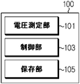
図2を参照してバッテリー状態推定装置100の具体的な構成を説明する。図2は、本発明の一実施形態によるバッテリー状態推定装置を概略的に示したブロック図である。
A specific configuration of the battery
図2を参照すると、バッテリー状態推定装置100は、電圧測定部101及び制御部103を含むことができる。電圧測定部101は、バッテリーモジュール10に含まれたバッテリーセル11の電圧を測定することができる。すなわち、電圧測定部101は、バッテリーモジュール10に含まれたそれぞれのバッテリーセル11の電圧を測定するように構成され得る。
Referring to FIG. 2, the battery
例えば、図1に示された実施形態において、バッテリー状態推定装置100は、バッテリーモジュール10に含まれた第1バッテリーセルC1、第2バッテリーセルC2、第3バッテリーセルC3及び第4バッテリーセルC4が放電するときの電圧をそれぞれ測定し得る。具体的には、電圧測定部101は、第1センシングラインSL1及び第2センシングラインSL2を通じて第1バッテリーセルC1の電圧を測定し、第2センシングラインSL2及び第3センシングラインSL3を通じて第2バッテリーセルC2の電圧を測定し得る。また、電圧測定部101は、第3センシングラインSL3及び第4センシングラインSL4を通じて第3バッテリーセルC3の電圧を測定し、第4センシングラインSL4及び第5センシングラインSL5を通じて第4バッテリーセルC4の電圧を測定し得る。
For example, in the embodiment shown in FIG. 1, the battery
電圧測定部101は、バッテリーセル11の開放回路電圧(OCV)を測定することができる。すなわち、電圧測定部101は、バッテリーセル11の電圧及び開放回路電圧を何れも測定することができる。特に、電圧測定部101は、測定した電圧が基準放電電圧に到達する度に各バッテリーセル11の開放回路電圧を測定することができる。ここで、基準放電電圧は、電圧測定部101が開放回路電圧を測定できるようにユーザなどによって予め設定されて保存された電圧であり得る。すなわち、基準放電電圧は、電圧測定部101によってバッテリーセル11の開放回路電圧を測定するための参照値であって、電圧測定部101がバッテリーセル11の開放回路電圧を測定する時点を提供し得る。例えば、所定の電圧は2.8Vに設定され得る。電圧測定部101は、複数のバッテリーセル11の電圧を測定し、各バッテリーセル11の測定された電圧が所定の電圧に到達する度に該当バッテリーセル11の開放回路電圧を測定することができる。
The voltage measuring unit 101 can measure the open circuit voltage (OCV) of the
例えば、図1に示された実施形態において、バッテリーセル11のそれぞれに対して、基準放電電圧がV1[V]に設定されていると仮定する。このとき、電圧測定部101は、放電によって第1バッテリーセルC1の電圧がV1[V]に到達すれば、第1バッテリーセルC1の開放回路電圧を測定し得る。同様に、電圧測定部101は、第2バッテリーセルC2、第3バッテリーセルC3及び第4バッテリーセルC4のうち少なくとも一つの電圧がV1[V]に到達すれば、電圧がV1[V]に到達したバッテリーセル11の開放回路電圧を測定し得る。
For example, in the embodiment shown in FIG. 1, it is assumed that the reference discharge voltage is set to V1 [V] for each of the
制御部103は、電圧測定部101によって測定された開放回路電圧を受信することができる。制御部103は、バッテリー状態推定装置100の内部で電圧測定部101と電気的信号を送受信できるように構成され、電圧測定部101から測定された開放回路電圧を受信することができる。
The
制御部103は、電圧測定部101から受信した開放回路電圧を予め保存された基準電圧と比較して電圧変動率(voltage fluctuation rate)を算出することができる。ここで、予め保存された基準電圧は、電圧測定部101によって測定された開放回路電圧との比較のための参照値であって、予め保存された値であり得る。例えば、予め保存された基準電圧は、所定のサイクル時点で測定されたバッテリーセル11の開放回路電圧を含み得る。電圧変動率は、予め保存された基準電圧と制御部103が電圧測定部101から受信した開放回路電圧とを比べて得られる。特に、電圧変動率は、予め保存された基準電圧と開放回路電圧の測定値との比率または差として算出され得る。すなわち、制御部103は、所定のサイクル時点以後のサイクルで電圧測定部101から測定された開放回路電圧を受信し、予め保存された基準電圧に対する受信した開放回路電圧の比率を電圧変動率として算出し得る。
The
例えば、第1バッテリーセルC1に対して予め保存された基準電圧をA1[V]と仮定する。また、電圧測定部101が第1時点で測定した第1バッテリーセルC1の開放回路電圧をB1[V]と仮定する。制御部103は、第1バッテリーセルC1の第1時点の電圧変動率を、A1に対するB1の比率として算出し得る。例えば、第1バッテリーセルC1の第1時点の電圧変動率は、「(B1÷A1)×100」の計算式によって算出され得る。
For example, it is assumed that the reference voltage stored in advance for the first battery cell C1 is A1 [V]. Further, it is assumed that the open circuit voltage of the first battery cell C1 measured by the voltage measuring unit 101 at the first time point is B1 [V]. The
制御部103は、算出した電圧変動率及び予め保存された電圧変動率データに基づいて電圧増減パターンを決定することができる。ここで、電圧変動率データは、算出された電圧変動率との比較のための参照データであって、予め保存され得る。制御部103は、算出した電圧変動率を予め保存された電圧変動率データに追加して、予め保存された電圧変動率データを更新することができる。そして、制御部103は、更新された電圧変動率データに基づいて電圧増減パターンを決定することができる。
The
例えば、予め保存された電圧変動率データは、制御部103によって過去算出された電圧変動率が保存されたデータであり得る。この場合、制御部103は、基準電圧が算出されたサイクル時点の以後に算出されたすべての電圧変動率に基づいてバッテリーセル11の電圧増減パターンを決定し得る。電圧増減パターンは、電圧増加パターン、電圧減少パターンまたは電圧一定パターンなどの多様なパターンを含み得る。以下では説明の便宜上、電圧増減パターンには電圧増加パターン及び電圧減少パターンが含まれ、電圧増加パターンには電圧減少パターンを除いた電圧一定パターンなどのパターンが含まれるとする。
For example, the voltage fluctuation rate data stored in advance may be data in which the voltage fluctuation rate calculated in the past by the
また、制御部103は、決定した電圧増減パターンに応じてバッテリーセル11の退化加速程度を判断するように構成され得る。ここで、退化加速程度とは、バッテリーセル11の退化が次第に速まっているか、それとも、次第に遅くなっているかなどを示す情報であり得る。すなわち、制御部103は、バッテリーセル11に対する電圧増減パターンを決定し、決定された電圧増減パターンに基づいてバッテリーセル11の退化加速程度を判断することができる。
Further, the
例えば、制御部103は、第1バッテリーセルC1の電圧増減パターンを決定し、決定された電圧増減パターンに応じて第1バッテリーセルC1の退化加速程度を判断し得る。
For example, the
本発明の一実施形態によるバッテリー状態推定装置100は、バッテリーセル11の現在状態に基づいた退化度の判断だけでなく、過去の履歴を総合して現在のバッテリーセル11が退化している速度を判断することができる。したがって、本発明の一実施形態によるバッテリー状態推定装置100は、未来時点におけるバッテリーセル11の状態を推定可能な情報を提供することで、バッテリーセル11の寿命予測または未来状態の判断に役に立つ情報を提供することができる。
The battery
特に、制御部103は、バッテリーセル11のそれぞれに対して退化加速程度を独立的に判断することができる。例えば、制御部103は、第1バッテリーセルC1、第2バッテリーセルC2、第3バッテリーセルC3及び第4バッテリーセルC4のそれぞれに対して別々に電圧増減パターンを決定し得る。そして、制御部103は、決定された電圧増減パターンに応じて第1バッテリーセルC1、第2バッテリーセルC2、第3バッテリーセルC3及び第4バッテリーセルC4のそれぞれに対して別々に退化加速程度を判断し得る。
In particular, the
すなわち、本発明の一実施形態によるバッテリー状態推定装置100は、それぞれのバッテリーセル11の退化加速程度を独立的に判断可能であるため、それぞれのバッテリーセル11の退化度及び退化加速程度を判断し、ひいてはそれぞれのバッテリーセル11の寿命を予測することができる。具体的には、バッテリー状態推定装置100は、それぞれのバッテリーセル11の開放回路電圧を測定することで損失容量を算出し、それぞれのバッテリーセル11の退化程度を算出できるだけでなく、それぞれのバッテリーセル11がどれくらい速く退化しているかについての退化加速程度を判断することができる。したがって、バッテリー状態推定装置100は、バッテリーセル11の退化加速程度に基づいてそれぞれのバッテリーセル11の今後の退化程度を推定でき、推定された退化程度に応じてそれぞれのバッテリーセル11の制御条件を調整及び設定することができる。
That is, since the battery
例えば、同じ製品ラインのバッテリーセル11であっても、初期抵抗または容量のバラツキなどの問題のため、全く同じ可用容量を有さないこともある。例えば、出荷時バッテリーセルの設定容量は1000mAhであるが、第1バッテリーセルC1の初期容量が900mAh、第2バッテリーセルC2の初期容量が1000mAhの状態で出荷されたと仮定する。同一期間の使用によって第1バッテリーセルC1及び第2バッテリーセルC2の現在可用容量が800mAhに等しくなった場合、第1バッテリーセルC1と第2バッテリーセルC2とは同じ可用容量を有するが、初期容量の差のため、二つのバッテリーセル11の退化度が同一であると判断することはバッテリーセル11の正確な状態推定であると言えない。また、第1バッテリーセルC1の退化度が約11%、第2バッテリーセルC2の退化度が20%に算出されたとしても、このように算出された退化度は初期容量対比現在容量による第1バッテリーセルC1及び第2バッテリーセルC2それぞれの現在状態のみを示す指標として意味があるだけで、現在の第1バッテリーセルC1及び第2バッテリーセルC2の退化加速程度または退化加速程度に基づいた予想寿命などの未来状況に係る予測指標としては適さない。すなわち、バッテリーセル11の初期容量などに対する現在容量の比率は、バッテリーセル11の退化程度を事後的に判断する指標に過ぎず、バッテリーセル11の退化加速程度、今後の退化程度または予想寿命などを判断する指標として使用するには適さないという問題がある。
For example, even
一方、本発明の一実施形態によるバッテリー状態推定装置100は、現在のバッテリーセル11の開放回路電圧を測定し、退化加速程度を判断することで、バッテリーセル11の現在状態を正確に判断することができる。また、バッテリー状態推定装置100は、バッテリーセル11の退化加速程度を判断し、バッテリーセル11の寿命がより長く持続されるようにバッテリーセル11の制御条件を変更するなどの措置を講じることができる。
On the other hand, the battery
ここで、制御部103は、本発明の一実施形態によるバッテリー状態推定装置100で行われる多様な制御ロジックを実行するため、当業界で知られたプロセッサ、ASIC(application-specific integrated circuit)、他のチップセット、論理回路、レジスタ、通信モデム、データ処理装置などを選択的に含むことができる。また、制御ロジックがソフトウェアとして具現されるとき、制御部103はプログラムモジュールの集合として具現され得る。このとき、プログラムモジュールはメモリに保存され、プロセッサによって実行され得る。メモリは、プロセッサの内部または外部に位置し得、周知の多様な手段でプロセッサと接続され得る。例えば、制御部103は、本発明の一実施形態によるバッテリー状態推定装置100に備えられたプロセッサであって、判断したバッテリーセル11の退化加速程度をディスプレイ装置などの出力装置を通じてユーザに提供し得る。また、制御部103は、バッテリーセル11の退化加速程度に基づいて、外部通知装置を通じてユーザにバッテリーセル11の交替または警告通知も提供し得る。
Here, the
また、図2を参照すると、本発明の一実施形態によるバッテリー状態推定装置100は、保存部105をさらに含むことができる。保存部105は基準電圧を保存することができる。すなわち、保存部105には基準電圧が予め保存されており、制御部103は保存部105に予め保存された基準電圧と電圧測定部101から受信した開放回路電圧とを比べて電圧変動率を算出することができる。また、保存部105は電圧変動率データを保存することができる。すなわち、保存部105には制御部103で算出された電圧変動率データが保存されており、制御部103は保存部105に予め保存された電圧変動率データに基づいてバッテリーセル11の電圧増減パターンを決定することができる。
Further, referring to FIG. 2, the battery
すなわち、保存部105は、電圧測定部101で測定した基準電圧及び制御部103で算出した過去の電圧変動率データなど、本発明の一実施形態によるバッテリー状態推定装置100の各構成要素が動作及び機能を実行するのに必要なデータやプログラムなどを保存することができる。保存部105は、データを記録、消去、更新及び読出できると知られた公知の情報記録手段であれば、その種類に特に制限がない。一例として、情報記録手段にはRAM、フラッシュメモリ、ROM、EEPROM、レジスタなどが含まれ得る。保存部105は、制御部103によって実行可能なプロセスが定義されたプログラムコードを保存することができる。
That is, in the
望ましくは、予め保存された基準電圧は、所定のサイクル時点でバッテリーセル11が放電してバッテリーセル11の電圧が基準放電電圧に到達したときの開放回路電圧を含むことができる。ここで、所定のサイクル時点は、BOL(Beginning of Life)から所定のサイクル数以内の時点であって、例えば、バッテリーセル11の出荷後一回目の放電時点であり得る。
Desirably, the pre-stored reference voltage can include an open circuit voltage when the
例えば、基準放電電圧が2.8Vに設定されたと仮定する。この場合、電圧測定部101は、第1バッテリーセルC1の最初放電過程(初期状態)における電圧を測定し、測定した電圧が2.8Vに到達したときの開放回路電圧を測定し得る。 For example, assume that the reference discharge voltage is set to 2.8V. In this case, the voltage measuring unit 101 can measure the voltage in the initial discharge process (initial state) of the first battery cell C1 and measure the open circuit voltage when the measured voltage reaches 2.8 V.
望ましくは、予め保存された電圧変動率データは、電圧測定部101によって開放回路電圧が測定される度に制御部103によって算出された電圧変動率を含むように構成され得る。すなわち、所定のサイクル時点以後から現在時点以前までにおいて、電圧測定部101は放電によってバッテリーセル11の電圧が基準放電電圧に到達すれば開放回路電圧を測定し、制御部103は電圧測定部101で測定された開放回路電圧に基づいて電圧変動率を算出し得る。そして、算出された電圧変動率は、保存部105に予め保存された電圧変動率データに含まれ得る。
Desirably, the pre-stored voltage volatility data may be configured to include the voltage volatility calculated by the
例えば、図1に示された実施形態において、第1バッテリーセルC1に対して予め保存された電圧変動率データには第1時点~第N-1時点で算出された第1バッテリーセルC1の電圧変動率が含まれ得る。ここで、Nは2以上の整数であって、Nが2であると、予め保存された電圧変動率データには第1時点で算出された第1バッテリーセルC1の電圧変動率のみが含まれ得る。制御部103によって第N時点で第1バッテリーセルC1の電圧変動率が算出された場合、第N時点で算出された第1バッテリーセルC1の電圧変動率は保存部105に予め保存された電圧変動率データに含まれ得る。この場合、保存部105に予め保存された電圧変動率データには第1~第N電圧変動率が含まれ得る。
For example, in the embodiment shown in FIG. 1, the voltage fluctuation rate data stored in advance for the first battery cell C1 includes the voltage of the first battery cell C1 calculated at the first to N-1 time points. Volatility may be included. Here, when N is an integer of 2 or more and N is 2, the voltage fluctuation rate data stored in advance includes only the voltage fluctuation rate of the first battery cell C1 calculated at the first time point. obtain. When the voltage fluctuation rate of the first battery cell C1 is calculated by the
本発明の一実施形態によるバッテリー状態推定装置100は、保存部105に過去時点から現在時点まで予め保存された電圧変動率データに基づいて現在のバッテリーセル11の電圧増減パターンを決定することができる。すなわち、本発明の一実施形態によるバッテリー状態推定装置100は、算出された電圧変動率を累積保存した予め保存された電圧変動率データに基づいて現在のバッテリーセル11の電圧増減パターン及び退化加速程度を判断するため、特定時点での電圧変動率のみでバッテリーセル11の退化度を判断する場合よりも、バッテリーセル11の退化加速程度及び退化度などをより正確に判断することができる。また、このように判断された退化加速程度及び退化度は、バッテリーセル11の未来状態を推定するための情報として活用できるため、本発明の一実施形態によるバッテリー状態推定装置100は、バッテリーセル11の過去及び現在の状態だけでなく、退化加速程度に基づいて未来の状態を推定可能な情報を提供することができる。
The battery
制御部103は、予め保存された電圧変動率データのうちバッテリーセル11の現在サイクルから所定のサイクル数以内に含まれた複数の電圧変動率の電圧変化率(rate of voltage change)を算出することができる。ここで、電圧変化率は、電圧変動率間の平均変化率(average rate of change)または瞬間変化率(instantaneous rate of change)を含むことができる。そして、現在サイクルから所定のサイクル数以内に含まれた複数の電圧変動率は、現在サイクルから予め設定されたサイクル数以内に含まれた複数の電圧変動率を含むことができる。例えば、制御部103は、現在サイクルから50サイクル以内に含まれた複数の電圧変動率の電圧変化率を算出し得る。図3及び図4を参照して電圧変化率の算出について具体的に説明する。
The
図3は、本発明の一実施形態によるバッテリー状態推定装置100によって算出された第1バッテリーセルC1の電圧変動率を示した図である。図4は、本発明の一実施形態によるバッテリー状態推定装置100によって算出された第2バッテリーセルC2の電圧変動率を示した図である。図3及び図4を参照すると、保存部105は、サイクル毎に第1バッテリーセルC1に対して予め保存された電圧変動率データ及び第2バッテリーセルC2に対して予め保存された電圧変動率データをそれぞれ保存することができる。以下、図3に示されたように、第1バッテリーセルC1に対して予め設定されたサイクル数を含む区間をIn区間として説明する。同様に、図4に示されたように、第2バッテリーセルC2に対して予め設定されたサイクル数を含む区間をJn区間として説明する。ここで、nは正の整数である。例えば、予め設定されたサイクル数が50である場合、I1区間には第1バッテリーセルC1の0~50サイクルが含まれ、I2区間には第1バッテリーセルC1の51~100サイクルが含まれ得る。説明の便宜のため、第1バッテリーセルC1の0サイクルはI1に含まれ、第2バッテリーセルC2の0サイクルはJ1区間に含まれたとして説明する。
FIG. 3 is a diagram showing the voltage fluctuation rate of the first battery cell C1 calculated by the battery
例えば、一区間に含まれるように予め設定されたサイクル数が50であると仮定する。図3において、第1バッテリーセルC1の現在サイクルが300サイクルであれば、制御部103は保存部105に第1バッテリーセルC1に対して予め保存されている電圧変動率データのうち251~300サイクルを含むI6区間に属したそれぞれのサイクルの電圧変動率を抽出する。すなわち、制御部103は、第1バッテリーセルC1のI6区間に属したそれぞれのサイクルの電圧変動率を互いに比べ、I6区間の電圧変化率を算出することができる。同様に、図4において、第2バッテリーセルC2の現在サイクルが150サイクルであれば、制御部103は保存部105に第2バッテリーセルC2に対して予め保存されている電圧変動率データのうち101~150サイクルを含むJ3区間に属したそれぞれのサイクルの電圧変動率を抽出する。制御部103は、第2バッテリーセルC2のJ3区間に属したそれぞれのサイクルの電圧変動率を互いに比べ、J3区間の電圧変化率を算出することができる。ここで、電圧変化率とは、変化率に対する特定の数値を意味する。
For example, it is assumed that the number of cycles preset to be included in one section is 50. In FIG. 3, if the current cycle of the first battery cell C1 is 300 cycles, the
以下、説明の便宜上、電圧変化率が0以上であれば正の変化率、電圧変化率が0未満であれば負の変化率であると説明する。また、図5を参照して制御部103が電圧変化率を算出する例を具体的に説明する。
Hereinafter, for convenience of explanation, a positive rate of change is described when the voltage change rate is 0 or more, and a negative rate of change is described when the voltage change rate is less than 0. Further, an example in which the
図5は、本発明の一実施形態によるバッテリー状態推定装置によって算出された第2バッテリーセルの電圧変動率のうち一区間を拡大して示した図である。すなわち、図5は、第2バッテリーセルC2に対して算出された電圧変動率のうちJ3区間に含まれた電圧変動率を拡大して示した図である。 FIG. 5 is an enlarged view showing one section of the voltage fluctuation rate of the second battery cell calculated by the battery state estimation device according to the embodiment of the present invention. That is, FIG. 5 is an enlarged view showing the voltage fluctuation rate included in the J3 section among the voltage fluctuation rates calculated for the second battery cell C2.
図5の実施形態を参照すると、制御部103は、バッテリーセル11の現在サイクルが属した区間に含まれた電圧変動率の電圧変化率を算出することができる。このとき、制御部103は、バッテリーセル11の現在サイクルが属した区間の電圧変化率に基づいて、バッテリーセル11の現在サイクルが属した区間を複数のサブ区間に区分することができる。具体的には、制御部103は、一区間内で算出した電圧変化率が正の変化率から負の変化率に、または、負の変化率から正の変化率に変わるサイクル地点を基準にして一つの区間を複数のサブ区間に区分することができる。例えば、図5の例において、制御部103は、J3区間に含まれた連続するサイクルに対する平均変化率またはJ3区間に含まれた連続するサイクルに対する瞬間変化率を算出し得る。具体的には、130サイクルを基準にして、J31区間の電圧変化率は正の変化率で算出され、J32の電圧変化率は負の変化率で算出され得る。したがって、制御部103は、130サイクルを基準にして第2バッテリーセルC2のJ3区間をJ31区間とJ32区間とに区分できる。
Referring to the embodiment of FIG. 5, the
すなわち、図5の実施形態において、制御部103は、J3区間をJ31とJ32区間とに区分し、J31区間及びJ32区間のそれぞれに対して電圧変化率を算出することができる。このように、制御部103は、一つの区間をサブ区間に分け、サブ区間毎に電圧変化率を算出することができる。
That is, in the embodiment of FIG. 5, the
制御部103は、バッテリーセル11の現在サイクルが属した区間に含まれた電圧変動率間の変化率を算出するとき、現在サイクルが属した区間を一つのみにして変化率を算出しないこともあり得る。そして、制御部103は、正から負に又は負から正に電圧変化率が変わるサイクル時点を判断し、判断したサイクル時点を基準にしてバッテリーセル11の現在サイクルが属した区間をサブ区間に区分することができる。
When the
このように、本発明の一実施形態によるバッテリー状態推定装置100は、バッテリーセル11の現在サイクルが属した区間を一律に一つの区間として判断することなく、場合によってサブ区間に分けて電圧変化率をより細かく算出するため、バッテリーセル11の現在状態をより正確に判断することができる。
As described above, the battery
また、制御部103は、算出した電圧変化率に基づいて電圧増減パターンを決定することができる。ここで、電圧増減パターンは、電圧増加パターン及び電圧減少パターンを含むことができる。特に、制御部103は、算出した変化率が正の変化率である場合に対する電圧増減パターンを電圧増加パターンと決定することができる。また、制御部103は、算出した変化率が負の変化率である場合に対する電圧増減パターンを電圧減少パターンと決定することができる。
Further, the
例えば、図3を参照すると、第1バッテリーセルC1の現在サイクルがI1区間に属する場合、制御部103は、I1区間に含まれた電圧変動率に基づいて第1バッテリーセルC1の電圧変化率を算出する。この場合、制御部103はI1区間の電圧変化率を0未満の値で算出し得る。すなわち、I1区間の電圧変化率が負の変化率で算出され得る。そして、制御部103は、このように電圧変化率が負の変化率で算出された結果に基づいて現在の第1バッテリーセルC1の電圧増減パターンを電圧減少パターンと決定し得る。また、第1バッテリーセルC1の現在サイクルがI2~I6のいずれか一つに属する場合、制御部103は、該当区間に含まれた電圧変動率に基づいて正の変化率を算出する。そして、制御部103は、算出した正の変化率に基づいて現在の第1バッテリーセルC1の電圧増減パターンを電圧増加パターンと決定し得る。
For example, referring to FIG. 3, when the current cycle of the first battery cell C1 belongs to the I1 section, the
例えば、図4を参照すると、第2バッテリーセルC2の現在サイクルがJ2区間に属する場合、制御部103は、J2区間に含まれた電圧変動率に基づいて電圧変化率を算出する。このとき、制御部103はJ2区間の電圧変化率を0以上の値で算出し得る。すなわち、J2区間の電圧変化率が正の変化率で算出され得る。そして、制御部103は、算出したJ2区間の電圧変化率に基づいて現在の第2バッテリーセルC2の電圧増減パターンを電圧増加パターンと決定し得る。
For example, referring to FIG. 4, when the current cycle of the second battery cell C2 belongs to the J2 section, the
もし、第2バッテリーセルC2の現在サイクルがJ3区間に属する場合、図5に示されたように、制御部103は、J3区間をJ31区間とJ32区間とに分け、J31区間及びJ32区間それぞれの電圧変化率を算出し得る。制御部103は、J31区間の電圧変化率は0以上の値で算出し、J32区間の電圧変化率は0未満の値で算出し得る。すなわち、J31区間の電圧変化率は正の変化率で算出され、J32区間の電圧変化率は負の変化率で算出され得る。そして、制御部103は、算出した電圧変化率に基づいて、J31区間の電圧増減パターンを電圧増加パターンと決定し、J32区間の電圧増減パターンを電圧減少パターンと決定し得る。
If the current cycle of the second battery cell C2 belongs to the J3 section, as shown in FIG. 5, the
すなわち、本発明の一実施形態によるバッテリー状態推定装置100は、バッテリーセル11の現在状態だけでなく、過去の状態までも考慮してバッテリーセル11の現在状態をより正確に推定することができる。また、本発明の一実施形態によるバッテリー状態推定装置100は、バッテリーセル11の電圧変化率を算出し、電圧変化率に基づいて電圧増減パターンを決定するため、バッテリーセル11の未来状態を推定し易い情報を提供することができる。また、現在サイクルから所定のサイクル数以内であっても、電圧変化率が負から正に又は正から負に変動する区間をサブ区間に分けてバッテリーセル11の電圧増減パターンをより具体的且つ細かく決定することで、バッテリーセル11の現在状態をより正確に推定することができる。
That is, the battery
制御部103は、バッテリーセル11の電圧増減パターンに応じてバッテリーセル11の退化加速程度を、加速退化、線形退化及び減速退化のうちいずれか一つとして判断することができる。ここで、加速退化は、バッテリーセル11の退化が次第に加速化する状態であり、線形退化は、バッテリーセル11の退化が加速退化のように次第に加速化しないが、線形的に一定に進行している状態である。逆に、減速退化は、バッテリーセル11の退化が次第に遅く進行している状態である。以下、電圧増減パターンに応じて退化加速程度を判断する構成について説明する。
The
制御部103は、電圧増減パターンを電圧増加パターンと決定した場合、決定した電圧増加パターンの変化率に基づいてバッテリーセル11の退化加速程度を加速退化または線形退化と判断するように構成され得る。
When the voltage increase / decrease pattern is determined to be the voltage increase pattern, the
例えば、上述したように図3を参照すると、第1バッテリーセルC1の現在サイクルがI2区間に属する場合、制御部103は、第1バッテリーセルC1の電圧増減パターンを電圧増加パターンと決定する。制御部103は、電圧増加パターンと決定されたI2区間の電圧変化率に基づいて第1バッテリーセルC1の現在の退化加速程度を加速退化または線形退化と判断し得る。
For example, referring to FIG. 3 as described above, when the current cycle of the first battery cell C1 belongs to the I2 section, the
同様に、上述したように図4を参照すると、第2バッテリーセルC2の現在サイクルがJ2区間に属する場合、制御部103は、第2バッテリーセルC2の電圧増減パターンを電圧増加パターンと決定する。制御部103は、電圧増加パターンと決定されたJ2区間の電圧変化率に基づいて第2バッテリーセルC2の退化加速程度を加速退化または線形退化と判断し得る。また、制御部103は、電圧増減パターンを電圧減少パターンと決定した場合、バッテリーセル11の退化加速程度を減速退化と判断するように構成され得る。
Similarly, referring to FIG. 4 as described above, when the current cycle of the second battery cell C2 belongs to the J2 section, the
例えば、上述したように図3を参照すると、第1バッテリーセルC1の現在サイクルがI1区間に属する場合、制御部103は、第1バッテリーセルC1の電圧増減パターンを電圧減少パターンと決定する。制御部103は、電圧減少パターンと決定された第1バッテリーセルC1のI1区間の電圧変化率に基づいて第1バッテリーセルC1の退化加速程度を減速退化と判断し得る。
For example, referring to FIG. 3 as described above, when the current cycle of the first battery cell C1 belongs to the I1 section, the
同様に、上述したように図4を参照すると、第2バッテリーセルC2の現在サイクルがJ4区間に属する場合、制御部103は、第2バッテリーセルC2の電圧増減パターンを電圧減少パターンと決定する。制御部103は、電圧減少パターンと決定された第2バッテリーセルC2のJ4区間の電圧変化率に基づいて第2バッテリーセルC2の退化加速程度を減速退化と判断し得る。本発明の一実施形態によるバッテリー状態推定装置100は、バッテリーセル11の電圧増減パターン及び電圧変化率に基づいてバッテリーセル11の退化加速程度を加速退化、線形退化または減速退化に細分化して判断することで、バッテリーセル11の現在状態をより正確に判断及び診断することができる。
Similarly, referring to FIG. 4 as described above, when the current cycle of the second battery cell C2 belongs to the J4 section, the
また、バッテリー状態推定装置100は、電圧増減パターンを電圧減少パターンと決定した場合、バッテリーセル11の退化加速程度を専ら減速退化と判断し、退化加速程度の判断にかかる時間を節減することができる。
Further, when the battery
バッテリーセル11の退化加速程度のうち加速退化及び線形退化は、バッテリーセル11の退化がどれくらい速く進行しているかによって区分可能である。以下、加速退化と線形退化との区分基準について説明する。
Of the degree of degeneration acceleration of the
制御部103は、算出した電圧変化率が既に設定された基準電圧変化率以上である場合、バッテリーセル11の退化加速程度を加速退化と判断するように構成され得る。逆に、制御部103は、算出した電圧変化率が既に設定された基準電圧変化率未満である場合、バッテリーセル11の退化加速程度を線形退化と判断するように構成され得る。ここで、既に設定された基準電圧変化率は、バッテリーセル11の電圧増減パターンが電圧増加パターンと決定された場合、退化加速程度を加速退化または線形退化として決定するための基準変化率である。
When the calculated voltage change rate is equal to or higher than the already set reference voltage change rate, the
例えば、図3及び図4に示された実施形態において、既に設定された基準電圧変化率は50サイクル毎に電圧変動率が1%増加するものとして既に設定され得る。例えば、図3に示された実施形態において、第1バッテリーセルC1の現在サイクルがI2~I6区間のうちいずれか一つに属すれば、制御部103は、第1バッテリーセルC1の現在サイクルが属する区間の電圧変化率を既に設定された基準電圧変化率と比較し得る。I2~I6区間のそれぞれの電圧変化率が既に設定された基準電圧変化率よりも小さいため、制御部103は、第1バッテリーセルC1の退化加速程度を線形退化と判断し得る。
For example, in the embodiments shown in FIGS. 3 and 4, the already set reference voltage volatility can already be set such that the voltage volatility increases by 1% every 50 cycles. For example, in the embodiment shown in FIG. 3, if the current cycle of the first battery cell C1 belongs to any one of the sections I2 to I6, the
同様に、図4に示された実施形態において、第2バッテリーセルC2の現在サイクルがJ1~J3区間のうちいずれか一つに属すれば、制御部103は、第2バッテリーセルC2の現在サイクルが属する区間の電圧変化率を既に設定された基準電圧変化率と比較し得る。望ましくは、図4及び図5を参照すると、第2バッテリーセルC2の現在サイクルがJ1~J31区間のうちいずれか一つに属すれば、制御部103は、第2バッテリーセルC2の現在サイクルが属する区間の電圧変化率を既に設定された基準電圧変化率と比較し得る。
Similarly, in the embodiment shown in FIG. 4, if the current cycle of the second battery cell C2 belongs to any one of the J1 to J3 sections, the
ここで、制御部103は、J1区間の電圧変化率に基づいて、J1区間をJ11区間とJ12区間とに区分し得る。図6は、本発明の一実施形態によるバッテリー状態推定装置によって算出された第2バッテリーセルの電圧変動率のうち他の一区間を拡大して示した図である。すなわち、図6は、第2バッテリーセルC2に対して算出された電圧変動率のうちJ1区間に含まれた電圧変動率を拡大して示した図である。制御部103は、J1区間の電圧変化率を算出する過程において、電圧変化率が急激に変わる地点を基準にしてJ1区間をJ11区間とJ12区間とに区分し得る。すなわち、制御部103は一つの区間を、算出された電圧変化率が既に設定された基準電圧変化率以上であるサブ区間と、算出された電圧変化率が既に設定された基準電圧変化率未満であるサブ区間とに区分し得る。ここで、J11区間の電圧変化率は既に設定された基準電圧変化率より大きく、J12区間の電圧変化率は既に設定された基準電圧変化率より小さいと仮定する。例えば、制御部103は、20サイクルを基準でJ1区間をJ11区間とJ12区間とに区分し得る。すなわち、J11区間及びJ12区間はJ1区間のサブ区間であり得る。
Here, the
例えば、第2バッテリーセルC2の現在サイクルがJ11区間に属すれば、制御部103は、J11区間の電圧変化率を算出し、算出された電圧変化率を既に設定された基準電圧変化率と比べて、第2バッテリーセルC2の退化加速程度を加速退化と判断し得る。逆に、第2バッテリーセルC2の現在サイクルがJ12区間に属すれば、制御部103は、J12区間の電圧変化率を算出し、算出された電圧変化率を既に設定された基準電圧変化率と比べて、第2バッテリーセルC2の退化加速程度を線形退化と判断し得る。
For example, if the current cycle of the second battery cell C2 belongs to the J11 section, the
すなわち、本発明の一実施形態によるバッテリー状態推定装置100は、電圧増加パターンに対する退化加速程度を一律に判断せず、既に設定された基準電圧変化率とバッテリーセル11の現在サイクルが属した区間の電圧変化率とを比べて、退化加速程度を加速退化または線形退化に細分化して判断することができる。したがって、バッテリーセル11の現在状態をより細分化して、具体的に診断することができる。
That is, the battery
制御部103は、バッテリーセル11に対して算出した電圧変動率が既に設定された電圧下限値を超え、且つ、既に設定された電圧上限値未満である場合に限って、バッテリーセル11の電圧増減パターンを決定するように構成され得る。すなわち、制御部103は、バッテリーセル11の電圧変動率が一定範囲以内である場合のみに電圧増減パターンを決定し得る。例えば、バッテリーセル11の電圧変動率が既に設定された電圧上限値以上である場合は、バッテリーセル11の開放回路電圧が基準値以上に増加した場合であって、バッテリーセル11が異常退化して急落危険(sudden drop risk)が存在する場合であり得る。また、バッテリーセル11の電圧変動率が既に設定された電圧下限値以下である場合は、短絡などによってバッテリーセル11の開放回路電圧が基準値以下に減少した場合であって、バッテリーセル11が異常退化した場合であり得る。したがって、制御部103は、バッテリーセル11が異常退化した場合を除いて、バッテリーセル11が正常に退化した場合に対して電圧増減パターンを決定することができる。
The
バッテリーセル11の正常状態または異常状態が事前に区分されないと、異常状態における電圧増減パターンに応じて退化加速程度が判断され、判断された退化加速程度に基づいてバッテリー制御条件が調整されて、バッテリーセル11の状態をさらに悪化させるおそれがある。したがって、本発明の一実施形態によるバッテリー状態推定装置100は、バッテリーセル11の状態を正常状態または異常状態に先に区分した後、バッテリーセル11の状態が正常状態である場合に限って電圧増減パターン及び退化加速程度を判断することで、バッテリーセル11の退化加速程度の判断にかかる時間を短縮し、バッテリーセル11の状態判断の正確度を向上させることができる。
If the normal state or abnormal state of the
制御部103は、バッテリーセル11の退化加速程度をバッテリーセル11の電圧変動率だけではなく、抵抗変動率(Electric resistance fluctuation rate)に基づいて判断することもできる。以下、抵抗変動率に基づいて判断された退化加速程度について具体的に説明する。
The
制御部103は、電圧測定部101によって測定されたバッテリーセル11の開放回路電圧及び予め保存された基準抵抗に基づいて抵抗変動率を算出することができる。具体的には、制御部103は電圧測定部101から測定された開放回路電圧を受信し、受信した開放回路電圧からバッテリーセル11の現在抵抗を算出できる。
The
例えば、制御部103は計算式「(|CCVEoD-OCVEoD|)÷it1」によってバッテリーセル11の現在抵抗を算出し得る。ここで、CCVEoDはバッテリーセル11のOCVEoDを測定した時点からt1時点以後に測定したバッテリーセル11の充電または放電電圧であり、OCVEoDは放電状況でバッテリーセル11の電圧が基準放電電圧に到達したときに測定されたバッテリーセル11の開放回路電圧であり、it1はt1時間にわたって流れた充電または放電電流の量を意味する。
For example, the
予め保存された基準抵抗は、制御部103によって算出されたバッテリーセル11の現在抵抗との比較のための参照値であって、保存部105に予め保存された値であり得る。例えば、予め保存された基準抵抗は、所定のサイクル時点で測定されたバッテリーセル11の抵抗であり得る。制御部103は、予め保存された基準抵抗に対する現在のバッテリーセル11の抵抗の比率または差を抵抗変動率として算出し得る。
The pre-stored reference resistance is a reference value for comparison with the current resistance of the
例えば、図1に示された第1バッテリーセルC1に対して予め保存された基準抵抗をA2[Ω]と仮定する。また、第1時点で電圧測定部101が測定した第1バッテリーセルC1の開放回路電圧に基づいて、制御部103が算出した第1バッテリーセルC1の現在抵抗をB2[Ω]と仮定する。制御部103は、第1バッテリーセルC1の第1時点の抵抗変動率をA2[Ω]に対するB2[Ω]の比率として算出し得る。例えば、第1バッテリーセルC1の第1時点の抵抗変動率は「(B2÷A2)×100」の計算式によって算出され得る。
For example, it is assumed that the reference resistance stored in advance with respect to the first battery cell C1 shown in FIG. 1 is A2 [Ω]. Further, it is assumed that the current resistance of the first battery cell C1 calculated by the
制御部103は、算出した抵抗変動率及び予め保存された抵抗変動率データに基づいて抵抗増減パターンを決定することができる。ここで、予め保存された抵抗変動率データは、算出された抵抗変動率との比較のための参照データであって、保存部105に予め保存され得る。制御部103は、算出した抵抗変動率を予め保存された抵抗変動率データに追加して、予め保存された抵抗変動率データを更新することができる。そして、制御部103は、更新された抵抗変動率データに基づいて抵抗増減パターンを決定することができる。
The
例えば、予め保存された抵抗変動率データは、制御部103によって過去算出された抵抗変動率が保存されたデータであり得る。この場合、制御部103は、基準抵抗が算出された所定のサイクル時点以後に算出されたすべての抵抗変動率に基づいてバッテリーセル11の抵抗増減パターンを決定し得る。抵抗増減パターンは、抵抗増加パターン、抵抗減少パターンまたは抵抗一定パターンなどの多様なパターンを含み得る。以下、説明の便宜上、抵抗増減パターンには抵抗増加パターン及び抵抗減少パターンが含まれ、抵抗増加パターンに抵抗減少パターンを除いた抵抗一定パターンなどのパターンが含まれるとして説明する。
For example, the resistance volatility data stored in advance may be data in which the resistance volatility calculated in the past by the
また、制御部103は、決定した電圧増減パターン及び抵抗増減パターンに応じてバッテリーセル11の退化加速程度を判断するように構成され得る。ここで、退化加速程度は、上述したように、バッテリーセル11の退化が次第に速まっているか、それとも、次第に遅くなっているかなどを示す情報であり得る。すなわち、制御部103は、バッテリーモジュール10に含まれたバッテリーセル11のそれぞれに対する電圧増減パターン及び抵抗増減パターンを決定し、決定された電圧増減パターン及び抵抗増減パターンに基づいてそれぞれのバッテリーセル11の退化加速程度を判断することができる。
Further, the
例えば、図1に示された実施形態において、制御部103は、第1バッテリーセルC1の電圧増減パターン及び抵抗増減パターンを決定し、決定された電圧増減パターン及び抵抗増減パターンに応じて第1バッテリーセルC1の退化加速程度を判断し得る。同様に、制御部103は第2バッテリーセルC2、第3バッテリーセルC3及び第4バッテリーセルC4に対しても電圧増減パターン及び抵抗増減パターンを決定し、決定された電圧増減パターン及び抵抗増減パターンに応じて退化加速程度を判断し得る。
For example, in the embodiment shown in FIG. 1, the
本発明の一実施形態によるバッテリー状態推定装置100は、電圧変動率だけでなく、抵抗変動率にも基づいてバッテリーセル11の退化加速程度を判断することができる。したがって、バッテリー状態推定装置100は、多様な指標を通じてバッテリーセル11の退化加速程度を含む状態を複合的に判断し、バッテリーセル11の状態をより客観的且つ正確に判断することができる。また、本発明の一実施形態によるバッテリー状態推定装置100は、多様な指標を通じてバッテリーセル11の過去、現在及び未来の状態を判断または推定可能な情報を提供できるため、バッテリーセル11をより効果的に管理可能な情報を提供することができる。
The battery
特に、制御部103は、バッテリーセル11のそれぞれに対して退化加速程度を独立的に判断することができる。
In particular, the
例えば、図1に示された実施形態において、制御部103は、第1バッテリーセルC1、第2バッテリーセルC2、第3バッテリーセルC3及び第4バッテリーセルC4に対してそれぞれ別々に電圧増減パターン及び抵抗増減パターンを決定し得る。そして、制御部103は、決定された電圧増減パターン及び抵抗増減パターンに応じて第1バッテリーセルC1、第2バッテリーセルC2、第3バッテリーセルC3及び第4バッテリーセルC4のそれぞれに対して別々に退化加速程度を判断し得る。
For example, in the embodiment shown in FIG. 1, the
すなわち、本発明の一実施形態によるバッテリー状態推定装置100は、それぞれのバッテリーセル11の退化加速程度を独立的に判断できるため、バッテリーセル11の退化加速程度に基づいてそれぞれのバッテリーセル11の今後の退化程度を推定でき、推定された退化程度に応じてそれぞれのバッテリーセル11の制御条件を調整することができる。
That is, since the battery
望ましくは、予め保存された基準抵抗は、保存部105に予め保存された基準電圧に基づいて算出された基準抵抗を含むことができる。すなわち、予め保存された基準抵抗は予め保存された基準電圧に対応するものであって、所定のサイクル時点でバッテリーセル11が放電してバッテリーセル11の電圧が基準放電電圧に到達したときの開放回路電圧に基づいて算出された抵抗であり得る。予め保存された基準抵抗は保存部105に保存され得る。
Desirably, the pre-stored reference resistance can include a reference resistance calculated based on the pre-stored reference voltage in the
例えば、保存部105には基準電圧A1[V]が予め保存され、基準電圧A1[V]に基づいて算出された基準抵抗A2[Ω]が予め保存され得る。
For example, the reference voltage A1 [V] can be stored in advance in the
望ましくは、予め保存された抵抗変動率データは、電圧測定部101によって開放回路電圧が測定される度に制御部103によって算出された抵抗変動率を含むように構成され得る。すなわち、所定のサイクル時点以後から現在以前までにおいて、電圧測定部101は放電によってバッテリーセル11の電圧が基準放電電圧に到達すれば開放回路電圧を測定し得る。そして、制御部103は、電圧測定部101によって測定された開放回路電圧に基づいて現在抵抗を算出し、算出した現在抵抗と保存部105に予め保存された基準抵抗に基づいてバッテリーセル11の抵抗変動率を算出し得る。そして、算出された抵抗変動率は、保存部105に予め保存された抵抗変動率データに含まれ得る。
Desirably, the pre-stored resistance volatility data may be configured to include the resistance volatility calculated by the
例えば、図1に示された実施形態において、第1バッテリーセルC1に対して予め保存された抵抗変動率データには第1時点~第N-1時点で算出された第1バッテリーセルC1の抵抗変動率が含まれ得る。ここで、Nは2以上の整数であって、Nが2であると、予め保存された抵抗変動率データには第1時点で算出された第1バッテリーセルC1の抵抗変動率のみが含まれ得る。制御部103によって第N時点で第1バッテリーセルC1の抵抗変動率が算出された場合、第N時点で算出された第1バッテリーセルC1の抵抗変動率は保存部105に予め保存された抵抗変動率データに含まれ得る。この場合、保存部105に予め保存された抵抗変動率データには第1~第N抵抗変動率が含まれ得る。
For example, in the embodiment shown in FIG. 1, the resistance fluctuation rate data stored in advance with respect to the first battery cell C1 includes the resistance of the first battery cell C1 calculated at the first to N-1 time points. Volatility can be included. Here, when N is an integer of 2 or more and N is 2, the resistance fluctuation rate data stored in advance includes only the resistance fluctuation rate of the first battery cell C1 calculated at the first time point. obtain. When the resistance fluctuation rate of the first battery cell C1 is calculated by the
本発明の一実施形態によるバッテリー状態推定装置100は、保存部105に過去時点から現在時点まで予め保存された抵抗変動率データに基づいて現在のバッテリーセル11の抵抗増減パターンを決定することができる。すなわち、本発明の一実施形態によるバッテリー状態推定装置100は、過去算出された抵抗変動率を累積保存した予め保存された抵抗変動率データに基づいて現在バッテリーセル11の抵抗増減パターンを決定することができる。そして、バッテリー状態推定装置100は、決定した抵抗増減パターン及び電圧増減パターンに基づいて現在バッテリーセル11の退化加速程度を判断するため、特定時点での抵抗変動率のみでバッテリーセル11の退化度を判断する場合よりも、バッテリーセル11の退化加速程度または退化度などをより正確に判断することができる。
The battery
また、このように判断された退化加速程度及び退化度は、バッテリーセル11の未来状態を推定するための情報として活用できるため、本発明の一実施形態によるバッテリー状態推定装置100は、バッテリーセル11の過去及び現在の状態だけでなく、退化加速程度に基づいて未来の状態を推定可能な情報を提供することができる。
Further, since the degree of degeneration acceleration and the degree of degeneration determined in this way can be utilized as information for estimating the future state of the
制御部103は、予め保存された抵抗変動率データのうちバッテリーセル11の現在サイクルから所定のサイクル数以内に含まれた複数の抵抗変動率の抵抗変化率を算出することができる。ここで、抵抗変化率は、抵抗変動率間の平均変化率または瞬間変化率を含むことができる。そして、現在サイクルから所定のサイクル数以内に含まれた複数の抵抗変動率は、現在サイクルから予め設定されたサイクル数以内に含まれた複数の抵抗変動率を含むことができる。例えば、制御部103は、現在サイクルから50サイクル以内に含まれた複数の抵抗変動率の抵抗変化率を算出し得る。図7及び図8を参照して抵抗変化率の算出について具体的に説明する。
The
図7は、本発明の一実施形態によるバッテリー状態推定装置によって算出された第1バッテリーセルの抵抗変動率を示した図である。図8は、本発明の一実施形態によるバッテリー状態推定装置によって算出された第2バッテリーセルの抵抗変動率を示した図である。図7及び8を参照すると、保存部105は、サイクル毎に第1バッテリーセルC1に対して予め保存された抵抗変動率データ及び第2バッテリーセルC2に対して予め保存された抵抗変動率データをそれぞれ保存することができる。以下、図7に示されたように、第1バッテリーセルC1に対して予め設定されたサイクル数を含む区間をIn区間として説明する。同様に、図8に示されたように、第2バッテリーセルC2に対して予め設定されたサイクル数を含む区間をJn区間として説明する。ここで、図7に示されたIn区間は図3に示されたIn区間に対応し、図8に示されたJn区間は図4に示されたJn区間に対応し得る。
FIG. 7 is a diagram showing the resistance fluctuation rate of the first battery cell calculated by the battery state estimation device according to the embodiment of the present invention. FIG. 8 is a diagram showing the resistance fluctuation rate of the second battery cell calculated by the battery state estimation device according to the embodiment of the present invention. Referring to FIGS. 7 and 8, the
例えば、一区間に含まれるように予め設定されたサイクル数が50であると仮定する。図7において、第1バッテリーセルC1の現在サイクルが300サイクルであれば、制御部103は保存部105に第1バッテリーセルC1に対して予め保存されている抵抗変動率データのうち251~300サイクルを含むI6区間に属したそれぞれのサイクルの抵抗変動率を抽出する。すなわち、制御部103は、第1バッテリーセルC1のI6区間に属したそれぞれのサイクルの抵抗変動率を互いに比べ、I6区間の抵抗変化率を算出することができる。
For example, it is assumed that the number of cycles preset to be included in one section is 50. In FIG. 7, if the current cycle of the first battery cell C1 is 300 cycles, the
同様に、図8において、第2バッテリーセルC2の現在サイクルが150サイクルであれば、制御部103は保存部105に第2バッテリーセルC2に対して予め保存されている抵抗変動率データのうち101~150サイクルを含むJ3区間に属した抵抗変動率を抽出する。制御部103は、第2バッテリーセルC2のJ3区間に属したそれぞれのサイクルの抵抗変動率を互いに比べ、J3区間の抵抗変化率を算出することができる。ここで、抵抗変化率とは、変化率に対する特定の数値を意味する。
Similarly, in FIG. 8, if the current cycle of the second battery cell C2 is 150 cycles, the
以下、説明の便宜上、抵抗変化率が0以上であれば正の変化率、抵抗変化率が0未満であれば負の変化率であると説明する。 Hereinafter, for convenience of explanation, a positive rate of change is described when the resistance change rate is 0 or more, and a negative rate of change is described when the resistance change rate is less than 0.
制御部103は、図5を参照して上述した電圧変化率算出の例示と同様に、バッテリーセル11の現在サイクルが属した区間に含まれた抵抗変動率間の変化率を算出するとき、現在サイクルが属した区間を一つのみにして抵抗変化率を算出しないこともあり得る。そして、制御部103は、正から負に又は負から正に抵抗変化率が変わるサイクル時点を判断し、判断したサイクル時点を基準にしてバッテリーセル11の現在サイクルが属した区間をサブ区間に区分することができる。すなわち、制御部103は、一区間に属した抵抗変動率の抵抗変化率に基づいて一区間を複数のサブ区間に区分し、区分したサブ区間それぞれに対する抵抗変化率を算出することができる。
When the
このように、本発明の一実施形態によるバッテリー状態推定装置100は、バッテリーセル11の現在サイクルが属した区間を一律に一つの区間として判断することなく、場合によってサブ区間に分けて抵抗変化率をより細かく算出するため、バッテリーセル11の現在状態をより正確に判断することができる。
As described above, the battery
また、制御部103は、算出した抵抗変化率に基づいて抵抗増減パターンを決定することができる。ここで、抵抗増減パターンは、抵抗増加パターン及び抵抗減少パターンを含むことができる。特に、制御部103は、算出した変化率が正の変化率である場合に対する抵抗増減パターンを抵抗増加パターンと決定することができる。また、制御部103は、算出した変化率が負の変化率である場合に対する抵抗増減パターンを抵抗減少パターンと決定することができる。
Further, the
例えば、図7を参照すると、第1バッテリーセルC1の現在サイクルがI1区間に属する場合、制御部103は、I1区間に含まれた抵抗変動率に基づいて第1バッテリーセルC1の抵抗変化率を算出する。この場合、制御部103はI1区間の抵抗変化率を0以上の値で算出し得る。すなわち、I1区間の抵抗変化率が正の変化率で算出され得る。そして、制御部103は、このように抵抗変化率が正の変化率で算出された結果に基づいて現在の第1バッテリーセルC1の抵抗増減パターンを抵抗増加パターンと決定し得る。同様に、第1バッテリーセルC1の現在サイクルがI2~I6のいずれか一つに属する場合にも、制御部103は、該当区間に含まれた抵抗変動率に基づいて抵抗変化率を正の変化率で算出する。そして、制御部103は、正の変化率で算出された結果に基づいて現在の第1バッテリーセルC1の抵抗増減パターンを抵抗増加パターンと決定し得る。
For example, referring to FIG. 7, when the current cycle of the first battery cell C1 belongs to the I1 section, the
他の例として、図8を参照すると、第2バッテリーセルC2の現在サイクルがJ1区間に属する場合、制御部103は、J1区間に含まれたサイクルそれぞれの抵抗変動率に基づいてJ1区間の抵抗変化率を算出する。このとき、制御部103はJ1区間の抵抗変化率を0以上の値で算出し得る。すなわち、J1区間の抵抗変化率が正の変化率で算出され得る。そして、制御部103は、算出したJ1区間の抵抗変化率に基づいて現在の第2バッテリーセルC2の抵抗増減パターンを抵抗増加パターンと決定し得る。同様に、第2バッテリーセルC2の現在サイクルがJ2~J6のいずれか一つに属する場合にも、制御部103は、該当区間に含まれた抵抗変動率に基づいて抵抗変化率を正の変化率で算出する。そして、制御部103は、このように正の変化率で算出されたJ2~J6区間に対しても、抵抗増減パターンを抵抗増加パターンと決定し得る。
As another example, referring to FIG. 8, when the current cycle of the second battery cell C2 belongs to the J1 section, the
すなわち、本発明の一実施形態によるバッテリー状態推定装置100は、算出された現在サイクルの抵抗変動率及び予め保存された抵抗変動率データに保存された過去の抵抗変化率に基づいて現在のバッテリーセル11の抵抗増減パターンを決定するため、バッテリーセル11の現在状態だけでなく、過去の状態までも考慮してバッテリーセル11の状態を推定することができる。また、本発明の一実施形態によるバッテリー状態推定装置100は、バッテリーセル11の抵抗変化率を算出し、算出した抵抗変化率に基づいて抵抗増減パターンを決定するため、バッテリーセル11の未来状態を推定し易い情報を提供することができる。
That is, the battery
制御部103は、バッテリーセル11の抵抗増減パターンに応じてバッテリーセル11の退化加速程度を加速退化、線形退化及び減速退化のうちいずれか一つとして判断することができる。ここで、加速退化は、バッテリーセル11の退化が次第に加速化する状態であり、線形退化は、バッテリーセル11の退化が加速退化のように次第に加速化しないが、線形的に一定に進行している状態である。逆に、減速退化は、バッテリーセル11の退化が次第に遅く進行している状態である。以下、抵抗増減パターンに応じて退化加速程度を判断する構成について説明する。
The
制御部103は、電圧増減パターンを電圧増加パターンと決定し、且つ、抵抗増減パターンを抵抗増加パターンと決定した場合、算出した抵抗変化率に基づいてバッテリーセル11の退化加速程度を加速退化または線形退化と判断するように構成され得る。また、制御部103は、電圧増減パターンを電圧増加パターンと決定し、且つ、抵抗増減パターンを抵抗減少パターンと決定した場合、バッテリーセル11の退化加速程度を減速退化と判断するように構成され得る。具体的には、放電状況では抵抗の変化要因に開放回路電圧が影響を及ぼし得る。例えば、電圧減少パターンである場合、または、電圧増加パターンであって且つ抵抗減少パターンである場合は、抵抗の変化要因に開放回路電圧が影響を及ぼす場合であるといえる。したがって、制御部103は、抵抗の変化要因に開放回路電圧が影響を及ぼさない場合のみに、抵抗増減パターン及び抵抗変化率に基づいてバッテリーセル11の退化加速程度を判断するように構成され得る。
When the
例えば、図3及び図7の実施形態において、上述したように制御部103は、第1バッテリーセルC1の電圧増減パターンに対してI1区間を電圧減少パターンと、I2~I6区間を電圧増加パターンと決定し得る。また、制御部103は、第1バッテリーセルC1の抵抗増減パターンに対してI1~I6区間をすべて抵抗増加パターンと決定し得る。このとき、制御部103は、電圧増減パターンが電圧増加パターンと決定され、抵抗増減パターンが抵抗増加パターンと決定されたI2~I6区間のみに対して、算出した各区間の抵抗変化率に基づいて第1バッテリーセルC1の退化加速程度を判断し得る。すなわち、制御部103は、電圧増減パターン及び抵抗増減パターンを考慮して抵抗増減パターンのみでバッテリーセル11の退化加速程度を判断できる区間を選択し、選択した区間のみに対して抵抗変化率に基づいてバッテリーセル11の退化加速程度を判断し得る。本例示において、制御部103は、抵抗増減パターンのみで第1バッテリーセルC1の退化加速程度を判断できる区間としてI2~I6区間を選択し、選択したI2~I6区間それぞれの抵抗変化率に基づいて各区間に対する第1バッテリーセルC1の退化加速程度を加速退化または線形退化と判断し得る。
For example, in the embodiment of FIGS. 3 and 7, as described above, the
他の例として、図4、図5及び図8を参照すると、上述したように制御部103は、第2バッテリーセルC2の電圧増減パターンに対してJ1~J31区間を電圧増加パターンと、J32~J6区間を電圧減少パターンと決定し得る。また、制御部103は、第2バッテリーセルC2の抵抗増減パターンに対してJ1~J6区間をすべて抵抗増加パターンと決定し得る。このとき、制御部103は、電圧増減パターンが電圧増加パターンであり、抵抗増減パターンが抵抗増加パターンと決定されたJ1~J31区間のみに対して、算出した各区間の抵抗変化率に基づいて第2バッテリーセルC2の退化加速程度を判断することができる。すなわち、制御部103は、抵抗増減パターンのみで第2バッテリーセルC2の退化加速程度を判断できる区間としてJ1~J31区間を選択し、選択したJ1~J31区間それぞれの抵抗変化率に基づいて各区間に対する第2バッテリーセルC2の退化加速程度を加速退化または線形退化と判断し得る。
As another example, referring to FIGS. 4, 5 and 8, as described above, the
すなわち、バッテリーセル11の放電状況では、充電状況と異なって、開放回路電圧による抵抗の変化要因を考慮しなければバッテリーセル11の状態を正確に診断することができない。したがって、本発明の一実施形態によるバッテリー状態推定装置100は、放電状況での抵抗の変化要因を考慮して抵抗変動率に基づいたバッテリーセル11の退化加速程度を判断するため、放電状況におけるバッテリーセル11の退化加速程度、退化度などに対する状態をより正確に判断することができる。
That is, in the discharge state of the
上述したように、バッテリーセル11の退化加速程度のうち加速退化及び線形退化は、バッテリーセル11の退化がどれくらい速く進行しているかによって区分可能である。制御部103は、電圧増減パターンが電圧増加パターンであり、抵抗増減パターンが抵抗増加パターンであり、且つ、算出した抵抗変化率が既に設定された基準抵抗変化率以上である場合、バッテリーセル11の退化加速程度を加速退化と判断するように構成され得る。また、制御部103は、電圧増減パターンが電圧増加パターンであり、抵抗増減パターンが抵抗増加パターンであり、且つ、算出した抵抗変化率が既に設定された基準抵抗変化率未満である場合、バッテリーセル11の退化加速程度を線形退化と判断するように構成され得る。逆に、制御部103は、電圧増減パターンが電圧減少パターンである場合、または電圧増減パターンが電圧増加パターンであって抵抗増減パターンが抵抗減少パターンである場合は、抵抗増減パターンを考慮することなく、電圧増減パターンに基づいてバッテリーセル11の退化加速程度を判断し得る。
As described above, among the degree of acceleration of degeneration of the
ここで、既に設定された基準抵抗変化率は、バッテリーセル11の抵抗増減パターンが抵抗増加パターンと決定された場合、退化加速程度を加速退化または線形退化として決定するための基準変化率である。例えば、既に設定された基準抵抗変化率は、100サイクル毎に抵抗変動率が10%増加するものとして既に設定され得る。
Here, the reference resistance change rate already set is a reference change rate for determining the degree of degeneration acceleration as accelerated degeneration or linear degeneration when the resistance increase / decrease pattern of the
例えば、図3及び図7の実施形態において、第1バッテリーセルC1の現在サイクルがI2~I6区間のうちいずれか一つに属すれば、制御部103は、第1バッテリーセルC1の現在サイクルが属する区間の抵抗変化率を既に設定された基準抵抗変化率と比較し得る。すなわち、I2区間~I6区間は電圧増減パターンが電圧増加パターンであり、且つ、抵抗増減パターンが抵抗増加パターンである区間であるため、制御部103は、第1バッテリーセルC1の現在サイクルが属する区間の抵抗変化率を既に設定された基準抵抗変化率と比較し得る。I2~I6区間の抵抗変化率が既に設定された基準抵抗変化率よりも小さいため、制御部103は、第1バッテリーセルC1の退化加速程度を線形退化と判断し得る。
For example, in the embodiment of FIGS. 3 and 7, if the current cycle of the first battery cell C1 belongs to any one of the sections I2 to I6, the
同様に、図4、図5及び図8の実施形態において、第2バッテリーセルC2の現在サイクルがJ1~J31区間のうちいずれか一つに属すれば、制御部103は、第2バッテリーセルC2の現在サイクルが属する区間の抵抗変化率を既に設定された基準抵抗変化率と比較し得る。すなわち、J1区間~J31区間は電圧増減パターンが電圧増加パターンであり、且つ、抵抗増減パターンが抵抗増加パターンである区間であるため、制御部103は、第2バッテリーセルC2の現在サイクルが属する区間の抵抗変化率を既に設定された基準抵抗変化率と比較し得る。J1~J31区間の抵抗変化率が既に設定された基準抵抗変化率よりも大きいため、制御部103は、第2バッテリーセルC2の退化加速程度を加速退化と判断し得る。
Similarly, in the embodiment of FIGS. 4, 5 and 8, if the current cycle of the second battery cell C2 belongs to any one of the J1 to J31 sections, the
例えば、図3~図8の実施形態において、I1区間及びJ32~J6区間はバッテリーセル11の電圧増減パターンが電圧減少パターンである区間である。したがって、制御部103は、I1区間及びJ32~J6区間に対しては、抵抗増減パターンに基づいて退化加速程度を判断せず、電圧増減パターンに基づいて退化加速程度を判断し得る。
For example, in the embodiment of FIGS. 3 to 8, the section I1 and the section J32 to J6 are sections in which the voltage increase / decrease pattern of the
すなわち、本発明の一実施形態によるバッテリー状態推定装置100は、抵抗増加パターンに対する退化加速程度を一律に判断せず、既に設定された基準抵抗変化率と抵抗変化率とを比べて、退化加速程度を加速退化または線形退化に細分化して判断することができる。したがって、バッテリーセル11の現在状態をより細分化して、具体的に診断することができる。
That is, the battery
制御部103は、バッテリーセル11の電圧増減パターンを電圧増加パターンと決定し、且つ、算出した抵抗変動率が既に設定された抵抗下限値を超過する場合に限って、バッテリーセル11の抵抗増減パターンを決定するように構成され得る。すなわち、制御部103は、バッテリーセル11の電圧増減パターンが電圧増加パターンであって、さらに抵抗変動率が既に設定された抵抗下限値を超過する場合のみに抵抗増減パターンを決定し、決定した抵抗増減パターンに応じてバッテリーセル11の退化加速程度を判断することができる。例えば、上述したように、放電状況において、バッテリーセル11の電圧増減パターンが電圧減少パターンである場合は、バッテリーセル11の抵抗変化要因に開放回路電圧が影響を及ぼす場合である。また、バッテリーセル11の抵抗変動率が既に設定された下限値以下である場合は、短絡などによってバッテリーセル11の開放回路電圧及び抵抗が基準値以下に減少した場合であって、バッテリーセル11が異常退化した場合である。したがって、制御部103は、バッテリーセル11の抵抗変化要因に開放回路電圧が影響を及ぼす場合及びバッテリーセル11が異常退化した場合を除いて、バッテリーセル11が正常に退化した場合に限って抵抗増減パターンを決定することができる。
The
バッテリーセル11の正常退化または異常退化が事前に区分されないと、異常退化状態における抵抗増減パターンに応じて退化加速程度が判断され、判断された退化加速程度に基づいてバッテリー制御条件が調整されて、バッテリーセル11の状態をさらに悪化させるおそれがある。したがって、本発明の一実施形態によるバッテリー状態推定装置100は、バッテリーセル11の状態が正常退化状態である場合に限って抵抗増減パターン及び退化加速程度を判断することで、バッテリーセル11の退化加速程度の判断にかかる時間を短縮し、バッテリーセル11の状態判断の正確度を向上させることができる。
If the normal or abnormal degeneration of the
図9は、本発明の一実施形態によるバッテリー状態推定装置において、電圧変動率に基づいてバッテリーセルの退化加速程度を判断する過程をツリー構造で簡略に示した図である。 FIG. 9 is a diagram simply showing in a tree structure the process of determining the degree of degeneration acceleration of a battery cell based on the voltage fluctuation rate in the battery state estimation device according to the embodiment of the present invention.
図9を参照すると、制御部103によって決定されたバッテリーセル11の電圧増減パターンに応じてバッテリーセル11の退化加速程度を判断することができる。
With reference to FIG. 9, it is possible to determine the degree of degeneration acceleration of the
まず、制御部103によって算出されたバッテリーセル11の電圧変動率が既に設定された電圧下限値以下であるか、または、既に設定された電圧上限値以上である場合は、異常退化と判断し得る。制御部103は、バッテリーセル11を異常退化と判断すれば、電圧変動率に基づく電圧増減パターンの決定を行わなくてもよい。すなわち、制御部103は、バッテリーセル11の電圧変動率が正常範囲内に属する場合のみに電圧増減パターンを決定し、決定された電圧増減パターンに応じてバッテリーセル11の退化加速程度を判断するように構成され得る。
First, if the voltage fluctuation rate of the
バッテリーセル11の電圧変動率が既に設定された電圧下限値を超え、且つ、既に設定された電圧上限値未満である場合、制御部103は、算出した電圧変動率及び予め保存された電圧変動率データに基づいてバッテリーセル11の電圧増減パターンを決定することができる。
When the voltage fluctuation rate of the
そして、制御部103は、決定した電圧増減パターンが電圧減少パターンであれば、バッテリーセル11の退化加速程度を減速退化と判断し、決定した電圧増減パターンが電圧増加パターンであれば、バッテリーセル11の退化加速程度を加速退化または線形退化と判断することができる。すなわち、制御部103は、決定した電圧増減パターンが電圧減少パターンであれば、バッテリーセル11の退化加速程度を専ら減速退化と判断し得る。
Then, if the determined voltage increase / decrease pattern is a voltage decrease pattern, the
逆に、制御部103は、決定した電圧増減パターンが電圧増加パターンであれば、バッテリーセル11の電圧変化率と既に設定された基準電圧変化率とを比べてバッテリーセル11の退化加速程度を加速退化または線形退化に細分化することができる。
On the contrary, if the determined voltage increase / decrease pattern is the voltage increase pattern, the
図10は、本発明の一実施形態によるバッテリー状態推定装置において、抵抗変動率に基づいてバッテリーセルの退化加速程度を判断する過程をツリー構造で簡略に示した図である。 FIG. 10 is a diagram simply showing in a tree structure the process of determining the degree of degeneration acceleration of a battery cell based on the resistance fluctuation rate in the battery state estimation device according to the embodiment of the present invention.
図10を参照すると、制御部103は、決定されたバッテリーセル11の電圧増減パターン及び抵抗増減パターンに応じてバッテリーセル11の退化加速程度を判断することができる。
With reference to FIG. 10, the
まず、制御部103で決定されたバッテリーセル11の電圧増減パターンによって、退化加速程度を判断する過程が区分され得る。
First, the process of determining the degree of degeneration acceleration can be classified by the voltage increase / decrease pattern of the
制御部103によって算出されたバッテリーセル11の抵抗変動率が既に設定された抵抗下限値以下である場合、制御部103は、バッテリーセル11の退化状態を異常退化と判断し得る。制御部103は、バッテリーセル11の退化状態が異常退化である場合はバッテリーセル11の退化加速程度を判断せず、正常退化である場合に限ってバッテリーセル11の退化加速程度を判断し得る。
When the resistance fluctuation rate of the
制御部103によって算出されたバッテリーセル11の抵抗変動率が既に設定された抵抗下限値を超える場合、制御部103は、バッテリーセル11の電圧増減パターンを先に考慮する。
When the resistance fluctuation rate of the
バッテリーセル11の電圧増減パターンが電圧増加パターンである場合、制御部103は、バッテリーセル11の抵抗変動率に基づいて抵抗増減パターンを決定することができる。ここで、バッテリーセル11の抵抗増減パターンが抵抗減少パターンと決定された場合、制御部103は、図9に示されたように、電圧変動率に基づいてバッテリーセル11の退化加速程度を判断することができる。
When the voltage increase / decrease pattern of the
制御部103は、バッテリーセル11の抵抗増減パターンが抵抗減少パターンである場合、バッテリーセル11の電圧変動率及び電圧増減パターンのみに基づいてバッテリーセル11の退化加速程度を判断することができる。
When the resistance increase / decrease pattern of the
逆に、バッテリーセル11の抵抗増減パターンが抵抗増加パターンと決定された場合、制御部103は、抵抗変化率に基づいてバッテリーセル11の退化加速程度を加速退化または線形退化と判断することができる。すなわち、バッテリーセル11の電圧増減パターンが電圧増加パターンであり、且つ、抵抗増減パターンが抵抗増加パターンと決定された場合に限って、制御部103は、バッテリーセル11の現在サイクルが属した区間の抵抗変化率に基づいて、バッテリーセル11の現在の退化加速程度を加速退化または線形退化と判断することができる。
On the contrary, when the resistance increase / decrease pattern of the
本発明の一実施形態によるバッテリー状態推定装置100は、バッテリーセル11の退化度、すなわち、電圧変動率または抵抗変動率だけでなく、現在進行している退化加速程度及び過去の退化加速程度の履歴を判断することができる。すなわち、本発明の一実施形態によるバッテリー状態推定装置100は、バッテリーセル11の現在状態をより正確に判断することができ、ひいてはバッテリーセル11の寿命などの未来状況を予測可能な具体的な情報を提供することができる。
The battery
また、本発明の一実施形態によるバッテリー状態推定装置100は、バッテリーセル11の放電状況で抵抗変化要因に開放回路電圧が影響を及ぼす放電状況での特殊性を考慮してバッテリーセル11の退化加速程度を判断することができる。すなわち、バッテリー状態推定装置100は、電圧増減パターンのみでバッテリーセル11の退化加速程度を判断できることは勿論、電圧増減パターン及び抵抗増減パターンを複合的に考慮してバッテリーセル11の退化加速程度を判断することもできる。したがって、バッテリー状態推定装置100は、電圧増減パターン及び抵抗増減パターンなど多様な指標を活用して多角的にバッテリーセル11の退化加速程度を判断することで、バッテリーセル11の状態をより具体的に判断することができる。
Further, the battery
本発明によるバッテリーパック1000は、上述した本発明によるバッテリー状態推定装置100を含むことができる。また、本発明によるバッテリーパック1000は、バッテリー状態推定装置100の外に、一つ以上のバッテリーセル11、各種の電装品(BMS、リレー、ヒューズなど)及びパックケースなどをさらに含むことができる。
The
また、本発明の他の実施形態として、バッテリー状態推定装置100は、電気自動車、エネルギー貯蔵システム(Energy Storage System、ESS)などのように電気エネルギーを使用する多様な装置に搭載され得る。特に、本発明によるバッテリー状態推定装置100は、電気自動車に含まれ得る。すなわち、本発明による電気自動車は、本発明によるバッテリー状態推定装置100を含むことができる。ここで、バッテリー状態推定装置100は、バッテリーパック1000に含まれた形態であり得るが、バッテリーパック1000とは別途の装置としても具現され得る。例えば、バッテリー状態推定装置100の少なくとも一部は、自動車のECU(Electronic Control Unit)によって具現され得る。また、本発明による自動車は、このようなバッテリー状態推定装置100の外に、自動車に通常備えられる車体や電子装備などを含むことができる。例えば、本発明による自動車は、本発明によるバッテリー状態推定装置100の外にも、コンタクタ、インバータ、モータ、一つ以上のECUなどを含み得る。ただし、本発明は、バッテリー状態推定装置100の外に、自動車の他の構成要素などについては特に限定しない。
Further, as another embodiment of the present invention, the battery
上述した本発明の実施形態は、装置及び方法のみによって具現されるものではなく、本発明の実施形態の構成に対応する機能を実現するプログラムまたはそのプログラムが記録された記録媒体を通じても具現され得、このような具現は上述した実施形態の記載から当業者であれば容易に具現できるであろう。 The above-described embodiment of the present invention is not only embodied by an apparatus and a method, but can also be embodied through a program that realizes a function corresponding to the configuration of the embodiment of the present invention or a recording medium on which the program is recorded. , Such realization can be easily realized by those skilled in the art from the description of the above-described embodiment.
以上のように、本発明を限定された実施形態と図面によって説明したが、本発明はこれに限定されるものではなく、本発明の属する技術分野で通常の知識を持つ者によって本発明の技術思想と特許請求の範囲の均等範囲内で多様な修正及び変形が可能であることは言うまでもない。 As described above, the present invention has been described with respect to the limited embodiments and drawings, but the present invention is not limited thereto, and the technique of the present invention is developed by a person having ordinary knowledge in the technical field to which the present invention belongs. It goes without saying that various modifications and modifications are possible within the same range of ideas and claims.
また、上述した本発明は、本発明が属する技術分野で通常の知識を持つ者により、本発明の技術的思想を逸脱しない範囲内で様々な置換、変形及び変更が可能であって、上述した実施形態及び添付の図面によって限定されるものではなく、多様な変形のため各実施形態の全部または一部が選択的に組み合わせられて構成され得る。 Further, the above-mentioned invention can be variously replaced, modified and modified by a person having ordinary knowledge in the technical field to which the present invention belongs, without departing from the technical idea of the present invention. Not limited by the embodiments and the accompanying drawings, all or part of each embodiment may be selectively combined and configured for various variations.
10:バッテリーモジュール
11:バッテリーセル
100:バッテリー状態推定装置
1000:バッテリーパック
10: Battery module 11: Battery cell 100: Battery state estimator 1000: Battery pack
Claims (13)
前記電圧測定部によって測定された開放回路電圧を受信し、前記開放回路電圧を予め保存された基準電圧と比較して電圧変動率を算出し、算出された電圧変動率及び予め保存された電圧変動率データに基づいて電圧増減パターンを決定し、決定された電圧増減パターンに応じて前記バッテリーセルの退化加速程度を判断するように構成された制御部と、を含む、バッテリー状態推定装置。 A voltage measuring unit configured to measure the voltage of the battery cell and measure the open circuit voltage of the battery cell each time the measured voltage reaches the reference discharge voltage.
The open circuit voltage measured by the voltage measuring unit is received, the open circuit voltage is compared with the pre-stored reference voltage to calculate the voltage fluctuation rate, and the calculated voltage fluctuation rate and the pre-stored voltage fluctuation are calculated. A battery state estimation device including a control unit configured to determine a voltage increase / decrease pattern based on rate data and determine the degree of degeneration acceleration of the battery cell according to the determined voltage increase / decrease pattern.
所定のサイクル時点で前記バッテリーセルが放電して前記バッテリーセルの電圧が前記基準放電電圧に到達したときの開放回路電圧を含み、
前記予め保存された電圧変動率データは、
前記電圧測定部によって開放回路電圧が測定される度に前記制御部によって算出された過去の電圧変動率を含む、請求項1に記載のバッテリー状態推定装置。 The pre-stored reference voltage is
Including the open circuit voltage when the battery cell is discharged at a predetermined cycle and the voltage of the battery cell reaches the reference discharge voltage.
The voltage fluctuation rate data stored in advance is
The battery state estimation device according to claim 1, which includes a past voltage fluctuation rate calculated by the control unit each time the open circuit voltage is measured by the voltage measuring unit.
前記予め保存された電圧変動率データのうち前記バッテリーセルの現在サイクルから所定のサイクル数以内に含まれた複数の電圧変動率と前記算出された電圧変動率との間の電圧変化率を算出し、前記算出された電圧変化率に基づいて前記電圧増減パターンを決定するように構成された、請求項1または2に記載のバッテリー状態推定装置。 The control unit
Among the voltage fluctuation rate data stored in advance, the voltage change rate between a plurality of voltage fluctuation rates included within a predetermined number of cycles from the current cycle of the battery cell and the calculated voltage fluctuation rate is calculated. The battery state estimation device according to claim 1 or 2, wherein the voltage increase / decrease pattern is determined based on the calculated voltage change rate.
前記電圧増減パターンが電圧増加パターンと決定された場合、前記算出された電圧変化率に基づいて前記バッテリーセルの退化加速程度を加速退化または線形退化と判断し、
前記電圧増減パターンが電圧減少パターンと決定された場合、前記バッテリーセルの退化加速程度を減速退化と判断するように構成された、請求項3に記載のバッテリー状態推定装置。 The control unit
When the voltage increase / decrease pattern is determined to be the voltage increase pattern, the degree of degeneration acceleration of the battery cell is determined to be accelerated degeneration or linear degeneration based on the calculated voltage change rate.
The battery state estimation device according to claim 3, wherein when the voltage increase / decrease pattern is determined to be a voltage decrease pattern, the degree of degeneration acceleration of the battery cell is determined to be deceleration / degeneration.
前記算出された電圧変化率が既に設定された基準電圧変化率以上である場合、前記バッテリーセルの退化加速程度を加速退化と判断し、
前記算出された電圧変化率が既に設定された基準電圧変化率未満である場合、前記バッテリーセルの退化加速程度を線形退化と判断するように構成された、請求項4に記載のバッテリー状態推定装置。 The control unit
When the calculated voltage change rate is equal to or higher than the already set reference voltage change rate, it is determined that the degree of degeneration acceleration of the battery cell is accelerated degeneration.
The battery state estimation device according to claim 4, wherein when the calculated voltage change rate is less than the already set reference voltage change rate, the degree of degeneration acceleration of the battery cell is determined to be linear degeneration. ..
前記算出された電圧変動率が既に設定された電圧下限値を超え、且つ、既に設定された電圧上限値未満である場合、前記電圧増減パターンを決定するように構成された、請求項1から5のいずれか一項に記載のバッテリー状態推定装置。 The control unit
Claims 1 to 5 configured to determine the voltage increase / decrease pattern when the calculated voltage volatility exceeds the voltage lower limit value already set and is less than the voltage upper limit value already set. The battery state estimation device according to any one of the above.
前記開放回路電圧及び予め保存された基準抵抗に基づいて抵抗変動率を算出し、前記算出された抵抗変動率及び予め保存された抵抗変動率データに基づいて抵抗増減パターンを決定し、前記決定された電圧増減パターン及び抵抗増減パターンに応じて前記バッテリーセルの退化加速程度を判断するように構成された、請求項1から6のいずれか一項に記載のバッテリー状態推定装置。 The control unit
The resistance fluctuation rate is calculated based on the open circuit voltage and the reference resistance stored in advance, and the resistance increase / decrease pattern is determined based on the calculated resistance fluctuation rate and the resistance fluctuation rate data stored in advance. The battery state estimation device according to any one of claims 1 to 6, which is configured to determine the degree of acceleration of degeneration of the battery cell according to the voltage increase / decrease pattern and the resistance increase / decrease pattern.
前記予め保存された基準電圧に基づいて算出された基準抵抗を含み、
前記予め保存された抵抗変動率データは、
前記電圧測定部によって開放回路電圧が測定される度に前記制御部によって算出された過去の抵抗変動率を含む、請求項7に記載のバッテリー状態推定装置。 The pre-stored reference resistance is
Includes reference resistance calculated based on the pre-stored reference voltage
The pre-stored resistance volatility data is
The battery state estimation device according to claim 7, which includes a past resistance fluctuation rate calculated by the control unit each time the open circuit voltage is measured by the voltage measuring unit.
前記予め保存された抵抗変動率データのうち前記バッテリーセルの現在サイクルから所定のサイクル数以内に含まれた複数の抵抗変動率と前記算出された抵抗変動率との間の抵抗変化率を算出し、前記算出された抵抗変化率に基づいて前記抵抗増減パターンを決定するように構成された、請求項7または8に記載のバッテリー状態推定装置。 The control unit
Among the pre-stored resistance volatility data, the resistance volatility between a plurality of resistance volatility included within a predetermined number of cycles from the current cycle of the battery cell and the calculated resistance volatility is calculated. The battery state estimation device according to claim 7 or 8, wherein the resistance increase / decrease pattern is determined based on the calculated resistance change rate.
前記電圧増減パターンが電圧増加パターンと決定され、且つ、前記抵抗増減パターンが抵抗増加パターンと決定された場合、前記算出された抵抗変化率に基づいて前記バッテリーセルの退化加速程度を加速退化または線形退化と判断するように構成された、請求項9に記載のバッテリー状態推定装置。 The control unit
When the voltage increase / decrease pattern is determined to be the voltage increase pattern and the resistance increase / decrease pattern is determined to be the resistance increase pattern, the degree of acceleration of the degeneration of the battery cell is accelerated or linear based on the calculated resistance change rate. The battery state estimation device according to claim 9, which is configured to be determined to be degenerated.
前記電圧増減パターンが電圧増加パターンと決定され、且つ、前記算出された抵抗変動率が既に設定された抵抗下限値を超える場合、前記抵抗増減パターンを決定するように構成された、請求項7から10のいずれか一項に記載のバッテリー状態推定装置。 The control unit
According to claim 7, when the voltage increase / decrease pattern is determined as the voltage increase pattern and the calculated resistance volatility exceeds the already set resistance lower limit value, the resistance increase / decrease pattern is determined. 10. The battery state estimation device according to any one of 10.
Applications Claiming Priority (3)
| Application Number | Priority Date | Filing Date | Title |
|---|---|---|---|
| KR1020190030708A KR102520673B1 (en) | 2019-03-18 | 2019-03-18 | Apparatus for estimating state of battery |
| KR10-2019-0030708 | 2019-03-18 | ||
| PCT/KR2020/002841 WO2020189914A1 (en) | 2019-03-18 | 2020-02-27 | Device for estimating battery condition |
Publications (2)
| Publication Number | Publication Date |
|---|---|
| JP2022503509A JP2022503509A (en) | 2022-01-12 |
| JP7048001B2 true JP7048001B2 (en) | 2022-04-05 |
Family
ID=72520375
Family Applications (1)
| Application Number | Title | Priority Date | Filing Date |
|---|---|---|---|
| JP2021505817A Active JP7048001B2 (en) | 2019-03-18 | 2020-02-27 | Battery status estimator |
Country Status (6)
| Country | Link |
|---|---|
| US (1) | US11614495B2 (en) |
| EP (1) | EP3835801B1 (en) |
| JP (1) | JP7048001B2 (en) |
| KR (1) | KR102520673B1 (en) |
| CN (1) | CN113711072B (en) |
| WO (1) | WO2020189914A1 (en) |
Families Citing this family (5)
| Publication number | Priority date | Publication date | Assignee | Title |
|---|---|---|---|---|
| KR102521576B1 (en) * | 2019-03-18 | 2023-04-12 | 주식회사 엘지에너지솔루션 | Apparatus for managing battery |
| KR20220048370A (en) | 2020-10-12 | 2022-04-19 | 주식회사 엘지에너지솔루션 | Apparatus and method for diagnosing battery |
| KR20220093843A (en) * | 2020-12-28 | 2022-07-05 | 주식회사 엘지에너지솔루션 | Apparatus and method for diagnosing battery |
| KR20220134391A (en) | 2021-03-26 | 2022-10-05 | 주식회사 엘지에너지솔루션 | Apparatus and method for diagnosing battery |
| KR20220139755A (en) * | 2021-04-08 | 2022-10-17 | 주식회사 엘지에너지솔루션 | Apparatus and method for diagnosing battery |
Citations (6)
| Publication number | Priority date | Publication date | Assignee | Title |
|---|---|---|---|---|
| US20040008031A1 (en) | 2002-05-14 | 2004-01-15 | Youichi Arai | Method of estimating state of charge and open circuit voltage of battery, and method and device for computing degradation degree of battery |
| WO2006093287A1 (en) | 2005-03-04 | 2006-09-08 | Autonetworks Technologies, Ltd. | Battery state monitor device |
| US20090088994A1 (en) | 2006-03-10 | 2009-04-02 | Shin-Kobe Electric Machinery Co., Ltd. | Battery state determining apparatus |
| WO2012053075A1 (en) | 2010-10-20 | 2012-04-26 | 古河電気工業株式会社 | Status detection method for electric power storage device, and apparatus therefor |
| WO2015155805A1 (en) | 2014-04-09 | 2015-10-15 | 三菱電機株式会社 | Storage battery deterioration measurement device and power storage system device |
| JP2018504875A (en) | 2014-12-16 | 2018-02-15 | インテル コーポレイション | Mechanisms for extending battery cycle life |
Family Cites Families (37)
| Publication number | Priority date | Publication date | Assignee | Title |
|---|---|---|---|---|
| JP2005172784A (en) * | 2003-11-19 | 2005-06-30 | Yazaki Corp | Method of estimating potential discharge capacity for battery, and method of calculating degree of deterioration thereof |
| JP4619709B2 (en) * | 2004-07-02 | 2011-01-26 | 株式会社オートネットワーク技術研究所 | Battery state management device |
| JP4861007B2 (en) * | 2005-12-28 | 2012-01-25 | 株式会社オートネットワーク技術研究所 | Battery state management device |
| TWI286218B (en) * | 2006-04-27 | 2007-09-01 | Ablerex Electronics Co Ltd | Method for determining state-of-health of batteries |
| US8102152B2 (en) * | 2007-01-11 | 2012-01-24 | Panasonic Corporation | Deterioration detecting method and deterioration suppressing method for rechargeable lithium batteries, deterioration detector, deterioration suppressor, battery pack, and charger |
| JP4703593B2 (en) * | 2007-03-23 | 2011-06-15 | 株式会社豊田中央研究所 | Secondary battery state estimation device |
| JP5112920B2 (en) * | 2008-03-19 | 2013-01-09 | 株式会社オートネットワーク技術研究所 | Deterioration degree calculation device and deterioration degree calculation method |
| KR100970841B1 (en) | 2008-08-08 | 2010-07-16 | 주식회사 엘지화학 | Apparatus and Method for estimating battery's state of health based on battery voltage variation pattern |
| KR100927541B1 (en) | 2008-08-14 | 2009-11-17 | 주식회사 엘지화학 | Apparatus and method for estimating battery's resistance characteristics based on open circuit voltage estimated by battery voltage variation pattern |
| JP5586219B2 (en) * | 2009-12-25 | 2014-09-10 | 株式会社東芝 | Diagnostic device, battery pack, and battery value index manufacturing method |
| KR101474401B1 (en) * | 2011-04-22 | 2014-12-19 | 주식회사 엘지화학 | Apparatus and method for estimating battery state and battery pack using it |
| JP5673406B2 (en) * | 2011-07-13 | 2015-02-18 | トヨタ自動車株式会社 | Degradation rate estimation device and degradation rate estimation method |
| JP5537521B2 (en) * | 2011-09-20 | 2014-07-02 | 株式会社日立製作所 | Lithium ion secondary battery control system and battery pack control system |
| EP2607910B1 (en) | 2011-12-23 | 2016-03-23 | Samsung SDI Co., Ltd. | A device and method for estimating life of a secondary battery |
| US9176198B2 (en) * | 2012-02-17 | 2015-11-03 | GM Global Technology Operations LLC | Battery state estimator with overpotential-based variable resistors |
| JP2013247003A (en) | 2012-05-28 | 2013-12-09 | Sony Corp | Charge control device for secondary battery, charge control method for secondary battery, charged state estimation device for secondary battery, charged state estimation method for secondary battery, deterioration degree estimation device for secondary battery, deterioration degree estimation method for secondary battery, and secondary battery device |
| KR101835656B1 (en) | 2012-10-25 | 2018-03-08 | 현대일렉트릭앤에너지시스템(주) | Method for Estimating State of Battery Health |
| JP6202592B2 (en) * | 2012-11-12 | 2017-09-27 | 日本電気株式会社 | Battery control device, power storage device, power storage method, and program |
| JP6171821B2 (en) | 2013-10-09 | 2017-08-02 | Tdk株式会社 | Power storage device having life determination function, and battery life determination method |
| JP6225340B2 (en) * | 2013-10-29 | 2017-11-08 | パナソニックIpマネジメント株式会社 | Battery state estimation device |
| KR102177721B1 (en) * | 2014-03-20 | 2020-11-11 | 현대모비스 주식회사 | Apparatus and Method for estimating deterioration of battery pack |
| JP2015230193A (en) * | 2014-06-04 | 2015-12-21 | ソニー株式会社 | Deterioration state estimation device, charge state estimation device, ocv curve calculation/generation device, and electricity storage device |
| JP6443656B2 (en) * | 2014-07-02 | 2018-12-26 | パナソニックIpマネジメント株式会社 | Battery status judgment device |
| KR102192254B1 (en) | 2014-07-22 | 2020-12-17 | 현대모비스 주식회사 | Apparatus and method for calculating full charge capacity information of battery |
| US9693308B2 (en) | 2014-09-18 | 2017-06-27 | Samsung Electronics Co., Ltd. | Method and mobile communication terminal for estimating battery consumption state |
| KR20160033588A (en) | 2014-09-18 | 2016-03-28 | 삼성전자주식회사 | A method and a mobile communication terminal for estimating battery consumption state |
| CN105652106A (en) * | 2014-11-19 | 2016-06-08 | 国家电网公司 | Comprehensive performance testing method and apparatus of energy storage system |
| KR101783918B1 (en) | 2015-02-24 | 2017-10-10 | 주식회사 엘지화학 | Apparatus and Method for Estimating Resistance of Secondary Battery |
| WO2017033311A1 (en) * | 2015-08-26 | 2017-03-02 | 日産自動車株式会社 | Deterioration degree estimation device and deterioration degree estimation method |
| US11623526B2 (en) | 2015-11-19 | 2023-04-11 | The Regents Of The University Of Michigan | State of battery health estimation based on swelling characteristics |
| JP6647111B2 (en) * | 2016-03-29 | 2020-02-14 | 古河電気工業株式会社 | Secondary battery deterioration estimating apparatus and secondary battery deterioration estimating method |
| JP6668905B2 (en) * | 2016-04-12 | 2020-03-18 | トヨタ自動車株式会社 | Battery deterioration estimation device |
| GB201612314D0 (en) | 2016-07-15 | 2016-08-31 | Knauf Insulation Sprl | Insulating product |
| JP6662228B2 (en) * | 2016-07-20 | 2020-03-11 | トヨタ自動車株式会社 | Battery system |
| EP3518376B1 (en) | 2016-09-23 | 2021-08-25 | Furukawa Electric Co., Ltd. | Secondary battery state detection device and secondary battery state detection method |
| KR102452548B1 (en) * | 2017-04-18 | 2022-10-07 | 현대자동차주식회사 | Apparatus for determination battery degradation, system having the same and method thereof |
| KR102521576B1 (en) * | 2019-03-18 | 2023-04-12 | 주식회사 엘지에너지솔루션 | Apparatus for managing battery |
-
2019
- 2019-03-18 KR KR1020190030708A patent/KR102520673B1/en active IP Right Grant
-
2020
- 2020-02-27 JP JP2021505817A patent/JP7048001B2/en active Active
- 2020-02-27 EP EP20774638.9A patent/EP3835801B1/en active Active
- 2020-02-27 WO PCT/KR2020/002841 patent/WO2020189914A1/en unknown
- 2020-02-27 CN CN202080021822.1A patent/CN113711072B/en active Active
- 2020-02-27 US US17/272,390 patent/US11614495B2/en active Active
Patent Citations (6)
| Publication number | Priority date | Publication date | Assignee | Title |
|---|---|---|---|---|
| US20040008031A1 (en) | 2002-05-14 | 2004-01-15 | Youichi Arai | Method of estimating state of charge and open circuit voltage of battery, and method and device for computing degradation degree of battery |
| WO2006093287A1 (en) | 2005-03-04 | 2006-09-08 | Autonetworks Technologies, Ltd. | Battery state monitor device |
| US20090088994A1 (en) | 2006-03-10 | 2009-04-02 | Shin-Kobe Electric Machinery Co., Ltd. | Battery state determining apparatus |
| WO2012053075A1 (en) | 2010-10-20 | 2012-04-26 | 古河電気工業株式会社 | Status detection method for electric power storage device, and apparatus therefor |
| WO2015155805A1 (en) | 2014-04-09 | 2015-10-15 | 三菱電機株式会社 | Storage battery deterioration measurement device and power storage system device |
| JP2018504875A (en) | 2014-12-16 | 2018-02-15 | インテル コーポレイション | Mechanisms for extending battery cycle life |
Also Published As
| Publication number | Publication date |
|---|---|
| JP2022503509A (en) | 2022-01-12 |
| CN113711072B (en) | 2023-07-21 |
| CN113711072A (en) | 2021-11-26 |
| KR102520673B1 (en) | 2023-04-10 |
| WO2020189914A1 (en) | 2020-09-24 |
| EP3835801A1 (en) | 2021-06-16 |
| EP3835801B1 (en) | 2024-02-21 |
| US20210325476A1 (en) | 2021-10-21 |
| EP3835801A4 (en) | 2021-11-03 |
| US11614495B2 (en) | 2023-03-28 |
| KR20200111014A (en) | 2020-09-28 |
Similar Documents
| Publication | Publication Date | Title |
|---|---|---|
| JP7048001B2 (en) | Battery status estimator | |
| JP7169497B2 (en) | battery management device | |
| JP7119262B2 (en) | battery management device | |
| JP7048002B2 (en) | Battery status estimator | |
| US11397217B2 (en) | Battery charging management apparatus and meihod | |
| US11105861B2 (en) | Device and method for estimating battery resistance | |
| JP7463008B2 (en) | Battery cell diagnostic device and method | |
| US11796599B2 (en) | Battery diagnosis apparatus, battery diagnosis method and energy storage system | |
| US20230258735A1 (en) | Battery Diagnosing Apparatus and Method | |
| EP4239348A1 (en) | Apparatus and method for estimating battery cell capacity |
Legal Events
| Date | Code | Title | Description |
|---|---|---|---|
| A621 | Written request for application examination |
Free format text: JAPANESE INTERMEDIATE CODE: A621 Effective date: 20210203 |
|
| TRDD | Decision of grant or rejection written | ||
| A01 | Written decision to grant a patent or to grant a registration (utility model) |
Free format text: JAPANESE INTERMEDIATE CODE: A01 Effective date: 20220222 |
|
| A61 | First payment of annual fees (during grant procedure) |
Free format text: JAPANESE INTERMEDIATE CODE: A61 Effective date: 20220308 |
|
| R150 | Certificate of patent or registration of utility model |
Ref document number: 7048001 Country of ref document: JP Free format text: JAPANESE INTERMEDIATE CODE: R150 |