JP7045588B2 - Battery module including busbar assembly - Google Patents
Battery module including busbar assembly Download PDFInfo
- Publication number
- JP7045588B2 JP7045588B2 JP2019560340A JP2019560340A JP7045588B2 JP 7045588 B2 JP7045588 B2 JP 7045588B2 JP 2019560340 A JP2019560340 A JP 2019560340A JP 2019560340 A JP2019560340 A JP 2019560340A JP 7045588 B2 JP7045588 B2 JP 7045588B2
- Authority
- JP
- Japan
- Prior art keywords
- bus bar
- battery module
- right direction
- end portion
- bus
- Prior art date
- Legal status (The legal status is an assumption and is not a legal conclusion. Google has not performed a legal analysis and makes no representation as to the accuracy of the status listed.)
- Active
Links
Images


Classifications
-
- H—ELECTRICITY
- H01—ELECTRIC ELEMENTS
- H01M—PROCESSES OR MEANS, e.g. BATTERIES, FOR THE DIRECT CONVERSION OF CHEMICAL ENERGY INTO ELECTRICAL ENERGY
- H01M50/00—Constructional details or processes of manufacture of the non-active parts of electrochemical cells other than fuel cells, e.g. hybrid cells
- H01M50/50—Current conducting connections for cells or batteries
- H01M50/502—Interconnectors for connecting terminals of adjacent batteries; Interconnectors for connecting cells outside a battery casing
-
- H—ELECTRICITY
- H01—ELECTRIC ELEMENTS
- H01M—PROCESSES OR MEANS, e.g. BATTERIES, FOR THE DIRECT CONVERSION OF CHEMICAL ENERGY INTO ELECTRICAL ENERGY
- H01M10/00—Secondary cells; Manufacture thereof
- H01M10/42—Methods or arrangements for servicing or maintenance of secondary cells or secondary half-cells
- H01M10/425—Structural combination with electronic components, e.g. electronic circuits integrated to the outside of the casing
- H01M10/4257—Smart batteries, e.g. electronic circuits inside the housing of the cells or batteries
-
- H—ELECTRICITY
- H01—ELECTRIC ELEMENTS
- H01M—PROCESSES OR MEANS, e.g. BATTERIES, FOR THE DIRECT CONVERSION OF CHEMICAL ENERGY INTO ELECTRICAL ENERGY
- H01M50/00—Constructional details or processes of manufacture of the non-active parts of electrochemical cells other than fuel cells, e.g. hybrid cells
- H01M50/20—Mountings; Secondary casings or frames; Racks, modules or packs; Suspension devices; Shock absorbers; Transport or carrying devices; Holders
- H01M50/204—Racks, modules or packs for multiple batteries or multiple cells
- H01M50/207—Racks, modules or packs for multiple batteries or multiple cells characterised by their shape
- H01M50/211—Racks, modules or packs for multiple batteries or multiple cells characterised by their shape adapted for pouch cells
-
- H—ELECTRICITY
- H01—ELECTRIC ELEMENTS
- H01M—PROCESSES OR MEANS, e.g. BATTERIES, FOR THE DIRECT CONVERSION OF CHEMICAL ENERGY INTO ELECTRICAL ENERGY
- H01M50/00—Constructional details or processes of manufacture of the non-active parts of electrochemical cells other than fuel cells, e.g. hybrid cells
- H01M50/50—Current conducting connections for cells or batteries
- H01M50/502—Interconnectors for connecting terminals of adjacent batteries; Interconnectors for connecting cells outside a battery casing
- H01M50/507—Interconnectors for connecting terminals of adjacent batteries; Interconnectors for connecting cells outside a battery casing comprising an arrangement of two or more busbars within a container structure, e.g. busbar modules
-
- H—ELECTRICITY
- H01—ELECTRIC ELEMENTS
- H01M—PROCESSES OR MEANS, e.g. BATTERIES, FOR THE DIRECT CONVERSION OF CHEMICAL ENERGY INTO ELECTRICAL ENERGY
- H01M50/00—Constructional details or processes of manufacture of the non-active parts of electrochemical cells other than fuel cells, e.g. hybrid cells
- H01M50/50—Current conducting connections for cells or batteries
- H01M50/502—Interconnectors for connecting terminals of adjacent batteries; Interconnectors for connecting cells outside a battery casing
- H01M50/521—Interconnectors for connecting terminals of adjacent batteries; Interconnectors for connecting cells outside a battery casing characterised by the material
- H01M50/522—Inorganic material
-
- H—ELECTRICITY
- H01—ELECTRIC ELEMENTS
- H01M—PROCESSES OR MEANS, e.g. BATTERIES, FOR THE DIRECT CONVERSION OF CHEMICAL ENERGY INTO ELECTRICAL ENERGY
- H01M2220/00—Batteries for particular applications
- H01M2220/20—Batteries in motive systems, e.g. vehicle, ship, plane
-
- Y—GENERAL TAGGING OF NEW TECHNOLOGICAL DEVELOPMENTS; GENERAL TAGGING OF CROSS-SECTIONAL TECHNOLOGIES SPANNING OVER SEVERAL SECTIONS OF THE IPC; TECHNICAL SUBJECTS COVERED BY FORMER USPC CROSS-REFERENCE ART COLLECTIONS [XRACs] AND DIGESTS
- Y02—TECHNOLOGIES OR APPLICATIONS FOR MITIGATION OR ADAPTATION AGAINST CLIMATE CHANGE
- Y02E—REDUCTION OF GREENHOUSE GAS [GHG] EMISSIONS, RELATED TO ENERGY GENERATION, TRANSMISSION OR DISTRIBUTION
- Y02E60/00—Enabling technologies; Technologies with a potential or indirect contribution to GHG emissions mitigation
- Y02E60/10—Energy storage using batteries
Landscapes
- Chemical & Material Sciences (AREA)
- Chemical Kinetics & Catalysis (AREA)
- Electrochemistry (AREA)
- General Chemical & Material Sciences (AREA)
- Engineering & Computer Science (AREA)
- Inorganic Chemistry (AREA)
- Microelectronics & Electronic Packaging (AREA)
- Manufacturing & Machinery (AREA)
- Connection Of Batteries Or Terminals (AREA)
- Battery Mounting, Suspending (AREA)
Description
本発明は、バスバーアセンブリーを含むバッテリーモジュールに関し、より詳しくは、内部構成の設計変更による製品の製造コストを節減させたバッテリーモジュールに関する。 The present invention relates to a battery module including a bus bar assembly, and more particularly to a battery module in which the manufacturing cost of a product is reduced by changing the design of the internal configuration.
本出願は、2017年12月14日出願の韓国特許出願第10-2017-0172515号に基づく優先権を主張し、該当出願の明細書及び図面に開示された内容は、すべて本出願に組み込まれる。 This application claims priority based on Korean Patent Application No. 10-2017-0172515 filed on December 14, 2017, and all the contents disclosed in the specification and drawings of the relevant application are incorporated into this application. ..
現在、商用化した二次電池としては、ニッケルカドミウム電池、ニッケル水素電池、ニッケル亜鉛電池、リチウム二次電池などがあり、このうち、リチウム二次電池は、ニッケル系の二次電池に比べてメモリー効果がほとんど起こらず、充放電が自由で、自己放電率が非常に低くてエネルギー密度が高いという長所から脚光を浴びている。 Currently, commercialized secondary batteries include nickel cadmium batteries, nickel hydrogen batteries, nickel zinc batteries, lithium secondary batteries, etc. Among them, lithium secondary batteries have more memory than nickel-based secondary batteries. It is in the limelight because it has almost no effect, it can be charged and discharged freely, its self-discharge rate is very low, and its energy density is high.
このようなリチウム二次電池は、主にリチウム系酸化物と炭素材をそれぞれ正極活物質と負極活物質として使用する。リチウム二次電池は、このような正極活物質及び負極活物質がそれぞれ塗布された正極板及び負極板がセパレータを挟んで配置された電極組立体と、電極組立体を電解液とともに封止して収納する外装材、即ち、電池パウチ外装材と、を備える。 Such a lithium secondary battery mainly uses a lithium-based oxide and a carbon material as a positive electrode active material and a negative electrode active material, respectively. In the lithium secondary battery, the electrode assembly in which the positive electrode plate and the negative electrode plate coated with the positive electrode active material and the negative electrode active material are arranged so as to sandwich the separator, and the electrode assembly are sealed together with the electrolytic solution. It includes an exterior material to be stored, that is, a battery pouch exterior material.
一般に、リチウム二次電池は、外装材の形状によって、電極組立体が金属缶に収納されている缶型二次電池と、電極組立体がアルミニウムラミネートシートのパウチに収納されているパウチ型二次電池とに分けることができる。 Generally, lithium secondary batteries are a can-type secondary battery in which the electrode assembly is housed in a metal can and a pouch-type secondary battery in which the electrode assembly is housed in a pouch of an aluminum laminated sheet, depending on the shape of the exterior material. It can be divided into batteries.
なお、最近は、携帯型電子機器のような小型装置のみならず、自動車や電力貯蔵装置のような中・大型装置にも二次電池が広く用いられている。このような中・大型装置に用いられる場合、容量及び出力を高めるために複数の二次電池が電気的に接続する。特に、このような中・大型装置には、積層が容易であるという長所からパウチ型二次電池がよく用いられる。 Recently, secondary batteries are widely used not only in small devices such as portable electronic devices but also in medium- and large-sized devices such as automobiles and power storage devices. When used in such medium and large equipment, a plurality of secondary batteries are electrically connected in order to increase the capacity and output. In particular, pouch-type secondary batteries are often used for such medium- and large-sized devices because they have the advantage of being easy to stack.
そして、バッテリーモジュールの内部で二次電池を電気的に接続するためには、電極リードが相互接続し、その接続状態を維持するために接続部分が溶接された。さらに、バッテリーモジュールは、二次電池同士の並列及び/または直列の電気的接続を有し得るが、このために電極リードの一端部は、各二次電池同士の電気的接続のためのバスバーに溶接などの方式で接触固定された。 Then, in order to electrically connect the secondary battery inside the battery module, the electrode leads were interconnected, and the connection portion was welded to maintain the connected state. Further, the battery module may have parallel and / or series electrical connections between the secondary batteries, for which one end of the electrode leads should be a bus bar for electrical connections between the secondary batteries. It was contact-fixed by a method such as welding.
また、二次電池同士の電気的接続は、電極リードをバスバーに接合する方式で構成される場合が多い。この際、二次電池を電気的に並列接続するためには、同じ極性の電極リードを相互接続接合し、電気的に直列接続するためには異なる極性の電極リードを相互接続して接合する。 Further, the electrical connection between the secondary batteries is often configured by joining the electrode leads to the bus bar. At this time, in order to electrically connect the secondary batteries in parallel, electrode leads of the same polarity are interconnected and joined, and in order to electrically connect in series, electrode leads of different polarities are interconnected and bonded.
さらに、バッテリーモジュールは、前記バスバーを複数個適用するために、バスバーが据え付けられ得る絶縁性素材のバスバーフレームを備える。 Further, the battery module includes a bus bar frame made of an insulating material to which the bus bar can be installed in order to apply the plurality of bus bars.
しかし、既存のバッテリーモジュールに適用される複数の二次電池の電気的接続構成、即ち、適用される複数の二次電池のうち、電気的に直列接続する二次電池の数と並列接続する二次電池の数とが変更される度に、適用されるバスバーの種類及びバスバーフレームの形態を変更しなければならなかった。 However, the electrical connection configuration of the plurality of secondary batteries applied to the existing battery module, that is, the number of the secondary batteries electrically connected in series among the plurality of applied secondary batteries and the secondary connection in parallel. Each time the number of rechargeable batteries was changed, the type of bus bar applied and the form of the bus bar frame had to be changed.
そして、バッテリーモジュールの前方及び後方の各々に形成されるバスバーアセンブリーには、モジュール端子を設けるためのモジュールバスバーの適用有無に応じて、前方及び後方各々に適用されるバスバーフレームの形状を相違に設計しなくてはならなかった。これによって、一つのバッテリーモジュールの二つの形態のバスバーフレームを製作する必要があり、製造コスト上昇の原因となった。 The shape of the bus bar frame applied to the front and the rear differs depending on whether or not the module bus bar for providing the module terminal is applied to the bus bar assembly formed on the front and the rear of the battery module. I had to design it. This made it necessary to manufacture two forms of busbar frames for one battery module, which caused an increase in manufacturing costs.
結論的に、従来技術のように、バッテリーモジュールの設計変更から、バスバーフレーム構成の頻繁な設計変更によって、バスバー及びバスバーフレーム形態の二元化がひどくなり、バスバー及びバスバーフレームの再設計による設計費用の追加及び金型を製作し直さなくてはならず、制作物の検証作業などによって製造時間が長くなり、製造コストが上昇するという問題があった。 In conclusion, as in the prior art, from the design change of the battery module to the frequent design change of the bus bar frame configuration, the dualization of the bus bar and the bus bar frame form becomes severe, and the design cost by redesigning the bus bar and the bus bar frame becomes worse. There was a problem that the manufacturing time became long and the manufacturing cost increased due to the verification work of the product and the like, which had to be added and the mold had to be remanufactured.
そこで、内部構成の設計変更によって製品の製造コストを節減できる技術が求められる。 Therefore, a technology that can reduce the manufacturing cost of a product by changing the design of the internal configuration is required.
本発明は、上記問題点に鑑みてなされたものであり、内部構成の設計変更によって製品の製造コストを節減したバッテリーモジュールを提供することを目的とする。 The present invention has been made in view of the above problems, and an object of the present invention is to provide a battery module in which the manufacturing cost of a product is reduced by changing the design of the internal configuration.
本発明の他の目的及び長所は、下記する説明によって理解でき、本発明の実施例によってより明らかに分かるであろう。また、本発明の目的及び長所は、特許請求の範囲に示される手段及びその組合せによって実現することができる。 Other objects and advantages of the invention can be understood by the description below and will be more apparent by the examples of the invention. In addition, the objects and advantages of the present invention can be realized by means and combinations thereof shown in the claims.
上記の課題を達成するため、本発明によるバッテリーモジュールは、
各々が複数の電極リードを備え、少なくとも一方向に積層されるように配列された複数の二次電池を備えたセルアセンブリーと、
前記複数の二次電池同士を電気的に接続し、前記電極リードが挿入されるように少なくとも一つ以上の貫通口が形成された複数のバスバー、及び前記複数のバスバーが外側面に据え付けられるように構成されたバスバーフレームを備えたバスバーアセンブリーと、を含み、
前記バスバーフレームは、前記バスバーの左右方向の位置を自由に設定できるように左右方向へ長く延びた挿入空間が形成され、前記バスバーの上端部及び下端部を固定するように構成されたバスバー固定部と、前記バスバーの左右方向の位置が可変することによって前記バスバーの貫通口が内側に露出するように開口されたバスバー開放部と、を備え得る。
In order to achieve the above problems, the battery module according to the present invention is
A cell assembly with multiple secondary batteries, each with multiple electrode leads and arranged to be stacked in at least one direction.
A plurality of bus bars in which the plurality of secondary batteries are electrically connected to each other and at least one through hole is formed so that the electrode leads are inserted, and the plurality of bus bars are installed on the outer surface. Includes a busbar assembly with a busbar frame configured in
The bus bar frame is formed with an insertion space extending in the left-right direction so that the position of the bus bar in the left-right direction can be freely set, and the bus bar fixing portion configured to fix the upper end portion and the lower end portion of the bus bar. And a bus bar opening portion opened so that the through-hole of the bus bar is exposed inward by changing the position of the bus bar in the left-right direction.
前記バスバーは、プレート形状であり得、前記プレート形状のバスバーには、前後方向へ貫通した貫通口が形成され得る。 The bus bar may be in the shape of a plate, and the bus bar in the shape of the plate may be formed with a through hole penetrating in the front-rear direction.
さらに、前記バスバー固定部は、前記バスバーの上端部及び下端部の少なくとも一つを内側方向へ加圧するように鉤形状が左右方向へ長く延びたフック構造を備え得る。 Further, the bus bar fixing portion may be provided with a hook structure in which the hook shape is elongated in the left-right direction so as to press at least one of the upper end portion and the lower end portion of the bus bar inward.
そして、前記バスバー固定部は、前記バスバーの上端部及び下端部の少なくとも一つが挿入され、上方または下方へ凹んだ溝が左右方向へ長く延びた挿入溝を備え得る。 Then, the bus bar fixing portion may include an insertion groove in which at least one of the upper end portion and the lower end portion of the bus bar is inserted and a groove recessed upward or downward extends long in the left-right direction.
また、前記挿入溝の内面には、前記バスバーが位置した方向へ突出した固定突起が所定の間隔を隔てて複数個形成され得る。 Further, a plurality of fixed protrusions protruding in the direction in which the bus bar is located may be formed on the inner surface of the insertion groove at predetermined intervals.
また、前記バスバーの端部には、前記固定突起が内部に挿入されるように上方へ凹んだ凹溝が形成され得る。 Further, at the end of the bus bar, a concave groove recessed upward may be formed so that the fixing protrusion is inserted inside.
さらに、前記挿入溝には、前記複数のバスバーの間に介在されて左右方向へ長く延びた距離調節ブロックが内部に挿入され得る。 Further, a distance adjusting block interposed between the plurality of bus bars and extending in the left-right direction can be inserted into the insertion groove.
そして、前記挿入溝の内面には、前記バスバーの下端部を外側方向へ加圧するように構成された加圧突起が形成され得る。 Then, on the inner surface of the insertion groove, a pressure projection configured to pressurize the lower end portion of the bus bar in the outward direction may be formed.
また、前記バスバー開放部は、前記バスバーの左右方向の長さよりも長く開口し得る。 Further, the bus bar opening portion may be opened longer than the length of the bus bar in the left-right direction.
また、前記バスバー開放部は、外側面に据え付けられた前記複数のバスバー全体の後面の一部が内部に露出するように一つの開口で形成され得る。 Further, the bus bar opening portion may be formed by one opening so that a part of the rear surface of the entire plurality of bus bars installed on the outer surface is exposed to the inside.
なお、前記のような目的を達成するための本発明によるバッテリーモジュールは、
各々が複数の電極リードを備え、少なくとも一方向に積層されるように配列された複数の二次電池を備えたセルアセンブリーと、前記複数の二次電池同士を電気的に接続し、前記電極リードが挿入されるように少なくとも一つ以上の貫通口が形成されてセンシング回路基板と電気的に接続した複数のバスバー、及び前記複数のバスバーが外側面に据え付けられるように構成されたバスバーフレームを備えたバスバーアセンブリーと、を含み得る。
The battery module according to the present invention for achieving the above object is
A cell assembly with a plurality of secondary batteries, each of which has a plurality of electrode leads and is arranged so as to be stacked in at least one direction, and the plurality of secondary batteries are electrically connected to each other to be electrically connected to the electrodes. A plurality of bus bars in which at least one through-hole is formed so that leads can be inserted and electrically connected to a sensing circuit board, and a bus bar frame configured such that the plurality of bus bars are installed on an outer surface. It may include, with a busbar assembly provided.
そして、前記バスバーフレームは、前記バスバーの左右方向の位置を自由に設定できるように左右方向へ長く延びた挿入空間が形成され、前記バスバーの上端部及び下端部を固定するように構成されたバスバー固定部と、前記バスバーの左右方向の位置が可変することによって前記バスバーの貫通口が内側に露出するように開口されたバスバー開放部と、を備え得る。 The bus bar frame is formed with an insertion space extending in the left-right direction so that the position of the bus bar in the left-right direction can be freely set, and the bus bar is configured to fix the upper end portion and the lower end portion of the bus bar. A fixed portion and a bus bar opening portion opened so that the through-port of the bus bar is exposed inward by changing the position of the bus bar in the left-right direction may be provided.
さらに、前記バスバー固定部は、前記バスバーの上端部及び下端部の少なくとも一つが挿入され、上方または下方へ凹んだ溝が左右方向へ長く延びた挿入溝を備え得る。 Further, the bus bar fixing portion may include an insertion groove in which at least one of the upper end portion and the lower end portion of the bus bar is inserted and a groove recessed upward or downward extends long in the left-right direction.
また、前記挿入溝の内面には、前記バスバーが位置した方向へ突出した固定突起が所定の間隔を隔てて複数個形成され、前記バスバーの端部には、前記固定突起が内部に挿入されるように上方へ凹んだ凹溝が形成され得る。 Further, a plurality of fixing protrusions protruding in the direction in which the bus bar is located are formed on the inner surface of the insertion groove at predetermined intervals, and the fixing protrusions are inserted inside at the end of the bus bar. As such, a concave groove that is recessed upward can be formed.
さらに、前記のような目的を達成するための本発明によるバッテリーパックは、本願のバッテリーモジュールを少なくとも一つ以上含み得る。 Further, the battery pack according to the present invention for achieving the above object may include at least one battery module of the present application.
そして、前記のような目的を達成するための本発明による自動車は、本願のバッテリーパックを備え得る。 The automobile according to the present invention for achieving the above object may be equipped with the battery pack of the present application.
本発明の一面によれば、バッテリーモジュールは、バスバーフレームにバスバーの左右方向の位置を自由に設定できるようにバスバー固定部を形成することで、設計変更によってバスバーの位置を変更することなく、バスバーの左右方向への位置可変によって前記バスバーの貫通口が内側に露出する開口が設けられるように、バスバー開放部が備えられるため、バスバーフレームの設計変更なくバスバーの左右方向の位置を再設定することができる。 According to one aspect of the present invention, the battery module forms a bus bar fixing portion on the bus bar frame so that the position of the bus bar in the left-right direction can be freely set, so that the position of the bus bar does not change due to a design change. Since the bus bar opening is provided so that the opening of the bus bar through hole is exposed to the inside by changing the position of the bus bar in the left-right direction, the position of the bus bar in the left-right direction should be reset without changing the design of the bus bar frame. Can be done.
さらに、本発明のこのような面によれば、バスバー固定部は、バスバーが固定される位置を自由に設定できるように、左右方向へ長く延びたフック構造及び挿入溝を備えることで、バッテリーモジュールの設計変更によってバスバーの大きさや位置が変更される場合でも、バスバーフレームを再設計ないし再製造しなくても、既存のバスバーフレームを用いることができ、バッテリーモジュールの生産コストを大きく節減することができる。 Further, according to such an aspect of the present invention, the bus bar fixing portion is provided with a hook structure and an insertion groove extending in the left-right direction so that the position where the bus bar is fixed can be freely set. Even if the size and position of the bus bar is changed due to the design change of, the existing bus bar frame can be used without redesigning or remanufacturing the bus bar frame, which can greatly reduce the production cost of the battery module. can.
また、本発明の一面によれば、バスバーフレームは、モジュールバスバーを固定するように、別途のフック構造を形成することで、バスバーフレームにモジュールバスバーを適用しない場合でも、バスバーフレームを設計変更することなく既存のバスバーフレームを用いることができる。これによって、前記バスバーフレームは、バッテリーモジュールの前後方に全て適用可能であり、バスバーフレームの設計コスト及び製造コストを効果的に節減することができる。 Further, according to one aspect of the present invention, the bus bar frame has a separate hook structure for fixing the module bus bar, so that the design of the bus bar frame can be changed even when the module bus bar is not applied to the bus bar frame. You can use the existing busbar frame instead. As a result, the bus bar frame can be applied to the front and rear of the battery module, and the design cost and the manufacturing cost of the bus bar frame can be effectively reduced.
さらに、本発明の一面によれば、本発明は、バスバー固定部が備える挿入溝に形成された固定突起と、バスバーに形成された凹溝との締結構造を用いて、バスバーが設定された位置から左右方向への移動を防止することができる。また、前記挿入溝は、バスバーが挿入溝に挿入された後、フック構造にバスバーの上端部が挿入されるように回転移動をガイドでき、バスバーアセンブリーの製造工程の効率を高めることができる。 Further, according to one aspect of the present invention, in the present invention, the position where the bus bar is set by using the fastening structure of the fixing protrusion formed in the insertion groove provided in the bus bar fixing portion and the concave groove formed in the bus bar. It is possible to prevent the movement from the to the left and right. Further, the insertion groove can guide the rotational movement so that the upper end portion of the bus bar is inserted into the hook structure after the bus bar is inserted into the insertion groove, and the efficiency of the manufacturing process of the bus bar assembly can be improved.
以下、添付された図面を参照して本発明の望ましい実施例を詳しく説明する。これに先立ち、本明細書及び請求範囲に使われた用語や単語は通常的や辞書的な意味に限定して解釈されてはならず、発明者自らは発明を最善の方法で説明するために用語の概念を適切に定義できるという原則に則して本発明の技術的な思想に応ずる意味及び概念で解釈されねばならない。 Hereinafter, desirable embodiments of the present invention will be described in detail with reference to the accompanying drawings. Prior to this, the terms and words used herein and in the scope of the claims should not be construed in a general or lexical sense only, and the inventor himself should explain the invention in the best possible way. It must be interpreted in the meaning and concept corresponding to the technical idea of the present invention in accordance with the principle that the concept of terms can be properly defined.
したがって、本明細書に記載された実施例及び図面に示された構成は、本発明のもっとも望ましい一実施例に過ぎず、本発明の技術的な思想のすべてを代弁するものではないため、本出願の時点においてこれらに代替できる多様な均等物及び変形例があり得ることを理解せねばならない。 Accordingly, the embodiments described herein and the configurations shown in the drawings are merely the most desirable embodiments of the invention and do not represent all of the technical ideas of the invention. It must be understood that at the time of filing, there may be a variety of equivalents and variants that can replace them.
図1は、本発明の一実施例によるバッテリーモジュールを概略的に示した斜視図である。そして、図2は、本発明の一実施例によるバッテリーモジュールに対する一部構成である二次電池を概略的に示した側面図である。 FIG. 1 is a perspective view schematically showing a battery module according to an embodiment of the present invention. FIG. 2 is a side view schematically showing a secondary battery which is a partial configuration for the battery module according to the embodiment of the present invention.
図1及び図2を参照すれば、本発明の一実施例によるバッテリーモジュール200は、セルアセンブリー210及びバスバーアセンブリー220を含む。
Referring to FIGS. 1 and 2, the
ここで、前記セルアセンブリー210は、左右方向へ配列された複数の二次電池100を含み得る。
Here, the
具体的に、前記二次電池100は、パウチ型二次電池100であり得る。特に、このようなパウチ型二次電池100は、電極組立体、電解液及びパウチ120を備え得る。
Specifically, the
ここで、前記パウチ120には、凹んだ形態の収納部115が形成され得る。また、前記収納部115には、電極組立体(図示せず)及び電解液(図示せず)が収納され得る。そして、前記パウチは、外部絶縁層、金属層及び内部接着層を備え、パウチ120の周縁部分には内部接着層が相互くっつけられることで、封止部が形成され得る。さらに、前記パウチ120の正極リード111及び負極リード112が形成された両端部の各々には、テラス部Sが形成され得る。
Here, the pouch 120 may be formed with a recessed
そして、前記電極組立体は、電極と分離膜との組立体であって、一つ以上の正極板及び一つ以上の負極板が分離膜を挟んで配置された形態で構成され得る。また、前記電極組立体の正極板には、正極タブが備えられ、一つ以上の正極タブが正極リード111と接続し得る。 The electrode assembly is an assembly of an electrode and a separation membrane, and may be configured in a form in which one or more positive electrode plates and one or more negative electrode plates are arranged with the separation membrane interposed therebetween. Further, the positive electrode plate of the electrode assembly is provided with a positive electrode tab, and one or more positive electrode tabs may be connected to the positive electrode lead 111.
ここで、前記正極リード111は、一端が前記正極タブに接続し、他端がパウチ120の外部に露出し、このように露出した部分が二次電池100の電極端子、例えば、二次電池100の正極端子として機能できる。
Here, one end of the positive electrode lead 111 is connected to the positive electrode tab, the other end is exposed to the outside of the pouch 120, and the exposed portion is an electrode terminal of the
また、前記電極組立体の負極板には負極タブが備えられ、一つ以上の負極タブが負極リード112と接続し得る。そして、前記負極リード112は、一端が前記負極タブに接続し、他端がパウチ120の外部に露出し、このように露出した部分が二次電池100の電極端子、例えば、二次電池100の負極端子として機能できる。
Further, the negative electrode plate of the electrode assembly is provided with a negative electrode tab, and one or more negative electrode tabs can be connected to the
さらに、前記正極リード111と前記負極リード112とは、前記二次電池100の中心を基準にして相互反対方向の両端部に形成され得る。即ち、前記正極リード111は、前記二次電池100の中心を基準にして一端部に備えられ得る。また、前記負極リード112は、二次電池100の中心を基準にして他端部に備えられ得る。例えば、図1及び図2に示したように、各二次電池100は、正極リード111及び負極リード112が前方及び後方へ突出するように構成され得る。
Further, the positive electrode lead 111 and the
したがって、本発明のこのような構成によれば、一つの二次電池100において、正極リード111と負極リード112との干渉がなくなり、電極リード110の面積を広げることができる。
Therefore, according to such a configuration of the present invention, in one
また、前記正極リード111及び前記負極リード112は、プレートの形態で構成され得る。特に、前記正極リード111及び前記負極リード112は、広い面が左側及び右側に向けるように立てられた状態で水平方向へ突出し得る。
Further, the positive electrode lead 111 and the
そして、前記二次電池100は、前記バッテリーモジュール200に複数個が含まれ、少なくとも一方向へ積層されるように配列され得る。例えば、図1及び図2に示したように、複数のパウチ型二次電池100が左右方向へ並んで相互積層されるように構成され得る。
A plurality of the
この際、各々のパウチ型二次電池100は、F方向(図1に示す)から見たとき、二つの広い面が左右側に各々位置し、上部及び下部、前方及び後方には、封止部が位置するように地面にほぼ垂直に立てられて配置され得る。言い換えれば、各二次電池100は、上下方向へ立てられて構成され得る。一方、本明細書においては、特に説明しない限り、上、下、前、後、左、右の方向は、F方向から見たときを基準にする。
At this time, each pouch-type
しかし、本発明によるバッテリーモジュール200には、前述したパウチ型二次電池100のみに限定されず、本願の出願時点における公知の多様な二次電池100を採用し得る。
However, the
図3は、図1におけるバッテリーモジュールのC’領域を拡大して示した一部拡大斜視図である。そして、図4は、図1の線A-A’に沿って見たバッテリーモジュールを概略的に示した水平断面図である。 FIG. 3 is a partially enlarged perspective view showing an enlarged C'region of the battery module in FIG. 1. And FIG. 4 is a horizontal sectional view schematically showing the battery module seen along the line AA'of FIG.
また、図1と共に図3及び図4を参照すれば、前記バスバーアセンブリー220は、前記セルアセンブリー210の前方または後方に位置し得る。また、前記バスバーアセンブリー220は、複数のバスバー221及びバスバーフレーム225を含む。
Also, referring to FIGS. 3 and 4 with FIG. 1, the
具体的に、前記バスバー221は、前記複数の二次電池100同士を電気的に接続するように伝導性素材からなり得る。即ち、前記バスバー221は、前記複数の二次電池100の各々に備えられた前記電極リード110と接触する構成であって、電気伝導率が比較的高い伝導性素材からなり得る。例えば、前記バスバーは、銅合金またはアルミニウム合金であり得る。
Specifically, the
例えば、前記バスバー221は、同じ極性の複数の電極リード111または異なる極性の複数の電極リード112と接触して複数の二次電池100同士を電気的に接続し得る。
For example, the
さらに、前記バスバー221は、金属プレートの形状を有し得る。具体的に、前記金属プレートの形状は、一方向へ長く延びたバー(bar)形状であり得る。
Further, the
また、前記バスバー221の一端部は、センシングリード(図示せず)によってセンシング回路基板(図示せず)と電気的に接続し得る。さらに、前記センシング回路基板は、複数の二次電池100の電圧、電流などを測定するように測定素子を備え得る。
Further, one end of the
そして、前記バスバーフレーム225は、前記バスバー221が外側面に据え付けられ得る。また、前記バスバーフレーム225は、前記バスバー221と電気的に絶縁されるように絶縁性素材からなり得る。例えば、前記バスバーフレーム225は、プラスチック素材からなり得る。
Then, in the
さらに、前記バスバーフレーム225は、前記バスバー221の上端部221U及び下端部221Bを固定するように構成されたバスバー固定部226を備え得る。
Further, the
具体的に、前記バスバー固定部226には、前記バスバー221の左右方向の位置を自由に設定できるように、左右方向へ長く延びた挿入空間227S、228Sが形成され得る。即ち、前記バスバー221の上端部221Uまたは下端部221Bを、前記バスバー固定部226の挿入空間227S、228Sに挿入して固定し得る。これによって、前記バスバー221は、前記バスバーフレーム225の外側面で前記バスバー221の設定された左右方向の位置に合わせて固定され得る。
Specifically, the bus
図5は、本発明の一実施例によるバッテリーモジュールの一部構成であるバスバー及びバスバーフレームを概略的に示した斜視図である。そして、図6は、本発明の一実施例によるバッテリーモジュールの一部構成であるバスバーフレームを概略的に示した正面図である。 FIG. 5 is a perspective view schematically showing a bus bar and a bus bar frame which are a partial configuration of a battery module according to an embodiment of the present invention. FIG. 6 is a front view schematically showing a bus bar frame which is a partial configuration of the battery module according to the embodiment of the present invention.
図4と共に、図5及び図6を参照すれば、前記複数のバスバー221には、前記電極リード110が挿入されるように少なくとも一つ以上の貫通口H2が形成され得る。また、前記バスバーフレーム225は、前記バスバー221の左右方向の位置が可変することによって、前記バスバー221の貫通口H2が内側に露出するように開口H1が形成されたバスバー開放部229を備え得る。さらに、前記貫通口H2は、前記プレート形状のバスバー221を前後方向へ貫通して形成され得る。
Referring to FIGS. 5 and 6 together with FIG. 4, at least one through hole H2 may be formed in the plurality of
即ち、前記バスバー開放部229は、前記バスバー221の左右方向の位置を変更しても、前記バスバーフレーム225に据え付けられたバスバー221の一部が内側に露出するように開口H1が形成され得る。また、前記バスバー開放部229は、場合によって、複数の開口(図示せず)を備え得る。そして、複数の開口の各々は、一つのバスバー221の左右方向の長さより長く形成され得る。
That is, even if the position of the bus
または、前記バスバー開放部229は、複数個ではなく、一つの開口H1で形成され得る。さらに、前記開口H1は、複数のバスバー221の左右方向の幅の長さの総合よりも広く形成され得る。即ち、前記バスバー開放部229は、外側面に据え付けられた前記複数のバスバー221全体の後面の一部が内部に露出するように一つの開口H1で形成され得る。
Alternatively, the bus
したがって、本発明のこのような構成によれば、前記バスバーフレーム225には、前記バスバー221の左右方向の位置を自由に設定できるように、前記バスバー固定部226が形成され得、前記バスバー221の左右方向の位置変更に影響を与えず、前記電極リード110が挿入される開口H1が設けられるように、前記バスバー開放部229が備えられるため、前記バスバーフレーム225の設計変更なくとも前記バスバー221の左右方向の位置を再設定することが可能である。
Therefore, according to such a configuration of the present invention, the bus
さらに、前記バッテリーモジュール200の複数の二次電池100の電気的接続構成(直列または並列接続構造)が変更されるなどの理由で、適用されるバスバー221の左右方向の大きさが変更されても、前記バスバーフレーム225を設計変更することなく、既存のバスバーフレーム225の形態のまま適用が可能である。これによって、新しい形態のバッテリーモジュール200の製造時に発生する製造コストを減らすことができる。
Further, even if the size of the applied
また、前記バスバー221は、前面及び後面が側面に比べて相対的に広く構成されたプレート形状であり得る。さらに、前記プレート形状のバスバー221には、少なくとも一つ以上の貫通口H2が形成され得る。そして、前記貫通口H2に前記二次電池100の前記電極リード110が挿入されるように構成され得る。
Further, the
また、図3及び図4を参照すれば、図1のF方向から見た場合、前記バスバー221の貫通口H2に挿入された電極リード110は、端部が左右方向へ折り曲げられ得る。さらに、前記電極リード110の折り曲げられた端部の側面は、前記バスバー221の前面または後面に接触するように構成され得る。
Further, referring to FIGS. 3 and 4, when viewed from the F direction of FIG. 1, the end portion of the
さらに、前記バスバーフレーム225の開口H1に挿入された電極リード110の端部は、前記バスバー221の左右方向の側部と対面するように突出し得る。また、前記電極リード110の端部は、左右方向へ折り曲げられ、前記バスバー221の外側面と接触するように構成され得る。
Further, the end portion of the
例えば、図5に示したように、前方に位置したバスバーアセンブリー220には、6個のバスバー221が備えられている。また、前記6個のバスバー221は、前面及び後面が側面よりも広く形成されたプレート形状であり得る。そして、前記バスバー221には、前記電極リード110が挿入されるように一つの貫通口H2が形成され得る。
For example, as shown in FIG. 5, the
さらに、例えば、図3に示したように、6個のバスバー221の各々には、4個の二次電池100の電極リード110が接触するように構成され得る。そして、4個の電極リード110のうち、2個の電極リード110は、前記バスバー221の側部と対面するように挿入され、残りの二つの電極リード110は、前記バスバー221の貫通口H2に挿入され、前記バスバー221と接触するように構成され得る。
Further, for example, as shown in FIG. 3, each of the six
したがって、本発明のこのような構成によれば、前記バスバー221がプレート形状で構成され、前記プレート形状に貫通口H2が形成されることによって、前記複数の二次電池100の電極リード110が適切な間隔で離隔分散して、前記バスバー221と前記電極リード110との接触を円滑にすることができる。
Therefore, according to such a configuration of the present invention, the
また、図5及び図6を参照すれば、前記バスバー固定部226は、前記バスバー221の上端部221U及び下端部221Bのうち少なくとも一つを内側方向へ加圧するように鉤形状のフック構造227を備え得る。また、一つのフック構造227は、一つ以上のバスバー221の上端部221Uまたは下端部221Bを固定するように構成され得る。
Further, referring to FIGS. 5 and 6, the bus
例えば、図5に示したように、前記バスバー固定部226は、6個のバスバー221の上端部221Uを内側方向へ加圧するように鉤形状のフック構造227が5個形成され得る。
For example, as shown in FIG. 5, the bus
また、前記フック構造227の鉤形状の内側には、前記バスバー221の上端部221Uを内部に収容できる左右方向へ長く延びた挿入空間227Sが形成され得る。さらに、前記挿入空間227Sに挿入された前記バスバー221の上端部221Uは、前記挿入空間227S内で左右方向へ移動可能に構成され得る。
Further, inside the hook shape of the
したがって、本発明のこのような構成によれば、前記バスバー固定部226は、前記バスバー221が固定される位置を自由に設定できるように、左右方向へ長く延びたフック構造227を備えることで、バッテリーモジュール200の設計変更によってバスバー221の大きさや位置が変更される場合にも、前記バスバーフレーム225を再設計または再製造することなく、既存のバスバーフレーム225を使うことができる。これによって、設計変更による時間と費用を節減することができ、バッテリーモジュール200の生産コストを大幅節減することができる。
Therefore, according to such a configuration of the present invention, the bus
図7は、本発明の他の実施例によるバッテリーモジュールの一部構成であるバスバーフレームを概略的に示した正面図である。 FIG. 7 is a front view schematically showing a bus bar frame which is a partial configuration of a battery module according to another embodiment of the present invention.
図5と共に図7を参照すれば、本発明の他の実施例によるバッテリーモジュール200に備えられたバスバー固定部226は、前記バスバー221の上端部221U及び下端部221Bの各々を内側方向へ加圧するようにフック構造227U、227Bを備え得る。
Referring to FIG. 7 together with FIG. 5, the bus
例えば、図7に示したように、前記バスバーフレーム225Bの外側面には、前記バスバー221の上端部221Uを固定するように構成された5個のフック構造227Uと、前記バスバー221の下端部221Bを固定するように構成された5個のフック構造227Bとが形成され得る。
For example, as shown in FIG. 7, on the outer surface of the bus bar frame 225B, five
したがって、本発明のこのような構成によれば、前記バスバー221の上端部221U及び下端部221Bの各々を内側方向へ加圧するフック構造227を構成する場合、前記バスバー221の上端部221U及び下端部221Bが前記バスバーフレーム225に堅固に固定でき、外部衝撃によるバスバー221の離脱を効果的に防止することができ、前記バッテリーモジュール200の耐久性をさらに高めることができる。
Therefore, according to such a configuration of the present invention, when the
また、図5及び図6を参照すれば、前記バスバー固定部226は、前記バスバー221の上端部221U及び下端部221Bの少なくとも一つが挿入されるように構成された挿入溝228を備え得る。また、前記挿入溝228は、上方または下方へ凹んだ溝が左右方向へ長く延びた形態であり得る。
Further, referring to FIGS. 5 and 6, the bus
そして、前記挿入溝228は、前記バスバー221の上端部221Uまたは下端部221Bが挿入された状態で左右方向への移動が可能になるように左右方向へ長く延びた挿入空間228Sで形成され得る。
The
但し、前記バスバー221は、左右方向への加圧力のみによって左右方向へ移動でき、前記バスバー221の位置設定が終わった後には、前記バスバー固定部226によってその位置が固定され、左右方向へ移動しない。
However, the
例えば、図5に示したように、前記バスバーフレーム225の外側面には、前記6個のバスバー221の下端部221Bを挿入収容できる挿入溝228が形成され得る。また、前記挿入溝228は、下方へ凹んだ溝が左右方向へ長く延びた形態であり得る。そして、前記挿入溝228に挿入されたバスバー221が、左右方向へ移動可能になるように左右方向へ長く延びた挿入空間228Sで形成され得る。
For example, as shown in FIG. 5, an
したがって、本発明のこのような構成によれば、前記バスバーフレーム225の外側に左右方向へ長く延びた挿入溝228を備えることで、バッテリーモジュール200の設計変更によってバスバー221の大きさや位置を変更する場合にも、バスバーフレーム225を再設計または再製造することなく、既存のバスバーフレーム225をそのまま使うことができる。これによって、設計変更による時間と費用を節減することができ、バッテリーモジュール200の生産コストを大幅節減することができる。
Therefore, according to such a configuration of the present invention, the size and position of the
図8は、本発明のさらに他の実施例によるバッテリーモジュールの一部構成であるバスバーフレームを概略的に示した正面図である。 FIG. 8 is a front view schematically showing a bus bar frame which is a partial configuration of a battery module according to still another embodiment of the present invention.
図5と共に図8を参照すれば、前記バスバーフレーム225Cの外側面には、前記バスバー221の上端部221Uが挿入され、上方へ凹んだ溝が左右方向へ長く延びた挿入溝228Uと、前記バスバー221の下端部221Bが挿入され、下方へ凹んだ溝が左右方向へ長く延びた挿入溝228Bを備え得る。
Referring to FIG. 8 together with FIG. 5, an
また、前記バスバー221が前記バスバーフレーム225Cに形成された挿入溝228に挿入固定できるように、前記バスバーフレーム225Cをインサート射出成形することができる。即ち、金型に前記バスバー221を予め挿入した後、前記バスバーフレーム225Cの溶融した材料を注入した後、バスバーフレーム225Cの形態に硬化させることで、前記バスバー221が前記バスバーフレーム225Cの内部に挿入された形態で製造され得る。
Further, the
したがって、本発明のこのような構成によれば、前記バスバーフレーム225Cは、前記バスバー221の上端部221U及び下端部221Bを収容した状態で左右方向への移動が可能になるように構成された挿入溝228を備えることで、バスバー221の位置や左右方向の大きさを自由に設定できるという利点がある。
Therefore, according to such a configuration of the present invention, the
図9は、本発明の一実施例によるバッテリーモジュールの一部構成である、後方に位置したバスバーフレームと据え付けられたバスバーの様子を概略的に示した正面図である。 FIG. 9 is a front view schematically showing the state of the bus bar frame located at the rear and the installed bus bar, which is a partial configuration of the battery module according to the embodiment of the present invention.
図1と共に図9を参照すれば、前記バッテリーモジュール200の後方に設けられたバスバーフレーム225には、モジュール端子240と接続するモジュールバスバー223が据え付けられ得る。具体的に、前記モジュールバスバー223は、前記複数の二次電池100とモジュール端子240とを電気的に接続するように構成され得る。ここで、前記モジュール端子240は、前記バッテリーモジュール200と外部デバイス(図示せず)との電気的接続のために備えられた端子であって、電気的極性によって正極モジュール端子240Aと負極モジュール端子240Bとを含み得る。
Referring to FIG. 9 together with FIG. 1, a
また、前記バスバーフレーム225には、前記モジュールバスバー223の側端部を加圧固定するためのフック構造227Cが少なくとも一つ以上形成され得る。
Further, at least one
例えば、図9に示したように、前記バスバーフレーム225の外側面には、二つのモジュールバスバー223の左右方向の側端部を加圧できる4個のフック構造227Cが形成され得る。
For example, as shown in FIG. 9, four
したがって、本発明のこのような構成によれば、前記バスバーフレーム225は、前記モジュールバスバー223を固定できるように別のフック構造227Cを形成することで、前記バスバーフレーム225にモジュールバスバー223を適用しない場合にもバスバーフレーム225を設計変更することなく、既存のバスバーフレーム225を使うことができる。また、前記バスバーフレーム225の外側面へのモジュール端子240の適用有無に無関係にバッテリーモジュール200の前後方に全て適用可能であるため、前記バスバーフレーム225の設計コスト及び製造コストを効果的に節減することができる。
Therefore, according to such a configuration of the present invention, the
そして、前記バッテリーモジュール200は、前記二次電池100及び前記バスバーアセンブリー220に加え、前記二次電池100の最上部及び最下部に位置した金属材質のエンドプレート、前記バッテリーモジュール200の内外部間の空気を流出及び流入させるダクト、前記二次電池100の電極リード110に接続し、二次電池100の電圧などをセンシングするセンシングリード、センシング回路基板などが備えられたセンシングアセンブリーなどをさらに備えることができる。
Then, in addition to the
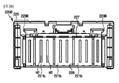
図10は、本発明の他の実施例によるバッテリーモジュールの一部構成である、後方に位置したバスバーフレームと据え付けられたバスバーの様子を概略的に示した正面図である。 FIG. 10 is a front view schematically showing a state of a bus bar frame located at the rear and a bus bar installed, which is a partial configuration of a battery module according to another embodiment of the present invention.
図1及び図6と共に、図10を参照すれば、他の実施例によるバッテリーモジュールのバスバーアセンブリー220Bは、図9のバスバーアセンブリー220に備えられたバスバー221に比べ、相対的に左右方向の幅が広いバスバー221bを備え得る。また、前記バスバー221bには、二つの貫通口H2が形成され得る。
Referring to FIG. 10 with FIGS. 1 and 6, the
即ち、前記バスバー221bは、形成された二つの貫通口H2の各々に少なくとも一つ以上の電極リード110が挿入され、バスバー221の外側面に接触し得る。これによって、前記バスバー221は、6個の二次電池100を並列接続するのに適用することができる。
That is, the
また、図10の前記バスバーフレーム225には、複数のフック構造227及び前記バスバー221bの下端部221Bを収容できる挿入溝228が備えられたバスバー固定部226が形成され得る。
Further, the
例えば、図10に示したように、前記バスバーアセンブリー220Bには、二つの貫通口H2が形成された三つのバスバー221bと、一つの貫通口H2が形成された二つのモジュールバスバー223と、が備えられ得る。
For example, as shown in FIG. 10, in the
したがって、本発明のこのような構成によれば、前記バスバーフレーム225にフック構造227及び挿入溝228が備えられたバスバー固定部226を形成し、一つの開口が形成されたバスバー開放部229を備えることで、左右方向の大きさが多様なサイズ及び種類のバスバー221bが収容可能である。
Therefore, according to such a configuration of the present invention, the
図11は、本発明の一実施例によるバッテリーモジュールの一部構成であるバスバーがバスバーフレームに据え付けられる様子を概略的に示した一部斜視図である。 FIG. 11 is a partial perspective view schematically showing how a bus bar, which is a partial configuration of a battery module according to an embodiment of the present invention, is installed on a bus bar frame.
図5と共に図11を参照すれば、前記バスバーフレーム225には、前記バスバー221の下端部221Bを挿入するように挿入溝228が形成され得る。また、前記挿入溝228の内面には前記バスバー221が位置した方向へ突出した固定突起228Pが所定の間隔で隔てて複数個が形成され得る。
Referring to FIG. 11 together with FIG. 5, an
さらに、前記バスバー221の下端部には、前記固定突起228Pが内部に挿入されるように上方に凹んだ凹溝221Gが形成され得る。そして、前記固定突起228Pは、前記挿入溝228の左右方向の内面に沿って一定の間隔で離隔して複数個が形成され得る。
Further, a
即ち、前記バスバーアセンブリー220は、前記バスバー221の下端部221Bに形成された凹溝221Gと、前記挿入溝228の内面に形成された固定突起228Pと、を相互締結するように、前記バスバー221の下端部221Bを前記挿入溝228に挿入し得る。この際、前記バスバー221の下端部221Bを斜めに前記挿入溝228に差し込んだ後、前記バスバー221の上端部221Uを前記バスバー221の下端部221Bを中心にして内側方向へ回転加圧して前記フック構造227に挿入し得る。
That is, the
したがって、本発明のこのような構成によれば、前記挿入溝228に形成された固定突起228Pと、前記バスバー221に形成された凹溝221Gとの締結構造を用いて、前記バスバー221が設定された位置で左右方向へ移動することを防止することだけではなく、前記バスバー221が挿入溝228に挿入された後、前記フック構造227に前記バスバー221の上端部221Uが挿入されるように回転移動をガイドすることができ、製造効率を高めることができる。
Therefore, according to such a configuration of the present invention, the
図12は、本発明の他の実施例によるバッテリーモジュールの一部構成であるバスバーがバスバーフレームに据え付けられた様子を概略的に示した一部斜視図である。 FIG. 12 is a partial perspective view schematically showing a state in which a bus bar, which is a partial configuration of a battery module according to another embodiment of the present invention, is installed on a bus bar frame.
図12を参照すれば、前記バスバーフレーム225Dに形成された挿入溝228には、前記複数のバスバー221の間に介在され、前記複数のバスバー221同士の離隔距離を設定するように構成された距離調節ブロック224が内部に挿入され得る。具体的に、前記距離調節ブロック224は、左右方向へ長く延びたバー(bar)の形状であり得る。
Referring to FIG. 12, the
また、前記バー形態の距離調節ブロック224は、前記挿入溝228の内部に挿入可能な幅を有し得る。さらに、前記距離調節ブロック224は、前記バスバー221の大きさや個数に応じて前記距離調節ブロック224の左右方向の長さを調節して形成し得る。
Further, the
図13は、本発明の他の実施例によるバッテリーモジュールに対する一部構成であるバスバーがバスバーフレームに据え付けられる様子を概略的に示した一部斜視図である。 FIG. 13 is a partial perspective view schematically showing how the bus bar, which is a partial configuration for the battery module according to another embodiment of the present invention, is installed on the bus bar frame.
図13を参照すれば、他の実施例によるバッテリーモジュールのバスバーフレーム225Eには、バスバー221の下端部221Bが挿入されるように構成された挿入溝228が形成され得る。また、前記挿入溝228の内面には、前記バスバー221の下端部221Bを外側方向へ加圧するように構成された加圧突起228Zが形成され得る。
Referring to FIG. 13, the
さらに、前記挿入溝228の内側面には、前記加圧突起228Zが所定の距離で離隔して複数個が形成され得る。そして、前記加圧突起228Zは、下方へ進むほど外側方向へ突出した大きさが漸進的に大きくなるように構成され得る。
Further, a plurality of the
したがって、本発明このような構成によれば、前記挿入溝228に形成された加圧突起228Zは、前記バスバー221の下端部221Bを前記挿入溝228に下方へ挿入することだけで、前記バスバー221をバスバーフレーム225に堅固に固定することができ、バッテリーモジュール200の耐久性を効果的に高めることができる。
Therefore, according to the present invention, the
さらに、本発明によるバッテリーパックは、本発明によるバッテリーモジュール200を一つ以上含み得る。また、本発明によるバッテリーパックは、このようなバッテリーモジュール200に加え、バッテリーモジュール200を収納するためのパックケース、バッテリーモジュール200の充放電を制御するための各種装置、例えば、BMS(Battery Management System)、電流センサー、ヒューズなどをさらに含み得る。
Further, the battery pack according to the present invention may include one or
また、本発明によるバッテリーパックは、電気自動車のような自動車に適用可能である。即ち、本発明による自動車は、本発明によるバッテリーパックを含み得る。 Further, the battery pack according to the present invention can be applied to an automobile such as an electric vehicle. That is, the vehicle according to the present invention may include a battery pack according to the present invention.
なお、本明細書において、上、下、左、右、前、後のような方向を示す用語が使用されたが、このような用語は相対的な位置を示し、説明の便宜のためのものであるだけで、対象となる事物の位置や観測者の位置などによって変わり得ることは、当業者にとって自明である。 In the present specification, terms indicating directions such as up, down, left, right, front, and back are used, but such terms indicate relative positions and are for convenience of explanation. It is obvious to those skilled in the art that it can change depending on the position of the object or the position of the observer.
以上のように、本発明を限定された実施例と図面によって説明したが、本発明はこれに限定されず、本発明が属する技術分野における通常の知識を持つ者によって本発明の技術思想と特許請求の範囲の均等範囲内で多様な修正及び変形が可能であることは言うまでもない。 As described above, the present invention has been described with limited examples and drawings, but the present invention is not limited to this, and the technical idea and patent of the present invention may be obtained by a person having ordinary knowledge in the technical field to which the present invention belongs. It goes without saying that various modifications and modifications are possible within the equal range of the claims.
本発明は、バッテリーモジュール及びそれを含むバッテリーパックに関する。また、本発明のバッテリーモジュールが備えられた電子デバイスまたは自動車関連産業に利用可能である。 The present invention relates to a battery module and a battery pack including the battery module. It can also be used in electronic devices equipped with the battery module of the present invention or in the automobile-related industry.
100:二次電池
200:バッテリーモジュール
210:セルアセンブリー
220:バスバーアセンブリー
221:バスバー
221G:凹溝
223:モジュールバスバー
224:距離調節ブロック
225:バスバーフレーム
226:バスバー固定部
227:フック構造
228:挿入溝
228P:固定突起
228Z:加圧突起
229:バスバー開放部
240:モジュール端子
H1:開口
H2:貫通口
100: Rechargeable battery 200: Battery module 210: Cell assembly 220: Bus bar assembly 221:
Claims (12)
前記複数の二次電池同士を電気的に接続し、前記電極リードが挿入されるように少なくとも一つ以上の貫通口が形成された複数のバスバー、及び前記複数のバスバーが外側面に据え付けられるように構成されたバスバーフレームを備えたバスバーアセンブリーと、を含み、
前記バスバーフレームは、前記バスバーの左右方向の位置を自由に設定できるように左右方向へ長く延びた挿入空間が形成され、前記バスバーの上端部及び下端部を固定するように構成されたバスバー固定部と、前記バスバーの左右方向の位置を変更しても、前記バスバーの貫通口が後方に露出するように開口されたバスバー開放部と、を備えたことを特徴とするバッテリーモジュール。 A cell assembly with multiple secondary batteries, each with multiple electrode leads and arranged to be stacked in at least one direction.
A plurality of bus bars in which the plurality of secondary batteries are electrically connected to each other and at least one through hole is formed so that the electrode leads are inserted, and the plurality of bus bars are installed on the outer surface. Includes a busbar assembly with a busbar frame configured in
The bus bar frame is formed with an insertion space extending in the left-right direction so that the position of the bus bar in the left-right direction can be freely set, and the bus bar fixing portion configured to fix the upper end portion and the lower end portion of the bus bar. The battery module is provided with a bus bar opening portion opened so that the through-hole of the bus bar is exposed to the rear even if the position of the bus bar in the left-right direction is changed .
前記プレート形状のバスバーには、前後方向へ貫通した貫通口が形成されていることを特徴とする請求項1に記載のバッテリーモジュール。 The bus bar has a plate shape and has a plate shape.
The battery module according to claim 1, wherein the plate-shaped bus bar is formed with a through-hole penetrating in the front-rear direction.
前記複数の二次電池同士を電気的に接続し、前記電極リードが挿入されるように少なくとも一つ以上の貫通口が形成され、センシング回路基板と電気的に接続した複数のバスバ
ー、及び前記複数のバスバーが外側面に据え付けられるように構成されたバスバーフレームを備えたバスバーアセンブリーと、を含み、
前記バスバーフレームは、前記バスバーの左右方向の位置を自由に設定できるように左右方向へ長く延びた挿入空間が形成され、前記バスバーの上端部及び下端部を固定するように構成されたバスバー固定部と、前記バスバーの左右方向の位置を変更しても、前記バスバーの貫通口が後方に露出するように開口されたバスバー開放部と、を備え、
前記バスバー固定部は、前記バスバーの上端部及び下端部の少なくとも一つが挿入され、上方または下方へ凹んだ溝が左右方向へ長く延びた挿入溝を備え、
前記挿入溝の内面には、前記バスバーが位置した方向へ突出した固定突起が所定の間隔を隔てて複数個形成され、前記バスバーの端部には、前記固定突起が内部に挿入されるように上方へ凹んだ凹溝が形成されていることを特徴とする、バッテリーモジュール。 A cell assembly with multiple secondary batteries, each with multiple electrode leads and arranged to be stacked in at least one direction.
A plurality of bus bars in which the plurality of secondary batteries are electrically connected to each other, at least one through hole is formed so that the electrode leads are inserted, and the plurality of bus bars are electrically connected to the sensing circuit board, and the plurality of. Includes a busbar assembly with a busbar frame configured so that the busbar can be mounted on the outside surface.
The bus bar frame is formed with an insertion space extending in the left-right direction so that the position of the bus bar in the left-right direction can be freely set, and the bus bar fixing portion configured to fix the upper end portion and the lower end portion of the bus bar. And a bus bar opening portion opened so that the through-hole of the bus bar is exposed to the rear even if the position of the bus bar in the left-right direction is changed .
The bus bar fixing portion includes an insertion groove in which at least one of the upper end portion and the lower end portion of the bus bar is inserted, and a groove recessed upward or downward extends long in the left-right direction.
A plurality of fixing protrusions protruding in the direction in which the bus bar is located are formed on the inner surface of the insertion groove at predetermined intervals, and the fixing protrusions are inserted into the end of the bus bar. A battery module characterized by the formation of a concave groove that is recessed upward.
Applications Claiming Priority (3)
| Application Number | Priority Date | Filing Date | Title |
|---|---|---|---|
| KR1020170172515A KR102259416B1 (en) | 2017-12-14 | 2017-12-14 | Battery Module Having Bus bar Assembly |
| KR10-2017-0172515 | 2017-12-14 | ||
| PCT/KR2018/015010 WO2019117514A1 (en) | 2017-12-14 | 2018-11-29 | Battery module comprising bus bar assembly |
Publications (2)
| Publication Number | Publication Date |
|---|---|
| JP2020518988A JP2020518988A (en) | 2020-06-25 |
| JP7045588B2 true JP7045588B2 (en) | 2022-04-01 |
Family
ID=66820536
Family Applications (1)
| Application Number | Title | Priority Date | Filing Date |
|---|---|---|---|
| JP2019560340A Active JP7045588B2 (en) | 2017-12-14 | 2018-11-29 | Battery module including busbar assembly |
Country Status (6)
| Country | Link |
|---|---|
| US (1) | US11223093B2 (en) |
| EP (1) | EP3637503A4 (en) |
| JP (1) | JP7045588B2 (en) |
| KR (1) | KR102259416B1 (en) |
| CN (1) | CN110915024B (en) |
| WO (1) | WO2019117514A1 (en) |
Families Citing this family (34)
| Publication number | Priority date | Publication date | Assignee | Title |
|---|---|---|---|---|
| KR102541537B1 (en) * | 2019-06-25 | 2023-06-08 | 주식회사 엘지에너지솔루션 | Battery module and battery pack including the same |
| KR102532699B1 (en) * | 2019-06-25 | 2023-05-12 | 주식회사 엘지에너지솔루션 | Battery module and battery pack including the same |
| KR102583650B1 (en) * | 2019-07-01 | 2023-09-26 | 주식회사 엘지에너지솔루션 | Battery module and battery pack including the same |
| KR20210015547A (en) * | 2019-08-02 | 2021-02-10 | 주식회사 엘지화학 | Movable Bus bar assembly and Battery pack including the same, and secondary battery including the same |
| KR20210023506A (en) * | 2019-08-23 | 2021-03-04 | 주식회사 엘지화학 | Battery module and battery pack including the same |
| CN112582719B (en) * | 2019-09-29 | 2022-04-29 | 东莞新能源科技有限公司 | Battery module unit, battery module, energy storage system and electric vehicle |
| KR20210087819A (en) * | 2020-01-03 | 2021-07-13 | 주식회사 엘지에너지솔루션 | Battery module and battery pack including the same |
| KR20210103297A (en) * | 2020-02-13 | 2021-08-23 | 주식회사 엘지에너지솔루션 | Battery module, battery pack and vehicle comprising the battery module |
| KR20210104491A (en) * | 2020-02-17 | 2021-08-25 | 주식회사 엘지에너지솔루션 | Battery module, battery pack and vehicle comprising the battery module |
| WO2021206350A1 (en) * | 2020-04-09 | 2021-10-14 | 주식회사 엘지에너지솔루션 | Battery module and battery pack including same |
| KR20210132397A (en) * | 2020-04-27 | 2021-11-04 | 주식회사 엘지에너지솔루션 | Battery module and battery pack including the same |
| KR20220005302A (en) * | 2020-07-06 | 2022-01-13 | 주식회사 엘지에너지솔루션 | Battery module and battery pack including the same |
| JP2022019024A (en) * | 2020-07-17 | 2022-01-27 | 株式会社オートネットワーク技術研究所 | Wiring module |
| KR20220011529A (en) * | 2020-07-21 | 2022-01-28 | 주식회사 엘지에너지솔루션 | Battery module with improved electrode lead connection structure, and battery pack and vehicle comprising the same |
| KR20220011430A (en) * | 2020-07-21 | 2022-01-28 | 주식회사 엘지에너지솔루션 | Battery module and battery pack including the same |
| KR20220012037A (en) | 2020-07-22 | 2022-02-03 | 주식회사 엘지에너지솔루션 | Battery module having a simple connection structure between cell lead and voltage sensing member and battery pack including the same |
| KR20220012033A (en) | 2020-07-22 | 2022-02-03 | 주식회사 엘지에너지솔루션 | Battery module having a simple connection structure between cell lead and voltage sensing member and battery pack including the same |
| KR20220055196A (en) * | 2020-10-26 | 2022-05-03 | 주식회사 엘지에너지솔루션 | Battery Module Sensing Unit and Method for Manufacturing Same |
| KR102567485B1 (en) * | 2020-11-03 | 2023-08-17 | 한국단자공업 주식회사 | Electrical connecting apparatus for battery and making method the same |
| KR20220063613A (en) * | 2020-11-10 | 2022-05-17 | 주식회사 엘지에너지솔루션 | A battery module with improved assembly structure of voltage sensing components and A battery pack including the same |
| KR20220094518A (en) * | 2020-12-29 | 2022-07-06 | 에스케이온 주식회사 | Battery module |
| EP4170796A4 (en) | 2021-01-19 | 2024-07-24 | Lg Energy Solution Ltd | Battery module and battery pack including same |
| JP7459012B2 (en) * | 2021-04-23 | 2024-04-01 | プライムプラネットエナジー&ソリューションズ株式会社 | Connection structure of laminate cells, connection method of assembled batteries and laminate cells |
| US11973205B2 (en) | 2021-09-16 | 2024-04-30 | Lunar Energy, Inc. | Cell temperature regulation |
| KR102637525B1 (en) | 2021-10-26 | 2024-02-19 | 주식회사 엘지에너지솔루션 | Battery moule and battery pack including the same |
| KR20230066868A (en) | 2021-11-08 | 2023-05-16 | 주식회사 엘지에너지솔루션 | Battery moule and battery pack including the same |
| KR102656950B1 (en) | 2021-11-12 | 2024-04-16 | 주식회사 엘지에너지솔루션 | Battery moule and battery pack including the same |
| KR20230069692A (en) | 2021-11-12 | 2023-05-19 | 주식회사 엘지에너지솔루션 | Battery moule and battery pack including the same |
| KR20230069667A (en) | 2021-11-12 | 2023-05-19 | 주식회사 엘지에너지솔루션 | Battery moule and battery pack including the same |
| CN216413212U (en) * | 2021-12-01 | 2022-04-29 | 宁德时代新能源科技股份有限公司 | Busbar assembly, battery and power consumption device |
| KR20230150635A (en) * | 2022-04-22 | 2023-10-31 | 현대모비스 주식회사 | Battery module assembly and method of manufacturing the same |
| KR20230160019A (en) * | 2022-05-16 | 2023-11-23 | 주식회사 엘지에너지솔루션 | Battery pack and vehicle including the same |
| KR102452156B1 (en) * | 2022-06-16 | 2022-10-12 | 덕양산업 주식회사 | Bracket for fixing a bus bar for battery pack |
| KR20240072713A (en) * | 2022-11-17 | 2024-05-24 | 주식회사 엘지에너지솔루션 | Battery module including busbar frame separated from top and bottom and assembly method having the same |
Citations (7)
| Publication number | Priority date | Publication date | Assignee | Title |
|---|---|---|---|---|
| JP2010225552A (en) | 2009-03-25 | 2010-10-07 | Sanyo Electric Co Ltd | Battery pack |
| WO2014073443A1 (en) | 2012-11-09 | 2014-05-15 | 日産自動車株式会社 | Assembled battery and method for manufacturing assembled battery |
| JP2014110219A (en) | 2012-12-04 | 2014-06-12 | Nissan Motor Co Ltd | Battery pack and method of manufacturing the same |
| JP2015056342A (en) | 2013-09-13 | 2015-03-23 | 株式会社オートネットワーク技術研究所 | Power storage module |
| US20160133906A1 (en) | 2014-11-11 | 2016-05-12 | Ford Global Technologies, Llc | Traction Battery Busbar Carriers for Pouch Battery Cells |
| JP2017084469A (en) | 2015-10-22 | 2017-05-18 | 日産自動車株式会社 | Battery pack and spacer for battery pack |
| JP2017188233A (en) | 2016-04-01 | 2017-10-12 | 日産自動車株式会社 | Battery pack and manufacturing method of battery pack |
Family Cites Families (28)
| Publication number | Priority date | Publication date | Assignee | Title |
|---|---|---|---|---|
| US8580423B2 (en) | 2009-10-22 | 2013-11-12 | Samsung Sdi Co., Ltd. | Bus bar holder and battery pack including the same |
| KR101201747B1 (en) * | 2010-05-24 | 2012-11-15 | 에스비리모티브 주식회사 | Battery module |
| KR101217564B1 (en) | 2010-08-16 | 2013-01-02 | 주식회사 엘지화학 | Voltage Sensing Assembly and Battery Module Employed with the Same |
| KR102024002B1 (en) * | 2012-07-05 | 2019-09-23 | 에스케이이노베이션 주식회사 | Battery pack |
| JP2014032949A (en) * | 2012-07-13 | 2014-02-20 | Toyota Motor Corp | Power storage device storage and bus bar unit |
| WO2014034079A1 (en) | 2012-08-30 | 2014-03-06 | 三洋電機株式会社 | Power source device, vehicle provided with power source device, and power storage device |
| KR20140060633A (en) * | 2012-11-12 | 2014-05-21 | 주식회사 엘지화학 | Battery module having bus bar assembly and battery pack comprising the same |
| JP2014116160A (en) | 2012-12-07 | 2014-06-26 | Yazaki Corp | Power supply device |
| KR102046122B1 (en) * | 2013-05-21 | 2019-11-19 | 에스케이이노베이션 주식회사 | PCB connecting unit for Battery modularizaton and Method for manufacturing Battery module and Battery module made by the method |
| JP6145314B2 (en) * | 2013-05-29 | 2017-06-07 | 矢崎総業株式会社 | Bus bar module and power supply |
| JP6016737B2 (en) * | 2013-08-29 | 2016-10-26 | 古河電気工業株式会社 | In-battery wiring module of battery pack |
| KR101632339B1 (en) * | 2013-10-31 | 2016-06-21 | 주식회사 엘지화학 | Battery pack assembly can absorb the external shock |
| KR102263304B1 (en) | 2013-11-05 | 2021-06-15 | 타이코에이엠피 주식회사 | A battery cell connecting board |
| KR101667519B1 (en) * | 2013-12-17 | 2016-10-28 | 주식회사 엘지화학 | Battery Module having Bus Bar employed with External Input-Output Terminal |
| WO2015152527A1 (en) * | 2014-03-31 | 2015-10-08 | 주식회사 엘지화학 | Battery module and battery pack comprising same |
| JP2015230892A (en) * | 2014-06-09 | 2015-12-21 | ソニー株式会社 | Battery module, power storage device, power storage system, electronic apparatus, electric vehicle and power system |
| KR101640100B1 (en) | 2014-11-10 | 2016-07-18 | 한국단자공업 주식회사 | Series connection apparatus of battery module |
| KR101797687B1 (en) * | 2014-12-22 | 2017-11-15 | 주식회사 엘지화학 | Battery Cell Interconnection Board Having Packing for Protecting Inflow of Foreign Substances |
| KR102381777B1 (en) * | 2015-02-25 | 2022-04-01 | 삼성에스디아이 주식회사 | Battery pack |
| DE102015217644A1 (en) * | 2015-09-15 | 2017-03-16 | Robert Bosch Gmbh | Cover element of a battery module housing, battery module with such a cover element and method for its production and battery |
| JP6309499B2 (en) | 2015-09-18 | 2018-04-11 | 矢崎総業株式会社 | Bus bar module and battery pack |
| KR102047482B1 (en) * | 2015-10-30 | 2019-12-02 | 주식회사 엘지화학 | Battery module and battery pack including the same |
| KR200491844Y1 (en) | 2015-11-12 | 2020-06-16 | 한국단자공업 주식회사 | Series connection apparatus of battery module |
| KR102032356B1 (en) | 2015-12-07 | 2019-11-08 | 주식회사 엘지화학 | Voltage Sensing Block for Battery Module |
| KR200485016Y1 (en) | 2015-12-11 | 2017-12-12 | 한국단자공업 주식회사 | Series connection apparatus of battery module |
| KR102093943B1 (en) | 2016-02-12 | 2020-03-26 | 주식회사 엘지화학 | Battery module, battery pack comprising the battery module and vehicle comprising the battery pack |
| KR102093944B1 (en) * | 2016-02-12 | 2020-03-26 | 주식회사 엘지화학 | Battery module, battery pack comprising the battery module and vehicle comprising the battery pack |
| KR102034208B1 (en) * | 2016-03-03 | 2019-10-18 | 주식회사 엘지화학 | Battery module, battery pack the battery module and vehicle comprising the battery pack |
-
2017
- 2017-12-14 KR KR1020170172515A patent/KR102259416B1/en active IP Right Grant
-
2018
- 2018-11-29 WO PCT/KR2018/015010 patent/WO2019117514A1/en unknown
- 2018-11-29 CN CN201880036425.4A patent/CN110915024B/en active Active
- 2018-11-29 JP JP2019560340A patent/JP7045588B2/en active Active
- 2018-11-29 US US16/611,353 patent/US11223093B2/en active Active
- 2018-11-29 EP EP18889754.0A patent/EP3637503A4/en active Pending
Patent Citations (7)
| Publication number | Priority date | Publication date | Assignee | Title |
|---|---|---|---|---|
| JP2010225552A (en) | 2009-03-25 | 2010-10-07 | Sanyo Electric Co Ltd | Battery pack |
| WO2014073443A1 (en) | 2012-11-09 | 2014-05-15 | 日産自動車株式会社 | Assembled battery and method for manufacturing assembled battery |
| JP2014110219A (en) | 2012-12-04 | 2014-06-12 | Nissan Motor Co Ltd | Battery pack and method of manufacturing the same |
| JP2015056342A (en) | 2013-09-13 | 2015-03-23 | 株式会社オートネットワーク技術研究所 | Power storage module |
| US20160133906A1 (en) | 2014-11-11 | 2016-05-12 | Ford Global Technologies, Llc | Traction Battery Busbar Carriers for Pouch Battery Cells |
| JP2017084469A (en) | 2015-10-22 | 2017-05-18 | 日産自動車株式会社 | Battery pack and spacer for battery pack |
| JP2017188233A (en) | 2016-04-01 | 2017-10-12 | 日産自動車株式会社 | Battery pack and manufacturing method of battery pack |
Also Published As
| Publication number | Publication date |
|---|---|
| KR102259416B1 (en) | 2021-06-01 |
| EP3637503A4 (en) | 2020-12-02 |
| CN110915024B (en) | 2022-06-10 |
| US20200144580A1 (en) | 2020-05-07 |
| JP2020518988A (en) | 2020-06-25 |
| KR20190071454A (en) | 2019-06-24 |
| CN110915024A (en) | 2020-03-24 |
| EP3637503A1 (en) | 2020-04-15 |
| US11223093B2 (en) | 2022-01-11 |
| WO2019117514A1 (en) | 2019-06-20 |
Similar Documents
| Publication | Publication Date | Title |
|---|---|---|
| JP7045588B2 (en) | Battery module including busbar assembly | |
| JP6768968B2 (en) | Battery module with guide coupling structure and battery pack containing it | |
| JP7045550B2 (en) | Battery pack with improved assembly structure | |
| JP6808074B2 (en) | Battery module with heat dissipation plate | |
| JP7045591B2 (en) | Battery module with busbar assembly | |
| JP7045568B2 (en) | Battery module including sensing assembly and busbar assembly | |
| US10096867B2 (en) | Compact secondary battery module integrated with BMS | |
| JP7128287B2 (en) | Battery module having structure with improved energy density, battery pack including the same, and automobile | |
| KR101271567B1 (en) | Battery Module of Structure Having Fixing Member Inserted into Through-Hole of Plates and Battery Pack Employed with the Same | |
| JP7084496B2 (en) | Battery module, battery pack containing the battery module and automobile including the battery pack | |
| JP5259599B2 (en) | Battery module interface | |
| JP7048838B2 (en) | Battery module and battery pack with busbar | |
| JP6755380B2 (en) | Battery module and battery pack containing it | |
| JP7237090B2 (en) | A battery module having a structure capable of accurate temperature sensing, a battery pack including the same, and an automobile | |
| KR102392767B1 (en) | Battery Module Having Inner Cover | |
| KR102122930B1 (en) | Battery module and battery pack having the same | |
| US11967735B2 (en) | Battery module | |
| KR20150137840A (en) | Unit battery module and Battery module having the same | |
| JP7044897B2 (en) | Battery module, battery pack containing the battery module and automobile including the battery pack | |
| US10468643B2 (en) | Battery module and battery pack including the same | |
| KR101783917B1 (en) | Compact secondary battery module having hook structure | |
| JP7150714B2 (en) | BATTERY MODULE AND BATTERY MODULE MANUFACTURING METHOD | |
| KR101658587B1 (en) | Lithium Secondary Battery and Battery Pack Comprising The Same | |
| KR101839653B1 (en) | Compact secondary battery module |
Legal Events
| Date | Code | Title | Description |
|---|---|---|---|
| A621 | Written request for application examination |
Free format text: JAPANESE INTERMEDIATE CODE: A621 Effective date: 20191101 |
|
| A977 | Report on retrieval |
Free format text: JAPANESE INTERMEDIATE CODE: A971007 Effective date: 20201019 |
|
| A131 | Notification of reasons for refusal |
Free format text: JAPANESE INTERMEDIATE CODE: A131 Effective date: 20201130 |
|
| A521 | Request for written amendment filed |
Free format text: JAPANESE INTERMEDIATE CODE: A523 Effective date: 20210219 |
|
| TRDD | Decision of grant or rejection written | ||
| A01 | Written decision to grant a patent or to grant a registration (utility model) |
Free format text: JAPANESE INTERMEDIATE CODE: A01 Effective date: 20210802 |
|
| A711 | Notification of change in applicant |
Free format text: JAPANESE INTERMEDIATE CODE: A712 Effective date: 20210831 |
|
| A61 | First payment of annual fees (during grant procedure) |
Free format text: JAPANESE INTERMEDIATE CODE: A61 Effective date: 20210831 |
|
| A521 | Request for written amendment filed |
Free format text: JAPANESE INTERMEDIATE CODE: A523 Effective date: 20211207 |
|
| R150 | Certificate of patent or registration of utility model |
Ref document number: 7045588 Country of ref document: JP Free format text: JAPANESE INTERMEDIATE CODE: R150 |