JP7044713B2 - Brush for autonomous cleaning robot - Google Patents
Brush for autonomous cleaning robot Download PDFInfo
- Publication number
- JP7044713B2 JP7044713B2 JP2018550696A JP2018550696A JP7044713B2 JP 7044713 B2 JP7044713 B2 JP 7044713B2 JP 2018550696 A JP2018550696 A JP 2018550696A JP 2018550696 A JP2018550696 A JP 2018550696A JP 7044713 B2 JP7044713 B2 JP 7044713B2
- Authority
- JP
- Japan
- Prior art keywords
- robot
- side brush
- brush
- arm
- hub
- Prior art date
- Legal status (The legal status is an assumption and is not a legal conclusion. Google has not performed a legal analysis and makes no representation as to the accuracy of the status listed.)
- Active
Links
Images


Classifications
-
- A—HUMAN NECESSITIES
- A47—FURNITURE; DOMESTIC ARTICLES OR APPLIANCES; COFFEE MILLS; SPICE MILLS; SUCTION CLEANERS IN GENERAL
- A47L—DOMESTIC WASHING OR CLEANING; SUCTION CLEANERS IN GENERAL
- A47L11/00—Machines for cleaning floors, carpets, furniture, walls, or wall coverings
- A47L11/24—Floor-sweeping machines, motor-driven
-
- A—HUMAN NECESSITIES
- A47—FURNITURE; DOMESTIC ARTICLES OR APPLIANCES; COFFEE MILLS; SPICE MILLS; SUCTION CLEANERS IN GENERAL
- A47L—DOMESTIC WASHING OR CLEANING; SUCTION CLEANERS IN GENERAL
- A47L9/00—Details or accessories of suction cleaners, e.g. mechanical means for controlling the suction or for effecting pulsating action; Storing devices specially adapted to suction cleaners or parts thereof; Carrying-vehicles specially adapted for suction cleaners
- A47L9/02—Nozzles
- A47L9/04—Nozzles with driven brushes or agitators
- A47L9/0461—Dust-loosening tools, e.g. agitators, brushes
- A47L9/0488—Combinations or arrangements of several tools, e.g. edge cleaning tools
-
- A—HUMAN NECESSITIES
- A47—FURNITURE; DOMESTIC ARTICLES OR APPLIANCES; COFFEE MILLS; SPICE MILLS; SUCTION CLEANERS IN GENERAL
- A47L—DOMESTIC WASHING OR CLEANING; SUCTION CLEANERS IN GENERAL
- A47L11/00—Machines for cleaning floors, carpets, furniture, walls, or wall coverings
- A47L11/40—Parts or details of machines not provided for in groups A47L11/02 - A47L11/38, or not restricted to one of these groups, e.g. handles, arrangements of switches, skirts, buffers, levers
- A47L11/4013—Contaminants collecting devices, i.e. hoppers, tanks or the like
-
- A—HUMAN NECESSITIES
- A47—FURNITURE; DOMESTIC ARTICLES OR APPLIANCES; COFFEE MILLS; SPICE MILLS; SUCTION CLEANERS IN GENERAL
- A47L—DOMESTIC WASHING OR CLEANING; SUCTION CLEANERS IN GENERAL
- A47L11/00—Machines for cleaning floors, carpets, furniture, walls, or wall coverings
- A47L11/40—Parts or details of machines not provided for in groups A47L11/02 - A47L11/38, or not restricted to one of these groups, e.g. handles, arrangements of switches, skirts, buffers, levers
- A47L11/4036—Parts or details of the surface treating tools
- A47L11/4044—Vacuuming or pick-up tools; Squeegees
-
- A—HUMAN NECESSITIES
- A47—FURNITURE; DOMESTIC ARTICLES OR APPLIANCES; COFFEE MILLS; SPICE MILLS; SUCTION CLEANERS IN GENERAL
- A47L—DOMESTIC WASHING OR CLEANING; SUCTION CLEANERS IN GENERAL
- A47L11/00—Machines for cleaning floors, carpets, furniture, walls, or wall coverings
- A47L11/40—Parts or details of machines not provided for in groups A47L11/02 - A47L11/38, or not restricted to one of these groups, e.g. handles, arrangements of switches, skirts, buffers, levers
- A47L11/4094—Accessories to be used in combination with conventional vacuum-cleaning devices
-
- A—HUMAN NECESSITIES
- A47—FURNITURE; DOMESTIC ARTICLES OR APPLIANCES; COFFEE MILLS; SPICE MILLS; SUCTION CLEANERS IN GENERAL
- A47L—DOMESTIC WASHING OR CLEANING; SUCTION CLEANERS IN GENERAL
- A47L9/00—Details or accessories of suction cleaners, e.g. mechanical means for controlling the suction or for effecting pulsating action; Storing devices specially adapted to suction cleaners or parts thereof; Carrying-vehicles specially adapted for suction cleaners
- A47L9/009—Carrying-vehicles; Arrangements of trollies or wheels; Means for avoiding mechanical obstacles
-
- A—HUMAN NECESSITIES
- A47—FURNITURE; DOMESTIC ARTICLES OR APPLIANCES; COFFEE MILLS; SPICE MILLS; SUCTION CLEANERS IN GENERAL
- A47L—DOMESTIC WASHING OR CLEANING; SUCTION CLEANERS IN GENERAL
- A47L9/00—Details or accessories of suction cleaners, e.g. mechanical means for controlling the suction or for effecting pulsating action; Storing devices specially adapted to suction cleaners or parts thereof; Carrying-vehicles specially adapted for suction cleaners
- A47L9/02—Nozzles
- A47L9/04—Nozzles with driven brushes or agitators
- A47L9/0405—Driving means for the brushes or agitators
- A47L9/0411—Driving means for the brushes or agitators driven by electric motor
-
- A—HUMAN NECESSITIES
- A47—FURNITURE; DOMESTIC ARTICLES OR APPLIANCES; COFFEE MILLS; SPICE MILLS; SUCTION CLEANERS IN GENERAL
- A47L—DOMESTIC WASHING OR CLEANING; SUCTION CLEANERS IN GENERAL
- A47L9/00—Details or accessories of suction cleaners, e.g. mechanical means for controlling the suction or for effecting pulsating action; Storing devices specially adapted to suction cleaners or parts thereof; Carrying-vehicles specially adapted for suction cleaners
- A47L9/02—Nozzles
- A47L9/04—Nozzles with driven brushes or agitators
- A47L9/0461—Dust-loosening tools, e.g. agitators, brushes
- A47L9/0466—Rotating tools
- A47L9/0477—Rolls
-
- A—HUMAN NECESSITIES
- A47—FURNITURE; DOMESTIC ARTICLES OR APPLIANCES; COFFEE MILLS; SPICE MILLS; SUCTION CLEANERS IN GENERAL
- A47L—DOMESTIC WASHING OR CLEANING; SUCTION CLEANERS IN GENERAL
- A47L9/00—Details or accessories of suction cleaners, e.g. mechanical means for controlling the suction or for effecting pulsating action; Storing devices specially adapted to suction cleaners or parts thereof; Carrying-vehicles specially adapted for suction cleaners
- A47L9/28—Installation of the electric equipment, e.g. adaptation or attachment to the suction cleaner; Controlling suction cleaners by electric means
- A47L9/2805—Parameters or conditions being sensed
- A47L9/2826—Parameters or conditions being sensed the condition of the floor
-
- A—HUMAN NECESSITIES
- A47—FURNITURE; DOMESTIC ARTICLES OR APPLIANCES; COFFEE MILLS; SPICE MILLS; SUCTION CLEANERS IN GENERAL
- A47L—DOMESTIC WASHING OR CLEANING; SUCTION CLEANERS IN GENERAL
- A47L9/00—Details or accessories of suction cleaners, e.g. mechanical means for controlling the suction or for effecting pulsating action; Storing devices specially adapted to suction cleaners or parts thereof; Carrying-vehicles specially adapted for suction cleaners
- A47L9/28—Installation of the electric equipment, e.g. adaptation or attachment to the suction cleaner; Controlling suction cleaners by electric means
- A47L9/2836—Installation of the electric equipment, e.g. adaptation or attachment to the suction cleaner; Controlling suction cleaners by electric means characterised by the parts which are controlled
- A47L9/2852—Elements for displacement of the vacuum cleaner or the accessories therefor, e.g. wheels, casters or nozzles
-
- A—HUMAN NECESSITIES
- A47—FURNITURE; DOMESTIC ARTICLES OR APPLIANCES; COFFEE MILLS; SPICE MILLS; SUCTION CLEANERS IN GENERAL
- A47L—DOMESTIC WASHING OR CLEANING; SUCTION CLEANERS IN GENERAL
- A47L2201/00—Robotic cleaning machines, i.e. with automatic control of the travelling movement or the cleaning operation
- A47L2201/04—Automatic control of the travelling movement; Automatic obstacle detection
-
- A—HUMAN NECESSITIES
- A47—FURNITURE; DOMESTIC ARTICLES OR APPLIANCES; COFFEE MILLS; SPICE MILLS; SUCTION CLEANERS IN GENERAL
- A47L—DOMESTIC WASHING OR CLEANING; SUCTION CLEANERS IN GENERAL
- A47L2201/00—Robotic cleaning machines, i.e. with automatic control of the travelling movement or the cleaning operation
- A47L2201/06—Control of the cleaning action for autonomous devices; Automatic detection of the surface condition before, during or after cleaning
Description
本願は、自律式清掃ロボットのためのブラシに関する。 The present application relates to brushes for autonomous cleaning robots.
自律式清掃ロボットは床面を横切って移動し、障害物を回避しながら床面を清掃して床面から屑を収集することができる。ロボットは、床面で屑を攪拌し、床面から屑を収集するためのブラシを含み得る。例えば、ブラシは、ロボットによって生成される真空気流の方向に屑を向けることができ、真空気流がロボットの清掃箱(bin)に屑を導くことができる。 The autonomous cleaning robot can move across the floor, clean the floor while avoiding obstacles, and collect debris from the floor. The robot may include a brush for agitating the debris on the floor and collecting the debris from the floor. For example, the brush can direct the debris in the direction of the vacuum airflow generated by the robot, which can guide the debris to the robot's bin.
一の態様では、自律式清掃ロボットは、床面を横切ってロボットを動かすように構成された駆動部と、ロボットの側面に近接しているブラシと、回転軸の周りでブラシを回転させるように構成されたモータと、を含む。ブラシは、ロボットのモータと係合するように構成されたハブと、ハブから回転軸の外側に延び、ブラシの回転軸に垂直な平面に対して傾斜したアームと、剛毛バンドル(bristle bundles)と、を含む。それぞれのアームは、回転軸から離れてハブから外側に延びる第1の部分と、回転軸から離れて第1の部分から外側に延びる第2の部分と、を含む。それぞれのアームの第1の部分と平面との間の角度は、それぞれのアームの第2の部分と平面との間の角度よりも大きい。それぞれの剛毛バンドルは、アームのそれぞれ1つに取り付けられ、それぞれのアームの第2の部分から外側に延びている。 In one embodiment, the autonomous cleaning robot rotates a drive unit configured to move the robot across the floor, a brush close to the side of the robot, and a brush around a axis of rotation. Includes, with and from the configured motors. The brush has a hub configured to engage the robot's motor, an arm that extends from the hub to the outside of the axis of rotation and is tilted with respect to a plane perpendicular to the axis of rotation of the brush, and bristle bundles. ,including. Each arm includes a first portion that extends outward from the hub away from the axis of rotation and a second portion that extends outward from the first portion away from the axis of rotation. The angle between the first portion of each arm and the plane is greater than the angle between the second portion of each arm and the plane. Each bristle bundle is attached to each one of the arms and extends outward from the second portion of each arm.
別の態様では、自律式清掃ロボットに取り付け可能なブラシは、モータが駆動されたときにブラシが回転軸の周りを回転して床面上の屑を収集するように自律式清掃ロボットのモータに係合するように構成されたハブと、ハブから回転軸の外側に延び、ブラシの回転軸線に垂直な平面に対して角度が付けられたブラシと、剛毛バンドルと、を含む。それぞれのアームは、回転軸から離れてハブから外側に延びる第1の部分と、回転軸から離れて第1の部分から外側に延びる第2の部分とを含む。それぞれのアームの第1の部分と平面との間の角度は、それぞれのアームの第2の部分と平面との間の角度よりも大きい。それぞれの剛毛バンドルは、アームのそれぞれ1つに取り付けられ、それぞれのアームの第2の部分から外側に延びている。 In another aspect, the brush that can be attached to the autonomous cleaning robot is attached to the motor of the autonomous cleaning robot so that when the motor is driven, the brush rotates around a axis of rotation and collects debris on the floor. Includes a hub configured to engage, a brush extending from the hub to the outside of the axis of rotation and angled with respect to a plane perpendicular to the axis of rotation of the brush, and a bristles bundle. Each arm includes a first portion that extends outward from the hub away from the axis of rotation and a second portion that extends outward from the first portion away from the axis of rotation. The angle between the first portion of each arm and the plane is greater than the angle between the second portion of each arm and the plane. Each bristle bundle is attached to each one of the arms and extends outward from the second portion of each arm.
実施形態では、以下または他の場所で本明細書において説明される1つ以上の特徴を含み得る。いくつかの実施形態では、ブラシはサイドブラシである。ロボットは、床面に平行な軸を中心に回転可能なメインブラシをさらに含み得る。サイドブラシは、サイドブラシの剛毛バンドルの少なくとも一部が、回転中の一部の間、メインブラシの下に配置可能であるように構成され得る。 In embodiments, it may include one or more features described herein below or elsewhere. In some embodiments, the brush is a side brush. The robot may further include a main brush that is rotatable about an axis parallel to the floor. The side brush may be configured such that at least a portion of the bristles bundle of the side brush can be placed under the main brush during the rotating portion.
いくつかの実施形態では、回転軸は床面に対して実質的に垂直である。 In some embodiments, the axis of rotation is substantially perpendicular to the floor surface.
いくつかの実施形態では、ブラシはサイドブラシである。ロボットは、実質的に矩形のフロント部と、ロボットのフロント部に沿って配置されたメインブラシとをさらに含み得る。メインブラシは、ロボットのフロント部の幅の60%~90%にわたって延び得る。いくつかの場合では、剛毛バンドルのそれぞれの遠位端が、ロボットのフロント部の幅の15%~35%の間の直径によって画定される円を通って掃引されるように、モータがブラシを回転するように構成される。 In some embodiments, the brush is a side brush. The robot may further include a substantially rectangular front portion and a main brush located along the front portion of the robot. The main brush can extend over 60% to 90% of the width of the front of the robot. In some cases, the motor brushes the bristles bundle so that each distal end is swept through a circle defined by a diameter between 15% and 35% of the width of the robot's front. It is configured to rotate.
いくつかの実施形態では、ブラシはサイドブラシであり、ロボットは、床面に平行な軸を中心に回転可能なメインブラシを含む清掃ヘッドモジュールをさらに含む。サイドブラシは、清掃ヘッドモジュールのコーナーに近接して取り付けることができる。 In some embodiments, the brush is a side brush and the robot further comprises a cleaning head module that includes a main brush that is rotatable about an axis parallel to the floor surface. The side brushes can be mounted close to the corners of the cleaning head module.
いくつかの実施形態では、ブラシは、ロボットの前方面とロボットの側面とによって形成されるロボットのコーナー部に近接して配置される。それぞれの剛毛バンドルがロボットの前方面及び側面を越えて位置決めできるように、モータがブラシを回転するように構成され得る。 In some embodiments, the brushes are placed in close proximity to the corners of the robot formed by the front surface of the robot and the sides of the robot. The motor may be configured to rotate the brush so that each bristle bundle can be positioned across the front and sides of the robot.
いくつかの実施形態では、ハブの頂部が、ブラシによって係合されたフィラメント屑を収集するためのインセット部分を含む。いくつかの場合では、ロボットはハウジングをさらに含み、ハウジングの底面は、ハブのインセット部分を受け入れるように構成されたインセット部分を含む。ハウジングのインセット部分とハブのインセット部分によって画定される領域にフィラメント屑を収集するように、ハブは構成され得る。いくつかの場合では、ロボットは、ブラシのハブを受け入れるための開口部をさらに含む。開口部は、ハブのインセット部分から受け取ったフィラメント屑を収集するように構成され得る。 In some embodiments, the top of the hub comprises an inset portion for collecting filament debris engaged by the brush. In some cases, the robot further includes a housing, the bottom of the housing including an inset portion configured to accommodate the inset portion of the hub. The hub may be configured to collect filament debris in the area defined by the inset portion of the housing and the inset portion of the hub. In some cases, the robot further includes an opening for receiving the brush hub. The opening may be configured to collect filament debris received from the inset portion of the hub.
いくつかの実施形態では、ハブの高さは0.25cm~1.5cmの間である。 In some embodiments, the height of the hub is between 0.25 cm and 1.5 cm.
いくつかの実施形態では、ハブは1~10GPaの間の弾性率を有する剛性ポリマー材料から形成され、アームは0.01~0.1GPaの間の弾性率を有する弾性材料から形成される。 In some embodiments, the hub is made of a rigid polymer material with a modulus of elasticity between 1 and 10 GPa and the arm is made of an elastic material with a modulus of elasticity between 0.01 and 0.1 GPa.
いくつかの実施形態では、それぞれのアームの第1の部分と平面との間の角度は70~90度の間である。 In some embodiments, the angle between the first portion of each arm and the plane is between 70 and 90 degrees.
いくつかの実施例では、それぞれのアームの第2の部分と平面との間の角度は15~60度の間である。 In some embodiments, the angle between the second portion of each arm and the plane is between 15-60 degrees.
いくつかの実施形態では、それぞれのアームの第1の部分とそれぞれのアームの第2の部分との間の角度は100~160度の間である。 In some embodiments, the angle between the first portion of each arm and the second portion of each arm is between 100 and 160 degrees.
いくつかの実施形態では、それぞれのアームの第2の部分は、ブラシの回転方向から離れたそれぞれのアームの第1の部分に対して傾斜している。 In some embodiments, the second portion of each arm is tilted with respect to the first portion of each arm away from the direction of rotation of the brush.
いくつかの実施形態では、第2の部分が延びる軸とハブの外周によって画定される円形との間の角度は30~60度の間である。 In some embodiments, the angle between the axis on which the second portion extends and the circle defined by the perimeter of the hub is between 30 and 60 degrees.
前述した利点は、以下および本明細書の他の箇所に記載される利点を含むが、これに限定されない。例えば、アームの異なる部分の相対角度は、ロボットの他の構成要素を妨害するような方法で配置されることなく、アームが床面に向かって伸びて床面に係合することを可能にする。アームの幾何学的形状は、回転側ブラシがロボットの他の移動部品、例えばロボットの他の回転ブラシに接触するのを阻止し得る。 The advantages described above include, but are not limited to, the advantages described below and elsewhere herein. For example, the relative angles of the different parts of the arm allow the arm to extend towards the floor and engage the floor without being placed in such a way as to interfere with other components of the robot. .. The geometry of the arm can prevent the rotating brush from coming into contact with other moving parts of the robot, such as the robot's other rotating brush.
ブラシは、ブラシによって係合されたフィラメント屑の回収を容易にする特徴をさらに含み得る。毛髪、糸、カーペット繊維などのフィラメント屑は、自律式清掃ロボットの回転部材の周りを容易に包み込む長い細い撚り線であり、それによってこれらの部材の動きが妨げられる。ブラシのインセット部分は、フィラメント屑がブラシのアームおよび剛毛バンドルの周りに巻き付くのを防止し、代わりに所定の領域内でフィラメント屑の収集を容易にする。この所定の領域は、フィラメント屑がブラシの動きを妨げず、ブラシの清掃動作を妨げないように、アームおよび剛毛から離れて配置され得る。 The brush may further include features that facilitate the collection of filament debris engaged by the brush. Filament debris, such as hair, threads, and carpet fibers, are long, thin strands that easily wrap around the rotating members of an autonomous cleaning robot, thereby hindering the movement of these members. The inset portion of the brush prevents filament debris from wrapping around the brush arm and bristle bundle, instead facilitating the collection of filament debris within a given area. This predetermined area may be placed away from the arm and bristles so that the filament debris does not interfere with the movement of the brush and does not interfere with the cleaning operation of the brush.
ロボットが回転可能なメインブラシを含み、ブラシがサイドブラシである例では、アームの幾何学的形状は、サイドブラシのアームがメインブラシと絡み合う危険性なしに、サイドブラシがメインブラシの下の床面の一部を直接清掃することを可能にする。この点に関して、メインブラシはロボットの幅のより広い部分にわたって延びることができ、メインブラシの下を容易に清掃することができないサイドブラシを有するロボットと比較して、より大きな清掃幅をロボットにもたらす。 In the example where the robot contains a rotatable main brush and the brush is a side brush, the geometry of the arm is such that the side brush is on the floor under the main brush without the risk of the arm of the side brush getting entangled with the main brush. Allows direct cleaning of parts of the surface. In this regard, the main brush can extend over a wider portion of the robot's width, providing the robot with a larger cleaning width compared to robots with side brushes that cannot easily clean under the main brush. ..
本明細書に記載される主題に関する1つまたは複数の実施形態の詳細は、添付の図面および以下の説明に記載される。他の潜在的な特徴、態様、および利点は、明細書、図面、および請求項から明らかになるであろう。 Details of one or more embodiments relating to the subject matter described herein are set forth in the accompanying drawings and the following description. Other potential features, embodiments, and advantages will be apparent from the specification, drawings, and claims.
様々な図面における同様の参照番号および名称は同様の要素を示す Similar reference numbers and names in various drawings indicate similar elements
図1に示すように、自律式清掃ロボット100は自律的に清掃作業を遂行し、ロボット100は自律的に床面102を移動し、床面102の異なる部分に位置する屑104を収集して床面102を清掃する。ロボット100のサイドブラシ106は、ロボット100の外周を越えて延び、回転方向108(図2にも示される)に回転可能で、ロボット100の外周の外側の屑104をロボット100の下側にあるメインブラシ120a(図2に示される)の方へ掃引する。例えば、サイドブラシ106は、ロボット100の前方の領域に向けて、またはロボット100の目標とされた清掃経路内に屑を掃引する。行動に伴う障害が生じると、ロボット100が障害物110の周囲に沿って前進し、ロボット100の側面112aが障害物110を追跡しながら、サイドブラシ106が障害物110に沿って屑を掃引する。図1に示すような長方形の正面を有するロボットの例では、サイドブラシ106が障害物(例えば壁、家具など)に沿って、障害物によって画定されるコーナーに位置する屑104にアクセスできるように、サイドブラシ106は、側面112aに近接して配置され、ロボット100の側面112aを越えて延びる。いくつかの例では、サイドブラシ106はまた、ロボット100の前方面114を越えて延びる。
As shown in FIG. 1, the
図2には、ロボット100のメインブラシ120aに対するサイドブラシ106の配置が示されている。メインブラシ120aの幅は、ロボット100の清掃幅118(図1に示される)を規定する。自律式清掃動作中に、メインブラシ120aが回転されて、ロボット100の下の屑104を清掃箱(cleaning bin)122内に導き、サイドブラシ106を回転させて屑104をメインブラシ120aに向けて進める。サイドブラシ106は、ロボット100がロボット100のメインブラシ120aの手の届かないところの屑104の収集を可能にする。図1に示すように、サイドブラシ106は、ロボット100の清掃幅118の目標経路116、例えばロボット100の目標とされた清掃経路内に屑104を掃引する。目標経路116は、例えば、真空気流、1つ以上の回転ブラシ、またはそれらの組み合わせによるロボット100によって、床面102上の屑104が収集される領域に対応する。
FIG. 2 shows the arrangement of the
図2に示すように、サイドブラシ106は、床面102を掃引し、メインブラシ120aに向かって屑を推進するように回転可能である。サイドブラシ106は、床面102から垂直方向に離れて延び、いくつかの例では、床面102と90度未満の角度をなす軸に沿って延びる回転軸124を中心に回転する。本明細書で説明されるように、サイドブラシ106の幾何学的形状は、メインブラシ120aが回転して床面102から屑104を収集する間に、サイドブラシ106がメインブラシ120aの下の床面102の一部を掃引することを可能にする。これによって、自律式清掃作業中にメインブラシ120a及びサイドブラシ106の動作を中断させることがなく、メインブラシ120aをロボット100の全体的な幅の広い部分に沿って延ばすことを可能にしている。
As shown in FIG. 2, the
「自律式清掃ロボットの例」
図3は、ロボット100の一例を示す。ロボット100は、略矩形状のフロント部128を有する。例えば、フロント部128は、ロボット100のバンパー129とロボット100の本体131の一部とを含むロボット100の領域を含む。前方面114は、側面112a、112bの両方に対して実質的に垂直で、例えば、側面112a、112bのそれぞれに対して85度~95度の間の角度を画定する。ロボット100のリア部130は、略半円形状を有する。
"Example of autonomous cleaning robot"
FIG. 3 shows an example of the
ロボット100は、床面を横切ってロボット100を前方駆動方向132(図1にも示される)に動かすための駆動システムを含む。駆動システムは、モータによって駆動される駆動ホイール134を含む。2つのモータ136が図3に概略的に示されており、各モータが駆動ホイール134のうちの1つを駆動する。モータ136は、ロボット100を動かすためにモータ136を動作させるように構成されたコントローラ138(図3に概略的に示される)に動作可能に接続される。
The
コントローラ138は、許容行動(a coverage behavior)及び障害次行動(an obstacle following behavior)を含む複数の挙動でロボット100を動作させるように構成される。例えば、内部を有する空間及びその内部を囲む外周においてロボット100が自律式清掃動作を実行する場合である。外周は、空間内の例えば家具、壁面等の障害物によって画定される。自律式清掃動作の間に、ロボット100は、空間の床面を清掃する動作の1つを選択する。許容行動では、ロボット100は床面を横切って閉じた空間の内部を清掃する。例えば、ロボット100は、ロボット100の障害物検出センサを用いて、閉じた空間の周囲の検出に応答して、空間を横切って前後に移動する。障害次行動では、ロボット100は障害物の周囲に沿って、したがって周辺をきれいにするための空間の周囲に沿って移動する。
The
ここで説明するように、ロボット100は、ブラシ120aをさらに含む。ロボット100は、図3に示されるように、単一のブラシ或いは複数のブラシを有し得る。例えば、ブラシ120aは、ロボット100の底面140に沿って床面に露出された複数のブラシ120a、120bの1つである。ブラシ120a、120bは、1つまたは複数のモータによって回転駆動され、床面上の屑を掃引する。例えば、図3に示す例では、単一のモータ142がコントローラ138に動作可能に接続されており、コントローラ138は、ブラシ120a、120bの両方を駆動するようにモータ142を動作させるように構成される。ブラシ120a、120bは、対応する回転軸144a、144bの周りにそれぞれ回転するように構成されている。回転軸144a、144bは、ロボット100が移動する床面に平行である。
As described herein, the
自律式清掃動作の間、ブラシ120a、120bは反対方向に回転駆動され、各ブラシ120a、120bは、清掃箱122への経路の入口146に向かって屑を引き出す。入口146は、ブラシ120aとブラシ120bとの間の空間である。いくつかの例では、入口146は、ブラシ120aまたはブラシ120bと、例えばブラシ120aおよび120bが取り付けられるハウジング188との間の空間とすることもできる。例えば、ロボット100は、1つのみのブラシを含み得る。ロボット100は、例えばブラシ120aまたはブラシ120bのいずれかの単一のブラシを含み、清掃箱122への経路の入口は、ブラシとハウジング188との間の空間とすることができる。
During the autonomous cleaning operation, the
ロボット100は、少なくとも入口146から経路を通って清掃箱122への空気流を発生させるためにコントローラ138によって動作可能な真空システム148を含み、それによって清掃箱122内の入口146に近接する屑を収集する。真空システム148は、負圧を生成して、ブラシ120a、120bによって経路に引き込まれた屑を運ぶ気流を生成する。ブラシ120a、120bの回転は、真空システム148が清掃箱122内に屑を運ぶことを可能にするために床面上の屑を入口146に導く。
ブラシ120a、120bは、それぞれ、ロボット100のフロント部128に配置されている。これにより、例えば、ロボット100の半円形リア部130のより狭い部分にブラシを配置したり、ホイール134の近くのロボット100の中心付近にブラシを配置したりする場合に比べて、ロボット100のフロント近くに、ブラシ120a、120bの幅を、ロボットの最大幅W1より大きい部分に沿って拡大することが可能である。ロボット100の半円形リア部130の直径は幅W1を有するが、フロント部128は、フロント部128の長さのほぼ全長、例えばフロント部128の長さの少なくとも90%以上の幅W1を有する。この点に関して、いくつかの実施例では、ブラシ120a、120bはロボット100のフロント部128にのみ配置され、ブラシ120a、120bは幅W1より大きい部分にわたって拡大することができる。いくつかの例では、幅W1はフロント部128の幅に対応する。幅W1は、例えば20cm~40cm(例えば、20cm~30cm、25cm~35cm、30cm~40cm、または約30cm)である。ブラシ120a、120bは、例えば15cm~35cmの間の幅W2(例えば、15cm~25cmの間、20cm~30cmの間、25cm~35cmの間、または約25cm )にわたって拡大する。幅W2は、ロボット100の幅W1の60%~90%(例えば、幅W1の60%~80%、65%~85%、70%~90%、75%~90%、80%~90%、または約75%)である。
The
本明細書で説明されるように、ロボット100は、ロボット100のブラシ120a、120bに向かって屑を掃引するように回転可能なサイドブラシ106(コーナーに置かれたときにコーナーブラシとも呼ばれる)をさらに含む。サイドブラシ106は、ブラシ120a、120bおよび真空システム148と協働して、床面から屑を清掃箱122内に収集する。
As described herein, the
サイドブラシ106は、ロボット100の外側に離れ、ロボット100の底面140から離れるように延びている。サイドブラシ106はロボット100のモータ150に取り付けられており、モータ150はコントローラ138に動作可能に接続されている。ブラシ120a、120bに向かって床面上の屑を掃引するサイドブラシ106を回転させるようにモータ150を動作するように、コントローラ138は構成されている。サイドブラシ106は、2cm~12cmの間(例えば、2cm~12cmの間、2cm~4cmの間、4cm~12cmの間、6cm~10cmの間、7cm~9cmの間、約3cm、または約8cm)の幅W3にわたって拡大する。幅W3は、ロボット100の幅W1の15%~35%(例えば、幅W1の15%~25%、20%~30%、25%~35%、または約25%)の間である。幅W3は、ブラシ120a、120bの幅W2の5%~40%(例えば、幅W1の5%~15%、10%~20%、20%~30%、25%~35% 、30%~40%、約10%、または約30%)の間である。サイドブラシ106の幅W3と重なるブラシ120a、120bの幅W2の部分に対応する幅W4は、例えば、0.5cm~5cm(例えば、0.5cm~1.5cm、1.5cm~4cm、2cm~4.5cm、2.5cm~5cm、約1cm、または約2.5cm)の間である。
The
サイドブラシ106は、ロボット100の側面112a、112bのうちの1つに近接して配置される。図3に示す例では、サイドブラシ106は、サイドブラシ106の回転中にサイドブラシ106の少なくとも一部が側面112aを越えて延びるように、側面112aに近接して配置される。サイドブラシ106の中心は、側面112aから1cm~5cm(例えば、側面112aから1~3cm、2~4cm、3~5cm、または約3cm)の間に取り付けられる。サイドブラシ106は、0.25cm~2cm(例えば、少なくとも0.25cm、少なくとも0.5cm、少なくとも0.75cm、0.25cm~1.25cm、0.5cm~1.5cm、0.75cm~1.75cm、1cm~2cm、または約1cm)の間だけ側面112aから越えて延びる。
The
サイドブラシ106は、サイドブラシ106の回転中にサイドブラシ106の少なくとも一部がロボット100の前方面114を越えて延びるように、前方面114に近接して配置される。いくつかの例では、サイドブラシの中心が、前方面114から1~5cm(例えば、前方面114から1~3cm、2~4cm、3~5cm、または約3cm)の間に取り付けられる。サイドブラシ106は、0.25cm~2cm(例えば、少なくとも0.25cm、少なくとも0.5cm、少なくとも0.75cm、0.25cm~1.25cm、0.5cm~1.5cm、0.75cm~1.75cm、1cm~2cm、約1cm、または約0.75cm)の間だけ前方面114を越えて延びる。
The
サイドブラシ106は、側面部112aと前方面114とに近接することにより、ロボット100のコーナー部152に近接して配置され、コーナー部152は、側面112aと前方面114とによって画定される。いくつかの場合では、コーナー部152は、側面112aと前方面114とによって接続された丸い部分を含み、側面112aによって画定されたコーナー部152の領域と前方面114の領域とが、実質的に正しい角度を形成する。コーナー部152は、例えば障害物によって画定される家庭内に見られるコーナー形状に対応して適合し得る。例えば、コーナー部152は、家庭内の障害物によって画定される直角の形状に対応して適合し得る。
The
サイドブラシ106の少なくとも一部が前方面114および側面112aの両方を越えて延びるように配置されることによって、サイドブラシ106が、ロボット100の真下領域の外側の床面上の屑に容易に接近して接触することが可能である。例えば、サイドブラシ106が屑に接触し、屑をブラシ120a、120bの目標経路内に進めることができるように、サイドブラシ106は、ブラシ120a、120bの目標経路116(図1に示される)の外側にある屑にアクセスできる。ロボット100が床面に沿って移動するにつれて、サイドブラシ106は、ロボット100が前方面114の前方の屑と側面112aに隣接する屑とを収集することを可能にする。さらに、サイドブラシ106は、ブラシ120a、120bが屑を収取できるように、コーナー形状に隣接する屑をブラシ120a、120bに向けて掃引することができる。いくつかの場合では、サイドブラシ106は、ロボット100の前方面114の最先端の前方に延びる。このような例では、サイドブラシ106は、ロボット100の前方の障害物に隣接した屑と係合することが可能である。
By arranging at least a portion of the
いくつかの例では、ロボット100は、ブラシ120a、120bを含む清掃ヘッドモジュール154を含む。清掃ヘッドモジュール154は、ブラシ120a、120bを駆動する1つ以上のモータをさらに含む。いくつかの実施形態では、清掃ヘッドモジュール154は、サイドブラシ106(図3に示される)と、サイドブラシ106を駆動するための1つ以上のモータと、をさらに含む。サイドブラシ106は、清掃ヘッドモジュール154のコーナー部156に近接して取り付けられる。例えば、サイドブラシ106は、コーナー部156から0.5cm~2.5cm(例えば、0.5cm~1.5cm、1cm~2cm、1.5cm~2.5cm、約1.5cm)の間に取り付けられる。ハウジング188、ブラシ120a、120b、モータ、およびサイドブラシ106を含む清掃ヘッドモジュール154は、完全なユニットとして取り外すことができ、必要に応じて交換することができる。
In some examples, the
サイドブラシ106は、サイドブラシ106を駆動するモータ150に接続された駆動シャフト157に取り付け可能である。図4に示すように、サイドブラシ106は、清掃ヘッドモジュール154から取り外し可能で、したがって駆動シャフト157から取り外すことができる。
The
清掃ヘッドモジュール154は、ユニットとしてロボット100の残りの部分に取り付け可能であり、ユニットとして、ロボット100の残りの部分から取り外すこともできる。いくつかの場合では、清掃ヘッドモジュール154は、少なくとも部分的に、(図3に示すように)ロボット100の本体131内に取り付けられる。これによって、清掃ヘッドモジュール154のメンテナンスをより容易に行うことができる。例えば、ブラシ120a、120bを含む清掃ヘッドモジュール154は、新しいブラシを備えた新しい清掃ヘッドモジュールによって容易に交換され得る。さらに、ロボット100が移動する床面に沿った障害物との接触に応じて、或いは、床面のタイプの変化に応じて、清掃ヘッドモジュール154が移動することができるように、清掃ヘッドモジュール154は、ロボット100のシャーシに対して移動可能である。サイドブラシ106が清掃ヘッドモジュール154上に配置されると、サイドブラシ106と床面上の障害物との間の接触によって、清掃ヘッドモジュール154を移動させることもできる。これによって、ブラシ120a、120b、サイドブラシ106および清掃ヘッドモジュール154の損傷を防止することが可能である。
The cleaning
図5Aおよび図5Bに示すように、障害次行動の間、ロボット100は、障害物160aの周囲158に隣接して移動し、その結果、側面112aが周囲158に隣接して配置される。サイドブラシ106は、側面112aに隣接して配置されることによって、障害次行動の間、障害物160aの周囲158に沿った屑に到達するように配置される。例えば、側面112aはロボット100の支配的な障害物追従側に対応し、コントローラ138(図3に示される)は、側面が追従対象物または壁に隣接するようにロボット100を再配置する。
As shown in FIGS. 5A and 5B, during the obstacle next action, the
図3に示すように、ロボット100は、複数の崖センサ(cliff sensors)137a~137fを含む。崖センサ137a~137fは、床面が1つ以上の崖センサ137a~137fの下の領域を占有していないときに信号を提供するように構成される。例えば、崖センサ137a~137fは、床面が崖センサ137a~137fの下に存在するときを識別し、床面が存在しないときにロボット100を方向転換する(例えば、ロボット100を階段のような崖から離れるように方向転換する)ように構成された重なり合う視野を有する赤外線受発信器ペアであり得る。
As shown in FIG. 3, the
図3に示すように、サイドブラシ106はコーナー部152に配置されている。サイドブラシ106およびそれに付随するモータの位置は、ブラシ120a、120bをロボットの中心からオフセットさせる。例えば、ブラシ120a、120bは、側面112aよりも側面112bに0.5cm~2.5cm(例えば、0.5~1.5cm、1cm~2cm、1.5cm~2.5cm、または約1cm)だけ近く配置される。さらに、ブラシ120a、120bを側面112bの近くに(例えば、約3cm以内に)配置することによって、側面112bに位置する崖センサ137bは、ブラシ120a、120bの後方に配置される(例えば、ブラシの後方でホイール134の前方)が、崖センサ137eはブラシ120に近接して配置される。したがって、サイド崖センサ137b、137eは、ロボット100の前後軸線FAを中心に対称的に配置されていない。また、ロボット100は、4つの追加の崖センサ137a、137c、137d、137fを含む。2つの崖センサ137c、137dは、ブラシ120a、120bの前方の前方面114に近接して配置され、2つの崖センサ137a、137fはホイール134の後方に配置される。前方崖センサ137c、137dおよび後方崖センサ137a、137fは、前後軸線FAに対して対称に配置されている。
As shown in FIG. 3, the
サイドブラシ106は、清掃領域162を通って回転可能である。サイドブラシ106は、側面112aおよび前方面114を越えて延びるので、清掃領域162は、側面112aおよび前方面114を越えて拡大する。その結果、サイドブラシ106は、床面102上の清掃領域162内の屑を係合して、ロボット100の清掃幅118の目標経路116に向けて屑を掃引することができるように構成される。例えば、サイドブラシ106は、ブラシ120a、120bおよび真空システム148と協働して、ロボット100の周囲を越えた屑を清掃箱122(図3に示す)内に収集する。清掃幅118は、障害物160aの周囲158に隣接する床面102の部分164内には拡大しない。目標経路116がロボット100の全幅W1に及ばないので、少なくともいくつかの部分164は、ロボット100の下に位置する。これに関して、ロボット100のブラシ120a、120bおよび真空システム148(図3に示す)は、この屑が目標経路116内に移動されない限り、床面102の部分164内の屑を収集することはできない。サイドブラシ106は、回転すると、屑のこの動きを促進することができる。例えば、サイドブラシ106は、清掃領域162内の屑に届き、したがって、部分164内の屑を目標経路116に向けて掃引し、ロボット100が部分164内に位置する屑を収集することを可能にする。
The
また、図5Bに示すように、サイドブラシ106は、前方面114および側面112aの両方を越えて延びるので、サイドブラシ106は、障害物160a、160bの交差によって画定されるコーナー166内に延びるように構成される。コーナー166は、ロボット100の外周の形状及び外周内におけるブラシ120a、120bの位置決めのために、ロボット100による清掃が難しい場合がある。サイドブラシ106は、外周を越えて延び、コーナー166や、例えば、曲線、クレバス等の他の複雑な障害物周囲形状から屑が収集されることを可能にする。
Also, as shown in FIG. 5B, the
[サイドブラシの例]
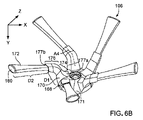
図6A~図6Eは、サイドブラシ106の一例を示す。この例は、X軸、Y軸、およびZ軸に関して説明される。サイドブラシ106の回転軸124は、Y軸に平行である。本明細書で説明するように、いくつかの場合では、Y軸は、床面から垂直に延びる垂直軸に平行であるが、他の実施形態では、Y軸および垂直軸は非ゼロ角を形成する。
[Example of side brush]
6A to 6E show an example of the
図6Aに示すように、サイドブラシ106は、ハブ168、アーム170、および剛毛バンドル172を含む。サイドブラシ106は、回転軸124の周りに軸対称である。サイドブラシ106が回転軸124を中心にして回転するにつれて、ロボット100の下の床面の一部を掃引して床面上の屑をブラシ120a、120bに向けて推進できるように、サイドブラシ106は取り付けられている。サイドブラシによって清掃される床面の部分は、ブラシ120a、120bの少なくとも1つの真下の部分をさらに含む。本明細書で説明されるように、ハブ168、アーム170、および剛毛バンドル172は、ブラシ120a、120bの動作を妨害することなく、ブラシ120a、120bの下をサイドブラシ106が掃引できるように構成される。
As shown in FIG. 6A, the
図6Bに示すように、ハブ168は、例えば、回転軸124に垂直な平面に沿った円形の断面を有する半球体171を含む。いくつかの例では、円形O1(図6Eに示される)は、ハブ168のY軸に沿った断面図である。円形O1は、1cm~3cm(例えば、1cm~2cm、1.5cm~2.5cm、2cm~3cm、または約2cm)の直径D1(図6Eに示す)を有する。
As shown in FIG. 6B, the
ハブ168は、ロボット100(図3に示す)のサイドブラシモータ(例えば、モータ150)と係合するように構成される。例えば、図6Aに示すように、ハブ168は、駆動シャフト157(図4に示す)と係合するように寸法決めされたボア175を含む。ボア175は、駆動シャフト157に係合されると、サイドブラシモータがハブ168にトルクを伝達し、サイドブラシモータがサイドブラシ106を回転させることができる。いくつかの場合では、ハブ168の少なくとも一部は、ロボット100(図3に示す)の底面140の上に配置される。
The
ハブ168の高さH1(図6Cに示す)は、0.25cm~1.5cm(例えば、0.25cm~1cm、0.5cm~1.25cm、0.75~1.5cm、または約0.75cm)である。例えば、高さH1は、アーム170がハブ168に取り付けられている最下点とボア175の最上面とによって画定される。ハブ168は剛性プラスチック部品であるので、ハブ168への衝撃力は、実質的な減衰なしに駆動シャフト157に伝達することができる。その結果、ハブ168への衝撃力は、駆動シャフト157を損傷させる可能性がある。高さH1は、ハブ168が床面に沿った障害物に接触しにくいように、比較的小さい。したがって、ハブ168の比較的小さい高さは、駆動シャフト157またはサイドブラシモータに対する損傷を防止することができる。本明細書で説明されるように、ハブ168は、清掃ヘッドモジュール154の一部とすることができる。その結果、ハブ168に衝撃が加わると、清掃ヘッドモジュール154がユニットとして動き、それによって衝撃の力を弱め、衝撃によるサイドブラシ106の損傷を防止することができる。
The height H1 of the hub 168 (shown in FIG. 6C) is 0.25 cm to 1.5 cm (eg, 0.25 cm to 1 cm, 0.5 cm to 1.25 cm, 0.75 to 1.5 cm, or about 0. 75 cm). For example, the height H1 is defined by the lowest point at which the
ハブ168、アーム170、および剛毛バンドル172は、異なる材料で形成され得る。例えば、ハブ168は、アーム170、剛毛バンドル172、またはその両方が延びているモノリシックプラスチックコンポーネントである。ハブ168は、1~10GPaの弾性率を有する剛性ポリマー材料から形成され、アーム170は、0.01~0.1の弾性率を有する弾性材料から形成される。例えば、ハブ168はポリカーボネートまたはアクリロニトリルブタジエンスチレンから形成され、アーム170はエラストマーから形成される。したがって、アーム170は、ハブ168よりも容易に変形可能である。アーム170は、それぞれの剛毛バンドル172の剛毛を一緒に保つが、変形可能で、剛毛バンドル172の保護シースとして機能し、剛毛バンドル172およびアーム170は、床面と床面上の障害物との接触に応じて一緒に変形し得る。その結果、アーム170は、剛毛バンドル172の損傷を防止することができる。
The
図6Cに示すように、アーム170は、ハブ168から外側にサイドブラシ106の回転軸124から離れるように延びている。アーム170はそれぞれ、0.5cm~2.5cm(0.5cm~1.5cm、1cm~2cm、1.5cm~2.5cm、または約1.5cm)の間の長さL1(図6Dに示す)延びる。長さL1は、それぞれのアーム170の近位端177aから遠位端177bまでの直線の長さに対応し、近位端177aはハブ168に取り付けられている。
As shown in FIG. 6C, the
アーム170のそれぞれは、ブラシ106の回転軸124に垂直な平面173に対して傾斜している。アーム170は、平面173に対して異なる角度をなす2つの部分174、176から形成されている。異なる角度の部分174、176は、アーム170がロボット100と床面との間の垂直距離に及んで、剛毛バンドル172に対して所望の掃引円を形成することを可能にする。例えば、ハブ168に最も近い、アーム170の部分174の(平面173に対する)傾斜は、ハブ168から遠い、アーム170の部分176の(平面173に対する)傾斜よりも大きい。
Each of the
第1の部分174および第2の部分176はそれぞれ、サイドブラシ106が駆動シャフト157に取り付けられたときに床面に向かって下方に延びている。これに関して、ハブ168の高さH1は、ハブ168がクリアランス高さで床面の上に位置するように小さいが、第1の部分174および第2の部分176は、剛毛バンドル172が床面に接触することを可能にするように下方に延びる。
The
第1の部分174および第2の部分176は、それぞれ、例えば、平面173に沿った方向に、ハブ168から外側に延びる。第1の部分174は、それぞれのアーム170の近位端177aでハブ168に取り付けられ、ハブ168から外側に回転軸124から離れて延びる。第2の部分176は、第1の部分174から外側に回転軸124から離れて延び、それぞれのアーム170の遠位端177bで終端する。例えば、図6Dに示すように、第1の部分174および第2の部分176の両方とも、サイドブラシ106が回転軸124の周りを回転するときに、それぞれのアーム170の遠位端177bが円形O2を通って掃引されるように、回転軸124から離れて延びる。円形O2は、Y軸に沿って見たときにそれぞれのアーム170の先端177bの外点によって掃引される円に対応する。円形O2は、2cm~4cm(例えば、2cm~3cm、2.5cm~3.5cm、3cm~4cm、または約3cm)の直径D2を有する。第1の部分174および第2の部分176は、それぞれ、回転軸124から外側に向かって伸びることによって、サイドブラシ106がロボット100から外向きに延びることを許容して、例えばロボット100の外周を越えた領域に拡大してカバーし、ロボット100の清掃幅の外側であってロボット100の下方の領域をカバーする。
The
再び図6Cに示すように、第1の部分174は、ハブ168から下方に延びる。いくつかの例では、第2の部分176もまた、第1の部分174から下方に延びる。アーム170は、ハブ168から下方に伸長することによって、剛毛バンドル172が、サイドブラシ106の下の床面の部分に接触するように配置されることを可能にする。例えば、それぞれのアーム170の近位端177a(すなわち、近位端177aの最下点)と遠位端177b(例えば、遠位端177bの最下点)との間の高さH2は、0.25~1.5cm(例えば、0.25cm~1cm、0.5cm~1.25cm、0.75cm~1.5cm、または約0.8cm)の間である。
As shown again in FIG. 6C, the
いくつかの例では、それぞれのアーム170の第1の部分174と平面173との間の角度A1は、それぞれのアームの第2の部分と平面173との間の角度A2より大きい。角度A1および角度A2は、X軸と平行に第2の部分176が沿って延びる軸線がXY平面内で測定される角度に対応する。それぞれのアーム170の第1の部分174は、第1の部分174が平面173に対して第2の部分176の急な角度よりも平面173に対して浅い角度を有するように、第2の部分176に対して上方に傾斜している。角度A1は、70度~90度(例えば、70度~80度、75度~85度、80度~90度、または約80度)の間である。角度A2は、0度~60度(例えば、15度~60度、15度~45度、15度~30度、または約30度)の間である。
In some examples, the angle A1 between the
アーム170のそれぞれの第2の部分176は、第1の部分174に対して、サイドブラシ106の回転方向108とは反対の方向に傾斜している。例えば、図6Eに示すように、それぞれのアーム170は、ハブ168の一部分から円形O1に沿って延びる。角度A3は、(i)XZ平面に沿った軸であって、アーム170の第2の部分176が延びる軸と、(ii)円形O1に接する線181であって、第2部分176の軸が円形O1と交差する点を通って延びる線181と、の間の角度に対応する。角度A3は、例えば、30度~60度(例えば、30度~50度、35度~55度、40度~60度等)の間である。いくつかの場合では、アーム170のそれぞれの第1の部分174は、半径方向の軸に沿って延び、したがって、接線181に対して実質的に垂直である。接線181に対する第2の部分176のこの角度は、サイドブラシ106の回転中にアーム170が撓むとき、アーム170に沿った応力集中を低減し得る。
Each
いくつかの実施形態では、図6Bに示すように、それぞれのアーム170の第1の部分174とそれぞれのアーム170の第2の部分176との間の角度A4は、100~160度(例えば、100~140度、110~150度、120~160度、または約130度)の間である。剛毛バンドル172は、それぞれ、自律式清掃動作中にサイドブラシ106が回転するときに、床面を掃引する多数の剛毛を含む。再び図2を参照すると、サイドブラシ106の剛毛バンドル172は、床面102を掃引し、メインブラシ120aに向けて屑を推進することができる。それぞれのブラシ剛毛バンドル172は、サイドブラシ106が回転されると再配置される。例えば、剛毛バンドル172の少なくとも一部、例えば、図2に示される剛毛バンドル172aは、メインブラシ120aの回転中でサイドブラシ106の回転の一部の間、メインブラシ120aの下に配置可能である。
In some embodiments, as shown in FIG. 6B, the angle A4 between the
図6A~図6Eに示す例では、剛毛バンドル172は、回転軸124に垂直な軸、例えば、同心円形O1、O2、O3のいずれかの半径を通って延びる軸に対して非ゼロの角度で、アーム170から延びる。いくつかの実施態様では、それぞれの剛毛バンドル172は垂直軸に平行に延びる。
In the example shown in FIGS. 6A-6E, the
それぞれの剛毛バンドル172は、束ねられた複数の偏向可能な繊維を含む。図6Bに示すように、それぞれの剛毛バンドル172は、対応するアーム170の第2の部分176から延び、それぞれの剛毛バンドル172は、対応する遠位端180で終端する。剛毛バンドル172は、アーム170の第2の部分176が延びる軸に平行な軸に沿ってアーム170から延びている。剛毛バンドル172のアーム170を越える長さL2(図6Bおよび図6Dに示す)は、1cm~5cm(例えば、1cm~4cm、1.5cm~4.5cm、2cm~5cm、約2.5cm、または約3cm)の間である。長さL2は、それぞれのアーム170の遠位端177bからそれぞれの剛毛バンドル172の遠位端180までの直線長さに対応する。長さL2は、アーム170の長さL1の40%~80%(例えば、アーム170の長さL1の40%~60%、50%~70%、60%~80%、約50%、約60%、または約70%)の間である。それぞれのアーム170の遠位端177b(例えば、遠位端177bの最下点)と各剛毛バンドル172の遠位端180との間の各剛毛バンドル172の高さH3は、0.25~2cm(例えば、0.25cm~1.5cm、0.5cm~1.75cm、0.75cm~2cm、または約1cm)の間である。
Each bristle
それぞれの剛毛バンドル172の少なくとも遠位端180は、床面に係合し、床面上の屑と係合するように構成されて、ロボット100(図2に示す)のブラシに向けて屑を推進させる。この点に関して、図2に簡単に戻ると、それぞれの剛毛バンドル172の少なくとも一部は、ロボット100の前方面114および側面112aを越えて位置決め可能である。
At least the
図6Dに示すように、それぞれの剛毛バンドル172の遠位端180は、Y軸に沿って見たときにそれぞれの剛毛バンドル172の遠位端180によって掃引される円に対応する円形O3を通って掃引される。円形O3は、直径D3によって規定される。いくつかの場合において、その回転軸124が垂直軸に平行になるようにサイドブラシ106が取り付けられている場合、直径D3は幅W3(図3に示す)に等しい。あるいは、サイドブラシ106が垂直軸に対してある角度で取り付けられている場合、直径D3は幅W3と異なり得る。この点に関して、直径D3は、例えば2cm~10cm(例えば、2cm~6cm、6cm~10cm、7cm~9cm、または約8cm)の間である。いくつかの場合では、直径D1(図6Eに示されている)は、直径D3の10%~40%(例えば、直径D3の10%~30%、15%~35%、20%~40%、または約25%)の間である。いくつかの場合では、直径D2は、直径D3の20%~50%(例えば、直径D3の20%~40%、25%~45%、または30%~40%)の間である。
As shown in FIG. 6D, the
いくつかの場合では、剛毛バンドル172は、アーム170、ハブ168、またはその両方に取り付けられている。例えば、剛毛バンドル172の近位端(図示せず)が、アーム170またはハブ168に取り付けられる。代替的にまたは追加的に、剛毛バンドル172は、アーム170を介して延び、アーム170の長さやその一部分の長さに沿ってアーム170に取り付けられる。
In some cases, the
図7Aに示すように、ハブ168の頂部182は、サイドブラシ106によって係合されたフィラメント屑を収集するように構成されている。自律式清掃作業の間に、毛、糸、カーペット繊維などを含むフィラメント屑は、サイドブラシ106の回転中にサイドブラシ106の周りに巻き付くことができる。フィラメント屑が、アーム170または剛毛バンドル172の周りに巻き付いた場合、サイドブラシ106の動作を妨げる可能性がある。フィラメント屑が、サイドブラシモータの駆動シャフトの周りに巻き付くと、サイドブラシモータの動作を妨げ得る。ハブ168の頂部182は、フィラメント屑がアーム170および剛毛バンドル172から離れた領域に集められるように構成されている。
As shown in FIG. 7A, the top 182 of the
図7A~図7Cに示すように、ハブ168の頂部182は、サイドブラシ106によって係合されたフィラメント屑を収集するためのインセット部184を含む。フィラメント屑は、回転軸124(図6Aに示す)に対するアーム170と剛毛バンドル172との角度のために、ハブ168の上部182に向かって集まる傾向がある。図4および図8を参照すると、清掃ヘッドモジュール154は、フィラメント屑を収集するようにも構成された開口部186を含む。駆動シャフト157は、開口部186を貫通して延びている。この点に関して、サイドブラシ106は、開口部186で駆動シャフト157に取り付けられている。
As shown in FIGS. 7A-7C, the top 182 of the
図8に示すように、ハブ168のインセット部184は、フィラメント屑を受け入れるように配置され、開口部186は、インセット部184からフィラメント屑を受け取るように配置される。インセット部184とハウジング188に沿ったインセット部187とは、フィラメント屑が収集される領域を画定する。ハウジング188は、清掃ヘッドモジュール154のハウジング、或いは、ロボット100のハウジングとなり得る。開口部186の周りに円周方向に配置された障壁190は、インセット部分187を通って延び、フィラメント屑が、インセット部分184およびインセット部分187によって画定された領域を越えて移動することを防止する。フィラメント屑がこの領域を越えて移動すると、フィラメント屑が開口部186に集められる。例えば、フィラメント屑は、駆動シャフト157の周りに集められる。
As shown in FIG. 8, the
サイドブラシ106によって収集されたフィラメント屑を除去するために、サイドブラシ106は駆動シャフト157から取り外される。フィラメント屑は、障壁190によって開口部186の外側に集まり易く、フィラメント屑を除去するプロセスをより簡単に行うことができる。例えば、インセット部184およびインセット部187によって画定される領域は、サイドブラシ106が取り外されると、手作業で容易にアクセス可能である。ユーザはサイドブラシ106を取り外すことができ、手作業でフィラメント屑をその領域から除去することができる。
The
[その他の実施形態]
既に多数の実施形態が説明されている。それにもかかわらず、様々な変更がなされ得ることが理解されるであろう。
[Other embodiments]
Many embodiments have already been described. Nevertheless, it will be understood that various changes can be made.
例えば、サイドブラシ106は、ロボット100の前方面114および側面112aを越えて延びるように記載されているが、いくつかの実施形態では、サイドブラシ106は、ロボット100の前方面114のみを越え、或いは、ロボット100の側面112aのみを越え得る。
For example, the
サイドブラシ106のハブ168は、図2に示されるように、ブラシ120a、120bの前方に位置している。例えば、ハブ168は、回転軸144a、144bの両方の前方にある。いくつかの実施形態では、ハブ168は、ブラシ120a、120bに水平に隣接して配置される。いくつかの実施形態では、サイドブラシ106は、例えば、ハブ168がブラシ120a、120bの後方に取り付けられるように、ブラシ120a、120bの後方に配置される。
The
図2に示すように、回転軸124は床面に対して実質的に垂直である(例えば、回転軸124は実質的に垂直である)。例えば、回転軸124および床面は、85度~90度の間の角度を形成する。あるいは、いくつかの実施形態では、回転軸124は、垂直軸に対して非ゼロの角度にある。例えば、回転軸124および床面は、85度未満(例えば、60度~85、70度~80度、約75度など)の角度を形成する。この点に関して、回転軸124および垂直軸は、5度よりも大きい角度(例えば、5度~30度、10度~20度、約15度など)を形成する。
As shown in FIG. 2, the
いくつかの実施形態では、ブラシ120a、120bは、床面の屑を係合してブラッシングする外面を有するローラを含む。外面は、例えば、円筒形とすることができる。いくつかの場合では、ブラシ120a、120bは、屑と係合してブラッシングする剛毛を含む。
In some embodiments, the
サイドブラシ106およびブラシ120a、120bは、複数のモータによって駆動されるものとして説明されているが、いくつかの実施形態では、サイドブラシ106およびブラシ120a、120bは、単一のモータによって駆動される。ロボット100は、モータからのトルクをそれぞれのブラシ106、120a、120bに伝達する駆動伝達部を含む。代替的に、ロボット100は、ブラシ106、120a、120bの対応する1つをそれぞれ駆動するように構成された3つの異なるモータを含む。
The
2つのブラシ120a、120bを含むロボット100が図3に示されているが、いくつかの実施形態では、ロボットは、床面に平行な軸の周りを回転可能な単一のブラシを含む。単一のブラシは、床面の屑をロボットの清掃箱に導く。さらに、ブラシ120a、120bは、同じ幅W2を有するものとして示されているが、いくつかの実施形態では、一方のブラシが他のブラシよりも大きい。例えば、1つのブラシの幅は、他のブラシの幅の70%~90%である。
A
単一のサイドブラシ106を含むロボット100として図3に示されているが、いくつかの実施形態では、ロボット100は、複数のサイドブラシを含む。例えば、サイドブラシの1つは、側面112aに近接して配置され、他のサイドブラシは、側面112bに近接して配置される。いくつかの実施形態では、ロボット100が複数のサイドブラシを含む場合、障害次行動の間、側面112a、112bのいずれかが障害物に隣接して配置される。ロボット100は支配的な障害物追従サイドを有していない。この点に関して、障害物の近傍を清掃するために、ロボット100の支配的なサイドが障害物に隣接して配置されるように、ロボット100の向きを変更する必要はない。
Although shown in FIG. 3 as a
サイドブラシ106は、ロボット100の右側面112aに近接して配置されたコーナーブラシとして示されて説明されているが、いくつかの実施形態では、コーナーブラシは、ロボット100の左側面112bに代わりに配置され得る。ロボット100の障害物追従サイドは、ロボット100の右側ではなく、ロボット100の左側に対応することができる。
The
サイドブラシ106は、コーナーブラシがロボット100の右側面112aに近接して配置されるように示されているが、いくつかの実施形態では、ロボットは、一方がロボット100の右側面に配置され、他方が左側面112bに配置される、2つのコーナーブラシを含み得る。
The
いくつかの追加の例では、ロボット100は形状が正方形であっても良く、4つのコーナーブラシを含み、1つのコーナーブラシがそれぞれのコーナーまたはその近くに配置され得る。4つのコーナーブラシを有することによって、ロボット100は、ロボット100の周囲を越えて経路の汚れを掃きながら、前方または後方に移動することができる。
In some additional examples, the
図6A~図6Gのアーム170は、ハブ168から外側にサイドブラシ106の回転軸124から延びるように記載されているが、いくつかの実施形態では、アーム170は、回転軸124から離れるようにハブ168から実質的に半径方向外向きに延びる。例えば、アーム170は、回転軸124に垂直な平面に沿って、回転軸124から放射状に延びる軸に沿って延びる。いくつかの場合では、それぞれのアーム170の少なくとも第1の部分174は、放射軸に沿って、例えば、半径方向の軸の下に、軸に沿って延びる。第2の部分176は、半径方向の軸に対して非ゼロの角度で、例えば、軸の下に、軸に沿って延びる。図6A~図6Eに示す例では、サイドブラシ106は、5つの別個のアーム170と5つの対応する別個の剛毛バンドル172とを含む。しかしながら、他の実施形態では、サイドブラシは、2つ、3つ、4つ、6つ、またはそれ以上の別個のアームおよび別個の剛毛バンドルを含み得る。一方、図示された例は、代替としてアーム毎に単一の剛毛バンドルを示している。
The
したがって、他の実施形態も特許請求の範囲内である。 Therefore, other embodiments are also within the scope of the claims.
100 自律式清掃ロボット
102 床面
104 屑
106 サイドブラシ
108 回転方向
110 障害物
112 側面
114 前方面
116 目標経路
118 清掃幅
120 メインブラシ
122 清掃箱
124 回転軸
128 フロント部
129 バンパー
130 リア部
132 駆動方向
134 駆動ホイール
136、142、150 モータ
137 崖センサ
138 コントローラ
140 底面
144 回転軸
146 入口
148 真空システム
152 コーナー部
154 清掃ヘッドモジュール
157 駆動シャフト
158 周囲
160 障害物
162 清掃領域
164 部分
168 ハブ
170 アーム
172 剛毛バンドル
173 平面
174 第1の部分
176 第2の部分
177a 近位端
177b、180 遠位端
181 接線
182 頂部
184、187 インセット部
186 開口部
188 ハウジング
190 障壁
100
Claims (25)
前記ロボットの側面に近接するサイドブラシと、
前記サイドブラシを回転軸の周りに回転させるように構成されたモータと、
を含んでなる自律式清掃ロボットであって、
前記サイドブラシが、
当該ロボットの前記モータと係合するように構成されたハブと、
前記回転軸から離れて前記ハブから外側に延び、前記サイドブラシの回転軸に垂直な平面に対して角度が付けられた複数のアームであって、それぞれの該アームが、前記回転軸から離れて前記ハブから外側に延びる第1の部分と、前記回転軸から離れて前記第1の部分から外側に延びる第2の部分とを含み、それぞれの該アームの前記第1の部分と前記平面との間の角度が、それぞれの該アームの前記第2の部分と前記平面との間の角度より大きく、それぞれの前記アームの前記第2の部分は、前記サイドブラシの回転方向とは反対の方向において、それぞれの前記アームの前記第1の部分に対して角度が付けられている、複数のアームと、
複数の剛毛バンドルであって、それぞれの該剛毛バンドルが複数の前記アームのそれぞれに取り付けられ、それぞれの前記アームの前記第2の部分から外側に延びる、複数の剛毛バンドルと、
を含んでなることを特徴とする自律式清掃ロボット。 A drive unit configured to move the robot across the floor,
A side brush near the side of the robot and
A motor configured to rotate the side brush around a rotation axis,
It is an autonomous cleaning robot that includes
The side brush
A hub configured to engage the motor of the robot,
A plurality of arms extending outward from the hub away from the axis of rotation and angled with respect to a plane perpendicular to the axis of rotation of the side brush, each of which is separated from the axis of rotation. A first portion extending outward from the hub and a second portion extending outward from the first portion away from the axis of rotation, the first portion of each of the arms and the plane. The angle between them is greater than the angle between the second portion of each arm and the plane, and the second portion of each arm is in a direction opposite to the direction of rotation of the side brush. In, a plurality of arms, each of which is angled with respect to the first portion of the arm.
A plurality of bristle bundles, each of which is attached to each of the plurality of the arms and extends outward from the second portion of the respective arm.
An autonomous cleaning robot characterized by including.
当該ロボットが、床面に平行な軸の周りを回転可能なメインブラシをさらに含み、
前記サイドブラシは、回転の一部の間、前記サイドブラシの前記剛毛バンドルの少なくとも一部が、前記メインブラシの下に配置可能であるように構成されていることを特徴とする、請求項1に記載のロボット。 The side brush is a corner brush,
The robot further includes a main brush that can rotate around an axis parallel to the floor.
Claim 1 is characterized in that the side brush is configured such that at least a portion of the bristles bundle of the side brush can be placed under the main brush during a portion of rotation. The robot described in.
当該ロボットが、
略矩形状のフロント部と、
当該ロボットの前記フロント部に沿って配置されたメインブラシであって、当該ロボットの前記フロント部の幅の60%~90%にわたって延びるメインブラシと、
を含んでなることを特徴とする、請求項1に記載のロボット。 The side brush is a corner brush,
The robot
Approximately rectangular front part and
A main brush arranged along the front portion of the robot, the main brush extending over 60% to 90% of the width of the front portion of the robot.
The robot according to claim 1, wherein the robot comprises.
前記清掃ヘッドモジュールが、前記床面に平行な軸の周りを回転可能なメインブラシと、前記清掃ヘッドモジュールのコーナーに近接して取り付けられるサイドブラシと、を含むことを特徴とする、請求項1に記載のロボット。 The robot further includes a cleaning head module,
1. The cleaning head module is characterized by comprising a main brush that is rotatable around an axis parallel to the floor surface and a side brush that is mounted close to a corner of the cleaning head module. The robot described in.
それぞれの前記剛毛バンドルが当該ロボットの前記前方面および前記側面を越えて位置決めできるように、前記モータが前記サイドブラシを回転するように構成されていることを特徴とする、請求項1に記載のロボット。 The side brush is arranged close to the corner portion of the robot formed by the front surface of the robot and the side surface of the robot.
1. robot.
前記ハウジングの底面が、前記ハブのインセット部を受け入れるように構成されたインセット部を含み、
前記ハウジングのインセット部と前記ハブのインセット部とによって画定された領域内に前記フィラメント屑を収集するように、前記ハブが構成されていることを特徴とする、請求項8に記載のロボット。 The robot further includes a housing
The bottom surface of the housing comprises an inset portion configured to accommodate the inset portion of the hub.
8. The robot according to claim 8, wherein the hub is configured to collect the filament debris in a region defined by an inset portion of the housing and an inset portion of the hub. ..
モータが駆動されたときに、当該サイドブラシが回転軸を中心に回転して床面上の屑を攪拌するように前記自律式清掃ロボットの前記モータと係合するように構成されたハブと、
前記回転軸から離れて前記ハブから外側に延び、前記サイドブラシの回転軸に垂直な平面に対して角度が付けられた複数のアームであって、それぞれの該アームが、前記回転軸から離れて前記ハブから外側に延びる第1の部分と、前記回転軸から離れて前記第1の部分から外側に延びる第2の部分とを含み、それぞれの該アームの前記第1の部分と前記平面との間の角度が、それぞれの該アームの前記第2の部分と前記平面との間の角度より大きく、それぞれの前記アームの前記第2の部分は、前記サイドブラシの回転方向とは反対の方向において、それぞれの前記アームの前記第1の部分に対して角度が付けられている、複数のアームと、
複数の剛毛バンドルであって、それぞれの該剛毛バンドルが複数の前記アームのそれぞれに取り付けられ、それぞれの前記アームの前記第2の部分から外側に延びる、複数の剛毛バンドルと、
を含んでなることを特徴とするサイドブラシ。 A side brush that can be attached to an autonomous cleaning robot.
A hub configured to engage the motor of the autonomous cleaning robot so that when the motor is driven, the side brush rotates about a axis of rotation to agitate debris on the floor.
A plurality of arms extending outward from the hub away from the axis of rotation and angled with respect to a plane perpendicular to the axis of rotation of the side brush, each of which is separated from the axis of rotation. A first portion extending outward from the hub and a second portion extending outward from the first portion away from the axis of rotation, the first portion of each of the arms and the plane. The angle between them is greater than the angle between the second portion of each arm and the plane, and the second portion of each arm is in a direction opposite to the direction of rotation of the side brush. In, a plurality of arms, each of which is angled with respect to the first portion of the arm.
A plurality of bristle bundles, each of which is attached to each of the plurality of the arms and extends outward from the second portion of the respective arm.
A side brush characterized by containing.
Applications Claiming Priority (3)
| Application Number | Priority Date | Filing Date | Title |
|---|---|---|---|
| US15/605,299 US11103113B2 (en) | 2017-05-25 | 2017-05-25 | Brush for autonomous cleaning robot |
| US15/605,299 | 2017-05-25 | ||
| PCT/US2017/059075 WO2018217226A1 (en) | 2017-05-25 | 2017-10-30 | Brush for autonomous cleaning robot |
Publications (3)
| Publication Number | Publication Date |
|---|---|
| JP2020520683A JP2020520683A (en) | 2020-07-16 |
| JP2020520683A5 JP2020520683A5 (en) | 2020-12-10 |
| JP7044713B2 true JP7044713B2 (en) | 2022-03-30 |
Family
ID=64396975
Family Applications (1)
| Application Number | Title | Priority Date | Filing Date |
|---|---|---|---|
| JP2018550696A Active JP7044713B2 (en) | 2017-05-25 | 2017-10-30 | Brush for autonomous cleaning robot |
Country Status (7)
| Country | Link |
|---|---|
| US (2) | US11103113B2 (en) |
| EP (1) | EP3629870B1 (en) |
| JP (1) | JP7044713B2 (en) |
| CN (2) | CN209826570U (en) |
| AU (2) | AU2017405992B2 (en) |
| MY (1) | MY195654A (en) |
| WO (1) | WO2018217226A1 (en) |
Families Citing this family (13)
| Publication number | Priority date | Publication date | Assignee | Title |
|---|---|---|---|---|
| CN108309143B (en) * | 2017-01-17 | 2021-08-31 | 美国iRobot公司 | Cleaning head of mobile cleaning robot |
| DE102017119216A1 (en) * | 2017-08-22 | 2019-02-28 | Vorwerk & Co. Interholding Gmbh | Sweeping brush for a self-propelled cleaning device |
| US10932631B2 (en) | 2018-03-29 | 2021-03-02 | Omachron Intellectual Property Inc. | Rotatable brush for surface cleaning apparatus |
| CN110393476A (en) * | 2018-04-25 | 2019-11-01 | 科沃斯机器人股份有限公司 | Clean robot and its welt traveling method, readable medium |
| EP3900591A4 (en) * | 2018-12-21 | 2022-09-21 | Positec Power Tools (Suzhou) Co., Ltd | Robot cleaner, cleaning method and automatically charging system |
| GB2588957B (en) * | 2019-11-15 | 2021-12-15 | Dyson Technology Ltd | A cleaner head |
| US11382473B2 (en) * | 2019-12-11 | 2022-07-12 | Irobot Corporation | Predictive maintenance of mobile cleaning robot |
| US20210244249A1 (en) | 2020-02-10 | 2021-08-12 | Matician, Inc. | Configuration of a cleaning head for an autonomous vacuum |
| EP4188181A1 (en) * | 2020-07-29 | 2023-06-07 | Innotalenz Limited | Multi-function cleaning appliance |
| DE102020129405A1 (en) | 2020-11-09 | 2022-05-12 | Miele & Cie. Kg | Vacuum robot for autonomous cleaning of floor surfaces in a room |
| EP4154763A1 (en) * | 2021-05-28 | 2023-03-29 | Techtronic Cordless GP | Scrubber with non-circular brush head |
| CN114376485A (en) * | 2021-12-17 | 2022-04-22 | 北京享捷科技有限公司 | Cleaning robot and mechanism are swept to cleaning robot limit |
| EP4260782A1 (en) * | 2022-04-14 | 2023-10-18 | Vorwerk & Co. Interholding GmbH | Cleaning device and sweeping brush for a cleaning device |
Citations (9)
| Publication number | Priority date | Publication date | Assignee | Title |
|---|---|---|---|---|
| JP3182649U (en) | 2012-11-20 | 2013-04-04 | イーゲンパワー インコーポレーテッド | Self-propelled vacuum cleaner |
| JP3182828U (en) | 2012-11-14 | 2013-04-11 | イーゲンパワー インコーポレーテッド | Self-propelled vacuum cleaner |
| JP2013081775A (en) | 2011-10-06 | 2013-05-09 | Samsung Electronics Co Ltd | Robot cleaner |
| US20130152332A1 (en) | 2011-12-16 | 2013-06-20 | Jaewon Jang | Automatic cleaner |
| JP2014046207A (en) | 2012-08-30 | 2014-03-17 | Samsung Electronics Co Ltd | Side brush assembly, robot cleaner and control method for the same |
| JP2014236803A (en) | 2013-06-06 | 2014-12-18 | シャープ株式会社 | Support structure of revolving shaft for auxiliary brush and self-propelled vacuum cleaner including the same |
| JP2015091290A (en) | 2013-10-04 | 2015-05-14 | 株式会社コーワ | Side brush for cleaner and self-propelled cleaner |
| US20160143496A1 (en) | 2014-11-20 | 2016-05-26 | Miele & Cie. Kg | Vacuum cleaner side brush and floor care device comprising a vacuum cleaner side brush |
| US20160166127A1 (en) | 2014-12-12 | 2016-06-16 | Irobot Corporation | Cleaning system for autonomous robot |
Family Cites Families (29)
| Publication number | Priority date | Publication date | Assignee | Title |
|---|---|---|---|---|
| US5903951A (en) * | 1995-11-16 | 1999-05-18 | Minnesota Mining And Manufacturing Company | Molded brush segment |
| US6532404B2 (en) | 1997-11-27 | 2003-03-11 | Colens Andre | Mobile robots and their control system |
| ES2172936T3 (en) | 1997-11-27 | 2002-10-01 | Solar & Robotics | IMPROVEMENTS IN MOBILE ROBOTS AND THEIR CONTROL SYSTEM. |
| DE60011266T2 (en) | 1999-06-17 | 2005-01-20 | Solar And Robotics S.A. | AUTOMATIC DEVICE FOR COLLECTING OBJECTS |
| US6594844B2 (en) | 2000-01-24 | 2003-07-22 | Irobot Corporation | Robot obstacle detection system |
| US7155308B2 (en) | 2000-01-24 | 2006-12-26 | Irobot Corporation | Robot obstacle detection system |
| US6883201B2 (en) * | 2002-01-03 | 2005-04-26 | Irobot Corporation | Autonomous floor-cleaning robot |
| US6690134B1 (en) | 2001-01-24 | 2004-02-10 | Irobot Corporation | Method and system for robot localization and confinement |
| US6809490B2 (en) | 2001-06-12 | 2004-10-26 | Irobot Corporation | Method and system for multi-mode coverage for an autonomous robot |
| US7571511B2 (en) | 2002-01-03 | 2009-08-11 | Irobot Corporation | Autonomous floor-cleaning robot |
| EP1408729B1 (en) | 2001-05-28 | 2016-10-26 | Husqvarna AB | Improvement to a robotic lawnmower |
| US7429843B2 (en) | 2001-06-12 | 2008-09-30 | Irobot Corporation | Method and system for multi-mode coverage for an autonomous robot |
| JP2005270413A (en) * | 2004-03-25 | 2005-10-06 | Funai Electric Co Ltd | Self-propelled vacuum cleaner |
| US7389156B2 (en) | 2005-02-18 | 2008-06-17 | Irobot Corporation | Autonomous surface cleaning robot for wet and dry cleaning |
| KR101247933B1 (en) | 2005-02-18 | 2013-03-26 | 아이로보트 코퍼레이션 | Autonomous surface cleaning robot for wet and dry cleaning |
| US20060272122A1 (en) * | 2005-06-07 | 2006-12-07 | Dennis Butler | Vacuum brushroll edge cleaner |
| KR101300493B1 (en) | 2005-12-02 | 2013-09-02 | 아이로보트 코퍼레이션 | Coverage robot mobility |
| KR101414321B1 (en) * | 2007-05-09 | 2014-07-01 | 아이로보트 코퍼레이션 | Autonomous coverage robot |
| EP2253258B1 (en) * | 2009-05-15 | 2016-10-19 | Samsung Electronics Co., Ltd. | Autonomous cleaning machine |
| ES2582006T3 (en) | 2009-06-30 | 2016-09-08 | Lg Electronics Inc. | Robot cleaner |
| KR101960816B1 (en) | 2011-12-22 | 2019-03-22 | 삼성전자주식회사 | Cleaning system |
| KR101970541B1 (en) * | 2012-04-06 | 2019-04-22 | 삼성전자주식회사 | Robot cleaner and control method for the same |
| US8695352B2 (en) | 2012-07-12 | 2014-04-15 | Solar Turbines Inc. | Baffle assembly for bleed air system of gas turbine engine |
| KR102015311B1 (en) | 2012-11-30 | 2019-08-28 | 삼성전자주식회사 | Cleaning robot and method for controlling the same |
| JP6140523B2 (en) * | 2013-05-14 | 2017-05-31 | シャープ株式会社 | Auxiliary brush mounting structure and self-propelled vacuum cleaner provided with the same |
| CN204146956U (en) * | 2014-09-02 | 2015-02-11 | 番禺得意精密电子工业有限公司 | Intelligent cleaning robot |
| KR102271782B1 (en) * | 2014-09-08 | 2021-06-30 | 에이비 엘렉트로룩스 | Robotic vacuum cleaner |
| WO2016091320A1 (en) * | 2014-12-12 | 2016-06-16 | Aktiebolaget Electrolux | Side brush and robotic cleaner |
| TWM527298U (en) | 2016-05-12 | 2016-08-21 | Ibot Co Ltd | Quick release auto-cleaning device |
-
2017
- 2017-05-25 US US15/605,299 patent/US11103113B2/en active Active
- 2017-10-30 MY MYPI2019000833A patent/MY195654A/en unknown
- 2017-10-30 WO PCT/US2017/059075 patent/WO2018217226A1/en active Application Filing
- 2017-10-30 JP JP2018550696A patent/JP7044713B2/en active Active
- 2017-10-30 AU AU2017405992A patent/AU2017405992B2/en active Active
- 2017-10-30 EP EP17900281.1A patent/EP3629870B1/en active Active
-
2018
- 2018-05-23 CN CN201820779566.2U patent/CN209826570U/en active Active
- 2018-05-23 CN CN201810502939.6A patent/CN108926290B/en active Active
-
2021
- 2021-08-27 US US17/459,765 patent/US20220000325A1/en active Pending
-
2024
- 2024-02-02 AU AU2024200637A patent/AU2024200637A1/en active Pending
Patent Citations (11)
| Publication number | Priority date | Publication date | Assignee | Title |
|---|---|---|---|---|
| JP2013081775A (en) | 2011-10-06 | 2013-05-09 | Samsung Electronics Co Ltd | Robot cleaner |
| US20130152332A1 (en) | 2011-12-16 | 2013-06-20 | Jaewon Jang | Automatic cleaner |
| JP2014046207A (en) | 2012-08-30 | 2014-03-17 | Samsung Electronics Co Ltd | Side brush assembly, robot cleaner and control method for the same |
| JP3182828U (en) | 2012-11-14 | 2013-04-11 | イーゲンパワー インコーポレーテッド | Self-propelled vacuum cleaner |
| US20140130294A1 (en) | 2012-11-14 | 2014-05-15 | Egenpower Inc. | Autonomous coverage vacuum cleaner having edge cleaning head easy to install and uninstall |
| JP3182649U (en) | 2012-11-20 | 2013-04-04 | イーゲンパワー インコーポレーテッド | Self-propelled vacuum cleaner |
| JP2014236803A (en) | 2013-06-06 | 2014-12-18 | シャープ株式会社 | Support structure of revolving shaft for auxiliary brush and self-propelled vacuum cleaner including the same |
| JP2015091290A (en) | 2013-10-04 | 2015-05-14 | 株式会社コーワ | Side brush for cleaner and self-propelled cleaner |
| US20160143496A1 (en) | 2014-11-20 | 2016-05-26 | Miele & Cie. Kg | Vacuum cleaner side brush and floor care device comprising a vacuum cleaner side brush |
| US20160166127A1 (en) | 2014-12-12 | 2016-06-16 | Irobot Corporation | Cleaning system for autonomous robot |
| JP2017537716A (en) | 2014-12-12 | 2017-12-21 | アイロボット コーポレイション | Autonomous robot cleaning system |
Also Published As
| Publication number | Publication date |
|---|---|
| EP3629870A4 (en) | 2020-12-30 |
| CN209826570U (en) | 2019-12-24 |
| MY195654A (en) | 2023-02-03 |
| WO2018217226A1 (en) | 2018-11-29 |
| EP3629870A1 (en) | 2020-04-08 |
| EP3629870B1 (en) | 2023-07-05 |
| AU2024200637A1 (en) | 2024-02-22 |
| JP2020520683A (en) | 2020-07-16 |
| CN108926290A (en) | 2018-12-04 |
| US11103113B2 (en) | 2021-08-31 |
| AU2017405992A1 (en) | 2018-12-13 |
| US20220000325A1 (en) | 2022-01-06 |
| AU2017405992B2 (en) | 2023-11-02 |
| CN108926290B (en) | 2022-03-29 |
| US20180338655A1 (en) | 2018-11-29 |
Similar Documents
| Publication | Publication Date | Title |
|---|---|---|
| JP7044713B2 (en) | Brush for autonomous cleaning robot | |
| EP2253258B1 (en) | Autonomous cleaning machine | |
| EP3231342B1 (en) | Automatic cleaning device and sweeping assembly thereof | |
| JP5175117B2 (en) | Cleaning robot | |
| EP3229983B1 (en) | Side brush and robotic cleaner | |
| JP6827926B2 (en) | Cleaning system for autonomous robots | |
| EP2689701B1 (en) | Autonomous cleaning device | |
| KR101460534B1 (en) | Autonomous cleaning device | |
| JP7117606B2 (en) | Autonomous vacuum cleaner | |
| JP6072603B2 (en) | Autonomous traveling vacuum cleaner | |
| JP6122180B2 (en) | Autonomous traveling vacuum cleaner | |
| US11517159B2 (en) | Cleaner | |
| JP6357560B2 (en) | Autonomous traveling vacuum cleaner | |
| JP6698745B2 (en) | Autonomous traveling vacuum cleaner | |
| JP6247521B2 (en) | Electric vacuum cleaner | |
| KR20170117691A (en) | Agitator and vacuum cleaner comprising the same | |
| KR20120057123A (en) | Autonomous cleaning device |
Legal Events
| Date | Code | Title | Description |
|---|---|---|---|
| A521 | Request for written amendment filed |
Free format text: JAPANESE INTERMEDIATE CODE: A523 Effective date: 20201021 |
|
| A621 | Written request for application examination |
Free format text: JAPANESE INTERMEDIATE CODE: A621 Effective date: 20201021 |
|
| A977 | Report on retrieval |
Free format text: JAPANESE INTERMEDIATE CODE: A971007 Effective date: 20211007 |
|
| A131 | Notification of reasons for refusal |
Free format text: JAPANESE INTERMEDIATE CODE: A131 Effective date: 20211018 |
|
| A521 | Request for written amendment filed |
Free format text: JAPANESE INTERMEDIATE CODE: A523 Effective date: 20211228 |
|
| TRDD | Decision of grant or rejection written | ||
| A01 | Written decision to grant a patent or to grant a registration (utility model) |
Free format text: JAPANESE INTERMEDIATE CODE: A01 Effective date: 20220221 |
|
| A61 | First payment of annual fees (during grant procedure) |
Free format text: JAPANESE INTERMEDIATE CODE: A61 Effective date: 20220317 |
|
| R150 | Certificate of patent or registration of utility model |
Ref document number: 7044713 Country of ref document: JP Free format text: JAPANESE INTERMEDIATE CODE: R150 |