JP7043265B2 - Imaging equipment and camera system - Google Patents

Imaging equipment and camera system Download PDF

Info

Publication number
JP7043265B2
JP7043265B2 JP2018002782A JP2018002782A JP7043265B2 JP 7043265 B2 JP7043265 B2 JP 7043265B2 JP 2018002782 A JP2018002782 A JP 2018002782A JP 2018002782 A JP2018002782 A JP 2018002782A JP 7043265 B2 JP7043265 B2 JP 7043265B2
Authority
JP
Japan
Prior art keywords
image
optical system
image pickup
plane vibration
image plane
Prior art date
Legal status (The legal status is an assumption and is not a legal conclusion. Google has not performed a legal analysis and makes no representation as to the accuracy of the status listed.)
Active
Application number
JP2018002782A
Other languages
Japanese (ja)
Other versions
JP2019122014A (en
JP2019122014A5 (en
Inventor
正史 木村
Current Assignee (The listed assignees may be inaccurate. Google has not performed a legal analysis and makes no representation or warranty as to the accuracy of the list.)
Canon Inc
Original Assignee
Canon Inc
Priority date (The priority date is an assumption and is not a legal conclusion. Google has not performed a legal analysis and makes no representation as to the accuracy of the date listed.)
Filing date
Publication date
Application filed by Canon Inc filed Critical Canon Inc
Priority to JP2018002782A priority Critical patent/JP7043265B2/en
Priority to US16/244,179 priority patent/US11153486B2/en
Publication of JP2019122014A publication Critical patent/JP2019122014A/en
Publication of JP2019122014A5 publication Critical patent/JP2019122014A5/ja
Priority to JP2022038680A priority patent/JP7346636B2/en
Application granted granted Critical
Publication of JP7043265B2 publication Critical patent/JP7043265B2/en
Active legal-status Critical Current
Anticipated expiration legal-status Critical

Links

Images

Classifications

    • HELECTRICITY
    • H04ELECTRIC COMMUNICATION TECHNIQUE
    • H04NPICTORIAL COMMUNICATION, e.g. TELEVISION
    • H04N23/00Cameras or camera modules comprising electronic image sensors; Control thereof
    • H04N23/60Control of cameras or camera modules
    • H04N23/68Control of cameras or camera modules for stable pick-up of the scene, e.g. compensating for camera body vibrations
    • H04N23/681Motion detection
    • H04N23/6811Motion detection based on the image signal
    • HELECTRICITY
    • H04ELECTRIC COMMUNICATION TECHNIQUE
    • H04NPICTORIAL COMMUNICATION, e.g. TELEVISION
    • H04N23/00Cameras or camera modules comprising electronic image sensors; Control thereof
    • H04N23/50Constructional details
    • H04N23/54Mounting of pick-up tubes, electronic image sensors, deviation or focusing coils
    • HELECTRICITY
    • H04ELECTRIC COMMUNICATION TECHNIQUE
    • H04NPICTORIAL COMMUNICATION, e.g. TELEVISION
    • H04N23/00Cameras or camera modules comprising electronic image sensors; Control thereof
    • H04N23/50Constructional details
    • H04N23/55Optical parts specially adapted for electronic image sensors; Mounting thereof
    • HELECTRICITY
    • H04ELECTRIC COMMUNICATION TECHNIQUE
    • H04NPICTORIAL COMMUNICATION, e.g. TELEVISION
    • H04N23/00Cameras or camera modules comprising electronic image sensors; Control thereof
    • H04N23/60Control of cameras or camera modules
    • H04N23/63Control of cameras or camera modules by using electronic viewfinders
    • H04N23/633Control of cameras or camera modules by using electronic viewfinders for displaying additional information relating to control or operation of the camera
    • HELECTRICITY
    • H04ELECTRIC COMMUNICATION TECHNIQUE
    • H04NPICTORIAL COMMUNICATION, e.g. TELEVISION
    • H04N23/00Cameras or camera modules comprising electronic image sensors; Control thereof
    • H04N23/60Control of cameras or camera modules
    • H04N23/66Remote control of cameras or camera parts, e.g. by remote control devices
    • H04N23/663Remote control of cameras or camera parts, e.g. by remote control devices for controlling interchangeable camera parts based on electronic image sensor signals
    • HELECTRICITY
    • H04ELECTRIC COMMUNICATION TECHNIQUE
    • H04NPICTORIAL COMMUNICATION, e.g. TELEVISION
    • H04N23/00Cameras or camera modules comprising electronic image sensors; Control thereof
    • H04N23/60Control of cameras or camera modules
    • H04N23/68Control of cameras or camera modules for stable pick-up of the scene, e.g. compensating for camera body vibrations
    • H04N23/681Motion detection
    • H04N23/6812Motion detection based on additional sensors, e.g. acceleration sensors
    • HELECTRICITY
    • H04ELECTRIC COMMUNICATION TECHNIQUE
    • H04NPICTORIAL COMMUNICATION, e.g. TELEVISION
    • H04N23/00Cameras or camera modules comprising electronic image sensors; Control thereof
    • H04N23/60Control of cameras or camera modules
    • H04N23/68Control of cameras or camera modules for stable pick-up of the scene, e.g. compensating for camera body vibrations
    • H04N23/682Vibration or motion blur correction
    • H04N23/685Vibration or motion blur correction performed by mechanical compensation
    • H04N23/687Vibration or motion blur correction performed by mechanical compensation by shifting the lens or sensor position

Description

本発明は、撮影時のブレを補正するために像面を移動させる像面防振機構を備えた撮像装置に関し、特にライブビュー撮影可能な撮像装置およびカメラシステムに関する。 The present invention relates to an image pickup device provided with an image plane anti-vibration mechanism for moving an image plane in order to correct blurring during shooting, and more particularly to an image pickup device and a camera system capable of live view shooting.

近年、撮像素子を平行移動させる手ブレ補正機構(像面防振機構)が搭載されている撮像装置が提案されている。より高い手ブレ補正性能を実現するために、動作範囲が大きい手ブレ補正機構が提案されている。しかしながら、撮影光学系の被写体像を投影する範囲(イメージサークル)には限りがあるため、手ブレ補正機構を動かしすぎると撮影光学系からの光束のケラレが発生し、光量が低下してしまう。また、光学ファインダと撮像素子を平行移動させる手ブレ補正機構を組み合わせた場合、光学ファインダの光軸と撮像素子の中心にずれがある場合には構図がずれてしまう。 In recent years, an image pickup device equipped with a camera shake correction mechanism (image plane vibration isolation mechanism) for moving an image pickup element in parallel has been proposed. In order to realize higher image stabilization performance, an image stabilization mechanism with a large operating range has been proposed. However, since the range (image circle) for projecting the subject image of the photographing optical system is limited, if the camera shake correction mechanism is moved too much, vignetting of the light beam from the photographing optical system occurs and the amount of light decreases. Further, when the optical viewfinder and the camera shake correction mechanism for moving the image sensor in parallel are combined, the composition will be misaligned if the optical axis of the optical viewfinder and the center of the image sensor are misaligned.

特許文献1には、構図ずれを発生させずに防振効果を得るために、撮影予備動作時はレンズ防振機構のみ動作させ、露光動作時は像面防振機構のみ動作させる撮像装置が開示されている。特許文献2には、あおり撮影などの特殊撮影においてユーザーの指示に基づいて像面防振機構の移動中心を変化させる撮像装置が開示されている。 Patent Document 1 discloses an image pickup device in which only the lens anti-vibration mechanism is operated during the pre-shooting operation and only the image plane anti-vibration mechanism is operated during the exposure operation in order to obtain the anti-vibration effect without causing composition deviation. Has been done. Patent Document 2 discloses an image pickup device that changes the moving center of an image plane vibration isolation mechanism based on a user's instruction in special shooting such as tilt shooting.

特開2009-251491号公報Japanese Unexamined Patent Publication No. 2009-251491 特開2010-117591号公報Japanese Unexamined Patent Publication No. 2010-117591

特許文献1の撮像装置では、光学ファインダ撮影のみに着目しているのでライブビューモードにおいて撮影光学系から得られる光束の一部がいわゆるケラレる状態となり周辺光量落ちが発生してしまうおそれがある。 Since the image pickup device of Patent Document 1 focuses only on optical finder shooting, a part of the luminous flux obtained from the shooting optical system in the live view mode may be in a so-called vignetting state, resulting in a drop in peripheral illumination.

特許文献2の撮像装置では、特殊撮影以外でのユーザー意図や防振機能の最大化という観点に応じて移動中心を設定できるわけではない。また、光学ファインダとの関係は考慮されていないので構図ずれが発生するおそれがある。 In the image pickup apparatus of Patent Document 2, the moving center cannot be set according to the user's intention other than special shooting and the viewpoint of maximizing the anti-vibration function. Moreover, since the relationship with the optical viewfinder is not taken into consideration, composition deviation may occur.

本発明は、構図ずれの発生を抑制しつつ、光学系の周辺光量落ちおよびブレを抑制可能な撮影装置およびカメラシステムを提供することを目的とする。 An object of the present invention is to provide a photographing apparatus and a camera system capable of suppressing a drop in peripheral illumination and blurring of an optical system while suppressing the occurrence of composition deviation.

本発明の一側面としての撮像装置は、撮影光学系を介して結像される被写体像を撮像する撮像素子と、前記撮像素子を前記撮影光学系の光軸に直交する平面において移動可能とする像面防振機構と、前記像面防振機構の移動を制御する制御手段と、前記撮影光学系に関する情報を受信する受信手段と、を有し、前記制御手段は、前記撮像素子の出力に基づく前記被写体像に関する画像信号を観察する電子プレビューモードにおいて、前記受信手段により受信した前記撮影光学系に関する情報に基づいて前記像面防振機構の移動中心を決定することを特徴とする。 The image pickup device as one aspect of the present invention has an image pickup element that captures an image of a subject imaged via a photographing optical system and the image pickup element can be moved in a plane orthogonal to the optical axis of the photographing optical system. It has an image plane anti-vibration mechanism, a control means for controlling the movement of the image plane anti-vibration mechanism, and a receiving means for receiving information about the photographing optical system, and the control means outputs to the output of the image pickup element. In the electronic preview mode for observing an image signal relating to the subject image based on the subject image, the moving center of the image plane vibration isolating mechanism is determined based on the information regarding the photographing optical system received by the receiving means .

構図ずれの発生を抑制しつつ、光学系の周辺光量落ちおよびブレを抑制可能な撮像装置およびカメラシステムを提供することができる。 It is possible to provide an image pickup device and a camera system capable of suppressing a drop in peripheral illumination and blurring of an optical system while suppressing the occurrence of composition deviation.

本発明の実施形態に係るカメラシステムの中央断面図および電気的構成を示すブロック図である。It is a block diagram which shows the central sectional view and the electric structure of the camera system which concerns on embodiment of this invention. 像面防振機構の分解斜視図である。It is an exploded perspective view of the image plane vibration isolation mechanism. 撮像装置の動作を示すフローチャートである。It is a flowchart which shows the operation of an image pickup apparatus. ケラレ状態の説明図である。It is explanatory drawing of the vignetting state.

以下、本発明の実施例について、図面を参照しながら詳細に説明する。各図において、同一の部材については同一の参照番号を付し、重複する説明は省略する。 Hereinafter, examples of the present invention will be described in detail with reference to the drawings. In each figure, the same member is given the same reference number, and duplicate description is omitted.

図1(a)および図1(b)はそれぞれ、本発明の実施形態に係るカメラシステムの中央断面図および電気的構成を示すブロック図である。本実施形態では、説明を簡単にするために図1(a)に示されるように座標系を定義している。 1 (a) and 1 (b) are block diagrams showing a central sectional view and an electrical configuration of a camera system according to an embodiment of the present invention, respectively. In this embodiment, the coordinate system is defined as shown in FIG. 1 (a) for the sake of simplicity.

カメラシステムは、撮像装置1およびレンズユニット2から構成されている。レンズユニット2は、マウント(機械接点)18を介して撮像装置1に着脱可能に取り付けられている。撮像装置1とレンズユニット2は、電気接点11を介して互いに通信を行う。 The camera system includes an image pickup device 1 and a lens unit 2. The lens unit 2 is detachably attached to the image pickup apparatus 1 via a mount (mechanical contact) 18. The image pickup apparatus 1 and the lens unit 2 communicate with each other via the electric contact 11.

カメラシステムは、撮像手段、画像処理手段、記録再生手段および制御手段を有する。撮像手段は、撮影光学系3、撮像素子6およびシャッタ機構16を有する。画像処理手段は、画像処理部7を有する。記録再生手段は、メモリ手段8および背面表示装置9を有する。制御手段は、カメラシステム制御回路(制御手段)5、操作検出部10、レンズシステム制御回路(記憶手段)12、レンズ駆動手段13、像面防振機構14およびブレ検出部15を有する。 The camera system includes an image pickup means, an image processing means, a recording / reproducing means, and a control means. The image pickup means includes a photographing optical system 3, an image pickup element 6, and a shutter mechanism 16. The image processing means includes an image processing unit 7. The recording / reproducing means includes a memory means 8 and a rear display device 9. The control means includes a camera system control circuit (control means) 5, an operation detection unit 10, a lens system control circuit (storage means) 12, a lens drive means 13, an image plane vibration isolation mechanism 14, and a blur detection unit 15.

撮像手段は、被写体光を、撮影光学系3を介して撮像素子6の撮像面に結像する光学処理系である。シャッタ機構16は、クイックリターンミラー機構20のミラーを退避させた状態で、シャッタ幕を走行させることで被写体光の光量を制御する。 The image pickup means is an optical processing system that forms an image of subject light on the image pickup surface of the image pickup element 6 via the photographing optical system 3. The shutter mechanism 16 controls the amount of subject light by moving the shutter curtain in a state where the mirror of the quick return mirror mechanism 20 is retracted.

本実施形態では、撮影予備動作時にクイックリターンミラー機構20の動作に応じて2つのモードを選択可能である。第1は、ファインダ光学系(光学ファインダ手段)17を利用して被写体像を光学的に観察する光学プレビューモードである。第2は、撮像素子6の出力に基づく被写体像に関する画像信号を背面表示装置9に表示することで被写体像を電気的に観察する電子プレビューモードである。光学プレビューモードでは、不図示のAEセンサやAFセンサから適当な露光量やピント評価量が得られる。電子プレビューモードでは、撮像素子6から適当な露光量やピント評価量が得られる。取得された露光量やピント評価量に基づいて適切に撮影光学系3が調整される。これにより、適切な光量の撮影光学系3からの光束を撮像素子6に露光させることができるとともに、撮像素子6近傍で被写体像を結像させることができる。 In the present embodiment, two modes can be selected according to the operation of the quick return mirror mechanism 20 during the preliminary shooting operation. The first is an optical preview mode for optically observing a subject image using a finder optical system (optical finder means) 17. The second is an electronic preview mode for electrically observing the subject image by displaying an image signal related to the subject image based on the output of the image sensor 6 on the rear display device 9. In the optical preview mode, an appropriate exposure amount and focus evaluation amount can be obtained from an AE sensor or AF sensor (not shown). In the electronic preview mode, an appropriate exposure amount and focus evaluation amount can be obtained from the image sensor 6. The photographing optical system 3 is appropriately adjusted based on the acquired exposure amount and focus evaluation amount. As a result, the light beam from the photographing optical system 3 having an appropriate amount of light can be exposed to the image pickup element 6, and the subject image can be formed in the vicinity of the image pickup element 6.

クイックリターンミラー機構20は、光学プレビューモードと電子プレビューモードの切り替えの際に動作する。図1(a)では光学プレビューモードの状態が示されており、撮影光学系3からの光束はクイックリターンミラー機構20で反射されてファインダ光学系17に導かれる。電子プレビューモードでは、クイックリターンミラー機構20のミラーを退避させた状態で、シャッタ機構16を動作させて撮像素子6に撮影光学系3の光束を導く。 The quick return mirror mechanism 20 operates when switching between the optical preview mode and the electronic preview mode. FIG. 1A shows the state of the optical preview mode, and the light flux from the photographing optical system 3 is reflected by the quick return mirror mechanism 20 and guided to the finder optical system 17. In the electronic preview mode, the shutter mechanism 16 is operated with the mirror of the quick return mirror mechanism 20 retracted to guide the light flux of the photographing optical system 3 to the image pickup element 6.

画像処理部7は、A/D変換器、ホワイトバランス調整回路、ガンマ補正回路および補間演算回路等を有し、記録用の画像を生成する。生成された画像は、メモリ手段8に保存される。また、画像処理部7は、色補間処理手段を有し、ベイヤ配列の信号から色補間(デモザイキング)処理を施してカラー画像を生成する。また、画像処理部7は、所定の方法を用いて画像、動画および音声などの圧縮を行う。 The image processing unit 7 has an A / D converter, a white balance adjustment circuit, a gamma correction circuit, an interpolation calculation circuit, and the like, and generates an image for recording. The generated image is stored in the memory means 8. Further, the image processing unit 7 has a color interpolation processing means, and performs color interpolation (demosizing) processing from the signals of the bayer array to generate a color image. In addition, the image processing unit 7 compresses images, moving images, sounds, and the like using a predetermined method.

カメラシステム制御回路5は、撮像の際のタイミング信号などを生成して出力する。また、カメラシステム制御回路5は、外部操作に応じて、撮像手段、画像処理手段および記録再生手段を制御する。例えば、不図示のシャッターレリーズボタンの押下を操作検出部10が検出した場合、カメラシステム制御回路5は、撮像素子6および画像処理部7を制御する。また、カメラシステム制御回路5は、背面表示装置9の表示動作を制御する。本実施形態では、背面表示装置9は、タッチパネルになっており、操作検出部10に接続されている。また、カメラシステム制御回路5は電気接点11を介してレンズシステム制御回路12に指令を出し、レンズシステム制御回路12はレンズ駆動手段13を適切に制御する。レンズ駆動手段13は、焦点レンズ、ブレ補正レンズおよび絞りなどを駆動することができる。 The camera system control circuit 5 generates and outputs a timing signal or the like at the time of imaging. Further, the camera system control circuit 5 controls the image pickup means, the image processing means, and the recording / reproducing means according to the external operation. For example, when the operation detection unit 10 detects the pressing of the shutter release button (not shown), the camera system control circuit 5 controls the image sensor 6 and the image processing unit 7. Further, the camera system control circuit 5 controls the display operation of the rear display device 9. In the present embodiment, the rear display device 9 is a touch panel and is connected to the operation detection unit 10. Further, the camera system control circuit 5 issues a command to the lens system control circuit 12 via the electric contact 11, and the lens system control circuit 12 appropriately controls the lens driving means 13. The lens driving means 13 can drive a focal lens, an image stabilization lens, an aperture, and the like.

像面防振機構14は、撮像素子6を撮影光学系3の光軸4に直交する平面において移動可能とする。光軸4に直交する平面において移動可能とは、光軸方向をz軸とすると、x軸方向とy軸方向の少なくともいずれかにおいて移動することを指し、z軸方向にも移動可能であってもよい。また、像面防振機構14は、撮像素子6を撮影光学系3の光軸4周りに回転させることができる。ブレ検出部15は、光軸周りの回転を含む装置の回転ブレを検出可能である。本実施形態ではブレ検出部15として振動ジャイロが用いられているが、本発明はこれに限定されない。 The image plane vibration isolation mechanism 14 makes the image pickup element 6 movable in a plane orthogonal to the optical axis 4 of the photographing optical system 3. Movable in a plane orthogonal to the optical axis 4 means that it moves in at least one of the x-axis direction and the y-axis direction when the optical axis direction is the z-axis, and it is also movable in the z-axis direction. It is also good. Further, the image plane vibration isolation mechanism 14 can rotate the image pickup element 6 around the optical axis 4 of the photographing optical system 3. The blur detection unit 15 can detect rotational blur of the device including rotation around the optical axis. In the present embodiment, the vibration gyro is used as the blur detection unit 15, but the present invention is not limited to this.

カメラシステム制御回路5は、操作検出部10への操作に応じて、撮像装置1の各部の動作を制御することで、静止画および動画の撮影が可能となっている。手ブレ補正を行うモードでは、まず、カメラシステム制御回路5は、ブレ検出部15から取得された信号に基づいて、撮像装置1およびレンズユニット2それぞれの防振機構(像面防振機構14およびレンズ防振機構)でブレ補正を行う量を決定する。次に、カメラシステム制御回路5は、レンズユニット2に備えられたレンズ防振機構でブレ補正を行う量を、電気接点11を介してレンズシステム制御回路12に指示をする。レンズシステム制御回路12は、レンズ駆動手段13を介してレンズ防振機構を適切に制御する。また、カメラシステム制御回路5は、像面防振機構14でブレ補正を行う量に基づいて像面防振機構14を動作させる。 The camera system control circuit 5 controls the operation of each unit of the image pickup apparatus 1 in response to the operation of the operation detection unit 10, so that still images and moving images can be captured. In the mode for performing camera shake correction, first, the camera system control circuit 5 first uses the vibration isolation mechanism (image plane vibration isolation mechanism 14 and) of the image pickup device 1 and the lens unit 2 based on the signal acquired from the blur detection unit 15. The amount of image stabilization is determined by the lens anti-vibration mechanism). Next, the camera system control circuit 5 instructs the lens system control circuit 12 via the electric contact 11 on the amount of blur correction by the lens vibration isolation mechanism provided in the lens unit 2. The lens system control circuit 12 appropriately controls the lens anti-vibration mechanism via the lens driving means 13. Further, the camera system control circuit 5 operates the image plane vibration isolating mechanism 14 based on the amount of blur correction performed by the image plane vibration isolating mechanism 14.

レンズユニット2は、前述したように、マウント18を介して撮像装置1に対して着脱可能に取り付けられている。マウント18の中心軸18aと撮影光学系3の光軸4は、必ずしも一致していない。レンズシステム制御回路12は、不揮発性のメモリ(不図示)を備えており、あらかじめ工場出荷時などに適当な工具で測定されたマウント18の中心軸18aと撮影光学系3の光軸4とのずれ量を保存している。また、レンズシステム制御回路12は、レンズユニット2の設計値や工場出荷時の測定値である、レンズの状態に応じたイメージサークルの大きさに関する情報も保存している。 As described above, the lens unit 2 is detachably attached to the image pickup apparatus 1 via the mount 18. The central axis 18a of the mount 18 and the optical axis 4 of the photographing optical system 3 do not always coincide with each other. The lens system control circuit 12 includes a non-volatile memory (not shown), and has a central axis 18a of the mount 18 and an optical axis 4 of the photographing optical system 3 measured in advance by an appropriate tool at the time of shipment from the factory. The amount of deviation is saved. The lens system control circuit 12 also stores information on the size of the image circle according to the state of the lens, which is a design value of the lens unit 2 and a measured value at the time of shipment from the factory.

また、マウント18の中心軸18とファインダ光学系17の光軸17aは、必ずしも一致していない。カメラシステム制御回路5は、不揮発性のメモリ(不図示)を備えており、あらかじめ工場出荷時などに適当な工具で測定されたマウント18の中心軸18aとファインダ光学系17の光軸17aとのずれ量を保存している。なお、本実施形態では、マウント18の中心軸18aとファインダ光学系17の光軸17aとはずれているものとしてマウント18の中心軸18aとファインダ光学系17の光軸17aとのずれを処理している。しかしながら、工場出荷時にマウント18の中心軸18aとファインダ光学系17の光軸17aとのずれを調整し、マウント18の中心軸18aとファインダ光学系17の光軸17aとが一致しているとして処理してもよい。 Further, the central axis 18 of the mount 18 and the optical axis 17a of the finder optical system 17 do not always coincide with each other. The camera system control circuit 5 is provided with a non-volatile memory (not shown), and has a central axis 18a of the mount 18 and an optical axis 17a of the finder optical system 17 measured in advance by an appropriate tool at the time of shipment from the factory. The amount of deviation is saved. In this embodiment, it is assumed that the central axis 18a of the mount 18 and the optical axis 17a of the finder optical system 17 are deviated from each other, and the deviation between the central axis 18a of the mount 18 and the optical axis 17a of the finder optical system 17 is processed. There is. However, at the time of shipment from the factory, the deviation between the central axis 18a of the mount 18 and the optical axis 17a of the finder optical system 17 is adjusted, and the processing is performed assuming that the central axis 18a of the mount 18 and the optical axis 17a of the finder optical system 17 match. You may.

図2は、像面防振機構14の分解斜視図である。なお、簡単のため、制御を行う電気的な仕組みは図示していない。図中の縦の線は撮影光学系3の光軸4と平行である。100番台の番号が付された部材は移動しない部材(固定部材)であり、200番台の番号が付された部材は移動する部材(可動部材)である。また、300番台の番号が付された部材は、固定部材と可動部材との間で挟持されるボールである。 FIG. 2 is an exploded perspective view of the image plane vibration isolation mechanism 14. For the sake of simplicity, the electrical mechanism for control is not shown. The vertical line in the figure is parallel to the optical axis 4 of the photographing optical system 3. Members numbered in the 100s are non-moving members (fixing members), and members numbered in the 200s are moving members (movable members). The members numbered in the 300s are balls that are sandwiched between the fixed member and the movable member.

上部ヨーク101、上部磁石103a,103b,103c,103d,103e,103f、下部磁石107a,107b,107c,107d,107e,107fおよび下部ヨーク108が磁気回路を形成しており、いわゆる閉磁路をなしている。上部磁石103a,103b,103c,103d,103e,103fは、上部ヨーク101に吸着した状態で接着固定されている。下部磁石107a,107b,107c,107d,107e,107fは、下部ヨーク108に吸着した状態で接着固定されている。上部磁石103a,103b,103c,103d,103e,103fおよび下部磁石107a,107b,107c,107d,107e,107fはそれぞれ、光軸方向(図中の上下方向)に沿って着磁されている。隣接する磁石(例えば、上部磁石103a,103b)は互いに異なる向きに着磁されている。また、対向する磁石(例えば、上部磁石103aと下部磁石107a)は互いに同じ向きに着磁されている。これにより、上部ヨーク101と下部ヨーク108との間には光軸方向に沿って強い磁束密度が生じる。 The upper yoke 101, the upper magnets 103a, 103b, 103c, 103d, 103e, 103f, the lower magnets 107a, 107b, 107c, 107d, 107e, 107f and the lower yoke 108 form a magnetic circuit, forming a so-called closed magnetic path. There is. The upper magnets 103a, 103b, 103c, 103d, 103e, 103f are adhesively fixed to the upper yoke 101 in a state of being attracted to them. The lower magnets 107a, 107b, 107c, 107d, 107e, and 107f are adhesively fixed to the lower yoke 108 in a state of being attracted to the lower magnets 107a, 107b, 107c, 107d, 107e, and 107f. The upper magnets 103a, 103b, 103c, 103d, 103e, 103f and the lower magnets 107a, 107b, 107c, 107d, 107e, 107f are magnetized along the optical axis direction (vertical direction in the figure), respectively. Adjacent magnets (eg, upper magnets 103a, 103b) are magnetized in different directions. Further, the opposing magnets (for example, the upper magnet 103a and the lower magnet 107a) are magnetized in the same direction. As a result, a strong magnetic flux density is generated between the upper yoke 101 and the lower yoke 108 along the optical axis direction.

上部ヨーク101と下部ヨーク108との間には強い吸引力が生じるので、上部ヨーク101と下部ヨーク108との間が適当な間隔になるように、メインスペーサ105a,105b,105cおよび補助スペーサ104a,104bが設けられている。なお、適当な間隔とは、上部磁石と下部磁石との間にコイル205a,205b,205cおよびFPC201を配置した上で適当な空隙を確保可能な間隔である。メインスペーサ105a,105b,105cにはネジ穴が設けられており、ビス102a,102b,102cによって上部ヨーク101がメインスペーサ105a,105b,105cに固定されている。また、メインスペーサ105a,105b,105cの胴部には、可動部材の機械的端部、いわゆるストッパーを形成しているゴムが設置されている。 Since a strong suction force is generated between the upper yoke 101 and the lower yoke 108, the main spacers 105a, 105b, 105c and the auxiliary spacers 104a, so that the distance between the upper yoke 101 and the lower yoke 108 is appropriate. 104b is provided. The appropriate spacing is a spacing that can secure an appropriate gap after arranging the coils 205a, 205b, 205c and FPC201 between the upper magnet and the lower magnet. The main spacers 105a, 105b, 105c are provided with screw holes, and the upper yoke 101 is fixed to the main spacers 105a, 105b, 105c by screws 102a, 102b, 102c. Further, rubber forming a so-called stopper, which is a mechanical end of a movable member, is installed on the body of the main spacers 105a, 105b, 105c.

下部ヨーク108は、ビス109a,109b,109cによってベース板110に固定されている。
ベース板110には、下部磁石107a,107b,107c,107d,107e,107fをよけるように穴が設けられている。下部磁石107a,107b,107c,107d,107e,107fは、ベース板110よりも厚み方向の寸法が大きいため、ベース板110に設けられた穴から突出する。
The lower yoke 108 is fixed to the base plate 110 by screws 109a, 109b, 109c.
The base plate 110 is provided with holes so as to avoid the lower magnets 107a, 107b, 107c, 107d, 107e, 107f. Since the lower magnets 107a, 107b, 107c, 107d, 107e, and 107f have larger dimensions in the thickness direction than the base plate 110, they protrude from the holes provided in the base plate 110.

可動枠206は、マグネシウムダイキャストまたはアルミダイキャストで形成されており、軽量で剛性が高い。可動枠206には、可動部の各要素が固定されている。FPC201の位置202a、202b,202cには、位置検出素子が取り付けられている。本実施形態では、前述した磁気回路を利用して位置を検出できるように、位置検出素子として一例としてホール素子が用いられている。ホール素子は小型なので、コイル205a,205b,205cの巻き線の内側に入れ子になるように配置される。 The movable frame 206 is formed of magnesium die-cast or aluminum die-cast, and is lightweight and has high rigidity. Each element of the movable portion is fixed to the movable frame 206. Position detection elements are attached to the positions 202a, 202b, and 202c of the FPC201. In the present embodiment, a Hall element is used as an example as a position detecting element so that the position can be detected by using the above-mentioned magnetic circuit. Since the Hall element is small, it is arranged so as to be nested inside the windings of the coils 205a, 205b, 205c.

可動PCB203には撮像素子6、コイル205a,205b,205cおよびホール素子が接続されている。これらの部材は、可動PCB203上のコネクタを介して外部との電気的なやり取りを行う。 An image pickup element 6, coils 205a, 205b, 205c and a Hall element are connected to the movable PCB 203. These members electrically exchange with the outside via the connector on the movable PCB 203.

ベース板110には、固定部転動板106a,106b,106cが接着固定されている。可動枠206には、可動部転動板204a,204b,204cが接着固定されている。固定部転動板106a,106b,106cおよび可動部転動板204a,204b,204cは、ボール301a,301b,301cの転動面を形成する。このように転動板を別途設けることで、表面粗さや硬さなどを好ましい状態に設計することが容易となる。 The fixing portion rolling plates 106a, 106b, 106c are adhesively fixed to the base plate 110. The movable portion rolling plates 204a, 204b, and 204c are adhesively fixed to the movable frame 206. The fixed portion rolling plates 106a, 106b, 106c and the movable portion rolling plates 204a, 204b, 204c form the rolling surfaces of the balls 301a, 301b, 301c. By separately providing the rolling plate in this way, it becomes easy to design the surface roughness, hardness, and the like in a preferable state.

上述した構成でコイル205a,205b,205cに電流を流すことで、フレミング左手の法則に従った力が発生し可動部材を移動させることができる。また、ホール素子の信号を用いることでフィードバック制御を行うことができる。ホール素子の信号の値を適当に制御することで、撮影光学系3の光軸4に直交する平面内で可動枠206を並進運動させることができる。また、位置202aに取り付けられているホール素子の信号を一定に保ったまま、位置202b、202cに取り付けられているホール素子の信号を逆位相で駆動することで、撮影光学系3の光軸4周りの回転運動を生み出すことができる。そのため、可動枠206を撮影光学系3の光軸4周りに回転させることができる。 By passing an electric current through the coils 205a, 205b, 205c with the above configuration, a force according to Fleming's left-hand rule is generated and the movable member can be moved. Further, feedback control can be performed by using the signal of the Hall element. By appropriately controlling the value of the signal of the Hall element, the movable frame 206 can be translated in a plane orthogonal to the optical axis 4 of the photographing optical system 3. Further, by driving the signal of the Hall element attached to the positions 202b and 202c in the opposite phase while keeping the signal of the Hall element attached to the position 202a constant, the optical axis 4 of the photographing optical system 3 is driven. It can create a rotational movement around it. Therefore, the movable frame 206 can be rotated around the optical axis 4 of the photographing optical system 3.

位置202a、202b,202cでは、光軸方向の磁束密度が検出される。上部磁石103a,103b,103c,103d,103e,103fと下部磁石107a,107b,107c,107d,107e,107fなどからなる磁気回路の特性は一般的に非線形である。そのため、位置202a、202b,202cで検出される磁束密度は、必ずしも駆動範囲のすべてで一定の分解能を持っていない(検出分解能が変化する)。具体的には、磁束密度の変化が急峻な位置となだらかな位置があり、急峻な位置ほど検出分解能が高い(移動量に対する磁束密度変化が大きい)。上述した磁気回路では、磁石の境界位置(例えば、上部磁石103a,103bの境界位置)において、磁束密度の変化がもっとも大きく、検出分解能が高い。 At positions 202a, 202b, and 202c, the magnetic flux density in the optical axis direction is detected. The characteristics of a magnetic circuit including upper magnets 103a, 103b, 103c, 103d, 103e, 103f and lower magnets 107a, 107b, 107c, 107d, 107e, 107f, etc. are generally non-linear. Therefore, the magnetic flux densities detected at the positions 202a, 202b, and 202c do not necessarily have a constant resolution in the entire drive range (the detection resolution changes). Specifically, there are positions where the change in magnetic flux density is steep and gentle, and the steeper the position, the higher the detection resolution (the change in magnetic flux density with respect to the amount of movement is large). In the above-mentioned magnetic circuit, the change in the magnetic flux density is the largest at the boundary position of the magnet (for example, the boundary position of the upper magnets 103a and 103b), and the detection resolution is high.

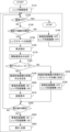
以下、図3を参照して、撮像装置1の動作について説明する。図3は、撮像装置1の動作を示すフローチャートである。撮像装置1の動作は、撮像装置1に電源が投入されることで開始される。 Hereinafter, the operation of the image pickup apparatus 1 will be described with reference to FIG. FIG. 3 is a flowchart showing the operation of the image pickup apparatus 1. The operation of the image pickup apparatus 1 is started when the power is turned on to the image pickup apparatus 1.

ステップS110では、カメラシステム制御回路5は、レンズシステム制御回路12からレンズ情報(撮影光学系3に関する情報)を取得する。本実施形態では、レンズ情報とは、撮影光学系3の光軸4の位置情報およびイメージサークルの大きさに関する情報の少なくとも一方の情報である。 In step S110, the camera system control circuit 5 acquires lens information (information about the photographing optical system 3) from the lens system control circuit 12. In the present embodiment, the lens information is at least one of information regarding the position information of the optical axis 4 of the photographing optical system 3 and the size of the image circle.

ステップS120では、カメラシステム制御回路5は、操作検出部10により電源OFFが検出されたかどうかを判定する。電顕OFFが検出されたと判定した場合、本動作を終了し、電源OFFが検出されていないと判定した場合、ステップS130に進む。 In step S120, the camera system control circuit 5 determines whether or not the power OFF is detected by the operation detection unit 10. If it is determined that the electron microscope OFF is detected, this operation is terminated, and if it is determined that the power OFF is not detected, the process proceeds to step S130.

ステップS130は、カメラシステム制御回路5は、操作検出部10により撮影予備動作の開始の指示(一般的にはレリーズボタンの反押し)が検出されたかどうかを判定する。指示が検出されたと判定した場合、ステップS140に進み、指示が検出されていないと判定した場合、ステップS150に進む。 In step S130, the camera system control circuit 5 determines whether or not the operation detection unit 10 has detected an instruction to start the preparatory shooting operation (generally, a counter-press of the release button). If it is determined that the instruction has been detected, the process proceeds to step S140, and if it is determined that the instruction has not been detected, the process proceeds to step S150.

ステップS140では、カメラシステム制御回路5は、レンズ防振機構および像面防振機構14を動作させないように制御する。 In step S140, the camera system control circuit 5 controls the lens anti-vibration mechanism and the image plane anti-vibration mechanism 14 so as not to operate.

ステップS150では、カメラシステム制御回路5は、撮影光学系3のフォーカスやズームなどの状態に関する情報であるレンズステートを取得する。 In step S150, the camera system control circuit 5 acquires a lens state which is information about a state such as focus and zoom of the photographing optical system 3.

ステップS160では、カメラシステム制御回路5は、光学プレビューモードが設定されている場合、AEセンサおよびAFセンサに測光および焦点検出を行わせ、適当な露光量およびピント評価量を取得する。また、カメラシステム制御回路5は、電子プレビューモードが設定されている場合、撮像素子6に測光および焦点検出を行わせ、適当な露光量およびピント評価量を取得する。さらに、カメラシステム制御回路5は、これらの情報に基づいて撮像素子6上に主被写体像が結像するようにフォーカスレンズを駆動するとともに、露光条件を決定する。露光条件とは、ISO感度、Fナンバーおよび露光時間の少なくともいずれかを含む情報である。また、フォーカスレンズの駆動では、カメラシステム制御回路5は電気接点11を介してレンズシステム制御回路12にフォーカスレンズを駆動する量を指示する。レンズシステム制御回路12は、レンズ駆動手段13を介してフォーカスレンズを適切に駆動する。 In step S160, the camera system control circuit 5 causes the AE sensor and the AF sensor to perform photometry and focus detection when the optical preview mode is set, and acquires an appropriate exposure amount and focus evaluation amount. Further, when the electronic preview mode is set, the camera system control circuit 5 causes the image sensor 6 to perform photometry and focus detection, and acquires an appropriate exposure amount and focus evaluation amount. Further, the camera system control circuit 5 drives the focus lens so that the main subject image is formed on the image pickup device 6 based on the information, and determines the exposure conditions. The exposure condition is information including at least one of ISO sensitivity, F number, and exposure time. Further, in driving the focus lens, the camera system control circuit 5 instructs the lens system control circuit 12 to drive the focus lens via the electric contact 11. The lens system control circuit 12 appropriately drives the focus lens via the lens driving means 13.

ステップS170では、カメラシステム制御回路5は、ステップS150で取得されたレンズステートを用いて、像面防振機構14およびレンズ防振機構の補正のための駆動量割合を決定する。像面でのブレ量は焦点距離が長くなるほど大きくなるので、相対的に焦点距離が長いレンズステートではレンズ防振機構の割合を大きくし、焦点距離が短いレンズステートでは像面防振機構14の割合を大きくすればよい。 In step S170, the camera system control circuit 5 uses the lens state acquired in step S150 to determine the image plane vibration isolation mechanism 14 and the drive amount ratio for correction of the lens vibration isolation mechanism. Since the amount of blurring on the image plane increases as the focal length increases, the proportion of the lens anti-vibration mechanism is increased in the lens state where the focal length is relatively long, and the image plane anti-vibration mechanism 14 in the lens state where the focal length is short. The ratio should be increased.

ステップS180では、カメラシステム制御回路5は、撮像装置1が電子プレビューモードであるかどうかを判定する。電子プレビューモードであると判定した場合は、ステップS190に進み、電子プレビューモードでないと判定した場合は、ステップS220に進む。 In step S180, the camera system control circuit 5 determines whether or not the image pickup apparatus 1 is in the electronic preview mode. If it is determined that the mode is the electronic preview mode, the process proceeds to step S190, and if it is determined that the mode is not the electronic preview mode, the process proceeds to step S220.

ステップS190では、カメラシステム制御回路5は、ステップS110で取得されたレンズ情報に基づいて、像面防振機構14の移動中心を決定する。カメラシステム制御回路5は、撮影光学系3の光軸4と一致するように、像面防振機構14の移動中心を決定してもよい。これにより、周辺光量落ちが緩和された画像を取得することができる。また、イメージサークルの大きさに余裕がある場合、すなわち周辺光量落ちが問題とならない場合、カメラシステム制御回路5は、撮影光学系3の光軸4とは無関係に像面防振機構14の移動中心を決定してもよい。例えば、像面防振機構14の移動中心を、防振機能を最大化できる位置や防振機構での電力を最小化する位置としてもよい。防振機能を最大化できる位置は、例えば、防振機構のストローク中心、制御性の良い場所(位置検出素子の検出分解能が良い場所)、および駆動時の摩擦が小さい場所などである。また、カメラシステム制御回路5は、撮影光学系3の光軸4と防振機能を最大化できる位置とを結ぶ直線上に位置するように、像面防振機構14の移動中心を決定してもよい。これにより、周辺光量落ちが問題ない範囲で防振機能を最大化することができる。 In step S190, the camera system control circuit 5 determines the moving center of the image plane vibration isolating mechanism 14 based on the lens information acquired in step S110. The camera system control circuit 5 may determine the moving center of the image plane vibration isolating mechanism 14 so as to coincide with the optical axis 4 of the photographing optical system 3. As a result, it is possible to acquire an image in which the peripheral light falloff is alleviated. Further, when there is a margin in the size of the image circle, that is, when the peripheral light falloff is not a problem, the camera system control circuit 5 moves the image plane vibration isolation mechanism 14 regardless of the optical axis 4 of the photographing optical system 3. The center may be determined. For example, the moving center of the image plane anti-vibration mechanism 14 may be a position where the anti-vibration function can be maximized or a position where the electric power in the anti-vibration mechanism is minimized. The position where the anti-vibration function can be maximized is, for example, the center of the stroke of the anti-vibration mechanism, the place where the controllability is good (the place where the detection resolution of the position detection element is good), and the place where the friction during driving is small. Further, the camera system control circuit 5 determines the moving center of the image plane vibration isolation mechanism 14 so as to be located on a straight line connecting the optical axis 4 of the photographing optical system 3 and the position where the vibration isolation function can be maximized. It is also good. As a result, the anti-vibration function can be maximized within the range where there is no problem in reducing the amount of peripheral light.

ステップS200では、カメラシステム制御回路5は、像面防振機構14およびレンズ防振機構を動作させる。カメラシステム制御回路5は、ステップS170で決定された駆動量割合およびブレ検出部15から取得された信号に基づいて、それぞれの防振機構でブレ補正を行う量を決定し、決定した量に基づいて各防振機構を動作させる。これにより、いわゆるブレによる画像の劣化を軽減することができる。また、ステップS190において、像面防振機構14の移動中心が適切に決定されているので、撮影光学系3の周辺光量落ちおよびブレを抑えた画像を取得することができる。 In step S200, the camera system control circuit 5 operates the image plane vibration isolation mechanism 14 and the lens vibration isolation mechanism. The camera system control circuit 5 determines the amount of image stabilization by each anti-vibration mechanism based on the drive amount ratio determined in step S170 and the signal acquired from the blur detection unit 15, and is based on the determined amount. Each anti-vibration mechanism is operated. This makes it possible to reduce image deterioration due to so-called blurring. Further, in step S190, since the moving center of the image plane vibration isolating mechanism 14 is appropriately determined, it is possible to acquire an image in which the peripheral light amount drop and blurring of the photographing optical system 3 are suppressed.

ステップS210では、カメラシステム制御回路5は、電子プレビューモードで表示するための画像を撮像素子6から取得して背面表示装置9に表示させる。これにより、画像が更新され被写体像を電子的に観察可能となる。 In step S210, the camera system control circuit 5 acquires an image to be displayed in the electronic preview mode from the image pickup device 6 and displays it on the rear display device 9. As a result, the image is updated and the subject image can be observed electronically.

ステップS220では、カメラシステム制御回路5は、ファインダ光学系17の光軸17aと一致するように、像面防振機構14の移動中心を決定する。本ステップでは、光学プレビューモードが設定されており、撮影者はファインダ光学系17を介して被写体像を光学的に観察している。ファインダ光学系17の光軸17aと撮像素子6の中心が一致しない場合、観察像と撮影された像が異なる構図ずれが発生してしまう。なお、構図ずれとは、構図決めしたときに見えていた像と記録された像がずれることを指す。電子プレビューモードでは撮像素子6から取得した像を表示するため、原理的に構図ずれは生じない。構図ずれが生じると撮影者の意図とは異なる像が取得されてしまう。構図は構図がずれて撮影したものから後程変更することは出来ないが、周辺光量は電子的に補正できる可能性がある。そのため、光学プレビューモードでは、周辺光量を犠牲にして構図ずれを抑制する。 In step S220, the camera system control circuit 5 determines the moving center of the image plane vibration isolating mechanism 14 so as to coincide with the optical axis 17a of the finder optical system 17. In this step, the optical preview mode is set, and the photographer optically observes the subject image via the finder optical system 17. If the optical axis 17a of the finder optical system 17 and the center of the image sensor 6 do not match, a composition shift in which the observed image and the captured image are different will occur. Note that the composition deviation means that the image that was visible when the composition was decided and the recorded image deviate from each other. Since the image acquired from the image sensor 6 is displayed in the electronic preview mode, composition deviation does not occur in principle. If the composition is misaligned, an image different from the photographer's intention will be acquired. The composition cannot be changed later from the one taken with the composition out of alignment, but the peripheral illumination may be electronically correctable. Therefore, in the optical preview mode, composition deviation is suppressed at the expense of peripheral illumination.

ステップS230では、カメラシステム制御回路5は、像面防振機構14は動作させず、レンズ防振機構を動作させる。光学プレビューモードでは、撮影光学系3からの光束はクイックリターンミラー機構20により反射されるので、後段に配置されている像面防振機構14を動作させても観察される像に変化はない。そのため、本ステップでは、像面防振機構14は、移動中心がファインダ光学系17の光軸17aと一致するように静止している。像面防振機構14が動作していない分ストロークは小さいが、レンズ防振機構は動作しているので、適当に防振された像が観察される。 In step S230, the camera system control circuit 5 does not operate the image plane anti-vibration mechanism 14, but operates the lens anti-vibration mechanism. In the optical preview mode, since the light flux from the photographing optical system 3 is reflected by the quick return mirror mechanism 20, there is no change in the observed image even if the image plane vibration isolating mechanism 14 arranged in the subsequent stage is operated. Therefore, in this step, the image plane vibration isolating mechanism 14 is stationary so that the moving center coincides with the optical axis 17a of the finder optical system 17. The stroke is small because the image plane vibration isolation mechanism 14 is not operating, but since the lens vibration isolation mechanism is operating, an appropriately vibration-proof image is observed.

ステップS240では、カメラシステム制御回路5は、操作検出部10により露光動作の開始の指示(一般的にはレリーズボタンの全押し)が検出されたかどうかを判定する。指示が検出されたと判定した場合、ステップS250に進み、指示が検出されていないと判定した場合、ステップS120に戻る。 In step S240, the camera system control circuit 5 determines whether or not the operation detection unit 10 has detected an instruction to start the exposure operation (generally, the release button is fully pressed). If it is determined that the instruction has been detected, the process proceeds to step S250, and if it is determined that the instruction has not been detected, the process returns to step S120.

ステップS250では、カメラシステム制御回路5は、像面防振機構14およびレンズ防振機構を動作させる。カメラシステム制御回路5は、ステップS170で決定された駆動量割合およびブレ検出部15から取得された信号に基づいて、それぞれの防振機構でブレ補正を行う量を決定し、決定した量に基づいて各防振機構を動作させる。これにより、いわゆるブレによる画像の劣化を軽減することができる。 In step S250, the camera system control circuit 5 operates the image plane vibration isolation mechanism 14 and the lens vibration isolation mechanism. The camera system control circuit 5 determines the amount of image stabilization by each anti-vibration mechanism based on the drive amount ratio determined in step S170 and the signal acquired from the blur detection unit 15, and is based on the determined amount. Each anti-vibration mechanism is operated. This makes it possible to reduce image deterioration due to so-called blurring.

ステップS260では、カメラシステム制御回路5は、撮像装置1に露光を行わせ、取得した被写体像をメモリ手段8に保存する。 In step S260, the camera system control circuit 5 causes the image pickup apparatus 1 to perform exposure, and stores the acquired subject image in the memory means 8.

以上説明したように、本実施形態では、像面防振機構14の移動中心を、光学プレビューモードでは構図優先位置(ファインダ光学系17の光軸17a)とし、電子プレビューモードでは撮影光学系3の光軸4や防振性能に基づく位置としている。これにより、構図ずれなく被写体像を取得することができる。電子プレビューモードでは、撮像素子6の信号を電気的な信号に変換した後、観察可能としている。撮像素子6の信号を利用している(プレビューと記録のための露光で同じ経路を利用しているので、偏心などが生じる余地がない)ので、原理的に構図ずれが生じない。また、撮像素子6の一部の信号を利用した現像、いわゆるクロップ撮影によらなくても周辺部まで確実に光束を導くことができる。 As described above, in the present embodiment, the moving center of the image plane vibration isolation mechanism 14 is set to the composition priority position (optical axis 17a of the finder optical system 17) in the optical preview mode, and the photographing optical system 3 is set in the electronic preview mode. The position is based on the optical axis 4 and anti-vibration performance. As a result, it is possible to acquire a subject image without composition deviation. In the electronic preview mode, the signal of the image pickup device 6 is converted into an electrical signal and then observed. Since the signal of the image sensor 6 is used (since the same path is used for the exposure for preview and recording, there is no room for eccentricity or the like), composition deviation does not occur in principle. In addition, it is possible to reliably guide the luminous flux to the peripheral portion without using development using a part of the signal of the image sensor 6, so-called crop photography.

以下、図4を参照して、本発明の効果や動作の状況について説明する。図4は、ケラレ状態の説明図であり、撮像素子6をZ軸の正方向から見た図である。撮像素子6の有効画素領域(出力画像を生成する領域)は、矩形で示されている。位置19a,19b,19cはそれぞれ、ファインダ光学系17の光軸17a、マウント18の中心軸18a、撮影光学系3の光軸4が撮像素子6の配置されている平面と交わる位置である。位置19a,19b,19cは、本実施形態では説明を簡単にするためにY方向にのみずれているが、実際にはXY平面上で相対的にずれている。中心線31は、位置19a,19b,19cを通るY軸である。中心線32a,32,32cはそれぞれ、位置19a,19b,19cを通るX軸に平行な線である。領域33は、撮影光学系3からの光量が十分に届いている領域である。領域34は、撮影光学系3からの光量がやや低下している領域である。領域35は、撮影光学系3からの光量が大きく低下している領域である。撮影光学系3からの光量は、実際には連続的に変化するが、本実施形態では説明を簡単にするために3つの水準に分けて段階的に示している。 Hereinafter, the effects of the present invention and the state of operation will be described with reference to FIG. FIG. 4 is an explanatory diagram of the vignetting state, and is a view of the image pickup device 6 as viewed from the positive direction of the Z axis. The effective pixel area (region for generating an output image) of the image pickup device 6 is shown by a rectangle. The positions 19a, 19b, and 19c are positions where the optical axis 17a of the finder optical system 17, the central axis 18a of the mount 18, and the optical axis 4 of the photographing optical system 3 intersect with the plane on which the image sensor 6 is arranged, respectively. The positions 19a, 19b, and 19c are displaced only in the Y direction in the present embodiment for the sake of simplicity, but are actually displaced relatively on the XY plane. The center line 31 is the Y axis passing through the positions 19a, 19b, 19c. The center lines 32a, 32, and 32c are lines parallel to the X-axis passing through the positions 19a, 19b, and 19c, respectively. The region 33 is a region where the amount of light from the photographing optical system 3 is sufficiently reached. The region 34 is a region where the amount of light from the photographing optical system 3 is slightly reduced. The region 35 is a region where the amount of light from the photographing optical system 3 is greatly reduced. The amount of light from the photographing optical system 3 actually changes continuously, but in the present embodiment, it is divided into three levels and shown step by step for the sake of simplicity.

図4(a)は、従来の電子プレビューモードにおける状態を示している。像面防振機構14の移動中心は、レンズ情報を用いずに撮像装置1の都合のみで決定される。そのため、像面防振機構14の移動中心を一般的には像面防振機構14の動作ストロークが最も大きくなる位置19bとしている。位置19cは設計称呼(設計値に対してずれがない状態)に対して下方向へ偏心しているとともに、イメージサークルの大きさに余裕がない。設計称呼の状態では、位置19a,19b,19cは一致している。「イメージサークルの大きさに余裕がない」とは、撮像素子6の有効画素領域と領域33の大きさにほぼ差がないことを意味する。すなわち、少しの誤差(偏心)によって、撮像素子6の有効画素領域が領域34にかかってしまうことを意味する。イメージサークルの半径はr1である。図に示されているように、撮像素子6の有効画素領域は、右上および左上が領域34にかかっている。すなわち、撮影画像の一部で光量落ちが目立ってしまう可能性がある。また、電子プレビューモードでは、構図ずれは発生しない。 FIG. 4A shows a state in the conventional electronic preview mode. The moving center of the image plane vibration isolating mechanism 14 is determined only by the convenience of the image pickup apparatus 1 without using the lens information. Therefore, the moving center of the image plane anti-vibration mechanism 14 is generally set to the position 19b where the operation stroke of the image plane anti-vibration mechanism 14 is the largest. The position 19c is eccentric downward with respect to the design name (a state in which there is no deviation from the design value), and there is no margin in the size of the image circle. In the state of design designation, the positions 19a, 19b, and 19c match. "There is no margin in the size of the image circle" means that there is almost no difference in the size of the effective pixel area and the area 33 of the image pickup device 6. That is, it means that the effective pixel region of the image pickup device 6 is applied to the region 34 due to a small error (eccentricity). The radius of the image circle is r1. As shown in the figure, the effective pixel region of the image sensor 6 covers the region 34 at the upper right and upper left. That is, there is a possibility that the light falloff will be noticeable in a part of the captured image. Further, in the electronic preview mode, composition deviation does not occur.

図4(b)は、本実施形態の電子プレビューモードにおける状態を示している。像面駆動機構の移動中心を撮影光学系3の光軸4と一致するように位置19cとしている。位置19cは設計称呼(図4(b)では、位置19bに位置する状態)に対して下方向へ偏心しているとともに、イメージサークルの大きさに余裕がない。イメージサークルの半径はr1である。しかしながら、図4(a)の場合と異なり、像面防振機構14の移動中心を位置19cとしているため、撮像素子6の有効画素領域はすべて領域33内である。すなわち、撮影画像には光量落ちが目立つ箇所はない。また、電子プレビューモードでは、構図ずれは発生しない。 FIG. 4B shows a state in the electronic preview mode of the present embodiment. The moving center of the image plane drive mechanism is set to the position 19c so as to coincide with the optical axis 4 of the photographing optical system 3. The position 19c is eccentric downward with respect to the design designation (the state located at the position 19b in FIG. 4B), and there is no margin in the size of the image circle. The radius of the image circle is r1. However, unlike the case of FIG. 4A, since the moving center of the image plane vibration isolating mechanism 14 is set at the position 19c, the effective pixel region of the image pickup device 6 is all within the region 33. That is, there is no conspicuous drop in the amount of light in the captured image. Further, in the electronic preview mode, composition deviation does not occur.

図4(c)は、本実施形態の光学プレビューモードにおける状態を示している。像面防振機構14の移動中心を位置19aとしている。位置19cは設計称呼(図4(c)では位置19bに位置する状態)に対して下方向へ偏心しているとともに、イメージサークルの大きさに余裕がない。イメージサークルの半径はr1である。この場合、図4(a)の場合に比べて、大きく光量落ちが生じてしまう。しかしながら、撮影者がファインダを見ながら構図を決めるため、構図ずれの抑制が光量落ちの抑制よりも優先され、周辺光量を犠牲にして構図ずれが抑制される。 FIG. 4C shows a state in the optical preview mode of the present embodiment. The moving center of the image plane vibration isolating mechanism 14 is set to the position 19a. The position 19c is eccentric downward with respect to the design designation (the state located at the position 19b in FIG. 4C), and there is no margin in the size of the image circle. The radius of the image circle is r1. In this case, the amount of light is greatly reduced as compared with the case of FIG. 4A. However, since the photographer decides the composition while looking at the finder, the suppression of the composition shift is prioritized over the suppression of the light falloff, and the composition shift is suppressed at the expense of the peripheral illumination.

図4(d)は、電子プレビューモードにおいて、イメージサークルの大きさに余裕がある状態を示している。位置19cは設計称呼(図4(d)では位置19bに位置する状態)に対して下方向へ偏心しているが、イメージサークルの大きさに余裕がある。イメージサークルの半径はr2(>r1)である。この場合、イメージサークルの大きさに余裕があるため、光量落ちが生じにくい。そのため、図4(b)の場合と同様に、撮影画像の光量落ちを基準に像面防振機構14の移動中心を決定する必要はなく、別の基準により像面防振機構14の移動中心を決定してもよい。別の基準とは、防振機能を最大化や防振機構での電力の最小化である。図4(d)ではストロークに着目して、像面防振機構14の移動中心を位置19bとしている。これにより、撮像素子6の有効画素領域はすべて領域33内である。すなわち、撮影画像には光量落ちが目立つ箇所がない。また、電子プレビューモードでは、構図ずれは発生しない。 FIG. 4D shows a state in which the size of the image circle has a margin in the electronic preview mode. The position 19c is eccentric downward with respect to the design designation (the state located at the position 19b in FIG. 4D), but there is a margin in the size of the image circle. The radius of the image circle is r2 (> r1). In this case, since there is a margin in the size of the image circle, the amount of light is unlikely to drop. Therefore, as in the case of FIG. 4B, it is not necessary to determine the moving center of the image plane vibration isolating mechanism 14 based on the light falloff of the captured image, and the moving center of the image plane vibration isolating mechanism 14 is determined by another reference. May be determined. Another criterion is maximizing the anti-vibration function and minimizing the power in the anti-vibration mechanism. In FIG. 4D, focusing on the stroke, the moving center of the image plane vibration isolating mechanism 14 is set to the position 19b. As a result, all the effective pixel regions of the image pickup device 6 are within the region 33. That is, there is no conspicuous drop in the amount of light in the captured image. Further, in the electronic preview mode, composition deviation does not occur.

図4(e)は、電子プレビューモードにおいて、イメージサークルの大きさに余裕がある状態を示している。像面防振機構14の移動中心を、光軸位置情報およびイメージサークルの大きさに関する情報を参照して、位置19bと位置19cとを結ぶ直線上の位置19dとしている。位置19cは設計称呼(図4(e)では位置19bに位置する状態)に対して下方向へ偏心しているが、イメージサークルの大きさに余裕がある。イメージサークルの半径はr2(>r1)である。図4(d)では、像面防振機構14の移動中心を決定する基準として、防振機能の最大化や防振機構での電力の最小化を例示した。図4(e)では、これに加えて、撮影画像の光量落ちも基準として加えている。前述したように、撮影光学系3からの光量は、実際には連続的に変化している。すなわち、光量のみを考えた場合、図4(b)の状態が最も都合が良い。一方、防振性能などを考えると図4(d)の状態が最も都合が良い。図4(e)では、それぞれの中間的な場合を示している。すなわち、光量と防振性能のバランスを取った位置を像面防振機構14の移動中心としている。例えば、撮影秒時があまり長くない場合には防振ストロークは必ずしも大きくなくてもよいので、光量を優先するように像面防振機構14の移動中心をシフトする場合などが考えられる。また、電子プレビューモードでは、構図ずれは発生しない。 FIG. 4 (e) shows a state in which the size of the image circle has a margin in the electronic preview mode. The moving center of the image plane anti-vibration mechanism 14 is set to the position 19d on a straight line connecting the position 19b and the position 19c with reference to the optical axis position information and the information regarding the size of the image circle. The position 19c is eccentric downward with respect to the design name (the state located at the position 19b in FIG. 4E), but there is a margin in the size of the image circle. The radius of the image circle is r2 (> r1). In FIG. 4D, maximization of the anti-vibration function and minimization of electric power in the anti-vibration mechanism are exemplified as criteria for determining the moving center of the image plane anti-vibration mechanism 14. In FIG. 4 (e), in addition to this, the light falloff of the captured image is also added as a reference. As described above, the amount of light from the photographing optical system 3 is actually continuously changing. That is, when only the amount of light is considered, the state shown in FIG. 4B is the most convenient. On the other hand, the state shown in FIG. 4D is the most convenient in consideration of anti-vibration performance and the like. FIG. 4 (e) shows an intermediate case between the two. That is, the position where the amount of light and the anti-vibration performance are balanced is set as the moving center of the image plane anti-vibration mechanism 14. For example, if the shooting seconds are not so long, the anti-vibration stroke does not necessarily have to be large, so it is conceivable that the moving center of the image plane anti-vibration mechanism 14 is shifted so as to give priority to the amount of light. Further, in the electronic preview mode, composition deviation does not occur.

以上説明したように、本発明によれば、構図ずれの発生を抑制しながら、光学系の周辺光量落ちおよびブレを抑えた画像を提供することができる。 As described above, according to the present invention, it is possible to provide an image in which the peripheral illumination amount drop and blurring of the optical system are suppressed while suppressing the occurrence of composition deviation.

以上、本発明の好ましい実施形態について説明したが、本発明はこれらの実施形態に限定されず、その要旨の範囲内で種々の変形及び変更が可能である。 Although the preferred embodiments of the present invention have been described above, the present invention is not limited to these embodiments, and various modifications and modifications can be made within the scope of the gist thereof.

1 撮像装置
3 撮影光学系
4 撮影光学系の光軸
5 カメラシステム制御回路(制御手段)
6 撮像素子
14 像面防振機構
1 Imaging device 3 Imaging optical system 4 Optical axis of the imaging optical system 5 Camera system control circuit (control means)
6 Image sensor 14 Image plane vibration isolation mechanism

Claims (18)

撮影光学系を介して結像される被写体像を撮像する撮像素子と、
前記撮像素子を前記撮影光学系の光軸に直交する平面において移動可能とする像面防振機構と、
前記像面防振機構の移動を制御する制御手段と、
前記撮影光学系に関する情報を受信する受信手段と、を有し、
前記制御手段は、前記撮像素子の出力に基づく前記被写体像に関する画像信号を観察する電子プレビューモードにおいて、前記受信手段により受信した前記撮影光学系に関する情報に基づいて前記像面防振機構の移動中心を決定することを特徴とする撮像装置。
An image sensor that captures an image of a subject imaged via a shooting optical system,
An image plane vibration isolation mechanism that allows the image sensor to move in a plane orthogonal to the optical axis of the photographing optical system.
A control means for controlling the movement of the image plane vibration isolation mechanism and
It has a receiving means for receiving information about the photographing optical system, and has.
The control means is a moving center of the image plane vibration isolation mechanism based on the information about the photographing optical system received by the receiving means in the electronic preview mode for observing the image signal related to the subject image based on the output of the image pickup device. An image pickup device characterized by determining.
前記撮影光学系に関する情報は、前記撮影光学系の光軸の位置情報および前記撮影光学系のイメージサークルの大きさに関する情報の少なくとも一方であることを特徴とする請求項1に記載の撮像装置。 The image pickup apparatus according to claim 1, wherein the information regarding the photographing optical system is at least one of information regarding the position of the optical axis of the photographing optical system and information regarding the size of the image circle of the photographing optical system. 前記撮影光学系に関する情報は、前記撮影光学系の光軸の位置を示す情報を含み、
前記制御手段は、前記電子プレビューモードにおいて、前記像面防振機構の移動中心が前記撮影光学系の光軸と交わるように、前記像面防振機構の移動中心を決定することを特徴とする請求項1または2に記載の撮像装置。
The information regarding the photographing optical system includes information indicating the position of the optical axis of the photographing optical system.
The control means is characterized in that, in the electronic preview mode, the moving center of the image plane vibration isolating mechanism is determined so that the moving center of the image plane vibration isolating mechanism intersects the optical axis of the photographing optical system. The imaging device according to claim 1 or 2.
前記撮影光学系を取り付け可能とするマウントを更に有し、
前記制御手段は、前記電子プレビューモードにおいて、前記像面防振機構の移動中心が前記マウントの中心軸と交わるように、前記像面防振機構の移動中心を決定することを特徴とする請求項1または2に記載の撮像装置。
It also has a mount that allows the imaging optical system to be attached.
The control means is characterized in that, in the electronic preview mode, the moving center of the image plane vibration isolating mechanism is determined so that the moving center of the image plane vibration isolating mechanism intersects the central axis of the mount. The image pickup apparatus according to 1 or 2.
前記制御手段は、前記電子プレビューモードにおいて、前記像面防振機構の移動中心を前記像面防振機構の電力が最小化する位置に決定することを特徴とする請求項1または2に記載の撮像装置。 The first or second aspect of the present invention, wherein the control means determines the moving center of the image plane vibration isolator at a position where the electric power of the image plane vibration isolator is minimized in the electronic preview mode. Imaging device. 前記撮影光学系を取り付け可能とするマウントを更に有し、
前記制御手段は、前記電子プレビューモードにおいて、前記像面防振機構の移動中心が、前記撮影光学系の光軸と前記撮像素子の配置されている平面との交点と、前記マウントの中心軸と前記撮像素子の配置されている平面との交点と、を結ぶ直線上に位置するように、前記像面防振機構の移動中心を決定することを特徴とする請求項1または2に記載の撮像装置。
It also has a mount that allows the imaging optical system to be attached.
In the electronic preview mode, the control means has the moving center of the image plane vibration isolation mechanism at the intersection of the optical axis of the photographing optical system and the plane on which the image pickup element is arranged, and the central axis of the mount. The imaging according to claim 1 or 2, wherein the moving center of the image plane vibration isolating mechanism is determined so as to be located on a straight line connecting the intersection with the plane on which the imaging element is arranged. Device.
前記被写体像を光学的に観察可能な光学ファインダ手段を更に有し、
前記制御手段は、前記光学ファインダ手段を用いて前記被写体像を光学的に観察する光学プレビューモードにおいて、前記光学ファインダ手段の光軸と交わるように前記像面防振機構の移動中心を決定することを特徴とする請求項1から6のいずれか1項に記載の撮像装置。
Further having an optical finder means capable of optically observing the subject image,
The control means determines the moving center of the image plane vibration isolating mechanism so as to intersect the optical axis of the optical finder means in the optical preview mode for optically observing the subject image using the optical finder means. The image pickup apparatus according to any one of claims 1 to 6, wherein the image pickup apparatus is characterized by the above-mentioned.
前記撮影光学系に関する情報は、前記撮影光学系の光軸の位置情報および前記撮影光学系のイメージサークルの大きさに関する情報の少なくとも一方であり、
前記制御手段は、
前記受信手段により受信した前記撮影光学系の光軸の位置を示す情報と前記撮影光学系のイメージサークルの大きさを示す情報との少なくともいずれかに基づいて、第1の方法により前記電子プレビューモードにおける前記像面防振機構の移動中心を決定するか、前記第1の方法と異なる第2の方法により前記電子プレビューモードにおける前記像面防振機構の移動中心を決定するかを決定することを特徴とする請求項1から7のいずれか1項に記載の撮像装置。
The information regarding the photographing optical system is at least one of the information regarding the position of the optical axis of the photographing optical system and the information regarding the size of the image circle of the photographing optical system.
The control means is
The electronic preview mode by the first method is based on at least one of the information indicating the position of the optical axis of the photographing optical system and the information indicating the size of the image circle of the photographing optical system received by the receiving means. Whether to determine the moving center of the image plane vibration isolating mechanism in the above, or to determine the moving center of the image plane vibration isolating mechanism in the electronic preview mode by a second method different from the first method. The imaging device according to any one of claims 1 to 7, wherein the image pickup apparatus is characterized.
前記第1の方法は、前記受信手段により受信した前記撮影光学系の光軸の位置を示す情報と前記撮影光学系のイメージサークルの大きさを示す情報との少なくともいずれかに基づいて、前記電子プレビューモードにおける前記像面防振機構の移動中心を決定する方法であることを特徴とする請求項8に記載の撮像装置。 The first method is based on at least one of information indicating the position of the optical axis of the photographing optical system and information indicating the size of the image circle of the photographing optical system received by the receiving means. The image pickup apparatus according to claim 8, wherein the method is for determining the moving center of the image plane vibration isolation mechanism in the preview mode. 前記第2の方法は、前記像面防振機構による前記撮像素子の移動に関する情報に基づいて、前記電子プレビューモードにおける前記像面防振機構の移動中心を決定する方法であることを特徴とする請求項8または9に記載の撮像装置。 The second method is characterized in that it is a method of determining the moving center of the image plane vibration isolating mechanism in the electronic preview mode based on the information regarding the movement of the image pickup element by the image plane vibration isolating mechanism. The image pickup device according to claim 8 or 9. 前記像面防振機構による前記撮像素子の移動に関する情報は、前記像面防振機構による前記撮像素子の移動に要する電力の情報であることを特徴とする請求項10に記載の撮像装置。 The image pickup apparatus according to claim 10, wherein the information regarding the movement of the image pickup element by the image plane vibration isolation mechanism is information on the electric power required for the movement of the image pickup element by the image plane vibration isolation mechanism. 前記像面防振機構による前記撮像素子の移動に関する情報は、前記像面防振機構による前記撮像素子の移動可能な範囲の中心を示す情報であることを特徴とする請求項10に記載の撮像装置。 The imaging according to claim 10, wherein the information regarding the movement of the image pickup element by the image plane vibration isolation mechanism is information indicating the center of the movable range of the image pickup element by the image plane vibration isolation mechanism. Device. 前記像面防振機構による前記撮像素子の移動に関する情報は、前記撮像素子の位置を検出する位置検出手段の検出分解能に関する情報であることを特徴とする請求項10に記載の撮像装置。 The image pickup apparatus according to claim 10, wherein the information regarding the movement of the image pickup element by the image plane vibration isolation mechanism is information regarding the detection resolution of the position detection means for detecting the position of the image pickup element. 前記像面防振機構による前記撮像素子の移動に関する情報は、前記撮像素子の移動に伴う摩擦に関する情報であることを特徴とする請求項10に記載の撮像装置。 The image pickup apparatus according to claim 10, wherein the information regarding the movement of the image pickup element by the image plane vibration isolation mechanism is information regarding friction due to the movement of the image pickup element. 前記第2の方法は、前記受信手段により受信した前記撮影光学系の光軸の位置を示す情報と、前記像面防振機構による前記撮像素子の移動に関する情報とに基づいて、前記電子プレビューモードにおける前記像面防振機構の移動中心を決定する方法であることを特徴とする請求項8または9に記載の撮像装置。 The second method is based on the information indicating the position of the optical axis of the photographing optical system received by the receiving means and the information regarding the movement of the image pickup device by the image plane vibration isolation mechanism, and the electronic preview mode. The image pickup apparatus according to claim 8 or 9, wherein the image pickup device is a method for determining a moving center of the image plane vibration isolation mechanism. 前記受信手段は、前記撮影光学系のイメージサークルの大きさを示す情報を少なくとも受信し、
前記制御手段は、
前記第1の方法により前記電子プレビューモードにおける前記像面防振機構の移動中心を決定するか、前記第2の方法により前記電子プレビューモードにおける前記像面防振機構の移動中心を決定するかを、前記イメージサークルの大きさを示す情報に基づいて決定することを特徴とする請求項8から15のいずれか1項に記載の撮像装置。
The receiving means receives at least information indicating the size of the image circle of the photographing optical system, and receives the information indicating the size of the image circle.
The control means is
Whether the moving center of the image plane vibration isolating mechanism in the electronic preview mode is determined by the first method or the moving center of the image plane vibration isolating mechanism in the electronic preview mode is determined by the second method. The image pickup apparatus according to any one of claims 8 to 15 , wherein the image circle is determined based on information indicating the size of the image circle.
撮影光学系と、
請求項1から16のいずれか1項に記載の撮像装置と、を有することを特徴とするカメラシステム。
With the shooting optical system
A camera system comprising the image pickup apparatus according to any one of claims 1 to 16.
前記撮影光学系は、前記撮影光学系に関する情報を記憶する記憶手段を有することを特徴とする請求項17に記載のカメラシステム。
The camera system according to claim 17, wherein the photographing optical system has a storage means for storing information about the photographing optical system.
JP2018002782A 2018-01-11 2018-01-11 Imaging equipment and camera system Active JP7043265B2 (en)

Priority Applications (3)

Application Number Priority Date Filing Date Title
JP2018002782A JP7043265B2 (en) 2018-01-11 2018-01-11 Imaging equipment and camera system
US16/244,179 US11153486B2 (en) 2018-01-11 2019-01-10 Imaging apparatus and camera system
JP2022038680A JP7346636B2 (en) 2018-01-11 2022-03-11 Imaging device, camera system and control method

Applications Claiming Priority (1)

Application Number Priority Date Filing Date Title
JP2018002782A JP7043265B2 (en) 2018-01-11 2018-01-11 Imaging equipment and camera system

Related Child Applications (1)

Application Number Title Priority Date Filing Date
JP2022038680A Division JP7346636B2 (en) 2018-01-11 2022-03-11 Imaging device, camera system and control method

Publications (3)

Publication Number Publication Date
JP2019122014A JP2019122014A (en) 2019-07-22
JP2019122014A5 JP2019122014A5 (en) 2021-02-04
JP7043265B2 true JP7043265B2 (en) 2022-03-29

Family

ID=67139159

Family Applications (2)

Application Number Title Priority Date Filing Date
JP2018002782A Active JP7043265B2 (en) 2018-01-11 2018-01-11 Imaging equipment and camera system
JP2022038680A Active JP7346636B2 (en) 2018-01-11 2022-03-11 Imaging device, camera system and control method

Family Applications After (1)

Application Number Title Priority Date Filing Date
JP2022038680A Active JP7346636B2 (en) 2018-01-11 2022-03-11 Imaging device, camera system and control method

Country Status (2)

Country Link
US (1) US11153486B2 (en)
JP (2) JP7043265B2 (en)

Families Citing this family (3)

* Cited by examiner, † Cited by third party
Publication number Priority date Publication date Assignee Title
WO2020017463A1 (en) 2018-07-20 2020-01-23 株式会社ニコン Camera body, camera accessory, and information transmission method
US10999509B2 (en) * 2018-11-15 2021-05-04 Canon Kabushiki Kaisha Systems, methods, and mediums for controlling image stabilization based on imaging condition
JP7404059B2 (en) * 2019-12-18 2023-12-25 キヤノン株式会社 Control device, lens device, imaging device, and imaging system

Citations (2)

* Cited by examiner, † Cited by third party
Publication number Priority date Publication date Assignee Title
JP2004048346A (en) 2002-07-11 2004-02-12 Minolta Co Ltd Image pickup device, image reproducing device, and program
JP2004274242A (en) 2003-03-06 2004-09-30 Minolta Co Ltd Digital camera

Family Cites Families (6)

* Cited by examiner, † Cited by third party
Publication number Priority date Publication date Assignee Title
JP2521816B2 (en) * 1989-08-17 1996-08-07 富士写真フイルム株式会社 camera
JP2009251491A (en) 2008-04-10 2009-10-29 Olympus Imaging Corp Imaging apparatus and control method for imaging apparatus
JP5293947B2 (en) 2008-11-13 2013-09-18 株式会社ニコン Imaging device
JP2011097377A (en) * 2009-10-29 2011-05-12 Sanyo Electric Co Ltd Imaging device
WO2016103746A1 (en) * 2014-12-25 2016-06-30 オリンパス株式会社 Imaging device
US11336827B2 (en) 2017-11-09 2022-05-17 Canon Kabushiki Kaisha Imaging apparatus and interchangeable lens apparatus that utilize image circle information of an imaging optical system in the interchangeable lens apparatus

Patent Citations (2)

* Cited by examiner, † Cited by third party
Publication number Priority date Publication date Assignee Title
JP2004048346A (en) 2002-07-11 2004-02-12 Minolta Co Ltd Image pickup device, image reproducing device, and program
JP2004274242A (en) 2003-03-06 2004-09-30 Minolta Co Ltd Digital camera

Also Published As

Publication number Publication date
JP2019122014A (en) 2019-07-22
JP7346636B2 (en) 2023-09-19
US11153486B2 (en) 2021-10-19
US20190215454A1 (en) 2019-07-11
JP2022084739A (en) 2022-06-07

Similar Documents

Publication Publication Date Title
JP7346636B2 (en) Imaging device, camera system and control method
JP4989730B2 (en) Camera body and imaging device
US20090027510A1 (en) Imaging Device
JP2010263254A (en) Camera system and camera body
JP7086591B2 (en) Image pickup device and its control method
JP2007163593A (en) Optical equipment and imaging system
US7071973B1 (en) Digital camera having multiple image taking modes
JP2007043584A (en) Image pickup device and control method thereof
JP2011013619A (en) Image shake correction apparatus and image pickup apparatus
JP2007057981A (en) Position detecting device, position detecting method and computer program
JP2017187693A (en) Image blur correction device and control method thereof, program, and storage medium
US9008499B2 (en) Optical viewfinder
CN112135037B (en) Stabilization control apparatus, image pickup apparatus, and stabilization control method
JP5293947B2 (en) Imaging device
JP5215818B2 (en) Imaging apparatus, control method thereof, and program
JP7187184B2 (en) Imaging device and imaging device control method
JP2019215426A (en) Imaging apparatus and control method of the same
JP2007163596A (en) Optical equipment
WO2007148453A1 (en) Camera body, camera system, interchangeable lens unit, and control method
JP2008139640A (en) Imaging apparatus
EP2039148A1 (en) Imaging apparatus and imaging method
JP7378971B2 (en) Control device, imaging device, control method, and program
JP7166949B2 (en) CONTROL DEVICE, AND LENS DEVICE AND IMAGING DEVICE INCLUDING THE SAME
JP4574633B2 (en) Imaging device
JP2024018412A (en) Image stabilization device and optical equipment

Legal Events

Date Code Title Description
A521 Request for written amendment filed

Free format text: JAPANESE INTERMEDIATE CODE: A523

Effective date: 20201218

A621 Written request for application examination

Free format text: JAPANESE INTERMEDIATE CODE: A621

Effective date: 20201218

A977 Report on retrieval

Free format text: JAPANESE INTERMEDIATE CODE: A971007

Effective date: 20211021

A131 Notification of reasons for refusal

Free format text: JAPANESE INTERMEDIATE CODE: A131

Effective date: 20211130

A521 Request for written amendment filed

Free format text: JAPANESE INTERMEDIATE CODE: A523

Effective date: 20220131

TRDD Decision of grant or rejection written
A01 Written decision to grant a patent or to grant a registration (utility model)

Free format text: JAPANESE INTERMEDIATE CODE: A01

Effective date: 20220215

A61 First payment of annual fees (during grant procedure)

Free format text: JAPANESE INTERMEDIATE CODE: A61

Effective date: 20220316

R151 Written notification of patent or utility model registration

Ref document number: 7043265

Country of ref document: JP

Free format text: JAPANESE INTERMEDIATE CODE: R151