JP7040937B2 - Injection device with optical system for monitoring the position of the piston rod - Google Patents
Injection device with optical system for monitoring the position of the piston rod Download PDFInfo
- Publication number
- JP7040937B2 JP7040937B2 JP2017501097A JP2017501097A JP7040937B2 JP 7040937 B2 JP7040937 B2 JP 7040937B2 JP 2017501097 A JP2017501097 A JP 2017501097A JP 2017501097 A JP2017501097 A JP 2017501097A JP 7040937 B2 JP7040937 B2 JP 7040937B2
- Authority
- JP
- Japan
- Prior art keywords
- optical sensor
- injection device
- light emitting
- housing
- liquid injection
- Prior art date
- Legal status (The legal status is an assumption and is not a legal conclusion. Google has not performed a legal analysis and makes no representation as to the accuracy of the status listed.)
- Active
Links
Images


Classifications
-
- A—HUMAN NECESSITIES
- A61—MEDICAL OR VETERINARY SCIENCE; HYGIENE
- A61M—DEVICES FOR INTRODUCING MEDIA INTO, OR ONTO, THE BODY; DEVICES FOR TRANSDUCING BODY MEDIA OR FOR TAKING MEDIA FROM THE BODY; DEVICES FOR PRODUCING OR ENDING SLEEP OR STUPOR
- A61M5/00—Devices for bringing media into the body in a subcutaneous, intra-vascular or intramuscular way; Accessories therefor, e.g. filling or cleaning devices, arm-rests
- A61M5/007—Devices for bringing media into the body in a subcutaneous, intra-vascular or intramuscular way; Accessories therefor, e.g. filling or cleaning devices, arm-rests for contrast media
-
- A—HUMAN NECESSITIES
- A61—MEDICAL OR VETERINARY SCIENCE; HYGIENE
- A61M—DEVICES FOR INTRODUCING MEDIA INTO, OR ONTO, THE BODY; DEVICES FOR TRANSDUCING BODY MEDIA OR FOR TAKING MEDIA FROM THE BODY; DEVICES FOR PRODUCING OR ENDING SLEEP OR STUPOR
- A61M5/00—Devices for bringing media into the body in a subcutaneous, intra-vascular or intramuscular way; Accessories therefor, e.g. filling or cleaning devices, arm-rests
- A61M5/178—Syringes
- A61M5/31—Details
- A61M5/315—Pistons; Piston-rods; Guiding, blocking or restricting the movement of the rod or piston; Appliances on the rod for facilitating dosing ; Dosing mechanisms
- A61M5/31565—Administration mechanisms, i.e. constructional features, modes of administering a dose
- A61M5/31566—Means improving security or handling thereof
- A61M5/31568—Means keeping track of the total dose administered, e.g. since the cartridge was inserted
-
- A—HUMAN NECESSITIES
- A61—MEDICAL OR VETERINARY SCIENCE; HYGIENE
- A61M—DEVICES FOR INTRODUCING MEDIA INTO, OR ONTO, THE BODY; DEVICES FOR TRANSDUCING BODY MEDIA OR FOR TAKING MEDIA FROM THE BODY; DEVICES FOR PRODUCING OR ENDING SLEEP OR STUPOR
- A61M5/00—Devices for bringing media into the body in a subcutaneous, intra-vascular or intramuscular way; Accessories therefor, e.g. filling or cleaning devices, arm-rests
- A61M5/178—Syringes
- A61M5/31—Details
- A61M5/315—Pistons; Piston-rods; Guiding, blocking or restricting the movement of the rod or piston; Appliances on the rod for facilitating dosing ; Dosing mechanisms
- A61M5/31565—Administration mechanisms, i.e. constructional features, modes of administering a dose
- A61M5/31566—Means improving security or handling thereof
- A61M5/31573—Accuracy improving means
-
- A—HUMAN NECESSITIES
- A61—MEDICAL OR VETERINARY SCIENCE; HYGIENE
- A61M—DEVICES FOR INTRODUCING MEDIA INTO, OR ONTO, THE BODY; DEVICES FOR TRANSDUCING BODY MEDIA OR FOR TAKING MEDIA FROM THE BODY; DEVICES FOR PRODUCING OR ENDING SLEEP OR STUPOR
- A61M2205/00—General characteristics of the apparatus
- A61M2205/18—General characteristics of the apparatus with alarm
-
- A—HUMAN NECESSITIES
- A61—MEDICAL OR VETERINARY SCIENCE; HYGIENE
- A61M—DEVICES FOR INTRODUCING MEDIA INTO, OR ONTO, THE BODY; DEVICES FOR TRANSDUCING BODY MEDIA OR FOR TAKING MEDIA FROM THE BODY; DEVICES FOR PRODUCING OR ENDING SLEEP OR STUPOR
- A61M2205/00—General characteristics of the apparatus
- A61M2205/33—Controlling, regulating or measuring
- A61M2205/3306—Optical measuring means
-
- A—HUMAN NECESSITIES
- A61—MEDICAL OR VETERINARY SCIENCE; HYGIENE
- A61M—DEVICES FOR INTRODUCING MEDIA INTO, OR ONTO, THE BODY; DEVICES FOR TRANSDUCING BODY MEDIA OR FOR TAKING MEDIA FROM THE BODY; DEVICES FOR PRODUCING OR ENDING SLEEP OR STUPOR
- A61M2205/00—General characteristics of the apparatus
- A61M2205/33—Controlling, regulating or measuring
- A61M2205/3379—Masses, volumes, levels of fluids in reservoirs, flow rates
- A61M2205/3389—Continuous level detection
-
- A—HUMAN NECESSITIES
- A61—MEDICAL OR VETERINARY SCIENCE; HYGIENE
- A61M—DEVICES FOR INTRODUCING MEDIA INTO, OR ONTO, THE BODY; DEVICES FOR TRANSDUCING BODY MEDIA OR FOR TAKING MEDIA FROM THE BODY; DEVICES FOR PRODUCING OR ENDING SLEEP OR STUPOR
- A61M5/00—Devices for bringing media into the body in a subcutaneous, intra-vascular or intramuscular way; Accessories therefor, e.g. filling or cleaning devices, arm-rests
- A61M5/14—Infusion devices, e.g. infusing by gravity; Blood infusion; Accessories therefor
- A61M5/142—Pressure infusion, e.g. using pumps
- A61M5/145—Pressure infusion, e.g. using pumps using pressurised reservoirs, e.g. pressurised by means of pistons
- A61M5/1452—Pressure infusion, e.g. using pumps using pressurised reservoirs, e.g. pressurised by means of pistons pressurised by means of pistons
-
- A—HUMAN NECESSITIES
- A61—MEDICAL OR VETERINARY SCIENCE; HYGIENE
- A61M—DEVICES FOR INTRODUCING MEDIA INTO, OR ONTO, THE BODY; DEVICES FOR TRANSDUCING BODY MEDIA OR FOR TAKING MEDIA FROM THE BODY; DEVICES FOR PRODUCING OR ENDING SLEEP OR STUPOR
- A61M5/00—Devices for bringing media into the body in a subcutaneous, intra-vascular or intramuscular way; Accessories therefor, e.g. filling or cleaning devices, arm-rests
- A61M5/14—Infusion devices, e.g. infusing by gravity; Blood infusion; Accessories therefor
- A61M5/168—Means for controlling media flow to the body or for metering media to the body, e.g. drip meters, counters ; Monitoring media flow to the body
- A61M5/16831—Monitoring, detecting, signalling or eliminating infusion flow anomalies
- A61M5/1684—Monitoring, detecting, signalling or eliminating infusion flow anomalies by detecting the amount of infusate remaining, e.g. signalling end of infusion
Description
<関連出願の相互参照>
本出願は、2014年3月21日に出願され、2015年3月18日にPCT国際特許出願として出願された、米国特許出願第14/222331号の優先権を主張する。本出願はまた、米国特許法120条の下での権利を主張し、2013年8月23日に、「ボリュームモニタ装置」と題して出願され米国特許出願第13/975052号の部分継続出願である。該米国特許出願第13/975052号は、2013年3月15日に出願された「中間注入量を調節するための装置および方法」と題する米国特許出願第13/839771号の部分継続出願であり、該米国特許出願第13/839771号は、「中間注入量を補正するための装置および方法」と題して2012年8月28日に出願された、米国特許仮出願第61/694137号の優先権および利益を主張する。前記出願の開示内容は、その全体が、引用により本明細書に組み込まれる。
<Cross-reference of related applications>
This application claims the priority of US Patent Application No. 14/222331, filed March 21, 2014 and filed as a PCT International Patent Application on March 18, 2015. This application also asserts rights under
本開示は、例えば、造影剤等の薬物の注入部位への注入の制御、変換、または調節のために使用される装置および方法、および/または、注入部位へ注入された液材の測定または定量的な評価を行うために使用することができる装置および方法に関する。より詳細には、以下に述べる装置および方法の目的は、血管、血管床、器官、および/または他の身体構造への液材の注入を調節および/または評価して、液材の注入対象でない血管、血管床、器官、および/またはその他の身体構造体への不注意による注入、または過度の注入を回避しながら、意図した部位への液材の注入を最適化することである。 The present disclosure discloses, for example, an apparatus and method used for controlling, converting, or regulating the injection of a drug such as a contrast medium into an injection site, and / or measuring or quantifying the liquid material injected into the injection site. With respect to the equipment and methods that can be used to make an evaluation. More specifically, the objectives of the devices and methods described below are to regulate and / or evaluate the infusion of fluid into blood vessels, vascular beds, organs, and / or other body structures and are not subject to infusion of fluid. Optimizing the infusion of fluid into the intended site while avoiding inadvertent or over-injection into blood vessels, vascular beds, organs, and / or other body structures.
液材(複数も可)、薬剤、薬物、薬材、薬品等の用語は、本明細書中で使用する場合、一般的に種々の液体を表わしており、この種々の液体は、少なくとも部分的に、医療診断、治療、および/または予防的医療処置の実行において使用される薬物を含むことができるが、このような使用に限定することを意図するものではない。 The terms liquid material (s), drug, drug, medicinal material, drug, etc., as used herein, generally refer to various liquids, which various liquids are at least partial. Can include drugs used in the practice of medical diagnosis, treatment, and / or prophylactic medical treatment, but is not intended to be limited to such use.
本概要は、以下の「発明の詳細な説明」で詳しく説明される技術思想の抜粋を簡略化した形で紹介するために開示する。本概要は、特許請求範囲の主題事項の主要な特徴または本質的な特徴を特定することを意図するものではなく、かつ、特許請求範囲の主題事項について開示した実施形態の各々または請求された全ての実施例を記載することも意図していない、かつ、特許請求範囲の主題事項の範囲を決定するときの手助けとして使用することを意図するものでもない。他の多くの新規な利点、特徴、および関係は、本明細の説明が進むにつれて明らかになる。以降、図面および明細書で、より詳細に図示の実施形態を、例を用いて説明する。 This outline is disclosed in order to introduce in a simplified form an excerpt of the technical idea explained in detail in the following "Detailed Description of the Invention". This summary is not intended to identify the main or essential features of the claims, and each or all of the embodiments disclosed for the claims. It is not intended to describe the examples of the above, nor is it intended to be used as an aid in determining the scope of the subject matter of the claims. Many other novel advantages, features, and relationships will become apparent as the description of this specification progresses. Hereinafter, the illustrated embodiment will be described in more detail with reference to the drawings and the specification.
一つの態様では、本発明の技術は装置に関し、該装置は、
注入器ハウジングと、
該注入器ハウジング内で、第1の位置と第2の位置との間に摺動可能に収容され、一つの実質的に不透明な部分と、一つの実質的に透明な部分とを有するピストン棒と、
前記注入器ハウジング上に配置された光センサ・モジュールであって、光センサ・ハウジングと、第1センサ素子と、第2センサ素子とを有し、前記第1センサ素子と前記第2センサ素子とが、前記センサ・ハウジング内に配置された、光センサ・モジュールと、を有し、
前記ピストン棒の位置を前記第1の位置に配置すると、前記実質的に透明な部分が第1センサ素子と並び、前記ピストン棒の位置を前記第2の位置に配置すると、前記実質的に透明な部分が第2センサ素子と並ぶ。
一つの実施形態では、前記装置は、前記光センサ・モジュールから延在するリードを有する。
もう一つ別の実施形態では、前記装置は、測定装置に前記リードを接続するためのインタフェースを有し、前記測定装置は、注入された総容量を表示し、かつ、クリティカルな結果に関する警告を発する。
さらに別の実施形態では、前記光センサ・ハウジングは、前記注入器ハウジングに取り外し可能に固定される。
さらに別の実施形態では、前記装置は前記光センサ・ハウジングを前記注入器ハウジングに取り外し可能に固定するための手段を有する。
In one embodiment, the technique of the invention relates to a device, wherein the device is a device.
With the injector housing,
A piston rod that is slidably contained between a first position and a second position within the injector housing and has one substantially opaque portion and one substantially transparent portion. When,
An optical sensor module arranged on the injector housing, comprising an optical sensor housing, a first sensor element, and a second sensor element, the first sensor element and the second sensor element. Has an optical sensor module, which is located within the sensor housing.
When the position of the piston rod is arranged at the first position, the substantially transparent portion is aligned with the first sensor element, and when the position of the piston rod is arranged at the second position, the substantially transparent portion is formed. Part is lined up with the second sensor element.
In one embodiment, the device has a lead extending from the optical sensor module .
In another embodiment, the device has an interface for connecting the lead to the measuring device, which displays the total volume injected and warns about critical consequences. Emit.
In yet another embodiment, the photosensor housing is detachably secured to the injector housing.
In yet another embodiment, the device has means for detachably fixing the photosensor housing to the injector housing.
上記態様の別の実施形態では、前記手段は、クランプと、留め金と、フックおよびループ・ファスナーと、磁石とのうちの少なくとも一つを有する。
一つの実施形態では、前記装置は、前記注入器ハウジング上に置かれた発光モジュールを有し、該発光モジュールは、発光ハウジングと第1発光素子と第2発光素子とを有し、第1発光素子と第2発光素子とは前記発光ハウジング内に配置される。
別の実施形態では、前記ピストン棒の位置を前記第1の位置に配置すると、前記実質的に透明な部分が第1発光素子と並び、前記ピストン棒の位置を前記第2の位置に配置すると、前記実質的に透明な部分が第2発光素子と並ぶ。
さらに別の実施形態では、前記第1発光素子と前記第1センサ素子とは平行に並んで配置されている。
さらに別の実施形態では、前記光センサ・モジュールが前記注入器ハウジングの周りに前記発光モジュールから約180度間隔をあけて配置される。
In another embodiment of the above embodiment, the means has at least one of a clamp, a clasp, a hook and a loop fastener, and a magnet.
In one embodiment, the device has a light emitting module placed on the injector housing, the light emitting module having a light emitting housing, a first light emitting element and a second light emitting element, and a first light emitting device. The element and the second light emitting element are arranged in the light emitting housing.
In another embodiment, when the position of the piston rod is arranged at the first position, the substantially transparent portion is arranged with the first light emitting element, and the position of the piston rod is arranged at the second position. , The substantially transparent portion is aligned with the second light emitting element.
In yet another embodiment, the first light emitting element and the first sensor element are arranged side by side in parallel .
In yet another embodiment, the photosensor module is placed around the injector housing at a distance of about 180 degrees from the light emitting module .
別の態様では、本発明の技術は装置に関し、該装置は、
注入器ハウジングと、
該注入器ハウジング内に摺動自在に収容されたピストン棒と、
前記注入器ハウジングに固定された光センサ・モジュールと、
前記注入器ハウジングに固定された発光モジュールと、を有し、
前記ピストン棒は、複数の実質的に透明な部分を有する。
一つの実施形態では、前記複数の実質的に透明な部分は、第1の透明度を持つ第1部分と、第1の透明度よりも低い第2の透明度を持つ第2部分を有する。
別の実施形態では、前記複数の実質的に透明な部分はグラデーションを有する。
さらに別の実施形態では、前記光センサ・モジュールは、複数の光センサを有し、前記発光モジュールは複数の発光素子を有する。
さらに別の実施形態では、前記発光モジュールは、前記注入器ハウジングの周囲に前記光センサ・モジュールから少なくとも約90度間隔をあけて配置される。
In another aspect, the technique of the invention relates to a device, wherein the device.
With the injector housing,
A piston rod slidably housed in the injector housing,
An optical sensor module fixed to the injector housing,
With a light emitting module fixed to the injector housing,
The piston rod has a plurality of substantially transparent portions.
In one embodiment, the plurality of substantially transparent portions have a first portion having a first transparency and a second portion having a second transparency lower than the first transparency.
In another embodiment, the plurality of substantially transparent portions have a gradation.
In yet another embodiment, the optical sensor module has a plurality of optical sensors and the light emitting module has a plurality of light emitting elements.
In yet another embodiment, the light emitting module is placed around the injector housing at a distance of at least about 90 degrees from the light sensor module.
さらに別の態様では、本発明の技術は、注入装置の状態を決定する方法に関し、該方法は、第1光センサからの第1信号を受信するステップを含み、前記注入装置上の前記第1光センサの位置は既知である。
一つの実施形態では、該方法は、前記注入装置内に配置されたピストンの第1の位置を、少なくとも部分的には、受信した前記第1信号に基づいて決定するステップを含む。
別の実施形態では、該方法は、さらに、前記注入装置上に配置された発光素子からの光信号を出力するステップを含む。
さらに別の実施形態では、該方法はさらに、第2光センサから第2信号を受信するステップを含み、前記注入装置上の前記第2光センサの位置は既知である。
さらに別の実施形態では、該方法は、さらに、前記ピストンの第2の位置を、少なくとも部分的には、前記受信した第2信号に基づいて決定するステップを含む。
In yet another aspect, the technique of the invention relates to a method of determining the state of an injection device, the method comprising receiving a first signal from a first optical sensor, said first on the injection device. The location of the optical sensor is known.
In one embodiment, the method comprises the step of determining the first position of the piston placed in the injection device, at least in part, based on the received first signal.
In another embodiment, the method further comprises outputting an optical signal from a light emitting element disposed on the injection device.
In yet another embodiment, the method further comprises the step of receiving a second signal from the second photosensor, the location of the second photosensor on the injection device is known.
In yet another embodiment, the method further comprises the step of determining the second position of the piston, at least in part, based on the received second signal.
図面には、現時点で好ましい実施形態を示しているが、本発明の技術は図示した細部の構成および手段に限定されるものではないことを理解されたい。
薬剤、薬物、または液材を、より総合的な全身への注入する医療とは反対に、好的な、身体内の特定の部位に注入する医療における、診断、予防、および治療の実際の処置には非常に多くの事例がある。その代表的な事例は、冠血管疾患の診断(すなわち、血管造影)と治療(すなわち、バルーン血管形成術およびステント術)における冠動脈血管系への造影剤の注入である。本明細書に記載された説明、ならびに装置および方法は、冠血管系への液材の注入を調節および/またはモニタして、上記のような薬剤の毒性が全身へ及ぶのを防ぐために使用することができる。しかしながら、当業者は、他にも多くの応用があり、前記応用における、身体の特定の血管、構造体、器官、または部位への液材の注入の制御および/または量的評価にも又、本明細書で開示する装置および方法が役に立つことを認識するであろう。簡単のため、これらの装置および方法は、造影剤の注入の調節および/または測定に関連するものとして説明される。この説明のように、これらの装置および方法は、造影剤誘発腎障害の防止に使用することができるが、しかしながら、この目的のみに使用を制限することを意図していないし、またそのように解釈されるべきではない。代表的な他の用途としては、数例をあげれば、癌治療薬の腫瘍への、血栓溶解剤の閉塞動脈への、閉塞剤または硬化剤の血管奇形組織や病変組織への、遺伝治療剤の筋肉床、神経腔、または神経器官への、乳剤の目への、増強剤の筋肉組織および/または括約筋への、造影剤のリンパ系への、抗生物質の感染組織への、および、サプリメントの腎臓透析への、投与、注入、調節、または測定がある。 The actual treatment of diagnosis, prevention, and treatment in a medical treatment that injects a drug, drug, or liquid material into a specific site in the body, which is favorable, as opposed to a more comprehensive systemic infusion medical treatment. There are numerous cases in. A typical example is the injection of contrast into the coronary vasculature in the diagnosis (ie, angiography) and treatment (ie, balloon angioplasty and stenting) of coronary vascular disease. The description, as well as the devices and methods described herein, are used to regulate and / or monitor the infusion of fluid into the coronary system to prevent systemic toxicity of such agents. be able to. However, one of ordinary skill in the art has many other applications, also in the control and / or quantitative evaluation of the infusion of liquid material into a particular blood vessel, structure, organ, or site of the body in said application. You will recognize that the devices and methods disclosed herein will be useful. For simplicity, these devices and methods are described as relating to the regulation and / or measurement of contrast infusion. As described in this description, these devices and methods can be used to prevent contrast-induced nephropathy, but are not intended and are to be construed as such. Should not be done. Typical other uses include genetic therapeutic agents for tumors of cancer therapeutic agents, thrombolytic agents for occlusive arteries, occlusive agents or sclerosing agents for vascular malformations and lesioned tissues, to name a few. To the muscle bed, nerve cavity, or organ of the emulsion, to the eyes of the emulsion, to the muscle tissue and / or sphincter muscle of the enhancer, to the lymphatic system of the contrast agent, to the infected tissue of the antibiotic, and to the supplement. Is administered, infused, regulated, or measured for renal dialysis.
<例> 造影剤誘発腎障害の予防
造影剤誘発腎障害(CIN、Contrast Induced Nephropathy)は、染料(放射線不透過性造影剤)の毒性作用によって引き起こされる腎障害の一形態であり、該染料は、例えば、血管造影、血管形成術、およびステント術のような一般的に行われる心臓手術の間に、心臓および心臓の血管を撮像するために心臓病専門医が使用する。一般に、前記染料は有毒であり、腎臓を損傷することが知られている。健康的な患者の多くはある程度の「毒性」に耐えられるが、腎臓がほとんどまたは全く機能していない患者は、急速な健康の悪化、生活の質の悪化、および余命の大幅な短縮に苦しむ可能性がある。CINの結末として起こり得ることとしては、腎臓の回復不能な損傷、入院の長期化、心臓病のリスクの増加、透析の長期化リスクの増大、そして、最終的に、死亡リスクの増大がある。CINを被った患者の死亡リスクはCINを被っていない他の患者よりも高い状態が続き、このリスクは、その手術の後5年まで続く可能性がある。CINは、保険医療システムに大きな経済的負担をかけ、また、患者が一度CINを発症すると、腎臓の損傷または腎臓の働きの不調を回復するための適用可能な治療法は、現在はない。
<Example> Prevention of contrast-induced nephropathy Contrast-induced nephropathy (CIN) is a form of nephropathy caused by the toxic action of a dye (radio-impermeable contrast agent). Used by cardiologists to image the heart and blood vessels of the heart, for example, during commonly performed heart surgery such as angiography, angioplasty, and stenting. Generally, the dye is toxic and is known to damage the kidneys. Many healthy patients can tolerate some degree of "toxicity", but patients with little or no kidney function can suffer from rapid deterioration of health, poor quality of life, and a significant reduction in life expectancy. There is sex. Possible consequences of CIN include irreparable damage to the kidneys, prolonged hospitalization, increased risk of heart disease, increased risk of prolonged dialysis, and ultimately, increased risk of death. Patients with CIN continue to have a higher risk of death than other patients without CIN, and this risk can last up to 5 years after the surgery. CIN puts a heavy financial burden on the health insurance system, and once a patient develops CIN, there is currently no applicable treatment to recover from kidney damage or kidney malfunction.
現在までに、染料に関係する手術を受ける患者、特にCIN発症のリスクが高い患者に対して、造影剤の毒性効果を減じる試みが行われてきた。これらの取り組みをいくつか挙げると、染料の生来の(化学的または分子的性質の)毒性の変更、注入する造影剤の総量の削減(注入管理および/または色素濃度の管理を通して)、および、冠血管系の切り離し、および血液/造影剤収集システムによる液材の除去、等がある。これらの方法および装置を造影剤の毒性作用の抑制に使用する場合、その性質上、全身への影響を最小限に抑えながら、かつ、目標となる部位に特別に造影剤を効果的に注入することが必要になるという課題があった。例えば、染料の組成および/または注入濃度を変更することは、その意図した機能(例えば、血管系の可視化)を実行する造影剤の能力を犠牲にして、造影剤の生来の毒性を軽減することができる。逆に、可視化部位から「下流」にある、造影剤含有血液を「収集」する機能は、可視化を確実にできるが、複雑な収集システムの配置および操作を必要とする。 To date, attempts have been made to reduce the toxic effects of contrast media in patients undergoing dye-related surgery, especially those at high risk of developing CIN. Some of these efforts include altering the innate toxicity (of chemical or molecular properties) of the dye, reducing the total amount of contrast medium injected (through injection control and / or dye concentration control), and crown. Separation of the vascular system and removal of liquid material by a blood / contrast agent collection system, etc. When these methods and devices are used to suppress the toxic effects of contrast media, by their nature, the contrast media is effectively injected specifically into the target site while minimizing its effect on the whole body. There was a problem that it was necessary. For example, changing the composition and / or infusion concentration of a dye reduces the inherent toxicity of the contrast agent at the expense of the contrast agent's ability to perform its intended function (eg, visualization of the vasculature). Can be done. Conversely, the ability to "collect" contrast-containing blood "downstream" from the visualization site can ensure visualization, but requires the placement and operation of a complex collection system.
患者に注入される造影剤の量を管理するための他の試みでは、(手動の注入器による注入に対して)自動化され、動力で動く造影剤注入システムを採用している。注入された造影剤の総量の緻密なモニタリングおよび制御が、CINの発生頻度を低下させる点でよい影響を与えることができる。しかし、これらの注入システムは、(資本設備や使い捨て部品を含み)高価であり、カテーテル検査室内での使用が容易でなく、正しくセットアップし動作させるために余分な時間と専門知識が必要である。不適切に使用すると、患者に注入した造影剤の量の管理の改善によって現れるどのような効果も失われ、かつ、上記のようなシステムを立ち上げるために必要な余分の時間によって手順が非常に複雑になる可能性がある。本明細書に記載の装置および方法は、注入部位に注入または投入された液材の量を、比較的、高速、簡易、経済的、かつ安全なシステムを使用して、測定または定量評価をすることができる。 Other attempts to control the amount of contrast injected into the patient employ an automated, powered, contrast injection system (as opposed to manual injection). Close monitoring and control of the total amount of injected contrast agent can have a positive effect in reducing the frequency of CIN occurrence. However, these infusion systems are expensive (including capital equipment and disposable parts), are not easy to use in a catheterization room, and require extra time and expertise to set up and operate properly. When used improperly, any effect manifested by improved control of the amount of contrast infused into the patient is lost, and the procedure is very much due to the extra time required to launch a system as described above. It can be complicated. The devices and methods described herein measure or quantitatively evaluate the amount of liquid material injected or charged into the injection site using a relatively fast, simple, economical and safe system. be able to.
本明細書に記載の測定システムは、定量的評価のシステムとして、または調節装置と組み合わせたシステムとして使用することができる。他のシステムが、米国特許出願第13/839771号に記載されており、その開示内容の全体が、引用により本明細書に組み込まれるものとする。図1A~1Dは、前記システムから注入される薬剤の量を測定するように構成された調節装置の実施形態を示す。逆に、図2は、調節装置と一緒に使用しているか否かに無関係に、例えば、注入された液材の体積の定量的評価と、注入した全体積と、グルム比等の何らかの所定の臨界量との定性的な分析のための測定システムの使用について示している。 The measurement system described herein can be used as a system for quantitative evaluation or as a system in combination with a regulator. Other systems are described in US Patent Application No. 13/839771, the entire disclosure of which is incorporated herein by reference. FIGS. 1A-1D show embodiments of a regulator configured to measure the amount of drug injected from the system. Conversely, FIG. 2 shows, for example, a quantitative evaluation of the volume of the injected liquid material and some predetermined volume of the injected liquid material and some predetermined grum ratio, etc., whether or not it is used with the regulator. It shows the use of a measurement system for qualitative analysis with critical quantities.
測定は、要望に応じて、液材の調節の前に、調節と同時に、または調節の後に行うことができることを理解されたい。さらに、前記測定装置および方法は、米国特許出願第13/839771号に記載のように、任意の調節装置と共に使用することができるように考慮されている。また、本明細書に記載の実施形態は、その性質上、代表例であり、様々な組合せの可能性を限定するものとして解釈するべきではない。 It should be understood that the measurements can be made, if desired, before, at the same time as, or after the adjustment of the liquid material. In addition, said measuring devices and methods are considered for use with any conditioning device, as described in US Patent Application No. 13/839771. Also, the embodiments described herein are representative by their nature and should not be construed as limiting the possibilities of various combinations.
本明細書に開示された制御装置および調節装置のいくつかの実施形態では、注入薬剤に対する弁操作、制御、または、その他の機能の調節を調整するためのセンサ信号を送信および/または受信し、その後、薬剤が意図した目標注入部位に入る。調節の例には、注入装置から行われた注入の弁操作(言いかえれば、弁調節)を含むことができる。米国特許出願第13/839771号に記載されているように、間接的な弁操作部(言いかえれば、制御機構)を、前記薬剤注入装置の内部、周辺、および/または、近接部の、中心近くまたは末端に配置することができる。間接的な調節制御システム10の一例が図1A~1Dに示されている。この例では、センサ12が注入用カテーテル14の末端部分に取り付けられ(図1A参照)、調節装置30がカテーテル14の近傍に配置されている(図1B参照)。図1Aのセンサ12は、注入用カテーテル14の末端に取り付けられた典型的な圧力センサであり、上述のように、液材の注入を血流速度と同期させるための信号を得るために使用することができるセンサの種類の一例に過ぎない。また、図1Aは、注入用カテーテル14の末端にあるセンサ12の位置が、大動脈16内の冠状動脈18の左で、大動脈根20から離間した所であることを示している。図1Aにおけるセンサ12の位置の代表例は、本明細書に記載の機能を実行するために図示した位置に限定されるものではない。この理由は、多くの種類のセンサ(および対応する信号の種類)が、身体の上の(すなわち、呼吸機能として)、身体を通る(すなわち、撮像機能として)、および、体内の(すなわち、目標注入部位近辺にある多様なものの機能として)さまざまな場所に置かれることがあるからである。明白なことであるが、代表例の図1Aの、遠位の圧力センサの設置場所についても、多くの形態を取ることができる。例えば、少し名前を挙げると、カテーテル付随の圧力ワイヤ、圧力測定用のカテーテル本体内の内腔、カテーテルの先端部内部に配置される圧力センサ、および、カテーテルの先端部から遠位にかつ目標血管内に配置された圧力センサ、等がある。
In some embodiments of the control and control devices disclosed herein, sensor signals for coordinating the regulation of valve operation, control, or other function for the infused agent are transmitted and / or received. The drug then enters the intended target injection site. Examples of conditioning can include valve manipulation of the infusion made from the infusion device (in other words, valve regulation). As described in U.S. Patent Application No. 13/839771, the indirect valve operating unit (in other words, the control mechanism) is located at the center of the interior, periphery, and / or proximity of the drug injection device. Can be placed near or at the end. An example of an indirect
図1Bを参照すると、調節装置30は、(前記注入装置からの)入口ポート32と(注入用カテーテル14への)出口ポート34とを持つことができる。注入液体の流れは、入口ポート32を通って調節装置30の本体またはハウジング38内の液体室36内に入る。調節装置30には、液体室36内に配置された円筒状ハブ42に取り付けられた羽根/板40を複数持つことができる。羽根40とハブ42とは、羽根-ハブ「風車」構造を作るように形成することができる。前記風車構造は、液材を入口ポート32から液体室36に注入するときに、(調節装置30の液体室36と本体38に対して)自由に回転可能である。ハブ42は、一方向に優先的に回転するように設計することができる。例えば、図1Bは、液体の好ましい流れと羽根-ハブの好ましい回転が時計回り方向であることを、流れの矢印44によって図示している。液体室36からの注入液体は、出口ポート34を通って調節装置30から流出することができる。
Referring to FIG. 1B, the
図1Bに示す羽根-ハブ調節装置30の利点の一つは、調節装置30を(経時的に)通って注入される注入液体の全体積の測定、または確認が容易にできるということである。この理由は、羽40またはハブ42の一回転中に調節装置30を通過する液体の体積を容易に決定することができ、かつ、回転数は計数機構により簡単に計数することができるからである。また、隣り合う羽40の間の液体の「セル」の各々も、容易に計数機構で計数することができる。前記計数機構は、調節装置30の羽40および/または何らかの他の要素が測定領域内を通過した回数を認識できる、またはハブ42の軸が回転する回数を測定できる、磁気的測定装置、機械的測定装置、超音波測定装置、赤外線測定装置、または類似の測定装置を有することができる。上記計数機構の出力は、1回の処理の間に使用される液材の総量を決定し、(リアルタイムで)表示するために利用することができる。注入された液材の管理において有利な点は、オペレータまたは医師が、使用する液材の量(計数機構によって決定され、適切なディスプレイまたは表示出力によって提示される)を容易にみることができるということである。前記量の測定(例えば、計数した回転数に基づく計算または変換による)は、計数器の一部として実行することができるし、または、表示装置によって実行することもできる。流量測定値の提示に加えて、前記計数機構、信号、またはディスプレイは、薬剤の最大量が投与される前、または、投与されたときに、(オペレータ決定値、最大許容造影材量、ガーム比、等に基づいて)オペレータに警告する、様々なアルゴリズムを組み込むことができる。例えば、最大許容造影材量インデクスは、Cigarroa等による「腎疾患患者への造影剤投与における腎障害防止」(アメリカ医療ジャーナル1989年6月、P649―652)では、注入造影剤の最大量(ミリリットル)は、5ミリリットル×体重(キログラム)/血清クレアチニン基準レベル(ミリグラム/デシリットル)に等しいことが示されている。別の例では、Gurm等による「経皮冠動脈介入施術中の患者におけるレントゲン造影剤の腎機能ベース投薬の安全限界定義」(JACC 2011、Vol 58、P907-14)は、最大使用造影材量(ミリリットル)は、患者のクレアチニン・クリアランス計算値(ミリリットル/分)で割った場合、2以下でなければならないことを示している。利用する指標に関係なく、前記システムは、使用総量を提示するだけでなく、最大投与量についての一つまたは複数の指標と比較した使用に関してオペレータに警告する、ディスプレイを持つことができる。
One of the advantages of the vane-
図1B~1Cに示す代表的な調節装置30の説明を続ける。羽根-ハブ調節装置30は、2つのコンポーネントを有する。第一のコンポーネント、(上述の)本体38は、コントローラ/アクチュエータ46に隣接して配置することができ、入力ポート32と、出力ポート34と、回転羽40とハブ42とを具備する液体室36と、を有することができる。本体38は、体液と接触するので、使い捨てにすることができる。コントローラ/アクチュエータ46は、また、ブレーキ機構48、および、センサ信号受信機50等を有し、ハブ42の回転動作のクラッチ、ブレーキ、または、回転に対して抵抗を与えるための回転動作の抑制に使用することができる。前記回転に対して励起される前記抵抗は、図1Aのセンサ12からの信号を用いて調整し、注入装置からの注入液を調節して、薬剤液の流れを改善するために使用することができる。
The description of the
図1Cの調節装置30のブレーキまたはクラッチは、種々の機構、例えば、機械的、油圧機械的、電気機械的、電磁気的、または、化学機械的機構によって実行することができる。図1Cは、そのような機構48の一つを示し、電磁力を使用してハブ42のシャフト52にブレーキをかけるための機構48を示している。代表的なブレーキ構造体48が図1Dでさらに詳細に示されており、ハブ42の長手シャフト52が、磁気コイル56内に配置されたヒステリシス板またはディスク54に結合されている。電力が磁気コイル56に印加されると、(ヒステリシス・ディスク54が前記領域を通過するとき)磁束がヒステリシス・ディスク54に伝播し、ディスク54に磁気的「牽引力」を誘起する。ヒステリシス・ディスク54(および、故にハブ42のシャフト52)に印加された牽引力、すなわちブレーキは、磁場にかかる電圧の増減に合わせて増減し、意図通りに液材の流れを調節することができる。電流が消去されると、結合されたディスク54はシャフト52の軸の周りを自由回転することができる。調節時には、図1Dのブレーキ機構48は、必要に応じて、前記薬剤の前記牽引力を増加させ(流速を減少させ)、前記薬剤または液体の流れプロフィルを改善することができる。
The brake or clutch of the
図1A~1Dは、流れプロフィルを制御し、調節装置を介して注入剤の量を決定するシステムの1つを記載しているが、このように、本明細書に開示した前記調節用のモニタリング、制御、および測定の概念を説明することを意図している。従って、本実施形態は、注入される薬剤の量を測定するだけでなく、薬剤の注入を制御するための調節装置および測定装置を使用する方法の単なる1つの例に過ぎない。 FIGS. 1A-1D describe one of the systems that controls the flow profile and determines the amount of infusion via a regulator, thus the monitoring for regulation disclosed herein. , Control, and measurement are intended to explain the concept. Therefore, this embodiment is merely an example of a method of using a regulator and a measuring device for controlling the infusion of a drug as well as measuring the amount of the infused drug.
薬剤の注入量の定量的評価または測定で用いる装置および方法を含む、他の実施形態を以下で説明する。これらの測定装置は、様々な薬剤調節装置と組み合わせて使用することができ、下記説明は代表例の説明であり、請求範囲を限定しないように意図していることを理解されたい。 Other embodiments are described below, including devices and methods used in the quantitative evaluation or measurement of drug infusions. It should be understood that these measuring devices can be used in combination with various drug control devices and the following description is a representative description and is intended not to limit the claims.
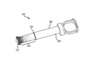
図2および図3は、モニタ付き注入装置100の斜視図および分解斜視図を示す。モニタ付き注入装置100は、内孔104を形成する注入器ハウジング(または注入器室)102を有する。ピストン棒106は、シャフト108とピストン110とを有し、内孔104に摺動自在に収容される。より具体的には、ピストン110が内孔104の内側表面に摺動自在に係合し、シャフト108の内孔104内での直線運動Mによってピストン110が動く。運動Mは、注入装置の軸Asに沿っている。ピストン棒106は、親指リング112のような親指パッドを動かすことによって内孔104内で前後に移動する。これを、以下で、より詳細に説明する。ピストン棒106が、運動Mの方向に沿って、注入器ハウジング102の排出端114に向かって移動すると、注入器ハウジング102内に含まれる液体が、管または針(図示せず)の中に排出され、患者に注入される。注意頂きたいことは、下記説明を通して、円筒型注入器室102と内孔104が記載されているが、しかしながら、本明細書で期待される機能および形状(長方形、楕円形、三角形等の断面がある)を内部および外部で提供するハウジング102/内孔104およびピストン棒106の構造は多種多様であり、本発明を限定しないように考慮されていることである。
2 and 3 show a perspective view and an exploded perspective view of the monitor-equipped
図示の実施形態では、光センサ・モジュール118が注入器ハウジング102の外側表面に固定されている。光センサ・モジュール118は、光センサ120を収容する光センサ・ハウジング119を有する。特定の実施形態では、光センサ120は、複数の画素を有する線形アレイとすることができる。このような線形アレイには、米国テキサス州プラノのAMS-TAOS USA社製のモデル番号TSL1406Rのアレイがある。他の実施形態では、光センサ120は、フォトレジスタ等の、1つまたは複数の個別の光センサにすることができる。一般的には、個別の光センサ素子(ピクセル、フォトレジスタ等)の数が多いほど精度を向上することができる。一つまたは複数のリード線またはワイヤ124が、光センサ・モジュール118の一端から延びている。これは、特定の用途に対する必要または要求に応じるものである。しかしながら、当業者であれば、ワイヤ124は、異なるセンサ構造では使用する必要がないことを容易に認識できるであろう。例えば、回路基板上で光センサを使用する場合は、別の接続を必要とすることがある。ケーブル126は、インタフェース・ユニットに端部128で接続されており、該インタフェース・ユニットは、光センサ・モジュール118の出力を分析し、得られた情報を、モニタ付き注入装置100のユーザに、典型的には、ディスプレイ上で提供する。他の実施形態では、通信は、無線、Bluetooth(登録商標)、または他の無線接続を経由して行ってもよい。前記表示される情報は、特定の用途に対する必要または要望に応じて、注入器室の体積、残り体積、投与済み体積、液体の種類、流速、液体の圧力または温度、および/または他の情報を含むことができる。
In the illustrated embodiment, the
図示の実施形態では、ピストン棒106のシャフト108は実質的に透明であり、これは、光が、通常はシャフト108を通過できることを意味する。不連続部分すなわちバンド130は、シャフト108上に配置、またはシャフト108と一緒に形成することができる。バンド130は、シャフト108の一部分であるが、この場合、透明度がシャフト108の他の部分より低い、言いかえれば、不透明度がシャフト108の残りの部分より大きい部分である。ピストン棒106が軸ASに沿って摺動しながら運動Mをすると、透明度がより低いバンド130が、光センサ素子118の光センサ120の前を通過する。光は、ピストン棒の、より高い透明度を持つ部分を通り、光センサ・モジュール118によって受光される。光センサ・モジュール118は、前記インタフェース部に信号を送り、該インタフェース部は、光センサ120を通過するバンド130の前記不透明度に基づいて、注入器ハウジング102内のピストン棒106の位置を決定する。このようにして、ピストン棒106の位置を決定することができる。前記インタフェースは、注入器ハウジング102の内孔104の既知の直径および長さに基づいて、上記の様々な種類の情報を決定することができる。2つの指リングすなわちタブ132に、使用中のユーザの指が入る。停止部134は、ピストン棒106が注入器ハウジング102の外に引き出されることを防止する。
In the illustrated embodiment, the
図4A~4Cは、本明細書の様々なモニタ付き注入装置で利用することができるピストン棒の様々な代替構成を示している。図4Aは、モニタ付き注入装置200の別の実施形態の部分拡大斜視図である。本実施形態では、ピストン棒206は、シャフト208を有する。図2および図3において上記で示された不連続なバンドとは異なり、本図に示す実施形態は、透明度/不透明度がピストン棒・シャフト208に沿って変化する、グラデーション230を有する。本図に示す実施形態では、ピストン210の近傍でグラデーション230が濃くなる(すなわち、より透明度が下がる、つまり、より不透明になる)。ストッパ234に近接するところでは、グラデーション部230の透明度はより高い(そして逆に、不透明度が低い)。グラデーションの遷移は滑らかにまたは不連続なバンド状にすることができる。図4Aに示すようなグラデーションを持つ特定の実施形態において、ストッパ234の近傍では、シェーディングしていない場合があり、その部分の透明度は、一般に、シャフト208の透明度と同一にすることができる。
4A-4C show various alternative configurations of piston rods that can be used in the various monitored infusion devices herein. FIG. 4A is a partially enlarged perspective view of another embodiment of the monitor-equipped
図4Bは、モニタ付き注入装置300の別の実施形態の部分拡大斜視図である。この実施形態では、ピストン棒306はシャフト308を有する。図2および図3について上述した、不透明度が高い不連続バンドとは異なり、図示の実施形態では、透明度が高い不連続バンド330を持つシャフト308を利用する。すなわち、シャフト308のピストン310とストッパ334との間に位置する部分は実質的に不透明であるが、バンド330は実質的に透明である。
FIG. 4B is a partially enlarged perspective view of another embodiment of the monitor-equipped
図4Cは、モニタ付き注入装置400の別の実施形態の部分拡大斜視図である。本実施形態では、ピストン棒406は、シャフト408を有する。グラデーション430が、図4Aの実施形態のグラデーションと反対に配置されている。図4Cの実施形態においては、グラデーション430は、ストッパ434の近傍で暗くなる(すなわち、より透明度が下がる、つまり、より不透明になる)。ピストン410の近傍では、グラデーション430の透明度が高くなる。グラデーション430の遷移は滑らかにまたは不連続バンド状にすることができる。特定の実施形態では、ピストン410の近傍ではシェーディングが全くなく、ピストン410の近傍の透明度をシャフト408の透明度と略同一にすることができる。
FIG. 4C is a partially enlarged perspective view of another embodiment of the monitor-equipped
図2、図3、または図4A~4Cに示すピストン棒の構成のいずれも、本明細書中に示すモニタ付き注入装置で利用することができる。すなわち、不透明または透明の不連続バンドを有するピストン棒、または、グラデーションが強くなる、または弱くなる(ピストンからストッパにかけて測定)ピストン棒を、光センサ・モジュールを用いる注入装置で利用することができる。ピストン棒の不透明度/透明度の構成に関係なく、前記光センサ・モジュールは、モニタ付き注入装置を使用するときに受信した光の変化を検出する。前記光センサ・モジュール内の1つまたは複数の光センサの位置に応じて、前記光の変化によって前記ピストン棒の位置を決定すること、従って、前記装置の体積および他の特性や状態を決定することができる。 Any of the piston rod configurations shown in FIGS. 2, 3 or 4A-4C can be used in the monitored injection device shown herein. That is, a piston rod with an opaque or transparent discontinuous band, or a piston rod with a stronger or weaker gradation (measured from the piston to the stopper) can be used in an injection device using an optical sensor module. Regardless of the opacity / transparency configuration of the piston rod, the photosensor module detects changes in light received when using a monitored injection device. Depending on the position of one or more photosensors in the photosensor module, the change in light determines the position of the piston rod, and thus the volume and other properties and conditions of the device. be able to.
図2~4Cの注入装置の測定の様々な実施形態では、全体として、前記装置ハウジングまたは内孔の上、中、または近傍に位置する光センサ・モジュールおよび/または光センサを有する装置を記載している。前記装置の透明度が変化する部分は、主に、前記装置のピストン棒の上、中、または近傍に置かれる。当然ながら、所望であれば前記コンポーネントの構成は逆にすることができる。例えば、前記ハウジング/内孔に透明度の変化する部分をおき、前記ピストン棒に光センサまたは光センサ・モジュールをおくようにできる。これらの実施形態はまた、本発明の技術の範囲内にあると考えられる。 Various embodiments of the measurement of the injection device of FIGS. 2-4C describe, as a whole, a device having a photosensor module and / or a photosensor located above, in, or near the device housing or inner hole. ing. The portion where the transparency of the device changes is mainly placed on, in, or in the vicinity of the piston rod of the device. Of course, the configuration of the component can be reversed if desired. For example, the housing / inner hole may be provided with a portion where the transparency changes, and the piston rod may be provided with an optical sensor or an optical sensor module. These embodiments are also considered to be within the scope of the art of the present invention.
図5A~5Cは、モニタ付き注入装置の様々な実施形態を示している。図5Aは、センサ・モジュール618を使用するモニタ付き注入装置600を示す。センサ・モジュール618は、センサ・ハウジング619および線形アレイ620を有し、線形アレイ620は複数の画素620Aを有する。図示の実施形態では、モニタ付き注入装置600はピストン棒606を有し、ピストン棒606はシャフト608を持ち、シャフト608は透明バンド630を持つ。バンド630は、完全に透明である必要はなく、単に、光アレイ620内の画素620Aが、受光した光の変化を検出することができる程度に透明であれば十分である。本実施形態では、受信した光は、手術室等の部屋に存在する周囲光640である。逆に、光源640は、例えば、赤外線や紫外線発生器のような、周囲光以外の光源からのものにすることができる。また、光センサ・モジュール618は、所定の波長(例えば、赤外線、紫外線等)のみの光を受光するフィルタで構成することができる。代わりに、ピストン棒606またはシャフト608は、受光した光を所望の波長でフィルタリングするためのフィルタで構成することもできる。
5A-5C show various embodiments of a monitor-equipped injection device. FIG. 5A shows a
図5Bは、センサ・モジュール718を使用したモニタ付き注入装置700を示している。センサ・モジュール718は、センサ・ハウジング719と、フォトレジスタのような離散光センサ素子720aを有する光センサ720と、を有する。図示の実施形態では、モニタ付き注入装置700は、ピストン棒706を有し、ピストン棒706はシャフト708を持ち、シャフト708はグラデーション730を持つ。グラデーション730は、ピストン710の近傍では透明度が低く、ストッパ734の近傍では透明度が高い。前述の実施形態のように周囲光を利用する代わりに、図5Bのモニタ付き注入装置は、例えば、発光ダイオード(LED(登録商標))等の発光モジュール750を利用する。発光モジュール750は、光センサ・モジュール718と同様に、注入器ハウジング702に固定されている。発光モジュール750は、エミッタ・ハウジング752と、複数の発光素子740aを持つ発光部740と、を有する。図示の実施形態では、離散発光素子740aは、離散光センサ素子720aと対向してかつ整列して配置することができるが、これは必須ではない。また、発光素子740aは、特定の波長の光のみを発光するように構成することができる、または、光をフィルタリングして放出および/または検知する光を制限するようにできる。グラデーション730が光センサ・モジュール718と発光モジュール750との間を通過するとき、光信号は、離散光センサ素子720aによって受光される。光センサ・モジュール718はインタフェース部に信号を送り、該インタフェース部は、該信号を処理してピストン710の位置を決定する。光センサ・モジュール718と発光モジュール750とは、注入器ハウジング702の周りに互いに約180度間隔をあけて配置される。他の実施形態では、モジュール718、750は、互いから約180度未満間隔をあけて配置してもよい。特定の実施形態において、モジュール718、750は、互いに約90度間隔をあけて配置することができる。所望であれば、モジュール718、750は、共通のハウジング内に収容することもできる。
FIG. 5B shows an
図5Cは、センサ・モジュール818を使用したモニタ付き注入装置800を示している。前記センサ・モジュールは、センサ・ハウジング819と、フォトレジスタ等の、離散配置された光センサ素子820aを持つ光センサ820を有する。図示の実施形態では、モニタ付き注入装置800は、ピストン棒806を有し、ピストン棒806はシャフト808を持ち、シャフト808はグラデーション830を持ち、グラデーション830は、ピストン810の近傍では透明度が低く、ストッパ834の近傍では透明度が高い。モニタ付き注入装置800は、発光モジュール850を使用している。発光モジュール850は、光センサ・モジュール818と同様にして、注入器ハウジング802に固定されている。発光モジュール850は、エミッタ・ハウジング852と、複数の発光素子840aを持つ発光部840と、を有する。留意すべきことは、エミッタ・ハウジング852とセンサ・ハウジング819とは、前記注入器室へのエミッタ/センサの固定を容易にするための構造部品(例えば、テープまたは接着剤)を持つことができる、または、前記注入器室の壁の内側に配置されたエミッタ/センサを持つことができることである。図示の実施形態では、離散配置された発光素子840aが離散配置された光センサ素子820aと対向し、かつ、平行に並んで配置されているが、これは必須ではない。さらに、発光素子840aは、特定の波長の光を放出する、または、フィルタリングするように構成することができる(例えば、近赤外光発生器)。グラデーション830が発光モジュール818と光センサ・モジュール850との間を通過するとき、光信号が離散配置された光センサ素子820aによって受光される。光センサ・モジュール818が信号をインタフェース部に送ると、該インタフェース部は前記信号を処理してピストン810の位置を決定する。光センサ・モジュール818と発光モジュール850とは、注入器ハウジング802の周りに互いに約180度間隔をあけて配置される。他の実施形態では、モジュール818、850は、図5Bに関して上述したように配置することができる。図5Cのモニタ付き注入装置800は、図5Aおよび図5Bのものよりもセンサとエミッタ密度が高い、光センサ・モジュール818と発光モジュール850とを使用する。上述したように、これによって、より高い位置精度を得ることができる。
Figure 5C shows an injection device with a
図6は、モニタ付き注入装置900の別の実施形態を示す。この実施形態では、光センサ・ハウジング919は、光センサ920および配線924を有し、注入器ハウジング902に着脱可能に固定されている。光センサ・ハウジング919は、クリップ、C型クランプ、弾性止め具、または他の構成要素960で固定して、注入器ハウジング902から取り外し可能にすることができる。このような構成は、光センサ・ハウジング919および関連する構成要素を、典型的には医療処置の後に別の注入装置に再利用するために、望ましい構成である。光センサ・ハウジング919は、第1の注入器ハウジング902から取り外し、後で第2の注入器ハウジングに再取り付けすることができる。配線924(または類似の接続器具)が前記インタフェース部(上記参照)に再接続されると、前記新しい注入装置の光センサ・モジュール918を較正するために、較正プログラムを実行することができる。
FIG. 6 shows another embodiment of the monitor-equipped
本明細書に記載の実施形態は、注入器室内のピストン棒の変位を測定および/または検出する、注入装置等の様々な構成要素またはコンポーネントを有することができる。そして、注入器室内のピストン棒の変位を検出することで、ユーザは、明示的または間接的に前記注入器室から排出された可能性がある液材の体積を決定することができる。説明した実施形態のいくつかは、光を検出または感知するコンポーネントだけでなく、ピストン棒/ピストンと前記注入器室との位置関係に応じた、様々な光の生成源を有することができる。ピストン棒と注入器室との位置関係(およびその変化)を特定することが可能な他の代替的な実施形態では、以下の技術を有することができるが、これに限定するものではない。ホールセンサ(注入装置の軸に沿ったコイル状ワイヤ)は、磁石が取り付けられた前記ピストン棒と組み合わせて、前記注入器室、またはその近傍に配置することができる(可変近接センサとして動作させるため)。複数の低感度ホールセンサを、前記ピストン棒に取り付けられた磁石と一緒に前記注入装置の前記注入器室に沿って配置することができる。レーザ光を放射、検出することによって、前記注入器室の軸に沿ったピストン棒の位置関係を決定することができる。アブソリュート・エンコーダを、前記ピストン棒の位置を直接「読み取る」ために使用することができる。 The embodiments described herein can have various components or components, such as an injection device, that measure and / or detect displacement of the piston rod in the injector chamber. Then, by detecting the displacement of the piston rod in the injector chamber, the user can explicitly or indirectly determine the volume of the liquid material that may have been discharged from the injector chamber. Some of the embodiments described can have not only components that detect or sense light, but also various sources of light, depending on the positional relationship between the piston rod / piston and the injector chamber. Other alternative embodiments that can identify the positional relationship (and changes thereof) between the piston rod and the injector chamber can include, but are not limited to, the following techniques. The Hall sensor (coiled wire along the axis of the injection device) can be placed in or near the injector chamber in combination with the piston rod to which a magnet is attached (to operate as a variable proximity sensor). ). A plurality of low-sensitivity Hall sensors can be placed along the injector chamber of the injection device together with a magnet attached to the piston rod. By radiating and detecting the laser beam, the positional relationship of the piston rod along the axis of the injector chamber can be determined. An absolute encoder can be used to directly "read" the position of the piston rod.
図7は、光信号を利用したモニタ付き注入装置を使用する方法1000を示している。ステップ1002において、光センサから信号が受信されるが、モニタ付き注入装置上の光センサの位置は既知である。受光可能な波長等の前記光センサの他の特性は既知である。ステップ1004で、前記光センサの位置と該光センサから受信した前記信号に基づいて、ピストンの位置が決定される。方法1000の特定の実施形態では、ステップ1006において第1の発光素子から光信号が放射される。ステップ1008において、複数の光センサを使用する実施形態で、光信号が、既知の特性(例えば、位置)を持つ第2の光センサで受信される。次に、動作1010において、最新の位置が、第2の光センサと前記信号の特性に基づいて決定される。光信号が既知の光センサで受信される任意の時点で、ステップ1012に記載したように、(本明細書に記載されているような)注入装置の状態を決定することができる。
FIG. 7 shows a
図8は、本明細書記載の実施形態の1つまたは複数を実装することができる好適な動作環境1100の一例を示している。これは、好適な動作環境の一例に過ぎず、使用範囲または機能範囲に関する限定を何ら示唆するものではない。使用に適した、他の周知のコンピューティング・システム、環境、および/または構成としては、パーソナル・コンピュータ、サーバ・コンピュータ、ハンドヘルドまたはラップトップ装置、マルチプロセッサ・システム、マイクロプロセッサベース・システム、スマートフォン等のプログラム可能なコンシューマ電子機器、ネットワークPC、ミニコンピュータ、メインフレームコンピュータ、スマートフォン、タブレット、上述のシステムまたは装置のいくつかを有する分散コンピューティング環境、等があるが、これらに限定されない。
FIG. 8 shows an example of a
最も基本的な構成では、典型的な動作環境1100は、少なくとも1つの処理ユニット1102およびメモリ1104を有する。コンピューティング装置そのものの構成と種類に応じて、メモリ1104(特に、本明細書に記載のモニタ方法を実行するための命令を記憶する)は、揮発性(RAM等)、不揮発性(ROM、フラッシュメモリ等)、またはこの2つの組み合わせにすることができる。この最も基本的な構成は、図8に破線1106によって示されている。さらに、環境1100は、記憶装置(取り外し可能な記憶装置1108、および/または取り外し不可能な記憶装置1110)を有する。該記憶装置には、これらに限定されないが、磁気ディスク、光ディスク、またはテープがある。同様に、環境1100は、また、タッチスクリーン、キーボード、マウス、ペン、音声入力等の入力装置1114(複数可)、および/または、ディスプレイ、スピーカ、プリンタ等の出力装置1116(複数可)を有することができる。また、前記環境には、LAN、WAN、ポイント・ツー・ポイント、Bluetooth(登録商標)、RF等の1つまたは複数の通信接続1112を含むことができる。
In the most basic configuration, a
動作環境1100は、典型的には、少なくとも何らかの形態のコンピュータ可読媒体を有する。コンピュータ可読媒体は、オペレーティング環境の組み込まれた処理ユニット1102または他の装置によってアクセス可能な、任意の利用可能媒体でよい。コンピュータ可読媒体の例としては、コンピュータ記憶媒体および通信媒体があるが、これに限定されない。コンピュータ記憶媒体には、揮発性媒体と不揮発性媒体、取り外し可能媒体と取り外し不可能媒体があり、任意の方法または技術で実装することができ、コンピュータ可読命令、データ構造、プログラム・モジュール、または他のデータ等の情報を記憶するためのものである。コンピュータ記憶媒体には、RAM、ROM、EEPROM、フラッシュメモリまたは他のメモリ技術、CD-ROM、デジタル多用途ディスク(DVD)または他の光記憶装置、磁気カセット、磁気テープ、磁気ディスク記憶装置または他の磁気記憶装置、固体記憶装置、あるいは所望の情報を格納するために使用することができる任意の他の有形の媒体がある。通信媒体は、コンピュータ可読命令、データ構造、プログラム・モジュール、または他のデータ等を、搬送波または他の送信機構等の変調データ信号内に組み込むもので、任意の情報転送媒体がある。用語「変調データ信号」は、情報を信号内で符号化するようにして構成または変更された、1つまたは複数の信号特性を持つ信号を意味する。通信媒体の例としては、有線ネットワークまたは直接有線接続等の有線媒体、および音響、RF、赤外線無線および他の無線、等の無線媒体が含まれるが、これに限定されない。上記の任意の組合せも、また、コンピュータ可読媒体の範囲内に含まれる。
The
動作環境1100は、1つまたは複数のリモート・コンピュータへの論理接続を使用して、ネットワーク環境で動作する単一のコンピュータとすることができる。前記リモート・コンピュータは、パーソナル・コンピュータ、サーバ、ルータ、ネットワークPC、ピア・デバイスまたは他の共通ネットワーク・ノードとすることができ、多くの、または、すべての上記構成要素、および、上記で言及のない他の構成要素を含むことができる。前記論理接続は、利用可能な通信媒体でサポートされている任意の方法を含むことができる。このようなネットワーク環境は、オフィスや企業規模のコンピュータ・ネットワーク、イントラネット、およびインターネットにおいて一般的である。いくつかの実施形態において、本明細書に記載されたコンポーネントは、コンピュータシステム1100によって実行可能なモジュールまたは命令を含むことができ、該モジュールまたは命令は、コンピュータ記憶媒体およびその他の有形媒体に格納し、かつ通信媒体で送信することができる。コンピュータ記憶媒体には、揮発性および不揮発性、取り外し可能媒体と取り外し不可能媒体があり、任意の方法または技術で実装することができ、コンピュータ可読命令、データ構造、プログラム・モジュール、または他のデータ等の情報を記憶するためのものである。上記の任意の組合せも可読媒体の範囲内に含まれる。いくつかの実施形態では、コンピュータシステム1100は、コンピュータシステム1100が使用するリモート記憶媒体にデータを格納するネットワークの一部になる。
The
本明細書に記載のモニタ・システムは、医療処置中に患者へ任意の種類の液体を注入するために使用することができる。このような液体には、液材(複数も可)、薬剤、薬物、薬材、薬品等がある。留意すべきことは、これらの用語は、本明細書中で種々の液体薬材を記載するために総称的に使用されており、前記液体薬材には、少なくとも一部に、診断、治療および/または予防的医療処置の実行において使用される薬物を含むことができるが、これらに限定することは意図していない、ということである。理解頂きたいことは、本明細書に記載の液材注入の調節および/または測定のための装置および方法は、上述の特定の典型的な実施形態に限定されるものではないことである。その理由は、これらの実施形態に対して、本開示の範囲および思想から逸脱することなく、変形を行うことができるからである。同様に、実施形態の説明に用いた用語は、請求範囲の限定を意図するものではなく、発明概念の伝達の目的にのみ使用している。別段の定義がない限り、本明細書中で使用する全ての技術的用語および科学的用語は、開示した装置および方法が関係する分野の当業者に共通的に理解されている意味と同一の意味を持つ。 The monitoring system described herein can be used to inject any type of liquid into a patient during a medical procedure. Such liquids include liquid materials (s), drugs, drugs, drug materials, drugs and the like. It should be noted that these terms are used generically herein to describe various liquid medicines, which are at least in part diagnostic, therapeutic and / Or drugs used in the practice of preventive medical procedures can be included, but are not intended to be limited to these. It should be understood that the devices and methods for the regulation and / or measurement of liquid material injection described herein are not limited to the particular typical embodiments described above. The reason is that these embodiments can be modified without departing from the scope and ideas of the present disclosure. Similarly, the terms used in the description of the embodiments are not intended to limit the claims, but are used only for the purpose of communicating the concept of the invention. Unless otherwise defined, all technical and scientific terms used herein have the same meaning as commonly understood by one of ordinary skill in the art to which the disclosed devices and methods relate. have.
モニタ付き注入装置の製造に利用する材料は、医療用途における代表的なものでよい。ポリカーボネート等のプラスチックを注入器ハウジングおよびピストン棒に用いることができる。前記バンドまたはグラデーションは、前記ピストン棒・シャフト上に直接印刷することも、個別のプラスチック・シートまたは鞘上に印刷してから前記ピストン棒・シャフトに固着することもできる。様々な種類の印刷を、前記バンドまたはグラデーションの透明度または不透明度を変更するために利用することができる。いくつかの実施形態では、印刷の種類は、前記センサによって受光される光の種類に基づいて決めることができる。例えば、カーボン・ベースの印刷は、赤外光を検出するセンサに利用することができる。このとき、前記バンドまたはグラデーションは、上述のフィルタとして利用することができる。 The material used in the manufacture of the infusion device with a monitor may be representative of medical applications. Plastics such as polycarbonate can be used for the injector housing and piston rod. The band or gradation can be printed directly on the piston rod / shaft or printed on a separate plastic sheet or sheath and then fixed to the piston rod / shaft. Various types of printing can be used to change the transparency or opacity of the band or gradation. In some embodiments, the type of print can be determined based on the type of light received by the sensor. For example, carbon-based printing can be used for sensors that detect infrared light. At this time, the band or the gradation can be used as the above-mentioned filter.
本明細書では、本発明の技術の代表的かつ好適な実施形態と考えられるものを説明したが、当業者には、本発明の技術の他の変形が本明細書の教示を参照して明らかになるであろう。本明細書に開示した、特定の製造方法および特定の幾何学的形状は、その性質上、代表例であり、何らかの限定をすると考えるべきではない。したがって、本発明の技術の思想および請求範囲内に入るようなすべての変形が保護されることが望まれる。したがって、特許による保護が望まれるものは、本明細書で定義され、従来技術と区別された本発明の技術、および全ての等価物である。 Although this specification has described what is considered to be a representative and preferred embodiment of the technique of the invention, other variations of the technique of the invention will be apparent to those of skill in the art with reference to the teachings herein. Will be. The specific manufacturing methods and specific geometries disclosed herein are representative by their nature and should not be considered to be of any limitation. Therefore, it is desired that all modifications that fall within the ideas and claims of the present invention are protected. Accordingly, what is desired to be protected by patent is the technique of the invention, as defined herein and distinguished from prior art, and all equivalents.
Claims (23)
該注入器ハウジングの前記内孔内に摺動可能に収容され、前記液体を前記内孔から排出するための、一つの実質的に不透明な部分と一つの実質的に透明な部分とを有するピストン棒と、
前記注入器ハウジングに取り外し可能に固定された光センサ・ハウジングを有する光センサ・モジュール、及び、
前記注入器ハウジングに取り外し可能に固定された光エミッタ・ハウジングを有する発光モジュールと、
を有し、
前記光エミッタ・ハウジングは前記光センサ・ハウジングとは分離した別体であり、
前記発光モジュールから発射された光が前記ピストン棒の少なくとも前記実質的に透明な部分を通過して前記光センサ・モジュールによって受光されること
を特徴とする、液体注入装置。 An injector housing with an inner hole for containing liquid,
A piston that is slidably housed in the inner hole of the injector housing and has one substantially opaque portion and one substantially transparent portion for draining the liquid from the inner hole. With a stick,
An optical sensor module having an optical sensor housing detachably fixed to the injector housing, and
A light emitting module having a light emitter housing detachably fixed to the injector housing,
Have,
The photoemitter housing is a separate body from the photosensor housing.
A liquid injection device, characterized in that light emitted from the light emitting module passes through at least the substantially transparent portion of the piston rod and is received by the photosensor module.
を特徴とする、請求項1に記載の液体注入装置。 The liquid injection device according to claim 1, further comprising a lead extending from the optical sensor module.
を特徴とする、請求項2に記載の液体注入装置。 Further, claim 2, the measuring device has an interface for connecting the lead, and the measuring device displays the total volume injected and issues a warning regarding a critical result. The liquid injection device described.
を特徴とする、請求項1に記載の液体注入装置。 The liquid injection device according to claim 1, wherein the photosensor module includes a photosensor housing and at least one photosensor element disposed within the photosensor housing.
を特徴とする、請求項4に記載の液体注入装置。 The liquid injection device according to claim 4, further comprising means for detachably fixing the photosensor housing to the injector housing.
を特徴とする、請求項5に記載の液体注入装置。 The liquid injection device according to claim 5, wherein the means comprises at least one of a clamp, a clasp, a hook and a loop fastener, and a magnet.
を特徴とする、請求項1に記載の液体注入装置。 The liquid injection device according to claim 1, wherein the light emitting module includes a light emitting housing and at least one light emitting element arranged in the light emitting housing.
を特徴とする、請求項1に記載の液体注入装置。 The liquid injection device according to claim 1, wherein the photosensor module is arranged around the injector housing at a distance of 180 degrees from the light emitting module.
前記第1光センサ素子と前記第2光センサ素子とが前記光センサ・ハウジング内に配置され、
前記ピストン棒の位置を第1の位置に配置すると、前記実質的に透明な部分が第1光センサ素子と並び、前記ピストン棒の位置を第2の位置に配置すると、前記実質的に透明な部分が前記第2光センサ素子と並ぶこと
を特徴とする請求項1に記載の液体注入装置。 The optical sensor module includes an optical sensor housing, a first optical sensor element, and a second optical sensor element.
The first optical sensor element and the second optical sensor element are arranged in the optical sensor housing.
When the position of the piston rod is arranged at the first position, the substantially transparent portion is aligned with the first optical sensor element, and when the position of the piston rod is arranged at the second position, the substantially transparent portion is formed. The liquid injection device according to claim 1, wherein the portion is aligned with the second optical sensor element.
を特徴とする、請求項1に記載の液体注入装置。 The piston rod has a plurality of substantially transparent portions, and the plurality of substantially transparent portions have a first portion having a first transparency and a second transparency lower than the first transparency. The liquid injection device according to claim 1, wherein the liquid injection device has a second portion.
を特徴とする、請求項10に記載の液体注入装置。 The liquid injection device according to claim 10, wherein the plurality of substantially transparent portions have a gradation.
を特徴とする、請求項1に記載の液体注入装置。 The liquid injection device according to claim 1, wherein the optical sensor module has a plurality of optical sensor elements, and the light emitting module has a plurality of light emitting elements.
を特徴とする、請求項12に記載の液体注入装置。 The liquid injection device according to claim 12, wherein the plurality of light emitting elements and the plurality of optical sensor elements are arranged side by side in parallel.
を特徴とする、請求項1に記載の液体注入装置。 The liquid injection device according to claim 1, wherein the light emitting module is arranged around the injector housing at a distance of at least 90 degrees from the optical sensor module.
該薬剤注入用処理システムは、コンピュータに含まれる一つ又は複数のプロセッサによって実行されて、該コンピュータに注入装置の状態を決定させるための命令を含むプログラムを記憶するコンピュータ可読記憶媒体を含み、前記命令は、
第1光センサにおいて第1光信号を受信するステップを含み、前記注入装置上の前記第1光センサの位置は既知であり、かつ、前記第1光信号は前記第1光センサによって受信される前に前記注入装置のピストンの実質的に透明な部分を通過すること
を特徴とする、薬剤注入用処理システム。 A drug injection processing system having at least one processing unit and a memory, and performing processing based on the sensor information sent from the liquid injection device according to claim 1.
The drug injection processing system includes a computer-readable storage medium that is executed by one or more processors included in the computer and stores a program containing instructions for causing the computer to determine the state of the injection device. , The command is
Including the step of receiving the first optical signal in the first optical sensor, the position of the first optical sensor on the injection device is known, and the first optical signal is received by the first optical sensor. A processing system for drug injection, characterized in that it previously passes through a substantially transparent portion of the piston of the injection device.
を特徴とする、請求項15に記載の薬剤注入用処理システム。 The instruction further comprises a step of determining a first position of the piston located within the injection device, at least in part, based on the received first optical signal. , The processing system for injecting a drug according to claim 15.
を特徴とする、請求項16に記載の薬剤注入用処理システム。 The processing system for drug injection according to claim 16, wherein the instruction further includes a step of outputting the first optical signal from the first light emitting element arranged on the injection device.
を特徴とする、請求項17に記載の薬剤注入用処理システム。 17. The instruction according to claim 17, further comprising the step of receiving a second optical signal at the second optical sensor, wherein the position of the second optical sensor on the injection device is known. Processing system for drug injection.
を特徴とする、請求項18に記載の薬剤注入用処理システム。 18. The agent of claim 18, wherein the instruction further comprises a step of determining a second position of the piston, at least in part, based on the received second optical signal. Injection processing system.
を特徴とする、請求項19に記載の薬剤注入用処理システム。 When the position of the piston is arranged at the first position, the substantially transparent portion is aligned with the first of at least two optical sensors including the first optical sensor and the second optical sensor. 19. When the position of the piston is arranged at the second position, the substantially transparent portion is aligned with the second optical sensor of the at least two optical sensors, according to claim 19. The described drug infusion processing system.
を特徴とする、請求項7に記載の液体注入装置。 The liquid injection device according to claim 7, wherein the light emitting module includes at least two light emitting elements.
を特徴とする、請求項1に記載の液体注入装置。 The liquid injection device according to claim 1, wherein the optical sensor module includes a plurality of optical sensor elements, or the light emitting module includes a plurality of light emitting elements.
前記シャフトは使用中に親指が少なくとも部分的に入るように構成されること
を特徴とする、請求項1に記載の液体注入装置。 The injector housing has two members configured to allow at least partial entry of two fingers during use, the piston rod having a shaft and a piston, within the injector housing. Slidingly housed,
The liquid injection device according to claim 1, wherein the shaft is configured so that the thumb is at least partially inserted during use.
Applications Claiming Priority (3)
| Application Number | Priority Date | Filing Date | Title |
|---|---|---|---|
| US14/222,331 | 2014-03-21 | ||
| US14/222,331 US9999718B2 (en) | 2012-08-28 | 2014-03-21 | Volume monitoring device utilizing light-based systems |
| PCT/US2015/021294 WO2015143058A1 (en) | 2014-03-21 | 2015-03-18 | Syringe with optical system for monitoring the position of the plunger rod |
Publications (3)
| Publication Number | Publication Date |
|---|---|
| JP2017508596A JP2017508596A (en) | 2017-03-30 |
| JP2017508596A5 JP2017508596A5 (en) | 2018-04-26 |
| JP7040937B2 true JP7040937B2 (en) | 2022-03-23 |
Family
ID=54145276
Family Applications (1)
| Application Number | Title | Priority Date | Filing Date |
|---|---|---|---|
| JP2017501097A Active JP7040937B2 (en) | 2014-03-21 | 2015-03-18 | Injection device with optical system for monitoring the position of the piston rod |
Country Status (4)
| Country | Link |
|---|---|
| EP (1) | EP3119465A1 (en) |
| JP (1) | JP7040937B2 (en) |
| AU (1) | AU2015231365B2 (en) |
| WO (1) | WO2015143058A1 (en) |
Families Citing this family (8)
| Publication number | Priority date | Publication date | Assignee | Title |
|---|---|---|---|---|
| US10255524B2 (en) * | 2016-06-03 | 2019-04-09 | Becton Dickinson Rowa Germany Gmbh | Method for providing a singling device of a storage and dispensing container |
| US10183120B2 (en) * | 2016-07-15 | 2019-01-22 | Common Sensing Inc. | Dose measurement systems and methods |
| CN109843360A (en) * | 2016-08-17 | 2019-06-04 | 尼莎·沙惠尼 | Inject monitoring device and system |
| CN110049794B (en) * | 2016-12-15 | 2021-11-16 | 伊莱利利公司 | Drug delivery device with sensing system |
| DE102017218551A1 (en) * | 2017-10-18 | 2019-04-18 | Robert Bosch Gmbh | Adhesive label for a container |
| JP7261229B2 (en) * | 2017-10-19 | 2023-04-19 | サノフイ | drug delivery device |
| EP3731900A1 (en) * | 2017-12-28 | 2020-11-04 | Sanofi | A dosage measurement system |
| CN115813767A (en) * | 2023-02-04 | 2023-03-21 | 潍坊医学院附属医院 | Supplementary medicine feeding device |
Citations (2)
| Publication number | Priority date | Publication date | Assignee | Title |
|---|---|---|---|---|
| JP2005533568A (en) | 2002-07-24 | 2005-11-10 | デカ・プロダクツ・リミテッド・パートナーシップ | Optical deflection sensor for injection devices. |
| WO2013177135A1 (en) | 2012-05-21 | 2013-11-28 | Common Sensing Inc. | Dose measurement system and method |
Family Cites Families (4)
| Publication number | Priority date | Publication date | Assignee | Title |
|---|---|---|---|---|
| US5376785A (en) * | 1992-10-02 | 1994-12-27 | Chin; Philip K. | Optical displacement sensor utilizing optical diffusion |
| JP3381301B2 (en) * | 1993-04-14 | 2003-02-24 | 株式会社ジェイ・エム・エス | Syringe pump |
| US5792117A (en) * | 1994-07-22 | 1998-08-11 | Raya Systems, Inc. | Apparatus for optically determining and electronically recording injection doses in syringes |
| DE19643813A1 (en) * | 1996-09-26 | 1998-04-02 | Schreiber Hans | Kit for controlled injection of drugs |
-
2015
- 2015-03-18 AU AU2015231365A patent/AU2015231365B2/en not_active Ceased
- 2015-03-18 WO PCT/US2015/021294 patent/WO2015143058A1/en active Application Filing
- 2015-03-18 JP JP2017501097A patent/JP7040937B2/en active Active
- 2015-03-18 EP EP15714346.2A patent/EP3119465A1/en not_active Withdrawn
Patent Citations (2)
| Publication number | Priority date | Publication date | Assignee | Title |
|---|---|---|---|---|
| JP2005533568A (en) | 2002-07-24 | 2005-11-10 | デカ・プロダクツ・リミテッド・パートナーシップ | Optical deflection sensor for injection devices. |
| WO2013177135A1 (en) | 2012-05-21 | 2013-11-28 | Common Sensing Inc. | Dose measurement system and method |
Also Published As
| Publication number | Publication date |
|---|---|
| AU2015231365A1 (en) | 2016-10-06 |
| JP2017508596A (en) | 2017-03-30 |
| WO2015143058A1 (en) | 2015-09-24 |
| EP3119465A1 (en) | 2017-01-25 |
| AU2015231365B2 (en) | 2019-12-05 |
Similar Documents
| Publication | Publication Date | Title |
|---|---|---|
| JP7040937B2 (en) | Injection device with optical system for monitoring the position of the piston rod | |
| US20150202386A1 (en) | Volume monitoring device utilizing hall sensor-based systems | |
| US20220233782A1 (en) | Volume monitoring systems | |
| US9999718B2 (en) | Volume monitoring device utilizing light-based systems | |
| JP6559681B2 (en) | Device, system and method for assessing intravascular pressure | |
| US11116892B2 (en) | Medium injection diversion and measurement | |
| US11654234B2 (en) | Respiratory parameter guided automated IV administration and IV tube clamp activation | |
| US10413677B2 (en) | Volume monitoring device | |
| CN111657863A (en) | Systems, devices, and methods for sensing physiological data and draining and analyzing bodily fluids | |
| US20150202361A1 (en) | Devices and methods for modulating medium delivery | |
| JP6863958B2 (en) | Syringe volume monitoring system with Hall sensor | |
| US20220143316A1 (en) | System with a device and a process for controlling an administration of a drug to a patient | |
| JP7200146B2 (en) | Injection, bypass and metering of media | |
| JP6526004B2 (en) | Capacity monitoring device | |
| US20220168498A1 (en) | Medium injection diversion and measurement | |
| JP2021142361A (en) | Devices and methods for modulating medium delivery |
Legal Events
| Date | Code | Title | Description |
|---|---|---|---|
| A521 | Request for written amendment filed |
Free format text: JAPANESE INTERMEDIATE CODE: A523 Effective date: 20180315 |
|
| A621 | Written request for application examination |
Free format text: JAPANESE INTERMEDIATE CODE: A621 Effective date: 20180315 |
|
| A977 | Report on retrieval |
Free format text: JAPANESE INTERMEDIATE CODE: A971007 Effective date: 20190121 |
|
| A131 | Notification of reasons for refusal |
Free format text: JAPANESE INTERMEDIATE CODE: A131 Effective date: 20190129 |
|
| A601 | Written request for extension of time |
Free format text: JAPANESE INTERMEDIATE CODE: A601 Effective date: 20190426 |
|
| A601 | Written request for extension of time |
Free format text: JAPANESE INTERMEDIATE CODE: A601 Effective date: 20190701 |
|
| A521 | Request for written amendment filed |
Free format text: JAPANESE INTERMEDIATE CODE: A523 Effective date: 20190729 |
|
| A131 | Notification of reasons for refusal |
Free format text: JAPANESE INTERMEDIATE CODE: A131 Effective date: 20200107 |
|
| A601 | Written request for extension of time |
Free format text: JAPANESE INTERMEDIATE CODE: A601 Effective date: 20200331 |
|
| A521 | Request for written amendment filed |
Free format text: JAPANESE INTERMEDIATE CODE: A523 Effective date: 20200608 |
|
| A02 | Decision of refusal |
Free format text: JAPANESE INTERMEDIATE CODE: A02 Effective date: 20201117 |
|
| A521 | Request for written amendment filed |
Free format text: JAPANESE INTERMEDIATE CODE: A523 Effective date: 20210317 |
|
| C60 | Trial request (containing other claim documents, opposition documents) |
Free format text: JAPANESE INTERMEDIATE CODE: C60 Effective date: 20210317 |
|
| C11 | Written invitation by the commissioner to file amendments |
Free format text: JAPANESE INTERMEDIATE CODE: C11 Effective date: 20210330 |
|
| A911 | Transfer to examiner for re-examination before appeal (zenchi) |
Free format text: JAPANESE INTERMEDIATE CODE: A911 Effective date: 20210527 |
|
| C21 | Notice of transfer of a case for reconsideration by examiners before appeal proceedings |
Free format text: JAPANESE INTERMEDIATE CODE: C21 Effective date: 20210601 |
|
| A912 | Re-examination (zenchi) completed and case transferred to appeal board |
Free format text: JAPANESE INTERMEDIATE CODE: A912 Effective date: 20210730 |
|
| C211 | Notice of termination of reconsideration by examiners before appeal proceedings |
Free format text: JAPANESE INTERMEDIATE CODE: C211 Effective date: 20210803 |
|
| C22 | Notice of designation (change) of administrative judge |
Free format text: JAPANESE INTERMEDIATE CODE: C22 Effective date: 20210914 |
|
| C23 | Notice of termination of proceedings |
Free format text: JAPANESE INTERMEDIATE CODE: C23 Effective date: 20220104 |
|
| C03 | Trial/appeal decision taken |
Free format text: JAPANESE INTERMEDIATE CODE: C03 Effective date: 20220208 |
|
| C30A | Notification sent |
Free format text: JAPANESE INTERMEDIATE CODE: C3012 Effective date: 20220208 |
|
| A61 | First payment of annual fees (during grant procedure) |
Free format text: JAPANESE INTERMEDIATE CODE: A61 Effective date: 20220310 |
|
| R150 | Certificate of patent or registration of utility model |
Ref document number: 7040937 Country of ref document: JP Free format text: JAPANESE INTERMEDIATE CODE: R150 |