JP6863958B2 - Syringe volume monitoring system with Hall sensor - Google Patents
Syringe volume monitoring system with Hall sensor Download PDFInfo
- Publication number
- JP6863958B2 JP6863958B2 JP2018502622A JP2018502622A JP6863958B2 JP 6863958 B2 JP6863958 B2 JP 6863958B2 JP 2018502622 A JP2018502622 A JP 2018502622A JP 2018502622 A JP2018502622 A JP 2018502622A JP 6863958 B2 JP6863958 B2 JP 6863958B2
- Authority
- JP
- Japan
- Prior art keywords
- plunger
- medium
- syringe
- vessel
- magnet
- Prior art date
- Legal status (The legal status is an assumption and is not a legal conclusion. Google has not performed a legal analysis and makes no representation as to the accuracy of the status listed.)
- Active
Links
Images


Classifications
-
- A—HUMAN NECESSITIES
- A61—MEDICAL OR VETERINARY SCIENCE; HYGIENE
- A61M—DEVICES FOR INTRODUCING MEDIA INTO, OR ONTO, THE BODY; DEVICES FOR TRANSDUCING BODY MEDIA OR FOR TAKING MEDIA FROM THE BODY; DEVICES FOR PRODUCING OR ENDING SLEEP OR STUPOR
- A61M5/00—Devices for bringing media into the body in a subcutaneous, intra-vascular or intramuscular way; Accessories therefor, e.g. filling or cleaning devices, arm-rests
- A61M5/14—Infusion devices, e.g. infusing by gravity; Blood infusion; Accessories therefor
- A61M5/142—Pressure infusion, e.g. using pumps
- A61M5/145—Pressure infusion, e.g. using pumps using pressurised reservoirs, e.g. pressurised by means of pistons
- A61M5/1452—Pressure infusion, e.g. using pumps using pressurised reservoirs, e.g. pressurised by means of pistons pressurised by means of pistons
-
- A—HUMAN NECESSITIES
- A61—MEDICAL OR VETERINARY SCIENCE; HYGIENE
- A61M—DEVICES FOR INTRODUCING MEDIA INTO, OR ONTO, THE BODY; DEVICES FOR TRANSDUCING BODY MEDIA OR FOR TAKING MEDIA FROM THE BODY; DEVICES FOR PRODUCING OR ENDING SLEEP OR STUPOR
- A61M5/00—Devices for bringing media into the body in a subcutaneous, intra-vascular or intramuscular way; Accessories therefor, e.g. filling or cleaning devices, arm-rests
- A61M5/14—Infusion devices, e.g. infusing by gravity; Blood infusion; Accessories therefor
- A61M5/168—Means for controlling media flow to the body or for metering media to the body, e.g. drip meters, counters ; Monitoring media flow to the body
- A61M5/16886—Means for controlling media flow to the body or for metering media to the body, e.g. drip meters, counters ; Monitoring media flow to the body for measuring fluid flow rate, i.e. flowmeters
-
- A—HUMAN NECESSITIES
- A61—MEDICAL OR VETERINARY SCIENCE; HYGIENE
- A61M—DEVICES FOR INTRODUCING MEDIA INTO, OR ONTO, THE BODY; DEVICES FOR TRANSDUCING BODY MEDIA OR FOR TAKING MEDIA FROM THE BODY; DEVICES FOR PRODUCING OR ENDING SLEEP OR STUPOR
- A61M5/00—Devices for bringing media into the body in a subcutaneous, intra-vascular or intramuscular way; Accessories therefor, e.g. filling or cleaning devices, arm-rests
- A61M5/14—Infusion devices, e.g. infusing by gravity; Blood infusion; Accessories therefor
- A61M5/168—Means for controlling media flow to the body or for metering media to the body, e.g. drip meters, counters ; Monitoring media flow to the body
- A61M5/172—Means for controlling media flow to the body or for metering media to the body, e.g. drip meters, counters ; Monitoring media flow to the body electrical or electronic
-
- A—HUMAN NECESSITIES
- A61—MEDICAL OR VETERINARY SCIENCE; HYGIENE
- A61M—DEVICES FOR INTRODUCING MEDIA INTO, OR ONTO, THE BODY; DEVICES FOR TRANSDUCING BODY MEDIA OR FOR TAKING MEDIA FROM THE BODY; DEVICES FOR PRODUCING OR ENDING SLEEP OR STUPOR
- A61M5/00—Devices for bringing media into the body in a subcutaneous, intra-vascular or intramuscular way; Accessories therefor, e.g. filling or cleaning devices, arm-rests
- A61M5/178—Syringes
-
- G—PHYSICS
- G01—MEASURING; TESTING
- G01F—MEASURING VOLUME, VOLUME FLOW, MASS FLOW OR LIQUID LEVEL; METERING BY VOLUME
- G01F1/00—Measuring the volume flow or mass flow of fluid or fluent solid material wherein the fluid passes through a meter in a continuous flow
- G01F1/007—Measuring the volume flow or mass flow of fluid or fluent solid material wherein the fluid passes through a meter in a continuous flow by measuring the level variations of storage tanks relative to the time
-
- G—PHYSICS
- G01—MEASURING; TESTING
- G01F—MEASURING VOLUME, VOLUME FLOW, MASS FLOW OR LIQUID LEVEL; METERING BY VOLUME
- G01F11/00—Apparatus requiring external operation adapted at each repeated and identical operation to measure and separate a predetermined volume of fluid or fluent solid material from a supply or container, without regard to weight, and to deliver it
- G01F11/02—Apparatus requiring external operation adapted at each repeated and identical operation to measure and separate a predetermined volume of fluid or fluent solid material from a supply or container, without regard to weight, and to deliver it with measuring chambers which expand or contract during measurement
- G01F11/021—Apparatus requiring external operation adapted at each repeated and identical operation to measure and separate a predetermined volume of fluid or fluent solid material from a supply or container, without regard to weight, and to deliver it with measuring chambers which expand or contract during measurement of the piston type
- G01F11/025—Apparatus requiring external operation adapted at each repeated and identical operation to measure and separate a predetermined volume of fluid or fluent solid material from a supply or container, without regard to weight, and to deliver it with measuring chambers which expand or contract during measurement of the piston type with manually operated pistons
- G01F11/027—Apparatus requiring external operation adapted at each repeated and identical operation to measure and separate a predetermined volume of fluid or fluent solid material from a supply or container, without regard to weight, and to deliver it with measuring chambers which expand or contract during measurement of the piston type with manually operated pistons of the syringe type
-
- G—PHYSICS
- G01—MEASURING; TESTING
- G01F—MEASURING VOLUME, VOLUME FLOW, MASS FLOW OR LIQUID LEVEL; METERING BY VOLUME
- G01F11/00—Apparatus requiring external operation adapted at each repeated and identical operation to measure and separate a predetermined volume of fluid or fluent solid material from a supply or container, without regard to weight, and to deliver it
- G01F11/02—Apparatus requiring external operation adapted at each repeated and identical operation to measure and separate a predetermined volume of fluid or fluent solid material from a supply or container, without regard to weight, and to deliver it with measuring chambers which expand or contract during measurement
- G01F11/021—Apparatus requiring external operation adapted at each repeated and identical operation to measure and separate a predetermined volume of fluid or fluent solid material from a supply or container, without regard to weight, and to deliver it with measuring chambers which expand or contract during measurement of the piston type
- G01F11/029—Apparatus requiring external operation adapted at each repeated and identical operation to measure and separate a predetermined volume of fluid or fluent solid material from a supply or container, without regard to weight, and to deliver it with measuring chambers which expand or contract during measurement of the piston type provided with electric controlling means
-
- A—HUMAN NECESSITIES
- A61—MEDICAL OR VETERINARY SCIENCE; HYGIENE
- A61M—DEVICES FOR INTRODUCING MEDIA INTO, OR ONTO, THE BODY; DEVICES FOR TRANSDUCING BODY MEDIA OR FOR TAKING MEDIA FROM THE BODY; DEVICES FOR PRODUCING OR ENDING SLEEP OR STUPOR
- A61M5/00—Devices for bringing media into the body in a subcutaneous, intra-vascular or intramuscular way; Accessories therefor, e.g. filling or cleaning devices, arm-rests
- A61M5/178—Syringes
- A61M5/20—Automatic syringes, e.g. with automatically actuated piston rod, with automatic needle injection, filling automatically
- A61M2005/2006—Having specific accessories
-
- A—HUMAN NECESSITIES
- A61—MEDICAL OR VETERINARY SCIENCE; HYGIENE
- A61M—DEVICES FOR INTRODUCING MEDIA INTO, OR ONTO, THE BODY; DEVICES FOR TRANSDUCING BODY MEDIA OR FOR TAKING MEDIA FROM THE BODY; DEVICES FOR PRODUCING OR ENDING SLEEP OR STUPOR
- A61M2205/00—General characteristics of the apparatus
- A61M2205/33—Controlling, regulating or measuring
- A61M2205/3317—Electromagnetic, inductive or dielectric measuring means
Description
本出願は、PCT国際特許出願として2016年4月1日に提出され、2015年4月1日に提出された「ホールセンサを利用する量監視装置」と題する米国仮特許出願第62/141723号に対する優先権を主張する。本出願は、又、2014年3月21日に提出された「光式のシステムを利用する量監視装置」と題する米国特許出願第14/222331号の一部継続出願であり、前記出願は、2013年8月23日に提出された「量監視装置」と題する米国特許出願第13/975052号の一部継続出願であり、前記出願は、2013年3月15日に提出された「媒体送達を調整するための装置及び方法」と題する米国特許出願第13/839771号の一部継続出願であり、前記出願は、2012年8月28日に提出された「媒体送達を調整するための装置及び方法」と題する米国仮特許出願第61/694137号に対する優先権及びその利益を主張する。本出願は、また、2015年9月11日に提出された「分流した(diverted)媒体の収集及び再使用のための容器」と題する米国特許出願第14/851958号の一部継続出願でもあり、前記出願は、2014年11年20日に提出された「媒体送達を調整するための装置及び方法」と題する米国仮特許出願第62/082260号、及び2014年9月11日に提出された「媒体送達を調整するための装置及び方法」と題する米国仮特許出願第62/048974号に対する優先権及びその利益を主張する。上記の出願の各々の開示は、参照によりその全体が本明細書に援用される。 This application was filed as a PCT international patent application on April 1, 2016, and was filed on April 1, 2015, entitled "Quantity Monitoring Device Using Hall Sensor", US Provisional Patent Application No. 62/141723. Claim priority to. This application is also a partial continuation of US Patent Application No. 14/222331, entitled "Quantity Monitoring Device Utilizing an Optical System," filed March 21, 2014. A partial continuation of US Patent Application No. 13/975052, entitled "Quantity Monitoring Device," filed August 23, 2013, which was filed on March 15, 2013 for "medium delivery." A partial continuation of US Patent Application No. 13/839771 entitled "Devices and Methods for Coordinating Media Delivery", which was filed on August 28, 2012. And Methods, ”claims priorities and interests in US Provisional Patent Application No. 61/694137. This application is also a partial continuation of US Patent Application No. 14/851958, entitled "Containers for Collection and Reuse of Divtered Media," filed September 11, 2015. , U.S. Provisional Patent Application No. 62/082260, entitled "Devices and Methods for Coordinating Media Delivery," filed November 20, 2014, and September 11, 2014. Claims priority and interests in US Provisional Patent Application No. 62/0489774 entitled "Devices and Methods for Coordinating Media Delivery". Each disclosure of the above applications is hereby incorporated by reference in its entirety.
本開示は、送達部位への放射線不透過造影剤などの物質の送達を制御、変形又は調整するために使用されるシステム、装置及び方法及び/又は送達部位へ送達された媒体を計測するために又は量的に査定するために使用できるシステム、装置及び方法に関する。具体的には、全身的導入を含めて他の脈管、血管床、器官及び/又はその他の身体構造への媒体の偶発的又は過剰な導入を減少しながら、意図する部位への媒体の送達を最適化するために、脈管、血管床、器官及び/又はその他の身体構造への媒体の送達を調節及び/又は査定することが、下記のシステム、装置及び方法の目的である。 The present disclosure is for measuring the systems, devices and methods used to control, transform or regulate the delivery of substances such as radiopaque contrast agents to the delivery site and / or the medium delivered to the delivery site. Or related to systems, devices and methods that can be used for quantitative assessment. Specifically, delivery of the medium to the intended site while reducing accidental or excessive introduction of the medium into other vessels, vascular beds, organs and / or other body structures, including systemic introduction. It is the purpose of the following systems, devices and methods to regulate and / or assess the delivery of media to vessels, vascular beds, organs and / or other body structures in order to optimize.
媒体、薬物、物質、材料、薬剤及びこれと同種の用語は、本明細書において、診断、治療及び/又は予防的な医療処置の実施において使用される物質を少なくとも部分的に含むことができる多様な流体材料を説明するために総称的に使用され、この使用は限定的であることを意図しない。 A variety of media, drugs, substances, materials, drugs and similar terms can be used herein at least in part to include substances used in the practice of diagnostic, therapeutic and / or prophylactic medical procedures. Used generically to describe fluid materials, this use is not intended to be limited.
本概要は、下の詳細な説明において更に説明する概念の選択を単純化した形式で紹介するためのものである。本概要は、主張する内容の重要な又は基本的特徴を特定することを意図せず、開示する各実施形態又は主張する内容の各実現形態を説明することを意図せず、又、主張する内容の範囲を規定する際の助けとして使用されることを意図しない。多くの他の新規の利点、特徴及び関係は、この説明が進む過程で明らかになる。以下の図面及び説明は、例証的実施形態をより特定的に例示する。 This overview is intended to introduce in a simplified form the selection of concepts that will be further described in the detailed description below. This Summary is not intended to identify the important or fundamental features of the claimed content, and is not intended to explain each of the disclosed embodiments or the realizations of the claimed content, and the claimed content. Not intended to be used as an aid in defining the scope of. Many other new advantages, features and relationships will become apparent as this description progresses. The drawings and description below illustrate exemplary embodiments more specifically.
1つの形態において、テクノロジーは、シリンジハウジングと、シャフトを有するプランジャであって、プランジャがシリンジハウジング内で第1位置と第2位置との間で滑動可能に受け入れられる、プランジャと、シャフト内に配置された少なくとも1つのホールセンサと、シリンジハウジングに近接して固定された少なくとも1つの磁石と、を有する装置に関する。1つの実施形態において、磁石は、シリンジハウジングの周りに配置された複数の磁石を含む。別の実施形態において、磁石保持リングがシリンジハウジングの周りに配置され、複数の磁石は磁石保持リング内に配置される。更に別の実施形態において、ホールセンサは、複数のホールセンサを含む。更に別の実施形態において、シャフトは、内部チェンバを形成し、複数のホールセンサは、チェンバ内に線形に配置される。 In one form, the technology is a plunger with a syringe housing and a shaft, the plunger is placed in the plunger and the shaft so that the plunger is slidably accepted between the first and second positions within the syringe housing. It relates to a device having at least one Hall sensor, and at least one magnet fixed in close proximity to the syringe housing. In one embodiment, the magnet comprises a plurality of magnets arranged around the syringe housing. In another embodiment, a magnet holding ring is placed around the syringe housing and a plurality of magnets are placed within the magnet holding ring. In yet another embodiment, the hall sensor comprises a plurality of hall sensors. In yet another embodiment, the shaft forms an internal chamber and the plurality of Hall sensors are arranged linearly within the chamber.
上記の形態の別の実施形態において、無線送信器がチェンバ内に配置される。1つの実施形態において、装置は、更に、回路板を有し、複数のホールセンサが回路板上に配置され、バッテリが回路板上に配置され、バッテリは、複数のホールセンサの少なくとも1つへ動力を提供するように構成され、スイッチがバッテリと複数のホールセンサの少なくとも1つとの間で選択的に動力を接続するために回路板上に配置される。別の実施形態において、スイッチは、プランジャの移動に基づいて起動される。 In another embodiment of the above embodiment, the radio transmitter is placed in the chamber. In one embodiment, the device further comprises a circuit board, the plurality of Hall sensors are arranged on the circuit board, the battery is arranged on the circuit board, and the battery is attached to at least one of the plurality of Hall sensors. It is configured to provide power and a switch is placed on the circuit board to selectively connect power between the battery and at least one of the plurality of Hall sensors. In another embodiment, the switch is activated based on the movement of the plunger.
別の形態において、テクノロジーは、軸を画定するシリンジハウジングと、シリンジハウジング内において軸に沿って滑動可能に配置されたプランジャと、プランジャに沿って配置された複数のホールセンサと、軸に沿ったプランジャの移動が少なくとも1つの磁石によって生成された磁場を通過して複数のホールセンサの少なくとも1つを移動させるように軸に対して固定された少なくとも1つの磁石と、を有する装置に関するものである。1つの実施形態において、少なくとも1つの磁石は、実質的に円形磁場を生成するように、軸の周りに配置された複数の磁石を含む。別の実施形態において、装置は、更に、シリンジハウジングの周りに配置された磁石保持リングを有し、複数の磁石は磁石保持リング内に配置される。更に別の実施形態において、無線送信器がプランジャ内に配置される。更に別の実施形態において、バッテリはプランジャ内に配置され、バッテリは、無線送信器及び複数のホールセンサの少なくとも1つに動力を提供するように構成され、スイッチが、バッテリと無線送信器及び複数のホールセンサの少なくとも1つとの間で選択的に動力を接続するためにプランジャ内に配置される。 In another form, the technology includes a syringe housing that defines the axis, a plunger that is slidably placed along the axis within the syringe housing, and multiple Hall sensors that are placed along the plunger and along the axis. It relates to a device having at least one magnet fixed relative to an axis such that the movement of the plunger passes through a magnetic field generated by at least one magnet to move at least one of the plurality of Hall sensors. .. In one embodiment, the at least one magnet comprises a plurality of magnets arranged around an axis so as to generate a substantially circular magnetic field. In another embodiment, the device further has a magnet holding ring located around the syringe housing, with the plurality of magnets placed within the magnet holding ring. In yet another embodiment, the radio transmitter is placed within the plunger. In yet another embodiment, the battery is located within the plunger, the battery is configured to power at least one of the wireless transmitter and the plurality of Hall sensors, and the switches are the battery and the wireless transmitter and the plurality. It is placed in a plunger to selectively connect power to and from at least one of the Hall sensors in the.
上記形態の別の実施形態において、スイッチは、プランジャの移動に基づいて起動される。1つの実施形態において、スイッチは、リードスイッチを含む。別の実施形態において、プランジャは、軸の周りで回転移動するように構成され、複数のホールセンサの少なくとも1つは、軸の周りにおけるプランジャの任意の角度位置において磁場を通過するように配置される。更に別の実施形態において、磁石保持リングは、シリンジハウジングの近位端に近接して配置される。更に別の実施形態において、磁石は、シリンジハウジングに直接固定される。 In another embodiment of the above embodiment, the switch is activated based on the movement of the plunger. In one embodiment, the switch comprises a reed switch. In another embodiment, the plunger is configured to rotate around an axis and at least one of the plurality of Hall sensors is arranged to pass a magnetic field at any angular position of the plunger around the axis. Plunger. In yet another embodiment, the magnet holding ring is placed in close proximity to the proximal end of the syringe housing. In yet another embodiment, the magnet is fixed directly to the syringe housing.
別の形態において、テクノロジーは、シリンジハウジングとシリンジハウジングの中に滑動可能に配置されたプランジャとを有するシリンジの状態を測定する方法に関する。方法は、第1ホールセンサから第1信号を受け取ることを含み、プランジャ上での第1ホールセンサの位置は既知である。1つの実施形態において、方法は、更に、受け取った第2信号に少なくとも部分的に基づいてプランジャの第2位置を測定することを含む。 In another embodiment, the technology relates to a method of measuring the condition of a syringe having a syringe housing and a plunger slidably disposed within the syringe housing. The method involves receiving a first signal from the first hole sensor, the position of the first hole sensor on the plunger is known. In one embodiment, the method further comprises measuring the second position of the plunger based at least in part on the second signal received.
更に、別の形態において、テクノロジーは、患者へ送達されている流体を調整するためのシステム及び送達された量を計測するための能力に関する。チェンバの中の量及びその後の患者の部位へ注入された媒体の量を計測する多数の方法について説明する。更に、患者への送達を調整する能力は、模範として説明する。1つの形態における調整は、シリンジ(又は同種のもの)によって注入される媒体の一部分の分流を含むことができる。テクノロジーの1つの形態は、シリンジ/チェンバから放出された媒体の総量を計測しながら、患者の予定部位へ送達された実際の量を測定するために患者から「分流」容器へ分流された媒体の量を計測することに関する。 In addition, in another form, the technology relates to a system for adjusting the fluid being delivered to the patient and the ability to measure the amount delivered. Numerous methods of measuring the amount in the chamber and the subsequent amount of medium injected into the patient's site will be described. In addition, the ability to coordinate delivery to the patient is illustrated as an example. Adjustments in one form can include diversion of a portion of the medium injected by a syringe (or of the same kind). One form of technology is to measure the total amount of medium released from the syringe / chamber while the medium being shunted from the patient into a "split" container to measure the actual amount delivered to the patient's planned site. Regarding measuring quantity.
別の形態において、テクノロジーは、患者体内へ注入された媒体の量を測定する方法に関する。方法は、注入シリンジと関連するセンサから注入信号を受け取ることと、分流容器と関連するセンサから分流信号を受け取ることと、注入信号及び分流信号に少なくとも部分的に基づいて注入された媒体の量を測定することと、を含む。1つの実施形態において、方法は、注入された媒体の量と関連する信号を送ることを含む。別の実施形態において、方法は、注入された媒体の量を表示することを含む。更に別の実施形態において、方法は、生理食塩水洗浄システムの弁と関連する洗浄信号を受け取ることを含む。更に別の実施形態において、方法は、洗浄信号に少なくとも部分的に基づいて注入信号及び分流信号の少なくとも1つを無視することを含む。別の実施形態において、方法は、洗浄信号に少なくとも部分的に基づいて少なくとも1つの弁の位置を調整することを含む。 In another form, the technology relates to a method of measuring the amount of medium injected into a patient's body. The method is to receive an injection signal from a sensor associated with the injection syringe, to receive a diversion signal from a sensor associated with the diversion vessel, and to determine the injection signal and the amount of medium injected based on the diversion signal at least in part. Including measuring. In one embodiment, the method comprises sending a signal associated with the amount of injected medium. In another embodiment, the method comprises displaying the amount of injected medium. In yet another embodiment, the method comprises receiving a wash signal associated with the valve of a saline wash system. In yet another embodiment, the method comprises ignoring at least one of the injection and diversion signals based at least in part on the wash signal. In another embodiment, the method comprises adjusting the position of at least one valve based at least in part on the wash signal.
図には、現在好ましい実施形態を示すが、テクノロジーは図示する配列及び装備のみに限定されないものとする。 The figure shows a currently preferred embodiment, but the technology is not limited to the arrangement and equipment shown.
医療の診断、予防及び治療の実践においては、薬物、薬剤又は媒体が、より全体的な全身的な導入ではなく体内の明白な部位へ送達されることが好ましい事例が多くある。このような代表的な事例は、冠状血管疾患の診断(即ち、血管造影)及び治療(即ち、バルーン血管造影及びステント留置)における冠状血管系への造影剤の送達である。説明並びに本明細書において説明する装置及び方法は、このような薬物の有毒な全身的影響を防止するために冠状血管系への造影剤送達を調整及び/又は監視する際に使用できる。但し、当業者は、身体の明白な血管/構造体/器官/部位への媒体の制御された送達及び/又は量的査定が本明細書に開示する装置及び方法から利益を受けられるその他の多くの応用があることが、分かるだろう。単純化のために、これらの装置及び方法は、造影剤送達調整及び/又は計測に関して説明できる。即ち、これらの装置及び方法は、造影剤腎症を予防するために使用できる。但し、使用をこの目的のみに限定するためのものではなく、又そのように解釈されるべきではない。代表的な他の使用法は、例えば、腫瘍へのがん治療薬の、閉塞動脈への血栓溶解剤の、血管奇形又は患部組織への閉塞剤又は硬化剤の、筋肉床、神経窩又は器官への遺伝薬の、眼へのエマルジョンの、筋肉系及び/又は括約筋への充填剤の、リンパ系への造影剤の、感染組織への抗生物質の、腎臓透析におけるサプリメントの、送達、注入、調整又は計測を含むことができる。 In medical diagnostic, prophylactic and therapeutic practices, it is often preferred that the drug, drug or vehicle be delivered to an apparent site within the body rather than a more global systemic introduction. A typical example of this is the delivery of contrast media to the coronary vascular system in the diagnosis (ie, angiography) and treatment of coronary vascular disease (ie, balloon angiography and stent placement). The devices and methods described herein and described herein can be used in adjusting and / or monitoring contrast delivery to the coronary vascular system to prevent toxic systemic effects of such drugs. However, one of ordinary skill in the art will benefit from the devices and methods disclosed herein for controlled delivery and / or quantitative assessment of the medium to the apparent blood vessels / structures / organs / sites of the body. You can see that there are applications for. For simplicity, these devices and methods can be described with respect to contrast agent delivery adjustment and / or measurement. That is, these devices and methods can be used to prevent contrast-induced nephropathy. However, its use is not intended to be limited to this purpose only and should not be construed as such. Typical other uses are, for example, cancer therapeutics for tumors, thrombolytic agents for occlusive arteries, vascular malformations or occluders or sclerosing agents for affected tissues, muscular beds, pits or organs. Delivery, infusion, delivery, infusion of genetic drug to the eye, emulsion to the eye, filler to the muscular system and / or sphincter, contrast medium to the lymphatic system, antibiotics to infected tissue, supplements in renal dialysis, Adjustment or measurement can be included.
実施例−造影剤腎症の予防
造影剤腎症(CIN)は、例えば、血管造影、血管形成及びステント留置などの一般に実施される心臓治療において、心臓及びその血管を画像化するために心臓医によって使用される染料(dye)(放射線不透過造影剤)の有害な影響によって生じる腎臓損傷の1つの形である。概略的に、染料は有毒であり、腎臓を損傷することが知られている。ほとんどの健康な患者は、ある程度の量の「毒性」に耐えるが、腎臓機能が悪い又は腎臓が機能しない患者は、急速な健康低下、生活の質の低下及び余命の著しい低下を被る可能性がある。CINの考えられる結果は、腎臓の非可逆的損傷、入院の長期化、心臓疾患の危険の増大、長期的透析の危険の増大、最終的に死亡率上昇のリスクを含む。CINを患った患者の場合、死亡のリスクはCINを持たない他の者より高く、このリスクは、処置の5年後までも続く可能性がある。CINは、医療制度に対する大きな経済的負担となり、現在、患者がCINを発症したら腎臓に対する損傷又は不適切な腎臓機能を逆転させるために利用できる治療はない。
Example-Prevention of Contrast Agent Nephropathy Contrast agent nephropathy (CIN) is used by cardiologists to image the heart and its blood vessels in commonly performed cardiac treatments such as angiography, angioplasty and stent placement. It is a form of kidney damage caused by the harmful effects of the dye (dye) (radio-impermeable contrast agent) used by. Generally, dyes are toxic and are known to damage the kidneys. Most healthy patients tolerate some amount of "toxicity", but patients with poor or non-functional kidneys can suffer from rapid deterioration in health, poor quality of life, and significant loss of life expectancy. is there. Possible consequences of CIN include irreversible kidney damage, prolonged hospital stay, increased risk of heart disease, increased risk of long-term dialysis, and ultimately increased risk of mortality. For patients with CIN, the risk of death is higher than for others without CIN, and this risk can persist up to 5 years after treatment. CIN has become a significant financial burden on the health care system, and there is currently no treatment available to reverse kidney damage or inadequate renal function once a patient develops CIN.
現在まで、染料を伴う処置を受ける患者特にCINを発症するリスクが高い患者に対する造影剤の有害な影響を減少するための試みがなされて来た。これらの試みのいくつかは、例えば、染料の固有の毒性(化学的/分子的性質)の変化、(注入管理及び/又は染料濃度による)注入される造影剤の総量の減少、及び冠状血管系の隔離及び血液/造影剤収集システムによる媒体の除去である。造影剤の有害な影響の制御において使用されるこれらの方法及び/又は装置は、全身的影響を最小限に抑えながら、明白に標的部位へ造影剤を効果的に送達する点で妥協が伴っていた。例えば、染料の組成及び/又は注入濃度を変えることは、その意図する機能(例えば、血管系の視覚化)を果たす造影剤の能力を犠牲にして造影剤の固有の毒性の減少を助けることができる。逆に、視覚化部位から「下流の」造影剤を含む血液を「収集する」能力は、視覚化を保証できるが、収集システムの配置及び作動の複雑性を必要とする。 To date, attempts have been made to reduce the harmful effects of contrast media on patients undergoing treatment with dyes, especially those at high risk of developing CIN. Some of these attempts include, for example, changes in the inherent toxicity (chemical / molecular properties) of the dye, reduction of the total amount of contrast medium injected (due to injection control and / or dye concentration), and coronary vasculature. Isolation and removal of the medium by a blood / contrast agent collection system. These methods and / or devices used in the control of the adverse effects of contrast media are compromised in the effective delivery of contrast media to the apparent target site while minimizing systemic effects. It was. For example, changing the composition and / or injection concentration of the dye can help reduce the inherent toxicity of the contrast agent at the expense of the ability of the contrast agent to perform its intended function (eg, visualization of the vascular system). it can. Conversely, the ability to "collect" blood containing contrast media "downstream" from the site of visualization can guarantee visualization, but requires the complexity of placement and operation of the collection system.
患者へ送達された造影剤の量を管理する別の試みにおいては、自動化された動力付きの(手動のシリンジによる注入ではなく)造影剤注入システムが採用された。注入された造影剤の総量の厳密な監視及び制御は、CIN発生を減少する上でプラスの影響を持ちうる。但し、このような注入システムは、高価であり(資本的設備及び使い捨て材料を含めて)、カテーテル検査ラボ内において使用するのが面倒であり、適切に構成し操作するためには付加的時間と熟練を必要とする。不適切な使用は、患者へ送達される造影剤の量のより良い管理によって得られる利益を無効にする可能性があり、この種のシステムを設定するために必要な付加的な時間は、処置の複雑性を著しく増大する可能性がある。本明細書において説明する装置及び方法は、比較的迅速、単純、経済的かつ安全なシステムを用いて送達部位へ注入又は送達された媒体の量を計測又は量的に査定できる。 In another attempt to control the amount of contrast delivered to the patient, an automated powered (rather than manual syringe injection) contrast injection system was adopted. Strict monitoring and control of the total amount of injected contrast agent can have a positive effect on reducing CIN occurrence. However, such injection systems are expensive (including capital equipment and disposable materials), cumbersome to use in catheterization laboratories, and require additional time to properly configure and operate. Requires skill. Improper use can negate the benefits gained by better management of the amount of contrast delivered to the patient, and the additional time required to set up this type of system is treatment. Can significantly increase the complexity of. The devices and methods described herein can measure or quantitatively assess the amount of medium injected or delivered to a delivery site using a relatively fast, simple, economical and safe system.
本明細書において説明する計測システムは、量的査定のシステムとして又は調整器と組み合わせて採用できる。付加的システムについては、米国特許出願第13/839771号(その開示は参照によりその全体が本明細書に援用される)において説明される。図1A〜1Dは、調整器がシステムから送達された薬物の量を計測するように構成される実施形態を示す。これに対して、図2は、調整器と一緒に使用されるか否かに関係なく、送達された媒体の量の量的査定及びGurm比率などの送達された総量対設定臨界量の固有分析のための計測システムの使用について説明する。 The measurement system described herein can be employed as a quantitative assessment system or in combination with a regulator. Additional systems are described in US Patent Application No. 13/839771, the disclosure of which is incorporated herein by reference in its entirety. 1A-1D show embodiments in which the regulator is configured to measure the amount of drug delivered from the system. In contrast, FIG. 2 shows a quantitative assessment of the amount of medium delivered and an intrinsic analysis of the total amount delivered vs. the critical mass set, such as the Gurm ratio, whether used with the regulator or not. Describe the use of the measurement system for.
計測は、媒体を調整する前、調整と同時又は所望の場合調整プロセス後に実施できることが分かるはずである。更に、計測装置及び方法は、米国特許出願第13/839771号において説明されるものなどの調整システムの任意のものと一緒に使用することも想定される。更に、本明細書に説明する実施形態はその性質上代表的なものであり、様々な可能な組合せを限定するものとして解釈すべきではない。 It should be found that the measurements can be performed before adjusting the medium, at the same time as the adjustment or, if desired, after the adjustment process. Further, measuring devices and methods are also envisioned for use with any of the adjustment systems, such as those described in US Patent Application No. 13/839771. Moreover, the embodiments described herein are representative in nature and should not be construed as limiting the various possible combinations.
本明細書において開示する制御及び調整装置のいくつかの実施形態は、薬物が予定の標的注入部位へ進入する前に注入薬物に対する弁調節、制御又はその他の調整機能を調和させるためにセンサ信号を送受信できる。調整は、例えば、注入装置から供給された注入物に対する弁調節(又は、調整)を含むことができる。米国特許出願第13/839771号において説明されるように、間接的弁調節(又は制御機構)は、薬物送達システム内、その周り及び/又はその上に、近位又は遠位に配置できる。間接的調整制御システム10の例を、図1A〜1Dに示す。この例において、センサ12は、送達カテーテル14上に遠位に配備され(図1A)、調整装置30(図1B)は近位に設置される。図1Aのセンサ12は、送達カテーテル14の遠位先端に配置された代表的圧力センサである。前述のように、これは、媒体の送達を血流速度と同期化するために信号を得る際に使用できるセンサのタイプの一例に過ぎない。更に、図1Aは、大動脈根20から離れて左冠状動脈18へ通じる大動脈16内の送達カテーテル14の遠位先端へのセンサ12の位置付けを示す。身体上の(即ち、呼吸の関数として)、身体を通過する(即ち、画像化の関数として)及び身体内の(標的送達部位の可変近接の関数として)様々な場所に配置される多数のセンサタイプ(及び同等の信号)があるので、図1Aにおけるセンサ12の代表的位置付けは、本明細書に説明する機能を果たすために図示するものに限定されるべきではない。明らかに、代表的な図1Aの遠位圧力センサの配置でも、カテーテルに並ぶ圧力ワイヤ、圧力計測のためのカテーテル本体内のルーメン、カテーテルの遠位先端内に配置された圧力センサ、カテーテルの遠位先端の遠位の標的血管の中まで配置された圧力センサなど、多くの形式を取ることができる。
Some embodiments of the control and regulation devices disclosed herein provide sensor signals to reconcile valve regulation, control or other regulatory functions for the injected drug prior to the drug entering the intended target injection site. You can send and receive. Adjustments can include, for example, valve adjustments (or adjustments) to the injectate supplied by the injection device. As described in US Patent Application No. 13/839771, indirect valve regulation (or control mechanism) can be located proximally or distally within, around and / or above the drug delivery system. Examples of the indirect
図1Bを参照すると、調整装置30は、入口ポート32(注入装置から)と、出口ポート34(送達カテーテル14へ)とを備えることができる。注入流体の流れは、注入ポート32を通過して、調整器30の本体又はハウジング38内の流体チェンバ36の中へ流れる。調整器30は、流体チェンバ36内に配置された円筒形ハブ42に取り付けられた複数の羽根/プレート40を持つことができる。羽根40及びハブ42は、注入ポート32を通過して媒体が流体チェンバ36へ注入されたとき自由に(調整器30の流体チェンバ36及び本体38に対して)回転できる羽根−ハブの「ピン歯車」構造を成すように形成できる。ハブ42は、1つの方向に優先的に回転するように設計できる。例えば、図1Bは、矢印44によって示される右回りの優先的な流体の流れ及び羽根−ハブの回転を示す。流体チェンバ36から、注入流体は出口ポート34を通って調整器30の外へ流出できる。
With reference to FIG. 1B, the adjusting
図1Bに示す羽根−ハブ調整器30の1つの利点は、羽根40又はハブ42の1回転において装置30を通過する流体の量を容易に測定でき、回転数は計数機構によって単純に計数できるので、調整装置30を通過して送達された(時間経過に伴う)注入流体の総量を容易に計測又は特定できることである。又は、隣り合う羽根40の間の流体の各「セル」を計数機構によって計数できる。計数機構は、羽根40又は装置30のその他の要素が測定領域内を通過した回数を特定できる又はハブ42の軸が回転した回数を測定できる磁気、機械的、超音波、赤外線又は同様の計測装置を備えることができる。このような計数装置の出力は、処置中に使用された媒体の総量を(リアルタイムに)測定し表示するために利用できる。注入される媒体の管理において、操作者又は医師は、使用された媒体の量(計数装置によって測定され、適切なディスプレイ又は表示的出力によって提示される)を簡単に知ることができる。量の測定(例えば計数された回数に基づく計算/変換による)は、計数装置の一部として実施するか又は表示装置によって実施できる。量計測値を示す他に、計数機構、信号又はディスプレイは、最大量の薬物(例えば、操作者が決定した値、最大許容造影剤量、Gurm比など)が投与される前に又はその時点で、操作者に警告するために様々なアルゴリズムを組み込める。例えば、Cigarroa他著「腎臓病患者において腎症を防止するための造影剤の投与量」(1989年6月)(Am Jour of Med.649−652)において説明される最大許容造影剤量指数は、注入される造影剤の総量が5ml×体重(Kg)/基準血清クリアチニンレベル(単位:mg/dL)に等しいと示唆する。別の例において、Gurm他著「経皮冠状動脈介入を受ける患者における放射線造影剤の安全限度を規定するための腎臓機能ベースの投薬」(JACC 2011:58:907−14)において説明されるように、注入される造影剤の最大量(単位:mL)は、使用される最大造影剤量(単位:mL)を、算定された患者のクリアチニンクリアランス(mL/分)で割って2未満または2に等しくすべきであると、示唆している。使用される指数に関係なく、システムは、使用された総量を示すだけでなく、最大投与の1つ又はそれ以上の指標と比較した使用量を操作者に警告するディスプレイを含むことができる。
One advantage of the blade-
図1B〜1Cに示す代表的調整装置30の説明を続けると、羽根−ハブ式調整器30は、2つのコンポーネントを含むことができる。第1のコンポーネントである本体38(上述)は、コントローラ/アクチュエータ46に隣接して配置され、入口ポート32と、出口ポート34と、回転羽根40及びハブ42を持つ流体チェンバ36とを含むことができる。本体38は、流体と接触する可能性があるので、使い捨てとすることができる。コントローラ/アクチュエータ46は、ブレーキ機構48、センサ信号レシーバ50及びこれと同種のものを備え、回転に対する抵抗を与えるためにハブ42の回転をクラッチ操作、ブレーキ又は抑制するために使用できる。回転に対する抵抗は、薬物の流れを改良するために注入器からの注入を調整するように、図1Aのセンサ12からの信号と調和できる。
Continuing the description of the
図1Cの調整器30のブレーキ又はクラッチ操作は、例えば、機械的、油圧機械式、電気機械的、電磁気的、化学機械的手段などを含めて多様な機構を使用して実施できる。図1Cは、電磁力を用いてハブ42のシャフト592をブレーキ操作するためのこの種の1つの機構48を示す。代表的ブレーキ構造体48を更に図1Dに詳細に示す。図1Dにおいて、ハブ42の長手軸52は、磁気コイル56内に配置されたヒステリシスプレート又はディスク54に結合される。磁気コイル56に電気が与えられたとき、磁束は、(ディスクが磁場を通過するとき)ヒステリシスディスク54へ移転されて、ディスク54上に磁気「ドラグ」を生じる。ヒステリシスディスク54(及びハブ42のシャフト52)に与えられるドラグ又はブレーキは、磁場に加えられる電圧を増減することによって増減でき、予定通りに媒体の流れを調整できる。電流が取り除かれたとき、接続されたディスク54は、シャフト52の軸の周りを自由に回転できる。調整において、図1Dのブレーキ機構48は、薬物又は流体の流動プロフィルを改良するために必要に応じて、薬物のドラグを増大(流量を減少)できる。
The brake or clutch operation of the
図1A〜1Dは、調整器を通過する注入薬物の流量プロフィルを調整し注入薬物の量を測定するための1つのシステムについて説明するものであり、限定無しに本明細書において開示する調整、監視、制御及び計測の概念を例示するためのものである。従って、この実施形態は、薬物の送達を制御しかつ送達された薬物の量を計測するために調整装置及び計測装置をどのように使用できるかの単なる一例である。 FIGS. 1A-1D describe one system for adjusting the flow profile of an infused drug through a regulator to measure the amount of infused drug, the adjustments and monitoring disclosed herein without limitation. , To illustrate the concept of control and measurement. Thus, this embodiment is merely an example of how a regulator and measuring device can be used to control the delivery of a drug and measure the amount of drug delivered.
薬物の送達量の量的査定又はその他の計測のための装置及び方法を含む他の実施形態について、下で説明する。これらの計測装置は、多様な薬物調整器と組み合わせても使用でき、説明は、限定的ではなく模範的であることを意図する。 Other embodiments, including devices and methods for quantitative assessment or other measurement of drug delivery, are described below. These instruments can also be used in combination with a variety of drug regulators and the description is intended to be exemplary rather than restrictive.
図2及び3は、それぞれ、モニタシリンジ100の斜視図及び分解斜視図である。モニタシリンジ100は、内部穴104を形成するシリンジハウジング102(又はチェンバ)を含む。シャフト108及びピストン110を含むプランジャ106は、穴104の中へ滑動可能に受け入れられる。より具体的には、ピストン110は、穴104の内面と滑動可能に係合し、穴104内でのシャフト108の線形移動Mは、ピストン110を移動する。移動Mは、シリンジの軸Asに沿っている。プランジャ106は、下でさらに詳しく説明するように、親指リング112などサムパッド(thumb pad)の移動によって穴104内で前後に移動される。プランジャ106がシリンジハウジング102の排出端部114へ向かう方向Mに移動されるとき、ハウジングの中の流体はチューブ又は針(図示せず)の中へ排出されて、患者へ送達される。説明全体を通じて、円筒形チェンバ102及び内側孔104について説明するが、本明細書において予想する機能を与えるハウジング102/穴104及びプランジャ106の多様な構成が想定され、その形状(長方形、卵形、三角形の断面などを含めて)は限定的ではない。
2 and 3 are a perspective view and an exploded perspective view of the
図示する実施形態において、光センサモジュール118は、シリンジハウジング102の外面に固定される。光センサモジュール118は、光センサ120を囲繞する光センサハウジング119を含む。特定の実施形態において、光センサ120は、AMS−TAOS USA,Inc.(テキサス州プラーノ)が製造する型番号TSL1406Rなどの複数のピクセルを備える線形アレイとすることができる。別の実施形態において、光センサ120は、フォトレジスタなどの1つ又はそれ以上の離散的光センサとすることができる。概略的に、離散的光センサ要素(ピクセル、フォトレジスタ又はその他)の数が多くなると精度を向上できる。1本またはそれ以上のリード線又はワイヤ124が、特定の用途の必要又は所望に応じて、光センサモジュール118の一端から延びる。但し、当業者は、異なるセンサ構成の場合ワイヤ124を利用する必要がないことが容易に分かるはずである。例えば、回路板上で光センサを使用する場合別の接続が必要になる。ケーブル126は、一端128において、光センサモジュール118の出力を分析しかつ典型的にはディスプレイ上でこの情報をモニタシリンジ100の使用者へ与えるインターフェイスユニットに接続される。別の実施形態において、通信は、無線、ブルートゥース又は他の無線接続を介することができる。表示される情報は、チェンバの容積、残留容積、供給済み量、流体タイプ、流量、流体圧力又は温度及び/又は特定の用途の必要又は所望に応じた他の情報を含むことができる。
In the illustrated embodiment, the
図示する実施形態において、プランジャ106のシャフト108は、実質的に半透明であり、光はシャフト108を概ね通過できる。離散的部分又は帯130は、シャフト108上に配置するか又はシャフトと一緒に形成できる。帯130は、この場合、シャフト108の残り部分の透光度より小さい透光度又はシャフトの残り部分の不透明度より大きい不透明度を有するシャフト108の部分である。プランジャ106が軸Asに沿ってM方向へ滑動されるとき、小さい透光度を持つ帯130は、光センサ要素118の光センサ120の前を通過する。光は、より高い透光度を有するプランジャの部分を通過して、光センサモジュール118によって受け取られる。光センサモジュール118は、インターフェイスユニットへ信号を送り、インターフェイスユニットは、光センサ120に沿った帯130の不透明度に基づいて、シリンダハウジング102内のプランジャ106の位置を測定する。このようにして、プランジャ106の位置を測定できる。インターフェイスは、シリンジハウジング102の穴104の既知の直径及び長さに基づいて、上記の様々なタイプの情報も測定できる。2つのフィンガリング又はタブ132は、使用時に使用者の指を受け入れる。ストッパ134は、プランジャ106がシリンジハウジング102から引き抜かれるのを防止する。
In the illustrated embodiment, the
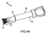
図4A〜4Cは、本明細書において説明する様々なモニタシリンジと使用できるプランジャの別の様々な構成である。図4Aは、モニタシリンジ200の別の実施形態の部分拡大斜視図である。この実施形態において、プランジャ206は、シャフト208を含む。図2及び3に示す離散的帯ではなく、図示する実施形態は、プランジャシャフト208に沿って変動する透光度/不透明度を持つグラデーション230を含む。図示する実施形態において、グラデーション230は、ピストン210に近接すると濃くなる(すなわち、より小さい透光度又はより大きい不透明度)。ストッパ234に近接すると、グラデーション230の透光度は高くなる(逆に、不透明度は低くなる)。グラデーションの移行は円滑とするか又は離散的帯状とすることができる。図4Aに示すような特定の実施形態においては、ストッパ234に近接してシェードがなく、この部分の透光度は、シャフト208の透光度と概ね同じとすることができる。
4A-4C are different configurations of the various monitor syringes described herein and the plungers that can be used. FIG. 4A is a partially enlarged perspective view of another embodiment of the
図4Bは、モニタシリンジ300の別の実施形態の部分拡大斜視図である。この実施形態において、プランジャ306は、シャフト308を含む。図2及び3に示すより高い不透明度の離散的帯ではなく、図示する実施形態は、透光度がより高い離散的帯330を有するシャフト308を利用する。即ち、ピストン310とストッパ334との間に配置されたシャフト330の部分は実質的に不透明であり、帯330は実質的に半透明である。
FIG. 4B is a partially enlarged perspective view of another embodiment of the
図4Cは、モニタシリンジ400の別の実施形態の部分拡大斜視図である。この実施形態において、プランジャ4706は、シャフト408を含む。グラデーション430は、図4Aの実施形態のグラデーションとは反対に配置される。図4Cの実施形態において、グラデーション430は、ストッパ434に近接して濃くなる(即ちより低い透光度又はより高い不透明度)。ピストン410に近接して、グラデーション430の透光度は高くなる。グラデーション430の移行は円滑であるか、又は離散的帯状とすることができる。特定の実施形態において、ピストン410付近にはシェードがなく、この部分の透光度は、概ねシャフト408の透光度と同じとすることができる。
FIG. 4C is a partially enlarged perspective view of another embodiment of the
図2、3又は4A〜4Cに示すプランジャの構成のいずれも、本明細書に示すモニタシリンジと一緒に利用できる。即ち、不透明又は半透明の離散的帯を持つプランジャ又は漸増又は漸減グラデーション(ピストンからストッパまで計測して)を持つプランジャを、光センサモジュールを用いるシリンジに利用できる。プランジャの不透明度/透光度構成に関係なく、光センサモジュールは、モニタシリンジが使用されるとき受け取る光の変化を検出する。光センサモジュール内での1つ又はそれ以上の光センサの設置位置に応じて、光の変化は、インターフェイス装置がプランジャの位置をしたがって装置の容積及びその他の特性又は状態を測定できるようにする。 Any of the plunger configurations shown in FIGS. 2, 3 or 4A-4C can be used with the monitor syringes shown herein. That is, a plunger with an opaque or translucent discrete band or a plunger with a gradual increase or decrease gradation (measured from the piston to the stopper) can be used for a syringe using an optical sensor module. Regardless of the opacity / translucency configuration of the plunger, the optical sensor module detects changes in the light it receives when the monitor syringe is used. Depending on the location of one or more photosensors within the photosensor module, the change in light allows the interface device to measure the position of the plunger and thus the volume and other properties or conditions of the device.
図2〜4Cの計測シリンジの様々な実施形態は、装置ハウジング又は穴に、その中に又はこれに近接して配置された光センサモジュール及び/又は光センサを含む装置について説明する。透光度の変動を含む装置の部分は、原則的には、プランジャに、その中に又はこれに近接して位置付けられる。当然、所望の場合には、ハウジング/穴が透光度の変動を含み、プランジャが光センサ又は光センサモジュールを含むように、コンポーネントの構成を逆転できる。これらの実施形態も、このテクノロジーの範囲内にあると考えられる。 Various embodiments of the measuring syringe of FIGS. 2-4C describe a device comprising an optical sensor module and / or an optical sensor located in or in close proximity to the device housing or hole. The part of the device that contains the variation in translucency is, in principle, positioned in or close to the plunger. Of course, if desired, the configuration of the components can be reversed such that the housing / hole contains variations in translucency and the plunger contains an optical sensor or optical sensor module. These embodiments are also considered to be within the scope of this technology.
図5A〜5Cは、モニタシリンジの様々な実施形態を示す。図5Aは、センサモジュール618を利用するモニタシリンジ600を示す。センサモジュール618は、センサハウジング619と、線形アレイ620とを含む。線形アレイ620は、複数のピクセル620aを含む。図示する実施形態において、モニタシリンジ600は、半透明帯630を含むシャフト608を有するプランジャ606を含む。帯630は、完全に半透明である必要はなく、線形アレイ620内のピクセル620aが受け取った光の変化を検出できるのに充分に半透明であればよい。この実施形態において、受け取る光は、手術室など部屋に在る周囲光640である。これに対して、光源640は、例えば赤外線又は紫外線発光器など、周囲光以外の光源から得ることができる。更に、光センサモジュール618は、設定された波長の光のみ(例えば、赤外線、紫外線など)を受け取るためのフィルタを持つように構成できる。又は、プランジャ606又はシャフト608は、受け取った光を所望の波長にフィルタリングするためのフィルタを持つように構成できる。
5A-5C show various embodiments of the monitor syringe. FIG. 5A shows a
図5Bは、センサモジュール718を利用するモニタシリンジ700を示す。センサモジュールは、センサハウジング791と、例えばフォトレジスタなどの離散的光センサ要素720aを含む光センサ720とを含む。図示する実施形態において、モニタシリンジ700は、グラデーション730を含むシャフト708を有するプランジャ706を含み、グラデーション730は、ピストン710に近接して透光度が小さくなり、ストッパ734に近接して透光度が大きくなる。以前の実施形態のように周囲光を使用する代わりに、図5Bのモニタシリンジは、例えば発光ダイオード(LED)などの発光モジュール750を利用する。発光モジュール750は、光センサモジュール718と同様にシリンジハウジング702に固定される。発光モジュール750は、発光器ハウジング752と、複数の発光要素740aを含む発光器740とを含む。図示する実施形態において、離散的発光要素740aは、離散的光センサ要素720aに対向しかつこれに整列して配置できるが、そうである必要はない。更に、発光要素740aは、特定の波長を持つ光のみを発するように構成するか、又は、光は、発光されかつ/又は感知される光を限定するようにフィルタリングできる。グラデーション730が光センサモジュール718と発光モジュール750との間を通過するとき、離散的光センサ要素720aによって光信号が受け取られる。光センサモジュール718は、インターフェイスへ信号を送り、インターフェイスは信号を処理して、ピストン710の位置を測定する。光センサモジュール718及び発光モジュール750は、シリンジハウジング702の円周の周りに相互から約180度に配置される。他の実施形態において、モジュール718、750は、相互から約180度未満に配置できる。特定の実施形態において、モジュール718、750は、相互から約90度に配置できる。所望の場合、モジュール718、950は、共通ハウジングに収容できる。
FIG. 5B shows a
図5Cは、センサモジュール818を利用するモニタセンサ800を示す。センサモジュールは、センサハウジング819と、フォトレジスタなどの離散的光センサ要素820aを含む光センサ820とを含む。図示する実施形態において、モニタシリンジ800は、グラデーション830を含むシャフト808を有するプランジャ806を含み、グラデーション830は、ピストン810に近接して透光度が小さくなり、ストッパ834に近接して透光度が大きくなる。モニタシリンジ800は、発光モジュール850を利用する。発光モジュール850は、光センサモジュール818と同様の様式でシリンジハウジング802に固定される。発光モジュール850は、発光器ハウジング852と、複数の発光要素840aを含む発光器840とを含む。発光器ハウジング852及びセンサハウジング819は、チェンバへの発光器/センサの固定を容易にするための構造要素(例えば、テープ又は接着剤)を含むか、又はチェンバ壁内に配置される発光器/センサを含むことができる。図示する実施形態において、離散的発光器840aは、離散的光センサ要素820aに対向して配置されかつこれと整列されるが、必ずしもそうでなくてよい。更に、発光要素840aは、特定の波長を有する光のみを発するように構成される(例えば近赤外線発光器)か、又はフィルタリングできる。グラデーション830が発光モジュール818と光センサモジュール850との間を通過するとき、離散的光センサ要素820aは光信号を受け取る。光センサモジュール818は、インターフェイスへ信号を送り、インターフェイスは信号を処理して、ピストン810の位置を測定する。光センサモジュール818及び発光モジュール850は、シリンジハウジング802の円周の周りに相互から約180度に配置される。他の実施形態において、モジュール818、850は、図5Bに関して説明するように配置できる。図5Cのモニタシリンジ800は、図5A及び5Bの発光モジュールより高いセンサ及び発光器密度を有する光センサモジュール818及び発光モジュール818を利用する。上述のように、その結果、より高い位置精度が得られる。
FIG. 5C shows a
図6は、モニタシリンジ900の別の実施形態を示す。この場合、光センサ920及びワイヤ924を収容する光センサハウジング919は、シリンジハウジング902に取外し可能に固定される。光センサハウジング919は、クリップ、Cクランプ、弾性キャッチ又は光センサハウジング919をシリンジハウジング902から取り外せるようにするその他の要素960で固定できる。このような構成は、典型的には医療処置後、光センサハウジング919及び関連コンポーネントを異なるシリンジに再使用できるので、望ましい。光センサハウジング919は、第1シリンジハウジング902から取り外せ、その後第2シリンジハウジングへ再取付けできる。ワイヤ924(又は同様の接続器具)がインターフェイスに(上述のように)再接続されたら、新しいシリンジのために光センサモジュール918を較正するために較正プログラムを実行できる。
FIG. 6 shows another embodiment of the
本明細書において説明する実施形態は、シリンジなどのチェンバ内でのプランジャの変位を計測及び/又は検出するための様々な要素又はコンポーメントを含むことができる。また、チェンバ内でのプランジャの位置関係の検出により、使用者は、明示的又は暗示的にチェンバから放出された媒体の体積を測定できる。説明する実施形態のいくつかは、プランジャ/ピストンとチェンバの位置関係に応じて、光を発生する様々な光源並びに光を検出又は感知するためのコンポーネントを含むことができる。リニアエンコーダ、誘導センサ、キャパシティブタッチセンサ(プランジャの中にメタルアクチュエータを持つ)、超音波エミッタ/レシーバ、圧力センサ、光学エンコーダ(微小ピッチのスロット及び光源を持つ)、ひずみゲージ(即ち重量を計測するため)、電磁エミッタ/レシーバ(例えば、ナビゲーションシステム)が、「分流」容器を計測するか否かに関係なく、注入器から患者へ送達された注入量の計測するために想定される代替テクノロジーである。プランジャとチェンバの位置関係(及び、その変化)を特定できる別の実施形態は、限定無しに、以下の技術を含むことができる。ホールセンサ(シリンジ軸に沿ったコイルワイヤ)を、チェンバに又はこれに近接して配置し、磁石をプランジャに取り付けることができる(可変近接センサとして作用するように)。複数の低感度ホールセンサをシリンジのチェンバに沿って配置し、磁石をプランジャに取り付けることができる。複数のホールセンサを利用するシステムの更に別の実施形態について、本明細書において説明する。チェンバ軸に沿ったプランジャの位置関係を測定するためにレーザー光を発して、これを検出できる。アブソリュートエンコーダを用いて、プランジャの直接変位を「読み取る」ことができる。 The embodiments described herein can include various elements or components for measuring and / or detecting displacement of the plunger within a chamber such as a syringe. In addition, the detection of the positional relationship of the plunger in the chamber allows the user to measure the volume of the medium discharged from the chamber, either explicitly or implicitly. Some of the embodiments described may include various light sources that generate light and components for detecting or sensing the light, depending on the positional relationship between the plunger / piston and the chamber. Linear encoders, inductive sensors, capacitive touch sensors (with metal actuators in the plunger), ultrasonic emitters / receivers, pressure sensors, optical encoders (with fine pitch slots and light sources), strain gauges (ie weighing) Because), with an alternative technology envisioned for electromagnetic emitters / receivers (eg, navigation systems) to measure the amount of injection delivered from the injector to the patient, whether or not the "split" container is measured. is there. Another embodiment that can identify the positional relationship (and its change) between the plunger and the chamber can include, without limitation, the following techniques. A Hall sensor (coil wire along the syringe shaft) can be placed on or near the chamber and the magnet can be attached to the plunger (to act as a variable proximity sensor). Multiple low-sensitivity Hall sensors can be placed along the syringe chamber and magnets can be attached to the plunger. Yet another embodiment of a system that utilizes a plurality of Hall sensors will be described herein. A laser beam can be emitted and detected to measure the positional relationship of the plunger along the chamber axis. An absolute encoder can be used to "read" the direct displacement of the plunger.
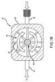
図9は、下で更に詳しく説明するホールセンサモジュールを利用するモニタシリンジ1200の1つの実施形態の斜視図である。モニタシリンジ1200は、内部穴1204を形成するシリンジハウジング1202を含む。下で更に詳しく説明するプランジャ又はピストンは、穴1204の中へ滑動可能に受け入れられる。より具体的には、ピストンは、穴1204の内面と滑動可能に係合し、穴1204内でのプランジャシャフトの線形移動Mは、ピストンを移動する。移動Mは、シリンジの軸Asに沿っている。親指リング1212は、下で更に詳しく説明するように、軸Asに沿ってプランジャを引いたり押したりするために利用できる。プランジャがシリンジハウジング1202の排出端1214aへ向かう方向Mに移動するとき、この中に収容される流体(例えば、媒体)は、チューブ又は針(図示せず)の中へ排出されて、患者へ送達される。2つのフィンガリング又はタブ1232は、使用時に使用者の指を受け入れる。説明全体を通じて、円筒形ハウジング1202及び内側穴1204について説明するが、本明細書において予想する機能を与えるハウジング1202/穴1204及びプランジャ406の多様な構成が想定され、その中の又はそれ自体の形状(長方形、卵形、三角形の断面などを含めて)は限定的ではない。モニタシリング1200は、下でさらに詳しく説明するホールセンサモジュール1250も含む。ホールセンサモジュール1250の1つのコンポーネントは、磁石保持リング1252であり、リングは、シリンジハウジング1202の外面に配置される。図示する実施形態において、磁石保持リング1252は、ハウジング1202の近位端1214bに近接して配置されるが、ハウジング1201に沿って他の場所に配置することができる。
FIG. 9 is a perspective view of one embodiment of the
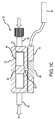
図10は、図9のモニタシリンジ1200の部分斜視断面図であり、ホールセンサモジュール1250を示す。ホールセンサモジュール1250の特定のコンポーネント1250aは、プランジャ1206の中空シャフト1208の内側チェンバ内に配置され、特定のコンポーネント1250bは、シリンジハウジングの外面に配置される。これらのコンポーネント1250a、1250bについては、下でさらに詳しく説明する。いわゆる内部コンポーネント1250a(即ちプランジャに対して内部)は、保持挿入物1254a、1254b、基板又は回路板1256、及びその上に配置される複数のホールセンサ1258を含む。1つ又はそれ以上のバッテリ1260及び制御スイッチ1262も、回路板に固定できる。ホールセンサ1258からの信号は、まず回路板1256によって処理でき、回路板はプランジャ1206の位置、シリンジ内の媒体の体積などを測定し、その後、この情報をその後の分析、ドクターへの表示などのために送信器1280を介して関連するシステムへ送る。別の実施形態において、例えば、非処理基板1256が使用される場合、各ホールセンサ1258からの信号は、送信器1280を介して処理のために関連するシステムへ直接送ることができる。
FIG. 10 is a partial perspective sectional view of the
遠位保持挿入物1254aは、ピストン1210の付近になるようにシャフト1208の中へ挿入できる。遠位保持挿入物1254aは、空隙1264を形成でき、空隙はブルートゥース送信器などの無線送信器1280を収容できる。送信器1280は、ホールセンサ1258から本明細書において説明するような関連信号処理装置へ信号を送ることができる。別の実施形態において、上述のようなケーブル接続を利用できる。近位保持挿入物1254bは、中空シャフト1208において親指リング1212付近に配置される。遠位保持挿入物1254a及び近位保持挿入物1254bは一緒に、中空シャフト1208内で回路板1256を支持、保護及び保持する。これらの2つのコンポーネントは、回転を防止するために、シャフト1208に滑り嵌めするように構成するか、又はシャフト1208の開口部又はスロットと係合するようにキーまたはその他の突出部を含むことができる。保持挿入物1254a、1254bは、シャフト1208内に永久的に固定できるが、取り外せるように挿入物1254a、1254bを構成することは、回路板1256、バッテリ1260などの交換又は修理を可能にするために有利である。1つの実施形態において、親指リング1212は、シャフト1208の対応するスロット1268と係合できる複数の突出部1266を含む弾性ベース1264を含むことができる。これらの突出部1266の係合を外すと、保持挿入物1254a、1254b及びその他の内部コンポーネントを取り外すことができる。複数のホールセンサ1258を図示する。様々な実施形態においてこれより多い又は少ない数のセンサ1258を利用できるが、センサ1258の数が多ければ、プランジャ1206の位置に関してより正確な測定ができる。ホールセンサ1258は、軸Asと実質的に整列するように又はこれに対して平行であるようにチェンバ内に線形に配置される。
The
外部コンポーネント1250bは、図示する実施形態において、複数の磁石1270(円弧磁石)を保持する磁石保持リング1252を含む。別の実施形態において、立方体、円筒形又はその他の磁石を利用できる。磁石1270の位置は、シリンジハウジングに対して及びその周りに固定される。円弧磁石1270は、実質的に円形の磁場を形成し、シャフト1208がシリンジの内側穴から引き抜かれる又は内側穴の中へ挿入されるとき、シャフト1208(及び、ホールセンサ1258)は磁場を通過する。円形磁場は、軸Asの周りでのプランジャ1206の回転位置に関係なく、ホールセンサ1258が磁場を検出できるようにする。別の実施形態において、磁石1270は、磁石保持リングなしに、シリンジハウジングに直接固定できる。
The
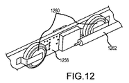
図11は、図10に示すモニタシリンジ1200の一部分の部分的分解斜視図である。具体的には、プランジャ1206、ホールセンサモジュール内部コンポーネント1250a及びホールセンサモジュール外部コンポーネント1250bを示す。概略的に、これらのコンポーネントのいくつかは、図9〜10に関連して説明したので、必ずしもこれ以上説明しない。但し、図示する実施形態において、遠位保持挿入物1254a及び近位保持挿入物1254bの両方は、回路板1256を所定の位置に保持するためにこの要素を受け入れるように構成された形状を持つ凹部1272を含む。凹部1272は、プランジャ1206の中空シャフト1208内に空間を保存するように挿入物1254a、1254bの中に配置される。ホールセンサ1258とは反対の回路板1256の側には、複数のバッテリ1260が配置される。これを図12に示す。更に、スイッチ1262を、バッテリ1260に近接して又は中空シャフト1208内の他の場所に配置できる。スイッチ1262は、いくつかの実施形態において、プランジャの移動を検出して係合又は起動位置へ移動するリードスイッチとすることができる。スイッチ1262は、要求はされないが、シリンジ1200が使用されないときに動力を保存するのに役立つ。起動されると、スイッチ1262は、バッテリ1260からの動力を複数のホールセンサ1258及び無線送信器1280の一方又は両方に選択的に接続する。他の実施形態において、プルタブ、ボタンまたはロッカスイッチなどの手動スイッチは、使用者によって作動できる。
FIG. 11 is a partially exploded perspective view of a part of the
システムの更なる実施形態において、モニタシリンジ1200の計測コンポーネントは、患者への造影剤の導入において容器を採用するシステムにおいては、調整器によって媒体分流容器へ分流された媒体の量を計測するためにも使用できる。このような媒体分流容器、及び関連する媒体管理及び監視システムへのその組み込みについては、本明細書の他の部分において説明する。この場合、内側穴1204は、調整器によって送達カテーテルへの媒体の注入から離れて分流される媒体を捕捉するための流体容器を形成できる。容器の別の実施形態において、チェンバは、チェンバ内の媒体の制御された充填、放出及び計測を容易にするために、プランジャ1206に作用する力によって充分に与圧できる。力は、ピストン1210を穴1204に収容される流体の中へ付勢し、その間、ホールセンサ1258は、プランジャ1206の位置を検出し続ける。図示する実施例において、加圧分流容器としてモニタシリンジ1200を構成するために、プランジャ1206の中空シャフト1208の周りにバネ1209を配置できる。このバネ1209は、ピストン1210をシリンジハウジング1202の排出端部1214aへ向かって付勢する。他のバネ構成及び/又は付勢機構を利用でき、これらの構成及び/又は機構は、均衡した加力のために、概ねシリンジ軸Asの周りに配置できる。
In a further embodiment of the system, the measurement component of the
図13は、ホールセンサモジュールを利用するモニタシリンジ1300の第2実施形態の斜視図である。モニタシリンジ1300は、中空内側穴を形成するシリンジハウジング1302を含む。シャフト1308及びピストン1310を含むプランジャ1306は、穴の中に滑動可能に受け入れられる。より具体的には、ピストン1310は、穴の内面と滑動可能に係合でき、穴内でのシャフト1308の線形移動Mは、ピストン1310を移動する。移動Mは、シリンジ軸Asに沿う。プランジャ1306は、親指リング1312などのサムパッドの移動によって孔1304内で前後に動かされる。プランジャ1306がシリンジハウジング1302の排出端部1314aへ向かう方向へ移動Mされると、ハウジングの中に収容された流体は、マニホルド組立体、チューブ又は針(図示せず)の中へ排出され、患者へ送達される。
FIG. 13 is a perspective view of a second embodiment of the
図10〜11に示す実施形態の代替実施形態として、ホールセンサモジュール1318は、プランジャに固定するのではなくシリンジハウジング1302の外面に固定できる。ホールセンサモジュール1318は、複数のホールセンサ1320を囲繞するホールセンサハウジング1319を含む。図9〜11に関して上に説明したように、離散的ホールセンサ要素の数が多いと、正確性を改良できる。1本又はそれ以上のリード線又はワイヤ1424は、ホールセンサモジュール1318の一端から延びる。ケーブル1326が、一端1328において、ホールセンサモジュール1318の出力を分析してこの情報を典型的にはディスプレイ上でモニタシリンジ1300の使用者へ提供するインターフェイスユニットに接続される。他の実施形態において、通信は、本明細書において説明するように、無線、ブルートゥース、又は他の無線接続を介することができる。表示される情報には、チェンバの容積、残り容積、供給された量、流体のタイプ、流量、流体圧力又は温度及び/又は特定の用途に必要な又は所望のその他の情報が含まれる。上述のように、ホールセンサからの信号はまず関連する回路板によって処理され、その後インターフェイスユニットへ送信されるか、又は離散信号は処理のためにインターフェイスユニットへ送信できる。
As an alternative embodiment of the embodiment shown in FIGS. 10-11, the
図示する実施形態において、プランジャ1306のシャフト1308は、シャフト1308上に又はシャフト8内に配置された1つ又はそれ以上の磁石1330を有する。磁石1330は、この場合、シャフト1308の周りに配置された複数の円弧磁石を含む。プランジャ1306が軸Asに沿って滑動するとき、磁石1330は、ホールセンサモジュール1318のホールセンサ1320の前を通過する。磁石1330によって発生したる磁場は、ホールセンサ1320によって検出される。ホールセンサ1320は、インターフェイスユニットへ信号を送り、インターフェイスユニットは、個別のホールセンサ1320によって検出された磁石1330の位置に基づいて、シリンジハウジング1302内でのプランジャ1306の位置を測定する。このようにして、プランジャ1306の位置を測定できる。インターフェイスは、シリンジハウジング1302の穴1304の既知の直径及び長さに基づいて上述の各種の情報も測定できる。2つのフィンガリング又はタブ1332は、使用時に使用者の指を受け入れる。ストッパ1334は、プランジャ1306がシリンジハウジング1302から引き抜かれるのを防止する。
In the illustrated embodiment, the
図9〜13に示す実施形態は複数のホールセンサを示すが、モニタシリンジの他の実施形態は、各種の1つ又はその他のセンサを利用できる。例えば、単一のセンサ又は複数のセンサを用いて、磁場、材料抵抗、キャパシタンスなどを計測できる。これらのセンサからの計測値を用いて、シリンジ内のプランジャの直線位置を測定できる。これらのセンサの例は、ホール効果センサ(本明細書において更に詳しく説明する)、誘導センサ、キャパシティブタッチセンサ及びその他を含むが、これらに限定されない。 While the embodiments shown in FIGS. 9-13 show a plurality of Hall sensors, other embodiments of the monitor syringe may utilize one or the other various sensors. For example, a single sensor or multiple sensors can be used to measure magnetic fields, material resistance, capacitance, and the like. The measured values from these sensors can be used to measure the linear position of the plunger in the syringe. Examples of these sensors include, but are not limited to, Hall effect sensors (discussed in more detail herein), inductive sensors, capacitive touch sensors and others.
図7Aは、光信号を利用するモニタシリンジを使用する第1方法1000aを示す。作動1002aにおいて、光センサから信号が受け取られる。モニタシリンジにおける光センサの位置は既知である。受信波長などの光センサの他の特性は、既知とすることができる。光センサの位置及び前記センサから受け取った信号に基づいて、作動1004aにおいてピストンの位置が測定される。方法1000aの特定の実施形態において、光信号は、作動1006aにおいて第1発光器から発せられる。複数の光センサが使用される実施形態において、光信号は、作動1008aにおいて既知の特性(例えば、位置)を有する第2光センサで受け取ることができる。作動1010aにおいて、第2光センサの特性及び信号に基づいて、更新された位置を測定できる。光信号が既知の光センサから受け取られた任意の時点で、作動1012aにおいてシリンジ(本明細書において説明するような)の状態が測定できる。
FIG. 7A shows a
図7Bは、ホールセンサを利用するモニタシリンジを使用する第2方法1000bを示す。作動1002bにおいて、第1ホールセンサから信号が受け取られる。プランジャにおけるこのホールセンサの、シャフトにおける他方のホールセンサに対する位置は、既知である。第1ホールセンサの位置及び前記ホールセンサから受け取った信号に基づき、作動1004bにおいてピストンの位置が測定される。シリンジの断面積、直径又はその他の寸法は既知なので、シリンジの中の媒体の量はピストンの位置に基づき測定できる。複数のホールセンサを使用する実施形態において、作動1006bにおいて既知の特性(例えば、位置)を有する第2ホールセンサから信号を受け取れる。第2ホールセンサから受け取った信号及び信号に基づいて、作動1008bにおいてピストンの更新位置が測定できる。既知のホールセンサから信号を受け取った任意の時点で、シリンジの状態(上述のような状態)を作動1010bにおいて測定できる。上述のように、方法1000bは、モニタシリンジ内の回路板において実施でき、更なる分析又は医師への表示のために送信器を介して関連システムへ送ることができる。別の実施形態において、別の実施形態において、各信号は、処理、分析、表示などのために送信器を介して関連システムへ送信できる。
FIG. 7B shows a
更に、図7A〜7Bに示す方法は、分流容器を採用するシステムにおいて使用されるとき、更に注入(即ち調整器を通過して)から分流した媒体を収集するチェンバにおいて測定された計測値を組み込める。シリンジによって注入された媒体の総量(感知装置によって測定される)マイナス分流した媒体の量(感知装置によって測定される)は、患者へ実際に送達された合計注入量を示す。 In addition, the methods shown in FIGS. 7A-7B can incorporate measurements measured in a chamber that collects the medium that has further diverted from the injection (ie, through the regulator) when used in a system that employs a divergence vessel. .. The total amount of medium injected by the syringe (measured by the sensing device) minus the amount of shunted medium (measured by the sensing device) indicates the total injection volume actually delivered to the patient.
図8は、本発明の実施形態の1つ又はそれ以上を実施できる適切な作動環境1100の一例を示す。これは、適切な作動環境の一例にすぎず、その使用または機能性の範囲を限定することを示唆するためのものではない。使用に適する他の周知のコンピューティング環境及び/又は構成としては、パソコン、サーバーコンピュータ、ハンドヘルド又はラップトップ装置、マルチプロセッサシステム、マイクロプロセッサベースのシステム、スマートフォンなどのプログラマブルコンシューマ電子機器、ネットワークPC、ミニコンピュータ、メインフレームコンピュータ、スマートフォン、タブレット、上記のシステムまたは装置の任意のものを含む分散コンピューティング環境、及びこれと同種のものを含むが、これらに限定されない。
FIG. 8 shows an example of a
最も基本的構成においては、作動環境1100は、典型的には、少なくとも1つの処理ユニット1102とメモリ1104とを含む。コンピューティング装置の正確な構成及びタイプに応じて、メモリ1104(特に、本明細書において説明する監視方法を実施するための命令を記憶する)は、揮発性(RAMなど)、非揮発性(ROM、フラッシュメモリなど)又はその組合せとすることができる。この最も基本的構成を、図8において線1106で示す。更に、環境1100は、磁気又は光ディスクまたはテープを含めて(但し、これに限定されない)記憶装置(可換型1108、及び/又は非可換型1110)を含むこともできる。同様に、環境1100は、タッチスクリーン、キーボード、マウス、ペン、音声インプットなどの入力装置1114及び/又はディスプレイ、スピーカ、プリンタなどの出力装置1116を含むこともできる。又、LAN、WAN、二点間通信、ブルートゥース、RFなどの1つ又はそれ以上の通信接続1112も、環境に含めることができる。
In the most basic configuration, the
作動環境1100は、典型的に、少なくとも何らかの形式のコンピュータ可読媒体を含む。コンピュータ可読媒体は、処理ユニット1102又は作動環境を備える他の装置がアクセスできる利用可能な任意の媒体とすることができる。例えば(限定的ではなく)、コンピュータ可読媒体は、コンピュータ記憶媒体及び通信媒体を備えることができる。コンピュータ記憶媒体は、コンピュータ可読命令、データ構造、プラグラムモジュール又はその他のデータなどの情報を記憶するための方法又はテクノロジーにおいて実現される揮発性及び非揮発性、可換型及び非可換型媒体を含む。コンピュータ記憶媒体は、RAM、ROM、EEPROM、フラッシュメモリ又はその他のメモリテクノロジー、CD−ROM、デジタル多機能ディスク(DVD)又はその他の光学記憶装置、磁気カセット、磁気テープ、磁気ディスク記憶装置またはその他の磁気記憶装置、ソリッドステート記憶装置又は所望の情報を記憶するために使用できる他の任意の有形媒体を含む。通信媒体は、搬送波又はその他の搬送機構などの変調データ信号の中のコンピュータ可読命令、データ構造、プログラムモジュール又はその他のデータを実現し、任意の情報伝達媒体を含む。「変調データ信号」は、信号の情報をコード化するように設定または変更された特性を1つ又はそれ以上を持つ信号を意味する。例えば(限定的ではなく)、通信媒体は、有線ネットワークまたは直接有線接続などの有線媒体、及び音響、RF、赤外線及びその他の無線媒体などの無線媒体を含む。上記のものの任意の組合せも、コンピュータ可読媒体の範囲に含まれるはずである。
The
作動環境1100は、1つ又はそれ以上の遠隔コンピュータとの論理結合を用いてネットワーク環境において作動する単一コンピュータとすることができる。遠隔コンピュータは、パソコン、サーバー、ルーター、ネットワークPC、ピア装置またはその他の共通ネットワークノードとすることができ、典型的には、上述の要素の多く又は全て並びに言及しない他の要素を含む。論理接続は、利用可能な通信媒体によってサポートされる任意の方法を含むことができる。この種のネットワーク環境は、オフィス、企業規模のコンピュータネットワーク、イントラネット及びインターネットにおいて一般的である。いくつかの実施形態において、本明細書において説明するコンポーネントは、コンピュータ記憶媒体及びその他の有形媒体において記憶できかつ通信媒体で転送できる、コンピュータシステム1100によって実行可能なモジュール又は命令を含む。コンピュータ記憶媒体は、コンピュータ可読命令、データ構造、プログラムモジュール又はその他のデータなどの情報を記憶するための任意の方法又はテクノロジーにおいて実行される揮発性及び非揮発性、可換型及び非可換型媒体を含む。上記のものの任意の組合せも、可読媒体の範囲に含まれるべきである。いくつかの実施形態において、コンピュータシステム1100は、コンピュータシステム1100が使用するために遠隔記憶媒体にデータを記憶するネットワークの一部である。
The
上述のようなモニタシリンジは、患者体内への媒体注入を制御及び監視するために各種の媒体管理システムにおいて利用できる。2つの代表的な媒体管理システム並びにそのコンポーネントについては、下で以下の図面において説明する。これらは本明細書において説明する監視テクノロジーを利用できるシステムの2つのタイプに過ぎない。他のシステム及びその構成が、当業者には明らかであろう。 Monitor syringes such as those described above can be used in a variety of media management systems to control and monitor media injection into the patient's body. Two typical media management systems and their components are described below in the drawings below. These are just two types of systems that can utilize the surveillance technologies described herein. Other systems and their configurations will be apparent to those skilled in the art.
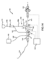
図14〜16は、例示的実施形態において図示するように、分流器組立体(即ち調整器)1402及び分流容器1404を含むことができる別の媒体管理システム1400である。この実施形態において、管状部材1406aが、分流器組立体1402の弁1426から媒体分流容器1404まで伸び、管状部材1406bが、分流容器1404から媒体容器(例えば、造影剤バイアル)1410まで延びる。媒体容器1410(例えば、造影剤バイアル)からの媒体は、媒体容器1410から管状部材1406bを介して分流容器1404及び管状部材1412を通過して流れることができる。図示する配列体において(図14)、シリンジ1414は、管状部材1406b、1412、1416及び1418によって媒体容器1410に流動可能に結合でき、これらのコンポーネントはマニホルド1420によってかつストップコック1422を介して一緒に結合される。シリンジ1414に媒体容器1410から媒体が装填されるとき、ストップコック1422は、管状部材1416と1418との間の媒体の流れを可能にするが、ストップコック1422と分流器組立体1402の弁1426との間に配置された管状部材1424へは流れないように、位置付けできる。シリンジ1414は、本明細書において説明するモニタシリンジ(例えば、光センサ、ホールセンサなどを使用する)又は技術上既知のモニタシリンジの任意のものとすることができる。シリンジ1414を引き戻すと、媒体容器1410から管状部材1406及び/又は分流容器104を通過して及び管状部材1412を通過して媒体を引っ張ることができる。媒体容器1410からの媒体及び/又は分流容器1404の中の媒体は、その後、更に管状部材1416及び1418を通過してシリンジ1414の中へ引っ張られる。シリンジが、媒体容器及び/又は分流容器1404からの媒体で装填されたら、マニホルド1420の弁Bは、管状部材1412を介して媒体容器1410及び分流容器1404へ逆流するのを防ぐように操作でき(この逆流は、分流容器1404と媒体容器1410との間に配置された逆止め弁によって更に妨害することができる)、ストップコック1422は、管状部材1418、1424,1416及びマニホルド1420を通過する流れを許容するように位置付けることができる。
14-16 are another
調整器(分流器組立体1402など)を組み込む造影剤注入処置において、シリンジ1414からの注入媒体の流れの一部は、分流器組立体1402によって注入カテーテル1428への媒体流路から分流できる。図14〜16に示す調整/容器システム1400において、分流器組立体1402を通過する分流した媒体は、媒体容器1410又はその他の流出/オーバーフロー容器/チェンバへ直接流れずに、分流容器1404の中へ流れる。有利なことは、分流容器1404は、媒体をシステムの中へ引き込むためにシリンジ1414が再び起動されるとき(例えば、カテーテル1428を介して患者体内へ導入するために)再使用できるように、分流器組立体によって分流されたオーバーフロー媒体を収集するための手段を与える。このように前記分流容器を使用すると、関連する逆止め弁が媒体容器1410への媒体の逆流を防止して、既にシステム(例えば、分流容器1404)に導入された媒体を捕捉し再使用することが可能であり、同時に、媒体容器1410内の媒体の無欠性をその元来の形のまま保存できる。
In a contrast agent injection procedure incorporating a regulator (such as the shunt assembly 1402), a portion of the flow of the injection medium from the
媒体管理システム1400は、その一部分を洗浄するために使用できる生理食塩水容器1430を含むこともできる。図14に示すシステム1400において、生理食塩水容器1430は、チューブ1432を介してマニホルド1420に接続され、弁Aによってシステム1400の残り部分から分離できる。弁Aは、弁Aの位置を検出する位置センサ又はその他のセンサSを含むことができる。洗浄信号は、弁AのセンサSから監視/表示システム1434へ送られる。監視/表示システムは、弁B及びストップコック1422の位置(センサSを用いて)並びにモニタシリンジ1414上の各種センサ及び/又は分流容器1404上のセンサからの出力を監視するように構成できる。例えば、弁Aが開放位置に在るとき、監視/表示システム1343は、モニタシリンジ1414及び/又は分流容器1404からの信号を無視できる(その読取り値はシリンジ1414から注入される又はシリンジの中へ引き込まれる造影剤を反映しないので)。別の実施例において、弁Aが開放位置に在るとき、監視/表示システム1434は、システム1400の前記部分(モニタシリンジ及び/又は分流容器)を隔離するために操作者に弁B及び/又はストップコック1422を閉鎖することを思い出させるために、命令を表示するか又は信号を発することができる。より複雑な別の実施例において、システム1400は、自動化弁B及び/又はストップコック1422を使用し、弁Aから開放信号を受け取ると前記の弁を閉鎖する。
The
分流容器1404の1つの実施形態を図15A〜15Dに示す。図15Aは、関連する管状部材1406a及び1412と一緒に分流容器1404の組立図を示す。図15Bは、図15Aの組立体の分解図である。システム1400は、更に、供給導管1406bと流体流通する第2供給導管1412及び分流導管1406aも含むことができ、第2供給導管1412は、流体媒体流路に流動可能に結合される。管状部材1406a及び1412は、図15Aの線15C−15Cに沿って見た断面図である図15Cに示すように、分流容器1404の第1エンドキャップ又はマニホルド1502に密封可能に接続される。貫通管1506の第1端部は、第1エンドキャップ1502の内側に(1504において)密封可能に接続される。貫通管1506は、これを貫通する内側導管1508を含む。内側導管1508は、図15Cに示すように、第1エンドキャップ1502において隣接するカップリングを介して管状部材1406a及び1412の内部と流体流通する。貫通管1506の第2端は、1510において逆止め弁組立体1540に密封可能に接続され、内側導管1508は、逆止め弁組立体1540と流体流通する。一方、逆止め弁組立体1540は、管状部材1406aと流体流通する。図15Cに示すように、逆止め弁組立体1540は、媒体容器1410(例えば、媒体バイアル)から管状導管1406bを介して貫通管1506の内側導管1508の中への流れを許容するがその逆の流れを妨害するように作動可能な可動弁板(又は弁を通過する一方向の流れを許容するその他の適切な構造体)を含む。この配列体は、流体容器1410から管状導管1406b、貫通管1506の内側導管1508及び管状導管1412を介してシリンジ1414への媒体の流れを許容できる。更に、分流器組立体1402によって分流された媒体は、管状部材1406aを介して貫通管1506の内側導管1508の中へ流れることができるが、逆止め弁組立体150によって媒体容器1410へ流れることは妨害される。分流容器1404の第2エンドキャップ1514は、逆止め弁組立体1540の周りに固定される。
One embodiment of the
分流容器1404は、分流器組立体1402からの媒体の流れに受け入れ、この媒体を収集して保持し、所望の場合には、注入カテーテル1428を介して患者へ追加の媒体を送達する際に使用するために、収集された媒体をシステムへ押し戻すように設計される。このための1つの実施形態において、分流容器1404は、貫通管1506の周りに配置された弾性伸縮管1516を含むことができる。図15C及び15Dに示すように、伸縮管1516は、貫通管1506の長さの一部分に沿って延びる。伸縮管1516は、それぞれ第1及び第2保持ワッシャ1518及び1520によって又は他の適切な密封可能な機械的締結配列体によって、その両端に隣接して貫通管1506の周りに密封可能に固定されるシリコン(又はこれと同様の可撓性の)材料で形成できる。貫通管1506の外面は、保持ワッシャ1518及び1520を介する貫通管1506への伸縮管1516の固定を更に容易にするために、表面特徴部又は環状干渉リム1506a(図15C)などの干渉要素を含むことができる。
The
ハウジング管状外殻1522は、第1エンドキャップ1502と第2エンドキャップ1514との間で接続され、それによって、伸縮管1516及びその中のその他の分流容器コンポーネントを被覆できる。外殻1522は、その中の分流容器1404のコンポーネント保護し、伸縮管1516の膨張又は拡張の範囲を制限し、かつ/又は(外殻1522が透明または半透明である場合)その中の伸縮管1516の状態(例えば膨張状態)を観察できるようにするのに役立つ。
The housing tubular
図15Dは、斜視断面図で分流容器1404を示し(この場合にも図15Aの線15C−15Cに沿って見る)、図示する伸縮管1516は、図15Cの弛緩状態と反対に、代表的な伸張拡張状態である。分流容器1404の伸縮管1516は、分流器組立体1402から、管状部材1406aを介して媒体の流れを受け取る。この媒体の流れは、図15Dにおいて矢印1524によって示すように、管状部材1406aから貫通管1506の第1端に隣接する貫通管1506の内側導管1508の中へ流れる。貫通管1506は、容器チェンバ1526内に在る媒体供給導管1406bの一部とすることができる。貫通管1506からの流出は、第2端において逆止め弁組立体1540によって妨害される。但し、供給導管貫通管1506は、1つ又はそれ以上の開口1528を持つことができ、開口を通じて、伸縮管1516の内部は内側導管1508及び容器チェンバ1526と流体流通できる。このようにして、分流器組立体1402からの媒体は、開口1528を通過して、伸縮管1516によって形成された媒体容器又はチェンバ1526の中へ流れることができる。この媒体チェンバ1526は、伸縮管1516の内面と貫通管1506の外面との間に形成され、それによって、伸縮チューブ1516は、供給導管1506の周りに配置された弾性ブラダーを形成し、伸縮管1516の壁は、チェンバ1526内の流体媒体に対して力を加えることができる。チェンバ1526内の面は、チェンバ1526内の流体媒体に対して可変的又は一定の力を加えることができ、面は、少なくとも部分的に伸縮管1516の弾性ブラダーの壁によって形成される。媒体チェンバ1526は、分流器組立体1402から媒体の流れの分流部分を受け取って、収集する。分流容器1404は、容器チェンバ1526内の流体媒体に対して面を押し付けるために容器チェンバ1526内の少なくとも1つの面に対して配置された可変的力又は定力付勢部材を備える。伸縮管1516の膨張可能壁は、このようにして媒体チェンバ1526内に面を形成して、媒体チェンバ1526内の流体媒体に対して力を(可変的又は一定)を加えることができる。1つの実施形態において、第2エンドキャップ1514は、これを貫通する開口1530を含み、カバー1522内の気体が逃げられるようにし、それによって、その中の伸縮管1516が容易に膨張できるようにする。
FIG. 15D shows a
使用時に、分流器組立体1402内の媒体の圧力が組立体を通過して流れるのに充分に増大すると、媒体は、分流器弁1426から管状部材1406aを介して分流容器1404へ流れる。流体結合は、分流容器1404と滅菌媒体容器1410との間に配置されかつこれらに流動可能に結合される媒体供給導管1406bによって与えられる。分流供給導管1406aは、分流器組立体1402から流体媒体の分流部分を容器1401へ供給するために、分流容器1404と分流器組立体1402との間に配置されかつこれらに流動可能に結合される。媒体は、矢印1524によって示されるように分流容器1404内で媒体チェンバ1526の中へ流れ、それによって、伸縮管1516の壁を伸張して、分流した媒体の流れを受け入れるためにチェンバ1526を拡張する。したがって、シリンジ1414を介して与えられた媒体圧力がシステムにおいて増大するとき、分流器組立体1402は比例的に媒体を分流するので、分流器組立体1402によって分流容器1404の中へ分流される流れが少なくなるとき、患者への流量が比例的に増大する。チェンバ1526に収容される媒体は、調整/容器システム1400を介して患者体内に更に注入するために利用できる。一例として、操作者は、分流容器1404のチェンバ1526からシリンジ1414(シリンジの中の流体を引っ張るために引き戻される)への媒体の流れを許容するために弁Bを起動できる。必要とされる流体がチェンバ1526内に保持される量より大きい場合、逆止め弁1512の力は打ち負かされ、更なる媒体が媒体容器1410(例えば、造影剤バイアル)から引き出される。充分な量の媒体がチェンバ1526及び/又は容器チェンバ1410から引き出されたら、弁Bは閉鎖され、調整/容器システム1400は、操作者によって注入シリンジ1414が起動されることによって、注入カテーテル1428を介して再び媒体が送達される状態になる。ストップコック1422が管状部材1416及び1424の中への流れを許容するように配置される限り、流量調整器組立体1402は、余分な媒体を分流して、最終的に注入カテーテル1428を介して患者体内へ導入される媒体の量を減少するように(例えば、有効な不透明性を得るために必要な量以上の媒体を導入しない)自動的に起動できる。図示する1つの実施形態において、調整器1402の中の圧力が増大するとき、分流器組立体1402の作動によって分流回路への媒体の流れに対する抵抗が増大する。このプロセスは、所望の処置を完了するために必要と思える回数だけ操作者によって反復できる。このように調整/容器システム1400を使用することによって、患者体内への不要な媒体の導入を有利に減少しながら、診断又は治療手段のために患者における媒体の必要量及び流量(例えば、不透明度)を得ることができる。更に、分流容器1404は、分流された媒体の流出分を再利用できるようにする。
During use, if the pressure of the medium in the
図15A〜15Dに示す分流容器は、このような容器の1形式を示す。別の形式も想定できる。例えば、分流器組立体1402から伸縮チェンバの中への媒体のオーバーフローを機能的に受け入れ、その後使用のために媒体容器1410から分流容器1404を介して調整/容器システム1400の中への媒体の流れを許容する弾性ブラダー又は弾性面の別の形式を提供できる。分流容器1404においてチェンバ内の媒体に対して力を加える別の手段は、図16に略図的に示すようにバイアスプランジャによって得ることができる。流体媒体の分流部分は、分流器組立体1402から離れて分流回路1406aを通過して流れる。システム1400は、システム1400のための流体媒体の供給源を含む媒体容器1410と、媒体容器1410と分流導管1406aを流動可能に接続する容器チェンバ1602を通過する供給導管1406bと、を備える。供給導管1406bは、供給導管1406bから媒体容器1410の中への流体媒体の流れを防止するための逆止め弁1508aを備える。分流容器1404aは、ハウジング1606の中で滑動可能に配置されかつ移動線1608で示すようにハウジング1606に対して線形に移動可能なプランジャ1604を含む。このように、面1610は、容器チェンバ1602内の流体媒体に対して線形方向に移動可能である。プランジャ1604の近位面1610は、管状部材1406aを介してハウジング内に受け入れられる分流媒体のためにハウジング1606内のチェンバの一部分を画定する。
The diversion vessels shown in FIGS. 15A-15D show one type of such vessel. Another format can be envisioned. For example, functionally accepting a medium overflow from the
図15A〜15Dに示す分流容器1400と同様、分流容器1404aは、媒体流動のためのマニホルドとして作用する第1エンドキャップ1502aを含むことができる。管状部材1406aは、管状部材1412と同様、第1エンドキャップ1502aに接続される。チェンバ1602は、図16に示すように、第1エンドキャップ1502a内のマニホルド1612を介してなど、管状部材1406a及び1412の内部と流体流通する。貫通管1506aもマニホルド1612と流体流通し、分流容器1404aのハウジング1606を通過して逆止め弁1508aまで延びる。逆止め弁1508aは、媒体容器1410から管状部材1406bを介して貫通管1506aの中への媒体の流れを許容するが、逆流を防止する。媒体容器1410からの媒体は、その後分流容器1404aから管状部材1412を介してシリンジの中へ流れることができる。
Similar to the
媒体が分流器組立体1402によって分流容器1404aの中へ分流されたとき、媒体は、矢印1524aによって示すように、管状部材1406aからマニホルド1612を通過してチェンバ1602の中へ流れる。分流容器1404aは、容器チェンバ1602内の流体媒体に面1610を押し付けるために、容器チェンバ1602内の少なくとも1つの面1610に対して配置されたバネなどの可変的又は一定の力の付勢部材を備える。代表的実施形態において、表面1610は平面状である。プランジャ1604の面1610は、バネ1614によってマニホルドチェンバ1612へ向かって付勢され、それによって、面に作用する力の付勢が打ち負かされたときより多くの媒体がチェンバに導入されて、チェンバ1602を拡張できるチェンバ1602のための可動面1610を形成する。この付勢は、力の矢印1616で略図的に示すように、ハウジング1606内のプランジャ1604に作用し、この力は、バネ、重量分散、線形アクチュエータ又はその他の力の要素などの適切な手段によって得られる。線形移動のプランジャ1604を使用することによって(その移動は矢印1608によって示される)、分流器組立体1402によって実際にどれだけの媒体が分流されたか、また分流によって実際にどれだけの媒体が注入カテーテル1428によって患者へ送達されたか、をより容易に計測できる。計測は、本明細書において説明するシステムのように、ハウジング1606の中又はその上に又は分流容器1404のその他の構造(プランジャなど)の中又はその上に配置された光式、ホールセンサ式又はその他の形式の監視システム1618を利用することによって実施できる。プランジャ1604は、このように、チェンバ1602において再利用できるように収集されたオーバーフロー媒体に力を加えるのに役立つ線形伸縮要素(表面1610)を与える。
When the medium is shunted into the
分流容器1404aは、分流器/調整組立体1402によって分流された媒体のための伸縮チェンバを与えることによって、上述の分流容器1404と同様に作動する。チェンバ(例えば、チェンバ1602、1526)は、再使用の可能性のために注入装置1414(導管1412を介して)へ向かって中の媒体を押し戻すために媒体に作用する少なくとも1つの面を有する。同様に、分流器組立体1402によって分流容器チェンバ1602の中へ分流された媒体は、分流器組立体1402へ逆流することも、媒体容器1410へ流れることも(逆止め弁1508sを介して)許容されない。調整/容器システムの別の実施形態において、分流容器は、分流容器を通過する媒体容器1410への流れが許容されない又は必要ないように構成される。このような配列を、調整/容器システム1400aに関連して図17に示す。このような配列において、分流容器を貫通する貫通管配列体は必要ない可能性がある。分流容器は、単に分流器組立体1402から分流された媒体を保持し再使用するためにその中に伸縮チェンバを与えるだけである。このような分流容器1404aは、図示し本明細書において論じるものなどのブラダー型のチェンバ又は一定又は可変力抵抗型のチェンバを採用できる。その中の少なくとも1つの面は、チェンバ内の流体媒体に対して充分な力を加えることができる。例えば、分流容器1404bは、図11に示すバネ式モニタシリンジ1200と同様に機能するように構成できる。シリンジ1200の「注入機能」は、分流容器として機能する必要はないが、ピストン1210を付勢するためにバネ1209を用いて「分流容器」として機能できるので、図11に示すようなチェンバから派生する計測機能を使用することに利点があることが分かるだろう。図17は、媒体容器チェンバ1410が、管状部材1406cを介して、分流容器1404b(貫通管を持たない)と分流器組立体1402との間に配置されたTコネクタ1702に接続される配列体を示す。Tコネクタ1702は、その第1端において管状部材1412及び1406aに接続され、第2端において、分流容器1404bへ通じる管状部材1406dに接続される。Tコネクタ1702の側面取付具は、管状部材1406cを介して媒体容器1410へ通じる。逆止め弁1508bが、分流器組立体1402及び/又は分流容器1404bから媒体容器1410への媒体の逆流を防止するために、Tコネクタ1702と媒体チェンバ1410との間に配置される。作動時に、図17に示す構成は、図14に関連して上に説明したものと同様とすることができる。分流器組立体1402内の媒体の圧力が、これを通過する流れを許容するのに充分に増大すると、媒体は、弁1426から管状部材1406aを介してTコネクタ1702へ流れる。その後、媒体は、Tコネクタ1702から管状容器1406dを介して分流容器1404bへ流れることができる。分流容器1404bの中へ流れる媒体は、分流した媒体の流れを受け入れるために分流容器の中のピストンを移動する。作動時に、シリンジ1414を介して供給された媒体は、分流器組立体1402によって患者への注入から離れて分流されて、分流容器1404bの中に蓄積できる。
The
分流容器1404b内の伸縮チェンバの中に収容された媒体は、調整/容器システム1400aを介した患者体内への更なる注入のために利用できる。このために、操作者は、弁Bを起動して、分流容器1404b内のチェンバからシリンジ1414(その中の流体を引っ張るために引っ込められる)の中への媒体の流れを可能にする。必要とされる流体がチェンバ容器1404bの中に保持される量より大きい場合、逆止め弁1508bの力が打ち負かされて、更なる媒体が媒体容器1410から引き出される。充分な量の媒体が分流容器1404b内のチェンバ及び/又は容器チェンバ1410から引き出されたら、弁Bは、再び閉鎖されて、調整システム1400aは、再び、操作者による注入シリンジ1414の起動によって注入カテーテル1428を介して媒体を送達するための状態になる。ストップコック1422が管状部材1416及び1424の中への流れを許容するように配置される限り、分流器組立体1402の起動の閾値圧力に達したとき、分流器組立体1402は、余分な媒体を分流するために、再び自動的に起動されて、それによって、注入カテーテル1428を介して患者体内へ導入される媒体の量を減少する。この場合にも、分流器組立体1402へ入る圧力が増大するとき、分流器1402を通過する流れは比例的に減少する(このようにして、分流器組立体1402の作動によって同時に患者への流れは比例的に増大する)。このプロセスは、所望の処置を完了するために必要と考えられる回数、操作者によって反復できる。このような調整/容器システム1400aの使用は、患者への不要な媒体の導入を有利に減少でき、同時に、所望の診断又は治療プロセスのために患者体内に必要な媒体の量及び流れを得ることができる。更に、調整/容器組立体は、操作者が流動調整器を変更することなく注入送達システム(即ち、ガイドカテーテル、診断カテーテル、治療器具など)を変更できるようにできる。更に、分流容器は、分流された媒体の平易な再使用を可能にできる。
The medium contained in the telescopic chamber in the
図18は、患者体内へ注入された媒体の量を測定する方法1800を示す。方法は、作動1802において開始され、注入信号が注入シリンジと結合されたセンサから受け取られる。作動1804において、分流信号が、分流容器と結合されたセンサから受け取られる。注入信号及び分流信号の各々は、本明細書において説明するように、光式センサシステム、ホールセンサ式システムなどを含む各種の監視システムから受け取ることができる。信号は、位置信号(例えば、ピストンの位置)を含むことができ、位置信号は、注入シリンジ及び/又は分流容器内に収容された媒体の量を測定するために使用できる。この情報を用いて、作動1806において、注入された媒体の量は、注入信号及び分流信号に少なくとも部分的に基づいて測定できる。1つの実施例において、注入された量は、注入シリンジの中の量と分流容器の量との間の差である。作動1802〜1806は、媒体が患者体内へ注入されるとき絶えず更新される。
FIG. 18
作動1808において、注入された媒体の量に関連する信号が送られる。時間経過に伴う患者体内へ注入された媒体総量の合計を維持できる。信号及び計測データは、注入された流体の量をシステムの操作者(即ち、外科医又は技師)に指示できる可聴又は可視信号の形式で操作者へ提供できる。信号は、注入された量の視覚的表示(例えば、モニタディスプレイ上に)又は造影剤の最大量が既に注入されたこと又はシリンジから放出された媒体が全く分流容器に受け取られていないこと(これは弁又はシステムの問題の兆候である可能性がある)を使用者に示すことができる信号を含むことができる。本明細書において説明するシステムは、又、生理食塩水洗浄システムを含む。システムを通過する生理食塩水の量は、注入された媒体の量が不正確に計算されないように、無視されるべきである。したがって、方法1800は、作動1810において生理食塩水洗浄システムの弁と関連する洗浄信号を受け取ることを想定する。作動1812において、その後の注入信号及び/又は分流信号は、受け取った洗浄信号に少なくとも部分的に基づいて、無視される。洗浄信号が受け取られる間、注入及び/又は分流信号は無視できる。これによって、システムを通過する生理食塩水の量が注入された媒体の計算違いを生じることなく、操作者が、システムを洗浄できるようにする。任意の作動1814において、システムにおいて自動化弁が利用されている場合には、洗浄信号に少なくとも部分的に基づく少なくとも1つの弁の位置を調節できる。手動弁が使用されるシステムにおいては、作動1810において受け取った洗浄信号は、洗浄システムに関連しない弁(例えば、図14の弁B及びストップコック1422)を閉鎖するよう操作者に知らせるために使用できる信号が発せられるようにすることができる。更に、図18のステップの順番は、本発明の範囲から逸脱することなく、異なる順番で実施できる。例えば、完全に包括的ではなく、注入センサ前に分流センサからデータを収集できる。
At
本明細書において説明する監視システムは、医療処置において患者へ任意のタイプの流体を送達するために利用できる。このような流体は、媒体、薬物、物質、薬剤及び同種のものを含むことができる。これらの用語は、本明細書において、診断、治療及び/又は予防的医療処置の実施において使用される物質を少なくとも部分的に含む多様な流体材料を説明するために総称的に使用されており、これらの使用は限定的なであることを意図しないことが分かるはずである。本明細書において説明する媒体送達調整及び/又は計測装置及び方法は、説明されるとおりの特定の代表的実施形態に限定されず、開示の範囲及び主旨から逸脱することなくこれらの実施形態に変化を加えることができることが分かるはずである。同様に、実施形態の説明において採用する用語は、限定的であることを意図せず、単に概念を伝えるために使用される。特に定義されない限り、本明細書において使用する全ての技術的及び科学的用語は、開示される装置及び方法が属する分野の当業者が共通して理解するのと同じ意味を持つ。 The surveillance systems described herein can be used to deliver any type of fluid to a patient in a medical procedure. Such fluids can include media, drugs, substances, drugs and the like. These terms are used generically herein to describe a variety of fluid materials that at least partially contain substances used in the practice of diagnostic, therapeutic and / or preventive medical procedures. It should be found that these uses are not intended to be limited. The media delivery adjustment and / or measuring devices and methods described herein are not limited to the particular representative embodiments as described and are varied to these embodiments without departing from the scope and gist of the disclosure. You should see that you can add. Similarly, the terms used in the description of embodiments are not intended to be limited and are used merely to convey a concept. Unless otherwise defined, all technical and scientific terms used herein have the same meaning as commonly understood by those skilled in the art to which the disclosed devices and methods belong.
モニタシリンジの製造に使用される材料は、医療用において典型的な材料とすることができる。ポリカーボネートなどのプラスチックは、シリンジハウジング及びプランジャに利用できる。帯又はグラデーションは、プランジャシャフトに直接印刷するか、又は分離プラスチックシートまたはシースに印刷して、その後これをプランジャシャフトに貼り付けることができる。帯又はグラデーションの透光度又は不透明度を変えるために様々なタイプの印刷を利用できる。いくつかの実施形態において、印刷のタイプは、センサが受け取る光のタイプに基づくことができる。例えば、カーボンベースの印刷は、赤外線光を検出するセンサに利用できる。このようにして、帯又はグラデーションは、上述のフィルタとして利用できる。 The materials used in the manufacture of monitor syringes can be typical materials for medical use. Plastics such as polycarbonate can be used for syringe housings and plungers. The strips or gradations can be printed directly on the plunger shaft or printed on a separate plastic sheet or sheath and then affixed to the plunger shaft. Various types of printing can be used to vary the translucency or opacity of bands or gradations. In some embodiments, the type of print can be based on the type of light received by the sensor. For example, carbon-based printing can be used for sensors that detect infrared light. In this way, the band or gradation can be used as the filter described above.
本明細書において本発明のテクノロジーの代表的かつ好ましい実施形態と考えられるものについて説明したが、本明細書の教示から当業者にはテクノロジーの他の修正が明らかになる。本明細書において開示する特定の製造方法及び形状は、性質上代表的なものであり、限定的とはみなされないものとする。したがって、テクノロジーの主旨及び範囲に属する全ての修正が保証されることが望ましい。したがって、特許状によって保証されることが望ましいものは、本明細書において規定され区別化されるテクノロジー及びその全ての同等物である。 Although what is considered to be a representative and preferred embodiment of the technology of the present invention has been described herein, the teachings of this specification will reveal to those skilled in the art other modifications of the technology. The specific manufacturing methods and shapes disclosed herein are representative in nature and are not considered to be limiting. Therefore, it is desirable to guarantee all modifications that belong to the gist and scope of the technology. Therefore, what is desirable to be guaranteed by letter is the technology defined and distinguished herein and all equivalents thereof.
Claims (18)
シャフトを備えるプランジャであって、前記プランジャが、第1位置と第2位置との間で滑動可能に前記シリンジハウジング内に受け入れられる、プランジャと、
前記シャフト内に配置された少なくとも1つのホールセンサと、
前記シリンジハウジングに近接して固定された少なくとも1つの磁石とを備え、前記少なくとも1つの磁石は、前記シャフトが前記第1位置から前記第2位置へ移動する間においてその中を通過する、実質的に円形の磁場を生成する、装置。 Syringe housing and
A plunger comprising a shaft, wherein the plunger is slidably received in the syringe housing between a first position and a second position.
With at least one Hall sensor located within the shaft,
With at least one magnet fixed in close proximity to the syringe housing, the at least one magnet passes through the shaft while moving from the first position to the second position, substantially. A device that produces a circular magnetic field.
回路板であって、前記複数のホールセンサが前記回路板上に配置される、回路板と、
前記回路板上に配置されたバッテリであって、前記バッテリが、前記複数のホールセンサの少なくとも1つに動力を提供するように構成される、バッテリと、
前記バッテリと前記複数のホールセンサの前記少なくとも1つとの間で選択的に動力を接続するために前記回路板上に配置されたスイッチとを備える、請求項4に記載の装置。 The device further
A circuit board in which the plurality of Hall sensors are arranged on the circuit board.
A battery arranged on the circuit board, wherein the battery is configured to power at least one of the plurality of Hall sensors.
The device according to claim 4, further comprising a switch arranged on the circuit board to selectively connect power between the battery and the at least one of the plurality of Hall sensors.
前記シリンジハウジング内において前記軸に沿って滑動可能に配置されたプランジャと、
前記プランジャに沿って配置された複数のホールセンサと、
前記軸に沿った前記プランジャの移動が、少なくとも1つの磁石によって生成された実質的に円形の磁場を通過して前記複数のホールセンサの少なくとも1つを移動させるように、前記軸に対して固定された少なくとも1つの磁石とを備える装置。 The syringe housing that defines the axis and
A plunger that is slidably arranged along the axis in the syringe housing,
A plurality of hall sensors arranged along the plunger,
Movement of the plunger along said axis, to move at least one of the one of the plurality of Hall sensors through the generated substantially circular magnetic field by the magnets even without low, relative to the shaft A device comprising at least one magnet fixed in place.
前記プランジャ内に配置されたバッテリであって、前記バッテリが、前記無線送信器及び前記複数のホールセンサの少なくとも1つに動力を提供するように構成される、バッテリと、
前記バッテリと前記無線送信器及び前記複数のホールセンサの少なくとも1つとの間で選択的に動力を接続するために前記プランジャ内に配置されたスイッチとを備える、請求項12に記載の装置。 The device further
A battery disposed within the plunger, wherein the battery is configured to power at least one of the radio transmitter and the plurality of Hall sensors.
12. The device of claim 12, comprising a switch arranged within the plunger to selectively connect power between the battery and the wireless transmitter and at least one of the plurality of Hall sensors.
Applications Claiming Priority (3)
| Application Number | Priority Date | Filing Date | Title |
|---|---|---|---|
| US201562141723P | 2015-04-01 | 2015-04-01 | |
| US62/141,723 | 2015-04-01 | ||
| PCT/US2016/025671 WO2016161346A1 (en) | 2015-04-01 | 2016-04-01 | Syringe volume monitoring systems with hall sensor |
Publications (3)
| Publication Number | Publication Date |
|---|---|
| JP2018513758A JP2018513758A (en) | 2018-05-31 |
| JP2018513758A5 JP2018513758A5 (en) | 2019-04-25 |
| JP6863958B2 true JP6863958B2 (en) | 2021-04-21 |
Family
ID=55910335
Family Applications (1)
| Application Number | Title | Priority Date | Filing Date |
|---|---|---|---|
| JP2018502622A Active JP6863958B2 (en) | 2015-04-01 | 2016-04-01 | Syringe volume monitoring system with Hall sensor |
Country Status (4)
| Country | Link |
|---|---|
| EP (1) | EP3277342B1 (en) |
| JP (1) | JP6863958B2 (en) |
| AU (1) | AU2016244004B2 (en) |
| WO (1) | WO2016161346A1 (en) |
Families Citing this family (4)
| Publication number | Priority date | Publication date | Assignee | Title |
|---|---|---|---|---|
| WO2018083061A1 (en) * | 2016-11-01 | 2018-05-11 | Sanofi-Aventis Deutschland Gmbh | Supplementary device for an injection device |
| US20210128944A1 (en) * | 2018-05-18 | 2021-05-06 | Bard Peripheral Vascular, Inc. | Systems and methods for determining flow parameters of administered fluid from radioembolization delivery device |
| AU2019270183A1 (en) | 2018-05-18 | 2021-01-07 | Bard Peripheral Vascular, Inc. | Systems and methods for use of a dosimetry application software tool to customize dosimetry and sphere selection for radioembolization procedure planning |
| CN109939294A (en) * | 2019-03-22 | 2019-06-28 | 深圳恩多克医疗有限公司 | A kind of micro infusion and insulin pump device of huge magnetic resistance effect sensor |
Family Cites Families (13)
| Publication number | Priority date | Publication date | Assignee | Title |
|---|---|---|---|---|
| US5882338A (en) * | 1993-05-04 | 1999-03-16 | Zeneca Limited | Syringes and syringe pumps |
| EP2319565A3 (en) * | 2001-02-14 | 2013-07-17 | Novo Nordisk A/S | Electronically controlled device |
| ES2498966T3 (en) * | 2001-05-21 | 2014-09-26 | Scott Laboratories, Inc. | RF-ID tag for a medical container |
| US20030055380A1 (en) * | 2001-09-19 | 2003-03-20 | Flaherty J. Christopher | Plunger for patient infusion device |
| DE10147973A1 (en) * | 2001-09-28 | 2003-04-17 | Disetronic Licensing Ag | ampoules recognition |
| DE10326306B4 (en) * | 2003-06-11 | 2010-09-23 | Henke-Sass Wolf Gmbh | Syringe, in particular for veterinary applications |
| US9687186B2 (en) * | 2005-07-21 | 2017-06-27 | Steadymed Ltd. | Drug delivery device |
| SE0501889L (en) * | 2005-08-25 | 2007-02-26 | Millicore Ab | Kärlresistansmätare |
| WO2007035563A2 (en) * | 2005-09-19 | 2007-03-29 | Lifescan, Inc. | Malfunction detection via pressure pulsation |
| US7654127B2 (en) * | 2006-12-21 | 2010-02-02 | Lifescan, Inc. | Malfunction detection in infusion pumps |
| WO2009120692A2 (en) * | 2008-03-25 | 2009-10-01 | Animal Innovations, Inc. | Syringe mechanism for detecting syringe status |
| MX2012012133A (en) * | 2010-04-20 | 2013-03-05 | Minipumps Llc | Electrolytically driven drug pump devices. |
| US10704944B2 (en) * | 2014-09-14 | 2020-07-07 | Becton, Dickinson And Company | System and method for capturing dose information |
-
2016
- 2016-04-01 WO PCT/US2016/025671 patent/WO2016161346A1/en unknown
- 2016-04-01 AU AU2016244004A patent/AU2016244004B2/en active Active
- 2016-04-01 JP JP2018502622A patent/JP6863958B2/en active Active
- 2016-04-01 EP EP16720215.9A patent/EP3277342B1/en active Active
Also Published As
| Publication number | Publication date |
|---|---|
| JP2018513758A (en) | 2018-05-31 |
| EP3277342C0 (en) | 2023-08-16 |
| AU2016244004B2 (en) | 2020-11-12 |
| EP3277342B1 (en) | 2023-08-16 |
| AU2016244004A1 (en) | 2017-09-14 |
| EP3277342A1 (en) | 2018-02-07 |
| WO2016161346A1 (en) | 2016-10-06 |
Similar Documents
| Publication | Publication Date | Title |
|---|---|---|
| US20220233782A1 (en) | Volume monitoring systems | |
| US20150202386A1 (en) | Volume monitoring device utilizing hall sensor-based systems | |
| US9999718B2 (en) | Volume monitoring device utilizing light-based systems | |
| US11116892B2 (en) | Medium injection diversion and measurement | |
| AU2015231365B2 (en) | Syringe with optical system for monitoring the position of the plunger rod | |
| JP6863958B2 (en) | Syringe volume monitoring system with Hall sensor | |
| JP5328897B2 (en) | System and method for an inflation syringe with improved display | |
| US10413677B2 (en) | Volume monitoring device | |
| JP6559681B2 (en) | Device, system and method for assessing intravascular pressure | |
| CN107072557B (en) | Physiological sensor delivery devices and methods | |
| US20140012120A1 (en) | Hemostasis sensor and method of use thereof | |
| US20150202361A1 (en) | Devices and methods for modulating medium delivery | |
| JP7200146B2 (en) | Injection, bypass and metering of media | |
| US20220168498A1 (en) | Medium injection diversion and measurement | |
| AU2014308655B2 (en) | Volume monitoring device | |
| CN114302752A (en) | Patient line empty detection and reuse prevention | |
| AU2016242924B2 (en) | Devices and methods for modulating medium delivery | |
| EP2826506A1 (en) | A pressure-sensing device | |
| WO2014036531A1 (en) | Hemostasis sensor and method thereof |
Legal Events
| Date | Code | Title | Description |
|---|---|---|---|
| A521 | Request for written amendment filed |
Free format text: JAPANESE INTERMEDIATE CODE: A523 Effective date: 20190312 |
|
| A621 | Written request for application examination |
Free format text: JAPANESE INTERMEDIATE CODE: A621 Effective date: 20190312 |
|
| A977 | Report on retrieval |
Free format text: JAPANESE INTERMEDIATE CODE: A971007 Effective date: 20200122 |
|
| A131 | Notification of reasons for refusal |
Free format text: JAPANESE INTERMEDIATE CODE: A131 Effective date: 20200218 |
|
| A601 | Written request for extension of time |
Free format text: JAPANESE INTERMEDIATE CODE: A601 Effective date: 20200515 |
|
| A521 | Request for written amendment filed |
Free format text: JAPANESE INTERMEDIATE CODE: A523 Effective date: 20200817 |
|
| TRDD | Decision of grant or rejection written | ||
| A01 | Written decision to grant a patent or to grant a registration (utility model) |
Free format text: JAPANESE INTERMEDIATE CODE: A01 Effective date: 20210302 |
|
| A61 | First payment of annual fees (during grant procedure) |
Free format text: JAPANESE INTERMEDIATE CODE: A61 Effective date: 20210401 |
|
| R150 | Certificate of patent or registration of utility model |
Ref document number: 6863958 Country of ref document: JP Free format text: JAPANESE INTERMEDIATE CODE: R150 |