JP7200146B2 - Injection, bypass and metering of media - Google Patents
Injection, bypass and metering of media Download PDFInfo
- Publication number
- JP7200146B2 JP7200146B2 JP2019572467A JP2019572467A JP7200146B2 JP 7200146 B2 JP7200146 B2 JP 7200146B2 JP 2019572467 A JP2019572467 A JP 2019572467A JP 2019572467 A JP2019572467 A JP 2019572467A JP 7200146 B2 JP7200146 B2 JP 7200146B2
- Authority
- JP
- Japan
- Prior art keywords
- reservoir
- media
- bypass
- fluid
- injector
- Prior art date
- Legal status (The legal status is an assumption and is not a legal conclusion. Google has not performed a legal analysis and makes no representation as to the accuracy of the status listed.)
- Active
Links
Images


Classifications
-
- A—HUMAN NECESSITIES
- A61—MEDICAL OR VETERINARY SCIENCE; HYGIENE
- A61M—DEVICES FOR INTRODUCING MEDIA INTO, OR ONTO, THE BODY; DEVICES FOR TRANSDUCING BODY MEDIA OR FOR TAKING MEDIA FROM THE BODY; DEVICES FOR PRODUCING OR ENDING SLEEP OR STUPOR
- A61M5/00—Devices for bringing media into the body in a subcutaneous, intra-vascular or intramuscular way; Accessories therefor, e.g. filling or cleaning devices, arm-rests
- A61M5/007—Devices for bringing media into the body in a subcutaneous, intra-vascular or intramuscular way; Accessories therefor, e.g. filling or cleaning devices, arm-rests for contrast media
-
- A—HUMAN NECESSITIES
- A61—MEDICAL OR VETERINARY SCIENCE; HYGIENE
- A61M—DEVICES FOR INTRODUCING MEDIA INTO, OR ONTO, THE BODY; DEVICES FOR TRANSDUCING BODY MEDIA OR FOR TAKING MEDIA FROM THE BODY; DEVICES FOR PRODUCING OR ENDING SLEEP OR STUPOR
- A61M5/00—Devices for bringing media into the body in a subcutaneous, intra-vascular or intramuscular way; Accessories therefor, e.g. filling or cleaning devices, arm-rests
- A61M5/178—Syringes
- A61M5/31—Details
- A61M5/315—Pistons; Piston-rods; Guiding, blocking or restricting the movement of the rod or piston; Appliances on the rod for facilitating dosing ; Dosing mechanisms
- A61M5/31565—Administration mechanisms, i.e. constructional features, modes of administering a dose
- A61M5/31566—Means improving security or handling thereof
- A61M5/31568—Means keeping track of the total dose administered, e.g. since the cartridge was inserted
-
- A—HUMAN NECESSITIES
- A61—MEDICAL OR VETERINARY SCIENCE; HYGIENE
- A61M—DEVICES FOR INTRODUCING MEDIA INTO, OR ONTO, THE BODY; DEVICES FOR TRANSDUCING BODY MEDIA OR FOR TAKING MEDIA FROM THE BODY; DEVICES FOR PRODUCING OR ENDING SLEEP OR STUPOR
- A61M39/00—Tubes, tube connectors, tube couplings, valves, access sites or the like, specially adapted for medical use
- A61M39/22—Valves or arrangement of valves
- A61M39/24—Check- or non-return valves
- A61M2039/2413—Check- or non-return valves designed to reduce and or shut-off the flow when a certain maximum flow limit is exceeded
-
- A—HUMAN NECESSITIES
- A61—MEDICAL OR VETERINARY SCIENCE; HYGIENE
- A61M—DEVICES FOR INTRODUCING MEDIA INTO, OR ONTO, THE BODY; DEVICES FOR TRANSDUCING BODY MEDIA OR FOR TAKING MEDIA FROM THE BODY; DEVICES FOR PRODUCING OR ENDING SLEEP OR STUPOR
- A61M2205/00—General characteristics of the apparatus
- A61M2205/33—Controlling, regulating or measuring
- A61M2205/3306—Optical measuring means
-
- A—HUMAN NECESSITIES
- A61—MEDICAL OR VETERINARY SCIENCE; HYGIENE
- A61M—DEVICES FOR INTRODUCING MEDIA INTO, OR ONTO, THE BODY; DEVICES FOR TRANSDUCING BODY MEDIA OR FOR TAKING MEDIA FROM THE BODY; DEVICES FOR PRODUCING OR ENDING SLEEP OR STUPOR
- A61M2205/00—General characteristics of the apparatus
- A61M2205/33—Controlling, regulating or measuring
- A61M2205/3317—Electromagnetic, inductive or dielectric measuring means
-
- A—HUMAN NECESSITIES
- A61—MEDICAL OR VETERINARY SCIENCE; HYGIENE
- A61M—DEVICES FOR INTRODUCING MEDIA INTO, OR ONTO, THE BODY; DEVICES FOR TRANSDUCING BODY MEDIA OR FOR TAKING MEDIA FROM THE BODY; DEVICES FOR PRODUCING OR ENDING SLEEP OR STUPOR
- A61M2205/00—General characteristics of the apparatus
- A61M2205/33—Controlling, regulating or measuring
- A61M2205/3331—Pressure; Flow
-
- A—HUMAN NECESSITIES
- A61—MEDICAL OR VETERINARY SCIENCE; HYGIENE
- A61M—DEVICES FOR INTRODUCING MEDIA INTO, OR ONTO, THE BODY; DEVICES FOR TRANSDUCING BODY MEDIA OR FOR TAKING MEDIA FROM THE BODY; DEVICES FOR PRODUCING OR ENDING SLEEP OR STUPOR
- A61M2205/00—General characteristics of the apparatus
- A61M2205/33—Controlling, regulating or measuring
- A61M2205/3379—Masses, volumes, levels of fluids in reservoirs, flow rates
-
- A—HUMAN NECESSITIES
- A61—MEDICAL OR VETERINARY SCIENCE; HYGIENE
- A61M—DEVICES FOR INTRODUCING MEDIA INTO, OR ONTO, THE BODY; DEVICES FOR TRANSDUCING BODY MEDIA OR FOR TAKING MEDIA FROM THE BODY; DEVICES FOR PRODUCING OR ENDING SLEEP OR STUPOR
- A61M5/00—Devices for bringing media into the body in a subcutaneous, intra-vascular or intramuscular way; Accessories therefor, e.g. filling or cleaning devices, arm-rests
- A61M5/14—Infusion devices, e.g. infusing by gravity; Blood infusion; Accessories therefor
- A61M5/142—Pressure infusion, e.g. using pumps
- A61M5/145—Pressure infusion, e.g. using pumps using pressurised reservoirs, e.g. pressurised by means of pistons
- A61M5/1452—Pressure infusion, e.g. using pumps using pressurised reservoirs, e.g. pressurised by means of pistons pressurised by means of pistons
-
- A—HUMAN NECESSITIES
- A61—MEDICAL OR VETERINARY SCIENCE; HYGIENE
- A61M—DEVICES FOR INTRODUCING MEDIA INTO, OR ONTO, THE BODY; DEVICES FOR TRANSDUCING BODY MEDIA OR FOR TAKING MEDIA FROM THE BODY; DEVICES FOR PRODUCING OR ENDING SLEEP OR STUPOR
- A61M5/00—Devices for bringing media into the body in a subcutaneous, intra-vascular or intramuscular way; Accessories therefor, e.g. filling or cleaning devices, arm-rests
- A61M5/48—Devices for bringing media into the body in a subcutaneous, intra-vascular or intramuscular way; Accessories therefor, e.g. filling or cleaning devices, arm-rests having means for varying, regulating, indicating or limiting injection pressure
- A61M5/488—Limiting injection pressure
Description
本出願は、PCT国際出願として2018年6月30日に提出され、2017年6月30日に提出された「造影剤、迂回及び計測」と題する米国仮特許出願第62/527919号(その開示の全体が参照により本明細書に組み込まれる)に対する優先権を主張する。 This application is filed June 30, 2018 as a PCT International Application and is filed June 30, 2017, U.S. Provisional Patent Application Serial No. 62/527,919, entitled "Contrast Agents, Diversion and Measurement," the disclosure of which is hereby incorporated by reference. which is incorporated herein by reference in its entirety).
本開示は、放射線不透過造影剤などの物質の送達部位への送達を制御、転換又はその他の調整を行うために使用されるシステム、装置及び方法、及び/又は送達部位へ送達された媒体の計測又はその他の量的評価を行うために使用できるシステム、装置及び方法に関する。具体的には、全身導入を含めて他の脈管、脈管床、器官及び/又は他の身体構造への媒体の不注意又は過剰な導入を減少しながら、意図される部位への媒体の送達を最適化するように脈管、脈管床、器官及び/又はその他の身体構造への媒体の送達を調節及び/又は評価することが、下記のシステム、装置及び方法の意図である。 The present disclosure provides systems, devices, and methods used to control, divert, or otherwise modulate the delivery of substances, such as radiopaque contrast agents, to a delivery site, and/or media delivered to the delivery site. Systems, devices and methods that can be used to make measurements or other quantitative assessments. Specifically, delivery of the medium to the intended site while reducing inadvertent or excessive introduction of the medium into other vessels, vascular beds, organs and/or other body structures, including systemic introduction. It is the intention of the systems, devices and methods described below to modulate and/or evaluate the delivery of vehicles to vessels, vascular beds, organs and/or other body structures to optimize delivery.
媒体、薬剤、物質、材料、医薬及びこれに類似する用語は、本明細書において、診断、治療及び/又は予防的医療措置の実施に使用される物質を少なくとも部分的に含む多様な流体材料を説明するために総称的に使用され、この使用は、限定的であることを意図しない。 The terms vehicle, agent, substance, material, medicament, and like terms are used herein to refer to a variety of fluid materials that contain, at least in part, substances used in the performance of diagnostic, therapeutic, and/or prophylactic medical procedures. Used generically for purposes of description, this use is not intended to be limiting.
本概要は、「発明を実施するための形態」において更に下で説明する概念の中から選択されたものを単純化して紹介するためのものである。この概要は、主張される内容の主要な又は基本的な特徴を完全に明示するためのものではなく、又、開示されるあらゆる実施例又は主張される内容のあらゆる実現形態を説明するためのものではなく、又、主張される内容の範囲を判定する際の助けとして全面的に使用するためのものでもない。他の多くの新規の利点、特徴、関係が、この説明を進めるうちに明らかになる。下記の説明及び図面は、例示的実施例を特に例証する。 This Summary is intended to introduce a selection of concepts in simplified form that are described further below in the Detailed Description. This summary is not intended to exhaustively identify key or essential features of the claimed subject matter, nor is it intended to describe every disclosed embodiment or every implementation of the claimed subject matter. It is not intended to be used entirely as an aid in determining the scope of the claimed subject matter. Many other novel advantages, features and relationships will become apparent as this description proceeds. The following description and drawings particularly illustrate illustrative embodiments.
1つの形態において、本テクノロジーは、流体注入装置を使って患者体内へ注入された流体の計測自動化のためのシステムに関する。システムは、貯蔵器と、流体注入装置であって、患者体内へ挿入され患者体内へ流体を送達するための送達導管と、注入器を送達導管に流通可能に結合する注入流体経路を介して患者体内へ流体を注入するための注入器と、送達導管と注入器との間に配置されたダイバータ組立体であって、前記ダイバータ組立体が、注入器と送達導管との間の注入流体経路から流体の少なくとも一部分を迂回する(divert)ように構成され、ダイバータ組立体が貯蔵器に流通可能に結合され、ダイバータ組立体が、注入器によって注入された流体の少なくとも一部分を注入流体経路の圧力及び流量の少なくとも一方に基づいて同時に送達導管から迂回できるように構成され、迂回された流体が、再使用のために貯蔵器の中に貯蔵される、ダイバータ組立体と、注入器をダイバータ組立体及び送達導管に流通可能に結合するコネクタと、を含む流体注入装置と、計測自動化装置であって、注入器のプランジャ及びハウジングに応用されるように構成された注入器センサモジュールであって、注入器センサモジュールが注入器内の容積排出の測定のためのデータを生成するように構成される注入器センサモジュールと、貯蔵器のプランジャ及びハウジングに応用されるように構成された貯蔵器センサモジュールであって、貯蔵器センサモジュールが、貯蔵器内の容積排出の測定のためのデータを生成するように構成される、貯蔵器センサモジュールと、注入器センサモジュール及び貯蔵器センサモジュールからデータを受信して、少なくとも部分的にデータに基づいて患者へ送達された流体の量を測定するように構成されたプロセッサと、患者へ送達された流体の量を表示するためにプロセッサに作動上結合されたディスプレイと、を含む計測自動化装置と、を含む。 In one form, the present technology relates to a system for automated metering of fluid injected into a patient using a fluid injection device. The system includes a reservoir, a fluid injection device, a delivery conduit for insertion into and delivering fluid to a patient, and a patient via an injection fluid pathway fluidly coupling the injector to the delivery conduit. An injector for infusing fluid into the body and a diverter assembly positioned between the delivery conduit and the injector, the diverter assembly diverting from the infusion fluid path between the injector and the delivery conduit. A diverter assembly is configured to divert at least a portion of the fluid and is fluidly coupled to the reservoir, the diverter assembly diverting at least a portion of the fluid injected by the injector to the pressure and pressure of the injection fluid path. a diverter assembly configured to simultaneously divert from the delivery conduit based on at least one of the flow rates, the diverted fluid being stored in a reservoir for reuse; A fluid injection device comprising: a connector for fluidly coupling to a delivery conduit; and a metering automation device, the injector sensor module configured to be applied to a plunger and housing of an injector, the injector comprising: an injector sensor module, wherein the sensor module is configured to generate data for measurement of volumetric displacement within the injector; and a reservoir sensor module, adapted for application to the plunger and housing of the reservoir. receiving data from the reservoir sensor module, the injector sensor module and the reservoir sensor module, wherein the reservoir sensor module is configured to generate data for measurement of volumetric discharge in the reservoir; a processor configured to determine an amount of fluid delivered to the patient based at least in part on the data; and a display operatively coupled to the processor for displaying the amount of fluid delivered to the patient. and a metrology automation device including.
上述の形態の1つの実施例において、注入器センサモジュールは、注入器のプランジャに配置されたホールセンサと、注入器のハウジングに配置された磁石とを含む。別の実施例において、貯蔵器センサモジュールは、貯蔵器のプランジャに配置されたホールセンサと貯蔵器のハウジングに配置された磁石とを含む。更に別の実施例において、貯蔵器のプランジャは、貯蔵器の流体入口へ向かって付勢される。更に別の実施例において、注入器センサモジュール及び貯蔵器センサモジュールの少なくとも一方は、光センサモジュールを含む。 In one embodiment of the above aspect, the injector sensor module includes a Hall sensor located on the plunger of the injector and a magnet located on the housing of the injector. In another embodiment, the reservoir sensor module includes a Hall sensor located on the plunger of the reservoir and a magnet located on the housing of the reservoir. In yet another embodiment, the plunger of the reservoir is biased toward the fluid inlet of the reservoir. In yet another embodiment, at least one of the injector sensor module and reservoir sensor module includes an optical sensor module.
システムの別の実施例は、更に、注入流体経路に結合されたマニホルドを含み、マニホルドは、少なくとも1つの作動可能弁を含む。別の実施例において、システムは、更に貯蔵器と少なくとも1つの作動可能弁を流通可能に結合する造影剤戻りラインを含む。更に別の実施例において、システムは、造影剤戻りラインと関連付けられた位置センサを含み、前記位置センサは、圧力センサである。更に別の実施例において、システムは、少なくとも1つの作動可能弁と関連付けられた位置センサを含む。特定の実施例において、システムは、食塩水源をマニホルドに流通可能に結合する第2作動可能弁を含む。実施例において、システムは、第2作動可能弁と関連付けられた位置センサを含む。いくつかの実施例において、システムは、少なくとも第2食塩水源導管と関連付けられた位置センサを含み、位置センサは圧力センサを含む。他の実施例において、計測自動化装置は、少なくとも部分的に位置センサから送信された信号に基づいて注入器センサモジュール及び貯蔵器センサモジュールの少なくとも一方によって生成されたデータを無視するように構成される。 Another embodiment of the system further includes a manifold coupled to the infusion fluid path, the manifold including at least one actuatable valve. In another embodiment, the system further includes a contrast agent return line fluidly coupling the reservoir and the at least one actuatable valve. In yet another embodiment, the system includes a position sensor associated with the contrast agent return line, said position sensor being a pressure sensor. In yet another embodiment, a system includes a position sensor associated with at least one actuatable valve. In certain embodiments, the system includes a second operable valve fluidly coupling the saline source to the manifold. In an embodiment, the system includes a position sensor associated with the second actuatable valve. In some examples, the system includes a position sensor associated with at least the second saline source conduit, the position sensor including a pressure sensor. In other embodiments, the metrology automation device is configured to ignore data generated by at least one of the injector sensor module and the reservoir sensor module based at least in part on signals transmitted from the position sensor. .
別の形態において、本テクノロジーは、送達導管を介する患者体内への流体の注入を監視する方法に関する。方法は、注入装置と関連付けられた注入センサからの連続的注入信号を受信することであって、注入装置が、送達導管の中へ流体を注入するように構成される、受信することと、迂回貯蔵器と関連付けられた貯蔵器センサから迂回貯蔵器信号を受信することであって、貯蔵器が迂回導管を介して送達導管からの流体の一部分を受け入れるように構成される、受信することと、少なくとも部分的に連続的注入信号及び連続的迂回貯蔵器信号に基づいて患者体内へ注入された流体の容積を自動的かつ連続的に計算することと、を含む。 In another form, the technology relates to a method of monitoring the infusion of fluid into a patient through a delivery conduit. The method is to receive continuous infusion signals from an infusion sensor associated with an infusion device, the infusion device configured to inject fluid into a delivery conduit, receiving and bypassing. receiving a bypass reservoir signal from a reservoir sensor associated with the reservoir, the reservoir configured to receive a portion of fluid from the delivery conduit via the bypass conduit; automatically and continuously calculating a volume of fluid infused into the patient based at least in part on the continuous infusion signal and the continuous divert reservoir signal.
上記の形態の実施例において、方法は、迂回弁と関連付けられた迂回弁センサから連続的迂回弁信号を受信することを含み、迂回弁は迂回導管を送達導管と選択的に係合するように構成され、患者体内へ注入された流体の容積を自動的かつ連続的に計算することは、更に、少なくとも部分的に連続的迂回弁信号に基づく。別の実施例において、方法は、食塩水洗浄弁と関連付けられた食塩水洗浄弁位置センサから食塩水洗浄信号を受信することを含み、食塩水洗浄弁は、食塩水洗浄液源を送達導管と選択的に係合するように構成される。更に別の実施例において、患者体内へ注入された流体の容積を自動的かつ連続的に計算することは、更に、少なくとも部分的に食塩水洗浄信号に基づく。別の実施例において、方法は、食塩水洗浄信号を受信すると、患者体内へ注入された流体の容積の自動的かつ連続的計算を一時中止することを含む。更に別の実施例において、方法は、患者体内へ注入された流体の容積を表示することを含む。 In an embodiment of the above aspect, the method includes receiving a continuous bypass valve signal from a bypass valve sensor associated with the bypass valve, the bypass valve selectively engaging the bypass conduit with the delivery conduit. Automatically and continuously calculating the configured and infused volume of fluid into the patient is further based at least in part on the continuous bypass valve signal. In another example, the method includes receiving a saline flush signal from a saline flush valve position sensor associated with the saline flush valve, wherein the saline flush valve selects the saline flush fluid source as the delivery conduit. configured to positively engage. In yet another embodiment, automatically and continuously calculating the volume of fluid infused into the patient is further based at least in part on the saline wash signal. In another embodiment, the method includes suspending automatic and continuous calculation of the volume of fluid infused into the patient upon receiving a saline flush signal. In yet another embodiment, the method includes displaying the volume of fluid infused into the patient.
上述の形態の別の実施例において、迂回貯蔵器センサは、ホールセンサモジュールである。別の実施例において、迂回弁センサは、止め栓位置センサである。更に別の実施例において、注入センサは、注入装置の第1部分に配置されたホールセンサと注入装置の第2部分に配置された磁石とを有するホールセンサモジュールを含む。更に別の実施例において、食塩水洗浄弁位置センサは、オン/オフセンサを含む。 In another embodiment of the above aspect, the bypass reservoir sensor is a Hall sensor module. In another embodiment, the bypass valve sensor is a stopcock position sensor. In yet another embodiment, the injection sensor includes a Hall sensor module having a Hall sensor located on the first portion of the injection device and a magnet located on the second portion of the injection device. In yet another embodiment, the saline flush valve position sensor includes an on/off sensor.
更に、別の形態において、本テクノロジーは、患者部位へ送達される流体を調整するためのシステム及び実際に患者部位へ送達された量を計測する機能に関する。チェンバの中の容積及び患者体内の部位へ実際に注入された媒体の量を計測する多数の様式を説明する。更に、患者への媒体送達を調整する機能は、模範として説明する。1つの形態における調整は、注射器(又は自動化ポンプ注入器などこれと類似するもの)によって注入される媒体の一部分の迂回を含むことができる。本テクノロジーの1つの形態は、患者の予定部位へ送達された実際容積を測定するために、患者から「迂回」貯蔵器へ迂回された媒体の量を計測しながら、注射器/チェンバから放出された媒体の総量を計測することに関する。更に、いくつかの実施例は、患者部位へ送達されるとき計測されることを意図しない注入器(又は注射器などこれと類似するもの)によって注入される媒体(食塩水など)に対処できる手段及び方法について模範として説明する。 Additionally, in another aspect, the present technology relates to a system for regulating fluid delivered to a patient site and the ability to meter the amount actually delivered to the patient site. A number of modalities for measuring the volume in the chamber and the amount of medium actually injected to the site within the patient are described. Additionally, the ability to modulate vehicle delivery to the patient is described as exemplary. Adjustment in one form may involve bypassing a portion of the medium injected by the syringe (or the like, such as an automated pump injector). One form of this technology measures the amount of medium diverted from the patient into a "divert" reservoir expelled from the syringe/chamber to determine the actual volume delivered to the patient's intended site. It relates to measuring the total amount of media. In addition, some embodiments are capable of handling media (such as saline) injected by an injector (or similar such as a syringe) that are not intended to be metered when delivered to the patient site and The method is described as an example.
別の形態において、本テクノロジーは、患者体内へ注入された媒体の量を測定するための方法及びシステムに関する。方法は、注射器と関連付けられたセンサから注入信号を受信することと、迂回貯蔵器と関連付けられたセンサから迂回信号を受信することと、少なくとも部分的に注入信号及び迂回信号に基づいて注入された媒体の量を測定することと、を含む。実施例において、方法及び/又はシステムは、注入された媒体の量に関連付けられた信号を送信するように構成される。別の実施例において、方法及び/又はシステムは、注入された媒体の量を表示することを含む又は表示するように構成される。更に別の実施例において、方法及び/又はシステムは、食塩水洗浄システムの弁と関連付けられた洗浄信号を受信することを含む又は前記信号を受信するように構成される。更に別の実施例において、方法及び/又はシステムは、少なくとも部分的に洗浄信号に基づいて注入信号及び迂回信号の少なくとも一方を無視することを含む、又は無視するように構成される。別の実施例において、方法及び/又はシステムは、少なくとも部分的に洗浄信号に基づいて少なくとも1つの弁の位置を調節することを含む、又は調節するように構成される。 In another aspect, the present technology relates to methods and systems for measuring the amount of medium injected into a patient. A method includes: receiving an injection signal from a sensor associated with a syringe; receiving a diversion signal from a sensor associated with a diversion reservoir; and measuring the amount of medium. In embodiments, the method and/or system is configured to transmit a signal associated with the amount of medium injected. In another embodiment, the method and/or system includes or is configured to display the amount of medium injected. In yet another embodiment, a method and/or system includes or is configured to receive a flush signal associated with a valve of a saline flush system. In yet another embodiment, the method and/or system includes or is configured to ignore at least one of the injection signal and the diversion signal based at least in part on the wash signal. In another embodiment, the method and/or system includes or is configured to adjust the position of at least one valve based at least in part on the wash signal.
図において、現在好ましい実施形態を示すが、本テクノロジーは、図示する配列及び計装に限定されないことが分かるはずである。 While the figures show presently preferred embodiments, it should be understood that the technology is not limited to the arrangements and instrumentation shown.
医療の診断、予防及び治療において、薬剤、医薬又は媒体が、より全体的で全身的な導入ではなく身体の明確な部位に送達されることが好ましい場合が多くある。このような代表的事例は、冠状血管疾患の診断(即ち、血管造影)及び治療(即ち、バルーン血管形成及びステント留置)における冠状血管への造影剤の送達である。説明、並びに本明細書において説明する装置及び方法は、この種の薬剤の有害な全身的影響を防止するために冠状血管への媒体送達を調整及び/又は監視する際に使用できる。当業者であれば、他の多くの用途があり、体内の特定の血管、構造、器官又は部位への媒体の制御された送達及び/又は量的評価が、本明細書において開示する装置及び方法の恩恵を受けられることが分かるはずである。単純化のために、これらの装置及び方法については、造影剤送達の調整及び計測に関するものとして説明する。したがって、これらの装置および方法は、造影剤誘発性腎障害の予防に使用されるが、この単独の目的に使用を限定することを意図しないし、そのように解釈されるべきではない。代表的な他の用途は、例えば、腫瘍へのがん治療剤、閉塞動脈への血栓溶解剤、脈管奇形又は疾患組織への閉塞又は硬化剤、筋肉床、神経腔又は器官への遺伝因子、目への乳剤、筋肉組織及び/又は括約筋への充填剤、リンパ系への造影剤、感染組織への抗生物質、腎臓透析における補助剤、の送達、注入、調整又は計測を含む。 In medical diagnosis, prophylaxis and therapy, it is often desirable to deliver a drug, medication or vehicle to a distinct site in the body rather than a more general, systemic introduction. A typical example of this is the delivery of contrast agents to coronary vessels in the diagnosis (ie, angiography) and treatment (ie, balloon angioplasty and stenting) of coronary vascular disease. The description, as well as the devices and methods described herein, can be used in modulating and/or monitoring vehicle delivery to the coronary vessels to prevent adverse systemic effects of such agents. Those skilled in the art will appreciate that there are many other uses for the controlled delivery and/or quantitative assessment of media to specific vessels, structures, organs or sites within the body, such as the devices and methods disclosed herein. You should know that you can benefit from For simplicity, these devices and methods are described as relating to regulation and measurement of contrast agent delivery. Thus, although these devices and methods find use in the prevention of contrast-induced renal injury, they are not intended, nor should they be construed, to be limited in use to this sole purpose. Other exemplary uses include, for example, cancer therapeutic agents to tumors, thrombolytic agents to occluded arteries, occlusive or sclerosing agents to vascular malformations or diseased tissue, genetic agents to muscle beds, neural cavities or organs. , emulsions to the eye, fillers to muscle tissue and/or sphincters, contrast agents to the lymphatic system, antibiotics to infected tissues, adjuncts in kidney dialysis, delivery, infusion, adjustment or measurement.
造影剤誘発腎不全(CIN)は、例えば、血管造影、血管形成及びステント留置など一般的に実施される心臓治療において心臓医が心臓及びその血管を画像化するために使用する染料(例えば放射線不透過造影剤)の有害な影響によって生じる腎臓の損傷の1つの形である。概略的に、染料は有害であり、腎臓を損傷することが知られている。ほとんどの健康な患者はある程度の量の「毒」に耐えるが、腎臓の機能が衰えているか又は機能していない患者は、急激に健康が低下し、生活の質が落ち、余命が著しく短くなる可能性がある。CINの考えられる結果は、腎臓の不可逆的な損傷、入院の長期化、心臓病の危険の増大、長期的透析の危険の増大、そして死亡の危険の上昇を含む。CINに罹った患者にとって、死の危険は、CINを患わない者より高く、この危険は、その治療後5年も続く可能性がある。CINは、医療システムにとって大きな経済的負担となり、現在、患者がCINを発症してしまうと、腎臓の損傷又は腎臓の機能不全を逆転させるための治療法がない。 Contrast-induced renal failure (CIN) is caused by the dyes (e.g., radio-insensitive) cardiologists use to image the heart and its blood vessels in commonly-performed cardiac procedures such as angiography, angioplasty, and stenting. It is a form of kidney damage caused by the deleterious effects of transmissive contrast agents. In general, dyes are toxic and known to damage the kidneys. Most healthy patients tolerate some amount of 'poison', but those with compromised or non-functioning kidneys experience a precipitous decline in health, poor quality of life, and significantly shortened life expectancy. there is a possibility. Possible consequences of CIN include irreversible kidney damage, prolonged hospital stay, increased risk of heart disease, increased risk of long-term dialysis, and increased risk of death. For patients with CIN, the risk of death is higher than for those without CIN, and this risk may persist up to 5 years after their treatment. CIN poses a significant economic burden to the health care system and currently there is no treatment to reverse the renal damage or dysfunction once a patient has developed CIN.
今日まで、染料が関与する処置を受ける患者特にCINを発症する危険の大きい患者に対する造影剤の有害な影響を減少しようと試みられてきた。これらの努力のいくつかは、例えば、染料の固有の毒性(化学的又は分子的)を変化させること、注入される造影剤の総量を減少すること(注入管理及び/又は染料濃度により)、及び冠状血管隔離及び血液/造影剤収集システムにより媒体を除去すること、であった。造影剤の有害な影響の制御に使用されるこれらの方法及び装置は、全身的影響を最小限に抑えながら標的部位へ明確に造影剤を効果的に送達する際に、固有の譲歩をしてきた。例えば、染料の組成及び/又は注入濃度の変更は、造影剤の意図される機能(脈管系の可視化)を果たす能力を犠牲にして、造影剤の固有の毒性を減少できる。 To date, attempts have been made to reduce the detrimental effects of contrast agents on patients undergoing procedures involving dyes, particularly those at high risk of developing CIN. Some of these efforts are, for example, changing the intrinsic toxicity (chemical or molecular) of the dye, reducing the total amount of contrast agent injected (via injection management and/or dye concentration), and removal of media by coronary isolation and blood/contrast collection system. These methods and devices used to control the deleterious effects of contrast agents have made inherent compromises in effectively delivering contrast agents specifically to target sites while minimizing systemic effects. . For example, altering the dye composition and/or injection concentration can reduce the inherent toxicity of the contrast agent at the expense of the contrast agent's ability to perform its intended function (visualization of the vasculature).
逆に、可視化部位から「下流」の造影剤を含む血液を「収集」する能力は、可視化は保証するが、収集システムの配置及び作動を複雑にする必要がある。 Conversely, the ability to "collect" contrast agent-bearing blood "downstream" from the visualization site ensures visualization, but requires complexity in the placement and operation of the collection system.
患者体内へ送達される造影剤の量を管理するその他の試みは、自動化された動力付き(手動で注射器による注入ではなく)造影剤注入システムを採用している。注入された造影剤の総量の綿密な監視及び制御は、CINの発生率の減少にプラスの影響を持つ可能性がある。但し、このような注入システムは、高価であり(資本設備及び消耗材を含めて)、カテ室(cath lab)内で使用するのが面倒であり、セットアップし適切に作動するために余分な時間および専門知識を必要とする。不適切に使用すると、患者へ送達された造影剤の量のより良い管理によって得られる利益を無駄にする可能性があり、この種のシステムをセットアップするために必要な余分な時間は、処置を著しく複雑にする可能性もある。本明細書において説明する装置及び方法は、比較的迅速、単純、経済的かつ安全なシステムを使用して送達部位へ注入又は送達された造影剤の量を計測又はその他の方法で量的に評価できる。 Other attempts to control the amount of contrast agent delivered into the patient employ automated, powered (as opposed to manual syringe injection) contrast injection systems. Close monitoring and control of the total volume of contrast agent injected can have a positive impact on reducing the incidence of CIN. However, such injection systems are expensive (including capital equipment and consumables), cumbersome to use in a cath lab, and require extra time to set up and operate properly. and requires expertise. If used improperly, the benefits gained by better control of the amount of contrast delivered to the patient can be wasted, and the extra time required to set up this type of system can compromise the procedure. It can be extremely complicated. The devices and methods described herein measure or otherwise quantitatively assess the amount of contrast agent injected or delivered to the delivery site using a relatively rapid, simple, economical and safe system. can.
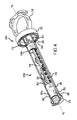
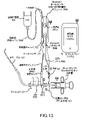
本明細書において説明する計測システムは、量的評価のシステムとして又は調整器と組み合わせて、採用できる。付加的なシステムが、米国特許出願第14/851958号明細書及び第15/089061号明細書(これらの開示は、参照により本明細書に援用される)において説明される。代表的実施形態を図13に示す。図13は、調整器及び再使用迂回貯蔵器を示し、システムは、システムから患者へ送達された薬剤の量を計測するように構成される一方、注入された媒体の一部分を迂回することによって注入された媒体の一部を再使用するために迂回貯蔵器を採用できる。逆に、図14は、調整器及び迂回貯蔵器(造影剤再使用のため)と一緒に使用するか否かに関係なく、例えば送達された媒体の量的評価及び患者へ送達された総量対いくつかの設定された臨界量(Gurm比など)の固有の分析のための計測システムの使用を説明する。計測は、媒体が調整される前、調整と同時又は調整プロセスの後に実施できることが分かるはずである。更に、計測装置及び方法は、米国特許出願第13/839771号明細書及び/又は第14/851958号明細書において説明されるような調整システムのいずれとでも使用することも想定される。更に、本明細書において説明する実施形態は、本質的に代表的なものであり、様々な可能な組合せを限定するものと解釈すべきではない。 The metrology system described herein can be employed as a system of quantitative evaluation or in combination with a regulator. Additional systems are described in US patent application Ser. Nos. 14/851,958 and 15/089,061, the disclosures of which are incorporated herein by reference. A representative embodiment is shown in FIG. FIG. 13 shows a regulator and reusable bypass reservoir, the system configured to meter the amount of drug delivered from the system to the patient while infusing by bypassing a portion of the infused medium. A bypass reservoir can be employed to reuse a portion of the depleted media. Conversely, FIG. 14 provides, for example, an assessment of the volume of media delivered and the total volume delivered to the patient versus the total volume delivered to the patient, whether or not used with a regulator and bypass reservoir (for contrast re-use). We describe the use of the metrology system for specific analysis of some set critical quantities (such as the Gurm ratio). It should be appreciated that the measurement can be performed before the media is conditioned, concurrently with the conditioning, or after the conditioning process. Further, it is envisioned that the metrology apparatus and method may be used with any of the conditioning systems described in US patent application Ser. Nos. 13/839,771 and/or 14/851,958. Furthermore, the embodiments described herein are representative in nature and should not be construed as limiting the various possible combinations.
本明細書において開示する制御及び調整装置のいくつかの実施形態は、薬剤が予定される標的注入部位へ進入する前に注入薬剤に対して弁調節、制御又はその他の調整機能を調整するためにセンサ信号を送受信できる。調整は、例えば、注入装置から供給された注入物の弁調節(又はその他の調整)を含むことができる。米国特許出願第13/839771号及び/又は14/851958号において説明されるように、間接的弁調節(又はその他の制御機構)は、近位又は遠位において薬剤送達システム内、その周り及び/又はその上に位置付けできる。更に、本明細書において説明する実施形態は、使用者の好みに対処するために様々なシステム及び方法又はその組合せを説明する。例えば、使用者は、注射器(全量注入を含むことができる)によって患者へ注入された媒体を計測できる。この種のシステムは、システムが迂回(調整)機能を含む場合に媒体注入を計測する別の構成より単純になる。 Some embodiments of the control and regulation device disclosed herein are used to adjust valving, control or other regulatory functions to the infused drug prior to the drug entering the intended target injection site. Can send and receive sensor signals. Adjustment can include, for example, valving (or other adjustment) of the infusate delivered from the injection device. As described in US patent application Ser. or can be positioned above it. Further, the embodiments described herein describe various systems and methods or combinations thereof to address user preferences. For example, the user can meter the medium injected into the patient by a syringe (which can include a full injection). This type of system is simpler than alternative configurations that meter media injection if the system includes a bypass (adjustment) function.
更に、最終使用者は、多様なニーズを持つ可能性があるので、これらのニーズに対処するために、計測、調整及び迂回(即ち、例えば媒体の再使用のための貯蔵器)のための本明細書において説明する様々な構成要素及び方法を部分的に又は全面的に使用できる。例えば、ある使用者は、注入のみを計測したく(食塩水洗浄を計測しない)、他の使用者は、再使用のために迂回された媒体は捕捉せずに(媒体を廃棄して)、調整及び計測を採用したく、更に別の使用者は、計測および再使用のための貯蔵器を採用したいが、再使用の捕捉のために既存のシステムを使用することを好む場合がある。これらは、本明細書において説明する実施形態の様々な構成要素を組み合わせることによって対処できる様々なニーズのほんの一部分であり、限定的ではなく代表的なものとして見るべきである。更に、本明細書において注入器の使用について説明しており、これは注射器及び/又はパワーインジェクタ(例えば、Acist CVi注入器)とすることができる。本明細書において説明する実施形態の構造は、注入器に応じて変化するが、実施形態の原則は、同じである。 In addition, end users may have diverse needs, and books for metering, conditioning, and diversion (i.e., reservoirs for reuse of media, for example) are designed to address these needs. Various components and methods described herein may be used in part or in full. For example, some users may want to meter infusions only (no saline flushes), while others may not capture the diverted media for reuse (discard media), Still other users who wish to employ calibration and metering may wish to employ reservoirs for metering and reuse, but prefer to use existing systems for reuse capture. These are but a few of the various needs that can be addressed by combining the various components of the embodiments described herein, and should be viewed as representative rather than limiting. Further, the use of an injector is described herein, which can be a syringe and/or a power injector (eg, Acist CVi injector). Although the structure of the embodiments described herein varies depending on the injector, the principles of the embodiments remain the same.
本明細書において説明する実施形態は、注射器などチェンバ内のプランジャの移動を計測及び/又は検出するための様々な要素又は構成要素を含むことができる。又、チェンバ内のプランジャの位置関係を検出して、使用者は、チェンバから放出された媒体の容積を暗示的又は明示的に測定できる。本明細書において説明する実施形態のいくつかは、プランジャ/ピストンとチェンバの位置関係に応じて、様々な発光源並びに光を検出又は感知するための構成要素を含むことができる。直線エンコーダ、誘導性センサ、容量性タッチセンサ(プランジャに金属アクチュエータを持つ)、超音波エミッタ/レシーバ、圧力センサ、光学エンコーダ(細目スロット及び光源を持つ)、ひずみゲージ(即ち、重量を測定するため)、電磁気エミッタ/レシーバ(例えばナビゲーションシステム)が、「迂回」貯蔵器を計測するかしないかに関係なく、注入器から患者へ送達された注入物の計測を使用するために想定されるテクノロジーである。プランジャとチェンバの位置関係(及びその変化)を識別できるその他の実施形態は、限定的でなく下記のテクノロジーを含むことができる。ホールセンサ(注射器の軸線に沿って巻かれたワイヤ)は、磁石がプランジャ(可変近接センサとして作用する)に取り付けられた状態で、チェンバに又はそれに近接して配置できる。複数の低感度ホールセンサを、磁石がプランジャに取り付けられた状態で、注射器のチェンバに沿って配置できる。複数のホールセンサを利用するシステムの更に別の実施形態について、本明細書において説明する。レーザー光線を放射し、検出して、チェンバの軸線に沿ったプランジャの位置関係を測定できる。絶対エンコーダは、プランジャの直接変位を「読み取る」ために使用できる。本明細書において説明するこれらのシステムの多くは、感知システムの少なくとも2つの部品又は部分を含む。1つの部品は、信号(又は変化)の送信または生成に使用でき、第2部品は、信号における差(又は変化)の読み取り、感知又は計測に使用できる。典型的に、本明細書において説明する実施形態の多くにおいて、計測の構成要素(即ち部品、部分など)の1つは、注入器のプランジャに関連付けられ、これに又は取り付けられ、又はこれに近接し、少なくとも第2の部品(即ち、構成要素、部分など)は、注入器ハウジングに取り付けられ、これに関連付けられ、又はこれに近接する。その1つの例が、図4において示される構成要素350a及び350bである。
Embodiments described herein can include various elements or components for measuring and/or detecting movement of a plunger within a chamber, such as a syringe. Also, by detecting the positional relationship of the plunger within the chamber, the user can implicitly or explicitly measure the volume of medium expelled from the chamber. Some of the embodiments described herein can include different light sources and components for detecting or sensing light, depending on the position of the plunger/piston and chamber. Linear encoders, inductive sensors, capacitive touch sensors (with metal actuators on the plunger), ultrasonic emitters/receivers, pressure sensors, optical encoders (with fine slot and light source), strain gauges (i.e. for measuring weight). ), an electromagnetic emitter/receiver (e.g., a navigation system), with or without measuring a "bypass" reservoir, a technology envisioned for using metering of infusate delivered from the injector to the patient. be. Other embodiments that can identify the positional relationship (and changes thereof) of the plunger and chamber can include, but are not limited to, the technologies described below. A Hall sensor (a wire wound along the axis of the syringe) can be placed in or near the chamber with a magnet attached to the plunger (acting as a variable proximity sensor). A plurality of low sensitivity Hall sensors can be placed along the chamber of the syringe with the magnet attached to the plunger. Further embodiments of systems utilizing multiple Hall sensors are described herein. A laser beam can be emitted and detected to determine the position of the plunger along the axis of the chamber. An absolute encoder can be used to "read" the direct displacement of the plunger. Many of these systems described herein include at least two parts or portions of the sensing system. One component can be used to transmit or generate a signal (or change) and a second component can be used to read, sense or measure the difference (or change) in the signal. Typically, in many of the embodiments described herein, one of the instrumentation components (i.e. parts, parts, etc.) is associated with, attached to, or proximate to the plunger of the injector. and at least a second part (ie, component, portion, etc.) is attached to, associated with, or proximate to the injector housing. One example is
図3は、ホールセンサモジュールを利用するモニタ注射器の実施形態の斜視図である。ホールセンサモジュールについては更に下で詳しく説明する。モニタ注射器300は、内側孔304を形成する注射器ハウジング302を含む。プランジャ又はピストン(これについては、下でさらに詳しく説明する)は、孔304の中に滑動可能に受け入れられる。具体的に言うと、ピストンは、孔304の内面と滑動可能に係合し、孔304内でのプランジャシャフトの直線移動Mは、ピストンを動かす。移動Mは、注射器軸線Asに沿う。下でさらに詳しく説明するように、親指リング312を利用して、軸線Asに沿ってプランジャを押し引きできる。プランジャが注射器ハウジング302の排出端314aへ向かう方向に移動Mするとき、その中に収容される流体(例えば、媒体)は、管又はニードル(図示せず)の中へ排出されて、患者へ送達される。2つのフィンガリング又はタブ332は、使用時に使用者の指を受け入れる。説明全体を通じて、円筒形ハウジング302及び内側孔304について説明するが、本明細書において予想する機能を与えるハウジング/孔/302/1204及びプランジャの多様な構造が想定され、形状(長方形、卵形、三角形断面などを含む)は限定的なものではない。モニタ注射器300は、ホールセンサモジュール350(下で更に詳しく説明する)も含む。ホールセンサモジュール350の1つの構成要素は、注射器ハウジング302の外面に配置される磁石保持リング352である。図示する実施形態において、磁石保持リング352は、ハウジング302の近位端314b付近に配置されるが、ハウジング302に沿って他の場所に配置してもよい。
FIG. 3 is a perspective view of an embodiment of a monitor syringe that utilizes a Hall sensor module; Hall sensor modules are described in more detail below.
図4は、図3のモニタ注射器300の部分断面斜視図であり、ホールセンサモジュール350を示す。ホールセンサモジュール350の特定の構成要素350aは、プランジャ306の中空シャフト308の内側チェンバ内に配置され、特定の構成要素350bは、注射器ハウジングの外面に配置される。各種構成要素350a、350bについては、下でさらに詳しく説明する。いわゆる内部構成要素350a(即ちプランジャ306の内部の)は、保持インサート354a、354b、ベース又は回路基板356、及びその上に配置された複数のホールセンサ358を含む。1つ又は複数のバッテリ360及び制御スイッチ362も、回路基板356に固定できる。ホールセンサ358からの信号は、まず回路基板356によって処理でき、回路基板は、プランジャ306の位置、注射器内の媒体の容積などを測定でき、その後、トランスミッタ380を介してその後の分析、医師への表示などのためにこの情報を関連するシステムへ送信する。別の実施形態において、例えば、非処理ベース356が使用される場合、各ホールセンサ358からの信号は、処理のためにトランスミッタを介して関連システムへ直接送信される。
4 is a partial cross-sectional perspective view of the
遠位保持インサート354aは、ピストン310近くになるようにシャフト308の中へ挿入できる。遠位保持インサート354aは、空隙364を形成でき、空隙は、Bluetooth(登録商標)トランスミッタなどの無線トランスミッタ380を収容できる。トランスミッタ380は、ホールセンサ358からの信号を本明細書において説明するような関連する信号処理装置へ送信できる。別の実施形態において、上に説明したようなケーブル接続を使用できる。近位保持インサート354bは、親指リング312付近の中空シャフト308の中に配置される。遠位保持インサート354aと近位保持インサート354bは、一緒に、中空シャフト308内に回路基板356を支持、保護及び保持する。これらの2つの構成要素は、シャフト308の中に滑り嵌めするように構成されるか、又は回転を防止するように、シャフト308の開口又はスロットと係合するためのキーまたはその他の突出部を含むことができる。保持インサート354a及び354bは、シャフト308内に永久的に固定できるが、保持インサート354a、354bを取り外せるように構成することは、回路基板356、バッテリ360などの交換又は修理を可能にするために有利である。1つの実施形態において、親指リング312は、シャフト308の噛合いスロット368と係合可能な複数の突出部366を含む弾性ベース364を含むことができる。これらの突出部366を外すと、保持インサート354a、354b及びその他の内部構成要素の取外しが可能である。複数のホールセンサ358を図示する。様々な実施形態においてこれより多い又は少ない数のセンサ358を利用できるが、より多いセンサ358は、プランジャ306の位置に関してより正確な測定を可能にする。ホールセンサ358は、実質的に軸線Asと整列する又はこれに対して平行となるようにチェンバ内に線形に配列される。
外部構成要素350bは、図示する実施形態において、複数の磁石を保持する磁石保持リング352を含み、磁石はアークマグネットとすることができる。他の実施形態において、キューブ、円筒形又はその他の磁石を利用できる。磁石370の位置は、注射器ハウジングに対して又はその周りに固定される。アークマグネット370は、実質的に円形磁場を形成し、シャフト308(及びホールセンサ358)は、注射器の内側孔から引き抜かれるとき又はこの中へ挿入されるとき前記磁場を通り抜ける。円形磁場は、軸線Asの周りでのプランジャ306の回転位置に関係なく、ホールセンサ358が磁場を検出できるようにする。他の実施形態において、磁石370は、磁石保持リングなしで注射器ハウジングに直接固定できる。
図5は図4に示すモニタ注射器300の一部分の部分分解斜視図である。具体的には、プランジャ306、ホールセンサモジュール内部構成要素350a及びオールセンサモジュール外部構成要素350bを図示する。概略的に、これらの構成要素の特定のものについては、図3~4に関して上で説明しており、それ以上は必ずしも説明しない。但し、図示する実施形態において、遠位保持インサート354a及び近位保持インサート354bは、回路基板356を所定の場所に保持するためにこの要素を受け入れるように構成された形状を持つ凹部372を含む。凹部372は、プランジャ306の中空シャフト308内の空間を保存するようにインサート354a、354bの中に配置される。ホールセンサ358の反対側の回路基板356の側には、複数のバッテリ360が配置される。これは図6にも示す。更に、スイッチ362をバッテリ360に近接して又は中空シャフト308内の別の場所に配置できる。スイッチ362は、特定の実施形態において、プランジャ移動を検出して係合又は起動位置へ移動するリードスイッチとすることができる。スイッチ362は、要求はされないが、注射器300が使用中ではないときの電力保存に役立つ。
FIG. 5 is a partially exploded perspective view of a portion of
起動されると、スイッチ362は、バッテリ360からの電力を選択的に複数のホールセンサ358及び無線トランスミッタのいずれか又はその両方に接続する。別の実施形態において、プルタブ、ボタン又はロッカースイッチなどの手動スイッチを使用者が作動できる。
When activated, the
システムの別の実施形態において、患者への造影剤の導入の際貯蔵器を採用するシステムにおいて、モニタ注射器300の計測構成要素を利用して、調整器によって媒体迂回貯蔵器へ迂回された媒体の容積を計測できる。この種の媒体迂回貯蔵器、及び関連する媒体管理及びモニタシステムへの媒体貯蔵器の組入れについては、本明細書の他の部分において説明する。この事例において、内側孔304は、送達カテーテルへの媒体の注入から調整器によって迂回される媒体を捕捉するための流体貯蔵器を形成できる。貯蔵器の別の実施形態において、チェンバは、チェンバ内の媒体の制御された充填、放出及び計測を容易にするために、プランジャ306に対して作用する力によって充分に与圧できる。力は、孔304の中に収容された流体の中へピストン310を付勢でき、その間、ホールセンサ358はプランジャ306の位置を引き続き検出する。図5に示す実施例において、与圧迂回貯蔵器としてモニタ注射器300を構成するために、バネ309をプランジャ306の中空シャフト308の周りに配置できる。このバネ309は、注射器ハウジング302の排出端314aへ向けてピストン310を付勢する。他のバネ構成及び/又は付勢機構を使用でき、この場合、概ね、機構は、均衡のとれた力を加えるために注射器軸線Asの周りに配置できる。
In another embodiment of the system, in a system that employs a reservoir during the introduction of contrast agent to the patient, the metering component of the
図7は、ホールセンサモジュールを利用するモニタ注射器400の第2実施形態の斜視図である。モニタ注射器400は、中空内側孔を形成する注射器ハウジング402を含む。シャフト408とピストン410とを含むプランジャ406は、孔の中に滑動可能に受け入れられる。具体的には、ピストン410は、孔の内面と滑動可能に係合でき、孔内部でのシャフト408の直線移動Mはピストン410を動かす。移動Mは、注射器軸線Asに沿う。プランジャ406は、親指リング412などの親指パッドの移動によって孔404内を前後に移動する。プランジャ406が注射器ハウジング402の排出端414aへ向かう方向へ移動Mするとき、その中に収容された流体はマニホルド組立体、管又はニードル(図示せず)の中へ排出されて、患者へ送達される。
FIG. 7 is a perspective view of a second embodiment of a
図4~5に示す実施形態とは別の実施形態として、ホールセンサモジュール418は、プランジャに固定されるのではなく、注射器ハウジング402の外面に固定できる。ホールセンサモジュール418は、複数のホールセンサ420を囲繞するホールセンサハウジング419を含む。図3~5に関連して上で説明したように、離散的ホールセンサ要素の数が多ければ、精度を改良できる。1本または複数本のリード又はワイヤ424が、ホールセンサモジュール418の一端から延びる。ケーブル426は、一端428において、ホールセンサモジュール418の出力を分析して、この情報をモニタ注射器400の使用者に典型的にはディスプレイ上で提供するインターフェイスユニットに接続する。別の実施形態において、通信は、本明細書において説明するように無線、Bluetooth(登録商標)又はその他の無線接続を介する。表示される情報は、チェンバの容積、残留容積、供給容積、流体タイプ、流量、流体圧力又は温度及び/又は特定の用途に必要とされるまたは望ましいその他の情報である。上述のように、ホールセンサからの信号は、まず、関連する回路基板によって処理され、その後インターフェイスユニットへ送信されるか、又は離散信号が処理のためにインターフェイスユニットへ送信される。
As an alternative to the embodiment shown in FIGS. 4-5,
図示する実施形態において、プランジャ406のシャフト408は、その上に又はシャフト408内部に配置された1つ又は複数の磁石430を有する。磁石430は、この事例において、シャフト408の周りに配置された複数のアークマグネットを含む。プランジャ406が軸線Asに沿って滑り移動Mするとき、磁石430は、ホールセンサモジュール418のホールセンサ420の前を通過する。磁石430によって生成された磁場は、ホールセンサ420によって検出される。ホールセンサ420は、インターフェイスユニットへ信号を送信し、インターフェイスユニットは、個々のホールセンサ420によって検出された磁石430の位置に基づいて注射器ハウジング402内でのプランジャ406の位置を測定する。このようにして、プランジャ406の位置を測定できる。インターフェイスユニットは、注射器ハウジング402の孔404の既知の直径及び長さに基づいて上記の様々なタイプの情報も測定できる。2つのフィンガリング又はタブ432は、使用時に使用者の指を受け入れる。ストッパ434は、プランジャ406が注射器ハウジング402から引き出されるのを防止する。
In the illustrated embodiment, the shaft 408 of the plunger 406 has one or more magnets 430 disposed thereon or within the shaft 408 . Magnets 430 , in this case, include multiple arc magnets arranged around shaft 408 . As plunger 406 slides M along axis As, magnet 430 passes in front of
図3~7に示される実施形態は複数のホールセンサを示すが、他のモニタ注射器の実施形態は、様々なタイプの1つ又は複数のセンサを利用できる。例えば、磁場、材料の抵抗、キャパシタンスなどを計測するために、単一のセンサ又は複数のセンサを使用できる。これらのセンサからの計測値を利用して、注射器内でのプランジャの直線位置を測定できる。このようなセンサの例は、ホール効果センサ(本明細書において更に詳しく説明する)、誘導性センサ、容量性タッチセンサなどを含むが、これらに限定されない。 Although the embodiments shown in FIGS. 3-7 show multiple Hall sensors, other monitor syringe embodiments can utilize one or more sensors of various types. For example, a single sensor or multiple sensors can be used to measure magnetic fields, material resistance, capacitance, and the like. Measurements from these sensors can be used to determine the linear position of the plunger within the syringe. Examples of such sensors include, but are not limited to, Hall effect sensors (described in further detail herein), inductive sensors, capacitive touch sensors, and the like.
図1は、ホールセンサを利用するモニタ注射器の使用方法100bを示す。動作102bにおいて、信号は第1ホールセンサから受信される。プランジャシャフト内でのセンサのプランジャにおける他のホールセンサに対する位置は既知である。第1ホールセンサの位置及び前記センサから受信した信号に基づいて、動作104bにおいてピストンの位置が測定される。注射器の断面積、直径又はその他の寸法は既知なので、ピストンの位置に基づき注射器の中の媒体の量を測定できる。複数のホールセンサが使用される実施形態において、信号は、動作106bにおいて、既知の特性(例えば位置)を持つ第2ホール光センサからの信号を受信できる。ピストンの更新された位置は、第2ホールセンサから受信した信号及び動作108bにおける信号に基づいて測定できる。既知のホールセンサから信号を受信すると、注射器の状態(本明細書において説明する)は、動作110bにおいて測定できる。上述のように、方法100bは、モニタ注射器内の回路基板において実施でき、それ以上の分析又は外科医などへの表示のためにトランスミッタを介して関連システムへ送られる。別の実施形態において、各信号は、トランスミッタを介して処理、分析、表示などのために関連システムへ送信できる。 FIG. 1 illustrates a method of use 100b of a monitor syringe that utilizes Hall sensors. At act 102b, a signal is received from the first Hall sensor. The position of the sensor in the plunger shaft relative to other Hall sensors in the plunger is known. Based on the position of the first Hall sensor and the signal received from said sensor, the position of the piston is determined in operation 104b. Since the cross-sectional area, diameter or other dimensions of the syringe are known, the amount of medium in the syringe can be determined based on the position of the piston. In embodiments in which multiple Hall sensors are used, the signal can be received from a second Hall light sensor with known characteristics (eg, position) in act 106b. The updated position of the piston can be determined based on the signal received from the second Hall sensor and the signal at action 108b. Upon receiving a signal from a known Hall sensor, the state of the syringe (described herein) can be determined in operation 110b. As described above, method 100b can be implemented on a circuit board within a monitor syringe and sent via a transmitter to an associated system for further analysis or display to a surgeon or the like. In another embodiment, each signal can be sent to an associated system for processing, analysis, display, etc. via a transmitter.
更に、図1に示す方法は、迂回貯蔵器を採用するシステムに使用される場合、更に、注入から迂回された(即ち、調整器を介して)媒体を収集するチェンバの中で測定された計測を組み込むことができる。注射器によって注入された媒体の総量(センサ装置によって測定)から迂回された媒体の量(センサ装置によって測定)を引くことによって、患者体内へ実際に送達された注入の総量が得られる。 Furthermore, the method illustrated in FIG. 1, when used in a system employing a bypass reservoir, furthermore, measures taken in the chamber that collects the medium bypassed from injection (i.e., via the regulator) can be incorporated. Subtracting the amount of bypassed medium (measured by the sensor device) from the total amount of medium injected by the syringe (measured by the sensor device) gives the total amount of injection actually delivered into the patient.
図2は、本発明の実施形態の1つ又はそれ以上を実現できる適切な作動環境200の1つの例を示す。これは、適切な作動環境の一例にすぎず、使用または機能性の範囲に対する限定を示唆するものではない。使用に適する他の周知のコンピュータシステム、環境及び/又は構成としては、パソコン、サーバーコンピュータ、携帯又はラップトップ装置、マルチプロセッサシステム、マイクロプロセッサシステム、スマホなどプログラム可能大衆電子機器、ネットワークPC、ミニコンピュータ、メインフレームコンピュータ、スマートフォン、タブレット、上述のシステムまたは装置のいずれかを含む分散コンピュータ環境及びこれに類似するものを含むが、これらに限定されない。
FIG. 2 illustrates one example of a
ほとんどの基本的構成において、作動環境200は、典型的に、少なくとも1つの処理ユニット202及びメモリ204を含むことができる。コンピュータ装置204の正確な構成及びタイプに応じて、メモリ204(特に本明細書において説明するモニタ方法を実施するための命令を記憶する)は、揮発性(RAMなど)、非揮発性(ROM、フラッシュメモリなど)又はその組合せとすることができる。この最も基本的構成を、図2において線206によって示す。更に、環境200は、磁気又は光ディスクまたはテープを含めて(但しこれらに限定されない)記憶装置(可換型208及び/又は非可換型2109)も含むことができる。同様に、環境200は、タッチスクリーン、キーボード、マウス、ペン、音声入力などの入力装置214、及び/又はディスプレイ、スピーカ、プリンタなどの出力装置216も持つことができる。また、LAN、WAN、2点間、Bluetooth(登録商標)、RFなど1つまたは複数の通信接続212を環境に含めることもできる。
In most basic configurations, operating
動作環境200は、典型的に、少なくともいくつかの形式のコンピュータ可読媒体を含むことができる。コンピュータ可読媒体は、処理ユニット202又は動作環境を構成する他の装置がアクセスできる任意の使用可能媒体とすることができる。例えば、限定的ではなく、コンピュータ可読媒体は、コンピュータ記憶媒体及び通信媒体を含むことができる。コンピュータ記憶媒体は、コンピュータ可読命令、データ構造、プログラムモジュール又はその他のデータなどの情報を記憶するための方法又はテクノロジーで実現された揮発性及び非揮発性、可換性及び非可換性媒体を含む。コンピュータ記憶媒体は、RAM、ROM、EEPROM、フラッシュメモリ又は他のメモリテクノロジー、CD-ROM。デジタル多機能ディスク(DVD)又はその他の光記憶装置、磁気カセット、磁気テープ、磁気ディスク記憶装置またはその他の磁気記憶装置、ソリッドステート記憶装置又は所望の情報を記憶するために使用できるその他の有形媒体を含む。通信媒体は、コンピュータ可読命令、データ構造、プログラムモジュール、又はキャリア波又はその他の搬送機構などの変調データ信号の中のその他のデータを実現し、任意の情報送達媒体を含む。「変調データ信号」は、その特性の1つ又は複数が信号の中の情報を符号化するように設定又は変更される信号を意味する。例えば、限定的ではなく、通信媒体は、有線又は直接有線接続などの有線媒体、及び音波、RF、赤外線及びその他の無線媒体などの無線媒体を含む。上述のもののいずれの組合せも、コンピュータ可読媒体の範囲内に含めるべきである。
動作環境200は、1台又は複数の遠隔コンピュータへの論理接続を使用するネットワーク環境において作動する単一コンピュータとすることができる。遠隔コンピュータは、パーソナルコンピュータ、サーバー、ルーター、ネットワークPC、ピアデバイス又はその他の共通ネットワークノードとすることができ、典型的には、上述の要素の多く又は全て並びに上に言及しないその他の要素を含む。論理接続は、利用可能な通信媒体によって支持される任意の方法を含むことができる。このようなネットワーク環境は、オフィス、企業内コンピュータネットワーク、イントラネット及びインターネットにおいて一般的である。いくつかの実施形態において、本明細書において説明する構成要素は、コンピュータ記憶媒体及び他の有形媒体に記憶して通信媒体で通信できるコンピュータシステム200によって実行可能なモジュール又は命令を含む。コンピュータ記憶媒体は、コンピュータ可読命令、データ構造、プログラムモジュール又はその他のデータなどの情報を記憶するための任意の方法又はテクノロジーで実現された揮発性及び非揮発性、可換型及び非可換型媒体を含む。上述のもののいずれの組合せも、可読媒体の範囲内に含まれる。いくつかの実施形態において、コンピュータシステム200は、コンピュータシステム200によって使用するために遠隔記憶媒体にデータを記憶するネットワークの一部である。
上述のようなモニタ注入器は、患者体内への媒体注入を制御し監視するために様々なタイプの媒体管理システムにおいて利用できる。2つの代表的な媒体管理システム並びにその構成要素について、下記の図面を参照して下で説明する。本明細書において説明する監視テクノロジーの恩恵を受けられるシステムのタイプを2つだけ示す。他のシステム及びその構成が、当業者には明らかであろう。 Monitor injectors such as those described above can be utilized in various types of media management systems to control and monitor media injection into a patient. Two representative media management systems and their components are described below with reference to the following figures. There are only two types of systems that can benefit from the surveillance technology described herein. Other systems and their configurations will be apparent to those skilled in the art.
図8~10は、図示する実施形態において示すように、フローダイバータ組立体(即ち、調整器)502と迂回貯蔵器504とを含む別の媒体管理システム500を示す。この実施形態において、管状部材506aがフローダイバータ組立体502の弁526から媒体迂回貯蔵器まで延び、管状部材506bが迂回貯蔵器504から媒体貯蔵器(例えば、造影剤バイアル)510まで延びる。
8-10 show another media management system 500 that includes a flow diverter assembly (ie, regulator) 502 and a
媒体貯蔵器510(例えば造影剤バイアル)からの媒体は、媒体貯蔵器510から管状部材506bを介して迂回貯蔵器504及び管状部材512を通過して流動できる。図示する配列体(図8)において、注射器514は、管状部材506b、512、516及び518によって媒体貯蔵器510に流通可能に結合でき、これらの構成要素をマニホルド520によって止め栓522を介して一緒に結合する。注射器514に媒体貯蔵器510から媒体が充填されるとき、止め栓522は、管状部材516と518との間の媒体の流れを許容するが止め栓522とフローダイバータ組立体502の弁526との間に配置された管状部材524への流れを許容しないように位置付けできる。注射器514は、本明細書において説明するモニタ注射器(例えば、光センサ、ホールセンサなどを使用する)又は技術上既知のモニタ注射器のいずれでもよい。注射器514を引き戻すと、媒体貯蔵器510から、管状部材506b及び/又は迂回貯蔵器504を通過し、管状部材512を通過して媒体を引き出す。
Media from media reservoir 510 (eg, a contrast vial) can flow from
媒体貯蔵器510からの媒体及び/又は迂回貯蔵器504の中の媒体は、管状部材516及び518を通過して注射器の中へ及びこれへ向けて更に引き寄せることができる。注射器514に媒体貯蔵器510及び/又は迂回貯蔵器504から媒体が充填されると、マニホルド520の弁Bは、管状部材512を介した媒体貯蔵器520及び迂回貯蔵器504への逆流を防止するように操作でき(この逆流は、迂回貯蔵器504と媒体貯蔵器510との間に配置された逆止め弁によって更に阻止できる)、止め栓522は、管状部材518、524、516及びマニホルド520を通過する流れを許容するように位置付けできる。
Media from
調整器(フローダイバータ組立体502など)を組み込む造影剤注入手順において、注射器514から注入された媒体の一部分は、フローダイバータ組立体502によって注入カテーテル528への媒体流路から迂回できる。図8~10に示す調整・貯蔵器システム500において、フローダイバータ組立体を通過するこのように迂回された媒体の流れは、媒体貯蔵器510又はその他の流出・越流貯蔵器/チェンバの中へ直接流れる迂回媒体とは異なり、迂回貯蔵器504へ流れ込む。好ましくは、システムへ媒体を引き入れるために(例えば、カテーテル528によって患者体内へ導入するため)注射器514が再び起動されるときの再利用のために、迂回貯蔵器504は、フローダイバータ組立体502によって迂回された越流媒体を収集するための手段を提供する。媒体貯蔵器510の中への媒体の逆流を防止する逆止め弁と一緒にこのように迂回貯蔵器を使用することによって、既にシステム(例えば、迂回貯蔵器504)に導入されている媒体を捕捉し再使用できるようにしながら、媒体貯蔵器510内に配置された媒体の完全性をその元来の形で保存できる。
In contrast injection procedures that incorporate a regulator (such as flow diverter assembly 502 ), a portion of the injected medium from
媒体管理システム500は、その諸部分を洗浄するために使用できる食塩水貯蔵器530も含むことができる。図8に示すシステム500において、食塩水貯蔵器530は、管532を介してマニホルド520に接続され、弁Aによってシステム500の残り部分から分離できる。前に説明した媒体の注入、迂回、再使用及びシステムの食塩水洗浄は、システムの各種弁(即ち、弁A、B、522又は流れの方向を定めるために使用されるその他の弁)を機械的に作動し迂回貯蔵器及び注入器に取り付けられた計測センサをオン/オフ切換えすることによって実施できるが、バルブセンサによる計測システムの自動化は、患者体内への媒体注入量を測定する際の計測又は非計測エラーを著しく減少できる。前述の通り、患者に注入された造影剤の綿密な監視及び計測は、注入された造影剤を使用する処置を受ける患者の結果に著しい影響を与える可能性がある。このために、弁Aは、弁Aの位置を検出する位置センサ又はその他のセンサSを含むことができる。洗浄信号は、弁AセンサSからモニタ/ディスプレイシステム534へ送信される。モニタ/ディスプレイシステムは、弁B及び止め栓522(センサS2を使用する)の位置並びにモニタ注射器514の各種センサ及び/又は迂回貯蔵器504のセンサからの出力を監視するように構成できる。例えば、弁Aが開放位置のとき、モニタ/ディスプレイシステム534は、モニタ注射器514及び/又は迂回貯蔵器504からの信号(その読取り値は、注射器514から注入又は注射器へ引き込まれる造影剤を反映しないので)を無視できる。別の実施例において、弁Aが開放位置にある場合、モニタ/ディスプレイシステム534は、弁B及び/又は止め栓522を閉鎖してシステム500のこの部分を隔離するように操作者に思い出させるために命令を表示するか又は信号を発することができる。別の更に複雑な実施例において、システム500は、自動弁B及び/又は止め栓522を使用して、弁Aからの開放信号を受信すると、前記の弁を閉鎖する。
The media management system 500 can also include a
変換貯蔵器504の1つの実施形態を図9A~9Dに示す。図9Aは、関連する管状部材506a及び512と一緒に迂回貯蔵器504の組立図を示す。図9Bは、図9Aの組立体の分解図である。システム500は、更に、供給導管506b及び迂回導管と流体連絡する第2供給導管512を含むことができ、第2供給導管512は、流体媒体経路に流通可能に結合される。管状部材506a及び512は、図9Aの線515C-515Cに沿って見た断面図である図9Cに更に示すように、迂回貯蔵器504の第1エンドキャップ又はマニホルド602に密封可能に接続される。貫通管606の第1端は、604においてなど第1エンドキャップ602の内側に密封可能に接続される。
One embodiment of
貫通管606は、これを貫通して延びる内側導管608を含む。内側導管608は、図9Cに示すように、第1エンドキャップ602の中の隣接する結合具を介して管状部材506a及び512の内部と流体連絡する。貫通管606の第2端は、610におけるなど逆止め弁組立体640に密閉可能に接続され、内側導管608は、逆止め弁組立体640と流体連絡する。逆止め弁組立体640は、管状部材506aと流体連絡する。図9Cに示すように、逆止め弁組立体640は、媒体貯蔵器510(例えば、造影剤バイアル)から管状導管506bを介して貫通管606の内側導管608の中への流れを許容するがその逆の流れを阻止するように作動する可動弁板612(又は弁を通過する一方向の流れを許容する他の適切な構造体)を含む。この配列体は、流体貯蔵器510から管状導管506b、貫通管606の内側導管608及び管状導管512を介して注射器514までの媒体の流れを許容できる。更に、フローダイバータ組立体502によって迂回された媒体の流れも、管状部材506aを介して貫通管606の内側導管608の中への流れることは許容されるが、チェック弁組立体640によって媒体貯蔵器510への流れは阻止される。迂回貯蔵器504の第2エンドキャップ614は、逆止め弁組立体640の周りに固定される。
迂回貯蔵器504は、フローダイバータ組立体502からの媒体の流れを収容し、この媒体を収集して保持し、その後所望の場合には、注入カテーテル528を介して患者に追加の媒体を送達する際に使用するためにこの収集された媒体をシステムへ押し戻すように設計される。このための1つの実施形態において、迂回貯蔵器504は、貫通管606の周りに配置された弾性膨張管616を含むことができる。図9C及び9Dに示すように、膨張管616は、貫通管606の長さの一部分に沿って延びる。膨張管616は、各端に隣接してそれぞれ第1及び第2保持ワッシャ618及び620によって又は他の適切な密封可能な機械的締結配列体によって貫通管6060の周りで密封可能に固定されたシリコン(又は同様に可撓性の)材料で形成できる。貫通管606の外面は、保持ワッシャ618及び620によって貫通管606への膨張管616の密封を更に容易にするために、表面特徴物又は環状干渉リム606aなどの干渉要素を含むことができる。
ハウジング管状外殻622は、第1エンドキャップ602と第2エンドキャップ614との間で接続でき、それによって、その中の膨張管616及び他の迂回貯蔵器構成要素を被覆する。外殻622は、その中の迂回貯蔵器504の構成要素を保護し、膨張管616の膨張又は拡張の程度を制限し、かつ/又は(外殻622が透明または半透明である場合)その中の膨張管616の状態(例えば、膨張状態)を観察できるようにするのに役立つ。
A
図9Dは、迂回貯蔵器504の斜視断面図(この場合にも、図9Aの線515C-515Cに沿って見る)を示し、図9Cに示す弛緩状態とは逆に代表的な伸張・膨張状態の膨張管616を示す。迂回貯蔵器504の膨張管616は、管状部材506aを介してフローダイバータ組立体502からの媒体の流れを受け入れる。この媒体の流れは、図9Dにおいて流れ矢印624で示すように、管状部材506aから、貫通管606の第1端に隣接する貫通管606の内側導管608の中へ流れる。貫通管606は、貯蔵器チェンバ626内に在る媒体供給導管506bの一部分とすることできる。貫通管606からの流出は、第2端において逆止め弁組立体640によって阻止される。但し、供給導管貫通管606は、1つ又は複数の開口628を持つことができ、開口を介して、膨張管616の内部は内側導管608及び貯蔵器チェンバ626と流体連絡できるようにする。フローダイバータ組立体502からの媒体は、このようにして、開口628を通過して膨張管616によって形成された媒体貯蔵器又はチェンバ626の中へ流入できる。この媒体チェンバ626は、膨張管616の内面と貫通管606の外面との間に形成されるので、膨張管616は、供給導管606の周りに配置された弾性袋(elastic bladder)を形成し、膨張管616の壁はチェンバ626内の流体媒体に対して力を加えることができる。チェンバ626内の1つの面は、チェンバ626内の流体媒体に対して可変力又は定力を加えることができ、面は、少なくとも部分的に、膨張管616の弾性袋の壁によって形成される。媒体チェンバ626は、このように、フローダイバータ組立体502からの媒体の流れの迂回部分を受け入れて収集する。迂回貯蔵器504は、貯蔵器チェンバ626内の流体媒体に対して面を押すために、貯蔵器チェンバ626内の少なくとも1つの面に対して配置された可変力又は定力付勢部材を備える。膨張管616の膨張可能壁は、このように、媒体チェンバ626内の流体媒体に対して力(可変又は不変)を加えることができる媒体チェンバ626内の面を形成する。1つの実施形態において、第2エンドキャップ614は、カバー622内のガスが逃げられるようにし、それによって中の膨張管616が容易に膨張できるようにするための貫通開口630を含む。
FIG. 9D shows a perspective cross-sectional view of bypass reservoir 504 (again, viewed along
使用時に、フローダイバータ組立体502内の媒体の圧力が、フローダイバータ組立体を通過して流れるに充分なほど上がるとき、媒体はダイバータ弁526から管状部材506aを介して迂回貯蔵器504まで流れる。流体結合は、迂回貯蔵器504と滅菌媒体貯蔵器510との間に配列されかつこれらに流通可能に結合された媒体供給導管506bによって与えられる。迂回供給導管506aは、フローダイバータ組立体502からの流体媒体の迂回部分を迂回貯蔵器504に供給するために、迂回貯蔵器504とフローダイバータ組立体502との間に配置されかつこれらに流通可能に結合される。媒体は、矢印624で示すように迂回貯蔵器504内で媒体チェンバ626の中へ流れ、それによって、膨張管616の壁を伸張して、迂回媒体の流れを受け入れるようにチェンバ626を膨張する。したがって、相対的に小さい流量がフローダイバータ組立体502によって迂回貯蔵器504の中へ迂回されるとき患者への流量が相対的に増大するように、注入器514を介して与えられる媒体圧力がシステムの中で増大するとき、相対的にフローダイバータ組立体502は媒体を迂回させる。チェンバ626の中に収容される媒体は、調整器/貯蔵器システム500を介して患者へその後注入するために利用可能である。例えば、操作者は、媒体が迂回貯蔵器504のチェンバ626から注射器514(その中へ流体を引き込むために引き戻される)の中へ流入できるように弁Bを起動できる。必要とされる流体が、チェンバ626内に保持された容積より大きい場合、逆止め弁612の力が圧倒され、更なる媒体が媒体貯蔵器510(例えば造影剤バイアル)から引き出される。チェンバ626及び/又は貯蔵器チェンバ510から充分な量の媒体が引き出されたら、弁Bは閉鎖されて、操作者が注射器514を起動することによって、注入カテーテル528を介して媒体を送達できる状態になる。止め栓522が管状部材516及び524への流れを可能にするように配置される限り、調整器組立体502は、過剰な媒体を自動的に迂回するように起動でき、それによって、最終的に注入カテーテル528を介して患者体内へ導入される媒体の量を自動的に減少する(不透明性を得るために必要な以上の媒体を導入しない)。図示する1つの実施形態において、調整器502において圧力が増大するとき、迂回回路への媒体の流れに対する抵抗は、フローダイバータ組立体502の作動によって増大する。操作者は、所望の処置を完了するために必要と思われる回数プロセスを反復できる。調整器/貯蔵器システム500をこのように使用することによって、患者への不要な媒体の導入を有利に減少しながら、診断又は治療手段(例えば、不透明性)のために患者への媒体の必要な量及び流量を得られる。更に、迂回貯蔵器504は、迂回された媒体の流出を再使用できるようにする。
In use, when the pressure of the medium within
図9A~9Dに示す迂回貯蔵器は、この種の貯蔵器の1つの形式を示す。別の形式も想定される。例えば、フローダイバータ組立体502から膨張チェンバへの媒体の越流を受け入れられるようにし、更に媒体貯蔵器510から迂回貯蔵器504を通過して調整/貯蔵器システム500の中への媒体の流れを(使用のために)可能にする弾性袋又は弾性面の別の形式も提供できる。迂回貯蔵器504のチェンバ内の媒体に力を加える別の手段は、図10において504aとして略図的に示すようなバイアスプランジャによって得られる。流体媒体の迂回部分は、フローダイバータ組立体502から迂回導管506aを通過して流れる。システム500は、システム500のための流体媒体の供給源を含む媒体貯蔵器510と、媒体貯蔵器510と迂回導管506aを流通可能に接続する貯蔵器チェンバ702を通過する供給導管506bとを備える。供給導管506bは、供給導管506bから媒体貯蔵器510の中への流体媒体の流れを防止するために逆止め弁808aを備える。迂回貯蔵器504aは、ハウジング706の中に滑動可能に配置され、移動線708で示すようにハウジング706に対して直線的に移動可能なプランジャ704を含む。このようにして、面710は、貯蔵器チェンバ702内の流体媒体に対して直線方向に移動可能である。プランジャ704の近位面710は、このように、管状部材506aを介して受け入れられる迂回媒体のためにハウジング706内のチェンバ702の一部分を形成する。
The bypass reservoir shown in Figures 9A-9D illustrates one type of reservoir of this type. Other formats are also envisioned. For example, to accommodate overflow of media from the
図9A~9に示す迂回貯蔵器500と同様、迂回貯蔵器504aは、媒体の流れのためのマニホルドとして作用する第1エンドキャップ602aを含むことができる。管状部材506aは、管状部材512と同様に第1エンドキャップ602aに接続される。チェンバ702は、図10に示すように、第1エンドキャップ602a内のマニホルド712を介するなどして管状部材506a及び512と流体連絡する。貫通管606aも、マニホルド712と流体連絡し、迂回貯蔵器504aのハウジング706を貫通して逆止め弁608aまで延びる。逆止め弁608aは、媒体が媒体貯蔵器510から管状部材506bを介して貫通管606aの中まで流れるようにするが、逆流は防止する。
Similar to the bypass reservoir 500 shown in FIGS. 9A-9, the
媒体貯蔵器510からの媒体は、その後、迂回貯蔵器504aから管状部材512を介して注射器514の中へ流入できる。媒体がフローダイバータ組立体502によって迂回貯蔵器504aの中へ流れるとき、媒体は、図において流れ矢印624aによって示すように、管状部材506aから、マニホルド712を通過してチェンバ702の中へ流れる。迂回貯蔵器504aは、貯蔵器チェンバ702内の流体媒体に面710を押し付けるために貯蔵器チェンバ702内の少なくとも1つの面710に対して配置されたバネ714などの可変力または定力付勢部材を備える。1つの代表的実施形態において、面710は平面状である。プランジャ704の面710は、バネ714によってマニホルドチェンバ712へ向かって付勢され、より多くの媒体が導入されて面に作用する付勢力が圧倒されると、チェンバ702を離れてこれを膨張できるようにチェンバ702の可動面710を形成する。この付勢力は、図において略図的に力の矢印716で示すように、ハウジング706内でプランジャ704に作用し、この力は、バネ、重量分布、直線アクチュエータ又はその他の力の要素などの適切な手段によって得ることができる。直線移動プランジャ704(矢印708によって示す移動など)を使用することによって、フローダイバータ組立体502によって実際にどれだけの媒体が迂回されたのかの計測、及び、推論によりどれだけの媒体が注入カテーテル528によって実際に患者に送達されたかの計測を、より容易にできる。計測は、本明細書において説明するように、ハウジング706に又はその中に又は迂回貯蔵器504のその他の構造(プランジャなど)に又はその中に配置された光式、ホールセンサ又はその他のタイプのモニタシステム718を利用することによって実施できる。プランジャ704は、このように、チェンバ702において再使用のために収集された越流媒体に力を加えるのに役立つ直線膨張要素(面710)を与える。
Media from
迂回貯蔵器504aは、フローダイバータ/調整組立体502によって迂回された媒体用の膨張可能チェンバを与えることによって、上述の迂回貯蔵器504と同様に作動する。チェンバ(例えば、チェンバ626)は、可能な再使用のために、その中の媒体を注入装置514へ向けて(導管512を介して)押し返すために作用する少なくとも1つの面を持つことができる。同様に、フローダイバータ組立体502によって迂回貯蔵器チェンバ702の中へ迂回された媒体は、ダイバータ組立体502へ逆流することも媒体貯蔵器510へ流れることも(逆止め弁608aを介して)できない。調整/貯蔵器システムの別の実施形態において、迂回貯蔵器は、迂回貯蔵器を通過して媒体貯蔵器510への流れが許容されない又は必要ないように構成される。
調整/貯蔵器システム500aに関連して、上記のような配列体を図11に示す。この配列体において、迂回貯蔵器を貫通する貫通管配列体は必要ない可能性がある。迂回貯蔵器は、フローダイバータ組立体502から迂回された媒体を保持し再使用することによって、単に膨張可能チェンバを与えるだけでよい。このような迂回貯蔵器504bは、袋形式のチェンバ又は定力または可変力抵抗型のチェンバ(図に示し本明細書において論じるようなもの)を採用でき、その中の少なくとも1つの面は、チェンバ内の流体媒体に対して充分な力を加えることができる。例えば、迂回貯蔵器504bは、図5に示すバネ式モニタ注射器300と同様に機能するように構成できる。注射器300の「注入機能」は、迂回貯蔵器として機能するために必要とされない可能性があるが、ピストン310を付勢するためにバネ309を利用する図5に示すようなチェンバ(「迂回貯蔵器」として機能できる)から派生する計測機能を利用する利点が得られる可能性がある。図11は、媒体貯蔵器チェンバ510が、管状部材506cを介して、迂回貯蔵器504b(貫通管を持たない)とフローダイバータ組立体502との間に配置されたTコネクタ302に接続される配列体を示す。Tコネクタ302は、その第1端において管状部材512及び506aに接続され、その第2端において、迂回貯蔵器504bに通じる管状部材506dに接続される。Tコネクタ302のサイド取付け部は、管状部材506cを介して媒体貯蔵器510に通じる。逆止め弁608bは、Tコネクタ302と媒体チェンバ510との間に配置されて、フローダイバータ組立体502及び/又は迂回貯蔵庫504bからの媒体容器510の中への媒体の逆流を防止する。作動上、図11に示す構成は、図8に関連して上で説明した構成と同様とすることができる。フローダイバータ組立体502内の媒体の圧力が組立体を通過して流れるのに充分なまで増大するとき、媒体は、弁526から管状部材506aを介してTコネクタ302まで流れる。その後、媒体は、Tコネクタ302から管状部材506dを介して迂回貯蔵器504bまで流れることができる。迂回貯蔵器504bの中へ流れる媒体は、その中のピストを動かして、迂回された媒体の流れを収容する。作動上、注射器514によって与えられる媒体は、フローダイバータ組立体502によって患者への注入から迂回され、迂回貯蔵器504bに蓄積される。
Such an arrangement is shown in FIG. 11 in connection with conditioning/
迂回貯蔵器504b内の膨張可能チェンバの中に収容された媒体は、調整/貯蔵器システム500aを介するその後の患者への注入のために利用可能である。そのために、操作者は、媒体が迂回貯蔵器504b内のチェンバから注射器514(その中へ流体を引き入れるために引き戻される)の中へ流れられるようにするために弁Bを起動する。必要とされる流体がチェンバ貯蔵器504bの中に保持される容積より大きい場合、逆止め弁608bの力が圧倒されて、更なる媒体が媒体貯蔵器510から引き出される。充分な量の媒体が迂回貯蔵器504b内のチェンバ及び/又は貯蔵器チェンバ510から引き出されたら、弁Bは、再び閉鎖され、調整システム500aは、操作者が注射器514を起動することによって、再び注入カテーテル528を介して媒体を送達できる状態になる。管状部材516及び524への流れを可能にするように止め栓522が配置される限り、フローダイバータ組立体502は、フローダイバータ組立体502の起動の閾値圧力に達したとき過剰な媒体を迂回するために自動的に起動され、それによって、注入カテーテル528を介して患者体内へ注入される媒体の量を最終的に減少する。この場合にも、フローダイバータシステム502へ入る圧力が増大するとき、ダイバータ502を通過する流れは、相対的に減少する(患者へ流れる流量は同時にフローダイバータ組立体502の作動によって相対的に増大する可能性がある)。このプロセスは、所望の処置を完了するために必要と思える回数だけ操作者によって反復できる。調整/貯蔵器システム500aのこのような使用は、患者への不要な媒体の導入を有利に減少できるようにしながら、所望の診断又は治療プロセスのために患者へ必要な量の媒体を流入できる。更に、調整/貯蔵器システムは、操作者が流量調整器を変更することなく注入送達システム(即ち、案内カテーテル、診断カテーテル、治療具等)を変えることができるようにする。
The media contained within the inflatable chamber within
更に、迂回貯蔵器は、迂回された媒体の単純な再使用を可能にできる。図12は、患者体内へ注入された媒体の量を測定する方法800を示す。方法は、動作801から始まり、システムの弁及び/又はトグルセンサの状態についての評価が行われる。トグル又は弁センサが、システムが媒体注入の用意ができていることを示す場合(例えば、迂回装置が機能するように設定され、食塩水装置が閉鎖されるか又は食塩水の通過を許容しない)、媒体の計測は動作802へ進み、注射器に関連付けられるセンサから注入信号を受信する。801において前記の状態が整っていないことをトグル/弁センサが示す場合、計測システムは、システムの洗浄を想定して、計測データを無視する。システムの注入準備が整っていることをセンサが示唆する場合、動作804が動作802に続き(又は同時に進行する)、迂回計測信号が迂回貯蔵器に関連付けられるセンサから受信される。注入信号及び迂回信号の各々は、光センサ式システム、ホールセンサ式システムなどを含めて本明細書において説明する各種モニタシステムから受信できる。これらの信号は、注射器及び/又は迂回貯蔵器内に収容される媒体の量を測定するために使用できる位置信号(例えば、ピストンの位置)を含むことができる。この情報を使用して、動作806において、注入された媒体の量が、少なくとも部分的に注入信号及び迂回信号に基づいて測定できる。1つの実施例において、注入された量は、注射器内の容積の変化マイナス迂回貯蔵器内の容積の変化の差である。動作801~806は、媒体が患者体内へ注入されるとき、絶えず更新される。
Additionally, the diverted reservoir can allow for simple reuse of diverted media. FIG. 12 illustrates a
動作808において、注入された媒体の量に関連付けられる信号が送られる。時間経過に伴い患者へ注入された媒体総量の合算を維持できる。信号及び計測データは、注入された流体の量をシステムの操作者(即ち、医師又は技師)へ知らせることができる可聴又は可視信号の形式で操作者に与えることができる。信号は、注入された量の可視表示(例えば、モニタディスプレイ上で)又は造影剤の最大量が既に注入されたこと又は注射器から放出された媒体が全く迂回貯蔵器に受け入れられていないこと(弁又はシステムに問題があることを示す可能性がある)を使用者に知らせる信号を含むことができる。本明細書において説明するシステムは、食塩水洗浄システムを含むこともできる。システムを通過する食塩水の容積は、注入された媒体の量が不正確に計算されないように無視されるべきである。したがって、方法800は、洗浄信号を受信すること、又は801において洗浄を許容する状態が存在すること又は逆に媒体の注入を許容する条件が存在することを弁又はトグルセンサが示すことを想定する。センサの状態の評価に応じて、その後の注入信号及び/又は迂回信号は、少なくとも部分的に受信した洗浄信号又は同様の指標に基づいて無視される。注入及び/又は迂回信号は、洗浄信号が受信される間は無視でき、操作者が、システムを通過する食塩水の容積が注入済み媒体の計算ミスを生じることなく、システムを洗浄できるようにする。任意の作動において、自動弁がシステムに利用される場合、少なくとも1つの弁の位置が少なくとも部分的に洗浄信号に基づき調節される。
At
又は、手動弁が使用されるシステムにおいて、動作801において受信した洗浄信号は、洗浄システムに関連付けられない弁(例えば、図8の弁B及び止め栓522)を閉鎖するよう操作者に知らせるために使用できる信号を発信させることができる。更に、図12のステップの順番は、本発明の範囲から逸脱することなく図に示すのと別の順番で実施できる。例えば、完全に包括的ではなく、注入センサ前に迂回センサからデータを収集できる。
Alternatively, in systems where manual valves are used, the flush signal received at
本明細書において説明するモニタシステムは、医療処置時に患者へ任意のタイプの流体を送達するために利用できる。この種の流体には、媒体、薬剤、材料、物質、医薬及びこれに類似するものを含むことができる。これらの用語は、本明細書において、少なくとも部分的に診察、治療及び/又は予防的医療処置に治療される物質を含む多様な流体材料を説明するために総称的に使用され、この使用は限定的であることを意図しないことが分かるはずである。本明細書において説明する媒体送達調整及び/又は計測装置及び方法は、説明する通りの特定の代表的実施形態に限定されず、本開示の範囲及び主旨から逸脱することなくこれらに実施形態に変更を加えることができる。同様に、実施形態の説明に採用される技術用語は、限定的であることを意図せず、単に概念を伝えるために使用される。特に規定しない限り、本明細書において使用される全ての技術的及び科学的用語は、開示する装置及び方法が所属する分野の当業者が一般的に理解するのと同じ意味を持つ。 The monitoring system described herein can be used to deliver any type of fluid to a patient during a medical procedure. Such fluids can include media, drugs, materials, substances, pharmaceuticals and the like. These terms are used generically herein to describe a variety of fluid materials, including substances that are treated, at least in part, for diagnostic, therapeutic and/or prophylactic medical procedures, and this use is not intended to be limiting. It should be clear that it is not intended to be a target. The media delivery regulation and/or metering devices and methods described herein are not limited to the particular exemplary embodiments as described, and modifications to these embodiments may be made without departing from the scope and spirit of this disclosure. can be added. Similarly, the technical terminology employed in describing the embodiments is not intended to be limiting and is used merely to convey concepts. Unless defined otherwise, all technical and scientific terms used herein have the same meaning as commonly understood by one of ordinary skill in the art to which the disclosed apparatus and methods belong.
モニタ注射器の製造に利用される材料は、医療用に典型的なものとすることができる。ポリカーボネートなどのプラスチックは、注射器ハウジング及びプランジャに利用できる。帯域(band)又は等級(gradation)は、直接プランジャシャフトに印刷するか、又は別のプラスチックシートまたはシースに印刷して、その後これをプランジャシャフトに貼り付けることができる。帯域又は等級の透明度又は不透明度を変えるために様々なタイプの印刷を利用できる。いくつかの実施形態において、印刷のタイプは、センサが受け取る光のタイプに基づくことができる。例えば、カーボン系印刷は赤外線を検出するセンサに利用できる。このようにして、帯域又は等級は、上記のフィルタとして利用できる。 The materials utilized in manufacturing the monitor syringe can be those typical of medical applications. Plastics such as polycarbonate are available for syringe housings and plungers. The bands or gradations can be printed directly onto the plunger shaft or printed onto another plastic sheet or sheath which is then affixed to the plunger shaft. Various types of printing are available to change the transparency or opacity of the bands or grades. In some embodiments, the type of printing can be based on the type of light received by the sensor. For example, carbon-based printing can be used for sensors that detect infrared radiation. In this way, the bands or magnitudes can be used as filters above.
本明細書においては、本発明の代表的かつ好ましい実施形態と考えられるものについて説明したが、当業者には、本明細書における教示から、本テクノロジーの他の修正が明らかになるだろう。本明細書において開示する特定の製造方法及び形状は、代表的なものであり、限定的と見なすべきではない。したがって、本テクノロジーの主旨及び範囲内に属する全ての修正が保証されることが望ましい。したがって、特許証によって保証されることが望まれることは、本明細書において規定され区別されるテクノロジー及びその全ての同等物である。 While what is considered to be representative and preferred embodiments of the invention has been described herein, other modifications of the technology will become apparent to those skilled in the art from the teachings herein. The specific manufacturing methods and geometries disclosed herein are representative and should not be considered limiting. Therefore, it is desirable to warrant all modifications that come within the spirit and scope of the technology. Accordingly, what is desired to be secured by Letters Patent is the technology defined and distinguished herein and all equivalents thereof.
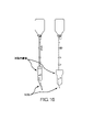
前述のように、システムの中の各種弁(及び/又は止め栓)の位置付け(又は機能―開閉)を示す各種センサは、迂回/調整システムの有無に関係なく、システムにおいて注射器514によって注入された媒体の計測に対処するのに役立つ。又、迂回貯蔵器を持たないシステム(迂回貯蔵器は単なる収集容器又は市販の貯蔵器である)を、迂回組立体502に取り付けできる。このようなシステムは、図11と同様に見え、迂回組立体502貫通管506aからの迂回は、使用者が自身の容器を容易に応用できるように、単純にTコネクタ/止め栓302又はその他の弁機構で終了できる。使用者が利用可能な又は採用できる利用可能な造影剤捕捉貯蔵器に取り付けるための単純なコネクタ(例えば、止め栓)を持つ組立体流体接続ライン906a及び912を有する図15に示す迂回組立体902を、使用できる。図16は、造影剤を捕捉するための市販の貯蔵器並びにこれらの貯蔵器を迂回組立体902に接続するために使用できる接続ラインを示す。これらの構成は、迂回組立体の利点は持つが、計測機能を持たない可能性があることに留意しなければならない。
As previously mentioned, various sensors indicating the positioning (or function—open or closed) of various valves (and/or stopcocks) in the system were injected by
図8及び11に関して論じたように、洗浄信号は、弁AセンサSからモニタ/ディスプレイシステム534へ送信できる。モニタ/ディスプレイシステムは弁B及び止め栓522の位置(センサSを使用して)並びにモニタ注射器514の各種センサ及び/又は迂回貯蔵器504aのセンサからの出力も監視するように構成できる。図13は、迂回貯蔵器を利用するシステムにおいて媒体の計測のために各種センサを利用するシステムを図式的に示す。図13に示すように、注射器の軸線に沿って位置付けられた1つ又は複数のホールセンサを備える注射器514を使用できる。前述のように、ホールセンサは、注射器のハウジング、又は注射器のプランジャに取り付けできる。図13の場合、ホールセンサはプランジャに取り付けられ、磁石は514で示すように注射器のハウジングに位置付けられる。注射器は、又、注射器ホールセンサからディスプレイユニット(これも、BlueTooth(登録商標)通信機能を備える)への情報の転送を調整するためにBlueTooth(登録商標)モジュールを備えることができる。
As discussed with respect to FIGS. 8 and 11, the flush signal can be sent from valve A sensor S to monitor/
注射器514、マニホルド4120及び迂回要素526に流通可能に結合された止め栓又は弁522は、注入器514、迂回弁526及びマニホルド520へ/からの流体の流れの位置付け及び/又は機能と関連付けられるセンサSを持つことができる。センサSは、弁522の回転/位置を検出できる回転センサとすることができる。522のセンサSは、迂回貯蔵器モジュール504aへの電気接続を持つことができ、BlueTooth(登録商標)接続を介してディスプレイ/モニタ200への通信を可能にする。
A stopcock or
カテーテル528を介して患者へ媒体を注入する際、弁522は、造影剤が注入器から迂回要素/弁526を通過して又マニホルド520を通過してカテーテル528へ流れるようにできる。どれだけの容積がマニホルド/患者及び迂回弁526へ(及び迂回ライン506aを通過して)放出されたかを計測できる。止め栓522が迂回弁526に対して閉鎖された場合、522センサSは、例えば注射器514からの注入の計測が行われるべきではないことを示す。この場合、医師は、システムを洗浄するために食塩水貯蔵器(図示せず)から食塩水を取り出すことができるが、造影剤注入として食塩水を処理したくない可能性がある。食塩水貯蔵器及び接続ライン(図示せず)は、典型的に弁A(522A)に接続される。
Upon injecting media into the patient through
造影剤の注入において、迂回ライン506aを通過する媒体の流れは、貯蔵器チェンバ702へ進入できる。迂回貯蔵器モジュール504aは、ホールセンサ718を通じて貯蔵器チェンバ702内の容積変化を計測できる。図示する事例において、ホールセンサは、貯蔵器チェンバのハウジングに取り付けられ、磁石は貯蔵器のプランジャに取り付けられる。但し、前述のように、ホールセンサは、貯蔵器のプランジャ/ピストンの一部分とすることができ、磁石は注入器ハウジングに取り付けるか、これと結合される又はこれに近接できる。迂回モジュールは、分析及び/又は表示のためにモニタ/ディスプレイに情報を転送するためにBlueTooth(登録商標)を備える。
Upon injection of contrast media, media flow through
注射器514からの容積量の変化及び貯蔵器チェンバ702において収集された容積の変化を計測することによって、制御ユニット/ディスプレイは、患者へ(カテーテル528を介して)注入された造影剤の量を計算できる。図13に示すように、迂回ライン506は、媒体が迂回貯蔵器504aへのみ流れられるようにするために一方向逆止め弁を組み込むことができる(迂回弁526の一部として含まれていなくても)。
By measuring the volume change from
注入が完了したら、弁B522Bを開放して、迂回貯蔵器から及び必要であれば(二次的に)染料媒体貯蔵器から造影剤を引き出すことができる。図13に示す事例において、圧力変換器は、止め栓弁B522Bの位置センサとして作用する。媒体を注射器514へ引き入れるために造影剤ライン512が開放されたとき、弁B522Bの圧力センサは、圧力の変化を感知して、迂回貯蔵器及び注射器ホールセンサ要素の両方を起動すべきであることを指示する。弁Bのセンサからの情報は、BlueTooth(登録商標)を介してその状態に関する情報をディスプレイシステムへ転送するために、迂回貯蔵器モジュール504aのBlueTooth(登録商標)要素への電気結合によって結合できる。上述のように、迂回貯蔵器チェンバ702から引き出された媒体は、迂回貯蔵器チェンバ702の中に媒体がある限り、造影剤貯蔵器504から引き出される媒体に先行できる。又、媒体が迂回貯蔵器の方向にのみ流れるようにするために(例えば、弁機構が迂回貯蔵器の一部ではない場合)、造影剤供給ライン506aに沿って一方向弁を取り付けることができる。
Once the injection is complete,
図13は、迂回貯蔵器に関連付けられる「一時停止ボタン」も示す。一時停止ボタンは、使用者が、迂回貯蔵器モジュール504aのBlueTooth(登録商標)と関連付けられるセンサの1つ又は全てによるデータの収集を一時停止するために注入/計測を無効(override)できるようにする。
Figure 13 also shows a "pause button" associated with the bypass reservoir. A pause button allows the user to override injection/metering to pause data collection by one or all of the sensors associated with the BlueTooth® of
図13の説明は、患者へ導入される造影剤の量を減少するために媒体を迂回するシステムに計測を使用するシステムの変形の一例に過ぎない。本発明の主旨から逸脱することなくこの種のシステムを提供する方法が他にもあることは明らかである。例えば、注射器又は迂回貯蔵器のために様々な感知システムを使用できる。又はホールセンサ構成は説明したものとは異なってもよい。 The illustration of FIG. 13 is but one example of a variation of a system that uses metrology to bypass media to reduce the amount of contrast agent introduced into the patient. Clearly, there are other ways of providing such a system without departing from the spirit of the invention. For example, various sensing systems can be used for syringes or bypass reservoirs. Alternatively, the Hall sensor configuration may differ from that described.
更に、回転及び圧力センサを含めて、各種の弁/止め栓の位置的関係を識別するための各種センサ要素について説明した。これらは感知様式においても様々な弁における様々な感知様式の配置においても、限定的であることを意図しない。 Additionally, various sensor elements have been described for identifying various valve/stopcock positional relationships, including rotational and pressure sensors. They are not intended to be limiting either in the sensing modality or in the placement of the various sensing modalities on the various valves.
本明細書における実施例は、患者体内へ注入される造影剤の総量を減少するために造影剤の注入を計測するため並びに媒体を調整/迂回するための各種要素を説明する。説明は、これらの要素を一緒に使用するための各種組合せも含む。各種システムが迂回及び/又は計測の各種要素を含むことが当業者には分かるはずである。これらの組合せの各々は、コンソールまたは同様のディスプレイを含んでも含まなくてもよい。上述のシステムの各種要素の例(完全に包括的であると解釈すべきではないが)は、例えば、迂回弁のみ、貯蔵器と共に迂回弁、貯蔵器及び測定システム/センサと共に迂回弁、及び媒体の調整/迂回無しの計測、を含むことができる。 The examples herein describe various elements for metering contrast injection and adjusting/bypassing media to reduce the total amount of contrast injected into the patient. The description also includes various combinations for using these elements together. Those skilled in the art should appreciate that various systems include various elements of bypass and/or instrumentation. Each of these combinations may or may not include a console or similar display. Examples of the various elements of the system described above (which should not be construed as completely exhaustive) include, for example, bypass valves alone, bypass valves with reservoirs, bypass valves with reservoirs and measurement systems/sensors, and media adjustment/diversion-free metering.
例えば、図14は、患者体内へ注入されている造影剤を計測するためのシステムについて説明する。図示するように、患者体内へ注入されている造影剤を調整又は迂回しようとはしない。計測システムは、ホールセンサ機能を有する514として示すものと同様のものとすることができる。また、モニタ/ディスプレイシステムと接続するためのBlueTooth要素を持つことができる。図示する実施例において、単純な圧力変換器(止め栓位置センサ)は、止め栓弁522Bの位置が開放/閉鎖されたときに指示を出す。開放された場合(造影剤貯蔵器に対する流体接続のみを持つ)、圧力センサは、造影剤が造影剤貯蔵器504から引き出されていることを示す。造影剤貯蔵器504との連絡を遮断するために弁522Bが閉鎖された場合、センサは、もはや造影剤がシステムの中へ(例えば、注射器514によって)引き入れられていないことを示す。更に、このデータは、BlueToothを介して位置センサ出力モジュールからディスプレイコンソールへ送信できる。
For example, FIG. 14 describes a system for measuring contrast agent being injected into a patient. As shown, no attempt is made to modulate or bypass the contrast agent being injected into the patient. The measurement system can be similar to that shown as 514 with Hall sensor functionality. It can also have a BlueTooth component for connecting with a monitor/display system. In the illustrated embodiment, a simple pressure transducer (stopcock position sensor) provides an indication when the position of
上述のように、計測及び/又は調整(迂回)及び/又は再使用のための媒体捕捉の各種構成要素について説明したが、各構成要素は、最終使用者の様々なニーズに対処するために様々に組み合わせて使用できる。好ましい実施形態の付加的例として、図17Aは、図17Bを図式的に示し、この例において、最終使用者は、患者への媒体注入を調整/迂回しかつ注入された媒体の計測を行うことができる。但し、最終使用者は、図13の完全自動化システムのプライム及びパージの努力は空気の注入システムをパージすることを難しくし、多少厄介になると感じる可能性がある。但し、最終使用者が再使用のための貯蔵器媒体ではなく単に迂回媒体を計測する場合には、システムのプライム及びパージは、貯蔵器及び再使用のための注入システムへの戻り導管の洗浄を除外することによって、著しく容易になる可能性がある。図17A及び17Bは、患者への注入量の計測を行い/測定するため並びに最終使用者が食塩水でシステムを洗浄しているときには計測値を無視するために、媒体が注射器によって及び迂回貯蔵器によって計測されるシステムを示す。但し、媒体貯蔵器の中の迂回媒体は、再使用されず(プライム/パージを必要とする貯蔵器再使用導管などの付加的要素をシステムに付加する)、その後注入システムから収集バッグの中へ廃物として排出される。カテ室時間及び人員に比べて注入造影剤が相対的に安価な場合があるので、使用者によっては、再使用のために媒体を捕捉することより迂回媒体を廃棄することを好むかも知れない。 While various components of media capture for metering and/or adjustment (diversion) and/or reuse have been described above, each component may vary to address different end user needs. can be used in combination with As an additional example of a preferred embodiment, FIG. 17A diagrammatically illustrates FIG. 17B, in which the end user can adjust/bypass media injection into the patient and perform metering of the injected media. can be done. However, the end user may find the priming and purging efforts of the fully automated system of FIG. 13 difficult and somewhat cumbersome to purge the air injection system. However, if the end user is simply metering bypass media rather than reservoir media for reuse, priming and purging the system may require cleaning of the reservoir and the return conduit to the injection system for reuse. Exclusion can make it significantly easier. Figures 17A and 17B show that the medium is dispensed by the syringe and the bypass reservoir to take/measure patient infusion volume and to ignore the metering when the end user is flushing the system with saline. shows a system that is instrumented by However, the bypass media in the media reservoir is not reused (adding additional elements to the system such as reservoir reuse conduits that require priming/purging) and then exits the injection system into the collection bag. Discharged as waste. Some users may prefer to discard bypass media rather than capture media for reuse, as injected contrast may be relatively inexpensive compared to cath lab time and personnel.
図17A及び17Bに示すように、造影剤ラインは、食塩水媒体容器から直接(又は図15及び16に関して前に論じたように食塩水貯蔵器からのライン)は、マニホルド1020まで延びる。造影剤ラインは、造影剤が造影剤ラインから引き出されるときにこれを指示するために圧力変換器などの位置センサを持つことができる。逆に、計測自動化が好ましいとき、位置センサ(図示せず)は、トグルの状態に関連付けられる位置センサを持つトグル(造影剤導管のオン/オフのため)を含めるようにマニホルドと造影剤ラインの接続部に応用できる、図17A及び17Bに示すように、注射器1024は、注入のために流体をそのチェンバの中へ引き入れることができる。ON/OFFトグル弁を迂回弁1026に対して開いて、注射器1014から患者へ注入されると、媒体は、送達導管(図示せず)を介して患者へ注入され、かつ注入の一部分は、患者へ(例えば、送達カテーテルを介して)実際に送達される注入媒体を調整/変更するために、迂回弁1026を介して迂回される。計測自動化が好ましい場合、注入器及び貯蔵器は、注入器から放出され貯蔵器に受け入れられた媒体の量を測定して、患者へ送達された媒体の量を測定するために、計測要素を含むことができる。図示するように、貯蔵器、迂回ライン及び収集(廃物)バッグの間に二重又は交互逆止め弁を配置できる。作動時に、二重/交互逆止め弁は、流体を迂回貯蔵器へ迂回できるようにし、その後(貯蔵器チェンバ内の圧力で)注入(注入器からの)が停止するとき又はON/OFFトグルスイッチが閉鎖される場合、流体を収集バックへ向けることができようにする。
As shown in FIGS. 17A and 17B, contrast agent lines run directly from the saline media container (or lines from the saline reservoir as previously discussed with respect to FIGS. 15 and 16) to
図18A及び18Bには、注入が注入器(図18Aには図示せず)から交互迂回弁#1又は#2へかつこれらを通過して迂回される(トグル又は止め栓を使用して迂回流路を開放する)別の実施形態を示す。図18Bに示すように、迂回止め栓は、二重迂回弁装置への迂回を可能にでき、二重迂回弁装置は、流れを2つの交互迂回弁へ向けるための弁を備える。2つの弁(したがって2つの迂回プロフィル)を図示するが、多数の使用者の好みに対処するためには多数(例えば、3、4又はそれ以上)の迂回弁が有利な場合がある。ここで論じる弁は、平行に構成されるものとして図示され説明される。しかし、数個の弁を直列に整列して同じ正味成果を得ることができることが、当業者には分かるはずである。前述の迂回弁は、比較的一定の流れの患者への注入を維持するために、注入された流体の一部分の迂回を調節しながら、注入器から多様な送達導管を通過する多様な注入に対処できる。このような事例において、上述のように、迂回弁は、注入される流体の様々な流量/圧力を調節し、迂回弁は、迂回弁における圧力を増大して迂回に対する抵抗を相対的に増大することによって、患者への流量を調節する。但し、このような構成は、注入器からの圧力/流量に大きな差がある状況又は大きい差を持つ速度で流体を送達するために操作使用に大きな差がある状況、又は患者への送達導管が構造及び/構成的に大きく異なる注入システムを介する場合に、充分に対処できない。
In Figures 18A and 18B, the injection is diverted from the injector (not shown in Figure 18A) to and through alternate
図18A及び18Dに示すような迂回システムの様々な使用例は、例えば、8F送達カテーテル対4F送達カテーテルによる流体の送達など送達導管の寸法に大きな差がある、1つの部位へ媒体を送達しその後第2の部位へ送達し、心臓への注入対末梢血管部位への注入又は大きい冠状動脈(RCA)対別の大きい冠状動脈(左主冠状、左冠状動脈及び/又は左回旋動脈)への注入など、それぞれの部位において患者への予定の注入(例えば、流量及び/又は圧力)が大きく異なる、及び注射器が定流量及び/又は定圧力(注射器より小さい変化)を維持するが、自動化されたパワーインジェクタ(図18B)を使用する際に見られるように異なる脈管部位を評価するために注入流量/圧力の調節を必要とする、などを含む。 Various uses of diversion systems, such as those shown in FIGS. Delivery to a second site and infusion into the heart versus injection into a peripheral vascular site or injection into a large coronary artery (RCA) versus another large coronary artery (left main coronary, left coronary and/or left circumflex artery) E.g., the scheduled infusion (e.g., flow rate and/or pressure) to the patient at each site varies greatly, and the syringe maintains a constant flow rate and/or constant pressure (change less than the syringe), but the automated power including requiring adjustment of injection flow/pressure to evaluate different vessel sites as seen when using an injector (FIG. 18B).
図18Aは、2つの別個の迂回弁及び逆止め弁(指向性の流体流量を維持するために)を有する迂回を示す。この例において、迂回された過剰な流体は、収集バッグ/貯蔵器に廃棄される(再使用のために捕捉されず)。図18Bは、更に、迂回弁にアクセスための迂回止め栓を示し、更に、2つの異なる迂回弁によって生じる異なる迂回プロフィルにアクセスするための別個トグルを持つ単一の装置に取り付けられた2つの迂回弁を示す。 FIG. 18A shows a bypass with two separate bypass and check valves (to maintain directional fluid flow). In this example, the diverted excess fluid is discarded (not captured for reuse) in a collection bag/reservoir. FIG. 18B further shows a bypass stopcock for accessing the bypass valves, and two bypasses attached to a single device with separate toggles for accessing the different bypass profiles produced by the two different bypass valves. Show valve.
図18A及び18Bには示さないが、前述の各種位置センサ(トグル、流量センサ、圧力変換器又は各種導管及び流体ラインの状態を測定できるその他の任意のセンサ)のいずれでも、注入システムの計測の自動化に利用できる。図18Bに示すようなパワーインジェクタの使用時に、典型的には、様々な脈管部位への注入のために注入のセッティングを最終使用者に変更させる。例えば、最終使用者は、右冠状動脈(RCA)への注入には1つの定流量/圧力を選択し、左冠状動脈(LCA)への注入には別の流量/圧力を選択するかも知れない。流量/圧力が2つの部位の間で著しく異なる場合、最終使用者は、迂回弁#1と#2との間で切り替えて、各部位に対処するために異なる迂回プロフィルを設定できる。
Although not shown in FIGS. 18A and 18B, any of the various position sensors previously described (toggles, flow sensors, pressure transducers, or any other sensor capable of measuring the condition of the various conduits and fluid lines) can be used to measure the infusion system. Available for automation. When using a power injector such as that shown in FIG. 18B, typically the end user will be allowed to change the injection settings for injection into various vascular sites. For example, the end user may select one constant flow/pressure for injection into the right coronary artery (RCA) and another flow/pressure for injection into the left coronary artery (LCA). . If the flow/pressure is significantly different between the two sites, the end user can switch between
また、迂回貯蔵器計測システム及び注入器計測システムについて本明細書において説明するものなど、任意の計測装置を、患者へ送達された流体の計測を自動化するために採用できる。更に、パワーインジェクタが注入器から放出された流体を計測するためのシステムを持つ場合、患者へ注入された媒体の計測を自動化するために、注入器及び迂回貯蔵器の貯蔵器計測装置(上述の)からのデータ収集を調整すると有利である。 Also, any metering device, such as those described herein for the bypass reservoir metering system and the injector metering system, can be employed to automate the metering of fluid delivered to the patient. Additionally, if the power injector has a system for metering the fluid emitted from the injector, the injector and bypass reservoir reservoir metering devices (see above) may be used to automate metering of the injected medium into the patient. ) to coordinate the collection of data from.
本明細書において、本テクノロジーの代表的かつ好ましい実施形態と考えられるものについて説明したが、本テクノロジーの他の修正が、本明細書の教示から当業者には明らかになるだろう。本明細書において開示する特定の製造方法及び形状は、性質上代表的なものであり、限定的であると見なされるべきではない。したがって、本テクノロジーの主旨及び範囲に属するあらゆる修正が保証されることが好ましい。したがって、特許証によって保証されることを望むものは、本明細書において規定及び区別される通りのテクノロジー及びその全ての同等物である。
本開示のある態様は、送達導管を介する患者体内への流体の注入を監視する方法において、前記方法が、注入装置と関連付けられた注入センサから連続的注入信号を受信する段階であって、前記注入装置が、前記送達導管の中へ前記流体を注入するように構成される、受信する段階と、貯蔵器と関連付けられた迂回貯蔵器センサから迂回貯蔵器信号を受信する段階であって、前記貯蔵器が、迂回導管を介して前記送達導管から前記流体の一部分を受け取るように構成される、受信する段階と、少なくとも部分的に前記連続的注入信号及び前記迂回貯蔵器信号に基づいて、患者へ注入された前記流体の容積を自動的かつ連続的に計算する段階とを含む、方法であり得る。
本開示のある態様において、前記方法が、更に、記迂回導管を前記送達導管と選択的に係合するように構成された迂回弁と関連付けられた迂回弁センサから連続的迂回弁信号を受信する段階を含み、前記患者へ注入された前記流体の容積を自動的かつ連続的に計算する段階が、更に、少なくとも部分的に前記連続的迂回弁信号に基づいてもよい。
本開示のある態様において、前記方法が、更に、食塩水洗浄弁と関連付けられた食塩水洗浄弁位置センサから食塩水洗浄信号を受信する段階を含み、前記食塩水洗浄弁が、食塩水洗浄液源を前記送達導管と選択的に係合するように構成されてもよい。
本開示のある態様において、前記患者へ注入された前記流体の前記容積を自動的かつ連続的に計算する段階が、更に少なくとも部分的に前記食塩水洗浄信号に基づいてもよい。
本開示のある態様において、前記方法が、更に、前記食塩水洗浄信号を受信したら患者へ注入された前記流体の前記容積の前記自動的かつ連続的計算を一時停止する段階とを含んでもよい。
本開示のある態様において、前記方法が、更に、前記患者体内へ注入された前記流体の前記容積を表示する段階を含んでもよい。
本開示のある態様において、前記迂回貯蔵器センサがホールセンサモジュールを備えてもよい。
本開示のある態様において、前記迂回弁センサが止め栓位置センサを含んでもよい。
本開示のある態様において、前記注入センサが、前記注入装置の第1部分に配置されたホールセンサと前記注入装置の第2部分に配置された磁石とを備えるホールセンサモジュールを備えてもよい。
本開示のある態様において、前記食塩水洗浄弁位置センサがオン/オフセンサを備えてもよい。
While what are considered to be representative and preferred embodiments of the technology have been described herein, other modifications of the technology will become apparent to those skilled in the art from the teachings herein. The specific manufacturing methods and geometries disclosed herein are representative in nature and should not be considered limiting. Therefore, any modifications that come within the spirit and scope of the technology are preferably warranted. Accordingly, what is desired to be secured by Letters Patent is the technology as defined and distinguished herein and all equivalents thereof.
An aspect of the present disclosure is a method of monitoring infusion of fluid into a patient through a delivery conduit, said method receiving a continuous infusion signal from an infusion sensor associated with an infusion device, said an infusion device configured to inject the fluid into the delivery conduit; receiving a bypass reservoir signal from a bypass reservoir sensor associated with a reservoir; receiving, wherein a reservoir is configured to receive a portion of the fluid from the delivery conduit via a bypass conduit; and based at least in part on the continuous infusion signal and the bypass reservoir signal, patient and automatically and continuously calculating the volume of said fluid injected into.
In certain aspects of the present disclosure, the method further receives a continuous bypass valve signal from a bypass valve sensor associated with a bypass valve configured to selectively engage the bypass conduit with the delivery conduit. The step of automatically and continuously calculating the volume of the fluid infused into the patient, including the step of, may be further based at least in part on the continuous bypass valve signal.
In some aspects of the present disclosure, the method further includes receiving a saline flush signal from a saline flush valve position sensor associated with the saline flush valve, wherein the saline flush valve is a source of saline flush fluid. may be configured to selectively engage the delivery conduit.
In certain aspects of the present disclosure, automatically and continuously calculating the volume of the fluid infused into the patient may be further based at least in part on the saline wash signal.
In certain aspects of the present disclosure, the method may further comprise suspending the automatic and continuous calculation of the volume of the fluid infused into the patient upon receipt of the saline flush signal.
In some aspects of the present disclosure, the method may further comprise displaying the volume of the fluid infused into the patient.
In some aspects of the present disclosure, the bypass reservoir sensor may comprise a Hall sensor module.
In some aspects of the present disclosure, the bypass valve sensor may include a stopcock position sensor.
In some aspects of the present disclosure, the injection sensor may comprise a Hall sensor module comprising a Hall sensor located in a first portion of the injection device and a magnet located in a second portion of the injection device.
In some aspects of the present disclosure, the saline flush valve position sensor may comprise an on/off sensor.
Claims (13)
貯蔵器と、
流体注入装置であって、
患者体内へ挿入して患者体内へ流体を送達するための送達導管と、
前記送達導管に注入器を流通可能に結合する注入流体経路を介して患者体内へ流体を注入するための注入器と、
前記送達導管と前記注入器との間に配置されたダイバータ組立体であって、前記ダイバータ組立体は、迂回止め栓と、少なくとも2つの迂回弁とを備え、前記迂回止め栓は、前記注入器と前記送達導管との間の注入流体経路からの流体の第1の部分を前記少なくとも2つの迂回弁の一方へと方向付け、前記ダイバータ組立体は、前記注入流体経路からの流体の少なくとも第1の部分を受け取るように構成され、前記ダイバータ組立体が前記貯蔵器に流通可能に結合され、前記ダイバータ組立体は、前記注入流体経路の圧力及び流量の少なくとも一方に基づいて、少なくとも前記貯蔵器へ向けた流体の前記第1の部分及び患者へ向けた流体の第2の部分の同時送達ができるように構成される、ダイバータ組立体と、
前記注入器を前記ダイバータ組立体及び前記送達導管に流通可能に結合するコネクタとを備える流体注入装置と、
計測自動化装置であって、
前記注入器からの容積排出を測定するためのデータを生成するように構成される、注入器センサモジュールと、
前記貯蔵器内の容積排出を測定するためのデータを生成するように構成される、貯蔵器センサモジュールと、
前記注入器センサモジュールによって生成された前記データ及び前記貯蔵器センサモジュールによって生成された前記データを受信して、患者へ送達された流体の量を測定するように構成されたプロセッサであって、前記注入器センサモジュールによって生成された前記データは、前記注入器の容積の変化を含み、かつ、前記貯蔵器センサモジュールによって生成された前記データは、前記貯蔵器の容積の変化を含み、患者へ送達された流体の量は、前記注入器の容積の変化から前記貯蔵器の容積の変化を引いた量を含む、プロセッサと、
患者へ送達された流体の量を表示するために前記プロセッサに作動上結合されたディスプレイとを備える、計測自動化装置とを備える、システム。 A system for automating the measurement of fluid injected into a patient using a fluid injection device, the system comprising:
a reservoir;
A fluid injection device comprising:
a delivery conduit for insertion into a patient to deliver fluid into the patient;
an injector for infusing fluid into a patient via an infusion fluid pathway fluidly coupling the injector to the delivery conduit;
A diverter assembly disposed between the delivery conduit and the injector, the diverter assembly comprising a bypass plug and at least two bypass valves, the bypass plug and the delivery conduit through one of the at least two bypass valves, the diverter assembly directing at least a first portion of fluid from the infusion fluid path wherein the diverter assembly is fluidly coupled to the reservoir, the diverter assembly diverting pressure to at least the reservoir based on at least one of pressure and flow in the infusion fluid path. a diverter assembly configured for simultaneous delivery of the first portion of fluid directed and the second portion of fluid directed to a patient ;
a fluid injection device comprising a connector fluidly coupling the injector to the diverter assembly and the delivery conduit;
A measurement automation device,
an injector sensor module configured to generate data for measuring volumetric discharge from the injector;
a reservoir sensor module configured to generate data for measuring volumetric discharge in the reservoir;
a processor configured to receive the data generated by the injector sensor module and the data generated by the reservoir sensor module to determine an amount of fluid delivered to a patient ; wherein the data generated by the injector sensor module includes changes in the volume of the injector; and the data generated by the reservoir sensor module includes changes in the volume of the reservoir; a processor, wherein the amount of fluid delivered to comprises a change in volume of said injector minus a change in volume of said reservoir ;
and a display operatively coupled to said processor for displaying the amount of fluid delivered to a patient.
Applications Claiming Priority (3)
| Application Number | Priority Date | Filing Date | Title |
|---|---|---|---|
| US201762527919P | 2017-06-30 | 2017-06-30 | |
| US62/527,919 | 2017-06-30 | ||
| PCT/US2018/040514 WO2019006432A1 (en) | 2017-06-30 | 2018-06-30 | Medium injection diversion and measurement |
Publications (3)
| Publication Number | Publication Date |
|---|---|
| JP2020526280A JP2020526280A (en) | 2020-08-31 |
| JP2020526280A5 JP2020526280A5 (en) | 2021-08-05 |
| JP7200146B2 true JP7200146B2 (en) | 2023-01-06 |
Family
ID=62976356
Family Applications (1)
| Application Number | Title | Priority Date | Filing Date |
|---|---|---|---|
| JP2019572467A Active JP7200146B2 (en) | 2017-06-30 | 2018-06-30 | Injection, bypass and metering of media |
Country Status (5)
| Country | Link |
|---|---|
| EP (1) | EP3645076A1 (en) |
| JP (1) | JP7200146B2 (en) |
| AU (1) | AU2018291037A1 (en) |
| MA (1) | MA49507A (en) |
| WO (1) | WO2019006432A1 (en) |
Families Citing this family (1)
| Publication number | Priority date | Publication date | Assignee | Title |
|---|---|---|---|---|
| EP4313209A1 (en) * | 2021-03-26 | 2024-02-07 | Osprey Medical, Inc. | Modulated power injector with input device |
Citations (3)
| Publication number | Priority date | Publication date | Assignee | Title |
|---|---|---|---|---|
| JP2009516577A (en) | 2005-11-21 | 2009-04-23 | アシスト・メディカル・システムズ・インコーポレーテッド | Medical fluid injection system |
| JP2015526243A (en) | 2012-08-28 | 2015-09-10 | オスプレイ メディカル インコーポレイテッド | Device for coordinating vehicle delivery |
| US20160213834A1 (en) | 2012-08-28 | 2016-07-28 | Osprey Medical, Inc. | Volume monitoring systems |
Family Cites Families (1)
| Publication number | Priority date | Publication date | Assignee | Title |
|---|---|---|---|---|
| US7094216B2 (en) * | 2000-10-18 | 2006-08-22 | Medrad, Inc. | Injection system having a pressure isolation mechanism and/or a handheld controller |
-
2018
- 2018-06-30 WO PCT/US2018/040514 patent/WO2019006432A1/en active Application Filing
- 2018-06-30 MA MA049507A patent/MA49507A/en unknown
- 2018-06-30 JP JP2019572467A patent/JP7200146B2/en active Active
- 2018-06-30 EP EP18743353.7A patent/EP3645076A1/en active Pending
- 2018-06-30 AU AU2018291037A patent/AU2018291037A1/en not_active Abandoned
Patent Citations (3)
| Publication number | Priority date | Publication date | Assignee | Title |
|---|---|---|---|---|
| JP2009516577A (en) | 2005-11-21 | 2009-04-23 | アシスト・メディカル・システムズ・インコーポレーテッド | Medical fluid injection system |
| JP2015526243A (en) | 2012-08-28 | 2015-09-10 | オスプレイ メディカル インコーポレイテッド | Device for coordinating vehicle delivery |
| US20160213834A1 (en) | 2012-08-28 | 2016-07-28 | Osprey Medical, Inc. | Volume monitoring systems |
Also Published As
| Publication number | Publication date |
|---|---|
| JP2020526280A (en) | 2020-08-31 |
| AU2018291037A1 (en) | 2019-12-12 |
| EP3645076A1 (en) | 2020-05-06 |
| WO2019006432A1 (en) | 2019-01-03 |
| MA49507A (en) | 2020-05-06 |
Similar Documents
| Publication | Publication Date | Title |
|---|---|---|
| US11135375B2 (en) | Volume monitoring systems | |
| US11116892B2 (en) | Medium injection diversion and measurement | |
| US20150202386A1 (en) | Volume monitoring device utilizing hall sensor-based systems | |
| US7617837B2 (en) | Low pressure measurement devices in high pressure environments | |
| US9999718B2 (en) | Volume monitoring device utilizing light-based systems | |
| AU2015231365B2 (en) | Syringe with optical system for monitoring the position of the plunger rod | |
| JP2008543502A (en) | Medical fluid injection and inflation system | |
| US20150202361A1 (en) | Devices and methods for modulating medium delivery | |
| EP3277342B1 (en) | Syringe volume monitoring systems with hall sensor | |
| US20140066860A1 (en) | Volume monitoring device | |
| JP7200146B2 (en) | Injection, bypass and metering of media | |
| US20220168498A1 (en) | Medium injection diversion and measurement | |
| US20210018348A1 (en) | Systems and methods for measuring injected fluids | |
| AU2016242924B2 (en) | Devices and methods for modulating medium delivery | |
| EP3035986B1 (en) | Volume monitoring device |
Legal Events
| Date | Code | Title | Description |
|---|---|---|---|
| A521 | Request for written amendment filed |
Free format text: JAPANESE INTERMEDIATE CODE: A523 Effective date: 20210624 |
|
| A621 | Written request for application examination |
Free format text: JAPANESE INTERMEDIATE CODE: A621 Effective date: 20210624 |
|
| A977 | Report on retrieval |
Free format text: JAPANESE INTERMEDIATE CODE: A971007 Effective date: 20220414 |
|
| A131 | Notification of reasons for refusal |
Free format text: JAPANESE INTERMEDIATE CODE: A131 Effective date: 20220510 |
|
| A601 | Written request for extension of time |
Free format text: JAPANESE INTERMEDIATE CODE: A601 Effective date: 20220808 |
|
| A521 | Request for written amendment filed |
Free format text: JAPANESE INTERMEDIATE CODE: A523 Effective date: 20221104 |
|
| TRDD | Decision of grant or rejection written | ||
| A01 | Written decision to grant a patent or to grant a registration (utility model) |
Free format text: JAPANESE INTERMEDIATE CODE: A01 Effective date: 20221122 |
|
| A61 | First payment of annual fees (during grant procedure) |
Free format text: JAPANESE INTERMEDIATE CODE: A61 Effective date: 20221221 |
|
| R150 | Certificate of patent or registration of utility model |
Ref document number: 7200146 Country of ref document: JP Free format text: JAPANESE INTERMEDIATE CODE: R150 |