JP7040887B2 - Waterless planographic printing for seamless cans and its manufacturing method - Google Patents
Waterless planographic printing for seamless cans and its manufacturing method Download PDFInfo
- Publication number
- JP7040887B2 JP7040887B2 JP2016196580A JP2016196580A JP7040887B2 JP 7040887 B2 JP7040887 B2 JP 7040887B2 JP 2016196580 A JP2016196580 A JP 2016196580A JP 2016196580 A JP2016196580 A JP 2016196580A JP 7040887 B2 JP7040887 B2 JP 7040887B2
- Authority
- JP
- Japan
- Prior art keywords
- silicone rubber
- plate
- laser
- seamless
- rubber layer
- Prior art date
- Legal status (The legal status is an assumption and is not a legal conclusion. Google has not performed a legal analysis and makes no representation as to the accuracy of the status listed.)
- Active
Links
Images


Landscapes
- Manufacture Or Reproduction Of Printing Formes (AREA)
- Printing Plates And Materials Therefor (AREA)
- Exposure And Positioning Against Photoresist Photosensitive Materials (AREA)
Description
本発明は、シームレス缶用水なし平版及びその製造方法に関するものであり、より詳細には、地汚れの発生が抑制され、画像の再現性に優れていると共に、耐刷性にも優れたシームレス缶用水なし平版及びその製造方法に関する。 The present invention relates to a waterless lithographic plate for a seamless can and a method for manufacturing the same. More specifically, the present invention is a seamless can in which the generation of background stains is suppressed, the image reproducibility is excellent, and the printing resistance is also excellent. Regarding waterless planographic printing and its manufacturing method.
飲料等に用いられるシームレス缶のような円筒形状容器の胴部への曲面印刷には、刷版と、刷版からインキ層を受領してこれを缶体胴部に転写させるためのブランケットとの組み合わせが使用されており、刷版として平版や凸版が使用されている。
刷版として凸版を用いる印刷方式、すなわち凸版ドライオフセット方式では、画線部や網点部の太りが大きいため、文字や網点画像の潰れが発生し、また網点のスクリーン線数が120線程度と低く、網点画像のざらつきや網点相互の干渉による縞模様或いはローゼット模様が目立ち、十分な印刷品質を得ることが難しかった。
For curved surface printing on the body of a cylindrical container such as a seamless can used for beverages, a printing plate and a blanket for receiving an ink layer from the printing plate and transferring it to the body of the can are used. Combinations are used, and planographic and letterpress plates are used as printing plates.
In the printing method using a letterpress as a printing plate, that is, the letterpress dry offset method, since the image lines and halftone dots are thick, characters and halftone dots are crushed, and the number of halftone dots is 120 lines. The degree was low, and the graininess of the halftone dot image and the striped pattern or rosette pattern due to the interference between the halftone dots were conspicuous, and it was difficult to obtain sufficient print quality.
一方、平版を用いるオフセット印刷では、親油性のインキ受領面と親水性の非画像面を備えた刷版を用い、インキを転移させるのに先立って、刷版に湿し水を施すのが一般的であり、上記凸版を用いた印刷方式に比して加飾性に優れた画像を形成することができる。しかしながら、この湿し水の使用はインキが広がりにくく、冷却効果があるなどの利点を有する反面、水が混入してインキが乳化する、画像に滲みが出る等の欠点を生じやすいと共に、インカーユニットが大型化する、印刷スピードが出にくいなどの欠点を有していた。 On the other hand, in offset printing using lithographic printing, it is common to use a printing plate having a lipophilic ink receiving surface and a hydrophilic non-image surface, and to apply dampening water to the printing plate prior to transferring the ink. This is a target, and it is possible to form an image having excellent decorativeness as compared with the printing method using the above-mentioned letterpress. However, the use of this dampening water has the advantages that the ink does not spread easily and has a cooling effect, but on the other hand, it tends to cause drawbacks such as water mixing and emulsification of the ink and blurring of the image, and the inker unit. However, it had drawbacks such as an increase in size and difficulty in printing speed.
このような観点から、湿し水を用いない、水なし平版が実用化されている。水なし平版とは、平面にインキ受容部とインキ非受容部とが形成され、インキ非受容部が湿し水の塗布なしに形成されるものであり、具体的には、湿し水を受容する親水性表面に代えて、インキ反発面となるシリコーンゴム等の非粘着性皮膜が使用され、非粘着性皮膜が取り除かれた部分がインク受容部になる。フィルムの画像部(マスキングされた部分)がインキ受容部になるポジフィルムタイプと、フィルムの非画像部がインキ受容部となるネガフィルムタイプとがある(特許文献1)。シームレス缶印刷では耐久性がよりよいためポジフィルムタイプが一般に使用されている。 From this point of view, waterless lithographic printing without using dampening water has been put into practical use. In the waterless slab, an ink receiving portion and an ink non-receptive portion are formed on a flat surface, and the ink non-receptive portion is formed without applying dampening water. Specifically, the dampening water is received. A non-adhesive film such as silicone rubber, which is an ink repellent surface, is used instead of the hydrophilic surface, and the portion from which the non-adhesive film is removed becomes an ink receiving portion. There are a positive film type in which the image portion (masked portion) of the film serves as an ink receiving portion and a negative film type in which the non-image portion of the film serves as an ink receiving portion (Patent Document 1). Positive film type is commonly used for seamless can printing because of its better durability.
シームレス缶の印刷において、刷版はブランケットに高速で接触し、且つ大量に印刷することから版の摩耗が激しく、版の摩耗により非画線部に地汚れが発生したタイミングで、版を交換する必要が生じるが、特に水なし平版においては、シリコーン層が薄いことから、耐刷性(耐久性)の点で未だ十分満足するものではなかった。その一方、耐刷性を向上するためにシリコーン層の厚みを厚くしてしまうと、小さい網点では網点が消えてしまうという問題が生じてしまう。
また、水なし平版において、フィルムでマスキングされた部分がインキ受容部(画像)となるポジフィルムタイプでは、静電気等によりフィルムに埃等の異物が付着した場合に、異物部分が画像(不要画像)になって目立ってしまうという問題があり、この問題を解決するには、異物の付着を予防する以外になかった。更にポジフィルムタイプの水なし平版では、露光時に光の回り込みがあるため、小さい網点では消えてしまうという問題があった。
In seamless can printing, the printing plate comes into contact with the blanket at high speed, and since a large amount of printing is performed, the plate is heavily worn, and the plate is replaced when the non-image area becomes dirty due to the wear of the plate. Although it is necessary, especially in the waterless lithographic plate, the silicone layer is thin, so that the printing durability (durability) is not yet sufficiently satisfied. On the other hand, if the thickness of the silicone layer is increased in order to improve the printing durability, there arises a problem that the halftone dots disappear in the case of small halftone dots.
In the positive film type where the part masked by the film is the ink receiving part (image) in the waterless flat plate, when foreign matter such as dust adheres to the film due to static electricity etc., the foreign matter part becomes an image (unnecessary image). There was a problem that it became conspicuous, and the only way to solve this problem was to prevent the adhesion of foreign matter. Further, in the positive film type waterless lithographic plate, there is a problem that light wraps around at the time of exposure, so that it disappears at small halftone dots.
従って本発明の目的は、高速での大量印刷が必要なシームレス缶用の印刷に用いられる水なし平版であって、地汚れの発生が抑制され、小さな網点による鮮明な画像の形成が可能であると共に、耐刷性にも優れたシームレス缶用水なし平版及びその製造方法を提供することである。 Therefore, an object of the present invention is a waterless lithographic plate used for printing for seamless cans that require mass printing at high speed, and it is possible to suppress the generation of background stains and to form a clear image with small halftone dots. At the same time, it is to provide a waterless planographic plate for seamless cans having excellent printing resistance and a method for manufacturing the same.
本発明によれば、シームレス缶の外面に印刷を施すための水なし平版であって、少なくとも基板、レーザ感熱層を有し、該感熱層上にシリコーンゴム層から成る非画線部及び該
シリコーンゴムが除去された画線部が形成されており、前記非画線部のシリコーンゴム層の厚みが3.3~4.3μmの範囲にあることを特徴とするシームレス缶用水なし平版が提供される。
本発明のシームレス缶用水なし平版においては、
1.前記基板、レーザ感熱層及びシリコーンゴム層を貫通するピン穴が形成されていること、
2.前記ピン穴が版の少なくとも一つの端縁付近に2つ形成されており、一方のピン穴が円形であり、他方のピン穴が矩形又は略楕円状であること、
が好適である。
According to the present invention, it is a waterless flat plate for printing on the outer surface of a seamless can, has at least a substrate and a laser heat-sensitive layer, and has a non-image portion made of a silicone rubber layer on the heat-sensitive layer and the silicone. Provided is a waterless flat plate for a seamless can, characterized in that an image portion from which rubber has been removed is formed, and the thickness of the silicone rubber layer of the non-image portion is in the range of 3.3 to 4.3 μm. Will be done.
In the waterless planographic plate for seamless cans of the present invention,
1. 1. A pin hole is formed that penetrates the substrate, the laser heat-sensitive layer, and the silicone rubber layer.
2. 2. Two pin holes are formed near at least one edge of the plate, one pin hole is circular, and the other pin hole is rectangular or substantially elliptical.
Is preferable.
本発明によればまた、シームレス缶の外面に印刷を施すための水なし平版の製造方法であって、少なくとも基板、レーザ感熱層及びシリコーンゴム層から成り、該シリコーンゴム層の厚みが3.3~4.3μmの範囲にある原版に、レーザを照射した後、レーザが照射された部分のシリコーンゴム層を除去することにより画線部を形成することを特徴とするシームレス缶用水なし平版の製造方法が提供される。
本発明のシームレス缶用水なし平版の製造方法においては、
1.前記基板、レーザ感熱層及びシリコーンゴム層を貫通するピン穴が形成された原版を、前記原版のピン穴に嵌合可能な複数個のピンを有する平面状の露光台上に載置すると共に、ピンをピン穴に嵌合させて原版を露光台上に固定した後、前記露光台の進行方向に対して直角方向に走査するレーザを用いて、原版にレーザを照射すること、
2.前記露光台に形成された複数個のピンが、ピンの軸方向に上下動可能であり、載置する原版の大きさに合わせてピンを組み合わせで使用すること、
3.前記露光台がバキューム機構を有し、前記原版が露光台に吸引固定されていること、
4.前記シリコーンゴム層のレーザ照射された部分の除去を、ブラシを用いた摺擦により行うこと、
5.前記シリコーンゴム層のレーザ照射された部分を除去することにより画線部を形成する現像工程の前後に、シリコーンゴム層のレーザ照射された部分を脆弱化させる前処理工程、及びシリコーンゴム層が除去された画線部を着色する後処理工程、を有すること、
が好適である。
According to the present invention, it is also a method for manufacturing a waterless flat plate for printing on the outer surface of a seamless can, which comprises at least a substrate, a laser heat-sensitive layer and a silicone rubber layer, and the thickness of the silicone rubber layer is 3.3 . A waterless flat plate for seamless cans, characterized in that an image portion is formed by irradiating an original plate in the range of ~ 4.3 μm with a laser and then removing the silicone rubber layer of the portion irradiated with the laser. A manufacturing method is provided.
In the method for producing a waterless planographic plate for a seamless can of the present invention,
1. 1. The original plate having pin holes penetrating the substrate, the laser heat sensitive layer, and the silicone rubber layer is placed on a flat exposure table having a plurality of pins that can be fitted into the pin holes of the original plate. After fitting the pin into the pin hole and fixing the original plate on the exposure table, irradiate the original plate with the laser using a laser that scans in the direction perpendicular to the traveling direction of the exposure table.
2. 2. A plurality of pins formed on the exposure table can be moved up and down in the axial direction of the pins, and the pins should be used in combination according to the size of the original plate to be mounted.
3. 3. The exposure table has a vacuum mechanism, and the original plate is suction-fixed to the exposure table.
4. The laser-irradiated portion of the silicone rubber layer is removed by rubbing with a brush.
5. Before and after the development step of forming the image area by removing the laser-irradiated portion of the silicone rubber layer, the pretreatment step of weakening the laser-irradiated portion of the silicone rubber layer and the removal of the silicone rubber layer. Having a post-treatment step, which colors the finished image area,
Is preferable.
本発明の水なし平版においては、非画線部を構成するシリコーンゴム層の厚みが2.2~5.5μmの範囲にあることによって、画線部を構成する網点の形成に支障を与えることなく、耐刷性を向上することができ、高速で大量印刷されるシームレス缶への印刷に長期にわたって効率よく使用することができる。
また画線部がレーザにより網点が小さく鮮明に形成されていることから、凸版を用いる印刷方式は勿論、従来のポジフィルムタイプの水なし平版による印刷に比して、文字や網点画像を鮮明に印刷することができ、特にグラデーション印刷におけるハイライト部分をも鮮明に印刷することができる。また、スクリーン線数を175Lpi以上の高密度にすることができる。
更に本発明の水なし平版においては、従来のポジフィルムタイプの水なし平版のように、フィルムを使用しないので、フィルムに埃等の異物が付着することを予防する必要がなく、シリコーンゴム層に異物が付着した場合でも、シリコーンゴム層は非画線部であるので、印刷画像に影響を与えることがない。
In the waterless lithographic plate of the present invention, the thickness of the silicone rubber layer constituting the non-image portion is in the range of 2.2 to 5.5 μm, which hinders the formation of halftone dots constituting the image portion. The printing durability can be improved without any problem, and it can be efficiently used for a long period of time for printing on seamless cans which are mass-printed at high speed.
In addition, since the halftone dots are clearly formed by the laser in the image area, characters and halftone dots are printed compared to the conventional positive film type waterless lithographic printing method as well as the printing method using letterpress. It is possible to print clearly, and especially the highlight part in gradation printing can be printed clearly. In addition, the number of screen lines can be increased to a high density of 175 Lpi or more.
Further, in the waterless lithographic plate of the present invention, unlike the conventional positive film type waterless lithographic plate, no film is used, so that it is not necessary to prevent foreign matter such as dust from adhering to the film, and it is not necessary to prevent foreign matter such as dust from adhering to the silicone rubber layer. Even if foreign matter adheres, the silicone rubber layer is a non-image area, so it does not affect the printed image.
本発明の水なし平版の製造方法においては、シリコーンゴム層の厚みが特定の範囲にある原版を用い、この原版にレーザで露光するため、小さい網点を鮮明にしかも短時間で形成することができる。しかもレーザ照射により脆弱化した感熱層部分のシリコーンゴム層をブラシなどで摺擦すること等によって除去することにより、容易に画線部を形成することができ、生産性にも優れている。
また本発明の水なし平版の製造方法においては、原版を平面状の露光台に載置してレーザ照射することから、複数の原版を露光台に載置してレーザ照射することが可能であり、シームレス缶用の比較的小さな水なし平版を同時に複数個製造することも可能であり、非常に生産性に優れている。
更に、露光台に形成されたピンに対応するピン穴が原版に形成されていることにより、原版の露光台への位置合わせが容易であり、特に複数の原版を露光台に載置する場合に有効である。また原版にピン穴が複数個形成され、一方がピンの形状に対応した円形、他方が矩形又は略楕円形等であることにより、ピンのピン穴への脱着及び原版の位置調整が容易であるという利点もある。また原版に形成されるピン穴は、印刷の際に刷版を版胴の位置合わせピンに挿入することで版胴への取り付け位置の精度を上げることができる。
更にまた、露光台に形成されるピンが上下動することによって、原版の大きさ等に応じて使用するピンを変更可能であり、シームレス缶のように種々の大きさ(容量)があり、刷版の大きさが異なる場合であっても、位置調整をすることができる。
また露光台がバキューム機構を有することにより、上記ピンとピン穴の嵌合と相俟って、原版を露光台に容易且つ確実に設置することが可能になる。
In the method for producing a waterless flat plate of the present invention, an original plate having a thickness in a specific range of the silicone rubber layer is used, and the original plate is exposed to a laser, so that small halftone dots can be formed clearly and in a short time. can. Moreover, by removing the silicone rubber layer of the heat-sensitive layer portion fragile by laser irradiation by rubbing with a brush or the like, the image portion can be easily formed and the productivity is also excellent.
Further, in the method for producing a waterless flat plate of the present invention, since the original plate is placed on a flat exposure table and irradiated with laser, it is possible to place a plurality of original plates on the exposure table and irradiate the laser. It is also possible to manufacture multiple relatively small waterless flat plates for seamless cans at the same time, which is extremely productive.
Further, since the pin holes corresponding to the pins formed on the exposure table are formed on the original plate, it is easy to align the original plate with the exposure table, and especially when a plurality of original plates are placed on the exposure table. It is valid. Further, since a plurality of pin holes are formed in the original plate, one is a circle corresponding to the shape of the pin and the other is a rectangle or a substantially elliptical shape, it is easy to attach / detach the pin to the pin hole and adjust the position of the original plate. There is also an advantage. Further, the pin holes formed in the original plate can improve the accuracy of the mounting position on the plate cylinder by inserting the printing plate into the alignment pin of the plate cylinder at the time of printing.
Furthermore, by moving the pins formed on the exposure table up and down, the pins used can be changed according to the size of the original plate, etc., and there are various sizes (capacities) like seamless cans, and printing. Even if the plate sizes are different, the position can be adjusted.
Further, since the exposure table has a vacuum mechanism, the original plate can be easily and surely installed on the exposure table in combination with the fitting of the pin and the pin hole.
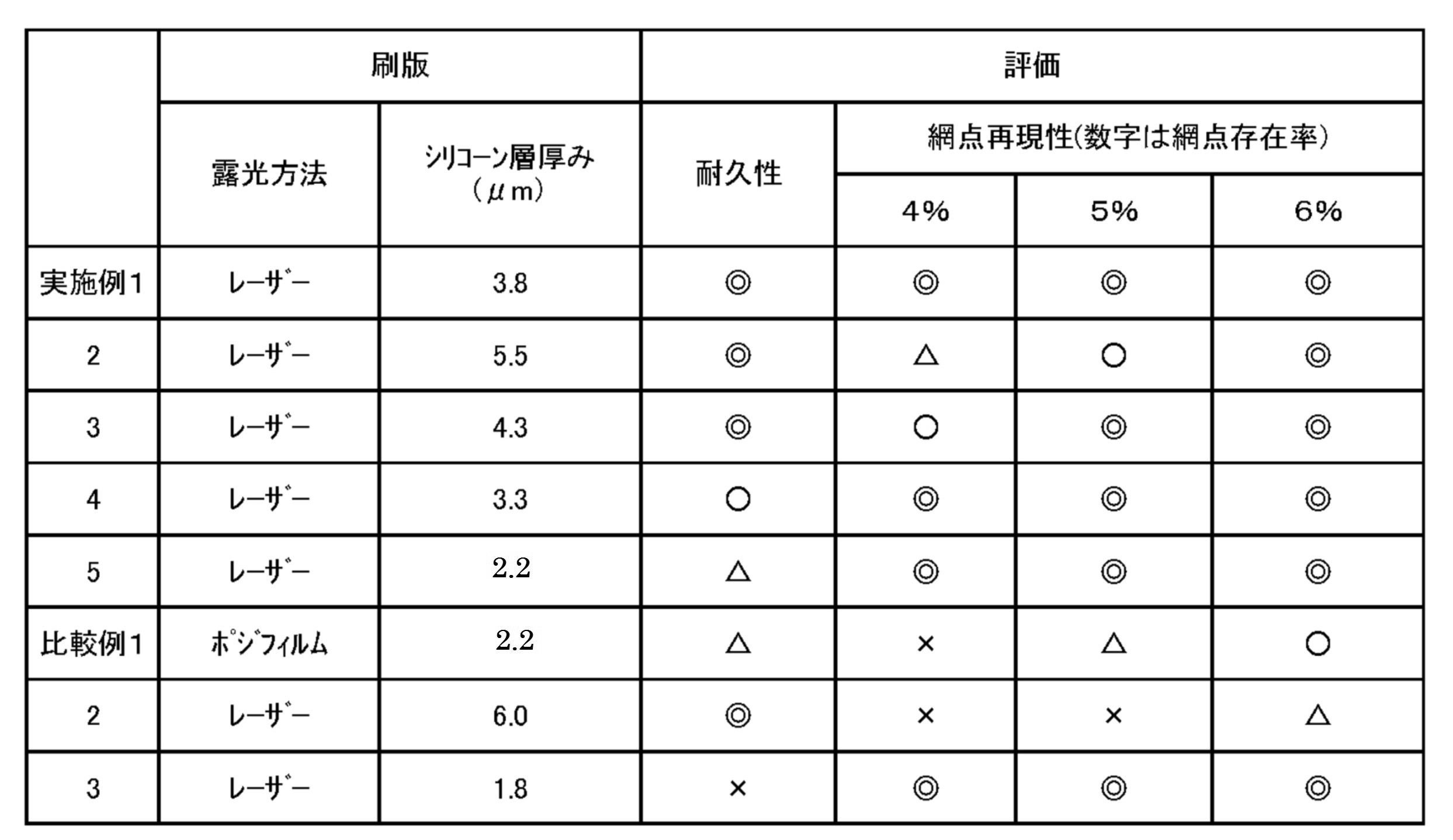
本発明の水なし平版が、小さい網点を鮮明に再現性良く形成することできると共に、シームレス缶への印刷のように高速且つ大量印刷した場合にも優れた耐刷性(耐久性)を有することは後述する実施例の結果からも明らかである。
すなわち、刷版のシリコーンゴム層の厚みが上記範囲よりも薄い場合には、網点再現性は優れているとしても、シリコーンゴム層の劣化が生じ、非画線部にインキ汚れが生じており、耐久性に劣っていることが明らかである(比較例3)。一方、刷版のシリコーンゴム層の厚みが上記範囲よりも厚い場合には、耐久性は優れているとしても、網点存在率が5%、4%と低くなると再現率が低下し、満足する網点再現性が得られていないことが明らかである(比較例2)。更に、水なし平版であっても、ポジフィルムタイプのものは、耐久性及び網点再現性のいずれにおいても十分満足する結果が得られていない(比較例1)。
これに対して、シリコーンゴム層の厚みが上記範囲にある本発明の水なし平版は、耐久性及び網点再現性の何れにおいても、満足する結果が得られている(実施例1~5)。
The waterless lithographic plate of the present invention can form small halftone dots clearly and with good reproducibility, and has excellent printing durability (durability) even when high-speed and mass printing such as printing on a seamless can. This is clear from the results of the examples described later.
That is, when the thickness of the silicone rubber layer of the printing plate is thinner than the above range, even if the halftone dot reproducibility is excellent, the silicone rubber layer is deteriorated and ink stains are generated in the non-image area. It is clear that the durability is inferior (Comparative Example 3). On the other hand, when the thickness of the silicone rubber layer of the printing plate is thicker than the above range, even if the durability is excellent, the reproducibility is lowered when the halftone dot presence rate is as low as 5% or 4%, which is satisfactory. It is clear that halftone dot reproducibility has not been obtained (Comparative Example 2). Further, even in the case of waterless lithographic printing, the positive film type has not obtained sufficiently satisfactory results in terms of durability and halftone dot reproducibility (Comparative Example 1).
On the other hand, the waterless lithographic plate of the present invention in which the thickness of the silicone rubber layer is in the above range has obtained satisfactory results in both durability and halftone dot reproducibility (Examples 1 to 5). ..
(水なし平版)
本発明のシームレス缶用水なし平版は、前述したとおり、少なくとも基板、レーザ感熱層を有し、該感熱層上にシリコーンゴム層から成る非画線部及び該シリコーンゴムが除去された画線部が形成されており、前記非画線部のシリコーンゴム層の厚みが2.2~5.5μm、特に3.3~4.3μmの範囲にあることが重要な特徴である。
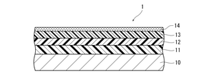
図1は、本発明のシームレス缶用水なし平版の形成に用いる原版の一例の断面図であり、原版1は、基板10上にプライマー層11を介してレーザ感熱層12及びシリコーンゴム層13が形成されて成り、特定の厚みを有するシリコーンゴム層13の上には、シリコーンゴム層13を保護するためのカバーフィルム14が形成されている。
本発明の水なし平版は、後述するように、この原版1の画線部を形成すべき部分にレーザを照射することによりレーザ感熱層12を発熱させてシリコーンゴム層13との界面を脆弱化させてシリコーンゴム層を除去した部分を画線部としている。
すなわち、図2に示すように、本発明の水なし平版2は、基板10上にプライマー層11を介してレーザ感熱層12が形成され、該レーザ感熱層12上に、シリコーンゴムから成る非画線部13aとシリコーンゴムが除去されて成る画線部13bが形成されて成るものである。尚、原版1に形成されていたカバーフィルム14は、画線部を形成する現像工程で取り外されている。
(Waterless planographic)
As described above, the waterless flat plate for seamless cans of the present invention has at least a substrate and a laser heat-sensitive layer, and a non-image portion made of a silicone rubber layer and an image portion from which the silicone rubber is removed are formed on the heat-sensitive layer. It is an important feature that the thickness of the silicone rubber layer in the non-image area is 2.2 to 5.5 μm, particularly 3.3 to 4.3 μm.
FIG. 1 is a cross-sectional view of an example of an original plate used for forming a waterless flat plate for a seamless can of the present invention. In the
As will be described later, the waterless flat plate of the present invention heats the laser heat-
That is, as shown in FIG. 2, in the
図3は、本発明の水なし平版(刷版)の一例の平面図である。図3に示す刷版2は、その中央部に、画像形成領域20が形成されており、画像形成領域20には、非画線部13aとA,B,Cの文字から成る画線部13b,13b,13bが形成されており、また画像形成領域20の周囲には、印刷する際に刷版の位置を確認するための位置調整マーク21が形成されている。
また刷版2の相対する短辺22a,22bのそれぞれの近傍には短辺22に沿って上下にピン穴23a,23bがそれぞれ形成されている。これらのピン穴は短辺の少なくとも片側に設けられていることが好ましく、短辺の両側に設けられていることがより好ましい。これらのピン穴は、上方のピン穴23aが円形、下方のピン穴23bが長方形の形状を有していることから、後述するように、刷版2を露光台に形成されたピンで位置合わせ及び固定をする際に、長方形のピン穴23bの存在により、ピンのピン穴への脱着が容易になる。尚、長方形状のピン穴に限定されず、略楕円形等、ピンの直径に対応した幅を有し、ピンの直径よりも長い長さを有する限り、その形状は限定されない。
FIG. 3 is a plan view of an example of a waterless planographic printing plate (printing plate) of the present invention. In the
Further,
図3に示す刷版において画像形成領域20は、サイズの異なる複数種類のシームレス缶の印刷に使用可能な態様になっており、画像形成領域全体が500mlシームレス缶用画像形成領域20であり、その画像形成領域20内に、200mlシームレス缶用画像形成領域24(一点鎖線区画部分)と、280mlシームレス缶用画像形成領域25(点線区画部分)が、それぞれのシームレス缶の印刷部分となる胴部の高さ及び胴部の周長さの大きさに対応するように、領域を共有するようにして形成されている。
すなわち図3の場合においては、200mlシームレス缶用画像形成領域24は、500mlシームレス缶用画像領域内の文字Aの画線部13bと文字Bの画線部13bが印刷されるように、500mlシームレス缶用画像形成領域20の縦方向及び横方向の長さが短く区画されている。また280mlシームレス缶用画像形成領域25は、文字Aの画線部13bと文字Bの画線部13bと文字Cの画線部13bが印刷されるが、缶高さに合わせるように、500mlシームレス缶用画像形成領域20よりも縦方向の長さが短く区画されている。
In the printing plate shown in FIG. 3, the
That is, in the case of FIG. 3, the
(水なし平版及び水なし平版を形成するための原版の構成層)
上述した水なし平版を作成するための原版及び水なし平版を構成する、シリコーンゴム層、レーザ感熱層、基板、プライマー層について説明する。
(Constituent layers of waterless planographic and original plates for forming waterless planographic)
The silicone rubber layer, the laser heat-sensitive layer, the substrate, and the primer layer constituting the original plate for producing the above-mentioned waterless lithographic plate and the waterless lithographic plate will be described.
[シリコーンゴム層]
本発明の水なし平版に適用するシリコーンゴム層は、その厚さが2.2~5.5μm、特に3.3~4.3μmの範囲にある以外は、従来の水なし平版において使用されていたシリコーンゴム層をすべて使用することができ、具体的には、縮合反応型シリコーンゴム又は付加反応型シリコーンゴム等を例示できる。
[Silicone rubber layer]
The silicone rubber layer applied to the waterless slab of the present invention has been used in the conventional waterless slab except that the thickness is in the range of 2.2 to 5.5 μm, particularly 3.3 to 4.3 μm. All of the silicone rubber layers can be used, and specific examples thereof include a condensation reaction type silicone rubber and an addition reaction type silicone rubber.
<付加反応型シリコーンゴム層>
付加反応型のシリコーンゴム層は、少なくともビニル基含有オルガノポリシロキサン、SiH基含有化合物(付加反応型架橋剤)、反応抑制剤および硬化触媒を含むシリコーンゴム組成物を塗布し、必要に応じて乾燥することにより形成される。
ビニル基含有オルガノポリシロキサンは、下記一般式(1)で表される構造を有し、主鎖末端もしくは主鎖中にビニル基を有するものである。中でも主鎖末端にビニル基を有するものが好ましい。
-(SiR1R2-O-)n- …(1)
式中、nは2以上の整数を示し、R1及びR2は同じでも異なってもよく、炭素数1~50の飽和または不飽和の炭化水素基を表す。炭化水素基は直鎖状でも枝分かれ状でも環状でもよく、芳香環を含んでいてもよい。
上記式(1)中、R1およびR2は全体の50%以上がメチル基であることが、印刷版のインキ反発性の面で好ましい。また、ビニル基含有オルガノポリシロキサンの重量平均分子量は1万~60万の範囲にあることが好ましい。
<Addition reaction type silicone rubber layer>
The addition reaction type silicone rubber layer is coated with a silicone rubber composition containing at least a vinyl group-containing organopolysiloxane, a SiH group-containing compound (addition reaction type cross-linking agent), a reaction inhibitor and a curing catalyst, and dried as necessary. It is formed by doing.
The vinyl group-containing organopolysiloxane has a structure represented by the following general formula (1) and has a vinyl group at the end of the main chain or in the main chain. Of these, those having a vinyl group at the end of the main chain are preferable.
-(SiR 1 R 2 -O-) n -... (1)
In the formula, n represents an integer of 2 or more, and R 1 and R 2 may be the same or different, and represent a saturated or unsaturated hydrocarbon group having 1 to 50 carbon atoms. The hydrocarbon group may be linear, branched or cyclic, and may contain an aromatic ring.
In the above formula (1), it is preferable that 50% or more of R 1 and R 2 are methyl groups in terms of ink resilience of the printing plate. Further, the weight average molecular weight of the vinyl group-containing organopolysiloxane is preferably in the range of 10,000 to 600,000.
SiH基含有化合物としては、例えば、オルガノハイドロジェンポリシロキサン、ジオルガノハイドロジェンシリル基を有する有機ポリマーが挙げられ、特にオルガノハイドロジェンポリシロキサンが好適に使用される。
SiH基含有化合物の含有量は、シリコーンゴム組成物中0.5~20重量%、特に1~15重量%の範囲であることが好ましい。
Examples of the SiH group-containing compound include organohydrogenpolysiloxane and organic polymers having a diorganohydrogensilyl group, and organohydrogenpolysiloxane is particularly preferably used.
The content of the SiH group-containing compound is preferably in the range of 0.5 to 20% by weight, particularly 1 to 15% by weight in the silicone rubber composition.
反応抑制剤としては、含窒素化合物、リン系化合物、不飽和アルコールなどが挙げられるが、アセチレン基含有のアルコールが好適に使用される。
反応抑制剤の含有量は、シリコーンゴム組成物中0.01~20重量%、特に0.1~15重量%の範囲にあることが好ましい。
Examples of the reaction inhibitor include nitrogen-containing compounds, phosphorus-based compounds, unsaturated alcohols and the like, and alcohols containing an acetylene group are preferably used.
The content of the reaction inhibitor is preferably in the range of 0.01 to 20% by weight, particularly 0.1 to 15% by weight in the silicone rubber composition.
硬化触媒は従来公知の物を使用することができるが、白金系化合物であることが好ましく、具体的には、白金単体、塩化白金、塩化白金酸、オレフィン配位白金、白金のアルコール変性錯体、白金のメチルビニルポリシロキサン錯体などを挙げることができる。
硬化触媒の含有量は、シリコーンゴム組成物中0.001~20重量%、特に0.01~15重量%の範囲にあることが好ましい。
Conventionally known curing catalysts can be used, but platinum-based compounds are preferable, and specific examples thereof include platinum alone, platinum chloride, platinum chloride acid, olefin-coordinated platinum, and alcohol-modified complexes of platinum. Examples thereof include a methyl vinyl polysiloxane complex of platinum.
The content of the curing catalyst is preferably in the range of 0.001 to 20% by weight, particularly 0.01 to 15% by weight in the silicone rubber composition.
上記成分の他に、水酸基含有オルガノポリシロキサンや加水分解性官能基含有シラン(もしくはシロキサン)、ゴム強度を向上させる目的でシリカなどの公知の充填剤、接着性を向上させる目的で公知のシランカップリング剤を含有してもよい。シランカップリング剤としては、アルコキシシラン類、アセトキシシラン類、ケトキシミノシラン類などが好ましく、特にビニル基やアリール基を有するものが好ましい。 In addition to the above components, hydroxyl group-containing organopolysiloxanes, hydrolyzable functional group-containing silanes (or siloxanes), known fillers such as silica for the purpose of improving rubber strength, and known silane cups for the purpose of improving adhesiveness. It may contain a ring agent. As the silane coupling agent, alkoxysilanes, acetoxysilanes, ketoximinosilanes and the like are preferable, and those having a vinyl group or an aryl group are particularly preferable.
<縮合反応型のシリコーンゴム層>
縮合反応型のシリコーンゴム層は、少なくとも水酸基含有オルガノポリシロキサン、架橋剤(脱酢酸型、脱オキシム型、脱アルコール型、脱アミン型、脱アセトン型、脱アミド型、脱アミノキシ型など)、および硬化触媒を含むシリコーンゴム組成物を塗布し、必要に応じて乾燥することにより形成される。
<Condensation reaction type silicone rubber layer>
Condensation reaction type silicone rubber layers include at least hydroxyl group-containing organopolysiloxanes, cross-linking agents (deacetic acid type, deoxime type, dealcohol type, deamine type, deacetone type, deamide type, deaminoxy type, etc.), and It is formed by applying a silicone rubber composition containing a curing catalyst and drying it if necessary.
水酸基含有オルガノポリシロキサンは、前記式(1)で表される構造を有し、主鎖末端もしくは主鎖中に水酸基を有するものである。中でも主鎖末端に水酸基を有するものが好ましい。
上記式(1)中のR1およびR2は、全体の50%以上がメチル基であることが好ましい。また水酸基含有オルガノポリシロキサンの重量平均分子量は1万~60万の範囲にあることが好ましい。
The hydroxyl group-containing organopolysiloxane has a structure represented by the above formula (1) and has a hydroxyl group at the end of the main chain or in the main chain. Of these, those having a hydroxyl group at the end of the main chain are preferable.
It is preferable that 50% or more of R 1 and R 2 in the above formula (1) are methyl groups. The weight average molecular weight of the hydroxyl group-containing organopolysiloxane is preferably in the range of 10,000 to 600,000.
縮合反応型のシリコーンゴム層に用いられる架橋剤としては、メチルトリアセトキシシラン、エチルトリアセトキシシラン、ビニルトリアセトキシシラン等のアセトキシシラン類、ビニルメチルビス(メチルエチルケトキシミノ)シラン等のケトキシミノシラン類を好適に使用できる。
架橋剤の含有量は、シリコーンゴム組成物中0.5~20重量%、特に1~15重量%の範囲にあることが好ましい。
Examples of the cross-linking agent used for the condensation reaction type silicone rubber layer include acetoxysilanes such as methyltriacetoxysilane, ethyltriacetoxysilane, and vinyltriacetoxysilane, and ketoximinosilanes such as vinylmethylbis (methylethylketoximino) silane. Can be preferably used.
The content of the cross-linking agent is preferably in the range of 0.5 to 20% by weight, particularly 1 to 15% by weight in the silicone rubber composition.
硬化触媒としては、従来公知の硬化触媒を使用することができ、中でもジブチル錫ジアセテート、ジブチル錫ジオクテート、ジブチル錫ジラウレート、オクチル酸亜鉛、オクチル酸鉄等が好適に使用される。
硬化触媒の含有量は、シリコーンゴム組成物中0.001~15重量%、特に0.01~10重量%の範囲であることが好ましい。
また、これらの成分の他に、ゴム強度を向上させる目的でシリカなどの公知の充填剤、公知のシランカップリング剤等を含有してもよい。
As the curing catalyst, a conventionally known curing catalyst can be used, and among them, dibutyltin diacetate, dibutyltin dioctate, dibutyltin dilaurate, zinc octylate, iron octylate and the like are preferably used.
The content of the curing catalyst is preferably in the range of 0.001 to 15% by weight, particularly 0.01 to 10% by weight in the silicone rubber composition.
Further, in addition to these components, a known filler such as silica, a known silane coupling agent, or the like may be contained for the purpose of improving the rubber strength.
[レーザ感熱層]
本発明の水なし平版に適用するレーザ感熱層としては、従来の水なし平版に適用されていたレーザ感熱層をすべて使用することができるが、具体的には、少なくとも(a)光熱変換物質と(b)金属キレート化合物と、(c)活性水素含有化合物、及び(d)バインダー樹脂を含有する組成物から成る感熱層を例示できる。
レーザ感熱層は、レーザ照射される前に予め金属キレート化合物(b)と活性水素含有化合物(c)により架橋構造が形成されていることが好ましく、これにより、レーザが照射された部分の感熱層とシリコーンゴム層間の接着力が低下し、その後の処理によって、レーザ光を照射した部分のシリコーンゴム層が除去されて、ネガ型の水なし平版が得られる。
[Laser heat sensitive layer]
As the laser heat-sensitive layer applied to the waterless slab of the present invention, all the laser heat-sensitive layers applied to the conventional waterless slab can be used. An example includes a heat-sensitive layer composed of a composition containing (b) a metal chelate compound, (c) an active hydrogen-containing compound, and (d) a binder resin.
The laser heat-sensitive layer preferably has a crosslinked structure formed in advance by the metal chelate compound (b) and the active hydrogen-containing compound (c) before being irradiated with the laser, whereby the heat-sensitive layer of the portion irradiated with the laser is formed. The adhesive strength between the silicone rubber layers is reduced, and the subsequent treatment removes the silicone rubber layer at the portion irradiated with the laser beam to obtain a negative type waterless flat plate.
<光熱変換物質>
光熱変換物質(a)としては、レーザ光を吸収するものであれば特に限定されず使用できる。レーザ光の波長としては、紫外域、可視域、赤外域のどの領域の波長であってもよく、使用するレーザ光の波長に合わせた吸収域を有する光熱変換物質を適宜選択して使用することができるが、特に、カーボンブラックを好適に使用できる。
また赤外線または近赤外線を吸収する染料も、光熱変換物質として使用することができ、最大吸収波長が700~900nmの範囲にある染料を好適に使用することができる。
これらの光熱変換物質の含有量は、感熱層を構成する組成物全体に対して0.1~40重量%が好ましく、より好ましくは0.5~25重量%である。
<Photothermal converter>
The photothermal conversion substance (a) can be used without particular limitation as long as it absorbs laser light. The wavelength of the laser light may be any of the ultraviolet region, the visible region, and the infrared region, and a photothermal conversion material having an absorption region matching the wavelength of the laser light to be used shall be appropriately selected and used. However, carbon black can be particularly preferably used.
Further, a dye that absorbs infrared rays or near infrared rays can also be used as a photothermal conversion substance, and a dye having a maximum absorption wavelength in the range of 700 to 900 nm can be preferably used.
The content of these photothermal conversion substances is preferably 0.1 to 40% by weight, more preferably 0.5 to 25% by weight, based on the entire composition constituting the heat-sensitive layer.
<金属キレート化合物>
金属キレート化合物(b)としては、金属ジケテネート、金属アルコキサイド、アルキル金属、金属カルボン酸塩類、酸化金属キレート化合物、金属錯体、ヘテロ金属キレート化合物等を例示することができる。
金属キレート化合物のうち、特に好ましく用いられる化合物としては、アルミニウム、鉄(III)、チタンのアセチルアセトネート(ペンタンジオネート)、エチルアセトアセトネート(ヘキサンジオネート)、プロピルアセトアセトネート(ヘプタンジオネート)、テトラメチルヘプタンジオネート、ベンゾイルアセトネート類などを挙げることができ、これらは単独で使用してもよいし、2種以上を混合して使用することもできる。
レーザ感熱層における金属キレート化合物の含有量は、後述する活性水素基含有組成物(C)100重量部に対して5~300重量部、特に10~150重量部の量であることが好ましい。
<Metal chelate compound>
Examples of the metal chelate compound (b) include metal diquetenates, metal alcoxides, alkyl metals, metal carboxylates, metal oxide chelate compounds, metal complexes, heterometal chelate compounds and the like.
Among the metal chelate compounds, particularly preferably used compounds are aluminum, iron (III), titanium acetylacetonate (pentangionate), ethylacetacetate (hexanegeonate), propylacetoacetonate (heptane). ), Tetramethylheptane, benzoylacetonates and the like, and these may be used alone or in combination of two or more.
The content of the metal chelate compound in the laser heat-sensitive layer is preferably 5 to 300 parts by weight, particularly preferably 10 to 150 parts by weight, based on 100 parts by weight of the active hydrogen group-containing composition (C) described later.
<活性水素基含有化合物>
活性水素基含有化合物(c)としては、水酸基含有化合物、アミノ基含有化合物、カルボキシル基含有化合物、チオール基含有化合物などが挙げられるが、水酸基含有化合物が好ましい。
水酸基含有化合物としては、フェノール性水酸基含有化合物又はアルコール性水酸基含有化合物の他、エポキシアクリレート、エポキシメタクリレート、ポリビニルブチラール樹脂、および公知の方法によって水酸基を導入したポリマーなどを例示することができる。
活性水素基含有化合物(c)の含有量は、レーザ感熱層を構成する組成物全体に対して5~80重量%、特に20~60重量%の範囲にあることが好ましい。
<Active hydrogen group-containing compound>
Examples of the active hydrogen group-containing compound (c) include a hydroxyl group-containing compound, an amino group-containing compound, a carboxyl group-containing compound, and a thiol group-containing compound, and a hydroxyl group-containing compound is preferable.
Examples of the hydroxyl group-containing compound include phenolic hydroxyl group-containing compounds and alcoholic hydroxyl group-containing compounds, as well as epoxy acrylates, epoxy methacrylates, polyvinyl butyral resins, and polymers in which hydroxyl groups are introduced by a known method.
The content of the active hydrogen group-containing compound (c) is preferably in the range of 5 to 80% by weight, particularly 20 to 60% by weight, based on the entire composition constituting the laser heat-sensitive layer.
[バインダーポリマー]
バインダーポリマー(d)は、有機溶剤に可溶でかつフィルム形成能のあるものであれば特に限定されない。
有機溶剤に可溶でかつフィルム形成能があり、さらに形態保持の機能をも果たすバインダーポリマーの具体例としては、これに限定されないが、ビニルポリマー類、未加硫ゴム、ポリオキシド類(ポリエーテル類)、ポリエステル類、ポリウレタン類、ポリアミド類等を例示することができ、これらの一種又は数種を混合して使用することもできる。
バインダーポリマーの含有量は、レーザ感熱層を構成する組成物全体に対して5~70重量%、特に10~50重量%の範囲にあることが好ましい。
[Binder polymer]
The binder polymer (d) is not particularly limited as long as it is soluble in an organic solvent and has a film-forming ability.
Specific examples of the binder polymer, which is soluble in an organic solvent, has a film-forming ability, and also has a morphological retention function, are not limited to this, but vinyl polymers, unsulfurized rubber, and polyoxides (polyesters). ), Polyesters, polyurethanes, polyamides and the like can be exemplified, and one or several of these can be used as a mixture.
The content of the binder polymer is preferably in the range of 5 to 70% by weight, particularly 10 to 50% by weight, based on the entire composition constituting the laser heat-sensitive layer.
<その他>
レーザ感熱層には、レベリング剤、界面活性剤、分散剤、可塑剤、カップリング剤等を必要に応じて任意に添加することができる。特に基板又はプライマー層、或いはシリコーンゴム層との接着性を高めるために、シランカップリング剤などの各種カップリング剤や不飽和基含有化合物を添加することが好ましい。
感熱層の厚さは、耐刷性や生産性等の点から、被覆層にして0.1~10g/m2、特に1~7g/m2の範囲にあることが好ましい。
<Others>
A leveling agent, a surfactant, a dispersant, a plasticizer, a coupling agent and the like can be arbitrarily added to the laser heat-sensitive layer, if necessary. In particular, it is preferable to add various coupling agents such as a silane coupling agent and unsaturated group-containing compounds in order to enhance the adhesiveness to the substrate, the primer layer, or the silicone rubber layer.
The thickness of the heat-sensitive layer is preferably in the range of 0.1 to 10 g / m 2 , particularly 1 to 7 g / m 2 for the coating layer from the viewpoint of printing resistance, productivity and the like.
[基板]
本発明の水なし平版に使用する基板としては、寸法的に安定な板状物であれば公知の金属板、フィルム等のいずれも使用することができる。
このような寸法安定性に優れた板状物としては、従来より刷版の基板として使用されたものを制限なく使用でき、紙、プラスチック(ポリエチレン、ポリプロピレン、ポリスチレンなど)がラミネートされた紙、アルミニウム(アルミニウム合金も含む)、亜鉛、銅などの金属の板、セルロースアセテート、ポリエチレンテレフタレ-ト、ポリエチレン、ポリエステル、ポリアミド、ポリイミド、ポリスチレン、ポリプロピレン、ポリカーボネート、ポリビニルアセタ-ルなどのプラスチックのフィルム、上記金属がラミネ-トもしくは蒸着された紙もしくはプラスチックフィルム等を例示できる。
中でもアルミニウム板は寸法的に著しく安定であり、しかも安価であるので特に好ましい。アルミニウム基板の厚みは、特に制限はないが、版胴への取り付け性等の点から、0.1~0.5mmの範囲にあることが望ましい。
[substrate]
As the substrate used for the waterless lithographic plate of the present invention, any known metal plate, film, or the like can be used as long as it is a dimensionally stable plate-like material.
As such a plate-like material having excellent dimensional stability, those conventionally used as a substrate for a printing plate can be used without limitation, and paper, paper laminated with plastic (polyethylene, polypropylene, polystyrene, etc.), aluminum. (Including aluminum alloys), metal plates such as zinc and copper, polyethylene acetate, polyethylene terephthalate, polyethylene, polyester, polyamide, polyimide, polystyrene, polypropylene, polycarbonate, polyvinyl acetate and other plastic films, Examples thereof include paper or plastic film in which the metal is laminated or vapor-deposited.
Among them, the aluminum plate is particularly preferable because it is remarkably stable in size and inexpensive. The thickness of the aluminum substrate is not particularly limited, but is preferably in the range of 0.1 to 0.5 mm from the viewpoint of mountability to the plate cylinder and the like.
[その他の層]
本発明の水なし平版は、基板とレーザ感熱層の接着性を向上させると共に、照射されたレーザによる熱が基板に逃げることを防ぐために、基板とレーザ感熱層の間にプライマー層を設けることが好ましい。
プライマー層としては、エポキシ樹脂、ポリウレタン樹脂、フェノ-ル樹脂、アクリル樹脂、アルキッド樹脂、ポリエステル樹脂、ポリアミド樹脂、尿素樹脂、ポリビニルブチラール樹脂等を含むものが挙げられる。これらの中では、ポリウレタン樹脂、ポリエステル樹脂、アクリル樹脂、エポキシ樹脂、尿素樹脂等を単独で、あるいは2種以上を混合して用いることが好ましい。
またプライマー層中に、顔料、染料等の添加剤を含有させて検版性を向上させることもできる。
プライマー層の厚みは、被覆層にして0.5~50g/m2、特に1~10g/m2の範囲にあることが好ましい。プライマー層の厚みが、上記範囲よりも薄い場合には、接着性及び上述したプライマー層による断熱効果が充分に得られないおそれがある一方、上記範囲よりも厚くても更なる効果は望めず、経済性に劣るようになる。
[Other layers]
In the waterless slab of the present invention, a primer layer may be provided between the substrate and the laser heat-sensitive layer in order to improve the adhesiveness between the substrate and the laser heat-sensitive layer and prevent the heat generated by the irradiated laser from escaping to the substrate. preferable.
Examples of the primer layer include those containing an epoxy resin, a polyurethane resin, a phenol resin, an acrylic resin, an alkyd resin, a polyester resin, a polyamide resin, a urea resin, a polyvinyl butyral resin and the like. Among these, it is preferable to use polyurethane resin, polyester resin, acrylic resin, epoxy resin, urea resin and the like alone or in combination of two or more.
Further, the primer layer may contain additives such as pigments and dyes to improve the plate inspection property.
The thickness of the primer layer is preferably in the range of 0.5 to 50 g / m 2 , particularly 1 to 10 g / m 2 for the coating layer. If the thickness of the primer layer is thinner than the above range, the adhesiveness and the heat insulating effect of the above-mentioned primer layer may not be sufficiently obtained, but even if the thickness is thicker than the above range, no further effect can be expected. It becomes inferior in economy.
本発明の水なし平版を作成するための原版においては、一般に、図1に示した通り、シリコーンゴム層を保護するためのカバーフィルムが設けられており、このようなカバーフィルムとしては、レーザ光を良好に透過可能なフィルムであることが好ましく、これに限定されないが、ポリエステルフィルム、ポリプロピレンフィルム、ポリビニルアルコールフィルム、エチレン酢酸ビニル共重合体ケン化物フィルム、ポリ塩化ビニリデンフィルム、また各種金属を蒸着したフィルム等を例示できる。 In the original plate for producing the waterless flat plate of the present invention, as shown in FIG. 1, a cover film for protecting the silicone rubber layer is generally provided, and such a cover film includes laser light. Is preferably, but is not limited to, a polyester film, a polypropylene film, a polyvinyl alcohol film, an ethylene vinyl acetate copolymer saponified film, a polyvinylidene chloride film, and various metals vapor-deposited. A film or the like can be exemplified.
[原版の製造方法]
本発明の水なし平版に用いられる原版は、従来公知の方法により製造することができ、これに限定されないが、基板上に、リバースロールコーター、エアーナイフコーター、グラビアコーター、ダイコーター等の通常のコーターや回転塗布装置を用い、必要に応じてプライマー層組成物を塗布し100~300℃で数分間加熱或いは活性光線照射により硬化させた後、レーザ感熱層組成物を塗布し50~180℃で数十秒から数分間加熱して硬化させる。次いで、シリコーンゴム組成物を塗布し50~200℃の温度で数分間熱処理してシリコーンゴム層を形成し、その後、必要に応じてカバーフィルムをラミネートするか、或いは保護層を形成することにより製造される。
[Manufacturing method of original plate]
The original plate used for the waterless flat plate of the present invention can be produced by a conventionally known method, and is not limited to this, and is usually used on a substrate such as a reverse roll coater, an air knife coater, a gravure coater, and a die coater. Using a coater or a rotary coating device, apply the primer layer composition as needed, heat at 100 to 300 ° C. for several minutes or cure by irradiation with active light, then apply the laser heat-sensitive layer composition and apply at 50 to 180 ° C. Heat for several tens of seconds to several minutes to cure. Then, the silicone rubber composition is applied and heat-treated at a temperature of 50 to 200 ° C. for several minutes to form a silicone rubber layer, and then, if necessary, a cover film is laminated or a protective layer is formed. Will be done.
(水なし平版の製造方法)
本発明の水なし平版は、前述したような、少なくとも基板、レーザ感熱層及びシリコーンゴム層から成り、該シリコーンゴム層の厚みが2.2~5.5μmの範囲にある原版を用い、この原版のカバーフィルム上からレーザを画線状に照射して露光した後、レーザが照射された部分のシリコーンゴム層を除去することにより画線部を形成することにより製造される。
(Manufacturing method of waterless planographic printing)
The waterless flat plate of the present invention comprises, as described above, at least a substrate, a laser heat-sensitive layer, and a silicone rubber layer, and the thickness of the silicone rubber layer is in the range of 2.2 to 5.5 μm. It is manufactured by irradiating the cover film with a laser in a line shape to expose the cover film, and then removing the silicone rubber layer of the irradiated portion to form an image portion.
[露光工程]
本発明の水なし平版の製造方法において、原版へのレーザ照射は従来公知の方法により行うことができるが、好適には、平面状の移動可能な露光台及びこの露光台の進行方向に対して直角方向に走査可能なレーザ照射装置を有する露光装置を用いて行うことが、生産性の点から好ましい。
すなわち、図4に示すように、露光装置3(露光台のみを表示)は、平面状の露光台31の進行方向(矢印X)に対して直角方向(矢印Y)に移動可能なレーザ照射装置(図示せず)を備えている。また、露光台31には、露光台平面に対して上下動可能なピン32a,32b,32c,32d・・・が複数形成されている。また露光台31には、バキューム機構が形成されていることが好ましく、これにより、露光台に設置された原版を吸引して露光台表面に密着固定させることができる。
[Exposure process]
In the method for producing a waterless flat plate of the present invention, laser irradiation to the original plate can be performed by a conventionally known method, but preferably, the planar movable exposure table and the traveling direction of the exposure table are preferred. From the viewpoint of productivity, it is preferable to use an exposure device having a laser irradiation device capable of scanning in the perpendicular direction.
That is, as shown in FIG. 4, the exposure device 3 (displaying only the exposure table) is a laser irradiation device that can move in a direction perpendicular to the traveling direction (arrow X) of the planar exposure table 31 (arrow Y). (Not shown). Further, the exposure table 31 is formed with a plurality of
図4に示す具体例では、露光台31に設けられた18本のピン32が露光台平面より上方に突出した状態となっており、このピン32が9枚の原版1の一方の端縁付近に形成されたピン穴23a,23bにそれぞれ挿入され、バキューム機構による原版の吸引と相俟って、9枚の原版1が露光台31に位置合わせされた状態で密着固定されている。
また図5に示す具体例では、露光台31のピンは8本のみが露光台平面より上方に突出し、原版1の固定に使用されない、すなわちピン穴との嵌合に使用されないピンはその先端が露光台表面よりも上方に突出することがないように下方に移動した状態になっている。これにより、図4とは大きさの異なる原版1を4枚、露光台に位置合わせされた状態で固定することができる。このように、使用するピンの位置を選択することにより、大きさの異なる原版に対しても位置合わせ及び固定を容易に行うことができる。
尚、原版にピン穴が形成されていない場合でも、露光台表面から突出したピンに原版の側面を接触させることによりピンを位置合わせの基準とすることができる。
露光台31上に位置を合わせて固定された複数枚の原版1に対して、レーザ照射装置を図の矢印Y方向に走査することによって、複数枚の原版に対して効率よくレーザを照射して画線部を露光することができ、複数枚の原版を同時に露光することができる。
In the specific example shown in FIG. 4, the 18 pins 32 provided on the exposure table 31 are in a state of protruding upward from the exposure table plane, and the pins 32 are in the vicinity of one edge of the nine
Further, in the specific example shown in FIG. 5, only eight pins of the exposure table 31 protrude above the exposure table plane, and the tips of the pins that are not used for fixing the
Even when the pin hole is not formed in the original plate, the pin can be used as a reference for alignment by bringing the side surface of the original plate into contact with the pin protruding from the surface of the exposure table.
By scanning the laser irradiation device in the direction of the arrow Y in the figure on the plurality of
レーザ照射に際して、原版がカバーフィルムを有する場合には、カバーフィルムを剥離してから或いはカバーフィルム上からレーザ光で画像状に露光する。
レーザ光源としては、発信波長領域が300nm~1500nmの範囲にある、アルゴンイオン、クリプトンイオン、ヘリウム-ネオン、ヘリウム-カドミウム、ルビー、ガラス、YAG、チタンサファイア、色素、窒素、金属蒸気、エキシマ、自由電子、半導体などの各種レーザを使用することができ、特に近赤外領域付近に発光波長領域が存在する半導体レーザを好適に使用することができる。
またこれに限定されないが、レーザ発振器の出力は10~200Wの範囲、レーザビームのスポット径は5~20μmの範囲、レーザビームの掃引速度は、30~100m/分の範囲にあることが好ましい。
When the original plate has a cover film during laser irradiation, the cover film is peeled off or the cover film is exposed to an image with a laser beam.
Laser light sources include argon ion, krypton ion, helium-neon, helium-cadmium, ruby, glass, YAG, titanium sapphire, dye, nitrogen, metal steam, excima, and free, whose emission wavelength range is in the range of 300 nm to 1500 nm. Various lasers such as electrons and semiconductors can be used, and in particular, a semiconductor laser having an emission wavelength region near the near infrared region can be preferably used.
The output of the laser oscillator is preferably in the range of 10 to 200 W, the spot diameter of the laser beam is preferably in the range of 5 to 20 μm, and the sweep speed of the laser beam is preferably in the range of 30 to 100 m / min.
[現像工程]
上記露光工程でレーザ照射した部分を除去することにより、画線部を現像する。
現像は、水又は有機溶剤の存在もしくは非存在下での摩擦処理により行うことが好適であるが、これに限定されず、カバーフィルムを剥離することによって刷版上にパターンを形成する、いわゆる剥離現像によって行うことも可能である。
現像処理を行う場合に使用される現像液としては、従来公知のものを使用することができ、これに限定されないが、例えば、水や、水に界面活性剤を添加したもの、さらには水にアルコールやケトン、エステル、カルボン酸等の極性溶媒を添加したものや、脂肪族炭化水素類(ヘキサン、ヘプタン、イソパラフィン系炭化水素など)、芳香族炭化水素類(トルエン、キシレンなど)、ハロゲン化炭化水素類(トリクレンなど)などに極性溶媒を添加したものを挙げることができる。
[Development process]
The image area is developed by removing the laser-irradiated portion in the exposure step.
Development is preferably carried out by friction treatment in the presence or absence of water or an organic solvent, but is not limited to this, and a pattern is formed on the printing plate by peeling the cover film, so-called peeling. It can also be done by development.
As the developing solution used in the development treatment, conventionally known ones can be used, and the developing solution is not limited to this, and is not limited to, for example, water, a solution obtained by adding a surfactant to water, and further to water. Addition of polar solvents such as alcohols, ketones, esters, and carboxylic acids, aliphatic hydrocarbons (hexane, heptane, isoparaffinic hydrocarbons, etc.), aromatic hydrocarbons (toluene, xylene, etc.), halogenated hydrocarbons, etc. Examples thereof include hydrocarbons (such as tricline) to which a polar solvent is added.
摩擦処理による現像は、現像液の存在下もしくは非存在下で、版面を摺擦することによって行う。具体的には、不織布、脱脂綿、布、スポンジ、ブラシ等で版面を擦ることによって、或いは現像液を含浸した不織布、脱脂綿、布、スポンジ等で版面を拭き取ることによって行うことができる。
また、現像に先立ち、前処理液又は現像液に一定期間版を浸漬し、レーザ照射された部分を脆弱化させる前処理を行った後に、水道水等をシャワーしながら回転ブラシで摺擦することや、高圧の水や温水、または水蒸気を版面に噴射することによっても行うことができる。
尚、現像液にクリスタルバイオレット、ビクトリアピュアブルー、アストラゾンレッド等の公知の染料を添加して現像と同時に画線部を着色してもよいし、或いは、現像後、後処理工程としてシリコーンゴム層が除去された画線部を着色して、画線部を目立たせる処理を行うこともできる。
Development by friction treatment is performed by rubbing the plate surface in the presence or absence of a developing solution. Specifically, it can be carried out by rubbing the plate surface with a non-woven fabric, absorbent cotton, cloth, sponge, brush or the like, or by wiping the plate surface with a non-woven fabric, absorbent cotton, cloth, sponge or the like impregnated with a developing solution.
In addition, prior to development, the plate is immersed in a pretreatment solution or a developing solution for a certain period of time to perform pretreatment to weaken the laser-irradiated part, and then rubbed with a rotating brush while showering tap water or the like. Alternatively, it can also be performed by injecting high-pressure water, hot water, or steam onto the plate surface.
A known dye such as crystal violet, Victoria pure blue, or Astrazon red may be added to the developer to color the image area at the same time as the development, or the silicone rubber layer may be used as a post-treatment step after the development. It is also possible to color the image area from which the image has been removed to make the image area stand out.
<評価方法>
(耐久性評価)
得られた画像なし刷版を、印刷試験機版胴に巻回して取り付け、ブランケットホイールに缶12個分のブランケットを取り付け、刷版とブランケットのニップ幅が6mmであるように配置し、版胴とブランケットホイールを600缶/分の速度で12時間回転させた。刷版のシリコーンゴム層の厚みは表1に示す仕様である。試験後の刷版表面に染色液を塗布し、染色部面積を下記基準で評価した。刷版表面のシリコーンゴム層に劣化がなければ染色せず、シリコーンゴム層が摩耗して劣化があれば染色する。劣化したシリコーンゴム層部には印刷した場合に地汚れと言われる非画線部のインキ汚れが発生する。
◎:刷版全面に染色なし
○:染色部が刷版の5%未満
△:染色部が刷版の5%以上で25%未満
×:染色部が刷版の25%以上
<Evaluation method>
(Durability evaluation)
The obtained imageless printing plate is wound around the plate cylinder of the printing tester and attached, the blanket for 12 cans is attached to the blanket wheel, and the printing plate and the blanket are arranged so that the nip width is 6 mm. And the blanket wheel was rotated at a speed of 600 cans / minute for 12 hours. The thickness of the silicone rubber layer of the printing plate is the specifications shown in Table 1. A dyeing solution was applied to the surface of the printing plate after the test, and the area of the dyed part was evaluated according to the following criteria. If the silicone rubber layer on the surface of the printing plate is not deteriorated, it is not dyed, and if the silicone rubber layer is worn and deteriorated, it is dyed. When printing, ink stains on non-image areas, which are called background stains, occur on the deteriorated silicone rubber layer portion.
⊚: No dyeing on the entire surface of the printing plate ○: The dyed part is less than 5% of the printing plate △: The dyed part is 5% or more of the printing plate and less than 25% ×: The dyed part is 25% or more of the printing plate
(網点再現性評価)
得られた画像あり刷版を、印刷試験機の版胴に巻回して取り付け、ブランケットホイールに缶12個分のブランケットを取り付け、マンドレルホイールにマンドレルを配置し、版胴、ブランケットホイール、マンドレルホイールを回転させて、マンドレルに配置したシームレス缶胴に墨インキで曲面印刷した。
評価は、印刷缶の缶胴画面内の網点再現率について下記基準で行った。
◎:画面内の網点再現率が100%である
○:画面内の網点再現率が100%未満で90%以上である
△:画面内の網点再現率が90%未満で70%以上である
×:画面内の網点再現率が70%未満である
缶胴画面内の網点再現率は刷版の網点再現率に対応する。ここで、表1の「網点存在率%」とは、画像全体における網点の面積%を表し、当試験では、この面積%は網点1個の面積に比例する。シリコーン層厚みや露光方法の違いにより、刷版の網点形成性が異なり、小さい網点が形成されにくい場合には、評点が低くなる。
(Evaluation of halftone dot reproducibility)
The printed plate with the obtained image is wound around the plate cylinder of the printing tester and attached, the blanket for 12 cans is attached to the blanket wheel, the mandrel is placed on the mandrel wheel, and the plate cylinder, blanket wheel, and mandrel wheel are attached. It was rotated and a curved surface was printed with black ink on the seamless can body placed on the mandrel.
The evaluation was performed based on the following criteria for the halftone dot reproduction rate in the can body screen of the printing can.
⊚: Halftone dot reproduction rate in the screen is 100% ○: Halftone dot reproduction rate in the screen is 90% or more when it is less than 100% △: Halftone dot reproduction rate in the screen is 70% or more when it is less than 90% X: The halftone dot reproduction rate in the screen is less than 70%. The halftone dot reproduction rate in the can body screen corresponds to the halftone dot reproduction rate of the printing plate. Here, the "halftone dot abundance rate%" in Table 1 represents the area% of halftone dots in the entire image, and in this test, this area% is proportional to the area of one halftone dot. The halftone dot forming property of the printing plate differs depending on the thickness of the silicone layer and the exposure method, and when it is difficult to form small halftone dots, the score is low.
(実施例1)
アルミ基板、プライマー層、レーザ感熱層、シリコーンゴム層、カバーフィルムから成る原版(東レ社製原版VT4のシリコーン層厚みのみを変更した原版)のシリコーンゴム層の厚みを3.8μmに設定して原版コイルを作製した。
得られた原版コイルを長方形形状に切断し、短辺側の両側に、短辺に平行に直径5mmの円形ピン穴と、短辺5mm長辺8mmの矩形ピン穴をパンチで形成して缶1個相当の原版を作製した。
次に、図4に示すように、露光台に上記原版がレーザ走査方向に3枚、その直角方向に3枚並ぶように、露光台のピンを凸状態にし、原版左側短辺の円形と矩形のピン穴に露光台のピンを挿入して原版を平面状に載置し、露光台下からのバキュームで固定した。このとき、原版長さ方向がレーザ走査方向に平行で、かつ刷版の円形ピン穴と矩形ピン穴の中心線がレーザ走査方向に直角であるように調整した。
次いで、解像度2400dpi、レーザ波長830nm、レーザ数16チャンネル、レーザスポット径10.6μm、レーザ出力27.2W、レーザビームの掃引速度13.3m/分で、レーザを原版長さ方向に走査させながら照射し、露光台をレーザ走査方向と直角方向に線数250Lpiの条件で移動させて、網点存在率4%、5%、6%の網点画像を作製した。
その後常法に準じて、カバーフィルムを剥離し、前処理液(東レ社製CP-Y)に浸漬した後、回転ブラシを用いて摺擦することにより現像した。次いで、形成された画線部を着色する後処理(後処理液東レ社製PA-1)を行い、網点再現性評価用の画像あり刷版を作製した。
耐久性評価用にはレーザ照射なしの条件で画像なし刷版を作製した。刷版画像のサイズは呼称202径200mlのシームレス缶胴用サイズである。得られた刷版で耐久性評価、網点再現性評価を行った。評価結果を表1に示す。
(Example 1)
The thickness of the silicone rubber layer of the original plate (the original plate in which only the silicone layer thickness of the original plate VT4 manufactured by Toray Industries, Inc. is changed) consisting of the aluminum substrate, the primer layer, the laser heat sensitive layer, the silicone rubber layer, and the cover film is set to 3.8 μm. A coil was made.
The obtained original plate coil is cut into a rectangular shape, and a circular pin hole having a diameter of 5 mm parallel to the short side and a rectangular pin hole having a short side of 5 mm and a long side of 8 mm are formed by punching on both sides of the short side. An original plate equivalent to the number was prepared.
Next, as shown in FIG. 4, the pins of the exposure table are made convex so that the three original plates are lined up on the exposure table in the laser scanning direction and three in the direction perpendicular to the original plate. The pin of the exposure table was inserted into the pin hole of the exposure table, the original plate was placed on a flat surface, and fixed by vacuum from under the exposure table. At this time, the length direction of the original plate was adjusted to be parallel to the scanning direction of the laser, and the center lines of the circular pin holes and the rectangular pin holes of the printing plate were adjusted to be perpendicular to the scanning direction of the laser.
Next, the laser is irradiated while scanning in the original plate length direction at a resolution of 2400 dpi, a laser wavelength of 830 nm, a laser number of 16 channels, a laser spot diameter of 10.6 μm, a laser output of 27.2 W, and a laser beam sweep speed of 13.3 m / min. Then, the exposure table was moved in a direction perpendicular to the laser scanning direction under the condition of a line number of 250 Lpi to prepare halftone dot images having halftone dot abundance rates of 4%, 5%, and 6%.
Then, according to a conventional method, the cover film was peeled off, immersed in a pretreatment liquid (CP-Y manufactured by Toray Industries, Inc.), and then rubbed with a rotating brush for development. Next, a post-treatment (post-treatment liquid PA-1 manufactured by Toray Industries, Inc.) for coloring the formed image line portion was performed to prepare a printing plate with an image for halftone dot reproducibility evaluation.
For durability evaluation, an imageless printing plate was produced under the condition of no laser irradiation. The size of the printing plate image is the size for a seamless can body with a nominal size of 202 diameter and 200 ml. Durability evaluation and halftone dot reproducibility evaluation were performed on the obtained printing plate. The evaluation results are shown in Table 1.
(実施例2)
原版のシリコーン層厚みを5.5μmにした以外は実施例1と同様に刷版を作製し、耐久性評価、網点再現性評価を行った。評価結果を表1に示す。
(Example 2)
A printing plate was prepared in the same manner as in Example 1 except that the thickness of the silicone layer of the original plate was 5.5 μm, and durability evaluation and halftone dot reproducibility evaluation were performed. The evaluation results are shown in Table 1.
(実施例3)
原版のシリコーン層厚みを4.3μmにした以外は実施例1と同様に刷版を作製し、耐久性評価、網点再現性評価を行った。評価結果を表1に示す。
(Example 3)
A printing plate was prepared in the same manner as in Example 1 except that the thickness of the silicone layer of the original plate was 4.3 μm, and durability evaluation and halftone dot reproducibility evaluation were performed. The evaluation results are shown in Table 1.
(実施例4)
原版のシリコーン層厚みを3.3μmにした以外は実施例1と同様に刷版を作製し、耐久性評価、網点再現性評価を行った。評価結果を表1に示す。
(Example 4)
A printing plate was prepared in the same manner as in Example 1 except that the thickness of the silicone layer of the original plate was 3.3 μm, and durability evaluation and halftone dot reproducibility evaluation were performed. The evaluation results are shown in Table 1.
(実施例5)
原版のシリコーン層厚みを2.2μmにした以外は実施例1と同様に刷版を作製し、耐久性評価、網点再現性評価を行った。評価結果を表1に示す。
(Example 5)
A printing plate was prepared in the same manner as in Example 1 except that the thickness of the silicone layer of the original plate was 2.2 μm, and durability evaluation and halftone dot reproducibility evaluation were performed. The evaluation results are shown in Table 1.
(比較例1)
シリコーン層厚みを2.2μmにした原版のカバーフィルム表面にポジフィルムを密着させ、波長350nmランプで露光させた以外は実施例1と同様に刷版を作製し、耐久性評価、網点再現性評価を行った。評価結果を表1に示す。網点存在率4%での網点再現性が不良であった。
(Comparative Example 1)
A printing plate was produced in the same manner as in Example 1 except that a positive film was adhered to the surface of the cover film of the original plate having a silicone layer thickness of 2.2 μm and exposed to a lamp having a wavelength of 350 nm, and durability evaluation and halftone dot reproducibility were achieved. Evaluation was performed. The evaluation results are shown in Table 1. The halftone dot reproducibility was poor at a halftone dot abundance rate of 4%.
(比較例2)
原版のシリコーン層厚みを6.0μmにした以外は実施例1と同様に刷版を作製し、耐久性評価、網点再現性評価を行った。評価結果を表1に示す。耐久性は良好であったが、網点存在率4%と5%での網点再現性が不良であった。
(Comparative Example 2)
A printing plate was prepared in the same manner as in Example 1 except that the thickness of the silicone layer of the original plate was 6.0 μm, and durability evaluation and halftone dot reproducibility evaluation were performed. The evaluation results are shown in Table 1. The durability was good, but the halftone dot reproducibility was poor at the halftone dot abundance rates of 4% and 5%.
(比較例3)
原版のシリコーン層厚みを1.8μmにした以外は実施例1と同様に刷版を作製し、耐久性評価、網点再現性評価を行った。評価結果を表1に示す。網点再現性は良好であったが、耐久性が不良であった。
(Comparative Example 3)
A printing plate was prepared in the same manner as in Example 1 except that the thickness of the silicone layer of the original plate was 1.8 μm, and durability evaluation and halftone dot reproducibility evaluation were performed. The evaluation results are shown in Table 1. The halftone dot reproducibility was good, but the durability was poor.
1 原版、2 水なし平版(刷版)、3 露光装置、10 基板、11 プライマー層、12 レーザ感熱層、13 シリコーンゴム層、13a 非画線部、13b 画線部、14 カバーフィルム、23 ピン穴、31 露光台、32 ピン。 1 Original plate, 2 Waterless flat plate (printing plate), 3 Exposure device, 10 substrate, 11 primer layer, 12 laser heat sensitive layer, 13 silicone rubber layer, 13a non-image area, 13b image area, 14 cover film, 23 pins Hole, 31 exposure table, 32 pins.
Claims (9)
少なくとも基板、レーザ感熱層及びシリコーンゴム層から成り、該シリコーンゴム層の厚みが3.3~4.3μmの範囲にある原版に、レーザを照射した後、レーザが照射された部分のシリコーンゴム層を除去することにより画線部を形成することを特徴とするシームレス缶用水なし平版の製造方法。 A method for manufacturing waterless lithographic plates for printing on the outer surface of seamless cans.
After irradiating the original plate, which consists of at least a substrate, a laser heat-sensitive layer and a silicone rubber layer, and the thickness of the silicone rubber layer is in the range of 3.3 to 4.3 μm, the silicone rubber in the portion irradiated with the laser. A method for manufacturing a waterless flat plate for a seamless can, which comprises forming an image portion by removing a layer.
Priority Applications (1)
| Application Number | Priority Date | Filing Date | Title |
|---|---|---|---|
| JP2016196580A JP7040887B2 (en) | 2016-10-04 | 2016-10-04 | Waterless planographic printing for seamless cans and its manufacturing method |
Applications Claiming Priority (1)
| Application Number | Priority Date | Filing Date | Title |
|---|---|---|---|
| JP2016196580A JP7040887B2 (en) | 2016-10-04 | 2016-10-04 | Waterless planographic printing for seamless cans and its manufacturing method |
Publications (2)
| Publication Number | Publication Date |
|---|---|
| JP2018058257A JP2018058257A (en) | 2018-04-12 |
| JP7040887B2 true JP7040887B2 (en) | 2022-03-23 |
Family
ID=61909475
Family Applications (1)
| Application Number | Title | Priority Date | Filing Date |
|---|---|---|---|
| JP2016196580A Active JP7040887B2 (en) | 2016-10-04 | 2016-10-04 | Waterless planographic printing for seamless cans and its manufacturing method |
Country Status (1)
| Country | Link |
|---|---|
| JP (1) | JP7040887B2 (en) |
Families Citing this family (3)
| Publication number | Priority date | Publication date | Assignee | Title |
|---|---|---|---|---|
| EP3988318A4 (en) * | 2019-06-20 | 2023-08-09 | Toray Industries, Inc. | Waterless planographic printing original plate and method for producing waterless planographic printing plate using same |
| JP7501206B2 (en) * | 2019-07-31 | 2024-06-18 | 東レ株式会社 | Method for producing printed matter and printing machine |
| JP7521237B2 (en) * | 2020-04-01 | 2024-07-24 | 東洋製罐株式会社 | Printing device and printing method |
Citations (6)
| Publication number | Priority date | Publication date | Assignee | Title |
|---|---|---|---|---|
| JP2001113849A (en) | 1999-08-11 | 2001-04-24 | Toray Ind Inc | Imaging medium, positioning method thereof, imaging method, imaging apparatus and printing apparatus |
| JP2002137366A (en) | 2000-11-01 | 2002-05-14 | Toray Ind Inc | How to manage a direct drawing type lithographic printing plate |
| JP2007148386A (en) | 2005-10-25 | 2007-06-14 | Toray Ind Inc | Waterless planographic printing plate precursor for wiring pattern printing and wiring pattern using the same |
| JP2009262354A (en) | 2008-04-23 | 2009-11-12 | Toray Ind Inc | Waterless lithographic printing plate original and image forming method characterized in usage of the same |
| JP2010058399A (en) | 2008-09-04 | 2010-03-18 | Toyo Seikan Kaisha Ltd | Seamless can, printing plate, curbed surface printing machine for seamless can, method for printing seamless can, and method for making seamless can |
| US20120055363A1 (en) | 2010-09-07 | 2012-03-08 | Danzinger Oded | Thermal imagable waterless lithographic member |
Family Cites Families (3)
| Publication number | Priority date | Publication date | Assignee | Title |
|---|---|---|---|---|
| JPH04243260A (en) * | 1991-01-18 | 1992-08-31 | Mitsubishi Kasei Corp | Photosensitive lithographic printing plate that does not require dampening water |
| JPH04268561A (en) * | 1991-02-22 | 1992-09-24 | Konica Corp | Damping waterless photosensitive planographic printing plate |
| JPH0553309A (en) * | 1991-08-28 | 1993-03-05 | Konica Corp | Production of dampening waterless photosensitive planographic printing plate |
-
2016
- 2016-10-04 JP JP2016196580A patent/JP7040887B2/en active Active
Patent Citations (6)
| Publication number | Priority date | Publication date | Assignee | Title |
|---|---|---|---|---|
| JP2001113849A (en) | 1999-08-11 | 2001-04-24 | Toray Ind Inc | Imaging medium, positioning method thereof, imaging method, imaging apparatus and printing apparatus |
| JP2002137366A (en) | 2000-11-01 | 2002-05-14 | Toray Ind Inc | How to manage a direct drawing type lithographic printing plate |
| JP2007148386A (en) | 2005-10-25 | 2007-06-14 | Toray Ind Inc | Waterless planographic printing plate precursor for wiring pattern printing and wiring pattern using the same |
| JP2009262354A (en) | 2008-04-23 | 2009-11-12 | Toray Ind Inc | Waterless lithographic printing plate original and image forming method characterized in usage of the same |
| JP2010058399A (en) | 2008-09-04 | 2010-03-18 | Toyo Seikan Kaisha Ltd | Seamless can, printing plate, curbed surface printing machine for seamless can, method for printing seamless can, and method for making seamless can |
| US20120055363A1 (en) | 2010-09-07 | 2012-03-08 | Danzinger Oded | Thermal imagable waterless lithographic member |
Also Published As
| Publication number | Publication date |
|---|---|
| JP2018058257A (en) | 2018-04-12 |
Similar Documents
| Publication | Publication Date | Title |
|---|---|---|
| JP7040887B2 (en) | Waterless planographic printing for seamless cans and its manufacturing method | |
| TW201629633A (en) | Waterless planographic printing original plate, and method for manufacturing printed matter using waterless planographic printing plate | |
| CN107107633B (en) | Method for manufacturing printed matter | |
| TW201641314A (en) | Lithographic printing original plate, method for producing lithographic printing plate using same, and method for producing printed matter | |
| CN107407885A (en) | Galley silicon-ketone composition, original edition of lithographic printing plate, the manufacture method of lithographic plate and printed article | |
| JP7472790B2 (en) | Waterless lithographic printing plate precursor and method for producing waterless lithographic printing plate using same | |
| JP4872835B2 (en) | Direct drawing type waterless planographic printing plate precursor | |
| CN115362063A (en) | Printing device, printing method and can body | |
| JP2023125063A (en) | 2-piece can printing sleeve waterless lithographic printing plate precursor and method for producing a 2-piece can printing sleeve waterless lithographic printing plate using the same | |
| JP4356195B2 (en) | Direct drawing type waterless planographic printing plate precursor | |
| JP7371684B2 (en) | Cylindrical printing plate and method for producing printed matter | |
| JP6930145B2 (en) | Silicone composition for printing plate, and method for manufacturing lithographic printing plate original plate, lithographic printing plate and printed matter | |
| JP2011034114A (en) | Method for manufacturing waterless lithographic printing precursor, and waterless lithographic printing precursor | |
| JP2005331924A (en) | Method for producing direct-drawing waterless planographic printing plate precursor | |
| JP2008170665A (en) | Waterless planographic printing plate precursor | |
| JP4661473B2 (en) | Method for producing waterless planographic printing plate precursor laminate | |
| JP2000301849A (en) | Manufacturing method of direct drawing type waterless planographic printing plate precursor | |
| CN120603716A (en) | Direct drawing type waterless planographic printing plate precursor and method for producing a waterless planographic printing plate using the same | |
| JP2021171996A (en) | Cylindrical printing plate Original plate, cylindrical printing plate, and their manufacturing method | |
| JP2022119304A (en) | Lithographic printing plate precursor, lithographic printing plate manufacturing method, and printed material manufacturing method | |
| JP2009080422A (en) | Waterless planographic printing plate precursor | |
| JP2002137366A (en) | How to manage a direct drawing type lithographic printing plate | |
| JP2011207031A (en) | Waterless lithographic printing plate precursor | |
| JP2000272266A (en) | Direct drawing type waterless planographic printing plate precursor | |
| JP2001312049A (en) | Manufacturing method of direct drawing type waterless planographic printing plate |
Legal Events
| Date | Code | Title | Description |
|---|---|---|---|
| A621 | Written request for application examination |
Free format text: JAPANESE INTERMEDIATE CODE: A621 Effective date: 20190920 |
|
| A977 | Report on retrieval |
Free format text: JAPANESE INTERMEDIATE CODE: A971007 Effective date: 20200826 |
|
| A131 | Notification of reasons for refusal |
Free format text: JAPANESE INTERMEDIATE CODE: A131 Effective date: 20201006 |
|
| A521 | Request for written amendment filed |
Free format text: JAPANESE INTERMEDIATE CODE: A523 Effective date: 20201202 |
|
| A131 | Notification of reasons for refusal |
Free format text: JAPANESE INTERMEDIATE CODE: A131 Effective date: 20210518 |
|
| A601 | Written request for extension of time |
Free format text: JAPANESE INTERMEDIATE CODE: A601 Effective date: 20210713 |
|
| TRDD | Decision of grant or rejection written | ||
| A01 | Written decision to grant a patent or to grant a registration (utility model) |
Free format text: JAPANESE INTERMEDIATE CODE: A01 Effective date: 20220215 |
|
| A61 | First payment of annual fees (during grant procedure) |
Free format text: JAPANESE INTERMEDIATE CODE: A61 Effective date: 20220310 |
|
| R150 | Certificate of patent or registration of utility model |
Ref document number: 7040887 Country of ref document: JP Free format text: JAPANESE INTERMEDIATE CODE: R150 |
|
| R250 | Receipt of annual fees |
Free format text: JAPANESE INTERMEDIATE CODE: R250 |
|
| R250 | Receipt of annual fees |
Free format text: JAPANESE INTERMEDIATE CODE: R250 |