JP7040636B2 - Traveling vehicle system - Google Patents
Traveling vehicle system Download PDFInfo
- Publication number
- JP7040636B2 JP7040636B2 JP2020554808A JP2020554808A JP7040636B2 JP 7040636 B2 JP7040636 B2 JP 7040636B2 JP 2020554808 A JP2020554808 A JP 2020554808A JP 2020554808 A JP2020554808 A JP 2020554808A JP 7040636 B2 JP7040636 B2 JP 7040636B2
- Authority
- JP
- Japan
- Prior art keywords
- track
- auxiliary
- traveling
- wheel
- gap
- Prior art date
- Legal status (The legal status is an assumption and is not a legal conclusion. Google has not performed a legal analysis and makes no representation as to the accuracy of the status listed.)
- Active
Links
Images


Classifications
-
- B—PERFORMING OPERATIONS; TRANSPORTING
- B61—RAILWAYS
- B61B—RAILWAY SYSTEMS; EQUIPMENT THEREFOR NOT OTHERWISE PROVIDED FOR
- B61B3/00—Elevated railway systems with suspended vehicles
- B61B3/02—Elevated railway systems with suspended vehicles with self-propelled vehicles
-
- B—PERFORMING OPERATIONS; TRANSPORTING
- B61—RAILWAYS
- B61B—RAILWAY SYSTEMS; EQUIPMENT THEREFOR NOT OTHERWISE PROVIDED FOR
- B61B13/00—Other railway systems
-
- B—PERFORMING OPERATIONS; TRANSPORTING
- B61—RAILWAYS
- B61B—RAILWAY SYSTEMS; EQUIPMENT THEREFOR NOT OTHERWISE PROVIDED FOR
- B61B13/00—Other railway systems
- B61B13/04—Monorail systems
- B61B13/06—Saddle or like balanced type
-
- B—PERFORMING OPERATIONS; TRANSPORTING
- B65—CONVEYING; PACKING; STORING; HANDLING THIN OR FILAMENTARY MATERIAL
- B65G—TRANSPORT OR STORAGE DEVICES, e.g. CONVEYORS FOR LOADING OR TIPPING, SHOP CONVEYOR SYSTEMS OR PNEUMATIC TUBE CONVEYORS
- B65G1/00—Storing articles, individually or in orderly arrangement, in warehouses or magazines
- B65G1/02—Storage devices
- B65G1/04—Storage devices mechanical
- B65G1/0457—Storage devices mechanical with suspended load carriers
-
- H—ELECTRICITY
- H01—ELECTRIC ELEMENTS
- H01L—SEMICONDUCTOR DEVICES NOT COVERED BY CLASS H10
- H01L21/00—Processes or apparatus adapted for the manufacture or treatment of semiconductor or solid state devices or of parts thereof
- H01L21/67—Apparatus specially adapted for handling semiconductor or electric solid state devices during manufacture or treatment thereof; Apparatus specially adapted for handling wafers during manufacture or treatment of semiconductor or electric solid state devices or components ; Apparatus not specifically provided for elsewhere
- H01L21/677—Apparatus specially adapted for handling semiconductor or electric solid state devices during manufacture or treatment thereof; Apparatus specially adapted for handling wafers during manufacture or treatment of semiconductor or electric solid state devices or components ; Apparatus not specifically provided for elsewhere for conveying, e.g. between different workstations
- H01L21/67703—Apparatus specially adapted for handling semiconductor or electric solid state devices during manufacture or treatment thereof; Apparatus specially adapted for handling wafers during manufacture or treatment of semiconductor or electric solid state devices or components ; Apparatus not specifically provided for elsewhere for conveying, e.g. between different workstations between different workstations
- H01L21/67706—Mechanical details, e.g. roller, belt
-
- H—ELECTRICITY
- H01—ELECTRIC ELEMENTS
- H01L—SEMICONDUCTOR DEVICES NOT COVERED BY CLASS H10
- H01L21/00—Processes or apparatus adapted for the manufacture or treatment of semiconductor or solid state devices or of parts thereof
- H01L21/67—Apparatus specially adapted for handling semiconductor or electric solid state devices during manufacture or treatment thereof; Apparatus specially adapted for handling wafers during manufacture or treatment of semiconductor or electric solid state devices or components ; Apparatus not specifically provided for elsewhere
- H01L21/677—Apparatus specially adapted for handling semiconductor or electric solid state devices during manufacture or treatment thereof; Apparatus specially adapted for handling wafers during manufacture or treatment of semiconductor or electric solid state devices or components ; Apparatus not specifically provided for elsewhere for conveying, e.g. between different workstations
- H01L21/67703—Apparatus specially adapted for handling semiconductor or electric solid state devices during manufacture or treatment thereof; Apparatus specially adapted for handling wafers during manufacture or treatment of semiconductor or electric solid state devices or components ; Apparatus not specifically provided for elsewhere for conveying, e.g. between different workstations between different workstations
- H01L21/67715—Changing the direction of the conveying path
-
- H—ELECTRICITY
- H01—ELECTRIC ELEMENTS
- H01L—SEMICONDUCTOR DEVICES NOT COVERED BY CLASS H10
- H01L21/00—Processes or apparatus adapted for the manufacture or treatment of semiconductor or solid state devices or of parts thereof
- H01L21/67—Apparatus specially adapted for handling semiconductor or electric solid state devices during manufacture or treatment thereof; Apparatus specially adapted for handling wafers during manufacture or treatment of semiconductor or electric solid state devices or components ; Apparatus not specifically provided for elsewhere
- H01L21/677—Apparatus specially adapted for handling semiconductor or electric solid state devices during manufacture or treatment thereof; Apparatus specially adapted for handling wafers during manufacture or treatment of semiconductor or electric solid state devices or components ; Apparatus not specifically provided for elsewhere for conveying, e.g. between different workstations
- H01L21/67703—Apparatus specially adapted for handling semiconductor or electric solid state devices during manufacture or treatment thereof; Apparatus specially adapted for handling wafers during manufacture or treatment of semiconductor or electric solid state devices or components ; Apparatus not specifically provided for elsewhere for conveying, e.g. between different workstations between different workstations
- H01L21/6773—Conveying cassettes, containers or carriers
-
- H—ELECTRICITY
- H01—ELECTRIC ELEMENTS
- H01L—SEMICONDUCTOR DEVICES NOT COVERED BY CLASS H10
- H01L21/00—Processes or apparatus adapted for the manufacture or treatment of semiconductor or solid state devices or of parts thereof
- H01L21/67—Apparatus specially adapted for handling semiconductor or electric solid state devices during manufacture or treatment thereof; Apparatus specially adapted for handling wafers during manufacture or treatment of semiconductor or electric solid state devices or components ; Apparatus not specifically provided for elsewhere
- H01L21/677—Apparatus specially adapted for handling semiconductor or electric solid state devices during manufacture or treatment thereof; Apparatus specially adapted for handling wafers during manufacture or treatment of semiconductor or electric solid state devices or components ; Apparatus not specifically provided for elsewhere for conveying, e.g. between different workstations
- H01L21/67703—Apparatus specially adapted for handling semiconductor or electric solid state devices during manufacture or treatment thereof; Apparatus specially adapted for handling wafers during manufacture or treatment of semiconductor or electric solid state devices or components ; Apparatus not specifically provided for elsewhere for conveying, e.g. between different workstations between different workstations
- H01L21/67733—Overhead conveying
-
- B—PERFORMING OPERATIONS; TRANSPORTING
- B65—CONVEYING; PACKING; STORING; HANDLING THIN OR FILAMENTARY MATERIAL
- B65G—TRANSPORT OR STORAGE DEVICES, e.g. CONVEYORS FOR LOADING OR TIPPING, SHOP CONVEYOR SYSTEMS OR PNEUMATIC TUBE CONVEYORS
- B65G2201/00—Indexing codes relating to handling devices, e.g. conveyors, characterised by the type of product or load being conveyed or handled
- B65G2201/02—Articles
- B65G2201/0297—Wafer cassette
Description
本発明は、走行車システムに関する。 The present invention relates to a traveling vehicle system.
半導体製造工場等の製造工場では、例えば、半導体ウエハあるいはレチクルを収容する搬送容器(FOUP、レチクルPod)などの物品を走行車により搬送する走行車システムが用いられている。この走行車システムとして、物品を保持する走行車が、天井に敷設された軌道に沿って走行するシステムが知られており、走行車の走行経路を多様化するため、軌道を格子状に配置して走行車を縦横に走行させる構成が提案されている。 In a manufacturing factory such as a semiconductor manufacturing factory, for example, a traveling vehicle system is used in which an article such as a transport container (FOUP, reticle pod) for accommodating a semiconductor wafer or a reticle is conveyed by a traveling vehicle. As this traveling vehicle system, a system in which a traveling vehicle holding an article travels along a track laid on the ceiling is known, and in order to diversify the traveling route of the traveling vehicle, the tracks are arranged in a grid pattern. A configuration has been proposed in which a traveling vehicle is driven vertically and horizontally.
走行車を縦横に走行させる走行車システムにおいて、物品を収容する収容部が走行車の本体部とともに軌道の上方に配置される構成では、軌道の下方の所定位置との間で物品を積み下ろす場合、軌道がない箇所あるいは軌道と軌道との間を用いて物品を昇降させる必要があるため、物品の積み下ろし位置が制限されてしまう。そこで、走行車が、物品を軌道の下側で保持した状態で、格子状の軌道に沿って縦横に走行可能な走行車システムが提案されている(特許文献1参照)。 In a traveling vehicle system in which a traveling vehicle travels vertically and horizontally, in a configuration in which an accommodating portion for accommodating an article is arranged above the track together with the main body of the traveling vehicle, when the article is loaded and unloaded from a predetermined position below the track. Since it is necessary to move the article up and down using a place where there is no track or between the tracks, the loading / unloading position of the article is limited. Therefore, there has been proposed a traveling vehicle system in which a traveling vehicle can travel vertically and horizontally along a grid-like track while holding an article under the track (see Patent Document 1).
特許文献1の走行車システムのように、物品を軌道の下側で保持するシステムでは、走行車輪は軌道の上方に配置される一方で、物品の収容部あるいは走行車の本体部は軌道の下方に配置される。従って、走行車輪と収容部(あるいは本体部)とを連結する連結部材が軌道の上下に跨って設けられる構成となる。格子状の軌道においてこの構成を実現する場合、軌道の交差位置で連結部材の通過を許容するための隙間(スリット)が必要となる。特許文献1の走行車システムでは、軌道の交差位置に隙間を設け、交差位置の軌道を隙間により分断した部分軌道を有している。軌道の一部に隙間が存在すると、走行車の走行車輪が隙間に落ち込むことにより、物品に振動を与える可能性があるため、この振動を抑制することが要求される。特許文献1の走行車システムでは、走行車輪の走行方向の前後に第1補助輪及び第2補助輪を設け、格子状の軌道の一部に設けられた隙間に走行車輪が落ち込むことを抑制している。
In a system that holds an article below the track, such as the traveling vehicle system of
また、補助輪の下端が走行車輪の下端よりも高くなるように補助輪を配置し、且つ、走行時に走行車輪が隙間上に位置するときに補助輪が当接する補助軌道を軌道に設けることにより、走行車輪が隙間に落ち込むことを防止する走行車システムが提案されている(特許文献2参照)。 Further, by arranging the training wheels so that the lower end of the training wheels is higher than the lower end of the traveling wheels, and by providing the training wheels with the auxiliary tracks that the auxiliary wheels come into contact with when the traveling wheels are located on the gap during traveling. , A traveling vehicle system that prevents the traveling wheels from falling into the gap has been proposed (see Patent Document 2).
特許文献1の走行車システムでは、走行車輪が走行面に接地している際に、第1補助輪及び第2補助輪が軌道に接触するのを防止するため、第1補助輪及び第2補助輪のそれぞれの下端が走行車輪の下端よりも高くなるように配置されている。この構成では、第1補助輪及び第2補助輪のそれぞれの下端と走行車輪の下端との差に相当する分、走行車輪の隙間への落ち込みがある。
In the traveling vehicle system of
また、上記した部分軌道では、走行車輪が走行する走行面が複数方向に一部重なることがある。このため、部分軌道に、特許文献2に記載される補助軌道を設ける構成では、走行車の走行の妨げとなる。 Further, in the above-mentioned partial track, the traveling surfaces on which the traveling wheels travel may partially overlap in a plurality of directions. Therefore, in the configuration in which the auxiliary track described in Patent Document 2 is provided on the partial track, the running of the traveling vehicle is hindered.
以上のような事情に鑑み、本発明は、走行車輪が軌道の一部に設けられる隙間に落ちることを抑制しつつ、部分軌道には補助輪の下端が当接する補助軌道等の配置を不要とすることを目的とする。 In view of the above circumstances, the present invention makes it unnecessary to arrange an auxiliary track or the like with which the lower end of the training wheels abuts on the partial track while suppressing the traveling wheel from falling into a gap provided in a part of the track. The purpose is to do.
本発明の態様に係る走行車システムは、軌道と、軌道に沿って走行する走行車と、を含み、軌道は、走行車の走行方向に沿って順に第1隙間と、部分軌道と、第2隙間とを有し、走行車は、軌道の走行面を転動する駆動輪と、走行面に対して非接触でありかつ駆動輪の走行方向の後方側に配置されて駆動輪に対する上下方向の相対位置が固定された第1補助輪と、走行面に対して非接触でありかつ駆動輪の走行方向の前方側に配置されて駆動輪に対する上下方向の相対位置が固定された第2補助輪と、を有し、走行方向における駆動輪の回転軸と第1補助輪の回転軸との間隔が第1隙間の走行方向における長さ以上であり、走行方向における駆動輪の回転軸と第2補助輪の回転軸との間隔が第2隙間の走行方向における長さ以上である、走行車システムであって、走行方向において第1隙間の手前側に設けられ、少なくとも第1隙間の走行方向における長さと同じ走行方向の長さを有し、駆動輪が部分軌道に進入する際に、駆動輪の下端が第1隙間を通過する間において第1補助輪の下端が当接する第1補助軌道と、走行方向において第2隙間の先側に設けられ、少なくとも第2隙間の走行方向における長さと同じ走行方向の長さを有し、駆動輪が部分軌道から退出する際に、駆動輪の下端が第2隙間を通過する間において第2補助輪の下端が当接する第2補助軌道と、を備え、第1補助輪が第1補助軌道に当接している間に第2補助輪が当接する位置には第2補助軌道がなく、第2補助輪が第2補助軌道に当接している間に第1補助輪に当接する位置には第1補助軌道がない。 The traveling vehicle system according to the aspect of the present invention includes a track and a traveling vehicle traveling along the track, and the track includes a first gap, a partial track, and a second in order along the traveling direction of the traveling vehicle. The traveling vehicle has a gap, and the traveling vehicle has a driving wheel that rolls on the traveling surface of the track, and is not in contact with the traveling surface and is arranged on the rear side of the driving wheel in the traveling direction in the vertical direction with respect to the driving wheel. The first auxiliary wheel whose relative position is fixed and the second auxiliary wheel which is non-contact with the traveling surface and is arranged on the front side of the driving wheel in the traveling direction and whose vertical relative position with respect to the driving wheel is fixed. The distance between the rotation axis of the drive wheel and the rotation axis of the first auxiliary wheel in the travel direction is equal to or greater than the length of the first gap in the travel direction, and the rotation axis of the drive wheel and the second are in the travel direction. A traveling vehicle system in which the distance from the rotating shaft of the auxiliary wheel is equal to or greater than the length of the second gap in the traveling direction, which is provided on the front side of the first gap in the traveling direction and is provided at least in the traveling direction of the first gap. It has a length in the same traveling direction as the length, and when the drive wheel enters the partial track, the lower end of the drive wheel comes into contact with the first auxiliary track while the lower end of the drive wheel passes through the first gap. , It is provided on the front side of the second gap in the traveling direction, has at least the same length in the traveling direction as the length in the traveling direction of the second gap, and when the driving wheels exit the partial track, the lower end of the driving wheels A second auxiliary track with which the lower end of the second auxiliary wheel abuts while passing through the second gap is provided, and a position where the second auxiliary wheel abuts while the first auxiliary wheel is in contact with the first auxiliary track. Has no second auxiliary track, and there is no first auxiliary track at a position where the second auxiliary wheel comes into contact with the first auxiliary wheel while the second auxiliary wheel is in contact with the second auxiliary track.
また、第1補助輪及び第2補助輪は、駆動輪に対して回転軸方向にずれて、かつ下端が駆動輪の下端より高い第1高さとなるように配置され、第1補助軌道及び第2補助軌道は、軌道の走行面からずれた位置に設けられて走行面より高い第2高さの上面を有してもよい。また、第1高さと第2高さとは、同一又はほぼ同一でもよい。また、第1補助軌道及び第2補助軌道の一方又は双方は、軌道に設けられる凸部でもよい。また、第1補助輪及び第2補助輪は、互いに回転軸方向にずれて配置され、第1補助軌道及び第2補助軌道は、それぞれ第1補助輪及び第2補助輪に対応して、回転軸方向にずれて配置されてもよい。 Further, the first auxiliary wheel and the second auxiliary wheel are arranged so as to be offset in the rotation axis direction with respect to the drive wheel and the lower end is at the first height higher than the lower end of the drive wheel, and the first auxiliary track and the first auxiliary wheel. (2) The auxiliary track may be provided at a position deviated from the running surface of the track and may have an upper surface having a second height higher than the running surface. Further, the first height and the second height may be the same or substantially the same. Further, one or both of the first auxiliary track and the second auxiliary track may be convex portions provided on the track. Further, the first auxiliary wheel and the second auxiliary wheel are arranged so as to be offset from each other in the rotation axis direction, and the first auxiliary track and the second auxiliary track rotate corresponding to the first auxiliary wheel and the second auxiliary wheel, respectively. They may be arranged so as to be offset in the axial direction.
また、第1補助軌道は、駆動輪の下端が第1隙間に達したときに第1補助輪の当接が始まるように配置され、第2補助軌道は、駆動輪の下端が第2隙間に達したときに第2補助輪の当接が始まるように配置されてもよい。また、走行車は、走行方向において前方側及び後方側のそれぞれに駆動輪を備え、走行方向において前方側の駆動輪の下端と後方側の駆動輪の下端との走行方向における間隔は、走行方向における部分軌道の長さから、走行方向における第1隙間の手前側の端部と第2隙間の先側の端部との間の長さまでの範囲を除いて設定されてもよい。また、走行車は、駆動輪の回転軸から垂下する連結部材に取り付けられて軌道より下方に位置する本体部を備え、第1隙間及び第2隙間の双方は、連結部材が通過可能に設けられてもよい。また、軌道は、第1方向に沿って設けられた第1軌道と、第1方向に直交する第2方向に沿って設けられた第2軌道と、を有し、部分軌道は、第1軌道と第2軌道との交差部分に配置されてもよい。 Further, the first auxiliary track is arranged so that the contact of the first auxiliary wheel starts when the lower end of the drive wheel reaches the first gap, and the second auxiliary track has the lower end of the drive wheel in the second gap. It may be arranged so that the contact of the second auxiliary wheel starts when it reaches. Further, the traveling vehicle is provided with drive wheels on the front side and the rear side respectively in the traveling direction, and the distance between the lower end of the driving wheel on the front side and the lower end of the driving wheel on the rear side in the traveling direction is the traveling direction. It may be set excluding the range from the length of the partial orbit in the above to the length between the front end of the first gap and the front end of the second gap in the traveling direction. Further, the traveling vehicle is provided with a main body portion attached to a connecting member hanging from the rotation shaft of the drive wheel and located below the track, and both the first gap and the second gap are provided so that the connecting member can pass through. You may. Further, the orbital has a first orbital provided along the first direction and a second orbital provided along the second direction orthogonal to the first direction, and the partial orbital is the first orbital. It may be arranged at the intersection of the second orbit and the second orbit.
本発明の走行車システムは、駆動輪の下端が第1隙間を通過する間は第1補助輪が第1補助軌道に当接して第2補助輪が軌道の走行面及び第2補助軌道と非接触な状態となり、また、駆動輪の下端が第2隙間を通過する間は第2補助輪が第2補助軌道に当接して第1補助輪が軌道の走行面及び第2補助軌道と非接触な状態となるので、第1補助輪及び第2補助輪のいずれか一方により駆動輪が第1隙間又は第2隙間に落ちることを抑制しつつ、部分軌道には第1補助輪又は第2補助輪の下端が当接する補助軌道等の配置を不要とすることができる。従って、例えば、部分軌道における駆動輪の走行面が複数方向に一部重なっている場合でも、その走行面に補助軌道等が配置されないので、部分軌道において駆動輪を円滑に走行させることができる。 In the traveling vehicle system of the present invention, while the lower ends of the driving wheels pass through the first gap, the first auxiliary wheels come into contact with the first auxiliary track, and the second auxiliary wheels are not the traveling surface of the track and the second auxiliary track. In the contact state, the second auxiliary wheel comes into contact with the second auxiliary track while the lower end of the drive wheel passes through the second gap, and the first auxiliary wheel is not in contact with the traveling surface of the track and the second auxiliary track. Therefore, while suppressing the driving wheels from falling into the first gap or the second gap by either the first auxiliary wheel or the second auxiliary wheel, the first auxiliary wheel or the second auxiliary wheel is placed on the partial track. It is possible to eliminate the need to arrange auxiliary tracks or the like with which the lower ends of the wheels come into contact with each other. Therefore, for example, even when the traveling surfaces of the driving wheels in the partial orbit partially overlap in a plurality of directions, the auxiliary orbits and the like are not arranged on the traveling surface, so that the driving wheels can be smoothly traveled in the partial orbit.
また、第1補助輪及び第2補助輪が、駆動輪に対して回転軸方向にずれて、かつ下端が駆動輪の下端より高い第1高さとなるように配置され、第1補助軌道及び第2補助軌道は、軌道の走行面からずれた位置に設けられて走行面より高い第2高さの上面を有する構成では、第1補助輪及び第2補助輪が駆動輪に対して回転軸方向にずれており、さらに、第1補助軌道及び第2補助軌道が、軌道の走行面からずれているので、駆動輪が第1補助軌道及び第2補助軌道に乗り上げることを回避しつつ、第1補助軌道及び第2補助軌道を容易に配置することができる。 Further, the first auxiliary wheel and the second auxiliary wheel are arranged so as to be offset in the rotation axis direction with respect to the drive wheel and the lower end is at the first height higher than the lower end of the drive wheel, and the first auxiliary track and the first auxiliary wheel are arranged. 2 The auxiliary track is provided at a position deviated from the running surface of the track and has an upper surface having a second height higher than the running surface. Further, since the first auxiliary track and the second auxiliary track are shifted from the traveling surface of the track, the first auxiliary track and the second auxiliary track are prevented from riding on the first auxiliary track and the second auxiliary track. The auxiliary track and the second auxiliary track can be easily arranged.
また、第1高さと第2高さとが、同一又はほぼ同一である構成では、第1高さと第2高さとが同一又はほぼ同一であるので、駆動輪の下端が第1隙間又は第2隙間を通過する際に、駆動輪が走行面の高さから上下に移動することを防止でき、駆動輪の高さを維持することにより、走行車が走行中に上下に揺れて振動することを抑制できる。 Further, in a configuration in which the first height and the second height are the same or substantially the same, the first height and the second height are the same or almost the same, so that the lower end of the drive wheel is the first gap or the second gap. It is possible to prevent the drive wheels from moving up and down from the height of the traveling surface when passing through, and by maintaining the height of the drive wheels, it is possible to prevent the traveling vehicle from shaking up and down and vibrating while traveling. can.
また、第1補助軌道及び第2補助軌道の一方又は双方が、軌道に設けられる凸部である構成では、第1補助軌道及び第2補助軌道を容易かつ低コストで設けることができる。 Further, in a configuration in which one or both of the first auxiliary track and the second auxiliary track are convex portions provided on the track, the first auxiliary track and the second auxiliary track can be provided easily and at low cost.
また、第1補助輪及び第2補助輪が、互いに回転軸方向にずれて配置され、第1補助軌道及び第2補助軌道が、それぞれ第1補助輪及び第2補助輪に対応して、回転軸方向にずれて配置される構成では、第1補助輪と第2補助輪とが回転軸方向にずれて配置され、かつ、第1補助軌道と第2補助軌道とが回転軸方向にずれて配置されるので、第1補助輪が第2補助軌道に当接すること、及び第2補助輪が第1補助軌道に当接することを回避し、走行時の抵抗あるいは振動が生じるのを回避できる。 Further, the first auxiliary wheel and the second auxiliary wheel are arranged so as to be offset from each other in the rotation axis direction, and the first auxiliary track and the second auxiliary track rotate corresponding to the first auxiliary wheel and the second auxiliary wheel, respectively. In the configuration in which the first auxiliary wheel and the second auxiliary wheel are arranged so as to be offset in the axial direction, the first auxiliary wheel and the second auxiliary wheel are arranged so as to be offset in the rotation axis direction, and the first auxiliary track and the second auxiliary track are displaced in the rotation axis direction. Since they are arranged, it is possible to prevent the first auxiliary wheel from coming into contact with the second auxiliary track and the second auxiliary wheel from coming into contact with the first auxiliary track, and it is possible to avoid the occurrence of resistance or vibration during traveling.
また、第1補助軌道が、駆動輪の下端が第1隙間に達したときに第1補助輪の当接が始まるように配置され、第2補助軌道が、駆動輪の下端が第2隙間に達したときに第2補助輪の当接が始まるように配置される構成では、駆動輪の下端が第1隙間に達したときに第1補助輪の当接が始まり、又は、駆動輪の下端が第2隙間に達したときに第2補助輪の当接が始まるので、駆動輪の下端が第1隙間又は第2隙間に達したと同時又はほぼ同時に、第1補助輪又は第2補助輪により走行車を支持することができ、さらに、第1補助軌道及び第2補助軌道を走行方向に短く設定することができる。 Further, the first auxiliary track is arranged so that the contact of the first auxiliary wheel starts when the lower end of the drive wheel reaches the first gap, and the second auxiliary track has the lower end of the drive wheel in the second gap. In the configuration arranged so that the contact of the second auxiliary wheel starts when it reaches, the contact of the first auxiliary wheel starts when the lower end of the drive wheel reaches the first gap, or the lower end of the drive wheel. Since the contact of the second auxiliary wheel starts when the second auxiliary wheel reaches the second gap, the first auxiliary wheel or the second auxiliary wheel starts at the same time or almost at the same time when the lower end of the drive wheel reaches the first gap or the second gap. Therefore, the traveling vehicle can be supported, and the first auxiliary track and the second auxiliary track can be set short in the traveling direction.
また、走行車が、走行方向において前方側及び後方側のそれぞれに駆動輪を備え、走行方向において前方側の駆動輪の下端と後方側の駆動輪の下端との走行方向における間隔が、走行方向における部分軌道の長さから、走行方向における第1隙間の手前側の端部と第2隙間の先側の端部との間の長さまでの範囲を除いて設定される構成では、前方側及び後方側の駆動輪の間隔が、部分軌道の長さから、第1隙間の手前側の端部と第2隙間の先側の端部との間の長さまでの範囲を除いて設定されるので、前方側及び後方側のうちの一方の駆動輪の下端が第1隙間又は第2隙間を通過しているときでも他方の駆動輪が軌道の走行面に当接しており、走行車の走行駆動力が途切れるのを回避できる。 Further, the traveling vehicle is provided with drive wheels on the front side and the rear side respectively in the traveling direction, and the distance between the lower end of the driving wheel on the front side and the lower end of the driving wheel on the rear side in the traveling direction is the traveling direction. In the configuration set by excluding the range from the length of the partial track in the above to the length between the front end of the first gap and the front end of the second gap in the traveling direction, the front side and Since the distance between the rear drive wheels is set excluding the range from the length of the partial track to the length between the front end of the first gap and the front end of the second gap. Even when the lower end of one of the front and rear drive wheels passes through the first gap or the second gap, the other drive wheel is in contact with the traveling surface of the track, and the traveling vehicle is driven. You can avoid the power being interrupted.
また、走行車が、駆動輪の回転軸から垂下する連結部材に取り付けられて軌道より下方に位置する本体部を備え、第1隙間及び第2隙間の双方が、連結部材が通過可能に設けられる構成では、走行車が連結部材を介して本体部を備え、第1隙間及び第2隙間を連結部材が通過可能であるので、この第1隙間及び第2隙間を利用することにより、軌道の一部に交差部分、あるいは直角等に走行方向を変更させる部分を形成することができる。 Further, the traveling vehicle is provided with a main body portion which is attached to a connecting member hanging from the rotation shaft of the drive wheel and is located below the track, and both the first gap and the second gap are provided so that the connecting member can pass through. In the configuration, the traveling vehicle is provided with a main body portion via the connecting member, and the connecting member can pass through the first gap and the second gap. Therefore, by using the first gap and the second gap, one of the tracks can be used. It is possible to form an intersecting portion or a portion that changes the traveling direction at a right angle or the like.
また、軌道が、第1方向に沿って設けられた第1軌道と、第1方向に直交する第2方向に沿って設けられた第2軌道と、を有し、部分軌道が、第1軌道と第2軌道との交差部分に配置される構成では、第1軌道と第2軌道との交差部分に部分軌道が配置されるので、走行車が第1軌道又は第2軌道のいずれを走行する場合であっても、交差部分を通過するときに駆動輪が第1補助軌道又は第2補助軌道に当接することを回避し、走行車が交差部分を通過する際に不要な振動が生じるのを回避できる。 Further, the orbit has a first orbit provided along the first direction and a second orbit provided along the second direction orthogonal to the first direction, and the partial orbit is the first orbit. In the configuration where the vehicle is arranged at the intersection of the first track and the second track, the partial track is arranged at the intersection of the first track and the second track, so that the traveling vehicle travels on either the first track or the second track. Even in this case, the drive wheels are prevented from coming into contact with the first auxiliary track or the second auxiliary track when passing through the intersection, and unnecessary vibration is generated when the traveling vehicle passes through the intersection. It can be avoided.
以下、本発明の実施形態について図面を参照しながら説明する。ただし、本発明は以下の説明に限定されない。また、図面においては実施形態を説明するため、一部分を大きく又は強調して記載するなど適宜縮尺を変更して表現している。以下の各図において、XYZ座標系を用いて図中の方向を説明する。このXYZ座標系においては、水平面に平行な平面をXY平面とする。このXY平面において走行車1の走行方向であって一の直線方向を便宜上X方向と表記し、X方向に直交する方向をY方向と表記する。また、XY平面に垂直な方向はZ方向と表記する。X方向、Y方向、及び、Z方向のそれぞれは、図中の矢印の方向が+方向であり、矢印の方向と反対の方向が-方向であるとして説明する。また、Y方向を軸とする回転方向をθY方向と表記する。また、Z方向を軸とする回転方向をθZ方向と表記する。なお、走行車1は、X方向に走行する以外にY方向に走行する場合もある。また、走行車1は、直線方向以外にも走行可能であり、例えば平面視において曲線形状の軌道を走行する場合もある。
Hereinafter, embodiments of the present invention will be described with reference to the drawings. However, the present invention is not limited to the following description. Further, in the drawings, in order to explain the embodiment, the scale is appropriately changed and expressed, for example, a part thereof is described in a large or emphasized manner. In each of the following figures, the directions in the figure will be described using the XYZ coordinate system. In this XYZ coordinate system, a plane parallel to the horizontal plane is defined as an XY plane. In this XY plane, the traveling direction of the traveling
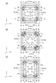
図1は、本実施形態に係る走行車システムSYSの一例を模式的に示す図である。図2は、本実施形態に係る走行車システムSYSの一例を示す斜視図である。図3は、軌道Rの一例を示す+Z方向から見た上面図である。なお、図3では、軌道Rの一部を示している。 FIG. 1 is a diagram schematically showing an example of a traveling vehicle system SYS according to the present embodiment. FIG. 2 is a perspective view showing an example of the traveling vehicle system SYS according to the present embodiment. FIG. 3 is a top view showing an example of the orbit R as viewed from the + Z direction. Note that FIG. 3 shows a part of the orbit R.
図1及び図2に示すように、走行車システムSYSは、軌道Rと、軌道Rに沿って走行する走行車1を含む。走行車システムSYSは、例えば、半導体製造工場のクリーンルームにおいて、物品Mを走行車1により搬送するためのシステムである。走行車1は、半導体ウエハを収容するFOUP、あるいはレチクルを収容するレチクルPod等の物品M(図5参照)を搬送する。走行車システムSYSでは、走行車1が格子状の軌道Rに沿って移動し、物品Mを搬送する。走行車システムSYSにおいて、走行車1は複数台用いられてもよい。複数の走行車1によって物品Mを搬送することにより、高密度な搬送が可能となり、物品Mの搬送効率を向上させることができる。なお、走行車システムSYSは、半導体デバイス製造分野以外の設備にも適用可能である。
As shown in FIGS. 1 and 2, the traveling vehicle system SYS includes a track R and a traveling
軌道Rは、図2及び図3に示すように、平面視において格子状をなすように設置された格子状軌道である。格子状軌道は、軌道Rの一形態である。軌道Rは、クリーンルーム等の建屋の天井(図示せず)又は天井付近に敷設されている。 As shown in FIGS. 2 and 3, the orbit R is a grid-like orbit installed so as to form a grid in a plan view. The grid-like orbit is a form of the orbit R. The track R is laid on the ceiling (not shown) of a building such as a clean room or near the ceiling.
軌道Rは、第1軌道R1と、第2軌道R2と、部分軌道R3と、を有する。第1軌道R1は、X方向(第1方向)に沿って設けられる。第2軌道R2は、Y方向(第2方向)に沿って設けられる。本実施形態では、複数の第1軌道R1と複数の第2軌道R2とは、互いに直交する方向に沿って設けられるが、互いに直接交差しないように設けられている。部分軌道R3は、第1軌道R1と第2軌道R2とが交差する交差部分に配置される。 The orbital R has a first orbital R1, a second orbital R2, and a partial orbital R3. The first track R1 is provided along the X direction (first direction). The second track R2 is provided along the Y direction (second direction). In the present embodiment, the plurality of first orbitals R1 and the plurality of second orbitals R2 are provided along the directions orthogonal to each other, but are provided so as not to directly intersect with each other. The partial track R3 is arranged at the intersection where the first track R1 and the second track R2 intersect.
軌道Rは、第1軌道R1と第2軌道R2とが直交する方向に沿って設けられることで、平面視で格子状のセルC(区画)が隣り合う状態となっている。走行車1は、平面視で1つのセルC内に収まる寸法に形成される(図2参照)。この構成により、隣り合う軌道Rを走行する他の走行車1とすれ違うことが可能となり、軌道Rに複数の走行車1を配置した場合に、各走行車1が他の走行車1と干渉することなく走行できる範囲を拡げることができる。
The track R is provided along the direction in which the first track R1 and the second track R2 are orthogonal to each other, so that the cells C (sections) in a grid pattern are adjacent to each other in a plan view. The traveling
第1軌道R1、第2軌道R2、及び、部分軌道R3は、吊り下げ部材Nを介して天井から吊り下げられた状態で設けられる(図2参照)。吊り下げ部材Nは、第1軌道R1を吊り下げるための第1部分N1と、第2軌道R2を吊り下げるための第2部分N2と、部分軌道R3を吊り下げるための第3部分N3と、を有する。第1部分N1及び第2部分N2は、それぞれ第3部分N3を挟んだ二か所に設けられている。第1軌道R1、第2軌道R2、及び部分軌道R3は、同一又はほぼ同一の水平面(XY平面)に沿って設けられる。 The first track R1, the second track R2, and the partial track R3 are provided in a state of being suspended from the ceiling via the suspension member N (see FIG. 2). The suspending member N includes a first portion N1 for suspending the first track R1, a second portion N2 for suspending the second track R2, and a third portion N3 for suspending the partial track R3. Have. The first portion N1 and the second portion N2 are provided at two locations sandwiching the third portion N3, respectively. The first orbital R1, the second orbital R2, and the partial orbital R3 are provided along the same or substantially the same horizontal plane (XY plane).
軌道Rは、走行車1の走行方向に沿って順に第1隙間D1と、部分軌道R3と、第2隙間D2と、を備えている(図1参照)。第1隙間D1は、部分軌道R3に対して、走行車1の走行方向と反対側(手前側、後方側と称す場合もある)に設けられる。第2隙間D2は、部分軌道R3に対して、走行車1の走行方向側(先側、前方側と称す場合もある)に設けられる。なお、第1隙間D1及び第2隙間D2は同一の隙間であり、第1隙間D1と第2隙間D2とを区別しない場合、適宜、隙間Dと表す。
The track R includes a first gap D1, a partial track R3, and a second gap D2 in order along the traveling direction of the traveling vehicle 1 (see FIG. 1). The first gap D1 is provided on the side opposite to the traveling direction of the traveling vehicle 1 (sometimes referred to as a front side or a rear side) with respect to the partial track R3. The second gap D2 is provided on the traveling direction side (sometimes referred to as a front side or a front side) of the traveling
第1隙間D1及び第2隙間D2は、第1軌道R1と部分軌道R3との間、あるいは、第2軌道R2と部分軌道R3との間に、設けられている(図2参照)。第1隙間D1及び第2隙間D2は、走行車1が第1軌道R1を走行して第2軌道R2を横切る際、あるいは第2軌道R2を走行して第1軌道R1を横切る際に、走行車1の一部である後述の連結部30が通過する部分である。従って、第1隙間D1及び第2隙間D2の双方は、連結部30が通過可能な所定の大きさ(間隔)に設けられている。第1隙間D1及び第2隙間D2の双方を連結部30が通過可能な構成の場合、後に図13(A)から(C)で説明するように、第1隙間D1及び第2隙間D2を利用することにより、連結部30の接続部材32を旋回させることができるので、格子状軌道において、走行車1の走行方向を変更可能な部分を形成することができる。第1隙間D1及び第2隙間D2については、後にさらに説明する。
The first gap D1 and the second gap D2 are provided between the first track R1 and the partial track R3, or between the second track R2 and the partial track R3 (see FIG. 2). The first gap D1 and the second gap D2 travel when the traveling
第1軌道R1、第2軌道R2及び部分軌道R3は、それぞれ、後述する駆動輪21が走行する走行面(上面)R1a、R2a、R3aを有する(図2、図3参照)。第1軌道R1及び第2軌道R2には、それぞれ、走行面R1a、R2aが隣接して2つ形成されている。走行面R1a、R2a、R3aは、同一又はほぼ同一の水平面(XY平面)に沿って設けられる。
The first track R1, the second track R2, and the partial track R3 each have traveling surfaces (upper surfaces) R1a, R2a, and R3a on which the
第1軌道R1及び第2軌道R2には、それぞれ、後述する第1補助輪W1が当接する第1補助軌道P1、及び、第2補助輪W2が当接する第2補助軌道P2が設けられている(図3参照)。第1補助軌道P1と第2補助軌道P2とは、対をなすように形成されている。第1軌道R1には、一対の第1補助軌道P1及び第2補助軌道P2が、第1軌道R1の+Y側及び-Y側のそれぞれに設けられている。また、第2軌道R2には、一対の第1補助軌道P1及び第2補助軌道P2が、第2軌道R2の+X側及び-X側のそれぞれに設けられている。例えば、図3に示すように、第1軌道R1の+Y側及び-Y側のそれぞれにおいて、第1補助軌道P1は第1軌道R1の+X側の端部に設けられ、第2補助軌道P2は第1軌道R1の-X側の端部に設けられ、各第1補助軌道P1は対をなす第2補助軌道P2に対して+X側に設けられる。また、第2軌道R2の+X側及び-X側のそれぞれにおいて、第1補助軌道P1は第2軌道R2の+Y側の端部に設けられ、第2補助軌道P2は第2軌道R2の-Y側の端部に設けられ、各第1補助軌道P1は対をなす第2補助軌道P2に対して+X側に設けられる。第1補助軌道P1及び第2補助軌道P2は、それぞれ、第1補助輪W1、第2補助輪W2が当接する走行面(上面)R4a、R5a(図1参照)を有する。第1補助軌道P1の走行面R4a及び第1補助軌道P1の走行面R4aは、駆動輪21の走行面R1a、R2aより高い第2高さL2となるように形成される。第2高さL2は、例えば数100μmから数mmに設定される。なお、第1補助軌道P1の走行面R4a及び第2補助軌道P2の走行面R5aは、駆動輪21の走行面R1a、R2aに対する高さが異なっていてもよい。なお、図3に示す第1補助軌道P1及び第2補助軌道P2の構成は、一例であって、他の構成でもよい。例えば、第1軌道R1において、第1補助軌道P1は対をなす第2補助軌道P2に対して-Y側に設けられてもよいし、第2軌道R2において、第1補助軌道P1は対をなす第2補助軌道P2に対して+X側に設けられてもよい。
The first track R1 and the second track R2 are provided with a first auxiliary track P1 to which the first auxiliary wheel W1 described later abuts and a second auxiliary track P2 to which the second auxiliary wheel W2 abuts, respectively. (See FIG. 3). The first auxiliary track P1 and the second auxiliary track P2 are formed so as to form a pair. In the first track R1, a pair of first auxiliary tracks P1 and a second auxiliary track P2 are provided on the + Y side and the −Y side of the first track R1, respectively. Further, in the second orbital R2, a pair of first auxiliary orbitals P1 and a second auxiliary orbital P2 are provided on the + X side and the −X side of the second orbital R2, respectively. For example, as shown in FIG. 3, in each of the + Y side and −Y side of the first orbit R1, the first auxiliary orbit P1 is provided at the end of the first orbit R1 on the + X side, and the second auxiliary orbit P2 is The first auxiliary orbit P1 is provided at the end of the first orbit R1 on the −X side, and each first auxiliary orbit P1 is provided on the + X side with respect to the paired second auxiliary orbit P2. Further, on each of the + X side and the −X side of the second orbital R2, the first auxiliary orbital P1 is provided at the end of the second orbital R2 on the + Y side, and the second auxiliary orbital P2 is −Y of the second orbital R2. It is provided at the end on the side, and each first auxiliary track P1 is provided on the + X side with respect to the paired second auxiliary track P2. The first auxiliary track P1 and the second auxiliary track P2 have traveling surfaces (upper surface) R4a and R5a (see FIG. 1) with which the first auxiliary wheels W1 and the second auxiliary wheels W2 abut, respectively. The traveling surface R4a of the first auxiliary track P1 and the traveling surface R4a of the first auxiliary track P1 are formed so as to have a second height L2 higher than the traveling surfaces R1a and R2a of the
第1補助軌道P1及び第2補助軌道P2は、それぞれ、軌道Rに設けられる凸部である(図1参照)。第1補助軌道P1及び第2補助軌道P2は、それぞれ、軌道Rの上面(+Z側の面)に対して+Z方向に突出する凸部である。第1補助軌道P1及び第2補助軌道P2の形状は、平面視において矩形状である。第1補助軌道P1及び第2補助軌道P2は、軌道Rに部材を取り付けることにより形成してもよいし、軌道Rと一体に形成されてもよい。第1補助軌道P1及び第2補助軌道P2を、軌道Rの一部を突出させて凸部とする構成の場合、第1補助軌道P1及び第2補助軌道P2を、軌道Rとは別に設ける必要がないので、装置構成を容易にすることができる。第1補助軌道P1及び第2補助軌道P2の一方又は双方が、軌道Rに設けられる凸部の場合、第1補助軌道P1及び第2補助軌道P2を容易かつ低コストで設けることができる。なお、第1補助軌道P1及び第2補助軌道P2の形状は、それぞれ、任意であり、例えば、第1補助軌道P1及び第2補助軌道P2の形状は、第1補助輪W1及び第2補助輪W2が進入する側の端部がスロープを有する形状でもよいし、第1補助輪W1及び第2補助輪W2の走行方向と直交する方向の移動を規制するガイドを有する形状でもよい。 The first auxiliary track P1 and the second auxiliary track P2 are convex portions provided on the track R, respectively (see FIG. 1). The first auxiliary track P1 and the second auxiliary track P2 are convex portions protruding in the + Z direction with respect to the upper surface (+ Z side surface) of the track R, respectively. The shapes of the first auxiliary track P1 and the second auxiliary track P2 are rectangular in a plan view. The first auxiliary track P1 and the second auxiliary track P2 may be formed by attaching a member to the track R, or may be formed integrally with the track R. In the case where the first auxiliary track P1 and the second auxiliary track P2 are configured to have a convex portion by projecting a part of the track R, the first auxiliary track P1 and the second auxiliary track P2 need to be provided separately from the track R. Since there is no such thing, the device configuration can be facilitated. When one or both of the first auxiliary track P1 and the second auxiliary track P2 are convex portions provided on the track R, the first auxiliary track P1 and the second auxiliary track P2 can be provided easily and at low cost. The shapes of the first auxiliary orbit P1 and the second auxiliary orbit P2 are arbitrary, respectively. For example, the shapes of the first auxiliary orbit P1 and the second auxiliary orbit P2 are the first auxiliary wheels W1 and the second auxiliary wheels. The end portion on the side where W2 enters may have a shape having a slope, or may have a shape having a guide for restricting the movement of the first auxiliary wheel W1 and the second auxiliary wheel W2 in the direction orthogonal to the traveling direction.
第1軌道R1と第2軌道R2との交差部分に部分軌道R3が配置される構成では、部分軌道R3に対して走行車1が第1軌道R1からX方向に進入及び通過する場合と、部分軌道R3に対して走行車1が第2軌道R2からY方向に進入及び通過する場合とがあるため、部分軌道R3において、走行車1の駆動輪21が走行する走行面R3aは、X方向及びY方向の複数方向において一部重なっている。このため、部分軌道R3に、第1補助軌道P1及び第2補助軌道P2を設ける構成では、走行車1の走行の妨げとなってしまう。このため、本実施形態では、部分軌道R3には、第1補助軌道P1及び第2補助軌道P2のいずれも設けられていない。部分軌道R3に第1補助軌道P1及び第2補助軌道P2を設けない構成の場合、部分軌道R3における駆動輪21の走行面R3aが複数方向に一部重なっている場合でも、その走行面R3aに第1補助軌道P1あるいは第2補助軌道P2等が配置されないので、部分軌道R3において駆動輪21を円滑に走行させることができる。
In the configuration in which the partial track R3 is arranged at the intersection of the first track R1 and the second track R2, the traveling
上記のように、本実施形態では、軌道Rが、第1方向に沿って設けられた第1軌道R1と、第1方向に直交する第2方向に沿って設けられた第2軌道R2と、を有し、部分軌道R3が、第1軌道R1と第2軌道R2との交差部分に配置される。この構成の場合、第1軌道R1と第2軌道R2との交差部分に、第1補助軌道P1及び第2補助軌道P2のいずれも設けられていない部分軌道R3が配置されるので、走行車1が第1軌道R1又は第2軌道R2のいずれを走行する場合であっても、交差部分を通過するときに駆動輪21が第1補助軌道P1又は第2補助軌道P2に当接することを回避し、走行車1が交差部分を通過する際に不要な振動が生じるのを回避できる。
As described above, in the present embodiment, the orbit R is a first orbit R1 provided along the first direction and a second orbit R2 provided along the second direction orthogonal to the first direction. And the partial orbit R3 is arranged at the intersection of the first orbit R1 and the second orbit R2. In the case of this configuration, since the partial track R3 in which neither the first auxiliary track P1 nor the second auxiliary track P2 is provided is arranged at the intersection of the first track R1 and the second track R2, the traveling
走行車1について説明する。図4は、走行車の一例を示す斜視図である。図5は、図4に示す走行車を-Y方向から見た側面図である。走行車1は、本体部10と、走行部20と、連結部30(連結部材)と、制御部50とを有する(図5参照)。制御部50は、走行車1の各部の動作を統括的に制御する。制御部50は、本体部10に設けられてもよいし、本体部10の外部に設けられてもよい。本体部10は、軌道Rの下方(-Z側)に配置される。本体部10は、駆動輪21の回転軸AX3から垂下する連結部30に取り付けられて軌道Rより下方に配置される。本体部10は、平面視で例えば矩形状に形成される。本体部10は、平面視で格子状の軌道Rにおける1つのセルCに収まる寸法に形成される(図2参照)。この構成の場合、隣り合う第1軌道R1又は第2軌道R2を走行する他の走行車1とすれ違うスペースが確保される。本体部10は、上部ユニット17と、移載装置18とを備える。上部ユニット17は、連結部30を介して走行部20に吊り下げられる。上部ユニット17は、例えば平面視で矩形状であり、上面17aに4つのコーナー部を有する(図4参照)。
The traveling
移載装置18は、上部ユニット17の下方に設けられる。移載装置18は、物品Mを保持し、且つ、自身と、軌道Rの下方の所定の位置との間で物品Mの受け渡しを行う。例えば、移載装置18は、自身と、保管装置の棚部あるいは搬入搬出部、又は加工装置等の搬入搬出部等との間で、物品Mの受け渡しを行う。移載装置18は、鉛直方向の回転軸AX1まわりに回転可能である(図5参照)。移載装置18は、物品Mを保持する物品保持部13と、物品保持部13を鉛直方向に昇降させる昇降駆動部14と、昇降駆動部14を移動させる横出し機構11と、横出し機構11を保持する回動部12とを有する。物品保持部13は、物品Mのフランジ部Maを把持することにより、物品Mを吊り下げて保持する。物品保持部13は、例えば、水平方向に移動可能な爪部13aを有するチャックであり、爪部13aを物品Mのフランジ部Maの下方に進入させ、物品保持部13を上昇させることで、物品Mを保持する。物品保持部13は、ワイヤあるいはベルトなどの吊り下げ部材13bに接続されている。
The
昇降駆動部14は、例えばホイストであり、吊り下げ部材13bを繰り出すことにより物品保持部13を下降させ、吊り下げ部材13bを巻き取ることにより物品保持部13を上昇させる。昇降駆動部14は、制御部50に制御され、所定の速度で物品保持部13を下降あるいは上昇させる。また、昇降駆動部14は、制御部50に制御され、物品保持部13を目標の高さに保持する。横出し機構11は、例えばZ方向に重ねて配置された複数の可動板を有する。可動板は、Y方向に移動可能である。最下層の可動板には、昇降駆動部14が取り付けられている。横出し機構11は、図5において2点鎖線に示すように、不図示の駆動装置により可動板を移動させ、最下層の可動板に取り付けられた昇降駆動部14及び物品保持部13を走行方向に対して横出しさせることができる。
The elevating
回動部12は、横出し機構11と上部ユニット17との間に設けられる。回動部12は、回動部材12aと、回動駆動部12bとを有する。回動部材12aは、Z軸の軸周り方向に回動可能に設けられる。回動部材12aは、横出し機構11を支持する。回動駆動部12bは、電動モータ等が用いられ、回動部材12aを回転軸AX1の軸周り方向に回動させる。回動部12は、回動駆動部12bからの駆動力によって回動部材12aを回動させ、横出し機構11(昇降駆動部14及び物品保持部13)を回転軸AX1の軸周り方向に回転させることができる。
The rotating
走行車1には、図4及び図5に示すように、移載装置18及び移載装置18により保持している物品Mを囲むようにカバーWが設けられてもよい。カバーWは、下端を開放した筒状であって、かつ、横出し機構11の可動板が突出する部分を切り欠いた形状を有している。カバーWは、上端が回動部12の回動部材12aに取り付けられており、回動部材12aの回動に伴って回転軸AX1の軸まわりに回動する。
As shown in FIGS. 4 and 5, the traveling
走行部20は、駆動輪21と、第1補助輪W1と、第2補助輪W2とを有する(図5参照)。走行部20は、上部ユニット17(本体部10)の上面17aの4つのコーナー部にそれぞれ配置される(図4参照)。本実施形態では、4つの走行部20は同一の構成である。すなわち、走行車1は、走行方向において前方側及び後方側のそれぞれに2つずつ合計4つの走行部20(駆動輪21、第1補助輪W1と、第2補助輪W2)を備える。各走行部20の駆動輪21は、後述する走行駆動部33の駆動力により回転駆動する駆動輪である。なお、4つの駆動輪21のすべてが走行駆動部33の駆動力により回転駆動する構成に限定されず、4つの駆動輪21のうちの一部について回転駆動させる構成であってもよい。すなわち、4つの駆動輪21のうちの一部が従動輪であってもよい。各走行部20は、旋回軸AX2を中心としてθZ方向に旋回可能に設けられる(図4参照)。各走行部20は、後述するステアリング機構34によってθZ方向に旋回し、その結果、走行車1は走行方向を変更することができる。
The traveling
図6(A)から(C)は、走行部20の一例を示す図である。図6(A)は-Y方向から見た側面図である。図6(B)は+X方向から見た正面図である。図6(C)は+Z方向から見た上面図である。
6 (A) to 6 (C) are views showing an example of the traveling
駆動輪21、第1補助輪W1、及び、第2補助輪W2は、それぞれ、後述する連結部30の支持部材31に接続された回転軸AX3、AX4、AX5に取り付けられている(図6(C)参照)。回転軸AX3、AX4、AX5は、それぞれ、XY平面に平行、且つ、走行車1の走行方向と直交する方向に設けられている。
The
駆動輪21は、軌道Rにおいて、第1軌道R1、第2軌道R2、及び、部分軌道R3の走行面R1a、R2a、R3aを転動し、走行車1を走行させる。駆動輪21の直径及び走行方向と直交する方向の厚みの寸法は、それぞれ、限定されず任意に設定可能である。駆動輪21は、軌道Rと接触する周面にゴム等を貼り付ける等の滑り止め加工を施してもよい。また、図6(A)から(C)に示す駆動輪21は一例であり、他の構成でもよい。例えば、駆動輪21は、1つの走行部20に2つ以上設けられる構成でもよい。
The
前方側の駆動輪21の下端及び後方側の駆動輪21の下端は、前方側の駆動輪21の下端及び後方側の駆動輪21の下端が同時に隙間Dを通過しないように設けられており、本実施形態では、走行方向において前方側の駆動輪21の下端と後方側の駆動輪21の下端との走行方向における間隔L3は、走行方向における部分軌道R3の長さL4から、走行方向における第1隙間D1の手前側の端部と第2隙間D2の先側の端部との間の長さL5までの範囲を除いて設定される(図3参照)。この構成の場合、前方側及び後方側のうちの一方の駆動輪21の下端が第1隙間D1又は第2隙間D2を通過しているときでも他方の駆動輪21が軌道Rの走行面R1a、R2a、R3aのいずれかに当接するので、走行車1の走行駆動力が途切れるのを回避できる。
The lower end of the
第1補助輪W1は、駆動輪21の走行方向の後方側に配置される。第2補助輪W2は、駆動輪21の走行方向の前方側に配置される(図6(A)参照)。第1補助輪W1及び第2補助輪W2は、走行方向と直交する方向に(図6ではY方向から)見たときに、それぞれの一部が駆動輪21に重なるように配置される。この構成の場合、走行部20をコンパクトにすることができる。第1補助輪W1及び第2補助輪W2は、駆動輪21における鉛直方向の中心線C1に対して、対称に配置される。
The first auxiliary wheel W1 is arranged on the rear side of the
また、第1補助輪W1の直径及び第2補助輪W2の直径は、駆動輪21の直径よりも小さい。この構成の場合、走行部20の全長を短くすることができ、さらに、走行部20をθZ方向に旋回させる際の回転半径を小さくすることができる。また、第1補助輪W1及び第2補助輪W2において、走行方向と直交する方向の厚みの寸法は、駆動輪21の厚みの寸法よりも小さい。この構成の場合、軌道R及び走行部20をコンパクトにすることができる。本実施形態では、第1補助輪W1及び第2補助輪W2のそれぞれの直径及び厚みの寸法は、それぞれ、同一に設定される。この構成の場合、第1補助輪W1及び第2補助輪W2の部品を共通にすることができるので、装置コストを抑制できる。
Further, the diameter of the first auxiliary wheel W1 and the diameter of the second auxiliary wheel W2 are smaller than the diameter of the
なお、第1補助輪W1及び第2補助輪W2のそれぞれの直径及び幅は、互いに異なっていてもよい。また、第1補助輪W1及び第2補助輪W2は、軌道Rと接触する周面に摩擦を低減する加工を施してもよい。この構成の場合、軌道Rに対する摩擦係数が低減されるので、走行車1の走行速度の低下を抑制することができる。また、図6に示す第1補助輪W1及び第2補助輪W2は一例であって、他の構成でもよい。例えば、第1補助輪W1及び第2補助輪W2の一方又は双方は、2つ以上の車輪を備える構成でもよいし、回転軸方向に対してテーパー形状を有する車輪を用いてもよい。
The diameters and widths of the first training wheels W1 and the second training wheels W2 may be different from each other. Further, the first auxiliary wheel W1 and the second auxiliary wheel W2 may be processed to reduce friction on the peripheral surface in contact with the track R. In the case of this configuration, since the coefficient of friction with respect to the track R is reduced, it is possible to suppress a decrease in the traveling speed of the traveling
本実施形態では、走行方向における駆動輪21の回転軸AX3と第1補助輪W1の回転軸AX4との間隔L7は、第1隙間D1の走行方向における長さL8以上に設定される(図1参照)。この構成の場合、第1補助軌道P1を用いることにより、駆動輪21が第1隙間D1に落ちこむことを抑制できる。また、走行方向における駆動輪21の回転軸AX3と第2補助輪W2の回転軸AX5との間隔L9が第2隙間D2の走行方向における長さL10以上に設定される(図1参照)。この構成の場合、第2補助軌道P2を用いることにより、駆動輪21が第2隙間D2に落ちこむことを抑制できる。
In the present embodiment, the distance L7 between the rotation shaft AX3 of the
第1補助輪W1及び第2補助輪W2は、それぞれ、駆動輪21に対する上下方向(Z方向)の相対位置が固定されている。第1補助輪W1及び第2補助輪W2は、それぞれ、第1軌道R1、第2軌道R2、及び、部分軌道R3の走行面R1a、R2a、R3aに対して、非接触な位置に配置される。第1補助輪W1及び第2補助輪W2は、それぞれ、その下端が駆動輪21の下端に対して高い位置に配置される。また、第1補助輪W1は、鉛直方向における第1補助輪W1の下端が、第1補助軌道P1の走行面R4aに当接する高さとなるように設けられる。また、第2補助輪W2は、鉛直方向における第2補助輪W2の下端が、第2補助軌道P2の走行面R5aに当接する高さとなるように設けられる(図1参照)。
The positions of the first auxiliary wheel W1 and the second auxiliary wheel W2 are fixed relative to the
第1補助輪W1及び第2補助輪W2は、第1補助輪W1の下端及び第2補助輪W2の下端がそれぞれ、駆動輪21の下端よりも第1高さL1だけ高くなるように配置される(図6(A)参照)。駆動輪21による走行時において、第1補助輪W1及び第2補助輪W2が走行面R4a、R5aに接触すると、駆動輪21の輪圧が走行面R1aに伝わらなくなるおそれがあるが、この構成の場合、駆動輪21による走行時において、駆動輪21が第1隙間D1あるいは第2隙間D2を通過しない際には、駆動輪21が走行面R1aに接触し、第1補助輪W1及び第2補助輪W2の双方は走行面R4a、R5aに接触しないので、上記した駆動輪21の輪圧が走行面R1aに伝わらなくなることを抑制することができる。第1高さL1は、例えば数100μmから数mmに設定される。なお、第1補助輪W1の下端の高さと、第2補助輪W2の下端の高さは、異なっていてもよい。
The first auxiliary wheels W1 and the second auxiliary wheels W2 are arranged so that the lower ends of the first auxiliary wheels W1 and the lower ends of the second auxiliary wheels W2 are each higher than the lower ends of the
また、本実施形態では、第1高さL1と第2高さL2とが同一又はほぼ同一に設定される。この構成の場合、駆動輪21の下端が第1隙間D1又は第2隙間D2を通過する際に、駆動輪21の下端が走行面R1a、R2a、R3aの高さから上下に移動することを防止でき、駆動輪21の高さを維持することにより、走行車1が走行中に上下に揺れて振動することを抑制できる。
Further, in the present embodiment, the first height L1 and the second height L2 are set to be the same or substantially the same. In this configuration, when the lower end of the
また、第1補助輪W1及び第2補助輪W2は、それぞれ、駆動輪21に対して、その回転軸AX4、AX5方向(走行方向と直交する方向)にずれて配置され、且つ、第1補助輪W1と第2補助輪W2とは、その回転軸AX4、AX5方向において、互いにずれて配置される(図6(B)参照)。また、第1補助軌道P1及び第2補助軌道P2は、それぞれ第1補助輪W1及び第2補助輪W2に対応して、駆動輪21の走行面R1a、R2aに対して、駆動輪21の回転軸AX3方向(走行方向と直交する方向)にずれて配置され、且つ、第1補助軌道P1及び第2補助軌道P2は、第1補助輪W1及び第2補助輪W2の回転軸AX4、AX5方向において、互いにずれて配置される。本実施形態では、第1補助輪W1及び第2補助輪W2は、それぞれ、駆動輪21に対して、軌道Rの外側の方向にずれて配置される(図6(B)参照)。この構成の場合、駆動輪21が軌道Rの内側方向に配置されるため、駆動輪21が軌道Rから走行方向と直交する方向側から脱落することを抑制することができる。なお、第1補助輪W1及び第2補助輪W2は、それぞれ、駆動輪21に対して、軌道Rの内側の方向にずれて配置されてもよいし、また、駆動輪21が、走行方向と直交する方向において、第1補助輪W1と第2補助輪W2とにより挟まれた位置に配置されてもよい。
Further, the first auxiliary wheels W1 and the second auxiliary wheels W2 are arranged with respect to the
このように、第1補助輪W1及び第2補助輪W2が、互いにその回転軸AX4、AX5方向にずれて配置され、第1補助軌道P1及び第2補助軌道P2が、それぞれ第1補助輪W1及び第2補助輪W2に対応して、その回転軸AX4、AX5方向にずれて配置される構成では、第1補助輪W1が第2補助軌道P2に当接すること、及び第2補助輪W2が第1補助軌道P1に当接することを回避し、走行時の抵抗あるいは振動が生じるのを回避できる。 In this way, the first training wheels W1 and the second training wheels W2 are arranged so as to be offset from each other in the directions of the rotation axes AX4 and AX5, and the first training wheels P1 and the second training wheels P2 are the first training wheels W1 respectively. And in a configuration in which the training wheels W2 are arranged so as to be offset in the directions of the rotation axes AX4 and AX5 corresponding to the second training wheels W2, the first training wheels W1 come into contact with the second training wheels P2, and the second training wheels W2 It is possible to avoid contact with the first auxiliary track P1 and to avoid the generation of resistance or vibration during traveling.
また、第1補助輪W1及び第2補助輪W2が、駆動輪21に対して、その回転軸AX4、AX5方向にずれて、かつ下端が駆動輪21の下端より高い第1高さL2となるように配置され、第1補助軌道P1及び第2補助軌道P2は、駆動輪21の走行面R1a、R2aからずれた位置に設けられて走行面R1a、R2aより高い第2高さL2の上面を有する構成では、駆動輪21が第1補助軌道P1及び第2補助軌道P2に乗り上げることを回避しつつ、第1補助軌道P1及び第2補助軌道P2を容易に配置することができる。
Further, the first auxiliary wheel W1 and the second auxiliary wheel W2 are displaced from the
第1補助軌道P1及び第2補助軌道P2は、それぞれ、第1補助輪W1及び第2補助輪W2の構成に対応するように形成される。第1補助軌道P1は、走行方向において第1隙間D1の手前側に設けられる。第1補助軌道P1は、駆動輪21が部分軌道R3に進入する際に、駆動輪21の下端が第1隙間D1を通過する間において第1補助輪W1の下端が当接するように設けられている(図1参照)。第1補助軌道P1は、少なくとも第1隙間D1の走行方向における長さL8と同じ走行方向の長さL12を有する。なお、第1補助軌道P1の長さは、短いほど、第1補助軌道P1と第1補助輪W1との接触が抑制され、接触によるパーティクルの発生を抑制することができる。例えば、長さL12は、長さL8よりも数10mm程度長く設定されてもよい。
The first auxiliary track P1 and the second auxiliary track P2 are formed so as to correspond to the configurations of the first auxiliary wheel W1 and the second auxiliary wheel W2, respectively. The first auxiliary track P1 is provided on the front side of the first gap D1 in the traveling direction. The first auxiliary track P1 is provided so that when the
また、本実施形態では、第2補助輪W2が第2補助軌道P2に当接している間に、第1補助輪W1が当接する位置には第1補助軌道P1がないように設けられる。この構成により、第1補助軌道P1と第1補助輪W1との不要な接触を抑制することができる。 Further, in the present embodiment, while the second auxiliary wheel W2 is in contact with the second auxiliary track P2, the first auxiliary track P1 is not provided at the position where the first auxiliary wheel W1 is in contact. With this configuration, unnecessary contact between the first auxiliary track P1 and the first auxiliary wheel W1 can be suppressed.
第2補助軌道P2は、走行方向において第2隙間D2の先側に設けられる。第2補助軌道P2は、駆動輪21が部分軌道R3から退出する際に、駆動輪21の下端が第2隙間D2を通過する間において第2補助輪W2の下端が当接するように設けられている。第2補助軌道P2は、少なくとも第2隙間D2の走行方向における長さL10と同じ走行方向の長さL13を有する。なお、第2補助軌道P2の長さは、短いほど、第2補助軌道P2と第2補助輪W2との接触が抑制され、接触によるパーティクルの発生を抑制することができる。例えば長さL13は、長さL10よりも数10mm程度長く設定されてもよい。
The second auxiliary track P2 is provided on the front side of the second gap D2 in the traveling direction. The second auxiliary track P2 is provided so that the lower end of the second auxiliary wheel W2 comes into contact with the second auxiliary track P2 while the lower end of the
また、本実施形態では、第1補助輪W1が第1補助軌道P1に当接している間に、第2補助輪W2が当接する位置には第2補助軌道P2がないように設けられる。この構成により、第2補助軌道P2と第2補助輪W2との不要な接触を抑制することができる。 Further, in the present embodiment, while the first auxiliary wheel W1 is in contact with the first auxiliary track P1, the second auxiliary track P2 is not provided at the position where the second auxiliary wheel W2 is in contact. With this configuration, unnecessary contact between the second auxiliary track P2 and the second auxiliary wheel W2 can be suppressed.
また、本実施形態では、第1補助軌道P1が、駆動輪21の下端が第1隙間D1に達したときに第1補助輪W1の当接が始まるように配置され、且つ、第2補助軌道P2が、駆動輪21の下端が第2隙間D2に達したときに第2補助輪W2の当接が始まるように配置される。この構成の場合、駆動輪21の下端が第1隙間D1又は第2隙間D2に達したと同時又はほぼ同時に、第1補助輪W1又は第2補助輪W2により走行車1を支持することができ、さらに、第1補助軌道P1及び第2補助軌道P2を走行方向に短く設定することができる。
Further, in the present embodiment, the first auxiliary track P1 is arranged so that the contact of the first auxiliary wheel W1 starts when the lower end of the
図7から図12は、走行部20が、軌道Rを走行する状態の一例を示す図である。図7から図12の各図において、(A)は走行方向において前方側の走行部20を-Y方向から見た側面図、(B)は(A)の+Z方向から見た上面図である。(C)は走行方向において前方側及び後方側の走行部20を+Z方向から見た上面図である。
7 to 12 are views showing an example of a state in which the traveling
図7(A)から(C)に示す状態は、走行車1が第1軌道R1を第1隙間D1に向かって走行し、走行部20が第1隙間D1の手前に位置する状態である。この状態の時、駆動輪21の下端は走行面R1aに当接する。第1補助輪W1の下端及び第2補助輪W2の下端は、走行面R1a、第1補助軌道P1、及び、第2補助軌道P2のいずれにも当接しない。また、後方側の走行部20では、駆動輪21の下端は部分軌道R3の走行面R3aに当接し、また、第1補助輪W1の下端及び第2補助輪W2の下端は、走行面R1a、第1補助軌道P1、及び、第2補助軌道P2のいずれにも当接しない。従って、走行車1は、走行方向において前方側の駆動輪21及び後方側の駆動輪21により支持される。
The states shown in FIGS. 7A to 7C are a state in which the traveling
続いて、図8(A)から(C)に示す状態は、駆動輪21の下端が第1隙間D1に進入する直前の状態である。この状態の時は、駆動輪21の下端は、第1隙間D1よりも手前に位置し、走行面R1aに当接する。従って、駆動輪21の下端の第1隙間D1への落ち込みはない。なお、第1補助軌道P1の長さL12を、第1隙間D1の走行方向における長さL8よりも長く設定する場合、この状態の時に第1補助輪W1の下端の第1補助軌道P1への当接が始まっている。本実施形態では、第1補助軌道P1が、駆動輪21の下端が第1隙間D1に達したときに第1補助輪W1の当接が始まるように配置されるので、この状態では、第1補助輪W1の下端は、第1補助軌道P1、及び、第2補助軌道P2のいずれにも当接しない。また、第2補助輪W2の下端は、第1補助軌道P1、及び、第2補助軌道P2のいずれにも当接しない。また、後方側の走行部20においては、駆動輪21の下端は第1軌道R1に当接し、且つ、第1補助輪W1の下端及び第2補助輪W2の下端は、第1軌道R1、第1補助軌道P1、及び、第2補助軌道P2のいずれにも当接しない。従って、走行車1は、走行方向において前方側の駆動輪21及び後方側の駆動輪21により水平に支持される。
Subsequently, the states shown in FIGS. 8A to 8C are states immediately before the lower end of the
続いて、図9(A)から(C)に示す状態は、駆動輪21の下端が第1隙間D1に進入した時の状態である。この状態の時、駆動輪21の下端は、第1隙間D1上に位置するため、駆動輪21は第1軌道R1及び部分軌道R3のいずれにも当接しない。本実施形態では、第1補助軌道P1が、駆動輪21の下端が第1隙間D1に達したときに第1補助輪W1の当接が始まるように配置されるので、この状態において、第1補助輪W1の下端が第1補助軌道P1に当接する。従って、駆動輪21の下端の第1隙間D1への落ち込みはない。また、本実施形態では、第1補助輪W1が第1補助軌道P1に当接している間に、第2補助輪W2が当接する位置には第2補助軌道P2を配置しないので、第2補助輪W2の下端は、走行面R1a、第1補助軌道P1、及び、第2補助軌道P2のいずれにも当接しない。また、後方側の走行部20においては、駆動輪21の下端は第1軌道R1に当接し、且つ、第1補助輪W1の下端及び第2補助輪W2の下端は、第1軌道R1、第1補助軌道P1、及び、第2補助軌道P2のいずれにも当接しない。従って、走行車1は、走行方向において前方側の第1補助輪W1及び後方側の駆動輪21により水平に支持される。
Subsequently, the states shown in FIGS. 9A to 9C are the states when the lower end of the
続いて、図10(A)から(C)に示す状態は、駆動輪21の下端が部分軌道R3に進入した時の状態である。この状態の時、駆動輪21の下端は部分軌道R3に当接するため、駆動輪21の下端の第1隙間D1への落ち込みはない。この際、第1補助輪W1が第1補助軌道P1に当接する。また、本実施形態では、第1補助輪W1が第1補助軌道P1に当接している間に、第2補助輪W2が当接する位置には第2補助軌道P2を配置しないので、第2補助輪W2の下端は、第1軌道R1、第1補助軌道P1、及び、第2補助軌道P2のいずれにも当接しない。また、後方側の走行部20においては、駆動輪21の下端は第1軌道R1に当接し、且つ、第1補助輪W1の下端及び第2補助輪W2の下端は、第1軌道R1、第1補助軌道P1、及び、第2補助軌道P2のいずれにも当接しない。従って、走行車1は、走行方向において前方側の駆動輪21、第1補助輪W1及び後方側の駆動輪21により水平に支持される。
Subsequently, the states shown in FIGS. 10A to 10C are the states when the lower end of the
続いて、図11(A)から(C)に示す状態は、駆動輪21の下端が第2隙間D2に進入した時の状態である。この状態の時、駆動輪21の下端は第2隙間D2上に位置するため、駆動輪21は第1軌道R1及び部分軌道R3のいずれにも当接しない。本実施形態では、第2補助軌道P2が、駆動輪21の下端が第2隙間D2に達したときに第2補助輪W2の当接が始まるように配置されるので、第2補助輪W2の下端が第2補助軌道P2に当接する。従って、駆動輪21の下端の第2隙間D2への落ち込みはない。第1補助輪W1の下端は、第1軌道R1、第1補助軌道P1、及び、第2補助軌道P2のいずれにも当接しない。また、後方側の走行部20においては、駆動輪21の下端は第1軌道R1に当接し、且つ、第1補助輪W1の下端及び第2補助輪W2の下端は、第1軌道R1、第1補助軌道P1、及び、第2補助軌道P2のいずれにも当接しない。従って、走行車1は、走行方向において前方側の第2補助輪W2及び後方側の駆動輪21により水平に支持される。
Subsequently, the states shown in FIGS. 11A to 11C are the states when the lower end of the
続いて、図12(A)から(C)に示す状態は、駆動輪21の下端が第2隙間D2から退出した後の状態である。この状態の時、駆動輪21の下端は第1軌道R1上に当接する。また、後方側の走行部20においては、駆動輪21の下端は第1軌道R1に当接し、且つ、第1補助輪W1の下端及び第2補助輪W2の下端は、第1軌道R1、第1補助軌道P1、及び、第2補助軌道P2のいずれにも当接しない。従って、走行車1は、走行方向において前方側の駆動輪21及び後方側の駆動輪21により水平に支持される。
Subsequently, the states shown in FIGS. 12A to 12C are states after the lower end of the
以上説明したように、本実施形態では、駆動輪21が軌道Rの一部に設けられる隙間Dに落ちることを抑制することができる。
As described above, in the present embodiment, it is possible to prevent the
図4及び図5の説明に戻り、連結部30は、本体部10の上部ユニットと走行部20とを連結する。連結部30は、駆動輪21の回転軸から垂下し、本体部10と走行部20とを連結する。連結部30は、上部ユニット17(本体部10)の上面17aの4つのコーナー部にそれぞれ設けられる。この連結部30によって本体部10は、吊り下げられた状態となり、軌道Rより下方に配置される。連結部30は、支持部材31と、接続部材32とを有する。支持部材31は、駆動輪21の回転軸AX3及び第1補助輪W1及び第2補助輪W2の回転軸AX4、AX5を回転可能に支持する。支持部材31により、駆動輪21と第1補助輪W1と第2補助輪W2との相対位置を保持する。
Returning to the description of FIGS. 4 and 5, the connecting
接続部材32は、支持部材31から下方に延びて上部ユニット17の上面17aに連結され、上部ユニット17を保持する。接続部材32は、後述する走行駆動部33の駆動力を駆動輪21に伝達する伝達機構を内部に備える。この伝達機構は、チェーン又はベルトが用いられる構成であってもよいし、歯車列が用いられる構成であってもよい。接続部材32は、旋回軸AX2を中心としてθZ方向に回転可能に設けられる。この接続部材32が旋回軸AX2を中心として回転することで、駆動輪21をθZ方向に旋回させることができる。
The connecting
連結部30には、走行駆動部33と、ステアリング機構34とが設けられる。走行駆動部33は、接続部材32に装着される。走行駆動部33は、駆動輪21を駆動する駆動源であり、例えば電動モータ等が用いられる。4つの駆動輪21は、それぞれ走行駆動部33によって駆動されて駆動輪となる。4つの駆動輪21は、同一又はほぼ同一の回転数となるように制御部50によって制御される。
The connecting
ステアリング機構34は、連結部30の接続部材32を、旋回軸AX2を中心として回転させることにより、走行部20をθZ方向に旋回させる。走行部20をθZ方向に旋回させることにより、走行車1の走行方向を第1方向(X方向)から第2方向(Y方向)に、又は第2方向から第1方向に変更可能である。
The
ステアリング機構34は、駆動源35と、ピニオンギア36と、ラック37とを有する。駆動源35は、走行駆動部33において旋回軸AX2から離れた側面に取り付けられている。駆動源35は、例えば電動モータ等が用いられる。ピニオンギア36は、駆動源35の下面側に取り付けられており、駆動源35で発生した駆動力によりθZ方向に回転駆動する。ピニオンギア36は、平面視で円形状であり、外周の周方向に複数の歯を有する。ラック37は、上部ユニット17の上面17aに固定される。ラック37は、上部ユニット17の上面17aの4つのコーナー部にそれぞれ設けられ、走行部20の旋回軸AX2を中心とした扇形状に設けられる。ラック37は、外周の周方向に、ピニオンギア36の歯と噛み合う複数の歯を有する。
The
ピニオンギア36及びラック37は、互いの歯が噛み合った状態で配置される。ピニオンギア36がθZ方向に回転することにより、ラック37の外周に沿うようにピニオンギア36が旋回軸AX2を中心とする円周方向に移動する。このピニオンギア36の移動により、走行駆動部33及びステアリング機構34がピニオンギア36とともに旋回軸AX2を中心とする円周方向に旋回する。
The
ステアリング機構34の旋回により、上面17aの4つのコーナー部に配置された走行部20のそれぞれが旋回軸AX2を中心としてθZ方向に90度の範囲で旋回する。ステアリング機構34の駆動は、制御部50によって制御される。制御部50は、4つの走行部20の旋回動作を同一のタイミングで行うように指示してもよいし、異なるタイミングで行うように指示してもよい。走行部20を旋回させることにより、駆動輪21が第1軌道R1及び第2軌道R2の一方に接触した状態から他方に接触した状態に移行する。このため、走行車1の走行方向を第1方向(X方向)と第2方向(Y方向)との間で切り替えることができる。
Due to the turning of the
続いて、走行車システムSYSが走行方向を変更する場合について説明する。図13(A)から(C)は、走行車システムSYSの走行方向を+Y方向から+X方向に変更する動作を示す図である。走行車システムSYSは、図13(A)に示すように、+Y方向に走行して本体部10が軌道Rの一区画(セルC)内に達した位置(4つのコーナー部が部分軌道R3に差し掛かった位置)で停止する。すなわち、制御部50(図5参照)は、位置検出部(図示せず)からの位置情報に基づいて、上記した位置で走行駆動部33の駆動を停止させる。このとき、4つの駆動輪21は、いずれも第2軌道R2の走行面R2aに接触した状態となっている。
Subsequently, a case where the traveling vehicle system SYS changes the traveling direction will be described. 13 (A) to 13 (C) are views showing an operation of changing the traveling direction of the traveling vehicle system SYS from the + Y direction to the + X direction. As shown in FIG. 13A, the traveling vehicle system SYS travels in the + Y direction and reaches a position where the
次に、図13(B)に示すように、制御部50は、ステアリング機構34を駆動して連結部30を旋回させ、4つのコーナー部に配置された走行部20のそれぞれを旋回軸AX2を中心としてθZ方向に旋回させる。このとき、対角にある走行部20等は同一方向に旋回する。例えば、4つの走行部20のうち、図示で左上の走行部20等と、右下の走行部20等は時計回りに旋回する。一方、図示で右上の走行部20等と、左下の走行部20等は反時計回りに旋回する。なお、このような旋回動作は、同一のタイミングで行われてもよいし、例えば、図示で左上及び右下の走行部20等を先に同時に旋回させ、その後、図示で右上及び左下の走行部20等を同時に旋回させるなど、異なるタイミングで旋回させてもよい。
Next, as shown in FIG. 13 (B), the
次に、図13(C)に示すように、制御部50は、各走行部20等がそれぞれθZ方向に90°旋回した後、ステアリング機構34の駆動を停止させる。この状態で走行駆動部33を駆動することにより、走行車システムSYSは、+X方向に走行可能となる。なお、走行車システムSYSは、-X方向にも走行可能である。また、走行部20等が旋回した場合でも本体部10は旋回しない。従って、走行車システムSYSがY方向に走行する場合、又はX方向に走行する場合のいずれであっても本体部10の向きは変更されない。
Next, as shown in FIG. 13C, the
以上の説明のように、本実施形態の走行車システムSYSは、軌道Rと、軌道Rに沿って走行する走行車1と、を含み、軌道Rは、走行車1の走行方向に沿って順に第1隙間D1と、部分軌道R3と、第2隙間D2とを有し、走行車1は、軌道Rの走行面R1a、R2a、R3aを転動する駆動輪21と、走行面R1a、R2a、R3aに対して非接触でありかつ駆動輪21の走行方向の後方側に配置されて駆動輪21に対する上下方向の相対位置が固定された第1補助輪W1と、走行面R1a、R2a、R3aに対して非接触でありかつ駆動輪21の走行方向の前方側に配置されて駆動輪21に対する上下方向の相対位置が固定された第2補助輪W2と、を有し、走行方向における駆動輪21の回転軸と第1補助輪W1の回転軸との間隔L7が第1隙間D1の走行方向における長さL8以上であり、走行方向における駆動輪21の回転軸と第2補助輪W2の回転軸との間隔L9が第2隙間D2の走行方向における長さL10以上である、走行車システムであって、走行方向において第1隙間D1の手前側に設けられ、少なくとも第1隙間D1の走行方向における長さL8と同じ走行方向の長さを有し、駆動輪21が部分軌道R3に進入する際に、駆動輪21の下端が第1隙間D1を通過する間において第1補助輪W1の下端が当接する第1補助軌道P1と、走行方向において第2隙間D2の先側に設けられ、少なくとも第2隙間D2の走行方向における長さと同じ走行方向の長さを有し、駆動輪21が部分軌道R3から退出する際に、駆動輪21の下端が第2隙間D2を通過する間において第2補助輪W2の下端が当接する第2補助軌道P2と、を備え、第1補助輪W1が第1補助軌道P1に当接している間に第2補助輪W2が当接する位置には第2補助軌道P2がなく、第2補助輪W2が第2補助軌道P2に当接している間に第1補助輪W1が当接する位置には第1補助軌道P1がない。なお、走行車システムSYSは、上記以外の構成は任意の構成であり、上記以外の構成はあってもよいし、なくてもよい。
As described above, the traveling vehicle system SYS of the present embodiment includes the driving wheel R and the driving
上記の構成によれば、駆動輪21の下端が第1隙間D1を通過する間は第1補助輪W1が第1補助軌道P1に当接して第2補助輪W2が軌道Rの走行面R1a、R2a、R3a及び第2補助軌道P2と非接触な状態となり、また、駆動輪21の下端が第2隙間D2を通過する間は第2補助輪W2が第2補助軌道P2に当接して第1補助輪W1が軌道Rの走行面R1a、R2a、R3a及び第2補助軌道P2と非接触な状態となるので、第1補助輪W1及び第2補助輪W2のいずれか一方により駆動輪21が第1隙間D1又は第2隙間D2に落ちることを抑制しつつ、部分軌道R3には第1補助輪W1又は第2補助輪W2の下端が当接する補助軌道等の配置を不要とすることができる。従って、例えば、部分軌道R3における駆動輪21の走行面R3aが複数方向に一部重なっている場合でも、その走行面R3aに補助軌道等が配置されないので、部分軌道R3において駆動輪21を円滑に走行させることができる。
According to the above configuration, while the lower end of the
なお、本発明の技術範囲は、上述の実施形態などで説明した態様に限定されない。上述の実施形態などで説明した要件の1つ以上は、省略されることがある。また、上述の実施形態などで説明した要件は、適宜組み合わせることができる。また、法令で許容される限りにおいて、日本特許出願である特願2018-203022、及び上述の実施形態などで引用した全ての文献の開示を援用して本文の記載の一部とする。 The technical scope of the present invention is not limited to the embodiments described in the above-described embodiments. One or more of the requirements described in the above embodiments and the like may be omitted. Further, the requirements described in the above-described embodiments and the like can be appropriately combined. In addition, to the extent permitted by law, the disclosure of Japanese Patent Application No. 2018-203022 and all the documents cited in the above-mentioned embodiments will be incorporated as part of the description of the main text.
なお、上記した実施形態では、第1補助輪W1及び第2補助輪W2が回転する構成を例に挙げて説明したが、この構成に限定されない。例えば、第1補助輪W1及び第2補助輪W2は、回転することなく滑る構成であってもよい。 In the above-described embodiment, the configuration in which the first auxiliary wheel W1 and the second auxiliary wheel W2 rotate is described as an example, but the present invention is not limited to this configuration. For example, the first auxiliary wheel W1 and the second auxiliary wheel W2 may be configured to slide without rotating.
また、上記した実施形態では、本体部10が平面視において格子状の軌道Rの一区画内に収まる寸法に形成された構成を例に挙げて説明したが、この構成に限定されない。例えば、本体部10は、平面視において軌道Rの一区画よりも大きい寸法に形成されてもよいし、軌道Rの一区画に対して一部が突出した形状であってもよい。
Further, in the above-described embodiment, the configuration in which the
SYS…走行車システム
1…走行車
D…隙間
D1…第1隙間
D2…第2隙間
M…物品
R…軌道
R1…第1軌道
R2…第2軌道
10…本体部
20…走行部
21…駆動輪
D1…第1隙間
D2…第2隙間
P1…第1補助軌道
P2…第2補助軌道
R1…第1軌道
R2…第2軌道
R3…部分軌道
W1…第1補助輪
W2…第2補助輪
SYS ... traveling
Claims (9)
前記軌道は、前記走行車の走行方向に沿って順に第1隙間と、部分軌道と、第2隙間とを有し、
前記走行車は、前記軌道の走行面を転動する駆動輪と、前記走行面に対して非接触でありかつ前記駆動輪の走行方向の後方側に配置されて前記駆動輪に対する上下方向の相対位置が固定された第1補助輪と、前記走行面に対して非接触でありかつ前記駆動輪の走行方向の前方側に配置されて前記駆動輪に対する上下方向の相対位置が固定された第2補助輪と、を有し、
前記走行方向における前記駆動輪の回転軸と前記第1補助輪の回転軸との間隔が前記第1隙間の前記走行方向における長さ以上であり、前記走行方向における前記駆動輪の回転軸と前記第2補助輪の回転軸との間隔が前記第2隙間の前記走行方向における長さ以上である、走行車システムであって、
前記走行方向において前記第1隙間の手前側に設けられ、少なくとも前記第1隙間の前記走行方向における長さと同じ前記走行方向の長さを有し、前記駆動輪が前記部分軌道に進入する際に、前記駆動輪の下端が前記第1隙間を通過する間において前記第1補助輪の下端が当接する第1補助軌道と、
前記走行方向において前記第2隙間の先側に設けられ、少なくとも前記第2隙間の前記走行方向における長さと同じ前記走行方向の長さを有し、前記駆動輪が前記部分軌道から退出する際に、前記駆動輪の下端が前記第2隙間を通過する間において前記第2補助輪の下端が当接する第2補助軌道と、を備え、
前記第1補助輪が前記第1補助軌道に当接している間に前記第2補助輪が当接する位置には前記第2補助軌道がなく、
前記第2補助輪が前記第2補助軌道に当接している間に前記第1補助輪が当接する位置には前記第1補助軌道がない、走行車システム。Including a track and a traveling vehicle traveling along the track.
The track has a first gap, a partial track, and a second gap in order along the traveling direction of the traveling vehicle.
The traveling vehicle has a driving wheel that rolls on the traveling surface of the track and is not in contact with the traveling surface and is arranged on the rear side of the driving wheel in the traveling direction so as to be relative to the driving wheel in the vertical direction. The first auxiliary wheel whose position is fixed and the second auxiliary wheel which is not in contact with the traveling surface and is arranged on the front side in the traveling direction of the driving wheel and whose vertical relative position with respect to the driving wheel is fixed are fixed. With training wheels,
The distance between the rotation shaft of the drive wheel and the rotation shaft of the first auxiliary wheel in the travel direction is equal to or longer than the length of the first gap in the travel direction, and the rotation shaft of the drive wheel and the rotation shaft in the travel direction are described. A traveling vehicle system in which the distance between the second auxiliary wheel and the rotating shaft is equal to or greater than the length of the second gap in the traveling direction.
When the drive wheels are provided on the front side of the first gap in the traveling direction, have at least the same length in the traveling direction as the length of the first gap in the traveling direction, and the driving wheels enter the partial track. With the first auxiliary track with which the lower end of the first auxiliary wheel comes into contact while the lower end of the drive wheel passes through the first gap.
When the drive wheels are provided on the front side of the second gap in the traveling direction, have at least the same length in the traveling direction as the length of the second gap in the traveling direction, and the driving wheels exit the partial track. A second auxiliary track with which the lower end of the second auxiliary wheel abuts while the lower end of the drive wheel passes through the second gap.
There is no second auxiliary track at the position where the second auxiliary wheel comes into contact while the first auxiliary wheel is in contact with the first auxiliary track.
A traveling vehicle system in which the first auxiliary track is not present at a position where the first auxiliary wheel comes into contact with the second auxiliary wheel while the second auxiliary wheel is in contact with the second auxiliary track.
前記第1補助軌道及び前記第2補助軌道は、前記軌道の前記走行面からずれた位置に設けられて前記走行面より高い第2高さの上面を有する、請求項1に記載の走行車システム。The first auxiliary wheel and the second auxiliary wheel are arranged so as to be offset in the rotation axis direction with respect to the drive wheel and the lower end thereof has a first height higher than the lower end of the drive wheel.
The traveling vehicle system according to claim 1, wherein the first auxiliary track and the second auxiliary track are provided at positions deviated from the traveling surface of the track and have an upper surface having a second height higher than the traveling surface. ..
前記第1補助軌道及び前記第2補助軌道は、それぞれ前記第1補助輪及び前記第2補助輪に対応して、前記回転軸方向にずれて配置される、請求項1から請求項4のいずれか一項に記載の走行車システム。The first auxiliary wheel and the second auxiliary wheel are arranged so as to be offset from each other in the rotation axis direction.
Any of claims 1 to 4, wherein the first auxiliary track and the second auxiliary track are arranged so as to be offset in the direction of the rotation axis corresponding to the first auxiliary wheel and the second auxiliary wheel, respectively. The traveling vehicle system described in the first paragraph.
前記第2補助軌道は、前記駆動輪の下端が前記第2隙間に達したときに前記第2補助輪の当接が始まるように配置される、請求項1から請求項5のいずれか一項に記載の走行車システム。The first auxiliary track is arranged so that the contact of the first auxiliary wheel starts when the lower end of the drive wheel reaches the first gap.
One of claims 1 to 5, wherein the second auxiliary track is arranged so that contact of the second auxiliary wheel starts when the lower end of the drive wheel reaches the second gap. Driving vehicle system described in.
前記走行方向において前方側の前記駆動輪の下端と後方側の前記駆動輪の下端との前記走行方向における間隔は、前記走行方向における前記部分軌道の長さから、前記走行方向における前記第1隙間の手前側の端部と前記第2隙間の先側の端部との間の長さまでの範囲を除いて設定される、請求項1から請求項5のいずれか一項に記載の走行車システム。The traveling vehicle is provided with the driving wheels on the front side and the rear side in the traveling direction, respectively.
The distance between the lower end of the drive wheel on the front side and the lower end of the drive wheel on the rear side in the travel direction is the first gap in the travel direction from the length of the partial track in the travel direction. The traveling vehicle system according to any one of claims 1 to 5, which is set excluding the range up to the length between the front end of the vehicle and the end of the second gap. ..
前記第1隙間及び前記第2隙間の双方は、前記連結部材が通過可能に設けられる、請求項1から請求項7のいずれか一項に記載の走行車システム。The traveling vehicle includes a main body portion that is attached to a connecting member that hangs down from the rotation shaft of the drive wheel and is located below the track.
The traveling vehicle system according to any one of claims 1 to 7, wherein both the first gap and the second gap are provided so that the connecting member can pass through.
前記部分軌道は、前記第1軌道と前記第2軌道との交差部分に配置される、請求項1から請求項8のいずれか一項に記載の走行車システム。The orbit has a first orbit provided along the first direction and a second orbit provided along a second direction orthogonal to the first direction.
The traveling vehicle system according to any one of claims 1 to 8, wherein the partial track is arranged at an intersection of the first track and the second track.
Applications Claiming Priority (3)
| Application Number | Priority Date | Filing Date | Title |
|---|---|---|---|
| JP2018203022 | 2018-10-29 | ||
| JP2018203022 | 2018-10-29 | ||
| PCT/JP2019/036184 WO2020090253A1 (en) | 2018-10-29 | 2019-09-13 | Traveling vehicle system |
Publications (2)
| Publication Number | Publication Date |
|---|---|
| JPWO2020090253A1 JPWO2020090253A1 (en) | 2021-09-30 |
| JP7040636B2 true JP7040636B2 (en) | 2022-03-23 |
Family
ID=70462963
Family Applications (1)
| Application Number | Title | Priority Date | Filing Date |
|---|---|---|---|
| JP2020554808A Active JP7040636B2 (en) | 2018-10-29 | 2019-09-13 | Traveling vehicle system |
Country Status (9)
| Country | Link |
|---|---|
| US (1) | US20210387654A1 (en) |
| EP (1) | EP3875331B1 (en) |
| JP (1) | JP7040636B2 (en) |
| KR (1) | KR102451691B1 (en) |
| CN (1) | CN112930291B (en) |
| IL (1) | IL282630B (en) |
| SG (1) | SG11202104310QA (en) |
| TW (1) | TWI799660B (en) |
| WO (1) | WO2020090253A1 (en) |
Cited By (1)
| Publication number | Priority date | Publication date | Assignee | Title |
|---|---|---|---|---|
| WO2024070297A1 (en) * | 2022-09-29 | 2024-04-04 | 村田機械株式会社 | Travel rail and traveling vehicle system |
Citations (2)
| Publication number | Priority date | Publication date | Assignee | Title |
|---|---|---|---|---|
| US20110006026A1 (en) | 2009-07-13 | 2011-01-13 | Samsung Electronics Co., Ltd. | Intersection navigation system |
| JP2016175506A (en) | 2015-03-19 | 2016-10-06 | 村田機械株式会社 | Conveyance truck and conveyance truck system |
Family Cites Families (13)
| Publication number | Priority date | Publication date | Assignee | Title |
|---|---|---|---|---|
| CA1236183A (en) * | 1985-01-04 | 1988-05-03 | W. John Ballantyne | Lim secondary reactance compensation and thrust control |
| JPH08324772A (en) * | 1995-06-05 | 1996-12-10 | Shin Meiwa Ind Co Ltd | Work carrier device |
| JPH0932403A (en) * | 1995-07-21 | 1997-02-04 | Okamura Corp | Electric partitioning device |
| CA2465474C (en) * | 2003-05-01 | 2012-07-10 | Daifuku Co., Ltd. | Conveyance apparatus using movable bodies |
| JP4214533B2 (en) * | 2006-08-10 | 2009-01-28 | 村田機械株式会社 | Mobile system |
| JP5440870B2 (en) * | 2010-08-19 | 2014-03-12 | 株式会社ダイフク | Goods transport equipment |
| JP2012116648A (en) | 2010-12-03 | 2012-06-21 | Yuzo Shimizu | Rail type crane |
| JP6278341B2 (en) * | 2015-04-06 | 2018-02-14 | 株式会社ダイフク | Goods transport equipment |
| CN106043316A (en) * | 2016-07-17 | 2016-10-26 | 乔为 | Telescopic rail type lateral stress steering suspension rail traveling device |
| JP6665938B2 (en) * | 2016-08-26 | 2020-03-13 | 村田機械株式会社 | Tracked bogie system and tracked bogie |
| CN106864464B (en) * | 2017-02-23 | 2018-07-06 | 万普华 | Personal suspension type double track road is double dynamical to automatically control railway traffic system |
| JP6476233B2 (en) | 2017-06-02 | 2019-02-27 | 本田技研工業株式会社 | Body structure |
| JP6906754B2 (en) * | 2017-10-31 | 2021-07-21 | 村田機械株式会社 | Transport system |
-
2019
- 2019-09-13 JP JP2020554808A patent/JP7040636B2/en active Active
- 2019-09-13 US US17/288,938 patent/US20210387654A1/en active Pending
- 2019-09-13 EP EP19878857.2A patent/EP3875331B1/en active Active
- 2019-09-13 KR KR1020217012451A patent/KR102451691B1/en active IP Right Grant
- 2019-09-13 IL IL282630A patent/IL282630B/en unknown
- 2019-09-13 WO PCT/JP2019/036184 patent/WO2020090253A1/en unknown
- 2019-09-13 SG SG11202104310QA patent/SG11202104310QA/en unknown
- 2019-09-13 CN CN201980070858.6A patent/CN112930291B/en active Active
- 2019-10-28 TW TW108138771A patent/TWI799660B/en active
Patent Citations (2)
| Publication number | Priority date | Publication date | Assignee | Title |
|---|---|---|---|---|
| US20110006026A1 (en) | 2009-07-13 | 2011-01-13 | Samsung Electronics Co., Ltd. | Intersection navigation system |
| JP2016175506A (en) | 2015-03-19 | 2016-10-06 | 村田機械株式会社 | Conveyance truck and conveyance truck system |
Cited By (1)
| Publication number | Priority date | Publication date | Assignee | Title |
|---|---|---|---|---|
| WO2024070297A1 (en) * | 2022-09-29 | 2024-04-04 | 村田機械株式会社 | Travel rail and traveling vehicle system |
Also Published As
| Publication number | Publication date |
|---|---|
| CN112930291A (en) | 2021-06-08 |
| JPWO2020090253A1 (en) | 2021-09-30 |
| KR102451691B1 (en) | 2022-10-06 |
| SG11202104310QA (en) | 2021-05-28 |
| US20210387654A1 (en) | 2021-12-16 |
| WO2020090253A1 (en) | 2020-05-07 |
| EP3875331A1 (en) | 2021-09-08 |
| KR20210066876A (en) | 2021-06-07 |
| TWI799660B (en) | 2023-04-21 |
| IL282630B (en) | 2022-08-01 |
| EP3875331A4 (en) | 2022-08-03 |
| EP3875331B1 (en) | 2024-01-03 |
| TW202026226A (en) | 2020-07-16 |
| IL282630A (en) | 2021-06-30 |
| CN112930291B (en) | 2023-08-01 |
Similar Documents
| Publication | Publication Date | Title |
|---|---|---|
| JP7040638B2 (en) | Ceiling carrier and ceiling carrier system | |
| JP6665938B2 (en) | Tracked bogie system and tracked bogie | |
| JP6946965B2 (en) | Transport system | |
| JP7040636B2 (en) | Traveling vehicle system | |
| TWI796508B (en) | Elevated trolley system | |
| JP7070704B2 (en) | Traveling vehicle system | |
| WO2021220582A1 (en) | Overhead carrier and overhead carrying system | |
| KR20220008331A (en) | carrier | |
| US20230170238A1 (en) | Overhead conveyance system | |
| WO2022149305A1 (en) | Overhead storage system | |
| TW202300370A (en) | Travelling vehicle system, unit, and grid-shaped track |
Legal Events
| Date | Code | Title | Description |
|---|---|---|---|
| A521 | Request for written amendment filed |
Free format text: JAPANESE INTERMEDIATE CODE: A523 Effective date: 20210426 |
|
| A621 | Written request for application examination |
Free format text: JAPANESE INTERMEDIATE CODE: A621 Effective date: 20210426 |
|
| TRDD | Decision of grant or rejection written | ||
| A01 | Written decision to grant a patent or to grant a registration (utility model) |
Free format text: JAPANESE INTERMEDIATE CODE: A01 Effective date: 20220208 |
|
| A61 | First payment of annual fees (during grant procedure) |
Free format text: JAPANESE INTERMEDIATE CODE: A61 Effective date: 20220221 |
|
| R150 | Certificate of patent or registration of utility model |
Ref document number: 7040636 Country of ref document: JP Free format text: JAPANESE INTERMEDIATE CODE: R150 |