JP7040553B2 - Pachinko machine - Google Patents
Pachinko machine Download PDFInfo
- Publication number
- JP7040553B2 JP7040553B2 JP2020068625A JP2020068625A JP7040553B2 JP 7040553 B2 JP7040553 B2 JP 7040553B2 JP 2020068625 A JP2020068625 A JP 2020068625A JP 2020068625 A JP2020068625 A JP 2020068625A JP 7040553 B2 JP7040553 B2 JP 7040553B2
- Authority
- JP
- Japan
- Prior art keywords
- unit
- winning opening
- state
- reel
- variable
- Prior art date
- Legal status (The legal status is an assumption and is not a legal conclusion. Google has not performed a legal analysis and makes no representation as to the accuracy of the status listed.)
- Active
Links
Images


Classifications
-
- Y—GENERAL TAGGING OF NEW TECHNOLOGICAL DEVELOPMENTS; GENERAL TAGGING OF CROSS-SECTIONAL TECHNOLOGIES SPANNING OVER SEVERAL SECTIONS OF THE IPC; TECHNICAL SUBJECTS COVERED BY FORMER USPC CROSS-REFERENCE ART COLLECTIONS [XRACs] AND DIGESTS
- Y02—TECHNOLOGIES OR APPLICATIONS FOR MITIGATION OR ADAPTATION AGAINST CLIMATE CHANGE
- Y02E—REDUCTION OF GREENHOUSE GAS [GHG] EMISSIONS, RELATED TO ENERGY GENERATION, TRANSMISSION OR DISTRIBUTION
- Y02E60/00—Enabling technologies; Technologies with a potential or indirect contribution to GHG emissions mitigation
- Y02E60/10—Energy storage using batteries
Description
本発明は、パチンコ機などの遊技機に関するものである。 The present invention relates to a gaming machine such as a pachinko machine.
従来より、パチンコ機などの遊技機は、遊技盤面上に設けられた始動口に遊技球が入球すると、遊技の当否が判定され、その判定結果を遊技者に示唆報知するための演出を実行し、当否判定の結果が当たりであった場合には、遊技者に有利となる特典遊技が実行されるものがある。 Conventionally, in a gaming machine such as a pachinko machine, when a gaming ball enters a starting port provided on the surface of the gaming board, the success or failure of the game is determined, and an effect for suggesting and notifying the player of the determination result is executed. However, if the result of the hit / fail judgment is a hit, there is a case where a privileged game that is advantageous to the player is executed.
しかしながら、当否判定の結果を示唆するための演出として更なる遊技の興趣向上が求められていた。 However, there has been a demand for further improvement in the interest of the game as a production for suggesting the result of the pass / fail judgment.
本発明は、上記例示した問題点等を解決するためになされたものであり、遊技の興趣を向上できる遊技機を提供することを目的とする。 The present invention has been made to solve the above-exemplified problems and the like, and an object of the present invention is to provide a gaming machine capable of improving the interest of gaming.
この目的を達成するために請求項1記載の遊技機は、判定を実行可能な判定手段と、その判定手段による判定結果を示すための識別情報が表示される表示手段と、その表示手段に特定の前記判定結果を示すための識別情報が表示された場合に、遊技者に有利な特典が付与される特典付与手段と、を有し、前記識別情報を所定の動作パターンで動的表示可能な動的表示手段と、第1状態と、その第1状態とは異なる第2状態とに可変可能な可変手段と、その可変手段を所定の可変パターンに基づいて可変させるための可変制御を実行可能な可変制御手段と、を有し、前記遊技機は、前記判定手段の前記判定結果を示すための演出パターンとして、前記動的表示手段により動的表示される前記識別情報の前記動作パターンと、前記可変制御手段により実行される前記可変手段の前記可変パターンと、を含む演出パターンを、少なくとも前記判定手段の1の前記判定結果に基づいて決定可能であり、前記可変手段が前記第1状態である場合よりも、前記第2状態である場合の方が前記動的表示手段により動的表示されている前記識別情報を視認困難とさせることが可能であり、前記可変制御手段は、前記識別情報が動的表示されていない状態においても前記演出パターンに含まれる可変態様で前記可変手段を可変可能であり、前記可変手段は、複数の可変部材で構成され、少なくとも1の可変部材が前記第1状態に可変されている状態で、他の可変部材のうち少なくとも1の可変部材を前記第2状態に可変させることが可能にされており、前記遊技機は、前記特定の判定結果である場合に前記特定の判定結果以外である場合よりも前記可変手段が可変される演出パターンが決定され易くされている。
In order to achieve this object, the gaming machine according to
請求項1記載の遊技機によれば、判定を実行可能な判定手段と、その判定手段による判定結果を示すための識別情報が表示される表示手段と、その表示手段に特定の前記判定結果を示すための識別情報が表示された場合に、遊技者に有利な特典が付与される特典付与手段と、を有し、前記識別情報を所定の動作パターンで動的表示可能な動的表示手段と、第1状態と、その第1状態とは異なる第2状態とに可変可能な可変手段と、その可変手段を所定の可変パターンに基づいて可変させるための可変制御を実行可能な可変制御手段と、を有し、前記遊技機は、前記判定手段の前記判定結果を示すための演出パターンとして、前記動的表示手段により動的表示される前記識別情報の前記動作パターンと、前記可変制御手段により実行される前記可変手段の前記可変パターンと、を含む演出パターンを、少なくとも前記判定手段の1の前記判定結果に基づいて決定可能であり、前記可変手段が前記第1状態である場合よりも、前記第2状態である場合の方が前記動的表示手段により動的表示されている前記識別情報を視認困難とさせることが可能であり、前記可変制御手段は、前記識別情報が動的表示されていない状態においても前記演出パターンに含まれる可変態様で前記可変手段を可変可能であり、前記可変手段は、複数の可変部材で構成され、少なくとも1の可変部材が前記第1状態に可変されている状態で、他の可変部材のうち少なくとも1の可変部材を前記第2状態に可変させることが可能にされており、前記遊技機は、前記特定の判定結果である場合に前記特定の判定結果以外である場合よりも前記可変手段が可変される演出パターンが決定され易くされている。
According to the gaming machine according to
よって、遊技の興趣を向上することができるという効果がある。 Therefore, there is an effect that the interest of the game can be improved.
以下、本発明の実施形態について、添付図面を参照して説明する。まず、図1から図6
3を参照し、第1実施形態として、本発明をパチンコ遊技機(以下、単に「パチンコ機」
という)10に適用した場合の一実施形態について説明する。図1は、第1実施形態にお
けるパチンコ機10の正面図であり、図2はパチンコ機10の遊技盤13の正面図であり
、図3はパチンコ機10の背面図である。
Hereinafter, embodiments of the present invention will be described with reference to the accompanying drawings. First, FIGS. 1 to 6
With reference to 3, as a first embodiment, the present invention is a pachinko gaming machine (hereinafter, simply "pachinko machine").
An embodiment when applied to 10) will be described. 1 is a front view of the
図1に示すように、パチンコ機10は、略矩形状に組み合わせた木枠により外殻が形成
される外枠2と、その外枠2と略同一の外形形状に形成され外枠2に対して開閉可能に支
持された内枠4とを備えている。外枠2には、内枠4を支持するために正面視(図1参照
)左側の上下2カ所に金属製のヒンジ18が取り付けられ、そのヒンジ18が設けられた
側を開閉の軸として内枠4が正面手前側へ開閉可能に支持されている。
As shown in FIG. 1, the
内枠4には、多数の釘や入賞口63,64等を有する遊技盤13(図2参照)が裏面側
から着脱可能に装着される。この遊技盤13の前面を球(遊技球)が流下することにより
弾球遊技が行われる。なお、内枠4には、球を遊技盤13の前面領域に発射する球発射ユ
ニット112a(図4参照)やその球発射ユニット112aから発射された球を遊技盤1
3の前面領域まで誘導する発射レール(図示せず)等が取り付けられている。
A game board 13 (see FIG. 2) having a large number of nails, winning
A launch rail (not shown) or the like that guides the vehicle to the front region of 3 is attached.
内枠4の前面側には、その前面上側を覆う前扉5と、その下側を覆う下皿ユニット15
とが設けられている。前扉5および下皿ユニット15を支持するために正面視(図1参照
)左側の上下2カ所に金属製のヒンジ19が取り付けられ、そのヒンジ19が設けられた
側を開閉の軸として前扉5および下皿ユニット15が正面手前側へ開閉可能に支持されて
いる。なお、内枠4の施錠と前扉5の施錠とは、シリンダ錠20の鍵穴21に専用の鍵を
差し込んで所定の操作を行うことでそれぞれ解除される。
On the front side of the
And are provided. Metal hinges 19 are attached to the upper and lower two places on the left side of the front view (see FIG. 1) to support the
前扉5は、装飾用の樹脂部品や電気部品等を組み付けたものであり、その略中央部には
略楕円形状に開口形成された窓部5cが設けられている。前扉5の裏面側には2枚の板ガ
ラス8を有するガラスユニット16が配設され、そのガラスユニット16を介して遊技盤
13の前面がパチンコ機10の正面側に視認可能となっている。
The
前扉5には、球を貯留する上皿17が前方へ張り出して上面を開放した略箱状に形成さ
れており、この上皿17に賞球や貸出球などが排出される。上皿17の底面は正面視(図
1参照)右側に下降傾斜して形成され、その傾斜により上皿17に投入された球が球発射
ユニット112a(図4参照)へと案内される。また、上皿17の上面には、枠ボタン2
2が設けられている。この枠ボタン22は、例えば、セグメント表示装置600及び装飾
図柄表示装置800(図2参照)で表示される演出の態様を変更したり、スーパーリーチ
の演出内容を変更したりする場合などに、遊技者により操作される。
On the
2 is provided. The
前扉5には、その周囲(例えばコーナー部分)に各種ランプ等の発光手段が設けられて
いる。これら発光手段は、大当たり時や所定のリーチ時等における遊技状態の変化に応じ
て、点灯又は点滅することにより発光態様が変更制御され、遊技中の演出効果を高める役
割を果たす。窓部5cの周縁には、LED等の発光手段を内蔵した電飾部29~33が設
けられている。パチンコ機10においては、これら電飾部29~33が大当たりランプ等
の演出ランプとして機能し、大当たり時やリーチ演出時等には内蔵するLEDの点灯や点
滅によって各電飾部29~33が点灯または点滅して、大当たり中である旨、或いは大当
たり一歩手前のリーチ中である旨が報知される。また、前扉5の正面視(図1参照)左上
部には、LED等の発光手段が内蔵され賞球の払い出し中とエラー発生時とを表示可能な
表示ランプ34が設けられている。
The
また、右側の電飾部32下側には、前扉5の裏面側を視認できるように裏面側より透明
樹脂を取り付けて小窓35が形成され、遊技盤13前面の貼着スペースK1(図2参照)
に貼付される証紙等がパチンコ機10の前面から視認可能とされている。また、パチンコ
機10においては、より煌びやかさを醸し出すために、電飾部29~33の周りの領域に
クロムメッキを施したABS樹脂製のメッキ部材36が取り付けられている。
Further, on the lower side of the illuminated
The certificate stamp or the like attached to the
窓部5cの下方には、貸球操作部40が配設されている。貸球操作部40には、度数表
示部41と、球貸しボタン42と、返却ボタン43とが設けられている。パチンコ機10
の側方に配置されるカードユニット(球貸しユニット)(図示せず)に紙幣やカード等を
投入した状態で貸球操作部40が操作されると、その操作に応じて球の貸出が行われる。
具体的には、度数表示部41はカード等の残額情報が表示される領域であり、内蔵された
LEDが点灯して残額情報として残額が数字で表示される。球貸しボタン42は、カード
等(記録媒体)に記録された情報に基づいて貸出球を得るために操作されるものであり、
カード等に残額が存在する限りにおいて貸出球が上皿17に供給される。返却ボタン43
は、カードユニットに挿入されたカード等の返却を求める際に操作される。なお、カード
ユニットを介さずに球貸し装置等から上皿17に球が直接貸し出されるパチンコ機、いわ
ゆる現金機では貸球操作部40が不要となるが、この場合には、貸球操作部40の設置部
分に飾りシール等を付加して部品構成は共通のものとしても良い。カードユニットを用い
たパチンコ機と現金機との共通化を図ることができる。
Below the window portion 5c, a ball
When the ball
Specifically, the
As long as there is a balance on the card or the like, the loan ball is supplied to the
Is operated when requesting the return of the card or the like inserted in the card unit. A pachinko machine in which balls are lent directly to the
上皿17の下側に位置する下皿ユニット15には、その中央部に上皿17に貯留しきれ
なかった球を貯留するための下皿50が上面を開放した略箱状に形成されている。下皿5
0の右側には、球を遊技盤13の前面へ打ち込むために遊技者によって操作される操作ハ
ンドル51が配設される。
In the
On the right side of 0, an
操作ハンドル51の内部には、球発射ユニット112aの駆動を許可するためのタッチ
センサ51aと、押下操作している期間中には球の発射を停止する発射停止スイッチ51
bと、操作ハンドル51の回動操作量(回動位置)を電気抵抗の変化により検出する可変
抵抗器(図示せず)などが内蔵されている。操作ハンドル51が遊技者によって右回りに
回動操作されると、タッチセンサ51aがオンされると共に可変抵抗器の抵抗値が回動操
作量に対応して変化し、その可変抵抗器の抵抗値に対応した強さ(発射強度)で球が発射
され、これにより遊技者の操作に対応した飛び量で遊技盤13の前面へ球が打ち込まれる
。また、操作ハンドル51が遊技者により操作されていない状態においては、タッチセン
サ51aおよび発射停止スイッチ51bがオフとなっている。
Inside the
It has a built-in variable resistor (not shown) that detects the rotation operation amount (rotation position) of the operation handle 51 by the change of electric resistance. When the operation handle 51 is rotated clockwise by the player, the
下皿50の正面下方部には、下皿50に貯留された球を下方へ排出する際に操作するた
めの球抜きレバー52が設けられている。この球抜きレバー52は、常時、右方向に付勢
されており、その付勢に抗して左方向へスライドさせることにより、下皿50の底面に形
成された底面口が開口して、その底面口から球が自然落下して排出される。この球抜きレ
バー52の操作は、通常、下皿50の下方に下皿50から排出された球を受け取る箱(一
般に「千両箱」と称される)を置いた状態で行われる。下皿50の右方には、上述したよ
うに操作ハンドル51が配設され、下皿50の左方には灰皿53が取り付けられている。
A
図2に示すように、遊技盤13は、正面視略正方形状に切削加工したベース板60に、
球案内用の多数の釘(図示せず)や風車の他、レール76,77、一般入賞口63、第1
入賞口64、第2入賞口140、可変入賞装置65、第1スルーゲート66、可変表示装
置ユニット80等を組み付けて構成され、その周縁部が内枠4(図1参照)の裏面側に取
り付けられる。ベース板60は薄い板材を張り合わせた木材からなり、その正面側からベ
ース板60の背面側に配設された各種構造体を遊技者に目視できないように形成される。
一般入賞口63、第1入賞口64、第2入賞口140、可変入賞装置65、可変表示装置
ユニット80は、ルータ加工によってベース板60に形成された貫通穴に配設され、遊技
盤13の前面側からタッピングネジ等により固定されている。
As shown in FIG. 2, the
In addition to a large number of nails (not shown) and windmills for ball guidance, rails 76, 77, general winning
The winning
The general winning
遊技盤13の前面中央部分は、前扉5の窓部5c(図1参照)を通じて内枠4の前面側
から視認することができる。以下に、主に図2を参照して、遊技盤13の構成について説
明する。
The front central portion of the
遊技盤13の前面には、帯状の金属板を略円弧状に屈曲加工して形成した外レール77
が植立され、その外レール77の内側位置には外レール77と同様に帯状の金属板で形成
した円弧状の内レール76が植立される。この内レール76と外レール77とにより遊技
盤13の前面外周が囲まれ、遊技盤13とガラスユニット16(図1参照)とにより前後
が囲まれることにより、遊技盤13の前面には、球の挙動により遊技が行われる遊技領域
が形成される。遊技領域は、遊技盤13の前面であって2本のレール76,77とレール
間を繋ぐ樹脂製の外縁部材73とにより区画して形成される領域(入賞口等が配設され、
発射された球が流下する領域)である。
An outer rail 77 formed by bending a strip-shaped metal plate into a substantially arc shape on the front surface of the
Is planted, and an arc-shaped
The area where the fired ball flows down).
2本のレール76,77は、球発射ユニット112a(図4参照)から発射された球を
遊技盤13上部へ案内するために設けられたものである。内レール76の先端部分(図2
の左上部)には戻り球防止部材68が取り付けられ、一旦、遊技盤13の上部へ案内され
た球が再度球案内通路内に戻ってしまうといった事態が防止される。外レール77の先端
部(図2の右上部)には、球の最大飛翔部分に対応する位置に返しゴム69が取り付けら
れ、所定以上の勢いで発射された球は、返しゴム69に当たって、勢いが減衰されつつ中
央部側へ跳ね返される。
The two
A return
遊技領域の正面視左側下部(図2の左側下部)には、発光手段である複数のLEDおよ
び7セグメント表示器を備える第1図柄表示装置37A,37Bが配設されている。第1
図柄表示装置37A,37Bは、主制御装置110(図4参照)で行われる各制御に応じ
た表示がなされるものであり、主にパチンコ機10の遊技状態の表示が行われる。本実施
形態では、第1図柄表示装置37A,37Bは、球が、第1入賞口64へ入賞したか、第
2入賞口140へ入賞したかに応じて使い分けられるように構成されている。具体的には
、球が、第1入賞口64へ入賞した場合には、第1図柄表示装置37Aが作動し、一方で
、球が、第2入賞口140へ入賞した場合には、第1図柄表示装置37Bが作動するよう
に構成されている。
In the lower left side of the front view (lower left side of FIG. 2) of the game area, first
The
また、第1図柄表示装置37A,37Bは、LEDにより、パチンコ機10が確変中か
時短中か通常中であるかを点灯状態により示したり、変動中であるか否かを点灯状態によ
り示したり、停止図柄が確変大当たりに対応した図柄か普通大当たりに対応した図柄か外
れ図柄であるかを点灯状態により示したり、保留球数を点灯状態により示すと共に、7セ
グメント表示装置により、大当たり中のラウンド数やエラー表示を行う。なお、複数のL
EDは、それぞれのLEDの発光色(例えば、赤、緑、青)が異なるよう構成され、その
発光色の組み合わせにより、少ないLEDでパチンコ機10の各種遊技状態を示唆するこ
とができる。
Further, the first
The ED is configured so that the emission color (for example, red, green, blue) of each LED is different, and the combination of the emission colors can suggest various gaming states of the
なお、本パチンコ機10では、第1入賞口64,第2入賞口140のいずれかに入賞が
あったことを契機として抽選が行われる。パチンコ機10は、その抽選において、大当た
りか否かの当否判定(大当たり抽選)を行うと共に、大当たりと判定した場合はその大当
たり種別の判定も行う。ここで判定される大当たり種別としては、15R確変大当たり、
4R確変大当たり、15R通常大当たりが用意されている。第1図柄表示装置37A,3
7Bには、変動終了後の停止図柄として抽選の結果が大当たりであるか否かが示されるだ
けでなく、大当たりである場合はその大当たり種別に応じた図柄が示される。
In the
4R probability variation jackpot and 15R normal jackpot are available. 1st
In 7B, not only whether or not the result of the lottery is a big hit is shown as a stop symbol after the end of the fluctuation, and if it is a big hit, a symbol corresponding to the big hit type is shown.
ここで、「15R確変大当たり」とは、最大ラウンド数が15ラウンドの大当たりの後
に高確率状態へ移行する確変大当たりのことであり、「4R確変大当たり」とは、最大ラ
ウンド数が4ラウンドの大当たりの後に高確率状態へ移行する確変大当たりのことである
。また、「15R通常大当たり」は、最大ラウンド数が15ラウンドの大当たりの後に、
低確率状態へ移行すると共に、所定の変動回数の間(例えば、100変動回数)は時短状
態となる大当たりのことである。
Here, the "15R probability variation jackpot" is a probability variation jackpot that shifts to a high probability state after the jackpot with a maximum number of rounds of 15 rounds, and the "4R probability variation jackpot" is a jackpot with a maximum number of rounds of 4 rounds. It is a probabilistic jackpot that shifts to a high-probability state after. In addition, "15R normal jackpot" is after the jackpot with a maximum number of rounds of 15 rounds.
It is a big hit that shifts to a low-probability state and shortens the time during a predetermined number of fluctuations (for example, 100 fluctuations).
また、「高確率状態」とは、大当たり終了後に付加価値としてその後の大当たり確率が
アップした状態、いわゆる確率変動中(確変中)の時をいい、換言すれば、特別遊技状態
へ移行し易い遊技の状態のことである。本実施形態における高確率状態(確変中)は、後
述する第2図柄の当たり確率がアップして第2入賞口140へ球が入賞し易い遊技の状態
を含む。「低確率状態」とは、確変中でない時をいい、大当たり確率が通常の状態、即ち
、確変の時より大当たり確率が低い状態をいう。また、「低確率状態」のうちの時短状態
(時短中)とは、大当たり確率が通常の状態であると共に、大当たり確率がそのままで第
2図柄の当たり確率のみがアップして第2入賞口140へ球が入賞し易い遊技の状態のこ
とをいう。一方、パチンコ機10が通常中とは、確変中でも時短中でもない遊技の状態(
大当たり確率も第2図柄の当たり確率もアップしていない状態)である。
In addition, the "high probability state" refers to a state in which the probability of a big hit is increased as an added value after the end of the big hit, that is, during a so-called probability fluctuation (probability change), in other words, a game in which it is easy to shift to a special gaming state. It is the state of. The high-probability state (during probability change) in the present embodiment includes a game state in which the winning probability of the second symbol, which will be described later, is increased and the ball is likely to win the second winning
Neither the jackpot probability nor the hit probability of the second symbol has increased).
確変中や時短中は、第2図柄の当たり確率がアップするだけではなく、第2入賞口14
0に付随する第1電動役物520が開放される時間も変更され、通常中と比して長い時間
が設定される。第1電動役物520が開放された状態(開放状態)にある場合は、その第
1電動役物520が閉鎖された状態(閉鎖状態)にある場合と比して、第2入賞口140
へ球が入賞しやすい状態となる。よって、確変中や時短中は、第2入賞口140へ球が入
賞し易い状態となり、大当たり抽選が行われる回数を増やすことができる。
During probabilistic change or shortening of time, not only the probability of winning the second symbol increases, but also the second winning
The time for opening the first
It becomes easy for the ball to win a prize. Therefore, during the probable change or the shortened working hours, it becomes easy for the ball to win the second winning
なお、確変中や時短中において、第2入賞口140に付随する第1電動役物520の開
放時間を変更するのではなく、または、その開放時間を変更することに加えて、1回の当
たりで第1電動役物520が開放する回数を通常中よりも増やす変更を行うものとしても
よい。また、確変中や時短中において、第2図柄の当たり確率は変更せず、第2入賞口1
40に付随する第1電動役物520が開放される時間および1回の当たりで第1電動役物
520が開放する回数の少なくとも一方を変更するものとしてもよい。また、確変中や時
短中において、第2入賞口140に付随する第1電動役物520が開放される時間や、1
回の当たりで第1電動役物520を開放する回数は変更せず、第2図柄の当たり確率だけ
を、通常中と比してアップするよう変更するものであってもよい。
It should be noted that, during the probability change or the time reduction, the opening time of the first
At least one of the time when the first
The number of times the first
遊技領域には、球が入賞することにより5個から15個の球が賞球として払い出される
複数の一般入賞口63が配設されている。また、遊技領域の中央部分には、可変表示装置
ユニット80が配設されている。可変表示装置ユニット80には、第1入賞口64、第2
入賞口140のいずれかの入賞(始動入賞)をトリガとして、第1図柄表示装置37A,
37Bにおける変動表示と同期させながら、第3図柄の変動表示を行うセグメント表示装
置600及び装飾図柄表示装置800と、第1スルーゲート66の球の通過をトリガとし
て第2図柄を変動表示するLEDで構成される第2図柄表示装置(図示せず)とが設けら
れている。
In the game area, a plurality of general winning
The first
The
また、可変表示装置ユニット80には、セグメント表示装置600及び装飾図柄表示装
置800の外周を囲むようにして、センタフレーム86が配設されている。このセンタフ
レーム86の中央に開口される開口部からセグメント表示装置600及び装飾図柄表示装
置800が視認可能とされる。
Further, in the variable
本実施形態のセグメント表示装置600及び装飾図柄表示装置800は、主制御装置1
10(図4参照)の制御に伴った遊技状態の表示が第1図柄表示装置37A,37Bで行
われるのに対して、その第1図柄表示装置37A,37Bの表示に応じた装飾的な表示お
よび変位動作を行うものである。なお、セグメント表示装置600及び装飾図柄表示装置
800に代えて、例えば液晶表示を用いて遊技状態の表示するようにしても良い。
The
While the game state is displayed by the first
第2図柄表示装置は、球が第1スルーゲート66を通過する毎に表示図柄(第2図柄(
図示せず))としての「○」の図柄と「×」の図柄とを所定時間交互に点灯させる変動表
示を行うものである。パチンコ機10では、球が第1スルーゲート66を通過したことが
検出されると、当たり抽選が行われる。その当たり抽選の結果、当たりであれば、第2図
柄表示装置において、第2図柄の変動表示後に「○」の図柄が停止表示される。また、当
たり抽選の結果、外れであれば、第2図柄表示装置において、第3図柄の変動表示後に「
×」の図柄が停止表示される。
The second symbol display device displays a symbol each time the sphere passes through the first through gate 66 (second symbol (second symbol).
(Not shown)), a variable display is performed in which the "○" symbol and the "×" symbol are alternately lit for a predetermined time. When the
The symbol of "x" is stopped and displayed.
パチンコ機10は、第2図柄表示装置における変動表示が所定図柄(本実施形態におい
ては「○」の図柄)で停止した場合に、第2入賞口140に付随された第1電動役物52
0が所定時間だけ作動状態となる(開放される)よう構成されている。
The
It is configured so that 0 is in the operating state (opened) for a predetermined time.
第2図柄の変動表示にかかる時間は、遊技状態が通常中の場合よりも、確変中または時
短中の方が短くなるように設定される。これにより、確変中および時短中は、第2図柄の
変動表示が短い時間で行われるので、当たり抽選を通常中よりも多く行うことができる。
よって、当たり抽選において当たりとなる機会が増えるので、第2入賞口140の第1電
動役物520が開放状態となる機会を遊技者に多く与えることができる。よって、確変中
および時短中は、第2入賞口140へ球が入賞しやすい状態とすることができる。
The time required for the variation display of the second symbol is set to be shorter during the probability change or the time reduction than when the gaming state is normal. As a result, during the probability change and the time reduction, the variation display of the second symbol is performed in a short time, so that the winning lottery can be performed more than in the normal time.
Therefore, since the chances of winning in the winning lottery increase, it is possible to give the player many opportunities to open the first
なお、確変中または時短中において、当たり確率を高める、1回に当たりに対する第1
電動役物520の開放時間や開放回数を増やすなど、その他の方法によっても、確変中ま
たは時短中に第2入賞口140へ球が入賞しやすい状態としている場合は、第2図柄の変
動表示にかかる時間を遊技状態にかかわらず一定としてもよい。一方、第2図柄の変動表
示にかかる時間を、確変中または時短中において通常中よりも短く設定する場合は、当た
り確率を遊技状態にかかわらず一定にしてもよいし、また、1回の当たりに対する第1電
動役物520の開放時間や開放回数を遊技状態にかかわらず一定にしてもよい。
In addition, during the probability change or the time reduction, the first one for each hit that increases the hit probability.
If the ball is in a state where it is easy to win the second winning
第1スルーゲート66は、可変表示装置ユニット80の右側の領域において遊技盤に組
み付けられる。第1スルーゲート66は、遊技盤に発射された球のうち、遊技盤を流下す
る球の一部が通過可能に構成されている。第1スルーゲート66を球が通過すると、第2
図柄の当たり抽選が行われる。当たり抽選の後、第2図柄表示装置にて変動表示を行い、
当たり抽選の結果が当たりであれば、変動表示の停止図柄として「○」の図柄を表示し、
当たり抽選の結果が外れであれば、変動表示の停止図柄として「×」の図柄を表示する。
The first through
A lottery will be held to win the design. After the winning lottery, variable display is performed on the second symbol display device, and
If the result of the winning lottery is a winning, the symbol "○" is displayed as the stop symbol of the variable display.
If the result of the winning lottery is wrong, the symbol "x" is displayed as the stop symbol of the variable display.
球の第1スルーゲート66の通過回数は、合計で最大4回まで保留され、その保留球数
が上述した第1図柄表示装置37A,37Bにより表示されると共に第2図柄保留ランプ
(図示せず)においても点灯表示される。第2図柄保留ランプは、最大保留数分の4つ設
けられ、セグメント表示装置600及び装飾図柄表示装置800の下方に左右対称に配設
されている。
The number of times the ball has passed through the first through
なお、第2図柄の変動表示は、本実施形態のように、第2図柄表示装置において複数の
ランプの点灯と非点灯を切り換えることにより行うものの他、第1図柄表示装置37A,
37B、セグメント表示装置600及び装飾図柄表示装置800の一部を使用して行うよ
うにしても良い。同様に、第2図柄保留ランプの点灯をセグメント表示装置600及び装
飾図柄表示装置800の一部で行うようにしても良い。また、第1スルーゲート66の球
の通過に対する最大保留球数は4回に限定されるものでなく、3回以下、又は、5回以上
の回数(例えば、8回)に設定しても良い。また、スルーゲートの組み付け数は2つに限
定されるものではなく、3つ以上の複数であっても良い。また、スルーゲートの組み付け
位置は可変表示装置ユニット80の左右両側に限定されるものではなく、例えば、可変表
示装置ユニット80の下方でも良い。また、第1図柄表示装置37A,37Bにより保留
球数が示されるので、第2図柄保留ランプにより点灯表示を行わないものとしてもよい。
The variation display of the second symbol is performed by switching between lighting and non-lighting of a plurality of lamps in the second symbol display device as in the present embodiment, as well as the first
37B, a part of the
可変表示装置ユニット80の下方には、球が入賞し得る第1入賞口64が配設されてい
る。この第1入賞口64へ球が入賞すると遊技盤13の裏面側に設けられる第1入賞口ス
イッチ(図示せず)がオンとなり、その第1入賞口スイッチのオンに起因して主制御装置
110(図4参照)で大当たりの抽選がなされ、その抽選結果に応じた表示が第1図柄表
示装置37Aで示される。
Below the variable
一方、第1入賞口64の正面視右方には、球が入賞し得る第2入賞口140が配設され
ている。第2入賞口140へ球が入賞すると遊技盤13の裏面側に設けられる第2入賞口
スイッチ(図示せず)がオンとなり、その第2入賞口スイッチのオンに起因して主制御装
置110(図4参照)で大当たりの抽選がなされ、その抽選結果に応じた表示が第1図柄
表示装置37Bで示される。
On the other hand, on the right side of the front view of the first winning
また、第1入賞口64,第2入賞口140は、それぞれ、球が入賞すると5個の球が賞
球として払い出される入賞口の1つにもなっている。なお、本実施形態においては、第1
入賞口64へ球が入賞した場合に払い出される賞球数と第2入賞口140へ球が入賞した
場合に払い出される賞球数とを同じに構成したが、第1入賞口64へ球が入賞した場合に
払い出される賞球数と第2入賞口140へ球が入賞した場合に払い出される賞球数とを異
なる数、例えば、第1入賞口64へ球が入賞した場合に払い出される賞球数を3個とし、
第2入賞口140へ球が入賞した場合に払い出される賞球数を5個として構成してもよい
。
Further, each of the first winning
The number of prize balls paid out when a ball wins in the winning
The number of prize balls to be paid out when a ball wins a prize in the second prize opening 140 may be configured as five.
第2入賞口140には第1電動役物520が付随されている。この第1電動役物520
は開閉可能に構成されており、通常は第1電動役物520が閉鎖状態(縮小状態)となっ
て、球が第2入賞口140へ入賞しにくい状態となっている。一方、第1スルーゲート6
6への球の通過を契機として行われる第2図柄の変動表示の結果、「○」の図柄が第2図
柄表示装置に表示された場合、第1電動役物520が開放状態(拡大状態)となり、球が
第2入賞口140へ入賞しやすい状態となる。
A first
Is configured to be openable and closable, and normally, the first
When the symbol "○" is displayed on the second symbol display device as a result of the variation display of the second symbol performed when the ball passes through No. 6, the first
上述した通り、確変中および時短中は、通常中と比して第2図柄の当たり確率が高く、
また、第2図柄の変動表示にかかる時間も短いので、第2図柄の変動表示において「○」
の図柄が表示され易くなって、第1電動役物520が開放状態(拡大状態)となる回数が
増える。更に、確変中または時短中は、第1電動役物520が開放される時間も、通常中
より長くなる。よって、確変中または時短中は、通常時と比して、第2入賞口140へ球
が入賞しやすい状態を作ることができる。
As described above, the probability of hitting the second symbol is higher during the probabilistic change and during the time reduction than during the normal period.
In addition, since the time required for the variable display of the second symbol is short, "○" is displayed in the variable display of the second symbol.
The symbol of is easily displayed, and the number of times that the first
ここで、第1入賞口64に球が入賞した場合と第2入賞口140へ球が入賞した場合と
で、大当たりとなる確率は、低確率状態であっても高確率状態でも同一である。しかしな
がら、大当たりとなった場合に選定される大当たりの種別として15R確変大当たりとな
る確率は、第2入賞口140へ球が入賞した場合のほうが第1入賞口64へ球が入賞した
場合よりも高く設定されている。一方、第1入賞口64は、第2入賞口140にあるよう
な第1電動役物520は有しておらず、球が常時入賞可能な状態となっている。
Here, the probability of winning a big hit is the same in both the low probability state and the high probability state when the ball wins in the first winning
よって、通常中においては、第2入賞口140に付随する電動役物が閉鎖状態にある場
合が多く、第2入賞口140に入賞しづらいので、電動役物のない第1入賞口64へ向け
て、可変表示装置ユニット80の左方を球が通過するように球を発射し(所謂「左打ち」
)、第1入賞口64への入賞によって大当たり抽選の機会を多く得て、大当たりとなるこ
とを狙った方が、遊技者にとって有利となる。
Therefore, during normal times, the electric accessory attached to the second winning
), It is advantageous for the player to get many chances of a big hit lottery by winning a prize in the first winning
一方、確変中や時短中は、第1スルーゲート66に球を通過させることで、第2入賞口
140に付随する第1電動役物520が開放状態となりやすく、第2入賞口140に入賞
しやすい状態であるので、第2入賞口140へ向けて、可変表示装置ユニット80の右方
を球が通過するように球を発射し(所謂「右打ち」)、第1スルーゲート66を通過させ
て第1電動役物520を開放状態にすると共に、第2入賞口140への入賞によって15
R確変大当たりとなることを狙った方が、遊技者にとって有利となる。
On the other hand, during the probability change or the time reduction, by passing the ball through the first through
It is advantageous for the player to aim for the R probability variation jackpot.
このように、本実施形態のパチンコ機10は、パチンコ機10の遊技状態(確変中であ
るか、時短中であるか、通常中であるか)に応じて、遊技者に対し、球の発射の仕方を「
左打ち」と「右打ち」とに変えさせることができる。よって、遊技者に対して、球の打ち
方に変化をもたらすことができるので、遊技を楽しませることができる。
As described above, the
It can be changed to "left-handed" and "right-handed". Therefore, it is possible to change the way the ball is hit for the player, so that the game can be enjoyed.
第1入賞口64の右側には可変入賞装置65が配設されており、その略中央部分に横長
矩形状の特定入賞口(大開放口)65aが設けられている。パチンコ機10においては、
第1入賞口64,第2入賞口140のいずれかの入賞に起因して行われた大当たり抽選が
大当たりとなると、所定時間(変動時間)が経過した後に、大当たりの停止図柄となるよ
う第1図柄表示装置37A又は第1図柄表示装置37Bを点灯させると共に、その大当た
りに対応した停止図柄をセグメント表示装置600及び装飾図柄表示装置800に表示さ
せて、大当たりの発生が示される。その後、球が入賞し易い特別遊技状態(大当たり)に
遊技状態が遷移する。この特別遊技状態として、通常時には閉鎖されている特定入賞口6
5aが、所定時間(例えば、30秒経過するまで、或いは、球が10個入賞するまで)開
放される。
A variable winning device 65 is arranged on the right side of the first winning
When the jackpot lottery performed due to the winning of either the first winning
5a is released for a predetermined time (for example, until 30 seconds have elapsed, or until 10 balls are won).
この特定入賞口65aは、所定時間が経過すると閉鎖され、その閉鎖後、再度、その特
定入賞口65aが所定時間開放される。この特定入賞口65aの開閉動作は、最高で例え
ば15回(15ラウンド)繰り返し可能にされている。この開閉動作が行われている状態
が、遊技者にとって有利な特別遊技状態の一形態であり、遊技者には、遊技上の価値(遊
技価値)の付与として通常時より多量の賞球の払い出しが行われる。
The
可変入賞装置65は、具体的には、特定入賞口65aを覆う横長矩形状の開閉板と、そ
の開閉板の下辺を軸として前方側に開閉駆動するための大開放口ソレノイド(図示せず)
とを備えている。特定入賞口65aは、通常時は、球が入賞できないか又は入賞し難い閉
状態になっている。大当たりの際には大開放口ソレノイドを駆動して開閉板を前面下側に
傾倒し、球が特定入賞口65aに入賞しやすい開状態を一時的に形成し、その開状態と通
常時の閉状態との状態を交互に繰り返すように作動する。
Specifically, the variable winning device 65 includes a horizontally long rectangular opening / closing plate that covers the specific winning
And have. The
なお、上記した形態に特別遊技状態は限定されるものではない。特定入賞口65aとは
別に開閉される大開放口を遊技領域に設け、第1図柄表示装置37A,37Bにおいて大
当たりに対応したLEDが点灯した場合に、特定入賞口65aが所定時間開放され、その
特定入賞口65aの開放中に、球が特定入賞口65a内へ入賞することを契機として特定
入賞口65aとは別に設けられた大開放口が所定時間、所定回数開放される遊技状態を特
別遊技状態として形成するようにしても良い。また、特定入賞口65aは1つに限るもの
ではなく、1つ若しくは2以上の複数(例えば3つ)配置しても良く、また配置位置も第
1入賞口64の右側に限らず、例えば、可変表示装置ユニット80の左方でも良い。
The special gaming state is not limited to the above-mentioned form. A large opening that opens and closes separately from the specific winning
遊技盤13の下側における右隅部には、証紙や識別ラベル等を貼着するための貼着スペ
ースK1が設けられ、貼着スペースK1に貼られた証紙等は、前扉5の小窓35(図1参
照)を通じて視認することができる。
In the right corner on the lower side of the
遊技盤13には、第1アウト口71が設けられている。遊技領域を流下する球であって
、いずれの入賞口63,64,65a,640にも入賞しなかった球は、第1アウト口7
1を通って図示しない球排出路へと案内される。第1アウト口71は、第1入賞口64の
下方に配設される。
The
It is guided to a ball discharge path (not shown) through 1. The first out opening 71 is arranged below the first winning
遊技盤13には、球の落下方向を適宜分散、調整等するために多数の釘が植設されてい
るとともに、風車等の各種部材(役物)とが配設されている。
A large number of nails are planted on the
図3に示すように、パチンコ機10の背面側には、制御基板ユニット90,91と、裏
パックユニット94とが主に備えられている。制御基板ユニット90は、主基板(主制御
装置110)と音声ランプ制御基板(音声ランプ制御装置113)と表示制御基板(表示
制御装置114)とが搭載されてユニット化されている。制御基板ユニット91は、払出
制御基板(払出制御装置111)と発射制御基板(発射制御装置112)と電源基板(電
源装置115)とカードユニット接続基板116とが搭載されてユニット化されている。
As shown in FIG. 3, the
裏パックユニット94は、保護カバー部を形成する裏パック92と払出ユニット93と
がユニット化されている。また、各制御基板には、各制御を司る1チップマイコンとして
のMPU、各種機器との連絡をとるポート、各種抽選の際に用いられる乱数発生器、時間
計数や同期を図る場合などに使用されるクロックパルス発生回路等が、必要に応じて搭載
されている。
In the
なお、主制御装置110、音声ランプ制御装置113および表示制御装置114、払出
制御装置111および発射制御装置112、電源装置115、カードユニット接続基板1
16は、それぞれ基板ボックス100~104に収納されている。基板ボックス100~
104は、ボックスベースと該ボックスベースの開口部を覆うボックスカバーとを備えて
おり、そのボックスベースとボックスカバーとが互いに連結されて、各制御装置や各基板
が収納される。
The
16 are housed in the
The 104 includes a box base and a box cover that covers an opening of the box base, and the box base and the box cover are connected to each other to house each control device and each board.
また、基板ボックス100(主制御装置110)および基板ボックス102(払出制御
装置111および発射制御装置112)は、ボックスベースとボックスカバーとを封印ユ
ニット(図示せず)によって開封不能に連結(かしめ構造による連結)している。また、
ボックスベースとボックスカバーとの連結部には、ボックスベースとボックスカバーとに
亘って封印シール(図示せず)が貼着されている。この封印シールは、脆性な素材で構成
されており、基板ボックス100,102を開封するために封印シールを剥がそうとした
り、基板ボックス100,102を無理に開封しようとすると、ボックスベース側とボッ
クスカバー側とに切断される。よって、封印ユニット又は封印シールを確認することで、
基板ボックス100,102が開封されたかどうかを知ることができる。
Further, in the board box 100 (main control device 110) and the board box 102 (
A sealing sticker (not shown) is attached to the connecting portion between the box base and the box cover over the box base and the box cover. This seal is made of a brittle material, and if you try to peel off the seal to open the
It is possible to know whether or not the
払出ユニット93は、裏パックユニット94の最上部に位置して上方に開口したタンク
130と、タンク130の下方に連結され下流側に向けて緩やかに傾斜するタンクレール
131と、タンクレール131の下流側に縦向きに連結されるケースレール132と、ケ
ースレール132の最下流部に設けられ、払出モータ216(図4参照)の所定の電気的
構成により球の払出を行う払出装置133とを備えている。タンク130には、遊技ホー
ルの島設備から供給される球が逐次補給され、払出装置133により必要個数の球の払い
出しが適宜行われる。タンクレール131には、当該タンクレール131に振動を付加す
るためのバイブレータ134が取り付けられている。
The
また、払出制御装置111には状態復帰スイッチ120が設けられ、発射制御装置11
2には可変抵抗器の操作つまみ121が設けられ、電源装置115にはRAM消去スイッ
チ122が設けられている。状態復帰スイッチ120は、例えば、払出モータ216(図
4参照)部の球詰まり等、払出エラーの発生時に球詰まりを解消(正常状態への復帰)す
るために操作される。操作つまみ121は、発射ソレノイドの発射力を調整するために操
作される。RAM消去スイッチ122は、パチンコ機10を初期状態に戻したい場合に電
源投入時に操作される。
Further, the
No. 2 is provided with an
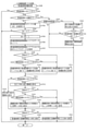
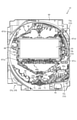
次に、図4を参照して、本パチンコ機10の電気的構成について説明する。図4は、パ
チンコ機10の電気的構成を示すブロック図である。
Next, with reference to FIG. 4, the electrical configuration of the
主制御装置110には、演算装置である1チップマイコンとしてのMPU201が搭載
されている。MPU201には、該MPU201により実行される各種の制御プログラム
や固定値データを記憶したROM202と、そのROM202内に記憶される制御プログ
ラムの実行に際して各種のデータ等を一時的に記憶するためのメモリであるRAM203
と、そのほか、割込回路やタイマ回路、データ送受信回路などの各種回路が内蔵されてい
る。主制御装置110では、MPU201によって、大当たり抽選や第1図柄表示装置3
7A,37B、セグメント表示装置600及び装飾図柄表示装置800における表示の設
定、第2図柄表示装置における表示結果の抽選といったパチンコ機10の主要な処理を実
行する。
The
In addition, various circuits such as an interrupt circuit, a timer circuit, and a data transmission / reception circuit are built-in. In the
7A, 37B, display setting in the
なお、払出制御装置111や音声ランプ制御装置113などのサブ制御装置に対して動
作を指示するために、主制御装置110から該サブ制御装置へ各種のコマンドがデータ送
受信回路によって送信されるが、かかるコマンドは、主制御装置110からサブ制御装置
へ一方向にのみ送信される。
In order to instruct the operation to the sub control device such as the
RAM203は、各種エリア、カウンタ、フラグのほか、MPU201の内部レジスタ
の内容やMPU201により実行される制御プログラムの戻り先番地などが記憶されるス
タックエリアと、各種のフラグおよびカウンタ、I/O等の値が記憶される作業エリア(
作業領域)とを有している。なお、RAM203は、パチンコ機10の電源の遮断後にお
いても電源装置115からバックアップ電圧が供給されてデータを保持(バックアップ)
できる構成となっており、RAM203に記憶されるデータは、すべてバックアップされ
る。
The
It has a work area). The
All the data stored in the
停電などの発生により電源が遮断されると、その電源遮断時(停電発生時を含む。以下
同様)のスタックポインタや、各レジスタの値がRAM203に記憶される。一方、電源
投入時(停電解消による電源投入を含む。以下同様)には、RAM203に記憶される情
報に基づいて、パチンコ機10の状態が電源遮断前の状態に復帰される。RAM203へ
の書き込みはメイン処理(図示せず)によって電源遮断時に実行され、RAM203に書
き込まれた各値の復帰は電源投入時の立ち上げ処理(図示せず)において実行される。な
お、MPU201のNMI端子(ノンマスカブル割込端子)には、停電等の発生による電
源遮断時に、停電監視回路252からの停電信号SG1が入力されるように構成されてお
り、その停電信号SG1がMPU201へ入力されると、停電時処理としてのNMI割込
処理(図示せず)が即座に実行される。
When the power is cut off due to the occurrence of a power failure or the like, the stack pointer at the time of the power failure (including the time when a power failure occurs; the same applies hereinafter) and the value of each register are stored in the
主制御装置110のMPU201には、アドレスバスおよびデータバスで構成されるバ
スライン204を介して入出力ポート205が接続されている。入出力ポート205には
、払出制御装置111、音声ランプ制御装置113、第1図柄表示装置37A,37B、
第2図柄表示装置、第2図柄保留ランプ、特定入賞口65aの開閉板の下辺を軸として前
方側に開閉駆動するための大開放口ソレノイドや電動役物を駆動するためのソレノイドな
どからなるソレノイド209が接続され、MPU201は、入出力ポート205を介して
これらに対し各種コマンドや制御信号を送信する。
The input /
A solenoid consisting of a second symbol display device, a second symbol hold lamp, a large opening solenoid for driving the opening and closing forward with the lower side of the opening / closing plate of the specific winning
また、入出力ポート205には、図示しないスイッチ群およびスライド位置検出センサ
Sや回転位置検出センサRを含むセンサ群などからなる各種スイッチ208、電源装置1
15に設けられた後述のRAM消去スイッチ回路253が接続され、MPU201は各種
スイッチ208から出力される信号や、RAM消去スイッチ回路253より出力されるR
AM消去信号SG2に基づいて各種処理を実行する。
Further, the input /
A RAM erase
Various processes are executed based on the AM erasure signal SG2.
払出制御装置111は、払出モータ216を駆動させて賞球や貸出球の払出制御を行う
ものである。演算装置であるMPU211は、そのMPU211により実行される制御プ
ログラムや固定値データ等を記憶したROM212と、ワークメモリ等として使用される
RAM213とを有している。
The
払出制御装置111のRAM213は、主制御装置110のRAM203と同様に、M
PU211の内部レジスタの内容やMPU211により実行される制御プログラムの戻り
先番地などが記憶されるスタックエリアと、各種のフラグおよびカウンタ、I/O等の値
が記憶される作業エリア(作業領域)とを有している。RAM213は、パチンコ機10
の電源の遮断後においても電源装置115からバックアップ電圧が供給されてデータを保
持(バックアップ)できる構成となっており、RAM213に記憶されるデータは、すべ
てバックアップされる。なお、主制御装置110のMPU201と同様、MPU211の
NMI端子にも、停電等の発生による電源遮断時に停電監視回路252から停電信号SG
1が入力されるように構成されており、その停電信号SG1がMPU211へ入力される
と、停電時処理としてのNMI割込処理(図示せず)が即座に実行される。
The
A stack area in which the contents of the internal registers of the PU211 and the return address of the control program executed by the MPU211 are stored, and a work area (work area) in which the values of various flags, counters, I / O, etc. are stored. have.
Even after the power supply is cut off, the backup voltage is supplied from the
1 is configured to be input, and when the power failure signal SG1 is input to the
払出制御装置111のMPU211には、アドレスバスおよびデータバスで構成される
バスライン214を介して入出力ポート215が接続されている。入出力ポート215に
は、主制御装置110や払出モータ216、発射制御装置112などがそれぞれ接続され
ている。また、図示はしないが、払出制御装置111には、払い出された賞球を検出する
ための賞球検出スイッチが接続されている。なお、該賞球検出スイッチは、払出制御装置
111に接続されるが、主制御装置110には接続されていない。
An input /
発射制御装置112は、主制御装置110により球の発射の指示がなされた場合に、操
作ハンドル51の回動操作量に応じた球の打ち出し強さとなるよう球発射ユニット112
aを制御するものである。球発射ユニット112aは、図示しない発射ソレノイドおよび
電磁石を備えており、その発射ソレノイドおよび電磁石は、所定条件が整っている場合に
駆動が許可される。具体的には、遊技者が操作ハンドル51に触れていることをタッチセ
ンサ51aにより検出し、球の発射を停止させるための発射停止スイッチ51bがオフ(
操作されていないこと)を条件に、操作ハンドル51の回動操作量(回動位置)に対応し
て発射ソレノイドが励磁され、操作ハンドル51の操作量に応じた強さで球が発射される
。
The
It controls a. The
The firing solenoid is excited according to the rotation operation amount (rotation position) of the operation handle 51 on the condition that it is not operated), and the ball is launched with the strength corresponding to the operation amount of the operation handle 51. ..
音声ランプ制御装置113は、音声出力装置(図示しないスピーカなど)226におけ
る音声の出力、ランプ表示装置(電飾部29~33、表示ランプ34など)227におけ
る点灯および消灯の出力、変動演出(変動表示)や予告演出といった表示制御装置114
で行われるセグメント表示装置600及び装飾図柄表示装置800の表示態様の設定など
を制御するものである。演算装置であるMPU221は、そのMPU221により実行さ
れる制御プログラムや固定値データ等を記憶したROM222と、ワークメモリ等として
使用されるRAM223とを有している。
The audio
It controls the setting of the display mode of the
音声ランプ制御装置113のMPU221には、アドレスバスおよびデータバスで構成
されるバスライン224を介して入出力ポート225が接続されている。入出力ポート2
25には、主制御装置110、表示制御装置114、音声出力装置226、ランプ表示装
置227、その他装置228、枠ボタン22などがそれぞれ接続されている。その他装置
228には、駆動モータKM1,KM2,KM3が含まれる。
An input /
A
音声ランプ制御装置113は、主制御装置110から受信した各種のコマンド(変動パ
ターンコマンド、停止種別コマンド等)に基づいて、セグメント表示装置600及び装飾
図柄表示装置800の表示態様を決定し、決定した表示態様をコマンド(表示用変動パタ
ーンコマンド、表示用停止種別コマンド等)によって表示制御装置114へ通知する。ま
た、音声ランプ制御装置113は、枠ボタン22からの入力を監視し、遊技者によって枠
ボタン22が操作された場合は、セグメント表示装置600及び装飾図柄表示装置800
で表示される態様を変更したり、スーパーリーチ時の演出内容を変更したりするように、
表示制御装置114へ指示する。表示される態様が変更される場合は、変更後の表示され
る態様に応じた装飾をセグメント表示装置600及び装飾図柄表示装置800に表示させ
るべく、変更後の表示される態様に関する情報を含めた背面画像変更コマンドを表示制御
装置114へ送信する。ここで、背面画像とは、セグメント表示装置600及び装飾図柄
表示装置800に表示させる主要な画像である第3図柄の背面側に表示される画像のこと
である。表示制御装置114は、この音声ランプ制御装置113から送信されるコマンド
に従って、セグメント表示装置600及び装飾図柄表示装置800に各種の装飾を表示す
る。
The voice
To change the mode displayed in, or to change the production content at the time of super reach,
Instruct the
また、音声ランプ制御装置113は、表示制御装置114からセグメント表示装置60
0及び装飾図柄表示装置800の表示内容を表すコマンド(表示コマンド)を受信する。
音声ランプ制御装置113では、表示制御装置114から受信した表示コマンドに基づき
、セグメント表示装置600及び装飾図柄表示装置800の表示内容に合わせて、その表
示内容に対応する音声を音声出力装置226から出力し、また、その表示内容に対応させ
てランプ表示装置227の点灯および消灯を制御する。
Further, the voice
0 and a command (display command) indicating the display contents of the decorative
The voice
表示制御装置114は、音声ランプ制御装置113およびセグメント表示装置600及
び装飾図柄表示装置800が接続され、音声ランプ制御装置113より受信したコマンド
に基づいて、セグメント表示装置600及び装飾図柄表示装置800における第3図柄の
変動演出などの表示を制御するものである。また、表示制御装置114は、セグメント表
示装置600及び装飾図柄表示装置800の表示内容を通知する表示コマンドを適宜音声
ランプ制御装置113へ送信する。音声ランプ制御装置113は、この表示コマンドによ
って示される表示内容にあわせて音声出力装置226から音声を出力することで、セグメ
ント表示装置600及び装飾図柄表示装置800の表示と音声出力装置226からの音声
出力とをあわせることができる。
The
電源装置115は、パチンコ機10の各部に電源を供給するための電源部251と、停
電等による電源遮断を監視する停電監視回路252と、RAM消去スイッチ122(図3
参照)が設けられたRAM消去スイッチ回路253とを有している。電源部251は、図
示しない電源経路を通じて、各制御装置110~114等に対して各々に必要な動作電圧
を供給する装置である。その概要としては、電源部251は、外部より供給される交流2
4ボルトの電圧を取り込み、各種スイッチ208などの各種スイッチや、ソレノイド20
9などのソレノイド、モータ等を駆動するための12ボルトの電圧、ロジック用の5ボル
トの電圧、RAMバックアップ用のバックアップ電圧などを生成し、これら12ボルトの
電圧、5ボルトの電圧およびバックアップ電圧を各制御装置110~114等に対して必
要な電圧を供給する。
The
It has a RAM erase
Various switches such as
Generates 12 volt voltage for driving solenoids such as 9, motor, etc., 5 volt voltage for logic, backup voltage for RAM backup, etc., and these 12 volt voltage, 5 volt voltage and backup voltage are generated. The required voltage is supplied to each of the
停電監視回路252は、停電等の発生による電源遮断時に、主制御装置110のMPU
201および払出制御装置111のMPU211の各NMI端子へ停電信号SG1を出力
するための回路である。停電監視回路252は、電源部251から出力される最大電圧で
ある直流安定24ボルトの電圧を監視し、この電圧が22ボルト未満になった場合に停電
(電源断、電源遮断)の発生と判断して、停電信号SG1を主制御装置110および払出
制御装置111へ出力する。停電信号SG1の出力によって、主制御装置110および払
出制御装置111は、停電の発生を認識し、NMI割込処理を実行する。なお、電源部2
51は、直流安定24ボルトの電圧が22ボルト未満になった後においても、NMI割込
処理の実行に充分な時間の間、制御系の駆動電圧である5ボルトの電圧の出力を正常値に
維持するように構成されている。よって、主制御装置110および払出制御装置111は
、NMI割込処理(図示せず)を正常に実行し完了することができる。
The power
This is a circuit for outputting the power failure signal SG1 to each NMI terminal of the
In 51, even after the DC stable 24 volt voltage becomes less than 22 volt, the output of the 5 volt voltage, which is the drive voltage of the control system, is returned to the normal value for a sufficient time for executing the NMI interruption process. It is configured to maintain. Therefore, the
RAM消去スイッチ回路253は、RAM消去スイッチ122(図3参照)が押下され
た場合に、主制御装置110へ、バックアップデータをクリアさせるためのRAM消去信
号SG2を出力するための回路である。主制御装置110は、パチンコ機10の電源投入
時に、RAM消去信号SG2を入力した場合に、バックアップデータをクリアすると共に
、払出制御装置111においてバックアップデータをクリアさせるための払出初期化コマ
ンドを払出制御装置111に対して送信する。
The RAM erase
次いで、図5を参照して、遊技盤13の概略構成について説明する。図5は、遊技盤1
3の分解斜視正面図である。なお、図13では、遊技盤13から入賞口ユニット500が
分解された状態が図示される。
Next, a schematic configuration of the
3 is an exploded perspective front view of 3. Note that FIG. 13 shows a state in which the winning
図5に示すように、入賞口ユニット500は、遊技盤13の前面に植立される2本のレ
ール76,77とレール間を繋ぐ樹脂製の外縁部材73とにより区画して形成される遊技
領域の下方に形成される開口13aに前面側から挿入して配設される。なお、入賞口ユニ
ット500の詳細な構成は後述する。
As shown in FIG. 5, the winning
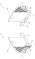
次いで、図6から図9を参照して、動作ユニット300の概略構成について説明する。
図6は、動作ユニット300の斜視正面図である。図7は、動作ユニット300の分解斜
視正面図である。また、図8及び図9は、動作ユニット300の正面図である。
Next, a schematic configuration of the
FIG. 6 is a perspective front view of the
なお、図8では、セグメント表示装置600に上下一対配設される変位部材670が上
下両側にそれぞれ退避された状態が、図9では、図8に示す態様から、セグメント表示装
置600に上下一対配設される変位部材670が上下中央位置に張り出された状態が、そ
れぞれ図示される。
In FIG. 8, the
図6及び図7に示すように、動作ユニット300は、箱状に形成される背面ケース40
0を備え、その背面ケース400の内部空間に、装飾図柄表示装置800、セグメント表
示装置600及び装飾ユニット700が収容される。
As shown in FIGS. 6 and 7, the
0 is provided, and the decorative
背面ケース400は、正面視略矩形の底壁部401と、その底壁部401の4辺の外縁
から正面へ向けて立設される外壁部402とを備え、それら各壁部401,402により
一面側(正面側)が開放された箱状に形成される。底壁部401には、その中央に正面視
矩形の開口401aが開口形成され、その開口401aを通じて、セグメント表示装置6
00が背面ケース400の背面側から配設される。
The
00 is arranged from the back side of the
装飾図柄表示装置800は、背面ケース400の底壁部401のうちの開口401aに
左右方向に3つ並設して配設される。装飾図柄表示装置800には、上下方向に回転変位
する内リールユニット810及び外リールユニット820(図31参照)が配設され、そ
の内リールユニット810及び外リールユニット820の外周面に装飾された図柄が変動
(回転)する態様を遊技者に視認可能に構成される。なお、装飾図柄表示装置800の詳
しい説明は後述する。
Three decorative
セグメント表示装置600は、背面ケース400の底壁部401に配設されると共に、
装飾図柄表示装置800を覆設する態様とされる。装飾図柄表示装置800のベース部材
660(図49参照)の対向間には所定の隙間が形成されており、その隙間の間に装飾図
柄表示装置800が配設されることで、遊技者側から、装飾図柄表示装置800を視認可
能とされる。
The
It is an embodiment in which the decorative
また、セグメント表示装置600には、上述したベース部材660の対向間の隙間の前
方を変位可能とされる変位部材670(図49参照)が配設され、変位部材670を装飾
図柄表示装置800の前方に変位させることで、遊技者側から装飾図柄表示装置800を
視認不能とする演出形態を形成できる。なお、セグメント表示装置600の詳しい説明は
後述する。
Further, the
装飾ユニット700は、正面視横長矩形の箱状に形成され、セグメント表示装置600
の上下に一対配設される。装飾ユニット700は、透明な樹脂材料から形成されると共に
、その形状がパチンコ機10のロゴやタイトル等を模した形状に形成される。また、装飾
ユニット700の内部には、光を照射するLED基盤が配設され、遊技者側に光を照射可
能に形成される。
The
A pair is arranged above and below. The
次いで、図10から図29を参照して、入賞口ユニット500の詳細な説明する。まず
、図10から図13を参照して、入賞口ユニット500の構成を説明する。
Next, the winning
図10(a)は、入賞口ユニット500の正面図であり、図10(b)は、入賞口ユニ
ット500の背面図である。図11は、入賞口ユニット500の分解斜視正面図であり、
図12は、入賞口ユニット500の分解斜視背面図である。図13は、ベース部材510
及び第1電動役物520の分解斜視図である。
10 (a) is a front view of the winning
FIG. 12 is an exploded perspective rear view of the winning
It is an exploded perspective view of the first
図10から図13に示すように、入賞口ユニット500は、遊技盤13の前面に配設(
図5参照)に配設されるベース部材510と、そのベース部材510の内側に回転可能に
軸支される第1電動役物520と、その第1電動役物520に駆動力を付与する駆動ユニ
ット530とを主に備えて形成される。
As shown in FIGS. 10 to 13, the winning
(See FIG. 5), a
ベース部材510は、正面側に配設される正面ベース511と、その正面ベース511
と所定の間隔を隔てて配設される背面ベース512とを締結して形成される。
The
And the
正面ベース511は、正面視横長矩形の板状体から形成されると共に、透明な樹脂材料
から形成される。正面ベース511は、左右方向中央部の上端部から背面側に突出する第
1突出部511aと、左右方向中央部において下端部から背面側に突出する第2突出部5
11bと、その第2突出部511bと左右方向に所定の隙間を隔てた位置に突出する第3
突出部511cとを主に備えて形成される。
The
A third projecting from 11b and its second projecting
It is mainly provided with a
また。正面ベース511は、その前面が遊技者側から視認可能な位置に配設され、前面
側に凹凸により模様が形成される。
Also. The front surface of the
第1突出部511aは、後述する第1電動役物520が閉鎖状態(羽部材520L,5
20Rの先端がその回転軸(軸部材JB1)の上部に位置する状態)の際に、背面ベース
512に形成される第2入賞口140に遊技球が送球されることを防止するための板部材
である。
In the first protruding
A plate member for preventing the game ball from being thrown to the second winning
即ち、第1突出部511aは、閉鎖状態における一対の羽部材520L,520Rの対
向間の上部に形成され、第1電動役物520と第1突出部511aとの離間する距離が遊
技球の直径よりも小さく設定される。
That is, the first protruding
また、第1突出部511aは、その上面が左右方向における略中央位置から左右両端部
に向かって下降傾斜して形成される。これにより、第1突出部511aの上部に送球され
た遊技球をその上面を転動させて下方に落下(流下)させることができる。
Further, the first protruding
第2突出部511bは、正面ベース511の背面側から横長矩形状に突出して形成され
ると共に、その上端面の上下方向の位置が、背面ベース512の第2入賞口140の底面
よりも下方に設定される。また、第2突出部511bは、背面ベース512の第2入賞口
140の前方に立設される立設部511b1と、その立設部511b1の左右両端から突
出する係合部511b2と、底面部に凹設される凹設部511b3とを主に備えて形成さ
れる。
The second protruding
また、第2突出部511bには、立設部511b1の下側に光を照射するLEDを備え
る基盤部材511fが配設される。基盤部材511fのLEDは、上方に向かって光を照
射する態様で配設される。よって、LEDにより第2入賞口140の周囲を発光させるこ
とができる。
Further, the second protruding
立設部511b1は、第2突出部511bの上端から上方に立設して形成されると共に
、左右方向に2つ並設され、その立設先端同士が連結される。また、立設部511b1は
、その上面が第2入賞口140(背面側)に向かって下方傾斜して形成され、第2入賞口
140側の端部の上下方向位置が、第2入賞口140の底面と一致する高さに設定される
。よって、立設部511b1の上部に送球された遊技球を第2入賞口140側に転動させ
ることができる。従って、立設部511b1の上部に送球された遊技球は、第2入賞口1
40に入球することができる。
The standing portion 511b1 is formed so as to stand upward from the upper end of the second protruding
You can enter 40.
また、並設される立設部511b1の連結部分は、周方向中央位置が下方に凹んだ形状
に形成される。これにより、立設部511b1の上部に送球された遊技球を立設部511
b1の左右方向中央位置に留まりやすくできる。従って、立設部511b1の上部に送球
される遊技球の転動方向を第2入賞口140側に早急に切り換えることができる。その結
果、立設部511b1の上部に送球された遊技球が、後から送球される遊技球と衝突して
外側に押し出されることを抑制でき、第2入賞口140に遊技球を入球させやすくできる
。
Further, the connecting portion of the standing portions 511b1 to be juxtaposed is formed in a shape in which the central position in the circumferential direction is recessed downward. As a result, the game ball thrown to the upper part of the standing part 511b1 is moved to the
It can be easily stayed at the center position in the left-right direction of b1. Therefore, the rolling direction of the game ball thrown to the upper part of the upright portion 511b1 can be quickly switched to the second winning
係合部511b2は、後述する左右の羽部材520L,520Rと係合する部分であり
、立設部511b1の基端部分の左右両側から後述する軸支部511dの中心に向かって
突出形成される。
The engaging portion 511b2 is a portion that engages with the left and
凹設部511b3は、正面ベース511と背面ベース512とを締結する際に、ドライ
バーを挿入するための空間を形成するための凹みである。これにより、凹設部511b3
の背面側の側面に貫通形成される貫通孔511b4にねじを挿通させることができる。
The recessed portion 511b3 is a recess for forming a space for inserting a driver when fastening the
A screw can be inserted into a through hole 511b4 formed through the side surface on the back surface side of the above.
第3突出部511cは、背面ベース512に形成される第1アウト口71に遊技球を転
動させる板部材であり、背面ベース512に第2入賞口140を挟んで2箇所に形成され
る第1アウト口71の左右方向両外側に隣接して形成される。言い変えると、第3突出部
511cは、第2突出部511bと第1アウト口71の左右方向における寸法分、左右方
向に離間した位置に形成される。
The
第3突出部511cの底面は、それぞれ隣接する第1アウト口71側に向かって(正面
ベース511の左右方向(図10(a)左右方向)中央側に向かって)下方傾斜して形成
され、最下方の位置が、第1アウト口71の底面よりも高く設定される。よって、第3突
出部511cの上部に送球された遊技球を第1アウト口71に向かって転動させ、第1ア
ウト口71に入球させることができる。
The bottom surface of the
軸支部511dは、正面ベース511の背面側から円環状に突出して形成されると共に
、立設部511b1を挟んで上下方向(図10(a)上下方向)同一の高さに2つ形成さ
れる。軸支部511dの内径は、後述する軸部材JB1の直径よりも大きく形成される。
よって、軸支部511dの内部に軸部材JB1を挿入できる。
The
Therefore, the shaft member JB1 can be inserted inside the
背面ベース512は、正面視において正面ベース511よりも正面視形状の大きい横長
矩形の板状体から形成される。よって、遊技者は、正面ベース511と前後方向に重なら
ない部分の背面ベース512の前面を直接視認することができる。
The
また、正面ベース511は、透明の材料から形成されるので、前方に正面ベース511
が重なる部分においては、正面ベース511を介して、背面ベース512を視認すること
ができる。さらに、遊技者は、背面ベース512と正面ベース511との対向間に送球さ
れる遊技球を正面ベース511を介して視認できる。
Also, since the
In the portion where the two are overlapped, the
背面ベース512は、正面側の上端部に形成される第1入賞口64と、その第1入賞口
64の下方に形成される第2入賞口140と、その第2入賞口140の両隣に形成される
第1アウト口71と、正面視右側の第1アウト口71の上部に形成される一般入賞口63
とを主に備えて形成される。
The
It is formed mainly with and.
第1入賞口64は、正面ベース511の左右方向(図10(a)左右方向)略中央位置
の上端部から下方に凹設されると共に、その凹設縁部に沿って前後両方向に突出して形成
される。また、前方側の突出先端(図10(a)紙面手前側)は、板部材により塞がれる
。
The first winning
第1入賞口64の凹設形状は、内側を遊技球が挿通可能な大きさで形成されると共に、
その底面(重力方向下側の内面)が背面側に傾斜して形成される。これにより、第1入賞
口64に入球した遊技球を遊技盤13の背面側に送球できる。
The concave shape of the first winning
Its bottom surface (inner surface on the lower side in the direction of gravity) is formed so as to be inclined toward the back surface side. As a result, the game ball that has entered the first winning
第2入賞口140は、第1入賞口64の重力方向下側(図10(a)下側)に貫通形成
される。第2入賞口140は、正面視において遊技球の直径よりも大きい寸法の正方形状
に貫通形成される。よって、遊技球を第2入賞口140を介して遊技盤13の背面側に送
球できる。また、第2入賞口140は、左右の内側側面に凹設される凹部140aを備え
る。
The second winning
凹部140aは、軸孔512aの軸を中心に湾曲して凹設される。これにより、後述す
る左右の羽部材520L,520Rの突起523L,523Rを、その内側に収容するこ
とができる。即ち、第2入賞口140の内側は、遊技球が通過可能にされると共に、突起
523L,523Rが挿通した状態とされる。
The
軸孔512aは、背面ベース512の第2入賞口140の左右両側に前方から背面側に
凹設される。軸孔512aは、後述する軸部材JB1を内部に挿入するための溝であり、
軸部材JB1の直径よりも大きい直径の円形状に形成される。
The
It is formed in a circular shape having a diameter larger than the diameter of the shaft member JB1.
第1アウト口71は、第2入賞口140の左右両側に貫通形成される。第1アウト口7
1は、遊技盤13の前面に形成される遊技領域を流下した遊技球を回収する孔であり、正
面視横長矩形に形成されると共に、その上下方向(短手方向)の幅寸法が遊技球の直径よ
りも大きく設定される。また、第1アウト口71は、その底面(重力方向下側の内面)が
、背面側に傾斜して形成される。よって、第1アウト口71に入球した遊技球を遊技盤1
3の背面側に送球できる。
The first out opening 71 is formed through the left and right sides of the second winning
The ball can be thrown to the back side of 3.
第1アウト口71には、その底面と連結して正面側に突出する案内壁512bが形成さ
れる。案内壁512bは、遊技領域を流下した遊技球をその上面で受け止めて第1アウト
口71に送球するための部材であり、その上面が背面側に向かって下方傾斜して形成され
る。
The first out
また、案内壁512bの底面(下面)には、前後方向に延設される複数のリブが並設さ
れる。これにより、案内壁512bの剛性を向上させることができる。その結果、遊技領
域を流下した遊技球が案内壁512bの上面に衝突した際に、案内壁512bが破損する
ことを抑制できる。
Further, on the bottom surface (lower surface) of the
正面ベース511と背面ベース512との締結は、上述した貫通孔511b4と、その
貫通孔511b4と対応する位置の背面ベース512に貫通形成される締結孔512cに
より行われる。即ち、正面ベース511と背面ベース512とを前後方向に組み合わせた
状態で、正面ベース511の下方側から凹設部511b3にドライバーを差し込んで、ネ
ジを貫通孔511b4を介して締結孔512cと締結することで行うことができる。
The
第1電動役物520は、第2入賞口140の正面視左側に配置される左羽部材520L
と、正面視右側に配置される右羽部材520Rと、を1つのユニットとして形成される。
The first
And the
なお、左羽部材520L及び右羽部材520Rは、後述する膨出部524L,524R
の位置が異なるのみであり、他の部材が第2入賞口140を挟んで左右対称に形成される
ので、膨出部524L,524R以外については、左羽部材520Lを説明するのみとし
、右羽部材520Rの詳しい説明は省略する。
The
The
また、左羽部材520L及び右羽部材520Rは、後述する駆動ユニット530のソレ
ノイド531の駆動により、貫通孔521Lから遠方側の角部を重力方向上方に位置した
第1状態(閉鎖状態)と、貫通孔521Lから遠方側の角部を第2入賞口140の左右方
向外側に離間した位置に変位した第2状態(開放状態)とで変位可能とされ、特段の指定
がない限り第1状態について説明するものとする。また、第1状態において左右の羽部材
520L,520Rの対向する側面を側面526L,526Rの符号を付して説明する。
Further, the
左羽部材520Lは、正面視略三角形に形成されると共に、前後方向に遊技球の直径よ
りも大きい寸法に形成される。左羽部材520Lは、重力方向下端部分に、前後方向に貫
通する貫通孔521Lと、その貫通孔521Lの周囲に正面側から背面側に凹設される凹
部522Lと、貫通孔521Lの近傍から背面側に突設される突起523Lと、貫通孔5
21L側の端面に貫通孔521Lの径方向に凹設される凹設部525Lと、側面526L
から突出する膨出部524Lと、貫通孔521Lの内部に挿入される軸部材JB1とを主
に備えて形成される。なお、膨出部524Lの詳しい説明は後述する。
The
A recessed
It is mainly provided with a bulging
軸部材JB1は、金属材料から形成される円柱状の棒部材である。軸部材JB1は、左
右の羽部材520L,520Rをそれぞれ回転可能に保持する軸であり、貫通孔521L
の内径よりも小さい外径に形成される。
The shaft member JB1 is a columnar rod member formed of a metal material. The shaft member JB1 is a shaft that rotatably holds the left and
It is formed to have an outer diameter smaller than the inner diameter of.
また、軸部材JB1は、その軸方向の長さが、軸孔512aの凹設先端面から正面ベー
ス511の背面側までの離間距離と略同一またはやや短く形成される。よって、正面ベー
ス511と背面ベース512とを組み付ける際に、軸部材JB1の一端(背面ベース51
2側の端部)を軸孔512aの内側へ挿入すると共に、他側(正面ベース511側の端部
)を軸支部511dの内側に挿入することで、軸部材JB1を正面ベース511と背面ベ
ース512との間に保持することができる。
Further, the shaft member JB1 is formed so that the length in the axial direction is substantially the same as or slightly shorter than the separation distance from the concave tip surface of the
The shaft member JB1 is inserted into the
左羽部材520Lは、前後方向における寸法が、正面ベース511と背面ベース512
との対向間の距離寸法よりも小さく設定される。よって、正面ベース511と背面ベース
512とを組み付ける際に、軸部材JB1を貫通孔521Lに挿通させることで、羽部材
520Lを、正面ベース511と背面ベース512との対向間に回転可能に保持できる。
The
It is set smaller than the distance dimension between facing and. Therefore, when assembling the
凹部522Lは、貫通孔521Lの軸周りに正面側から凹設して形成されており、その
凹設寸法が軸支部511dの突出距離よりも小さく設定される。また、凹部522Lの貫
通孔521Lの軸から内周面までの距離寸法は、軸支部511dの軸から外周面の半径寸
法よりも大きく設定される。
The
よって、羽部材520Lを、正面ベース511及び背面ベース512との対向間に配置
した際に、羽部材520Lの正面と正面ベース511の背面とが接地することを抑制でき
ると共に、羽部材520Lと正面ベース511との接地部分を、凹部522Lと軸支部5
11dとにすることができる。従って、羽部材520Lと正面ベース511との接地を部
分的にすることができる。その結果、羽部材520Lを後述するソレノイド531の駆動
により回転させる際に、羽部材520Lに作用する抵抗を小さくして羽部材520Lを回
転させやすくできる。
Therefore, when the
It can be 11d. Therefore, the
また、軸支部511dを凹部522Lの内側に収めることができるので、正面ベース5
11と背面ベース512との対向間の距離寸法を小さくできる。その結果、入賞口ユニッ
ト500の前後方向の距離寸法を小さくできる。
Further, since the
The distance dimension between the facing 11 and the
ここで、従来より、羽部材520Lの貫通孔521Lに軸部材JB1を内嵌する遊技機
があった。
Here, conventionally, there has been a gaming machine in which the shaft member JB1 is internally fitted in the through
しかしながら、従来の遊技機では、軸部材JB1を貫通孔521Lに内嵌するために、
羽部材520Lが破損した際には、部品交換の際に羽部材520Lと軸部材JB1とを交
換する必要がある。その為、部品コストが高くなるという問題点があった。
However, in the conventional gaming machine, in order to fit the shaft member JB1 in the through
When the
これに対し、本実施形態では、軸部材JB1が、羽部材520Lに形成される貫通孔5
21Lの内部に挿入されるのみであり、羽部材520L及び軸部材JB1を別体として入
賞口ユニット500に配設することができる。従って、羽部材520Lが破損した際の交
換部品を羽部材520Lのみとすることができる。その結果、部品コストが高くなること
を抑制できる。
On the other hand, in the present embodiment, the shaft member JB1 has a through
It is only inserted inside the 21L, and the
また、上述したように、背面ベース512への正面ベース511の締結は、正面ベース
511の前方側から行うことができる。従って、羽部材520Lが破損した際には、遊技
盤13に入賞口ユニット500が取着された状態で、背面ベース512から正面ベース5
11を取り外すことができる。その結果、羽部材520Lの部品交換を簡易に行うことが
できる。
Further, as described above, the
11 can be removed. As a result, the parts of the
即ち、正面ベース511を背面ベース512の背面側から取り外す場合では、遊技盤1
3から入賞口ユニット500を取り外してから正面ベース511を背面ベース512から
取り外す必要があるところ、かかる正面ベース511は、正面側から取り外し可能に形成
されるので、正面ベース511の取り外しを簡易に行うことができる。その結果、羽部材
520Lの部品交換を簡易に行うことができる。
That is, when the
Where it is necessary to remove the
ここで、正面ベース511を背面ベース512の正面側から取り外し可能にすると、正
面ベース511と背面ベース512とを締結するネジ等の頭が遊技者側(正面側)から視
認可能となり、遊技者が、正面ベース511と背面ベース512とを締結するネジの頭を
視認することで、遊技者の興趣が損なわれる恐れがある。
Here, if the
これに対し、本実施形態では、正面ベース511と背面ベース512との締結が、正面
ベース511に形成される凹設部511b3の空間を使って行われる。即ち、正面ベース
511の下方側から、凹設部511b3に斜めにドライバ-を差し込むことで、貫通孔5
11b4を介して締結孔512cにねじを締結することができる。よって、貫通孔511
b4の正面側に正面ベース511が位置する状態においても、凹設部511b3に斜めに
ドライバーを差し込むことで、正面ベース511と背面ベース512とを締結できる。従
って、正面ベース511と背面ベース512とを締結するネジ等の頭が遊技者側(正面側
)から視認しにくくできる。その結果、遊技者が、正面ベース511と背面ベース512
とを締結するネジの頭を視認することで、遊技者の興趣が損なわれることを抑制できる。
On the other hand, in the present embodiment, the
A screw can be fastened to the
Even when the
By visually recognizing the head of the screw that fastens the screw, it is possible to prevent the player's interest from being impaired.
また通常は、遊技盤13の中央部に形成される開口を介して視認できる装飾図柄表示装
置800及びセグメント表示装置600が遊技者の目線の高さに設定される。従って、入
賞口ユニット500は、遊技者の目線高さよりも下方に配置される。その結果、遊技者側
から正面ベース511と背面ベース512とを締結するネジの頭を視認しにくくでき、遊
技者が正面ベース511と背面ベース512とを締結するネジの頭を視認することで興趣
が損なわれることを抑制できる。
Further, normally, the decorative
なお、正面ベース511は、透明な樹脂材料から形成されるので、正面ベース511を
介して、ネジの頭を視認することができるが、上述したように正面ベース511には、正
面側に凹凸も模様が形成されるので、板の厚みの違いにより光を他方向に出射できる。こ
れにより、正面ベース511を介して視認できるねじの頭をぼやかすことができる。その
結果、遊技者の興趣が損なわれることを抑制できる。
Since the
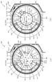
次いで、図14から図16を参照して、駆動ユニット530の詳細な説明をする。図1
4は、駆動ユニット530の分解斜視正面図である。図15(a)及び図15(b)は、
駆動ユニット530及び第1電動役物520の側面図である。図16(a)及び図16(
b)は、駆動ユニット530及び第1電動役物520の正面図である。
Next, the
4 is an exploded perspective front view of the
It is a side view of the
b) is a front view of the
なお、図15(a)及び図16(a)は、第1電動役物520が、第1状態に位置する
状態が図示され、図15(b)及び図16(b)は、第1電動役物520が、第2状態に
位置する状態が図示される。
15 (a) and 16 (a) show a state in which the first
図14に示すように、駆動ユニット530は、ソレノイド531と、そのソレノイド5
31に連結される摺動部材532と、その摺動部材532に連結される回転部材533と
、その回転部材533及び摺動部材532を内部に変位可能な状態で配設する第1ケース
部材534と、その第1ケース部材534の背面側に取着される第2ケース部材536と
を主に備えて形成される。
As shown in FIG. 14, the
The
ソレノイド531は、内部に電線を備え、電線に電力が流されることで電磁力を発生す
る本体部531aと、その本体部の内側に摺動可能に配設される可動体531bと、その
可動体の先端部に取着される係合部531cとを主に備えて形成される。
The
本体部531aは、前後方向に長く形成される角柱状に形成されると共に、内部に電線
が配設される。本体部531aの正面側には、背面側に凹設される凹部が形成されており
、その凹部の内側に円柱状に形成される可動体531bが配設される。
The
可動体531bは、金属材料から形成されており、本体部531aの電線に電力が付与
され電磁力を発生させることで背面側(本体部531aの内側)に摺動することができる
。
The
係合部531cは、可動体531bの本体部531aと反対側の端部に取着される。係
合部531cは、可動体531bの外径よりも大きい外径の円盤状に形成されており、そ
の軸が可動体531bの軸と略同一線状に位置して配置される。
The engaging
係合部531cは、後述する摺動部材532の係合溝532a2に挿入される。これに
より、可動体531bの変位に伴って、摺動部材532を前後方向(図15(a)左右方
向)に変位させることができる。
The engaging
摺動部材532は、上面視略E字状に形成されており、左右方向に延設される連結部5
32aと、その連結部532aの左右両端から正面側に突設される2本の第1突起532
bと、その2本の第1突起532bの中間に位置すると共に、正面側に突設される第2突
起532cとを主に備えて形成される。
The sliding
Two
It is formed mainly including b and a
摺動部材532は、連結部532aの左右方向における寸法が、後述する第1ケース部
材534の内周面における左右方向の対向間寸法よりも小さく形成される。これにより、
摺動部材532を第1ケース部材534の内側に収容配置することができる。
The sliding
The sliding
連結部532aは、背面側に凹設される凹部532a1と、その凹部532a1の正面
側に連結して上面側から凹設される係合溝532a2と、第2突起532cの基端左右両
側に形成される切込部532a3とを主に備えて形成される。
The connecting
凹部532a1は、上述したように、係合溝532a2にソレノイド531の係合部5
31cが挿入された際に、ソレノイド531の可動体531bが連結部532aに当接す
ることを抑制する凹みである。即ち、凹部532a1は、その凹設面が可動体531bの
外径よりも大きい円弧状に形成される。これにより、ソレノイド531の可動体531b
が連結部532aに当接することを抑制できる。
As described above, the recess 532a1 has the engaging
It is a recess that prevents the
Can be prevented from coming into contact with the connecting
係合溝532a2は、凹部532a1の正面側に連結して形成されており、上面側から
重力方向への凹設深さが、係合部531cの直径よりも大きく設定される。また、係合溝
532a2は、左右方向の幅寸法が係合部531cの直径よりも大きく設定されると共に
、前後方向の幅寸法が係合部531cの前後方向における厚み寸法と略同一または係合部
531cの前後方向における厚み寸法よりも大きく形成される。よって、係合溝532a
2の内側に、係合部531cを挿入できる。
The engaging groove 532a2 is formed by being connected to the front side of the recess 532a1, and the recessing depth in the gravity direction from the upper surface side is set to be larger than the diameter of the engaging
The engaging
切込部532a3は、後述する第1突起532bを回転部材533に連結する際に、摺
動部材532を弾性変形しやすくするための切れ目であり、上述したように第2突起53
2cの基端左右両側に形成されると共に、背面側に向かって切込み形成される。
The cut portion 532a3 is a cut for making it easy for the sliding
It is formed on both the left and right sides of the base end of 2c, and is notched toward the back surface side.
第1突起532bは、左右方向に貫通形成される係合孔532dを備える。係合孔53
2dは、前後方向に長い長穴状に形成されると共に、正面側の端部から重力方向下側に凹
設される第1開口532d1と背面側の端部から重力方向下側に凹設される第2開口53
2d2とを主に備えて形成される。なお、第1開口532d1及び第2開口532d2の
詳しい説明は後述する。
The
The 2d is formed in a long hole shape long in the front-rear direction, and is recessed downward in the gravity direction from the first opening 532d1 recessed downward in the gravity direction from the end portion on the front side and the end portion on the back surface side.
It is formed mainly with 2d2. A detailed description of the first opening 532d1 and the second opening 532d2 will be described later.
係合孔532dは、前後方向中央部(第1開口532d1及び第2開口532d2以外
の部分)における上下方向の幅寸法が、後述する回転部材533の突起533bの上下方
向における幅寸法よりも大きく設定される。これにより、係合孔532dの内側に突起5
33bを配置できる。
The
33b can be placed.
第2突起532cは、上述したように2つの第1突起532bの間に形成されると共に
、正面側に突設して形成される。また、第2突起532cは、連結部532aと反対側の
先端側に下方に向かって立設される立設壁532c1を備える。なお、立設壁532c1
の詳しい説明は後述する。
As described above, the
Will be described in detail later.
回転部材533は、側面視略L字に形成される板状体を左右方向に所定の幅を隔てて2
つ並設されると共に、一端側の対向間が連結部533aにより連結して形成される。回転
部材533の2つの板状体の対向間における隙間は、遊技球の直径よりも大きく設定され
る。これにより、回転部材533の内側(2つの板状体の対向間)に遊技球を通過させる
ことができる。
The rotating
The two are arranged side by side, and the facing portions on one end side are connected by the connecting
また、回転部材533の左右方向における幅寸法(2つの板状体の外側面の対向間寸法
)は、摺動部材532の2つの第1突起532bの内側の対向間寸法よりも、小さく設定
される。これにより、回転部材533を、摺動部材532の第1突起532bの対向間に
配置できる。
Further, the width dimension of the rotating
回転部材533は、側面視略L字の屈曲部分から左右方向両側に突出する回転軸533
cと、側面視略L字の一端側の端部から左右方向両側に突出する突起533bと、側面視
略L字の他端側の先端に凹設して形成される駆動部533dとを主に備えて形成される。
The rotating
Mainly c, a
回転軸533cは、回転部材533の左右両外側に突出形成されており、その突出先端
面同士の離間した距離寸法が、第1ケース部材534の左右方向における幅寸法と略同一
に設定される。また、回転軸533cの突出寸法は、第1ケース部材534の左右方向に
おける厚み寸法よりも大きく設定される。よって、後述する第1ケース部材534の凹部
534aの内側に回転軸533cを受け入れると共に、第2ケース部材535を第1ケー
ス部材534に組み付けることで、回転部材533を、第1ケース部材534及び第2ケ
ース部材535に対して回転可能な状態で保持できる。
The
突起533bは、回転部材533の左右両外側に突出形成されており、その突出先端面
同士の離間した距離寸法が、摺動部材532の2つの第1突起532bの左右の外側側面
の離間した距離寸法と略同一に設定される。また、突起533bの突出寸法は、第1突起
532bの左右方向における幅寸法よりも大きく設定される。よって、突起533bを第
1突起532bの係合孔532dに挿入することで、摺動部材532と回転部材533と
を連結できる。
The
なお、摺動部材532と回転部材533との連結は、摺動部材532の2つの第1突起
532bを左右に弾性変形させて、2つの第1突起532bの対向間を広げることで行う
ことができる。この場合、上述したように、摺動部材532には、切込部532a3が形
成されるので、2つの第1突起532bの対向間を広げやすくするできる。その結果、回
転部材533と摺動部材532との連結をさせやすくできる。
The connection between the sliding
さらに、第1ケース部材534の左右方向における内側面の対向間の距離寸法が、第1
突起532bの外側面同士の対向間における距離寸法と略同一もしくは、第1突起532
bの外側面同士の対向間における距離寸法よりもやや大きく設定される。これにより、回
転部材533及び摺動部材532を第1ケース部材534の内側に配置した状態では、第
1突起532bが、左右方向外側に弾性変形することを抑制できる。その結果、回転部材
533と摺動部材532との連結が外れることを抑制できる。
Further, the distance dimension between the facing surfaces of the inner side surfaces of the
Approximately the same as the distance dimension between the outer surfaces of the
It is set to be slightly larger than the distance dimension between the outer surfaces of b facing each other. As a result, when the rotating
駆動部533dは、正面側から背面側に向かって凹設して形成される。駆動部533d
は、内側に羽部材520Lの突起523L,523Rを収容できる。即ち、駆動部533
dは、突起523L,523Rよりも上下方向に大きい寸法に設定される。駆動部533
dに突起523L,523Rを収容することで、駆動部533dの変位に伴って第1電動
役物520を第1状態と第2状態とで変位させることができる。なお、第1電動役物52
0の変位についての詳しい説明は後述する。
The
Can accommodate the
d is set to a dimension larger in the vertical direction than the
By accommodating the
A detailed description of the displacement of 0 will be described later.
第1ケース部材534は、内部が開口した正面視略正方形に形成されると共に、前後方
向に延設して形成される。第1ケース部材534は、背面側の下側が切り欠き形成されて
おり、その切り欠き部分に、第2ケース部材535を配設できる。
The
第1ケース部材534は、背面側の切り欠き部分に正面側に凹設される凹部534aと
、内周側の底面に立設される立設部534bとを主に備えて形成される。
The
凹部534aは、上述したように、内側に回転部材533の回転軸533cを収容する
凹みであり、回転軸533cの直径よりも大きい形状に凹設される。よって、回転軸53
3cを内部に収容した状態で、第1ケース部材534に第2ケース部材535を組み付け
ることで、回転部材533を第1ケース部材534の内側に配設できる。
As described above, the
By assembling the
立設部534bは、背面ベース512の第2入賞口140の下側内周面とその立設先端
面が同一高さに設定されると共に、背面側に延設されると共に下方傾斜して形成される。
これにより、駆動ユニット530を背面ベース512の背面に配置した状態では、第2入
賞口140に入球したした遊技球を立設部534bの上面を転動させて第2ケース部材5
35に送球できる。
The
As a result, in a state where the
You can throw the ball to 35.
第2ケース部材535は、正面視横長矩形に形成されると共に、背面側に所定の厚みを
備えて形成される。第2ケース部材535は、上下方向に貫通形成される貫通孔535a
を備える。
The
To prepare for.
貫通孔535aは、内径が遊技球の直径よりも大きく形成されており、上述したように
立設部534bの上部と転動させて第2ケース部材535に送球された遊技球を貫通孔5
35aを介して下方に送球することができる。これにより、遊技領域を流下して第2入賞
口140に入球された遊技球を回収できる。
The through
The ball can be thrown downward via 35a. As a result, the game ball that has flowed down the game area and entered the second winning
次いで、図15及び図16を参照して、第1電動役物520の変位について説明する。
Next, the displacement of the first
図15(a)及び図16(a)に示すように、第1電動役物520が第1状態に位置さ
れる状態では、ソレノイド531の可動体531bが、可動体531bの周囲に配設され
ると共に、本体部531a及び連結部532aの間に介設される付勢ばね(図示せず)の
付勢力により正面側(図15(a)左側)に張り出される。
As shown in FIGS. 15A and 16A, in the state where the first
この場合、回転部材533の突起533bは、係合孔532dの背面側(第2開口53
2d2側)に位置される。また、回転部材533は、側面視における重心の位置が駆動部
533d及び回転軸533cの間に位置される。即ち、回転部材533には、回転軸53
3cの軸周りに、駆動部533dを下方に押し下げる方向への回転力が常に作用された状
態とされる。
In this case, the
It is located on the 2d2 side). Further, in the rotating
It is assumed that a rotational force in the direction of pushing down the
よって、回転部材533の突起533bは、係合孔532dの背面側(第2開口533
d2側)に位置された状態においても、第2開口533d2の内側(係合孔532dの下
方(図15(a)下側))に案内されることなく、その上部で停滞することができる。
Therefore, the
Even in the state of being positioned on the d2 side), the second opening 533d2 can be stagnant at the upper part without being guided to the inside (lower side of the
また、駆動部533dが下方に押し下げられるので、駆動部533dの内側に収容され
る左右の羽部材520L,520Rの各突起523L,523Rが下方に押し下げられる
。これにより、左右の羽部材520L,520Rは、貫通孔521L,521Rから遠方
側の角部を貫通孔521L,521Rの上方に位置した状態(第1状態(図16(a)参
照))とされる。
Further, since the
図15(b)及び図16(b)に示すように、ソレノイド531の本体部531aに電
力が付与されると、本体部531aに発生する電磁力により可動体531bが本体部53
1aの内部に引き込まれる。
As shown in FIGS. 15B and 16B, when electric power is applied to the
It is drawn inside 1a.
よって、可動体531bの変位に伴って、可動体531bの先端側に連結する摺動部材
532が後方側(図15(b)右側)にスライド変位される。上述したように、回転部材
533は、回転軸533cの軸周りに、駆動部533dを下方に押し下げる方向への回転
力が常に作用された状態とされるので、摺動部材532の係合孔532dの内側に収容さ
れる突起533bは、第2開口533d2の基端部分に引っ掛ることなくその内部を摺動
される。
Therefore, with the displacement of the
第2開口533d2の内部を摺動する突起533bは、可動体531bの変位終端位置
では、係合孔532dの正面側(第1開口532d1側)の端部と当接して、背面側(図
15(b)右側)に変位される。この場合、突起533bは、回転軸533cの軸を中心
に回転変位するので、突起533bを第1開口532d1の内側に収容することができる
。即ち、第1開口532d1は、突起533bの変位と対応する形状に形成される。
The
また、回転部材533が回転軸533cの軸周りに回転するので、駆動部533dを上
方(図15(b)上側)に変位できる。その結果、羽部材520Lは、貫通孔521L,
521Rの軸を中心に回転されて、貫通孔521L,521Rから遠方側の角部を左右外
側に変位させた状態(第2状態(図16(b)参照))とされる。
Further, since the rotating
It is rotated around the axis of 521R, and the corners on the far side from the through
一方、第2状態から第1状態への変位は、ソレノイド531の本体部531aへの電力
の供給を遮断することで行われる。これにより、本体部531aに発生する電磁力が消え
るので、可動体531bの周囲に配設されると共に、本体部531a及び連結部532a
の間に介設される付勢ばね(図示せず)の付勢力により、可動体531bが正面側(図1
5(a)左側)に張り出される。その結果、第1電動役物520を第1状態の位置に変位
させることができる。
On the other hand, the displacement from the second state to the first state is performed by cutting off the supply of electric power to the
Due to the urging force of the urging spring (not shown) interposed between the
5 (a) Overhangs on the left side). As a result, the first
上述したように、第1開口532d1は、突起533bの変位に対応する形状に形成さ
れるので、第1開口532d1の重力方向下側(図15(b)下側)への凹設深さが背面
側(図15(b)右側)に向かって深く形成される。
As described above, since the first opening 532d1 is formed in a shape corresponding to the displacement of the
その結果、第1電動役物520を第2状態から第1状態に変位させる際には、第1開口
532d1の基端部分を回転部材533の突起533bにと衝突させて、突起533bを
重力方向に変位させやすくできる。
As a result, when the first
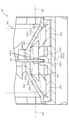
次いで、図17を参照して、第2突起532cの動作について説明する。図17(a)
及び図17(b)は、図10(a)のXVII-XVII線における入賞口ユニット50
0の断面図である。なお、図17(a)では、第1電動役物520が第1状態に位置され
、図17(b)では、第1電動役物520が第2状態に位置される状態がそれぞれ図示さ
れる。
Next, the operation of the
And FIG. 17 (b) shows the winning
It is sectional drawing of 0. In addition, in FIG. 17A, the state in which the first
図17(a)に示すように、第1電動役物520が第1状態にされると、左右の羽部材
520L,520Rの貫通孔521L,521Rの遠方の角部が第1突出部511aの近
傍に配置される。これにより、第1電動役物520が第1状態において、左右の羽部材5
20L,520Rの対向間に遊技球が流下されることを抑制できる。
As shown in FIG. 17A, when the first
It is possible to prevent the game ball from flowing down between the 20L and 520R facing each other.
また、上述したように、ソレノイド531は、本体部531aの内側から可動体531
bが張り出した状態とされる。よって、可動体531b(係合部531c)に連結される
摺動部材532が正面側(図17(a)左側)に位置した状態とされる。即ち、第2突起
532cの立設壁532c1が第2入賞口140の近傍に配置される。
Further, as described above, the
It is assumed that b is in an overhanging state. Therefore, the sliding
この場合、立設壁532c1の立設先端(重力方向下側(図17(a)下側)の端部)
から第1ケース部材534に形成される立設部534bの上端面までの距離寸法L1は、
遊技球の直径よりも小さく設定される。
In this case, the erection tip of the erection wall 532c1 (the end of the lower side in the direction of gravity (lower side in FIG. 17A)).
The distance dimension L1 from to the upper end surface of the
It is set smaller than the diameter of the game ball.
これにより、第1電動役物520が破損して、ソレノイド531の可動体531bが前
方に張り出した状態であっても、左右の羽部材520L,520Rの対向間に遊技球を流
入可能とされた場合に、遊技球が第2入賞口140の内部に入球されて転動することを抑
制できる。即ち、第1ケース部材534の立設部534bを転動する遊技球を摺動部材5
32の立設壁532c1に衝突させて、遊技球の転動を停止させることができる。その結
果、第1電動役物520が破損した際に、遊技者が遊技を継続して行ったとしても店舗側
が不利となる状況を抑制できる。
As a result, even if the first
The rolling of the game ball can be stopped by colliding with the vertical wall 532c1 of 32. As a result, when the first
なお、本実施形態では、第2入賞口140に遊技球が入球されたことを検知するセンサ
装置SE1が第2ケース部材535の遊技球の流下経路に配設される。よって、第2入賞
口140の内部を遊技球が通過したことを検知するには、第2ケース部材535まで遊技
球を転動させる必要がある。そのため、第1ケース部材534の内部で遊技球の転動を停
止させることで、第2入賞口140に遊技球が入球されたことをパチンコ機10が検知す
ることを抑制できる。
In the present embodiment, the sensor device SE1 for detecting that the game ball has entered the second winning
一方、図17(b)に示すように、第1電動役物520が第2状態にされると、左右の
羽部材520L,520Rの貫通孔521L,521Rの遠方の角部が第1状態よりも第
1突出部511aから離間され、その離間した距離が遊技球の直径よりも大きくされる。
これにより、遊技領域を流下する遊技球を、左右の羽部材520L,520Rの側面52
6L,526Rで受け止めて、第2入賞口140に転動させることができる。即ち、第1
電動役物520が第2状態にされると、第2入賞口140に遊技球を入球させやすくでき
る。
On the other hand, as shown in FIG. 17B, when the first
As a result, the game ball flowing down the game area can be moved to the side surfaces 52 of the left and
It can be received by 6L, 526R and transferred to the second winning
When the
また、上述したように、ソレノイド531は、本体部531aの内側に可動体531b
が引き込まれた状態とされる。よって、可動体531b(係合部531c)に連結される
摺動部材532が背面側(図17(b)右側)に位置した状態とされる。即ち、第2突起
532cの立設壁532c1が第1状態よりも第2入賞口140から離間する位置に配置
される。
Further, as described above, the
Is in a retracted state. Therefore, the sliding
この場合、立設壁532c1の立設先端(重力方向下側(図17(b)下側)の端部)
から第1ケース部材534に形成される立設部534bの上端面までの距離寸法L2は、
遊技球の直径よりも大きく設定される。
In this case, the erection tip of the erection wall 532c1 (the end of the lower side in the direction of gravity (lower side in FIG. 17B)).
The distance dimension L2 from to the upper end surface of the
It is set larger than the diameter of the game ball.
これにより、第1電動役物520が第2状態とされる際には、左右の羽部材520L,
520Rを変位させて、遊技領域を流下する遊技球を第2入賞口140に入球しやすくで
きると共に、第2入賞口140に入球された遊技球を第1ケース部材534に形成される
立設部534bを転動させて第2ケース部材535に送球できる。
As a result, when the first
By displacing the 520R, it is possible to easily enter the game ball flowing down the game area into the second winning
さらに、立設壁532c1の変位方向は、第2入賞口140に入球される遊技球の転動
方向と略一致する方向に立設壁532c1をスライド変位させることができるので、羽部
材520L,520Rが破損して(又は、不正行為により)開放された際に、立設壁53
2c1に衝突させて停止させた遊技球が、立設壁532c1の変位により転動方向と反対
側に押し出されることを抑制できる。これにより、第1電動役物520をソレノイド53
1の駆動により開放して、第2入賞口140に遊技球を入球可能とされる際に、遊技球が
第2入賞口140で詰まることを抑制できる。その結果、第1電動役物520を開放状態
とした際に、遊技球を第2入賞口の内側にスムーズに案内することができる。
Further, since the displacement direction of the erection wall 532c1 can slide and displace the erection wall 532c1 in a direction substantially coincide with the rolling direction of the game ball entering the second winning
It is possible to prevent the game ball that has been stopped by colliding with 2c1 from being pushed out to the side opposite to the rolling direction due to the displacement of the erection wall 532c1. As a result, the first
It is possible to prevent the game ball from being clogged at the second winning
次いで、図18及び図19を参照して第1電動役物520が遊技者の不正行為により、
第1状態から第2状態に変位された場合の説明をする。図18(a)及び図18(b)は
、入賞口ユニット500の正面図である。図19(a)及び図19(b)は、第1電動役
物520及び駆動ユニット530の側面図である。
Then, referring to FIGS. 18 and 19, the first
The case of being displaced from the first state to the second state will be described. 18 (a) and 18 (b) are front views of the winning
なお、図18(a)及び図18(b)では、理解を容易とするために、正面ベース51
1が透明視されて図示される。また、図19(a)では、第1状態における第1電動役物
520及び駆動ユニット530が図示され、図19(b)では、第1状態から第1電動役
物520のみが変位された場合の状態が図示される。
In addition, in FIGS. 18A and 18B, the
1 is shown transparently. Further, FIG. 19 (a) illustrates the first
図18及び図19に示すように、第1状態の第1電動役物520が、遊技者の不正行為
(ゴト行為)により、第1電動役物520のみ強引に第2状態に変位された際には、左右
の羽部材520L,520Rの突起523L,523Rが係合孔532dの第2開口53
2d2の内側に変位される。即ち、突起523L,523Rが変位できるスペースが形成
されるので、第1電動役物520が無理に変位された際に第1電動役物520が破損する
ことを抑制できる。
As shown in FIGS. 18 and 19, when the first
Displaced inside 2d2. That is, since a space is formed in which the
次いで、図20(a)及び図11(b)を参照して、遊技者の不正行為により第1電動
役物520が変位された場合の立設部523c1の変位について説明する。図20(a)
は、図18(a)のXXa-XXa線における入賞口ユニット500の断面図であり、図
20(b)は、図18(b)のXXb-XXb線における入賞口ユニット500の断面図
である。
Next, with reference to FIGS. 20 (a) and 11 (b), the displacement of the erection portion 523c1 when the first
18A is a cross-sectional view of the winning
図20(a)及び図20(b)に示すように、第1状態の第1電動役物520が、遊技
者の付勢行為により、無理に回転された際には、駆動ユニット530のソレノイド531
及び摺動部材532の位置は変位させず、第1電動役物520及び回転部材533のみが
回転変位される。
As shown in FIGS. 20 (a) and 20 (b), when the first
And the position of the sliding
上述したように、第1電動役物520が第1状態に位置する場合には、立設壁532c
1の立設先端(重力方向下側(図20(a)下側)の端部)から第1ケース部材534に
形成される立設部534bの上端面までの距離寸法L1は、遊技球の直径よりも小さく設
定される。
As described above, when the first
The distance dimension L1 from the vertical tip of 1 (the end of the lower side in the direction of gravity (lower side in FIG. 20A)) to the upper end surface of the standing
ここで、従来より、遊技球が入球可能に形成される第2入賞口140と、その第2入賞
口140を挟んで配設される一対の羽部材520L,520Rと、それら一対の羽部材5
20L,520Rに駆動力を付与して開放または閉鎖させる駆動手段(ソレノイド531
)と、その駆動手段(ソレノイド531)の駆動力により一対の羽部材520L,520
Rが開放されると第2入賞口140への遊技球の入球を許容する許容位置に配置されると
共に駆動手段(ソレノイド531)の駆動力により一対の羽部材520L,520Rが閉
鎖されると第2入賞口140への遊技球の入球を規制する規制位置に配置される規制手段
とを備えた遊技機が知られている。
Here, conventionally, a second winning
Driving means (solenoid 531) that applies driving force to 20L and 520R to open or close
) And the driving force of the driving means (solenoid 531), a pair of
When R is opened, it is arranged at an allowable position that allows the ball to enter the second winning
しかしながら、上述した従来の遊技機では、規制手段の変位が規制されていないため、
例えば、一対の羽部材520L,520Rを外部から強制開放した上で、規制手段を規制
位置から許容位置へ変位させることができるため、遊技球が第2入賞口140へ不正に入
球されることを規制する効果が不十分であるという問題点があった。
However, in the conventional gaming machine described above, the displacement of the regulating means is not regulated, so that the displacement is not regulated.
For example, since the pair of
これに対し、本実施形態によれば、一対の羽部材520L,520Rが閉鎖された状態
または一対の羽部材520L,520Rが外部から開放された状態において立設壁532
c1の配置が規制位置に維持可能に形成されるので、立設壁532c1が許容位置へ変位
されることを抑制できる。よって、遊技球が第2入賞口140へ不正に入球されることを
規制しやすくできる。
On the other hand, according to the present embodiment, the
Since the arrangement of c1 is formed so as to be sustainable at the restricted position, it is possible to prevent the erection wall 532c1 from being displaced to the allowable position. Therefore, it is possible to easily regulate that the game ball is illegally entered into the second winning
即ち、一対の羽部材520L,520Rが閉鎖された状態または一対の羽部材520L
,520Rが外部から開放された状態では、摺動部材532を操作して、立設壁532c
1の立設先端(重力方向下側(図20(b)下側)の端部)から第1ケース部材534に
形成される立設部534bの上端面までの距離寸法L3は、遊技球の直径よりも小さく設
定される。従って、第1電動役物520が遊技者の不正行為によって、第2入賞口140
に遊技球を送球可能とされても、遊技球が第2入賞口140の内部に入球されて転動する
ことを抑制できる。よって、第1ケース部材534の立設部534bを転動する遊技球を
摺動部材532の立設壁532c1に衝突させて、遊技球の転動を停止させることができ
る。その結果、第1電動役物520が遊技者の不正行為によって、第2状態(第2入賞口
140に遊技球を送球可能)にされた際に、遊技球が第2入賞口140へ不正に入球され
ることを規制しやすくできる。
That is, the pair of
, 520R is open from the outside, the sliding
The distance dimension L3 from the standing tip of 1 (the end of the lower side in the direction of gravity (lower side in FIG. 20B)) to the upper end surface of the standing
Even if the game ball can be thrown to the inside, it is possible to prevent the game ball from entering the inside of the second winning
また、この場合、遊技球を第2入賞口140へ入球不能にする立設壁532c1を一対
の羽部材520L,520Rを変位させる摺動部材532に連なって形成することができ
るので、第2入賞口140へ不正に入球されることを規制する部材を別途必要としない。
よって、その分、部品点数を削減することができるので、製造コストが増加することを抑
制できる。
Further, in this case, since the standing wall 532c1 that makes it impossible for the game ball to enter the second winning
Therefore, the number of parts can be reduced by that amount, and the increase in manufacturing cost can be suppressed.
次いで、図21及び図22を参照して、遊技者の不正行為により第1電動役物520が
第2状態とされた際に、さらに第2突起532cが背面側に押し込まれた場合を説明する
。図21(a)及び図21(b)は、第1電動役物520及び駆動ユニット530の側面
図である。図22(a)は、図21(a)の範囲XXIIaにおける駆動ユニット530
の部分拡大側面図であり、図22(b)は、図21(b)の範囲XXIIbにおける駆動
ユニット530の部分拡大側面図である。
Next, with reference to FIGS. 21 and 22, when the first
22 (b) is a partially enlarged side view of the
図21及び図22に示すように、第2開口532d2の内側には、正面側(図22(a
)左側)の内面から突出する突起532d3が形成される。また、回転部材533の突起
533bには、側面視における外周面が切り込まれて形成される切欠部533b1が形成
される。
As shown in FIGS. 21 and 22, the front side (FIG. 22 (a)) is inside the second opening 532d2.
) A protrusion 532d3 protruding from the inner surface of the left side) is formed. Further, the
突起532d3及び切欠部533b1は、その外径が対応する形状に形成される。即ち
、側面視における突起532d3の突出形状と、切欠部533b1の切込み形状とが略同
一とされる。
The protrusion 532d3 and the notch 533b1 are formed so that their outer diameters correspond to each other. That is, the protruding shape of the protrusion 532d3 in the side view and the cut shape of the cutout portion 533b1 are substantially the same.
よって、図21(a)及び図22(a)に示す、第1電動役物520のみを不正行為に
より第2状態とした状態から、立設壁532c1(摺動部材532)を背面側に押し込む
と、切欠部533b1の内側に突起532d3が収容され、立設壁532c1(摺動部材
532)の背面側へ変位が規制される。その結果、第1電動役物520が遊技者の不正行
為により第2状態とされた際に、遊技球が、第2入賞口140に入球されて、第1ケース
部材534の立設部534bを転動して送球されることを抑制できる。
Therefore, the erection wall 532c1 (sliding member 532) is pushed toward the back side from the state where only the first
また、本実施形態では、突起532d3の側面のうちの一面が、上方に向かって背面側
に傾斜して形成される(図22(a)参照)。これにより、突起532d3が、切欠部5
33b1の内側に挿入された際に、突起532d3が切欠部533b1から抜け出にくく
することができる。
Further, in the present embodiment, one surface of the side surface of the protrusion 532d3 is formed so as to be inclined upward toward the back surface (see FIG. 22A). As a result, the protrusion 532d3 becomes the
When inserted inside the 33b1, the protrusion 532d3 can be prevented from coming out of the notch 533b1.
即ち、突起532d3の側面が、上方に向かって背面側に傾斜して形成されるので、突
起532d3が切欠部532b1に挿入された状態で、さらに立設壁532c1(摺動部
材532)を背面側に押し込む力が作用した際に、突起532d3と切欠部532b1と
の当接面に作用する力の方向を、突起532d3が切欠部532b1の内側に入り込む方
向とすることができる。従って、突起532d3が、切欠部533b1の内側に挿入され
た際に、突起532d3が切欠部533b1から抜け出にくくすることができる。その結
果、第1電動役物520が遊技者の不正行為により第2状態とされた際に、遊技球が第2
入賞口140に入球して、第1ケース部材534の立設部534bを転動して送球される
ことを確実に抑制できる。
That is, since the side surface of the protrusion 532d3 is formed so as to be inclined upward toward the back side, the upright wall 532c1 (sliding member 532) is further placed on the back side in a state where the protrusion 532d3 is inserted into the notch portion 532b1. The direction of the force acting on the contact surface between the protrusion 532d3 and the notch portion 532b1 when the force for pushing into the protrusion 532d3 can be set to the direction in which the protrusion 532d3 enters the inside of the notch portion 532b1. Therefore, when the protrusion 532d3 is inserted inside the notch 533b1, the protrusion 532d3 can be prevented from coming out of the notch 533b1. As a result, when the first
It is possible to reliably prevent the ball from entering the winning
言い変えると、駆動手段(ソレノイド531)の駆動力を一対の羽部材520L,52
0Rへ伝達する伝達機構を備え、伝達機構は、駆動手段(ソレノイド531)の駆動力に
より開放スライド位置(図17(b)に示す位置)と閉鎖スライド位置(図17(a)に
示す位置)との間でスライド変位される摺動部材532と、その摺動部材532の開放ス
ライド位置へのスライド変位により開放回転位置へ回転されて一対の羽部材520L,5
20Rを開放させると共に摺動部材532の閉鎖スライド位置へのスライド変位により閉
鎖回転位置へ回転されて一対の羽部材520L,520Rを閉鎖させる回転部材533と
を備え、立設壁532c1が摺動部材532に配設され、摺動部材532が開放スライド
位置へスライド変位されると立設壁532c1が許容位置に配置されると共に、摺動部材
532が閉鎖スライド位置へスライド変位されると立設壁532c1が規制位置に配置さ
れ、摺動部材532が閉鎖スライド位置に配置された状態で、回転部材533が開放回転
位置に配置されると、回転部材533と摺動部材532とが係合されることで、摺動部材
532の開放スライド位置へのスライド変位が規制されるので、遊技球が第2入賞口14
0へ不正に入球されることを規制しやすくできる。
In other words, the driving force of the driving means (solenoid 531) is applied to the pair of
A transmission mechanism for transmitting to 0R is provided, and the transmission mechanism has an open slide position (position shown in FIG. 17 (b)) and a closed slide position (position shown in FIG. 17 (a)) by the driving force of the driving means (displacement 531). A pair of
The erection wall 532c1 is provided with a rotating
It is possible to easily regulate the illegal entry of a ball to 0.
即ち、閉鎖されている一対の羽部材520L,520Rが外部から不正に強制開放され
る場合には、摺動部材532が閉鎖スライド位置に配置された状態で、回転部材533が
開放回転位置へ回転される。かかる状態では、回転部材533と摺動部材532とが係合
されることで、摺動部材532の開放スライド位置へのスライド変位が規制されるので、
規制手段を規制位置に維持できる(規制手段が許容位置へ外部から不正に強制変位される
ことを抑制できる)。その結果、一対の羽部材520L,520Rを外部から強制開放し
た上で、それら一対の羽部材520L,520Rの間から遊技球を通過させたとしても、
かかる遊技球が第2入賞口140へ入球することを規制手段によって規制できる。
That is, when the pair of
The regulatory means can be maintained in the regulated position (the regulatory means can be prevented from being illegally forcibly displaced from the outside to the allowable position). As a result, even if the pair of
It is possible to regulate the entry of such a game ball into the second winning
さらに、摺動部材532および回転部材533の一方に係合孔532dが延設されると
共に他方から突起533bが突設され、突起533bが係合孔532dに沿って摺動され
ることで摺動部材532のスライド変位が伝達されて回転部材533が回転されると共に
、係合孔532dの内壁面に突起533bが係合されることで、摺動部材532の開放ス
ライド位置へのスライド変位が規制されるので、小型化を図りつつ規制を解除され難くで
きる。
Further, an engaging
即ち、摺動部材532のスライド変位を回転部材533へ伝達して回転させるための係
合孔532dおよび突起533bを利用して、摺動部材532の開放スライド位置へのス
ライド変位を規制する手段を形成でき、かかる手段を別の箇所に別途設けることを不要と
できるので、その分、小型化を図ることができる。また、係合孔532dの内壁面に突起
533bを係合させる構造とすることで、かかる係合部分への外部からの不正なアクセス
を困難とでき、その分、規制(係合)を解除され難くできる。
That is, a means for regulating the slide displacement of the sliding
次いで、図23及び図24を参照して、左右の羽部材520L,520Rの膨出部52
4L,524Rについて詳しく説明する。図23(a)は、左羽部材520Lの正面斜視
図であり、図23(b)は右羽部材520Rの正面斜視図である。図24(a)は、入賞
口ユニット500の正面図であり、図24(b)は、図24(a)のXXIVb-XXI
Vb線における入賞口ユニット500の断面図である。
Next, with reference to FIGS. 23 and 24, the bulging
4L and 524R will be described in detail. FIG. 23A is a front perspective view of the
It is sectional drawing of the winning
なお、図23(a)及び図23(b)では、斜視した際の左右方向が図23(a)と図
23(b)とで逆転される。また、図24(a)では、正面ベース511が透明視されて
図示される。さらに、図24(b)では、図24(a)において透明視された正面ベース
511が不透明とされて図示される。また、図24(b)では、側面526L,526R
を転動する遊技球の転動方向が仮想線KS1の符号と共に、2点鎖線で図示される。更に
、仮想線KS1の正面方向が矢印Fで図示され、背面方向が矢印Bで図示される。
In addition, in FIGS. 23 (a) and 23 (b), the left-right direction when viewed is reversed between FIGS. 23 (a) and 23 (b). Further, in FIG. 24A, the
The rolling direction of the game ball that rolls is shown by a two-dot chain line together with the reference numeral of the virtual line KS1. Further, the front direction of the virtual line KS1 is shown by an arrow F, and the back direction is shown by an arrow B.
図23及び図24に示すように、左羽部材520Lの側面526Lに形成される膨出部
524Lは、貫通孔521L側の端部に形成されると共に、正面側(図24(b)矢印F
側)の端面に連なって形成される。一方、右羽部材520Rの側面526Rに形成される
膨出部524Rは、貫通孔521R側の端部に形成されると共に、背面側(図24(b)
矢印B側)の端面に連なって形成される。
As shown in FIGS. 23 and 24, the bulging
It is formed in a row on the end face of the side). On the other hand, the bulging
It is formed continuously on the end face of the arrow B side).
即ち、左羽部材520Lの膨出部524Lと右羽部材520Rの膨出部524Rとでは
、前後方向に異なる位置に形成される(図24(b)参照)。
That is, the bulging
さらに、側面526L,526Rには、羽部材520L,520Rの先端側から基端側
まで連続する第1領域が形成され、第1領域を案内される遊技球には非当接となる大きさ
で膨出部524L,524Rが形成されると共に、一対の羽部材520L,520Rのう
ちの一方の羽部材(羽部材520L,520Rのうちの一方)における側面526L,5
26Rの第1領域と他方の羽部材(羽部材520L,520Rのうちの他方)における側
面526L,526Rの第1領域とが、側面526L,526Rに沿って遊技球が案内さ
れる方向と直交する方向に位置を異ならせて配置される。
Further, on the side surfaces 526L and 526R, a first region continuous from the tip end side to the base end side of the
The first region of 26R and the first region of the side surfaces 526L and 526R of the other wing member (the other of the
また、膨出部524Lは、貫通孔521Lから遠方側の端部が、正面側(図24(b)
下側)から背面側(図24(b)上側)に向かって貫通孔521L側に傾斜して形成され
る。一方、膨出部524Rは、貫通孔521Rから遠方側の端部が、背面側から正面側に
向かって貫通孔521R側に傾斜して形成される。
Further, in the bulging
It is formed so as to be inclined toward the through
次いで、図25及び図26を参照して、左右の羽部材520L,520Rの側面526
L,526Rに遊技球が送球された場合の説明をする。図25(a)及び図25(b)は
、入賞口ユニット500の断面図である。図26(a)及び図26(b)は、入賞口ユニ
ット500の断面図である。
Then, with reference to FIGS. 25 and 26, the side surfaces 526 of the left and
The case where the game ball is thrown to L, 526R will be described. 25 (a) and 25 (b) are cross-sectional views of the winning
なお、図25(a)、図25(b)、図26(a)及び図26(b)は、図24(b)
における入賞口ユニット500の断面図と対応する。また、図25(a)及び図25(b
)では、第1電動役物520の両側から遊技球が送球された場合の遊技球の遷移状態が順
に図示される。図26(a)及び図26(b)では、左羽部材520Lのみに遊技球が送
球された場合の遊技球の遷移状態が順に図示される。
25 (a), 25 (b), 26 (a) and 26 (b) are shown in FIG. 24 (b).
Corresponds to the cross-sectional view of the winning
), The transition state of the game ball when the game ball is thrown from both sides of the first
図25(a)及び図25(b)に示すように、第1電動役物520の両側に遊技球が送
球された場合には、左右の羽部材520L,520Rの側面526L,526Rを転動す
る遊技球を、膨出部524L,524Rにより前後方向に異なる位置に転動させることが
できる。
As shown in FIGS. 25 (a) and 25 (b), when the game balls are thrown on both sides of the first
詳しく説明すると、上述したように、左羽部材520Lの膨出部524Lは、正面側の
端面に連結して形成される。よって、左羽部材520Lの側面526Lを転動する遊技球
は、膨出部524Lに接触しながら側面526Lを転動することで、背面側に転動される
。
More specifically, as described above, the bulging
この場合、膨出部524Lは、貫通孔521Lから遠方側の端部が、正面側(図25(
b)下側)から背面側(図25(b)上側)に向かって貫通孔521L側に傾斜して形成
されるので、側面526Lを転動する遊技球が膨出部524Lと接触した際、転動方向へ
の抵抗が大きくなって遊技球の転動が停止されることを抑制できる。
In this case, the bulging
b) Since it is formed so as to be inclined toward the through
一方、右羽部材520Rの膨出部524Rは、背面側の端面に連結して形成される。よ
って、右羽部材520Rの側面526Rを転動する遊技球は、膨出部524Rに接触しな
がら側面526Rを転動することで、正面側に転動される。
On the other hand, the bulging
この場合、膨出部524Rは、貫通孔521Rから遠方側の端部が、背面側(図25(
b)上側)から正面側(図25(b)下側)に向かって貫通孔521R側に傾斜して形成
されるので、側面526Rを転動する遊技球が膨出部524Rと接触した際、転動方向へ
の抵抗が大きくなって遊技球の転動が停止されることを抑制できる。
In this case, the bulging
b) Since it is formed so as to be inclined toward the through
よって、左羽部材520L側を転動する遊技球を背面側に寄せることができる一方、右
羽部材520R側を転動する遊技球を正面側に寄せることができる。その結果、左右両側
から遊技球が送球された際に、左右から送球される遊技球が正面衝突することを抑制でき
る。
Therefore, the game ball that rolls on the
ここで、従来より、遊技球が入球可能に形成される入球口(第2入賞口140)と、そ
の入球口に遊技球を案内する案内面(側面526L,526R)を有すると共に変位可能
に形成された案内部材(第1電動役物520)とを備えた遊技機が知られている。案内部
材としては、例えば、入球口へ遊技球を案内する案内面を有すると共に入球口を挟んで配
設され基端側が回転可能に軸支される一対の羽部材(羽部材520L,520R)が例示
される。
Here, conventionally, a ball entry port (second winning opening 140) formed so that the game ball can enter, and a guide surface (
また、一方の羽部材(羽部材520L,520Rのどちらか一方)における案内面(側
面526L,526R)の全面に第1の溝を設けると共に、他方の羽部材における案内面
(側面526L,526R)の全面に第2の溝をそれぞれ設ける技術が開示される。かか
る技術によれば、第1の溝と第2の溝とが互いに異なる方向へ傾斜されるため、一方の羽
部材(羽部材520L,520Rのどちらか一方)における案内面(側面526L,52
6R)および一方の羽部材(羽部材520L,520Rのどちらか他方)における案内面
(側面526L,526R)をそれぞれ遊技球が同時に案内(転動)される場合でも、そ
れら各遊技球を互いに異なる方向(一方はガラス板側であって他方は遊技盤側)へ偏倚さ
せることできる。よって、これら各遊技球を第2入賞口140へスムーズに入球させるこ
とができる。
Further, a first groove is provided on the entire surface of the guide surface (
Even when the game balls are simultaneously guided (rolled) on the guide surface (
しかしながら、上述した従来の技術では、遊技球を十分に偏倚させることができないと
いう問題点があった。また、案内部材の一側(羽部材520L,520Rのどちらか一方
)から進入した遊技球が案内面(側面526L,526R)を通過して案内部材の他側(
羽部材520L,520Rのどちらか他方)から通り抜けることがあり、この場合には、
遊技球が入球口(第2入賞口140)へ入球されないため、遊技者の興趣が損なわれると
いう問題点があった。
However, the above-mentioned conventional technique has a problem that the game ball cannot be sufficiently biased. Further, the game ball that has entered from one side of the guide member (either one of the
It may pass through either the
Since the game ball is not entered into the entrance (second prize opening 140), there is a problem that the interest of the player is impaired.
これに対し、本実施形態によれば、第1電動役物520は、側面526L,526Rか
ら突設され側面526L,526Rを転動する遊技球に当接可能に形成される一対の膨出
部524L,524Rを備え、それら一対の膨出部524L,524Rが、側面526L
,526Rに沿って遊技球が案内される方向と直交する方向に位置を異ならせて配置され
るので、側面526L,526Rを案内(転動)される遊技球を膨出部524L,524
Rに当接させることで、かかる遊技球を確実に偏倚させることができる。その結果、入球
口へスムーズに入球させることができる。
On the other hand, according to the present embodiment, the first
, 526 Since the game balls are arranged at different positions in the direction orthogonal to the direction in which the game balls are guided along the 526R, the game balls guided (rolled) on the side surfaces 526L and 526R are bulged 524L and 524.
By bringing it into contact with R, the game ball can be reliably biased. As a result, the ball can be smoothly entered into the ball entry port.
また、一対の膨出部524L,524Rが、側面526L,526Rに沿って遊技球が
案内される方向と直交する方向に位置を異ならせて配置されることで、一対の羽部材52
0L,520Rの一側から進入した遊技球を膨出部524L,524Rに当接させること
ができる。よって、一対の羽部材520L,520Rの一側(羽部材520L,520R
のどちらか一方)から進入した遊技球が一対の羽部材520L,520Rを(羽部材52
0L,520Rのどちらか他方に)通り抜けることを抑制できる。その結果、遊技球を入
球口へ入球させて、遊技者の興趣を向上できる。
Further, the pair of bulging
A game ball that has entered from one side of 0L, 520R can be brought into contact with the bulging
A game ball that has entered from either of the two) has a pair of
It is possible to suppress passing through (either 0L or 520R). As a result, it is possible to improve the interest of the player by allowing the game ball to enter the entrance.
さらに、第1電動役物520は、第2入賞口140を挟んで配設され基端側が回転可能
に軸支される一対の羽部材520L,520Rとして形成され、一対の膨出部524L,
524Rは、一対の羽部材520L,520Rのそれぞれの側面526L,526Rから
突設され、一対の羽部材520L,520Rのうちの一方の羽部材520L,520Rに
おける膨出部524L,524Rと他方の羽部材520L,520Rにおける膨出部52
4L,524Rとが、側面526L,526Rに沿って遊技球が案内される方向と直交す
る方向に位置を異ならせて配置されるので、側面526L,526Rを案内(転動)され
る遊技球を膨出部524L,524Rに当接させることで、かかる遊技球を確実に偏倚さ
せることができる。その結果、第2入賞口140へスムーズに入球させることができると
共に、球詰まりを抑制できる。
Further, the first
The 524R is projected from the side surfaces 526L and 526R of the pair of
Since the 4L and 524R are arranged at different positions along the side surfaces 526L and 526R in a direction orthogonal to the direction in which the game ball is guided, the game ball guided (rolled) on the
また、一方の羽部材520L,520Rにおける膨出部524L,524Rと他方の羽
部材520L,520Rにおける膨出部524L,524Rとが、側面526L,526
Rに沿って遊技球が案内される方向(羽部材520L,520Rの先端側から基端側へ向
かう方向)と直交する方向に位置を異ならせて配置されることで、一方の羽部材520L
,520Rにおける側面526L,526Rへ進入した遊技球が他方の羽部材520L,
520Rにおける側面5.26L,526Rへ到達した場合には、かかる遊技球を他方の
羽部材520L,520Rにおける膨出部524L,524Rに当接させることができる
。よって、一方の羽部材520L,520Rにおける側面526L,526Rへ進入した
遊技球が他方の羽部材における側面526L,526Rを通り抜けることを抑制できる。
その結果、遊技球を第2入賞口140へ入球させて、遊技者の興趣を向上できる。
Further, the bulging
One of the
, The game ball that has entered the
When the side surfaces 5.26L and 526R of the 520R are reached, the game ball can be brought into contact with the bulging
As a result, the game ball can be entered into the second winning
言い変えると、左右の羽部材520L,520Rにぞれぞれ前後方向に異なる位置に膨
出部524L,524Rが形成されるので、左右から転動される遊技球を前後方向に異な
る位置に転動させることができる。よって、左右両側から遊技球が送球された際に、左右
から送球される遊技球が正面衝突することを抑制できる。その結果、第2入賞口140へ
の遊技球の入球に時間がかかることを抑制できる。
In other words, since the bulging
即ち、遊技球の衝突する位置を左右で前後方向に異なる位置とすることで、図25(b
)に示すように、背面側に寄せられた左側の遊技球は、その衝突により背面側(図25(
b)上側)に跳ね返りやすくなる。一方、正面側に寄せられた右側の遊技球は、その衝突
により正面側(図25(b)下側)に跳ね返りやすくなる。
That is, by setting the collision positions of the game balls to different positions in the front-rear direction on the left and right, FIG. 25 (b).
), The game ball on the left side moved to the back side is on the back side due to the collision (FIG. 25 (FIG. 25).
b) It becomes easy to bounce to the upper side). On the other hand, the game ball on the right side brought closer to the front side tends to bounce back to the front side (lower side in FIG. 25B) due to the collision.
よって、一方の(本実施形態では、左羽部材520Lを転動する)遊技球を第2入賞口
140に入球させやすくできると共に、他方の遊技球を正面側に跳ね返らせることで、衝
突した際に、遊技球が第2入賞口140から離間しすぎることを抑制できる。従って、あ
とから第2入賞口140に入球する第2の遊技球の第2入賞口140への入球を早くする
ことができる。その結果、第1電動役物520左右両側に遊技球が送球された際に、両側
の遊技球が第2入賞口140に入球されるまでにかかる時間を短くでき、遊技の進行をス
ムーズに進めることができる。
Therefore, one of the game balls (in the present embodiment, which rolls the
また、膨出部524L,524Rは、羽部材520L,520Rの先端側よりも基端側
(貫通孔521側)に近い位置において側面526L,526Rから突設されるので、側
面526L,526Rに案内される遊技球が膨出部524L,524Rに当接するまでに
転動可能な領域を確保できる。よって、その分、遊技球の転動速度の低下を抑制して、第
2入賞口140へスムーズに入球させることができる。
Further, since the bulging
さらに、膨出部524L,524Rが羽部材520L,520Rの先端側よりも基端側
に近い位置において側面526L,526Rから突設されることで、膨出部524L,5
24Rに当接して偏倚された遊技球の進路が、入球口の手前(案内面の終端)に到達する
までの間に偏倚前の進路に戻ることを抑制できる。即ち、偏倚された状態のままで遊技球
を側面526L,526Rから入球口へ送球しやすくできる。
Further, the bulging
It is possible to prevent the course of the game ball that has been deflected in contact with the 24R from returning to the path before the deviation until it reaches the front of the entrance (the end of the guide surface). That is, it is possible to easily throw the game ball from the side surfaces 526L and 526R to the ball entry port while the game ball is in a deviated state.
また、上述したように、側面526L,526Rには、羽部材520L,520Rの先
端側から基端側まで連続する第1領域が形成され、第1領域を案内される遊技球には非当
接となる大きさで膨出部524L,524Rが形成されるので、側面526L,526R
に進入した遊技球が第1領域を転動する場合には、その遊技球の転動速度が低下すること
を回避でき、第2入賞口140へスムーズに入球させることができる。
Further, as described above, the side surfaces 526L and 526R are formed with a first region continuous from the tip end side to the proximal end side of the
When the game ball that has entered the first area rolls in the first region, it is possible to avoid a decrease in the rolling speed of the game ball, and the ball can be smoothly entered into the second winning
この場合、一対の羽部材520L,520Rのうちの一方の羽部材(羽部材520L,
520Rのどちらか一方)における側面526L,526Rの第1領域と他方の羽部材(
羽部材520L,520Rのどちらか他方)における側面526L,526Rの第1領域
とが、側面526L,526Rに沿って遊技球が案内される方向と直交する方向に位置を
異ならせて配置されるので、一方の羽部材(羽部材520L,520Rのどちらか一方)
における側面526L,526Rの第1領域および他方の羽部材(羽部材520L,52
0Rのどちらか他方)における側面526L,526Rの第1領域をそれぞれ遊技球が同
時に案内(転動)される場合でも、それら各遊技球を、互いに異なる方向へ偏倚させてお
くことができ、第2入賞口140へスムーズに入球させることができる。
In this case, one of the pair of
The first region of the side surfaces 526L and 526R on either side of 520R) and the other wing member (
Since the first region of the
First region of the
Even when the game balls are simultaneously guided (rolled) in the first regions of the side surfaces 526L and 526R on either of the 0Rs), the game balls can be biased in different directions. 2 The ball can be smoothly entered into the winning
次に、図26(a)及び図26(b)に示すように、左右の羽部材520L,520R
のどちらか一方に遊技球が送球された場合には、他方の左右の羽部材520L,520R
の膨出部524Lまたは膨出部524Rに遊技球を当接させることで、遊技球が他方の左
右の羽部材520L,520Rの側面526L,526Rを転動してその先端から落下す
ることを抑制できる。
Next, as shown in FIGS. 26 (a) and 26 (b), the left and
When the game ball is thrown to either one, the other left and
By bringing the game ball into contact with the bulging
詳しく説明すると、上述したように、左羽部材520Lの膨出部524Lは、正面側の
端面に連結して形成される。よって、左羽部材520Lの側面526Lを転動する遊技球
は、膨出部524Lに接触しながら側面526Lを転動することで、背面側に転動される
。これにより、左羽部材520Lの側面526Lを転動する遊技球を右羽部材520Rに
形成される膨出部524R側に寄せることができる。
More specifically, as described above, the bulging
言い変えると、左右の羽部材520L,520Rに形成される膨出部524L,524
Rは、前後方向に異なる位置に形成されるので、左羽部材520Lまたは右羽部材520
Rのどちらか一方を第2入賞口側に転動する遊技球を左羽部材520Lまたは右羽部材5
20Rのどちらか他方に形成される膨出部524L,524Rと前後方向に一致する位置
に転動させる(寄せる)ことができる。
In other words, the bulging
Since R is formed at different positions in the front-rear direction, the
A game ball that rolls either one of R toward the second winning opening side is a
It can be rolled (closed) to a position that coincides with the bulging
よって、左羽部材520Lの側面526Lを遊技球が転動する場合は、遊技球を背面側
に転動させて(寄せて)、右羽部材520Rの膨出部524Rと前後方向に略一致する位
置とさせることができる。一方、右羽部材520Rの側面526Rを遊技球が転動する場
合は、遊技球を正面側に転動させて(寄せて)、左羽部材520Lの膨出部524Lと前
後方向に略一致する位置とさせることができる。
Therefore, when the game ball rolls on the
これにより、側面526Lまたは側面526Rのどちらか一方を転動する遊技球の転動
速度が速い場合に、遊技球が他方の左羽部材520Lまたは右羽部材520Rの側面52
6L,526Rに乗り上げることを抑制できる。
As a result, when the rolling speed of the game ball rolling on either the
It is possible to suppress riding on 6L and 526R.
ここで、従来の入賞口ユニット500は、第1電動役物520の側面526L,526
Rが平滑な面に形成されるので、第1電動役物520のうち一方から送球された遊技球が
他方の羽部材520L,520Rに乗り上げて、他方の羽部材520L,520Rの先端
から流下領域に送球されてしまうという問題点があった。
Here, the conventional winning
Since R is formed on a smooth surface, a game ball thrown from one of the first
これに対し、本実施形態では、第1電動役物520にぞれぞれ前後方向に異なる位置に
膨出部524L,524Rが形成されるので、一方の羽部材から転動される遊技球を他方
の羽部材に形成される膨出部524L,524Rと前後方向に略一致する位置に転動させ
ることができる。よって、一方の羽部材520L,520Rを転動する遊技球を他方の羽
部材520L,520Rの膨出部524L,524Rに衝突させることで、遊技球が他方
の羽部材520L,520Rの側面526L,526Rに乗り上げて羽部材520L,5
20Rの先端から遊技領域に送球されることを抑制できる。
On the other hand, in the present embodiment, since the bulging
It is possible to prevent the ball from being thrown from the tip of the 20R to the game area.
次いで、図27及び図28を参照して、凹設部525L及び係合部511b2について
説明する。図27(a)は、入賞口ユニット500の上面図であり、図27(b)は、図
27(a)のXXVIIb-XXVIIb線における入賞口ユニット500の断面図であ
る。図28(a)及び図28(b)は、図27(b)の範囲XXVIIIにおける入賞口
ユニット500の部分拡大断面図である。なお、図28(a)では、第1電動役物520
が第1状態とされ、図28(b)では、第1電動役物520が第2状態とされた状態がそ
れぞれ図示される。
Next, the recessed
Is the first state, and in FIG. 28 (b), the states in which the first
図27及び図28に示すように、正面ベース511の第2突出部511bに形成される
係合部511b2は、それぞれ左右の羽部材520L,520Rの凹設部525L,52
5Rの内側に配置される。
As shown in FIGS. 27 and 28, the engaging portions 511b2 formed on the second protruding
It is placed inside the 5R.
また、第1状態では、係合部511b2と凹設部525L,525Rの膨出部524L
,524R(側面526L,526R)側の端部とが当接された状態(図28(a)参照
)とされ、第2状態では、係合部511b2と凹設部525L,525Rの膨出部524
L,524R(側面526L,526R)側と反対側の端部とが当接された状態とされる
。
Further, in the first state, the engaging portion 511b2 and the recessed
, 524R (
It is assumed that the L, 524R (
即ち、第1電動役物520が第1状態から第2状態または、第2状態から第1状態に変
位する際に、係合部511b2が、凹設部525L,525Rの端部と当接されることで
、その変位量を規制できる。
That is, when the first
さらに、第1状態では、貫通孔521L,521Rの軸周りに作用する回転力が、その
自重により、羽部材520L,520Rの貫通孔521L,521Rから遠方の角部が第
2入賞口140側に回転する方向とされる。よって、係合部511b2と凹設部525L
,525Rの膨出部524L,524R(側面526L,526R)側の端部とが当接さ
れることで、羽部材520L,520Rが自重で回転することを抑制できると共に、羽部
材520L,520Rを第1状態で保持できる。
Further, in the first state, the rotational force acting around the axis of the through
, 525R's bulging
また、第1状態では、係合部511b2に凹設部525L,525Rの膨出部524L
,524R(側面526L,526R)側の端部を当接させるので、羽部材520L,5
20Rの膨出部524L,524Rの側面を係合部511b2に当接させることができる
。よって、膨出部524L,524Rが形成される分、当接部分の剛性を高くすることが
できるので、羽部材520L,520Rが、係合部511b2と当接することで破損する
ことを抑制できる。
Further, in the first state, the recessed
, 524R (
The side surfaces of the bulging
即ち、本実施形態では、羽部材520L、520Rを回転可能に軸支するベース部材5
10を備え、そのベース部材510は、羽部材520L、520Rに当接することでその
羽部材520L、520Rの回転を規制する係合部511b2を備え、そのベース部材5
10の係合部511b2に羽部材520L、520Rの膨出部524L,524Rが当接
されるので、羽部材520L、520Rの破損を抑制できる。即ち、膨出部524L,5
24Rは、羽部材520L、520R(側面526L,526R)から突設される部位で
あるので、羽部材520L、520Rの比較的剛性が高くされる部分を、ベース部材51
0の係合部511b2に当接させるストッパとして利用できるので、その分、羽部材52
0L、520Rの破損を抑制できる。
That is, in the present embodiment, the
The
Since the bulging
Since the 24R is a portion projecting from the
Since it can be used as a stopper for contacting the engaging portion 511b2 of 0, the
Damage to 0L and 520R can be suppressed.
さらに、膨出部524L,524Rは、その側面が羽部材520L,520Rの基端側
の側面に略面一に形成され、閉鎖状態において、羽部材520L,520Rの基端側の側
面に略面一に形成される膨出部524L,524Rの側面が少なくともベース部材510
の係合部511b2に当接されるので、回転軸(貫通孔521L,521R)からの距離
が遠い部位(膨出部524L,524Rの側面)をベース部材510の係合部511b2
に当接させることができる分、係合部511b2から羽部材520L,520Rへ入力さ
れる反力を小さくできえる。よって、羽部材520L,520Rの破損を抑制できる。ま
た、例えば、膨出部524L,524Rの突設先端面をベース部材510の係合部511
b2に当接させる場合と比較して、ベース部材510の係合部511b2を第2入賞口1
40から離間させることができ、第2入賞口140への流路となるスペースを確保できる
。なお、ベース部材510の係合部511b2に、膨出部524L,524Rの側面に加
え、羽部材520L,520Rの基端側の側面も当接されるものであっても良い。この場
合には、面圧を低減して、羽部材520L,520Rの破損をより抑制できる。
Further, the side surface of the bulging
Since it is in contact with the engaging portion 511b2 of the
The reaction force input from the engaging portion 511b2 to the
Compared with the case where the
It can be separated from 40, and a space serving as a flow path to the second winning
羽部材520L,520Rが閉鎖した状態では、膨出部524L,524Rが正面ベー
ス511に形成される立設部511b1よりも下方(図28(a)下方)に配置される。
言い変えると、立設部511b1は、膨出部524L,524Rの対向間に配置される。
In the state where the
In other words, the upright portion 511b1 is arranged between the bulging
ここで、一対の羽部材520L,520Rは、遊技球を挟み込まないように、閉鎖状態
における側面526L,526Rの対向間隔が遊技球の直径よりも大きな対向間隔となる
位置に配置される。この場合、側面526L,526Rから膨出部524L,524Rを
突設すると、膨出部524L,524Rの間に遊技球を挟み込まないように、膨出部52
4L,524Rの突設高さの分だけ一対の羽部材520L,520Rを更に離間させて配
置する必要が生じ、一対の羽部材520L,520Rの配設に必要なスペースが嵩む。
Here, the pair of
It becomes necessary to arrange the pair of
これに対し、本実施形態では、閉鎖状態において膨出部524L,524Rの対向間に
位置する立設部511b1を備え、一対の羽部材520L,520Rは、回転軸方向視に
おいて、膨出部524L,524Rが非形成とされる領域での側面526L,526Rの
対向間隔が遊技球の直径よりも大きくされと共に、膨出部524L,524Rの対向間隔
が遊技球の直径よりも小さくされるので、一対の羽部材520L,520Rの配設に必要
なスペースを抑制できる。
On the other hand, in the present embodiment, the erected portion 511b1 located between the bulging
即ち、遊技球が側面526L,526Rを案内(転動)されている状態で、一対の羽部
材520L,520Rが閉じ始めても(閉鎖状態への移行を開始しても)、膨出部524
L,524Rの対向間に立設部511b1が位置することで、遊技球を膨出部524L,
524Rの対向間から排出して、膨出部524L,524Rの間に遊技球が挟み込まれる
ことを回避できる。立設部511b1により膨出部524L,524Rの対向間から排出
された遊技球は、膨出部524L,524Rが非形成とされる領域での側面526L,5
26Rの対向間に位置されるところ、かかる位置での対向間隔は、遊技球の直径よりも大
きくされるので、遊技球が挟み込まれることはない(図27(a)参照)。その結果、膨
出部524L,524Rの対向間隔を遊技球の直径よりも小さくできる。これにより、一
対の羽部材520L,520Rの配設に必要なスペースを抑制できる。言い換えると、側
面526L,526Rに膨出部524L,524Rを突設しない従来品の配設に必要なス
ペースと同等のスペースに一対の羽部材520L,520Rを配設できる。
That is, even if the pair of
By locating the upright portion 511b1 between the facing portions of L and 524R, the game ball can be expanded to the bulging
It is possible to prevent the game ball from being caught between the bulging
When the 26R is located between the facing spaces, the facing distance at such a position is larger than the diameter of the game ball, so that the game ball is not pinched (see FIG. 27 (a)). As a result, the facing distance between the bulging
一方、第2状態では、貫通孔521L521Rの軸周りに作用する回転力が、その自重
により、羽部材520L,520Rの貫通孔521L,521Rから遠方の角部が重力方
向下側に回転する方向とされる。よって、係合部511b2と凹設部525L,525R
の膨出部524L,524R(側面526L,526R)側と反対側の端部とが当接され
ることで、羽部材520L,520Rが自重で回転することを抑制できると共に、羽部材
520L,520Rを第2状態で保持できる。
On the other hand, in the second state, the rotational force acting around the axis of the through
By abutting the bulging
よって、羽部材520L,520Rの変位の規制を上述した駆動部533d及び突起5
23L,523R以外の箇所で行うことができるので、駆動部533d及び突起523L
,523Rが破損することを抑制できる。よって、回転部材533の剛性を高くするため
に部品を大きく形成する必要がない分、回転部材533を小型化することができる。その
結果、駆動ユニット530を小型化することができる。
Therefore, the
Since it can be performed at a location other than 23L and 523R, the
, 523R can be prevented from being damaged. Therefore, the rotating
また、開放状態においては、立設部511b1の上面が、側面526L,526Rの下
端よりも重力方向下方に位置すると共に第2入賞口140の下端よりも重力方向上方に位
置するので、側面526L,526Rに案内された遊技球を、立設部511b1の上面に
送球できると共に、立設部511b1の上面を転動させることで、第2入賞口140へ入
球させることができる(図28(b)参照)。
Further, in the open state, the upper surface of the standing portion 511b1 is located below the lower end of the side surfaces 526L and 526R in the gravity direction and is located above the lower end of the second winning
さらに、上述したように第2突出部511bには、羽部材520L,520R側(第2
入賞口140側)に光を照射するLEDを備える基盤部材511fが配置される。図28
(a)に示すように、第1状態では、凹設部525L,525Rが重力方向下側に位置さ
れる。よって、基盤部材511fのLEDから照射された光を羽部材520L,520R
の内部に入射させやすくできる。
Further, as described above, the second projecting
A
As shown in (a), in the first state, the recessed
It can be easily incident on the inside of.
即ち、凹設部525L,525Rの凹設部分にLEDの光を照射することで、羽部材5
20L,520Rの外面にLEDの光が反射されることを抑制できる。その結果、羽部材
520L,520Rの内部に光を入射させやすくできる。よって、羽部材520L,52
0Rの内部から遊技者側に出射される光の量を増やすことができる。その結果、透明材量
から形成される正面ベース511を介した状態においても、羽部材520L,520Rを
遊技者に視認させやすくできる。
That is, by irradiating the recessed portions of the recessed
It is possible to suppress the reflection of the LED light on the outer surface of the 20L and 520R. As a result, light can be easily incident on the inside of the
It is possible to increase the amount of light emitted from the inside of 0R to the player side. As a result, the
また、羽部材520L,520Rが、図28(b)に示す第2状態とされる際には、凹
設部525L,525Rが、貫通孔521L,521Rの上下方向において略同一の位置
とされる。よって、第2入賞口140の正面側に送球された遊技球を基盤部材511fの
LEDにより照射させやすくできる。
Further, when the
即ち、凹設部525L,525Rの凹設部分が、貫通孔521L,521Rの上下方向
において略同一の位置とされることで、第1電動役物520の対向間における隙間を大き
くすることができる。よって、第2入賞口の正面側に送球された遊技球を基盤部材511
fのLEDにより照射させやすくできる。その結果、透明材料から形成される正面ベース
511を介した状態であっても、第2入賞口140に入球される遊技球を遊技者が視認し
やすくできる。
That is, the recessed portions of the recessed
The LED of f makes it easier to irradiate. As a result, the player can easily see the game ball entered in the second winning
次いで、図29を参照して、入賞口ユニット500の遊技盤13への配設態様について
説明する。図29は、図2の範囲XXIXにおける遊技盤13の部分拡大図である。
Next, with reference to FIG. 29, an arrangement mode of the winning
図29に示すように、入賞口ユニット500は、内レール76の内縁と所定の隙間を隔
てて配設される。
As shown in FIG. 29, the winning
内レール76の下端部分の内側には、従来遊技領域を流下する遊技球を回収する第1ア
ウト口71が形成される。そのため、内レール76の下端部分は、遊技球を集まり易くす
るために、内レール76の全体における曲率よりも大きい曲率で湾曲形成される湾曲部7
6aが形成される。
Inside the lower end portion of the
6a is formed.
よって、入賞口ユニット500と内レール76とは、内リールの下端部分(湾曲部76
aが形成される部分)において隙間が大きくされる。上述したように、入賞口ユニット5
00の正面ベース511と背面ベース512との締結は、正面ベース511の下方から凹
設部511b3に斜めにドライバー等を差し込むことで行われる。
Therefore, the winning
The gap is increased in the portion where a is formed). As mentioned above, the winning
The
貫通孔511b4は、正面ベース511の左右方向略中央位置に形成される第2突出部
511bに形成される。よって、貫通孔511b4を湾曲部76aの上方(図29上方)
に位置させることができる。従って、正面ベース511の下方から凹設部511b3に斜
めにドライバー等を差し込む際に、湾曲部76aにより形成される入賞口ユニット500
との隙間を利用できるので、遊技盤13の正面側から正面ベース511を背面ベース51
2から着脱しやすくできる。
The through hole 511b4 is formed in the second protruding
Can be located in. Therefore, when a driver or the like is diagonally inserted into the recessed portion 511b3 from below the
Since the gap between the two can be used, the
It can be easily attached and detached from 2.
また、凹設部511b3の内部を内レール76により遊技者から視認しにくくできるの
で、遊技者が正面ベース511と背面ベース512とを締結するねじ等を視認することで
、遊技者の興趣が低下することを抑制できる。
Further, since the inside of the recessed portion 511b3 can be made difficult to see from the player by the
次いで図30から図36を参照して、装飾図柄表示装置800について説明する。
Next, the decorative
初めに、図30から図33を参照して、装飾図柄表示装置800の構成について説明す
る。図30(a)は、装飾図柄表示装置800の正面図であり、図30(b)は、図30
(a)のXXXb-XXXb線における装飾図柄表示装置800の断面図である。図31
は、装飾図柄表示装置800の分解斜視正面図であり、図32は、装飾図柄表示装置80
0の分解斜視背面図である。図33(a)は、内リール811を展開した正面図であり、
図33(b)は、外リール821を展開した正面図である。
First, the configuration of the decorative
It is sectional drawing of the decorative
Is an exploded perspective front view of the decorative
It is an exploded perspective rear view of 0. FIG. 33A is a front view of the
FIG. 33B is a front view of the
図30から図33に示すように、装飾図柄表示装置800は、回転可能に構成される内
リールユニット810と、その内リールユニット810の一部を収容する外リールユニッ
ト820と、内リールユニット810及び外リールユニット820を内部に収容する収容
ユニット880と、その収容ユニット880に取着され、内リールユニット810を回転
駆動させる駆動モータKM1と、収容ユニット880に取着され、外リールユニット82
0を回転駆動させる駆動モータKM2と、内リールユニット810の内側に配設されるバ
ックライトユニット830とを主に備えて形成される。
As shown in FIGS. 30 to 33, the decorative
It is mainly provided with a drive motor KM2 for rotationally driving 0 and a
内リールユニット810は、左右に貫通する略円筒状の内リール811と、その内リー
ル811の開口の一端側(図30(a)左側)に配設される回転部材812と、内リール
811の開口の他端側(図30(a)右側)に配設される円環部材813とを備えて形成
される。
The
内リール811は、透明な樹脂から形成される帯状のシートを周方向に沿って巻くこと
で形成される。内リール811は、図33(a)に示すように、長手方向を縦向きとして
、装飾図柄が等間隔に配列される。なお、3つ並設される装飾図柄表示装置800のそれ
ぞれの内リール811は、それぞれ装飾図柄の配置が異なる態様とされる。
The
回転部材812は、略円盤状に形成されるハブ812aと、そのハブ812aよりも大
径の略円環状に形成されるリム812bと、ハブ812aの外周面とリム812bの内周
面とを連結するスポーク812cとを主に備えて形成される。
The rotating
ハブ812aとリム812bは、それぞれの軸が同一の直線状に形成されると共に、軸
方向に異なる位置に配置される。よって、スポーク812cは、ハブ812aの径方向外
側に向けて軸方向に傾斜して形成される。
The
リム812bは、その外周面に、内リール811の一端側が貼付される部位であり、内
リール811の内径と略同一の外径に形成される。言い変えると、リム812bの外周部
分における周方向の距離寸法は、展開した内リール811の長手方向の寸法と略同一に設
定される。よって、内リール811をリム812bの外周面に隙間なく配設(貼付)でき
る。
The
ハブ812aは、内リール811の内側に配置される。即ち、ハブ812aとリム81
2bとを連結するスポーク812cは、径方向内側に向かうに従って、内リール811の
開口の他端(後述する円環部材813)側に向かって傾斜して形成される。これにより、
ハブ812aを内リール811の内側に配置することができる。また、スポーク812c
は、リム812bからハブ812aに延設される複数の棒状体から形成されており、周方
向に隣り合うスポーク812cとの間に開口する内側開口部812c1を備える。
The
The
The
Is formed of a plurality of rods extending from the
ハブ812aは、軸方向における位置が、内リール811の左右方向中央位置と略同一
の位置とされる。これにより、ハブ812aよりも円環部材813側のスペースを確保で
きる。ハブ812aには、内リールユニット810に回転の駆動力を付与する駆動モータ
KM1が連結される。
The position of the
駆動モータKM1は、内リール811の軸方向における厚み寸法が、内リール811の
軸方向寸法の略半分とされる。上述したように、ハブ812aは、軸方向における位置が
、内リール811の左右方向中央位置と略同一の位置とされ、内リール811の開口の他
端(円環部材813)側の内側部分にスペースが形成されるので、駆動モータKM1のほ
とんどを内リール811の内側に配設する事ができる。その結果、内リールユニット81
0及び駆動モータKM1の左右方向(内リール811の軸方向)における寸法を小さくす
ることができる。
In the drive motor KM1, the thickness dimension of the
The dimensions of 0 and the drive motor KM1 in the left-right direction (axial direction of the inner reel 811) can be reduced.
また、駆動モータKM1は、ハブ812aの軸と同軸の直線状に回転軸が配設される。
即ち、駆動モータKM1の回転軸に、ハブ812aの軸が連結される。上述したように、
ハブ812aの軸とリム812bの軸とは同一の直線上に配置されるので、駆動モータK
M1の回転により、内リール811を内リール811の軸を中心として回転できる。これ
により、内リール811に装飾した図柄を、遊技者に上下方向に変位する態様として視認
させることができる。
Further, in the drive motor KM1, a rotating shaft is arranged in a straight line coaxial with the shaft of the
That is, the shaft of the
Since the shaft of the
By the rotation of M1, the
円環部材813は、リム812bの外径と略同一の外径の円環状に形成される。円環部
材813は、内リール811の開口の他端側(図30(a)右側)の内周面がその外周面
に添付される。
The
ここで、内リール811は、上述したように透明な樹脂のシートから形成されるので、
比較的剛性が低い。その為、内リールユニット810が回転変位されると、その回転の遠
心力や風圧等により変形し、遊技者にその周囲に装飾した図柄を正確に認識させることが
できなくなる恐れがあった。
Here, since the
The rigidity is relatively low. Therefore, when the
これに対し、本実施形態では、内リール811は、一端側に回転部材812のリム81
2bが連結されると共に、他端側に円環部材813が連結されるので、内リールユニット
810が回転した際に、その遠心力や風圧により変位しにくくなる。その結果、内リール
ユニット810が回転変位した際に、内リール811の周囲に装飾した図柄を正確に遊技
者に認識させることができる。
On the other hand, in the present embodiment, the
Since 2b is connected and the
また、内リール811をシートから形成することができるので、その分、内リール81
1の荷重を小さくすることができる。従って、内リールユニット810を回転駆動させる
際に駆動モータKM1にかかる負荷を小さくすることができる。その結果、内リールユニ
ット810の回転始動をスムーズにすることができる。
Further, since the
The load of 1 can be reduced. Therefore, the load applied to the drive motor KM1 when the
外リールユニット820は、円筒状に形成される外リール821と、その外リール82
1よりも、小さい直径の円盤状に形成されるハブ823と、外リール821の開口の一端
側(図30(a)左側)の内周面および外リール821の外周面を連結するスポーク82
2とを主に備えて形成される。
The
Spokes 82 that connect the
It is formed mainly with 2.
外リール821は、内径が内リール811の外形よりも大きく形成されると共に、軸方
向における幅寸法が内リール811の軸方向寸法よりも大きく形成される。また、内リー
ル811は、透明な樹脂材料から形成され径方向に所定の厚みを備えて形成される。なお
、内リール811の外周面には、図柄が装飾されており、その装飾態様についての説明は
後述する。
The
ハブ823は、その軸が外リール821と同軸上に配置されると共に、外リール821
の軸方向略中央位置に配置される。また、ハブ823には、外リールユニット820に回
転の駆動力を付与する駆動モータKM2が連結される。
The axis of the
It is located approximately in the center of the axis. Further, a drive motor KM2 that applies a rotational driving force to the
スポーク822は、ハブ823の径方向外側に向けて外リール821の軸方向に傾斜し
て形成されており、これにより、スポーク822と外リール821の開口の一端側(図3
0(a)左側)との間に空間を形成することができる。また、スポーク822は、ハブ8
23から縁部824に延設される複数の棒状体から形成されており、周方向に隣り合うス
ポーク822との間に開口する開口部822aを備える。
The
A space can be formed between 0 (a) and the left side). Further, the
It is formed of a plurality of rod-shaped bodies extending from 23 to the
駆動モータKM2は、外リール821の軸方向における厚み寸法が、外リール821の
軸方向寸法の略半分とされる。上述したように、ハブ823は、軸方向における位置が、
外リール821の左右方向中央と略同一に位置とされ、外リール821の開口の一端(図
30(a)左右方向左)側に空間が形成されるので、駆動モータKM2のほとんどを外リ
ール821の内側に配設することができる。その結果、外リールユニット820及び駆動
モータKM2の左右方向(外リール821の軸方向)における寸法を小さくできる。
In the drive motor KM2, the thickness dimension of the
Since the position is substantially the same as the center of the
収容ユニット880は、正面側が開口する箱状体に形成されており、その内部に内リー
ルユニット810及び外リールユニット820を収容できる。収容ユニット880は、左
右一対の側壁部881と、その一対の側壁部881の対向間の縁部に配設される上壁部8
82,下壁部883及び背面壁部884とを主に備えて形成される。
The
It is mainly provided with 82, a
側壁部881は、側面視略矩形の板状体から形成され、上下方向(図30(a)上下方
向)において外ドラムの外径よりも大きく形成されると共に、前後方向(図30(b)左
右方向)において外ドラムの外径よりも小さく形成される。
The
側壁部881には、正面視左側(図30(a)左側)の側壁部881の右面(内面)に
外リールユニット820を駆動する駆動モータKM2が配設され、正面視右側(図30(
a)右側)の側壁部881の左面(内面)に内リールユニット810を駆動する駆動モー
タKM1が配設される。即ち、内リールユニット810及び外リールユニット820は、
側壁部881に対して回転変位される。
On the
a) A drive motor KM1 for driving the
It is rotationally displaced with respect to the
また、側壁部881は、正面側の側面に内リール811の外周面と対応する湾曲状に膨
出する膨出部881aを備える。これにより、後述するバックライトユニット830から
照射される光がその内リール811の左右外側から抜け出ることを抑制できる。
Further, the
また、側壁部881は、金属材料から形成される。これにより、収容ユニット880の
剛性を高くすることができる。また、一般的に樹脂材料よりも熱伝導性が高い金属材料か
ら形成されることで、収容ユニット880の内部に発生する熱を収容ユニット880の外
側に排出することができる。その結果、収容ユニット880の内部に熱が溜まることで、
部品が壊れることを抑制できる。
Further, the
It is possible to prevent the parts from breaking.
上壁部882及び下壁部883は、収容ユニット880の上下の側面を形成する板部材
であり、側壁部881の上部(図30(b)上部)の縁部と下部(図30(b)下部)の
縁部とにそれぞれ沿って配設される。
The
上壁部882及び下壁部の左右方向(図30(a)左右方向)における幅寸法は、外リ
ール821の左右方向(軸方向)の幅寸法よりも小さく形成される。これにより、側壁部
881の対向間における距離寸法を確保でき、その対向間に内リールユニット810及び
外リールユニット820を配置することができる。
The width dimension of the
また、上壁部882及び下壁部883には、外リール821の軸に対して径方向に貫通
する貫通孔が複数形成される。これにより、収容ユニット880の内部と外部との空気の
流動性を高めることができる。その結果、収容ユニット880の内部に熱が溜まることを
抑制でき、収容ユニット880の熱で部品が壊れることを抑制できる。
Further, the
背面壁部884は、収容ユニット880の背面側の側面を形成する板部材であり、側壁
部881の背面側(図30(b)右側)の縁部沿って配設される。
The
背面壁部884は、外リール821の軸と水平方向(図30(b)左右方向)に交わる
位置に前後方向に貫通する開口884aが形成されると共に、その開口884aが形成さ
れる左右両端部に正面側に屈曲して立設される立設部884bとを備えて形成される。
The
開口884aは、左右方向(図30(a)左右方向)の幅寸法が外リール821の軸方
向の幅寸法よりも大きく形成される。これにより、外リール821が、回転動作の慣性力
や振動等により前後方向に動作した(揺れ動いた)際に、背面壁部884と衝突すること
を抑制できる。
The
即ち、外リール821が、回転動作の慣性力や振動等により前後方向に動作下(揺れ動
いた)際には、外リール821の後方側(図30(b)右側)の一部を、開口884aの
内側に挿入することができる。その結果、外リール821が、背面壁部884と衝突する
ことを抑制できる。
That is, when the
また、開口884aにより、収容ユニット880の内部と外部とを空気の流動性を高め
ることができる。その結果、収容ユニット880の内部に熱が留まることを抑制でき、収
容ユニット880の熱で部品が壊れることを抑制できる。
Further, the
ここで、背面壁部884に外リール821の軸方向における幅よりも大きい開口884
aを形成すると、その開口884aの左右両隣の背面壁部884の剛性が低くなる。その
ために、背面壁部884が曲がる恐れがあった。
Here, an
When a is formed, the rigidity of the
また、この場合に、側壁部881の対向間を大きくすることで、開口884aの左右両
隣の背面壁部884の剛性を高くすることも考えられるが、対向間を大きくすることで、
装飾図柄表示装置800のユニットそのものが大きくなるという問題点があった。
Further, in this case, it is conceivable to increase the rigidity of the
There is a problem that the unit itself of the decorative
これに対し、本実施形態では、開口884aが形成される位置の背面壁部884の左右
両隣に立設部884bが形成される。これにより、背面壁部884の剛性を高くすること
ができる。その結果、背面壁部884が曲がることを抑制できる。
On the other hand, in the present embodiment, the
また、本実施形態では、背面壁部884は、金属材料から形成され、開口884aの左
右両端部から背面壁部884の左右両端部までの距離寸法が十分に小さくされる。よって
、背面壁部884の左右両端を形成する際の塑性変形の変形率を大きくできる。その結果
、剛性を高くすることができる。
Further, in the present embodiment, the
バックライトユニット830は、内リール811の図柄を遊技者に認識させ易くするた
めに、内リール811の内側から光を発光するユニットであり、内リール811の正面内
側に配置される。
The
バックライトユニット830は、側面視円弧状に形成され、その円弧の軸が内リール8
11の軸と同軸上に配置される。また、バックライトユニット830の軸方向における幅
寸法は、内リール811の軸方向の幅寸法と略同一に設定される。
The
It is arranged coaxially with the axis of 11. Further, the width dimension of the
また、内リール811側のバックライトユニット830の周方向の長さ寸法L4は、後
述する内リール811に装飾される図柄の3つ分の長さに形成される。
Further, the length dimension L4 in the circumferential direction of the
さらに、バックライトユニット830は、外周面に径方向内側に凹設される凹部831
が周方向に3つ並設される。よって、各凹部831の間には、それぞれバックライトユニ
ット830の径方向外側に立設される仕切板832が形成される。
Further, the
Are arranged side by side in the circumferential direction. Therefore, a
各凹部831の径方向内側の側面には、光を照射するLEDを備える基盤部材833が
配設され、そのLEDによりバックライトユニット830の径方向外側に向かって光を照
射することができる。
A
各基盤部材833には、それぞれ独立して電力を供給可能とされ、内リール811を部
分的に発光可能とされる。この場合、各基盤部材833は、それぞれ4方が囲まれた領域
(凹部831)に配設されるので、基盤部材833のLEDから照射した光が、他の基盤
部材833の前面の領域に入射することを抑制できる。よって、内リール811を部分的
に発光させやすくできる。
Electric power can be independently supplied to each
次いで、図33を参照して、内リール811及び外リール821に装飾される図柄につ
いて説明する。図33(a)は、内リール811を展開した正面図であり、図33(b)
は、外リール821を展開した正面図である。
Next, with reference to FIG. 33, the symbols decorated on the
Is an unfolded front view of the
図33(a)に示すように、内リール811には、周方向(図33では上下方向)に複
数の図柄が等間隔で描かれる。なお、1の図柄の周方向における寸法L5は、上述したよ
うに、バックライトユニット830の周方向の長さ寸法L4の3分の1の長さに設定され
る(L5×3=L4)。
As shown in FIG. 33A, a plurality of symbols are drawn on the
また、内リール811は、全体的に光を透過することのできる素材で形成される。特に
、図柄の部分(例えば「7」の表示)は、その周りの余白部分よりも光の透過率が高くさ
れる。よって、内リール811の内側に配置されるバックライトユニット830のLED
から光を照射することで、LEDの光が内リール811を透過して、図柄の部分を浮かび
上がらせることができる。従って、バックライトユニット830のLEDを発光状態とし
ておけば、外側の光(店舗内の光やパチンコ機10に配置する他のLEDの光)が内リー
ル811に照射されなくても内リール811の図柄を遊技者に視認させることができる。
Further, the
By irradiating the light from the
なお、本実施形態では、周方向に5種類10個の図柄が連続して描かれており、後述す
るセグメント表示装置600により、遊技者側から最多で3つの図柄を視認可能とされる
。上述したように、各装飾図柄表示装置800には、それぞれ異なる配列の図柄が装飾さ
れており、遊技者に最多で9つの図柄を視認させることができる。
In this embodiment, 10 symbols of 5 types are continuously drawn in the circumferential direction, and the
また、パチンコ機10は、内リール811により3×3個の図柄を表示することで、水
平方向へ平行に3本、斜め方向へたすき掛けに2本、計5本の大当たりの有効ラインが設
定される。そのいずれかの有効ライン上に「7」図柄が3つ揃うように内リール811を
停止させることにより、大当たり状態の発生を遊技者に教示することができる。
In addition, the
図33(b)に示すように、外リール821は、装飾が施されない非装飾面821aと
、光を透過させない装飾が施される非透過面821bとを備える。
As shown in FIG. 33 (b), the
非装飾面821aは、装飾が施されないことで、光を透過可能とされる。即ち、外リー
ル821を、透明な材料(本実施形態では、透明な樹脂材料)から形成することで、光を
透過可能とする非装飾面821aが形成される。なお、非装飾面821aは、光を透過可
能に形成されていれば良く、例えば、光を透過可能な半透明の装飾が施されるものであっ
ても良い。
The
装飾図柄表示装置800は、外リールユニット820を回転させて、非装飾面821a
を遊技者側に向けることで、外リール821の内側に配置した内リール811の図柄を遊
技者に視認させることができる。即ち、遊技者は、外リール821の非装飾面821aを
介して内リール811の図柄を視認できる。
The decorative
Is directed toward the player, so that the player can visually recognize the design of the
非透過面821bは、外リール821の外周面(図33(b)では紙面手前側)に、黒
色の装飾が施されることで、光を非透過とされる。また、非透過面821bは、その周方
向における長さ(図33(b)では上下方向の長さ)が、内リール811に装飾される図
柄3つ分以上に形成される。
The
上述したように、本実施形態では、遊技者側に内リール811の図柄3つ分を表示可能
とされる。よって、非透過面821bの周方向における長さが、内リール811に装飾さ
れる図柄3つ分以上とされることで、外リールユニット820を回転させて外リール82
1の非透過面を遊技者側に配置することで、遊技者側から内リール811を視認不能とす
ることができる。
As described above, in the present embodiment, it is possible to display three symbols of the
By arranging the non-transparent surface of No. 1 on the player side, the
なお、非透過面821bの周方向における長さは、内リール811に装飾される図柄3
つ分以上に限定されるものではなく、遊技者側から内リール811の装飾が視認不能とで
きる周方向長さが形成されれば良い。即ち、遊技者側から視認可能な内リール811の周
方向長さ分、非透過面821bが形成されていれば良い。
The length of the
It is not limited to one or more, and it is sufficient that a circumferential length is formed so that the decoration of the
また、非透過面821bは、部分的に光を透過可能な透過領域821b1と、図柄が装
飾された図柄821b2とを備える。
Further, the
透過領域821b1は、正面視において左右方向(図33左右方向)に長い矩形状に形
成される。透過領域821b1は、後述するセグメント表示装置600と組み合わされる
ことで、7セグメント表示をする部分であり、内リール811を透過する光を部分的に遊
技者側に透過できる。これにより、後述する7セグメント表示の一部を形成することがで
きる。
The transmission region 821b1 is formed in a rectangular shape that is long in the left-right direction (left-right direction in FIG. 33) in the front view. The transmission region 821b1 is a portion for displaying 7 segments by being combined with the
図柄821b2は、内リール811に装飾される図柄の3つ分の周方向長さで形成され
ており、各装飾図柄表示装置800の各図柄821b2を水平方向へ平行に3つ揃うよう
に外リール821を停止させることにより、大当たり状態の発生を遊技者に教示すること
ができる。
The symbol 821b2 is formed to have three circumferential lengths of the symbols to be decorated on the
また、上述したように、図柄821b2の周囲は非透過とされるので、遊技者から内リ
ール811を視認不能とできる。よって、図柄821b2の図柄が3つ揃う演出をしつつ
、内リール811の図柄を有効ライン上に停止させることができる。従って、外リール8
21の回転演出により、遊技者に外リール821を注視させた後に、外リール821の演
出が終わるととほぼ同時に内リール811を注視させることができる。その結果、遊技者
の興趣が損なわれることを抑制できる。
Further, as described above, since the periphery of the symbol 821b2 is opaque, the
The rotation effect of 21 allows the player to gaze at the
次いで、図34から図36を参照して、内リールユニット810と外リールユニット8
20とについて説明する。図34は、図30(a)のXXXIV-XXXIV線における
装飾図柄表示装置800の断面図である。図35は、図34の範囲XXXVにおける装飾
図柄表示装置800の部分拡大図である。図36(a)は、回転部材812の部分拡大図
であり、図36(b)は、図36(a)のXXXVIb-XXXVIb線における回転部
材812の断面図である。
Then, referring to FIGS. 34 to 36, the
20 will be described. FIG. 34 is a cross-sectional view of the decorative
図34から図36に示すように、内リールユニット810の内リール811と外リール
ユニット820の外リール821との対向間には、所定の隙間が形成される。また、内リ
ールユニット810のハブ812aと外リールユニット820の外リール821の開口の
一端側(図34左側)に径方向に向かって突設される縁部824との対向間には、所定の
隙間が形成される。
As shown in FIGS. 34 to 36, a predetermined gap is formed between the
回転部材812のハブ812aには、外リールユニット820の縁部824側に突出す
る突起812a1が形成される。突起812a1は、ハブ812aの周方向に所定の間隔
で形成される(本実施形態では、スポーク812cの延長線上に形成される(図36参照
))。突起812a1は、ハブ812aの周方向に両側が傾斜する山形に形成される。よ
って、内リールユニット810を回転させることで、突起812a1により風を発生させ
ることができる。
The
ここで、従来より、回転可能に形成される第1リール(外リールユニット820)と、
その第1リール(外リールユニット820)の内側に略同心に配設されると共に回転可能
に形成される第2リール(内リールユニット810)とを備えた(即ち、二重リール構造
を備えた)遊技機が知られている。また、リールの外周面(表示面)に回転ブラシを当接
させ、かかる回転部材をリールの回転に従動させることで、リールの表示面に付着する埃
を除去して掃除する技術も知られている。
Here, conventionally, the first reel (outer reel unit 820) that is rotatably formed and the first reel (outer reel unit 820)
It is provided with a second reel (inner reel unit 810) which is arranged substantially concentrically inside the first reel (outer reel unit 820) and is rotatably formed (that is, has a double reel structure). ) A game machine is known. Further, a technique is also known in which a rotating brush is brought into contact with the outer peripheral surface (display surface) of the reel and the rotating member is driven by the rotation of the reel to remove dust adhering to the display surface of the reel for cleaning. There is.
しかしながら、二重リール構造では、掃除が困難であるという問題点があった。即ち、
二重リール構造では、外側のリール(第1リール(外リールユニット820))と内側の
リール(第2リール(内リールユニット810))との間に上述した回転ブラシを配設す
るスペースが確保できないため、外側のリールの内周面および内側のリール(第2リール
)の外周面を掃除することができない。
However, the double reel structure has a problem that cleaning is difficult. That is,
In the double reel structure, a space for arranging the above-mentioned rotary brush is secured between the outer reel (first reel (outer reel unit 820)) and the inner reel (second reel (inner reel unit 810)). Therefore, it is not possible to clean the inner peripheral surface of the outer reel and the outer peripheral surface of the inner reel (second reel).
即ち、内リール811の外周面と外リール821の内周面との対向間は、狭く形成され
るので、その対向間に侵入して張り付いた埃(ゴミ)を取り除くには、装飾図柄表示装置
800を分解する必要があるため、清掃することが難しい。
That is, since the space between the outer peripheral surface of the
これに対し、本実施形態では、突起812a1により、内リールユニット810を回転
させた際に、空気を押し出して風を発生させることができる。押し出された空気(風)は
、対向する外リール821の縁部824に衝突することで、内リール811の外周面と外
リール821の内周面との対向間に流入される。
On the other hand, in the present embodiment, the protrusion 812a1 can push out air to generate wind when the
この場合、内リール811の外周面と外リール821の内周面との対向間の空間の方が
、縁部824及びハブ812aの内周側の空間よりも狭くされるので、空気が縁部824
及びハブ812aの内周側の空間から内リール811の外周面と外リール821の内周面
との対向間の空間に流れるようにできる。これにより、内リール811の外周面または外
リール821の内周面に張り付いた埃(ゴミ)及び張り付こうとする埃を吹き飛ばすこと
ができる。その結果、内リール811の外周面または外リール821の内周面に埃が張り
付くことを抑制できる。
In this case, the space between the outer peripheral surface of the
The space can be made to flow from the space on the inner peripheral side of the
即ち、本実施形態では、外リールユニット820が、円筒状に形成される外リール82
1と、その外リール821の軸方向一側から径方向内側へ張り出す縁部824とを備え、
内リールユニット810が、円筒状に形成されると共にその外面が外リール821の内面
に所定間隔を隔てて対面される内リール811と、その内リール811の軸方向一側から
径方向内側へ張り出すと共にその外面が縁部824の内面に所定間隔を隔てて対面される
ハブ812aとを備え、ハブ812aの外面から縁部824の内面へ向けて突起812a
1が立設されるので、縁部824の内面とハブ812aの外面との間を突起812a1が
周方向へ変位されることで風圧を発生させ、かかる風圧を利用して、外リール821の内
面と内リール811の外面との間の空気を流動させることができる。これにより、空気の
流動により埃を除去することができ、外リール821の内面および第2外周面の外面を掃
除することができる。
That is, in the present embodiment, the
1 and an
The
Since 1 is erected, wind pressure is generated by the protrusion 812a1 being displaced in the circumferential direction between the inner surface of the
ここで、縁部824またはハブ812aの少なくとも一方に開口が形成されている場合
や周方向の一部が部分的に分断されていると、縁部824の内面とハブ812aの外面と
の間を突起812a1が周方向へ変位されることで発生した風圧が、開口部分や分断部分
から逃げるため、風圧が弱まり、その分、外リール821の内面と内リール811の外面
との間の空気を流動させ難くなる。
Here, if an opening is formed in at least one of the
これに対し、本実施形態では、縁部824およびハブ812aが軸方向視円環状に形成
され周方向に連続する面を有して形成されるので、縁部824の内面とハブ812aの外
面との間を突起812a1が周方向へ変位されることで発生する風圧を高めることができ
る。よって、その分、外リール821の内面と内リール811の外面との間の空気を流動
させやすくできる。その結果、縁部824の内面とハブ812aの外面との間を突起81
2a1が周方向へ変位されることで発生する風圧を利用して、外リール821の内面と内
リール811の外面との間の空気を流動させやすくできる。
On the other hand, in the present embodiment, since the
The wind pressure generated by the displacement of 2a1 in the circumferential direction can be used to facilitate the flow of air between the inner surface of the
また、突起812a1により、内リールユニット810のハブ812aと外リールユニ
ット820の縁部824との対向間は、内リール811の周方向において部分的に対向間
が狭くされる。従って、突起812a1により内リールユニット810のハブ812aと
外リールユニット820の縁部824との対向間における大気圧を変化させやすくできる
。よって、大気圧の変化を利用して風を発生させやすくすることができ、その風を内リー
ル811の外周面と外リール821の内周面との対向間に流入させて、内リール811の
外周面または外リール821の内周面に張り付いた埃(ゴミ)及び張り付こうとする埃を
吹き飛ばすことができる。その結果、内リール811の外周面または外リール821の内
周面に埃が張り付くことを抑制できる。
Further, the protrusion 812a1 partially narrows the distance between the
詳しく説明すると、空気は高い気圧から低い気圧側に流れる性質があり、突起812a
1の突出先端と外リールユニット820の縁部824との対向間が狭くされることで、部
分的に気圧を高くすることができる。従って、気圧の変化が発生しにくい内リール811
の外周面および外リール821の内周面の対向間の空間の気圧が、突起812a1の突出
先端と外リールユニット820の縁部824との対向間の気圧よりも低くされる。その結
果、内リール811の外周面および外リール821の内周面の対向間の空間に空気を送り
やすくでき、内リール811の外周面または外リール821の内周面に埃が張り付くこと
を抑制できる。
To explain in detail, air has the property of flowing from a high pressure to a low pressure side, and the
By narrowing the space between the protruding tip of 1 and the
The air pressure in the space between the outer peripheral surface and the inner peripheral surface of the
さらに、突起812a1の突出先端と縁部824との対向間の大気圧を高めることがで
きるので、突起812a1が縁部824側に又は、縁部824が突起812a1側に変位
する(ぐらつく)ことを抑制できる。
Further, since the atmospheric pressure between the protruding tip of the protrusion 812a1 and the
また、縁部824を支持するスポーク822及びハブ812aを支持するスポーク81
2cに外側開口部825及び内側開口部812c1が開口形成されるので、その外側開口
部825及び内側開口部812c1を介して、縁部824の内面とハブ812aの外面と
の間の空気を外部へ排気する(又は、縁部824の内面とハブ812aの外面との間へ外
部から空気を吸気する)ことができる。即ち、空気の流動抵抗を低減して、その分、縁部
824の内面とハブ812aの外面との間の空気を流動(流出または流入)させやすくで
きる。その結果、縁部824の内面とハブ812aの外面との間を立設部が周方向へ変位
されることで発生する風圧を利用して、外リール821の内面と内リール811の外面と
の間の空気を流動させやすくできる。
Further, the
Since the
さらに、内リールユニット810(又は外リールユニット820)のハブ812a(股
は縁部824)に突起812a1が立設され、外リールユニット820(又は内リールユ
ニット810)のスポーク822(又はスポーク812c)に外側開口部825(又は内
側開口部812c1)が少なくとも形成されるので、外側開口部825を介して空気を吸
気(又は排気)することによる流動抵抗の低減効果を発揮しやすくできる。即ち、外リー
ルユニット820及び内リールユニット810のうちの突起812a1が立設される一方
を回転させる際に、外側開口部825又は内側開口部812c1が開口形成される他方を
停止させておくことで、外側開口部825又は内側開口部812c1を介した空気の流動
(排気または吸気)の抵抗を低減できる。
Further, a protrusion 812a1 is erected on the
外リール821は、スポーク822が連結される縁部824(一端)側から他端側に向
かって、少し径方向外側に傾斜して(拡径して)形成される。よって、内リール811の
外周面および外リール821の内周面の対向間に一端側から流入した空気を他端側に送り
やすくできる。その結果、内リール811の外周面および外リール821の内周面の対向
間を流れる空気の流れが停止されることを抑制でき、内リール811の外周面または外リ
ール821の内周面に埃が張り付くことを抑制できる。
The
さらに、スポーク812cの内リール811の軸から径方向外側への傾斜角θ1は、ス
ポーク822の外リール821の軸から径方向外側への傾斜角θ2よりも大きくされる(
θ1>θ2)。よって、スポーク812cとスポーク822とは、軸方向(図34左右方
向)に重なる位置(例えば、図34に示す位置)に回転変位した際に、径方向(図34上
下方向)外側に向かって対向間における寸法が大きくされる。
Further, the inclination angle θ1 from the axis of the
θ1> θ2). Therefore, the
従って、内リールユニット810及び外リールユニット820のうちどちらか一方また
は両方を回転変位させることで、スポーク812cとスポーク822との対向間の距離の
差により、内リール811の外周面と外リール821の内周面との対向間に向かう風を発
生させやすくできる。
Therefore, by rotationally displacement one or both of the
詳しく説明すると、内リール811及び外リール821の径方向外側に向かって、スポ
ーク812cとスポーク822との対向間における離間距離が大きくされる。よって、ス
ポーク812cとスポーク822とが軸方向に重なる位置に回転変位した際には、内リー
ル811及び外リール821の径方向内側部分のスポーク812cとスポーク822との
対向間の方が大気圧が高くされる。
More specifically, the distance between the
上述したように、空気は高い気圧から低い気圧側に流れる性質がある。従って、径方向
内側部分から、径方向外側部分に向かう空気の流れを形成することができる。即ち、内リ
ール811及び外リール821の軸側からハブ812aと縁部824との対向間側に向か
う空気の流れを形成できる。従って、内リール811の外周面と外リール821の内周面
との対向間の空間に空気を送りやくすできる。その結果、内リール811の外周面または
外リール821の内周面に埃が張り付くことを抑制できる。
As mentioned above, air has the property of flowing from a high atmospheric pressure to a low atmospheric pressure side. Therefore, it is possible to form an air flow from the radial inner portion to the radial outer portion. That is, it is possible to form an air flow from the shaft side of the
また、外リールユニット820の外リール821の少なくとも一部が光透過性を有して
形成されると共に、内リールユニット810の内リール811に複数の図柄が周方向に沿
って配列されるので、外リールユニット820を介して内リールユニット810の回転に
伴う図柄の変動を遊技者に視認させることができる。この場合、内リールユニット810
のハブ812aに突起812a1が立設される、即ち、外リールユニット820よりも回
転回数が多くされる内リールユニット810のハブ812aに突起812a1が立設され
るので、外リールユニット820又は内リールユニット810の回転による演出において
、外リール821の内面および内リール811の外面を掃除する機会を増加させることが
できる。即ち、2重リール構造において、掃除をしやすくできる。
Further, at least a part of the
The protrusion 812a1 is erected on the
なお、内リールユニット810を回転させることで、内リール811の外周面および外
リール821の内周面を清掃するタイミングとしては、遊技者の操作がなく(遊技球が遊
技領域に打出されず)、パチンコ機10が待機状態とされる際に行うことが好ましい。こ
の場合、風を発生させるために、内リールユニット810を高速で回転されるので、内リ
ール811の図柄の切り替わりにより遊技者の興趣を引き付けることができる。
The timing for cleaning the outer peripheral surface of the
また、外リール821の非透過面821bを遊技者側に回転変位させる演出を行ってい
る間に内リール811の外周面および外リール821の内周面を清掃してもよい。この場
合、遊技者から内リール811が不可視とされるので、清掃状態を遊技者に視認させず清
掃を行うことができる。その結果、遊技者の興趣が低下することを抑制できる。また、遊
技状態の際に行うことができるので、遊技が所定時間継続して行われる場合にも、内リー
ル811の外周面および外リール821の内周面を清掃をすることができる。従って、遊
技中に内リール811の外周面および外リール821の内周面に埃等のゴミが溜まること
を抑制できる。
Further, the outer peripheral surface of the
次いで、図37から図63を参照して、セグメント表示装置600について説明する。
初めに、図37及び図38を参照して、セグメント表示装置600の構成について説明す
る。図37は、セグメント表示装置600の正面図であり、図38は、セグメント表示装
置600の分解図である。
Next, the
First, the configuration of the
図37及び図38に示すように、セグメント表示装置600は、正面視左側に配設され
る上下変位ユニット600Lと、正面視右側に配設される上下変位ユニット600Rと、
左右の上下変位ユニット600L,600Rの間に配置される上下変位ユニット600C
とを水平方向に並設して、背面側から連結部材601を締結固定することで形成される。
As shown in FIGS. 37 and 38, the
And are arranged side by side in the horizontal direction, and are formed by fastening and fixing the connecting
なお、各上下変位ユニット600L,600C,600Rは構成がほぼ同一であるため
、以下では、正面視左側に配設される上下変位ユニット600Lのみについて説明するこ
とで、上下変位ユニット600C,600Rについての詳しい説明は省略する。
Since the configurations of the
次いで、図39から図41を参照して、上下変位ユニット600Lについて説明する。
図39(a)は、上下変位ユニット600Lの正面図であり、図39(b)は、上下変位
ユニット600Cの側面図である。図40は、上下変位ユニット600Lの分解斜視正面
図であり、図41は、上下変位ユニット600Lの分解斜視背面図である。
Next, the
39 (a) is a front view of the
なお、図40及び図41では、第1セグユニット610及び第2セグユニット620と
変位ユニット650とが分解された態様が図示される。
It should be noted that FIGS. 40 and 41 show an aspect in which the
図39から図41に示すように、上下変位ユニット600Lは、変位可能に構成される
変位ユニット650と、その変位ユニット650の左右に配設される第1セグユニット6
10及び第2セグユニット620とを備えて配設される。
As shown in FIGS. 39 to 41, the
10 and a
なお、第1セグユニット610は、左右方向に1本分のセグを表示可能とされるユニッ
トであり、第2セグユニット620は、左右方向に2本分のセグを表示可能とされるユニ
ットである。また、第1セグユニット610は、第2セグユニット620を左右方向に半
分にして形成されるのみであるので、以下では、第2セグユニット620のみを説明し、
第2セグユニット620の構成における符号を第1セグユニット610に同様に付与する
。
The
The reference numerals in the configuration of the
各上下変位ユニット600L,600C,600Rは、第1セグユニット610及び第
2セグユニット620の配置がそれぞれ異なって形成されており、上下変位ユニット61
0Cは、正面視右側のみに第2セグユニット620が配設され、上下変位ユニット610
Rは、正面視右側の視に第2セグユニット620が配設される。
Each of the
In 0C, the
In R, the
よって、上下変位ユニット600Lは、正面視左側に1本分のセグ表示を、正面視右側
に2本分のセグ表示をそれぞれすることができる。また、上下変位ユニット600Cは、
正面視右側のみに2本分のセグ表示をすることができる。更に、上下変位ユニット600
Lは、正面視右側のみに1本分のセグ表示をすることができる。即ち、各上下変位ユニッ
ト600L,600C,600Rの左右両側に1本分のセグが形成される態様とすること
ができる。
Therefore, the
Two segs can be displayed only on the right side of the front view. Further, the
L can display one segment only on the right side of the front view. That is, one segment can be formed on both the left and right sides of each of the
次いで、図42から図44を参照して、第2セグユニット620に説明する。図42(
a)は、第2セグユニット620の正面図であり、図42(b)は、第2セグユニット6
20の背面図である。図43は、第2セグユニット620の分解斜視正面図であり、図4
4は、第2セグユニット620の分解斜視背面図である。
Next, the
a) is a front view of the
It is a rear view of 20. FIG. 43 is an exploded perspective front view of the
4 is an exploded perspective rear view of the
図42から図44に示すように、第2セグユニット620は、正面側に配設される光透
過部材621と、その光透過部材621の背面に配設される仕切部材622と、仕切部材
622の背面に配設される複数の拡散部材623と、複数の拡散部材623の間に配設さ
れる基盤部材624と、その基盤部材624の両隣に配設される反射部材625とを主に
備えて形成される。
As shown in FIGS. 42 to 44, the
光透過部材621は、光が内部を通過可能な半透明の光透過性の樹脂材料から形成され
る。光透過部材621は、正面側に凸となる円弧の板状に形成される光透過部621aと
、その光透過部621aの上下に連なって形成される平面部621bとを主に備えて形成
される。
The
光透過部621aは、左右の端部から背面側に立設される立設壁621a1と、上下の
端部から背面側に円環状に突出する締結部621a2と、正面側左右中央位置に上下方向
に連続して背面側に凹設される装飾部621a3とを主に備えて形成される。
The
立設壁621a1は、光透過部621aの左右の端部から背面側に立設して形成される
。立設壁621a1同士の対向間寸法は、後述する仕切部材622の左右方向における幅
寸法と略同一に設定される。よって、光透過部621aの背面側に仕切部材622を配設
した際に、仕切部材622が、左右に動くことを規制できる。
The upright wall 621a1 is formed so as to stand upright from the left and right ends of the
締結部621a2は、後述する反射部材625をねじで締結する孔を形成する突起であ
り、光透過部621aの背面側から円環状に突出形成される。よって、締結部621a2
の内縁部にねじの先端を螺合することで反射部材625を締結できる。
The fastening portion 621a2 is a protrusion that forms a hole for fastening the
The
装飾部621a3は、上述したように光透過部621aの左右中央位置に上下方向に連
続して凹設される。これにより、正面視左側を透過する光が装飾部621a3内部を反射
して正面視右側から出射されることを抑制できる。なお、装飾部621a3を透過する光
についての詳しい説明は後述する。
As described above, the decorative portion 621a3 is continuously recessed in the vertical direction at the center position on the left and right of the
平面部621bは、後述する変位ユニット650のベース部材660と締結するための
板部材である。平面部621bは、ベース部材660と略同一の正面視形状の板状体に形
成されており、平面部621bを介してねじを締結することで、変位ユニット650と第
2セグユニット620とを締結することができる。
The
また、平面部621bには、対向する側に突出する弾性片621b1が突出形成される
。弾性片621b1は、上下一対に形成される平面部621bの対向する側面から突出形
成されると共に、正面側に凸となる湾曲状に突出する。また、弾性片621b1は、光透
過部621aよりも小さい半径の湾曲状に形成され、その突出先端が、変位ユニット65
0の内側に配設される装飾図柄表示装置800の上壁部882又は下壁部883に当接す
る態様とされる。これにより、装飾図柄表示装置800の内リールユニット810及び外
リールユニット820が回転駆動された際に、装飾図柄表示装置800が振動することを
抑制できる。
Further, an elastic piece 621b1 projecting to the opposite side is formed on the
It is an embodiment that abuts on the
仕切部材622は、光を透過しにくい樹脂材料から形成されると共に、側面視において
湾曲した板状態に形成される。仕切部材622は、湾曲した外周面の半径が、光透過部6
21aの内周面の半径と略同一に設定され、上下方向(図42上下方向)の幅が光透過部
621aの上下方向の幅よりも小さく設定される。よって、光透過部621aの内周面に
仕切部材622の外周面を接地した状態で配置することができる。
The
It is set to be substantially the same as the radius of the inner peripheral surface of 21a, and the width in the vertical direction (vertical direction in FIG. 42) is set to be smaller than the width in the vertical direction of the
また、仕切部材622は正面視において、左右(図42左右)の両端面から中央に向か
って凹設される第1凹設部622aと、上下(図42上下)の端面から中央に向かって凹
設される第2凹設部622bと、背面側の左右中央位置から突出する突設部622cとを
主に備えて形成される。
Further, the
第1凹設部622aは、左右の両側に上下方向に2つ並んで形成される。即ち、第1凹
設部622aは、仕切部材622に4箇所形成される。
Two first recessed
第2凹設部622bは、上下の両端から凹設して形成される。第2凹設部622bの凹
設先端における対向間の寸法は、光透過部材621に形成される締結部621a2の上下
方向の離間距離と略同一に設定される。よって、仕切部材622を光透過部材621の背
面側に配設した際に、第2凹設部622bの内側に締結部621a2を挿入することで、
仕切部材622が上下方向に動くことを抑制できる。
The second recessed
It is possible to prevent the
突設部622cは、仕切部材622の左右中央位置に、上下方向に延設して形成される
。また、突設部622cは、その突設先端面に凹設される凹部622c1を備える。凹部
622c1は、左右方向における幅寸法が、後述する基盤部材624の厚み寸法よりも大
きく形成される。よって、基盤部材624を仕切部材622に配設する際には、凹部62
2c1の内側に基盤部材624の先端側を挿入できる。その結果、基盤部材624を配置
する際に、基盤部材624を位置決めできると共に、基盤部材624が、左右方向に動く
ことを抑制できる。
The projecting
The tip end side of the
拡散部材623は、白濁色の樹脂材料から形成され、内部に侵入する光を拡散すること
ができる。拡散部材623は、側面視において湾曲した板状に形成され、その外周部分(
正面側)の半径が、仕切部材622の内周部分(背面側)の半径と略同一に設定される。
よって、拡散部材623を仕切部材622の背面側に接地した状態で配置できる。
The diffusing
The radius on the front side) is set to be substantially the same as the radius on the inner peripheral portion (back side) of the
Therefore, the
また、拡散部材623は、上下に2つ並んで並設されると共に、左右に所定の距離を離
間して2つ配設される。即ち、拡散部材623は、仕切部材622の背面側に4つ配設さ
れる。
Further, two
拡散部材623の左右方向における幅寸法は、光透過部材621の立設壁621a1と
仕切部材622の突設部622cとの対向間寸法と略同一に設定される。これにより、拡
散部材623を仕切部材622の背面側に配設した際に、拡散部材623が左右に動くこ
とを抑制できる。
The width dimension of the
また、拡散部材623は、正面側に突出する突出部623aと、その突出部623aの
背面側に凹設される凹設部623bとを備えて形成される。
Further, the
突出部623aは、拡散部材623の正面側に配設される仕切部材622の第1凹設部
622aと対応する位置に突出形成され、第1凹設部622aの内側に挿入された状態で
配設される。これにより、拡散部材623を仕切部材622の背面側に配設した際に、仕
切部材622が左右および上下方向にずれることを抑制できる。
The protruding
また、突出部623aの突出距離は、仕切部材622の厚み寸法よりも小さく設定され
る。即ち、突出部623aの突出先端面と光透過部材621の背面との間に所定の隙間を
形成した状態で配設される(図45参照)。
Further, the protruding distance of the protruding
凹設部623bは、突出部623aと反対側(拡散部材623の背面側)に突出部62
3aの正面視形状よりもやや小さい形状に凹設して形成される。が形成される。これによ
り、拡散部材623の板の厚みを略一定とすることができ、拡散部材623を型成形した
際の歪みを抑制できる。また、凹設部623bは、突出部623aよりもやや小さい形状
に形成されることで、突出部623aの端部の背面側の面積を大きくできる。従って、後
述するLED624aから拡散部材623に入射される光を、突出部623aの端部で多
くすることができる。その結果、拡散部材623を介して遊技者に視認させる光の態様を
はっきり(くっきり)させることができ、遊技者の興趣が低下することを抑制できる。
The recessed
It is formed by being recessed into a shape slightly smaller than the front view shape of 3a. Is formed. As a result, the thickness of the plate of the
基盤部材624は、正面側が湾曲する三日月形状の板状体から形成され、側面に光を照
射するLED624aを備える。基盤部材624の円弧の半径は、仕切部材622に形成
される凹部622c1の凹設先端面の半径と略同一に設定される。よって、基盤部材62
4を仕切部材622の背面へ配設する際には、基盤部材624を仕切部材622の凹部6
22c1の内側に挿入することで、基盤部材624が左右方向に位置ずれすることを抑制
できる。
The
When disposing 4 on the back surface of the
By inserting it inside the 22c1, it is possible to prevent the
LED624aは、基盤部材624の左右両側面に複数個配設され、その照射方向が、
基盤部材624の側面に対して垂直とされる。即ち、LED624aの光の照射方向は、
左右方向とされる。なお、LED624aの光の照射について詳しい説明は後述する。
A plurality of
It is perpendicular to the side surface of the
It is considered to be in the left-right direction. A detailed description of the irradiation of the light of the
反射部材625は、その基盤部材624の左右両側に1つずつ配設される。反射部材6
25は、白色の樹脂材料から形成され、正面側に凸の円弧形状に形成される。また、反射
部材625の円弧の半径は、拡散部材623の内周面の半径と略同一に設定される。これ
により、反射部材625を拡散部材623の背面側に配設した際に、反射部材625と拡
散部材623とを接地した状態とできる。
One
Reference numeral 25 is formed of a white resin material and is formed in an arc shape convex on the front surface side. Further, the radius of the arc of the
反射部材625は、背面側から正面側に向かって、基盤部材624と左右方向に離間す
る板状体に形成され、その背面側から正面側に向かって傾斜した傾斜部625aと、その
傾斜部625aの正面側に上下方向に並んで複数個凹設形成される凹部625bと、その
凹部625bの上端部,下端部および中間部に正面側に向かって突出形成される壁部62
5cとを主に備えて形成される。
The
It is formed mainly with 5c.
傾斜部625aの正面側は、基盤部材624のLED624aの光を正面側に反射する
反射面625a1であり、基盤部材624の側面に対して略60度傾斜して形成される。
上述したように、LED624aの光の照射方向は、基盤部材624の側面に対して垂直
とされるので、反射面625a1が、基盤部材624の側面に対して傾斜して形成される
ことで、LED624aから照射される光を正面側に反射させることができる。なお、L
ED624aの光の進む態様は後述する。
The front side of the
As described above, the irradiation direction of the light of the
The mode in which the light of the ED624a advances will be described later.
凹部625bは、背面側に凸の湾曲形状に凹設して形成される。また、凹部625bは
、基盤部材624のLED624aと対応する位置に形成されており、これにより、拡散
部材623を介して遊技者に視認させるLED624aの光の量を均一にできる。その結
果、遊技者の興趣が低下することを抑制できる。
The
次いで、図45を参照して、第2セグユニット620のLED624aから照射される
光の進行について詳しく説明する。図45は、図42(a)のXLV-XLV線における
第2セグユニット620の断面図である。なお、図45では、LED624aから照射さ
れる光の態様が一部が2点鎖線で図示される。また、第2セグユニット620の左右の背
面側に配設される装飾図柄表示装置800の外形が2点鎖線で図示される。
Next, with reference to FIG. 45, the progress of the light emitted from the
図45に示すように、反射面625a1は、基盤部材624の側面に対して鈍角に傾斜
して形成される(即ち、LED624aから照射された光と反射面625a1とが鋭角に
交わる)ので、光の反射方向を外側にできる。この場合、反射部材625は、厚みが略一
定の板部材から形成されるので、反射面625a1の反対側(反射部材625の背面側)
のスペースを大きくできる。これにより、第2セグユニット620の背面側に装飾図柄表
示装置800の端部を配置することができる。
As shown in FIG. 45, the reflective surface 625a1 is formed so as to be inclined at an obtuse angle with respect to the side surface of the base member 624 (that is, the light emitted from the
Space can be increased. As a result, the end portion of the decorative
ここで、回転可能に形成されると共に複数が所定間隔を隔てて並設される回動(装飾図
柄表示装置800)と、それら複数の回胴どうしの間に沿って配設されると共に少なくと
も一部が光透過性を有する装飾部材(光透過部材621)と、装飾部材の背面側に配設さ
れると共に複数の発光手段(LED624a)が搭載される基板(基盤部材624)とを
備え、発光手段が搭載される面を装飾部材の背面に略直交させた姿勢で基板が配設される
遊技機が知られている。この遊技機によれば、回胴どうしの間の空間を装飾部材により遊
技者から遮蔽できるだけでなく、装飾部材を透過した発光手段の光により装飾部材の表面
に図柄を形成(表示)して、かかる装飾部材の図柄を、回胴の外周面に表示される図柄と
一体的に遊技者に視認させる演出を行うことができる。
Here, a rotation (decorative symbol display device 800) that is rotatably formed and a plurality of them are juxtaposed at predetermined intervals, and at least one that is arranged along between the plurality of rotating cylinders. A decorative member (light transmitting member 621) having a light transmitting portion and a substrate (base member 624) on which a plurality of light emitting means (
しかしながら、上述した従来の遊技機では、発光手段が搭載される面を装飾部材の背面
に直交させた姿勢で基板が配設されるので、発光手段から発光された光を装飾部材の背面
に十分に照射することができず、発光手段の光により形成(表示)される図柄を十分に大
きくすることができない。そのため、演出効果が不十分であるという問題点があった。一
方、発光手段の光により形成(表示)される図柄は小さいまま、装飾部材(図柄を除く領
域)を大きくしたのでは、装飾部材と回胴との一体感が阻害される。
However, in the above-mentioned conventional gaming machine, since the substrate is arranged in such a posture that the surface on which the light emitting means is mounted is orthogonal to the back surface of the decorative member, the light emitted from the light emitting means is sufficiently applied to the back surface of the decorative member. The pattern formed (displayed) by the light of the light emitting means cannot be sufficiently enlarged. Therefore, there is a problem that the effect of production is insufficient. On the other hand, if the decorative member (region excluding the symbol) is enlarged while the symbol formed (displayed) by the light of the light emitting means is small, the sense of unity between the decorative member and the rotating cylinder is hindered.
これに対し、本実施形態によれば、LED624aから発光された光を光透過部材62
1の背面へ反射させる反射部材625を備えるので、LED624aが搭載される面を光
透過部材621の背面に直交させた姿勢が基盤部材624が配設される場合であっても、
LED624aから発光された光による光透過部材621の背面への照射範囲を広くする
ことができる。よって、その分、LED624aの光により形成(表示)される図柄を大
きくでき、演出効果を高めることができる。また、LED624aの光により形成(表示
)される図柄を大きくできる分、図柄を除く領域を小さくできるので、光透過部材621
と装飾図柄表示装置800との一体感を形成できる。
On the other hand, according to the present embodiment, the light emitted from the
Since the
The irradiation range of the back surface of the
And the decorative
また、光透過部材621は、図45に示すように、装飾図柄表示装置800の外周面よ
りも正面側に位置すると共に、正面視において、装飾図柄表示装置800の外周面に重な
る位置まで外縁を延出させて形成されるので、装飾図柄表示装置800の軸方向端面を遊
技者から遮蔽しやすく(視認させ難く)できる。また、LED624aから発光された光
により形成(表示)される光透過部材621の図柄と、装飾図柄表示装置800の外周面
に表示される図柄とをより近接させることができるので、光透過部材621と装飾図柄表
示装置800との一体感を形成しやすくできる。
Further, as shown in FIG. 45, the
さらに、反射部材625は、基盤部材624におけるLED624aが搭載される面と
光透過部材621の背面とを連結することで、基盤部材624におけるLED624aが
搭載される領域と光透過部材621における図柄が形成される領域とを取り囲み、反射部
材625の背面が、光透過部材621から基盤部材624へ向かうに従って装飾図柄表示
装置800の軸方向端面から離間する方向へ傾斜されるので、LED624aから発光さ
れた光により形成(表示)される図柄の大きさを確保しつつ、光透過部材621の背面を
装飾図柄表示装置800の外周面に近接させ、且つ、装飾図柄表示装置800を光透過部
材621の背面の奥側へ入り込ませる(装飾図柄表示装置800を基盤部材624へ近接
させる)ことができる。その結果、装飾図柄表示装置800の軸方向端面を遊技者から遮
蔽しやすく(視認させ難く)できると共に、光透過部材621と装飾図柄表示装置800
との一体感を形成しやすくできる。
Further, the
It is possible to easily form a sense of unity with.
また、基盤部材624の一側の面および他側の面の両面に前記LED624aが搭載さ
れるので、一側の面に搭載されるLED624aから発光される光と、他側の面に搭載さ
れるLED624aから発光される光とのそれぞれによって異なる図柄を光透過部材62
1に独立して形成(表示)することができる。
Further, since the
It can be formed (displayed) independently of 1.
この場合、並設される装飾図柄表示装置800どうしの間に配設される基盤部材624
の枚数を1枚とできる。よって、基盤部材624の配設に必要なスペースを抑制できるの
で、その分、装飾図柄表示装置800を光透過部材621の背面の奥側へ入り込ませる(
装飾図柄表示装置800を基盤部材624へ近接させる)ことができる。その結果、装飾
図柄表示装置800の軸方向端面を遊技者から遮蔽しやすく(視認させ難く)できると共
に、光透過部材621と装飾図柄表示装置800との一体感を形成しやすくできる。
In this case, the
The number of sheets can be one. Therefore, since the space required for arranging the
The decorative
さらに、上述したように、反射面625a1は、基盤部材624の側面に対して鈍角に
傾斜して形成される(即ち、LED624aから照射された光と反射面625a1とが鋭
角に交わる)ので、光の反射方向を外側にできる。これにより、(反射面625a1を、
基盤部材624の側面に対して鋭角に傾斜させた場合よりも)反射部材625を小さくす
ることができる。よって、その分、第2セグユニット620の背面側のスペースを確保す
ることができる。その結果、第2セグユニット620と装飾図柄表示装置800とを近く
に配置することができるので、その分、光透過部材621と装飾図柄表示装置800との
一体感を形成しやすくできる。
Further, as described above, the reflecting surface 625a1 is formed so as to be inclined at an obtuse angle with respect to the side surface of the base member 624 (that is, the light emitted from the
The
次いで、図46及び図47を参照して、LED624aと凹部625bとの関係につい
て説明する。図46は、基盤部材624の側面図である。図47は、図42(a)のXL
VII-XLVII線における第2セグユニット620の断面図である。
Next, the relationship between the
It is sectional drawing of the
図46に示すように、LED624aは、側面視四角状に形成され、四角の全域から光
を照射可能とされる。LED624aは、基盤部材624の正面側の湾曲軸と略同一の軸
を中心に周方向に傾斜角θ1の間隔で離間されて配置される。これにより、LED624
aの照射による基盤部材624に蓄熱される熱を分散することができる。その結果、基盤
部材624が部分的に熱が高くなりLED624aが破損することを抑制できる。
As shown in FIG. 46, the
The heat stored in the
なお、本実施形態では、LED624aは、周方向に8個分散配置される。また、LE
D624aは、正方形に形成された発光面の一辺を基盤部材624の湾曲形状における接
線方向に沿わせる向きで配設される。
In this embodiment, eight
The D624a is arranged so that one side of the light emitting surface formed in a square is oriented along the tangential direction in the curved shape of the
ここで、従来より複数の発光手段(LED624a)が搭載される基板(基盤部材62
4)と、発光手段から発光された光を透過させる透過部材(光透過部材621)とを備え
、透過部材(光透過部材621の光透過部621a)が湾曲して形成されると共に、複数
の発光手段が透過部材の湾曲に沿って配列される遊技機が知られている。この場合、複数
の発光手段は、透過部材の正面視において等間隔となるように配列される。即ち、複数の
発光手段がなす湾曲線(弧)の両端を結ぶ線分(弦)の方向に沿って等間隔とされる。し
かしながら、上述した遊技機では、複数の発光手段のうちの一部で隣接する発光手段との
間隔が狭くされるため、発光手段が発する熱の分布に偏りが生じるという問題点があった
。そのため、一部の発光手段に熱が集中して、寿命の低下を招きやすい。
Here, a substrate (base member 62) on which a plurality of light emitting means (LED624a) are conventionally mounted.
4) and a transmitting member (light transmitting member 621) that transmits light emitted from the light emitting means are provided, and the transmitting member (
これに対し、本実施形態によれば、LED624aが周方向略等間隔に配列されるので
、各LED624aにおいて隣接するLED624aとの間隔を一定とでき、LED62
4aが発する熱の分布を均一化できる。その結果、一部のLED624aに熱が集中する
ことを抑制して、各LED624aの寿命の向上を図ることができる。
On the other hand, according to the present embodiment, since the
The distribution of heat generated by 4a can be made uniform. As a result, it is possible to suppress the concentration of heat on some of the
図47に示すように、凹部625bは、各LED624aの背面側(図47の右側)に
ひとつずつ形成される。また、1の凹部625bの上下方向の一端側(下側端部)から他
端側(上側端部)までの離間距離X1は、それぞれ同一に設定される。
As shown in FIG. 47, one
ここで、上述したように、LED624aは、周方向に傾斜角θ1の角度で等間隔に配
設される。その為、各LED624aの上下方向間隔は、上下方向(図46上下方向)中
央側が、上下方向外側に比べて狭くされる。従って、反射部材625により反射されて遊
技者側に照射される光の量が、上下方向中央側に多くなってしまい(上下方向中央側が濃
くなってしまい)、光を遊技者に均一に視認させることができないという問題点があった
。
Here, as described above, the
言い変えると、光透過部621aの湾曲に沿って等間隔(即ち、周方向等間隔)に複数
のLED624aが配列されると、それら複数のLED624aは、光透過部621aの
正面視において不等間隔に配列されることとなる。即ち、光透過部621aの正面視にお
いて、LED624aどうしの間隔が狭い領域と広い領域とが形成される。そのため、複
数のLED624aの配列方向に沿って光量の分布が不均一になる。
In other words, when a plurality of
これに対し、本実施形態では、LED624aから発光された光を光透過部621aへ
向けて反射させる反射部材625を備え、反射部材625は、複数のLED624aに対
応して区画される複数の凹部625bを備え、それら複数の凹部625bの光透過部62
1aの正面視における区画幅が略同一に設定されるので、光透過部621aの正面視にお
いて視認される各凹部625bの光量を略同一とできる。その結果、複数のLED624
aの配列方向に沿う光量の分布を均一化できる。
On the other hand, in the present embodiment, the
Since the partition widths of 1a in the front view are set to be substantially the same, the amount of light in each
The distribution of the amount of light along the arrangement direction of a can be made uniform.
即ち、1の凹部625bの上下方向の一端側(下側端部)から他端側(上側端部)まで
の離間距離X1は、それぞれ同一に設定されるので、1のLED624aの照射により遊
技者側に出射する光の領域を上下方向に略同一とすることができる。従って、遊技者側に
照射される光の量が、上下方向中央側に多くなることを抑制できる。その結果、光を遊技
者に均一に視認させることができる。
That is, since the separation distance X1 from one end side (lower end portion) to the other end side (upper end portion) of the
また、LED624aの発光面が正面視矩形状(正方形)に形成されるので、例えば、
発光面が円形状とされる場合と比較して、光の拡散性を確保できる(光をより広角に発光
できる)ので、1の凹部625bにおいて光量の分布を均一化できる。
Further, since the light emitting surface of the
Since the diffusivity of light can be ensured (light can be emitted at a wider angle) as compared with the case where the light emitting surface has a circular shape, the distribution of the amount of light can be made uniform in the
なお、発光面とは、LEDチップを封入する封入樹脂の正面を意味する。よって、発光
面が正面視矩形状とは、封入樹脂の正面視形状(封入樹脂を取り囲むリフレクターの内部
空間の正面視形状)が矩形状であることを意味する。
The light emitting surface means the front surface of the encapsulating resin that encloses the LED chip. Therefore, the front view rectangular shape of the light emitting surface means that the front view shape of the encapsulating resin (the front view shape of the internal space of the reflector surrounding the encapsulating resin) is rectangular.
さらに、複数のLED624aの少なくとも一部は、発光面の一辺を光透過部621a
の湾曲形状における接線方向に沿わせる向きで配設されるので、そのLED624aから
発光された光を、光透過部621aの湾曲に沿って均一に拡散させやすくできる。その結
果、光透過部621aを透過して視認される光量の分布を均一化できる。
Further, at least a part of the plurality of
Since it is arranged in the direction along the tangential direction in the curved shape of the above, the light emitted from the
また、凹部625bが光透過部621aの背面に対面されると共に光透過部621aの
背面から離間する側に凹む湾曲面として形成され、LED624aの発光面が光透過部6
21aと凹部625bとの対向間を臨むので、光透過部621aに対して基盤部材624
を直交する姿勢で配設できる。即ち、光透過部621a、基盤部材624および反射部材
625からなるユニットの配設の自由度を高めることができる。この場合、LED624
aの発光面から発光された光の周囲をその光の進行方向と直交する方向から取り囲む態様
で凹部625bが配置されるので、凹部625bに反射された光を光透過部621aの背
面へ均一に入射させることができる。その結果、光透過部621aを透過して視認される
光量の分布を均一化できる。
Further, the
Since it faces the opposite space between the 21a and the
Can be arranged in an orthogonal posture. That is, it is possible to increase the degree of freedom in arranging the unit including the
Since the
次いで、図48を参照して、LED624aにより照射される光の態様について説明す
る。図48は、上下変位ユニット600Lの正面図である。なお、図48では、LED6
24aにより照射された光が、2点鎖線で図示されると共に、照射領域SR1の符号を付
して図示される。
Next, the mode of the light emitted by the
The light irradiated by the 24a is shown by a two-dot chain line and is shown with a reference numeral of the irradiation region SR1.
図48に示すように、LED624aから光を出射することで、第1セグユニット61
0には、上下方向(図48上下方向)に並んだ2つの照射領域SR1から光が照射される
。また、第2セグユニット620には、上下左右に2×2で並んだ照射領域SR1から光
が照射される。なお、第2セグユニット620の照射領域SR1は、光透過部材621の
装飾部621a3を挟んだ左右に形成される。
As shown in FIG. 48, the
0 is irradiated with light from two irradiation regions SR1 arranged in the vertical direction (vertical direction in FIG. 48). Further, the
よって、第1セグユニット610の照射領域SR1と第2セグユニット620の照射領
域SR1の左側とにより、7セグメント表示による数字の左右両側を表示することができ
る。なお、7セグメント表示による数字の上下及び中央については、後述する。
Therefore, the left and right sides of the numbers in the 7-segment display can be displayed by the irradiation region SR1 of the
次いで、図49及び図50を参照して、変位ユニット650の構成について説明する。
図49は、上下変位ユニット600Lの分解斜視正面図であり、図50は、上下変位ユニ
ット600Lの分解斜視背面図である。なお、図49及び図50では、上下変位ユニット
600Lの変位ユニット650を分解した状態が図示される。
Next, the configuration of the
FIG. 49 is an exploded perspective front view of the
図49及び図50に示すように、変位ユニット650は、左右一対に配設されるベース
部材660と、そのベース部材660に軸支されて回転変位する変位部材670と、ベー
ス部材660に配設される駆動モータKM3の回転駆動を変位部材670に伝達する駆動
手段680とを主に備えて形成される。
As shown in FIGS. 49 and 50, the
ベース部材660は、中央に上述した装飾図柄表示装置800よりも大きい空間を備え
る形状の左右で一対の板部材から形成される。また、正面視左側のベース部材660には
、正面側に第1セグユニット610が配設され、正面視右側のベース部材660には、正
面側に第2セグユニット620が配設される。なお、ベース部材660は、左右で上下左
右反対に配置されており、本実施形態では、正面視左側のベース部材660のみを説明し
て、正面視左側のベース部材660についての説明を省略する。
The
ベース部材660は、側面視上下方向に長い矩形状に形成されると共に、その正面側の
側面から正面側に凸状に湾曲して突出する突出部661を備える。また、ベース部材66
0は、上下方向の一端(上側端部)に配設される駆動モータKM3の軸を挿通する貫通孔
662と、上下方向の両端(下側端部)に配設される連結棒681を挿通する挿通孔66
3と、後述する変位部材670が軸支される凹部664と、その凹部664の軸を中心と
する円弧状に開口形成される摺動溝665と、凹部664の上下に会場に突出する係合部
666とを主に備えて形成される。
The
0 inserts a through
3. The
突出部661は、その突出先端の半径が上述した反射部材625の内周面における半径
よりも小さく設定されると共に、その湾曲軸が反射部材625の湾曲軸と略同一直線上に
設定される。よって、ベース部材660に、第1セグユニット610及び第2セグユニッ
ト620を配設した際に、突出部661と反射部材625とが当接することを抑制できる
と共に、基盤部材624の熱が、対向するベース部材660の対向間に侵入することを抑
制できる。その結果、対向するベース部材660の内側に配設される装飾図柄表示装置8
00の温度が上がり、内リールユニット810及び外リールユニット820を回転駆動さ
せる駆動モータKM1,KM2が壊れることを抑制できる。
The radius of the protruding tip of the protruding
It is possible to prevent the drive motors KM1 and KM2 that rotationally drive the
貫通孔662は、駆動モータKM3の軸およびその軸に連結されるギヤ682を挿通す
る孔であり、その内径が、ギヤ682の外形よりも大きく形成されると共に、駆動モータ
KM3の本体よりも小さく設定される。よって、駆動モータKM3にギヤ682を連結し
た状態で、駆動モータKM3をベース部材660に配設できる。なお、駆動モータKM3
は、対向配置されるベース部材660の対向間側からベース部材660に取着される。
The through
Is attached to the
貫通孔662は、後述する駆動手段680のの連結棒681を挿入する孔であり、連結
棒681の外形よりも大きく形成されると共に、ベース部材660の上下両端に形成され
る。
The through
凹部664は、ベース部材660の対向間側から外側に向かって円形状に凹設して形成
される。凹部664は、後述する変位部材670の連結突起671bの外径よりもやや大
きく形成される。これにより、連結突起671bを凹部664の内側に挿入して配設でき
る。
The
摺動溝665は、変位部材670の連結突起671bを挿入することで、変位部材67
0と一対のベース部材660の外側に配設される駆動手段680とを連結できる。また、
摺動溝665に連結突起671bが挿入された状態とされることで、変位部材670の変
位を案内できる。よって、変位部材670の変位をスムーズに行うことができる。
The sliding
0 and the drive means 680 arranged outside the pair of
By inserting the connecting
係合部666は、ベース部材660の対向側に、その先端がベース部材660の対向す
る側面と後述するねじりバネSP1の一端の直径よりも大きい隙間を備えて形成される。
これにより、ねじりバネSP1の一端を係合部666と係合させることができる。
The engaging
As a result, one end of the torsion spring SP1 can be engaged with the engaging
変位部材670は、上下一対に反対向きで配設される。変位部材670は、一端がベー
ス部材660に軸支される延設部材671と、その延設部材671の他端側に連結される
装飾ユニット672とから形成される。
The
延設部材671は、略L字状の板状に形成されると共に、左右反対向きで一対配設され
る。延設部材671は、長手側の一端に左右方向に貫通する軸支孔671aと、長手側の
長方向略中央位置に左右外側に突出する連結突起671bと、長手側の側面から軸支孔6
71aの周方向に突出する突起671dと、弾性材料からなり延設部材671の側面に配
設される弾性部材671fとを主に備えて形成される。
The extending
A
軸支孔671aは、内側にカラーCを挿入する孔であり、その内径がカラーCの外径よ
りも大きく形成される。よって、軸支孔671aにカラーCを挿入すると共に、カラーC
をベース部材660の凹部664の内側にねじで締結固定することで、変位部材670を
ベース部材660に対して回転可能な状態で連結できる。
The
Is fastened and fixed to the inside of the
また、一対の変位部材670の軸支孔671aを同軸上に配設して、カラーCを一対の
変位部材670の軸支孔671aに挿通してベース部材660に締結固定することで、上
下の変位部材670が同軸上を回転可能に配置される。
Further, the shaft support holes 671a of the pair of
さらに、左右の延設部材671は、一方の軸支孔671aの周囲に左右方向外側に膨出
する膨出部671a1が形成される。膨出部671a1は、その外径がベース部材660
の凹部664の内径よりもやや小さく形成される。また、膨出部671a1は、一対の変
位部材670の左右外側に配置される。
Further, the left and right extending
It is formed to be slightly smaller than the inner diameter of the
即ち、本実施形態では、上側に配置される変位部材670の右側の軸支孔671aに膨
出部671a1が形成されるので、下側に配置される変位部材670の右側の軸支孔67
1aが、膨出部671a1の内側に配置された状態とされる。一方、左側の軸支孔671
aは、下側に配置される変位部材670の左側の軸支孔671aに膨出部671a1が形
成されるので、上側に配置される変位部材670の左側の軸支孔671aが、膨出部67
1a1の内側に配置された状態とされる(図49参照)。
That is, in the present embodiment, since the bulging portion 671a1 is formed in the
It is assumed that 1a is arranged inside the bulging portion 671a1. On the other hand, the left
In a, since the bulging portion 671a1 is formed in the left
It is in a state of being arranged inside 1a1 (see FIG. 49).
これにより、カラーCにより、変位部材670をベース部材660に配設する際に、凹
部664の内部に膨出部671a1を挿入できる。その結果、変位部材670の軸支孔6
71aの軸の径方向に力が作用した際に、膨出部671a1の外周面と凹部664の内周
面とが当接することで、軸支孔671a又はカラーCが破損することを抑制できる。
Thereby, when the
When a force is applied in the radial direction of the shaft of the 71a, the outer peripheral surface of the bulging portion 671a1 and the inner peripheral surface of the
即ち、本実施形態では、一対に配設される変位部材670は、ベース部材660に同軸
上に配設されるので、その分、カラーCの軸方向長さが長くされる。よって、変位部材6
70の回転軸に対して径方向に力が作用した際に、回転軸に力が大きく作用しやすくなる
。その為、軸支孔671a又は、カラーCが破損しやすくなるところ、かかる膨出部67
1a1と凹部664とが当接することにより、変位部材670の回転軸に対して径方向に
作用する力を保持することができる。その結果、軸支孔671a又はカラーCが破損する
ことを抑制できる。
That is, in the present embodiment, since the
When a force is applied in the radial direction to the rotating shaft of 70, a large force is likely to be applied to the rotating shaft. Therefore, where the
When 1a1 and the
突起671dには、延設部材671の長手側の長手方向に貫通する貫通孔671d1が
形成される。貫通孔671d1は、後述するねじりバネSP1,SP2を内部に挿通させ
る孔であり、ねじりバネSP1,SP2の外径よりも大きく形成される。
The
弾性部材671fは、後述する上下一対に配設される変位部材670の互いに近づく方
向側の延設部材671の側面に配設される。また、上下の延設部材671が互いに近接す
る位置に配設された際に、互いの弾性部材671fの側面が当接する大きさに設定される
。これにより、上下一対の変位部材670が近接する位置に変位された際の衝撃を吸収す
ることができる。
The
駆動手段680は、駆動モータKM3の動力を変位部材670に伝達する手段である。
駆動手段680は、駆動モータKM3の軸に連結されるギヤ682と、そのギヤ682に
歯合する大径ギヤ683と、棒状体に形成され一端が大径ギヤ683の側面に連結され、
他端が変位部材670に連結される第1リンク部材684と、ベース部材660を間に介
して反対側に動力を伝達する連結棒681と、その連結棒681に連結されて回転するカ
ム部材685と、棒状体に形成され一端がカム部材685に回転可能に連結され、他端が
変位部材670に連結される第2リンク部材686とを主に備えて形成される。
The drive means 680 is a means for transmitting the power of the drive motor KM3 to the
The drive means 680 includes a
A
ギヤ682は、上述したように駆動モータKM3の軸に連結され、駆動モータKM3の
回転により回転される。
The
大径ギヤ683は、側面視円形状に形成されると共に、ギヤ682と歯合する歯面に形
成されるギヤ面683aと、その回転軸方向の側面に円環状に突出する突起683bとを
備えて形成される。大径ギヤ683は、ギヤ面683aがギヤ682と歯合されるので、
ギヤ682が回転されることで回転される。即ち、駆動モータKM3が回転駆動されるこ
とで回転される。
The large-
It is rotated by rotating the
突起683bは、円環状に突出形成され、その軸が、大径ギヤ683の回転軸と異なる
位置に配置される。よって、突起683bは、大径ギヤ683が回転変位されると、その
回転軸を中心とする円上を回転変位する。
The
第1リンク部材684は、棒状体に形成されると共に、その両端に左右方向に貫通形成
される挿通孔684a,684bが形成される。
The
挿通孔684aは、大径ギヤ683の突起683bが挿入される孔であり、突起683
bの外径よりも大きい内径に形成される。挿通孔684aに突起683bが挿入され、突
起683bの先端が挿通孔684aの内径よりも頭の外径が大きいねじで締結されること
で、第1リンク部材684を大径ギヤ683に回転可能な状態で連結できる。
The
It is formed to have an inner diameter larger than the outer diameter of b. The
挿通孔684bは、変位部材670の連結突起671bが挿入される孔であり、連結突
起671bの外径よりも大きい内径に形成される。挿通孔684bに連結突起671bが
挿入され、連結突起671bの先端が挿通孔684bの内径よりも頭の外径が大きいねじ
で締結されることで、第1リンク部材684を変位部材670に回転可能な状態で連結で
きる。
The
よって、ギヤ682を介して大径ギヤ683が回転されると、その大径ギヤ683の回
転変位に伴って、突起683bが大径ギヤ683の回転軸を中心に回転変位され、その突
起683bに一端が連結される第1リンク部材684が変位して、第1リンク部材684
の他端に連結される変位部材670が変位される。
Therefore, when the large-
The
連結棒681は、一端が正面視左側に配設されるベース部材660の挿通孔663に挿
通されると共に、大径ギヤ683の回転軸部分に内嵌される。一方、連結棒681の他端
は、カム部材685に連結される。よって、駆動モータKM3の回転駆動により、連結棒
681が回転してカム部材685が回転される。
One end of the connecting
カム部材685は、側面視円形状に形成され、その軸部分に連結棒681が内嵌される
。また、カム部材685は、その軸方向の側面から外側に円環状に突出する突起685a
を備える。突起685aは、円環状に突出形成され、その軸が、カム部材685の回転軸
と異なる位置に配置される。よって、突起685aは、カム部材685が回転変位される
と、その回転軸を中心とする円上を回転変位する。
The
To prepare for. The
第2リンク部材686は、第1リンク部材684と左右反転した形状と同形状に形成さ
れる。第2リンク部材686は、その長手方向の両端に挿通孔686a,686bを備え
る。
The
挿通孔686aは、カム部材685の突起685aが挿入される孔であり、突起685
aの外径よりも大きい内径に形成される。挿通孔686aに突起685aが挿入され、突
起685aの先端が挿通孔686aの内径よりも頭の外径が大きいねじで締結されること
で、第2リンク部材686をカム部材685に回転可能な状態で連結できる。
The
It is formed to have an inner diameter larger than the outer diameter of a. A
挿通孔686bは、変位部材670の連結突起671bが挿入される孔であり、連結突
起671bの外径よりも大きい内径に形成される。挿通孔686bに連結突起671bが
挿入され、連結突起671bの先端が挿通孔684bの内径よりも頭の外径が大きいねじ
で締結されることで、第2リンク部材686を変位部材670に回転可能な状態で連結で
きる。
The
よって、連結棒681を介してカム部材685が回転されると、そのカム部材685の
回転変位に伴って、突起685aがカム部材685の回転軸を中心に回転変位され、その
突起685aに一端が連結される第2リンク部材686が変位して、第2リンク部材68
6の他端に連結される変位部材670が変位される。
Therefore, when the
The
即ち、変位部材670、第1リンク部材684及び第2リンク部材686が変位するこ
とにより行われる。ここで、第1リンク部材684の動作と第2リンク部材686の動作
とは、連結棒681を介して同期されるので、変位部材670が変位する際に傾くことを
抑制できる。その結果、変位部材670をスムーズに変位させることができる。
That is, the
次いで、図51から図53を参照して、変位部材670の詳細な説明をする。図51(
a)は、変位部材670の正面図であり、図51(b)は、変位部材670の側面図であ
る。図52は、変位部材670の分解斜視正面図である。図53は、51(a)のLII
I-LIII線における変位部材670の断面図である。
Next, the
a) is a front view of the
It is sectional drawing of the
変位部材670は、上述したように、ベース部材660に回転可能に軸支される延設部
材671と、その延設部材671に連結される装飾ユニット672とを備えて形成される
。
As described above, the
図51から図53に示すように、延設部材671は、短手側(装飾ユニット672の連
結側)に板状に形成される連結部671cを備える。左右一対に配設される延設部材67
1の互いの連結部671cが対向する面には、部分的に階段状に突出する段部671c1
が形成される。段部671c1は、左右で互い違いに形成され、互いの段部671c1が
所定の隙間を隔てて噛み合った状態とされる。これにより、延設部材671を型成形した
際に寸法誤差を吸収できる。
As shown in FIGS. 51 to 53, the
Stepped portion 671c1 that partially protrudes in a stepped manner on the surface of 1 to which the connecting
Is formed. The stepped portions 671c1 are formed alternately on the left and right sides, and the stepped portions 671c1 are in a state of being meshed with each other with a predetermined gap. This makes it possible to absorb dimensional errors when the
装飾ユニット672は、内部に光を照射するLEDを備え、遊技者側に光を照射するユ
ニットである。装飾ユニット672は、背面側に配設される背面カバー673と、その背
面カバー673を覆設して背面カバー673の正面側に配設される正面カバー676と、
背面カバー673と正面カバー676との対向間に配設される基盤部材674と、基盤部
材674と正面カバー676との間に配設される拡散部材675及びレンズ部材677と
を主に備えて形成される。
The
It is mainly provided with a
背面カバー673は、正面視横長矩形の板状体に形成され、背面側に延設部材671の
連結部671cが締結される。これにより、装飾ユニット672と延設部材671とを締
結できる。
The
また、背面カバー673は、光を透過しにくい(不透過の)樹脂材料から形成される。
背面カバー673は、後述する拡散部材675と対向する位置に背面側に凹設して形成さ
れる反射部673aを備える。
Further, the
The
反射部673aは、背面カバー673の下縁部に左右方向に亘って形成され、その内面
には、光の反射率の高い白色の塗装が施される。これにより、反射部673aの内側に照
射された光を反射部673aの内部で反射させて拡散部材675側に照射することができ
る。
The
正面カバー676は、正面視形状が背面カバー673の形状と略同一に形成され、背面
カバー673の正面側を覆う態様で配設される。また、正面カバー676は、光を透過可
能な樹脂材料から形成され、後述する第1LED674a及び第2LEDから出射される
光を正面側(遊技者側)に出射できる。
The
基盤部材674は、正面視において背面カバー673よりも小さい横長矩形の板状体に
形成される。基盤部材674の正面側には、下縁部に左右方向並んで配設され、拡散部材
675側に光を照射する第1LED674aと、その第1LED674aよりも上方に配
設され、レンズ部材677に光を照射する第2LED674bとを主に備えて形成される
。
The
第1LED674aは、拡散部材675の上端部と対向する位置に配設されると共に、
基盤部材674の下方向に光を照射可能に配設される。これにより、第1LED674a
から照射される光が、後述するレンズ部材677に入射することを抑制できる。その結果
、遊技者が拡散部材675を介して正面側に出射される光と、レンズ部材677を介して
正面側に出射される光とを区別しやすくなり、遊技者の興趣が損なわれることを抑制でき
る。
The
The
It is possible to prevent the light emitted from the
第2LED674bは、第1LED674aの上部に配設される。よって、拡散部材6
75の上部に配設されるレンズ部材677に第2LED674bの光を入射させることが
できる。
The
The light of the
拡散部材675は、正面視横長矩形の板状体から形成され、正面カバー676の背面側
下端部に配設される。拡散部材675は、内部に入射された光を拡散可能な白濁色の樹脂
材料で形成される。これにより、第1LED674aから出射され、拡散部材675に入
射された光を拡散して全体に光を均一化して正面側(遊技者側)に出射できる。
The
レンズ部材677は、正面視横長矩形の板状体から形成され、正面カバー676の背面
側上端部に配設される。レンズ部材677は、透明の樹脂材料から形成されると共に、背
面側に複数の突起が形成される(図示せず)。これにより、第2LED674bから出射
される光を背面側の突起により内部に入射させやすくできる。その結果、第2LED67
4bから出射される光の量を少なくしても、レンズ部材677に光を入射させることがで
き、正面カバー676の正面側(遊技者側)に光を出射させることができる。
The
Even if the amount of light emitted from 4b is reduced, the light can be incident on the
次いで、図54を参照して、第1LED674aにより正面カバー676の正面側(遊
技者側)に出射される光の態様について説明する。図54は、変位部材670の正面図で
ある。なお、図54では、第1LED674aにより遊技者側に出射される光の領域が2
点鎖線で図示されると共に、照射領域SR2の符号を付して図示される。
Next, with reference to FIG. 54, an aspect of the light emitted to the front side (player side) of the
It is shown by a dotted line and is shown with a reference numeral of the irradiation region SR2.
図54に示すように、第1LED674aにより、遊技者側に出射される光の領域は、
装飾ユニット672(正面カバー676)の下端部に左右方向に長い矩形状とされる。変
位部材670は、上下変位ユニット600Lの上下両端に配設されるので、変位部材67
0により、上下方向に所定の距離離間する位置に照射領域SR2が形成される。よって、
上下一対の変位部材670の照射領域SR2により、7セグメント表示による数字の上下
の表示をすることができる。
As shown in FIG. 54, the region of light emitted to the player side by the
The lower end of the decorative unit 672 (front cover 676) has a rectangular shape that is long in the left-right direction. Since the
With 0, the irradiation region SR2 is formed at a position separated by a predetermined distance in the vertical direction. Therefore,
The irradiation area SR2 of the pair of upper and
次いで、図55及び図56を参照して、セグメント表示装置600及び装飾図柄表示装
置800により表示される7セグメント表示について説明する。図55は、セグメント表
示装置600及び装飾図柄表示装置800の正面図である。図56は、セグメント表示装
置600及び装飾図柄表示装置800の模式図である。なお、図55及び図56では、外
リール821の透過領域821b1を遊技者側に回転させた状状態が図示されると共に、
照射領域SR1、照射領域SR2及び透過領域821b1が2点鎖線で図示される。
Next, the 7-segment display displayed by the
The irradiation region SR1, the irradiation region SR2, and the transmission region 821b1 are illustrated by a two-dot chain line.
図55に示すように、セグメント表示装置600の第1セグユニット610及び第2セ
グユニット620により形成される照射領域SR1は、上下方向に2つ並んで形成される
と共に、左右方向に6本並んだ状態とされる。
As shown in FIG. 55, the irradiation regions SR1 formed by the
照射領域SR1は、装飾図柄表示装置800を間に挟む態様の4本で1組として形成さ
れされ、その組が左右方向に3組並設される。1組の照射領域SR1の間には、上下に照
射領域SR2が配置され、上下中間位置に透過領域821b1が配置される。よって、7
本の照射領域SR1,SR2及び透過領域821b1により、7セグメント表示による数
字を表示できる。
The irradiation area SR1 is formed as a set of four elements having a decorative
The irradiation areas SR1 and SR2 and the transmission area 821b1 of the book can display numbers in a 7-segment display.
上述したように、照射領域SR1の4本1組は、左右方向に3組並設されるので、それ
ぞれの組で7セグメント表示が形成される。即ち、7セグメント表示は、左右方向に3つ
並設された状態とされる。
As described above, since the four sets of the irradiation region SR1 are arranged side by side in three sets in the left-right direction, a seven-segment display is formed in each set. That is, the 7-segment display is in a state where three are arranged side by side in the left-right direction.
よって、左右方向に並設される7セグメント表示を、パチンコ機10の大当たりの抽選
の有効ラインとして、数字を表示させることができる(例えば、全ての7セグメント表示
に「7」のセグメント表示をさせる。)これにより、上述した装飾図柄表示装置800に
よる大当たり表示だけでなく、7セグメント表示による大当たりの表示をすることができ
る。その結果、遊技者に複数の表示形態を視認させることができるので、遊技者の興趣を
向上することができる。
Therefore, the 7-segment display arranged side by side in the left-right direction can be displayed as a valid line for the jackpot lottery of the pachinko machine 10 (for example, all 7-segment displays are displayed with "7" segments. As a result, not only the jackpot display by the decorative
ここで、セグメント表示装置600の第1セグユニット610及び第2セグユニット6
20の光透過部621aは、正面側に凸形状に湾曲して形成されるので、遊技者に7セグ
メントの表示を視認させた際に、遊技者に近い上下方向中央部の表示が大きくなり、遊技
者から遠い上下方向両端部の表示が小さくなる。その為、7セグメントによる数字の表示
を綺麗に遊技者に視認させることができないという問題点があった。
Here, the
Since the
これに対し、本実施形態では、図56に示すように、7セグメント表示を上下中央位置
から上下の端部に向かうに従って、その左右方向の幅寸法が順次大きく形成される。これ
により、上下の端部と上下中央位置での7セグメントによる表示を、全体で均一化するこ
とができる。その結果、7セグメントによる数字の表示を綺麗に遊技者に視認させること
ができる。
On the other hand, in the present embodiment, as shown in FIG. 56, the width dimension in the left-right direction is sequentially formed to be larger as the 7-segment display is directed from the upper and lower center positions toward the upper and lower ends. As a result, the display of the seven segments at the upper and lower edges and the upper and lower center positions can be made uniform as a whole. As a result, the display of the numbers by the 7 segments can be clearly visually recognized by the player.
さらに、左右両側に形成される7セグメントの表示は、上下方向中央部分が左右方向中
央側に傾斜して形成される。これにより、左右両側に形成される7セグメントの表示を遊
技者に綺麗に視認させることができる。
Further, the display of the 7 segments formed on both the left and right sides is formed so that the central portion in the vertical direction is inclined toward the central side in the horizontal direction. As a result, the player can clearly see the display of the 7 segments formed on both the left and right sides.
即ち、遊技者の視点は、通常パチンコ機10の左右方向中央位置に位置される。また、
セグメント表示装置600は、パチンコ機10の左右方向中央位置に配置される。その為
、遊技者の視点は、中央に表示される7セグメントの正面に位置される。従って、遊技者
の視点から左右に離間するほど、第1セグユニット610及び第2セグユニット620の
光透過部621aの湾曲形状により、7セグメント表示が湾曲する態様で遊技者に視認さ
れるところ、7セグメント表示の上下方向中央部分が左右方向中央側に傾斜して形成され
るので、遊技者の視点から7セグメント表示が湾曲する態様で視認されにくい。その結果
、遊技者に7セグメントの表示を綺麗に視認させることができる。
That is, the viewpoint of the player is usually located at the center position in the left-right direction of the
The
次いで、図57から図60を参照して、変位部材670の変位態様について説明する。
図57(a)からG01(c)は、上下変位ユニット600Lの正面図である。図58(
a)、図59(a)及び図60(a)は、上下変位ユニット600Lの側面図であり、図
58(b)、図59(a)及び図60(b)は、図57(a)のLVIIIb-LVII
Ib線における上下変位ユニット600Lの断面図である。
Next, the displacement mode of the
57 (a) to G01 (c) are front views of the
a), FIGS. 59 (a) and 60 (a) are side views of the
It is sectional drawing of the
なお、図57(a)、図58(a)、図58(b)では、変位部材670が退避状態に
配置された状態が図示され、図57(b)、図59(a)、図59(b)では、変位部材
670が中間状態に配置された状態が図示され、図57(c)、図60(a)、図60(
b)では、変位部材670が張出状態に配置された状態が図示される。
In addition, in FIGS. 57 (a), 58 (a), and 58 (b), the state in which the
In b), the state in which the
また、変位部材670の退避状態とは、上下一対に配設される変位部材670が互いに
上下外側に離間した状態であり、変位部材670の張出状態とは、上下一対に配設される
変位部材670が上下中間位置で当接した状態であり、変位部材670の中間状態とは、
退避状態と張出状態との間に変位部材670が配置された状態である。
Further, the retracted state of the
The
図57(a)及び図58に示すように、変位部材670が退避状態とされる位置では、
上下一対に配置されるうちの上方(図57上方)に配置される変位部材670は、第1リ
ンク部材684及び第2リンク部材686が上方に位置されることで、軸支孔671aを
回転軸として装飾ユニット672を上方に位置させた状態とされる。
As shown in FIGS. 57 (a) and 58, at the position where the
The
また、上方に配置される変位部材670の貫通孔671d1に挿入されるねじりバネS
P1は、貫通孔671d1との係合位置が、他端側(貫通孔671d1に挿入される側)
の基端部分とされる。よって、ねじりバネSP1により作用される付勢力を大きくできる
。その結果、変位部材670に装飾ユニット672を重力方向上側に配置した状態を維持
させやすくできる。
Further, the torsion spring S inserted into the through hole 671d1 of the
In P1, the engagement position with the through hole 671d1 is on the other end side (the side inserted into the through hole 671d1).
It is said to be the base end of. Therefore, the urging force exerted by the torsion spring SP1 can be increased. As a result, it is possible to easily maintain the state in which the
一方、上下一対に配置されるうちの下方(図57下方)に配置される変位部材670は
、第1リンク部材684及び第2リンク部材686が下方に位置されることで、軸支孔6
71aを回転軸として装飾ユニット672を下方に位置させた状態とされる。
On the other hand, in the
The
また、下方に配置される変位部材670の貫通孔671d1に挿入されるねじりバネS
P2は、貫通孔671d1との係合位置が、他端側(貫通孔671d1に挿入される側)
の基端部分とされる。よって、ねじりバネSP2により作用される付勢力を大きくできる
。その結果、変位部材670に装飾ユニット672を重力方向上側に変位させやすくでき
る。
Further, the torsion spring S inserted into the through hole 671d1 of the
In P2, the engagement position with the through hole 671d1 is on the other end side (the side inserted into the through hole 671d1).
It is said to be the base end of. Therefore, the urging force exerted by the torsion spring SP2 can be increased. As a result, the
退避状態では、上下一対の変位部材670の装飾ユニット762の対向間に開口が形成
され、上下変位ユニット600Lの内側に配置される装飾図柄表示装置800を視認させ
ることができる。なお、この場合、上述したように、装飾図柄表示装置800の内リール
811に装飾される図柄を上下方向に3つ遊技者側に表示させることができる。
In the retracted state, an opening is formed between the decorative units 762 of the pair of upper and
図57(a)及び図58に示す状態から、駆動モータKM3に回転の駆動力が付与され
ると、大径ギヤ683及びカム部材685が回転される。これにより、第1リンク部材6
84及び第2リンク部材686が上下変位ユニット600Lの上下方向略中央位置に変位
される。従って、第1リンク部材684及び第2リンク部材686の挿通孔684b,6
86bに連結される変位部材670が、軸支孔671aを軸に回転変位され、図57(b
)及び図59に示す状態を介して、図57(c)及び図60に示す状態まで変位される。
From the states shown in FIGS. 57 (a) and 58, when a rotational driving force is applied to the drive motor KM3, the
The 84 and the
The
) And the state shown in FIG. 59, and are displaced to the state shown in FIG. 57 (c) and FIG. 60.
図57(b)及び図59に示すように、変位部材670を中間状態の位置に変位させた
際には、上方に配置される変位部材670の貫通孔671d1に挿入されるねじりバネS
P1の貫通孔671d1との係合位置が、他端側(貫通孔671d1に挿入される側)の
中間位置とされる。よって、ねじりバネSP1を変形させる分、ねじりバネSP1の付勢
力を増やすことができると共に、係合位置を変える分、ねじりバネSP1の付勢力を退避
状態の係合位置よりも小さくできる。
As shown in FIGS. 57B and 59, when the
The engagement position of P1 with the through hole 671d1 is set to an intermediate position on the other end side (the side inserted into the through hole 671d1). Therefore, the urging force of the torsion spring SP1 can be increased by the amount of deforming the torsion spring SP1, and the urging force of the torsion spring SP1 can be made smaller than the engagement position in the retracted state by the amount of changing the engagement position.
また、下側に配置される変位部材670の貫通孔671d1に挿入されるねじりバネS
P2ねじりバネSP1と同様に、貫通孔671d1との係合位置が、他端側(貫通孔67
1d1に挿入される側)の中間位置とされる。よって、ねじりバネSP2を変形させる分
、ねじりバネSP2の付勢力を小さくすることができると共に、係合位置を変える分、ね
じりバネSP1の付勢力を退避状態の係合位置よりも小さくできる。
Further, the torsion spring S inserted into the through hole 671d1 of the
Similar to the P2 torsion spring SP1, the engagement position with the through hole 671d1 is on the other end side (through hole 67).
It is an intermediate position on the side inserted into 1d1). Therefore, the urging force of the torsion spring SP2 can be reduced by the amount of deformation of the torsion spring SP2, and the urging force of the torsion spring SP1 can be reduced by the amount of changing the engagement position.
中間状態では、上下一対の変位部材670の装飾ユニット762の対向間に、退避状態
よりも小さい開口が形成され、上下変位ユニット600Lの内側に配置される装飾図柄表
示装置800を視認させることができる。なお、この場合、装飾図柄表示装置800の内
リール811に装飾される図柄を1つ遊技者側に表示させることができる。
In the intermediate state, an opening smaller than that in the retracted state is formed between the facing of the decorative unit 762 of the pair of upper and
よって、内リール811に装飾される図柄を上下方向に3つ表示させる退避状態から、
内リール811に装飾される図側を上下方向に1つ表示させる中間状態に変位部材670
を変位させることで、その演出態様を複数形成でき遊技者の興趣を向上させることができ
る。また、内リール811に装飾される図側を上下方向に1つ表示させる態様とすること
で、1つの図柄を遊技者に注目させることができる。よって、注目させたい部分を明確に
することができるので、遊技者に演出を視認させやすくできる。その結果、遊技者の興趣
が低下することを抑制できる。
Therefore, from the retracted state in which three symbols to be decorated on the
By displacing the above, it is possible to form a plurality of the production modes and improve the interest of the player. Further, by displaying one of the drawing sides decorated on the
図57(c)及び図60に示すように、変位部材670を退避状態の位置に変位させた
際には、上方に配置される変位部材670の貫通孔671d1に挿入されるねじりバネS
P1の貫通孔671d1との係合位置が、他端側(貫通孔671d1に挿入される側)の
先端位置とされる。よって、ねじりバネSP1を変形させる分、ねじりバネSP1の付勢
力を増やすことができると共に、係合位置を変える分、ねじりバネSP1の付勢を中間状
態の係合位置よりも小さくできる。
As shown in FIGS. 57 (c) and 60, when the
The engagement position of P1 with the through hole 671d1 is set to the tip position on the other end side (the side inserted into the through hole 671d1). Therefore, the urging force of the torsion spring SP1 can be increased by deforming the torsion spring SP1, and the urging force of the torsion spring SP1 can be made smaller than the engagement position in the intermediate state by changing the engagement position.
また、下側に配置される変位部材670の貫通孔671d1に挿入されるねじりバネS
P2もねじりバネSP1と同様に、貫通孔671d1との係合位置が、他端側(貫通孔6
71d1に挿入される側)の先端位置とされる。よって、ねじりバネSP2を変形させる
分、ねじりバネSP2の付勢力を増やすことができると共に、係合位置を変える分、ねじ
りバネSP1の付勢力を中間状態の係合位置よりも小さくできる。
Further, the torsion spring S inserted into the through hole 671d1 of the
Similar to the torsion spring SP1, P2 also has the engagement position with the through hole 671d1 on the other end side (through hole 6).
It is the tip position of the side to be inserted into 71d1). Therefore, the urging force of the torsion spring SP2 can be increased by the amount of deforming the torsion spring SP2, and the urging force of the torsion spring SP1 can be made smaller than the engagement position in the intermediate state by the amount of changing the engagement position.
即ち、ねじりバネSP1,SP2の付勢力を変位部材670の変位に伴った非線形とで
きる。これにより、変位部材670の変位位置により、必要な付勢力をねじりバネSP1
,SP2から付与されやすくできる。その結果、駆動モータKM3の駆動にかかるエネル
ギーを最小にすることができる。
That is, the urging force of the torsion springs SP1 and SP2 can be made non-linear with the displacement of the
, Can be easily assigned from SP2. As a result, the energy required to drive the drive motor KM3 can be minimized.
張出状態では、上下一対の変位部材670の装飾ユニット672が、上下変位ユニット
600Lの上下方向中間位置で当接される。この場合、装飾ユニット672は、装飾図柄
表示装置800の正面側に配置されており、遊技者側(正面側)から装飾図柄表示装置8
00の表示を視認不能とできる。
In the overhanging state, the
The display of 00 can be made invisible.
よって、変位部材670を張出状態として、内リールユニット810及び外リールユニ
ット820を回転変位させ、その後に、変位部材670を中間状態または退避状態に変位
させることで、遊技者に図柄が揃う(大当たりの抽選がされた)期待感を持たせやすくで
きる。その結果、遊技者の興趣を高めることができる。
Therefore, with the
なお、上記実施形態では、上下一対に配置される変位部材670が、同じ量変位する場
合を説明したが、これに限られるものではなく、2つ配設される駆動モータKM3の一方
を回転駆動させて、上下一対に配置される変位部材670を片側のみ、中間状態または張
出状態の位置に変位させることもできる。
In the above embodiment, the case where the
また、上下一対に配設される変位部材670の最大変位量は、中間位置に設定されるも
のではなく、図60に示す位置をこえて変位することができる。即ち、一対の変位部材6
70を当接した状態で上下に変位可能とされる。
Further, the maximum displacement amount of the
It can be displaced up and down with the 70 in contact.
次いで、図61から図63を参照して、上下変位ユニット600Lの動作について説明
する。図61から図63は、上下変位ユニット600Lの模式図である。なお、図61か
ら図63では、変位部材670の遷移状態が順に図示される。
Next, the operation of the
なお、図61から図63では、上下変位ユニット600Lの上側に配設される変位部材
670及びその変位部材670を駆動する駆動手段の符号の末尾にUを付与すると共に、
上下変位ユニット600Lの下側に配設され変位部材670及びその変位部材670を駆
動する駆動手段の符号の末尾にDの符号を付与して説明する。
In FIGS. 61 to 63, a U is added to the end of the code of the
A reference numeral D will be added to the end of the reference numerals of the
図61に示すように、上下変位ユニット600Lは、変位部材670の延設部材671
が左右両側に配設される。一対の延設部材671は、駆動モータKM3の駆動力が連結棒
681を介して伝達される従動側と、駆動モータKM3の駆動力が大径ギヤ683の突起
683bにより伝達される駆動側とのどちらかにそれぞれ連結される。
As shown in FIG. 61, the
Are arranged on both the left and right sides. The pair of
図62に示すように、上下に配置される変位部材670が変位されると、互いの装飾ユ
ニット672の側面を上下変位ユニット600Lの上下中央位置で当接させた状態とされ
る。
As shown in FIG. 62, when the vertically arranged
図63に示すように、図62に示す状態から変位部材670の両者を同方向に変位させ
ることで、互いの装飾ユニット672の側面を当接させた状態で、上下方向に変位させる
ことができる。
As shown in FIG. 63, by displacing both of the
ここで、対向配置され近接または離間する方向へそれぞれ変位可能に形成されると共に
対向辺どうしを当接させた状態で同方向へ変位可能に形成された第1変位部材(装飾ユニ
ット672U)および第2変位部材(装飾ユニット672D)を備えた遊技機が知られて
いる。かかる遊技機によれば、第1変位部材および第2変位部材を対向辺どうしが当接す
る位置まで近接させることで、それら第1変位部材および第2変位部材の背面側に位置す
る対象物(例えば、液晶表示装置や演出部材)を遮蔽すると共に、第1変位部材および第
2変位部材を互いに離間する方向へ変位させることで、その変位に伴って遮蔽を解除して
、対象物を視認可能とする演出を行うことができる。また、対向辺どうしを当接させた状
態で第1変位部材および第2変位部材を同方向へ変位(例えば、一方向および他方向へ往
復変位)させることで、対象物の遮蔽を維持しつつ、その遮蔽の解除を行う前の演出(遮
蔽の解除動作に着目させる演出)を行うこともできる。
Here, the first displacement member (
しかしながら、上述した従来の遊技機では、構成部材の寸法公差や組立公差に起因して
、第1変位部材および第2変位部材の対向辺どうしを密着させることが困難であり、対向
辺どうしの間に隙間が形成される恐れがあるという問題点があった。対向辺どうしの間に
隙間が形成されると、その隙間を通して背面側の対象物を遊技者が視認可能となり、演出
効果が阻害される。
However, in the above-mentioned conventional gaming machine, it is difficult to bring the facing sides of the first displacement member and the second displacement member into close contact with each other due to the dimensional tolerances and assembly tolerances of the constituent members, and between the facing sides. There was a problem that a gap might be formed in the. When a gap is formed between the opposite sides, the player can see the object on the back side through the gap, and the effect of the effect is hindered.
これに対し、本実施形態によれば、ベース部材660と、そのベース部材660に装飾
ユニット672Uおよび装飾ユニット672Dをそれぞれ変位可能に支持する駆動手段6
80Uおよび駆動手段680Dを備え、駆動手段680Uの支持態様が装飾ユニット67
2Uの対向辺の一側へ偏倚され、装飾ユニット672Uの対向辺の一側に当接される装飾
ユニット672Dの対向辺の他側とは反対側となる装飾ユニット672Dの対向辺の一側
へ駆動手段680Dの支持態様が偏倚されるので、装飾ユニット672Uおよび装飾ユニ
ット672Dの対向辺どうしを当接させた状態では、駆動手段680Uの支持態様と駆動
手段680Dの支持態様とを互いに反対側(対向辺の一側および他側の中央を回転中心と
して180°回転させた側)へ偏倚させることができる。これにより、装飾ユニット67
2U及び装飾ユニット672Dの対向辺どうしを密着させやすくでき、対向辺どうしの間
に隙間が形成されることを抑制できる(図63参照)。
On the other hand, according to the present embodiment, the
80U and drive means 680D are provided, and the support mode of the drive means 680U is a
To one side of the facing side of the
The facing sides of the 2U and the
本実施形態では、一側と他側(左右方向の両側)で、構成部材の配設数が異なるので、
装飾ユニット672の左右に伝達される駆動力が異なり、駆動手段680U及び駆動手段
680Dは、自分の剛性の高い側(低い側)を相手の剛性の低い側(高い側)に向か合せ
ることができる。よって、装飾ユニット672Uおよび装飾ユニット672Dの対向辺ど
うしを当接させた状態では、駆動手段680Uおよび駆動手段680Dのそれぞれが、剛
性の高い側では相手を押し込む(前進する)と共に、剛性の低い側では相手を受け入れる
(後退する)状態を形成できる。その結果、装飾ユニット672Uおよび装飾ユニット6
72Dの対向辺どうしを密着させやすくでき、対向辺どうしの間に隙間が形成されること
を抑制できる。
In this embodiment, since the number of constituent members is different between one side and the other side (both sides in the left-right direction),
The driving force transmitted to the left and right of the
The facing sides of the 72D can be easily brought into close contact with each other, and the formation of a gap between the facing sides can be suppressed.
駆動手段680Uは、駆動力を発生する駆動モータKM3Uと、装飾ユニット672U
をベース部材に連結する一対の延設部材671Uと、それら一対の延設部材671Uへ駆
動モータKM3Uの駆動力をそれぞれ伝達すると共に互いに異なる構成とされる第1リン
ク部材684Uおよび第2リンク部材686Uとを備え、駆動手段680Dは、駆動力を
発生する駆動モータKM3Dと、装飾ユニット672Dをベース部材660に連結する一
対の延設部材671Uと、それら一対の延設部材671Uへ駆動モータKM3Uの駆動力
をそれぞれ伝達すると共に互いに異なる構成とされる第2リンク部材686Dおよび第1
リンク部材684Dとを備えるので、装飾ユニット672Uおよび装飾ユニット672D
の対向辺どうしを密着させやすくでき、対向辺どうしの間に隙間が形成されることを抑制
できる。
The drive means 680U includes a drive motor KM3U that generates a driving force and a
The driving force of the drive motor KM3U is transmitted to the pair of extending
Since it is provided with the
It is possible to easily bring the facing sides into close contact with each other, and it is possible to suppress the formation of a gap between the facing sides.
即ち、装飾ユニット672Uおよび装飾ユニット672Dの対向辺どうしを当接させた
状態では、駆動手段680Uおよび駆動手段680Dのそれぞれが、例えば、駆動力の大
きい側や駆動力の伝達タイミングが先の側では相手を押し込む(前進する)と共に、駆動
力の小さい側や駆動力の伝達タイミングが後の側では相手を受け入れる(後退する)状態
を形成できる。その結果、装飾ユニット672Uおよび装飾ユニット672Dの対向辺ど
うしを密着させやすくでき、対向辺どうしの間に隙間が形成されることを抑制できる。
That is, in a state where the facing sides of the
また、延設部材671Uおよび延設部材671Dは、互いに略同一の長さに形成される
と共に、一端側が装飾ユニット672Uまたは装飾ユニット672Dに連結されると共に
他端側がベース部材660に同軸上に回転可能に軸支されるので、装飾ユニット672U
および装飾ユニット672Dをそれらの対向辺どうしを当接させつつ同方向へ往復動作さ
せる際に、支持態様の偏倚を利用する場合でも、対向辺どうしが当接された状態を維持し
やすくできる。
Further, the
And when the
さらに、延設部材671Uまたは延設部材671Dには、ゴム状弾性材料から形成され
る弾性部材671fが配設され、装飾ユニット672Uおよび装飾ユニット672Dが対
向辺どうしを当接させた状態では、弾性体が延設部材671Uおよび延設部材671Dの
間に弾性的に圧縮された状態で介在されるので、装飾ユニット672Uおよび装飾ユニッ
ト672Dをそれらの対向辺どうしを当接させつつ同方向へ往復動作させる際に、支持態
様の偏倚を利用する場合でも、対向辺どうしが当接された状態を維持しやすくできる。
Further, the
また、上述したように、駆動手段680Uは、駆動力を発生する駆動モータKM3Uと
、その駆動モータKM3Uにより駆動されると共に装飾ユニット672Uをベース部材6
60に連結する一対の延設部材671Uと、それら一対の延設部材671Uへそれぞれ異
なる付勢力を付与する2つのねじりバネSP1とを備え、駆動手段680Dは、駆動力を
発生する駆動モータKM3Dと、その駆動モータKM3Dにより駆動されると共に装飾ユ
ニット672Dを前記ベース部材660に連結する一対の延設部材671Dと、それら一
対の延設部材671Dへそれぞれ異なる付勢力を付与する2つのねじりバネSP2とを備
えるので、装飾ユニット672Uおよび装飾ユニット672Dの対向辺どうしを密着させ
やすくでき、対向辺どうしの間に隙間が形成されることを抑制できる。
Further, as described above, the drive means 680U is driven by the drive motor KM3U that generates the driving force and the drive motor KM3U, and also has the
A pair of
即ち、装飾ユニット672Uおよび装飾ユニット672Dの対向辺どうしを当接させた
状態では、駆動手段680Uおよび駆動手段680Dのそれぞれが、例えば、付勢力の大
きい側では相手を押し込む(前進する)と共に、付勢力の小さい側では相手を受け入れる
(後退する)状態を形成できる。その結果、装飾ユニット672Uおよび装飾ユニット6
72Dの対向辺どうしを密着させやすくでき、対向辺どうしの間に隙間が形成されること
を抑制できる。
That is, in a state where the facing sides of the
The facing sides of the 72D can be easily brought into close contact with each other, and the formation of a gap between the facing sides can be suppressed.
なお、2つのねじりバネSP1とは、互いに同一の構成であっても良い。即ち、付勢力
を作用させる位置が互いに異なる、或いは、弾性変形量が互いに異なることで、一対の延
設部材671Uへそれぞれ付与する付勢力を異ならせるものであっても良い。2つのねじ
りバネSP2とについても同様である。
The two torsion springs SP1 may have the same configuration as each other. That is, the positions on which the urging forces are applied may be different from each other, or the amount of elastic deformation may be different from each other, so that the urging forces applied to the pair of extending
さらに、駆動手段680Uは、駆動力を発生する駆動モータKM3Uと、その駆動モー
タKM3Uにより駆動されると共に装飾ユニット672Uをベース部材660に連結する
一対の延設部材671Uと、それら一対の延設部材671Uのうちの一方へ付勢力を付与
する第1付勢部材とを備え、駆動手段680Dは、駆動力を発生する駆動モータKM3D
と、その駆動モータKM3Dにより駆動されると共に装飾ユニット672Dをベース部材
660に連結する一対の延設部材671Dと、それら一対の延設部材671Dのうちの一
方へ付勢力を付与する第2付勢部材とを備えるので、装飾ユニット672Uおよび装飾ユ
ニット672Dの対向辺どうしを密着させやすくでき、対向辺どうしの間に隙間が形成さ
れることを抑制できる。
Further, the drive means 680U includes a drive motor KM3U that generates a driving force, a pair of
A second urging force is applied to one of the pair of extending
即ち、装飾ユニット672Uおよび装飾ユニット672Dの対向辺どうしを当接させた
状態では、駆動手段680Uおよび駆動手段680Dのそれぞれが、例えば、付勢力が作
用される側では相手を押し込む(前進する)と共に、付勢力が作用されない側では相手を
受け入れる(後退する)状態を形成できる。その結果、装飾ユニット672Uおよび装飾
ユニット672Dの対向辺どうしを密着させやすくでき、対向辺どうしの間に隙間が形成
されることを抑制できる。
That is, in a state where the facing sides of the
上述したように、ねじりばねとして形成され一方の脚が延設部材671Uに連結される
と共に他方の脚がベース部材660に連結され、装飾ユニット672Uを装飾ユニット6
72Dへ近接させる方向への付勢力を付与するねじりバネSP1を備えるので、装飾ユニ
ット672Uを装飾ユニット672Dへ近接する方向へ変位させる際には、延設部材67
1Uを回転させるのに必要な駆動モータKM3Uの駆動力を、ねじりバネSP1の付勢力
によって補助することができる。よって、例えば、装飾ユニット672Uを、装飾ユニッ
ト672Dから離間する退避位置から装飾ユニット672Dと当接する当接位置へ停止状
態から変位させる際には、その変位の開始をスムーズに行うことができる。
As described above, it is formed as a torsion spring, one leg is connected to the
Since the torsion spring SP1 that applies a urging force in the direction close to the 72D is provided, when the
The driving force of the driving motor KM3U required to rotate 1U can be assisted by the urging force of the torsion spring SP1. Therefore, for example, when the
この場合、装飾ユニット672Uを装飾ユニット672Dへ近接させる方向へ延設部材
671Uが回転されるに従って、ねじりバネSP1の一方の脚と延設部材671Uとの連
結位置またはねじりバネSP1の他方の脚とベース部材660との連結位置の少なくとも
一方が巻回部から離間されるので、巻回部から力の作用位置までの距離が長くなる分、装
飾ユニット672Uを装飾ユニット672Dへ近接させる方向への付勢力を弱めることが
できる。よって、例えば、装飾ユニット672Dへ近接させた装飾ユニット672Uを停
止させる際には、その変位の停止を確実に行うことができるので、衝突に伴う破損を抑制
できる。また、対向辺どうしを当接させた状態で装飾ユニット672Uおよび装飾ユニッ
ト672Dを同方向へ往復変位させる際には、その往復変位に必要な駆動力を抑制できる
ので、往復変位の変位速度を高めることができ、演出効果を向上できる。
In this case, as the
一方で、ねじりばねとして形成され一方の脚が延設部材671Dに連結されると共に他
方の脚がベース部材に連結され、装飾ユニット672Dを装飾ユニット672Uへ近接さ
せる方向への付勢力を付与するねじりバネSP2を備え、装飾ユニット672Dを装飾ユ
ニット672Uへ近接させる方向へ延設部材671Dが回転されるに従って、ねじりバネ
SP2の一方の脚と延設部材671Dとの連結位置またはねじりバネSP2の他方の脚と
ベース部材との連結位置の少なくとも一方が巻回部から離間されるので、ねじりバネSP
1と同様の効果をねじりバネSP2が奏する。特に、対向辺どうしを当接させた状態で装
飾ユニット672Uおよび装飾ユニット672Dを同方向へ往復変位させる際には、両者
においてその往復変位に必要な駆動力を抑制できるので、特に有効となる。また、装飾ユ
ニット672Uおよび装飾ユニット672Dが互いに同じ高さ(重力方向位置に配置され
る)され、両者の当接する位置が重力方向で最も高い位置(又は最も低い位置)となり且
つ両者の離間する位置(退避位置)が重力方向で最も低い位置(又は最も高い位置)とな
る場合に、ねじりバネSP1及びねじりバネSP2の構成が特に有効となる。
On the one hand, a torsion that is formed as a torsion spring and one leg is connected to the
The torsion spring SP2 has the same effect as 1. In particular, when the
装飾ユニット672Uが重力方向上方への変位により装飾ユニット672Dへ近接され
るものであるので、装飾ユニット672Uが重力方向下方に位置するほど装飾ユニット6
72Uを重力方向上方へ変位させる方向への付勢力を強くできる(即ち、装飾ユニット6
72Uが重力方向上方に位置するほど装飾ユニット672Uを重力方向上方へ変位させる
方向への付勢力を弱くできる)。
Since the
The urging force in the direction of displacing the 72U upward in the direction of gravity can be increased (that is, the decorative unit 6).
The more the 72U is located above the gravitational direction, the weaker the urging force in the direction of displacing the
よって、重力方向上方へ向けて装飾ユニット672Uを停止状態から変位(上昇)させ
る際には、その変位(上昇)の開始をスムーズに行うことができると共に、上昇した装飾
ユニット672Uを停止させる際には、その変位の停止を、重力の作用だけでなく、付勢
力が弱まることで、確実に行うことができる。その結果、装飾ユニット672Dへの衝突
に伴う破損を抑制できる。一方、重力方向下方へ向けて変位(下降)された装飾ユニット
672Uを停止させる際には、付勢力が強まることで、かかる付勢力を、下降を継続させ
ようとする重力の作用に対抗させることができる。その結果、装飾ユニット672Uの停
止を確実に行わせることができる。
Therefore, when the
ねじりばねとして形成され一方の脚が延設部材671Dに連結されると共に他方の脚が
ベース部材660に連結され、装飾ユニット672Dを装飾ユニット672Uから離間さ
せる方向への付勢力を付与するねじりバネSP2を備え、装飾ユニット672Dが重力方
向上方への変位により装飾ユニット672Uから離間されるものであるので、装飾ユニッ
ト672Dを装飾ユニット672Uから離間する方向へ変位させる際、即ち、装飾ユニッ
ト672Dを重力方向に逆らって変位(上昇)させることが必要な際に、延設部材671
Uを回転させるのに必要な駆動モータKM3Dの駆動力を、ねじりバネSP2の付勢力に
よって補助することができる。よって、その変位をスムーズに行うことができる。
A torsion spring SP2 formed as a torsion spring, one leg connected to an
The driving force of the driving motor KM3D required to rotate the U can be assisted by the urging force of the torsion spring SP2. Therefore, the displacement can be smoothly performed.
この場合、装飾ユニット672Dを装飾ユニット672Uへ近接させる方向へ延設部材
671Dが回転されるに従って、ねじりバネSP2の一方の脚と延設部材671Dとの連
結位置またはねじりバネSP2の他方の脚とベース部材660との連結位置の少なくとも
一方が巻回部から離間されるので、巻回部から力の作用位置までの距離が長くなる分、装
飾ユニット672Dを装飾ユニット672Uから離間させる方向(重力方向上方へ上昇さ
せる方向)への付勢力を弱めることができる。よって、例えば、対向辺どうしを当接させ
た状態で装飾ユニット672Uおよび装飾ユニット672Dを同方向へ往復変位させる際
には、その往復変位に必要な駆動力を抑制できるので、往復変位の変位速度を高めること
ができ、演出効果を向上できる。
In this case, as the
次いで、図64を参照して、第2実施形態の回転部材2812について説明する。上記
第1実施形態では、回転部材812に形成される突起812a1が、ハブ812aの周方
向に沿って両側に傾斜する山形に形成される場合を説明したが、第2実施形態の回転部材
2812に形成される突起2812aは、湾曲した半球状に形成される。なお、上述した
第1実施形態と同一の部分には同一の符号を付して、その説明は省略する。
Next, the rotating
図64(a)は、第2実施形態における回転部材2812の部分拡大図であり、図64
(b)は、図64(a)のLXIVb-LXIVb線における回転部材2812の断面図
である。なお、図64(a)は、図36(a)と対応する。
FIG. 64 (a) is a partially enlarged view of the rotating
(B) is a cross-sectional view of the rotating
図64に示すように、回転部材2812のハブ812aには、外リールユニット820
の縁部824側に突出する突起2812a1が形成される。突起2812a1は、ハブ8
12aの周方向に所定の間隔で形成される。
As shown in FIG. 64, the
A protrusion 2812a1 is formed so as to project toward the
It is formed at predetermined intervals in the circumferential direction of 12a.
突起2812a1は、お椀型に湾曲して形成される。これにより、内リールユニット8
10を回転させた際に、空気を押し出して風を発生させることができる。また、押し出さ
れた空気(風)は、対向する外リール821の縁部824に衝突することでで、内リール
811の外周面と外リールとの対向間に流入される。これにより、内リール811の外周
面または外リール821の内周面に張り付いた埃(ゴミ)及び張り付こうとする埃を吹き
飛ばすことができる。その結果、内リール811の外周面または外リール821の内周面
に埃が張り付くことを抑制できる。
The protrusion 2812a1 is formed by being curved in a bowl shape. As a result, the
When 10 is rotated, air can be pushed out to generate wind. Further, the extruded air (wind) collides with the
また、第2実施形態の突起2812a1は、お椀型に湾曲して形成されるので、第1実
施形態の突起812a1よりもその剛性を高くできる。その結果、内リールユニット81
0又は外リールユニット820が回転駆動された際にぐらついて突起2812a1の先端
が外リールユニット820のスポーク822と当接した場合に、突起2812aが破損す
ることを抑制できる。
Further, since the protrusion 2812a1 of the second embodiment is formed by being curved in a bowl shape, its rigidity can be made higher than that of the protrusion 812a1 of the first embodiment. As a result, the
It is possible to prevent the protrusion 2812a from being damaged when the tip of the protrusion 2812a1 comes into contact with the
次いで、図65及び図66を参照して、第3実施形態の外リールユニット820につい
て説明する。上記第1実施形態では、回転部材812に突起812a1が形成される場合
を説明したが、第2実施形態では、突起3824aが、縁部824に形成される。なお、
上述した各実施形態と同一の部分には同一の符号を付して、その説明は省略する。
Next, the
The same parts as those of the above-described embodiments are designated by the same reference numerals, and the description thereof will be omitted.
図65は、第3実施形態における装飾図柄表示装置800の断面図であり、図66(a
)は、外リールユニット820の部分拡大図であり、図66(b)は、図66(a)のL
XVIb-LXVIb線における外リールユニット820の断面図である。
FIG. 65 is a cross-sectional view of the decorative
) Is a partially enlarged view of the
It is sectional drawing of the
図65及び図66に示すように、外リールユニット820のスポーク3822の延長線
上の縁部824には、内リールユニット810の回転部材812側に突出する突起382
4aが形成される。突起3824aは、各スポーク3822の外側(外リール821側)
端部に形成される。
As shown in FIGS. 65 and 66, the
4a is formed. The
Formed at the ends.
突起3824aは、外リール821の周方向に沿って両側が傾斜する形に形成される。
よって、外リールユニット820を回転させることで、空気を押し出して風を発生させる
ことができる。また、押し出された空気(風)は、対向する内リールユニット810のハ
ブ812aに衝突することで、内リール811の外周面と外リールとの対向間に流入され
る。これにより、内リール811の外周面または外リール821の内周面に張り付いた埃
(ゴミ)及び張り付こうとする埃を吹き飛ばすことができる。その結果、内リール811
の外周面または外リール821の内周面に埃が張り付くことを抑制できる。
The
Therefore, by rotating the
It is possible to prevent dust from sticking to the outer peripheral surface or the inner peripheral surface of the
次いで、図67及び図68を参照して、第4実施形態の回転部材4812について説明
する。上記第1実施形態では、回転部材812に形成される突起812a1が、ハブ81
2aの周方向に沿って両側が傾斜する山型に形成される場合を説明したが、第4実施形態
の回転部材4812に形成される突起4812aは、ハブ812aの径方向に対して傾斜
して形成される。なお、上述した各実施形態と同一の部分には同一の符号を付して、その
説明は省略する。
Next, the rotating
Although the case where both sides are formed in a mountain shape inclined along the circumferential direction of 2a has been described, the protrusion 4812a formed on the rotating
図67は、第4実施形態における装飾図柄表示装置800の断面図であり、図68(a
)は、回転部材4812の部分拡大図であり、図68(b)は、図68(a)のLXVI
IIb-LXVIIIb線における回転部材4812の断面図である。
FIG. 67 is a cross-sectional view of the decorative
) Is a partially enlarged view of the rotating
It is sectional drawing of the rotating
図67及び図68に示すように、回転部材4812のハブ812aには、外リールユニ
ットの縁部824側に突出する突起4812a1が形成される。突起4812a1は、ハ
ブ812aの周方向に所定の間隔で形成される。
As shown in FIGS. 67 and 68, the
突起4812a1は、側面視において矩形状に形成され、その長手方向とハブ812a
の径方向とが交わる態様に形成される。即ち、突起4812a1は、ハブ812aの径方
向外側端部から径方向内側端部に向かうに従って、周方向に傾斜して形成される。また、
その傾斜方向は、内リールユニット810の通常の回転方向側に傾斜して形成される。
The protrusion 4812a1 is formed in a rectangular shape in the side view, and the protrusion 4812a1 is formed in the longitudinal direction thereof and the
It is formed so as to intersect with the radial direction of. That is, the protrusion 4812a1 is formed so as to be inclined in the circumferential direction from the radial outer end portion of the
The inclination direction is formed so as to be inclined toward the normal rotation direction side of the
よって、内リールユニット810を回転させた際に、空気を押し出して風を発生させる
ことができる。また、押し出された空気(風)は、対向する外リール821の縁部824
に衝突することで、内リール811の外周面と外リール821との対向間に流入される。
これにより、内リール811の外周面または外リール821の内周面に張り付いた埃(ゴ
ミ)及び張り付こうとする埃を吹き飛ばすことができる。その結果、内リール811の外
周面または外リール821の内周面に埃が張り付くことを抑制できる。
Therefore, when the
By colliding with, the reels flow into the space between the outer peripheral surface of the
As a result, dust (dust) sticking to the outer peripheral surface of the
また、第4実施形態の突起4812a1は、ハブ812aの径方向外側端部から径方向
内側端部に向かうに従って周方向に傾斜して形成され、その傾斜方向が、内リールユニッ
ト810の通常の回転方向側とされるので、内リールユニット810の回転で風を発生さ
せやすくできる。その結果、内リール811の外周面または外リール821の内周面に埃
が張り付くことを抑制できる。
Further, the protrusion 4812a1 of the fourth embodiment is formed so as to be inclined in the circumferential direction from the radial outer end portion of the
即ち、外リールユニット820の外リール821の少なくとも一部が光透過性を有して
形成されると共に、内リールユニット810の内リール811に複数の図柄が周方向に沿
って配列されるので、外リールユニット820を介して内リールユニット810の回転に
伴う図柄の変動を遊技者に視認させることができる。この場合、内リールユニット810
のハブ812aに突起4812a1が立設される、即ち、外リールユニット820よりも
回転回数が多くされる内リールユニット810のハブ812aに突起4812a1が立設
されるので、外リールユニット820又は内リールユニット810の回転による演出にお
いて、外リール821の内面および内リール811の外面を掃除する機会を増加させるこ
とができる。
That is, at least a part of the
The protrusion 4812a1 is erected on the
次いで、図69及び図70を参照して、第5実施形態の内リールユニット5810につ
いて説明する。上記第1実施形態では、内リールユニット810のスポーク812cが、
径方向外側に向かうに従って、外リールユニット820の縁部824側に傾斜する態様に
形成される場合を説明したが、第5実施形態では、内リールユニット5810のスポーク
5812cが、径方向外側に向かうに従って、外リールユニット820の縁部824と反
対側に傾斜する態様に形成される。なお、上述した各実施形態と同一の部分には同一の符
号を付して、その説明は省略する。
Next, the
The case where the
図69は、第5実施形態における装飾図柄表示装置800の断面図である。図70(a
)は、円環部材813の部分拡大図であり、図70(b)は、図70(a)のLXXb-
LXXb線における円環部材813の断面図である。なお、第5実施形態における装飾図
柄表示装置800では、バックライトユニット830が取り外される。
FIG. 69 is a cross-sectional view of the decorative
) Is a partially enlarged view of the
It is sectional drawing of the
図69及び図70に示すように、第5実施形態における内リールユニット5810は、
回転部材5812のスポーク812cが、径方向外側に向かうに従って、外リールユニッ
ト820の縁部824と反対側に傾斜して形成される。よって、外リールユニット820
のスポーク822の傾斜方向と内リールユニット810のスポーク812cの傾斜方向と
が、左右対称とされる。
As shown in FIGS. 69 and 70, the
The
The tilting direction of the
また、内リールユニット5810の円環部材813の外リールユニット820の縁部8
24と対向する面には、突起5813aが突出形成される(図70参照)。突起5813
aは、円環部材813の周方向に一定の間隔で複数個形成される。
Further, the
A
A plurality of a are formed at regular intervals in the circumferential direction of the
突起5813aは、円環部材813の周方向に沿って両側に傾斜する山形に形成される
。これにより、内リールユニット810を回転させた際に、空気を押し出して風を発生さ
せることができる。また、押し出された空気(風)は、対向する外リール821の縁部8
24に衝突することでで、内リール811の外周面と外リールの内周面との対向間に流入
される。これにより、内リール811の外周面または外リール821の内周面に張り付い
た埃(ゴミ)及び張り付こうとする埃を吹き飛ばすことができる。その結果、内リール8
11の外周面または外リール821の内周面に埃が張り付くことを抑制できる。
The
By colliding with 24, it flows into the space between the outer peripheral surface of the
It is possible to prevent dust from sticking to the outer peripheral surface of 11 or the inner peripheral surface of the
ここで、外リールユニット820のスポーク822と内リールユニット810のスポー
ク812cとが、装飾図柄表示装置800の左右両側に配置されると、その対向間(内リ
ールユニット810と外リールユニット820との間のスペース)に空気を十分に送れな
くなるために、内リールユニット810と外リールユニット820とを駆動させる駆動モ
ータKM1,KM2を十分に冷却することができなくなり、駆動モータKM1,KM2が
故障する恐れがあった。
Here, when the
これに対し、第5実施形態では、突起5813aにより、内リール811の外周面と外
リールの内周面との対向間に流入される空気の流れを発生させることができるので、この
空気の流れにより、装飾図柄表示装置800の左右両側からの吸気をさせやすくできる。
従って、内リールユニット810と外リールユニット820との間のスペースに空気を送
ることができる。その結果、駆動モータKM1,KM2を冷却することができるので、駆
動モータKM1,KM2が故障することを抑制できる。
On the other hand, in the fifth embodiment, the
Therefore, air can be sent to the space between the
次いで、図71から図73を参照して、第6実施形態の内リールユニット810及び外
リールユニット820について説明する。上記第1実施形態では、突起812a1が内リ
ールユニット810のみに形成される場合を説明したが、第6実施形態では、突起681
2a1,6824aが、内リールユニット810及び外リールユニット820に形成され
る。なお、上述した各実施形態と同一の部分には同一の符号を付して、その説明は省略す
る。
Next, the
2a1,6824a are formed in the
図71は、第6実施形態における装飾図柄表示装置800の断面図である。図72(a
)は、回転部材6812の部分拡大図であり、図72(b)は、図72(a)のLXXI
Ib-LXXIIb線における回転部材6812の断面図である。図73(a)は、外リ
ールユニット820の部分拡大図であり、図73(b)は、図73(a)のLXXIII
b-LXXIIIb線における外リールユニット820の断面図である。
FIG. 71 is a cross-sectional view of the decorative
) Is a partially enlarged view of the rotating
It is sectional drawing of the rotating
It is sectional drawing of the
図71から図73に示すように、回転部材6812のハブ812aには、外リールユニ
ット820の縁部824側に突出する突起6812a1が形成される。突起2812a1
は、ハブ812aの周方向に所定の間隔で形成される。また、突起6812a1は、ハブ
812aの周方向に沿って両側が傾斜した山形に形成される。
As shown in FIGS. 71 to 73, the
Are formed at predetermined intervals in the circumferential direction of the
外リールユニット820の縁部824には、回転部材6812のハブ812a側に突出
する突起6824aが形成される。突起6824aは、外リール821の周方向に一定の
間隔で形成される。また、突起6824aは、外リール821の周方向に沿って両側が傾
斜した山形に形成される。
A
突起6812a1は、突起6824aよりも回転部材6812の径方向内側に形成され
る。これにより、内リールユニット810又は外リールユニット820が回転された際に
、突起6812a1が、突起6824aと衝突することを抑制できる。
The protrusion 6812a1 is formed on the radial inside of the rotating
よって、内リールユニット810又は外リールユニット820が回転された際に突起6
812a1及び突起6824aにより風を発生させることができる。即ち、内リールユニ
ット810又は外リールユニット820のうちどちらか一方が回転されることで風を発生
させることができる。
Therefore, when the
Wind can be generated by the 812a1 and the
また、この場合、突起6812a1又は突起6824aのどちらか一方に押し出された
空気を、突起6812a1又は突起6824aのどちらか他方に衝突させることができる
ので、空気の流れをより規制することができる。よって、内リール811の外周面と外リ
ールの内周面との対向間に流入される空気の流れを早くすることができる。これにより、
内リール811の外周面または外リール821の内周面に張り付いた埃(ゴミ)及び張り
付こうとする埃を吹き飛ばすことができる。その結果、内リール811の外周面または外
リール821の内周面に埃が張り付くことを抑制できる。
Further, in this case, the air extruded to either the protrusion 6812a1 or the
Dust (dust) sticking to the outer peripheral surface of the
即ち、第6実施形態では、縁部824の内面とハブ812aの外面とのそれぞれに径方
向に位置を違えて突起8624a及び突起6812aが立設されるので、外リールユニッ
ト820又は内リールユニット810のいずれが回転される場合であっても、縁部824
の内面とハブ812aの外面との間で突起8624a及び突起6812aを周方向へ変位
させて風圧を発生させることができる。よって、外リールユニット820又は内リールユ
ニット810の回転による演出において、外リール821の内面および内リール811の
外面を掃除する機会を増加させることができる。
That is, in the sixth embodiment, the protrusions 8624a and the protrusions 6812a are erected on the inner surface of the
The protrusion 8624a and the protrusion 6812a can be displaced in the circumferential direction between the inner surface of the
突起6812a1と突起6824aとが径方向に対向する互いの面には、傾斜した面が
形成される。これにより、径方向に空気が流れる際の空気抵抗を小さくすることができる
。その結果、内リール811の外周面または外リール821の内周面に張り付いた埃(ゴ
ミ)及び張り付こうとする埃を吹き飛ばしやすくできる。
An inclined surface is formed on the surfaces of the protrusions 6812a1 and the
さらに、突起6812a1の周方向への配置間隔と突起6824aの周方向への配置間
隔とは、異なる間隔で形成される。これにより、突起6812a1と突起6824aとが
、径方向に重なる位置をずらすことができる。従って、突起6812a1と突起6824
aとが、径方向に重なることで空気が圧縮される位置を複数にばらけさせることができる
。その結果、突起6812a1と突起6824aとが径方向に重なって空気が圧縮される
ことで、内リールユニット810及び外リールユニット820の回転速度が遅くされるこ
とを抑制できる。
Further, the arrangement interval of the protrusion 6812a1 in the circumferential direction and the arrangement interval of the
By overlapping a with the radial direction, it is possible to disperse the positions where the air is compressed into a plurality of positions. As a result, the protrusions 6812a1 and the
次いで、図74から図77を参照して、第7実施形態の回転部材7533について説明
する。上記第1実施形態では、第1電動役物520が左右対称に同じ態様で駆動される場
合を説明したが、第7実施形態では、第1電動役物520の駆動が左右で異なって駆動さ
れる。なお、上述した各実施形態と同一の部分には同一の符号を付して、その説明は省略
する。
Next, the rotating
初めに、図74を参照して、第7実施形態における回転部材7533の詳しい説明をす
る。図74(a)は、第7実施形態における回転部材7533の正面図であり、図74(
b)は、回転部材7533の側面図である。
First, with reference to FIG. 74, a detailed description of the rotating
b) is a side view of the rotating
図74に示すように、回転部材7533は、側面視略L字に形成される板状体を左右方
向に所定の幅を隔てて2つ並設すると共に、一端側の対向間が連結部533aにより連結
されて形成される。また、左右両端に配設される板状体は、その側面視形状における略L
字に屈曲した屈曲角度が左右でそれぞれ異なって配設される。第7実施形態では、正面視
左側に形成される板状体のL字の屈曲角度は、正面視右側に形成される板状体のL字の屈
曲角度よりも大きく設定される。
As shown in FIG. 74, in the rotating
The bending angles bent into a character are arranged differently on the left and right. In the seventh embodiment, the L-shaped bending angle of the plate-shaped body formed on the left side of the front view is set to be larger than the L-shaped bending angle of the plate-shaped body formed on the right side of the front view.
よって、回転部材7533の他端側(図74(b)左側)に凹設して形成される駆動部
7533dは、左右で上下方向に異なる位置に形成される。また、駆動部7533dは、
その凹設幅(図74(b)左側の上下方向幅)が、第1電動役物520に形成される突起
523の外形よりも大きく形成され、駆動部7533dの内部を突起523が摺動可能に
形成される。
Therefore, the
The recessed width (vertical width on the left side of FIG. 74B) is formed to be larger than the outer shape of the
また、回転部材7533の正面視左右方向における幅寸法(2つの板状体の外側面の対
向間寸法)は、摺動部材532の2つの第1突起532bの内側の対向間寸法よりも、小
さく設定される。これにより、回転部材533を、摺動部材532の第1突起532bの
対向間に配置できる。
Further, the width dimension of the rotating
また、正面視において回転部材7533は、左右の板部材の対向間の寸法が、遊技球の
直径よりも大きく設定される。これにより、回転部材7533の内側(2つの板部材の対
向間)に遊技球を通過させることができる。
Further, in the front view, the size of the rotating
回転部材7533は、側面視略L字の屈曲部分から左右方向両側に突出する回転軸53
3cと、側面視略L字の一端側の端部から左右方向両側に突出する突起533bと、側面
視略L字の他端側の先端に凹設して形成される駆動部7533dとを主に備えて形成され
る。
The rotating
Mainly 3c, a
次いで、図75から図76を参照して、第7実施形態の第1電動役物520の駆動態様
について説明する。図75(a)から図75(c)は、駆動ユニット530及び第1電動
役物520の側面図である。図76(a)から図76(c)は、駆動ユニット530及び
第1電動役物520の正面図である。
Next, with reference to FIGS. 75 to 76, a driving mode of the first
なお、図75(a)及び図76(a)は第1電動役物520の第1状態が、図75(c
)及び図76(c)は第1電動役物520の第2状態が、図75(b)及び図76(b)
は第1電動役物520が第1状態と第2状態との間に位置する状態が、それぞれ図示され
る。また、図75及び図76では、第1ケース部材534及び第2ケース部材535が透
明視された状態が図示される。
In addition, in FIGS. 75 (a) and 76 (a), the first state of the first
) And FIG. 76 (c) show that the second state of the first
The state in which the first
図75(a)及び図76(a)に示すように、ソレノイド531の可動体531bが、
本体部531aの内部から張り出した状態では、回転部材533の突起533bが正面側
(図75(a)左側)に押されて、駆動部7533dを下方に位置させた状態とされる。
これにより、第1電動役物520は、突起523が下方に押し下げられて、第1状態とさ
れる。
As shown in FIGS. 75 (a) and 76 (a), the
In the state of protruding from the inside of the
As a result, the
なお、この場合、右側の駆動部7533dの内側と右羽部材520Rの突起523Rの
上側(図75(a)上側)との間に隙間ができる。これは、突起523Rを駆動部753
3dにより一定位置まで押し下げて右羽部材520Rを第1状態とする途中で、右羽部材
520Rの重心が回転軸(貫通孔521R)よりも正面視左側に切り替えて、右羽部材5
20Rを自重により第1状態まで回転させることで形成される。
In this case, a gap is formed between the inside of the
While pushing down to a certain position by 3d to put the
It is formed by rotating 20R to the first state by its own weight.
また、左側の駆動部7533dの内側と左羽部材520Lの突起523Lの下側(図7
5(a)下側)との間に隙間が形成される。
Further, the inside of the
A gap is formed between the 5 (a) and the lower side).
次いで、図75(b)及び図76(b)に示すように、ソレノイド531の可動体53
1bを本体部531aの内部に引き込む際には、回転部材533の突起533bが背面側
(図75(b)右側)に引き込まれて、駆動部7533dが上方へ持ち上げられる。これ
により、第1電動役物520は、突起523を上方に押し上げられて回転される。
Then, as shown in FIGS. 75 (b) and 76 (b), the
When the 1b is pulled into the
この場合、上述したように、第1状態では、左側の駆動部7533dの内側と左羽部材
520Lの突起523Lの下側(図75(a)下側)との間に隙間が形成されるので、回
転部材533が回転された(駆動部533dが持ち上げられた)際に、その隙間の分、左
側の駆動部7533dと突起523Lの係合が遅くされる。よって、右側の羽部材520
Rの第2状態への変位の始動の方が早くされる。
In this case, as described above, in the first state, a gap is formed between the inside of the
The start of the displacement of R to the second state is faster.
次いで、図75(b)及び図76(b)に示す状態を経て、ソレノイド531の可動体
531bが更に本体部531aの内部に引き込まれると、回転部材533が回転終端位置
まで回転される。よって、回転部材533の駆動部7533dが上方へ持ち上げられて、
第1電動役物520が、図76(c)及び図76(c)に示す第2状態とされる。
Next, when the
The first
なお、この場合、左側の駆動部7533dの内側と右羽部材520Rの突起523Rの
下側(図75(c)下側)との間に隙間が形成される。これは、突起523Lを駆動部7
533dにより一定位置まで押し上げて左羽部材520Lを第2状態とする途中で、左羽
部材520Lの重心が回転軸(貫通孔521L)よりも正面視左側に切り替えて、左羽部
材520Lを自重により第1状態まで回転させることで形成される。
In this case, a gap is formed between the inside of the
While pushing up to a certain position by 533d to put the
また、右側の駆動部7533dの内側と右羽部材520Rの突起523Rの下側(図7
5(a)下側)との間に隙間が形成される。
Further, the inside of the
A gap is formed between the 5 (a) and the lower side).
よって、第1状態から第2状態へ第1電動役物520を変位させる際には、右羽部材5
20Rの始動を先にすることができると共に、左羽部材520Lの第2状態への変位を右
羽部材520Rよりも後にすることができる。
Therefore, when the first
The start of the 20R can be started first, and the displacement of the
図75(c)及び図76(c)に示す第2状態から図75(a)及び図76(c)に示
す第1状態への変位は、上述した第1状態から第2状態への変位と反対となるのみである
のでその詳しい説明は省略する。
The displacement from the second state shown in FIGS. 75 (c) and 76 (c) to the first state shown in FIGS. 75 (a) and 76 (c) is the displacement from the first state to the second state described above. Since it is only the opposite of, the detailed explanation is omitted.
よって、第2状態から第1状態へ第1電動役物520を変位させる際には、左羽部材5
20Lの始動を先にすることができると共に、右羽部材520Rの第1状態への変位を左
羽部材520Lよりも先にすることができる。
Therefore, when the first
The start of 20L can be preceded, and the displacement of the
次いで、図77を参照して、第7実施形態の入賞口ユニット500に遊技球が入球する
場合の説明をする。図77(a)及び図77(b)は、入賞口ユニット500の断面図で
ある。
Next, a case where the game ball enters the winning
なお、図77(a)及び図77(b)は、図24(b)の入賞口ユニット500の断面
図と対応する。また、図77(a)及び図77(b)では、第1電動役物520が第2状
態から第1状態へ変位される途中の状態が図示される。
77 (a) and 77 (b) correspond to the cross-sectional view of the winning
図77(a)及び図77(b)に示すように、第1電動役物520が第2状態から第1
状態へ変位される際には、左羽部材520Lの始動が先に行われると共に、右羽部材52
0Rの第1状態への変位が左羽部材520Lよりも遅くされる。
As shown in FIGS. 77 (a) and 77 (b), the first
When displaced to the state, the
The displacement of 0R to the first state is slower than that of the
即ち、第1電動役物520の右羽部材520Rのみが開放された状態を瞬間的に形成で
きる。この際に、右羽部材520R側から遊技球が入球されると、右羽部材520Rの側
面526Rを転動する遊技球は、膨出部524Rにより正面側(図77(a)下側)に案
内される。よって、左羽部材520Lの膨出部524Lに遊技球を衝突させやすくできる
。
That is, it is possible to instantaneously form a state in which only the
左羽部材520Lの膨出部524Lは、正面側の端部に形成されるので、膨出部524
Lに衝突させた遊技球を背面側に跳ね返らせやすい。従って、右羽部材520Rから入球
される遊技球を第2入賞口140に入球させやすくできる。
Since the bulging
It is easy to bounce the game ball that collided with L to the back side. Therefore, the game ball entered from the
即ち、第7実施形態では、第1電動役物520を第1状態へ変位させる際に、膨出部5
24Lが正面側に形成される側の左羽部材520Lと反対側の右羽部材520Rの変位を
、左羽部材520Lよりも後にすることで、第1状態への変位途中に入球される遊技球を
スムーズに第2入賞口140に送球させることができる。
That is, in the seventh embodiment, when the first
By displacing the
また、第7実施形態では、一対の羽部材520L,520Rのうちの一方の羽部材(羽
部材520L,520Rのうちの一方)が閉鎖状態を形成する位置に配置されるタイミン
グと他方の羽部材(羽部材520L,520Rのうちの他方)が閉鎖状態を形成する位置
に配置されるタイミングとが異なるので、一対の羽部材520L,520R(側面526
L,526R)の間に遊技球を挟み込み難くでき、その分、一対の羽部材520L,52
0Rの対向間隔を狭くできる。よって、一対の羽部材520L,520Rの配設に必要な
スペースを抑制できる。
Further, in the seventh embodiment, the timing at which one of the pair of
It is possible to make it difficult to pinch the game ball between L, 526R), and the pair of
The facing interval of 0R can be narrowed. Therefore, the space required for arranging the pair of
次いで、図78から図82を参照して、第8実施形態の回転部材8533について説明
する。上記第1実施形態では、摺動部材532に遊技球の入球を規制する第2突起532
cが形成される場合を説明したが、第8実施形態では、回転部材8533に遊技球の入球
を規制する第2突起8533eが形成される。なお、上述した各実施形態と同一の部分に
は同一の符号を付して、その説明は省略する。
Next, the rotating
Although the case where c is formed has been described, in the eighth embodiment, the
初めに、図78を参照して、第8実施形態における駆動ユニット8530の構成につい
て説明する。図78は、第8実施形態における駆動ユニット8530の分解斜視正面図で
ある。
First, the configuration of the
図78に示すように、第8実施形態の駆動ユニット8530は、ソレノイド531と、
そのソレノイド531に連結される摺動部材8532と、その摺動部材8532に連結さ
れる回転部材8533と、その回転部材8533及び摺動部材8532を内部に変位可能
な状態で配設する第1ケース部材534と、その第1ケース部材534の背面側に取着さ
れる第2ケース部材536とを主に備えて形成される。
As shown in FIG. 78, the
A first case in which a sliding
摺動部材8532は、上面視略E字状に形成されており、左右方向に延設される連結部
532aと、その連結部532aの左右両端から正面側に突設される2本の第1突起53
2bと、その2本の第1突起532bの中間に位置すると共に正面側に突設される第3突
起532eとを主に備えて形成される。
The sliding
It is mainly provided with 2b and a third protrusion 532e located between the two
摺動部材8532は、連結部532aの左右方向における寸法が、第1ケース部材53
4の内周面における左右方向の対向間寸法よりも小さく形成される。これにより、摺動部
材8532を第1ケース部材534の内側に収容配置することができる。
The sliding
It is formed smaller than the dimension between facing each other in the left-right direction on the inner peripheral surface of 4. As a result, the sliding
第3突起8532eは、後述する回転部材8533の連結部533aの上部に位置され
ることで、第1電動役物520を第2状態へ変位させる際の回転部材8533の回転変位
を規制できる。即ち、第3突起8532eは、その下端面が第1電動役物520が第1状
態とされる場合の連結部533aよりも上部に形成される。
The
回転部材8533は、側面視略L字に形成される板状体を左右方向に所定の幅を隔てて
2つ並設されると共に、一端側の対向間が連結部533aにより連結して形成される。回
転部材8533の2つの板状体の対向間における隙間は、遊技球の直径よりも大きく設定
される。これにより、回転部材8533の内側(2つの板状体の対向間)に遊技球を通過
させることができる。
The rotating
また、回転部材8533の左右方向における幅寸法(2つの板状体の外側面の対向間寸
法)は、摺動部材8532の2つの第1突起532bの内側の対向間寸法よりも、小さく
設定される。これにより、回転部材8533を、摺動部材8532の第1突起532bの
対向間に配置できる。
Further, the width dimension of the rotating
回転部材8533は、側面視略L字の屈曲部分から左右方向両側に突出する回転軸53
3cと、側面視略L字の一端側の端部から左右方向両側に突出する突起533bと、側面
視略L字の他端側の先端に凹設して形成される駆動部533dと、連結部533aの左右
方向中央位置から正面側に突設される第2突起8533eとを主に備えて形成される。
The rotating
3c, a
第2突起8533eは、正面側に延設される棒状に形成されると共に、その突設先端部
に下方に屈曲して立設される立設壁8533e1を備える。立設壁8533e1は、側面
視において正面側に凸形状に湾曲して形成され、その湾曲軸が回転部材8533の軸と同
軸上に設定される。
The
次いで、図79から図81を参照して、駆動ユニット530の動作について説明する。
図79(a)及び図79(b)は、第1電動役物520及び駆動ユニット530の側面図
である。図80(a)及び図80(b)は、第1電動役物520及び駆動ユニット530
の正面図である。図81(a)及び図81(b)は、入賞口ユニット500の断面図であ
る。
Next, the operation of the
79 (a) and 79 (b) are side views of the first
It is a front view of. 81 (a) and 81 (b) are cross-sectional views of the winning
なお、図79及び図80では、第1ケース部材534及び第2ケース部材535が透明
視された状態が図示される。また、図79(a)、図80(a)及び図81(a)では第
1電動役物520が第1状態とされた状態が、図79(b)、図80(b)及び図81(
b)では第1電動役物520が第2状態とされた状態がそれぞれ図示される。更に、図8
1(a)及び図81(b)は、図17の断面図と対応する。
Note that FIGS. 79 and 80 show a state in which the
In b), the states in which the first
1 (a) and FIG. 81 (b) correspond to the cross-sectional view of FIG.
図79から図81に示すように、ソレノイド531の可動体531bが、本体部531
aから張り出された状態では、回転部材8533の突起533bが正面側(図79(a)
左側)に押されて、駆動部533dを下方に位置させた状態とされる。これにより、第1
電動役物520は、突起523が下方に押し下げられて第1状態とされる。
As shown in FIGS. 79 to 81, the
In the state of protruding from a, the
Pushed to the left side), the
The
また、ソレノイド531の可動体531bが、本体部531aから張り出された状態で
は、第2突起8533eの立設壁8533e1の先端が下方に位置される。この場合、立
設壁8533e1の先端から第1ケース部材534の立設部534bの上端面までの距離
寸法L6(図82(a)参照)は、遊技球の直径よりも小さくされる。よって、立設壁8
533e1により、遊技球が立設部534bの上端面を転動して第2ケース部材535に
送球されることを抑制できる。
Further, in a state where the
With 533e1, it is possible to prevent the game ball from rolling on the upper end surface of the
さらに、ソレノイド531の可動体531bが、本体部531aから張り出された状態
では、摺動部材8532の第3突起8532eが回転部材8533の連結部533aの上
部に位置される。よって、第1電動役物520を操作して第2状態に変位させようとした
際に、回転部材8533の回転が第3突起8532eにより規制される。
Further, in a state where the
言い変えると、駆動手段(ソレノイド531)の駆動力を一対の羽部材520L,52
0Rへ伝達する伝達機構を備え、伝達機構は、駆動手段(ソレノイド531)の駆動力に
より開放スライド位置(図79(b)に示す位置)と閉鎖スライド位置(図79(a)に
示す位置)との間でスライド変位される摺動部材8532と、その摺動部材8532の開
放スライド位置へのスライド変位により開放回転位置へ回転されて一対の羽部材520L
,520Rを開放させると共に摺動部材8532の閉鎖スライド位置へのスライド変位に
より閉鎖回転位置へ回転されて一対の羽部材520L,520Rを少なくとも閉鎖可能と
する回転部材8533とを備え、立設壁8533e1が回転部材8533に配設され、回
転部材8533が開放回転位置へ回転されると立設壁8533e1が許容位置に配置され
ると共に、回転部材8533が閉鎖回転位置へ回転されると立設壁8533e1が規制位
置に配置され、摺動部材8532が閉鎖スライド位置に配置されると共に回転部材853
3が閉鎖回転位置に配置された状態では、回転部材8533と摺動部材8532とが係合
されることで、回転部材8533の開放回転位置への回転が規制されるので、遊技球が第
2入賞口へ不正に入球されることを規制しやすくできる。
In other words, the driving force of the driving means (solenoid 531) is applied to the pair of
A transmission mechanism for transmitting to 0R is provided, and the transmission mechanism has an open slide position (position shown in FIG. 79 (b)) and a closed slide position (position shown in FIG. 79 (a)) by the driving force of the driving means (displacement 531). A pair of
, 520R is opened and the sliding
In the state where 3 is arranged in the closed rotation position, the rotation of the rotating
即ち、一対の羽部材520L,520Rが閉鎖されている状態から、例えば、一対の羽
部材520L,520Rを外部から不正に強制開放する、又は、回転部材8533を直接
操作することで、かかる回転部材8533を開放位置へ回転させようとしても、回転部材
8533と摺動部材8532とが係合されることで、回転部材8533の開放回転位置へ
の回転が規制されるので、立設壁8533e1を規制位置に維持できる(即ち、立設壁8
533e1が許容位置へ外部から不正に強制変位されることを抑制できる)。その結果、
遊技球が入球口へ不正に入球されることを立設壁8533e1によって規制できる。
That is, from a state in which the pair of
It is possible to prevent the 533e1 from being illegally forcibly displaced from the outside to the allowable position). as a result,
The erection wall 8533e1 can regulate the illegal entry of the game ball into the entrance.
また、摺動部材8532(または回転部材8533)から突出される第3突起8532
eと、その第3突起8532eと係合可能に摺動部材8532(または回転部材8533
)に形成される連結部533aとを備え、第3突起8532eが摺動部材8532のスラ
イド変位の方向に沿って突出されるので、摺動部材8532のスライド変位を利用して、
第3突起8532eおよび連結部533aにおける係合とその係合の解除とを切り替える
ことができ、構造の簡素化を図ることができる。
Further, the
The sliding member 8532 (or the rotating member 8533) can be engaged with e and its
), And the
Engagement and disengagement of the
なお、係合する部分は、第3突起8532eが当接可能な面(摺動部材8532または
回転部材8533の他方の外面)であっても良く、第3突起8532eが挿入可能な孔ま
たは凹部(摺動部材8532または回転部材8533の一方に穿設される孔または凹設さ
れる凹部)であっても良い。即ち、第3突起8532eが連結部533aに当接すること
で、回転部材8533の開放回転位置への回転を規制できるものであれば良い。この場合
、連結部533aを孔または凹部とすることが好ましい。第3突起8532eが連結部5
33aに挿入される分、第3突起8532eの配設に必要なスペースを抑制して、小型化
を図ることができると共に、連結部533aに挿通されていることで、第3突起8532
eを外部から遮蔽でき、かかる第3突起8532eへの外部からの不正なアクセスを困難
とできるからである。
The engaging portion may be a surface (the other outer surface of the sliding
As much as it is inserted into 33a, the space required for arranging the
This is because e can be shielded from the outside, and unauthorized access to the
一方、ソレノイド531の可動体531bが、本体部531aの内部に引き込まれた状
態では、回転部材8533の突起533bが背面側(図79(b)右側)に引き込まれて
、駆動部533dが上方に変位される。これにより、第1電動役物520は、突起533
bが上方に押し上げられた第2状態とされる。
On the other hand, when the
The second state is that b is pushed upward.
また、ソレノイド531の可動体531bが、本体部531aの内部に引き込まれた状
態では、摺動部材8532の第3突起8532eが回転部材8533の連結部533aの
背面側に位置される。よって、回転部材8533の回転の規制が解除される。その結果、
回転部材8533を回転させて、第1電動役物520を変位させることができる。
Further, in a state where the
The rotating
よって、回転部材8533の駆動部533dは、開放回転位置へ向けて回転される際に
一対の羽部材520L,520Rに当接して開放させる開放側当接部8533d1と、閉
鎖回転位置へ向けて回転される際に一対の羽部材520L,520Rに当接して閉鎖させ
る閉鎖側当接部8533d2とを備えるので、一対の羽部材520L,520Rが外部か
ら不正に強制開放されることを抑制でき、回転部材8533または摺動部材8532への
外部からの不正なアクセスを困難とできる。
Therefore, the
即ち、一対の羽部材520L,520Rを強制開放の方向へ外部から変位させると、回
転部材8533の閉鎖側当接部8533d2が羽部材520L,520Rにより押圧され
て、回転部材8533を開放回転位置へ向けて回転させようとする。この場合、本発明に
よれば、回転部材8533と摺動部材8532との係合により、回転部材8533の開放
回転位置への回転を規制できるので、羽部材の変位を回転部材8533の閉鎖側当接部8
533d2により規制できる。即ち、羽部材が強制開放の方向へ外部から変位されること
を規制できる。その結果、一対の羽部材520L,520Rが外部から不正に強制開放さ
れることを抑制でき、回転部材8533または摺動部材8532への外部からの不正なア
クセスを困難とできる。
That is, when the pair of
It can be regulated by 533d2. That is, it is possible to regulate that the wing member is displaced from the outside in the direction of forced opening. As a result, it is possible to prevent the pair of
ソレノイド531の可動体531bが、本体部531aの内部に引き込まれた状態では
、回転部材8533が回転されることで、立設壁8533e1の先端から第1ケース部材
534の立設部534bの上端面までの距離寸法L7(図82(b)参照)が遊技球の直
径よりも大きくされる。その結果、第2入賞口140に入球された遊技球を立設部534
bの上端面を転動させて第2ケース部材535に送球することができる。
When the
The upper end surface of b can be rolled and thrown to the
次いで、図82を参照して、第1電動役物520が破損した場合の説明をする。図82
(a)及び図82(b)は、入賞口ユニット500の断面図である。なお、図82(a)
及び図82(b)は、図17の断面図と対応する。また、図14(a)では第1電動役物
520が第1状態とされた状態が、図14(b)では第1電動役物520が第2状態とさ
れた状態が、それぞれ図示される。
Next, a case where the first
(A) and FIG. 82 (b) are cross-sectional views of the winning
And FIG. 82 (b) corresponds to the cross-sectional view of FIG. Further, FIG. 14 (a) shows a state in which the first
図82(a)及び図82(b)に示すように、不正行為や経年劣化等により第1電動役
物520の突起534L,534Rが基端から折れて、第1電動役物520が第1状態か
ら第2状態とされた際には、ソレノイド531の可動体531bが、本体部531aから
張り出された状態とされるので、第2突起8533eの立設壁8533e1の先端が下方
に位置される。よって、立設壁8533e1により、遊技球が立設部534bの上端面を
転動して第2ケース部材535に送球されることを抑制できる。
As shown in FIGS. 82 (a) and 82 (b), the protrusions 534L and 534R of the first
よって、一対の羽部材520L,520Rが閉鎖された状態または一対の羽部材520
L,520Rが外部から開放された状態において立設壁8533e1の配置が規制位置に
維持可能に形成されるので、立設壁8533e1が許容位置へ変位されることを抑制でき
る。よって、遊技球が第2入賞口140へ不正に入球されることを規制しやすくできる。
Therefore, the pair of
Since the arrangement of the erection wall 8533e1 can be maintained at the restricted position when the L and 520R are open from the outside, it is possible to prevent the erection wall 8533e1 from being displaced to the allowable position. Therefore, it is possible to easily regulate that the game ball is illegally entered into the second winning
即ち、一対の羽部材520L,520Rが閉鎖された状態または一対の羽部材520L
,520Rが外部から開放された状態では、摺動部材8532を操作して、立設壁853
3e1の立設先端(重力方向下側(図20(b)下側)の端部)から第1ケース部材53
4に形成される立設部534bの上端面までの距離寸法L6は、遊技球の直径よりも小さ
く設定される。従って、第1電動役物520が遊技者の不正行為によって、第2入賞口1
40に遊技球を送球可能とされても、遊技球が第2入賞口140の内部に入球されて転動
することを抑制できる。よって、第1ケース部材534の立設部534bを転動する遊技
球を摺動部材8532の立設壁8533e1に衝突させて、遊技球の転動を停止させるこ
とができる。その結果、第1電動役物520が遊技者の不正行為によって、第2状態(第
2入賞口140に遊技球を送球可能)にされた際に、遊技球が第2入賞口140へ不正に
入球されることを規制しやすくできる。
That is, the pair of
, 520R is open from the outside, the sliding
From the vertical tip of 3e1 (the end of the lower side in the direction of gravity (lower side in FIG. 20B)), the
The distance dimension L6 to the upper end surface of the
Even if the game ball can be thrown to 40, it is possible to prevent the game ball from entering the inside of the second winning
また、この場合、遊技球を第2入賞口140へ入球不能にする立設壁8533e1を一
対の羽部材520L,520Rを変位させる摺動部材8532に連なって形成することが
できるので、第2入賞口140へ不正に入球されることを規制する部材を別途必要としな
い。よって、その分、部品点数を削減することができるので、製造コストが増加すること
を抑制できる。
Further, in this case, since the standing wall 8533e1 that makes it impossible for the game ball to enter the second winning
さらに、第8実施形態では、遊技球の入球を規制する第2突起8533e及びその第2
突起が変位されることを抑制する第3突起8532eが、回転部材8533及び摺動部材
8532に一体に形成されるので、駆動ユニット8530の部品点数を少なくすることが
できる。その結果、駆動ユニット8530の製造コストを低下することができる。
Further, in the eighth embodiment, the
Since the
次いで、図83から図87を参照して、第9実施形態の駆動ユニット9530について
説明する。上記第8実施形態では、ソレノイド531の可動体531bが、本体部531
aから張り出された状態時に第1電動役物520の可動が規制される場合を説明したが、
第9実施形態では、ソレノイド531の可動体531bが、本体部531aから張り出さ
れた状態時に第1電動役物520が可動可能とされる。なお、上述した各実施形態と同一
の部分には同一の符号を付して、その説明は省略する。
Next, the
The case where the movement of the first
In the ninth embodiment, the first
初めに、図83を参照して、第9実施形態における駆動ユニット9530の構成につい
て説明する。図83は、第9実施形態における駆動ユニット9530の分解斜視正面図で
ある。
First, the configuration of the
図83に示すように、第9実施形態の駆動ユニット8530は、ソレノイド531と、
そのソレノイド531に連結される摺動部材8532と、その摺動部材8532に連結さ
れる回転部材9533と、その回転部材9533及び摺動部材8532を内部に変位可能
な状態で配設する第1ケース部材534と、その第1ケース部材534の背面側に取着さ
れる第2ケース部材536とを主に備えて形成される。
As shown in FIG. 83, the
A first case in which a sliding
回転部材9533は、側面視略L字に形成される板状体を左右方向に所定の幅を隔てて
2つ並設されると共に、一端側の対向間が連結部533aにより連結して形成される。回
転部材9533の2つの板状体の対向間における隙間は、遊技球の直径よりも大きく設定
される。これにより、回転部材9533の内側(2つの板状体の対向間)に遊技球を通過
させることができる。
The rotating
また、回転部材9533の左右方向における幅寸法(2つの板状体の外側面の対向間寸
法)は、摺動部材8532の2つの第1突起532bの内側の対向間寸法よりも、小さく
設定される。これにより、回転部材9533を、摺動部材8532の第1突起532bの
対向間に配置できる。
Further, the width dimension of the rotating
回転部材9533は、側面視略L字の屈曲部分から左右方向両側に突出する回転軸53
3cと、側面視略L字の一端側の端部から左右方向両側に突出する突起533bと、側面
視略L字の他端側の先端に正面側に突出する突設部9533dと、連結部533aの左右
方向中央位置から正面側に突設される第2突起8533eとを主に備えて形成される。
The rotating
3c, a
突設部9533dは、正面側の端部から突設して形成されており、その上部(図84(
a)上部)側面に、羽部材520L,520Rの突起523L,523Rが当接可能な長
さに設定される。
The projecting portion 9533d is formed so as to project from the end portion on the front side, and the upper portion thereof (FIG. 84 (FIG. 84).
a) The
次いで、図84から図86を参照して、駆動ユニット530の動作について説明する。
図84(a)及び図84(b)は、第1電動役物520及び駆動ユニット530の側面図
である。図85(a)及び図85(b)は、第1電動役物520及び駆動ユニット530
の正面図である。図86(a)及び図86(b)は、入賞口ユニット500の断面図であ
る。
Next, the operation of the
84 (a) and 84 (b) are side views of the first
It is a front view of. 86 (a) and 86 (b) are cross-sectional views of the winning
なお、図84及び図85では、第1ケース部材534及び第2ケース部材535が透明
視された状態が図示される。また、図84(a)、図85(a)及び図86(a)では第
1電動役物520が第1状態とされた状態が、図84(b)、図85(b)及び図86(
b)では第1電動役物520が第2状態とされた状態がそれぞれ図示される。更に、図8
6(a)及び図86(b)は、図17の断面図と対応する。
In addition, in FIGS. 84 and 85, the state in which the
In b), the states in which the first
6 (a) and FIG. 86 (b) correspond to the cross-sectional view of FIG.
図84から図86に示すように、ソレノイド531の可動体531bが、本体部531
aから張り出された状態では、回転部材8533の突起533bが正面側(図84(a)
左側)に押されて、突設部9533fを下方に位置させた状態とされる。これにより、第
1電動役物520は、突起523が下方に押し下げられて第1状態とされる。
As shown in FIGS. 84 to 86, the
In the state of protruding from a, the
Pushed by the left side), the projecting
なお、第9実施形態では、第1電動役物520の回転軸に図示しない付勢ばねが配設さ
れており、その付勢ばねの付勢力により第1電動役物520に第1状態側へ回転変位する
付勢力が常時作用される。これにより、第1電動役物520が、ソレノイド531の駆動
以外の力(例えば、パチンコ機の揺れ)によって第2状態に変位された際に、第2状態に
留まることを抑制できる。
In the ninth embodiment, an urging spring (not shown) is arranged on the rotating shaft of the first
一方、ソレノイド531の可動体531bが、本体部531aの内部に引き込まれた状
態では、回転部材8533の突起533bが背面側(図79(b)右側)に引き込まれて
、突設部9533fが上方に変位される。これにより、第1電動役物520は、突起53
3bが上方に押し上げられた第2状態とされる。
On the other hand, when the
The second state is that 3b is pushed upward.
この場合、突設部9533fと第1電動役物520の突起523L,523Rとが常に
当接することで、第1電動役物520を第2状態に維持することができる。
In this case, the
また、第2状態からソレノイド531の可動体531bを本体部531aから張り出し
て、突設部9533fを下方に変位させることにより、第1電動役物520は付勢ばねの
付勢力で回転されて第1状態へ変位される。
Further, by projecting the
次いで、図87を参照して、第1電動役物520が不正に操作された場合の説明をする
。図87(a)及び図87(b)は、入賞口ユニット500の断面図である。なお、図8
7(a)及び図87(b)は、図17の断面図と対応する。また、図87(a)では第1
電動役物520が第1状態とされた状態が、図87(b)では第1電動役物520が第2
状態とされた状態が、それぞれ図示される。
Next, with reference to FIG. 87, a case where the first
7 (a) and FIG. 87 (b) correspond to the cross-sectional view of FIG. Further, in FIG. 87 (a), the first
The state in which the
Each of the states is illustrated.
図87(a)及び図87(b)に示すように、ソレノイド531の可動体531bが本
体部531aから張り出された状態で、遊技者の不正行為により第1電動役物520が操
作されて第1状態から第2状態とされた際には、第1電動役物520のみが回転変位され
る。
As shown in FIGS. 87 (a) and 87 (b), the first
従って、第2突起8533eの立設壁8533e1の先端が下方に位置された状態とさ
れるので、立設壁8533e1により、遊技球が立設部534bの上端面を転動して第2
ケース部材535に送球されることを抑制できる。
Therefore, since the tip of the erection wall 8533e1 of the
It is possible to prevent the ball from being thrown to the
この(ソレノイド531の可動体531bが本体部531aから張り出された状態の)
場合、上述したように、摺動部材8532の第3突起8532eが回転部材8533の連
結部533aの上部に位置される。よって、回転部材8533の回転変位を規制すること
ができる。従って、遊技者側から立設壁8533e1を操作することを抑制できる。その
結果、遊技者の不正行為により店舗側に不利益となることを抑制できる。
This (in a state where the
In this case, as described above, the
また、第9実施形態では、遊技球の入球を規制する第2突起8533e及びその第2突
起が変位されることを抑制する第3突起8532eが、回転部材9533及び摺動部材8
532に一体に形成されるので、駆動ユニット9530の部品点数を少なくすることがで
きる。その結果、駆動ユニット9530の製造コストを低下することができる。
Further, in the ninth embodiment, the
Since it is integrally formed with the 532, the number of parts of the
さらに、第9実施形態では、遊技者の不正行為により第1電動役物520が壊されるこ
とを抑制できる。その結果、遊技者の不正行為による店舗側の損失を抑えることができる
。
Further, in the ninth embodiment, it is possible to prevent the first
即ち、第9実施形態では、一対の羽部材520L,520Rを閉鎖方向へ付勢する付勢
ばねを備え、回転部材9533は、開放回転位置へ向けて回転される際に一対の羽部材5
20L,520Rに当接して開放させる突設部9533fを備え、回転部材9533が閉
鎖回転位置へ向けて回転されると一対の羽部材520L,520Rが付勢ばねの付勢力に
より閉鎖されるので、一対の羽部材520L,520Rが外部から不正に強制開放された
際に、一対の羽部材520L,520Rが回転部材9533に当接されず、かかる強制開
放による外力が回転部材9533に作用されることを回避できる。その結果、一対の羽部
材520L,520R、回転部材9533または摺動部材8532が破損されることを抑
制できる。
That is, in the ninth embodiment, the pair of
A projecting
なお、第1電動役物520に第1状態側へ回転変位する付勢力を常時作用させる付勢手
段としては、一対の羽部材520L,520Rを弾性回復力により閉鎖方向へ付勢するば
ね(ねじりばねやコイルスプリング)だけでなく、一対の羽部材520L,520Rを吸
着力により閉鎖方向へ付勢する磁石などが例示される。
As an urging means for constantly exerting an urging force that is rotationally displaced toward the first state side on the first
次いで、図88から図91を参照して、第10実施形態の変位部材10670について
説明する。上記第1実施形態では、変位部材670の変位に伴って、ねじりバネSP2の
付勢力を非線形状に小さく(又は大きく)変位させる場合を説明したが、第10実施形態
では、回転部材10678を変位させることでねじりバネSP2の付勢力を変化させる。
なお、上述した各実施形態と同一の部分には同一の符号を付して、その説明は省略する。
Next, the
The same parts as those of the above-described embodiments are designated by the same reference numerals, and the description thereof will be omitted.
初めに、図88及び図89を参照して、第10実施形態における変位部材10670の
構成について説明する。図88(a)は、第10実施形態における変位部材10670の
正面図であり、図88(b)は、変位部材10670の側面図である。図89は、変位部
材10670の分解斜視正面図である。
First, the configuration of the
図88及び図89に示すように、第10実施形態の変位部材10670は、延設部材6
71と、その延設部材671と対向して配設される延設部材10671と、その延設部材
10671及び延設部材671に連結される装飾ユニット672と、延設部材に回転可能
な状態で配設される回転部材10678とを主に備えて形成される。
As shown in FIGS. 88 and 89, the
71, an
延設部材10671は、正面視略L字状に形成されており、長手側の端部に正面視左右
方向に貫通する軸支孔671aと、長手側の長手方向略中央位置に左右外側に突出する連
結突起671bと、その連結突起671bよりも軸支孔671a側に円柱状に突出形成さ
れる回転軸10671eとを主に備えて形成される。
The
回転部材10678は、側面視略矩形に形成されると共に、側面視においてその長手方
向を延設部材10671の長手側の長手方向と略直角に交わる状態で延設部材10671
に配設される。
The rotating
Is arranged in.
回転部材10678は、左右方向に貫通する軸支孔10678aと、長手方向の一端側
に延設部材10671の軸支孔10671aの周方向に貫通形成される貫通孔10678
bと、長手方向の他端側の側面に切り欠いて形成される傾斜面10678cとを主に備え
て形成される。
The rotating
It is mainly provided with b and an
軸支孔10678aは、延設部材10671の回転軸10671eが挿入される孔であ
り、回転軸10671eの外径よりも内径が大きく形成される。よって、回転軸1067
1eを軸支孔10677aに挿入して、回転軸10671eにねじ止めすることで、回転
部材10678を延設部材10671に回転可能な状態で配設できる。
The
By inserting 1e into the shaft support hole 10677a and screwing it to the
貫通孔10678bは、ねじりバネSP2が挿入される孔であり、ねじりバネSP2の
外径よりも大きく形成される。
The through
次いで、図90及び図91を参照して、回転部材10678の動作について説明する。
図90は、上下変位ユニット600Lの断面図である。図91(a)及び図91(b)は
、図90の範囲XCIにおける上下変位ユニット600Lの部分拡大図である。
Next, the operation of the rotating
FIG. 90 is a cross-sectional view of the vertical displacement unit 600L. 91 (a) and 91 (b) are partially enlarged views of the
なお、図90は、図58(b)の断面図と対応する。また、図91(a)及び図91(
b)では、変位部材670,10670が変位された際の状態が図示され、図91(b)
では、互いの装飾ユニット672の側面が当接した状態の断面が図示される。
Note that FIG. 90 corresponds to the cross-sectional view of FIG. 58 (b). In addition, FIGS. 91 (a) and 91 (
In b), the state when the
Then, a cross section in a state where the side surfaces of the
図90に示すように、第10実施形態における上下変位ユニット600Lには、上方側
に変位部材670が配設されると共に、下方側に変位部材10670が配設され、変位部
材670,10670の軸支孔671aの軸が同軸上に配置される。即ち、第1実施形態
では、上下反対向きに一対配置され変位部材670のうち、下側の変位部材670を変位
部材10670に変更した状態とされる。なお、変位部材10670の駆動手段について
は、第1実施形態の変位部材670を駆動させる手段と同様であるため、その詳しい説明
は省略する。
As shown in FIG. 90, in the
次いで、図91に示すように、上下に配設される変位部材670,10670の装飾ユ
ニット672が互いに近づく方向に変位されると、互いの延設部材671,10671が
近づけられる。
Next, as shown in FIG. 91, when the
図91(b)に示す、装飾ユニット672の側面同士が当接された状態では、回転部材
10678の傾斜面10678cが、延設部材671の側面と当接される。これにより、
傾斜面10678cが、延設部材671の側面と略平行となる状態に、回転部材1067
8が軸支孔10678aを軸に回転される(図91(b)では、回転部材10678が軸
支孔10678aを軸に反時計回りに回転される)。
In the state where the side surfaces of the
The rotating member 1067 so that the
8 is rotated about the
従って、傾斜面10678cと軸支孔10678aを挟んだ反対側に形成される貫通孔
10678bも同様に回転される。貫通孔10678bの位置が変位されることで、貫通
孔10678bがねじりバネSP2と係合する位置が変化される。
Therefore, the through
第9実施形態では、貫通孔10678bの位置がねじりバネSP2の端部側から基端側
に変位される。よって、ねじりバネSP2から変位部材10670に作用する付勢力を大
きくすることができる。
In the ninth embodiment, the position of the through
従って、装飾ユニット672の側面同士が当接された状態とされる場合に、上下変位ユ
ニット600Lの下方に配設される変位部材10670に作用するねじりバネSP2の付
勢力を大きくできる。その結果、装飾ユニット672の側面同士を当接させた状態で、変
位部材670,10670を変位させる際に、装飾ユニット672の側面同士の当接が離
れることを抑制できる。
Therefore, when the side surfaces of the
また、回転部材10678が配設される延設部材10671は、変位部材10670を
駆動させる駆動手段680の従動側(連結棒681を介して動作される側)であるので、
駆動モータKM3からの駆動力の伝達が駆動側(大径ギヤ683の突起683bに連結さ
れる側)に比べて駆動力が小さくされるところ、かかる回転部材10678の変位により
ねじりバネSP2の付勢力を大きくして、駆動力の不足分を補うことができる。その結果
、装飾ユニット672の側面同士の当接が離れることを抑制できる。
Further, since the
Where the driving force is smaller than the driving side (the side connected to the
次いで、図92から図94を参照して、第11実施形態の上下変位ユニット11600
Lについて説明する。上記第1実施形態では、変位部材670が左右両側から駆動力が伝
達される場合を説明したが、第11実施形態では、変位部材11670が一方側のみから
駆動力が伝達される。なお、上述した各実施形態と同一の部分には同一の符号を付して、
その説明は省略する。
Then, with reference to FIGS. 92 to 94, the vertical displacement unit 11600 of the eleventh embodiment
L will be described. In the first embodiment, the case where the driving force is transmitted from both the left and right sides of the
The description thereof will be omitted.
また、図92から図94では、図61から図63と同様に、上下変位ユニット600L
の上側に配設される変位部材670及びその変位部材670を駆動する駆動手段の符号の
末尾にUを付与すると共に、上下変位ユニット600Lの下側に配設され変位部材670
及びその変位部材670を駆動する駆動手段の符号の末尾にDの符号を付与して説明する
。
Further, in FIGS. 92 to 94, the
A U is added to the end of the code of the
And the reference numeral D is added to the end of the reference numeral of the driving means for driving the
図92から図94を参照して、上下変位ユニット11600Lの動作について説明する
。図92から図94は、第11実施形態における上下変位ユニット11600Lの模式図
である。なお、図92から図94では、変位部材11670の遷移状態が順に図示される
。
The operation of the
図92に示すように、第11実施形態における上下変位ユニット11600Lは、変位
部材11670の延設部材671が片側のみに配設される。即ち、上記第1実施形態では
、変位部材670に左右対称に一対配設される延設部材671が、第11実施形態では、
延設部材671がどちらか一方にのみ配設された状態とされる。
As shown in FIG. 92, in the
It is assumed that the
また、第11実施形態では、駆動手段680が駆動側(大径ギヤ683の突起683b
に連結される側)のみ形成され、延設部材671は、駆動側の駆動手段に連結される。よ
って、上下変位ユニット11600Lに上下一対に配設される変位部材11670の延設
部材671は、上下で左右反対に配設される。
Further, in the eleventh embodiment, the drive means 680 is on the drive side (the
Only the side connected to) is formed, and the
図93に示すように、上下に配置される変位部材11670が変位されると、互いの装
飾ユニット672の側面を上下変位ユニット11600Lの上下中央位置で当接させた状
態とされる。
As shown in FIG. 93, when the vertically arranged displacement members 11670 are displaced, the side surfaces of the
図94に示すように、図93の状態から両者を同方向に変位させることで、互いの装飾
ユニット672の側面を当接させた状態で、上下方向に変位させることができる。
As shown in FIG. 94, by displacing both in the same direction from the state of FIG. 93, the
第11実施形態の場合、変位部材11670の延設部材671が片側に配置されるので
、駆動側と反対側の装飾ユニット672の駆動が遅くなり、2つの装飾ユニット672の
間に隙間ができる恐れがあるところ、かかる延設部材671は上下で左右反対側に配設さ
れるので、一方の装飾ユニット672の駆動側と反対側の端部を他方の装飾ユニット67
2の駆動側の端部で押すことができる。その結果、2つの装飾ユニット672の間に隙間
ができることを抑制できる。
In the case of the eleventh embodiment, since the
It can be pushed at the end of the drive side of 2. As a result, it is possible to suppress the formation of a gap between the two
この場合、装飾ユニット672の変位方向側の変位部材11670の駆動のタイミング
を遅らせることが好ましい。装飾ユニット672の変位方向側の変位部材11670の駆
動のタイミングを遅らせることで、2つの装飾ユニット672の間に隙間ができることを
抑制できる。
In this case, it is preferable to delay the drive timing of the displacement member 11670 on the displacement direction side of the
詳しく説明すると、装飾ユニット672の変位方向側と反対側の変位部材11670の
駆動のタイミングが早くされることで、先に駆動された装飾ユニット672の駆動側の端
部が後に駆動される装飾ユニット672の駆動側と反対側の端部を押し出すことができる
。一方、先に駆動された装飾ユニット672の駆動側と反対側の端部は、後に駆動される
装飾ユニット672の駆動側の端部とより強い力で当接される。その結果、2つの変位部
材11670を装飾ユニット672の側面を当接させた状態で変位させる際に、2つの装
飾ユニット672の間に隙間ができることを抑制できる。
More specifically, by accelerating the drive timing of the displacement member 11670 on the side opposite to the displacement direction side of the
また、第11実施形態の場合、変位部材11670の延設部材671が片側とされるこ
とで、変位部材11670(延設部材671)を変形させやすくできる。従って、装飾ユ
ニット672の変位方向側と反対側の変位部材11670の駆動のタイミングが早くされ
ることで、互いの変位部材11670(延設部材671)を変形させて、変位が戻る際の
弾性力を利用して、2つの装飾ユニット672の間に隙間ができることを抑制できる。
Further, in the case of the eleventh embodiment, since the
次いで、図95を参照して、第12実施形態の入賞口ユニット500について説明する
。上記第1実施形態では、入賞口ユニット500の正面ベース511及び背面ベース51
2の厚みが略一定に形成される場合を説明したが、第11実施形態では、正面ベース51
1及び背面ベース512の厚みが部分的に変更される。なお、上述した各実施形態と同一
の部分には同一の符号を付して、その説明は省略する。
Next, the winning
Although the case where the thickness of 2 is formed to be substantially constant has been described, in the eleventh embodiment, the
The thickness of 1 and the
図95(a)は、第12実施形態における入賞口ユニット500の上面図であり、図9
5(b)は、図95(a)のXCVb-XCVb線における入賞口ユニット500の断面
図である。なお、図95(a)では、正面ベース511が透明視されて図示されると共に
、図95(b)では、正面ベース511が不透明視されて図示される。また、図95(b
)では、図24(b)と同様に側面526L,526Rを転動する遊技球の転動方向が仮
想線KS1の符号と共に、2点鎖線で図示される。更に、仮想線KS1の正面方向が矢印
Fで図示され、背面方向が矢印Bで図示される。
FIG. 95 (a) is a top view of the winning
5 (b) is a cross-sectional view of the winning
), The rolling direction of the game ball rolling on the side surfaces 526L and 526R is shown by a two-dot chain line together with the reference numeral of the virtual line KS1 as in FIG. 24B. Further, the front direction of the virtual line KS1 is shown by an arrow F, and the back direction is shown by an arrow B.
図95に示すように、正面ベース511は、第2入賞口140を間に介した左右におい
て前後方向(図95(b)上下方向)の厚みが部分的に異なって形成される。即ち、第2
入賞口140の右側上部において背面側に膨出する正面側膨出部12511fを備える。
As shown in FIG. 95, the
A front
また、背面ベース512は、第2入賞口140を間に介した左右において前後方向(図
95(b)上下方向)の厚みが部分的に異なって形成される。即ち、第2入賞口140の
左側上部において背面側に膨出する背面側膨出部12512dを備える。
Further, the
正面側膨出部12511f及び背面側膨出部12512dは、一対の羽部材520L,
520Rの変位領域の外側に形成される。これにより、一対の羽部材520L,520R
と正面側膨出部12511f及び背面側膨出部12512dとが衝突することが抑制され
る。
The front bulging
It is formed outside the displacement region of 520R. As a result, a pair of
Collision with the front bulging
また、正面側膨出部12511f及び背面側膨出部12512dは、その端部が一対の
羽部材520L,520Rの開放状態における側面526L,526Rの上面よりも、左
右方向(図95(b)左右方向)外側に位置される。これにより、第1電動役物520の
上流側から流下され、側面526L,526Rに送球される可能性がある遊技球を確実に
正面側膨出部12511f及び背面側膨出部12512dに衝突させることができる。
Further, the front
正面側膨出部12511fは、右羽部材520Rの膨出部524Rの前後方向の形成位
置と対向する側面に形成される。言い変えると、膨出部524Rの前後方向の形成位置と
反対側の前後方向に位置する側面に正面側膨出部12511fが形成される。
The front
一方、背面側膨出部12512dは、左羽部材520Lの膨出部524Lの前後方向の
形成位置と対向する側面に形成される。言い変えると、膨出部524Lの前後方向の形成
位置と反対側の前後方向に位置する側面に背面側膨出部12512dが形成される。
On the other hand, the back surface
これにより、第1電動役物520の右側上方を流下する遊技球を正面側膨出部1251
1fに衝突させて背面側に案内することができる。従って、第1電動役物520の右側上
方を流下する遊技球が右羽部材520Rの側面526Rに送球された際に背面側に寄せて
おくことができる。その結果、側面526Rを転動する遊技球を膨出部524Rに衝突さ
せやすくできる。
As a result, the game ball flowing down on the upper right side of the first
It can be guided to the back side by colliding with 1f. Therefore, when the game ball flowing down on the upper right side of the first
一方、第1電動役物520の左側上方を流下する遊技球を背面側膨出部12512dに
衝突させて、正面側に案内することができる。従って、第1電動役物520の左側上方を
流下する遊技球が左羽部材520Lの側面526Lに送球された際に正面側に寄せておく
ことができる。その結果、側面526Lを転動する遊技球を膨出部524Lに衝突させや
すくできる。
On the other hand, the game ball flowing down on the upper left side of the first
よって、案内面(側面526L,526R)を案内(転動)される遊技球を膨出部52
4L,524Rに当接させることで、かかる遊技球を確実に偏倚させることができる。そ
の結果、第2入賞口140へスムーズに入球させることができると共に、球詰まりを抑制
できる。
Therefore, the bulging
By contacting the 4L and 524R, the game ball can be reliably deviated. As a result, the ball can be smoothly entered into the second winning
また、一方の羽部材(羽部材520L,520Rのどちらか一方)における案内面へ進
入した遊技球が一方の羽部材(羽部材520L,520Rのどちらか他方)における案内
面へ到達した場合には、かかる遊技球を他方の羽部材における突設部に当接させることが
できる。よって、一方の羽部材(羽部材520L,520Rのどちらか一方)における案
内面へ進入した遊技球が他方の羽部材における案内面を通り抜けることを抑制できる。そ
の結果、遊技球を入球口へ入球させて、遊技者の興趣を向上できる。
Further, when the game ball that has entered the guide surface of one wing member (either of the
さらに、第12実施形態では、羽部材520L,520Rに送球される遊技球を正面側
膨出部12511f及び背面側膨出部12512dに衝突させることで、送球速度を遅く
することができる。従って、羽部材520L,520Rの側面526L,526Rを転動
する遊技球の転動速度を遅くすることができる。その結果、膨出部524L,524Rに
衝突した際の衝撃を小さくすることができ、羽部材520L,520Rが破損することを
抑制できる。
Further, in the twelfth embodiment, the throwing speed can be slowed down by colliding the game ball thrown to the
次いで、図96を参照して、第13実施形態の入賞口ユニット500について説明する
。上記第13実施形態の入賞口ユニット500は、第1実施形態の正面ベース511及び
背面ベース512の対向間に突出する突起を備えて形成される。なお、上述した各実施形
態と同一の部分には同一の符号を付して、その説明は省略する。
Next, the winning
図96(a)は、第13実施形態における入賞口ユニット500の上面図であり、図9
6(b)は、図96(a)のXCVIb-XCVIb線における入賞口ユニット500の
断面図である。なお、図96(a)では、正面ベース511が透明視されて図示されると
共に、図96(b)では、正面ベース511が不透明視されて図示される。また、図96
(b)では、図24(b)と同様に側面526L,526Rを転動する遊技球の転動方向
が仮想線KS1の符号と共に、2点鎖線で図示される。更に、仮想線KS1の正面方向が
矢印Fで図示され、背面方向が矢印Bで図示される。
FIG. 96A is a top view of the winning
6 (b) is a cross-sectional view of the winning
In (b), the rolling direction of the game ball rolling on the side surfaces 526L and 526R is shown by a two-dot chain line together with the reference numeral of the virtual line KS1 as in FIG. 24 (b). Further, the front direction of the virtual line KS1 is shown by an arrow F, and the back direction is shown by an arrow B.
図96に示すように、正面ベース511は、第2入賞口140の左側に背面ベース51
2側に突出する突起13511gが形成される。また、背面ベース512は、第2入賞口
140の右側に正面ベース511側に突出する突起13512eが形成される。
As shown in FIG. 96, the
A
突起13511g及び突起13512eは、一対の羽部材520L,520Rの変位領
域の外側に形成される。これにより、一対の羽部材520L,520Rと突起13511
g及び突起13512eとが衝突することが抑制される。
The
Collision between g and the
突起13511gは、右羽部材520Rの膨出部524Rの前後方向の形成位置と同じ
側の側面に形成される。一方、突起13512eは、左羽部材520Lの膨出部524L
の前後方向の形成位置と対向する側面に形成される。
The
It is formed on the side surface facing the formation position in the front-back direction of.
これにより、第1電動役物520の右側上方を流下する遊技球を突起13511gに衝
突させて、正面側に案内することができる。従って、第1電動役物520の右側上方を流
下する遊技球が右羽部材520Rの側面526Rに送球された際には、その遊技球を正面
側に寄せておくことができる。その結果、第1電動役物520の右側上方を流下する遊技
球が側面526Rに送球された際に膨出部524Rに衝突しにくくできる。その結果、羽
部材520Rが破損することを抑制できる。
As a result, the game ball flowing down on the upper right side of the first
また、第1電動役物520の右側から羽部材520Rの側面526Rに送球される遊技
球は、羽部材520Rの上方に形成される突起13511gに衝突することなく側面52
6Rに送球されることとなる。この場合の遊技球は、側面526Rを転動させる際に膨出
部524Rに衝突させることで、背面側に案内することができる。
Further, the game ball thrown from the right side of the first
The ball will be thrown to 6R. The game ball in this case can be guided to the back side by colliding with the bulging
一方、第1電動役物520の左側上方を流下する遊技球は、突起13512eに衝突さ
せて、背面側に案内することができる。従って、第1電動役物520の左側上方を流下す
る遊技球が左羽部材520Lの側面526Lに送球された際には、その遊技球を背面側に
寄せておくことができる。その結果、第1電動役物520の左側上方を流下する遊技球が
側面526Lに送球された際に膨出部524Lに衝突しにくくできる。その結果、羽部材
520Lが破損することを抑制できる。
On the other hand, the game ball flowing down the upper left side of the first
また、第1電動役物520の左側から羽部材520Lの側面526Lに送球される遊技
球は、羽部材520Lの上方に形成される突起13512eに衝突することなく側面52
6Lに送球されることとなる。この場合の遊技球は、側面526Lを転動させる際に、膨
出部524Lに衝突させることで、正面側に案内することができる。
Further, the game ball thrown from the left side of the first
The ball will be thrown to 6L. In this case, the game ball can be guided to the front side by colliding with the bulging
よって、案内面(側面526L,526R)を案内(転動)される遊技球を膨出部52
4L,524Rに当接させることで、かかる遊技球を確実に偏倚させることができる。そ
の結果、第2入賞口140へスムーズに入球させることができると共に、球詰まりを抑制
できる。
Therefore, the bulging
By contacting the 4L and 524R, the game ball can be reliably deviated. As a result, the ball can be smoothly entered into the second winning
また、一方の羽部材(羽部材520L,520Rのどちらか一方)における案内面へ進
入した遊技球が一方の羽部材(羽部材520L,520Rのどちらか他方)における案内
面へ到達した場合には、かかる遊技球を他方の羽部材における突設部に当接させることが
できる。よって、一方の羽部材(羽部材520L,520Rのどちらか一方)における案
内面へ進入した遊技球が他方の羽部材における案内面を通り抜けることを抑制できる。そ
の結果、遊技球を入球口へ入球させて、遊技者の興趣を向上できる。
Further, when the game ball that has entered the guide surface of one wing member (either of the
さらに、突起13511g及び突起13512eにより羽部材520L,520Rの膨
出部524L,524Rに衝突する遊技球を少なくすることができるので、羽部材520
L,520Rの耐久性を向上することができる。
Further, since the
The durability of L, 520R can be improved.
次いで、図97及び図98を参照して、第14実施形態の羽部材14520L,145
20R(第1可変装置14520)について説明する。第14実施形態の羽部材1452
0L,14520Rは、上記第1実施形態と膨出部524L,524Rの前後方向の幅寸
法が異なって形成される。なお、上述した各実施形態と同一の部分には同一の符号を付し
て、その説明は省略する。
Then, with reference to FIGS. 97 and 98, the
20R (first variable device 14520) will be described. Wing member 1452 of the 14th embodiment
The 0L and 14520R are formed so that the width dimensions of the bulging
図97(a)は、第14実施形態における左羽部材520Lの斜視正面図であり、図9
7(b)は、右羽部材520Rの斜視正面図である。図98(a)は、入賞口ユニット5
00の断面図であり、図98(b)は、図98(a)のXCVIIIb-XCVIIIb
線における左羽部材520Lの断面模式図であり、図98(c)は、図98(b)のXC
VIIIc-XCVIIIc線における右羽部材520Rの断面模式図である。
FIG. 97A is a perspective front view of the
7 (b) is a perspective front view of the
It is a cross-sectional view of 00, and FIG. 98 (b) is an XCVIIIb-XCVIIIb of FIG. 98 (a).
It is sectional drawing of the
It is sectional drawing of the
なお、図97(a)及び図97(b)では、その左右方向における斜視方向が左右反対
視されて図示される。また、図98(b)の断面図は、図24(b)の断面図と対応する
。図98(a)では、図24(b)と同様に側面14526L,14526Rを転動する
遊技球の転動方向が仮想線KS1の符号と共に、2点鎖線で図示される。更に、仮想線K
S1の正面方向が矢印Fで図示され、背面方向が矢印Bで図示される。
In addition, in FIG. 97 (a) and FIG. 97 (b), the perspective direction in the left-right direction is shown to be opposite to the left-right. Further, the cross-sectional view of FIG. 98 (b) corresponds to the cross-sectional view of FIG. 24 (b). In FIG. 98 (a), the rolling direction of the game ball rolling on the side surfaces 14526L and 14526R is shown by a two-dot chain line together with the reference numeral of the virtual line KS1 as in FIG. 24 (b). Furthermore, virtual line K
The front direction of S1 is shown by an arrow F, and the back direction is shown by an arrow B.
図97及び図98に示すように、左羽部材14520Lは、正面視略三角形に形成され
ると共に、前後方向に遊技球の直径よりも大きい寸法に形成される。左羽部材14520
Lは、重力方向下端部分に、前後方向に貫通する貫通孔521Lと、その貫通孔521L
の周囲に正面側から背面側に凹設される凹部522Lと、貫通孔521Lの近傍から背面
側に突設される突起523Lと、貫通孔521L側の端面に貫通孔521Lの径方向に凹
設される凹設部525Lと、閉鎖状態において一対の羽部材14520L,14520R
の対向する面の側面14526Lと、その側面14526Lに突出形成される膨出部14
524Lと、を主に備えて形成される。
As shown in FIGS. 97 and 98, the
L is a through
A
14526L on the side surface facing each other and the bulging
It is formed mainly with 524L.
側面14526Lは、前後方向略中央位置から背面側に向かって上方傾斜して形成され
る傾斜面14526L1と、前後方向略中央位置から正面側に形成される平滑面1452
6L2とを備える。
The
It is equipped with 6L2.
傾斜面14526L1は、背面側(図98(b)左側)から平滑面14526L2側に
向かって下方傾斜して形成される。これにより、側面14256Lに送球される遊技球の
うち、傾斜面14526L1に送球される遊技球を、その下方傾斜により、平滑面145
2L2側に案内することができる。
The inclined surface 14526L1 is formed so as to be inclined downward from the back surface side (left side in FIG. 98B) toward the smooth surface 14526L2 side. As a result, among the game balls thrown to the side surface 14256L, the game ball thrown to the inclined surface 14526L1 is tilted downward to the smooth surface 145.
It can be guided to the 2L2 side.
また、膨出部14524Lは、傾斜面14526L1の基端側(図98(b)紙面奥側
)に形成される。膨出部14524Lは、その前後方向における幅寸法が羽部材1452
0Lの前後方向幅の半分よりも小さく形成される。即ち、膨出部14524Lの前後方向
幅よりも、膨出部15254Lの前後方向幅の方が小さくされる。
Further, the bulging
It is formed to be smaller than half the width in the front-back direction of 0L. That is, the width in the front-rear direction of the bulge portion 15254L is smaller than the width in the front-rear direction of the
上述したように、左羽部材14520Lの側面14526Lを転動する遊技球のうちの
傾斜面14526L1を転動する遊技球は、平滑面14526L2側に転動されるので、
側面14526Lを転動する遊技球が膨出部14524Lに衝突する確率を小さくするこ
とができる。
As described above, the game ball rolling on the inclined surface 14526L1 among the game balls rolling on the
It is possible to reduce the probability that the game ball rolling on the
一方、右羽部材14520Rは、正面視略三角形に形成されると共に、前後方向に遊技
球の直径よりも大きい寸法に形成される。右羽部材14520Rは、重力方向下端部分に
前後方向に貫通する貫通孔521Rと、その貫通孔521Rの周囲に正面側から背面側に
凹設される凹部522Lと、貫通孔521Rの近傍から背面側に突設される突起523R
と、貫通孔521R側の端面に貫通孔521Rの軸方向に凹設される凹設部525Rと、
閉鎖状態において一対の羽部材14520L,14520Rの対向する面の側面1452
6Rと、その側面14526Rに突出形成される膨出部14524Rと、を主に備えて形
成される。
On the other hand, the
And the recessed
Side surfaces 1452 of facing surfaces of a pair of
6R and a bulging
側面14526Rは、前後方向略中央位置から背面側に向かって上方傾斜して形成され
る傾斜面14526R1と、前後方向略中央位置から正面側に形成される平滑面1452
6R2とを備える。
The
It is equipped with 6R2.
傾斜面14526R1は、背面側(図98(c)右側)から平滑面14526R2側に
向かって下方傾斜して形成される。これにより、側面14256Rに送球される遊技球の
うち、傾斜面14526R1に送球される遊技球を、その下方傾斜により、平滑面145
2R2側に案内することができる。
The inclined surface 14526R1 is formed so as to be inclined downward from the back surface side (right side in FIG. 98C) toward the smooth surface 14526R2 side. As a result, among the game balls thrown to the side surface 14256R, the game ball thrown to the inclined surface 14526R1 is tilted downward to the smooth surface 145.
It can be guided to the 2R2 side.
また、膨出部14524Rは、傾斜面14526R1の基端側(図98(b)紙面奥側
)に形成される。膨出部14524Lは、その前後方向における幅寸法が羽部材1452
0Lの前後方向幅の半分よりも大きく形成される。即ち、膨出部14524Lの前後方向
幅よりも、傾斜面14526R1の前後方向幅の方が大きくされる。よって、左羽部材1
4520Lの膨出部14524Lの前後方向幅よりも、右羽部材14520Rの膨出部1
4524Rの前後方向幅の方が大きく形成される。
Further, the bulging
It is formed larger than half of the width in the front-rear direction of 0L. That is, the width in the front-rear direction of the inclined surface 14526R1 is larger than the width in the front-rear direction of the bulging
The bulging
The width in the front-rear direction of 4524R is formed to be larger.
上述したように、右羽部材14520Rの側面14526Rを転動する遊技球のうちの
傾斜面14526R1を転動する遊技球は、平滑面14526R2側に転動されるので、
側面14526Rを転動する遊技球が膨出部14524Rに衝突する確率を小さくするこ
とができる。
As described above, among the game balls rolling on the
It is possible to reduce the probability that the game ball rolling on the
また、第14実施形態のパチンコ機10は、第1電動役物520の左側から遊技球が流
下して、開放状状態の羽部材520L,520Rの側面526L,526Rに送球されや
すい形態に形成される。詳しく説明すると、パチンコ機10は、一対の羽部材520L,
520Rを開放状態とする第1スルーゲート66が、センタフレーム86の左側に配置さ
れ、時短中や確変中に遊技球をセンタフレーム86の左側に向けて打出しされるように構
成される。これにより、遊技盤13を流下する遊技球は、全体的に遊技盤13の左側を流
下して、第1可変装置14520(一対の羽部材14520L,14520R)の左側か
ら側面14526L,14526Rに送球されやすくなる。
Further, the
The first through
そのため、右羽部材14520Rに比べて、左羽部材14520Lの側面14526L
に多く遊技球が送球され、左羽部材14520Lの膨出部14524Lの摩耗が早くなり
、左羽部材14520Lが壊れやすくなるという問題点があった。
Therefore, compared to the
There is a problem that a large number of game balls are thrown, the bulging
これに対し、第14実施形態では、側面14526L,14526Rに傾斜面1452
6L1,14526R1を形成すると共に、その傾斜面14526L1,14526R1
に膨出部14524L,14524Rを形成し、遊技球が多く送球される側の膨出部14
524L,14524Rを前後方向に小さく形成するので、多く送球される側の羽部材1
4520Lの膨出部14524Lに遊技球が衝突する確率を小さくすることで、膨出部1
4524Lの摩耗が早くされることを抑制することができる。その結果、遊技球が多く送
球される側の羽部材14520L,14520Rが壊れやすくなることを抑制できる。
On the other hand, in the 14th embodiment, the inclined surfaces 1452 are on the side surfaces 14526L and 14526R.
6L1,14526R1 is formed, and its inclined surface 14526L1,14526R1 is formed.
The bulging
Since the 524L and 14524R are formed small in the front-rear direction, the
By reducing the probability that the game ball will collide with the bulging
It is possible to prevent the 4524L from being worn quickly. As a result, it is possible to prevent the
次いで、図99及び図100を参照して、第15実施形態における可変入賞装置150
65について説明する。上記第1実施形態では、一対の羽部材520L,520Rに膨出
部524L,524Rが形成される場合を説明したが、第15実施形態では、可変入賞装
置65に膨出部15065b,15065cが形成される。なお、上述した各実施形態と
同一の部分には同一の符号を付して、その説明は省略する。
Then, with reference to FIGS. 99 and 100, the
65 will be described. In the first embodiment, the case where the bulging
図99(a)は、第15実施形態における遊技盤13の部分拡大図であり、図99(b
)は、図99のXCIXb-XCIXb線における遊技盤13の断面図である。図100
(a)は、遊技盤13の部分拡大図であり、図100(b)は、図100(a)における
Cb-Cb線における遊技盤13の断面図である。
FIG. 99 (a) is a partially enlarged view of the
) Is a cross-sectional view of the
(A) is a partially enlarged view of the
なお、図99(a)及び図100(a)は、図29の部分拡大図と対応する。また、図
99では、可変入賞装置15065の閉鎖状態が図示され、図100では、可変入賞装置
15065の開放状態が図示される。また、図100(b)では、図24(b)と同様に
側面15065aを転動する遊技球の転動方向が仮想線KS1の符号と共に、2点鎖線で
図示される。更に、仮想線KS1の正面方向が矢印Fで図示され、背面方向が矢印Bで図
示される。
Note that FIGS. 99 (a) and 100 (a) correspond to the partially enlarged views of FIG. 29. Further, FIG. 99 shows a closed state of the
また、可変入賞装置15065の閉鎖状態とは、板状態に形成される可変入賞装置15
065の平面が遊技盤13の正面側の平面と略平行に位置され、遊技領域を流下する遊技
球が特定入賞口(大開放口)65aに入球不能とされる状態である。一方、可変入賞装置
15065の開放状態とは、可変入賞装置15065の平面が、遊技盤13の正面側の平
面と略直交に位置され、遊技領域を流下する遊技球が特定入賞口(大開放口)65aに入
球可能とされる状態である。
Further, the closed state of the
The plane of 065 is positioned substantially parallel to the plane on the front side of the
図99及び図100に示すように、可変入賞装置15065は、左右に長い板状体に形
成されると共に、背面側の一端を軸に遊技盤13に対して回転可能に配設される。また、
可変入賞装置15065は、背面側に図示しない駆動装置に連結されており、駆動装置に
駆動力が付与されることで、可変入賞装置15065が閉鎖状態の位置と開放状態の位置
とで変位可能とされる。
As shown in FIGS. 99 and 100, the
The
また、可変入賞装置15065は、開放状態において上面側の側面15065aに2つ
の膨出部15065b,15065cが突出形成される。さらに、可変入賞装置1506
5の側面15065aは、左右両側から中央側に向かって下降傾斜して形成される。これ
により、側面15065aに送球された遊技球を特定入賞口(大開放口)65a側に向か
って転動させ、特定入賞口(大開放口)65aに入球することができる。
Further, in the
The
膨出部15065bは、特定入賞口(大開放口)65aの正面視左側に位置すると共に
、開放状態(図100(b)の状態)において、正面側の端面に連結して形成される。膨
出部15065cは、特定入賞口(大開放口)65aの正面視右側に位置すると共に、肺
胞状態(図100(b)の状態)において、背面側の端面に連結して形成される。
The bulging
即ち、膨出部15065b及び膨出部15065cは、特定入賞口(大開放口)65a
を間に挟んで左右両側に形成されると共に、前後方向に異なる位置に形成される。これに
より、開放状態の可変入賞装置15065の左右両側に遊技球が送球された際に、遊技球
が、特定入賞口(大開放口)65aの前方で衝突して左右両側に跳ね返ることを抑制でき
る。
That is, the bulging
It is formed on both the left and right sides with a gap in between, and is formed at different positions in the front-rear direction. As a result, when the game ball is thrown to the left and right sides of the
詳しく説明すると、側面15065aの正面視左側に送球される遊技球は、特定入賞口
(大開放口)65a側に転動される際に、膨出部15065bと衝突して、背面側に案内
される。一方、側面15065aの正面視右側に送球される遊技球は、特定入賞口(大開
放口)65a側に転動される際に、膨出部15065cと衝突して、正面側に案内される
。
More specifically, the game ball thrown to the left side of the front view of the
よって、側面15065aの左右両側から送球される遊技球の前後方向位置を膨出部1
5065b及び膨出部15065cにより、変位させることができる。従って、側面15
065aの左右両側に遊技球が送球されて、特定入賞口(大開放口)65aの前方で左右
の遊技球が衝突する際に、その跳ね返り(反発)方向を前後方向にすることができる。そ
の結果、遊技球の特定入賞口(大開放口)65aへの入球をスムーズにできる。
Therefore, the bulging
It can be displaced by the 5065b and the
When the game balls are thrown on both the left and right sides of 065a and the left and right game balls collide in front of the specific winning opening (large opening) 65a, the bounce (repulsion) direction can be set to the front-back direction. As a result, it is possible to smoothly enter the game ball into the specific winning opening (large opening opening) 65a.
また、側面15065aの左右一方から遊技球が送球される際には、膨出部15065
b又は膨出部15065cの一方に遊技球を衝突させて前後方向位置を変位させることで
、遊技球が側面15065aの正面側を左右方向に転動した際に、遊技球を膨出部150
65b又は膨出部15065cの他方に衝突させることができる。その結果、側面150
65aの一方側から送球された遊技球が、特定入賞口(大開放口)65aの前方を転動し
て側面15065aの他方側に抜け出ることを抑制できる。
Further, when the game ball is thrown from one of the left and right sides of the
By colliding the game ball with one of b or the bulging
It can collide with the other of 65b or the
It is possible to prevent the game ball thrown from one side of the 65a from rolling in front of the specific winning opening (large opening) 65a and coming out to the other side of the
可変入賞装置15065の側面15065aは、特定入賞口(大開放口)65aの幅と
同等または特定入賞口(大開放口)65aの幅よりも大きな幅を有して形成され、一対の
膨出部15065b,15065cは、正面視において入球口を挟んだ位置に配設される
と共に、幅方向(側面15065aに沿って遊技球が案内される方向)と直交する方向に
位置を異ならせて配置されるので、側面15065aを案内(転動)される遊技球を膨出
部15065b,15065cに当接させることで、かかる遊技球を確実に偏倚させるこ
とができる。その結果、特定入賞口(大開放口)65aへスムーズに入球させることがで
きる。
The
また、一方の膨出部15065b,15065cと他方の膨出部15065b,150
65cとが、可変入賞装置15065の幅方向(側面15065aに沿って遊技球が案内
される方向)と直交する方向に位置を異ならせて配置されることで、可変入賞装置150
65の側面15065aへ幅方向一側(又は他側)から遊技球が進入した場合には、かか
る遊技球を一対の膨出部15065b,15065cのいずれか一方に当接させることが
できる。よって、可変入賞装置15065の側面15065aへ幅方向一側(又は他側)
から進入した遊技球が、可変入賞装置15065の側面15065aを通り抜けて可変入
賞装置15065の側面15065aの幅方向他側から流出することを抑制できる。その
結果、遊技球を特定入賞口(大開放口)65aへ入球させて、遊技者の興趣を向上できる
。
Further, one bulging
The
When a game ball enters the
It is possible to prevent the game ball that has entered from the above, passing through the
次いで、図101を参照して、第16実施形態における、摺動部材8532と回転部材
8533の係合について説明する。上記第8実施形態では、回転部材8533と摺動部材
8532との係合は、連結部533aの上面と第3突起8532eとが当接することによ
り可能とされたが、第16実施形態では、連結部533aの凹みに第3突起16532e
が挿入されることで行われる。なお、上述した各実施形態と同一の部分には同一の符号を
付して、その説明は省略する。
Next, with reference to FIG. 101, the engagement between the sliding
Is done by inserting. The same parts as those of the above-described embodiments are designated by the same reference numerals, and the description thereof will be omitted.
図101(a)は、第16実施形態における第1電動役物520及び駆動ユニット85
30の正面図であり、図101(b)は、図101(a)CIb-CIb線における第1
電動役物520及び駆動ユニット8530の断面図であり、図101(c)は、図101
(b)のCIc-CIc線における第1電動役物520及び駆動ユニット8530の断面
図である。
FIG. 101 (a) shows the first
30 is a front view, FIG. 101 (b) is FIG. 101 (a) the first in the CIb-CIb line.
It is sectional drawing of the
It is sectional drawing of the 1st
図101に示すように、第16実施形態の回転部材8533の連結部533aには、そ
の左右方向略中央位置に背面側から正面側に向かって凹設される凹設部16533a1が
形成される。凹設部16533a1は、背面視横長矩形に形成される。
As shown in FIG. 101, the connecting
また、摺動部材8532の第3突起16532eは、上述した凹設部16533a1と
前後方向に対向する位置に突出形成される。第3突起16532eの正面視形状は、凹設
部16533a1よりもやや小さい横長矩形に形成され、先端が先細りの形状に形成され
る。
Further, the
これにより、一対の羽部材520L,520Rが閉鎖状態とされる際には、凹設部16
533a1の内側に第3突起16532eを収容することができる。その結果、回転部材
8533と摺動部材8532とを係合することができる。
As a result, when the pair of
The
また、この場合、係合部が凹設部16533a1とされるので、第3突起16532e
が凹設部16533a1に挿入される分、第3突起16532eの配設に必要なスペース
を抑制して、小型化を図ることができると共に、凹設部16533a1に挿通されている
ことで、第3突起16532eを外部から遮蔽でき、かかる第3突起16532eへの外
部からの不正なアクセスを困難とできる。
Further, in this case, since the engaging portion is the recessed portion 16533a1, the
Is inserted into the recessed portion 16533a1, so that the space required for arranging the
次いで、図102から図104を参照して、第17実施形態における摺動部材1573
2について説明する。上記第1実施形態では、立設壁532c1が、第2入賞口140に
入球した遊技球の流下経路上に配設されるセンサ装置SE1よりも上流側に位置される場
合を説明したが、第17実施形態では、立設壁17532c1が、センサ装置SE1より
も下流側に配置される場合を説明する。なお、上述した各実施形態と同一の部分には同一
の符号を付して、その説明は省略する。
Then, with reference to FIGS. 102 to 104, the sliding member 1573 in the 17th embodiment.
2 will be described. In the first embodiment, the case where the erection wall 532c1 is located upstream of the sensor device SE1 arranged on the flow path of the game ball that has entered the second winning
初めに、図102及び図103を参照して、摺動部材17532の構成を説明する。図
102(a)及び図102(b)は、第17実施形態における第1電動役物520及び駆
動ユニット17530の側面図である。図103(a)及び図103(b)は、入賞口ユ
ニット500の断面図である。
First, the configuration of the sliding member 17532 will be described with reference to FIGS. 102 and 103. 102 (a) and 102 (b) are side views of the first
なお、図102では、第1ケース部材534及び第2ケース部材535が透明視されて
図示される。また、図102(a)及び図103(a)は、第1電動役物520が閉鎖状
態とされ、図102(b)及び図102(b)では、第1電動役物520が開放状態とさ
れた状態がそれぞれ図示される。また、図102(a)及び図102(b)は、図17(
a)及び図17(b)の断面とそれぞれ対応する。
In FIG. 102, the
Corresponds to the cross sections of a) and FIG. 17 (b), respectively.
図102及び図103に示すように、第17実施形態における摺動部材17532は、
連結部532aの下側(図102(a)下側)から立設壁17532c1が突出形成され
る。立設壁17532c1は、その先端が第2ケース部材535の下端面を超える位置に
設定される共に、先端が正面側に屈曲して形成される立設壁17532c1を備える。
As shown in FIGS. 102 and 103, the sliding member 17532 according to the 17th embodiment is
The erection wall 17532c1 is formed so as to project from the lower side of the connecting
立設壁17532c1の正面側への立設長さは、第1電動役物520が閉鎖状態とされ
る際に、上下の側面が第2ケース部材535に配設されるセンサ装置SE1の下方に位置
する長さに設定される。
The length of the standing wall 17532c1 to the front side is set below the sensor device SE1 whose upper and lower side surfaces are arranged on the
また、第2ケース部材535には、上下方向に貫通成形される開口17535bが形成
される(図103(a)参照)。第2突起17532cは、開口17535bの内側に挿
通された状態で配設される。
Further, the
さらに、開口17535bの前後方向における開口幅が、前後方向にスライド変位する
摺動部材17532のスライド幅(ソレノイド531の駆動幅)よりも、大きく設定され
る。これにより、開口17535bの内側に第2突起17532cを挿通した状態で、摺
動部材17532を前後方向に摺動させることができる。
Further, the opening width of the
よって、図103(a)及び図103(b)に示すように、第1電動役物520が閉鎖
状態とされる際には、立設壁17532c1がセンサ装置SE1の下流側に位置して遊技
球の挿通を規制できる。一方、第1電動役物520が開放状態とされる際には、立設壁1
7532c1が、センサ装置SE1の開口(遊技球の通過を検知する孔)よりも背面側に
配置される。これにより、第1電動役物520が開放状態とされる際には、遊技球を挿通
可能とできる。
Therefore, as shown in FIGS. 103 (a) and 103 (b), when the first
The 7532c1 is arranged on the back side of the opening (hole for detecting the passage of the game ball) of the sensor device SE1. As a result, when the first
次いで、図104を参照して、遊技者の不正により第1電動役物が無理やりに第2状態
とされた場合を説明する。図104(a)及び図104(b)は、入賞口ユニット500
の断面図である。なお、図104(a)及び図104(b)は、図20(a)及び図20
(b)の断面とそれぞれ対応する。また、図104(a)は、第1電動役物520が閉鎖
状態とされ、図104(b)では、第1電動役物520が開放状態とされた状態がそれぞ
れ図示される。
Next, with reference to FIG. 104, a case where the first electric accessory is forcibly put into the second state due to a player's fraud will be described. 104 (a) and 104 (b) show the winning
It is a cross-sectional view of. In addition, FIG. 104 (a) and FIG. 104 (b) are shown in FIGS. 20 (a) and 20.
Corresponds to each of the cross sections of (b). Further, FIG. 104 (a) shows a state in which the first
図104(a)及び図104(b)に示すように、第1電動役物520が、閉鎖状態と
される際に、遊技者の不正行為により一対の羽部材520L,520Rが無理やり開放さ
れて、第1電動役物520が開放状態とされた際には、上記第1実施形態と同様に、摺動
部材17532の前後方向位置が閉鎖状態と同じ位置とされる。
As shown in FIGS. 104 (a) and 104 (b), when the first
よって、第1電動役物520を無理やり開放状態とした場合には、センサ装置SE1の
下流側に立設壁17532c1が配置される。従って、第2入賞口140から遊技球が入
球された遊技球は、立設壁17532c1の上面で停滞される。
Therefore, when the first
この場合、センサ装置SE1から立設壁17532c1の上面までの離間距離は、遊技
球の半径と略一致する寸法に設定される。これにより、立設壁17532c1の上面に留
めた遊技球は、センサ装置SE1により常時検出される状態とされる。従って、センサ装
置SE1が所定時間遊技球を検知することで、不正により第1電動役物520が不正によ
り開放されたことをパチンコ機10が検知できる。その結果、遊技者の不正行為を防止す
ると共に、店舗運営者へ遊技者の不正行為を通知することができる。
In this case, the separation distance from the sensor device SE1 to the upper surface of the erection wall 17532c1 is set to a dimension substantially matching the radius of the game ball. As a result, the game ball fastened to the upper surface of the erection wall 17532c1 is always detected by the sensor device SE1. Therefore, when the sensor device SE1 detects the game ball for a predetermined time, the
即ち、第17実施形態におけるパチンコ機10は、第2入賞口140に入球された遊技
球を検出するセンサ装置SE1を備え、立設壁17532c1は、規制位置がセンサ装置
SE1よりも下流とされると共に、センサ装置SE1による検出が可能な位置で遊技球を
規制するので、例えば、羽部材520L,520Rが強制開放され、遊技球が入球口から
不正に流入された場合には、センサ装置SE1が遊技球を検出した状態を継続させること
ができる。よって、センサ装置SE1による検出が所定時間を越えて継続されたかを判断
することで、不正に遊技球が流入されたことを検出することができる。
That is, the
次いで、図105を参照して、第18実施形態の回転部材18812について説明する
。上記第2実施形態では、回転部材2812に形成される突起2812a1がハブ812
aの軸から径方向に一定の離間距離で形成される場合を説明したが、第18実施形態では
、突起18812a1が、ハブ812aの軸から径方向に異なる離間距離で形成される。
なお、上述した各実施形態と同一の部分には同一の符号を付して、その説明は省略する。
Next, the rotating
Although the case where the protrusions are formed at a constant radial distance from the axis of a has been described, in the eighteenth embodiment, the protrusions 18812a1 are formed at different radial distances from the axis of the
The same parts as those of the above-described embodiments are designated by the same reference numerals, and the description thereof will be omitted.
図105(a)は、第18実施形態における回転部材18812の部分拡大図であり、
図105(b)は、図105(a)のCVb-CVb線における回転部材18812の断
面図である。
FIG. 105 (a) is a partially enlarged view of the rotating
FIG. 105 (b) is a cross-sectional view of the rotating
図105に示すように、第18実施形態における回転部材18812のハブ812aに
は、対向して配置される外リールユニット820の縁部824側(図35参照)へ半球状
に突出する突起18812a1を複数個備える。
As shown in FIG. 105, the
突起18812a1は、隣合う突起18812aとハブ812aの軸からの径方向距離
がそれぞれ異なって形成される。これにより、内リールユニット810が回転された際に
、第1(回転側に位置する先)の突起18812a1により発生する気流を、第2(先の
突起18812a1よりも回転後方側)の突起18812a1に衝突させやすくできる。
従って、内リールユニット810を回転させた際に、気流を発生させやすくできる。その
結果、内リール811と外リール821の対向間に空気を送って内リール811の外周面
および外リール821の内周面を清掃することができる。
The protrusions 18812a1 are formed with different radial distances from the axes of the adjacent protrusions 18812a and the
Therefore, when the
次いで、図106を参照して、第19実施形態における収容ユニット880と内リール
ユニット810と外リールユニット820との関係を説明する。上記第1実施形態では、
収容ユニット880の側壁部881は板状体に形成される場合を説明したが、第19実施
形態における側壁部881は開口が複数個形成される。なお、上述した各実施形態と同一
の部分には同一の符号を付して、その説明は省略する。
Next, the relationship between the
Although the case where the
図106(a)及び図12(b)は、第19実施形態における装飾図柄表示装置800
の断面図である。なお、図106(a)及び図106(b)では、外リールユニット82
0が遷移(回転変位)された状態がそれぞれ図示される。また、図106(b)では、側
壁部881に形成される開口19881dが鎖線で図示される。
106 (a) and 12 (b) show the decorative
It is a cross-sectional view of. In addition, in FIG. 106 (a) and FIG. 106 (b), the outer reel unit 82
The state in which 0 is transitioned (rotational displacement) is shown in the figure. Further, in FIG. 106 (b), the
図106(a)に示すように、装飾図柄表示装置800の正面視左側に配置される側壁
部881(図30(a)参照)には、左右方向に貫通形成される開口19881dが複数
個形成される。
As shown in FIG. 106 (a), a plurality of
開口19881dは、内リールユニット810及び外リールユニット820の回転軸を
中心に周方向に所定の間隔を隔てて形成される。隣合う開口19881dの形成角度は、
内リールユニット810のスポーク812c及び外リールユニット820のスポーク82
2の形成角度と略同一に設定される。また、開口19881dの周方向における開口寸法
は、スポーク812c及びスポーク822の周方向における幅寸法よりも小さく設定され
る。これにより、図106(a)に示すように、外リールユニット820(又は内リール
ユニット810)を所定位置に回転させることで、スポーク822(又はスポーク812
c)を開口19881dの隣に配置することができる。即ち、開口19881dをスポー
ク822(又はスポーク812c)により側面視において覆うことができる。
The
It is set to be substantially the same as the formation angle of 2. Further, the opening dimension of the
c) can be placed next to the
これにより、内リールユニット810(又は外リールユニット820)が回転される際
に開口19812cから空気が流入することを抑制することができる。
Thereby, it is possible to suppress the inflow of air from the opening 19812c when the inner reel unit 810 (or the outer reel unit 820) is rotated.
一方、図106(b)に示すように、外リールユニット820(又は内リールユニット
810)を所定位置に回転させることで、スポーク822(又はスポーク812c)を開
口19881dと異なる周方向位置に配置することができる。
On the other hand, as shown in FIG. 106 (b), the spoke 822 (or the
これにより、内リールユニット810(又は外リールユニット820)が回転される際
に開口19812cから空気が流入することを許容することができる。即ち、空気の流入
経路を最短として、空気抵抗を減らすことで、空気を装飾図柄表示装置800(収容ユニ
ット880)の内側に流入しやすくできる。
Thereby, it is possible to allow air to flow in from the opening 19812c when the inner reel unit 810 (or the outer reel unit 820) is rotated. That is, by making the inflow path of air the shortest and reducing the air resistance, it is possible to easily allow air to flow into the inside of the decorative symbol display device 800 (accommodation unit 880).
従って、内リールユニット810を回転させて、内リール811の外周面に装飾され他
図柄を遊技者に視認させる演出を行う際には、開口19881dからの空気の流入を規制
して内リール811の表示を遊技者に視認させやすくできる。一方、内リール811の外
周面および外リール821の内周面を清掃する際には、開口19881dからの吸気の流
入を許容して内リール811の外周面および外リール821の内周面を清掃しやすくでき
る。
Therefore, when the
以上、上記各実施形態に基づき本発明を説明したが、本発明は上記各実施形態に何ら限
定されるものではなく、本発明の趣旨を逸脱しない範囲内で種々の変形改良が可能である
ことは容易に推察できるものである。
Although the present invention has been described above based on each of the above embodiments, the present invention is not limited to each of the above embodiments, and various modifications and improvements can be made without departing from the spirit of the present invention. Can be easily inferred.
上記各実施形態において、1の実施形態の一部または全部を他の1又は複数の実施形態
の一部または全部と入れ替えて又は組み合わせて、遊技機を構成しても良い。
In each of the above embodiments, a gaming machine may be configured by replacing or combining a part or all of one embodiment with a part or all of another one or a plurality of other embodiments.
上記第1実施形態では、左右一対の羽部材520L,520Rの膨出部524L,52
4R以外を左右対称に形成する場合を説明したが、必ずしもこれに限られるものではない
。例えば、羽部材520L,520Rの突起523L,523Rを回転部材533側に形
成して、羽部材520L,520Rを同一形状としても良い。この場合、羽部材520L
,520Rを同一の部品で形成できるので、部品を共通化することで、羽部材520L,
520Rの製造コストを低減できる。
In the first embodiment, the bulging
Although the case of forming symmetrically other than 4R has been described, the present invention is not necessarily limited to this. For example, the
, 520R can be formed with the same parts, so by sharing the parts, the
The manufacturing cost of 520R can be reduced.
上記第1実施形態では、反射部材625の傾斜部625aが平滑な面に形成される場合
を説明したが、必ずしもこれに限られるものではない。例えば、傾斜部625aを、光透
過部621a側に凸状態に湾曲形成してもよい。この場合、傾斜部625aに反射された
光を分散しやすくでき、光透過部621aの背面へ均一に入射させることができる。その
結果、光透過部621aを透過して視認される光量の分布を均一化できる。
In the first embodiment, the case where the
上記第1及び第11実施では、装飾部材752の支持状態が一側に偏倚される態様とし
て、構成部品の配設数が異なる場合を説明したが、必ずしもこれに限られるものではない
。例えば、一側と他側(装飾部材の両側)とで、構成される剛性(構成部材の寸法、材質
など)が異なるもの、一側と他側とで、伝達される駆動力(大きさ、伝達時間、伝達タイ
ミングなど)が異なるもの、一側と他側とで構成部材どうしの連結状態(例えば、連結部
分の数、連結部分のがたつき量など)が異なるもの、一側と他側とで相手への変位のしや
すさ(付勢手段から受ける付勢力、重力、変位(スライドや回転)の際の抵抗など)が異
なるもの、これらを組み合わせたものなどであってもよい。
In the first and eleventh embodiments described above, the case where the number of components arranged is different has been described as an embodiment in which the support state of the decorative member 752 is biased to one side, but the present invention is not necessarily limited to this. For example, one side and the other side (both sides of the decorative member) have different rigidity (dimensions, materials, etc. of the constituent members), and the driving force (magnitude,) transmitted between one side and the other side. Those with different transmission times (transmission time, transmission timing, etc.), those with different connection states (for example, the number of connection parts, rattling amount of connection parts, etc.) between the components on one side and the other side, one side and the other side The easiness of displacement to the other party (the urging force received from the urging means, gravity, resistance at the time of displacement (slide or rotation), etc.) may be different, or a combination thereof may be used.
これにより、支持状態を構成部材の剛性により一側へ偏倚させる場合には、駆動手段6
80U及び駆動手段680Dは、自分の剛性の高い側(低い側)を相手の剛性の低い側(
高い側)に向か合せることができる。よって、装飾ユニット672Uおよび装飾ユニット
672Dの対向辺どうしを当接させた状態では、駆動手段680Uおよび駆動手段680
Dのそれぞれが、剛性の高い側では相手を押し込む(前進する)と共に、剛性の低い側で
は相手を受け入れる(後退する)状態を形成できる。その結果、装飾ユニット672Uお
よび装飾ユニット672Dの対向辺どうしを密着させやすくでき、対向辺どうしの間に隙
間が形成されることを抑制できる。
As a result, when the support state is biased to one side due to the rigidity of the constituent members, the drive means 6
The 80U and the drive means 680D have their own high-rigidity side (low side) as the other party's low-rigidity side (the other side).
You can face the higher side). Therefore, in a state where the facing sides of the
Each of D can form a state in which the other party is pushed (advanced) on the high-rigidity side and the other party is accepted (backward) on the low-rigidity side. As a result, the facing sides of the
上記第9実施形態では、付勢ばねにより第1電動役物520が閉鎖状態へ変位される場
合を説明したが、必ずしもこれに限られるものではない。例えば、第1電動役物520の
内側に磁性体を配設すると共に、正面ベース511又は背面ベース512に磁石を配置す
ることで、その磁石の磁力により第1電動役物520を閉鎖状態へ変位させるものであっ
ても良い。
In the ninth embodiment, the case where the first
上記第1及び第11実施形態では、装飾部材752の支持状態が一側に偏倚される態様
として、構成部品の配設数が異なる場合を説明したが、必ずしもこれに限られるものでは
ない。例えば、第1リンク部材684Uおよび第2リンク部材686U(第2リンク部材
686Dおよび第1リンク部材684D)が互いに異なる構成とされる態様としては、構
成部材の剛性(構成部材の寸法、配設数、材質など)が異なるもの、構成部材どうしの連
結状態(例えば、連結部分の数、連結部分のがたつき量など)が異なるもの、これらを組
み合わせたものなどであってもよい。これら構成の相異により、伝達する駆動力の大きさ
や伝達タイミングが異なることとなり、駆動手段680Uおよび駆動手段680Dの支持
態様がそれぞれ一側に偏倚される。
In the first and eleventh embodiments described above, the case where the number of components arranged is different has been described as an embodiment in which the support state of the decorative member 752 is biased to one side, but the present invention is not necessarily limited to this. For example, as an embodiment in which the
上記第1実施形態では、立設壁532c1が、第1ケース部材534の内側をスライド
可能に形成される場合を説明したが、必ずしもこれに限られるものではない。例えば、ソ
レノイド531の可動体531bが本体部531aの内側から張り出された状態では、立
設壁532c1が第2入賞口140の内側から正面側に突出されていてもよい。この場合
、遊技球が第2入賞口140の内側に入球されることを抑制できるので、不正により羽部
材520L,520Rを開放した場合であっても、第2入賞口140の内側(立設壁53
2c1の前方)に遊技球が停滞されることを抑制できる。その結果、遊技者の不正を防止
できる。
In the first embodiment, the case where the erection wall 532c1 is slidably formed inside the
It is possible to prevent the game ball from being stagnant in front of 2c1). As a result, the player's fraud can be prevented.
上記第12及び13実施形態では、正面ベース511及び背面ベース512の対向間に
おける側面形状を変更することで、遊技球を前後方向に案内させる場合を説明したが、必
ずしもこれに限られるものではない。
In the twelfth and thirteenth embodiments, the case where the game ball is guided in the front-rear direction by changing the side surface shape between the
例えば、正面ベース511及び背面ベース512の内側に磁石を配設し、その磁石の吸
着力により遊技球を前後方向に案内してもよい。これにより、正面ベース511及び背面
ベース512の対向間を狭くする必要がなくなるので、遊技球が、正面ベース511及び
背面ベース512の対向間に挟持されることを抑制できる。なお、この場合、磁石の吸着
力は、磁石の吸着面に遊技球を保持できない程度の吸着力にすることが好ましい。これに
より、遊技球が正面ベース511及び背面ベース512の側面に吸着された状態とされる
ことを抑制できる。
For example, magnets may be arranged inside the
上記第2及び第18実施形態では、回転部材18812のハブ812aに複数の突起2
812a1,18812a1が形成される場合を説明したが、必ずしもこれに限られるも
のではない。例えば、ハブ812aの縁部824と対向する側面に、凹設される溝が複数
個形成されるものであってもよい。この場合も、第2及び第18実施形態と同様に溝の凹
凸形状により気流を発生させることができる。その結果、内リール811と外リール82
1の対向間に空気を送って内リール811の外周面および外リール821の内周面を清掃
することができる。
In the second and eighteenth embodiments, a plurality of
Although the case where 812a1 and 18812a1 are formed has been described, the present invention is not limited to this. For example, a plurality of recessed grooves may be formed on the side surface of the
Air can be sent between the two facing each other to clean the outer peripheral surface of the
上記第15実施形態では、可変入賞装置15065が遊技盤13に対して回転変位可能
に配設される場合を説明したが、必ずしもこれに限られるものではない。例えば、可変入
賞装置15065を遊技盤13に対して前後方向にスライド変位可能に配設して、閉鎖状
態では、可変入賞装置15065を遊技盤13に没入された状態とし特定入賞口65aに
遊技球を入球不能とし、開放状態では、可変入賞装置15065を遊技盤13の正面側に
張り出して特定入賞口65aに遊技球を入球可能とする構成であっても良い。
In the fifteenth embodiment, the case where the variable winning
<第1制御例>
次いで、上述した各実施形態における第1制御例について、図107から図155を参照して説明する。本第1制御例では、第1実施形態で説明したパチンコ機10で実行される制御処理(パチンコ機10の遊技に関する制御や、可変表示装置ユニット80に対する動作制御や、各種ランプの発光制御等に関わる処理)について説明する。本制御例では、内リール811、外リール821、7セグ表示部1600、変位部材670の動作を制御することで、遊技者に対して特別図柄の抽選結果を様々な表示動作態様で表示するように制御している。これにより、遊技者に対して飽きの来ない遊技を提供することができる。
<First control example>
Next, the first control example in each of the above-described embodiments will be described with reference to FIGS. 107 to 155. In the first control example, control processing executed by the
また、本制御例では、内リール811を覆うように外リール821を設けた二重リール構造を設け、更に、外リール821の外周面を構成する領域として、内部(内リール811の表示面)を透過させる透過領域821a1(図109参照)と、内部(内リール811の表示面)を透過させない非透過領域821a2,821a3(図109参照)と、を有している。このように構成することで、例えば、特別図柄の抽選結果を示すための第3図柄の組み合わせを遊技者に視認可能にするための表示窓880に対向する位置に外リール821の透過領域821a1を位置させることにより、遊技者に対して内リール811の動作態様を視認させることができ、外リール821の非透過領域821a2,821a3を位置させることにより、遊技者に対して内リール811の動作態様を視認させないようにすることができる。
Further, in this control example, a double reel structure in which the
このように構成することで、パチンコ機10の構造上、大きさが制限される表示窓880の領域において、多種多様なリール表示を実行することができ演出効果を高めることができる。加えて、外リール821を回動させることにより、内リール811の動作態様を遊技者が視認不可能となる状態を作り出すことができるため、例えば、内リール811を初期状態へと位置させる動作を行う際や、特定の図柄を停止表示させたい場合に実行される通常とは異なる(演出パターン(変動パターン)として設定されることの無い)動作内容(例えば、通常の演出パターンの2倍の速さで回動させたり、通常の演出パターンの1/3の早さで回動させたりする動作)で動作を行う際に、その内リール811の動作内容を遊技者に視認されないようにすることができる。よって、遊技者に対して、違和感を与えてしまうことを抑制することができる。
With this configuration, a wide variety of reel displays can be executed in the area of the
さらに、本制御例では、上述した二重リール構造によるリール表示に加え、セグメント表示装置600を用いた7セグ表示によっても、特別図柄の抽選結果を遊技者に報知するように構成している。これにより、より多様な表示態様で遊技者に対して特別図柄の抽選結果を報知することができ、演出効果を高めることができる。加えて、本制御例では、パチンコ機10の遊技状態に応じて、特別図柄の抽選結果を示すための図柄(第3図柄)の表示方法を異ならせている。
Further, in this control example, in addition to the reel display by the double reel structure described above, the player is notified of the lottery result of the special symbol by the 7-segment display using the
上述したように、本制御例のパチンコ機10は、特別図柄の抽選結果を、液晶画面を用いて表示する従来の遊技機とは異なり、特別図柄の抽選結果をリールの停止態様によって表示するように構成している。このような遊技機では、従来の遊技機のように液晶画面を用いて特別図柄の抽選結果以外の情報、例えば、連続するほど大当たり当選の期待度が高くなる連続演出(例えば、疑似連演出)が実行された回数を示す情報を、遊技者に報知するための表示領域が無いため、遊技者に対して、連続演出に対する過程を明確に報知することが困難になるという問題があった。これに対して、本制御例では、変位部材670を動作させて遊技者が視認可能な表示領域を可変させることによって、連続演出に対する過程(連続演出の実行回数)を遊技者に報知するように構成している。これにより、液晶表示装置を有していないパチンコ機10であっても、連続演出の過程を遊技者に分かり易く認識されることができる。
As described above, the
なお、本制御例では、リール表示の表示領域を可変させることで連続演出の過程を遊技者に報知する構成を用いているが、それ以外の構成を用いて、連続演出の過程を遊技者に報知するように構成しても良い。具体的には、連続演出が実行された回数に応じて、リール表示の色(リール表示面を照射するバックライトの色)を可変させたり、リール動作中の効果音を可変させたりするように構成しても良い。 In this control example, a configuration is used in which the player is notified of the process of continuous production by changing the display area of the reel display, but other configurations are used to inform the player of the process of continuous production. It may be configured to notify. Specifically, the color of the reel display (the color of the backlight that illuminates the reel display surface) can be changed, or the sound effect during reel operation can be changed according to the number of times the continuous effect is executed. It may be configured.
さらに、本制御例では、パチンコ機10において、上述した連続演出が実行された場合に、その連続演出の実行回数に応じて、リール表示の表示領域が徐々に狭くなるように構成している。このように構成することで、遊技者に対してリール表示の表示領域が狭くなればなるほど大当たりの期待度を高くすることができるため、遊技者に対して分かり易い遊技機を提供することができる。
Further, in this control example, when the above-mentioned continuous effect is executed in the
また、変位部材670を動作させて、リール表示の表示領域を狭くすることで、表示領域に停止表示される図柄数(特別図柄の抽選結果を示すための図柄の組み合わせを表示する有効ラインの数)を減らすように構成しているため、遊技者に対して特別図柄の抽選結果を予測させ易くすることができる。
Further, by operating the
本第1制御例では、設定される遊技状態に応じて、特別図柄の抽選が実行されてから、その抽選結果を停止表示するまでの時間(変動時間)が異なるように構成している。具体的には、特別図柄の抽選が実行され易い遊技状態(時短状態、確変状態)では、単位時間当たりに実行される特別図柄の抽選回数を増加させるために短い変動時間が設定され易く、特別図柄の抽選が実行され難い遊技状態(通常状態)では、特別図柄の抽選が行われていない期間(特別図柄が変動していない期間)を減らすために長い変動時間が設定され易くなるように構成している。 In the first control example, the time (variable time) from the execution of the special symbol lottery to the stop display of the lottery result is configured according to the set gaming state. Specifically, in the game state (time saving state, probability variation state) in which the lottery of the special symbol is easily executed, a short variable time is likely to be set in order to increase the number of lottery of the special symbol executed per unit time, which is special. In the gaming state (normal state) in which it is difficult to execute the lottery of symbols, it is configured so that a long fluctuation time can be easily set in order to reduce the period during which the lottery of special symbols is not performed (the period during which the special symbols are not changed). is doing.
このように構成された本制御例では、長い変動時間が設定され易い遊技状態(通常状態)において表示領域に表示される第3図柄を可変させる速度が遅い(例えば、0.2秒)リール表示を実行し、短い変動時間が設定され易い遊技状態(確変状態、時短状態)において表示領域に表示される図柄を可変させる速度が速い(例えば、0.05秒)7セグ表示を実行するように構成している。これにより、第3図柄の可変速度が異なる複数の表示方法を用いた場合であっても、特別図柄の抽選結果を示すための第3図柄を、予め定められた変動時間経過後に確実に停止表示させることができる。 In this control example configured in this way, the speed at which the third symbol displayed in the display area is changed in the gaming state (normal state) in which a long fluctuation time is likely to be set is slow (for example, 0.2 seconds) reel display. To execute 7-segment display with a high speed (for example, 0.05 seconds) to change the symbol displayed in the display area in the game state (probability change state, time reduction state) in which a short fluctuation time is easily set. It is composed. As a result, even when a plurality of display methods having different variable speeds of the third symbol are used, the third symbol for showing the lottery result of the special symbol is surely stopped and displayed after the lapse of a predetermined fluctuation time. Can be made to.
次に、図107を参照して、本第1制御例におけるパチンコ機10の遊技盤13の構造について説明をする。図107は、本第1制御例におけるパチンコ機10の遊技盤13を模式的に示した正面図である。なお、図107は、上述した第1実施形態のパチンコ機10の遊技盤13(図2参照)に対して、本制御例の説明を行い易くするために符号を付した構成を追加した点と、符号を異ならせた点で相違している。それ以外の要素は同一であり、同一の要素については同一の符号を付してその説明を省略する。
Next, with reference to FIG. 107, the structure of the
図107に示した通り、可変表示装置ユニット80は、装飾図柄表示装置800と、7セグ表示部1600と、を有し、異なる表示方法で特別図柄の抽選結果を遊技者に報知可能に構成している。装飾図柄表示装置800は、左回動ユニット800a、中回動ユニット800b、右回動ユニット800cから構成されており、各回動ユニット800a~800cは、二重リール構造で構成されている(図32参照)。そして、遊技盤13の中央部には、装飾図柄表示装置800にて停止表示された図柄(第3図柄)の一部を遊技者に視認させるための表示窓880が形成されている。
As shown in FIG. 107, the variable
このように構成することで、表示窓880内に停止表示された図柄(第3図柄)の組み合わせによって、遊技者に特別図柄の抽選結果を報知することができる。尚、以下、表示窓880内の領域、即ち、装飾図柄表示装置800にて停止表示された図柄(第3図柄)のうち、遊技者が視認可能な領域を図柄表示領域(単に表示領域とも言う)として説明をする。また、各回動ユニット800a~800cの二重リール構造おける表示図柄の詳細については、図108及び図109を参照して後述する。
With this configuration, the player can be notified of the lottery result of the special symbol by the combination of the symbols (third symbol) stopped and displayed in the
次に、7セグ表示部1600は、各回動ユニット800a~800cの表示領域の外周を覆うように形成されており、所定の識別情報を表示するための7セグメントの一部として用いられる。具体的には、7セグメントのうち6セグメントを形成するように、横1セグメント、縦2セグメントの長方形(6セグメント)で構成されている。尚、各セグメントを構成する発光部材の詳細な内容については、上述した第1実施形態と同一(図55参照)であるため省略する。
Next, the 7-
本第1制御例では、7セグ表示部1600として、左回動ユニット800aの外周を覆う左7セグ表示部1600aと、中回動ユニット800bの外周を覆う中7セグ表示部1600bと、右回動ユニット800cの外周を覆う右7セグ表示部1600cを設けており、各7セグ表示部1600a~1600cを用いて、第3図柄として3つの識別情報(数字)を表示可能に構成している。
In this first control example, as the 7-
尚、7セグ表示部1600が有する6つのセグメントと、装飾図柄表示装置800によって表示される発光領域822(図109参照)と、を組み合わせることにより、1つの7セグメント(7セグ)が構成されるように構成している。このように構成することにより、リール表示の表示領域と、7セグ表示の表示領域とを重複させることができる。よって、限られたスペース内で多様な表示態様を表示することができる。この7セグ表示部1600を用いた詳細な表示内容(第3図柄の表示内容)については、図110、図111を参照して後述する。
By combining the six segments of the 7-
さらに、表示窓880(7セグ表示部1600)の外縁には、リール表示の表示領域に向けて光を照射可能な発光手段としてLED(稲妻LED)671が配設されている。このLED671は、表示窓880の4角に対応する位置に配設されており、表示窓880の左下側(図107を正面視した場合の視点で左下側)に稲妻LED671a、左上側に稲妻LED671b、右下側に稲妻LED671c、右上側の稲妻LED671dが配設されている。
Further, an LED (lightning bolt LED) 671 is arranged on the outer edge of the display window 880 (7-segment display unit 1600) as a light emitting means capable of irradiating light toward the display area of the reel display. The
これら稲妻LED671を発光させると、リール表示の表示領域の一部領域に向けて指向性の高い光が照射され、上述した一部領域に停止表示されている図柄と合体した合成図柄が表現されるように構成している。尚、この合成図柄の詳細な内容については、図114(a)を参照して後述する。
When these
次に、図108及び図109を参照して、各回動ユニット800a~800cにて表示可能な表示図柄(第3図柄)の表示内容について説明をする。図108は、各回動ユニット800a~800cの内リール811の表示図柄を模式的に示した模式図で、図109は、各回動ユニット800a~800cの内リール811の表示図柄を模式的に示した模式図である。
Next, with reference to FIGS. 108 and 109, the display contents of the display symbols (third symbols) that can be displayed by the rotating
左回動ユニット800aは、左内リール811aと、左外リール821aと、によって二重リール構造が構成されており、中回動ユニット800bは、中内リール811bと、中外リール821bと、によって二重リール構造が構成されており、右回動ユニット800cは、右内リール811cと、右外リール821cと、によって二重リール構造が構成されている。
The
ここで、各回動ユニット800a~800cを用いた図柄(第3図柄)の表示方法について、左回動ユニット800aを用いて簡単に説明をする。上述した通り、左回動ユニット800aは、左内リール811aと、左外リール821aと、によって二重リール構造が構成されており、それぞれのリールに対して駆動源であるモータ(図示せず)が設けられている。そして、モータに対して特定方向の電流を流すことでリールが順回転(図107の視点で上から下に向かってリールが回転する方向)し、特定方向とは逆方向の電流を流すことでリールが逆回転(図107の視点で下から上に向かってリールが回転する方向)するように構成している。
Here, a method of displaying a symbol (third symbol) using each of the
さらに、本制御例では、各回動ユニット800a~800cに用いられる各リールのモータ駆動を制御するための駆動制御手段として、モータ用MPU(図示せず)を備えている。このモータ用MPUは各モータの回転方向や回転速度を可変設定するために用いるものであり、特別図柄の抽選結果に基づいて実行される各種変動表示に対応させた駆動制御を実行するものである。このように各回動ユニット800a~800cに用いられる各リールのモータ駆動制御を1つのモータ用MPUにより管理することにより、遊技者に対して違和感の無い動作制御を実行することができる。
Further, in this control example, a motor MPU (not shown) is provided as a drive control means for controlling the motor drive of each reel used in each
まず、図108を参照して、内リール811の表示図柄について説明をする。図108は各内リール(左内リール811a、中内リール811b、右内リール811c)にて表示可能な表示図柄(表示面に印刷されている表示図柄)を有す表示面部材(表示テープ)を模式的に示した模式図である。本制御例では、各内リールの外周面に沿って、上述した表示面部材を貼付することでループ上の表示面を形成するように構成している。
First, the display symbol of the
よって、例えば、左内リール811aを順方向(表示窓880(図107参照)内にて表示図柄が上から下へと移動する方向)へと回動させると、表示面部材に印刷されている表示図柄が下から上へと可変しながら表示窓880内に表示される。そして、表示面部材の最上部に印刷されている表示図柄(図108の表示で最も上、左内リール811aの場合は青7図柄R1)の次は、表面部材の最下部に印刷されている表示図柄(図108の表示で最も下、左内リール811aの場合は組合せ図柄R3の一部)が表示される。
Therefore, for example, when the left
次に、各内リールの表示面部材に印刷されている表示図柄について具体的に説明をする。左回動ユニット800aの左内リール811aには、特別図柄の抽選結果を示すための表示図柄として、遊技者に対して最も有利な大当たり(例えば、大当たりA(図120(b)参照))に当選したことを示すための図柄の組み合わせに対応する青7図柄R1と、遊技者に対して大当たりに当選したことを示すための図柄の組み合わせに対応する赤7図柄R2と、特定の表示領域に停止表示された場合に、特別演出の実行条件が成立し得る組合せ図柄R3の一部である左組合せ図柄R3aと、特別図柄の抽選結果が遊技者に不利な結果(例えば、外れ)であることを示すための図柄の組合せに対応するデンジャー図柄R4と、が、少なくともリール表示面に印刷されている。
Next, the display symbol printed on the display surface member of each inner reel will be specifically described. The left
青7図柄R1、赤7図柄R2は、各内リール811にそれぞれ印刷されている図柄であって、各内リール811の所定位置に停止表示された場合に(一列に停止表示した場合に)、特別図柄の大当たりに当選したことを示すものである。本制御例は遊技者に付与される特典量(例えば、賞球数や大当たり遊技終了後に設定される遊技状態)が異なる複数の大当たりを設定可能であり、遊技者に有利となる大当たりに当選した場合には、青7図柄R1が大当たりに当選したことを示す停止表示態様(図柄の組み合わせ)が停止(青7当たり)表示される。また、当選した大当たりの種別に関わらず大当たりに当選した場合には、赤7図柄R2が大当たりに当選したことを示す停止表示態様(図柄の組み合わせ)が停止(赤7当たり)表示される。
The blue 7 symbol R1 and the red 7 symbol R2 are symbols printed on each
つまり、青7当たりとなった場合には、遊技者に対して有利大当たりに当選したことを予め(大当たり遊技が開始されるまでに)報知することができるため、遊技者に安心して大当たり遊技を行わせることができる。また、赤7当たりとなった場合には、遊技者に対して大当たりに当選したことを報知するのみであるため、大当たり遊技の内容(ラウンド数)や、大当たり遊技終了後に設定される遊技状態が遊技者に有利となることを期待させながら大当たり遊技を行わせることができる。 In other words, in the case of a blue 7 hit, it is possible to notify the player in advance that he / she has won an advantageous jackpot (until the jackpot game starts), so that the player can play the jackpot game with peace of mind. Can be done. In addition, when the number of red hits is 7, the player is only notified that the jackpot has been won, so that the content (number of rounds) of the jackpot game and the game state set after the jackpot game is completed are determined. It is possible to play a jackpot game while expecting the player to have an advantage.
詳細な説明は省略するが、本制御例では、主制御装置110から出力された大当たり抽選の結果を示す情報が含まれる変動パターンコマンドに基づいて、音声ランプ制御装置113にて青7当たりを停止表示させるか、赤7当たりを停止表示させるかを決定するように構成しているが、これに限ること無く、例えば、遊技者が操作手段である枠ボタン22を操作することにより、青7当たりを停止表示可能な条件(遊技者に有利となる大当たりに当選)が成立した場合における青7当たりの停止表示割合を可変させるように構成しても良い。なお、ここでいう割合を可変とは、青7当たりの停止表示割合が0%、即ち、青7当たりを停止表示させない状態、或いは、青7当たりの停止表示割合が100%、即ち、青7当たりを必ず停止表示させる状態を含む概念である。
Although detailed description is omitted, in this control example, the blue 7 hit is stopped by the voice
組合せ図柄R3は、特別図柄の大当たり当選を示すための図柄では無く、可変表示装置ユニット80に配設された稲妻LED671との組み合わせにより、大当たり当選の期待度を示唆報知することが可能な示唆図柄である。具体的な説明は図114(a)を参照して後述するが、左内リール811aの組合せ図柄R3aと、右内リール811cの組合せ図柄R3bとが、所定位置に停止表示された場合にのみ、特別図柄の抽選結果を示すための有効ラインとして特殊有効ラインが設定されるように構成しており、大当たりに当選した場合に特殊有効ラインが設定され易くなるように構成している。
The combination symbol R3 is not a symbol for indicating the jackpot winning of the special symbol, but is a suggestion symbol capable of suggesting and notifying the expectation of the jackpot winning by combining with the lightning bolt LED671 arranged in the variable
このように構成することにより、内リール811を用いた変動表示に対して、予め定められた有効ラインに大当たり当選を示すための図柄(青7図柄R1、或いは赤7図柄R2)が停止表示されるか否かを注視する遊技に加え、組合せ図柄R3が所定位置に停止表示されるか否かを注視する遊技を行わせることができるため、図柄変動表示中の遊技の興趣を向上させることができる。
With this configuration, the symbol (blue 7 symbol R1 or red 7 symbol R2) for showing the jackpot winning is stopped and displayed on the predetermined effective line for the fluctuation display using the
また、本制御例では、内リール811に印刷されている図柄(組合せ図柄R3)と、可変表示装置ユニット80に配設された稲妻LED671とを組み合わせて大当たり当選の期待度を示唆報知することができるように構成している。加えて、組合せ図柄R3が所定位置に停止表示された場合に、組合せ図柄R3と、稲妻LED671とが一体的に表現されるように、組合せ図柄R3の表示態様と稲妻LED671の形状(発光態様)とに関連性を持たせるように構成している。これにより、遊技者に対して、組合せ図柄R3が所定位置に停止表示されたことを視覚的に把握させることができるため、分かり易い遊技を提供することができる。
Further, in this control example, the symbol printed on the inner reel 811 (combination symbol R3) and the lightning bolt LED671 arranged on the variable
デンジャー図柄R4は、左内リール811aと、右内リール811cとにのみ印刷される図柄であって、上述した組合せ図柄R3と同様に大当たり当選の期待度を示すための示唆図柄として構成されている。このデンジャー図柄R4が左内リール811a、及び、右内リール811cに所定の配列(例えば、一列上になる配列)で停止表示され、中内リール811bにチャンス図柄R5が停止表示されると、特定の変動表示態様が実行されることになる。即ち、デンジャー図柄R4は、組合せ図柄R3とは異なり、内リール811に印刷されている図柄のみを用いて大当たり当選の期待度を示唆可能な示唆図柄となる。
The Danger symbol R4 is a symbol printed only on the left
なお、本制御例では、特別図柄の変動時間が経過したタイミングで停止表示された図柄の組み合わせによって特別図柄の抽選結果を報知するための第3図柄の停止表示となり、特別図柄の変動時間中に停止表示(遊技者が停止表示していると認識可能な程度揺動させる仮停止表示を含む)された場合には、実行中の特別図柄の大当たり期待度を示唆するための示唆図柄の停止表示となる。 In this control example, the stop display of the third symbol is used to notify the lottery result of the special symbol by the combination of the symbols that are stopped and displayed at the timing when the fluctuation time of the special symbol has elapsed, and the stop display is performed during the fluctuation time of the special symbol. When the stop display (including the temporary stop display that swings to the extent that the player can recognize that the stop display is displayed), the stop display of the suggestion symbol for suggesting the jackpot expectation of the special symbol being executed is displayed. Will be.
このように、特別図柄の変動期間中に内リール811を停止表示(仮停止表示)させる場合に、大当たり図柄の抽選結果を示す図柄(例えば、青7図柄R1、赤7図柄R2)を停止表示(仮停止表示)させるのでは無く、示唆図柄(例えば、組合せ図柄R3、デンジャー図柄R4)を停止表示(仮停止表示)させるように構成しているため、特別図柄の変動期間中における内リール811の停止表示(仮停止表示)を、第3図柄の停止表示と誤認してしまうことを抑制することができる。
In this way, when the
ここで、第3図柄の停止表示も、示唆図柄の停止表示も、主制御装置110によって実行された特別図柄の抽選結果に基づいて設定されるものである。具体的には、特別図柄の当否抽選結果と、特別図柄の変動抽選(変動パターンの抽選)の結果とに基づいて設定されるものであるため、何れの図柄も、特別図柄の抽選結果を示すための図柄となる。
Here, both the stop display of the third symbol and the stop display of the suggestion symbol are set based on the lottery result of the special symbol executed by the
左内リール811aには、合計で10個の表示図柄が印刷されている。ここで、内リールユニット810は一周2秒で回動するように構成されているため、左内リール811aは、表示図柄が0.2秒毎に可変するように構成される表示手段となる。なお、本制御例では、内リールユニット810が有する左内リール811a、中内リール811b、右内リール811cの各々が同一の変動速度(一周2秒)で回動するように構成しているが、これに限ること無く、各内リールの変動速度を異ならせても良い。また、各内リールに対して、回動を実行してから特定の変動速度(一周2秒)に到達するまでに要する時間(加速期間)を異ならせても良いし、特定の変動速度(一周2秒)で回動している状態から、停止表示するまでに要する時間(減速期間)を異ならせても良い。さらに、各内リールの回動が開始されるタイミングを異ならせても良い。
A total of 10 display symbols are printed on the left
このように様々な回動パターンで各内リールを回動させることにより、遊技者に対して各内リールの回動パターンと、特別図柄の抽選結果とに何らかの法則性があるのではと想起させることができ、遊技に早期に飽きてしまうことを抑制することができる。加えて、本制御例では、特別図柄変動に同期させて、左内リール811a、中内リール811b、右内リール811cの変動(回動)制御及び停止制御を実行するように構成しているが、これに限ること無く、例えば、前回の特別図柄変動にて停止表示されている図柄(第3図柄)のうち、一部の図柄の停止位置(停止表示態様)が、今回の特別図柄変動の変動結果(抽選結果)を示す停止表示態様と同一であると判別した場合に、その停止表示態様が表示されている内リールを回動させることなく、残りの内リールのみ回動を開始するように構成しても良い。
By rotating each inner reel with various rotation patterns in this way, the player is reminded that there is some rule between the rotation pattern of each inner reel and the lottery result of the special symbol. It is possible to prevent the player from getting bored with the game at an early stage. In addition, in this control example, the fluctuation (rotation) control and stop control of the left
同様に、右内リール811cにも、合計で10個の表示図柄が印刷されている。印刷されている表示図柄の種別としては、左内リール811aの表示図柄に対して、左組合せ図柄R3aに替えて特定の表示領域に停止表示された場合に、特別演出の実行条件が成立し得る組合せ図柄R3の一部である右組合せ図柄R3bを設けた点で相違しており、それ以外は同一である。同一の表示図柄に対してはその符号及び説明を省略する。
Similarly, a total of 10 display symbols are printed on the right
本制御例では、通常、左内リール811aの回動が停止した後に、右内リール811cの回動が停止するように構成している。よって、右内リール811cが停止表示された時点で、今回の特別図柄抽選の結果が大当たりである可能性(リーチ状態となったか否か)を示唆することができる。
In this control example, the rotation of the right
最後に、中内リール811bの表示図柄について説明をする。本制御例では、内リールユニット810を用いて特別図柄の抽選結果を示すための変動表示を実行する場合に、中内リール811bが最後に停止されるように構成している。よって、上述した左内リール811a、及び右内リール811cに印刷されている表示図柄に対して、大当たりの抽選結果が外れであることを示すための表示図柄や、特定の変動表示態様が実行されることを報知するための表示図柄を追加している点で相違している。それ以外の表示図柄については、上述した左内リール811a、或いは、右内リール811cと同一であるため、その詳細な説明を省略する。
Finally, the display design of the
ここで、本制御例では、3つの内リールを用いて特別図柄の抽選結果を遊技者に報知する場合に、左内リール811a、右内リール811c、中内リール811bの順でリール駆動を停止させるように構成している。そして、停止された左内リール811a、右内リール811c、中内リール811bにおいて、表示窓880から遊技者が視認可能な領域(表示領域)に停止表示された複数の表示図柄のうち、特定の領域(有効ライン)に停止表示された図柄(第3図柄)の組合せによって、特別図柄の抽選結果を遊技者に報知するように構成している。
Here, in this control example, when the player is notified of the lottery result of the special symbol using the three inner reels, the reel drive is stopped in the order of the left
このように、3つの内リールを所定の順序で停止表示させることにより、遊技者に対して、次に停止表示される内リールがどれであるのかを容易に把握させることができる。よって遊技者に分かり易い遊技機を提供することができる。なお、所定条件(例えば、特別図柄の大当たりに当選した場合に成立する条件)が成立した場合にのみ、各リールを停止させる順序を異ならせるように構成しても良い。これにより、通常とは異なる動作が実行された場合に、大当たりに当選した可能性が高いことを遊技者に報知することができる。また、遊技者が、リール動作が通常と異なるか否かを識別するためには、通常時のリール動作を把握する必要があることから、通常のリール動作が行われている場合にも、リール動作の内容に興味を持たせることができる。 In this way, by displaying the three inner reels in a predetermined order, the player can easily grasp which of the inner reels is to be stopped and displayed next. Therefore, it is possible to provide a gaming machine that is easy for the player to understand. It should be noted that the order in which each reel is stopped may be changed only when a predetermined condition (for example, a condition that is satisfied when a big hit of a special symbol is won) is satisfied. As a result, it is possible to notify the player that there is a high possibility that the jackpot has been won when an unusual operation is executed. Further, since it is necessary for the player to grasp the reel operation at the normal time in order to identify whether the reel operation is different from the normal one, the reel is also performed even when the normal reel operation is performed. You can be interested in the content of the operation.
また、3つの内リールを所定の順序で停止表示させる構成を用いることで、左内リール811a、右内リール811c、中内リール811bのうち、2つのリールが停止した時点において、その停止した2つのリールに対応する特別図柄の抽選結果を示すための特定の領域に特別図柄の抽選結果が大当たりであることを示す表示図柄が停止した状態(以下、リーチ状態と称す)となるか否かを遊技者に分かり易く報知することができる。
Further, by using a configuration in which the three inner reels are stopped and displayed in a predetermined order, the left
また、変動表示中の演出効果を高めるために、モータ用MPUによって左内リール811a、右内リール811c、中内リール811bのそれぞれに対して、異なる回動動作が行えるように構成してもよく、例えば、3つのリールを順回転させ、リーチ状態となった後に、残りのリールのみ逆回転させるように制御することで、リーチ状態となったことを遊技者に分かり易く報知するように構成しても良いし、今回の変動表示がリーチ状態である(リーチ状態となる可能性が高い)場合に、3つの内リールの回動が実行される時点から、全ての内リールを逆回転させるように制御することで、変動表示が実行されるタイミング(何れの内リールも停止していないタイミング)において、今回の特別図柄の抽選結果を遊技者に予測させ易くするように構成しても良い。
Further, in order to enhance the effect of effect during variable display, the motor MPU may be configured to perform different rotation operations for each of the left
以上、説明をした通り、本制御例では、図108に示した通り左内リール811a、中内リール811b、右内リール811cのそれぞれに対して均等に表示図柄が印刷されており、左内リール811a、中内リール811b、右内リール811cをそれぞれ回動させることで、遊技者の視認領域(表示窓880内)に表示される表示図柄が可変するよう構成されている。
As described above, in this control example, as shown in FIG. 108, the display symbols are evenly printed on each of the left
詳細な説明は図110を参照して後述するが、本制御例の内リール811が表示される表示領域には有効ラインが設定されており、有効ライン上に青7図柄R1、赤7図柄R2、BAR図柄のいずれかが一列に揃うと、大当たり遊技が実行されるよう構成している。また特定の位置に組合せ図柄R3や特殊図柄R6などが停止すると、特殊な演出が実行されるよう構成している。このように構成することで遊技者に分かりやすく大当たり遊技や特殊演出が実行されることを報知することができる。
A detailed description will be described later with reference to FIG. 110, but an effective line is set in the display area where the
本制御例では、表示図柄の間隔が均等に配置するよう構成したが、その間隔が不均等に配置するよう構成してもよい。具体的には、特別図柄の抽選結果が遊技者に有利となる抽選結果(例えば、大当たり)であることを示すための表示図柄が多く印刷されている区間と、その表示図柄が殆ど印刷されていない区間とを設けることにより、表示図柄の間隔が不均等になるように構成しても良い。これにより、遊技者に対して内リール811の回動がどの区間で停止するのかといった曖昧な感覚で遊技結果を予測させることができる。
In this control example, the display symbols are arranged to be evenly spaced, but the intervals may be unevenly arranged. Specifically, a section in which many display symbols are printed to indicate that the lottery result of the special symbol is a lottery result (for example, a big hit) that is advantageous to the player, and most of the display symbols are printed. By providing a section that does not exist, the intervals between the displayed symbols may be made uneven. As a result, the player can predict the game result with an ambiguous feeling as to which section the rotation of the
次に、図109を参照して、外リール821の表示図柄について説明をする。本制御例で用いられる外リール821の表示面は、大きく3つに区分けされている。ここで、左回動ユニット800aが有する左外リール821aを用いて、外リール821の表示面について説明をする。上述した通り、本制御例では、二重リール構造を採用しており、内リール811の表示面を覆うように外リール821が配設されている。
Next, the display symbol of the
外リール821の表示面の内容について左外リール821aを参照して説明をすると、内部を透過可能な透過部材で形成された左第1領域(透過領域)821a1と、セグ表示部1600と組み合わせて1つの7セグメントが形成される左第2領域(セグ用領域)821a2と、外リール821の表示面で特別図柄の抽選結果を報知するための特別表示態様が形成される左第3領域(演出表示領域)821a3とに区画されている。
Explaining the contents of the display surface of the
上述した通り、外リール821は各領域(第1領域~第3領域)のうち、第1領域のみ内部が視認可能な透過部材で形成されている。つまり、本制御例の二重リール構造において、内リール811を用いて特別図柄の抽選結果を示すための変動表示を行う場合には、外リール821の表示面の第1領域が表示窓880に対応する位置で停止するようにモータ用MPUにより駆動制御される。
As described above, the
このように構成することで、二重リール構造のうち内側に設けられたリール(内リール811)の駆動内容(変動表示態様)を、遊技者に対して表示窓880から容易に視認させることができる。
With this configuration, the drive content (variation display mode) of the reel (inner reel 811) provided inside the double reel structure can be easily visually recognized by the player from the
また、図109に示した通り、左第2領域821a2の上下方向中央位置には、左外リール821aの左右全幅に渡って左発光領域822aが形成されており、左7セグ表示部1600aと組み合わせることで1つの7セグメントとなるように構成している(図110(b)参照)。この左発光領域822aは、7セグ表示部1600の発光表示に連動するように発光制御され、7セグ表示部1600の6つのセグメントと、同一の色(遊技者が識別困難な程度の誤差を含む概念)で発光するように構成されている。具体的には、装飾図柄表示装置800のバックライトユニット830(図31参照)から照射される7セグ表示部1600の発光色と同一の発光色を透過させるように構成している。
Further, as shown in FIG. 109, a left
また、左第2領域821a2のうち、左発光領域822a以外の部分は、黒色の非透過部材で形成されており、遊技者が左外リール821aの内側(奥側)に設けられている左内リール811aを視認出来ないように構成されている。これにより、装飾図柄表示装置800の表示態様として、外リール821を第2領域に位置させることで、7セグメントを用いた変動表示(7セグ表示)を実行することができる。
Further, in the left second region 821a2, the portion other than the left
なお、本制御例では、7セグ表示が実行されると、特別図柄の変動時間中は、7つのセグメントの個々に対して点灯、点滅を高速で行わせる制御を行い、7セグ表示が停止表示されていないことを示す動的表示を実行するように構成している。加えて、動的表示中の7セグ表示(高速で点灯、点滅を繰り返している7セグ表示)が特定の図柄であると誤認させることが無いように制御するように構成している。 In this control example, when the 7-segment display is executed, the 7-segment display is stopped and displayed by controlling the lighting and blinking of each of the 7 segments at high speed during the fluctuation time of the special symbol. It is configured to perform a dynamic display indicating that it has not been done. In addition, it is configured to control so that the 7-segment display during dynamic display (7-segment display that lights up and blinks repeatedly at high speed) is not misunderstood as a specific symbol.
具体的に説明をすると、本制御例では、7つのセグメントを1つずつ点灯させるように制御することで、点灯している1つのセグメントが円を描いて移動しているように見える動的表示を行うように構成している。これにより、遊技者に対して、現在が動的表示期間中であることを容易に把握させると共に、その動的表示期間中の7セグ表示の表示態様が特別図柄の抽選結果を示すための表示図柄であると誤認させてしまうことを抑制することができる。 Specifically, in this control example, by controlling the seven segments to be lit one by one, a dynamic display in which one lit segment appears to move in a circle. Is configured to do. As a result, the player can easily grasp that the current is in the dynamic display period, and the display mode of the 7-segment display during the dynamic display period is a display for showing the lottery result of the special symbol. It is possible to prevent misidentification as a design.
つまり、本制御例では、装飾図柄表示装置800の周囲に7セグ表示部1600を配設し、装飾図柄表示装置800の停止態様に応じて、特別図柄の抽選結果を示すための図柄(第3図柄)を変動表示させる変動表示態様の種別を可変させるように構成している。具体的には、内リール811を用い変動表示態様と、外リール821を用いた変動表示態様と、7セグメントを用いた変動表示態様と、を容易に切り替えることができると共に、各変動表示態様が表示される領域を重複させることができる。よって、限られた所定領域内にて多様な変動表示態様を提供することができ、遊技の興趣を向上させることができる。
That is, in this control example, the 7-
次に、図109に示した通り、左第3領域821a3には、特別図柄の抽選結果が大当たりであることを示すための図柄(「7」を模した図柄)の一部が印刷されており、モータ用MPUにより表示窓880に対応する位置で停止するように駆動制御されると、左外リール821aに印刷されている左特別表示態様823aと、中外リール821bに印刷されている中特別表示態様823bと、右外リール821cに印刷されている右特別表示態様823cとが組み合わさって「7」を模した特別表示態様が停止表示されるように構成している。
Next, as shown in FIG. 109, a part of a symbol (a symbol imitating "7") for showing that the lottery result of the special symbol is a big hit is printed in the left third area 821a3. When the MPU for the motor is driven and controlled to stop at the position corresponding to the
このように構成することで、表示窓880内の表示領域の大半を占める大きさの表示図柄を用いて特別図柄の抽選結果を遊技者に報知することができるため、遊技者にインパクトを与えることができる。また、詳細は後述するが、本制御例では、外リール821を用いて特別図柄の抽選結果を報知するための変動表示を実行する場合に、各外リール821の図柄列を揃えた状態で(図109に示した状態で)、各外リール821を同期させて回動させる制御を実行するように構成している。
With this configuration, the lottery result of the special symbol can be notified to the player by using the display symbol having a size that occupies most of the display area in the
以上、外リール821の表示図柄について、左外リール821aを参照して説明をしたが、中外リール821b、及び、右外リール821cの表示図柄は、左外リール821aと同様(特別図柄表示態様のデザインが異なる点のみ相違)であるため、詳細な説明を省略する。
The display symbol of the
次に、図110から図115を参照して、本制御例のパチンコ機10の可変表示装置ユニット80にて実行される変動表示の内容について説明をする。まず、図110(a)を参照して、遊技状態として通常状態が設定されている場合における変動表示内容について説明をする。図110(a)は、通常状態中における内リール811を用いた変動表示の内容を模式的に示した模式図である。図110(a)に示した通り、通常時は、表示窓880内に各内リール(左内リール811a~右内リール811c)の表示図柄が上下に3つ表示されるように構成されており、特別図柄の抽選結果を示すための有効ラインとして、上段部に停止表示された表示図柄(左内リール811aは青7図柄R1、中内リール811bはブランク図柄R7、右内リール811cは右組み合わせ図柄R3b)を有効ラインとする第1ラインS1と、中段部に停止表示された表示図柄(左内リール811aは赤7図柄R2、中内リール811bは特殊図柄R6、右内リール811cは青7図柄R1)を有効ラインとする第2ラインS2と、下段部に停止表示された表示図柄(左内リール811aはバー図柄、中内リール811bはブランク図柄R7、右内リール811cは右組み合わせ図柄R3b)を有効ラインとする第3ラインS3と、が形成されている。
Next, with reference to FIGS. 110 to 115, the contents of the variable display executed by the variable
さらに、左内リール811aの下段と、中内リール811bの中段と、右内リール811cの上段と、を有効ラインとする第1斜めラインV1と、左内リール811aの上段と、中内リール811bの中段と、右内リール811cの下段と、を有効ラインとする第2斜めラインV2と、が形成されている。
Further, the first diagonal line V1 whose effective lines are the lower stage of the left
つまり、遊技状態として通常状態が設定されている場合には、可変表示装置ユニット80の表示面に形成される5つの有効ライン(S1~S3、及びV1,V2)上に停止表示される表示図柄の組み合わせによって特別図柄の抽選結果が遊技者に報知される。さらに、本制御例では、表示図柄の停止位置に応じて、対象となる有効ラインの数を異ならせるように構成している。具体的には、図110(a)に示した通り、左内リール811aの上段位置は2つの有効ライン(第1ラインS1および第2斜めラインV2)の一部を構成し、左内リール811aの中段位置は1つの有効ライン(第2ラインS2)の一部を構成するようにしている。これにより、各内リールのうち1つ目の内リール(例えば、左内リール811a)が停止した場合に、次に停止する内リール(例えば、右内リール811c)がどの位置で停止することが望ましいかを予測しながら遊技を行わせることができる。また、複数の有効ラインの一部を構成する停止位置に遊技者に有利な抽選結果を示すための表示図柄の組み合わせに該当する一部の表示図柄が停止した場合には、複数の有効ライン上でリーチ状態となり得るため、遊技者の大当たりへの期待感を高めることができる。
That is, when the normal state is set as the game state, the display symbol is stopped and displayed on the five effective lines (S1 to S3, and V1 and V2) formed on the display surface of the variable
次に、遊技状態として時短状態(確変状態)が設定されている場合における変動表示内容について図110(b)を参照して説明をする。図110(b)は、時短状態中における7セグ表示部1600を用いた変動表示の内容を模式的に示した模式図である。本制御例では、時短状態(確変状態)が設定されると、特別図柄の変動パターンとして通常状態よりも短い変動時間の変動パターンが設定され易くなるように構成している。
Next, the variation display content when the time saving state (probability change state) is set as the game state will be described with reference to FIG. 110 (b). FIG. 110B is a schematic diagram schematically showing the content of the variation display using the 7-
そして、短い変動時間の変動パターンが設定され易い時短状態(確変状態)では、特別図柄の抽選結果を示すための変動表示として7セグ表示を実行するように構成している。これにより、短い変動時間の変動パターンが設定された場合であっても特別図柄の抽選結果を示すための第3図柄を、予め定められた変動時間経過後に確実に停止表示させることができる。 Then, in the time-saving state (probability variation state) in which the variation pattern of the short variation time is easily set, the 7-segment display is configured to be executed as the variation display for showing the lottery result of the special symbol. As a result, even when a fluctuation pattern with a short fluctuation time is set, the third symbol for showing the lottery result of the special symbol can be reliably stopped and displayed after the lapse of a predetermined fluctuation time.
図110(b)に示した通り、時短状態中は、左外リール821aの左第2領域(セグ用領域)821a2、中外リール821bの中第2領域(セグ用領域)821b2、右外リール821cの右第2領域(セグ用領域)821c2のそれぞれを表示窓880に対応するように位置させることで、表示領域内に左7セグ表示部1600a、中7セグ表示部1600b、右7セグ表示部1600cの3つの7セグが形成される。図110(b)では、7セグ表示にて点灯可能な領域を全て点灯させた状態を示しているが、各7セグ表示はそれぞれ「0」~「9」の数字を模した表示態様が表示可能となる。
As shown in FIG. 110 (b), during the time saving state, the left second region (segment region) 821a2 of the left
この時短状態中に特別図柄の抽選結果が開始されると、各7セグが動的表示され、所定期間(変動パターンに設定されている変動時間)経過後に特別図柄の抽選結果を示す表示態様で表示図柄が停止表示される。ここで、本制御例では、特別図柄の抽選結果が外れであることを示すための表示図柄として、発光領域822を発光させた表示図柄が表示され易くなるように構成している。
When the lottery result of the special symbol is started during this time saving state, each 7-segment is dynamically displayed, and the display mode showing the lottery result of the special symbol after a predetermined period (variation time set in the fluctuation pattern) has elapsed. The display symbol is stopped and displayed. Here, in this control example, as a display symbol for indicating that the lottery result of the special symbol is out of order, the display symbol in which the
具体的に説明をすると、本制御例では7セグの表示図柄として「0」~「9」の10種類の数字を模した表示図柄を表示し得るように構成しており、特別図柄の抽選結果が外れである場合は、上述した10種類の数字を模した表示図柄のうち、発光領域822を発光させた表示図柄(「2」、「3」、「4」、「5」、「6」、「8」、「9」)が設定され易くなるように構成している。これにより、停止表示された表示図柄を遊技者が誤認してしまうことを抑制することができる。
More specifically, in this control example, a display symbol imitating 10 types of numbers "0" to "9" can be displayed as a 7-segment display symbol, and a lottery result of a special symbol is displayed. If is off, among the display symbols imitating the above-mentioned 10 types of numbers, the display symbols (“2”, “3”, “4”, “5”, “6” that emit light in the
つまり、7セグ表示に用いられる7つのセグメントのうち、外リール821を用いて形成する1つのセグメント(発光領域822)は、他の6つのセグメントに対して、点灯時(発光時)の表示態様が同一となるように、同一の色で点灯させるように構成しているが、消灯時(非発光時)の態様が他の6つのセグメントとは異なる態様となることから、非発光時の発光領域822が特別図柄の抽選結果を示すための表示図柄の一部を形成していると誤認されることを抑制することができる。
That is, of the seven segments used for the 7-segment display, one segment (light emitting region 822) formed by using the
さらに詳細に説明をすると、本制御例では、外リール821の第2領域を、バックライトユニット830から照射された光を透過させる領域と、透過させない領域とで区画し、光を透過させる領域を用いて発光領域822を形成し、それ以外の領域を、光を透過させないための非透過部材(黒色部材)で形成している。そして、発光領域822はバックライトユニット830の光を透過させるための白色部材で形成されている。
More specifically, in this control example, the second region of the
よって、発光領域822は、黒色部材に周囲を囲まれた白色部材で形成された領域となる。これにより、バックライトユニット830の非点灯時中においても、非透過中の発光領域822が容易に把握されてしまい、結果として特別図柄の抽選結果を示すための表示図柄の一部を形成していると誤認されることを抑制することができる。
Therefore, the
そして、この3つの7セグを用いて、遊技者に対して特別図柄の抽選結果を示すための変動表示が実行され、所定期間の変動時間が経過した後に、特別図柄の抽選結果を示す為の表示図柄が停止表示される。 Then, using these three 7-segments, a variable display for showing the lottery result of the special symbol is executed for the player, and after the variable time of a predetermined period has elapsed, the lottery result of the special symbol is shown. The display symbol is stopped and displayed.
また、本制御例では、遊技状態として時短状態が設定された後、特別図柄の抽選回数が100回に到達するまでの期間が時短状態となるように構成しており、時短状態中に実行される特別図柄の抽選回数が所定回数に到達した場合に、即ち、時短状態中に実行される特別図柄の残抽選回数が所定回数に到達した場合に、7セグを用いて残時短回数(残抽選回数)を表示するように構成している。 Further, in this control example, after the time saving state is set as the gaming state, the period until the number of lottery of the special symbol reaches 100 times is configured to be the time saving state, and it is executed during the time saving state. When the number of lottery of special symbols reaches a predetermined number of times, that is, when the number of remaining lottery of special symbols executed during the time saving state reaches the predetermined number of times, the number of remaining time reductions (remaining lottery) using 7-segment display The number of times) is displayed.
次に、図111(a)を参照して、可変表示装置ユニット80にて時短中(時短状態中)に表示される第3図柄の表示内容について説明をする。本制御例では遊技状態として時短状態が設定されている場合には、セグメント表示装置600のセグ表示部1600を用いて第3図柄が変動表示されるように構成されている。図111(a)は時短中における第3図柄の表示内容の一例を示した図である。図111(a)に示した通り、図柄を7セグメント表示による表示態様で変動結果を示す。図111(a)では、左7セグ表示部1600aに「7」、中7セグ表示部1600bに「5」、右7セグ表示部1600cに「6」が停止表示されている。このように、7セグメントを用いた表示態様は、バックライトユニットに設けられた光の照射により図柄を変動表示するため、変動時間が短い変動パターンにも対応することができる。
Next, with reference to FIG. 111 (a), the display contents of the third symbol displayed in the variable
ここで、図111(b)を参照して残時短回数表示について説明をする、図111(b)は、時短状態中における残時短回数が表示された状態を模式的に示した模式図である。図111(b)に示した通り、残時短回数は、中7セグ表示部1600bに表示される。本制御例では、残時短回数が5回未満となった場合に、7セグを用いて残時短回数が遊技者に報知されるように構成している。これにより、遊技者に有利となる遊技状態(通常状態よりも有利な時短状態)が終了するまでの期間を予め報知することができるため、いきなり時短状態が終了してしまい遊技者に不快感を与えてしまうことを抑制することができる。
Here, the display of the number of remaining time reductions will be described with reference to FIG. 111 (b). FIG. 111 (b) is a schematic diagram schematically showing a state in which the number of remaining time reductions in the time reduction state is displayed. .. As shown in FIG. 111 (b), the number of remaining time reductions is displayed on the middle 7-
加えて、本制御例では、特別図柄の変動表示期間中に、まず、特別図柄の抽選結果を示すための表示図柄を停止表示させ(図110(a)参照)、その後、残時短回数が表示されるように構成している。そして、次に残時短回数として表示される数と同一の数を示す表示図柄が残時短回数を表示する7セグに表示されないように特別図柄の抽選結果を示すための表示図柄を設定するように構成している。 In addition, in this control example, during the variable display period of the special symbol, the display symbol for showing the lottery result of the special symbol is first stopped and displayed (see FIG. 110 (a)), and then the remaining time reduction number is displayed. It is configured to be done. Then, a display symbol for showing the lottery result of the special symbol is set so that the display symbol showing the same number as the number displayed as the remaining time reduction count is not displayed in the 7-segment display for the remaining time reduction count. It is composed.
このように構成することで、特別図柄の抽選結果を示すための表示図柄と、残時短回数を示す残時短回数表示と、の表示態様を異ならせることができるため、遊技者に対して残時短回数を確実に報知することができる。 With this configuration, it is possible to make the display mode of the display symbol for showing the lottery result of the special symbol different from the display mode of the remaining time reduction number indicating the remaining time reduction number, so that the player can have the remaining time reduction. The number of times can be reliably notified.
さらに、本制御例では、特別図柄の抽選結果を示すための表示図柄が停止表示された後に、残時短回数を示す残時短回数表示を表示する必要が無い場合、即ち、特別図柄の大当たりに当選した場合には、次に表示される残時短回数の数値に関わらず表示図柄を設定するように構成しているため、大当たりに当選したことを示すための表示図柄の態様を制限無く設定することができる。よって、当選した大当たりにより付与される特典(賞球数の大小や、大当たり遊技終了後に設定される遊技状態)に応じて停止表示される表示図柄の表示態様を設定することができる。 Further, in this control example, when it is not necessary to display the remaining time reduction number display indicating the remaining time reduction number after the display symbol for indicating the lottery result of the special symbol is stopped and displayed, that is, the special symbol jackpot is won. In that case, since the display symbol is set regardless of the numerical value of the number of remaining time reductions to be displayed next, the mode of the display symbol to indicate that the jackpot has been won should be set without limitation. Can be done. Therefore, it is possible to set the display mode of the display symbol that is stopped and displayed according to the privilege (the size of the number of prize balls and the game state set after the end of the big hit game) given by the winning big hit.
なお、本制御例では、図111(b)に示した通り、中7セグ表示部1600bを用いて残時短回数を表示するように構成しているが、これに限ること無く、例えば、左7セグ表示部1600aや、右7セグ表示部1600cを用いて残時短回数を表示するようにしても良い。この場合、例えば、最初に停止表示される左7セグ表示部1600aを用いて残時短回数を表示するように構成した場合には、次に表示される残時短回数を予め把握した状態で遊技を行うことで、左7セグ表示部1600aに特別図柄の抽選結果を示すための表示図柄として、次に表示される残時短回数と同一の数値が停止表示された場合に、今回の抽選結果が大当たりであることを事前に把握させることができる。また、残時短回数が表示される7セグ表示部1600を適宜変更しても良い。
In this control example, as shown in FIG. 111 (b), the middle 7-
さらに、詳細は後述するが、本制御例では、1回の変動表示期間(図柄確定時間)を含む)内に特別図柄の変動表示と、残時短回数表示とを表示するように構成しており、設定された特別図柄の変動時間に関わらず一定期間(例えば、0.5秒)の間、残時短回数表示を実行するように構成している。よって、例えば、設定された特別図柄の変動時間が2秒の場合は、残時短回数表示の実行の有無に関わらず、1.5秒の特別図柄の変動表示を行い、その後、0.5秒の残時短回数表示を実行するが、特別図柄の変動時間が1秒の場合は、残時短回数表示の実行の有無を判別し、残時短回数表示を実行しない状態である場合は、1秒の特別図柄変動を実行するのに対して、残時短回数表示を実行する状態である場合は、特別図柄変動として0.5秒の短縮変動を実行し、その後、0.5秒の残時短回数表示を実行するように構成している。このように構成することで、1回の特別図柄の変動表示期間内に、特別図柄の変動表示と残時短回数表示とを共に実行することができる。 Further, although details will be described later, in this control example, the variation display of the special symbol and the remaining time reduction number display are configured to be displayed within one variation display period (including the symbol confirmation time). , It is configured to execute the display of the remaining time reduction number of times for a certain period (for example, 0.5 seconds) regardless of the fluctuation time of the set special symbol. Therefore, for example, when the set variation time of the special symbol is 2 seconds, the variation display of the special symbol of 1.5 seconds is performed regardless of whether or not the remaining time reduction number display is executed, and then 0.5 seconds. The remaining time reduction count display is executed, but if the fluctuation time of the special symbol is 1 second, it is determined whether or not the remaining time reduction count display is executed, and if the remaining time reduction count display is not executed, 1 second. When the special symbol variation is executed while the remaining time reduction number display is executed, the shortened variation of 0.5 seconds is executed as the special symbol variation, and then the remaining time reduction number display of 0.5 seconds is executed. Is configured to run. With this configuration, it is possible to execute both the variation display of the special symbol and the display of the number of remaining hours within the variation display period of one special symbol.
なお、本制御例では、上述したとおり、1回の特別図柄の変動表示期間内に特別図柄の変動表示と残時短回数表示とを共に実行する構成としているが、これに限ること無く、複数の特別図柄変動を跨ぐように残時短回数表示を実行するように構成しても良い。この場合、例えば、設定される変動時間に関わらず一定時間の特別図柄変動表示を実行し、その変動表示が実行される期間と、設定される変動時間との差分となる残時間を、残時短回数表示を実行する時間として設定すると良い。これにより、特別図柄の変動表示態様を一定にすることができ、遊技者に分かり易い遊技を提供することができると共に、変動表示態様のパターンを簡素化することができるため、変動表示データの種類を削減することができる。 In this control example, as described above, the configuration is such that the variation display of the special symbol and the display of the number of remaining hours are both executed within the variation display period of one special symbol, but the present invention is not limited to this. It may be configured to execute the remaining time reduction number display so as to straddle the special symbol fluctuation. In this case, for example, the special symbol fluctuation display for a certain period of time is executed regardless of the set fluctuation time, and the remaining time, which is the difference between the period in which the fluctuation display is executed and the set fluctuation time, is shortened. It is good to set it as the time to execute the number display. As a result, the variable display mode of the special symbol can be made constant, the game can be provided to the player in an easy-to-understand manner, and the pattern of the variable display mode can be simplified. Can be reduced.
加えて、残時短回数表示を実行するための表示下限時間を設定し、特別図柄の変動表示が実行される期間と、設定される変動時間との差分となる残時間が所定時間(例えば、0.5秒)よりも短くなる場合には、次の特別図柄変動が実行されている期間を跨いで残時短回数表示を実行するように構成すると良い。このように構成することで、確実に残時短回数を遊技者に把握させることができる。しかしながら、この場合、残時短回数表示が実行されている間に、特別図柄の変動が開始されることになるため、遊技者に対して新たな特別図柄変動が開始されたことを把握させ難くなるという問題がある。そこで、残時短回数表示に用いていない領域(図111(b)の例では、左内リール811aの左発光領域822a)を点滅させることで特別図柄変動が開始されたことを遊技者に報知したり、残時短回数表示の表示態様(図111(b)では「4」を模した表示態様)の発光色を可変させることで特別図柄変動が開始されたことを遊技者に報知したりするように構成すると良い。これにより、残時短回数表示を実行しながらも新たな特別図柄変動が開始されたことを遊技者に分かり易く報知することができる。
In addition, the display lower limit time for executing the remaining time reduction number display is set, and the remaining time that is the difference between the period in which the variation display of the special symbol is executed and the set variation time is a predetermined time (for example, 0). If it is shorter than .5 seconds), it is preferable to configure it so that the remaining time reduction number display is executed over the period during which the next special symbol change is executed. With such a configuration, it is possible to make the player surely grasp the remaining time reduction number of times. However, in this case, since the change of the special symbol is started while the remaining time reduction number display is being executed, it becomes difficult for the player to grasp that the new special symbol change has been started. There is a problem. Therefore, the player is notified that the special symbol change has started by blinking the area not used for displaying the remaining time reduction number (in the example of FIG. 111B, the left
上述した処理を実行する場合には、具体的に、次の構成を音声ランプ制御装置113に設けると良い。まず、主制御装置110から出力された変動パターンコマンドに含まれる情報から特別図柄変動の変動パターン(変動時間)を抽出する変動時間抽出手段と、特別図柄変動の変動時間内で第3図柄の変動表示を実行する第3図柄変動表示時間及び残時短回数表示を実行する残時短回数表示時間を設定する設定手段と、設定手段により設定された第3図柄変動表示時間と、変動時間抽出手段が抽出した変動パターン(変動時間)の差分を算出する算出手段と、算出手段により算出された時間が所定の下限時間(例えば、1秒)以下であるかを判別する下限判別手段と、下限判別手段が下限変動時間以下であると判別した場合に、残時短回数表示が今回の変動パターン期間内に終了しないことを示すための継続フラグをオンに設定するように構成する。
When executing the above-mentioned process, it is preferable to specifically provide the following configuration in the voice
そして、この継続フラグは残時短回数表示が終了するタイミングでオフに設定されるように構成し、この継続フラグがオンに設定されている状態、即ち、残時短回数表示が実行されている状態で新たな変動パターンが設定される場合に、残時短回数表示中に新たな図柄変動が実行される旨を示すための変動開始表示態様を設定するように構成すれば良い。 Then, this continuation flag is configured to be set to off at the timing when the remaining time reduction count display ends, and the continuation flag is set to on, that is, the remaining time reduction count display is being executed. When a new variation pattern is set, it may be configured to set a variation start display mode for indicating that the new symbol variation is executed during the display of the remaining time reduction number of times.
さらに、設定手段が残時短回数表示を実行する時間として複数の異なる時間を設定するように構成し、複数の異なる時間のうち最も短い時間を設定したとしても残時短回数表示が今回の変動パターン期間内に終了しないと判別した場合に、継続フラグをオンに設定するように構成しても良い。さらに、時短状態が設定されている場合において、設定手段が設定する第3図柄変動表示時間を、残時短回数表示を実行する場合と、実行しない場合とで、異ならせるように構成し、残時短回数表示を実行する場合には、実行しない場合よりも短い第3図柄変動表示時間が設定され易くなるように構成しても良い。 Furthermore, the setting means is configured to set a plurality of different times as the time for executing the remaining time reduction number display, and even if the shortest time among the plurality of different times is set, the remaining time reduction number display is the current variation pattern period. It may be configured to set the continuation flag to on when it is determined that it does not end within. Further, when the time saving state is set, the third symbol variation display time set by the setting means is configured to be different depending on whether the remaining time saving number display is executed or not, and the remaining time saving is shortened. When the number of times display is executed, it may be configured so that the third symbol variation display time, which is shorter than the case where the number display is not executed, can be easily set.
また、本制御例では、特別図柄の変動時間内に、特別図柄を変動表示する期間(図柄変動期間)と、特別図柄を停止表示させている期間(図柄確定期間)と、を含ませて説明をしているが、これに限ること無く、特別図柄の図柄変動期間と、図柄確定期間と、を区分けして制御するように構成しても良い。この場合、例えば、残時短回数表示期間を図柄確定期間と同一となるように予め設定しておき、図柄変動期間よりも長い第3図柄変動表示時間が設定された場合や、残時短回数表示期間が図柄確定期間よりも長くなるように予め設定しておき、図柄変動期間中に残時短回数表示を実行することができないと判別した場合に、今回の変動パターン期間内に終了しないことを示すための継続フラグをオンに設定するように構成しても良い。 Further, in this control example, the period in which the special symbol is variablely displayed (symbol variation period) and the period in which the special symbol is stopped and displayed (symbol confirmation period) are included in the description within the fluctuation time of the special symbol. However, the present invention is not limited to this, and the symbol variation period of the special symbol and the symbol determination period may be controlled separately. In this case, for example, when the remaining time reduction number display period is set in advance so as to be the same as the symbol confirmation period and the third symbol variation display time longer than the symbol variation period is set, or when the remaining time reduction number display period is set. Is set in advance so that it is longer than the symbol confirmation period, and if it is determined that the remaining time reduction number display cannot be executed during the symbol variation period, it is shown that it does not end within the current variation pattern period. May be configured to turn on the continuation flag of.
本制御例では、7セグ表示部1600を用いた変動表示(7セグメントによる変動表示)を実行する際に、第3図柄を示すための図柄表示態様を変動表示させるように構成しているが、これに限ること無く、特別図柄の抽選結果を示すための第3図柄とは異なる表示態様(例えば、7セグメントのうち、1つのセグメントのみを点灯させた表示態様)を可変させながら変動表示するように構成しても良い。このように構成することで、第3図柄の変動表示中において7セグ表示部1600の点灯、消灯を高速で繰り返した場合に、光の残像で特定の第3図柄が停止表示していると遊技者に誤認を与えてしまう事態を抑制することができる。
In this control example, when the variation display (variation display by 7 segments) using the 7-
また、7セグ表示部1600を用いた変動表示として、可変表示される個々の図柄表示態様を遊技者が視認困難な高速変動表示期間と、可変表示される個々の図柄表示態様を遊技者が視認容易な低速変動表示期間と、を設定し、高速変動表示期間は第3図柄とは異なる表示態様を可変表示させ、低速変動表示期間は第3図柄を示す図柄表示態様を可変表示させるように構成しても良い。これにより、高速変動中において光の残像によって第3図柄が停止表示していると誤認を与えてしまうことを抑制しながらも、第3図柄が急に停止してしまうことを抑制することができる。
Further, as the variable display using the 7-
次に、図112を参照して、内リール811の変動表示と、セグ表示部1600の変動表示と、を用いた変動表示内容について説明をする。本制御例では、上述した通り、内リール811を用いて実行される第3図柄の変動表示と、外リール821を用いて実行される第3図柄の変動表示と、セグ表示部1600を用いて実行される第3図柄の変動表示と、を実行可能に構成しており、さらに、1回の特別図柄変動表示に対応させて、上述した複数の装置(内リール811、外リール821、セグ表示部1600)を用いた第3図柄の変動表示(混合変動表示)を実行可能に構成している。
Next, with reference to FIG. 112, the variation display contents of the
さらに、本制御例では、特別図柄の抽選の結果が大当たりである場合に、大当たり以外である場合よりも上述した混合変動表示が実行され易くなるように構成している。これにより、第3図柄を変動表示可能な複数の装置を有するパチンコ機10において、複数の装置を用いた第3図柄の変動表示(混合変動表示)が実行されることを遊技者に期待させることができると共に、特別図柄の大当たりに当選した可能性が高いことを華やかな演出(混合変動表示)を用いて遊技者に示唆することができる。
Further, in this control example, when the result of the lottery of the special symbol is a big hit, the above-mentioned mixed variation display is more likely to be executed than when it is not a big hit. As a result, the player is expected to execute the variable display (mixed variable display) of the third symbol using the plurality of devices in the
図112は、内リール811とセグ表示部1600とを用いた混合変動表示(特殊リーチ1)中に表示される表示態様の一例を示した模式図である。詳細は、図125を参照して後述するが、第3図柄の変動表示態様として特殊リーチ1が設定された場合には、まず、内リール811を回動させる変動表示(通常変動表示)が実行され、特別図柄の抽選結果が大当たり(当たり)では無いことを示す第3図柄の組み合わせで一旦停止(遊技者に停止したと思わせる程度の若干の揺動状態も含む)される。その後、変位部材670が内リール811の表示面を全て覆う位置(第4位置)まで可変し、再度、変位部材670を初期位置(第1位置)まで可変すると、可変表示装置ユニット80にて図112に示した演出態様が表示される。
FIG. 112 is a schematic diagram showing an example of a display mode displayed in the mixed variation display (special reach 1) using the
図112に示した演出態様では、左7セグ表示部1600と右7セグ表示部1600cにて「7」を示す第3図柄が停止表示され、中内リール811bが矢印方向(上から下方向)に向けて回転している。この状態では、左外リール821aと、右外リール821cが7セグ表示部1600に対応した第2領域(内リール811を遊技者に視認させない領域)が表示窓880内に位置するように制御され、中外リール821bのみ、内リール811を遊技者が視認可能となる第1領域が表示窓880内に位置するように制御される。
In the effect mode shown in FIG. 112, the third symbol indicating "7" is stopped and displayed on the left 7-
このように3つの外リール821に対して実行される演出態様に応じて異なる動作制御を実行することで、混合変動表示を実行することができる。そして、中内リール811bにおいて、表示窓880内に表示される表示領域の何れかに「7」を模した第3図柄が停止表示することで、今回の特別図柄の抽選結果が大当たりであることを遊技者に報知する。
By executing different operation controls according to the effect mode executed for the three
つまり、図112に示した演出態様によれば、中内リール811bの上段位置、中段位置、下段位置の何れに「7」を模した第3図柄が停止表示したとしても、大当たりとなるように演出(変動表示)が実行されるため、遊技者に対して大当たりとなる可能性が高い演出が実行されていることを分かり易く報知することができる。
That is, according to the effect mode shown in FIG. 112, even if the third symbol imitating "7" is stopped and displayed at any of the upper position, the middle position, and the lower position of the
なお、図112に示した演出態様に対して、中内リール811bの表示領域を可変させるように対応する変位部材670(中変位部材670b)のみを可変させるように構成しても良いし、7セグ表示部1600に表示される「7」を模した第3図柄を赤色、或いは青色に発光させ、大当たりに当選したことを示す中内リール811bの第3図柄の色を限定するように構成しても良い。
In addition, with respect to the effect mode shown in FIG. 112, only the corresponding displacement member 670 (medium displacement member 670b) may be configured to be variable so as to change the display area of the
次に、図113を参照して、外リール821を用いた変動表示内容について説明をする。本制御例では、内リール811を用いた変動表示中の演出として、外リール821を回動させる特殊リーチ2演出を実行可能に構成している。この特殊リーチ2演出は、外リール821を構成する左外リール821a、中外リール821b、右外リール821cの図柄を揃えた状態で同期させて回動させる演出である。
Next, with reference to FIG. 113, the variable display content using the
図113(a)は、特殊リーチ2の演出内容を模式的に示した模式図である。図113(a)に示した通り、内リール811が順方向に高速回転している状態で外リール821がゆっくりと順方向に回転(内リール811の回転速度の1/3の速度)し、特別表示態様823が徐々に表示窓880内の表示領域に表示される演出が実行される。この特別表示態様823が印刷されている第3領域は内リール811を視認できない非透過領域であるため、外リール821の回転状況によって、内リール811の表示領域が徐々に狭くなり、外リール821が内リール811を完全に覆った状態で停止表示すると、図113(b)に示した通り、大当たりに当選したことを示す表示図柄が表示される。
FIG. 113A is a schematic diagram schematically showing the effect content of the
なお、図113(a),(b)では、内リール811が順方向に高速回転をしている間に、外リール821を順方向にゆっくりと回転させることで、内リール811の回転の勢いで外リール821の第3領域(821a3,821b3,821c3)に表示されている特別表示態様(823a,823b,823c)が押し出されるように連動回転する演出例を示したが、これに限ること無く、例えば、内リール811の回転方向と、外リール821の回転方向と、が逆方向となるように構成しても良い。このように構成することで、内リール811が従来よりも速い速度で回転しているような錯覚を遊技者に与えることができる。
In FIGS. 113 (a) and 113 (b), while the
また、図113(a),(b)では、外リール821が1方向に向けて一定の回転速度で駆動する例を示したが、これに限ること無く、例えば、図113(a)に示した状態から外リール821の回転方向が逆方向(順方向とは逆の方向)となるように制御したり、図113(b)に示した状態で外リール821が停止すること無く、順方向の回転を継続するように構成しても良い。この場合、図113(a)に示した状態から図113(b)に示した状態へと移行する(回転する)際の速度よりも、図113(b)に示した状態を過ぎてから、再度、図113(a)の状態に到達するまでの速度のほうが速くなるように構成すると良い。これにより、特別表示態様が表示窓880内に停止表示されるのではと思わせる期間を相対的に長くすることができる。
Further, in FIGS. 113 (a) and 113 (b), an example in which the
加えて、本制御例では、図113を用いて説明をした通り、外リール821を構成する各リール(左外リール821a、中外リール821b、右外リール821c)を整列させた状態で、回動させるように構成しているが、これに限ること無く、例えば、内リール811と同様に別個に駆動させるように構成してもよい。
In addition, in this control example, as described with reference to FIG. 113, the reels (left
次に、図114を参照して、特殊リーチ3演出(疑似変動演出)の演出内容について説明する。図114(a)は、疑似変動演出における装飾図柄表示装置の表示内容の一例を示した図である。本制御例では、特別図柄の1回の抽選結果を示すための表示図柄を動的表示させる動的表示期間中(変動表示期間中)に、あたかも複数回の抽選結果が表示されているかのようにみせる疑似変動演出を実行するように構成している。
Next, with reference to FIG. 114, the effect contents of the
この疑似変動演出では、1回の動的表示期間中に、表示図柄を停止表示(仮停止表示)させた後に再度変動を開始させる再変動演出が複数回実行されるように構成されており、この再変動演出が実行される回数が増加するほど大当たりに当選している可能性が高くなるように構成している。 In this pseudo-variation effect, the re-variation effect of stopping the display symbol (temporarily stop display) and then starting the variation again is executed a plurality of times during one dynamic display period. As the number of times this re-variation effect is executed increases, the possibility of winning the jackpot increases.
ここで、液晶表示装置を用いたパチンコ機10であれば、例えば、疑似変動演出中に実行された再変動演出の回数(疑似連回数)を、液晶表示装置の表示画面に表示することで、遊技者に分かり易く報知することが可能であるが、本制御例のパチンコ機10は液晶表示装置を有しておらず、遊技者に対して疑似変動演出中に実行された再変動演出の回数(疑似連回数)を分かり易く報知することが困難となるという問題があった。
Here, in the case of the
そこで、本制御例では、再変動演出が実行される毎に、変位部材670を可変させることで、実行された再変動演出の回数を遊技者に報知するように構成している。これにより、遊技者に分かり易い遊技を提供することができる。
Therefore, in this control example, the
さらに、本制御例では、再変動演出が実行される毎に、装飾図柄表示装置800の表示領域が狭くなるように変位部材670を可変させるように構成し、再変動演出が実行される毎に、表示領域内の有効ライン数を減少させるようにしている。このように構成することで、遊技者に対して注視させる有効ラインを限定させることができるため、大当たりに対応する表示図柄の組み合わせが停止表示される過程を見逃してしまうことを抑制することができる。
Further, in this control example, the
図114(a)に示すように、可変表示装置ユニット80には、変位部材670が配設されている。さらに、可変表示装置ユニット80の四つ角にはLEDランプから構成される発光手段である稲妻LED671が配設されており、可変表示装置ユニット80の左下側に第1稲妻LED671a、左上側に第2稲妻LED671b、右上側に第3稲妻LED671c、右下側に第4稲妻LED671dがそれぞれ配設されている。本制御例では、各稲妻LED671の対応位置に組合せ図柄R3が停止表示された場合に、特殊な有効ラインである第1特殊ラインL1~第5特殊ラインL5が形成され、第5特殊ラインL5に特殊図柄R6(黒色の星印を模した図柄)が停止することで、各内リール811が再度回動する演出(所謂、疑似変動演出)が実行されるように構成している。
As shown in FIG. 114 (a), the variable
具体的には、特別図柄の変動に対応して各内リール811の回動(変動)が開始され、左内リール811aの上段及び下段に組合せ図柄R3aが停止し、その後右内リール811cの上段及び下段に組合せ図柄R3bが停止すると、4つの稲妻LED671が点灯し、第1特殊ラインL1~第4特殊ラインL4が形成される。そして、その状態で中内リール811bの回動速度が徐々に低下し、第5特殊ラインL5に特殊図柄R6が停止表示されると、第1特殊ラインL1~第5特殊ラインL5に予め定められた特定の表示図柄が停止表示されたことになり(図114(a)参照)、変位部材670が内リール811の表示領域を狭くする方向へと可変(図114(b)参照)すると共に、各内リール811が再変動(回動)する(1回目の疑似変動演出を実行する)。
Specifically, the rotation (variation) of each
1回目の疑似変動演出が実行されると、変位部材670が可変したことにより、内リール811の表示領域が通常よりも狭くなるため、表示図柄の有効ライン数が、5ライン(S1~S3及びV1,V2)から3ラインへと減少する(図114(b)参照)。本制御例では、可変表示装置ユニット80の上下に変位部材670を配設し、それぞれが内リール811の表示領域を覆うように可変動作することで、内リール811の表示領域を狭くするように構成しているため、1回目の疑似変動演出中の表示領域に形成される左右方向の有効ライン(第4ラインS4、第5ラインS5)が、第1ラインS1~第3ラインS3とは異なる位置に形成される。
When the first pseudo-variation effect is executed, the
具体的には、第1ラインS1と第2ラインS2(図110(a)参照)との間に第4ラインS4が形成され、第2ラインS2と第3ラインS3(図110(a)参照)との間に第5ラインS5が形成される。このように内リール811の表示領域が可変する構成を有するパチンコ機10において設定されている表示領域の大きさに対応させて、表示図柄の有効ラインが形成される位置を可変することにより、遊技者に分かり易い表示態様で表示図柄を停止表示させることができる。
Specifically, the fourth line S4 is formed between the first line S1 and the second line S2 (see FIG. 110 (a)), and the second line S2 and the third line S3 (see FIG. 110 (a)). ), A fifth line S5 is formed. By varying the position where the effective line of the display symbol is formed in accordance with the size of the display area set in the
詳細な説明は省略するが、内リール811の駆動制御を行うリール用MPU114aでは、音声ランプ制御装置113から現在設定されている有効ライン種別を示す情報が含まれるコマンドを受信し、受信した情報に基づいて、表示図柄の停止位置を制御するように構成している。よって、表示図柄の有効ラインが形成される位置(上下位置)が可変し得る構成において、適正な位置に表示図柄を停止表示させることができる。
Although detailed description is omitted, the
なお、上述した構成以外に、例えば、変位部材670の実際の可変位置を検知するための検知手段(センサ)を設け、その検知手段の検知結果に基づいてリール用MPU114aが有効ラインの形成位置を判別し、表示図柄の停止位置を決定するように構成しても良い。このように構成することで、音声ランプ制御装置113から表示制御装置114へと出力するコマンドの数(情報量)を削減することができると共に、実際の変位部材670の位置を判別するため、変位部材670が正常に作動していない異常時(故障時)であっても、適切な表示態様で表示図柄を停止させることができる。
In addition to the above-described configuration, for example, a detection means (sensor) for detecting the actual variable position of the
なお、本制御例では、疑似変動演出中に変位部材670が可変することにより、表示領域の大きさが可変した場合に、表示図柄の有効ラインの形成位置を表示領域の大きさに合わせて可変するように構成しているが、これに限ること無く、変位部材670が初期位置(図114(a)参照)、即ち、通常であれば有効ラインが5ライン(S1~S3及びV1,V2(図110(a)参照)形成される状態において、第2ラインS2と第3ラインS3が有効ラインとなるように有効ライン形成位置のみを可変設定するように構成しても良い。
In this control example, when the size of the display area is changed by changing the
図114(b)に戻り、説明を続ける。1回目の疑似変動演出(特殊リーチ3)中は、各内リール811に印刷されている表示図柄(図108参照)が最大で2つ視認可能な程度の表示領域が形成される。この状態では、斜め方向に有効ラインを形成することが出来ないため、左内リール811a及び右内リール811cには2つの有効ライン(第4ラインS4、第5有効ラインS5)の一部を形成する位置が表示図柄の停止位置として設定される。そして、中内リール811bは、上述した2つの有効ライン(第4ラインS4、第5有効ラインS5)の一部を形成する位置に加え、第5特殊ラインL5を形成する位置が表示図柄の停止位置として設定される。
Returning to FIG. 114 (b), the description will be continued. During the first pseudo-variation effect (special reach 3), a display area is formed so that a maximum of two display symbols (see FIG. 108) printed on each
つまり、1回目の疑似変動演出中において左内リール811a及び右内リール811cは表示図柄を2つの位置で停止表示させるための変動表示(2コマ変動)を実行し、中内リール811bは表示図柄を3つの位置で停止表示させるための変動表示(3コマ変動)を実行するように構成されている。
That is, during the first pseudo-variation effect, the left
このように、各内リール811の表示領域が同一の大きさであっても、表示図柄を停止表示させる位置数を異ならせることで、内リール811毎の変動表示態様を可変させることができるため、遊技者に斬新な演出を提供することができる。また、変動表示のコマ数即ち、表示図柄が変動している間に変動速度を落とすことで遊技者に表示図柄が停止するのではと思わせる位置数を、表示図柄を停止表示可能な位置数に応じて異ならせることで遊技者に対して、現在の変位部材670の可変状態において、どの位置で表示図柄が停止するのかを容易に把握させることができる。
In this way, even if the display area of each
また、本制御例では、上述したように稲妻LED671と組合せ図柄R3が組み合わさることで、第5特殊ラインL5が形成される位置に向けて稲妻が走るような表示態様(図114(a)参照)となり、遊技者が新たに形成された有効ライン上にどの表示図柄が停止表示されるのかを注視させ易くすることができるように構成しているが、これに限られることは無く、他の記号や模様となるよう構成してもよい。 Further, in this control example, as described above, by combining the lightning bolt LED671 and the combination symbol R3, the lightning bolt runs toward the position where the fifth special line L5 is formed (see FIG. 114 (a)). ), Which makes it easier for the player to watch which display symbol is stopped and displayed on the newly formed effective line, but it is not limited to this, and other It may be configured to be a symbol or a pattern.
さらに、本制御例では、内リール811に印刷される表示図柄と、可変表示装置ユニット80に配設された発光手段(稲妻LED671)とを組み合わせることで新たな有効ラインを形成するように構成しているが、これ以外に、例えば、装飾用の可動役物が特定位置に位置している状態で特定の表示図柄が特定位置に停止表示された場合に、新たな有効ラインを形成するように構成しても良い。加えて、先に表示図柄を停止表示させて、その後に発光手段(稲妻LED671)が発光した場合に新たな有効ラインが形成されるように構成しても良い。このように、変動表示可能な表示図柄と、表示図柄以外の要素と、が所定条件を満たすように組み合わされることにより新たな有効ラインを形成することで、遊技者が特別図柄の抽選結果を把握する際に、表示図柄の変動表示態様だけでは無く、発光手段の発光態様や、装飾用可動役物の可動態様を注視することになるため、遊技者が遊技に早期に飽きてしまうことを抑制することができる。
Further, in this control example, a new effective line is formed by combining the display symbol printed on the
次に、図115を参照して、2回目の疑似変動演出中における内リール811の表示領域の表示内容について説明する。図114(b)を参照して説明をした1回目の疑似変動演出中において第5特殊ラインL5に特殊図柄R6が停止表示されると、2回目の疑似変動演出が実行され、変位部材670が内リール811の表示領域をより狭くする方向に向けて可変すると共に、各内リール811が再度変動(回動)を開始する。この2回目の疑似変動演出中は、内リール811の表示領域が、表示図柄1個分まで縮小され、表示図柄の有効ラインが1ライン(第2ラインS2)のみ形成される。
Next, with reference to FIG. 115, the display contents of the display area of the
そして、左内リール811aと、右内リール811cには、特別図柄の抽選結果が大当たりであることを示すための赤7図柄R2が停止表示されたリーチ状態となり、遊技者に対して中内リール811bに停止表示される表示図柄の種別のみに注視させる変動表示が実行される。
Then, on the left
次に、疑似変動演出(特殊リーチ3)が実行されている間の各種装置の動作内容の流れについて図116を参照して説明をする。図116は、疑似連演出時(疑似変動演出時)における各種装置の動作内容を示すためのタイミングチャートである。図116に示した通り、疑似変動演出(特殊リーチ3)が実行されると、可変表示装置ユニット80に設けられた各種装置(内リール811、外リール821、7セグ表示部1600、変位部材670、稲妻LED671)が予め定められたタイミングで駆動するように構成している。
Next, the flow of the operation contents of the various devices while the pseudo-variation effect (special reach 3) is being executed will be described with reference to FIG. 116. FIG. 116 is a timing chart for showing the operation contents of various devices during the pseudo-continuous effect (during the pseudo-variation effect). As shown in FIG. 116, when the pseudo-variation effect (special reach 3) is executed, various devices (
具体的には、まず、特別図柄の変動が実行されるタイミングに合わせて、各内リール811が回転し、まず、左内リール811aが、左組合せ図柄R3aが特定位置に停止するように停止制御され、その後、右内リール811cが、右組合せ図柄R3bが特定位置に停止するように停止制御される。その後、稲妻LED671が点灯し、4つの有効ライン(第1特殊ラインL1~第4特殊ラインL4)が形成される。そして、第1特殊ラインL1~第4特殊ラインL4が形成されている状態にて有効に判別される第5特殊ラインL5上に、中内リール811bの特殊図柄R6が停止すると(図114(a)参照)、1回目のチャンス目が成立した状態となり、疑似変動演出が継続する。
Specifically, first, each
1回目のチャンス目が成立すると、各内リール811が再度変動を開始すると共に、変位部材670が初期位置である第1位置から、第2位置(内リール811の表示面の領域が第1位置よりも狭くなる位置)へと可変され、有効ラインが3つとなる変動表示状態が形成される(図114(b)参照)。この状態では、左内リール811a、右内リール811cの停止表示態様は関係無く、第5特殊ラインL5上に特殊図柄R6が停止するか否のみに注目を集めるための演出が実行される。ここで、第5特殊ラインL5上に特殊図柄R6が停止すると、最後に、各内リール811が再度変動を開始すると共に、変位部材670が第2位置から、第3位置へと可変される(図115参照)。
When the first chance is established, each
変位部材670を第3位置まで可変させると、有効ラインは1つ(第2ラインS2)となり、左内リール811a、右内リール811cが共に、大当たり当選を示す表示図柄(第3図柄)のリーチ状態となるように赤7図柄R2が停止表示される(図115参照)。図116に示した通り、特別図柄の変動表示時間に対応して実行される演出表示時間の上限を長く設定し、その演出表示中に第3図柄を仮停止させながら実行させる演出が実行される。
When the
なお、本制御例では、一回の特別図柄変動が実行される期間を用いて、上述した疑似変動演出、即ち、第3図柄が停止表示される有効図柄列を可変させる演出を実行するように構成しているが、それ以外の構成として複数回の特別図柄変動を跨いで有効図柄列を可変させる演出を実行するように構成しても良い。 In this control example, the above-mentioned pseudo-variation effect, that is, the effect of changing the effective symbol sequence in which the third symbol is stopped and displayed is executed by using the period during which one special symbol change is executed. Although it is configured, as another configuration, it may be configured to execute an effect of varying the effective symbol sequence across a plurality of special symbol fluctuations.
この場合、例えば、図132を参照して後述する主制御装置110にて実行される先読み処理(図132のS513参照)にて設定された入賞情報コマンドに基づいて、次変動以降の特別図柄の抽選結果を事前に判別し、その事前判別結果に基づいて複数回の特別図柄変動を跨ぐように演出(連続演出)を設定するように構成すると良い。このように構成することで、連続演出が実行されている期間中に特別図柄の抽選結果を複数回停止表示させることが可能となるため、遊技者に対して、どのタイミングで実行される特別図柄の変動表示に対応させて連続演出が実行されたのかを分かり難くすることができる。
In this case, for example, based on the winning information command set in the look-ahead process (see S513 in FIG. 132) executed by the
また、本制御例では、第3図柄の有効ライン数が徐々に減少していくように疑似変動演出が実行される構成を用いているが、第3図柄の有効ラインを可変させることで遊技者に対して新たな変動表示演出を提供するように構成すれば良く、例えば、第3図柄の有効ライン数が徐々に増加していくように疑似変動演出を実行するように構成しても良い。 Further, in this control example, a configuration is used in which the pseudo-variation effect is executed so that the number of effective lines of the third symbol gradually decreases, but the player can change the effective lines of the third symbol. It may be configured to provide a new variable display effect, and for example, it may be configured to execute a pseudo variable display effect so that the number of effective lines of the third symbol gradually increases.
本制御例では、疑似変動演出が実行された場合に、再変動回数が増加すればするほど(設定される変動時間が長いほど)大当たりに当選している可能性が高くなるように構成しているが、これに限ること無く、例えば、疑似変動演出中における第3図柄の疑似停止回数が所定回数である状態でリーチ表示となった場合に、大当たりに当選している可能性が高くなるように構成しても良い。これにより、疑似変動演出が実行されてから終了するまでの期間において、常に遊技者に対して大当たりに関する期待感を持たせながら遊技を行わせることができる。 In this control example, when the pseudo-variation effect is executed, the higher the number of re-variations (the longer the set fluctuation time), the higher the possibility of winning the jackpot. However, the possibility is not limited to this, and for example, when the reach is displayed with the number of pseudo stops of the third symbol being a predetermined number during the pseudo-variation effect, there is a high possibility that the jackpot has been won. It may be configured in. As a result, during the period from the execution of the pseudo-variation effect to the end of the pseudo-variation effect, it is possible to make the player always have a feeling of expectation regarding the jackpot while playing the game.
<第1制御例におけるパチンコ機10の電気的構成>
まず、図117から図126を参照し、本第1制御例におけるパチンコ機10の電気的構成の内容について説明をする。まず、図117は、本第1制御例におけるパチンコ機10の電気的構成を示すブロック図である。主制御装置110には、演算装置である1チップマイコンとしてのMPU201が搭載されている。MPU201には、該MPU201により実行される各種の制御プログラムや固定値データを記憶したROM202と、そのROM202内に記憶される制御プログラムの実行に際して各種のデータ等を一時的に記憶するためのメモリであるRAM203と、そのほか、割込回路やタイマ回路、データ送受信回路などの各種回路が内蔵されている。主制御装置110では、MPU201によって、大当たり抽選や第1図柄表示装置37および可変表示装置ユニット80における表示の設定、第2図柄表示装置における表示結果の抽選といったパチンコ機10の主要な処理を実行する。
<Electrical configuration of
First, with reference to FIGS. 117 to 126, the contents of the electrical configuration of the
また、払出制御装置111や音声ランプ制御装置113などのサブ制御装置に対して動作を指示するために、主制御装置110から該サブ制御装置へ各種のコマンドがデータ送受信回路によって送信されるが、かかるコマンドは、主制御装置110からサブ制御装置へ一方向にのみ送信される。なお、本制御例では払出制御装置111をサブ制御装置の一部とし、主制御装置110から各種コマンドが一方向で送信されるように構成しているが、これに限ること無く、払出制御装置111からのコマンドを主制御装置110が受信できるように各種コマンドを双方向で送信可能に構成しても良い。
Further, in order to instruct the operation to the sub control device such as the
RAM203は、各種エリア、カウンタ、フラグのほか、MPU201の内部レジスタの内容やMPU201により実行される制御プログラムの戻り先番地などが記憶されるスタックエリアと、各種のフラグおよびカウンタ、I/O等の値が記憶される作業エリア(作業領域)とを有している。なお、RAM203は、パチンコ機10の電源の遮断後においても電源装置115からバックアップ電圧が供給されてデータを保持(バックアップ)できる構成となっており、RAM203に記憶されるデータは、すべてバックアップされる。
The
停電などの発生により電源が遮断されると、その電源遮断時(停電発生時を含む。以下同様)のスタックポインタや、各レジスタの値がRAM203に記憶される。一方、電源投入時(停電解消による電源投入を含む。以下同様)には、RAM203に記憶される情報に基づいて、パチンコ機10の状態が電源遮断前の状態に復帰される。RAM203への書き込みはメイン処理(図示せず)によって電源遮断時に実行され、RAM203に書き込まれた各値の復帰は電源投入時の立ち上げ処理(図示せず)において実行される。なお、MPU201のNMI端子(ノンマスカブル割込端子)には、停電等の発生による電源遮断時に、停電監視回路252からの停電信号SG1が入力されるように構成されており、その停電信号SG1がMPU201へ入力されると、停電時処理としてのNMI割込処理(図135参照)が即座に実行される。
When the power is cut off due to the occurrence of a power failure or the like, the stack pointer at the time of the power failure (including the time when a power failure occurs; the same applies hereinafter) and the value of each register are stored in the
主制御装置110のMPU201には、アドレスバスおよびデータバスで構成されるバスライン204を介して入出力ポート205が接続されている。入出力ポート205には、払出制御装置111、音声ランプ制御装置113、第1図柄表示装置37、第2図柄表示装置83、第2図柄保留ランプ、可変入賞装置65の開閉板65fの下辺を軸として右方側に開閉駆動するための大開放口ソレノイドや電動役物を駆動するためのソレノイドなどからなるソレノイド209が接続され、MPU201は、入出力ポート205を介してこれらに対し各種コマンドや制御信号を送信する。
The input /
また、入出力ポート205には、図示しないスイッチ群およびセンサ群などからなる各種スイッチ208、電源装置115に設けられた後述のRAM消去スイッチ回路253が接続され、MPU201は各種スイッチ208から出力される信号や、RAM消去スイッチ回路253より出力されるRAM消去信号SG2に基づいて各種処理を実行する。
Further,
払出制御装置111は、払出モータ216を駆動させて賞球や貸出球の払出制御を行うものである。演算装置であるMPU211は、そのMPU211により実行される制御プログラムや固定値データ等を記憶したROM212と、ワークメモリ等として使用されるRAM213とを有している。
The
払出制御装置111のRAM213は、主制御装置110のRAM203と同様に、MPU211の内部レジスタの内容やMPU211により実行される制御プログラムの戻り先番地などが記憶されるスタックエリアと、各種のフラグおよびカウンタ、I/O等の値が記憶される作業エリア(作業領域)とを有している。RAM213は、パチンコ機10の電源の遮断後においても電源装置115からバックアップ電圧が供給されてデータを保持(バックアップ)できる構成となっており、RAM213に記憶されるデータは、すべてバックアップされる。なお、主制御装置110のMPU201と同様、MPU211のNMI端子にも、停電等の発生による電源遮断時に停電監視回路252から停電信号SG1が入力されるように構成されており、その停電信号SG1がMPU211へ入力されると、停電時処理としてのNMI割込処理(図示せず)が即座に実行される。
The
払出制御装置111のMPU211には、アドレスバスおよびデータバスで構成されるバスライン214を介して入出力ポート215が接続されている。入出力ポート215には、主制御装置110や払出モータ216、発射制御装置112などがそれぞれ接続されている。また、図示はしないが、払出制御装置111には、払い出された賞球を検出するための賞球検出スイッチが接続されている。なお、該賞球検出スイッチは、払出制御装置111に接続されるが、主制御装置110には接続されていない。
An input /
発射制御装置112は、主制御装置110により球の発射の指示がなされた場合に、操作ハンドル51の回動操作量に応じた球の打ち出し強さとなるよう球発射ユニット112aを制御するものである。球発射ユニット112aは、図示しない発射ソレノイドおよび電磁石を備えており、その発射ソレノイドおよび電磁石は、所定条件が整っている場合に駆動が許可される。具体的には、遊技者が操作ハンドル51に触れていることをタッチセンサ51aにより検出し、球の発射を停止させるための発射停止スイッチ51bがオフ(操作されていないこと)を条件に、操作ハンドル51の回動操作量(回動位置)に対応して発射ソレノイドが励磁され、操作ハンドル51の操作量に応じた強さで球が発射される。
The
音声ランプ制御装置113は、音声出力装置(図示しないスピーカなど)226における音声の出力、ランプ表示装置(電飾部29~33、表示ランプ34、7セグ表示部1600など)227における点灯および消灯の出力、変動演出(変動表示)が行われる可変表示装置ユニット80の表示態様の設定などを制御するものである。そして、可変表示装置ユニット80に設けられた各種装置を駆動させるための駆動モータKM(内リール駆動モータKM1a~1c、外リール駆動モータKM2a~2c、変位部材駆動モータKM3a~3c)を駆動するものである。演算装置であるMPU221は、そのMPU221により実行される制御プログラムや固定値データ等を記憶したROM222と、ワークメモリ等として使用されるRAM223とを有している。
The audio
音声ランプ制御装置113のMPU221には、アドレスバスおよびデータバスで構成されるバスライン224を介して入出力ポート225が接続されている。入出力ポート225には、主制御装置110、音声出力装置226、ランプ表示装置227、駆動モータKM、枠ボタン22が接続されている。
An input /
音声ランプ制御装置113は、主制御装置110から受信した各種のコマンド(変動パターンコマンド、停止種別コマンド等)に基づいて、可変表示装置ユニット80の表示態様を決定し、決定した表示態様に基づいて各種駆動モータKMの駆動制御、及び、7セグ表示部1600の発光制御を実行する。また、音声ランプ制御装置113は、枠ボタン22からの入力を監視し、遊技者によって枠ボタン22が操作された場合は、可変表示装置ユニット80を用いて実行される変動表示の表示態様を可変させたり、リーチ状態中におけるランプ表示装置227の発光態様を可変させたり、変動表示を実行する対象(内リール811、外リール821、7セグ表示部1600)を可変させたりするように、各種装置に対するコマンド内容を可変する。
The voice
また、音声ランプ制御装置113は、図示しないが、各駆動モータKMの駆動結果を検知するための検知手段の検知結果を受信するように構成している。そして、受信した各検知手段の検知結果に基づいて、停止表示されている図柄表示の種別を判別できるように構成している。これにより、音声ランプ制御装置113が決定した表示態様と、実際に停止表示された表示態様とが一致しているか否かを判別し、一致していない場合にエラーコマンドを設定し、エラー報知を実行するように構成している。これにより、遊技者に違和感のある変動表示が実行されてしまうことを抑制することができる。
Further, although not shown, the voice
なお、本制御例は、異なる変動表示態様を有しているため、例えば、内リール811の動作内容に不具合が生じたと判別した場合に、内リール811を用いない変動表示態様(例えば、外リール821を用いた変動表示態様、7セグ表示部1600を用いた変動表示態様)に切り替える処理を実行するように構成しても良い。これにより、1つの変動表示態様に不具合が生じた場合であっても、遊技者に対して違和感の無い変動表示を実行させることができる。さらに、この場合、設定されている遊技状態に応じて切り替え先の変動表示態様を異ならせても良いし、遊技者が操作手段(枠ボタン22)を操作することで設定するように構成しても良い。
Since this control example has a different variation display mode, for example, when it is determined that a problem has occurred in the operation content of the
電源装置115は、パチンコ機10の各部に電源を供給するための電源部251と、停電等による電源遮断を監視する停電監視回路252と、RAM消去スイッチ122(図3参照)が設けられたRAM消去スイッチ回路253とを有している。電源部251は、図示しない電源経路を通じて、各制御装置110~114等に対して各々に必要な動作電圧を供給する装置である。その概要としては、電源部251は、外部より供給される交流24ボルトの電圧を取り込み、各種スイッチ208などの各種スイッチや、ソレノイド209などのソレノイド、モータ等を駆動するための12ボルトの電圧、ロジック用の5ボルトの電圧、RAMバックアップ用のバックアップ電圧などを生成し、これら12ボルトの電圧、5ボルトの電圧およびバックアップ電圧を各制御装置110~114等に対して必要な電圧を供給する。
The
停電監視回路252は、停電等の発生による電源遮断時に、主制御装置110のMPU201および払出制御装置111のMPU211の各NMI端子へ停電信号SG1を出力するための回路である。停電監視回路252は、電源部251から出力される最大電圧である直流安定24ボルトの電圧を監視し、この電圧が22ボルト未満になった場合に停電(電源断、電源遮断)の発生と判断して、停電信号SG1を主制御装置110および払出制御装置111へ出力する。停電信号SG1の出力によって、主制御装置110および払出制御装置111は、停電の発生を認識し、NMI割込処理を実行する。なお、電源部251は、直流安定24ボルトの電圧が22ボルト未満になった後においても、NMI割込処理の実行に充分な時間の間、制御系の駆動電圧である5ボルトの電圧の出力を正常値に維持するように構成されている。よって、主制御装置110および払出制御装置111は、NMI割込処理(図示せず)を正常に実行し完了することができる。
The power
RAM消去スイッチ回路253は、RAM消去スイッチ122(図3参照)が押下された場合に、主制御装置110へ、バックアップデータをクリアさせるためのRAM消去信号SG2を出力するための回路である。主制御装置110は、パチンコ機10の電源投入時に、RAM消去信号SG2を入力した場合に、バックアップデータをクリアすると共に、払出制御装置111においてバックアップデータをクリアさせるための払出初期化コマンドを払出制御装置111に対して送信する。
The RAM erase
次に、主制御装置110に設けられているRAM203について説明する。主制御装置110では、特別図柄(第1図柄)の抽選、普通図柄(第2図柄)の抽選、第1図柄表示装置37における表示の設定、第2図柄表示装置83における表示の設定といったパチンコ機10の主要な処理を実行する。そして、RAM203には、これらの処理を制御するための各種カウンタが設けられている。
Next, the
ここで、図118を参照して、主制御装置110のRAM203内に設けられるカウンタ等について説明する。これらのカウンタ等は、特別図柄の抽選、普通図柄の抽選、第1図柄表示装置37における表示の設定、第2図柄表示装置83における表示の設定、および、可変表示装置ユニット80における表示制御の条件設定などを行うために、主制御装置110のMPU201で使用される。
Here, with reference to FIG. 118, a counter and the like provided in the
特別図柄の抽選や、第1図柄表示装置37および可変表示装置ユニット80における表示制御の条件設定には、特別図柄の抽選に使用する第1当たり乱数カウンタC1と、特別図柄の大当たり種別を選択するために使用する第1当たり種別カウンタC2と、特別図柄における外れの停止種別を選択するために使用する停止種別選択カウンタC3と、第1当たり乱数カウンタC1の初期値設定に使用する第1初期値乱数カウンタCINI1と、変動パターン選択に使用する変動種別カウンタCS1とが用いられる。また、普通図柄の抽選には、第2当たり乱数カウンタC4が用いられ、第2当たり乱数カウンタC4の初期値設定には第2初期値乱数カウンタCINI2が用いられる。これら各カウンタは、更新の都度、前回値に1が加算され、最大値に達した後0に戻るループカウンタとなっている。
For the special symbol lottery and the display control condition setting in the first symbol display device 37 and the variable
各カウンタは、例えば、タイマ割込処理(図127参照)の実行間隔である2ミリ秒間隔で更新され、また、一部のカウンタは、メイン処理(図137参照)の中で不定期に更新されて、その更新値がRAM203のカウンタ用バッファ203yに適宜格納される。RAM203には、1つの実行エリアと4つの保留エリア(保留第1~第4エリア)とからなる特別図柄1保留球格納エリア203aと特別図柄2保留球格納エリア203bとがそれぞれ設けられており、これらの各エリアには、第1入賞口64と第2入賞口140とへの入球タイミングに合わせて、第1当たり乱数カウンタC1、第1当たり種別カウンタC2及び停止種別選択カウンタC3の各値がそれぞれ格納される。また、RAM203には、1つの実行エリアと4つの保留エリア(保留第1~第4エリア)とからなる普通図柄保留球格納エリア203cが設けられており、これらの各エリアには、球が普通入球口(スルーゲート)66を通過したタイミングに合わせて、第2当たり乱数カウンタC4の値が格納される。
Each counter is updated, for example, at intervals of 2 milliseconds, which is the execution interval of the timer interrupt process (see FIG. 127), and some counters are updated irregularly in the main process (see FIG. 137). Then, the updated value is appropriately stored in the
各カウンタについて詳しく説明する。第1当たり乱数カウンタC1は、所定の範囲(例えば、0~399)内で順に1ずつ加算され、最大値(例えば、0~399の値を取り得るカウンタの場合は399)に達した後0に戻る構成となっている。特に、第1当たり乱数カウンタC1が1周した場合、その時点の第1初期値乱数カウンタCINI1の値が当該第1当たり乱数カウンタC1の初期値として読み込まれる。 Each counter will be described in detail. The first random number counter C1 is incremented by 1 in order within a predetermined range (for example, 0 to 399) and reaches the maximum value (for example, 399 in the case of a counter that can take a value of 0 to 399) and then 0. It is configured to return to. In particular, when the first random number counter C1 makes one round, the value of the first initial value random number counter CINI1 at that time is read as the initial value of the first random number counter C1.
また、第1初期値乱数カウンタCINI1は、第1当たり乱数カウンタC1と同一範囲で更新されるループカウンタとして構成される。即ち、例えば、第1当たり乱数カウンタC1が0~399の値を取り得るループカウンタである場合には、第1初期値乱数カウンタCINI1もまた、0~399の範囲のループカウンタである。この第1初期値乱数カウンタCINI1は、タイマ割込処理(図127参照)の実行毎に1回更新されると共に、メイン処理(図137参照)の残余時間内で繰り返し更新される。 Further, the first initial value random number counter CINI1 is configured as a loop counter updated in the same range as the first random number counter C1. That is, for example, when the first random number counter C1 is a loop counter that can take a value of 0 to 399, the first initial value random number counter CINI1 is also a loop counter in the range of 0 to 399. The first initial value random number counter CINI1 is updated once for each execution of the timer interrupt process (see FIG. 127), and is repeatedly updated within the remaining time of the main process (see FIG. 137).
第1当たり乱数カウンタC1の値は、例えば定期的に(本実施形態ではタイマ割込処理毎に1回)更新され、球が第1入賞口64または第2入賞口140に入賞したタイミングでRAM203の特別図柄1保留球格納エリア203aまたは特別図柄2保留球格納エリア203bに格納される。そして、特別図柄の大当たりとなる乱数の値は、主制御装置110のROM202に格納される第1当たり乱数テーブル202a(図120(a)参照)によって設定されており、第1当たり乱数カウンタC1の値が、第1当たり乱数テーブル202aによって設定された大当たりとなる乱数の値と一致する場合に、特別図柄の大当たりと判定する。また、この第1当たり乱数テーブル202aは、特別図柄の低確率時(特別図柄の低確率状態である期間)用と、その低確率時より特別図柄の大当たりとなる確率の高い高確率時(特別図柄の高確率状態である期間)用との2種類に分けられる。即ち、第1当たり乱数テーブル202a(図120(a)参照)は、低確率時用の第1当たり乱数テーブルと、高確率時用の第1当たり乱数テーブルとで構成され、それぞれのテーブルに含まれる大当たりとなる乱数の個数が異なっている。このように、大当たりとなる乱数の個数を異ならせることにより、特別図柄の低確率時と特別図柄の高確率時とで、大当たりとなる確率が変更される。なお、特別図柄の低確率時用の第1当たり乱数テーブル202aと、特別図柄の高確率時用の第1当たり乱数テーブル202aとは、主制御装置110のROM202内に設けられている。
The value of the first random number counter C1 is updated periodically (once for each timer interrupt process in this embodiment), and the
第1当たり種別カウンタC2は、特別図柄の大当たりとなった場合に、第1図柄表示装置37の表示態様を決定するものであり、所定の範囲(例えば、0~99)内で順に1ずつ加算され、最大値(例えば、0~99の値を取り得るカウンタの場合は99)に達した後0に戻る構成となっている。第1当たり種別カウンタC2の値は、例えば、定期的に(本実施形態ではタイマ割込処理毎に1回)更新され、球が第1入賞口64または第2入賞口140に入賞したタイミングでRAM203の特別図柄1保留球格納エリア203aまたは特別図柄2保留球格納エリア203bに格納される。
The first hit type counter C2 determines the display mode of the first symbol display device 37 when a special symbol is a big hit, and adds 1 in order within a predetermined range (for example, 0 to 99). It is configured to return to 0 after reaching the maximum value (for example, 99 in the case of a counter that can take a value of 0 to 99). The value of the first hit type counter C2 is updated periodically (once for each timer interrupt process in this embodiment), for example, at the timing when the ball wins the first winning
ここで、特別図柄1保留球格納エリア203aまたは特別図柄2保留球格納エリア203bに格納された第1当たり乱数カウンタC1の値が、特別図柄の大当たりとなる乱数でなければ、即ち、特別図柄の外れとなる乱数であれば、第1図柄表示装置37に表示される停止図柄に対応した表示態様は、特別図柄の外れ時のものとなる。
Here, the value of the first random number counter C1 stored in the
一方で、特別図柄1保留球格納エリア203aまたは特別図柄2保留球格納エリア203bに格納された第1当たり乱数カウンタC1の値が、特別図柄の大当たりとなる乱数であれば、第1図柄表示装置37に表示される停止図柄に対応した表示態様は、特別図柄の大当たり時のものとなる。この場合、その大当たり時の具体的な表示態様は、同じ特別図柄1保留球格納エリア203aまたは特別図柄2保留球格納エリア203bに格納されている第1当たり種別カウンタC2の値が示す表示態様となる。
On the other hand, if the value of the first random number counter C1 stored in the
本実施形態のパチンコ機10における第1当たり乱数カウンタC1は、0~399の範囲の2バイトのループカウンタとして構成されている。この第1当たり乱数カウンタC1において、特別図柄の低確率時に、特別図柄の大当たりとなる乱数値は1個あり、その乱数値である「0」は、低確率時用の第1当たり乱数テーブル202a(図120(a)参照)に格納されている。このように特別図柄の低確率時には、乱数値の総数が400ある中で、大当たりとなる乱数値の総数が1なので、特別図柄の大当たりとなる確率は、「1/400」となる。
The first random number counter C1 in the
一方で、特別図柄の高確率時に、特別図柄の大当たりとなる乱数値は10個あり、その値である「0~9」は、高確率時用の第1当たり乱数テーブル202a(図120(a)参照)に格納されている。このように特別図柄の高確率時には、乱数値の総数が400ある中で、大当たりとなる乱数値の総数が10なので、特別図柄の大当たりとなる確率は、「1/40」となる。 On the other hand, when the special symbol has a high probability, there are 10 random numbers that are big hits of the special symbol, and the values "0 to 9" are the first random number table 202a for the high probability (FIG. 120 (a)). ) Is stored in). As described above, when the probability of the special symbol is high, the total number of random numbers that become big hits is 10 while the total number of random numbers is 400, so the probability of becoming a big hit of the special symbol is "1/40".
また、本実施形態のパチンコ機10における第1当たり種別カウンタC2の値は、0~99の範囲のループカウンタとして構成されており、この第1当たり種別カウンタC2の値と、ROM202内に設けられている第1当たり種別選択テーブル202b(図120(b)参照)とに基づいて大当たり種別が決定される。具体的には、第1当たり種別カウンタC2の値が、「0~39」である場合には大当たりA(16R確変大当たり)が選択され、「40~79」である場合には大当たりB(16R時短大当たり)が選択され、「80~99」である場合には大当たりC(2R確変大当たり)が選択される。
Further, the value of the first hit type counter C2 in the
本実施形態では、第1当たり種別選択テーブル202b(図120(b)参照)に設定されている大当たり種別は、大当たりA、大当たりB、大当たりCの3種類としたが、それに限らず、4種類以上の大当たり種別が選択されるように構成してもよいし、2種類以下、例えば、1種類の大当たり種別のみが選択されるようにしてもよい。また、特別図柄1の大当たりと、特別図柄2の大当たりとでそれぞれ選択される大当たり種別の種類や、割合が異なるように設定してもよい。
In the present embodiment, the jackpot types set in the first hit type selection table 202b (see FIG. 120 (b)) are three types of jackpot A, jackpot B, and jackpot C, but are not limited to four types. The above jackpot types may be selected, or two or less types, for example, only one type of jackpot may be selected. Further, the type and ratio of the jackpot types selected for the jackpot of the
停止種別選択カウンタC3は、例えば0~99の範囲内で順に1ずつ加算され、最大値(つまり99)に達した後0に戻る構成となっている。本実施形態では、停止種別選択カウンタC3によって、可変表示装置ユニット80で表示される外れ時の停止種別が選択され、リーチが発生した後、最終停止図柄がリーチ図柄以外で停止する「外れリーチ」(例えば90~99の範囲)と、リーチ発生しない「完全外れ」(例えば0~89の範囲)との2つの停止(演出)パターンが選択される。停止種別選択カウンタC3の値は、例えば定期的に(本実施形態ではタイマ割込処理毎に1回)更新され、球が第1入賞口64または第2入賞口140に入賞したタイミングでRAM203の特別図柄1保留球格納エリア203aまたは特別図柄2保留球格納エリア203bに格納される。
The stop type selection counter C3 is configured to be incremented by 1 in order within the range of, for example, 0 to 99, reach the maximum value (that is, 99), and then return to 0. In the present embodiment, the stop type selection counter C3 selects the stop type at the time of disconnection displayed by the variable
尚、停止種別選択カウンタC3の値(乱数値)から、特別図柄の停止種別を決定するための乱数値は、停止種別選択テーブル(図示せず)により設定されており、このテーブルは、主制御装置110のROM202内に設けられている。また、本実施形態ではこのテーブルを、特別図柄の高確率時用と、特別図柄の低確率時用とに分けており、テーブルに応じて、外れの停止種別ごとに設定される乱数値の範囲を変えている。これは、パチンコ機10が特別図柄の高確率状態であるか、特別図柄の低確率状態であるか等に応じて、停止種別の選択比率を変更するためである。
From the value (random value) of the stop type selection counter C3, the random number value for determining the stop type of the special symbol is set by the stop type selection table (not shown), and this table is the main control. It is provided in the
例えば、高確率状態では、大当たりが発生し易いため必要以上にリーチ演出が選択されないように、「完全外れ」の停止種別に対応した乱数値の範囲が0~89と広い高確率時用のテーブルが選択され、「完全外れ」が選択され易くなる。また、低確率状態であれば、第1入賞口64への球の入球時間を確保するために「完全外れ」の停止種別に対応した乱数値の範囲が0~79と狭い低確率時用のテーブルが選択され、「完全外れ」が選択され難くなる。
For example, in a high-probability state, a table for high-probability times where the range of random value corresponding to the stop type of "completely off" is wide, 0 to 89, so that the reach effect is not selected more than necessary because a big hit is likely to occur. Is selected, and "completely off" is easily selected. Further, in the low probability state, the range of the random number value corresponding to the stop type of "completely off" is narrow as 0 to 79 in order to secure the ball entry time to the first winning
変動種別カウンタCS1は、例えば0~198の範囲内で順に1ずつ加算され、最大値(つまり198)に達した後0に戻る構成となっている。変動種別カウンタCS1によって、いわゆるノーマルリーチ、スーパーリーチ等の大まかな表示態様が決定される。表示態様の決定は、具体的には、図柄変動の変動時間の決定である。変動種別カウンタCS1により決定された変動時間に基づいて、音声ランプ制御装置113により可変表示装置ユニット80で表示される第3図柄のリーチ種別や細かな図柄変動態様が決定される。変動種別カウンタCS1の値は、後述するメイン処理(図137参照)が1回実行される毎に1回更新され、当該メイン処理内の残余時間内でも繰り返し更新される。尚、変動種別カウンタCS1の値(乱数値)から、図柄変動の変動時間を一つ決定する乱数値を格納した変動パターンテーブル202d(図121参照)は、主制御装置110のROM202内に設けられている。
The variation type counter CS1 is configured to be incremented by 1 in order within the range of, for example, 0 to 198, reach the maximum value (that is, 198), and then return to 0. The variation type counter CS1 determines a rough display mode such as so-called normal reach and super reach. Specifically, the determination of the display mode is the determination of the fluctuation time of the symbol variation. Based on the fluctuation time determined by the variation type counter CS1, the reach type and the fine symbol variation mode of the third symbol displayed by the variable
ここで、図121を参照して変動パターンテーブル202dについて説明する。この変動パターンテーブル202dは、図121(a)に示すように、大当たり用変動パターンテーブル202d1(図121(b)参照)と、外れ用(通常)変動パターンテーブル202d2(図121(c)参照)と、外れ用(確変)変動パターンテーブル202d3(図121(d)参照)とが少なくとも設定されている。尚、遊技状態として潜確状態(確変有時短無状態)が設定されている場合は、外れ用(通常)変動パターンテーブル202d2が参照され、遊技状態として時短状態が設定されている場合は、外れ用(確変)変動パターンテーブル202d3が参照される。 Here, the variation pattern table 202d will be described with reference to FIG. 121. As shown in FIG. 121 (a), the fluctuation pattern table 202d includes a jackpot fluctuation pattern table 202d1 (see FIG. 121 (b)) and a deviation (normal) fluctuation pattern table 202d2 (see FIG. 121 (c)). And at least the deviation pattern table 202d3 (see FIG. 121 (d)) are set. If the latent state (probability change with time reduction / non-state) is set as the gaming state, the deviation pattern table 202d2 is referred to, and if the time reduction state is set as the gaming state, the deviation is achieved. For (probability variation) variation pattern table 202d3 is referred to.
まず、図121(b)を参照して、大当たり用変動パターンテーブル202d1について説明する。図121(b)は、この大当たり用変動パターンテーブル202d1の内容を模式的に示した模式図である。大当たり用変動パターンテーブル202d1は、特別図柄の抽選結果が大当たりである場合に、選択される変動パターンの種別(変動時間)が設定されたデータテーブルである。大当たりの変動パターンとしては、ノーマルリーチ各種(30秒)、スーパーリーチ各種(60秒)、スペシャルリーチ(90秒)がそれぞれ設定されている。各変動パターンに対して、それぞれ変動種別カウンタCS1の値が判定値として設定されている。 First, the jackpot variation pattern table 202d1 will be described with reference to FIG. 121 (b). FIG. 121B is a schematic diagram schematically showing the contents of the jackpot variation pattern table 202d1. The jackpot variation pattern table 202d1 is a data table in which the type (variation time) of the variation pattern to be selected is set when the lottery result of the special symbol is a jackpot. As the jackpot fluctuation pattern, various normal reach (30 seconds), various super reach (60 seconds), and special reach (90 seconds) are set respectively. For each variation pattern, the value of the variation type counter CS1 is set as a determination value.
具体的には、ノーマルリーチ各種(30秒)の変動パターンについては、「0~50」が、スーパーリーチ各種(60秒)の変動パターンについては、「51~179」が、スペシャルリーチ各種(90秒)の変動パターンについては、「180~198」がそれぞれ変動種別カウンタCS1の判定値として設定される。主制御装置110のMPU201は、特別図柄の抽選結果が大当たりとなる場合の変動パターンを選択する時には、取得している変動種別カウンタCS1の値に対応する判定値が設定されている変動パターンを大当たり用変動パターンテーブル202d1より選択する。
Specifically, for the fluctuation patterns of various normal reach (30 seconds), "0 to 50", and for the fluctuation patterns of various super reach (60 seconds), "51 to 179", various special reach (90 seconds). ), Each of "180 to 198" is set as a determination value of the variation type counter CS1. When the
図121(c)は、外れ用(通常)変動パターンテーブル202d2の内容を模式的に示した模式図である。外れ用(通常)変動パターンテーブル202d2は、特別図柄の抽選結果が外れである場合に、選択される変動パターンの種別(変動時間)が設定されたデータテーブルである。特別図柄の抽選結果が外れである場合には、上述したように、図示しない停止種別選択テーブルより停止種別が完全外れ(非リーチ)であるか、リーチ外れ(リーチ共通)であるかが停止種別選択カウンタC3の値によって決定される。具体的には、停止種別選択カウンタC3の値が「0~79」の範囲にあれば、完全外れを設定し、「80~99」の範囲にあれば外れリーチを設定する。 FIG. 121 (c) is a schematic diagram schematically showing the contents of the deviation pattern table 202d2 for deviation (normal). The out-of-order (normal) variation pattern table 202d2 is a data table in which the type (variation time) of the variation pattern to be selected is set when the lottery result of the special symbol is out of order. If the lottery result of the special symbol is out of order, as described above, the stop type is completely out of reach (non-reach) or out of reach (common to reach) from the stop type selection table (not shown). It is determined by the value of the selection counter C3. Specifically, if the value of the stop type selection counter C3 is in the range of "0 to 79", the complete deviation is set, and if the value is in the range of "80 to 99", the deviation reach is set.
ここで、変動パターン種別が、完全外れである場合には、変動時間の比較的に短い短外れ(7秒)と変動時間の長い長外れ(10秒)が設定されている。短外れ(7秒)に対しては、「0~98」が、長外れ(10秒)に対しては、「99~198」が変動種別カウンタCS1の判定値として設定されている。 Here, when the fluctuation pattern type is a complete deviation, a short deviation (7 seconds) with a relatively short fluctuation time and a long deviation (10 seconds) with a long fluctuation time are set. For a short deviation (7 seconds), "0 to 98" is set as a determination value, and for a long deviation (10 seconds), "99 to 198" is set as a determination value of the variation type counter CS1.
また、外れリーチに対しては、外れのノーマルリーチ各種(30秒)に対して「0~149」が、外れのスーパーリーチ各種(60秒)に対して「150~197」が、外れのスペシャルリーチ各種(90秒)に対して「198」が、変動種別カウンタCS1の判定値として設定されている。 Also, for the off-reach, "0-149" for various out-of-normal reach (30 seconds), and "150-197" for various out-of-super reach (60 seconds), out of special reach. "198" is set as a determination value of the variation type counter CS1 for each type (90 seconds).
このように、主制御装置110のMPU201は、通常遊技状態時に特別図柄の抽選結果が外れである場合には、停止種別が決定され、外れ用(通常)変動パターンテーブル202d2より取得している変動種別選択カウンタCS1の値に基づいて、外れ用(通常)変動パターンテーブル202d2より変動パターンを選択する。
As described above, in the
図121(d)は、外れ用(確変)変動パターンテーブル202d3の内容を模式的に示した模式図である。この外れ用(確変)変動パターンテーブル202d3は、遊技状態が確変遊技状態である場合に、外れとなる特別図柄の変動パターンを選択するためのデータテーブルである。この外れ用(確変)変動パターンテーブル202d3では、設定されている変動種別選択カウンタCS1の値が、上述した外れ用(通常)変動パターンテーブル202d2とは異なる点で相違する。 FIG. 121 (d) is a schematic diagram schematically showing the contents of the deviation pattern table 202d3 for deviation (probability variation). The deviation pattern table 202d3 is a data table for selecting a variation pattern of a special symbol that is out of alignment when the gaming state is the probability variation gaming state. The deviation (probability) variation pattern table 202d3 differs from the deviation (normal) variation pattern table 202d2 described above in that the set value of the variation type selection counter CS1 is different.
なお、上述したように、遊技状態が確変遊技状態である場合には、図示しない停止種別選択テーブルにより停止種別選択カウンタC3の値が「0~89」の範囲にあれば、完全外れが決定され、「90~99」の範囲にあれば外れリーチが決定される。 As described above, when the gaming state is the probabilistic gaming state, if the value of the stop type selection counter C3 is in the range of "0 to 89" by the stop type selection table (not shown), complete deviation is determined. , If it is in the range of "90 to 99", the out-of-reach is determined.
このように、通常遊技状態よりも確変遊技状態である場合には、外れである場合にリーチとなる確率が低く設定されている。よって、確変時に外れの変動時間が長くなってしまい、大当たりとなるまでの期間が長くなってしまうことを抑制できる。よって、大当たりし易い確変遊技状態時に遊技が間延びしてしまい、遊技者が退屈に感じる不具合を抑制できる。 As described above, in the case of the probabilistic gaming state than in the normal gaming state, the probability of reaching is set lower when the game is out of the game. Therefore, it is possible to suppress that the fluctuation time of the deviation becomes long at the time of the probability change and the period until the big hit becomes long. Therefore, it is possible to suppress a problem that the player feels bored because the game is delayed in the probabilistic game state where a big hit is likely to occur.
以上、図121(b)~図121(d)を用いて説明をした通り、ノーマルリーチ(30秒)、スーパーリーチ(60秒)、スペシャルリーチ(90秒)は、特別図柄の大当たり当選を遊技者に期待させるための変動パターンであって、本制御例では、長い変動時間の変動パターンが選択されるほど、大当たりの期待度が高くなるように各変動パターンテーブルの内容を規定している。 As described above with reference to FIGS. 121 (b) to 121 (d), the normal reach (30 seconds), the super reach (60 seconds), and the special reach (90 seconds) are the players who win the big hit of the special symbol. In this control example, the contents of each fluctuation pattern table are defined so that the expectation of the jackpot increases as the fluctuation pattern having a long fluctuation time is selected.
そして、ノーマルリーチ(30秒)、スーパーリーチ(60秒)、スペシャルリーチ(90秒)を示す変動パターンが設定された場合には、その旨を示すための変動パターンコマンドが音声ランプ制御装置113へと出力され、音声ランプ制御装置113側にて受信した変動パターンコマンドに基づいたリーチ演出が設定される。ここで、本制御例では、リーチ演出態様を複数用意しており、例えば、各内リール811のうち、左内リール811aと右内リール811cとを、有効ライン上に同一の表示図柄(青7図柄R1、或いは、赤7図柄R2)が停止表示させる図柄リーチ演出態様と、組合せ図柄R3を特定位置に停止表示させ、且つ、稲妻LED671を点灯させる組合せリーチ演出態様と、外リール821を回動させる回動リーチ演出態様を有している。
Then, when a variation pattern indicating normal reach (30 seconds), super reach (60 seconds), and special reach (90 seconds) is set, a variation pattern command for indicating that effect is sent to the voice
つまり、主制御装置110からは、音声ランプ制御装置113側で設定される変動表示演出として、リーチ演出を実行する旨と、変動表示期間と、を示すコマンドのみを出力し、音声ランプ制御装置113側で今回実行するリーチ演出態様としてどのリーチ演出態様を設定するのかを選択するように構成している。
That is, the
そして、音声ランプ制御装置113では今回実行するリーチ演出態様を設定する際に、現在の遊技状態や、特別図柄抽選の結果、遊技者による枠ボタン22への操作の有無、ランダムに取得可能な値(演出カウンタの値)等に基づいて設定するように構成している。このように構成することで、遊技者に対して、様々なリーチ演出態様を提供することができるため、変動表示演出の実行過程において、様々なタイミングでリーチ演出を実行することができ、遊技者が遊技に早期に飽きないようにすることができる。
Then, in the voice
なお、本制御例では、主制御装置110から変動パターンコマンドを受信したタイミングで、即ち、新しい特別図柄変動の開始タイミングで、今回実行するリーチ演出態様の内容を設定するように構成しているが、これに限ること無く。例えば、最初に変動表示を停止させる左内リール811aの停止表示態様(停止出目)を判別し、その判別結果に応じて今回実行するリーチ演出態様を設定するように構成しても良い。このように構成することで、リーチ演出態様を設定するタイミングを異ならせることができる。また、リーチ演出態様を設定するタイミングを特別図柄の変動が開始されるタイミング、即ち、パチンコ機10において実行処理が集中するタイミングをと異ならせることができるため、パチンコ機10の各種処理に対して一時的に大きな負荷がかかってしまう事態を抑制することができる。
In this control example, the content of the reach effect mode to be executed this time is set at the timing when the fluctuation pattern command is received from the
また、疑似変動演出である特殊リーチ3(図114、図115参照)を、演出の途中段階で終了させる演出(所謂、ガセ演出)として、例えば、今回の抽選結果が外れであって、変動パターンとして30秒の変動時間が設定される「ノーマルリーチ」の場合に、1回目のチャンス目が成立することなく変動表示が終わる短ガセ演出を実行し、変動パターンとして60秒の変動時間が設定される「スーパーリーチ」の場合に、1回目のチャンス目は成立し、2回目のチャンス目が成立しない中ガセ演出を実行するように構成しても良い。 Further, as an effect (so-called Gase effect) in which the special reach 3 (see FIGS. 114 and 115), which is a pseudo-variable effect, is terminated in the middle of the effect, for example, the lottery result of this time is out of order, and the variation pattern. In the case of "normal reach" in which a fluctuation time of 30 seconds is set, a short-gaze effect is executed in which the fluctuation display ends without the first chance being established, and a fluctuation time of 60 seconds is set as the fluctuation pattern. In the case of "super reach", the first chance may be established and the second chance may not be established.
このようなガセ演出を実行することにより、90秒の変動時間が設定されなかった場合にも疑似変動演出と同様の演出態様を実行することができるため、遊技者に対して疑似変動演出の前半部分を体験させ易くすることができ、疑似変動演出の少なくとも一部を体験すること無く、遊技に飽きてしまうことを抑制することができる。 By executing such a fake effect, the same effect mode as the pseudo-variation effect can be executed even when the variation time of 90 seconds is not set, so that the first half of the pseudo-variation effect is given to the player. It is possible to make it easier to experience the part, and it is possible to suppress getting bored with the game without experiencing at least a part of the pseudo-variation effect.
さらに、例えば、特別図柄の抽選結果が大当たりであって、変動時間が60秒の変動パターンが設定された場合に、疑似変動演出における2回目のチャンス目が成立し得るタイミングで特別図柄の大当たりに当選したことを示すための表示図柄(第3図柄)の組み合わせを停止表示するように構成しても良い。これにより、1回目のチャンス目が成立した後に、2回目のチャンス目が成立するか否かの演出(第5特殊ラインに特殊図柄R6が停止するか否かの演出)、或いは、青7図柄R1、赤7図柄R2がリーチ状態となる演出の何れかを実行させるように演出内容を設定することができる。よって、遊技者に対して、どちらの演出内容が設定された場合にも、大当たりに対する期待感を持たせることができるため、演出効果を高めることができる。 Further, for example, when the lottery result of the special symbol is a big hit and a fluctuation pattern with a fluctuation time of 60 seconds is set, the special symbol jackpot can be established at the timing when the second chance in the pseudo-variation effect can be established. The combination of display symbols (third symbol) for indicating that the winner has been won may be configured to be stopped and displayed. As a result, after the first chance is established, the effect of whether or not the second chance is established (the effect of whether or not the special symbol R6 stops on the fifth special line), or the blue 7 symbol The effect content can be set so as to execute any of the effects in which R1 and the red 7 symbol R2 are in the reach state. Therefore, regardless of which effect content is set, the player can have a feeling of expectation for the big hit, so that the effect of the effect can be enhanced.
加えて、例えば、変動時間が60秒の変動パターンが設定された場合において、1回目のチャンス目が成立した後に(図114(a)参照)、2回目のチャンス目を成立させるための演出(図114(b)参照)をスキップして疑似変動演出の最終段階(図115参照)を実行する演出(スキップ演出)を実行するように構成しても良い。これにより、遊技者に対して意外性のある演出を提供することができる。なお、特殊リーチ3以外の演出態様においても、設定される変動時間の長さに対応させたガセ演出やスキップ演出を実行するように構成しても良い。
In addition, for example, when a fluctuation pattern with a fluctuation time of 60 seconds is set, an effect for establishing the second chance after the first chance is established (see FIG. 114 (a)) (see FIG. 114 (a)). It may be configured to skip the effect (see FIG. 114 (b)) and execute the effect (skip effect) to execute the final stage (see FIG. 115) of the pseudo-variation effect. As a result, it is possible to provide a player with an unexpected effect. In addition, even in the production mode other than the
図118に戻り、説明を続ける。第2当たり乱数カウンタC4は、例えば0~239の範囲内で順に1ずつ加算され、最大値(つまり239)に達した後0に戻るループカウンタとして構成されている。また、第2当たり乱数カウンタC4が1周した場合、その時点の第2初期値乱数カウンタCINI2の値が当該第2当たり乱数カウンタC4の初期値として読み込まれる。第2当たり乱数カウンタC4の値は、本実施形態ではタイマ割込処理毎に、例えば定期的に更新され、球が普通入球口(スルーゲート)66を通過したことが検知された時に取得され、RAM203の普通図柄保留球格納エリア203cに格納される。
Returning to FIG. 118, the description will be continued. The second random number counter C4 is configured as a loop counter in which, for example, 1 is sequentially added in the range of 0 to 239, the maximum value (that is, 239) is reached, and then the counter returns to 0. Further, when the second random number counter C4 makes one round, the value of the second initial value random number counter CINI2 at that time is read as the initial value of the second random number counter C4. In the present embodiment, the value of the second random number counter C4 is updated periodically, for example, at each timer interrupt process, and is acquired when it is detected that the ball has passed through the normal entry port (through gate) 66. , Is stored in the normal symbol holding
そして、普通図柄の当たりとなる乱数の値は、主制御装置のROM202に格納される第2当たり乱数テーブル(図120(c)参照)によって設定されており、第2当たり乱数カウンタC4の値が、第2当たり乱数テーブル(図120(c)参照)によって設定された当たりとなる乱数の値と一致する場合に、普通図柄の当たりと判定する。また、この第2当たり乱数テーブルは、普通図柄の低確率時(普通図柄の通常状態である期間)用と、その低確率時より普通図柄の当たりとなる確率の高い高確率時(普通図柄の時短状態である期間)用との2種類に分けられ、それぞれに含まれる大当たりとなる乱数の個数が異なって設定されている。このように、当たりとなる乱数の個数を異ならせることにより、普通図柄の低確率時と普通図柄の高確率時とで、当たりとなる確率が変更される。
The value of the random number that is a hit of the normal symbol is set by the second hit random number table (see FIG. 120 (c)) stored in the
図120(c)に示すように、普通図柄の低確率時に、普通図柄の当たりとなる乱数値は24個あり、その範囲は「5~28」となっている。これら乱数値は、低確率時用の第2当たり乱数テーブルに格納されている。このように普通図柄の低確率時には、乱数値の総数が240ある中で、大当たりとなる乱数値の総数が24なので、特別図柄の大当たりとなる確率は、「1/10」となる。 As shown in FIG. 120 (c), when the probability of a normal symbol is low, there are 24 random numbers that are hit by the normal symbol, and the range is "5 to 28". These random number values are stored in the second random number table for low probability. As described above, when the probability of a normal symbol is low, the total number of random numbers that become a jackpot is 24 while the total number of random numbers is 240, so the probability of a jackpot of a special symbol is "1/10".
パチンコ機10が普通図柄の低確率時である場合に、球がスルーゲート66を通過すると、第2当たり乱数カウンタC4の値が取得されると共に、第2図柄表示装置83において普通図柄の変動表示が30秒間実行される。そして、取得された第2当たり乱数カウンタC4の値が「5~28」の範囲であれば当選と判定されて、第2図柄表示装置83における変動表示が終了した後に、停止図柄(第2図柄)として「○」の図柄が点灯表示されると共に、第2入賞口140が「0.2秒間×1回」だけ開放される。なお、本実施形態では、パチンコ機10が普通図柄の低確率時である場合に、普通図柄の当たりとなったら第2入賞口140が「0.2秒間×1回」だけ開放されるが、開放時間や回数は任意に設定すれば良い。例えば、「0.5秒間×2回」開放しても良い。
When the sphere passes through the through
一方で、普通図柄の高確率時に、普通図柄の大当たりとなる乱数値は200個あり、その範囲は「5~204」となっている。これらの乱数値は、高確率時用の第2当たり乱数テーブルに格納されている。このように特別図柄の低確率時には、乱数値の総数が240ある中で、大当たりとなる乱数値の総数が200なので、特別図柄の大当たりとなる確率は、「1/1.2」となる。 On the other hand, when there is a high probability of a normal symbol, there are 200 random values that are big hits of the normal symbol, and the range is "5 to 204". These random number values are stored in the second random number table for high probability. As described above, when the probability of the special symbol is low, the total number of random random values is 200 while the total number of random numbers is 240, so the probability of the special symbol being a jackpot is "1 / 1.2".
パチンコ機10が普通図柄の高確率時である場合に、球がスルーゲート66を通過すると、第2当たり乱数カウンタC4の値が取得されると共に、第2図柄表示装置83において普通図柄の変動表示が3秒間実行される。そして、取得された第2当たり乱数カウンタC4の値が「5~204」の範囲であれば当選と判定されて、第2図柄表示装置83における変動表示が終了した後に、停止図柄(第2図柄)として「○」の図柄が点灯表示されると共に、第2入賞口140が「1秒間×2回」開放される。このように、普通図柄の高確率時には、普通図柄の低確率時と比較して、変動表示の時間が「30秒→3秒」と非常に短くなり、更に、第2入賞口140の解放期間が「0.2秒×1回→1秒間×2回」と非常に長くなるので、第2入賞口140へ球が入球し易い状態となる。なお、第2当たり乱数カウンタC4の値(乱数値)から、普通図柄の当たりか否かを判定する乱数値を格納したテーブル(図示せず)は、ROM202内に設けられている。尚、本実施形態では、パチンコ機10が普通図柄の高確率時である場合に、普通図柄の当たりとなったら第2入賞口140が「1秒間×2回」だけ開放されるが、開放時間や回数は任意に設定すれば良い。例えば、「3秒間×3回」開放しても良い。
When the sphere passes through the through
第2初期値乱数カウンタCINI2は、第2当たり乱数カウンタC4と同一範囲で更新されるループカウンタとして構成され(値=0~239)、タイマ割込処理(図127参照)毎に1回更新されると共に、メイン処理(図137参照)の残余時間内で繰り返し更新される。 The second initial value random number counter CINI2 is configured as a loop counter that is updated in the same range as the second random number counter C4 (value = 0 to 239), and is updated once for each timer interruption process (see FIG. 127). At the same time, it is repeatedly updated within the remaining time of the main process (see FIG. 137).
このように、RAM203には種々のカウンタ等が設けられており、主制御装置110では、このカウンタ等の値に応じて大当たり抽選や第1図柄表示装置37および可変表示装置ユニット80における表示の設定、第2図柄表示装置83における表示結果の抽選といったパチンコ機10の主要な処理を実行することができる。
As described above, the
次いで、図119を参照して、主制御装置110に設けられるROM202とRAM203の内容について説明する。ROM202は、上述したように、第1当たり乱数テーブル202a、第1当たり種別選択テーブル202b、第2当たり乱数テーブル202c、変動パターンテーブル202dが少なくとも設けられている。ROM202に設けられた各テーブルの内容は、上述した通りであるため、その詳細な説明を省略する。
Next, the contents of the
また、RAM203は、図119(b)に示すように、特別図柄1保留球格納エリア203aと、特別図柄2保留球格納エリア203bと、普通図柄保留球格納エリア203cと、特別図柄1保留球数カウンタ203dと、特別図柄2保留球数カウンタ203eと、普通図柄保留球数カウンタ203fと、確変フラグ203gと、時短中カウンタ203hと、大当たりフラグ203iと、時短フラグ203kと、カウンタ用バッファ203yと、その他メモリエリア203zとを少なくとも有している。
Further, as shown in FIG. 119 (b), the
特別図柄1保留球格納エリア203aは、第1入賞口64(特別図柄1)専用の記憶エリアであり、1つの実行エリアと、4つの保留エリア(保留第1エリア~保留第4エリア)とを有しており、これらの各エリアには、第1当たり乱数カウンタC1、第1当たり種別カウンタC2、及び停止種別選択カウンタC3の各値がそれぞれ格納される。
The
より具体的には、球が第1入賞口64へ入賞(始動入賞)したタイミングで、各カウンタC1~C3の各値が取得され、その取得されたデータが、4つの保留エリア(保留第1エリア~保留第4エリア)の空いているエリアの中で、エリア番号(第1~第4)の小さいエリアから順番に記憶される。つまり、エリア番号の小さいエリアほど、時間的に古い入賞に対応するデータが記憶され、保留第1エリアには、時間的に最も古い入賞に対応するデータが記憶される。なお、4つの保留エリアの全てにデータが記憶されている場合には、新たに何も記憶されない。 More specifically, at the timing when the ball wins the first winning opening 64 (starting winning), each value of each counter C1 to C3 is acquired, and the acquired data is the four holding areas (holding first). Among the vacant areas (area to reserved 4th area), the areas with the smallest area numbers (1st to 4th) are stored in order. That is, the smaller the area number, the data corresponding to the oldest prize in time is stored, and the data corresponding to the oldest prize in time is stored in the reserved first area. If data is stored in all four holding areas, nothing is newly stored.
その後、主制御装置110において、特別図柄の抽選が行われる場合には、特別図柄1保留球格納エリア203aの保留第1エリアに記憶されている各カウンタC1~C3の各値が、実行エリアへシフトされ(移動させられ)、その実行エリアに記憶された各カウンタC1~C3の各値に基づいて、特別図柄の抽選などの判定が行われる。
After that, when the special symbol lottery is performed in the
なお、保留第1エリアから実行エリアへデータをシフトすると、保留第1エリアが空き状態となる。そこで、他の保留エリア(保留第2エリア~保留第4エリア)に記憶されている入賞のデータを、エリア番号の1小さい保留エリア(保留第1エリア~保留第3エリア)に詰めるシフト処理が行われる。本実施形態では、特別図柄1保留球格納エリア203aにおいて、入賞のデータが記憶されている保留エリア(第2保留エリア~第4保留エリア)についてのみデータのシフトが行われる。
When the data is shifted from the hold 1st area to the execution area, the hold 1st area becomes empty. Therefore, a shift process is performed in which the winning data stored in the other holding areas (holding 2nd area to holding 4th area) is packed into the holding area (holding 1st area to holding 3rd area) having a smaller area number. Will be done. In the present embodiment, in the
本パチンコ機10では、球が第1入賞口64へ入賞(始動入賞)し、その始動入賞に応じて各カウンタC1~C3の各値が取得されると直ちに、本来の特別図柄の大当たり抽選とは別に、その取得された各カウンタC1~C3の各値から、本来の抽選が行われた場合に得られる各種情報が予測(推定)される。このように、本来の特別図柄の抽選が行われる前に、始動入賞に対応するデータ(各カウンタC1~C3の各値)に基づいて、本来の抽選が行われた場合に得られる各種情報を予測することを、以後、特別図柄の抽選結果を先読みすると記載する。なお、各種情報としては、当否、停止種別、変動パターンなどが該当する。
In this
そして、先読みが終了すると、先読みにより得られた各種情報(当否、停止種別、変動パターン)を含む入賞情報コマンドが音声ランプ制御装置113へ送信される。入賞情報コマンドが音声ランプ制御装置113によって受信されると、音声ランプ制御装置113は、入賞情報コマンドから、当否、停止種別、および変動パターンを抽出し、それらを入賞情報としてRAM233の特別図柄1または特別図柄2のうち該当する特別図柄の入賞情報格納エリア223aに格納する。
Then, when the look-ahead is completed, a winning information command including various information (whether or not, stop type, fluctuation pattern) obtained by the look-ahead is transmitted to the voice
本パチンコ機10では、主制御装置110において始動入賞となった場合に、その始動入賞に応じて取得された第1当たり乱数カウンタC1、第1当たり種別カウンタC2及び停止種別選択カウンタC3の各値から、その始動入賞に対応する特別図柄の抽選により得られる各種情報(当否、停止種別、変動パターン)を予測する。なお、この予測(先読み)は、当該始動入賞に対応する変動が開始される時点での、遊技状態(通常遊技状態または確変遊技状態)に応じた大当たり判定値を参照するように構成している。これにより、その始動入賞に対応する特別図柄の抽選結果を正確に予測することができる。
In the
特別図柄2保留球格納エリア203bは、第2入賞口140(特別図柄2)専用の記憶エリアであり、上述した特別図柄1保留球格納エリア203aに対して、第1入賞口64(特別図柄1)が第2入賞口140(特別図柄2)に変更される点で相違するのみであるので、その詳細な説明は省略する。
The
普通図柄保留球格納エリア203cは、特別図柄1保留球格納エリア203aと同様に、1つの実行エリアと、4つの保留エリア(保留第1エリア~保留第4エリア)とを有している。これらの各エリアには、第2当たり乱数カウンタC4が格納される。
The ordinary symbol holding
より具体的には、球がスルーゲート66を通過したタイミングで、カウンタC4の値が取得され、その取得されたデータが、4つの保留エリア(保留第1エリア~保留第4エリア)の空いているエリアの中で、エリア番号(第1~第4)の小さいエリアから順番に記憶される。つまり、特別図柄1保留球格納エリア203aと同様に、入賞した順序が保持されつつ、入賞に対応するデータが格納される。尚、4つの保留エリアの全てにデータが記憶されている場合には、新たに何も記憶されない。
More specifically, the value of the counter C4 is acquired at the timing when the sphere passes through the through
その後、主制御装置110において、普通図柄の当たりの抽選が行われる場合には、普通図柄保留球格納エリア203cの保留第1エリアに記憶されているカウンタC4の値が、実行エリアへシフトされ(移動させられ)、その実行エリアに記憶されたカウンタC4の値に基づいて、普通図柄の当たりの抽選などの判定が行われる。
After that, when the lottery for winning the normal symbol is performed in the
なお、保留第1エリアから実行エリアへデータをシフトすると、保留第1エリアが空き状態となるので、特別図柄1保留球格納エリア203aの場合と同様に、他の保留エリアに記憶されている入賞のデータを、エリア番号の1小さい保留エリアに詰めるシフト処理が行われる。また、データのシフトも、入賞のデータが記憶されている保留エリアについてのみ行われる。
When the data is shifted from the hold 1st area to the execution area, the hold 1st area becomes empty. Therefore, as in the case of the
特別図柄1保留球数カウンタ203dは、第1入賞口64への入球(始動入賞)に基づいて第1図柄表示装置37で行われる特別図柄(第1図柄)の変動表示(可変表示装置ユニット80で行われる変動表示)の保留球数(待機回数)を最大4回まで計数するカウンタである。この特別図柄1保留球数カウンタ203dは、初期値がゼロに設定されており、第1入賞口64へ球が入球して変動表示の保留球数が増加する毎に、最大値4まで1加算される(図131のS504参照)。一方、特別図柄1保留球数カウンタ203dは、新たに特別図柄の変動表示が実行される毎に、1減算される(図128のS210参照)。
The
この特別図柄1保留球数カウンタ203dの値(特別図柄1における変動表示の保留回数N1)は、保留球数コマンドによって音声ランプ制御装置113に通知される(図128のS211、図131のS505参照)。保留球数コマンドは、特別図柄1保留球数カウンタ203dの値が変更される度に、主制御装置110から音声ランプ制御装置113に対して送信されるコマンドである。
The value of the
音声ランプ制御装置113は、特別図柄1保留球数カウンタ203dの値が変更される度に、主制御装置110より送信される保留球数コマンドによって、主制御装置110に保留された変動表示の保留球数そのものの値を取得することができる。これにより、音声ランプ制御装置113の特別図柄1保留球数カウンタ223bによって管理される変動表示の保留球数が、ノイズ等の影響によって、主制御装置110に保留された実際の変動表示の保留球数からずれてしまった場合であっても、次に受信する保留球数コマンドによって、そのずれを修正することができる。
The voice
なお、音声ランプ制御装置113は、保留球数コマンドに基づいて保留球数を管理し、保留球数が変化する度に表示制御装置114に対して、保留球数を通知するための表示用保留球数コマンドを送信する。表示制御装置114は、この表示用保留球数コマンドによって通知された保留球数を基に、可変表示装置ユニット80に保留球数図柄を表示する。
The voice
特別図柄2保留球数カウンタ203eは、第2入賞口140(特別図柄2)の保留球数をカウントするためのカウンタである。この特別図柄2保留球数カウンタ203eは、特別図柄1保留球数カウンタ203dに対して、第1入賞口(特別図柄1)が第2入賞口140(特別図柄2)に変わる点で相違するのみでありその他の点については同一であるので詳細な説明については省略する。なお、特別図柄2保留球数カウンタ203eは、図131のS510の処理により1ずつ加算され、新たに特別図柄の変動表示が実行される毎に、1減算される(図128のS205参照)。また、特別図柄2保留球数カウンタ203eの値(特別図柄2における変動表示の保留回数N2)は、保留球数コマンドによって音声ランプ制御装置113に通知される(図128のS206、図131のS511参照)。
The
普通図柄保留球数カウンタ203fは、スルーゲート66における球の通過に基づいて第2図柄表示装置83で行われる普通図柄(第2図柄)の変動表示の保留球数(待機回数)を最大4回まで計数するカウンタである。この普通図柄保留球数カウンタ203fは、初期値がゼロに設定されており、球がスルーゲート66を通過して変動表示の保留球数が増加する毎に、最大値4まで1加算される(図127のS804参照)。一方、普通図柄保留球数カウンタ203fは、新たに普通図柄(第2図柄)の変動表示が実行される毎に、1減算される(図133のS705参照)。
The normal symbol reserved
球がスルーゲート66を通過した場合に、この普通図柄保留球数カウンタ203fの値(普通図柄における変動表示の保留回数M)が4未満であれば、第2当たり乱数カウンタC4の値が取得され、その取得されたデータが、普通図柄保留球格納エリア203cに記憶される(図134のS805)。一方、球がスルーゲート66を通過した場合に、この普通図柄保留球数カウンタ203fの値が4であれば、普通図柄保留球格納エリア203cには新たに何も記憶されない(図134のS803:No)。
When the ball passes through the through
確変フラグ203gは、パチンコ機10が特別図柄の確変状態(特別図柄の高確率状態)であるか否かを示すフラグであり、確変フラグ203gの値がオンであれば、パチンコ機10が特別図柄の確変状態であることを示し、確変フラグ203gの値がオフであれば、パチンコ機10が特別図柄の通常状態(特別図柄の低確率状態)であることを示す。この確変フラグ203gは、初期値がオフに設定されており、大当たり制御処理において、大当たりA(16R確変大当たり)または大当たりC(2R確変有時短無大当たり)に基づくエンディング演出の開始タイミング(大当たり遊技の終了タイミング)であると判別された場合に、オンに設定される(図138のS1214参照)。そして、特別図柄変動開始処理(図129参照)において遊技状態が確変状態であるか否かを判別するために参照され(図129のS302参照)、次の大当たり遊技が開始される場合にオフに設定される(図138のS1202参照)。
The
具体的には、特別図柄変動開始処理(図129、S208)が実行されると、特別図柄の抽選が行われる。特別図柄変動開始処理(図129、S208)では、確変フラグ203gの値が参照され、その値がオンであれば、高確率時用の第1当たり乱数テーブル202aに基づいて、特別図柄の抽選が行われる一方、確変フラグ203gの値がオフであれば、低確率時用の第1当たり乱数テーブル202aに基づいて、特別図柄の抽選が行われる。
Specifically, when the special symbol change start processing (FIG. 129, S208) is executed, a special symbol lottery is performed. In the special symbol fluctuation start processing (FIG. 129, S208), the value of the
なお、本制御例では、確変フラグ203gをオンに設定するタイミングを、大当たり制御処理において、大当たりA(16R確変大当たり)または大当たりC(2R確変有時短無大当たり)に基づくエンディング演出の開始タイミング(大当たり遊技の終了タイミング)としているが、大当たり終了後に実行される特別図柄の抽選を高確率状態で行えるように設定するものであれば良く、例えば、大当たり遊技のエンディング演出が終了したタイミングにオンに設定するように構成しても良いし、大当たり遊技終了後における1回目の特別図柄抽選を実行する条件が成立した場合に、その特別図柄抽選が実行されるまでに確変フラグ203gをオンに設定するように構成しても良い。
In this control example, the timing for setting the
また、確変フラグ203gをオフに設定するタイミングを大当たり遊技が開始される場合としているが、これに限ること無く、例えば、特別図柄の抽選結果が大当たりであることを示す表示図柄(第2図柄)が停止表示されたタイミングでオフに設定するように構成しても良い。
Further, the timing for setting the
時短中カウンタ203hは、パチンコ機10が特別図柄の時短状態であるか否かを示すカウンタであり、時短中カウンタ203hの値が0より大きい場合は、パチンコ機10が特別図柄の時短状態であることを示し、時短中カウンタ203hの値が0であれば、パチンコ機10が特別図柄の通常状態であることを示す。この時短中カウンタ203hは、大当たり制御処理によりエンディング演出の開始タイミング(即ち、大当たり遊技の終了タイミング)に、大当たりB(16R時短大当たり)が実行されていた場合に100に設定される(図138のS1215参照)。そして、普通図柄変動処理で時短中であるか否かを判別するために参照され(図133のS708参照)、特別図柄変動処理において、変動時間が経過する毎に1ずつ減算されるものである(図128のS205参照)。なお、時短中カウンタ203hの値が0より大きく、上述した確変フラグ203gがオンである場合は、パチンコ機10が特別図柄の確変状態かつ時短状態であることを示す。
The time saving
大当たりフラグ203iは、大当たりの発生有無を示すフラグである。大当たりフラグ203iがオンになっている場合に、主制御装置110のMPU201が実行する大当たり制御処理(図138、S1104)により可変入賞装置65が開放状態に設定される大当たり遊技が実行される。
The
時短フラグ203kは、パチンコ機10が特別図柄の時短状態(普通図柄の高確率状態)であるか否かを示すフラグであり、時短フラグ203kの値がオンであれば、パチンコ機10が特別図柄の時短状態であることを示し、時短フラグ203kの値がオフであれば、パチンコ機10が特別図柄の通常状態(普通図柄の低確率状態)であることを示す。この時短フラグ203kは、初期値がオフに設定されており、大当たり制御処理において、大当たりA(16R確変大当たり)に基づくエンディング演出の開始タイミング(大当たり遊技の終了タイミング)であると判別された場合に、オンに設定される(図138のS1216参照)。そして、特別図柄変動開始処理(図129参照)において遊技状態が確変状態であるか否かを判別するために参照され(図129のS302参照)、次の大当たり遊技が開始される場合にオフに設定される(図138のS1202参照)。
The
上述したように、大当たりA(16R確変大当たり)では、確変フラグ203gと時短フラグ203kとが共にオンに設定され、確変遊技と共に時短遊技が付与される。一方、大当たりC(2R確変有時短無大当たり)では、確変フラグ203gはオンに設定されるものの、時短フラグ203kはオフのままとなり、確変遊技のみが付与される潜確遊技状態となる。
As described above, in the jackpot A (16R probability variation jackpot), the
ここで、潜確遊技状態(特別図柄の確変状態)は、第1入賞口64または第2入賞口140への入球に基づく抽選が大当たりとなる確率が高確率に設定されるものであり、演出態様を変更するなどで潜確遊技状態であることを示唆しなければ、遊技者が現在の遊技が通常遊技であるのか潜確遊技であるのかを判別することが困難なものである。一方、時短遊技は、第2入賞口140に付随する第1電動役物520の開放回数や開放時間が変更されるため、通常遊技であるのか時短遊技であるのかを判別することが容易なものである。
Here, in the latent probability game state (probability change state of the special symbol), the probability that the lottery based on the entry into the first winning
よって、遊技者は大当たりA(16R確変大当たり)に基づいて確変遊技と共に時短遊技が付与された場合(確変遊技状態が設定され場合)は、確変遊技であることを容易に認識することができるが、大当たりC(2R確変有時短無大当たり)に基づいて確変遊技のみが付与された場合は、確変遊技であることを認識することが困難となる(所謂、潜伏確変状態)。これにより、遊技者は通常遊技か確変遊技のどちらの遊技状態であるかを推測する必要があり、遊技者の興趣を向上させることができる。 Therefore, the player can easily recognize that it is a probabilistic game when a time-saving game is given together with the probable change game based on the jackpot A (16R probable change jackpot) (when the probabilistic game state is set). , When only the probabilistic game is given based on the jackpot C (2R probable change time-saving no jackpot), it becomes difficult to recognize that the probabilistic game is a probabilistic game (so-called latent probability change state). As a result, the player needs to guess whether the game is in a normal game or a probabilistic game, and the player's interest can be improved.
その他メモリエリアは203z、は上述したデータ以外のデータを格納する領域として設けられており、主制御装置110のMPU201が使用するその他カウンタ値などを一時的に記憶しておくための領域や、MPU201の内部レジスタの内容やMPU201により実行される制御プログラムの戻り先番地などが記憶されるスタックエリアと、各種のフラグおよびカウンタ、I/O等の値が記憶される作業エリア(作業領域)などを有している。
The other memory area is 203z, which is provided as an area for storing data other than the above-mentioned data, and is an area for temporarily storing other counter values used by the
なお、RAM203は、パチンコ機10の電源の遮断後においても電源装置115からバックアップ電圧が供給されてデータを保持(バックアップ)できる構成となっており、RAM203に記憶されるデータは、すべてバックアップされる。
The
停電などの発生により電源が遮断されると、その電源遮断時(停電発生時を含む。以下同様)のスタックポインタや、各レジスタの値がRAM203に記憶される。一方、電源投入時(停電解消による電源投入を含む。以下同様)には、RAM203に記憶される情報に基づいて、パチンコ機10の状態が電源遮断前の状態に復帰される。RAM203への書き込みはメイン処理(図137参照)によって電源遮断時に実行され、RAM203に書き込まれた各値の復帰は電源投入時の立ち上げ処理(図136参照)において実行される。なお、MPU201のNMI端子(ノンマスカブル割込端子)には、停電等の発生による電源遮断時に、停電監視回路252からの停電信号SG1が入力されるように構成されており、その停電信号SG1がMPU201へ入力されると、停電時処理としてのNMI割込処理(図135参照)が即座に実行される。
When the power is cut off due to the occurrence of a power failure or the like, the stack pointer at the time of the power failure (including the time when a power failure occurs; the same applies hereinafter) and the value of each register are stored in the
次に、図122(a)を参照して、音声ランプ制御装置113のROM222、およびRAM223について説明を行う。音声ランプ制御装置113のROM222には、変動パターン選択テーブル222aと、外リール動作テーブル222c、内リール動作テーブル222d、図柄動作テーブル222e、特殊演出シナリオテーブル222f、図柄群格納エリア222gとが少なくとも格納されている。
Next, the
変動パターン選択テーブル222aは、既に公知のものであるため簡単に説明するが、音声ランプ制御装置113は主制御装置110から出力された変動パターンコマンドに基づいて、その変動パターンコマンドが示す大まかな変動内容(変動時間、変動種別(リーチ、外れ等))から更に詳細な変動内容を変動パターン選択テーブル222aより決定する。これにより、さらに多様な変動態様を決定することができる。ここでは、主制御装置110から指示された大まかな変動内容に対して、抽選により複数種類の中より1の変動態様が決定される。
Since the variation pattern selection table 222a is already known, it will be briefly described. However, the voice
ここで、図123を参照して、本制御例における変動パターン選択テーブル222aの内容に基づいて説明をする。図123(a)は、本制御例における変動パターン選択テーブルに222aの内容を示した模式図である。本制御例では、特別図柄の抽選結果或いは当否判定結果に加え、設定された変動パターン(変動時間)が長期間(ロング期間)である場合に、専用の変動パターンテーブルを参照して第3図柄の変動表示態様を設定するように構成している。 Here, a description will be given based on the contents of the variation pattern selection table 222a in this control example with reference to FIG. 123. FIG. 123 (a) is a schematic diagram showing the contents of 222a in the variation pattern selection table in this control example. In this control example, in addition to the lottery result or the pass / fail judgment result of the special symbol, when the set variation pattern (variation time) is a long period (long period), the third symbol is referred to by the dedicated variation pattern table. It is configured to set the variable display mode of.
次に、図123(b)を参照して、ロング変動用変動パターンテーブル222a3の内容について説明をする。図123(b)は、ロング変動用変動パターンテーブル222a3に規定されている内容を模式的に指名して模式図である。図123に示した通り、ロング変動用変動パターンテーブル222a3は、今回の特別図柄変動で設定された変動時間(例えば、60秒、または90秒)の種別と、今回の特別図柄変動の抽選結果、現在設定されている動作シナリオ(動作パターン)、及び、取得した演出カウンタ223jの値に基づいて、演出態様が設定される。
Next, the contents of the variation pattern table 222a3 for long variation will be described with reference to FIG. 123 (b). FIG. 123 (b) is a schematic diagram in which the contents specified in the variation pattern table 222a3 for long variation are schematically designated. As shown in FIG. 123, the variation pattern table 222a3 for long variation shows the type of variation time (for example, 60 seconds or 90 seconds) set in this special symbol variation, and the lottery result of this special symbol variation. The effect mode is set based on the currently set operation scenario (operation pattern) and the acquired value of the
外リール動作テーブル222cは、外リール821の動作内容が記憶されているデータテーブルである。この外リール動作テーブル222cには、主制御装置110から受信した変動パターンコマンドに対応する動作シナリオが複数設定されており、変動表示設定処理(図145のS2213参照)において設定された変動パターンに対応する動作シナリオが決定される。
The outer reel operation table 222c is a data table in which the operation contents of the
ここで決定された動作シナリオは、外リール動作カウンタ223pの値に対応付けて外リール駆動モータKM2a~2cの動作内容(モータデータ)が設定されており、動作制御処理(図149のS2211参照)の外リール制御処理(図150のS3002参照)が実行される毎に外リール動作カウンタ223pの値が更新され(図150のS3102参照)、対応するモータデータが設定される(図150のS3104参照)。ここで設定されたモータデータに基づいてモータ用MPUにより各外リール駆動モータKM2a~2cの駆動が制御される。
In the operation scenario determined here, the operation contents (motor data) of the outer reel drive motors KM2a to 2c are set in association with the value of the outer
なお、詳細な説明は省略するが、本制御例では、特別図柄の変動表示に対応させて、即ち、特別図柄の抽選結果を示すための表示図柄を停止表示させるまでの動的表示(第3図柄の変動表示)とは別に、特別図柄の抽選結果を示唆するための演出として、外リール821、内リール811、を駆動させる演出表示を実行するように構成している。
Although detailed description is omitted, in this control example, dynamic display (third) until the display symbol for showing the lottery result of the special symbol is stopped and displayed corresponding to the variable display of the special symbol. Apart from the variable display of the symbol), as an effect for suggesting the lottery result of the special symbol, the effect display for driving the
つまり、内リール811、及び外リール821の表示面に印刷されている表示図柄を第3図柄として用いる場合と、演出用の演出図柄として用いる場合とを切替可能に構成している。これにより、遊技者に対してどの変動表示態様(動作表示態様)が特別図柄の抽選結果を示すためのものであるのかを分かり難くすることができ、意外性のある遊技を提供することができる。
That is, the case where the display symbol printed on the display surface of the
また、特別図柄の変動表示に対応して実行される1回の動的表示の中で、第3図柄を示すための変動表示態様を切り替えるようにも構成している。具体的に説明をすると、例えば、特別図柄の変動パターンとして60秒間の変動時間が設定されている変動パターンが設定された場合において、最初の30秒間は内リール811に印刷されている表示図柄を第3図柄として用いて、後半の30秒間は外リール821に印刷されている表示図柄を第3図柄として用いるように構成している。これにより、遊技者の予測し難い変動表示態様を設定することができ、より意外性のある遊技を提供することができる。
It is also configured to switch the variable display mode for showing the third symbol in one dynamic display executed in response to the variable display of the special symbol. Specifically, for example, when a fluctuation pattern in which a fluctuation time of 60 seconds is set is set as a fluctuation pattern of a special symbol, the display symbol printed on the
なお、本制御例では、内リール811、外リール821、7セグ表示部1600の何れかが第3図柄を表示するための変動表示態様となるように構成しているが、これに限ること無く、例えば、遊技盤13の特定箇所に複数のLEDからなる発光手段(表示手段)を設け、その発光手段(表示手段)を用いて第3図柄の変動表示を実行するように構成しても良い。これにより、内リール811、外リール821、7セグ表示部1600を用いた変動表示態様を全て演出用の変動表示態様として用いることができるため、より自由度の増した演出を実行することができ、演出効果を高めることができる。さらに、特別図柄の変動表示期間中は、上述した発光手段(表示手段)を用いて、特別図柄が変動表示中であることを報知し、特別図柄が停止表示された時のみ、内リール811、外リール821、7セグ表示部1600の何れかを用いて第3図柄を停止表示するように構成しても良い。
In this control example, any one of the
内リール動作テーブル222dは、内リール811の動作内容が記憶されているデータテーブルである。この内リール動作テーブル222dには、主制御装置110から受信した変動パターンコマンドに対応する動作シナリオが複数設定されており、変動表示設定処理(図145のS2213参照)において設定された変動パターンに対応する動作シナリオが決定される。
The inner reel operation table 222d is a data table in which the operation contents of the
ここで決定された動作シナリオは、内リール動作カウンタ223qの値に対応付けて内リール駆動モータKM1a~1cの動作内容(モータデータ)が設定されており、動作制御処理(図149のS2211参照)の内リール制御処理(図151のS3003参照)が実行される毎に内リール動作カウンタ223qの値が更新され(図151のS3202参照)、対応するモータデータが設定される(図151のS3204参照)。ここで設定されたモータデータに基づいてモータ用MPUにより各外リール駆動モータKM1a~1cの駆動が制御される。
In the operation scenario determined here, the operation contents (motor data) of the inner reel drive motors KM1a to 1c are set in association with the value of the inner
図柄動作テーブル222eは、設定される遊技状態や遊技条件に応じて、可変表示装置ユニット80に設けられた各装置(内リール811、外リール821、7セグ表示部1600、変位部材670)の動作態様の初期状態(動作パターン)を設定する際に参照される動作情報が格納されているデータテーブルである。本制御例のパチンコ機10は、特別図柄の抽選結果を示すための変動表示態様(動作表示態様)を複数設定(例えば、内リール811を用いた変動表示態様、外リール821を用いた変動表示態様、7セグ表示部1600を用いた変動表示態様の何れかを設定)できるように構成している。そして、例えば異なる遊技状態が設定されたことによって、実行させる変動表示態様を異ならせる場合には、各種装置を変更後の変動表示態様に対応させた初期状態に位置させる必要がある。図柄動作テーブル222eには、各変動表示態様に対応させた各種装置の初期状態(動作パターン)が記憶されているため、変動表示態様を可変させた場合に各種装置に対して実行する駆動制御を的確に実行することができる。
The symbol operation table 222e is an operation of each device (
また、図柄動作テーブル222eには、変動表示態様が可変されない場合であっても、特殊な演出を実行する場合に、可変表示装置ユニット80に設けられた各装置(内リール811、外リール821、7セグ表示部1600、変位部材670)に対して、特殊な動作制御を実行するように構成しており、図柄動作テーブル222eには、特殊演出の初期状態(動作パターン)が記憶されている。
Further, in the symbol operation table 222e, even when the variable display mode is not changed, each device (
加えて、特別図柄の大当たりに当選し、大当たり遊技が実行される場合には、可変表示装置ユニット80に設けられた各装置(内リール811、外リール821、7セグ表示部1600、変位部材670)を用いた大当たり演出が実行されるように構成しており、図柄動作テーブル222eには、大当たり演出の初期状態(動作パターン)も記憶されている。
In addition, when a jackpot of a special symbol is won and a jackpot game is executed, each device (
ここで、図124を参照して、図柄動作テーブル222eに記憶されている内容を具体的に説明すると、遊技状態として通常状態、或いは、潜確状態が設定されている場合の動作パターンとして、内リール811(左内リール811a、中内リール811b、右内リール811c)を動作可能(図124では「○」と表記)と規定し、外リール821(左外リール821a、中外リール821b、右外リール821c)を透過部材で形成されている第1領域(図124では「第1」と表記)と規定し、7セグ表示部1600(左7セグ表示部1600a、中7セグ表示部1600b、右7セグ表示部1600c)を非表示(図124では「×」と表記)と規定し、変位部材670(左変位部材670a、中変位部材670b、右変位部材670c)を第1位置(最も開いている状態(図114(a)参照))と規定する動作パターン(第1動作パターン)が記憶されている。
Here, with reference to FIG. 124, the contents stored in the symbol operation table 222e will be specifically described. As an operation pattern when a normal state or a latent state is set as the gaming state, the reels are included. Reel 811 (left
この第1動作パターンが選択された場合は、特別図柄の変動表示に対応させて内リール811の回動動作が実行され、内リール811に印刷されている表示図柄が第3図柄として停止表示される(図110(a)参照)。
When this first operation pattern is selected, the rotation operation of the
次に、遊技状態として時短状態、或いは、確変状態が設定されている場合の動作パターンとして、内リール811(左内リール811a、中内リール811b、右内リール811c)を動作可能(図124では「○」と表記)と規定し、外リール821(左外リール821a、中外リール821b、右外リール821c)を発光領域822が形成される第2領域(図124では「第2」と表記)と規定し、7セグ表示部1600(左7セグ表示部1600a、中7セグ表示部1600b、右7セグ表示部1600c)を動作可能(図124では「○」と表記)と規定し、変位部材670(左変位部材670a、中変位部材670b、右変位部材670c)を第1位置(最も開いている状態(図114(a)参照))と規定する動作パターン(第2動作パターン)が記憶されている。
Next, the inner reel 811 (left
この第2動作パターンが選択された場合は、特別図柄の変動表示に対応させて7セグ表示部1600の変動表示が実行され、7セグ表示部1600に第3図柄が停止表示される(図111(a)参照)。なお、本制御例では、第2動作パターンが設定されている状態においても、内リールユニット810が動作するように構成している。つまり、外リール821の第2領域が表示され、遊技者が内リール811の回動状況を視認することができない状態であっても、内リールユニット810が動作するように構成している。
When this second operation pattern is selected, the variation display of the 7-
このように構成することで、例えば、7セグ表示部1600に不具合が生じ、7セグ表示部1600の表示態様によって特別図柄の抽選結果を違和感無く報知することが出来ない状況となった場合に、外リール821を回動させて、遊技者が内リール811を視認できるように構成し。内リール811を用いて抽選結果を停止表示するようことが可能となる。
With this configuration, for example, when a problem occurs in the 7-
図124に戻り、図柄動作テーブル222eに規定されている内容の説明を続ける。動作パターンとして第1動作パターンが設定されている状態において、第1演出条件が成立した場合に実行される特殊リーチ(第1特殊演出)の内容が動作パターン「動作3」として規定されている。
Returning to FIG. 124, the description of the contents specified in the symbol operation table 222e will be continued. In a state where the first operation pattern is set as the operation pattern, the content of the special reach (first special effect) executed when the first effect condition is satisfied is defined as the operation pattern "
この「動作3」では、内リール811のうち中内リール811bのみ動作可能「○」とし、各外リール821を第1位置に設定し、7セグ表示部1600のうち、左7セグ表示部1600aと右7セグ表示部1600cのみ表示可能とし、変位部材670の左変位部材670a、右変位部材670cを第1位置、中変位部材670bを第1位置~第3位置の範囲で可変動作可能にする動作内容が規定されている。この動作パターン「動作3」が設定されている場合には、図112にて上述した演出(特殊リーチ1)が実行される。
In this "
また、動作パターンとして第1動作パターンが設定されている状態において、第2演出条件が成立した場合に実行される特殊リーチ2(第2特殊演出)の内容が規定され、動作パターンとして第1動作パターンが設定されている状態において、第3演出条件が成立した場合に実行される特殊リーチ3(第3特殊演出)の内容が規定されている。加えて、大当たり遊技中に実行される大当たり演出に対応する動作パターンとして「動作6」が規定されている。 Further, in a state where the first operation pattern is set as the operation pattern, the content of the special reach 2 (second special effect) executed when the second effect condition is satisfied is defined, and the first operation is defined as the operation pattern. The content of the special reach 3 (third special effect) to be executed when the third effect condition is satisfied in the state where the pattern is set is defined. In addition, "motion 6" is defined as an motion pattern corresponding to the jackpot effect executed during the jackpot game.
特殊演出シナリオテーブル222fは、特殊演出が実行される場合における各装置(内リール811、外リール821、7セグ表示部1600、変位部材670)に対する動作制御内容が、経過時間に対応させて規定されているデータテーブルであって、特殊演出が実行される際に設定され、定期的に更新されるシナリオカウンタ223iの値に対応させた動作制御内容が記憶されている。
In the special effect scenario table 222f, the operation control contents for each device (
次に、図125を参照して、特殊演出シナリオテーブル222fの内容について説明をする。図125は、特殊演出シナリオテーブル222fに規定されている内容を模式的に示した模式図である。図125に示した通り、特殊演出シナリオテーブル222fには、本制御例のパチンコ機10にて実行される特殊演出(リーチ)1~3が実行される場合における各種装置(内リール811、外リール821、7セグ表示部1600、変位部材670)への動作内容が経過時間(シナリオカウンタ223iの値)に対応して規定されている。なお、シナリオカウンタ223iは後述するように1ミリ秒毎にカウンタの値を更新するように構成しているため、実際には特殊演出シナリオテーブル222fにミリ秒単位でシナリオが規定されているが、図125では説明の便宜上秒単位(S単位)でシナリオを規定している。
Next, the contents of the special effect scenario table 222f will be described with reference to FIG. 125. FIG. 125 is a schematic diagram schematically showing the contents specified in the special effect scenario table 222f. As shown in FIG. 125, the special effect scenario table 222f shows various devices (
まず、特殊演出(リーチ)1には、演出期間が60秒(60S)の特殊演出シナリオが対応づけて規定されており、60秒の変動時間が設定された場合に設定され得るものである。この特殊演出(リーチ)1は、残変動時間が60秒のタイミング、即ち、特別図柄変動が開始されたタイミングで各内リール811が回動を開始し、各外リール821は、各内リール811の回動状況を遊技者が視認できるように第1領域(第1位置)に位置させ、変位部材670を第1位置に位置させる動作シナリオが規定されている。
First, the special effect (reach) 1 is defined in association with a special effect scenario having an effect period of 60 seconds (60S), and can be set when a variation time of 60 seconds is set. In this special effect (reach) 1, each
その後、残変動時間が55秒のタイミングで左内リール811aを停止し、残変動時間が50秒のタイミングで右外リール821cを停止し、残変動時間が40秒のタイミングで中内リール811bを停止、即ち、全ての内リール811が一旦停止表示すると共に、7セグ表示部1600を全点灯させる。そして、残変動時間が35秒のタイミングで左7セグ表示部1600aと、右7セグ表示部1600cに「7」を模した図柄を呈し表示させ、残変動時間が34秒のタイミングで中内リール811bを再変動させる(図112参照)。そして、残変動時間が5秒のタイミングで中内リール811bが停止するように動作シナリオが規定されている。
After that, the left
このように、複数の装置(内リール811、外リール821、7セグ表示部1600、変位部材670)に対して様々な動作制御を実行する場合において、各装置を対象とした動作シナリオを予め規定しておくことで、特殊演出を円滑に実行することができる。
In this way, when various operation controls are executed for a plurality of devices (
図柄群格納エリア222gは、7セグ表示部1600にて停止表示させる表示図柄を設定する際に選択可能な図柄種別(「0」~「9」)を制限するための情報が格納されているデータ領域であって、設定された図柄群に含まれる図柄種別を用いて停止表示させる表示図柄が設定される。
The symbol
図柄群格納エリア222gは、第3図柄の停止表示態様を設定する際に参照される図柄群が格納されている記憶エリアである。ここで、図126を参照して、図柄群格納エリア222gの内容について説明をする。図126は図柄群格納エリア222gの内容を模式的に示した模式図である。
The symbol
図126に示した通り、図柄群格納エリア222gには、3つの図柄群(図柄群A~C)が規定されており、各図柄群がそれぞれ異なる数字を有している。具体的には、図柄群Aは「0,1,7」の数字が、図柄群Bは「2,3,4,5,6,8,9」の数字が、図柄群Cは「0~9」の数字が、それぞれ対応付けて格納されている。
As shown in FIG. 126, three symbol groups (symbol groups A to C) are defined in the symbol
この図柄群格納エリア222gは、遊技状態として時短状態が設定され、7セグ表示部1600を用いた第3図柄の変動表示(図111参照)が実行されている場合における各停止図柄の表示態様を設定する際に用いられるものである。上述した通り、本制御例では、7セグメントを構成する1つのセグメント(発光領域822)のみ異なる形態で形成されており、この発光領域822は他のセグメントに対して消灯状態においても遊技者が視認し易いセグメントとして形成されている。
The symbol
そこで、本制御例では、遊技者の誤認を抑制するために停止図柄態様を設定する処理を実行するように構成し、その処理において図柄群格納エリア222gを用いている。
Therefore, in this control example, in order to suppress the misidentification of the player, it is configured to execute the process of setting the stop symbol mode, and the symbol
図122(b)に戻り、説明を続ける。図122(b)は、音声ランプ制御装置113のRAM223の内容を模式的に示した模式図である。このRAM223には、入賞情報格納エリア223aと、特別図柄1保留球数カウンタ223bと、特別図柄2保留球数カウンタ223cと、変動開始フラグ223dと、停止種別選択フラグ223e、残時短回数カウンタ223g、特定残期間フラグ223h、シナリオカウンタ223i、演出カウンタ223j、遊技状態格納エリア223k、動作モード格納エリア223m、停止図柄格納エリア223n、復帰中フラグ223l、電源断フラグ223y、その他メモリエリア223zとが少なくとも設けられている。
Returning to FIG. 122 (b), the description will be continued. FIG. 122B is a schematic diagram schematically showing the contents of the
入賞情報格納エリア223aは、1つの実行エリアと、8つのエリア(特別図柄1用の第1エリア~第4エリア、特別図柄2用の第1エリア~第4エリア)とを有しており、これらの各エリアには、入賞情報がそれぞれ格納される。本パチンコ機10では、主制御装置110において始動入賞となった場合に、その始動入賞に応じて取得された第1当たり乱数カウンタC1、第1当たり種別カウンタC2及び停止種別選択カウンタC3の各値から、その始動入賞に対応する特別図柄の抽選が行われた場合に得られる各種情報(当否、停止種別、変動パターン)が主制御装置110において予測(推定)され、その予測された各種情報が、主制御装置110から音声ランプ制御装置113へ入賞情報コマンドによって通知される。
The prize
音声ランプ制御装置113では、入賞情報コマンドが受信されると、その入賞情報コマンドにより通知された各種情報(当否、停止種別、変動パターン)が入賞情報として抽出されて、その入賞情報が、入賞情報格納エリア223aに記憶される。より具体的には、抽出された入賞情報が、特別図柄1(第1特別図柄)または特別図柄2(第2特別図柄)のうち該当する特別図柄の4つのエリア(第1エリア~第4エリア)の空いているエリアの中で、エリア番号(第1~第4)の小さいエリアから順番に記憶される。つまり、エリア番号の小さいエリアほど、時間的に古い入賞に対応するデータが記憶され、第1エリアには、時間的に最も古い入賞に対応するデータが記憶される。
When the winning information command is received, the voice
特別図柄1保留球数カウンタ223bは、主制御装置110の特別図柄1保留球数カウンタ203dと同様に、第1図柄表示装置37(および可変表示装置ユニット80)で行われる変動演出(変動表示)であって、主制御装置110において保留されている特別図柄1の変動演出の保留球数(待機回数)を最大4回まで計数するカウンタである。
The
上述したように、音声ランプ制御装置113は、主制御装置110に直接アクセスして、主制御装置110のRAM203に格納されている特別図柄1保留球数カウンタ203dの値を取得することができない。よって、音声ランプ制御装置113では、主制御装置110から送信される保留球数コマンドに基づいて保留球数をカウントし、特別図柄1保留球数カウンタ223bにて、その保留球数を管理するようになっている。
As described above, the voice
具体的には、主制御装置110では、第1入賞口64への入球によって変動表示の保留球数が加算された場合、又は、主制御装置110において特別図柄における変動表示が実行されて保留球数が減算された場合に、加算後または減算後の特別図柄1保留球数カウンタ203dの値を示す保留球数コマンドを、音声ランプ制御装置113へ送信する。
Specifically, in the
音声ランプ制御装置113は、主制御装置110より送信される保留球数コマンドを受信すると、その保留球数コマンドから、主制御装置110の特別図柄1保留球数カウンタ203dの値を取得して、特別図柄1保留球数カウンタ223bに格納する(図142のS2308参照)。このように、音声ランプ制御装置113では、主制御装置110より送信される保留球数コマンドに従って、特別図柄1保留球数カウンタ223bの値を更新するので、主制御装置110の特別図柄1保留球数カウンタ203dと同期させながら、その値を更新することができる。
When the voice
特別図柄1保留球数カウンタ223bの値は、可変表示装置ユニット80における保留球数図柄の表示に用いられる。即ち、音声ランプ制御装置113は、保留球数コマンドの受信に応じて、そのコマンドにより示される保留球数を特別図柄1保留球数カウンタ223bに格納すると共に、格納後の特別図柄1保留球数カウンタ223bの値を専用の表示手段を用いて遊技者に報知するように構成している。
The value of the
また、特別図柄2保留球数カウンタ223cは、特別図柄1保留球数カウンタ223bと同様に、主制御装置110において保留されている特別図柄2の変動演出の保留球数(待機回数)を最大4回まで計数するカウンタである。特別図柄2保留球数カウンタ223cとは、第2入賞口140への入球によって保留球数が加算され、専用の表示手段において特別図柄1の保留球数図柄の表示とは異なる特別図柄2の保留球数図柄の表示に用いられる点でのみ相違し、その他は同一であるため、その詳細な説明を省略する。
Further, the
なお、特別図柄1保留球数カウンタ223bの値、および、特別図柄2保留球数カウンタ223cの値に基づいて、音声出力装置226やランプ表示装置227に対して出力する動作内容を異ならせるように構成しても良く、例えば、特別図柄1と特別図柄2の保留球数が共に上限に到達している場合にのみ、実行される特別な音声や発光態様を設けても良い。これにより、保留球を貯留させようと遊技者に対して意欲的に遊技を行わせることができる。
It should be noted that the operation content to be output to the
変動開始フラグ223dは、主制御装置110から送信される変動パターンコマンドを受信した場合に実行される変動パターン受信処理においてオンに設定され(図142のS2302参照)、可変表示装置ユニット80における変動表示の設定がなされるときにオフされる(図145のS2602参照)。変動開始フラグ223dがオンになると、受信した変動パターンコマンドから抽出された変動パターンに基づいて、変動パターンコマンドが設定される。
The
ここで設定された表示用変動パターンコマンドは、RAM223に設けられたコマンド送信用のリングバッファに記憶され、MPU221により実行されるメイン処理(図141参照)のコマンド出力処理(S2202)の中で、表示制御装置114に向けて送信される。表示制御装置114では、受信した表示用変動パターンコマンドに基づいて、第3図柄の変動表示を実行する装置(内リール811、外リール821、7セグ表示部1600)を特定し、対応するMPU(セグメント用MPU114a、リール用MPU114b)を用いて表示制御を実行する。
The display variation pattern command set here is stored in the command transmission ring buffer provided in the
停止種別選択フラグ223eは、主制御装置110から送信される停止種別コマンドを受信した場合にオンに設定され(図142のS2305参照)、停止種別の設定がなされるときにオフされる(図145のS2609参照)。停止種別選択フラグ223eがオンに設定されると、受信した停止種別コマンドから抽出された停止種別が設定される。また、設定された停止種別は、表示用停止種別コマンドによって、表示制御装置114に通知される。表示制御装置114では、音声ランプ制御装置113より受信した表示用停止種別コマンドによって示される停止種別に応じた停止図柄が、可変表示装置ユニット80で停止表示されるように、変動演出の停止表示を制御する。
The stop
なお、本制御例では、表示制御装置114により制御される各種装置(内リール811、外リール821、7セグ表示部1600)を用いて、上述した特別図柄の変動表示に対応する第3図柄変動表示に加え、特別図柄の抽選結果を示唆するための示唆演出用変動表示や、大当たり遊技中に実行される大当たり演出用変動表示を実行可能に構成している。示唆演出用変動表示は、音声ランプ制御装置113により表示用変動パターンコマンドが設定される際に、第3図柄変動表示の対象となる装置以外の装置に対して設定される示唆演出用変動表示コマンドを表示制御装置114が受信した場合に実行される。
In this control example, the third symbol variation corresponding to the above-mentioned special symbol variation display is used by using various devices (
また、大当たり演出用変動表示は、音声ランプ制御装置113により設定される表示用大当たり開始コマンドを受信した場合に、そのコマンドに含まれる内容に基づいて実行される。このように、第3図柄変動表示を実行可能な装置を複数有するパチンコ機10において、一の特別図柄変動に対応する第3図柄変動が実行されない装置を用いて、示唆演出用変動表示を実行するようにことで、遊技者に対して、どの装置が第3図柄変動を実行しているのかを分かり難くすることができ、意外性のある遊技を提供することができる。
Further, when the jackpot start command for display set by the voice
加えて、内リール811や外リール821のように予め表示図柄が印刷されている装置において、音声ランプ制御装置113にて設定された表示用変動パターンコマンドに基づいて、その表示図柄を第3図柄として用いるパターンと、示唆演出用の演出図柄として用いるパターンとを切り替えることができるため、遊技者により意外性のある遊技を提供することができる。
In addition, in a device such as the
残時短回数カウンタ223gは、時短状態が終了するまでの特別図柄変動回数を計測するためのカウンタである。この残時短回数カウンタ223gは、音声ランプ制御装置113のコマンド判定処理(図142のS2212参照)にて実行される状態設定処理(図144のS2317参照)において、時短状態が設定されたことを示すための状態コマンドを受信したと判別した場合に(図144のS2506:Yes)、100の値が設定され(図144のS2507)、変動表示設定処理(図145のS2606参照)において、表示用変動パターンコマンドを設定した後に、1減算される(図145のS2606参照)。
The remaining
そして、変動パターン選択処理(図146のS2603参照)において、現在の値が参照され、その値が5以下であると判別された場合に(図146のS2709:Yes)、時短状態中に実行可能な特別図柄変動の残回数(残時短回数)を表示するための残回数表示処理(図147のS2710参照)が実行され、7セグ表示部1600に残時短回数が表示される(図111(b)参照)。 Then, in the fluctuation pattern selection process (see S2603 in FIG. 146), when the current value is referred to and it is determined that the value is 5 or less (S2709: Yes in FIG. 146), it can be executed during the time saving state. The remaining number display process (see S2710 in FIG. 147) for displaying the remaining number of special symbol fluctuations (remaining time reduction number) is executed, and the remaining time reduction number is displayed on the 7-segment display unit 1600 (FIG. 111 (b). )reference).
つまり、本制御例では、時短状態中の残時短回数が5回に到達した場合に、遊技者に対して残時短回数を報知するように構成している。これにより、遊技者に対して予告をすること無く急に時短状態が終了してしまう事態を抑制することができる。また、時短状態が設定された直後から残時短回数が表示されてしまい、第3図柄の停止表示内容が把握し難くなる事態を抑制することができる。 That is, in this control example, when the number of remaining time reductions in the time reduction state reaches 5, the player is configured to be notified of the remaining time reduction number. As a result, it is possible to suppress a situation in which the time saving state suddenly ends without giving notice to the player. In addition, it is possible to suppress a situation in which the number of remaining time reductions is displayed immediately after the time reduction state is set, making it difficult to grasp the stop display content of the third symbol.
なお、本制御例では、残時短回数が表示される期間を残時短回数が5回以下の期間としているが、これに限ること無く、残時短回数が10回以下の期間としても良い。また、残時短回数を継続して表示する必要も無く、例えば、残時短回数が10の倍数になる場合に表示するように構成しても良い。さらに、本制御例では残時短回数を表示する期間中は必ず残時短回数を表示するように構成しているが、残時短回数を表示するか否かを抽選で決定するように構成しても良いし、遊技者が枠ボタン22を操作することにより、残時短回数の表示の有無を選択できるように構成しても良い。
In this control example, the period in which the remaining time reduction number is displayed is set to a period in which the remaining time reduction number is 5 times or less, but the period is not limited to this, and the remaining time reduction number may be a period of 10 times or less. Further, it is not necessary to continuously display the number of remaining time reductions, and for example, it may be configured to be displayed when the number of remaining time reductions is a multiple of 10. Further, in this control example, the remaining time reduction number is always displayed during the period for displaying the remaining time reduction number, but it may be configured to determine whether or not to display the remaining time reduction number by lottery. Alternatively, the player may operate the
特定残期間フラグ223hは、時短状態中において残時短回数を表示する期間であるか否かを示すためのフラグであって、残時短回数を表示する期間である場合にオンに設定されるものである。この特定残期間フラグ223hは、残回数表示処理(図147のS2710参照)が実行されるとオンに設定され(図147のS2801参照)、残時短回数カウンタ223gの値が0となった場合にオフに設定される(図147のS2806参照)。
The specific remaining
また、第3図柄の停止表示態様(停止図柄)を設定するための停止図柄設定処理(図153のS2608参照)において参照され(図153のS3406参照)、オンに設定されていると判別された場合に(図153のS3406:Yes)、表示される残時短回数の数値とは異なる数値を用いた停止図柄が設定される(図153のS3408参照)。 Further, it was referred to in the stop symbol setting process (see S2608 in FIG. 153) for setting the stop display mode (stop symbol) of the third symbol (see S3406 in FIG. 153), and it was determined that it was set to ON. In some cases (S3406: Yes in FIG. 153), a stop symbol is set using a numerical value different from the displayed numerical value of the number of remaining time reductions (see S3408 in FIG. 153).
このように構成することにより、第3図柄の停止表示態様(停止図柄)と、残時短回数を示す表示態様とが同一の表示態様となることを防ぐことができるため、遊技者に対して、特別図柄の抽選結果を示す情報と、残時短回数を示す情報とを分かり易く報知することができる。 With such a configuration, it is possible to prevent the stop display mode (stop symbol) of the third symbol and the display mode indicating the number of remaining time reductions from being the same display mode. Information indicating the lottery result of the special symbol and information indicating the number of remaining time reductions can be notified in an easy-to-understand manner.
シナリオカウンタ223iは、可変表示装置ユニット80が有する各装置(内リール811、外リール821、変位部材670)に対する動作制御を実行するタイミングを判別する際に参照されるカウンタであって、変動表示設定処理(図145のS2213参照)にて実行される変動パターン選択処理(図146のS2603参照)において、今回実行する動作シナリオ(演出シナリオ)が設定された場合に(図146のS2707参照)、設定された動作シナリオ(演出シナリオ)に対応する値がセットされる(図146のS2708参照)。
The
セットされた値は、音声ランプ制御装置113のメイン処理(図141参照)にて1ミリ秒毎に実行される動作制御処理(図149のS2211参照)において減算され(図149のS3005参照)、シナリオカウンタ223iの値が0よりも大きいと判別された場合に(図149のS3001参照)、可変表示装置ユニット80が有する各装置(内リール811、外リール821、変位部材670)に対する動作制御内容を設定するために参照される。
The set value is subtracted in the operation control process (see S2211 in FIG. 149) executed every 1 millisecond in the main process (see FIG. 141) of the voice lamp control device 113 (see S3005 in FIG. 149). When it is determined that the value of the
具体的に説明をすると、動作シナリオ(演出シナリオ)は、図125に示した通り、シナリオカウンタ223iの値に対応づけて各装置に対応する動作制御内容が規定されており、動作制御処理(図149のS2211参照)が実行された時点のシナリオカウンタ223iの値と、現在設定されている動作シナリオ(演出シナリオ)と、に基づいて今回の処理において実行すべき動作制御内容を決定し、決定した動作制御内容に応じた動作コマンド(モータデータ)を設定する。そして、音声ランプ制御装置113のコマンド出力処理(図141のS2202参照)において、表示制御装置114に動作コマンドを出力し、表示制御装置114は、受信した動作コマンドの内容に基づいて、各装置に対する動作を実行する。
More specifically, as shown in FIG. 125, the operation scenario (effect scenario) defines the operation control content corresponding to the value of the
本制御例では、動作シナリオ(演出シナリオ)が設定された場合に、その動作シナリオ(演出シナリオ)の時間に対応する値をシナリオカウンタ223iに設定し、1ミリ秒毎にシナリオカウンタ223iの値を減算するように構成している。つまり、30秒の動作シナリオ(演出シナリオ)が設定された場合には、シナリオカウンタ223iの値として「30000」が設定され、動作制御処理(図149のS2211)が実行される毎にシナリオカウンタ223iの値を1減算するように構成しているが、動作シナリオの進捗を判別可能な構成であれば良く、例えば、パチンコ機10の電源がオンされてからの時間の経過を計時する計時手段と、動作シナリオ(演出シナリオ)が設定されたタイミングにおける計時情報を記憶する記憶手段と、有し、記憶手段に記憶されている計時情報と、計時手段により計時されている現在の時間情報との差分を算出し、その算出結果に基づいて動作シナリオ(演出シナリオ)の進捗状況を判別するように構成しても良い。
In this control example, when an operation scenario (effect scenario) is set, the value corresponding to the time of the operation scenario (effect scenario) is set in the
また、本制御例では、可変表示装置ユニット80が有する複数の装置(内リール811、外リール821、変位部材670等)の動作制御内容を1つの動作シナリオ(演出シナリオ)にて統括して規定することで、複数の装置の動作内容にずれが生じ難くなるように構成しているが、これに限ること無く、各装置それぞれに対して動作シナリオ(演出シナリオ)を規定するように構成し、各動作シナリオに対して専用のシナリオカウンタを設けるように構成しても良い。このように構成することで、複数の動作シナリオを組み合わせることで、可変表示装置ユニット80が有する複数の装置を用いた動作制御パターンの数を増加させることができる。
Further, in this control example, the operation control contents of a plurality of devices (
演出カウンタ223jは、音声ランプ制御装置113において、各種演出(変動パターン、予告演出など)の選択や各種抽選等に用いられるカウンタであり、音声ランプ制御装置113のメイン処理(図141参照)において0から198の範囲で繰り返し更新される(図示せず)。
The
遊技状態格納エリア223kは、主制御装置110から出力された各種状態コマンドに含まれる現在の遊技状態を示すための情報を格納しておくためのデータ領域であって、音声ランプ制御装置113側で現在設定されている遊技状態を判別する際に用いられる。本制御例では、主制御装置110にて異なる遊技状態を設定する毎に、また、パチンコ機10に電源が投入する毎に、現在の遊技状態を示す状態コマンドを設定するように構成し、さらに、状態コマンドが設定される毎に音声ランプ制御装置113へと状態コマンドを出力するように構成しているため、音声ランプ制御装置113側で確実に現在の遊技状態を判別することができる。
The game
加えて、本制御例の遊技状態格納エリア223kには、現在設定されている遊技状態を格納する領域と、1つ前に設定されていた遊技状態を格納する領域と、を有しており、例えば、大当たり遊技が終了する直前(大当たり遊技中)に、大当たり当選時の遊技状態を判別することができるように構成し、時短状態が設定されている状態で大当たりに当選し、大当たり終了後に再度時短状態が設定された場合と、通常状態が設定されている状態で大当たりに当選し、大当たり終了後に時短状態が設定された場合と、で異なる演出態様を設定することが可能となる。
In addition, the game
復帰中フラグ223lは、現在が電源投入後におけるリール動作確認処理の実行中であることを示すためのフラグであって、リール動作確認処理の実行中である場合にオンに設定されるものである。この復帰中フラグ223lは、音声ランプ制御装置113の立ち上げ処理(図139参照)の中で実行されるリール動作確認処理(図140のS2013参照)が実行された場合にオンに設定され(図140のS2104)、外リール821が第2位置まで移動した場合に(図140のS2102:Yes)、オフに設定される(図140のS2113)。
The returning flag 223l is a flag for indicating that the reel operation confirmation process is currently being executed after the power is turned on, and is set to ON when the reel operation confirmation process is being executed. .. This returning flag 223l is set to ON when the reel operation confirmation process (see S2013 in FIG. 140) executed in the start-up process (see FIG. 139) of the voice
リール動作確認処理が実行されてから外リール821が第2位置まで移動したことが検知されるまでに所定期間(10秒)が経過したか否かを判別する際に(図140のS2105)、復帰中フラグ223lをオンに設定しているかが判別される(図140のS2103)。この復帰中フラグ223lは、リール動作確認処理が実行されてから10秒が経過したにも関わらず、外リール821が第2位置に到達していないと判別され(図140のS2105:Yes)、エラーコマンドを設定する際に(図140のS2107)、オフに設定される。また、正常にリール動作確認処理が実行された場合にもオフに設定される(図140のS2113参照)。
When determining whether or not a predetermined period (10 seconds) has elapsed from the execution of the reel operation confirmation process to the detection that the
動作モード格納エリア223mは、現在の動作モード(動作パターン)が何れであるかを判別するための情報が格納される。動作モードは、現在の遊技状態が通常状態、潜確状態であれば「動作1」が記憶され、時短状態、確変状態であれば「動作2」が記憶され、特殊リーチ1中であれば「動作3」が記憶され、特殊リーチ2中であれば「動作4」が記憶され、特殊リーチ3中であれば「動作5」が記憶され、大当たり中であれば「動作6」が記憶される。この各動作モード(動作パターン)は、図柄動作テーブル222eを参照して設定されるものである。
The operation
本制御例では、動作モード格納エリア223mに格納された動作モードに応じて、可変表示装置ユニット80に配設される各種装置(内リール811、外リール821、7セグ表示部1600、変位部材670)の動作態様(動作制御を実行するまでの初期態様(初期位置)や、動作制御の対象の有無)を異ならせるように構成している。
In this control example, various devices (
なお、動作モード格納エリア223mに格納された動作モードを示すための情報を電源が断された状態でも保持可能な保持手段(バックアップ手段)を設けても良い。これにより、停電復帰後であっても、可変表示装置ユニット80の各種装置の動作態様を適正な動作態様を設定することができる。
It should be noted that a holding means (backup means) that can hold the information for indicating the operation mode stored in the operation
停止図柄格納エリア223nは、設定した停止図柄の表示態様を一時的に記憶するための記憶エリアである。この停止図柄格納エリア223nには、変動表示設定処理(図145のS2213参照)にて停止種別選択フラグがオンに設定されていると判別した場合に(図145のS2607:Yes)実行される停止図柄設定処理(図153のS2608参照)において設定された停止図柄を示す情報が格納される。 The stop symbol storage area 223n is a storage area for temporarily storing the set display mode of the stop symbol. In the stop symbol storage area 223n, when it is determined in the variation display setting process (see S2213 in FIG. 145) that the stop type selection flag is set to ON (S2607: Yes in FIG. 145), the stop is executed. Information indicating the stop symbol set in the symbol setting process (see S2608 of FIG. 153) is stored.
本制御例では、遊技状態として時短状態が設定され(動作パターン(動作モード)が「動作2」)、7セグ表示部1600を用いて第3図柄の変動表示を行っている状態において、所定条件が成立すると(時短状態が設定される残りの特別図柄変動回数(残時短回数)が5回以下となると)、7セグ表示部1600を用いて残時短回数を表示するように構成している。
In this control example, a predetermined condition is set in a state in which a time saving state is set as a game state (operation pattern (operation mode) is "
このように残時短回数を表示する状態では、第3図柄の停止図柄(数字を模した図柄)と、残時短回数表示を示す値とで同一の数を示す表示態様が表示されてしまうと、表示された表示態様が特別図柄の抽選結果を示すためのものであるか、それとも、残時短回数を示すためのものであるかを分かり難くしてしまうという問題があった。そこで、本制御例では、残時短回数を表示する状態となった場合には、第3図柄の停止図柄(数字を模した図柄)が残時短回数を示す値とは異なるように制御する処理を実行しており、この処理において設定された停止図柄が停止図柄格納エリア223nに格納される。 In the state of displaying the number of remaining time reductions in this way, if the stop symbol (a symbol imitating a number) of the third symbol and the value indicating the number of remaining time reductions are displayed, the display mode indicating the same number is displayed. There is a problem that it is difficult to understand whether the displayed display mode is for showing the lottery result of the special symbol or for showing the number of remaining time reductions. Therefore, in this control example, when the number of remaining time reductions is displayed, the process of controlling the stop symbol (the symbol imitating a number) of the third symbol to be different from the value indicating the number of remaining time reductions is performed. It is being executed, and the stop symbol set in this process is stored in the stop symbol storage area 223n.
外リール動作カウンタ223pは、外リール821に対する動作指示を行う期間を判別する際に参照されるカウンタであって、動作制御処理(図149のS2211参照)の外リール制御処理(図150のS3002)にてシナリオカウンタ223iの値が動作シナリオにおいて外リール821を動作させるタイミングであることを示す場合に(外リール動作テーブルが設定される場合に)、外リール821を動作させる期間を示す値(ENDデータ)が設定される(図150のS3107)。
The outer
外リール動作テーブル222cが設定されている間は、音声ランプ制御装置113のメイン処理(図141参照)にて外リール動作カウンタ223pの値が1加算され(図150のS3102参照)、加算後の値がENDデータに到達したかを判別する際に参照される(図150のS3103参照)。そして、図150のS3103の参照結果に基づいて、外リール駆動モータKM2a~2cの動作が制御される。
While the outer reel operation table 222c is set, the value of the outer
内リール動作カウンタ223qは、上述した外リール動作カウンタ223pに対して、対象を外リール821から内リール811へと変更した点と、さらに、カウンタの値を設定したり、参照したりする処理を、外リール制御処理(図150のS3002参照)から内リール制御処理(図151のS3003参照)へと変更した点で相違している。それ以外の要素については、同一であるため、詳細な説明を省略する。
The inner
上述した通り、本制御例では、シナリオカウンタ223iの値に基づいて動作シナリオを管理し、その動作シナリオが各種装置の何れかを動作させるタイミングとなった場合に、その動作対象となる装置に対して専用のカウンタを動作させるように構成している。このように、大きな動作な流れを管理するためのメインカウンタ(シナリオカウンタ223i)と、各装置の動作を管理するためのサブカウンタ(外リール動作カウンタ223p、内リール動作カウンタ223q)とに分けることにより、メインカウンタが管理する項目数を削減することができるため、頻繁に実行されるシナリオカウンタ223iの簡素化を図ることができる。
As described above, in this control example, the operation scenario is managed based on the value of the
また、例えば、音声ランプ制御装置113にてメインカウンタに対応するカウンタの管理のみ行い、表示制御装置114にてサブカウンタに対応するカウンタの管理を行わせるように構成することで、音声ランプ制御装置113の処理負荷を軽減させながらも、各種装置の動作を一元的に管理することができ、各種装置の動作を同期させることができる。
Further, for example, the voice
電源断フラグ223yは、主制御装置110が電源断を検知すると音声ランプ制御装置113へ電源断コマンドが送られ、音声ランプ制御装置113がその電源断コマンドを受信すると、電源断フラグ223yがオンに設定され、電源断処理が実行される(図141のS2217)。そして、音声ランプ制御装置113の立ち上げ処理(図139)において、電源断フラグ223yがオンの場合に、RAMの作業領域のクリアおよびデータ読込処理を実行し、電源断フラグ223yがオフに設定される(図139のS2010)。これにより、電源断時のデータ記憶処理によって保存された遊技情報を、電源復旧時の立ち上げ処理においてデータ読込処理によって電源断発生前の遊技情報を再度利用でき、遊技を継続して実行することができる。
The
その他メモリエリア223zは上述したデータ以外のデータを格納する領域として設けられており、音声ランプ制御装置113のMPU221が使用するその他カウンタ値などを一時的に記憶しておくための領域である。
The
RAM223は、その他、主制御装置110より受信したコマンドを、そのコマンドに対応した処理が行われるまで一時的に記憶するコマンド記憶領域(図示せず)などを有している。なお、コマンド記憶領域はリングバッファで構成され、FIFO(First In First Out)方式によってデータの読み書きが行われる。音声ランプ制御装置113のコマンド判定処理(図142参照)が実行されると、コマンド記憶領域に記憶された未処理のコマンドのうち、最初に格納されたコマンドが読み出され、コマンド判定処理によって、そのコマンドが解析されて、そのコマンドに応じた処理が行われる。
The
<第1制御例における主制御装置の制御処理について>
次に、図127から図138のフローチャートを参照して、主制御装置110内のMPU201により実行される各制御処理を説明する。かかるMPU201の処理としては大別して、電源投入に伴い起動される立ち上げ処理と、その立ち上げ処理後に実行されるメイン処理と、定期的に(本制御例では2m秒間隔で)起動されるタイマ割込処理と、NMI端子への停電信号SG1の入力により起動されるNMI割込処理とがあり、説明の便宜上、はじめにタイマ割込処理とNMI割込処理とを説明し、その後、立ち上げ処理とメイン処理とを説明する。
<Regarding the control process of the main control device in the first control example>
Next, each control process executed by the
図127は、主制御装置110内のMPU201により実行されるタイマ割込処理を示すフローチャートである。タイマ割込処理は、例えば2ミリ秒毎に実行される定期処理である。タイマ割込処理では、まず各種入賞スイッチの読み込み処理を実行する(S101)。即ち、主制御装置110に接続されている各種スイッチの状態を読み込むと共に、当該スイッチの状態を判定して検出情報(入賞検知情報)を保存する。
FIG. 127 is a flowchart showing a timer interrupt process executed by the
次に、第1初期値乱数カウンタCINI1と第2初期値乱数カウンタCINI2の更新を実行する(S102)。具体的には、第1初期値乱数カウンタCINI1を1加算すると共に、そのカウンタ値が最大値(本制御例では399)に達した際、0にクリアする。そして、第1初期値乱数カウンタCINI1の更新値を、RAM203の該当するバッファ領域に格納する。同様に、第2初期値乱数カウンタCINI2を1加算すると共に、そのカウンタ値が最大値(本制御例では239)に達した際、0にクリアし、その第2初期値乱数カウンタCINI2の更新値をRAM203の該当するバッファ領域に格納する。
Next, the first initial value random number counter CINI1 and the second initial value random number counter CINI2 are updated (S102). Specifically, the first initial value random number counter CINI1 is added by 1, and when the counter value reaches the maximum value (399 in this control example), it is cleared to 0. Then, the updated value of the first initial value random number counter CINI1 is stored in the corresponding buffer area of the
更に、第1当たり乱数カウンタC1、第1当たり種別カウンタC2、停止種別選択カウンタC3、第2当たり乱数カウンタC4の更新を実行する(S103)。具体的には、第1当たり乱数カウンタC1、第1当たり種別カウンタC2、停止種別選択カウンタC3及び第2当たり乱数カウンタC4をそれぞれ1加算すると共に、それらのカウンタ値が最大値(本制御例ではそれぞれ、399,99、239)に達した際、それぞれ0にクリアする。そして、各カウンタC1~C4の更新値を、RAM203の該当するバッファ領域に格納する。
Further, the first random number counter C1, the first type counter C2, the stop type selection counter C3, and the second random number counter C4 are updated (S103). Specifically, the first random number counter C1, the first type counter C2, the stop type selection counter C3, and the second random number counter C4 are each added by 1, and their counter values are the maximum values (in this control example). When it reaches 399, 99, 239), it clears to 0, respectively. Then, the updated values of the counters C1 to C4 are stored in the corresponding buffer area of the
次に、第1図柄表示装置37において表示を行うための処理であると共に、可変表示装置ユニット80による第3図柄の変動パターンなどを設定する特別図柄変動処理を実行する(S104)。その後、第1入賞口64または第2入賞口140への入賞(始動入賞)に伴う始動入賞処理を実行する(S105)。尚、特別図柄変動処理、始動入賞処理の詳細は、図128~図132を参照して後述する。
Next, in addition to the process for displaying on the first symbol display device 37, a special symbol variation process for setting the variation pattern of the third symbol by the variable
始動入賞処理を実行した後は、第2図柄表示装置83において表示を行うための処理である普通図柄変動処理を実行し(S106)、普通図柄始動口(スルーゲート)66における球の通過に伴うスルーゲート通過処理を実行する(S107)。尚、普通図柄変動処理、及び、スルーゲート通過処理の詳細は、図133、図134を参照して後述する。スルーゲート通過処理を実行した後は、発射制御処理を実行し(S108)、更に、定期的に実行すべきその他の処理を実行して(S109)、タイマ割込処理を終了する。なお、発射制御処理は、遊技者が操作ハンドル51に触れていることをタッチセンサ51aにより検出し、且つ、発射を停止させるための発射停止スイッチ51bが操作されていないことを条件に、球の発射のオン/オフを決定する処理である。主制御装置110は、球の発射がオンである場合に、発射制御装置112に対して球の発射指示をする。
After the start winning process is executed, the normal symbol variation process, which is a process for displaying on the second symbol display device 83, is executed (S106), and the ball passes through the normal symbol start port (through gate) 66. The through gate passage process is executed (S107). The details of the normal symbol variation processing and the through gate passing processing will be described later with reference to FIGS. 133 and 134. After the through-gate passage process is executed, the launch control process is executed (S108), and other processes that should be executed periodically are executed (S109) to end the timer interrupt process. In the launch control process, the
次に、図128を参照して、主制御装置110内のMPU201により実行される特別図柄変動処理(S104)について説明する。図128は、この特別図柄変動処理(S104)を示すフローチャートである。この特別図柄変動処理(S104)は、タイマ割込処理(図127参照)の中で実行され、第1図柄表示装置37A,37Bにおいて行う特別図柄(第1図柄)の変動表示や、可変表示装置ユニット80において行う第3図柄の変動表示(変動時間)などを制御するための処理である。
Next, the special symbol variation processing (S104) executed by the
この特別図柄変動処理では、まず、今現在が、特別図柄の大当たり中であるか否かを判定する(S201)。特別図柄の大当たり中としては、第1図柄表示装置37A,37B及び可変表示装置ユニット80において特別図柄の大当たり(特別図柄の大当たり遊技中も含む)を示す表示がなされている最中と、特別図柄の大当たり遊技終了後の所定時間の最中とが含まれる。判定の結果、特別図柄の大当たり中であれば(S201:Yes)、そのまま本処理を終了する。
In this special symbol variation processing, first, it is determined whether or not the special symbol is currently being a big hit (S201). As for the special symbol jackpot, the first
即ち、本制御例では、特別図柄の抽選結果が大当たりであることを示す停止表示が実行されてから、大当たり遊技が終了するまで(大当たり遊技のエンディング期間が終了するまで)新たな特別図柄変動が開始されないように構成している。これにより、大当たり遊技中に新たな特別図柄変動が開始されてしまい、遊技者が大当たり遊技に集中できない事態を抑制することができる。 That is, in this control example, a new special symbol change occurs from the execution of the stop display indicating that the lottery result of the special symbol is a jackpot to the end of the jackpot game (until the ending period of the jackpot game ends). It is configured not to start. As a result, it is possible to suppress a situation in which a new special symbol change is started during the jackpot game and the player cannot concentrate on the jackpot game.
なお、本制御例の構成に限ること無く、例えば、特別図柄の抽選結果が大当たりであることを示す停止表示が実行されている期間中や、大当たり遊技のエンディング期間中は、新たな特別図柄変動を開始させることが可能な期間として設定しても良いし、大当たり遊技中も新たな特別図柄変動を開始させることが可能な期間として設定しても良い。これにより、特別図柄変動の実行回数を増加させることができる。 Not limited to the configuration of this control example, for example, during the period when the stop display indicating that the lottery result of the special symbol is a big hit is being executed, or during the ending period of the big hit game, a new special symbol change. It may be set as a period during which it is possible to start a new special symbol change during a jackpot game. As a result, the number of times the special symbol change is executed can be increased.
特別図柄の大当たり中でなければ(S201:No)、第1図柄表示装置37A,37Bの表示態様が変動中であるか否かを判定し(S202)、第1図柄表示装置37A,37Bの表示態様が変動中でなければ(S202:No)、特別図柄1保留球数カウンタ203d(特別図柄における変動表示の保留回数N1)と、特別図柄2保留球数カウンタ203eの値(特別図柄における変動表示の保留回数N2)を取得する(S203)。次に、特別図柄2保留球数カウンタ203eの値(N2)が0よりも大きいか否か(即ち、特別図柄2の保留記憶があるか)を判別する(S204)。
Unless it is a big hit of a special symbol (S201: No), it is determined whether or not the display mode of the first
特別図柄2保留球数カウンタ203eの値(N2)が0でなければ(S204:Yes)、特別図柄2保留球数カウンタ203eの値(N2)を1減算し(S205)、演算により変更された特別図柄2保留球数カウンタ203eの値を示す保留球数コマンド(特図2保留球数コマンド)を設定する(S206)。ここで設定された保留球数コマンドは、RAM203に設けられたコマンド送信用のリングバッファに記憶され、MPU201により実行される後述のメイン処理(図137参照)の外部出力処理(S1101)の中で、音声ランプ制御装置113に向けて送信される。音声ランプ制御装置113は、保留球数コマンドを受信すると、その保留球数コマンドから特別図柄1保留球数カウンタ203d、特別図柄2保留球数カウンタ203eの値を抽出し、抽出した値をRAM223の特別図柄1保留球数カウンタ223b、特別図柄2保留球数カウンタ223cにそれぞれ格納する。
If the value (N2) of the
S206の処理により特図2保留球数コマンドを設定した後は、特別図柄2保留球格納エリア203bに格納されたデータをシフトする(S207)。S207の処理では、特別図柄2保留球格納エリア203bの保留第1エリア~保留第4エリアに格納されているデータを、実行エリア側に順にシフトさせる処理を行う。より具体的には、保留第1エリア→実行エリア、保留第2エリア→保留第1エリア、保留第3エリア→保留第2エリア、保留第4エリア→保留第3エリアといった具合に各エリア内のデータをシフトする。データをシフトした後は、S208の処理へ移行する。
After the special figure 2 reserved ball number command is set by the process of S206, the data stored in the
一方、S204の処理において、特別図柄2保留球数カウンタ203eの値(N2)が0である(即ち、特別図柄2の保留球がない)と判別された場合には(S204:No)、特別図柄1保留球数カウンタ203dの値(N1)が0より大きい(即ち、特別図柄1の保留球が記憶されている)か判別する(S209)。特別図柄1保留球数カウンタ203dの値(N1)が0である(特別図柄1の保留球が記憶されていない)と判別された場合には(S209:No)、特別図柄1,特別図柄2共に保留球が無い状態であるので、この処理を終了する。
On the other hand, in the process of S204, when it is determined that the value (N2) of the
一方、特別図柄1保留球数カウンタ203dの値(N1)が0でなければ(S209:Yes)、特別図柄1保留球数カウンタ203dの値(N1)を減算し(S210)、演算により変更された特別図柄1保留球数カウンタ203dの値(N1)を示す保留球数コマンド(特図1保留球数コマンド)を設定する(S211)。S211の処理により特図1保留球数コマンドを設定した後は、特別図柄1保留球格納エリア203aに格納されたデータをシフトする(S212)。S212の処理では、特別図柄1保留球格納エリア203aの保留第1エリア~保留第4エリアに格納されているデータを、実行エリア側に順にシフトさせる処理を行う。より具体的には、保留第1エリア→実行エリア、保留第2エリア→保留第1エリア、保留第3エリア→保留第2エリア、保留第4エリア→保留第3エリアといった具合に各エリア内のデータをシフトする。データをシフトした後は、S208の処理へ移行する。
On the other hand, if the value (N1) of the
S208の処理では、第1図柄表示装置37A,37Bにおいて変動表示を開始するための特別図柄変動開始処理を実行する(S208)。なお、特別図柄変動開始処理については、図129を参照して後述する。その後、この処理を終了する。
In the process of S208, the first
S202の処理において、第1図柄表示装置37A,37Bの表示態様が変動中であれば(S202:Yes)、第1図柄表示装置37A,37Bにおいて実行している変動表示の変動時間が経過したか否かを判別する(S213)。第1図柄表示装置37A,37Bにおいて実行される変動表示の変動時間は、変動種別カウンタCS1により選択された変動パターンに応じて決められており(変動パターンコマンドに応じて決められており)、この変動時間が経過していなければ(S213:No)、第1図柄表示装置37A,37Bの表示を更新し(S214)、本処理を終了する。
In the process of S202, if the display mode of the first
一方、S213の処理において、実行している変動表示の変動時間が経過していれば(S213:Yes)、停止設定処理を実行し(S215)、この処理を終了する。なお、停止設定処理(S215)については、図130を参照して後述する。 On the other hand, in the process of S213, if the variable time of the variable display being executed has elapsed (S213: Yes), the stop setting process is executed (S215), and this process is terminated. The stop setting process (S215) will be described later with reference to FIG. 130.
次に、図129を参照して、主制御装置110内のMPU201により実行される特別図柄変動開始処理(S208)について説明する。図129は、特別図柄変動開始処理(S208)を示したフローチャートである。この特別図柄変動開始処理(S208)は、タイマ割込処理(図127参照)の特別図柄変動処理(図128参照)の中で実行される処理であり、特別図柄1保留球格納エリア203aと特別図柄2保留球格納エリア203bとの共通の実行エリアに格納された各種カウンタの値に基づいて、「特別図柄の大当たり」、又は「特別図柄の外れ」の抽選(当否判定)を行うと共に、第1図柄表示装置37A,37Bおよび可変表示装置ユニット80で行われる変動演出の演出パターン(変動パターン)に関する条件(例えば変動時間)を決定するための処理である。
Next, the special symbol change start processing (S208) executed by the
特別図柄変動開始処理では、まず、特別図柄1保留球格納エリア203aと特別図柄2保留球格納エリア203bとの共通の実行エリアに格納されている第1当たり乱数カウンタC1、第1当たり種別カウンタC2、停止種別選択カウンタC3、及び、停止種別カウンタCN1の各値を取得する(S301)。次に、確変中であるかを判定する(S302)。S302の処理では、確変フラグ203gがオンに設定されているか否かを判別することで今現在が確変中であるかを判別している。
In the special symbol change start processing, first, the first random number counter C1 and the first type counter C2 stored in the common execution area of the
確変中であると判別した場合は(S302:Yes)、S301の処理で取得した第1当たり乱数カウンタC1の値と、第1当たり乱数テーブル(図120(a)参照)の高確率時用の大当たり判定値とに基づいて、特別図柄の大当たりか否かの抽選結果を取得する(S303)。具体的には、第1当たり乱数カウンタC1の値を、第1当たり乱数テーブル(図117(a)参照)に設定された10の乱数値と1つ1つ比較する。上述したように、特別図柄の大当たりとなる乱数値としては、「0~9」の10個が設定されており、第1当たり乱数カウンタC1の値と、これらの当たりとなる乱数値とが一致する場合に、特別図柄の大当たりであると判定する。特別図柄の抽選結果を取得したら、S305の処理へ移行する。 When it is determined that the probability is changing (S302: Yes), the value of the first random number counter C1 acquired in the process of S301 and the first random number table (see FIG. 120 (a)) for high probability. Based on the jackpot determination value, the lottery result of whether or not the special symbol is a jackpot is acquired (S303). Specifically, the value of the first random number counter C1 is compared with the 10 random number values set in the first random number table (see FIG. 117 (a)) one by one. As described above, 10 random numbers "0 to 9" are set as the random number values that are the big hits of the special symbol, and the value of the first random number counter C1 and the random number values that are the hits match. If so, it is determined that the special symbol is a big hit. After obtaining the lottery result of the special symbol, the process proceeds to S305.
なお、本実施形態では、第1特別図柄と第2特別図柄とでは、大当たりと判定される判定値を同じとしたが、それに限らず、異なる乱数値としてもよい。このように構成することで、第1特別図柄では外れと判定される乱数値が第2特別図柄では、当たりと判定されるように構成され、大当たりの偏りを抑制できる。 In the present embodiment, the determination value determined to be a big hit is the same for the first special symbol and the second special symbol, but the determination value is not limited to this, and different random values may be used. With this configuration, the random number value determined to be out of order in the first special symbol is configured to be determined to be a hit in the second special symbol, and the bias of the jackpot can be suppressed.
また、本実施形態では、第1特別図柄と第2特別図柄とで、大当たり乱数値の個数を同じに設定したが、それに限らず、第1特別図柄と第2特別図柄とで大当たりと判定される乱数値の数を異なるように設定してもよい。このように、構成することで、第1特別図柄と第2特別図柄とで大当たりの確率を異ならせることができ、大当たり確率の高い方の特別図柄で抽選が実行される場合には、遊技者により大当たりへの期待を持たせることができる。 Further, in the present embodiment, the number of jackpot random numbers is set to be the same for the first special symbol and the second special symbol, but the number is not limited to this, and the first special symbol and the second special symbol are determined to be jackpots. The number of random numbers may be set differently. By configuring in this way, the probability of a big hit can be made different between the first special symbol and the second special symbol, and when the lottery is executed with the special symbol having the higher jackpot probability, the player It is possible to have expectations for a big hit.
一方、S302の処理において、確変中でない場合は(S302:No)、パチンコ機10が特別図柄の通常状態(低確率遊技状態)であるので、S301の処理で取得した第1当たり乱数カウンタC1の値と、低確率時用の第1当たり乱数テーブル(図120(a)参照)とに基づいて、特別図柄の大当たりか否かの抽選結果を取得する(S304)。具体的には、第1当たり乱数カウンタC1の値を、低確率時用の第1当たり乱数テーブルに格納されている1の乱数値と比較する。特別図柄の大当たりとなる乱数値としては、「0」の1個が設定されており、第1当たり乱数カウンタC1の値と、この当たりとなる乱数値とが一致する場合に、特別図柄の大当たりであると判定する。特別図柄の抽選結果を取得したら、S305の処理へ移行する。
On the other hand, in the processing of S302, if the probability change is not in progress (S302: No), the
そして、S303またはS304の処理によって取得した特別図柄の抽選結果が、特別図柄の大当たりであるかを判定し(S305)、特別図柄の大当たりであると判定した場合には(S305:Yes)、大当たりを示す大当たり時の表示態様を設定する(S306)。 Then, it is determined whether the lottery result of the special symbol acquired by the processing of S303 or S304 is a jackpot of the special symbol (S305), and if it is determined to be a jackpot of the special symbol (S305: Yes), the jackpot is determined. The display mode at the time of a big hit indicating is set (S306).
このS306の処理では、判定された大当たり種別(大当たりA、大当たりB、大当たりCのいずれか)に応じて、第1図柄表示装置37A,37Bの表示態様が設定される。また、大当たり種別に対応した停止図柄を、可変表示装置ユニット80において停止表示させるべく、大当たり種別が停止種別として設定される。具体的には、第1当たり種別カウンタC2の値を、第1当たり種別選択テーブルに格納されている乱数値と比較する。この第1当たり種別カウンタC2において、乱数値が「0~39」のいずれかであった場合の大当たり種別は、大当たりA(16R確変大当たり)となり、値「40~79」のいずれかであった場合の大当たり種別は、大当たりB(16R時短大当たり)となり、「80~99」のいずれかであった場合の大当たり種別は、大当たりC(2R確変大当たり)となる。
In this process of S306, the display mode of the first
次に、大当たり時の変動パターン(大当たり変動パターン)を変動種別カウンタCS1の値に基づいて、変動パターン選択テーブル(図121参照)より決定する(S307)。具体的には、大当たり用変動パターンテーブル202d1を用いて大当たり時の変動パターンを決定する。その後、S310の処理へ移行する。 Next, the fluctuation pattern at the time of big hit (big hit fluctuation pattern) is determined from the fluctuation pattern selection table (see FIG. 121) based on the value of the fluctuation type counter CS1 (S307). Specifically, the fluctuation pattern at the time of jackpot is determined using the jackpot fluctuation pattern table 202d1. After that, the process proceeds to S310.
一方、S305の処理において、今回の特別図柄の抽選結果が、特別図柄の外れであると判定された場合には(S305:No)、特別図柄に対応した外れ時の表示様態を設定する(S308)。このS308の処理では、判定された外れに応じて、第1図柄表示装置37A,37Bの表示態様が設定される。
On the other hand, in the process of S305, when it is determined that the lottery result of the special symbol is out of the special symbol (S305: No), the display mode at the time of the out of the special symbol is set (S308). ). In this process of S308, the display mode of the first
次に、外れ時の変動パターンを、設定されている遊技状態に応じて決定する。具体的には、現在の遊技状態が通常状態、或いは、潜確状態である場合には、外れ用(通常)変動パターンテーブル202d2(図121(c)参照)を用いて変動パターンを決定し、現在の遊技状態が確変状態、或いは、時短状態である場合には、外れ用(確変)変動パターンテーブル202d3(図121(d)参照)を用いて変動パターンを決定する。その後、S310の処理へ移行する。 Next, the fluctuation pattern at the time of disconnection is determined according to the set gaming state. Specifically, when the current gaming state is the normal state or the latent state, the variation pattern is determined using the off (normal) variation pattern table 202d2 (see FIG. 121 (c)). When the current gaming state is the probabilistic state or the time saving state, the variation pattern is determined using the deviation pattern table 202d3 (see FIG. 121 (d)). After that, the process proceeds to S310.
なお、本制御例では、特別図柄の抽選結果と、設定されている遊技状態とに応じて異なる変動パターンテーブルを用いて変動パターンを決定するように構成しているが、これに限ること無く、例えば、現在の保留球数に応じて異なる変動パターンを決定するように構成しても良い。また、本制御例では、特別図柄の抽選結果が大当たりである場合には、設定されている遊技状態に関わらず、同一の変動パターンテーブルを用いて変動パターンを設定するように構成しているが、これに限ること無く、特別図柄の抽選結果が大当たりである場合も、設定されている遊技状態や記憶されている保留球数に応じて異なる変動パターンテーブルを用いて変動パターンを決定するように構成しても良い。 In this control example, the variation pattern is determined using a variation pattern table that differs depending on the lottery result of the special symbol and the set gaming state, but the present invention is not limited to this. For example, it may be configured to determine different fluctuation patterns according to the current number of reserved balls. Further, in this control example, when the lottery result of the special symbol is a big hit, the fluctuation pattern is set using the same fluctuation pattern table regardless of the set gaming state. , Not limited to this, even if the lottery result of the special symbol is a big hit, the fluctuation pattern is determined using a variation pattern table that differs according to the set game state and the number of reserved balls stored. It may be configured.
また、本制御例では、遊技状態として通常状態が設定されている場合と、潜確状態が設定されている場合とで、同一の変動パターンテーブル(外れ用(通常)変動パターンテーブル202d2)を用いるように構成している。これにより、現在の遊技状態が通常状態であるのか潜確状態であるのかを、決定された変動パターンに基づいて遊技者に把握されてしまうことを確実に防止することができる。 Further, in this control example, the same fluctuation pattern table (disengagement (normal) fluctuation pattern table 202d2) is used depending on whether the normal state is set as the gaming state and the latent state is set. It is configured as follows. As a result, it is possible to reliably prevent the player from grasping whether the current gaming state is the normal state or the latent state based on the determined fluctuation pattern.
なお、本制御例の構成とは異ならせて、例えば、各遊技状態に対応させた変動パターンテーブルを設け、通常状態中に用いられる変動パターンテーブル(通常用変動パターンテーブル)と、潜確状態中に用いられる変動パターンテーブル(潜確用変動パターンテーブル)と、で規定されている内容を若干異ならせるように構成しても良く、具体的には、通常用変動パターンテーブルと、潜確用変動パターンテーブルとで選択可能な変動パターン種別(変動時間)を統一し、且つ、各変動パターンの選択割合を異ならせるように構成すると良い。このように構成することで、決定される変動パターン種別からは現在の遊技状態を遊技者に識別されないが、決定される変動パターン種別の選択割合によって現在の遊技状態を遊技者に予測させることができる。よって、複数回実行される特別図柄変動の変動パターン(外れ変動パターン)に対して遊技者を注視させることができる。 In addition, different from the configuration of this control example, for example, a variation pattern table corresponding to each gaming state is provided, and a variation pattern table (normal variation pattern table) used in the normal state and a latent state are in progress. It may be configured so that the contents specified in the fluctuation pattern table (latent fluctuation pattern table) used in the above are slightly different from each other. Specifically, the fluctuation pattern table for normal use and the fluctuation for latent probability are used. It is preferable to unify the variation pattern types (variation time) that can be selected in the pattern table and to make the selection ratio of each variation pattern different. With this configuration, the player cannot identify the current gaming state from the determined variation pattern type, but the player can predict the current gaming state by the selection ratio of the determined variation pattern type. can. Therefore, it is possible to make the player pay close attention to the fluctuation pattern (disengagement fluctuation pattern) of the special symbol fluctuation executed a plurality of times.
さらに、潜確用変動パターンテーブルを用いた場合にのみ決定される特殊変動パターン種別(変動時間)を、低確率(例えば、1%)で選択されるように構成しても良い。これにより、特殊変動パターン種別が決定された場合のみ現在の遊技状態を遊技者に把握させることができる。よって、特別図柄の抽選結果が外れである場合に実行される特別図柄変動に対して、遊技者に有利な特典(現在の遊技状態を把握可能な情報)を設けることができ、遊技の興趣を向上させることができる。 Further, the special variation pattern type (variation time) determined only when the latent variation pattern table may be used may be configured to be selected with a low probability (for example, 1%). As a result, the player can be made to grasp the current gaming state only when the special variation pattern type is determined. Therefore, it is possible to provide a privilege (information that can grasp the current game state) that is advantageous to the player against the special symbol change that is executed when the lottery result of the special symbol is out of order, and the interest of the game is enhanced. Can be improved.
S310の処理では、決定した各変動パターンを音声ランプ制御装置113へ通知するための変動パターンコマンドを設定し(S310)、停止種別コマンドを設定し(S311)、その後、この処理を終了し特別図柄変動処理へ戻る。
In the process of S310, a variation pattern command for notifying each determined variation pattern to the voice
次に、図130を参照して、主制御装置110内のMPU201により実行される停止設定処理(S215)を説明する。図130は、停止設定処理(S215)を示したフローチャートである。この停止設定処理(S215)は、タイマ割込処理(図127参照)の特別図柄変動処理(図128参照)の中で実行される処理である。
Next, the stop setting process (S215) executed by the
停止設定処理(S215)では、まず、第1図柄表示装置37A,37Bの停止表示を設定する(S261)。この際に停止される停止図柄の表示態様は、図129の特別図柄変動開始処理(S208)によって予め設定されている(図129のS306,S308参照)。
In the stop setting process (S215), first, the stop display of the first
尚、本実施形態では、大当たりAになる場合には、第1図柄表示装置37A,37Bにおいて青色のLEDを点灯させ、大当たりBになる場合には、赤色のLEDを点灯させ、大当たりCになる場合には黄色のLEDを点灯させる。なお、各LEDの表示は、次の変動表示が開始される場合に点灯が解除されるが、変動の停止後数秒間のみ点灯させるものとしても良い。なお、上記したLEDの表示色や点灯態様に限らず、大当たりの種別、変動状態を識別可能な点灯態様であれば、他の点灯態様であってもよい。
In the present embodiment, when the jackpot A is reached, the blue LED is turned on in the first
S261の処理が終了した後は、第1図柄表示装置37A,37Bにおいて実行中の変動表示が開始されたときに、特別図柄変動開始処理によって行われた特別図柄の抽選結果(今回の抽選結果)が、特別図柄の大当たりであるかを判定する(S262)。今回の抽選結果が特別図柄の大当たりであれば(S262:Yes)、大当たりフラグ203iをオンに設定し(S263)、大当たりの開始を設定し(S264)、その後、S265の処理に移行する。
After the processing of S261 is completed, when the variation display being executed by the first
一方、S262の処理において、今回の抽選結果が外れ(大当たりでは無い)であれば(S262:No)、時短中カウンタ203hの値が1以上(0よりも大きい)であるか判別する(S269)。時短中カウンタ203hの値が1以上では無い(0である)と判別した場合には(S269:No)、S265の処理へ移行する。一方、時短中カウンタ203hが1以上(0よりも大きい)であると判別した場合には(S269:Yes)、時短中カウンタ203hの値を1減算し(S270)、S265の処理へ移行する。S265の処理では、停止コマンドを設定し(S265)、この処理を終了する。
On the other hand, in the process of S262, if the lottery result of this time is out of order (not a big hit) (S262: No), it is determined whether the value of the time saving /
なお、本制御例では図130に示した通り、特別図柄の変動時間が経過すると、直ぐに今回の特別図柄変動の結果に対応する処理を実行するように構成しているが、これに限ること無く、例えば、第1図柄表示装置の停止表示を設定(図130のS261参照)してから所定時間(所定の停止表示期間)が経過した後に、S262の処理が実行されるように構成しても良い。つまり、特別図柄変動開始処理において決定された変動パターン(変動時間)が終了したタイミングで特別図柄を停止表示し、その停止表示を所定期間(例えば、0.5秒)維持するように構成しても良い。このように構成することで、停止表示された特別図柄を遊技者に把握させ易くすることができる。 In this control example, as shown in FIG. 130, when the fluctuation time of the special symbol elapses, the process corresponding to the result of the current special symbol fluctuation is immediately executed, but the present invention is not limited to this. For example, even if the process of S262 is configured to be executed after a predetermined time (predetermined stop display period) has elapsed after setting the stop display of the first symbol display device (see S261 in FIG. 130). good. That is, the special symbol is stopped and displayed at the timing when the fluctuation pattern (variation time) determined in the special symbol fluctuation start processing is completed, and the stop display is maintained for a predetermined period (for example, 0.5 seconds). Is also good. With this configuration, it is possible to make it easier for the player to grasp the special symbol that has been stopped and displayed.
次に、図131のフローチャートを参照して、主制御装置110内のMPU201により実行される始動入賞処理(S105)を説明する。図131は、この始動入賞処理(S105)を示すフローチャートである。この始動入賞処理(S105)は、タイマ割込処理(図127参照)の中で実行され、第1入賞口64または第2入賞口140への球の入賞(始動入賞)の有無を判断し、始動入賞があった場合に、各種乱数カウンタを取得し、その値の保留処理を実行するための処理である。
Next, the start winning process (S105) executed by the
始動入賞処理(図131のS105)が実行されると、まず、球が第1入賞口64に入賞(始動入賞)したか否かを判定する(S501)。ここでは、第1入賞口64への入球を3回のタイマ割込処理にわたって検出する。そして、球が第1入賞口64に入賞したと判別されると(S501:Yes)、特別図柄1保留球数カウンタ203dの値(特別図柄1における変動表示の保留回数N1)を取得する(S502)。そして、特別図柄1保留球数カウンタ203dの値(N1)が上限値(本実施形態では4)未満であるか否かを判定する(S503)。
When the start winning process (S105 in FIG. 131) is executed, it is first determined whether or not the ball has won the first winning opening 64 (starting winning) (S501). Here, the ball entering the first winning
そして、第1入賞口64への入賞がないか(S501:No)、或いは、第1入賞口64への入賞があっても特別図柄1保留球数カウンタ203dの値(N1)が4未満でなければ(S503:No)、S507の処理へ移行する。
Then, whether or not there is a prize in the first winning opening 64 (S501: No), or even if there is a winning in the first winning
一方、第1入賞口64への入賞があり(S501:Yes)、且つ、特別図柄1保留球数カウンタ203dの値(N1)が4未満であれば(S503:Yes)、特別図柄1保留球数カウンタ203dの値(N1)を1加算する(S504)。そして、演算により変更された特別図柄1保留球数カウンタ203dの値を示す保留球数コマンド(特図1保留球数コマンド)を設定する(S505)。
On the other hand, if there is a prize in the first winning opening 64 (S501: Yes) and the value (N1) of the
ここで設定された保留球数コマンドは、RAM203に設けられたコマンド送信用のリングバッファに記憶され、MPU201により実行される後述のメイン処理(図137参照)の外部出力処理(S1101)の中で、音声ランプ制御装置113に向けて送信される。音声ランプ制御装置113は、保留球数コマンドを受信すると、その保留球数コマンドから特別図柄1保留球数カウンタ203dの値を抽出し、抽出した値をRAM223の特別図柄1保留球数カウンタ223bに格納する。
The reserved ball number command set here is stored in the ring buffer for command transmission provided in the
S505の処理により保留球数コマンドを設定した後は、上述したタイマ割込処理のS103で更新した第1当たり乱数カウンタC1、第1当たり種別カウンタC2、停止種別選択カウンタC3の各値を、RAM203の特別図柄1保留球格納エリア203aの空き保留エリア(保留第1エリア~保留第4エリア)のうち最初のエリアに格納する(S506)。尚、S506の処理では、特別図柄1保留球数カウンタ203dの値を参照し、その値が0であれば、保留第1エリアを最初のエリアとする。同様に、その値が1であれば保留第2エリアを、その値が2であれば保留第3エリアを、その値が3であれば保留第4エリアを、それぞれ最初のエリアとする。
After setting the hold ball number command by the process of S505, the values of the first random number counter C1, the first type counter C2, and the stop type selection counter C3 updated in S103 of the timer interrupt process described above are set to RAM 203. The
次いで、S507~S512までの処理では、S501~S506までの処理に対して、同様の処理が第2入賞口140の入賞に対しても実行される。第2入賞口140の入賞に対して、第2特別図柄に対する保留処理が実行される点で異なるのみで、その他の処理については同一であるので、その詳細な説明は省略する。そして、S507の処理において球が第2入賞口140へ入賞していないと判定された場合(S507:No)と、S512の処理の後、先読み処理を実行する(S513)。その後、この処理を終了する。
Next, in the processes of S507 to S512, the same process is executed for the winning of the second winning
次に、図132を参照して、主制御装置110内のMPU201により実行される始動入賞処理(図131のS105参照)内の一処理である先読み処理(S513)について説明する。図132は、この先読み処理(S513)を示すフローチャートである。
Next, with reference to FIG. 132, a look-ahead process (S513), which is a process in the start winning process (see S105 in FIG. 131) executed by the
この先読み処理(図132,S513)では、まず、第1入賞口64または第2入賞口140に新たな入賞があるかどうかが判定される(S601)。判定の結果、第1入賞口64または第2入賞口140に新たな入賞がない場合(S601;No)、そのまま本処理を終了する。一方、第1入賞口64または第2入賞口140に新たな入賞があった場合(S601:Yes)、変動開始時の遊技状態が確変であるかどうか否かを判定し(S602)、遊技状態が確変であれば(S602:Yes)、高確率時用の第1当たり乱数テーブル(図120(a)参照)に基づいて抽選結果を取得し(S603)、S605の処理に移る。S602の処理において、遊技状態が確変でなければ(S602:No)、低確率時用の第1当たり乱数テーブル(図120(a)参照)に基づいて抽選結果を取得し(S604)、S605の処理に移る。S605の処理では、S603,S604の処理で実行した大当たり判定結果を含む入賞情報コマンドを設定し(S605)、この処理を終了する。なお、この先読み処理(S513)では、本実施形態に限らず、選択される変動パターンの種別(外れリーチ、スーパーリーチ、スペシャルリーチ等)まで判別して入賞情報コマンドによって音声ランプ制御装置113に対して通知するように構成してもよい。
In this look-ahead process (FIGS. 132, S513), first, it is determined whether or not there is a new prize in the first winning
また、本制御例では、第1入賞口64に球が入賞した場合も、第2入賞口140に球が入賞した場合も先読み処理を実行するように構成しているが、何れか一方の場合のみ先読み処理を実行するように構成しても良く、例えば、優先的に特別図柄変動開始処理が実行される特別図柄2に対応する第2入賞口140に球が入賞した場合のみ先読み処理を実行するように構成しても良い。
Further, in this control example, the look-ahead process is executed regardless of whether the ball wins in the first winning
次に、図133を参照して、主制御装置110内のMPU201により実行される普通図柄変動処理(S106)について説明する。図133は、この普通図柄変動処理(S106)を示すフローチャートである。この普通図柄変動処理(S106)は、タイマ割込処理(図127参照)の中で実行され、第2図柄表示装置において行う第2図柄の変動表示や、第2入賞口140に付随する第1電動役物520の開放時間などを制御するための処理である。
Next, the normal symbol variation processing (S106) executed by the
この普通図柄変動処理(図133のS106)では、まず、今現在が、普通図柄(第2図柄)の当たり中であるか否かを判定する(S701)。普通図柄(第2図柄)の当たり中としては、第2図柄表示装置において当たりを示す表示がなされている最中と、第2入賞口140に付随する第1電動役物520の開閉制御がなされている最中とが含まれる。判定の結果、普通図柄(第2図柄)の当たり中であれば(S701:Yes)、そのまま本処理を終了する。
In this normal symbol variation processing (S106 in FIG. 133), first, it is determined whether or not the current symbol is hit by the normal symbol (second symbol) (S701). As for the hitting of the normal symbol (second symbol), the opening / closing control of the first
一方、普通図柄(第2図柄)の当たり中でなければ(S701:No)、第2図柄表示装置の表示態様が変動中であるか否かを判定し(S702)、第2図柄表示装置の表示態様が変動中でなければ(S702:No)、普通図柄保留球数カウンタ203fの値(普通図柄における変動表示の保留回数M)を取得する(S703)。次に、普通図柄保留球数カウンタ203fの値(M)が0よりも大きいか否かを判別し(S704)、普通図柄保留球数カウンタ203fの値(M)が0であれば(S704:No)、そのまま本処理を終了する。一方、普通図柄保留球数カウンタ203fの値(M)が0でなければ(S704:Yes)、普通図柄保留球数カウンタ203fの値(M)を1減算する(S705)。
On the other hand, if the normal symbol (second symbol) is not hit (S701: No), it is determined whether or not the display mode of the second symbol display device is changing (S702), and the second symbol display device is used. If the display mode is not changing (S702: No), the value of the normal symbol reserved
次に、普通図柄保留球格納エリア203cに格納されたデータをシフトする(S706)。S706の処理では、普通図柄保留球格納エリア203cの保留第1エリア~保留第4エリアに格納されているデータを、実行エリア側に順にシフトさせる処理を行う。より具体的には、保留第1エリア→実行エリア、保留第2エリア→保留第1エリア、保留第3エリア→保留第2エリア、保留第4エリア→保留第3エリアといった具合に各エリア内のデータをシフトする。データをシフトした後は、普通図柄保留球格納エリア203cの実行エリアに格納されている第2当たり乱数カウンタC4の値を取得する(S707)。
Next, the data stored in the normal symbol holding
次に、パチンコ機10が普通図柄の時短状態であるか否かを判定する(S708)。パチンコ機10が普通図柄の時短状態である場合は(S708:Yes)、今現在が、特別図柄の大当たり中であるか否かを判定する(S709)。特別図柄の大当たり中としては、第1図柄表示装置37A,37B及び可変表示装置ユニット80において特別図柄の大当たり(特別図柄の大当たり遊技中も含む)を示す表示がなされている最中と、特別図柄の大当たり遊技終了後の所定時間の最中とが含まれる。判定の結果、特別図柄の大当たり中であれば(S709:Yes)、S711の処理に移行する。
Next, it is determined whether or not the
S709の処理において、特別図柄の大当たり中でなければ(S709:No)、パチンコ機10が特別図柄の大当たり中でなくて、パチンコ機10が普通図柄の時短状態であるので、S707の処理で取得した第2当たり乱数カウンタC4の値と、高確率時用の第2当たり乱数テーブルとに基づいて、普通図柄の当たりか否かの抽選結果を取得する(S710)。具体的には、第2当たり乱数カウンタC4の値と、高確率時用の第2当たり乱数テーブルに格納されている乱数値と比較する。上述したように、第2当たり種別カウンタC4の値が「5~204」の範囲にあれば、普通図柄の当たりであると判定し、「0~4,205~239」の範囲にあれば、普通図柄の外れであると判定する(図120(c)参照)。
In the processing of S709, if the special symbol is not in the jackpot (S709: No), the
S708の処理において、パチンコ機10が普通図柄の時短状態でない場合は(S708:No)、S711の処理へ移行する。S711の処理では、パチンコ機10が特別図柄の大当たり中であるか、又は、パチンコ機10が普通図柄の通常状態であるので、S707の処理で取得した第2当たり乱数カウンタC4の値と、低確率時用の第2当たり乱数テーブルとに基づいて、普通図柄の当たりか否かの抽選結果を取得する(S711)。具体的には、第2当たり乱数カウンタC4の値と、低確率時用の第2当たり乱数テーブルに格納されている乱数値と比較する。上述したように、第2当たり種別カウンタC4の値が「5~28」の範囲にあれば、普通図柄の当たりであると判定し、「0~4,29~239」の範囲にあれば、普通図柄の外れであると判定する(図120(c)参照)。
In the process of S708, if the
次に、S710またはS711の処理によって取得した普通図柄の抽選結果が、普通図柄の当たりであるかを判定し(S712)、普通図柄の当たりであると判定された場合には(S712:Yes)、当たり時の表示態様を設定する(S713)。このS713の処理では、第2図柄表示装置における変動表示が終了した後に、停止図柄(第2図柄)として「○」の図柄が点灯表示されるように設定する。 Next, it is determined whether the lottery result of the normal symbol acquired by the processing of S710 or S711 is a hit of the normal symbol (S712), and if it is determined to be a hit of the normal symbol (S712: Yes). , The display mode at the time of hit is set (S713). In the process of S713, after the variation display in the second symbol display device is completed, the symbol "○" is set to be lit and displayed as the stop symbol (second symbol).
そして、パチンコ機10が普通図柄の時短状態であるかを判定し(S714)、パチンコ機10が普通図柄の時短状態であれば(S714:Yes)、今現在が、特別図柄の大当たり中であるか否かを判定する(S715)。判定の結果、特別図柄の大当たり中であれば(S715:Yes)、S717の処理に移行する。本実施形態では、特別図柄の大当たり中は、球が第1入賞口64に入ることをできるだけ抑制するために、普通図柄の当たりになった場合でも、普通図柄の外れとなった場合と同様に、第1電動役物520の開放回数および開放時間が設定される。
Then, it is determined whether the
S715の処理において、特別図柄の大当たり中でなければ(S715:No)、パチンコ機10が特別図柄の大当たり中でなくて、パチンコ機10が普通図柄の時短状態であるので、第2入賞口140に付随する第1電動役物520の開放期間を1秒間に設定すると共に、その開放回数を2回に設定し(S716)、S719の処理へ移行する。S614の処理において、パチンコ機10が普通図柄の時短状態でない場合は(S714:No)、S717の処理へ移行する。S717の処理では、パチンコ機10が特別図柄の大当たり中であるか、又は、パチンコ機10が普通図柄の通常状態であるので、第2入賞口140に付随する第1電動役物520の開放期間を0.2秒間に設定すると共に、その開放回数を1回に設定し(S717)、S719の処理へ移行する。
In the processing of S715, if the special symbol is not in the jackpot (S715: No), the
S712の処理において、普通図柄の外れであると判定された場合には(S712:No)、外れ時の表示態様を設定する(S718)。このS718の処理では、第2図柄表示装置における変動表示が終了した後に、停止図柄(第2図柄)として「×」の図柄が点灯表示されるように設定する。外れ時の表示態様の設定が終了したら、S719の処理へ移行する。 In the process of S712, when it is determined that the normal symbol is out of alignment (S712: No), the display mode at the time of out of alignment is set (S718). In the process of S718, after the variation display in the second symbol display device is completed, the symbol "x" is set to be lit and displayed as the stop symbol (second symbol). When the setting of the display mode at the time of disconnection is completed, the process proceeds to S719.
S719の処理では、パチンコ機10が普通図柄の時短状態であるかを判定し(S719)、パチンコ機10が普通図柄の時短状態であれば(S719:Yes)、第2図柄表示装置における変動表示の変動時間を3秒間に設定して(S720)、本処理を終了する。一方、パチンコ機10が普通図柄の時短状態でない場合は(S719:No)、第2図柄表示装置における変動表示の変動時間を30秒間に設定して(S721)、本処理を終了する。このように、特別図柄の大当たり中を除き、普通図柄の高確率時には、普通図柄の低確率時と比較して、変動表示の時間が「30秒→3秒」と非常に短くなり、更に、第2入賞口140の解放期間が「0.2秒×1回→1秒間×2回」と非常に長くなるので、第2入賞口140へ球が入球し易い状態となる。
In the process of S719, it is determined whether the
S702の処理において、第2図柄表示装置の表示態様が変動中であれば(S702:Yes)、第2図柄表示装置において実行している変動表示の変動時間が経過したか否かを判別する(S722)。尚、ここでの変動時間は、第2図柄表示装置において変動表示が開始される前に、S720の処理またはS721の処理によって予め設定された時間である。 In the process of S702, if the display mode of the second symbol display device is changing (S702: Yes), it is determined whether or not the variation time of the variation display executed in the second symbol display device has elapsed (S702: Yes). S722). The fluctuation time here is a time preset by the process of S720 or the process of S721 before the variation display is started in the second symbol display device.
S722の処理において、変動時間が経過していなければ(S722:No)、本処理を終了する。一方、S722の処理において、実行している変動表示の変動時間が経過していれば(S722:Yes)、第2図柄表示装置の停止表示を設定する(S723)。S723の処理では、普通図柄の抽選が当たりとなって、S713の処理により表示態様が設定されていれば、第2図柄としての「○」図柄が、第2図柄表示装置において停止表示(点灯表示)されるように設定される。一方、普通図柄の抽選が外れとなって、S718の処理により表示態様が設定されていれば、第2図柄としての「×」図柄が、第2図柄表示装置において停止表示(点灯表示)されるように設定される。S723の処理により、停止表示が設定されると、次にメイン処理(図137参照)の第2図柄表示更新処理(S1107参照)が実行された場合に、第2図柄表示装置における変動表示が終了し、S713の処理またはS718の処理で設定された表示態様で、停止図柄(第2図柄)が第2図柄表示装置に停止表示(点灯表示)される。 If the fluctuation time has not elapsed in the process of S722 (S722: No), this process ends. On the other hand, in the process of S722, if the fluctuation time of the fluctuation display being executed has elapsed (S722: Yes), the stop display of the second symbol display device is set (S723). In the processing of S723, if the lottery of ordinary symbols is a win and the display mode is set by the processing of S713, the "○" symbol as the second symbol is stopped and displayed (lighted display) in the second symbol display device. ) Is set to be done. On the other hand, if the lottery of ordinary symbols is out of order and the display mode is set by the processing of S718, the "x" symbol as the second symbol is stopped and displayed (lighted up) on the second symbol display device. Is set. When the stop display is set by the process of S723, the variation display in the second symbol display device ends when the second symbol display update process (see S1107) of the main process (see FIG. 137) is executed next. Then, the stop symbol (second symbol) is stopped and displayed (lighted up) on the second symbol display device in the display mode set in the process of S713 or the process of S718.
次に、第2図柄表示装置において実行中の変動表示が開始されたときに、普通図柄変動処理(図133のS106)によって行われた普通図柄の抽選結果(今回の抽選結果)が、普通図柄の当たりであるかを判定する(S724)。今回の抽選結果が普通図柄の当たりであれば(S724:Yes)、第2入賞口140に付随する第1電動役物520の開閉制御開始を設定し(S725)、本処理を終了する。S725の処理によって、第1電動役物520の開閉制御開始が設定されると、次にメイン処理(図137参照)の電動役物開閉処理(S1105参照)が実行された場合に、電動役物の開閉制御が開始され、S716の処理またはS717の処理で設定された開放時間および開放回数が終了するまで電動役物の開閉制御が継続される。一方、S724の処理において、今回の抽選結果が普通図柄の外れであれば(S724:No)、S725の処理をスキップして、本処理を終了する。
Next, when the variation display being executed in the second symbol display device is started, the lottery result (current lottery result) of the ordinary symbol performed by the ordinary symbol variation process (S106 of FIG. 133) is the ordinary symbol. It is determined whether it is a hit (S724). If the result of the lottery this time is a hit of a normal symbol (S724: Yes), the opening / closing control start of the first
次に、図134のフローチャートを参照して、主制御装置110内のMPU201により実行されるスルーゲート通過処理(S107)を説明する。図134は、このスルーゲート通過処理(S107)を示すフローチャートである。このスルーゲート通過処理(S107)は、タイマ割込処理(図127参照)の中で実行され、普通図柄始動口(スルーゲート)66における球の通過の有無を判断し、球の通過があった場合に、第2当たり乱数カウンタC4が示す値を取得し保留するための処理である。
Next, the through-gate passage process (S107) executed by the
スルーゲート通過処理(図134のS107)では、まず、球が普通図柄始動口(スルーゲート)66を通過したか否かを判定する(S801)。ここでは、普通図柄始動口(スルーゲート)66における球の通過を3回のタイマ割込処理にわたって検出する。そして、球が普通図柄始動口(スルーゲート)66を通過したと判定されると(S801:Yes)、普通図柄保留球数カウンタ203fの値(普通図柄における変動表示の保留回数M)を取得する(S802)。そして、普通図柄保留球数カウンタ203fの値(M)が上限値(本実施形態では4)未満であるか否かを判定する(S803)。
In the through gate passing process (S107 in FIG. 134), first, it is determined whether or not the ball has passed through the normal symbol start port (through gate) 66 (S801). Here, the passage of the ball at the normal symbol start port (through gate) 66 is detected over three timer interrupt processes. Then, when it is determined that the ball has passed through the normal symbol start port (through gate) 66 (S801: Yes), the value of the normal symbol hold
球が普通図柄始動口(スルーゲート)66を通過していないか(S801:No)、或いは、球が普通図柄始動口(スルーゲート)66を通過していても普通図柄保留球数カウンタ203fの値(M)が4未満でなければ(S803:No)、本処理を終了する。一方、球が普通図柄始動口(スルーゲート)66を通過し(S801:Yes)、且つ、普通図柄保留球数カウンタ203fの値(M)が4未満であれば(S803:Yes)、普通図柄保留球数カウンタ203fの値(M)を1加算する(S804)。そして、上述したタイマ割込処理のS103で更新した第2当たり乱数カウンタC4の値を、RAM203の普通図柄保留球格納エリア203cの空き保留エリア(保留第1エリア~保留第4エリア)のうち最初のエリアに格納して(S805)、本処理を終了する。尚、S805の処理では、普通図柄保留球数カウンタ203fの値を参照し、その値が0であれば、保留第1エリアを最初のエリアとする。同様に、その値が1であれば保留第2エリアを、その値が2であれば保留第3エリアを、その値が3であれば保留第4エリアを、それぞれ最初のエリアとする。
Whether the ball has passed through the normal symbol start port (through gate) 66 (S801: No), or even if the ball has passed through the normal symbol start port (through gate) 66, the normal symbol hold
図135は、主制御装置110内のMPU201により実行されるNMI割込処理を示すフローチャートである。NMI割込処理は、停電の発生等によるパチンコ機10の電源遮断時に、主制御装置110のMPU201により実行される処理である。このNMI割込処理により、電源断の発生情報がRAM203に記憶される。即ち、停電の発生等によりパチンコ機10の電源が遮断されると、停電信号SG1が停電監視回路252から主制御装置110内のMPU201のNMI端子に出力される。すると、MPU201は、実行中の制御を中断してNMI割込処理を開始し、電源断の発生情報の設定として、電源断の発生情報をRAM203に記憶し(S901)、NMI割込処理を終了する。
FIG. 135 is a flowchart showing an NMI interrupt process executed by the
なお、上記のNMI割込処理は、払出制御装置111でも同様に実行され、かかるNMI割込処理により、電源断の発生情報がRAM213に記憶される。即ち、停電の発生等によりパチンコ機10の電源が遮断されると、停電信号SG1が停電監視回路252から払出制御装置111内のMPU211のNMI端子に出力され、MPU211は実行中の制御を中断して、NMI割込処理を開始するのである。
The above NMI interrupt process is also executed in the
次に、図136を参照して、主制御装置110に電源が投入された場合に主制御装置110内のMPU201により実行される立ち上げ処理について説明する。図136は、この立ち上げ処理を示すフローチャートである。この立ち上げ処理は電源投入時のリセットにより起動される。立ち上げ処理では、まず、電源投入に伴う初期設定処理を実行する(S1001)。例えば、スタックポインタに予め決められた所定値を設定する。次いで、サブ側の制御装置(音声ランプ制御装置113、払出制御装置111等の周辺制御装置)が動作可能な状態になるのを待つために、ウエイト処理(本実施形態では1秒)を実行する(S1002)。そして、RAM203のアクセスを許可する(S1003)。
Next, with reference to FIG. 136, the start-up process executed by the
その後は、電源装置115に設けたRAM消去スイッチ122(図3参照)がオンされているか否かを判別し(S1004)、オンされていれば(S1004:Yes)、処理をS1012へ移行する。一方、RAM消去スイッチ122がオンされていなければ(S1004:No)、更にRAM203に電源断の発生情報が記憶されているか否かを判別し(S1005)、記憶されていなければ(S1005:No)、前回の電源遮断時の処理が正常に終了しなかった可能性があるので、この場合も、処理をS1012へ移行する。
After that, it is determined whether or not the RAM erasing switch 122 (see FIG. 3) provided in the
RAM203に電源断の発生情報が記憶されていれば(S1005:Yes)、RAM判定値を算出し(S1006)、算出したRAM判定値が正常でなければ(S1007:No)、即ち、算出したRAM判定値が電源遮断時に保存したRAM判定値と一致しなければ、バックアップされたデータは破壊されているので、かかる場合にも処理をS1012へ移行する。なお、メイン処理(図137)のS1114の処理で後述する通り、RAM判定値は、例えばRAM203の作業領域アドレスにおけるチェックサム値である。このRAM判定値に代えて、RAM203の所定のエリアに書き込まれたキーワードが正しく保存されているか否かによりバックアップの有効性を判断するようにしても良い。
If the power cutoff occurrence information is stored in the RAM 203 (S1005: Yes), the RAM determination value is calculated (S1006), and if the calculated RAM determination value is not normal (S1007: No), that is, the calculated RAM. If the determination value does not match the RAM determination value saved when the power is cut off, the backed up data is destroyed, and the process is shifted to S1012 even in such a case. As will be described later in the process of S1114 of the main process (FIG. 137), the RAM determination value is, for example, a checksum value at the work area address of the
S1012の処理では、サブ側の制御装置(周辺制御装置)となる払出制御装置111を初期化するために払出初期化コマンドを送信する(S1012)。払出制御装置111は、この払出初期化コマンドを受信すると、RAM213のスタックエリア以外のエリア(作業領域)をクリアし、初期値を設定して、遊技球の払い出し制御を開始可能な状態となる。主制御装置110は、払出初期化コマンドの送信後は、RAM203の初期化処理(S1013,S1014)を実行する。
In the process of S1012, a payout initialization command is transmitted in order to initialize the
上述したように、本パチンコ機10では、例えばホールの営業開始時など、電源投入時にRAMデータを初期化する場合にはRAM消去スイッチ122を押しながら電源が投入される。従って、立ち上げ処理の実行時にRAM消去スイッチ122が押されていれば、RAMの初期化処理(S1013,S1014)を実行する。また、電源断の発生情報が設定されていない場合や、RAM判定値(チェックサム値等)によりバックアップの異常が確認された場合も同様に、RAM203の初期化処理(S1013,S1014)を実行する。RAMの初期化処理(S1013,S1014)では、RAM203の使用領域を0クリアし(S1013)、その後、RAM203の初期値を設定する(S1014)。RAM203の初期化処理の実行後は、S1010の処理へ移行する。
As described above, in the
一方、RAM消去スイッチ122がオンされておらず(S1004:No)、電源断の発生情報が記憶されており(S1005:Yes)、更にRAM判定値(チェックサム値等)が正常であれば(S1007:Yes)、RAM203にバックアップされたデータを保持したまま、電源断の発生情報をクリアする(S1008)。次に、サブ側の制御装置(周辺制御装置)を駆動電源遮断時の遊技状態に復帰させるための復電時の払出復帰コマンドを送信し(S1009)、S1010の処理へ移行する。払出制御装置111は、この払出復帰コマンドを受信すると、RAM213に記憶されたデータを保持したまま、遊技球の払い出し制御を開始可能な状態となる。
On the other hand, if the RAM erase
S1010の処理では、演出許可コマンドを音声ランプ制御装置113へ送信し、音声ランプ制御装置113および表示制御装置114に対して各種演出の実行を許可する。次いで、割込みを許可して(S1011)、後述するメイン処理に移行する。
In the process of S1010, the effect permission command is transmitted to the voice
次に、図137を参照して、上記した立ち上げ処理後に主制御装置110内のMPU201により実行されるメイン処理について説明する。図137は、このメイン処理を示すフローチャートである。このメイン処理では遊技の主要な処理が実行される。その概要として、4m秒周期の定期処理としてS1101~S1107の各処理が実行され、その残余時間でS1110,S1111のカウンタ更新処理が実行される構成となっている。
Next, with reference to FIG. 137, the main process executed by the
メイン処理(図137参照)においては、まず、タイマ割込処理(図127参照)の実行中に、RAM203に設けられたコマンド送信用のリングバッファに記憶されたコマンド等の出力データをサブ側の各制御装置(周辺制御装置)に送信する外部出力処理を実行する(S1101)。具体的には、タイマ割込処理(図127参照)におけるS101のスイッチ読み込み処理で検出した入賞検知情報の有無を判別し、入賞検知情報があれば払出制御装置111に対して獲得球数に対応する賞球コマンドを送信する。また、特別図柄変動処理(図128参照)や始動入賞処理(図131参照)で設定された保留球数コマンドを音声ランプ制御装置113に送信する。更に、この外部出力処理により、可変表示装置ユニット80による第3図柄の変動表示に必要な変動パターンコマンド、停止種別コマンド等を音声ランプ制御装置113に送信する。また、大当たり制御処理(図131参照)で設定されたオープニングコマンド、ラウンド数コマンド、エンディングコマンドを音声ランプ制御装置113へ送信する。加えて、球の発射を行う場合には、発射制御装置112へ球発射信号を送信する。
In the main process (see FIG. 137), first, during the execution of the timer interrupt process (see FIG. 127), the output data such as commands stored in the ring buffer for command transmission provided in the
次に、変動種別カウンタCS1の値を更新する(S1102)。具体的には、変動種別カウンタCS1を1加算すると共に、そのカウンタ値が最大値(本実施形態では198)に達した際、0にクリアする。そして、変動種別カウンタCS1の更新値を、RAM203の該当するバッファ領域に格納する。
Next, the value of the variation type counter CS1 is updated (S1102). Specifically, the variation type counter CS1 is added by 1, and when the counter value reaches the maximum value (198 in the present embodiment), it is cleared to 0. Then, the update value of the variation type counter CS1 is stored in the corresponding buffer area of the
変動種別カウンタCS1の更新が終わると、払出制御装置111より受信した賞球計数信号や払出異常信号を読み込み(S1103)、次いで、特別図柄の大当たり状態である場合に、大当たり演出の実行や、特定入賞口(大開放口)65aを開放又は閉鎖するための大当たり制御処理を実行する(S1104)。大当たり制御処理では、大当たり状態のラウンド毎に特定入賞口65aを開放し、特定入賞口65aの最大開放時間が経過したか、又は特定入賞口65aに球が規定数入賞したかを判定する。そして、これら何れかの条件が成立すると特定入賞口65aを閉鎖する。この特定入賞口65aの開放と閉鎖とを所定ラウンド数繰り返し実行する。尚、本実施形態では、大当たり制御処理(S1104)をメイン処理(図137参照)において実行しているが、タイマ割込処理(図127参照)において実行しても良い。また、大当たり制御処理(S1104)の詳細については、図138を参照して後述する。
When the update of the variation type counter CS1 is completed, the prize ball counting signal and the payout abnormality signal received from the
次に、第2入賞口140に付随する第1電動役物520の開閉制御を行う電動役物開閉処理を実行する(S1105)。電動役物開閉処理では、普通図柄変動処理(図133参照)のS725の処理によって電動役物の開閉制御開始が設定された場合に、電動役物の開閉制御を開始する。尚、この電動役物の開閉制御は、普通図柄変動処理におけるS716の処理またはS717の処理で設定された開放時間および開放回数が終了するまで継続される。
Next, the electric accessory opening / closing process for controlling the opening / closing of the first
次に、第1図柄表示装置37A,37Bの表示を更新する第1図柄表示更新処理を実行する(S1106)。第1図柄表示更新処理では、特別図柄変動開始処理(図129参照)のS307の処理またはS309の処理によって変動パターンが設定された場合に、その変動パターンに応じた変動表示を、第1図柄表示装置37A,37Bにおいて開始する。本実施形態では、第1図柄表示装置37A,37BのLEDの内、変動が開始されてから変動時間が経過するまでは、例えば、現在点灯しているLEDが赤であれば、その赤のLEDを消灯すると共に緑のLEDを点灯させ、緑のLEDが点灯していれば、その緑のLEDを消灯すると共に青のLEDを点灯させ、青のLEDが点灯していれば、その青のLEDを消灯すると共に赤のLEDを点灯させる。
Next, the first symbol display update process for updating the display of the first
なお、メイン処理は4ミリ秒毎に実行されるが、そのメイン処理の実行毎にLEDの点灯色を変更すると、LEDの点灯色の変化を遊技者が確認することができない。そこで、遊技者がLEDの点灯色の変化を確認することができるように、メイン処理が実行される毎にカウンタ(図示せず)を1カウントし、そのカウンタが100に達した場合に、LEDの点灯色の変更を行う。即ち、0.4s毎にLEDの点灯色の変更を行う。尚、カウンタの値は、LEDの点灯色が変更されたら、0にリセットされる。 The main process is executed every 4 milliseconds, but if the LED lighting color is changed each time the main process is executed, the player cannot confirm the change in the LED lighting color. Therefore, a counter (not shown) is counted by 1 each time the main process is executed so that the player can confirm the change in the lighting color of the LED, and when the counter reaches 100, the LED is displayed. Change the lighting color of. That is, the lighting color of the LED is changed every 0.4 s. The value of the counter is reset to 0 when the lighting color of the LED is changed.
また、第1図柄表示更新処理では、特別図柄変動開始処理(図129参照)のS307,S309の処理によって設定された変動パターンに対応する変動時間が終了した場合に、第1図柄表示装置37A,37Bにおいて実行されている変動表示を終了し、特別図柄変動開始処理(図129参照)のS306,S308の処理によって設定された表示態様で、停止図柄(第1図柄)を第1図柄表示装置37A,37Bに停止表示(点灯表示)する。
Further, in the first symbol display update process, when the variation time corresponding to the variation pattern set by the processes of S307 and S309 of the special symbol variation start process (see FIG. 129) is completed, the first
次に、第2図柄表示装置の表示を更新する第2図柄表示更新処理を実行する(S1107)。第2図柄表示更新処理では、普通図柄変動開始処理(図133参照)のS720の処理またはS721の処理によって第2図柄の変動時間が設定された場合に、第2図柄表示装置において変動表示を開始する。これにより、第2図柄表示装置では、第2図柄としての「○」の図柄と「×」の図柄とを交互に点灯させる変動表示が行われる。また、第2図柄表示更新処理では、普通図柄変動処理(図133参照)のS723の処理によって第2図柄表示装置の停止表示が設定された場合に、第2図柄表示装置において実行されている変動表示を終了し、普通図柄変動開始処理(図133参照)のS713の処理またはS718の処理によって設定された表示態様で、停止図柄(第2図柄)を第2図柄表示装置に停止表示(点灯表示)する。 Next, the second symbol display update process for updating the display of the second symbol display device is executed (S1107). In the second symbol display update process, when the variation time of the second symbol is set by the process of S720 or the process of S721 of the normal symbol variation start process (see FIG. 133), the variation display is started on the second symbol display device. do. As a result, in the second symbol display device, variable display is performed in which the symbol of "○" and the symbol of "x" as the second symbol are alternately lit. Further, in the second symbol display update process, when the stop display of the second symbol display device is set by the process of S723 of the normal symbol variation process (see FIG. 133), the variation executed in the second symbol display device. The display is terminated, and the stop symbol (second symbol) is stopped and displayed on the second symbol display device (lighting display) in the display mode set by the processing of S713 or the processing of S718 in the normal symbol variation start processing (see FIG. 133). )do.
その後は、RAM203に電源断の発生情報が記憶されているか否かを判別し(S1108)、RAM203に電源断の発生情報が記憶されていなければ(S1108:No)、停電監視回路252から停電信号SG1は出力されておらず、電源は遮断されていない。よって、かかる場合には、次のメイン処理の実行タイミングに至ったか否か、即ち今回のメイン処理の開始から所定時間(本実施形態では4m秒)が経過したか否かを判別し(S1109)、既に所定時間が経過していれば(S1109:Yes)、処理をS1101へ移行し、上述したS1101以降の各処理を繰り返し実行する。
After that, it is determined whether or not the power outage occurrence information is stored in the RAM 203 (S1108), and if the power outage occurrence information is not stored in the RAM 203 (S1108: No), the power failure signal from the power
一方、今回のメイン処理の開始から未だ所定時間が経過していなければ(S1109:No)、所定時間に至るまで間、即ち、次のメイン処理の実行タイミングに至るまでの残余時間内において、第1初期値乱数カウンタCINI1、第2初期値乱数カウンタCINI2及び変動種別カウンタCS1の更新を繰り返し実行する(S1110,S1111)。 On the other hand, if the predetermined time has not yet elapsed from the start of the main process this time (S1109: No), the first is within the period until the predetermined time is reached, that is, within the remaining time until the execution timing of the next main process is reached. 1 The initial value random number counter CINI1, the second initial value random number counter CINI2, and the variation type counter CS1 are repeatedly updated (S1110, S1111).
まず、第1初期値乱数カウンタCINI1と第2初期値乱数カウンタCINI2との更新を実行する(S1110)。具体的には、第1初期値乱数カウンタCINI1と第2初期値乱数カウンタCINI2を1加算すると共に、そのカウンタ値が最大値(本実施形態では299、239)に達した際、0にクリアする。そして、第1初期値乱数カウンタCINI1と第2初期値乱数カウンタCINI2の更新値を、RAM203の該当するバッファ領域にそれぞれ格納する。次に、変動種別カウンタCS1の更新を、S1102の処理と同一の方法によって実行する(S1111)。
First, the first initial value random number counter CINI1 and the second initial value random number counter CINI2 are updated (S1110). Specifically, the first initial value random number counter CINI1 and the second initial value random number counter CINI2 are added by 1, and when the counter value reaches the maximum value (299, 239 in this embodiment), it is cleared to 0. .. Then, the updated values of the first initial value random number counter CINI1 and the second initial value random number counter CINI2 are stored in the corresponding buffer areas of the
ここで、S1101~S1107の各処理の実行時間は遊技の状態に応じて変化するため、次のメイン処理の実行タイミングに至るまでの残余時間は一定でなく変動する。故に、かかる残余時間を使用して第1初期値乱数カウンタCINI1と第2初期値乱数カウンタCINI2の更新を繰り返し実行することにより、第1初期値乱数カウンタCINI1と第2初期値乱数カウンタCINI2(即ち、第1当たり乱数カウンタC1の初期値、第2当たり乱数カウンタC4の初期値)をランダムに更新することができ、同様に変動種別カウンタCS1についてもランダムに更新することができる。 Here, since the execution time of each process of S1101 to S1107 changes according to the state of the game, the remaining time until the execution timing of the next main process is not constant and fluctuates. Therefore, by repeatedly updating the first initial value random number counter CINI1 and the second initial value random number counter CINI2 using the remaining time, the first initial value random number counter CINI1 and the second initial value random number counter CINI2 (that is, , The initial value of the first random number counter C1 and the initial value of the second random number counter C4) can be updated at random, and similarly, the variation type counter CS1 can also be updated at random.
また、S1108の処理において、RAM203に電源断の発生情報が記憶されていれば(S1108:Yes)、停電の発生または電源のオフにより電源が遮断され、停電監視回路252から停電信号SG1が出力された結果、図135のNMI割込処理が実行されたということなので、S1112以降の電源遮断時の処理が実行される。まず、各割込処理の発生を禁止し(S1112)、電源が遮断されたことを示す電源断コマンドを他の制御装置(払出制御装置111や音声ランプ制御装置113等の周辺制御装置)に対して送信する(S1113)。そして、RAM判定値を算出して、その値を保存し(S1114)、RAM203のアクセスを禁止して(S1115)、電源が完全に遮断して処理が実行できなくなるまで無限ループを継続する。ここで、RAM判定値は、例えば、RAM203のバックアップされるスタックエリア及び作業エリアにおけるチェックサム値である。
Further, in the process of S1108, if the power cutoff occurrence information is stored in the RAM 203 (S1108: Yes), the power supply is cut off due to the occurrence of a power failure or the power is turned off, and the power failure signal SG1 is output from the power
なお、S1108の処理は、S1101~S1107で行われる遊技の状態変化に対応した一連の処理の終了時、又は、残余時間内に行われるS1110とS1111の処理の1サイクルの終了時となるタイミングで実行されている。よって、主制御装置110のメイン処理において、各設定が終わったタイミングで電源断の発生情報を確認しているので、電源遮断の状態から復帰する場合には、立ち上げ処理の終了後、処理をS1101の処理から開始することができる。即ち、立ち上げ処理において初期化された場合と同様に、処理をS1101の処理から開始することができる。よって、電源遮断時の処理において、MPU201が使用している各レジスタの内容をスタックエリアへ退避したり、スタックポインタの値を保存しなくても、初期設定の処理(S1001)において、スタックポインタが所定値(初期値)に設定されることで、S1101の処理から開始することができる。従って、主制御装置110の制御負担を軽減することができると共に、主制御装置110が誤動作したり暴走することなく正確な制御を行うことができる。
The processing of S1108 is performed at the end of a series of processing corresponding to the state change of the game performed in S1101 to S1107, or at the end of one cycle of the processing of S1110 and S1111 performed within the remaining time. It is running. Therefore, in the main process of the
次に、図138のフローチャートを参照して、主制御装置110内のMPU201により実行される大当たり制御処理(S1104)を説明する。図138は、この大当たり制御処理(S1104)を示すフローチャートである。この大当たり制御処理(S1104)は、メイン処理(図137参照)の中で実行され、パチンコ機10が特別図柄の大当たり状態である場合に、大当たりに応じた各種演出の実行や、特定入賞口(大開放口)65aを開放又は閉鎖するための処理である。
Next, the jackpot control process (S1104) executed by the
大当たり制御処理(図138のS1104)では、まず、特別図柄の大当たりが開始されるかを判定する(S1201)。具体的には、停止設定処理(図130参照)のS264の処理が実行され、特別図柄の大当たりの開始が設定されていれば、特別図柄の大当たりが開始されると判定する。S1201の処理において、特別図柄の大当たりが開始される場合には(S1201:Yes)、確変フラグ203g、時短フラグ203kをオフにし(S1202)、オープニングコマンドを設定し(S1203)、そのまま本処理を終了する。
In the jackpot control process (S1104 in FIG. 138), first, it is determined whether or not the jackpot of the special symbol is started (S1201). Specifically, if the process of S264 of the stop setting process (see FIG. 130) is executed and the start of the jackpot of the special symbol is set, it is determined that the jackpot of the special symbol is started. In the processing of S1201, when the big hit of the special symbol is started (S1201: Yes), the
一方、S1201の処理において、特別図柄の大当たりが開始されない場合には(S1201:No)、特別図柄の大当たり中であるかを判定する(S1204)。特別図柄の大当たり中としては、第1図柄表示装置37及び可変表示装置ユニット80において特別図柄の大当たり(特別図柄の大当たり遊技中も含む)を示す表示がなされている最中と、特別図柄の大当たり遊技終了後の所定時間の最中とが含まれる。S1204の処理において、特別図柄の大当たり中でなければ(S1204:No)、そのまま本処理を終了する。
On the other hand, if the jackpot of the special symbol is not started in the process of S1201 (S1201: No), it is determined whether the jackpot of the special symbol is in progress (S1204). The special symbol jackpot includes the special symbol jackpot (including during the special symbol jackpot game) being displayed on the first symbol display device 37 and the variable
一方、S1204の処理において、特別図柄の大当たり中であると判別した場合には(S1204:Yes)、S1205の処理を実行する。S1205の処理では、新たなラウンドの開始タイミングであるか判別する(S1205)。S1205の処理において、新たなラウンドの開始タイミングであると判別した場合には(S1205:Yes)、可変入賞装置65の特定入賞口(大開放口)65aを開放し(S1206)、新たに開始するラウンド数を示すラウンド数コマンドを設定し(S1207)、そのまま本処理を終了する。 On the other hand, in the process of S1204, if it is determined that the special symbol is in the big hit (S1204: Yes), the process of S1205 is executed. In the process of S1205, it is determined whether it is the start timing of a new round (S1205). When it is determined in the process of S1205 that it is the start timing of a new round (S1205: Yes), the specific winning opening (large opening) 65a of the variable winning device 65 is opened (S1206), and a new start is started. A round number command indicating the number of rounds is set (S1207), and this process ends as it is.
一方、S1205の処理において、新たなラウンドの開始タイミングでないと判別した場合には(S1205:No)、特定入賞口(大開放口)65aの閉鎖条件が成立したかを判別する(S1208)。特定入賞口(大開放口)65aの閉鎖条件が成立していれば(S1208:Yes)、特定入賞口(大開放口)65aを閉鎖し(S1209)、その後、本処理を終了する。 On the other hand, in the process of S1205, when it is determined that it is not the start timing of a new round (S1205: No), it is determined whether the closing condition of the specific winning opening (large opening opening) 65a is satisfied (S1208). If the closing condition of the specific winning opening (large opening) 65a is satisfied (S1208: Yes), the specific winning opening (large opening) 65a is closed (S1209), and then this process is terminated.
一方、S1208の処理において、特定入賞口(大開放口)65aの閉鎖条件が成立していなければ(S1208:No)、エンディング演出の開始タイミングであるか判別する(S1210)。エンディング演出の開始タイミングは、15ラウンドが終了して開閉扉65f1が閉状態にされ、球はけ時間である待機時間(本実施形態では、3秒)が経過した場合に、エンディング演出の開始タイミングとして判別する。エンディング演出の開始タイミングであると判別した場合には(S1210:Yes)、大当たりフラグ203iをオフにして(S1211)、エンディングコマンドを設定する(S1212)。そして、大当たり種別がAまたはCであるかを判別する(S1213)。S1213の処理において、大当たり種別がAまたはCでなければ(S1213:No)、時短中カウンタ203hに100を設定し(S1217)、その後、本処理を終了する。
On the other hand, in the process of S1208, if the closing condition of the specific winning opening (large opening opening) 65a is not satisfied (S1208: No), it is determined whether it is the start timing of the ending effect (S1210). The start timing of the ending effect is the start timing of the ending effect when the opening / closing door 65f1 is closed after the 15th round and the waiting time (3 seconds in the present embodiment), which is the ball ejection time, has elapsed. To determine as. When it is determined that it is the start timing of the ending effect (S1210: Yes), the
一方、S1213の処理において、大当たり種別がAまたはCであれば(S1213:Yes)、確変フラグ203gをオンにし(S1214)、大当たり種別がAであるかを判別する(S1215)。大当たり種別がAでなければ(S1215:No)、そのまま本処理を終了する。一方、S1215の処理において、大当たり種別がAであれば(S1215:Yes)、時短フラグ203kをオンにして(S1216)、その後、この処理を終了する。
On the other hand, in the process of S1213, if the jackpot type is A or C (S1213: Yes), the
<第1制御例における音声ランプ制御装置の制御処理について>
次に、図139から図155を参照して、音声ランプ制御装置113内のMPU221により実行される各制御処理を説明する。かかるMPU221の処理としては大別して、電源投入に伴い起動される立ち上げ処理と、その立ち上げ処理後に実行されるメイン処理とがある。
<Regarding the control process of the audio lamp control device in the first control example>
Next, with reference to FIGS. 139 to 155, each control process executed by the
まず、図139を参照して、音声ランプ制御装置113内のMPU221により実行される立ち上げ処理を説明する。図139は、この立ち上げ処理を示したフローチャートである。この立ち上げ処理は電源投入時に起動される。
First, the start-up process executed by the
立ち上げ処理が実行されると、まず、電源投入に伴う初期設定処理を実行する(S2001)。具体的には、スタックポインタに予め決められた所定値を設定する。その後、電源断処理中フラグがオンしているか否かによって、今回の立ち上げ処理が瞬間的な電圧降下(瞬間的な停電、所謂「瞬停」)によって、S2217の電源断処理(図141参照)の実行途中に開始されたものであるか否かが判断される(S2002)。図141を参照して後述する通り、音声ランプ制御装置113は、主制御装置110から電源断コマンドを受信すると(図141のS2214:Yes)、S2217の電源断処理を実行する。かかる電源断処理の実行前に、電源断処理中フラグがオンされ、該電源断処理の終了後に、電源断処理中フラグはオフされる。よって、S2217の電源断処理が実行途中であるか否かは、電源断処理中フラグの状態によって判断できる。
When the start-up process is executed, first, the initial setting process associated with turning on the power is executed (S2001). Specifically, a predetermined predetermined value is set in the stack pointer. After that, depending on whether or not the power cutoff processing flag is turned on, the power cutoff process of S2217 (see FIG. 141) is caused by a momentary voltage drop (momentary power failure, so-called "momentary power failure") in this start-up process. ) Is started in the middle of execution (S2002). As will be described later with reference to FIG. 141, when the voice
電源断処理中フラグがオフであれば(S2002:No)、今回の立ち上げ処理は、電源が完全に遮断された後に開始されたか、瞬間的な停電が生じた後であってS1514の電源断処理の実行を完了した後に開始されたか、或いは、ノイズなどによって音声ランプ制御装置113のMPU221にのみリセットがかかって(主制御装置110からの電源断コマンドを受信することなく)開始されたものである。よって、これらの場合には、RAM223のデータが破壊されているか否かを確認する(S2003)。
If the power off processing flag is off (S2002: No), the start-up process is started after the power is completely cut off, or after a momentary power failure occurs and the power of S1514 is turned off. It was started after the execution of the process was completed, or it was started by resetting only the MPU221 of the audio lamp control device 113 (without receiving the power off command from the main control device 110) due to noise or the like. be. Therefore, in these cases, it is confirmed whether or not the data in the
RAM223のデータ破壊の確認は、次のように行われる。即ち、RAM223の特定の領域には、S2006の処理によって「55AAh」のキーワードとしてのデータが書き込まれている。よって、その特定領域に記憶されるデータをチェックし、該データが「55AAh」であればRAM223のデータ破壊は無く、逆に「55AAh」でなければRAM223のデータ破壊を確認することができる。RAM223のデータ破壊が確認されれば(S2003:Yes)、S2004へ移行して、RAM223の初期化を開始する。一方、RAM223のデータ破壊が確認されなければ(S2003:No)、S2008へ移行する。
Confirmation of data corruption in
なお、今回の立ち上げ処理が、電源が完全に遮断された後に開始された場合には、RAM223の特定領域に「55AAh」のキーワードは記憶されていないので(電源断によってRAM223の記憶は喪失するから)、RAM223のデータ破壊と判断され(S2003:Yes)、S2004へ移行する。一方、今回の立ち上げ処理が、瞬間的な停電が生じた後であってS2217の電源断処理の実行を完了した後に開始されたか、或いは、ノイズなどによって音声ランプ制御装置113のMPU221にのみリセットがかかって開始された場合には、RAM223の特定領域には「55AAh」のキーワードが記憶されているので、RAM223のデータは正常と判断されて(S2003:No)、S2008へ移行する。
If the start-up process is started after the power is completely cut off, the keyword "55AAh" is not stored in the specific area of the RAM 223 (the memory of the
電源断処理中フラグがオンであれば(S2002:Yes)、今回の立ち上げ処理は、瞬間的な停電が生じた後であって、S2217の電源断処理の実行途中に、音声ランプ制御装置113のMPU221にリセットがかかって開始されたものである。かかる場合は電源断処理の実行途中なので、RAM223の記憶状態は必ずしも正しくない。よって、かかる場合には制御を継続することはできないので、処理をS2004へ移行して、RAM223の初期化を開始する。
If the power-off processing flag is on (S2002: Yes), the start-up processing this time is after a momentary power failure occurs, and the voice
S2004の処理では、RAM223の全範囲の記憶領域をチェックする(S2004)。チェック方法としては、まず、1バイト毎に「0FFh」を書き込み、それを1バイト毎に読み出して「0FFh」であるか否かを確認し、「0FFh」であれば正常と判別する。かかる1バイト毎の書き込み及び確認を、「0FFh」に次いで、「55h」、「0AAh」、「00h」の順に行う。このRAM223の読み書きチェックにより、RAM223のすべての記憶領域が0クリアされる。
In the process of S2004, the storage area of the entire range of the
RAM223のすべての記憶領域について、読み書きチェックが正常と判別されれば(S2005:Yes)、RAM223の特定領域に「55AAh」のキーワードを書き込んで、RAM破壊チェックデータを設定する(S2006)。この特定領域に書き込まれた「55AAh」のキーワードを確認することにより、RAM223にデータ破壊があるか否かがチェックされる。一方、RAM223のいずれかの記憶領域で読み書きチェックの異常が検出されれば(S2005:No)、RAM223の異常を報知して(S2007)、電源が遮断されるまで無限ループする。RAM223の異常は、表示ランプ34により報知される。なお、音声出力装置226により音声を出力してRAM223の異常報知を行うようにしても良いし、表示制御装置114にエラーコマンドを送信して、可変表示装置ユニット80にエラーメッセージを表示させるようにしてもよい。
If the read / write check is determined to be normal for all the storage areas of the RAM 223 (S2005: Yes), the keyword "55AAh" is written in the specific area of the
S2008の処理では、電源断フラグ223yがオンされているか否かを判別する(S2008)。電源断フラグ223yはS2217の電源断処理の実行時にオンされる(図141のS2217参照)。つまり、電源断フラグ223yは、S2217の電源断処理が実行される前にオンされるので、電源断フラグ223yがオンされた状態でS2008の処理に至るのは、今回の立ち上げ処理が、瞬間的な停電が生じた後であってS2217の電源断処理の実行を完了した状態で開始された場合である。従って、かかる場合には(S2008:Yes)、音声ランプ制御装置113の各処理を初期化するためにRAMの作業エリアをクリアし(S2009)、電源断フラグ223yをオフに設定した後(S2010)、RAM223の初期値を設定する(S2011)。なお、RAM223の作業エリアとしては、主制御装置110から受信したコマンド等を記憶する領域以外の領域をいう。その後、割込み許可を設定し(S2012)、リール動作確認処理を実行して(S2013)、メイン処理へ移行する。リール動作確認処理の詳細については、図140を参照して後述する。
In the process of S2008, it is determined whether or not the
一方、電源断フラグ223yがオフされた状態でS2008の処理に至るのは、今回の立ち上げ処理が、例えば電源が完全に遮断された後に開始されたためにS2004からS2006の処理を経由してS2008の処理へ至ったか、或いは、ノイズなどによって音声ランプ制御装置113のMPU221にのみリセットがかかって(主制御装置110からの電源断コマンドを受信することなく)開始された場合である。よって、かかる場合には(S2008:No)、RAM223の作業領域のクリア処理であるS2009をスキップして、処理をS2011へ移行し、RAM223の初期値を設定した後(S2011)、割込み許可を設定し(S2012)、リール動作確認処理を実行して(S2013)、メイン処理へ移行する。
On the other hand, the reason why the process of S2008 is reached with the
なお、S2009のクリア処理をスキップするのは、S2004からS2006の処理を経由してS2008の処理へ至った場合には、S2004の処理によって、既にRAM223のすべての記憶領域はクリアされているし、ノイズなどによって音声ランプ制御装置113のMPU221にのみリセットがかかって、立ち上げ処理が開始された場合には、RAM223の作業領域のデータをクリアせず保存しておくことにより、音声ランプ制御装置113の制御を継続できるからである。
It should be noted that the reason for skipping the clearing process of S2009 is that when the processing of S2008 is reached via the processing of S2004 to S2006, all the storage areas of the
ここで、図140を参照して、音声ランプ制御装置113の立ち上げ処理内の一処理であるリール動作確認処理(S2013)について説明する。図140はリール動作確認処理(S2013)の内容を示したフローチャートである。リール動作確認処理(S2013)では、電源投入時に外リールユニット820と内リールユニット810が正常に作動するか確認するための処理を実行する。
Here, the reel operation confirmation process (S2013), which is one of the processes in the start-up process of the voice
リール動作確認処理(S2013)では、まず、外リールユニット820を第2位置(非透過領域)まで移動する(S2101)。ここで、外リールユニット820を非透過領域(第2位置)まで移動させることで、後に実行される内リールの動作確認処理を視認不可にすることができる。次に、外リールユニット820は第2位置の原点位置で検知したかどうか判別する(S2102)。外リールユニット820は原点検知されていないと判別した場合には(S2102:No)、復帰中フラグ223lがオンであるか、即ち、外リールユニット820を第2位置の原点まで移動中であるかどうかを判別する(S2103)。復帰中フラグ223lがオンではないと判別した場合には(S2103:No)、復帰中フラグ223lをオンに設定し(S2104)、S2102の処理に戻る。
In the reel operation confirmation process (S2013), first, the
S2102の処理に戻り、外リールユニット820は第2位置の原点で検知されるか判別する(S2102)。それでも、外リールユニット820が第2位置の原点で検知されていないと判別した場合には(S2102:No)、S2104の処理において復帰中フラグ223lがオンに設定されているかどうか判別する(S2103)。復帰中フラグ223lがオンに設定されていると判別した場合には(S2103:Yes)、復帰中フラグ223lをオンに設定してから、即ち、外リールユニット820の復帰を開始してから所定時間(本制御例では10秒)が経過したかどうか判別する(S2105)。復帰を開始してから所定時間が経過していないと判別した場合には(S2105:No)、復帰中であるため、S2102の処理に戻る。一方、復帰を開始してから所定時間経過していると判別した場合には(S2105:No)、外リールユニット820の異常を報知するエラーコマンドを設定して(S2106)、電源が遮断されるまで無限ループする。外リールユニット820の異常は、表示ランプ34により報知される。なお、音声出力装置226により音声を出力して外リールユニット820の異常報知を行うようにしても良いし、可変表示装置ユニット80にエラーメッセージを表示させるようにしてもよい。
Returning to the process of S2102, it is determined whether the
一方、S2102の処理において、外リールユニット820は第2位置の原点位置で検知されたと判別した場合には(S2102:Yes)、次に、内リールユニット810の動作確認処理を実行する(S2107)。次に、S2107の内リールユニット810の動作確認処理が終了したかどうか判別する(S2108)。内リールユニット810の動作確認処理が終了していないと判別した場合には(S2108:No)、動作確認処理が終了するまでS2108の処理をループする。一方、内リールユニット810の動作確認処理が終了したと判別した場合には(S2108:Yes)、S2107の処理において、内リールユニット810の動作の正常が確認されたかどうか判別する(S2109)。内リールユニット810の動作の正常が確認された場合には(S2109:Yes)、内リールユニット810を初期用外れ図柄列まで移動し(S2110)、次に、外リールユニット820を第1位置(透過領域)まで移動し(S2111)、本処理を終了する。
On the other hand, in the process of S2102, if it is determined that the
このように、外リールユニット820と内リールユニット810の正常が確認された後、各リールをそれぞれ、初期位置まで移動させるよう構成することで、立ち上げ処理(図139参照)終了後、すぐに遊技を開始できるという効果がある。一方、S2109の処理において、内リールユニット810の動作異常が発見された場合には(S2109:No)、内リールユニット810の動作異常を示すエラーコマンドを設定し(S2112)、本処理を終了する。内リールユニット810の異常は、外リールユニット820と同様に表示ランプ34により報知される。なお、音声出力装置226により音声を出力して内リールユニット810の異常報知を行うようにしても良いし、可変表示装置ユニット80にエラーメッセージを表示させるようにしてもよい。
In this way, after the normality of the
次に、図141を参照して、音声ランプ制御装置113の立ち上げ処理後に音声ランプ制御装置113内のMPU221により実行されるメイン処理について説明する。図141は、このメイン処理を示したフローチャートである。メイン処理が実行されると、まず、メイン処理が開始されてから、又は、今回のS2201の処理が実行されてから1m秒以上が経過したか否かが判別され(S2201)、1m秒以上経過していなければ(S2201:No)、S2202~S2211の処理を行わずにS2212の処理へ移行する。S2201の処理で、1m秒経過したか否かを判別するのは、S2202~S2212が主に表示(演出)に関する処理であり、短い周期(1m秒以内)で編集する必要がないのに対して、S2212のコマンド判定処理やS2213の変動表示設定処理などを短い周期で実行する方が好ましいからである。S1511の処理が短い周期で実行されることにより、主制御装置110から送信されるコマンドの受信洩れを防止でき、S2213の処理が短い周期で実行されることにより、コマンド判定処理によって受信されたコマンドに基づき、変動演出に関する設定を遅滞なく行うことができる。
Next, with reference to FIG. 141, the main process executed by the
S2201の処理で1m秒以上経過していれば(S2201:Yes)、まず、S2203~S2213の処理によって設定された、表示制御装置114に対する各種コマンドを、表示制御装置114に対して送信する(S2202)。次いで、表示ランプ34の点灯態様の設定や後述するS2208の処理で編集されるランプの点灯態様となるよう各ランプの出力を設定し(S2203)、その後電源投入報知処理を実行する(S2204)。電源投入報知処理は、電源が投入された場合に所定の時間(例えば30秒)電源が投入されたことを知らせる報知を行うものであり、その報知は音声出力装置226やランプ表示装置227により行われる。
If 1 msec or more has elapsed in the process of S2201 (S2201: Yes), first, various commands for the
また、停電等による電源断からの復旧時には、電源断時点で実行されていた遊技に基づく演出許可コマンドが主制御装置110の立ち上げ処理(図136参照)により音声ランプ制御装置113へ送信される。音声ランプ制御装置113では、この特別図柄の変動中であることを含む演出許可コマンドを受信したことに基づいて、この電源投入報知処理(S2204)で表示用変動パターンコマンドを作成し、表示制御装置114へ向けて送信する。表示制御装置114では、この変動開始コマンドを簡易コマンド判定処理(図118(b)参照)で判別し、受信したコマンドに基づく変動パターンに基づいて、電源投入時用の変動表示を実行する(図82(b)または(c)参照)。ここで作成される表示用変動パターンコマンドは、上述したように、簡易な変動表示を実行するためのものであるので、後述する変動パターン選択処理(図146参照)で選択されるものよりも簡易なものである。これにより、表示用変動パターンコマンドを作成するための処理負荷を軽減することができ、電源断からの復旧時にレスポンス良く電源投入状態である旨を遊技者に報知することができる。
Further, at the time of recovery from the power outage due to a power failure or the like, the effect permission command based on the game executed at the time of the power outage is transmitted to the voice
なお、本制御例では、内リール811、外リール821を用いた変動表示に加え、7セグ表示部1600を用いた変動表示を実行可能に構成している。そこで、電源投入時においては、どの装置を用いて変動表示をしていたとしても、7セグ表示部1600を用いた変動表示にて電源投入時用の変動表示を実行するように構成すると良い。これにより、電源投入後にモータ動作により多くの電力を消費するリール動作を実行することが無くなるため、突発的な電力使用量増加を抑制することができる。また、変動表示を停止させるまでのタイミング(残期間)が不明な場合であっても、7セグ表示部1600を用いることで停止表示させる第3図柄を停止タイミングにて任意の第3図柄に可変させ易くすることができる。
In this control example, in addition to the fluctuation display using the
さらに、電源断時点で実行されていた遊技に基づく演出許可コマンドが主制御装置110の立ち上げ処理(図136参照)により音声ランプ制御装置113へ送信された後に、当該演出許可コマンドに基づいて実行される変動表示を停止するための停止コマンドが主制御装置110より音声ランプ制御装置113へ送信される。音声ランプ制御装置113では、この停止コマンドを受信したことに基づいて、表示制御装置114へ表示用停止コマンドを送信する。表示制御装置114では、表示用停止コマンドを受信したことを簡易コマンド判定処理(118(b)参照)で判別し、受信したコマンドに基づく表示態様で電源投入時の表示態様(図82(b)または(c)参照)を停止させる。
Further, after the effect permission command based on the game executed at the time of power off is transmitted to the voice
また、可変表示装置ユニット80において電源が供給されたことを報知するようコマンドを表示制御装置114に送信するものとしても良い。なお、電源投入時でなければ、電源投入報知処理による報知は行わずにS2205の処理へ移行する。
Further, a command may be transmitted to the
S2205の処理では客待ち演出処理が実行され、その後、保留個数表示更新処理が実行される(S2206)。客待ち演出処理では、パチンコ機10が遊技者により遊技されない時間が所定時間経過した場合に、可変表示装置ユニット80の表示態様を初期態様(例えば、変位部材670を第4位置に可変させる態様)に切り替える設定などが行われ、その設定がコマンドとして表示制御装置114に送信される。保留個数表示更新処理では、特別図柄1保留球数カウンタ223bの値に応じて保留ランプ(図示せず)を点灯させる処理が行われる。
In the process of S2205, the customer waiting effect process is executed, and then the hold quantity display update process is executed (S2206). In the customer waiting effect processing, when the time when the
その後、枠ボタン入力監視・演出処理が実行される(S2207)。この枠ボタン入力監視・演出処理は、演出効果を高めるために遊技者に操作される枠ボタン22が押されたか否かの入力を監視し、枠ボタン22の入力が確認された場合に対応した演出を行うよう設定する処理である。この処理では、枠ボタン22の遊技者による操作が検出されると、表示制御装置114に対して枠ボタン22の操作に対応する表示用コマンドを設定する。
After that, the frame button input monitoring / effect processing is executed (S2207). This frame button input monitoring / effect processing monitors the input of whether or not the
枠ボタン入力監視・演出処理が終わると、ランプ編集処理を実行し(S2208)、その後音編集・出力処理を実行する(S2209)。ランプ編集処理では、可変表示装置ユニット80で行われる表示に対応するよう電飾部29~33の点灯パターンなどが設定される。音編集・出力処理では、可変表示装置ユニット80で行われる表示に対応するよう音声出力装置226の出力パターンなどが設定され、その設定に応じて音声出力装置226から音が出力される。
When the frame button input monitoring / effect processing is completed, the lamp editing process is executed (S2208), and then the sound editing / output processing is executed (S2209). In the lamp editing process, the lighting patterns of the
S2209の処理後、演出実行管理処理が実行される(S2210)。演出実行管理処理では、主制御装置110から送信される変動パターンコマンドに基づいてセグメント表示装置600で行われる変動表示に要する時間と同期した時間が設定される。この演出実行管理処理で設定された時間に基づいてS2208のランプ編集処理が実行される。なお、S2209の音編集・出力処理も可変表示装置ユニット80で行われる変動表示に要する時間と同期した時間で実行される。
After the process of S2209, the effect execution management process is executed (S2210). In the effect execution management process, a time synchronized with the time required for the variation display performed by the
演出実行管理処理の後に、リールや変位部材の動作を制御するための動作制御処理を行う(S2211)。この動作制御処理(S2211)の詳細については、図149を参照して後述する。 After the effect execution management process, an operation control process for controlling the operation of the reel or the displacement member is performed (S2211). The details of this operation control process (S2211) will be described later with reference to FIG. 149.
動作制御処理を実行した後は、主制御装置110より受信したコマンドに応じた処理を行うコマンド判定処理を行う(S2212)。このコマンド判定処理の詳細については、図142を参照して後述する。
After executing the operation control process, a command determination process for performing a process according to the command received from the
次に、S2213の処理へ移行する。S2213の処理では、変動表示設定処理が実行される(S2213)。変動表示設定処理では、可変表示装置ユニット80において変動演出を実行させるために、主制御装置110より受信した変動パターンコマンドに基づいて表示用変動パターンコマンドが生成されて設定される。その結果、そのコマンドが表示制御装置114に送信される。尚、この変動表示設定処理の詳細については、図145を参照して後述する。
Next, the process proceeds to S2213. In the process of S2213, the variable display setting process is executed (S2213). In the variation display setting process, a display variation pattern command is generated and set based on the variation pattern command received from the
変動表示設定処理(S2213)を終えると、ワークRAM233に電源断の発生情報が記憶されているか否かを判別する(S2214)。電源断の発生情報は、主制御装置110から電源断コマンドを受信した場合に記憶される。S2214の処理で電源断の発生情報が記憶されていれば(S2214:Yes)、電源断フラグ223y及び電源断処理中フラグを共にオンして(S2216)、電源断処理を実行する(S2217)。電源断処理の実行後は、電源断処理中フラグをオフし(S2218)、その後、処理を、無限ループする。電源断処理では、割込処理の発生を禁止すると共に、各出力ポートをオフして、音声出力装置226およびランプ表示装置227からの出力をオフする。また、電源断の発生情報の記憶も消去する。
When the variation display setting process (S2213) is completed, it is determined whether or not the power cutoff occurrence information is stored in the work RAM 233 (S2214). The power-off occurrence information is stored when a power-off command is received from the
一方、S2214の処理で電源断の発生情報が記憶されていなければ(S2214:No)、RAM223に記憶されるキーワードに基づき、RAM223が破壊されているか否かが判別され(S2215)、RAM223が破壊されていなければ(S2215:No)、S2201の処理へ戻り、繰り返しメイン処理が実行される。一方、RAM223が破壊されていれば(S2215:Yes)、以降の処理の実行を停止させるために、処理を無限ループする。ここで、RAM破壊と判別されて無限ループするとメイン処理が実行されないので、その後、可変表示装置ユニット80による表示が変化しない。よって、遊技者は、異常が発生したことを知ることができるので、ホールの店員などを呼びパチンコ機10の修復などを頼むことができる。また、RAM223が破壊されていると確認された場合に、音声出力装置226やランプ表示装置227によりRAM破壊の報知を行うものとしても良い。
On the other hand, if the power cutoff occurrence information is not stored in the process of S2214 (S2214: No), it is determined whether or not the
次に、図142を参照して、音声ランプ制御装置113内のMPU221により実行されるコマンド判定処理(S2212)について説明する。図142は、このコマンド判定処理(S2212)を示したフローチャートである。このコマンド判定処理(S2212)は、音声ランプ制御装置113内のMPU221により実行されるメイン処理(図141参照)の中で実行され、上述したように、主制御装置110から受信したコマンドを判定する。
Next, the command determination process (S2212) executed by the
コマンド判定処理(S2212)では、まず、RAM223に設けられたコマンド記憶領域から、未処理のコマンドのうち主制御装置110より受信した最初のコマンドを読み出し、解析して、主制御装置110より変動パターンコマンドを受信したか否かを判定する(S2301)。変動パターンコマンドを受信した場合には(S2301:Yes)、変動開始フラグ223dをオンに設定し(S2302)、今回受信した変動パターンコマンドから変動パターン種別を抽出し(S2303)、本処理を終了する。ここで抽出された変動パターン種別はRAM223に記憶され、後述の変動表示設定処理(図145参照)が実行される場合に参照される。そして、可変表示装置ユニット80に対して変動演出の開始とその変動パターン種別を通知する表示用変動パターンコマンドを設定するために用いられる。
In the command determination process (S2212), first, the first command received from the
一方、S2301の処理において、変動パターンコマンドを受信していない場合には(S2301:No)、次いで、主制御装置110より停止種別コマンドを受信したか否かを判定する(S2304)。そして、停止種別コマンドを受信した場合には(S2304:Yes)、RAM223の停止種別選択フラグ223eをオンに設定し(S2305)、受信した停止種別コマンドから停止種別を抽出して(S2306)、メイン処理に戻る。ここで抽出された停止種別は、RAM223に記憶され、後述の変動表示設定処理(図145参照)が実行される場合に参照される。そして、表示制御装置114に対して変動演出の停止種別を通知する表示用停止種別コマンドを設定するために用いられる。
On the other hand, in the process of S2301, when the fluctuation pattern command is not received (S2301: No), then it is determined whether or not the stop type command is received from the main control device 110 (S2304). Then, when the stop type command is received (S2304: Yes), the stop
一方、停止種別コマンドを受信していない場合には(S2304:No)、次いで、主制御装置110より保留球数コマンドを受信したか否かを判定する(S2307)。そして、保留球数コマンドを受信した場合には(S2307:Yes)、受信した保留球数コマンドが特図1保留球数コマンドであるか、特図2保留球数コマンドであるかを判別して、そのコマンドに含まれている値、即ち、主制御装置110の特別図柄1保留球数カウンタ203dの値(特別図柄における変動表示の保留回数N1)と、主制御装置110の特別図柄2保留球数カウンタ203eの値(特別図柄における変動表示の保留回数N2)を抽出し、これを音声ランプ制御装置113の特別図柄2保留球数カウンタ223cに格納する(S2308)。また、S2309の処理では、更新された特別図柄1保留球数カウンタ223b、特別図柄2保留球数カウンタ223cの値をそれぞれ表示制御装置114へ通知するための表示用保留球数コマンドを設定する。S2308の処理の終了後は、メイン処理に戻る。
On the other hand, if the stop type command has not been received (S2304: No), then it is determined whether or not the hold ball number command has been received from the main control device 110 (S2307). Then, when the hold ball number command is received (S2307: Yes), it is determined whether the received hold ball number command is the special figure 1 hold ball number command or the special figure 2 hold ball number command. , That is, the value included in the command, that is, the value of the
ここで、特図1保留球数コマンド又は特図2保留球数コマンドは、球が第1入賞口64又は第2入賞口140に入賞(始動入賞)したとき、又は、特別図柄の抽選が行われたときに主制御装置110から送信されるので、始動入賞が検出される毎に、又は、特別図柄の抽選が行われる毎に、S2308の処理によって音声ランプ制御装置113の特別図柄1保留球数カウンタ223b、特別図柄2保留球数カウンタ223cの値を主制御装置110の特別図柄1保留球数カウンタ203d、特別図柄2保留球数カウンタ203eの値に合わせることができる。よって、ノイズなどの影響により、音声ランプ制御装置113の特別図柄1保留球数カウンタ223bまたは特別図柄2保留球数カウンタ223cの値が主制御装置110の特別図柄1保留球数カウンタ203dまたは特別図柄2保留球数カウンタ203eの値とずれても、始動入賞の検出時や特別図柄の抽選時に、音声ランプ制御装置113の特別図柄1保留球数カウンタ223bまたは特別図柄2保留球数カウンタ223cの値を修正し、主制御装置110の特別図柄1保留球数カウンタ203dまたは特別図柄2保留球数カウンタ203eの値に合わせることができる。尚、S2308の処理が実行されると、更新された特別図柄1保留球数カウンタ223b、特別図柄2保留球数カウンタ223cの値を表示制御装置114へ通知するための表示用保留球数コマンドが設定される。これにより、表示制御装置114では、保留球数に応じた保留球数図柄が可変表示装置ユニット80に表示される。
Here, the special figure 1 reserved ball number command or the special figure 2 reserved ball number command is used when a ball wins a prize (starting prize) in the first winning
S2307の処理において、保留球数コマンドを受信していない場合には(S2307:No)、次いで、主制御装置110より入賞情報コマンドを受信したか判別する(S2309)。S2309の処理において、入賞情報コマンドを受信したと判別した場合には(S2310:Yes)、その受信した入賞情報コマンドに基づいた入賞情報(特別図柄の抽選結果など)を入賞情報格納エリア223aに格納し(S2310)、本処理を終了する。
In the process of S2307, if the reserved ball number command has not been received (S2307: No), then it is determined whether or not the winning information command has been received from the main control device 110 (S2309). If it is determined in the process of S2309 that the winning information command has been received (S2310: Yes), the winning information (such as the lottery result of the special symbol) based on the received winning information command is stored in the winning
一方、入賞情報コマンドを受信しなかった場合(S2309:No)、大当たりに関するコマンドを受信したか否かを判定する(S2311)。S2311の処理において、大当たりに関するコマンドを受信した場合(S2311:Yes)、大当たり関連処理を実行し(S2311)、本処理を終了する。大当たりに関するコマンドとしては、例えば、オープニングコマンド、ラウンド数コマンド、エンディングコマンドがある。また、受信した大当たりに関するコマンドに対応する処理としては、例えば、表示用オープニングコマンド、表示用ラウンド数コマンド、表示用エンディングコマンドを設定する処理がある。 On the other hand, when the winning information command is not received (S2309: No), it is determined whether or not the command related to the jackpot has been received (S2311). When a command related to a jackpot is received in the process of S2311 (S2311: Yes), the jackpot-related process is executed (S2311), and this process is terminated. The commands related to the jackpot include, for example, an opening command, a round number command, and an ending command. Further, as the process corresponding to the received command related to the jackpot, for example, there is a process of setting a display opening command, a display round number command, and a display ending command.
ここで、図143を参照して、音声ランプ制御装置113内のMPU221により実行されるコマンド判定処理(S2212)内の一処理である大当たり関連処理(S2312)について説明する。図143は、大当たり関連処理(S2312)を示したフローチャートである。大当たり関連処理では、大当たりに当選した場合に実行される大当たり遊技に対応した演出表示を可変表示装置ユニット80に実行させるための処理を行うものであり、大当たりに当選した場合に、主制御装置110から送信される様々なコマンドに対応した処理が実行される。
Here, with reference to FIG. 143, a jackpot-related process (S2312), which is one process in the command determination process (S2212) executed by the
大当たり関連処理(S2312)では、まず、コマンド判定処理(S2212)により受信した当たり関連のコマンドが、大当たり開始コマンドを受信したか判別する(S2401)。大当たり開始コマンドを受信した場合には(S2401:Yes)、表示用大当たり開始コマンドを設定し(S2402)、本処理を終了する。ここで設定される表示用大当たり開始コマンドは、RAM223に設けられたコマンド送信用のリングバッファに記憶され、MPU221により実行されるメイン処理(図141参照)のコマンド出力処理(S2202)の中で、可変表示装置ユニット80に向けて送信される。
In the jackpot-related process (S2312), first, it is determined whether or not the hit-related command received by the command determination process (S2212) has received the jackpot start command (S2401). When the jackpot start command is received (S2401: Yes), the jackpot start command for display is set (S2402), and this process is terminated. The display jackpot start command set here is stored in the command transmission ring buffer provided in the
一方、S2401の処理において、大当たり開始コマンドを受信していないと判別した場合には(S2401:No)、ラウンド数コマンドを受信したか判別する(S2403)。ラウンド数コマンドを受信した場合には(S2403:Yes)、ラウンド数に基づいて表示用ラウンド数コマンドを設定し(S2404)、本処理を終了する。なお、本実施形態では主制御装置110からラウンド数コマンドとしてラウンド数を示す情報を送信しているため、受信したラウンド数コマンドに基づいて表示用ラウンド数コマンドを設定しているが、例えば、主制御装置110から送信するコマンドデータの容量を軽減するために、主制御装置110から新たなラウンドが開始されたことを示すための情報をラウンド更新コマンドとして送信する構成する場合は、音声ランプ制御装置113のRAM223にラウンド更新コマンドを受信した場合に、受信したラウンド更新コマンドの数を蓄積するラウンド数蓄積カウンタを設け、そのラウンド数蓄積カウンタの値に基づいて音声ランプ制御装置113側で現在のラウンド数を算出し、表示用ラウンド数コマンドを設定するように構成しても良い。
On the other hand, in the process of S2401, when it is determined that the jackpot start command has not been received (S2401: No), it is determined whether or not the round number command has been received (S2403). When the round number command is received (S2403: Yes), the display round number command is set based on the round number (S2404), and this process is terminated. In the present embodiment, since the information indicating the number of rounds is transmitted from the
一方、S2403の処理において、ラウンド数コマンドを受信していないと判別した場合には(S2403:No)、エンディングコマンドを受信したか判別する(S2405)。エンディングコマンドを受信していないと判別した場合には(S2405:No)、そのまま本処理を終了する。一方、エンディングコマンドを受信したと判別した場合には(S2405:Yes)、表示用エンディングコマンドを設定し(S2406)、遊技状態格納エリア223kから大当たり後の遊技状態の読み出しを実行する(S2407)。次に、S2407の処理において読み出した情報に対応する動作パターンを図柄動作テーブル222eより決定する(S2408)。具体的には、大当たり終了後には、時短もしくは、確変状態が設定されるため、図柄動作テーブル222eより動作パターンとして動作2を決定する(図124参照)。次に、S2408の処理において決定した動作モードに対応する可変表示装置ユニット動作を設定し(S2409)、本処理を終了する。
On the other hand, in the process of S2403, when it is determined that the round number command has not been received (S2403: No), it is determined whether or not the ending command has been received (S2405). If it is determined that the ending command has not been received (S2405: No), this process ends as it is. On the other hand, when it is determined that the ending command has been received (S2405: Yes), the display ending command is set (S2406), and the game state after the big hit is read from the game
本制御例では、上述したように、確変もしくは、時短状態では、セグメント表示装置600による表示態様となる(図110(b)参照)。時短状態での変動時間は、1秒もしくは2秒に設定されるため、大当たり終了後に動作パターンを設定するよう構成すると、変動開始から終了までに、遊技者の視認領域に外リールユニット820を第2領域821a1~821c3まで切り替えることができない不具合が生じる可能性がある。本制御例では、エンディング中に可変表示装置ユニットの動作パターンを設定することで、大当たり終了後までに外リールユニット820を切り替えることができ、不具合を抑制することができる。
In this control example, as described above, in the probabilistic change or the time saving state, the display mode is set by the segment display device 600 (see FIG. 110 (b)). Since the fluctuation time in the time saving state is set to 1 second or 2 seconds, if the operation pattern is set after the jackpot ends, the
図142に戻り説明を続ける。S2311の処理において、大当たりに関するコマンドを受信していないと判別された場合には、(S2311:No)、停止コマンドを受信したか否かを判別する(S2313)。S2313の処理において、停止コマンドを受信したと判別された場合は(S2313:Yes)、実行されている変動表示の停止処理を実行し(S2314)、表示用停止コマンドを設定して(S2315)、本処理を終了する。 Returning to FIG. 142, the explanation will be continued. If it is determined in the process of S2311 that the command related to the jackpot has not been received, it is determined (S2311: No) whether or not the stop command has been received (S2313). If it is determined that the stop command has been received in the processing of S2313 (S2313: Yes), the execution stop processing of the variable display being executed is executed (S2314), and the display stop command is set (S2315). This process ends.
S2315の処理により設定された表示用停止コマンドは、RAM223に設けられたコマンド送信用のリングバッファに記憶され、MPU221により実行されるメイン処理(図141参照)のコマンド出力処理(S2201)の中で、可変表示装置ユニット80に向けて送信される。可変表示装置ユニット80は、当該表示停止コマンドを受信すると、実行中の変動演出を、停止種別コマンドにより設定された停止種別に基づく表示態様で停止させる。
The display stop command set by the process of S2315 is stored in the ring buffer for command transmission provided in the
一方、S2313の処理において、停止コマンドを受信していないと判別した場合には(S2313:No)、状態コマンドを受信したか否かを判別する(S2316)。S2316の処理において、状態コマンドを受信したと判別された場合は(S2316:Yes)、状態設定処理を実行し(S2317)、本処理を終了する。 On the other hand, in the process of S2313, when it is determined that the stop command has not been received (S2313: No), it is determined whether or not the status command has been received (S2316). If it is determined that the status command has been received in the processing of S2316 (S2316: Yes), the status setting processing is executed (S2317), and this processing is terminated.
ここで、図144を参照して、音声ランプ制御装置113内のMPU221により実行されるコマンド判定処理(S2212)内の一処理である状態設定処理(S2317)について説明する。図144は、状態設定処理(S2317)を示したフローチャートである。状態設定処理(S2317)では、主制御装置110より受信したコマンドから現在の遊技状態を抽出し、可変表示装置ユニット80の動作態様を設定するための処理が実行される。
Here, with reference to FIG. 144, a state setting process (S2317), which is a process in the command determination process (S2212) executed by the
状態設定処理(S2317)では、まず、コマンド判定処理(S2212)で主制御装置110より受信した状態コマンドに含まれる情報から現在の遊技状態を抽出する(S2501)。次に、図柄動作テーブル222eを用いて現在の遊技状態に対応する図柄動作を設定する(S2502)。内リール811の動作態様を設定し(S2503)、外リール821の動作態様を設定する(S2504)。次に、7セグ表示部1600の動作態様を設定する(S2505)。本制御例では、図124を参照して示すように、内リール811、外リール821、7セグ表示部1600、変位部材670の動作態様は、対応する遊技状態により異なるため、S2503~S2505の処理において動作態様をそれぞれ設定する。
In the state setting process (S2317), first, the current gaming state is extracted from the information included in the state command received from the
次に、受信した状態コマンドが、時短状態への移行を示すコマンドか判別する(S2506)。時短状態への移行を示すコマンドであると判別した場合には(S2506:Yes)、残時短回数カウンタ223gに100を設定し(S2507)、S2508の処理へ移行する。一方、S2506の処理において、受信した状態コマンドが時短状態への移行を示すコマンドではないと判別した場合には(S2506:No)、現在の遊技状態を遊技状態格納エリア223kに格納し(S2508)、本処理を終了する。
Next, it is determined whether the received state command is a command indicating the transition to the time saving state (S2506). If it is determined that the command indicates the transition to the time reduction state (S2506: Yes), 100 is set in the remaining
図142に戻り説明を続ける。S2316の処理において状態コマンドを受信していないと判別した場合には(S2316:No)、その他のコマンドを受信したか否かを判定し、その受信したコマンドに応じた処理を実行して(S2318)、メイン処理に戻る。その他のコマンドが、音声ランプ制御装置113で用いるコマンドであればそのコマンドに対応した処理を行い、処理結果をRAM223に記憶し、可変表示装置ユニット80で用いるコマンドであればそのコマンドを可変表示装置ユニット80に送信するように、コマンドの設定を行う。
Returning to FIG. 142, the explanation will be continued. If it is determined that the status command has not been received in the processing of S2316 (S2316: No), it is determined whether or not another command has been received, and the processing corresponding to the received command is executed (S2318). ), Return to the main process. If the other command is a command used by the voice
次に、図145を参照して、音声ランプ制御装置113内のMPU221により実行される変動表示設定処理(S2213)について説明する。図145は、この変動表示設定処理(S2213)を示したフローチャートである。この変動表示設定処理(S2213)は、音声ランプ制御装置113内のMPU221により実行されるメイン処理(図141参照)の中で実行され、可変表示装置ユニット80において変動演出を実行させるために、主制御装置110より受信した変動パターンコマンドに基づいて表示用変動パターンコマンドを生成し設定する。
Next, with reference to FIG. 145, the variation display setting process (S2213) executed by the
変動表示設定処理では、まず、RAM223に設けられた変動開始フラグ223dがオンか否かを判別する(S2601)。そして、変動開始フラグ223dがオンではない(即ち、オフである)と判別された場合(S2601:No)、主制御装置110より変動パターンコマンドを受信していない状態であるので、S2607の処理へ移行する。一方、変動開始フラグ223dがオンであると判別された場合(S2601:Yes)、変動開始フラグ223dをオフし(S2602)、次いで、主制御装置110より受信した変動パターンコマンドに基づく変動パターン種別を選択するための変動パターン選択処理を実行する(S2603)。
In the variation display setting process, first, it is determined whether or not the
ここで、図146を参照して、変動パターン選択処理(S2603)の詳細について説明する。図146は、変動パターン選択処理(S2603)を示すフローチャートである。この変動パターン選択処理では、主制御装置110より受信した変動パターンコマンドと、音声ランプ制御装置113でカウントしている演出カウンタ223jとに基づいて、演出モードに応じた変動パターン種別を選択する処理である。
Here, the details of the variation pattern selection process (S2603) will be described with reference to FIG. 146. FIG. 146 is a flowchart showing a variation pattern selection process (S2603). In this variation pattern selection process, the variation pattern type according to the effect mode is selected based on the variation pattern command received from the
変動パターン選択処理では、まず、演出カウンタ223jの値を取得し(S2701)、今回の変動パターンがロング変動であるかどうか判別する(S2702)。S2702の処理において、今回の変動がロング変動であると判別した場合には(S2702:Yes)、ロング変動用変動パターンテーブル222a3(図123(b)参照)より、S2701の処理において取得した演出カウンタ223jの値に基づいて、コマンド判定処理(S2212)のS2303の処理において受信した変動パターンコマンドに対応する変動パターンを決定する(S2703)。S2703の処理において、ロング変動用変動パターンテーブルを設定することで特殊リーチ1~3の各演出期間におけるに応じた変動表示を行うことが出来る。次に、S2707の処理に移行する。
In the variation pattern selection process, first, the value of the
一方、S2702の処理においてロング変動ではないと判別した場合には(S2702:No)、現在の遊技状態が時短中であるか否かを判別する(S2704)。S2704の処理において、現在の遊技状態が時短中であると判別された場合は(S2704:Yes)、コマンド判定処理(図142参照)のS2703の処理において、受信した変動パターンコマンドから抽出した変動パターン種別と演出カウンタ223jとに基づいて、対応する変動パターンを、確変時短中変動パターン選択テーブル222a2より選択し(S2705)、本処理を終了する。ここで選択された変動パターンに基づいて、後述する変動表示設定処理において表示用変動パターンコマンドとして設定される(図145のS2604参照)。
On the other hand, when it is determined in the process of S2702 that the fluctuation is not long (S2702: No), it is determined whether or not the current gaming state is in the time saving (S2704). If it is determined in the process of S2704 that the current gaming state is in the time saving (S2704: Yes), the variation pattern extracted from the received variation pattern command in the process of S2703 of the command determination process (see FIG. 142). The corresponding variation pattern is selected from the probability variation time / short / medium variation pattern selection table 222a2 (S2705) based on the type and the
一方、S2704の処理において、現在の遊技状態が時短中でないと判別された場合は(S2704:No)、抽出した変動パターン種別と演出カウンタ223jとに基づいて、対応する変動パターンを、通常中変動パターン選択テーブル222a1より選択し(S2706)、S2707の処理に移行する。このように、変動パターン選択処理(S2603)の処理が実行されることにより、各演出期間(演出モード)に応じた変動表示を行うことができる。
On the other hand, in the process of S2704, when it is determined that the current gaming state is not in the time saving (S2704: No), the corresponding fluctuation pattern is usually changed to the middle fluctuation based on the extracted fluctuation pattern type and the
次にS2703,S2705,S2706の処理のいずれかの処理において決定した変動パターンに対応する演出シナリオを設定し(S2707)、設定した演出シナリオに基づいてシナリオカウンタ223iの値を設定する(S2708)。次に残時短回数カウンタ223gの値が5以上であるか判別する(S2709)。残時短回数カウンタの値が5以上であると判別した場合には(S2709:Yes)、残回数表示処理を実行し(S2710)、本処理を終了する。一方、S2709の処理において、残時短回数カウンタ223gの値が5未満であると判別した場合には(S2709:No)、そのまま本処理を終了する。
Next, an effect scenario corresponding to the variation pattern determined in any of the processes of S2703, S2705, and S2706 is set (S2707), and the value of the
ここで、図147を参照して残回数表示処理(S2710)の詳細について説明する。図147は、残回数表示処理(S2710)を示すフローチャートである。この残回数表示処理(S2710)は、上述した変動パターン選択処理(図146参照)において実行され、セグメント表示装置600に残時短回数表示するためのコマンドを設定するための処理である。
Here, the details of the remaining number display process (S2710) will be described with reference to FIG. 147. FIG. 147 is a flowchart showing the remaining number display process (S2710). This remaining number display process (S2710) is executed in the above-mentioned fluctuation pattern selection process (see FIG. 146), and is a process for setting a command for displaying the remaining time reduction number on the
残回数表示処理(S2710)では、まず、特定残期間フラグ223hをオンに設定する(S2801)。次に、残時短回数カウンタ223g(n)の値の読み出しを実行する(S2802)。次にn―1の値を算出する(S2803)。次に、S2803の処理において算出したn-1の値が0であるか否か判別する(S2804)。n―1の値が0であると判別した場合には(S2804:Yes)、回数表示期間(1S)の表示態様として「END」を示す表示用回数コマンドを設定し(S2805)、特定残期間フラグ223hをオフに設定し(S2806)、S2808の処理へ移行する。一方、S2804の処理においてN-1の値が0ではないと判別した場合には(S2804:No)、回数表示期間(1S)の表示態様として、S2803の処理において算出した「n―1」の値を示す表示用回数コマンドを設定し(S2807)、S2809の処理へ移行する。
In the remaining number display process (S2710), first, the specific remaining
本制御例では、上述したように時短状態の変動が停止してから、次の変動が始まるまでの間、7セグ表示部1600にて、残時短回数を表示する(図111(b)参照)。残時短回数がnの場合、n変動目の変動が停止してから残時短回数を表示するため、nから1を引いた数が残時短回数となる。なお、本制御例では変動が停止してから、残時短回数を表示するよう構成したが、変動が開始する前に、残時短回数を表示するよう構成してもよい。
In this control example, the number of remaining time reductions is displayed on the 7-
S2806或いはS2807の処理を実行した後、今回受信した変動パターンの変動時間の読み出しを実行する(S2808)。次に、S2808の処理において、読み出した変動時間が1秒であるか判別する(S2809)。1秒であると判別した場合には(S2809:Yes)、決定した変動パターンを短縮用変動パターンに書き換える処理を実行する(S2810)。一方、S2809の処理において変動時間が1秒ではないと判別した場合には(S2809:No)、そのまま本処理を終了する。 After executing the process of S2806 or S2807, the variation time of the variation pattern received this time is read out (S2808). Next, in the process of S2808, it is determined whether the read variation time is 1 second (S2809). When it is determined that the time is 1 second (S2809: Yes), a process of rewriting the determined fluctuation pattern into the shortening fluctuation pattern is executed (S2810). On the other hand, if it is determined in the process of S2809 that the fluctuation time is not 1 second (S2809: No), the present process is terminated as it is.
図145に戻り、説明を続ける。S2603の処理を終えると、S2603の処理において選択した変動パターンに基づいて、可変表示装置ユニット80へ通知するための表示用変動パターンコマンドを生成して、そのコマンドを可変表示装置ユニット80へ送信するために設定する(S2604)。可変表示装置ユニット80では、この表示用変動パターンコマンドを受信することによって、この表示用変動パターンコマンドによって示される変動パターンで、可変表示装置ユニット80において第3図柄の変動表示が行われるように、その変動演出の表示制御が開始される。S2604の処理を終えると、次いで、現在の演出モードに応じた当否判定結果に基づく予告演出を設定するための予告選択処理を実行する(S2605)。
Returning to FIG. 145, the description will be continued. When the processing of S2603 is completed, a display variation pattern command for notifying the variable
ここで、図148を参照して予告選択処理(S2605)の詳細について説明する。図148は、予告選択処理(S2605)を示すフローチャートである。この予告選択処理(S2605)は、上述した変動表示設定処理(図145参照)において実行され、現在の演出モードに応じた当否判定結果に基づく予告演出を設定するための処理である。 Here, the details of the advance notice selection process (S2605) will be described with reference to FIG. 148. FIG. 148 is a flowchart showing the advance notice selection process (S2605). This advance notice selection process (S2605) is executed in the above-mentioned variable display setting process (see FIG. 145), and is a process for setting a notice effect based on a hit / fail determination result according to the current effect mode.
予告選択処理(S2605)では、まず、演出カウンタ223jを取得し(S2901)、現在の遊技状態が時短中であるか否かを判別する(S2902)。S2902の処理において、現在の遊技状態が時短中であると判別された場合は(S2902:Yes)、入賞情報格納エリア223aに格納されている各保留球の当否判定結果と、演出カウンタ223jの値とに基づいて、時短演出期間の予告演出である時短中予告演出を選択し(S2903)、S2907の処理へ移行する。
In the advance notice selection process (S2605), first, the
一方、S2902の処理において、現在の遊技状態が時短中でないと判別された場合は(S2902:No)、入賞情報格納エリア223aに格納されている各保留球の当否判定結果と、演出カウンタ223jの値とに基づいて、通常演出期間の予告演出である通常予告演出を選択し(S2905)、S2906の処理へ移行する。
On the other hand, in the process of S2902, when it is determined that the current gaming state is not in the time saving (S2902: No), the hit / fail determination result of each reserved ball stored in the winning
S2905の処理では、S2904の処理において選択された通常予告演出が、シャッター回動の予告演出であるか否かを判別する(S2905)。S2904の処理において、選択された通常予告演出がシャッター回動の予告演出であると判別された場合は(S2905:Yes)、シャッター予告シナリオを設定し(S2906)、S2907の処理へ移行する。 In the process of S2905, it is determined whether or not the normal advance notice effect selected in the process of S2904 is the advance notice effect of shutter rotation (S2905). In the process of S2904, if it is determined that the selected normal advance notice effect is the advance notice effect of shutter rotation (S2905: Yes), the shutter advance notice scenario is set (S2906), and the process proceeds to S2907.
一方、S2905の処理において、選択された時間予告演出がシャッター回動の予告演出以外のものであると判別された場合は(S2905:No)、S2906の処理をスキップして、S2907の処理へ移行する。 On the other hand, in the process of S2905, if it is determined that the selected time advance notice effect is other than the advance notice effect of shutter rotation (S2905: No), the process of S2906 is skipped and the process proceeds to S2907. do.
S2903,S2905、またはS2906の処理を終えると、選択した予告演出を示す表示用予告コマンドを設定して(S2907)、本処理を終了する。ここで設定された表示用予告コマンドは、RAM223に設けられたコマンド送信用のリングバッファに記憶され、MPU221により実行されるメイン処理(図141参照)のコマンド出力処理(S2202)の中で、可変表示装置ユニット80に向けて送信される。可変表示装置ユニット80は、表示用予告コマンドを受信すると、そのコマンドに応じた予告演出を可変表示装置ユニット80に表示する。
When the processing of S2903, S2905, or S2906 is completed, a display warning command indicating the selected warning effect is set (S2907), and this processing is terminated. The display notice command set here is stored in the command transmission ring buffer provided in the
図145に戻り、説明を続ける。S2605の処理を終えると、残時短回数カウンタ223gの値を1減算し(S2606)、次いで、停止種別選択フラグ223eがオンであるか否かを判別する(S2607)。そして、停止種別選択フラグ223eがオンではない(即ち、オフである)と判別された場合(S2607:No)、主制御装置110より停止種別コマンドを受信していない状態であるので、この変動表示設定処理を終了し、メイン処理に戻る。一方、停止種別選択フラグ223eがオンであると判別された場合(S2607:Yes)、停止図柄設定処理を実行する(S2608)。
Returning to FIG. 145, the description will be continued. When the processing of S2605 is completed, the value of the remaining
ここで、図153を参照して、変動表示設定処理(S2213)内の一処理である停止図柄設定処理(S2608)について説明する。図153は、停止図柄設定処理(S2608)の内容を示したフローチャートである。停止図柄設定処理(S2608)は、現在の遊技状態に基づいて、可変表示装置ユニット80で停止表示させる図柄を設定するための処理を実行する。
Here, with reference to FIG. 153, a stop symbol setting process (S2608), which is one process in the variable display setting process (S2213), will be described. FIG. 153 is a flowchart showing the contents of the stop symbol setting process (S2608). The stop symbol setting process (S2608) executes a process for setting a symbol to be stopped and displayed by the variable
停止図柄設定処理(S2608)では、まず、遊技状態格納エリア223kから現在の遊技状態の読み出しを実行する(S3401)。遊技状態格納エリア223kは、状態設定処理(図144参照)のS2508の処理において設定される。次に、S3401の処理において、読み出した現在の遊技状態が時短中であるか判別する(S3402)。現在の遊技状態が時短中ではないと判別した場合には(S3402:No)、通常停止図柄設定処理(S3403)を実行し、S3409の処理に移行する。
In the stop symbol setting process (S2608), first, the current game state is read from the game
ここで、図154を参照して、停止図柄設定処理(S2608)内の一処理である通常停止図柄設定処理(S3403)について説明する。図154は、通常停止図柄設定処理(S3403)の内容を示したフローチャートである。通常停止図柄設定処理(S3403)は、現在の遊技状態が通常時の場合に、可変表示装置ユニット80で停止表示させる図柄を設定するための処理を実行する。
Here, the normal stop symbol setting process (S3403), which is one of the processes in the stop symbol setting process (S2608), will be described with reference to FIG. 154. FIG. 154 is a flowchart showing the contents of the normal stop symbol setting process (S3403). The normal stop symbol setting process (S3403) executes a process for setting a symbol to be stopped and displayed by the variable
通常停止図柄設定処理(S3403)では、まず、決定されている変動パターンに対応する変動時間を変動パターン選択テーブル222aより抽出する(S3501)。次に、停止図柄格納エリア223nに格納されている停止図柄の読み出しを実行する(S3502)。次に読み出した停止図柄(前回の停止図柄)と今回の変動に基づいて、停止表示可能な表示範囲を設定する(S3503)。次に受信した停止種別コマンドに対応する停止図柄を停止表示可能な表示範囲の中から設定し(S3504)、本処理を終了する。 In the normal stop symbol setting process (S3403), first, the fluctuation time corresponding to the determined fluctuation pattern is extracted from the fluctuation pattern selection table 222a (S3501). Next, the stop symbol stored in the stop symbol storage area 223n is read out (S3502). Next, the display range in which stop display is possible is set based on the read stop symbol (previous stop symbol) and the current variation (S3503). Next, the stop symbol corresponding to the received stop type command is set from the display range that can be stopped and displayed (S3504), and this process is terminated.
図153に戻り説明を続ける。S3402の処理において、現在の遊技状態が時短中であると判別した場合には(S3402:Yes)、今回の変動が当たり変動であるかどうか判別する(S3404)。今回の変動が当たり変動であると判別した場合には(S3404:Yes)、受信した停止種別コマンドに対応する停止図柄を図柄群格納エリア222gの図柄群Cを用いて設定し(S3405)、S3409の処理に移行する。一方、今回の変動が当たり変動ではないと判別した場合には(S3404:No)、特定残期間フラグ223hがオンであるかどうか判別する(S3406)。特定残期間フラグ223hがオンであると判別した場合には(S3406:Yes)、残時短回数カウンタ223gの値(n)の値の読み出しを実行する(S3407)。次に、中7セグ表示部1600bの停止図柄をn-1の値とは異ならせ、図柄群格納エリア222gの図柄群Bを用いて停止図柄を設定する(S3408)。
Returning to FIG. 153, the explanation will be continued. In the process of S3402, when it is determined that the current gaming state is in the time saving (S3402: Yes), it is determined whether or not the current variation is a hit variation (S3404). When it is determined that the current fluctuation is a hit fluctuation (S3404: Yes), the stop symbol corresponding to the received stop type command is set using the symbol group C of the symbol
このように、S3408の処理において停止図柄と残時短回数を異ならせるよう設定することで、遊技者が停止図柄と残時短回数を誤認することを防ぐことができる。次に設定した停止図柄を停止図柄格納エリア223nに格納し(S3409)、本処理を終了する。一方、S3406の処理において、特定残期間フラグ223hがオンではないと判別した場合には(S3406:No)、時短停止図柄設定処理を実行し(S3410)、S3409を実行し、本処理を終了する。
In this way, by setting the stop symbol and the remaining time reduction number to be different in the processing of S3408, it is possible to prevent the player from misidentifying the stop symbol and the remaining time reduction number. Next, the set stop symbol is stored in the stop symbol storage area 223n (S3409), and this process is terminated. On the other hand, in the process of S3406, when it is determined that the specific remaining
ここで、図155を参照して、停止図柄設定処理(S2608)内の一処理である時短停止図柄設定処理(S3410)について説明する。図155は、時短停止図柄設定処理(S3410)の内容を示したフローチャートである。時短停止図柄設定処理(S3410)は、現在の遊技状態が時短中の場合に、セグメント表示装置600で停止表示させる図柄を設定するための処理を実行する。
Here, with reference to FIG. 155, a time-saving stop symbol setting process (S3410), which is one of the processes in the stop symbol setting process (S2608), will be described. FIG. 155 is a flowchart showing the contents of the time saving stop symbol setting process (S3410). The time saving stop symbol setting process (S3410) executes a process for setting a symbol to be stopped and displayed on the
時短停止図柄設定処理(S3410)では、まず、入賞情報格納エリア223aの情報の読み出しを実行する(S3601)。次に、S3601の処理において読み出した情報に当たり情報があるかどうか判別する(S3602)。読み出した情報に当たり情報がない(外れである)と判別した場合には(S3602:Yes)、受信した停止種別コマンドに対応する停止図柄を図柄群格納エリア222gの図柄群Bを用いて設定する(S3603)。
In the time saving stop symbol setting process (S3410), first, the information in the winning
上述したように、図柄群格納エリア222gの図柄群Bには、「2,3,4,5,6,8,9」の図柄が格納されており(図126参照)、これらの数字図柄は、7セグ表示部1600による表示を実行した場合、全て発光領域822を使用して表示する図柄である。本制御例では、時短中は7セグ表示部1600による表示態様として変動結果を示すため、外リール821が遊技者の視認領域に設定される。そして、発光領域822も用いて7セグでの表示態様を示す。しかし、発光領域822は発光していない場合にも、遊技者に認識可能であるため、変動結果として誤認させてしまう恐れがあった。本制御例では、外れの変動結果を示す場合に、全て発光領域822を使用する図柄を選択することで、遊技者が、図柄を明確に認識させることができる。なお、本制御例では、外れ図柄は必ず発光領域822を使用する図柄を用いるよう構成したが、前回の変動結果を示す図柄を用いることがないよう構成してもよい。
As described above, the symbols of "2,3,4,5,6,8,9" are stored in the symbol group B of the symbol
S3604の処理において、次変動が当たりであると判別した場合には(S3604:Yes)、受信した停止種別コマンドに対応する停止図柄を図柄群格納エリア222gの図柄群Aを用いて設定する(S3605)。図柄群格納エリア222gの図柄群Aには「0,1,7」の数字図柄が格納されている(図126参照)。上述したように、本制御例では、時短中に外れの変動結果を示す場合には、発光領域822を必ず用いる図柄を表示させるよう構成したが、当たりの変動結果を示す場合には、発光領域822を発光させないよう構成する。このように構成することで、外れ図柄と当たり図柄を明確にすることができ、遊技者が認識しやすくなるという効果がある。
In the process of S3604, when it is determined that the next fluctuation is a hit (S3604: Yes), the stop symbol corresponding to the received stop type command is set using the symbol group A of the symbol
一方、次変動が当たりではないと判別した場合には(S3604:No)、受信した停止種別コマンドに対応する停止図柄を図柄群格納エリア222gの図柄群Cを用いて設定し(S3606)、本処理を終了する。
On the other hand, when it is determined that the next fluctuation is not a hit (S3604: No), the stop symbol corresponding to the received stop type command is set using the symbol group C of the symbol
図145に戻り説明を続ける。停止図柄設定処理(S2608)を実行した後、停止種別選択フラグ223eをオフし(S2609)、設定された停止種別に基づいて、表示制御装置114へ通知するための表示用停止種別コマンドを生成して、そのコマンドを表示制御装置114へ送信するために設定する(S2610)。可変表示装置ユニット80では、この表示用停止種別コマンドを受信することによって、この表示用停止種別コマンドによって示される停止種別に応じた停止図柄が、可変表示装置ユニット80で停止表示されるように、変動演出の停止表示が制御される。
Returning to FIG. 145, the explanation will be continued. After executing the stop symbol setting process (S2608), the stop
次に、図149を参照して動作制御処理(S2211)の詳細について説明する。図149は、動作制御処理(S2211)を示すフローチャートである。この動作制御処理(S2211)は、上述したメイン処理(図141参照)において実行され、現在の演出モードに応じて可変表示装置ユニット80を制御するための処理を実行する。
Next, the details of the operation control process (S2211) will be described with reference to FIG. 149. FIG. 149 is a flowchart showing the operation control process (S2211). This operation control process (S2211) is executed in the above-mentioned main process (see FIG. 141), and executes a process for controlling the variable
動作制御処理(S2211)では、まず、シナリオカウンタ223iの値が0より大きいか判別する(S3001)。シナリオカウンタ223iの値は0より大きくない(即ち0である)と判別した場合には(S3001:No)、可変表示装置ユニット80を制御するタイミングではないため、そのまま本処理を終了する。一方、S3001の処理においてシナリオカウンタ223iの値は0より大きいと判別した場合には(S3001:Yes)、外リール制御処理を実行する(S3002)。
In the operation control process (S2211), first, it is determined whether the value of the
ここで、図150を参照して動作制御処理(S2211)内の一処理である外リール制御処理(S3002)の詳細について説明する。図150は外リール制御処理(S3002)を示すフローチャートである。この外リール制御処理(S3002)は、現在の演出モードに応じて外リール821を制御するための処理を実行する。
Here, the details of the outer reel control process (S3002), which is one process in the operation control process (S2211), will be described with reference to FIG. 150. FIG. 150 is a flowchart showing the outer reel control process (S3002). This outer reel control process (S3002) executes a process for controlling the
外リール制御処理(S3002)では、まず、外リール動作テーブル222cを設定中かどうか判別する(S3101)。外リール動作テーブル222cを設定中であると判別した場合には(S3101:Yes)、外リール動作カウンタ223pの値を1加算する(S3102)。次に、設定したデータがENDデータか判別する(S3103)。設定したデータはENDデータではないと判別した場合には(S3103:No)、演出カウンタ223jの値に対応するモータデータを設定し(S3104)、本処理を終了する。一方、S3103の処理において、設定されたデータはENDデータであると判別した場合には(S3104)、外リール動作テーブル設定エリアをリセットし(S3105)、本処理を終了する。
In the outer reel control process (S3002), first, it is determined whether or not the outer reel operation table 222c is being set (S3101). When it is determined that the outer reel operation table 222c is being set (S3101: Yes), the value of the outer
一方、S3101の処理において、外リール動作テーブル222cは設定中ではないと判別した場合には(S3101:No)、シナリオカウンタ223iの値は外リールユニット820の動作開始を示す値であるか判別する(S3106)。シナリオカウンタ223iの値は外リールユニット820の動作開始を示す値であると判別した場合には(S3106:Yes)、動作内容に対応する動作カウンタの値を設定し(S3107)、本処理を終了する。一方、S3106の処理において、シナリオカウンタ223iの値が外リール動作開始を示す値ではないと判別した場合には(S3106:No)、そのまま本処理を終了する。
On the other hand, in the process of S3101, when it is determined that the outer reel operation table 222c is not being set (S3101: No), it is determined whether the value of the
図149に戻り説明を続ける。外リール制御処理を実行した後(S3002)、内リールユニット810を制御するための内リール制御処理(S3003)を実行する。図151は内リール制御処理(S3003)の内容を示すフローチャートである。内リール制御処理(S3202)は上述した外リール制御処理(図150のS3002)に対して、処理の対象を外リールユニット820から内リールユニット810に変更しただけであるため、その詳細な説明は省略する。
Returning to FIG. 149, the explanation will be continued. After executing the outer reel control process (S3002), the inner reel control process (S3003) for controlling the
内リール制御処理(S3003)を実行した後、変位部材制御処理(S3004)を実行する。図152は変位部材制御処理(S3004)の詳細を示したフローチャートである。変位部材制御処理(S3004)は、上述した外リール制御処理(図150)に対して、処理の対象を変位部材670に変更しただけであるため、その詳細な説明は省略する。変位部材制御処理(S3004)を実行すると、次にシナリオカウンタ223iの値を1減算し(S3005)、本処理を終了する。
After executing the inner reel control process (S3003), the displacement member control process (S3004) is executed. FIG. 152 is a flowchart showing the details of the displacement member control process (S3004). Since the displacement member control process (S3004) merely changes the target of the process to the
なお、本制御例では、可変表示装置ユニット80を外リールユニット820、内リールユニット810、変位部材670の順に制御するよう構成したが、制御する順を替えて構成しても良い。
In this control example, the variable
本第1制御例では、7セグ表示部1600にて数字(0~9)を模した図柄(第3図柄)を表示する構成を用いているが、7セグ表示部1600(外リール821の発光領域822含む)のセグメントを用いてアルファベットや文字を模した図柄を表示するように構成しても良い。この場合、例えば、内リール811を用いて変動表示を実行している最中に変位部材670を内リール811の表示面を全て覆う位置(第4位置)まで可変させ、変位部材670が第4位置に位置している間、即ち、遊技者が内リール811、及び外リール821を視認不能(困難)な期間中に、各外リール821が第2領域(発光領域822を有する領域)に位置するように回動制御し、変位部材670が初期位置(第1位置)へと戻った際に7セグ表示部1600を用いた変動表示演出が実行されるように構成し、3つの7セグ表示部1600の左から「S」、「E」、「G」を模した図柄を表示することで変動表示演出の途中で第3図柄の変動表示を7セグ表示部1600にて実行する旨を遊技者に報知するための変動開始表示態様を表示してから、7セグ表示部1600を用いた変動表示演出を実行するように構成しても良い。
In this first control example, a configuration is used in which a symbol (third symbol) imitating a number (0 to 9) is displayed on the 7-
このように、7セグ表示部1600を、第3図柄の変動表示以外に、演出の内容を説明したり、遊技状態を報知したりするために用いる、即ち、複数の表示手段(内リール811、外リール821、7セグ表示部1600)のうち、第3図柄を表示していない表示手段を用いて、特別図柄の抽選結果以外の遊技に関する情報を遊技者に報知するために用いることにより、変動表示演出中に遊技者に報知可能な情報量を増加させることができるため、液晶表示装置を用いていない場合であっても、遊技者に分かり易い遊技を提供することができる。
In this way, the 7-
<第2制御例>
次に、図156から図198を参照して、第2制御例について説明をする。上述した第1制御例では、特別図柄の抽選結果を示すための表示手段として可変表示装置ユニット80、即ち、内リール811、外リール821によるリール表示、及び、7セグ表示部1600によるセグメント表示を用いたパチンコ機10について説明をした。これに対して、本第2制御例では、特別図柄の抽選結果を示すための表示手段として、液晶ディスプレイを用いた第3図柄表示装置81を用いている点で相違している。
<Second control example>
Next, a second control example will be described with reference to FIGS. 156 to 198. In the first control example described above, the variable
さらに、本第2制御例では、上述した第1制御例に対して、パチンコ機10の音声出力制御について詳細に説明をした点で相違している。具体的には、本第2制御例では、特別図柄の変動表示中(第3図柄の変動表示中)に出力される変動音(BGM)のテンポ(BPM(ビート・パー・ミニッツ)を可変可能に構成しており、再生される変動音(BGM)のテンポに合わせて、第3図柄の停止音を可変させるように構成している。
Further, the second control example differs from the first control example described above in that the voice output control of the
このように、異なるテンポで再生されるBGMに対応させて第3図柄の停止音を可変設定することにより、変動音と第3図柄の停止音とに一体感を持たせることができ、演出効果を高めることができる。 In this way, by variably setting the stop sound of the third symbol corresponding to the BGM played at different tempos, it is possible to give a sense of unity between the fluctuating sound and the stop sound of the third symbol, and the effect is produced. Can be enhanced.
まず、図156を参照して、本第2制御例のパチンコ機10の構成について説明をする。図156は、第2制御例におけるパチンコ機10の遊技盤13を模式的に示した正面図である。図156に示した通り、本第2制御例のパチンコ機10は、上述した第1制御例のパチンコ機10に対して、遊技盤13の中央部に設けられた可変表示装置ユニット80に替えて第3図柄表示装置81を設けた点で相違している。それ以外の要素については同一であり、同一の要素については同一の符号を付してその詳細な説明を省略する。
First, the configuration of the
<第2制御例におけるパチンコ機10の電気的構成>
まず、図157および図158を参照し、本第2制御例におけるパチンコ機10の電気的構成について簡単に説明をする。図157は、本第2制御例におけるパチンコ機10の電気的構成を示すブロック図である。本第2制御例では、上述した第1制御例に対して音声ランプ制御装置113から出力される各種コマンドを受信する装置の構成が相違している。具体的には、第3図柄表示装置81に対して音声ランプ制御装置113が設定した各種コマンドを出力可能にした点で相違している。それ以外の構成については、上述した第1制御例と同一であり、同一の要素に対しては、同一の符号を付してその詳細な説明を省略する。
<Electrical configuration of
First, with reference to FIGS. 157 and 158, the electrical configuration of the
次に、本第2制御例の表示制御装置1140の内容について、図158を参照して説明する。図158は、音声出力装置226の電気的構成を示したブロック図である。図158に示した通り、音声出力装置226は音声ランプ制御装置113から出力されるデータ(各種コマンド)を受信可能に接続されている。
Next, the contents of the
図158に示した通り、音声出力装置226は、演算装置である1チップマイコンとしてMPU301が搭載されている。MPU301には、当該MPU301により実行される各種の制御プログラムの実行に際して各種のデータ等を一時的に記憶するためのメモリであるRAM303とが内蔵されている。
As shown in FIG. 158, the
音声出力装置226のMPU301は、入力ポート305、および音声合成部306と電気的に接続されている。音声ランプ制御装置113から音声出力装置226に対して、音声データを指定するコマンドを受信した場合には、そのコマンドが入力ポート305、およびバスライン304を介してMPU301へ入力される。また、音声ランプ制御装置113によって指定された音声データは、ROM302から読み出されて、音声合成部306の、音声種別に対応するチャンネルに対して出力される。例えば、BGMに対応する音声データは、CN1に対して出力され、停止音に対応する音声データは、CN2に対して出力され、警告音に対応する音声データは、CN3に対して出力される。
The
音声合成部306は、各チャンネルに入力された音声データを合成したものを、合成音声データとしてアンプ部307へと出力する公知の音声合成LSIで構成されている。合成音声データは、アンプ部307によって増幅され、スピーカー部308に入力される。これにより、スピーカー部308から、音声ランプ制御装置113によって指定された各種音声を出力することができる。
The voice synthesis unit 306 is composed of a known voice synthesis LSI that synthesizes the voice data input to each channel and outputs the synthesized voice data to the
なお、本第2制御例では、音声ランプ制御装置113から出力された音声データに対応させて音声合成部のチャンネル数を設定しているが、これに限ること無く、例えば、複数種別の音声データ(例えば、大当たり遊技用の音声データ、停止音用の音声データ)とを同一のチャンネルによって出力するように構成しても良い。この場合、同一のチャンネルに出力される複数の音声データを、同一タイミングで発生し得ない音声データで設定するように構成すると良い。このように構成することで、音声出力装置が有するチャンネル数を削減することができるため、製品コストを下げることができる。
In this second control example, the number of channels of the voice synthesis unit is set corresponding to the voice data output from the voice
次に、音声出力装置226のMPU301に設けられているROM302の構成について説明する。音声出力装置226のMPU301のROM302には、音声ファイル記憶エリア302aが少なくとも設けられている。
Next, the configuration of the
次に、音声出力装置226のMPU301に設けられているROM302の構成について説明する。音声出力装置226のMPU301のROM302には、音声ファイル記憶エリア302aが少なくとも設けられている。
Next, the configuration of the
音声ファイル記憶エリア302aには、楽曲や効果音等を出力するために用いる音声ファイル(音声データ)が記憶されている記憶領域である。各種音声データの出力が音声ランプ制御装置113により指示された場合には、この音声ファイル記憶エリア302aから演出に対応する音声ファイルが読み出され、音声合成部306の対応するチャンネルに出力される。
The audio
具体的には、音声ファイル記憶エリア302aには、楽曲(BGM)に関する楽曲用データ(BGMA、BGMB)と、停止音に関する停止音用データ(停止音A、停止音B)が記憶されている。本制御例では、楽曲(BGM)のテンポを異ならせて実行することが可能に構成しており、同一楽曲に対して異なるテンポを設定する場合には、同一の楽曲用データを用いて、そのデータの再生速度を可変させる処理を実行するように構成している(図196のS9211参照)。このように構成することにより、各テンポに対応させた楽曲データを記憶させる必要がなくなるため、音声ファイル記憶エリア302aの記憶量を削減することができる。
Specifically, the music
次に、音声出力装置226のMPU301に設けられているRAM303の構成について説明する。図158に示した通り、RAM303は、楽曲用データ群格納エリア303aと、楽曲用ポインタ303bと、最大値格納エリア303cと、楽曲用タイマ303dとを少なくとも設けている。
Next, the configuration of the
楽曲用データ群格納エリア303aは、再生する音声(BGM、停止音等)に対応する音声ファイル(楽曲用データ群)を格納しておくための記憶領域である。この楽曲用データ群格納エリア303aに格納されている楽曲用データ群を楽曲用ポインタ303bの値の順番に再生していくことにより、1の楽曲を再生する構成となっている。この楽曲用データ群格納エリア303aには、音声ランプ制御装置113より、楽曲の再生を指示するために出力されたコマンド(音声用BGMコマンド)、または表示図柄(第3図柄)の停止音の再生を指示するために出力されたコマンド(音声用停止音コマンド)を受信した場合に、コマンドにより指示された楽曲に対応する楽曲用データ群が音声ファイル記憶エリア302aから読み出されて格納される(図196のS9205,S9210参照)。
The music data
また、本制御例では、再生する音声の種別毎に楽曲用データ群(音声ファイル)を格納するように構成している。つまり、BGMを再生する際に用いられる音声ファイルと、停止音を再生する際に用いられる音声ファイルと、を別々に格納するように構成しており、読み出した音声ファイル毎に再生する音声を出力するように構成している。そして、音声ファイル毎に異なるチャンネルに出力される。 Further, in this control example, the music data group (audio file) is configured to be stored for each type of audio to be reproduced. That is, the audio file used when playing the BGM and the audio file used when playing the stop sound are configured to be stored separately, and the audio to be reproduced is output for each read audio file. It is configured to do. Then, it is output to a different channel for each audio file.
楽曲用ポインタ303bは、楽曲用データ群格納エリア303aに格納された楽曲用データ群のうち、いずれのデータを再生中であるかを示すためのポインタである。この楽曲用ポインタ303bは、楽曲の再生が指示された(音声用BGMコマンドを受信した)場合に、値が「00H」に設定される(図196のS9212参照)。また、これに伴って、ポインタ値「00H」に対応するBGM音声データの再生が設定される。
The
本制御例では、1つの楽曲に対して複数のポインタ値が設定されるように構成されており、例えば、1つの楽曲の「Aメロ」、「Bメロ」、「サビ1」、「サビ2」等に対応してポインタ値が設定されている。これにより、最初に設定するポインタの値に応じて、特定の楽曲の再生を開始する箇所を容易に可変することができる。
In this control example, a plurality of pointer values are set for one song. For example, "A melody", "B melody", "
なお、例えば、楽曲を再生する際に、最初に設定する楽曲用ポインタ303bの値や、楽曲用ポインタ303bの更新順序を、設定される特別図柄の変動時間や、設定されている遊技状態や、特別図柄の抽選結果に応じて可変させるように構成しても良い。これにより、同一の楽曲が再生される場合において、どの箇所から楽曲が再生されたのか、或いは、楽曲の編曲内容(例えば、「Aメロ」から「サビ1」へ移行する編曲)に応じて、遊技者に対して遊技内容を示唆することができるため、遊技者に対してパチンコ機10から出力される音声にも興味を持たせることができる。
For example, when playing a musical piece, the value of the
一方、第3図柄の停止タイミングに合わせた停止音の再生が指示された(音声用停止音コマンドを受信した)場合には、停止音の再生が実行されるタイミングに対応したポインタ値が設定される(図196のS9206参照)。 On the other hand, when the playback of the stop sound in accordance with the stop timing of the third symbol is instructed (the stop sound command for voice is received), the pointer value corresponding to the timing in which the playback of the stop sound is executed is set. (See S9206 in FIG. 196).
この楽曲用ポインタ303bの値は、楽曲用データ群格納エリア303aに設定されている1の楽曲用データの再生が終了する毎に、値が1ずつ更新される。また、楽曲用ポインタ303bの値が、楽曲の種別毎に設定されている最大値となっている状態で、更にポインタ値が更新される際には、値が「00H」に更新される。つまり、最後まで楽曲が再生された場合には、再度、「Aメロ」から楽曲が再生される。
The value of the
最大値格納エリア303cは、楽曲用ポインタ303bの最大値を一時的に記憶しておくための記憶領域である。よって、楽曲用データ群を楽曲用データ群格納エリア303aに格納して楽曲の再生を設定する場合には、この最大値格納エリア303cに対して、再生しようとしている楽曲に対応する楽曲用ポインタ303bの最大値を予め設定しておく構成としている(図196のS9207,S9212参照)。
The maximum
楽曲用タイマ303dは、再生中の楽曲用データの再生時間を計時するタイマである。この楽曲用タイマ303dには、新たな楽曲用データの再生を設定する度に、当該楽曲用データの再生時間に対応するタイマ値が設定される。なお、各楽曲用データの再生時間は、楽曲用データ群格納エリア303aにおいて、楽曲用データの種別に対応付けて規定される。楽曲の再生中は、この楽曲用タイマ303dの値に基づいて、再生時間が経過したかどうかを判別する。なお、図示については省略したが、この楽曲用タイマ303dは、定期的(例えば、1ミリ秒毎)に更新される。
The
なお、本第2制御例では、音声ランプ制御装置113から出力された音声データに対応させて音声合成部のチャンネル数を設定しているが、これに限ること無く、例えば、複数種別の音声データ(例えば、大当たり遊技用の音声データ、停止音用の音声データ)を同一のチャンネルによって出力するように構成しても良い。この場合、同一のチャンネルに出力される複数の音声データを、同一タイミングで発生し得ない音声データで設定するように構成すると良い。このように構成することで、音声出力装置が有するチャンネル数を削減することができるため、製品コストを下げることができる。
In this second control example, the number of channels of the voice synthesis unit is set corresponding to the voice data output from the voice
第3図柄表示装置81は、第1図柄表示装置37の表示に応じた装飾的な表示を行うものである。例えば、第1入賞口64、または第2入賞口140へ遊技球が入賞(始動入賞)すると、それをトリガとして、第1図柄表示装置37において特別図柄(第1図柄)の変動表示が実行される。更に、第3図柄表示装置81では、その特別図柄の変動表示に同期して、その特別図柄の変動表示に対応する第3図柄の変動表示が行われる。
The third
第3図柄表示装置81は、14インチサイズの大型の液晶ディスプレイで構成されるものであり、後述する表示制御装置1140によって表示内容が制御されることにより、例えば上、中及び下の3つの図柄列が表示される。各図柄列は複数の図柄によって構成され、これらの図柄が図柄列毎に横スクロールして第3図柄表示装置81の表示画面上にて第3図柄が可変表示されるようになっている。本制御例では、主制御装置110の制御に伴った遊技状態の表示が第1図柄表示装置37で行われるのに対して、第3図柄表示装置81はその第1図柄表示装置37の表示に応じた装飾的な表示が行われる。なお、表示装置に代えて、例えば、リール等を用いて第3図柄表示装置81を構成するようにしても良い。
The third
ここで、図159を参照して、第3図柄表示装置81の表示内容について説明する。図159は、第3図柄表示装置81の表示画面を説明するための図面であり、図159(a)は、表示画面の領域区分設定と有効ライン設定とを模式的に示した図であり、図159(b)は、実際の表示画面を例示した図である。
Here, the display contents of the third
第3図柄は、「1」から「9」の数字を付した9種類の主図柄により構成されている。各主図柄は、「1」から「9」の数字を模して構成されている。各主図柄は、動物を模した後方図柄の上に「1」から「9」の数字を付して構成されている。 The third symbol is composed of nine types of main symbols with numbers from "1" to "9". Each main symbol is configured by imitating the numbers "1" to "9". Each main symbol is composed of numbers "1" to "9" on the rear symbol that imitates an animal.
本制御例のパチンコ機10においては、主制御装置110により行われる特別図柄の抽選結果が大当たりであった場合に、同一の主図柄が揃う変動表示が行われ、その変動表示が終わった後に大当たりが発生するよう構成されている。一方、特別図柄の抽選結果が外れであった場合は、同一の主図柄が揃わない変動表示が行われる。
In the
図159(a)に示すように、第3図柄表示装置81の表示画面は、大きくは上下に2分割され、上側の約3/4が第3図柄を変動表示する主表示領域Dm、それ以外の下側の約1/4が予告演出、キャラクタおよび保留球数などを表示する副表示領域Dsとなっている。
As shown in FIG. 159 (a), the display screen of the third
主表示領域Dmは、上、中、下の3つの図柄列L1,L2,L3が表示される。各図柄列L1~L3には、上述した第3図柄が規定の順序で表示される。即ち、各図柄列L1~L3には、数字の昇順または降順に主図柄が配列され、図柄列L1~L3毎に周期性をもって左右方向へとスクロールして変動表示が行われる。特に、上図柄列L1においては主図柄の数字が降順に現れるように配列され、中図柄列L2及び下図柄列L3においては主図柄の数字が昇順に現れるように配列されている。 In the main display area Dm, three symbol rows L1, L2, and L3, which are upper, middle, and lower, are displayed. In each of the symbol rows L1 to L3, the above-mentioned third symbol is displayed in a specified order. That is, the main symbols are arranged in the ascending or descending order of the numbers in each of the symbol rows L1 to L3, and the variable display is performed by scrolling in the left-right direction with periodicity for each of the symbol rows L1 to L3. In particular, in the upper symbol row L1, the numbers of the main symbols are arranged so as to appear in descending order, and in the middle symbol row L2 and the lower symbol row L3, the numbers of the main symbols are arranged so as to appear in ascending order.
また、主表示領域Dmには、図柄列L1~L3毎に左・中・右の3段に第3図柄が表示される。この主表示領域Dmの左側の縦のライン、中段の縦のライン、右側の縦のラインがそれぞれ有効ラインV1~V3として設定されている。加えて、主表示領域Dmにおける右下がりの斜めのライン、および右上がりの斜めのラインがそれぞれ有効ラインV4,V5として設定されている。毎回の遊技に際して、上図柄列L1→下図柄列L3→中図柄列L2の順に、有効ラインV1~V5上に第3図柄が停止表示される。この停止表示状態は最低1秒間保持される。このように、停止した第3図柄を一定期間(1秒以上)表示させておくことで、遊技者が大当たりに対応する第3図柄の組み合わせであるか否か(特別図柄の抽選結果が大当たりであるか否か)を見落としてしまうことを抑制することができる。また、第3図柄の停止時に有効ラインV1~V5上に大当たり図柄の組合せ(本制御例では、同一の主図柄の組合せ)が揃えば、大当たりとして大当たり動画(オープニング演出)が表示される。 Further, in the main display area Dm, the third symbol is displayed in the three columns of left, middle, and right for each of the symbol rows L1 to L3. The vertical line on the left side of the main display area Dm, the vertical line in the middle stage, and the vertical line on the right side are set as effective lines V1 to V3, respectively. In addition, the downward-sloping diagonal line and the upward-sloping diagonal line in the main display area Dm are set as effective lines V4 and V5, respectively. In each game, the third symbol is stopped and displayed on the effective lines V1 to V5 in the order of the upper symbol row L1 → the lower symbol row L3 → the middle symbol row L2. This stop display state is held for at least 1 second. In this way, by displaying the stopped 3rd symbol for a certain period (1 second or more), whether or not the player is a combination of the 3rd symbols corresponding to the jackpot (the lottery result of the special symbol is a jackpot). It is possible to prevent overlooking (whether or not there is). Further, if a combination of jackpot symbols (combination of the same main symbol in this control example) is aligned on the effective lines V1 to V5 when the third symbol is stopped, a jackpot moving image (opening effect) is displayed as a jackpot.
また、停止表示された第3図柄の組み合わせが外れに対応する組み合わせであって、保留球が存在する場合は、1秒間の停止表示後に、保留球に基づく抽選に対応する変動表示が開始される。なお、複数の保留球が存在する場合は、時間的に最も古い入球に対応する保留球に基づいて抽選が実行される。 Further, if the combination of the third symbols displayed as stopped is a combination corresponding to the disconnection and the reserved ball exists, the variable display corresponding to the lottery based on the reserved ball is started after the stopped display for 1 second. .. If there are a plurality of reserved balls, the lottery is executed based on the reserved balls corresponding to the oldest incoming balls in time.
一方、保留球が存在しない状態で、特別図柄の外れに対応する組み合わせの第3図柄が1秒間停止表示された場合は、その後も第3図柄が停止表示された状態が継続する。この状態は、所定時間(例えば、30秒)が経過するか、または、第1入賞口64、および第2入賞口140のどちらかに対して新たに球が入球するまで継続する。そして、第3図柄が停止表示されてから所定時間(例えば、30秒)が経過した場合は、遊技が実行されていないことを示すデモ演出(客待ちデモ画面)が表示される。遊技者が球を所定時間(例えば、30秒)連続して発射させているにも関わらず、第1入賞口64、および第2入賞口140への入球が無いという状況は稀であり、第3図柄が停止表示された状態が所定時間(例えば、30秒)継続する場合の多くは、遊技者が遊技を辞めたことで、パチンコ機10による遊技が全く行われていないことに起因する。よって、本制御例のパチンコ機10では、第3図柄が停止表示されてから所定時間(例えば、30秒)が経過した時点で、遊技者が遊技を行っていないと判断し、デモ演出を開始する。これにより、遊技を開始するためにパチンコ機10を選択しようとしている遊技者が、デモ演出の表示の有無に基づいて遊技が行われているか否かを容易に判断することができる。一方、所定時間(例えば、30秒)が経過する前に第1入賞口64、および第2入賞口140に対して新たに球が入球した場合は、その新たな入球に対応する第3図柄の変動表示が実行される。
On the other hand, when the third symbol of the combination corresponding to the deviation of the special symbol is stopped and displayed for 1 second in the state where the reserved ball does not exist, the state in which the third symbol is stopped and displayed continues thereafter. This state continues until a predetermined time (for example, 30 seconds) elapses or a new ball enters either the first winning
副表示領域Dsは、主表示領域Dmよりも下方に横長に設けられている。この副表示領域Dsは、第1入賞口64或いは第2入賞口140に入球された球のうち変動が未実行である球(保留球)の数である保留球数を表示する領域である。本制御例では、第3図柄表示装置81(第1図柄表示装置37)にて特別図柄の抽選に基づく変動表示が行われている間に球が第1入賞口64、或いは第2入賞口140へ入賞した場合に、その入球回数は第1特別図柄、第2特別図柄の各々で最大4回まで保留され、その保留球数は第1図柄表示装置37により示されると共に、副表示領域Dsの小領域Ds1においても示される。この副表示領域Dsに表示される保留図柄の数によって、遊技者に対して現在変動表示が保留されている保留球数を明確に認識させることができる。なお、本制御例では、第1特別図柄と第2特別図柄の何れも保留可能に構成しており、遊技者に対して第1特別図柄の保留球数と第2特別図柄の保留球数を容易に把握させるために、第1特別図柄の保留球数を示す第1保留図柄の表示態様と、第2特別図柄の保留球数を示す第2保留図柄の表示態様と、を異ならせて表示するように構成している。
The sub-display area Ds is provided horizontally below the main display area Dm. This sub-display area Ds is an area for displaying the number of reserved balls, which is the number of balls (reserved balls) whose fluctuation has not been executed among the balls entered in the first winning
次に、図159(b)を参照して、第3図柄表示装置81に対して実際に表示される表示内容の一例について説明する。実際の表示画面では、図159(b)に示すように、主表示領域Dmに第3図柄の主図柄および副図柄が合計9個表示される。また、表示領域Dmの右側および左側には、主図柄および副図柄の一部が3個ずつ表示される。特別図柄の抽選結果を示している。更に、主表示領域Dmの上部中央部分には、特別図柄の抽選結果を示す第3図柄を表示させるための小領域Dm1が表示される。この小領域Dm1では、「1」~「9」のいずれかの数字のみで構成された簡素な態様の3つの第3図柄の変動表示が実行される。この小領域Dm1においても、同一の数字で構成される3つの第3図柄が停止表示されることにより、大当たりが開始される。
Next, an example of the display content actually displayed on the third
このように、本制御例における第3図柄表示装置81では、主表示領域Dmの全面を用いて特別図柄の抽選結果を5つの有効ライン(V1~V5)上で示す演出効果の高い変動表示(メイン変動表示)と、主制御装置110の小領域Dm1にてメイン変動表示よりも小さく実行される変動表示(サブ変動表示)と、を実行するように構成している。これにより、例えば、パチンコ機10の遊技盤13に設けられた装飾用の可動部材が第3図柄表示装置81の表示領域を覆う位置まで可動されたとしても、小領域Dm1にて実行されているサブ変動表示によって遊技者に特別図柄の抽選結果を確実に報知することができる。
As described above, in the third
また、例えば、メイン変動表示においてリーチ状態(3つの図柄列のうち、2つの図柄列の変動が停止した状態で、大当たりに当選したことを示すための第3図柄の組み合わせの一部が停止表示されている状態)となり、主表示領域Dmにて実行される演出の態様を大きく可変させるためにメイン変動表示を一時的に消す際にも、小領域Dm1のサブ変動表示のみ残しておくことで、遊技者に対して現在が特別図柄の変動表示中であることを把握させることができる。 Further, for example, in the main variation display, the reach state (a part of the combination of the third symbols for showing that the jackpot is won in the state where the fluctuation of the two symbol rows out of the three symbol rows is stopped is stopped and displayed. Even when the main variation display is temporarily turned off in order to greatly change the mode of the effect executed in the main display area Dm, only the sub variation display of the small area Dm1 is left. , It is possible to make the player understand that the special symbol is currently being displayed in a variable manner.
なお、本制御例では、小領域Dm1の表示位置を主表示領域Dmの中央位置の上方と固定しているが、小領域Dm1が形成される位置を可変可能に構成しても良い。この場合、装飾用の可動部材の可動の有無や、メイン変動表示において実行される演出態様に応じて可変させるように構成すると良い。また、小領域Dm1の大きさを可変しても良いし、サブ変動表示とメイン変動との何れかのみ実行される期間を設けても良い。 In this control example, the display position of the small area Dm1 is fixed above the center position of the main display area Dm, but the position where the small area Dm1 is formed may be variably configured. In this case, it may be configured to be variable according to whether or not the movable member for decoration is movable and the effect mode executed in the main variation display. Further, the size of the small area Dm1 may be varied, or a period may be provided in which only one of the sub-variation display and the main variation is executed.
副表示領域Dsにおける小領域Ds1においては、鳥の顔を模した第1保留図柄が、第1特別図柄の保留球数と同じ個数だけ表示され、卵を模した第2保留図柄が、第2特別図柄の保留球数と同じ個数だけ表示される。この保留図柄は、それぞれに対応する保留球に基づく変動表示の開始時に、小領域Ds1における右方に表示された家屋の内部へと入っていく演出が実行される。これにより、保留球に対応する変動表示が開始されたことを遊技者に対して容易に理解させることができる。また、小領域Ds1では、時として保留図柄が特別な動作をしたり、別のキャラクタが現出する等して予告演出が行われる。 In the small area Ds1 in the sub-display area Ds, the number of the first reserved symbols imitating the face of a bird is displayed in the same number as the number of reserved balls of the first special symbol, and the second reserved symbol imitating an egg is the second. The same number of balls as the number of reserved balls of the special symbol is displayed. At the start of the variable display based on the corresponding reserved ball, the reserved symbol is executed to enter the inside of the house displayed on the right side in the small area Ds1. As a result, the player can easily understand that the variable display corresponding to the reserved ball has started. Further, in the small area Ds1, a notice effect is sometimes performed such that the reserved symbol performs a special operation or another character appears.
なお、本制御例においては、第1入賞口64、或いは第2入賞口140への入球は、最大4回まで保留されるように構成したが、最大保留球数は4回に限定されるものでなく、3回以下、又は、5回以上の回数(例えば、8回)に設定しても良い。また、小領域Ds1における保留球数図柄の表示に代えて、保留球数を第3図柄表示装置81の一部に数字で、或いは、4つに区画された領域を保留球数分だけ異なる態様(例えば、色や点灯パターン)にして表示するようにしても良い。また、第1図柄表示装置37により保留球数が示されるので、第3図柄表示装置81に保留球数を表示させないものとしてもよい。更に、可変表示装置ユニット80に、保留球数を示す保留ランプを最大保留数分の4つ設け、点灯状態の保留ランプの数に応じて、保留球数を表示するものとしてもよい。
In this control example, the ball entering the first winning
表示制御装置1140は、音声ランプ制御装置113及び第3図柄表示装置81が接続され、音声ランプ制御装置113より受信したコマンドに基づいて、第3図柄表示装置81における第3図柄の変動表示(変動演出)や連続予告演出を制御するものである。ここで、表示制御装置1140の詳細について、図160を参照して説明をする。図160は、表示制御装置1140の電気的構成を示すブロック図である。表示制御装置1140は、MPU231と、ワークRAM233と、キャラクタROM234と、常駐用ビデオRAM235と、通常用ビデオRAM236と、画像コントローラ237と、入力ポート238と、出力ポート239と、バスライン240,241とを有している。
The
入力ポート238の入力側には音声ランプ制御装置113の出力側が接続され、入力ポート238の出力側には、MPU231、ワークRAM233、キャラクタROM234、画像コントローラ237がバスライン240を介して接続されている。画像コントローラ237には、常駐用ビデオRAM235及び通常用ビデオRAM236が接続されると共に、バスライン241を介して出力ポート239が接続されている。また、出力ポート239の出力側には、第3図柄表示装置81が接続されている。
The output side of the voice
なお、パチンコ機10は、特別図柄の大当たりとなる抽選確率や、1回の特別図柄の大当たりで払い出される賞球数が異なる別機種であっても、第3図柄表示装置81で表示される図柄構成が全く同じ仕様の機種があるので、表示制御装置1140は共通部品化されコスト低減が図られている。
Even if the
以下では、先にMPU231、キャラクタROM234、画像コントローラ237、常駐用ビデオRAM235、通常用ビデオRAM236について説明し、次いで、ワークRAM233について説明する。
In the following, the
まず、MPU231は、主制御装置110の変動パターンコマンドに基づく音声ランプ制御装置113から出力された表示用変動パターンコマンドに基づいて、第3図柄表示装置81の表示内容を制御するものである。MPU231は、命令ポインタ231aを内蔵しており、命令ポインタ231aで示されるアドレスに格納された命令コードを読み出してフェッチし、その命令コードに従って各種処理を実行する。MPU231には、電源投入(停電からの復電を含む。以下、同じ。)直後に、電源装置115からシステムリセットがかけられるようになっており、そのシステムリセットが解除されると、命令ポインタ231aは、MPU231のハードウェアによって自動的に「0000H」に設定される。そして、命令コードがフェッチされる度に、命令ポインタ231aは、その値が1ずつ加算される。また、MPU231が命令ポインタの設定命令を実行した場合は、その設定命令により指示されたポインタの値が命令ポインタ231aにセットされる。
First, the
なお、詳細については後述するが、本実施形態において、MPU231によって実行される制御プログラムや、その制御プログラムで使用される各種の固定値データは、従来の遊技機のように専用のプログラムROMを設けて記憶させるのではなく、第3図柄表示装置81に表示させる画像のデータを記憶させるために設けられたキャラクタROM234に記憶させている。
Although details will be described later, in the present embodiment, the control program executed by the
詳細については後述するが、キャラクタROM234は、小面積で大容量化を図ることが可能なNAND型フラッシュメモリ234aによって構成されている。これにより、画像データだけでなく制御プログラム等を十分に記憶させておくことができる。そして、キャラクタROM234に制御プログラム等を記憶させておけば、制御プログラム等を記憶する専用のプログラムROMを設ける必要がない。よって、表示制御装置1140における部品点数を削減することができ、製造コストを削減できるほか、部品数増加による故障発生率の増加を抑制することができる。
Although the details will be described later, the
一方で、一般的にNAND型フラッシュメモリは、特にランダムアクセスを行う場合において読み出し速度が遅くなるという問題点がある。例えば、複数のページに連続して並んだデータの読み出しを行う場合において、2ページ目以降のデータは高速読み出しが可能であるが、最初の1ページ目のデータの読み出しには、アドレスが指定されてからデータが出力されるまでに大きな時間を要する。また、連続していないデータを読み出す場合は、そのデータを読み出す度に大きな時間を要する。このように、NAND型フラッシュメモリは、その読み出しに係る速度が遅いため、MPU231が直接キャラクタROM234から制御プログラムを読み出して各種処理を実行するように構成すると、制御プログラムを構成する命令の読み出しに時間がかかる場合が発生し、MPU231として高性能のプロセッサを用いても、表示制御装置1140の処理性能を悪化させてしまうおそれがある。
On the other hand, the NAND flash memory generally has a problem that the read speed becomes slow, especially when performing random access. For example, when reading data that is continuously arranged on a plurality of pages, high-speed reading is possible for the data on the second and subsequent pages, but an address is specified for reading the data on the first page. It takes a long time to output the data. Further, when reading non-consecutive data, it takes a long time to read the data. As described above, since the speed of reading the NAND flash memory is slow, if the
そこで、本実施形態では、MPU231のシステムリセットが解除されると、まず、キャラクタROM234のNAND型フラッシュメモリ234aに記憶されている制御プログラムを、各種データの一時記憶用に設けたワークRAM233に転送して格納する。そして、MPU231はワークRAM233に格納された制御プログラムに従って、各種処理を実行する。ワークRAM233は、後述するようにDRAM(Dynamic RAM)によって構成され、高速でデータの読み書きが行われるので、MPU231は遅滞なく制御プログラムを構成する命令の読み出しを行うことができる。よって、表示制御装置1140において高い処理性能を保つことができ、第3図柄表示装置81を用いて、多様化、複雑化させた演出を容易に実行することができる。
Therefore, in the present embodiment, when the system reset of the
キャラクタROM234は、MPU231において実行される制御プログラムや、第3図柄表示装置81に表示される画像のデータを記憶したメモリであり、MPU231とバスライン240を介して接続されている。MPU231は、バスライン240を介してシステムリセット解除後にキャラクタROM234に直接アクセスし、そのキャラクタROM234の後述する第2プログラム記憶エリア234a1に記憶された制御プログラムを、ワークRAM233のプログラム格納エリア233aへ転送する。また、バスライン240には画像コントローラ237も接続されており、画像コントローラ237はキャラクタROM234の後述するキャラクタ記憶エリア234a2に格納された画像データを、画像コントローラ237に接続されている常駐用ビデオRAM235や通常用ビデオRAM236へ転送する。
The
このキャラクタROM234は、NAND型フラッシュメモリ234a、ROMコントローラ234b、バッファRAM234c、NOR型ROM234dをモジュール化して構成されている。
The
NAND型フラッシュメモリ234aは、キャラクタROM234におけるメインの記憶部として設けられる不揮発性のメモリであり、MPU231によって実行される制御プログラムの大部分や第3図柄表示装置81を駆動させるための固定値データを記憶する第2プログラム記憶エリア234a1と、第3図柄表示装置81に表示させる画像(キャラクタ等)のデータを格納するキャラクタ記憶エリア234a2とを少なくとも有する。
The
ここで、NAND型フラッシュメモリは、小さな面積で大きな記憶容量が得られる特徴を有しており、キャラクタROM234を容易に大容量化することができる。これにより、本パチンコ機において、例えば2ギガバイトの容量を持つNAND型フラッシュメモリ234aを用いることにより、第3図柄表示装置81に表示させる画像として、多くの画像をキャラクタ記憶エリア234a2に記憶させることができる。よって、遊技者の興趣をより高めるために、第3図柄表示装置81に表示される画像を多様化、複雑化することができる。
Here, the NAND flash memory has a feature that a large storage capacity can be obtained in a small area, and the
また、NAND型フラッシュメモリ234aは、多くの画像データをキャラクタ記憶エリア234a2に記憶させた状態で、更に、制御プログラムや固定値データも第2プログラム記憶エリア234a1に記憶させることができる。このように、制御プログラムや固定値データを、従来の遊技機のように専用のプログラムROMを設けて記憶させることなく、第3図柄表示装置81に表示させる画像のデータを記憶させるために設けられたキャラクタROM234に記憶させることができるので、表示制御装置1140における部品点数を削減することができ、製造コストを削減できるほか、部品数増加による故障発生率の増加を抑制することができる。
Further, the
ROMコントローラ234bは、キャラクタROM234の動作を制御するためのコントローラであり、例えば、バスライン240を介してMPU231や画像コントローラ237から伝達されたアドレスに基づいて、NAND型フラッシュメモリ234a等から該当するデータを読み出し、バスライン240を介してMPU231又は画像コントローラ237へ出力する。
The
ここで、NAND型フラッシュメモリ234aは、その性質上、データの書き込み時にエラービット(誤ったデータが書き込まれたビット)が比較的多く発生したり、データを書き込むことができない不良データブロックが発生したりする。そこで、ROMコントローラ234bは、NAND型フラッシュメモリ234aから読み出したデータに対して公知の誤り訂正を施し、また、不良データブロックを避けてNAND型フラッシュメモリ234aへのデータの読み書きが行われるように公知のデータアドレスの変換を実行する。
Here, due to the nature of the
このROMコントローラ234bにより、エラービットを含むNAND型フラッシュメモリ234aから読み出されたデータに対して誤り訂正が行われるので、キャラクタROM234としてNAND型フラッシュメモリ234aを用いたとしても、誤ったデータに基づいてMPU231が処理を行ったり、画像コントローラ237が各種画像を生成したりすることを抑制することができる。
Since the
また、ROMコントローラ234bによってNAND型フラッシュメモリ234aの不良データブロックが解析され、その不良データブロックへのアクセスが回避されるので、MPU231や画像コントローラ237は、個々のNAND型フラッシュメモリ234aで異なる不良データブロックのアドレス位置を考慮することなく、キャラクタROM234へのアクセスを容易に行うことができる。よって、キャラクタROM234にNAND型フラッシュメモリ234aを用いても、キャラクタROM234へのアクセス制御が複雑化することを抑制することができる。
Further, since the defective data block of the
バッファRAM234cは、NAND型フラッシュメモリ234aから読み出したデータを一時的に記憶するバッファとして用いられるメモリである。MPU231や画像コントローラ237からバスライン240を介してキャラクタROM234に割り振られたアドレスが指定されると、ROMコントローラ234bは、その指定されたアドレスに対応するデータを含む1ページ分(例えば、2キロバイト)のデータがバッファRAM234cにセットされているか否かを判断する。そして、セットされていなければ、その指定されたアドレスに対応するデータを含む1ページ分(例えば、2キロバイト)のデータをNAND型フラッシュメモリ234a(またはNOR型ROM234d)より読み出してバッファRAM234cに一旦セットする。そして、ROMコントローラ234bは、公知の誤り訂正処理を施した上で、指定されたアドレスに対応するデータを、バスライン240を介してMPU231や画像コントローラ237に出力する。
The
このバッファRAM234cは、2バンクで構成されており、1バンク当たりNAND型フラッシュメモリ234aの1ページ分のデータがセットできるようになっている。これにより、ROMコントローラ234bは、例えば、一方のバンクにデータをセットした状態のまま他方のバンクを使用して、NAND型フラッシュメモリ234aのデータを外部に出力したり、MPU231や画像コントローラ237より指定されたアドレスに対応するデータを含む1ページ分のデータをNAND型フラッシュメモリ234aから一方のバンクに転送してセットする処理と、MPU231や画像コントローラ237によって指定されたアドレスに対応するデータを他方のバンクから読み出してMPU231や画像コントローラ237に対して出力する処理とを、並列して処理したりすることができる。よって、キャラクタROM234の読み出しにおける応答性を向上させることができる。
The
NOR型ROM234dは、キャラクタROM234におけるサブの記憶部として設けられる不揮発性のメモリであり、NAND型フラッシュメモリ234aを補完することを目的にそのNAND型フラッシュメモリ234aよりも極めて小容量(例えば、2キロバイト)に構成されている。このNOR型ROM234dには、キャラクタROM234に記憶される制御プログラムのうち、NAND型フラッシュメモリ234aの第2プログラム記憶エリア234a1に記憶されていないプログラム、具体的には、MPU231においてシステムリセット解除後に最初に実行されるブートプログラムの一部を格納する第1プログラム記憶エリア234d1が少なくとも設けられている。
The NOR
ブートプログラムは、第3図柄表示装置81に対する各種制御が実行可能となるように表示制御装置1140を起動するための制御プログラムであり、システムリセット解除後にMPU231が先ずこのブートプログラムを実行する。これにより、表示制御装置1140において各種制御が実行可能に状態とすることができる。第1プログラム記憶エリア234d1は、このブートプログラムのうち、バッファRAM234cの1バンク分(即ち、NAND型フラッシュメモリ234aの1ページ分)の容量の範囲で、システムリセット解除後にMPU231によって最初に処理すべき命令から所定数の命令(例えば、1ページの容量が2キロバイトであれば、1024ワード(1ワード=2バイト)分の命令)を格納する。なお、第1プログラム記憶エリア234d1に格納されるブートプログラムの命令数は、バッファRAM234cの1バンク分の容量以下に収まっていればよく、表示制御装置1140の仕様に合わせて適宜設定されるものであってもよい。
The boot program is a control program for starting the
MPU231は、システムリセットが解除されると、ハードウェアによって命令ポインタ231aの値を「0000H」に設定すると共に、バスライン240に対して命令ポインタ231aにて示されるアドレス「0000H」を指定するように構成されている。一方、キャラクタROM234のROMコントローラ234bは、バスライン240にアドレス「0000H」が指定されたことを検知すると、NOR型ROM234dの第1プログラム記憶エリア234d1に記憶されたブートプログラムをバッファRAM234cの一方のバンクにセットして、対応するデータ(命令コード)をMPU231へ出力する。
When the system reset is released, the
MPU231は、キャラクタROM234から受け取った命令コードをフェッチすると、そのフェッチした命令コードに従って各種処理を実行するとともに、命令ポインタ231aを1だけ加算し、命令ポインタ231aにて示されるアドレスをバスライン240に対して指定する。そして、キャラクタROM234のROMコントローラ234bは、バスライン240によって指定されたアドレスがNOR型ROM234dに記憶されたプログラムを指し示すアドレスである間、先にNOR型ROM234dからバッファRAM234cにセットされたプログラムの中から、対応するアドレスの命令コードをバッファRAM234cより読み出して、MPU231に対して出力する。
When the
ここで、本実施形態において、制御プログラムを全てNAND型フラッシュメモリ234aに格納するのではなく、ブートプログラムのうち、システムリセット解除後にMPU231によって最初に処理すべき命令から所定数の命令をNOR型ROM234dに格納するのは、次の理由による。即ち、NAND型フラッシュメモリ234aは、上述したように、最初の1ページ目のデータの読み出しにおいて、アドレスを指定してからデータが出力されるまでに大きな時間を要する、というNAND型フラッシュメモリ特有の問題がある。
Here, in the present embodiment, instead of storing all the control programs in the
このようなNAND型フラッシュメモリ234aに対して制御プログラムを全て格納すると、システムリセット解除後にMPU231が最初に実行すべき命令コードをフェッチするためにMPU231からバスライン240を介してアドレス「0000H」が指定された場合、キャラクタROM234はアドレス「0000H」に対応するデータ(命令コード)を含む1ページ分のデータをNAND型フラッシュメモリ234aから読み出してバッファRAM234cにセットしなければならい。そして、NAND型フラッシュメモリ234aの性質上、その読み出しからバッファRAM234cへのセットに多大な時間を要することになるので、MPU231は、アドレス「0000H」を指定してからアドレス「0000H」に対応する命令コードを受け取るまでに多くの待ち時間を消費する。よって、MPU231の起動にかかる時間が長くなるので、結果として、表示制御装置1140における第3図柄表示装置81の制御が即座に開始されないおそれがあるという問題点が生じる。
When all the control programs are stored in such a
これに対し、NOR型ROMは高速にデータを読み出すことが可能なメモリであるので、ブートプログラムのうち、システムリセット解除後にMPU231によって最初に処理すべき命令から所定数の命令をNOR型ROM234dに格納することによって、システムリセット解除後にMPU231からバスライン240を介してアドレス「0000H」が指定されると、キャラクタROM234は即座にNOR型ROM234dの第1プログラム記憶エリア234d1に記憶されたブートプログラムをバッファRAM234cにセットして、対応するデータ(命令コード)をMPU231へ出力することができる。よって、MPU231は、アドレス「0000H」を指定してから短い時間でアドレス「0000H」に対応する命令コードを受け取ることができ、MPU231の起動を短時間で行うことができる。従って、読み出し速度の遅いNAND型フラッシュメモリ234aで構成されたキャラクタROM234に制御プログラムを格納しても、表示制御装置1140における第3図柄表示装置81の制御を即座に開始することができる。
On the other hand, since the NOR type ROM is a memory capable of reading data at high speed, a predetermined number of instructions from the instruction to be processed first by the
さて、ブートプログラムは、NAND型フラッシュメモリ234aの第2プログラム記憶エリア234a1に記憶されている制御プログラム、即ち、NOR型ROM234dの第1プログラム記憶エリア234d1に記憶されているブートプログラムを除く制御プログラムや、その制御プログラムで用いられる固定値データ(例えば、後述する表示データテーブル、転送データテーブルなど)を、所定量(例えば、NAND型フラッシュメモリ234aの1ページ分の容量)ずつワークRAM233のプログラム格納エリア233aやデータテーブル格納エリア233bへ転送するようにプログラミングされている。そして、MPU231は、まず、システムリセット解除後に第1プログラム記憶エリア234d1から読み出したブートプログラムに従って、第2プログラム記憶エリア234a1に記憶されている制御プログラムを、第1プログラム記憶エリア234d1のブートプログラムがセットされているバッファRAM234cのバンクとは異なるバンクを使用しながら、所定量だけプログラム格納エリア233aに転送し、格納する。
The boot program includes a control program stored in the second program storage area 234a1 of the
ここで、第1プログラム記憶エリア234d1に記憶されているブートプログラムは、上述したように、バッファRAM234cの1バンク分に相当する容量で構成されているので、内部バスのアドレスが「0000H」に指定されたことを受けて第1プログラム記憶エリア234d1のブートプログラムがバッファRAM234cにセットされる場合、そのブートプログラムはバッファRAM234cの一方のバンクにのみセットされる。よって、第1プログラム記憶エリア234d1のブートプログラムに従って、第2プログラム記憶エリア234a1に記憶されている制御プログラムをプログラム格納エリア233aに転送する場合は、バッファRAM234cの一方のバンクにセットされた第1プログラム記憶エリア234d1のブートプログラムを残したまま、他方のバンクを使用してその転送処理を実行することができる。従って、その転送処理後に、第1プログラム記憶エリア234d1のブートプログラムを再度バッファRAM234cにセットし直すといった処理が不要であるので、ブート処理に係る時間を短くすることができる。
Here, since the boot program stored in the first program storage area 234d1 has a capacity corresponding to one bank of the
第1プログラム記憶エリア234d1に記憶されているブートプログラムは、第2プログラム記憶エリア234a1に記憶されている制御プログラムを所定量だけプログラム格納エリア233aに転送すると、命令ポインタ231aをプログラム格納エリア233a内の第1の所定番地に設定するようにプログラミングされている。これにより、システムリセット解除後、MPU231によって第2プログラム記憶エリア234a1に記憶されている制御プログラムが所定量だけプログラム格納エリア233aに転送されると、命令ポインタ231aがプログラム格納エリア233aの第1の所定番地に設定される。
When the boot program stored in the first program storage area 234d1 transfers the control program stored in the second program storage area 234a1 to the
よって、第2プログラム記憶エリア234a1に記憶されている制御プログラムのうち所定量のプログラムがプログラム格納エリア233aに格納されると、MPU231は、そのプログラム格納エリア233aに格納された制御プログラムを読み出して、各種処理を実行することができる。即ち、MPU231は、第2プログラム記憶エリア234a1を有するNAND型フラッシュメモリ234aから制御プログラムを読み出して命令フェッチするのではなく、プログラム格納エリア233aを有するワークRAM233に転送された制御プログラムを読み出して命令フェッチし、各種処理を実行することになる。後述するように、ワークRAM233はDRAMによって構成されるため、高速に読み出し動作が行われる。よって、制御プログラムの殆どを読み出し速度の遅いNAND型フラッシュメモリ234aに記憶させた場合であっても、MPU231は高速に命令をフェッチし、その命令に対する処理を実行することができる。
Therefore, when a predetermined amount of programs among the control programs stored in the second program storage area 234a1 are stored in the
ここで、第2プログラム記憶エリア234a1に記憶されている制御プログラムには、第1プログラム記憶エリア234d1に記憶されていない残りのブートプログラムが含まれている。一方、第1プログラム記憶エリア234d1に記憶されているブートプログラムは、ワークRAM233のプログラム格納エリア233aに所定量だけ第2プログラム記憶エリア234a1から転送される制御プログラムの中に、その残りのブートプログラムが含まれるようにプログラミングされていると共に、プログラム格納エリア233aに格納されたその残りのブートプログラムの先頭アドレスを第1の所定番地として命令ポインタ231aを設定するようにプログラミングされている。
Here, the control program stored in the second program storage area 234a1 includes the remaining boot programs that are not stored in the first program storage area 234d1. On the other hand, the boot program stored in the first program storage area 234d1 has the remaining boot programs in the control program transferred from the second program storage area 234a1 by a predetermined amount to the
これにより、MPU231は、第1プログラム記憶エリア234d1に記憶されているブートプログラムによって、第2プログラム記憶エリア234a1に記憶されている制御プログラムを所定量だけプログラム格納エリア233aに転送した後、その転送した制御プログラムに含まれる残りのブートプログラムを実行する。
As a result, the
この残りのブートプログラムでは、プログラム格納エリア233aに転送されていない残りの制御プログラムやその制御プログラムで用いられる固定値データ(例えば、後述する表示データテーブル、転送データテーブルなど)を全て第2プログラム記憶エリア234a1から所定量ずつプログラム格納エリア233a又はデータテーブル格納エリア233bに転送する処理を実行する。また、ブートプログラムの最後で、命令ポインタ231aをプログラム格納エリア233a内の第2の所定番地に設定する。具体的には、この第2の所定番地として、プログラム格納エリア233aに格納された、ブートプログラムによるブート処理(図180のS6001参照)の終了後に実行される初期設定処理(図180のS6002参照)に対応するプログラムの先頭アドレスを設定する。
In this remaining boot program, the remaining control program that has not been transferred to the
MPU231は、この残りのブートプログラムを実行することによって、第2プログラム記憶エリア234a1に記憶されている制御プログラムや固定値データが全てプログラム格納エリア233a又はデータテーブル格納エリア233bに転送される。そして、ブートプログラムがMPU231により最後まで実行されると、命令ポインタ231aが第2の所定番地に設定され、以後、MPU231は、NAND型フラッシュメモリ234aを参照することなく、プログラム格納エリア233aに転送された制御プログラムを用いて各種処理を実行する。
By executing the remaining boot program, the
よって、制御プログラムの殆どを読み出し速度の遅いNAND型フラッシュメモリ234aによって構成されるキャラクタROM234に記憶させた場合であっても、システムリセット解除後にその制御プログラムをワークRAM233のプログラム格納エリア233aに転送することで、MPU231は、読み出し速度が高速なDRAMによって構成されるワークRAMから制御プログラムを読み出して各種制御を行うことができる。従って、表示制御装置1140において高い処理性能を保つことができ、第3図柄表示装置81を用いて、多様化、複雑化させた演出を容易に実行することができる。
Therefore, even when most of the control program is stored in the
また、上述したように、NOR型ROM234dにブートプログラムを全て格納せずに、システムリセット解除後にMPU231によって最初に処理すべき命令から所定数の命令を格納しておき、残りのブートプログラムについては、NAND型フラッシュメモリ234aの第2プログラム記憶エリア234a1に記憶させても、第2プログラム記憶エリア234a1に記憶されている制御プログラムを確実にプログラム格納エリア233aに転送することができる。よって、キャラクタROM234は、極めて小容量のNOR型ROM234dを追加するだけで、MPU231の起動を短時間で行うことができるようになるので、その短時間化に伴うキャラクタROM234のコスト増加を抑制することができる。
Further, as described above, instead of storing all the boot programs in the NOR
画像コントローラ237は、画像を描画し、その描画した画像を所定のタイミングで第3図柄表示装置81に表示させるデジタル信号プロセッサ(DSP)である。画像コントローラ237は、MPU231から送信される後述の描画リスト(図166参照)に基づき1フレーム分の画像を描画して、後述する第1フレームバッファ236bおよび第2フレームバッファ236cのいずれか一方のフレームバッファに描画した画像を展開すると共に、他方のフレームバッファにおいて先に展開された1フレーム分の画像情報を第3図柄表示装置81へ出力することによって、第3図柄表示装置81に画像を表示させる。画像コントローラ237は、この1フレーム分の画像の描画処理と1フレーム分の画像の表示処理とを、第3図柄表示装置81における1フレーム分の画像表示時間(本実施形態では、20ミリ秒)の中で並列処理する。
The
画像コントローラ237は、1フレーム分の画像の描画処理が完了する20ミリ秒毎に、MPU231に対して垂直同期割込信号(以下、「V割込信号」と称す)を送信する。MPU231は、このV割込信号を検出する度に、V割込処理(図182(b)参照)を実行し、画像コントローラ237に対して、次の1フレーム分の画像の描画を指示する。この指示により、画像コントローラ237は、次の1フレーム分の画像の描画処理を実行すると共に、先に描画によって展開された画像を第3図柄表示装置81に表示させる処理を実行する。
The
このように、MPU231は、画像コントローラ237からのV割込信号に伴ってV割込処理を実行し、画像コントローラ237に対して描画指示を行うので、画像コントローラ237は、画像の描画処理および表示処理間隔(20ミリ秒)毎に、画像の描画指示をMPU231より受け取ることができる。よって、画像コントローラ237では、画像の描画処理や表示処理が終了していない段階で、次の画像の描画指示を受け取ることがないので、画像の描画途中で新たな画像の描画を開始したり、表示中の画像情報が格納されているフレームバッファに、新たな描画指示に伴って画像が展開されたりすることを防止することができる。
In this way, the
画像コントローラ237は、また、MPU231からの転送指示や、描画リストに含まれる転送データ情報に基づいて、画像データをキャラクタROM234から常駐用ビデオRAM235や通常用ビデオRAM236に転送する処理も実行する。
The
なお、画像の描画は、常駐用ビデオRAM235および通常用ビデオRAM236に格納された画像データを用いて行われる。即ち、描画の際に必要となる画像データは、その描画が行われる前に、MPU231からの指示に基づき、キャラクタROM234から常駐用ビデオRAM235または通常用ビデオRAM236へ転送される。
The image is drawn using the image data stored in the
ここで、一般的にNAND型フラッシュメモリは、ROMの大容量化を容易にする一方、読み出し速度がその他のROM(マスクROMやEEPROMなど)と比して遅い。これに対し、表示制御装置1140では、MPU231が、キャラクタROM234に格納されている画像データのうち一部の画像データを電源投入後に常駐用ビデオRAM235に転送するように、画像コントローラ237に対して指示するよう構成されている。そして、後述するように、常駐用ビデオRAM235に格納された画像データは、上書きされることなく常駐されるように制御される。
Here, in general, the NAND flash memory facilitates a large capacity of the ROM, but the read speed is slower than that of other ROMs (mask ROM, EEPROM, etc.). On the other hand, in the
これにより、電源が投入されてから常駐用ビデオRAM235に常駐すべき画像データの転送が終了した後は、常駐用ビデオRAM235に常駐された画像データを使用しながら、画像コントローラ237にて画像の描画処理を行うことができる。よって、描画処理に使用する画像データが常駐用ビデオRAM235に常駐されていれば、画像描画時に読み出し速度の遅いNAND型フラッシュメモリ234aで構成されたキャラクタROM234から対応する画像データを読み出す必要がないため、その読み出しにかかる時間を省略でき、画像の描画を即座に行って第3図柄表示装置81に描画した画像を表示することができる。
As a result, after the transfer of the image data to be resident in the
特に、常駐用ビデオRAM235には、頻繁に表示される画像の画像データや、主制御装置110または表示制御装置1140によって表示が決定された後、即座に表示すべき画像の画像データを常駐させるので、キャラクタROM234をNAND型フラッシュメモリ234aで構成しても、第3図柄表示装置81に何らかの画像を表示させるまでの応答性を高く保つことができる。
In particular, since the
また、表示制御装置1140は、常駐用ビデオRAM235に非常駐の画像データを用いて画像の描画を行う場合は、その描画が行われる前に、キャラクタROM234から通常用ビデオRAM236に対して描画に必要な画像データを転送するように、MPU231が画像コントローラ237に対して指示するよう構成されている。後述するように、通常用ビデオRAM236に転送された画像データは、画像の描画に用いられた後、上書きによって削除される可能性はあるものの、画像描画時には、読み出し速度の遅いNAND型フラッシュメモリ234aで構成されたキャラクタROM234から対応する画像データを読み出す必要がなく、その読み出しにかかる時間を省略できるので、画像の描画を即座に行って第3図柄表示装置81に描画した画像を表示することができる。
Further, when drawing an image using non-resident image data in the
また、通常用ビデオRAM236にも画像データを格納することによって、全ての画像データを常駐用ビデオRAM235に常駐させておく必要がないため、大容量の常駐用ビデオRAM235を用意する必要がない。よって、常駐用ビデオRAM235を設けたことによるコスト増大を抑えることができる。
Further, by storing the image data in the
画像コントローラ237は、NAND型フラッシュメモリ234aの1ブロック分の容量である132キロバイトのSRAMによって構成されたバッファRAM237aを有している。
The
MPU231が、転送指示や描画リストの転送データ情報によって画像コントローラ237に対して行う画像データの転送指示には、転送すべき画像データが格納されているキャラクタROM234の先頭アドレス(格納元先頭アドレス)と最終アドレス(格納元最終アドレス)、転送先の情報(常駐用ビデオRAM235及び通常用ビデオRAM236のいずれに転送するかを示す情報)、及び転送先(常駐用ビデオRAM235又は通常用ビデオRAM236)の先頭アドレスが含まれる。なお、格納元最終アドレスに代えて、転送すべき画像データのデータサイズを含めてもよい。
The image data transfer instruction given by the
画像コントローラ237は、この転送指示の各種情報に従って、キャラクタROM234の所定アドレスから1ブロック分のデータを読み出して一旦バッファRAM237aに格納し、常駐用ビデオRAM235または通常用ビデオRAM236の未使用時に、バッファRAM237aに格納された画像データを常駐RAM235または通常用ビデオRAM236に転送する。そして、転送指示により示された格納元先頭アドレスから格納元最終アドレスに格納された画像データが全て転送されるまで、その処理を繰り返し実行する。
The
これにより、キャラクタROM234から時間をかけて読み出された画像データを一旦そのバッファRAM237aに格納し、その後、その画像データをバッファRAM237aから常駐用ビデオRAM235又は通常用ビデオRAM236へ短時間で転送することができる。よって、キャラクタROM234から画像データが常駐用ビデオRAM235又は通常用ビデオRAM236へ転送される間に、常駐用ビデオRAM235又は通常用ビデオRAM236が、その画像データの転送で長時間占有されるのを防止することができる。従って、画像データの転送により常駐用ビデオRAM235や通常用ビデオRAM236が占有されることで、画像の描画処理にそれらのビデオRAM235,236が使用できず、結果として必要な時間までに画像の描画や、第3図柄表示装置81への表示が間に合わないことを防止することができる。
As a result, the image data read from the
また、バッファRAM234cから常駐用ビデオRAM235又は通常用ビデオRAM236への画像データへの転送は、画像コントローラ237によって行われるので、常駐用ビデオRAM235及び通常用ビデオRAM236が画像の描画処理や第3図柄表示装置81への表示処理に未使用である期間を容易に判定することができ、処理の単純化を図ることができる。
Further, since the transfer of the image data from the
常駐用ビデオRAM235は、キャラクタROM234より転送された画像データが、電源投入中、上書きされることがなく保持され続けるように用いられ、電源投入時主画像エリア235a、背面画像エリア235c、キャラクタ図柄エリア235e、エラーメッセージ画像エリア235fが設けられているほか、電源投入時変動画像エリア235b、第3図柄エリア235dが少なくとも設けられている。
The
電源投入時主画像エリア235aは、電源が投入されてから常駐用ビデオRAM235に常駐すべき全ての画像データが格納されるまでの間に第3図柄表示装置81に表示する電源投入時主画像に対応するデータを格納する領域である。また、電源投入時変動画像エリア235bは、第3図柄表示装置81に電源投入時主画像が表示されている間に遊技者によって遊技が開始され、第1入賞口64、または第2入賞口140への入球が検出された場合に、主制御装置110において行われた抽選結果を変動演出によって表示する電源投入時変動画像に対応する画像データを格納する領域である。
The
MPU231は、電源部251から電源供給が開始されたときに、キャラクタROM234から電源投入時主画像および電源投入時変動画像に対応する画像データを電源投入時主画像エリア235aへ転送するように、画像コントローラ237へ転送指示を送信する(図180のS6003,S6004参照)。
When the power supply from the
ここで、図161を参照して、電源投入時変動画像について説明する。図161は、表示制御装置1140が電源投入直後において、常駐用ビデオRAM235に対して格納すべき画像データをキャラクタROM234から転送している間に、第3図柄表示装置81にて表示される電源投入時画像を説明する説明図である。
Here, a variation image when the power is turned on will be described with reference to FIG. 161. FIG. 161 shows the power-on displayed by the third
表示制御装置1140は、電源投入直後に、キャラクタROM234から電源投入時主画像および電源投入時変動画像に対応する画像データを、電源投入時主画像エリア235aおよび電源投入時変動画像エリア235bへ転送すると、続いて、常駐用ビデオRAM235に格納すべき残りの画像データを、キャラクタROM234から常駐用ビデオRAM235に対して転送する。この残りの画像データの転送が行われている間、表示制御装置1140は、先に電源投入時主画像エリア235aに格納された画像データを用いて、図161(a)に示す電源投入時主画像を第3図柄表示装置81に表示させる。
Immediately after the power is turned on, the
このとき、変動開始の指示コマンドである主制御装置110からの変動パターンコマンドに基づき音声ランプ制御装置113から送信される表示用変動パターンコマンドを受信すると、表示制御装置1140は、図161(b)に示すように、電源投入時主画像の表示画面上に、画面に向かって右下の位置に「○」図柄の電源投入時変動画像と、図161(c)に示すように、「○」図柄と同位置に「×」図柄の電源投入時変動画像とを、変動期間中、交互に繰り返して表示する。そして、主制御装置110からの変動パターンコマンドや停止種別コマンドに基づき音声ランプ制御装置113から送信される表示用変動パターンコマンドおよび表示用停止種別コマンドから、主制御装置110にて行われた抽選の結果を判断し、「特別図柄の大当たり」である場合は図161(b)に示す画像を変動演出の停止後に一定期間表示させ、「特別図柄の外れ」である場合は図161(c)に示す画像を変動演出の停止後に一定期間表示させる。
At this time, when the display variation pattern command transmitted from the voice
MPU231は、常駐用ビデオRAM235に常駐すべき全ての画像データが常駐用ビデオRAM235に対して転送されるまで、画像コントローラ237に対し、電源投入時主画像エリア235aに格納された画像データを用いて電源投入時主画像の描画を行うよう指示する。これにより、残りの常駐すべき画像データが常駐用ビデオRAM235に転送されている間、遊技者やホール関係者は、第3図柄表示装置81に表示された電源投入時主画像を確認することができる。よって、表示制御装置1140は、電源投入時主画像を第3図柄表示装置81に表示させている間に、時間をかけて残りの常駐すべき画像データをキャラクタROM234から常駐用ビデオRAM235に転送することができる。また、遊技者等は、電源投入時主画像が第3図柄表示装置81に表示されている間、何らかの処理が行われていることを認識できるので、残りの常駐用ビデオRAM235に常駐すべき画像データが、キャラクタROM234から常駐用ビデオRAM235に転送されるまでの間、動作が停止していないか、といった不安を持つことなく、常駐用ビデオRAM235への画像データの転送が完了するまで待機することができる。
The
また、製造時の工場等における動作チェックにおいても、電源投入時主画像がすぐに第3図柄表示装置81に表示されることによって、第3図柄表示装置81が電源投入によって問題なく動作が開始されていることをすぐに確認することができ、更に、キャラクタROM234に読み出し速度の遅いNAND型フラッシュメモリ234aを用いることにより動作チェックの効率が悪化することを抑制できる。
Further, even in the operation check in the factory or the like at the time of manufacturing, the main image at the time of turning on the power is immediately displayed on the third
また、電源投入時主画像が第3図柄表示装置81に表示されている間に遊技者が遊技を開始し、第1入賞口64、または第2入賞口140に入球が検出された場合は、電源投入時変動画像エリア235bに常駐された電源投入時変動画像に対応する画像データを用いて電源投入時変動画像が描画され、図161(b)及び(c)に示す画像が交互に第3図柄表示装置81に表示されるように、MPU231から画像コントローラ237に対して指示される。これにより、電源投入時変動画像を用いて簡単な変動演出を行うことができる。よって、遊技者は、電源投入時主画像が第3図柄表示装置81に表示されている間であっても、その簡単な変動演出によって確実に抽選が行われたことを確認することができる。
Further, when the player starts the game while the main image at the time of turning on the power is displayed on the third
また、電源投入時主画像が第3図柄表示装置81に表示される段階で、すでに電源投入時変動演出画像に対応する画像データが電源投入時変動画像エリア235bに常駐されているので、電源投入時主画像が第3図柄表示装置81に表示されている間に第1入賞口64、または第2入賞口140に入球が検出された場合は、対応する変動演出を第3図柄表示装置81に即座に表示させることができる。
Further, since the image data corresponding to the power-on fluctuation effect image is already resident in the power-on
図160に戻って、説明を続ける。背面画像エリア235cは、第3図柄表示装置81に表示される背面画像に対応する画像データを格納する領域である。ここで、図162を参照して、背面画像と、その背面画像のうち、背面画像エリア235cに格納される背面画像の範囲について説明する。図162は、4種類の背面画像と、各背面画像に対して常駐用ビデオRAM235の背面画像エリア235cに格納される背面画像の範囲を説明する説明図であり、図162(a)は、「街中ステージ」に対応する背面Aに対して、図162(b)は、「森ステージ」、「川ステージ」、および「空ステージ」に対応する背面B~Dに対してそれぞれ示したものである。また、図163は、「島ステージ」に対応する背面Eに対して示したものである。
Returning to FIG. 160, the description will be continued. The
各背面A~Dに対応する背面画像は、図162に示すように、いずれも第3図柄表示装置81において表示される表示領域よりも水平方向に長い画像が、キャラクタROM234に用意されている。画像コントローラ237は、その画像を水平方向に左から右へスクロールさせながら背面画像が第3図柄表示装置81に表示されるように、画像の描画をおこなう。
As shown in FIG. 162, as the rear image corresponding to each of the rear surfaces A to D, an image longer in the horizontal direction than the display area displayed on the third
各背面A~Dに用意された画像(以下、「スクロール用画像」と称す。)は、いずれも位置aおよび位置cのところで背面画像が連続するように画像が構成されている。そして、位置cから位置dの間の画像および位置aから位置a’の間の画像は、表示領域の水平方向の幅分の画像によって構成されており、位置cから位置dの間にある画像が表示領域として第3図柄表示装置81に表示された後に、位置aから位置a’の間にある画像を表示領域として第3図柄表示装置81に表示させると、第3図柄表示装置81にスムーズなつながりで背面画像がスクロール表示されるようになっている。
The images prepared on the back surfaces A to D (hereinafter referred to as "scrolling images") are configured so that the back image is continuous at the positions a and c. The image between the position c and the position d and the image between the position a and the position a'are composed of an image corresponding to the horizontal width of the display area, and the image between the position c and the position d. Is displayed on the third
背面種別選択テーブル222bに基づいて背面種別の変更が決定され、ステージが「街中ステージ」、「森ステージ」、「川ステージ」、または「空ステージ」に変更されると、MPU231は、対応する背面画像のまず位置aから位置a’の間を表示領域の初期位置として設定し、その初期位置の画像が第3図柄表示装置81に表示されるように、画像コントローラ237を制御する。そして、時間の経過とともに、表示領域をスクロール用画像に対して左から右に移動させ、順次その表示領域が第3図柄表示装置81に表示されるように画像コントローラ237を制御し、更に、表示領域が位置cから位置dの間の画像に到達した場合、再び表示領域を位置aから位置a’の画像として第3図柄表示装置81に表示されるように画像コントローラ237を制御する。よって、第3図柄表示装置81には、位置a~位置cの間の画像を、左方向に向かって流れるように、スムーズなつながりで繰り返しスクロールされて表示させることができる。
When the back type change is determined based on the back type selection table 222b and the stage is changed to "city stage", "forest stage", "river stage", or "empty stage", the
一方、背面Eにおける背面画像は、図163に示すように、時間の経過とともに、図163の(a)→(b)→(c)→(a)→・・・の順で、第3図柄表示装置81に表示される。具体的には、背面Eは、島にそびえる山の画像と、山のふもとに広がる砂浜の画像と、島を囲む海の画像とが、その表示される位置が固定された状態で第3図柄表示装置81に表示される。一方、山の上に広がる空の画像は、その色調が時間経過とともに変化する。
On the other hand, as shown in FIG. 163, the rear image on the back surface E has a third symbol in the order of (a) → (b) → (c) → (a) → ... In FIG. 163 with the passage of time. It is displayed on the
ステージが「島ステージ」に変更されると、背面Eの初期背面画像として、図163(a)に示す背面画像が表示される。この図163(a)に示す背面画像では、朝やけを示すオレンジ色の空が表示される。そして、時間の経過とともに空の色調がオレンジ色から徐々に鮮やかな青色に変化して、所定時間経過後、図163(b)に示す背面画像が表示される。図163(b)に示す背面画像では、昼を示す鮮やかな青色の空が表示される。次に、時間の経過とともに空の色調が鮮やかな青色から徐々に黒色に変化して、所定時間経過後、図163(c)に示す背面画像が表示される。図163(c)に示す背面画像では、夜を示す黒色の空が表示される。その後、時間の経過とともに空の色調が黒色から徐々に白みはじめ更にオレンジ色に変化する。そして、所定時間経過後、図163(a)に示す背面画像に戻って、再び図163(a)~(c)の背面画像が第3図柄表示装置81に表示される。
When the stage is changed to the "island stage", the rear image shown in FIG. 163 (a) is displayed as the initial rear image of the rear surface E. In the rear image shown in FIG. 163 (a), an orange sky indicating a morning glow is displayed. Then, with the passage of time, the color tone of the sky gradually changes from orange to bright blue, and after a predetermined time elapses, the back image shown in FIG. 163 (b) is displayed. In the rear image shown in FIG. 163 (b), a bright blue sky indicating daytime is displayed. Next, the color tone of the sky gradually changes from bright blue to black with the lapse of time, and after a lapse of a predetermined time, the back image shown in FIG. 163 (c) is displayed. In the rear image shown in FIG. 163 (c), a black sky indicating the night is displayed. After that, with the passage of time, the color tone of the sky gradually begins to turn white from black and then changes to orange. Then, after the lapse of a predetermined time, the image returns to the back image shown in FIG. 163 (a), and the back images of FIGS. 163 (a) to 163 (c) are displayed on the third
次いで、各背面画像において、背面画像エリア235cに格納される背面画像の範囲について説明する。初期ステージである街中ステージに対応する背面Aは、図162(a)に示すように、その背面Aの全範囲、即ち、位置aから位置dに対応する画像データが全て常駐用ビデオRAM235の背面画像エリア235cに格納される。通常、初期ステージである「街中ステージ」を表示させたまま、ステージを変更せずに遊技が行われる場合が多いので、多頻度で表示される「街中ステージ」に対応する背面Aの画像データを全て背面画像エリア235cに常駐させておくことで、キャラクタROM234へのデータアクセス回数を減らすことができる。よって、表示制御装置1140にかかる処理負荷を軽減することができる。
Next, in each back image, the range of the back image stored in the
一方、「森ステージ」に対応する背面B、「川ステージ」に対応する背面C、および「空ステージ」に対応する背面Dは、図162(b)に示すように、その背面の一部領域、即ち、位置aから位置bの間の画像に対応する画像データだけが常駐用ビデオRAM235の背面画像エリア235cに格納される。また、島ステージに対応する背面Eは、図163(a)を含み、図163(b)を除く図163(a)~(b)の間の背面画像に対応する画像データが、電源投入後の立ち上げ処理の中で常駐用ビデオRAM235の背面画像エリア235cに格納され、常駐される。
On the other hand, the back surface B corresponding to the "forest stage", the back surface C corresponding to the "river stage", and the back surface D corresponding to the "empty stage" are a part of the back surface as shown in FIG. 162 (b). That is, only the image data corresponding to the image between the position a and the position b is stored in the
ここで、即座に背面画像を変更するためには、全ての背面画像について全範囲の画像データを常駐用ビデオRAM235に常駐させておくことが理想的であるが、そのようにすると常駐用ビデオRAM235として非常に大きな容量のRAMを用いなければならず、コストの増大につながるおそれがある。
Here, in order to change the rear image immediately, it is ideal to make the entire range of image data resident in the
これに対し、本パチンコ機10では、ステージが変更された場合に最初に表示される背面画像の初期位置を、位置aから位置a’の範囲(または図163(a)~(b)の範囲)に固定し、その初期位置を含む位置aから位置bの間の画像(または図163(a)~(b)の間の画像)に対応する画像データを常駐用ビデオRAM235の背面画像エリア235cに格納しておく構成としているので、キャラクタROM234を読み出し速度の遅いNAND型フラッシュメモリ234aで構成しても、変動開始時の抽選によりステージの変更が決定された場合に、常駐用ビデオRAM235の背面画像エリア235cに常駐されている画像データを用いることによって、即座にその背面B~Dの初期位置を第3図柄表示装置81に表示させることができ、また、時間経過とともにスクロール表示または色調を変化させながら表示させることができる。また、背面B~Dについては、一部範囲の画像に対応する画像データだけを格納するので、常駐用ビデオRAM235の記憶容量の増大を抑制でき、コストの増大を抑えることができる。
On the other hand, in the
また、背面B~Dは、初期位置の画像が表示された後、常駐用ビデオRAM235の背面画像エリア235cに常駐された画像データを用いて位置aから位置bの範囲を左から右に向けてスクロールさせている間に、位置b’から位置dの画像に対応する画像データをキャラクタROM234から通常用RAM236へ転送完了できるように、その位置aから位置bの範囲が設定されている。これにより、位置aから位置bの範囲をスクロールさせる間に位置b’から位置dの画像データを通常用ビデオRAM236へ転送できるので、常駐用ビデオRAM235の背面画像エリア235cに格納された画像データを用いて位置aから位置bの範囲をスクロールさせた後、遅滞なく通常用ビデオRAM236に格納された背面画像に対応する画像データを用いて、位置b’から位置dの範囲をスクロールさせて第3図柄表示装置81に表示させることができる。
Further, on the back surfaces B to D, after the image at the initial position is displayed, the range from the position a to the position b is directed from left to right using the image data resident in the
同様に、背面Eは、初期位置の画像が表示された後、常駐用ビデオRAM235の背面画像エリア235cに常駐された画像データを用いて図163(a)~(b)の画像を表示させている間に、図163(b)~(c)および図163(c)~(a)に対応する画像の画像データがキャラクタROM234から通常用RAM236へ転送が完了できるように、図163(a)~(b)の範囲が設定されている。これにより、図163(a)~(b)の画像を表示させている間に図163(b)~(c)および図163(c)~(a)の画像に対応する画像データを通常用ビデオRAM236へ転送できるので、常駐用ビデオRAM235の背面画像エリア235cに常駐された画像データを用いて図163(a)~(b)の画像を表示させた後、遅滞なく通常用ビデオRAM236に格納された背面画像に対応する画像データを用いて、図163(b)~(c)および図163(c)~(a)の画像を時間経過とともに、順次、第3図柄表示装置81に表示させることができる。
Similarly, on the back surface E, after the image at the initial position is displayed, the images of FIGS. 163 (a) to 163 (b) are displayed using the image data resident in the
なお、背面B~Eにおいて、通常用ビデオRAM236に格納される画像データは、通常用ビデオRAM236の画像格納エリア236a(図160参照)に設けられた背面画像専用のサブエリアに格納される。これにより、背面画像専用のサブエリアに格納された背面画像データが、他の画像データによって上書きされることがないので、背面画像を確実に表示させることができる。
In the backs B to E, the image data stored in the
また、背面B~Dにおいて、常駐用ビデオRAM235の背面画像エリア235cに格納される画像データと、通常用ビデオRAM236に格納される画像データとでは、位置b’から位置bの間の画像に対応する画像データが重複して格納される。そして、MPU231による画像コントローラ237の制御により、常駐用ビデオRAM235の背面画像エリア235cに格納された画像データを用いて位置bまでの画像を第3図柄表示装置81に表示させ、次いで、通常用ビデオRAM236に格納された画像データを用いて位置b’からの画像を第3図柄表示装置81に表示させることで、第3図柄表示装置81にスムーズなつながりで背面画像がスクロール表示されるようになっている。
Further, in the rear surfaces B to D, the image data stored in the
更に、MPU231は、通常用ビデオRAM236の画像データを用いて、位置cから位置dの間の画像を表示領域として第3図柄表示装置81に表示されるように画像コントローラ237を制御すると、次いで、MPU231は、常駐用ビデオRAM235の背面画像エリア235cの画像データを用いて、位置aから位置a’の間の画像を表示領域として第3図柄表示装置81に表示されるように画像コントローラ237を制御する。これにより、第3図柄表示装置81には、位置a~位置cの間の画像が、左方向に向かって流れるように、スムーズなつながりで繰り返しスクロールされて表示させることができる。
Further, the
図160に戻って、説明を続ける。第3図柄エリア235dは、第3図柄表示装置81に表示される変動演出において使用される第3図柄を常駐するためのエリアである。即ち、第3図柄エリア235dには、第3図柄である「1」から「9」の数字を付した上述の9種類の主図柄(図159(b)参照)に対応する画像データが常駐される。これにより、第3図柄表示装置81にて変動演出を行う場合、逐一キャラクタROM234から画像データを読み出す必要がないので、キャラクタROM234にNAND型フラッシュメモリ234aを用いても、第3図柄表示装置81において素早く変動演出を開始することができる。よって、第1入賞口64、または第2入賞口140への入球が発生してから、第1図柄表示装置37では変動演出が開始されているにも関わらず、第3図柄表示装置81において変動演出が即座に開始されないような状態が発生するのを抑制することができる。
Returning to FIG. 160, the description will be continued. The
また、第3図柄エリア235dには、「1」から「9」の数字が付されていない主図柄に対応する画像データも常駐される。これらの画像データは、一の変動演出が停止してから所定時間経過しても、始動入賞に伴う次の変動演出が開始されない場合に、第3図柄表示装置81に表示されるデモ演出に用いられる。これにより、デモ演出が第3図柄表示装置81に表示されると、そのデモ演出において、第3図柄として数字の付されていない主図柄が表示される。よって、遊技者は、数字の付されていない主図柄を第3図柄表示装置81の表示画像から視認することによって、当該パチンコ機10がデモ状態にあることを容易に認識することができる。
Further, in the
キャラクタ図柄エリア235eは、第3図柄表示装置81に表示される各種演出で使用されるキャラクタ図柄に対応する画像データを格納する領域である。本パチンコ機10では、「青年」や「女性」をはじめとする様々なキャラクタが各種演出にあわせて表示されるようになっており、これらに対応するデータがキャラクタ図柄エリア235eに常駐されることにより、表示制御装置1140は、音声ランプ制御装置113より受信したコマンドの内容に基づいてキャラクタ図柄を変更する場合、キャラクタROM234から対応の画像データを新たに読み出すのではなく、常駐用ビデオRAM235のキャラクタ図柄エリア235eに予め常駐されている画像データを読み出すことによって、画像コントローラ237にて所定の画像を描画できるようになっている。これにより、キャラクタROM234から対応の画像データを読み出す必要がないので、キャラクタROM234に読み出し速度の遅いNAND型フラッシュメモリ234aを用いても、キャラクタ図柄を即座に変更することができる。
The character symbol area 235e is an area for storing image data corresponding to the character symbols used in various effects displayed on the third
エラーメッセージ画像エリア235fは、パチンコ機10内にエラーが発生した場合に表示されるエラーメッセージに対応する画像データを格納する領域である。本パチンコ機10では、例えば、遊技盤13の裏面に取り付けられた振動センサ(図示せず)の出力から、音声ランプ制御装置113によって振動を検出すると、音声ランプ制御装置113は振動エラーの発生をエラーコマンドによって表示制御装置1140に通知する。また、音声ランプ制御装置113により、その他のエラーの発生が検出された場合にも、音声ランプ制御装置113は、エラーコマンドによって、そのエラーの発生をそのエラー種別と共に表示制御装置1140へ通知する。表示制御装置1140では、エラーコマンドを受信すると、その受信したエラーに対応するエラーメッセージを第3図柄表示装置81に表示させるように構成されている。
The error
ここで、エラーメッセージは、遊技者の不正防止やエラーに対する遊技者の保護の観点から、エラーの発生とほぼ同時に表示されることが求められる。本パチンコ機10では、エラーメッセージ画像エリア235fに、各種エラーメッセージに対応する画像データが予め常駐されているので、表示制御装置1140は、受信したエラーコマンドに基づいて、常駐用ビデオRAM235のエラーメッセージ画像エリア235fに予め常駐されている画像データを読み出すことによって、画像コントローラ237にて各エラーメッセージ画像を即座に描画できるようになっている。これにより、キャラクタROM234から逐次エラーメッセージに対応する画像データを読み出す必要がないので、キャラクタROM234に読み出し速度の遅いNAND型フラッシュメモリ234aを用いても、エラーコマンドを受信してから対応するエラーメッセージを即座に表示させることができる。
Here, from the viewpoint of preventing fraud of the player and protecting the player against the error, the error message is required to be displayed almost at the same time as the occurrence of the error. In the
通常用ビデオRAM236は、データが随時上書きされ更新されるように用いられるもので、画像格納エリア236a、第1フレームバッファ236b、第2フレームバッファ236cが少なくとも設けられている。
The
画像格納エリア236aは、第3図柄表示装置81に表示させる画像の描画に必要な画像データのうち、常駐用ビデオRAM235に常駐されていない画像データを格納するためのエリアである。画像格納エリア236aは、複数のサブエリアに分割されており、サブエリア毎に、そのサブエリアに格納される画像データの種別が予め定められている。
The
MPU231は、常駐用ビデオRAM235に常駐されていない画像データのうち、その後の画像の描画で必要となる画像データを、キャラクタROM234から通常用ビデオRAM236の画像格納エリア236aに設けられたサブエリアのうち、その画像データの種別を格納すべき所定のサブエリアに転送するように、画像コントローラ237に対して指示をする。これにより画像コントローラ237は、MPU231により指示された画像データをキャラクタROM234から読み出し、バッファRAM237aを介して、画像格納エリア236aの指定された所定のサブエリアにその読み出した画像データを転送する。
Of the image data that is not resident in the
なお、画像データの転送指示は、MPU231が画像コントローラ237に対して画像の描画を指示する後述の描画リストの中に、転送データ情報を含めることによって行われる。これにより、MPU231は、画像の描画指示と、画像データの転送指示とを、描画リストを画像コントローラ237に送信するだけで行うことができるので、処理負荷を低減することができる。
The transfer instruction of the image data is performed by including the transfer data information in the drawing list described later in which the
第1フレームバッファ236bおよび第2フレームバッファ236cは、第3図柄表示装置81に表示すべき画像を展開するためのバッファである。画像コントローラ237は、MPU231からの指示に従って描画した1フレーム分の画像を、第1フレームバッファ236bおよび第2フレームバッファ236cのいずれか一方のフレームバッファに書き込むことによって、そのフレームバッファに1フレーム分の画像を展開すると共に、その一方のフレームバッファに画像を展開している間、他方のフレームバッファから先に展開された1フレーム分の画像情報を読み出し、駆動信号と共に第3図柄表示装置81に対してその画像情報を送信することによって、第3図柄表示装置81に、その1フレーム分の画像を表示させる処理を実行する。
The
このように、フレームバッファとして、第1フレームバッファ236bおよび第2フレームバッファ236cの2つを設けることによって、画像コントローラ237は、一方のフレームバッファに描画した1フレーム分の画像を展開しながら、同時に、他方のフレームバッファから先に展開された1フレーム分の画像を読み出して、第3図柄表示装置81にその読み出した1フレーム分の画像を表示させることができる。
In this way, by providing two frame buffers, the
そして、1フレーム分の画像を展開するフレームバッファと、第3図柄表示装置81に画像を表示させるために1フレーム分の画像情報が読み出されるフレームバッファとは、1フレーム分の画像の描画処理が完了する20ミリ秒毎に、MPU231によって、それぞれ第1フレームバッファ236bおよび第2フレームバッファ236cのいずれかが交互に入れ替えて指定される。
The frame buffer that expands the image for one frame and the frame buffer for reading the image information for one frame in order to display the image on the third
即ち、あるタイミングで、1フレーム分の画像を展開するフレームバッファとして第1フレームバッファ236bが指定され、1フレーム分の画像情報が読み出されるフレームバッファとして第2フレームバッファ236cが指定されて、画像の描画処理および表示処理が実行されると、1フレーム分の画像の描画処理が完了する20ミリ秒後に、1フレーム分の画像を展開するフレームバッファとして第2フレームバッファ236cが指定され、1フレーム分の画像情報が読み出されるフレームバッファとして第1フレームバッファ236bが指定される。これにより、先に第1フレームバッファ236bに展開された画像の画像情報が読み出されて第3図柄表示装置81に表示させることができると同時に、第2フレームバッファ236cに新たな画像が展開される。
That is, at a certain timing, the
そして、更に次の20ミリ秒後には、1フレーム分の画像を展開するフレームバッファとして第1フレームバッファ236bが指定され、1フレーム分の画像情報が読み出されるフレームバッファとして第2フレームバッファ236cが指定される。これにより、先に第2フレームバッファ236cに展開された画像の画像情報が読み出されて第3図柄表示装置81に表示させることができると同時に、第1フレームバッファ236bに新たな画像が展開される。以後、1フレーム分の画像を展開するフレームバッファと、1フレーム分の画像情報が読み出されるフレームバッファとを、20ミリ秒毎に、それぞれ第1フレームバッファ236bおよび第2フレームバッファ236cのいずれかを交互に入れ替えて指定することによって、1フレーム分の画像の描画処理を行いながら、1フレーム分の画像の表示処理を20ミリ秒単位で連続的に行わせることができる。
Then, after the next 20 milliseconds, the
ワークRAM233は、キャラクタROM234に記憶された制御プログラムや固定値データを格納したり、MPU231による各種制御プログラムの実行時に使用されるワークデータやフラグを一時的に記憶するためのメモリであり、DRAMによって構成される。このワークRAM233は、プログラム格納エリア233a、データテーブル格納エリア233b、簡易画像表示フラグ233c、表示データテーブルバッファ233d、転送データテーブルバッファ233e、ポインタ233f、描画リストエリア233g、計時カウンタ233h、格納画像データ判別フラグ233i、描画対象バッファフラグ233jを少なくとも有している。
The
プログラム格納エリア233aは、MPU231によって実行される制御プログラムを格納するためのエリアである。MPU231は、システムリセットが解除されると、キャラクタROM234から制御プログラムを読み出してワークRAM233へ転送し、このプログラム格納エリア233aに格納する。そして、全ての制御プログラムをプログラム格納エリア233aに格納すると、以後、MPU231はプログラム格納エリア233aに格納された制御プログラムを用いて各種制御を実行する。上述したように、ワークRAM233はDRAMによって構成されるため、高速に読み出し動作が行われる。よって、制御プログラムを読み出し速度の遅いNAND型フラッシュメモリ234aによって構成されるキャラクタROM234に記憶させた場合であっても、表示制御装置1140において高い処理性能を保つことができ、第3図柄表示装置81を用いて、多様化、複雑化させた演出を容易に実行することができる。
The
データテーブル格納エリア233bは、主制御装置110からのコマンドに基づき表示させる一の演出に対し、時間経過に伴い第3図柄表示装置81に表示すべき表示内容を記載した表示データテーブルと、表示データテーブルにより表示される一の演出において使用される画像データのうち常駐用ビデオRAM235に常駐されていない画像データの転送データ情報ならびに転送タイミングを規定した転送データテーブルとが格納される領域である。
The data
これらのデータテーブルは、通常、キャラクタROM234のNAND型フラッシュメモリ234aに設けられた第2プログラム記憶エリア234a1に固定値データの一種として記憶されており、システムリセット解除後にMPU231によって実行されるブートプログラムに従って、これらのデータテーブルがキャラクタROM234からワークRAM233へ転送され、このデータテーブル格納エリア233bに格納される。そして、全てのデータテーブルがデータテーブル格納エリア233bに格納されると、以後、MPU231は、データテーブル格納エリア233bに格納されたデータテーブルを用いて第3図柄表示装置81の表示を制御する。上述したように、ワークRAM233はDRAMによって構成されるため、高速に読み出し動作が行われる。よって、各種データテーブルを読み出し速度の遅いNAND型フラッシュメモリ234aによって構成されるキャラクタROM234に記憶させた場合であっても、表示制御装置1140において高い処理性能を保つことができ、第3図柄表示装置81を用いて、多様化、複雑化させた演出を容易に実行することができる。
These data tables are usually stored as a kind of fixed value data in the second program storage area 234a1 provided in the
ここで、各種データテーブルの詳細について説明する。まず、表示データテーブルは、主制御装置110からのコマンドに基づいて第3図柄表示装置81に表示される各演出の演出態様毎に1つずつ用意されるもので、例えば、変動演出、オープニング演出、ラウンド演出、エンディング演出、デモ演出に対応する表示データテーブルが用意されている。
Here, the details of various data tables will be described. First, the display data table is prepared one by one for each effect mode displayed on the third
変動演出は、音声ランプ制御装置113からの表示用変動パターンコマンドを受信した場合に、第3図柄表示装置81おいて開始される演出である。なお、表示用変動パターンコマンドが受信される場合には、変動演出の停止種別を示す表示用停止種別コマンドも受信される。例えば、変動演出が開始された場合に、その変動演出の停止種別が外れであれば、外れを示す停止図柄が最終的に停止表示される一方、その変動演出の停止種別が大当たりA~Fのいずれかであれば、それぞれの大当たり種別を示す停止図柄が最終的に停止表示される。遊技者は、この変動演出における停止図柄を視認することで大当たり種別を認識でき、大当たり種別に応じて付与される遊技価値を容易に判断することができる。
The variation effect is an effect started by the third
オープニング演出は、これからパチンコ機10が特別遊技状態へ移行して、通常時には閉鎖されている特定入賞口65aが繰り返し開放されることを遊技者に報知するための演出であり、ラウンド演出は、これから開始されるラウンド数を遊技者に報知するための演出である。エンディング演出は、特別遊技状態の終了を遊技者に報知するための演出である。
The opening effect is an effect for notifying the player that the
なお、デモ演出は、上述したように、一の変動演出が停止してから所定時間経過しても、始動入賞に伴う次の変動演出が開始されない場合に、第3図柄表示装置81に表示される演出であり、「0」から「9」の数字が付されていない主図柄からなる第3図柄が停止表示されると共に、背面画像のみが変化する。第3図柄表示装置81にデモ演出が表示されていれば、遊技者やホール関係者が、当該パチンコ機10において遊技が行われていないことを認識することができる。
As described above, the demo effect is displayed on the third
データテーブル格納エリア233bには、オープニング演出、ラウンド演出、エンディング演出およびデモ演出に対応する表示データテーブルをそれぞれ1つずつ格納する。また、変動演出用の表示データテーブルである変動表示データテーブルは、設定される変動演出パターンが32パターンあれば、1変動演出パターンに1テーブル、合計で32テーブルが用意される。
In the data
ここで、図164を参照して、表示データテーブルの詳細について説明する。図164は、表示データテーブルのうち、変動表示データテーブルの一例を模式的に示した模式図である。表示データテーブルは、第3図柄表示装置81において1フレーム分の画像が表示される時間(本実施形態では、20ミリ秒)を1単位として表したアドレスに対応させて、その時間に表示すべき1フレーム分の画像の内容(描画内容)を詳細に規定したものである。
Here, the details of the display data table will be described with reference to FIG. 164. FIG. 164 is a schematic diagram schematically showing an example of a variable display data table among the display data tables. The display data table should be displayed at the time corresponding to the address represented by the time (20 milliseconds in this embodiment) in which the image for one frame is displayed on the third
描画内容には、1フレーム分の画像を構成する表示物であるスプライト毎に、そのスプライトの種別を規定すると共に、そのスプライトの種別に応じて、表示位置座標、拡大率、回転角度、半透明値、αブレンディング情報、色情報、フィルタ指定情報といった、スプライトを第3図柄表示装置81に描画させるための描画情報が規定されている。
In the drawing content, the type of sprite is specified for each sprite that is a display object that constitutes an image for one frame, and the display position coordinates, enlargement ratio, rotation angle, and translucency are specified according to the type of sprite. Drawing information for causing the third
スプライトの種別は、表示すべきスプライトを特定するための情報である。表示位置座標は、そのスプライトを表示すべき第3図柄表示装置81上の座標を特定するための情報である。拡大率は、そのスプライトに対して予め設定された標準的な表示サイズに対する拡大率を指定するための情報で、その拡大率に従って表示されるスプライトの大きさが特定される。なお、拡大率が100%より大きい場合は、そのスプライトが標準的な大きさよりも拡大されて表示され、拡大率が100%未満の場合は、そのスプライトが標準的な大きさもよりも縮小されて表示される。
The type of sprite is information for specifying the sprite to be displayed. The display position coordinates are information for specifying the coordinates on the third
回転角度は、スプライトを回転させて表示させる場合の回転角度を特定するための情報である。半透明値は、スプライト全体の透明度を特定するためのものであり、半透明値が高いほど、スプライトの背面側に表示される画像が透けて見えるように画像が表示される。αブレンディング情報は、他のスプライトとの重ね合わせ処理を行う場合に用いられる既知のαブレンディング係数を特定するための情報である。色情報は、表示すべきスプライトの色調を指定するための情報である。そして、フィルタ指定情報は、指定されたスプライトを描画する場合に、そのスプライトに対して施すべき画像フィルタを指定するための情報である。 The rotation angle is information for specifying the rotation angle when the sprite is rotated and displayed. The translucency value is for specifying the transparency of the entire sprite, and the higher the translucency value, the more the image displayed on the back side of the sprite can be seen through. The α-blending information is information for specifying a known α-blending coefficient used when performing superposition processing with other sprites. The color information is information for designating the color tone of the sprite to be displayed. Then, the filter designation information is information for designating an image filter to be applied to the sprite when drawing the designated sprite.
変動表示データテーブルでは、各アドレスに対応して規定される1フレーム分の描画内容として、1つの背面画像、9個の第3図柄(図柄1,図柄2,・・・)、その画像において光の差し込みなどを表現するエフェクト、少年画像や文字などの各種演出に用いられるキャラクタといった各スプライトに対する描画情報が、アドレス毎に規定されている。なお、エフェクトやキャラクタに関する情報は、そのフレームに表示すべき内容に合わせて、1つ又は複数規定される。
In the variable display data table, one back image, nine third symbols (
ここで、背面画像は、表示位置は第3図柄表示装置81の画面全体に固定され、拡大率、回転角度、半透明値、αブレンディング情報、色情報およびフィルタ指定情報は、時間経過に対して一定とされるので、変動表示データテーブルでは、背面画像の種別を特定するための情報である背面種別のみが規定されている。この背面種別は、遊技者によって選択されているステージ(「街中ステージ」、「森ステージ」、「川ステージ」、「空ステージ」、「島ステージ」のいずれか)に対応する背面A~Eのいずれかを表示させるか、背面A~Eとは異なる背面画像を表示させるかを特定する情報が記載されている。また、背面種別は、背面A~Eとは異なる背面画像を表示させることを特定する場合、どの背面画像を表示させるかを特定する情報も合わせて記載されている。
Here, the display position of the rear image is fixed to the entire screen of the third
MPU231は、この背面種別によって、背面A~Eのいずれかを表示させることが特定される場合は、背面A~Eのうち抽選により決定されたステージに対応する背面画像を描画対象として特定し、また、そのフレームに対して表示すべき背面画像の範囲を時間経過に合わせて特定する。一方、背面A~Eとは異なる背面画像を表示させることが特定される場合は、背面種別から表示させるべき背面画像を特定する。
When it is specified that any of the back surfaces A to E is to be displayed by the back surface type, the
なお、本実施形態では、表示データテーブルにおいて、背面画像の描画内容として背面種別のみを規定する場合について説明するが、これに代えて、背面種別と、その背面種別に対応する背面画像のどの範囲を表示すべきかを示す位置情報とを規定するようにしてもよい。この位置情報は、例えば、初期位置に対応する範囲の背面画像が表示されてからの経過時間を示す情報であってもよい。この場合、MPU231は、そのフレームに対して表示すべき背面画像の範囲を、位置情報により示される初期位置に対応する範囲の背面画像が表示されてからの経過時間に基づいて特定する。 In this embodiment, a case where only the back type is specified as the drawing content of the back image in the display data table will be described. Instead, the back type and the range of the back image corresponding to the back type are described. It may be specified as the position information indicating whether or not the display should be performed. This position information may be, for example, information indicating the elapsed time since the rear image of the range corresponding to the initial position is displayed. In this case, the MPU 231 specifies the range of the back image to be displayed for the frame based on the elapsed time from the display of the back image of the range corresponding to the initial position indicated by the position information.
また、位置情報は、この表示データテーブルに基づく画像の描画(もしくは、第3図柄表示装置81の表示)が開始されてからの経過時間を示す情報であってもよい。この場合、MPU231は、そのフレームに対して表示すべき背面画像の範囲を、表示用データベースに基づき画像の描画(もしくは、第3図柄表示装置81の表示)が開始された段階で表示されていた背面画像の位置と、位置情報により示される該画像の描画(もしくは、第3図柄表示装置81の表示)が開始されてからの経過時間とに基づいて特定する。 Further, the position information may be information indicating the elapsed time from the start of drawing the image (or the display of the third symbol display device 81) based on the display data table. In this case, the MPU 231 displayed the range of the rear image to be displayed for the frame at the stage when the drawing of the image (or the display of the third symbol display device 81) was started based on the display database. It is specified based on the position of the rear image and the elapsed time from the start of drawing (or the display of the third symbol display device 81) of the image indicated by the position information.
更に、位置情報は、背面種別に応じて、初期位置に対応する範囲の背面画像が表示されてからの経過時間を示す情報および表示データテーブルに基づく画像の描画(もしくは、第3図柄表示装置81の表示)が開始されてからの経過時間を示す情報のいずれかを示すものであってもよいし、背面種別および位置情報とともに、その位置情報の種別情報(例えば、初期位置に対応する範囲の背面画像が表示されてからの経過時間を示す情報であるか、表示用データベースに基づく画像の描画(もしくは、第3図柄表示装置81の表示)が開始されてからの経過時間を示す情報であるかを示す情報)を、背面画像の描画内容として規定してもよい。その他、位置情報は、経過時間を示す情報ではなく、表示すべき背面画像の範囲が格納されたアドレスを示す情報であってもよい。 Further, the position information is information indicating the elapsed time since the rear image of the range corresponding to the initial position is displayed and the drawing of the image based on the display data table (or the third symbol display device 81) according to the rear type. It may indicate any of the information indicating the elapsed time since the start of the display), and the type information of the position information (for example, the range corresponding to the initial position) together with the back type and the position information. It is information indicating the elapsed time since the rear image is displayed, or information indicating the elapsed time since the drawing of the image based on the display database (or the display of the third symbol display device 81) is started. Information indicating that) may be specified as the drawing content of the back image. In addition, the position information may not be information indicating the elapsed time, but may be information indicating an address in which the range of the rear image to be displayed is stored.
第3図柄(図柄1,図柄2,・・・)は、表示すべき第3図柄を特定するための図柄種別情報として、図柄種別オフセット情報が記載されている。このオフセット情報は、各第3図柄に付された数字の差分を表す情報である。第3図柄の種別を直接特定するのではなく、オフセット情報を特定するのは、変動演出における第3図柄の表示は、1つ前に行われた変動演出の停止図柄および今回行われる変動演出の停止図柄に応じて変わるためであり、変動が開始されてから所定時間経過するまでの図柄オフセット情報では、1つ前に行われた変動演出の停止図柄からのオフセット情報を記載する。これにより、1つ前の変動演出における停止図柄から変動演出が開始される。
In the third symbol (
一方、変動が開始されてから所定時間経過後は、音声ランプ制御装置113を介して主制御装置110より受信した停止種別コマンド(表示用停止種別コマンド)に応じて設定される停止図柄からのオフセット情報を記載する。これにより、変動演出を、主制御装置110より指定された停止種別に応じた停止図柄で停止させることができる。
On the other hand, after a predetermined time has elapsed from the start of the fluctuation, the offset from the stop symbol set according to the stop type command (display stop type command) received from the
なお、各第3図柄には固有の数字が付されているので、1つ前の変動演出における変動図柄や、主制御装置110より指定された停止種別に応じた停止図柄を、その第3図柄に付された数字で管理し、また、オフセット情報を、各第3図柄に付された数字の差分で表すことにより、そのオフセット情報から容易に表示すべき第3図柄を特定することができる。
Since each third symbol has a unique number, the third symbol can be the variation symbol in the previous variation effect or the stop symbol according to the stop type specified by the
また、図柄オフセット情報において、1つ前に行われた変動演出の停止図柄のオフセット情報から今回行われている変動演出の停止図柄のオフセット情報に切り替えられる所定時間は、第3図柄が高速に変動表示されている時間となるように設定されている。第3図柄が高速に変動表示されている間は、その第3図柄が遊技者に視認不能な状態であるので、その間に、図柄オフセット情報を1つ前に行われた変動演出の停止図柄のオフセット情報から今回行われている変動演出の停止図柄のオフセット情報に切り替えることによって、第3図柄の数字の連続性が途切れても、その数字の連続性の途切れを遊技者に認識させないようにすることができる。 Further, in the symbol offset information, the third symbol fluctuates at high speed for a predetermined time during which the offset information of the stop symbol of the variation effect performed immediately before is switched to the offset information of the stop symbol of the variation effect performed this time. It is set to be the displayed time. While the third symbol is variablely displayed at high speed, the third symbol is invisible to the player. Therefore, during that time, the stop symbol of the variable effect performed immediately before the symbol offset information is displayed. By switching from the offset information to the offset information of the stop symbol of the fluctuation effect performed this time, even if the continuity of the numbers of the third symbol is interrupted, the player is prevented from recognizing the interruption of the continuity of the numbers. be able to.
表示データテーブルの先頭アドレスである「0000H」には、データテーブルの開始を示す「Start」情報が記載され、表示データテーブルの最終アドレス(図164の例では、「02F0H」)には、データテーブルの終了を示す「End」情報が記載されている。そして、「Start」情報が記載されたアドレス「0000H」と「End」情報が記載されたアドレスとの間の各アドレスに対して、その表示データテーブルで規定すべき演出態様に対応させた描画内容が記載されている。 "Start" information indicating the start of the data table is described in "0000H" which is the start address of the display data table, and the data table is described in the final address of the display data table ("02F0H" in the example of FIG. 164). "End" information indicating the end of is described. Then, for each address between the address "0000H" in which the "Start" information is described and the address in which the "End" information is described, the drawing content corresponding to the effect mode to be specified in the display data table is obtained. Is described.
MPU231は、主制御装置110からのコマンド等に基づき音声ランプ制御装置113から送信されるコマンド(例えば、表示用変動パターンコマンド)等に応じて、使用する表示データテーブルを選定し、その選定した表示データテーブルをデータテーブル格納エリア233bから読み出して、表示データテーブルバッファ233dに格納すると共に、ポインタ233fを初期化する。そして、1フレーム分の描画処理が完了する度にポインタ233fを1加算し、表示データテーブルバッファ233dに格納された表示データテーブルにおいて、ポインタ233fが示すアドレスに規定された描画内容に基づき、次に描画すべき画像内容を特定して後述する描画リスト(図166参照)を作成する。この描画リストを画像コントローラ237に送信することで、その画像の描画指示を行う。これにより、ポインタ233fの更新に従って、表示データテーブルで規定された順に描画内容が特定されるので、その表示データテーブルで規定された通りの画像が第3図柄表示装置81に表示される。
The MPU 231 selects a display data table to be used according to a command (for example, a display variation pattern command) transmitted from the voice
このように、本パチンコ機10では、表示制御装置1140において、主制御装置110からのコマンド等に基づき音声ランプ制御装置113から送信されるコマンド(例えば、表示用変動パターンコマンド)等に応じて、MPU231により実行すべきプログラムを変更するのではなく、表示データテーブルを表示データテーブルバッファ233dに適宜置き換えるという単純な操作だけで、第3図柄表示装置81に表示すべき演出画像を変更することができる。
As described above, in the
ここで、従来のパチンコ機のように、第3図柄表示装置81に表示させる演出画像を変更する度にMPU231で実行されるプログラムを起動するように構成した場合、演出画像の多種多様化に伴って複雑かつ膨大化するプログラムの起動や実行の処理に多大な負荷がかかるため、表示制御装置1140における処理能力が制限となって、制御可能な演出画像の多様化に限界が生じてしまうおそれがあった。これに対し、本パチンコ機10では、表示データテーブルを表示データテーブルバッファ233dに適宜置き換えるという単純な操作だけで、第3図柄表示装置81に表示すべき演出画像を変更することができるので、表示制御装置1140の処理能力に関係なく、多種多様な演出画像を第3図柄表示装置81に表示させることができる。
Here, when the program executed by the MPU 231 is started every time the effect image displayed on the third
また、このように各演出態様に対応して表示データテーブルを用意し、表示すべき演出態様に応じた表示データテーブルバッファを設定して、その設定されたデータテーブルに従い、1フレームずつ描画リストを作成することができるのは、パチンコ機10では、始動入賞に基づいて行われる抽選の結果に基づいて、予め第3図柄表示装置81に表示させる演出が決定されるためである。これに対し、パチンコ機といった遊技機を除くゲーム機などでは、ユーザの操作に基づいてその場その場で表示内容が変わるため、表示内容を予測することができず、よって、上述したような各演出態様に対応する表示データテーブルを持たせることはできない。このように、各演出態様に対応して表示データテーブルを用意し、表示すべき演出態様に応じた表示データテーブルバッファを設定して、その設定されたデータテーブルに従い、1フレームずつ描画リストを作成する構成は、パチンコ機10が、始動入賞に基づいて行われる抽選の結果に基づき予め第3図柄表示装置81に表示させる演出態様を決定する構成であることに基づいて初めて実現できるものである。
Further, in this way, a display data table is prepared corresponding to each effect mode, a display data table buffer is set according to the effect mode to be displayed, and a drawing list is drawn frame by frame according to the set data table. This can be created because, in the
次いで、図165を参照して、転送データテーブルの詳細について説明する。図165は、転送データテーブルの一例を模式的に示した模式図である。転送データテーブルは、演出毎に用意された表示データテーブルに対応して用意されるもので、上述したように、表示データテーブルで規定されている演出において使用されるスプライトの画像データのうち、常駐用ビデオRAM235に常駐されていない画像データをキャラクタROM234から通常用ビデオRAM236の画像格納エリア236aに転送するための転送データ情報ならびにその転送タイミングが規定されている。
Next, the details of the transfer data table will be described with reference to FIG. 165. FIG. 165 is a schematic diagram schematically showing an example of a transfer data table. The transfer data table is prepared corresponding to the display data table prepared for each effect, and as described above, among the sprite image data used in the effect specified by the display data table, it is resident. The transfer data information for transferring the image data not resident in the
なお、表示データテーブルに規定された演出において使用されるスプライトの画像データが、全て常駐用ビデオRAM235に格納されていれば、その表示データテーブルに対応する転送データテーブルは用意されていない。これにより、データテーブル格納エリア233bの容量増大を抑制することができる。
If all the sprite image data used in the effect specified in the display data table is stored in the
転送データテーブルは、表示データテーブルにおいて規定されるアドレスに対応させて、そのアドレスで示される時間に転送を開始すべきスプライトの画像データ(以下、「転送対象画像データ」と称す)の転送データ情報が記載されている(図165のアドレス「0001H」及び「0097H」が該当)。ここで、表示データテーブルに従って所定のスプライトの描画が開始されるまでに、その所定のスプライトに対応する画像データが画像格納エリア236aに格納されるように、その転送対象画像データの転送開始タイミングが設定されており、転送データテーブルでは、その転送開始タイミングに対応するアドレスに対応させて、転送対象画像データの転送データ情報が規定される。
The transfer data table corresponds to the address specified in the display data table, and the transfer data information of the sprite image data (hereinafter referred to as "transfer target image data") to start the transfer at the time indicated by the address. Is described (corresponding to the addresses "0001H" and "097H" in FIG. 165). Here, the transfer start timing of the transfer target image data is set so that the image data corresponding to the predetermined sprite is stored in the
一方、表示データテーブルにおいて規定されるアドレスで示される時間に、転送を開始すべき転送対象画像データが存在しない場合は、そのアドレスに対応して転送を開始すべき転送対象画像データが存在しないことを意味するNullデータが規定される(図165のアドレス「0002H」が該当)。 On the other hand, if there is no transfer target image data to start transfer at the time indicated by the address specified in the display data table, there is no transfer target image data to start transfer corresponding to that address. Null data is defined (corresponding to the address "0002H" in FIG. 165).
転送データ情報としては、その転送対象画像データが格納されているキャラクタROM234の先頭アドレス(格納元先頭アドレス)と最終アドレス(格納元最終アドレス)、及び、転送先(通常用ビデオRAM236)の先頭アドレスが含まれる。
The transfer data information includes the start address (storage source start address) and final address (storage source final address) of the
なお、転送データテーブルの先頭アドレスである「0000H」には、表示データテーブルと同様に、データテーブルの開始を示す「Start」情報が記載され、転送データテーブルの最終アドレス(図165の例では、「02F0H」)には、データテーブルの終了を示す「End」情報が記載されている。そして、「Start」情報が記載されたアドレス「0000H」と「End」情報が記載されたアドレスとの間の各アドレスに対して、その転送データテーブルで規定すべき転送対象画像データの転送データ情報が記載されている。 As with the display data table, "Start" information indicating the start of the data table is described in "0000H", which is the start address of the transfer data table, and the final address of the transfer data table (in the example of FIG. 165, in the example of FIG. 165). In "02F0H"), "End" information indicating the end of the data table is described. Then, for each address between the address "0000H" in which the "Start" information is described and the address in which the "End" information is described, the transfer data information of the image data to be transferred that should be specified in the transfer data table. Is described.
MPU231は、主制御装置110からのコマンド等に基づき音声ランプ制御装置113から送信されるコマンド(例えば、表示用変動パターンコマンド)等に応じて、使用する表示データテーブルを選定すると、その表示データテーブルに対応する転送データテーブルが存在する場合は、その転送データテーブルをデータテーブル格納エリア233bから読み出して、後述するワークRAM233の転送データテーブルバッファ233eに格納する。そして、ポインタ233fの更新毎に、表示データテーブルバッファ233dに格納された表示データテーブルから、ポインタ233fが示すアドレスに規定された描画内容を特定して、後述する描画リスト(図166参照)を作成すると共に、転送データテーブルバッファ233eに格納された転送データテーブルから、その時点において転送を開始すべき所定のスプライトの画像データの転送データ情報を取得して、その転送データ情報を作成した描画リストに追加する。
When the
例えば、図165の例では、ポインタ233fが「0001H」や「0097H」となった場合に、MPU231は、転送データテーブルの当該アドレスに規定された転送データ情報を、表示データテーブルに基づいて作成した描画リストに追加して、その追加後の描画リストを画像コントローラ237へ送信する。一方、ポインタ233fが「0002H」である場合、転送データテーブルのアドレス「0002H」には、Nullデータが規定されているので、転送を開始すべき転送対象画像データが存在しないと判断し、生成した描画リストに転送データ情報を追加せずに、描画リストを画像コントローラ237へ送信する。
For example, in the example of FIG. 165, when the
そして、画像コントローラ237は、MPU231より受信した描画リストに転送データ情報が記載されていた場合、その転送データ情報に従って、転送対象画像データを、キャラクタROM234から画像格納エリア236aの所定のサブエリアに転送する処理を実行する。
Then, when the transfer data information is described in the drawing list received from the
ここで、上述したように、表示データテーブルに従って所定のスプライトの描画が開始されるまでに、その所定のスプライトに対応する画像データが画像格納エリア236aに格納されるように、転送データテーブルでは、転送対象画像データの転送データ情報が所定のアドレスに対して規定されているので、この転送データテーブルに規定された転送データ情報に従って、画像データをキャラクタROM234から画像格納エリア236aに転送することにより、表示データテーブルに従って所定のスプライトを描画する場合に、そのスプライトの描画に必要な常駐用ビデオRAM235に常駐されていない画像データを、必ず画像格納エリア236aに格納させておくことができる。そして、その画像格納エリア236aに格納された画像データを用いて、表示データテーブルに基づき、所定のスプライトの描画を行うことができる。
Here, as described above, in the transfer data table, the image data corresponding to the predetermined sprite is stored in the
これにより、読み出し速度の遅いNAND型フラッシュメモリ234aによってキャラクタROM234を構成しても、遅滞なく表示に必要な画像を予めキャラクタROM234から読み出し、通常用ビデオRAM236へ転送しておくことができるので、表示データテーブルで指定された各スプライトの画像を描画しながら、対応する演出を第3図柄表示装置81に表示させることができる。また、転送データテーブルの記載によって、常駐用ビデオRAM235に非常駐の画像データだけを容易に且つ確実にキャラクタROM234から通常用ビデオRAM236へ転送することができる。
As a result, even if the
また、本パチンコ機10では、表示制御装置1140において、主制御装置110からのコマンド等に基づき音声ランプ制御装置113から送信されるコマンド(例えば、表示用変動パターンコマンド)等に応じて、表示データテーブルを表示データテーブルバッファ233dに設定するのに合わせて、その表示データテーブルに対応する転送データテーブルが転送データテーブルバッファ233eに設定されるので、その表示データテーブルで用いられるスプライトの画像データを、所望のタイミングで確実にキャラクタROM234から通常用ビデオRAM236へ転送することができる。
Further, in the
また、転送データテーブルでは、スプライトに対応する画像データ毎にキャラクタROM234から通常用ビデオRAM236へ画像データが転送されるように、その転送データ情報を規定する。これにより、その画像データの転送をスプライト毎に管理し、また、制御することができるので、その転送に係る処理を容易に行うことができる。そして、スプライト単位でキャラクタROM234から通常用ビデオRAM236への画像データの転送を制御することにより、その処理を容易にしつつ、詳細に画像データの転送を制御できる。よって、転送にかかる負荷の増大を効率よく抑制することができる。
Further, in the transfer data table, the transfer data information is defined so that the image data is transferred from the
また、転送データテーブルは、表示データテーブルと同様のデータ構造を有し、表示データテーブルにおいて規定されるアドレスに対応させて、そのアドレスで示される時間に転送を開始すべき転送対象画像データの転送データ情報が規定されているので、表示データテーブルバッファ233dに設定された表示データテーブルに基づいて所定のスプライトの画像データが用いられる前に、確実にその画像データが通常用ビデオRAM236へ格納されるように、転送開始のタイミングを指示することができるので、読み出し速度の遅いNAND型フラッシュメモリ234aによってキャラクタROM234を構成しても、多種多様な演出画像を容易に第3図柄表示装置81に表示させることができる。
Further, the transfer data table has the same data structure as the display data table, and is associated with the address specified in the display data table, and the transfer of the transfer target image data to be started at the time indicated by the address is transferred. Since the data information is specified, the image data of a predetermined sprite is surely stored in the
簡易画像表示フラグ233cは、第3図柄表示装置81に、図161(a)~(c)に示す電源投入時画像(電源投入時主画像および電源投入時変動画像)を表示するか否かを示すフラグである。この簡易画像表示フラグ233cは、電源投入時主画像および電源投入時変動画像に対応する画像データが常駐用ビデオRAMの電源投入時主画像エリア235a又は電源投入時変動画像エリア235bに転送された後に、MPU231により実行されるメイン処理(図180参照)の中でオンに設定される(図180のS6005参照)。そして、画像転送処理の常駐画像転送処理によって、全ての常駐対象画像データが常駐用ビデオRAM235に格納された段階で、第3図柄表示装置81に電源投入時画像以外の画像を表示させるために、オフに設定される(図192(b)のS7605参照)。
The simple
この簡易画像表示フラグ233cは、画像コントローラ237から送信されるV割込信号を検出する毎にMPU231によって実行されるV割込処理の中で参照され(図182(b)のS6301参照)、簡易画像表示フラグ233cがオンである場合は、電源投入時画像が第3図柄表示装置81に表示されるように、簡易コマンド判定処理(図182(b)のS6308参照)および簡易表示設定処理(図182(b)のS6309参照)が実行される。一方、簡易画像表示フラグ233cがオフである場合は、主制御装置110からのコマンド等に基づき音声ランプ制御装置113から送信されるコマンドに応じて、種々の画像が表示されるように、コマンド判定処理(図183~図187参照)および表示設定処理(図189~図191参照)が実行される。
This simple
また、簡易画像表示フラグ233cは、V割込処理の中でMPU231により実行される転送設定処理の中で参照され(図192(a)のS7501参照)、簡易画像表示フラグ233cがオンである場合は、常駐用ビデオRAM235に格納されていない常駐対象画像データが存在するため、常駐対象画像データをキャラクタROM234から常駐用ビデオRAM235へ転送する常駐画像転送設定処理(図192(b)参照)を実行し、簡易画像表示フラグ233cがオフである場合は、描画処理に必要な画像データをキャラクタROM234から通常用ビデオRAM236へ転送する通常画像転送設定処理(図193参照)を実行する。
Further, the simple
表示データテーブルバッファ233dは、主制御装置110からのコマンド等に基づき音声ランプ制御装置113から送信されるコマンド等に応じて第3図柄表示装置81に表示させる演出態様に対応する表示データテーブルを格納するためのバッファである。MPU231は、その音声ランプ制御装置113から送信されるコマンド等に基づいて、第3図柄表示装置81に表示させる演出態様を判断し、その演出態様に対応する表示データテーブルをデータテーブル格納エリア233bから選定して、その選定された表示データテーブルを表示データテーブルバッファ233dに格納する。そして、MPU231は、ポインタ233fを1ずつ加算しながら、表示データテーブルバッファ233dに格納された表示データテーブルにおいてそのポインタ233fで示されるアドレスに規定された描画内容に基づき、1フレーム毎に画像コントローラ237に対する画像描画の指示内容を記載した後述の描画リスト(図166参照)を生成する。これにより、第3図柄表示装置81には、表示データテーブルバッファ233dに格納された表示データテーブルに対応する演出が表示される。
The display
MPU231は、ポインタ233fを1ずつ加算しながら、表示データテーブルバッファ233dに格納された表示データテーブルにおいてそのポインタ233fで示されるアドレスに規定された描画内容に基づき、1フレーム毎に画像コントローラ237に対する画像描画の指示内容を記載した後述の描画リスト(図166参照)を生成する。これにより、第3図柄表示装置81には、表示データテーブルに対応する演出が表示される。
The
転送データテーブルバッファ233eは、主制御装置110からのコマンド等に基づき音声ランプ制御装置113から送信されるコマンド等に応じて、表示データテーブルバッファ233dに格納された表示データテーブルに対応する転送データテーブルを格納するためのバッファである。MPU231は、表示データテーブルバッファ233dに表示データテーブルを格納するのに合わせて、その表示データテーブルに対応する転送データテーブルをデータテーブル格納エリア233bから選定して、その選定された転送データテーブルを転送データテーブルバッファ233eに格納する。なお、表示データテーブルバッファ233dに格納される表示データテーブルにおいて用いられるスプライトの画像データが全て常駐用ビデオRAM235に格納されている場合は、その表示データテーブルに対応する転送データテーブルが用意されていないので、MPU231は、転送データテーブルバッファ233eに転送対象画像データが存在しないことを意味するNullデータを書き込むことで、その内容をクリアする。
The transfer
そして、MPU231は、ポインタ233fを1ずつ加算しながら、転送データテーブルバッファ233eに格納された転送データテーブルにおいてそのポインタ233fで示されるアドレスに規定された転送対象画像データの転送データ情報が規定されていれば(即ち、Nullデータが記載されていなければ)、1フレーム毎に生成される画像コントローラ237に対する画像描画の指示内容を記載した後述の描画リスト(図166参照)に、その転送データ情報を追加する。
Then, the
これにより、画像コントローラ237は、MPU231より受信した描画リストに転送データ情報が記載されていた場合、その転送データ情報に従って、転送対象画像データを、キャラクタROM234から画像格納エリア236aの所定のサブエリアに転送する処理を実行する。ここで、上述したように、表示データテーブルに従って所定のスプライトの描画が開始されるまでに、その所定のスプライトに対応する画像データが画像格納エリア236aに格納されるように、転送データテーブルでは、転送対象画像データの転送データ情報が所定のアドレスに対して規定されている。よって、この転送データテーブルに規定された転送データ情報に従って、画像データをキャラクタROM234から画像格納エリア236aに転送することにより、表示データテーブルに従って所定のスプライトを描画する場合に、そのスプライトの描画に必要な常駐用ビデオRAM235に常駐されていない画像データを、必ず画像格納エリア236aに格納させておくことができる。
As a result, when the transfer data information is described in the drawing list received from the
これにより、読み出し速度の遅いNAND型フラッシュメモリ234aによってキャラクタROM234を構成しても、遅滞なく表示に必要な画像を予めキャラクタROM234から読み出し、通常用ビデオRAM236へ転送しておくことができるので、表示データテーブルで指定された各スプライトの画像を描画しながら、対応する演出を第3図柄表示装置81に表示させることができる。また、転送データテーブルの記載によって、常駐用ビデオRAM235に非常駐の画像データだけを容易に且つ確実にキャラクタROM234から通常用ビデオRAM236へ転送することができる。
As a result, even if the
ポインタ233fは、表示データテーブルバッファ233dおよび転送データテーブルバッファ233eの各バッファにそれぞれ格納された表示データテーブルおよび転送データテーブルから、対応する描画内容もしくは転送対象画像データの転送データ情報を取得すべきアドレスを指定するためのものである。MPU231は、表示データテーブルバッファ233dに表示データテーブルが格納されるのに合わせて、ポインタ233fを一旦0に初期化する。そして、画像コントローラ237から1フレーム分の画像の描画処理が完了する20ミリ秒ごとに送信されるV割込信号に基づいてMPU231により実行されるV割込処理の表示設定処理(図182(b)のS6303参照)の中で、ポインタ更新処理(図191のS7205参照)が実行され、ポインタ233fの値が1ずつ加算される。
The
MPU231は、このようなポインタ233fの更新が行われる毎に、表示データテーブルバッファ233dに格納された表示データテーブルから、ポインタ233fが示すアドレスに規定された描画内容を特定して、後述する描画リスト(図166参照)を作成すると共に、転送データテーブルバッファ233eに格納された転送データテーブルから、その時点において転送を開始すべき所定のスプライトの画像データの転送データ情報を取得して、その転送データ情報を作成した描画リストに追加する。
Each time the
これにより、表示データテーブルバッファ233dに格納された表示データテーブルに対応する演出が第3図柄表示装置81に表示される。よって、表示データテーブルバッファ233dに格納する表示データテーブルを変更するだけで、容易に第3図柄表示装置81に表示させる演出を変更することができる。従って、表示制御装置1140の処理能力に関わらず、多種多様な演出を表示させることができる。
As a result, the effect corresponding to the display data table stored in the display
また、転送データテーブルバッファ233eに格納された転送データテーブルが格納されている場合は、その転送データテーブルに基づいて、対応する表示データテーブルによって所定のスプライトの描画が開始されるまでに、そのスプライトの描画で用いられる常駐用ビデオRAM235に常駐されていない画像データを、必ず画像格納エリア236aに格納させておくことができる。これにより、読み出し速度の遅いNAND型フラッシュメモリ234aによってキャラクタROM234を構成しても、遅滞なく表示に必要な画像を予めキャラクタROM234から読み出し、通常用ビデオRAM236へ転送しておくことができるので、表示データテーブルで指定された各スプライトの画像を描画しながら、対応する演出を第3図柄表示装置81に表示させることができる。また、転送データテーブルの記載によって、常駐用ビデオRAM235に非常駐の画像データだけを容易に且つ確実にキャラクタROM234から通常用ビデオRAM236へ転送することができる。
If the transfer data table stored in the transfer
描画リストエリア233gは、表示データテーブルバッファ233dに格納された表示データテーブル、及び、転送データテーブルバッファ233eに格納された転送データテーブルに基づいて生成される、1フレーム分の画像の描画を画像コントローラ237に指示する描画リストを格納するためのエリアである。
The
ここで、図166を参照して、描画リストの詳細について説明する。図166は、描画リストの内容を模式的に示した模式図である。描画リストは、画像コントローラ237に対して、1フレーム分の画像の描画を指示する指示表であり、図166に示すように、1フレームの画像で使用する背面画像、第3図柄(図柄1,図柄2,・・・)、エフェクト(エフェクト1,エフェクト2,・・・)、キャラクタ(キャラクタ1,キャラクタ2,・・・,保留球数図柄1,保留球数図柄2,・・・,エラー図柄)といったスプライト毎に、そのスプライトの詳細な描画情報(詳細情報)を記述したものである。
Here, the details of the drawing list will be described with reference to FIG. 166. FIG. 166 is a schematic diagram schematically showing the contents of the drawing list. The drawing list is an instruction table instructing the
なお、本制御例では、後述する図167に示すように、縦スクロール用の表示画面(縦スクロール表示データ群)を作成するための各種スプライトと、横スクロール用の表示画面(横スクロール表示データ群)を作成するための各種スプライトと、縦スクロール表示、横スクロール表示で共通して使用される表示画面(共通表示データ)を作成するための各種スプライトとに対応させた描画リストが作成される。また、描画リストには、画像コントローラ237に対して所定の画像データをキャラクタROM234から通常用ビデオRAM236へ転送させるための転送データ情報もあわせて記述される。
In this control example, as shown in FIG. 167 described later, various sprites for creating a display screen for vertical scrolling (vertical scroll display data group) and a display screen for horizontal scrolling (horizontal scroll display data group) are used. ), And a drawing list corresponding to various sprites for creating a display screen (common display data) commonly used in vertical scroll display and horizontal scroll display are created. In addition, transfer data information for transferring predetermined image data from the
各スプライトの詳細な描画情報(詳細情報)には、対応するスプライト(表示物)の画像データが格納されているRAM種別(常駐用ビデオRAM235か、通常用ビデオRAM236か)を示す情報と、そのアドレスとが記述されており、画像コントローラ237は、そのRAM種別およびアドレスによって指定されるメモリ領域から、当該スプライトの画像データを取得する。また、その詳細な描画情報(詳細情報)には、表示位置座標、拡大率、回転角度、半透明値、αブレンディング情報、色情報およびフィルタ指定情報が含まれており、画像コントローラ237は、各種ビデオRAMより読み出した当該スプライトの画像データにより生成される標準的な画像に対し、拡大率に応じて拡大縮小処理を施し、回転角度に応じて回転処理を施し、半透明値に応じて半透明化処理を施し、αブレンディング情報に応じて他のスプライトとの合成処理を施し、色情報に応じて色調補正処理を施し、フィルタ指定情報に応じてその情報により指定された方法でフィルタリング処理を施した上で、表示位置座標に示される表示位置に各種処理を施して得られた画像を描画する。そして、描画した画像は、画像コントローラ237によって、描画対象バッファフラグ233jで指定される第1フレームバッファ236b又は第2フレームバッファ236cのいずれかに展開される。
The detailed drawing information (detailed information) of each sprite includes information indicating the RAM type (
MPU231は、表示データテーブルバッファ233dに格納された表示データテーブルにおいて、ポインタ233fによって示されるアドレスに規定された描画内容と、その他の描画すべき画像の内容(例えば、保留球数図柄を表示する保留画像や、エラーの発生を通知する警告画像など)とに基づき、1フレーム分の画像の描画に用いられる全スプライトに対する詳細な描画情報(詳細情報)を生成すると共に、その詳細情報をスプライト毎に並び替えることによって描画リストを作成する。
In the display data table stored in the display
ここで、各スプライトの詳細情報のうち、スプライト(表示物)のデータの格納RAM種別とアドレスとは、表示データテーブルに規定されるスプライト種別や、その他の画像の内容から特定されるスプライト種別に応じて生成される。即ち、スプライト毎に、そのスプライトの画像データが格納される常駐用ビデオRAM235のエリア、又は、通常用ビデオRAM236の画像格納エリア236aのサブエリアが固定されているので、MPU231は、スプライト種別に応じて、そのスプライトの画像データが格納されている格納RAM種別とアドレスとを即座に特定し、それらの情報を描画リストの詳細情報に容易に含めることができる。
Here, among the detailed information of each sprite, the storage RAM type and address of the sprite (display object) are set to the sprite type specified in the display data table and the sprite type specified from the contents of other images. Generated accordingly. That is, since the area of the
また、MPU231は、各スプライトの詳細情報のうち、その他の情報(表示位置座標、拡大率、回転角度、半透明値、αブレンディング情報、色情報およびフィルタ指定情報)について、表示データテーブルに規定されるそれらの情報をそのままコピーする。
Further, the
また、MPU231は、描画リストを生成するにあたり、1フレーム分の画像の中で、最も背面側に配置すべきスプライトから前面側に配置すべきスプライト順に並び替えて、それぞれのスプライトに対する詳細な描画情報(詳細情報)を記述する。即ち、描画リストでは、最初に背面画像に対応する詳細情報が記述され、次いで、第3図柄(図柄1,図柄2,・・・)、エフェクト(エフェクト1,エフェクト2,・・・)、キャラクタ(キャラクタ1,キャラクタ2,・・・,保留球数図柄1,保留球数図柄2,・・・,エラー図柄)の順に、それぞれのスプライトに対応する詳細情報が記述される。
Further, in generating the drawing list, the
画像コントローラ237では、描画リストに記述された順番に従って、各スプライトの描画処理を実行し、フレームバッファにその描画されたスプライトを上書きによって展開していく。従って、描画リストによって生成した1フレーム分の画像において、最初に描画したスプライトが最も背面側に配置させ、最後に描画したスプライトが最も前面側に配置させることができるのである。
The
ここで、本制御例の描画リストは、図166に示した通り、最初に描画するスプライトが縦スクロール表示データ群に関するスプライトとなり、次いで、横スクロール表示データ群に関するスプライトとなり、最後に、共通表示データに関するスプライトとなるように構成している。そして、横スクロール表示データ群のうち背面画像(横スクロール表示データ群のうちもっとも背面側に配置される画像)は、その背面画像よりも背面側に作成される縦スクロール表示データ群の画像を遊技者が視認不能となるように設定される。 Here, in the drawing list of this control example, as shown in FIG. 166, the sprite to be drawn first becomes a sprite related to the vertical scroll display data group, then a sprite related to the horizontal scroll display data group, and finally, the common display data. It is configured to be a sprite for. Then, the rear image of the horizontal scroll display data group (the image arranged on the rearmost side of the horizontal scroll display data group) is a game of the image of the vertical scroll display data group created on the rear side of the rear image. It is set so that the person cannot see it.
これにより、横スクロール表示が実行されている場合は、その横スクロール表示に関する表示データよりも背面側に形成されている縦スクロール表示を表示させないように構成している。そして、所定条件が成立し遊技者に縦スクロール表示を視認させる場合には、横スクロール表示データ群全てのスプライトが透明で表示される処理(透過処理)を実行することで、横スクロール表示データ群よりも背面側に形成される縦スクロール表示を遊技者に視認させるように構成している。 As a result, when the horizontal scroll display is executed, the vertical scroll display formed on the back side of the display data related to the horizontal scroll display is not displayed. Then, when a predetermined condition is satisfied and the player is made to visually recognize the vertically scrolled display, the side-scrolled display data group is performed by executing a process (transparency process) in which all sprites of the horizontally scrolled display data group are displayed transparently. The vertical scroll display formed on the back side of the screen is configured to be visually recognized by the player.
このように、常に、複数の変動表示態様を描画しておき、所定条件の成立の有無に応じて遊技者が視認できるように表示させる変動表示態様を可変させることで、遊技者に対して多彩な変動表示態様を提供することができるため、演出効果を高めることができる。また、常に、複数の変動表示態様を作成するようにしているため、例えば、遊技者の操作に応じて変動表示態様を可変させるように構成したとしてもスムーズに変動表示態様を可変させることができる。 In this way, by always drawing a plurality of variable display modes and changing the variable display modes to be displayed so that the player can visually recognize them depending on whether or not a predetermined condition is satisfied, the player can be varied. Since it is possible to provide various variable display modes, it is possible to enhance the effect of production. Further, since a plurality of variable display modes are always created, for example, even if the variable display mode is configured to be variable according to the operation of the player, the variable display mode can be smoothly changed. ..
さらに、本制御例では、上述した通り、縦スクロール表示が実行された場合にも、横スクロール表示が実行された場合にも、共通して表示される共通表示(例えば、保留球図柄表示)を最も前面側に形成しているため、他の表示データの影響を受けること無く(横スクロール表示データに対する透過処理の有無に関わらず)共通表示を実行することができる。 Further, in this control example, as described above, the common display (for example, the reserved ball symbol display) that is commonly displayed regardless of whether the vertical scroll display is executed or the horizontal scroll display is executed is displayed. Since it is formed on the frontmost side, common display can be executed without being affected by other display data (regardless of whether or not transparent processing is performed on the side-scrolling display data).
なお、本制御例では、縦スクロール表示用のデータと、横スクロール表示用のデータとを完全に独立させて描画リストを作成するように構成しているが、縦スクロール表示と横スクロール表示とで共通化できるスプライト(例えば、エフェクト)に対しては、前面側(横スクロール側)の表示用データにのみその情報を記載し、スクロール方向を変更する際に、そのスプライト(例えば、エフェクトを描画するためのスプライト)の表示位置座標のみをスクロール方向に対応する値へと可変するように構成しても良い。これにより、描画リスト全体におけるスプライトの量を削減することができる。 In this control example, the data for vertical scroll display and the data for horizontal scroll display are configured to be completely independent to create a drawing list, but the vertical scroll display and the horizontal scroll display are used. For sprites (for example, effects) that can be shared, the information is described only in the display data on the front side (horizontal scroll side), and when the scroll direction is changed, the sprites (for example, effects) are drawn. Only the display position coordinates of the sprite) may be configured to be variable to the value corresponding to the scroll direction. This can reduce the amount of sprites in the entire drawing list.
上述したとおり、本制御例では、第3図柄表示装置81(1つの液晶ディスプレイ)に第3図柄を表示させるための変動表示態様として、縦スクロール表示と横スクロール表示とを設定可能に構成し、各変動表示態様を表示するための画像データを並行して作成するように構成することで、第3図柄の変動開始時において何れの変動表示態様を表示するのかが決定しない場合であっても(例えば、第3図柄の変動表示中において遊技者の枠ボタン22に対する操作内容に基づいて表示させる変動表示態様を可変させる場合であっても)、スムーズに変動表示態様を可変させることができるように構成しているが、これ以外に、複数の変動表示態様に関する画像データを並行して作成することにより、変動表示態様をスムーズに可変させることが可能な構成を用いても良い。
As described above, in this control example, vertical scroll display and horizontal scroll display can be set as a variable display mode for displaying the third symbol on the third symbol display device 81 (one liquid crystal display). By configuring the image data for displaying each variation display mode to be created in parallel, even if it is not determined which variation display mode is to be displayed at the start of the variation of the third symbol (). For example, even when the variable display mode to be displayed is changed based on the operation content of the player's
さらに、本制御例では、第3図柄表示装置81の表示画面の表示領域を可変させること無く、異なる変動表示態様を実行可能な構成としているが、上述した第1制御例と同様に、第3図柄を変動表示させるための表示手段(本第2制御例では第3図柄表示装置81)の表示領域の一部を、遊技者が視認困難となるように覆う表示領域遮蔽手段(例えば、可動役物や導光板や有機EL)を設け、所定条件が成立した場合(例えば、特定の変動パターンが設定された場合)に、第3図柄表示装置81の表示画面の表示領域を可変させ、可変された表示領域に対応した変動表示態様を設定するように構成しても良い。
Further, in this control example, different variable display modes can be executed without changing the display area of the display screen of the third
このように、第3図柄を変動表示させる表示領域の大きさを可変させ、その可変させた表示領域に対応した変動表示態様を設定するように構成する場合には、同一方向に第3図柄を変動させる変動表示態様を表示領域に対応させて設定したとしても、遊技者に異なる変動表示が実行されていると思わせることができるため、描画リスト全体におけるスプライトの量をより削減し易くすることができる。 In this way, when the size of the display area for variable display of the third symbol is varied and the variable display mode corresponding to the variable display area is set, the third symbol is displayed in the same direction. Even if the variable display mode to be changed is set corresponding to the display area, it is possible to make the player think that a different variable display is being executed, so that it is easier to reduce the amount of sprites in the entire drawing list. Can be done.
また、MPU231は、転送データテーブルバッファ233eに格納された転送データテーブルにおいて、ポインタ233fによって示されるアドレスに転送データ情報が記載されている場合、その転送データ情報(転送対象画像データが格納されたキャラクタROM234における格納元先頭アドレスおよび格納元最終アドレスと、その転送対象画像データを格納すべき画像格納エリア236aに設けられたサブエリアの格納先先頭アドレス)を、描画リストの最後に追加する。画像コントローラ237は、描画リストにこの転送データ情報が含まれていれば、その転送データ情報に基づいて、キャラクタROM234の所定の領域(格納元先頭アドレスおよび格納元最終アドレスによって示される領域)から画像データを読み出して、通常用ビデオRAM236の画像格納エリア236aに設けられた所定のサブエリア(格納先アドレス)に、転送対象となる画像データを転送する。
Further, when the transfer data information is described in the transfer data table stored in the transfer
計時カウンタ233hは、表示データテーブルバッファ233dに格納された表示データテーブルにより第3図柄表示装置81にて表示される演出の演出時間をカウントするカウンタである。MPU231は、表示データテーブルバッファ233dに一の表示データテーブルを格納するのに合わせて、その表示データテーブルに基づいて表示される演出の演出時間を示す時間データを設定する。この時間データは、演出時間を第3図柄表示装置81における1フレーム分の画像表示時間(本実施形態では、20ミリ秒)で割った値である。
The timekeeping counter 233h is a counter that counts the effect time displayed on the third
そして、1フレーム分の画像の描画処理および表示処理が完了する20ミリ秒毎に画像コントローラ237から送信されるV割込信号に基づいて、MPU231により実行されるV割込処理(図182(b)参照)の表示設定処理が実行される度に、計時カウンタ233hが1ずつ減算される(図189のS7207参照)。その結果、計時カウンタ233hの値が0以下となった場合、MPU231は、表示データテーブルバッファ233dに格納された表示データテーブルにより表示される演出が終了したことを判断し、演出終了に合わせて行うべき種々の処理を実行する。
Then, the V interrupt process executed by the
格納画像データ判別フラグ233iは、対応する画像データが常駐用ビデオRAM235に常駐されない全てのスプライトに対して、それぞれ、そのスプライトに対応する画像データが通常用ビデオRAM236の画像格納エリア236aに格納されているか否かを表す格納状態を示すフラグである。
The stored image
この格納画像データ判別フラグ233iは、電源投入時にメイン処理の中でMPU231により実行される初期設定処理(図180のS6002参照)によって生成される。ここで生成される格納画像データ判別フラグ233iは、全てのスプライトに対する格納状態が、画像格納エリア236aに格納されていないことを示す「オフ」に設定される。
The stored image
そして、格納画像データ判別フラグ233iの更新は、MPU231により実行される通常画像転送設定処理(図193参照)の中で、一のスプライトに対応する転送対象画像データの転送指示を設定した場合に行われる。この更新では、転送指示が設定された一のスプライトに対応する格納状態を、対応する画像データが画像格納エリア236aに格納されていることを示す「オン」に設定する。また、その一のスプライトと同じ画像格納エリア236aのサブエリアに格納されることになっているその他のスプライトの画像データは、一のスプライトの画像データが格納されることによって必ず未格納状態となるので、その他のスプライトに対応する格納状態を「オフ」に設定する。
Then, the stored image
また、MPU231は、常駐用ビデオRAM235に画像データが常駐されていないスプライトの画像データをキャラクタROM234から通常用ビデオRAM236へ転送する際に、格納画像データ判別フラグ233iを参照し、転送対象のスプライトの画像データが、既に通常用ビデオRAM236の画像格納エリア236aに格納されているか否かを判断する(図193のS7713参照)。そして、転送対象のスプライトに対応する格納状態が「オフ」であり、対応する画像データが画像格納エリア236aに格納されていなければ、その画像データの転送指示を設定し(図193のS7714参照)、画像コントローラ237に対して、その画像データをキャラクタROM234から画像格納エリア236aの所定サブエリアに転送させる。一方、転送対象のスプライトに対応する格納状態が「オン」であれば、既に対応する画像データが画像格納エリア236aに格納されているので、その画像データの転送処理を中止する。これにより、無駄にキャラクタROM234から通常用ビデオRAM236に対して転送されるのを抑制することができ、表示制御装置1140の各部における処理負担の軽減や、バスライン240におけるトラフィックの軽減を図ることができる。
Further, the
描画対象バッファフラグ233jは、2つのフレームバッファ(第1フレームバッファ236bおよび第2フレームバッファ236c)の中から、画像コントローラ237によって描画された画像を展開するフレームバッファ(以下、「描画対象バッファ」と称す)を指定するためのフラグで、描画対象バッファフラグ233jが0である場合は描画対象バッファとして第1フレームバッファ236bを指定し、1である場合は第2フレームバッファ236cを指定する。そして、この指定された描画対象バッファの情報は、描画リストと共に画像コントローラ237に送信される(図194のS7802参照)。
The drawing target buffer flag 233j is a frame buffer (hereinafter referred to as “drawing target buffer”) that expands the image drawn by the
これにより、画像コントローラ237は、描画リストに基づいて描画した画像を、指定された描画対象バッファ上に展開する描画処理を実行する。また、画像コントローラ237は、描画処理と同時並列的に、描画対象バッファとは異なるフレームバッファから先に展開済みの描画画像情報を読み出し、駆動信号と共に第3図柄表示装置81に対して、その画像情報を転送することで、第3図柄表示装置81に画像を表示させる表示処理を実行する。
As a result, the
描画対象バッファフラグ233jは、描画対象バッファ情報が描画リストと共に画像コントローラ237に対して送信されるのに合わせて、更新される。この更新は、描画対象バッファフラグ233jの値を反転させることにより、即ち、その値が「0」であった場合は「1」に、「1」であった場合は「0」に設定することによって行われる。これにより、描画対象バッファは、描画リストが送信される度に、第1フレームバッファ236bと第2フレームバッファ236cとの間で交互に設定される。また、描画リストの送信は、1フレーム分の画像の描画処理および表示処理が完了する20ミリ秒毎に画像コントローラ237から送信されるV割込信号に基づいて、MPU231により実行されるV割込処理の描画処理(図182(b)のS6306参照)が実行される度に行われる。
The drawing target buffer flag 233j is updated when the drawing target buffer information is transmitted to the
即ち、あるタイミングで、1フレーム分の画像を展開するフレームバッファとして第1フレームバッファ236bが指定され、1フレーム分の画像情報が読み出されるフレームバッファとして第2フレームバッファ236cが指定されて、画像の描画処理および表示処理が実行されると、1フレーム分の画像の描画処理が完了する20ミリ秒後に、1フレーム分の画像を展開するフレームバッファとして第2フレームバッファ236cが指定され、1フレーム分の画像情報が読み出されるフレームバッファとして第1フレームバッファ236bが指定される。これにより、先に第1フレームバッファ236bに展開された画像の画像情報が読み出されて第3図柄表示装置81に表示させることができると同時に、第2フレームバッファ236cに新たな画像が展開される。
That is, at a certain timing, the
そして、更に次の20ミリ秒後には、1フレーム分の画像を展開するフレームバッファとして第1フレームバッファ236bが指定され、1フレーム分の画像情報が読み出されるフレームバッファとして第2フレームバッファ236cが指定される。これにより、先に第2フレームバッファ236cに展開された画像の画像情報が読み出されて第3図柄表示装置81に表示させることができると同時に、第1フレームバッファ236bに新たな画像が展開される。以後、1フレーム分の画像を展開するフレームバッファと、1フレーム分の画像情報が読み出されるフレームバッファとを、20ミリ秒毎に、それぞれ第1フレームバッファ236bおよび第2フレームバッファ236cのいずれかを交互に入れ替えて指定することによって、1フレーム分の画像の描画処理を行いながら、1フレーム分の画像の表示処理を20ミリ秒単位で連続的に行わせることができる。
Then, after the next 20 milliseconds, the
次に、図167を参照して、本制御例における画像表示の内容について説明をする。図167は描画リストに基づいて作成される各種画像を模式的に示した模式図である。図167に示した通り、本制御例では、図166を参照して説明をした描画リストに示されている種別順に画像(レイヤ)を重ねることで1つの表示画像が作成されるように構成しており、最も手前側(遊技者側)に、保留球数図柄やエラー図柄といった共通情報を表示するための共通表示データ群(共通レイヤ群)が形成され、その奥に、横スクロール表示データ群(横スクロールレイヤ群)が形成され、最も奥側に、縦スクロール表示データ群(縦スクロールレイヤ群)が形成されるように構成している。 Next, the content of the image display in this control example will be described with reference to FIG. 167. FIG. 167 is a schematic diagram schematically showing various images created based on the drawing list. As shown in FIG. 167, in this control example, one display image is created by superimposing images (layers) in the order of the types shown in the drawing list described with reference to FIG. 166. A common display data group (common layer group) for displaying common information such as a reserved ball number symbol and an error symbol is formed on the foremost side (player side), and a horizontal scroll display data group is formed behind the common display data group. (Horizontal scroll layer group) is formed, and the vertical scroll display data group (vertical scroll layer group) is formed on the innermost side.
更に、横スクロールレイヤ群に属する全ての画像に対して透過処理(色情報を全て無色にする処理)を施すことができるように構成している。このように構成されたパチンコ機10によれば、通常であれば、横スクロールレイヤ群の最奥の位置に形成される背面画像によって、それよりも奥側の画像、即ち、縦スクロール用に作成される各種画像を遊技者が視認できないようにし、所定条件が成立(例えば、遊技者が枠ボタン22を操作)した場合に、横スクロールレイヤ群に属する全ての画像に対して透過処理を施すことにより、横スクロールレイヤ群よりも奥側(後方)で表示されていた縦スクロール表示を遊技者に視認させることができる。
Further, it is configured so that all images belonging to the side-scrolling layer group can be subjected to transparency processing (processing for making all color information colorless). According to the
次に、第3図柄表示装置にて実行される演出中の表示画面の内容について、図168を参照して説明をする。図168(a)は、変動表示レイヤ1(横スクロールレイヤ群)を用いた表示画面の一例を模式的に示した模式図であり、図168(b)は、変動表示レイヤ2(縦スクロールレイヤ群)を用いた表示画面の一例を模式的に示した模式図である。 Next, the contents of the display screen during the effect executed by the third symbol display device will be described with reference to FIG. 168. FIG. 168 (a) is a schematic diagram schematically showing an example of a display screen using the variable display layer 1 (horizontal scroll layer group), and FIG. 168 (b) is a variable display layer 2 (vertical scroll layer). It is a schematic diagram schematically showing an example of a display screen using a group).
本制御例では、図159(b)に示した通り、通常は横スクロール表示によって第3図柄が変動表示されるように構成されており、横スクロール表示中は図159(a)に示した通り、5つの有効ライン(V1~V5)を用いて特別図柄の抽選結果に対応させて第3図柄を変動表示させるように構成している。 In this control example, as shown in FIG. 159 (b), the third symbol is normally configured to be variablely displayed by the side-scrolling display, and is as shown in FIG. 159 (a) during the side-scrolling display. Five effective lines (V1 to V5) are used to change the display of the third symbol according to the lottery result of the special symbol.
この横スクロール表示中において、有効ラインV4,V5上でリーチ状態(所謂、ダブルリーチ状態)となった場合に(図168(a)参照)、遊技者が枠ボタン22を操作すると、切替フラグ223aaがオンに設定され、第3図柄表示装置81の表示画面が図168(b)に示す縦スクロール表示へと切り替わる。図168(b)に示した通り、縦スクロール表示では、1つの有効ラインのみが表示されるように構成されており、横スクロール表示中の数字の「2」と「3」を模した主図柄のダブルリーチ状態から、数字の「3」のみのリーチ状態へと表示が切り替わる。
During this side-scrolling display, when the reach state (so-called double reach state) is reached on the effective lines V4 and V5 (see FIG. 168 (a)), when the player operates the
ここで、本制御例のパチンコ機10では、偶数の数字を模した主図柄が揃って大当たりになるよりも、奇数の数字を模した主図柄が揃って大当たりとなったほうが遊技者に有利な大当たりとなり易くなるように構成されており、図168(a)に示した通り、横スクロール表示中は、何れの主図柄で大当たりとなるかを主図柄が停止するタイミングまで分からず遊技者を最後までドキドキさせるものであったが、図168(b)に示した縦スクロール表示へと切り替えることで、大当たりした場合には有利な大当たりとなり易いことを遊技者に報知することができ、安心感を与えることができる。
Here, in the
このように、スクロール方向を異ならせた変動表示に切り替え、主図柄の有効ライン数を異ならせることで、特別図柄の抽選結果に対応した変動表示の内容を可変させることにより遊技者に対して飽きの来ない遊技を提供することができる。尚、本制御例では、スクロール方向を異ならせることにより、有効ライン数を減少させることにより異なる変動表示態様を提供するように構成しているが、これに限ること無く、例えば、スクロール方向を異ならせることにより、有効ライン数を増加させるように構成しても良い。この場合、通常の横スクロール表示中はリーチ状態になっていないにも関わらず、縦スクロール表示へと切り替えることでリーチ状態となるように構成すると良い。これにより、変動表示が終了するまで遊技者に対して大当たりへの期待感を持たせたまま遊技を行わせることができる。 In this way, by switching to the variable display with different scroll directions and different the number of effective lines of the main symbol, the content of the variable display corresponding to the lottery result of the special symbol can be changed, and the player gets tired of it. It is possible to provide a game that does not come. In this control example, the scroll direction is different to provide different variable display modes by reducing the number of effective lines, but the present invention is not limited to this, and for example, if the scroll direction is different. It may be configured to increase the number of effective lines. In this case, although it is not in the reach state during the normal horizontal scroll display, it is preferable to configure it so that it is in the reach state by switching to the vertical scroll display. As a result, it is possible to make the player play the game with the expectation for the big hit until the variable display is completed.
また、本制御例では、スクロール方向を切り替えるための切替条件の成立方法を、遊技者が枠ボタン22を操作することと規定しているが、これに限ること無く、例えば、特定の変動パターンが設定された場合に、必ず切り替わるように構成しても良いし、遊技者が枠ボタン22を操作することにより、スクロール方向が可変しないように構成しても良い。
Further, in this control example, the method of establishing the switching condition for switching the scroll direction is defined as that the player operates the
加えて、本制御例では、表示制御装置1140により、横スクロール用の変動表示画像と、縦スクロール用の変動表示画像と、を共に作成するように構成しているため、どのタイミングで切替条件が成立したとしても即座にスクロール方向を切り替えることができ、演出効果を高めることができる。
In addition, in this control example, since the
なお、本制御例では、1つの特別図柄の抽選結果を示すための変動パターンとして、横スクロール表示用の変動パターンと、縦スクロール表示用の変動パターンとを設定し、表示画像を形成するように構成しているが、これに限ること無く、例えば、一方のスクロール表示にて大当たりを示す主図柄が停止表示された場合に、その一方のスクロール表示では大当たりを示す主図柄が停止表示された表示画面を継続して表示するようにし、他方のスクロール表示側で大当たり遊技中の演出画像を表示するように構成しても良い。このように構成することで、大当たり遊技中の任意のタイミングで、枠ボタン22を操作し、表示画面を切り替えることにより今回の大当たり図柄を容易に確認することができる。
In this control example, as a variation pattern for showing the lottery result of one special symbol, a variation pattern for horizontal scroll display and a variation pattern for vertical scroll display are set to form a display image. However, the present invention is not limited to this. For example, when the main symbol indicating the jackpot is stopped and displayed in one of the scroll displays, the main symbol indicating the jackpot is stopped and displayed in the other scroll display. The screen may be continuously displayed, and the other scroll display side may be configured to display the effect image during the jackpot game. With this configuration, the jackpot symbol can be easily confirmed by operating the
また、第1特別図柄と第2特別図柄との抽選を同時に実行可能な遊技機においては、一方のスクロール表示にて第1特別図柄の抽選結果を示すための変動表示を実行し、他方のスクロール表示にて第2特別図柄の抽選結果を示すための変動表示を実行するように構成しても良い。 Further, in a gaming machine capable of simultaneously executing a lottery of a first special symbol and a second special symbol, one scroll display is used to execute a variable display for showing the lottery result of the first special symbol, and the other scroll is displayed. The display may be configured to execute a variable display for showing the lottery result of the second special symbol.
本制御例では、変動表示を示す表示画面を切り替えた場合に、第3図柄の変動方向を切り替える構成を用いているが、遊技者に対して大当たり抽選の結果を示すための変動表示態様を異ならせて報知する構成であれば、本制御例の構成に限定されるものでは無く、例えば、一方の表示画面にて3つの図柄の組み合わせで大当たりの抽選結果を示すための変動表示が実行され、他方の表示画面では1つの図柄の停止表示態様のみで大当たりの抽選結果を示すように構成しても良いし、一方の表示画面ではリールを模した変動表示態様が実行され、他方の表示画面では7セグメントを模した変動表示態様が実行されるように構成しても良い。 In this control example, a configuration is used in which the fluctuation direction of the third symbol is switched when the display screen showing the variation display is switched, but if the variation display mode for showing the result of the jackpot lottery to the player is different. The configuration for notifying is not limited to the configuration of this control example, and for example, a variable display for showing a jackpot lottery result is executed by a combination of three symbols on one display screen. The other display screen may be configured to show the jackpot lottery result with only one symbol stop display mode, one display screen may execute a variable display mode imitating a reel, and the other display screen may display a variable display mode. It may be configured to execute a variable display mode imitating a 7-segment display.
さらに、本制御例では、1つの液晶表示装置の中に2つの表示画面を表示可能な構成を用いているが、これに限ること無く、例えば、液晶表示装置を2つ重複配置し、液晶表示装置を可変動作させることにより異なる変動表示態様へと切り替えるように構成しても良い。 Further, in this control example, a configuration capable of displaying two display screens in one liquid crystal display device is used, but the present invention is not limited to this, and for example, two liquid crystal display devices are arranged in an overlapping manner to display a liquid crystal display. It may be configured to switch to a different variable display mode by variably operating the device.
次に、図169を参照して、本第2制御例における特別図柄の確定停止音の態様について説明する。後述するが、本第2制御例では、特別図柄が変動される期間に出力されるBGMとしてBGMAとBGMBとの2種類が設定されている。音声ランプ制御装置113では、特別図柄が変動開始されるタイミング(変動パターンコマンドが主制御装置110より出力されて、音声ランプ制御装置113に受信されたタイミング)で、後述する音声演出カウンタ223abの値が取得されて、その取得した値と、特別図柄の抽選結果(当たりまたは外れ)とによって、BGMの種別が決定される。BGMの種別には、BGMの内容(BGMA、BGMB)だけでなくBGMのテンポについても決定される。
Next, with reference to FIG. 169, an aspect of the fixed stop sound of the special symbol in the second control example will be described. As will be described later, in this second control example, two types of BGM, BGMA and BGMB, are set as BGM output during the period when the special symbol is changed. In the voice
本実施形態では、同一のBGMであっても出力するテンポを可変させることで遊技者が多様なBGMが出力されているように感じさせることができ、遊技に早期に飽きてしまう不具合を抑制できる。さらに、BGMのテンポを可変させることで、同じ変動パターンで変動表示(動的表示)される場合であっても、それに合わせて出力されるBGMのテンポによって異なる変動パターンが実行されているように思わせることができ、特別図柄の変動態様を多様に感じさせることができる。 In the present embodiment, even if the same BGM is used, by changing the output tempo, the player can feel that various BGMs are being output, and it is possible to suppress a problem that the game gets tired early. .. Furthermore, by changing the tempo of the BGM, even if the fluctuation display (dynamic display) is performed with the same fluctuation pattern, different fluctuation patterns are executed depending on the tempo of the BGM output according to the fluctuation display. It can be reminiscent, and the variation mode of the special symbol can be felt in various ways.
ここで、特別図柄の変動としては、主に、図柄がすべての図柄列の変動表示(スクロール表示)が開始された後に、高速でスクロール表示された後に、予め変動パターンによって定められている順序でそれぞれの図柄列が順に高速スクロール状態から低速スクロール表示状態となった後に、停止表示される。具体的には、3列の図柄列で構成されている例では、左、中、右の図柄列が高速でスクロール表示されている状態から、左図柄列が低速スクロール状態となり、その後、右図柄列、中図柄列の順で低速スクロール状態となった後に、左図柄列が停止表示され、右図柄列が停止表示されて、中図柄列が停止表示される。その後、停止された左、中、右図柄が仮停止していることを示す揺れ変動状態(わずかに上下に所定周期で変動表示される状態)となった後に、変動期間が経過して、主制御装置110より出力される確定コマンドを受信したことに基づいて、確定停止表示(静止表示)される。
Here, as the variation of the special symbol, mainly, the symbol is scrolled at high speed after the variation display (scroll display) of all the symbol columns is started, and then in the order determined in advance by the variation pattern. After each symbol column changes from the high-speed scroll state to the low-speed scroll display state in order, it is stopped and displayed. Specifically, in the example composed of three columns of symbols, the left, middle, and right symbol columns are scrolled at high speed, the left symbol column is scrolled at low speed, and then the right symbol is displayed. After the slow scroll state is entered in the order of the column and the middle symbol column, the left symbol column is stopped and displayed, the right symbol column is stopped and displayed, and the middle symbol column is stopped and displayed. After that, after the stopped left, middle, and right symbols are in a swaying fluctuation state (a state in which fluctuations are displayed slightly up and down in a predetermined cycle) indicating that the symbols are temporarily stopped, the fluctuation period elapses, and the main Based on the receipt of the confirmation command output from the
ここで、各図柄列がスクロール表示される状態から停止表示されるタイミングには図柄が停止表示することを遊技者に報知するための図柄停止音(例えば、ダーン)という効果音が出力されているBGMとは別に出力される。これにより、図柄が停止されたことを遊技者にわかりやすく報知することができ、各図柄列で停止表示される図柄の組み合わせがどのような判定結果を示すための組み合わせとなるかを遊技者に期待させることができる。 Here, a sound effect called a symbol stop sound (for example, Dan) is output to notify the player that the symbol is stopped and displayed at the timing when each symbol string is scrolled and displayed. It is output separately from BGM. As a result, it is possible to inform the player that the symbol has been stopped in an easy-to-understand manner, and the player is informed of what kind of determination result the combination of the symbols stopped and displayed in each symbol row is. You can expect it.
しかしながら、本制御例のように、多種のBGMを使用したり、BGMのテンポを変更することで、出力されていたBGMの図柄停止のタイミングに出力されている状態やテンポと図柄の停止音とが音楽として合致せず、遊技者に違和感を与えてしまう不具合が考えられる。具体的には、テンポの速いBGMであったのに、テンポの遅い図柄停止音を出力することで、BGMと停止音とが合わず、特別図柄の変動演出として違和感を与えてしまったり、特別図柄が停止するタイミングで出力されていたBGMが停止することで切れの悪いBGMとなってしまう不具合が考えられる。また、本制御例では、特別図柄の変動期間(変動パターンの変動期間)は多様に設定されているが、出力されるBGMはその期間よりも短い音楽(曲またはフレーズ)を繰り返し出力することで、必要な出力期間で音楽が出力されるように構成されている。このように構成されていることで、図柄の停止タイミングにおいて、出力されているBGMが必ずしも切れの良いタイミングとならずに遊技者に違和感を与えやすい構成となっている。 However, as in this control example, by using various BGMs or changing the tempo of the BGM, the output state and tempo and the stop sound of the symbol can be obtained at the timing of the output BGM symbol stop. However, it is possible that the music does not match and the player feels uncomfortable. Specifically, even though it was a fast-paced BGM, by outputting a slow-tempo symbol stop sound, the BGM and the stop sound do not match, giving a sense of discomfort as a special symbol variation effect, or special. It is conceivable that the BGM that was output at the timing when the symbol stops stops, resulting in a poorly cut BGM. Further, in this control example, the fluctuation period of the special symbol (variation period of the fluctuation pattern) is set in various ways, but the output BGM is by repeatedly outputting music (song or phrase) shorter than that period. , It is configured to output music for the required output period. With this configuration, the output BGM does not always have a sharp timing at the stop timing of the symbol, and the player is likely to feel a sense of discomfort.
ここで、本制御例では、出力されているBGMのテンポや種別によって、出力される停止音の種別を変えて設定して出力するように構成されている。これにより、BGMのテンポや種別に合わせた図柄の停止音を出力することが可能となり、図柄停止タイミングにおいて、遊技者に与える違和感を軽減できるように構成されている。 Here, in this control example, the type of the output stop sound is changed and set according to the tempo and type of the output BGM, and the output is configured. As a result, it is possible to output the stop sound of the symbol according to the tempo and type of the BGM, and it is configured so that the discomfort given to the player at the symbol stop timing can be reduced.
図169を参照して、変動パターンA(12秒)が実行される場合に出力されるBGMがBGMAのテンポ120(BPM120)が選択される例とテンポ80(BPM80)が選択される例とをそれぞれ比較して、出力される停止音について説明する。変動パターンAでは、変動開始から8秒後に、左図柄列が停止されて、10秒後に右図柄列が停止されて、12秒後に中図柄列が停止表示されるように設定されている。 With reference to FIG. 169, an example in which the tempo 120 (BPM120) of the BGMA is selected as the BGM output when the fluctuation pattern A (12 seconds) is executed and an example in which the tempo 80 (BPM80) is selected are shown. The output stop sound will be described in comparison with each other. In the fluctuation pattern A, the left symbol row is stopped 8 seconds after the start of the fluctuation, the right symbol row is stopped 10 seconds later, and the middle symbol row is stopped and displayed 12 seconds later.
図169に示すように、BGMA(テンポ120)では、1小節2秒で4分音符4つが演奏されるBGMで構成されており、その1小節が繰り返し出力されるように制御される。BGMA(テンポ120)では、0.5秒毎に一つの四分音符が出力される(0.5秒間ずつ一つの四分音符が演奏される)。BGMA(テンポ120)では、停止音として停止音Aが出力されるように設定される。停止音Aでは、図169に示すように8分音符の停止音がテンポ120で出力されるように構成されている。具体的には、停止音Bは、「ダッー、ダッー」という音声で構成されており、約0.5秒間合計で出力されるように構成されている。ここで、BGMA(テンポ120)では、図169(a)~(b)に示すように、変動開始から8秒のタイミングでは、α1で示した4分音符の出力が実際には開始されるタイミングであるが、停止音の出力タイミングであるので、その音は出力されずに停止音Aが出力される。このように、実際には、BGMA(テンポ120)によって、四分音符に対応する音が出力されるタイミングでBGMの出力が停止してしまうが、そのタイミングで停止音Aの8分音符の出力が開始されるので、遊技者には実際に音が出力されるタイミングに合わせて停止音Aが出力されるように感じさせることができ、違和感を減少させることができる。同様に、変動開始から10秒の右図柄列停止タイミングでは、α2で示した4分音符がBGMでは出力されるタイミングで停止音Aが出力されて、変動開始から12秒の中図柄列停止タイミングでは、α3で示した4分音符が出力されるタイミングで停止音Aが出力される。 As shown in FIG. 169, the BGMA (tempo 120) is composed of a BGM in which four quarter notes are played in one bar and two seconds, and one bar is controlled to be repeatedly output. In BGMA (tempo 120), one quarter note is output every 0.5 seconds (one quarter note is played every 0.5 seconds). In BGMA (tempo 120), the stop sound A is set to be output as the stop sound. As shown in FIG. 169, the stop sound A is configured so that the stop sound of an eighth note is output at a tempo of 120. Specifically, the stop sound B is composed of the voice "Doo, Daddy", and is configured to be output in total for about 0.5 seconds. Here, in BGMA (tempo 120), as shown in FIGS. 169 (a) to 169 (b), at the timing of 8 seconds from the start of fluctuation, the timing at which the output of the quarter note indicated by α1 is actually started. However, since it is the output timing of the stop sound, the stop sound A is output without outputting the sound. In this way, in reality, the BGM (tempo 120) stops the output of the BGM at the timing when the sound corresponding to the quarter note is output, but at that timing, the output of the eighth note of the stop sound A is stopped. Is started, so that the player can feel that the stop sound A is output at the timing when the sound is actually output, and the discomfort can be reduced. Similarly, at the right symbol row stop timing 10 seconds from the start of fluctuation, the stop sound A is output at the timing when the quarter note indicated by α2 is output in BGM, and the middle symbol row stop timing 12 seconds from the start of fluctuation. Then, the stop sound A is output at the timing when the quarter note indicated by α3 is output.
このように、BGMA(テンポ120)では、2秒の短い1小節の音楽が繰り返し出力されることで、遊技者が音楽のパターンを早期に覚えてしまい、次に出力される音の種別を意識してしまうが、図柄停止タイミングでは、BGMで設定されている音の出力タイミングに合わせて停止音Aが出力されるのでBGMの切れが悪くなってしまう不具合を抑制できる。なお、左図柄、右図柄の停止タイミングで停止音Aが出力された後には、BGMの出力がその時間の経過に合わせて出力されるように構成されている。具体的には、図柄が停止される場合にもBGMの再生処理は継続されており、停止音が出力される期間、BGMの出力チャンネルがミュートに設定されるように構成されている。 In this way, in BGMA (tempo 120), the short 1-bar music of 2 seconds is repeatedly output, so that the player can remember the music pattern at an early stage and be aware of the type of sound to be output next. However, at the symbol stop timing, the stop sound A is output in accordance with the output timing of the sound set by the BGM, so that it is possible to suppress the problem that the BGM is not cut well. After the stop sound A is output at the stop timings of the left symbol and the right symbol, the output of the BGM is configured to be output according to the passage of time. Specifically, even when the symbol is stopped, the BGM reproduction process is continued, and the output channel of the BGM is set to mute during the period when the stop sound is output.
図169(c)で示すように、BGMA(テンポ80)では、BGMA(テンポ120)と同様の1小節の構成内容を3秒で演奏されるように出力される。変動開始から8秒の停止タイミングでは、BGMA(テンポ80)では、新たな音符が出力されるタイミングではなく、その前に設定されている音符の出力が継続されているタイミングである。BGMA(テンポ80)のBGMでは、変動開始から8.25秒経過後に、実際には新たな音符(β1)に対応する音が出力されるタイミングとなる。ここで、BGMA(テンポ80)では、図169(c)に示すように、変動開始から8秒の左図柄停止タイミングに基づいて3連符で構成された停止音Bが出力されるように構成されている。この停止音Bは、テンポ80で出力されるので、0.25秒後に新たな音符の音が出力され、その後0.25秒後にさらに新たな音符に対応する音が出力される。このように、構成されていることで、BGMA(テンポ80)における変動開始から8.25秒後に出力されるはずだったβ1の音符に対応する出力タイミングで停止音Bにおける音符に対応する音(3連符の2つめの音符)の出力が実行されるので、BGMA(テンポ80)で出力されるはずだった音が、停止音Bの出力により出力されないとしても、停止音Bによってそのタイミングで音が出力されるので、遊技者が感じる違和感を抑制できる。 As shown in FIG. 169 (c), in BGMA (tempo 80), the same composition of one bar as BGMA (tempo 120) is output so as to be played in 3 seconds. At the stop timing of 8 seconds from the start of fluctuation, in BGMA (tempo 80), it is not the timing at which a new note is output, but the timing at which the output of the note set before that is continued. In the BGM of BGMA (tempo 80), the timing corresponding to the new note (β1) is actually output after 8.25 seconds have elapsed from the start of the fluctuation. Here, in BGMA (tempo 80), as shown in FIG. 169 (c), the stop sound B composed of triplets is output based on the left symbol stop timing 8 seconds from the start of fluctuation. Has been done. Since this stop sound B is output at a tempo of 80, a new note sound is output after 0.25 seconds, and then a sound corresponding to the new note is output 0.25 seconds later. With this configuration, the sound corresponding to the note in the stop sound B at the output timing corresponding to the note of β1 that should have been output 8.25 seconds after the start of fluctuation in BGMA (tempo 80) ( Since the output of the second note of the triplet) is executed, even if the sound that should have been output at BGMA (tempo 80) is not output by the output of the stop sound B, the stop sound B will output at that timing. Since the sound is output, it is possible to suppress the discomfort felt by the player.
また、図169(c)に示すように変動開始から10秒後の右図柄列の停止タイミングで出力される停止音Bでは、停止音Bにおける音が出力されるタイミング(3連符における3つめの音符)が出力されるタイミングが、BGMA(テンポ80)の変動開始から10.5秒後に出力される音符β2に対応した音の出力タイミングと一致するので、BGMA(テンポ80)と停止音Bとを合わせることができ遊技者の違和感を抑制できる。さらに、変動開始から12秒後の中図柄列の停止タイミングでは、BGMA(テンポ80)における音符の出力タイミングと停止音Bの出力タイミングとが一致するので、停止音が出力されることへの違和感を抑制できる。
Further, as shown in FIG. 169 (c), in the stop sound B output at the stop timing of the
このように、BGMのテンポを変えて出力する場合にも、そのテンポ変化に合わせた停止音が選択されて出力されるので、BGMと停止音とが一致しない不具合を抑制できる。また、BGMのテンポを抽選等により、柔軟に変化して再生させる場合にも、そのテンポの変化に合わせて停止音を変換させて出力させることで、基準となるテンポであうように停止音を設定しておけば、容易に合わせた停止音を出力させるように構成することができる。 In this way, even when the tempo of the BGM is changed and output, the stop sound corresponding to the tempo change is selected and output, so that it is possible to suppress the problem that the BGM and the stop sound do not match. Also, even when the tempo of BGM is flexibly changed and played by lottery etc., the stop sound is set so that it matches the reference tempo by converting the stop sound according to the change in the tempo and outputting it. If it is set, it can be easily configured to output a matching stop sound.
また、本制御例では、抽選結果によって選択されるBGMのテンポの抽選割合を可変させて設定したので、当たりである場合に選択されやすいテンポのBGMが出力されることで、遊技者に当否判定結果が当たりであることを早期に期待させることができる。 Further, in this control example, since the lottery ratio of the tempo of the BGM selected according to the lottery result is changed and set, the BGM of the tempo that is easy to be selected when it is a hit is output, and the player is determined to win or fail. You can expect the result to be a hit at an early stage.
次に、図170を参照して、図169を参照して上述した変動パターンA(12秒変動)とは異なる変動時間が設定される変動パターンB(18秒変動)に対する各種音声の出力内容について説明をする。図170(a)は、変動パターンB(18秒変動)の流れを模式的に示したタイミングチャートであって、図170(b)は、変動パターンBに対してBGMAが再生された場合の各音の出力タイミングを模式的に示したタイミングチャートであって、図170(c)は、変動パターンBに対してBGMBが再生された場合の各音の出力タイミングを模式的に示したタイミングチャートである。 Next, with reference to FIG. 170, with reference to FIG. 169, the output contents of various sounds for the fluctuation pattern B (18-second fluctuation) in which the fluctuation time different from the fluctuation pattern A (12-second fluctuation) described above is set. I will explain. FIG. 170 (a) is a timing chart schematically showing the flow of the fluctuation pattern B (18-second fluctuation), and FIG. 170 (b) shows each case where the BGMA is reproduced with respect to the fluctuation pattern B. FIG. 170 (c) is a timing chart schematically showing the output timing of sounds, and FIG. 170 (c) is a timing chart schematically showing the output timing of each sound when BGMB is reproduced with respect to the fluctuation pattern B. be.
図170(b)に示した通り、変動時間が18秒の変動パターンBが設定された場合は、変動時間が12秒の変動パターンAとは異なるタイミングで各図柄列の停止タイミングが設定されており、図170(a)に示した例では、左図柄列が変動開始から14経過後に、右図柄列が変動開始から16秒経過後に、中図柄列が変動開始から18秒経過後に停止するように設定されている。なお、各図柄列の停止タイミングは、変動時間が異なる場合、或いは、同一の変動時間であっても実行される演出態様が異なる場合に、それぞれの変動に対応して設定されるものであり、図170(a)に示した停止タイミングはあくまで一例である。また、図柄列を停止させる順序や、各図柄列を停止させる間隔についても実行される演出態様に応じて設定されるものであり、例えば、複数の図柄列を同時に停止させても良いし、遊技者が操作手段(枠ボタン22)を操作したことに基づいて停止させるように構成しても良い。 As shown in FIG. 170 (b), when the fluctuation pattern B having a fluctuation time of 18 seconds is set, the stop timing of each symbol row is set at a timing different from the fluctuation pattern A having a fluctuation time of 12 seconds. In the example shown in FIG. 170 (a), the left symbol row stops 14 seconds after the start of fluctuation, the right symbol row stops 16 seconds after the start of fluctuation, and the middle symbol row stops 18 seconds after the start of fluctuation. Is set to. It should be noted that the stop timing of each symbol row is set in response to each fluctuation when the fluctuation time is different or when the effect mode to be executed is different even if the fluctuation time is the same. The stop timing shown in FIG. 170 (a) is just an example. Further, the order in which the symbol rows are stopped and the interval at which each symbol row is stopped are also set according to the mode of production to be executed. For example, a plurality of symbol rows may be stopped at the same time, or a game. It may be configured to stop based on the operation of the operating means (frame button 22) by a person.
図170(b)に示した例によれば、図169(b)に示した例に対して、各図柄列が停止するタイミングが異なるが、図169(b)に示した例と同様に、各図柄列の停止タイミングに合わせて停止音A(連桁付き8分音符)を出力(再生)することができる。 According to the example shown in FIG. 170 (b), the timing at which each symbol row is stopped differs from the example shown in FIG. 169 (b), but the same as the example shown in FIG. 169 (b). The stop sound A (eighth note with beam) can be output (reproduced) according to the stop timing of each symbol string.
このように、再生されるBGMの内容(リズム)と、再生速度(テンポ)に基づいて、図柄列の停止タイミングに合わせて出力(再生)される停止音の種別やテンポを設定することにより、再生中のBGMにて拍を打つタイミングと、図柄列の停止タイミングと、の何れにも合致した停止音を再生することができるため、遊技者に対して、一体感のある映像と音の演出を提供することができ、演出効果を高めることができるという効果がある。 In this way, by setting the type and tempo of the stop sound that is output (reproduced) according to the stop timing of the symbol string, based on the content (rhythm) of the BGM to be reproduced and the reproduction speed (tempo). Since it is possible to reproduce a stop sound that matches both the timing of beating with the BGM being played and the stop timing of the symbol sequence, the player can produce a unified image and sound. There is an effect that the effect can be enhanced.
さらに、図170(c)に示した通り、再生されるBGMの内容(リズム)に対応させて、停止音の種別を決定し、その後に、停止音のテンポを可変させることにより、停止音の再生タイミング(拍を打つタイミング)を、再生中のBGMにて拍を打つタイミングと、図柄列の停止タイミングと、の何れにも合致するように構成しても良い。 Further, as shown in FIG. 170 (c), the type of the stop sound is determined according to the content (rhythm) of the BGM to be reproduced, and then the tempo of the stop sound is changed to change the tempo of the stop sound. The reproduction timing (timing of striking a beat) may be configured to match both the timing of striking a beat in the BGM being reproduced and the stop timing of the symbol sequence.
また、図170(c)に示した通り、BGMが拍を打つタイミングと、停止音が拍を打つタイミングとが完全に合致した場合には、両方の音声を出力するように構成しても良く、この場合、BGMが拍を打つタイミングと、停止音が拍を打つタイミングとに若干のズレが生じたと判別した場合にのみ、BGMの音声を消音(ミュート)にする消音処理を実行するように構成すれば良い。これにより、BGMが拍を打つタイミングと、停止音が拍を打つタイミングが完全に合致した場合にのみ、再生中の音声のリズムを損なうこと無く強調した音声を出力することができるため、遊技者に対して図柄が停止したことを強調して報知することができる。 Further, as shown in FIG. 170 (c), if the timing at which the BGM beats and the timing at which the stop sound beats completely match, both sounds may be output. In this case, only when it is determined that there is a slight difference between the timing at which the BGM beats and the timing at which the stop sound beats, the mute processing for muting the BGM sound is executed. It should be configured. As a result, only when the timing at which the BGM beats and the timing at which the stop sound beats completely match, the emphasized sound can be output without impairing the rhythm of the sound being played. It is possible to emphasize that the symbol has stopped and notify the like.
具体的には、図170(c)に示した通り、BGMBは、BGMAに対して4分音符に替えて8分音符の三連符を用いたリズムを繰り返し再生するように構成し、そのBGMBに対応する停止音(停止音B)として三連符(4分音符が音を出力する期間(1拍)を3等分して3回拍を打つ音符)1つから構成される停止音が設定される。
Specifically, as shown in FIG. 170 (c), the BGMB is configured to repeatedly reproduce the rhythm using the triplet of the eighth note instead of the quarter note with respect to the BGMB. As a stop sound (stop sound B) corresponding to, a stop sound consisting of one triplet (a note that divides the period during which a quarter note outputs a sound (1 beat) into 3 equal parts and
そして、左図柄列が停止するタイミング(変動開始から14秒後)に合わせて、停止音Bを再生し、その停止音B(γ1,γ2)と重複するBGMBの拍β1,β2をミュートに設定する。なお、図170(b)に示した例によれば、BGMの拍β2の次の拍と、停止音Bの拍γ2の次の拍と、の出力タイミングが完全に合致していると判別し、何れの拍に対しても音声を出力(強調出力)するように構成している。これにより、左図柄列が停止したことをBGMBのテンポに合わせて遊技者に分かり易く報知することができる。 Then, the stop sound B is played at the timing when the left symbol sequence stops (14 seconds after the start of fluctuation), and the beats β1 and β2 of the BGMB that overlap with the stop sound B (γ1, γ2) are set to mute. do. According to the example shown in FIG. 170 (b), it is determined that the output timings of the next beat of the BGM beat β2 and the next beat of the stop sound B beat γ2 are completely matched. , It is configured to output (emphasized output) sound for any beat. As a result, it is possible to notify the player in an easy-to-understand manner that the left symbol row has stopped according to the tempo of the BGMB.
同様に、右図柄列が停止するタイミング(変動開始から16秒後)において、停止音Bの拍γ3,γ4と重複するBGMBの拍β3,β4を消音(ミュート)に設定し、その間の拍を強調出力する。最後に、中図柄列を停止表示させる場合には(変動表示期間が終了する場合には)、変動表示期間が終了するタイミングでBGMの再生が終了するが、BGMの種別に対応して設定された停止音B(三連符)の出力が変動表示期間終了後、即ち、確定期間中に跨いで出力されるため、変動表示期間が終了した後にも、あたかもBGMが再生されているのでは思わせることができる。 Similarly, at the timing when the right symbol sequence stops (16 seconds after the start of fluctuation), the beats β3 and β4 of the BGMB that overlap with the beats γ3 and γ4 of the stop sound B are set to mute, and the beats in between are set to mute. Highlight output. Finally, when the middle symbol column is stopped and displayed (when the variable display period ends), the BGM playback ends at the timing when the variable display period ends, but it is set according to the type of BGM. Since the output of the stop sound B (triplet) is output after the variable display period ends, that is, across the fixed period, it seems as if the BGM is being played even after the variable display period ends. Can be made.
なお、本制御例では、特別図柄の変動開始タイミングに基づいてBGMの再生を開始し、変動停止タイミング(確定期間到達タイミング)にBGMの再生を終了するように構成している。これにより、特別図柄の変動開始タイミングのBGMの再生位置を常に一定にすることができるため、特別図柄の変動開始タイミングにおいて、各図柄列の停止タイミングや実行されているBGMの種別を容易に判別することができ、停止音を設定するための処理を簡素化することができるが、これ以外の構成として、特別図柄の変動状況にかかわらず、常に特定のBGMをループ再生するような構成を用いても良い。この場合、特別図柄の変動開始タイミングにおいて、今回設定される変動パターンに対応する各図柄列の停止タイミングを判別する手段と、特別図柄の変動開始時において再生中のBGMの再生位置を判別する手段と、を設け、各図柄列の停止タイミング付近におけるBGMの再生状況を判定した上で、停止音の種別を設定するように構成すると良い。 In this control example, the reproduction of the BGM is started based on the fluctuation start timing of the special symbol, and the reproduction of the BGM is terminated at the fluctuation stop timing (determined period arrival timing). As a result, the reproduction position of the BGM at the fluctuation start timing of the special symbol can always be fixed, so that the stop timing of each symbol row and the type of BGM being executed can be easily determined at the fluctuation start timing of the special symbol. However, as a configuration other than this, a configuration in which a specific BGM is always played in a loop is used regardless of the fluctuation status of the special symbol. May be. In this case, at the variation start timing of the special symbol, a means for determining the stop timing of each symbol sequence corresponding to the variation pattern set this time, and a means for determining the reproduction position of the BGM being reproduced at the start of the variation of the special symbol. And, it is preferable to set the type of the stop sound after determining the reproduction status of the BGM in the vicinity of the stop timing of each symbol string.
また、特別図柄の変動途中でBGMの種別を可変させたり、BGMのテンポを可変させたりするように構成しても良い。この場合は、停止音の種別を設定するタイミングを特別図柄の変動開始時では無く、各図柄列の停止タイミングが到来する所定時間(停止タイミングが到来するまでに再度BGMを可変することが出来ない程度の期間)前に再生中のBGMの種別やテンポを判別する処理を実行すれば良い。これにより、急に変化したBGMに対してもスムーズに対応することができる。 Further, the BGM type may be changed or the BGM tempo may be changed during the change of the special symbol. In this case, the timing for setting the type of stop sound is not the time when the special symbol changes start, but the predetermined time when the stop timing of each symbol row arrives (BGM cannot be changed again by the time the stop timing arrives). It suffices to execute the process of determining the type and tempo of the BGM being played before (a period of about). As a result, it is possible to smoothly respond to a sudden change in BGM.
さらに、例えば、特別図柄の保留球数を判別する保留球数判別手段と、その判別手段の判別結果が、保留球数が所定個数以上(例えば、3個以上)であると判別した場合に、所定個数未満であると判別した場合よりも短い変動時間が設定される変動パターンが設定されやすいように構成したパチンコ機において、保留球数に応じて再生するBGMのテンポを異ならせる、具体的には、保留球数が多い場合にテンポの速いBGMが設定され易くなりように構成しても良い。 Further, for example, when the holding ball number determination means for determining the number of reserved balls of the special symbol and the determination result of the determination means determine that the number of reserved balls is a predetermined number or more (for example, 3 or more). In a pachinko machine configured to easily set a fluctuation pattern in which a shorter fluctuation time is set than when it is determined that the number is less than a predetermined number, the tempo of the BGM to be played differs according to the number of reserved balls, specifically. May be configured so that a fast-paced BGM can be easily set when the number of reserved balls is large.
また、本制御例では、第3図柄の停止タイミングに対応させて音声出力される停止音の種別を停止音選択テーブル222abに規定されている予め定められたデータから選択するように構成しているが、これに限ること無く、例えば、再生されるBGMのテンポやリズムを判別するBGM判別手段を設け、そのBGM判別手段の判別結果に応じて停止音を作成するように構成しても良い。この場合、例えば、BGMのリズムに応じて停止音に設定される拍を設定し(例えば、2拍の停止音、3拍の停止音)、BGMのテンポに応じて設定される停止音の再生速度を設定する処理を実行すれば良い。加えて、BGM判別手段の判別結果に応じて、停止音の出力期間を可変するように構成しても良い。 Further, in this control example, the type of the stop sound output as voice corresponding to the stop timing of the third symbol is configured to be selected from the predetermined data defined in the stop sound selection table 222ab. However, the present invention is not limited to this, and for example, a BGM discriminating means for discriminating the tempo or rhythm of the BGM to be reproduced may be provided, and a stop sound may be created according to the discriminating result of the BGM discriminating means. In this case, for example, a beat set as a stop sound is set according to the rhythm of the BGM (for example, a stop sound of 2 beats) and a playback of the stop sound set according to the tempo of the BGM. All you have to do is execute the process of setting the speed. In addition, the output period of the stop sound may be varied according to the discrimination result of the BGM discrimination means.
さらに、本制御例では、第3図柄の停止タイミングにおいて、停止音とBGMとが重複した場合には、停止音をBGMよりも優先して出力するように構成しているが、これ以外の構成を用いても良く、例えば、今回の特別図柄の抽選結果を判別する当否判別手段と、その当否判別手段の判別結果が大当たりであると判別した場合に音声出力の設定を可変させる可変手段を設け、可変手段により音声出力の設定を可変させた場合には、停止音よりもBGMを優先して出力するように構成しても良い。このように構成することで、いつもは停止音が出力されるタイミング、即ち、第3図柄の停止タイミングにおいて停止音を出力しないようにすることができる。よって、通常とは異なる違和感のある演出を実行することができる。 Further, in this control example, when the stop sound and the BGM overlap at the stop timing of the third symbol, the stop sound is output with priority over the BGM, but other configurations are used. For example, a winning / failing determination means for determining the lottery result of the special symbol this time and a variable means for changing the setting of the audio output when it is determined that the determination result of the winning / failing determination means is a big hit are provided. When the audio output setting is varied by the variable means, the BGM may be configured to be output with priority over the stop sound. With this configuration, it is possible to prevent the stop sound from being output at the timing when the stop sound is usually output, that is, at the stop timing of the third symbol. Therefore, it is possible to perform an effect that is different from the usual one.
本制御例では、停止音とBGMとが重複した場合に一方の音声のみを出力させるために、他方の音声を消音(ミュート)にするための処理を実行しているが、これに限ること無く、重複した各音声を合成して出力するように構成しても良く、この場合、特別図柄の抽選結果に応じて重複する音声を合成するか否かを判別する判別手段を設けると良い。これにより、重複した音声が合成されるか否かに応じて特別図柄の抽選結果を遊技者に予測させることができる。 In this control example, in order to output only one voice when the stop sound and the BGM overlap, a process for muting the other voice is executed, but the process is not limited to this. , Each duplicated voice may be synthesized and output. In this case, it is preferable to provide a discriminating means for determining whether or not to synthesize the duplicated voice according to the lottery result of the special symbol. As a result, the player can predict the lottery result of the special symbol depending on whether or not the duplicated voice is synthesized.
加えて、パチンコ機10の電源をオフにしても、継続して現在の時刻を計時可能なバックアップ電源を有する時刻計時手段(例えば、RTC)を設け、その時刻計時手段により所定時刻(例えば、正午)が計時された場合に、特定の時刻演出を実行可能な時刻演出実行手段を設けたパチンコ機10において、その時刻演出中に再生されるBGMに対応した停止音群の中から1の停止音を設定できるように構成しても良い。この場合、同一仕様のパチンコ機10を複数台並べて設置した際に、隣接するパチンコ機10とで同一の停止音群の中から設定される停止音が異なるように、例えば、パチンコ機10の製造番号に応じて設定する停止音を異ならせるように構成しても良い。
In addition, even if the power of the
このように構成することで、時刻演出によって複数のパチンコ機10に対して同時に同一のBGMを再生することができ、さらに、同一のBGMに対応し、且つ、異なる態様(例えば、音階、リズム、テンポ、期間)の停止音を隣接するパチンコ機10で再生することができるため、単体のパチンコ機10では実現困難な臨場感溢れる音声演出を実行することができる。
With this configuration, the same BGM can be reproduced simultaneously for a plurality of
さらに、特別図柄の保留球数や、特別図柄の抽選結果に応じて異なる長さの変動時間(変動パターン)が設定されるパチンコ機10において、最初の所定期間が経過するまでは第3図柄を高速変動(第3図柄を停止表示し得ない高速変動)させ、その後、第3図柄を低速変動(第3図柄を停止表示し得る低速変動)を実行するように各変動パターンを構成した場合に、設定される変動時間の長さに関わらず、低速変動する期間が一定となるように変動パターンを設定するように構成させたうえで、上述した停止音、BGMの処理を実行するように構成しても良い。この場合、高速変動から低速変動へと切り替わるタイミングにおいて、低速変動用のBGMを決定し、決定したBGMに基づいて停止音の種別を決定するように構成すると良い。
Further, in the
このように構成することで、複数の異なる変動時間を有する変動パターンを設定可能にした場合であっても、第3図柄の停止タイミングを共通化することができるため、停止音、BGMを設定する処理を簡素化することができる。 With this configuration, even when it is possible to set fluctuation patterns with a plurality of different fluctuation times, the stop timing of the third symbol can be shared, so the stop sound and BGM are set. The process can be simplified.
なお、本制御例では、パチンコ機10において出力される複数の音声として、BGMと停止音とを対象にした処理を説明しているが、これに限ること無く、その他の音声の出力タイミングや出力態様を調整可能としても良い。具体的には、枠ボタン22を操作した際に出力される音声(操作音)の種別を、再生されているBGMの種別に合わせて可変させたり、再生されているBGMの拍のタイミングに合わせて、操作音の出力タイミングを調整したりするように構成しても良いし、パチンコ機10の異常を報知する異常音を、再生中の音声の拍とは異なるタイミングで異常音の拍が設定されるように構成しても良い。これにより、パチンコ機10にて再生されているBGMの拍に異常音の拍が吸収されてしまい、異常音が出力されていることを聞き逃してしまうことを抑制することができる。
In this control example, processing for the BGM and the stop sound is described as a plurality of voices output by the
<第2制御例における主制御装置の電気的構成について>
次に、図171、図172を参照して、本第2制御例における主制御装置110の電気的構成について説明をする。本第2制御例では、上述した第1制御例に対して、変動パターンテーブル202dに替えて変動パターン2テーブル202aaを用いている点で相違し、それ以外は同一である。同一の要素については同一の符号を付し、その詳細な説明を省略する。
<Regarding the electrical configuration of the main controller in the second control example>
Next, with reference to FIGS. 171 and 172, the electrical configuration of the
ここで、図172を参照して、変動パターン2テーブル202aaの内容について説明をする。図172(a)は、変動パターン2テーブル202aaに規定されている内容を模式的に示した模式図である。図172(a)に示した通り、変動パターン2テーブル202aaは、上述した第1制御例の変動パターンテーブル202d(図121参照)に対して外れ用(確変)変動パターン2テーブル202aa1を設けた点で相違している。この外れ用(確変)変動パターン2テーブル202aa1は、遊技状態として特別図柄が短縮変動となる確変状態、時短状態が設定され、且つ、特別図柄の抽選結果が外れである場合における変動パターンを選択する際に参照されるものであって、取得した変動種別カウンタCS1の値、及び、決定された停止種別に基づいて異なる変動時間の変動パターンが規定されているデータテーブルである。
Here, the contents of the
ここで、図172(b)を参照して、外れ用(確変)変動パターン2テーブル202aa1の内容について説明をする。図172(b)は、外れ用(確変)変動パターン2テーブル202aa1に規定されている内容を模式的に示した模式図である。図172(b)に示した通り、特別図柄の抽選結果を示すための停止種別が「完全外れ」で、取得した変動種別カウンタCS1の値が「0~190」の範囲である場合には、「短外れ(12秒)」が選択され、「191~198」の範囲である場合には、「外れ(18秒)」が選択される。そして、停止種別が「リーチ」で、取得した変動種別カウンタCS1の値が「0~190」である場合には、「ノーマルリーチ各種(30秒)」が選択され、「191~197」である場合には、「スーパーリーチ各種(60秒)」が選択され、「198」である場合には、「スペシャルリーチ各種(90秒)」が選択されるように規定している。
Here, the contents of the
ここで、「短外れ(12秒)」や「外れ(18秒)」が選択された場合に、図169や図170を参照して説明をしたBGMと停止音との設定処理が実行される。なお、上述した図169、図170では、特別図柄の抽選結果が外れの場合におけるBGMと停止音との設定処理を例にあげて説明をしたが、それ以外の変動パターンが設定された場合においても同様の設定処理が実行される。 Here, when "short off (12 seconds)" or "off (18 seconds)" is selected, the setting process of the BGM and the stop sound described with reference to FIGS. 169 and 170 is executed. .. In addition, in FIGS. 169 and 170 described above, the setting process of the BGM and the stop sound when the lottery result of the special symbol is out of order is described as an example, but when other fluctuation patterns are set, the explanation is given. Is also executed in the same setting process.
外れ用(確変)変動パターン2テーブル202aa1を参照して各種変動パターンが選択されると、その変動パターンを示すための変動パターンコマンドが設定され、その他コマンドと同様に音声ランプ制御装置113へと出力される。音声ランプ制御装置113は、変動パターンコマンドを受信すると、受信した変動パターンコマンドに対応させて第3図柄表示装置81の表示画面にて実行する演出態様を設定する。
When various fluctuation patterns are selected with reference to the
<第2制御例における音声ランプ制御装置の電気的構成について>
次に、図173及び図174を参照して、本第2制御例における音声ランプ制御装置113の電気的構成について説明をする。本第2制御例では、上述した第1制御例に対して、音声ランプ制御装置113が動作制御を行う第3図柄の変動表示を実行させる対象(装置)を異ならせている。具体的には、上述した第1制御例では、可変表示装置ユニット80を用いて第3図柄を変動表示させたのに対して、本第2制御例では第3図柄表示装置81を用いて第3図柄を変動表示させている点で相違している。
<Regarding the electrical configuration of the audio lamp control device in the second control example>
Next, with reference to FIGS. 173 and 174, the electrical configuration of the voice
ここで、図173(a)を参照して、本第2制御例における音声ランプ制御装置113のROM222の構成について説明をする。図173(a)は、音声ランプ制御装置113のROM222の構成を模式的に示した模式図である。図173(a)に示した通り、本第2制御例のROM222は、上述した第1制御例のROM222に対して、外リール動作テーブル222c、内リール動作テーブル222d、図柄動作テーブル222e、特殊演出シナリオテーブル222f、図柄群格納エリア222gを削除した点、BGM種別選択テーブル222aa、停止音選択テーブル222abを追加した点、で相違している。さらに、変動パターン選択テーブル222aに規定されている各種変動パターンを、第3図柄表示装置81の表示画面にて表示させる各種演出態様に対応させている点で相違している。なお、変動パターン選択テーブル222aに規定されている具体的な内容(演出態様を示す内容)については、液晶表示装置を用いた周知の遊技機と同一であるためその詳細な説明を省略する。
Here, the configuration of the
BGM種別選択テーブル222aaは、特別図柄の変動表示に対応させて実行される第3図柄の変動表示中に再生されるBGMを選択するためのデータテーブルである。ここで、図174(a)を参照して、BGM種別選択テーブル222aaの内容について説明をする。図174(a)は、BGM種別選択テーブル222aaの内容を模式的に示した模式図である。図174(a)に示した通り、本制御例では、特別図柄の抽選結果(当否判定結果)と、取得した音声演出カウンタ223abの値と、に基づいて異なるBGM種別(BGMA、BGMB)、及び、異なるテンポ(BPM80、BPM120)が選択されるように構成されている。 The BGM type selection table 222aa is a data table for selecting a BGM to be reproduced during the variation display of the third symbol, which is executed in correspondence with the variation display of the special symbol. Here, the contents of the BGM type selection table 222aa will be described with reference to FIG. 174 (a). FIG. 174 (a) is a schematic diagram schematically showing the contents of the BGM type selection table 222aa. As shown in FIG. 174 (a), in this control example, different BGM types (BGMA, BGMB) and different BGM types (BGMA, BGMB) based on the lottery result (win / fail determination result) of the special symbol and the acquired value of the voice effect counter 223ab, and , Different tempos (BPM80, BPM120) are configured to be selected.
具体的には、当否判定結果が「当たり(大当たり)」であって、音声演出カウンタ223abの値が「0~69」の範囲である場合には、BGMとして、「BGMA(BPM120)」が選択され、「70~89」の範囲である場合には、「BGMA(BPM80)が選択され、「90~99」の範囲である場合には、「BGMB(BPM120)」が選択されるように構成している。 Specifically, when the hit / fail determination result is "hit (big hit)" and the value of the voice effect counter 223ab is in the range of "0 to 69", "BGMA (BPM120)" is selected as the BGM. In the case of the range of "70 to 89", "BGMA (BPM80)" is selected, and in the case of the range of "90 to 99", "BGMB (BPM120)" is selected. is doing.
そして、当否判定結果が「外れ」であって、音声演出カウンタ223abの値が「0~89」の範囲である場合には、「BGMA(BPM80)」が選択され、「90~99」の範囲である場合には、「BGMA(BPM120)」が選択されるように構成している。 When the hit / fail determination result is "off" and the value of the voice effect counter 223ab is in the range of "0 to 89", "BGMA (BPM80)" is selected and the range is "90 to 99". In the case of, "BGMA (BPM120)" is configured to be selected.
つまり、本第2制御例では、特別図柄の抽選結果に応じて変動表示中に再生されるBGM種別及びテンポを異ならせるように構成している。具体的には、特別図柄の抽選結果が大当たりの場合にのみ選択されるBGM(BGMB(BPM120))や、特別図柄の抽選結果が大当たりの場合のほうが外れの場合よりも選択され易いBGM(BGMA(BPM120))を設けるように構成している。このように構成することで、特別図柄の変動表示中(第3図柄の変動表示中)において再生されるBGMに基づいて今回の特別図柄の抽選結果を遊技者に予測させることができるため、遊技者に対して第3図柄表示装置81に表示される演出態様だけでは無く、音声出力装置226から出力される音声にも興味を持たせることができる。
That is, in the second control example, the BGM type and the tempo to be reproduced during the variable display are configured to be different according to the lottery result of the special symbol. Specifically, BGM (BGMB (BPM120)), which is selected only when the lottery result of the special symbol is a big hit, and BGM (BGMA), which is easier to select when the lottery result of the special symbol is a big hit, are easier to select. (BPM120)) is provided. With this configuration, the player can predict the lottery result of this special symbol based on the BGM reproduced during the variable display of the special symbol (during the variable display of the third symbol). It is possible to make a person interested not only in the effect mode displayed on the third
また、本制御例では、特別図柄の抽選結果が大当たりである場合のほうがテンポの速いBGMが選択され易く構成している。これにより、遊技者に対する高揚感を高めることができる。なお、詳細な説明は省略するが、本制御例では、BGMを選択する際の要素として、時短状態の残期間を判別し、その判別結果に基づいてBGM種別の選択割合を異ならせている。具体的には、時短状態の残期間(残時短回数)が10回以上であると判別して場合は、テンポの遅いBGMが選択され易いように構成し、時短状態の残期間(残時短回数)が10回未満であると判別した場合は、テンポの速いBGMが選択され易くなるように構成している。これにより、遊技者に有利な遊技状態である時短状態の終了が迫ってきていることを音声によって煽ることができる。加えて、残時短回数に応じてBGM種別の選択割合を異ならせることで、例えば、残時短回数が多く残っている状態においてテンポの速いBGMが選択された場合に、今回の特別図柄抽選が大当たりではと遊技者に期待感を持たせることができる。さらに、残時短回数に応じて選択されるBGMのテンポと、特別図柄の抽選結果に応じて選択されるBGMのテンポとで共通の処理を実行することができるため、音声ランプ制御装置113の処理負荷を軽減することができる。
Further, in this control example, the BGM having a faster tempo is more likely to be selected when the lottery result of the special symbol is a big hit. This makes it possible to enhance the feeling of exhilaration for the player. Although detailed description is omitted, in this control example, the remaining period of the time saving state is determined as an element when selecting the BGM, and the selection ratio of the BGM type is different based on the determination result. Specifically, when it is determined that the remaining period of the time saving state (number of remaining time reductions) is 10 times or more, the BGM having a slow tempo is configured so as to be easily selected, and the remaining period of the time saving state (number of remaining time reductions) is set. ) Is less than 10 times, the BGM having a fast tempo is easily selected. As a result, it is possible to voice the fact that the end of the time saving state, which is a gaming state advantageous to the player, is approaching. In addition, by making the selection ratio of the BGM type different according to the number of remaining time reductions, for example, when a fast-paced BGM is selected in a state where a large number of remaining time reductions remain, this special symbol lottery is a big hit. Then, it is possible to give the player a sense of expectation. Further, since common processing can be executed between the tempo of the BGM selected according to the number of remaining time reductions and the tempo of the BGM selected according to the lottery result of the special symbol, the processing of the voice
なお、本制御例では、特別図柄の抽選結果や、時短状態の残期間に応じてBGMの種類と、再生速度(テンポ)を選択するように構成しているが、それ以外の構成でも良く、例えば、BGMの種類を選択するテーブルと、BGMのテンポを選択するテーブルを異ならせ、異なる条件に応じて各テーブルより何れかの要素を選択するように構成しても良い。これにより、各テーブルから選択した要素を組み合わせることで再生するBGMが決定されるのでBGMの多様化を図ることができる。この場合、遊技者が操作可能な操作手段(例えば、枠ボタン22)を用いてBGMの種類を選択可能に構成し、BGMのテンポを所定条件の成立の有無で可変選択するように構成すると良い。 In this control example, the type of BGM and the playback speed (tempo) are selected according to the lottery result of the special symbol and the remaining period of the time saving state, but other configurations may be used. For example, the table for selecting the type of BGM and the table for selecting the tempo of BGM may be different, and one of the elements may be selected from each table according to different conditions. As a result, the BGM to be reproduced is determined by combining the elements selected from each table, so that the BGM can be diversified. In this case, it is preferable to configure the BGM type to be selectable using an operation means that can be operated by the player (for example, the frame button 22), and to variably select the BGM tempo depending on whether or not a predetermined condition is satisfied. ..
また、本制御例では、大当たり当選したほうがBGMのテンポが速くなり易く構成しているが、BGMのテンポに応じて特別図柄の抽選結果を遊技者が予測可能な構成であれば良く、逆に、テンポの遅いBGMが再生され易く構成しても良い。さらに、本制御例では、再生されるBGMのテンポとして特定のテンポが選択されるように構成しているが、BGMの再生中にテンポが可変するように構成しても良い。この場合、例えば、BGMを再生してから所定時間(例えば、5秒)が経過するまでは共通のテンポでBGMが再生され、それ以降は、選択されたBGMの再生速度に応じてBGMを再生するように構成すると良い。このように構成することで、特別図柄変動が開始された直後は音声によって抽選結果を予測不能とすることができるため、遊技者に対して、特別図柄変動中の各種演出に興味を持たせることができる。 Further, in this control example, the tempo of the BGM is likely to be faster if the jackpot is won, but it is sufficient if the player can predict the lottery result of the special symbol according to the tempo of the BGM. , BGM with a slow tempo may be easily reproduced. Further, in this control example, a specific tempo is selected as the tempo of the BGM to be reproduced, but the tempo may be changed during the reproduction of the BGM. In this case, for example, the BGM is played at a common tempo until a predetermined time (for example, 5 seconds) elapses after the BGM is played, and after that, the BGM is played according to the playback speed of the selected BGM. It is good to configure it so that it does. With this configuration, the lottery result can be made unpredictable by voice immediately after the special symbol change is started, so that the player is interested in various effects during the special symbol change. Can be done.
さらに、第3図柄表示装置81の表示画面にて今回実行されているBGMの種類と、再生速度(テンポ)と、を示すための情報を表示するように構成しても良い。これにより、遊技者に対して、現在再生されている音声に関する情報を視認させることができるため、より分かり易い遊技を提供することができる。
Further, the display screen of the third
停止音選択テーブル222abは、第3図柄表示装置81の表示画面にて実行される第3図柄の停止タイミングに合わせて再生される音声(停止音)の種別を選択するためのデータテーブルである。本制御例では、特別図柄変動中に再生されるBGMの種類や再生速度、或いは、設定される変動パターンに応じて、停止音の種別を異ならせるように構成している。これにより、第3図柄表示装置81の表示画面にて実行される変動表示演出と、音声出力装置226より出力されるBGMと、の何れにも対応した停止音を再生することができ、表示演出と音声演出との一体感を高めることができる。
The stop sound selection table 222ab is a data table for selecting the type of sound (stop sound) to be reproduced according to the stop timing of the third symbol executed on the display screen of the third
ここで、図174(b)を参照して、停止音選択テーブル222abの内容について説明をする。図174(b)は、停止音選択テーブル222abに規定されている内容を模式的に示した模式図である。図174(b)に示した通り、本制御例では、BGM種別選択テーブル222aaを用いて選択されたBGM種別と、今回設定された変動パターン(図柄停止タイミング)と、に応じて異なる停止音が選択されるように構成している。 Here, the contents of the stop sound selection table 222ab will be described with reference to FIG. 174 (b). FIG. 174 (b) is a schematic diagram schematically showing the contents specified in the stop sound selection table 222ab. As shown in FIG. 174 (b), in this control example, different stop sounds are produced according to the BGM type selected using the BGM type selection table 222aa and the variation pattern (symbol stop timing) set this time. It is configured to be selected.
具体的には、BGM種別が「BGMA(BPM120)」である場合は、図柄停止タイミングがタイミングA(図169(a)参照)、タイミングB(図170(a)参照)の何れにおいても、停止音A(連桁付き8分音符)が選択され(図169(b)参照)、「BGMA(BPM80)」である場合は、図柄停止タイミングがタイミングA(図169(a)参照)、タイミングB(図170(a)参照)の何れにおいても、停止音B(三連符)が選択され(図169(c)参照)、「BGMB(BPM120)」である場合は、図柄停止タイミングがタイミングA(図169(a)参照)、タイミングB(図170(a)参照)の何れにおいても、停止音B(三連符)が選択される。 Specifically, when the BGM type is "BGMA (BPM120)", the symbol is stopped at either timing A (see FIG. 169 (a)) or timing B (see FIG. 170 (a)). When sound A (eighth note with beam) is selected (see FIG. 169 (b)) and is "BGMA (BPM80)", the symbol stop timing is timing A (see FIG. 169 (a)) and timing B. In any of (see FIG. 170 (a)), when the stop sound B (triplet) is selected (see FIG. 169 (c)) and is “BGMB (BPM120)”, the symbol stop timing is timing A. In both (see FIG. 169 (a)) and timing B (see FIG. 170 (a)), the stop sound B (triplet) is selected.
図173(b)に戻り説明を続ける。図173(b)は、本第2制御例における音声ランプ制御装置113のRAM223に規定されている内容を模式的に示した模式図である。本第2制御例のRAM223は、上述した第1制御例のRAM223に対して、特定残期間フラグ223h、シナリオカウンタ223i、復帰中フラグ223l、動作モード格納エリア223m、停止図柄格納エリア223n、外リール動作カウンタ223p、内リール動作カウンタ223qを削除し、切替フラグ223aa、音声演出カウンタ223abを設けた点で相違している。それ以外の要素については同一であり、同一の要素については同一の符号を付してその詳細な説明を省略する。
The explanation will be continued by returning to FIG. 173 (b). FIG. 173 (b) is a schematic diagram schematically showing the contents defined in the
切替フラグ223aaは、第3図柄表示装置81の表示画面を切り替えるための切替条件が成立したことを示すためのフラグであって、切替条件が成立した場合にオンに設定される。具体的には、本制御例では、遊技状態が待機中である場合に、枠ボタン22を操作することにより、第3図柄表示装置81の表示画面にて実行される第3図柄のスクロール態様を切り替えることができるように構成されており、その待機中における枠ボタン22の操作に基づいて切替条件が成立した場合に(スクロール態様を可変させるための枠ボタン操作が実行された場合に)、オンに設定され、切替フラグ223aaがオンに設定されている状態で特別図柄変動の変動パターンコマンドを受信した場合に、即ち、新たな特別図柄変動を実行する場合に、スクロール態様を切り替えるための切替コマンドが設定される。
The switching flag 223aa is a flag for indicating that the switching condition for switching the display screen of the third
このように、本制御例では、遊技状態の待機中にスクロール態様を可変させるための操作を行うと、その後に実行される特別図柄変動からスクロール態様を可変させた変動表示が実行されるように構成している。なお、本制御例では、特定の変動表示中に所定条件が成立した場合(遊技者が枠ボタン22を操作した場合)にも、スクロール態様が可変するように構成しているが、この場合は、枠ボタン22を操作した直後にスクロール態様を可変させるため、切替フラグ223aaがオンになることが無い。
As described above, in this control example, when the operation for changing the scroll mode is performed while waiting in the gaming state, the variable display in which the scroll mode is changed is executed from the special symbol change executed thereafter. It composes. In this control example, the scroll mode is configured to change even when a predetermined condition is satisfied during a specific variation display (when the player operates the frame button 22). In this case, the scroll mode is changed. Since the scroll mode is changed immediately after the
なお、この切替フラグ223aaのオン状態が設定されてからの経過時間を計時するための計時手段を設け、その計時手段が所定時間(例えば、5分)の経過を計時した場合に、切替フラグ223aaをオフに設定するように構成しても良い。これにより、前に遊技を行っていた遊技者が、遊技を止める際に切替フラグ223aaをオンにするための操作を行って遊技を止めたとしても、次の遊技者が可変されたスクロール態様で遊技を行ってしまう事態を抑制することができる。また、待機中の第3図柄表示装置81の表示画面に現在設定されているスクロール態様を示すための情報を表示するように構成しても良い。
It should be noted that a timekeeping means for measuring the elapsed time since the on state of the switching flag 223aa is set is provided, and when the timekeeping means measures the passage of a predetermined time (for example, 5 minutes), the switching flag 223aa May be configured to be set to off. As a result, even if the player who was playing the game before stops the game by performing an operation for turning on the switching flag 223aa when stopping the game, the next player can change the scroll mode. It is possible to suppress the situation of playing a game. Further, the display screen of the third
音声演出カウンタ223abは、音声ランプ制御装置113において、BGM種別を選択する際に用いられるカウンタであり、音声ランプ制御装置113のメイン処理(図141参照)において0から99の範囲で繰り返し更新される(図示せず)。
The voice effect counter 223ab is a counter used when selecting a BGM type in the voice
次に、図175を参照して、音声出力装置226のROM302及び、RAM303に規定されている内容を説明する。図175(a)は、音声出力装置226のROM302の内容を模式的に示した模式図であって、図175(b)は、音声出力装置226のRAM303の内容を模式的に示した模式図である。
Next, with reference to FIG. 175, the contents specified in the
なお、ROM302に規定されている音声ファイル記憶エリア302a、及び、RAM303に規定されている楽曲用データ群格納エリア303a、楽曲用ポインタ303b、最大値格納エリア303c、楽曲用タイマ303dの内容については、図158を参照して上述したため省略する。
The contents of the audio
確定フラグ303eは、音声ランプ制御装置113から特別図柄が確定表示されたことを示すためのコマンドを受信したことを示すためのフラグであって、特別図柄が確定表示されたことを示すためのコマンドを受信した場合にオンに設定される(図196のS9217参照)。そして、音声設定処理(図198のS9002参照)において、再生中の楽曲用データの終了タイミングで参照され(図198のS9403)、オンに設定されている場合には(図198のS9403:Yes)、正常と判別し、オフに設定する(図198のS9404)。一方、S9403の処理においてオフに設定されている場合には、再度楽曲用ポインタの値を00Hに構成する処理を実行する(図198のS9405参照)。
The
つまり、本制御例では、設定された変動パターンの変動時間に応じて予め楽曲データを設定しておき、楽曲データの再生終了タイミング、即ち、変動時間の終了タイミングにおいて、特別図柄が確定表示したことを示す確定コマンドを受信したかを判別し、確定コマンドを受信していないと判別した場合に、即ち、予め定められた変動時間が経過したにも関わらず、特別図柄変動が終了していないと判別した場合に、楽曲をループ再生するように構成している。これにより、不具合により特別図柄の変動が終了しなかった場合において、楽曲の再生のみが先に終了してしまう事態を抑制することができ、遊技者に違和感を与えてしまうことを防ぐことができる。 That is, in this control example, the music data is set in advance according to the fluctuation time of the set fluctuation pattern, and the special symbol is confirmed and displayed at the playback end timing of the music data, that is, the end timing of the fluctuation time. When it is determined that the confirmation command indicating that the confirmation command has been received and it is determined that the confirmation command has not been received, that is, the special symbol change has not been completed even though the predetermined fluctuation time has elapsed. When it is determined, the music is configured to be played in a loop. As a result, when the change of the special symbol is not completed due to a defect, it is possible to suppress the situation where only the reproduction of the music is terminated first, and it is possible to prevent the player from giving a sense of discomfort. ..
<第2制御例における音声ランプ制御装置が実行する制御処理>
次に、図176~図179を参照して、本第2制御例における音声ランプ制御装置113の制御について説明する。なお、第1制御例に対して変更されている点について説明し、同一の制御については、図示とその説明を省略する。
<Control processing executed by the voice lamp control device in the second control example>
Next, the control of the voice
図176は、第2制御例における音声ランプ制御装置113における変動表示設定処理2の内容を示したフローチャートである。変動表示設定処理2(S2263)では、第1制御例における変動表示設定処理(図145:S2213)に対して、変動パターン選択処理(図145:S2603)が変動パターン選択処理2(S2653)に、音声設定処理(S2651)の処理が追加されている点で相違する。その他の処理については同一であるので、その詳細な説明は省略する。
FIG. 176 is a flowchart showing the contents of the variation
図177を参照して、第2制御例における音声ランプ制御装置113の変動表示設定処理2(S2263)内の一処理である変動パターン選択処理2(S2653)について説明する。図177は、この変動パターン選択処理2(S2653)の内容を示したフローチャートである。
With reference to FIG. 177, the variation pattern selection process 2 (S2653), which is one process in the variation display setting process 2 (S2663) of the voice
変動パターン選択処理2(S2653)では、主制御装置110からの変動パターンコマンドに基づいて詳細な変動パターンの内容を決定して、切替フラグ223aaがオンに設定されていれば、(縦スクロールから横スクロールまたは横スクロールから縦スクロールに切り替えるタイミング)その切替設定に必要なコマンドを出力するための処理が実行される。
In the variation pattern selection process 2 (S2653), the content of the detailed variation pattern is determined based on the variation pattern command from the
変動パターン選択処理2(S2653)では、まず、演出カウンタ223jの値を取得して(S2701)、取得した演出カウンタ223jの値と、抽出した変動パターンの種別(変動パターンコマンドに対応して変動種別)とに基づいて、変動パターン2テーブル202aaより変動パターンを決定する(S2751)。その後、切替フラグ223aaがオンであるか判別し、切替フラグ223aaがオンであれば(S2752:Yes)、表示用切替コマンド、音声用切替コマンドを設定する(S2753)。ここで、現在が縦スクロールで設定されていれば、横スクロールに変更することを指示するための表示用切替コマンド、音声用切替コマンドがそれぞれ設定される。一方、現在が横スクロールで設定されていれば、縦スクロールに変更することを指示するための表示用切替コマンド、音声用切替コマンドがそれぞれ設定される。なお、S2752の処理において、切替フラグ223aaがオフであると判別した場合には(S2752:No)、この処理を終了する。
In the variation pattern selection process 2 (S2653), first, the value of the
次に、図178を参照して、変動表示設定処理2(S2263)内の一処理である音声設定処理(S2651)について説明する。図178は、この音声設定処理(S2651)の内容を示したフローチャートである。この音声設定処理(S2651)では、特別図柄の変動中に出力するBGMの種別を決定して、その決定されたBGMの種別により特別図柄の停止音種別を決定する処理が実行される。 Next, the voice setting process (S2651), which is one of the processes in the variable display setting process 2 (S2663), will be described with reference to FIG. 178. FIG. 178 is a flowchart showing the contents of this voice setting process (S2651). In this voice setting process (S2651), a process of determining the type of BGM to be output during the fluctuation of the special symbol and determining the stop sound type of the special symbol according to the determined BGM type is executed.
音声設定処理(図178:S2651)では、音声演出カウンタ223abの値が取得される(S3701)。取得した音声演出カウンタ223abの値と当否判定結果(変動パターンコマンドが示す特別図柄の当否判定結果)とに基づいて、BGM種別選択テーブル222aa(図174(a)参照)よりBGM種別を決定する(S3702)。選択されたBGM種別に対応する音声用BGMコマンドを設定する(S3703)。今回の変動パターンより各図柄列の停止タイミングを抽出(解析)する(S3704)。決定したBGM停止種別と各図柄列停止タイミングとに基づいて、停止音選択テーブル222ab(図174(b)参照)より停止音種別を決定する(S3705)。決定した停止音種別に対応した音声用停止音種別コマンドを設定する(S3706)。その他の演出等に必要な音声用コマンドを設定し(S3707)、この処理を終了する。 In the voice setting process (FIG. 178: S2651), the value of the voice effect counter 223ab is acquired (S3701). The BGM type is determined from the BGM type selection table 222aa (see FIG. 174 (a)) based on the acquired value of the voice effect counter 223ab and the hit / fail judgment result (the hit / fail judgment result of the special symbol indicated by the fluctuation pattern command) (see FIG. 174 (a)). S3702). The voice BGM command corresponding to the selected BGM type is set (S3703). The stop timing of each symbol sequence is extracted (analyzed) from the current fluctuation pattern (S3704). Based on the determined BGM stop type and each symbol row stop timing, the stop sound type is determined from the stop sound selection table 222ab (see FIG. 174 (b)) (S3705). A voice stop sound type command corresponding to the determined stop sound type is set (S3706). A voice command necessary for other effects and the like is set (S3707), and this process is terminated.
このように、BGM種別が当否判定結果に基づいて決定されるので、出力されるBGMによって早期に当否判定結果について予測させて、当たりへの期待を持たせることができる。 In this way, since the BGM type is determined based on the hit / fail judgment result, it is possible to predict the hit / miss judgment result at an early stage by the output BGM and to have an expectation for a hit.
なお、本制御例では、抽選によって当否判定結果に基づいて変動する特別図柄のBGM種別を決定するように構成したがそれに限らず、特別図柄の変動が実行される複数のステージ(背景)データを設定しておき、抽選によって背景を決定して、その背景に対応したBGMが選択されるように構成してもよい。このような構成では、例えば、朝の背景、夜の背景を設定しておき、朝の背景では、テンポを速く設定したBGMを出力して、夜の背景ではテンポを遅くしたBGMを出力するように構成することで、同じBGMであっても背景に合わせた印象のBGMを出力させることができる。 In this control example, the BGM type of the special symbol that fluctuates based on the winning / failing determination result is determined by lottery, but the present invention is not limited to this, and a plurality of stage (background) data in which the fluctuation of the special symbol is executed is used. It may be set, the background may be determined by lottery, and the BGM corresponding to the background may be selected. In such a configuration, for example, a morning background and a night background are set, a BGM with a fast tempo is output for the morning background, and a BGM with a slow tempo is output for the night background. By configuring the above, it is possible to output a BGM with an impression that matches the background even if the BGM is the same.
なお、本制御例では、同一のBGMで異なるテンポで設定するように構成したが、それに限らず、異なるBGMを異なるテンポで出力するように構成して、そのテンポに合わせた停止音を設定するように構成してもよい。さらには、1の変動中に複数のBGMを設定して切り替えて出力するように構成して、図柄の停止タイミングで出力されているBGMのテンポに合わせて停止音を選択して出力するように構成してもよい。 In this control example, the same BGM is configured to be set at different tempos, but the present invention is not limited to this, and different BGMs are configured to be output at different tempos, and the stop sound is set according to the tempo. It may be configured as follows. Furthermore, a plurality of BGMs are set and switched to be output during the fluctuation of 1, and the stop sound is selected and output according to the tempo of the BGM output at the stop timing of the symbol. It may be configured.
次に、図179を参照して、第2制御例における音声ランプ制御装置113が実行する枠ボタン入力監視・演出処理2(S2257)について説明する。図179は、この枠ボタン入力監視・演出処理2(S2257)の内容を示したフローチャートである。この枠ボタン入力監視・演出処理2(S2257)では、枠ボタン22が操作された際のパチンコ機10の状態(待機中(待ち受け中)であるか、特定演出実行中(Wリーチのリーチ表示態様中))によって、縦スクロール、横スクロールを切り替えるための設定を切り替えて設定する処理が実行される。
Next, with reference to FIG. 179, the frame button input monitoring / effect processing 2 (S2257) executed by the voice
枠ボタン入力監視・演出処理2(図179:S2257)では、まず、枠ボタン22に対する操作が検出されたか(枠ボタン22が操作されたか(押下されたか))を判別する(S3801)。枠ボタン22を操作したと判別した場合には(S3801:Yes)、パチンコ機10の状態は待機中(待受中)であるか判別する(S3802)。パチンコ機10の状態が待機中であると判別した場合には(S3802:Yes)、切替フラグ223aaをオンに設定して(S3803)、この処理を終了する。
In the frame button input monitoring / effect process 2 (FIG. 179: S2257), first, it is determined whether an operation for the
ここで、切替フラグ223aaがオンに設定されると、待機状態中から新たに特別図柄の変動が開始される際に、縦スクロール、横スクロールの設定が切り替えられて変更される。これにより、遊技者が遊技を行う際に、遊技者の好みに合わせたスクロール方向によって遊技を行うことができる。 Here, when the switching flag 223aa is set to ON, the vertical scrolling and horizontal scrolling settings are switched and changed when a new change of the special symbol is started from the standby state. As a result, when the player plays the game, the game can be played in the scroll direction according to the player's preference.
一方、S3802の処理において、待機中でないと判別した場合には(S3802:No)、特定演出の実行中であるか判別する(S3804)。ここで、特定演出とは、Wリーチとなる変動パターンにおけるWリーチ表示態様で特別図柄が表示されている演出期間を示している。なお、特定演出は、Wリーチに限ることなく、他の演出であってもよい。 On the other hand, in the process of S3802, when it is determined that the device is not on standby (S3802: No), it is determined whether the specific effect is being executed (S3804). Here, the specific effect indicates an effect period in which the special symbol is displayed in the W reach display mode in the variation pattern that becomes the W reach. The specific effect is not limited to W reach, and may be another effect.
S3804の処理において、特定演出の実行中であると判別した場合には(S3804:Yes)、現在が縦スクロールで設定されていれば、横スクロールに変更することを指示するための表示用切替コマンド、音声用切替コマンドがそれぞれ設定される(S3805)。一方、現在が横スクロールで設定されていれば、縦スクロールに変更することを指示するための表示用切替コマンド、音声用切替コマンドがそれぞれ設定される。その後、この処理を終了する。一方、特定演出の実行中ではないと判別した場合には(S3804:No)、その他枠ボタン処理を実行し(S3705)、本処理を終了する。 In the process of S3804, if it is determined that the specific effect is being executed (S3804: Yes), if the current setting is vertical scrolling, a display switching command for instructing to change to horizontal scrolling. , Voice switching commands are set respectively (S3805). On the other hand, if the current setting is horizontal scrolling, a display switching command and an audio switching command for instructing to change to vertical scrolling are set respectively. After that, this process ends. On the other hand, if it is determined that the specific effect is not being executed (S3804: No), the other frame button process is executed (S3705), and this process is terminated.
一方、S3801の処理において、枠ボタン22が操作されていないと判別した場合には(S3801:No)、この処理を終了する。
On the other hand, if it is determined in the process of S3801 that the
<第2制御例における表示制御装置1140の制御処理について>
次に、図180から図194を参照して、表示制御装置1140のMPU231により実行される各制御について説明する。かかるMPU231の処理としては大別して、電源投入後から繰り返し実行されるメイン処理と、音声ランプ制御装置113よりコマンドを受信した場合に実行されるコマンド割込処理と、画像コントローラ237より1フレーム分の画像の描画処理が完了する20ミリ秒毎に送信されるV割込信号をMPU231が検出した場合に実行されるV割込処理とがある。MPU231は、通常、メイン処理を実行し、コマンドの受信やV割込信号の検出に合わせて、コマンド割込処理やV割込処理を実行する。なお、コマンドの受信とV割込信号の検出とが同時に行われた場合は、コマンド受信処理を優先的に実行する。これにより、音声ランプ制御装置113より受信したコマンドの内容を素早く反映して、V割込処理を実行させることができる。
<Regarding the control processing of the
Next, with reference to FIGS. 180 to 194, each control executed by the
まず、図180を参照して、表示制御装置1140内のMPU231により実行されるメイン処理について説明する。図180は、このメイン処理を示したフローチャートである。メイン処理は、電源投入時の初期化処理を実行するものである。
First, with reference to FIG. 180, the main processing executed by the
このメイン処理の起動は、具体的には、以下の流れに従って行われる。電源装置115から表示制御装置1140に対して電源が投入され、システムリセットが解除されると、MPU231は、そのハードウェア構成によって、MPU231内に設けられた命令ポインタ231aを「0000H」に設定すると共に、命令ポインタ231aにて示されるアドレス「0000H」をバスライン240に対して指定する。キャラクタROM234のROMコントローラ234bは、バスライン240に指定されたアドレスが「0000H」であることを検知すると、NOR型フラッシュメモリ234dの第1プログラム記憶エリア234d1に記憶されたブートプログラムをバッファRAM234cにセットして、対応するデータ(命令コード)をMPU231へ出力する。そして、MPU231は、キャラクタROM234から受け取った命令コードをフェッチし、そのフェッチした命令に応じた処理の実行を開始することで、メイン処理を起動する。
Specifically, the activation of this main process is performed according to the following flow. When the power is turned on from the
ここで、仮にシステムリセット解除後にMPU231によって最初に処理されるブートプログラムを全てNAND型フラッシュメモリ234aに記憶させた場合、キャラクタROM234は、バスライン240に指定されたアドレスが「0000H」であることを検知すると、アドレス「0000H」に対応するデータ(命令コード)を含む1ページ分のデータをNAND型フラッシュメモリ234aから読み出してバッファRAM234cにセットしなければならない。そして、NAND型フラッシュメモリ234aの性質上、その読み出しからバッファRAM234cへのセットに多大な時間を要するので、MPU231は、アドレス「0000H」を指定してからアドレス「0000H」に対応する命令コードを受け取るまでに多くの待ち時間を消費することとなる。よって、MPU231の起動にかかる時間が長くなるので、結果として、表示制御装置1140における第3図柄表示装置81の制御が即座に開始されないおそれがあるという問題点が生じる。
Here, if all the boot programs initially processed by the
これに対し、本実施形態のように、ブートプログラムのうち、システムリセット解除後にMPU231によって最初に処理すべき命令から所定数の命令がNOR型フラッシュメモリ234dに格納されることにより、NOR型フラッシュメモリは高速にデータを読み出すことが可能なメモリであるため、システムリセット解除後にMPU231からバスライン240を介してアドレス「0000H」が指定されると、キャラクタROM234は即座にNOR型フラッシュメモリ234dの第1プログラム記憶エリア234d1に記憶されたブートプログラムをバッファRAM234cにセットして、対応するデータ(命令コード)をMPU231へ出力することができる。よって、MPU231は、アドレス「0000H」を指定してから短い時間でアドレス「0000H」に対応する命令コードを受け取ることができるので、MPU231においてメイン処理の起動を短時間で行うことができる。従って、読み出し速度の遅いNAND型フラッシュメモリ234aで構成されたキャラクタROM234に制御プログラムを格納しても、表示制御装置1140における第3図柄表示装置81の制御を即座に開始することができる。
On the other hand, as in the present embodiment, among the boot programs, a predetermined number of instructions from the instruction to be processed first by the
以上のようにしてメイン処理が実行されると、まず、ブートプログラムによって実行されるブート処理を実行し(S6001)、第3図柄表示装置81に対する各種制御が実行可能となるように表示制御装置1140を起動する。
When the main process is executed as described above, first, the boot process executed by the boot program is executed (S6001), and the
ここで、図181を参照して、ブート処理(S6001)について説明する。図181は、表示制御装置1140のMPU231において、メイン処理の中で実行されるブート処理(S6001)を示すフローチャートである。
Here, the boot process (S6001) will be described with reference to FIG. 181. FIG. 181 is a flowchart showing a boot process (S6001) executed in the main process in the
上述したように、本実施形態では、MPU231によって実行される制御プログラムや固定値データは、従来の遊技機のように専用のプログラムROMを設けて記憶させるのではなく、第3図柄表示装置81に表示させる画像のデータを記憶させるために設けられたキャラクタROM234に記憶させている。そしてキャラクタROM234は、小面積で大容量化を図ることが可能なNAND型フラッシュメモリ234aによって構成されているため、画像データだけでなく制御プログラム等を十分に記憶させておくことができる一方、制御プログラム等を記憶する専用のプログラムROMを設ける必要がない。よって、表示制御装置1140における部品点数を削減することができ、製造コストを削減できるほか、部品数増加による故障発生率の増加を抑制することができる。
As described above, in the present embodiment, the control program and the fixed value data executed by the
一方、NAND型フラッシュメモリ234aは、特にランダムアクセスを行う場合において読み出し速度が遅いため、MPU231がNAND型フラッシュメモリ234aに格納された制御プログラムや固定値データを直接読み出して処理していては、MPU231として高性能のプロセッサを用いても、表示制御装置1140の処理性能を悪化させてしまうおそれがある。そこで、本ブート処理では、NAND型フラッシュメモリ234aの第2プログラム記憶エリア234a1に記憶されている制御プログラム及び固定値データを、DRAMによって構成されるワークRAM233に設けられたプログラム格納エリア233aやデータテーブル格納エリア233bへ転送し格納する処理を実行する。
On the other hand, since the
具体的には、まず、上述のMPU231及びキャラクタROM234のハードウェアによる動作に基づき、システムリセット解除後にNOR型フラッシュメモリ234dの第1プログラム記憶エリア234d1より読み出されバッファRAM234cにセットされたブートプログラムに従って、第2プログラム記憶エリア234a1に記憶されている制御プログラムのうち、所定量だけプログラム格納エリア233aへ転送する(S6101)。ここで転送される所定量の制御プログラムには、第1プログラム記憶エリア234d1に記憶されていない残りのブートプログラムが含まれる。
Specifically, first, based on the above-mentioned operation by the hardware of the
そして、命令ポインタ231aをプログラム格納エリア233aの第1の所定番地、即ち、プログラム格納エリア233aに格納されたその残りのブートプログラムの先頭アドレスを設定する(S6102)。これにより、MPU231は、S6101の処理によってプログラム格納エリア233aに転送され格納された制御プログラムに含まれる残りのブートプログラムの実行を開始する。
Then, the instruction pointer 231a is set to the first predetermined address of the
また、S6102の処理により命令ポインタ231aをプログラム格納エリア233aの所定番地に設定することで、MPU231は、そのワークRAM233のプログラム格納エリア233aに格納された制御プログラムを読み出しながら、各種処理を実行することになる。即ち、MPU231は、第2プログラム記憶エリア234a1を有するNAND型フラッシュメモリ234aから制御プログラムを読み出して命令フェッチするのではなく、プログラム格納エリア233aを有するワークRAM233に転送された制御プログラムを読み出して命令フェッチし、各種処理を実行する。上述したように、ワークRAM233はDRAMによって構成されるため、高速に読み出し動作が行われる。よって、制御プログラムを読み出し速度の遅いNAND型フラッシュメモリ234aによって構成されるキャラクタROM234に記憶させた場合であっても、MPU231は高速に命令をフェッチし、その命令に対する処理を実行することができる。
Further, by setting the instruction pointer 231a to the predetermined address of the
S6102の処理により命令ポインタ231aが設定されると、続いて、その設定された命令ポインタ231aによって実行が開始される残りのブートプログラムに従って、NAND型フラッシュメモリ234aの第2プログラム記憶エリア234a1に記憶されている制御プログラムのうちプログラム格納エリア233aに未転送である残りの制御プログラムと固定値データとを、所定量ずつプログラム格納エリア233a又はデータテーブル格納エリア233bへ転送する(S6103)。具体的には、制御プログラムおよび一部の固定データを、ワークRAM233のプログラム格納エリア233aに格納し、また、固定値データのうち上述の各種データテーブル(表示データテーブル、転送データテーブル)をデータテーブル格納エリア233bに転送する。
When the instruction pointer 231a is set by the process of S6102, it is subsequently stored in the second program storage area 234a1 of the
そして、ブート処理に必要なその他の処理を実行(S6104)した後、命令ポインタ231aをプログラム格納エリア233aの第2の所定番地、即ち、このブート処理(図180のS6001参照)の終了後に実行すべき初期化処理(図180のS6002参照)に対応するプログラムの先頭アドレスを設定することで(S6105)、ブートプログラムの実行を終え、本ブート処理を終了する。
Then, after executing other processing necessary for the boot processing (S6104), the instruction pointer 231a is executed at the second predetermined address of the
このように、ブート処理(S6001)が実行されることによって、NAND型フラッシュメモリ234aの第2プログラム記憶エリア234a1に記憶されている制御プログラム及び固定値データは、全てDRAMによって構成されたワークRAM233のプログラム格納エリア233a及びデータテーブル格納エリア233bに転送され、格納される。そして、ブート処理の終了時に、命令ポインタ231aが上述の第2の所定番地に設定され、以後、MPU231は、NAND型フラッシュメモリ234aを参照することなく、プログラム格納エリア233aに転送された制御プログラムを用いて各種処理を実行する。
By executing the boot process (S6001) in this way, the control program and the fixed value data stored in the second program storage area 234a1 of the
よって、制御プログラムを読み出し速度の遅いNAND型フラッシュメモリ234aによって構成されるキャラクタROM234に記憶させた場合であっても、システムリセット解除後にその制御プログラムや固定値データをワークRAM233のプログラム格納エリア233a及びデータテーブル格納エリア233bに転送することで、MPU231は、読み出し速度が高速なDRAMによって構成されるワークRAMから制御プログラムや固定値データを読み出して各種制御を行うことができるので、表示制御装置1140において高い処理性能を保つことができ、補助演出部を用いて多様化、複雑化させた演出を容易に実行することができる。
Therefore, even when the control program is stored in the
一方、NOR型フラッシュメモリ234dにブートプログラムを全て格納せずに、システムリセット解除後にMPU231によって最初に処理すべき命令から所定数の命令を格納しておき、残りのブートプログラムについては、NAND型フラッシュメモリ234aの第2プログラム記憶エリア234a1に記憶させても、第2プログラム記憶エリア234a1に記憶されている制御プログラムを確実にプログラム格納エリア233aに転送することができる。よって、キャラクタROM234は、極めて小容量のNOR型フラッシュメモリ234dを追加するだけで、MPU231の起動を短時間で行うことができるようになるので、その短時間化に伴うキャラクタROM234のコスト増加を抑制することができる。
On the other hand, instead of storing all the boot programs in the NOR
なお、図181に示すブート処理では、S6101の処理によってプログラム格納エリア233aに転送される所定量の制御プログラムに、第1プログラム記憶エリア234d1に記憶されていない残りのブートプログラムが全て含まれるように構成されているが、必ずしもこれに限られるものではなく、S6101の処理によってプログラム格納エリア233aに転送される所定量の制御プログラムは、S6102の処理に続いて処理すべきブート処理を実行するブートプログラムの一部としてもよい。ここで転送されるブートプログラムは、残りのブートプログラムを全て含む制御プログラムを所定量だけプログラム格納エリア233aに転送し、更に、これによりプログラム格納エリア233aに格納されたブートプログラムの先頭アドレスを命令ポインタ231aに設定する処理を実行するものであってもよい。そして、プログラム格納エリア233aに格納された残り全てのブートプログラムによって、S6103~S6105の処理を実行するようにしてもよい。
In the boot process shown in FIG. 181, the predetermined amount of control programs transferred to the
また、S6101の処理によって転送されるブートプログラムは、残りのブートプログラムの一部を更に所定量だけプログラム格納エリア233aに転送し、続いて、これによりプログラム格納エリア233aに格納されたブートプログラムの先頭アドレスを命令ポインタ231aに設定する処理を実行するものであってもよい。また、この処理によってプログラム格納エリア233aに格納された一部のブートプログラムは、更に残りのブートプログラムの一部を所定量だけプログラム格納エリア233aに転送し、続いて、これによりプログラム格納エリア233aに格納されたブートプログラムの先頭アドレスを命令ポインタ231aに設定する処理を実行するものであってもよい。そして、残りのブートプログラムの一部を所定量だけプログラム格納エリア233aに転送し、続いて、これによりプログラム格納エリア233aに格納されたブートプログラムの先頭アドレスを命令ポインタ231aに設定する処理を、S6101及びS6102の処理を含めて複数回繰り返した後、S6103~S6105の処理を実行するようにしてもよい。
Further, the boot program transferred by the process of S6101 further transfers a part of the remaining boot program to the
これにより、ブートプログラムのプログラムサイズが大きく、第1プログラム記憶エリア234d1に記憶されていない残りのブートプログラムが一度にプログラム格納エリア233aへ転送できなくても、MPU231はプログラム格納エリア233aに既に格納されたブートプログラムを使用して、所定量ずつプログラム格納エリア233aに転送することができる。
As a result, even if the program size of the boot program is large and the remaining boot programs that are not stored in the first program storage area 234d1 cannot be transferred to the
また、本実施形態では、第1プログラム記憶エリア234d1に、ブートプログラムのうち、システムリセット解除時にまずMPU231によって実行されるブートプログラムの一部を記憶させる場合について説明したが、全てのブートプログラムを第1プログラム記憶エリア234d1に記憶させてもよい。この場合、MPU231は、ブート処理を開始すると、S6101及びS6102の処理を行わずに、S6103~S6105の処理を実行してもよい。これにより、ブートプログラムをプログラム格納エリア233aへ転送する処理が不要となるので、キャラクタROM234かプログラム格納エリア233aへのプログラムの転送処理回数が減るため、ブート処理の処理時間を減らすことができる。よって、ブート処理後に可能となるMPU231における補助演出部の制御の開始をより早く行うことができる。
Further, in the present embodiment, the case where a part of the boot program executed by the
ここで、図180の説明に戻る。ブート処理を終了すると、次いで、ワークRAM233のプログラム格納エリア233aに転送され格納された制御プログラムに従って、初期設定処理を実行する(S6002)。具体的には、スタックポインタの値をMPU231内に設定すると共に、MPU231内のレジスタ群や、I/O装置等に対する各種の設定などを行う。また、ワークRAM233、常駐用ビデオRAM235、通常用ビデオRAM236の記憶をクリアする処理などが行われる。更に、ワークRAM233に各種フラグを設け、それぞれのフラグに初期値を設定する。なお、各フラグの初期値として、特に明示した場合を除き、「オフ」又は「0」が設定される。
Here, the explanation returns to FIG. 180. When the boot process is completed, the initial setting process is then executed according to the control program transferred and stored in the
更に、初期設定処理では、画像コントローラ237の初期設定を行った後、第3図柄表示装置81に特定の色の画像が画面全体に表示されるように、画像コントローラ237に対して、画像の描画および表示処理の実行を指示する。これにより、電源投入直後において、第3図柄表示装置81には、まず、特定の色の画像が画面全体に表示される。ここで、電源投入直後に第3図柄表示装置81の画面全体に表示される画像の色が、パチンコ機の機種に応じて異なる色となるように設定されている。これにより、製造時の工場等における動作チェックにおいて、電源投入直後に、その機種に応じた色の画像が第3図柄表示装置81に表示されるか否かを検査することで、パチンコ機10が正常に起動開始できるか否かを簡易かつ即座に判断することができる。
Further, in the initial setting process, after the initial setting of the
次いで、電源投入時主画像に対応する画像データを常駐用ビデオRAM235の電源投入時主画像エリア235aへ転送するように、画像コントローラ237に対して転送指示を送信する(S6003)。この転送指示には、電源投入時主画像に対応する画像データが格納されているキャラクタROM234の先頭アドレスおよび最終アドレスと、転送先の情報(ここでは、常駐用ビデオRAM235)と、転送先である電源投入時主画像エリア235aの先頭アドレスとが含まれており、画像コントローラ237は、この転送指示に従って、電源投入時主画像に対応する画像データがキャラクタROM234から常駐用ビデオRAM235の電源投入時主画像エリア235aに転送される。
Next, a transfer instruction is transmitted to the
そして、転送指示により示された画像データの転送が全て完了すると、画像コントローラ237は、MPU231に対して転送終了を示す転送終了信号を送信する。MPU231はこの転送終了信号を受信することにより、転送指示で指定した画像データの転送が終了したことを把握することができる。なお、画像コントローラ237は、転送指示により示された画像データの転送を全て完了した場合、画像コントローラ237の内部に設けられたレジスタまたは内蔵メモリの一部領域に、転送終了を示す転送終了情報を書き込むようにしてもよい。そして、MPU231は随時このレジスタまたは内蔵メモリの一部領域の情報を読み出し、画像コントローラ237による転送終了情報の書き込みを検出することによって、転送指示で指定した画像データの転送が終了したことを把握するようにしてもよい。
Then, when all the transfer of the image data indicated by the transfer instruction is completed, the
電源投入時主画像エリア235aに転送された画像データは、電源が遮断されるまで上書きされないように保持される。S6003の処理により画像コントローラ237に対して送信された転送指示に基づき、電源投入時主画像に対応する画像データの電源投入時主画像エリア235aへの転送が終了すると、次いで、電源投入時変動画像に対応する画像データを常駐用ビデオRAM235の電源投入時変動画像エリア235bへ転送するように、画像コントローラに対して転送指示を送信する(S6004)。この転送指示には、電源投入時変動画像に対応する画像データが格納されているキャラクタROM234の先頭アドレスと、その画像データのデータサイズと、転送先の情報(ここでは、常駐用ビデオRAM235)と、転送先である電源投入時変動画像エリア235bの先頭アドレスとが含まれており、画像コントローラは、この転送指示に従って、電源投入時変動画像に対応する画像データがキャラクタROM234から常駐用ビデオRAM235の電源投入時変動画像エリア235bに転送される。そして、電源投入時変動画像エリア235bに転送された画像データは、電源が遮断されるまで上書きされないように保持される。
The image data transferred to the
S6004の処理により画像コントローラ237に対して送信された転送指示に基づき、電源投入時変動画像に対応する画像データの電源投入時変動画像エリア235bへの転送が終了すると、次いで、簡易画像表示フラグ233cをオンする(S6005)。これにより、簡易画像表示フラグ233cがオンの間は、後述する転送設定処理(図192(a)参照)において、常駐用ビデオRAM235に常駐すべき全ての画像データをキャラクタROM234から常駐用ビデオRAM235へ転送するように画像コントローラ237へ転送を指示する常駐画像転送設定処理が実行される(図192(b)のS7502参照)。
When the transfer of the image data corresponding to the power-on variable image to the power-on
また、簡易画像表示フラグ233cは、この常駐画像転送設定処理による画像コントローラ237への転送指示に基づき、常駐用ビデオRAM235に常駐すべき全ての画像データのキャラクタROM234から常駐用ビデオRAM235への転送が終了するまでの間、オンに維持される。これにより、その間は、V割込処理(図182(b)参照)において、図161に示す電源投入時画像(電源投入時主画像や電源投入時変動画像)が描画されるように、簡易コマンド判定処理(図182(b)のS6308参照)および簡易表示設定処理(図182(b)のS6309参照)が実行される。
Further, the simple
上述したように、本パチンコ機10では、キャラクタROM234にNAND型フラッシュメモリ234aを用いているため、その読み出し速度が遅いことに起因して、常駐用ビデオRAM235に格納すべき全ての画像データが、キャラクタROM234から常駐用ビデオRAM235に転送されるまでに多くの時間を要する。そこで、本メイン処理のように、電源が投入された後、まず先に電源投入時主画像および電源投入時変動画像をキャラクタROM234から常駐用ビデオRAM235へ転送し、電源投入時主画像を第3図柄表示装置81に表示することで、残りの常駐すべき画像データが常駐用ビデオRAM235に転送されている間、遊技者やホール関係者は、第3図柄表示装置81に表示された電源投入時主画像を確認することができる。よって、表示制御装置1140は、電源投入時主画像を第3図柄表示装置81に表示させている間に、時間をかけて残りの常駐すべき画像データをキャラクタROM234から常駐用ビデオRAM235に転送することができる。一方、遊技者等は、電源投入時主画像が第3図柄表示装置81に表示されている間、何らかの初期化処理が行われていることを認識できるので、残りの常駐用ビデオRAM235に常駐すべき画像データがキャラクタROM234から常駐用ビデオRAM235に転送されるまでの間、動作が停止していないか、といった不安を持つことなく、初期化が完了するまで待機することができる。
As described above, in the
また、製造時の工場等における動作チェックにおいても、電源投入時主画像がすぐに第3図柄表示装置81に表示されることによって、第3図柄表示装置81が電源投入によって問題なく動作が開始されていることをすぐに確認することができ、キャラクタROM234に読み出し速度の遅いNAND型フラッシュメモリ234aを用いることにより動作チェックの効率が悪化することを抑制できる。
Further, even in the operation check in the factory or the like at the time of manufacturing, the main image at the time of turning on the power is immediately displayed on the third
また、パチンコ機10の表示制御装置1140では、電源投入後に電源投入時主画像とあわせて電源投入時変動画像もキャラクタROM234から常駐用ビデオRAM235へ転送するので、電源投入時主画像が第3図柄表示装置81に表示されている間に遊技者が遊技を開始したことにより、第1入賞口64へ入球(始動入賞)があり、変動演出の開始指示が主制御装置110より音声ランプ制御装置113を介してあった場合、即ち、表示用変動パターンコマンドを受信した場合は、電源投入時変動画像をその変動演出期間中に即座に表示させ、簡単な変動演出を行うことができる。よって、遊技者は、電源投入時主画像が第3図柄表示装置81に表示されている間であっても、その簡単な変動演出によって確実に抽選が行われたことを確認することができる。
Further, in the
また、上述したように、残りの常駐すべき画像データがキャラクタROM234から常駐用ビデオRAM235に転送されている間は、第3図柄表示装置81に電源投入時主画像が表示され続けるが、キャラクタROM234は読み出し速度の遅いNAND型フラッシュメモリ234aによって構成されており、その転送に時間がかかるので、電源投入後、電源投入時主画像が表示され続ける時間も長くなる。しかしながら、本パチンコ機10では、電源投入後に常駐用ビデオRAM235に転送された電源投入時変動画像を用いて簡易的な変動演出を行うことができるので、電源が投入された直後、例えば、停電復帰直後などにおいて、電源投入時主画像が表示されている間であっても、遊技者に安心して遊技を行わせることができる。
Further, as described above, while the remaining image data to be resident is transferred from the
S6005の処理の後、割込許可を設定し(S6006)、以後、メイン処理は電源が切断されるまで、無限ループ処理を実行する。これにより、S6006の処理によって割込許可が設定されて以降、コマンドの受信およびV割込信号の検出に従って、コマンド割込処理およびV割込処理を実行する。 After the process of S6005, the interrupt permission is set (S6006), and thereafter, the main process executes an infinite loop process until the power is turned off. As a result, after the interrupt permission is set by the process of S6006, the command interrupt process and the V interrupt process are executed according to the reception of the command and the detection of the V interrupt signal.
次いで、図182(a)を参照して、表示制御装置1140のMPU231で実行されるコマンド割込処理について説明する。図182(a)は、そのコマンド割込処理を示すフローチャートである。上述したように、音声ランプ制御装置113からコマンドを受信すると、MPU231によってコマンド割込処理が実行される。
Next, the command interrupt process executed by the
このコマンド割込処理では、受信したコマンドデータを抽出し、ワークRAM233に設けられたコマンドバッファ領域に、その抽出したコマンドデータを順次格納して(S6201)、終了する。このコマンド割込処理によってコマンドバッファ領域に格納された各種コマンドは、後述するV割込処理のコマンド判定処理または簡易コマンド判定処理によって読み出され、そのコマンドに応じた処理が行われる。 In this command interrupt process, the received command data is extracted, the extracted command data is sequentially stored in the command buffer area provided in the work RAM 233 (S6201), and the process is terminated. Various commands stored in the command buffer area by this command interrupt process are read by the command determination process or the simple command determination process of the V interrupt process described later, and the process corresponding to the command is performed.
次いで、図182(b)を参照して、表示制御装置1140のMPU231で実行されるV割込処理について説明する。図182(b)は、そのV割込処理を示すフローチャートである。このV割込処理では、コマンド割込処理によってコマンドバッファ領域に格納されたコマンドに対応する各種処理を実行すると共に、第3図柄表示装置81に表示させる画像を特定した上で、その画像の描画リストを作成し、その描画リストを画像コントローラ237に送信することで、画像コントローラ237に対し、その画像の描画処理および表示処理の実行を指示するものである。
Next, the V interrupt process executed by the
上述したように、このV割込処理は、画像コントローラ237からのV割込信号が検出されることによって実行が開始される。このV割込信号は、画像コントローラ237において、1フレーム分の画像の描画処理が完了する20ミリ秒毎に生成され、MPU231に対して送信される信号である。よって、このV割込信号に同期させてV割込処理を実行することにより、画像コントローラ237に対して描画指示が、1フレーム分の画像の描画処理が完了する20ミリ秒毎に行われることになる。よって、画像コントローラ237では、画像の描画処理や表示処理が終了していない段階で、次の画像の描画指示を受け取ることがないので、画像の描画途中で新たな画像の描画を開始したり、表示中の画像情報が格納されているフレームバッファに、新たな描画指示に伴って画像が展開されたりすることを防止することができる。
As described above, the execution of this V interrupt process is started when the V interrupt signal from the
ここでは、まず、V割込処理のフローの概略について説明し、次いで、各処理の詳細について他の図面を参照して説明する。このV割込処理では、図182(b)に示すように、まず、簡易画像表示フラグ233cがオンであるか否かを判別し(S6301)、簡易画像表示フラグ233cがオンではない、即ち、オフであれば(S6301:No)、常駐用ビデオRAM235に常駐すべき全ての画像データの転送が完了していることを意味するので、電源投入時画像ではなく、通常の演出画像を第3図柄表示装置81に表示させるべく、コマンド判定処理(S6302)を実行し、次いで、表示画像設定処理(S6351)を実行する。
Here, first, the outline of the flow of the V interrupt processing will be described, and then the details of each processing will be described with reference to other drawings. In this V interrupt process, as shown in FIG. 182 (b), first, it is determined whether or not the simple
コマンド判定処理(S6302)では、コマンド割込処理によってコマンドバッファ領域に格納された音声ランプ制御装置113からのコマンドの内容を解析し、そのコマンドに応じた処理を実行すると共に、表示用デモコマンドや表示用変動パターンコマンドが格納されていた場合は、デモ用表示データテーブル又は変動パターン種別に応じた変動表示データテーブルを表示データテーブルバッファ233dに設定すると共に、設定された表示データテーブルに対応する転送データテーブルを転送データテーブルバッファ233eに設定する。
In the command determination process (S6302), the content of the command from the voice
このコマンド判定処理では、その時点でコマンドバッファ領域に格納されている全てのコマンドを解析して、処理を実行する。これは、コマンド判定処理が、V割込処理の実行される20ミリ秒間隔で行われるため、その20ミリ秒の間に複数のコマンドがコマンドバッファ領域に格納されている可能性が高いためである。特に、主制御装置110において、変動演出の開始が決定された場合、表示用変動パターンコマンドや表示用停止種別コマンドなどが同時にコマンドバッファ領域に格納されている可能性が高い。従って、これらのコマンドを一度に解析して実行することによって、主制御装置110や音声ランプ制御装置113によって選定された変動演出の態様や停止種別を素早く把握し、その態様に応じた演出画像を第3図柄表示装置81に表示させるように、画像の描画を制御することができる。なお、このコマンド判定処理の詳細については、図183~図187を参照して後述する。
In this command determination process, all commands stored in the command buffer area at that time are analyzed and the process is executed. This is because the command determination process is performed at intervals of 20 milliseconds when the V interrupt process is executed, so there is a high possibility that multiple commands are stored in the command buffer area during that 20 milliseconds. be. In particular, when the start of the variation effect is determined in the
表示画像設定処理(S6351)では、コマンド判定処理(S6302)により切替コマンドを受信した場合に、変動表示レイヤ1の画像情報を透過するための処理を実行する。表示画像設定処理(S6351)の詳細については、図188を参照して後述する。
In the display image setting process (S6351), when a switching command is received by the command determination process (S6302), a process for transmitting the image information of the
表示画像設定処理(S6351)を実行した後、次いで、表示設定処理(S6303)を実行する。表示設定処理(S6303)では、コマンド判定処理(S6302)などによって表示データテーブルバッファ233dに設定された表示データテーブルの内容に基づき、第3図柄表示装置81において次に表示すべき1フレーム分の画像の内容を具体的に特定する。また、処理の状況などに応じて、第3図柄表示装置81に表示すべき演出態様を決定し、その決定した演出態様に対応する表示データテーブルを表示データテーブルバッファ233dに設定する。なお、この表示設定処理の詳細については、図189~図191を参照して後述する。
After executing the display image setting process (S6351), the display setting process (S6303) is then executed. In the display setting process (S6303), an image for one frame to be displayed next on the third
表示設定処理が実行された後、次いで、タスク処理を実行する(S6304)。このタスク処理では、表示設定処理(S6303)もしくは簡易表示設定処理(S6309)によって特定された、第3図柄表示装置81に表示すべき次の1フレーム分の画像の内容に基づき、その画像を構成するスプライト(表示物)の種別を特定すると共に、スプライト毎に、表示座標位置や拡大率、回転角度といった描画に必要な各種パラメータを決定する。
After the display setting process is executed, the task process is then executed (S6304). In this task process, the image is configured based on the content of the image for the next frame to be displayed on the third
次に、転送設定処理を実行する(S6305)。この転送設定処理では、簡易画像表示フラグ233cがオンである間は、画像コントローラ237に対して、常駐用ビデオRAM235に常駐すべき画像データをキャラクタROM234から常駐用ビデオRAM235の所定エリアへ転送させる転送指示を設定する。また、簡易画像表示フラグ233cがオフである間は、転送データテーブルバッファ233eに設定される転送データテーブルの転送データ情報に基づき、画像コントローラ237に対して、所定の画像データをキャラクタROM234から通常用ビデオRAM236の画像格納エリア236aの所定サブエリアへ転送させる転送指示を設定すると共に、音声ランプ制御装置113から背面画像変更コマンドを受信した場合にも、画像コントローラ237に対して、変更後の背面画像の画像データをキャラクタROM234から通常用ビデオRAM236の画像格納エリア236aの所定サブエリアへ転送させる転送指示を設定する。なお、転送設定処理の詳細については、図192および図193を参照して後述する。
Next, the transfer setting process is executed (S6305). In this transfer setting process, while the simple
次いで、描画処理を実行する(S6306)。この描画処理では、タスク処理(S6304)で決定された、1フレームを構成する各種スプライトの種別やそれぞれのスプライトの描画に必要なパラメータと、転送設定処理(S6305)により設定された転送指示とから、図166に示す描画リストを生成し、描画対象バッファ情報と共に、その描画リストを画像コントローラ237に対して送信する。これにより、画像コントローラ237では、描画リストに従って、画像の描画処理を実行する(S6306)。なお、描画処理の詳細については、図194を参照して後述する。
Next, the drawing process is executed (S6306). In this drawing process, the types of various sprites constituting one frame, the parameters required for drawing each sprite, and the transfer instruction set by the transfer setting process (S6305), which are determined by the task process (S6304), are used. , The drawing list shown in FIG. 166 is generated, and the drawing list is transmitted to the
次いで、表示制御装置1140に設けられた各種カウンタの更新処理を実行する(S6307)。そして、V割込処理を終了する。S6307の処理によって更新されるカウンタとしては、例えば、停止図柄を決定するための停止図柄カウンタ(図示せず)がある。この停止図柄カウンタの値は、ワークRAM233に格納され、V割込処理が実行される度に、更新処理が行われる。そして、コマンド判定処理において、表示用停止種別コマンドの受信が検出されると、表示用停止種別コマンドにより示される停止種別(大当たりA~F、前後外れリーチ、前後外れ以外リーチ、完全外れ)に対応する停止種別テーブルと停止種別カウンタとが比較され、第3図柄表示装置81に表示される変動演出後の停止図柄が最終的に設定される。
Next, update processing of various counters provided in the
一方、S6301の処理において、簡易画像表示フラグ233cがオンであると判別されると(S6301:Yes)、常駐用ビデオRAM235に常駐すべき全ての画像データの転送が完了していないことを意味するので、電源投入時画像を第3図柄表示装置81に表示させるべく、簡易コマンド判定処理(S6308)を実行し、次いで、簡易表示設定処理(S6309)を実行して、S6304の処理へ移行する。
On the other hand, if it is determined in the process of S6301 that the simple
次いで、図183~図187を参照して、表示制御装置1140のMPU231で実行されるV割込処理の一処理である上述のコマンド判定処理(S6302)の詳細について説明する。まず、図183は、このコマンド判定処理を示すフローチャートである。
Next, with reference to FIGS. 183 to 187, the details of the above-mentioned command determination process (S6302), which is one process of the V interrupt process executed by the
このコマンド判定処理では、図183に示すように、まず、コマンドバッファ領域に未処理の新規コマンドがあるか否かを判別し(S6401)、未処理の新規コマンドがなければ(S6401:No)、コマンド判定処理を終了してV割込処理に戻る。一方、未処理の新規コマンドがあれば(S6401:Yes)、オン状態で新規コマンドを処理したことを表示設定処理(S6303)に通知する新規コマンドフラグをオンに設定し(S6402)、次いで、コマンドバッファ領域に格納されている未処理のコマンドすべてについて、そのコマンドの種別を解析する(S6403)。 In this command determination process, as shown in FIG. 183, first, it is determined whether or not there is an unprocessed new command in the command buffer area (S6401), and if there is no unprocessed new command (S6401: No), The command judgment process is terminated and the process returns to the V interrupt process. On the other hand, if there is an unprocessed new command (S6401: Yes), the new command flag that notifies the display setting process (S6303) that the new command has been processed in the ON state is set to ON (S6402), and then the command. For all unprocessed commands stored in the buffer area, the command type is analyzed (S6403).
そして、未処理のコマンドの中に、表示用切替コマンドがあるかどうか判別する(S6451)。表示用切替コマンドがあると判別した場合には(S6451:Yes)、無効フラグ233kをオンに設定して(S6452)、S6401の処理へ戻る。 Then, it is determined whether or not there is a display switching command among the unprocessed commands (S6451). If it is determined that there is a display switching command (S6451: Yes), the invalid flag 233k is set to ON (S6452), and the process returns to S6401.
一方、表示用切替コマンドがないと判別した場合には(S6451:No)、表示用変動パターンコマンドがあるか否かを判別する(S6404)。そして、表示用変動パターンコマンドがあれば(S6404:Yes)、変動パターンコマンド処理を実行して(S6405)、S6401の処理へ戻る。 On the other hand, when it is determined that there is no display switching command (S6451: No), it is determined whether or not there is a display variation pattern command (S6404). Then, if there is a variable pattern command for display (S6404: Yes), the variable pattern command process is executed (S6405), and the process returns to the process of S6401.
ここで、図184(a)を参照して、変動パターンコマンド処理(S6405)の詳細について説明する。図184(a)は、変動パターンコマンド処理(S6405)を示すフローチャートである。この変動パターンコマンド処理(S6405)は、音声ランプ制御装置113より受信した表示用変動パターンコマンドに対応する処理を実行するものである。
Here, the details of the variation pattern command processing (S6405) will be described with reference to FIG. 184 (a). FIG. 184 (a) is a flowchart showing the variation pattern command processing (S6405). This fluctuation pattern command processing (S6405) executes the processing corresponding to the display fluctuation pattern command received from the voice
変動パターンコマンド処理では、まず、表示用変動パターンコマンドによって示される変動演出パターンに対応した変動表示データテーブルを決定し、その決定した変動表示データテーブルをデータテーブル格納エリア233bから読み出して、表示データテーブルバッファ233dに設定する(S6501)。
In the variation pattern command processing, first, a variation display data table corresponding to the variation effect pattern indicated by the variation pattern command for display is determined, and the determined variation display data table is read from the data
ここで、主制御装置110において変動の開始の判断は、必ず数秒以上離れて行われるので、20ミリ秒以内に2以上の表示用変動パターンコマンドを受信することはなく、したがって、コマンド判定処理を実行する場合に、コマンドバッファ領域に2以上の表示用変動パターンコマンドが格納されている場合はあり得ないが、ノイズ等の影響によってコマンドの一部が変化し、別のコマンドが誤って表示用変動パターンコマンドとして解釈されるおそれもあり得る。S6501の処理では、このような場合に備え、2以上の表示用変動パターンコマンドがコマンドバッファ領域に格納されていると判断される場合は、変動時間が最も短い変動パターンに対応する変動表示データテーブルを表示データテーブルバッファ233dに設定する。
Here, since the determination of the start of fluctuation is always performed in the
仮に、変動時間の長い変動パターンに対応する変動表示データテーブルを表示データテーブルバッファ233dに設定してしまうと、実際には、設定した表示データテーブルよりも短い変動時間を有する変動演出が主制御装置110によって指示されていた場合に、設定された変動表示データテーブルに従った変動演出を第3図柄表示装置81に表示させている最中に主制御装置110から次の表示用変動パターンコマンドを受信することとなり、別の変動表示が急に開始されてしまうので、遊技者に対して違和感を持たせるおそれがあった。
If a variation display data table corresponding to a variation pattern having a long variation time is set in the display
これに対し、本実施形態のように、変動時間が最も短い変動パターンに対応する変動表示データテーブルを表示データテーブルバッファ233dに設定することで、実際には、設定した表示データテーブルよりも長い変動時間を有する変動演出が主制御装置110によって指示されていた場合であっても、後述するように、表示データテーブルバッファ233dに従った変動演出が終了したのち、主制御装置110から次の表示用パターンコマンドを受信するまでの間、デモ演出が表示されるように、表示設定処理によって、第3図柄表示装置81の表示が制御されるので、遊技者は違和感なく第3図柄表示装置81における第3図柄の変動を見続けることができる。
On the other hand, by setting the variation display data table corresponding to the variation pattern having the shortest variation time in the display
次いで、S6501で設定された表示データテーブルに対応する転送データテーブルを決定してデータテーブル格納エリア233bから読み出し、それを転送データテーブルバッファ233eに設定する(S6502)。そして、S6501の処理によって表示データテーブルバッファ233dに設定された変動表示データテーブルに対応する変動パターンの変動時間を基に、その変動時間を表す時間データを計時カウンタ233hに設定し(S6503)、ポインタ233fを0に初期化する(S6504)。そして、デモ表示フラグおよび確定表示フラグをいずれもオフに設定して(S6505)、変動パターンコマンドを終了し、コマンド判定処理に戻る。
Next, the transfer data table corresponding to the display data table set in S6501 is determined, read from the data
この変動パターンコマンド処理が実行されることにより、表示設定処理では、S6504の処理によって初期化されたポインタ233fを更新しながら、S6501の処理によって表示データテーブルバッファ233dに設定された変動表示データテーブルから、ポインタ233fに示されるアドレスに規定された描画内容を抽出し、第3図柄表示装置81において次に表示すべき1フレーム分の画像の内容を特定すると同時に、S6502の処理によって転送データテーブルバッファ233eに設定された転送データテーブルから、ポインタ233fに示されるアドレスに規定された転送データ情報を抽出し、設定された変動表示データテーブルにおいて必要なスプライトの画像データが、予めキャラクタROM234から通常用ビデオRAM236の画像格納エリア236aに転送されるように、画像コントローラ237を制御する。
By executing this variation pattern command process, in the display setting process, while updating the
また、表示設定処理では、S6503の処理によって時間データが設定された計時カウンタ233hを用いて、変動表示データテーブルで規定された変動演出の時間を計時し、変動表示データテーブルにおける変動演出が終了すると判断された場合、主制御装置110からの表示用停止種別コマンドに応じた停止図柄を第3図柄表示装置81に表示するように、その停止表示の設定を制御する。
Further, in the display setting process, the time of the variation effect specified in the variation display data table is timed by using the time counting counter 233h in which the time data is set by the process of S6503, and when the variation effect in the variation display data table is completed. If it is determined, the stop display setting is controlled so that the stop symbol corresponding to the display stop type command from the
ここで、図183の説明に戻る。S6404の処理において、表示用変動パターンコマンドがないと判別されると(S6404:No)、次いで、未処理のコマンドの中に、表示用停止種別コマンドがあるか否かを判別し(S6406)、表示用停止種別コマンドがあれば(S6406:Yes)、停止種別コマンド処理を実行して(S6407)、S6401の処理へ戻る。 Here, the explanation returns to FIG. 183. In the processing of S6404, if it is determined that there is no display variation pattern command (S6404: No), then it is determined whether or not there is a display stop type command among the unprocessed commands (S6406). If there is a stop type command for display (S6406: Yes), the stop type command process is executed (S6407), and the process returns to the process of S6401.
ここで、図184(b)を参照して、停止種別コマンド処理(S6407)の詳細について説明する。図184(b)は、停止種別コマンド処理を示すフローチャートである。この停止種別コマンド処理は、音声ランプ制御装置113より受信した表示用変動種別コマンドに対応する処理を実行するものである。
Here, the details of the stop type command processing (S6407) will be described with reference to FIG. 184 (b). FIG. 184 (b) is a flowchart showing the stop type command processing. This stop type command process executes the process corresponding to the display variation type command received from the voice
停止種別コマンド処理(S6407)では、まず、表示用停止種別コマンドによって示される停止種別情報(大当たりA~F、前後外れリーチ、前後外れ以外リーチ、完全外れ、のいずれか)に対応する停止種別テーブルを決定し(S6601)、その停止種別テーブルと、V割込処理(図182(b)参照)が実行されるたびに更新される停止種別カウンタの値とを比較して、第3図柄表示装置81に表示される変動演出後の停止図柄を最終的に設定する(S6602)。 In the stop type command processing (S6407), first, the stop type table corresponding to the stop type information (big hit A to F, front / rear off reach, non-front / back out reach, complete off) indicated by the display stop type command. (S6601), the stop type table is compared with the value of the stop type counter updated every time the V interrupt process (see FIG. 182 (b)) is executed, and the third symbol display device is used. The stop symbol after the variation effect displayed on 81 is finally set (S6602).
そして、停止図柄毎に設けられた停止図柄判別フラグのうち、S6602の処理によって設定された停止図柄に対応する停止図柄判別フラグをオンすると共に、その他の停止図柄に対応する停止図柄判別フラグをオンに設定し(S6603)、コマンド判定処理に戻る。 Then, among the stop symbol discrimination flags provided for each stop symbol, the stop symbol discrimination flag corresponding to the stop symbol set by the process of S6602 is turned on, and the stop symbol discrimination flag corresponding to other stop symbols is turned on. Is set to (S6603), and the process returns to the command determination process.
ここで、上述したように、変動表示データテーブルでは、そのデータテーブルに基づく変動が開始されてから所定時間経過後において、第3図柄表示装置81に表示すべき第3図柄を特定する種別情報として、S6602の処理によって設定された停止図柄からのオフセット情報(図柄オフセット情報)が記載されている。上述のタスク処理(S6304)では、変動が開始されてから所定時間が経過した後、S6603によって設定された停止図柄判別フラグからS6602の処理によって設定された停止図柄を特定すると共に、その特定した停止図柄に対して表示設定処理により取得された図柄オフセット情報を加算することによって、実際に表示すべき第3図柄を特定する。そして、この特定された第3図柄に対応する画像データが格納されたアドレスを特定する。第3図柄に対応する画像データは、上述したように、常駐用ビデオRAM235の第3図柄エリア235dに格納されている。
Here, as described above, in the variation display data table, as the type information for specifying the third symbol to be displayed on the third
なお、主制御装置110において変動の開始の判断は、必ず数秒以上離れて行われるので、20ミリ秒以内に2以上の表示用停止種別コマンドを受信することはなく、したがって、コマンド判定処理を実行する場合に、コマンドバッファ領域に2以上の表示用停止種別コマンドが格納されている場合はあり得ないが、ノイズ等の影響によってコマンドの一部が変化し、別のコマンドが誤って表示用停止種別コマンドとして解釈されるおそれもあり得る。S6601の処理では、このような場合に備え、2以上の表示用停止種別コマンドがコマンドバッファ領域に格納されていると判断される場合は、停止種別が完全外れであると仮定して、停止種別テーブルを決定する。これにより、完全外れに対応する停止図柄がS6602の処理によって設定される。
Since the determination of the start of fluctuation is always made at a distance of several seconds or more in the
仮に、「特別図柄の大当たり」に対応する停止図柄が設定されてしまうと、実際には、「特別図柄の外れ」であった場合であっても、第3図柄表示装置81には「特別図柄の大当たり」に対応する停止図柄が表示されることとなり、遊技者にパチンコ機10が「特別図柄の大当たり」となったと勘違いさせてしまい、パチンコ機10の信頼性を低下させるおそれがあった。これに対し、本実施形態のように、完全外れに対応する停止図柄が設定されることで、実際には、「特別図柄の大当たり」であれば、第3図柄表示装置81に完全外れの停止図柄が表示されても、パチンコ機10が「特別図柄の大当たり」になるので、遊技者を喜ばせることができる。
If a stop symbol corresponding to the "special symbol jackpot" is set, the third
図183に戻り、説明を続ける。S6406の処理において、表示用停止種別コマンドがないと判別されると(S6406:No)、次いで、未処理のコマンドの中に、表示用オープニングコマンドがあるか否かを判別し(S6408)、表示用オープニングコマンドがあれば(S6408:Yes)、オープニングコマンド処理を実行して(S6409)、S6401の処理へ戻る。 Returning to FIG. 183, the description will be continued. In the processing of S6406, if it is determined that there is no display stop type command (S6406: No), then it is determined whether or not there is a display opening command among the unprocessed commands (S6408), and the display is performed. If there is an opening command for (S6408: Yes), the opening command process is executed (S6409), and the process returns to the process of S6401.
ここで、図185(a)を参照して、オープニングコマンド処理(S6411)の詳細について説明する。図185(a)は、オープニングコマンド処理を示すフローチャートである。このオープニングコマンド処理は、音声ランプ制御装置113より受信したオープニングコマンドに対応する処理を実行するものである。
Here, the details of the opening command processing (S6411) will be described with reference to FIG. 185 (a). FIG. 185 (a) is a flowchart showing the opening command processing. This opening command process executes the process corresponding to the opening command received from the voice
オープニングコマンド処理では、まず、オープニング表示データテーブルを表示データテーブルバッファ233dに設定する(S6701)。その後、オープニング表示データテーブルに対応する転送データテーブルを転送データテーブルバッファ233eに設定し(S6702)、設定したオープニング表示データテーブルを基に、時間データを計時カウンタ233hに設定する(S6703)。その後、ポインタ233fを0に初期化する(S6704)。そして、デモ表示フラグ、および確定表示フラグをいずれもオフに設定して(S6705)、オープニングコマンドを終了し、コマンド判定処理に戻る。
In the opening command processing, first, the opening display data table is set in the display
図183に戻り、説明を続ける。S6408の処理において、表示用オープニングコマンドがないと判別されると(S6408:No)、次いで、未処理のコマンドの中に、表示用ラウンド数コマンドがあるか否かを判別し(S6410)、表示用ラウンド数コマンドがあれば(S6410:Yes)、ラウンド数コマンド処理を実行して(S6411)、S6401の処理へ戻る。 Returning to FIG. 183, the description will be continued. In the processing of S6408, if it is determined that there is no display opening command (S6408: No), then it is determined whether or not there is a display round number command among the unprocessed commands (S6410), and the display is performed. If there is a round number command (S6410: Yes), the round number command process is executed (S6411), and the process returns to the process of S6401.
ここで、図185(b)を参照して、ラウンド数コマンド処理(S6411)の詳細について説明する。図185(b)は、ラウンド数コマンド処理を示すフローチャートである。このラウンド数コマンド処理は、音声ランプ制御装置113より受信した表示用ラウンド数コマンドに対応する処理を実行するものである。
Here, the details of the round number command processing (S6411) will be described with reference to FIG. 185 (b). FIG. 185 (b) is a flowchart showing the round number command processing. This round number command process executes the process corresponding to the display round number command received from the voice
ラウンド数コマンド処理では、まず、表示用ラウンド数コマンドによって示されるラウンド数に対応したラウンド数表示データテーブルを決定し、その決定したラウンド数表示データテーブルをデータテーブル格納エリア233bから読み出して、表示データテーブルバッファ233dに設定する(S6801)。次いで、転送データテーブルバッファ233eにNullデータを書き込むことで、その内容をクリアする(S6802)。
In the round number command processing, first, the round number display data table corresponding to the round number indicated by the display round number command is determined, the determined round number display data table is read from the data
そして、S6801の処理によって表示データテーブルバッファ233dに設定されたラウンド数表示データテーブルを基に、その演出時間を表す時間データを計時カウンタ233hに設定し(S6803)、ポインタ233fを0に初期化する(S6804)。そして、デモ表示フラグ、および確定表示フラグをいずれもオフに設定して(S6805)、ラウンド数コマンド処理を終了し、コマンド判定処理に戻る。
Then, based on the round number display data table set in the display
図183に戻って説明を続ける。S6410の処理において、表示用ラウンド数コマンドがないと判別されると(S6410:No)、次いで、未処理のコマンドの中に、表示用エンディングコマンドがあるか否かを判別し(S6412)、表示用エンディングコマンドがあれば(S6412:Yes)、エンディングコマンド処理を実行して(S6413)、S6401の処理へ戻る。 The explanation will be continued by returning to FIG. 183. In the processing of S6410, if it is determined that there is no display round number command (S6410: No), then it is determined whether or not there is a display ending command among the unprocessed commands (S6412), and the display is performed. If there is an ending command for (S6412: Yes), the ending command process is executed (S6413), and the process returns to the process of S6401.
ここで、図186を参照して、エンディングコマンド処理(S6413)の詳細について説明する。図186は、エンディングコマンド処理を示すフローチャートである。このエンディングコマンド処理は、音声ランプ制御装置113より受信した表示用エンディングコマンドに対応する処理を実行するものである。
Here, the details of the ending command processing (S6413) will be described with reference to FIG. 186. FIG. 186 is a flowchart showing the ending command processing. This ending command process executes the process corresponding to the display ending command received from the voice
エンディングコマンド処理では、まず、表示用エンディングコマンドによって示されるエンディング演出の表示態様に対応したエンディング表示データテーブルを決定し、その決定したエンディング表示データテーブルをデータテーブル格納エリア233bから読み出して、表示データテーブルバッファ233dに設定する(S6901)。次いで、転送データテーブルバッファ233eにNullデータを書き込むことで、その内容をクリアする(S6902)。
In the ending command processing, first, an ending display data table corresponding to the display mode of the ending effect indicated by the display ending command is determined, and the determined ending display data table is read from the data
次いで、S6901の処理によって表示データテーブルバッファ233dに設定されたエンディング表示データテーブルを基に、その演出時間を表す時間データを計時カウンタ233hに設定し(S6903)、ポインタ233fを0に初期化する(S6904)。そして、デモ表示フラグ、および確定表示フラグをいずれもオフに設定して(S6905)、エンディングコマンド処理を終了し、コマンド判定処理に戻る。
Next, based on the ending display data table set in the display
図183に戻り、説明を続ける。S6412の処理において、表示用エンディングコマンドがないと判別されると(S6412:No)、次いで、未処理のコマンドの中に、背面画像変更コマンドがあるか否かを判別し(S6414)、背面画像変更コマンドがあれば(S6414:Yes)、背面画像変更コマンド処理を実行して(S6415)、S6401の処理へ戻る。 Returning to FIG. 183, the description will be continued. In the processing of S6412, if it is determined that there is no display ending command (S6412: No), then it is determined whether or not there is a rear image change command among the unprocessed commands (S6414), and the rear image is determined. If there is a change command (S6414: Yes), the rear image change command process is executed (S6415), and the process returns to the process of S6401.
ここで、図187(a)を参照して、背面画像変更コマンド処理(S6415)の詳細について説明する。図187(a)は、背面画像変更コマンド処理を示すフローチャートである。この背面画像変更コマンド処理は、音声ランプ制御装置113より受信した背面画像変更コマンドに対応する処理を実行するものである。
Here, the details of the rear image change command process (S6415) will be described with reference to FIG. 187 (a). FIG. 187 (a) is a flowchart showing the rear image change command process. This rear image change command process executes the process corresponding to the rear image change command received from the voice
背面画像変更コマンド処理では、まず、オン状態で背面画像変更コマンドを受信したことに伴う背面画像の変更を通常画像転送設定処理(S7503)に通知する背面画像変更フラグをオンに設定する(S7001)。そして、背面画像種別(背面A,B)毎に設けられた背面画像判別フラグの各ビットのうち、背面画像変更コマンドによって示された背面画像種別に対応するビットをオンに設定すると共に、その他の背面画像種別に対応するビットをオフに設定して(S7002)、この背面画像変更コマンド処理を終了し、コマンド判定処理に戻る。 In the rear image change command process, first, the rear image change flag for notifying the normal image transfer setting process (S7503) of the change of the rear image due to the reception of the rear image change command in the on state is set to on (S7001). .. Then, among the bits of the rear image discrimination flag provided for each rear image type (rear surface A, B), the bit corresponding to the rear image type indicated by the rear image change command is set to on, and other bits are set. The bit corresponding to the rear image type is set to off (S7002), the rear image change command process is terminated, and the process returns to the command determination process.
通常画像転送設定処理では、S7001の処理により設定される背面画像変更フラグがオンされていることを検出すると、S7002の処理によって設定される背面画像判別フラグから、変更後の背面画像種別を特定する。 In the normal image transfer setting process, when it is detected that the rear image change flag set by the process of S7001 is turned on, the rear image type after the change is specified from the rear image discrimination flag set by the process of S7002. ..
また、タスク処理(S6304)では、表示データテーブルに規定された背面画像の背面種別によって、背面A,Bのいずれかを表示させることが規定されていた場合、S7102によって設定された背面画像判別フラグから、その時点において表示すべき背面画像種別を特定し、更に、表示すべき背面画像の範囲を時間経過に合わせて特定して、その背面画像の範囲に対応する画像データが格納されているRAM種別(常駐用ビデオRAM235か、通常用ビデオRAM236か)と、そのRAMのアドレスを特定する。
Further, in the task processing (S6304), when it is specified to display either the back surface A or B according to the back surface type of the rear image specified in the display data table, the rear image discrimination flag set by S7102 is specified. From, the back image type to be displayed at that time is specified, and the range of the back image to be displayed is specified according to the passage of time, and the RAM in which the image data corresponding to the range of the back image is stored is stored. The type (
なお、遊技者が枠ボタン22を20ミリ秒以下で連続して操作することはないので、20ミリ秒以内に2以上の背面画像変更コマンドを受信することはなく、したがって、コマンド判定処理を実行する場合に、コマンドバッファ領域に2以上の背面画像変更コマンドが格納されている場合はないはずであるが、ノイズ等の影響によってコマンドの一部が変化し、別のコマンドが誤って背面画像変更コマンドとして解釈されるおそれもあり得る。S7102の処理では、2以上の背面画像コマンドがコマンドバッファ領域に格納されていると判断される場合、先に受信した背面画像コマンドによって示される背面画像種別に対応する背面画像判別フラグをオンしてもよいし、後に受信した背面画像コマンドによって示される背面画像種別に対応する背面画像判別フラグをオンしてもよい。また、任意の1の背面画像変更コマンドを抽出し、そのコマンドによって示される背面画像種別に対応する背面画像判別フラグをオンしてもよい。この背面画像の変更は、パチンコ機10における遊技価値の直接影響を与えるものではないので、パチンコ機10の特性や操作性に応じて、適宜設定するのが好ましい。
Since the player does not continuously operate the
ここで、図183の説明に戻る。S6414の処理において、背面画像変更コマンドがないと判別されると(S6414:No)、次いで、未処理のコマンドの中に、エラーコマンドがあるか否かを判別し(S6416)、エラーコマンドがあれば(S6416:Yes)、エラーコマンド処理を実行して(S6417)、S6401の処理へ戻る。 Here, the explanation returns to FIG. 183. In the processing of S6414, if it is determined that there is no rear image change command (S6414: No), then it is determined whether or not there is an error command among the unprocessed commands (S6416), and there is an error command. If (S6416: Yes), error command processing is executed (S6417), and the process returns to S6401 processing.
ここで、図187(b)を参照して、エラーコマンド処理(S6417)の詳細について説明する。図187(b)は、エラーコマンド処理を示すフローチャートである。このエラーコマンド処理は、音声ランプ制御装置113より受信したエラーコマンドに対応する処理を実行するものである。
Here, the details of the error command processing (S6417) will be described with reference to FIG. 187 (b). FIG. 187 (b) is a flowchart showing error command processing. This error command processing executes the processing corresponding to the error command received from the voice
エラーコマンド処理では、まず、オン状態でエラーが発生していることを示すエラー発生フラグをオンに設定する(S7101)。そして、エラー種別毎に設けられたエラー判別フラグのうち、エラーコマンドによって示されるエラー種別に対応するエラー判別フラグをオンすると共に、その他のエラー判別フラグをオフに設定して(S7102)、エラーコマンド処理を終了し、コマンド判定処理に戻る。 In the error command processing, first, the error occurrence flag indicating that an error has occurred in the ON state is set to ON (S7101). Then, among the error discrimination flags provided for each error type, the error discrimination flag corresponding to the error type indicated by the error command is turned on, and the other error discrimination flags are set to off (S7102), and the error command is used. Ends the process and returns to the command judgment process.
表示設定処理(S6303)では、S7201の処理によって設定されたエラー発生フラグに基づいて、エラーの発生を検出すると、S7202の処理によって設定されたエラー判別フラグから発生したエラー種別を判断し、そのエラー種別に対応する警告画像を第3図柄表示装置81に表示させるように処理を実行する。
In the display setting process (S6303), when the occurrence of an error is detected based on the error occurrence flag set by the process of S7201, the error type generated from the error determination flag set by the process of S7202 is determined and the error is determined. The process is executed so that the warning image corresponding to the type is displayed on the third
なお、2以上のエラーコマンドがコマンドバッファ領域に格納されていると判断される場合、S7202の処理では、それぞれのエラーコマンドによって示される全てのエラー種別に対応するエラー判別フラグをオンに設定する。これにより、全てのエラー種別に対応する警告画像が第3図柄表示装置81に表示されるので、遊技者やホール関係者が、エラーの発生状況を正しく把握することができる。
When it is determined that two or more error commands are stored in the command buffer area, in the process of S7202, the error discrimination flags corresponding to all the error types indicated by the respective error commands are set to ON. As a result, the warning images corresponding to all the error types are displayed on the third
ここで、図183の説明に戻る。S6416の処理において、エラーコマンドがないと判別されると(S6416:No)、次いで、その他の未処理のコマンドに対応する処理を実行し(S6418)、S6401の処理へ戻る。 Here, the explanation returns to FIG. 183. If it is determined that there is no error command in the process of S6416 (S6416: No), then the process corresponding to the other unprocessed command is executed (S6418), and the process returns to the process of S6401.
各コマンドの処理が実行された後に再び実行されるS6401の処理では、再度、コマンドバッファ領域に未処理の新規コマンドがあるか否かを判別し、未処理の新規コマンドがあれば(S6401:Yes)、再びS6402~S6418の処理を実行する。そして、コマンドバッファ領域に未処理の新規コマンドがなくなるまで、S6401~S6418の処理が繰り返し実行され、S6401の処理で、コマンドバッファ領域に未処理の新規コマンドがないと判別されると、このコマンド判定処理を終了する。 In the processing of S6401 that is executed again after the processing of each command is executed, it is determined again whether or not there is an unprocessed new command in the command buffer area, and if there is an unprocessed new command (S6401: Yes). ), The processing of S6402 to S6418 is executed again. Then, the processes of S6401 to S6418 are repeatedly executed until there are no unprocessed new commands in the command buffer area, and when it is determined in the process of S6401 that there are no unprocessed new commands in the command buffer area, this command determination is made. End the process.
なお、V割込処理(図182(b)参照)において簡易画像表示フラグ233cがオンの場合に実行される簡易コマンド判定処理(S6308)も、コマンド判定処理と同様の処理が行われる。ただし、簡易コマンド判定処理では、コマンドバッファ領域に格納されている未処理のコマンドから、電源投入時画像を表示するのに必要なコマンド、即ち、表示用変動パターンコマンドおよび表示用停止種別コマンドだけを抽出して、それぞれのコマンドに対応する処理である、変動パターンコマンド処理(図184(a)参照)および停止種別コマンド処理(図184(b)参照)を実行すると共に、その他のコマンドについては、そのコマンドに対応する処理を実行せずに破棄する処理を行う。
The simple command determination process (S6308) executed when the simple
ここで、この場合に実行される、変動パターンコマンド処理(図184(a)参照)では、S6501の処理で、電源投入時変動画像の表示に対応した表示データテーブルバッファが表示データテーブルバッファ233dに設定され、また、その場合に必要となる電源投入時主画像および電源投入時変動画像の画像データは常駐用ビデオRAM235の電源投入時主画像エリア235aおよび電源投入時変動画像エリア235bに格納されているので、S6502の処理では、転送データテーブルバッファ233eにはNullデータを書き込み、その内容をクリアする処理が行われる。
Here, in the variation pattern command process (see FIG. 184 (a)) executed in this case, the display data table buffer corresponding to the display of the variation image at power-on is changed to the display
次いで、図188を参照して、表示制御装置1140のMPU231で実行されるV割込処理の一処理である上述の表示画像設定処理(S6351)の詳細について説明する。図188は、この表示画像設定処理(S6351)を示すフローチャートである。
Next, with reference to FIG. 188, the details of the above-mentioned display image setting process (S6351), which is one of the V interrupt processes executed by the
表示画像設定処理(S6351)では、まず、無効フラグ(図示せず)がオンに設定されているか判別する(S7151)。この無効フラグはコマンド判定処理(S6302)において、音声ランプ制御装置113より、表示用切替コマンドを受信したと判別した場合に、S6452の処理においてオンに設定する。S7151の処理において、無効フラグがオンに設定されていると判別した場合には(S7151:Yes)、表示用データテーブルバッファに設定されている変動表示データのうち、横スクロール用表示データの画像情報を透過情報に書き替え(S7152)、本処理を終了する。一方、無効フラグがオフであると判別した場合には(S7151:No)、そのまま本処理を終了する。
In the display image setting process (S6351), first, it is determined whether the invalid flag (not shown) is set to ON (S7151). This invalid flag is set to ON in the process of S6452 when it is determined in the command determination process (S6302) that the display switching command has been received from the voice
次いで、図189~図191を参照して、表示制御装置1140のMPU231で実行されるV割込処理の一処理である上述の表示設定処理(S6303)の詳細について説明する。図189は、この表示設定処理を示すフローチャートである。
Next, the details of the above-mentioned display setting process (S6303), which is one of the V interrupt processes executed by the
この表示設定処理では、図189に示すように、まず、新規コマンドフラグがオンであるか否かを判別し(S7201)、新規コマンドフラグがオンではない、即ち、オフであれば(S7201:No)、先に実行されるコマンド判定処理において新規コマンドが処理されていないと判断して、S7202~S7204の処理をスキップし、S7205の処理へ移行する。一方、新規コマンドフラグがオンであれば(S7201:Yes)、先に実行されるコマンド判定処理において新規コマンドが処理されたと判断し、新規コマンドフラグをオフに設定した後(S7202)、S7203~S7204の処理によって、新規コマンドに対応する処理を実行する。 In this display setting process, as shown in FIG. 189, first, it is determined whether or not the new command flag is on (S7201), and if the new command flag is not on, that is, it is off (S7201: No). ), It is determined that the new command has not been processed in the command determination process executed earlier, the processes of S7202 to S7204 are skipped, and the process proceeds to the process of S7205. On the other hand, if the new command flag is on (S7201: Yes), it is determined that the new command has been processed in the command determination process executed first, and after the new command flag is set to off (S7202), S7203 to S7204 Executes the process corresponding to the new command by the process of.
S7203の処理では、エラー発生フラグがオンであるか否かを判別する(S7203)。そして、エラー発生フラグがオンであれば(S7203:Yes)、警告画像設定処理を実行する(S7204)。 In the process of S7203, it is determined whether or not the error occurrence flag is on (S7203). Then, if the error occurrence flag is on (S7203: Yes), the warning image setting process is executed (S7204).
ここで、図190を参照して、警告画像設定処理の詳細について説明する。図190は、警告画像設定処理を示すフローチャートである。この処理は、発生したエラーに対応する警告画像を第3図柄表示装置81に表示させる画像データを展開するための処理で、まず、エラー判別フラグを参照し、オンが設定された全てのエラー判別フラグに対応したエラーの警告画像を第3図柄表示装置81に表示させる警告画像データを展開する(S7301)。
Here, the details of the warning image setting process will be described with reference to FIG. 190. FIG. 190 is a flowchart showing a warning image setting process. This process is a process for expanding the image data for displaying the warning image corresponding to the generated error on the third
タスク処理(S6304)では、この展開された警告画像データを元に、その警告画像を構成するスプライト(表示物)の種別を特定すると共に、スプライト毎に、表示座標位置や拡大率、回転角度といった描画に必要な各種パラメータを決定する。 In the task processing (S6304), based on the expanded warning image data, the type of sprite (display object) constituting the warning image is specified, and the display coordinate position, enlargement ratio, rotation angle, etc. are used for each sprite. Determine various parameters required for drawing.
そして、警告画像設定処理では、S7301の処理の後、エラー発生フラグをオフに設定して(S7302)、表示設定処理に戻る。 Then, in the warning image setting process, after the process of S7301, the error occurrence flag is set to off (S7302), and the process returns to the display setting process.
ここで、図189の説明に戻る。警告画像設定処理(S7204)の後、又は、S7203の処理において、エラー発生フラグがオンではない、即ち、オフであると判別されると(S7203:No)、次いで、S7205の処理へ移行する。 Here, the explanation returns to FIG. 189. After the warning image setting process (S7204) or in the process of S7203, when it is determined that the error occurrence flag is not on, that is, it is turned off (S7203: No), the process proceeds to the process of S7205.
S7205では、ポインタ更新処理を実行する(S7205)。ここで、図191を参照して、ポインタ更新処理の詳細について説明する。図191は、ポインタ更新処理を示すフローチャートである。このポインタ更新処理は、表示データテーブルバッファ233dおよび転送データテーブルバッファ233eの各バッファにそれぞれ格納された表示データテーブルおよび転送データテーブルから、対応する描画内容もしくは転送対象画像データの転送データ情報を取得すべきアドレスを指定するポインタ233fの更新を行う処理である。
In S7205, the pointer update process is executed (S7205). Here, the details of the pointer update process will be described with reference to FIG. 191. FIG. 191 is a flowchart showing the pointer update process. This pointer update process acquires the transfer data information of the corresponding drawing contents or transfer target image data from the display data table and transfer data table stored in the display
このポインタ更新処理では、まず、ポインタ233fに1を加算する(S7401)。即ち、ポインタ233fは、原則、V割込処理が実行される度に1だけ加算されるように更新処理が行われる。また、上述したように、各種データテーブルは、アドレス「0000H」には、Start情報が記載されており、それぞれのデータの実体はアドレス「0001H」以降に規定されているところ、表示データテーブルが表示データテーブルバッファ233dに格納されるのに合わせてポインタ233fの値が0に初期化された場合は、このポインタ更新処理によってその値が1に更新されるので、アドレス「0001H」から順に、それぞれのデータテーブルから実体的なデータを読み出すことができる。
In this pointer update process, first, 1 is added to the
S7401の処理によって、ポインタ233fの値を更新した後、次いで、表示データテーブルバッファ233dに設定された表示データテーブルにおいて、その更新後のポインタ233fで示されるアドレスのデータがEnd情報であるか否かを判別する(S7402)。その結果、End情報であれば(S7402:Yes)、表示データテーブルバッファ233dに設定された表示データテーブルにおいて、その実体データが記載されたアドレスを過ぎてポインタ233fが更新されたことを意味する。
After updating the value of the
そこで、表示データテーブルバッファ233dに格納されている表示データテーブルがデモ用表示データテーブルであるか否かを判別して(S7403)、デモ用表示データテーブルであれば(S7403:Yes)、表示データテーブルバッファ233dに設定されているデモ用表示データテーブルの演出時間に対応する時間データを計時カウンタ233hに設定する(S7404)。次に、S7405の処理へ移行する。
Therefore, it is determined whether or not the display data table stored in the display
S7405の処理では、ポインタ233fを1に設定して初期化し(S7405)、本処理を終了して、表示設定処理に戻る。これにより、表示設定処理では、デモ用表示データテーブルの先頭から順に描画内容を展開することができるので、第3図柄表示装置81には、デモ演出を繰り返し表示させることができる。
In the process of S7405, the
一方、S7505の処理において、表示データテーブルバッファ233dに格納されている表示データテーブルがデモ用表示データテーブルでないと判別された場合は(S7403:No)、ポインタ233fの値を1だけ減算して(S7406)、本処理を終了し、表示設定処理に戻る。これにより、表示設定処理では、表示データテーブルバッファ233dにデモ用表示データテーブル以外の表示データテーブル、例えば、変動表示データテーブルが設定されている場合は、End情報が記載された1つ前のアドレスの描画内容が常に展開されるので、第3図柄表示装置81には、その表示データテーブルで規定される最後の画像を停止させた状態で表示させることができる。一方、S7402の処理において、更新後のポインタ233fで示されるアドレスのデータがEnd情報でなければ(S7402:No)、本処理を終了し、表示設定処理に戻る。
On the other hand, in the process of S7505, when it is determined that the display data table stored in the display
ここで、図189に戻り説明を続ける。ポインタ更新処理の後、表示データテーブルバッファ233dに設定されている表示データテーブルから、ポインタ更新処理によって更新されたポインタ233fで示されるアドレスの描画内容を取得する(S7206)。タスク処理(S6304)では、先に展開された警告画像などと共に、S7206の処理で展開された描画内容を元に、画像を構成するスプライト(表示物)の種別を特定すると共に、スプライト毎に、表示座標位置や拡大率、回転角度といった描画に必要な各種パラメータを決定する。
Here, the explanation will be continued by returning to FIG. 189. After the pointer update process, the drawing content of the address indicated by the
次いで、計時カウンタ233hの値を1だけ減算し(S7207)、減算後の計時カウンタ233hの値が0以下であるか否かを判別する(S7208)。そして、計時カウンタ233hの値が1以上である場合は(S7208:No)、そのまま表示設定処理を終了してV割込処理に戻る。一方、計時カウンタ233hの値が0以下である場合は(S7208:Yes)、表示データテーブルバッファ233dに設定されている表示データテーブルに対応する演出の演出時間が経過したことを意味する。このとき、表示データテーブルバッファ233dに変動表示データテーブルが設定されている場合は、その変動表示を終了すると共に停止表示を行うタイミングであるので、確定表示フラグがオンであるか否かを確認する(S7209)。
Next, the value of the timekeeping counter 233h is subtracted by 1 (S7207), and it is determined whether or not the value of the timekeeping counter 233h after the subtraction is 0 or less (S7208). Then, when the value of the time counter 233h is 1 or more (S7208: No), the display setting process is terminated as it is and the process returns to the V interrupt process. On the other hand, when the value of the timekeeping counter 233h is 0 or less (S7208: Yes), it means that the effect time corresponding to the display data table set in the display
その結果、確定表示フラグがオフであれば(S7209:No)、まだ確定表示の演出を行っておらず、確定表示の演出を行うタイミングなので、まず、確定表示データテーブルを表示データテーブルバッファ233dに設定し(S7210)、次いで、転送データテーブルバッファ233eにNullデータを書き込むことで、その内容をクリアする(S7211)。そして、確定表示データテーブルの演出時間に対応する時間データを計時カウンタ233hに設定し(S7212)、更に、ポインタ233fの値を0に初期化する(S7213)。そして、オン状態で確定表示演出中であることを示す確定表示フラグをオンに設定した後(S7214)、停止図柄判別フラグの内容をそのままワークRAM233に設けられた前回停止図柄判別フラグにコピーして(S7215)、V割込処理に戻る。
As a result, if the definite display flag is off (S7209: No), the definite display effect has not been performed yet, and it is the timing to perform the definite display effect. Therefore, first, the definite display data table is set in the display
これにより、表示データテーブルバッファ233dに変動表示データテーブルが設定されている場合などにおいて、その演出の終了に合わせて、変動演出における停止図柄の確定表示演出が第3図柄表示装置81に表示されるように、その描画内容を設定することができる。また、表示データテーブルバッファ233dに設定される表示データテーブルを確定表示データテーブルに変更するだけで、容易に、第3図柄表示装置81に表示させる演出を確定表示演出に変更することができる。そして、従来のように、別のプログラムを起動させることによって表示内容を変更する場合と比較して、プログラムが複雑かつ肥大化することなく、よって、MPU231に多大な負荷がかかることがないので、表示制御装置1140の処理能力に関係なく、多種多様な演出画像を第3図柄表示装置81に表示させることができる。
As a result, when the variable display data table is set in the display
なお、S7215の処理によって設定された前回停止図柄判別フラグは、次に行われる変動演出において第3図柄表示装置81に表示すべき第3図柄を特定するために用いられる。即ち、上述したように、変動演出における第3図柄の表示は、1つ前に行われた変動演出の停止図柄に応じて変わるためであり、変動表示データテーブルでは、そのデータテーブルに基づく変動が開始されてから所定時間経過するまでは、1つ前に行われた変動演出の停止図柄からの図柄オフセット情報が記載されている。タスク処理(S6304)では、変動が開始されてから所定時間が経過するまで、S7215によって設定された前回停止図柄判別フラグから、1つ前に行われた変動演出の停止図柄を特定すると共に、その特定した停止図柄に対して表示設定処理により取得された図柄オフセット情報を加算することによって、実際に表示すべき第3図柄を特定する。これにより、1つ前の変動演出における停止図柄から変動演出が開始される。
The previous stop symbol determination flag set by the process of S7215 is used to specify the third symbol to be displayed on the third
一方、S7209の処理において、確定表示フラグがオンであれば(S7209:Yes)、デモ表示フラグがオンであるか否かを判別する(S7216)。そして、デモ表示フラグがオフであれば(S7216:No)、確定表示演出の終了に伴って計時カウンタ233hの値が0以下になったことを意味するので、確定表示演出の終了から一定時間経過後に、第3図柄表示装置81にデモ演出を表示させるための処理を行う。
On the other hand, in the process of S7209, if the definite display flag is on (S7209: Yes), it is determined whether or not the demo display flag is on (S7216). If the demo display flag is off (S7216: No), it means that the value of the timekeeping counter 233h has become 0 or less with the end of the final display effect, so that a certain period of time has elapsed from the end of the final display effect. Later, a process for displaying the demo effect on the third
まず、デモ用表示データテーブルを取得して表示データテーブルバッファ233dへ設定し(S7217)、転送データテーブルバッファ233eにNullデータを書き込むことで、その内容をクリアする(S7218)。そして、デモ用表示データテーブルの演出時間に対応する時間データを計時カウンタ233hに設定する(S7219)。そして、ポインタ233fを0に初期化し(S7220)、オン状態でデモ演出中であることを示すデモ表示フラグをオンに設定して(S7221)、本処理を終了し、V割込処理に戻る。
First, the demo display data table is acquired and set in the display
これにより、確定表示演出が終了した後に、次の変動演出開始を示す表示用変動パターンコマンドを受信しなかった場合には、自動的に、第3図柄表示装置81にデモ演出が表示されるように、その描画内容を設定することができる。
As a result, if the display variation pattern command indicating the start of the next variation effect is not received after the final display effect is completed, the demo effect is automatically displayed on the third
S7216の処理において、デモ表示フラグがオンであれば(S7216:Yes)、確定表示演出が終了した後にデモ演出が行われ、そのデモ演出が終了したことを意味するので、そのまま表示設定処理を終了し、V割込処理に戻る。そして、この場合、次回のV割込処理の中で実行されるポインタ更新処理によって、上述したように、再びデモ演出が開始されるように、各種設定が行われるので、音声ランプ制御装置113より新たな表示用変動パターンコマンドを受信するまでは、デモ演出を繰り返し第3図柄表示装置81に表示させることができる。
In the process of S7216, if the demo display flag is on (S7216: Yes), it means that the demo effect is performed after the final display effect is completed, and the demo effect is completed. Therefore, the display setting process is terminated as it is. Then, the process returns to the V interrupt process. Then, in this case, as described above, various settings are made so that the demo effect is started again by the pointer update process executed in the next V interrupt process, so that the voice
なお、V割込処理(図182(b)参照)において簡易画像表示フラグ233cがオンの場合に実行される簡易表示設定処理(S6309)でも、表示設定処理と同様の処理が行われる。ただし、簡易表示設定処理では、電源投入時変動画像による変動演出の演出時間が終了した後、所定時間、表示用停止種別コマンドに基づいて設定された停止図柄に応じた電源投入時変動画像の一方の画像を停止表示させることを規定した表示データテーブルを、表示データテーブルバッファ233dに設定する処理が行われる。
The simple display setting process (S6309) executed when the simple
次いで、図192及び図193を参照して、表示制御装置1140のMPU231で実行されるV割込処理の一処理である上述の転送設定処理(S6305)の詳細について説明する。まず、図192(a)は、この転送設定処理を示すフローチャートである。
Next, with reference to FIGS. 192 and 193, the details of the above-mentioned transfer setting process (S6305), which is one process of the V interrupt process executed by the
この転送設定処理では、まず、簡易画像表示フラグ233cがオンか否かを判別する(S7501)。そして、簡易画像表示フラグ233cがオンであれば、(S7501:Yes)、常駐用ビデオRAM235に常駐すべき全ての画像データがキャラクタROM234から常駐用ビデオRAM235に転送されていないので、常駐画像転送設定処理を実行して(S7502)、転送設定処理を終了し、V割込処理へ戻る。これにより、画像コントローラ237に対して、常駐用ビデオRAM235に常駐すべき画像データをキャラクタROM234から常駐用ビデオRAM235へ転送させるための転送指示が設定される。なお、常駐画像転送設定処理の詳細については、図192(b)を参照して後述する。
In this transfer setting process, first, it is determined whether or not the simple
一方、S7501の処理の結果、簡易画像表示フラグ233cがオンではない、即ち、オフであれば、(S7501:No)、常駐用ビデオRAM235に常駐すべき全ての画像データがキャラクタROM234から常駐用ビデオRAM235に転送されている。この場合は、通常画像転送設定処理を実行し(S7503)、転送設定処理を終了して、V割込処理へ戻る。これにより、以後のキャラクタROM234からの画像データの転送は、通常用ビデオRAM236に対して行われるように転送指示が設定される。なお、通常画像転送設定処理の詳細については、図193を参照して後述する。
On the other hand, if the simple
次いで、図192(b)を参照して、表示制御装置1140のMPU231で実行される転送設定処理(S6305)の一処理である常駐画像転送設定処理(S7502)について説明する。図192(b)は、この常駐画像転送設定処理(S7502)を示すフローチャートである。
Next, the resident image transfer setting process (S7502), which is one of the transfer setting processes (S6305) executed by the
この常駐画像転送設定処理では、まず、画像コントローラ237に対して、未転送の画像データの転送指示をしているか否かを判別し(S7601)、転送指示を送信していれば(S7601:Yes)、更に、その転送指示に基づき画像コントローラ237により行われる画像データの転送処理が終了したか否かを判別する(S7602)。このS7602の処理では、画像コントローラ237に対して画像データの転送指示を行った後、画像コントローラ237から、転送処理の終了を示す転送終了信号を受信した場合に、転送処理が終了したと判断する。そして、S7602の処理により、転送処理が終了していないと判別される場合(S7602:No)、画像コントローラ237において画像の転送処理が継続して行われているので、この常駐画像転送設定処理を終了する。一方、転送処理が終了したと判別される場合(S7602:Yes)、S7603の処理へ移行する。また、S7601の処理の結果、画像コントローラ237に対して、未転送の画像データの転送指示を送信していない場合も(S7601:No)、S7603の処理へ移行する。
In this resident image transfer setting process, first, it is determined whether or not the
S7603の処理では、常駐用ビデオRAM235に常駐すべき全ての常駐対象画像データを転送したか否かを判別し(S7603)、未転送の常駐対象画像データがあれば(S7603:No)、その未転送の常駐対象画像データをキャラクタROM234から常駐用ビデオRAM235へ転送するように、画像コントローラ237に対する転送指示を設定し(S7604)、本処理を終了する。
In the process of S7603, it is determined whether or not all the resident target image data to be resident in the
これにより、描画処理において画像コントローラ237に対して送信される描画リストに、未転送の常駐対象画像データに関する転送データ情報が含められることになり、画像コントローラ237は、その描画リストに記載された転送データ情報を基に、常駐対象画像データをキャラクタROM234から常駐用ビデオRAM235へ転送することができる。なお、転送データ情報には、常駐対象画像データが格納されているキャラクタROM234の先頭アドレスと最終アドレス、転送先の情報(この場合は、常駐用ビデオRAM235)、及び転送先(ここで転送される常駐対象画像データを格納すべき常駐用ビデオRAM235に設けられたエリア)の先頭アドレスが含められる。画像コントローラ237は、この転送データ情報に基づいて画像転送処理を実行し、転送処理で指定された画像データをキャラクタROM234から読み出して一旦バッファRAM237aに格納した後、常駐用ビデオRAM235の未使用期間中に、常駐用ビデオRAM235の指定されたアドレスに転送する。そして、転送が完了すると、MPU231に対して、転送終了信号を送信する。
As a result, the drawing list transmitted to the
S7603の処理の結果、全ての常駐対象画像データが転送されていれば(S7603:Yes)、簡易画像表示フラグ233cをオフに設定して(S7605)、本処理を終了する。これにより、V割込処理(図182(b)参照)において、簡易コマンド判定処理(図182(b)のS6308参照)および簡易表示設定処理(図182(b)のS6309参照)ではなく、コマンド判定処理(図183~図187参照)および表示設定処理(図189~図191参照)が実行されるので、通常時の画像の描画が設定されることになり、第3図柄表示装置81には通常時の画像が表示される。また、以後のキャラクタROM234からの画像データの転送は、通常画像転送設定処理(図193参照)により、通常用ビデオRAM236に対して行われる(図192(a)のS7501:No参照)。
If all the resident target image data has been transferred as a result of the process of S7603 (S7603: Yes), the simple
MPU231は、この常駐画像転送設定処理を実行することにより、既にメイン処理の中で転送されている電源投入時主画像および電源投入時変動画像を除く、常駐用ビデオRAM235に常駐すべき全ての常駐対象画像データをキャラクタROM234から常駐用ビデオRAM235に対して転送することができる。そして、MPU231は、常駐用ビデオRAM235に転送された画像データを、電源投入中、上書きすることなく保持され続けるよう制御する。これにより、常駐画像転送設定処理によって常駐用ビデオRAM235に転送された画像データは、電源投入中、常駐用ビデオRAM235に常駐されることになる。
By executing this resident image transfer setting process, the
よって、常駐用ビデオRAM235に常駐すべき全ての画像データが常駐用ビデオRAM235に転送された後、表示制御装置1140は、この常駐用ビデオRAM235に常駐された画像データを使用しながら、画像コントローラ237にて画像の描画処理を行うことができる。これにより、描画処理に使用する画像データが常駐用ビデオRAM235に常駐されていれば、画像描画時に読み出し速度の遅いNAND型フラッシュメモリ234aで構成されたキャラクタROM234から対応する画像データを読み出す必要がないため、その読み出しにかかる時間を省略でき、画像の描画を即座に行って第3図柄表示装置81に描画した画像を表示することができる。
Therefore, after all the image data to be resident in the
特に、常駐用ビデオRAM235には、背面画像や、第3図柄、キャラクタ図柄、エラーメッセージといった、頻繁に表示される画像の画像データや、主制御装置110、音声ランプ制御装置113や表示制御装置1140などによって表示が決定された後、即座に表示すべき画像の画像データを常駐させるので、キャラクタROM234をNAND型フラッシュメモリ234aで構成しても、遊技者によって任意のタイミングで行われる種々の操作から、第3図柄表示装置81に何らかの画像を表示させるまでの応答性を高く保つことができる。
In particular, the
次いで、図193を参照して、表示制御装置1140のMPU231で実行される転送設定処理(図192(a)、S6305参照)の一処理である通常画像転送設定処理(S7503)について説明する。図193は、この通常画像転送設定処理(S7503)を示すフローチャートである。
Next, with reference to FIG. 193, a normal image transfer setting process (S7503), which is one process of the transfer setting process (see FIGS. 192 (a) and S6305) executed by the
この通常画像転送設定処理では、まず、転送データテーブルバッファ233eに設定されている転送データテーブルから、先に実行された表示設定処理(図189、S6303参照)のポインタ更新処理(S7205)によって更新されたポインタ233fで示されるアドレスに記載された情報を取得する(S7701)。そして、取得した情報が転送データ情報であるか否かを判別し(S7702)、転送データ情報であれば(S7702:Yes)、その転送データ情報から、転送対象画像データが格納されているキャラクタROM234の先頭アドレス(格納元先頭アドレス)と最終アドレス(格納元最終アドレス)、及び、転送先(通常用ビデオRAM236)の先頭アドレスを抽出して、ワークRAM233に設けられた転送データバッファに格納し(S7703)、更に、ワークRAM233に設けられ、オン状態で転送開始すべき画像データが存在することを示す転送開始フラグをオンに設定して(S7704)、S7705の処理へ移行する。
In this normal image transfer setting process, first, the transfer data table set in the transfer
また、S7702の処理において、取得した情報が転送データ情報ではなく、Nullデータであれば(S7702:No)、S7703及びS7704の処理をスキップして、S7705の処理へ移行する。S7705の処理では、画像コントローラ237に対して、前回行われた画像データの転送が終了した後に、新たに画像データの転送指示を設定したか否かを判別し(S7705)、転送指示を設定していれば(S7705:Yes)、更に、その転送指示に基づき画像コントローラ237により行われる画像データの転送が終了したか否かを判別する(S7706)。
Further, in the process of S7702, if the acquired information is not the transfer data information but the Null data (S7702: No), the processes of S7703 and S7704 are skipped and the process proceeds to the process of S7705. In the process of S7705, it is determined whether or not a new image data transfer instruction has been set for the
このS7706の処理では、画像コントローラ237に対して画像データの転送指示を設定した後、画像コントローラ237から、転送処理の終了を示す転送終了信号を受信した場合に、転送処理が終了したと判断する。そして、S7706の処理により、転送処理が終了していないと判別される場合(S7706:No)、画像コントローラ237において画像の転送処理が継続して行われているので、この通常画像転送設定処理を終了する。一方、転送処理が終了したと判別される場合(S7706:Yes)、S7707の処理へ移行する。また、S7705の処理の結果、前回の転送処理の終了後に、画像コントローラ237に対して画像データの転送指示を設定していない場合も(S7705:No)、S7707の処理へ移行する。
In the process of S7706, after setting the image data transfer instruction to the
S7707の処理では、転送開始フラグがオンか否かを判別し(S7707)、転送開始フラグがオンであれば(S7707:Yes)、転送開始すべき画像データが存在しているので、転送開始フラグをオフにし(S7708)、S7703の処理によって転送データバッファに格納した各種情報によって示されるスプライトの画像データを転送対象画像データに設定した上で、S7713の処理へ移行する。一方、転送開始フラグがオンではなく、オフであれば(S7707:No)、次いで、背面画像変更フラグはオンか否かを判別する(S7709)。そして、背面画像変更フラグがオンではなく、オフであれば(S7709:No)、転送開始すべき画像データが存在していないので、そのまま通常画像転送設定処理を終了する。 In the process of S7707, it is determined whether or not the transfer start flag is on (S7707), and if the transfer start flag is on (S7707: Yes), the image data to be transferred exists, so that the transfer start flag is present. Is turned off (S7708), the image data of the sprite indicated by various information stored in the transfer data buffer by the process of S7703 is set as the image data to be transferred, and then the process proceeds to the process of S7713. On the other hand, if the transfer start flag is not on but off (S7707: No), then it is determined whether or not the rear image change flag is on (S7709). If the rear image change flag is not on but off (S7709: No), the image data to be transferred does not exist, so the normal image transfer setting process is terminated as it is.
一方、背面画像変更フラグがオンであれば(S7709:Yes)、背面画像の変更を意味するので、背面画像変更フラグをオフに設定した後(S7710)、背面画像種別毎に設けられた背面画像判別フラグのうち、オン状態にある背面画像判別フラグに対応する背面画像の画像データを特定し、その画像データを転送対象画像データに設定する(S7711)。更に、オン状態にある背面画像判別フラグに対応する背面画像の画像データが格納されているキャラクタROM234の先頭アドレス(格納元先頭アドレス)と最終アドレス(格納元最終アドレス)、及び、転送先(通常用ビデオRAM236)の先頭アドレスを取得し(S7712)、S7713の処理へ移行する。
On the other hand, if the rear image change flag is on (S7709: Yes), it means that the rear image is changed. Therefore, after the rear image change flag is set to off (S7710), the rear image provided for each rear image type. Among the discrimination flags, the image data of the rear image corresponding to the rear image discrimination flag in the on state is specified, and the image data is set as the transfer target image data (S7711). Further, the start address (storage source start address), the final address (storage source final address), and the transfer destination (normally) of the
S7713の処理では、転送対象画像データが通常用ビデオRAM236に既に格納されているか否かを判別する(S7713)。このS7713の処理における判別では、格納画像データ判別フラグ233iを参照することによって行われる。即ち、転送対象画像データとされたスプライトに対応する格納状態を格納画像データ判別フラグ233iより読み出して、その格納状態が「オン」であれば、転送対象となったスプライトの画像データが通常用ビデオRAM236に格納されていると判断し、格納状態が「オフ」であれば、転送対象となったスプライトの画像データが通常用ビデオRAM236に格納されていないと判断する。
In the process of S7713, it is determined whether or not the image data to be transferred is already stored in the normal video RAM 236 (S7713). The discrimination in the processing of S7713 is performed by referring to the stored image
そして、S7713の処理の結果、転送対象画像データが通常用ビデオRAM236に格納されていれば(S7713:Yes)、キャラクタROM234から通常用ビデオRAM236に対して、その画像データを転送する必要がないので、そのまま通常画像転送設定処理を終了する。これにより、無駄に画像データがキャラクタROM234から通常用ビデオRAM236に対して転送されるのを抑制することができ、表示制御装置1140の各部における処理負担の軽減や、バスライン240におけるトラフィックの軽減を図ることができる。
If, as a result of the processing of S7713, the image data to be transferred is stored in the normal video RAM 236 (S7713: Yes), it is not necessary to transfer the image data from the
一方、S7713の処理の結果、転送対象画像データが通常用ビデオRAM236に格納されていなければ(S7713:No)、その転送対象画像データの転送指示を設定する(S7714)。これにより、描画処理において画像コントローラ237に対して送信される描画リストに、転送対象画像データの転送データ情報が含められることになり、画像コントローラ237は、その描画リストに記載された転送データ情報を基に、転送対象画像の画像データをキャラクタROM234から通常用ビデオRAM236へ転送することができる。なお、転送データ情報には、転送対象画像の画像データが格納されているキャラクタROM234の先頭アドレスと最終アドレス、転送先の情報(この場合は、通常用ビデオRAM236)、及び転送先(ここで転送される転送対象画像の画像データを格納すべき通常用ビデオRAM236の画像格納エリア236aに設けられたサブエリア)の先頭アドレスが含められる。画像コントローラ237は、この転送データ情報に基づいて画像転送処理を実行し、転送処理で指定された画像データをキャラクタROM234から読み出して、指定されたビデオRAM(ここでは、通常用ビデオRAM236)の指定されたアドレスに転送する。そして、転送が完了すると、MPU231に対して、転送終了信号を送信する。
On the other hand, if the transfer target image data is not stored in the
S7714の処理の後、格納画像データ判別フラグ233iを更新し(S7715)、この通常画像転送設定処理を終了する。格納画像データ判別フラグ233iの更新は、上述したように、転送対象画像データとなったスプライトに対応する格納状態を「オン」に設定し、また、その一のスプライトと同じ画像格納エリア236aのサブエリアに格納されることになっているその他のスプライトに対応する格納状態を「オフ」に設定することによって行われる。
After the processing of S7714, the stored image
このように、この通常画像転送処理を実行することによって、先に実行されたコマンド判定処理の中で、表示用停止種別コマンドに対応する処理が実行され、その結果、表示用停止種別コマンドによって示される停止種別情報が大当たりの停止種別であると判別された場合は、オープニング演出において使用する画像データを遅滞なくキャラクタROM234から通常用ビデオRAM236に転送させることができる。また、先に実行されたコマンド判定処理の中で背面画像変更コマンドの受信に基づいて背面画像の変更が行われた場合は、その背面画像で用いられる画像データのうち、常駐用ビデオRAM235の背面画像エリア235cに格納されていない画像データを、遅滞なく、キャラクタROM234から通常用ビデオRAM236に転送させることができる。
In this way, by executing this normal image transfer process, the process corresponding to the display stop type command is executed in the command determination process executed earlier, and as a result, it is indicated by the display stop type command. When it is determined that the stop type information is the stop type of the jackpot, the image data used in the opening effect can be transferred from the
また、本実施形態では、主制御装置110からのコマンド等に基づき音声ランプ制御装置113から送信されるコマンド(例えば、表示用変動パターンコマンド)等に応じて、表示データテーブルが表示データテーブルバッファ233dに設定されるのに合わせて、その表示データテーブルに対応する転送データテーブルが転送データテーブルバッファ233eに設定される。そして、MPU231は、通常画像転送設定処理を実行することにより、転送データテーブルバッファ233eに設定された転送データテーブルのポインタ233fで示されるエリアに記載されている転送データ情報に従って、画像コントローラ237に対し転送対象画像データの転送指示を設定するので、表示データテーブルバッファ233dに設定された表示データテーブルで用いられるスプライトの画像データを、所望のタイミングで確実にキャラクタROM234から通常用ビデオRAM236へ転送することができる。
Further, in the present embodiment, the display data table is displayed as the display
ここで、表示データテーブルに従って所定のスプライトの描画が開始されるまでに、その所定のスプライトに対応する画像データが画像格納エリア236aに格納されるように、転送データテーブルでは、転送対象画像データの転送データ情報が所定のアドレスに対して規定されているので、この転送データテーブルに規定された転送データ情報に従って、画像データをキャラクタROM234から画像格納エリア236aに転送することにより、表示データテーブルに従って所定のスプライトを描画する場合に、そのスプライトの描画に必要な常駐用ビデオRAM235に常駐されていない画像データを、必ず画像格納エリア236aに格納させておくことができる。
Here, in the transfer data table, the image data to be transferred is stored in the
これにより、読み出し速度の遅いNAND型フラッシュメモリ234aによってキャラクタROM234を構成しても、遅滞なく表示に必要な画像を予めキャラクタROM234から読み出し、通常用ビデオRAM236へ転送しておくことができるので、表示データテーブルで指定された各スプライトの画像を描画しながら、対応する演出を第3図柄表示装置81に表示させることができる。また、転送データテーブルの記載によって、常駐用ビデオRAM235に非常駐の画像データだけを容易に且つ確実にキャラクタROM234から通常用ビデオRAM236へ転送することができる。
As a result, even if the
また、転送データテーブルでは、スプライトに対応する画像データ毎にキャラクタROM234から通常用ビデオRAM236へ画像データが転送されるように、その転送データ情報を規定する。これにより、その画像データの転送をスプライト毎に管理し、また、制御することができるので、その転送に係る処理を容易に行うことができる。そして、スプライト単位でキャラクタROM234から通常用ビデオRAM236への画像データの転送を制御することにより、その処理を容易にしつつ、詳細に画像データの転送を制御できる。よって、転送にかかる負荷の増大を効率よく抑制することができる。
Further, in the transfer data table, the transfer data information is defined so that the image data is transferred from the
次いで、図194を参照して、表示制御装置1140のMPU231で実行されるV割込処理の一処理である上述の描画処理(S6306)の詳細について説明する。図194は、この描画処理を示すフローチャートである。
Next, with reference to FIG. 194, the details of the above-mentioned drawing process (S6306), which is one of the V interrupt processes executed by the
描画処理では、タスク処理(S6304)で決定された1フレームを構成する各種スプライトの種別ならびにそれぞれのスプライトの描画に必要なパラメータ(表示位置座標、拡大率、回転角度、半透明値、αブレンディング情報、色情報、フィルタ指定情報)、及び、転送設定処理(S6305)により設定された転送指示から、描画リスト(図166参照)を生成する(S7801)。即ち、S7801の処理では、タスク処理(S6304)で決定された1フレームを構成する各種スプライトの種別から、スプライト毎に、そのスプライトの画像データが格納されている格納RAM種別とアドレスとを特定し、その特定された格納RAM種別とアドレスとに対して、タスク処理で決定されたそのスプライトに必要なパラメータを対応付ける。そして、各スプライトを、1フレーム分の画像の中で最も背面側に配置すべきスプライトから前面側に配置すべきスプライト順に並び替えた上で、その並び替え後のスプライト順に、それぞれのスプライトに対する詳細な描画情報(詳細情報)として、スプライトの画像データが格納されている格納RAM種別ならびにアドレスおよびそのスプライトの描画に必要なパラメータを記述することで、描画リストを生成する。また、転送設定処理(S6305)により転送指示が設定された場合は、その描画リストの末尾に、転送データ情報として、転送対象画像データが格納されているキャラクタROM234の先頭アドレス(格納元先頭アドレス)と最終アドレス(格納元最終アドレス)、及び、転送先(通常用ビデオRAM236)の先頭アドレスを追記する。
In the drawing process, the types of various sprites constituting one frame determined by the task process (S6304) and the parameters required for drawing each sprite (display position coordinates, enlargement ratio, rotation angle, translucency value, α blending information). , Color information, filter designation information), and a drawing list (see FIG. 166) is generated from the transfer instruction set by the transfer setting process (S6305) (S7801). That is, in the processing of S7801, the storage RAM type and address in which the image data of the sprite is stored are specified for each sprite from the types of various sprites constituting one frame determined in the task processing (S6304). , The specified storage RAM type and address are associated with the parameters required for the sprite determined by the task process. Then, after rearranging each sprite in the order of the sprites to be arranged on the front side from the sprites to be arranged on the back side in the image for one frame, the details for each sprite in the order of the sprites after the rearrangement. A drawing list is generated by describing the storage RAM type in which the image data of the sprite is stored, the address, and the parameters necessary for drawing the sprite as various drawing information (detailed information). When a transfer instruction is set by the transfer setting process (S6305), the start address (storage source start address) of the
なお、上述したように、スプライト毎に、そのスプライトの画像データが格納される常駐用ビデオRAM235のエリア、又は、通常用ビデオRAM236の画像格納エリア236aのサブエリアが固定されているので、MPU231は、スプライト種別に応じて、そのスプライトの画像データが格納されている格納RAM種別とアドレスとを即座に特定し、それらの情報を描画リストの詳細情報に容易に含めることができる。
As described above, since the area of the
描画リストを生成すると、その生成した描画リストと、描画対象バッファフラグ233jによって特定される描画対象バッファ情報とを画像コントローラへ送信する(S7802)。ここでは、描画対象バッファフラグ233jが0である場合は、描画対象バッファ情報として第1フレームバッファ236bに描画された画像を展開するよう指示する情報を含め、描画対象バッファフラグ233jが1である場合は、描画対象バッファ情報として第2フレームバッファ236cに描画された画像を展開するよう指示する情報を含める。
When the drawing list is generated, the generated drawing list and the drawing target buffer information specified by the drawing target buffer flag 233j are transmitted to the image controller (S7802). Here, when the drawing target buffer flag 233j is 0, the drawing target buffer flag 233j is 1 including the information instructing the image drawn in the
画像コントローラ237は、MPU231より受信した描画リストに基づいて、その描画リストの先頭に記述されたスプライトから順に画像を描画し、それを描画対象バッファ情報によって指示されたフレームバッファに上書きによって展開する。これにより、描画リストによって生成された1フレーム分の画像において、最初に描画したスプライトが最も背面側に配置させ、最後に描画したスプライトが最も前面側に配置させることができる。
The
また、描画リストに転送データ情報が含まれている場合は、その転送データ情報から、転送対象画像データが格納されているキャラクタROM234の先頭アドレス(格納元先頭アドレス)と最終アドレス(格納元最終アドレス)、及び、転送先(通常用ビデオRAM236)の先頭アドレスを抽出し、その格納元先頭アドレスから格納元最終アドレスまでに格納された画像データを順にキャラクタROM234から読み出してバッファRAM237aに一時的に格納した後、通常用ビデオRAM236が未使用状態にあるときを見計らって、バッファRAM237aに格納した画像データを通常用ビデオRAM236の転送先先頭アドレスによって示されるエリアに順次転送する。そして、この通常用ビデオRAM236に格納された画像データは、その後にMPU231より送信される描画リストに基づいて使用され、描画リストに従った画像の描画が行われる。
If the drawing list contains transfer data information, the transfer data information is used to obtain the start address (storage source start address) and final address (storage source final address) of the
なお、画像コントローラ237は、描画対象バッファ情報によって指示されたフレームバッファとは異なるフレームバッファから、先に展開された画像の画像情報を読み出して、駆動信号と共にその画像情報を第3図柄表示装置81に送信する。これにより、第3図柄表示装置81に対して、フレームバッファに展開した画像を表示させることができる。また、一方のフレームバッファに描画した画像を展開しながら、一方のフレームバッファから展開した画像を第3図柄表示装置81に表示させることができ、描画処理と表示処理とを同時並列的に処理することができる。
The
描画処理は、S7802の処理の後、描画対象バッファフラグ233jを更新する(S7803)。そして、描画処理を終了して、V割込処理に戻る。描画対象バッファフラグ233jの更新は、その値を反転させることにより、即ち、値が「0」であった場合は「1」に、「1」であった場合は「0」に設定することによって行われる。これにより、描画対象バッファは、描画リストが送信される度に、第1フレームバッファ236bと第2フレームバッファ236cとの間で交互に設定される。
The drawing process updates the drawing target buffer flag 233j after the processing of S7802 (S7803). Then, the drawing process is terminated, and the process returns to the V interrupt process. The drawing target buffer flag 233j is updated by inverting its value, that is, by setting it to "1" when the value is "0" and to "0" when the value is "1". Will be done. As a result, the drawing target buffer is alternately set between the
ここで、描画リストの送信は、1フレーム分の画像の描画処理および表示処理が完了する20ミリ秒毎に画像コントローラ237から送信されるV割込信号に基づいて、MPU231により実行されるV割込処理(図182(b)参照)の描画処理が実行される度に、行われることになる。これにより、あるタイミングで、1フレーム分の画像を展開するフレームバッファとして第1フレームバッファ236bが指定され、1フレーム分の画像情報が読み出されるフレームバッファとして第2フレームバッファ236cが指定されて、画像の描画処理および表示処理が実行されると、1フレーム分の画像の描画処理が完了する20ミリ秒後に、1フレーム分の画像を展開するフレームバッファとして第2フレームバッファ236cが指定され、1フレーム分の画像情報が読み出されるフレームバッファとして第1フレームバッファ236bが指定される。よって、先に第1フレームバッファ236bに展開された画像の画像情報が読み出されて第3図柄表示装置81に表示させることができると同時に、第2フレームバッファ236cに新たな画像が展開される。
Here, the transmission of the drawing list is performed by the
そして、更に次の20ミリ秒後には、1フレーム分の画像を展開するフレームバッファとして第1フレームバッファ236bが指定され、1フレーム分の画像情報が読み出されるフレームバッファとして第2フレームバッファ236cが指定される。よって、先に第2フレームバッファ236cに展開された画像の画像情報が読み出されて第3図柄表示装置81に表示させることができると同時に、第1フレームバッファ236bに新たな画像が展開される。以後、1フレーム分の画像を展開するフレームバッファと、1フレーム分の画像情報が読み出されるフレームバッファとを、20ミリ秒毎に、それぞれ第1フレームバッファ236bおよび第2フレームバッファ236cのいずれかを交互に指定することによって、1フレーム分の画像の描画処理を行いながら、1フレーム分の画像の表示処理を20ミリ秒単位で連続的に行わせることができる。
Then, after the next 20 milliseconds, the
<第2制御例における音声出力装置226の制御処理について>
次に、図195から図198を参照して、本第2制御例における音声出力装置226のMPU301によって実行される各種制御処理について説明する。本第2制御例では、音声ランプ制御装置113が設定した音声用コマンドが、音声ランプ制御装置113のコマンド出力処理(図141のS2202参照)によって音声出力装置226へと出力され、音声出力装置226は、受信した音声用コマンドに対応した音声データを出力するように構成している。
<Regarding the control processing of the
Next, with reference to FIGS. 195 to 198, various control processes executed by the
このように、主制御装置110により実行される特別図柄抽選の結果を示すためのコマンドを受信し得る音声ランプ制御装置113にて、表示制御装置1140に対して出力する各種表示用コマンドと、音声出力装置226に対して出力する各種音声用コマンドと、を設定することにより、特別図柄の抽選結果を示すための複数の演出態様(第3図柄表示装置81の表示画面に表示される演出表示態様(視覚的表示態様)、音声出力装置226を介してスピーカーから出力される演出音声態様(聴覚的音声態様))、を一元的に設定することが可能となる。よって、特別図柄の抽選結果を示すために複数の演出態様を実行した場合において、各演出態様の実行タイミングにズレが生じてしまうことを抑制することができ、演出効果を高めることができる。
In this way, various display commands and voices output to the
なお、本制御例では、特別図柄の抽選結果を示すための複数の演出態様として上述した視覚的表示態様と、聴覚的音声態様と、を用いているが、これに限るものでは無く、遊技者に対して特別図柄の抽選結果を示すための演出を実行するものであれば良い。例えば、遊技者の体の一部(例えば、操作ハンドルを操作する手)に対して所定の圧力を与えるための触覚的押圧態様や、遊技者の嗅覚を刺激するための嗅覚的演出態様を用いて特別図柄の抽選結果を遊技者に示唆、報知するように構成しても良い。このように、複数種類の演出態様を適宜組み合わせて1つの演出を実行するように構成することにより、特別図柄の抽選結果を示すために実行される演出態様を多様に設定することができる。 In this control example, the above-mentioned visual display mode and auditory voice mode are used as a plurality of effect modes for showing the lottery result of the special symbol, but the present invention is not limited to this, and the player is not limited to this. Anything may be used as long as it performs an effect for showing the lottery result of the special symbol. For example, a tactile pressing mode for applying a predetermined pressure to a part of the player's body (for example, a hand operating the operation handle) or an olfactory effect mode for stimulating the player's sense of smell is used. It may be configured to suggest and notify the player of the lottery result of the special symbol. As described above, by appropriately combining a plurality of types of effect modes to execute one effect, it is possible to set various effect modes to be executed to show the lottery result of the special symbol.
まず、図195(a)を参照して、音声出力装置226のMPU301により実行されるメイン処理について説明する。図195(a)は、このメイン処理の内容を示したフローチャートである。
First, with reference to FIG. 195 (a), the main process executed by the
この音声出力装置226のメイン処理が実行されると、まず、音声ランプ制御装置113から受信したコマンドに応じた処理を行うコマンド判定処理を実行する(S9001)。このコマンド判定処理(S9001)の詳細については、図196を参照して後述するが、音声ランプ制御装置113から出力された各種音声用コマンドを受信した場合に、その受信した音声用コマンドに対応させた音声を出力するための処理が実行される。S9001の処理後は、音声データの再生および楽曲用ポインタの値の更新を実行するための音声設定処理を実行する(S9002)。この音声設定処理(S9002)の詳細については、図198を参照して後述する。
When the main process of the
S9002の処理が終了すると、ワークRAM303に電源断の発生情報が記憶されているか否かを判別する(S9003)。S9003の処理で電源断の発生情報が記憶されていれば(S9003:Yes)、電源断フラグ及び電源断処理中フラグを共にオンして(S9005)、電源断処理を実行する(S9006)。電源断処理の実行後は、電源断処理中フラグをオフし(S9007)、その後、処理を無限ループする。 When the processing of S9002 is completed, it is determined whether or not the power cutoff occurrence information is stored in the work RAM 303 (S9003). If the power-off occurrence information is stored in the processing of S9003 (S9003: Yes), both the power-off flag and the power-off processing in progress flag are turned on (S9005), and the power-off processing is executed (S9006). After the power cutoff process is executed, the power cutoff process in progress flag is turned off (S9007), and then the process is looped infinitely.
一方、S9003の処理で電源断の発生情報が記憶されていなければ(S9003:No)、RAM303に記憶されるキーワードに基づき、RAM303が破壊されているか否かが判別され(S9004)、RAM303が破壊されていなければ(S9004:No)、S9001の処理へ戻り、繰り返しメイン処理が実行される。一方、RAM303が破壊されていれば(S9004:Yes)、以降の処理の実行を停止させるために、処理を無限ループする。
On the other hand, if the power cutoff occurrence information is not stored in the process of S9003 (S9003: No), it is determined whether or not the
次に、図195(b)を参照して、音声出力装置226のMPU301により実行されるコマンド割込処理について説明する。図195(b)は、このコマンド割込処理の内容を示したフローチャートである。このコマンド割込処理(図195(b)参照)は、音声ランプ制御装置113からコマンドを受信する毎に実行する処理である。
Next, the command interrupt process executed by the
このコマンド割込処理では、受信したコマンドデータを抽出し、RAM303に設けられたコマンドバッファ領域に、その抽出したコマンドデータを順次格納して(S9101)、終了する。このコマンド割込処理によってコマンドバッファ領域に格納された各種コマンドは、後述するコマンド判定処理によって読み出され、読み出されたコマンドに応じた処理が行われる。 In this command interrupt process, the received command data is extracted, the extracted command data is sequentially stored in the command buffer area provided in the RAM 303 (S9101), and the process is terminated. Various commands stored in the command buffer area by this command interrupt processing are read by the command determination processing described later, and processing is performed according to the read commands.
次に、図196を参照して、音声出力装置226のMPU301により実行されるメイン処理(図195(a)参照)内の一処理であるコマンド判定処理(S9001)について説明する。図196は、このコマンド判定処理(S9001)の内容を示したフローチャートである。このコマンド判定処理(S9001)では、音声ランプ制御装置113から受信した各種コマンドの種別に応じた制御が実行される。
Next, with reference to FIG. 196, a command determination process (S9001), which is one process in the main process (see FIG. 195 (a)) executed by the
コマンド判定処理(S9001)では、まず、コマンドバッファ領域に未処理の新規コマンドがあるか否かを判別し(S9201)、未処理の新規コマンドが無いと判別した場合は(S9201:No)、コマンド判定処理を終了してメイン処理に戻る。一方、未処理の新規コマンドがあると判別すると(S9201:Yes)、新規コマンドを処理したことを示す新規コマンドフラグをオンに設定し(S9202)、次いで、コマンドバッファ領域に格納されている未処理のコマンドすべてについて、そのコマンドの種別を解析する(S9203)。 In the command determination process (S9001), first, it is determined whether or not there is an unprocessed new command in the command buffer area (S9201), and if it is determined that there is no unprocessed new command (S9201: No), the command The judgment process is finished and the process returns to the main process. On the other hand, when it is determined that there is an unprocessed new command (S9201: Yes), the new command flag indicating that the new command has been processed is set to ON (S9202), and then the unprocessed stored in the command buffer area is set. For all the commands of, the type of the command is analyzed (S9203).
そして、未処理のコマンドの中に、まず、各第3図柄を停止させるタイミングで音声(停止オン)が出力される音声用停止音コマンドがあるか否かを判別し(S9204)、音声用停止音コマンドがあると判別した場合には(S9204:Yes)、コマンドにより通知された停止音に対応する音声ファイル(停止音用データ群)を、ROM302の音声ファイル記憶エリア302aから読み出して、読み出した音声ファイル(停止音用データ群)を楽曲用データ群格納エリア303aに格納する(S9205)。次に、楽曲用ポインタ303bの値に停止音が再生されるタイミングに対応する値を設定し、停止音用データの再生時間に対応するタイマ値を楽曲用タイマ303dに設定する(S9206)。
Then, among the unprocessed commands, first, it is determined whether or not there is a voice stop sound command that outputs a voice (stop on) at the timing of stopping each third symbol (S9204), and the voice stop is performed. When it was determined that there was a sound command (S9204: Yes), the voice file (stop sound data group) corresponding to the stop sound notified by the command was read from the voice
S9206の処理が終了すると、次いで、今回楽曲用データ群格納エリア303aに格納した楽曲用データ群に対応する楽曲用ポインタ303bの最大値を、最大値格納エリア303cに格納し(S9207)、音声合成部306のCN(チャンネル)2へ停止音用データの再生を設定して(S9208)、S9209の処理へ移行する。
When the processing of S9206 is completed, the maximum value of the
一方、S9204の処理において、音声ランプ制御装置113から受信したコマンドの中に、音声用停止音コマンドが含まれていないと判別した場合(S9204:No)、或いは、上述したS9208の処理を実行した場合に、次いで、音声ランプ制御装置113から受信したコマンドの中に、音声用BGMコマンドがあるか否かを判別する(S9209)。S9209の処理において、音声用BGMコマンドがあると判別した場合は(S9209:Yes)、受信した音声用BGMコマンドが示す楽曲に対応する音声ファイル(楽曲用データ群)を音声ファイル記憶エリア302aから読出して、読み出した音声ファイル(楽曲用データ群)を、楽曲用データ群格納エリア303aに格納する(S9210)。
On the other hand, in the process of S9204, when it is determined that the command received from the voice
S9210の処理が終了すると、次いで、受信した音声用BGMコマンドが示すBGMのテンポに対応する再生速度を設定する(S9211)。次に、楽曲用ポインタ303bの値に対して、「00H」を設定すると共に、BGM用データの再生時間に対応するタイマ値を楽曲用タイマ303dに設定する(S9212)。次に、BGM補正処理(S9213)を実行する。
When the processing of S9210 is completed, the reproduction speed corresponding to the tempo of the BGM indicated by the received BGM command for voice is set (S9211). Next, "00H" is set for the value of the
ここで、本制御例では、同一のBGMが再生される場合であっても、再生されるBGMのテンポを異ならせることが可能に構成されている。具体的には、音声ファイル記憶エリア302aには、標準テンポ(例えば、BPM(ビート・パー・ミニッツ)80、即ち、一分間に四分音符が80回の拍を実行するテンポ)の楽曲に対応した音声データが格納されており、音声ファイル記憶エリア302aから読み出した標準テンポの楽曲を示す音声データが、今回受信した楽曲用BGMコマンドに含まれるテンポを示す情報(テンポ情報)に対応するテンポとなるように音声データの再生速度を可変させるように構成している。
Here, in this control example, even when the same BGM is reproduced, the tempo of the reproduced BGM can be made different. Specifically, the audio
このように、記憶手段(音声ファイル記憶エリア302a)に記憶された音声ファイルに対して再生速度を可変させることで異なるテンポを設定可能に構成することで、同一の楽曲に対して異なるテンポの音声ファイルを記憶手段(音声ファイル記憶エリア302a)に記憶させる必要を無くすことができる。
In this way, by configuring the audio file stored in the storage means (audio
ここで、図197を参照して、音声出力装置226のMPU301により実行されるコマンド判定処理(S9001)内の一処理であるBGM補正処理(S9213)について説明する。BGM補正処理(S9213)では、BGMと停止音の出力期間が重複した場合に、補正音声ファイルを作る処理が実行される。図197は、BGM補正処理(S9213)の内容を示したフローチャートである。
Here, with reference to FIG. 197, a BGM correction process (S9213), which is one process in the command determination process (S9001) executed by the
BGM補正処理(S9213)では、まず、楽曲用データ群格納エリア303aに格納されている停止音データの音声ファイルの読み出しを実行する(S9301)。S9301の処理で読み出した停止音データは、コマンド判定処理(図196のS9001)のS9205の処理において格納されるものである。次に、読み出した音声ファイルより音声出力期間(停止音が再生される期間)を抽出し(S9302)、抽出した停止音データの音声出力期間とBGMデータの音声出力期間とを比較する(S9303)。次に、S9303の処理において、停止音データとBGMデータとを比較した結果、音声出力期間が重複する重複期間があるかどうか判別する(S9304)。停止音とBGMに重複期間があると判別した場合には(S9304:Yes)、その重複期間に対応するBGMデータを消音に補正した補正音声ファイルを作成し(S9305)、楽曲用データ群格納エリア303aに格納されたBGM用の音声ファイルを、S9305の処理において作成した補正音声ファイルに書き替え(S9306)、本処理を終了する。一方、S9304の処理において、停止音データとBGMデータの音声出力期間に重複期間がないと判別した場合には(S9304:No)、補正音声ファイルを作る必要がないため、そのまま本処理を終了する。
In the BGM correction process (S9213), first, the audio file of the stop sound data stored in the music data
以上、説明をした通り、本制御例では、音声ランプ制御装置113にて特別図柄変動に対応したBGM(楽曲、テンポ)が設定され、設定されたBGMの態様に対応した停止音を設定するように構成している。これにより、BGMのテンポを異ならせた場合でも、そのテンポに対応させた停止音を再生することができる。また、設定されたBGMの拍を踏むタイミング(拍を打つタイミング)と、特別図柄変動に対応させて実行される第3図柄の停止タイミングが一致しない場合には、停止音の種別として、再生期間が長い停止音を設定し、設定されているBGMの拍を打つタイミングと、第3図柄の停止タイミングとの両方で拍を打つ停止音を設定するように構成している。このように構成することで、BGMのテンポを異ならせた場合であっても、設定されたBGMのテンポと、第3図柄の停止タイミングとの何れにも対応した停止音を再生することができるため、遊技者に違和感を与えることの無い音声と表示とが組み合わされた演出態様を設定することができ、演出効果を高めることができる。
As described above, in this control example, the BGM (music, tempo) corresponding to the special symbol fluctuation is set by the voice
さらに、本制御例では、音声出力装置226にて、第3図柄の停止タイミングに合わせて再生される停止音の音声ファイルと、特別図柄変動に対応して再生されるBGMの音声ファイルとを、別々に設定可能に構成し、それぞれ設定された音声ファイルを再生する際に、音声の再生タイミングが重複する箇所に対しては、BGMの音声を消音に設定するように構成している。
Further, in this control example, the
このように構成することで、BGMの音声と、停止音の音声とが同時に出力されてしまい、部分的に音量が大きくなる事態を抑制することができる。更に、BGMの拍を打つタイミングと、停止音の拍を打つタイミングとが若干(例えば、0.05秒)異なっている場合にも、遊技者に違和感を与えること無く音声を再生することができる。 With such a configuration, it is possible to suppress a situation in which the BGM sound and the stop sound sound are output at the same time and the volume is partially increased. Further, even when the timing of striking the beat of the BGM and the timing of striking the beat of the stop sound are slightly different (for example, 0.05 seconds), the sound can be reproduced without giving the player a sense of discomfort. ..
図196に戻り説明を続ける。BGM補正処理(S9213)を実行した後、今回楽曲用データ群格納エリア303aに格納した楽曲用データ群に対応する楽曲用ポインタ303bの最大値を、最大値格納エリア303cに格納し(S9214)、音声合成部306のCN1へBGM用データの再生を設定して(S9215)、S9201の処理に戻る。
Returning to FIG. 196, the explanation will be continued. After executing the BGM correction process (S9213), the maximum value of the
これに対し、S9209の処理において、音声ランプ制御装置113から音声用BGMコマンドを受信していないと判別した場合は(S9209:No)、音声用確定コマンドがあるかどうか判別する(S9216)。音声用確定コマンドがあると判別した場合には(S9216:Yes)、確定フラグ303eをオンに設定し(S9217)、S9201の処理に戻る。
On the other hand, in the process of S9209, when it is determined that the voice BGM command has not been received from the voice lamp control device 113 (S9209: No), it is determined whether or not there is a voice confirmation command (S9216). If it is determined that there is a voice confirmation command (S9216: Yes), the
一方、S9216の処理において、音声用確定コマンドがないと判別した場合には(S9216:No)、音声用切替コマンドがあるかどうか判別する(S9218)。音声用切替コマンドがあると判別した場合には(S9218:Yes)、音声ファイルのデータを切替設定し(S9219)、S9201の処理に戻る。一方、S9218の処理において、音声用切替コマンドを受信していないと判別した場合には(S9218:No)、音声ランプ制御装置113から受信したその他のコマンドに応じた処理を実行して(S9214)、処理をS9201へと戻す。このS9214の処理では、音声ランプ制御装置113から受信したコマンドが、例えば、効果音の再生を指示するコマンドであれば、コマンドによって指定された種別の効果音の再生を設定する。また、警告音の再生を指示するコマンドであれば、コマンドによって指定された種別の警告音の再生を設定する。
On the other hand, in the process of S9216, when it is determined that there is no voice confirmation command (S9216: No), it is determined whether or not there is a voice switching command (S9218). If it is determined that there is an audio switching command (S9218: Yes), the audio file data is switched and set (S9219), and the process returns to S9201. On the other hand, in the process of S9218, when it is determined that the voice switching command has not been received (S9218: No), the process corresponding to the other command received from the voice
次に、図198を参照して、音声出力装置226のMPU301により、メイン処理(図195(a)参照)の中で実行される音声設定処理(S9002)の詳細について説明する。図198は、この音声設定処理(S9002)を示したフローチャートである。
Next, with reference to FIG. 198, the details of the audio setting process (S9002) executed in the main process (see FIG. 195 (a)) by the
この音声設定処理(図198参照)では、まず、BGMを再生中であるか否かを判別し(S9401)、BGMの再生中ではないと判別した場合は(S9401:No)、単発の効果音や警告音等を再生しているか、音声が出力されていないことを意味し、音声の再生中に他の音声データへの切り替えを行う可能性が無いので、そのまま本処理を終了する。 In this audio setting process (see FIG. 198), first, it is determined whether or not the BGM is being played (S9401), and if it is determined that the BGM is not being played (S9401: No), a single sound effect is produced. This process is terminated as it is because it means that the sound or warning sound is being played or the sound is not output, and there is no possibility of switching to other sound data during the sound playback.
一方、S9401の処理において、BGMを再生中であると判別した場合は(S9401:Yes)、次に、再生中の楽曲用データの終了タイミングであるかを判別する(S9402)。即ち、楽曲用タイマ303dの値が0になったかを判別し、楽曲用データの再生終了タイミングではない(即ち、楽曲用タイマ303dの値が0になっていない)と判別した場合は(S9402:No)、そのまま本処理を終了する。
On the other hand, if it is determined in the process of S9401 that the BGM is being reproduced (S9401: Yes), then it is determined whether it is the end timing of the music data being reproduced (S9402). That is, when it is determined whether or not the value of the
これに対して、S9402の処理において、再生中の楽曲用データの終了タイミングになった(即ち、楽曲用タイマ303dの値が0になった)と判別した場合は(S9402:Yes)、楽曲用データ群格納エリア303aのうち、今回再生が終了した楽曲用データの次の楽曲用データの再生を設定するための処理を実行する。具体的には、まず、確定フラグ303eがオンに設定されているか判別する(S9403)。確定フラグ303eがオンであると判別した場合には(S9403:Yes)、確定フラグ303eをオフに設定し(S9404)、S9406の処理に移行する。一方、確定フラグ303eがオンではないと判別した場合には(S9403:No)、楽曲用ポインタ303bの値を00Hに更新する(S9405)。
On the other hand, when it is determined in the processing of S9402 that the end timing of the data for the music being played has come (that is, the value of the
つまり、通常であれば、特別図柄の変動停止タイミングに合わせて、BGMに対応する楽曲用タイマ303dの値が設定され、特別図柄の変動が停止するタイミングでBGMも停止するように構成しているが、パチンコ機10の不具合により、主制御装置110から出力される特別図柄の変動停止を示すための停止コマンドを音声ランプ制御装置113が受信できなかった場合には、確定フラグ303eをオンに設定すること無く、BGMを最初から再生するように構成している。これにより、特別図柄の変動が停止していない場合(特別図柄の変動が停止したことを示すためのコマンドを受信できなかった場合)に、BGMだけが先に停止してしまう不具合を抑制することができる。
That is, normally, the value of the
次に、S9406の処理では、楽曲用ポインタ303bの値が今回の楽曲用データ群に対応する最大値(最大値格納エリア303cに格納されているデータ)に一致したか否かを判別する(S9406)。
Next, in the process of S9406, it is determined whether or not the value of the
S9406の処理において、楽曲用ポインタ303bの値が、今回の楽曲用データ群に対応する最大値に一致していないと判別した場合は(S9406:No)、楽曲用ポインタ303bの値に1を加算して更新し(S9407)、処理をS9409へと移行する。これに対し、S9406の処理において、楽曲用ポインタ303bの値が、今回の楽曲用データ群に対応する最大値に一致したと判別した場合は(S9406:Yes)、楽曲用ポインタ303bの値を「01H」に更新し(S9408)、処理をS9409へと移行する。このS9408の処理により、楽曲用ポインタ303bの値を更新することで、予め定められた順序で楽曲を再生することができる。
If it is determined in the processing of S9406 that the value of the
<第2制御例の別例について>
次に、図199を参照して、第2制御例の別例について説明をする。本別例では、上述した第2制御例に対して、第3図柄表示装置81に替えて、上述した第1制御例にて用いた可変表示装置ユニット80を設けた点で相違している。なお、本別例で用いられるパチンコ機10の構成は、上述した第1制御例の構成と第2制御例の構成とを組み合わせたものであり、その詳細な説明を省略する。
<About another example of the second control example>
Next, another example of the second control example will be described with reference to FIG. 199. This alternative example differs from the above-mentioned second control example in that the variable
本別例では、上述した第1制御例にて説明をした内リール811の動作制御に対して、内リールの回転速度を、設定されるBGMのテンポに応じて可変させるように構成している。このように、再生されるBGMのテンポに応じて内リール811の回転速度を可変させることにより、音声と、内リール811の回転状況とによって臨場感のある演出を実行することができる。具体的には、BGMのテンポが速くなるほど、内リール811の回転速度が速くなるように構成している。
In this alternative example, the rotation speed of the inner reel is changed according to the set tempo of the BGM with respect to the operation control of the
ここで、図199を参照して、本別例において実行される音声設定処理3(S2671)の内容について説明をする。この音声設定処理3(S2671)は、上述した第2制御例の音声ランプ制御装置113にて実行される音声設定処理(図178のS2651参照)に対して、BGM種別選択テーブル222aaより決定したBGM種別のテンポ(BPM)を判別し(S3751)、決定されたBGMのテンポ(BPM)が120であると判別した場合は(S3751:Yes)、リール回転速度として高速を設定し(S3753)、決定されたBGMのテンポ(BPM)が120では無い(即ち、80である)と判別した場合は(S3751:No)、リール回転速度として低速を設定(S3752)するように構成している点で相違しており、それ以外は同一であるため、同一の符号を付して詳細な説明を省略する。
Here, with reference to FIG. 199, the contents of the voice setting process 3 (S2671) executed in the present alternative example will be described. The voice setting process 3 (S2671) is a BGM determined from the BGM type selection table 222aa with respect to the voice setting process (see S2651 in FIG. 178) executed by the voice
このよう構成することで、特別図柄の抽選結果を遊技者に示唆するために、BGM種別選択テーブル222aaを用いて決定されたBGMに対して、内リール811の回転速度を対応させるように駆動制御することができるため演出効果を高めることができる。
With this configuration, in order to suggest the lottery result of the special symbol to the player, the drive control is made so that the rotation speed of the
なお、上述した本別例では、内リール811の回転速度を、設定されたBGMに応じて可変させるように構成したが、内リール811以外の動作内容を設定されたBGMに応じて可変させるように構成しても良い。
In this alternative example described above, the rotation speed of the
今回実行されるBGMのテンポを遊技者が把握するタイミングと、今回実行される内リール811の回転速度を遊技者が把握するタイミングと、同一となるように、内リール811の回転開始時の動作制御を実行するように構成すると良い。これにより、BGMが再生される前に、内リール811の回転速度を遊技者が把握してしまい、今回の抽選結果を把握してしまうという事態を抑制することができる。
The operation at the start of rotation of the
また、本別例では、設定されるBGMのテンポに対応させて内リール811の回転速度を可変させるように構成しているが、それ以外の動作制御を内リール811に対して実行しても良く、例えば、BGMの種別やテンポに応じて、一時的に内リール811の回転を停止させたり、一時的に回転速度を上下させたり、一時的に回転方向を可変させたりするように構成しても良い。このように構成することで、内リール811の回転速度だけではない回動態様を用いて、設定されているBGMとの一体感のある演出を図ることができる。
Further, in this alternative example, the rotation speed of the
さらに、本別例では、設定されるBGMのテンポに合わせて、上述した第1制御例にて用いた可変表示装置ユニット80の内リール811の回転速度を可変させる構成を用いているが、それ以外にも、例えば7セグ表示部1600の変動表示速度や、第3図柄表示装置81の表示画面に表示される第3図柄の変動表示速度を可変させるように構成しても良い。
Further, in this alternative example, a configuration is used in which the rotation speed of the
また、本別例では、設定されるBGMのテンポに合わせて第3図柄(特別図柄の抽選結果を示すために変動表示する図柄)の変動速度(内リール811の回転速度)を可変させるように構成しているが、第3図柄の変動速度を可変させることで、予め定められた第3図柄の停止図柄を停止させることが困難になるという問題があった。 Further, in this alternative example, the fluctuation speed (rotation speed of the inner reel 811) of the third symbol (the symbol that is variablely displayed to show the lottery result of the special symbol) is changed according to the tempo of the set BGM. However, there is a problem that it becomes difficult to stop the predetermined stop symbol of the third symbol by changing the fluctuation speed of the third symbol.
そこで、上述した問題に対して、例えば、第3図柄の変動速度を可変させた情報に基づいて第3図柄の停止表示態様を設定するように構成すると良い。これにより、設定された第3図柄の変動速度に対応させた停止図柄を表示することができるため、遊技者に違和感を与えることの無い変動表示を実行することができる。また、別の対応案として、複数の第3図柄を停止させ、停止表示された複数の第3図柄の組み合わせによって特別図柄の抽選結果を表示する場合には、各第3図柄を停止させるタイミングを設定された第3図柄の変動速度に対応させて決定するように構成しても良い。さらに、高速変動中の第3図柄の変動速度を低速に設定し、低速の変動速度で所定期間、第3図柄の変動を継続させることで予め定められた停止表示態様で第3図柄を停止させるように構成しても良い。 Therefore, for the above-mentioned problem, for example, it is preferable to set the stop display mode of the third symbol based on the information in which the fluctuation speed of the third symbol is changed. As a result, since the stop symbol corresponding to the set fluctuation speed of the third symbol can be displayed, it is possible to execute the fluctuation display that does not give a sense of discomfort to the player. Further, as another countermeasure, when the lottery result of the special symbol is displayed by the combination of the plurality of third symbols displayed as stopped by stopping the plurality of third symbols, the timing of stopping each third symbol is set. It may be configured to be determined in correspondence with the set fluctuation speed of the third symbol. Further, the fluctuation speed of the third symbol during high-speed fluctuation is set to a low speed, and the fluctuation of the third symbol is continued for a predetermined period at the low fluctuation speed to stop the third symbol in a predetermined stop display mode. It may be configured as follows.
上述した第1制御例では、特別図柄の抽選結果を示すための識別情報(第3図柄)を変動表示可能な表示手段を複数(内リール811、外リール821、7セグ表示部1600)設け、その複数の表示手段の表示領域(遊技者が視認可能な領域)が重複するように配置し、各表示手段の動作態様を切り替えることにより、様々な変動表示態様を設定するように構成している。このように構成することで、遊技者に対して様々な変動表示態様を提供することができ、遊技に早期に飽きてしまうことを抑制することができる。
In the first control example described above, a plurality of display means (
なお、第1制御例では、第3図柄が予め印刷されている媒体を用いた表示手段(内リール811、外リール821)と、7つのセグメントを用いた表示手段(7セグ表示部1600)を用いているが、遊技者に対して第3図柄を表示可能な表示手段であればそれ以外の構成を用いても良く、例えば、上述した第2制御例にて用いた液晶ディスプレイで構成される第3図柄表示装置81を表示手段の1つとして用いても良いし、特定の表示態様を示すための刻印を施した透明のアクリル板に対して側面から光を照射することにより、特定の表示態様を遊技者に視認させる導光板を用いた表示手段や、有機ELを用いた表示手段を表示手段の1つとして用いても良い。さらに、上述した第2制御例のように、1つの液晶ディスプレイに対して複数の画像レイヤを作成し、実際に表示する画像レイヤを切り替えるように構成しても良い。
In the first control example, a display means (
また、上述した第1制御例では、設定される遊技状態に応じて、第3図柄の変動表示を実行させる表示手段を切り替えるように構成しているため、実行されている変動表示態様を把握することで現在設定されている遊技状態を遊技者に容易に把握させることができる。なお、これに限ること無く、現在設定されている遊技状態を遊技者に分かり難くするように変動表示態様を設定しても良い。 Further, in the above-mentioned first control example, since the display means for executing the variable display of the third symbol is switched according to the set gaming state, the executed variable display mode is grasped. This makes it possible for the player to easily grasp the currently set game state. Not limited to this, a variable display mode may be set so as to make it difficult for the player to understand the currently set gaming state.
上述した第1制御例では、リール方式の表示手段を重複配置した二重リール構造を用い、二重リール構造のうち外側(遊技者の視点に近い側)のリール(外リール821)に対して、二重リール構造の内側に設けられたリール(内リール811)を遊技者が視認可能な領域(第1領域)と、視認困難な領域(第2領域、第3領域)を形成し、内リール811を用いて第3図柄の変動表示を実行する場合には、外リール821を第1領域へと可変動作させ、外リール821を用いて第3図柄の変動表示を実行する場合には、外リール821の第2領域と第3領域とを用いて実行するように構成している。
In the first control example described above, a double reel structure in which reel-type display means are overlapped is used, and the outer reel (outer reel 821) of the double reel structure (the side closer to the player's viewpoint) is used. , The reel (inner reel 811) provided inside the double reel structure forms a visible area (first area) and a difficult-to-see area (second area, third area), and is inside. When the variation display of the third symbol is executed using the
これにより、二重リール構造を用いて複数の変動表示態様を容易に設定することができる。さらに、本制御例では、二重リール構造の両リールを用いて第3図柄の変動表示態様を設定するように構成しているため、より多くの変動表示態様を設定することができ、演出効果を高めることができる。 Thereby, a plurality of variable display modes can be easily set by using the double reel structure. Further, in this control example, since both reels having a double reel structure are configured to set the variable display mode of the third symbol, more variable display modes can be set, and the effect is produced. Can be enhanced.
本制御例では、上述した二重リール構造によるリール表示に加え、セグメント表示装置600を用いた7セグ表示によっても、特別図柄の抽選結果を遊技者に報知するように構成している。これにより、より多様な表示態様で遊技者に対して特別図柄の抽選結果を報知することができ、演出効果を高めることができる。加えて、本制御例では、パチンコ機10の遊技状態に応じて、特別図柄の抽選結果を示すための図柄(第3図柄)の表示方法を異ならせている。
In this control example, in addition to the reel display by the double reel structure described above, the player is notified of the lottery result of the special symbol by the 7-segment display using the
上述したように、本制御例のパチンコ機10は、特別図柄の抽選結果を、液晶画面を用いて表示する従来の遊技機とは異なり、特別図柄の抽選結果をリールの停止態様によって表示するように構成している。このような遊技機では、従来の遊技機のように液晶画面を用いて特別図柄の抽選結果以外の情報、例えば、連続するほど大当たり当選の期待度が高くなる連続演出(例えば、疑似連演出)が実行された回数を示す情報を、遊技者に報知するための表示領域が無いため、遊技者に対して、連続演出に対する過程を明確に報知することが困難になるという問題があった。これに対して、本制御例では、変位部材670を動作させて遊技者が視認可能な表示領域を可変させることによって、連続演出に対する過程(連続演出の実行回数)を遊技者に報知するように構成している。これにより、液晶表示装置を有していないパチンコ機10であっても、連続演出の過程を遊技者に分かり易く認識されることができる。
As described above, the
なお、本制御例では、リール表示の表示領域を可変させることで連続演出の過程を遊技者に報知する構成を用いているが、それ以外の構成を用いて、連続演出の過程を遊技者に報知するように構成しても良い。具体的には、連続演出が実行された回数に応じて、リール表示の色(リール表示面を照射するバックライトの色)を可変させたり、リール動作中の効果音を可変させたりするように構成しても良い。 In this control example, a configuration is used in which the player is notified of the process of continuous production by changing the display area of the reel display, but other configurations are used to inform the player of the process of continuous production. It may be configured to notify. Specifically, the color of the reel display (the color of the backlight that illuminates the reel display surface) can be changed, or the sound effect during reel operation can be changed according to the number of times the continuous effect is executed. It may be configured.
さらに、本制御例では、パチンコ機10において、上述した連続演出が実行された場合に、その連続演出の実行回数に応じて、リール表示の表示領域が徐々に狭くなるように構成している。このように構成することで、遊技者に対してリール表示の表示領域が狭くなればなるほど大当たりの期待度を高くすることができるため、遊技者に対して分かり易い遊技機を提供することができる。
Further, in this control example, when the above-mentioned continuous effect is executed in the
また、変位部材670を動作させて、リール表示の表示領域を狭くすることで、表示領域に停止表示される図柄数(特別図柄の抽選結果を示すための図柄の組み合わせを表示する有効ラインの数)を減らすように構成しているため、遊技者に対して特別図柄の抽選結果を予測させ易くすることができる。
Further, by operating the
本第1制御例では、設定される遊技状態に応じて、特別図柄の抽選が実行されてから、その抽選結果を停止表示するまでの時間(変動時間)が異なるように構成している。具体的には、特別図柄の抽選が実行され易い遊技状態(時短状態、確変状態)では、単位時間当たりに実行される特別図柄の抽選回数を増加させるために短い変動時間が設定され易く、特別図柄の抽選が実行され難い遊技状態(通常状態)では、特別図柄の抽選が行われていない期間(特別図柄が変動していない期間)を減らすために長い変動時間が設定され易くなるように構成している。 In the first control example, the time (variable time) from the execution of the special symbol lottery to the stop display of the lottery result is configured according to the set gaming state. Specifically, in the game state (time saving state, probability variation state) in which the lottery of the special symbol is easily executed, a short variable time is likely to be set in order to increase the number of lottery of the special symbol executed per unit time, which is special. In the gaming state (normal state) in which it is difficult to execute the lottery of symbols, it is configured so that a long fluctuation time can be easily set in order to reduce the period during which the lottery of special symbols is not performed (the period during which the special symbols are not changed). is doing.
このように構成された本制御例では、長い変動時間が設定され易い遊技状態(通常状態)において表示領域に表示される第3図柄を可変させる速度が遅い(例えば、0.2秒)リール表示を実行し、短い変動時間が設定され易い遊技状態(確変状態、時短状態)において表示領域に表示される図柄を可変させる速度が速い(例えば、0.05秒)7セグ表示を実行するように構成している。これにより、第3図柄の可変速度が異なる複数の表示方法を用いた場合であっても、特別図柄の抽選結果を示すための第3図柄を、予め定められた変動時間経過後に確実に停止表示させることができる。 In this control example configured in this way, the speed at which the third symbol displayed in the display area is changed in the gaming state (normal state) in which a long fluctuation time is likely to be set is slow (for example, 0.2 seconds) reel display. To execute 7-segment display with a high speed (for example, 0.05 seconds) to change the symbol displayed in the display area in the game state (probability change state, time reduction state) in which a short fluctuation time is easily set. It is composed. As a result, even when a plurality of display methods having different variable speeds of the third symbol are used, the third symbol for showing the lottery result of the special symbol is surely stopped and displayed after the lapse of a predetermined fluctuation time. Can be made to.
本制御例では、特別図柄の1回の抽選結果を示すための表示図柄を動的表示させる動的表示期間中(変動表示期間中)に、あたかも複数回の抽選結果が表示されているかのようにみせる疑似変動演出を実行するように構成している。 In this control example, it is as if a plurality of lottery results are displayed during the dynamic display period (during the variable display period) in which the display symbol for showing the result of one lottery of the special symbol is dynamically displayed. It is configured to execute the pseudo-variable effect shown in.
この疑似変動演出では、1回の動的表示期間中に、表示図柄を停止表示(仮停止表示)させた後に再度変動を開始させる再変動演出が複数回実行されるように構成されており、この再変動演出が実行される回数が増加するほど大当たりに当選している可能性が高くなるように構成している。 In this pseudo-variation effect, the re-variation effect of stopping the display symbol (temporarily stop display) and then starting the variation again is executed a plurality of times during one dynamic display period. As the number of times this re-variation effect is executed increases, the possibility of winning the jackpot increases.
ここで、液晶表示装置を用いたパチンコ機10であれば、例えば、疑似変動演出中に実行された再変動演出の回数(疑似連回数)を、液晶表示装置の表示画面に表示することで、遊技者に分かり易く報知することが可能であるが、本制御例のパチンコ機10は液晶表示装置を有しておらず、遊技者に対して疑似変動演出中に実行された再変動演出の回数(疑似連回数)を分かり易く報知することが困難となるという問題があった。
Here, in the case of the
そこで、本制御例では、再変動演出が実行される毎に、変位部材670を可変させることで、実行された再変動演出の回数を遊技者に報知するように構成している。これにより、遊技者に分かり易い遊技を提供することができる。
Therefore, in this control example, the
さらに、本制御例では、再変動演出が実行される毎に、装飾図柄表示装置800の表示領域が狭くなるように変位部材670を可変させるように構成し、再変動演出が実行される毎に、表示領域内の有効ライン数を減少させるようにしている。このように構成することで、遊技者に対して注視させる有効ラインを限定させることができるため、大当たりに対応する表示図柄の組み合わせが停止表示される過程を見逃してしまうことを抑制することができる。
Further, in this control example, the
なお、本制御例では、一回の特別図柄変動が実行される期間を用いて、上述した疑似変動演出、即ち、第3図柄が停止表示される有効図柄列を可変させる演出を実行するように構成しているが、それ以外の構成として複数回の特別図柄変動を跨いで有効図柄列を可変させる演出を実行するように構成しても良い。 In this control example, the above-mentioned pseudo-variation effect, that is, the effect of changing the effective symbol sequence in which the third symbol is stopped and displayed is executed by using the period during which one special symbol change is executed. Although it is configured, as another configuration, it may be configured to execute an effect of varying the effective symbol sequence across a plurality of special symbol fluctuations.
この場合、例えば、図132を参照して後述する主制御装置110にて実行される先読み処理(図132のS513参照)にて設定された入賞情報コマンドに基づいて、次変動以降の特別図柄の抽選結果を事前に判別し、その事前判別結果に基づいて複数回の特別図柄変動を跨ぐように演出(連続演出)を設定するように構成すると良い。このように構成することで、連続演出が実行されている期間中に特別図柄の抽選結果を複数回停止表示させることが可能となるため、遊技者に対して、どのタイミングで実行される特別図柄の変動表示に対応させて連続演出が実行されたのかを分かり難くすることができる。
In this case, for example, based on the winning information command set in the look-ahead process (see S513 in FIG. 132) executed by the
また、本制御例では、第3図柄の有効ライン数が徐々に減少していくように疑似変動演出が実行される構成を用いているが、第3図柄の有効ラインを可変させることで遊技者に対して新たな変動表示演出を提供するように構成すれば良く、例えば、第3図柄の有効ライン数が徐々に増加していくように疑似変動演出を実行するように構成しても良い。 Further, in this control example, a configuration is used in which the pseudo-variation effect is executed so that the number of effective lines of the third symbol gradually decreases, but the player can change the effective lines of the third symbol. It may be configured to provide a new variable display effect, and for example, it may be configured to execute a pseudo variable display effect so that the number of effective lines of the third symbol gradually increases.
本制御例では、疑似変動演出が実行された場合に、再変動回数が増加すればするほど(設定される変動時間が長いほど)大当たりに当選している可能性が高くなるように構成しているが、これに限ること無く、例えば、疑似変動演出中における第3図柄の疑似停止回数が所定回数である状態でリーチ表示となった場合に、大当たりに当選している可能性が高くなるように構成しても良い。これにより、疑似変動演出が実行されてから終了するまでの期間において、常に遊技者に対して大当たりに関する期待感を持たせながら遊技を行わせることができる。 In this control example, when the pseudo-variation effect is executed, the higher the number of re-variations (the longer the set fluctuation time), the higher the possibility of winning the jackpot. However, the possibility is not limited to this, and for example, when the reach is displayed with the number of pseudo stops of the third symbol being a predetermined number during the pseudo-variation effect, there is a high possibility that the jackpot has been won. It may be configured in. As a result, during the period from the execution of the pseudo-variation effect to the end of the pseudo-variation effect, it is possible to make the player always have a feeling of expectation regarding the jackpot while playing the game.
さらに、本制御例では、内リール811に印刷される表示図柄と、可変表示装置ユニット80に配設された発光手段(稲妻LED671)とを組み合わせることで新たな有効ラインを形成するように構成しているが、これ以外に、例えば、装飾用の可動役物が特定位置に位置している状態で特定の表示図柄が特定位置に停止表示された場合に、新たな有効ラインを形成するように構成しても良い。加えて、先に表示図柄を停止表示させて、その後に発光手段(稲妻LED671)が発光した場合に新たな有効ラインが形成されるように構成しても良い。このように、変動表示可能な表示図柄と、表示図柄以外の要素と、が所定条件を満たすように組み合わされることにより新たな有効ラインを形成することで、遊技者が特別図柄の抽選結果を把握する際に、表示図柄の変動表示態様だけでは無く、発光手段の発光態様や、装飾用可動役物の可動態様を注視することになるため、遊技者が遊技に早期に飽きてしまうことを抑制することができる。
Further, in this control example, a new effective line is formed by combining the display symbol printed on the
本制御例では、残時短回数が5回未満となった場合に、7セグを用いて残時短回数が遊技者に報知されるように構成している。これにより、遊技者に有利となる遊技状態(通常状態よりも有利な時短状態)が終了するまでの期間を予め報知することができるため、いきなり時短状態が終了してしまい遊技者に不快感を与えてしまうことを抑制することができる。 In this control example, when the number of remaining time reductions is less than 5, the player is configured to be notified of the number of remaining time reductions using the 7-segment display. As a result, the period until the end of the gaming state that is advantageous to the player (the time saving state that is more advantageous than the normal state) can be notified in advance, so that the time saving state suddenly ends and the player feels uncomfortable. It is possible to suppress giving.
加えて、本制御例では、特別図柄の変動表示期間中に、まず、特別図柄の抽選結果を示すための表示図柄を停止表示させ(図110(a)参照)、その後、残時短回数が表示されるように構成している。そして、次に残時短回数として表示される数と同一の数を示す表示図柄が残時短回数を表示する7セグに表示されないように特別図柄の抽選結果を示すための表示図柄を設定するように構成している。 In addition, in this control example, during the variable display period of the special symbol, the display symbol for showing the lottery result of the special symbol is first stopped and displayed (see FIG. 110 (a)), and then the remaining time reduction number is displayed. It is configured to be done. Then, a display symbol for showing the lottery result of the special symbol is set so that the display symbol showing the same number as the number displayed as the remaining time reduction count is not displayed in the 7-segment display for the remaining time reduction count. It is composed.
このように構成することで、特別図柄の抽選結果を示すための表示図柄と、残時短回数を示す残時短回数表示と、の表示態様を異ならせることができるため、遊技者に対して残時短回数を確実に報知することができる。 With this configuration, it is possible to make the display mode of the display symbol for showing the lottery result of the special symbol different from the display mode of the remaining time reduction number indicating the remaining time reduction number, so that the player can have the remaining time reduction. The number of times can be reliably notified.
さらに、本制御例では、特別図柄の抽選結果を示すための表示図柄が停止表示された後に、残時短回数を示す残時短回数表示を表示する必要が無い場合、即ち、特別図柄の大当たりに当選した場合には、次に表示される残時短回数の数値に関わらず表示図柄を設定するように構成しているため、大当たりに当選したことを示すための表示図柄の態様を制限無く設定することができる。よって、当選した大当たりにより付与される特典(賞球数の大小や、大当たり遊技終了後に設定される遊技状態)に応じて停止表示される表示図柄の表示態様を設定することができる。 Further, in this control example, when it is not necessary to display the remaining time reduction number display indicating the remaining time reduction number after the display symbol for indicating the lottery result of the special symbol is stopped and displayed, that is, the special symbol jackpot is won. In that case, since the display symbol is set regardless of the numerical value of the number of remaining time reductions to be displayed next, the mode of the display symbol to indicate that the jackpot has been won should be set without limitation. Can be done. Therefore, it is possible to set the display mode of the display symbol that is stopped and displayed according to the privilege (the size of the number of prize balls and the game state set after the end of the big hit game) given by the winning big hit.
なお、本制御例では、図111(b)に示した通り、中7セグ表示部1600bを用いて残時短回数を表示するように構成しているが、これに限ること無く、例えば、左7セグ表示部1600aや、右7セグ表示部1600cを用いて残時短回数を表示するようにしても良い。この場合、例えば、最初に停止表示される左7セグ表示部1600aを用いて残時短回数を表示するように構成した場合には、次に表示される残時短回数を予め把握した状態で遊技を行うことで、左7セグ表示部1600aに特別図柄の抽選結果を示すための表示図柄として、次に表示される残時短回数と同一の数値が停止表示された場合に、今回の抽選結果が大当たりであることを事前に把握させることができる。また、残時短回数が表示される7セグ表示部1600を適宜変更しても良い。
In this control example, as shown in FIG. 111 (b), the middle 7-
さらに、詳細は後述するが、本制御例では、1回の変動表示期間(図柄確定時間)を含む)内に特別図柄の変動表示と、残時短回数表示とを表示するように構成しており、設定された特別図柄の変動時間に関わらず一定期間(例えば、0.5秒)の間、残時短回数表示を実行するように構成している。よって、例えば、設定された特別図柄の変動時間が2秒の場合は、残時短回数表示の実行の有無に関わらず、1.5秒の特別図柄の変動表示を行い、その後、0.5秒の残時短回数表示を実行するが、特別図柄の変動時間が1秒の場合は、残時短回数表示の実行の有無を判別し、残時短回数表示を実行しない状態である場合は、1秒の特別図柄変動を実行するのに対して、残時短回数表示を実行する状態である場合は、特別図柄変動として0.5秒の短縮変動を実行し、その後、0.5秒の残時短回数表示を実行するように構成している。このように構成することで、1回の特別図柄の変動表示期間内に、特別図柄の変動表示と残時短回数表示とを共に実行することができる。 Further, although details will be described later, in this control example, the variation display of the special symbol and the remaining time reduction number display are configured to be displayed within one variation display period (including the symbol confirmation time). , It is configured to execute the display of the remaining time reduction number of times for a certain period (for example, 0.5 seconds) regardless of the fluctuation time of the set special symbol. Therefore, for example, when the set variation time of the special symbol is 2 seconds, the variation display of the special symbol of 1.5 seconds is performed regardless of whether or not the remaining time reduction number display is executed, and then 0.5 seconds. The remaining time reduction count display is executed, but if the fluctuation time of the special symbol is 1 second, it is determined whether or not the remaining time reduction count display is executed, and if the remaining time reduction count display is not executed, 1 second. When the special symbol variation is executed while the remaining time reduction number display is executed, the shortened variation of 0.5 seconds is executed as the special symbol variation, and then the remaining time reduction number display of 0.5 seconds is executed. Is configured to run. With this configuration, it is possible to execute both the variation display of the special symbol and the display of the number of remaining hours within the variation display period of one special symbol.
なお、本制御例では、上述したとおり、1回の特別図柄の変動表示期間内に特別図柄の変動表示と残時短回数表示とを共に実行する構成としているが、これに限ること無く、複数の特別図柄変動を跨ぐように残時短回数表示を実行するように構成しても良い。この場合、例えば、設定される変動時間に関わらず一定時間の特別図柄変動表示を実行し、その変動表示が実行される期間と、設定される変動時間との差分となる残時間を、残時短回数表示を実行する時間として設定すると良い。これにより、特別図柄の変動表示態様を一定にすることができ、遊技者に分かり易い遊技を提供することができると共に、変動表示態様のパターンを簡素化することができるため、変動表示データの種類を削減することができる。 In this control example, as described above, the configuration is such that the variation display of the special symbol and the display of the number of remaining hours are both executed within the variation display period of one special symbol, but the present invention is not limited to this. It may be configured to execute the remaining time reduction number display so as to straddle the special symbol fluctuation. In this case, for example, the special symbol fluctuation display for a certain period of time is executed regardless of the set fluctuation time, and the remaining time, which is the difference between the period in which the fluctuation display is executed and the set fluctuation time, is shortened. It is good to set it as the time to execute the number display. As a result, the variable display mode of the special symbol can be made constant, the game can be provided to the player in an easy-to-understand manner, and the pattern of the variable display mode can be simplified. Can be reduced.
加えて、残時短回数表示を実行するための表示下限時間を設定し、特別図柄の変動表示が実行される期間と、設定される変動時間との差分となる残時間が所定時間(例えば、0.5秒)よりも短くなる場合には、次の特別図柄変動が実行されている期間を跨いで残時短回数表示を実行するように構成すると良い。このように構成することで、確実に残時短回数を遊技者に把握させることができる。しかしながら、この場合、残時短回数表示が実行されている間に、特別図柄の変動が開始されることになるため、遊技者に対して新たな特別図柄変動が開始されたことを把握させ難くなるという問題がある。そこで、残時短回数表示に用いていない領域(図111(b)の例では、左内リール811aの左発光領域822a)を点滅させることで特別図柄変動が開始されたことを遊技者に報知したり、残時短回数表示の表示態様(図111(b)では「4」を模した表示態様)の発光色を可変させることで特別図柄変動が開始されたことを遊技者に報知したりするように構成すると良い。これにより、残時短回数表示を実行しながらも新たな特別図柄変動が開始されたことを遊技者に分かり易く報知することができる。
In addition, the display lower limit time for executing the remaining time reduction number display is set, and the remaining time that is the difference between the period in which the variation display of the special symbol is executed and the set variation time is a predetermined time (for example, 0). If it is shorter than .5 seconds), it is preferable to configure it so that the remaining time reduction number display is executed over the period during which the next special symbol change is executed. With such a configuration, it is possible to make the player surely grasp the remaining time reduction number of times. However, in this case, since the change of the special symbol is started while the remaining time reduction number display is being executed, it becomes difficult for the player to grasp that the new special symbol change has been started. There is a problem. Therefore, the player is notified that the special symbol change has started by blinking the area not used for displaying the remaining time reduction number (in the example of FIG. 111B, the left
上述した処理を実行する場合には、具体的に、次の構成を音声ランプ制御装置113に設けると良い。まず、主制御装置110から出力された変動パターンコマンドに含まれる情報から特別図柄変動の変動パターン(変動時間)を抽出する変動時間抽出手段と、特別図柄変動の変動時間内で第3図柄の変動表示を実行する第3図柄変動表示時間及び残時短回数表示を実行する残時短回数表示時間を設定する設定手段と、設定手段により設定された第3図柄変動表示時間と、変動時間抽出手段が抽出した変動パターン(変動時間)の差分を算出する算出手段と、算出手段により算出された時間が所定の下限時間(例えば、1秒)以下であるかを判別する下限判別手段と、下限判別手段が下限変動時間以下であると判別した場合に、残時短回数表示が今回の変動パターン期間内に終了しないことを示すための継続フラグをオンに設定するように構成する。
When executing the above-mentioned process, it is preferable to specifically provide the following configuration in the voice
そして、この継続フラグは残時短回数表示が終了するタイミングでオフに設定されるように構成し、この継続フラグがオンに設定されている状態、即ち、残時短回数表示が実行されている状態で新たな変動パターンが設定される場合に、残時短回数表示中に新たな図柄変動が実行される旨を示すための変動開始表示態様を設定するように構成すれば良い。 Then, this continuation flag is configured to be set to off at the timing when the remaining time reduction count display ends, and the continuation flag is set to on, that is, the remaining time reduction count display is being executed. When a new variation pattern is set, it may be configured to set a variation start display mode for indicating that the new symbol variation is executed during the display of the remaining time reduction number of times.
さらに、設定手段が残時短回数表示を実行する時間として複数の異なる時間を設定するように構成し、複数の異なる時間のうち最も短い時間を設定したとしても残時短回数表示が今回の変動パターン期間内に終了しないと判別した場合に、継続フラグをオンに設定するように構成しても良い。さらに、時短状態が設定されている場合において、設定手段が設定する第3図柄変動表示時間を、残時短回数表示を実行する場合と、実行しない場合とで、異ならせるように構成し、残時短回数表示を実行する場合には、実行しない場合よりも短い第3図柄変動表示時間が設定され易くなるように構成しても良い。 Furthermore, the setting means is configured to set a plurality of different times as the time for executing the remaining time reduction number display, and even if the shortest time among the plurality of different times is set, the remaining time reduction number display is the current variation pattern period. It may be configured to set the continuation flag to on when it is determined that it does not end within. Further, when the time saving state is set, the third symbol variation display time set by the setting means is configured to be different depending on whether the remaining time saving number display is executed or not, and the remaining time saving is shortened. When the number of times display is executed, it may be configured so that the third symbol variation display time, which is shorter than the case where the number display is not executed, can be easily set.
また、本制御例では、特別図柄の変動時間内に、特別図柄を変動表示する期間(図柄変動期間)と、特別図柄を停止表示させている期間(図柄確定期間)と、を含ませて説明をしているが、これに限ること無く、特別図柄の図柄変動期間と、図柄確定期間と、を区分けして制御するように構成しても良い。この場合、例えば、残時短回数表示期間を図柄確定期間と同一となるように予め設定しておき、図柄変動期間よりも長い第3図柄変動表示時間が設定された場合や、残時短回数表示期間が図柄確定期間よりも長くなるように予め設定しておき、図柄変動期間中に残時短回数表示を実行することができないと判別した場合に、今回の変動パターン期間内に終了しないことを示すための継続フラグをオンに設定するように構成しても良い。 Further, in this control example, the period in which the special symbol is variablely displayed (symbol variation period) and the period in which the special symbol is stopped and displayed (symbol confirmation period) are included in the description within the fluctuation time of the special symbol. However, the present invention is not limited to this, and the symbol variation period of the special symbol and the symbol determination period may be controlled separately. In this case, for example, when the remaining time reduction number display period is set in advance so as to be the same as the symbol confirmation period and the third symbol variation display time longer than the symbol variation period is set, or when the remaining time reduction number display period is set. Is set in advance so that it is longer than the symbol confirmation period, and if it is determined that the remaining time reduction number display cannot be executed during the symbol variation period, it is shown that it does not end within the current variation pattern period. May be configured to turn on the continuation flag of.
本制御例では、7セグ表示部1600を用いた変動表示(7セグメントによる変動表示)を実行する際に、第3図柄を示すための図柄表示態様を変動表示させるように構成しているが、これに限ること無く、特別図柄の抽選結果を示すための第3図柄とは異なる表示態様(例えば、7セグメントのうち、1つのセグメントのみを点灯させた表示態様)を可変させながら変動表示するように構成しても良い。このように構成することで、第3図柄の変動表示中において7セグ表示部1600の点灯、消灯を高速で繰り返した場合に、光の残像で特定の第3図柄が停止表示していると遊技者に誤認を与えてしまう事態を抑制することができる。
In this control example, when the variation display (variation display by 7 segments) using the 7-
また、7セグ表示部1600を用いた変動表示として、可変表示される個々の図柄表示態様を遊技者が視認困難な高速変動表示期間と、可変表示される個々の図柄表示態様を遊技者が視認容易な低速変動表示期間と、を設定し、高速変動表示期間は第3図柄とは異なる表示態様を可変表示させ、低速変動表示期間は第3図柄を示す図柄表示態様を可変表示させるように構成しても良い。これにより、高速変動中において光の残像によって第3図柄が停止表示していると誤認を与えてしまうことを抑制しながらも、第3図柄が急に停止してしまうことを抑制することができる。
Further, as the variable display using the 7-
上述した第2制御例では、特別図柄の変動表示中(第3図柄の変動表示中)に出力される変動音(BGM)のテンポ(BPM(ビート・パー・ミニッツ)を可変可能に構成しており、再生される変動音(BGM)のテンポに合わせて、第3図柄の停止音を可変させるように構成している。 In the second control example described above, the tempo (BPM (beat per minute)) of the variable sound (BGM) output during the variable display of the special symbol (during the variable display of the third symbol) is configured to be variable. It is configured to change the stop sound of the third symbol according to the tempo of the fluctuating sound (BGM) to be reproduced.
このように、異なるテンポで再生されるBGMに対応させて第3図柄の停止音を可変設定することにより、変動音と第3図柄の停止音とに一体感を持たせることができ、演出効果を高めることができる。 In this way, by variably setting the stop sound of the third symbol corresponding to the BGM played at different tempos, it is possible to give a sense of unity between the fluctuating sound and the stop sound of the third symbol, and the effect is produced. Can be enhanced.
上述した第2制御例では、同一のBGMであっても出力するテンポを可変させることで遊技者が多様なBGMが出力されているように感じさせることができ、遊技に早期に飽きてしまう不具合を抑制できる。さらに、BGMのテンポを可変させることで、同じ変動パターンで変動表示(動的表示)される場合であっても、それに合わせて出力されるBGMのテンポによって異なる変動パターンが実行されているように思わせることができ、特別図柄の変動態様を多様に感じさせることができる。 In the second control example described above, even if the BGM is the same, by changing the output tempo, the player can feel that various BGMs are being output, and the game gets tired early. Can be suppressed. Furthermore, by changing the tempo of the BGM, even if the fluctuation display (dynamic display) is performed with the same fluctuation pattern, different fluctuation patterns are executed depending on the tempo of the BGM output according to the fluctuation display. It can be reminiscent, and the variation mode of the special symbol can be felt in various ways.
また、BGMのテンポを変えて出力する場合にも、そのテンポ変化に合わせた停止音が選択されて出力されるので、BGMと停止音とが一致しない不具合を抑制できる。また、BGMのテンポを抽選等により、柔軟に変化して再生させる場合にも、そのテンポの変化に合わせて停止音を変換させて出力させることで、基準となるテンポであうように停止音を設定しておけば、容易に合わせた停止音を出力させるように構成することができる。 Further, even when the tempo of the BGM is changed and output, the stop sound corresponding to the tempo change is selected and output, so that it is possible to suppress the problem that the BGM and the stop sound do not match. Also, even when the tempo of BGM is flexibly changed and played by lottery etc., the stop sound is set so that it matches the reference tempo by converting the stop sound according to the change in the tempo and outputting it. If it is set, it can be easily configured to output a matching stop sound.
また、本制御例では、抽選結果によって選択されるBGMのテンポの抽選割合を可変させて設定したので、当たりである場合に選択されやすいテンポのBGMが出力されることで、遊技者に当否判定結果が当たりであることを早期に期待させることができる。 Further, in this control example, since the lottery ratio of the tempo of the BGM selected according to the lottery result is changed and set, the BGM of the tempo that is easy to be selected when it is a hit is output, and the player is determined to win or fail. You can expect the result to be a hit at an early stage.
なお、上述した第2制御例では、特別図柄の抽選結果を示すための複数の演出態様として上述した視覚的表示態様と、聴覚的音声態様と、を用いているが、これに限るものでは無く、遊技者に対して特別図柄の抽選結果を示すための演出を実行するものであれば良い。例えば、遊技者の体の一部(例えば、操作ハンドルを操作する手)に対して所定の圧力を与えるための触覚的押圧態様や、遊技者の嗅覚を刺激するための嗅覚的演出態様を用いて特別図柄の抽選結果を遊技者に示唆、報知するように構成しても良い。このように、複数種類の演出態様を適宜組み合わせて1つの演出を実行するように構成することにより、特別図柄の抽選結果を示すために実行される演出態様を多様に設定することができる。 In the second control example described above, the visual display mode and the auditory voice mode described above are used as a plurality of effect modes for showing the lottery result of the special symbol, but the present invention is not limited to this. , It suffices as long as it performs an effect for showing the player a lottery result of a special symbol. For example, a tactile pressing mode for applying a predetermined pressure to a part of the player's body (for example, a hand operating the operation handle) or an olfactory effect mode for stimulating the player's sense of smell is used. It may be configured to suggest and notify the player of the lottery result of the special symbol. As described above, by appropriately combining a plurality of types of effect modes to execute one effect, it is possible to set various effect modes to be executed to show the lottery result of the special symbol.
本発明を上記各実施形態とは異なるタイプのパチンコ機等に実施してもよい。例えば、
一度大当たりすると、それを含めて複数回(例えば2回、3回)大当たり状態が発生する
まで、大当たり期待値が高められるようなパチンコ機(通称、2回権利物、3回権利物と
称される)として実施してもよい。また、大当たり図柄が表示された後に、所定の領域に
球を入賞させることを必要条件として遊技者に所定の遊技価値を付与する特別遊技を発生
させるパチンコ機として実施してもよい。また、Vゾーン等の特別領域を有する入賞装置
を有し、その特別領域に球を入賞させることを必要条件として特別遊技状態となるパチン
コ機に実施してもよい。更に、パチンコ機以外にも、アレパチ、雀球、スロットマシン、
いわゆるパチンコ機とスロットマシンとが融合した遊技機などの各種遊技機として実施す
るようにしても良い。
The present invention may be implemented in a pachinko machine or the like of a type different from each of the above embodiments. for example,
Once a jackpot is hit, it is called a pachinko machine (commonly known as a two-time right item or a three-time right item) that raises the expected value of the jackpot until multiple hits (for example, two or three times) including it occur. It may be carried out as. Further, after the jackpot symbol is displayed, it may be implemented as a pachinko machine that generates a special game that gives a player a predetermined game value on the condition that a ball is won in a predetermined area. Further, it may be carried out on a pachinko machine that has a winning device having a special area such as a V zone and is in a special gaming state on the condition that a ball is won in the special area. In addition to pachinko machines, there are other pachinko machines, sparrow balls, slot machines, etc.
It may be implemented as various gaming machines such as a gaming machine in which a so-called pachinko machine and a slot machine are fused.
なお、スロットマシンは、例えばコインを投入して図柄有効ラインを決定させた状態で
操作レバーを操作することにより図柄が変動され、ストップボタンを操作することにより
図柄が停止されて確定される周知のものである。従って、スロットマシンの基本概念とし
ては、「複数の識別情報からなる識別情報列を変動表示した後に識別情報を確定表示する
表示装置を備え、始動用操作手段(例えば操作レバー)の操作に起因して識別情報の変動
表示が開始され、停止用操作手段(例えばストップボタン)の操作に起因して、或いは、
所定時間経過することにより、識別情報の変動表示が停止して確定表示され、その停止時
の識別情報の組合せが特定のものであることを必要条件として、遊技者に所定の遊技価値
を付与する特別遊技を発生させるスロットマシン」となり、この場合、遊技媒体はコイン
、メダル等が代表例として挙げられる。
In the slot machine, for example, the symbol is changed by operating the operation lever in a state where a coin is inserted and the symbol effective line is determined, and the symbol is stopped and confirmed by operating the stop button. It is a thing. Therefore, the basic concept of the slot machine is "provided with a display device that displays the identification information in a variable manner after displaying the identification information string composed of a plurality of identification information in a variable manner, and is caused by the operation of the starting operation means (for example, the operation lever). The variable display of the identification information is started, and it is caused by the operation of the stop operation means (for example, the stop button), or
After a lapse of a predetermined time, the variable display of the identification information is stopped and fixedly displayed, and the player is given a predetermined game value on condition that the combination of the identification information at the time of the stop is specific. It becomes a "slot machine that generates a special game", and in this case, coins, medals, etc. are typical examples of the game medium.
また、パチンコ機とスロットマシンとが融合した遊技機の具体例としては、複数の図柄
からなる図柄列を変動表示した後に図柄を確定表示する表示装置を備えており、球打出用
のハンドルを備えていないものが挙げられる。この場合、所定の操作(ボタン操作)に基
づく所定量の球の投入の後、例えば操作レバーの操作に起因して図柄の変動が開始され、
例えばストップボタンの操作に起因して、或いは、所定時間経過することにより、図柄の
変動が停止され、その停止時の確定図柄がいわゆる大当たり図柄であることを必要条件と
して遊技者に所定の遊技価値を付与する特別遊技が発生させられ、遊技者には、下部の受
皿に多量の球が払い出されるものである。かかる遊技機をスロットマシンに代えて使用す
れば、遊技ホールでは球のみを遊技価値として取り扱うことができるため、パチンコ機と
スロットマシンとが混在している現在の遊技ホールにおいてみられる、遊技価値たるメダ
ルと球との別個の取扱による設備上の負担や遊技機設置個所の制約といった問題を解消し
得る。
Further, as a specific example of a gaming machine in which a pachinko machine and a slot machine are fused, a display device for variablely displaying a symbol sequence consisting of a plurality of symbols and then confirming the symbol is provided, and a handle for launching a ball is provided. Some are not. In this case, after a predetermined amount of balls are thrown in based on a predetermined operation (button operation), the symbol change is started due to, for example, the operation of the operation lever.
For example, due to the operation of the stop button or after a predetermined time elapses, the fluctuation of the symbol is stopped, and the player is given a predetermined game value on the condition that the confirmed symbol at the time of the stop is a so-called jackpot symbol. A special game is generated, and a large amount of balls are paid out to the player in the lower saucer. If such a gaming machine is used instead of a slot machine, only the ball can be treated as a gaming value in the gaming hall, which is a gaming value seen in the current gaming hall where pachinko machines and slot machines coexist. It is possible to solve problems such as the burden on equipment and restrictions on the location of gaming machines due to the separate handling of medals and balls.
以下に、本発明の遊技機に加えて上述した実施形態に含まれる各種発明の概念を示す。 Hereinafter, the concepts of various inventions included in the above-described embodiments in addition to the gaming machine of the present invention will be shown.
<入賞口ユニット500を一例とする発明の概念について>
遊技球が入球可能に形成される入球口と、その入球口に遊技球を案内する案内面を有す
ると共に変位可能に形成された案内部材とを備えた遊技機において、前記案内部材は、前
記案内面から突設され前記案内面を転動する遊技球に当接可能に形成される一対の突設部
を備え、それら一対の突設部が、前記案内面に沿って遊技球が案内される方向と直交する
方向に位置を異ならせて配置されることを特徴とする遊技機A1。
<Concept of the invention using the winning
In a gaming machine provided with a ball entry port formed so that a game ball can enter, and a guide member having a guide surface for guiding the game ball at the entry port and being formed so as to be displaceable, the guide member is A pair of projecting portions are provided so as to be able to come into contact with a game ball that is projected from the guide surface and rolls on the guide surface, and the pair of projecting portions is such that the game ball is formed along the guide surface. The gaming machine A1 characterized in that it is arranged at a different position in a direction orthogonal to the guided direction.
ここで、遊技球が入球可能に形成される入球口と、その入球口に遊技球を案内する案内
面を有すると共に変位可能に形成された案内部材とを備えた遊技機が知られている。案内
部材としては、例えば、入球口へ遊技球を案内する案内面を有すると共に入球口を挟んで
配設され基端側が回転可能に軸支される一対の羽部材が例示される。この場合、特開20
03-164598号公報には、一方の羽部材における案内面の全面に第1の溝を設ける
と共に、他方の羽部材における案内面の全面に第2の溝をそれぞれ設ける技術が開示され
る。かかる技術によれば、第1の溝と第2の溝とが互いに異なる方向へ傾斜されるため、
一方の羽部材における案内面および他方の羽部材における案内面をそれぞれ遊技球が同時
に案内(転動)される場合でも、それら各遊技球を互いに異なる方向(一方はガラス板側
であって他方は遊技盤側)へ偏倚させることできる。よって、これら各遊技球を入球口へ
スムーズに入球させることができる。しかしながら、上述した従来の技術では、遊技球を
十分に偏倚させることができないという問題点があった。また、案内部材の一側から進入
した遊技球が案内面を通過して案内部材の他側から通り抜けることがあり、この場合には
、遊技球が入球口へ入球されないため、遊技者の興趣が損なわれるという問題点があった
。
Here, there is known a gaming machine provided with an entry port formed so that a game ball can enter, and a guide member having a guide surface for guiding the game ball at the entry port and being formed so as to be displaceable. ing. As the guide member, for example, a pair of wing members having a guide surface for guiding the game ball to the ball entry port, arranged with the ball entry port interposed therebetween, and pivotally supported on the base end side are exemplified. In this case, Japanese Patent Application Laid-Open No. 20
Japanese Patent Application Laid-Open No. 03-164598 discloses a technique in which a first groove is provided on the entire surface of the guide surface of one wing member and a second groove is provided on the entire surface of the guide surface of the other wing member. According to such a technique, the first groove and the second groove are inclined in different directions, so that the first groove and the second groove are inclined in different directions.
Even when the game balls are simultaneously guided (rolled) on the guide surface of one wing member and the guide surface of the other wing member, the game balls are guided (rolled) in different directions from each other (one is on the glass plate side and the other is on the other side). It can be biased toward the game board side). Therefore, each of these game balls can be smoothly entered into the entrance. However, the above-mentioned conventional technique has a problem that the game ball cannot be sufficiently biased. In addition, a game ball that has entered from one side of the guide member may pass through the guide surface and pass through from the other side of the guide member. There was a problem that the interest was spoiled.
これに対し、遊技機A1によれば、案内部材は、前記案内面から突設され案内面を転動
する遊技球に当接可能に形成される一対の突設部を備え、それら一対の突設部が、案内面
に沿って遊技球が案内される方向と直交する方向に位置を異ならせて配置されるので、案
内面を案内(転動)される遊技球を突設部に当接させることで、かかる遊技球を確実に偏
倚させることができる。その結果、入球口へスムーズに入球させることができる。
On the other hand, according to the gaming machine A1, the guide member includes a pair of projecting portions formed so as to be able to come into contact with a game ball projecting from the guide surface and rolling on the guide surface, and the pair of protrusions thereof. Since the installation part is arranged at a different position along the guide surface in the direction orthogonal to the direction in which the game ball is guided, the game ball guided (rolled) on the guide surface abuts on the protrusion part. By making the ball play ball, the game ball can be reliably deflected. As a result, the ball can be smoothly entered into the ball entry port.
また、一対の突設部が、案内面に沿って遊技球が案内される方向と直交する方向に位置
を異ならせて配置されることで、案内部材の一側から進入した遊技球を突設部に当接させ
ることができる。よって、案内部材の一側から進入した遊技球が案内部材を通り抜けるこ
とを抑制できる。その結果、遊技球を入球口へ入球させて、遊技者の興趣を向上できる。
Further, by arranging the pair of projecting portions at different positions in the direction orthogonal to the direction in which the game ball is guided along the guide surface, the game ball that has entered from one side of the guide member is projected. It can be brought into contact with the portion. Therefore, it is possible to prevent the game ball that has entered from one side of the guide member from passing through the guide member. As a result, it is possible to improve the interest of the player by allowing the game ball to enter the entrance.
遊技機A1において、前記案内部材は、前記入球口を挟んで配設され基端側が回転可能
に軸支される一対の羽部材として形成され、前記一対の羽部材が先端側を近接または離間
させる方向へ回転されることで、遊技球が通過不能な閉鎖状態または遊技球が通過可能な
開放状態が形成され、前記一対の突設部は、前記一対の羽部材のそれぞれの案内面から突
設され、前記一対の羽部材のうちの一方の羽部材における前記突設部と他方の羽部材にお
ける前記突設部とが、前記案内面に沿って遊技球が案内される方向と直交する方向に位置
を異ならせて配置されることを特徴とする遊技機A2。
In the gaming machine A1, the guide member is formed as a pair of wing members arranged so as to sandwich the ball entry port and whose base end side is rotatably supported by a shaft, and the pair of wing members are close to or separated from each other on the tip side. By being rotated in the direction of causing the ball to pass, a closed state in which the game ball cannot pass or an open state in which the game ball can pass is formed, and the pair of projecting portions project from the respective guide surfaces of the pair of wing members. A direction in which the protruding portion of one of the pair of wing members and the protruding portion of the other wing member are orthogonal to the direction in which the game ball is guided along the guide surface. The gaming machine A2, which is characterized in that it is arranged at different positions.
遊技機A2によれば、遊技機A1の奏する効果に加え、案内部材は、入球口を挟んで配
設され基端側が回転可能に軸支される一対の羽部材として形成され、一対の突設部は、一
対の羽部材のそれぞれの案内面から突設され、一対の羽部材のうちの一方の羽部材におけ
る突設部と他方の羽部材における突設部とが、案内面に沿って遊技球が案内される方向と
直交する方向に位置を異ならせて配置されるので、案内面を案内(転動)される遊技球を
突設部に当接させることで、かかる遊技球を確実に偏倚させることができる。その結果、
入球口へスムーズに入球させることができると共に、球詰まりを抑制できる。
According to the gaming machine A2, in addition to the effect of the gaming machine A1, the guide member is formed as a pair of wing members arranged so as to sandwich the entrance and whose base end side is rotatably supported by a shaft, and a pair of protrusions. The installation portion is projected from each guide surface of the pair of wing members, and the protrusion portion in one wing member of the pair of wing members and the protrusion portion in the other wing member are formed along the guide surface. Since the game balls are arranged at different positions in the direction orthogonal to the direction in which the game balls are guided, the game balls guided (rolled) on the guide surface are brought into contact with the projecting portion to ensure the game balls. Can be biased towards. as a result,
The ball can be smoothly entered into the ball entry port, and the ball can be prevented from being clogged.
また、一方の羽部材における突設部と他方の羽部材における突設部とが、案内面に沿っ
て遊技球が案内される方向(羽部材の先端側から基端側へ向かう方向)と直交する方向に
位置を異ならせて配置されることで、一方の羽部材における案内面へ進入した遊技球が他
方の羽部材における案内面へ到達した場合には、かかる遊技球を他方の羽部材における突
設部に当接させることができる。よって、一方の羽部材における案内面へ進入した遊技球
が他方の羽部材における案内面を通り抜けることを抑制できる。その結果、遊技球を入球
口へ入球させて、遊技者の興趣を向上できる。
Further, the projecting portion of one wing member and the projecting portion of the other wing member are orthogonal to the direction in which the game ball is guided along the guide surface (direction from the tip end side to the base end side of the wing member). When a game ball that has entered the guide surface of one wing member reaches the guide surface of the other wing member by being arranged at a different position in the direction of the other wing member, the game ball is placed on the other wing member. It can be brought into contact with the projecting portion. Therefore, it is possible to prevent the game ball that has entered the guide surface of one wing member from passing through the guide surface of the other wing member. As a result, it is possible to improve the interest of the player by allowing the game ball to enter the entrance.
遊技機A2において、前記突設部は、前記羽部材の先端側よりも基端側に近い位置にお
いて前記案内面から突設されることを特徴とする遊技機A3。
The gaming machine A2 is characterized in that the protruding portion is projected from the guide surface at a position closer to the base end side than the tip end side of the wing member.
遊技機A3によれば、遊技機A2の奏する効果に加え、突設部は、羽部材の先端側より
も基端側に近い位置において案内面から突設されるので、案内面に案内される遊技球が突
設部に当接するまでに転動可能な領域を確保できる。よって、その分、遊技球の転動速度
の低下を抑制して、入球口へスムーズに入球させることができる。
According to the gaming machine A3, in addition to the effect of the gaming machine A2, the projecting portion is projected from the guide surface at a position closer to the base end side than the tip end side of the wing member, so that the projecting portion is guided to the guide surface. It is possible to secure a rollable area before the game ball comes into contact with the projecting portion. Therefore, the decrease in the rolling speed of the game ball can be suppressed by that amount, and the ball can be smoothly entered into the ball entry port.
また、突設部が羽部材の先端側よりも基端側に近い位置において突設面から突設される
ことで、突設部に当接して偏倚された遊技球の進路が、入球口の手前(案内面の終端)に
到達するまでの間に偏倚前の進路に戻ることを抑制できる。即ち、偏倚された状態のまま
で遊技球を案内面から入球口へ送球しやすくできる。
In addition, since the projecting portion is projected from the projecting surface at a position closer to the base end side than the tip end side of the wing member, the path of the game ball that abuts on the projecting portion and is deviated is the entry port. It is possible to suppress the return to the path before the deviation before reaching the front (the end of the guide surface). That is, it is possible to easily throw the game ball from the guide surface to the ball entrance while the game ball is in a deviated state.
遊技機A2又はA3において、前記案内面には、前記羽部材の先端側から基端側まで連
続する第1領域が形成され、前記第1領域を案内される遊技球には非当接となる大きさで
前記突設部が形成されると共に、前記一対の羽部材のうちの一方の羽部材における前記案
内面の第1領域と他方の羽部材における前記案内面の第1領域とが、前記案内面に沿って
遊技球が案内される方向と直交する方向に位置を異ならせて配置されることを特徴とする
遊技機A4。
In the gaming machines A2 or A3, a first region continuous from the tip end side to the proximal end side of the wing member is formed on the guide surface, and the gaming ball guided through the first region is not abutted. The projecting portion is formed in a size, and the first region of the guide surface in one of the pair of wing members and the first region of the guide surface in the other wing member are described above. The gaming machine A4 is characterized in that the gaming balls are arranged at different positions along the guide surface in a direction orthogonal to the direction in which the gaming balls are guided.
遊技機A4によれば、遊技機A2又はA3において、案内面には、羽部材の先端側から
基端側まで連続する第1領域が形成され、第1領域を案内される遊技球には非当接となる
大きさで突設部が形成されるので、案内面に進入した遊技球が第1領域を転動する場合に
は、その遊技球の転動速度が低下することを回避でき、入球口へスムーズに入球させるこ
とができる。
According to the gaming machine A4, in the gaming machine A2 or A3, a first region continuous from the tip end side to the proximal end side of the wing member is formed on the guide surface, and the gaming ball guided through the first region is not formed. Since the projecting portion is formed with a size that serves as a contact, when the gaming ball that has entered the guide surface rolls in the first region, it is possible to avoid a decrease in the rolling speed of the gaming ball. The ball can be smoothly entered into the entrance.
この場合、一対の羽部材のうちの一方の羽部材における案内面の第1領域と他方の羽部
材における案内面の第1領域とが、案内面に沿って遊技球が案内される方向と直交する方
向に位置を異ならせて配置されるので、一方の羽部材における案内面の第1領域および他
方の羽部材における案内面の第1領域をそれぞれ遊技球が同時に案内(転動)される場合
でも、それら各遊技球を、互いに異なる方向へ偏倚させておくことができ、入球口へスム
ーズに入球させることができる。
In this case, the first region of the guide surface in one of the pair of wing members and the first region of the guide surface in the other wing member are orthogonal to the direction in which the game ball is guided along the guide surface. When the game balls are simultaneously guided (rolled) in the first region of the guide surface of one wing member and the first region of the guide surface of the other wing member because they are arranged at different positions in the direction of the wing. However, each of these game balls can be deflected in different directions from each other, and can be smoothly entered into the entrance.
遊技機A2からA4のいずれかにおいて、前記羽部材を回転可能に軸支するベース部材
を備え、前記ベース部材は、前記羽部材に当接してその羽部材の回転を規制する規制部を
備え、そのベース部材の規制部に前記羽部材の突設部が当接されることを特徴とする遊技
機A5。
In any of the gaming machines A2 to A4, the base member is provided to rotatably support the wing member, and the base member is provided with a regulating portion that abuts on the wing member and regulates the rotation of the wing member. The gaming machine A5, characterized in that the protruding portion of the wing member is brought into contact with the regulating portion of the base member.
遊技機A5によれば、遊技機A2からA4のいずれかにおいて、羽部材を回転可能に軸
支するベース部材を備え、ベース部材は、羽部材に当接することでその羽部材の回転を規
制する規制部を備え、そのベース部材の規制部に羽部材の突設部が当接されるので、羽部
材の破損を抑制できる。即ち、突設部は、羽部材(案内面)から突設される部位であるの
で、羽部材の比較的剛性が高くされる部分を、ベース部材の規制部に当接させるストッパ
として利用できるので、その分、羽部材の破損を抑制できる。
According to the gaming machine A5, in any of the gaming machines A2 to A4, a base member that rotatably supports the wing member is provided, and the base member regulates the rotation of the wing member by abutting on the wing member. Since the regulating portion is provided and the protruding portion of the wing member is brought into contact with the regulating portion of the base member, damage to the wing member can be suppressed. That is, since the projecting portion is a portion projecting from the wing member (guide surface), the portion where the wing member has relatively high rigidity can be used as a stopper for abutting the regulating portion of the base member. By that amount, damage to the wing member can be suppressed.
遊技機A5において、前記突設部は、その側面が前記羽部材の基端側の側面に略面一に
形成され、前記閉鎖状態において、前記羽部材の基端側の側面に略面一に形成される前記
突設部の側面が少なくとも前記ベース部材の規制部に当接されることを特徴とする遊技機
A6。
In the gaming machine A5, the side surface of the projecting portion is formed substantially flush with the side surface on the proximal end side of the wing member, and in the closed state, the side surface thereof is substantially flush with the side surface on the proximal end side of the wing member. The gaming machine A6, wherein the side surface of the projecting portion to be formed is in contact with at least the regulating portion of the base member.
遊技機A6によれば、遊技機A5の奏する効果に加え、突設部は、その側面が羽部材の
基端側の側面に略面一に形成され、閉鎖状態において、羽部材の基端側の側面に略面一に
形成される突設部の側面が少なくともベース部材の規制部に当接されるので、回転軸から
の距離が遠い部位(突設部の側面)をベース部材の規制部に当接させることができる分、
規制部から羽部材へ入力される反力を小さくできえる。よって、羽部材の破損を抑制でき
る。また、例えば、突設部の突設先端面をベース部材の規制部に当接させる場合と比較し
て、ベース部材の規制部を入球口から離間させることができ、入球口への流路となるスペ
ースを確保できる。なお、ベース部材の規制部に、突設部の側面に加え、羽部材の基端側
の側面も当接されるものであっても良い。この場合には、面圧を低減して、羽部材の破損
をより抑制できる。
According to the gaming machine A6, in addition to the effect of the gaming machine A5, the side surface of the projecting portion is formed substantially flush with the side surface on the proximal end side of the wing member, and in the closed state, the proximal end side of the wing member is formed. Since the side surface of the projecting portion formed substantially flush with the side surface of the base member is in contact with at least the regulating portion of the base member, the portion far from the rotation axis (the side surface of the projecting portion) is the regulating portion of the base member. Because it can be brought into contact with
The reaction force input from the regulation part to the blade member can be reduced. Therefore, damage to the wing member can be suppressed. Further, for example, as compared with the case where the protruding tip surface of the protruding portion is brought into contact with the regulating portion of the base member, the regulating portion of the base member can be separated from the ball entry port, and the flow to the ball entry port can be separated. You can secure a space to become a road. In addition to the side surface of the projecting portion, the side surface on the base end side of the wing member may also be in contact with the regulating portion of the base member. In this case, the surface pressure can be reduced to further suppress the damage of the wing member.
遊技機A2からA6のいずれかにおいて、前記閉鎖状態において前記突設部の対向間に
位置する介在壁を備え、前記一対の羽部材は、回転軸方向視において、前記突設部が非形
成とされる領域での前記案内面の対向間隔が遊技球の直径よりも大きくされと共に、前記
突設部の対向間隔が遊技球の直径よりも小さくされることを特徴とする遊技機A7。
In any of the gaming machines A2 to A6, the intervening wall located between the facing portions of the protruding portions is provided in the closed state, and the pair of wing members have the protruding portions that are not formed in the direction of rotation axis. The gaming machine A7 is characterized in that the facing distance between the guide surfaces in the region is made larger than the diameter of the gaming ball, and the facing spacing of the projecting portion is made smaller than the diameter of the gaming ball.
ここで、一対の羽部材は、遊技球を挟み込まないように、閉鎖状態における案内面の対
向間隔が遊技球の直径よりも大きな対向間隔となる位置に配置される。この場合、案内面
から突設部を突設すると、突設部の間に遊技球を挟み込まないように、突設部の突設高さ
の分だけ一対の羽部材を更に離間させて配置する必要が生じ、一対の羽部材の配設に必要
なスペースが嵩む。
Here, the pair of wing members are arranged at positions where the facing intervals of the guide surfaces in the closed state are larger than the diameter of the game balls so as not to sandwich the game balls. In this case, when the projecting portion is projected from the guide surface, the pair of wing members are further separated by the height of the projecting portion so that the game ball is not sandwiched between the projecting portions. The need arises, and the space required for arranging the pair of wing members increases.
これに対し、遊技機A7によれば、遊技機A2からA6のいずれかの奏する効果に加え
、閉鎖状態において突設部の対向間に位置する介在壁を備え、一対の羽部材は、回転軸方
向視において、突設部が非形成とされる領域での案内面の対向間隔が遊技球の直径よりも
大きくされと共に、突設部の対向間隔が遊技球の直径よりも小さくされるので、一対の羽
部材の配設に必要なスペースを抑制できる。
On the other hand, according to the gaming machine A7, in addition to the effect of any of the gaming machines A2 to A6, an intervening wall located between the facing portions of the projecting portions is provided in the closed state, and the pair of wing members have a rotation shaft. In the direction view, the facing distance between the guide surfaces in the region where the protruding portion is not formed is made larger than the diameter of the game ball, and the facing distance between the protruding parts is made smaller than the diameter of the game ball. The space required for arranging the pair of wing members can be suppressed.
即ち、遊技球が案内面を案内(転動)されている状態で、一対の羽部材が閉じ始めても
(閉鎖状態への移行を開始しても)、突設部の対向間に介在壁が位置することで、遊技球
を突設部の対向間から排出して、突設部の間に遊技球が挟み込まれることを回避できる。
介在壁により突設部の対向間から排出された遊技球は、突設部が非形成とされる領域での
案内面の対向間に位置されるところ、かかる位置での対向間隔は、遊技球の直径よりも大
きくされるので、遊技球が挟み込まれることはない。その結果、突設部の対向間隔を遊技
球の直径よりも小さくできる。これにより、一対の羽部材の配設に必要なスペースを抑制
できる。言い換えると、案内面に突設部を突設しない従来品の配設に必要なスペースと同
等のスペースに一対の羽部材を配設できる。
That is, even if the pair of wing members start to close (even if the transition to the closed state is started) while the game ball is being guided (rolled) on the guide surface, an intervening wall is formed between the facing portions of the projecting portions. By locating the game ball, it is possible to prevent the game ball from being caught between the projecting portions by ejecting the game ball from the opposite space between the projecting portions.
The game ball discharged from the facing space of the projecting portion by the intervening wall is located between the facing surfaces of the guide surfaces in the region where the projecting portion is not formed, and the facing interval at such a position is the game ball. Since it is made larger than the diameter of, the game ball will not be pinched. As a result, the facing distance between the projecting portions can be made smaller than the diameter of the game ball. As a result, the space required for arranging the pair of wing members can be suppressed. In other words, the pair of wing members can be arranged in a space equivalent to the space required for the arrangement of the conventional product in which the projecting portion is not projected on the guide surface.
遊技機A7において、前記開放状態において、前記介在壁の上面が、前記案内面の下端
よりも重力方向下方に位置すると共に前記入球口の下端よりも重力方向上方に位置するこ
とを特徴とする遊技機A8。
The gaming machine A7 is characterized in that, in the open state, the upper surface of the intervening wall is located below the lower end of the guide surface in the gravity direction and is located above the lower end of the entry port in the gravity direction. Gaming machine A8.
遊技機A8によれば、遊技機A7の奏する効果に加え、開放状態において、介在壁の上
面が、案内面の下端よりも重力方向下方に位置すると共に入球口の下端よりも重力方向上
方に位置するので、案内面に案内された遊技球を、介在壁の上面に送球できると共に、介
在壁の上面を転動させることで、入球口へ入球させることができる。
According to the gaming machine A8, in addition to the effect of the gaming machine A7, the upper surface of the intervening wall is located below the lower end of the guide surface in the gravity direction and above the lower end of the entrance of the ball in the gravity direction in the open state. Since it is located, the game ball guided by the guide surface can be thrown to the upper surface of the intervening wall, and by rolling the upper surface of the intervening wall, the ball can be entered into the ball entry port.
遊技機A2からA8のいずれかにおいて、前記一対の羽部材のうちの一方の羽部材が前
記閉鎖状態を形成する位置に配置されるタイミングと他方の羽部材が前記閉鎖状態を形成
する位置に配置されるタイミングとが異なることを特徴とする遊技機A9。
In any of the gaming machines A2 to A8, the timing at which one of the pair of wing members is arranged at the position where the closed state is formed and the timing at which the other wing member is arranged at the position where the closed state is formed are arranged. The gaming machine A9 characterized in that the timing is different from the timing at which it is played.
遊技機A9によれば、遊技機A2からA8のいずれかの奏する効果に加え、一対の羽部
材のうちの一方の羽部材が閉鎖状態を形成する位置に配置されるタイミングと他方の羽部
材が閉鎖状態を形成する位置に配置されるタイミングとが異なるので、一対の羽部材(案
内面)の間に遊技球を挟み込み難くでき、その分、一対の羽部材の対向間隔を狭くできる
。よって、一対の羽部材の配設に必要なスペースを抑制できる。
According to the gaming machine A9, in addition to the effect of any of the gaming machines A2 to A8, the timing at which one of the wing members of the pair of wing members is arranged at the position forming the closed state and the other wing member are set. Since the timing at which the pachinko balls are arranged at the positions forming the closed state is different, it is difficult to sandwich the game ball between the pair of wing members (guide surfaces), and the facing distance between the pair of wing members can be narrowed accordingly. Therefore, the space required for arranging the pair of wing members can be suppressed.
遊技機A1において、前記案内部材は、前記案内面を前記入球口へ対面させる姿勢とな
り遊技球の入球口への入球を不能とする閉鎖位置と、前記案内面を上面とする姿勢で前記
入球口の正面側へ張り出し前記案内面を転動する遊技球の入球口への入球を可能とする開
放位置との間で回転可能に形成され、前記案内部材の案内面は、前記入球口の幅と同等ま
たは前記入球口の幅よりも大きな幅を有して形成され、前記一対の突設部は、正面視にお
いて前記入球口を挟んだ位置に配設されると共に、幅方向(前記案内面に沿って遊技球が
案内される方向)と直交する方向に位置を異ならせて配置されることを特徴とする遊技機
A10。
In the game machine A1, the guide member is in a posture in which the guide surface faces the entrance, and is in a closed position that prevents the game ball from entering the entrance, and in a posture with the guide surface as the upper surface. The guide surface of the guide member is rotatably formed between the ball and the open position that allows the game ball that overhangs the front side of the ball entry port and rolls on the guide surface to enter the ball entry port. It is formed with a width equal to or larger than the width of the ball entry port, and the pair of projecting portions are arranged at positions sandwiching the ball entry port in front view. A10 is characterized in that the game machine A10 is arranged at a different position in a direction orthogonal to the width direction (the direction in which the game ball is guided along the guide surface).
遊技機A1において、前記案内部材は、前記入球口の下方に没入する姿勢となり遊技球
の入球口への入球を不能とする閉鎖位置と、前記案内面を上面とする姿勢で前記入球口の
正面側へ張り出し前記案内面を転動する遊技球の入球口への入球を可能とする開放位置と
の間でスライド変位可能に形成され、前記案内部材の案内面は、前記入球口の幅と同等ま
たは前記入球口の幅よりも大きな幅を有して形成され、前記一対の突設部は、正面視にお
いて前記入球口を挟んだ位置に配設されると共に、幅方向(前記案内面に沿って遊技球が
案内される方向)と直交する方向に位置を異ならせて配置されることを特徴とする遊技機
A11。
In the game machine A1, the guide member is in a closed position in which the guide member is immersed below the entry port to prevent the game ball from entering the entry port, and the guide member is in a posture with the guide surface as the upper surface. It is formed so that it can be slidably displaced from the open position that allows the game ball that overhangs the front side of the ball mouth and rolls on the guide surface to enter the ball entrance, and the guide surface of the guide member is in front. It is formed with a width equal to or larger than the width of the entry ball opening, and the pair of projecting portions are arranged at positions sandwiching the entry ball opening in front view. The gaming machine A11 is characterized in that the game machines are arranged at different positions in a direction orthogonal to the width direction (the direction in which the game ball is guided along the guide surface).
遊技機A10又はA11によれば、遊技機A1の奏する効果に加え、案内部材は、案内
部材の案内面は、入球口の幅と同等または入球口の幅よりも大きな幅を有して形成され、
一対の突設部は、正面視において入球口を挟んだ位置に配設されると共に、幅方向(案内
面に沿って遊技球が案内される方向)と直交する方向に位置を異ならせて配置されるので
、案内面を案内(転動)される遊技球を突設部に当接させることで、かかる遊技球を確実
に偏倚させることができる。その結果、入球口へスムーズに入球させることができる。
According to the gaming machine A10 or A11, in addition to the effect of the gaming machine A1, the guide member has a guide surface having a width equal to or larger than the width of the ball entrance. Formed,
The pair of projecting portions are arranged at positions sandwiching the entrance in front view, and are positioned differently in a direction orthogonal to the width direction (the direction in which the game ball is guided along the guide surface). Since it is arranged, the game ball guided (rolled) on the guide surface is brought into contact with the projecting portion, so that the game ball can be reliably deflected. As a result, the ball can be smoothly entered into the ball entry port.
また、一方の突設部と他方の突設部とが、案内部材の幅方向(案内面に沿って遊技球が
案内される方向)と直交する方向に位置を異ならせて配置されることで、案内部材の案内
面へ幅方向一側(又は他側)から遊技球が進入した場合には、かかる遊技球を一対の突設
部のいずれか一方に当接させることができる。よって、案内部材の案内面へ幅方向一側(
又は他側)から進入した遊技球が、案内部材の案内面を通り抜けて案内部材の案内面の幅
方向他側から流出することを抑制できる。その結果、遊技球を入球口へ入球させて、遊技
者の興趣を向上できる。
Further, one projecting portion and the other projecting portion are arranged at different positions in a direction orthogonal to the width direction of the guide member (the direction in which the game ball is guided along the guide surface). When a game ball enters the guide surface of the guide member from one side (or the other side) in the width direction, the game ball can be brought into contact with either one of the pair of projecting portions. Therefore, one side in the width direction to the guide surface of the guide member (
Alternatively, it is possible to prevent the game ball that has entered from the other side) from passing through the guide surface of the guide member and flowing out from the other side in the width direction of the guide surface of the guide member. As a result, it is possible to improve the interest of the player by allowing the game ball to enter the entrance.
<入賞口ユニット500を一例とする発明の概念について>
遊技球が入球可能に形成される入球口と、その入球口を挟んで配設される一対の羽部材
と、それら一対の羽部材に駆動力を付与して開放または閉鎖させる駆動手段と、その駆動
手段の駆動力により前記一対の羽部材が開放されると前記入球口への遊技球の入球を許容
する許容位置に配置されると共に前記駆動手段の駆動力により前記一対の羽部材が閉鎖さ
れると前記入球口への遊技球の入球を規制する規制位置に配置される規制手段とを備えた
遊技機において、前記一対の羽部材が閉鎖された状態または前記一対の羽部材が外部から
開放された状態において前記規制手段が前記規制位置に維持可能に形成されることを特徴
とする遊技機B1。
<Concept of the invention using the winning
An entry port formed so that a game ball can enter, a pair of wing members arranged across the entry opening, and a driving means for applying a driving force to the pair of wing members to open or close them. When the pair of wing members are opened by the driving force of the driving means, the pair of wing members are arranged at an allowable position to allow the gaming ball to enter the ball entry port, and the pair of wings are arranged by the driving force of the driving means. In a gaming machine provided with a restricting means arranged at a restricting position for restricting the entry of a game ball into the entrance when the wing member is closed, the pair of wing members is closed or the pair B1 is a gaming machine B1 characterized in that the restricting means is formed so as to be able to maintain the restricting means in a state where the wing member of the slingshot is open from the outside.
ここで、遊技球が入球可能に形成される入球口と、その入球口を挟んで配設される一対
の羽部材と、それら一対の羽部材に駆動力を付与して開放または閉鎖させる駆動手段と、
その駆動手段の駆動力により一対の羽部材が開放されると入球口への遊技球の入球を許容
する許容位置に配置されると共に駆動手段の駆動力により一対の羽部材が閉鎖されると入
球口への遊技球の入球を規制する規制位置に配置される規制手段とを備えた遊技機が知ら
れている(例えば、特開2011-172833号公報)。
Here, an entry port formed so that the game ball can enter, a pair of wing members arranged across the entry opening, and a driving force applied to the pair of wing members to open or close. The driving means to make it
When the pair of wing members are opened by the driving force of the driving means, the pair of wing members are arranged at an allowable position to allow the game ball to enter the ball entrance, and the pair of wing members are closed by the driving force of the driving means. And a gaming machine provided with a restricting means arranged at a restricting position for restricting the entry of a gaming ball into a ball entrance port (for example, Japanese Patent Application Laid-Open No. 2011-172833).
この遊技機によれば、駆動手段の駆動力により一対の羽部材が開放されると、規制手段
が許容位置に配置されることで、一対の羽部材の間を通過した遊技球を入球口へ入球させ
ることができる。一方、駆動手段の駆動力により一対の羽部材が閉鎖されると、規制手段
が規制位置に配置されるので、一対の羽部材が外部から強制開放された場合に、遊技球が
入球口へ入球されることを規制できる。
According to this gaming machine, when a pair of wing members are opened by the driving force of the driving means, the regulating means is arranged at an allowable position, so that the gaming ball that has passed between the pair of wing members can enter the ball. Can be entered into. On the other hand, when the pair of wing members is closed by the driving force of the driving means, the regulating means is arranged at the regulated position. Therefore, when the pair of wing members are forcibly released from the outside, the game ball enters the ball entrance. It is possible to regulate the entry of a ball.
しかしながら、上述した従来の遊技機では、規制手段の変位が規制されていないため、
例えば、一対の羽部材を外部から強制開放した上で、規制手段を規制位置から許容位置へ
変位させることができるため、遊技球が入球口へ不正に入球されることを規制する効果が
不十分であるという問題点があった。
However, in the conventional gaming machine described above, the displacement of the regulating means is not regulated, so that the displacement is not regulated.
For example, since the pair of wing members can be forcibly released from the outside and then the regulating means can be displaced from the regulated position to the allowable position, the effect of restricting the illegal entry of the game ball into the entrance is effective. There was a problem that it was insufficient.
これに対し、遊技機B1によれば、一対の羽部材が閉鎖された状態または一対の羽部材
が外部から開放された状態において規制手段の配置が規制位置に維持可能に形成されるの
で、規制手段が許容位置へ変位されることを抑制できる。よって、遊技球が入球口へ不正
に入球されることを規制しやすくできる。
On the other hand, according to the gaming machine B1, the arrangement of the regulating means can be maintained at the regulated position when the pair of wing members is closed or the pair of wing members are opened from the outside. It is possible to prevent the means from being displaced to the allowable position. Therefore, it is possible to easily regulate that the game ball is illegally entered into the entrance.
なお、入球口への遊技球の入球を規制する規制位置とは、遊技球を所定位置で停止させ
られれば足りる趣旨である。即ち、入球口と、その入球口に連なり入球口から流入した遊
技球が通過する通路とを備える場合、規制手段による規制位置(遊技球を停止させる位置
)は、入球口よりも上流であっても良く、入球口よりも下流(即ち、入球口から流入し通
路を通過する経路の途中)であっても良い。後者の場合、規制手段による規制位置は、遊
技球の通過を検出するために通路の途中に配設される検出手段(検出センサ)に対し、検
出手段よりも上流であっても良く、検出手段よりも下流であっても良い。
It should be noted that the regulated position for restricting the entry of the game ball into the entrance is sufficient if the game ball can be stopped at a predetermined position. That is, when the ball entry port and the passage connected to the ball entry port and through which the game ball flowing in from the ball entry port passes, the regulated position (the position where the game ball is stopped) by the regulating means is larger than the ball entry port. It may be upstream or downstream from the entrance (that is, in the middle of the path that flows in from the entrance and passes through the passage). In the latter case, the regulated position by the regulating means may be upstream of the detecting means (detection sensor) arranged in the middle of the passage for detecting the passage of the game ball, and the detecting means may be upstream. It may be downstream from.
遊技機B1において、前記駆動手段の駆動力を前記一対の羽部材へ伝達する伝達機構を
備え、前記伝達機構は、前記駆動手段の駆動力により開放スライド位置と閉鎖スライド位
置との間でスライド変位されるスライド伝達部材と、そのスライド伝達部材の開放スライ
ド位置へのスライド変位により開放回転位置へ回転されて前記一対の羽部材を開放させる
と共に前記スライド伝達部材の閉鎖スライド位置へのスライド変位により閉鎖回転位置へ
回転されて前記一対の羽部材を閉鎖させる回転伝達部材とを備え、前記規制手段が前記ス
ライド伝達部材に配設され、前記スライド伝達部材が開放スライド位置へスライド変位さ
れると前記規制手段が許容位置に配置されると共に、前記スライド伝達部材が閉鎖スライ
ド位置へスライド変位されると前記規制手段が規制位置に配置され、前記スライド伝達部
材が閉鎖スライド位置に配置された状態で、前記回転伝達部材が開放回転位置に配置され
ると、前記回転伝達部材と前記スライド伝達部材とが係合されることで、前記スライド伝
達部材の開放スライド位置へのスライド変位が規制されることを特徴とする遊技機B2。
The game machine B1 includes a transmission mechanism that transmits the driving force of the driving means to the pair of wing members, and the transmission mechanism is displaced by sliding displacement between the open slide position and the closed slide position due to the driving force of the driving means. The slide transmission member is rotated to the open rotation position by the slide displacement of the slide transmission member to the open slide position to open the pair of wing members, and the slide transmission member is closed by the slide displacement to the closed slide position. The regulation includes a rotation transmission member that is rotated to a rotation position and closes the pair of wing members, the restricting means is arranged on the slide transmission member, and the slide transmission member is slidly displaced to the open slide position. When the means is arranged in an allowable position and the slide transmission member is slide-displaced to the closed slide position, the restricting means is arranged in the restricted position, and the slide transmission member is arranged in the closed slide position. When the rotation transmission member is arranged at the open rotation position, the rotation transmission member and the slide transmission member are engaged with each other, so that the slide displacement of the slide transmission member to the open slide position is restricted. The game machine B2.
遊技機B2によれば、遊技機B1の奏する効果に加え、スライド伝達部材が閉鎖スライ
ド位置に配置された状態で、回転伝達部材が開放回転位置に配置されると、回転伝達部材
とスライド伝達部材とが係合されることで、スライド伝達部材の開放スライド位置へのス
ライド変位が規制されるので、遊技球が入球口へ不正に入球されることを規制しやすくで
きる。
According to the game machine B2, in addition to the effect of the game machine B1, when the rotation transmission member is arranged in the open rotation position while the slide transmission member is arranged in the closed slide position, the rotation transmission member and the slide transmission member are arranged. By engaging with, the slide displacement of the slide transmission member to the open slide position is regulated, so that it is easy to regulate that the game ball is illegally entered into the ball entry port.
即ち、閉鎖されている一対の羽部材が外部から不正に強制開放される場合には、スライ
ド伝達部材が閉鎖スライド位置に配置された状態で、回転伝達部材が開放回転位置へ回転
される。かかる状態では、回転伝達部材とスライド伝達部材とが係合されることで、スラ
イド伝達部材の開放スライド位置へのスライド変位が規制されるので、規制手段を規制位
置に維持できる(規制手段が許容位置へ外部から不正に強制変位されることを抑制できる
)。その結果、一対の羽部材を外部から強制開放した上で、それら一対の羽部材の間から
遊技球を通過させたとしても、かかる遊技球が入球口へ入球することを規制手段によって
規制できる。
That is, when the pair of closed wing members are illegally forcibly released from the outside, the rotation transmission member is rotated to the open rotation position with the slide transmission member arranged at the closed slide position. In such a state, the rotation transmission member and the slide transmission member are engaged with each other to regulate the slide displacement of the slide transmission member to the open slide position, so that the regulation means can be maintained at the regulation position (the regulation means is permissible). It is possible to prevent unauthorized forced displacement from the outside to the position). As a result, even if the pair of wing members are forcibly released from the outside and the game ball is passed between the pair of wing members, the ball is restricted from entering the entrance by the regulating means. can.
遊技機B2において、前記スライド伝達部材および回転伝達部材の一方に摺動溝が延設
されると共に他方から摺動突起が突設され、前記摺動突起が前記摺動溝に沿って摺動され
ることで前記スライド伝達部材のスライド変位が伝達されて前記回転伝達部材が回転され
ると共に、前記摺動溝の内壁面に前記摺動突起が係合されることで、前記スライド伝達部
材の開放スライド位置へのスライド変位が規制されることを特徴とする遊技機B3。
In the game machine B2, a sliding groove is extended to one of the slide transmission member and the rotation transmission member, and a sliding protrusion is projected from the other, and the sliding protrusion is slid along the sliding groove. As a result, the slide displacement of the slide transmission member is transmitted to rotate the rotation transmission member, and the sliding projection is engaged with the inner wall surface of the sliding groove to open the slide transmission member. The game machine B3 characterized in that the slide displacement to the slide position is regulated.
遊技機B3によれば、遊技機B2の奏する効果に加え、スライド伝達部材および回転伝
達部材の一方に摺動溝が延設されると共に他方から摺動突起が突設され、摺動突起が摺動
溝に沿って摺動されることでスライド伝達部材のスライド変位が伝達されて回転伝達部材
が回転されると共に、摺動溝の内壁面に摺動突起が係合されることで、スライド伝達部材
の開放スライド位置へのスライド変位が規制されるので、小型化を図りつつ規制を解除さ
れ難くできる。
According to the game machine B3, in addition to the effect of the game machine B2, a sliding groove is extended to one of the slide transmission member and the rotation transmission member, and a sliding protrusion is projected from the other, and the sliding protrusion slides. By sliding along the moving groove, the slide displacement of the slide transmission member is transmitted and the rotation transmission member is rotated, and the sliding projection is engaged with the inner wall surface of the sliding groove to transmit the slide. Since the slide displacement of the member to the open slide position is regulated, it is possible to make it difficult to lift the regulation while trying to reduce the size.
即ち、スライド伝達部材のスライド変位を回転伝達部材へ伝達して回転させるための摺
動溝および摺動突起を利用して、スライド伝達部材の開放スライド位置へのスライド変位
を規制する手段を形成でき、かかる手段を別の箇所に別途設けることを不要とできるので
、その分、小型化を図ることができる。また、摺動溝の内壁面に摺動突起を係合させる構
造とすることで、かかる係合部分への外部からの不正なアクセスを困難とでき、その分、
規制(係合)を解除され難くできる。
That is, it is possible to form a means for regulating the slide displacement of the slide transmission member to the open slide position by using the sliding groove and the sliding protrusion for transmitting the slide displacement of the slide transmission member to the rotation transmission member and rotating the slide transmission member. Since it is not necessary to separately provide such means at another location, the size can be reduced accordingly. In addition, by adopting a structure in which the sliding protrusion is engaged with the inner wall surface of the sliding groove, it is possible to make it difficult for unauthorized access to the engaging portion from the outside.
It can be difficult to release the regulation (engagement).
遊技機B1において、前記駆動手段の駆動力を前記一対の羽部材へ伝達する伝達機構を
備え、前記伝達機構は、前記駆動手段の駆動力により開放スライド位置と閉鎖スライド位
置との間でスライド変位されるスライド伝達部材と、そのスライド伝達部材の開放スライ
ド位置へのスライド変位により開放回転位置へ回転されて前記一対の羽部材を開放させる
と共に前記スライド伝達部材の閉鎖スライド位置へのスライド変位により閉鎖回転位置へ
回転されて前記一対の羽部材を少なくとも閉鎖可能とする回転伝達部材とを備え、前記規
制手段が前記回転伝達部材に配設され、前記回転伝達部材が開放回転位置へ回転されると
前記規制手段が許容位置に配置されると共に、前記回転伝達部材が閉鎖回転位置へ回転さ
れると前記規制手段が規制位置に配置され、前記スライド伝達部材が閉鎖スライド位置に
配置されると共に前記回転伝達部材が閉鎖回転位置に配置された状態では、前記回転伝達
部材と前記スライド伝達部材とが係合されることで、前記回転伝達部材の開放回転位置へ
の回転が規制されることを特徴とする遊技機B4。
The game machine B1 includes a transmission mechanism for transmitting the driving force of the driving means to the pair of wing members, and the transmission mechanism is displaced by sliding displacement between the open slide position and the closed slide position due to the driving force of the driving means. The slide transmission member is rotated to the open rotation position by the slide displacement of the slide transmission member to the open slide position to open the pair of wing members, and the slide transmission member is closed by the slide displacement to the closed slide position. When the rotation transmission member is provided which is rotated to a rotation position so that the pair of wing members can be closed at least, the restricting means is arranged on the rotation transmission member, and the rotation transmission member is rotated to the open rotation position. When the restricting means is arranged in an allowable position and the rotation transmitting member is rotated to a closed rotation position, the restricting means is arranged in the restricted position, the slide transmitting member is arranged in the closed slide position, and the rotation is performed. When the transmission member is arranged in the closed rotation position, the rotation transmission member and the slide transmission member are engaged with each other to restrict the rotation of the rotation transmission member to the open rotation position. Amusement machine B4.
遊技機B4によれば、遊技機B1の奏する効果に加え、スライド伝達部材が閉鎖スライ
ド位置に配置されると共に回転伝達部材が閉鎖回転位置に配置された状態では、回転伝達
部材とスライド伝達部材とが係合されることで、回転伝達部材の開放回転位置への回転が
規制されるので、遊技球が入球口へ不正に入球されることを規制しやすくできる。
According to the gaming machine B4, in addition to the effect of the gaming machine B1, in a state where the slide transmission member is arranged in the closed slide position and the rotation transmission member is arranged in the closed rotation position, the rotation transmission member and the slide transmission member By engaging the ball, the rotation of the rotation transmission member to the open rotation position is restricted, so that it is easy to regulate that the game ball is illegally entered into the entrance.
即ち、一対の羽部材が閉鎖されている状態から、例えば、一対の羽部材を外部から不正
に強制開放する、又は、回転伝達部材を直接操作することで、かかる回転伝達部材を開放
位置へ回転させようとしても、回転伝達部材とスライド伝達部材とが係合されることで、
回転伝達部材の開放回転位置への回転が規制されるので、規制手段を規制位置に維持でき
る(即ち、規制手段が許容位置へ外部から不正に強制変位されることを抑制できる)。そ
の結果、遊技球が入球口へ不正に入球されることを規制手段によって規制できる。
That is, from a state in which the pair of wing members are closed, for example, the pair of wing members is illegally forcibly released from the outside, or the rotation transmission member is directly operated to rotate the rotation transmission member to the open position. Even if you try to make it, the rotation transmission member and the slide transmission member are engaged, so that
Since the rotation of the rotation transmission member to the open rotation position is restricted, the restricting means can be maintained at the restricted position (that is, the restricting means can be prevented from being illegally forcibly displaced from the outside to the allowable position). As a result, it is possible to regulate that the game ball is illegally entered into the entrance by a regulatory means.
遊技機B4において、前記スライド伝達部材または回転伝達部材の一方から突出される
突出部と、その突出部と係合可能に前記スライド伝達部材または回転伝達部材の他方に形
成される係合部とを備え、前記突出部が前記スライド伝達部材のスライド変位の方向に沿
って突出されることを特徴とする遊技機B5。
In the game machine B4, a protrusion protruding from one of the slide transmission member or the rotation transmission member and an engaging portion formed on the other of the slide transmission member or the rotation transmission member so as to be engageable with the protrusion. The gaming machine B5 is provided, wherein the protruding portion is projected along the direction of slide displacement of the slide transmission member.
遊技機B5によれば、遊技機B4の奏する効果に加え、スライド伝達部材または回転伝
達部材の一方から突出される突出部と、その突出部と係合可能にスライド伝達部材または
回転伝達部材の他方に形成される係合部とを備え、突出部がスライド伝達部材のスライド
変位の方向に沿って突出されるので、スライド伝達部材のスライド変位を利用して、突出
部および係合部における係合とその係合の解除とを切り替えることができ、構造の簡素化
を図ることができる。
According to the game machine B5, in addition to the effect of the game machine B4, a protrusion protruding from one of the slide transmission member or the rotation transmission member and the other of the slide transmission member or the rotation transmission member so as to be engaged with the protrusion. Since the protrusion is projected along the direction of the slide displacement of the slide transmission member, the slide displacement of the slide transmission member is used to engage in the protrusion and the engagement portion. And the disengagement of the engagement can be switched, and the structure can be simplified.
なお、係合部は、突出部が当接可能な面(スライド伝達部材または回転伝達部材の他方
の外面)であっても良く、突出部が挿入可能な孔または凹部(スライド伝達部材または回
転伝達部材の一方に穿設される孔または凹設される凹部)であっても良い。即ち、突出部
が係合部に当接することで、回転伝達部材の開放回転位置への回転を規制できるものであ
れば良い。この場合、係合部を孔または凹部とすることが好ましい。突出部が係合部に挿
入される分、突出部の配設に必要なスペースを抑制して、小型化を図ることができると共
に、係合部に挿通されていることで、突出部を外部から遮蔽でき、かかる突出部への外部
からの不正なアクセスを困難とできるからである。
The engaging portion may be a surface (slide transmission member or the other outer surface of the rotation transmission member) to which the protrusion can be contacted, and a hole or recess (slide transmission member or rotation transmission) into which the protrusion can be inserted. It may be a hole drilled in one of the members or a recess recessed). That is, it suffices as long as the protrusion can be brought into contact with the engaging portion to regulate the rotation of the rotation transmission member to the open rotation position. In this case, it is preferable that the engaging portion is a hole or a recess. Since the protruding portion is inserted into the engaging portion, the space required for arranging the protruding portion can be suppressed to reduce the size, and the protruding portion is externally inserted by being inserted into the engaging portion. This is because it can be shielded from the surface, and unauthorized access to the protrusion from the outside can be difficult.
遊技機B4又はB5において、前記回転伝達部材は、開放回転位置へ向けて回転される
際に前記一対の羽部材に当接して開放させる開放側当接部と、閉鎖回転位置へ向けて回転
される際に前記一対の羽部材に当接して閉鎖させる閉鎖側当接部とを備えることを特徴と
する遊技機B6。
In the gaming machine B4 or B5, the rotation transmission member is rotated toward an open side contact portion that abuts and opens by contacting the pair of wing members when rotated toward an open rotation position, and toward a closed rotation position. The gaming machine B6 is provided with a closing side contact portion that abuts and closes the pair of wing members.
遊技機B6によれば、遊技機B4又はB5の奏する効果に加え、回転伝達部材は、開放
回転位置へ向けて回転される際に一対の羽部材に当接して開放させる開放側当接部と、閉
鎖回転位置へ向けて回転される際に一対の羽部材に当接して閉鎖させる閉鎖側当接部とを
備えるので、一対の羽部材が外部から不正に強制開放されることを抑制でき、回転伝達部
材またはスライド伝達部材への外部からの不正なアクセスを困難とできる。
According to the gaming machine B6, in addition to the effect of the gaming machine B4 or B5, the rotation transmission member has an open side contact portion that abuts and opens a pair of wing members when rotated toward the open rotation position. Since it is provided with a closing side contact portion that abuts and closes the pair of wing members when rotated toward the closing rotation position, it is possible to prevent the pair of wing members from being illegally forcibly released from the outside. Unauthorized access to the rotation transmission member or slide transmission member from the outside can be difficult.
即ち、羽部材を強制開放の方向へ外部から変位させると、回転伝達部材の閉鎖側当接部
が羽部材により押圧されて、回転伝達部材を開放回転位置へ向けて回転させようとする。
この場合、本発明によれば、回転伝達部材とスライド伝達部材との係合により、回転伝達
部材の開放回転位置への回転を規制できるので、羽部材の変位を回転伝達部材の閉鎖側当
接部により規制できる。即ち、羽部材が強制開放の方向へ外部から変位されることを規制
できる。その結果、一対の羽部材が外部から不正に強制開放されることを抑制でき、回転
伝達部材またはスライド伝達部材への外部からの不正なアクセスを困難とできる。
That is, when the wing member is displaced from the outside in the direction of forced opening, the closed-side contact portion of the rotation transmission member is pressed by the wing member and tries to rotate the rotation transmission member toward the open rotation position.
In this case, according to the present invention, the rotation of the rotation transmission member to the open rotation position can be regulated by the engagement between the rotation transmission member and the slide transmission member, so that the displacement of the wing member is abutted on the closed side of the rotation transmission member. It can be regulated by the department. That is, it is possible to regulate that the wing member is displaced from the outside in the direction of forced opening. As a result, it is possible to prevent the pair of wing members from being illegally forcibly released from the outside, and it is possible to make it difficult for the rotation transmission member or the slide transmission member to be illegally accessed from the outside.
遊技機B4又はB5において、前記一対の羽部材を閉鎖方向へ付勢する付勢手段を備え
、前記回転伝達部材は、開放回転位置へ向けて回転される際に前記一対の羽部材に当接し
て開放させる開放側当接部を備え、前記回転伝達部材が閉鎖回転位置へ向けて回転される
と前記一対の羽部材が前記付勢手段の付勢力により閉鎖されることを特徴とする遊技機B
7。
The gaming machine B4 or B5 includes an urging means for urging the pair of wing members in the closing direction, and the rotation transmission member comes into contact with the pair of wing members when rotated toward the open rotation position. The gaming machine is provided with an open-side contact portion for opening, and when the rotation transmitting member is rotated toward a closed rotation position, the pair of wing members are closed by the urging force of the urging means. B
7.
遊技機B7によれば、遊技機B4又はB5の奏する効果に加え、一対の羽部材を閉鎖方
向へ付勢する付勢手段を備え、回転伝達部材は、開放回転位置へ向けて回転される際に一
対の羽部材に当接して開放させる開放側当接部を備え、回転伝達部材が閉鎖回転位置へ向
けて回転されると一対の羽部材が付勢手段の付勢力により閉鎖されるので、一対の羽部材
が外部から不正に強制開放された際に、一対の羽部材が回転伝達部材に当接されず、かか
る強制開放による外力が回転伝達部材に作用されることを回避できる。その結果、一対の
羽部材、回転伝達部材またはスライド伝達部材が破損されることを抑制できる。
According to the gaming machine B7, in addition to the effect of the gaming machine B4 or B5, a urging means for urging a pair of wing members in the closing direction is provided, and when the rotation transmitting member is rotated toward the open rotation position. The pachinko machine is provided with an open side contact portion that abuts and opens the pair of wing members, and when the rotation transmission member is rotated toward the closed rotation position, the pair of wing members are closed by the urging force of the urging means. When the pair of wing members is illegally forcibly released from the outside, the pair of wing members are not brought into contact with the rotation transmission member, and it is possible to prevent the external force due to the forced opening from being applied to the rotation transmission member. As a result, it is possible to prevent the pair of wing members, the rotation transmission member, or the slide transmission member from being damaged.
なお、付勢手段としては、一対の羽部材を弾性回復力により閉鎖方向へ付勢するばね(
ねじりばねやコイルスプリング)、一対の羽部材を吸着力により閉鎖方向へ付勢する磁石
などが例示される。
As an urging means, a spring that urges a pair of wing members in the closing direction by an elastic restoring force (
(Torsion springs and coil springs), magnets that urge a pair of wing members in the closing direction by an attractive force, and the like are exemplified.
遊技機B1からB7のいずれかにおいて、前記入球口に入球された遊技球を検出する検
出手段を備え、前記規制手段は、前記規制位置が前記検出手段よりも下流とされると共に
、前記検出手段による検出が可能な位置で遊技球を規制することを特徴とする遊技機B8
。
In any of the gaming machines B1 to B7, the pachinko / pachislot machine B1 to B7 is provided with a detecting means for detecting a gaming ball that has entered the ball entrance, and the pachinko / pachislot means has the regulated position downstream from the detecting means. A gaming machine B8 characterized by regulating a gaming ball at a position where it can be detected by a detecting means.
..
遊技機B8によれば、遊技機B1からB7のいずれかにおいて、入球口に入球された遊
技球を検出する検出手段を備え、規制手段は、規制位置が検出手段よりも下流とされると
共に、検出手段による検出が可能な位置で遊技球を規制するので、例えば、羽部材が強制
開放され、遊技球が入球口から不正に流入された場合には、検出手段が遊技球を検出した
状態を継続させることができる。よって、検出手段による検出が所定時間を越えて継続さ
れたかを判断することで、不正に遊技球が流入されたことを検出することができる。
According to the gaming machine B8, in any of the gaming machines B1 to B7, a detecting means for detecting the gaming ball entered into the ball entrance is provided, and the regulating means is said to have a regulated position downstream of the detecting means. At the same time, the gaming ball is regulated at a position where it can be detected by the detecting means. Therefore, for example, when the wing member is forcibly opened and the gaming ball is illegally flowed in from the entrance, the detecting means detects the gaming ball. It is possible to continue the state. Therefore, it is possible to detect that the game ball has been illegally flowed in by determining whether the detection by the detection means has been continued for a predetermined time.
<装飾図柄表示装置800を一例とする発明の概念について>
回転可能に形成される第1リールと、その第1リールの内側に略同心に配設されると共
に回転可能に形成される第2リールとを備えた遊技機において、前記第1リールは、円筒
状に形成される第1外周壁と、その第1外周壁の軸方向一側から径方向内側へ張り出す第
1側壁とを備え、前記第2リールは、円筒状に形成されると共にその外面が前記第1外周
壁の内面に所定間隔を隔てて対面される第2外周壁と、その第2外周壁の軸方向一側から
径方向内側へ張り出すと共にその外面が前記第1側壁の内面に所定間隔を隔てて対面され
る第2側壁とを備え、前記第1側壁の内面または第2側壁の外面の少なくとも一方から他
方へ向けて立設部が立設されることを特徴とする遊技機C1。
<Concept of the invention using the decorative
In a gaming machine comprising a rotatably formed first reel and a second reel rotatably arranged and rotatably formed inside the first reel, the first reel is a cylinder. A first outer peripheral wall formed in a shape and a first side wall protruding radially inward from one axial side of the first outer peripheral wall are provided, and the second reel is formed in a cylindrical shape and has an outer surface thereof. A second outer peripheral wall facing the inner surface of the first outer peripheral wall at a predetermined interval, and the second outer peripheral wall projecting radially inward from one axial side of the second outer peripheral wall, and the outer surface thereof is the inner surface of the first side wall. A game characterized in that a second side wall facing each other at a predetermined interval is provided, and an upright portion is erected from at least one of the inner surface of the first side wall or the outer surface of the second side wall toward the other. Machine C1.
ここで、回転可能に形成される第1リールと、その第1リールの内側に略同心に配設さ
れると共に回転可能に形成される第2リールとを備えた(即ち、二重リール構造を備えた
)遊技機が知られている(例えば、特開2003-230693号公報)。また、リール
の外周面(表示面)に回転ブラシを当接させ、かかる回転部材をリールの回転に従動させ
ることで、リールの表示面に付着する埃を除去して掃除する技術も知られている(例えば
、特開2009-28241号公報)。
Here, a first reel rotatably formed and a second reel rotatably arranged and rotatably formed inside the first reel are provided (that is, a double reel structure). A gaming machine is known (for example, Japanese Patent Application Laid-Open No. 2003-230693). Further, a technique is also known in which a rotating brush is brought into contact with the outer peripheral surface (display surface) of the reel and the rotating member is driven by the rotation of the reel to remove dust adhering to the display surface of the reel for cleaning. (For example, Japanese Patent Application Laid-Open No. 2009-28241).
しかしながら、二重リール構造では、掃除が困難であるという問題点があった。即ち、
二重リール構造では、外側のリール(第1リール)と内側のリール(第2リール)との間
に上述した回転ブラシを配設するスペースが確保できないため、外側のリールの内周面お
よび内側のリール(第2リール)の外周面を掃除することができない。
However, the double reel structure has a problem that cleaning is difficult. That is,
In the double reel structure, the space for arranging the above-mentioned rotating brush cannot be secured between the outer reel (first reel) and the inner reel (second reel), so that the inner peripheral surface and the inner side of the outer reel cannot be secured. The outer peripheral surface of the reel (second reel) cannot be cleaned.
これに対し、遊技機C1によれば、第1リールが、円筒状に形成される第1外周壁と、
その第1外周壁の軸方向一側から径方向内側へ張り出す第1側壁とを備え、第2リールが
、円筒状に形成されると共にその外面が第1外周壁の内面に所定間隔を隔てて対面される
第2外周壁と、その第2外周壁の軸方向一側から径方向内側へ張り出すと共にその外面が
第1側壁の内面に所定間隔を隔てて対面される第2側壁とを備え、第1側壁の内面または
第2側壁の外面の少なくとも一方から他方へ向けて立設部が立設されるので、第1側壁の
内面と第2側壁の外面との間を立設部が周方向へ変位されることで風圧を発生させ、かか
る風圧を利用して、第1外周壁の内面と第2外周壁の外面との間の空気を流動させること
ができる。これにより、空気の流動により埃を除去することができ、第1外周壁の内面お
よび第2外周壁の外面を掃除することができる。即ち、二重リール構造において、掃除を
しやすくできる。
On the other hand, according to the gaming machine C1, the first reel has a first outer peripheral wall formed in a cylindrical shape and a first outer peripheral wall.
It is provided with a first side wall that projects radially inward from one axial side of the first outer peripheral wall, the second reel is formed in a cylindrical shape, and the outer surface thereof is separated from the inner surface of the first outer peripheral wall by a predetermined interval. A second outer peripheral wall facing each other and a second side wall protruding radially inward from one axial side of the second outer peripheral wall and having its outer surface facing the inner surface of the first side wall at predetermined intervals. Since the erecting portion is erected from at least one of the inner surface of the first side wall or the outer surface of the second side wall toward the other, the erecting portion is provided between the inner surface of the first side wall and the outer surface of the second side wall. Wind pressure is generated by being displaced in the circumferential direction, and the air pressure can be used to flow air between the inner surface of the first outer peripheral wall and the outer surface of the second outer peripheral wall. Thereby, dust can be removed by the flow of air, and the inner surface of the first outer peripheral wall and the outer surface of the second outer peripheral wall can be cleaned. That is, in the double reel structure, cleaning can be facilitated.
遊技機C1において、前記第1側壁および第2側壁が軸方向視円環状に形成され周方向
に連続する面を有して形成されることを特徴とする遊技機C2。
The gaming machine C1 is characterized in that the first side wall and the second side wall are formed in an annular shape in the axial direction and have a surface continuous in the circumferential direction.
ここで、第1側壁または第2側壁の少なくとも一方に開口が形成されている場合や周方
向の一部が部分的に分断されていると、第1側壁の内面と第2側壁の外面との間を立設部
が周方向へ変位されることで発生した風圧が、開口部分や分断部分から逃げるため、風圧
が弱まり、その分、第1外周壁の内面と第2外周壁の外面との間の空気を流動させ難くな
る。
Here, when an opening is formed in at least one of the first side wall or the second side wall, or when a part in the circumferential direction is partially divided, the inner surface of the first side wall and the outer surface of the second side wall The wind pressure generated by the displacement of the erecting portion in the circumferential direction escapes from the opening portion and the divided portion, so that the wind pressure weakens, and the inner surface of the first outer peripheral wall and the outer surface of the second outer peripheral wall are correspondingly reduced. It becomes difficult to flow the air between them.
これに対し、遊技機C2によれば、遊技機C1の奏する効果に加え、第1側壁および第
2側壁が軸方向視円環状に形成され周方向に連続する面を有して形成されるので、第1側
壁の内面と第2側壁の外面との間を立設部が周方向へ変位されることで発生する風圧を高
めることができる。よって、その分、第1外周壁の内面と第2外周壁の外面との間の空気
を流動させやすくできる。その結果、第1側壁の内面と第2側壁の外面との間を立設部が
周方向へ変位されることで発生する風圧を利用して、第1外周壁の内面と第2外周壁の外
面との間の空気を流動させやすくできる。
On the other hand, according to the gaming machine C2, in addition to the effect of the gaming machine C1, the first side wall and the second side wall are formed in an annular shape in the axial direction and have a surface continuous in the circumferential direction. The wind pressure generated by the displacement of the vertical portion between the inner surface of the first side wall and the outer surface of the second side wall in the circumferential direction can be increased. Therefore, it is possible to facilitate the flow of air between the inner surface of the first outer peripheral wall and the outer surface of the second outer peripheral wall by that amount. As a result, the wind pressure generated by the displacement of the erecting portion between the inner surface of the first side wall and the outer surface of the second side wall in the circumferential direction is used to utilize the wind pressure generated by the inner surface of the first outer peripheral wall and the outer surface of the second outer peripheral wall. The air between the outer surface and the outer surface can be easily flowed.
遊技機C1又はC2において、前記第1リールは、中央が回転可能に軸支されると共に
前記第1側壁を支持する第1支持壁を備えると共に、前記第2リールは、中央が回転可能
に軸支されると共に前記第2側壁を支持する第2支持壁を備え、前記第1支持壁または第
2支持壁の少なくとも一方に開口部が開口形成されることを特徴とする遊技機C3。
In the gaming machines C1 or C2, the first reel is provided with a first support wall rotatably supported at the center and supports the first side wall, and the second reel is rotatably shafted at the center. The gaming machine C3 is provided with a second support wall that is supported and supports the second side wall, and an opening is formed in at least one of the first support wall and the second support wall.
遊技機C3によれば、遊技機C1又はC2の奏する効果に加え、第1側壁を支持する支
持壁または第2側壁を支持する第2支持壁の少なくとも一方に開口部が開口形成されるの
で、その開口部を介して、第1側壁の内面と第2側壁の外面との間の空気を外部へ排気す
る、又は、第1側壁の内面と第2側壁の外面との間へ外部から空気を吸気することができ
る。即ち、空気の流動抵抗を低減して、その分、第1側壁の内面と第2側壁の外面との間
の空気を流動(流出または流入)させやすくできる。その結果、第1側壁の内面と第2側
壁の外面との間を立設部が周方向へ変位されることで発生する風圧を利用して、第1外周
壁の内面と第2外周壁の外面との間の空気を流動させやすくできる。
According to the gaming machine C3, in addition to the effect of the gaming machine C1 or C2, an opening is formed in at least one of the support wall supporting the first side wall or the second support wall supporting the second side wall. Through the opening, the air between the inner surface of the first side wall and the outer surface of the second side wall is exhausted to the outside, or the air is blown from the outside between the inner surface of the first side wall and the outer surface of the second side wall. Can be inhaled. That is, the flow resistance of air can be reduced, and the air between the inner surface of the first side wall and the outer surface of the second side wall can be easily flowed (outflow or inflow) by that amount. As a result, the wind pressure generated by the displacement of the erecting portion between the inner surface of the first side wall and the outer surface of the second side wall in the circumferential direction is used to utilize the wind pressure generated by the inner surface of the first outer peripheral wall and the outer surface of the second outer peripheral wall. The air between the outer surface and the outer surface can be easily flowed.
遊技機C3において、前記第1リール又は第2リールのうちの一方の前記第1側壁また
は第2側壁に前記立設部が立設される場合、前記第1リール又は第2リールのうちの他方
の前記第1支持壁または第2支持壁に前記開口部が少なくとも形成されることを特徴とす
る遊技機C4。
In the gaming machine C3, when the erecting portion is erected on the first side wall or the second side wall of one of the first reel or the second reel, the other of the first reel or the second reel The gaming machine C4, characterized in that at least the opening is formed in the first support wall or the second support wall of the above.
遊技機C4によれば、遊技機C3の奏する効果に加え、第1リール又は第2リールのう
ちの一方の第1側壁または第2側壁に立設部が立設される場合、第1リール又は第2リー
ルのうちの他方の第1支持壁または第2支持壁に開口部が少なくとも形成されるので、開
口部を介して空気を排気または吸気することによる流動抵抗の低減効果を発揮しやすくで
きる。即ち、第1リール及び第2リールのうちの立設部が立設される一方を回転させる際
に、開口部が開口形成される他方を停止させておくことで、開口部を介した空気の流動(
排気または吸気)の抵抗を低減できる。
According to the gaming machine C4, in addition to the effect of the gaming machine C3, when the standing portion is erected on the first side wall or the second side wall of one of the first reel or the second reel, the first reel or Since at least an opening is formed in the other first support wall or the second support wall of the second reel, it is possible to easily exert the effect of reducing the flow resistance by exhausting or sucking air through the opening. .. That is, when rotating one of the first reel and the second reel on which the upright portion is erected, the other of the openings is stopped so that the air through the opening is stopped. flow(
The resistance of exhaust or intake) can be reduced.
遊技機C1からC4のいずれかにおいて、前記第1側壁の内面と前記第2側壁の外面と
のそれぞれに径方向に位置を違えて前記立設部が立設されることを特徴とする遊技機C5
。
In any of the gaming machines C1 to C4, the gaming machine is characterized in that the upright portion is erected at different positions in the radial direction on each of the inner surface of the first side wall and the outer surface of the second side wall. C5
..
遊技機C5において、遊技機C1からC4のいずれかにおいて、第1側壁の内面と第2
側壁の外面とのそれぞれに径方向に位置を違えて立設部が立設されるので、第1リール又
は第2リールのいずれが回転される場合であっても、第1側壁の内面と第2側壁の外面と
の間で立設部を周方向へ変位させて風圧を発生させることができる。よって、第1リール
又は第2リールの回転による演出において、第1外周壁の内面および第2外周壁の外面を
掃除する機会を増加させることができる。
In the gaming machine C5, in any of the gaming machines C1 to C4, the inner surface of the first side wall and the second
Since the erecting portion is erected at different positions in the radial direction from the outer surface of the side wall, the inner surface and the first of the first side wall are rotated regardless of whether the first reel or the second reel is rotated. The wind pressure can be generated by displacing the standing portion in the circumferential direction between the two side walls and the outer surface. Therefore, it is possible to increase the chances of cleaning the inner surface of the first outer peripheral wall and the outer surface of the second outer peripheral wall in the effect of rotating the first reel or the second reel.
遊技機C1からC5のいずれかにおいて、前記第1リールの第1外周壁の少なくとも一
部が光透過性を有して形成されると共に、前記第2リールの第2外周壁に複数の図柄が周
方向に沿って配列され、前記第2リールの第2側壁に前記立設部が立設されることを特徴
とする遊技機C6。
In any of the gaming machines C1 to C5, at least a part of the first outer peripheral wall of the first reel is formed with light transmission, and a plurality of symbols are formed on the second outer peripheral wall of the second reel. The gaming machine C6 is arranged along the circumferential direction, and the upright portion is erected on the second side wall of the second reel.
遊技機C6によれば、遊技機C1からC5のいずれかにおいて、第1リールの第1外周
壁の少なくとも一部が光透過性を有して形成されると共に、第2リールの第2外周壁に複
数の図柄が周方向に沿って配列されるので、第1リールを介して第2リールの回転に伴う
図柄の変動を遊技者に視認させることができる。この場合、第2リールの第2側壁に立設
部が立設される、即ち、第1リールよりも回転回数が多くされる第2リールの第2側壁に
立設部が立設されるので、第1リール又は第2リールの回転による演出において、第1外
周壁の内面および第2外周壁の外面を掃除する機会を増加させることができる。
According to the gaming machine C6, in any of the gaming machines C1 to C5, at least a part of the first outer peripheral wall of the first reel is formed with light transmission, and the second outer peripheral wall of the second reel is formed. Since a plurality of symbols are arranged along the circumferential direction, the player can visually recognize the fluctuation of the symbols accompanying the rotation of the second reel via the first reel. In this case, the upright portion is erected on the second side wall of the second reel, that is, the upright portion is erected on the second side wall of the second reel, which has a higher number of rotations than the first reel. , The opportunity to clean the inner surface of the first outer peripheral wall and the outer surface of the second outer peripheral wall can be increased in the effect of rotating the first reel or the second reel.
<セグメント表示装置600を一例とする発明の概念について>
複数の発光手段が搭載される基板と、前記発光手段から発光された光を透過させる透過
部材とを備え、前記透過部材が湾曲して形成されると共に、前記複数の発光手段が前記透
過部材の湾曲に沿って配列される遊技機において、前記複数の発光手段が周方向略等間隔
に配列されることを特徴とする遊技機D1。
<Concept of the invention using the
A substrate on which a plurality of light emitting means are mounted and a transmitting member that transmits light emitted from the light emitting means are provided, the transmitting member is formed in a curved shape, and the plurality of light emitting means are formed of the transmitting member. In a gaming machine arranged along a curve, the gaming machine D1 is characterized in that the plurality of light emitting means are arranged at substantially equal intervals in the circumferential direction.
ここで、複数の発光手段が搭載される基板と、発光手段から発光された光を透過させる
透過部材とを備え、透過部材が湾曲して形成されると共に、複数の発光手段が透過部材の
湾曲に沿って配列される遊技機が知られている(例えば、特開2013-106672号
公報)。この場合、複数の発光手段は、透過部材の正面視において等間隔となるように配
列される。即ち、複数の発光手段がなす湾曲線(弧)の両端を結ぶ線分(弦)の方向に沿
って等間隔とされる。しかしながら、上述した遊技機では、複数の発光手段のうちの一部
で隣接する発光手段との間隔が狭くされるため、発光手段が発する熱の分布に偏りが生じ
るという問題点があった。そのため、一部の発光手段に熱が集中して、寿命の低下を招き
やすい。
Here, a substrate on which a plurality of light emitting means are mounted and a transmitting member for transmitting light emitted from the light emitting means are provided, and the transmitting member is formed to be curved, and the plurality of light emitting means are curved to the transmitting member. There are known gaming machines arranged along the same line (for example, Japanese Patent Application Laid-Open No. 2013-106672). In this case, the plurality of light emitting means are arranged so as to be evenly spaced in the front view of the transmissive member. That is, they are evenly spaced along the direction of the line segment (chord) connecting both ends of the curved line (arc) formed by the plurality of light emitting means. However, in the above-mentioned gaming machine, there is a problem that the distribution of heat generated by the light emitting means is biased because the distance between the light emitting means and the adjacent light emitting means is narrowed in a part of the plurality of light emitting means. Therefore, heat is concentrated on some of the light emitting means, which tends to shorten the life.
これに対し、遊技機D1によれば、複数の発光手段が周方向略等間隔に配列されるので
、各発光手段において隣接する発光手段との間隔を一定とでき、発光手段が発する熱の分
布を均一化できる。その結果、一部の発光手段に熱が集中することを抑制して、各発光手
段の寿命の向上を図ることができる。
On the other hand, according to the gaming machine D1, since a plurality of light emitting means are arranged at substantially equal intervals in the circumferential direction, the distance between each light emitting means and the adjacent light emitting means can be kept constant, and the heat generated by the light emitting means can be distributed. Can be made uniform. As a result, it is possible to suppress the concentration of heat on some of the light emitting means and improve the life of each light emitting means.
遊技機D1において、前記発光手段から発光された光を前記透過部材へ向けて反射させ
る反射部材を備え、前記反射部材は、前記複数の発光手段に対応して区画される複数の区
画面を備え、それら複数の区画面の前記透過部材の正面視における区画幅が略同一に設定
されることを特徴とする遊技機D2。
The gaming machine D1 includes a reflecting member that reflects light emitted from the light emitting means toward the transmitting member, and the reflecting member includes a plurality of division screens that are partitioned corresponding to the plurality of light emitting means. 2. The gaming machine D2, characterized in that the division widths of the transparent members of the plurality of ward screens in the front view are set to be substantially the same.
ここで、透過部材の湾曲に沿って等間隔(即ち、周方向等間隔)に複数の発光手段が配
列されると、それら複数の発光手段は、透過部材の正面視において不等間隔に配列される
こととなる。即ち、透過部材の正面視において、発光手段どうしの間隔が狭い領域と広い
領域とが形成される。そのため、複数の発光手段の配列方向に沿って光量の分布が不均一
になる。
Here, when a plurality of light emitting means are arranged at equal intervals (that is, at equal intervals in the circumferential direction) along the curvature of the transmitting member, the plurality of light emitting means are arranged at irregular intervals in the front view of the transmitting member. The Rukoto. That is, in the front view of the transmissive member, a region where the distance between the light emitting means is narrow and a region where the distance between the light emitting means is wide is formed. Therefore, the distribution of the amount of light becomes non-uniform along the arrangement direction of the plurality of light emitting means.
これに対し、遊技機D2によれば、遊技機D1の奏する効果に加え、発光手段から発光
された光を透過部材へ向けて反射させる反射部材を備え、反射部材は、複数の発光手段に
対応して区画される複数の区画面を備え、それら複数の区画面の透過部材の正面視におけ
る区画幅が略同一に設定されるので、透過部材の正面視において視認される各区画面の光
量を略同一とできる。その結果、複数の発光手段の配列方向に沿う光量の分布を均一化で
きる。
On the other hand, according to the gaming machine D2, in addition to the effect of the gaming machine D1, a reflecting member for reflecting the light emitted from the light emitting means toward the transmitting member is provided, and the reflecting member corresponds to a plurality of light emitting means. Since the partition widths in the front view of the transmissive members of the plurality of ward screens are set to be substantially the same, the amount of light of each ward screen visually recognized in the front view of the transmissive members is abbreviated. Can be the same. As a result, the distribution of the amount of light along the arrangement direction of the plurality of light emitting means can be made uniform.
遊技機D2において、前記発光手段の発光面が正面視矩形状に形成されることを特徴と
する遊技機D3。
In the gaming machine D2, the gaming machine D3 is characterized in that the light emitting surface of the light emitting means is formed in a rectangular shape in a front view.
遊技機D3によれば、遊技機D2の奏する効果に加え、発光手段の発光面が正面視矩形
状に形成されるので、例えば、発光面が円形状とされる場合と比較して、光の拡散性を確
保できる(光をより広角に発光できる)ので、1の区画面において光量の分布を均一化で
きる。
According to the gaming machine D3, in addition to the effect of the gaming machine D2, the light emitting surface of the light emitting means is formed in a rectangular shape in front view, so that, for example, the light emitting surface has a circular shape as compared with the case where the light emitting surface has a circular shape. Since diffusivity can be ensured (light can be emitted at a wider angle), the distribution of the amount of light can be made uniform on one screen.
なお、発光面とは、LEDチップを封入する封入樹脂の正面を意味する。よって、発光
面が正面視矩形状とは、封入樹脂の正面視形状(封入樹脂を取り囲むリフレクターの内部
空間の正面視形状)が矩形状であることを意味する。
The light emitting surface means the front surface of the encapsulating resin that encloses the LED chip. Therefore, the front view rectangular shape of the light emitting surface means that the front view shape of the encapsulating resin (the front view shape of the internal space of the reflector surrounding the encapsulating resin) is rectangular.
遊技機D3において、前記複数の発光手段の少なくとも一部は、前記発光面の一辺を前
記透過部材の湾曲形状における接線方向に沿わせる向きで配設されることを特徴とする遊
技機D4。
In the gaming machine D3, at least a part of the plurality of light emitting means is arranged so that one side of the light emitting surface is oriented along the tangential direction in the curved shape of the transmitting member.
遊技機D4によれば、遊技機D3の奏する効果に加え、複数の発光手段の少なくとも一
部は、発光面の一辺を透過部材の湾曲形状における接線方向に沿わせる向きで配設される
ので、その発光手段から発光された光を、透過部材の湾曲に沿って均一に拡散させやすく
できる。その結果、透過部材を透過して視認される光量の分布を均一化できる。
According to the gaming machine D4, in addition to the effect of the gaming machine D3, at least a part of the plurality of light emitting means is arranged so that one side of the light emitting surface is oriented along the tangential direction in the curved shape of the transmissive member. The light emitted from the light emitting means can be easily diffused uniformly along the curvature of the transmitting member. As a result, the distribution of the amount of light transmitted through the transmitting member and visually recognized can be made uniform.
遊技機D2からD4のいずれかにおいて、前記区画面が前記透過部材の背面に対面され
ると共に前記透過部材の背面から離間する側に凹む湾曲面として形成され、前記発光手段
の発光面が前記透過部材と前記区画面との対向間を臨むことを特徴とする遊技機D5。
In any of the gaming machines D2 to D4, the section screen is formed as a curved surface facing the back surface of the transmissive member and recessed on a side away from the back surface of the transmissive member, and the light emitting surface of the light emitting means is the transmissive surface. The gaming machine D5, characterized in that the member faces the opposite side of the ward screen.
遊技機D5によれば、遊技機D2からD4のいずれかにおいて、区画面が透過部材の背
面に対面されると共に透過部材の背面から離間する側に凹む湾曲面として形成され、発光
手段の発光面が透過部材と区画面との対向間を臨むので、透過部材に対して基板を直交す
る姿勢で配設できる。即ち、透過部材、基板および反射部材からなるユニットの配設の自
由度を高めることができる。この場合、発光手段の発光面から発光された光の周囲をその
光の進行方向と直交する方向から取り囲む態様で区画面が配置されるので、区画面に反射
された光を透過部材の背面へ均一に入射させることができる。その結果、透過部材を透過
して視認される光量の分布を均一化できる。
According to the gaming machine D5, in any of the gaming machines D2 to D4, the ward screen is formed as a curved surface facing the back surface of the transmissive member and dented on the side away from the back surface of the transmissive member, and the light emitting surface of the light emitting means. Faces between the transmissive member and the ward screen, so that the substrate can be arranged in a posture orthogonal to the transmissive member. That is, it is possible to increase the degree of freedom in arranging the unit composed of the transmissive member, the substrate and the reflective member. In this case, since the ward screen is arranged so as to surround the light emitted from the light emitting surface of the light emitting means from the direction orthogonal to the traveling direction of the light, the light reflected on the ward screen is transferred to the back surface of the transmitting member. It can be uniformly incident. As a result, the distribution of the amount of light transmitted through the transmitting member and visually recognized can be made uniform.
遊技機D5において、前記反射部材は、前記区画面に連設されると共に前記発光手段の
発光面に対面される連設面を備え、その連設面が前記発光手段の発光面へ向けて凸となる
湾曲面として形成されることを特徴とする遊技機D6。
In the gaming machine D5, the reflective member is provided with a continuous surface that is connected to the ward screen and faces the light emitting surface of the light emitting means, and the continuous surface is convex toward the light emitting surface of the light emitting means. A gaming machine D6 characterized in that it is formed as a curved surface.
遊技機D6によれば、遊技機D5の奏する効果に加え、反射部材は、区画面に連設され
ると共に発光手段の発光面に対面される連設面を備え、その連設面が発光手段の発光面へ
向けて凸となる湾曲面として形成されるので、連設面に反射された光を透過部材の背面へ
均一に入射させることができる。その結果、透過部材を透過して視認される光量の分布を
均一化できる。
According to the gaming machine D6, in addition to the effect of the gaming machine D5, the reflective member is connected to the ward screen and has a continuous surface facing the light emitting surface of the light emitting means, and the connected surface is the light emitting means. Since it is formed as a curved surface that is convex toward the light emitting surface of the above, the light reflected by the continuous surface can be uniformly incident on the back surface of the transmitting member. As a result, the distribution of the amount of light transmitted through the transmitting member and visually recognized can be made uniform.
<セグメント表示装置600を一例とする発明の概念について>
回転可能に形成されると共に複数が所定間隔を隔てて並設される回胴と、それら複数の
回胴どうしの間に沿って配設されると共に少なくとも一部が光透過性を有する装飾部材と
、装飾部材の背面側に配設されると共に複数の発光手段が搭載される基板とを備え、前記
発光手段が搭載される面を前記装飾部材の背面に略直交させた姿勢で前記基板が配設され
る遊技機において、前記発光手段から発光された光を前記装飾部材の背面へ反射させる反
射部材を備えることを特徴とする遊技機E1。
<Concept of the invention using the
A rotating cylinder that is rotatably formed and a plurality of the rotating cylinders arranged side by side at predetermined intervals, and a decorative member that is arranged along the plurality of rotating cylinders and has at least a part of light transmission. , A substrate is provided on the back surface side of the decorative member and on which a plurality of light emitting means are mounted, and the substrate is arranged in a posture in which the surface on which the light emitting means is mounted is substantially orthogonal to the back surface of the decorative member. The gaming machine E1 is provided with a reflecting member that reflects light emitted from the light emitting means to the back surface of the decorative member.
ここで、回転可能に形成されると共に複数が所定間隔を隔てて並設される回胴と、それ
ら複数の回胴どうしの間に沿って配設されると共に少なくとも一部が光透過性を有する装
飾部材と、装飾部材の背面側に配設されると共に複数の発光手段が搭載される基板とを備
え、発光手段が搭載される面を装飾部材の背面に略直交させた姿勢で基板が配設される遊
技機が知られている(例えば、特開2013-5927号公報)。この遊技機によれば、
回胴どうしの間の空間を装飾部材により遊技者から遮蔽できるだけでなく、装飾部材を透
過した発光手段の光により装飾部材の表面に図柄を形成(表示)して、かかる装飾部材の
図柄を、回胴の外周面に表示される図柄と一体的に遊技者に視認させる演出を行うことが
できる。
Here, a pachinko machine that is rotatably formed and a plurality of slingshots are arranged side by side at predetermined intervals, and a pachinko machine that is arranged along between the plurality of slingshots and at least a part thereof has light transmission. A decorative member and a substrate arranged on the back side of the decorative member and on which a plurality of light emitting means are mounted are provided, and the substrate is arranged in a posture in which the surface on which the light emitting means is mounted is substantially orthogonal to the back surface of the decorative member. A gaming machine to be installed is known (for example, Japanese Patent Application Laid-Open No. 2013-5927). According to this gaming machine
Not only can the space between the cylinders be shielded from the player by the decorative member, but also a pattern is formed (displayed) on the surface of the decorative member by the light of the light emitting means transmitted through the decorative member, and the design of the decorative member is displayed. It is possible to make the player visually recognize the pattern displayed on the outer peripheral surface of the rotating cylinder.
しかしながら、上述した従来の遊技機では、発光手段が搭載される面を装飾部材の背面
に直交させた姿勢で基板が配設されるので、発光手段から発光された光を装飾部材の背面
に十分に照射することができず、発光手段の光により形成(表示)される図柄を十分に大
きくすることができない。そのため、演出効果が不十分であるという問題点があった。一
方、発光手段の光により形成(表示)される図柄は小さいまま、装飾部材(図柄を除く領
域)を大きくしたのでは、装飾部材と回胴との一体感が阻害される。
However, in the above-mentioned conventional gaming machine, since the substrate is arranged in such a posture that the surface on which the light emitting means is mounted is orthogonal to the back surface of the decorative member, the light emitted from the light emitting means is sufficiently applied to the back surface of the decorative member. The pattern formed (displayed) by the light of the light emitting means cannot be sufficiently enlarged. Therefore, there is a problem that the effect of production is insufficient. On the other hand, if the decorative member (region excluding the symbol) is enlarged while the symbol formed (displayed) by the light of the light emitting means is small, the sense of unity between the decorative member and the rotating cylinder is hindered.
これに対し、遊技機E1によれば、発光手段から発光された光を装飾部材の背面へ反射
させる反射部材を備えるので、発光手段が搭載される面を装飾部材の背面に直交させた姿
勢が基板が配設される場合であっても、発光手段から発光された光による装飾部材の背面
への照射範囲を広くすることができる。よって、その分、発光手段の光により形成(表示
)される図柄を大きくでき、演出効果を高めることができる。また、発光手段の光により
形成(表示)される図柄を大きくできる分、図柄を除く領域を小さくできるので、装飾部
材と回胴との一体感を形成できる。
On the other hand, the gaming machine E1 includes a reflective member that reflects the light emitted from the light emitting means to the back surface of the decorative member, so that the surface on which the light emitting means is mounted is orthogonal to the back surface of the decorative member. Even when the substrate is disposed, the range of irradiation of the back surface of the decorative member by the light emitted from the light emitting means can be widened. Therefore, the design formed (displayed) by the light of the light emitting means can be enlarged by that amount, and the effect of the effect can be enhanced. Further, since the area excluding the symbol can be made smaller by the amount that the symbol formed (displayed) by the light of the light emitting means can be made larger, it is possible to form a sense of unity between the decorative member and the rotating cylinder.
遊技機E1において、前記装飾部材は、前記回胴の外周面よりも正面側に位置すると共
に、正面視において、前記回胴の外周面に重なる位置まで外縁を延出させて形成されるこ
とを特徴とする遊技機E2。
In the gaming machine E1, the decorative member is located on the front side of the outer peripheral surface of the rotating cylinder, and is formed by extending the outer edge to a position overlapping the outer peripheral surface of the rotating cylinder in front view. The featured gaming machine E2.
遊技機E2によれば、遊技機E1の奏する効果に加え、装飾部材は、回胴の外周面より
も正面側に位置すると共に、正面視において、回胴の外周面に重なる位置まで外縁を延出
させて形成されるので、回胴の軸方向端面を遊技者から遮蔽しやすく(視認させ難く)で
きる。また、発光手段から発光された光により形成(表示)される装飾部材の図柄と、回
胴の外周面に表示される図柄とをより近接させることができるので、装飾部材と回胴との
一体感を形成しやすくできる。
According to the gaming machine E2, in addition to the effect of the gaming machine E1, the decorative member is located on the front side of the outer peripheral surface of the rotating cylinder and extends the outer edge to a position overlapping the outer peripheral surface of the rotating cylinder in the front view. Since it is formed by pulling it out, it is possible to easily shield (difficult to visually recognize) the axial end surface of the rotating cylinder from the player. Further, since the design of the decorative member formed (displayed) by the light emitted from the light emitting means can be made closer to the design displayed on the outer peripheral surface of the rotating cylinder, the decorative member and the rotating cylinder can be combined with each other. It can be easy to form a feeling.
遊技機E2において、前記反射部材は、前記基板における発光手段が搭載される面と前
記装飾部材の背面とを連結することで、前記基板における発光手段が搭載される領域と前
記装飾部材における図柄が形成される領域とを取り囲み、前記反射部材の背面が、前記装
飾部材から前記基板へ向かうに従って前記回胴の軸方向端面から離間する方向へ傾斜され
ることを特徴とする遊技機E3。
In the gaming machine E2, the reflective member connects a surface on the substrate on which the light emitting means is mounted and a back surface of the decorative member so that a region on the substrate on which the light emitting means is mounted and a design on the decorative member are formed. A gaming machine E3 that surrounds a region to be formed, and the back surface of the reflective member is inclined in a direction away from the axial end face of the rotating cylinder toward the substrate from the decorative member.
遊技機E3によれば、遊技機E2の奏する効果に加え、反射部材は、基板における発光
手段が搭載される面と装飾部材の背面とを連結することで、基板における発光手段が搭載
される領域と装飾部材における図柄が形成される領域とを取り囲み、反射部材の背面が、
装飾部材から基板へ向かうに従って回胴の軸方向端面から離間する方向へ傾斜されるので
、発光手段から発光された光により形成(表示)される図柄の大きさを確保しつつ、装飾
部材の背面を回胴の外周面に近接させ、且つ、回胴を装飾部材の背面の奥側へ入り込ませ
る(回胴を基板へ近接させる)ことができる。その結果、回胴の軸方向端面を遊技者から
遮蔽しやすく(視認させ難く)できると共に、装飾部材と回胴との一体感を形成しやすく
できる。
According to the gaming machine E3, in addition to the effect of the gaming machine E2, the reflective member is a region in which the light emitting means on the substrate is mounted by connecting the surface on the substrate on which the light emitting means is mounted and the back surface of the decorative member. And the area where the pattern is formed in the decorative member, and the back surface of the reflective member
Since it is inclined in a direction away from the axial end face of the cylinder as it goes from the decorative member to the substrate, the back surface of the decorative member is secured while ensuring the size of the pattern formed (displayed) by the light emitted from the light emitting means. Can be brought close to the outer peripheral surface of the rotating cylinder, and the rotating cylinder can be inserted into the back side of the back surface of the decorative member (the rotating cylinder is brought close to the substrate). As a result, the axial end surface of the rotating cylinder can be easily shielded (difficult to be visually recognized) from the player, and a sense of unity between the decorative member and the rotating cylinder can be easily formed.
遊技機E2又はE3において、前記基板の一側の面および他側の面の両面に前記発光手
段が搭載されることを特徴とする遊技機E4。
In the gaming machine E2 or E3, the gaming machine E4 is characterized in that the light emitting means is mounted on both one side surface and the other side surface of the substrate.
遊技機E4によれば、遊技機E2又はE3の奏する効果に加え、基板の一側の面および
他側の面の両面に前記発光手段が搭載されるので、一側の面に搭載される発光手段から発
光される光と、他側の面に搭載される発光手段から発光される光とのそれぞれによって異
なる図柄を装飾部材に独立して形成(表示)することができる。
According to the gaming machine E4, in addition to the effect of the gaming machine E2 or E3, the light emitting means is mounted on both one side surface and the other side surface of the substrate, so that the light emitting means is mounted on one side surface. Different patterns can be independently formed (displayed) on the decorative member depending on the light emitted from the means and the light emitted from the light emitting means mounted on the other side surface.
この場合、並設される回胴どうしの間に配設される基板の枚数を1枚とできる。よって
、基板の配設に必要なスペースを抑制できるので、その分、回胴を装飾部材の背面の奥側
へ入り込ませる(回胴を基板へ近接させる)ことができる。その結果、回胴の軸方向端面
を遊技者から遮蔽しやすく(視認させ難く)できると共に、装飾部材と回胴との一体感を
形成しやすくできる。
In this case, the number of substrates arranged between the rotating cylinders arranged side by side can be one. Therefore, since the space required for arranging the substrate can be suppressed, the rotating cylinder can be inserted into the back side of the back surface of the decorative member (the rotating cylinder is brought close to the substrate) by that amount. As a result, the axial end surface of the rotating cylinder can be easily shielded (difficult to be visually recognized) from the player, and a sense of unity between the decorative member and the rotating cylinder can be easily formed.
<セグメント表示装置600を一例とする発明の概念について>
対向配置され近接または離間する方向へそれぞれ変位可能に形成されると共に対向辺ど
うしを当接させた状態で同方向へ変位可能に形成された第1変位部材および第2変位部材
を備えた遊技機において、ベース部材と、そのベース部材に前記第1変位部材および第2
変位部材をそれぞれ変位可能に支持する第1支持機構および第2支持機構を備え、前記第
1支持機構の支持態様が前記第1変位部材の対向辺の一側へ偏倚され、前記第1変位部材
の対向辺の一側に当接される前記第2変位部材の対向辺の他側とは反対側となる前記第2
変位部材の対向辺の一側へ前記第2支持機構の支持態様が偏倚されることを特徴とする遊
技機F1。
<Concept of the invention using the
A gaming machine provided with a first displacement member and a second displacement member that are arranged facing each other and are displaceable in the directions of proximity or separation, and are displaceable in the same direction with the facing sides in contact with each other. In, the base member and the first displacement member and the second displacement member on the base member.
A first support mechanism and a second support mechanism that support the displacement members in a displaceable manner are provided, and the support mode of the first support mechanism is biased to one side of the facing side of the first displacement member, and the first displacement member is provided. The second displacement member is on the opposite side to the other side of the second displacement member that is in contact with one side of the opposite side.
A gaming machine F1 characterized in that the support mode of the second support mechanism is biased to one side of the facing side of the displacement member.
ここで、対向配置され近接または離間する方向へそれぞれ変位可能に形成されると共に
対向辺どうしを当接させた状態で同方向へ変位可能に形成された第1変位部材および第2
変位部材を備えた遊技機が知られている(例えば、特開2013-106844号公報)
。かかる遊技機によれば、第1変位部材および第2変位部材を対向辺どうしが当接する位
置まで近接させることで、それら第1変位部材および第2変位部材の背面側に位置する対
象物(例えば、液晶表示装置や演出部材)を遮蔽すると共に、第1変位部材および第2変
位部材を互いに離間する方向へ変位させることで、その変位に伴って遮蔽を解除して、対
象物を視認可能とする演出を行うことができる。また、対向辺どうしを当接させた状態で
第1変位部材および第2変位部材を同方向へ変位(例えば、一方向および他方向へ往復変
位)させることで、対象物の遮蔽を維持しつつ、その遮蔽の解除を行う前の演出(遮蔽の
解除動作に着目させる演出)を行うこともできる。
Here, the first displacement member and the second displacement member are arranged so as to face each other and are displaceable in the directions of proximity or separation, and are displaceable in the same direction with the facing sides in contact with each other.
A gaming machine provided with a displacement member is known (for example, Japanese Patent Application Laid-Open No. 2013-106844).
.. According to such a gaming machine, an object (for example, an object) located on the back surface side of the first displacement member and the second displacement member by bringing the first displacement member and the second displacement member close to the position where the facing sides abut with each other. , The liquid crystal display device and the effect member) are shielded, and the first displacement member and the second displacement member are displaced in a direction away from each other, so that the shield is released according to the displacement and the object can be visually recognized. It is possible to perform the production to be done. Further, by displacementing the first displacement member and the second displacement member in the same direction (for example, reciprocating displacement in one direction and the other direction) with the facing sides in contact with each other, the shielding of the object is maintained. , It is also possible to perform an effect before releasing the shield (an effect that focuses on the operation of releasing the shield).
しかしながら、上述した従来の遊技機では、構成部材の寸法公差や組立公差に起因して
、第1変位部材および第2変位部材の対向辺どうしを密着させることが困難であり、対向
辺どうしの間に隙間が形成される恐れがあるという問題点があった。対向辺どうしの間に
隙間が形成されると、その隙間を通して背面側の対象物を遊技者が視認可能となり、演出
効果が阻害される。
However, in the above-mentioned conventional gaming machine, it is difficult to bring the facing sides of the first displacement member and the second displacement member into close contact with each other due to the dimensional tolerances and assembly tolerances of the constituent members, and between the facing sides. There was a problem that a gap might be formed in the. When a gap is formed between the opposite sides, the player can see the object on the back side through the gap, and the effect of the effect is hindered.
これに対し、遊技機F1によれば、ベース部材と、そのベース部材に第1変位部材およ
び第2変位部材をそれぞれ変位可能に支持する第1支持機構および第2支持機構を備え、
第1支持機構の支持態様が第1変位部材の対向辺の一側へ偏倚され、第1変位部材の対向
辺の一側に当接される第2変位部材の対向辺の他側とは反対側となる第2変位部材の対向
辺の一側へ第2支持機構の支持態様が偏倚されるので、第1変位部材および第2変位部材
の対向辺どうしを当接させた状態では、第1支持機構の支持態様と第2支持機構の支持態
様とを互いに反対側(対向辺の一側および他側の中央を回転中心として180°回転させ
た側)へ偏倚させることができる。これにより、第1変位部材および第2変位部材の対向
辺どうしを密着させやすくでき、対向辺どうしの間に隙間が形成されることを抑制できる
。
On the other hand, according to the gaming machine F1, the base member and the base member are provided with a first support mechanism and a second support mechanism that support the first displacement member and the second displacement member in a displaceable manner, respectively.
The support mode of the first support mechanism is biased to one side of the opposite side of the first displacement member, which is opposite to the other side of the opposite side of the second displacement member which is in contact with one side of the opposite side of the first displacement member. Since the support mode of the second support mechanism is biased to one side of the facing side of the second displacement member on the side, the first is in a state where the facing sides of the first displacement member and the second displacement member are in contact with each other. The support mode of the support mechanism and the support mode of the second support mechanism can be displaced to opposite sides (the side rotated by 180 ° with the center of one side and the other side of the opposite sides as the center of rotation). As a result, the facing sides of the first displacement member and the second displacement member can be easily brought into close contact with each other, and the formation of a gap between the facing sides can be suppressed.
ここで、支持状態が一側へ偏倚される態様としては、例えば、一側と他側とで構成部材
の剛性(構成部材の寸法、配設数、材質など)が異なるもの、一側と他側とで伝達される
駆動力(例えば、大きさ、伝達時間、伝達タイミングなど)が異なるもの、一側と他側と
で構成部材どうしの連結状態(例えば、連結部分の数、連結部分のがたつき量など)が異
なるもの、一側と他側とで相手への変位のしやすさ(付勢手段から受ける付勢力、重力、
変位(スライドや回転)の際の抵抗など)が異なるもの、これらを組み合わせたものなど
が例示される。
Here, as an embodiment in which the support state is displaced to one side, for example, the rigidity of the constituent members (dimensions, number of arrangements, materials, etc.) of the constituent members differs between one side and the other side, and one side and the other. The driving force transmitted on the side (for example, size, transmission time, transmission timing, etc.) is different, and the connected state of the constituent members on one side and the other side (for example, the number of connected parts, the connected part) Things with different fluttering amount, etc., ease of displacement to the other side on one side and the other side (the urging force received from the urging means, gravity, etc.)
Examples include those with different displacements (resistance during sliding and rotation), and those with a combination of these.
よって、支持状態を構成部材の剛性により一側へ偏倚させる場合には、第1支持機構及
び第2支持機構は、自分の剛性の高い側(低い側)を相手の剛性の低い側(高い側)に向
か合せることができる。よって、第1変位部材および第2変位部材の対向辺どうしを当接
させた状態では、第1支持機構および第2支持機構のそれぞれが、剛性の高い側では相手
を押し込む(前進する)と共に、剛性の低い側では相手を受け入れる(後退する)状態を
形成できる。その結果、第1変位部材および第2変位部材の対向辺どうしを密着させやす
くでき、対向辺どうしの間に隙間が形成されることを抑制できる。
Therefore, when the support state is biased to one side by the rigidity of the constituent members, the first support mechanism and the second support mechanism have their own high rigidity side (low side) as the other's low rigidity side (high side). ) Can be met. Therefore, in a state where the facing sides of the first displacement member and the second displacement member are in contact with each other, each of the first support mechanism and the second support mechanism pushes (advances) the other on the highly rigid side and at the same time. On the side with low rigidity, it is possible to form a state of accepting (retracting) the other party. As a result, the facing sides of the first displacement member and the second displacement member can be easily brought into close contact with each other, and the formation of a gap between the facing sides can be suppressed.
遊技機F1において、前記第1支持機構は、駆動力を発生する第1駆動手段と、前記第
1変位部材を前記ベース部材に連結する一対の第1連結部材と、それら一対の第1連結部
材へ前記第1駆動手段の駆動力をそれぞれ伝達すると共に互いに異なる構成とされる第1
一側伝達部材および第1他側伝達部材とを備え、前記第2支持機構は、駆動力を発生する
第2駆動手段と、前記第2変位部材を前記ベース部材に連結する一対の第2連結部材と、
それら一対の第2連結部材へ前記第2駆動手段の駆動力をそれぞれ伝達すると共に互いに
異なる構成とされる第2一側伝達部材および第2他側伝達部材とを備えることを特徴とす
る遊技機F2。
In the gaming machine F1, the first support mechanism includes a first driving means for generating a driving force, a pair of first connecting members for connecting the first displacement member to the base member, and a pair of the first connecting members. The driving force of the first driving means is transmitted to the first, and the first driving means has a different configuration from each other.
The second support mechanism includes a one-side transmission member and a first other-side transmission member, and the second support mechanism is a pair of a second driving means for generating a driving force and a pair of second connecting members for connecting the second displacement member to the base member. Parts and
A gaming machine characterized in that a driving force of the second driving means is transmitted to the pair of second connecting members, and a second first-side transmitting member and a second other-side transmitting member having different configurations are provided. F2.
遊技機F2によれば、遊技機F1の奏する効果に加え、第1支持機構は、駆動力を発生
する第1駆動手段と、第1変位部材をベース部材に連結する一対の第1連結部材と、それ
ら一対の第1連結部材へ第1駆動手段の駆動力をそれぞれ伝達すると共に互いに異なる構
成とされる第1一側伝達部材および第1他側伝達部材とを備え、第2支持機構は、駆動力
を発生する第2駆動手段と、第2変位部材をベース部材に連結する一対の第2連結部材と
、それら一対の第2連結部材へ第2駆動手段の駆動力をそれぞれ伝達すると共に互いに異
なる構成とされる第2一側伝達部材および第2他側伝達部材とを備えるので、第1変位部
材および第2変位部材の対向辺どうしを密着させやすくでき、対向辺どうしの間に隙間が
形成されることを抑制できる。
According to the gaming machine F2, in addition to the effect of the gaming machine F1, the first support mechanism includes a first driving means for generating a driving force and a pair of first connecting members for connecting the first displacement member to the base member. The second support mechanism is provided with a first side transmission member and a first other side transmission member having different configurations while transmitting the driving force of the first driving means to the pair of first connecting members. The driving force of the second driving means is transmitted to the second driving means that generates the driving force, the pair of second connecting members that connect the second displacement member to the base member, and the pair of the second connecting members, and each other. Since the second first-side transmission member and the second other-side transmission member having different configurations are provided, it is possible to easily bring the facing sides of the first displacement member and the second displacement member into close contact with each other, and there is a gap between the facing sides. It can be suppressed from being formed.
即ち、第1変位部材および第2変位部材の対向辺どうしを当接させた状態では、第1支
持機構および第2支持機構のそれぞれが、例えば、駆動力の大きい側や駆動力の伝達タイ
ミングが先の側では相手を押し込む(前進する)と共に、駆動力の小さい側や駆動力の伝
達タイミングが後の側では相手を受け入れる(後退する)状態を形成できる。その結果、
第1変位部材および第2変位部材の対向辺どうしを密着させやすくでき、対向辺どうしの
間に隙間が形成されることを抑制できる。
That is, in a state where the facing sides of the first displacement member and the second displacement member are in contact with each other, each of the first support mechanism and the second support mechanism has, for example, a side having a large driving force or a transmission timing of the driving force. It is possible to form a state in which the opponent is pushed (advanced) on the front side and the opponent is accepted (backward) on the side where the driving force is small or the transmission timing of the driving force is on the rear side. as a result,
The facing sides of the first displacement member and the second displacement member can be easily brought into close contact with each other, and the formation of a gap between the facing sides can be suppressed.
ここで、第1一側伝達部材および第1他側伝達手段(第2一側伝達部材および第2他側
伝達手段)が互いに異なる構成とされる態様としては、例えば、構成部材の剛性(構成部
材の寸法、配設数、材質など)が異なるもの、構成部材どうしの連結状態(例えば、連結
部分の数、連結部分のがたつき量など)が異なるもの、これらを組み合わせたものなどが
例示される。即ち、これら構成の相異により、伝達する駆動力の大きさや伝達タイミング
が異なることとなり、第1支持機構および第2支持機構の支持態様がそれぞれ一側に偏倚
される。
Here, as an embodiment in which the first one-side transmission member and the first other-side transmission means (the second first-side transmission member and the second other-side transmission means) have different configurations, for example, the rigidity (configuration) of the constituent members is used. Examples include those with different member dimensions, number of arrangements, materials, etc., those with different connected states (for example, number of connected parts, amount of rattling of connected parts, etc.), and those that combine these. Will be done. That is, the magnitude of the driving force to be transmitted and the transmission timing are different due to the difference in these configurations, and the support modes of the first support mechanism and the second support mechanism are biased to one side, respectively.
遊技機F2において、前記第1連結部材および第2連結部材は、互いに略同一の長さに
形成され、一端側が前記第1変位部材または第2変位部材に連結されると共に他端側が前
記ベース部材に同軸上に回転可能に軸支されることを特徴とする遊技機F3。
In the gaming machine F2, the first connecting member and the second connecting member are formed to have substantially the same length as each other, one end side is connected to the first displacement member or the second displacement member, and the other end side is the base member. A gaming machine F3 characterized in that it is rotatably supported on the same axis.
遊技機F3によれば、遊技機F2の奏する効果に加え、第1連結部材および第2連結部
材は、互いに略同一の長さに形成されると共に、一端側が前記第1変位部材または第2変
位部材に連結されると共に他端側がベース部材に同軸上に回転可能に軸支されるので、第
1変位部材および第2変位部材をそれらの対向辺どうしを当接させつつ同方向へ往復動作
させる際に、支持態様の偏倚を利用する場合でも、対向辺どうしが当接された状態を維持
しやすくできる。
According to the gaming machine F3, in addition to the effect of the gaming machine F2, the first connecting member and the second connecting member are formed to have substantially the same length as each other, and one end side thereof is the first displacement member or the second displacement member. Since it is connected to the member and the other end side is pivotally supported coaxially with the base member, the first displacement member and the second displacement member are reciprocated in the same direction while abutting the opposite sides thereof. At that time, even when the displacement of the support mode is used, it is possible to easily maintain the state in which the facing sides are in contact with each other.
遊技機F3において、前記第1連結部材または第2連結部材の少なくとも一方には、ゴ
ム状弾性材料から形成される弾性体が配設され、前記第1変位部材および第2変位部材が
対向辺どうしを当接させた状態では、前記弾性体が前記第1連結部材および第2連結部材
の間に弾性的に圧縮された状態で介在されることを特徴とする遊技機F4。
In the gaming machine F3, an elastic body formed of a rubber-like elastic material is disposed on at least one of the first connecting member and the second connecting member, and the first displacement member and the second displacement member face each other. The gaming machine F4 is characterized in that the elastic body is interposed between the first connecting member and the second connecting member in an elastically compressed state in a state of being in contact with the first connecting member.
遊技機F4によれば、遊技機F3の奏する効果に加え、第1連結部材または第2連結部
材の少なくとも一方には、ゴム状弾性材料から形成される弾性体が配設され、第1変位部
材および第2変位部材が対向辺どうしを当接させた状態では、弾性体が第1連結部材およ
び第2連結部材の間に弾性的に圧縮された状態で介在されるので、第1変位部材および第
2変位部材をそれらの対向辺どうしを当接させつつ同方向へ往復動作させる際に、支持態
様の偏倚を利用する場合でも、対向辺どうしが当接された状態を維持しやすくできる。
According to the game machine F4, in addition to the effect of the game machine F3, an elastic body formed of a rubber-like elastic material is disposed on at least one of the first connecting member and the second connecting member, and the first displacement member. And in the state where the second displacement members are in contact with each other, the elastic body is interposed between the first connecting member and the second connecting member in an elastically compressed state. When the second displacement member is reciprocated in the same direction while abutting the facing sides thereof, it is possible to easily maintain the state in which the facing sides are in contact with each other even when the displacement of the support mode is used.
遊技機F1からF4のいずれかにおいて、前記第1支持機構は、駆動力を発生する第1
駆動手段と、その第1駆動手段により駆動されると共に前記第1変位部材を前記ベース部
材に連結する一対の第1連結部材と、それら一対の第1連結部材へそれぞれ異なる付勢力
を付与する第1一側付勢部材および第1他側付勢部材とを備え、前記第2支持機構は、駆
動力を発生する第2駆動手段と、その第2駆動手段により駆動されると共に前記第2変位
部材を前記ベース部材に連結する一対の第2連結部材と、それら一対の第2連結部材へそ
れぞれ異なる付勢力を付与する第2一側付勢部材および第2他側付勢部材とを備えること
を特徴とする遊技機F5。
In any of the gaming machines F1 to F4, the first support mechanism is the first to generate a driving force.
A driving means, a pair of first connecting members that are driven by the first driving means and connect the first displacement member to the base member, and a pair of first connecting members that are subjected to different urging forces. (1) A one-side urging member and a first other-side urging member are provided, and the second support mechanism is driven by a second driving means for generating a driving force and the second driving means, and the second displacement. It is provided with a pair of second connecting members that connect the members to the base member, and a second side urging member and a second other side urging member that apply different urging forces to the pair of second connecting members. The gaming machine F5 characterized by.
遊技機F5によれば、遊技機F1からF4のいずれかの奏する効果に加え、第1支持機
構は、駆動力を発生する第1駆動手段と、その第1駆動手段により駆動されると共に第1
変位部材をベース部材に連結する一対の第1連結部材と、それら一対の第1連結部材へそ
れぞれ異なる付勢力を付与する第1一側付勢部材および第1他側付勢部材とを備え、第2
支持機構は、駆動力を発生する第2駆動手段と、その第2駆動手段により駆動されると共
に第2変位部材を前記ベース部材に連結する一対の第2連結部材と、それら一対の第2連
結部材へそれぞれ異なる付勢力を付与する第2一側付勢部材および第2他側付勢部材とを
備えるので、第1変位部材および第2変位部材の対向辺どうしを密着させやすくでき、対
向辺どうしの間に隙間が形成されることを抑制できる。
According to the gaming machine F5, in addition to the effect of any of the gaming machines F1 to F4, the first support mechanism is driven by the first driving means for generating the driving force and the first driving means thereof, and the first one.
It is provided with a pair of first connecting members that connect the displacement members to the base member, and a first side urging member and a first other side urging member that apply different urging forces to the pair of first connecting members. Second
The support mechanism includes a second driving means that generates a driving force, a pair of second connecting members that are driven by the second driving means and connect the second displacement member to the base member, and a pair of second connecting members thereof. Since the second first side urging member and the second other side urging member that apply different urging forces to the members are provided, the facing sides of the first displacement member and the second displacement member can be easily brought into close contact with each other, and the facing sides can be easily brought into close contact with each other. It is possible to prevent the formation of a gap between the two.
即ち、第1変位部材および第2変位部材の対向辺どうしを当接させた状態では、第1支
持機構および第2支持機構のそれぞれが、例えば、付勢力の大きい側では相手を押し込む
(前進する)と共に、付勢力の小さい側では相手を受け入れる(後退する)状態を形成で
きる。その結果、第1変位部材および第2変位部材の対向辺どうしを密着させやすくでき
、対向辺どうしの間に隙間が形成されることを抑制できる。
That is, in a state where the facing sides of the first displacement member and the second displacement member are in contact with each other, each of the first support mechanism and the second support mechanism pushes (advances) the other, for example, on the side where the urging force is large. ), The side with less urging force can form a state of accepting (retreating) the opponent. As a result, the facing sides of the first displacement member and the second displacement member can be easily brought into close contact with each other, and the formation of a gap between the facing sides can be suppressed.
なお、第1一側付勢部材と第1他側付勢部材とは、互いに同一の構成であっても良い。
即ち、付勢力を作用させる位置が互いに異なる、或いは、弾性変形量が互いに異なること
で、一対の第1連結部材へそれぞれ付与する付勢力を異ならせるものであっても良い。第
2一側付勢部材と第2他側付勢部材とについても同様である。
The first side urging member and the first other side urging member may have the same configuration.
That is, the positions on which the urging forces are applied may be different from each other, or the amount of elastic deformation may be different from each other, so that the urging forces applied to the pair of first connecting members may be different. The same applies to the second side urging member and the second other side urging member.
遊技機F1からF4のいずれかにおいて、前記第1支持機構は、駆動力を発生する第1
駆動手段と、その第1駆動手段により駆動されると共に前記第1変位部材を前記ベース部
材に連結する一対の第1連結部材と、それら一対の第1連結部材のうちの一方へ付勢力を
付与する第1付勢部材とを備え、前記第2支持機構は、駆動力を発生する第2駆動手段と
、その第2駆動手段により駆動されると共に前記第2変位部材を前記ベース部材に連結す
る一対の第2連結部材と、それら一対の第2連結部材のうちの一方へ付勢力を付与する第
2付勢部材とを備えることを特徴とする遊技機F6。
In any of the gaming machines F1 to F4, the first support mechanism is the first to generate a driving force.
An urging force is applied to a driving means, a pair of first connecting members driven by the first driving means and connecting the first displacement member to the base member, and one of the pair of the first connecting members. The second support mechanism is driven by a second driving means that generates a driving force and the second driving means, and connects the second displacement member to the base member. A gaming machine F6 comprising a pair of second connecting members and a second urging member that applies a urging force to one of the pair of second connecting members.
遊技機F6によれば、遊技機F1からF4のいずれかの奏する効果に加え、第1支持機
構は、駆動力を発生する第1駆動手段と、その第1駆動手段により駆動されると共に第1
変位部材をベース部材に連結する一対の第1連結部材と、それら一対の第1連結部材のう
ちの一方へ付勢力を付与する第1付勢部材とを備え、第2支持機構は、駆動力を発生する
第2駆動手段と、その第2駆動手段により駆動されると共に第2変位部材をベース部材に
連結する一対の第2連結部材と、それら一対の第2連結部材のうちの一方へ付勢力を付与
する第2付勢部材とを備えるので、第1変位部材および第2変位部材の対向辺どうしを密
着させやすくでき、対向辺どうしの間に隙間が形成されることを抑制できる。
According to the gaming machine F6, in addition to the effect of any of the gaming machines F1 to F4, the first support mechanism is driven by the first driving means for generating the driving force and the first driving means thereof, and the first one.
A pair of first connecting members for connecting the displacement members to the base member and a first urging member for applying an urging force to one of the pair of first connecting members are provided, and the second support mechanism has a driving force. Is attached to one of a pair of second connecting members driven by the second driving means and connecting the second displacement member to the base member, and a pair of the second connecting members. Since the second urging member for applying the force is provided, the facing sides of the first displacement member and the second displacement member can be easily brought into close contact with each other, and the formation of a gap between the facing sides can be suppressed.
即ち、第1変位部材および第2変位部材の対向辺どうしを当接させた状態では、第1支
持機構および第2支持機構のそれぞれが、例えば、付勢力が作用される側では相手を押し
込む(前進する)と共に、付勢力が作用されない側では相手を受け入れる(後退する)状
態を形成できる。その結果、第1変位部材および第2変位部材の対向辺どうしを密着させ
やすくでき、対向辺どうしの間に隙間が形成されることを抑制できる。
That is, in a state where the facing sides of the first displacement member and the second displacement member are in contact with each other, each of the first support mechanism and the second support mechanism pushes the other, for example, on the side where the urging force is applied ( Along with (advancing), it is possible to form a state of accepting (retreating) the opponent on the side where the urging force is not applied. As a result, the facing sides of the first displacement member and the second displacement member can be easily brought into close contact with each other, and the formation of a gap between the facing sides can be suppressed.
遊技機F3又はF4において、ねじりばねとして形成され一方の脚が前記第1連結部材
に連結されると共に他方の脚が前記ベース部材に連結され、前記第1変位部材を前記第2
変位部材へ近接させる方向への付勢力を付与する第1ねじりばねを備え、前記第1変位部
材を前記第2変位部材へ近接させる方向へ前記第1連結部材が回転されるに従って、前記
第1ねじりばねの一方の脚と前記第1連結部材との連結位置または前記第1ねじりばねの
他方の脚と前記ベース部材との連結位置の少なくとも一方が巻回部から離間されることを
特徴とする遊技機F7。
In the gaming machine F3 or F4, one leg is connected to the first connecting member and the other leg is connected to the base member, which is formed as a torsion spring, and the first displacement member is connected to the second.
The first torsion spring is provided to apply an urging force in the direction of approaching the displacement member, and the first connecting member is rotated in the direction of bringing the first displacement member closer to the second displacement member. It is characterized in that at least one of the connecting position between one leg of the torsion spring and the first connecting member or the connecting position between the other leg of the first torsion spring and the base member is separated from the winding portion. Game machine F7.
遊技機F7によれば、遊技機F3又はF4の奏する効果に加え、ねじりばねとして形成
され一方の脚が第1連結部材に連結されると共に他方の脚がベース部材に連結され、第1
変位部材を第2変位部材へ近接させる方向への付勢力を付与する第1ねじりばねを備える
ので、第1変位部材を第2変位部材へ近接する方向へ変位させる際には、第1連結部材を
回転させるのに必要な第1駆動手段の駆動力を、第1ねじりばねの付勢力によって補助す
ることができる。よって、例えば、第1変位部材を、第2変位部材から離間する退避位置
から第2変位部材と当接する当接位置へ停止状態から変位させる際には、その変位の開始
をスムーズに行うことができる。
According to the gaming machine F7, in addition to the effects of the gaming machine F3 or F4, one leg is connected to the first connecting member and the other leg is connected to the base member, which is formed as a torsion spring.
Since it is provided with a first torsion spring that applies an urging force in the direction of bringing the displacement member closer to the second displacement member, when the first displacement member is displaced in the direction closer to the second displacement member, the first connecting member is provided. The driving force of the first driving means required for rotating the first torsion spring can be assisted by the urging force of the first torsion spring. Therefore, for example, when the first displacement member is displaced from the stopped state from the retracted position separated from the second displacement member to the contact position in contact with the second displacement member, the displacement can be smoothly started. can.
この場合、第1変位部材を第2変位部材へ近接させる方向へ第1連結部材が回転される
に従って、第1ねじりばねの一方の脚と第1連結部材との連結位置または第1ねじりばね
の他方の脚とベース部材との連結位置の少なくとも一方が巻回部から離間されるので、巻
回部から力の作用位置までの距離が長くなる分、第1変位部材を第2変位部材へ近接させ
る方向への付勢力を弱めることができる。よって、例えば、第2変位部材へ近接させた第
1変位部材を停止させる際には、その変位の停止を確実に行うことができるので、衝突に
伴う破損を抑制できる。また、対向辺どうしを当接させた状態で第1変位部材および第2
変位部材を同方向へ往復変位させる際には、その往復変位に必要な駆動力を抑制できるの
で、往復変位の変位速度を高めることができ、演出効果を向上できる。
In this case, as the first connecting member is rotated in the direction in which the first displacement member is brought closer to the second displacement member, the connection position between one leg of the first torsion spring and the first connecting member or the first torsion spring. Since at least one of the connecting positions between the other leg and the base member is separated from the winding portion, the distance from the winding portion to the position where the force is applied becomes longer, so that the first displacement member is closer to the second displacement member. It is possible to weaken the urging force in the direction of making it. Therefore, for example, when the first displacement member brought close to the second displacement member is stopped, the displacement can be reliably stopped, so that damage due to a collision can be suppressed. In addition, the first displacement member and the second displacement member are in contact with each other.
When the displacement member is reciprocally displaced in the same direction, the driving force required for the reciprocating displacement can be suppressed, so that the displacement speed of the reciprocating displacement can be increased and the effect of effect can be improved.
遊技機F7において、ねじりばねとして形成され一方の脚が前記第2連結部材に連結さ
れると共に他方の脚が前記ベース部材に連結され、前記第2変位部材を前記第1変位部材
へ近接させる方向への付勢力を付与する第2ねじりばねを備え、前記第2変位部材を前記
第1変位部材へ近接させる方向へ前記第2連結部材が回転されるに従って、前記第2ねじ
りばねの一方の脚と前記第2連結部材との連結位置または前記第2ねじりばねの他方の脚
と前記ベース部材との連結位置の少なくとも一方が巻回部から離間されることを特徴とす
る遊技機F8。
In the game machine F7, a direction formed as a torsion spring in which one leg is connected to the second connecting member and the other leg is connected to the base member to bring the second displacement member closer to the first displacement member. A second torsion spring is provided to impart an urging force to the second torsion spring, and one leg of the second torsion spring is rotated as the second connecting member is rotated in a direction in which the second displacement member is brought closer to the first displacement member. The gaming machine F8 is characterized in that at least one of the connection position between the second connecting member and the second connecting member or the connecting position between the other leg of the second torsion spring and the base member is separated from the winding portion.
遊技機F8によれば、遊技機F7における第1ねじりばねと同様の効果を第2ねじりば
ねが奏する。特に、対向辺どうしを当接させた状態で第1変位部材および第2変位部材を
同方向へ往復変位させる際には、両者においてその往復変位に必要な駆動力を抑制できる
ので、特に有効となる。また、第1変位部材および第2変位部材が互いに同じ高さ(重力
方向位置に配置される)され、両者の当接する位置が重力方向で最も高い位置(又は最も
低い位置)となり且つ両者の離間する位置(退避位置)が重力方向で最も低い位置(又は
最も高い位置)となる場合に、遊技機F8の構成が特に有効となる。
According to the gaming machine F8, the second torsion spring has the same effect as that of the first torsion spring in the gaming machine F7. In particular, when the first displacement member and the second displacement member are reciprocally displaced in the same direction with the facing sides in contact with each other, the driving force required for the reciprocating displacement can be suppressed in both cases, which is particularly effective. Become. Further, the first displacement member and the second displacement member are placed at the same height (arranged at the position in the direction of gravity), and the position where they abut is the highest position (or the lowest position) in the direction of gravity, and the two are separated from each other. The configuration of the gaming machine F8 is particularly effective when the position to be moved (retracted position) is the lowest position (or the highest position) in the direction of gravity.
遊技機F7において、前記第1変位部材が重力方向上方への変位により前記第2変位部
材へ近接されるものであることを特徴とする遊技機F9。
In the gaming machine F7, the gaming machine F9 is characterized in that the first displacement member is brought close to the second displacement member by displacement upward in the direction of gravity.
遊技機F9によれば、遊技機F7の奏する効果に加え、第1変位部材が重力方向上方へ
の変位により第2変位部材へ近接されるものであるので、第1変位部材が重力方向下方に
位置するほど第1変位部材を重力方向上方へ変位させる方向への付勢力を強くできる(即
ち、第1変位部材が重力方向上方に位置するほど第1変位部材を重力方向上方へ変位させ
る方向への付勢力を弱くできる)。
According to the game machine F9, in addition to the effect of the game machine F7, since the first displacement member is brought close to the second displacement member by the displacement upward in the gravity direction, the first displacement member moves downward in the gravity direction. The more it is located, the stronger the urging force in the direction of displacement of the first displacement member in the direction of gravity (that is, the more the first displacement member is located in the upper direction of gravity, the stronger the urging force in the direction of displacement of the first displacement member in the direction of gravity). Can weaken the force of the.).
よって、重力方向上方へ向けて第1変位部材を停止状態から変位(上昇)させる際には
、その変位(上昇)の開始をスムーズに行うことができると共に、上昇した第1変位部材
を停止させる際には、その変位の停止を、重力の作用だけでなく、付勢力が弱まることで
、確実に行うことができる。その結果、第2変位部材への衝突に伴う破損を抑制できる。
一方、重力方向下方へ向けて変位(下降)された第1変位部材を停止させる際には、付勢
力が強まることで、かかる付勢力を、下降を継続させようとする重力の作用に対抗させる
ことができる。その結果、第1変位部材の停止を確実に行わせることができる。
Therefore, when the first displacement member is displaced (ascended) from the stopped state in the upward direction in the direction of gravity, the displacement (ascending) can be smoothly started and the ascended first displacement member is stopped. In some cases, the displacement can be stopped reliably not only by the action of gravity but also by the weakening of the urging force. As a result, damage due to collision with the second displacement member can be suppressed.
On the other hand, when the first displacement member displaced (descended) downward in the direction of gravity is stopped, the urging force is strengthened to counteract the action of gravity that tries to continue the descent. be able to. As a result, the first displacement member can be reliably stopped.
遊技機F9において、ねじりばねとして形成され一方の脚が前記第2連結部材に連結さ
れると共に他方の脚が前記ベース部材に連結され、前記第2変位部材を前記第1変位部材
から離間させる方向への付勢力を付与する第2ねじりばねを備え、前記第2変位部材が重
力方向上方への変位により第1変位部材から離間されるものであり、前記第2変位部材を
前記第1変位部材へ近接させる方向へ前記第2連結部材が回転されるに従って、前記第2
ねじりばねの一方の脚と前記第2連結部材との連結位置または前記第2ねじりばねの他方
の脚と前記ベース部材との連結位置の少なくとも一方が巻回部から離間されることを特徴
とする遊技機F10。
In the game machine F9, a direction formed as a torsion spring, in which one leg is connected to the second connecting member and the other leg is connected to the base member to separate the second displacement member from the first displacement member. The second torsion spring is provided, and the second displacement member is separated from the first displacement member by displacement upward in the direction of gravity, and the second displacement member is separated from the first displacement member. As the second connecting member is rotated in the direction of approaching the second connecting member, the second connecting member is rotated.
It is characterized in that at least one of the connecting position between one leg of the torsion spring and the second connecting member or the connecting position between the other leg of the second torsion spring and the base member is separated from the winding portion. Game machine F10.
遊技機F10によれば、遊技機F9の奏する効果に加え、ねじりばねとして形成され一
方の脚が第2連結部材に連結されると共に他方の脚がベース部材に連結され、第2変位部
材を第1変位部材から離間させる方向への付勢力を付与する第2ねじりばねを備え、第2
変位部材が重力方向上方への変位により第1変位部材から離間されるものであるので、第
2変位部材を第1変位部材から離間する方向へ変位させる際、即ち、第2変位部材を重力
方向に逆らって変位(上昇)させることが必要な際に、第1連結部材を回転させるのに必
要な第2駆動手段の駆動力を、第2ねじりばねの付勢力によって補助することができる。
よって、その変位をスムーズに行うことができる。
According to the game machine F10, in addition to the effect of the game machine F9, it is formed as a torsion spring and one leg is connected to the second connecting member and the other leg is connected to the base member to form a second displacement member. 1 Provided with a second torsion spring that applies urging force in the direction away from the displacement member, and a second
Since the displacement member is separated from the first displacement member by displacement upward in the direction of gravity, when the second displacement member is displaced in the direction away from the first displacement member, that is, the second displacement member is displaced in the direction of gravity. When it is necessary to displace (raise) against the above, the driving force of the second driving means required to rotate the first connecting member can be assisted by the urging force of the second torsion spring.
Therefore, the displacement can be smoothly performed.
この場合、第2変位部材を第1変位部材へ近接させる方向へ第2連結部材が回転される
に従って、第2ねじりばねの一方の脚と第2連結部材との連結位置または第2ねじりばね
の他方の脚とベース部材との連結位置の少なくとも一方が巻回部から離間されるので、巻
回部から力の作用位置までの距離が長くなる分、第2変位部材を第1変位部材から離間さ
せる方向(重力方向上方へ上昇させる方向)への付勢力を弱めることができる。よって、
例えば、対向辺どうしを当接させた状態で第1変位部材および第2変位部材を同方向へ往
復変位させる際には、その往復変位に必要な駆動力を抑制できるので、往復変位の変位速
度を高めることができ、演出効果を向上できる。
In this case, as the second connecting member is rotated in the direction in which the second displacement member is brought closer to the first displacement member, the connecting position between one leg of the second torsion spring and the second connecting member or the second torsion spring Since at least one of the connecting positions between the other leg and the base member is separated from the winding portion, the second displacement member is separated from the first displacement member by the amount that the distance from the winding portion to the action position of the force becomes longer. It is possible to weaken the urging force in the direction of making (the direction of raising upward in the direction of gravity). Therefore,
For example, when the first displacement member and the second displacement member are reciprocally displaced in the same direction with the facing sides in contact with each other, the driving force required for the reciprocating displacement can be suppressed, so that the displacement speed of the reciprocating displacement. Can be enhanced, and the effect of production can be improved.
<特徴G群>(ドラムの前に独立したドラム)
判定を実行可能な判定手段と、その判定手段による判定結果を示すための識別情報が表示される表示手段と、その表示手段に特定の前記判定結果を示すための識別情報が表示された場合に、遊技者に有利な特典が付与される特典付与手段と、を有した遊技機において、前記識別情報は、複数の図柄で構成された図柄列で構成されており、前記遊技機は、前記図柄列を動的変位させる動的変位手段と、その動的変位手段により動的変位される動作内容を切り替える切替手段と、を有するものであることを特徴とする遊技機G1。
<Characteristic G group> (Independent drum in front of the drum)
When the determination means capable of performing the determination, the display means for displaying the identification information for indicating the determination result by the determination means, and the identification information for indicating the specific determination result are displayed on the display means. In a gaming machine having a privilege granting means for granting a privilege advantageous to the player, the identification information is composed of a symbol string composed of a plurality of symbols, and the gaming machine is the symbol. The gaming machine G1 is characterized by having a dynamic displacement means for dynamically displacing a row and a switching means for switching an operation content dynamically displaced by the dynamic displacement means.
従来より、パチンコ機などの遊技機においては、遊技盤面上に大当たりの抽選結果を示すための演出表示を実行するために、大当たりの抽選結果を示すための識別情報(図柄)が印刷された媒体(例えば、リールやベルト)を回動させる変動表示を実行可能な表示装置(例えば、リール式表示装置、ベルト式表示装置)を備えた遊技機が提案されていた(例えば、特開2003-144675号公報)。上記した遊技機は、実際に図柄が印刷された媒体を動作させることで大当たりの抽選結果を遊技者に報知することから、遊技者に対して変動表示に興味を持たせることができるものであったが、予め定められた表示態様(印刷された図柄を表示するだけの表示態様)でしか変動表示を実行することができず、演出表示のバリエーションが乏しくなってしまうため、遊技者が遊技に早期に飽きてしまうという問題があった。上記した遊技機において、変動表示のバリエーションを多様化させることにより、遊技の興趣を向上した遊技機を提供することを目的とする。 Conventionally, in a gaming machine such as a pachinko machine, a medium on which identification information (design) for showing the jackpot lottery result is printed in order to execute an effect display for showing the jackpot lottery result on the game board surface. A gaming machine provided with a display device (for example, a reel type display device, a belt type display device) capable of executing a variable display for rotating (for example, a reel or a belt) has been proposed (for example, Japanese Patent Application Laid-Open No. 2003-144675). Issue). The above-mentioned gaming machine notifies the player of the lottery result of the jackpot by actually operating the medium on which the pattern is printed, so that the player can be interested in the variable display. However, the variable display can be executed only in a predetermined display mode (display mode that only displays the printed pattern), and the variation of the effect display becomes scarce, so that the player can play the game. There was a problem of getting bored early. It is an object of the above-mentioned gaming machines to provide gaming machines with improved play interest by diversifying variations of variable display.
遊技機G1によれば、図柄列が動的変位される動作内容が切替手段により切り替えられるので、図柄列の動的変位による演出を多様に切り替えることができ、遊技者が遊技に早期に飽きてしまう不具合を抑制できるという効果がある。 According to the gaming machine G1, since the operation content in which the symbol sequence is dynamically displaced is switched by the switching means, it is possible to switch various effects by the dynamic displacement of the symbol sequence, and the player gets tired of the game at an early stage. It has the effect of suppressing the problems that occur.
遊技機G1において、前記識別情報は、複数の図柄で構成された第1図柄列と、その第1図柄列の前面側または、後面側に配置されることが可能な第2図柄列とで構成されており、前記動的変位手段は、前記第1図柄列を動的変位させる方向と前記第2図柄列を動的変位させる方向とを異なる方向に変位させるものであり、前記切替手段は、前記第1図柄列と前記第2図柄列との視認状態を切り替えることにより前記動作内容を切り替えるものであることを特徴とする遊技機G2。 In the gaming machine G1, the identification information is composed of a first symbol row composed of a plurality of symbols and a second symbol row that can be arranged on the front side or the rear surface side of the first symbol row. The dynamic displacement means displaces the direction in which the first symbol array is dynamically displaced and the direction in which the second symbol array is dynamically displaced in different directions. The gaming machine G2 is characterized in that the operation content is switched by switching the visual recognition state between the first symbol row and the second symbol row.
遊技機G2によれば、遊技機G1の奏する効果に加え、切替手段により視認状態が切り替えられることで、遊技者に第1図柄列と第2図柄列とをそれぞれ切り替えて視認させることが可能となり、異なる方向に変位させる動的変位を見せて遊技の興趣を向上できるという効果がある。 According to the gaming machine G2, in addition to the effect played by the gaming machine G1, the visual recognition state can be switched by the switching means, so that the player can switch between the first symbol row and the second symbol row for visual recognition. It has the effect of improving the interest of the game by showing dynamic displacement that displaces in different directions.
遊技機G1において、前記第1図柄列は、前記第2図柄列の後面側に配置されているものであり、前記第2図柄列には、前記第1図柄列を視認可能とする透過部が形成されており、前記切替手段は、前記第2図柄列の位置を可変させることで、遊技者に視認可能な動作内容を可変させるものであることを特徴とする遊技機G3。 In the gaming machine G1, the first symbol row is arranged on the rear surface side of the second symbol row, and the second symbol row has a transmissive portion that makes the first symbol row visible. The gaming machine G3 is formed, and the switching means is characterized in that the operation content visible to the player is changed by changing the position of the second symbol row.
遊技機G3によれば、遊技機G1の奏する効果に加え、視認可能な透過部の位置を変えることで、第1図柄列と第2図柄列との視認状態を変えることができ、多様な表示を行うことができるという効果がある。 According to the gaming machine G3, in addition to the effect of the gaming machine G1, by changing the position of the visible transmissive portion, the visual state of the first symbol row and the second symbol row can be changed, and various displays can be obtained. Has the effect of being able to do.
遊技機G2またはG3のいずれかにおいて、前記第1図柄列は、複数配置されており、その複数の図柄列が停止した場合における各図柄列の図柄の組み合わせにより前記判定結果が報知されるように構成されており、前記第2図柄列は、1の図柄列で構成されており、その図柄列が停止した場合における一の図柄により前記判定結果が報知されるように構成されているものであることを特徴とする遊技機G4。 In either the gaming machine G2 or G3, a plurality of the first symbol rows are arranged, and the determination result is notified by the combination of the symbols of each symbol row when the plurality of symbol rows are stopped. The second symbol row is configured by one symbol row, and the determination result is notified by one symbol when the symbol row is stopped. A gaming machine G4 characterized by this.
遊技機G4によれば、遊技機G2またはG3の奏する効果に加え、第1図柄列と第2図柄列とで図柄列の数が異なるので、遊技者に異なる判定結果の報知態様を提供して遊技の興趣を向上することができるという効果がある。 According to the gaming machine G4, in addition to the effect of the gaming machine G2 or G3, the number of symbol rows differs between the first symbol row and the second symbol row, so that the player is provided with different notification modes of the determination result. It has the effect of improving the interest of the game.
<特徴H群>(通常時はドラム、時短時は7セグ)
判定を実行可能な判定手段と、その判定手段による判定結果を示すための識別情報が表示される表示手段と、その表示手段に表示される前記識別情報を動的変位させる動的変位手段と、前記表示手段に特定の前記判定結果を示すための前記識別情報が表示された場合に遊技者に有利となる特典を付与する特典付与手段と、を有した遊技機において、複数の異なる遊技状態を設定可能な遊技状態設定手段と、その遊技状態設定手段により設定されている前記遊技状態に対応して前記動的変位手段により動的変位される態様を決定する動的変位態様決定手段と、を有し、前記識別情報は、複数の異なる図柄により構成されており、前記複数の異なる図柄の組み合わせることにより前記判定結果を示すものであり、前記動的変位手段は、前記遊技状態設定手段により第1遊技状態が設定されている場合には、前記複数の異なる図柄を所定の順序で変位させて動的変位させるものであり、前記遊技状態設定手段により第2遊技状態が設定されている場合には、前記複数の異なる図柄のうち、1の図柄から他の任意な図柄へと変位させて動的変位させることが可能に構成されているものであることを特徴とする遊技機H1。
<Characteristic H group> (Drum in normal time, 7-segment in short time)
A determination means capable of performing determination, a display means for displaying identification information for indicating a determination result by the determination means, a dynamic displacement means for dynamically displacing the identification information displayed on the display means, and the like. In a gaming machine having a privilege granting means for granting a privilege advantageous to the player when the identification information for indicating the specific determination result is displayed on the display means, a plurality of different gaming states are displayed. A game state setting means that can be set, and a dynamic displacement mode determining means that determines a mode that is dynamically displaced by the dynamic displacement means in response to the game state set by the game state setting means. The identification information is composed of a plurality of different symbols, and the determination result is shown by combining the plurality of different symbols, and the dynamic displacement means is the first by the gaming state setting means. When one game state is set, the plurality of different symbols are displaced in a predetermined order to be dynamically displaced, and when the second game state is set by the game state setting means. The gaming machine H1 is characterized in that, among the plurality of different symbols, one symbol is configured to be dynamically displaced by being displaced from one symbol to another arbitrary symbol.
従来より、パチンコ機などの遊技機においては、遊技盤面上に大当たりの抽選結果を示すための演出表示を実行するために、大当たりの抽選結果を示すための識別情報(図柄)が印刷された媒体(例えば、リールやベルト)を回動させる変動表示を実行可能な表示装置(例えば、リール式表示装置、ベルト式表示装置)を備えた遊技機が提案されていた(例えば、特開2003-144675号公報)。上記した遊技機は、実際に図柄が印刷された媒体を動作させることで大当たりの抽選結果を遊技者に報知することから、遊技者に対して変動表示に興味を持たせることができるものであったが、印刷された図柄の順序に応じた変動表示しか実行することができないため、遊技者に遊技の結果(停止表示される識別情報(図柄))を容易に予測されてしまい、遊技者が遊技に早期に飽きてしまうという問題があった。上記した遊技機において、遊技の興趣を向上した遊技機を提供することを目的とする。 Conventionally, in a gaming machine such as a pachinko machine, a medium on which identification information (design) for showing the jackpot lottery result is printed in order to execute an effect display for showing the jackpot lottery result on the game board surface. A gaming machine provided with a display device (for example, a reel type display device, a belt type display device) capable of executing a variable display for rotating (for example, a reel or a belt) has been proposed (for example, Japanese Patent Application Laid-Open No. 2003-144675). Issue). The above-mentioned gaming machine notifies the player of the lottery result of the jackpot by actually operating the medium on which the pattern is printed, so that the player can be interested in the variable display. However, since only the variable display according to the order of the printed symbols can be executed, the player can easily predict the result of the game (identification information (symbol) to be stopped and displayed), and the player can use it. There was a problem of getting bored of the game early. It is an object of the above-mentioned gaming machine to provide a gaming machine having an improved interest in gaming.
遊技機H1によれば、遊技状態により図柄の変位内容が異なるように演出されるので、次に変位する図柄種別を予測できる場合と、予測が困難となる演出とを切り替えることができ、遊技者が遊技に早期に飽きてしまう不具合を抑制できるという効果がある。 According to the gaming machine H1, since the displacement content of the symbol is produced so as to be different depending on the gaming state, it is possible to switch between the case where the next displaced symbol type can be predicted and the effect where the prediction is difficult. However, it has the effect of suppressing the problem of getting bored of the game at an early stage.
遊技機H1において、前記識別情報は、前記複数の異なる図柄が配置された図柄列と、前記複数の異なる図柄の一部の図柄を点灯表示される表示図柄とで構成されており、前記動的変位手段は、前記第1遊技状態では、前記図柄列を動的変位させるものであり、前記第2遊技状態では、前記表示図柄を点灯制御することで動的変位させるものであることを特徴とする遊技機H2。 In the gaming machine H1, the identification information is composed of a symbol sequence in which the plurality of different symbols are arranged and a display symbol in which some of the plurality of different symbols are lit and displayed. The displacement means is characterized in that, in the first gaming state, the symbol train is dynamically displaced, and in the second gaming state, the display symbol is dynamically displaced by lighting control. Gaming machine H2 to play.
遊技機H2によれば、遊技機H1の奏する効果に加え、第1遊技状態では図柄列が動的変位されて、第2遊技状態では、表示図柄が点灯制御することで動的変位されるので、第2遊技状態では短時間で動的変位させることができ、短時間の演出をすることが可能にできるという効果がある。 According to the gaming machine H2, in addition to the effect of the gaming machine H1, the symbol sequence is dynamically displaced in the first gaming state, and the display symbol is dynamically displaced by lighting control in the second gaming state. In the second gaming state, the dynamic displacement can be performed in a short time, and there is an effect that the effect can be produced in a short time.
遊技機H1またはH2において、前記動的変位態様決定手段は、前記第1遊技状態が設定されている場合には、前記第2遊技状態が設定されている場合よりも長い動的期間となる前記動的変位態様を決定し易く構成されているものであることを特徴とする遊技機H3。 In the gaming machine H1 or H2, when the first gaming state is set, the dynamic displacement mode determining means has a longer dynamic period than when the second gaming state is set. The gaming machine H3 is characterized in that it is configured so that the dynamic displacement mode can be easily determined.
遊技機H3によれば、遊技機H1またはH2の奏する効果に加え、第1遊技状態では、第2期間よりも長い動的期間が決定され易くなるので、長い動的表示期間を利用して、図柄の動的変位をわかりやすく遊技者に報知できるという効果がある。 According to the gaming machine H3, in addition to the effect of the gaming machine H1 or H2, in the first gaming state, a longer dynamic period than the second period is likely to be determined. Therefore, the long dynamic display period is used. It has the effect of notifying the player of the dynamic displacement of the symbol in an easy-to-understand manner.
<特徴I群>(表示領域の大きさを可変)
演出を実行可能な演出実行手段と、その演出実行手段による演出が実行される演出実行領域を有する演出手段と、特定の前記演出が実行された場合に、遊技者に有利となる特典を付与する特典付与手段と、を有した遊技機において、前記演出実行領域を可変させる可変手段と、実行される前記演出に対応して前記演出実行領域を前記可変手段により可変させる可変制御手段と、を有することを特徴とする遊技機I1。
<Feature I group> (Variable display area size)
An effect executing means capable of executing the effect, an effect means having an effect execution area in which the effect is executed by the effect execution means, and a privilege advantageous to the player when the specific effect is executed are given. In a gaming machine having a privilege granting means, the gaming machine has a variable means for varying the effect execution area, and a variable control means for changing the effect execution area by the variable means in response to the effect to be executed. The gaming machine I1 characterized by this.
従来より、パチンコ機などの遊技機において、遊技盤面上に大当たりの抽選結果を示すための演出表示を実行するために、大当たりの抽選結果を示すための識別情報(図柄)が印刷された媒体(例えば、リールやベルト)を回動させる変動表示を実行可能な表示装置(例えば、リール式表示装置、ベルト式表示装置)を備えた遊技機が提案されていた(例えば、特開2003-144675号公報)。上記した遊技機は、遊技者に対して変動表示に興味を持たせることができるものであったが、実際に装置を駆動制御させて変動表示を実行するものであることから、液晶表示装置を用いた従来型の遊技機よりも変動表示の演出態様を可変させることが困難となり遊技の興趣を向上することができないという問題があった。上記した遊技機において、遊技の興趣を向上した遊技機を提供することを目的とする。 Conventionally, in a gaming machine such as a pachinko machine, a medium on which identification information (design) for showing the lottery result of the big hit is printed in order to execute an effect display for showing the lottery result of the big hit on the game board surface. For example, a gaming machine provided with a display device (for example, a reel type display device, a belt type display device) capable of executing a variable display for rotating a reel or a belt has been proposed (for example, Japanese Patent Application Laid-Open No. 2003-144675). Gazette). The above-mentioned gaming machine was able to make the player interested in the variable display, but since the device is actually driven and controlled to execute the variable display, the liquid crystal display device is used. There is a problem that it is difficult to change the effect mode of the variable display as compared with the conventional gaming machine used, and it is not possible to improve the interest of the game. It is an object of the above-mentioned gaming machine to provide a gaming machine having an improved interest in gaming.
遊技機I1によれば、実行される演出に対応して演出実行領域が可変されるので、実行されている演出を演出実行領域によっても判別することができ、実行されている演出を分かりやすくすることができ、遊技の興趣を向上できるという効果がある。 According to the gaming machine I1, since the effect execution area is variable according to the effect to be executed, the effect being executed can be determined also by the effect execution area, and the effect being executed is made easy to understand. It has the effect of improving the interest of the game.
遊技機I1において、前記演出実行手段により実行される演出実行期間を決定する演出期間決定手段を有し、前記演出実行手段は、前記演出期間決定手段により決定される演出実行期間内に複数の連続する演出が実行される連続演出を実行可能に構成されており、前記可変制御手段は、前記連続演出の実行回数に対応して前記演出実行領域を可変させるものであることを特徴とする遊技機I2。 The gaming machine I1 has an effect period determining means for determining an effect execution period executed by the effect execution means, and the effect execution means has a plurality of continuous effects within the effect execution period determined by the effect period determination means. The game machine is configured to be able to execute a continuous effect in which the effect to be performed is executed, and the variable control means is characterized in that the effect execution area is changed according to the number of times the continuous effect is executed. I2.
遊技機I2によれば、遊技機I1の奏する効果に加え、連続演出の実行回数に対応して演出実行領域が可変されるので、演出実行領域によって、連続演出の実行回数を識別させることが可能となり、分かりやすい遊技をさせることができるという効果がある。 According to the gaming machine I2, in addition to the effect played by the gaming machine I1, the effect execution area is changed according to the number of times the continuous effect is executed, so that the number of times the continuous effect is executed can be identified by the effect execution area. It has the effect of being able to play easy-to-understand games.
遊技機I1またはI2において、判定を実行可能な判定手段を有し、前記演出実行手段は、複数の異なる図柄が配置された図柄列を複数組み合わせて動的表示させた後に、停止表示させて、有効ラインに停止表示された各図柄列の組み合わせにより前記判定手段による判定結果を示すことが可能に構成されており、前記有効ラインは、前記可変手段により前記演出実行領域が可変することに対応して増減して設定されるものであることを特徴とする遊技機I3。 The gaming machine I1 or I2 has a determination means capable of executing a determination, and the effect executing means dynamically displays a combination of a plurality of symbol sequences in which a plurality of different symbols are arranged, and then displays the stop display. It is configured so that the determination result by the determination means can be shown by the combination of the symbol strings stopped and displayed on the effective line, and the effective line corresponds to the change of the effect execution area by the variable means. The gaming machine I3, which is characterized in that it is set by increasing or decreasing.
遊技機I3によれば、遊技機I1またはI2の奏する効果に加え、演出実行手段により実行される演出に対応して有効ラインが増減することとなるので、遊技者に多様な当たりへの期待を持たせることができ、遊技の興趣を向上できるという効果がある。 According to the gaming machine I3, in addition to the effects played by the gaming machines I1 or I2, the effective lines increase or decrease according to the effects executed by the effect executing means, so that the players are expected to have various hits. It has the effect of being able to have it and improving the interest of the game.
<特徴J群>(有効ラインを作る演出)
判定を実行可能な判定手段と、その判定手段による判定結果を示すための識別情報が表示される表示手段と、その表示手段に特定の前記判定結果を示すための前記識別情報が表示された場合に、遊技者に有利となる特典を付与する特典付与手段と、を有する遊技機において、前記識別情報は、複数の図柄を組み合わせることで前記判定結果を示すことが可能に構成されており、前記複数の図柄を動的表示させた後に、予め定められた有効ラインに前記判定結果を示すための組み合わせで前記複数の図柄を停止表示させることが可能な動的表示手段と、特定条件が成立した場合に、前記有効ラインとは異なる特定の有効ラインを設定可能な有効ライン設定手段と、を有するものであることを特徴とする遊技機J1。
<Characteristic J group> (Direction to create an effective line)
When the determination means capable of performing the determination, the display means for displaying the identification information for indicating the determination result by the determination means, and the identification information for indicating the specific determination result are displayed on the display means. In a gaming machine having a privilege granting means for granting a privilege that is advantageous to the player, the identification information is configured to be capable of showing the determination result by combining a plurality of symbols. After dynamically displaying a plurality of symbols, a dynamic display means capable of stopping and displaying the plurality of symbols in a combination for showing the determination result on a predetermined effective line and a specific condition are satisfied. In this case, the gaming machine J1 is characterized by having an effective line setting means capable of setting a specific effective line different from the effective line.
従来より、パチンコ機などの遊技機において、遊技盤面上に大当たりの抽選結果を示すための演出表示を実行するために、大当たりの抽選結果を示すための識別情報(図柄)が印刷された複数の媒体(例えば、リールやベルト)を回動させる変動表示を実行可能な表示装置(例えば、リール式表示装置、ベルト式表示装置)を備え、特定の表示位置に停止表示された複数の識別情報(図柄)の組み合わせによって大当たりの抽選結果を遊技者に報知する遊技機が提案されていた(例えば、特開2003-144675号公報)。上記した遊技機は、大当たりの抽選結果を示すために識別情報(図柄)が停止表示される特定の表示位置が固定されていることから、遊技者に遊技の結果(停止表示される識別情報(図柄))を容易に予測されてしまい、遊技者が遊技に早期に飽きてしまうという問題があった。上記した遊技機において、遊技の興趣を向上した遊技機を提供することを目的とする。 Conventionally, in a gaming machine such as a pachinko machine, in order to execute an effect display for showing a big hit lottery result on a game board surface, a plurality of identification information (designs) for showing a big hit lottery result are printed. A display device (for example, a reel type display device, a belt type display device) capable of executing a variable display for rotating a medium (for example, a reel or a belt) is provided, and a plurality of identification information (for example, a plurality of identification information stopped and displayed at a specific display position) are provided. A gaming machine that notifies a player of a jackpot lottery result by a combination of symbols) has been proposed (for example, Japanese Patent Application Laid-Open No. 2003-144675). In the above-mentioned gaming machine, since the specific display position where the identification information (design) is stopped and displayed is fixed to show the lottery result of the jackpot, the result of the game (identification information to be stopped and displayed) is fixed to the player. There was a problem that the pattern)) was easily predicted and the player got tired of the game at an early stage. It is an object of the above-mentioned gaming machine to provide a gaming machine having an improved interest in gaming.
遊技機J1によれば、特定条件が成立することで、予め定められた有効ラインとは異なる特定の有効ラインが有効ライン設定手段により設定されるので、予め定められた有効ラインに特定の判定結果を示すための図柄が表示されること以外に、特定条件が成立することを期待させることができ、遊技の興趣を向上できるという効果がある。 According to the gaming machine J1, when a specific condition is satisfied, a specific effective line different from the predetermined effective line is set by the effective line setting means. Therefore, a specific determination result is set for the predetermined effective line. In addition to displaying a symbol for indicating, it is possible to expect that a specific condition is satisfied, and there is an effect that the interest of the game can be improved.
遊技機J1において、前記複数の図柄とは別に、図柄を表示可能な図柄表示手段を有し、前記有効ライン設定手段は、前記図柄表示手段と、前記複数の図柄のうち、一部の図柄とを組み合わせた結果、特定の組み合わせとなった場合に前記特定の条件の成立として、特定の有効ラインを設定するものであることを特徴とする遊技機J2。 The gaming machine J1 has a symbol display means capable of displaying a symbol in addition to the plurality of symbols, and the effective line setting means includes the symbol display means and a part of the symbols among the plurality of symbols. The gaming machine J2 is characterized in that when a specific combination is obtained as a result of combining the above, a specific effective line is set as the above-mentioned specific condition is satisfied.
遊技機J2によれば、遊技機J1の奏する効果に加え、図柄表示手段に表示される図柄の組み合わせにより特定の条件が成立するので、予め定められた有効ラインに表示される図柄以外にも興味を持たせることができ、遊技者が早期に遊技に飽きてしまう不具合を抑制できるという効果がある。 According to the gaming machine J2, in addition to the effect played by the gaming machine J1, specific conditions are satisfied by the combination of the symbols displayed on the symbol display means, so that the person is interested in other than the symbols displayed on the predetermined effective line. It has the effect of suppressing the problem that the player gets tired of the game at an early stage.
遊技機J2において、前記図柄表示手段に表示される前記図柄は、前記複数の図柄のうち、特定の図柄が停止表示された場合に、動的表示が開始されるように構成されているものであることを特徴とする遊技機J3。 In the gaming machine J2, the symbol displayed on the symbol display means is configured to start dynamic display when a specific symbol is stopped and displayed among the plurality of symbols. A gaming machine J3 characterized by being there.
遊技機J3によれば、遊技機J2の奏する効果に加え、特定の図柄が停止表示された場合に動的表示が開始されるので、特定の図柄の停止表示を期待させて遊技の興趣を向上できるという効果がある。 According to the gaming machine J3, in addition to the effect played by the gaming machine J2, the dynamic display is started when a specific symbol is stopped and displayed, so that the stopping display of the specific symbol is expected to improve the interest of the game. It has the effect of being able to do it.
遊技機J3において、前記図柄表示手段は、点灯状態と消灯状態とに切り替えることで、図柄を動的表示させるように構成されているものであることを特徴とする遊技機J4。 The gaming machine J3 is characterized in that the symbol displaying means is configured to dynamically display a symbol by switching between a lighting state and an extinguishing state.
遊技機J4によれば、遊技機J3の奏する効果に加え、図柄表示手段に表示される図柄は、点灯状態と消灯状態とを切り替えることで、動的表示されるので、短時間に複数回動的表示させることができるという効果がある。 According to the gaming machine J4, in addition to the effect of the gaming machine J3, the symbols displayed on the symbol display means are dynamically displayed by switching between the lit state and the extinguished state, so that the symbols are rotated multiple times in a short time. It has the effect of being able to display the target.
<特徴K群>(7セグ表示で時短回数表示)
判定を実行可能な判定手段と、その判定手段による判定結果を示すための識別情報が表示される表示手段と、その表示手段に特定の前記判定結果を示すための前記識別情報が表示された場合に遊技者に有利となる特典を付与する特典付与手段と、を有した遊技機において、特定の条件が成立するまでの期間、前記判定手段による判定が実行され易い特定遊技状態を設定可能な遊技状態設定手段と、前記特定の条件が成立するまでの残期間に対応する情報を前記識別情報の少なくとも一部を使用して遊技者に報知する報知手段と、を有するものであることを特徴とする遊技機K1。
<Characteristic K group> (7-segment display with reduced time display)
When the determination means capable of performing the determination, the display means for displaying the identification information for indicating the determination result by the determination means, and the identification information for indicating the specific determination result are displayed on the display means. In a gaming machine having a privilege granting means for granting a privilege that is advantageous to the player, a game capable of setting a specific gaming state in which a determination by the determination means is likely to be executed until a specific condition is satisfied. It is characterized by having a state setting means and a notification means for notifying a player of information corresponding to a remaining period until the specific condition is satisfied by using at least a part of the identification information. Game machine K1 to play.
従来より、パチンコ機などの遊技機において、遊技盤面上に大当たりの抽選結果を示すための演出表示を実行するために、7つのセグメントに対して点灯制御、消灯制御を実行する表示手段(7セグ表示装置)を備えた遊技機が提案されていた(例えば、特開2002-11180号公報)。また、液晶ディスプレイを備えた遊技機において、遊技者に有利な遊技状態(例えば、時短状態)を所定期間の間設定可能とし、その時短状態が設定され得る残期間を液晶ディスプレイにて表示する機能(例えば、残時短回数表示機能)を有した遊技機も提案されていた。ところで、上記した7セグ表示装置を備えた遊技機は、7つのセグメントを用いた情報しか遊技者に報知することができないため、従来型の液晶ディスプレイを備えた遊技機に対して、遊技者に報知可能な情報量が減少してしまうことから、例えば、上述した残時短回数を遊技者に報知することが困難であるという問題があった。また、残時短回数表示を実行するための専用の表示手段を設けてしまうと、遊技機を製造する際のコストが上がってしまうという問題があった。上記した遊技機において、大当たりの抽選結果を示すための演出表示を実行する7セグ表示装置を用いて、残時短回数を報知可能とすることで、遊技者に分かり易い遊技を提供することを目的とする。 Conventionally, in a gaming machine such as a pachinko machine, a display means (7-segment) for executing lighting control and extinguishing control for seven segments in order to execute an effect display for showing a big hit lottery result on the game board surface. A gaming machine equipped with a display device) has been proposed (for example, Japanese Patent Application Laid-Open No. 2002-11180). Further, in a gaming machine equipped with a liquid crystal display, a function that enables a player to set a favorable gaming state (for example, a time saving state) for a predetermined period of time and displays the remaining period during which the time saving state can be set on the liquid crystal display. A gaming machine having (for example, a function of displaying the number of remaining hours) has also been proposed. By the way, since the gaming machine equipped with the above-mentioned 7-segment display device can only notify the player of information using the seven segments, the gaming machine equipped with the conventional liquid crystal display can be compared to the gaming machine. Since the amount of information that can be notified decreases, for example, there is a problem that it is difficult to notify the player of the above-mentioned remaining time reduction number of times. Further, if a dedicated display means for executing the display of the number of remaining hours is provided, there is a problem that the cost for manufacturing the gaming machine increases. The purpose of the above-mentioned gaming machine is to provide a player with an easy-to-understand game by making it possible to notify the number of remaining time reductions by using a 7-segment display device that executes an effect display for showing the result of a big hit lottery. And.
遊技機K1において、前記表示手段は、7セグ表示部を有し、前記識別情報は、前記7セグ表示部により表示される図柄で構成されているものであることを特徴とする遊技機K2。 The gaming machine K1 is characterized in that the display means has a 7-segment display unit, and the identification information is composed of a symbol displayed by the 7-segment display unit.
遊技機K1またはK2において、前記識別情報を動的表示した後に、前記判定結果を示すための態様で停止表示させる動的表示手段と、その動的表示手段に前記識別情報を動的表示させる期間を決定する動的表示期間決定手段と、を有するものであることを特徴とする遊技機K3。 In the gaming machines K1 or K2, after the identification information is dynamically displayed, a dynamic display means for causing the identification information to be stopped and displayed in a manner for showing the determination result, and a period for causing the dynamic display means to dynamically display the identification information. The gaming machine K3 is characterized by having a dynamic display period determining means for determining the above.
遊技機K3において、前記識別情報が停止表示された後に、次に前記識別情報の前記動的表示が開始されるまでの間に、前記識別情報の動的表示を規制する規制期間を設定する規制期間設定手段と、を有するものであることを特徴とする遊技機K4。 In the gaming machine K3, a regulation for setting a regulation period for restricting the dynamic display of the identification information between the time when the identification information is stopped and displayed and the time when the dynamic display of the identification information is started next time. A gaming machine K4 characterized by having a period setting means.
遊技機K3において、前記動的表示期間決定手段により決定された前記動的表示期間に前記識別情報により前記判定結果を示すための態様で仮停止表示させた後に、前記判定結果を示す態様から前記情報を示す態様に切り替えて表示されるものであることを特徴とする遊技機K5。 In the gaming machine K3, after the temporary stop display is performed in the mode for showing the determination result by the identification information in the dynamic display period determined by the dynamic display period determining means, the above-mentioned aspect from the aspect showing the determination result. The gaming machine K5, characterized in that it is displayed by switching to an aspect showing information.
<特徴L群> シャッターの回転によって有効ライン数を可変する
判定を実行可能な判定手段と、その判定手段による判定結果を示すための識別情報が表示される表示手段と、その表示手段に特定の前記判定結果を示すための前記識別情報が表示された場合に、遊技者に有利となる特典を付与する特典付与手段と、を有する遊技機において、前記識別情報は、複数の図柄を組み合わせることで前記判定結果を示すことが可能に構成されており、前記複数の図柄を動的表示させた後に、予め定められた有効ラインに前記判定結果を示すための組み合わせで前記複数の図柄を停止表示させることが可能な動的表示手段を有するものであることを特徴とする遊技機L1。
<Characteristic L group> A determination means capable of performing a determination in which the number of effective lines is changed by rotating the shutter, a display means for displaying identification information for indicating the determination result by the determination means, and a specific display means. In a gaming machine having a privilege-giving means for granting a privilege that is advantageous to the player when the identification information for showing the determination result is displayed, the identification information is obtained by combining a plurality of symbols. It is configured so that the determination result can be shown, and after the plurality of symbols are dynamically displayed, the plurality of symbols are stopped and displayed in a combination for showing the determination result on a predetermined effective line. The gaming machine L1 characterized by having a dynamic display means capable of capable.
従来より、パチンコ機などの遊技機においては、遊技盤面上に大当たりの抽選結果を示すための演出表示を実行するために、大当たりの抽選結果を示すための識別情報(図柄)が印刷された媒体(例えば、リールやベルト)を回動させる変動表示を実行可能な表示装置(例えば、リール式表示装置、ベルト式表示装置)を備えた遊技機が提案されていた(例えば、特開2003-144675号公報)。上記した遊技機は、実際に図柄が印刷された媒体を動作させることで大当たりの抽選結果を遊技者に報知することから、遊技者に対して変動表示に興味を持たせることができるものであったが、予め定められた表示態様(印刷された図柄を表示するだけの表示態様)でしか変動表示を実行することができず、演出表示のバリエーションが乏しくなってしまうため、遊技者が遊技に早期に飽きてしまうという問題があった。上記した遊技機において、変動表示のバリエーションを多様化させることにより、遊技の興趣を向上した遊技機を提供することを目的とする。 Conventionally, in a gaming machine such as a pachinko machine, a medium on which identification information (design) for showing the jackpot lottery result is printed in order to execute an effect display for showing the jackpot lottery result on the game board surface. A gaming machine provided with a display device (for example, a reel type display device, a belt type display device) capable of executing a variable display for rotating (for example, a reel or a belt) has been proposed (for example, Japanese Patent Application Laid-Open No. 2003-144675). Issue). The above-mentioned gaming machine notifies the player of the lottery result of the jackpot by actually operating the medium on which the pattern is printed, so that the player can be interested in the variable display. However, the variable display can be executed only in a predetermined display mode (display mode that only displays the printed pattern), and the variation of the effect display becomes scarce, so that the player can play the game. There was a problem of getting bored early. It is an object of the above-mentioned gaming machines to provide gaming machines with improved play interest by diversifying variations of variable display.
遊技機L1によれば、複数の図柄を動的表示させた後に、予め定められた有効ラインに判定結果を示すための組み合わせで複数の図柄を停止表示させることができるため、有効ラインに興味を持たせることが可能となり、遊技の興趣を向上できるという効果がある。 According to the gaming machine L1, after dynamically displaying a plurality of symbols, a plurality of symbols can be stopped and displayed in a combination for showing a determination result on a predetermined effective line, so that the player is interested in the effective line. It is possible to have it, which has the effect of improving the interest of the game.
遊技機L1において、前記表示手段の表示領域の大きさを可変させることが可能な可変部材を有し、前記可変部材が可変することで、表示領域の大きさが可変されることにより、前記有効ラインを増減されるものであることを特徴とする遊技機L2。 The gaming machine L1 has a variable member capable of changing the size of the display area of the display means, and by changing the variable member, the size of the display area is changed, which is effective. A gaming machine L2 characterized in that the line can be increased or decreased.
遊技機L2によれば、遊技機L1の奏する効果に加え、可変部材が可変されることで有効ラインが増減するので、可変部材を可変させることで、特定の判定結果への期待度を可変させることが可能となり、遊技の興趣を向上することができるという効果がある。 According to the gaming machine L2, in addition to the effect of the gaming machine L1, the effective line is increased or decreased by changing the variable member. Therefore, by changing the variable member, the degree of expectation for a specific determination result is changed. This has the effect of improving the interest of the game.
<特徴M群>(図柄停止時のBGM(停止音)をキリの良いBGM(停止音)とする)
判定を実行可能な判定手段と、その判定手段により実行される判定結果が所定の判定結果である場合に遊技者に有利となる特典を付与する特典付与手段と、を有した遊技機において、前記判定手段の判定結果を示すための識別情報を動的表示可能な動的表示手段と、その動的表示手段に動的表示される前記識別情報の動的表示態様を設定する動的表示態様設定手段と、少なくとも、前記動的表示手段に前記識別情報を動的表示させている期間中に音声を出力可能な音声出力手段と、その音声出力手段により出力される音声の種別を設定する音声種別設定手段と、を有し、前記音声種別設定手段は、前記動的表示態様設定手段により設定された前記動的表示態様に含まれる前記識別情報の停止タイミングに応じて、前記音声の種別を設定するものであることを特徴とする遊技機M1。
<Characteristic M group> (BGM (stop sound) when the symbol is stopped is defined as BGM (stop sound) with good sharpness)
The above-mentioned gaming machine having a determination means capable of executing a determination and a privilege granting means for granting a privilege advantageous to the player when the determination result executed by the determination means is a predetermined determination result. Dynamic display mode setting for setting a dynamic display means capable of dynamically displaying identification information for indicating a determination result of the determination means and a dynamic display mode of the identification information dynamically displayed on the dynamic display means. Means, at least an audio output means capable of outputting audio during a period in which the dynamic display means is dynamically displaying the identification information, and an audio type for setting the type of audio output by the audio output means. The voice type setting means has a setting means, and the voice type setting means sets the voice type according to the stop timing of the identification information included in the dynamic display mode set by the dynamic display mode setting means. A gaming machine M1 characterized by being a machine to play.
従来より、パチンコ機などの遊技機は、遊技盤面上に設けられた表示手段(例えば、液晶表示装置)を用いて大当たりの抽選結果を示すための演出表示を実行すると共に、その演出表示に対応させた音声を再生するものがあった。さらに、再生される音声の音量を遊技者が調整可能な機能を備えることで、遊技者が所望する音声を設定可能にする遊技機が提案されていた(例えば、特開2016-73432号公報)。ところで、上記した遊技機は、再生される音声の音量を調整することは可能だが、再生される音声の出力タイミングを調整することが出来ないため、実行される演出表示のうち表示内容を遊技者に強調すべきタイミング(例えば、大当たりの抽選結果を示すための識別情報の一部を停止表示するタイミング)と、再生される音声が強調して出力されるタイミング(拍を打つタイミング)とが異なってしまうという問題があった。このように、演出表示の強調タイミングと、音声の強調タイミングとが異なってしまうと、遊技者に対して実行される演出のうち注視すべきタイミングを分かり易く報知することが困難となり、視覚的な演出(演出表示)と、聴覚的な演出(音声出力)と、を一体感のある演出として実行することが出来ないという問題があった。上記した遊技機において、さらに遊技の興趣を向上した遊技機を提供することを目的とする。 Conventionally, gaming machines such as pachinko machines use a display means (for example, a liquid crystal display device) provided on the surface of the game board to perform an effect display for showing a lottery result of a big hit, and also support the effect display. There was something that played the sound that was made to play. Further, a gaming machine has been proposed that enables a player to set a desired voice by providing a function that allows the player to adjust the volume of the reproduced voice (for example, Japanese Patent Application Laid-Open No. 2016-73432). .. By the way, in the above-mentioned gaming machine, although it is possible to adjust the volume of the reproduced sound, it is not possible to adjust the output timing of the reproduced sound. The timing to be emphasized (for example, the timing to stop and display a part of the identification information for showing the lottery result of the jackpot) and the timing to emphasize and output the reproduced voice (timing to beat the beat) are different. There was a problem that it would end up. In this way, if the emphasis timing of the effect display and the emphasis timing of the sound are different, it becomes difficult to clearly inform the player of the timing to be watched among the effects to be executed, which is visual. There is a problem that the production (effect display) and the auditory production (audio output) cannot be executed as a production with a sense of unity. It is an object of the above-mentioned gaming machine to provide a gaming machine having further improved the interest of the game.
遊技機M1によれば、識別情報の停止タイミングに応じて音声の種別を設定することができるため、識別情報の停止タイミングに合わせた音声を出力することができ、遊技者に違和感の無い演出を設定することができるという効果がある。 According to the gaming machine M1, since the type of voice can be set according to the stop timing of the identification information, it is possible to output the voice according to the stop timing of the identification information, and the player does not feel uncomfortable. It has the effect of being able to be set.
遊技機M1において、前記動的表示手段は、複数の識別情報から形成される図柄列を複数動的表示可能とするものであり、前記動的表示態様設定手段は、複数の前記図柄列を異なるタイミングで停止表示させる動的表示態様を設定するものであり、前記音声種別設定手段は、前記複数の図柄列を停止表示させる各タイミングで同一の前記音声の種別を設定するものであることを特徴とする遊技機M2。 In the gaming machine M1, the dynamic display means enables a plurality of symbol sequences formed from a plurality of identification information to be dynamically displayed, and the dynamic display mode setting means differs from the plurality of the symbol sequences. The dynamic display mode for stopping and displaying at the timing is set, and the voice type setting means is characterized in that the same voice type is set at each timing for stopping and displaying the plurality of symbol strings. The gaming machine M2.
遊技機M2によれば、動的表示態様設定手段により設定される複数の停止タイミングに合わせて、同一種別の音声を出力することができるため、識別情報が動的表示されている期間中において一体感のある演出を提供することができるという効果がある。 According to the gaming machine M2, the same type of voice can be output according to a plurality of stop timings set by the dynamic display mode setting means, so that the identification information can be dynamically displayed during the period of one. It has the effect of being able to provide a sensational effect.
遊技機M1またはM2において、前記音声出力手段は、前記音声種別設定手段により設定される音声とは異なる第2音声を出力可能とするものであり、前記音声種別設定手段により設定された前記音声と、前記第2音声と、が出力されるタイミングを判別する出力タイミング判別手段と、その出力タイミング判別手段の判別結果に基づいて、前記第2音声の出力態様を補正する補正手段と、を有するものであることを特徴とする遊技機M3。 In the gaming machine M1 or M2, the voice output means can output a second voice different from the voice set by the voice type setting means, and the voice set by the voice type setting means and the voice set by the voice type setting means. The second voice has an output timing discriminating means for discriminating the timing at which the second voice is output, and a correction means for correcting the output mode of the second voice based on the discriminating result of the output timing discriminating means. The gaming machine M3 characterized by being.
遊技機M3によれば、識別情報の停止タイミングに基づいて出力される音声と、第2音声との出力タイミングの判別結果に基づいて第2音声の出力態様を補正することができるため、識別情報の停止タイミングに基づいて出力される音声をその他の音声よりも優先して出力することができるという効果がある。 According to the gaming machine M3, the output mode of the second voice can be corrected based on the determination result of the output timing between the voice output based on the stop timing of the identification information and the second voice, so that the identification information There is an effect that the voice output based on the stop timing of is given priority over other voices.
遊技機M3において、前記補正手段は、前記出力タイミング判別手段により、前記音声の出力タイミングと、前記第2音声の出力タイミングとが所定期間内に重複した場合には、前記第2音声の出力を禁止するものであることを特徴とする遊技機M4。 In the gaming machine M3, when the output timing of the voice and the output timing of the second voice overlap within a predetermined period by the output timing determining means, the correction means outputs the second voice. A gaming machine M4 characterized by being prohibited.
遊技機M4によれば、識別情報の停止タイミングに合わせて出力される音声が、他の音声と重複する場合に、他の音声の出力が禁止されるため、識別情報の停止タイミングに合わせて出力される音声を遊技者が聞き取り易くすることができるという効果がある。 According to the gaming machine M4, when the voice output at the stop timing of the identification information overlaps with the other voice, the output of the other voice is prohibited, so that the voice is output at the stop timing of the identification information. There is an effect that the sound to be played can be easily heard by the player.
遊技機M4において、前記音声出力手段により出力される前記音声、或いは、前記第2音声の音量を調整可能な音量調整手段を有し、前記補正手段により前記第2音声の出力を禁止する場合には、音量調整手段により前記第2音声の音量を消音に調整するものであることを特徴とする遊技機M5。 When the gaming machine M4 has a volume adjusting means capable of adjusting the volume of the voice output by the voice output means or the second voice, and prohibits the output of the second voice by the correction means. Is a gaming machine M5 characterized in that the volume of the second voice is adjusted to mute by a volume adjusting means.
遊技機M5によれば、第2音声に対応する音量を調整するだけで遊技者に優先して第1音声を聞き取らせることができるため、補正手段の処理を簡素化することができるという効果がある。 According to the gaming machine M5, it is possible to give priority to the player to hear the first voice only by adjusting the volume corresponding to the second voice, so that there is an effect that the processing of the correction means can be simplified. be.
遊技機M3からM5のいずれかにおいて、前記第2音声は、少なくとも前記識別情報が動的表示されている期間において継続して出力される楽曲であることを特徴とする遊技機M6。 In any of the gaming machines M3 to M5, the gaming machine M6 is characterized in that the second voice is a musical piece that is continuously output at least during a period in which the identification information is dynamically displayed.
遊技機M6によれば、遊技機M3からM5のいずれかの奏する効果に加え、第2音声として識別情報の動的表示期間中に楽曲が出力されるため、演出効果を高めることができるという効果がある。 According to the gaming machine M6, in addition to the effect played by any of the gaming machines M3 to M5, the music is output as the second voice during the dynamic display period of the identification information, so that the effect of enhancing the effect can be enhanced. There is.
遊技機M6において、前記出力タイミング判別手段は、前記音声が出力されるタイミングと、前記楽曲の拍のタイミングとを判別するものであることを特徴とする遊技機M7。 In the gaming machine M6, the output timing determining means discriminates between the timing at which the voice is output and the timing of the beat of the music.
遊技機M7によれば、遊技機M6の奏する効果に加え、出力タイミング判別手段によって音声を出力するタイミングと、楽曲の拍のタイミングとが判別されるため、音声出力手段から出力される音声を適正に判別することができ、演出効果を高めることができるという効果がある。 According to the gaming machine M7, in addition to the effect played by the gaming machine M6, the timing of outputting the voice and the timing of the beat of the music are determined by the output timing determining means, so that the voice output from the voice output means is appropriate. There is an effect that it can be discriminated and the effect of production can be enhanced.
遊技機M1からM7の何れかにおいて、前記音声種別設定手段は、前記判定手段の判定結果が前記所定の判定結果である場合に、前記動的表示態様設定手段により設定された前記動的表示態様に含まれる前記識別情報の停止タイミングとは異なるタイミングで出力される前記音声の種別を設定するものであることを特徴とする遊技機M8。 In any of the gaming machines M1 to M7, the voice type setting means has the dynamic display mode set by the dynamic display mode setting means when the determination result of the determination means is the predetermined determination result. The gaming machine M8 is characterized in that it sets a type of the voice output at a timing different from the stop timing of the identification information included in the above.
遊技機M8によれば、遊技機M1からM7のいずれかの奏する効果に加え、判定手段の判定結果が所定の判定結果である場合に、意図的に音声の出力タイミングを識別情報の停止タイミングからズラすことができるため、遊技者にとって有利な遊技結果を違和感のある演出で報知することができ、意外性のある遊技を遊技者に提供することができるという効果がある。 According to the gaming machine M8, in addition to the effect of any of the gaming machines M1 to M7, when the determination result of the determination means is a predetermined determination result, the sound output timing is intentionally determined from the stop timing of the identification information. Since it can be shifted, it is possible to notify the player of the game result which is advantageous for the player with a strange effect, and it is possible to provide the player with an unexpected game.
<特徴N群>(テンポの違うBGMにより、ドラムのスクロール速度を変える)
判定を実行可能な判定手段と、その判定手段により実行される判定結果が所定の判定結果である場合に遊技者に有利となる特典を付与する特典付与手段と、を有した遊技機において、前記判定手段の判定結果を示すための識別情報を動的表示可能な動的表示手段と、その動的表示手段に動的表示される前記識別情報の動的表示態様を設定する動的表示態様設定手段と、少なくとも、前記動的表示手段に前記識別情報を動的表示させている期間中に音声を出力可能な音声出力手段と、その音声出力手段により出力される音声の種別を設定する音声種別設定手段と、前記音声種別設定手段により設定された前記音声の種別を判別する音声種別判別手段と、を有し、前記動的表示態様設定手段は、前記音声種別判別手段の判別結果に基づいて、前記識別情報の動的表示態様を異ならせて設定するものであることを特徴とする遊技機N1。
<Characteristic N group> (Drum scroll speed is changed by BGM with different tempo)
The above-mentioned gaming machine having a determination means capable of executing a determination and a privilege granting means for granting a privilege advantageous to the player when the determination result executed by the determination means is a predetermined determination result. Dynamic display mode setting for setting a dynamic display means capable of dynamically displaying identification information for indicating a determination result of the determination means and a dynamic display mode of the identification information dynamically displayed on the dynamic display means. Means, at least an audio output means capable of outputting audio during a period in which the dynamic display means is dynamically displaying the identification information, and an audio type for setting the type of audio output by the audio output means. It has a setting means and a voice type discriminating means for discriminating the voice type set by the voice type setting means, and the dynamic display mode setting means is based on the discriminating result of the voice type discriminating means. , The gaming machine N1 characterized in that the dynamic display mode of the identification information is set differently.
従来より、パチンコ機などの遊技機は、遊技盤面上に設けられた表示手段(例えば、液晶表示装置)を用いて大当たりの抽選結果を示すための演出表示を実行すると共に、その演出表示に対応させた音声を再生するものがあった。さらに、再生される音声の音量を遊技者が調整可能な機能を備えることで、遊技者が所望する音声を設定可能にする遊技機が提案されていた(例えば、特開2016-73432号公報)。ところで、上記した遊技機は、再生される音声の音量を調整することは可能だが、再生される音声の出力タイミングを調整することが出来ないため、実行される演出表示のうち表示内容を遊技者に強調すべきタイミング(例えば、大当たりの抽選結果を示すための識別情報の一部を停止表示するタイミング)と、再生される音声が強調して出力されるタイミング(拍を打つタイミング)とが異なってしまうという問題があった。このように、演出表示の強調タイミングと、音声の強調タイミングとが異なってしまうと、遊技者に対して実行される演出のうち注視すべきタイミングを分かり易く報知することが困難となり、視覚的な演出(演出表示)と、聴覚的な演出(音声出力)と、を一体感のある演出として実行することが出来ないという問題があった。上記した遊技機において、さらに遊技の興趣を向上した遊技機を提供することを目的とする。 Conventionally, gaming machines such as pachinko machines use a display means (for example, a liquid crystal display device) provided on the surface of the game board to perform an effect display for showing a lottery result of a big hit, and also support the effect display. There was something that played the sound that was made to play. Further, a gaming machine has been proposed that enables a player to set a desired voice by providing a function that allows the player to adjust the volume of the reproduced voice (for example, Japanese Patent Application Laid-Open No. 2016-73432). .. By the way, in the above-mentioned gaming machine, although it is possible to adjust the volume of the reproduced sound, it is not possible to adjust the output timing of the reproduced sound. The timing to be emphasized (for example, the timing to stop and display a part of the identification information for showing the lottery result of the jackpot) and the timing to emphasize and output the reproduced voice (timing to beat the beat) are different. There was a problem that it would end up. In this way, if the emphasis timing of the effect display and the emphasis timing of the sound are different, it becomes difficult to clearly inform the player of the timing to be watched among the effects to be executed, which is visual. There is a problem that the production (production display) and the auditory production (audio output) cannot be executed as a production with a sense of unity. It is an object of the above-mentioned gaming machine to provide a gaming machine having further improved the interest of the game.
遊技機N1によれば、音声種別判別手段の判別結果に基づいて動的表示態様を異ならせることができるため、音声出力手段により出力される音声に対して違和感の無い動的表示態様を設定することができる。よって、遊技者に対して違和感の無い演出を実行することができる。 According to the gaming machine N1, since the dynamic display mode can be changed based on the discrimination result of the voice type discriminating means, a dynamic display mode that does not give a sense of discomfort to the voice output by the voice output means is set. be able to. Therefore, it is possible to perform an effect that does not give a sense of discomfort to the player.
遊技機N1において、前記音声種別設定手段は、音声種別として、第1音声種別と、その第1音声種別よりもテンポの速い第2音声種別とを少なくとも設定可能に構成されるものであり、前記動的表示態様設定手段は、前記音声種別設定手段により設定される前記音声種別のテンポに応じて前記識別情報の動的表示速度を異ならせて設定するものであることを特徴とする遊技機N2。 In the game machine N1, the voice type setting means is configured so that at least a first voice type and a second voice type having a faster tempo than the first voice type can be set as the voice type. The game machine N2 is characterized in that the dynamic display mode setting means sets the dynamic display speed of the identification information differently according to the tempo of the voice type set by the voice type setting means. ..
遊技機N2によれば、音声出力手段から出力される音声のテンポに合わせて動的表示速度を可変させることができるため、出力される音声と設定される動的表示態様とに一体感を持たせることができ、演出効果を高めることができるという効果がある。 According to the gaming machine N2, since the dynamic display speed can be changed according to the tempo of the sound output from the sound output means, there is a sense of unity between the output sound and the set dynamic display mode. It has the effect of being able to make it and enhance the effect of production.
遊技機N1またはN2において、前記音声種別設定手段は、前記判定手段の判定結果に基づいて前記音声種別を設定するものであることを特徴とする遊技機N3。 The gaming machine N3 is characterized in that, in the gaming machine N1 or N2, the voice type setting means sets the voice type based on the determination result of the determination means.
遊技機N3によれば、出力される音声種別によって、遊技者に判定手段の判定結果を予測させることができるため、遊技者に対して出力される音声の態様に興味を持たせることができるという効果がある。さらに、判定手段の判定結果に基づいて設定された音声種別に合わせた動的表示態様が設定されるため、判定手段の判定結果を予測させ易くすることができるという効果がある。 According to the gaming machine N3, since the player can predict the determination result of the determination means depending on the output voice type, the player can be interested in the mode of the output voice. effective. Further, since the dynamic display mode is set according to the voice type set based on the determination result of the determination means, there is an effect that the determination result of the determination means can be easily predicted.
遊技機N1からN3の何れかにおいて、前記判定手段の判定結果に基づいて前記識別情報の停止表示態様を設定する停止表示態様設定手段を設け、前記動的表示態様設定手段は、前記音声種別判別手段の判別結果に基づいて設定される第1動的表示態様と、その第1動的表示態様で動的表示される前記識別情報を前記停止表示態様で停止表示させるための第2動的表示態様と、を少なくとも設定するものであることを特徴とする遊技機N4。 In any of the gaming machines N1 to N3, a stop display mode setting means for setting the stop display mode of the identification information based on the determination result of the determination means is provided, and the dynamic display mode setting means determines the voice type. The first dynamic display mode set based on the determination result of the means and the second dynamic display for causing the identification information dynamically displayed in the first dynamic display mode to be stopped and displayed in the stop display mode. The gaming machine N4, characterized in that the aspect and at least are set.
遊技機N4によれば、設定された音声種別に合わせた動的表示態様を設定したとしても、停止表示態様設定手段により設定された停止表示態様で確実に識別情報を停止表示させることができるため、判定手段の判定結果を遊技者に分かり易く報知することができるという効果がある。 According to the gaming machine N4, even if the dynamic display mode is set according to the set voice type, the identification information can be reliably stopped and displayed in the stop display mode set by the stop display mode setting means. , There is an effect that the determination result of the determination means can be notified to the player in an easy-to-understand manner.
遊技機N4において、前記動的表示態様設定手段は、前記第1動的表示態様として設定された前記動的表示速度に基づいて、前記第2動的表示態様の動的表示速度を設定するものであることを特徴とする遊技機N5。 In the gaming machine N4, the dynamic display mode setting means sets the dynamic display speed of the second dynamic display mode based on the dynamic display speed set as the first dynamic display mode. The gaming machine N5 characterized by being.
遊技機N5によれば、設定された音声種別に合わせた動的表示速度を設定したとしても、停止表示態様設定手段により設定された停止表示態様で識別情報を停止表示させることができるため、判定手段の判定結果を遊技者に分かり易く報知することができるという効果がある。 According to the gaming machine N5, even if the dynamic display speed is set according to the set voice type, the identification information can be stopped and displayed in the stop display mode set by the stop display mode setting means. There is an effect that the determination result of the means can be notified to the player in an easy-to-understand manner.
<特徴O群>(図柄停止時のBGM(停止音)をキリの良いBGM(停止音)とする制御の派生)
判定を実行可能な判定手段と、その判定手段により実行される判定結果が所定の判定結果である場合に遊技者に有利となる特典を付与する特典付与手段と、を有した遊技機において、前記判定手段の判定結果を示すための識別情報を動的表示可能な動的表示手段と、その動的表示手段に動的表示される前記識別情報の動的表示態様を設定する動的表示態様設定手段と、少なくとも、前記動的表示手段に前記識別情報を動的表示させている期間中に音声を出力可能な音声出力手段と、その音声出力手段により出力される音声の種別を設定する音声種別設定手段と、を有し、前記音声種別設定手段は、前記動的表示態様設定手段により設定された前記動的表示態様に含まれる情報に応じて、前記音声の種別を設定するものであることを特徴とする遊技機O1。
<Characteristic O group> (Derivation of control that makes the BGM (stop sound) when the symbol is stopped a sharp BGM (stop sound))
The above-mentioned gaming machine having a determination means capable of executing a determination and a privilege granting means for granting a privilege advantageous to the player when the determination result executed by the determination means is a predetermined determination result. Dynamic display mode setting for setting a dynamic display means capable of dynamically displaying identification information for indicating a determination result of the determination means and a dynamic display mode of the identification information dynamically displayed on the dynamic display means. Means, at least an audio output means capable of outputting audio during a period in which the dynamic display means is dynamically displaying the identification information, and an audio type for setting the type of audio output by the audio output means. The voice type setting means has a setting means, and the voice type setting means sets the voice type according to the information included in the dynamic display mode set by the dynamic display mode setting means. A game machine O1 characterized by.
従来より、パチンコ機などの遊技機は、遊技盤面上に設けられた表示手段(例えば、液晶表示装置)を用いて大当たりの抽選結果を示すための演出表示を実行すると共に、その演出表示に対応させた音声を再生するものがあった。さらに、再生される音声の音量を遊技者が調整可能な機能を備えることで、遊技者が所望する音声を設定可能にする遊技機が提案されていた(例えば、特開2016-73432号公報)。ところで、上記した遊技機は、再生される音声の音量を調整することは可能だが、再生される音声の出力タイミングを調整することが出来ないため、実行される演出表示のうち表示内容を遊技者に強調すべきタイミング(例えば、大当たりの抽選結果を示すための識別情報の一部を停止表示するタイミング)と、再生される音声が強調して出力されるタイミング(拍を打つタイミング)とが異なってしまうという問題があった。このように、演出表示の強調タイミングと、音声の強調タイミングとが異なってしまうと、遊技者に対して実行される演出のうち注視すべきタイミングを分かり易く報知することが困難となり、視覚的な演出(演出表示)と、聴覚的な演出(音声出力)と、を一体感のある演出として実行することが出来ないという問題があった。上記した遊技機において、さらに遊技の興趣を向上した遊技機を提供することを目的とする。 Conventionally, gaming machines such as pachinko machines use a display means (for example, a liquid crystal display device) provided on the surface of the game board to perform an effect display for showing a lottery result of a big hit, and also support the effect display. There was something that played the sound that was made to play. Further, a gaming machine has been proposed that enables a player to set a desired voice by providing a function that allows the player to adjust the volume of the reproduced voice (for example, Japanese Patent Application Laid-Open No. 2016-73432). .. By the way, in the above-mentioned gaming machine, although it is possible to adjust the volume of the reproduced sound, it is not possible to adjust the output timing of the reproduced sound. The timing to be emphasized (for example, the timing to stop and display a part of the identification information for showing the lottery result of the jackpot) and the timing to emphasize and output the reproduced sound (timing to beat the beat) are different. There was a problem that it would end up. In this way, if the emphasis timing of the effect display and the emphasis timing of the sound are different, it becomes difficult to clearly inform the player of the timing to be watched among the effects to be executed, which is visual. There is a problem that the production (production display) and the auditory production (audio output) cannot be executed as a production with a sense of unity. It is an object of the above-mentioned gaming machine to provide a gaming machine having further improved the interest of the game.
遊技機O1によれば、設定された動的表示態様に応じた音声の種別を設定することができるため、動的表示態様に合わせた音声を出力することができ、遊技者に違和感の無い演出を設定することができるという効果がある。 According to the gaming machine O1, since the type of sound can be set according to the set dynamic display mode, it is possible to output the sound according to the dynamic display mode, and the player does not feel uncomfortable. Has the effect of being able to set.
<特徴P群>(曲のテンポを同じにすることで図柄停止時のBGMを合わせる、曲のテンポと図柄停止タイミングとに応じて停止音を設定する)
判定を実行可能な判定手段と、その判定手段により実行される判定結果が所定の判定結果である場合に遊技者に有利となる特典を付与する特典付与手段と、を有した遊技機において、前記判定手段の判定結果を示すための識別情報を動的表示可能な動的表示手段と、その動的表示手段に動的表示される前記識別情報の動的表示態様を設定する動的表示態様設定手段と、少なくとも、前記動的表示手段に前記識別情報を動的表示させている期間中に音声を出力可能な音声出力手段と、その音声出力手段により出力される音声の種別を設定する音声種別設定手段と、前記音声種別設定手段により設定された前記音声の種別を判別する音声種別判別手段と、前記動的表示態様設定手段により設定された前記動的表示態様が所定の表示条件を満たすタイミングを判別するタイミング判別手段と、そのタイミング判別手段の判別結果と、前記音声種別判別手段の判別結果とに基づいて、前記音声出力手段により出力される特定音声を設定する特定音声設定手段を有するものであることを特徴とする遊技機P1。
<Characteristic P group> (By making the tempo of the song the same, the BGM at the time of stopping the symbol is adjusted, and the stop sound is set according to the tempo of the song and the timing of stopping the symbol)
The game machine having the determination means capable of executing the determination and the privilege granting means for granting a privilege advantageous to the player when the determination result executed by the determination means is a predetermined determination result. Dynamic display mode setting for setting a dynamic display means capable of dynamically displaying identification information for indicating a determination result of the determination means and a dynamic display mode of the identification information dynamically displayed on the dynamic display means. Means, at least an audio output means capable of outputting audio during a period in which the dynamic display means is dynamically displaying the identification information, and an audio type for setting the type of audio output by the audio output means. The timing at which the setting means, the voice type discriminating means for discriminating the voice type set by the voice type setting means, and the dynamic display mode set by the dynamic display mode setting means satisfy a predetermined display mode. A device having a specific voice setting means for setting a specific voice output by the voice output means based on a timing discriminating means for discriminating the above, a discriminating result of the timing discriminating means, and a discriminating result of the voice type discriminating means. The gaming machine P1 characterized by being.
従来より、パチンコ機などの遊技機は、遊技盤面上に設けられた表示手段(例えば、液晶表示装置)を用いて大当たりの抽選結果を示すための演出表示を実行すると共に、その演出表示に対応させた音声を再生するものがあった。さらに、再生される音声の音量を遊技者が調整可能な機能を備えることで、遊技者が所望する音声を設定可能にする遊技機が提案されていた(例えば、特開2016-73432号公報)。ところで、上記した遊技機は、再生される音声の音量を調整することは可能だが、再生される音声の出力タイミングを調整することが出来ないため、実行される演出表示のうち表示内容を遊技者に強調すべきタイミング(例えば、大当たりの抽選結果を示すための識別情報の一部を停止表示するタイミング)と、再生される音声が強調して出力されるタイミング(拍を打つタイミング)とが異なってしまうという問題があった。このように、演出表示の強調タイミングと、音声の強調タイミングとが異なってしまうと、遊技者に対して実行される演出のうち注視すべきタイミングを分かり易く報知することが困難となり、視覚的な演出(演出表示)と、聴覚的な演出(音声出力)と、を一体感のある演出として実行することが出来ないという問題があった。上記した遊技機において、さらに遊技の興趣を向上した遊技機を提供することを目的とする。 Conventionally, gaming machines such as pachinko machines use a display means (for example, a liquid crystal display device) provided on the surface of the game board to perform an effect display for showing a lottery result of a big hit, and also support the effect display. There was something that played the sound that was made to play. Further, a gaming machine has been proposed that enables a player to set a desired voice by providing a function that allows the player to adjust the volume of the reproduced voice (for example, Japanese Patent Application Laid-Open No. 2016-73432). .. By the way, in the above-mentioned gaming machine, although it is possible to adjust the volume of the reproduced sound, it is not possible to adjust the output timing of the reproduced sound. The timing to be emphasized (for example, the timing to stop and display a part of the identification information for showing the lottery result of the jackpot) and the timing to emphasize and output the reproduced voice (timing to beat the beat) are different. There was a problem that it would end up. In this way, if the emphasis timing of the effect display and the emphasis timing of the sound are different, it becomes difficult to clearly inform the player of the timing to be watched among the effects to be executed, which is visual. There is a problem that the production (production display) and the auditory production (audio output) cannot be executed as a production with a sense of unity. It is an object of the above-mentioned gaming machine to provide a gaming machine having further improved the interest of the game.
遊技機P1によれば、タイミング判別手段の判別結果と、音声種別判別手段の判別結果とに基づいて、特定音声を設定することができるため、識別情報の動的表示と出力されている音声の何れにも対応した特定音声を設定することができ、演出効果を高めることができるという効果がある。 According to the gaming machine P1, the specific voice can be set based on the discrimination result of the timing discriminating means and the discriminating result of the voice type discriminating means, so that the dynamic display of the identification information and the output voice of the voice can be set. It is possible to set a specific sound corresponding to any of them, and there is an effect that the effect of production can be enhanced.
遊技機P1において、前記動的表示手段は、複数の識別情報から形成される図柄列を複数動的表示可能とするものであり、前記動的表示態様設定手段は、複数の前記図柄列を異なるタイミングで停止表示させる動的表示態様を設定するものであり、前記タイミング判別手段は、前記図柄列が停止するタイミングを前記所定の表示条件を満たすタイミングとして判別するものであることを特徴とする遊技機P2。 In the gaming machine P1, the dynamic display means enables a plurality of symbol sequences formed from a plurality of identification information to be dynamically displayed, and the dynamic display mode setting means differs from the plurality of the symbol sequences. A game characterized in that a dynamic display mode for displaying a stop display at a timing is set, and the timing determination means determines the timing at which the symbol sequence is stopped as a timing satisfying the predetermined display condition. Machine P2.
遊技機P2によれば、各図柄列が停止するタイミングに合わせて特定音声を設定することができるため、実行される動的表示態様に適した特定音声を設定することができ、演出効果を高めることができるという効果がある。 According to the gaming machine P2, since the specific voice can be set according to the timing at which each symbol row is stopped, the specific voice suitable for the dynamic display mode to be executed can be set, and the effect of the effect is enhanced. It has the effect of being able to.
遊技機P2において、前記音声種別設定手段は、出力される音声の拍のタイミングを異ならせた複数の音声種別から何れか一の音声種別を設定するものであり、前記音声種別判別手段は、前記音声種別設定手段により設定された音声種別の拍のタイミングを判別するものであることを特徴とする遊技機P3。 In the gaming machine P2, the voice type setting means sets any one voice type from a plurality of voice types having different beat timings of the output voice, and the voice type determining means is said. A gaming machine P3 characterized in that it determines the timing of beats of a voice type set by a voice type setting means.
遊技機P3によれば、音声出力手段より出力される音声の拍のタイミングにも合わせて特定音声を設定することができる。 According to the gaming machine P3, the specific voice can be set according to the timing of the beat of the voice output from the voice output means.
遊技機P3において、前記特定音声設定手段は、前記タイミング判別手段により判別されたタイミングと、前記音声種別判別手段により判別された前記音声種別の拍のタイミングとに対応した拍が設定される特定音声を設定するものであることを特徴とする遊技機P4。 In the gaming machine P3, the specific voice setting means sets a beat corresponding to the timing determined by the timing determination means and the timing of the beat of the voice type determined by the voice type determination means. The gaming machine P4, which is characterized by setting.
遊技機P4によれば、特定音声として各図柄列の停止タイミングと、音声の拍のタイミングとに対応した拍が設定されるため、出力される特定音声によって動的表示態様と音声とに一体感を持たせることができ、遊技の興趣を向上させることができるという効果がある。 According to the gaming machine P4, a beat corresponding to the stop timing of each symbol sequence and the timing of the beat of the voice is set as the specific voice, so that the output specific voice gives a sense of unity between the dynamic display mode and the voice. It has the effect of improving the interest of the game.
遊技機P4において、複数の前記特定音声を予め記憶する特定音声記憶手段を有し、前記特定音声設定手段は、前記音声種別設定手段により設定された音声種別に対応した前記特定音声を前記特定音声記憶手段から読み出して設定するものであることを特徴とする遊技機P5。 The game machine P4 has a specific voice storage means for storing a plurality of the specific voices in advance, and the specific voice setting means uses the specific voice corresponding to the voice type set by the voice type setting means as the specific voice. The gaming machine P5, which is read from a storage means and set.
遊技機P5によれば、音声種別に対応した特定音声を特定音声記憶手段に予め記憶させておくことで、特定音声を設定する際の処理を簡素化することができるという効果がある。 According to the gaming machine P5, by storing the specific voice corresponding to the voice type in the specific voice storage means in advance, there is an effect that the process for setting the specific voice can be simplified.
遊技機P5において、前記特定音声記憶手段には、前記特定音声の拍の間隔が異なる複数の特定音声を記憶するものであることを特徴とする遊技機P6。 In the gaming machine P5, the gaming machine P6 is characterized in that the specific voice storage means stores a plurality of specific voices having different beat intervals of the specific voices.
遊技機P6によれば、図柄列の停止タイミングと、音声の拍のタイミングとの間隔に合わせて特定音声を設定することができるため、特性音声を容易に設定することができるという効果がある。 According to the gaming machine P6, since the specific voice can be set according to the interval between the stop timing of the symbol sequence and the timing of the beat of the voice, there is an effect that the characteristic voice can be easily set.
遊技機P5またはP6において、前記特定音声記憶手段には、出力期間の長さが異なる複数の特定音声が記憶されているものであることを特徴とする遊技機P7。 The gaming machine P7 is characterized in that, in the gaming machine P5 or P6, a plurality of specific voices having different lengths of output periods are stored in the specific voice storage means.
遊技機P7によれば、特定音声が出力される期間の長さを異ならせることにより、無用に長い期間、特定音声を出力してしまう事態が発生してしまうことを抑制することができる。 According to the gaming machine P7, by making the length of the period in which the specific sound is output different, it is possible to suppress the occurrence of a situation in which the specific sound is output for an unnecessarily long period.
上述した各遊技機のいずれかにおいて、前記遊技機はスロットマシンであることを特徴とする遊技機Z1。中でも、スロットマシンの基本構成としては、「複数の識別情報からなる識別情報列を動的表示した後に識別情報を確定表示する可変表示手段を備え、始動用操作手段(例えば操作レバー)の操作に起因して識別情報の動的表示が開始され、停止用操作手段(ストップボタン)の操作に起因して、或いは、所定時間経過することにより、識別情報の動的表示が停止され、その停止時の確定識別情報が特定識別情報であることを必要条件として、遊技者に有利な特別遊技状態を発生させる特別遊技状態発生手段とを備えた遊技機」となる。この場合、遊技媒体はコイン、メダル等が代表例として挙げられる。 In any of the above-mentioned gaming machines, the gaming machine Z1 is characterized in that the gaming machine is a slot machine. Among them, the basic configuration of the slot machine is "provided with a variable display means for dynamically displaying an identification information string composed of a plurality of identification information and then confirming the display of the identification information, and for operating a starting operation means (for example, an operation lever). Due to this, the dynamic display of the identification information is started, and the dynamic display of the identification information is stopped due to the operation of the stop operation means (stop button) or after a predetermined time has elapsed, and at the time of the stop. It is a gaming machine provided with a special gaming state generating means for generating a special gaming state advantageous to the player, provided that the definite identification information of the above is the specific identification information. In this case, coins, medals, and the like are typical examples of the game medium.
上述した各遊技機のいずれかにおいて、前記遊技機はパチンコ遊技機であることを特徴とする遊技機K2。中でも、パチンコ遊技機の基本構成としては操作ハンドルを備え、その操作ハンドルの操作に応じて球を所定の遊技領域へ発射し、球が遊技領域内の所定の位置に配設された作動口に入賞(又は作動口を通過)することを必要条件として、表示手段において動的表示されている識別情報が所定時間後に確定停止されるものが挙げられる。また、特別遊技状態の発生時には、遊技領域内の所定の位置に配設された可変入賞装置(特定入賞口)が所定の態様で開放されて球を入賞可能とし、その入賞個数に応じた有価価値(景品球のみならず、磁気カードへ書き込まれるデータ等も含む)が付与されるものが挙げられる。 In any of the above-mentioned gaming machines, the gaming machine K2 is characterized in that the gaming machine is a pachinko gaming machine. Among them, the basic configuration of the pachinko gaming machine is provided with an operation handle, and the ball is launched into a predetermined game area according to the operation of the operation handle, and the ball is placed in a predetermined position in the game area. As a necessary condition for winning (or passing through the operating port), the identification information dynamically displayed in the display means is fixedly stopped after a predetermined time. Further, when a special gaming state occurs, a variable winning device (specific winning opening) arranged at a predetermined position in the gaming area is opened in a predetermined manner to enable a ball to be won, and is valuable according to the number of winnings. Some are given value (including not only prize balls but also data written on a magnetic card).
上述した各遊技機のいずれかにおいて、前記遊技機はパチンコ遊技機とスロットマシンとを融合させたものであることを特徴とする遊技機K3。中でも、融合させた遊技機の基本構成としては、「複数の識別情報からなる識別情報列を動的表示した後に識別情報を確定表示する可変表示手段を備え、始動用操作手段(例えば操作レバー)の操作に起因して識別情報の変動が開始され、停止用操作手段(例えばストップボタン)の操作に起因して、或いは、所定時間経過することにより、識別情報の動的表示が停止され、その停止時の確定識別情報が特定識別情報であることを必要条件として、遊技者に有利な特別遊技状態を発生させる特別遊技状態発生手段とを備え、遊技媒体として球を使用すると共に、前記識別情報の動的表示の開始に際しては所定数の球を必要とし、特別遊技状態の発生に際しては多くの球が払い出されるように構成されている遊技機」となる。
<その他>
従来より、パチンコ機などの遊技機は、遊技盤面上に設けられた始動口に遊技球が入球すると、遊技の当否が判定され、その判定結果を遊技者に示唆報知するための演出を実行し、当否判定の結果が当たりであった場合には、遊技者に有利となる特典遊技が実行されるものがある(例えば、特許文献1:特開2012-217766号公報)。
しかしながら、当否判定の結果を示唆するための演出として更なる遊技の興趣向上が求められていた。
本技術的思想は、上記例示した問題点等を解決するためになされたものであり、遊技者の興趣を向上できる遊技機を提供することを目的とする。
<手段>
この目的を達成するために技術的思想1の遊技機は、演出を実行可能な演出実行手段と、その演出実行手段による演出が実行される演出実行領域を有する演出手段と、特定の前記演出が実行された場合に、遊技者に有利となる特典を付与する特典付与手段と、を有し、前記演出実行領域を可変させる可変手段と、実行される前記演出に対応して前記演出実行領域を前記可変手段により可変させる可変制御手段と、を有するものである。
技術的思想2の遊技機は、技術的思想1記載の遊技機において、前記演出実行手段により実行される演出実行期間を決定する演出期間決定手段を有し、前記演出実行手段は、前記演出期間決定手段により決定される演出実行期間内に複数の連続する演出が実行される連続演出を実行可能に構成されており、前記可変制御手段は、前記連続演出の実行回数に対応して前記演出実行領域を可変させるものである。
技術的思想3の遊技機は、技術的思想1または2記載の遊技機において、判定を実行可能な判定手段を有し、前記演出実行手段は、複数の異なる図柄が配置された図柄列を複数組み合わせて動的表示させた後に、停止表示させて、有効ラインに停止表示された各図柄列の組み合わせにより前記判定手段による判定結果を示すことが可能に構成されており、前記有効ラインは、前記可変手段により前記演出実行領域が可変することに対応して増減して設定されるものである。
<効果>
技術的思想1記載の遊技機によれば、演出を実行可能な演出実行手段と、その演出実行手段による演出が実行される演出実行領域を有する演出手段と、特定の前記演出が実行された場合に、遊技者に有利となる特典を付与する特典付与手段と、を有し、前記演出実行領域を可変させる可変手段と、実行される前記演出に対応して前記演出実行領域を前記可変手段により可変させる可変制御手段と、を有するものである。
よって、遊技の興趣を向上することができるという効果がある。
技術的思想2記載の遊技機によれば、技術的思想1記載の遊技機の奏する効果に加え、次の効果を奏する。即ち、前記演出実行手段により実行される演出実行期間を決定する演出期間決定手段を有し、前記演出実行手段は、前記演出期間決定手段により決定される演出実行期間内に複数の連続する演出が実行される連続演出を実行可能に構成されており、前記可変制御手段は、前記連続演出の実行回数に対応して前記演出実行領域を可変させるものである。
よって、遊技の興趣を向上することができるという効果がある。
技術的思想3記載の遊技機によれば、技術的思想1または2記載の遊技機の奏する効果に加え、次の効果を奏する。即ち、判定を実行可能な判定手段を有し、前記演出実行手段は、複数の異なる図柄が配置された図柄列を複数組み合わせて動的表示させた後に、停止表示させて、有効ラインに停止表示された各図柄列の組み合わせにより前記判定手段による判定結果を示すことが可能に構成されており、前記有効ラインは、前記可変手段により前記演出実行領域が可変することに対応して増減して設定されるものである。
よって、遊技の興趣を向上することができるという効果がある。
In any of the above-mentioned gaming machines, the gaming machine K3 is characterized in that the gaming machine is a fusion of a pachinko gaming machine and a slot machine. Among them, as a basic configuration of the fused gaming machine, "a variable display means for dynamically displaying an identification information string composed of a plurality of identification information and then confirming and displaying the identification information is provided, and a starting operation means (for example, an operation lever). The fluctuation of the identification information is started due to the operation of, and the dynamic display of the identification information is stopped due to the operation of the stop operation means (for example, the stop button) or after a predetermined time elapses. A special gaming state generating means for generating a special gaming state advantageous to the player is provided on the condition that the definite identification information at the time of stopping is the specific identification information, the ball is used as the game medium, and the identification information is described. A game machine that requires a predetermined number of balls to start the dynamic display of, and is configured to pay out a large number of balls when a special gaming state occurs. "
<Others>
Conventionally, in a gaming machine such as a pachinko machine, when a gaming ball enters a starting port provided on the surface of the gaming board, the success or failure of the game is determined, and an effect for suggesting and notifying the player of the determination result is executed. However, if the result of the hit / fail determination is a hit, there is a case where a privileged game that is advantageous to the player is executed (for example, Patent Document 1: Japanese Patent Application Laid-Open No. 2012-217766).
However, there has been a demand for further improvement in the interest of the game as a production for suggesting the result of the pass / fail judgment.
The present technical idea is made to solve the above-exemplified problems and the like, and an object thereof is to provide a gaming machine capable of improving the interest of a player.
<Means>
In order to achieve this purpose, the gaming machine of the
The gaming machine of the
The gaming machine of the
<Effect>
According to the gaming machine according to the
Therefore, there is an effect that the interest of the game can be improved.
According to the gaming machine described in
Therefore, there is an effect that the interest of the game can be improved.
According to the gaming machine described in
Therefore, there is an effect that the interest of the game can be improved.
10 パチンコ機(遊技機)
80 可変表示装置ユニット(表示手段)
81
第3図柄表示装置(表示手段)
S305 判定手段
S2211 動的表示手段
10 Pachinko machine (game machine)
80 Variable display device unit (display means)
81 Third symbol display device (display means)
S305 Judgment means S2211 Dynamic display means
Claims (1)
その判定手段による判定結果を示すための識別情報が表示される表示手段と、
その表示手段に特定の前記判定結果を示すための識別情報が表示された場合に、遊技者に有利な特典が付与される特典付与手段と、を有した遊技機において、
前記識別情報を所定の動作パターンで動的表示可能な動的表示手段と、
第1状態と、その第1状態とは異なる第2状態とに可変可能な可変手段と、
その可変手段を所定の可変パターンに基づいて可変させるための可変制御を実行可能な可変制御手段と、を有し、
前記遊技機は、
前記判定手段の前記判定結果を示すための演出パターンとして、前記動的表示手段により動的表示される前記識別情報の前記動作パターンと、前記可変制御手段により実行される前記可変手段の前記可変パターンと、を含む演出パターンを、少なくとも前記判定手段の1の前記判定結果に基づいて決定可能であり、
前記可変手段が前記第1状態である場合よりも、前記第2状態である場合の方が前記動的表示手段により動的表示されている前記識別情報を視認困難とさせることが可能であり、
前記可変制御手段は、前記識別情報が動的表示されていない状態においても前記演出パターンに含まれる可変態様で前記可変手段を可変可能であり、
前記可変手段は、複数の可変部材で構成され、少なくとも1の可変部材が前記第1状態に可変されている状態で、他の可変部材のうち少なくとも1の可変部材を前記第2状態に可変させることが可能にされており、
前記遊技機は、前記特定の判定結果である場合に前記特定の判定結果以外である場合よりも前記可変手段が可変される演出パターンが決定され易くされていることを特徴とする遊技機。 Judgment means that can execute judgment and
A display means for displaying identification information for showing a judgment result by the judgment means, and a display means for displaying the identification information.
In a gaming machine having a privilege granting means for granting a privilege advantageous to the player when the display means displays identification information for indicating the specific determination result.
A dynamic display means capable of dynamically displaying the identification information in a predetermined operation pattern,
A variable means that can be changed to a first state and a second state different from the first state,
It has a variable control means capable of executing variable control for changing the variable means based on a predetermined variable pattern.
The gaming machine is
As an effect pattern for showing the determination result of the determination means, the operation pattern of the identification information dynamically displayed by the dynamic display means and the variable pattern of the variable means executed by the variable control means. It is possible to determine an effect pattern including, based on at least the determination result of 1 of the determination means.
It is possible to make the identification information dynamically displayed by the dynamic display means more difficult to see when the variable means is in the second state than when the variable means is in the first state.
The variable control means can change the variable means in a variable manner included in the effect pattern even when the identification information is not dynamically displayed .
The variable means is composed of a plurality of variable members, and in a state where at least one variable member is variable to the first state, at least one of the other variable members is variable to the second state. Is made possible
The gaming machine is characterized in that when it is the specific determination result, it is easier to determine an effect pattern in which the variable means is variable than when it is other than the specific determination result .
Priority Applications (2)
| Application Number | Priority Date | Filing Date | Title |
|---|---|---|---|
| JP2020068625A JP7040553B2 (en) | 2020-04-06 | 2020-04-06 | Pachinko machine |
| JP2022035878A JP2022069526A (en) | 2020-04-06 | 2022-03-09 | Game machine |
Applications Claiming Priority (1)
| Application Number | Priority Date | Filing Date | Title |
|---|---|---|---|
| JP2020068625A JP7040553B2 (en) | 2020-04-06 | 2020-04-06 | Pachinko machine |
Related Parent Applications (1)
| Application Number | Title | Priority Date | Filing Date |
|---|---|---|---|
| JP2017073224A Division JP2018171399A (en) | 2017-03-31 | 2017-03-31 | Game machine |
Related Child Applications (1)
| Application Number | Title | Priority Date | Filing Date |
|---|---|---|---|
| JP2022035878A Division JP2022069526A (en) | 2020-04-06 | 2022-03-09 | Game machine |
Publications (3)
| Publication Number | Publication Date |
|---|---|
| JP2020099833A JP2020099833A (en) | 2020-07-02 |
| JP2020099833A5 JP2020099833A5 (en) | 2020-08-13 |
| JP7040553B2 true JP7040553B2 (en) | 2022-03-23 |
Family
ID=71140505
Family Applications (2)
| Application Number | Title | Priority Date | Filing Date |
|---|---|---|---|
| JP2020068625A Active JP7040553B2 (en) | 2020-04-06 | 2020-04-06 | Pachinko machine |
| JP2022035878A Pending JP2022069526A (en) | 2020-04-06 | 2022-03-09 | Game machine |
Family Applications After (1)
| Application Number | Title | Priority Date | Filing Date |
|---|---|---|---|
| JP2022035878A Pending JP2022069526A (en) | 2020-04-06 | 2022-03-09 | Game machine |
Country Status (1)
| Country | Link |
|---|---|
| JP (2) | JP7040553B2 (en) |
Citations (3)
| Publication number | Priority date | Publication date | Assignee | Title |
|---|---|---|---|---|
| JP2008029727A (en) | 2006-07-31 | 2008-02-14 | Daikoku Denki Co Ltd | Drum type display device for game machine |
| JP2011098026A (en) | 2009-11-05 | 2011-05-19 | Nippon Pachinko Buhin Kk | Accessory device for game machine and game machine provided with the same |
| JP6724848B2 (en) | 2017-03-31 | 2020-07-15 | 株式会社三洋物産 | Amusement machine |
Family Cites Families (4)
| Publication number | Priority date | Publication date | Assignee | Title |
|---|---|---|---|---|
| JP5884310B2 (en) * | 2011-06-24 | 2016-03-15 | 株式会社三洋物産 | Game machine |
| JP5812490B2 (en) * | 2011-12-09 | 2015-11-11 | ダイコク電機株式会社 | Pachinko machine |
| JP5946748B2 (en) * | 2012-10-31 | 2016-07-06 | 株式会社ニューギン | Game machine |
| JP6543881B2 (en) * | 2013-10-31 | 2019-07-17 | 株式会社三洋物産 | Gaming machine |
-
2020
- 2020-04-06 JP JP2020068625A patent/JP7040553B2/en active Active
-
2022
- 2022-03-09 JP JP2022035878A patent/JP2022069526A/en active Pending
Patent Citations (3)
| Publication number | Priority date | Publication date | Assignee | Title |
|---|---|---|---|---|
| JP2008029727A (en) | 2006-07-31 | 2008-02-14 | Daikoku Denki Co Ltd | Drum type display device for game machine |
| JP2011098026A (en) | 2009-11-05 | 2011-05-19 | Nippon Pachinko Buhin Kk | Accessory device for game machine and game machine provided with the same |
| JP6724848B2 (en) | 2017-03-31 | 2020-07-15 | 株式会社三洋物産 | Amusement machine |
Also Published As
| Publication number | Publication date |
|---|---|
| JP2022069526A (en) | 2022-05-11 |
| JP2020099833A (en) | 2020-07-02 |
Similar Documents
| Publication | Publication Date | Title |
|---|---|---|
| JP6724848B2 (en) | Amusement machine | |
| JP2022048257A (en) | Game machine | |
| JP2022044720A (en) | Game machine | |
| JP2022040283A (en) | Game machine | |
| JP2022040284A (en) | Game machine | |
| JP7264140B2 (en) | game machine | |
| JP2018183523A (en) | Game machine | |
| JP6724849B2 (en) | Amusement machine | |
| JP7040553B2 (en) | Pachinko machine | |
| JP2019217361A5 (en) | ||
| JP2019217361A (en) | Game machine | |
| JP7013675B2 (en) | Pachinko machine | |
| JP7416178B2 (en) | gaming machine | |
| JP2022044719A (en) | Game machine | |
| JP2022058985A (en) | Game machine | |
| JP2022044721A (en) | Game machine | |
| JP2022084937A (en) | Game machine | |
| JP2022058987A (en) | Game machine | |
| JP2022058984A (en) | Game machine | |
| JP2022058986A (en) | Game machine | |
| JP2022079710A (en) | Game machine | |
| JP2022048258A (en) | Game machine | |
| JP2022044722A (en) | Game machine | |
| JP2018171406A (en) | Game machine | |
| JP2018171403A (en) | Game machine |
Legal Events
| Date | Code | Title | Description |
|---|---|---|---|
| A521 | Request for written amendment filed |
Free format text: JAPANESE INTERMEDIATE CODE: A523 Effective date: 20200407 |
|
| A621 | Written request for application examination |
Free format text: JAPANESE INTERMEDIATE CODE: A621 Effective date: 20200430 |
|
| A521 | Request for written amendment filed |
Free format text: JAPANESE INTERMEDIATE CODE: A523 Effective date: 20200624 |
|
| A131 | Notification of reasons for refusal |
Free format text: JAPANESE INTERMEDIATE CODE: A131 Effective date: 20210601 |
|
| A601 | Written request for extension of time |
Free format text: JAPANESE INTERMEDIATE CODE: A601 Effective date: 20210802 |
|
| A521 | Request for written amendment filed |
Free format text: JAPANESE INTERMEDIATE CODE: A523 Effective date: 20210930 |
|
| TRDD | Decision of grant or rejection written | ||
| A01 | Written decision to grant a patent or to grant a registration (utility model) |
Free format text: JAPANESE INTERMEDIATE CODE: A01 Effective date: 20220208 |
|
| A61 | First payment of annual fees (during grant procedure) |
Free format text: JAPANESE INTERMEDIATE CODE: A61 Effective date: 20220221 |
|
| R150 | Certificate of patent or registration of utility model |
Ref document number: 7040553 Country of ref document: JP Free format text: JAPANESE INTERMEDIATE CODE: R150 |