JP7037726B2 - Contact / detachment mechanism, fixing device, transfer device, image forming device - Google Patents

Contact / detachment mechanism, fixing device, transfer device, image forming device Download PDF

Info

Publication number
JP7037726B2
JP7037726B2 JP2018046605A JP2018046605A JP7037726B2 JP 7037726 B2 JP7037726 B2 JP 7037726B2 JP 2018046605 A JP2018046605 A JP 2018046605A JP 2018046605 A JP2018046605 A JP 2018046605A JP 7037726 B2 JP7037726 B2 JP 7037726B2
Authority
JP
Japan
Prior art keywords
contact
cam member
rotation
state
cam
Prior art date
Legal status (The legal status is an assumption and is not a legal conclusion. Google has not performed a legal analysis and makes no representation as to the accuracy of the status listed.)
Active
Application number
JP2018046605A
Other languages
Japanese (ja)
Other versions
JP2019159142A (en
Inventor
茂夫 南野
敏夫 小木曽
雅裕 醒井
Current Assignee (The listed assignees may be inaccurate. Google has not performed a legal analysis and makes no representation or warranty as to the accuracy of the list.)
Ricoh Co Ltd
Original Assignee
Ricoh Co Ltd
Priority date (The priority date is an assumption and is not a legal conclusion. Google has not performed a legal analysis and makes no representation as to the accuracy of the date listed.)
Filing date
Publication date
Application filed by Ricoh Co Ltd filed Critical Ricoh Co Ltd
Priority to JP2018046605A priority Critical patent/JP7037726B2/en
Publication of JP2019159142A publication Critical patent/JP2019159142A/en
Application granted granted Critical
Publication of JP7037726B2 publication Critical patent/JP7037726B2/en
Active legal-status Critical Current
Anticipated expiration legal-status Critical

Links

Images

Landscapes

  • Fixing For Electrophotography (AREA)
  • Electrophotography Configuration And Component (AREA)
  • Electrostatic Charge, Transfer And Separation In Electrography (AREA)
  • Control Or Security For Electrophotography (AREA)

Description

本発明は、接離機構、定着装置、転写装置、および画像形成装置に関する。 The present invention relates to a contact / detachment mechanism, a fixing device, a transfer device, and an image forming device.

複写機、プリンタ等の画像形成装置に用いられる定着装置や転写装置においては、部材同士を接近離間させる接離機構が設けられたものが知られている。 In fixing devices and transfer devices used in image forming devices such as copiers and printers, those provided with a contact / detachment mechanism for bringing members closer to each other are known.

例えば、定着装置においては、定着回転体と加圧回転体との接触圧を変更するために、これらの回転体を接近離間させる接離機構が設けられている。また、転写装置においては、モノクロ画像形成時に使用しないカラー画像用感光体に対する一次転写部材の離間を行う接離機構や、中間転写体と二次転写部材との接触部に紙が進入することによる中間転写体の速度低下を抑制するために中間転写体に対する二次転写部材の離間を行う接離機構などが設けられている。 For example, in the fixing device, in order to change the contact pressure between the fixing rotating body and the pressurized rotating body, a contact / detaching mechanism for bringing these rotating bodies close to each other is provided. Further, in the transfer device, the contact / separation mechanism for separating the primary transfer member from the color image photoconductor that is not used when forming a monochrome image, and the paper entering the contact portion between the intermediate transfer body and the secondary transfer member. In order to suppress the decrease in the speed of the intermediate transfer body, a contact / detachment mechanism for separating the secondary transfer member from the intermediate transfer body is provided.

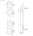
一般的に、回転することで相手部材に対して接離部材を接近離間させるカム部材を備えている。例えば、特許文献1(特開2014-906442号公報)では、図40(a)に示すように、一次転写ローラ910を支持する支持部材901と、支持部材901に当接するカム部材902が設けられる。カム部材902は、回転軸903を中心に回転可能に設けられ、回転軸903からの距離が最も大きい大径部902aと最も小さい小径部902bとを有する。支持部材901は、バネ904によってカム部材902の側へ付勢されている。そして、カム部材902と支持部材901の当接位置を変更することにより、支持部材901に支持される各一次転写ローラ910を、各感光体ドラム911に対して接離させることができる。具体的には、図40(a)に示すように、小径部902bを支持部材901に当接させることにより、各一次転写ローラ910を各感光体ドラム911から離間させ、図40(b)に示すように、大径部902aを支持部材901に当接させることにより、各一次転写ローラ910を各感光体ドラム911に接近させることができる。カム部材902の回転量は、カム位置検出センサの検知結果に基づいて決定される。 Generally, it is provided with a cam member that brings the contact / detachment member closer to and away from the mating member by rotating. For example, in Patent Document 1 (Japanese Unexamined Patent Publication No. 2014-906442), as shown in FIG. 40 (a), a support member 901 that supports the primary transfer roller 910 and a cam member 902 that abuts on the support member 901 are provided. .. The cam member 902 is rotatably provided around the rotation shaft 903, and has a large diameter portion 902a having the largest distance from the rotation shaft 903 and a small diameter portion 902b having the smallest distance. The support member 901 is urged toward the cam member 902 by a spring 904. Then, by changing the contact position between the cam member 902 and the support member 901, each primary transfer roller 910 supported by the support member 901 can be brought into contact with each photoconductor drum 911. Specifically, as shown in FIG. 40 (a), by bringing the small diameter portion 902b into contact with the support member 901, each primary transfer roller 910 is separated from each photoconductor drum 911, and FIG. 40 (b) shows. As shown, each primary transfer roller 910 can be brought closer to each photoconductor drum 911 by bringing the large diameter portion 902a into contact with the support member 901. The amount of rotation of the cam member 902 is determined based on the detection result of the cam position detection sensor.

特許文献1のように、カム面の周方向において、回転中心からの距離が急激に変化する部分、つまり、大径部の端縁とそれに隣接する小径側との間に形成される段差部(図40aの段差部902c参照)を有する構成では、カム部材が想定以上に回転することによるカム部材とカム部材に当接する当接部材との衝突が問題になる。 As in Patent Document 1, a portion where the distance from the center of rotation changes rapidly in the circumferential direction of the cam surface, that is, a stepped portion formed between the edge of the large diameter portion and the adjacent small diameter side (a step portion). In the configuration having the stepped portion 902c in FIG. 40a), the collision between the cam member and the abutting member in contact with the cam member due to the cam member rotating more than expected becomes a problem.

つまり、図40(a)から図40(b)のように、カム部材902が支持部材901に対して小径部902bを当接させた状態から大径部902aを当接させた状態へ移行する場合、カム部材902は矢印Z方向へ回転して大径部902aが支持部材901に当接する図40(b)の位置で停止する。しかし、センサの故障などにより、大径部902aの支持部材901への当接のタイミングの検知できないと、カム部材902は、図40(a)の位置からさらに矢印Z方向へ回転を続けることになる。これにより、カム部材902の支持部材901への当接位置が、大径部902aから段差部902cを乗り越えて、小径側へ移動する。この際、カム面の支持部材に当接する部分の径が急激に小さくなることにより、バネ904の付勢力によって支持部材901が急激に図の上方向へ引き寄せられ、カム部材902と支持部材901とが大きな速度を伴って衝突してしまう。そして、この衝突により、カム部材やカム部材に当接する当接部材が破損することが問題になる。 That is, as shown in FIGS. 40A to 40B, the cam member 902 shifts from the state in which the small diameter portion 902b is in contact with the support member 901 to the state in which the large diameter portion 902a is in contact with the support member 901. In this case, the cam member 902 rotates in the direction of arrow Z and stops at the position shown in FIG. 40 (b) where the large diameter portion 902a abuts on the support member 901. However, if the timing of contact of the large diameter portion 902a with the support member 901 cannot be detected due to a sensor failure or the like, the cam member 902 will continue to rotate in the direction of arrow Z from the position shown in FIG. 40 (a). Become. As a result, the contact position of the cam member 902 with the support member 901 moves from the large diameter portion 902a over the stepped portion 902c to the small diameter side. At this time, since the diameter of the portion of the cam surface that comes into contact with the support member suddenly decreases, the support member 901 is suddenly pulled upward in the figure by the urging force of the spring 904, and the cam member 902 and the support member 901 Collides with a large speed. Then, this collision causes a problem that the cam member and the contact member in contact with the cam member are damaged.

特に、画像形成装置に設けられた接離機構では、画像形成装置の起動時等には、カム部材の初期位置を装置側に認識させるためのイニシャライズ動作が必要になるが、このイニシャライズ動作において、センサが正常に動作しないことでカム部材の回転が継続して上記の衝突を生じてしまう。 In particular, in the contact / detachment mechanism provided in the image forming apparatus, an initialization operation for making the apparatus side recognize the initial position of the cam member is required at the time of starting the image forming apparatus. If the sensor does not operate normally, the rotation of the cam member will continue and the above-mentioned collision will occur.

このような事情から、本発明では、カム部材の回転位置検知動作において、カム部材と当接部材との大きな速度での衝突を防止することを課題としている。 Under such circumstances, it is an object of the present invention to prevent a collision between the cam member and the contact member at a large speed in the rotation position detection operation of the cam member.

上記の課題を解決するため、本発明は、当接部材にカム面を当接させるカム部材と、検知状態と非検知状態との状態変化により、前記カム部材の回転位置を検知する回転位置検知手段と、前記カム部材の回転動作を制御する制御部とを備え、前記制御部が前記カム部材を回転させることで前記当接部材に対する当接位置を変化させることにより、相手部材に対して接離部材を接近離間させる接離機構であって、前記カム部材は、回転方向の半周よりも多い領域にわたって回転中心からの距離が漸増するカム面を有し、一方向およびこれとは逆方向に回転可能であり、前記カム面は、前記カム部材の回転方向に対して回転中心からの距離が大きく変化する段差部を有し、前記制御部が前記カム部材の回転位置を認識するための回転位置認識動作において、前記回転位置検知手段が初期に非検知状態になった場合には、前記制御部は、前記カム部材を、前記段差部の前記回転中心からの距離が大きい側を回転方向の上流側、前記段差部の前記回転中心からの距離が小さい側を下流側とする方向へ回転させ、前記接離部材が前記相手部材に接近することを特徴とする。 In order to solve the above problems, the present invention has a rotation position detection that detects the rotation position of the cam member by the state change between the detection state and the non-detection state of the cam member that brings the cam surface into contact with the contact member. The means and a control unit that controls the rotational operation of the cam member are provided, and the control unit rotates the cam member to change the contact position with respect to the contact member, thereby contacting the mating member. A contact / detachment mechanism that brings the release members closer to each other, wherein the cam member has a cam surface in which the distance from the center of rotation gradually increases over a region larger than half a circumference in the rotation direction, and is in one direction and in the opposite direction. The cam surface is rotatable, and the cam surface has a stepped portion in which the distance from the rotation center greatly changes with respect to the rotation direction of the cam member, and the control unit rotates to recognize the rotation position of the cam member. In the position recognition operation, when the rotation position detecting means is initially in the non-detection state, the control unit sets the cam member on the side of the step portion where the distance from the rotation center is large in the rotation direction. It is characterized in that the contacting / separating member approaches the mating member by rotating the upstream side in the direction in which the side of the step portion having a small distance from the rotation center is the downstream side.

本発明では、回転位置検知手段が非検知状態になった場合に、段差部を乗り越える方向とは逆方向へカム部材を回転させる。これにより、回転位置検知手段が正常な検知動作を行えずに非検知状態を継続した場合であっても、カム部材と当接部材との大きな速度を伴う衝突を防止することができる。 In the present invention, when the rotation position detecting means is in the non-detection state, the cam member is rotated in the direction opposite to the direction of overcoming the step portion. As a result, even when the rotation position detecting means cannot perform a normal detection operation and continues in the non-detection state, it is possible to prevent a collision between the cam member and the contact member with a large speed.

本発明の実施形態に係る画像形成装置の概略構成図である。It is a schematic block diagram of the image forming apparatus which concerns on embodiment of this invention. 定着装置の概略構成図である。It is a schematic block diagram of the fixing device. 定着装置の正面側を斜め上方から見た斜視図である。It is a perspective view which looked at the front side of the fixing device from diagonally above. 定着装置を左側から見た側面図である。It is a side view which looked at the fixing device from the left side. 定着装置が装着された状態の装置本体の概略断面図である。It is the schematic sectional drawing of the apparatus main body with the fixing apparatus attached. 装置本体に設けられたガイドレールの概略図である。It is a schematic diagram of the guide rail provided in the apparatus main body. 取っ手部の持ち方の一例を示す図である。It is a figure which shows an example of how to hold a handle part. 定着装置を取り外す様子を示す図である。It is a figure which shows the state of removing a fixing device. 定着装置を取り外す様子を示す図である。It is a figure which shows the state of removing a fixing device. 定着装置を取り外す様子を示す図である。It is a figure which shows the state of removing a fixing device. 開閉カバーを閉じた状態を示す図である。It is a figure which shows the state which the opening / closing cover is closed. 定着装置の外装部の上部分を取り除いた状態の斜視図である。It is a perspective view of the state which the upper part of the exterior part of a fixing device is removed. 定着装置に設けられた接離機構周辺の構成を示す側面図である。It is a side view which shows the structure around the contact / separation mechanism provided in the fixing device. カム部材と遮光部材と光学センサとを抜き出して示す図である。It is a figure which shows the cam member, the light-shielding member, and an optical sensor by extracting them. 本実施形態に係る接離機構の駆動系の概略構成図である。It is a schematic block diagram of the drive system of the attachment / detachment mechanism which concerns on this embodiment. 本実施形態に係る接離機構の制御系のブロック図である。It is a block diagram of the control system of the contact / detachment mechanism which concerns on this embodiment. カム部材による加圧ローラの離間動作を説明するための図である。It is a figure for demonstrating the separation operation of a pressure roller by a cam member. カム部材による加圧ローラの接近動作を説明するための図である。It is a figure for demonstrating the approaching operation of a pressure roller by a cam member. 脱圧動作時の回転制御方法を説明するための図である。It is a figure for demonstrating the rotation control method at the time of decompression operation. 脱圧動作時の回転制御のフローチャートである。It is a flowchart of rotation control at the time of decompression operation. 加圧動作時の回転制御方法を説明するための図である。It is a figure for demonstrating the rotation control method at the time of a pressurizing operation. 加圧動作時の回転制御のフローチャートである。It is a flowchart of rotation control at the time of a pressurizing operation. 第一のイニシャライズ動作時の回転制御方法を説明するための図である。It is a figure for demonstrating the rotation control method at the time of the first initialization operation. 第一のイニシャライズ動作時の回転制御方法を説明するための図である。It is a figure for demonstrating the rotation control method at the time of the first initialization operation. 第一のイニシャライズ動作時の回転制御のフローチャートである。It is a flowchart of rotation control at the time of the first initialization operation. 第二のイニシャライズ動作時の回転制御方法を説明するための図である。It is a figure for demonstrating the rotation control method at the time of the 2nd initialization operation. 第二のイニシャライズ動作時の回転制御方法を説明するための図である。It is a figure for demonstrating the rotation control method at the time of the 2nd initialization operation. 第二のイニシャライズ動作時の回転制御のフローチャートである。It is a flowchart of rotation control at the time of the second initialization operation. カム部材が逆方向へ過剰に回転した場合を説明するための図である。It is a figure for demonstrating the case where a cam member is excessively rotated in the reverse direction. カム部材が正方向へ過剰に回転した場合を説明するための図である。It is a figure for demonstrating the case where a cam member is excessively rotated in the positive direction. 定着装置における第1の平歯車の配置を示す図である。It is a figure which shows the arrangement of the 1st spur gear in a fixing device. カム部材を正方向へ回転させる際のギアの回転状態を示す図である。It is a figure which shows the rotation state of the gear when rotating a cam member in a positive direction. カム部材を逆方向へ回転させる際のギアの回転状態を示す図である。It is a figure which shows the rotation state of the gear when the cam member is rotated in the reverse direction. 定着ベルトを備える定着装置の概略構成図である。It is a schematic block diagram of the fixing device provided with a fixing belt. 定着ローラが対向ローラに対して接近離間する定着装置の概略構成図である。It is a schematic block diagram of the fixing device in which the fixing roller approaches and separates from the facing roller. 二次転写ローラを接近離間させる接離機構の概略構成図である。It is a schematic block diagram of the contact and separation mechanism which brings a secondary transfer roller close and separate. 縦搬送タイプのカラー画像形成装置の概略構成図である。It is a schematic block diagram of the vertical transfer type color image forming apparatus. 転写装置の概略構成図である。It is a schematic block diagram of a transfer apparatus. 一次転写ローラを接近離間させる接離機構の概略構成図である。It is a schematic block diagram of the contact and separation mechanism which brings the primary transfer roller close and separate. 従来の接離機構を示す図である。It is a figure which shows the conventional contact and separation mechanism.

以下、本発明に係る実施の形態について、図面を参照して説明する。なお、各図中、同一又は相当する部分には同一の符号を付しており、その重複説明は適宜に簡略化ないし省略する。 Hereinafter, embodiments according to the present invention will be described with reference to the drawings. In each figure, the same or corresponding parts are designated by the same reference numerals, and the duplicated description thereof will be appropriately simplified or omitted.

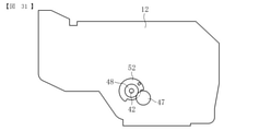
図1は、本発明の実施の一形態に係る画像形成装置の概略構成図である。まず、図1を参照して、画像形成装置の全体構成及び動作について説明する。 FIG. 1 is a schematic configuration diagram of an image forming apparatus according to an embodiment of the present invention. First, with reference to FIG. 1, the overall configuration and operation of the image forming apparatus will be described.

図1に示す画像形成装置は、モノクロ画像形成装置である。その装置本体(画像形成装置本体)100には、作像ユニットとしてのプロセスユニット1が着脱可能に装着されている。プロセスユニット1は、表面に画像を担持する像担持体としての感光体2と、感光体2の表面を帯電させる帯電手段としての帯電ローラ3と、感光体2上の潜像を可視画像化する現像手段としての現像装置4と、感光体2の表面をクリーニングするクリーニング手段としてのクリーニングブレード5等を備える。また、感光体2に対向する位置に、感光体2の表面を露光する露光手段としてのLEDヘッドアレイ6が配置されている。 The image forming apparatus shown in FIG. 1 is a monochrome image forming apparatus. A process unit 1 as an image forming unit is detachably attached to the apparatus main body (image forming apparatus main body) 100. The process unit 1 visualizes a photoconductor 2 as an image carrier that carries an image on the surface, a charging roller 3 as a charging means for charging the surface of the photoconductor 2, and a latent image on the photoconductor 2. A developing device 4 as a developing means, a cleaning blade 5 as a cleaning means for cleaning the surface of the photoconductor 2, and the like are provided. Further, an LED head array 6 as an exposure means for exposing the surface of the photoconductor 2 is arranged at a position facing the photoconductor 2.

プロセスユニット1には、画像形成用の粉体であるトナーを収容する粉体収容器としてのトナーカートリッジ7が着脱可能に装着されている。トナーカートリッジ7は、未使用のトナーを収容する未使用トナー収容部8と、使用された廃トナーを収容する廃トナー収容部9とを有する。 A toner cartridge 7 as a powder container for accommodating toner, which is powder for image formation, is detachably attached to the process unit 1. The toner cartridge 7 has an unused toner accommodating portion 8 for accommodating unused toner and a waste toner accommodating portion 9 for accommodating used waste toner.

また、画像形成装置は、記録媒体としての用紙に画像を転写する転写装置10と、用紙を供給する給紙装置11と、用紙に転写された画像を定着させる定着装置12と、用紙を装置外へ排出する排紙装置13と、タイミングローラとしての一対のレジストローラ17とを備える。 Further, the image forming apparatus includes a transfer device 10 for transferring an image to paper as a recording medium, a paper feeding device 11 for supplying the paper, a fixing device 12 for fixing the image transferred to the paper, and the paper outside the apparatus. It is provided with a paper ejection device 13 for discharging to, and a pair of resist rollers 17 as timing rollers.

転写装置10は、転写部材としての転写ローラ14を備える。転写ローラ14は、プロセスユニット1を装置本体100に装着した状態で感光体2と接触するように配置されている。また、転写ローラ14は、図示しない電源に接続されており、所定の直流電圧(DC)及び/又は交流電圧(AC)が印加されるようになっている。 The transfer device 10 includes a transfer roller 14 as a transfer member. The transfer roller 14 is arranged so as to come into contact with the photoconductor 2 in a state where the process unit 1 is attached to the apparatus main body 100. Further, the transfer roller 14 is connected to a power source (not shown), and a predetermined direct current voltage (DC) and / or alternating current voltage (AC) is applied.

給紙装置11は、用紙Pが収容される給紙カセット15と、給紙カセット15に収容されている用紙Pを給送する給紙ローラ16とを備える。 The paper feed device 11 includes a paper feed cassette 15 in which the paper P is housed, and a paper feed roller 16 for feeding the paper P housed in the paper feed cassette 15.

定着装置12は、用紙に画像を定着させる相手部材(回転体)としての定着ローラ18と、定着ローラ18に対向して配置される接離部材(回転体)としての加圧ローラ19とを備える。定着ローラ18は、ヒータ等の加熱手段によって加熱される。加圧ローラ19は、定着ローラ18側へ加圧され、定着ローラ18に接触して定着ニップを形成している。 The fixing device 12 includes a fixing roller 18 as a mating member (rotating body) for fixing an image on paper, and a pressure roller 19 as a contacting / separating member (rotating body) arranged to face the fixing roller 18. .. The fixing roller 18 is heated by a heating means such as a heater. The pressure roller 19 is pressurized to the fixing roller 18 side and comes into contact with the fixing roller 18 to form a fixing nip.

排紙装置13は、用紙を装置外に排出する一対の排紙ローラ20を備える。また、装置本体100の外装上面部には、排紙ローラ20によって排出された用紙を載置するための排紙トレイ21が形成されている。 The paper ejection device 13 includes a pair of paper ejection rollers 20 for ejecting paper to the outside of the device. Further, a paper ejection tray 21 for placing the paper ejected by the paper ejection roller 20 is formed on the outer upper surface portion of the apparatus main body 100.

また、装置本体100内には、給紙カセット15から、レジストローラ17、転写ローラ14と感光体2との間の画像転写部(転写ニップ)、定着装置12を経由して、排紙ローラ20まで用紙Pを搬送するための搬送路R1が設けられている。さらに、画像形成装置100内には、両面印刷する際に定着装置12を通過した用紙Pを画像転写部に再度搬送するための両面搬送路R2が設けられている。 Further, in the apparatus main body 100, the paper ejection roller 20 is entered from the paper feed cassette 15 via the resist roller 17, the image transfer portion (transfer nip) between the transfer roller 14 and the photoconductor 2, and the fixing device 12. A transport path R1 for transporting the paper P to is provided. Further, the image forming apparatus 100 is provided with a double-sided transport path R2 for transporting the paper P that has passed through the fixing device 12 to the image transfer unit again when double-sided printing is performed.

続けて、図1を参照しつつ、本実施形態に係る画像形成装置の作像動作について説明する。
作像動作が開始されると、感光体2が回転駆動され、帯電ローラ3によって感光体2の表面が所定の極性に一様に帯電される。次いで、読取装置又はコンピュータ等からの画像情報に基づいてLEDヘッドアレイ6が感光体2の帯電面を露光し、静電潜像が形成される。そして、現像装置4によって感光体2上の静電潜像にトナーが供給されることにより、静電潜像はトナー画像として顕像化(可視像化)される。
Subsequently, with reference to FIG. 1, the image forming operation of the image forming apparatus according to the present embodiment will be described.
When the image forming operation is started, the photoconductor 2 is rotationally driven, and the surface of the photoconductor 2 is uniformly charged to a predetermined polarity by the charging roller 3. Next, the LED head array 6 exposes the charged surface of the photoconductor 2 based on the image information from the reader, a computer, or the like, and an electrostatic latent image is formed. Then, the developing device 4 supplies toner to the electrostatic latent image on the photoconductor 2, so that the electrostatic latent image is visualized (visualized) as a toner image.

また、作像動作が開始されると、給紙ローラ16が回転駆動を開始し、給紙カセット15から用紙Pが送り出される。送り出された用紙Pは、レジストローラ17によって搬送を一旦停止される。その後、所定のタイミングでレジストローラ17の回転駆動を開始し、感光体2上のトナー画像が画像転写部に達するタイミングに合わせて、用紙Pを画像転写部へ搬送する。 Further, when the image drawing operation is started, the paper feed roller 16 starts the rotation drive, and the paper P is fed out from the paper feed cassette 15. The paper P that has been sent out is temporarily stopped from being conveyed by the resist roller 17. After that, the rotation drive of the resist roller 17 is started at a predetermined timing, and the paper P is conveyed to the image transfer unit at the timing when the toner image on the photoconductor 2 reaches the image transfer unit.

そして、用紙Pが画像転写部に搬送されると、転写ローラ14に所定の電圧が印加されることにより生じた転写電界によって感光体2上のトナー画像が用紙P上に転写される。また、このとき用紙Pに転写されなかった感光体2上のトナーは、クリーニングブレード5によって除去され、トナーカートリッジ7の廃トナー収容部9へ回収される。 Then, when the paper P is conveyed to the image transfer unit, the toner image on the photoconductor 2 is transferred onto the paper P by the transfer electric field generated by applying a predetermined voltage to the transfer roller 14. Further, the toner on the photoconductor 2 that has not been transferred to the paper P at this time is removed by the cleaning blade 5 and collected in the waste toner accommodating portion 9 of the toner cartridge 7.

トナー画像が転写された用紙Pは、定着装置12へと搬送され、定着ローラ18と加圧ローラ19とによって形成される定着ニップを通過することにより加熱及び加圧されて、用紙P上のトナー画像が定着される。そして、用紙Pは、排紙ローラ20によって装置外に排出され、排紙トレイ21上に載置される。 The paper P on which the toner image is transferred is conveyed to the fixing device 12, heated and pressurized by passing through a fixing nip formed by the fixing roller 18 and the pressure roller 19, and the toner on the paper P is transferred. The image is fixed. Then, the paper P is discharged to the outside of the device by the paper ejection roller 20 and placed on the paper ejection tray 21.

また、両面印刷を行う場合は、定着装置12を通過した用紙Pを装置外に排出せずにスイッチバックさせて両面搬送路R2に送る。用紙Pは両面搬送路R2を通ってレジストローラ17の手前側で搬送路R1に送り込まれ、レジストローラ17によって画像転写部へ再度搬送される。そして、用紙Pの裏面に画像が転写され、定着装置12によって裏面側の画像が定着された後、用紙Pは装置外へ排出される。 When double-sided printing is performed, the paper P that has passed through the fixing device 12 is switched back without being discharged to the outside of the device and sent to the double-sided transfer path R2. The paper P is fed to the transport path R1 on the front side of the resist roller 17 through the double-sided transport path R2, and is again conveyed to the image transfer unit by the resist roller 17. Then, the image is transferred to the back surface of the paper P, the image on the back surface side is fixed by the fixing device 12, and then the paper P is discharged to the outside of the device.

図2は、定着装置12の概略断面図である。
図2に示すように、定着装置12は、内部に定着ローラ18や加圧ローラ19が収容される外装部を構成する樹脂製のフレーム部材23を有する。フレーム部材23の正面には、定着装置12内に用紙を進入させるための入口部23aが形成され、フレーム部材23の背面には、定着装置12から用紙を排出するための出口部23bが形成されている。なお、ここでいう定着装置12の「正面」とは、定着装置12が画像形成装置に装着された状態で画像形成装置の正面、すなわち作業者が画像形成装置に設けられた操作部(操作パネル等)で印刷指示をする際に立つ側の面を意味する。また、定着ローラ18内には発熱体としてのハロゲンヒータ22が設けられている。加圧ローラ19は、後述の加圧部材によって定着ローラ18に対して加圧されており、定着ローラ18と加圧ローラ19とが圧接する箇所には定着ニップNが形成されている。
FIG. 2 is a schematic cross-sectional view of the fixing device 12.
As shown in FIG. 2, the fixing device 12 has a resin frame member 23 constituting an exterior portion in which the fixing roller 18 and the pressure roller 19 are housed. An inlet portion 23a for allowing the paper to enter the fixing device 12 is formed on the front surface of the frame member 23, and an outlet portion 23b for ejecting the paper from the fixing device 12 is formed on the back surface of the frame member 23. ing. The "front" of the fixing device 12 here means the front of the image forming device with the fixing device 12 mounted on the image forming device, that is, an operation unit (operation panel) provided on the image forming device by an operator. Etc.) means the side that stands when giving a print instruction. Further, a halogen heater 22 as a heating element is provided in the fixing roller 18. The pressure roller 19 is pressed against the fixing roller 18 by a pressure member described later, and a fixing nip N is formed at a position where the fixing roller 18 and the pressure roller 19 are in pressure contact with each other.

装置本体100側の駆動源から定着ローラ18に駆動力が伝達されると、定着ローラ18は図2中の矢印Aで示す方向に回転駆動する。また、加圧ローラ19は、回転駆動する定着ローラ18に対して図2中の矢印Bで示す方向に従動回転するように構成されている。なお、本実施形態とは反対に、加圧ローラ19を駆動ローラとし、定着ローラ18を従動ローラとしてもよい。 When the driving force is transmitted from the drive source on the device main body 100 side to the fixing roller 18, the fixing roller 18 is rotationally driven in the direction indicated by the arrow A in FIG. Further, the pressure roller 19 is configured to be driven to rotate in the direction indicated by the arrow B in FIG. 2 with respect to the rotation-driven fixing roller 18. Contrary to the present embodiment, the pressurizing roller 19 may be used as a driving roller and the fixing roller 18 may be used as a driven roller.

図2を参照しつつ、定着装置12の動作について簡単に説明する。
ハロゲンヒータ22から発せられる輻射熱によって定着ローラ18が所定の温度に加熱され、定着ローラ18と加圧ローラ19とが回転している状態で、用紙が図2中の矢印C1で示す方向から定着ニップNへ進入すると、用紙は定着ローラ18と加圧ローラ19とによって挟持されながら搬送される。このとき、用紙上の未定着画像が、定着ローラ18の熱によって加熱されると共に、定着ローラ18と加圧ローラ19とによって加圧されることで、用紙に画像が定着される。そして、画像が定着された用紙は定着ニップNから図2中の矢印C2方向へ排出される。
The operation of the fixing device 12 will be briefly described with reference to FIG. 2.
The fixing roller 18 is heated to a predetermined temperature by the radiant heat generated from the halogen heater 22, and the paper is fixed from the direction indicated by the arrow C1 in FIG. 2 in a state where the fixing roller 18 and the pressure roller 19 are rotating. Upon entering N, the paper is conveyed while being sandwiched between the fixing roller 18 and the pressure roller 19. At this time, the unfixed image on the paper is heated by the heat of the fixing roller 18 and is pressed by the fixing roller 18 and the pressure roller 19, so that the image is fixed on the paper. Then, the paper on which the image is fixed is ejected from the fixing nip N in the direction of arrow C2 in FIG.

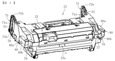
図3に示すように、フレーム部材23には、定着装置12を装置本体100に対して着脱する際に作業者が把持する取っ手部71が設けられている。取っ手部71は、フレーム部材23の背面の左右端部にそれぞれ設けられる。 As shown in FIG. 3, the frame member 23 is provided with a handle portion 71 that is gripped by an operator when the fixing device 12 is attached to and detached from the device main body 100. Handles 71 are provided at the left and right ends of the back surface of the frame member 23, respectively.

一対の取っ手部71は、互いに左右対称の形状に構成されている。具体的に、各取っ手部71は、上下方向に延びる把持部71aと、把持部71aの上端部及び下端部から前方(正面側)に延びる一対のアーム部71bとを有し、把持部71aが一対のアーム部71bを介してフレーム部材23の背面に固定されている。そして、各把持部71aとフレーム部材23の背面との間には、作業者が手又は指を挿入可能な空間部S1が形成されている。 The pair of handle portions 71 are configured to have a symmetrical shape with each other. Specifically, each handle portion 71 has a grip portion 71a extending in the vertical direction and a pair of arm portions 71b extending forward (front side) from the upper end portion and the lower end portion of the grip portion 71a, and the grip portion 71a has. It is fixed to the back surface of the frame member 23 via a pair of arm portions 71b. A space portion S1 into which an operator can insert a hand or a finger is formed between each grip portion 71a and the back surface of the frame member 23.

さらに、フレーム部材23には、装置本体100に対して定着装置12を位置決めするための複数の位置決め部77~79が設けられている。複数の位置決め部77~79は、フレーム部材23の正面右端部に設けられた第1位置決め突起77と、フレーム部材23の左側面及び右側面の正面側にそれぞれ設けられた一対の第2位置決め突起78と、フレーム部材23の左側面及び右側面の背面側にそれぞれ設けられた一対の第3位置決め突起79とで構成される。 Further, the frame member 23 is provided with a plurality of positioning portions 77 to 79 for positioning the fixing device 12 with respect to the device main body 100. The plurality of positioning portions 77 to 79 include a first positioning protrusion 77 provided at the front right end portion of the frame member 23 and a pair of second positioning protrusions provided on the front side of the left side surface and the right side surface of the frame member 23, respectively. It is composed of 78 and a pair of third positioning protrusions 79 provided on the left side surface and the back surface side of the right side surface of the frame member 23, respectively.

また、フレーム部材23の左側面及び右側面には、それぞれ定着装置12を装置本体100に着脱する際に後述の本体側ガイド部に沿って案内される凸状のガイド部としてのガイド突起80が設けられている。各ガイド突起80は、矩形(略長方形又は略正方形)に形成されており、それぞれの上平面及び下平面が本体側ガイド部に対して摺動する摺動面80a,80bとして機能する。特に、本実施形態では、定着装置12の着脱時に、定着装置12におけるガイド突起80以外の部分は装置本体100に対して摺動しない(ガイド機能を発揮しない)ようにすることで、摺動抵抗を少なくし、操作性を向上させている。 Further, on the left side surface and the right side surface of the frame member 23, guide protrusions 80 as convex guide portions are guided along the main body side guide portion described later when the fixing device 12 is attached to and detached from the apparatus main body 100, respectively. It is provided. Each guide protrusion 80 is formed in a rectangular shape (a substantially rectangular shape or a substantially square shape), and functions as sliding surfaces 80a and 80b on which the upper plane and the lower plane slide with respect to the guide portion on the main body side. In particular, in the present embodiment, when the fixing device 12 is attached / detached, the portion of the fixing device 12 other than the guide protrusion 80 does not slide with respect to the device main body 100 (does not exhibit the guide function), thereby causing sliding resistance. Is reduced and operability is improved.

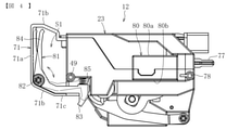
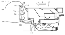
図4は、定着装置12を左側から見た側面図である。
図4に示すように、定着装置12には、定着装置12を装置本体100に装着した状態で離脱しないように固定するロック部83が設けられている。ロック部83は、取っ手部71に回動可能に設けられた回動部材81の一部に設けられている。回動部材81は、略L字型に形成されており、その回動中心(支点82)から前方(正面側)に延びる部分の先端部にロック部83が設けられている。一方、回動部材81の回動中心(支点82)から上方に延びる部分は、作業者が回動部材81を回動操作するための操作部84である。
FIG. 4 is a side view of the fixing device 12 as viewed from the left side.
As shown in FIG. 4, the fixing device 12 is provided with a lock portion 83 for fixing the fixing device 12 in a state of being attached to the device main body 100 so as not to be detached. The lock portion 83 is provided on a part of the rotating member 81 rotatably provided on the handle portion 71. The rotating member 81 is formed in a substantially L-shape, and a lock portion 83 is provided at the tip of a portion extending forward (front side) from the rotation center (fulcrum 82). On the other hand, the portion extending upward from the rotation center (fulcrum 82) of the rotating member 81 is an operation unit 84 for the operator to rotate the rotating member 81.

また、ロック部83は、その上面とフレーム部材23の下面との間に配置されている付勢部材としてのコイルバネ85によって常時下方へ付勢されている。このため、回動部材81が作業者によって回動操作されない状態では、回動部材81の下部が下側のアーム部71bの底部71cに当接し、ロック部83の先端部(下端部)が下側のアーム部71bの底部71cよりも下方へ大きく突出した状態(図4中の実線で示す状態)で保持される。この状態では、ロック部83が、装置本体100側に設けられた後述の係合部に対して係合可能なロック可能状態となる。 Further, the lock portion 83 is constantly urged downward by a coil spring 85 as a urging member arranged between the upper surface thereof and the lower surface of the frame member 23. Therefore, in a state where the rotating member 81 is not rotated by the operator, the lower portion of the rotating member 81 comes into contact with the bottom portion 71c of the lower arm portion 71b, and the tip portion (lower end portion) of the lock portion 83 is lowered. The arm portion 71b on the side is held in a state of protruding significantly downward from the bottom portion 71c (the state shown by the solid line in FIG. 4). In this state, the lock portion 83 is in a lockable state in which it can engage with the engagement portion described later provided on the device main body 100 side.

これに対して、作業者がコイルバネ85の付勢力に抗して回動部材81を図4における反時計回りに回動させた場合は、ロック部83の先端部が上方へ退避し、装置本体100側の係合部に対して係合しないロック不可状態(図4中の二点鎖線で示す状態)となる。このように、作業者が操作部84を操作して回動部材81を回動させることで、ロック部83をロック可能状態とロック不可状態とに切り替えることが可能である。なお、回動部材81は右側の取っ手部71にも同様に設けられている。 On the other hand, when the operator rotates the rotating member 81 counterclockwise against the urging force of the coil spring 85, the tip portion of the lock portion 83 retracts upward and the device main body. It is in a non-lockable state (a state shown by a two-dot chain line in FIG. 4) in which the engagement portion on the 100 side is not engaged. In this way, the operator can operate the operation unit 84 to rotate the rotating member 81, so that the lock unit 83 can be switched between the lockable state and the non-lockable state. The rotating member 81 is also provided on the right handle portion 71 in the same manner.

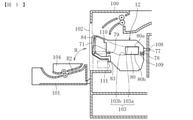
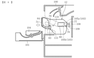
図5は、定着装置12が装着された状態の装置本体100の概略断面図である。
図5に示すように、装置本体100の背面(図における左側の面)には開閉カバー101が設けられている。開閉カバー101は、図5中の矢印H方向に回動することで開閉する。図5に示す状態は、開閉カバー101が開いて装置本体100の背面に開口部102が形成された状態である。この状態で、定着装置12を開口部102から後方へ取り外すことが可能である。なお、定着装置12の着脱方法については後で詳しく説明する。
FIG. 5 is a schematic cross-sectional view of the apparatus main body 100 in a state where the fixing apparatus 12 is attached.
As shown in FIG. 5, an opening / closing cover 101 is provided on the back surface (left side surface in the drawing) of the apparatus main body 100. The opening / closing cover 101 opens / closes by rotating in the direction of arrow H in FIG. The state shown in FIG. 5 is a state in which the opening / closing cover 101 is opened and the opening 102 is formed on the back surface of the apparatus main body 100. In this state, the fixing device 12 can be removed rearward from the opening 102. The method of attaching and detaching the fixing device 12 will be described in detail later.

また、開閉カバー101には、両面搬送路R2の一部を構成する両面搬送ユニット104が一体的に設けられている。このため、図5に示すように、開閉カバー101を開いた状態にすると、両面搬送ユニット104は開閉カバー101と一緒に回動し、定着装置12の背面近傍から退避した状態となる。 Further, the open / close cover 101 is integrally provided with a double-sided transport unit 104 that constitutes a part of the double-sided transport path R2. Therefore, as shown in FIG. 5, when the open / close cover 101 is opened, the double-sided transfer unit 104 rotates together with the open / close cover 101 and is retracted from the vicinity of the back surface of the fixing device 12.

装置本体100の左側壁及び右側壁の各内面には、それぞれ定着装置12を装置本体100に着脱する際に定着装置12を案内する本体側ガイド部としての一対のガイドレール103が設けられている。各ガイドレール103は、上側のガイド面103a及び下側のガイド面103bを有している。定着装置12の着脱時に、これらのガイド面103a,103bに対して上記ガイド突起80の上側の摺動面80aと下側の摺動面80bとが摺動することで定着装置12が案内される。 A pair of guide rails 103 as main body side guides for guiding the fixing device 12 when the fixing device 12 is attached to and detached from the device main body 100 are provided on each inner surface of the left side wall and the right side wall of the device main body 100, respectively. .. Each guide rail 103 has an upper guide surface 103a and a lower guide surface 103b. When the fixing device 12 is attached or detached, the fixing device 12 is guided by sliding the upper sliding surface 80a and the lower sliding surface 80b of the guide protrusion 80 with respect to these guide surfaces 103a and 103b. ..

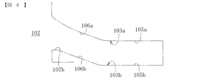
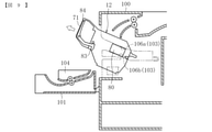
また、図6に示すように、各ガイドレール103の上側のガイド面103a及び下側のガイド面103bは、開口部102から遠い奥側で略水平方向に延びる奥側水平面105a,105bと、奥側水平面105a,105bから開口部102側(手前側)に向かって上方へ傾斜しながら延びる手前側傾斜面106a,106bとを有している。さらに、下側のガイド面103bは、手前側傾斜面106bよりも開口部102に近い手前側に略水平方向に配置された手前側水平面107bを有している。 Further, as shown in FIG. 6, the upper guide surface 103a and the lower guide surface 103b of each guide rail 103 are the inner horizontal planes 105a and 105b extending in a substantially horizontal direction on the inner side far from the opening 102. It has front-side inclined surfaces 106a and 106b extending upward from the side horizontal planes 105a and 105b toward the opening 102 side (front side). Further, the lower guide surface 103b has a front side horizontal plane 107b arranged in a substantially horizontal direction on the front side closer to the opening 102 than the front side inclined surface 106b.

また、図5に示すように、装置本体100には、装置本体100に対する定着装置12の位置決めを行う複数の本体側位置決め部108~110が設けられている。複数の本体側位置決め部108~110は、定着装置12に設けられた第1位置決め突起77と係合して主に定着装置12の左右方向の位置決めを行う第1本体側位置決め部108と、定着装置12に設けられた第2位置決め突起78と係合して主に定着装置12の前方向と上下方向の位置決めを行う第2本体側位置決め部109と、定着装置12に設けられた第3位置決め突起79と係合して主に定着装置12の第2位置決め突起78を中心とする回転方向の位置決めを行う第3本体側位置決め部110とで構成される。 Further, as shown in FIG. 5, the apparatus main body 100 is provided with a plurality of main body side positioning portions 108 to 110 for positioning the fixing device 12 with respect to the apparatus main body 100. The plurality of main body side positioning portions 108 to 110 are fixed to the first main body side positioning portion 108 which engages with the first positioning protrusion 77 provided on the fixing device 12 to mainly position the fixing device 12 in the left-right direction. A second main body side positioning unit 109 that engages with a second positioning protrusion 78 provided on the device 12 to mainly position the fixing device 12 in the front direction and the vertical direction, and a third positioning provided on the fixing device 12. It is mainly composed of a third main body side positioning portion 110 that engages with the protrusion 79 to perform positioning in the rotation direction centered on the second positioning protrusion 78 of the fixing device 12.

また、装置本体100には、定着装置12のロック部83が係合する係合部111が設けられている。図7に示すように、定着装置12を装置本体100に装着した状態では、係合部111とロック部83の間に僅かな隙間が設けられる。定着装置12に引き出す方向(矢印K方向)の力が発生した場合には、係合部111がロック部83に係合することにより、定着装置12の引き出し方向の移動が規制される。 Further, the apparatus main body 100 is provided with an engaging portion 111 with which the lock portion 83 of the fixing device 12 is engaged. As shown in FIG. 7, when the fixing device 12 is attached to the device main body 100, a slight gap is provided between the engaging portion 111 and the locking portion 83. When a force in the pulling direction (arrow K direction) is generated in the fixing device 12, the engaging portion 111 engages with the lock portion 83, so that the movement of the fixing device 12 in the pulling direction is restricted.

以下、定着装置12の着脱方法について説明する。
定着装置12を装置本体100から取り外す場合は、まず、図5に示すように、開閉カバー101を開いた状態にする。そして、装置本体100の開口部102を通して取っ手部71を両手で把持する。例えば、作業者は、図7に示す例のように、親指を取っ手部71の上側のアーム部71b上に載せ、その他の指で把持部71aと操作部84とを一緒に握る。この状態で、操作部84を図7中の矢印J方向に引いて回動させることで、装置本体100側の係合部111に対するロック部83の係合が解除される。そして、ロック部83をロック解除状態(ロック不可状態)としたまま、定着装置12を離脱方向(図7中の矢印K方向)に引き動かす。
Hereinafter, a method of attaching / detaching the fixing device 12 will be described.
When removing the fixing device 12 from the device main body 100, first, as shown in FIG. 5, the opening / closing cover 101 is opened. Then, the handle portion 71 is gripped by both hands through the opening 102 of the apparatus main body 100. For example, as in the example shown in FIG. 7, the operator puts his thumb on the upper arm portion 71b of the handle portion 71, and grips the grip portion 71a and the operation portion 84 together with other fingers. In this state, by pulling and rotating the operation unit 84 in the direction of the arrow J in FIG. 7, the engagement of the lock portion 83 with the engagement portion 111 on the device main body 100 side is released. Then, while the lock portion 83 is in the unlocked state (unlockable state), the fixing device 12 is pulled in the release direction (arrow K direction in FIG. 7).

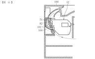
これにより、図8に示すように、定着装置12は装置本体100側のガイドレール103に沿って図の左方向(離脱方向)に移動し、定着装置12に設けられた各位置決め突起77~79が装置本体100側の各装置本体側位置決め部108~110に対して離脱する。また、定着装置12を引き動かし始めると、初めのうちは定着装置12のガイド突起80がガイドレール103の奥側水平面105a,105bに対して摺動し、定着装置12は略水平方向に移動する。次いで、図9に示すように、ガイド突起80はガイドレール103の手前側傾斜面106a,106bに対して摺動するため、定着装置12は斜め上方に移動する。その後、図10に示すように、定着装置12は装置本体100から完全に引き出されて取り外された状態となる。 As a result, as shown in FIG. 8, the fixing device 12 moves in the left direction (disengagement direction) of the figure along the guide rail 103 on the device main body 100 side, and the positioning protrusions 77 to 79 provided on the fixing device 12 are provided. Is separated from the positioning portions 108 to 110 on the device main body side on the device main body 100 side. Further, when the fixing device 12 starts to be pulled, the guide protrusion 80 of the fixing device 12 initially slides with respect to the horizontal horizontal planes 105a and 105b on the back side of the guide rail 103, and the fixing device 12 moves in a substantially horizontal direction. .. Next, as shown in FIG. 9, since the guide protrusion 80 slides on the front side inclined surfaces 106a and 106b of the guide rail 103, the fixing device 12 moves diagonally upward. After that, as shown in FIG. 10, the fixing device 12 is completely pulled out from the device main body 100 and is in a state of being removed.

このように、本実施形態では、定着装置12を両面搬送ユニット104に対して当接させないように斜め上方向に案内して取り外すことができる。ここで仮に、定着装置12を水平方向のみに案内するように構成すると、両面搬送ユニット104に対する定着装置12の当接を回避するために、定着装置12の装着位置や開口部102の上端位置を高くしなければならず、装置本体100の高さが高くなってしまう。これに対して、本実施形態の場合は、定着装置12の装着位置や開口部102の上端位置を高くしなくても両面搬送ユニット104に対する定着装置12の当接を回避することができるので、装置本体100の高さを低くすることができ、小型化を図れるようになる。 As described above, in the present embodiment, the fixing device 12 can be guided and removed diagonally upward so as not to come into contact with the double-sided transport unit 104. Here, if the fixing device 12 is configured to be guided only in the horizontal direction, the mounting position of the fixing device 12 and the upper end position of the opening 102 are set in order to avoid contact of the fixing device 12 with the double-sided transfer unit 104. The height must be increased, and the height of the apparatus main body 100 becomes high. On the other hand, in the case of the present embodiment, it is possible to avoid the contact of the fixing device 12 with the double-sided transfer unit 104 without raising the mounting position of the fixing device 12 or the upper end position of the opening 102. The height of the device main body 100 can be lowered, and the size can be reduced.

次に、定着装置12を装置本体100に装着する場合は、上記取り外し時の手順とは逆の手順で行えばよい。すなわち、取っ手部71と操作部84とを把持しながら、定着装置12をガイドレール103に沿って装置本体100内に挿入し、各位置決め突起77~79が各本体側位置決め部108~110に係合した時点で、取っ手部71及び操作部84を握る力を緩める。これにより、ロック部83がコイルバネ85の付勢力によって装置本体100側の係合部111に係合し、ロック状態となる。なお、本実施形態では、その後、定着装置12に駆動力が伝達される際に、装置本体100側に設けられた駆動ギアと定着ローラ18の端部に設けられた定着ギアとの間で装着方向の力が作用するため、定着装置12の位置決めがより確実になされる。 Next, when the fixing device 12 is attached to the device main body 100, the procedure at the time of removal may be reversed. That is, while gripping the handle portion 71 and the operation portion 84, the fixing device 12 is inserted into the device main body 100 along the guide rail 103, and the positioning protrusions 77 to 79 engage with the main body side positioning portions 108 to 110. At the time of fitting, the force for gripping the handle portion 71 and the operation portion 84 is relaxed. As a result, the lock portion 83 is engaged with the engaging portion 111 on the device main body 100 side by the urging force of the coil spring 85, and is in the locked state. In this embodiment, when the driving force is subsequently transmitted to the fixing device 12, it is mounted between the driving gear provided on the device main body 100 side and the fixing gear provided at the end of the fixing roller 18. Since the force in the direction acts, the positioning of the fixing device 12 is more reliable.

また、図11に示すように、本実施形態では、開閉カバー101を閉じると、左右の取っ手部71の間に両面搬送ユニット104が配置される。このように、取っ手部71の間に両面搬送ユニット104が配置されることで、取っ手部71間の空間を両面搬送路R2の一部として有効活用することができ、一層の小型化が図れる。 Further, as shown in FIG. 11, in the present embodiment, when the opening / closing cover 101 is closed, the double-sided transport unit 104 is arranged between the left and right handle portions 71. By arranging the double-sided transport unit 104 between the handle portions 71 in this way, the space between the handle portions 71 can be effectively utilized as a part of the double-sided transport path R2, and further miniaturization can be achieved.

以下、定着装置12に設けられた、加圧ローラを定着ローラに切離させるための接離機構およびその周辺構成について説明する。
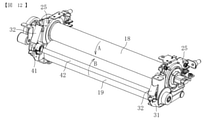
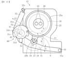
図12は、定着装置12の外装部の上部分を取り除いた状態の斜視図、図13は、定着装置の側面図である。
Hereinafter, a contact / detachment mechanism for separating the pressure roller from the fixing roller and a peripheral configuration thereof provided in the fixing device 12 will be described.
FIG. 12 is a perspective view of the fixing device 12 with the upper portion of the exterior portion removed, and FIG. 13 is a side view of the fixing device.

図12に示すように、フレーム部材23の長手方向の一端部側と他端部側とには、それぞれ金属製の支持部材25が取り付けられている。図13に示すように、各支持部材25に設けられた軸受26,27によって定着ローラ18と加圧ローラ19は回転可能に支持されている。 As shown in FIG. 12, metal support members 25 are attached to one end side and the other end side of the frame member 23 in the longitudinal direction, respectively. As shown in FIG. 13, the fixing roller 18 and the pressure roller 19 are rotatably supported by bearings 26 and 27 provided on each support member 25.

加圧ローラ19は、支持部材25によって定着ローラ18に対して図13中の矢印D方向に接近離間可能に支持されている。具体的には、加圧ローラ19を支持する軸受27が、支持部材25に設けられた長方形状の孔である軸受ガイド部25bに嵌め込まれており、この軸受ガイド部25bに沿って軸受27が案内されることで、加圧ローラ19は定着ローラ18に対して接近離間する。一方、定着ローラ18を支持する軸受26は、各支持部材25に設けられた円形の孔である軸受嵌合部25aに嵌め込まれており、定着ローラ18はその軸位置が軸方向と直交する方向に移動しないように固定されている。 The pressure roller 19 is supported by the support member 25 so as to be close to and separated from the fixing roller 18 in the direction of arrow D in FIG. Specifically, the bearing 27 that supports the pressure roller 19 is fitted into the bearing guide portion 25b, which is a rectangular hole provided in the support member 25, and the bearing 27 is formed along the bearing guide portion 25b. By being guided, the pressure roller 19 approaches and separates from the fixing roller 18. On the other hand, the bearing 26 that supports the fixing roller 18 is fitted into a bearing fitting portion 25a that is a circular hole provided in each support member 25, and the fixing roller 18 has a direction in which its axial position is orthogonal to the axial direction. It is fixed so that it does not move to.

また、本実施形態に係る定着装置12は、定着ローラ18に対して加圧ローラ19を加圧する加圧部材としての加圧レバー31と、加圧レバー31を加圧方向に付勢する付勢部材としての加圧バネ32とを備えている。加圧レバー31及び加圧バネ32は、加圧ローラ19の両端部側にそれぞれ1つずつ設けられている。加圧レバー31は、その一端部31aが支持部材25の下部に設けられた支軸33に取り付けられ、支軸33を中心に図13の矢印E方向に回動可能に構成されている。各加圧バネ32は、加圧レバー31の他端部31b側と支持部材25の上部とに設けられた引っ掛け部31c,25cに引っ掛けて取り付けられている。これにより、加圧レバー31の他端部31bは、加圧バネ32によって常時図13における上方へ引っ張られた状態で保持されている。そして、加圧レバー31は、支持部材25の軸受ガイド部25bに嵌め込まれたパッド34を介して加圧ローラ19を支持する軸受27を押圧し、加圧ローラ19を定着ローラ18に向かって加圧している。 Further, the fixing device 12 according to the present embodiment has a pressurizing lever 31 as a pressurizing member that pressurizes the pressurizing roller 19 against the fixing roller 18, and an urging device that urges the pressurizing lever 31 in the pressurizing direction. It is provided with a pressure spring 32 as a member. A pressure lever 31 and a pressure spring 32 are provided on both ends of the pressure roller 19. The pressure lever 31 has one end 31a attached to a support shaft 33 provided at the lower part of the support member 25, and is configured to be rotatable around the support shaft 33 in the direction of arrow E in FIG. Each pressure spring 32 is attached by being hooked on the hooking portions 31c and 25c provided on the other end 31b side of the pressure lever 31 and the upper portion of the support member 25. As a result, the other end 31b of the pressure lever 31 is always held in a state of being pulled upward in FIG. 13 by the pressure spring 32. Then, the pressure lever 31 presses the bearing 27 that supports the pressure roller 19 via the pad 34 fitted in the bearing guide portion 25b of the support member 25, and applies the pressure roller 19 toward the fixing roller 18. I'm pressing.

また、本実施形態に係る定着装置12は、定着ローラ18に対して加圧ローラ19を接近離間させる接離機構90を備えている。接離機構90は、カム部材41と、カム部材41の回転位置(回転角度)を検知する回転位置検知手段として、光学センサ51と、遮光部材52等を主に備えている。 Further, the fixing device 12 according to the present embodiment includes a contact / detachment mechanism 90 that brings the pressure roller 19 close to and separated from the fixing roller 18. The contact / detachment mechanism 90 mainly includes a cam member 41, an optical sensor 51, a light-shielding member 52, and the like as rotation position detecting means for detecting the rotation position (rotation angle) of the cam member 41.

カム部材41は、一対の支持部材25によって回転可能に支持される回転軸42の両端部側にそれぞれ設けられている。回転軸42が回転すると、一対のカム部材41は回転軸42と一体的に回転する。また、カム部材41は、回転中心からの距離が回転方向に向かって変化するカム面41aを有する。加圧レバー31が加圧バネ32によって引っ張られることで、加圧レバー31に設けられたカム受け部(当接部材)31dがカム面41aに対して接触した状態で保持されている。この状態で、カム部材41が一方向に回転すると、加圧レバー31がカム面41aによって図13における下方へ押し動かされることで、加圧ローラ19が定着ローラ18に対して離間し、カム部材41が逆回転すると、加圧レバー31が図13における上方へ戻されることで、加圧ローラ19が定着ローラ18に対して接近するように構成されている。なお、カム部材41による詳しい接離動作については後述する。 The cam member 41 is provided on both end sides of the rotary shaft 42 rotatably supported by the pair of support members 25. When the rotating shaft 42 rotates, the pair of cam members 41 rotate integrally with the rotating shaft 42. Further, the cam member 41 has a cam surface 41a whose distance from the center of rotation changes in the direction of rotation. By pulling the pressure lever 31 by the pressure spring 32, the cam receiving portion (contact member) 31d provided on the pressure lever 31 is held in contact with the cam surface 41a. In this state, when the cam member 41 rotates in one direction, the pressurizing lever 31 is pushed downward in FIG. 13 by the cam surface 41a, so that the pressurizing roller 19 is separated from the fixing roller 18 and the cam member is separated. When the 41 rotates in the reverse direction, the pressurizing lever 31 is returned upward in FIG. 13, so that the pressurizing roller 19 approaches the fixing roller 18. The detailed contact / detachment operation by the cam member 41 will be described later.

光学センサ51は、透過型の光学センサであり、光を照射する投光部と、投光部から照射された光を受ける受光部とを有する。遮光部材52は、カム部材41と一体的に回転することで、光学センサ51の照射光を遮蔽又は透過し、受光の有無を切り換えることにより光学センサ51によって回転位置が検知される被検知部材である。光学センサ51及び遮光部材52は、2つあるカム部材41のうちの片方のカム部材41側にのみ設けられている。 The optical sensor 51 is a transmissive optical sensor, and has a light projecting unit that irradiates light and a light receiving unit that receives light emitted from the light projecting unit. The light-shielding member 52 is a member to be detected whose rotation position is detected by the optical sensor 51 by rotating integrally with the cam member 41 to shield or transmit the irradiation light of the optical sensor 51 and switching between the presence and absence of light reception. be. The optical sensor 51 and the light-shielding member 52 are provided only on the cam member 41 side of one of the two cam members 41.

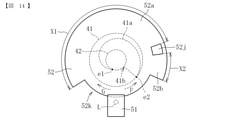
図14は、カム部材と遮光部材と光学センサとを抜き出して示す図である。
図14に示すように、カム部材41に設けられたカム面41aは、回転中心からの距離が図における時計回りに漸増するように形成されている。そして、カム面41aは、回転方向の半周(180°)よりも多い領域に渡って設けられている。具体的に、本実施形態では、カム面41aの回転中心からの距離が最も小さい最下点e1から、カム面41aの回転中心からの距離が最も大きい最上点e2まで、約270°の範囲に渡って設けられている。また、カム面41aには、最上点e2を境として、回転中心からの距離が急激に変化する段差部41bを有する。
FIG. 14 is a diagram showing an extracted cam member, a light-shielding member, and an optical sensor.
As shown in FIG. 14, the cam surface 41a provided on the cam member 41 is formed so that the distance from the center of rotation gradually increases clockwise in the figure. The cam surface 41a is provided over a region larger than the half circumference (180 °) in the rotation direction. Specifically, in the present embodiment, the range is about 270 ° from the lowest point e1 where the distance from the rotation center of the cam surface 41a is the smallest to the highest point e2 where the distance from the rotation center of the cam surface 41a is the largest. It is provided across. Further, the cam surface 41a has a stepped portion 41b whose distance from the center of rotation changes abruptly with the uppermost point e2 as a boundary.

遮光部材52は、回転方向に長い(回転方向の長さがX1である)被検知領域としての長遮光部52aと、長遮光部52aよりも回転方向に短い(回転方向の長さがX2である)被検知領域としての短遮光部52bとを有する。長遮光部52aと短遮光部52bは、いずれも回転に伴って光学センサ51の光照射部Lを通過することで照射光を遮蔽する。また、長遮光部52aと短遮光部52bとの間には、光学センサ51の照射光を透過させる孔部(透光部)52jが形成されている。また、遮光部材52は、周方向の一部に、孔部(透光部)52jとは別の透光部である、非遮光部(透光部)52kを有する。 The light-shielding member 52 has a long light-shielding portion 52a as a detected region that is long in the rotation direction (the length in the rotation direction is X1) and shorter in the rotation direction than the long light-shielding portion 52a (the length in the rotation direction is X2). It has a short light-shielding portion 52b as a detected area. Both the long light-shielding unit 52a and the short light-shielding unit 52b shield the irradiation light by passing through the light irradiation unit L of the optical sensor 51 as they rotate. Further, a hole portion (translucent portion) 52j for transmitting the irradiation light of the optical sensor 51 is formed between the long light-shielding portion 52a and the short light-shielding portion 52b. Further, the light-shielding member 52 has a non-light-shielding portion (translucent portion) 52k, which is a translucent portion different from the hole portion (translucent portion) 52j, in a part in the circumferential direction.

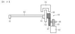
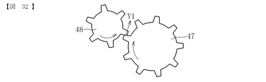
図15は、本実施形態に係る接離機構の駆動系の概略構成図である。
図15に示すように、駆動系は、駆動機構としてのモータ43と、モータ43からの駆動力をカム部材41や遮光部材52に伝達するギア列44とを備える。本実施形態では、モータ43として、小型で安価なDCブラシモータを用いている。ギア列44は、モータ43の出力軸に取り付けられた第1のウォームギア45と、第1のウォームギア45と噛み合う第2のウォームギア46と、第2のウォームギア46と一体に設けられた駆動伝達部材としての第1の平歯車47と、第1の平歯車47と噛み合う(係合する)と共に遮光部材52と一体に設けられた駆動伝達部材としての第2の平歯車48とで構成される。モータ43の出力軸が一方向又はこれと逆方向に回転すると、各ウォームギア45,46と各平歯車47,48が回転し、第2平歯車48と遮光部材52が一体的に回転することで、回転軸42を介して各カム部材41が一方向(図14中の矢印Fで示す方向)とこれとは逆方向(図14中の矢印Gで示す方向)とに回転する。
FIG. 15 is a schematic configuration diagram of a drive system of the contact / detachment mechanism according to the present embodiment.
As shown in FIG. 15, the drive system includes a motor 43 as a drive mechanism and a gear train 44 that transmits the driving force from the motor 43 to the cam member 41 and the light-shielding member 52. In this embodiment, a small and inexpensive DC brush motor is used as the motor 43. The gear train 44 serves as a drive transmission member integrally provided with a first worm gear 45 attached to the output shaft of the motor 43, a second worm gear 46 that meshes with the first worm gear 45, and a second worm gear 46. The first spur gear 47 is composed of a second spur gear 48 as a drive transmission member that meshes with (engages with) the first spur gear 47 and is provided integrally with the light-shielding member 52. When the output shaft of the motor 43 rotates in one direction or in the opposite direction, the worm gears 45, 46 and the spur gears 47, 48 rotate, and the second spur gear 48 and the light-shielding member 52 rotate integrally. , Each cam member 41 rotates in one direction (direction indicated by arrow F in FIG. 14) and in the opposite direction (direction indicated by arrow G in FIG. 14) via the rotation shaft 42.

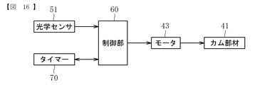
図16は、本実施形態に係る接離機構の制御系のブロック図である。
図16に示すように、制御系は、カム部材41の回転を制御する制御部60と、カム部材41の回転位置を検知するための上記光学センサ51、及び、カム部材41の回転時間を計測するタイマー70を備える。制御部60は、例えば、画像形成装置本体に設けられたCPU(Central Processing Unit )、ROM(Read Only Memory)、RAM(Random Access Memory)等で構成される。制御部60は、光学センサ51によって検知された信号やタイマー70によって計測された時間に基づいてモータ43の駆動を制御してカム部材41の回転を制御する。また、制御部60は、光学センサ51によって検知された信号に基づいてタイマー70による時間計測開始のタイミングや時間計測停止のタイミングを制御するようにも設定されている。
FIG. 16 is a block diagram of a control system of the contact / detachment mechanism according to the present embodiment.
As shown in FIG. 16, the control system measures the rotation time of the control unit 60 that controls the rotation of the cam member 41, the optical sensor 51 for detecting the rotation position of the cam member 41, and the cam member 41. The timer 70 is provided. The control unit 60 is composed of, for example, a CPU (Central Processing Unit), a ROM (Read Only Memory), a RAM (Random Access Memory), etc. provided in the image forming apparatus main body. The control unit 60 controls the drive of the motor 43 based on the signal detected by the optical sensor 51 and the time measured by the timer 70 to control the rotation of the cam member 41. Further, the control unit 60 is also set to control the timing of starting time measurement and the timing of stopping time measurement by the timer 70 based on the signal detected by the optical sensor 51.

ところで、定着ニップに封筒等の2枚重ねの用紙を通紙する場合、普通紙を通紙する場合と同様の加圧力で定着ローラと加圧ローラとを加圧すると、用紙にシワが発生する可能性がある。そのため、封筒等の用紙を通紙する場合は、普通紙を通紙する際の通常の加圧力に比べて小さい加圧力で定着ニップを形成するのがよい。 By the way, when two layers of paper such as envelopes are passed through the fixing nip, wrinkles occur on the paper when the fixing roller and the pressure roller are pressed with the same pressing force as when passing plain paper. there is a possibility. Therefore, when passing paper such as envelopes, it is preferable to form the fixing nip with a smaller pressing force than the normal pressing force when passing plain paper.

そこで、本実施形態に係る定着装置では、上記のように、加圧ローラを定着ローラに対して接近離間可能にすることで、紙種に応じて定着ニップにおける加圧力を変更できるようにしている。以下、通常の加圧力から脱圧する場合の脱圧動作と、通常の加圧力に戻す場合の加圧動作について説明する。 Therefore, in the fixing device according to the present embodiment, as described above, the pressure roller can be brought close to and separated from the fixing roller so that the pressing force at the fixing nip can be changed according to the paper type. .. Hereinafter, the depressurization operation when depressurizing from the normal pressing force and the pressurizing operation when returning to the normal pressing force will be described.

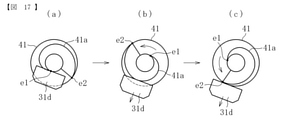
まず、カム部材41による加圧ローラ19の接離動作について説明する。
図17において、(a)は、加圧レバーのカム受け部31dがカム面41aに対して最下点e1側で接触している状態を示す。この状態では、加圧ローラが定着ローラに対して接近し、通常の加圧力で加圧されている。
First, the contact / detachment operation of the pressure roller 19 by the cam member 41 will be described.
In FIG. 17, (a) shows a state in which the cam receiving portion 31d of the pressurizing lever is in contact with the cam surface 41a on the lowest point e1 side. In this state, the pressurizing roller approaches the fixing roller and is pressurized by a normal pressing force.

図17の(a)に示す状態から、図17の(b)に示すように、カム部材41を図における反時計回りに回転させると、カム面41aがカム受け部31dに対して摺動し、カム面41aに対するカム受け部31dの接触位置が最下点e1側から最上点e2側へ相対的に移動する。これに伴って、カム受け部31dがカム面41aによって図における下方へ押し動かされ、加圧レバーが加圧ローラの軸受から退避することで、加圧ローラが定着ローラに対して離間する方向に移動する。 When the cam member 41 is rotated counterclockwise in the figure as shown in FIG. 17 (b) from the state shown in FIG. 17 (a), the cam surface 41a slides with respect to the cam receiving portion 31d. The contact position of the cam receiving portion 31d with respect to the cam surface 41a moves relatively from the lowest point e1 side to the highest point e2 side. Along with this, the cam receiving portion 31d is pushed downward in the figure by the cam surface 41a, and the pressurizing lever is retracted from the bearing of the pressurizing roller, so that the pressurizing roller is separated from the fixing roller. Moving.

そして、図17の(c)に示すように、カム面41aに対するカム受け部31dの接触位置が最上点e2側へ至ると、定着ローラに対する加圧ローラの離間動作が完了し、定着ニップにおける加圧力が通常の加圧よりも小さくなった脱圧状態となる。この時点で、カム部材41の回転を停止させる。 Then, as shown in FIG. 17 (c), when the contact position of the cam receiving portion 31d with respect to the cam surface 41a reaches the uppermost point e2 side, the separation operation of the pressure roller with respect to the fixing roller is completed, and the pressure is applied to the fixing nip. It becomes a depressurized state where the pressure becomes smaller than the normal pressurization. At this point, the rotation of the cam member 41 is stopped.

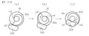
反対に、図18の(a)に示す脱圧状態から、図18の(b)に示すように、カム部材41を図における時計回り(上記脱圧移行時の回転方向とは逆方向)に回転させると、カム面41aがカム受け部31dに対して摺動し、カム面41aに対するカム受け部31dの接触位置が最上点e2側から最下点e1側へ相対的に移動する。これに伴って、カム受け部31dが加圧バネの付勢力によって図における上方へ引き上げられ、加圧レバーが加圧ローラの軸受を押圧することで、加圧ローラが定着ローラに対して接近する方向に移動する。 On the contrary, from the depressurized state shown in FIG. 18 (a), as shown in FIG. 18 (b), the cam member 41 is moved clockwise in the figure (in the direction opposite to the rotation direction at the time of depressurization transition). When rotated, the cam surface 41a slides with respect to the cam receiving portion 31d, and the contact position of the cam receiving portion 31d with respect to the cam surface 41a moves relatively from the highest point e2 side to the lowest point e1 side. Along with this, the cam receiving portion 31d is pulled upward in the figure by the urging force of the pressure spring, and the pressure lever presses the bearing of the pressure roller, so that the pressure roller approaches the fixing roller. Move in the direction.

そして、図18の(c)に示すように、カム面41aに対するカム受け部31dの接触位置が最下点e1側へ至ると、定着ローラに対する加圧ローラの接近動作が完了し、定着ニップにおける加圧力が増加した通常の加圧状態に戻される。この時点で、カム部材41の回転を停止させる。 Then, as shown in FIG. 18C, when the contact position of the cam receiving portion 31d with respect to the cam surface 41a reaches the lowest point e1, the approaching operation of the pressure roller with respect to the fixing roller is completed, and the fixing nip It is returned to the normal pressurized state where the pressing force is increased. At this point, the rotation of the cam member 41 is stopped.

このように、本実施形態に係る定着装置においては、加圧ローラを離間させるときはカム部材41を一方向に回転させ、加圧ローラを接近させるときはカム部材41を逆方向に回転させることで、加圧レバーを押し動かすのと戻すのとを同じカム面41aを用いて行っている。このため、本実施形態に係るカム部材41においては、カム面41aを回転方向の半周よりも多い領域に渡って設けることができる。これにより、カム面41aの勾配を緩やかにしても、勾配の最大高低差が小さくなるのを回避することができるので、定着ローラに対する加圧ローラの接近離間距離を十分に確保しつつ、カム面41aの勾配を緩やかにして回転トルクの増大や作動音(異音)の発生を抑制することができる。 As described above, in the fixing device according to the present embodiment, the cam member 41 is rotated in one direction when the pressure roller is separated, and the cam member 41 is rotated in the opposite direction when the pressure roller is brought close to the pressure roller. Then, the pressure lever is pushed and moved back and forth using the same cam surface 41a. Therefore, in the cam member 41 according to the present embodiment, the cam surface 41a can be provided over a region larger than the half circumference in the rotation direction. As a result, even if the gradient of the cam surface 41a is made gentle, it is possible to prevent the maximum height difference of the gradient from becoming small. Therefore, the cam surface can be sufficiently secured from the pressure roller with respect to the fixing roller. The gradient of 41a can be made gentle to suppress an increase in rotational torque and generation of operating noise (abnormal noise).

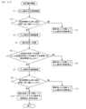
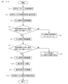
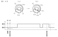
次に、カム部材の回転制御方法について説明する。まず、カム部材の回転制御方法のうち、脱圧動作時の回転制御方法について説明する。図19は、脱圧動作時の回転制御方法を説明するための図であり、図の上段は遮光部材の回転位置を示す図、図の中段はカム部材の回転位置を示す図、図の下段は光学センサの照射光が遮断又は透過されるタイミングチャートを示す。また、上段、中段、下段のそれぞれの(a)、(b)、(c)、(d)は互いに対応している。図20は、脱圧動作時の回転制御のフローチャートである。 Next, a method of controlling the rotation of the cam member will be described. First, among the rotation control methods of the cam member, the rotation control method at the time of depressurization operation will be described. FIG. 19 is a diagram for explaining a rotation control method during depressurization operation, in which the upper part of the figure shows the rotation position of the light-shielding member, the middle part of the figure shows the rotation position of the cam member, and the lower part of the figure shows the rotation position. Shows a timing chart in which the irradiation light of the optical sensor is blocked or transmitted. Further, the upper, middle, and lower (a), (b), (c), and (d) correspond to each other. FIG. 20 is a flowchart of rotation control during depressurization operation.

図19において、(a)は、加圧レバーのカム受け部31dがカム面41aに対して最下点e1側で接触し、加圧ローラが定着ローラに対して接近した状態で加圧される通常の加圧状態である。また、この状態で光学センサ51は透光状態となっている。 In FIG. 19, in (a), the cam receiving portion 31d of the pressurizing lever is in contact with the cam surface 41a on the lowest point e1 side, and the pressurizing roller is pressurized in a state of being close to the fixing roller. It is in a normal pressurized state. Further, in this state, the optical sensor 51 is in a translucent state.

通常の加圧状態から脱圧状態となるように、上記制御部からカム部材41を回転させる指示が発せられると、モータが駆動を開始し、図19の(b)に示すように、カム部材41は図における反時計回り(一方向としての正方向)に回転し始める(図20のS1)。これにより、カム受け部31dがカム部材41によって図における下方へ押し動かされる。 When an instruction to rotate the cam member 41 is issued from the control unit so as to change from the normal pressurization state to the depressurization state, the motor starts driving, and as shown in FIG. 19B, the cam member 41 starts to rotate counterclockwise (positive direction as one direction) in the figure (S1 in FIG. 20). As a result, the cam receiving portion 31d is pushed downward in the figure by the cam member 41.

また、カム部材41の回転に伴って、遮光部材52も同方向(正方向)へ回転し始める。そして、通常であればその後、図19の(b)に示すように、長遮光部52aの回転方向の前端部が光照射部Lに到達することで、光学センサ51が遮光状態に切り換えられる。 Further, as the cam member 41 rotates, the light-shielding member 52 also starts to rotate in the same direction (positive direction). Then, normally, after that, as shown in FIG. 19B, the optical sensor 51 is switched to the light-shielding state when the front end portion of the long light-shielding portion 52a in the rotation direction reaches the light irradiation unit L.

しかしながら、ここで遮光部材52が正常に回転しないなどの異常が生じた場合、通常通りに図19の(b)に示す遮光状態に切り換わらない可能性がある。そのため、図19の(b)に示す透光状態に切り換わるのが、上記カム部材41の回転が開始されてから予め設定された時間h1以内に行われるか否かが制御部によって判断される(図20のS2)。なお、本実施形態では、この時間h1は、後述のタイマーの設定時間Tに猶予時間αを加えた時間としている。 However, if an abnormality such as the light-shielding member 52 not rotating normally occurs here, it may not switch to the light-shielding state shown in FIG. 19 (b) as usual. Therefore, it is determined by the control unit whether or not the switching to the translucent state shown in FIG. 19B is performed within the preset time h1 after the rotation of the cam member 41 is started. (S2 in FIG. 20). In the present embodiment, this time h1 is the time obtained by adding the grace time α to the set time T of the timer described later.

その結果、予め設定された時間h1以内に透光状態に切り換わった場合は、異常がないと判断され、そのままカム部材41の回転が継続される(図20のS3)。一方、予め設定された時間h1を超えても遮光状態に切り換わらない場合は、異常があると判断してカム部材41の回転をこれ以上継続しないように停止させる(図20のS4)。そして、カム部材41の回転が継続された場合は、その後しばらくの間、遮光状態が継続し、カム部材41によってカム受け部31dがさらに下方へ押し動かされる。 As a result, when the state is switched to the translucent state within the preset time h1, it is determined that there is no abnormality, and the rotation of the cam member 41 is continued as it is (S3 in FIG. 20). On the other hand, if the light-shielding state is not switched even after the preset time h1, it is determined that there is an abnormality and the rotation of the cam member 41 is stopped so as not to continue any more (S4 in FIG. 20). When the rotation of the cam member 41 is continued, the light-shielding state is continued for a while after that, and the cam member 41 further pushes the cam receiving portion 31d downward.

そして、図19の(c)に示すように、遮光部材52の回転に伴って、孔部52jが光照射部Lに対向する位置まで移動すると、光学センサ51が透光状態に切り換えられる(図20のS5)。このとき、制御部によって、上記図19の(b)に示す遮光状態に切り換わってから図19の(c)に示す透光状態に切り換わるのに要する時間t1が算出され、この時間t1が予め設定された時間h2以上か否か判断される(図20のS6)。ここで、予め設定された時間h2は、図19の(b)に示す遮光状態に切り換わってから図19の(c)に示す透光状態に切り換わるのに要すると想定される通常時間である。要するに、図21に示す長遮光部52aが光照射部Lを通過するのに要すると想定される時間である。 Then, as shown in FIG. 19 (c), when the hole portion 52j moves to a position facing the light irradiation portion L with the rotation of the light shielding member 52, the optical sensor 51 is switched to the translucent state (FIG. 19). 20 S5). At this time, the control unit calculates the time t1 required to switch to the light-shielding state shown in FIG. 19 (b) and then to the translucent state shown in FIG. 19 (c), and this time t1 is calculated. It is determined whether or not the time is h2 or more set in advance (S6 in FIG. 20). Here, the preset time h2 is a normal time that is assumed to be required to switch to the light-shielding state shown in FIG. 19 (b) and then to the translucent state shown in FIG. 19 (c). be. In short, it is an estimated time required for the long light-shielding portion 52a shown in FIG. 21 to pass through the light irradiation portion L.

上記判断の結果、時間t1が予め設定された時間h2以上である場合は、そのままカム部材41の回転が継続される(図20のS7)。一方、時間t1が予め設定された時間h2よりも短い場合は、遮光部材52の回転位置に異常があると判断して、カム部材41の回転が停止される(図20のS8)。 As a result of the above determination, when the time t1 is equal to or longer than the preset time h2, the rotation of the cam member 41 is continued as it is (S7 in FIG. 20). On the other hand, when the time t1 is shorter than the preset time h2, it is determined that there is an abnormality in the rotation position of the light-shielding member 52, and the rotation of the cam member 41 is stopped (S8 in FIG. 20).

上記図19の(c)に示す状態からカム部材41の回転が継続された場合は、通常であればその後すぐに、図19の(d)に示すように、短遮光部52bの前端部が光照射部Lに到達し、光学センサ51が遮光状態に戻される。 When the rotation of the cam member 41 is continued from the state shown in FIG. 19 (c), the front end portion of the short light-shielding portion 52b is normally immediately after that, as shown in FIG. 19 (d). It reaches the light irradiation unit L, and the optical sensor 51 is returned to the light-shielding state.

また、ここでも、遮光部材52の回転などに異常がないか否か制御部によって判断される。具体的には、図19の(d)に示す遮光状態に切り換わるのが、上記図19の(c)に示す透光状態に切り換わってから予め設定された時間h3以内に行われるか否かが制御部によって判断される(図20のS9)。 Further, here as well, the control unit determines whether or not there is an abnormality in the rotation of the light-shielding member 52. Specifically, whether or not the light-shielding state shown in FIG. 19 (d) is switched to the light-transmitting state shown in FIG. 19 (c) within a preset time h3. Is determined by the control unit (S9 in FIG. 20).

その結果、予め設定された時間h3以内に遮光状態に切り換わった場合は、異常がないと判断され、この透光状態への切換を光学センサ51が検知したタイミングで、制御部からカム部材41の回転を停止させる指示が発せられる(図20のS10)。そして、この停止指示を受けてモータが駆動を停止し、カム部材41の回転が完全に停止されて、脱圧動作が完了する。一方、予め設定された時間h3を超えても遮光状態に切り換わらない場合は、異常があると判断してカム部材41の回転をこれ以上継続しないように停止させる(図20のS11)。 As a result, when the light-shielding state is switched to within the preset time h3, it is determined that there is no abnormality, and the cam member 41 is detected by the optical sensor 51 at the timing when the optical sensor 51 detects the switching to the translucent state. An instruction is issued to stop the rotation of the light (S10 in FIG. 20). Then, in response to this stop instruction, the motor stops driving, the rotation of the cam member 41 is completely stopped, and the depressurization operation is completed. On the other hand, if the light-shielding state is not switched even after the preset time h3 is exceeded, it is determined that there is an abnormality and the rotation of the cam member 41 is stopped so as not to continue any more (S11 in FIG. 20).

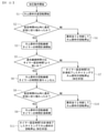
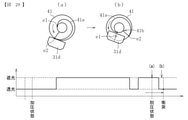
続いて、通常の加圧力に戻す加圧動作時のカム部材の回転制御方法について説明する。 図21は、加圧動作時のカム部材の回転制御方法を説明するための図であり、図の上段は遮光部材の回転位置を示す図、図の中段はカム部材の回転位置を示す図、図の下段は光学センサの照射光が遮断又は透過されるタイミングチャートを示す。また、上段、中段、下段のそれぞれの(a)、(b)、(c)、(d)、(e)は互いに対応している。図22は、加圧動作時の回転制御のフローチャートである。 Subsequently, a method of controlling the rotation of the cam member during the pressurizing operation of returning to the normal pressing force will be described. FIG. 21 is a diagram for explaining a method of controlling the rotation of the cam member during the pressurizing operation. The upper part of the figure shows the rotation position of the light-shielding member, and the middle part of the figure shows the rotation position of the cam member. The lower part of the figure shows a timing chart in which the irradiation light of the optical sensor is blocked or transmitted. Further, the upper, middle, and lower stages (a), (b), (c), (d), and (e) correspond to each other. FIG. 22 is a flowchart of rotation control during pressurization operation.

図21において、(a)は、加圧ローラが定着ローラに対して離間した状態の脱圧状態を示す。この状態で、カム部材41及び遮光部材52は上記脱圧動作時の制御によって正常に回転動作が停止された位置にある。すなわち、加圧レバーのカム受け部31dはカム面41aに対して最上点e2側で接触した状態にあり、光学センサ51は、短遮光部52bが光照射部Lに重なるように配置された遮光状態となっている。 In FIG. 21, (a) shows a depressurized state in which the pressurizing roller is separated from the fixing roller. In this state, the cam member 41 and the light-shielding member 52 are in a position where the rotation operation is normally stopped by the control during the depressurization operation. That is, the cam receiving portion 31d of the pressurizing lever is in contact with the cam surface 41a on the uppermost point e2 side, and the optical sensor 51 is arranged so that the short light shielding portion 52b overlaps the light irradiation portion L. It is in a state.

この脱圧状態から通常の加圧状態となるように、上記制御部からカム部材41を回転させる指示が発せられると、モータが駆動を開始し、図21の(b)に示すように、カム部材41は図における時計回り(逆方向)に回転し始める(図22のS1)。これにより、脱圧移行時とは反対に、カム受け部31dが上記加圧バネの付勢力で図における上方へ引き上げられる。 When an instruction to rotate the cam member 41 is issued from the control unit so that the depressurized state becomes a normal pressurized state, the motor starts driving, and as shown in FIG. 21 (b), the cam The member 41 begins to rotate clockwise (reverse direction) in the figure (S1 in FIG. 22). As a result, the cam receiving portion 31d is pulled upward in the figure by the urging force of the pressure spring, contrary to the case of the depressurization transition.

また、カム部材41の回転に伴って、遮光部材52も同方向(逆方向)へ回転し始める。そして、通常であればその後すぐに、図21の(b)に示すように、短遮光部52bが光照射部Lを通過することで、光学センサ51は透光状態に切り換えられる。 Further, as the cam member 41 rotates, the light-shielding member 52 also starts to rotate in the same direction (reverse direction). Then, normally, immediately after that, as shown in FIG. 21B, the short light-shielding portion 52b passes through the light irradiation portion L, so that the optical sensor 51 is switched to the translucent state.

また、ここでも、遮光部材52の回転などに異常が生じていないか確認するため、図21の(b)に示す透光状態に切り換わるのが、上記カム部材41の回転が開始されてから予め設定された時間h4以内に行われるか否かが制御部によって判断される(図22のS2)。 Further, also here, in order to confirm whether or not an abnormality has occurred in the rotation of the light-shielding member 52, the light transmissive state shown in FIG. 21 (b) is switched to after the rotation of the cam member 41 is started. The control unit determines whether or not the operation is performed within the preset time h4 (S2 in FIG. 22).

その結果、予め設定された時間h4以内に透光状態に切り換わった場合は、異常がないと判断され、そのままカム部材41の回転が継続されると共に、当該透光状態への切換が検知されたタイミングで、上記タイマーによる時間計測が開始される(図22のS3)。一方、予め設定された時間h4を超えても透光状態に切り換わらない場合は、異常があると判断してカム部材41の回転をこれ以上継続しないように停止させる(図22のS4)。 As a result, when the state is switched to the translucent state within the preset time h4, it is determined that there is no abnormality, the rotation of the cam member 41 is continued as it is, and the switching to the translucent state is detected. At the same timing, the time measurement by the timer is started (S3 in FIG. 22). On the other hand, if the translucent state is not switched even after the preset time h4 is exceeded, it is determined that there is an abnormality and the rotation of the cam member 41 is stopped so as not to continue any more (S4 in FIG. 22).

ここで、タイマーが計測する時間は予め設定されており、タイマーが予め設定された時間を計測し終えた時点で制御部からカム部材を停止させる信号が発せられる。ただし、タイマーによる時間計測は、光学センサの透光状態が継続している間は継続するが、タイマーが時間計測を完了する前に透光状態から遮光状態に切り換わると、タイマーによる時間計測は途中でキャンセルされるように設定されている。 Here, the time measured by the timer is set in advance, and when the timer finishes measuring the preset time, the control unit issues a signal to stop the cam member. However, the time measurement by the timer continues as long as the light transmission state of the optical sensor continues, but if the timer switches from the light transmission state to the light blocking state before the time measurement is completed, the time measurement by the timer will be performed. It is set to be canceled on the way.

このように設定されたタイマーに対して、孔部52jは、回転時に光照射部Lを通過する通過時間がタイマーの設定時間Tよりも短くなるように形成されている。従って、上記図21の(b)に示す透光状態に切り換わったタイミングでタイマーによる時間計測が開始されるが、図21の(c)に示すように、孔部52jはすぐに光照射部Lを通過するので、通常、ここでの透光継続時間t2はタイマーの設定時間Tより短い。このため、タイマーが設定時間Tを計測し終えるよりも早い段階で遮光状態に切り換えられる。 With respect to the timer set in this way, the hole portion 52j is formed so that the passing time passing through the light irradiation unit L during rotation is shorter than the set time T of the timer. Therefore, the time measurement by the timer is started at the timing of switching to the translucent state shown in FIG. 21 (b), but as shown in FIG. 21 (c), the hole portion 52j immediately becomes the light irradiation unit. Since it passes through L, the light transmission duration t2 here is usually shorter than the set time T of the timer. Therefore, the timer is switched to the light-shielding state at an earlier stage than when the set time T has been measured.

また、このとき、制御部によって、上記透光継続時間t2がタイマーの設定時間Tよりも短いか否かが判断される(図22のS5)。その結果、透光継続時間t2がタイマーの設定時間Tよりも短い場合は、タイマーが設定時間Tを計測し終える前に遮光状態に切り換えられたことになるので、タイマーによる時間計測が途中でキャンセルされる(図22のS6)。また、この場合、カム部材41の回転は継続される。 Further, at this time, the control unit determines whether or not the translucency duration t2 is shorter than the timer set time T (S5 in FIG. 22). As a result, when the translucency duration t2 is shorter than the set time T of the timer, it means that the timer has been switched to the light blocking state before the set time T has been measured, so that the time measurement by the timer is canceled halfway. (S6 in FIG. 22). Further, in this case, the rotation of the cam member 41 is continued.

一方、遮光継続時間t2がタイマーの設定時間Tの間継続する場合は、タイマーが設定時間Tを計測し終えた時点で、制御部からカム部材41を停止させる信号が発せられ、カム部材41の回転が停止される(図22のS7)。なお、この場合は、結果的にカム部材41が正規の停止位置(加圧状態)で停止されることになる。 On the other hand, when the light blocking duration t2 continues for the set time T of the timer, when the timer finishes measuring the set time T, the control unit issues a signal to stop the cam member 41, and the cam member 41 receives a signal. The rotation is stopped (S7 in FIG. 22). In this case, as a result, the cam member 41 is stopped at the normal stop position (pressurized state).

上記のように、孔部52jの通過によってタイマーによる時間計測がキャンセルされた場合は、しばらくの間、遮光状態が継続し、カム部材41の回転に伴ってカム受け部31dがさらに上方へ引き上げられる。その後、通常であれば図21(d)に示すように、長遮光部52aが光照射部Lを通過することで、再び透光状態に切り換えられる。 As described above, when the time measurement by the timer is canceled due to the passage of the hole portion 52j, the light-shielding state continues for a while, and the cam receiving portion 31d is further pulled upward as the cam member 41 rotates. .. After that, normally, as shown in FIG. 21D, the long light-shielding portion 52a passes through the light irradiation unit L, so that the light-transmitting state is switched again.

また、ここでも、遮光部材52の回転などに異常が生じていないか確認するため、図21の(d)に示す遮光状態に切り換わるのが、上記図21の(c)に示す遮光状態に切り換わってから予め設定された時間h5以内に行われるか否かが制御部によって判断される(図22のS8)。 Further, also here, in order to confirm whether or not an abnormality has occurred in the rotation of the light-shielding member 52, the light-shielding state shown in FIG. 21 (d) is switched to the light-shielding state shown in FIG. 21 (c). The control unit determines whether or not the switching is performed within the preset time h5 (S8 in FIG. 22).

その結果、予め設定された時間h5以内に透光状態に切り換わった場合は、異常がないと判断され、そのままカム部材41の回転が継続されると共に、当該透光状態への切換が検知されたタイミングで、タイマーによる時間計測が再び最初から開始される(図22のS9)。一方、予め設定された時間h5を超えても透光状態に切り換わらない場合は、異常があると判断してカム部材41の回転をこれ以上継続しないように停止させる(図22のS10)。 As a result, when the state is switched to the translucent state within the preset time h5, it is determined that there is no abnormality, the rotation of the cam member 41 is continued as it is, and the switching to the translucent state is detected. At the same timing, the time measurement by the timer is started again from the beginning (S9 in FIG. 22). On the other hand, if the translucent state is not switched even after the preset time h5 is exceeded, it is determined that there is an abnormality and the rotation of the cam member 41 is stopped so as not to continue any more (S10 in FIG. 22).

そして、カム部材41の回転が継続され、タイマーによる時間計測が再び最初から開始された場合は、長遮光部52aによる透光状態が継続されるので、透光状態はタイマーによる時間計測の間継続する。その結果、図21の(e)に示すように、タイマーが設定時間Tを計測し終えた時点で、制御部からカム部材41を停止させる信号が発せられる(図22のS11)。そして、この停止指示を受けてモータが駆動を停止し、カム部材41の回転が完全に停止される。これにより、加圧ローラが定着ローラに対して接近した通常の加圧状態で保持され、加圧動作が完了する。 When the rotation of the cam member 41 is continued and the time measurement by the timer is started again from the beginning, the translucent state by the long light-shielding portion 52a is continued, so that the translucent state is continued during the time measurement by the timer. do. As a result, as shown in FIG. 21 (e), when the timer finishes measuring the set time T, the control unit issues a signal to stop the cam member 41 (S11 in FIG. 22). Then, in response to this stop instruction, the motor stops driving, and the rotation of the cam member 41 is completely stopped. As a result, the pressurizing roller is held in a normal pressurizing state close to the fixing roller, and the pressurizing operation is completed.

以上のように、本実施形態では、脱圧動作時のカム部材の回転停止は、光学センサによる検知タイミングに基づいて行い(図20のS10参照)、これに対して、加圧動作時のカム部材の回転停止は、タイマーによる時間計測のタイミングに基づいて行っている(図22のS11参照)。すなわち、本実施形態では、脱圧動作時と加圧動作時のそれぞれのカム部材の停止位置を制御するためのタイミング判定手段を、光学センサとタイマーとに分けている。さらに、カム部材の回転トルクが大きくなる脱圧方向への移動時に光学センサを用いてカム部材を停止させることにより、脱圧位置を停止目標位置とした場合のカム部材の回転停止位置の精度が向上する。 As described above, in the present embodiment, the rotation stop of the cam member during the depressurization operation is performed based on the detection timing by the optical sensor (see S10 in FIG. 20), whereas the cam during the pressurization operation is performed. The rotation of the member is stopped based on the timing of time measurement by the timer (see S11 in FIG. 22). That is, in the present embodiment, the timing determination means for controlling the stop position of each cam member during the depressurization operation and the pressurization operation is divided into an optical sensor and a timer. Furthermore, by stopping the cam member using an optical sensor when the cam member moves in the depressurization direction where the rotational torque of the cam member increases, the accuracy of the rotation stop position of the cam member when the decompression position is set as the stop target position is improved. improves.

以上のようにしてカム部材を制御することにより、加圧状態と脱圧状態との切り換えが可能になる。このように、加圧状態と脱圧状態との切り換えは、それぞれカム部材の初期回転位置が加圧状態の位置(図19のaの位置)、あるいは脱圧状態の位置(図21aの位置)からの回転であり、カム部材の初期回転位置が定まっているため、上記のように一定のタイミングで遮光状態あるいは透光状態に切り換わらない場合に、異常であると判断することができる。なお、上記の異常状態が生じる場合としては、初期のカム部材の回転位置が上記の加圧状態の位置や脱圧状態の位置から位置ズレしている場合がある。 By controlling the cam member as described above, it is possible to switch between the pressurized state and the depressurized state. As described above, in the switching between the pressurized state and the depressurized state, the initial rotation position of the cam member is the position in the pressurized state (position in FIG. 19a) or the position in the depressurized state (position in FIG. 21a). Since the initial rotation position of the cam member is fixed, it can be determined that the cam member is abnormal when it does not switch to the light-shielding state or the translucent state at a certain timing as described above. When the above-mentioned abnormal state occurs, the rotation position of the initial cam member may be displaced from the above-mentioned position in the pressurized state or the position in the depressurized state.

一方で、例えば画像形成装置の電源投入時や上記の加圧状態と脱圧状態との切り換え時に異常状態であると判断された場合のように、カム部材の現在の回転位置(回転位相)がいずれの位置であるかを制御部が正確に認識できない場合がある。この場合、以下で説明するイニシャライズ動作(制御部がカム部材の回転位置を認識するための回転位置認識動作)を実施することにより、まず、カム部材の初期位置に関わらずカム部材を所定位置まで回転させる制御を行い、カム部材の回転位置を制御部に認識させる動作を行う。なお、上記のカム部材の所定位置とは、加圧状態の位置のことである。 On the other hand, for example, when the power of the image forming apparatus is turned on or when it is determined that the cam member is in an abnormal state when switching between the pressurized state and the depressurized state, the current rotation position (rotation phase) of the cam member is The control unit may not be able to accurately recognize which position it is. In this case, by performing the initialization operation (rotational position recognition operation for the control unit to recognize the rotation position of the cam member) described below, first, the cam member is moved to a predetermined position regardless of the initial position of the cam member. The rotation is controlled, and the control unit is made to recognize the rotation position of the cam member. The predetermined position of the cam member is a position in a pressurized state.

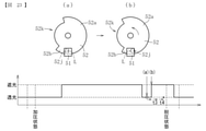
カム部材のイニシャライズ動作では、まず、光学センサ51により検知動作を行い、透光状態(検知状態)か遮光状態(非検知状態)かの判別を行う。そして、それぞれの状態に応じて、異なるフローでイニシャライズ動作を実施する。以下、最初の検知動作で透光状態であった場合に行われるイニシャライズ動作を第一のイニシャライズ動作、そして、遮光状態であった場合のイニシャライズ動作を第二のイニシャライズ動作と呼ぶ。また、以下の説明では、まず第一のイニシャライズ動作について図23~図25を用いて説明する。なお、図23、図24の上段は遮光部材の回転位置を示す図、図の下段は光学センサの照射光が遮断又は透過されるタイミングチャートを示す。また、上段下段の(a)、(b)は互いに対応している。図25は、第一のイニシャライズ動作時の回転制御のフローチャートである。 In the initialization operation of the cam member, first, the optical sensor 51 performs a detection operation to determine whether the light transmissive state (detection state) or the light blocking state (non-detection state). Then, the initialization operation is performed with different flows according to each state. Hereinafter, the initialization operation performed when the first detection operation is in the translucent state is referred to as the first initialization operation, and the initialization operation when the light-shielding state is in the light-shielding state is referred to as the second initialization operation. Further, in the following description, first, the first initialization operation will be described with reference to FIGS. 23 to 25. The upper part of FIGS. 23 and 24 shows the rotation position of the light-shielding member, and the lower part of the figure shows a timing chart in which the irradiation light of the optical sensor is blocked or transmitted. Further, (a) and (b) in the upper and lower rows correspond to each other. FIG. 25 is a flowchart of rotation control during the first initialization operation.

図25に示すように、光学センサ51により検知動作を行い(図25のステップS1)、透光状態であることが確認される(図25のステップS2)。 As shown in FIG. 25, the optical sensor 51 performs a detection operation (step S1 in FIG. 25), and it is confirmed that the light transmissive state is obtained (step S2 in FIG. 25).

透光状態が検知されると、カム部材41は正回転を開始する(図25のステップS3)。 When the translucent state is detected, the cam member 41 starts to rotate in the forward direction (step S3 in FIG. 25).

そして、カム部材41が正回転を継続することにより、光学センサ51は遮光状態に切り換わる(図25のステップS4)。つまり、ステップS1の検知動作において、光学センサ51が透光状態になるのは、光照射部Lが孔部52jに対向する場合(図23のaの場合)か、あるいは、非遮光部52kに対向する場合(図24のaの場合)である。このため、いずれの場合でも正回転動作を継続することにより、短遮光部52bが光照射部Lに到達する(図23のb参照)か、長遮光部52aが光照射部Lに到達し(図24b参照)、ステップS4のように遮光状態に切り換わる。 Then, as the cam member 41 continues to rotate in the forward direction, the optical sensor 51 switches to the light-shielding state (step S4 in FIG. 25). That is, in the detection operation of step S1, the optical sensor 51 is in the translucent state when the light irradiation unit L faces the hole portion 52j (in the case of a in FIG. 23) or in the non-light-shielding portion 52k. This is the case of facing each other (in the case of a in FIG. 24). Therefore, in either case, the short light-shielding portion 52b reaches the light irradiation unit L (see b in FIG. 23) or the long light-shielding unit 52a reaches the light irradiation unit L by continuing the forward rotation operation (see b in FIG. 23). (See FIG. 24b), the state is switched to the light-shielded state as in step S4.

そして、遮光状態に切り換わると、t3秒間正回転を継続した後(図25のステップS5)、カム部材41に回転停止指令を出し、それからt4秒後にカム部材41の回転を停止させる(図25のステップS6)。つまり、カム部材41は、遮光状態に切り換わった後、t3+t4秒間正回転を行って停止する。図23に示すように、t3+t4秒は、カム部材41が図23(b)の位置から脱圧位置まで移動する時間以下の時間に設定される。これにより、初期位置が図23、図24のいずれの場合でも、遮光状態でカム部材41が回転を停止する(図23、図24の黒丸参照)。以上で第一のイニシャライズ動作を終了する。そして、第一のイニシャライズ動作を実施した後には、以下で説明する第二のイニシャライズ動作を実施する。 Then, when the light-shielded state is switched, the forward rotation is continued for t3 seconds (step S5 in FIG. 25), a rotation stop command is issued to the cam member 41, and then the rotation of the cam member 41 is stopped after t4 seconds (FIG. 25). Step S6). That is, after switching to the light-shielding state, the cam member 41 rotates forward for t3 + t4 seconds and stops. As shown in FIG. 23, t3 + t4 seconds is set to a time equal to or less than the time for the cam member 41 to move from the position shown in FIG. 23 (b) to the depressurized position. As a result, the cam member 41 stops rotating in the light-shielded state regardless of whether the initial position is FIG. 23 or FIG. 24 (see the black circles in FIGS. 23 and 24). This completes the first initialization operation. Then, after the first initialization operation is performed, the second initialization operation described below is performed.

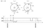
次に、第二のイニシャライズ動作について図26~図28を用いて説明する。第二のイニシャライズ動作は、第一のイニシャライズ動作終了後、あるいは、最初の検知動作で遮光状態であった場合に実施される。なお、図26、図27の上段は遮光部材の回転位置を示す図、図の下段は光学センサの照射光が遮断又は透過されるタイミングチャートを示す。また、上段下段の(a)、(b)は互いに対応している。図28は、第二のイニシャライズ動作時の回転制御のフローチャートである。 Next, the second initialization operation will be described with reference to FIGS. 26 to 28. The second initialization operation is performed after the completion of the first initialization operation or when the light is shielded in the first detection operation. The upper part of FIGS. 26 and 27 shows the rotation position of the light-shielding member, and the lower part of the figure shows a timing chart in which the irradiation light of the optical sensor is blocked or transmitted. Further, (a) and (b) in the upper and lower rows correspond to each other. FIG. 28 is a flowchart of rotation control during the second initialization operation.

図28に示すように、光学センサ51により検知動作を行い(図28のステップS1)、遮光状態であることが確認される(図28のステップS2)。 As shown in FIG. 28, the optical sensor 51 performs a detection operation (step S1 in FIG. 28), and it is confirmed that the light-shielding state is obtained (step S2 in FIG. 28).

遮光状態が検知されると、カム部材41は逆回転を開始する(図28のステップS3)。ステップS1の検知動作において、光学センサ51が遮光状態になるのは、光照射部Lが長遮光部52aに対向する場合(図26のaの場合)か、あるいは、短遮光部52bに対向する場合(図27のaの場合)、そして、光学センサ51の不具合により、正常な検知動作が行われない場合である。 When the light-shielding state is detected, the cam member 41 starts reverse rotation (step S3 in FIG. 28). In the detection operation of step S1, the optical sensor 51 is in a light-shielding state when the light irradiation unit L faces the long light-shielding unit 52a (in the case of FIG. 26a) or faces the short light-shielding unit 52b. This is the case (in the case of a in FIG. 27), and the case where the normal detection operation is not performed due to a malfunction of the optical sensor 51.

まず、予め設定した設定時間h6以内に透光状態に切り換わるか否かの判断が行われる(図28のステップS4)。図26の(a)の位置からカム部材41を逆方向へ回転させると、図26の(b)に示すように、長遮光部52aが光照射部Lを通過して孔部52jが光照射部Lに到達し、透光状態に切り換わる。あるいは、図27の(a)の位置からカム部材41を逆方向へ回転させると、図27の(b)に示すように、短遮光部52bが光照射部Lを通過して、非遮光部52kが光照射部Lに到達し、透光状態に切り換わる。 First, it is determined whether or not to switch to the translucent state within the preset time h6 (step S4 in FIG. 28). When the cam member 41 is rotated in the opposite direction from the position (a) in FIG. 26, the long light-shielding portion 52a passes through the light irradiation portion L and the hole portion 52j is irradiated with light, as shown in FIG. 26 (b). It reaches the part L and switches to the translucent state. Alternatively, when the cam member 41 is rotated in the opposite direction from the position (a) in FIG. 27, the short light-shielding portion 52b passes through the light irradiation unit L and is a non-light-shielding portion as shown in FIG. 27 (b). 52k reaches the light irradiation unit L and switches to the translucent state.

これに対して、光学センサ51に不具合が生じた場合、例えば、投光部の故障やコネクタの接続不良等により光が受光部に向けて照射されなかった場合、カム部材41の回転位置に関わらず、常に遮光状態となる。このため、ステップS4で透光状態が確認されなかった場合には、光学センサ51に不具合が生じたものと判断し、カム部材41の回転を停止する。また、サービスコールを行って、光学センサ51の交換や接続不良の解消等の対策を施すことができる(図28のステップS6) On the other hand, when a defect occurs in the optical sensor 51, for example, when the light is not emitted toward the light receiving portion due to a failure of the floodlight portion or a poor connection of the connector, the rotation position of the cam member 41 does not matter. Instead, it is always in a light-shielded state. Therefore, if the translucent state is not confirmed in step S4, it is determined that the optical sensor 51 has a problem, and the rotation of the cam member 41 is stopped. Further, it is possible to make a service call and take measures such as replacement of the optical sensor 51 and elimination of the connection failure (step S6 in FIG. 28).

透光状態に切り換わった場合には、カム部材41の逆回転を継続する(ステップS5)。そして、予め設定した設定時間h7秒以内に、遮光状態に切り換わった否かの判断を行う(図28のステップS7)。 When the state is switched to the translucent state, the reverse rotation of the cam member 41 is continued (step S5). Then, it is determined whether or not the light-shielding state has been switched to within the preset time h7 seconds (step S7 in FIG. 28).

図26の(b)のように、光照射部Lが長遮光部52aを通過すると、その後、カム部材41を逆転させても、遮光状態に切り換わることはない。この場合、図28のステップS4で透光状態に切り換わってから、h7+t5秒後にカム部材41の回転を停止する(図28のステップS9)。h7+t5秒は、カム部材41が図26の(b)の位置から加圧状態の位置まで移動するために必要と想定される時間に設定される。これにより、カム部材41が回転を停止した状態で、加圧ローラが加圧状態に配置されることになる。 As shown in FIG. 26B, when the light irradiation unit L passes through the long light-shielding portion 52a, the cam member 41 is not switched to the light-shielding state even if the cam member 41 is subsequently reversed. In this case, the rotation of the cam member 41 is stopped after h7 + t5 seconds after switching to the translucent state in step S4 of FIG. 28 (step S9 of FIG. 28). h7 + t5 seconds is set to a time assumed to be necessary for the cam member 41 to move from the position (b) in FIG. 26 to the position in the pressurized state. As a result, the pressurizing roller is arranged in the pressurized state with the cam member 41 stopped rotating.

一方、図27の(b)のように、短遮光部52bが光照射部Lを通過して孔部52jが到達し、透光状態になった場合には、孔部52jが光照射部Lを通過して長遮光部52aが光照射部Lに到達することで、図27の(c)に示すように、再び遮光状態に切り換わる。設定時間h7は、この図27(b)から図27(c)への再度の遮光状態への切り換わりを判断するために設けられた時間であり、具体的には、カム部材41の逆転動作により、孔部52jが光照射部Lを通過するために必要な時間よりも大きな時間に設定される。 On the other hand, as shown in FIG. 27 (b), when the short light-shielding portion 52b passes through the light irradiation portion L and reaches the hole portion 52j and becomes a translucent state, the hole portion 52j becomes the light irradiation portion L. When the long light-shielding portion 52a reaches the light-irradiated portion L, the light-shielding portion 52a switches to the light-shielding state again as shown in FIG. 27 (c). The set time h7 is a time provided for determining the switching from FIG. 27 (b) to the light-shielding state again, and specifically, the reverse operation of the cam member 41. Therefore, the time required for the hole portion 52j to pass through the light irradiation portion L is set to be longer than the time required.

図28のステップS7で遮光状態への切り換わりが検知されると、カム部材41の逆転動作を継続する(図28のステップS8)。そして、逆転動作を所定時間実施することにより、図27の(d)に示すように、長遮光部52aが光照射部Lを通過して再度透光状態に切り換わる(図28のステップS10)。その後、h7+t5秒後にカム部材41の回転を停止させ(図28のステップS11,12)、加圧ローラが加圧状態に配置されることになる。 When the switch to the light-shielding state is detected in step S7 of FIG. 28, the reverse operation of the cam member 41 is continued (step S8 of FIG. 28). Then, by performing the reverse rotation operation for a predetermined time, as shown in FIG. 27 (d), the long light-shielding portion 52a passes through the light irradiation portion L and is switched to the translucent state again (step S10 in FIG. 28). .. Then, after h7 + t5 seconds, the rotation of the cam member 41 is stopped (steps S11 and 12 in FIG. 28), and the pressurizing roller is arranged in the pressurized state.

以上のように、本実施形態の構成では、最初の検知動作時に透光状態であるか遮光状態であるかにより、それぞれ第一のイニシャライズ動作、あるいは第二のイニシャライズ動作を実施する。そして最終的には、カム部材の初期位置がいずれの位置であっても、加圧状態の位置まで移動させることができる。従って、イニシャライズ動作完了後には、制御部がカム部材41の回転位置を正確に認識することができ、加圧ローラを定着ローラに接近した加圧状態に配することができる。 As described above, in the configuration of the present embodiment, the first initialization operation or the second initialization operation is performed, respectively, depending on whether the light-transmitting state or the light-shielding state is performed at the time of the first detection operation. Finally, regardless of the initial position of the cam member, it can be moved to the position in the pressurized state. Therefore, after the initialization operation is completed, the control unit can accurately recognize the rotational position of the cam member 41, and the pressure roller can be placed in a pressure state close to the fixing roller.

ところで、上記のイニシャライズ動作において、光学センサに不具合が生じて正常な検知動作をしなくなった場合には、カム部材を回転停止させる制御としているが(図28のステップS6参照)、制御部が光学センサの不具合を認識してカム部材に回転停止の指令を出し、カム部材が実施に回転停止をするまでの間には時間差があることもあり、カム部材41が正方向あるいは逆方向へ過剰に回転することでカム部材41とカム受け部31dの衝突が発生してしまうことがある。以下、このカム部材41とカム受け部31dの衝突について説明する。 By the way, in the above initialization operation, when a malfunction occurs in the optical sensor and the normal detection operation is not performed, the cam member is controlled to stop rotating (see step S6 in FIG. 28), but the control unit is optical. Recognizing the malfunction of the sensor, issuing a command to stop the rotation to the cam member, and there may be a time lag between the time when the cam member stops rotating, and the cam member 41 excessively moves in the forward direction or the reverse direction. The rotation may cause a collision between the cam member 41 and the cam receiving portion 31d. Hereinafter, the collision between the cam member 41 and the cam receiving portion 31d will be described.

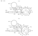
図29に示すように、カム部材41が脱圧状態の位置を超えてさらに正方向へ回転された場合、カム面とカム受け部が大きな速度で衝突する。つまり、図29の(a)のように、脱圧状態では、カム面41aの最上点e2とカム受け部31dとが当接している(以下、このカム面41aのカム受け部31dに対する当接位置を、単に当接位置とも呼ぶ)。 As shown in FIG. 29, when the cam member 41 is further rotated in the positive direction beyond the position of the depressurized state, the cam surface and the cam receiving portion collide with each other at a high speed. That is, as shown in FIG. 29 (a), in the depressurized state, the uppermost point e2 of the cam surface 41a and the cam receiving portion 31d are in contact with each other (hereinafter, the contact of the cam surface 41a with respect to the cam receiving portion 31d). The position is also simply called the contact position).

そして、この脱圧状態よりもさらにカム部材41が正方向(反時計回りの方向)へ回転すると、当接位置が、段差部41bを乗り越えて、最下点e1側へ移動する。これにより、図29の(b)に示すように、当接位置の回転中心からの距離が急激に小さくなり、カム受け部31dは、加圧バネ32(図2参照)の付勢力によって急激にカム部材41の回転中心の側へ移動する。 Then, when the cam member 41 further rotates in the positive direction (counterclockwise direction) from this depressurized state, the contact position moves over the step portion 41b and moves to the lowest point e1 side. As a result, as shown in FIG. 29 (b), the distance from the rotation center of the contact position is sharply reduced, and the cam receiving portion 31d is suddenly pressed by the urging force of the pressure spring 32 (see FIG. 2). It moves to the side of the rotation center of the cam member 41.

そして、カム受け部31dがカム面41aに衝突することになる。この際の衝撃により、カム部材41やカム受け部31d、その他の定着装置12内の部材が破損してしまう虞がある。 Then, the cam receiving portion 31d collides with the cam surface 41a. The impact at this time may damage the cam member 41, the cam receiving portion 31d, and other members in the fixing device 12.

一方、図30に示すように、カム部材41が加圧状態の位置を超えてさらに逆方向へ回転された場合、図21の(a)から図21の(b)のように、カム受け部31dと最上点e2を形成する壁部41cとが衝突する。ただしこの場合、当接位置において、カム面41aの回転中からの距離は変化しないため、カム受け部31dがカム部材41の側へ移動する力は作用せず、上記衝突は、カム部材41の逆方向への回転力によって生じるものである。従って、この際の衝撃は相対的に小さく、部材の破損を生じない。 On the other hand, as shown in FIG. 30, when the cam member 41 is further rotated in the opposite direction beyond the position of the pressurized state, the cam receiving portion is as shown in FIGS. 21 (a) to 21 (b). The 31d and the wall portion 41c forming the uppermost point e2 collide with each other. However, in this case, since the distance of the cam surface 41a from the rotation does not change at the contact position, the force of the cam receiving portion 31d to move toward the cam member 41 does not act, and the collision is caused by the cam member 41. It is caused by the rotational force in the opposite direction. Therefore, the impact at this time is relatively small, and the member is not damaged.

本実施形態では、光学センサ51に不具合が生じた場合でも、脱圧状態の側の衝突(図21のaの衝突)ではなく、加圧状態の側の衝突(図21のbの衝突)が発生する構成とすることにより、定着装置の破損を防止している。 In the present embodiment, even if a defect occurs in the optical sensor 51, the collision on the pressurized state side (collision in FIG. 21b) is not caused by the collision on the depressurized state side (collision in FIG. 21a). By making the configuration generate, damage to the fixing device is prevented.

具体的には、前述したように、光学センサ51に不具合が生じた場合には、正常な検知動作ができなくなり、最初の検知動作では遮光状態と判断される。このため、イニシャライズ動作では第二のイニシャライズ動作が実施されることになり、図28のステップS1~S4を経て、ステップS6でカム部材41の回転停止およびサービスコールをして、その動作を停止することになる。この際、第二のイニシャライズ動作ではカム部材41が逆方向へ回転するため、仮にカム部材41が必要以上に回転してカム面41aとカム受け部31dの衝突が発生した場合でも、その衝突は、より衝撃の小さな加圧状態の側の衝突になる。 Specifically, as described above, when a defect occurs in the optical sensor 51, the normal detection operation cannot be performed, and it is determined that the light-shielding state is obtained in the first detection operation. Therefore, in the initialization operation, the second initialization operation is performed, and the rotation of the cam member 41 and the service call are performed in step S6 through steps S1 to S4 of FIG. 28 to stop the operation. It will be. At this time, since the cam member 41 rotates in the opposite direction in the second initialization operation, even if the cam member 41 rotates more than necessary and a collision occurs between the cam surface 41a and the cam receiving portion 31d, the collision does not occur. , It becomes a collision on the side of the pressurized state with less impact.

このように本実施形態では、イニシャライズ動作時において、光学センサ51に不具合が生じた場合には、カム部材41が逆方向へ回転する構成とすることで、大きな衝撃の衝突(脱圧状態の側の衝突)を避けることができる。従って、衝突時の定着装置12内の各部材の破損を防止することができる。なお、カム部材41の逆方向への回転とは、段差部41bの回転中心からの距離が大きい側である最上点e2の側を回転方向の上流側とし、段差部41bの回転中心からの距離が小さい側を回転方向の下流側とする方向の回転である。 As described above, in the present embodiment, when a defect occurs in the optical sensor 51 during the initialization operation, the cam member 41 is configured to rotate in the opposite direction, so that a large impact collision (side in the depressurized state side) occurs. Collision) can be avoided. Therefore, it is possible to prevent damage to each member in the fixing device 12 at the time of a collision. The rotation of the cam member 41 in the opposite direction means that the side of the highest point e2, which is the side where the distance from the rotation center of the step portion 41b is large, is the upstream side in the rotation direction, and the distance from the rotation center of the step portion 41b. Is the rotation in the direction in which the smaller side is the downstream side in the rotation direction.

また、本実施形態のイニシャライズ動作は、その終了までに必ず透光状態を経る構成のため、光学センサ51の不具合を確実に検出することができる。つまり、最初の検知動作において遮光状態になった場合、図26あるいは図27で示す第二のイニシャライズ動作を実施することになる。そして、この第二のイニシャライズ動作では、その初期位置が図26の(a)の位置、あるいは、図27(a)の位置のいずれの場合であっても、その後のカム部材41の逆回転により、加圧状態の位置に至るまでに透光状態に切り換わることになる。従って、この段階(図28のステップS4)で透光状態の切り換わりの有無を判断することにより、光学センサ51の不具合を確実に検出することができる。つまり、前述した脱圧状態と加圧状態の切り換え動作時には、すでに実施されたイニシャライズ動作によって光学センサ51の不具合が生じていない(つまり、光学センサ51が透光状態になる)状態となっている。 Further, since the initialization operation of the present embodiment is configured to always pass through a translucent state by the end of the initialization operation, a defect of the optical sensor 51 can be reliably detected. That is, when the light-shielded state is obtained in the first detection operation, the second initialization operation shown in FIG. 26 or 27 is performed. Then, in this second initialization operation, regardless of whether the initial position is the position (a) in FIG. 26 or the position shown in FIG. 27 (a), the subsequent reverse rotation of the cam member 41 causes the cam member 41 to rotate in the reverse direction. , It will switch to the translucent state by the time it reaches the position of the pressurized state. Therefore, by determining whether or not the translucent state is switched at this stage (step S4 in FIG. 28), it is possible to reliably detect the defect of the optical sensor 51. That is, at the time of the above-mentioned switching operation between the depressurization state and the pressurization state, the optical sensor 51 is in a state in which the optical sensor 51 is not defective (that is, the optical sensor 51 is in the translucent state) due to the initialization operation already performed. ..

次に、カム部材41を駆動させる駆動伝達機構について説明する。
図15に示すように、カム部材41は、モータ43の駆動力がギア列44を介して伝達されることで、正方向および逆方向へ回転することができる。図15および図31に示すように、第1の平歯車47が画像形成装置本体側に、そして、第2の平歯車48が定着装置の側にそれぞれ設けられており、定着装置の画像形成装置本体への装着によって第1の平歯車47と第2の平歯車48が噛み合う。これにより、カム部材41がモータ43の駆動力によって回転可能な状態になる。
Next, a drive transmission mechanism for driving the cam member 41 will be described.
As shown in FIG. 15, the cam member 41 can rotate in the forward direction and the reverse direction by transmitting the driving force of the motor 43 via the gear train 44. As shown in FIGS. 15 and 31, the first spur gear 47 is provided on the image forming apparatus main body side, and the second spur gear 48 is provided on the fixing device side. The first spur gear 47 and the second spur gear 48 mesh with each other when mounted on the main body. As a result, the cam member 41 becomes rotatable by the driving force of the motor 43.

加圧状態から脱圧状態にする場合には、図32に示すように、モータによって第1の平歯車47を時計回りに回転させることにより、第1の平歯車47と噛み合う第2の平歯車48に矢印Y1方向の力を加え、第2の平歯車48を反時計回りに回転させる。これにより、カム部材41を正方向へ回転させて脱圧状態へ移行させることができる(図19a→eのように、カム受け部31dを移動させることができる)。 When changing from the pressurized state to the depressurized state, as shown in FIG. 32, the second spur gear meshes with the first spur gear 47 by rotating the first spur gear 47 clockwise by a motor. A force in the direction of arrow Y1 is applied to 48 to rotate the second spur gear 48 counterclockwise. As a result, the cam member 41 can be rotated in the positive direction to shift to the depressurized state (the cam receiving portion 31d can be moved as shown in FIGS. 19a → e).

この際、定着装置12は、定着装置に設けられた第2の平歯車48が矢印Y1方向の力を受けることにより、画像形成装置本体への挿入方向の力(図8の右方向の力)を受けることになる。しかし、定着装置は、三つの位置決め突起77~79により本体側位置決め部108~110に位置決めされており(図5参照)、挿入方向の力を受けても定着装置が画像形成装置に対して移動することはない。上記のようにして生じた挿入方向の力は、第1の平歯車47と第2の平歯車48との噛合部で、その回転力として逃がすことができる。 At this time, the fixing device 12 receives a force in the direction of the arrow Y1 by the second spur gear 48 provided in the fixing device, so that the force in the insertion direction into the image forming apparatus main body (force in the right direction in FIG. 8). Will receive. However, the fixing device is positioned on the main body side positioning portions 108 to 110 by three positioning protrusions 77 to 79 (see FIG. 5), and the fixing device moves with respect to the image forming device even when a force in the insertion direction is received. There is nothing to do. The force in the insertion direction generated as described above can be released as a rotational force at the meshing portion between the first spur gear 47 and the second spur gear 48.

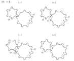
一方、脱圧状態から加圧状態にする場合には、図33(a)に示すように、モータによって第1の平歯車47を反時計回りに回転させる。これにより、図33(b)に示すように、第1の平歯車47と噛み合う第2の平歯車48に矢印Y2方向の力を加え、第2の平歯車48を時計回りに回転させる。 On the other hand, when changing from the depressurized state to the pressurized state, as shown in FIG. 33 (a), the first spur gear 47 is rotated counterclockwise by the motor. As a result, as shown in FIG. 33 (b), a force in the direction of arrow Y2 is applied to the second spur gear 48 that meshes with the first spur gear 47, and the second spur gear 48 is rotated clockwise.

第2の平歯車48が時計回りに回転すると、カム部材41が逆方向へ回転する(図21a→eのように、カム受け部31dを移動させる)。この際、図13に示すように、加圧バネ32の付勢力により、カム受け部31dが回転軸42の側へ移動する。この加圧バネ32の付勢力によってカム部材41の逆方向への回転が加速され、図33(b)に示すように、第1の平歯車47の反時計回りへの回転よりも速い速度で、第2の平歯車48が時計回りに回転する。これにより、図33(c)に示すように、第2の平歯車48が第1の平歯車47を矢印Y2方向へ押し出す形になり、その反力として、第2の平歯車48が矢印Y1方向の力を受ける。そして、図33(d)のように各歯車が回転する。 When the second spur gear 48 rotates clockwise, the cam member 41 rotates in the opposite direction (moves the cam receiving portion 31d as shown in FIGS. 21a → e). At this time, as shown in FIG. 13, the cam receiving portion 31d moves to the side of the rotating shaft 42 by the urging force of the pressure spring 32. The urging force of the pressurizing spring 32 accelerates the rotation of the cam member 41 in the opposite direction, and as shown in FIG. 33 (b), the rotation of the first spur gear 47 is faster than the counterclockwise rotation. , The second spur gear 48 rotates clockwise. As a result, as shown in FIG. 33 (c), the second spur gear 48 pushes the first spur gear 47 in the direction of arrow Y2, and as a reaction force thereof, the second spur gear 48 pushes the first spur gear 47 in the direction of arrow Y1. Receive the force of direction. Then, each gear rotates as shown in FIG. 33 (d).

以上のように、脱圧状態から加圧状態への移行時には、その初期には第1の平歯車47が矢印Y2方向の力を受けて、定着装置に引き出し方向の力(図8の左方向の力)が発生する。しかし、その後、加圧バネ32の付勢力によって第1の平歯車47が回転することで、定着装置に挿入方向の力が発生する。従って、脱圧状態と加圧状態の切り換え時には、いずれの場合も定着装置に画像形成装置本体への挿入方向の力が作用し、定着装置を画像形成装置本体に確実に位置決めすることができる。 As described above, at the time of transition from the depressurized state to the pressurized state, the first spur gear 47 receives the force in the direction of arrow Y2 at the initial stage, and the force in the pulling direction (left direction in FIG. 8) is applied to the fixing device. Force) is generated. However, after that, the urging force of the pressure spring 32 causes the first spur gear 47 to rotate, so that a force in the insertion direction is generated in the fixing device. Therefore, at the time of switching between the depressurized state and the pressurized state, the force in the insertion direction to the image forming apparatus main body acts on the fixing device, and the fixing device can be reliably positioned on the image forming apparatus main body.

また、脱圧状態から加圧状態への移行時において、前述の光学センサ51の不具合によりカム部材41とカム受け部31dの衝突が発生した場合には、図30の(b)のように、カム受け部31dが壁部41cに押し当てられる位置でカム部材41の回転が停止し、第2の平歯車48の回転も停止する。しかし、カム部材の回転が実際に停止(図28のステップS6)するまでの間に、モータがさらに駆動し続けて第1の平歯車47に回転力が伝達され、図33(b)のように、第1の平歯車47が第2の平歯車48を矢印Y2方向へ押圧することがある。これにより、定着装置12は、引き出し方向の力(図8の左方向の力)を受けることになる。 Further, when the cam member 41 and the cam receiving portion 31d collide with each other due to the above-mentioned malfunction of the optical sensor 51 at the time of transition from the depressurized state to the pressurized state, as shown in FIG. 30 (b). The rotation of the cam member 41 is stopped at the position where the cam receiving portion 31d is pressed against the wall portion 41c, and the rotation of the second spur gear 48 is also stopped. However, until the rotation of the cam member actually stops (step S6 in FIG. 28), the motor continues to be driven and the rotational force is transmitted to the first spur gear 47, as shown in FIG. 33 (b). In addition, the first spur gear 47 may press the second spur gear 48 in the direction of arrow Y2. As a result, the fixing device 12 receives a force in the pulling direction (a force in the left direction in FIG. 8).

ところで、前述したように、定着装置12は、装置本体100に装着された状態で、ロック部83と係合部111との間に僅かな隙間が設けられており(図7参照)、定着装置12は、この隙間分だけ引き出し方向へ移動することができる。従って、上記のように定着装置12に引き出し方向の力が発生した場合でも、このわずかな隙間分だけ定着装置12が引き出し方向へ移動し、カム部材の過剰な回転によって生じた回転力を逃がすことができる。従って、定着装置12や装置本体100の係合部分の破損を防止することができる。なお、制御部が光学センサ51の不具合が生じたと判断した場合には、カム部材41に回転停止の指令が出される(図28のステップS6参照)ため、カム部材41が脱圧状態の位置を超えて正方向へ回転する量はわずかである。従って、上記のように定着装置12にわずかに引き出し方向へ移動する余分なスペースがあるだけで、モータの駆動力を逃がすことができ、定着装置の破損を防止できる。 By the way, as described above, the fixing device 12 is provided with a slight gap between the lock portion 83 and the engaging portion 111 in a state of being mounted on the device main body 100 (see FIG. 7), and is a fixing device. 12 can move in the withdrawal direction by the amount of this gap. Therefore, even when a force in the pull-out direction is generated in the fixing device 12 as described above, the fixing device 12 moves in the pull-out direction by this slight gap, and the rotational force generated by the excessive rotation of the cam member is released. Can be done. Therefore, it is possible to prevent damage to the engaging portion of the fixing device 12 and the device main body 100. When the control unit determines that a defect has occurred in the optical sensor 51, a command to stop rotation is issued to the cam member 41 (see step S6 in FIG. 28), so that the position of the cam member 41 in the depressurized state is determined. The amount of forward rotation beyond that is small. Therefore, as described above, the fixing device 12 has an extra space for slightly moving in the pull-out direction, so that the driving force of the motor can be released and the fixing device can be prevented from being damaged.

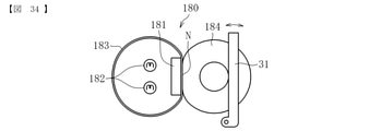
また、本発明を適用する定着装置は、上記実施形態のような一対のローラ(定着ローラ及び加圧ローラ)を備える定着装置に限らない。例えば、図34に示すような、定着ローラに代えて、無端状の定着ベルト183を備える定着装置180であってもよい。この例では、定着ベルト183の内周側に加熱源182とニップ形成部材181が配置されており、定着ベルト183に対して加圧ローラ184がニップ形成部材181の位置で加圧されることで定着ニップNが形成されている。 Further, the fixing device to which the present invention is applied is not limited to the fixing device provided with a pair of rollers (fixing roller and pressure roller) as in the above embodiment. For example, instead of the fixing roller as shown in FIG. 34, the fixing device 180 provided with the endless fixing belt 183 may be used. In this example, the heating source 182 and the nip forming member 181 are arranged on the inner peripheral side of the fixing belt 183, and the pressure roller 184 is pressed against the fixing belt 183 at the position of the nip forming member 181. A fixing nip N is formed.

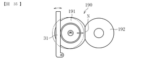
さらに、本発明を適用する定着装置は、上記実施形態のような加圧ローラが定着ローラに対して接近離間する定着装置に限らず、図35に示す例のように、定着ローラ191がこれと対向する対向ローラ192に対して接近離間する定着装置190であってもよい。 Further, the fixing device to which the present invention is applied is not limited to the fixing device in which the pressurizing roller approaches and separates from the fixing roller as in the above embodiment, and as shown in the example shown in FIG. 35, the fixing roller 191 is used. The fixing device 190 may be a fixing device 190 that approaches and separates from the facing rollers 192.

また、本発明に係る接離機構は、定着装置だけでなく、用紙等の記録媒体に画像を転写する転写装置にも適用可能である。例えば、中間転写ベルトを備える転写装置においては、厚紙が二次転写ニップに進入すると、そのときの衝撃によって中間転写ベルトやローラに急激な負荷がかかって中間転写ベルトの回転速度が瞬間的に低下することがある。この中間転写ベルトの回転速度の低下により、感光体と中間転写ベルトとの間に回転速度差が生じた場合は、中間転写ベルトに転写される画像のドットが感光体の回転方向に引き伸ばされるため、画質が低下する。 Further, the contact / detachment mechanism according to the present invention can be applied not only to a fixing device but also to a transfer device for transferring an image to a recording medium such as paper. For example, in a transfer device equipped with an intermediate transfer belt, when thick paper enters the secondary transfer nip, a sudden load is applied to the intermediate transfer belt and rollers due to the impact at that time, and the rotation speed of the intermediate transfer belt drops momentarily. I have something to do. When a difference in rotation speed occurs between the photoconductor and the intermediate transfer belt due to the decrease in the rotation speed of the intermediate transfer belt, the dots of the image transferred to the intermediate transfer belt are stretched in the rotation direction of the photoconductor. , Image quality deteriorates.

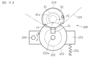
そこで、本実施形態に係る転写装置においては、図36に示すように、二次転写ニップに厚紙が進入することによる急激な負荷を抑制するために、二次転写ローラを中間転写ベルト(又は二次転写バックアップローラ)に対して接近離間させる接離機構を設けている。 Therefore, in the transfer device according to the present embodiment, as shown in FIG. 36, in order to suppress a sudden load due to the thick paper entering the secondary transfer nip, the secondary transfer roller is used as an intermediate transfer belt (or second). A contact / detachment mechanism is provided to bring the next transfer backup roller (next transfer backup roller) closer and further away.

図36に示すように、転写装置206は、中間転写体としての中間転写ベルト216と、二次転写部材としての二次転写ローラ222と、二次転写対向部材としての二次転写バックアップローラ219と、保持部材250等を主に備える。中間転写ベルト216は、二次転写バックアップローラ219をはじめとした複数のローラによって張架されている。また、二次転写ローラ222と中間転写ベルト216との間には二次転写ニップが形成されている。 As shown in FIG. 36, the transfer device 206 includes an intermediate transfer belt 216 as an intermediate transfer body, a secondary transfer roller 222 as a secondary transfer member, and a secondary transfer backup roller 219 as a secondary transfer facing member. , The holding member 250 and the like are mainly provided. The intermediate transfer belt 216 is stretched by a plurality of rollers including a secondary transfer backup roller 219. Further, a secondary transfer nip is formed between the secondary transfer roller 222 and the intermediate transfer belt 216.

二次転写ローラ222は、支軸250を中心に図における矢印M方向に回動する保持部材251に保持されている。保持部材251が支軸250を中心に回動すると、二次転写ローラ222は中間転写ベルト216に対して接近離間する。また、保持部材251は、付勢部材としての加圧バネ252によって図における上方へ付勢されている。このため、二次転写ローラ222は中間転写ベルト216に対して加圧された状態で保持されている。また、二次転写ローラ222の回転軸222aには、空転コロ253が相対的に回転可能に設けられている。 The secondary transfer roller 222 is held by a holding member 251 that rotates around the support shaft 250 in the direction of arrow M in the figure. When the holding member 251 rotates about the support shaft 250, the secondary transfer roller 222 approaches and separates from the intermediate transfer belt 216. Further, the holding member 251 is urged upward in the figure by a pressure spring 252 as a urging member. Therefore, the secondary transfer roller 222 is held in a state of being pressurized with respect to the intermediate transfer belt 216. Further, the rotating shaft 222a of the secondary transfer roller 222 is provided with the idling roller 253 so as to be relatively rotatable.

二次転写バックアップローラ219には、上記実施形態に係る定着装置が備えるのと同様のカム部材41が設けられている。また、本実施形態に係る転写装置には、カム部材41の回転位置を検知する回転位置検知手段として、上記と同様の光学センサ51と、遮光部材52とが設けられている。 The secondary transfer backup roller 219 is provided with a cam member 41 similar to that provided in the fixing device according to the above embodiment. Further, the transfer device according to the present embodiment is provided with an optical sensor 51 similar to the above and a light-shielding member 52 as rotation position detecting means for detecting the rotation position of the cam member 41.

図36に示す状態では、加圧バネ252の付勢力によって空転コロ253がカム面41aに対して最下点e1側で接触している。この状態では、二次転写ローラ222が中間転写ベルト216に対して接近した位置で保持されており、二次転写ニップにおける加圧力は普通紙を通紙する際の通常の加圧力となっている。 In the state shown in FIG. 36, the idling roller 253 is in contact with the cam surface 41a on the lowest point e1 side due to the urging force of the pressure spring 252. In this state, the secondary transfer roller 222 is held in a position close to the intermediate transfer belt 216, and the pressing force at the secondary transfer nip is the normal pressing force when passing plain paper. ..

この状態から厚紙を通紙する際の脱圧状態(減圧状態)にする場合は、カム部材41を図36における反時計回りに回転させる。これにより、カム面41aに対する空転コロ253の接触位置が最下点e1側から最上点e2側へ相対的に移動し、空転コロ253がカム部材41によって図における下方へ押し動かされる。また、これに伴って二次転写ローラ222も下方へ押し動かされる。その結果、二次転写ローラ222が中間転写ベルト216に対して離間した位置に移動し、二次転写ニップにおける加圧力が低減された脱圧状態となる。 When changing from this state to the depressurized state (depressurized state) when passing thick paper, the cam member 41 is rotated counterclockwise in FIG. 36. As a result, the contact position of the idling roller 253 with respect to the cam surface 41a moves relatively from the lowest point e1 side to the uppermost point e2 side, and the idling roller 253 is pushed downward in the figure by the cam member 41. Along with this, the secondary transfer roller 222 is also pushed downward. As a result, the secondary transfer roller 222 moves to a position separated from the intermediate transfer belt 216, resulting in a depressurized state in which the pressing force at the secondary transfer nip is reduced.

また、通常の加圧状態に戻す場合は、上記脱圧状態からカム部材41を上記とは逆方向に回転させればよい。これにより、カム面41aに対する空転コロ253の接触位置が最上点e2側から最下点e1側へ相対的に移動し、空転コロ253がカム部材41に対して接近する。これに伴って、二次転写ローラ222が中間転写ベルト216に対して接近し、二次転写ニップおける加圧力が増加した通常の加圧状態に戻される。なお、ここでの加圧動作時と脱圧動作時におけるカム部材の回転制御には、上記定着装置におけるカム部材の制御方法と同様の制御方法を適用可能である。 Further, when returning to the normal pressurized state, the cam member 41 may be rotated in the direction opposite to the above from the depressurized state. As a result, the contact position of the idling roller 253 with respect to the cam surface 41a moves relatively from the uppermost point e2 side to the lowermost point e1 side, and the idling roller 253 approaches the cam member 41. Along with this, the secondary transfer roller 222 approaches the intermediate transfer belt 216 and is returned to the normal pressurized state in which the pressing force at the secondary transfer nip is increased. It should be noted that the same control method as the control method of the cam member in the fixing device can be applied to the rotation control of the cam member during the pressurizing operation and the depressurizing operation.

このように、中間転写ベルトに対して二次転写ローラを接近離間させる接離機構においても、本発明に係る接離機構を適用することが可能である。また、本発明に係るカム部材を転写装置の接離機構に適用することで、上記定着装置と同様の作用効果が得られる。すなわち、図36に示すように、回転方向の半周よりも多い領域に渡ってカム面41aを設けることができるので、カム面41aの勾配を緩やかにしても、勾配の最大高低差が小さくなるのを回避することができる。これにより、中間転写ベルトに対する二次転写ローラの接近離間距離を十分に確保しつつ、回転トルクの増大や作動音(異音)の発生を抑制することが可能となる。 As described above, the contact / detachment mechanism according to the present invention can also be applied to the contact / detachment mechanism for bringing the secondary transfer roller closer to and away from the intermediate transfer belt. Further, by applying the cam member according to the present invention to the contact / detachment mechanism of the transfer device, the same function and effect as those of the fixing device can be obtained. That is, as shown in FIG. 36, since the cam surface 41a can be provided over a region larger than the half circumference in the rotation direction, even if the gradient of the cam surface 41a is made gentle, the maximum height difference of the gradient becomes small. Can be avoided. As a result, it is possible to suppress an increase in rotational torque and generation of operating noise (abnormal noise) while sufficiently ensuring the proximity and separation distance of the secondary transfer roller with respect to the intermediate transfer belt.

上記転写装置では、厚紙を二次転写ニップに通紙させる場合に二次転写ローラを離間させる構成であるが、本発明は、これ以外に、二次転写ローラが中間転写ベルトに対して常時加圧されることによる塑性変形やトナー固着を抑制するために、転写時以外のタイミングで二次転写ローラを離間させておく構成にも適用可能である。 In the above transfer device, the secondary transfer roller is separated when the thick paper is passed through the secondary transfer nip, but in the present invention, the secondary transfer roller is constantly applied to the intermediate transfer belt. It can also be applied to a configuration in which the secondary transfer rollers are separated at a timing other than the time of transfer in order to suppress plastic deformation and toner sticking due to pressure.

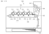
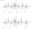
図37に示す例のように、二次転写ニップに対して用紙が縦方向(垂直方向)に搬送される転写装置306においても本発明に係る接離機構を適用可能である。この場合、図36に示す接離機構を例えば横向きに(90°回転させて)配置することで、図37に示す二次転写ローラ322を中間転写ベルト316に対して接近離間させる接離機構を構成できる。なお、図37において、300は画像形成装置、301は複数の感光体311を備える画像形成部、321は一次転写ローラ、302は給紙部、308は定着装置、330は排紙部である。 As shown in the example shown in FIG. 37, the contact / detachment mechanism according to the present invention can also be applied to the transfer device 306 in which the paper is conveyed in the vertical direction (vertical direction) with respect to the secondary transfer nip. In this case, by arranging the contact / detachment mechanism shown in FIG. 36 sideways (rotated by 90 °), for example, the contact / detachment mechanism for bringing the secondary transfer roller 322 shown in FIG. 37 closer to and separated from the intermediate transfer belt 316 is provided. Can be configured. In FIG. 37, 300 is an image forming device, 301 is an image forming section including a plurality of photoconductors 311, 321 is a primary transfer roller, 302 is a feeding section, 308 is a fixing device, and 330 is a paper ejection section.

転写装置306は、中間転写体としての中間転写ベルト316、駆動ローラ318、二次転写対向部材としての二次転写バックアップローラ319、一次転写部材としての4つの一次転写ローラ321、二次転写部材としての二次転写ローラ322などを有する。中間転写ベルト316は、張架ローラ317を含む複数のローラによってテンションがかけられた状態で張架されている。 The transfer device 306 includes an intermediate transfer belt 316 as an intermediate transfer body, a drive roller 318, a secondary transfer backup roller 319 as a secondary transfer facing member, four primary transfer rollers 321 as a primary transfer member, and a secondary transfer member. It has a secondary transfer roller 322 and the like. The intermediate transfer belt 316 is tensioned by a plurality of rollers including the tension roller 317.

4つの一次転写ローラ321は、それぞれ、中間転写ベルト316を介して感光体211に接触している。これにより、中間転写ベルト316と各感光体311とが互いに接触し、これらの間に一次転写ニップが形成されている。 Each of the four primary transfer rollers 321 is in contact with the photoconductor 211 via the intermediate transfer belt 316. As a result, the intermediate transfer belt 316 and each photoconductor 311 come into contact with each other, and a primary transfer nip is formed between them.

二次転写ローラ322は、中間転写ベルト316を介して二次転写バックアップローラ319に接触している。これにより、二次転写ローラ322と中間転写ベルト316との間には二次転写ニップが形成されている。 The secondary transfer roller 322 is in contact with the secondary transfer backup roller 319 via the intermediate transfer belt 316. As a result, a secondary transfer nip is formed between the secondary transfer roller 322 and the intermediate transfer belt 316.

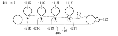
また、本発明に係る接離機構は、図38に示すような感光体に対して一次転写ローラを接近離間させる転写装置406にも適用可能である。ここでは、モノクロ画像形成時に、画像形成に寄与しないカラー画像用の感光体411Y,411M,411Cに対して対応する一次転写ローラ421Y,421M,421Cを離間させることで(図38において点線で示す状態を参照)、これらの感光体411Y,411M,411Cや中間転写ベルト416の不要な摩耗や電力消費を抑えるようにしている。なお、図38において、422は二次転写ローラである。 Further, the contact / detachment mechanism according to the present invention can also be applied to a transfer device 406 that brings the primary transfer roller closer to and away from the photoconductor as shown in FIG. 38. Here, when forming a monochrome image, the primary transfer rollers 421Y, 421M, and 421C corresponding to the photoconductors 411Y, 411M, and 411C for color images that do not contribute to image formation are separated from each other (the state shown by the dotted line in FIG. 38). ), These photoconductors 411Y, 411M, 411C and the intermediate transfer belt 416 are designed to suppress unnecessary wear and power consumption. In FIG. 38, 422 is a secondary transfer roller.

図39は、一次転写ローラを接近離間させる接離機構の概略構成図である。
図39では、接近離間する3つの一次転写ローラのうち、1つ一次転写ローラのみ示しているが、いずれの一次転写ローラに関する接離機構も同様に構成されているので、1つの一次転写ローラに関する接離機構を例に説明する。
FIG. 39 is a schematic configuration diagram of a contact / detachment mechanism for bringing the primary transfer rollers closer to each other.
In FIG. 39, only one primary transfer roller is shown among the three primary transfer rollers that are close to each other, but since the contact / separation mechanism for each of the primary transfer rollers is similarly configured, the primary transfer roller is concerned. The contact / detachment mechanism will be described as an example.

図39の(a)に示すように、一次転写ローラ421Yは、支軸450を中心に図における矢印Q方向に回動する保持部材451に保持されている。保持部材451は、図における矢印W方向に直線移動するリンク部材452に係合し、リンク部材452と連動可能に構成されている。また、リンク部材452の一端部(図における左端部)は、付勢部材としての加圧バネ453によって他端部側(図における右方向)へ加圧されている。これにより、リンク部材452の他端部は、カム部材41のカム面41aに対して接触した状態で保持されている。このカム部材41は、上記実施形態に係る定着装置が備えるのと同様に構成されたものである。また、転写装置には、カム部材41の回転位置を検知する回転位置検知手段として、上記定着装置と同様に、光学センサ51と、遮光部材52とが設けられている。 As shown in FIG. 39 (a), the primary transfer roller 421Y is held by a holding member 451 that rotates about the support shaft 450 in the direction of arrow Q in the figure. The holding member 451 engages with the link member 452 that linearly moves in the direction of the arrow W in the figure, and is configured to be interlockable with the link member 452. Further, one end portion (left end portion in the figure) of the link member 452 is pressurized to the other end portion side (right direction in the figure) by the pressure spring 453 as an urging member. As a result, the other end of the link member 452 is held in contact with the cam surface 41a of the cam member 41. The cam member 41 is configured in the same manner as the fixing device according to the above embodiment. Further, the transfer device is provided with an optical sensor 51 and a light-shielding member 52 as the rotation position detecting means for detecting the rotation position of the cam member 41, as in the fixing device.

図39の(a)に示す状態から、カム部材41が図における時計回りに回転すると、カム面41aに対するリンク部材452の接触位置が最上点e2側から最下点e1側へ相対的に移動する。これに伴って、図39の(b)に示すように、リンク部材452が加圧バネ453に押されて図における右側へ移動する。そして、このリンク部材452の移動に伴って、保持部材451が図における反時計回りに回動し、一次転写ローラ421Yが感光体411Yから離間する。これにより、中間転写ベルト416がカラー画像用の感光体411Yから離れた状態で保持される。 When the cam member 41 rotates clockwise in the figure from the state shown in FIG. 39 (a), the contact position of the link member 452 with respect to the cam surface 41a moves relatively from the highest point e2 side to the lowest point e1 side. .. Along with this, as shown in FIG. 39 (b), the link member 452 is pushed by the pressure spring 453 and moves to the right side in the figure. Then, as the link member 452 moves, the holding member 451 rotates counterclockwise in the drawing, and the primary transfer roller 421Y separates from the photoconductor 411Y. As a result, the intermediate transfer belt 416 is held away from the photoconductor 411Y for color images.

また、一次転写ローラ421Yを感光体411Yに対して接近させるには、図39の(b)に示す状態からカム部材41を上記とは逆方向に回転させればよい。これにより、カム面41aに対するリンク部材452の接触位置が最下点e1側から最上点e2側へ相対的に移動し、リンク部材452がカム部材41によって図における左側へ押し動かされるので、これに伴って保持部材451が図における時計回りに回動する。その結果、図39の(a)に示すように、二次転写ローラ222が中間転写ベルト416に対して接近した状態に戻される。 Further, in order to bring the primary transfer roller 421Y closer to the photoconductor 411Y, the cam member 41 may be rotated in the direction opposite to the above from the state shown in FIG. 39 (b). As a result, the contact position of the link member 452 with respect to the cam surface 41a moves relatively from the lowest point e1 side to the highest point e2 side, and the link member 452 is pushed to the left side in the drawing by the cam member 41. Along with this, the holding member 451 rotates clockwise in the figure. As a result, as shown in FIG. 39 (a), the secondary transfer roller 222 is returned to a state of being close to the intermediate transfer belt 416.

このように、感光体に対して一次転写ローラを接近離間させる接離機構においても、本発明に係る接離機構を適用することが可能である。また、本発明に係るカム部材を、一次転写ローラを接近離間させる接離機構に適用することで、上記定着装置や上記転写装置と同様に、カム面の勾配を緩やかにしても、勾配の最大高低差が小さくなるのを回避することができる。従って、感光体に対する一次転写ローラの接近離間距離を十分に確保しつつ、回転トルクの増大や作動音(異音)の発生を抑制することが可能である。 As described above, the contact / detachment mechanism according to the present invention can also be applied to the contact / detachment mechanism that brings the primary transfer roller closer to and away from the photoconductor. Further, by applying the cam member according to the present invention to the contact / detachment mechanism for bringing the primary transfer rollers closer to each other, the maximum gradient can be achieved even if the gradient of the cam surface is made gentle as in the fixing device and the transfer device. It is possible to avoid the height difference from becoming small. Therefore, it is possible to suppress an increase in rotational torque and generation of operating noise (abnormal noise) while sufficiently ensuring the proximity and separation distance of the primary transfer roller with respect to the photoconductor.

以上、本発明の実施形態について説明したが、本発明は上述の実施形態に限定されるものではなく、本発明の要旨を逸脱しない範囲で種々の変更を加え得ることは勿論である。 Although the embodiments of the present invention have been described above, the present invention is not limited to the above-described embodiments, and it goes without saying that various modifications can be made without departing from the gist of the present invention.

本発明に係る画像形成装置は、図1に示すモノクロ画像形成装置に限らず、カラー画像形成装置や、複写機、プリンタ、ファクシミリ、あるいはこれらの複合機等であってもよい。 The image forming apparatus according to the present invention is not limited to the monochrome image forming apparatus shown in FIG. 1, and may be a color image forming apparatus, a copying machine, a printer, a facsimile, or a combination machine thereof.

記録媒体としては、用紙P(普通紙)の他、厚紙、はがき、封筒、薄紙、塗工紙(コート紙やアート紙等)、トレーシングペーパ、OHPシート、プラスチックフィルム、プリプレグ、銅箔等が含まれる。 Recording media include paper P (plain paper), thick paper, postcards, envelopes, thin paper, coated paper (coated paper, art paper, etc.), tracing paper, transparencies, plastic films, prepregs, copper foil, etc. included.

1 画像形成装置
12 定着装置
18 定着ローラ(相手部材)
19 加圧ローラ(接離部材)
31 加圧レバー
31d カム受け部(当接部材)
41 カム部材
41a カム面
41b 段差部
43 モータ(駆動機構)
47 第1の平歯車(駆動伝達部材)
48 第2の平歯車(駆動伝達部材)
51 光学センサ(回転位置検知手段)
52 遮光部材
52a 長遮光部
52b 短遮光部
52j 孔部(透光部)
52k 非遮光部(透光部)
60 制御部
90 接離機構
206 転写装置
216 中間転写ベルト(中間転写体)
219 二次転写バックアップローラ(二次転写対向部材)
222 二次転写ローラ(二次転写部材)
306 転写装置
311 感光体
316 中間転写ベルト(中間転写体)
321 一次転写ローラ(一次転写部材)
322 二次転写ローラ(二次転写部材)
406 転写装置
411Y,411M,411C,411K 感光体
416 中間転写ベルト(中間転写体)
421Y,421M,421C,421K 一次転写ローラ(一次転写部材)
422 二次転写ローラ(二次転写部材)
1 Image forming device 12 Fixing device 18 Fixing roller (counterpart member)
19 Pressurized roller (contact / detachment member)
31 Pressurizing lever 31d Cam receiving part (contact member)
41 Cam member 41a Cam surface 41b Stepped part 43 Motor (drive mechanism)
47 First spur gear (drive transmission member)
48 Second spur gear (drive transmission member)
51 Optical sensor (rotational position detection means)
52 Light-shielding member 52a Long light-shielding part 52b Short light-shielding part 52j Hole (translucent part)
52k non-light-shielding part (translucent part)
60 Control unit 90 Contact / detachment mechanism 206 Transfer device 216 Intermediate transfer belt (intermediate transfer body)
219 Secondary transfer backup roller (secondary transfer facing member)
222 Secondary transfer roller (secondary transfer member)
306 Transfer device 311 Photoreceptor 316 Intermediate transfer belt (intermediate transfer)
321 Primary transfer roller (primary transfer member)
322 Secondary transfer roller (secondary transfer member)
406 Transfer device 411Y, 411M, 411C, 411K Photoreceptor 416 Intermediate transfer belt (intermediate transfer body)
421Y, 421M, 421C, 421K Primary transfer roller (primary transfer member)
422 Secondary transfer roller (secondary transfer member)

特開2014-906442号公報Japanese Unexamined Patent Publication No. 2014-906442

Claims (8)

当接部材にカム面を当接させるカム部材と、
検知状態と非検知状態との状態変化により、前記カム部材の回転位置を検知する回転位置検知手段と、
前記カム部材の回転動作を制御する制御部とを備え、
前記制御部が前記カム部材を回転させることで前記当接部材に対する当接位置を変化させることにより、相手部材に対して接離部材を接近離間させる接離機構であって、
前記カム部材は、回転方向の半周よりも多い領域にわたって回転中心からの距離が漸増するカム面を有し、一方向およびこれとは逆方向に回転可能であり、
前記カム面は、前記カム部材の回転方向に対して回転中心からの距離が大きく変化する段差部を有し、
前記制御部が前記カム部材の回転位置を認識するための回転位置認識動作において、前記回転位置検知手段が初期に非検知状態になった場合には、前記制御部は、前記カム部材を、前記段差部の前記回転中心からの距離が大きい側を回転方向の上流側、前記段差部の前記回転中心からの距離が小さい側を下流側とする方向へ回転させ、前記接離部材が前記相手部材に接近することを特徴とする接離機構。
A cam member that brings the cam surface into contact with the contact member,
Rotational position detecting means for detecting the rotational position of the cam member by changing the state between the detected state and the non-detected state, and
A control unit that controls the rotational operation of the cam member is provided.
A contact / detachment mechanism in which the control unit rotates the cam member to change the contact position with respect to the contact member, thereby bringing the contact / detachment member closer to and away from the mating member.
The cam member has a cam surface that gradually increases in distance from the center of rotation over a region greater than half a circumference in the direction of rotation, and is rotatable in one direction and in the opposite direction.
The cam surface has a stepped portion in which the distance from the rotation center greatly changes with respect to the rotation direction of the cam member.
In the rotation position recognition operation for the control unit to recognize the rotation position of the cam member, when the rotation position detecting means is initially in the non-detection state, the control unit uses the cam member. The side of the step portion having a large distance from the rotation center is rotated in the upstream side in the rotation direction, and the side of the step portion having a small distance from the rotation center is the downstream side. A contact / detachment mechanism characterized by approaching .
互いに対向する一対の回転体を備え、
前記回転体同士の間に未定着画像を担持する記録媒体を通過させて前記未定着画像を前記記録媒体に定着する定着装置であって、
相手部材である一方の前記回転体に対して接離部材である他方の前記回転体を接近離間させる接離機構として、請求項記載の接離機構を備える定着装置。
With a pair of rotating bodies facing each other,
A fixing device for fixing an unfixed image on the recording medium by passing a recording medium carrying an unfixed image between the rotating bodies.
The fixing device provided with the contact / detachment mechanism according to claim 1 , as a contact / detachment mechanism for bringing the other rotating body, which is a contact / detachment member, closer to and away from one of the rotating bodies which is a mating member.
請求項記載の定着装置を備えた画像形成装置 An image forming apparatus including the fixing device according to claim 2 . 前記定着装置は、画像形成装置本体に対して着脱可能に設けられる請求項記載の画像形成装置。 The image forming apparatus according to claim 3 , wherein the fixing device is detachably provided with respect to the image forming apparatus main body. 画像形成装置本体の側に設けられた、前記カム部材が回転するための駆動源となる駆動機構と、
画像形成装置本体と前記定着装置の側にそれぞれ設けられ、互いに係合して前記駆動機構の駆動力を伝達する複数の駆動伝達部材とをさらに備え、
前記定着装置の側の駆動伝達部材は、前記カム部材が前記段差部の前記回転中心からの距離が大きい側を回転方向の上流側、前記段差部の前記回転中心からの距離が小さい側を下流側とする方向の回転時に、前記画像形成装置本体側の駆動伝達部材から、前記定着装置を画像形成装置本体から離脱させる方向の力を受ける請求項記載の画像形成装置。
A drive mechanism provided on the side of the image forming apparatus main body, which is a drive source for rotating the cam member,
A plurality of drive transmission members provided on the side of the image forming apparatus main body and the fixing apparatus, respectively, which are engaged with each other to transmit the driving force of the driving mechanism, are further provided.
As for the drive transmission member on the side of the fixing device, the side where the cam member has a large distance from the rotation center of the step portion is the upstream side in the rotation direction, and the side where the step portion has a small distance from the rotation center is downstream. The image forming apparatus according to claim 4 , wherein the fixing device receives a force in a direction to be separated from the image forming apparatus main body from the drive transmission member on the image forming apparatus main body side when rotating in the side direction.
中間転写体と、複数の感光体に形成された画像を前記中間転写体に転写する複数の一次転写部材と、前記中間転写体に転写された画像を記録媒体に転写する二次転写部材とを備える転写装置であって、
相手部材である前記感光体に対して接離部材である前記一次転写部材を接近離間させる接離機構として、請求項記載の接離機構を備える転写装置。
An intermediate transfer member, a plurality of primary transfer members that transfer an image formed on a plurality of photoconductors to the intermediate transfer body, and a secondary transfer member that transfers an image transferred to the intermediate transfer body to a recording medium. It is a transfer device equipped with
The transfer device provided with the contact / detachment mechanism according to claim 1 , as a contact / detachment mechanism for bringing the primary transfer member, which is a contact / detachment member, closer to and away from the photoconductor, which is a mating member.
中間転写体と、複数の感光体に形成された画像を前記中間転写体に転写する複数の一次転写部材と、前記中間転写体に転写された画像を記録媒体に転写する二次転写部材とを備える転写装置であって、
相手部材である前記中間転写体に対して接離部材である前記二次転写部材を接近離間させる接離機構として、請求項記載の接離機構を備える転写装置。
An intermediate transfer member, a plurality of primary transfer members that transfer an image formed on a plurality of photoconductors to the intermediate transfer body, and a secondary transfer member that transfers an image transferred to the intermediate transfer body to a recording medium. It is a transfer device equipped with
The transfer device provided with the contact / detachment mechanism according to claim 1 , as a contact / detachment mechanism for bringing the secondary transfer member, which is a contact / detachment member, closer to and away from the intermediate transfer body which is a mating member.
請求項6または7いずれか記載の転写装置を備えた画像形成装置。 An image forming apparatus comprising the transfer apparatus according to any one of claims 6 or 7 .
JP2018046605A 2018-03-14 2018-03-14 Contact / detachment mechanism, fixing device, transfer device, image forming device Active JP7037726B2 (en)

Priority Applications (1)

Application Number Priority Date Filing Date Title
JP2018046605A JP7037726B2 (en) 2018-03-14 2018-03-14 Contact / detachment mechanism, fixing device, transfer device, image forming device

Applications Claiming Priority (1)

Application Number Priority Date Filing Date Title
JP2018046605A JP7037726B2 (en) 2018-03-14 2018-03-14 Contact / detachment mechanism, fixing device, transfer device, image forming device

Publications (2)

Publication Number Publication Date
JP2019159142A JP2019159142A (en) 2019-09-19
JP7037726B2 true JP7037726B2 (en) 2022-03-17

Family

ID=67994842

Family Applications (1)

Application Number Title Priority Date Filing Date
JP2018046605A Active JP7037726B2 (en) 2018-03-14 2018-03-14 Contact / detachment mechanism, fixing device, transfer device, image forming device

Country Status (1)

Country Link
JP (1) JP7037726B2 (en)

Families Citing this family (4)

* Cited by examiner, † Cited by third party
Publication number Priority date Publication date Assignee Title
JP7596847B2 (en) * 2021-02-25 2024-12-10 京セラドキュメントソリューションズ株式会社 Image forming device
US11754964B2 (en) 2021-09-21 2023-09-12 Ricoh Company, Ltd. Cam driver, transfer device, and image forming apparatus
JP7790174B2 (en) * 2022-01-28 2025-12-23 株式会社リコー Fixing device and image forming apparatus
JP2023110476A (en) * 2022-01-28 2023-08-09 株式会社リコー Fixing device and image forming device

Citations (5)

* Cited by examiner, † Cited by third party
Publication number Priority date Publication date Assignee Title
JP2007256875A (en) 2006-03-27 2007-10-04 Canon Inc Image heating device
JP2009037198A (en) 2007-07-12 2009-02-19 Ricoh Co Ltd Rotation drive device, image forming apparatus
JP2012013876A (en) 2010-06-30 2012-01-19 Kyocera Mita Corp Fixing device and image forming apparatus
US20140072325A1 (en) 2012-09-11 2014-03-13 Samsung Electronics Co., Ltd. Rotary cam apparatus and electrophotographic image forming apparatus adopting the same
JP2017076091A (en) 2015-10-16 2017-04-20 京セラドキュメントソリューションズ株式会社 Fixing device and image forming apparatus including the same

Patent Citations (5)

* Cited by examiner, † Cited by third party
Publication number Priority date Publication date Assignee Title
JP2007256875A (en) 2006-03-27 2007-10-04 Canon Inc Image heating device
JP2009037198A (en) 2007-07-12 2009-02-19 Ricoh Co Ltd Rotation drive device, image forming apparatus
JP2012013876A (en) 2010-06-30 2012-01-19 Kyocera Mita Corp Fixing device and image forming apparatus
US20140072325A1 (en) 2012-09-11 2014-03-13 Samsung Electronics Co., Ltd. Rotary cam apparatus and electrophotographic image forming apparatus adopting the same
JP2017076091A (en) 2015-10-16 2017-04-20 京セラドキュメントソリューションズ株式会社 Fixing device and image forming apparatus including the same

Also Published As

Publication number Publication date
JP2019159142A (en) 2019-09-19

Similar Documents

Publication Publication Date Title
JP4974290B2 (en) Image forming apparatus
JP7037726B2 (en) Contact / detachment mechanism, fixing device, transfer device, image forming device
US7526214B2 (en) Image forming device
JP6303640B2 (en) Image forming apparatus
JP6890767B2 (en) Contact / detachment mechanism, fixing device, transfer device and image forming device
JP2007079570A (en) Image forming apparatus
US8725039B2 (en) Fixing device and image forming apparatus with a cover for generating a stable nipping pressure on a conveyance roller pair
JP6287540B2 (en) Image forming apparatus and box mounting structure
JP6291807B2 (en) Paper feeding device and image forming apparatus
JP2015184598A (en) Information processor and program
JP5039847B2 (en) Image forming apparatus
JP2004117395A (en) Image forming device
CN110199227B (en) Fixing device and image forming apparatus
JP5761592B2 (en) Rotating door mechanism and image forming apparatus
JP4952216B2 (en) Image forming apparatus
JP5305253B2 (en) Image forming apparatus
JP7006109B2 (en) Sheet feeding device and image forming device
JP2008268401A (en) Image fixing unit and image forming device incorporating it
JP6986205B2 (en) Fixing device, image forming device
JP2008089661A (en) Image forming apparatus
JP4681971B2 (en) Image forming apparatus
JP5459544B2 (en) Sheet conveying apparatus and image forming apparatus using the same
JP6344371B2 (en) Fixing apparatus and image forming apparatus
JP5645729B2 (en) Fixing apparatus and image forming apparatus having the same
US20240329574A1 (en) Image forming apparatus

Legal Events

Date Code Title Description
A621 Written request for application examination

Free format text: JAPANESE INTERMEDIATE CODE: A621

Effective date: 20201210

A977 Report on retrieval

Free format text: JAPANESE INTERMEDIATE CODE: A971007

Effective date: 20211027

A131 Notification of reasons for refusal

Free format text: JAPANESE INTERMEDIATE CODE: A131

Effective date: 20211028

A521 Request for written amendment filed

Free format text: JAPANESE INTERMEDIATE CODE: A523

Effective date: 20211129

TRDD Decision of grant or rejection written
A01 Written decision to grant a patent or to grant a registration (utility model)

Free format text: JAPANESE INTERMEDIATE CODE: A01

Effective date: 20220203

A61 First payment of annual fees (during grant procedure)

Free format text: JAPANESE INTERMEDIATE CODE: A61

Effective date: 20220216

R151 Written notification of patent or utility model registration

Ref document number: 7037726

Country of ref document: JP

Free format text: JAPANESE INTERMEDIATE CODE: R151