JP7036412B2 - Pachinko machine - Google Patents

Pachinko machine Download PDF

Info

Publication number
JP7036412B2
JP7036412B2 JP2017106617A JP2017106617A JP7036412B2 JP 7036412 B2 JP7036412 B2 JP 7036412B2 JP 2017106617 A JP2017106617 A JP 2017106617A JP 2017106617 A JP2017106617 A JP 2017106617A JP 7036412 B2 JP7036412 B2 JP 7036412B2
Authority
JP
Japan
Prior art keywords
movable
movable portion
display
display screen
image
Prior art date
Legal status (The legal status is an assumption and is not a legal conclusion. Google has not performed a legal analysis and makes no representation as to the accuracy of the status listed.)
Active
Application number
JP2017106617A
Other languages
Japanese (ja)
Other versions
JP2018201561A5 (en
JP2018201561A (en
Inventor
葵 小林
Original Assignee
株式会社サンセイアールアンドディ
Priority date (The priority date is an assumption and is not a legal conclusion. Google has not performed a legal analysis and makes no representation as to the accuracy of the date listed.)
Filing date
Publication date
Application filed by 株式会社サンセイアールアンドディ filed Critical 株式会社サンセイアールアンドディ
Priority to JP2017106617A priority Critical patent/JP7036412B2/en
Publication of JP2018201561A publication Critical patent/JP2018201561A/en
Publication of JP2018201561A5 publication Critical patent/JP2018201561A5/ja
Application granted granted Critical
Publication of JP7036412B2 publication Critical patent/JP7036412B2/en
Active legal-status Critical Current
Anticipated expiration legal-status Critical

Links

Images

Description

本発明は、表示部の表示面に沿って移動可能な移動部材を有する遊技機に関する。 The present invention relates to a gaming machine having a moving member that can move along the display surface of the display unit.

特許文献1に開示の遊技機では、待機位置に配置された移動部材が表示画面に沿って移動すると、表示画面を前方から覆う出現位置に配置される。 In the gaming machine disclosed in Patent Document 1, when the moving member arranged in the standby position moves along the display screen, it is arranged in the appearance position covering the display screen from the front.

特開2011-224193号(段落[0024]、図2)JP-A-2011-224193 (paragraph [0024], FIG. 2)

特許文献1の遊技機では、移動部材が表示画面を覆った状態では表示画面に画像を表示させることが困難であるため、移動部材を待機位置に戻してから画像を表示する。このため、移動部材が戻るまでの間、表示画面における表示が間延びしてしまうという問題があった。 In the gaming machine of Patent Document 1, it is difficult to display an image on the display screen when the moving member covers the display screen. Therefore, the moving member is returned to the standby position and then the image is displayed. Therefore, there is a problem that the display on the display screen is delayed until the moving member returns.

本発明は、上記事情に鑑みてなされたもので、表示の間延びを抑制可能な遊技機の提供を目的とする。 The present invention has been made in view of the above circumstances, and an object of the present invention is to provide a gaming machine capable of suppressing extension of display.

第1の手段は、外縁に表示される外縁演出画像と、前記外縁演出画像よりも内側に表示される内側演出画像と、を表示可能な表示部と、前記表示部の前側に配され、前記表示部のうち互いに対向する1対の辺部が対向する第1方向で、前記表示部を挟むように対をなし、前記表示部に重ならない第1位置と、前記表示部の前記1対の辺部に重なり、前記表示部の視認領域を第1方向で狭める第2位置と、に配置されることが可能な1対の移動部材と、前記移動部材の移動に合わせて前記表示部に表示される前記内側演出画像を前記第1方向でのみ圧縮する一方、前記外縁演出画像を圧縮しない表示制御手段と、を有する遊技機である。 The first means is arranged on a display unit capable of displaying an outer edge effect image displayed on the outer edge and an inner effect image displayed inside the outer edge effect image, and on the front side of the display unit. In the first direction in which a pair of sides of the display unit facing each other face each other, a pair is formed so as to sandwich the display unit, and the first position that does not overlap the display unit and the pair of the display unit. A pair of moving members that can be placed at a second position that overlaps the sides and narrows the visible area of the display unit in the first direction, and displays on the display unit as the moving members move. It is a gaming machine having a display control means that compresses the inner effect image to be compressed only in the first direction, but does not compress the outer edge effect image .

上記発明によれば、表示の間延びを抑制することが可能となる。 According to the above invention, it is possible to suppress the extension of the display.

本発明の一実施形態に係る遊技機の正面図Front view of a gaming machine according to an embodiment of the present invention 遊技盤の正面図Front view of the game board 第1可動部と第2可動部が待機位置に配置された状態の遊技盤の正面図Front view of the game board with the first movable part and the second movable part arranged in the standby position 可動役物ユニットが取り付けられた機構枠の正面図Front view of the mechanism frame to which the movable accessory unit is attached 可動役物ユニットの斜視図Perspective view of the movable accessory unit (A)可動ベースが第1回転位置に配置されたときの可動役物ユニットの正面図、(B)可動ベースが第2回転位置に配置されたときの可動役物ユニットの正面図(A) Front view of the movable accessory unit when the movable base is placed in the first rotation position, (B) Front view of the movable accessory unit when the movable base is placed in the second rotation position. 直動駆動機構の概略構成図Schematic configuration of the linear drive mechanism 可動演出部の斜視図Perspective view of the movable production unit (A)第1透光壁が前側を向くように配置されたブロックの断面図、(B)第2透光壁が前側を向くように配置されたブロックの断面図(A) Cross-sectional view of the block arranged so that the first translucent wall faces the front side, (B) Cross-sectional view of the block arranged so that the second translucent wall faces the front side. 遊技機の電気的構成を示すブロック図Block diagram showing the electrical configuration of a gaming machine (A)第1画像を表示する表示画面と第1可動部及び第2可動部の配置を示す図、(B)表示画面の空白部を説明するための図、(C)第2画像を表示する表示画面と第1可動部及び第2可動部の配置を示す図(A) A display showing a display screen for displaying a first image, a diagram showing the arrangement of a first movable portion and a second movable portion, (B) a diagram for explaining a blank portion of the display screen, and (C) displaying a second image. The figure which shows the display screen and the arrangement of the 1st movable part and the 2nd movable part ツイスト動作を伴う演出の流れを説明するための図Diagram to explain the flow of production with twisting motion ツイスト動作を伴う演出の流れを説明するための図Diagram to explain the flow of production with twisting motion ツイスト動作を伴う演出の流れを説明するための図Diagram to explain the flow of production with twisting motion 動作パターンAの流れを説明するための図The figure for demonstrating the flow of operation pattern A 動作パターンBの流れを説明するための図The figure for demonstrating the flow of operation pattern B 動作パターンCの流れを説明するための図The figure for demonstrating the flow of the operation pattern C 動作パターンDの流れを説明するための図The figure for demonstrating the flow of the operation pattern D 可動演出の流れを説明するための図Diagram to explain the flow of movable production 可動演出の流れを説明するための図Diagram to explain the flow of movable production ボタン振動演出と可動演出の消費電流のタイムチャートTime chart of current consumption of button vibration effect and movable effect

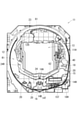
図1に示されるように、本実施形態の遊技機10は、パチンコ遊技機であって、前面枠10Zを前面に備え、その前面枠10Zに形成されたガラス窓10Wを通して、図2に示す遊技盤11の前面に形成された遊技領域R1が視認可能になっている。 As shown in FIG. 1, the gaming machine 10 of the present embodiment is a pachinko gaming machine, the front frame 10Z is provided on the front surface, and the game shown in FIG. 2 is passed through a glass window 10W formed in the front frame 10Z. The gaming area R1 formed on the front surface of the board 11 is visible.

前面枠10Zのうちガラス窓10Wより下方には、上皿26と下皿27が上下2段にして設けられ、下皿27の右側には、発射ハンドル28が備えられている。そして、発射ハンドル28が回動操作されると、上皿26に収容された遊技球が遊技領域R1(図2)に向けて弾き出される。また、下皿27の左側には、演出用の操作ボタン29Bを備える操作ボタン装置29が備えられている。なお、操作ボタン装置29には、操作ボタン29Bが所定距離押し込まれたことを検出するためのボタンセンサ29Sと、操作ボタン29Bを遊技者に体感可能な態様で振動させる振動モータ29Mと、が備えられている(図10)。 An upper plate 26 and a lower plate 27 are provided in two upper and lower stages below the glass window 10W of the front frame 10Z, and a firing handle 28 is provided on the right side of the lower plate 27. Then, when the launch handle 28 is rotated, the game ball housed in the upper plate 26 is ejected toward the game area R1 (FIG. 2). Further, on the left side of the lower plate 27, an operation button device 29 including an operation button 29B for directing is provided. The operation button device 29 includes a button sensor 29S for detecting that the operation button 29B has been pressed by a predetermined distance, and a vibration motor 29M that vibrates the operation button 29B in a manner that can be experienced by the player. (Fig. 10).

図2に示されるように、遊技領域R1は全体が略円形状となっていて、ガイドレール12により囲まれている。遊技盤11のうち遊技領域R1の中央には、表示開口11Hが貫通形成され、この表示開口11Hを通して、表示装置13の表示画面13Gが前方に臨んでいる。なお、表示装置13の表示画面13Gには、遊技に関する種々の演出が表示される。 As shown in FIG. 2, the game area R1 has a substantially circular shape as a whole and is surrounded by the guide rail 12. A display opening 11H is formed through the center of the game area R1 of the game board 11, and the display screen 13G of the display device 13 faces forward through the display opening 11H. The display screen 13G of the display device 13 displays various effects related to the game.

表示開口11Hの開口縁には、表示装飾枠23が取り付けられている。詳細には、表示装飾枠23は、遊技盤11の前面側から表示開口11Hに嵌め込まれて遊技盤11の前面から突出し、遊技領域R1を流下する遊技球が表示装飾枠23の内側に進入することを規制している。 A display decorative frame 23 is attached to the opening edge of the display opening 11H. Specifically, the display decorative frame 23 is fitted into the display opening 11H from the front side of the game board 11 and protrudes from the front surface of the game board 11, and the game ball flowing down the game area R1 enters the inside of the display decoration frame 23. It regulates that.

表示装飾枠23の内側の開口部は、横長略矩形状に形成されていて、表示装飾枠23の下辺部には、遊技球が転動可能なステージ24が形成されている。また、表示装飾枠23の側部には、遊技領域R1を流下する遊技球を受け入れてステージ24へと誘導するワープ路24Rが形成されている。 The opening inside the display decorative frame 23 is formed in a substantially rectangular shape in a horizontally long shape, and a stage 24 on which the game ball can roll is formed on the lower side portion of the display decorative frame 23. Further, on the side portion of the display decorative frame 23, a warp path 24R that receives the game ball flowing down the game area R1 and guides it to the stage 24 is formed.

表示装飾枠23の下側には、第1と第2の始動入賞口14A,14Bが上下に並べて設けられている。表示装飾枠23の右側には、始動ゲート18が備えられている。表示装飾枠23の右下側、即ち、第1と第2の始動入賞口14A,14Bの右側には、大入賞口15が設けられている。また、遊技領域R1には、始動入賞口14A,14B及び大入賞口15のほかに、複数の一般入賞口20が備えられている。 On the lower side of the display decorative frame 23, the first and second starting winning openings 14A and 14B are provided side by side. A starting gate 18 is provided on the right side of the display decorative frame 23. A large winning opening 15 is provided on the lower right side of the display decorative frame 23, that is, on the right side of the first and second starting winning openings 14A and 14B. Further, the game area R1 is provided with a plurality of general winning openings 20 in addition to the starting winning openings 14A and 14B and the large winning openings 15.

一般入賞口20は、遊技球が1つずつ入ることが可能な大きさで上方又は側方に開口している。一般入賞口20へ遊技球が入球(入賞)すると、その遊技球は遊技盤11の後側に取り込まれ、例えば、1個の入球につき15個の賞球が上皿26に払い出される。 The general winning opening 20 is large enough to accommodate one game ball at a time and is open upward or laterally. When a game ball enters (wins) into the general winning opening 20, the game ball is taken into the rear side of the game board 11, and for example, 15 prize balls are paid out to the upper plate 26 for each winning ball.

始動ゲート18は、遊技球が潜って通過可能な門形構造をなしている。始動ゲート18を遊技球が通過すると、普通図柄当否判定が行われる。普通図柄当否判定の結果は、普通図柄用表示部18Hに表示される。 The starting gate 18 has a gate-shaped structure through which a game ball can dive and pass. When the game ball passes through the start gate 18, a normal symbol hit / miss determination is made. The result of the normal symbol hit / miss determination is displayed on the normal symbol display unit 18H.

第1の始動入賞口14Aは、ポケット構造に形成され、遊技球が1つずつ入ることが可能な大きさで上方に開口している。第2の始動入賞口14Bは、遊技球が1つずつ入ることが可能な大きさで前方に開口し、通常は、開閉扉14Tにて前方が閉塞されることで、遊技球の入球(入賞)が規制されている。開閉扉14Tは、上述した普通図柄当否判定の結果が当りとなったときに、下端部を中心に回動して所定時間だけ前側に倒される。すると、開閉扉14Tに受け止められた遊技球が第2の始動入賞口14Bに入球可能となる。 The first starting winning opening 14A is formed in a pocket structure and is open upward with a size that allows one game ball to be inserted. The second start winning opening 14B opens forward in a size that allows one game ball to enter, and normally, the front is closed by the opening / closing door 14T, so that the game ball enters ( Winning) is regulated. When the result of the above-mentioned normal symbol hit / miss determination is a hit, the opening / closing door 14T rotates about the lower end portion and is tilted forward for a predetermined time. Then, the game ball received by the opening / closing door 14T can enter the second starting winning opening 14B.

始動入賞口14A,14Bに遊技球が入球(入賞)すると、所定個数の賞球が上皿26に払い出されると共に、特別図柄当否判定が行われる。特別図柄当否判定の結果は、特別図柄用表示部14Hに表示されると共に、表示装置13の表示画面13Gに表示される。そして、特別図柄当否判定の結果が当りであると、大当り遊技が実行される。なお、表示画面13Gにおいては、例えば、数字や文字等で構成される図柄の変動、停止が行われ、停止した図柄の組合せによって特別図柄当否判定の結果が表示される。 When a game ball enters (wins) in the starting winning openings 14A and 14B, a predetermined number of prize balls are paid out to the upper plate 26, and a special symbol winning / failing determination is performed. The result of the special symbol winning / failing determination is displayed on the special symbol display unit 14H and also displayed on the display screen 13G of the display device 13. Then, if the result of the special symbol winning / failing determination is a hit, the big hit game is executed. On the display screen 13G, for example, a symbol composed of numbers, characters, or the like is changed or stopped, and the result of the special symbol winning / failing determination is displayed depending on the combination of the stopped symbols.

大入賞口15は、横長矩形状をなし、通常の遊技状態では、可動扉15Tにて閉塞されている。上述の大当り遊技が実行されると、可動扉15Tが所定期間に亘って前側に倒される。すると、大入賞口15が前方に開放し、可動扉15Tを案内にして大入賞口15に多くの遊技球が入賞可能となる。大入賞口15に遊技球が入賞すると、所定個数の賞球が上皿26に払い出される。 The large winning opening 15 has a horizontally long rectangular shape, and is closed by the movable door 15T in a normal gaming state. When the above-mentioned jackpot game is executed, the movable door 15T is tilted forward for a predetermined period of time. Then, the large winning opening 15 opens forward, and a large number of game balls can be won in the large winning opening 15 by using the movable door 15T as a guide. When a game ball wins in the large prize opening 15, a predetermined number of prize balls are paid out to the upper plate 26.

上述した各入賞口14A,14B,15,20の何れにも入賞しなかった遊技球は、遊技領域R1の下端部に設けられたアウト口16に全て取り込まれる。アウト口16に取り込まれた遊技球は、図示しない球回収装置に回収される。 The game balls that do not win any of the above-mentioned winning openings 14A, 14B, 15 and 20 are all taken into the out openings 16 provided at the lower end of the gaming area R1. The game ball taken into the out port 16 is collected by a ball collecting device (not shown).

遊技盤11の裏側には、図4に示される機構枠17が備えられている。そして、この機構枠17に、可動役物ユニット40を含む種々の部品が固定されている。なお、機構枠17の内側の開口部17Aは、遊技盤11の表示開口11H(図2参照)に重ねられて、表示装置13の表示画面13Gを視認可能とする。 The mechanism frame 17 shown in FIG. 4 is provided on the back side of the game board 11. Then, various parts including the movable accessory unit 40 are fixed to the mechanism frame 17. The opening 17A inside the mechanism frame 17 is overlapped with the display opening 11H (see FIG. 2) of the game board 11 so that the display screen 13G of the display device 13 can be visually recognized.

図4,5に示されるように、可動役物ユニット40は、固定ベース41と、可動ベース51と、を備えている。固定ベース41は、略円形の開口部41Aを内側に有する枠状に形成され、機構枠17に前側から重ねて固定されている。可動ベース51は、略円形状をなして、固定ベース41の開口部41Aの内側に嵌め込まれ、固定ベース41に対して回転可能に構成されている。なお、本実施形態では、固定ベース41及び可動ベース51は無色透明に形成され、固定ベース41及び可動ベース51を通して表示画面13Gを視認可能に構成されている。 As shown in FIGS. 4 and 5, the movable accessory unit 40 includes a fixed base 41 and a movable base 51. The fixed base 41 is formed in a frame shape having a substantially circular opening 41A inside, and is stacked and fixed to the mechanism frame 17 from the front side. The movable base 51 has a substantially circular shape and is fitted inside the opening 41A of the fixed base 41 so as to be rotatable with respect to the fixed base 41. In the present embodiment, the fixed base 41 and the movable base 51 are formed colorless and transparent, and the display screen 13G can be visually recognized through the fixed base 41 and the movable base 51.

具体的には、可動ベース51の外周面の一部には、外歯51Gが形成されている。図6(A)に示されるように、可動ベース51の外歯51Gには、固定ベース41に回転可能に支持された駆動ギア42が噛み合っている。駆動ギア42は、固定ベース41に備えられたベース駆動源43(図5参照)によって駆動される。 Specifically, external teeth 51G are formed on a part of the outer peripheral surface of the movable base 51. As shown in FIG. 6A, a drive gear 42 rotatably supported by the fixed base 41 meshes with the external teeth 51G of the movable base 51. The drive gear 42 is driven by a base drive source 43 (see FIG. 5) provided in the fixed base 41.

可動ベース51は、通常は、図6(A)に示される第1回転位置に配置され、駆動ギア42の駆動によって、可動ベース51は、第1回転位置と図6(B)に示される第2回転位置との間を移動する。第2回転位置は、正面から見て第1回転位置に対して時計方向に約90度ずれている。ここで、可動ベース51の中央部には、矩形状の窓部51Aが形成されていて、可動ベース51が第1回転位置又は第2回転位置に配置されると、該窓部51Aが表示画面13G(図2参照)の中央部と重なる。 The movable base 51 is normally arranged at the first rotation position shown in FIG. 6 (A), and by driving the drive gear 42, the movable base 51 is moved to the first rotation position and the first rotation position shown in FIG. 6 (B). Move between 2 rotation positions. The second rotation position is shifted clockwise by about 90 degrees from the first rotation position when viewed from the front. Here, a rectangular window portion 51A is formed in the central portion of the movable base 51, and when the movable base 51 is arranged at the first rotation position or the second rotation position, the window portion 51A is displayed on the display screen. It overlaps with the central part of 13G (see FIG. 2).

図5に示されるように、可動ベース51には、互いに対向配置される第1可動部61及び第2可動部62と、第1可動部61及び第2可動部62をその対向方向に接近、離間させる直動駆動機構70と、が搭載されている。なお、第1可動部61と第2可動部62は、通常は、その対向方向で最も離れる待機位置に配置され(図3参照)、直動駆動機構70によって、最も近接する合体位置に配置される(図2参照)。 As shown in FIG. 5, the movable base 51 is approached by the first movable portion 61 and the second movable portion 62, which are arranged to face each other, and the first movable portion 61 and the second movable portion 62 in the opposite directions. A linear drive mechanism 70 that separates them is mounted. The first movable portion 61 and the second movable portion 62 are usually arranged at the standby positions farthest from each other in the opposite direction (see FIG. 3), and are arranged at the closest combined position by the linear motion drive mechanism 70. (See Fig. 2).

第1可動部61と第2可動部62のそれぞれには、対向方向の内側に配置される内側可動体61A,62Aと、対向方向の外側に配置される外側可動体61B,62Bと、が備えられている。なお、可動ベース51が第1回転位置に配置されたとき、第1可動部61と第2可動部62は上下方向に対向し、第1可動部61が第2可動部62に対して上側に配置される(図6(A))。また、可動ベース51が第2回転位置に配置されたとき、第1可動部61と第2可動部62は左右方向に対向し、第1可動部61が第2可動部62に対して右側に配置される(図6(B))。以下では、第1可動部61の内側可動体61A、外側可動体61Bを第1内側可動体61A、第1外側可動体61Bと適宜称し、第2可動部62の内側可動体62A、外側可動体62Bを第2内側可動体62A、第2外側可動体62Bと適宜称することとする。 Each of the first movable portion 61 and the second movable portion 62 includes inner movable bodies 61A and 62A arranged inside in the facing direction and outer movable bodies 61B and 62B arranged outside in the facing direction. Has been done. When the movable base 51 is arranged at the first rotation position, the first movable portion 61 and the second movable portion 62 face each other in the vertical direction, and the first movable portion 61 is above the second movable portion 62. It is arranged (FIG. 6 (A)). Further, when the movable base 51 is arranged at the second rotation position, the first movable portion 61 and the second movable portion 62 face each other in the left-right direction, and the first movable portion 61 is on the right side with respect to the second movable portion 62. It is arranged (FIG. 6 (B)). Hereinafter, the inner movable body 61A and the outer movable body 61B of the first movable portion 61 are appropriately referred to as the first inner movable body 61A and the first outer movable body 61B, and the inner movable body 62A and the outer movable body of the second movable portion 62 are appropriately referred to. 62B will be appropriately referred to as a second inner movable body 62A and a second outer movable body 62B.

図7に示されるように、第1可動部61の各可動体61A,61Bと第2可動部62の各可動体62A,62Bには、第1可動部61と第2可動部62の対向方向に延びる第1プレート部64及び第2プレート部65と、第1プレート部64と第2プレート部65の間に差し渡された可動演出部63と、が設けられている。第1プレート部64と第2プレート部65は、可動ベース51の窓部51Aを可動演出部63の延在方向に挟むように配置される。なお、図7には、第1外側可動体61Bと第2外側可動体62Bのみが示されている。 As shown in FIG. 7, the movable bodies 61A and 61B of the first movable portion 61 and the movable bodies 62A and 62B of the second movable portion 62 are in the opposite direction of the first movable portion 61 and the second movable portion 62. A first plate portion 64 and a second plate portion 65 extending to the above, and a movable effect portion 63 passed between the first plate portion 64 and the second plate portion 65 are provided. The first plate portion 64 and the second plate portion 65 are arranged so as to sandwich the window portion 51A of the movable base 51 in the extending direction of the movable effect portion 63. Note that FIG. 7 shows only the first outer movable body 61B and the second outer movable body 62B.

第1可動部61においては、可動演出部63の延在方向の一方側に第1プレート部64が配置され、他方側に第2プレート部65が配置される。一方、第2可動部62においては、可動演出部63の延在方向の一方側に第2プレート部65が配置され、他方側に第1プレート部64が配置される。第1可動部61と第2可動部62の間では、第1プレート部64と第2プレート部65が突き合わされるように配置され、第1可動部61と第2可動部62が最も近接したときに、第1可動部61の第1プレート部64と第2可動部62の第2プレート部65が横並びに配置され、第1可動部61の第2プレート部65と第2可動部62の第1プレート部64が横並びに配置される。 In the first movable portion 61, the first plate portion 64 is arranged on one side in the extending direction of the movable effect portion 63, and the second plate portion 65 is arranged on the other side. On the other hand, in the second movable portion 62, the second plate portion 65 is arranged on one side in the extending direction of the movable effect portion 63, and the first plate portion 64 is arranged on the other side. Between the first movable portion 61 and the second movable portion 62, the first plate portion 64 and the second plate portion 65 are arranged so as to be butted against each other, and the first movable portion 61 and the second movable portion 62 are closest to each other. Occasionally, the first plate portion 64 of the first movable portion 61 and the second plate portion 65 of the second movable portion 62 are arranged side by side, and the second plate portion 65 and the second movable portion 62 of the first movable portion 61 are arranged side by side. The first plate portions 64 are arranged side by side.

また、第1可動部61においては、第1内側可動体61Aの第1プレート部64と第1外側可動体61Bの第1プレート部64が重ねられると共に、第1内側可動体61Aの第2プレート部65と第1外側可動体61Bの第2プレート部65が重ねられる(図5参照)。同様に、第2可動部62においては、第2内側可動体62Aの第1プレート部64と第2外側可動体62Bの第1プレート部64が重ねられると共に、第2内側可動体62Aの第2プレート部65と第2外側可動体62Bの第2プレート部65が重ねられる。 Further, in the first movable portion 61, the first plate portion 64 of the first inner movable body 61A and the first plate portion 64 of the first outer movable body 61B are overlapped with each other, and the second plate of the first inner movable body 61A is overlapped. The portion 65 and the second plate portion 65 of the first outer movable body 61B are overlapped with each other (see FIG. 5). Similarly, in the second movable portion 62, the first plate portion 64 of the second inner movable body 62A and the first plate portion 64 of the second outer movable body 62B are overlapped with each other, and the second inner movable body 62A is second. The plate portion 65 and the second plate portion 65 of the second outer movable body 62B are overlapped with each other.

図7に示されるように、第1プレート部64と第2プレート部65には、その延在方向に延びる長孔64N,65Nが形成されている。長孔64N,65Nには、可動ベース51に固定された支持軸部66が挿通されていて、これにより、第1プレート部64と第2プレート部65は、それぞれの延在方向に直動可能となっている。また、第1プレート部64の両側部には、ラック64R,64Rが形成され、第2プレート部65のうち第1プレート部64と反対側の部分には、ラック65Rが形成されている。 As shown in FIG. 7, the first plate portion 64 and the second plate portion 65 are formed with elongated holes 64N and 65N extending in the extending direction thereof. A support shaft portion 66 fixed to the movable base 51 is inserted through the elongated holes 64N and 65N, whereby the first plate portion 64 and the second plate portion 65 can move linearly in their respective extending directions. It has become. Racks 64R and 64R are formed on both sides of the first plate portion 64, and racks 65R are formed on the portion of the second plate portion 65 opposite to the first plate portion 64.

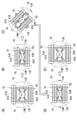
図4,5,7に示されるように、直動駆動機構70は、可動演出部63の延在方向で可動ベース51の窓部51Aを挟むように対をなして設けられている。各直動駆動機構70には、第1内側可動体61Aと第2内側可動体62Aを駆動するための内側可動体用駆動源71Aと、第1外側可動体61Bと第2外側可動体62Bを駆動するための外側可動体用駆動源71Bと、各駆動源71A,71Bによって回転駆動される駆動ギア72,72(図7には、外側可動体用駆動源71Bにより回転駆動される駆動ギア72のみが示されている。)と、が備えられている。 As shown in FIGS. 4, 5 and 7, the linear drive mechanisms 70 are provided in pairs so as to sandwich the window portion 51A of the movable base 51 in the extending direction of the movable effect portion 63. Each linear drive mechanism 70 includes a drive source 71A for the inner movable body for driving the first inner movable body 61A and the second inner movable body 62A, and a first outer movable body 61B and a second outer movable body 62B. The drive source 71B for the outer movable body for driving and the drive gears 72 and 72 rotationally driven by the drive sources 71A and 71B (in FIG. 7, the drive gear 72 rotationally driven by the drive source 71B for the outer movable body). Only are shown.) And are provided.

図7に示されるように、駆動ギア72は、第1プレート部64のラック64R,64Rのうち第2プレート部65と反対側に配されるラック64Rと噛合する。詳細には、1対の直動駆動機構70,70のうち一方の直動駆動機構70(図7では、右側の直動駆動機構70)の駆動ギア72は、第1可動部61の各可動体61A,61Bにおける第1プレート部64のラック64Rと噛合し、他方の直動駆動機構70(図7では、左側の直動駆動機構70)の駆動ギア72は、第2可動部62の各可動体62A,62Bにおける第1プレート部64のラック64Rと噛合する。 As shown in FIG. 7, the drive gear 72 meshes with the rack 64R arranged on the side opposite to the second plate portion 65 among the racks 64R and 64R of the first plate portion 64. Specifically, the drive gear 72 of one of the pair of linear drive mechanisms 70 and 70 (the linear drive mechanism 70 on the right side in FIG. 7) is movable in each of the first movable portions 61. The drive gear 72 of the other linear drive mechanism 70 (in FIG. 7, the left linear drive mechanism 70 in FIG. 7) meshes with the rack 64R of the first plate portion 64 in the bodies 61A and 61B, and each of the second movable portions 62. It meshes with the rack 64R of the first plate portion 64 in the movable bodies 62A and 62B.

また、一方の直動駆動機構70には、第1可動部61の第1プレート部64と第2可動部62の第2プレート部65の間に挟まれて、該第1プレート部64のラック64Rと該第2プレート部65のラック65Rの両方と噛合する中継ギア73が備えられている。他方の直動駆動機構70には、第1可動部61の第2プレート部65と第2可動部62の第1プレート部64の間に挟まれて、該第1プレート部64のラック64Rと該第2プレート部65のラック65Rの両方と噛合する中継ギア73が備えられている。 Further, one of the linear drive mechanisms 70 is sandwiched between the first plate portion 64 of the first movable portion 61 and the second plate portion 65 of the second movable portion 62, and is sandwiched between the rack of the first plate portion 64. A relay gear 73 that meshes with both the 64R and the rack 65R of the second plate portion 65 is provided. The other linear drive mechanism 70 is sandwiched between the second plate portion 65 of the first movable portion 61 and the first plate portion 64 of the second movable portion 62, and is sandwiched between the rack 64R of the first plate portion 64. A relay gear 73 that meshes with both racks 65R of the second plate portion 65 is provided.

1対の直動駆動機構70,70において外側可動体用駆動源71Bにより駆動ギア72が回転駆動されると、図7の矢印に示されるように、第1外側可動体61Bの第1プレート部64と第2外側可動体62Bの第1プレート部64が長孔64Nに沿って逆方向に移動する。なお、1対の直動駆動機構70,70において駆動ギア72の回転方向は同じになっている。 When the drive gear 72 is rotationally driven by the drive source 71B for the outer movable body in the pair of linear drive mechanisms 70, 70, the first plate portion of the first outer movable body 61B is shown by the arrow in FIG. The first plate portion 64 of the 64 and the second outer movable body 62B moves in the opposite direction along the elongated hole 64N. In the pair of linear drive mechanisms 70, 70, the rotation directions of the drive gears 72 are the same.

第1外側可動体61Bの第1プレート部64が長孔64Nに沿って移動すると、その移動に伴って中継ギア73が回転し、第2外側可動体62Bの第2プレート部65が該第1プレート部64と逆方向に移動する。ここで、第2外側可動体62Bの第2プレート部65の移動方向は、該可動体62Bの第1プレート部64の移動方向と同じになっているので、第2外側可動体62Bは、2つの外側可動体用駆動源71B,71Bによって駆動されることになる。 When the first plate portion 64 of the first outer movable body 61B moves along the elongated hole 64N, the relay gear 73 rotates with the movement, and the second plate portion 65 of the second outer movable body 62B is the first. It moves in the opposite direction to the plate portion 64. Here, since the moving direction of the second plate portion 65 of the second outer movable body 62B is the same as the moving direction of the first plate portion 64 of the movable body 62B, the second outer movable body 62B is 2 It will be driven by two drive sources 71B and 71B for the outer movable body.

また、第2外側可動体62Bの第1プレート部64が長孔64Nに沿って移動すると、その移動に伴って中継ギア73が回転し、第1外側可動体61Bの第2プレート部65が該第1プレート部64と逆方向に移動する。ここで、第1外側可動体61Bの第2プレート部65の移動方向は、該可動体61Bの第1プレート部64の移動方向と同じになっているので、第1外側可動体61Bは、2つの外側可動体用駆動源71B,71Bによって第2外側可動体62Bと逆方向に駆動されることになる Further, when the first plate portion 64 of the second outer movable body 62B moves along the elongated hole 64N, the relay gear 73 rotates along with the movement, and the second plate portion 65 of the first outer movable body 61B is said to be the same. It moves in the opposite direction to the first plate portion 64. Here, since the moving direction of the second plate portion 65 of the first outer movable body 61B is the same as the moving direction of the first plate portion 64 of the movable body 61B, the first outer movable body 61B is 2 It will be driven in the opposite direction to the second outer movable body 62B by the two outer movable body drive sources 71B and 71B.

第1内側可動体61Aと第2内側可動体62Aの駆動は、第1外側可動体61Bと第2外側可動体62Bの駆動と同様になっている。そして、直動駆動機構70は、第1外側可動体61Bと第2外側可動体62Bの駆動と同様にして、第1内側可動体61Aと第2内側可動体62Aを逆方向に駆動する。 The driving of the first inner movable body 61A and the second inner movable body 62A is the same as the driving of the first outer movable body 61B and the second outer movable body 62B. Then, the linear drive mechanism 70 drives the first inner movable body 61A and the second inner movable body 62A in the opposite directions in the same manner as the driving of the first outer movable body 61B and the second outer movable body 62B.

図5,8に示されるように、可動演出部63は、角柱状の回転体81と、回転体81を軸方向に挟んで支持する1対の支持体82,82と、回転体81の裏側に配置されて1対の支持体82,82を連絡する連絡部材83と、を有している。一方の支持体82には、回転体81の中心軸81J(図8参照)を中心にして回転体81を回転させる回転駆動源81Kが備えられている。なお、回転体81は、複数のブロック85を並べて構成され、連絡部材83には、ブロック85同士の間及びブロック85と支持体82の間を仕切る仕切り板84が設けられている。 As shown in FIGS. It has a liaison member 83, which is arranged in and connects a pair of supports 82, 82. One support 82 is provided with a rotation drive source 81K that rotates the rotating body 81 around the central axis 81J (see FIG. 8) of the rotating body 81. The rotating body 81 is configured by arranging a plurality of blocks 85 side by side, and the connecting member 83 is provided with a partition plate 84 for partitioning between the blocks 85 and between the blocks 85 and the support 82.

図9(A)、9(B)に示されるように、回転体81の各ブロック85は、角筒体86の内部に発光基板87を備えた構造になっている。角筒体86の両端は、円形開口89Aを有する端部壁89によって閉塞され、円形開口89Aの内周面に内歯歯車89Gが形成されている。端部壁89は、仕切り板84に回転可能に支持される。角筒体86の内部には、内歯歯車89Gと噛合するギア88が備えられている。ギア88は、回転体81を貫通する回転シャフト88Sに固定されている。回転シャフト88Sは、仕切り板84に支持され、回転駆動源81Kによって回転駆動される。 As shown in FIGS. 9A and 9B, each block 85 of the rotating body 81 has a structure in which a light emitting substrate 87 is provided inside the square cylinder 86. Both ends of the square cylinder 86 are closed by an end wall 89 having a circular opening 89A, and an internal gear 89G is formed on the inner peripheral surface of the circular opening 89A. The end wall 89 is rotatably supported by the partition plate 84. Inside the square cylinder 86, a gear 88 that meshes with the internal tooth gear 89G is provided. The gear 88 is fixed to the rotating shaft 88S penetrating the rotating body 81. The rotary shaft 88S is supported by the partition plate 84 and is rotationally driven by the rotary drive source 81K.

発光基板87には、複数の発光素子87Aが搭載されている。また、角筒体86の周壁には、第1透光壁86Aと第2透光壁86Bが設けられている。そして、第1透光壁86A又は第2透光壁86Bが発光素子87Aに対向配置されると、発光素子87Aからの光が遊技者に認識されるようになる。ここで、第1透光壁86Aと第2透光壁86Bは互いに対向配置されていて、通常は、第1透光壁86Aが発光素子87Aに対向配置されている(図9(A))。回転体81が回転して、第2透光壁86Bが発光素子87Aに対向配置されると、第2透光壁86Bを通して、発光素子87Aの光が遊技者に認識可能となる(図9(B))。 A plurality of light emitting elements 87A are mounted on the light emitting substrate 87. Further, a first translucent wall 86A and a second translucent wall 86B are provided on the peripheral wall of the square cylinder 86. Then, when the first translucent wall 86A or the second translucent wall 86B is arranged to face the light emitting element 87A, the light from the light emitting element 87A is recognized by the player. Here, the first translucent wall 86A and the second translucent wall 86B are arranged to face each other, and normally, the first translucent wall 86A is arranged to face the light emitting element 87A (FIG. 9A). .. When the rotating body 81 rotates and the second translucent wall 86B is arranged to face the light emitting element 87A, the light of the light emitting element 87A can be recognized by the player through the second translucent wall 86B (FIG. 9 (FIG. 9). B)).

図10には、遊技機10の電気的な構成が示されている。同図において、符号150は、主制御回路150であって、CPU150A、RAM150B、ROM150C及び複数のカウンタを備えたマイクロコンピュータと、該マイクロコンピュータとサブ制御回路152を結ぶ入出力回路と、大入賞装置等が接続された中継回路及び払出制御回路等を結ぶ入出力回路とを備え、遊技に関わる主制御を行う。CPU150Aは、当否判定部、制御部、演算部、各種カウンタ、各種レジスタ、各種フラグ等を備え、演算制御を行う他、特別図柄当否判定や普通図柄当否判定に関する乱数等も生成し、制御信号をサブ制御回路152等へ出力(送信)可能に構成されている。RAM150Bは、CPU150Aで生成される各種乱数値用の記憶領域、各種データを一時的に記憶する記憶領域やフラグ、CPU50Aの作業領域を備える。ROM150Cには、制御データ、特別図柄及び普通図柄の変動表示に関する図柄変動データ等が書き込まれている他、特別図柄当否判定及び普通図柄当否判定の判定値等が書き込まれている。 FIG. 10 shows the electrical configuration of the gaming machine 10. In the figure, reference numeral 150 is a main control circuit 150, which is a microcomputer including a CPU 150A, a RAM 150B, a ROM 150C, and a plurality of counters, an input / output circuit connecting the microcomputer and the sub control circuit 152, and a prize-winning device. It is equipped with a relay circuit to which etc. are connected and an input / output circuit for connecting a payout control circuit, etc., and performs main control related to the game. The CPU 150A is provided with a hit / fail judgment unit, a control unit, a calculation unit, various counters, various registers, various flags, etc., and performs arithmetic control, and also generates random numbers related to a special symbol hit / fail judgment and a normal symbol hit / miss judgment, and outputs a control signal. It is configured to be able to output (transmit) to the sub control circuit 152 or the like. The RAM 150B includes a storage area for various random values generated by the CPU 150A, a storage area and a flag for temporarily storing various data, and a work area of the CPU 50A. In addition to the control data, the symbol variation data related to the variation display of the special symbol and the normal symbol, and the like, the determination value of the special symbol hit / fail judgment and the normal symbol hit / miss determination is written in the ROM 150C.

サブ制御回路152は、主制御回路150と同様に、CPU152A、RAM152B、ROM152C及び複数のカウンタを備えたマイクロコンピュータと、該マイクロコンピュータと主制御回路150を結ぶ入出力回路と、表示制御回路154、ランプ制御回路155、可動役物ユニット40、操作ボタン装置29等を結ぶ入出力回路を備えている。CPU152Aは、制御部、演算部、各種カウンタ、各種レジスタ、各種フラグ等を備え、演算制御を行う他、制御信号を表示制御回路154、ランプ制御回路155、可動役物ユニット40、操作ボタン29等へ出力(送信)可能に構成されている。RAM152Bは、各種データの記憶領域とCPU152Aによる作業領域を有している。ROM152Cには、各種演出のデータ等が記憶されている。 Similar to the main control circuit 150, the sub control circuit 152 includes a microcomputer having a CPU 152A, a RAM 152B, a ROM 152C, and a plurality of counters, an input / output circuit connecting the microcomputer and the main control circuit 150, and a display control circuit 154. It includes an input / output circuit that connects a lamp control circuit 155, a movable accessory unit 40, an operation button device 29, and the like. The CPU 152A includes a control unit, an arithmetic unit, various counters, various registers, various flags, etc., and performs arithmetic control, and also displays a control signal, such as a display control circuit 154, a lamp control circuit 155, a movable accessory unit 40, and an operation button 29. It is configured to be able to output (send) to. The RAM 152B has a storage area for various data and a work area by the CPU 152A. The ROM 152C stores data of various effects and the like.

サブ制御回路152は、可動役物ユニット40のベース駆動源43、内側可動体用駆動源71A、外側可動体用駆動源71B、回転駆動源81Kを制御することで、可動ベース51と、第1可動部61及び第2可動部62の各可動体61A,61B,62A,62Bと、各可動体61A,61B,62A,62Bにおける回転体81と、を駆動制御する。また、サブ制御回路152は、操作ボタン装置29のボタンセンサ29Sの検出信号を受信可能であって、振動モータ29Mを制御して操作ボタン29Bを振動可能に構成されている。 The sub control circuit 152 controls the base drive source 43 of the movable accessory unit 40, the drive source 71A for the inner movable body, the drive source 71B for the outer movable body, and the rotary drive source 81K to control the movable base 51 and the first. Drive control is performed on the movable bodies 61A, 61B, 62A, 62B of the movable portion 61 and the second movable portion 62, and the rotating body 81 in each of the movable bodies 61A, 61B, 62A, 62B. Further, the sub control circuit 152 can receive the detection signal of the button sensor 29S of the operation button device 29, and controls the vibration motor 29M to vibrate the operation button 29B.

表示制御回路154は、表示装置13に設けられていて、CPU154A、RAM154B及びROM154Cを有している。CPU154Aは、サブ制御回路152からの制御信号に基づき、画像データをROM154Cから取得し、その画像データに基づいて表示画面13Gに画像を表示する。 The display control circuit 154 is provided in the display device 13 and has a CPU 154A, a RAM 154B, and a ROM 154C. The CPU 154A acquires image data from the ROM 154C based on the control signal from the sub control circuit 152, and displays the image on the display screen 13G based on the image data.

ランプ制御回路155は、サブ制御回路152からの制御信号に基づいて、装飾ランプや可動役物ユニット40の発光基板87に実装された発光素子87A(図9(A)参照)をオンオフ制御する。 The lamp control circuit 155 controls on / off of the light emitting element 87A (see FIG. 9A) mounted on the light emitting board 87 of the decorative lamp or the movable accessory unit 40 based on the control signal from the sub control circuit 152.

<画面空白部のブラインド>
本実施形態の遊技機10では、表示画面13Gに表示される画像として、表示画面13Gの全体に表示される第1画像G1(図11(A))と、表示画面13Gの上辺部と下辺部を除く部分に表示される第2画像G2(図11(B))と、が備えられている。第1画像G1と第2画像G2に対応する画像データは、表示制御回路154のROM154Cに記憶されている。
<Blind in the blank area of the screen>
In the gaming machine 10 of the present embodiment, as images displayed on the display screen 13G, a first image G1 (FIG. 11 (A)) displayed on the entire display screen 13G, and upper and lower sides of the display screen 13G are used. A second image G2 (FIG. 11 (B)) displayed in a portion other than the above is provided. The image data corresponding to the first image G1 and the second image G2 is stored in the ROM 154C of the display control circuit 154.

図3に示されるように、可動ベース51が第1回転位置に配置され、且つ、第1可動部61と第2可動部62が最も離れる待機位置に配置されている状態では、表示画面13Gの全体が視認可能となる。この状態で、第1画像G1が表示されると、図11(A)に示されるように、第1画像G1の全体が視認可能となる。一方、図3に示される状態で、第2画像G2が表示されると、図11(B)に示されるように、表示画面13Gの上辺部と下辺部とに、画像が表示されない空白部13Bが発生する。本実施形態では、この空白部13Bを目立たなくするために、表示画面13Gに第2画像G2が表示されるときには、第1可動部61と第2可動部62を合体位置(図2参照)側へ移動させて、第1可動部61と第2可動部62とで空白部13Bの全体を前側から覆うようにする(図11(C))。これにより、空白部13Bを目立たなくして、表示画面13Gの見栄えが悪くなることが抑制される。 As shown in FIG. 3, in a state where the movable base 51 is arranged at the first rotation position and the first movable portion 61 and the second movable portion 62 are arranged at the farthest standby position, the display screen 13G is displayed. The whole becomes visible. When the first image G1 is displayed in this state, the entire first image G1 becomes visible as shown in FIG. 11A. On the other hand, when the second image G2 is displayed in the state shown in FIG. 3, as shown in FIG. 11B, a blank portion 13B in which no image is displayed on the upper side portion and the lower side portion of the display screen 13G. Occurs. In the present embodiment, in order to make the blank portion 13B inconspicuous, when the second image G2 is displayed on the display screen 13G, the first movable portion 61 and the second movable portion 62 are combined at the combined position (see FIG. 2). The first movable portion 61 and the second movable portion 62 cover the entire blank portion 13B from the front side (FIG. 11 (C)). As a result, the blank portion 13B is made inconspicuous, and the appearance of the display screen 13G is suppressed from being deteriorated.

第1画像G1と第2画像G2が表示されるタイミングの例として、第1画像G1が通常の遊技状態で表示され、第2画像G2が大当り遊技中に表示される例が考えられる。この例では、第1可動部61と第2可動部62の移動によって大当り遊技の開始を遊技者に認識させることが可能となる。なお、本例においては、大当り遊技が終了する前に第1可動部61と第2可動部62が待機位置(図11(A)参照)に戻される構成とすることが好ましい。このような構成とすれば、大当り遊技が終了したときに、第1可動部61と第2可動部62が表示画面13Gに表示される第1画像G1の妨げになることが防がれる。 As an example of the timing at which the first image G1 and the second image G2 are displayed, an example in which the first image G1 is displayed in a normal gaming state and the second image G2 is displayed during the jackpot game can be considered. In this example, the movement of the first movable portion 61 and the second movable portion 62 makes it possible for the player to recognize the start of the jackpot game. In this example, it is preferable that the first movable portion 61 and the second movable portion 62 are returned to the standby positions (see FIG. 11A) before the jackpot game is completed. With such a configuration, it is possible to prevent the first movable portion 61 and the second movable portion 62 from interfering with the first image G1 displayed on the display screen 13G when the big hit game is completed.

また、第1画像G1と第2画像G2が表示されるタイミングの別の例として、第2画像G2が通常の遊技状態で表示され、第1画像G1が大当り遊技中に表示される例が考えられる。この例によっても、第1可動部61と第2可動部62の移動によって大当り遊技の開始を遊技者に認識させることが可能となる。なお、本例においては、大当り遊技が終了する前に第1可動部61と第2可動部62が待機位置(図11(A)参照)から合体位置(図11(C)参照)側へ移動して空白部13Bを覆う構成とすることが好ましい。このような構成とすれば、大当り遊技が終了して通常の遊技状態に戻ったときに、表示画面13Gの空白部13Bを第1可動部61と第2可動部62で覆うことが可能となる。 Further, as another example of the timing at which the first image G1 and the second image G2 are displayed, an example in which the second image G2 is displayed in a normal gaming state and the first image G1 is displayed during the jackpot game can be considered. Be done. Also in this example, it is possible to make the player recognize the start of the big hit game by moving the first movable portion 61 and the second movable portion 62. In this example, the first movable portion 61 and the second movable portion 62 move from the standby position (see FIG. 11 (A)) to the combined position (see FIG. 11 (C)) before the jackpot game ends. It is preferable to cover the blank portion 13B. With such a configuration, when the jackpot game ends and the normal game state is restored, the blank portion 13B of the display screen 13G can be covered with the first movable portion 61 and the second movable portion 62. ..

なお、本実施形態の別の形態として、表示装置13を複数備え、何れか1の表示装置13の表示画面13Gに第1画像G1と第2画像G2(図11参照)が表示される構成としてもよい。この場合においても、第1画像G1と第2画像G2の表示に合わせて、第1可動部61と第2可動部62を移動させることで、表示画面13Gの空白部13Bを目立たなくすることが可能となる。 As another embodiment of the present embodiment, a plurality of display devices 13 are provided, and the first image G1 and the second image G2 (see FIG. 11) are displayed on the display screen 13G of any one of the display devices 13. May be good. Even in this case, the blank portion 13B of the display screen 13G can be made inconspicuous by moving the first movable portion 61 and the second movable portion 62 according to the display of the first image G1 and the second image G2. It will be possible.

また、本実施形態の別の形態として、第1可動部61及び第2可動部62は、第1画像G1又は第2画像G2が表示されるときに、表示画面13Gに沿って回動する構成であってもよいし、直動と回動を組み合わせた動作を行う構成であってもよい。 Further, as another embodiment of the present embodiment, the first movable portion 61 and the second movable portion 62 are configured to rotate along the display screen 13G when the first image G1 or the second image G2 is displayed. It may be a configuration that performs an operation that combines linear motion and rotation.

また、本実施形態の別の形態として、第2画像G2は、表示画面13Gの一部に表示される大きさ、形状であればよく、例えば、五角形、六角形等の多角形、楕円形、円形等でもよい。また、第2画像G2は、複数の領域(例えば、複数の正方形の領域)に区画されるものであってもよい。 Further, as another embodiment of the present embodiment, the second image G2 may have a size and shape displayed on a part of the display screen 13G, and may be, for example, a polygon such as a pentagon or a hexagon, or an ellipse. It may be circular or the like. Further, the second image G2 may be divided into a plurality of regions (for example, a plurality of square regions).

また、本実施形態では、待機位置に配置されている第1可動部61と第2可動部62は、正面から見て表示画面13Gより外側に配置されていたが、表示画面13Gの外縁部に重ねられてもよい。 Further, in the present embodiment, the first movable portion 61 and the second movable portion 62 arranged in the standby position are arranged outside the display screen 13G when viewed from the front, but are arranged on the outer edge portion of the display screen 13G. It may be stacked.

<ツイスト動作>
本実施形態の遊技機10では、第1可動部61と第2可動部62が表示画面13Gに前側から重なった状態で、可動ベース51が第1回転位置(図6(A)参照)から回転するツイスト動作が行われることがある。図12~13には、ツイスト動作を取り入れた演出(以下、「ツイスト演出」という。)の一例が示されている。
<Twist operation>
In the gaming machine 10 of the present embodiment, the movable base 51 rotates from the first rotation position (see FIG. 6A) with the first movable portion 61 and the second movable portion 62 overlapping the display screen 13G from the front side. Twisting action may be performed. FIGS. 12 to 13 show an example of an effect incorporating a twist operation (hereinafter, referred to as “twist effect”).

図12(A)に示されるように、ツイスト演出では、まず、可動ベース51が第1回転位置に配置され、第1可動部61と第2可動部62が待機位置に配置されている。この状態では、第1可動部61と第2可動部62が表示画面13Gを遮ることがなく、表示画面13Gの全体が視認可能となっている。表示画面13Gには、特別図柄当否判定の結果が報知される前にその結果を示唆する報知前演出の画像が表示される。なお、図12~13の例では、報知前演出は、主人公が山の頂上のゴールに到達できれば大当りになるという演出内容となっている。 As shown in FIG. 12A, in the twist effect, first, the movable base 51 is arranged at the first rotation position, and the first movable portion 61 and the second movable portion 62 are arranged at the standby position. In this state, the first movable portion 61 and the second movable portion 62 do not block the display screen 13G, and the entire display screen 13G can be visually recognized. On the display screen 13G, an image of the pre-notification effect suggesting the result of the special symbol winning / failing determination is displayed before being notified. In the examples of FIGS. 12 to 13, the pre-notification effect is such that if the main character can reach the goal at the top of the mountain, it will be a big hit.

図12(B)→図12(C)の流れに示されるように、ツイスト演出が開始されると、ツイスト動作が行われる。即ち、図12(B)に示されるように、第1可動部61と第2可動部62が待機位置から合体位置側へ移動して、表示画面13Gの上辺部と下辺部を前側から覆う。そして、図12(C)に示されるように、可動ベース51が第1回転位置から第2回転位置(図6(B)参照)側へと回転する。ツイスト動作が行われているとき、表示画面13Gでは、報知前演出が実行される。具体的には、表示画面13Gには、可動ベース51が回転するまでの間、主人公が平坦な道を進む画像が表示され(図12(B)参照)、可動ベース51の回転に同期して、主人公が上り坂を進む画像が表示される(図12(C)参照)。 As shown in the flow of FIG. 12 (B) → FIG. 12 (C), when the twist effect is started, the twist operation is performed. That is, as shown in FIG. 12B, the first movable portion 61 and the second movable portion 62 move from the standby position to the combined position side and cover the upper side portion and the lower side portion of the display screen 13G from the front side. Then, as shown in FIG. 12 (C), the movable base 51 rotates from the first rotation position to the second rotation position (see FIG. 6 (B)). When the twist operation is performed, the pre-notification effect is executed on the display screen 13G. Specifically, on the display screen 13G, an image of the main character traveling on a flat road is displayed until the movable base 51 rotates (see FIG. 12B), and is synchronized with the rotation of the movable base 51. , An image of the hero going uphill is displayed (see FIG. 12 (C)).

図12(A)→図13(A)又は図12(A)→図14(A)の流れに示されるように、可動ベース51が第1回転位置から所定の角度(同図の例では、45度)だけ回転して停止し、表示画面13Gに報知前演出の結果(即ち、主人公がゴールに到達できたか否か)が遊技者に知らされる。ここで、図13(A)又は図14(A)に示される状態では、第1可動部61と第2可動部62が表示画面13Gを前側から覆い、表示画面13Gの一部の領域のみが視認可能となっている。そして、報知前演出の結果は、表示画面13Gにおいて視認可能な領域(以下、「視認領域」という。)に表示される。本例では、視認領域は、表示画面13Gのうち第1可動部61と第2可動部62に挟まれる領域で構成される。なお、報知前演出の結果は、図12(C)に示される状態から第1可動部61と第2可動部62が合体位置に配置されて合体し、その後、待機位置側へ移動して分離するタイミングで知らされてもよい。 As shown in the flow of FIG. 12 (A) → FIG. 13 (A) or FIG. 12 (A) → FIG. 14 (A), the movable base 51 is at a predetermined angle from the first rotation position (in the example of the figure, in the example of the figure). It rotates and stops by 45 degrees), and the display screen 13G informs the player of the result of the pre-notification effect (that is, whether or not the hero has reached the goal). Here, in the state shown in FIG. 13A or FIG. 14A, the first movable portion 61 and the second movable portion 62 cover the display screen 13G from the front side, and only a part of the display screen 13G is covered. It is visible. Then, the result of the pre-notification effect is displayed in a visible area (hereinafter referred to as "visual area") on the display screen 13G. In this example, the visible area is composed of an area of the display screen 13G sandwiched between the first movable portion 61 and the second movable portion 62. As for the result of the pre-notification effect, the first movable portion 61 and the second movable portion 62 are arranged at the combined position and united from the state shown in FIG. 12 (C), and then move to the standby position side and separated. You may be informed at the timing of doing so.

図13(A)~図13(C)又は図14(A)~図14(C)には、可動ベース51と第1可動部61及び第2可動部62を元の位置に戻す復帰動作の流れが示されている。復帰動作では、まず、図13(B),14(B)に示されるように、可動ベース51が第1回転位置へと移動する。このとき、表示画面13Gにおいて視認領域(即ち、第1可動部61と第2可動部62に挟まれる領域)は、可動ベース51の回転に伴って移動する。そして、図13(A),14(A)の状態で表示画面13Gに表示されていた報知前演出の結果が、視認領域の移動に合わせて移動する。 13 (A) to 13 (C) or 14 (A) to 14 (C) show the return operation of returning the movable base 51, the first movable portion 61, and the second movable portion 62 to their original positions. The flow is shown. In the return operation, first, as shown in FIGS. 13 (B) and 14 (B), the movable base 51 moves to the first rotation position. At this time, the visual recognition area (that is, the area sandwiched between the first movable portion 61 and the second movable portion 62) on the display screen 13G moves with the rotation of the movable base 51. Then, the result of the pre-notification effect displayed on the display screen 13G in the states of FIGS. 13 (A) and 14 (A) moves in accordance with the movement of the visual recognition area.

図13(B)→図13(C)の流れ又は図14(B)→図14(C)の流れに示されるように、可動ベース51が第1回転位置に戻ると、第1可動部61と第2可動部62が待機位置へ戻る。このとき、報知前演出が終了して、表示画面13Gには、特別図柄当否判定の結果が図柄の組合せによって報知される。 As shown in the flow of FIG. 13 (B) → FIG. 13 (C) or the flow of FIG. 14 (B) → FIG. 14 (C), when the movable base 51 returns to the first rotation position, the first movable portion 61 And the second movable portion 62 returns to the standby position. At this time, the pre-notification effect is completed, and the result of the special symbol hit / miss determination is notified on the display screen 13G by the combination of symbols.

このように、本実施形態の遊技機10では、可動ベース51の移動に伴う第1可動部61と第2可動部62の移動に合わせて表示画面13Gの表示が制御される。具体的には、第1可動部61と第2可動部62に挟まれる視認領域に表示する画像を、視認領域の移動に合わせて移動させる。遊技機10によれば、第1可動部61と第2可動部62が表示画面13Gに重なっている状態でも表示画面13Gに画像を表示することが可能となるので、第1可動部61と第2可動部62が表示画面13Gに重ならなくなるまで画像の表示を待つ場合と比較して、表示の間延びを抑制可能となる。また、ツイスト動作を終えて復帰動作が行われるときに、視認領域の移動に伴って画像を移動させるので、第1可動部61と第2可動部62が待機位置へ戻るまで、表示画面13Gの表示を遅らせる必要がなくなる。しかも、第1可動部61と第2可動部62の移動に合わせて表示画面13Gに表示される画像が変化することで、表示画面13Gによる演出の趣向性の向上が図られる。 As described above, in the gaming machine 10 of the present embodiment, the display of the display screen 13G is controlled according to the movement of the first movable portion 61 and the second movable portion 62 accompanying the movement of the movable base 51. Specifically, the image to be displayed in the visual recognition area sandwiched between the first movable portion 61 and the second movable portion 62 is moved according to the movement of the visual recognition area. According to the gaming machine 10, an image can be displayed on the display screen 13G even when the first movable portion 61 and the second movable portion 62 overlap the display screen 13G, so that the first movable portion 61 and the first movable portion 61 can be displayed. 2 Compared with the case of waiting for the display of the image until the movable portion 62 does not overlap the display screen 13G, it is possible to suppress the extension of the display. Further, since the image is moved along with the movement of the visual recognition area when the twist operation is completed and the return operation is performed, the display screen 13G is displayed until the first movable portion 61 and the second movable portion 62 return to the standby position. There is no need to delay the display. Moreover, the image displayed on the display screen 13G changes according to the movement of the first movable portion 61 and the second movable portion 62, so that the taste of the effect produced by the display screen 13G can be improved.

また、視認領域は、表示画面13Gのうち第1可動部61と第2可動部62の間に挟まれる部分で構成されるので、視認領域の表示を第1可動部61と第2可動部62で装飾しているように見せることが可能となる。しかも、第1可動部61と第2可動部62は可動ベース51の回転に伴って遊技盤11の前面に沿って回転するので、第1可動部61及び第2可動部62の回転と一体的に視認領域の画像が回転しているように見せることが可能となり、駆動役物による演出と表示画面13Gによる演出の趣向性を向上させることが可能となる。 Further, since the visual recognition area is composed of a portion of the display screen 13G sandwiched between the first movable portion 61 and the second movable portion 62, the display of the visual recognition area is displayed by the first movable portion 61 and the second movable portion 62. It is possible to make it look like it is decorated with. Moreover, since the first movable portion 61 and the second movable portion 62 rotate along the front surface of the game board 11 with the rotation of the movable base 51, they are integrated with the rotation of the first movable portion 61 and the second movable portion 62. It is possible to make the image in the visual recognition area appear to be rotated, and it is possible to improve the taste of the effect by the driving accessory and the effect by the display screen 13G.

なお、本実施形態の別の形態として、ツイスト演出は、大当り遊技中の演出に適用されてもよい。 As another embodiment of the present embodiment, the twist effect may be applied to the effect during the jackpot game.

また、本実施形態の別の形態として、可動ベース51を固定ベース41に対して直動可能な構成として、第1可動部61と第2可動部62が表示画面13Gに前側から重なった状態で可動ベース51が直動するスライド動作をツイスト動作の代わりに実行可能な構成としてもよい。この場合、スライド動作に伴って変化する視認領域に合わせて、表示画面13Gに表示される画像が制御されればよい。 Further, as another embodiment of the present embodiment, the movable base 51 is configured to be able to move directly with respect to the fixed base 41, and the first movable portion 61 and the second movable portion 62 are overlapped with the display screen 13G from the front side. A slide operation in which the movable base 51 moves linearly may be executed instead of the twist operation. In this case, the image displayed on the display screen 13G may be controlled according to the visual recognition area that changes with the slide operation.

<可動役物演出の演出パターン>
本実施形態の遊技機10では、表示画面13Gに、特別図柄当否判定の結果が報知される前にその結果を示唆する報知前演出の画像が表示される。そして、遊技機10では、報知前演出と合わせて可動役物ユニット40による役物演出が行われる。この役物演出には、第1可動部61及び第2可動部62の動作パターンが異なる複数種類が設けられている。そして、役物演出の種類によって、特別図柄当否判定が当りであることに対する報知前演出の期待度が異なっている。
<Direction pattern of movable character production>
In the gaming machine 10 of the present embodiment, the image of the pre-notification effect suggesting the result of the special symbol winning / failing determination is displayed on the display screen 13G before the result is notified. Then, in the gaming machine 10, the movable accessory unit 40 performs the accessory effect together with the pre-notification effect. In this accessory effect, a plurality of types having different operation patterns of the first movable portion 61 and the second movable portion 62 are provided. Then, the degree of expectation of the pre-notification effect for the hit / fail determination of the special symbol differs depending on the type of the character effect.

図15~図18には、役物演出の動作パターンA~Dが示されている。この役物演出と合わせて行われる報知前演出の期待度は、動作パターンA→動作パターンB→動作パターンC→動作パターンDの順に高くなる。 15 to 18 show the operation patterns A to D of the accessory effect. The degree of expectation of the pre-notification effect performed in combination with the accessory effect increases in the order of operation pattern A → operation pattern B → operation pattern C → operation pattern D.

図15に示される役物演出の動作パターンAでは、まず、図15(A)に示されるように、第1可動部61及び第2可動部62が待機位置に配置され、表示画面13Gの全体が視認可能となっている。次いで、第1内側可動体61Aと第2内側可動体62Aが互いに接近し(図15(B))、合体する(図15(C))。このとき、表示画面13Gの中央部が第1内側可動体61Aと第2内側可動体62Aによって覆われる。次いで、第1内側可動体61Aと第2内側可動体62Aが互い離れて待機位置へと戻る(図15(D))。 In the operation pattern A of the accessory effect shown in FIG. 15, first, as shown in FIG. 15A, the first movable portion 61 and the second movable portion 62 are arranged at the standby positions, and the entire display screen 13G is displayed. Is visible. Next, the first inner movable body 61A and the second inner movable body 62A approach each other (FIG. 15 (B)) and coalesce (FIG. 15 (C)). At this time, the central portion of the display screen 13G is covered with the first inner movable body 61A and the second inner movable body 62A. Then, the first inner movable body 61A and the second inner movable body 62A are separated from each other and returned to the standby position (FIG. 15 (D)).

図16に示される役物演出の動作パターンBでは、まず、図16(A)に示されるように、第1可動部61及び第2可動部62が待機位置に配置され、表示画面13Gの全体が視認可能となっている。次いで、第1可動部61(第1内側可動体61A及び第1外側可動体61B)と第2可動部62(第2内側可動体62A及び第2外側可動体62B)が表示画面13Gを狭めるように互いに接近し、待機位置と合体位置の間の途中位置に配置される(図16(B))。このとき、表示画面13Gにおいて視認可能な領域は、第1可動部61と第2可動部62の移動に応じて狭められ、表示画面13Gに表示される画像は、第1可動部61と第2可動部62の移動に応じて圧縮されるように表示される。次いで、第1可動部61と第2可動部62が互いに離れて待機位置へと戻る(図16(C))。このとき、表示画面13Gにおいて視認可能な領域は、第1可動部61と第2可動部62の移動に応じて広げられ、表示画面13Gに表示される画像は、第1可動部61と第2可動部62の復帰に応じて元の大きさに戻る。 In the operation pattern B of the accessory effect shown in FIG. 16, first, as shown in FIG. 16A, the first movable portion 61 and the second movable portion 62 are arranged at the standby positions, and the entire display screen 13G is displayed. Is visible. Next, the first movable portion 61 (the first inner movable body 61A and the first outer movable body 61B) and the second movable portion 62 (the second inner movable body 62A and the second outer movable body 62B) narrow the display screen 13G. Close to each other and placed in the middle between the standby position and the coalescing position (FIG. 16B). At this time, the visible area on the display screen 13G is narrowed according to the movement of the first movable portion 61 and the second movable portion 62, and the image displayed on the display screen 13G is the first movable portion 61 and the second movable portion 61. It is displayed so as to be compressed according to the movement of the movable portion 62. Next, the first movable portion 61 and the second movable portion 62 are separated from each other and returned to the standby position (FIG. 16 (C)). At this time, the visible area on the display screen 13G is expanded according to the movement of the first movable portion 61 and the second movable portion 62, and the images displayed on the display screen 13G are the first movable portion 61 and the second movable portion 61. It returns to the original size according to the return of the movable portion 62.

図17に示される役物演出の動作パターンCでは、まず、図17(A)に示されるように、第1可動部61及び第2可動部62が待機位置に配置され、表示画面13Gの全体が視認可能となっている。次いで、第1可動部(第1内側可動体61A及び第1外側可動体61B)と第2可動部62(第2内側可動体62A及び第2外側可動体62B)が表示画面13Gを狭めるように互いに接近し、待機位置と合体位置の間の途中位置に配置される(図17(B))。このとき、表示画面13Gにおいて視認可能な領域は、第1可動部61と第2可動部62の移動に応じて狭められ、表示画面13Gに表示される画像は、第1可動部61と第2可動部62の移動に応じて圧縮されるように表示される。次いで、第1可動部61Aと第2可動部62が途中位置に配置された状態のまま、可動ベース51が第2回転位置側へ回転し(図17(C))、所定時間停止した後、第1回転位置へと戻る(図17(D))。このとき、可動ベース51の回転に伴って第1可動部61と第2可動部62も回転し、表示画面13Gに表示される画像は、第1可動部61と第2可動部62の回転に応じて回転するように表示される。次いで、第1可動部61と第2可動部62が互いに離れて待機位置へと戻る(図17(E))。このとき、表示画面13Gにおいて視認可能な領域は、第1可動部61と第2可動部62の移動に応じて広げられ、表示画面13Gに表示される画像は、第1可動部61と第2可動部62の復帰に応じて元の大きさに戻る。なお、動作パターンCの途中までの動作(図17(A)→図17(B)に示される動作)は、動作パターンBの途中までの動作(図16(A)→図16(B)に示される動作)と共通している。 In the operation pattern C of the accessory effect shown in FIG. 17, first, as shown in FIG. 17A, the first movable portion 61 and the second movable portion 62 are arranged at the standby positions, and the entire display screen 13G is displayed. Is visible. Next, the first movable portion (first inner movable body 61A and first outer movable body 61B) and the second movable portion 62 (second inner movable body 62A and second outer movable body 62B) narrow the display screen 13G. They are close to each other and are placed in the middle position between the standby position and the coalescing position (FIG. 17 (B)). At this time, the visible area on the display screen 13G is narrowed according to the movement of the first movable portion 61 and the second movable portion 62, and the image displayed on the display screen 13G is the first movable portion 61 and the second movable portion 61. It is displayed so as to be compressed according to the movement of the movable portion 62. Next, the movable base 51 rotates toward the second rotation position side while the first movable portion 61A and the second movable portion 62 are arranged at the intermediate positions (FIG. 17 (C)), and after stopping for a predetermined time, It returns to the first rotation position (FIG. 17 (D)). At this time, the first movable portion 61 and the second movable portion 62 also rotate with the rotation of the movable base 51, and the image displayed on the display screen 13G is the rotation of the first movable portion 61 and the second movable portion 62. It is displayed to rotate accordingly. Next, the first movable portion 61 and the second movable portion 62 are separated from each other and returned to the standby position (FIG. 17 (E)). At this time, the visible area on the display screen 13G is expanded according to the movement of the first movable portion 61 and the second movable portion 62, and the images displayed on the display screen 13G are the first movable portion 61 and the second movable portion 61. It returns to the original size according to the return of the movable portion 62. The operation up to the middle of the operation pattern C (the operation shown in FIG. 17 (A) → FIG. 17 (B)) is the operation up to the middle of the operation pattern B (FIG. 16 (A) → FIG. 16 (B). It is common with the shown operation).

図18に示される役物演出の動作パターンDでは、まず、図18(A)に示されるように、第1可動部61及び第2可動部62が待機位置に配置され、表示画面13Gの全体が視認可能となっている。次いで、第1内側可動体61Aと第2内側可動体62Aが互いに接近し(図18(B))、両可動体61A,62Aの間隔が所定間隔となったときに停止する。次いで、各可動体61A,61B,62A,62Bの回転体81が中心軸81Jを中心にして所定時間だけ回転する(図18(C))。次いで、第1内側可動体61Aと第2内側可動体62Aが互い離れて待機位置へと戻る(図18(D))。なお、動作パターンDにおける途中までの動作(図18(A)→図18(B)に示される動作)は、動作パターンAにおける途中までの動作(図15(A)→図15(B)に示される動作)と共通している。 In the operation pattern D of the accessory effect shown in FIG. 18, first, as shown in FIG. 18A, the first movable portion 61 and the second movable portion 62 are arranged at the standby positions, and the entire display screen 13G is displayed. Is visible. Next, the first inner movable body 61A and the second inner movable body 62A approach each other (FIG. 18B), and stop when the distance between the two movable bodies 61A and 62A becomes a predetermined distance. Next, the rotating body 81 of each movable body 61A, 61B, 62A, 62B rotates about the central axis 81J for a predetermined time (FIG. 18C). Then, the first inner movable body 61A and the second inner movable body 62A are separated from each other and returned to the standby position (FIG. 18 (D)). The operation halfway in the operation pattern D (the operation shown in FIGS. 18 (A) → 18 (B)) is the operation halfway in the operation pattern A (FIG. 15 (A) → FIG. 15 (B)). It is common with the shown operation).

本実施形態では、動作パターンA~Dに対応して、第1可動部61及び第2可動部62における各可動体61A,61B,62A,62Bの発光態様が異なっている。具体的には、各可動体61A,61B,62A,62Bは、動作パターンAが行われているときに白色に点灯し、動作パターンBが行われているときに青色に点灯し、動作パターンCが行われているときに緑色に点灯し、動作パターンDが行われているときに赤色に点灯する。本実施形態によれば、可動体61A,61B,62A,62Bの点灯態様によって動作パターンA~Dの相違を遊技者に認識させ易くなる。 In the present embodiment, the light emitting modes of the movable bodies 61A, 61B, 62A, 62B in the first movable portion 61 and the second movable portion 62 are different according to the operation patterns A to D. Specifically, each movable body 61A, 61B, 62A, 62B lights up in white when the movement pattern A is performed, lights up in blue when the movement pattern B is performed, and the movement pattern C is performed. Lights up in green when the operation pattern D is performed, and lights up in red when the operation pattern D is performed. According to this embodiment, it becomes easy for the player to recognize the difference in the operation patterns A to D depending on the lighting mode of the movable bodies 61A, 61B, 62A, 62B.

ここで、動作パターンA,Dの間、動作パターンB,Cの間では、途中までの動作が共通しているので、動作パターンの相違が遊技者に認識され難くなっているところ、可動体61A,61B,62A,62Bの点灯態様によって動作パターンの相違が認識され易くなる。なお、可動体61A,61B,62A,62Bが各動作パターンA~Dに対応する色に点灯するタイミングは、動作パターンA~Dが開始されるタイミングであってもよいし、動作パターンA,Dの間、動作パターンB,Cの間では、共通の動作が終了して個別の動作が開始されるタイミングであってもよい。前者の場合には、第1可動部61及び第2可動部62の動作から実行される動作パターンが認識される前に、実行される動作パターンを先読み的に知らせることが可能となる。また、後者の場合には、第1可動部61及び第2可動部62の動作から実行される動作パターンが認識されるタイミングまで、実行される動作パターンを遊技者に分からなくすることができるので、実行される動作パターンについて遊技者に期待を持たせることが可能となる。 Here, since the movements up to the middle are common between the movement patterns A and D and between the movement patterns B and C, it is difficult for the player to recognize the difference in the movement patterns. , 61B, 62A, 62B, it becomes easy to recognize the difference in the operation pattern depending on the lighting mode. The timing at which the movable bodies 61A, 61B, 62A, and 62B are lit in the colors corresponding to the respective operation patterns A to D may be the timing at which the operation patterns A to D are started, or the operation patterns A and D may be started. During, between the operation patterns B and C, it may be the timing when the common operation ends and the individual operations start. In the former case, it is possible to pre-read the operation pattern to be executed before the operation pattern executed from the operations of the first movable portion 61 and the second movable portion 62 is recognized. Further, in the latter case, the player can not know the executed motion pattern from the motion of the first movable portion 61 and the second movable portion 62 to the timing when the executed motion pattern is recognized. , It is possible to give the player expectations about the motion pattern to be executed.

また、本実施形態では、動作パターンA~Dに対応して、報知前演出において表示画面13Gに表示される画像が異なっている。具体的には、表示画面13Gには、報知前演出におけるメイン画像13Mに追加的に表示されるエフェクト画像13Eが表示される。エフェクト画像13Eは、例えば、表示画面13Gの外周部にメイン画像13Mを縁取るように表示される。そして、エフェクト画像13Eの態様が動作パターンA~Dに対応して異なっている。より具体的には、動作パターンAが行われているときのエフェクト画像13Eが白色であり、動作パターンBが行われているときのエフェクト画像13Eが青色であり、動作パターンCが行われているときのエフェクト画像13Eが緑色であり、動作パターンDが行われているときのエフェクト画像13Eが赤色である。本実施形態によれば、表示画面13Gに表示される画像(エフェクト画像13E)によって動作パターンA~Dの相違を遊技者に認識させ易くなる。また、各動作パターンA~Dにおけるエフェクト画像13Eの色は、可動体61A,61B,62A,62Bの点灯色に一致しているので、可動体61A,61B,62A,62Bとエフェクト画像13Eに統一感を持たせることが可能となる。しかも、エフェクト画像13Eは、表示画面13Gのメイン画像13Mに付加されるので、動作パターンA~Dに対応する画像(エフェクト画像13E)がメイン画像13Mを妨げることが抑制される。 Further, in the present embodiment, the images displayed on the display screen 13G in the pre-notification effect are different according to the operation patterns A to D. Specifically, the effect image 13E additionally displayed on the main image 13M in the pre-notification effect is displayed on the display screen 13G. The effect image 13E is displayed, for example, so as to border the main image 13M on the outer peripheral portion of the display screen 13G. The mode of the effect image 13E is different depending on the operation patterns A to D. More specifically, the effect image 13E when the operation pattern A is performed is white, the effect image 13E when the operation pattern B is performed is blue, and the operation pattern C is performed. The effect image 13E at the time is green, and the effect image 13E at the time when the operation pattern D is performed is red. According to this embodiment, it becomes easy for the player to recognize the difference between the operation patterns A to D by the image (effect image 13E) displayed on the display screen 13G. Further, since the color of the effect image 13E in each operation pattern A to D matches the lighting color of the movable bodies 61A, 61B, 62A, 62B, the movable bodies 61A, 61B, 62A, 62B and the effect image 13E are unified. It is possible to give a feeling. Moreover, since the effect image 13E is added to the main image 13M of the display screen 13G, it is possible to prevent the images (effect images 13E) corresponding to the operation patterns A to D from interfering with the main image 13M.

なお、本実施形態の別の形態として、各動作パターンA~Dにおけるエフェクト画像13Eの色が、可動体61A,61B,62A,62Bの点灯色と異なっていてもよい。 As another embodiment of the present embodiment, the color of the effect image 13E in each of the operation patterns A to D may be different from the lighting color of the movable bodies 61A, 61B, 62A, 62B.

また、本実施形態の別の形態として、表示画面13Gに表示される文字、記号等の色や模様や大きさを、動作パターンA~Dに対応して異ならせてもよい。この場合、エフェクト画像13Eが表示されてもよいし、表示されなくてもよい。 Further, as another embodiment of the present embodiment, the colors, patterns, and sizes of characters, symbols, and the like displayed on the display screen 13G may be different according to the operation patterns A to D. In this case, the effect image 13E may or may not be displayed.

また、本実施形態の別の形態として、役物演出の動作パターンが2つであってもよいし、3つであってもよいし、5つ以上であってもよい。 Further, as another embodiment of the present embodiment, the operation pattern of the accessory effect may be two, three, or five or more.

また、本実施形態の別の形態として、動作パターンB,Cにおいて、表示画面13Gに表示される画像は、第1可動部61及び第2可動部62の移動に合わせて変化しなくてもよい。 Further, as another embodiment of the present embodiment, in the operation patterns B and C, the image displayed on the display screen 13G does not have to change according to the movement of the first movable portion 61 and the second movable portion 62. ..

また、本実施形態の別の形態として、動作パターンA~Dに対応して、第1可動部61と第2可動部62において発光させる発光素子87Aの数又は位置を異ならせてもよいし、発光素子87Aの点滅の有無や点滅のパターンを異ならせてもよい。 Further, as another embodiment of the present embodiment, the number or position of the light emitting elements 87A to emit light in the first movable portion 61 and the second movable portion 62 may be different according to the operation patterns A to D. The presence / absence of blinking of the light emitting element 87A and the pattern of blinking may be different.

また、本実施形態の別の形態として、各動作パターンの間で、途中までの動作が共通していない構成であってもよい。 Further, as another embodiment of the present embodiment, there may be a configuration in which the operations up to the middle are not common among the operation patterns.

<ボタン振動と可動役物の駆動>
本実施形態の遊技機10では、操作ボタン装置29の操作ボタン29B(図1参照)が操作されたときに、操作ボタン29Bが遊技者に体感可能な態様で振動するボタン振動演出が行われる。また、遊技機10では、可動役物ユニット40の第1可動部61と第2可動部62による可動演出が行われる。ここで、遊技機10では、消費電流に上限がある。そして、操作ボタン29Bの振動に要する消費電流と第1可動部61と第2可動部62の4つの可動体61A,61B,62A,62Bの駆動に要する消費電流の合計は、遊技機10の消費電流の上限を上回っている。このため、遊技機10では、ボタン振動演出が実行される可能性のない期間(図21の期間T2を参照)において、4つの可動体61A,61B,62A,62Bの全てを駆動し、ボタン振動演出が実行される可能性のある期間(図21の期間T1を参照)では、4つの可動体61A,61B,62A,62Bのうち一部の可動体のみを駆動する。別の見方をすれば、遊技機10では、4つの可動体61A,61B,62A,62Bの全てを駆動する可能性があるときには、ボタン振動演出が実行されず、4つの可動体61A,61B,62A,62Bのうち一部の可動体のみを駆動するときに、ボタン振動演出が実行される。
<Button vibration and drive of movable accessories>
In the gaming machine 10 of the present embodiment, when the operation button 29B (see FIG. 1) of the operation button device 29 is operated, the operation button 29B vibrates in a manner that can be experienced by the player. Further, in the gaming machine 10, a movable effect is performed by the first movable portion 61 and the second movable portion 62 of the movable accessory unit 40. Here, in the gaming machine 10, there is an upper limit to the current consumption. Then, the total of the current consumption required for the vibration of the operation button 29B and the current consumption required for driving the four movable bodies 61A, 61B, 62A, 62B of the first movable portion 61 and the second movable portion 62 is the consumption of the gaming machine 10. It exceeds the upper limit of the current. Therefore, in the gaming machine 10, all four movable bodies 61A, 61B, 62A, and 62B are driven during the period in which the button vibration effect is unlikely to be executed (see the period T2 in FIG. 21), and the button vibration is performed. During the period in which the effect may be performed (see period T1 in FIG. 21), only a part of the four movable bodies 61A, 61B, 62A, 62B is driven. From another point of view, in the gaming machine 10, when there is a possibility of driving all four movable bodies 61A, 61B, 62A, 62B, the button vibration effect is not executed, and the four movable bodies 61A, 61B, When driving only a part of the movable bodies of 62A and 62B, the button vibration effect is executed.

図19には、ボタン振動演出が実行される可能性のない期間(図21の期間T2)に実行される可動演出の例が示されている。同図の(A)~(C)の右側部分には、操作ボタン29Bの状態が概念的に示されている。図19の例では、まず、第1可動部61と第2可動部62が待機位置に配置されていて(図19(A))、その後、第1可動部61と第2可動部62が合体位置へと移動し(図19(B))、待機位置へと戻る(図19(C))。 FIG. 19 shows an example of a movable effect that is executed during a period in which the button vibration effect is unlikely to be executed (period T2 in FIG. 21). The state of the operation button 29B is conceptually shown on the right side of (A) to (C) in the figure. In the example of FIG. 19, first, the first movable portion 61 and the second movable portion 62 are arranged in the standby position (FIG. 19 (A)), and then the first movable portion 61 and the second movable portion 62 are combined. It moves to the position (FIG. 19 (B)) and returns to the standby position (FIG. 19 (C)).

図20には、ボタン振動演出が実行される可能性のある期間(図21の期間T1)に実行される可動演出の流れが示されている。同図の(A)~(C)の右側部分には、操作ボタン29Bの状態が概念的に示されている。図20の例では、まず、第1可動部61と第2可動部62が待機位置に配置されていて(図20(A))、表示画面13Gには、操作ボタン29Bの操作を遊技者に促す画像が表示されている。操作ボタン29Bが操作されると、図20(B)に示されるように、操作ボタン29Bが振動すると共に、第1可動部61の第1内側可動体61Aと第2可動部62の第2内側可動体62Aが互いに接近して合体する。その後、図20(C)に示されるように、操作ボタン29Bの振動が停止されると共に、第1内側可動体61Aと第2内側可動体62Aが互いに離れて、図20(A)に示される状態に戻る。 FIG. 20 shows the flow of the movable effect executed during the period in which the button vibration effect may be executed (period T1 in FIG. 21). The state of the operation button 29B is conceptually shown on the right side of (A) to (C) in the figure. In the example of FIG. 20, first, the first movable portion 61 and the second movable portion 62 are arranged in the standby position (FIG. 20A), and the operation of the operation button 29B is performed by the player on the display screen 13G. A prompting image is displayed. When the operation button 29B is operated, as shown in FIG. 20B, the operation button 29B vibrates and the first inner movable body 61A of the first movable portion 61 and the second inner side of the second movable portion 62 are operated. The movable bodies 62A approach each other and coalesce. After that, as shown in FIG. 20 (C), the vibration of the operation button 29B is stopped, and the first inner movable body 61A and the second inner movable body 62A are separated from each other, and are shown in FIG. 20 (A). Return to the state.

図21には、期間T1と期間T2におけるボタン振動演出と可動演出の消費電流のタイムチャートが示されている。同図の(A)に示されるように、期間T1において操作ボタン29Bが操作されると、操作ボタン29Bが振動する。操作ボタン29Bの振動に必要な消費電流はI1となっている。同図の(B)に示されるように、期間T1において操作ボタン29Bが操作されると、図20で示した可動演出が行われる。即ち、第1内側可動体61Aと第2内側可動体62Aが互いに接近した後、離れる。2つの可動体61A,62Aの移動に必要な消費電流はI2となっている。また、図21(B)には、期間T2に図19で示した可動演出が行われたときの消費電流が示されている。上述したように、図19の可動演出では、第1可動部61と第2可動部62が互いに接近した後、離れる。4つの可動体61A,61B,62A,62Bの移動に必要な消費電流はI3となっている。なお、I3はI2の約2倍となっている。 FIG. 21 shows a time chart of the current consumption of the button vibration effect and the movable effect in the period T1 and the period T2. As shown in (A) of the figure, when the operation button 29B is operated in the period T1, the operation button 29B vibrates. The current consumption required for the vibration of the operation button 29B is I1. As shown in FIG. 20B, when the operation button 29B is operated in the period T1, the movable effect shown in FIG. 20 is performed. That is, the first inner movable body 61A and the second inner movable body 62A approach each other and then separate from each other. The current consumption required for the movement of the two movable bodies 61A and 62A is I2. Further, FIG. 21B shows the current consumption when the movable effect shown in FIG. 19 is performed in the period T2. As described above, in the movable effect of FIG. 19, the first movable portion 61 and the second movable portion 62 approach each other and then separate from each other. The current consumption required for the movement of the four movable bodies 61A, 61B, 62A, 62B is I3. I3 is about twice as large as I2.

図21(C)には、期間T1と期間T2におけるボタン振動演出と可動演出の消費電流の合計が示されている。また、同図には、遊技機10の消費電流の上限I4が2点鎖線で示されている。同図から明らかなように、ボタン振動演出が行われているときに、図20の可動演出が実行されても消費電流の合計I1+I2は遊技機10の消費電流の上限I4を上回らない。また、ボタン振動演出に必要な消費電流I1と、図19の可動演出の消費電流I3の合計は、遊技機10の消費電流の上限I4を上回り、ボタン振動演出が実行されているときに4つの可動体61A,61B,62A,62Bの移動が困難となっている。なお、図21の例では、操作ボタン29Bの消費電流I1は、2つの可動体61A,62Aの消費電流I2より大きくなっているが、消費電流I2と同じであってもよいし、消費電流I2より小さくてもよい。 FIG. 21C shows the total current consumption of the button vibration effect and the movable effect in the period T1 and the period T2. Further, in the figure, the upper limit I4 of the current consumption of the gaming machine 10 is shown by a two-dot chain line. As is clear from the figure, when the button vibration effect is being performed, the total current consumption I1 + I2 does not exceed the upper limit I4 of the current consumption of the gaming machine 10 even if the movable effect of FIG. 20 is executed. Further, the total of the current consumption I1 required for the button vibration effect and the current consumption I3 for the movable effect in FIG. 19 exceeds the upper limit I4 of the current consumption of the game machine 10, and four when the button vibration effect is executed. It is difficult to move the movable bodies 61A, 61B, 62A, and 62B. In the example of FIG. 21, the current consumption I1 of the operation button 29B is larger than the current consumption I2 of the two movable bodies 61A and 62A, but may be the same as the current consumption I2 or the current consumption I2. It may be smaller.

このように、本実施形態の遊技機10では、第1可動部61と第2可動部62の4つの可動体61A,61B,62A,62Bのうち一部の可動体(具体的には、第1内側可動体61Aと第2内側可動体62A)が駆動されているときに、操作ボタン29Bが駆動される。別の見方をすれば、操作ボタン29Bを振動可能な期間T1の間では、4つの可動体61A,61B,62A,62Bのうちの一部の可動体61A,62Aが駆動される。遊技機10によれば、操作ボタン29Bの駆動に伴う消費電流が大きい場合であっても、第1可動部61及び第2可動部62の可動体と操作ボタン29Bを駆動することが可能となる。即ち、可動体と操作ボタン29Bを同時に駆動することが可能となる。 As described above, in the gaming machine 10 of the present embodiment, some of the four movable bodies 61A, 61B, 62A, 62B of the first movable portion 61 and the second movable portion 62 (specifically, the first movable body). The operation button 29B is driven while the 1 inner movable body 61A and the second inner movable body 62A) are being driven. From another point of view, some of the four movable bodies 61A, 61B, 62A, 62B are driven during the period T1 in which the operation button 29B can be vibrated. According to the gaming machine 10, even when the current consumption associated with driving the operation button 29B is large, it is possible to drive the movable body of the first movable portion 61 and the second movable portion 62 and the operation button 29B. .. That is, it is possible to drive the movable body and the operation button 29B at the same time.

また、図19で示した4つの可動体61A,61B,62A,62Bの動作と図20で示した2つの可動体61A,62Aの動作は、共に、上下方向に接近して合体した後、離間するものであり、略同じに構成されている。この構成によれば、4つの可動体61A,61B,62A,62Bの動作と同様の動作を、その一部である2つの可動体61A,62Aによって達成することが可能となる。 Further, the movements of the four movable bodies 61A, 61B, 62A, 62B shown in FIG. 19 and the movements of the two movable bodies 61A, 62A shown in FIG. 20 are both close to each other in the vertical direction and then separated from each other. It has almost the same structure. According to this configuration, it is possible to achieve the same operation as the operation of the four movable bodies 61A, 61B, 62A, 62B by the two movable bodies 61A, 62A which are a part thereof.

また、本実施形態では、ボタン振動演出が行われる可能性のある期間T1に操作ボタン29Bが操作されたときに、操作ボタン29Bが駆動され、期間T1の間は一部の可動体61A,62Aが駆動されるので、操作ボタン29Bが操作されるタイミングが異なっても可動体と操作ボタン29Bを同時に駆動することが可能となる。 Further, in the present embodiment, when the operation button 29B is operated during the period T1 where the button vibration effect may be performed, the operation button 29B is driven, and some movable bodies 61A and 62A are driven during the period T1. Is driven, so that the movable body and the operation button 29B can be driven at the same time even if the operation button 29B is operated at different timings.

なお、本実施形態の別の形態として、操作ボタン29Bが操作されたときに、操作ボタン29Bとは異なる別の可動部材が振動してもよい。別の可動部材の振動は、遊技者に体感可能な態様のものであってもよいし、視認可能な態様のものであってもよい。前者の例としては、発射ハンドル28(図1)を振動させる構成が挙げられる。 As another embodiment of the present embodiment, when the operation button 29B is operated, another movable member different from the operation button 29B may vibrate. The vibration of another movable member may be in a mode that can be experienced by the player or may be in a mode that can be visually recognized. An example of the former is a configuration in which the firing handle 28 (FIG. 1) is vibrated.

また、本実施形態の別の形態として、可動役物ユニット40とは別の可動役物ユニットを備え、該別の可動役物ユニットの可動体が駆動されているときには、可動役物ユニット40の4つの可動体61A,61B,62A,62Bのうち一部の可動体を駆動するように構成されてもよい。 Further, as another embodiment of the present embodiment, the movable accessory unit 40 is provided with a movable accessory unit different from the movable accessory unit 40, and when the movable body of the other movable accessory unit is driven, the movable accessory unit 40 is provided. It may be configured to drive a part of the four movable bodies 61A, 61B, 62A, 62B.

また、本実施形態の別の形態として、可動役物ユニット40に備える可動体は2つであってもよいし、3つであってもよいし、5つ以上であってもよい。また、一部の可動体を駆動するときの可動体の数は、2つに限定されず、1つであってもよいし、3つ以上であってもよい。 Further, as another embodiment of the present embodiment, the number of movable bodies provided in the movable accessory unit 40 may be two, three, or five or more. Further, the number of movable bodies when driving a part of the movable bodies is not limited to two, and may be one or three or more.

また、本実施形態の別の形態として、期間T2における4つの可動体61A,61B,62A,62Bの動作と、期間T1における2つの可動体61A,62Aの動作とが、異なるように構成されていてもよい。 Further, as another embodiment of the present embodiment, the operation of the four movable bodies 61A, 61B, 62A, 62B in the period T2 and the operation of the two movable bodies 61A, 62A in the period T1 are configured to be different. You may.

[他の実施形態]
本発明は、上記実施形態に限定されるものではなく、例えば、以下に説明するような実施形態も本発明の技術的範囲に含まれ、さらに、下記以外にも要旨を逸脱しない範囲内で種々変更して実施することができる。
[Other embodiments]
The present invention is not limited to the above embodiments, and for example, embodiments as described below are also included in the technical scope of the present invention, and various other than the following, as long as they do not deviate from the gist. It can be changed and implemented.

(1)上記実施形態では、本発明をパチンコ遊技機に適用した例を示したが、スロットマシンやアレンジボールに適用してもよい。 (1) In the above embodiment, an example in which the present invention is applied to a pachinko gaming machine is shown, but it may be applied to a slot machine or an arrange ball.

(2)上記実施形態では、可動ベース51が固定ベース41に対して回転する構成であったが、固定ベース41に対して直動する構成であってもよい。この場合、第1可動部61と第2可動部62の移動方向は、可動ベース51の移動方向と異なることが好ましい。 (2) In the above embodiment, the movable base 51 is configured to rotate with respect to the fixed base 41, but it may be configured to directly move with respect to the fixed base 41. In this case, it is preferable that the moving direction of the first movable portion 61 and the second movable portion 62 is different from the moving direction of the movable base 51.

(3)上記実施形態では、第1可動部61と第2可動部62の各可動体61A,61B,62A,62Bは、表示画面13Gに沿って直動する構成であったが、表示画面13Gに沿って回動する構成であってもよい。 (3) In the above embodiment, the movable bodies 61A, 61B, 62A, 62B of the first movable portion 61 and the second movable portion 62 are configured to move directly along the display screen 13G, but the display screen 13G. It may be configured to rotate along the above.

(4)上記実施形態において、第1可動部61と第2可動部62の各可動体61A,61B,62A,62Bに、回転体81を備えない構成としてもよい。 (4) In the above embodiment, the movable bodies 61A, 61B, 62A, 62B of the first movable portion 61 and the second movable portion 62 may not be provided with the rotating body 81.

<付記>
以下、上述した各実施の形態から抽出される発明群の特徴について、必要に応じて効果等を示しつつ説明する。なお、以下では、理解の容易のため、上記実施形態において対応する構成を括弧書き等で適宜示すが、この括弧書き等で示した具体的構成に限定されるものではない。
<Additional Notes>
Hereinafter, the characteristics of the invention group extracted from each of the above-described embodiments will be described while showing the effects and the like as necessary. In the following, for the sake of easy understanding, the corresponding configurations in the above-described embodiment are appropriately shown in parentheses or the like, but the present invention is not limited to the specific configurations shown in the parentheses or the like.

<特徴A群>
以下の特徴A群は、「表示部の表示面に沿って移動可能な移動部材を有する」遊技機に関し、「特許文献A(特開2011-224193)の遊技機では、待機位置に配置された移動部材が表示画面に沿って移動すると、表示画面を前方から覆う出現位置に配置される。」という背景技術について、「特許文献Aの遊技機では、移動部材が表示画面を覆った状態では表示画面に画像を表示させることが困難であるため、移動部材を待機位置に戻してから画像を表示する。このため、移動部材が戻るまでの間、表示画面における表示が間延びしてしまうという問題があった。」という課題をもってなされたものである。
<Characteristic A group>
The following feature A group is arranged in a standby position in the gaming machine of "Patent Document A (Japanese Patent Laid-Open No. 2011-224193)" with respect to the gaming machine "having a moving member movable along the display surface of the display unit". Regarding the background technology that "when the moving member moves along the display screen, it is placed at an appearance position that covers the display screen from the front.", "In the gaming machine of Patent Document A, the moving member is displayed in a state of covering the display screen." Since it is difficult to display the image on the screen, the moving member is returned to the standby position and then the image is displayed. Therefore, there is a problem that the display on the display screen is delayed until the moving member returns. It was done with the task of "There was."

[特徴A1]
表示部(表示装置13)と、
前記表示部の表示面(表示画面13G)に重なった状態で前記表示面に沿って移動可能な移動部材(第1可動部61と第2可動部62)と、を有する遊技機(遊技機10)であって、
前記移動部材の移動に合わせて前記表示部の表示を制御する表示制御手段(表示制御回路154)をさらに有する遊技機。
[Feature A1]
Display unit (display device 13) and
A gaming machine (gaming machine 10) having a moving member (first movable portion 61 and second movable portion 62) that can move along the display surface while overlapping the display surface (display screen 13G) of the display unit. ) And
A gaming machine further comprising a display control means (display control circuit 154) that controls the display of the display unit in accordance with the movement of the moving member.

本特徴に示す構成では、移動部材の移動に合わせて表示部の表示が制御されるので、移動部材が表示面に重なった状態から表示面に重ならなくなるまで表示部の表示を待つ必要がなくなり、表示の間延びを抑制可能となる。 In the configuration shown in this feature, the display of the display unit is controlled according to the movement of the moving member, so that it is not necessary to wait for the display unit to display from the state where the moving member overlaps the display surface until it does not overlap the display surface. , It is possible to suppress the extension of the display.

[特徴A2]
特徴A1に記載の遊技機において、
前記表示面のうち遊技者に視認可能となる視認領域が、前記移動部材の移動に伴って移動又は変化し、
前記表示制御手段は、前記視認領域の移動又は変化に合わせた表示を行う遊技機。
[Feature A2]
In the gaming machine described in feature A1,
The visible area of the display surface that can be visually recognized by the player moves or changes with the movement of the moving member.
The display control means is a gaming machine that displays according to the movement or change of the visual recognition area.

本特徴に示す構成によれば、移動部材の移動に合わせて、視認領域に画像等を表示させることが可能となる。 According to the configuration shown in this feature, it is possible to display an image or the like in the visual recognition area according to the movement of the moving member.

[特徴A3]
特徴A2に記載の遊技機において、
前記移動部材には、前記表示面に沿った方向で間隔をあけて配置される1対の移動体(第1可動部61と第2可動部62)が備えられ、
前記視認領域は、前記表示面のうち前記1対の移動体の間の隙間から遊技者に視認可能となる領域で構成される遊技機。
[Feature A3]
In the gaming machine described in feature A2,
The moving member is provided with a pair of moving bodies (first movable portion 61 and second movable portion 62) arranged at intervals in a direction along the display surface.
The visual recognition area is a gaming machine composed of an area of the display surface that can be visually recognized by a player through a gap between the pair of moving bodies.

本特徴に示す構成によれば、視認領域の表示を1対の移動体で装飾しているように見せることが可能となる。 According to the configuration shown in this feature, it is possible to make the display of the viewing area appear to be decorated with a pair of moving objects.

[特徴A4]
特徴A3に記載の遊技機において、
前記移動部材は、前記表示面に沿って回転可能に構成され、
前記表示制御手段は、前記視認領域に画像を表示させると共に、その画像を前記移動部材の回転に伴って回転させる遊技機。
[Feature A4]
In the gaming machine described in the feature A3,
The moving member is configured to be rotatable along the display surface.
The display control means is a gaming machine that displays an image in the visual recognition area and rotates the image with the rotation of the moving member.

本特徴に示す構成によれば、移動部材の回転と一体的に画像が回転しているように見せることが可能となる。 According to the configuration shown in this feature, it is possible to make the image appear to rotate integrally with the rotation of the moving member.

[特徴A5]
特徴A1乃至A3のうち何れか1に記載の遊技機において、
前記移動部材は、通常は、前記表示部の外縁寄り部分と重なるか又は前記表示部の外側に位置する待機位置(図12(A)に示される第1可動部61と第2可動部62の位置)に配置され、所定の移動条件が成立したときに、前記待機位置から前記表示部の中央寄り部分と重なる出現位置(図12(C),13(A),14(A)に示される第1可動部61と第2可動部62の位置)へと移動し、前記待機位置と前記出現位置との間を移動するときに前記表示部と重なった状態で前記表示部に沿って移動するように構成され、
前記表示制御手段は、前記移動部材が前記出現位置から前記待機位置に戻るときに、前記表示部の表示を制御する遊技機。
[Feature A5]
Features In the gaming machine according to any one of A1 to A3,
The moving member usually overlaps with the outer edge portion of the display unit or is located outside the display unit in a standby position (the first movable portion 61 and the second movable portion 62 shown in FIG. 12A). Positions), and when a predetermined movement condition is satisfied, the appearance positions (shown in FIGS. 12 (C), 13 (A), 14 (A)) overlap from the standby position toward the center of the display unit. It moves to the position of the first movable portion 61 and the second movable portion 62), and moves along the display unit in a state of overlapping with the display unit when moving between the standby position and the appearance position. Is configured as
The display control means is a gaming machine that controls the display of the display unit when the moving member returns from the appearance position to the standby position.

本特徴に示す構成によれば、移動部材が待機位置に戻るまで表示部の表示を遅らせる必要がなくなるので、表示の間延びが抑制される。 According to the configuration shown in this feature, it is not necessary to delay the display of the display unit until the moving member returns to the standby position, so that the extension of the display is suppressed.

[特徴A6]
特徴A5に記載の遊技機において、
前記移動部材は、前記待機位置と前記出現位置との間を移動するときに前記表示面に沿って回転可能に構成され、
前記表示制御手段は、前記移動部材が前記待機位置と前記出現位置との間を移動する際の該移動部材の回転に合わせて前記表示部に表示する画像を回転させる遊技機。
[Feature A6]
Feature In the gaming machine described in A5,
The moving member is configured to be rotatable along the display surface as it moves between the standby position and the appearance position.
The display control means is a gaming machine that rotates an image to be displayed on the display unit in accordance with the rotation of the moving member when the moving member moves between the standby position and the appearance position.

本特徴に示す構成によれば、移動部材の回転と一体的に画像が回転しているように見せることが可能となる。 According to the configuration shown in this feature, it is possible to make the image appear to rotate integrally with the rotation of the moving member.

[特徴A7]
表示部(表示装置13)の表示面(表示画面13G)に沿って移動可能な移動部材(第1可動部61と第2可動部62)を有し、
前記表示面のうち遊技者に視認可能となる視認領域が前記移動部材の移動に伴って移動又は変化する遊技機(遊技機10)において、
前記視認領域の移動又は変化に合わせて前記表示部の表示を制御する表示制御手段(表示制御回路154)をさらに有する遊技機。
[Feature A7]
It has moving members (first movable portion 61 and second movable portion 62) that can be moved along the display surface (display screen 13G) of the display unit (display device 13).
In a gaming machine (gaming machine 10) in which a visible area of the display surface that can be visually recognized by a player moves or changes with the movement of the moving member.
A gaming machine further comprising a display control means (display control circuit 154) that controls the display of the display unit in accordance with the movement or change of the visual recognition area.

本特徴に示す構成では、移動部材の移動に合わせて表示部の表示が制御されるので、移動部材が表示面に重なった状態から表示面に重ならなくなるまで表示部の表示を待つ必要がなくなり、表示の間延びを抑制可能となる。 In the configuration shown in this feature, the display of the display unit is controlled according to the movement of the moving member, so that it is not necessary to wait for the display unit to display from the state where the moving member overlaps the display surface until it does not overlap the display surface. , It is possible to suppress the extension of the display.

[特徴A8]
表示部(表示装置13)と、
前記表示部の表示面(表示画面13G)に重なった状態で前記表示面に沿って移動可能な移動部材(第1可動部61と第2可動部62)と、を有する遊技機(遊技機10)であって、
前記移動部材の移動に合わせた画像を前記表示面に表示させる表示制御手段(表示制御回路154)をさらに有する遊技機。
[Feature A8]
Display unit (display device 13) and
A gaming machine (gaming machine 10) having a moving member (first movable portion 61 and second movable portion 62) that can move along the display surface while overlapping the display surface (display screen 13G) of the display unit. ) And
A gaming machine further comprising a display control means (display control circuit 154) for displaying an image corresponding to the movement of the moving member on the display surface.

本特徴に示す構成では、移動部材の移動に合わせて表示部の表示が制御されるので、移動部材が表示面に重なった状態から表示面に重ならなくなるまで表示部の表示を待つ必要がなくなり、表示の間延びを抑制可能となる。 In the configuration shown in this feature, the display of the display unit is controlled according to the movement of the moving member, so that it is not necessary to wait for the display unit to display from the state where the moving member overlaps the display surface until it does not overlap the display surface. , It is possible to suppress the extension of the display.

[特徴A9]
表示部(表示装置13)の表示面(表示画面13G)に沿って移動可能な移動部材(第1可動部61と第2可動部62)を有し、
前記表示面のうち遊技者に視認可能となる視認領域が前記移動部材の移動に伴って移動又は変化する遊技機(遊技機10)において、
前記視認領域の移動又は変化に合わせた画像を前記表示面に表示させる表示制御手段(表示制御回路154)をさらに有する遊技機。
[Feature A9]
It has moving members (first movable portion 61 and second movable portion 62) that can be moved along the display surface (display screen 13G) of the display unit (display device 13).
In a gaming machine (gaming machine 10) in which a visible area of the display surface that can be visually recognized by a player moves or changes with the movement of the moving member.
A gaming machine further comprising a display control means (display control circuit 154) for displaying an image corresponding to the movement or change of the visual recognition area on the display surface.

本特徴に示す構成では、移動部材の移動に合わせて表示部の表示が制御されるので、移動部材が表示面に重なった状態から表示面に重ならなくなるまで表示部の表示を待つ必要がなくなり、表示の間延びを抑制可能となる。 In the configuration shown in this feature, the display of the display unit is controlled according to the movement of the moving member, so that it is not necessary to wait for the display unit to display from the state where the moving member overlaps the display surface until it does not overlap the display surface. , It is possible to suppress the extension of the display.

なお、特徴A7~特徴A9に示す構成に、特徴A2~A6に示す構成が組み合わされてもよい。 The configurations shown in the features A7 to A9 may be combined with the configurations shown in the features A2 to A6.

10 遊技機
11 遊技盤
13 表示装置
13G 表示画面
61 第1可動部
62 第2可動部
150 主制御回路
152 サブ制御回路
154 表示制御回路
10 Gaming machine 11 Gaming board 13 Display device 13G Display screen 61 1st movable part 62 2nd movable part 150 Main control circuit 152 Sub control circuit 154 Display control circuit

Claims (1)

外縁に表示される外縁演出画像と、前記外縁演出画像よりも内側に表示される内側演出画像と、を表示可能な表示部と、
前記表示部の前側に配され、前記表示部のうち互いに対向する1対の辺部が対向する第1方向で、前記表示部を挟むように対をなし、前記表示部に重ならない第1位置と、前記表示部の前記1対の辺部に重なり、前記表示部の視認領域を第1方向で狭める第2位置と、に配置されることが可能な1対の移動部材と、
前記移動部材の移動に合わせて前記表示部に表示される前記内側演出画像を前記第1方向でのみ圧縮する一方、前記外縁演出画像を圧縮しない表示制御手段と、を有する遊技機。
A display unit capable of displaying an outer edge effect image displayed on the outer edge and an inner effect image displayed inside the outer edge effect image .
A first position arranged on the front side of the display unit, in which a pair of sides of the display unit facing each other are paired so as to sandwich the display unit and do not overlap the display unit. And a pair of moving members that can be placed at a second position that overlaps the pair of sides of the display and narrows the visible area of the display in the first direction.
A gaming machine having a display control means that compresses the inner effect image displayed on the display unit in accordance with the movement of the moving member only in the first direction, but does not compress the outer edge effect image .
JP2017106617A 2017-05-30 2017-05-30 Pachinko machine Active JP7036412B2 (en)

Priority Applications (1)

Application Number Priority Date Filing Date Title
JP2017106617A JP7036412B2 (en) 2017-05-30 2017-05-30 Pachinko machine

Applications Claiming Priority (1)

Application Number Priority Date Filing Date Title
JP2017106617A JP7036412B2 (en) 2017-05-30 2017-05-30 Pachinko machine

Publications (3)

Publication Number Publication Date
JP2018201561A JP2018201561A (en) 2018-12-27
JP2018201561A5 JP2018201561A5 (en) 2020-07-30
JP7036412B2 true JP7036412B2 (en) 2022-03-15

Family

ID=64954251

Family Applications (1)

Application Number Title Priority Date Filing Date
JP2017106617A Active JP7036412B2 (en) 2017-05-30 2017-05-30 Pachinko machine

Country Status (1)

Country Link
JP (1) JP7036412B2 (en)

Citations (5)

* Cited by examiner, † Cited by third party
Publication number Priority date Publication date Assignee Title
JP2004049604A (en) 2002-07-22 2004-02-19 Daikoku Denki Co Ltd Game machine
JP2007097727A (en) 2005-09-30 2007-04-19 Samii Kk Pinball game machine
JP2007268205A (en) 2006-03-31 2007-10-18 Daito Giken:Kk Game machine and performance device
JP2013215228A (en) 2012-04-04 2013-10-24 Sophia Co Ltd Game machine
JP2015180270A (en) 2015-05-22 2015-10-15 株式会社ソフイア Game machine

Patent Citations (5)

* Cited by examiner, † Cited by third party
Publication number Priority date Publication date Assignee Title
JP2004049604A (en) 2002-07-22 2004-02-19 Daikoku Denki Co Ltd Game machine
JP2007097727A (en) 2005-09-30 2007-04-19 Samii Kk Pinball game machine
JP2007268205A (en) 2006-03-31 2007-10-18 Daito Giken:Kk Game machine and performance device
JP2013215228A (en) 2012-04-04 2013-10-24 Sophia Co Ltd Game machine
JP2015180270A (en) 2015-05-22 2015-10-15 株式会社ソフイア Game machine

Also Published As

Publication number Publication date
JP2018201561A (en) 2018-12-27

Similar Documents

Publication Publication Date Title
JP6232367B2 (en) Game machine
JP7064737B2 (en) Pachinko machine
JP2010029373A (en) Movable image display, game board and pachinko game machine
JP7036412B2 (en) Pachinko machine
JP2009261420A (en) Game machine
JP7016508B2 (en) Pachinko machine
JP7050272B2 (en) Pachinko machine
JP2018201578A (en) Game machine
JP5702429B2 (en) Game machine
JP2021183230A (en) Game machine
JP7141676B2 (en) game machine
JP5503268B2 (en) Game machine
JP2014212948A (en) Game machine
JP2018201571A (en) Game machine
JP6925614B2 (en) Pachinko machine
JP6877035B2 (en) Pachinko machine
JP2018201557A (en) Game machine
JP2018201560A (en) Game machine
JP6786110B2 (en) Game machine
JP2018201565A (en) Game machine
JP2016154812A (en) Game machine
JP2016154676A (en) Game machine
JP6097810B2 (en) Bullet ball machine
JP5837541B2 (en) Bullet ball machine
JP6097175B2 (en) Game machine

Legal Events

Date Code Title Description
RD04 Notification of resignation of power of attorney

Free format text: JAPANESE INTERMEDIATE CODE: A7424

Effective date: 20190315

A521 Request for written amendment filed

Free format text: JAPANESE INTERMEDIATE CODE: A523

Effective date: 20200529

A621 Written request for application examination

Free format text: JAPANESE INTERMEDIATE CODE: A621

Effective date: 20200529

A977 Report on retrieval

Free format text: JAPANESE INTERMEDIATE CODE: A971007

Effective date: 20210120

A131 Notification of reasons for refusal

Free format text: JAPANESE INTERMEDIATE CODE: A131

Effective date: 20210216

A521 Request for written amendment filed

Free format text: JAPANESE INTERMEDIATE CODE: A523

Effective date: 20210414

A131 Notification of reasons for refusal

Free format text: JAPANESE INTERMEDIATE CODE: A131

Effective date: 20210706

A521 Request for written amendment filed

Free format text: JAPANESE INTERMEDIATE CODE: A523

Effective date: 20210830

TRDD Decision of grant or rejection written
A01 Written decision to grant a patent or to grant a registration (utility model)

Free format text: JAPANESE INTERMEDIATE CODE: A01

Effective date: 20220201

A61 First payment of annual fees (during grant procedure)

Free format text: JAPANESE INTERMEDIATE CODE: A61

Effective date: 20220224

R150 Certificate of patent or registration of utility model

Ref document number: 7036412

Country of ref document: JP

Free format text: JAPANESE INTERMEDIATE CODE: R150